User’s Manual For PBSV4 - Zone Medicalzonemedical.com.au/c.728341/site/PDF/Meike/PBPBS V4... ·...
54
User’s Manual For PBSV4.1 1 In order to use this device safely and correctly, Please read this manual carefully before operating it. Note: 1. Please check the power supply of adapter and must stop using it once the voltage of the power exceeds the scope printed on the adapter instructed. 2. Please pull out the power cable and take the battery out after charging battery. Incomplete blackout may result in the occurrence of unusual or unsafe (Such as: thunder strike and fire caused by static, etc.) 3. Please check the power cable of the charger before using the device. If power cable is damaged or broken, fire or electric shock will easily result in casualties. 4. Check the following before power on the device: ◆ Lock the probe tightly on the device; ◆ Make sure the battery has power and right into the device, battery cover has fastened with screws. 5. Power supply must be cut off after finish use of the device. 6. Do not be away from the device while it is being used. 7. You should take the battery out of the device if the device isn’t be used for a long time. 8. Do not use the charger and cut off the power in thunder storm, taking the battery out of the device. 9. During using the charger and the device, Please stop use of them if any unusual occur as follows: ◆ Abnormal noise ◆ Sudden fume or burning smell ◆ Brightness of the display on the device is too high. 10. If AC adapter is damaged, please contact the manufacturer for replacement or purchase the adapter which must be in conformity with the standard GB9706.1-2007. Using any incorrect adapter may be dangerous. 11. PBSV4.1 bladder scanner meets the requirement of electromagnetic compatibility in IEC60601-1-2. 12. The user needs to install and use according to electromagnetism compatibility information which is attached with it. 13. Portable and mobile RF communication devices may influence PBSV4.1 bladder scanner performance, so PBSV4.1 bladder scanner should be kept away from them during using. 14. Guidance and manufacturer’s declaration stated in the appendix.
Transcript of User’s Manual For PBSV4 - Zone Medicalzonemedical.com.au/c.728341/site/PDF/Meike/PBPBS V4... ·...

User’s Manual For PBSV4.1
1
In order to use this device safely and correctly, Please read this manual carefully before
operating it.
Note:
1. Please check the power supply of adapter and must stop using it once the voltage of the
power exceeds the scope printed on the adapter instructed.
2. Please pull out the power cable and take the battery out after charging battery. Incomplete
blackout may result in the occurrence of unusual or unsafe (Such as: thunder strike and fire
caused by static, etc.)
3. Please check the power cable of the charger before using the device. If power cable is
damaged or broken, fire or electric shock will easily result in casualties.
4. Check the following before power on the device:
◆ Lock the probe tightly on the device;
◆ Make sure the battery has power and right into the device, battery cover has fastened
with screws.
5. Power supply must be cut off after finish use of the device.
6. Do not be away from the device while it is being used.
7. You should take the battery out of the device if the device isn’t be used for a long time.
8. Do not use the charger and cut off the power in thunder storm, taking the battery out of
the device.
9. During using the charger and the device, Please stop use of them if any unusual occur as
follows:
◆ Abnormal noise
◆ Sudden fume or burning smell
◆ Brightness of the display on the device is too high.
10. If AC adapter is damaged, please contact the manufacturer for replacement or purchase
the adapter which must be in conformity with the standard GB9706.1-2007. Using any incorrect
adapter may be dangerous.
11. PBSV4.1 bladder scanner meets the requirement of electromagnetic compatibility in
IEC60601-1-2.
12. The user needs to install and use according to electromagnetism compatibility
information which is attached with it.
13. Portable and mobile RF communication devices may influence PBSV4.1 bladder
scanner performance, so PBSV4.1 bladder scanner should be kept away from them during using.
14. Guidance and manufacturer’s declaration stated in the appendix.

User’s Manual For PBSV4.1
2
Warning:
1. Please must read Appendix B of this manual carefully before use of the battery .
2. The service for the device repair must be carried out by our authorized professionals.
Users are not allowed to disassemble the device without our permission.
3. Only trained doctors or the authorized people by the medical institutions could use the
PBSV4.1. The user must fully study the manual or instructions and understand all the steps
before operating it. It will make the device abnormal or the practice result incorrect if it is not
followed by the instructions during the operation.
For the newest vision of manual, please contact the distributor in your region.
4. The ultrasound is safe under the low-power. And the safety was not completely verified
under the high-power and long-time ultrasound irradiation. Thus, during the operation, please
choose the lowest sound power and the shortest time and be careful.
5. In general situation, the heat of probe will not make any uncomfortable feeling on patients,
but continuous use the probe in high temperature environment ( e. g: Summer ) may increase the
temperature on acoustic window of probe surface, and might make the patients uncomfortable, So
per-scan will not be suggested to use for a long time while the use of the device.
6. For avoiding the interference or influence from electromagnetic radiation, do not use this
device together with other medical electrical equipments.
7. The device is not allowed to use together with high-frequency operation equipment.
8. Need to calibrate time before use the device.
9. The system will automatically power off if no any operation on the device for 10 minutes
during using the device.
10. Don’t pull out the probe while using the device.
11. PBSV4.1 bladder scanner should not be used adjacent to or stacked with other
equipment and that if adjacent or stacked use is necessary, the PBSV4.1 bladder scanner should
be observed to verify normal operation in the configuration in which it will be used.
12. Class A equipment is intended for use in an industrial environment. The PBSV4.1
bladder scanner may be potential difficulties in ensuring electromagnetic compatibility in other
environments, due to conducted as well as radiated disturbances.
13. The choosing of compliant. It is should be non-conductivity medical ultrasound complant
but not conductivity or corrosion complant.
This manual includes user’s manual and technical instruction Thanks for your attention

User’s Manual For PBSV4.1
3
Mianyang Meike Electronic Equipment Co., Ltd. Register add: No.6 East Road , High-tech Zone, Mianyang, Sichuan, China Production Add.: No.238, Middle Section of Chuangye Road, Kechuangyuan Zone,Mianyang. Sichuan, China
Contact Add.: No.238, Middle Section of Chuangye Road, Kechuangyuan Zone,Mianyang. Sichuan, China
Post Code: 621000
Sales Tel: 0086-816-6355080
Service Tel: 0086-0816-6355073
Fax: 0086-816-6355070
Http: www.bladder-scanner.com
E-mail: [email protected]

User’s Manual For PBSV4.1
4
Content CHAPTER ONE OVERVIEW ........................................................................................................................6
1.1 FEATURE .......................................................................................................................................................6 1.2 CONFIGURATION ...........................................................................................................................................6 1.3 SCOPE OF APPLICATION .................................................................................................................................6 1.4 CONTRAINDICATION ......................................................................................................................................6 1.5 ILLUSTRATION ABOUT SIGN OF INTERFACE ON THE DEVICE ...........................................................................6 1.6 REQUIREMENT FOR ENVIRONMENT TEST.......................................................................................................7
CHAPTER TWO TECHNICAL SPECIFICATION .....................................................................................8
2.1 MAIN TECHNICAL SPECIFICATION..................................................................................................................8 2.2 MAIN FUNCTION ............................................................................................................................................8 2.3 ACCURACY DESCRIPTION ..............................................................................................................................8
CHAPTER THREE SYSTEM PRINCIPLE ................................................................................................ 10
3.1 PRINCIPLE: .................................................................................................................................................. 10 3.2 SYSTEM COMPONENTS ................................................................................................................................ 10 3.3 PICTURES OF THE DEVICE ............................................................................................................................ 11 3.4 CIRCUIT DIAGRAM AND PARTS LIST............................................................................................................ 13
CHAPTER FOUR CONTROL PANEL ...................................................................................................... 14
4.1 CONTROL PANEL ......................................................................................................................................... 14
CHAPTER FIVE ENVIRONMENTAL REQUIREMENT ....................................................................... 15
5.1 ENVIRONMENTAL REQUIREMENT FOR USE OF THE DEVICE .......................................................................... 15 5.2 ENVIRONMENT REQUIREMENT FOR DEVICE STORAGE ........................................................................... 15 5.3 ENVIRONMENT REQUIREMENT FOR TRANSPORTATION .......................................................................... 15
CHAPTER SIX DEVICE INSTALLATION .............................................................................................. 16
6.1 CHECK AFTER OPENING THE CARTON .......................................................................................................... 16 6.2 DEVICE INSTALLATION ................................................................................................................................ 16
CHAPTER SEVEN OPERATION OF DEVICE ....................................................................................... 19
7.1 PREPARATION BEFORE SWITCHING ON THE DEVICE ..................................................................................... 19 7.2 SWITCH ON THE DEVICE .............................................................................................................................. 19 7.3 READY INTERFACE ...................................................................................................................................... 20 7.4 SCAN INTERFACE ......................................................................................................................................... 22 7.5 SCAN RESULT INTERFACE ............................................................................................................................ 23 7.6 GRAY SCALE SCANNED RESULT INTERFACE ................................................................................................. 24 7.7 SAVE / EDIT INTERFACE ............................................................................................................................... 25 7.8 BROWSE HISTORICAL RECORD INTERFACE .................................................................................................. 26 7.9 SYSTEM RESET INTERFACE .......................................................................................................................... 27 7.10 ENCRYPTING INTERFACE SETTING IN TRIAL PERIOD .................................................................................. 33 7.11 LOCATION PRESENTATION ......................................................................................................................... 33 7.12 SCANNED RESULT PRINT ............................................................................................................................ 35 7.13 EXPORT DATA AFTER CONNECTION WITH PC ............................................................................................. 35 7.14 HEAT PRINTER ........................................................................................................................................... 36 7.15 BATTERY RECHARGING ............................................................................................................................. 37
CHAPTER EIGHT CLINICAL APPLICATION ...................................................................................... 38
8.1 OPERATION STEPS ....................................................................................................................................... 38 8.2 INVALID SCAN RESULT SHOWN WITH SOME IMAGES . .................................................................................. 38
CHAPTER NINE TRANSPORTATION AND STORAGE ....................................................................... 40
9.1 TRANSPORTATION........................................................................................................................................ 40 9.2 STORAGE ..................................................................................................................................................... 40

User’s Manual For PBSV4.1
5
CHAPTER TEN MAINTENANCE AND SERVICE ................................................................................. 41
10.1 MAINTENANCE FOR PROBE ....................................................................................................................... 41 10.2 DEVICE MAINTENANCE ............................................................................................................................. 41 10.3 SERVICE GUIDE.......................................................................................................................................... 41
CHAPTER ELEVENTH SIMPLE PROBLEM ELIMINATION .......................................................... 43
APPENDIX A DEVICE CALIBRATION ................................................................................................... 44
APPENDIX B CAUTIONS FOR POLYMER LITHIUM-ION BATTERY .............................................. 46
B.1 PROHIBITION FOR POLYMER LITHIUM-ION BATTERY ................................................................................. 46 B.2 NOTICE FOR RECHARGING AND DISCHARGING THE BATTERY ..................................................................... 46 B.3 STORAGE FOR POLYMER LITHIUM-ION BATTERY ........................................................................................ 47 B.4 BATTERY TRANSPORTATION ....................................................................................................................... 47 B.5 OTHER INSTRUCTION .................................................................................................................................. 47
APPENDIX C HOW TO SET THE STARTING LOCATION OF THE PROBE ..................................... 49
C.1 PRE-SCANNING IMAGE CENTER-LEFT. ............................................................................................ 49
C.2 PRE-SCANNING IMAGE CENTER-RIGHT ......................................................................................... 50
APPENDIX D GUIDANCE AND MANUFACTURER’S DECLARATION ............................................. 51

User’s Manual For PBSV4.1
6
Chapter One Overview
1.1 Feature
PBSV4.1 bladder scanner is used for measurement of bladder volume with its ultrasonic
echo. It consist of data processing of main frame and ultrasonic probe. Its display is color LED
with Pixel 800×600, and its measured result can be printout with thermal printer and also can be
stored in the built-in flash-disk. The measured record stored in flash-disk can be sent to the
computer through USB interface. The power supply for the device come from the battery.
The device is strict in accordance with the national standard GB9706.1-2007 《Medical
electrical equipment Part I: General requirements for safety》 in its design and manufacture.
The whole process of design, production and sale are controlled by ISO13485:2003QMS. The
Device on the risk of electrical shock protection type: class II, B type for charging device, and
internal power supply for the host.
1.2 Configuration
Main unit, mechanical probe (standard frequency 2.6MHz), internal battery, charging
device.
1.3 Scope of application
The device is mainly applied to the measurement of bladder volume
1.4 Contraindication
The device is not suitable for those who are allergic, abdomen wound and skin disease to
couplant.
1.5 Illustration about sign of interface on the device
Sign Meaning sign meaning
USB interface Class II device
Probe
B-type application
Indicate arrow of battery insert
direction Be away from liquid intrusion

User’s Manual For PBSV4.1
7
Open the battery buckle Check the documents enclosed in the
device
Lock the battery buckle DC
Switch indicator
AC
1.6 Requirement for environment test
The environmental testing for the device accord with requirements of GB/T 14710-2009
《Medical electrical equipment environmental requirement and test method 》
1.7 Description of the sound output:
1)The device is in accordance with GB16846-2008 and the announcement exemption for
public in chapter 6 of 《 Requirement of medical ultrasound diagnosis device for its sound
output 》:
Transducer frequency: 2.6MHz
Fig 1-1 Technical datasheet for level of sound output
2)Device accords with requirements of GB9706.9-2008 -< Part 2-37 in Medical electrical
equipment : 51.2aa),dd) in requirements for particular safety of ultrasound diagnostic and
monitoring equipment> . Exempted from showing MI, TI.
MI <1
TI<1

User’s Manual For PBSV4.1
8
Chapter Two Technical Specification
2.1 Main technical specification
1) Transducer: 2.6MHz;
2) Probe: mechanical sector scanning;
3) Detect depth : ≥140 mm;
4)Host power supply: internal battery
5) Battery: Voltage 7.4V( standard value), capacity: ≥4200mAh
Charge the batteries: charge for 3.5-4 hours full;
Full batteries: sustainable use for 4 hours(In the ready state);
6) Charger : Input voltage for the device: AC 220V±10%,50±1HZ;
Output voltage for adapter:9.0V;
Output voltage for charger: 8.5V;
7 ) Output interface: USB for data store and software upgrade
8) Display mode: measured result, present location and B mode image
9) Measured result : automatically measurement and display its result.
10) Case management: Store, browse and export
11) Max. measurement: 999ml;
12) Measurement accuracy: 0ml≤V≤999ml, ±15%;
13) Storage capacity: 100 cases
14 ) Device dimension: 310x260x50mm;
15) Net weight: about 2.1 KG。
2.2 Main function
1) Battery management: electrical capacity indicating and low battery warning ;
2) Touch screen
3) Patient ID no. 12 figures
4) Measure mode: “ ” for male,“ ” for female,and “ ”for Pediatric” .
5) Language : English
2.3 accuracy Description
The accuracy of the description is based on the instrument based on correct steps.

User’s Manual For PBSV4.1
9
Explain Narrative
Bladder volume accuracy
±25%(60ml≦V≦150)
±15%(150ml≦V≦999)
Bladder volume range 0-999ml

User’s Manual For PBSV4.1
10
Chapter Three System Principle
3.1 Principle:
Palm bladder scanner is a medical device with high performance combined with modern
B-mode ultrasound technology and computer technology. The device consists of host and probe,
it can speedily complete the detection of bladder area through scan of probe connected with the
device, and transmit B ultrasound echo signal detected to embedded computer system after
processing before computer identify the edge of image and volume calculation, realize the
measurement of bladder volume. And display and print out the relative information through LED
/ built-in printer.
3.2 System components
The system consists of three parts --hardware circuit, embedded software.
3.2.1 Hardware components
The hardware circuit consists of embedded micro-controller system, B-mode transducer,
B-mode signal processing module, B-mode signal A/D conversion module, Step-motor driving
module, LED display system, print system, keyboard input, high speed USB interface,
power/battery management system. Its composition is shown in Figure. 3-1:
Figure3-1 Hardware configuration 3.2.2 Embedded software system
For its better stability and easy operation, friendly interface, the embedded software system
is fully designed according to the hardware structure. The software modules mainly include
B-mode ultrasonic-image data acquisition, image edge identification, step-motor drive control,
LED drive, graphical menu display, printing, power management, USB data communication.Its

User’s Manual For PBSV4.1
11
components is showed in Figure 3-2.
Figure3-2 Software module block diagram
3.3 Pictures of the device
PBSV4.1 consists of mainframe, ultrasonic probe and external thermal printer.
1) The picture of the device, see Figure 3-3
Figure 3-3 Device picture
6. Screen buckle
2. Control panel
3. Printer
4. Power instructive light
1. LED display
5. 3 D probe
7. Printer cover buckle

User’s Manual For PBSV4.1
12
① :LCD display screen
② :Control panel
③ :Printer
④ :Power indicator
⑤ :Probe
⑥ :Screen buckle
⑦ :Printer cover buckle
⑧ :Battery buckle
2) Schematic for instructive Interface of mainframe ( See Figure3-4 )
Figure 3-4, Interfaces of mainframe
②
①

User’s Manual For PBSV4.1
13
① :Probe interface
② :USB port
3)Complete new 3D probe , see Figure 3-5
Figure 3-5 complete 3D probe
4)Battery box , See Figure3-6
Fighure3-6 battery box
3.4 Circuit Diagram and Parts List
In case of eligible technicians of user’s part have any need to repair device parts permitted
and indicated by our company, may apply to our company or any offices for circuit diagram, parts
list and other materials connected with the parts.
Battery
Probe perspective window
Probe cable
Probe plug

User’s Manual For PBSV4.1
14
Chapter Four Control Panel
4.1 Control Panel
Figure4-1 control panel

User’s Manual For PBSV4.1
15
Chapter Five Environmental Requirement
5.1 Environmental requirement for use of the device
1) The range of environment temperature: +5~+40℃;
2) Relative humidity:≤70%;
3) Atmospheric pressure: 700~1060 hPa;
4) Power supply of charger: AC 220V±10%,50Hz±1Hz;
5) Away from strong electrical field, strong magnetic field and high-voltage equipment.
6) Use the socket from independent power supply net.
7) The operating room should avoid strong light in order to look over the image clearly. Indoor
should be clean, no pollution and no noisy
5.2 Environment requirement for device storage
1) Environmental Temp. -5℃~+40℃,
2) Relative humidity ≤ 80%
3) Scope of atmosphere pressure: 700 hPa~1060 hPa
5.3 Environment requirement for transportation
1) Environmental Temp. -10℃~+55℃,
2) Relative humidity ≤ 80%
3) Scope of atmosphere pressure: 700 hPa~1060 hPa
Note:
The battery must be removed out of the device and be packed separately in transportation.

User’s Manual For PBSV4.1
16
Chapter Six Device Installation
6.1 Check after opening the carton
1) Please check the device according to “Packing list”, confirming if each part accord with the
packing list and if the user’s manual, maintenance document and accessories along with the
device.
2) Check if the device is in good condition. If any difference from the packing list, please
contact your local distributer.
Main Unit Packing List
No. Name of Parts Quantity
1 Main Unit 1
2 Probe 1
3 Adapter 1
4 Recharger 1
5 Battery 2
6 USB Cable 1
7 Cross screwdriver 1
8 Certificate 1
6.2 Device installation
The following operating instruction is a back view of assembly.
1) Put the battery into its box, see Figure 6-1and 6-2
User’s Manual For PBSV4.1
17
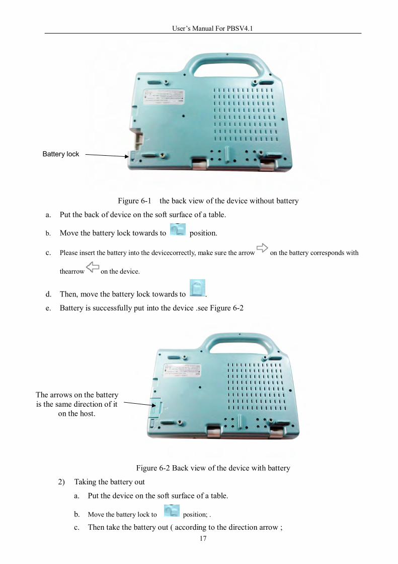
Figure 6-1 the back view of the device without battery
a. Put the back of device on the soft surface of a table.
b. Move the battery lock towards to position.
c. Please insert the battery into the devicecorrectly, make sure the arrow on the battery corresponds with
thearrow on the device.
d. Then, move the battery lock towards to .
e. Battery is successfully put into the device .see Figure 6-2
Figure 6-2 Back view of the device with battery
2) Taking the battery out
a. Put the device on the soft surface of a table.
b. Move the battery lock to position; . c. Then take the battery out ( according to the direction arrow ;
Battery lock
The arrows on the battery is the same direction of it
on the host.

User’s Manual For PBSV4.1
18
Note: The device must be switched off before taking the battery out!!!.
3) Probe installation
Figure 6-3 Probe socket Figure 6-4 Probe plug
a. Find the indicative point 1 and 2 on the probe socket of the device and probe plug as
shown Figure 6-3/6-4 ( red dot );
b. Plug the probe into the socket of the device according to the indicative point 1and 2;
c. Make sure that the proce is connected with the device as shown in Figure 6-5
Figure 6-5 probe connected well with the device
Note:
1) Please do not scratch the surface of the probe as it will influence measuring result.
2) The probe interface is only suitable to the probe designed by ourselves.
Indicative dot 1
Indicative( red) dot 2
Indicative point 1
Red dot 2

User’s Manual For PBSV4.1
19
Chapter Seven Operation of Device
7.1 Preparation before switching on the device
1) Check if the battery is right installed and its cover is locked.
2) The device is connected with probe well.
3) Check-up the device is fixed on the trolley steadily according to < Manual of cradle
installation> before use of PBS.
The user can switch on the device by press “POWER” key, the device will check the
electricity of battery, the state of printer connection and probe connection, memory capacity, then
enter into the checking interface after switching on.
7.2 Switch on the device
The user can switch on/off the device by press “POWER” key on the main panel of the
device. The interface is displayed as Figure7-1 after of switching on the device.
Figure7-1 Self-checking interface
Note:
Once the device self-check successfully, the system will enter its main system interface
directly; If any of one item fails in self-checking, alarm will remind you, then you need to
press direction key “►”before entering main system. If printer fails in its checking, no
influence to your measurement with the device.
Instruction for the state during self-checking on the device
“Battery checking …OK”: Battery is ok
“Probe checking…..OK”: Probe connection is ok
“Probe checking…..Disconnect”: Probe is not connected well (or not reliable connection );

User’s Manual For PBSV4.1
20
“Printer checking..OK” : Printer connection is ok;
“Storage…………...100%”: the actual space remained for storage.
If there is “ Probe Checking......Disconnect” please turn off the device and re-insert the probe
to the device.
Please check the probe line is good or not. If it is good but still with the same problem, please
contact your distributor.
Functional key
There are prompt and icons in the interface once switching on the device.
a. : When self-checking fails, touch or press direction key “►” on the
right to enter “Ready” interface of system.
b. : You may touch slightly with touch pen or press POWER key
to switch off the device.
Note:
the system will be shut down automatically if you do not press “►” key on the
right within 20s once the self-checking fails.
7.3 Ready interface
1) “Ready interface” is as shown in Figure 7-2:
Figure7-2 Ready interface
state bar
Touch Navi function buttons
Scan Mode
User’s Manual For PBSV4.1
21
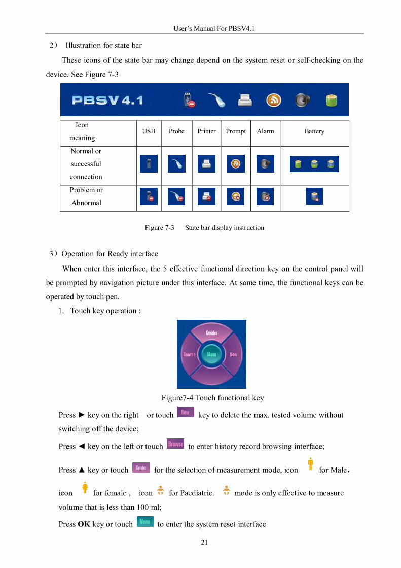
2) Illustration for state bar
These icons of the state bar may change depend on the system reset or self-checking on the
device. See Figure 7-3
Icon
meaning USB Probe Printer Prompt Alarm Battery
Normal or
successful
connection
Problem or
Abnormal
Figure 7-3 State bar display instruction
3)Operation for Ready interface
When enter this interface, the 5 effective functional direction key on the control panel will
be prompted by navigation picture under this interface. At same time, the functional keys can be
operated by touch pen.
1. Touch key operation :
Figure7-4 Touch functional key
Press ► key on the right or touch key to delete the max. tested volume without
switching off the device;
Press ◄ key on the left or touch to enter history record browsing interface;
Press ▲ key or touch for the selection of measurement mode, icon for Male,
icon for female , icon for Paediatric. mode is only effective to measure
volume that is less than 100 ml;
Press OK key or touch to enter the system reset interface
User’s Manual For PBSV4.1
22
Press SCAN key before entering Pre-scan interface. If there’s no probe it
could not get into the pre-scan interface Note:
All the icons in the status bar will change accordingly by the system setting or the system
checking condition to the device.
If you see that “ Only xx days left for probation “ will display on the screen in trial period.
That indicates how many day left in your trial period on the unit.
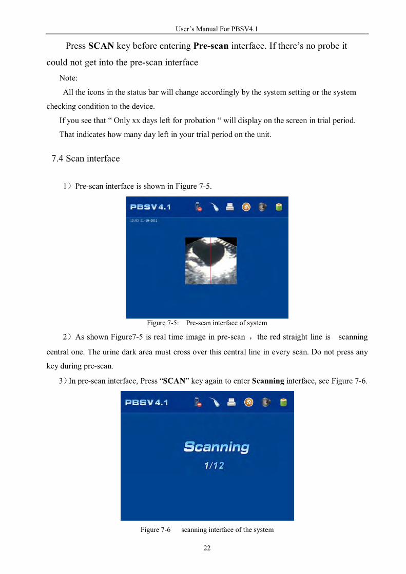
7.4 Scan interface
1)Pre-scan interface is shown in Figure 7-5.
Figure 7-5: Pre-scan interface of system
2)As shown Figure7-5 is real time image in pre-scan ,the red straight line is scanning
central one. The urine dark area must cross over this central line in every scan. Do not press any
key during pre-scan.
3)In pre-scan interface, Press “SCAN” key again to enter Scanning interface, see Figure 7-6.
Figure 7-6 scanning interface of the system

User’s Manual For PBSV4.1
23
4)Do not operate the device during scanning. There are 12 images for option in“Scan
images ” of the system interface reset. If select 12 images, its scan time take about 10s; If choose
24 images, its scan time take about 20s. The scanning progress will be displayed in the course of
scan (see Figure 7-6). “1/12”means it is scanning the first image of twelve at this moment as it
will scan 12 images, it will enter ‘Calculating…’interface after scan (see figure7-7) .
“Calculating... 12” mean it is scanning the twelfth images.
Figure7-7 Calculating progress
5)The system will enter “the scanned result interface ”after calculation.
7.5 scan result interface
1)This is presentation of current measured result and its location in Figure7-8
Figure7-8 scan result interface

User’s Manual For PBSV4.1
24
Note:
“Max. measured value” is one that hasn’t been being deleted ( press► under Ready
interface ) in previous measurement after restarting the device.
1) Press“►” key or touch for return to Ready interface;
2) Press“◄” key or touch to enter Save/Edit interface;
3) Press“▲” key or touch to switch into the scanned result of 6 images before and
after;
4) Press“▼” key or touch to switch between gray scale and 2-color images;
5) Press “PRINT” key to print the current image with the form of 2-color;
6) Press “SCAN” key to pre-scan and, then scan by pressing this key again.
Note:
In “ ” mode, If the current measured result display >100ml, “ Invalid measurement.
please select correct mode to measure !” will display on the screen, that indicates the
measured result >100ml, you need to change this mode into male or female
before measurement again.
7.6 Gray scale scanned result interface
1)Figure 7-9 is gray scale scanned result interface
Figure7-9 Scanned result in gray scale image
2)Press ▲ key to enter gray scale interface in scanned result interface. There are two
setting in ‘Scan Page’ of the system. 12 gray scale images be displayed separately in two pages
if setting 12, 6 images in each page. If setting 24, the images will be displayed separately in 4
pages.

User’s Manual For PBSV4.1
25
Operation:
1) Press► key or touch for return to Ready interface;
2) Press◄ key or touch to enter Save/Edit interface;
3) Press▲ key or touch to switch into the scanned result of 6 images before and after;
4) Press▼ key or touch to switch between gray scale and 2-color images;
5) Press PRINT key to print the current image ;
6) Press SCAN key to pre-scan and, then scan by pressing this key again.
Note:
Suggest to press ▼ or touch to see if red line and the edge of dark area in fluid
are coincident ( see Figure7-10), . If the deviation is too large, press "SCAN" button to rescan for
measurement again.
Figure 7-10 Scanned 2-color images interface
7.7 Save / Edit interface
1)Figure 7-11 is the save/ edit interface
Figure 7-11 Save/Edit interface

User’s Manual For PBSV4.1
26
Press ◄ key or touch enter Save/Edit interface in “Scanned result interface or scanned
result in gray scale image ” . Operation by pressing functional key
1) By pressing ►, ◄, ▲, ▼ to choose the character needed, the character key will change
into white while moving to the selected character.
2) Press “OK” key to confirm the selected character.
3) Chose “←” before pressing “OK” to delete the inputted character ;
4) Press PRINT key to save and return to Ready interface.;
5) Press SCAN key to cancel the saved and return to the Ready interface.
Operation in touch screen :
Use the touch pen to select the character you want according to the relative icon.
Note:
1) There are up to 12 figures for ID input;
2) No need to input in Gender. The system will display automatically according to the
system reset in the Ready interface;
3) Press PRINT to save the record, it will take about 4s to save the record .Never operate
other functional key during saving the record;
4) Memory : remind of remaining storage space;
5) It is not possible to save the same name for ID.
7.8 Browse historical record interface
Historical record browse interface is to browse saved measured record in the system (see
Figure 7-12).The record includes measurement result, patients’ information and their scanned
image in gray scale. User can select current record to print or delete. After deleting the current
record, the next one in order will be the current record and displayed in browse area.
Figure7-12 Historically browsing record interface

User’s Manual For PBSV4.1
27
Press ◄ key or touch to enter this historically browsing record interface;
1) Display patient’s ID, sex, measured volume record. There are some area for relative
images displayed in the right under each patient ID , 6 images displayed in each pages at
same time.。
2) Displaying “This is 01/09” indicates “01”is one of nine records, “09”indicates that total
nine records have been saved.
Operation of functional key:
a. Press PRINT key to print the current browsing historical record;
b. Press ▲ key or touch to browse previous record;
c. Press ▼ key or touch to check next record;
d. Press ◄ key or touch to switch the six images before and after;
e. Press ► key or touch to return the Ready interface;
f. Press OK key or touch to delete the current ID record.
7.9 System reset interface
Figure 7-13 is the system reset interface
Figure 7-13 system reset interface
Press OK key or touch to enter the system reset interface under Ready interface,
setting time, date, print mode, display mold, name of hospital, key prompt sound and alarm on/off
in the system..
Press the press key for turning on/off alarm and sound.
System reset operation:
1) Time : HH\MM\SS

User’s Manual For PBSV4.1
28
A. Operation by key-press.
a. Press ▲/▼ key to move and select “Time Set” , its background is purple
b. Press OK key to underline HH ;
c. Press ◄/► key to move the underscore between HH/MM/SS
d. Press ▲/▼key adjust the location of the underscore;
e. Press OK key to complete its setting.
B. Operation on touch screen:
a. Use touch “Time Set” with touch pen, a underscore will display on the option of HH,
0-9 character space will appear at the same time.
b. Touch 0-9 figures which you need with touch pen, then the underscore will automatically
switch over to the next option until completing your setting.
c. Touch “Time Set” with touch pen again to save this setting.
2) Date:Date setting, its form is dd\ mm\yy
Key-press :
a. Press ▲/▼ key to move the option of setting, select “Date Set”, its background is
purple .
b. Press OK key to underline HH ;
c. Press ◄/► key to move the underscore among DD /MM/YY
d. Press ▲/▼key adjust the location of the underscore;
e. Press OK key to complete its setting.
Touch screen:
a. Use touch “Date Set” with touch pen, a underscore will appear on the option of DD,
0-9 character space will appear at the same time.
b. Touch 0-9 figures which you need with touch pen, then the underscore will automatically
switch over to the next option until completing your setting.
c. Touch “Date Set” with touch pen again to save this setting.
3) Print Images: Print images, this device only can print 2 images.
a. Press ▲/▼ key or touch the option in “Print Page” with touch pen,its option
background is purple.
b. Press OK key to underline the figure of page;
c. Press ▲/▼ key to set the number of images,selecting the number among 02、04、06、
08,10,12
d. Press OK key to complete its setting.
4) Image Display: Images display type is in two color and gray scale at option.
a. Press▲/▼ key or touch “ Image Display ” with touch pen, this option’s background is

User’s Manual For PBSV4.1
29
purple.
b. Press OK key to underline the original mode, then press ▲/▼ to select ‘ Gray scan +red
line’ or ‘Gray scale’.
c. Press OK key for saving the setting
5) Hospital :
a. Press ▲/▼ key or select “Hospital Name” with touch pen in the option of “Hospital ,
its background is purple.
b. Press OK key or touch the name of hospital switch to the interface of editing hospital
name (see Figure 7-14);
c. Press PRINT key or touch after editing the hospital name to save it
automatically and return to the system reset interface, then press Scan key or touch
to exit from this system.
If you need to change the name of hospital, you need to enter only the edit interface of
hospital name( see Fighure7-14), re-input correct information before pressing PRINT key or
touch to save it.
Figure 7-14 Hospital name editing interface
6) Sound: setting sound on/off
a. Press ▲/▼ key or touch Sound Set to select it before its background will change into
purple.
b. Press OK key or touch ON/OFF to have ON or OFF with underscore, then press ▲/▼
or touch ON/OFF for selection of characters.
c. Press OK key or touch Sound Set again for saving this setting.
7) Alarm: Alarm ON/OFF setting
a. Press ▲/▼ key or touch Alarm Set in option before selecting Alarm Set that its

User’s Manual For PBSV4.1
30
background will change into purple.
b. Press OK key or touch ON/OFF to have it with underscore, then press ▲/▼ key or
touch ON/OFF again for selection.
c. Press OK key or touch Alarm Set in the option again for saving the setting.
8) Format: delete all stored records ( NO for not deleting ; Yes for deleting )
a. Press ▲/▼ key or touch Format in the option to select Forma, then its background
changes into purple;
b. Press OK key or touch NO to have it with underscore,
c. Press ▲/▼ key or touch YES/NO again and switch between YES/NO.
d. When display YES, press OK or touch Format again to delete all measured records
9) Volume Calibration:
Set calibration value with phantom . Use correcting phantom as its measurement object.
When measured value is different from phantom standard value, you can calibrate it through
adjusting correction parameter, the range of its correction is ±40ml.
Press ▲/▼ key or touch Volume Calibration in the option, where its background
changes into purple . Press OK to enter password input interface or touch Volume
Calibration to enter password input interface( see Figure 7-15)
Figure 7-15 Calibration interface with input password
a. When input password in calibration interface, press Print or touch to enter
calibration valve setting interface , see Figure 7-16.

User’s Manual For PBSV4.1
31
Figure 7-16, Calibration value setting interface
b. Press ▲/▼ key again to set ‘+’ ‘-‘ , then press ◄/► to set calibration value.
c. Press Print key or touch to save the calibration value and return the interface
setting. Press Scan key or touch to exit from calibration value setting interface
before return the interface setting.
11) Scan Images: selection the number of images to scan
a. Press ▲/▼ key or touch Scan Images in option to select it in the purple background.
b. Press OK key to underline the numbers of images you need to scan.
c. Press ▲/▼ key or touch the number of images before selecting 12 or 24 images to scan.
d. Press OK key or touch Scan Images in the option to complete the setting.
12) Scan Mode:
a. Press▲/▼ key or touch Scan Mode with touch pen in the option,selecting Scan Mode
in the purple’s background.
b. Press OK key or touch Scan character before be underlined under the character.
c. Press ▲/▼ key or touch the mode of character before selecting Scan Mode under
Human/Phantom.
d. Press OK key or touch Scan Mode in the option before saving the setting.
13) Screen Calibration:
a. Press ▲/ ▼ key or touch Screen Calibration in the option, selecting Screen
Calibration , its background changes into purple.
b. Press OK key or touch “ Screen Calibration to enter calibration interface on touch
screen (See figure 7-17).
c. Click cursor with touch pen ( for more time) to complete the calibration on the touch
screen, then return the system interface setting.

User’s Manual For PBSV4.1
32
Figure 7-17 touch screen calibration interface
14 ) Scanning adjust : start point for setting the probe location before scan.
a. Press ▲, ▼ key or touch Scanning adjust in the option, selecting Scanning adjust, its
background changes into purple.
b. Press OK key or touch “-/+” to have it with underscore, then press ▲, ▼ key or touch
“-/+” again before selection;
c. Again press ◄,► key or touch number character, selecting number setting. The window
of number icon will appear once touch the number, then touch the number icon for
number setting.
15 Save and Exit:exit from the setting before return to Ready interface
a. Press ▲,▼ key or touch Save and Exit in the option, selecting Save and Exit, its
background changes into purple.
b. Press OK key or touch Save and Exit to save the setting before return to Ready
interface.
Note:
a. There are up to 25 characters for hospital name.
b. Delete all saved records through the option of Format .
c. When selecting Human mode,there is icon displayed on the top left of Ready
interface.
d. When selecting Phantom mode, the character of Phantom will be displayed on the top
left of Ready interface.
e. The way of the correction of negative and positive value is calculated in Appendix A.

User’s Manual For PBSV4.1
33
7.10 Encrypting interface setting in trial period
The trail period is expired, the device will pop out a activation interface automatically (As
fig. 7-18), the user need to re-activate it to keep it working.
Figure 7-18 Encrypt setting interface
a. The end-user needs to send SN to your local distributers to get activation code.
b. Input activation code by touching character.
c. Press Print key or touch to activate the device.
d. Press Scan key or touch to exit this encrypting setting interface and return Ready
interface.
Note: If decrypting code for over 6 time, the system will automatically freeze, you are not able
to operate on the device. If need to reactivate the device, please restart the device again.
7.11 Location presentation
When making measurement, nurse should put the scan key of the probe face to the head of
patient. After scan and measurement, if the picture of bladder locates in center of the coordinate,
that mean the scanned result is ok; if the picture of bladder is not in the center of the coordinate
( see Figure7-19 and 7-26, need to rescan and measurement according to the operation
instruction.

User’s Manual For PBSV4.1
34
Figure 7-19 Figure7-20
Move probe to lower right Move the probe to lower left
Figure 7-21 Figure 7-22
Move the probe to up right Move the probe to up left
Figure 7-23 Figure 7-24
Move the probe towards patient’s feet. Move the probe towards patient’s head
Figure 7-25 Figure 7-26
Move the probe to right Move the probe to left
Bladder Head Head
Head Head
Head
Head
Head Head
Foot Foot
Right Left Right Left
Foot
Right Left Right Left
Foot
Right Left
Foot
Right Left
Foot
Right Left
Foot
Right
Left
Foot

User’s Manual For PBSV4.1
35
7.12 Scanned result print
Scanned result can be printed out directly after scan. Also possible to print the saved records
in history record browsing interface
The number of images printed depend on the number you set in Print Page ( see Figure
7-27).
Figure7-27 two images printed
7.13 Export data after connection with PC
1).You may export the historical data saved in the system to your PC through USB
connection. The system also may build a folder under each user, which should be corresponding
with patient ID. There are only gray scale images and a file of its text information saved in each
folder.
2) Operation for USB connection with the device :
a. Connect PBS and your PC through USB cable after switching on the device. and make
sure that their connection are ok.
b. Or Shut down the power of device first, connecting the device with PC through USB
cable , before switching on the device to enter Ready interface.
c. Observe the state bar, if see , means that connection is Ok , and tells you “this is USB
Mode!”. If , means that connection is not Ok. After connecting PC with USB, check if there
is any new hard disk on PC and open this disk before selecting the images before copying them or
cutting its folder to a specified place.
4) Shut down the power after successful the above operation, then disconnect USB
connection.

User’s Manual For PBSV4.1
36
Notice:
1). Operation is not allowed under USB connection mode unless disconnecting USB
connection and enter the normal mode after restarting the system.
2). The copied file only can be viewed through our special software ‘picViewer.exe ( See
Figure7-28), clicking on the folder icon in the toolbar and open the images to be viewed, use left
and right direction key to view images before and after.
Figure7-28 picViewer.exe
7.14 Heat printer
1). The device is internal thermal printer
2). Operation for changing the print paper:
Figure7-29 Figure 7-30 Figure7-31 Figure 7-32
1) As shown in Figure 7-29, open the lid of printer .
2) As shown in Figure 7-30, put the paper into paper box .
3) As shown in Figure 7-31, pull out the paper about 5cm.
4) As shown in Figure 7-32, close the cover of printer
3) The specification of the print paper: Φ30×57mm (outer diameter*width )
Note: The printer won’t work if you put the paper in wrong direction .

User’s Manual For PBSV4.1
37
7.15 Battery recharging
1).Battery charger and its connection: Battery charger consists of power adaptor and charger.
2) Charging:
A. Put the battery into the charger and insure it is right placed. The connection between plug
of battery and the socket of charger must be correct.
B. Connect the Charger with power supply before battery recharging, the red light will be
on while battery charging;
C. The green light will be on after recharging battery ( suggest battery charging for 2 hours
at least)
D. Disconnect the power between power supply and charger before taking the battery out.
Note:
Do not away from the place where the battery is recharging. The adapter, charger and
battery must be away from fire, heat, flammable and explosive materials.
Please don’t charge it when there’s nobody around. The adapter, charger and battery have
to far from the inflammables and explosives.
All the charger, adapter and battery are meet all the requirements of GB9706.1-2007
adapter Power supply AC 220V Charger

User’s Manual For PBSV4.1
38
Chapter Eight Clinical Application
8.1 Operation steps
1) Patient should be in supine posture when it is scanned with the device.
2) The coupling agent will be evenly put on the acoustic window of the probe.
3) Put the probe placed in the human abdomen at about 2 cm above the pubic bone and the
direction of probe must be slightly sloped towards to the head of patient, aiming at the
position of bladder.
4) Pre-scan by press SCAN key, moving the probe to find the max. surface of fluid dark
area
of bladder, while making it in the central fan-shaped area at the same time.
5) Scan again by press SCAN for measurement. After measurement, suggest to press ▼
key to see if both edges of the red line and the dark fluid area in gray scale are
overlapped. If the deviation is too large, rescan and measurement is necessary by press
SCAN key.
6) During scan, need to give appropriate pressure to the abdomen through the probe to
ensure that the acoustic window contact fully patient’s abdomen through the coupling
agent and relatively fixed.
7) Try to make patient’s posture stability during scan, let the patient to breath smoothly, do
not speak as well as no abdominal exercise.
8.2 Invalid scan result shown with some images .
The following images ( see Figure 8-1 to 8-10 ) that the red edge and dark fluid area didn’t
coincide are invalid scans. You have to rescan if you see some similar typical scanned images.
Figure 8-1. Too large red edge line Figure 8-2 Too large red edge line Figure 8-3 Too large red edge line

User’s Manual For PBSV4.1
39
Figure 8-4 Too small red line Figure 8-5 Too small red line
Figure 8-6 red line is not in dark fluid area Figure 8-7 Non-fluid area Figure 8-8 Non-fluid area
Figure8-9 Normal red line Figure 8-10 Non-red line
Note:
a. If red edge is too big, then its volume will be too big
b. If red edge is too small, then its volume will be small
c. If red edge is not in the dark fluid area, its measured result will be small
d. If red edge is not in dark fluid area, its scanned result will be ineffective.

User’s Manual For PBSV4.1
40
Chapter Nine Transportation and storage
9.1 Transportation
The marks on the device packaging case conform to the requirement of GB/T191-2008
<Packaging and Storage Illustrated Marks>. With simple shockproof facility inside of case, be fit
for air, railway, highway and steamboat transportation. Any rain, snow, inversion and collision
must be avoided.
9.2 Storage
When the device storage period exceeds 6 months, it should be took out from case and keep
running at least 4 hours. Then packing it as original package and placed properly. Do not put
heavy object upon the packaging case, The storage condition should be dry and ventilated,
without strong sunlight and corrosion from causticity gas. See 5.2 for details about storage
condition requirements.

User’s Manual For PBSV4.1
41
Chapter Ten Maintenance and Service
10.1 Maintenance for probe
1) As the probe is valuable and damageable part, any collision or falling is forbidden. Please
turn off the scanning key and put it into the case for probe, during paused of scanning.
Especially give attention to the acoustic window of probe, must guard against any damage,
even any minim scar also will reduce the effect and its life.
2) The component of probe is a non-watertight, its degree of protection into liquid is : IP×4;
3) In order to avoid probe or its protective material be corroded, any conductive liquid to the
probe is prohibited.
4) Please check and stop use the probe for maintenance immediately if there is any crack on the
lens material of acoustic window of the probe and its plastic part; or stop use the probe if
there is a breakage on the probe cable.
5) Regarding the medical gel, please select neuter PH , good sonolucency and easy to clean.
6) After diagnosis, please scrubbing probe softly and sterilize it before putting it into probe case
for storage.
7) As soon as the probe is connected with the device, do not take the probe off freely, otherwise
the plug of probe and socket will be incorrect connection.
10.2 Device maintenance
1). Clean the shell with soft and wet cotton cloth. Never use any chemical cleanser to clean, such as hydrochloric acid and bleacher.
a.Clean the probe by a soft cloth with alcohol (or the right medical cleanser)
b.Please clean the remaining cleanser and dry the probe by a soft cloth if cleaned by the
medical cleanser.
c. If the device need to disinfection, please wet the soft cloth by medical cleanser like
Cidex® or Cidex 7®, or other item like Sporicidin®.
d. Please wet the soft cloth with asepsis water to clean the cleanser.
e.Please clean the device with a clean soft cloth before using it.
2). Regularly check the visible part of device.
10.3 Service guide
Once the device has problem, firstly check and make sure all of their connection are ok , and
enough electricity of battery.

User’s Manual For PBSV4.1
42
A. If the device still doesn’t work after the above work, please contact your local distributor
or manufacturer.
B. The following necessary information must be needed
1) Model of the device and its configuration;
2) SN of the device and the date of delivery;
3) Detailed problem description displayed on the screen.
4) Doesn’t it have any previous maintenance, if yes, how did you deal with? What’s its
result after your solution.
C. Within quality warranty, freely service will be provided by us or your local distributor
once the device has problem.
D. In general, the device can be used for 6 years (exclude battery). The device must be
checked by our authorized technician before continuously using it.
E. The device must be managed as classified rubbish once it is announced as a waste.

User’s Manual For PBSV4.1
43
Chapter Eleventh Simple Problem Elimination For guarantee your normal use of this device, the solutions for trouble shooting are as below
( For your reference only):
1. Checking the battery is fixed well or not, enough electricity in battery..
2. Checking the connection between probe and device and lock up.
3. Check the connection of printer and the direction of print paper.
If you have problem while using the device, please contact our service department.

User’s Manual For PBSV4.1
44
Appendix A Device Calibration A1. Fix the probe on a holder and make sure that the probe is placed vertically on the center of
acoustic window of phantom ( standard phantom 128ml ) See Figure A-1.
Figure A-1the place of probe
A2. Please press “MENU/OK” to get into the system setting interface. (As fig. A-2)
Figure A-2 System setting interface
Enter the system reset interface after switching on the device, selecting Phantom in the
Scan Mode before return to Ready interface.
A3. Enter pre-scan state by pressing SCAN key (FigureA-3).
Figure A-3 Pre-scan image

User’s Manual For PBSV4.1
45
A4. Adjust the distance between probe and phantom, let the round dark area (target) be in
the middle of fan-image in pre-scan. The red line shown in Figure A-3 is central line, the
object measuring must be across this center line
A5. Enter Scan interface (see Figure A-4) by pressing SCAN key to get its scan result.
Figure A-4 Clear two color images after scan
A6. Repeat measurement for 5 time , no need calibration to the device if the measurement
result are within 128±10ml.
A7. If the measured result is not within 128±10ml, get the mean value through calculation
with 5 time measurement before getting the calibrated with following formula.
128 (phantom volume ) – mean value = calibrating value
A8. Select Calibration in the system reset interface for the device calibration.
A9. Phantom Parameter:
1. Phantom Parameter:
a. Sound speed of background material: 1540m/s±10m/s,23 ±3℃ ℃
b. Attenuation of background material: 0.7dB/(cm•MHz)±0.05dB/(cm•MHz),23 ±3℃ ℃
c. Protective plate:≤0.4mm
2.The internal target parameter of the Phantom
a. Weight: 1322g±0.1g
b. Density: 1021kg/m3±1kg/m3
c. Attenuation at 3MHz: 0.03dB/(cm·MHz)±0.02dB/(cm·MHz)
d. Sound speed at 23℃: 1547m/s±1m/s

User’s Manual For PBSV4.1
46
Appendix B Cautions for Polymer Lithium-ion Battery
B.1 Prohibition for Polymer Lithium-ion Battery
B.1.1 Prohibit to collide the battery with sharp parts.
B.1.2 Keep a clean environment, avoid sharp components exist around battery.
B.1.3.Do not perforate the battery with nail or other edge tools.
B.1.4. Do not transport or keep together with metallic things, such as necklace and barrette.
B.1.5. Do drop and impact the battery
B.1.6. Do not knock, throw and trample the battery.
B.1.7. Prohibit any items covered on the battery and charger.
B.1.8. Prohibit or mix the battery from different manufacturer as well as mix of old and new one
in use of it.
B.1.9. Do not use the mixed battery together with one-off battery capability, or different
capability or different mode or different brand battery.
B.1.10 Prohibit the use of non-designated and no safety-certified charger to charge the battery,
only the dedicated charger is suitable to the battery. never charge it unattended.
B.1.11 Any electrical short circuit will result in serious damage of the battery, any metal objects
are prohibited to use in connection with positive and negative of the battery.
B.1.12 Prohibit use of battery in the following situation.
a. Stop using the battery right away once the battery are found to hot, the emission of odor,
discoloration, deformation or other anomalies
b. Prohibit use of deformed battery caused by drop, impact and bump.
B.2 Notice for recharging and discharging the battery
B 2.1 Battery recharging
The recharging current and voltage is not allowed to exceed the following standard,
otherwise it might result in damage of mechanical performance and security, also resulting in
heat and leakage.
a. The charger must be worked with constant current and voltage.
b. The current of single battery must be below 1C during recharging.
c. The range of temperature must be 0~ 45 during recharging.℃
d. The voltage must be less than 9.4V during charging battery

User’s Manual For PBSV4.1
47
Special caution:
Power supply must be cut off once if the battery is found out of the way during recharging,
for instance, expand, smoke, break, then before touch or closing to battery in 4 hour later and
this battery is forbidden to be used again.
B 2.2 Battery discharging
Discharge current do not exceed the following regulation
a. The discharge current must be less than 1C.
b. The temperature range is -20~60 during discharging.℃
c. The terminated voltage must be bigger than 5.6V when battery discharged.
B.3 Storage for polymer Lithium-ion battery
a. The environment temperature for Long time storage: -5~40℃
b. Relative humidity: <80%
c. The battery needs to be recharged and discharged in every 90 days if you want to store it
for a long time. See 7.15 for the way of battery recharging.
Notice: Only remain 50% electricity on it when the battery is stored for one year.
B.4 Battery Transportation
Battery should be transported under the state of 50% electricity.
B.5 Other instruction
B.5.1 Please pay attention to the following prevention for preventing battery from leakage,
heat and explosive.
a. Prohibit disassembly of the battery in any condition
b. Prohibit the probe immerged into water, keep it dried.
c. Prohibit use or place of battery nearby heat resource, e.g: fire and heater.
d. Prohibit heating the battery or throwing it into fire.
e. Prohibit doing any soldering on the battery directly.
f. Prohibit recharging beside fire or in very hot environment.
g. Prohibit battery put in microwave oven or high pressure container
h. Prohibit use or place of the battery in high temp. ( e.g: strong sunshine, fire or place with
a higher than 60℃ inside of car) environment.

User’s Manual For PBSV4.1
48
B.5.2 In theory, there is no flowing electrolyte in such polymer Lithium-ion battery. you
must wash with running water and see the doctor in case the electrolyte leaks out and touch your
skin, eyes or other part of body,
B.5.3 Do not use any damaged battery ( such as broken battery, breakage of shell, the smell
of electrolyte, leakiness, etc.)
B.5.4 Be away from fire or blast if the battery leaks out or smell of electrolyte.
B.5.5 Keep in cool and dry place, keep away from children.
B5.6 The battery must be away from static field in recharging, use and storage.
B.5.7 If use the battery beyond the listed environment on the manual, will cause the fire or
shorten the life and worse its performance, even lead to explosion or fire. user will take the full
responsibility for the results of missing it.
B.5.8 Damage of the battery caused by misuse will be user’s account.
B.5.9 Don’t casually discard the abandoned battery; don’t deal it with the house refuse.
Recycle it by the related policy to avoid environment pollution.

User’s Manual For PBSV4.1
49
Appendix C How to set the starting location of the probe There might 3 kinds of images on the screen in the pre-scanning.
Figure C-1 Image center-left. Figure C-2 Correct Figure C-3. Image center-right.
C.1 Pre-scanning image center-left.
1)When the image looks like fig. C-1, please choose “-“ of “Scanning Adjust” in the system
setting. Input the degree value of ∠a, as fig. C-4(∠a equals the center of the image between the
red line’s degree)
Figure C-4 ∠a
Formula: When 0° < ∠a < 15°, then 0 < a < 10
When 15°< ∠a < 30°,10 < a < 20;
When 30°< ∠a < 45°,20 < a < 30;
When 45°< ∠a < 60°,30 < a < 40;
Back to pre-scan mode to check the red line and image’s position, if it still incorrect, please
back to adjust until it is correct (as Fig. C-2) or else, the practice result will with error.

User’s Manual For PBSV4.1
50
C.2 Pre-scanning image center-right
1)When the image looks like fig. C-3, please choose “+“ of “Scanning Adjust” in the system
setting. Input the degree value of ∠a, as fig. C-5(∠a equals the center of the image between the
red line’ degree)
Figure C-5 ∠a
Formula: When 0° < ∠a < 15°, then 0 < a < 10
When 15°< ∠a < 30°,10 < a < 20;
When 30°< ∠a < 45°,20 < a < 30;
When 45°< ∠a < 60°,30 < a < 40;
Back to pre-scan mode to check the red line and image’s position, if it still incorrect, please
back to adjust until it is correct (as Fig. C-2) or else, the practice result will with error.

User’s Manual For PBSV4.1
51
Appendix D Guidance and manufacturer’s declaration D1 Guidance and manufacturer’s declaration-Electromagnetic emissions
Guidance and manufacturer’s declaration –electromagnetic emissions The PBSV4.1 bladder scanner is intended for use in the electromagnetic environment specified below. The customer or the user of the SECP-II should assure that it is used in such an environment.
Emissions test Compliance Electromagnetic environment - guidance RF emissions CISPR 11 Group 1
The PBSV4.1 bladder scanner uses RF energy only for its internal function. Therefore, its RF emissions are very low and are not likely to cause any interference in nearby electronic equipment.
RF emissions CISPR 11 Class B The PBSV4.1 bladder scanner is suitable for use in all
establishments other than domestic and those directly connected to the public low-voltage power supply network that supplies buildings used for domestic purposes.
Harmonic emissions IEC 61000-3-2 Class B
Voltage fluctuations / flicker emissions IEC 61000-3-3
Complies
D2 Guidance and manufacturer’s declaration-Electromagnetic immunity
Guidance and manufacturer’s declaration – electromagnetic immunity The PBSV4.1 bladder scanner is intended for use in the electromagnetic environment specified below. The customer or the user of the PBSV4.1 bladder scanner should assure that it is used in such an environment.
Immunity test IEC 60601 test level Compliance level Electromagnetic environment –
guidance Electrostatic discharge (ESD) IEC 61000-4-2
±6 kV contact ±8 kV air
± 6 kV contact ± 8 kV air
Floors should be wood, concrete or ceramic tile. If floors are covered with synthetic material, the relative humidity should be at least 30 %.
Electrical fast transient/burst IEC 61000-4-4
±2 kV for power supply lines
±2 kV for power supply lines
Mains power quality should be that of a typical commercial or hospital environment.
Surge IEC 61000-4-5
± 1 kV line(s) to line(s) ± 2 kV line(s) to earth
± 1 kV line(s) to line(s) ± 2 kV line(s) to earth
Mains power quality should be that of a typical commercial or hospital environment.
User’s Manual For PBSV4.1
52
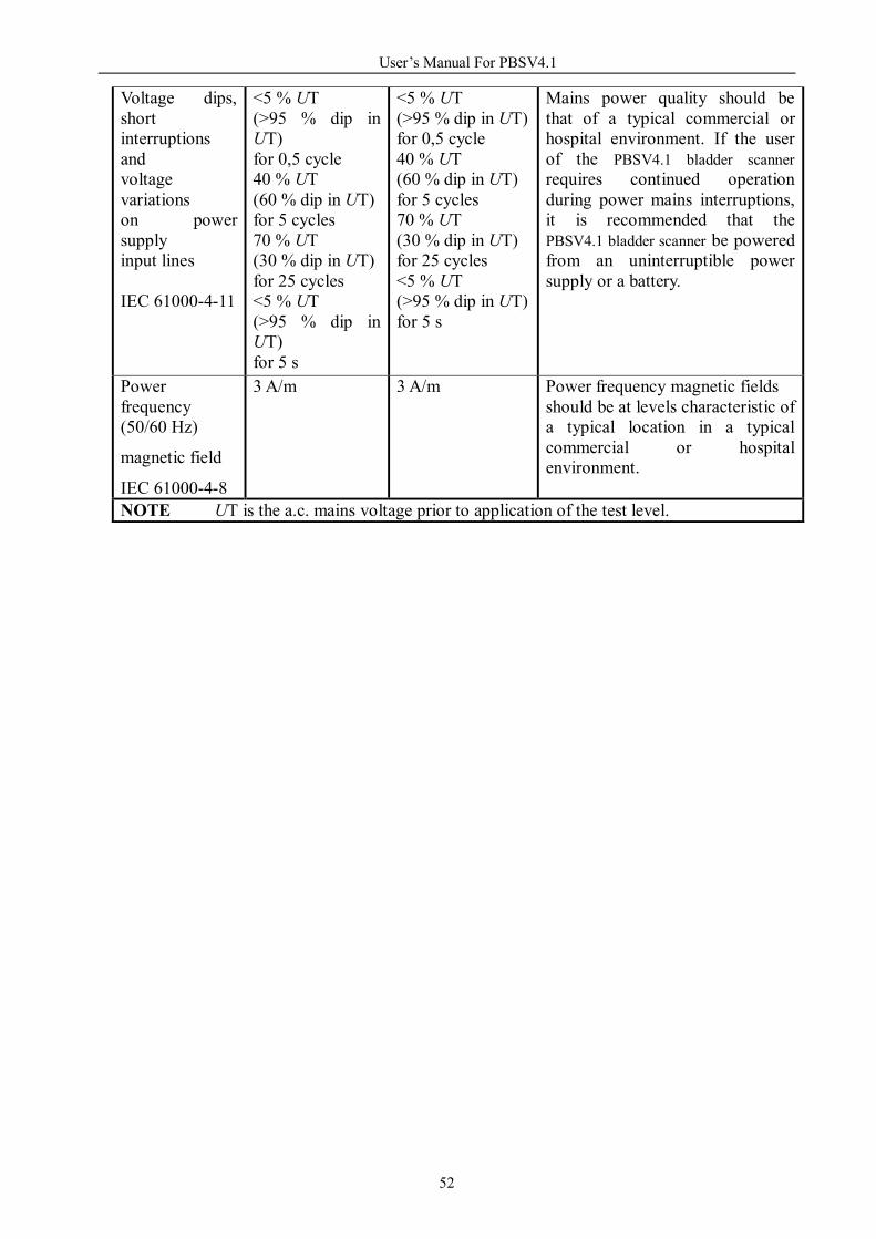
Voltage dips, short interruptions and voltage variations on power supply input lines IEC 61000-4-11
<5 % UT (>95 % dip in UT) for 0,5 cycle 40 % UT (60 % dip in UT) for 5 cycles 70 % UT (30 % dip in UT) for 25 cycles <5 % UT (>95 % dip in UT) for 5 s
<5 % UT (>95 % dip in UT) for 0,5 cycle 40 % UT (60 % dip in UT) for 5 cycles 70 % UT (30 % dip in UT) for 25 cycles <5 % UT (>95 % dip in UT) for 5 s
Mains power quality should be that of a typical commercial or hospital environment. If the user of the PBSV4.1 bladder scanner requires continued operation during power mains interruptions, it is recommended that the PBSV4.1 bladder scanner be powered from an uninterruptible power supply or a battery.
Power frequency (50/60 Hz)
magnetic field
IEC 61000-4-8
3 A/m 3 A/m Power frequency magnetic fields should be at levels characteristic of a typical location in a typical commercial or hospital environment.
NOTE UT is the a.c. mains voltage prior to application of the test level.

User’s Manual For PBSV4.1
53
Guidance and manufacturer’s declaration – electromagnetic immunity The PBSV4.1 bladder scanner is intended for use in the electromagnetic environment specified below. The customer or the user of the PBSV4.1 bladder scanner should assure that it is used in such an environment.
Immunity test IEC 60601 test level Compliance level
Electromagnetic environment – guidance
Conducted RF IEC 61000-4-6 Radiated RF IEC 61000-4-3
3Vrms 150kHz to 80MHz 3V/m 80MHz to 2.5GHz
3Vrms 3V/m
Portable and mobile RF communications equipment should be used no closer to any part of the PBSV4.1 bladder scanner, including cables, than the recommended separation distance calculated from the equation applicable to the frequency of the transmitter. Recommended separation distance d = 1.2 P d = 1.2 P 80MHz to 800MHz d = 2.3 P 800MHz to 2.5GHz where P is the maximum output power rating of the transmitter in watts (W) according to the transmitter manufacturer and d is the recommended separation distance in meters (m). Field strengths from fixed RF transmitters, as determined by an electromagnetic site survey, ashould be less than the compliance level in each frequency range. b
Interference may occur in the vicinity of equipment marked with the following symbol:
NOTE 1 At 80MHz and 800MHz, the higher frequency range applies. NOTE 2 These guidelines may not apply in all situations. Electromagnetic propagation is affected by absorption and reflection from structures, objects and people. a Field strengths from fixed transmitters, such as base stations for radio (cellular/cordless) telephones and
land mobile radios, amateur radio, AM and FM radio broadcast and TV broadcast cannot be predicted theoretically with accuracy. To assess the electromagnetic environment due to fixed RF transmitters, an electromagnetic site survey should be considered. If the measured field strength in the location in which the PBSV4.1 bladder scanner is used exceeds the applicable RF compliance level above, the PBSV4.1 bladder scanner should be observed to verify normal operation. If abnormal performance is observed, additional measures may be necessary, such as reorienting or relocating the PBSV4.1 bladder scanner.
b Over the frequency range 150kHz to 80MHz, field strengths should be less than 3V/m.

User’s Manual For PBSV4.1
54
Recommended separation distances between portable and mobile RF communications equipment and the PBSV4.1 bladder scanner
The PBSV4.1 bladder scanner is intended for use in an electromagnetic environment in which radiated RF disturbances are controlled. The customer or the user of the PBSV4.1 bladder scanner can help prevent electromagnetic interference by maintaining a minimum distance between portable and mobile RF communications equipment (transmitters) and the PBSV4.1 bladder scanner as recommended below, according to the maximum output power of the communications equipment.
Rated maximum
output power of transmitter
W
Separation distance according to frequency of transmitter m
150kHz to 80MHz d = 1.2 P
80MHz to 800MHz d = 1.2 P
800MHz to 2.5GHz d =2.3 P
0.01 0.12 0.12 0.23 0.1 0.38 0.38 0.73 1 1.2 1.2 2.3 10 3.8 3.8 7.3
100 12 12 23 For transmitters rated at a maximum output power not listed above, the recommended separation distance d in meters (m) can be estimated using the equation applicable to the frequency of the transmitter, where P is the maximum output power rating of the transmitter in watts (W) according to the transmitter manufacturer. NOTE 1 At 80MHz and 800MHz, the separation distance for the higher frequency range applies. NOTE 2 These guidelines may not apply in all situations. Electromagnetic propagation is affected by absorption and reflection from structures, objects and people.
Declaration:
All the pictures in this user manual are just for reference.