USER’S MANUAL - fantasy cut | gemstone | lapidary | gem ... · PDF fileCONCAVE FACETING...
14
CONCAVE FACETING MACHINE USER’S MANUAL The Concave Machine is shown with the Faceting Mast Mounted on it. The Mast (not part of the Concave Faceting Machine) is moved from the flat Faceting Machine and mounted as shown, for the completion of the concave facets. 2627.7 / 2627.2 Rev1
Transcript of USER’S MANUAL - fantasy cut | gemstone | lapidary | gem ... · PDF fileCONCAVE FACETING...
CONCAVE FACETING MACHINE
USER’S MANUAL
The Concave Machine is shown with the Faceting Mast Mounted on it. The Mast (not part of the Concave Faceting Machine) is moved from the flat Faceting Machine and mounted as shown, for the completion of the concave facets. 2627.7 / 2627.2 Rev1

TABLE OF CONTENTS INTRODUCTION 1.0 UNPACKAGING THE UNIT 2.0 AN OVERVIEW 3.0 SETTING UP
3.1 The Machine
3.2 Install Dial Indicators
3.3 Install Drip Tank 3.4 Install Splashguard
3.5 Install Lamp
4.0 OPERATION
4.1 The Control Panel 4.1.1 Control of Tool-drive Motor 4.1.2 Control of Reciprocation Motor 4.2 Tool-drive Motor position 4.2.1 Moving motor position 4.3 The Mast 4.3.1 The Mounting Block 4.3.2 Mounting the Mast. 4.3.2.1 Affixing the Rigidizer to the Mast 4.4 The “Home” position. Aligning the Mast to the unit’s working mechanisms 4.5 Horizontal Positioning – X, Y, θ 4.5.1 X Positioning. 4.5.2 Y Positioning. 4.5.3 θ Positioning 5.0 TOOLS 5.1 Mounting Tools into the Tool-drive Motor 5.1.1 Cylindrical tools 5.1.2 Slitting Tools 5.2 CUTTING AND POLISHING TOOLS 6.0 CUTTING INFORMATION
INTRODUCTION The Ultra Tec Faceting Machine has been manufactured since 1966. It displays Ultra Tec’s approach to equipment design -- direct, simple, thorough and non-compromising – providing the user with the precision and repeatability that fine lapidary work requires. The Concave Faceting machine has been developed at the urging of professional gem cutters. It is based on their “wish list” – a machine that is easy to set up to a “home” position, accurate and repeatable, and offering the reliability that is typical of Ultra Tec equipment. The Concave Faceting Machine has gone through a period of extensive testing to assure that the design goals have been met successfully. ABOUT YOUR CONCAVE FACETING MACHINE It is a precision device, but not a delicate device. For maintenance, it only needs normal “wipe-it-down” cleanliness and reasonable care. Pay attention to safety -- there are tools in multiple motion. In general, these are not sharp cutting tools, but sometimes are, and are necessarily exposed. So -- treat them with respect. As with any electro-mechanical device, there can be occasional problems--and if you experience one, re-read the Owner's manual for the function involved, to assure that you are performing the operation correctly. If you still experience a problem, communicate with your Ultra Tec representative or with the factory.
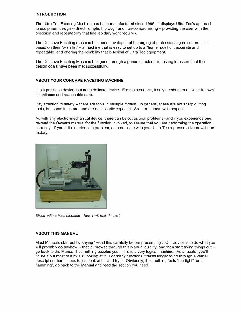
Shown with a Mast mounted – how it will look “in use”. ABOUT THIS MANUAL Most Manuals start out by saying “Read this carefully before proceeding”. Our advice is to do what you will probably do anyhow -- that is: browse through this Manual quickly, and then start trying things out – go back to the Manual if something puzzles you. This is a very logical machine. As a faceter you’ll figure it out most of it by just looking at it. For many functions it takes longer to go through a verbal description than it does to just look at it—and try it. Obviously, if something feels “too tight”, or is “jamming”, go back to the Manual and read the section you need.
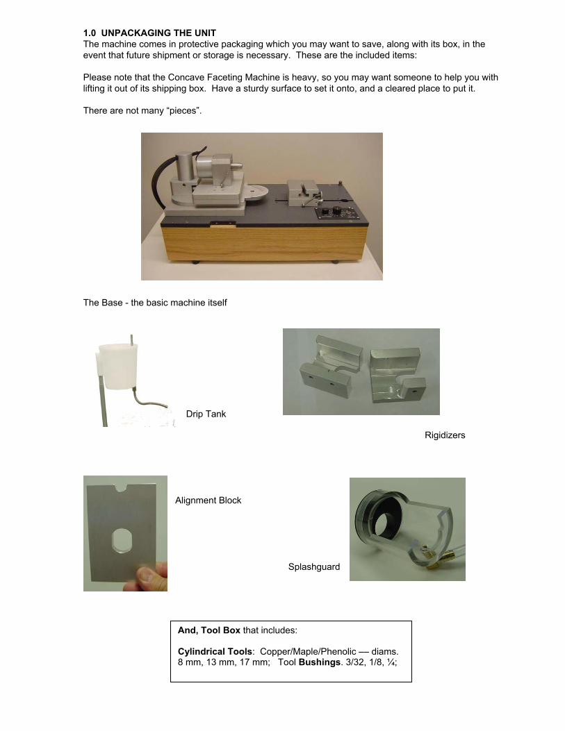
1.0 UNPACKAGING THE UNIT The machine comes in protective packaging which you may want to save, along with its box, in the event that future shipment or storage is necessary. These are the included items: Please note that the Concave Faceting Machine is heavy, so you may want someone to help you with lifting it out of its shipping box. Have a sturdy surface to set it onto, and a cleared place to put it. There are not many “pieces”. The Base - the basic machine itself
Drip Tank
Rigidizers
Alignment Block Splashguard
And, Tool Box that includes: Cylindrical Tools: Copper/Maple/Phenolic –– diams. 8 mm, 13 mm, 17 mm; Tool Bushings. 3/32, 1/8, ¼;
2.0 SETTING UP 2.1 The Machine – The machine should be placed on a workbench or desk surface. It is fairly heavy—about 50 pounds—so be sure the workbench is sturdy and you may need assistance in lifting it to the surface. The machine will need a plug-in electrical supply and a container for draining – a gallon container is adequate.
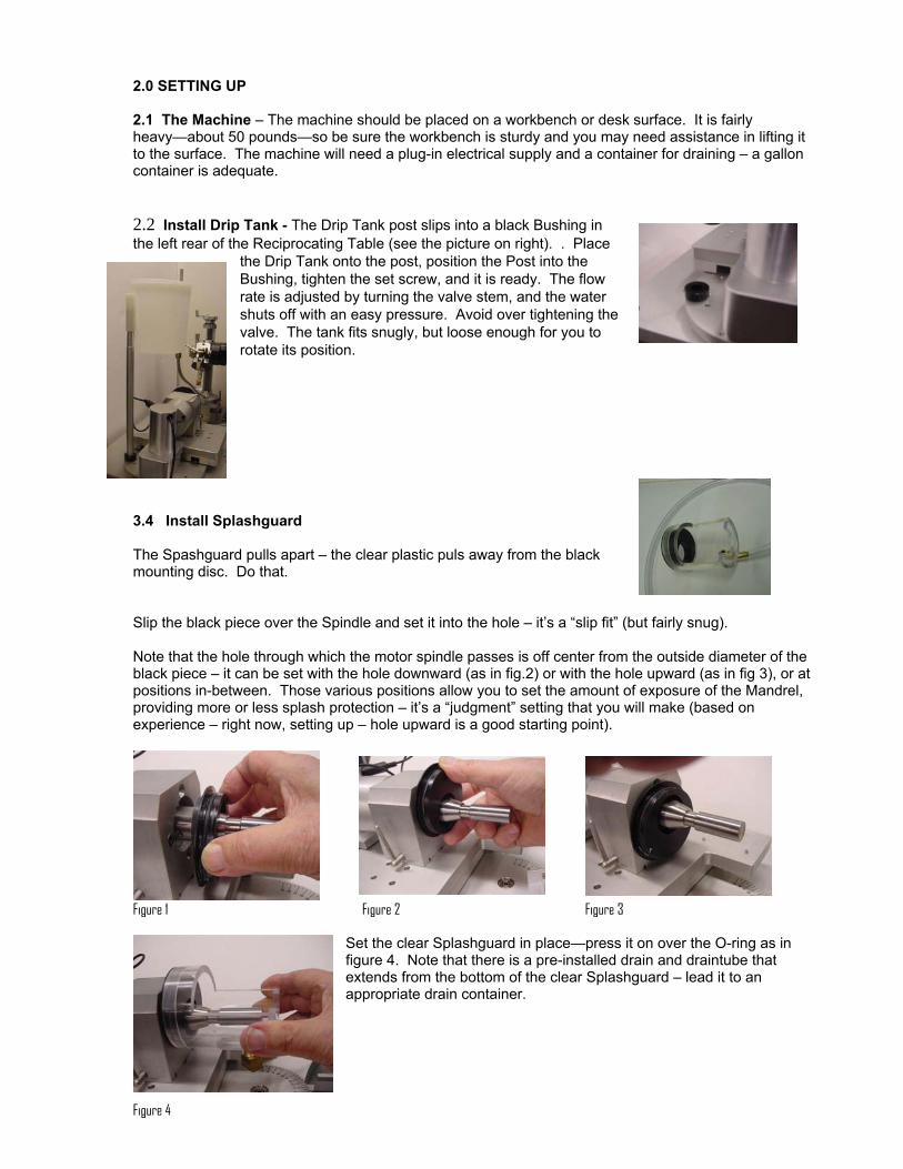
2.2 Install Drip Tank - The Drip Tank post slips into a black Bushing in the left rear of the Reciprocating Table (see the picture on right). . Place
the Drip Tank onto the post, position the Post into the Bushing, tighten the set screw, and it is ready. The flow rate is adjusted by turning the valve stem, and the water shuts off with an easy pressure. Avoid over tightening the valve. The tank fits snugly, but loose enough for you to rotate its position.
3.4 Install Splashguard The Spashguard pulls apart – the clear plastic puls away fmounting disc. Do that.
rom the black
Slip the black piece over the Spindle and set it into the hole – it’s a “slip fit” (but fairly snug). Note that the hole through which the motor spindle passes is off center from the outside diameter of the black piece – it can be set with the hole downward (as in fig.2) or with the hole upward (as in fig 3), or at positions in-between. Those various positions allow you to set the amount of exposure of the Mandrel, providing more or less splash protection – it’s a “judgment” setting that you will make (based on experience – right now, setting up – hole upward is a good starting point).
Figure 1 Figure 2 Figure 3
Set the clear Splashguard in place—press it on over the O-ring as in figure 4. Note that there is a pre-installed drain and draintube that extends from the bottom of the clear Splashguard – lead it to an appropriate drain container.
Figure 4

3.5 Install Lamp The Lamp is an option. If you have purchased it… The Lamp mounts onto the pre-assembled stud located in the right rear corner of the Baseplate. The lamp mounting lock has a snap-on design. Pull back the nylon ring, place the lamp onto the stud, and push down the ring. You will feel the ring snap into the down position, where it holds the lap securely.
4.0 OPERATION 4.1 The Control Panel The electronic control converts AC current to DC, which the motors require. It contains controls for both motors that are part of the unit, the Tool-drive Motor and the Reciprocation Motor. Note that the motor controls are independent – modifying the running characteristics of one of the motors does not affect the other one.
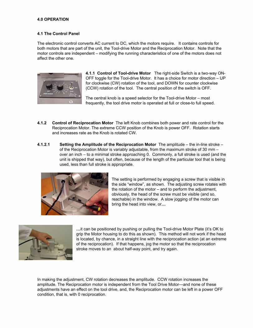
4.1.1 Control of Tool-drive Motor The right-side Switch is a two-way ON-OFF toggle for the Tool-drive Motor. It has a choice for motor direction – UP for clockwise (CW) rotation of the tool, and DOWN for counter clockwise (CCW) rotation of the tool. The central position of the switch is OFF. The central knob is a speed selector for the Tool-drive Motor – most frequently, the tool drive motor is operated at full or close-to full speed.
4.1.2 Control of Reciprocation Motor The left Knob combines both power and rate control for the
Reciprocation Motor. The extreme CCW position of the Knob is power OFF. Rotation starts and increases rate as the Knob is rotated CW.
4.1.2.1 Setting the Amplitude of the Reciprocation Motor The amplitude – the in-line stroke –
of the Reciprocation Motor is variably adjustable, from the maximum stroke of 30 mm – over an inch – to a minimal stroke approaching 0. Commonly, a full stroke is used (and the unit is shipped that way), but often, because of the length of the particular tool that is being used, less than full stroke is appropriate.
The setting is performed by engaging a screw that is visible in the side “window”, as shown. The adjusting screw rotates with the rotation of the motor – and to perform the adjustment, obviously, the head of the screw must be visible (and so, reachable) in the window. A slow jogging of the motor can bring the head into view, or…
…it can be positioned by pushing or pulling the Tool-drive Motor Plate (it’s OK to grip the Motor housing to do this as shown). This method will not work if the head is located, by chance, in a straight line with the reciprocation action (at an extreme of the reciprocation). If that happens, jog the motor so that the reciprocation stroke moves to an about half-way point, and try again.
In making the adjustment, CW rotation decreases the amplitude. CCW rotation increases the amplitude. The Reciprocation motor is independent from the Tool Drive Motor—and none of these adjustments have an effect on the tool drive, and, the Reciprocation motor can be left in a power OFF condition, that is, with 0 reciprocation.
4.3 The Mast. Most often, preparation of the workpiece is done on the standard flat Faceting
Machine, and after the preparation is complete, to do the concave facets, the Mast, holding the stone, is moved to the Mounting Block (see next paragraph).
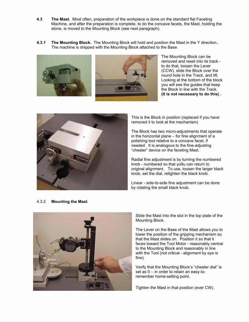
4.3.1 The Mounting Block. The Mounting Block will hold and position the Mast in the Y direction..
The machine is shipped with the Mounting Block attached to the Base
The Mounting Block can be removed and reset into its track - to do that, loosen the Lever (CCW), slide the Block over the round hole in the Track, and lift. Looking at the bottom of the block you will see the guides that keep the Block in line with the Track. (It is not necessary to do this) .
This is the Block in position (replaced if you have removed it to look at the mechanism) The Block has two micro-adjustments that operate in the horizontal plane – for fine alignment of a polishing tool relative to a concave facet, if needed. It is analogous to the fine-adjusting “cheater” device on the faceting Mast.
k knob.
retain an easy-to-e-setting point.
ast in that position (ever CW).
Radial fine adjustment is by turning the numbered knob - numbered so that yo9u can return to original alignment. To use, loosen the larger blacknob, set the dial, retighten the black Linear - side-to-side fine adjustment can be done by rotating the small black knob.
4.3.2 Mounting the Mast.
Slide the Mast into the slot in the top plate of the Mounting Block. The Lever on the Base of the Mast allows you to lower the position of the gripping mechanism so that the Mast slides on. Position it so that it faces toward the Tool Motor - reasonably central to the Mounting Block and reasonably in line with the Tool (not critical - alignment by eye is fine). Verify that the Mounting Block’s “cheater dial” is set as 0 – in order to remember hom Tighten the M
4.3.3 Affixing the Rigidizer to the Mast. It is necessary to eliminate lateral swinging of the Yoke. To do this, “Rigidizers” are provided – the Rigidizer mounts onto the Mast. Here are the mounting steps – it takes less than a minute to do.
Note that two Rigidizers have been provided, the “RC”(Rigidizer for Concave -- this is the one that will be used when adding the concave facets), and the “RF”.(this one is used for setup of the Home position).
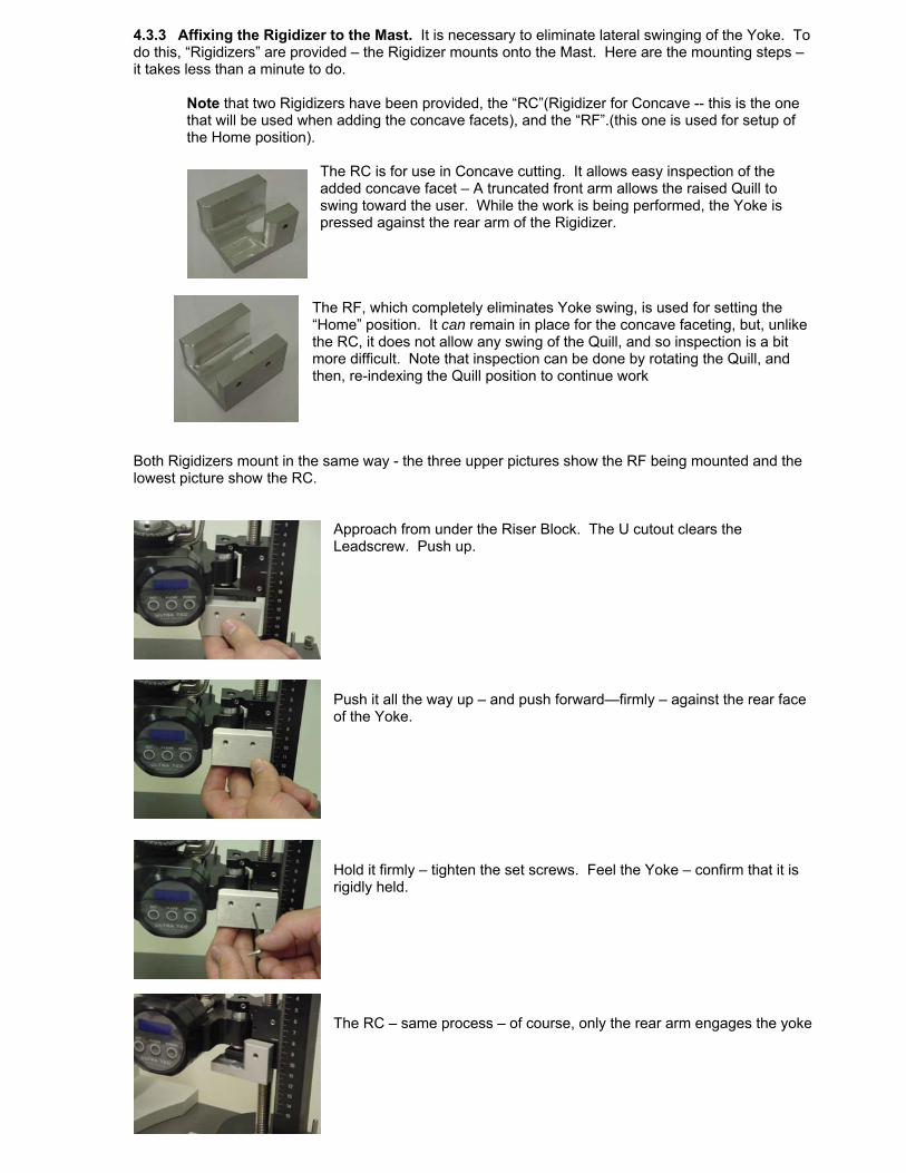
The RC is for use in Concave cutting. It allows easy inspection of the added concave facet – A truncated front arm allows the raised Quill to swing toward the user. While the work is being performed, the Yoke is pressed against the rear arm of the Rigidizer.
The RF, which completely eliminates Yoke swing, is used for setting the “Home” position. It can remain in place for the concave faceting, but, unlike the RC, it does not allow any swing of the Quill, and so inspection is a bit more difficult. Note that inspection can be done by rotating the Quill, and then, re-indexing the Quill position to continue work
Both Rigidizers mount in the same way - the three upper pictures show the RF being mounted and the lowest picture show the RC.
Approach from under the Riser Block. The U cutout clears the Leadscrew. Push up. Push it all the way up – and push forward—firmly – against the rear face of the Yoke. Hold it firmly – tighten the set screws. Feel the Yoke – confirm that it is rigidly held. The RC – same process – of course, only the rear arm engages the yoke

4.4 The “Home” position. Aligning the Mast to the unit’s working mechanisms. Alignment of the Mast in its new position is quickly and easily done. Alignment – and repeated alignment, if that becomes needed – usually takes about a minute. Here it is, step by step:
The Alignment Plate
Figure 2
Set the Alignment Plate in place—there are two flats on the motor Spindle that line up with the cutout in the Plate – set those flats manually into a vertical position. Resting the bottom edge of the Alignment Plate against the Motor mounting plate surface push the Alignment Plate over the flats and flush against the face of the Motor Housing – let go -- it will sit there. On the Mast, set the Quill angle at about 90+ degrees. Raise the height position of the Quill so that as the Mast is advanced forward (which is what will happen next) the Quill will pass over the top edge of the Plate. Using the X adjustment knob, advance the Mast toward the Alignment Plate until the front end of the Quill is a small amount higher than the top edge, and perhaps a quarter inch past the back face of the Alignment Block - as shown.
Loosen the Base lock on the Mast (slightly) so that the Mast can be rotated on the Mounting plate, and rotate the Mast so that the Quill (still over the top edge of the Alignment Plate) is to the side of the notch—by perhaps a half inch. Now, lower the Quill position so that it comes to a rest on the top edge of the Alignment Plate, and continue to lower until the angle readout is about 94 degrees – no precision needed (my 94.6 is OK). Disengage the Angle Stop on the Mast – back it off.
Now, as the Quill rests on the top edge of the Alignment Plate—and the Base lock of the Mast is slightly loose, holding down the Base of the Mast, against the top surface of the Mounting Block, rotate it – in a direction to drag the Quill along the top of the Plate toward the notch. At some point, the Quill “pops” into the notch – that’s it (you can adjust the angle to 90º--but you don’t have to—it just gives a “feeling” of having completed the task that has already been completed). It is on center – relock the Mast Base lock. That’s “home”. Using the X positioning Knob, move the Mast back to a working position
That took many words to say – it is much quicker to do than to read.
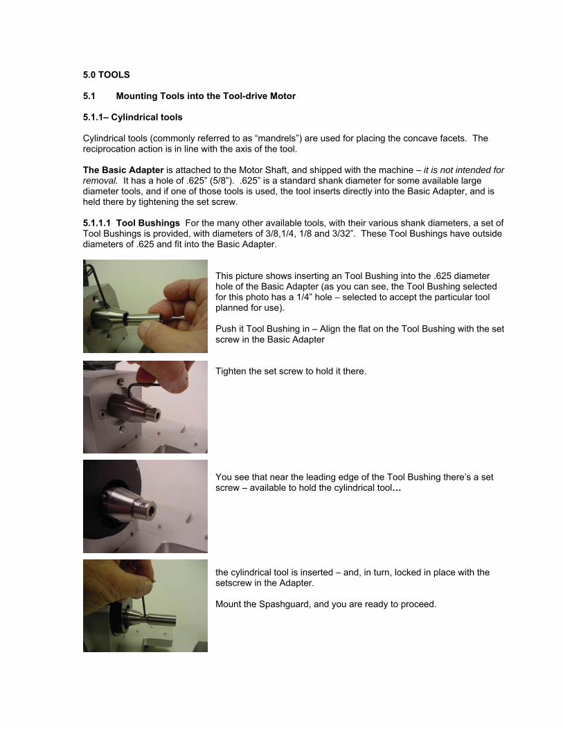
5.0 TOOLS 5.1 Mounting Tools into the Tool-drive Motor 5.1.1– Cylindrical tools Cylindrical tools (commonly referred to as “mandrels”) are used for placing the concave facets. The reciprocation action is in line with the axis of the tool. The Basic Adapter is attached to the Motor Shaft, and shipped with the machine – it is not intended for removal. It has a hole of .625” (5/8”). .625” is a standard shank diameter for some available large diameter tools, and if one of those tools is used, the tool inserts directly into the Basic Adapter, and is held there by tightening the set screw. 5.1.1.1 Tool Bushings For the many other available tools, with their various shank diameters, a set of Tool Bushings is provided, with diameters of 3/8,1/4, 1/8 and 3/32”. These Tool Bushings have outside diameters of .625 and fit into the Basic Adapter.
This picture shows inserting an Tool Bushing into the .625 diameter hole of the Basic Adapter (as you can see, the Tool Bushing selected for this photo has a 1/4” hole – selected to accept the particular tool planned for use). Push it Tool Bushing in – Align the flat on the Tool Bushing with the set screw in the Basic Adapter Tighten the set screw to hold it there.
You see that near the leading edge of the Tool Bushing there’s a set screw – available to hold the cylindrical tool…
the cylindrical tool is inserted – and, in turn, locked in place with the setscrew in the Adapter. Mount the Spashguard, and you are ready to proceed.
5.2 CUTTING AND POLISHING TOOLS Concave faceting is strongly related to flat faceting - it amounts to taking it another step. Adding the concave surface results in a dramatic increase in brilliance and complexity of appearance. A comparatively small number of cylindrical tools (mandrels) accomplish the task. Yes, it can get pretty “fancy”, and there is room for creativity, but still, it is done within faceting design “discipline” – specific positions, controlled dimensions. A search for concave tools on Internet sites reveals the availability of a number of diameter sizes (sometimes in inches, sometimes metric) – in several materials. Our plan has become that we will supply certain materials – in certain sizes – and include them in a “starters kit”. The “standard” materials are copper, maple, phenolic. Right now, the sizes are limited – but if you need a certain size, contact us (email is best – [email protected]), we will try to accommodate your need. (and if it is not a completely “oddball” size, we may add it to the list of standard available sizes). There are various “off the shelf” tools that you may wish to use, it is best for you, the user, to purchase directly from the tool suppliers (and for us NOT to be just a middle man). Find them on the Internet – google them. Here are a few suggestions—
● Special materials—that have been very successful in flat faceting – “Lightning Laps” and “BATT Laps” have made mandrels available.
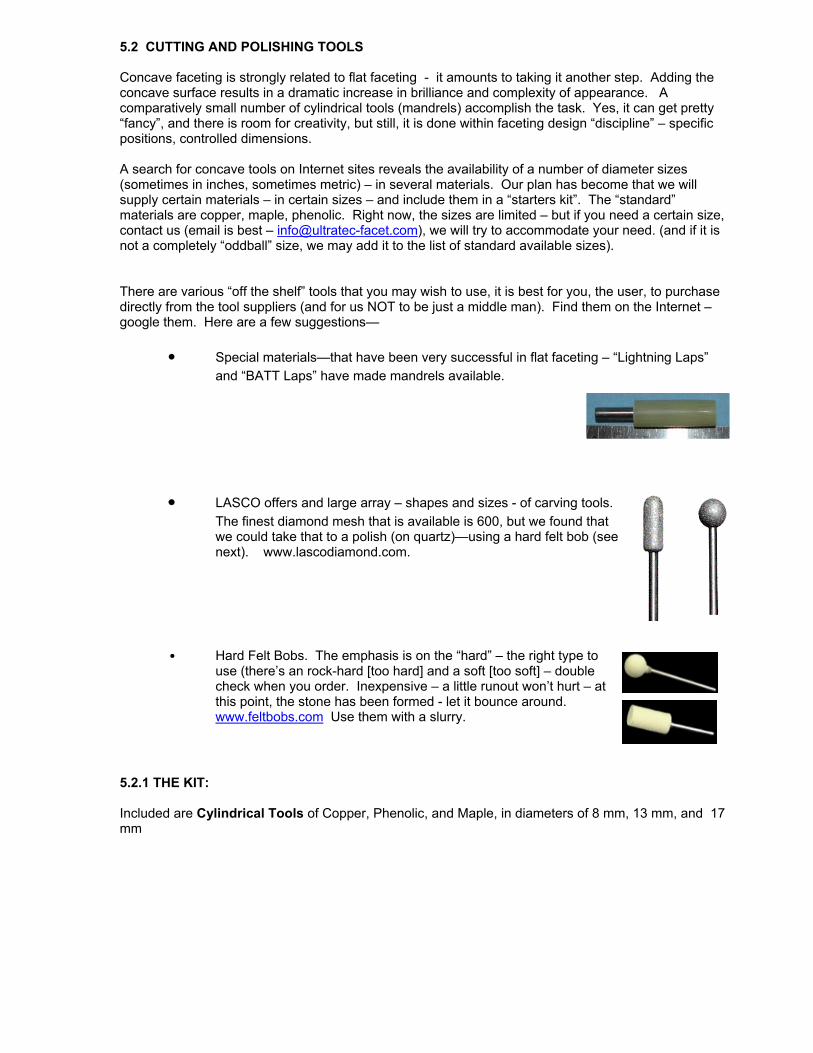
● LASCO offers and large array – shapes and sizes - of carving tools.
The finest diamond mesh that is available is 600, but we found that we could take that to a polish (on quartz)—using a hard felt bob (see next). www.lascodiamond.com.
• Hard Felt Bobs. The emphasis is on the “hard” – the right type to use (there’s an rock-hard [too hard] and a soft [too soft] – double check when you order. Inexpensive – a little runout won’t hurt – at this point, the stone has been formed - let it bounce around. www.feltbobs.com Use them with a slurry.
5.2.1 THE KIT: Included are Cylindrical Tools of Copper, Phenolic, and Maple, in diameters of 8 mm, 13 mm, and 17 mm

6.0 CUTTING INFORMATION Attached to this Instruction is a design -- a very nice concave-cut stone in itself -- and valuable as a guide to concave faceting There is a scarcity of published designs – something that we expect to be remedied soon. Dalan Hargrave has published the attached design and more will be issued in the near future. You can find another very good beginning design by googling “Merle's Surprise Cut” – it’s a good step-by-step instruction. You will catch on quickly, and defining your own concave versions of standard designs. ● The various tools would be used with Diamond Powder slurries – coarse diamond for cutting, and,
for polishing, in addition to fine diamond (14K – commonly used by many professionals, 50K – used by “perfectionists”), Aluminum Oxide slurry or Cerium Oxide slurry can be used. Various oils are used as carriers – very commonly, olive oil (a carry-over [?] of the use of olive oil in diamond faceting).
Miscellaneous Minor notes: ● When using a ball end cutter, straight forward plunging leads to swirl marks (the dead
center isn’t moving much – it’s a dead center all right). Approaching the stone from the side at some angle or other, provides the same cutting profile, but much swiping action.
● Setting a rapid reciprocation is generally advantageous. The side swiping action acts
against the radial grooving that develops in the small contained areas. ● Through much of the process you will probably not be using water or a thin slurry, at
which times you may not want to use the Splashguard. The clear plastic part is easy to remove and set to the side. Leave the black part in place (it functions to protect the motor area.
● Designs needed? Some Concave cuts are available to view on the Web –

Concave Conversion and Comparison
– Dalan Hargrave
Standard Round Brilliant 12mm
Angles for R.I. = 1.540
57 + 16 girdles = 73 facets
8-fold, mirror-image symmetry
96 index Note: Any size gem.
PAVILION
1 90.00° 03-09-15-21-27-33-39-45-
51-57-63-69-75-81-87-93
2 42.00° 03-09-15-21-27-33-39-45-
51-57-63-69-75-81-87-93
3 41.00° 06-18-30-42-54-66-78-90
CROWN
1 42.00° 03-09-15-21-27-33-39-45-
51-57-63-69-75-81-87-93
2 35.00° 06-18-30-42-54-66-78-90
3 19.00° 96-12-24-36-48-60-72-84
4 0.00° Table
Concave Round Brilliant (CRB) 12mm
Angles for R.I. = 1.540
73 + 16 girdles = 89 facets
8-fold, mirror-image symmetry
96 index Note: The 60 degree angle on
the pavilion provides a level surface for
setting the gemstone.
PAVILION
1 90.00° 03-09-15-21-27-33-39-45-
51- 57-63-69-75-81-87-93 flat facet
2 60.00° 03-09-15-21-27-33-39-45-
51-57-63-69-75-81-87-93 flat facet
3 43.00° 03-09-15-21-27-33-39-45-51-
57-63-69-75-81-87-93 use a 13mm
mandrel and cut close to girdle
4 41.00° 06-18-30-42-54-66-78-90
cut with 13mm mandrel
CROWN
1 42.00° 03-09-15-21-27-33-39-45-
51-57-63-69-75-81-87-93 cut with
17mm mandrel
2 30.00° 06-18-30-42-54-66-78-90
cut with 17mm mandrel
3 10.00° 96-12-24-36-48-60-72-84
cut with 17mm mandrel
4 0.00° Table