User’s Manual - Extreme Telematics...
35
Sasquatch User’s Manual Revision 4 April 23, 2018
Transcript of User’s Manual - Extreme Telematics...

Sasquatch User’s Manual
Revision 4
April 23, 2018

i
Table of Contents
1 Background ........................................................................................................................................... 1
2 Physical Connections ............................................................................................................................. 1
2.1 Power ............................................................................................................................................ 1
2.2 Output Signal ................................................................................................................................ 1
2.2.1 Dry Contact Input .................................................................................................................. 2
2.2.2 Voltage Input ......................................................................................................................... 2
2.3 Communications Port ................................................................................................................... 3
2.3.1 Communications Settings ..................................................................................................... 3
2.3.2 Modbus Slave ........................................................................................................................ 4
2.3.3 Program Mode ...................................................................................................................... 4
2.3.4 Wiring .................................................................................................................................... 4
3 Sensitivity .............................................................................................................................................. 6
3.1 Default Sensitivity ......................................................................................................................... 6
3.2 Adjusting the Default Sensitivities ................................................................................................ 7
4 Operating Modes .................................................................................................................................. 7
4.1 Normal .......................................................................................................................................... 7
4.2 Capture - Full Debug ..................................................................................................................... 7
4.3 Capture - Raw Samples ................................................................................................................. 7
5 Configurable Options ............................................................................................................................ 8
5.1 Output Switch Parameters ............................................................................................................ 8
5.1.1 Minimum Output Hold Time ................................................................................................. 8
5.1.2 Output Hold Scale ................................................................................................................. 8
5.2 Output Switch - Modes of Operation............................................................................................ 8
5.2.1 Static Time ............................................................................................................................. 8
5.2.2 Velocity Scaled ...................................................................................................................... 9
5.2.3 Plunger Hold .......................................................................................................................... 9
5.3 Detection Algorithm Timers ........................................................................................................ 10
5.3.1 Baseline Update Timer ........................................................................................................ 10
5.3.2 Arrival Detection Period ...................................................................................................... 10
5.3.3 Velocity Gathering Period ................................................................................................... 10

ii
5.3.4 Velocity Gathering Timeout ................................................................................................ 10
5.3.5 Velocity Calculation Timer .................................................................................................. 10
5.3.6 Departure Detection Period ................................................................................................ 10
5.3.7 Re-Initialize Timer ............................................................................................................... 10
5.4 Lubricator / Spring Wear Settings ............................................................................................... 10
5.4.1 Plunger Mass ....................................................................................................................... 10
5.4.2 Hard Arrival Velocity Threshold .......................................................................................... 10
5.4.3 Hard Arrival Kinetic Energy Threshold ................................................................................ 11
5.4.4 Dangerous Arrival Velocity Threshold ................................................................................. 11
5.4.5 Dangerous Arrival Kinetic Energy Threshold ....................................................................... 11
5.4.6 Consecutive Hard Arrival Alarm Threshold ......................................................................... 11
5.4.7 Cumulative Hard Arrival Threshold ..................................................................................... 11
5.4.8 Cumulative Kinetic Energy Threshold ................................................................................. 11
6 History ................................................................................................................................................. 11
6.1 Parameters .................................................................................................................................. 11
6.1.1 Date and Time ..................................................................................................................... 12
6.1.2 Units .................................................................................................................................... 12
6.2 Arrival Log ................................................................................................................................... 12
6.2.1 Arrival Time ......................................................................................................................... 12
6.2.2 Velocity................................................................................................................................ 12
6.2.3 Velocity Confidence Code ................................................................................................... 12
7 Lubricator / Spring Wear Monitoring ................................................................................................. 12
8 Hazardous Locations Certification ...................................................................................................... 14
9 Cathodic Protection ............................................................................................................................ 15
10 Company Contact Information ....................................................................................................... 15
Index of Tables
Table 1 - Dial Setting and Threshold Relationship ......................................................................................................... 6
Table 2 – Lubricator / Spring Wear Settings ................................................................................................................ 13
Table 3 – General Specifications (Normal Mode) ........................................................................................................ 16
Table 4 – Performance ................................................................................................................................................. 16
Table 5 – Environmental Data ..................................................................................................................................... 16
Table 6 - Double Word Register Format ...................................................................................................................... 17

iii
Table 7 - Elapsed Time Register Format ...................................................................................................................... 17
Table 8 - Date/Time Register Format .......................................................................................................................... 18
Table 9 - Available Coils ............................................................................................................................................... 19
Table 10 - Available Input Discretes............................................................................................................................. 20
Table 11 - Available Input Registers ............................................................................................................................ 21
Table 12 - Available Holding Registers ........................................................................................................................ 26
Table of Figures
Figure 1 - Sasquatch Physical Connections .................................................................................................................... 1
Figure 2 - Typical Dry Contact Interface......................................................................................................................... 2
Figure 3 - External Resistor for Voltage Input ................................................................................................................ 2
Figure 4 – RS-485 Connection ........................................................................................................................................ 4
Figure 5 - Sensitivity Dial ................................................................................................................................................ 6
Figure 6 - Static Time Output Mode ............................................................................................................................... 8
Figure 7 - Velocity Scaled Output Mode ........................................................................................................................ 9
Figure 8 - Plunger Hold Output Mode ............................................................................................................................ 9
Figure 9 – Vision Sasquatch Kinetic Energy Settings .................................................................................................... 14

iv
Installation Location: Class I, Division 2, Groups A, B, C, D or Non-
Hazardous Locations Only
Applicable to all models
WARNING - DO NOT REMOVE, REPLACE OR DISCONNECT WHILE CIRCUIT IS LIVE UNLESS THE AREA IS KNOWN TO BE FREE OF IGNITIBLE CONCENTRATIONS OF FLAMMABLE SUBSTANCES.
WARNING – EQUIPMENT SHALL BE CONNECTED TO AN APPROVED POWER SOURCE OR BARRIER THAT DOES NOT PROVIDE MORE THAN 24VDC AND 8A.
WARNING - EXPLOSION HAZARD – SUBSTITUTION OF COMPONENTS MAY IMPAIR SUITABILITY FOR CLASS I, DIVISION 2.
WARNING - THIS EQUIPMENT IS SUITABLE FOR USE IN CLASS I, DIVISION 2, GROUPS A, B, C, D OR NON-HAZARDOUS LOCATIONS ONLY.
WARNING - NO SERVICEABLE PARTS.
WARNING - IF EQUIPMENT IS USED IN A MANNER NOT SPECIFIED BY THE MANUFACTURER, THE PROTECTION PROVIDED BY THE EQUIPMENT MAY BE IMPAIRED.
AVIS – NE PAS ENLEVER, REMPLACER OU COUPER SI LE CIRCUIT EST SOUS TENSION À MOINS QUE LA RÉGION EST SAUF ET SANS SUBSTANCES INFLAMMABLES.
AVIS – L’ÉQUIPEMENT DOIT ÊTRE BRANCHER À UNE SOURCE D’ALIMENTATION APPROUVÉE OU UNE BARRIÈRE QUI NE FOURNIRA PAS PLUS QUE 24VDC ET 8A.
AVIS – RISQUE D'EXPLOSION – LA SUBSTITUTION DE COMPOSANTS PEUT RENDRE CE MATERIEL INACCEPTABLE POUR LES EMPLACEMENTS DE CLASSE I, DIVISION 2.
AVIS – L’ÉQUIPMENT EST ADAPTÉ POUR UTILISATION DANS CLASS I, DIVISION 2, GROUPS A, B, C, D OU DANS DES RÉGIONS SAUFS.
AVIS – PAS DE COMPOSANTS SERVICEABLES.
AVIS – SI L’ÉQUIPEMENT N’EST PAS UTILISÉ TANT QU’AUX INSTRUCTIONS DU FABRICANT, LA PROTECTION PEUT ÊTRE RÉDUITE.
v
Installation Location: Class I, Division 1, Groups C, D or Class 1 Zone 0
Locations Only
Applicable to model ET-11000-1031-0000 ONLY
WARNING – INTRINSICALLY SAFE WHEN CONNECTED PER DRAWING ET-11000-1031-2001.
WARNING – EQUIPMENT SHALL BE CONNECTED TO AN APPROVED POWER SOURCE OR BARRIER THAT DOES NOT PROVIDE MORE THAN 24VDC AND 8A.
WARNING – SUBSTITUTION OF COMPONENTS MAY IMPAIR INTRINSIC SAFETY.
WARNING – NO SERVICEABLE PARTS. WARNING – AVOID STRIKING OR EXCESSIVE FRICTION ON THE EQUIPMENT SURFACE DUE TO IGNITION HAZARD. WARNING – TO PREVENT IGNITION OF FLAMMABLE OR COMBUSTIBLE ATMOSPHERES, DISCONNECT POWER BEFORE OPENING.
AVIS – L’ÉQUIPEMENT EST EN SÉCURITÉ INTRINSÈQUE QUAND IL EST BRANCHÉ SELON LE DESSIN ET-11000-1031-2001.
AVIS – L’ÉQUIPEMENT DOIT ÊTRE BRANCHER À UNE SOURCE D’ALIMENTATION APPROUVÉE OU UNE BARRIÈRE QUI NE FOURNIRA PAS PLUS QUE 24VDC ET 8A.
AVIS – LA SUBSTITUTION DE COMPOSANTS PEUT COMPROMETTRE LA SECURITE INTRINSEQUE.
AVIS – PAS DE COMPOSANTS SERVICEABLES. AVIS – ÉVITER DE FRAPPER OU FRICTION EXCESSIVE SUR LA SURFACE DE L’ÉQUIPEMENT EN RAISON DE RISQUES D'INFLAMMATION. AVIS – POUR ÉVITER L’ALLUMAGE DES ATMOSPHÈRES INFLAMMABLES OU COMBUSTIBLES, COUPER LE COURANT AVANT OUVERTURE.

1
1 Background The Sasquatch is a revolutionary new magnetic field sensor that can not only detect the movement of a
ferrous object, but calculate and store its velocity. It features a rugged aluminum case with support for
two hose clamps, a ½” NPT strain relief port, and captive screws in the lid. The adjustable sensitivity dial
allows the operator to reduce sensitivity to eliminate false detections in noisy environments or increase
sensitivity for hard to detect objects.
Sasquatch is the only velocity sensor on the market that features a communication mode where you can
upgrade the firmware, access more sensitivity settings, and see real time readings to troubleshoot hard
to detect situations. This microprocessor based design incorporates noise reducing filters and also
controls the output switch to give a clean, user configurable switch closure that is easy for any controller
to detect.
2 Physical Connections The Sasquatch provides two connectors so that it can be powered, configured, and communicated with.
All cables should be labeled with the corresponding signal connection prior to inserting into terminals.
Ensure cables used meet the temperature and electrical ratings of the equipment. (See Table 2, 4)
Figure 1 - Sasquatch Physical Connections
2.1 Power The Sasquatch requires a DC power source with a voltage of 5 V to 24 V. Power must be supplied while
waiting for an arrival and during any time the interface will be accessed as there is no internal battery.
• PWR – 5 V to 24 V DC
• COM – Ground
2.2 Output Signal Each Sasquatch sensor is factory programmed to operate an internal switch when an arrival occurs. The
physical wiring and descriptions of the connections are shown below:
• SIG – Connect this to the input signal on your controller.

2
• COM – The common (COM) is connected to ground. When an arrival occurs, current will flow
through the signal (SIG) connection to ground. There is 100 Ohms of impedance in this path to
limit the current.
This output can be used with controllers that support a dry contact or voltage input.
2.2.1 Dry Contact Input
The Sasquatch has been designed with an open collector field effect transistor (FET) so that it acts as a
dry contact, which ensures that it can be connected directly to most controllers. Most magnetic sensors
available on the market are designed to act as a dry contact, so the Sasquatch can easily be used as a
replacement sensor for any system. A dry contact input on a controller features an internal pull up
resistor. When the contact is open, the internal input will read the system voltage. When the contact
closes, the input will now read ground.
ETC Controller
100kΩ5 V
PWR
SIG
COM
Sasquatch
PWR
SIG
COM
100Ω To Input
Figure 2 - Typical Dry Contact Interface
2.2.2 Voltage Input
When using a programmable logic controller (PLC) or other application specific controller (i.e. Flow
Computer) it is possible that you need to connect to a voltage based input. This type of input is
expecting to see a change in the voltage and is not directly compatible with the Sasquatch because it
closes a switch instead of sending back a voltage. The difference is that there is no internal pull up
resistor provided by these controllers, so an external pull up resistor must be connected. Connecting a
100kΩ resistor between the power and input on the controller will allow these systems to connect to a
Sasquatch.
When the Sasquatch switch is open, the input will see the voltage coming from the power connection.
When the switch closes, the input will be pulled to ground. This difference in voltage can then be
detected.
Controller w/ Voltage Input
100kΩ
5 - 24 V
PWR
SIG
COM
Sasquatch
PWR
SIG
COM
100Ω To Input
Figure 3 - External Resistor for Voltage Input

3
2.3 Communications Port The Sasquatch also provides a serial communications port. This is a standard 2 wire RS-485 differential
signal with a common (ground). It is used for accessing settings, reading the device status and history,
upgrading firmware, and configuring the operating mode.
• A/B – Two wire RS-485 Differential Signal
• COM – An additional ground connection to be used with an RS-485 connection.
2.3.1 Communications Settings
The settings for the communications port are fully configurable so that the Sasquatch can be used with
any other RS-485 compatible communication device. The following outlines the parameters that can be
configured.
2.3.1.1 Baud Rate
This is the data rate, represented in bits per second. The default is 9600 bps. The following are the
available rates:
• 1200 bps
• 2400 bps
• 4800 bps
• 9600 bps
• 19,200 bps
• 38,400 bps
• 56,000 bps
• 115,200 bps
• 128,000 bps
• 256,000 bps
2.3.1.2 Parity
The parity can be configured as no parity, even, or odd.
2.3.1.3 Data Bits
This is the number of data bits used to send one byte of data. It can be configured to 7 or 8, which is the
default.
2.3.1.4 Stop Bits
This is the number of bits that are appended at the end of the data to indicate the end of byte. The
default is 1 stop bit, but can be configured to 2.
2.3.1.5 Station Address
This is the Modbus slave station address. It is used to distinguish one Modbus slave from another and
must be unique on a given network. It can be configured between 1 and 247. The default is 1.

4
2.3.1.6 Protocol
The default protocol is RTU, which transmits data in binary format. This is the most efficient protocol for
Modbus. It can also be set to ASCII, which sends the equivalent ASCII code for each digit, essentially
doubling the amount of data required.
2.3.2 Modbus Slave
The COM port supports the Modbus protocol. The Sasquatch acts as a Modbus slave device and only
responds to communication from the master. There is no special cable required and any other RS-485
compatible device can be connected directly to these connections. Please note that there may be a
requirement for an intrinsic safety barrier depending on the installation location and certification of the
master device.
RS-485 Modbus Master
B
A
COM
Sasquatch
B
A
COM
Figure 4 – RS-485 Connection
2.3.3 Program Mode
When the sensitivity dial is set to 0, Sasquatch enters a mode where it listens for external commands on
the RS-485 COM port. Using ETC Vision, you can program new firmware, change the operating mode,
and adjust the sensitivity levels.
2.3.4 Wiring
Most computers do not come with an RS-485 port, so a USB to RS-485 adapter must be used. The
connection is relatively straightforward.
2.3.4.1 Using the Raven USB to RS-485 Adapter
The Raven is the only adapter that has been certified for use in hazardous locations. When connecting to
the Sasquatch in hazardous locations, a Raven adapter should be used.

5
Figure 5 - USB to RS-485 Adapter Wiring using the Raven
2.3.4.2 Using the LinkTM Device Connection Adapter
Use the Sasquatch device cable that came with Link to connect to the device. Before connecting Link to
Sasquatch, ensure that the switch on Link is set to position 1 (the leftmost position).
Figure 6 - USB to RS-485 Adapter Wiring using the Link
6
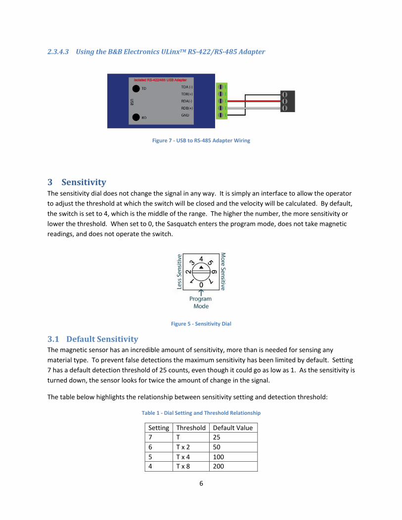
2.3.4.3 Using the B&B Electronics ULinxTM RS-422/RS-485 Adapter
Figure 7 - USB to RS-485 Adapter Wiring
3 Sensitivity The sensitivity dial does not change the signal in any way. It is simply an interface to allow the operator
to adjust the threshold at which the switch will be closed and the velocity will be calculated. By default,
the switch is set to 4, which is the middle of the range. The higher the number, the more sensitivity or
lower the threshold. When set to 0, the Sasquatch enters the program mode, does not take magnetic
readings, and does not operate the switch.
Figure 5 - Sensitivity Dial
3.1 Default Sensitivity The magnetic sensor has an incredible amount of sensitivity, more than is needed for sensing any
material type. To prevent false detections the maximum sensitivity has been limited by default. Setting
7 has a default detection threshold of 25 counts, even though it could go as low as 1. As the sensitivity is
turned down, the sensor looks for twice the amount of change in the signal.
The table below highlights the relationship between sensitivity setting and detection threshold:
Table 1 - Dial Setting and Threshold Relationship
Setting Threshold Default Value
7 T 25
6 T x 2 50
5 T x 4 100
4 T x 8 200

7
3 T x 16 400
2 T x 32 800
1 T x 64 1600
3.2 Adjusting the Default Sensitivities Using the program mode, the detection threshold for setting 7 can be adjusted to make the sensor more
or less sensitive. Because there is some noise in the readings, the threshold can only be set as low as 10.
The threshold for each sensitivity dial setting is automatically calculated by doubling the threshold from
the next most sensitive setting. The net result is that each dial setting is twice as sensitive as the
previous setting.
4 Operating Modes There are several operating modes that can be entered while the sensitivity dial is in position 0. The
sensor will not start operating in a given mode until the sensitivity dial is set to a non-zero position.
Before connecting the Sasquatch to a controller, the mode must be set to back to Normal. If the mode
is not set to Normal, the detection algorithm will not run and the COM port will be setup to interact with
ETC Vision instead of running the Modbus slave. Data transmitted out the COM port will cause a
controller to interpret it as an arrival.
4.1 Normal This is the mode that each sensor is shipped in by default. When the sensitivity dial is set to any number
other than 0, the sensor will take magnetic readings, calculate a baseline and compare the current
reading to see if it has surpassed the threshold. When the threshold is exceeded, the velocity is
calculated and stored in a Modbus register that can be read from the RS-485 port and the switch is
closed on the SIG wire. (See 5.2 Output Switch - Modes of Operation).
ETC Vision provides a SCADA viewer to view and modify registers on the Sasquatch when it is operating
in Normal Mode
4.2 Capture - Full Debug This mode will run just like the normal mode, except the RS-485 port is used to stream live data to ETC
Vision. This data includes the current readings, baseline, current switch position and velocity. Run a
capture in ETC Vision to see the real time stream of these values.
4.3 Capture - Raw Samples The Raw Samples mode is similar to the Full Debug mode. It will take magnetic readings and stream
data that is captured by ETC Vision. The difference is that no other filtering or calculations is done on
the data before being sent to ETC Vision. This mode essentially eliminates all internal algorithms to give
an accurate picture of the readings coming from the magnetic sensor.
8
5 Configurable Options The following parameters can be used to modify the way that the Sasquatch operates. This allows for
maximum flexibility for a variety of different applications.
5.1 Output Switch Parameters These parameters are used for one or more of the modes of operation in the following section.
5.1.1 Minimum Output Hold Time
This sets the minimum time that the output switch is closed when the plunger arrives. In some modes,
this will be extended based on the behaviour of the plunger or its velocity. The default is 1000 ms or 1 s.
5.1.2 Output Hold Scale
This is a scaling parameter used to extend the close time of the switch in relation to the velocity of the
plunger. The default is 10 ms per m/min of velocity.
5.2 Output Switch - Modes of Operation The behavior of the switch can be modified to operate in one of 3 modes to integrate better with
different systems.
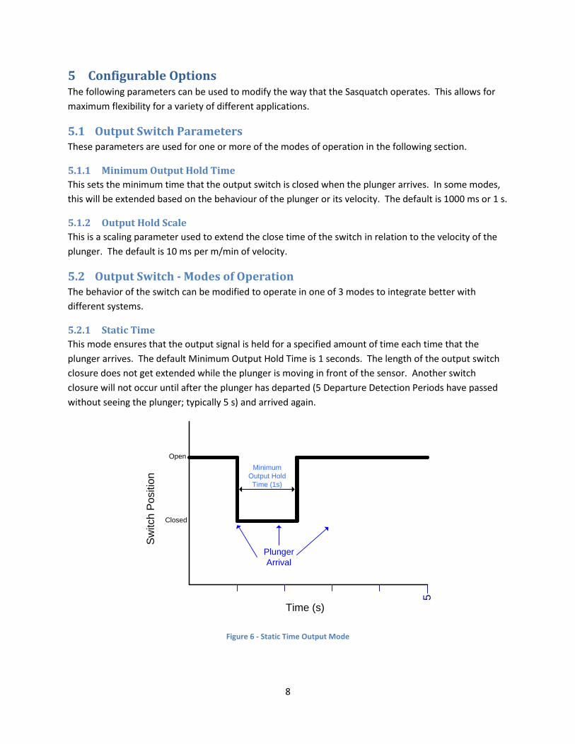
5.2.1 Static Time
This mode ensures that the output signal is held for a specified amount of time each time that the
plunger arrives. The default Minimum Output Hold Time is 1 seconds. The length of the output switch
closure does not get extended while the plunger is moving in front of the sensor. Another switch
closure will not occur until after the plunger has departed (5 Departure Detection Periods have passed
without seeing the plunger; typically 5 s) and arrived again.
5
Plunger
Arrival
Minimum
Output Hold
Time (1s)
Open
Closed
Sw
itch
Po
sitio
n
Time (s)
Figure 6 - Static Time Output Mode

9
5.2.2 Velocity Scaled
This allows for the velocity information to be transmitted along with the switch closure. The switch will
always close for the Minimum Output Hold Time as above, but will be held closed for an additional time
that is calculated based on the Output Hold Scale parameter. In the example below, the Output Hold
Scale is set to 10 ms per m/min of velocity, which is the default. The plunger arrived at 200 m/min, so
2000 ms or 2 seconds was added.
5
Open
Closed
Sw
itch
Po
sitio
n
Time (s)
Extended
Output Hold
Time (2 s)
Minimum
Output Hold
Time (1 s)
Plunger
Arrival
Figure 7 - Velocity Scaled Output Mode
5.2.3 Plunger Hold
This mode works similar to the Cyclops. When the plunger arrives, the output switch is closed for the
Minimum Output Hold Time (default of 1 s). As long as the plunger continues to move in front of the
sensor, the output switch is held closed as the plunger is considered present. While the plunger is
departing (5 Departure Detection Periods; typically 5 s), the switch will continue to be held. If the
plunger does not appear within this window, the switch is then released.
5
Open
Closed
Sw
itch
Po
sitio
n
Time (s)
Minimum
Output Hold
Time (1 s)
Plunger
Arrival
Plunger
Present
10
Plunger
Departing (5 s)
Figure 8 - Plunger Hold Output Mode
10
5.3 Detection Algorithm Timers The following detection algorithm timers help set the filtering and data gathering rates. By default they
are configured to detect the arrival and velocity of a plunger. They are made available to fine tune the
operation of the sensor for other applications.
5.3.1 Baseline Update Timer
This is the frequency at which the baseline is updated.
5.3.2 Arrival Detection Period
This is the rate at which the magnetic signal is sampled while waiting for a plunger to arrive.
5.3.3 Velocity Gathering Period
This is the rate at which the magnetic signal is sampled once the plunger has been detected.
5.3.4 Velocity Gathering Timeout
This specifies how long we gather data after an arrival has been detected before we stop to calculate
the velocity.
5.3.5 Velocity Calculation Timer
This specifies a time that the Sasquatches uses to process all other operations once the velocity has
been calculated before it begins looking for the plunger departure.
5.3.6 Departure Detection Period
This is the rate at which the magnetic signal is sampled when waiting for the plunger to depart. The
plunger is not considered departed until we see 5 consecutive periods pass without detecting the
plunger.
5.3.7 Re-Initialize Timer
This timer specifies how long to wait after the plunger has departed before re-initializing the sensor.
5.4 Lubricator / Spring Wear Settings The Sasquatch provides alarms and statistics for monitoring spring wear due to hard plunger arrivals.
This functionality is useful for monitoring well safely and for maintenance scheduling
5.4.1 Plunger Mass
The mass of the plunger in thousandths of a pound (x1000 lbs) or grams. This is required in order for the
Sasquatch to calculate accurate kinetic energy of the arriving plunger as it hits the lubricator. If this
information is not provided, the velocity-based lubricator / spring alarms will still operate.
5.4.2 Hard Arrival Velocity Threshold
If the velocity of the plunger exceeds this threshold a hard arrival has occurred. If enough consecutive
hard arrivals occur an alarm flag will be set. Hard arrivals can also trip the Cumulative Hard Arrival Alarm
and the Cumulative Kinetic Energy Alarm
Associated Alarms: Consecutive Hard Arrival Alarm, Cumulative Hard Arrival Alarm, Cumulative Kinetic
Energy Alarm

11
5.4.3 Hard Arrival Kinetic Energy Threshold
This is the equivalent kinetic energy of the Hard Arrival Velocity Threshold. This value is linked with the
Hard Arrival Velocity Threshold so that if one is changed the other changes as well.
Associated Alarms: Consecutive Hard Arrival Alarm, Cumulative Hard Arrival Alarm, Cumulative Kinetic
Energy Alarm
5.4.4 Dangerous Arrival Velocity Threshold
If the velocity of the plunger exceeds this threshold a dangerous arrival has occurred. This will trigger a
Dangerous Alarm.
Associated Alarm: Dangerous Arrival Alarm
5.4.5 Dangerous Arrival Kinetic Energy Threshold
This is the equivalent kinetic energy of the Dangerous Arrival Velocity Threshold. This value is linked with
the Hard Arrival Velocity Threshold so that if one is changed the other changes as well.
Associated Alarm: Dangerous Arrival Alarm
5.4.6 Consecutive Hard Arrival Alarm Threshold
This setting defines when a consecutive hard arrival alarm will trip. For example, if this setting is 3, then
3 consecutive arrivals with a velocity higher than the Hard Arrival threshold will cause an alarm flag to
be set.
Associated Alarm: Consecutive Hard Arrival Alarm
5.4.7 Cumulative Hard Arrival Threshold
The Sasquatch counts the number of arrivals above the Hard Arrival threshold. If this count exceeds the
Cumulative Hard Arrival Threshold, and alarm flag is set. These do not need to be consecutive hard
arrivals to trip the alarm.
Associated Alarm: Cumulative Hard Arrival Alarm
5.4.8 Cumulative Kinetic Energy Threshold
The Sasquatch accumulates (adds together) all kinetic energies for arrivals that exceed the Hard Arrival
threshold. When that sum exceeds the Cumulative Hard Arrival Threshold, an alarm will occur.
Associated Alarm: Cumulative Kinetic Energy Alarm
6 History The following outlines the parameters that are required and the history records that are stored during
normal operation.
6.1 Parameters The following parameters are used when storing each entry in the history.

12
6.1.1 Date and Time
The date/time defaults to January 1, 2000. This is non-persistent and should be set after powering up
the Sasquatch. The Date/Time Set flag can be queried to see if this has been done. The logs will use this
information to timestamp each log entry. If the date/time is changed, all new log entries will use the
new date/time. Old entries will not be updated and will remain in the order in which they were
recorded.
6.1.2 Units
The units of the Sasquatch can be set to either Metric or Imperial. This setting will affect the internal
calculations and the velocity will be logged in the given units.
6.2 Arrival Log The Arrival Log is a historical log that stores the last 120 arrivals in reverse chronological order. This
means that the most recent log entry will always appear at the top of the log. The following
information is stored in the Arrival Log.
6.2.1 Arrival Time
This is the date/time of the arrival. It is accessible as a collection of registers that each represents part
of the date and time or two registers that represents the total number of seconds since January 1, 2000.
6.2.2 Velocity
The velocity value is the calculated velocity of the given arrival. It is either reported as m/min or
feet/min, depending on the configured units.
6.2.3 Velocity Confidence Code
The velocity code indicates whether the calculated velocity is valid, or if an error occurred during the
calculation. If the velocity is valid, this code also provides a figure of merit in the confidence of the
velocity.
7 Lubricator / Spring Wear Monitoring An important reason for knowing plunger speed at surface is to know if the lubricator is being damaged
by hard plunger hits. The Sasquatch can monitor plunger arrivals to determine if the well is operating
safely and if the lubricator spring may need maintenance or replacement. The ability for a lubricator to
absorb a plunger hit is specified in kinetic energy units – inch-pounds (in-lbs) in imperial or Joules (J) in
metric. The Sasquatch can convert plunger speed into kinetic energy and activate an alarm to indicate
that the lubricator is under stress.
The API standard for plunger lift well heads specifies that manufactures should stamp a kinetic energy
rating on the equipment they produce. The standard lists kinetic energy and plunger mass in these
imperial units: in-lbs and lbs, so for convenience, the Sasquatch uses the same units. Likewise, for the
metric units of kg and J.
Two key pieces of information are required to configure the Sasquatch for this functionality:

13
Where to get it Imperial Units Metric Units
Plunger Mass Ask vendor to provide it
or weigh it
Pounds (lbs) Kilogram (kg)
Lubricator Kinetic
Energy Rating
Stamped on lubricator or
ask vendor to provide it
Inch-pounds (in-lbs) Joules (J)
Table 2 – Lubricator / Spring Wear Settings
The Dangerous Arrival Kinetic Energy Threshold should be set to the lubricator’s kinetic energy rating.
We recommend that the Hard Arrival Kinetic Energy Setting be set to 85% of the lubricator’s kinetic
energy rating.
The Sasquatch allows you to specify alarm thresholds in either velocity or kinetic energy units. It is up to
the user to decide which to use. Velocity thresholds may be more familiar to some users but requires a
manual calculation to check that it is within the lubricator specifications. Kinetic energy lets you use the
lubricator rating directly.
Vision provides a settings page (below) to make the settings changes to the Sasquatch for your specific
lubricator and plunger. You can also check/reset alarm status and statistics. This settings page is shown
below. This tool is useful for initial integration and site auditing. The functionality of this page would
typically be integrated into a SCADA system for automated lubricator / spring wear monitoring.

14
Figure 9 – Vision Sasquatch Kinetic Energy Settings
8 Hazardous Locations Certification Sasquatch is certified as follows in Canada and the US:
Model: ET-11000-1030-0000
• Class 1, Division 2, Groups A, B, C and D T4
• Class 1, Zone 2, Group IIC T4
Model: ET-11000-1031-0000
• Class 1, Division 1, Groups C, D T4
• Class 1, Zone 0, AEx ia [ia] IIB T4 Ga
• Ex ia [ia] IIB T4 Ga
• Class 1, Division 2, Groups A, B, C and D T4
• Class 1, Zone 2, Group IIC T4

15
9 Cathodic Protection A common problem with magnetic sensors is that they often become an electrical path between the
well and the controller. Often, high voltages associated with cathodic protection can leak back through
the sensor to the controller, causing erratic behavior or permanent damage.
The Sasquatch has been designed such that its internal circuitry does not come in contact with the case.
This means that even if the case comes in contact with a surface that has a stray voltage; it will not be
transmitted back through the wiring to the controller.
Please do keep in mind that any shielding on the cable that is connected to the case of the Sasquatch
will act as a path for any stray voltage to travel.
10 Company Contact Information
Extreme Telematics Corp.
5925 12th Street SE, Bay 14
Calgary, Alberta, Canada
Ph. 403-290-6300

16
Appendix A Specifications The following is a high level list of specifications:
Table 3 – General Specifications (Normal Mode)
Supply Voltage 5 V DC – 24 V DC
Power Consumption @5V - 37.5mW @24V - 180mW
Average Current Draw 7.5mA
Peak Current Draw 8mA
Switch Impedance 100 ohms
Communications Port 2 wire RS-485
Protocol Modbus
Baud Rates (bps)* • 1200 bps
• 2400 bps
• 4800 bps
• 9600 bps
• 19,200 bps
• 38,400 bps
• 56,000 bps
• 115,200 bps
• 128,000 bps
• 256,000 bps *Baud rates may vary based on barrier type
Table 4 – Performance
Range 50 to 1000 m/min (164 to 3281 ft/min)
Accuracy +/- 8% @ 250 m/min
Arrival Latency Min = 251 ms, Typ = 710 ms, Max = 2 s
Table 5 – Environmental Data
Operating Temperature -40 to +70 C (-40 to +158 F)
Storage Temperature -40 to +125 C (-40 to +257 F)
Certification
Model: ET-11000-1030-0000
• Class 1, Division 2, Groups A, B, C and D T4
• Class 1, Zone 2, Group IIC T4 Model: ET-11000-1031-0000
• Class 1, Division 1, Groups C, D T4
• Class 1, Zone 0, Ex ia IIB T4 Ga
• Class 1, Division 2, Groups A, B, C and D T4
• Class 1, Zone 2, Group IIC T4
17
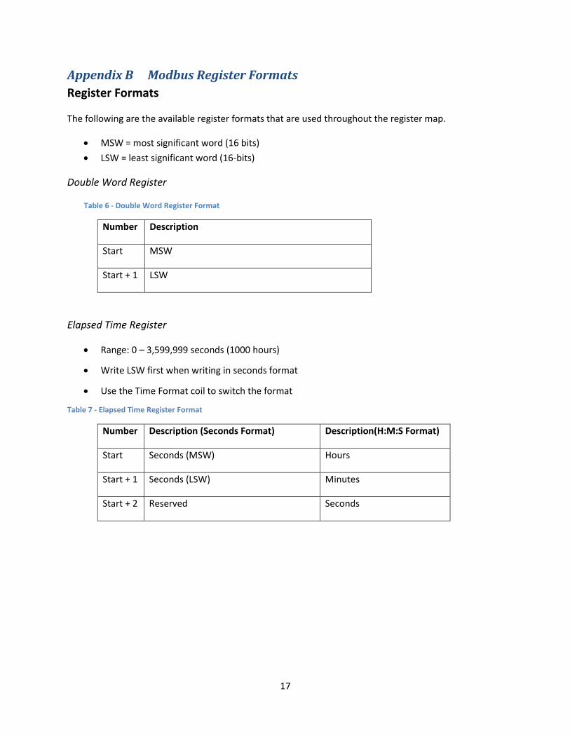
Appendix B Modbus Register Formats
Register Formats
The following are the available register formats that are used throughout the register map.
• MSW = most significant word (16 bits)
• LSW = least significant word (16-bits)
Double Word Register
Table 6 - Double Word Register Format
Number Description
Start MSW
Start + 1 LSW
Elapsed Time Register
• Range: 0 – 3,599,999 seconds (1000 hours)
• Write LSW first when writing in seconds format
• Use the Time Format coil to switch the format
Table 7 - Elapsed Time Register Format
Number Description (Seconds Format) Description(H:M:S Format)
Start Seconds (MSW) Hours
Start + 1 Seconds (LSW) Minutes
Start + 2 Reserved Seconds

18
Date/Time Register
• Range: 0 – 4,294,967,295
• Write MSW first when writing in seconds format, followed by LSW
• Use the Time Format coil to switch the format
Table 8 - Date/Time Register Format
Number Description (Seconds Format) Description(H:M:S Format)
Start Seconds since January 1, 2000 (MSW) Year
Start + 1 Seconds since January 1, 2000 (LSW) Month
Start + 2 Reserved Day
Start + 3 Reserved Hours
Start + 4 Reserved Minutes
Start + 5 Reserved Seconds
19
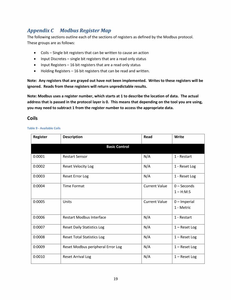
Appendix C Modbus Register Map The following sections outline each of the sections of registers as defined by the Modbus protocol.
These groups are as follows:
• Coils – Single bit registers that can be written to cause an action
• Input Discretes – single bit registers that are a read only status
• Input Registers – 16 bit registers that are a read only status
• Holding Registers – 16 bit registers that can be read and written.
Note: Any registers that are grayed out have not been implemented. Writes to these registers will be
ignored. Reads from these registers will return unpredictable results.
Note: Modbus uses a register number, which starts at 1 to describe the location of data. The actual
address that is passed in the protocol layer is 0. This means that depending on the tool you are using,
you may need to subtract 1 from the register number to access the appropriate data.
Coils
Table 9 - Available Coils
Register Description Read Write
Basic Control
0:0001 Restart Sensor N/A 1 - Restart
0:0002 Reset Velocity Log N/A 1 - Reset Log
0:0003 Reset Error Log N/A 1 - Reset Log
0:0004 Time Format Current Value 0 – Seconds
1 – H:M:S
0:0005 Units Current Value 0 – Imperial
1 - Metric
0:0006 Restart Modbus Interface N/A 1 - Restart
0:0007 Reset Daily Statistics Log N/A 1 – Reset Log
0:0008 Reset Total Statistics Log N/A 1 – Reset Log
0:0009 Reset Modbus peripheral Error Log N/A 1 – Reset Log
0:0010 Reset Arrival Log N/A 1 – Reset Log
20
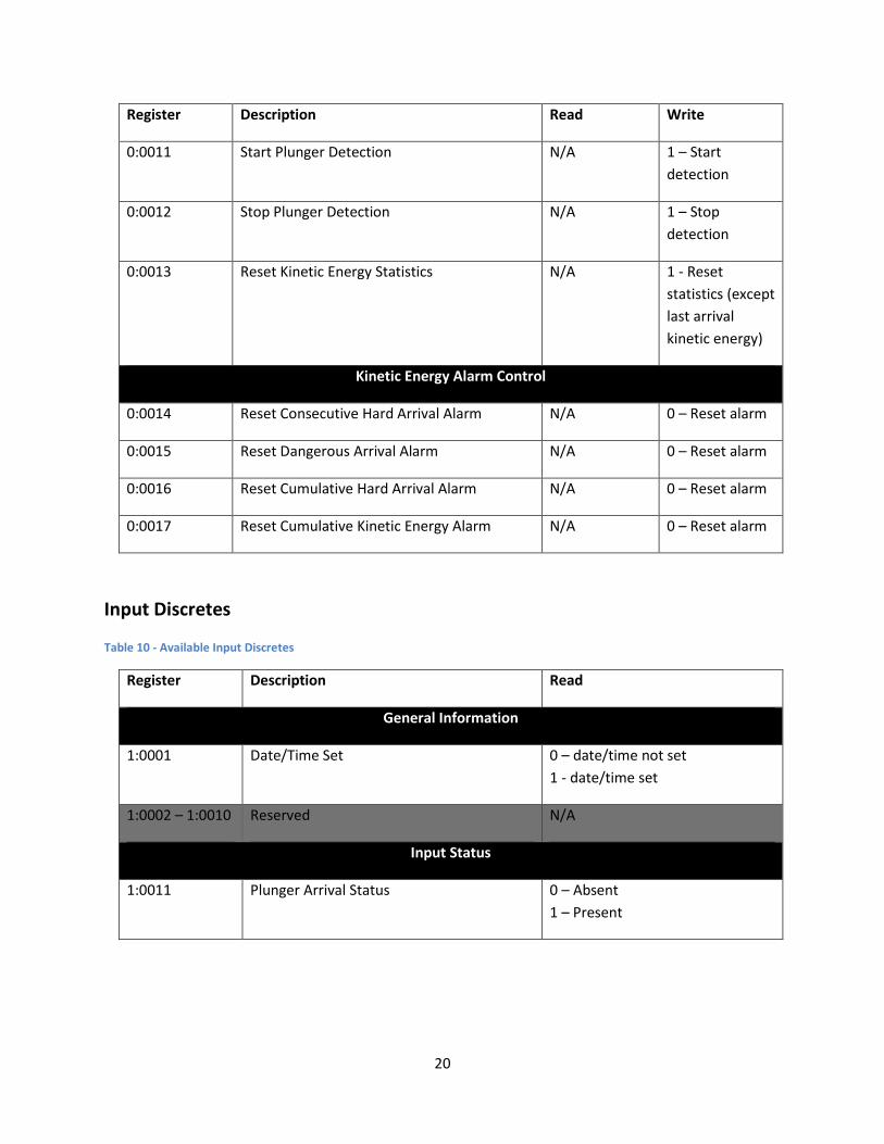
Register Description Read Write
0:0011 Start Plunger Detection N/A 1 – Start
detection
0:0012 Stop Plunger Detection N/A 1 – Stop
detection
0:0013 Reset Kinetic Energy Statistics N/A 1 - Reset
statistics (except
last arrival
kinetic energy)
Kinetic Energy Alarm Control
0:0014 Reset Consecutive Hard Arrival Alarm N/A 0 – Reset alarm
0:0015 Reset Dangerous Arrival Alarm N/A 0 – Reset alarm
0:0016 Reset Cumulative Hard Arrival Alarm N/A 0 – Reset alarm
0:0017 Reset Cumulative Kinetic Energy Alarm N/A 0 – Reset alarm
Input Discretes
Table 10 - Available Input Discretes
Register Description Read
General Information
1:0001 Date/Time Set 0 – date/time not set
1 - date/time set
1:0002 – 1:0010 Reserved N/A
Input Status
1:0011 Plunger Arrival Status 0 – Absent
1 – Present

21
Register Description Read
1:0012 New Velocity Indicator 0 – No new velocity measured
since last polled
1 – New velocity measured since
last polled (value resets to 0 once
it has been read)
Kinetic Energy Alarm Status
1:0013 Consecutive Hard Arrival Alarm Status 0 - Consecutive Hard Arrival
Statistic under threshold
1 - Consecutive Hard Arrival
Statistic over threshold
1:0014 Dangerous Arrival Alarm Status 0 - Dangerous Arrival Alarm
Statistic under threshold
1 - Dangerous Arrival Alarm
Statistic over threshold
1:0015 Cumulative Hard Arrival Alarm Status 0 - Cumulative Hard Arrival Alarm
Statistic under threshold
1 - Cumulative Hard Arrival Alarm
Statistic over threshold
1:0016 Cumulative Kinetic Energy Alarm Status 0 - Cumulative Kinetic Energy
Alarm Statistic under threshold
1 - Cumulative Kinetic Energy
Alarm Statistic over threshold
Input Registers
Table 11 - Available Input Registers
Register Description Read
Controller Information
3:0001 – 3:0002 Serial Number Double Word format: 0 - 99999

22
Register Description Read
3:0003 Firmware Version – Major Version 0 – 99
3:0004 Firmware Version – Minor Version 0 – 99
3:0005 Firmware Version – Fix Version 0 – 99
3:0006 Hardware Version 0 – 99
3:0007 – 3:0008 Reserved N/A
3:0009 Hardware Model 3
3:0010 Product Variant 0
State Information
3:0011 Sensor State 0 – Initializing
1 – Detect
3:0012 Dial Switch Setting 1 – 7
3:0013 Sensor Sensitivity Threshold 0 - 65535
3:0014 – 3:0020 Reserved N/A
Kinetic Energy Statistics
3:0021 – 3:0022 Last Arrival Kinetic Energy Floating-point format: 0 –
3.402823 × 1038 ft-in (J)
3:0023 Consecutive Hard Arrivals 0 – 65535
3:0024 Cumulative Hard Arrivals 0 – 65535
3:0025 Cumulative Dangerous Arrivals 0 – 65535
3:0026 – 3:0027 Cumulative Kinetic Energy Floating-point format: 0 –
3.402823 × 1038 ft-in (J)
3:0028 Total Hard/Dangerous Arrivals 0 – 65535
3:0029 – 3:0100 Reserved N/A
Arrival/Velocity Log
3:0101 Log Count 0 – 120

23
Register Description Read
3:0102 + 6(n-1)
to
3:0107 + 6(n-1)
Arrival Time – Entry n
n = 1 to 120
Date/Time format
3:822 + (n-1)
Velocity – Entry n
n = 1 to 120
0 – 1000 m/min (0 – 3281 ft/min)
3:942 + (n – 1) Velocity Calculation Code – Entry n
n = 1 to 120
0 – Reserved
1 – No multipoint velocity was
calculated
2 – Two points used to calculate
velocity
3 – Three points used to calculate
velocity
4 – Four points use to calculate
velocity
5 – Five points use to calculate
velocity
6 – Six points use to calculate
velocity
7 - Seven points used to calculate
velocity
8 – Eight points used to calculate
velocity
20 - Velocity under range
21 – Velocity over range
22 – Velocity Waveform Sync.
Failed
23 – False Arrival

24
Register Description Read
3:1062 + (n-1)
Kinetic Energy – Entry n
n = 1 to 120
0 – 315.0 J (0 – 2788.2 lbs-in)
3:1282 – 3:1500 Reserved N/A
Modbus Error Log
3:1501 Slave Access Failure Type
This register may be read to view details of
the last Slave Device Failure or Illegal Data
Address exception response.
0 – 12
3:1502 Slave Access Failure Bank
Contains the Modbus bank in which the last
Slave Device Failure or Illegal Data Address
exception response occurred. The bank
returned does not include any address
information.
0 – 4
3:1503 Slave Access Failure Register
Contains the register number at which the
last Slave Device Failure or Illegal Data
Address exception response occurred. The
address returned does not include any
bank information. For example, abcd is
returned for an error at address 0:abcd,
1:abcd, 3:abcd, or 4:abcd.
0 – 65535
3:1504 – 3:1510 Reserved N/A
Firmware Error Log
3:1511 Number of Log Entries 0 - 10

25
Register Description Read
3:1512 +
3(n – 1)
Error Log Type
10 Available error logs.
“n” in the register column represents the
error log number.
1 = System Definition Error
2 = Assertion Failure
3 = Check Failure
255 = No Error Log Available
3:1513 +
3(n – 1)
Error Log Data 1
10 Available error logs.
“n” in the register column represents the
error log number.
Contact for Details
3:1514 +
3(n – 1)
Error Log Data 2
10 Available error logs.
“n” in the register column represents the
error log number.
Contact for Details
Daily Production Log
3:2101 Daily Production Log Count 0 - 15
3:2102 + 6(n-1)
to
3:2107 + 6(n-1)
Daily Production Log Save Time – Entry n
n = 1 - 15
Date / Time Format
3:2192 + (n-1) Daily Production Log Plunger Arrival Count
– Entry n
n = 1 – 15
0 - 65534
3:2207 + (n-1) Daily Production Log Maximum recorded
Velocity – Entry n
n = 1 - 15
0 – 1000 m/min (0 – 3281 ft/min)
3:2222 + (n-1) Daily Production Log Minimum recorded
Velocity – Entry n
n = 1 – 15
0 – 1000 m/min (0 – 3281 ft/min)
3:2237 – 3:2500 Reserved N/A

26
Register Description Read
Total Production Log
3:2501 – 3: 2506 Total Production Save Time Date / Time Format
3:2507 Total Production Log Plunger Arrival Count 0 - 65535
3:2508 Total Production Log Maximum recorded
Velocity
0 – 1000 m/min (0 – 3281 ft/min)
3:2509 Total Production Log Minimum recorded
Velocity
0 – 1000 m/min (0 – 3281 ft/min)
Holding Registers
Table 12 - Available Holding Registers
Register Description Read/Write
General Controller Settings
4:0001 Modbus Write Time
The amount of time to wait after the last
written value before saving all changes to
the controller.
0 – 65535 seconds.
Writing zero (which is the default)
will save all changes as they are
made.
4:0002 – 4:0007 Controller Date/Time Date/Time
4:0008 Daylight Savings Time configuration
0 = Disabled
1 = Enabled
4:0009 – 4:0010 Day Start Time – Start of the gas day.
Elapsed Time format: 0 – 86340
(00:00: – 23:59)
When in HH:MM:SS format, only
Hours and Minutes are available.
4:0011 – 4:0030 Reserved N/A

27
Register Description Read/Write
Output Configuration
4:0031 Output Mode 0 = Static Time
1 = Velocity Scaled
2 = Plunger Hold (default)
4:0032 Output Hold Scale 1 – 600 ms per m/min (ft/min)
default = 10 ms
4:0033 Minimum Output Hold Time 100 – 65,535 ms
default = 1000 ms
4:0034 – 4:0040 Reserved N/A
Data Processing Timers
4:0041 Baseline Update Timer 500 – 10,000 ms
default = 999 ms
4:0042 Arrival Detection Period 1 – 500 ms
default = 3 ms
4:0043 Velocity Gathering Period 1 – 10 ms
default = 1 ms
4:0044 Velocity Gathering Timeout 250 – 1000 ms
default = 700 ms
4:0045 Velocity Calculation Timer 1 – 1000 ms
default = 10 ms
4:0046 Departure Detection Period 1 – 1000 ms
default = 1000 ms
4:0047 Re-initialize Timer 1 – 65,535 s
default = 1 s
4:0048 False Arrival Period 150 – 750 ms
Default = 500ms
4:0049 – 4:0050 Reserved N/A

28
Register Description Read/Write
Modbus Settings
4:0051 Baud Rate 0 = 1200 bps
1 = 2400 bps
2 = 4800 bps
3 = 9600 bps
4 = 19,200 bps
5 = 38,400 bps
6 = 56,000 bps
7 = 115,200 bps
8 = 128,000 bps
9 = 256,000 bps
4:0052 Parity 0 = None
1 = Even
2 = Odd
4:0053 Data Bits 0 = 7 Data Bits
1 = 8 Data Bits
4:0054 Stop Bits 0 = 1 Stop Bit
1 = 2 Stop Bits
4:0055 Modbus Slave Station Address 1 - 247
4:0056 Modbus Protocol 0 = RTU
1 = ASCII
Kinetic Energy Configuration
4:0061 Plunger Mass 0 – 65.535 lbs (kg)
Where 65535 = 65.535
4:0062 Hard Arrival Velocity Threshold 0 – 65535 ft/min (m/min)
4:0063 – 4:0064 Hard Arrival Kinetic Energy Threshold Floating-point format: 0 –
3.402823 × 1038 ft-in (J)
4:0065 Consecutive Hard Arrival Alarm Threshold 0 – 65535
4:0066 Dangerous Arrival Velocity Threshold 0 – 65535 ft/min (m/min)
29
Register Description Read/Write
4:0067 – 4:0068 Dangerous Arrival Kinetic Energy Threshold Floating-point format: 0 –
3.402823 × 1038 ft-in (J)
4:0069 Cumulative Hard/Dangerous Arrival
Threshold
0 – 65535
4:0070 Cumulative Kinetic Energy Threshold Floating-point format: 0 –
3.402823 × 1038 ft-in (J)


![cathodic protection in practise · 2 [CATHODIC PROTECTION/BM] CATHODIC PROTECTION P E FRANCIS 1 INTRODUCTION The first practical use of cathodic protection is generally credited to](https://static.fdocuments.in/doc/165x107/5ace93c87f8b9ae2138b87e4/cathodic-protection-in-cathodic-protectionbm-cathodic-protection-p-e-francis.jpg)