![A. C]. I Red) a .2(1. Black) Brown) Orange) Yellow) Green) 0.7(ü Blue) a.8(ik Purple) Cl.9(/k Gray) B. .J2-8P (á Brown) Red) D.C(KF Orange) Yellow)](https://static.fdocuments.in/doc/165x107/5e909b9c5ec48d00223e9943/a-c-i-red-a-21-black-brown-orange-yellow-green-07-blue-a8ik-purple.jpg)
USER’S MANUAL - docs.circutor.comdocs.circutor.com/docs/M98229801-03.pdf · (l 2) phase 2 red...
36
Portable quality network analyzer USER’S MANUAL (M98229801-03-12A)
Transcript of USER’S MANUAL - docs.circutor.comdocs.circutor.com/docs/M98229801-03.pdf · (l 2) phase 2 red...
Portable quality network analyzer
USER’S MANUAL
(M98229801-03-12A)

_____________________________________________
_________________________________________________________________________________________________________ 2 of 36 CIR-eQ User’s Manual
WARNINGS / SYMBOLS
DANGER
Death, serious injury, or fire hazard could result from improper connection of this instrument. Read and understand this manual before connecting this instrument. Follow all installation and operating instructions while using this instrument. Installation, operation, and maintenance of this instrument must be performed by qualified personnel only. The National Electrical Code defines a qualified person as “one who has the skills and knowledge related to the construction and operation of the electrical equipment and installations, and who has received safety training on the hazards involved.”
WARNING
Consult the instruction manual before using the equipment. In this manual, if the instructions preceded by this symbol are not met or done correctly, can cause personal injury or equipment damage and / or facilities.
ADVERTENCIAS / SÍMBOLOS
PELIGRO
Una conexión incorrecta del equipo puede producir la muerte, lesiones graves y riesgo de incendio. Lea y entienda el manual antes de conectar el equipo. Observe todas las instrucciones de instalación y operación durante el uso de este instrumento. La instalación, operación y mantenimiento de este instrumento debe ser efectuado por personal cualificado solamente. El Código Eléctrico Nacional define a una persona cualificada como "una que esté familiarizada con la construcción y operación del equipo y con los riesgos involucrados".
ATENCIÓN
Consultar el manual de instrucciones antes de utilizar el equipo En el presente manual, si las instrucciones precedidas por este símbolo no se respetan o realizan correctamente, pueden ocasionar daños personales o dañar el equipo y /o las instalaciones.

_______________________________________________________
_________________________________________________________________________________________________________ CIR-eQ User’s Manual 3 of 36
AVERTISSEMENT / SYMBOLES
DANGER
Un branchement incorrect de l’appareil peut entraîner la mort ou des lésions graves et peut provoquer un incendie. Avant de brancher votre appareil, lisez attentivement le manuel et assurez-vous de bien avoir compris toutes les explications données. Respectez toutes les instructions concernant le mode d’installation de l’appareil et son fonctionnement. L’installation, le fonctionnement et la maintenance de cet appareil doivent être réalisés uniquement par du personnel qualifié. Le code électrique national définit en tant que personne qualifiée « toute personne connaissant le montage et le fonctionnement de l’appareil ainsi que les risques que ceux-ci comportent
ATTENTION
Consulter le manuel d’instructions avant d’utiliser l’appareil Si les instructions suivantes, précédées dans le manuel d’un symbole, ne sont pas respectées ou sont réalisées incorrectement, elles pourront provoquer des dommages personnels ou abîmer l’appareil et/ou les installations.
WARNHINWEISE / SYMBOLE
GEFAHR
Durch einen nicht sachgemäßen Anschluss der Anlage können Tod, schwere Verletzungen und Brandrisiko hervorgerufen werden. Bevor Sie die Anlage anschließen, lesen Sie bitte das Handbuch durch und machen Sie sich dessen Inhalt klar. Beachten Sie bei Einsatz dieses Instrumentes sämtliche Installations- und Betriebshinweise. Installation, Betrieb und Wartung dieses Instrumentes müssen ausschließlich von entsprechend qualifiziertem Personal vorgenommen werden. Von dem nationalen Elektrocode wird eine qualifizierte Person als jemand definiert, “der mit der Konstruktion und dem Betrieb einer Anlage und der damit verbundenen Risiken vertraut ist“.
ACHTUNG
Vor Inbetriebnahme der Anlage ist das Handbuch zu lesen. Werden die in dem vorliegenden Handbuch mit diesem Symbol versehenen Hinweise nicht beachtet oder falsch verstanden, können Personenschäden und Schäden an der Anlage und/oder den Installationen verursacht werden.
_____________________________________________
_________________________________________________________________________________________________________ 4 of 36 CIR-eQ User’s Manual
ADVERTÊNCIAS / SÍMBOLOS
PERIGO
Uma ligação incorrecta do equipamento pode provocar a morte, lesões graves e risco de incêndio. Leia e compreenda o manual antes de ligar o equipamento. Observe todas as instruções de instalação e operação durante o uso deste aparelho. A instalação, operação e manutenção deste aparelho devem ser levadas a cabo exclusivamente por pessoal qualificado. O Código Eléctrico Nacional define uma pessoa qualificada como "uma pessoa que se encontre familiarizada com a construção e operação do equipamento assim como com os riscos inerentes”.
ATENÇÃO
Consultar o manual de instruções antes de utilizar o equipamento No presente manual, se as instruções que precedem este símbolo não forem respeitadas ou realizadas de forma correcta, podem ocorrer ferimentos pessoais ou danos no equipamento e/ou nas instalações.
AVVERTENZE / SIMBOLI
PERICOLO
Un collegamento errato del dispositivo può provocare morte, lesioni gravi nonché rischio di incendio. Prima di collegare il dispositivo leggere attentamente il manuale. Osservare tutte le istruzioni relative all’installazione e all’operatività durante l’uso di questo strumento. L’installazione, operatività e manutenzione di questo strumento devono essere realizzate solamente da personale qualificato. Il Codice Elettrico Nazionale definisce una persona qualificata come “colui che ha familiarità con la costruzione e operatività del dispositivo e con i rischi che ne possano derivare”.
ATTENZIONE
Consultare il manuale di istruzioni prima di utilizzare il dispositivo Qualora le istruzioni riportate nel presente manuale precedute da questo simbolo non vengano osservate o realizzate correttamente, possono provocare danni personali o danneggiare il dispositivo e/o gli impianti.

_______________________________________________________
_________________________________________________________________________________________________________ CIR-eQ User’s Manual 5 of 36
1.- LIMITATION OF LIABILITY ..................................................................................72.- VERIFICATION UPON RECEPTION ...................................................................73.- SAFETY PRECAUTIONS. ...................................................................................74.- DESCRIPTION OF THE UNIT .............................................................................8
4.1.- ELECTRICAL FEATURES ................................................................................94.2.- MECHANICAL FEATURES. ............................................................................ 104.3.- ELECTRICAL PARAMETERS ......................................................................... 11
4.3.1.- Register parameters ......................................................................................... 11
5.- BASIC FEATURES ............................................................................................ 125.1.- ENVIRONMENTAL AND OTHER FEATURES ................................................ 13
6.- INSTALLATION AND COMMISSIONING .......................................................... 136.1.- CIR-EQ CONFIGURATION ............................................................................. 13
6.1.1.- Generating the setup file ................................................................................... 146.1.2.- Menu options. ................................................................................................... 14
6.1.2.1.- Configure ................................................................................................. 146.1.2.2.- Connect ................................................................................................... 186.1.2.3.- Send to Web ............................................................................................ 186.1.2.4.- Exit .......................................................................................................... 18
6.2.- INSERT SD CARD .......................................................................................... 186.3.- START-UP SEQUENCE .................................................................................. 18
6.3.1.- Power and connect the unit .............................................................................. 196.3.1.1.- Single-phase connection diagram ............................................................ 206.3.1.2.- Three-phase connection diagram (3 wires) .............................................. 206.3.1.3.- Three-phase connection diagram (4 wires) .............................................. 21
6.3.2.- Verification of connections ................................................................................ 216.3.2.1.- Faulty connection .................................................................................... 21
6.4.- START/STOP BUTTON .................................................................................. 226.5.- SAFE EXTRACTION OF THE SD MEMORY CARD ....................................... 226.6.- VISUALIZATION OF DATA RECORDED ........................................................ 23
7.- QUALITY EVENTS ............................................................................................ 238.- CIR-E WEB ........................................................................................................ 24
8.1.- CONNECTING TO AND REGISTERING IN CIR-E WEB ................................ 248.1.1.- Accessing cir-e web .......................................................................................... 248.1.2.- Registration ...................................................................................................... 25
8.2.- DOWNLOADING THE XCG IDENTIFICATION FILE: ..................................... 278.2.1.- Personal user information on the web ............................................................... 28
8.2.1.1.- User information modify ........................................................................... 288.2.1.2.- Password modify ..................................................................................... 28
_____________________________________________
_________________________________________________________________________________________________________ 6 of 36 CIR-eQ User’s Manual
8.2.1.3.- Generate XCG file ................................................................................... 298.2.1.4.- Downloads .............................................................................................. 29
9.- FAQS ................................................................................................................. 3010.- REGULATIONS ................................................................................................. 3211.- TECHNICAL SERVICE ...................................................................................... 3212.- BATTERY EXCHANGE ..................................................................................... 3313.- SETTING THE CLOCK OF THE ANALYZER. ................................................... 3314.- CE CERTIFICATE ............................................................................................. 36
_______________________________________________________
_________________________________________________________________________________________________________ CIR-eQ User’s Manual 7 of 36
1.- LIMITATION OF LIABILITY
CIRCUTOR, SA reserves the right to modify the device or the specifications of the equipment, described in this instruction manual, without prior notice. CIRCUTOR, SA recommends obtaining the latest version of the unit's specifications and applications of the device from: http://cir-e3.circutor.com
CIRCUTOR, SA recommends the use of the original cables and accessories supplied with the unit.
2.- VERIFICATION UPON RECEPTION
CIR-eQ has been designed to incorporate the latest technologies and it offers the most advanced performance features in the market for the measurement and recording of the electrical parameters of electrical networks.
Please read this manual carefully before connecting the unit, in order to avoid any incorrect usage that could seriously damage the unit.
Check the following when you receive the unit:
a) The unit's specifications are the same as you order. b) The unit has not been damaged during transport. c) Check that the following accessories are included:
1 Transport bag. 1 CIR-eQ measurement unit 1 SD Card with mínimum 1 Gb capacity. 1 Kit of six power supply and voltage cables (2 m). 4 Crocodile clamps. 1 RS-232 Communications wire. 1 SD Card reader. 1 User’s Manual
3.- SAFETY PRECAUTIONS.
Please observe the warnings described in this manual. The warnings are marked with the following symbols.
DANGER: Electrical risk warning.
ATTENTION: Special attention message or warning.
DANGER Do not handle when connected.
_____________________________________________
_________________________________________________________________________________________________________ 8 of 36 CIR-eQ User’s Manual
4.- DESCRIPTION OF THE UNIT
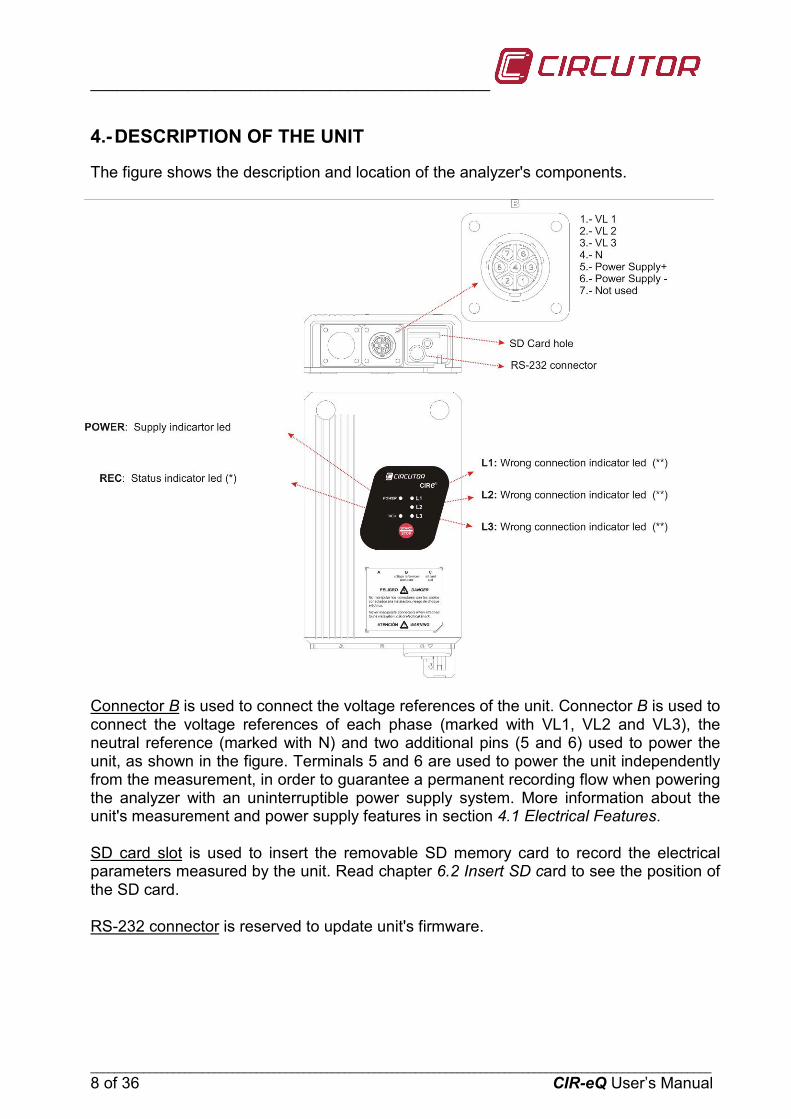
The figure shows the description and location of the analyzer's components.
Connector B
is used to connect the voltage references of the unit. Connector B is used to connect the voltage references of each phase (marked with VL1, VL2 and VL3), the neutral reference (marked with N) and two additional pins (5 and 6) used to power the unit, as shown in the figure. Terminals 5 and 6 are used to power the unit independently from the measurement, in order to guarantee a permanent recording flow when powering the analyzer with an uninterruptible power supply system. More information about the unit's measurement and power supply features in section 4.1 Electrical Features.
SD card slot
is used to insert the removable SD memory card to record the electrical parameters measured by the unit. Read chapter 6.2 Insert SD card to see the position of the SD card.
RS-232 connector
is reserved to update unit's firmware.
_______________________________________________________
_________________________________________________________________________________________________________ CIR-eQ User’s Manual 9 of 36
POWER LED
is on when the unit is powered. It is off when the unit is not powered.
The START/STOP
is used to start or stop the recording of quality events of the network. Hold the button during 3 seconds.
(*) The REC LED
has three basic modes. When it is off, the unit is not recording information. When it is permanently on, the unit is recording electrical parameters, which are stored in the SD memory card. When the REC LED is flashing, there is an error in the SD memory card. The REC LED can be flashing for the following reasons:
• No memory card inserted in the unit's SD card slot. • The memory card inserted does not have the correct format or data can not be
written. (for example, if the card is writen protected or it has a FAT32 format; in that case change the format of the memory card to FAT16).
(**) The LED L1, L2 or L3 start flashing to indicate that there is an incorrect connection. The phase LED start flashing when R-S-T sequence is not correct.
CIR-eQ LED’s start flashing to indicate a connection error. The unit has been installed correctly when the LED’s are permanently on.
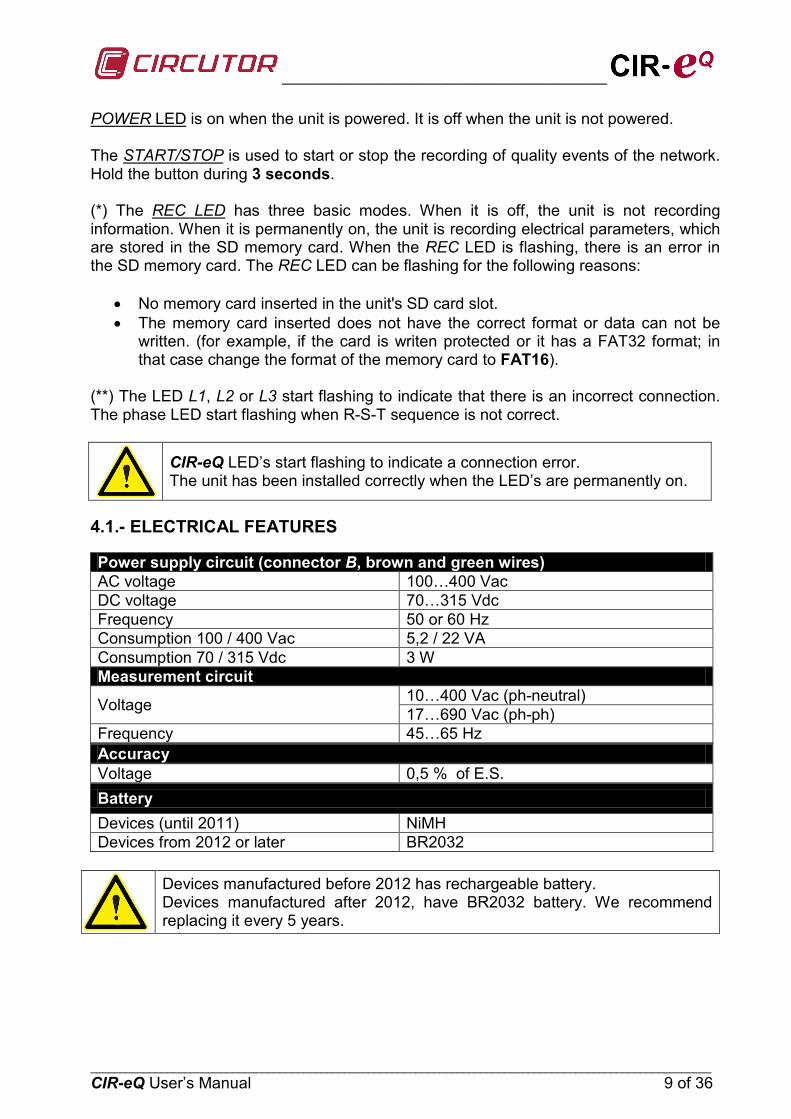
4.1.- ELECTRICAL FEATURES
Power supply circuit (connector B, brown and green wires) AC voltage 100…400 Vac DC voltage 70…315 Vdc Frequency 50 or 60 Hz Consumption 100 / 400 Vac 5,2 / 22 VA Consumption 70 / 315 Vdc 3 W Measurement circuit
Voltage 10…400 Vac (ph-neutral) 17…690 Vac (ph-ph)
Frequency 45…65 Hz Accuracy Voltage 0,5 % of E.S. Battery Devices (until 2011) NiMH Devices from 2012 or later BR2032
Devices manufactured before 2012 has rechargeable battery. Devices manufactured after 2012, have BR2032 battery. We recommend replacing it every 5 years.

_____________________________________________
_________________________________________________________________________________________________________ 10 of 36 CIR-eQ User’s Manual
4.2.- MECHANICAL FEATURES.
The CIR-eQ analyzer has been specially designed for an installation in small spaces. For example, in boxes with double isolation where billing energy meters, single or three-phase models are installed. The external dimensions in mm are as follows:
The colours of voltage phases can change according to the colour scheme selected in the device code. The following table lists the references for each phase of the different colours.
PHASE EUROPEAN RYBLB
Phase reference Wire colour Wire colour (L 1) PHASE 1 BLACK RED (L 2) PHASE 2 RED YELLOW (L 3) PHASE 3 YELLOW BLUE (N) NEUTRAL BLUE BLACK
Auxiliary supply BROWN BROWN Auxiliary supply GREEN GREEN
_______________________________________________________
_________________________________________________________________________________________________________ CIR-eQ User’s Manual 11 of 36
4.3.- ELECTRICAL PARAMETERS
The parameters recorded by CIR-eQ can not be selected and they are those shown on the following table. The parameters are valid for three and single-phase circuits.
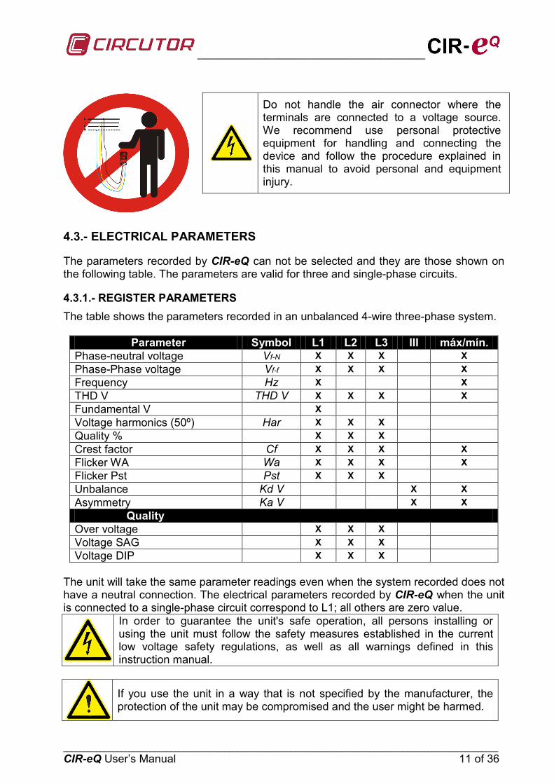
4.3.1.- REGISTER PARAMETERS The table shows the parameters recorded in an unbalanced 4-wire three-phase system.
Parameter Symbol L1 L2 L3 III máx/mín. Phase-neutral voltage Vf-N X X X X Phase-Phase voltage Vf-f X X X X Frequency Hz X X THD V THD V X X X X Fundamental V X Voltage harmonics (50º) Har X X X Quality % X X X Crest factor Cf X X X X Flicker WA Wa X X X X Flicker Pst Pst X X X Unbalance Kd V X X Asymmetry Ka V X X
Quality Over voltage X X X Voltage SAG X X X Voltage DIP X X X
The unit will take the same parameter readings even when the system recorded does not have a neutral connection. The electrical parameters recorded by CIR-eQ when the unit is connected to a single-phase circuit correspond to L1; all others are zero value.
In order to guarantee the unit's safe operation, all persons installing or using the unit must follow the safety measures established in the current low voltage safety regulations, as well as all warnings defined in this instruction manual.
If you use the unit in a way that is not specified by the manufacturer, the protection of the unit may be compromised and the user might be harmed.
Do not handle the air connector where the terminals are connected to a voltage source. We recommend use personal protective equipment for handling and connecting the device and follow the procedure explained in this manual to avoid personal and equipment injury.
_____________________________________________
_________________________________________________________________________________________________________ 12 of 36 CIR-eQ User’s Manual
5.- BASIC FEATURES
CIR-eQ analyzer is a programmable measurement unit that measures, calculates and records the main electrical quality events in single and three-phase electrical networks in its memory. We must highlight the following concepts: Serial number: The serial number of CIR-eQ is an important parameter, since all files
generated by the unit must be identified with that number. The 10-digit serial number is written on the rear features label of CIR-eQ.
Programming: The unit is programmed with the setup software CIR-e.exe. The application is stored in the SD card supplied with the unit.
Display: The visualization of the quality events is done with Power Vision and Power Vision +.
Installation: The analyzer can be installed to analyze balanced (3 wire) or unbalanced (4 wire) single and three-phase networks. The unit must be powered with the auxiliary power supply cables in any of the connection options. The auxiliary power supply wires of the unit are Brown and Green.
Measurements: The analyzer takes 128 samples per cycle of the variables in true root mean square (TRMS). With all of the samples taken, the unit calculates the arithmetic mean during the recording period selected by the user. The analyzer also records the maximum and minimum values measured during each period. To take these measurements, the analyzer has four voltage inputs.
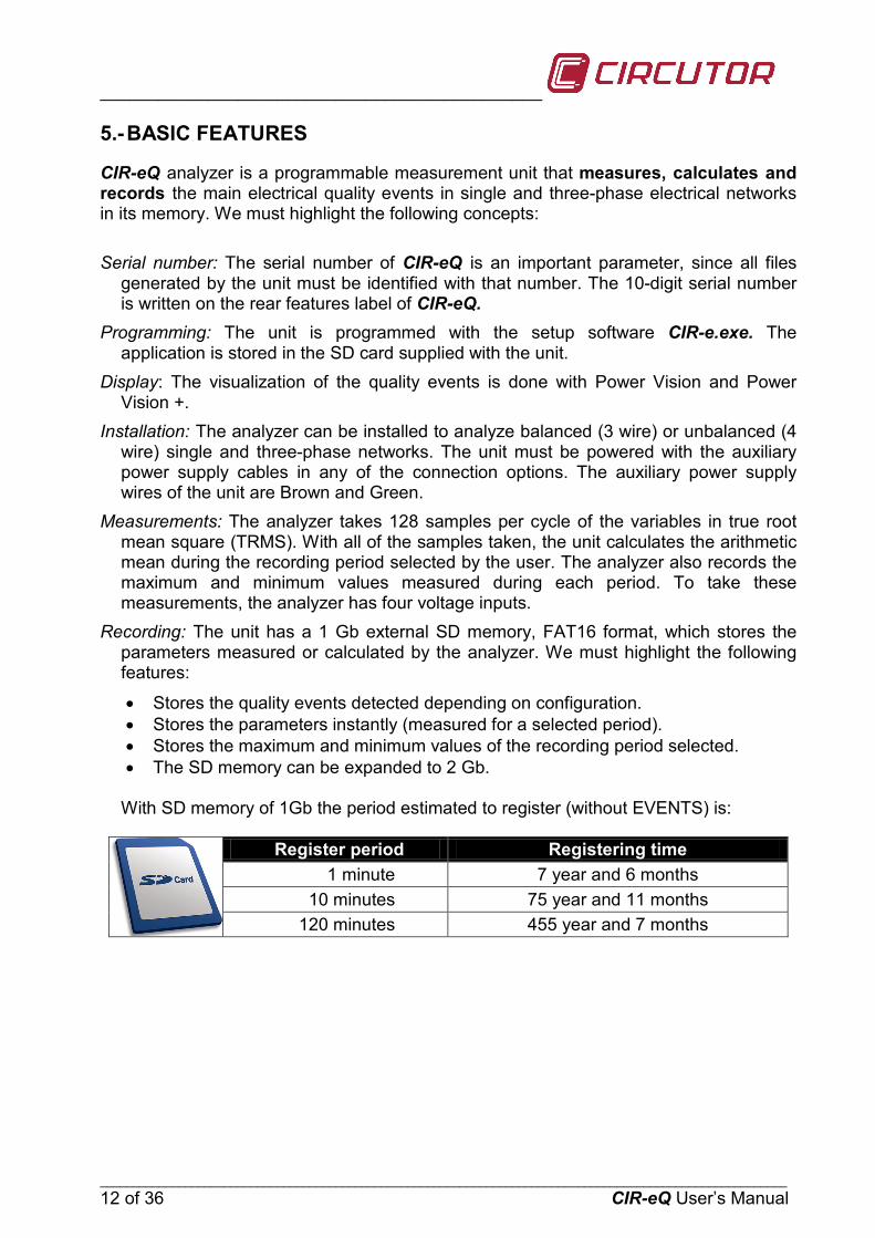
Recording: The unit has a 1 Gb external SD memory, FAT16 format, which stores the parameters measured or calculated by the analyzer. We must highlight the following features:
• Stores the quality events detected depending on configuration. • Stores the parameters instantly (measured for a selected period). • Stores the maximum and minimum values of the recording period selected. • The SD memory can be expanded to 2 Gb.
With SD memory of 1Gb the period estimated to register (without EVENTS) is:
Register period Registering time 1 minute 7 year and 6 months
10 minutes 75 year and 11 months 120 minutes 455 year and 7 months

_______________________________________________________
_________________________________________________________________________________________________________ CIR-eQ User’s Manual 13 of 36
5.1.- ENVIRONMENTAL AND OTHER FEATURES
Environmental Work Conditions Temperature -10…50 ºC Altitude 2.000 m Humidity 95% RH non-condensing Others Storage temperature -15…65 ºC Degree of protection IP 53 Weight (only CIR-eQ) 0,657 kg Weight (with packaging) 0,713 kg
This manual contains information and warnings that must be observed at all times to guarantee the safe operation of the unit and maintain it in perfect working conditions. When you suspect an operational fault in the unit's protection system (for example, visible damage), disconnect the unit from any voltage or current source and contact a qualified service representative or the after sales service of CIRCUTOR, SA.
Anyone installing or using the equipment must follow the safety measures set forth and all warnings indicated in this instruction manual to guarantee a safe operation.
6.- INSTALLATION AND COMMISSIONING
If the battery is discharged when the team loses and records are made with the default date 01/01/2011 00:00 It is recommended to check the time of the device before making a record and, after long period of inactivity, connect the device 12 hours to charge the battery.
CIR-eQ is a portable analyzer that is easy to install and use. It has been designed to facilitate the work of the companies and/or persons that wish to perform quality network audits. The unit is configured from the PC with the SD card supplied with the unit. Make sure that all voltage connections are correct so that the unit is ready to take measurements and record data. Please follow these steps to configure, install and commission the unit.
6.1.- CIR-EQ CONFIGURATION
CIR-eQ analyzer does not have configuration buttons or a setup screen and it needs a file with the configuration information required to register the data. This file has the xst extension and it is generated with the CIR-e.exe application. This application is supplied with the unit and is stored in the SD card. And you can download the latest version from Web page of CIR-e³ http://cir-e3.circutor.com inside “User information” menu.

_____________________________________________
_________________________________________________________________________________________________________ 14 of 36 CIR-eQ User’s Manual
6.1.1.- GENERATING THE SETUP FILE To generate the setup file, run the CIR-e.exe application located in the root directory of the SD card. In the event that the SD card format from which the application is running is not a FAT16 format, the executable warns the user of an incorrect format using the following window:
The application determines the installation parameters that will determine how the CIR-eQ takes the measurements and records the parameters. These parameters are stored in the SD memory card. The setup application generates a file that must be stored in the SD card and which is named after the unit's serial number and has the xst extension. If the setup application is not available, you can also download it from http://cir-e3.circutor.com, in menu “User information”. When you run the application for the first time, the window will appear blank, as shown on the figure.
6.1.2.- MENU OPTIONS. The application has 4 different function buttons. “Config”, “Connect” “Exit” and “Send to Web”.
6.1.2.1.- Select the configure option to create a new file with the installation's features for a CIR-e³. The following window will be displayed when you click on “Configure”. requested the serial number of the device to display the configuration menu that corresponds to that model of device. The window displayed is:
Configure
_______________________________________________________
_________________________________________________________________________________________________________ CIR-eQ User’s Manual 15 of 36
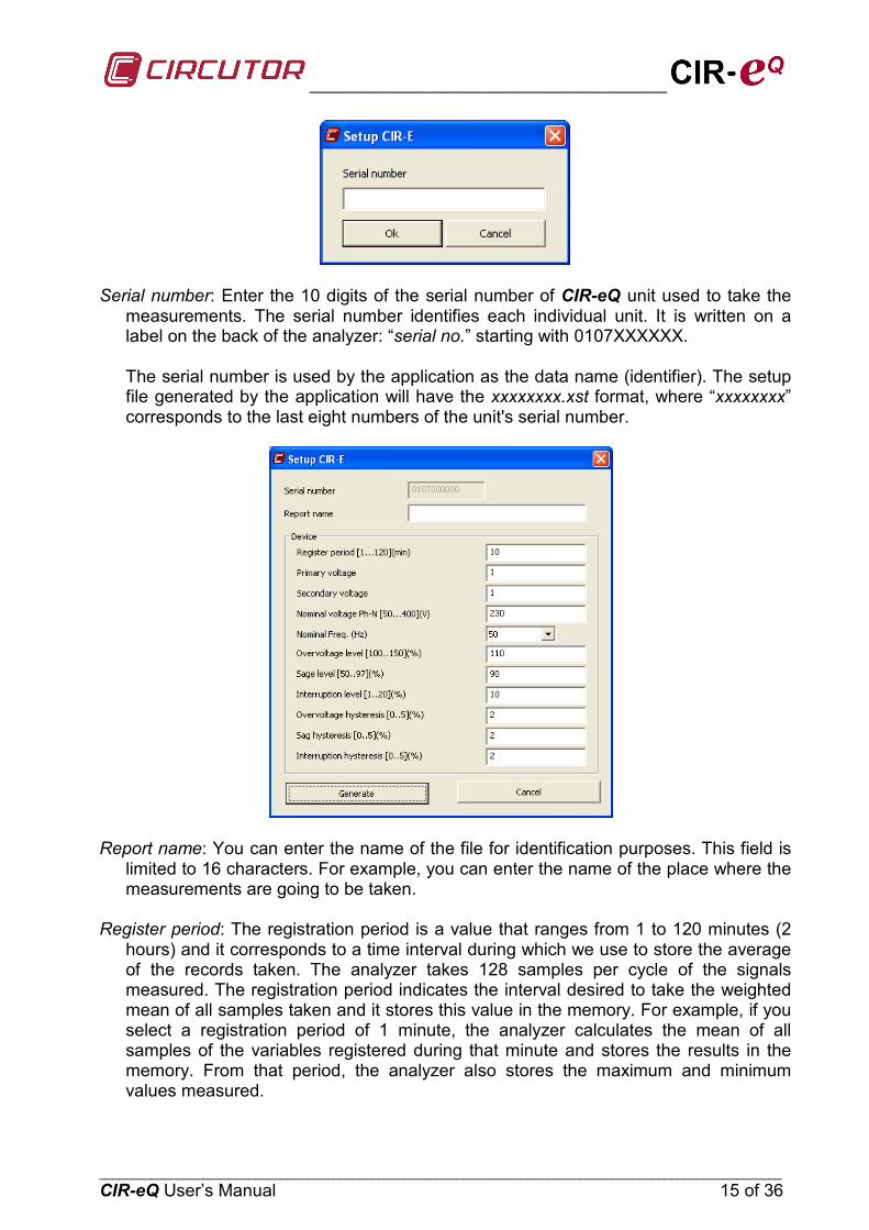
Serial number: Enter the 10 digits of the serial number of CIR-eQ unit used to take the
measurements. The serial number identifies each individual unit. It is written on a label on the back of the analyzer: “serial no.” starting with 0107XXXXXX. The serial number is used by the application as the data name (identifier). The setup file generated by the application will have the xxxxxxxx.xst format, where “xxxxxxxx” corresponds to the last eight numbers of the unit's serial number.
Report name: You can enter the name of the file for identification purposes. This field is
limited to 16 characters. For example, you can enter the name of the place where the measurements are going to be taken.
Register period: The registration period is a value that ranges from 1 to 120 minutes (2
hours) and it corresponds to a time interval during which we use to store the average of the records taken. The analyzer takes 128 samples per cycle of the signals measured. The registration period indicates the interval desired to take the weighted mean of all samples taken and it stores this value in the memory. For example, if you select a registration period of 1 minute, the analyzer calculates the mean of all samples of the variables registered during that minute and stores the results in the memory. From that period, the analyzer also stores the maximum and minimum values measured.

_____________________________________________
_________________________________________________________________________________________________________ 16 of 36 CIR-eQ User’s Manual
Primary voltage*: When using transformers to measure the voltage, enter the primary voltage value of the transformer. The information related to this feature of the transformer can be found on a features label on the transformer. This label must indicate the primary ratio. In case you are not using voltage transformers and you are taking a direct measurement (up to 400 V ph-n), the value entered must be 1.
Secondary voltage*: When using transformers to measure the voltage, enter the
secondary voltage value of the transformer. The information related to this feature of the transformer can be found on a features label on the transformer. This label must indicate the secondary ratio. In case you are not using voltage transformers and you are taking a direct measurement, the value entered must be 1.
the setup of voltage transformer relation has a limit that depends on some conditions which are defined with the range:
1º. Primary voltage value between 1 and 220.000 2º. Secondary voltage value between 1 and 999 3º. Value of primary/secondary between 1 and10.000
Nominal voltage (Ph-n): Enter the nominal voltage value between the installation's phase and neutral between 50…400V. That value has to be equal to the secondary of the voltage transformer if it is different to 1. Nominal Freq.: Enter the nominal value of the installation's frequency. The values
allowed for this field are 50 or 60 Hz. Over voltage level: The threshold for detecting an over voltage is introduced in %. Is
referenced to the value entered in the field nominal voltage. It is the value above which the device records an event of over voltage. The margin of that set point is between 100 and 150%
Sag level: The threshold for detecting a sag is introduced in %. Is referenced to the value
entered in the field nominal voltage. Is the value below which the device recorded a sag event in voltage. The margin is between 1 and 20%.
Interruption level: The threshold for detecting an interruption and is introduced in %. Is
referenced to the value entered in the field nominal voltage. Is the value below which the device recorded an interruption event in voltage. The margin is between 50 and 97%.
Over voltage hysteresis: Is the value in % to be recovered the voltage after an over
voltage (within the voltage range defined as normal) to record the end of the event. The margin of this field is from 0 to 5 %.
Sag hysteresis: Is the value in % to be recovered the voltage after a sag voltage (within
the voltage range defined as normal) to record the end of the event. The margin of this field is from 0 to 5 %
Interruption hysteresis: Is the value in% to be recovered the voltage after an interruption
voltage (within the voltage range defined as normal) to record the end of the event. The margin of this field is from 0 to 5 %
_______________________________________________________
_________________________________________________________________________________________________________ CIR-eQ User’s Manual 17 of 36
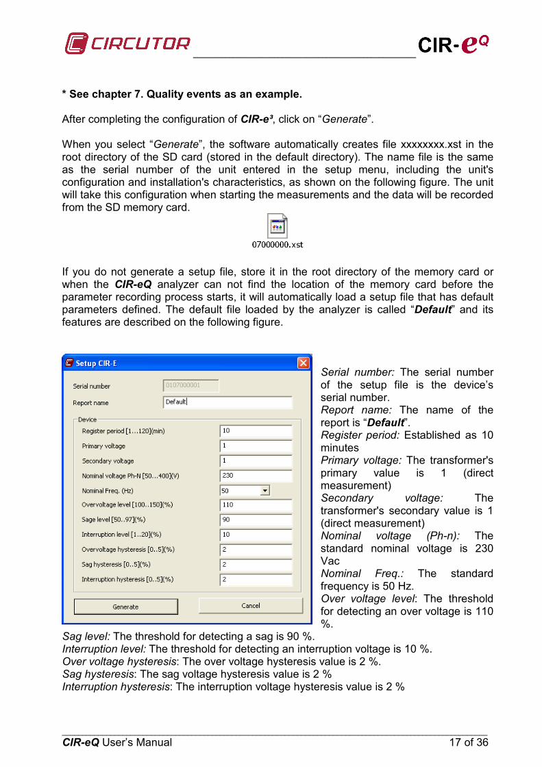
* See chapter 7. Quality events as an example. After completing the configuration of CIR-e³, click on “Generate”. When you select “Generate”, the software automatically creates file xxxxxxxx.xst in the root directory of the SD card (stored in the default directory). The name file is the same as the serial number of the unit entered in the setup menu, including the unit's configuration and installation's characteristics, as shown on the following figure. The unit will take this configuration when starting the measurements and the data will be recorded from the SD memory card.
If you do not generate a setup file, store it in the root directory of the memory card or when the CIR-eQ analyzer can not find the location of the memory card before the parameter recording process starts, it will automatically load a setup file that has default parameters defined. The default file loaded by the analyzer is called “Default” and its features are described on the following figure.
Serial number: The serial number of the setup file is the device’s serial number. Report name: The name of the report is “Default”. Register period: Established as 10 minutes Primary voltage: The transformer's primary value is 1 (direct measurement) Secondary voltage: The transformer's secondary value is 1 (direct measurement) Nominal voltage (Ph-n): The standard nominal voltage is 230 Vac Nominal Freq.: The standard frequency is 50 Hz. Over voltage level: The threshold for detecting an over voltage is 110 %.
Sag level: The threshold for detecting a sag is 90 %. Interruption level: The threshold for detecting an interruption voltage is 10 %. Over voltage hysteresis: The over voltage hysteresis value is 2 %. Sag hysteresis: The sag voltage hysteresis value is 2 % Interruption hysteresis: The interruption voltage hysteresis value is 2 %
_____________________________________________
_________________________________________________________________________________________________________ 18 of 36 CIR-eQ User’s Manual
6.1.2.2.- Another option of the CIR-e.exe application is “Connect”. This option automatically connects with the main page of the CIR-e³Web application where user can send STD files. Needs the file XCG in the same folder that the application to connect.
Connect
6.1.2.3.- To send files a pre-registration is required and to download an XCG file as user ID. For more information on registration, send files and STD parameter display on the Web, see Chapter 8. Website CIR-e ³
Send to Web
6.1.2.4.- The “Exit” option closes the application and cancels the unit's setup file creation process.
Exit
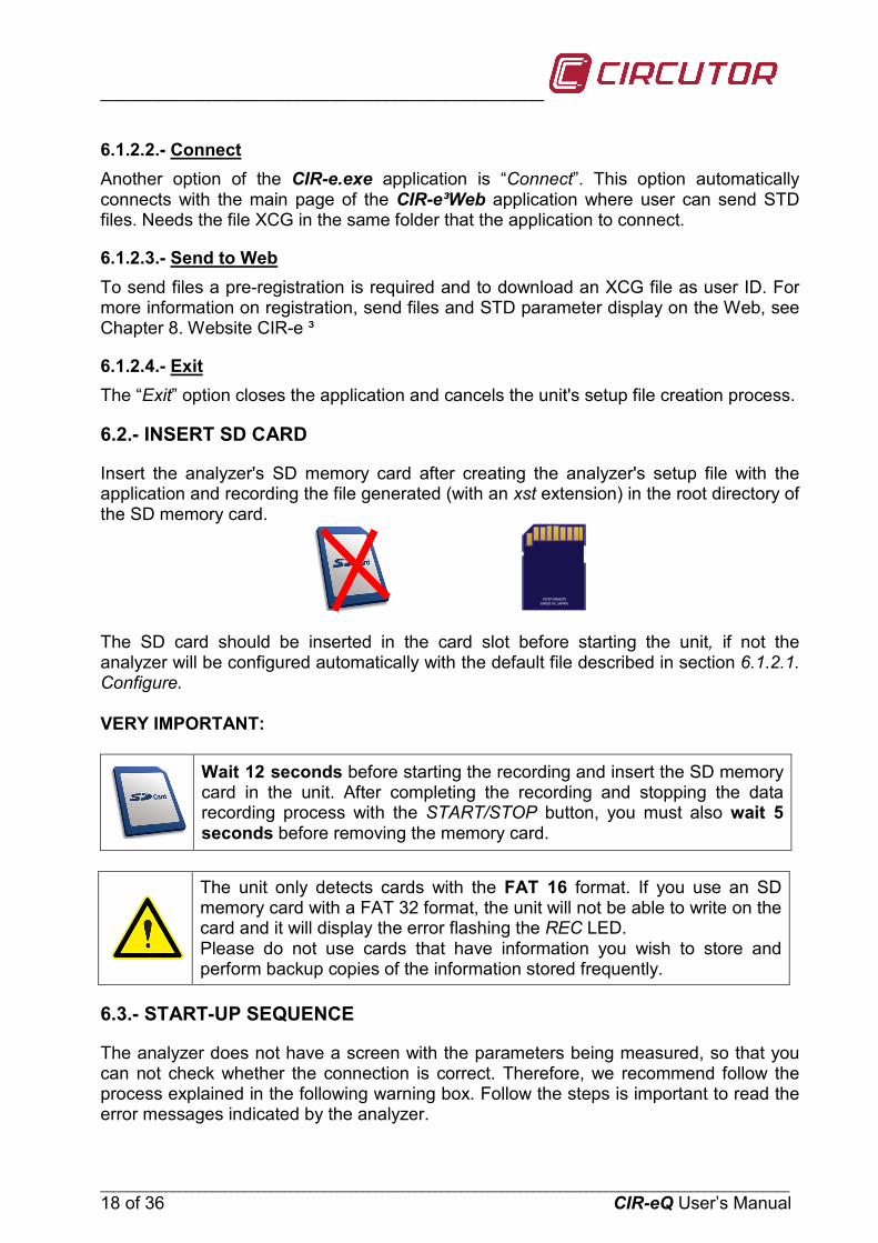
6.2.- INSERT SD CARD
Insert the analyzer's SD memory card after creating the analyzer's setup file with the application and recording the file generated (with an xst extension) in the root directory of the SD memory card.
The SD card should be inserted in the card slot before starting the unit, if not the analyzer will be configured automatically with the default file described in section 6.1.2.1. Configure. VERY IMPORTANT:
Wait 12 seconds before starting the recording and insert the SD memory card in the unit. After completing the recording and stopping the data recording process with the START/STOP button, you must also wait 5 seconds before removing the memory card.
The unit only detects cards with the FAT 16 format. If you use an SD memory card with a FAT 32 format, the unit will not be able to write on the card and it will display the error flashing the REC LED. Please do not use cards that have information you wish to store and perform backup copies of the information stored frequently.
6.3.- START-UP SEQUENCE
The analyzer does not have a screen with the parameters being measured, so that you can not check whether the connection is correct. Therefore, we recommend follow the process explained in the following warning box. Follow the steps is important to read the error messages indicated by the analyzer.
_______________________________________________________
_________________________________________________________________________________________________________ CIR-eQ User’s Manual 19 of 36
Is obligatory follow this installation procedure: 1. Insert SD card. 2. Insert B connector, voltage references. 3. Power the analyzer. 4. Check the voltage phase inversion. 5. Start the recording process.
After inserting the SD card in the analyzer's slot, connect it to start measuring and taking the readings of the installation's electrical parameters. The connection process is explained in detail in the following points.
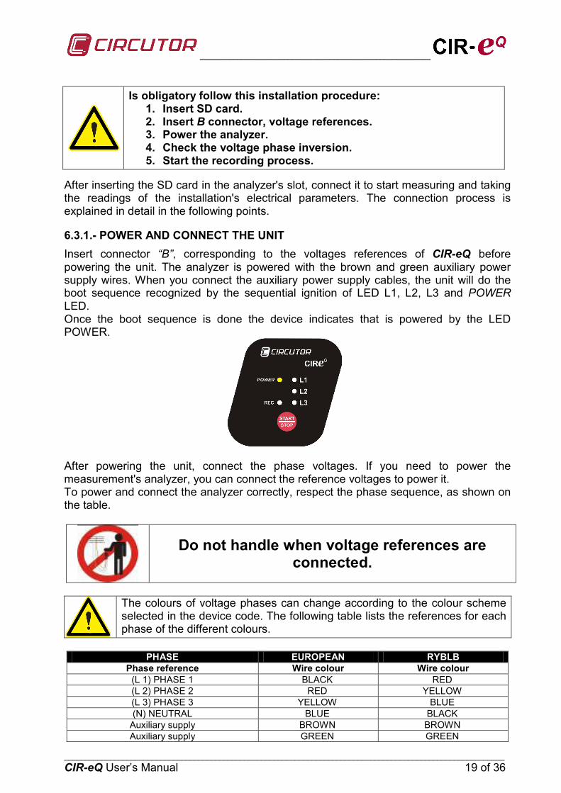
6.3.1.- POWER AND CONNECT THE UNIT Insert connector “B”, corresponding to the voltages references of CIR-eQ before powering the unit. The analyzer is powered with the brown and green auxiliary power supply wires. When you connect the auxiliary power supply cables, the unit will do the boot sequence recognized by the sequential ignition of LED L1, L2, L3 and POWER LED. Once the boot sequence is done the device indicates that is powered by the LED POWER.
After powering the unit, connect the phase voltages. If you need to power the measurement's analyzer, you can connect the reference voltages to power it. To power and connect the analyzer correctly, respect the phase sequence, as shown on the table.
Do not handle when voltage references are connected.
The colours of voltage phases can change according to the colour scheme selected in the device code. The following table lists the references for each phase of the different colours.
PHASE EUROPEAN RYBLB
Phase reference Wire colour Wire colour (L 1) PHASE 1 BLACK RED (L 2) PHASE 2 RED YELLOW (L 3) PHASE 3 YELLOW BLUE (N) NEUTRAL BLUE BLACK
Auxiliary supply BROWN BROWN Auxiliary supply GREEN GREEN
_____________________________________________
_________________________________________________________________________________________________________ 20 of 36 CIR-eQ User’s Manual
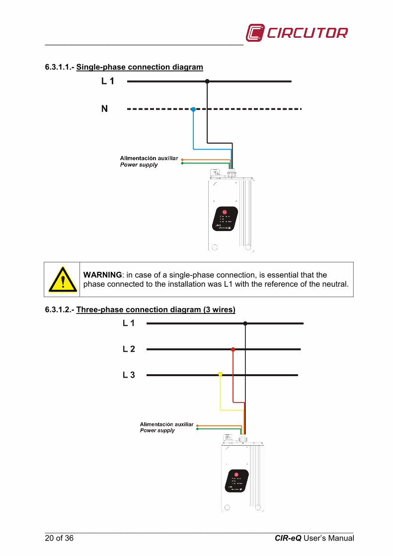
6.3.1.1.- Single-phase connection diagram
WARNING: in case of a single-phase connection, is essential that the phase connected to the installation was L1 with the reference of the neutral.
6.3.1.2.- Three-phase connection diagram (3 wires)
_______________________________________________________
_________________________________________________________________________________________________________ CIR-eQ User’s Manual 21 of 36
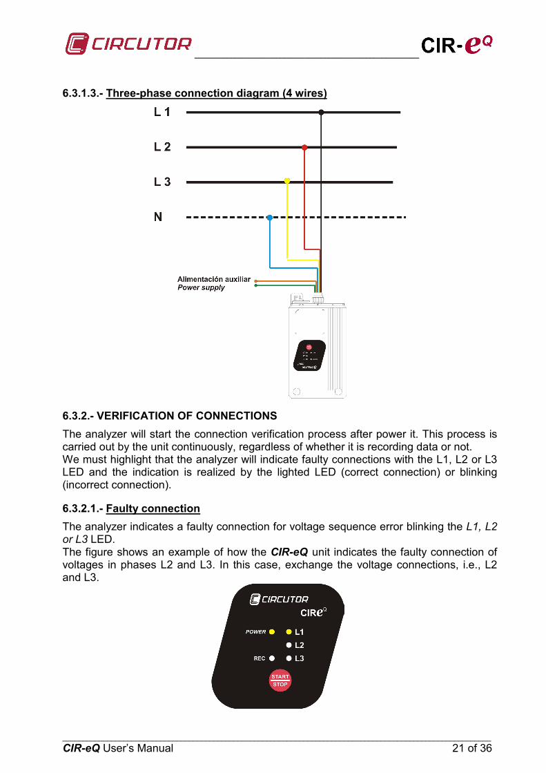
6.3.1.3.- Three-phase connection diagram (4 wires)
6.3.2.- VERIFICATION OF CONNECTIONS The analyzer will start the connection verification process after power it. This process is carried out by the unit continuously, regardless of whether it is recording data or not. We must highlight that the analyzer will indicate faulty connections with the L1, L2 or L3 LED and the indication is realized by the lighted LED (correct connection) or blinking (incorrect connection).
6.3.2.1.- The analyzer indicates a faulty connection for voltage sequence error blinking the L1, L2 or L3 LED.
Faulty connection
The figure shows an example of how the CIR-eQ unit indicates the faulty connection of voltages in phases L2 and L3. In this case, exchange the voltage connections, i.e., L2 and L3.

_____________________________________________
_________________________________________________________________________________________________________ 22 of 36 CIR-eQ User’s Manual
LED L1, L2 and L3 must be on before recording, as shown on the figure.
6.4.- START/STOP BUTTON
After following these steps and making sure that the unit is connected, hold the red START/STOP button during 3 seconds to start recording the installation's parameters. When you hold the START/STOP button, the REC LED will be lit, indicating that the electrical parameters are being recorded as shown in the figure.
When you wish to stop the recording process, hold START/STOP during 3 seconds to stop and end the recording.
When the memory card is full during a recording, the unit will automatically change to the STOP mode and indicate the incident with the REC LED, which will start flashing.
To read the STD and EVQ data stored in SD card the user has to insert the SD card in the computer and open them with Power Vision or Power Vision +.
6.5.- SAFE EXTRACTION OF THE SD MEMORY CARD
To extract the SD card safely, make sure that the unit is not in the recording mode. The REC LED must be off. If the REC LED is on or flashing, stop the recording by pressing START/STOP before removing the SD card.
Removing the SD card while the unit is in the recording mode can corrupt the file stored in the memory and render it illegible.
_______________________________________________________
_________________________________________________________________________________________________________ CIR-eQ User’s Manual 23 of 36
6.6.- VISUALIZATION OF DATA RECORDED
CIR-eQ records two different file types. One is a STD file which includes standard electrical parameters. The other is EVQ file that includes quality events recorded by the analyzer. Is recommended for study the data recorded using the software Power Vision or Power Vision +, that allow visualization of the two types of files and display data using graphs and / or tables. However, it is possible to send data standard (STD file) of the web of CIR-e3. To register as a user of the Web, send and display STD data, see Chapter 8. CIR-e3 Web.
7.- QUALITY EVENTS
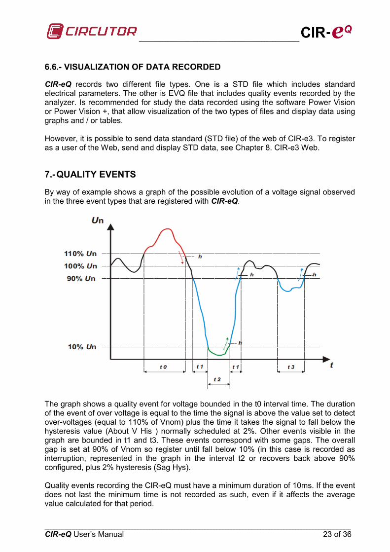
By way of example shows a graph of the possible evolution of a voltage signal observed in the three event types that are registered with CIR-eQ.
The graph shows a quality event for voltage bounded in the t0 interval time. The duration of the event of over voltage is equal to the time the signal is above the value set to detect over-voltages (equal to 110% of Vnom) plus the time it takes the signal to fall below the hysteresis value (About V His ) normally scheduled at 2%. Other events visible in the graph are bounded in t1 and t3. These events correspond with some gaps. The overall gap is set at 90% of Vnom so register until fall below 10% (in this case is recorded as interruption, represented in the graph in the interval t2 or recovers back above 90% configured, plus 2% hysteresis (Sag Hys). Quality events recording the CIR-eQ must have a minimum duration of 10ms. If the event does not last the minimum time is not recorded as such, even if it affects the average value calculated for that period.
_____________________________________________
_________________________________________________________________________________________________________ 24 of 36 CIR-eQ User’s Manual
8.- CIR-E WEB
It allows the use of CIR-e³ Web to send and view STD files that records CIR-eQ. For this reason during this chapter refer to device CIR-e ³. It is not allowed to send EVQ data to the Web. In this chapter, the reference data CIR-eQ is only about STD files.
The maximum size of a file to send to the Web tool is 64 Mb. For larger files to use the software Power Vision or Power Vision Plus.
8.1.- CONNECTING TO AND REGISTERING IN CIR-E WEB
CIRCUTOR recommends to the user to register on the web site in order to receive all the information and to have the latest version of manual and firmware. The web page is a tool used to analyze and export the files recorded by the CIR-EQ analyzer. Web site: http://cir-e3.circutor.com. The access and registration procedure is described next.
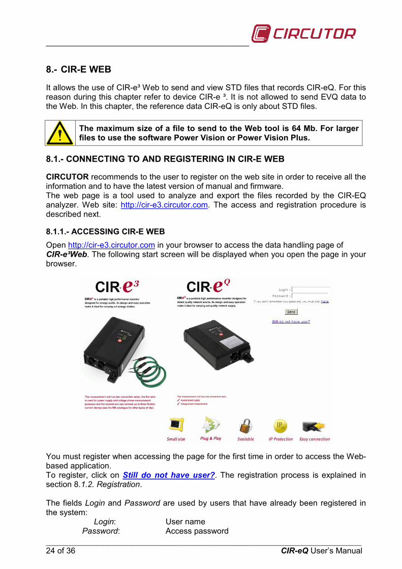
8.1.1.- ACCESSING CIR-E WEB Open http://cir-e3.circutor.com in your browser to access the data handling page of CIR-e³Web. The following start screen will be displayed when you open the page in your browser.
You must register when accessing the page for the first time in order to access the Web-based application. To register, click on Still do not have user?. The registration process is explained in section 8.1.2. Registration. The fields Login and Password are used by users that have already been registered in the system:
Login: User name Password: Access password

_______________________________________________________
_________________________________________________________________________________________________________ CIR-eQ User’s Manual 25 of 36
After entering the login and password, click on “Send” to access the Web site.
8.1.2.- REGISTRATION You must fill in the registration form when accessing CIR-e³Web for the first time. Its function is to reserve a space on the web site that you can use to send and handle the data recorded by the CIR-eQ device. To register, click on Still do not have user?
Click on this link and the application will display the registration form. Fill it in with your information.
The following information is requested to register a new user:
Login: Access name used to register and access future connections to the CIR-e³Web server. You can enter alphanumerical values in this field, although we recommend not using symbols, accents, etc.
Password: Access password with which the user is registered and which will be used in future connections to the CIR-e³Web server. You can enter alphanumerical values in this field, although we recommend not using symbols, accents, etc.
CIF: Company / Personal Tax Identification code. E-mail: Contact email address. Company: Name of the company. Telephone: Contact phone. Description: Description of the account (optional). Time zone: Must be set in this field the time zone where the user will use the
device. This field entered by the user is very important since this field is that the application uses to calculate the local time registrations by the analyzer.
_____________________________________________
_________________________________________________________________________________________________________ 26 of 36 CIR-eQ User’s Manual
The use of CIRCUTOR's CIR-e3 Web application is subject to the acceptance of the following Conditions for Use:
1. 1The user is responsible for any activity carried out with his/her user name and for any information sent through the CIR-eQ Web application.
2. The user is responsible for the use of the CIR-eQ Web application under the legal terms.
3. The user is responsible for sending files that are free from viruses or worms to the CIR-eQ Web application. Should a virus or worm be sent to the CIR-eQ Web application or a fraudulent use of the tool is detected, CIRCUTOR reserves the right to cancel the user's registration.
4. CIRCUTOR, shall not be liable for the incorrect interpretation of the information sent to the display tool or the incorrect recording of said data.
5. CIRCUTOR, shall not be liable for the damages resulting in the loss of information to you or third parties, derived from the data sent to the Web application.
6. The user is responsible for keeping the appropriate original files and backup copies of the records registered by the CIR-eQ analyzer with an STD extension, which will be stored in the original hard drive where they were sent from.
7. CIRCUTOR, shall not be liable for storing the data sent to the Web application, since it will enable the sending of the data required as many times as the user finds it necessary.
8. CIRCUTOR informs its users that the information can not be retrieved from the Web site, since it is sent in encrypted form to the Web application.
9. Each user will have a 10-report limit on the Web site and store reports during 12 months.
10. CIRCUTOR reserves the right to modify these Conditions for Use at any time. Legal information (LPD) In compliance with Organic Law 15/1999, 13th of December, on the Protection of Personal Data, we would like to inform that the user data will be included in an automated file, property of CIRCUTOR, S.A., with the purpose of managing the service hired, whereby the user will authorise the treatment of the said data under the corresponding terms and conditions. The undersigned can exert their right to access, rectification, cancellation and objection of the said data at any time by writing to the address of the file's manager, CIRCUTOR, S.A., Vial Sant Jordi, s/n, 08232 de Viladecavalls (Barcelona). After filling in the form, the user has to accept the conditions for use and click on “Create user” to validate the data and register the new user. This is when the user is created with the registration form and already has access to the CIR-e³Web page. You will be able to send a maximum of 10 files and access the page an unlimited number of times to check and handle the information sent to the server. Select “Cancel” to stop the user registration process and the application will return to the previous screen.
_______________________________________________________
_________________________________________________________________________________________________________ CIR-eQ User’s Manual 27 of 36
8.2.- DOWNLOADING THE XCG IDENTIFICATION FILE:
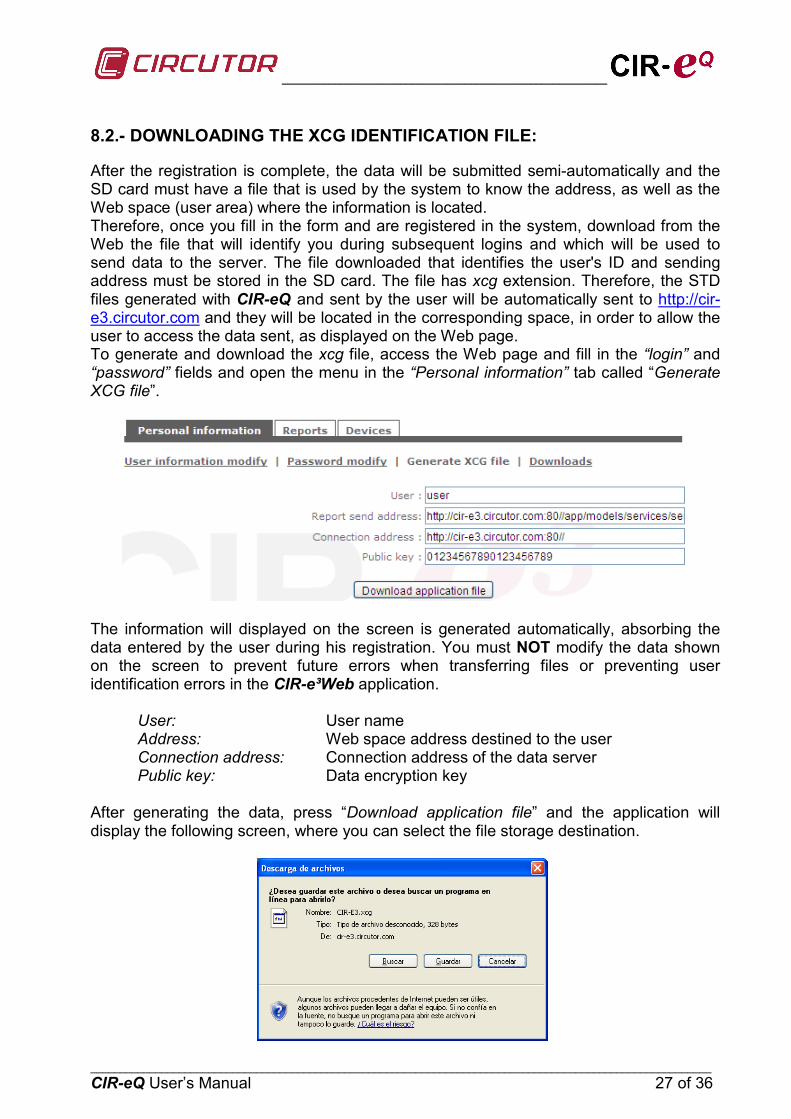
After the registration is complete, the data will be submitted semi-automatically and the SD card must have a file that is used by the system to know the address, as well as the Web space (user area) where the information is located. Therefore, once you fill in the form and are registered in the system, download from the Web the file that will identify you during subsequent logins and which will be used to send data to the server. The file downloaded that identifies the user's ID and sending address must be stored in the SD card. The file has xcg extension. Therefore, the STD files generated with CIR-eQ and sent by the user will be automatically sent to http://cir-e3.circutor.com and they will be located in the corresponding space, in order to allow the user to access the data sent, as displayed on the Web page. To generate and download the xcg file, access the Web page and fill in the “login” and “password” fields and open the menu in the “Personal information” tab called “Generate XCG file”.
The information will displayed on the screen is generated automatically, absorbing the data entered by the user during his registration. You must NOT modify the data shown on the screen to prevent future errors when transferring files or preventing user identification errors in the CIR-e³Web application.
User: User name Address: Web space address destined to the user Connection address: Connection address of the data server Public key: Data encryption key
After generating the data, press “Download application file” and the application will display the following screen, where you can select the file storage destination.
_____________________________________________
_________________________________________________________________________________________________________ 28 of 36 CIR-eQ User’s Manual
The storage destination must be the root directory of the SD card. This is the same location of the CIR-e.exe setup application.
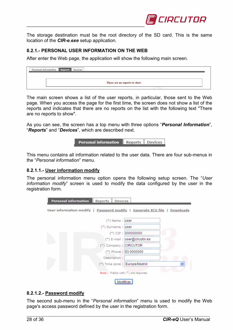
8.2.1.- PERSONAL USER INFORMATION ON THE WEB After enter the Web page, the application will show the following main screen.
The main screen shows a list of the user reports, in particular, those sent to the Web page. When you access the page for the first time, the screen does not show a list of the reports and indicates that there are no reports on the list with the following text "There are no reports to show". As you can see, the screen has a top menu with three options “Personal Information”, “Reports” and “Devices”, which are described next.
This menu contains all information related to the user data. There are four sub-menus in the “Personal information” menu.
8.2.1.1.- The personal information menu option opens the following setup screen. The “User information modify” screen is used to modify the data configured by the user in the registration form.
User information modify
8.2.1.2.- The second sub-menu in the “Personal information” menu is used to modify the Web page's access password defined by the user in the registration form.
Password modify
_______________________________________________________
_________________________________________________________________________________________________________ CIR-eQ User’s Manual 29 of 36
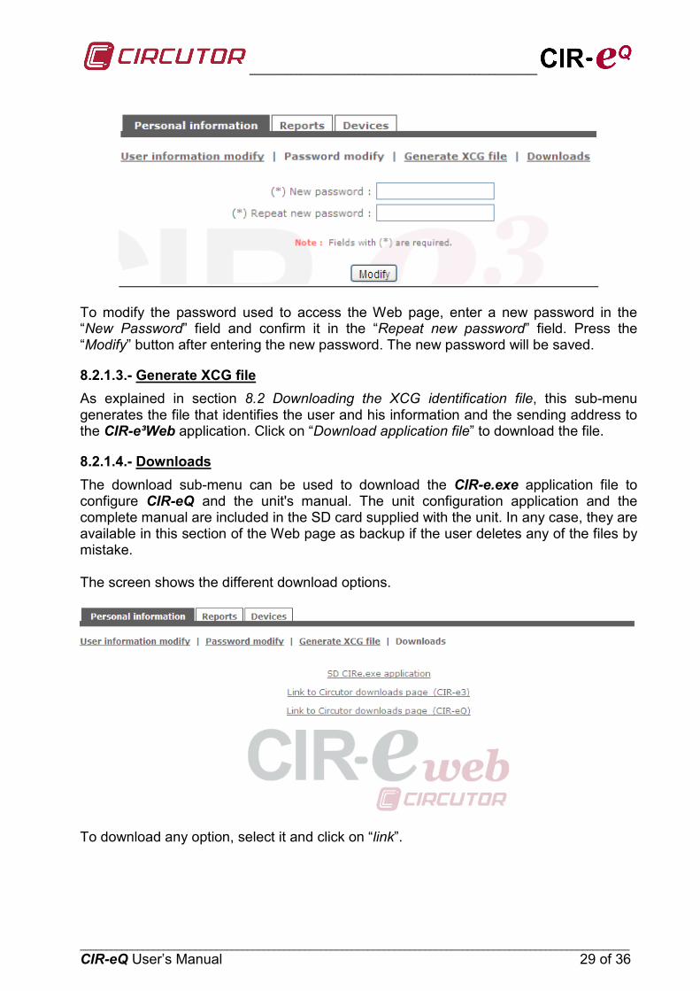
To modify the password used to access the Web page, enter a new password in the “New Password” field and confirm it in the “Repeat new password” field. Press the “Modify” button after entering the new password. The new password will be saved.
8.2.1.3.- Generate XCG file As explained in section 8.2 Downloading the XCG identification file, this sub-menu generates the file that identifies the user and his information and the sending address to the CIR-e³Web application. Click on “Download application file” to download the file.
8.2.1.4.- Downloads The download sub-menu can be used to download the CIR-e.exe application file to configure CIR-eQ and the unit's manual. The unit configuration application and the complete manual are included in the SD card supplied with the unit. In any case, they are available in this section of the Web page as backup if the user deletes any of the files by mistake. The screen shows the different download options.
To download any option, select it and click on “link”.
_____________________________________________
_________________________________________________________________________________________________________ 30 of 36 CIR-eQ User’s Manual
9.- FAQS
Can I start recording when the phases LEDs start flashing? When LEDs start to flash, we recommend checking the installation to make sure that there are no connection faults. If the LEDs continue to flash after you have checked the connections, you can start the recording since this is probably due to a Ka or Kd higher than 50%
Can I start recording when the REC LED is flashing? Is unable to start the record if the REC LED is blinking because indicates a writing SD card error, because of these possible causes. o No memory card inserted in the unit's SD card slot. o The memory card inserted does not have the correct format or data can not be
written. (for example, if the card is write protected or it has a FAT32 format; please change the format of the memory card to FAT16).
Why has the EVQ file been deleted from the root directory of the memory card?
The EVQ file can be deleted from the memory card's root directory for the following reasons: o The user has powered CIR-eQ without inserting the SD memory card in the unit.
This loads the “Default” file with the specific setup. When you insert the memory card, the analyzer detects the new setup file. This is interpreted as a modification of the setup and the unit proceeds with the process explained in point 1.
Why is the recording period different from the period you have configured?
If the analyzer does not find the setup file from the root directory of the SD card, it is self-configured with the “Default” file, which has a 10 minute registration period.
What happens when the user enters an incorrect serial number when generating the setup file with the PC application? If you have created a setup file with the wrong name, i.e., the analyzer's serial number entered is incorrect, the analyzer will not use it as the unit's serial and it will configure itself with the “Default” file.
Can I send the EVQ files recorded by CIR-eQ to the Web? It is not possible to send EVQ data to the Web. Only send the STD because they are standard format that supports the application. For this reason we recommend using Power Vision + software for the study of the recorded CIR-eQ data as it can open the STD and EVQ files.

_______________________________________________________
_________________________________________________________________________________________________________ CIR-eQ User’s Manual 31 of 36
The software can not open a file. What could happen? - The card is corrupted due to unsafe removal from the device. - The card is unreadable or write-protected. - The file has been registered with a date that is not interpreted by the program. This
date is generated when the device loose battery charge. The data is recorded with an incorrect date. Why?
The device records with the default date 01/01/2011 00:00h when the battery is empty and is unable to maintain the clock. For devices with rechargeable battery, connect the device for 12 h to recharge the battery and configure the data. For devices with non rechargeable battery, change the battery by a new one.

_____________________________________________
_________________________________________________________________________________________________________ 32 of 36 CIR-eQ User’s Manual
10.- REGULATIONS
ELECTRICAL SAFETY REGULATIONS IEC 60664-1 Insulation of low voltage equipment IEC 61010-1 Electrical safety IEC 62053-21 Active energy meters (class 1 and 2) UL 94 Enclosure flammability test VDE 110 Low voltage equipment insulation
ELECTROMAGNETIC EMISSIONS
IEC 61000-3-2 Harmonics IEC 61000-3-3 Voltage Fluctuations IEC 61000-6-4 Industrial Emission EN 55011 Radioelectric alterations. Industrial, scientific and medical. EN 55022 Radioelectric alterations. Information technology equipment.
ELECTROMAGNETIC IMMUNITY IEC 61000-6-2 Industrial immunity. IEC 61000-4-2 Electrostatic discharge IEC 61000-4-3 Electromagnetic, radiated and radiofrequency fields IEC 61000-4-4 Quick transient bursts. IEC 61000-4-5 Shockwave. IEC 61000-4-8 Magnetic field at the industrial frequency IEC 61000-6-1 Domestic immunity. IEC 61000-4-11 Interruptions, gaps and power supply variations. ENV 50141 Radiofrequency in common mode.
PROTECTION DEGREE:
IEC 60529 Enclosing protection degrees. HOUSING SYMBOLS
Maximum input voltage 400 V
Reinforced insulation
Product manufactured with recyclable and reusable material. Do not dispose with domestic wastes. At the end of its lifespan, deposit the product at a specific collection point meant for electrical or electronic devices. REI-RAEE register (ES) Nº: 3338
11.- TECHNICAL SERVICE
Please contact the after sales service or technical service of CIRCUTOR, S.A. in case you have a question about the unit's operation or you have detected a fault. CIRCUTOR S.A. - After Sales Service. Vial Sant Jordi, s/n 08232 - Viladecavalls. Tel: (+34) 93 745 29 00 Fax: (+34) 93 745 29 14 E-mail [email protected]

_______________________________________________________
_________________________________________________________________________________________________________ CIR-eQ User’s Manual 33 of 36
12.- BATTERY EXCHANGE
Pre-2012 analyzers have a rechargeable battery. In case of malfunction must plug for 12 hours to charge the battery. After that must set the time of the analyzer as described in Chapter 13 Setting the time of the analyzer.
To proceed to change the battery, disconnect the scanner from any source of voltage and current measurement and power
Is recommended change the battery each 5 years. To change the battery (models from 2012) remove the 7 screws on the back of the analyzer and remove the back cover. You must respect the position of the battery as shown in the adhesive as shown in the following picture
After changing the battery of the device must be set the time and an hour. To set the time should follow the instructions in Chapter 13. Setting the time of the analyzer
13.- SETTING THE CLOCK OF THE ANALYZER.
User must supply and connect the device to de PC, using the wire communications given with the device. This cable has one four-pin connector (CIR-e) and at the other end is a DB-9 (PC).
(See instruction manual to verify connections and maximum voltage of the device)
_____________________________________________
_________________________________________________________________________________________________________ 34 of 36 CIR-eQ User’s Manual
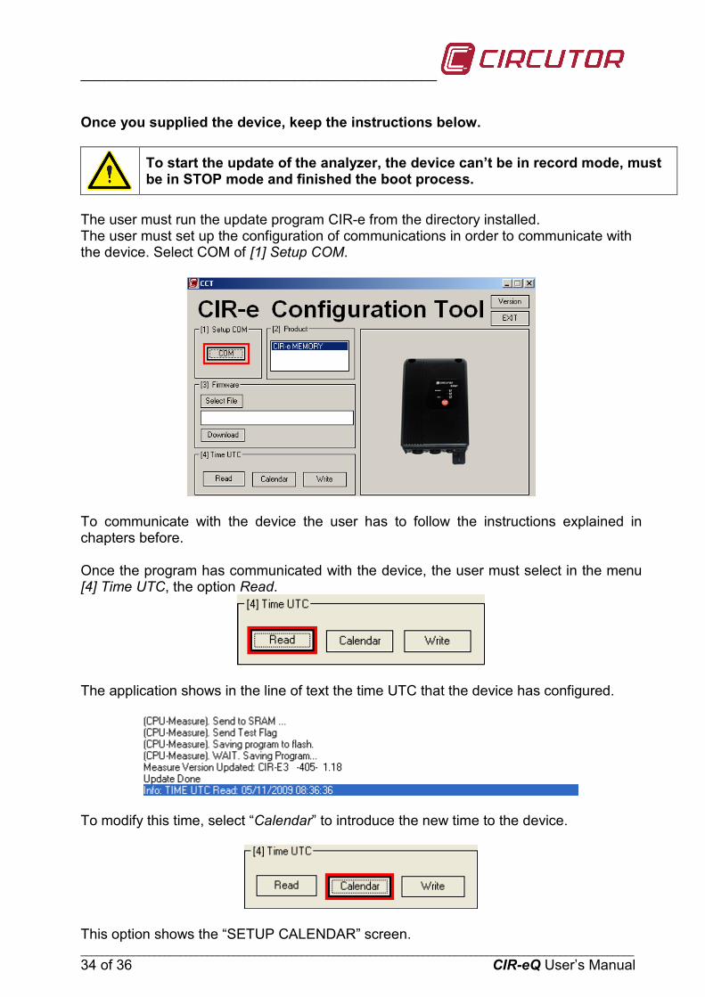
Once you supplied the device, keep the instructions below. To start the update of the analyzer, the device can’t be in record mode, must
be in STOP mode and finished the boot process. The user must run the update program CIR-e from the directory installed. The user must set up the configuration of communications in order to communicate with the device. Select COM of [1] Setup COM.
To communicate with the device the user has to follow the instructions explained in chapters before. Once the program has communicated with the device, the user must select in the menu [4] Time UTC, the option Read.
The application shows in the line of text the time UTC that the device has configured.
To modify this time, select “Calendar” to introduce the new time to the device.
This option shows the “SETUP CALENDAR” screen.

_______________________________________________________
_________________________________________________________________________________________________________ CIR-eQ User’s Manual 35 of 36
UTC Time. This part is informational only and shows the conversion to UTC time settings according to user-entered in the field below “Local Time”.
Local Time. In this field the user must enter the local date and time and indicate in the selection field "Summer", if you are applying DST.
The lower field is a dropdown menu for the user to select the time zone in which it is located. With all this information on applying calculations UTC time is displayed in the "UTC Time". Now push Ok to introduce all data.
Once the user is in the principal screen, must click “Write” in order to write in the device the time set by the user.
The time that is sent appears in the line of the text.
_____________________________________________
_________________________________________________________________________________________________________ 36 of 36 CIR-eQ User’s Manual
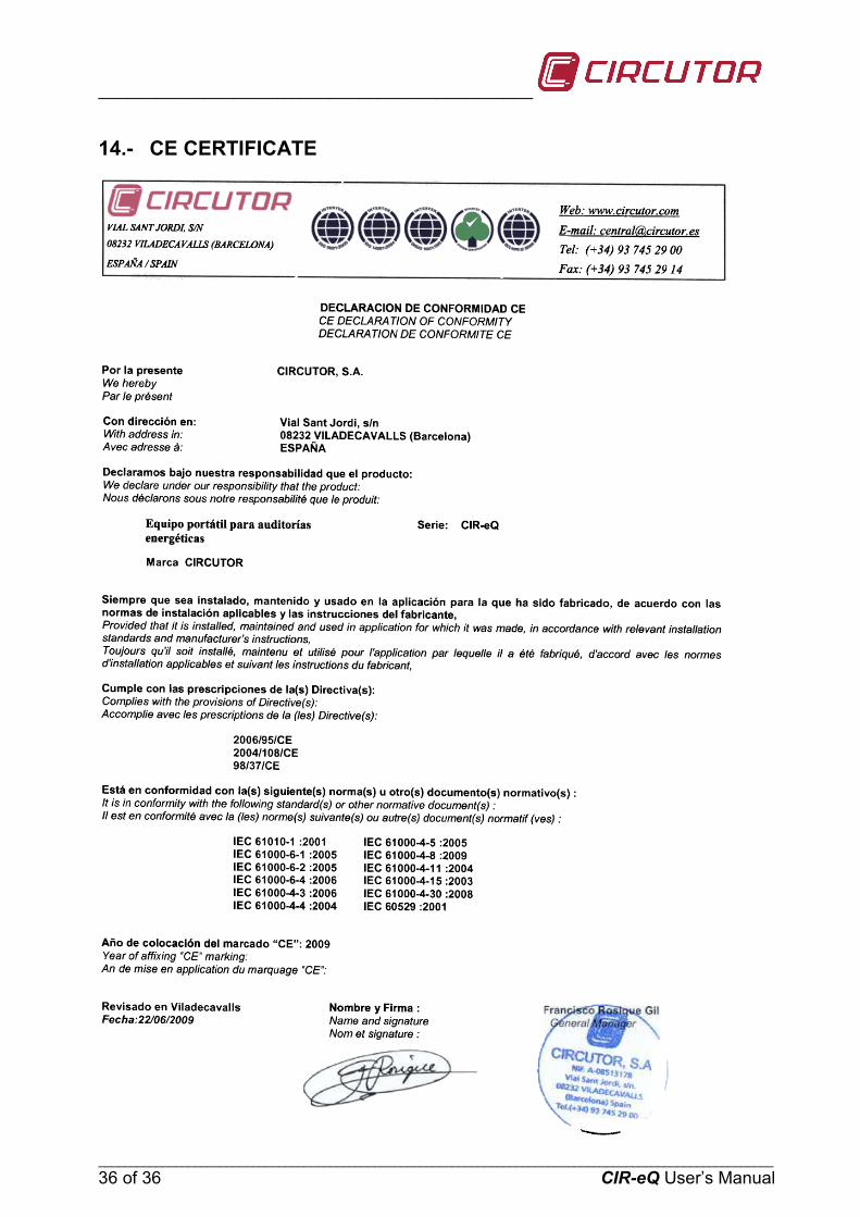
14.- CE CERTIFICATE