User’s Manual - D-Link€¦ · DVG-5102S User’s Manual Product Overview D-Link Systems, Inc. 4...
30
DVG-5102S VoIP Telephone Adapter User’ s Manual Version 1.2 (16 Sept. 2014)
-
Upload
phungquynh -
Category
Documents
-
view
223 -
download
0
Transcript of User’s Manual - D-Link€¦ · DVG-5102S User’s Manual Product Overview D-Link Systems, Inc. 4...

DVG-5102S VoIP Telephone Adapter
User’s Manual
Version 1.2
(16 Sept. 2014)

© 2008 D-Link Corporation. All rights reserved.
Reproduction in any manner whatsoever without the written permission of D-Link Corporation is strictly forbidden.
Trademarks used in this text: D-Link and the D-Link logo are trademarks of D-Link Corporation/D-Link Systems
Inc.; Other trademarks and trade names may be used in this document to refer to either the entities claiming the
marks and names or their products. D-Link Corporation disclaims any proprietary interest in trademarks and trade
names other than its own.
Warranty: please contact your D-Link Authorized Reseller or the D-Link Branch Office nearest your place of
purchase for information about the warranty offered on your D-Link product.
Information in this document is subject to change without notice.
FCC Warning
This equipment has been tested and found to comply with the limits for a Class B digital device, pursuant to Part 15
of the FCC Rules. These limits are designed to provide reasonable protection against harmful interference in a
residential installation. This equipment generates, uses, and can radiate radio frequency energy and, if not installed
and used in accordance with the instructions, may cause harmful interference to radio communication. However,
there is no guarantee that interference will not occur in a particular installation. If this equipment does cause harmful
interference to radio or television reception, which can be determined by turning the equipment off and on, the user
is encouraged to try to correct the interference by one or more of the following measures:
‧ Reorient or relocate the receiving antenna.
‧ Increase the separation between the equipment and receiver.
‧ Connect the equipment into an outlet on a circuit different from that to which the receiver is connected.
‧ Consult the dealer or an experienced radio/TV technician for help.
CE Mark Warning
This is a Class B product. In a domestic environment, this product may cause radio interference in which case the
user may be required to take adequate measures.
Warnung!
Dies ist ein Produkt der Klasse B. Im Wohnbereich kann dieses Produkt Funkstoerungen verursachen. In diesem
Fall kann vom Benutzer verlangt werden, angemessene Massnahmen zu ergreifen.
Precaución!
Este es un producto de Clase B. En un entorno doméstico, puede causar interferencias de radio, en cuyo case, puede
requerirse al usuario para que adopte las medidas adecuadas.
Attention!
Ceci est un produit de classe B. Dans un environnement domestique, ce produit pourrait causer des interférences
radio, auquel cas l`utilisateur devrait prendre les mesures adéquates.
Attenzione!
Il presente prodotto appartiene alla classe B. Se utilizzato in ambiente domestico il prodotto può causare interferenze
radio, nel cui caso è possibile che l`utente debba assumere provvedimenti adeguati.

Contents
1. Introduction ........................................................................................................................................................ 4 1-1 Product Overview ....................................................................................................................................... 4 1-2 Hardware Description ................................................................................................................................. 5
2. Getting Started ................................................................................................................................................... 7 2-1 SETUP ...................................................................................................................................................... 10
2-1-1 Internet Setup ................................................................................................................................. 10 2-1-2 LAN Settings .................................................................................................................................. 13
2-2 MAINTENANCE........................................................................................................................................ 15 2-2-1 Device Management ...................................................................................................................... 15 2-2-2 Backup and Restore ....................................................................................................................... 15 2-2-3 Diagnostics ..................................................................................................................................... 17
2-3 STATUS .................................................................................................................................................... 18 2-3-1 Device Info ..................................................................................................................................... 18 2-3-2 VoIP Status ..................................................................................................................................... 19 2-3-3 Statistics ......................................................................................................................................... 20 2-3-4 Logout ............................................................................................................................................ 20
3. Configuring the VoIP TA through IVR ............................................................................................................ 21 3-1 IVR (Interactive Voice Response) ............................................................................................................ 21
3-1-1 IVR Functions Table: ...................................................................................................................... 22 3-2 IP Configuration Settings—Set the IP Configuration of the WAN Port..................................................... 23
3-2-1 PPPoE Character Conversion Table: ............................................................................................. 25
4. Dialing Principles ............................................................................................................................................. 26 4-1 Dialing Options ......................................................................................................................................... 26 4-2 Number Translation .................................................................................................................................. 26 4-3 Routing ..................................................................................................................................................... 27
Appendix ............................................................................................................................................................... 29 Product Features ............................................................................................................................................ 29

DVG-5102S User’s Manual Product Overview
D-Link Systems, Inc. 4
1. Introduction
1-1 Product Overview
The DVG-5102S is designed to carry both voice and facsimile over the IP network. It uses the industry standard SIP call control protocol so as to be compatible with free registration services or VoIP service providers’ systems. As a standard user agent, it is compatible with all common Soft Switches and SIP proxy servers. While running optional server software, the VoIP Telephone Adapter can be configured to establish a private VoIP network over the Internet without a third-party SIP Proxy Server. The DVG-5102S can be seamlessly integrated into an existing network by connecting to a phone set and fax machine. With only a broadband connection such as an ADSL bridge/router, a Cable Modem or a leased-line router, the VoIP Telephone Adapter allows you to use voice and fax services over IP in order to reduce the cost of all long distance calls. The DVG-5102S can be configured a fixed IP address or it can have one dynamically assigned by DHCP or PPPoE. It adopts either the G.711, G.726, G.729A, G.723.1 and G.722 voice compression format to save network bandwidth while providing real-time, toll quality voice transmission and reception.

DVG-5102S User’s Manual Telephone Interface Description
D-Link Systems, Inc. 5
1-2 Hardware Description
Front Panel
Power: Solid green light indicates a normal power supply.
Alarm: Red light indicates abnormal status, such as failed to register or provision or not obtained IP address.
Register: The Register LED will turn on when the VoIP Router is connected to a VoIP service provider. The LED will blink if not connected to a service provider.
LAN indicator: When a connection is established the LED will light up solid. The LEDs will blink to indicate activity. If the LED does not light up when a cable is connected, verify the cable connections and make sure your devices are powered on.
WAN indicator: When a connection is established the LED will light up solid. The LED will blink to indicate activity. If the LED does not light up when a cable is connected, verify the cable connections and make sure your devices are powered on.
Phone Indicator: Phone LED will light up solid if a phone connected to a phone port is off the hook or in use. When a phone is ringing, the indicator will blink.
Note: When starting up DVG-5102S, all indicators will light up. After about 40 seconds, the Register
indicator will blink in green. If the Alarm indicator continues to blink, it means DVG-5102S is currently communicating with ISP and has yet to obtain an IP address or fail to register to VoIP Service Provider.

DVG-5102S User’s Manual Telephone Interface Description
D-Link Systems, Inc. 6
Rear Panel
1. Phone Port: Connect to your phones using standard phone cabling (RJ-11). 2. WAN: Connect to your broadband modem / router using an Ethernet cable. 3. LAN: Connect to your Ethernet enabled computers using Ethernet cabling. 4. Power Receptor: Receptor for the provided power adapter. 5. Reset : Use to Restore to factory default :
(1) Power on. (2) Press and hold the reset button for 5 seconds. (3) Release the reset button. Factory settings will be restored.
WARNING: DO NOT connect any phone port directly to a PSTN line (FXS to PSTN) or to an internal PBX line (FXS to PBX extension). Doing so may damage your VoIP TA.
POWER Connects to the power adapter
(comes with VoIP TA) FXS ports 1 ~ 6
(telephone connectors) Connects to phone sets
FXO ports 7,8 (PSTN line connectors) Connects to PSTN lines
LAN ports 1 ~ 4 (built-in Ethernet switch) Connect LAN hosts here
to share WAN
P2-P4

DVG-5102S User’s Manual MAINTENANCE
D-Link Systems, Inc. 7
2. Getting Started
To access the web-based configuration utility, set a statics IP on the LAN adapter, open a web browser such as Internet Explorer and enter the IP address of the DVG-5102S. *Statics IP: 192.168.8.XXX, the “XXX” can be any number from 1~253 except 254 cannot be used*
If the DVG-5102S is connected behind a router, the IP address of the router is determine by the router’s DHCP Server.
Open your Web browser and type http://192.168.8.254 into the URL address box. Press the Enter or Return Key.
Click Login to enter Web Site.

DVG-5102S User’s Manual MAINTENANCE
D-Link Systems, Inc. 8
VoIP TA Web Configuration
During configuration, please follow the Setup Hint for some specific procedure in case the VoIP TA fails to make the changes active.
Situation 1: (example: Internet Setup)
Setup Hint: 1. Select DHCP WAN Setup. 2. Click “Apply”. 3. Click “Save and Restart” to make change take effect.

DVG-5102S User’s Manual MAINTENANCE
D-Link Systems, Inc. 9
Situation 2: (example: Enable IP Filtering)
Setup Hint: 1. Click “Enable IP Filtering” check box to open the main screen. 2. Click “Add” to enter an entry. 3. After Adding an entry, you have to click “Apply”. 4. Don’t forget to click “Apply” which in the field of “Enable IP Filtering”. 5. After settings, save and reboot.
1
2
3
4
DVG-5102S User’s Manual MAINTENANCE
D-Link Systems, Inc. 10
2-1 SETUP
2-1-1 Internet Setup
WAN (Wide Area Network) Settings are used to connect to your ISP (Internet Service Provider). The WAN settings are provided to you by your ISP and oftentimes referred to as "public settings". Please select the appropriate option for your specific ISP.
IP Configuration (Setting WAN Port)
There are five methods of obtaining a WAN port IP address: 1. DHCP, which means a Dynamic IP (Cable Modem) 2. Static IP 3. PPPoE (dial-up ADSL)
Methods for using DHCP and PPPoE for obtaining an IP address may vary. If you are not familiar with creating a network connection, please contact your local ISP.
After selecting the suitable option, click Accept at the bottom of the screen to save the settings.
You need to save the changes and restart the VoIP TA to make the changes active. Saving the settings: Click MAINTENANCE and select Save/Restart in System from the left menu. Tick Save Settings and Restart, then click Accept. Wait for about 40 seconds before the VoIP TA obtaining an IP address by the method you selected.
Note: When the system has obtained a new IP address, and you are using a WAN port to enter the Web Configuration Screen, the new IP address has to be used before you can get connected to the VoIP TA. The same principle applies to the next two settings.
SETUP → Internet Setup
SETUP → Internet Setup

DVG-5102S User’s Manual MAINTENANCE
D-Link Systems, Inc. 11
DHCP: Select this option if your ISP (Internet Service Provider) provides you an IP address automatically. Cable modem providers typically use dynamic assignment of IP Address. The Host Name field and Vendor Class ID are optional but may be required by some Internet Service Providers.
SETUP → Internet Setup
Static IP: Select this option if your ISP (Internet Service Provider) provides you a Static IP address. Enter the IP address, Subnet Mask and Default Gateway IP.
SETUP → Internet Setup
PPPoE: Select this option if your ISP requires you to use a PPPoE (Point-to-Point Protocol over Ethernet) connection. Enter the PPPoE Account, PPPoE Password and re-enter Password to confirm.
DVG-5102S User’s Manual MAINTENANCE
D-Link Systems, Inc. 12
SETUP → Internet Setup
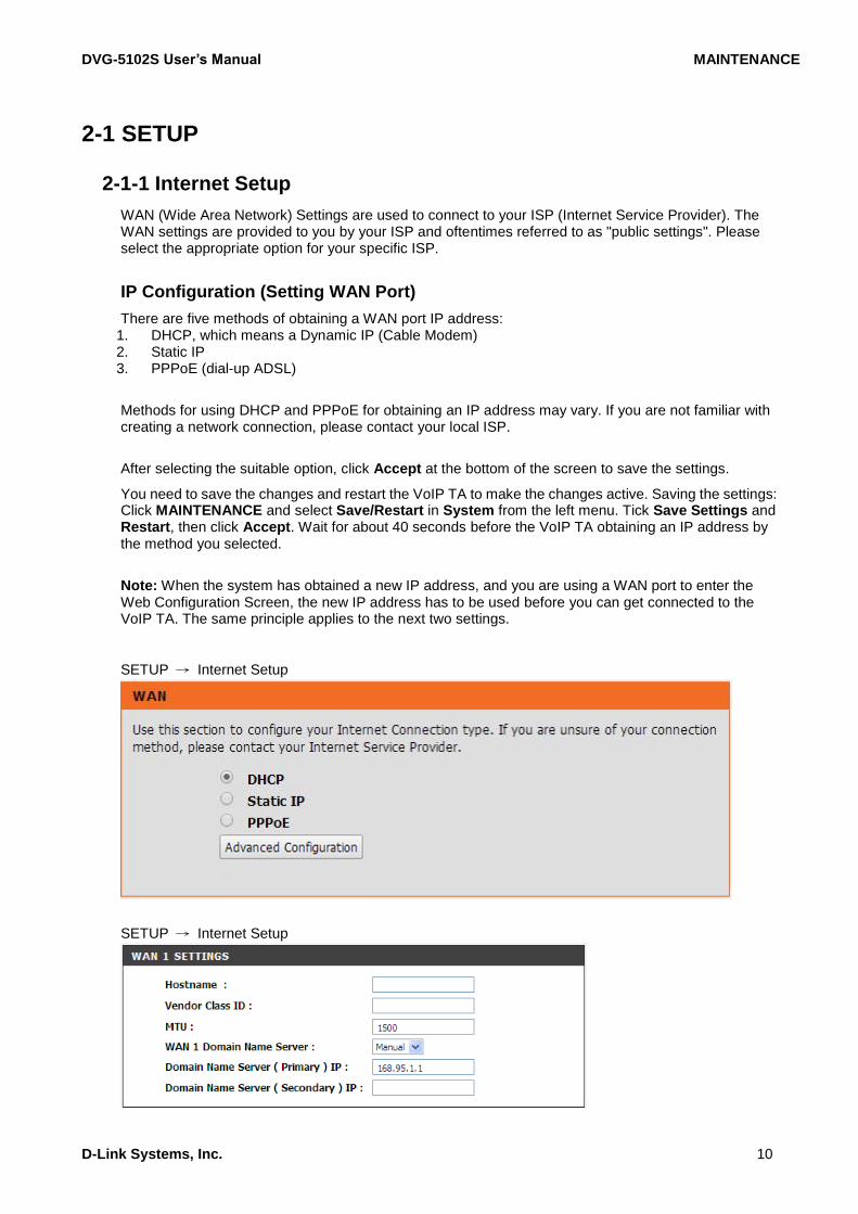
VoIP Connection Interface: Select a WAN interface for DVG-5102S VoIP traffic.
SETUP → Internet Setup
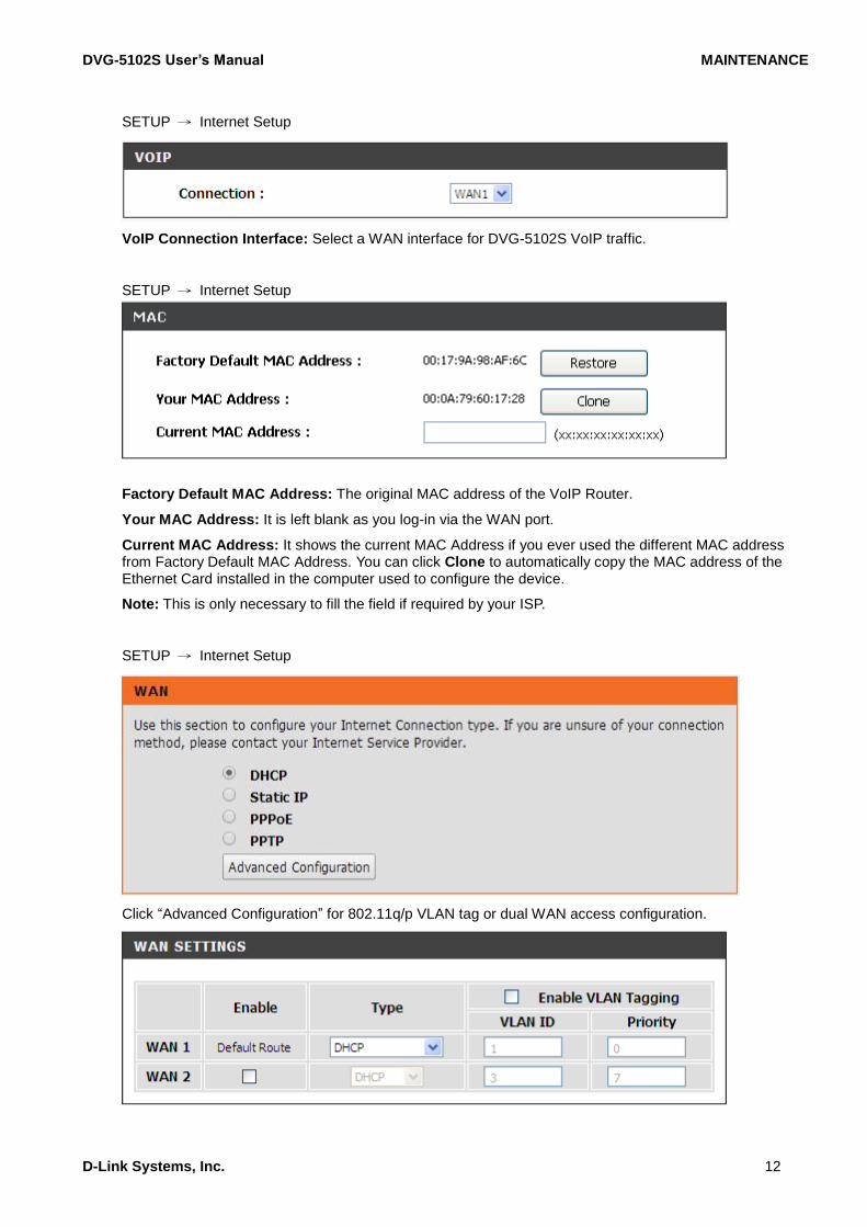
Factory Default MAC Address: The original MAC address of the VoIP Router.
Your MAC Address: It is left blank as you log-in via the WAN port.
Current MAC Address: It shows the current MAC Address if you ever used the different MAC address from Factory Default MAC Address. You can click Clone to automatically copy the MAC address of the Ethernet Card installed in the computer used to configure the device.
Note: This is only necessary to fill the field if required by your ISP.
SETUP → Internet Setup
Click “Advanced Configuration” for 802.11q/p VLAN tag or dual WAN access configuration.

DVG-5102S User’s Manual MAINTENANCE
D-Link Systems, Inc. 13
VLAN is optional. It works with the Router or Switch that supports VLAN tag. By adding VLAN tag in packets may improve efficiency of voice traffic performance and security.
Enable VLAN Tagging: It is to tag the packets for VLAN Router or Switch identifying.
VLAN ID: It is to assign uniquely a user-defined ID to each packet.
Priority: It is the proprietary to VLAN Router or Switch.
Note: Please do not change anything here unless requested by your ISP.
2-1-2 LAN Settings
SETUP → LAN Setup
LAN Port Address: Enter the LAN IP address of the VoIP TA. It is also the default gateway for DHCP clients.
Subnet Make: Enter the subnet mask for DHCP clients.
SETUP → LAN Setup
Enable Port: It is to active/des-active LAN port physical connection.
Incoming Rate Limit: Set the incoming (from LAN to WAN) rate limit of a specific LAN port (can not exceed the real downstream bandwidth).
Outgoing Rate Limit: Set the outgoing (from WAN to LAN) rate limit of a specific LAN port (can not exceed the real upstream bandwidth).
NAT/Bridge: Select the VoIP Router serving as a Bridge between WAN port and LAN port without NAT.
Note: If you set a LAN port to be bridge mode that the LAN port will be bundled with WAN. If you would like to connect to DVG-5102S at the bridged LAN port you must enter WAN port IP.
VLAN ID: Assign a VLAN ID for DVG-5102S to transit traffic through-out at WAN port for WAN-LAN

DVG-5102S User’s Manual MAINTENANCE
D-Link Systems, Inc. 14
bridge mode. The packets are un-tagged at LAN port and added tag at WAN port.
Note: It is not allowed to change VLAN ID for NAT mode LAN ports. The VLAN ID of NAT LAN ports are bundled with WAN 1 which assigned at Internet Setting page. The packets are un-tagged at LAN port and added tag at WAN port.
2-1-2-1 UPnP
ADVANCED → Advanced Network → UPnP
Enable UPnP: Check the box to enable the VoIP TA’s IP traffic to pass through an Internet sharing device. This function only works when the Internet sharing device supports UPnP and has it enabled.
Note: The “Status Current Status” page will show the status of UPnP.
2-1-2-2 IGMP Proxy
ADVANCED → Advanced Network → IGMP Proxy
Enable IGMP proxy: Check the box to enable IGMP proxy. IGMP proxy enables the system to issue IGMP host messages on behalf of hosts that the system discovered through standard IGMP interfaces.

DVG-5102S User’s Manual MAINTENANCE
D-Link Systems, Inc. 15
2-2 MAINTENANCE
2-2-1 Device Management
MAINTENANCE → Device Management
Password: By default there is no password configured. It is highly recommended that you create a password to keep your router secure.
2-2-2 Backup and Restore
Save and Reboot
MAINTENANCE → Backup and Restore
Save All Settings: Click the Save All Settings check box and reboot the system after completing changes. The new settings will take effect after the VoIP TA is restarted.
Restart: Click the Reboot button to reboot the system.
Backup Configurations File
MAINTENANCE → Backup and Restore
The current system settings can be saved as a file onto the local hard drive. Click the Backup Settings button to save your current settings to a file.

DVG-5102S User’s Manual MAINTENANCE
D-Link Systems, Inc. 16
Backup Configurations Template File
MAINTENANCE → Backup and Restore
Click the Backup Settings button to save your current settings to a template file for editing.
Update Settings
MAINTENANCE → Backup and Restore
To restore a system settings file, click on Browse to search the local hard drive for the file to be used. Once you locate the file, click Upload Settings to overwrite the current settings with the settings saved to the file.
Restore Default Settings
MAINTENANCE → Backup and Restore
Select Restore Default Settings to reset the VoIP TA’s settings back to the factory default settings.

DVG-5102S User’s Manual MAINTENANCE
D-Link Systems, Inc. 17
2-2-3 Diagnostics
Use “Ping” to verify if a remote peer is reachable. Enter a remote IP address and click “Test” to ping the remote host. The result would be shown on Result Table
MAINTENANCE → Diagnostics

DVG-5102S User’s Manual STATUS
D-Link Systems, Inc. 18
2-3 STATUS
2-3-1 Device Info
STATUS → Device Info
For System Information, it shows Model Name, Time and Date and Firmware Version. For WAN Port Information, it shows IP address, subnet mask, default gateway and DNS server. If you use PPPoE to obtain IP, you will know if the IP is obtained through this method. If IP address, subnet mask, default gateway is blank, it means that the VoIP TA does not obtain IP. For LAN Port Information, it shows LAN port IP and the subnet mask.

DVG-5102S User’s Manual STATUS
D-Link Systems, Inc. 19
STATUS → Device Info
For Hardware, it shows the hardware platform and driver version.
2-3-2 VoIP Status
STATUS → VoIP Status
For Port Status, it includes if each port registers to Proxy successfully, the last dialed number, how many calls each port has made since the VoIP TA is start, etc. For Server Registration Status, it shows the registration status of DDNS and STUN.

DVG-5102S User’s Manual STATUS
D-Link Systems, Inc. 20
2-3-3 Statistics
STATUS → Statistics
Display the information of the last call made. Press Refresh button to get the latest RTP Packet Summary.
2-3-4 Logout
If setting or parameter has been changed, remember to save the changes before you logout the configuration menu. Logout

DVG-5102S User’s Manual VoIP Router Configuration-IVR
D-Link Systems, Inc. 21
3. Configuring the VoIP TA through IVR
VoIP transmits voice data (packets) via the Internet, hence the condition and status of the network environment is relatively important to the telecommunications quality. If any one of the parties involved in VoIP communications has insufficient bandwidth or frequent packet loss, the telecommunication quality will be poor. Therefore, excellent telecommunication can only happen when the VoIP TAs are connected to the Internet and when the network environment is stable.
Preparation
1. Connect the power supply, telephone set, telephone cable, and network cable properly.
2. If a static IP is provided, confirm the correct IP settings of the WAN Port (IP address, Subnet Mask, and Default gateway). Please contact your local Internet Service Provider (ISP) if you have any question.
3. If you are using ADSL (PPPoE) for your network connection, confirm the account number and password.
4. If you intend to operate the VoIP TA under NAT, the IP range of VoIP TA WAN Port and LAN Port IP Address should not be the same in order to avoid phone failures.
Basic Setup
The VoIP TA provides two setup modes:
1. Telephone IVR Configuration Mode
2. Browser Configuration Mode
IVR configuration provides basic query and setup functions, while browser configuration provides full setup functions.
3-1 IVR (Interactive Voice Response)
The VoIP TA provides convenient IVR functions. Users are able to get query and setup the VoIP TA with a phone-set and function-codes without turning on the PC.
Note: When finishing the setup, make sure the new settings are saved. This will enable the new settings to take effect after the system is restarted.
Instructions
FXS Port: Connect to telephones. To access IVR mode, passwords should be entered, “* * password #”. Alphabets to digits conversion information is provided in the PPPoE Character Conversion Table. (Refer to Page 71) When correct IVR passwords are entered and accepted, an indication tone can be heard indicates the system is in IVR setup mode. Enter function codes to check or configure the VoIP TA. (Please refer to page 68 for function codes).
Example: If your password is “1234”, enter * (star) * (star) 1 2 3 4 # (pound), and now you are entering
IVR setup mode. Next, enter a function code to check or configure the VoIP TA. If your password is
“admin”, enter * (star) * (star) * (star) 41 44 53 49 54 # (pound). Please refer to the IVR Functions Table
(page 68) for available functions and codes.
Once the setting or query has been completed, you can hear a dial tone. Use the same procedure to make a second query or setting. To exit IVR mode, simply hang up the phone.
Example: enter “**#” (you are now in IVR mode) enter 101 (to query the current IP address) the system responds with an IP address. You can continue with more settings or queries: enter 111 (to set

DVG-5102S User’s Manual VoIP Router Configuration-IVR
D-Link Systems, Inc. 22
a new IP address) enter 192*168*1*2 (new IP address).
Save Settings
When all setting procedures are completed, dial 509 (Save Settings) from phone keypad. Wait for about three seconds, you should hear a voice prompt “1 (one).” You can now hang up the phone and please reboot the VoIP TA to enable the new settings.
To inquire about the current VoIP TA WAN Port IP address setting
After completing all your settings, dial 101 from the keypad, then you can hear the system play back the current WAN Port IP address. If the system does not play back the IP address after dialing 101, this indicates that the VoIP TA currently is not connected to the Internet. Please check and make sure the cable connections, account numbers, and passwords are correct.
3-1-1 IVR Functions Table:
Function Code
Description Example / Notes
111/101 WAN Port IP address Set/Query Dial function code 114 and then dial
1 for a Static IP connection then setup the IP address.
112/102 WAN Port Subnet Mask Set/Query
113/103 WAN Port Default Gateway Set/Query
114/104 Current Network IP Access Set/Query (1: Static IP, 2: DHCP, 3: PPPoE)
115/105 DNS IP address Set/Query
116/106 Phone Book manager IP address Set/Query
117/107 Set/Query whether or not to use a Public Telephone Book
(0: Disable 1: Enable)
199/099 Set/Query whether or not this VoIP TA acts as the Phone Book manager (0: Disable 1: Enable)
066 Querying the connection to Phone Book manager
118 Restart
121 Setup PPPoE Account Dial function code 114 and then dial
3 for a PPPoE connection. 122 Set PPPoE Password
123 Set NAT IP address
124 Uses NAT (0: Disable 1: Enable)
311/301 LAN Port IP Set/Query
312/302 LAN Port Subnet Mask Set/Query
109 Restore factory default IP address configuration A static IP address for WAN Port
IP:192.168.1.2
Mask:255.255.255.0
Gateway:192.168.1.254
409 Restore factory default settings
509 Save settings
900 Set the IVR and the language used on the Web GUI
(1: English, 2: Traditional Chinese, 3: Simplified Chinese)
209 Software Upgrade

DVG-5102S User’s Manual VoIP Router Configuration-IVR
D-Link Systems, Inc. 23
3-2 IP Configuration Settings—Set the IP Configuration of the
WAN Port
Static IP Settings
Note: Complete static IP settings should include a static IP (option 1 under 114), IP address (111), Subnet Mask (112), and Default Gateway (113). Please contact your Internet Service Provider (ISP) if you have any question.
Function Command
Select a Static IP After entering IVR mode, dial 114.
When voice prompt plays “Enter value”, dial 1 (to select static IP)
IP address Settings After entering IVR mode, dial 111. When voice prompt plays “Enter value”, enter your IP address followed by “#”.
Example: If the IP address is 192.168.1.200, dial 192*168*1*200#.
Subnet Mask Settings After entering IVR mode, dial 112. When voice prompt plays “Enter value”, enter your subnet mask followed by “#”.
Example: If the subnet mask value is 255.255.255.0, dial 255*255*255*0#.
Default Gateway Settings After entering IVR mode, dial 113. When voice prompt plays “Enter value”, enter your default gateway’s IP address followed by “#”.
Example: If the default gateway is 192.168.1.254, dial 192*168*1*254#.
Save Settings and Restart To save settings, dial 509 (Save Settings). The system will save the current settings. Please restart the system. Wait for about 40 seconds for the system to restart, and then enter 101 to check whether the IP address was retained. If the system does not play back the IP address after dialing 101, this indicates that the VoIP TA currently is not connected to the Internet. Please check and make sure the cable connections, account numbers, and passwords are correct.
Dynamic IP (DHCP) Settings
After entering IVR mode, dial 114.
When voice prompt plays “Enter value”, dial 2 (to select DHCP).
Saving settings –press 509 (Save Settings). Please restart the system. After the system is restarted, press 101 to check whether or not the IP address was retained.
Note: If the system does not play back the IP address, this indicates that the VoIP TA failed to communicate with a DHCP server. Please check with your DHCP server or ISP.
ADSL PPPoE Settings
Note: Complete PPPoE settings should include: Select PPPoE (option 3 of 114), PPPoE account (121) and PPPoE password (122).
Please contact your local Internet Service Provider (ISP) if you have any questions.
DVG-5102S User’s Manual VoIP Router Configuration-IVR
D-Link Systems, Inc. 24
Select a PPPoE
After entering IVR mode, dial 114.
When voice prompt plays “Enter value,” dial 3 (to select PPPoE).
PPPoE Account Settings
After entering IVR mode, dial 121.
When voice prompt plays “Enter value”, enter the account number followed by”#”.
Example: If the account is “[email protected],” please enter 08 07 06 05 04 03 02 01 71 48 49 54 45 60 72 54 45 60 #.
Note: It is necessary to enter two digits for each alphabet/number; for example, you must enter “01” for “1” and “11” for “A”. Using the web Interface to configure your PPPoE account details is recommended. Refer to the PPPoE Character Conversion Table on the next page for key mappings if you choose to use IVR setup.
PPPoE Password Setting
After entering IVR mode, dial 122,
When voice prompt plays “Enter value,” enter the new password followed by “#”.
Example: If the password is “3t2ixiae”, please enter “03 60 02 49 64 49 41 45#”.
Save Settings and Restart
To save settings, dial 509 (Save Settings). The system will save the settings. Please restart the system. Wait for about 40 seconds for the system to restart, then enter 101 to check whether the IP address was retained. If the system does not play back the IP address after dialing 101, this indicates that the VoIP TA currently is not connected to the Internet. Please check and make sure the cable connections, account numbers, and passwords are correct.

DVG-5102S User’s Manual VoIP Router Configuration-IVR
D-Link Systems, Inc. 25
3-2-1 PPPoE Character Conversion Table:
The table below provides a list of PPPoE conversion codes. The first row (high-lighted) of each pair of the column lists the numbers, alphabets or symbols and the second row (high-lighted) of each pair of the column (“Input Key”) represents the codes to be entered for the corresponding numbers, alphabets or symbols. For example, to enter “D-Link” according to the table below, enter: 148322495451
Numbers Input Key Upper Case Letters
Input Key Lower Case Letters
Input Key Symbols Input Key
0 00 A 11 a 41 @ 71
1 01 B 12 b 42 • 72
2 02 C 13 c 43 ! 73
3 03 D 14 d 44 " 74
4 04 E 15 e 45 $ 75
5 05 F 16 f 46 % 76
6 06 G 17 g 47 & 77
7 07 H 18 h 48 ' 78
8 08 I 19 i 49 ( 79
9 09 J 20 j 50 ) 80
K 21 k 51 + 81
L 22 l 52 , 82
M 23 m 53 - 83
N 24 n 54 / 84
O 25 o 55 : 85
P 26 p 56 ; 86
Q 27 q 57 < 87
R 28 r 58 = 88
S 29 s 59 > 89
T 30 t 60 ? 90
U 31 u 61 [ 91
V 32 v 62 \ 92
W 33 w 63 ] 93
X 34 x 64 ^ 94
Y 35 y 65 _ 95
Z 36 z 66 { 96
| 97
} 98

DVG-5102S User’s Manual Appendix
D-Link Systems, Inc. 26
4. Dialing Principles
4-1 Dialing Options
Dial the phone number which you want to call and press # to call out immediately. Note that if the “# (pound)” not dialed, the number will be called out after 4 seconds by default. The period between number dialed and call out is named “Inter Digits Timeout”. (Configurable from “DTMF and PULSE”, default=4 seconds, see page 50).
If the phone number matches the setting of the Digit Map, the phone number will be dialed out through the assigned VoIP Service Provider according to VoIP Route Profile automatically.
4-2 Number Translation
Phone number is dialed by user. The system will check if the phone number is matched Digit Map Table. If no matched is found from Digit Map Table, it will use the phone number to look up number translation of the server set in VoIP Routing Profile.

DVG-5102S User’s Manual Appendix
D-Link Systems, Inc. 27
4-3 Routing
To achieve maximum flexibility, the number dialed will be looked up in several tables defined by VoIP TA. If no match is found from Digit Map Table, it will then look up the number from another table and to the registered VoIP Service Provdier.
Routing Processing Flow
The routing after checking Digit Map Table may be vary. The routing accords with VoIP Route Profile. By default, Phone Book is the first route of VoIP Route Profile. The second and third route is Server 1 and Server 2. Server 3 is the last route. Each server has a dialing plan, i.e. number translation, table, and the number will be translated according the dialing plan before dialing out. For default setting, the number look up flow appears like:
Assume that the route of Default Route Profile is Server 2 as the first route, Server 3 as the second route and Server 1 as the last route. The number look up flow appears like:
Digit Map Table
Phone Book
Server 1
Server 2
Server 3
Digit Map Table
Server 2
Server 3
Server 1

DVG-5102S User’s Manual Appendix
D-Link Systems, Inc. 28
Start
Enter a phone number (D#)
Is (D#) defined in Digit Map
table?
End
Change the number to Global Number.
No
Yes
No
No
No
No
Yes
Yes
Yes
Dial out as defined in the first match
case by VoIP Router
Yes
Is (D#) or Global Number defined in Phone Book
table?
Is (D#) or Global Number defined in Server 1?
Is (D#) or Global Number defined in Server 2?
Is (D#) or Global Number defined in Server 3?
DVG-5102S User’s Manual Appendix
D-Link Systems, Inc. 29
Appendix
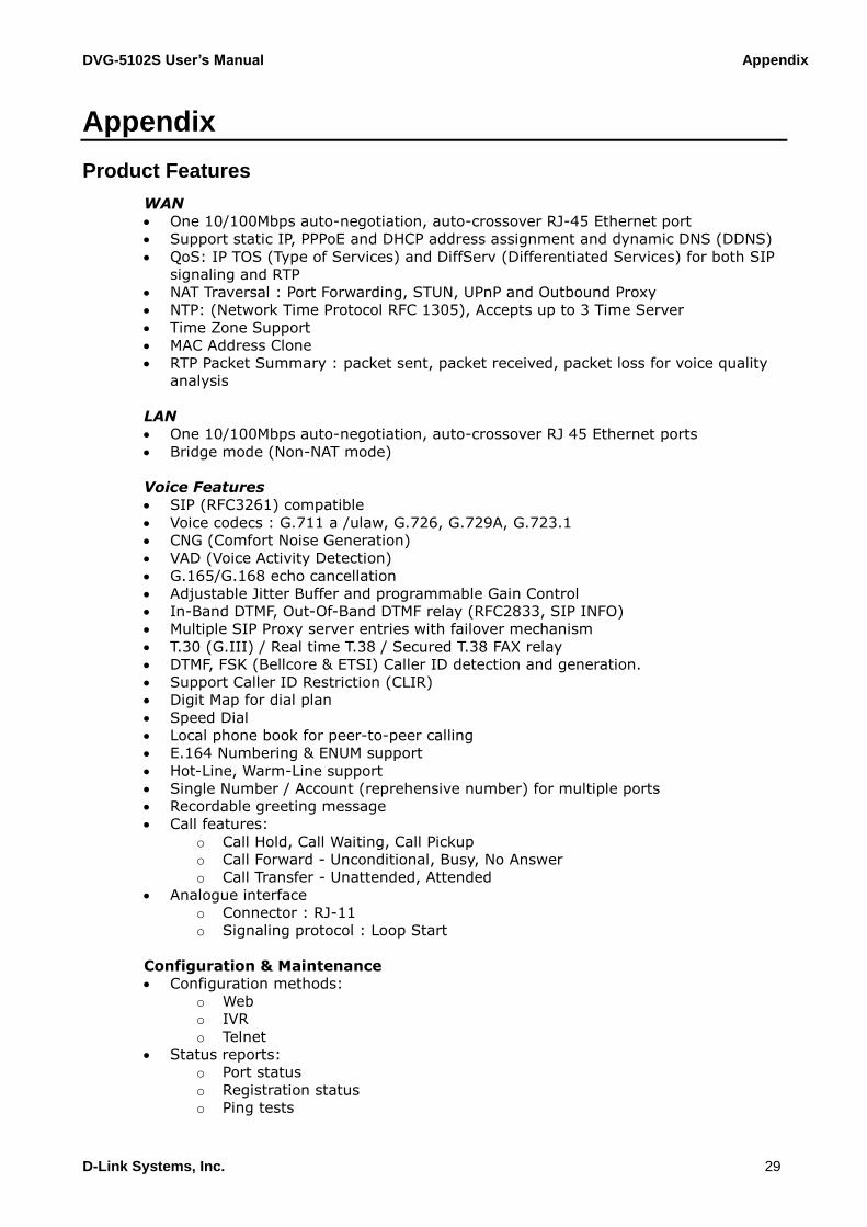
Product Features
WAN
One 10/100Mbps auto-negotiation, auto-crossover RJ-45 Ethernet port
Support static IP, PPPoE and DHCP address assignment and dynamic DNS (DDNS)
QoS: IP TOS (Type of Services) and DiffServ (Differentiated Services) for both SIP
signaling and RTP
NAT Traversal : Port Forwarding, STUN, UPnP and Outbound Proxy
NTP: (Network Time Protocol RFC 1305), Accepts up to 3 Time Server
Time Zone Support
MAC Address Clone
RTP Packet Summary : packet sent, packet received, packet loss for voice quality
analysis
LAN
One 10/100Mbps auto-negotiation, auto-crossover RJ 45 Ethernet ports
Bridge mode (Non-NAT mode)
Voice Features
SIP (RFC3261) compatible
Voice codecs : G.711 a /ulaw, G.726, G.729A, G.723.1
CNG (Comfort Noise Generation)
VAD (Voice Activity Detection)
G.165/G.168 echo cancellation
Adjustable Jitter Buffer and programmable Gain Control
In-Band DTMF, Out-Of-Band DTMF relay (RFC2833, SIP INFO)
Multiple SIP Proxy server entries with failover mechanism
T.30 (G.III) / Real time T.38 / Secured T.38 FAX relay
DTMF, FSK (Bellcore & ETSI) Caller ID detection and generation.
Support Caller ID Restriction (CLIR)
Digit Map for dial plan
Speed Dial
Local phone book for peer-to-peer calling
E.164 Numbering & ENUM support
Hot-Line, Warm-Line support
Single Number / Account (reprehensive number) for multiple ports
Recordable greeting message
Call features:
o Call Hold, Call Waiting, Call Pickup
o Call Forward - Unconditional, Busy, No Answer
o Call Transfer - Unattended, Attended
Analogue interface
o Connector : RJ-11
o Signaling protocol : Loop Start
Configuration & Maintenance
Configuration methods:
o Web
o IVR
o Telnet
Status reports:
o Port status
o Registration status
o Ping tests

DVG-5102S User’s Manual Appendix
D-Link Systems, Inc. 30
o STUN/UPnP status
o Hardware / software information
Firmware Upgrade through HTTP, TFTP, FTP and proprietary image server
Configuration Backup/Restore
Reset button (with restore factory default function)
Front Panel LED : voice ports, WAN, LAN, Register, Power, Alarm
Optional Auto Provisioning Server (APS) for mass