User's Manual - AudioCodes · 11 Network ... 12 Security ..... 133 12.1 Configuring Firewall...
702
Mediant™ 2000 VoIP Media Gateway Digital PSTN Lines User's Manual Version 6.6 February 2015 Document # LTRT-68822
Transcript of User's Manual - AudioCodes · 11 Network ... 12 Security ..... 133 12.1 Configuring Firewall...

Mediant™ 2000
VoIP Media Gateway
Digital PSTN Lines
User's Manual
Version 6.6 February 2015
Document # LTRT-68822


Version 6.6 3 Mediant 2000
User's Manual Contents
Table of Contents 1 Overview ............................................................................................................ 19
1.1 SIP Overview ......................................................................................................... 20
Getting Started with Initial Connectivity ................................................................25
2 Assigning the OAMP LAN IP Address ............................................................. 27
2.1 Web Interface ......................................................................................................... 27 2.2 BootP/TFTP Server ................................................................................................ 29 2.3 CLI .......................................................................................................................... 30
Management Tools ..................................................................................................31
3 Introduction ....................................................................................................... 33
4 Web-Based Management .................................................................................. 35
4.1 Getting Acquainted with the Web Interface ............................................................ 35 4.1.1 Computer Requirements .......................................................................................... 35 4.1.2 Accessing the Web Interface ................................................................................... 35 4.1.3 Areas of the GUI ...................................................................................................... 36 4.1.4 Toolbar Description .................................................................................................. 38 4.1.5 Navigation Tree ....................................................................................................... 39
4.1.5.1 Displaying Navigation Tree in Basic and Full View ..................................39 4.1.5.2 Showing / Hiding the Navigation Pane .....................................................40
4.1.6 Working with Configuration Pages .......................................................................... 41 4.1.6.1 Accessing Pages ......................................................................................41 4.1.6.2 Viewing Parameters .................................................................................42 4.1.6.3 Modifying and Saving Parameters ...........................................................43 4.1.6.4 Working with Tables .................................................................................44
4.1.7 Searching for Configuration Parameters ................................................................. 47 4.1.8 Working with Scenarios ........................................................................................... 48
4.1.8.1 Creating a Scenario ..................................................................................48 4.1.8.2 Accessing a Scenario ...............................................................................50 4.1.8.3 Editing a Scenario ....................................................................................51 4.1.8.4 Saving a Scenario to a PC .......................................................................52 4.1.8.5 Loading a Scenario to the Device ............................................................53 4.1.8.6 Deleting a Scenario ..................................................................................53 4.1.8.7 Quitting Scenario Mode ............................................................................54
4.1.9 Creating a Login Welcome Message ....................................................................... 55 4.1.10 Getting Help ............................................................................................................. 56 4.1.11 Logging Off the Web Interface ................................................................................. 56
4.2 Viewing the Home Page ......................................................................................... 57 4.2.1 Assigning a Port Name ............................................................................................ 59 4.2.2 Switching Between Modules .................................................................................... 59
4.3 Configuring Web User Accounts ............................................................................ 60 4.3.1 Basic User Accounts Configuration ......................................................................... 61 4.3.2 Advanced User Accounts Configuration .................................................................. 63
4.4 Displaying Login Information upon Login ............................................................... 66 4.5 Configuring Web Security Settings ........................................................................ 67 4.6 Web Login Authentication using Smart Cards ....................................................... 68 4.7 Configuring Web and Telnet Access List ............................................................... 68
User's Manual 4 Document #: LTRT-68822
Mediant 2000
4.8 Configuring RADIUS Settings ................................................................................ 70
5 CLI-Based Management .................................................................................... 71
5.1 Enabling CLI using Telnet ...................................................................................... 71 5.2 Enabling CLI using SSH and RSA Public Key ....................................................... 71 5.3 Establishing a CLI Session .................................................................................... 73 5.4 CLI Commands ...................................................................................................... 74
5.4.1 Status Commands ................................................................................................... 74 5.4.2 Ping Command ........................................................................................................ 77 5.4.3 Test Call (TC) Commands ....................................................................................... 77 5.4.4 Management Commands ........................................................................................ 78 5.4.5 Configuration Commands ........................................................................................ 79 5.4.6 PSTN Commands .................................................................................................... 79 5.4.7 LDAP Commands .................................................................................................... 80
6 SNMP-Based Management ............................................................................... 81
6.1 Configuring SNMP Community Strings .................................................................. 81 6.2 Configuring SNMP Trap Destinations .................................................................... 82 6.3 Configuring SNMP Trusted Managers ................................................................... 83 6.4 Configuring SNMP V3 Users .................................................................................. 84
7 EMS-Based Management .................................................................................. 87
8 INI File-Based Management .............................................................................. 89
8.1 INI File Format ....................................................................................................... 89 8.1.1 Configuring Individual ini File Parameters ............................................................... 89 8.1.2 Configuring Table ini File Parameters ..................................................................... 89 8.1.3 General ini File Formatting Rules ............................................................................ 91
8.2 Loading an ini File .................................................................................................. 91 8.3 Modifying an ini File ............................................................................................... 92 8.4 Secured Encoded ini File ....................................................................................... 92
General System Settings ........................................................................................93
9 Configuring Certificates ................................................................................... 95
9.1 Replacing the Device's Certificate ......................................................................... 95 9.2 Loading a Private Key ............................................................................................ 96 9.3 Mutual TLS Authentication ..................................................................................... 98 9.4 Configuring Certificate Revocation Checking (OCSP) ........................................... 98 9.5 Self-Signed Certificates ........................................................................................ 100 9.6 Loading Certificate Chain for Trusted Root .......................................................... 100
10 Date and Time .................................................................................................. 101
10.1 Configuring Date and Time Manually ................................................................... 101 10.2 Automatic Date and Time through SNTP Server ................................................. 101
General VoIP Configuration ..................................................................................103
11 Network ............................................................................................................ 105
11.1 Ethernet Interface Configuration .......................................................................... 105 11.2 Ethernet Interface Redundancy ........................................................................... 105

Version 6.6 5 Mediant 2000
User's Manual Contents
11.3 Configuring IP Network Interfaces ....................................................................... 106 11.3.1 Assigning NTP Services to Application Types ......................................................111 11.3.2 Multiple Interface Table Configuration Rules.........................................................111 11.3.3 Troubleshooting the Multiple Interface Table ........................................................112 11.3.4 Networking Configuration Examples .....................................................................112
11.3.4.1 One VoIP Interface for All Applications ................................................. 113 11.3.4.2 VoIP Interface per Application Type ...................................................... 113 11.3.4.3 VoIP Interfaces for Combined Application Types ................................. 114 11.3.4.4 VoIP Interfaces with Multiple Default Gateways ................................... 114
11.4 Configuring the IP Routing Table ......................................................................... 115 11.4.1 Interface Column ...................................................................................................117 11.4.2 Routing Table Configuration Summary and Guidelines ........................................117 11.4.3 Troubleshooting the Routing Table .......................................................................118
11.5 Configuring Quality of Service .............................................................................. 118 11.6 Disabling ICMP Redirect Messages ..................................................................... 120 11.7 DNS ...................................................................................................................... 120
11.7.1 Configuring the Internal DNS Table .......................................................................120 11.7.2 Configuring the Internal SRV Table .......................................................................122
11.8 Configuring NFS Settings ..................................................................................... 123 11.9 Network Address Translation Support ................................................................. 125
11.9.1 Device Located behind NAT ..................................................................................125 11.9.1.1 Configuring STUN ................................................................................. 126 11.9.1.2 Configuring a Static NAT IP Address for All Interfaces ......................... 127 11.9.1.3 Configuring NAT Translation per IP Interface ....................................... 127
11.9.2 Remote UA behind NAT ........................................................................................129 11.9.2.1 First Incoming Packet Mechanism ........................................................ 129 11.9.2.2 No-Op Packets ...................................................................................... 130
11.10 Robust Receipt of Media Streams ....................................................................... 130 11.11 Multiple Routers Support ...................................................................................... 131 11.12 IP Multicasting ...................................................................................................... 131
12 Security ............................................................................................................ 133
12.1 Configuring Firewall Settings ............................................................................... 133 12.2 Configuring General Security Settings ................................................................. 137 12.3 IPSec and Internet Key Exchange ....................................................................... 137
12.3.1 Enabling IPSec ......................................................................................................138 12.3.2 Configuring IP Security Proposal Table .................................................................139 12.3.3 Configuring IP Security Associations Table ...........................................................140
12.4 Intrusion Detection System .................................................................................. 144 12.4.1 Enabling IDS ..........................................................................................................144 12.4.2 Configuring IDS Policies ........................................................................................145 12.4.3 Assigning IDS Policies ...........................................................................................148 12.4.4 Viewing IDS Alarms ...............................................................................................150
13 Media ................................................................................................................ 153
13.1 Configuring Voice Settings ................................................................................... 153 13.1.1 Configuring Voice Gain (Volume) Control .............................................................153 13.1.2 Silence Suppression (Compression) .....................................................................154 13.1.3 Echo Cancellation ..................................................................................................154
13.2 Fax and Modem Capabilities ................................................................................ 155 13.2.1 Fax/Modem Operating Modes ...............................................................................156 13.2.2 Fax/Modem Transport Modes ...............................................................................156
13.2.2.1 T.38 Fax Relay Mode ............................................................................ 156
User's Manual 6 Document #: LTRT-68822
Mediant 2000
13.2.2.2 G.711 Fax / Modem Transport Mode .................................................... 158 13.2.2.3 Fax Fallback .......................................................................................... 158 13.2.2.4 Fax/Modem Bypass Mode .................................................................... 159 13.2.2.5 Fax / Modem NSE Mode ....................................................................... 160 13.2.2.6 Fax / Modem Transparent with Events Mode ....................................... 161 13.2.2.7 Fax / Modem Transparent Mode ........................................................... 161 13.2.2.8 RFC 2833 ANS Report upon Fax/Modem Detection ............................ 162
13.2.3 V.34 Fax Support ...................................................................................................162 13.2.3.1 Bypass Mechanism for V.34 Fax Transmission .................................... 163 13.2.3.2 Relay Mode for T.30 and V.34 Faxes ................................................... 163
13.2.4 V.152 Support ........................................................................................................164 13.2.5 Fax Transmission behind NAT ..............................................................................164
13.3 Configuring RTP/RTCP Settings .......................................................................... 165 13.3.1 Configuring the Dynamic Jitter Buffer ....................................................................165 13.3.2 Comfort Noise Generation .....................................................................................166 13.3.3 Dual-Tone Multi-Frequency Signaling ...................................................................167
13.3.3.1 Configuring DTMF Transport Types ...................................................... 167 13.3.3.2 Configuring RFC 2833 Payload ............................................................ 168
13.3.4 RTP Multiplexing (ThroughPacket) ........................................................................169 13.3.5 Configuring RTP Base UDP Port ...........................................................................170
13.4 Configuring IP Media Settings .............................................................................. 171 13.4.1 Answer Machine Detector (AMD) ..........................................................................171 13.4.2 Automatic Gain Control (AGC) ..............................................................................175
13.5 Configuring DSP Templates ................................................................................. 176 13.6 Configuring Media Realms ................................................................................... 177
13.6.1 Configuring Bandwidth Management per Media Realm ........................................179 13.7 Configuring Media Security .................................................................................. 181
14 Services ........................................................................................................... 183
14.1 Routing Based on LDAP Active Directory Queries .............................................. 183 14.1.1 Configuring the LDAP Server ................................................................................183 14.1.2 Configuring the Device's LDAP Cache ..................................................................184 14.1.3 Active Directory based Tel-to-IP Routing for Microsoft Lync .................................186
14.1.3.1 Querying the AD and Routing Priority ................................................... 186 14.1.3.2 Configuring AD-Based Routing Rules ................................................... 189 14.1.3.3 Querying the AD for Calling Name ........................................................ 191
14.2 Least Cost Routing ............................................................................................... 192 14.2.1 Overview ................................................................................................................192 14.2.2 Configuring LCR ....................................................................................................194
14.2.2.1 Enabling the LCR Feature ..................................................................... 194 14.2.2.2 Configuring Cost Groups ....................................................................... 196 14.2.2.3 Configuring Time Bands for Cost Groups ............................................. 197 14.2.2.4 Assigning Cost Groups to Routing Rules .............................................. 198
15 Enabling Applications ..................................................................................... 199
16 Control Network .............................................................................................. 201
16.1 Configuring SRD Table ........................................................................................ 201 16.2 Configuring SIP Interface Table ........................................................................... 202 16.3 Configuring IP Groups .......................................................................................... 204 16.4 Configuring Proxy Sets Table .............................................................................. 209
17 SIP Definitions ................................................................................................. 215
17.1 Configuring SIP Parameters ................................................................................ 215 17.2 Configuring Account Table ................................................................................... 215

Version 6.6 7 Mediant 2000
User's Manual Contents
17.3 Configuring Proxy and Registration Parameters .................................................. 218 17.3.1 SIP Message Authentication Example ..................................................................219
17.4 Configuring SIP Message Manipulation ............................................................... 221 17.5 Configuring SIP Message Policy Rules ................................................................ 225
18 Coders and Profiles ........................................................................................ 229
18.1 Configuring Coders .............................................................................................. 229 18.2 Configuring Coder Groups ................................................................................... 232 18.3 Configuring Tel Profile .......................................................................................... 233 18.4 Configuring IP Profiles ......................................................................................... 235
Gateway and IP-to-IP Application ........................................................................241
19 Introduction ..................................................................................................... 243
20 IP-to-IP Routing Application ........................................................................... 245
20.1 Theory of Operation ............................................................................................. 246 20.1.1 Proxy Sets .............................................................................................................247 20.1.2 IP Groups ...............................................................................................................247 20.1.3 Inbound and Outbound IP Routing Rules ..............................................................248 20.1.4 Accounts ................................................................................................................249
20.2 IP-to-IP Routing Configuration Example .............................................................. 249 20.2.1 Step 1: Enable the IP-to-IP Capabilities ................................................................251 20.2.2 Step 2: Configure the Number of Media Channels ................................................251 20.2.3 Step 3: Define a Trunk Group for the Local PSTN ................................................252 20.2.4 Step 4: Configure the Proxy Sets ..........................................................................252 20.2.5 Step 5: Configure the IP Groups ...........................................................................254 20.2.6 Step 6: Configure the Account Table .....................................................................255 20.2.7 Step 7: Configure IP Profiles for Voice Coders .....................................................256 20.2.8 Step 8: Configure Inbound IP Routing ...................................................................257 20.2.9 Step 9: Configure Outbound IP Routing ................................................................259 20.2.10 Step 10: Configure Destination Phone Number Manipulation ...............................260
21 Digital PSTN ..................................................................................................... 261
21.1 Configuring Trunk Settings ................................................................................... 261 21.2 TDM and Timing ................................................................................................... 263
21.2.1 Configuring TDM Bus Settings ..............................................................................263 21.2.2 Clock Settings ........................................................................................................264
21.2.2.1 Recovering Clock from PSTN Line Interface ........................................ 264 21.2.2.2 Configuring Internal Clock as Clock Source ......................................... 265
21.3 Configuring CAS State Machines ......................................................................... 265 21.4 Configuring Digital Gateway Parameters ............................................................. 267 21.5 Tunneling Applications ......................................................................................... 268
21.5.1 TDM Tunneling ......................................................................................................268 21.5.1.1 DSP Pattern Detector ............................................................................ 271
21.5.2 QSIG Tunneling .....................................................................................................271 21.6 ISDN Non-Facility Associated Signaling (NFAS) ................................................. 272
21.6.1 NFAS Interface ID ..................................................................................................273 21.6.2 Working with DMS-100 Switches ..........................................................................273 21.6.3 Creating an NFAS-Related Trunk Configuration ...................................................274 21.6.4 Performing Manual D-Channel Switchover in NFAS Group ..................................275
21.7 ISDN Overlap Dialing ........................................................................................... 275

User's Manual 8 Document #: LTRT-68822
Mediant 2000
21.7.1 Collecting ISDN Digits and Sending Complete Number in SIP .............................275 21.7.2 Interworking ISDN Overlap Dialing with SIP According to RFC 3578 ...................276
21.8 Redirect Number and Calling Name (Display) ..................................................... 277
22 Trunk Group .................................................................................................... 279
22.1 Configuring Trunk Group Table ............................................................................ 279 22.2 Configuring Trunk Group Settings ........................................................................ 281
23 Manipulation .................................................................................................... 287
23.1 Configuring General Settings ............................................................................... 287 23.2 Configuring Source/Destination Number Manipulation Rules .............................. 287 23.3 Manipulating Number Prefix ................................................................................. 293 23.4 SIP Calling Name Manipulations .......................................................................... 294 23.5 Configuring Redirect Number IP to Tel ................................................................ 296 23.6 Manipulating Redirected and Diverted Numbers for Call Diversion ..................... 300 23.7 Mapping NPI/TON to SIP Phone-Context ............................................................ 301 23.8 Configuring Release Cause Mapping .................................................................. 302
23.8.1 Fixed Mapping of SIP Response to ISDN Release Reason ..................................303 23.8.2 Fixed Mapping of ISDN Release Reason to SIP Response ..................................305 23.8.3 Reason Header ......................................................................................................307
23.9 Numbering Plans and Type of Number ................................................................ 307
24 Routing ............................................................................................................. 309
24.1 Configuring General Routing Parameters ............................................................ 309 24.2 Configuring Outbound IP Routing Table .............................................................. 309 24.3 Configuring Inbound IP Routing Table ................................................................. 317 24.4 IP Destinations Connectivity Feature ................................................................... 320 24.5 Alternative Routing for Tel-to-IP Calls .................................................................. 322
24.5.1 Alternative Routing Based on IP Connectivity .......................................................322 24.5.2 Alternative Routing Based on SIP Responses ......................................................323 24.5.3 PSTN Fallback .......................................................................................................325
24.6 Alternative Routing for IP-to-Tel Calls .................................................................. 325 24.6.1 Alternative Routing to Trunk upon Q.931 Call Release Cause Code ...................325 24.6.2 Alternative Routing to an IP Destination upon a Busy Trunk ................................326
25 Configuring DTMF and Dialing ....................................................................... 329
25.1 Dialing Plan Features ........................................................................................... 330 25.1.1 Digit Mapping .........................................................................................................330 25.1.2 External Dial Plan File ...........................................................................................332
26 Configuring Supplementary Services ........................................................... 333
26.1 Call Hold and Retrieve ......................................................................................... 334 26.2 Call Transfer ......................................................................................................... 334
26.2.1 Consultation Call Transfer .....................................................................................334 26.2.2 Consultation Transfer for QSIG Path Replacement ..............................................335 26.2.3 Blind Call Transfer .................................................................................................335
26.3 Call Forward ......................................................................................................... 336 26.4 Message Waiting Indication ................................................................................. 336 26.5 Emergency E911 Phone Number Services .......................................................... 338
26.5.1 Pre-empting Existing Calls for E911 IP-to-Tel Calls ..............................................338 26.5.2 Enhanced 9-1-1 Support for Lync Server 2010 .....................................................338
26.5.2.1 About E9-1-1 Services .......................................................................... 339

Version 6.6 9 Mediant 2000
User's Manual Contents
26.5.2.2 Microsoft Lync Server 2010 and E9-1-1 ................................................ 340 26.5.2.3 AudioCodes ELIN Gateway for Lync Server 2010 E9-1-1 Calls to PSTN 344 26.5.2.4 Configuring AudioCodes ELIN Gateway ............................................... 348
26.6 Multilevel Precedence and Preemption ................................................................ 349 26.6.1 MLPP Preemption Events in SIP Reason Header ................................................352 26.6.2 Precedence Ring Tone ..........................................................................................353
26.7 Advice of Charge Services for Euro ISDN ........................................................... 353 26.8 Configuring Voice Mail ......................................................................................... 354
Stand-Alone Survivability Application .................................................................355
27 Overview .......................................................................................................... 357
27.1 SAS Operating Modes ......................................................................................... 357 27.1.1 SAS Outbound Mode .............................................................................................358
27.1.1.1 Normal State ......................................................................................... 358 27.1.1.2 Emergency State ................................................................................... 358
27.1.2 SAS Redundant Mode ...........................................................................................359 27.1.2.1 Normal State ......................................................................................... 360 27.1.2.2 Emergency State ................................................................................... 360 27.1.2.3 Exiting Emergency and Returning to Normal State .............................. 360
27.2 SAS Routing ......................................................................................................... 361 27.2.1 SAS Routing in Normal State ................................................................................361 27.2.2 SAS Routing in Emergency State ..........................................................................363
28 SAS Configuration .......................................................................................... 365
28.1 General SAS Configuration .................................................................................. 365 28.1.1 Enabling the SAS Application ................................................................................365 28.1.2 Configuring Common SAS Parameters .................................................................366
28.2 Configuring SAS Outbound Mode ........................................................................ 368 28.3 Configuring SAS Redundant Mode ...................................................................... 369 28.4 Configuring Gateway Application with SAS ......................................................... 369
28.4.1 Gateway with SAS Outbound Mode ......................................................................370 28.4.2 Gateway with SAS Redundant Mode ....................................................................371
28.5 Advanced SAS Configuration ............................................................................... 372 28.5.1 Manipulating URI user part of Incoming REGISTER .............................................372 28.5.2 Manipulating Destination Number of Incoming INVITE .........................................374 28.5.3 SAS Routing Based on IP-to-IP Routing Table .....................................................376 28.5.4 Blocking Calls from Unregistered SAS Users........................................................381 28.5.5 Configuring SAS Emergency Calls ........................................................................381 28.5.6 Adding SIP Record-Route Header to SIP INVITE .................................................382 28.5.7 Re-using TCP Connections ...................................................................................382 28.5.8 Replacing Contact Header for SIP Messages .......................................................383
28.6 Viewing Registered SAS Users ............................................................................ 384
29 SAS Cascading ................................................................................................ 385
IP Media Capabilities .............................................................................................387
30 Transcoding using Third-Party Call Control ................................................. 389
30.1 Using RFC 4117 ................................................................................................... 389
User's Manual 10 Document #: LTRT-68822
Mediant 2000
Maintenance ...........................................................................................................391
31 Basic Maintenance .......................................................................................... 393
31.1 Resetting the Device ............................................................................................ 393 31.2 Remotely Resetting Device using SIP NOTIFY ................................................... 394 31.3 Locking and Unlocking the Device ....................................................................... 395 31.4 Saving Configuration ............................................................................................ 396
32 Restarting a B-Channel ................................................................................... 397
33 Software Upgrade ............................................................................................ 399
33.1 Loading Auxiliary Files ......................................................................................... 399 33.1.1 Call Progress Tones File .......................................................................................401 33.1.2 Prerecorded Tones File .........................................................................................403 33.1.3 CAS Files ...............................................................................................................404 33.1.4 Dial Plan File ..........................................................................................................404
33.1.4.1 Creating a Dial Plan File........................................................................ 404 33.1.4.2 Dialing Plans for Digit Collection ........................................................... 405 33.1.4.3 Dial Plan Prefix Tags for IP-to-Tel Routing ........................................... 407 33.1.4.4 Obtaining IP Destination from Dial Plan File ......................................... 409 33.1.4.5 Modifying ISDN-to-IP Calling Party Number ......................................... 409
33.1.5 User Information File .............................................................................................410 33.1.5.1 User Information File for PBX Extensions and "Global" Numbers ........ 410 33.1.5.2 Enabling the User Info Table ................................................................. 412
33.1.6 AMD Sensitivity File ...............................................................................................412 33.2 Software License Key .......................................................................................... 415
33.2.1 Obtaining the Software License Key File ...............................................................415 33.2.2 Installing the Software License Key .......................................................................416
33.2.2.1 Installing Software License Key using Web Interface ........................... 417 33.2.2.2 Installing Software License Key using BootP/TFTP .............................. 418
33.3 Software Upgrade Wizard .................................................................................... 419 33.4 Backing Up and Loading Configuration File ......................................................... 422
34 Automatic Update ............................................................................................ 423
34.1 BootP Request and DHCP Discovery upon Device Initialization ......................... 423 34.2 Obtaining IP Address Automatically using DHCP ................................................ 425 34.3 Configuring Automatic Update ............................................................................. 425 34.4 Automatic Configuration Methods ........................................................................ 427
34.4.1 Local Configuration Server with BootP/TFTP ........................................................427 34.4.2 DHCP-based Configuration Server .......................................................................428 34.4.3 Configuration using DHCP Option 67 ....................................................................428 34.4.4 TFTP Configuration using DHCP Option 66 ..........................................................429 34.4.5 HTTP-based Automatic Updates ...........................................................................429 34.4.6 Configuration using FTP or NFS ...........................................................................430 34.4.7 Configuration using AudioCodes EMS ..................................................................430
34.5 Loading Files Securely (Disabling TFTP) ............................................................. 431 34.6 Remotely Triggering Auto Update using SIP NOTIFY ......................................... 432
35 Restoring Factory Defaults ............................................................................ 433
35.1 Restoring Defaults using CLI ............................................................................... 433 35.2 Restoring Defaults using an ini File ...................................................................... 434
Status, Performance Monitoring and Reporting .................................................435

Version 6.6 11 Mediant 2000
User's Manual Contents
36 System Status ................................................................................................. 437
36.1 Viewing Device Information .................................................................................. 437 36.2 Viewing Ethernet Port Information ....................................................................... 438
37 Carrier-Grade Alarms ...................................................................................... 439
37.1 Viewing Active Alarms .......................................................................................... 439 37.2 Viewing Alarm History .......................................................................................... 439
38 Performance Monitoring ................................................................................. 441
38.1 Viewing MOS per Media Realm ........................................................................... 441 38.2 Viewing Trunk Utilization ...................................................................................... 442
39 VoIP Status ...................................................................................................... 445
39.1 Viewing Trunks & Channels Status ...................................................................... 445 39.2 Viewing NFAS Groups and D-Channel Status ..................................................... 447 39.3 Viewing Active IP Interfaces ................................................................................. 448 39.4 Viewing Performance Statistics ............................................................................ 449 39.5 Viewing Call Counters .......................................................................................... 449 39.6 Viewing Registered Users .................................................................................... 451 39.7 Viewing Registration Status ................................................................................. 452 39.8 Viewing Call Routing Status ................................................................................. 453 39.9 Viewing IP Connectivity ........................................................................................ 454
40 Reporting Information to External Party ....................................................... 457
40.1 RTP Control Protocol Extended Reports (RTCP XR) .......................................... 457 40.2 Generating Call Detail Records ............................................................................ 460
40.2.1 Configuring CDR Reporting ...................................................................................460 40.2.2 CDR Field Description ...........................................................................................461
40.2.2.1 CDR Fields for Gateway/IP-to-IP Application ....................................... 461 40.2.2.2 Release Reasons in CDR ..................................................................... 464
40.3 Configuring RADIUS Accounting ......................................................................... 467 40.4 Event Notification using X-Detect Header ............................................................ 470 40.5 Querying Device Channel Resources using SIP OPTIONS ................................ 472
Diagnostics ............................................................................................................473
41 Syslog and Debug Recordings ...................................................................... 475
41.1 Syslog Message Format ...................................................................................... 475 41.1.1 Event Representation in Syslog Messages ...........................................................476 41.1.2 Identifying AudioCodes Syslog Messages using Facility Levels ...........................478 41.1.3 Syslog Fields for Automatic Machine Detection ....................................................478 41.1.4 SNMP Alarms in Syslog Messages .......................................................................479
41.2 Configuring Syslog Settings ................................................................................. 479 41.3 Configuring Debug Recording .............................................................................. 480 41.4 Filtering Syslog Messages and Debug Recordings ............................................. 481
41.4.1 Filtering IP Network Traces ...................................................................................483 41.5 Viewing Syslog Messages ................................................................................... 484 41.6 Collecting Debug Recording Messages ............................................................... 485

User's Manual 12 Document #: LTRT-68822
Mediant 2000
42 Self-Testing ...................................................................................................... 487
43 Testing SIP Signaling Calls ............................................................................ 489
43.1 Configuring Test Call Endpoints ........................................................................... 489 43.1.1 Starting, Stopping and Restarting Test Calls.........................................................492 43.1.2 Viewing Test Call Statistics....................................................................................493
43.2 Configuring DTMF Tones for Test Calls ............................................................... 494 43.3 Configuring Basic Test Call .................................................................................. 495 43.4 Test Call Configuration Examples ........................................................................ 496
Appendix ................................................................................................................499
44 Dialing Plan Notation for Routing and Manipulation .................................... 501
45 Configuration Parameters Reference ............................................................ 503
45.1 Networking Parameters ........................................................................................ 503 45.1.1 Ethernet Parameters ..............................................................................................503 45.1.2 Multiple VoIP Network Interfaces and VLAN Parameters .....................................504 45.1.3 Routing Parameters ...............................................................................................505 45.1.4 Quality of Service Parameters ...............................................................................506 45.1.5 NAT and STUN Parameters ..................................................................................508 45.1.6 NFS Parameters ....................................................................................................509 45.1.7 DNS Parameters ....................................................................................................510 45.1.8 DHCP Parameters .................................................................................................511 45.1.9 NTP and Daylight Saving Time Parameters ..........................................................512
45.2 Management Parameters ..................................................................................... 513 45.2.1 General Parameters ..............................................................................................513 45.2.2 Web Parameters ....................................................................................................513 45.2.3 Telnet Parameters .................................................................................................517 45.2.4 SNMP Parameters .................................................................................................517
45.3 Debugging and Diagnostics Parameters .............................................................. 520 45.3.1 General Parameters ..............................................................................................520 45.3.2 SIP Test Call Parameters ......................................................................................522 45.3.3 Syslog, CDR and Debug Parameters ....................................................................522 45.3.4 Resource Allocation Indication Parameters...........................................................526 45.3.5 BootP Parameters .................................................................................................526
45.4 Security Parameters ............................................................................................. 528 45.4.1 General Parameters ..............................................................................................528 45.4.2 HTTPS Parameters ...............................................................................................529 45.4.3 SRTP Parameters ..................................................................................................530 45.4.4 TLS Parameters .....................................................................................................533 45.4.5 SSH Parameters ....................................................................................................535 45.4.6 IPSec Parameters ..................................................................................................536 45.4.7 OCSP Parameters .................................................................................................537 45.4.8 IDS Parameters .....................................................................................................538
45.5 RADIUS Parameters ............................................................................................ 539 45.6 SIP Media Realm Parameters .............................................................................. 541 45.7 Control Network Parameters ................................................................................ 542
45.7.1 IP Group, Proxy, Registration and Authentication Parameters .............................542 45.7.2 Network Application Parameters ...........................................................................552
45.8 General SIP Parameters ...................................................................................... 553 45.9 Coders and Profile Parameters ............................................................................ 580 45.10 Channel Parameters ............................................................................................ 583

Version 6.6 13 Mediant 2000
User's Manual Contents
45.10.1 Voice Parameters ..................................................................................................583 45.10.2 Coder Parameters .................................................................................................586 45.10.3 DTMF Parameters .................................................................................................587 45.10.4 RTP, RTCP and T.38 Parameters .........................................................................588
45.11 Gateway and IP-to-IP Parameters ....................................................................... 593 45.11.1 Fax and Modem Parameters .................................................................................593 45.11.2 DTMF and Hook-Flash Parameters .......................................................................598 45.11.3 Digit Collection and Dial Plan Parameters .............................................................601 45.11.4 Voice Mail Parameters ...........................................................................................603 45.11.5 Supplementary Services Parameters ....................................................................608
45.11.5.1 Caller ID Parameters ............................................................................. 608 45.11.5.2 Call Waiting Parameters ........................................................................ 610 45.11.5.3 Call Forwarding Parameters ................................................................. 610 45.11.5.4 Call Hold Parameters ............................................................................ 610 45.11.5.5 Call Transfer Parameters ...................................................................... 611 45.11.5.6 MLPP and Emergency Call Parameters ............................................... 613 45.11.5.7 Call Cut-Through Parameters ............................................................... 618 45.11.5.8 TTY/TDD Parameters ............................................................................ 618
45.11.6 PSTN Parameters ..................................................................................................619 45.11.6.1 General Parameters .............................................................................. 619 45.11.6.2 TDM Bus and Clock Timing Parameters ............................................... 623 45.11.6.3 CAS Parameters ................................................................................... 625 45.11.6.4 ISDN Parameters .................................................................................. 628
45.11.7 ISDN and CAS Interworking Parameters ..............................................................635 45.11.8 Answer and Disconnect Supervision Parameters .................................................650 45.11.9 Tone Parameters ...................................................................................................653
45.11.9.1 Telephony Tone Parameters ................................................................. 653 45.11.9.2 Tone Detection Parameters .................................................................. 657 45.11.9.3 Metering Tone Parameters ................................................................... 659
45.11.10 Trunk Groups and Routing Parameters ...........................................................660 45.11.11 IP Connectivity Parameters ..............................................................................666 45.11.12 Alternative Routing Parameters .......................................................................667 45.11.13 Number Manipulation Parameters ....................................................................669
45.12 Least Cost Routing Parameters ........................................................................... 679 45.13 LDAP Parameters ................................................................................................ 680 45.14 Standalone Survivability Parameters ................................................................... 682 45.15 IP Media Parameters ........................................................................................... 687 45.16 Auxiliary and Configuration File Name Parameters ............................................. 692 45.17 Automatic Update Parameters ............................................................................. 693
46 DSP Templates ................................................................................................ 695
47 Selected Technical Specifications ................................................................. 697

User's Manual 14 Document #: LTRT-68822
Mediant 2000
Reader's Notes

Version 6.6 15 Mediant 2000
User's Manual Notices
Notice This document describes the AudioCodes Mediant 2000 Voice-over-IP (VoIP) media gateway. Information contained in this document is believed to be accurate and reliable at the time of printing. However, due to ongoing product improvements and revisions, AudioCodes cannot guarantee accuracy of printed material after the Date Published nor can it accept responsibility for errors or omissions. Before consulting this document, check the corresponding Release Notes regarding feature preconditions and/or specific support in this release. In cases where there are discrepancies between this document and the Release Notes, the information in the Release Notes supersedes that in this document. Updates to this document and other documents as well as software files can be downloaded by registered customers at http://www.audiocodes.com/downloads.
© Copyright 2015 AudioCodes Ltd. All rights reserved. This document is subject to change without notice.
Date Published: February-22-2015
Trademarks AudioCodes, AC, AudioCoded, Ardito, CTI2, CTI², CTI Squared, HD VoIP, HD VoIP Sounds Better, InTouch, IPmedia, Mediant, MediaPack, NetCoder, Netrake, Nuera, Open Solutions Network, OSN, Stretto, TrunkPack, VMAS, VoicePacketizer, VoIPerfect, VoIPerfectHD, What’s Inside Matters, Your Gateway To VoIP and 3GX are trademarks or registered trademarks of AudioCodes Limited. All other products or trademarks are property of their respective owners. Product specifications are subject to change without notice.
WEEE EU Directive Pursuant to the WEEE EU Directive, electronic and electrical waste must not be disposed of with unsorted waste. Please contact your local recycling authority for disposal of this product.
Customer Support Customer technical support and service are generally provided by AudioCodes’ Distributors, Partners, and Resellers from whom the product was purchased. For technical support for products purchased directly from AudioCodes, or for customers subscribed to AudioCodes Customer Technical Support (ACTS), contact [email protected].
Abbreviations and Terminology Each abbreviation, unless widely used, is spelled out in full when first used. Throughout this manual, unless otherwise specified, the term device refers to the Mediant 2000.

User's Manual 16 Document #: LTRT-68822
Mediant 2000
Related Documentation
Manual Name
SIP CPE Release Notes
Mediant 2000 Hardware Installation Manual
CPE Configuration Guide for IP Voice Mail
DConvert User's Guide
AcBootP Utility User's Guide
SNMP User's Guide
CAS Protocol Table User's Guide
Notes and Warnings
Note: The scope of this document does not fully cover security aspects for deploying the device in your environment. Security measures should be done in accordance with your organization’s security policies. For basic security guidelines, you should refer to AudioCodes Recommended Security Guidelines document.
Note: Before configuring the device, ensure that it is installed correctly as instructed in the Hardware Installation Manual.
Note: This device is considered an INDOOR unit and therefore must be installed only indoors.
Legal Notice:
• By default, the device supports export-grade (40-bit and 56-bit) encryption due to US government restrictions on the export of security technologies. To enable 128-bit and 256-bit encryption on your device, contact your AudioCodes sales representative.
• This device includes software developed by the OpenSSL Project for use in the OpenSSL Toolkit (http://www.openssl.org/).
• This device includes cryptographic software written by Eric Young ([email protected]).
Version 6.6 17 Mediant 2000
User's Manual Notices
Document Revision Record
LTRT Description
68816 Initial document release for Version 6.6.
68822 Serial port interface removed; Restoring defaults updated; Blade specifications removed.
Documentation Feedback AudioCodes continually strives to produce high quality documentation. If you have any comments (suggestions or errors) regarding this document, please fill out the Documentation Feedback form on our Web site at http://www.audiocodes.com/downloads.

User's Manual 18 Document #: LTRT-68822
Mediant 2000
Reader's Notes
Version 6.6 19 Mediant 2000
User's Manual 1. Overview
1 Overview This manual provides you with the information for installing, configuring, and operating the Mediant 2000 SIP gateway (referred to throughout this manual as device). The device is a SIP-based Voice-over-IP (VoIP) media gateway. The device enables voice, fax, and data traffic to be sent over the same IP network. The device provides excellent voice quality and optimized packet voice streaming over IP networks. The device uses the award-winning, field-proven VoIPerfect™ voice compression technology. The device incorporates 1, 2, 4, 8 or 16 E1, T1, or J1 spans for direct connection to the Public Switched Telephone Network (PSTN) / Private Branch Exchange (PBX) through digital telephony trunks. The device also provides SIP trunking capabilities for Enterprises operating with multiple Internet Telephony Service Providers (ITSP) for VoIP services. The device includes two 10/100Base-TX Ethernet ports, providing redundancy connection to the network. The device supports up to 480 simultaneous VoIP or Fax over IP (FoIP) calls, supporting various Integrated Services Digital Network (ISDN) Primary Rate Interface (PRI) protocols such as EuroISDN, North American NI2, Lucent™ 4/5ESS, Nortel™ DMS-100 and others. In addition, it supports different variants of Channel Associated Signaling (CAS) protocols for E1 and T1 spans, including MFC R2, E&M immediate start, E&M delay dial/start, loop start and ground start. The device, best suited for large and medium-sized VoIP applications is a compact device, comprising a 19-inch, 1U chassis with optional dual AC or single DC power supplies. The deployment architecture can include several devices in branch or departmental offices, connected to local PBXs. Call routing is performed by the devices using internal routing or SIP Proxy(s). The device enables users to make cost-effective, long distance or international telephone/fax calls between distributed company offices, using their existing telephones/fax. These calls can be routed over the existing network using state-of-the-art compression techniques, ensuring that voice traffic uses minimum bandwidth. The device can also route calls over the network using SIP signaling protocol, enabling the deployment of Voice over Packet solutions in environments where access is enabled to PSTN subscribers by using a trunking device. This provides the ability to transmit voice and telephony signals between a packet network and a TDM network.
Notes:
• The device is offered as a 1-module (up to 240 channels or 8 trunk spans) or 2-module (for 480 channels or 16 trunk spans only) platform. The latter configuration supports two TrunkPack modules, each having its own IP address. Configuration instructions in this document relate to the device as a 1-module platform and must be repeated for the second module as well.
• For channel capacity, refer to the device's specifications in 'Selected Technical Specifications' on page 697.

User's Manual 20 Document #: LTRT-68822
Mediant 2000
The figure below illustrates a typical device applications VoIP network:
1.1 SIP Overview Session Initiation Protocol (SIP) is an application-layer control (signaling) protocol used on the gateway for creating, modifying, and terminating sessions with one or more participants. These sessions can include Internet telephone calls, media announcements, and conferences. SIP invitations are used to create sessions and carry session descriptions that enable participants to agree on a set of compatible media types. SIP uses elements called Proxy servers to help route requests to the user's current location, authenticate and authorize users for services, implement provider call-routing policies and provide features to users. SIP also provides a registration function that enables users to upload their current locations for use by Proxy servers. SIP implemented in the gateway, complies with the Internet Engineering Task Force (IETF) RFC 3261 (refer to http://www.ietf.org).

Version 6.6 21 Mediant 2000
User's Manual 1. Overview
The SIP call flow, shown in the figure below, describes SIP messages exchanged between two devices during a basic call. In this call flow example, device 10.8.201.158 with phone number 6000, dials device 10.8.201.161 with phone number 2000.
Figure 1-1: SIP Call Flow
F1 INVITE - 10.8.201.108 to 10.8.201.161:
INVITE sip:[email protected];user=phone SIP/2.0 Via: SIP/2.0/UDP 10.8.201.108;branch=z9hG4bKacsiJkDGd From: <sip:[email protected]>;tag=1c5354 To: <sip:[email protected]> Call-ID: [email protected] CSeq: 18153 INVITE Contact: <sip:[email protected];user=phone> User-Agent: Audiocodes-Sip-Gateway/Mediant 2000/v.6.60.010.006 Supported: 100rel,em Allow: REGISTER,OPTIONS,INVITE,ACK,CANCEL,BYE, NOTIFY,PRACK,REFER,INFO Content-Type: application/sdp Content-Length: 208 v=0 o=AudiocodesGW 18132 74003 IN IP4 10.8.201.108 s=Phone-Call c=IN IP4 10.8.201.108 t=0 0 m=audio 4000 RTP/AVP 8 96 a=rtpmap:8 pcma/8000 a=rtpmap:96 telephone-event/8000 a=fmtp:96 0-15 a=ptime:20

User's Manual 22 Document #: LTRT-68822
Mediant 2000
F2 TRYING - 10.8.201.161 to 10.8.201.108: SIP/2.0 100 Trying Via: SIP/2.0/UDP 10.8.201.108;branch=z9hG4bKacsiJkDGd From: <sip:[email protected]>;tag=1c5354 To: <sip:[email protected]> Call-ID: [email protected] Server: Audiocodes-Sip-Gateway/Mediant 2000/v.6.60.010.006 CSeq: 18153 INVITE Content-Length: 0
F3 RINGING 180 - 10.8.201.161 to 10.8.201.108: SIP/2.0 180 Ringing Via: SIP/2.0/UDP 10.8.201.108;branch=z9hG4bKacsiJkDGd From: <sip:[email protected]>;tag=1c5354 To: <sip:[email protected]>;tag=1c7345 Call-ID: [email protected] Server: Audiocodes-Sip-Gateway/Mediant 2000/v.6.60.010.006 CSeq: 18153 INVITE Supported: 100rel,em Content-Length: 0
Note: Phone 2000 answers the call and then sends a SIP 200 OK response to device 10.8.201.108.
F4 200 OK - 10.8.201.161 to 10.8.201.108:
SIP/2.0 200 OK Via: SIP/2.0/UDP 10.8.201.108;branch=z9hG4bKacsiJkDGd From: <sip:[email protected]>;tag=1c5354 To: <sip:[email protected]>;tag=1c7345 Call-ID: [email protected] CSeq: 18153 INVITE Contact: <sip:[email protected];user=phone> Server: Audiocodes-Sip-Gateway/Mediant 2000/v.6.60.010.006 Supported: 100rel,em Allow: REGISTER,OPTIONS,INVITE,ACK,CANCEL,BYE, NOTIFY,PRACK,REFER,INFO Content-Type: application/sdp Content-Length: 206 v=0 o=AudiocodesGW 30221 87035 IN IP4 10.8.201.161 s=Phone-Call c=IN IP4 10.8.201.10 t=0 0 m=audio 7210 RTP/AVP 8 96 a=rtpmap:8 pcma/8000 a=ptime:20 a=rtpmap:96 telephone-event/8000 a=fmtp:96 0-15
F5 ACK - 10.8.201.108 to 10.8.201.10: ACK sip:[email protected];user=phone SIP/2.0 Via: SIP/2.0/UDP 10.8.201.108;branch=z9hG4bKacZYpJWxZ From: <sip:[email protected]>;tag=1c5354 To: <sip:[email protected]>;tag=1c7345 Call-ID: [email protected] User-Agent: Audiocodes-Sip-Gateway/Mediant 2000/v.6.60.010.006 CSeq: 18153 ACK

Version 6.6 23 Mediant 2000
User's Manual 1. Overview
Supported: 100rel,em Content-Length: 0
Note: Phone 6000 goes on-hook and device 10.8.201.108 sends a BYE to device 10.8.201.161 and a voice path is established.
F6 BYE - 10.8.201.108 to 10.8.201.10:
BYE sip:[email protected];user=phone SIP/2.0 Via: SIP/2.0/UDP 10.8.201.108;branch=z9hG4bKacRKCVBud From: <sip:[email protected]>;tag=1c5354 To: <sip:[email protected]>;tag=1c7345 Call-ID: [email protected] User-Agent: Audiocodes-Sip-Gateway/Mediant 2000/v.6.60.010.006 CSeq: 18154 BYE Supported: 100rel,em Content-Length: 0
F7 OK 200 - 10.8.201.10 to 10.8.201.108: SIP/2.0 200 OK Via: SIP/2.0/UDP 10.8.201.108;branch=z9hG4bKacRKCVBud From: <sip:[email protected]>;tag=1c5354 To: <sip:[email protected]>;tag=1c7345 Call-ID: [email protected] Server: Audiocodes-Sip-Gateway/Mediant 2000/v.6.60.010.006 CSeq: 18154 BYE Supported: 100rel,em Content-Length: 0

User's Manual 24 Document #: LTRT-68822
Mediant 2000
Reader's Notes

Part I Getting Started with Initial Connectivity


Version 6.6 27 Mediant 2000
User's Manual 2. Assigning the OAMP LAN IP Address
2 Assigning the OAMP LAN IP Address The device is shipped with a factory default IP address for its operations, administration, maintenance, and provisioning (OAMP) VoIP LAN interface, as shown in the table below:
Default VoIP OAMP IP Address
IP Address Value
IP Address Device with single module (trunks 1-8): 10.1.10.11 Device's second module (trunks 9-16): 10.1.10.10
Subnet Mask 255.255.0.0
Default Gateway IP Address
0.0.0.0
The default IP address can be used for initially accessing the device, using any of its management tools (i.e., embedded Web server, EMS, or Telnet). Once accessed, you can change this default IP address to correspond with your networking scheme in which the device is deployed. After changing the IP address, you can re-access the device with this new OAMP IP address and start configuring and managing the device as desired. This section describes the different methods for changing the device's default IP address to suit your networking environment: Embedded command line interface (CLI) - see 'CLI' on page 30 Embedded HTTP/S-based Web server - see 'Web Interface' on page 27 Bootstrap Protocol (BootP) - see BootP/TFTP Server on page 29
2.1 Web Interface The procedure below describes how to assign a new OAMP IP address using the Web interface.
To assign a new OAMP IP address using the Web interface:
1. Disconnect the network cables (if connected) from the device. 2. Connect one of the Ethernet ports located on the rear panel (labeled ETH) directly to
the network interface of your computer, using a straight-through Ethernet cable.
3. Change the IP address and subnet mask of your computer to correspond with the
default IP address and subnet mask of the device.

User's Manual 28 Document #: LTRT-68822
Mediant 2000
4. Access the Web interface: a. On your computer, start a Web browser and in the URL address field, enter the
default IP address of the device; the Web interface's Login screen appears:
Figure 2-1: Web Login Screen
b. In the 'Username' and 'Password' fields, enter the default login user name
("Admin" - case-sensitive) and password ("Admin" - case-sensitive), and then click Login; the device's Web interface is accessed.
5. Change the default IP address to one that corresponds with your network: a. Open the Multiple Interface Table page (Configuration tab > VoIP menu >
Network submenu > IP Settings).
Figure 2-2: IP Settings Page (Single Network Interface)
b. Select the 'Index' radio button corresponding to the "OAMP + Media + Control"
application type, and then click Edit. c. Change the IP address, subnet mask, and Default Gateway IP address to
correspond with your network IP addressing scheme. d. Click Apply, and then click Done to validate your settings.
6. Save your settings to the flash memory with a device reset (see Resetting the Device on page 393).
7. Disconnect the computer from the device and then reconnect the device to your network.

Version 6.6 29 Mediant 2000
User's Manual 2. Assigning the OAMP LAN IP Address
2.2 BootP/TFTP Server You can assign an IP address to the device using BootP/TFTP protocols. This can be done using the AudioCodes AcBootP utility (supplied) or any standard compatible BootP server.
Note: You can also use the AcBootP utility to load the software file (.cmp) and configuration file (.ini). For a detailed description of the AcBootP utility, refer to AcBootP Utility User's Guide.
To assign an IP address using BootP/TFTP: 1. Start the AcBootP utility. 2. Select the Preferences tab, and then set the 'Timeout' field to "50". 3. Select the Client Configuration tab, and then click the Add New Client button.
Figure 2-3: BootP Client Configuration Screen
4. Configure the following fields:
• ‘Client MAC’: Enter the device's MAC address. The MAC address is printed on the label located on the underside of the device. Ensure that the check box to the right of the field is selected in order to enable the client.
• 'Client IP’: Enter the new IP address (in dotted-decimal notation) that you want to assign the device.
• ‘Subnet’: Enter the new subnet mask (in dotted-decimal notation) that you want to assign the device.
• ‘Gateway’: Enter the IP address of the Default Gateway (if required). 5. Click Apply to save the new client.

User's Manual 30 Document #: LTRT-68822
Mediant 2000
6. Physically reset the device by powering it down and then up again. This enables the device to receive its new networking parameters through the BootP process.
7. Repeat steps 2 through 6 for the device's second module (if used).
2.3 CLI The procedure below describes how to assign a new OAMP IP address, using CLI.
To assign a new OAMP IP address using CLI:
1. Establish a Telnet session with the device using a terminal emulator program (such as HyperTerminal) with the following communication port settings: • Baud Rate: 115,200 bps • Data Bits: 8 • Parity: None • Stop Bits: 1 • Flow Control: None
2. At the prompt, type the following command to access the configuration folder, and then press Enter: conf
3. At the prompt, type the following command to view the current network settings, and then press Enter: GCP IP
4. At the prompt, typing the following command to change the network settings, and then press Enter: SCP IP <ip_address> <subnet_mask> <default_gateway> You must enter all three network parameters, each separated by a space, for example: SCP IP 10.13.77.7 255.255.0.0 10.13.0.1
5. At the prompt, type the following command to save the settings and reset the device, and then press Enter: SAR

Part II Management Tools


Version 6.6 33 Mediant 2000
User's Manual 3. Introduction
3 Introduction This part provides an overview of the various management tools that can be used to configure the device. It also provides step-by-step procedures on how to configure the management settings. The following management tools can be used to configure the device: Embedded HTTP/S-based Web server - see 'Web-based Management' on page 35 Command Line Interface (CLI) - see 'CLI-Based Management' on page 71 AudioCodes Element Management System - see EMS-Based Management on page
87 Simple Network Management Protocol (SNMP) browser software - see 'SNMP-Based
Management' on page 81 Configuration ini file - see 'INI File-Based Management' on page 89
Notes:
• Some configuration settings can only be done using a specific management tool. For example, some configuration can only be done using the Configuration ini file method.
• Throughout this manual, where a parameter is mentioned, its corresponding Web, CLI, and ini parameter is mentioned.
• For a list and description of all the configuration parameters, see 'Configuration Parameters Reference' on page 503.
• The ini file parameters are enclosed in square brackets [...].

User's Manual 34 Document #: LTRT-68822
Mediant 2000
Reader's Notes

Version 6.6 35 Mediant 2000
User's Manual 4. Web-Based Management
4 Web-Based Management The device provides an embedded Web server (hereafter referred to as Web interface), supporting fault management, configuration, accounting, performance, and security (FCAPS), including the following: Full configuration Software and configuration upgrades Loading auxiliary files, for example, the Call Progress Tones file Real-time, online monitoring of the device, including display of alarms and their
severity Performance monitoring of voice calls and various traffic parameters The Web interface provides a user-friendly, graphical user interface (GUI), which can be accessed using any standard Web browser (e.g., Microsoft™ Internet Explorer). Access to the Web interface is controlled by various security mechanisms such as login user name and password, read-write privileges, and limiting access to specific IP addresses.
Notes:
• The Web interface allows you to configure most of the device's settings. However, additional configuration parameters may exist that are not available in the Web interface and which can only be configured using other management tools.
• Some Web interface pages and/or parameters are available only for certain hardware configurations or software features. The software features are determined by the installed Software License Key (see 'Software License Key' on page 415).
4.1 Getting Acquainted with the Web Interface This section provides a description of the Web interface.
4.1.1 Computer Requirements The client computer requires the following to work with the Web interface of the device: A network connection to the device One of the following Web browsers:
• Microsoft™ Internet Explorer™ (Version 6.0 and later) • Mozilla Firefox® (Versions 5 through 9.0)
Recommended screen resolutions: 1024 x 768 pixels, or 1280 x 1024 pixels
Note: Your Web browser must be JavaScript-enabled to access the Web interface.
4.1.2 Accessing the Web Interface The procedure below describes how to access the Web interface.

User's Manual 36 Document #: LTRT-68822
Mediant 2000
To access the Web interface:
1. Open a standard Web browser (see 'Computer Requirements' on page 35). 2. In the Web browser, specify the IP address of the device (e.g., http://10.1.10.10); the
Web interface's Login window appears, as shown below:
Figure 4-1: Web Login Screen
3. In the 'Username' and 'Password' fields, enter the case-sensitive, user name and
password respectively. 4. Click Login; the Web interface is accessed, displaying the Home page. For a detailed
description of the Home page, see 'Viewing the Home Page' on page 57.
Notes:
• The default username and password is "Admin". To change the login user name and password, see 'Configuring the Web User Accounts' on page 60.
• If you want the Web browser to remember your password, select the 'Remember Me' check box and then agree to the browser's prompt (depending on your browser) to save the password for future logins. On your next login attempt, simply press the Tab or Enter keys to auto-fill the 'Username' and 'Password' fields, and then click Login.
4.1.3 Areas of the GUI The areas of the Web interface's GUI are shown in the figure below and described in the subsequent table.
Figure 4-2: Main Areas of the Web Interface GUI

Version 6.6 37 Mediant 2000
User's Manual 4. Web-Based Management
Description of the Web GUI Areas
Item # Description
1 Displays AudioCodes (corporate) logo image.
2 Displays the product name.
3 Toolbar, providing frequently required command buttons. For more information, see 'Toolbar Description' on page 38.
4 Displays the username of the Web user that is currently logged in.
5 Navigation bar, providing the following tabs for accessing various functionalities in the Navigation tree: Configuration, Maintenance, and Status & Diagnostics tabs: Access the
configuration menus (see 'Working with Configuration Pages' on page 41) Scenarios tab: Creates configuration scenarios (see Working with Scenarios on
page 48) Search tab: Enables a search engine for searching configuration parameters
(see 'Searching for Configuration Parameters' on page 47)
6 Navigation tree, displaying a tree-like structure of elements (configuration menus, Scenario steps, or search engine) pertaining to the selected tab on the Navigation bar. For more information, see 'Navigation Tree' on page 39.
7 Work pane, displaying the configuration page of the selected menu in the Navigation tree. This is where configuration is done. For more information, see 'Working with Configuration Pages' on page 41.

User's Manual 38 Document #: LTRT-68822
Mediant 2000
4.1.4 Toolbar Description The toolbar provides frequently required command buttons, described in the table below:
Description of Toolbar Buttons
Icon Button Name
Description
Submit Applies parameter settings to the device (see 'Saving Configuration'
on page 396). Note: This icon is grayed out when not applicable to the currently opened page.
Burn Saves parameter settings to flash memory (see 'Saving Configuration'
on page 396).
Device Actions
Opens a drop-down list with frequently needed commands: Load Configuration File: Opens the Configuration File page for
loading an ini file to the device (see 'Backing Up and Loading Configuration File' on page 422).
Save Configuration File: Opens the Configuration File page for saving the ini file to a folder on a computer (see 'Backing Up and Loading Configuration File' on page 422).
Reset: Opens the Maintenance Actions page for performing various maintenance procedures such as resetting the device (see 'Resetting the Device' on page 393).
Software Upgrade Wizard: starts the Software Upgrade wizard for upgrading the device's software (see 'Software Upgrade Wizard' on page 419).
Home Opens the Home page (see 'Viewing the Home Page' on page 57).
Help Opens the Online Help topic of the currently opened configuration
page (see 'Getting Help' on page 56).
Log off Logs off a session with the Web interface (see 'Logging Off the Web
Interface' on page 56).
Note: If you modify a parameter that takes effect only after a device reset, after you click the Submit button in the configuration page, the toolbar displays "Reset", as shown in the figure below. This is a reminder that you need to later save your settings to flash memory and reset the device.
Figure 4-3: "Reset" Displayed on Toolbar

Version 6.6 39 Mediant 2000
User's Manual 4. Web-Based Management
4.1.5 Navigation Tree The Navigation tree is located in the Navigation pane and displays a tree-like structure of menus pertaining to the selected tab on the Navigation bar. You can drill-down to the required page item level to open its corresponding page in the Work pane. The terminology used throughout this manual for referring to the hierarchical structure of the tree is as follows: Menu: first level (highest level) Submenu: second level - contained within a menu Page item: last level (lowest level in a menu) - contained within a menu or submenu
Figure 4-4: Navigating in Hierarchical Menu Tree (Example)
Note: The figure above is used only as an example. The displayed menus depend on supported features based on the Software License Key installed on your device.
4.1.5.1 Displaying Navigation Tree in Basic and Full View You can view an expanded or reduced display of the Navigation tree. This affects the number of displayed menus and submenus in the tree. The expanded (Full) view displays all the menus pertaining to the selected configuration tab; the reduced (Basic) view displays only commonly used menus. This is relevant when using the configuration tabs

User's Manual 40 Document #: LTRT-68822
Mediant 2000
(i.e., Configuration, Maintenance, and Status & Diagnostics) on the Navigation bar. The advantage of the Basic view is that it prevents "cluttering" of the Navigation tree with menus that may not be required.
To toggle between Full and Basic view: To display a reduced menu tree, select the Basic option (default). To display all the menus and submenus in the Navigation tree, select the Full option.
Figure 4-5: Basic and Full View Options
Notes:
• After you reset the device, the Web GUI is displayed in Basic view. • When in Scenario mode (see Scenarios on page 48), the Navigation tree is
displayed in Full view.
4.1.5.2 Showing / Hiding the Navigation Pane You can hide the Navigation pane to provide more space for elements displayed in the Work pane. This is especially useful when the Work pane displays a wide table. The arrow button located below the Navigation bar is used to hide and show the pane.
To hide and show the Navigation pane:
To hide the Navigation pane: Click the left-pointing arrow ; the pane is hidden and the button is replaced by the right-pointing arrow button.

Version 6.6 41 Mediant 2000
User's Manual 4. Web-Based Management
To show the Navigation pane: Click the right-pointing arrow ; the pane is displayed and the button is replaced by the left-pointing arrow button.
Figure 4-6: Show and Hide Button (Navigation Pane in Hide View)
4.1.6 Working with Configuration Pages The configuration pages contain the parameters for configuring the device and are displayed in the Work pane.
4.1.6.1 Accessing Pages The configuration pages are accessed by clicking the required page item in the Navigation tree.
To open a configuration page:
1. On the Navigation bar, click the required tab (Configuration, Maintenance, or Status & Diagnostics); the menus pertaining to the selected tab appear in the Navigation tree.
2. Navigate to the required page item, by performing the following: • Drill-down using the plus sign to expand the menu and submenus. • Drill-up using the minus sign to collapse the menu and submenus.
3. Click the required page item; the page opens in the Work pane. You can also access previously opened pages by clicking the Web browser's Back button until you have reached the required page. This is useful if you want to view pages in which you have performed configurations in the current Web session.
Notes:
• You can also access certain pages from the Device Actions button located on the toolbar (see 'Toolbar Description' on page 38).
• To view all the menus in the Navigation tree, ensure that the Navigation tree is in Full view (see 'Displaying Navigation Tree in Basic and Full View' on page 39).
• To get Online Help for the currently displayed page, see 'Getting Help' on page 56.
• Certain pages may not be accessible or may be read-only, depending on the access level of your Web user account (see 'Configuring Web User Accounts' on page 60). If a page is read-only, "Read-Only Mode" is displayed at the bottom of the page.

User's Manual 42 Document #: LTRT-68822
Mediant 2000
4.1.6.2 Viewing Parameters Some pages allow you to view a reduced or expanded display of parameters. The Web interface provides two methods for displaying page parameters: Displaying "basic" and "advanced" parameters - see 'Displaying Basic and Advanced
Parameters' on page 42 Displaying parameter groups - see 'Showing / Hiding Parameter Groups' on page 43
4.1.6.2.1 Displaying Basic and Advanced Parameters
Some pages provide a toggle button that allows you to show and hide parameters that typically are used only in certain deployments. This button is located on the top-right corner of the page and has two display states: Advanced Parameter List button with down-pointing arrow: click this button to
display all parameters. Basic Parameter List button with up-pointing arrow: click this button to show only
common (basic) parameters. The figure below shows an example of a page displaying basic parameters only. If you click the Advanced Parameter List button (shown below), the page will also display the advanced parameters.
Figure 4-7: Toggling between Basic and Advanced View
Notes:
• When the Navigation tree is in Full mode (see 'Navigation Tree' on page 39), configuration pages display all their parameters.
• If a page contains only basic parameters, the Basic Parameter List button is not displayed.
• If you reset the device, the Web pages display only the basic parameters. • The basic parameters are displayed in a dark blue background.

Version 6.6 43 Mediant 2000
User's Manual 4. Web-Based Management
4.1.6.2.2 Showing / Hiding Parameter Groups
Some pages provide groups of parameters, which can be hidden or shown. To toggle between hiding and showing a group, simply click the group title button that appears above each group. The button appears with a down-pointing or up-pointing arrow, indicating that it can be collapsed or expanded when clicked, respectively.
Figure 4-8: Expanding and Collapsing Parameter Groups
4.1.6.3 Modifying and Saving Parameters
When you modify a parameter value on a page, the Edit symbol appears to the right of the parameter. This indicates that the parameter has been modified, but has yet to be applied (submitted). After you apply your modifications, the symbol disappears.
Figure 4-9: Edit Symbol after Modifying Parameter Value
To save configuration changes on a page to the device's volatile memory (RAM), do one of the following:
On the toolbar, click the Submit button.
At the bottom of the page, click the Submit button. When you click Submit, modifications to parameters with on-the-fly capabilities are immediately applied to the device and take effect. Parameters displayed on the page with the lightning symbol take effect only after a device reset. For resetting the device, see 'Resetting the Device' on page 393.

User's Manual 44 Document #: LTRT-68822
Mediant 2000
Note: Parameters saved to the volatile memory (by clicking Submit), revert to their previous settings after a hardware or software reset, or if the device is powered down. Therefore, to ensure parameter changes (whether on-the-fly or not) are retained, save ('burn') them to the device's non-volatile memory, i.e., flash (see 'Saving Configuration' on page 396).
If you enter an invalid parameter value (e.g., not in the range of permitted values) and then click Submit, a message box appears notifying you of the invalid value. In addition, the parameter value reverts to its previous value and is highlighted in red, as shown in the figure below:
Figure 4-10: Value Reverts to Previous Valid Value
4.1.6.4 Working with Tables This section describes how to work with configuration tables, which are provided in basic or enhanced design, depending on the configuration page.
4.1.6.4.1 Basic Design Tables
A few of the tables in the Web interface are in basic design format. The figure below displays a typical table in the basic design format and the subsequent table describes its command buttons.
Figure 4-11: Adding an Index Entry to a Table
Basic Table Design Description
Item # Button / Field
1 Add Index (or Add) button Adds an index entry row to the table.
2 Edit Edits the selected row.
3 Delete Removes the selected row from the table.
4 'Add Index' field Defines the index number. When adding a new row, enter the required index number in this field, and then click Add

Version 6.6 45 Mediant 2000
User's Manual 4. Web-Based Management
Item # Button / Field
Index.
5 Index radio button Selects the row for editing and deleting.
- Compact button Organizes the index entries in ascending, consecutive order, starting from index 0. For example, assume you have three index entries, 0, 4 and 6. After you click Compact, index entry 4 is re-assigned to index 1 and index entry 6 is re-assigned to index 2.
- Apply button Saves the row configuration. Click this button after you add or edit each index entry.
4.1.6.4.2 Enhanced Design Tables
Most of the tables in the Web interface are designed in the enhanced table format. The figure below displays a typical table in the enhanced design format and the subsequent table describes its command buttons and areas.
Figure 4-12: Displayed Details Pane
Enhanced Table Design Description
Item # Button
1 Add Adds a new index entry row to the table. When you click this button, a dialog box appears with parameters for configuring the new entry. When you have completed configuration, click the Submit button in the dialog box to add it to the table.
2 Edit Edits the selected row.
3 Delete Removes the selected row from the table. When you click this button, a confirmation box appears requesting you to confirm deletion. Click Delete to accept deletion.

User's Manual 46 Document #: LTRT-68822
Mediant 2000
Item # Button
4 Show/Hide Toggles between displaying and hiding the full configuration of a
selected row. This configuration is displayed below the table (see Item #6) and is useful for large tables that cannot display all its columns in the work pane.
5 - Selected index row entry for editing, deleting and showing configuration.
6 - Displays the full configuration of the selected row when you click the Show/Hide button.
7 - Links to access additional configuration tables related to the current configuration.
If the configuration of an entry row is invalid, the index of the row is highlighted in red, as shown below:
Figure 4-13: Invalid Configuration with Index Highlighted in Red
The table also enables you to define the number of rows to display on the page and to navigate between pages displaying multiple rows. This is done using the page navigation area located below the table, as shown in the figure below:
Figure 4-14: Viewing Table Rows per Page
Row Display and Page Navigation
Item # Description
1 Defines the page that you want to view. Enter the required page number or use the following page navigation buttons: - Displays the next page - Displays the last page - Displays the previous page - Displays the first page
2 Defines the number of rows to display per page. You can select 5 or 10, where the

Version 6.6 47 Mediant 2000
User's Manual 4. Web-Based Management
Item # Description
default is 10.
3 Displays the currently displayed page number.
4.1.7 Searching for Configuration Parameters You can locate the exact Web page on which a specific parameter appears, by using the device's Search feature. The Web parameter's corresponding ini file parameter name is used as the search key. The search key can include the full parameter name (e.g., "EnableIPSec") or a substring of it (e.g., "sec"). If you search for a substring, all parameters containing the specified substring in their names are listed in the search result.
Note: If an ini file parameter is not configurable in the Web interface, the search fails.
To search for a parameter:
1. On the Navigation bar, click the Search tab; the Search engine appears in the Navigation pane.
2. In the field alongside the Search button, enter the parameter name or a substring of the name for which you want to search. If you have done a previous search for such a parameter, instead of entering the required string, you can use the 'Search History' drop-down list to select the string saved from a previous search.
3. Click Search; a list of found parameters based on your search key appears in the Navigation pane. Each searched result displays the following: • ini file parameter name • Link (in green) to the Web page on which the parameter appears • Brief description of the parameter • Menu navigation path to the Web page on which the parameter appears
4. In the searched list, click the required parameter (green link) to open the page on which the parameter appears; the relevant page opens in the Work pane and the searched parameter is highlighted in the page for easy identification, as shown in the figure below:
Figure 4-15: Searched Result Screen

User's Manual 48 Document #: LTRT-68822
Mediant 2000
Search Description
Item # Description
1 Search field for entering search key and Search button for activating the search process.
2 Search results listed in Navigation pane.
3 Found parameter, highlighted on relevant Web page
4.1.8 Working with Scenarios The Web interface allows you to create your own menu (Scenario) of up to 20 pages, selected from the menus in the Navigation tree (i.e., pertaining to the Configuration, Maintenance, and Status & Diagnostics tabs). Each page in the Scenario is referred to as a Step. For each Step, you can select up to 25 parameters on the page to include in the Scenario. Therefore, the Scenario feature is useful in that it allows you quick-and-easy access to commonly used configuration parameters specific to your network environment. When you log in to the Web interface, your Scenario is displayed in the Navigation tree. Instead of creating a new Scenario, you can load a saved Scenario on a computer to the device (see 'Loading a Scenario to the Device' on page 53).
4.1.8.1 Creating a Scenario The procedure below describes how to create a Scenario.
To create a Scenario:
1. On the Navigation bar, click the Scenarios tab; a message box appears, requesting you to confirm creation of a Scenario:
Figure 4-16: Create Scenario Confirmation Message Box
Note: If a Scenario already exists, the Scenario Loading message box appears.
2. Click OK; the Scenario mode appears in the Navigation tree as well as the menus of the Configuration tab.
3. In the 'Scenario Name' field, enter an arbitrary name for the Scenario. 4. On the Navigation bar, click the Configuration or Maintenance tab to display their
respective menus in the Navigation tree. 5. In the Navigation tree, select the required page item for the Step, and then in the page
itself, select the required parameters by selecting the check boxes corresponding to the parameters.
6. In the 'Step Name' field, enter a name for the Step. 7. Click the Next button located at the bottom of the page; the Step is added to the

Version 6.6 49 Mediant 2000
User's Manual 4. Web-Based Management
Scenario and appears in the Scenario Step list. 8. Repeat steps 5 through 7 to add additional Steps (i.e., pages). 9. When you have added all the required Steps for your Scenario, click the Save &
Finish button located at the bottom of the Navigation tree; a message box appears informing you that the Scenario has been successfully created.
10. Click OK; the Scenario mode is quit and the menu tree of the Configuration tab appears in the Navigation tree.
Figure 4-17: Creating a Scenario
Scenario Description
Item # Description
1 Selected page item in the Navigation tree whose page contains the parameter that you want to add to the Scenario Step.
2 Name of a Step that has been added to the Scenario.
3 'Scenario Name' field for defining a name for the Scenario.
4 'Step Name' field for defining a name for a Scenario Step.
5 Save & Finish button to save your Scenario.
6 Selected parameter(s) that you want added to a Scenario Step.
7 Next button to add the current Step to the Scenario and enables you to add additional Steps.

User's Manual 50 Document #: LTRT-68822
Mediant 2000
Notes:
• You can add up to 20 Steps per Scenario, where each Step can contain up to 25 parameters.
• When in Scenario mode, the Navigation tree is in 'Full' display (i.e., all menus are displayed in the Navigation tree) and the configuration pages are in 'Advanced Parameter List' display (i.e., all parameters are shown in the pages). This ensures accessibility to all parameters when creating a Scenario. For a description on the Navigation tree views, see 'Navigation Tree' on page 39.
• If you previously created a Scenario and you click the Create Scenario button, the previously created Scenario is deleted and replaced with the one you are creating.
• Only Security Administrator Web users can create Scenarios.
4.1.8.2 Accessing a Scenario Once you have created the Scenario, you can access it by following the procedure below:
To access the Scenario:
1. On the Navigation bar, select the Scenario tab; a message box appears, requesting you to confirm the loading of the Scenario.
2. Click OK; the Scenario and its Steps appear in the Navigation tree, as shown in the example below:
Figure 4-18: Scenario Example
Loaded Scenario Description
Item # Description
1 Scenario name.
2 Scenario Steps.
3 Scenario configuration command buttons.
4 Parameters available on a page for the selected Scenario Step. These are displayed in a blue background; unavailable parameters are displayed in a gray or light-blue
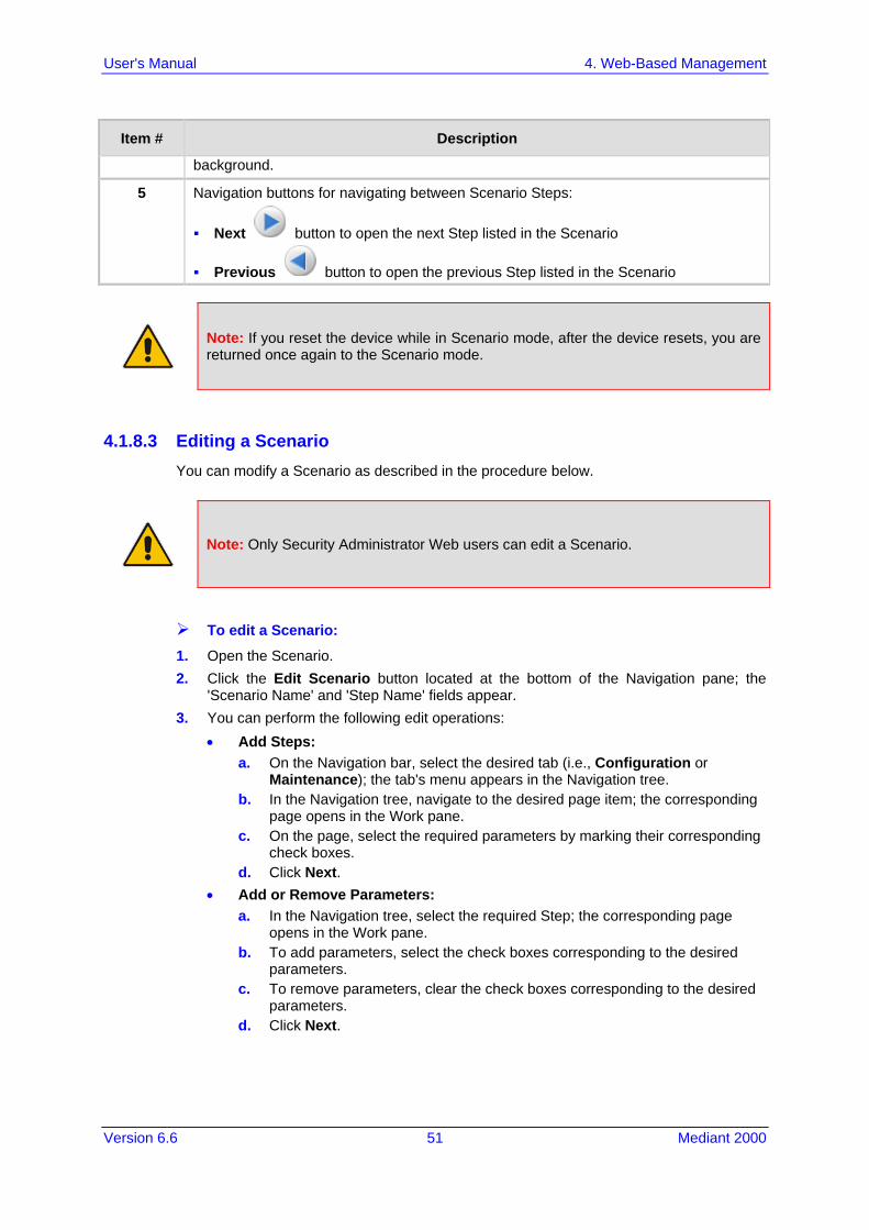
Version 6.6 51 Mediant 2000
User's Manual 4. Web-Based Management
Item # Description
background.
5 Navigation buttons for navigating between Scenario Steps:
Next button to open the next Step listed in the Scenario
Previous button to open the previous Step listed in the Scenario
Note: If you reset the device while in Scenario mode, after the device resets, you are returned once again to the Scenario mode.
4.1.8.3 Editing a Scenario You can modify a Scenario as described in the procedure below.
Note: Only Security Administrator Web users can edit a Scenario.
To edit a Scenario:
1. Open the Scenario. 2. Click the Edit Scenario button located at the bottom of the Navigation pane; the
'Scenario Name' and 'Step Name' fields appear. 3. You can perform the following edit operations:
• Add Steps: a. On the Navigation bar, select the desired tab (i.e., Configuration or
Maintenance); the tab's menu appears in the Navigation tree. b. In the Navigation tree, navigate to the desired page item; the corresponding
page opens in the Work pane. c. On the page, select the required parameters by marking their corresponding
check boxes. d. Click Next.
• Add or Remove Parameters: a. In the Navigation tree, select the required Step; the corresponding page
opens in the Work pane. b. To add parameters, select the check boxes corresponding to the desired
parameters. c. To remove parameters, clear the check boxes corresponding to the desired
parameters. d. Click Next.

User's Manual 52 Document #: LTRT-68822
Mediant 2000
• Edit Step Name: a. In the Navigation tree, select the required Step. b. In the 'Step Name' field, modify the Step name. c. On the page, click Next.
• Edit Scenario Name: a. In the 'Scenario Name' field, edit the Scenario name. b. On the displayed page, click Next.
• Remove a Step: a. In the Navigation tree, select the required Step; the corresponding page
opens in the Work pane. b. On the page, clear all the check boxes corresponding to the parameters. c. Click Next.
4. After clicking Next, a message box appears notifying you of the change. Click OK. 5. Click Save & Finish; a message box appears informing you that the Scenario has
been successfully modified. The Scenario mode is exited and the menus of the Configuration tab appear in the Navigation tree.
4.1.8.4 Saving a Scenario to a PC You can save a Scenario (as a dat file) to a folder on your computer. This is useful when you need multiple Scenarios to represent different deployments. Once you create a Scenario and save it to your computer, you can then keep on saving modifications to it under different Scenario file names. When you require a specific network environment setup, you can load the suitable Scenario file from your computer (see 'Loading a Scenario to the Device' on page 53).
To save a Scenario to a computer:
1. On the Navigation bar, click the Scenarios tab; the Scenario appears in the Navigation tree.
2. Click the Get/Send Scenario File button, located at the bottom of the Navigation tree; the Scenario File page appears, as shown below:
Figure 4-19: Scenario File Page
3. Click the Get Scenario File button; the File Download window appears. 4. Click Save, and then in the Save As window navigate to the folder to where you want
to save the Scenario file. When the file is successfully downloaded to your computer, the Download Complete window appears.
5. Click Close to close the window.

Version 6.6 53 Mediant 2000
User's Manual 4. Web-Based Management
4.1.8.5 Loading a Scenario to the Device The procedure below describes how to load a previously saved Scenario file (data file) from your computer to the device. For saving a Scenario, see 'Saving a Scenario to a PC' on page 52.
To load a Scenario to the device:
1. On the Navigation bar, click the Scenarios tab; the Scenario appears in the Navigation tree.
2. Click the Get/Send Scenario File button, located at the bottom of the Navigation tree; the Scenario File page appears.
3. Click the Browse button, and then navigate to the Scenario file saved on your computer.
4. Click the Send File button.
Notes:
• You can only load a Scenario file to a device that has the same hardware configuration as the device on which it was created.
• The loaded Scenario replaces any existing Scenario. • You can also load a Scenario file using BootP, by loading an ini file that contains
the ini file parameter ScenarioFileName (see Web and Telnet Parameters on page 513). The Scenario file must be located in the same folder as the ini file. For information on using AudioCodes AcBootP utility, refer to AcBootP Utility User's Guide.
4.1.8.6 Deleting a Scenario You can delete the Scenario, as described in the procedure below.
To delete the Scenario:
1. On the Navigation bar, click the Scenarios tab; a message box appears, requesting you to confirm:
2. Click OK; the Scenario mode appears in the Navigation tree. 3. Click the Delete Scenario File button; a message box appears requesting
confirmation for deletion.
Figure 4-20: Message Box for Confirming Scenario Deletion
4. Click OK; the Scenario is deleted and the Scenario mode closes.
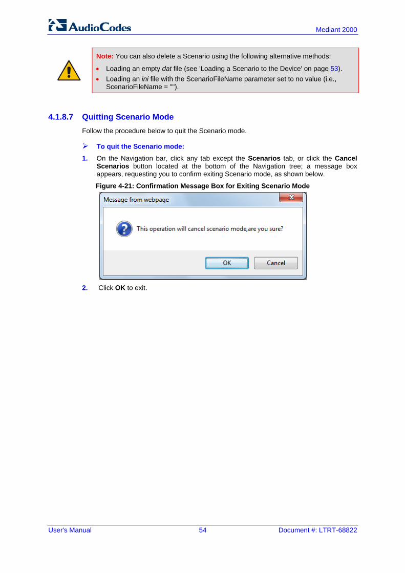
User's Manual 54 Document #: LTRT-68822
Mediant 2000
Note: You can also delete a Scenario using the following alternative methods:
• Loading an empty dat file (see 'Loading a Scenario to the Device' on page 53). • Loading an ini file with the ScenarioFileName parameter set to no value (i.e.,
ScenarioFileName = "").
4.1.8.7 Quitting Scenario Mode Follow the procedure below to quit the Scenario mode.
To quit the Scenario mode: 1. On the Navigation bar, click any tab except the Scenarios tab, or click the Cancel
Scenarios button located at the bottom of the Navigation tree; a message box appears, requesting you to confirm exiting Scenario mode, as shown below.
Figure 4-21: Confirmation Message Box for Exiting Scenario Mode
2. Click OK to exit.

Version 6.6 55 Mediant 2000
User's Manual 4. Web-Based Management
4.1.9 Creating a Login Welcome Message You can create a Welcome message box that is displayed on the Web Login page for logging in to the Web interface. The figure below displays an example of a Welcome message:
Figure 4-22: User-Defined Web Welcome Message after Login
To enable and create a Welcome message, use the WelcomeMessage table ini file parameter. If this parameter is not configured, no Welcome message is displayed.
ini File Parameter for Welcome Login Message
Parameter Description
[WelcomeMessage] Enables and defines a Welcome message that appears on the Web Login page for logging in to the Web interface. The format of this parameter is as follows: [WelcomeMessage] FORMAT WelcomeMessage_Index = WelcomeMessage_Text; [\WelcomeMessage] For Example: [WelcomeMessage ] FORMAT WelcomeMessage_Index = WelcomeMessage_Text; WelcomeMessage 1 = "*********************************"; WelcomeMessage 2 = "********* This is a Welcome message **"; WelcomeMessage 3 = "*********************************"; [\WelcomeMessage] Each index row represents a line of text in the Welcome message box. Up to 20 lines (or rows) of text can be defined.
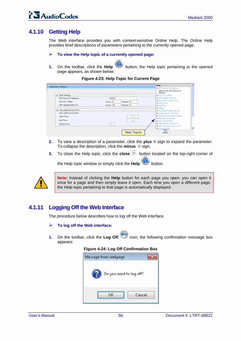
User's Manual 56 Document #: LTRT-68822
Mediant 2000
4.1.10 Getting Help The Web interface provides you with context-sensitive Online Help. The Online Help provides brief descriptions of parameters pertaining to the currently opened page.
To view the Help topic of a currently opened page:
1. On the toolbar, click the Help button; the Help topic pertaining to the opened page appears, as shown below:
Figure 4-23: Help Topic for Current Page
2. To view a description of a parameter, click the plus sign to expand the parameter.
To collapse the description, click the minus sign.
3. To close the Help topic, click the close button located on the top-right corner of
the Help topic window or simply click the Help button.
Note: Instead of clicking the Help button for each page you open, you can open it once for a page and then simply leave it open. Each time you open a different page, the Help topic pertaining to that page is automatically displayed.
4.1.11 Logging Off the Web Interface The procedure below describes how to log off the Web interface.
To log off the Web interface:
1. On the toolbar, click the Log Off icon; the following confirmation message box appears:
Figure 4-24: Log Off Confirmation Box

Version 6.6 57 Mediant 2000
User's Manual 4. Web-Based Management
2. Click OK; you are logged off the Web session and the Web Login dialog box appears enabling you to re-login, if required.
4.2 Viewing the Home Page The Home page is displayed when you access the device's Web interface. The Home page provides you with a graphical display of the device's front panel, showing color-coded status icons for various operations device.
To access the Home page:
On the toolbar, click the Home icon.
Note: The displayed number of modules (trunks) depends on the ordered hardware configuration.
In addition to the color-coded status information depicted on the graphical display of the device, the Home page displays various read-only information in the General Information pane: IP Address: IP address of the device Subnet Mask: Subnet mask address of the device Default Gateway Address: Default gateway used by the device Firmware Version: Software version running on the device Protocol Type: Signaling protocol currently used by the device (i.e. SIP) Gateway Operational State:
• "LOCKED": device is locked (i.e. no new calls are accepted) • "UNLOCKED": device is not locked • "SHUTTING DOWN": device is currently shutting down To perform these operations, see 'Basic Maintenance' on page 393.
The table below describes the areas of the Home page.
Home Page Description
Item # Description
1 Displays the highest severity of an active alarm raised (if any) by the device: Green = No alarms Red = Critical alarm Orange = Major alarm Yellow = Minor alarm To view the active alarms, click this Alarms area to open the Active Alarms page
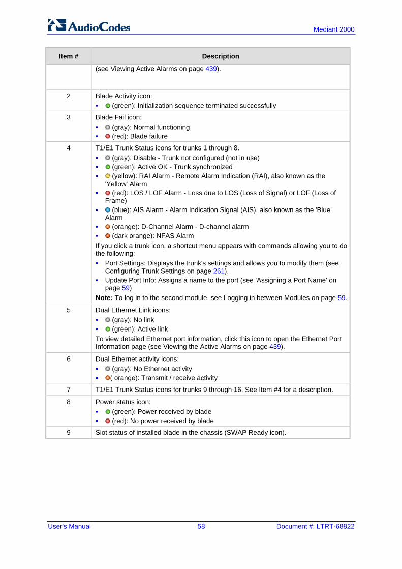
User's Manual 58 Document #: LTRT-68822
Mediant 2000
Item # Description
(see Viewing Active Alarms on page 439).
2 Blade Activity icon: (green): Initialization sequence terminated successfully
3 Blade Fail icon: (gray): Normal functioning (red): Blade failure
4 T1/E1 Trunk Status icons for trunks 1 through 8. (gray): Disable - Trunk not configured (not in use) (green): Active OK - Trunk synchronized (yellow): RAI Alarm - Remote Alarm Indication (RAI), also known as the
'Yellow' Alarm (red): LOS / LOF Alarm - Loss due to LOS (Loss of Signal) or LOF (Loss of
Frame) (blue): AIS Alarm - Alarm Indication Signal (AIS), also known as the 'Blue'
Alarm (orange): D-Channel Alarm - D-channel alarm (dark orange): NFAS Alarm If you click a trunk icon, a shortcut menu appears with commands allowing you to do the following: Port Settings: Displays the trunk's settings and allows you to modify them (see
Configuring Trunk Settings on page 261). Update Port Info: Assigns a name to the port (see 'Assigning a Port Name' on
page 59) Note: To log in to the second module, see Logging in between Modules on page 59.
5 Dual Ethernet Link icons: (gray): No link (green): Active link To view detailed Ethernet port information, click this icon to open the Ethernet Port Information page (see Viewing the Active Alarms on page 439).
6 Dual Ethernet activity icons: (gray): No Ethernet activity ( orange): Transmit / receive activity
7 T1/E1 Trunk Status icons for trunks 9 through 16. See Item #4 for a description.
8 Power status icon: (green): Power received by blade (red): No power received by blade
9 Slot status of installed blade in the chassis (SWAP Ready icon).

Version 6.6 59 Mediant 2000
User's Manual 4. Web-Based Management
4.2.1 Assigning a Port Name The Home page allows you to assign an arbitrary name or a brief description to each port. This description appears as a tooltip when you move your mouse over the port.
Note: Only alphanumerical characters can be used in the port description.
To add a port description:
1. Click the required port icon; a shortcut menu appears, as shown below:
2. From the shortcut menu, choose Update Port Info; a text box appears.
3. Type a brief description for the port, and then click Apply Port Info.
4.2.2 Switching Between Modules The device can house up to two modules. Since each module is a standalone gateway, the Home page displays only one of the modules to which you are connected. However, you can easily switch to the second module, by having the Web browser connect to the IP address of the second module.
To switch modules: 1. In the Home page, click anywhere on the module to which you want to switch, as
shown below:
Figure 4-25: Click Module to which you want to Switch

User's Manual 60 Document #: LTRT-68822
Mediant 2000
A confirmation message box appears requesting you to confirm switching of modules.
Figure 4-26: Confirmation Message Box for Switching Modules
2. Click OK; the Web Login screen of the switched module's Web interface appears. 3. Enter the login username and password, and then click Login.
4.3 Configuring Web User Accounts You can create up to 10 Web user accounts for the device. Up to five Web users can simultaneously be logged in to the device's Web interface. Web user accounts prevent unauthorized access to the Web interface, enabling login access only to users with correct credentials (i.e., username and password). Each Web user account is composed of the following attributes: Username and password: Credentials that enable authorized login access to the
Web interface. Access level (user type): Access privileges specifying what the user can view in the
Web interface and its read/write privileges. The table below describes the different types of Web user account access levels:
Access Levels of Web User Accounts
User Access Level
Numeric Representation* Privileges
Master 220
Read / write privileges for all pages. Can create all user types, including additional Master users and Security Administrators. It can delete all users except the last Security Administrator.
Security Administrator
200
Read / write privileges for all pages. It can create all user types and is the only one that can create the first Master user. Note: There must be at least one Security Administrator.
Administrator 100 Read / write privileges for all pages except security-related pages, which are read-only.
Monitor 50 No access to security-related and file-loading pages; read-only access to other pages.
No Access
0
No access to any page. Note: This access level is not applicable when using advanced Web user account configuration in the Web Users table.
* The numeric representation of the access level is used only to define accounts in a RADIUS server (the access level ranges from 1 to 255).

Version 6.6 61 Mediant 2000
User's Manual 4. Web-Based Management
By default, the device is pre-configured with the following two Web user accounts:
Pre-configured Web User Accounts
User Access Level Username (Case-Sensitive)
Password (Case-Sensitive)
Security Administrator Admin Admin
Monitor User User
After you log in to the Web interface, the username is displayed on the toolbar. If the Web session is idle (i.e., no actions are performed) for more than five minutes, the Web session expires and you are once again requested to login with your username and password. Users can be banned for a period of time upon a user-defined number of unsuccessful login attempts. Login information (such as how many login attempts were made and the last successful login time) can be presented to the user.
To prevent user access after a specific number of failed logins:
1. From the 'Deny Access On Fail Count' drop-down list, select the number of failed logins after which the user is prevented access to the device for a user-defined time (see next step).
2. In the 'Deny Authentication Timer' field, enter the interval (in seconds) that the user needs to wait before a new login attempt from the same IP address can be done after reaching the number of failed login attempts (defined in the previous step).
Notes:
• For security, it's recommended that you change the default username and password.
• The Security Administrator user can change all attributes of all Web user accounts. Web users with access levels other than Security Administrator can change only their password and username.
• To restore the two Web user accounts to default settings (usernames and passwords), set the ini file parameter ResetWebPassword to 1.
• To log in to the Web interface with a different Web user, click the Log off button and then login with with a different username and password.
• You can set the entire Web interface to read-only (regardless of Web user access levels), by using the ini file parameter DisableWebConfig (see 'Web and Telnet Parameters' on page 513).
• You can define additional Web user accounts using a RADIUS server (see 'Configuring RADIUS Settings' on page 70).
4.3.1 Basic User Accounts Configuration This section describes basic Web user account configuration. This is relevant only if the two default, pre-configured Web user accounts - Security Administrator ("Admin") and Monitor ("User") - are sufficient for your management scheme. For the Security Administrator, you can change only the username and password; not its access level. For the Monitor user, you can change username and password as well as access level (Administrator, Monitor, or No Access).

User's Manual 62 Document #: LTRT-68822
Mediant 2000
Notes:
• The access level of the Security Administrator cannot be modified. • The access level of the second user account can be modified only by the Security
Administrator. • The username and password can be a string of up to 19 characters. When you log
in to the Web interface, the username and password string values are case-sensitive, according to your configuration.
• Up to two users can be logged in to the Web interface at the same time, and they can be of the same user.
To configure the two pre-configured Web user accounts:
1. Open the Web User Accounts page (Configuration tab > System menu > Web User Accounts). If you are logged in as Security Administrator, both Web user accounts are displayed (as shown below). If you are logged in with the second user account, only the details of this user account are displayed.
Figure 4-27: WEB User Accounts Page (for Users with 'Security Administrator' Privileges)
2. To change the username of an account:
a. In the 'User Name' field, enter the new user name. b. Click Change User Name; if you are currently logged in to the Web interface with
this account, the 'Web Login' dialog box appears. c. Log in with your new user name.
3. To change the password of an account: a. In the 'Current Password' field, enter the current password. b. In the 'New Password' and 'Confirm New Password' fields, enter the new
password.
Version 6.6 63 Mediant 2000
User's Manual 4. Web-Based Management
c. Click Change Password; if you are currently logged in to the Web interface with this account, the 'Web Login' dialog box appears.
d. Log in with your new password. 4. To change the access level of the optional, second account:
a. Under the Account Data for User: User group, from the 'Access Level' drop-down list, select a new access level user.
b. Click Change Access Level; the new access level is applied immediately.
4.3.2 Advanced User Accounts Configuration This section describes advanced Web user account configuration. This is relevant if you need the following management scheme: Enhanced security settings per Web user (e.g., limit session duration) More than two Web user accounts (up to 10 Web user accounts) Master users This advanced Web user configuration is done in the Web Users table, which is initially accessed from the Web User Accounts page (see procedure below). Once this table is accessed, subsequent access immediately opens the Web Users table instead of the Web User Accounts page.
Notes:
• Only the Security Administrator user can initially access the Web Users table. • Only Security Administrator and Master users can add, edit, or delete users. • Admin users have read-only privileges in the Web Users table. Monitor users have
no access to this page. • If you delete a user who is currently in an active Web session, the user is
immediately logged off by the device. • All users can change their own passwords. This is done in the WEB Security
Settings page (see 'Configuring Web Security Settings' on page 67). • To remove the Web Users table and revert to the Web User Accounts page with
the pre-configured, default Web user accounts, set the ResetWebPassword ini file parameter to 1. This also deletes all other Web users.
• Once the Web Users table is accessed, Monitor users and Admin users can only change their passwords in the Web Security Settings page (see 'Configuring Web Security Settings' on page 67). The new password must have at least four different characters than the previous password. (The Security Administrator users and Master users can change their passwords in the Web Users table and in the Web Security Settings page.)
• This table can only be configured using the Web interface.

User's Manual 64 Document #: LTRT-68822
Mediant 2000
To add Web user accounts with advanced settings:
1. Open the Web Users Table page: • Upon initial access:
a. Open the Web User Accounts page (Configuration tab > System menu > Web User Accounts).
b. Under the Web Users Table group, click the Create Table button. • Subsequent access: Configuration tab > System menu > Web User Accounts. The Web Users table appears, listing the two default, pre-configured Web use accounts - Security Administrator ("Admin") and Monitor ("User"):
Figure 4-28: Web Users Table Page
2. Click the Add button; the following dialog box is displayed:
Figure 4-29: Web Users Table - Add Record Dialog Box
3. Add a user as required. For a description of the parameters, see the table below. 4. Click Submit.
Web User Parameters Description
Parameter Description
Web: Username
Defines the Web user's username. The valid value is a string of up to 40 alphanumeric characters, including the period ".", underscore "_", and hyphen "-" signs.
Web: Password
Defines the Web user's password. The valid value is a string of 8 to 40 ASCII characters, which must include the following: At least eight characters At least two letters that are upper case (e.g., "AA") At least two letters that are lower case (e.g., "aa")

Version 6.6 65 Mediant 2000
User's Manual 4. Web-Based Management
Parameter Description
At least two numbers At least two signs (e.g., the dollar "$" sign) No spaces in the string At least four characters different to the previous password
Web: Status
Defines the status of the Web user. New = (Default) User is required to change its password on the
next login. When the user logs in to the Web interface, the user is immediately prompted to change the current password.
Valid = User can log in to the Web interface as normal. Failed Access = This state is automatically set for users that
exceed a user-defined number of failed login attempts, set by the 'Deny Access on Fail Count' parameter (see 'Configuring Web Security Settings' on page 67). These users can log in only after a user-defined timeout configured by the 'Block Duration' parameter (see below) or if their status is changed (to New or Valid) by a System Administrator or Master.
Old Account = This state is automatically set for users that have not accessed the Web interface for a user-defined number of days, set by the 'User Inactivity Timer' (see 'Configuring Web Security Settings' on page 67). These users can only log in to the Web interface if their status is changed (to New or Valid) by a System Administrator or Master.
Notes: The Old Account status is applicable only to Admin and Monitor
users; System Administrator and Master users can be inactive indefinitely.
For security, it is recommended to set the status of a newly added user to New in order to enforce password change.
Web: Password Age
Defines the duration (in days) of the validity of the password. When this duration elapses, the user is prompted to change the password; otherwise, access to the Web interface is blocked. The valid value is 0 to 10000, where 0 means that the password is always valid. The default is 90.
Web: Session Limit
Defines the maximum number of Web interface sessions allowed for the user. In other words, this allows the same user account to log in to the device from different sources (i.e., IP addresses). The valid value is 0 to 5. The default is 2. Note: Up to 5 users can be logged in to the Web interface at any given.
Web: Session Timeout
Defines the duration (in minutes) of Web inactivity of a logged-in user, after which the user is automatically logged off the Web interface. The valid value is 0 to 100000. The default is according to the settings of the 'Session Timeout' global parameter (see 'Configuring Web Security Settings' on page 67).

User's Manual 66 Document #: LTRT-68822
Mediant 2000
Parameter Description
Web: Block Duration
Defines the duration (in seconds) for which the user is blocked when the user exceeds a user-defined number of failed login attempts. This is configured by the 'Deny Access On Fail Count' parameter (see 'Configuring Web Security Settings' on page 67). The valid value is 0 to 100000, where 0 means that the user can do as many login failures without getting blocked. The default is according to the settings of the 'Deny Authentication Timer' parameter (see 'Configuring Web Security Settings' on page 67). Note: The 'Deny Authentication Timer' parameter relates to failed Web logins from specific IP addresses.
Web: User Level
Defines the user's access level. Monitor = (Default) Read-only user. This user can only view Web
pages and access to security-related pages is denied. Admin = Read/write privileges for all pages, except security-related
pages including the Web Users table where this user has only read-only privileges.
SecAdmin = Read/write privileges for all pages. This user is the Security Administrator.
Master-User = Read/write privileges for all pages. This user also functions as a security administrator.
Notes: At least one Security Administrator must exist. The last remaining
Security Administrator cannot be deleted. The first Master user can be added only by a Security
Administrator user. Additional Master users can be added, edited and deleted only by
Master users. If only one Master user exists, it can be deleted only by itself. Master users can add, edit, and delete Security Administrators (but
cannot delete the last Security Administrator). Only Security Administrator and Master users can add, edit, and
delete Admin and Monitor users.
4.4 Displaying Login Information upon Login The device can display login information immediately upon Web login.
To enable display of user login information upon a successful login:
1. Open the WEB Security Settings page (Configuration tab > System menu > Management submenu > WEB Security Settings).
2. From the 'Display Login Information' drop-down list, select Yes. 3. Click Submit to apply your changes.

Version 6.6 67 Mediant 2000
User's Manual 4. Web-Based Management
Once enabled, the Login Information window is displayed upon a successful login, as shown in the example below:
Figure 4-30: Login Information Window
4.5 Configuring Web Security Settings The WEB Security Settings page is used to define a secure Web access communication method. For a description of these parameters, see 'Web and Telnet Parameters' on page 513.
To define Web access security:
1. Open the WEB Security Settings page (Configuration tab > System menu > Management submenu > WEB Security Settings).
2. Configure the parameters as required. 3. Click Submit to apply your changes. 4. To save the changes to flash memory, see 'Saving Configuration' on page 396.

User's Manual 68 Document #: LTRT-68822
Mediant 2000
4.6 Web Login Authentication using Smart Cards You can enable Web login authentication using certificates from a third-party, common access card (CAC) with user identification. When a user attempts to access the device through the Web browser (HTTPS), the device retrieves the Web user’s login username (and other information, if required) from the CAC. The user attempting to access the device is only required to provide the login password. Typically, a TLS connection is established between the CAC and the device’s Web interface, and a RADIUS server is implemented to authenticate the password with the username. Therefore, this feature implements a two-factor authentication - what the user has (i.e., the physical card) and what the user knows (i.e., the login password). This feature is enabled using the EnableMgmtTwoFactorAuthentication parameter.
Note: For specific integration requirements for implementing a third-party smart card for Web login authentication, contact your AudioCodes representative.
To log in to the Web interface using CAC:
1. Insert the Common Access Card into the card reader. 2. Access the device using the following URL: https://<host name or IP address>; the
device prompts for a username and password. 3. Enter the password only. As some browsers require that the username be provided,
it’s recommended to enter the username with an arbitrary value.
4.7 Configuring Web and Telnet Access List The Web & Telnet Access List page is used to define IP addresses (up to ten) that are permitted to access the device's Web, Telnet, and SSH interfaces. Access from an undefined IP address is denied. If no IP addresses are defined, this security feature is inactive and the device can be accessed from any IP address. The Web and Telnet Access List can also be defined using the ini file parameter WebAccessList_x (see 'Web and Telnet Parameters' on page 513).
To add authorized IP addresses for Web, Telnet, and SSH interfaces access: 1. Open the Web & Telnet Access List page (Configuration tab > System menu >
Management submenu > Web & Telnet Access List).
Figure 4-31: Web & Telnet Access List Page - Add New Entry

Version 6.6 69 Mediant 2000
User's Manual 4. Web-Based Management
2. To add an authorized IP address, in the 'Add an authorized IP address' field, enter the required IP address, and then click Add New Entry; the IP address you entered is added as a new entry to the Web & Telnet Access List table.
Figure 4-32: Web & Telnet Access List Table
3. To delete authorized IP addresses, select the Delete Row check boxes corresponding
to the IP addresses that you want to delete, and then click Delete Selected Addresses; the IP addresses are removed from the table and these IP addresses can no longer access the Web and Telnet interfaces.
4. To save the changes to flash memory, see 'Saving Configuration' on page 396.
Notes:
• The first authorized IP address in the list must be your PC's (terminal) IP address; otherwise, access from your PC is denied.
• Delete your PC's IP address last from the 'Web & Telnet Access List page. If it is deleted before the last, subsequent access to the device from your PC is denied.

User's Manual 70 Document #: LTRT-68822
Mediant 2000
4.8 Configuring RADIUS Settings The RADIUS Settings page is used for configuring the Remote Authentication Dial In User Service (RADIUS) accounting parameters. For a description of these parameters, see 'Configuration Parameters Reference' on page 503.
To configure RADIUS: 1. Open the RADIUS Settings page (Configuration tab > System menu > Management
submenu > RADIUS Settings).
Figure 4-33: RADIUS Parameters Page
2. Configure the parameters as required. 3. Click Submit to apply your changes. 4. To save the changes to flash memory, see 'Saving Configuration' on page 396.

Version 6.6 71 Mediant 2000
User's Manual 5. CLI-Based Management
5 CLI-Based Management This section provides an overview of the CLI-based management and configuration relating to CLI management. The device's CLI-based management interface can be accessed using Secure SHell (SSH) or Telnet through the Ethernet interface.
Notes:
• For security, CLI is disabled by default. • For information on accessing the CLI interface, see 'CLI' on page 30. • CLI is used only for debugging and mainly allows you to view various information
regarding device configuration and performance.
5.1 Enabling CLI using Telnet The device's CLI can be accessed using Telnet. Secure Telnet using Secure Socket Layer (SSL) can be configured whereby information is not transmitted in the clear. If SSL is used, a special Telnet client is required on your PC to connect to the Telnet interface over a secured connection; examples include C-Kermit for UNIX and Kermit-95 for Windows. For security, some organizations require the display of a proprietary notice upon starting a Telnet session. You can use the configuration ini file parameter, WelcomeMessage to configure such a message (see Creating a Login Welcome Message on page 55).
To enable Telnet: 1. Open the Telnet/SSH Settings page (Configuration tab > System menu >
Management > Telnet/SSH Settings).
Figure 5-1: Telnet Settings on Telnet/SSH Settings Page
2. Set the ‘Embedded Telnet Server’ parameter to Enable Unsecured or Enable
Secured (i.e, SSL). 3. Configure the other Tenet parameters as required. For a description of these
parameters, see Telnet Parameters on page 517. 4. Click Submit. 5. Save the changes to flash memory with a device reset.
5.2 Enabling CLI using SSH and RSA Public Key The device's CLI can be accessed using Telnet. However, unless configured for TLS, Telnet is not secure as it requires passwords to be transmitted in clear text. To overcome this, Secure SHell (SSH) is used, which is the de-facto standard for secure CLI. SSH 2.0 is a protocol built above TCP, providing methods for key exchange, authentication, encryption, and authorization. SSH requires appropriate client software for the management PC. Most Linux distributions have OpenSSH pre-installed; Windows-based PCs require an SSH client software such as PuTTY, which can be downloaded from http://www.chiark.greenend.org.uk/~sgtatham/putty/.

User's Manual 72 Document #: LTRT-68822
Mediant 2000
By default, SSH uses the same username and password as the Telnet and Web server. SSH supports 1024/2048-bit RSA public keys, providing carrier-grade security. Follow the instructions below to configure the device with an administrator RSA key as a means of strong authentication.
To enable SSH and configure RSA public keys for Windows (using PuTTY SSH):
1. Start the PuTTY Key Generator program, and then do the following: a. Under the 'Parameters' group, do the following:
♦ Select the SSH-2 RSA option. ♦ In the 'Number of bits in a generated key' field, enter "1024" bits.
b. Under the 'Actions' group, click Generate and then follow the on-screen instructions.
c. Under the 'Actions' group, click Save private key to save the new private key to a file (*.ppk) on your PC.
d. Under the 'Key' group, select the displayed encoded text between "ssh-rsa" and "rsa-key-….", as shown in the example below:
Figure 5-2: Selecting Public RSA Key in PuTTY
2. Open the Telnet/SSH Settings page (Configuration tab > System menu >
Management > Telnet/SSH Settings), and then do the following: a. Set the 'Enable SSH Server' parameter to Enable. b. Paste the public key that you copied in Step 1.d into the 'Admin Key' field, as
shown below:
Figure 5-3: SSH Settings - Pasting Public RSA Key in 'Admin Key' Field
Version 6.6 73 Mediant 2000
User's Manual 5. CLI-Based Management
c. For additional security, you can set the 'Require Public Key' to Enable. This ensures that SSH access is only possible by using the RSA key and not by using user name and password.
d. Configure the other SSH parameters as required. For a description of these parameters, see SSH Parameters on page 535.
e. Click Submit. 3. Start the PuTTY Configuration program, and then do the following:
a. In the 'Category' tree, drill down to Connection, then SSH, and then Auth; the 'Options controlling SSH authentication' pane appears.
b. Under the 'Authentication parameters' group, click Browse and then locate the private key file that you created and saved in Step 4.
4. Connect to the device with SSH using the username "Admin"; RSA key negotiation occurs automatically and no password is required.
To configure RSA public keys for Linux (using OpenSSH 4.3): 1. Run the following command to create a new key in the admin.key file and to save the
public portion to the admin.key.pub file: ssh-keygen -f admin.key -N "" -b 1024
2. Open the admin.key.pub file, and then copy the encoded string from "ssh-rsa" to the white space.
3. Open the Telnet/SSH Settings page (Configuration tab > System menu > Management > Telnet/SSH Settings), and then paste the value copied in Step 2 into the 'Admin Key' field.
4. Click Submit. 5. Connect to the device with SSH, using the following command:
ssh -i admin.key xx.xx.xx.xx
where xx.xx.xx.xx is the device's IP address. RSA-key negotiation occurs automatically and no password is required.
5.3 Establishing a CLI Session The procedure below describes how to establish a CLI session with the device.
Notes:
• The default login username and password are both "Admin" (case-sensitive). • Only the primary User Account, which has Security Administration access level
(200) can access the device using Telnet. For configuring the username and password, see Configuring Web User Accounts on page 60.
To establish a CLI session with the device:
1. Establish a Telnet or SSH session with the device using its OAMP IP address. 2. Log in to the session using the username and password assigned to the Admin user of
the Web interface. 3. At the login prompt, type the username, and then press Enter:
login: Admin

User's Manual 74 Document #: LTRT-68822
Mediant 2000
4. At the password prompt, type the password, and then press Enter: password: Admin
After logging in, the current directory (root), available commands, available subdirectories, and a welcome message are displayed at the CLI prompt: login: Admin password: ready. Type "exit" to close the connection. SIP/ SECurity/ PStn/ DebugRecording/ MGmt/ ControlProtocol/ CONFiguration/ IPNetworking/ TPApp/ BSP/ PING SHow />
5.4 CLI Commands The CLI commands are used mainly to display current configuration and performance. These commands are organized in subdirectories. When the CLI session starts, you are located in the 'root' directory. To access a subdirectory, type its name, and then press Enter. The CLI commands can be entered in an abbreviated format by typing only the letters shown in upper case (i.e., capital letters). For example, the CHangePassWord command can be entered by typing chpw. If you know the full path to a command inside one of the subdirectories, the short format can be used to run it directly. For example, the PERFormance command in the MGmt subdirectory may be run directly by typing /mg/perf. The following table summarizes the basic CLI commands:
Table 1: Basic CLI Commands
Purpose Commands Description
Help h Displays the help for a specific command, action, or parameter.
Navigation cd Enters another directory.
cd root Navigates to the root directory (/).
.. Goes up one level.
exit Terminates the CLI session.
5.4.1 Status Commands The following table summarizes the Show commands and their corresponding options.
Table 2: Show CLI Commands
Command Short Format Arguments Description
SHow sh info | tdm | dsp | ip | log
Displays operational data. info: Displays general device information tdm: Displays PSTN-related information dsp: Displays DSP resource information ip: Displays information about IP interfaces
SHow INFO sh info - Displays device hardware information, versions, uptime, temperature reading, and the last reset reason.
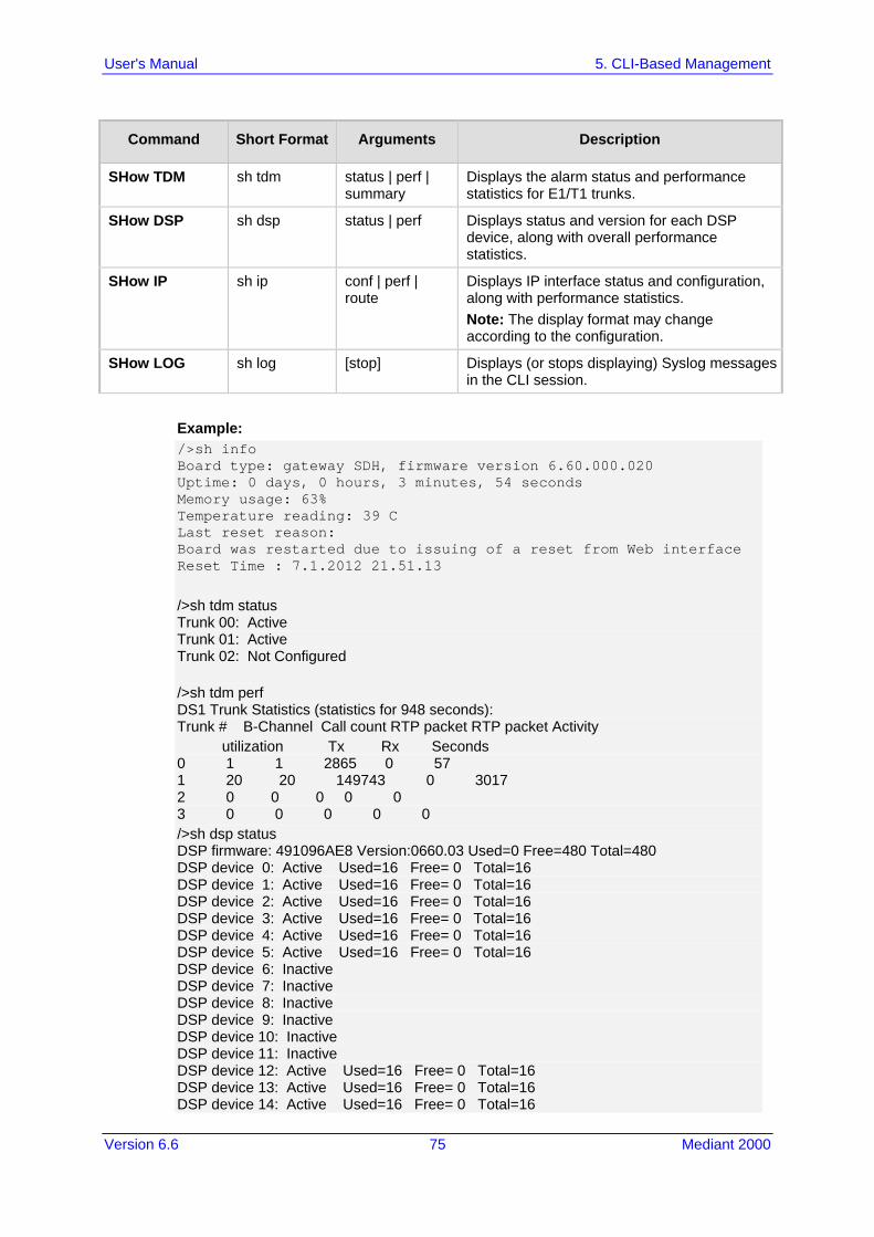
Version 6.6 75 Mediant 2000
User's Manual 5. CLI-Based Management
Command Short Format Arguments Description
SHow TDM sh tdm status | perf | summary
Displays the alarm status and performance statistics for E1/T1 trunks.
SHow DSP sh dsp status | perf Displays status and version for each DSP device, along with overall performance statistics.
SHow IP sh ip conf | perf | route
Displays IP interface status and configuration, along with performance statistics. Note: The display format may change according to the configuration.
SHow LOG sh log [stop] Displays (or stops displaying) Syslog messages in the CLI session.
Example: />sh info Board type: gateway SDH, firmware version 6.60.000.020 Uptime: 0 days, 0 hours, 3 minutes, 54 seconds Memory usage: 63% Temperature reading: 39 C Last reset reason: Board was restarted due to issuing of a reset from Web interface Reset Time : 7.1.2012 21.51.13 />sh tdm status Trunk 00: Active Trunk 01: Active Trunk 02: Not Configured />sh tdm perf DS1 Trunk Statistics (statistics for 948 seconds): Trunk # B-Channel Call count RTP packet RTP packet Activity utilization Tx Rx Seconds 0 1 1 2865 0 57 1 20 20 149743 0 3017 2 0 0 0 0 0 3 0 0 0 0 0 />sh dsp status DSP firmware: 491096AE8 Version:0660.03 Used=0 Free=480 Total=480 DSP device 0: Active Used=16 Free= 0 Total=16 DSP device 1: Active Used=16 Free= 0 Total=16 DSP device 2: Active Used=16 Free= 0 Total=16 DSP device 3: Active Used=16 Free= 0 Total=16 DSP device 4: Active Used=16 Free= 0 Total=16 DSP device 5: Active Used=16 Free= 0 Total=16 DSP device 6: Inactive DSP device 7: Inactive DSP device 8: Inactive DSP device 9: Inactive DSP device 10: Inactive DSP device 11: Inactive DSP device 12: Active Used=16 Free= 0 Total=16 DSP device 13: Active Used=16 Free= 0 Total=16 DSP device 14: Active Used=16 Free= 0 Total=16

User's Manual 76 Document #: LTRT-68822
Mediant 2000
DSP device 15: Active Used=16 Free= 0 Total=16 DSP device 16: Active Used=16 Free= 0 Total=16 DSP device 17: Active Used=16 Free= 0 Total=16 DSP device 18: Inactive PSEC - DSP firmware: AC491IPSEC Version: 0660.03 CONFERENCE - DSP firmware: AC491256C Version: 0660.03 />sh dsp perf DSP Statistics (statistics for 968 seconds): Active DSP resources: 480 Total DSP resources: 480 DSP usage %: 100 />sh ip perf Networking Statistics (statistics for 979 seconds): IP KBytes TX: 25 IP KBytes RX: 330 IP KBytes TX per second: 0 IP KBytes RX per second: 1 IP Packets TX: 1171 IP Packets RX: 5273 IP Packets TX per second: 3 IP Packets RX per second: 12 Peak KByte/s TX in this interval: 18 Peak KByte/s RX in this interval: 4 Discarded packets: 186 DHCP requests sent: 0 IPSec Security Associations: 0 />/mg/perf reset Done. />sh ip perf Networking Statistics (statistics for 2 seconds): IP KBytes TX: 2 IP KBytes RX: 4 IP KBytes TX per second: 0 IP KBytes RX per second: 1 IP Packets TX: 24 IP Packets RX: 71 IP Packets TX per second: 3 IP Packets RX per second: 12 Peak KByte/s TX in this interval: 18 Peak KByte/s RX in this interval: 4 Discarded packets: 0 DHCP requests sent: 0 IPSec Security Associations: 0 />sh ip conf Interface IP Address Subnet Mask Default Gateway --------- ------------------ -------------- ---------- OAM 10.4.64.13 55.255.0.0 10.4.0.1 Media 10.4.64.13 255.255.0.0 10.4.0.1 Control 10.4.64.13 255.255.0.0 10.4.0.1 MAC address: 00-90-8f-04-5c-e9 />sh ip route Destination Mask Gateway Intf Flags ------------- ---------------- ------------------------ 0.0.0.0 0.0.0.0 10.4.0.1 OAM A S 10.4.0.0 255.255.0.0 10.4.64.13 OAM A L 127.0.0.0 255.0.0.0 127.0.0.1 AR S 127.0.0.1 255.255.255.255 127.0.0.1 A L H Flag legend: A=Active R=Reject L=Local S=Static E=rEdirect M=Multicast

Version 6.6 77 Mediant 2000
User's Manual 5. CLI-Based Management
B=Broadcast H=Host I=Invalid End of routing table, 4 entries displayed.
5.4.2 Ping Command The Ping command is described in the following table:
Table 3: Ping Command
Command Short Format Arguments Description
PING ping [-n count] [-l size] [-w timeout] [-p cos] ip-address
Sends ICMP echo request packets to a specified IP address. count: number of packets to send. size: payload size in each packet. timeout: time (in seconds) to wait for a reply
to each packet. cos: Class-of-Service (as per 802.1p) to
use.
Example: />ping 10.31.2.10 Ping process started for address 10.31.2.10. Process ID - 27. Reply from 10.31.2.10: bytes=0 time<0ms Reply from 10.31.2.10: bytes=0 time<0ms Reply from 10.31.2.10: bytes=0 time<0ms Reply from 10.31.2.10: bytes=0 time<0ms Ping statistics for 10.31.2.10: Packets:Sent = 4, Received = 4, Lost 0 (0% loss), Approximate round trip times in milli-seconds: Minimum = 0ms, Maximum = 0ms, Average = 0ms
5.4.3 Test Call (TC) Commands The Test Call commands can be used to simulate an IP-to-PSTN call.
Note: Only one test call can be activated at a given time.
Table 4: Test Call Command
Command Short Format Sub-Commands
/SIP/TestCall /sip/tc set dest | set src | set cid | set DTMFs | display | connect
Table 5: Sub-Commands of Test (TC) Command
Sub-Command Arguments Description
set dest <number> Sets the Destination Number for the test call.

User's Manual 78 Document #: LTRT-68822
Mediant 2000
Sub-Command Arguments Description
set src <number> Sets the Source Number for the test call.
set cid <display string> Sets the Display Name for the test call.
set DTMFs <DTMF pattern> Sets the pattern of DTMFs that is played to the PSTN side after the test call is connected.
display - Displays all the set parameters for the test call. These values can be manually set using the set commands or defaults.
connect <destination number> <source number> <caller ID> <time>
Generates the test call toward the PSTN side using the set parameters. If no arguments are defined in the connect command line, the test call uses the values defined using the set commands (or defaults). Note: There is no option for defining only the <time> value without specifying all the other arguments that appear before it.
Example: /SIP>tc TestCall - TC Manage Test Tel-Link Call. Usage: TC set dest <number> TC set src <number> TC set cid <display string> TC set DTMFs <dtmf string> TC display TC connect [dest-number] [src number] [CID] [time] /SIP>tc display Test Call configuration Dest number: 402 Src number: 700 Cid display: TESTING DTMFs String 112233 Time After DTMF are sent: 20 sec /SIP>tc connect Start Test call. Receive ALERT Event Receive Connect Wait more 20 seconds before disconnecting Receive SS_TIMER_EV Event Send Release To Call Receive RELEASE_ACK Event Receive SS_TIMER_EV Event
5.4.4 Management Commands The commands under the MGmt directory, described in the table below, display current performance values.
Table 6: CLI Management Command
Command Short Format Arguments Description
/MGmt/PERFormance /mg/perf basic | control | dsp | net | ds1 | reset
Displays performance statistics. The reset argument clears all statistics to zero.

Version 6.6 79 Mediant 2000
User's Manual 5. CLI-Based Management
5.4.5 Configuration Commands The commands under the CONFiguration directory query and modify the current device configuration. The following commands are available:
Table 7: Configuration CLI Commands
Command Short Format
Arguments Description
SetConfigParam IP /conf/scp ip ip-addr subnet def-gw
Sets the IP address, subnet mask, and default gateway address of the device (on-the-fly). Note: This command may cause disruption of service. The CLI session may disconnect since the device changes its IP address.
RestoreFactorySettings /conf/rfs Restores all parameters to factory settings.
SaveAndRestart /conf/sar Saves all current configurations to the non-volatile memory and resets the device.
ConfigFile /conf/cf view | get | set Retrieves the full ini file from the device and allows loading a new ini file directly in the CLI session. Note: The argument view displays the file, page by page. The argument get displays the file without breaks.
5.4.6 PSTN Commands The commands under the PSTN directory allow you to perform various PSTN actions.
Table 8: PSTN CLI Command
Command Short Format
Arguments Description
PstnLoopCommands PS/PH/PLC <TrunkId> <LoopCode> <BChannel>
Activates a loopback on a specific trunk and B-channel. For loopback on the entire trunk, set BChannel=(-1). The valid value options for LoopCode include the following: 0 = NO_LOOPS 1 = REMOTE_LOOP (whole trunk
only) 2 = LINE_PAYLOAD_LOOP (whole
trunk only) 3 = LOCAL_ALL_CHANNELS_LOOP
(whole trunk only)
PstnSendAlarm PS/PH/PSA <TrunkId> <AlarmSendCode>
Sends an alarm signal at the Tx interface or on a specific Trunk ID. The valid value options for AlarmSendCode include the

User's Manual 80 Document #: LTRT-68822
Mediant 2000
Command Short Format
Arguments Description
following: 0 = NO_ALARMS (means stop
sending AIS) 1 = AIS_ALARM 2 = STOP_RAI_ALARM 3 = SEND_RAI_ALARM
DeleteCasFile PS/CAS/DCF
<TableIndex> Deletes all the device's CAS files when <TableIndex> is set to -1 (other options are currently not supported).
5.4.7 LDAP Commands The commands under the IPNetworking\OpenLdap directory allow you to perform various Lightweight Directory Access Protocol (LDAP) actions.
Table 9: LDAP Commands
Sub-Command Arguments Description
LdapSTatus - Displays the LDAP connection status.
LdapSearch <search key> <attribute1> [<attribute 2> ...<attribute 5>]
Searches an LDAP server. The parameters enclosed by [] are optional.
LDapOpen - Opens a connection to the LDAP server using parameters provided in the configuration file.
LDapSetDebugmode <mode> Sets the LdapDebugLevelMode parameter. Possible levels 0-3.
LDapGetDebugmode - Gets the LdapDebugLevelMode parameter value

Version 6.6 81 Mediant 2000
User's Manual 6. SNMP-Based Management
6 SNMP-Based Management The device provides an embedded SNMP Agent to operate with a third-party SNMP Manager (e.g., element management system or EMS) for operation, administration, maintenance, and provisioning (OAMP) of the device. The SNMP Agent supports standard Management Information Base (MIBs) and proprietary MIBs, enabling a deeper probe into the interworking of the device. The SNMP Agent can also send unsolicited events (SNMP traps) towards the SNMP Manager. All supported MIB files are supplied to customers as part of the release. This section provides configuration relating to SNMP management.
Note: For more information on SNMP support such as SNMP traps, refer to the SNMP User's Guide.
6.1 Configuring SNMP Community Strings The SNMP Community String page allows you to configure up to five read-only and up to five read-write SNMP community strings and to configure the community string that is used for sending traps. For detailed descriptions of the SNMP parameters, see 'SNMP Parameters' on page 517.
To configure the SNMP community strings:
1. Open the SNMP Community String page (Configuration tab > System menu > Management submenu > SNMP submenu > SNMP Community String).
2. Configure the SNMP community strings parameters according to the table below. 3. Click Submit to apply your changes.

User's Manual 82 Document #: LTRT-68822
Mediant 2000
4. To save the changes to flash memory, see 'Saving Configuration' on page 396. To delete a community string, select the Delete check box corresponding to the community string that you want to delete, and then click Submit.
SNMP Community String Parameters Description
Parameter Description
Community String Read Only [SNMPReadOnlyCommunityString_x]: Up to five read-only community strings (up to 19 characters each). The default string is 'public'.
Read / Write [SNMPReadWriteCommunityString_x]: Up to five read / write community strings (up to 19 characters each). The default string is 'private'.
Trap Community String [SNMPTrapCommunityString]
Community string used in traps (up to 19 characters). The default string is 'trapuser'.
6.2 Configuring SNMP Trap Destinations The SNMP Trap Destinations page allows you to configure up to five SNMP trap managers. You can associate a trap destination with SNMPv2 users and specific SNMPv3 users. Associating a trap destination with SNMPv3 users sends encrypted and authenticated traps to the SNMPv3 destination. By default, traps are sent unencrypted using SNMPv2.
To configure SNMP trap destinations:
1. Open the SNMP Trap Destinations page (Configuration tab > System menu > Management submenu > SNMP > SNMP Trap Destinations).
Figure 6-1: SNMP Trap Destinations Page
2. Configure the SNMP trap manager parameters according to the table below. 3. Select the check box corresponding to the SNMP Manager that you wish to enable. 4. Click Submit to apply your changes.
Note: Only row entries whose corresponding check boxes are selected are applied when clicking Submit; otherwise, settings revert to their defaults.

Version 6.6 83 Mediant 2000
User's Manual 6. SNMP-Based Management
SNMP Trap Destinations Parameters Description
Parameter Description
Web: SNMP Manager [SNMPManagerIsUsed_x]
Enables the SNMP Manager to receive traps and checks the validity of the configured destination (IP address and port number). [0] (check box cleared) = (Default) Disables SNMP Manager [1] (check box selected) = Enables SNMP Manager
Web: IP Address [SNMPManagerTableIP_x]
Defines the IP address (in dotted-decimal notation, e.g., 108.10.1.255) of the remote host used as the SNMP Manager. The device sends SNMP traps to this IP address.
Trap Port [SNMPManagerTrapPort_x]
Defines the port number of the remote SNMP Manager. The device sends SNMP traps to this port. The valid value range is 100 to 4000. The default is 162.
Web: Trap User [SNMPManagerTrapUser]
Associates a trap user with the trap destination. This determines the trap format, authentication level, and encryption level. v2cParams (default) = SNMPv2 user community string SNMPv3 user configured in 'Configuring SNMP V3 Users' on page
84
Trap Enable [SNMPManagerTrapSendingEnable_x]
Activates the sending of traps to the SNMP Manager. [0] Disable [1] Enable (Default)
6.3 Configuring SNMP Trusted Managers The SNMP Trusted Managers page allows you to configure up to five SNMP Trusted Managers, based on IP addresses. By default, the SNMP agent accepts SNMP Get and Set requests from any IP address, as long as the correct community string is used in the request. Security can be enhanced by using Trusted Managers, which is an IP address from which the SNMP agent accepts and processes SNMP requests.
Notes: The SNMP Trusted Managers table can also be configured using the table ini file parameter, SNMPTrustedMgr_x (see 'SNMP Parameters' on page 517).
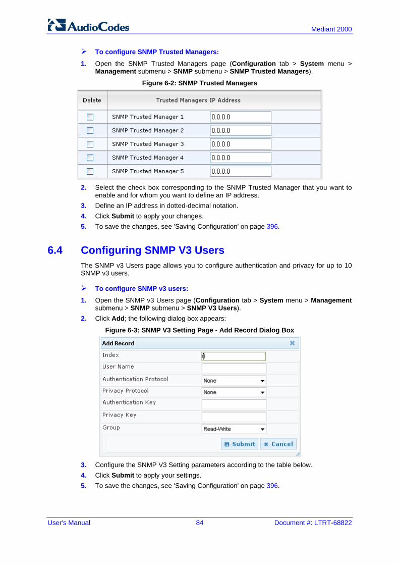
User's Manual 84 Document #: LTRT-68822
Mediant 2000
To configure SNMP Trusted Managers:
1. Open the SNMP Trusted Managers page (Configuration tab > System menu > Management submenu > SNMP submenu > SNMP Trusted Managers).
Figure 6-2: SNMP Trusted Managers
2. Select the check box corresponding to the SNMP Trusted Manager that you want to
enable and for whom you want to define an IP address. 3. Define an IP address in dotted-decimal notation. 4. Click Submit to apply your changes. 5. To save the changes, see 'Saving Configuration' on page 396.
6.4 Configuring SNMP V3 Users The SNMP v3 Users page allows you to configure authentication and privacy for up to 10 SNMP v3 users.
To configure SNMP v3 users:
1. Open the SNMP v3 Users page (Configuration tab > System menu > Management submenu > SNMP submenu > SNMP V3 Users).
2. Click Add; the following dialog box appears:
Figure 6-3: SNMP V3 Setting Page - Add Record Dialog Box
3. Configure the SNMP V3 Setting parameters according to the table below. 4. Click Submit to apply your settings. 5. To save the changes, see 'Saving Configuration' on page 396.

Version 6.6 85 Mediant 2000
User's Manual 6. SNMP-Based Management
Notes:
• If you delete a user that is associated with a trap destination (in 'Configuring SNMP Trap Destinations' on page 82), the configured trap destination becomes disabled and the trap user reverts to default (i.e., SNMPv2).
• The SNMP v3 Users table can also be configured using the table ini file parameter, SNMPUsers (see 'SNMP Parameters' on page 517).
SNMP V3 Users Parameters
Parameter Description
Index [SNMPUsers_Index]
The table index. The valid range is 0 to 9.
User Name [SNMPUsers_Username]
Name of the SNMP v3 user. This name must be unique.
Authentication Protocol [SNMPUsers_AuthProtocol]
Authentication protocol of the SNMP v3 user. [0] None (default) [1] MD5 [2] SHA-1
Privacy Protocol [SNMPUsers_PrivProtocol]
Privacy protocol of the SNMP v3 user. [0] None (default) [1] DES [2] 3DES [3] AES-128 [4] AES-192 [5] AES-256
Authentication Key [SNMPUsers_AuthKey]
Authentication key. Keys can be entered in the form of a text password or long hex string. Keys are always persisted as long hex strings and keys are localized.
Privacy Key [SNMPUsers_PrivKey]
Privacy key. Keys can be entered in the form of a text password or long hex string. Keys are always persisted as long hex strings and keys are localized.
Group [SNMPUsers_Group]
The group with which the SNMP v3 user is associated. [0] Read-Only (default) [1] Read-Write [2] Trap Note: All groups can be used to send traps.

User's Manual 86 Document #: LTRT-68822
Mediant 2000
Reader's Notes

Version 6.6 87 Mediant 2000
User's Manual 7. EMS-Based Management
7 EMS-Based Management AudioCodes Element Management System (EMS) is an advanced solution for standards-based management of gateways within VoP networks, covering all areas vital for the efficient operation, administration, management and provisioning (OAM&P) of AudioCodes' families of gateways. The EMS enables Network Equipment Providers (NEPs) and System Integrators (SIs) the ability to offer customers rapid time-to-market and inclusive, cost-effective management of next-generation networks. The standards-compliant EMS uses distributed SNMP-based management software, optimized to support day-to-day Network Operation Center (NOC) activities, offering a feature-rich management framework. It supports fault management, configuration and security.
Note: For more information on using the EMS tool, refer to the EMS User's Manual and EMS Server IOM Manual.

User's Manual 88 Document #: LTRT-68822
Mediant 2000
Reader's Notes

Version 6.6 89 Mediant 2000
User's Manual 8. INI File-Based Management
8 INI File-Based Management The device can be configured using an ini file, which is a text-based file with an ini file extension name that can be created using any standard text-based editor such as Notepad. Each configuration element of the device has a corresponding ini file parameter that you can use in the ini file for configuring the device. When you have created the ini file with your ini file parameter settings, you apply these settings to the device by installing (loading) the ini file to the device.
Notes:
• For a list and description of the ini file parameters, see 'Configuration Parameters Reference' on page 503.
• To restore the device to default settings using the ini file, see 'Restoring Factory Defaults' on page 423.
8.1 INI File Format The ini file can be configured with any number of parameters. These ini file parameters can be one of the following types: Individual parameters - see 'Configuring Individual ini File Parameters' on page 89 Table parameters - see 'Configuring Table ini File Parameters' on page 89
8.1.1 Configuring Individual ini File Parameters The syntax for configuring individual ini file parameters in the ini file is as follows: An optional, subsection name (or group name) enclosed in square brackets "[...]". This
is used to conveniently group similar parameters by their functionality. Parameter name, followed by an equal "=" sign and then its value. Comments must be preceded by a semicolon ";". [subsection name] parameter name = value parameter name = value ; this is a comment line ; for example: [System Parameters] SyslogServerIP = 10.13.2.69 EnableSyslog = 1
For general ini file formatting rules, see 'General ini File Formatting Rules' on page 91.
8.1.2 Configuring Table ini File Parameters The table ini file parameters allow you to configure tables, which include multiple parameters (columns) and row entries (indices). When loading an ini file to the device, it's recommended to include only tables that belong to applications that are to be configured (dynamic tables of other applications are empty, but static tables are not). The table ini file parameter is composed of the following elements: Title of the table: The name of the table in square brackets, e.g.,
[MY_TABLE_NAME]. Format line: Specifies the columns of the table (by their string names) that are to be

User's Manual 90 Document #: LTRT-68822
Mediant 2000
configured. • The first word of the Format line must be "FORMAT", followed by the Index field
name and then an equal "=" sign. After the equal sign, the names of the columns are listed.
• Columns must be separated by a comma ",". • The Format line must only include columns that can be modified (i.e., parameters
that are not specified as read-only). An exception is Index fields, which are mandatory.
• The Format line must end with a semicolon ";". Data line(s): Contain the actual values of the columns (parameters). The values are
interpreted according to the Format line. • The first word of the Data line must be the table’s string name followed by the
Index field. • Columns must be separated by a comma ",". • A Data line must end with a semicolon ";".
End-of-Table Mark: Indicates the end of the table. The same string used for the table’s title, preceded by a backslash "\", e.g., [\MY_TABLE_NAME].
The following displays an example of the structure of a table ini file parameter. [Table_Title] ; This is the title of the table. FORMAT Index = Column_Name1, Column_Name2, Column_Name3; ; This is the Format line. Index 0 = value1, value2, value3; Index 1 = value1, $$, value3; ; These are the Data lines. [\Table_Title] ; This is the end-of-the-table-mark.
The table ini file parameter formatting rules are listed below: Indices (in both the Format and the Data lines) must appear in the same order. The
Index field must never be omitted. The Format line can include a subset of the configurable fields in a table. In this case,
all other fields are assigned with the pre-defined default values for each configured line.
The order of the fields in the Format line isn’t significant (as opposed to the Index fields). The fields in the Data lines are interpreted according to the order specified in the Format line.
The double dollar sign ($$) in a Data line indicates the default value for the parameter. The order of the Data lines is insignificant. Data lines must match the Format line, i.e., it must contain exactly the same number
of Indices and Data fields and must be in exactly the same order. A row in a table is identified by its table name and Index field. Each such row may
appear only once in the ini file. Table dependencies: Certain tables may depend on other tables. For example, one
table may include a field that specifies an entry in another table. This method is used to specify additional attributes of an entity, or to specify that a given entity is part of a larger entity. The tables must appear in the order of their dependency (i.e., if Table X is referred to by Table Y, Table X must appear in the ini file before Table Y).
For general ini file formatting rules, see 'General ini File Formatting Rules' on page 91. The table below displays an example of a table ini file parameter: [ CodersGroup0 ] FORMAT CodersGroup0_Index = CodersGroup0_Name, CodersGroup0_pTime, CodersGroup0_rate, CodersGroup0_PayloadType, CodersGroup0_Sce;

Version 6.6 91 Mediant 2000
User's Manual 8. INI File-Based Management
CodersGroup0 0 = g711Alaw64k, 20, 0, 255, 0; CodersGroup0 1 = eg711Ulaw, 10, 0, 71, 0; [ \CodersGroup0 ]
Note: Do not include read-only parameters in the table ini file parameter as this can cause an error when attempting to load the file to the device.
8.1.3 General ini File Formatting Rules The ini file must adhere to the following formatting rules: The ini file name must not include hyphens "-" or spaces; if necessary, use an
underscore "_" instead. Lines beginning with a semi-colon ";" are ignored. These can be used for adding
remarks in the ini file. A carriage return (i.e., Enter) must be done at the end of each line. The number of spaces before and after the equals sign "=" is irrelevant. Subsection names for grouping parameters are optional. If there is a syntax error in the parameter name, the value is ignored. Syntax errors in the parameter's value can cause unexpected errors (parameters may
be set to the incorrect values). Parameter string values that denote file names (e.g., CallProgressTonesFileName)
must be enclosed with inverted commas, e.g., CallProgressTonesFileName = 'cpt_usa.dat'.
The parameter name is not case-sensitive. The parameter value is not case-sensitive, except for coder names. The ini file must end with at least one carriage return.
8.2 Loading an ini File You can load an ini file to the device using the following methods: Web interface, using any of the following pages:
• Configuration File - see 'Backing Up and Loading Configuration File' on page 422 • Load Auxiliary Files - see 'Loading Auxiliary Files' on page 399
AudioCodes AcBootP utility, which uses Bootstrap Protocol (BootP) and acts as a TFTP server. For information on using the AcBootP utility, refer to AcBootP Utility User's Guide.
Any standard TFTP server. This is done by storing the ini file on a TFTP server and then having the device download the file from it.
When loaded to the device, the configuration settings of the ini file are saved to the device's non-volatile memory. If a parameter is not included in the loaded ini file, the following occurs: Using the Load Auxiliary Files page: Current settings for parameters that were not
included in the loaded ini file are retained. All other methods: The default is assigned to the parameters that were not included in
the loaded ini file and thereby, overriding values previously configured for these parameters.

User's Manual 92 Document #: LTRT-68822
Mediant 2000
Notes:
• For a list and description of the ini file parameters, see 'Configuration Parameters Reference' on page 503.
• Some parameters are configurable only through the ini file (and not the Web interface).
• To restore the device to default settings using the ini file, see 'Restoring Factory Defaults' on page 423.
8.3 Modifying an ini File You can modify an ini file currently used by the device. Modifying an ini file instead of loading an entirely new ini file preserves the device's current configuration.
To modify an ini file:
1. Save the device's configuration as an ini file on your computer, using the Web interface (see 'Loading an ini File' on page 91).
2. Open the ini file using a text file editor such as Notepad, and then modify the ini file parameters as required.
3. Save the modified ini file, and then close the file. 4. Load the modified ini file to the device (see 'Loading an ini File' on page 91).
Tip: Before loading the ini file to the device, verify that the file extension of the file is .ini.
8.4 Secured Encoded ini File The ini file contains sensitive information that is required for the functioning of the device. The file may be loaded to the device using TFTP or HTTP. These protocols are not secure and are vulnerable to potential hackers. To overcome this security threat, the AudioCodes DConvert utility allows you to binary-encode (encrypt) the ini file before loading it to the device. For more information, refer to DConvert Utility User's Guide.
Notes:
• The procedure for loading an encoded ini file is identical to the procedure for loading an unencoded ini file (see 'Loading an ini File' on page 91).
• If you download from the device (to a folder on your computer) an ini file that was loaded encoded to the device, the file is saved as a regular ini file (i.e., unencoded).

Part III General System Settings


Version 6.6 95 Mediant 2000
User's Manual 9. Configuring Certificates
9 Configuring Certificates The Certificates page allows you to configure X.509 certificates, which are used for secure management of the device, secure SIP transactions, and other security applications.
Note: The device is shipped with an active TLS setup. Thus, configure certificates only if required.
9.1 Replacing the Device's Certificate The device is supplied with a working TLS configuration consisting of a unique self-signed server certificate. If an organizational Public Key Infrastructure (PKI) is used, you may wish to replace this certificate with one provided by your security administrator.
To replace the device's certificate:
1. Your network administrator should allocate a unique DNS name for the device (e.g., dns_name.corp.customer.com). This DNS name is used to access the device and therefore, must be listed in the server certificate.
2. If the device is operating in HTTPS mode, then set the 'Secured Web Connection (HTTPS)' parameter (HTTPSOnly) to HTTP and HTTPS (see 'Configuring Web Security Settings' on page 67). This ensures that you have a method for accessing the device in case the new certificate does not work. Restore the previous setting after testing the configuration.
3. Open the Certificates page (Configuration tab > System menu > Certificates). 4. Under the Certificate Signing Request group, do the following:
a. In the 'Subject Name [CN]' field, enter the DNS name. b. Fill in the rest of the request fields according to your security provider's
instructions. c. Click the Create CSR button; a textual certificate signing request is displayed in
the area below the button:
Figure 9-1: Certificate Signing Request Group

User's Manual 96 Document #: LTRT-68822
Mediant 2000
5. Copy the text and send it to your security provider. The security provider, also known as Certification Authority or CA, signs this request and then sends you a server certificate for the device.
6. Save the certificate to a file (e.g., cert.txt). Ensure that the file is a plain-text file containing the"‘BEGIN CERTIFICATE" header, as shown in the example of a Base64-Encoded X.509 Certificate below: -----BEGIN CERTIFICATE----- MIIDkzCCAnugAwIBAgIEAgAAADANBgkqhkiG9w0BAQQFADA/MQswCQYDVQQGEwJGUjETMBEGA1UEChMKQ2VydGlwb3N0ZTEbMBkGA1UEAxMSQ2VydGlwb3N0ZSBTZXJ2ZXVyMB4XDTk4MDYyNDA4MDAwMFoXDTE4MDYyNDA4MDAwMFowPzELMAkGA1UEBhMCRlIxEzARBgNVBAoTCkNlcnRpcG9zdGUxGzAZBgNVBAMTEkNlcnRpcG9zdGUgU2VydmV1cjCCASEwDQYJKoZIhvcNAQEBBQADggEOADCCAQkCggEAPqd4MziR4spWldGRx8bQrhZkonWnNm`+Yhb7+4Q67ecf1janH7GcN/SXsfx7jJpreWULf7v7Cvpr4R7qIJcmdHIntmf7JPM5n6cDBv17uSW63er7NkVnMFHwK1QaGFLMybFkzaeGrvFm4k3lRefiXDmuOe+FhJgHYezYHf44LvPRPwhSrzi9+Aq3o8pWDguJuZDIUP1F1jMa+LPwvREXfFcUW+w== -----END CERTIFICATE-----
7. Scroll down to the Upload certificates files from your computer group, click the Browse button corresponding to the 'Send Device Certificate...' field, navigate to the cert.txt file, and then click Send File.
8. After the certificate successfully loads to the device, save the configuration with a device reset (see 'Saving Configuration' on page 396); the Web interface uses the provided certificate.
9. Open the Certificates page again and verify that under the Certificate information group (at the top of the page), the 'Private key' read-only field displays "OK"; otherwise, consult your security administrator:
Figure 9-2: Private key "OK" in Certificate Information Group
10. If the device was originally operating in HTTPS mode and you disabled it in Step 2,
then return it to HTTPS by setting the 'Secured Web Connection (HTTPS)' parameter to HTTPS Only, and then reset the device with a flash burn.
Notes:
• The certificate replacement process can be repeated when necessary (e.g., the new certificate expires).
• It is possible to use the IP address of the device (e.g., 10.3.3.1) instead of a qualified DNS name in the Subject Name. This is not recommended since the IP address is subject to change and may not uniquely identify the device.
• The device certificate can also be loaded via the Automatic Update Facility by using the HTTPSCertFileName ini file parameter.
9.2 Loading a Private Key The device is shipped with a self-generated random private key, which cannot be extracted from the device. However, some security administrators require that the private key be generated externally at a secure facility and then loaded to the device through configuration. Since private keys are sensitive security parameters, take precautions to

Version 6.6 97 Mediant 2000
User's Manual 9. Configuring Certificates
load them over a physically-secure connection such as a back-to-back Ethernet cable connected directly to the managing computer.
To replace the device's private key:
1. Your security administrator should provide you with a private key in either textual PEM (PKCS #7) or PFX (PKCS #12) format. The file may be encrypted with a short pass-phrase, which should be provided by your security administrator.
2. If the device is operating in HTTPS mode, then set the 'Secured Web Connection (HTTPS)' field (HTTPSOnly) to HTTP and HTTPS (see 'Configuring Web Security Settings' on page 67). This ensures that you have a method for accessing the device in case the new configuration does not work. Restore the previous setting after testing the configuration.
3. Open the Certificates page (Configuration tab > System menu > Certificates) and scroll down to the Upload certificate files from your computer group.
Figure 9-3: Upload Certificate Files from your Computer Group
4. Fill in the 'Private key pass-phrase' field, if required. 5. Click the Browse button corresponding to the 'Send Private Key' field, navigate to the
key file, and then click Send File. 6. If the security administrator has provided you with a device certificate file, load it using
the 'Send Device Certificate' field. 7. After the files successfully load to the device, save the configuration with a device
reset (see 'Saving Configuration' on page 396); the Web interface uses the new configuration.
8. Open the Certificates page again, and verify that under the Certificate information group (at the top of the page) the 'Private key' read-only field displays "OK"; otherwise, consult your security administrator.
9. If the device was originally operating in HTTPS mode and you disabled it in Step 2, then enable it by setting the 'Secured Web Connection (HTTPS)' field to HTTPS Only.

User's Manual 98 Document #: LTRT-68822
Mediant 2000
9.3 Mutual TLS Authentication By default, servers using TLS provide one-way authentication. The client is certain that the identity of the server is authentic. When an organizational PKI is used, two-way authentication may be desired - both client and server should be authenticated using X.509 certificates. This is achieved by installing a client certificate on the managing PC and loading the root CA's certificate to the device's Trusted Root Certificate Store. The Trusted Root Certificate file may contain more than one CA certificate combined, using a text editor. Since X.509 certificates have an expiration date and time, the device must be configured to use NTP (see 'Simple Network Time Protocol Support' on page 101) to obtain the current date and time. Without the correct date and time, client certificates cannot work.
To enable mutual TLS authentication for HTTPS:
1. Set the 'Secured Web Connection (HTTPS)' field to HTTPS Only (see 'Configuring Web Security Settings' on page 67) to ensure you have a method for accessing the device in case the client certificate does not work. Restore the previous setting after testing the configuration.
2. Open the Certificates page (see 'Replacing the Device's Certificate' on page 95). 3. In the Upload certificate files from your computer group, click the Browse button
corresponding to the 'Send Trusted Root Certificate Store ...' field, navigate to the file, and then click Send File.
4. When the operation is complete, set the 'Requires Client Certificates for HTTPS connection' field to Enable (see 'Configuring Web Security Settings' on page 67).
5. Save the configuration with a device reset (see 'Saving Configuration' on page 396). When a user connects to the secured Web interface of the device: If the user has a client certificate from a CA that is listed in the Trusted Root Certificate
file, the connection is accepted and the user is prompted for the system password. If both the CA certificate and the client certificate appear in the Trusted Root
Certificate file, the user is not prompted for a password (thus, providing a single-sign-on experience - the authentication is performed using the X.509 digital signature).
If the user does not have a client certificate from a listed CA or does not have a client certificate, the connection is rejected.
Notes:
• The process of installing a client certificate on your PC is beyond the scope of this document. For more information, refer to your operating system documentation, and/or consult your security administrator.
• The root certificate can also be loaded via the Automatic Update facility, using the HTTPSRootFileName ini file parameter.
• You can enable the device to check whether a peer's certificate has been revoked by an Online Certificate Status Protocol (OCSP) server (see Configuring Certificate Revocation Checking (OCSP) on page 98.
9.4 Configuring Certificate Revocation Checking (OCSP) Some Public-Key Infrastructures (PKI) can revoke a certificate after it has been issued. You can configure the device to check whether a peer's certificate has been revoked, using the Online Certificate Status Protocol (OCSP). When OCSP is enabled, the device queries the OCSP server for revocation information whenever a peer certificate is received (IPSec, TLS client mode, or TLS server mode with mutual authentication).

Version 6.6 99 Mediant 2000
User's Manual 9. Configuring Certificates
To configure OCSP:
1. Open the General Security Settings page (Configuration tab > VoIP menu > Security > General Security Settings).
Figure 9-4: OCSP Parameters
2. Configure the OCSP parameters as required. For a description of these parameters,
see OCSP Parameters on page 537. 3. Click Submit.
Notes:
• The device does not query OCSP for its own certificate. • Some PKIs do not support OCSP but generate Certificate Revocation Lists
(CRLs). For such cases, set up an OCSP server such as OCSPD.
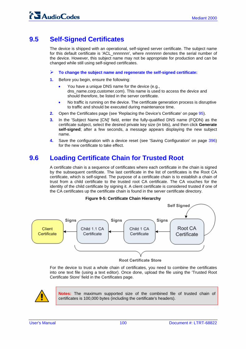
User's Manual 100 Document #: LTRT-68822
Mediant 2000
9.5 Self-Signed Certificates The device is shipped with an operational, self-signed server certificate. The subject name for this default certificate is 'ACL_nnnnnnn', where nnnnnnn denotes the serial number of the device. However, this subject name may not be appropriate for production and can be changed while still using self-signed certificates.
To change the subject name and regenerate the self-signed certificate:
1. Before you begin, ensure the following: • You have a unique DNS name for the device (e.g.,
dns_name.corp.customer.com). This name is used to access the device and should therefore, be listed in the server certificate.
• No traffic is running on the device. The certificate generation process is disruptive to traffic and should be executed during maintenance time.
2. Open the Certificates page (see 'Replacing the Device's Certificate' on page 95). 3. In the 'Subject Name [CN]' field, enter the fully-qualified DNS name (FQDN) as the
certificate subject, select the desired private key size (in bits), and then click Generate self-signed; after a few seconds, a message appears displaying the new subject name.
4. Save the configuration with a device reset (see 'Saving Configuration' on page 396) for the new certificate to take effect.
9.6 Loading Certificate Chain for Trusted Root A certificate chain is a sequence of certificates where each certificate in the chain is signed by the subsequent certificate. The last certificate in the list of certificates is the Root CA certificate, which is self-signed. The purpose of a certificate chain is to establish a chain of trust from a child certificate to the trusted root CA certificate. The CA vouches for the identity of the child certificate by signing it. A client certificate is considered trusted if one of the CA certificates up the certificate chain is found in the server certificate directory.
Figure 9-5: Certificate Chain Hierarchy
For the device to trust a whole chain of certificates, you need to combine the certificates into one text file (using a text editor). Once done, upload the file using the 'Trusted Root Certificate Store' field in the Certificates page.
Notes: The maximum supported size of the combined file of trusted chain of certificates is 100,000 bytes (including the certificate's headers).

Version 6.6 101 Mediant 2000
User's Manual 10. Date and Time
10 Date and Time The date and time of the device can be configured manually or it can be obtained automatically from a Simple Network Time Protocol (SNTP) server.
10.1 Configuring Date and Time Manually The date and time of the device can be configured manually.
To manually configure the device's date and time, using the Web interface:
1. Open the Regional Settings page (Configuration tab > System menu > Regional Settings).
Figure 10-1: Regional Settings Page
2. Enter the current date and time of the geographical location in which the device is
installed. 3. Click the Submit button.
Notes:
• If the device is configured to obtain the date and time from an SNTP server, the fields on this page are read-only, displaying the received date and time.
• After performing a hardware reset, the date and time are returned to their defaults and thus, should be updated.
10.2 Automatic Date and Time through SNTP Server The Simple Network Time Protocol (SNTP) client functionality generates requests and reacts to the resulting responses using the NTP version 3 protocol definitions (according to RFC 1305). Through these requests and responses, the NTP client synchronizes the system time to a time source within the network, thereby eliminating any potential issues should the local system clock 'drift' during operation. By synchronizing time to a network time source, traffic handling, maintenance, and debugging become simplified for the network administrator. The NTP client follows a simple process in managing system time: the NTP client requests an NTP update, receives an NTP response, and then updates the local system clock based on a configured NTP server within the network. The client requests a time update from a specified NTP server at a specified update interval. In most situations, this update interval is every 24 hours based on when the system was restarted. The NTP server identity (as an IP address or FQDN) and the update interval are user-defined, or an SNMP MIB object. When the client receives a response to its request from the identified NTP server, it must be interpreted based on time zone or location offset that the system is to a standard point of reference called the Universal Time Coordinate (UTC). The time offset that the NTP client uses is configurable. If required, the clock update is performed by the client as the final step of the update process. The update is performed in such a way as to be transparent to the end users. For instance, the response of the server may indicate that the clock is running too fast on the client. The client slowly robs bits from the clock counter to update the clock to the correct time. If the clock is running too slow, then in an effort to catch the clock up, bits are added

User's Manual 102 Document #: LTRT-68822
Mediant 2000
to the counter, causing the clock to update quicker and catch up to the correct time. The advantage of this method is that it does not introduce any disparity in the system time that is noticeable to an end user or that could corrupt call timeouts and timestamps. The procedure below describes how to configure SNTP.
To configure SNTP using the Web interface:
1. Open the Application Settings page (Configuration tab > System menu > Application Settings).
Figure 10-2: SNTP Configuration in Application Settings Page
2. Configure the NTP parameters:
• 'NTP Server DN/IP' (NTPServerIP) - defines the IP address or FQDN of the NTP server.
• 'NTP UTC Offset' (NTPServerUTCOffset) - defines the time offset in relation to the UTC. For example, if your region is 2 hours ahead of the UTC, enter "2".
• 'NTP Updated Interval' (NTPUpdateInterval) - defines the period after which the date and time of the device is updated.
• 'NTP Secondary Server IP' (NTPSecondaryServerIP) - defines the secondary NTP server.
3. Configure daylight saving, if required: • 'Day Light Saving Time' (DayLightSavingTimeEnable) - enables daylight saving
time. • 'DST Mode' - Determines the range type for configuring the start and end date for
daylight saving: ♦ Day of Year: The range is configured by date of month, for example, from
January 4 to August 31. ♦ Day of month: The range is configured by day of month, for example, from
the second Sunday of May January to the last Sunday of August. • 'Start Time' (DayLightSavingTimeStart) and 'End Time' (DayLightSavingTimeEnd)
- defines the period for which daylight saving time is relevant. • 'Offset' (DayLightSavingTimeOffset) - defines the offset in minutes to add to the
time for daylight saving. For example, if your region has daylight saving of one hour, the time received from the NTP server is 11:00, and the UTC offset for your region is +2 (i.e., 13:00), you need to enter "60" to change the local time to 14:00.
4. Verify that the device is set to the correct date and time. You can do this by viewing the date and time in the Regional Settings page, as described in 'Configuring Date and Time Manually' on page 101.

Part IV General VoIP Configuration


Version 6.6 105 Mediant 2000
User's Manual 11. Network
11 Network This section describes the network-related configuration.
11.1 Ethernet Interface Configuration The device's Ethernet connection can be configured, using the ini file parameter EthernetPhyConfiguration, to one of the following modes: Manual:
• 10Base-T Half-Duplex or 10Base-T Full-Duplex • 100Base-TX Half-Duplex or 100Base-TX Full-Duplex
Auto-Negotiation: chooses common transmission parameters such as speed and duplex mode
The Ethernet connection should be configured according to the following recommended guidelines: When the device's Ethernet port is configured for Auto-Negotiation, the opposite port
must also operate in Auto-Negotiation. Auto-Negotiation falls back to Half-Duplex mode when the opposite port is not in Auto-Negotiation mode, but the speed in this mode is always configured correctly. Configuring the device to Auto-Negotiation mode while the opposite port is set manually to Full-Duplex is invalid as it causes the device to fall back to Half-Duplex mode while the opposite port is Full-Duplex. Any mismatch configuration can yield unexpected functioning of the Ethernet connection.
When configuring the device's Ethernet port manually, the same mode (i.e., Half Duplex or Full Duplex) and speed must be configured on the remote Ethernet port. In addition, when the device's Ethernet port is configured manually, it is invalid to set the remote port to Auto-Negotiation. Any mismatch configuration can yield unexpected functioning of the Ethernet connection.
It's recommended to configure the port for best performance and highest bandwidth (i.e., Full Duplex with 100Base-TX), but at the same time adhering to the guidelines listed above.
Note: For remote configuration, the device should be in the correct Ethernet setting prior to the time this parameter takes effect. When, for example, the device is configured using BootP/TFTP, the device performs many Ethernet-based transactions prior to reading the ini file containing this device configuration parameter. To resolve this problem, the device always uses the last Ethernet setup mode configured. In this way, if you want to configure the device to operate in a new network environment in which the current Ethernet setting of the device is invalid, you should first modify this parameter in the current network so that the new setting holds next time the device is restarted. After reconfiguration has completed, connect the device to the new network and restart it. As a result, the remote configuration process that occurs in the new network uses a valid Ethernet configuration
11.2 Ethernet Interface Redundancy The device supports an Ethernet redundancy scheme. At the beginning of the start-up procedure, the device tests whether the ‘primary’ Ethernet interface is connected, by checking the existence of the Ethernet link carrier. If it's connected, the start-up procedure commences as usual. If not, the start-up application tries the ‘secondary’ Ethernet interface. If this interface is connected, the whole start-up procedure is performed using it. If both interfaces are not connected, the start-up procedure commences using the parameters, tables, and software residing on the device's non-volatile memory. Note that

User's Manual 106 Document #: LTRT-68822
Mediant 2000
Ethernet switchover occurs only once during the start-up procedure (at the beginning). If the Ethernet interface fails after the selection is made, the device does not switch over to the second port. After start-up is complete and the operational software is running, the device continues to use the Ethernet port used for software upload. The device switches over from one Ethernet port to the other each time an Ethernet link carrier-loss is detected on the active Ethernet port, and if the Ethernet link of the other port is operational. Switchover occurs only once per link loss (i.e., the ‘secondary’ interface stays the active one even if the ‘primary’ interface has returned to life). After start-up, the device generates a gratuitous ARP message each time a switchover occurs. For correct functionality of the redundancy mechanism, it's recommended to configure both links to the same mode. It is essential that both link partners (primary and secondary) have the same capabilities. This ensures that whenever a switchover occurs, the device is able to provide at least the same Ethernet services as were provided prior to the switchover. In addition, it's recommended to set the physical secondary link prior to resetting the device (since the MAC configuration cannot be changed thereafter). Note that since the two Ethernet ports use the same MAC address, the external switches connected to the device can in some cases create a noticeable switchover delay due to their internal switching logic, though at the device level, the switchover delay is minimal (milliseconds). The Ethernet port redundancy feature is enabled using the ini file parameter MIIRedundancyEnable. By default, this feature is disabled.
11.3 Configuring IP Network Interfaces You can configure a single VoIP network interface for all applications, which includes OAMP (management traffic), call control (SIP messages), and media (RTP traffic), or you can configure multiple logical, IP network interfaces for these applications. A need often arises to have logically separated network segments for these applications for administration and security. This can be achieved by employing Layer-2 VLANs and Layer-3 subnets. The figure below illustrates a typical network architecture where the device is configured with three network interfaces for the OAMP, call control, and media applications. The device is connected to a VLAN-aware switch for directing traffic from and to the device to the three separated Layer-3 broadcast domains according to VLAN tags (middle pane).
Figure 11-1: Multiple Network Interfaces

Version 6.6 107 Mediant 2000
User's Manual 11. Network
The Multiple Interface Table page allows you to configure these network interfaces. Each row of the table defines a logical IP interface with the following attributes: Application type allowed on the interface:
• Control - call control signaling traffic (i.e., SIP) • Media - RTP traffic • Operations, Administration, Maintenance and Provisioning (OAMP) -
management (such as Web- and SNMP-based management) IP address and subnet mask represented by prefix length VLAN ID (if VLANs are enabled) Default Gateway - traffic from this interface destined to a subnet that does not meet
any of the routing rules, local or static routes, are forwarded to this gateway (as long this application type is allowed on this interface.
Primary and secondary DNS IP address (optional) You can configure up to 16 interfaces, consisting of up to 15 Control and Media interfaces and 1 OAMP interface. This page also provides VLAN-related parameters for enabling VLANs and defining the Native VLAN ID. This is the VLAN ID to which incoming, untagged packets are assigned. You can also configure Quality of Service (QoS) by assigning VLAN priorities and Differentiated Services (DiffServ) for the supported Class of Service (CoS). For configuring Quality of Service (QoS), see 'Configuring the QoS Settings' on page 118. Complementing the Multiple Interface table is the IP Routing table, which allows you to define static routing rules for non-local hosts/subnets. For more information, see 'Configuring the IP Routing Table' on page 115.
Notes:
• When adding more than one interface, ensure that you enable VLANs using the 'VLAN Mode' (VlANMode) parameter.
• When booting using BootP/DHCP protocols, an IP address is obtained from the server. This address is used as the OAMP address for this session, overriding the IP address configured in the Multiple Interface table. The address specified in this table takes effect only after you save the configuration to the device's flash memory. This enables the device to use a temporary IP address for initial management and configuration, while retaining the address configured in this table for deployment.
• To configure firewall rules (access list) for allowing or blocking packets received from specific IP network interfaces, see 'Configuring Firewall Settings' on page 133.
• The Multiple Interface table can also be configured using the table ini file parameter, InterfaceTable (see 'Networking Parameters' on page 503).
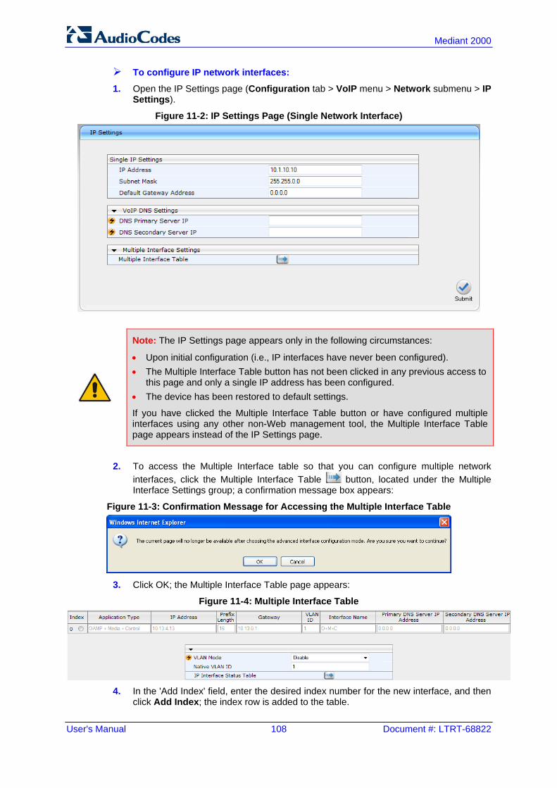
User's Manual 108 Document #: LTRT-68822
Mediant 2000
To configure IP network interfaces:
1. Open the IP Settings page (Configuration tab > VoIP menu > Network submenu > IP Settings).
Figure 11-2: IP Settings Page (Single Network Interface)
Note: The IP Settings page appears only in the following circumstances:
• Upon initial configuration (i.e., IP interfaces have never been configured). • The Multiple Interface Table button has not been clicked in any previous access to
this page and only a single IP address has been configured. • The device has been restored to default settings.
If you have clicked the Multiple Interface Table button or have configured multiple interfaces using any other non-Web management tool, the Multiple Interface Table page appears instead of the IP Settings page.
2. To access the Multiple Interface table so that you can configure multiple network
interfaces, click the Multiple Interface Table button, located under the Multiple Interface Settings group; a confirmation message box appears:
Figure 11-3: Confirmation Message for Accessing the Multiple Interface Table
3. Click OK; the Multiple Interface Table page appears:
Figure 11-4: Multiple Interface Table
4. In the 'Add Index' field, enter the desired index number for the new interface, and then
click Add Index; the index row is added to the table.

Version 6.6 109 Mediant 2000
User's Manual 11. Network
5. Configure the interface according to the table below. 6. Click the Apply button; the interface is added to the table and the Done button
appears. 7. Click Done to validate the interface. If the interface is not valid (e.g., if it overlaps with
another interface in the table or if it does not adhere to the other rules as summarized in 'Multiple Interface Table Configuration Summary and Guidelines' on page 111), a warning message is displayed.
8. Save the changes to flash memory and reset the device (see 'Saving Configuration' on page 396).
To view configured network interfaces that are currently active, click the IP Interface Status Table button. For more information, see Viewing Active IP Interfaces on page 448.
Multiple Interface Table Parameters Description
Parameter Description
Table parameters
Index [InterfaceTable_Index]
Table index row of the interface. The range is 0 to 15.
Web: Application Type EMS: Application Types [InterfaceTable_ApplicationTypes]
Defines the applications allowed on the interface. [0] OAMP = Operations, Administration, Maintenance and Provisioning
(OAMP) applications (e.g., Web, Telnet, SSH, and SNMP). [1] Media = Media (i.e., RTP streams of voice). [2] Control = Call Control applications (e.g., SIP). [3] OAMP + Media = OAMP and Media applications. [4] OAMP + Control = OAMP and Call Control applications. [5] Media + Control = Media and Call Control applications. [6] OAMP + Media + Control = All application types are allowed on the
interface. Note: For valid configuration, see Multiple Interface Table Configuration Rules on page 111.
Web/EMS: IP Address [InterfaceTable_IPAddress]
Defines the IPv4 IP address in dotted-decimal notation. Note: For valid configuration, see Multiple Interface Table Configuration Rules on page 111.
Web/EMS: Prefix Length [InterfaceTable_PrefixLength]
Defines the prefix length of the related IP address. This is a Classless Inter-Domain Routing (CIDR)-style representation of a dotted-decimal subnet notation. The CIDR-style representation uses a suffix indicating the number of bits which are set in the dotted-decimal format. For example, 192.168.0.0/16 is synonymous with 192.168.0.0 and subnet 255.255.0.0. This CIDR lists the number of ‘1’ bits in the subnet mask (i.e., replaces the standard dotted-decimal representation of the subnet mask for IPv4 interfaces). For example, a subnet mask of 255.0.0.0 is represented by a prefix length of 8 (i.e., 11111111 00000000 00000000 00000000) and a subnet mask of 255.255.255.252 is represented by a prefix length of 30 (i.e., 11111111 11111111 11111111 11111100). The prefix length is a Classless Inter-Domain Routing (CIDR) style presentation of a dotted-decimal subnet notation. The CIDR-style presentation is the latest method for interpretation of IP addresses. Specifically, instead of using eight-bit address blocks, it uses the variable-length subnet masking technique to allow allocation on arbitrary-length prefixes.

User's Manual 110 Document #: LTRT-68822
Mediant 2000
Parameter Description
The prefix length for IPv4 can range from 0 to 30. Note: For valid configuration, see Multiple Interface Table Configuration Rules on page 111.
Web/EMS: Gateway [InterfaceTable_Gateway]
Defines the IP address of the default gateway for the interface. When traffic is sent from this interface to an unknown destination (i.e., not in the same subnet and not defined for any static routing rule), it is forwarded to this default gateway. Note: For valid configuration, see Multiple Interface Table Configuration Rules on page 111.
Web/EMS: VLAN ID [InterfaceTable_VlanID]
Defines a VLAN ID for the interface. Incoming traffic tagged with this VLAN ID is routed to the corresponding interface. Outgoing traffic from this interface is tagged with this VLAN ID. Notes: To enable VLANs, use the 'VLAN Mode' parameter. For valid configuration, see Multiple Interface Table Configuration
Rules on page 111.
Web/EMS: Interface Name [InterfaceTable_InterfaceName]
Defines a name for this interface. This name is used in various configuration tables to associate this network interface with other configuration entities such as Media Realms. It is also displayed in management interfaces (Web, CLI, and SNMP) for clarity where it has no functional use. The valid value is a string of up to 16 characters. Note: For valid configuration, see Multiple Interface Table Configuration Rules on page 111.
Web/EMS: Primary DNS Server IP address [InterfaceTable_PrimaryDNSServerIPAddress]
(Optional) Defines the primary DNS server's IP address (in dotted-decimal notation), which is used for translating domain names into IP addresses for the interface. By default, no IP address is defined.
Web/EMS: Secondary DNS Server IP address [InterfaceTable_SecondaryDNSServerIPAddress]
(Optional) Defines the secondary DNS server's IP address (in dotted-decimal notation), which is used for translating domain names into IP addresses for the interface. By default, no IP address is defined.
General Parameters
Web/EMS: VLAN Mode [VLANMode]
Enables VLANs tagging (IEEE 802.1Q). [0] Disable (default) [1] Enable Notes: For this parameter to take effect, a device reset is required. To operate with multiple network interfaces, VLANs must be
enabled. VLANs are available only when booting the device from flash. When
booting using BootP/DHCP protocols, VLANs are disabled to allow easier maintenance access. In this scenario, multiple network interface capabilities are unavailable.
Web/EMS: Native VLAN ID
Defines the Native VLAN ID. This is the VLAN ID to which untagged incoming traffic is assigned. Outgoing packets sent to this VLAN are

Version 6.6 111 Mediant 2000
User's Manual 11. Network
Parameter Description
[VLANNativeVLANID] sent only with a priority tag (VLAN ID = 0). When the Native VLAN ID is equal to one of the VLAN IDs listed in the Multiple Interface table (and VLANs are enabled), untagged incoming traffic is considered as incoming traffic for that interface. Outgoing traffic sent from this interface is sent with the priority tag (tagged with VLAN ID = 0). When the Native VLAN ID is different to any value in the 'VLAN ID' column in the table, untagged incoming traffic is discarded and all outgoing traffic is tagged. The default Native VLAN ID is 1. Note: If this parameter is not configured (i.e., default is 1) and one of the interfaces has a VLAN ID set to 1, this interface is still considered the ‘Native’ VLAN. If you do not wish to have a ‘Native’ VLAN ID and want to use VLAN ID 1, set this parameter to a value other than any VLAN ID in the table.
11.3.1 Assigning NTP Services to Application Types You can associate the Network Time Protocol (NTP) application with the OAMP or Control application type. This is done using the EnableNTPasOAM ini file parameter.
11.3.2 Multiple Interface Table Configuration Rules The Multiple Interface table configuration must adhere to the following rules: Each interface must have its own subnet. Configuring two interfaces with addresses in
the same subnet (e.g., 192.168.0.1/16 and 192.168.100.1/16) is invalid. Subnets of different interfaces must not overlap (i.e. 10.0.0.1/8 and 10.50.10.1/24 is
invalid); each interface must have its own address space. Each interface must be assigned a unique IP address (i.e., two interfaces may not
share the same address space, or even part of it). The prefix length replaces the dotted-decimal subnet mask presentation and must
have a value of 0-30 for IPv4 addresses. Only one OAMP interface must be configured and this must be an IPv4 address. This
OAMP interface can be combined with Media and Control. At least one Control interface must be configured with an IPv4 address. At least one Media interface must be configured with an IPv4 address. . The network interface types can be combined:
• Example 1: One combined OAMP-Media-Control interface with an IPv4 address • Example 2:
♦ One OAMP interface with an IPv4 address ♦ One or more Control interfaces with IPv4 addresses ♦ One or more Media interfaces with IPv4 interfaces (with VLANs)
• Example 3: ♦ One combined OAMP-Media interface with an IPv4 address ♦ One or more combined Media-Control interfaces with IPv4 addresses.
Each network interface can be configured with a Default Gateway. The address of the Default Gateway must be in the same subnet as the associated interface. Additional

User's Manual 112 Document #: LTRT-68822
Mediant 2000
static routing rules can be configured in the IP Routing table. The interface name must be configured (mandatory) and unique for each interface,
and can include up to 16 characters. For IPv4 addresses, the 'Interface Mode' column must be set to IPv4 Manual (numeric
value 10). Each network interface must be assigned a unique VLAN ID. When configuring more than one IP interface of the same address family, VLANs must
be enabled. For network configuration to take effect, you must save the configuration to the
device's flash memory (burn) with a device reset.
Notes:
• When configuring the network interfaces and VLANs in the Multiple Interface table using the Web interface, it is recommended to check that your configuration is valid, by clicking the Done button in the Multiple Interface Table page.
• Upon device start up, the Multiple Interface table is parsed and passes comprehensive validation tests. If any errors occur during this validation phase, the device sends an error message to the Syslog server and falls back to a "safe mode", using a single interface and no VLANs. Ensure that you view the Syslog messages that the device sends in system startup to see if any errors occurred.
11.3.3 Troubleshooting the Multiple Interface Table If any of the Multiple Interface table guidelines are violated, the device falls back to a "safe mode" configuration, consisting of a single IPv4 interface without VLANs. For more information on validation failures, consult the Syslog messages. Validation failures may be caused by one of the following: One of the Application Types (OAMP, Control, or Media) are missing in the IPv4
interfaces. There are too many interfaces for Application Type, OAMP. There is only one
interface defined, but the 'Application Types' column is not set to OAMP + Media + Control (numeric value 6).
An IPv4 interface was defined with 'Interface Type' other than IPv4 Manual (10). Two interfaces have the same VLAN ID value while VLANs are enabled. Two interfaces have the same name. At least two interfaces share the same address space or subnet. Apart from these validation errors, connectivity problems may be caused by one of the following: Trying to access the device with VLAN tags while booting from BootP/DHCP. Trying to access the device with untagged traffic when VLANs are on and Native
VLAN is not configured properly. The IP Routing table is not configured properly.
11.3.4 Networking Configuration Examples This section provides configuration examples of networking interfaces.
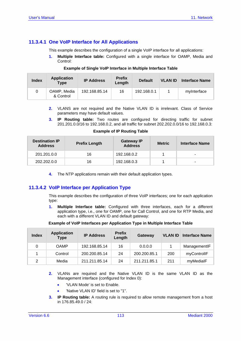
Version 6.6 113 Mediant 2000
User's Manual 11. Network
11.3.4.1 One VoIP Interface for All Applications This example describes the configuration of a single VoIP interface for all applications: 1. Multiple Interface table: Configured with a single interface for OAMP, Media and
Control:
Example of Single VoIP Interface in Multiple Interface Table
Index Application Type IP Address Prefix
Length Default VLAN ID Interface Name
0 OAMP, Media & Control
192.168.85.14 16 192.168.0.1 1 myInterface
2. VLANS are not required and the Native VLAN ID is irrelevant. Class of Service
parameters may have default values. 3. IP Routing table: Two routes are configured for directing traffic for subnet
201.201.0.0/16 to 192.168.0.2, and all traffic for subnet 202.202.0.0/16 to 192.168.0.3:
Example of IP Routing Table
Destination IP Address Prefix Length Gateway IP
Address Metric Interface Name
201.201.0.0 16 192.168.0.2 1 -
202.202.0.0 16 192.168.0.3 1 -
4. The NTP applications remain with their default application types.
11.3.4.2 VoIP Interface per Application Type This example describes the configuration of three VoIP interfaces; one for each application type: 1. Multiple Interface table: Configured with three interfaces, each for a different
application type, i.e., one for OAMP, one for Call Control, and one for RTP Media, and each with a different VLAN ID and default gateway:
Example of VoIP Interfaces per Application Type in Multiple Interface Table
Index Application Type IP Address Prefix
Length Gateway VLAN ID Interface Name
0 OAMP 192.168.85.14 16 0.0.0.0 1 ManagementIF
1 Control 200.200.85.14 24 200.200.85.1 200 myControlIF
2 Media 211.211.85.14 24 211.211.85.1 211 myMediaIF
2. VLANs are required and the Native VLAN ID is the same VLAN ID as the Management interface (configured for Index 0): • 'VLAN Mode' is set to Enable. • 'Native VLAN ID' field is set to "1".
3. IP Routing table: A routing rule is required to allow remote management from a host in 176.85.49.0 / 24:

User's Manual 114 Document #: LTRT-68822
Mediant 2000
Example IP Routing Table
Destination IP Address Prefix Length Gateway IP
Address Metric Interface Name
176.85.49.0 24 192.168.0.1 1 -
4. All other parameters are set to their respective default values. The NTP application remains with its default application types.
11.3.4.3 VoIP Interfaces for Combined Application Types This example describes the configuration of multiple interfaces for the following applications: One interface for the OAMP application. Interfaces for Call Control and Media applications. 1. Multiple Interface table:
Example of VoIP Interfaces of Combined Application Types in Multiple Interface Table
Index Application Type IP Address Prefix
Length Gateway VLAN ID Interface Name
0 OAMP 192.168.85.14 16 192.168.0.1 1 Mgmt
1 Media & Control
200.200.85.14 24 200.200.85.1 201 MediaCntrl1
2 Media & Control
200.200.86.14 24 200.200.86.1 202 MediaCntrl2
2. VLANs are required and the Native VLAN ID is the same VLAN ID as the
Management interface (index 0): • 'VLAN Mode' is set to Enable. • 'Native VLAN ID' field is set to "1".
3. IP Routing table: A routing rule is required to allow remote management from a host in 176.85.49.0/24:
Example of IP Routing Table
Destination IP Address Prefix Length Gateway IP
Address Metric Interface Name
176.85.49.0 24 192.168.0.10 1 -
4. The NTP application is configured (using the ini file) to serve as OAMP applications: EnableNTPasOAM = 1
11.3.4.4 VoIP Interfaces with Multiple Default Gateways Below is a configuration example using default gateways per IP network interface. In this example, the default gateway 200.200.85.1 is available for applications allowed on Interface #1, whereas outgoing management traffic (originating on Interface #0) is never directed to this default gateway.

Version 6.6 115 Mediant 2000
User's Manual 11. Network
Configured Default Gateway Example
Index Application Type IP Address Prefix
Length Gateway VLAN ID Interface Name
0 OAMP 192.168.085.214 16 0.0.0.0 100 Mgmt
1 Media & Control 200.200.85.14 24 200.200.85.1 200 CntrlMedia
A separate IP routing table enables you to configure static routing rules. Configuring the following static routing rules enables OAMP applications to access peers on subnet 17.17.0.0 through the gateway 192.168.0.1.
Separate Routing Table Example
Destination IP Address Prefix Length Gateway IP
Address Metric Interface Name Status
17.17.0.0 16 192.168.0.1 1 0 Active
11.4 Configuring the IP Routing Table The IP Routing Table page allows you to define up to 30 static IP routing rules for the device. These rules can be associated with a network interface (defined in the Multiple Interface table) and therefore, the routing decision is based on the source subnet/VLAN. If not associated with an IP interface, the static IP rule is based on destination IP address. Traffic destined to the subnet specified in the routing rule is re-directed to the defined gateway, reachable through the specified interface. Before sending an IP packet, the device searches this table for an entry that matches the requested destination host/network. If such an entry is found, the device sends the packet to the indicated router. If no explicit entry is found, the packet is sent to the default gateway.
To configure static IP routing:
1. Open the IP Routing Table page (Configuration tab > VoIP menu > Network submenu > IP Routing Table).
Figure 11-5: IP Routing Table Page
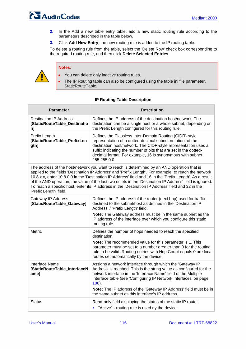
User's Manual 116 Document #: LTRT-68822
Mediant 2000
2. In the Add a new table entry table, add a new static routing rule according to the parameters described in the table below.
3. Click Add New Entry; the new routing rule is added to the IP routing table. To delete a routing rule from the table, select the 'Delete Row' check box corresponding to the required routing rule, and then click Delete Selected Entries.
Notes:
• You can delete only inactive routing rules. • The IP Routing table can also be configured using the table ini file parameter,
StaticRouteTable.
IP Routing Table Description
Parameter Description
Destination IP Address [StaticRouteTable_Destination]
Defines the IP address of the destination host/network. The destination can be a single host or a whole subnet, depending on the Prefix Length configured for this routing rule.
Prefix Length [StaticRouteTable_PrefixLength]
Defines the Classless Inter-Domain Routing (CIDR)-style representation of a dotted-decimal subnet notation, of the destination host/network. The CIDR-style representation uses a suffix indicating the number of bits that are set in the dotted-decimal format. For example, 16 is synonymous with subnet 255.255.0.0.
The address of the host/network you want to reach is determined by an AND operation that is applied to the fields 'Destination IP Address' and 'Prefix Length'. For example, to reach the network 10.8.x.x, enter 10.8.0.0 in the 'Destination IP Address' field and 16 in the 'Prefix Length'. As a result of the AND operation, the value of the last two octets in the 'Destination IP Address' field is ignored. To reach a specific host, enter its IP address in the 'Destination IP Address' field and 32 in the 'Prefix Length' field.
Gateway IP Address [StaticRouteTable_Gateway]
Defines the IP address of the router (next hop) used for traffic destined to the subnet/host as defined in the 'Destination IP Address' / 'Prefix Length' field. Note: The Gateway address must be in the same subnet as the IP address of the interface over which you configure this static routing rule.
Metric Defines the number of hops needed to reach the specified destination. Note: The recommended value for this parameter is 1. This parameter must be set to a number greater than 0 for the routing rule to be valid. Routing entries with Hop Count equals 0 are local routes set automatically by the device.
Interface Name [StaticRouteTable_InterfaceName]
Assigns a network interface through which the 'Gateway IP Address' is reached. This is the string value as configured for the network interface in the 'Interface Name' field of the Multiple Interface table (see 'Configuring IP Network Interfaces' on page 106). Note: The IP address of the 'Gateway IP Address' field must be in the same subnet as this interface's IP address.
Status Read-only field displaying the status of the static IP route: "Active" - routing rule is used ny the device.
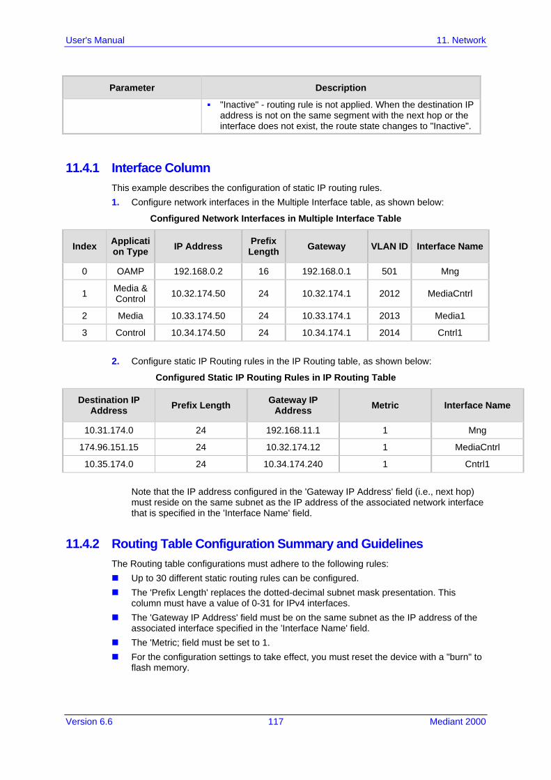
Version 6.6 117 Mediant 2000
User's Manual 11. Network
Parameter Description
"Inactive" - routing rule is not applied. When the destination IP address is not on the same segment with the next hop or the interface does not exist, the route state changes to "Inactive".
11.4.1 Interface Column This example describes the configuration of static IP routing rules. 1. Configure network interfaces in the Multiple Interface table, as shown below:
Configured Network Interfaces in Multiple Interface Table
Index Application Type IP Address Prefix
Length Gateway VLAN ID Interface Name
0 OAMP 192.168.0.2 16 192.168.0.1 501 Mng
1 Media & Control 10.32.174.50 24 10.32.174.1 2012 MediaCntrl
2 Media 10.33.174.50 24 10.33.174.1 2013 Media1
3 Control 10.34.174.50 24 10.34.174.1 2014 Cntrl1
2. Configure static IP Routing rules in the IP Routing table, as shown below:
Configured Static IP Routing Rules in IP Routing Table
Destination IP Address Prefix Length Gateway IP
Address Metric Interface Name
10.31.174.0 24 192.168.11.1 1 Mng
174.96.151.15 24 10.32.174.12 1 MediaCntrl
10.35.174.0 24 10.34.174.240 1 Cntrl1
Note that the IP address configured in the 'Gateway IP Address' field (i.e., next hop) must reside on the same subnet as the IP address of the associated network interface that is specified in the 'Interface Name' field.
11.4.2 Routing Table Configuration Summary and Guidelines The Routing table configurations must adhere to the following rules: Up to 30 different static routing rules can be configured. The 'Prefix Length' replaces the dotted-decimal subnet mask presentation. This
column must have a value of 0-31 for IPv4 interfaces. The 'Gateway IP Address' field must be on the same subnet as the IP address of the
associated interface specified in the 'Interface Name' field. The 'Metric; field must be set to 1. For the configuration settings to take effect, you must reset the device with a "burn" to
flash memory.

User's Manual 118 Document #: LTRT-68822
Mediant 2000
11.4.3 Troubleshooting the Routing Table When adding a new static routing rule, the added rule passes a validation test. If errors are found, the routing rule is rejected and is not added to the IP Routing table. Failed routing validations may result in limited connectivity (or no connectivity) to the destinations specified in the incorrect routing rule. For any error found in the Routing table or failure to configure a routing rule, the device sends a notification message to the Syslog server reporting the problem. Common routing rule configuration errors may include the following: The IP address specified in the 'Gateway IP Address' field is unreachable from the
interface specified in the 'Interface Name' field. The same destination is configured in two different routing rules. More than 30 routing rules have been configured.
Note: If an IP routing rule is required to access OAMP applications (for remote management, for example) and the route is not configured correctly, the route is not added and the device is not accessible remotely. To restore connectivity, the device must be accessed locally from the OAMP subnet and the required routes be configured.
11.5 Configuring Quality of Service The QoS Settings page is used for configuring the Layer-2 and Layer-3 Quality of Service (QoS) parameters. Differentiated Services (DiffServ) is an architecture providing different types or levels of service for IP traffic. DiffServ (according to RFC 2474), prioritizes certain traffic types based on their priority, thereby, accomplishing a higher-level QoS at the expense of other traffic types. By prioritizing packets, DiffServ routers can minimize transmission delays for time-sensitive packets such as VoIP packets. You can assign different VLAN priorities (IEEE 802.1p) and DiffServ to the supported Class of Service (CoS): Network Service class – network control traffic (ICMP, ARP) Premium Media service class – used for RTP media traffic Premium Control service class – used for call control (i.e., SIP) traffic Gold service class – used for streaming applications Bronze service class – used for OAMP applications The Layer-2 QoS parameters define the values for the 3 priority bits in the VLAN tag of frames related to a specific service class (according to the IEEE 802.1p standard). The Layer-3 QoS parameters define the values of the DiffServ field in the IP Header of the frames related to a specific service class. The mapping of an application to its CoS and traffic type is shown in the table below:
Traffic/Network Types and Priority
Application Traffic / Network Types Class-of-Service (Priority)
Debugging interface Management Bronze
Telnet Management Bronze
DHCP Management Network
Web server (HTTP) Management Bronze
SNMP GET/SET Management Bronze
Web server (HTTPS) Management Bronze

Version 6.6 119 Mediant 2000
User's Manual 11. Network
Application Traffic / Network Types Class-of-Service (Priority)
IPSec IKE Determined by the service Determined by the service
RTP traffic Media Premium media
RTCP traffic Media Premium media
T.38 traffic Media Premium media
SIP Control Premium control
SIP over TLS (SIPS) Control Premium control
Syslog Management Bronze
ICMP Management Determined by the initiator of the request
ARP listener Determined by the initiator of the request
Network
SNMP Traps Management Bronze
DNS client Varies according to DNS settings: OAMP Control
Depends on traffic type: Control: Premium Control Management: Bronze
NTP Varies according to the interface type associated with NTP (see 'Assigning NTP Services to Application Types' on page 111): OAMP Control
Depends on traffic type: Control: Premium control Management: Bronze
NFS NFSServers_VlanType in the NFSServers table
Gold
To configure QoS: 1. Open the QoS Settings page (Configuration tab > VoIP menu > Network submenu >
QoS Settings).
2. Configure the QoS parameters as required. 3. Click Submit to apply your changes. 4. Save the changes to flash memory (see 'Saving Configuration' on page 396).

User's Manual 120 Document #: LTRT-68822
Mediant 2000
11.6 Disabling ICMP Redirect Messages You can configure the device's handling of ICMP Redirect messages. These messages can either be rejected (ignored) or permitted.
Note: You can also configure this feature using the ini file parameter DisableICMPRedirects (see 'Routing Parameters' on page 505).
To configure the handling of ICMP Redirect messages:
1. Open the Network Settings page (Configuration tab > VoIP menu > Network submenu > Network Settings).
Figure 11-6: Disabling ICMP Redirect in Network Settings Page
2. From the 'Disable ICMP Redirects' drop-down list, select the required option. 3. Click Submit to apply your changes.
11.7 DNS You can use the device's embedded domain name server (DNS) or an external, third-party DNS to translate domain names into IP addresses. This is useful if domain names are used as the destination in call routing. The device supports the configuration of the following DNS types: Internal DNS table - see 'Configuring the Internal DNS Table' on page 120 Internal SRV table - see 'Configuring the Internal SRV Table' on page 122
11.7.1 Configuring the Internal DNS Table The Internal DNS Table page, similar to a DNS resolution, translates up to 20 host (domain) names into IP addresses. This functionality can be used when a domain name (FQDN) is configured as an IP destination for Tel-to-IP or IP-to-IP routing in the Outbound IP Routing Table. Up to four different IP addresses can be assigned to the same host name. This is typically needed for alternative Tel-to-IP call routing.
Notes:
• The device initially attempts to resolve a domain name using the Internal DNS table. If the domain name isn't listed in the table, the device performs a DNS resolution using an external DNS server for the related IP network interface, configured in the Multiple Interface table (see 'Configuring IP Network Interfaces' on page 106).
• You can also configure the DNS table using the table ini file parameter, DNS2IP (see 'DNS Parameters' on page 510).

Version 6.6 121 Mediant 2000
User's Manual 11. Network
To configure the internal DNS table:
1. Open the Internal DNS Table page (Configuration tab > VoIP menu > Network submenu > DNS submenu > Internal DNS Table).
2. Click Add; the following dialog box appears:
Figure 11-7: Internal DNS Table - Add Record Dialog Box
3. Configure the DNS rule, as required. For a description of the parameters, see the
table below. 4. Click Submit; the DNS rule is added to the table.
Internal DNS Table Parameter Description
Parameter Description
Domain Name [Dns2Ip_DomainName]
Defines the host name to be translated. The valid value is a string of up to 31 characters.
First IP Address [Dns2Ip_FirstIpAddress]
Defines the first IP address (in dotted-decimal format notation) to which the host name is translated.
Second IP Address [Dns2Ip_SecondIpAddress]
Defines the second IP address (in dotted-decimal format notation) to which the host name is translated.
Third IP Address [Dns2Ip_ThirdIpAddress]
Defines the third IP address (in dotted-decimal format notation) to which the host name is translated.
Fourth IP Address [Dns2Ip_FourthIpAddress]
Defines the fourth IP address (in dotted-decimal format notation) to which the host name is translated.

User's Manual 122 Document #: LTRT-68822
Mediant 2000
11.7.2 Configuring the Internal SRV Table The Internal SRV Table page resolves host names to DNS A-Records. Three different A-Records can be assigned to each host name, where each A-Record contains the host name, priority, weight, and port.
Notes:
• If the Internal SRV table is configured, the device initially attempts to resolve a domain name using this table. If the domain name isn't found, the device performs a Service Record (SRV) resolution using an external DNS server configured in the Multiple Interface table (see 'Configuring IP Network Interfaces' on page 106).
• The Internal SRV table can also be configured using the table ini file parameter, SRV2IP (see 'DNS Parameters' on page 510).
To configure the Internal SRV table: 1. Open the Internal SRV Table page (Configuration tab > VoIP menu > Network
submenu > DNS submenu > Internal SRV Table). 2. Click Add; the following dialog box appears:
Figure 11-8: Internal SRV Table Page
3. Configure the SRV rule, as required. For a description of the parameters, see the table
below. 4. Click Submit; the SRV rule is added to the table.

Version 6.6 123 Mediant 2000
User's Manual 11. Network
Internal SRV Table Parameter Description
Parameter Description
Domain Name [Srv2Ip_InternalDomain]
Defines the host name to be translated. The valid value is a string of up to 31 characters.
Transport Type [Srv2Ip_TransportType]
Defines the transport type. [0] UDP (default) [1] TCP [2] TLS
DNS Name (1-3) [Srv2Ip_Dns1/2/3]
Defines the first, second or third DNS A-Record to which the host name is translated.
Priority (1-3) [Srv2Ip_Priority1/2/3]
Defines the priority of the target host. A lower value means that it is more preferred.
Weight (1-3) [Srv2Ip_Weight1/2/3]
Defines a relative weight for records with the same priority.
Port (1-3) [Srv2Ip_Port1/2/3]
Defines the TCP or UDP port on which the service is to be found.
11.8 Configuring NFS Settings Network File System (NFS) enables the device to access a remote server's shared files and directories and to handle them as if they're located locally. The device can use NFS to load cmp, ini, and auxiliary files through the Automatic Update mechanism (see 'Automatic Update' on page 423). You can configure up to 16 different NFS file systems. As a file system, the NFS is independent of machine types, operating systems and network architectures. Note that an NFS file server can share multiple file systems. There must be a separate row for each remote file system shared by the NFS file server that needs to be accessed by the device.
To add remote NFS file systems: 1. Open the Application Settings page (Configuration tab > System menu >
Application Settings).
2. Under the 'NFS Settings' group, click the NFS Table button; the NFS Table page appears.
3. Click the Add button; the Add Record dialog box appears:
Figure 11-9: Add Record Dialog Box for NFS

User's Manual 124 Document #: LTRT-68822
Mediant 2000
4. Configure the NFS parameters according to the table below. 5. Click the Submit button; the remote NFS file system is immediately applied, which
can be verified by the appearance of the 'NFS mount was successful' message in the Syslog server.
6. To save the changes to flash memory, see 'Saving Configuration' on page 396.
Notes:
• To avoid terminating current calls, a row must not be deleted or modified while the device is currently accessing files on that remote NFS file system.
• The combination of 'Host Or IP' and 'Root Path' must be unique for each row in the table. For example, the table must include only one row with a Host/IP of 192.168.1.1 and Root Path of /audio.
• The NFS table can also be configured using the table ini file parameter NFSServers (see 'NFS Parameters' on page 509)
NFS Settings Parameters
Parameter Description
Index The row index of the remote file system. The valid range is 1 to 16.
Host Or IP [NFSServers_HostOrIP]
The domain name or IP address of the NFS server. If a domain name is provided, a DNS server must be configured.
Root Path [NFSServers_RootPath]
Path to the root of the remote file system in the format: /[path]. For example, '/audio'.
NFS Version [NFSServers_NfsVersion]
NFS version used to access the remote file system. [2] NFS Version 2 [3] NFS Version 3 (default)
Authentication Type [NFSServers_AuthType]
Authentication method used for accessing the remote file system. [0] Null [1] Unix (default)
User ID [NFSServers_UID]
User ID used in authentication when using Unix. The valid range is 0 to 65537. The default is 0.
Group ID [NFSServers_GID]
Group ID used in authentication when using Unix. The valid range is 0 to 65537. The default is 1.
VLAN Type [NFSServers_VlanType]
The VLAN type for accessing the remote file system. [0] OAM [1] MEDIA (default) Note: This parameter applies only if VLANs are enabled or if Multiple IPs is configured (see 'Configuring IP Network Interfaces' on page 106).

Version 6.6 125 Mediant 2000
User's Manual 11. Network
11.9 Network Address Translation Support Network Address Translation (NAT) is a mechanism that maps internal IP addresses (and ports) used within a private network to global IP addresses and vice versa, providing transparent routing to end hosts. The primary advantages of NAT include (1) reduction in the number of global IP addresses required in a private network (global IP addresses are only used to connect to the Internet) and (2) better network security by hiding the internal architecture. The design of SIP creates a problem for VoIP traffic to pass through NAT. SIP uses IP addresses and port numbers in its message body. However, the NAT server is unable to modify the SIP messages and thus, can’t change local addresses to global addresses. This section discusses the device's solutions for overcoming NAT traversal issues.
11.9.1 Device Located behind NAT Two different streams traverse through NAT - signaling and media. A device located behind a NAT, that initiates a signaling path has problems receiving incoming signaling responses as they are blocked by the NAT server. Therefore, the initiating device must inform the receiving device where to send the media. To resolve this NAT problem, the following solutions are provided by the device, listed in priority of the selected method used by the device: a. If configured, uses an external STUN server to assign a NAT address to all interfaces
- see .Configuring STUN on page 126. b. If configured, uses the single Static NAT IP address for all interfaces - see 'Configuring
a Static NAT IP Address for All Interfaces' on page 127. c. If configured, uses the NAT Translation table which configures NAT per interface - see
Configuring NAT Translation per IP Interface on page 127. If NAT is not configured by any of the above-mentioned methods, the device sends the packet according to its IP address configured in the Multiple Interface table. he figure below illustrates the NAT problem faced by the SIP networks where the device is located behind a NAT:
Figure 11-10: Device behind NAT and NAT Issues

User's Manual 126 Document #: LTRT-68822
Mediant 2000
11.9.1.1 Configuring STUN Simple Traversal of UDP through NATs (STUN), based on RFC 3489 is a client / server protocol that solves most of the NAT traversal problems. The STUN server operates in the public Internet and the STUN clients are embedded in end-devices located behind NAT. STUN is used for signaling and the media streams. STUN works with many existing NAT types and does not require any special behavior. STUN enables the device to discover the presence (and types) of NATs and firewalls located between it and the public Internet. It provides the device with the capability to determine the public IP address and port allocated to it by the NAT. This information is later embedded in outgoing SIP / SDP messages and enables remote SIP user agents to reach the device. It also discovers the binding lifetime of the NAT - the refresh rate necessary to keep NAT ‘pinholes’ open. On startup, the device sends a STUN Binding Request. The information received in the STUN Binding Response (IP address:port) is used for SIP signaling. This information is updated every user-defined period (NATBindingDefaultTimeout). At the beginning of each call and if STUN is required (i.e., not an internal NAT call), the media ports of the call are mapped. The call is delayed until the STUN Binding Response (that includes a global IP:port) for each media (RTP, RTCP and T.38) is received.
Notes:
• STUN is applicable only to UDP connections (not TCP and TLS). • STUN can’t be used when the device is located behind a symmetric NAT. • Use either the STUN server IP address (STUNServerPrimaryIP) or domain name
(STUNServerDomainName) method, with priority to the first one.
To enable STUN:
1. Open the Application Settings page (Configuration tab > System menu > Application Settings).
Figure 11-11: STUN Parameters in Application Settings Page
2. From the 'Enable STUN' (EnableSTUN) drop-down list, select Enable to enable the
STUN feature. 3. Configure the STUN server address using one of the following methods:
• Define the IP address of the primary and secondary (optional) STUN servers, using the 'STUN Server Primary IP' field (STUNServerPrimaryIP) and 'STUN Server Secondary IP' field. If the primary STUN server is unavailable, the device attempts to communicate with the second server.
• Define the domain name of the STUN server using the ini file parameter, STUNServerDomainName. The STUN client retrieves all STUN servers with an SRV query to resolve this domain name to an IP address and port, sorts the server list, and uses the servers according to the sorted list.
4. Configure the default NAT binding lifetime (in secondsUse) using the ini file parameter, NATBindingDefaultTimeout. STUN refreshes the binding information after this time expires.

Version 6.6 127 Mediant 2000
User's Manual 11. Network
11.9.1.2 Configuring a Static NAT IP Address for All Interfaces You can configure a global (public) IP address of the router to enable static NAT between the device and the Internet for all network interfaces. Thus, the device replaces the source IP address for media of all outgoing SIP messages sent on any of its network interfaces to this public IP address.
Note: The NAT IP address can also be configured using the ini file parameter, StaticNATIP.
To configure a single static NAT IP address for all interfaces:
1. Open the SIP General Parameters page (Configuration tab > VoIP menu > SIP Definitions submenu > General Parameters).
Figure 11-12: Configuring Static NAT IP Address in SIP General Parameters Page
2. In the 'NAT IP Address' field, enter the NAT IP address in dotted-decimal notation. 3. Click Submit. 4. Save the setting to the device's flash memory with a device reset (see 'Saving
Configuration' on page 396).
11.9.1.3 Configuring NAT Translation per IP Interface The NAT Translation table defines network address translation (NAT) rules for translating source IP addresses per VoIP interface (SIP control and RTP media traffic) into NAT IP addresses (global or public), when the device is located behind NAT. This allows, for example, the separation of VoIP traffic between different ITSP’s, and topology hiding of internal IP addresses to the “public” network. Each IP interface (configured in the Multiple Interface table) can be associated with a NAT rule in this table, translating the source IP address and port of the outgoing packet into the NAT address (IP address and port range). The device's NAT traversal mechanism replaces the source IP address of SIP messages sent from a specified VoIP interface to a public IP address.
Note: The NAT Translation table can also be configured using the table ini file parameter, NATTranslation.

User's Manual 128 Document #: LTRT-68822
Mediant 2000
To configure NAT translation rules:
1. Open the NAT Translation Table page (Configuration tab > VoIP menu > Control Network submenu > NAT Translation Table).
2. Click the Add button; the following dialog box appears:
Figure 11-13: NAT Translation Table Page
3. Configure the parameters as required. For a description of the parameters, see the
table below: 4. Click Submit to apply your changes. 5. To save the changes to flash memory, see 'Saving Configuration' on page 396.
NAT Translation Table Parameters
Parameter Description
Index [NATTranslation_Index]
Defines the table index entry. This table can include up to 32 entries.
Source Interface Name [NATTranslation_SourceIPInterfaceName]
Defines the name of the IP interface, as appears in the Multiple Interface table. Note: If the Multiple Interface table is not configured, the default Source IP Interface Name is "All". This represents the single IP interface for OAMP, Control, and Media (defined by the LocalOAMIPAddress, LocalOAMSubnetMask, and LocalOAMDefaultGW parameters).
Target IP Address [NATTranslation_TargetIPAddress]
Defines the global IP address. This address is set in the SIP Via and Contact headers as well as in the o= and c= SDP fields.
Source Start Port [NATTranslation_SourceStartPort]
Defines the optional starting port range (1-65536) of the IP interface, used as matching criteria for this NAT rule. If not configured, the match is done on the entire port range. Only IP addresses and ports of matched source ports will be replaced.
Source End Port [NATTranslation_SourceEndPort]
Defines the optional ending port range (1-65536) of the IP interface, used as matching criteria for this NAT rule. If not configured, the match is done on the entire port range. Only IP addresses and ports of matched source ports will be replaced.

Version 6.6 129 Mediant 2000
User's Manual 11. Network
Parameter Description
Target Start Port [NATTranslation_TargetStartPort]
Defines the optional, starting port range (1-65536) of the global address. If not configured, the ports are not replaced. Matching source ports are replaced with the target ports. This address is set in the SIP Via and Contact headers, as well as in the o= and c= SDP fields.
Target End Port [NATTranslation_TargetEndPort]
Defines the optional, ending port range (1-65536) of the global address. If not configured, the ports are not replaced. Matching source ports are replaced with the target ports. This address is set in the SIP Via and Contact headers, as well as in the o= and c= SDP fields.
11.9.2 Remote UA behind NAT If the remote User Agent with which the device needs to communicate with is located behind NAT, the device can resolve the problem of activating the RTP/RTCP/T.38 streams to an invalid IP address / UDP port. To resolve this NAT traversal issue, the device offers the following features: First Incoming Packet Mechanism - see 'First Incoming Packet Mechanism' on page
129 RTP No-Op packets according to the avt-rtp-noop draft - see 'No-Op Packets' on page
130 The figure below illustrates a typical network architecture where the remote UA is located behind NAT:
Figure 11-14: Remote UA behind NAT
11.9.2.1 First Incoming Packet Mechanism If the remote device resides behind a NAT device, it’s possible that the device can activate the RTP/RTCP/T.38 streams to an invalid IP address / UDP port. To avoid such cases, the device automatically compares the source address of the first received incoming RTP/RTCP/T.38 stream with the IP address and UDP port of the remote device when the session was initially opened. If the two are not identical, then the destination IP address of the outgoing RTP packets is set to the source IP address of the first incoming packet. The RTP, RTCP and T.38 can thus have independent destination IP addresses and UDP ports.
To enable NAT resolution using the First Incoming Packet mechanism:
1. Open the General Media Settings page (Configuration tab > VoIP menu > Media > General Media Settings).
2. Set the 'NAT Traversal' parameter to Enable. 3. Click Submit.

User's Manual 130 Document #: LTRT-68822
Mediant 2000
The EnableIpAddrTranslation and EnableUdpPortTranslation parameters allow you to specify the type of compare operation that occurs on the first incoming packet. To compare only the IP address, set EnableIpAddrTranslation to 1, and EnableUdpPortTranslation to 0. In this case, if the first incoming packet arrives with only a difference in the UDP port, the sending addresses won’t change. If both the IP address and UDP port need to be compared, then both parameters need to be set to 1.
11.9.2.2 No-Op Packets The device's No-Op packet support can be used to verify Real-Time Transport Protocol (RTP) and T.38 connectivity, and to keep NAT bindings and Firewall pinholes open. The No-Op packets are available for sending in RTP and T.38 formats. You can control the activation of No-Op packets by using the ini file parameter NoOpEnable. If No-Op packet transmission is activated, you can control the time interval in which No-Op packets are sent in the case of silence (i.e., no RTP or T.38 traffic). This is done using the ini file parameter NoOpInterval. For a description of the RTP No-Op ini file parameters, see 'Networking Parameters' on page 503. RTP No-Op: The RTP No-Op support complies with IETF Internet-Draft draft-wing-
avt-rtp-noop-03 ("A No-Op Payload Format for RTP"). This IETF document defines a No-Op payload format for RTP. The draft defines the RTP payload type as dynamic. You can control the payload type with which the No-Op packets are sent. This is performed using the RTPNoOpPayloadType ini parameter (see 'Networking Parameters' on page 503). The default payload type is 120.
T.38 No-Op: T.38 No-Op packets are sent only while a T.38 session is activated. Sent packets are a duplication of the previously sent frame (including duplication of the sequence number).
Note: Receipt of No-Op packets is always supported.
11.10 Robust Receipt of Media Streams The “robust-media” mechanism is an AudioCodes proprietary mechanism to filter out unwanted media (i.e., RTP, RTCP, and T.38) streams that are sent to the same port number on the device. In practice, the media RTP/RTCP ports may receive additional multiple unwanted media streams as result of traces of previous calls, call control errors, or deliberate attacks. When more than one media stream reaches the device on the same port number, the “robust-media” mechanism detects the valid media stream and ignores the rest.

Version 6.6 131 Mediant 2000
User's Manual 11. Network
11.11 Multiple Routers Support Multiple routers support is designed to assist the device when it operates in a multiple routers network. The device learns the network topology by responding to Internet Control Message Protocol (ICMP) redirections and caches them as routing rules (with expiration time). When a set of routers operating within the same subnet serve as devices to that network and intercommunicate using a dynamic routing protocol, the routers can determine the shortest path to a certain destination and signal the remote host the existence of the better route. Using multiple router support, the device can utilize these router messages to change its next hop and establish the best path.
Note: Multiple Routers support is an integral feature that doesn’t require configuration.
11.12 IP Multicasting The device supports IP Multicasting level 1, according to RFC 2236 (i.e., IGMP version 2) for RTP channels. The device is capable of transmitting and receiving multicast packets.

User's Manual 132 Document #: LTRT-68822
Mediant 2000
Reader's Notes

Version 6.6 133 Mediant 2000
User's Manual 12. Security
12 Security This section describes the VoIP security-related configuration.
12.1 Configuring Firewall Settings The device provides an internal firewall that enables you to configure network traffic filtering rules (access list). You can add up to 50 firewall rules. The access list offers the following firewall possibilities: Block traffic from known malicious sources Allow traffic only from known "friendly" sources, and block all other traffic Mix allowed and blocked network sources Limit traffic to a user-defined rate (blocking the excess) Limit traffic to specific protocols, and specific port ranges on the device For each packet received on the network interface, the table is scanned from top to bottom until the first matching rule is found. This rule can either permit (allow) or deny (block) the packet. Once a rule in the table is located, subsequent rules further down the table are ignored. If the end of the table is reached without a match, the packet is accepted.
Notes:
• This firewall applies to a very low-level network layer and overrides your other security-related configuration. Thus, if you have configured higher-level security features (e.g., on the Application level), you must also configure firewall rules to permit this necessary traffic. For example, if you have configured IP addresses to access the Web and Telnet interfaces in the Web Access List (see 'Configuring Web and Telnet Access List' on page 68), you must configure a firewall rule that permits traffic from these IP addresses.
• Only Security Administrator users or Master users can configure firewall rules. • Setting the 'Prefix Length' field to 0 means that the rule applies to all packets,
regardless of the defined IP address in the 'Source IP' field. Therefore, it is highly recommended to set this parameter to a value other than 0.
• It is recommended to add a rule at the end of your table that blocks all traffic and to add firewall rules above it that allow required traffic (with bandwidth limitations). To block all traffic, use the following firewall rule: - Source IP: 0.0.0.0 - Prefix Length: 0 (i.e., rule matches all IP addresses) - Start Port - End Port: 0-65535 - Protocol: Any - Action Upon Match: Block
• You can also configure the firewall settings using the table ini file parameter, AccessList (see 'Security Parameters' on page 528).

User's Manual 134 Document #: LTRT-68822
Mediant 2000
To add firewall rules:
1. Open the Firewall Settings page (Configuration tab > VoIP menu > Security submenu > Firewall Settings).
2. Click the Add button; the following dialog box appears:
Figure 12-1: Firewall Settings Page - Add Record
3. Configure the firewall parameters, as required. For a description of the parameters,
see the table below. 4. Click Submit to add the new firewall rule to the table. 5. Reset the device to activate the rules. The table below provides an example of configured firewall rules:
Firewall Rule Examples
Parameter Value per Rule
1 2 3 4 5
Source IP 12.194.231.76 12.194.230.7 0.0.0.0 192.0.0.0 0.0.0.0
Prefix Length 16 16 0 8 0
Start Port and End Port 0-65535 0-65535 0-65535 0-65535 0-65535
Protocol Any Any icmp Any Any
Use Specific Interface Enable Enable Disable Enable Disable
Interface Name WAN WAN None Voice-Lan None
Byte Rate 0 0 40000 40000 0
Burst Bytes 0 0 50000 50000 0
Action Upon Match Allow Allow Allow Allow Block

Version 6.6 135 Mediant 2000
User's Manual 12. Security
The firewall rules in the above configuration example do the following: Rules 1 and 2: Typical firewall rules that allow packets ONLY from specified IP
addresses (e.g., proxy servers). Note that the prefix length is configured. Rule 3: A more "advanced” firewall rule - bandwidth rule for ICMP, which allows a
maximum bandwidth of 40,000 bytes/sec with an additional allowance of 50,000 bytes. If, for example, the actual traffic rate is 45,000 bytes/sec, then this allowance would be consumed within 10 seconds, after which all traffic exceeding the allocated 40,000 bytes/sec is dropped. If the actual traffic rate then slowed to 30,000 bytes/sec, the allowance would be replenished within 5 seconds.
Rule 4: Allows traffic from the LAN voice interface and limits bandwidth. Rule 5: Blocks all other traffic.
Internal Firewall Parameters
Parameter Description
Source IP [AccessList_Source_IP]
Defines the IP address (or DNS name) or a specific host name of the source network (i.e., from where the incoming packet is received).
Source Port [AccessList_Source_Port]
Defines the source UDP/TCP ports (of the remote host) from where packets are sent to the device. The valid range is 0 to 65535. Note: When set to 0, this field is ignored and any source port matches the rule.
Prefix Length [AccessList_PrefixLen]
(Mandatory) Defines the IP network mask - 32 for a single host or the appropriate value for the source IP addresses. A value of 8 corresponds to IPv4 subnet class A (network mask
of 255.0.0.0). A value of 16 corresponds to IPv4 subnet class B (network mask
of 255.255.0.0). A value of 24 corresponds to IPv4 subnet class C (network mask
of 255.255.255.0). The IP address of the sender of the incoming packet is trimmed in accordance with the prefix length (in bits) and then compared to the parameter ‘Source IP’. The default is 0 (i.e., applies to all packets). You must change this value to any of the above options. Note: A value of 0 applies to all packets, regardless of the defined IP address. Therefore, you must set this parameter to a value other than 0.
Start Port [AccessList_Start_Port]
Defines the destination UDP/TCP start port (on this device) to where packets are sent. The valid range is 0 to 65535. Note: When the protocol type isn't TCP or UDP, the entire range must be provided.
End Port [AccessList_End_Port]
Defines the destination UDP/TCP end port (on this device) to where packets are sent. The valid range is 0 to 65535. Note: When the protocol type isn't TCP or UDP, the entire range must be provided.
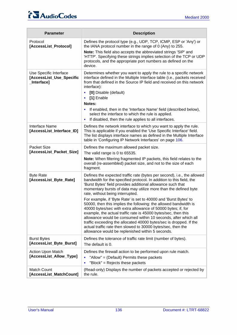
User's Manual 136 Document #: LTRT-68822
Mediant 2000
Parameter Description
Protocol [AccessList_Protocol]
Defines the protocol type (e.g., UDP, TCP, ICMP, ESP or 'Any') or the IANA protocol number in the range of 0 (Any) to 255. Note: This field also accepts the abbreviated strings 'SIP' and 'HTTP'. Specifying these strings implies selection of the TCP or UDP protocols, and the appropriate port numbers as defined on the device.
Use Specific Interface [AccessList_Use_Specific_Interface]
Determines whether you want to apply the rule to a specific network interface defined in the Multiple Interface table (i.e., packets received from that defined in the Source IP field and received on this network interface): [0] Disable (default) [1] Enable Notes: If enabled, then in the 'Interface Name' field (described below),
select the interface to which the rule is applied. If disabled, then the rule applies to all interfaces.
Interface Name [AccessList_Interface_ID]
Defines the network interface to which you want to apply the rule. This is applicable if you enabled the 'Use Specific Interface' field. The list displays interface names as defined in the Multiple Interface table in 'Configuring IP Network Interfaces' on page 106.
Packet Size [AccessList_Packet_Size]
Defines the maximum allowed packet size. The valid range is 0 to 65535. Note: When filtering fragmented IP packets, this field relates to the overall (re-assembled) packet size, and not to the size of each fragment.
Byte Rate [AccessList_Byte_Rate]
Defines the expected traffic rate (bytes per second), i.e., the allowed bandwidth for the specified protocol. In addition to this field, the 'Burst Bytes' field provides additional allowance such that momentary bursts of data may utilize more than the defined byte rate, without being interrupted. For example, if 'Byte Rate' is set to 40000 and 'Burst Bytes' to 50000, then this implies the following: the allowed bandwidth is 40000 bytes/sec with extra allowance of 50000 bytes; if, for example, the actual traffic rate is 45000 bytes/sec, then this allowance would be consumed within 10 seconds, after which all traffic exceeding the allocated 40000 bytes/sec is dropped. If the actual traffic rate then slowed to 30000 bytes/sec, then the allowance would be replenished within 5 seconds.
Burst Bytes [AccessList_Byte_Burst]
Defines the tolerance of traffic rate limit (number of bytes). The default is 0.
Action Upon Match [AccessList_Allow_Type]
Defines the firewall action to be performed upon rule match. "Allow" = (Default) Permits these packets "Block" = Rejects these packets
Match Count [AccessList_MatchCount]
(Read-only) Displays the number of packets accepted or rejected by the rule.

Version 6.6 137 Mediant 2000
User's Manual 12. Security
12.2 Configuring General Security Settings The General Security Settings page is used to configure various security features. For a description of the parameters appearing on this page, refer 'Configuration Parameters Reference' on page 503.
To configure the general security parameters:
1. Open the General Security Settings page (Configuration tab > VoIP menu > Security submenu > General Security Settings).
2. Configure the parameters as required. 3. Click Submit to apply your changes. 4. To save the changes to flash memory, refer to 'Saving Configuration' on page 396.
12.3 IPSec and Internet Key Exchange IP security (IPSec) and Internet Key Exchange (IKE) protocols are part of the IETF standards for establishing a secured IP connection between two applications (also referred to as peers). Providing security services at the IP layer, IPSec and IKE are transparent to IP applications. IPSec and IKE are used together to provide security for control and management (e.g., SNMP and Web) protocols, but not for media (i.e., RTP, RTCP and T.38). IKE is used to obtain the Security Associations (SA) between peers (the device and the application it’s trying to contact). The SA contains the encryption keys and profile used by IPSec to encrypt the IP stream. IKE negotiation comprises the following two phases: Main Mode (creates a secured channel for the Quick mode by obtaining a "master"
encryption key, without any prior keys, and authenticates the peers to each other):

User's Manual 138 Document #: LTRT-68822
Mediant 2000
• SA negotiation: The peers negotiate their capabilities using up to four proposals. Each proposal includes the Encryption method, Authentication algorithm, and the Diffie-Hellman (DH) group. The master key’s lifetime is also negotiated.
• Key exchange (DH): The DH protocol creates the master key. DH requires both peers to agree on certain mathematical parameters, known as the "group".
• Authentication: The two peers authenticate one another using a pre-shared key configured in the IP Security Associations Table or by using certificate-based authentication.
Quick Mode (creates the encrypted IPSec tunnel once initial security is set up): • SA negotiation: An IPSec SA is created by negotiating encryption and
authentication capabilities using the same proposal mechanism as in Main mode. • Key exchange: A symmetrical key is created for encrypting IPSec traffic; the
peers communicate with each other in encrypted form, secured by the previously negotiated "master" key.
IKE specifications summary: Authentication methods: pre-shared key or certificate-based authentication Main mode supported for IKE Phase 1 DH group 1 or group 2 Encryption algorithms: Data Encryption Standard (DES), Advanced Encryption
Standard (AES), and 3DES Hash algorithms: SHA1 and MD5 IPSec is responsible for securing the IP traffic. This is accomplished by using the Encapsulation Security Payload (ESP) protocol to encrypt (and decrypt) the IP payload. This is configured in the IPSec Security Association table, which defines the IP peers to which IPSec security is applied. IPSec specifications summary: Transport and Tunneling Mode Encapsulation Security Payload (ESP) only Encryption algorithms: AES, DES, and 3DES Hash types: SHA1 and MD5
12.3.1 Enabling IPSec To enable IKE and IPSec processing, you must enable the IPSec feature, as described below.
To enable IPSec:
1. Open the General Security Settings page (Configuration tab > VoIP menu > Security > General Security Settings).
Figure 12-2: Enabling IPSec
2. Set the 'Enable IP Security' parameter to Enable. 3. Click Submit, and then reset the device with a flash burn.

Version 6.6 139 Mediant 2000
User's Manual 12. Security
12.3.2 Configuring IP Security Proposal Table The IP Security Proposal Table page is used to configure Internet Key Exchange (IKE) with up to four proposal settings. Each proposal defines an encryption algorithm, an authentication algorithm, and a Diffie-Hellman group identifier. The same set of proposals applies to both Main mode and Quick mode.
Note: You can also configure the IP Security Proposals table using the table ini file parameter IPsecProposalTable (see 'Security Parameters' on page 528).
To configure IP Security Proposals:
1. Open the IP Security Proposal Table page (Configuration tab > VoIP menu > Security submenu > IPSec Proposal Table).
2. Click the Add button; the following dialog box appears:
Figure 12-3: IP Security Proposals Table - Add Record Dialog Box
3. Configure the parameters, as required. For a description of the parameters, see the
table below. 4. Click Submit. 5. To save the changes to flash memory, see 'Saving Configuration' on page 396.
IP Security Proposals Table Configuration Parameters
Parameter Name Description
Encryption Algorithm [IPsecProposalTable_EncryptionAlgorithm]
Defines the encryption (privacy) algorithm. [0] NONE [1] DES CBC [2] 3DES CBC [3] AES (default)
Authentication Algorithm [IPsecProposalTable_AuthenticationAlgorithm]
Defines the message authentication (integrity) algorithm. [0] NONE [2] HMAC SHA1 96 [4] HMAC MD5 96 (default)
Diffie Hellman Group [IPsecProposalTable_DHGroup]
Defines the length of the key created by the DH protocol for up to four proposals. For the ini file parameter, X denotes the proposal number (0 to 3). [0] Group 1 (768 Bits) = DH-786-Bit [1] Group 2 (1024 Bits) (default) = DH-1024-Bit
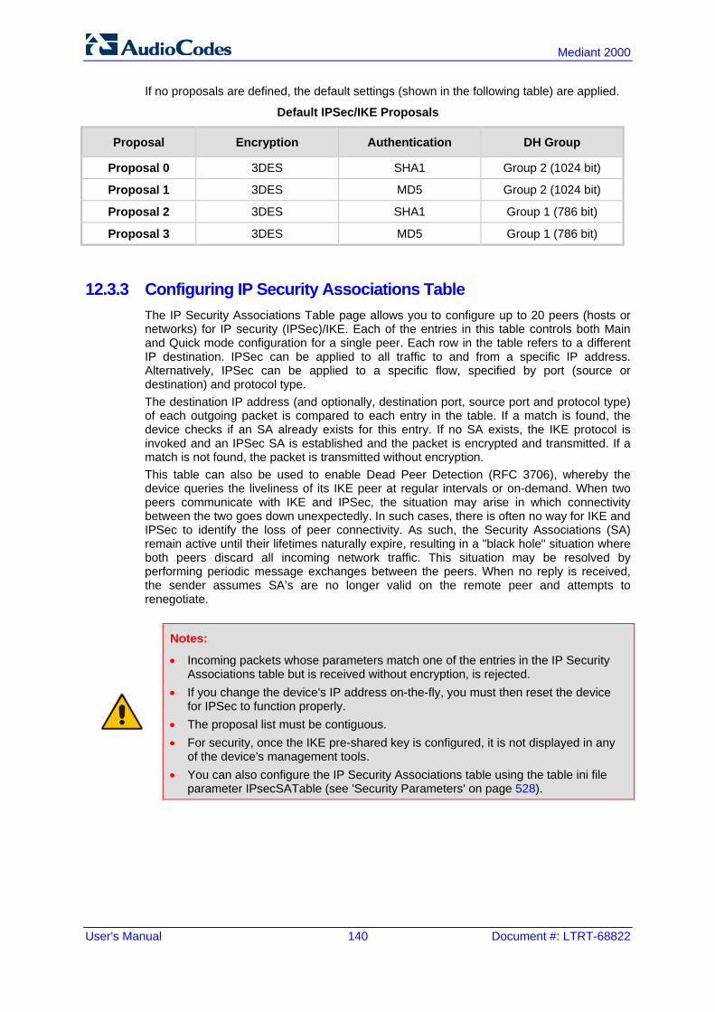
User's Manual 140 Document #: LTRT-68822
Mediant 2000
If no proposals are defined, the default settings (shown in the following table) are applied.
Default IPSec/IKE Proposals
Proposal Encryption Authentication DH Group
Proposal 0 3DES SHA1 Group 2 (1024 bit)
Proposal 1 3DES MD5 Group 2 (1024 bit)
Proposal 2 3DES SHA1 Group 1 (786 bit)
Proposal 3 3DES MD5 Group 1 (786 bit)
12.3.3 Configuring IP Security Associations Table The IP Security Associations Table page allows you to configure up to 20 peers (hosts or networks) for IP security (IPSec)/IKE. Each of the entries in this table controls both Main and Quick mode configuration for a single peer. Each row in the table refers to a different IP destination. IPSec can be applied to all traffic to and from a specific IP address. Alternatively, IPSec can be applied to a specific flow, specified by port (source or destination) and protocol type. The destination IP address (and optionally, destination port, source port and protocol type) of each outgoing packet is compared to each entry in the table. If a match is found, the device checks if an SA already exists for this entry. If no SA exists, the IKE protocol is invoked and an IPSec SA is established and the packet is encrypted and transmitted. If a match is not found, the packet is transmitted without encryption. This table can also be used to enable Dead Peer Detection (RFC 3706), whereby the device queries the liveliness of its IKE peer at regular intervals or on-demand. When two peers communicate with IKE and IPSec, the situation may arise in which connectivity between the two goes down unexpectedly. In such cases, there is often no way for IKE and IPSec to identify the loss of peer connectivity. As such, the Security Associations (SA) remain active until their lifetimes naturally expire, resulting in a "black hole" situation where both peers discard all incoming network traffic. This situation may be resolved by performing periodic message exchanges between the peers. When no reply is received, the sender assumes SA’s are no longer valid on the remote peer and attempts to renegotiate.
Notes:
• Incoming packets whose parameters match one of the entries in the IP Security Associations table but is received without encryption, is rejected.
• If you change the device's IP address on-the-fly, you must then reset the device for IPSec to function properly.
• The proposal list must be contiguous. • For security, once the IKE pre-shared key is configured, it is not displayed in any
of the device's management tools. • You can also configure the IP Security Associations table using the table ini file
parameter IPsecSATable (see 'Security Parameters' on page 528).
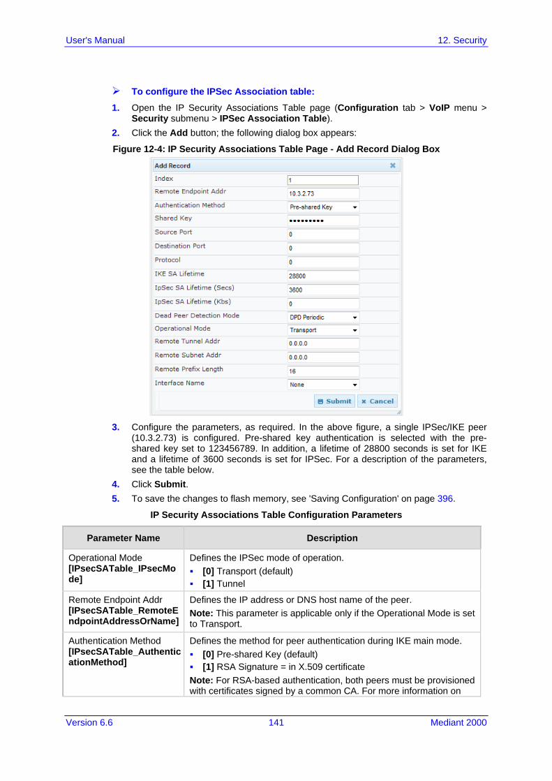
Version 6.6 141 Mediant 2000
User's Manual 12. Security
To configure the IPSec Association table:
1. Open the IP Security Associations Table page (Configuration tab > VoIP menu > Security submenu > IPSec Association Table).
2. Click the Add button; the following dialog box appears:
Figure 12-4: IP Security Associations Table Page - Add Record Dialog Box
3. Configure the parameters, as required. In the above figure, a single IPSec/IKE peer
(10.3.2.73) is configured. Pre-shared key authentication is selected with the pre-shared key set to 123456789. In addition, a lifetime of 28800 seconds is set for IKE and a lifetime of 3600 seconds is set for IPSec. For a description of the parameters, see the table below.
4. Click Submit. 5. To save the changes to flash memory, see 'Saving Configuration' on page 396.
IP Security Associations Table Configuration Parameters
Parameter Name Description
Operational Mode [IPsecSATable_IPsecMode]
Defines the IPSec mode of operation. [0] Transport (default) [1] Tunnel
Remote Endpoint Addr [IPsecSATable_RemoteEndpointAddressOrName]
Defines the IP address or DNS host name of the peer. Note: This parameter is applicable only if the Operational Mode is set to Transport.
Authentication Method [IPsecSATable_AuthenticationMethod]
Defines the method for peer authentication during IKE main mode. [0] Pre-shared Key (default) [1] RSA Signature = in X.509 certificate Note: For RSA-based authentication, both peers must be provisioned with certificates signed by a common CA. For more information on

User's Manual 142 Document #: LTRT-68822
Mediant 2000
Parameter Name Description
certificates, see 'Replacing the Device's Certificate' on page 95.
Shared Key [IPsecSATable_SharedKey]
Defines the pre-shared key (in textual format). Both peers must use the same pre-shared key for the authentication process to succeed. Notes: This parameter is applicable only if the Authentication Method
parameter is set to pre-shared key. The pre-shared key forms the basis of IPSec security and
therefore, it should be handled with care (the same as sensitive passwords). It is not recommended to use the same pre-shared key for several connections.
Since the ini file is plain text, loading it to the device over a secure network connection is recommended. Use a secure transport such as HTTPS, or a direct crossed-cable connection from a management PC.
After it is configured, the value of the pre-shared key cannot be retrieved.
Source Port [IPsecSATable_SourcePort]
Defines the source port to which this configuration applies. The default is 0 (i.e., any port).
Destination Port [IPsecSATable_DestPort]
Defines the destination port to which this configuration applies. The default is 0 (i.e., any port).
Protocol [IPsecSATable_Protocol]
Defines the protocol type to which this configuration applies. Standard IP protocol numbers, as defined by the Internet Assigned Numbers Authority (IANA) should be used, for example: 0 = Any protocol (default) 17 = UDP 6 = TCP
IKE SA Lifetime [IPsecSATable_Phase1SaLifetimeInSec]
Defines the duration (in seconds) for which the negotiated IKE SA (Main mode) is valid. After this time expires, the SA is re-negotiated. The default is 0 (i.e., unlimited). Note: Main mode negotiation is a processor-intensive operation; for best performance, do not set this parameter to less than 28,800 (i.e., eight hours).
IPSec SA Lifetime (sec) [IPsecSATable_Phase2SaLifetimeInSec]
Defines the duration (in seconds) for which the negotiated IPSec SA (Quick mode) is valid. After this time expires, the SA is re-negotiated. The default is 0 (i.e., unlimited). Note: For best performance, a value of 3,600 (i.e., one hour) or more is recommended.
IPSec SA Lifetime (Kbs) [IPsecSATable_Phase2SaLifetimeInKB]
Defines the maximum volume of traffic (in kilobytes) for which the negotiated IPSec SA (Quick mode) is valid. After this specified volume is reached, the SA is re-negotiated. The default is 0 (i.e., the value is ignored).
Dead Peer Detection Mode [IPsecSATable_DPDmode]
Defines dead peer detection (DPD), according to RFC 3706. [0] DPD Disabled (default) [1] DPD Periodic = DPD is enabled with message exchanges at
regular intervals [2] DPD on demand = DPD is enabled with on-demand checks -
message exchanges as needed (i.e., before sending data to the peer). If the liveliness of the peer is questionable, the device sends

Version 6.6 143 Mediant 2000
User's Manual 12. Security
Parameter Name Description
a DPD message to query the status of the peer. If the device has no traffic to send, it never sends a DPD message.
Remote Tunnel Addr [IPsecSATable_RemoteTunnelAddress]
Defines the IP address of the peer router. Note: This parameter is applicable only if the Operational Mode is set to Tunnel.
Remote Subnet Addr [IPsecSATable_RemoteSubnetIPAddress]
Defines the IP address of the remote subnet. Together with the Prefix Length parameter (below), this parameter defines the network with which the IPSec tunnel allows communication. Note: This parameter is applicable only if the Operational Mode is set to Tunnel.
Remote Prefix Length [IPsecSATable_RemoteSubnetPrefixLength]
Defines the prefix length of the Remote Subnet IP Address parameter (in bits). The prefix length defines the subnet class of the remote network. A prefix length of 16 corresponds to a Class B subnet (255.255.0.0); a prefix length of 24 corresponds to a Class C subnet (255.255.255.0). Note: This parameter is applicable only if the Operational Mode is set to Tunnel.
Interface Name [IPsecSATable_InterfaceName]
Assigns a network interface to this IPSec rule. The network interfaces are defined in the Multiple Interface table ('Interface Name' column) in 'Configuring IP Network Interfaces' on page 106

User's Manual 144 Document #: LTRT-68822
Mediant 2000
12.4 Intrusion Detection System The device can be configured to detect malicious attacks on its system and send SNMP traps if malicious activity is identified. The Intrusion Detection System (IDS) is an important feature for Enterprises to ensure legitimate calls are not being adversely affected by attacks and to prevent Theft of Service and unauthorized access. If, for example, you identify the source (IP address) of the attack, you can add that source to your blacklist to prevent it from accessing your device. There are many types of malicious attacks, the most common being: Denial of service: This can be Denial of Service (DoS) where an attacker wishing to
prevent a server from functioning correctly directs a large amount of requests – sometimes meaningless and sometimes legitimate, or it can be Distributed Denial of Service (DDoS) where the attacker controls a large group of systems to coordinate a large scale DoS attack against a system: • Message payload tampering: Attacker may inject harmful content into a message,
e.g., by entering meaningless or wrong information, with the goal of exploiting a buffer overflow at the target. Such messages can be used to probe for vulnerabilities at the target.
• Message flow tampering: This is a special case of DoS attacks. These attacks disturb the ongoing communication between users. An attacker can then target the connection by injecting fake signaling messages into the communication channel (such as CANCEL messages).
• Message Flooding: The most common DoS attack is where an attacker sends a huge amount of messages (e.g., INVITEs) to a target. The goal is to overwhelm the target’s processing capabilities, thereby rendering the target inoperable.
SPAM over Internet Telephony (SPIT): VoIP spam is unwanted, automatically dialed, pre-recorded phone calls using VoIP. It is similar to e-mail spam.
Theft of Service (ToS): Service theft can be exemplified by phreaking, which is a type of hacking that steals service (i.e., free calls) from a service provider, or uses a service while passing the cost to another person.
The IDS configuration is based on IDS Policies, where each policy can be configured with a set of IDS rules. Each rule defines a type of malicious attack to detect and the number of attacks during an interval (threshold) before an SNMP trap is sent. Each policy is then applied to a target under attack (SIP interface) and/or source of attack (Proxy Set and/or subnet address).
12.4.1 Enabling IDS The procedure below describes how to enable IDS.
To enable IDS: 1. Open the IDS Global Parameters page (Configuration tab > VoIP menu > Security >
Intrusion Detection and Prevention > Global Parameters).
Figure 12-5: Enabling IDS on IDS Global Parameters Page
2. From the 'Intrusion Detection System' drop-down list, select Enable. 3. Reset the device with a burn-to-flash for the setting to take effect (see Saving
Configuration).

Version 6.6 145 Mediant 2000
User's Manual 12. Security
12.4.2 Configuring IDS Policies Configuring IDS policies is a two-stage process done in the following tables: 1. IDS Policy table: Defines a name and description for the policy. You can define up to
20 policies. 2. IDS Rules table: Defines the actual IDS rules per policy. Each policy can be
configured with up to 20 rules.
Note: A maximum of 100 IDS rules can be configured (regardless of how many rules are assigned to each policy).
By default and for your convenience, the device provides three pre-configured IDS policies with rules that can be used in your deployment if they meet your requirements: "DEFAULT_FEU": Policy for far-end users in the WAN "DEFAULT_PROXY": Policy for proxy server "DEFAULT_GLOBAL": Policy with global thresholds These default policies are read-only.
To configure IDS polices:
1. Open the IDS Policy Table page (Configuration tab > VoIP menu > Security > Intrusion Detection and Prevention > Policy Table).
Figure 12-6: IDS Policy Table with Default Rules
2. Add a Policy name:
a. Click Add.
Figure 12-7: IDS Policy Table - Add Record
b. Configure the parameters as described in the following table, and then click
Submit.

User's Manual 146 Document #: LTRT-68822
Mediant 2000
Table 12-1: IDS Policy Table Parameters
Parameter Description
Index CLI: policy [IDSPolicy_Index]
Defines the table row number for the policy.
Name CLI: rule [IDSPolicy_Description]
Defines a name for the policy. The valid value is a string of up to 20 characters.
Description [IDSPolicy_Name]
Defines an arbitrary description of the policy. The valid value is a string of up to 100 characters.
3. Add rules to the policy:
a. In the IDS Policy table, select the required policy and then click the IDS Rule Table link located below the table:
Figure 12-8: IDS Rule Table of Selected IDS Policy
b. Click Add.
Figure 12-9: IDS Rule Table - Add Record
c. Configure the parameters as required, and then click Submit. For a description of
these parameters, see the table below. The figure above shows an example configuration where if 15 malformed SIP messages are received within a period of 30 seconds, a minor alarm is sent. Every 30 seconds, the rule’s counters are cleared.
d. To add more rules to the policy, repeat steps 1.b to 1.c.

Version 6.6 147 Mediant 2000
User's Manual 12. Security
Table 12-2: IDS Rule Table Parameters
Parameter Description
Index CLI: rule-id [IDSRule_RuleID]
Defines the table row number for the rule.
Reason CLI: reason [IDSRule_Reason]
Defines the type of intrusion attack (malicious event). [0] Any = All events listed below are considered as attacks and
are counted together. [1] Connection abuse (default) = TLS authentication failure. [2] Malformed message = Message exceeds a user-defined maximum message length
(50K) Any SIP parser error Message Policy match (see Configuring SIP Message Policy
Rules) Basic headers not present Content length header not present (for TCP) Header overflow
[3] Authentication failure = Local authentication ("Bad digest" errors) Remote authentication (SIP 401/407 is sent if original
message includes authentication) [4] Dialog establish failure = Classification failure (see Configuring Classification Rules) Routing failure Other local rejects (prior to SIP 180 response) Remote rejects (prior to SIP 180 response)
[5] Abnormal flow = Requests and responses without a matching transaction user
(except ACK requests) Requests and responses without a matching transaction
(except ACK requests) Threshold Scope CLI: threshold-scope [IDSRule_ThresholdScope]
Defines the source of the attacker to consider in the device's detection count. [0] Global = All attacks regardless of source are counted together
during the threshold window. [2] IP = Attacks from each specific IP address are counted
separately during the threshold window. [3] IP+Port = Attacks from each specific IP address:port are
counted separately during the threshold window. This option is useful for NAT servers, where numerous remote machines use the same IP address but different ports. However, it is not recommended to use this option as it may degrade detection capabilities.
Threshold Window CLI: threshold-window [IDSRule_ThresholdWindow]
Defines the threshold interval (in seconds) during which the device counts the attacks to check if a threshold is crossed. The counter is automatically reset at the end of the interval. The valid range is 1 to 1,000,000. The default is 1.

User's Manual 148 Document #: LTRT-68822
Mediant 2000
Parameter Description
Minor-Alarm Threshold CLI: minor-alrm-thr [IDSRule_MinorAlarmThreshold]
Defines the threshold that if crossed a minor severity alarm is sent. The valid range is 1 to 1,000,000. A value of 0 or -1 means not defined.
Major-Alarm Threshold CLI: major-alrm-thr [IDSRule_MajorAlarmThreshold]
Defines the threshold that if crossed a major severity alarm is sent. The valid range is 1 to 1,000,000. A value of 0 or -1 means not defined.
Critical-Alarm Threshold CLI: critical-alrm-thr [IDSRule_CriticalAlarmThreshold]
Defines the threshold that if crossed a critical severity alarm is sent. The valid range is 1 to 1,000,000. A value of 0 or -1 means not defined.
12.4.3 Assigning IDS Policies The IDS Match table enables you to use your configured IDS policies. This is done by assigning them to any or a combination of the following entities: SIP Interface: Detects malicious attacks (according to specified IDS Policy) on
specific SIP Interface(s) Proxy Sets: Detects malicious attacks (according to specified IDS Policy) from
specified Proxy Set(s) Subnet addresses: Detects malicious attacks (according to specified IDS Policy)
from specified subnet address Up to 20 IDS policy-matching rules can be configured.
To assign an IDS policy:
1. Open the IDS Match Table page (Configuration tab > VoIP menu > Security > Intrusion Detection and Prevention > Match Table).
2. Click Add.
Figure 12-10: IDS Match Table - Add Record
The figure above shows a configuration example where the IDS Policy, "SIP Trunk" is applied to SIP Interfaces 1 and 2, and all source IP addresses outside of subnet 10.1.0.0/16 and IP address 10.2.2.2.
3. Configure the IDS matching parameters. For a description of these parameters, see the following table.
4. Click Submit.

Version 6.6 149 Mediant 2000
User's Manual 12. Security
Table 12-3: IDS Match Table Parameters
Parameter Description
Index [IDSMatch_Index]
Defines the table row number for the rule.
SIP Interface CLI: sip-interface [IDSMatch_SIPInterface]
Defines the SIP Interface(s) to which you want to assign the IDS policy. This indicates the SIP Interfaces that are being attacked. The entered value must be the ID of the SIP Interface. The following syntax is supported: A comma-separated list of SIP Interface IDs (e.g., 1,3,4) A hyphen "-" indicates a range of SIP Interfaces (e.g., 3,4-7
means IDs 3, and 4 through 7) A prefix of an exclamation mark "!" means negation of the set
(e.g., !3,4-7 means all indexes excluding 3, and excluding 4 through 7)
ProxySet CLI: proxy-set [IDSMatch_ProxySet]
Defines the Proxy Set(s) to which the IDS policy is assigned. This indicates the Proxy Sets from where the attacks are coming from. The following syntax is supported: A comma-separated list of Proxy Set IDs (e.g., 1,3,4) A hyphen "-" indicates a range of Proxy Sets (e.g., 3,4-7 means
IDs 3, and 4 through 7) A prefix of an exclamation mark "!" means negation of the set
(e.g., !3,4-7 means all indexes excluding 3, and excluding 4 through 7)
Notes: Only the IP address of the Proxy Set is considered (not the port). If a Proxy Set has multiple IP addresses, the device considers
the Proxy Set as one entity and includes all its IP addresses in the same IDS count.
Subnet CLI: subnet [IDSMatch_Subnet]
Defines the subnet(s) to which the IDS policy is assigned. This indicates the subnets from where the attacks are coming from. The following syntax can be used: Basic syntax is a subnet in CIDR notation (e.g., 10.1.0.0/16
means all sources with IP address in the range 10.1.0.0–10.1.255.255)
An IP address can be specified without the prefix length to refer to the specific IP address.
Each subnet can be negated by prefixing it with "!", which means all IP addresses outside that subnet.
Multiple subnets can be specified by separating them with "&" (and) or "|" (or) operations. For example: 10.1.0.0/16 | 10.2.2.2: includes subnet 10.1.0.0/16 and IP
address 10.2.2.2. !10.1.0.0/16 & !10.2.2.2: includes all addresses except those
of subnet 10.1.0.0/16 and IP address 10.2.2.2. Note that the exclamation mark "!" appears before each subnet.
10.1.0.0/16 & !10.1.1.1: includes subnet 10.1.0.0/16, except IP address 10.1.1.1.
Policy CLI: policy [IDSMatch_Policy]
Selects the IDS policy, configured in 'Configuring IDS Policies' on page 145.

User's Manual 150 Document #: LTRT-68822
Mediant 2000
12.4.4 Viewing IDS Alarms The device uses SNMP (and Syslog) to notify the detection of malicious attacks. The trap displays the IDS Policy and Rule, and the Policy-Match index. The device sends the SNMP alarm, acIDSPolicyAlarm whenever a threshold of a specific IDS Policy rule is crossed. For each scope that crosses this threshold, the device sends an additional SNMP event (trap) - acIDSThresholdCrossNotification - indicating the specific details (IP address or IP address:port). If the trap severity level is raised, the alarm of the former severity is cleared and the device then sends a new alarm with the new severity. The SNMP alarm is cleared after a user-defined period (configured by the ini file parameter, IDSAlarmClearPeriod) during which no thresholds have been crossed. However, this "quiet" period must be at least twice the Threshold Window value (configured in 'Configuring IDS Policies' on page 145). For example, if IDSAlarmClearPeriod is set to 20 sec and the Threshold Window is set to 15 sec, the IDSAlarmClearPeriod parameter is ignored and the alarm is cleared only after 30 seconds (2 x 15 sec). The figure below shows an example of IDS alarms in the Active Alarms table (Viewing Active Alarms), where a minor threshold alarm is cleared and replaced by a major threshold alarm:
Figure 12-11: IDS Alarms in Active Alarms Table
You can also view the IDS alarms in the CLI: To view active IDS alarms:
show voip security ids active-alarm all To view all IP addresses that crossed the threshold for an active IDS alarm:
show voip security ids active-alarm match * rule * The device also sends IDS notifications in Syslog messages to a Syslog server (if enabled - see Configuring Syslog). The table below shows the Syslog text message per malicious event:
Table 12-4: Types of Malicious Events and Syslog Text String
Type Description Syslog String
Connection Abuse
TLS authentication failure abuse-tls-auth-fail
Malformed Messages
Message exceeds a user-defined maximum message length (50K)
Any SIP parser error Message policy match Basic headers not present Content length header not present (for TCP) Header overflow
malformed-invalid-msg-len
malformed-parse-error malformed-message-
policy malformed-miss-
header malformed-miss-
content-len malformed-header-
overflow
Authentication Failure
Local authentication ("Bad digest" errors) Remote authentication (SIP 401/407 is sent if
original message includes authentication)
auth-establish-fail auth-reject-response
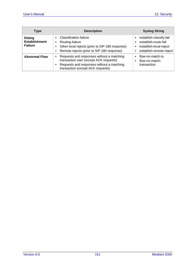
Version 6.6 151 Mediant 2000
User's Manual 12. Security
Type Description Syslog String
Dialog Establishment Failure
Classification failure Routing failure Other local rejects (prior to SIP 180 response) Remote rejects (prior to SIP 180 response)
establish-classify-fail establish-route-fail establish-local-reject establish-remote-reject
Abnormal Flow Requests and responses without a matching transaction user (except ACK requests)
Requests and responses without a matching transaction (except ACK requests)
flow-no-match-tu flow-no-match-
transaction

User's Manual 152 Document #: LTRT-68822
Mediant 2000
Reader's Notes

Version 6.6 153 Mediant 2000
User's Manual 13. Media
13 Media This section describes the media-related configuration.
13.1 Configuring Voice Settings The Voice Settings page configures various voice parameters such as voice volume, silence suppression, and DTMF transport type. For a detailed description of these parameters, see 'Configuration Parameters Reference' on page 503.
To configure the voice parameters: 1. Open the Voice Settings page (Configuration tab > VoIP menu > Media submenu >
Voice Settings).
Figure 13-1: Voice Settings Page
2. Configure the Voice parameters as required. 3. Click Submit to apply your changes. 4. To save the changes to flash memory, see 'Saving Configuration' on page 396.
13.1.1 Configuring Voice Gain (Volume) Control The device allows you to configure the level of the received (input gain) Tel-to-IP signal and the level of the transmitted (output gain) IP-to-Tel signal. The gain can be set between -32 and 31 decibels (dB). The procedure below describes how to configure gain control using the Web interface:
To configure gain control using the Web interface:
1. Open the Voice Settings page (Configuration tab > VoIP menu > Media submenu > Voice Settings).
Figure 13-2: Voice Volume Parameters in Voice Settings Page
2. Configure the following parameters:
• 'Voice Volume' (VoiceVolume) - Defines the voice gain control (in decibels) for IP-to-Tel
• 'Input Gain' (InputGain) - Defines the PCM input gain control (in decibels) for Tel-to-IP
3. Click Submit to apply your settings.

User's Manual 154 Document #: LTRT-68822
Mediant 2000
13.1.2 Silence Suppression (Compression) Silence suppression (compression) is a method for conserving bandwidth on VoIP calls by not sending packets when silence is detected. The device uses its VAD feature to detect periods of silence in the voice channel during an established call. When silence is detected, it stops sending packets in the channel. The procedure below describes how to enable silence suppression using the Web interface.
To enable silence suppression using the Web interface:
1. Open the Voice Settings page (Configuration tab > VoIP menu > Media submenu > Voice Settings).
Figure 13-3: Enabling Silence Suppression in Voice Settings Page
2. Set the 'Silence Suppression' (EnableSilenceCompression) field to Enable. 3. Click Submit to apply your changes.
13.1.3 Echo Cancellation The device supports adaptive linear (line) echo cancellation according to G.168-2002. Echo cancellation is a mechanism that removes echo from the voice channel. Echoes are reflections of the transmitted signal. In this line echo, echoes are generated when two-wire telephone circuits (carrying both transmitted and received signals on the same wire pair) are converted to a four-wire circuit. Echoes are reflections of the transmitted signal, which result from impedance mismatch in the hybrid (bi-directional 2-wire to 4-wire converting device). An estimated echo signal is built by feeding the decoder output signal to an RLS-like adaptive filter, which adapts itself to the characteristics of the echo path. The ‘estimated echo signal’ (the output of this filter) is then subtracted from the input signal (which is the sum of the desired input signal and the undesired echo) to provide a clean signal. To suppress the remaining residual echo, a Non Linear Processor (NLP) is used, as well as a double-talk (two people speak at the same time) detector that prevents false adaptation during near-end speech. The procedure below describes how to configure echo cancellation using the Web interface:
To configure echo cancellation using the Web interface: 1. Configure line echo cancellation:
a. Open the Voice Settings page (Configuration tab > VoIP menu > Media submenu > Voice Settings).
Figure 13-4: Enabling Echo Cancellation in Voice Settings Page
b. Set the 'Echo Canceller' field (EnableEchoCanceller) to Enable. c. Open the General Media Settings page (Configuration tab > VoIP menu > Media
submenu > General Media Settings). d. From the 'Max Echo Canceller Length' drop-down list (MaxEchoCancellerLength),
select the maximum echo path delay (tail length) for the echo canceller.

Version 6.6 155 Mediant 2000
User's Manual 13. Media
Note: The following additional echo cancellation parameters are configurable only through the ini file:
• ECHybridLoss - defines the four-wire to two-wire worst-case Hybrid loss • ECNLPMode - defines the echo cancellation Non-Linear Processing (NLP) mode • EchoCancellerAggressiveNLP - enables Aggressive NLP at the first 0.5 second of
the call
13.2 Fax and Modem Capabilities This section describes the device's fax and modem capabilities and corresponding configuration. The fax and modem configuration is done in the Fax/Modem/CID Settings page.
Notes:
• Unless otherwise specified, the configuration parameters mentioned in this section are available on this page.
• Some SIP parameters override these fax and modem parameters. For example, the IsFaxUsed parameter and V.152 parameters in Section 'V.152 Support' on page 164).
• For a detailed description of the parameters appearing on this page, see 'Configuration Parameters Reference' on page 503.
To access the fax and modem parameters:
1. Open the Fax/Modem/CID Settings page (Configuration tab > VoIP menu > Media submenu > Fax/Modem/CID Settings).
Figure 13-5: Fax/Modem/CID Settings Page
2. Configure the parameters, as required.
User's Manual 156 Document #: LTRT-68822
Mediant 2000
3. Click Submit to apply your changes.
13.2.1 Fax/Modem Operating Modes The device supports two modes of operation: Fax/modem negotiation that is not performed during the establishment of the call. Voice-band data (VBD) mode for V.152 implementation (see 'V.152 Support' on page
164): fax/modem capabilities are negotiated between the device and the remote endpoint at the establishment of the call. During a call, when a fax/modem signal is detected, transition from voice to VBD (or T.38) is automatically performed and no additional SIP signaling is required. If negotiation fails (i.e., no match is achieved for any of the transport capabilities), fallback to existing logic occurs (according to the parameter IsFaxUsed).
13.2.2 Fax/Modem Transport Modes The device supports the following transport modes for fax per modem type (V.22/V.23/Bell/V.32/V.34): T.38 fax relay (see 'T.38 Fax Relay Mode' on page 156) G.711 Transport: switching to G.711 when fax/modem is detected (see 'G.711 Fax /
Modem Transport Mode' on page 158) Fax fallback to G.711 if T.38 is not supported (see 'Fax Fallback' on page 158) Fax and modem bypass: a proprietary method that uses a high bit rate coder (see
'Fax/Modem Bypass Mode' on page 159) NSE Cisco’s Pass-through bypass mode for fax and modem (see 'Fax / Modem NSE
Mode' on page 160) Transparent with events: passing the fax / modem signal in the current voice coder
with adaptations (see 'Fax / Modem Transparent with Events Mode' on page 161) Transparent: passing the fax / modem signal in the current voice coder (see 'Fax /
Modem Transparent Mode' on page 161) RFC 2833 ANS Report upon Fax/Modem Detection (see 'RFC 2833 ANS Report upon
Fax/Modem Detection' on page 162) ‘Adaptations’ refer to automatic reconfiguration of certain DSP features for handling fax/modem streams differently than voice.
13.2.2.1 T.38 Fax Relay Mode In Fax Relay mode, fax signals are transferred using the T.38 protocol. T.38 is an ITU standard for sending fax across IP networks in real-time mode. The device currently supports only the T.38 UDP syntax. T.38 can be configured in the following ways: Switching to T.38 mode using SIP Re-INVITE messages (see 'Switching to T.38 Mode
using SIP Re-INVITE' on page 157) Automatically switching to T.38 mode without using SIP Re-INVITE messages (see
'Automatically Switching to T.38 Mode without SIP Re-INVITE' on page 157) When fax transmission ends, the reverse switching from fax relay to voice is automatically performed at both the local and remote endpoints. You can change the fax rate declared in the SDP, using the 'Fax Relay Max Rate' parameter (FaxRelayMaxRate). This parameter does not affect the actual transmission rate. You can also enable or disable Error Correction Mode (ECM) fax mode using the 'Fax Relay ECM Enable' parameter (FaxRelayECMEnable).
Version 6.6 157 Mediant 2000
User's Manual 13. Media
When using T.38 mode, you can define a redundancy feature to improve fax transmission over congested IP networks. This feature is activated using the 'Fax Relay Redundancy Depth' parameter (FaxRelayRedundancyDepth) and the 'Fax Relay Enhanced Redundancy Depth' parameter (FaxRelayEnhancedRedundancyDepth). Although this is a proprietary redundancy scheme, it should not create problems when working with other T.38 decoders.
13.2.2.1.1 Switching to T.38 Mode using SIP Re-INVITE
In the Switching to T.38 Mode using SIP Re-INVITE mode, upon detection of a fax signal the terminating device negotiates T.38 capabilities using a Re-INVITE message. If the far-end device doesn't support T.38, the fax fails. In this mode, the 'Fax Transport Mode' parameter (FaxTransportMode) is ignored.
To configure T.38 mode using SIP Re-INVITE messages:
1. In the SIP General Parameters page (Configuration tab > VoIP menu > SIP Definitions > General Parameters), set the 'Fax Signaling Method' parameter to T.38 Relay (IsFaxUsed = 1).
2. In the Fax/Modem/CID Settings page, configure the following optional parameters: • 'Fax Relay Redundancy Depth' (FaxRelayRedundancyDepth) • 'Fax Relay Enhanced Redundancy Depth'
(FaxRelayEnhancedRedundancyDepth) • 'Fax Relay ECM Enable' (FaxRelayECMEnable) • 'Fax Relay Max Rate' (FaxRelayMaxRate)
Note: The terminating gateway sends T.38 packets immediately after the T.38 capabilities are negotiated in SIP. However, the originating device by default, sends T.38 (assuming the T.38 capabilities are negotiated in SIP) only after it receives T.38 packets from the remote device. This default behavior cannot be used when the originating device is located behind a firewall that blocks incoming T.38 packets on ports that have not yet received T.38 packets from the internal network. To resolve this problem, the device should be configured to send CNG packets in T.38 upon CNG signal detection (CNGDetectorMode = 1).
13.2.2.1.2 Automatically Switching to T.38 Mode without SIP Re-INVITE
In the Automatically Switching to T.38 Mode without SIP Re-INVITE mode, when a fax signal is detected, the channel automatically switches from the current voice coder to answer tone mode and then to T.38-compliant fax relay mode.
To configure automatic T.38 mode: 1. In the SIP General Parameters page (Configuration tab > VoIP menu > SIP
Definitions > General Parameters), set the 'Fax Signaling Method' parameter to No Fax (IsFaxUsed = 0).
2. In the Fax/Modem/CID Settings page, set the 'Fax Transport Mode' parameter to RelayEnable (FaxTransportMode = 1).
3. Configure the following optional parameters: • 'Fax Relay Redundancy Depth' (FaxRelayRedundancyDepth) • 'Fax Relay Enhanced Redundancy Depth'
(FaxRelayEnhancedRedundancyDepth) • 'Fax Relay ECM Enable' (FaxRelayECMEnable)

User's Manual 158 Document #: LTRT-68822
Mediant 2000
• 'Fax Relay Max Rate' (FaxRelayMaxRate)
13.2.2.2 G.711 Fax / Modem Transport Mode In this mode, when the terminating device detects fax or modem signals (CED or AnsAM), it sends a Re-INVITE message to the originating device, requesting it to re-open the channel in G.711 VBD with the following adaptations: Echo Canceller = off Silence Compression = off Echo Canceller Non-Linear Processor Mode = off Dynamic Jitter Buffer Minimum Delay = 40 Dynamic Jitter Buffer Optimization Factor = 13 After a few seconds upon detection of fax V.21 preamble or super G3 fax signals, the device sends a second Re-INVITE enabling the echo canceller (the echo canceller is disabled only on modem transmission). A ‘gpmd’ attribute is added to the SDP according to the following format: For G.711 A-law:
a=gpmd:0 vbd=yes;ecan=on (or off for modems)
For G.711 µ-law: a=gpmd:8 vbd=yes;ecan=on (or off for modems)
The following parameters are ignored and automatically set to Events Only: 'Fax Transport Mode' (FaxTransportMode) 'Vxx ModemTransportType' (VxxModemTransportType)
To configure fax / modem transparent mode: In the SIP General Parameters page (Configuration tab > VoIP menu > SIP
Definitions > General Parameters), set the 'Fax Signaling Method' parameter to G.711 Transport (IsFaxUsed = 2).
13.2.2.3 Fax Fallback In this mode, when the terminating device detects a fax signal, it sends a Re-INVITE message to the originating device with T.38. If the remote device doesn’t support T.38 (replies with SIP response 415 "Media Not Supported"), the device sends a new Re-INVITE with G.711 VBD with the following adaptations: Echo Canceller = on Silence Compression = off Echo Canceller Non-Linear Processor Mode = off Dynamic Jitter Buffer Minimum Delay = 40 Dynamic Jitter Buffer Optimization Factor = 13 When the device initiates a fax session using G.711, a ‘gpmd’ attribute is added to the SDP according to the following format: For G.711A-law:
a=gpmd:0 vbd=yes;ecan=on
For G.711 µ-law: a=gpmd:8 vbd=yes;ecan=on
In this mode, the 'Fax Transport Mode' (FaxTransportMode) parameter is ignored and automatically set to Disable (transparent mode).
Version 6.6 159 Mediant 2000
User's Manual 13. Media
To configure fax fallback mode: In the SIP General Parameters page (Configuration tab > VoIP menu > SIP
Definitions > General Parameters), set the 'Fax Signaling Method' parameter to Fax Fallback (IsFaxUsed = 3).
13.2.2.4 Fax/Modem Bypass Mode In this proprietary mode, when fax or modem signals are detected, the channel automatically switches from the current voice coder to a high bit-rate coder, according to the 'Fax/Modem Bypass Coder Type' parameter (FaxModemBypassCoderType). The channel is also automatically reconfigured with the following fax / modem adaptations: Disables silence suppression Enables echo cancellation for fax Disables echo cancellation for modem Performs certain jitter buffering optimizations The network packets generated and received during the bypass period are regular voice RTP packets (per the selected bypass coder), but with a different RTP payload type according to the following parameters: 'Fax Bypass Payload Type' (FaxBypassPayloadType) ModemBypassPayloadType (ini file) During the bypass period, the coder uses the packing factor, configured by the 'Fax/Modem Bypass Packing Factor' parameter (FaxModemBypassM). The packing factor determines the number of coder payloads (each the size of FaxModemBypassBasicRTPPacketInterval) that are used to generate a single fax/modem bypass packet. When fax/modem transmission ends, the reverse switching, from bypass coder to regular voice coder is performed.
To configure fax / modem bypass mode: 1. In the SIP General Parameters page (Configuration tab > VoIP menu > SIP
Definitions > General Parameters), set the 'Fax Signaling Method' parameter to No Fax (IsFaxUsed = 0).
2. In the Fax/Modem/CID Settings page, do the following: a. Set the 'Fax Transport Mode' parameter to Bypass (FaxTransportMode = 2). b. Set the 'V.21 Modem Transport Type' parameter to Enable Bypass
(V21ModemTransportType = 2). c. Set the 'V.22 Modem Transport Type' parameter to Enable Bypass
(V22ModemTransportType = 2). d. Set the 'V.23 Modem Transport Type' parameter to Enable Bypass
(V23ModemTransportType = 2). e. Set the 'V.32 Modem Transport Type' parameter to Enable Bypass
(V32ModemTransportType = 2). f. Set the 'V.34 Modem Transport Type' parameter to Enable Bypass
(V34ModemTransportType = 2). 3. Set the ini file parameter, BellModemTransportType to 2 (Bypass). 4. Configure the following optional parameters:
• 'Fax/Modem Bypass Coder Type' (FaxModemBypassCoderType). • 'Fax Bypass Payload Type' (FaxBypassPayloadType) - in the RTP/RTCP
Settings page (Configuration tab > VoIP menu > Media > RTP/RTCP Settings). • ModemBypassPayloadType (ini file).

User's Manual 160 Document #: LTRT-68822
Mediant 2000
• FaxModemBypassBasicRTPPacketInterval (ini file). • FaxModemBypasDJBufMinDelay (ini file).
Note: When the device is configured for modem bypass and T.38 fax, V.21 low-speed modems are not supported and fail as a result.
Tip: When the remote (non-AudioCodes) gateway uses the G.711 coder for voice and doesn’t change the coder payload type for fax or modem transmission, it is recommended to use the Bypass mode with the following configuration:
• EnableFaxModemInbandNetworkDetection = 1. • 'Fax/Modem Bypass Coder Type' = same coder used for voice. • 'Fax/Modem Bypass Packing Factor'(FaxModemBypassM) = same interval as
voice. • ModemBypassPayloadType = 8 if voice coder is A-Law or 0 if voice coder is Mu-
Law.
13.2.2.5 Fax / Modem NSE Mode In this mode, fax and modem signals are transferred using Cisco-compatible Pass-through bypass mode. Upon detection of fax or modem answering tone signal, the terminating device sends three to six special NSE RTP packets (configured by the NSEpayloadType parameter; usually to 100). These packets signal the remote device to switch to G.711 coder, according to the 'Fax/Modem Bypass Packing Factor' parameter. After a few NSE packets are exchanged between the devices, both devices start using G.711 packets with standard payload type (8 for G.711 A-Law and 0 for G.711 Mu-Law). In this mode, no Re-INVITE messages are sent. The voice channel is optimized for fax/modem transmission (same as for usual bypass mode). The parameters defining payload type for AudioCodes proprietary Bypass mode -- 'Fax Bypass Payload Type' (RTP/RTCP Settings page) and ModemBypassPayloadType (ini file) -- are not used with NSE Bypass. When configured for NSE mode, the device includes in its SDP the following line: a=rtpmap:100 X-NSE/8000
Where 100 is the NSE payload type. The Cisco gateway must include the following definition: modem passthrough nse payload-type 100 codec g711alaw
To configure NSE mode:
1. In the SIP General Parameters page (Configuration tab > VoIP menu > SIP Definitions > General Parameters), set the 'Fax Signaling Method' parameter to No Fax (IsFaxUsed = 0).
2. In the Fax/Modem/CID Settings page, do the following: a. Set the 'Fax Transport Mode' parameter to Bypass (FaxTransportMode = 2). b. Set the 'V.21 Modem Transport Type' parameter to Enable Bypass
(V21ModemTransportType = 2). c. Set the 'V.22 Modem Transport Type' parameter to Enable Bypass
(V22ModemTransportType = 2). d. Set the 'V.23 Modem Transport Type' parameter to Enable Bypass
(V23ModemTransportType = 2).
Version 6.6 161 Mediant 2000
User's Manual 13. Media
e. Set the 'V.32 Modem Transport Type' parameter to Enable Bypass (V32ModemTransportType = 2).
f. Set the 'V.34 Modem Transport Type' parameter to Enable Bypass (V34ModemTransportType = 2).
3. Set the ini file parameter, BellModemTransportType to 2 (Bypass). 4. Set the ini file parameter, NSEMode parameter to 1 (enables NSE). 5. Set the ini file parameter, NSEPayloadType parameter to 100.
13.2.2.6 Fax / Modem Transparent with Events Mode In this mode, fax and modem signals are transferred using the current voice coder with the following automatic adaptations: Echo Canceller = on (or off for modems) Echo Canceller Non-Linear Processor Mode = off Jitter buffering optimizations
To configure fax / modem transparent with events mode: 1. In the SIP General Parameters page (Configuration tab > VoIP menu > SIP
Definitions > General Parameters), set the 'Fax Signaling Method' parameter to No Fax (IsFaxUsed = 0).
2. In the Fax/Modem/CID Settings page, do the following: a. Set the 'Fax Transport Mode' parameter to Events Only (FaxTransportMode =
3). b. Set the 'V.21 Modem Transport Type' parameter to Events Only
(V21ModemTransportType = 3). c. Set the 'V.22 Modem Transport Type' parameter to Events Only
(V22ModemTransportType = 3). d. Set the 'V.23 Modem Transport Type' parameter to Events Only
(V23ModemTransportType = 3). e. Set the 'V.32 Modem Transport Type' parameter to Events Only
(V32ModemTransportType = 3). f. Set the 'V.34 Modem Transport Type' parameter to Events Only
(V34ModemTransportType = 3). 3. Set the ini file parameter, BellModemTransportType to 3 (transparent with events).
13.2.2.7 Fax / Modem Transparent Mode In this mode, fax and modem signals are transferred using the current voice coder without notifications to the user and without automatic adaptations. It's possible to use Profiles (see 'Coders and Profiles' on page 229) to apply certain adaptations to the channel used for fax / modem. For example, to use the coder G.711, to set the jitter buffer optimization factor to 13, and to enable echo cancellation for fax and disable it for modem.
To configure fax / modem transparent mode:
1. In the SIP General Parameters page (Configuration tab > VoIP menu > SIP Definitions > General Parameters), set the 'Fax Signaling Method' parameter to No Fax (IsFaxUsed = 0).
2. In the Fax/Modem/CID Settings page, do the following: a. Set the 'Fax Transport Mode' parameter to Disable (FaxTransportMode = 0).

User's Manual 162 Document #: LTRT-68822
Mediant 2000
b. Set the 'V.21 Modem Transport Type' parameter to Disable (V21ModemTransportType = 0).
c. Set the 'V.22 Modem Transport Type' parameter to Disable (V22ModemTransportType = 0).
d. Set the 'V.23 Modem Transport Type' parameter to Disable (V23ModemTransportType = 0).
e. Set the 'V.32 Modem Transport Type' parameter to Disable (V32ModemTransportType = 0).
f. Set the 'V.34 Modem Transport Type' parameter to Disable (V34ModemTransportType = 0).
3. Set the ini file parameter, BellModemTransportType to 0 (transparent mode). 4. Configure the following optional parameters:
a. Coders table - (Configuration tab > VoIP menu > Coders and Profiles > Coders).
b. 'Dynamic Jitter Buffer Optimization Factor' (DJBufOptFactor) - RTP/RTCP Settings page (Configuration tab > VoIP menu > Media > RTP/RTCP Settings).
c. 'Silence Suppression' (EnableSilenceCompression) - Voice Settings page (Configuration tab > VoIP menu > Media > Voice Settings).
d. 'Echo Canceller' (EnableEchoCanceller) - Voice Settings page.
Note: This mode can be used for fax, but is not recommended for modem transmission. Instead, use the Bypass (see 'Fax/Modem Bypass Mode' on page 159) or Transparent with Events modes (see 'Fax / Modem Transparent with Events Mode' on page 161) for modem.
13.2.2.8 RFC 2833 ANS Report upon Fax/Modem Detection The device (terminator gateway) sends RFC 2833 ANS/ANSam events upon detection of fax and/or modem answer tones (i.e., CED tone). This causes the originator to switch to fax/modem. This parameter is applicable only when the fax or modem transport type is set to bypass, Transparent-with-Events, V.152 VBD, or G.711 transport. When the device is located on the originator side, it ignores these RFC 2833 events
To configure RFC 2833 ANS Report upon fax/modem detection:
1. In the SIP General Parameters page (Configuration tab > VoIP menu > SIP Definitions > General Parameters), set the 'Fax Signaling Method' parameter to No Fax or Fax Fallback (IsFaxUsed = 0 or 3).
2. In the Fax/Modem/CID Settings page, do the following: a. Set the 'Fax Transport Mode' parameter to Bypass (FaxTransportMode = 2). b. Set the 'V.xx Modem Transport Type' parameters to Enable Bypass
(VxxModemTransportType = 2). 3. Set the ini file parameter, FaxModemNTEMode to 1 (enables this feature).
13.2.3 V.34 Fax Support V.34 fax machines can transmit data over IP to the remote side using various methods. The device supports the following modes for transporting V.34 fax data over IP: Bypass mechanism for V.34 fax transmission (see 'Bypass Mechanism for V.34 Fax
Transmission' on page 163) T38 Version 0 relay mode, i.e., fallback to T.38 (see 'Relay Mode for T.30 and V.34
Faxes' on page 163)

Version 6.6 163 Mediant 2000
User's Manual 13. Media
Note: The CNG detector is disabled in all the subsequent examples. To disable the CNG detector, set the 'CNG Detector Mode' parameter (CNGDetectorMode) to Disable.
13.2.3.1 Bypass Mechanism for V.34 Fax Transmission In this proprietary scenario, the device uses bypass (or NSE) mode to transmit V.34 faxes, enabling the full utilization of its speed.
To use bypass mode for T.30 and V.34 faxes:
1. In the Fax/Modem/CID Settings page, do the following: a. Set the 'Fax Transport Mode' parameter to Bypass (FaxTransportMode = 2). b. Set the 'V.22 Modem Transport Type' parameter to Enable Bypass
(V22ModemTransportType = 2). c. Set the 'V.23 Modem Transport Type' parameter to Enable Bypass
(V23ModemTransportType = 2). d. Set the 'V.32 Modem Transport Type' parameter to Enable Bypass
(V32ModemTransportType = 2). e. Set the 'V.34 Modem Transport Type' parameter to Enable Bypass
(V34ModemTransportType = 2).
To use bypass mode for V.34 faxes, and T.38 for T.30 faxes: 1. In the Fax/Modem/CID Settings page, do the following:
a. Set the 'Fax Transport Mode' parameter to Relay (FaxTransportMode = 1). b. Set the 'V.22 Modem Transport Type' parameter to Enable Bypass
(V22ModemTransportType = 2). c. Set the 'V.23 Modem Transport Type' parameter to Enable Bypass
(V23ModemTransportType = 2). d. Set the 'V.32 Modem Transport Type' parameter to Enable Bypass
(V32ModemTransportType = 2). e. Set the 'V.34 Modem Transport Type' parameter to Enable Bypass
(V34ModemTransportType = 2).
13.2.3.2 Relay Mode for T.30 and V.34 Faxes In this scenario, V.34 fax machines are forced to use their backward compatibility with T.30 faxes and operate in the slower T.30 mode.
To use T.38 mode for V.34 and T.30 faxes:
1. In the Fax/Modem/CID Settings page, do the following: a. Set the 'Fax Transport Mode' parameter to Relay (FaxTransportMode = 1). b. Set the 'V.22 Modem Transport Type' parameter to Disable
(V22ModemTransportType = 0). c. Set the 'V.23 Modem Transport Type' parameter to Disable
(V23ModemTransportType = 0). d. Set the 'V.32 Modem Transport Type' parameter to Disable
(V32ModemTransportType = 0). e. Set the 'V.34 Modem Transport Type' parameter to Disable
(V34ModemTransportType = 0).

User's Manual 164 Document #: LTRT-68822
Mediant 2000
13.2.4 V.152 Support The device supports the ITU-T recommendation V.152 (Procedures for Supporting Voice-Band Data over IP Networks). Voice-band data (VBD) is the transport of modem, facsimile, and text telephony signals over a voice channel of a packet network with a codec appropriate for such signals. For V.152 capability, the device supports T.38 as well as VBD codecs (i.e., G.711 A-law and G.711 μ-law). The selection of capabilities is performed using the coders table (see 'Configuring Coders' on page 229). When in VBD mode for V.152 implementation, support is negotiated between the device and the remote endpoint at the establishment of the call. During this time, initial exchange of call capabilities is exchanged in the outgoing SDP. These capabilities include whether VBD is supported and associated RTP payload types ('gpmd' SDP attribute), supported codecs, and packetization periods for all codec payload types ('ptime' SDP attribute). After this initial negotiation, no Re-INVITE messages are necessary as both endpoints are synchronized in terms of the other side's capabilities. If negotiation fails (i.e., no match was achieved for any of the transport capabilities), fallback to existing logic occurs (according to the parameter IsFaxUsed). Below is an example of media descriptions of an SDP indicating support for V.152. In the example, V.152 implementation is supported (using the dynamic payload type 96 and G.711 u-law as the VBD codec) as well as the voice codecs G.711 μ-law and G.729. v=0 o=- 0 0 IN IPV4 <IPAdressA> s=- t=0 0 p=+1 c=IN IP4 <IPAddressA m=audio <udpPort A> RTP/AVP 18 0 a=ptime:10 a=rtpmap:96 PCMU/8000 a=gpmd: 96 vbd=yes
Instead of using VBD transport mode, the V.152 implementation can use alternative relay fax transport methods (e.g., fax relay over IP using T.38). The preferred V.152 transport method is indicated by the SDP ‘pmft’ attribute. Omission of this attribute in the SDP content means that VBD mode is the preferred transport mechanism for voice-band data. To configure T.38 mode, use the CodersGroup parameter.
Note: You can also configure the device to handle G.711 coders received in INVITE SDP offers as VBD coders, using the HandleG711asVBD parameter. For example, if the device is configured with G.729 and G.711 VBD coders and it receives an INVITE with an SDP offer containing G.729 and “regular” G.711 coders, it sends an SDP answer containing G.729 and G.711 VBD coders, allowing subsequent bypass (passthrough) sessions if fax / modem signals are detected during the call.
13.2.5 Fax Transmission behind NAT The device supports transmission from fax machines (connected to the device) located inside (behind) a Network Address Translation (NAT). Generally, the firewall blocks T.38 (and other) packets received from the WAN, unless the device behind the NAT sends at least one IP packet from the LAN to the WAN through the firewall. If the firewall blocks T.38 packets sent from the termination IP fax, the fax fails. To overcome this, the device sends No-Op (“no-signal”) packets to open a pinhole in the NAT for the answering fax machine. The originating fax does not wait for an answer, but immediately starts sending T.38 packets to the terminating fax machine upon receipt of a re-INVITE with T.38 only in the SDP, or T.38 and audio media in the SDP. This feature is

Version 6.6 165 Mediant 2000
User's Manual 13. Media
configured using the T38FaxSessionImmediateStart parameter. The No-Op packets are enabled using the NoOpEnable and NoOpInterval parameters.
13.3 Configuring RTP/RTCP Settings This section describes configuration relating to Real-Time Transport Protocol (RTP) and RTP Control Protocol (RTCP).
13.3.1 Configuring the Dynamic Jitter Buffer Voice frames are transmitted at a fixed rate. If the frames arrive at the other end at the same rate, voice quality is perceived as good. However, some frames may arrive slightly faster or slower than the other frames. This is called jitter (delay variation) and degrades the perceived voice quality. To minimize this problem, the device uses a jitter buffer. The jitter buffer collects voice packets, stores them and sends them to the voice processor in evenly spaced intervals. The device uses a dynamic jitter buffer that can be configured with the following: Minimum delay: Defines the starting jitter capacity of the buffer. For example, at 0
msec, there is no buffering at the start. At the default level of 10 msec, the device always buffers incoming packets by at least 10 msec worth of voice frames.
Optimization Factor: Defines how the jitter buffer tracks to changing network conditions. When set at its maximum value of 12, the dynamic buffer aggressively tracks changes in delay (based on packet loss statistics) to increase the size of the buffer and doesn’t decay back down. This results in the best packet error performance, but at the cost of extra delay. At the minimum value of 0, the buffer tracks delays only to compensate for clock drift and quickly decays back to the minimum level. This optimizes the delay performance but at the expense of a higher error rate.
The default settings of 10 msec Minimum delay and 10 Optimization Factor should provide a good compromise between delay and error rate. The jitter buffer ‘holds’ incoming packets for 10 msec before making them available for decoding into voice. The coder polls frames from the buffer at regular intervals in order to produce continuous speech. As long as delays in the network do not change (jitter) by more than 10 msec from one packet to the next, there is always a sample in the buffer for the coder to use. If there is more than 10 msec of delay at any time during the call, the packet arrives too late. The coder tries to access a frame and is not able to find one. The coder must produce a voice sample even if a frame is not available. It therefore compensates for the missing packet by adding a Bad-Frame-Interpolation (BFI) packet. This loss is then flagged as the buffer being too small. The dynamic algorithm then causes the size of the buffer to increase for the next voice session. The size of the buffer may decrease again if the device notices that the buffer is not filling up as much as expected. At no time does the buffer decrease to less than the minimum size configured by the Minimum delay parameter. In certain scenarios, the Optimization Factor is set to 13: One of the purposes of the Jitter Buffer mechanism is to compensate for clock drift. If the two sides of the VoIP call are not synchronized to the same clock source, one RTP source generates packets at a lower rate, causing under-runs at the remote Jitter Buffer. In normal operation (optimization factor 0 to 12), the Jitter Buffer mechanism detects and compensates for the clock drift by occasionally dropping a voice packet or by adding a BFI packet. Fax and modem devices are sensitive to small packet losses or to added BFI packets. Therefore, to achieve better performance during modem and fax calls, the Optimization Factor should be set to 13. In this special mode the clock drift correction is performed less frequently - only when the Jitter Buffer is completely empty or completely full. When such condition occurs, the correction is performed by dropping several voice packets simultaneously or by adding several BFI packets simultaneously, so that the Jitter Buffer returns to its normal condition.

User's Manual 166 Document #: LTRT-68822
Mediant 2000
The procedure below describes how to configure the jitter buffer using the Web interface.
To configure jitter buffer using the Web interface:
1. Open the RTP/RTCP Settings page (Configuration tab > VoIP menu > Media submenu > RTP/RTCP Settings). The relevant parameters are listed under the 'General Settings' group, as shown below:
Figure 13-6: Jitter Buffer Parameters in the RTP/RTCP Settings Page
2. Set the 'Dynamic Jitter Buffer Minimum Delay' parameter (DJBufMinDelay) to the
minimum delay (in msec) for the Dynamic Jitter Buffer. 3. Set the 'Dynamic Jitter Buffer Optimization Factor' parameter (DJBufOptFactor) to the
Dynamic Jitter Buffer frame error/delay optimization factor. 4. Click Submit to apply your settings.
13.3.2 Comfort Noise Generation The device can generate artificial background noise, called comfort noise, in the voice channel during periods of silence (i.e. when no call party is speaking). This is useful in that it reassures the call parties that the call is still connected. The device detects silence using its Voice Activity Detection (VAD) mechanism. When the Calling Tone (CNG) is enabled and silence is detected, the device transmits Silence Identifier Descriptors (SIDs) parameters to reproduce the local background noise at the remote (receiving) side. The Comfort Noise Generation (CNG) support also depends on the silence suppression (SCE) setting for the coder used in the voice channel. For more information, see the description of the CNG-related parameters. The procedure below describes how to configure CNG using the Web interface.
To configure CNG using the Web interface:
1. Open the RTP/RTCP Settings page (Configuration tab > VoIP menu > Media submenu > RTP/RTCP Settings). The relevant parameters are listed under the 'General Settings' group, as shown below:
Figure 13-7: Comfort Noise Parameter in RTP/RTCP Settings Page
2. Set the 'Comfort Noise Generation Negotiation' parameter (ComfortNoiseNegotiation)
to Enable. 3. Click Submit to apply your changes.
Version 6.6 167 Mediant 2000
User's Manual 13. Media
13.3.3 Dual-Tone Multi-Frequency Signaling This section describes the configuration of Dual-Tone Multi-Frequency (DTMF) signaling.
13.3.3.1 Configuring DTMF Transport Types The device supports various methods for transporting DTMF digits over the IP network to the remote endpoint. These methods and their configuration are configured in the DTMF & Dialing page (Configuration tab > VoIP menu > GW and IP to IP > DTMF and Supplementary > DTMF & Dialing): Using INFO message according to Nortel IETF draft: DTMF digits are sent to the
remote side in INFO messages. To enable this mode, define the following: a. Set the 'Declare RFC 2833 in SDP' parameter to No (RxDTMFOption = 0). b. Set the '1st Tx DTMF Option' parameter to INFO (Nortel) (TxDTMFOption = 1). Note: In this mode, DTMF digits are removed from the audio stream (and the 'DTMF Transport Type' parameter is automatically set to Mute DTMF).
Using INFO message according to Cisco’s mode: DTMF digits are sent to the remote side in INFO messages. To enable this mode, define the following: a. Set the 'Declare RFC 2833 in SDP' parameter to No (RxDTMFOption = 0). b. Set the '1st Tx DTMF Option' parameter to INFO (Cisco) (TxDTMFOption = 3). Note: In this mode, DTMF digits are removed from the audio stream (and the 'DTMF Transport Type' parameter is automatically set to Mute DTMF).
Using NOTIFY messages according to IETF Internet-Draft draft-mahy-sipping-signaled-digits-01: DTMF digits are sent to the remote side using NOTIFY messages. To enable this mode, define the following: a. Set the 'Declare RFC 2833 in SDP' parameter to No (RxDTMFOption = 0). b. Set the '1st Tx DTMF Option' parameter to NOTIFY (TxDTMFOption = 2). Note: In this mode, DTMF digits are removed from the audio stream (and the 'DTMF Transport Type' parameter is automatically set to Mute DTMF).
Using RFC 2833 relay with Payload type negotiation: DTMF digits are sent to the remote side as part of the RTP stream according to RFC 2833. To enable this mode, define the following: a. Set the 'Declare RFC 2833 in SDP' parameter to Yes (RxDTMFOption = 3). b. Set the '1st Tx DTMF Option' parameter to RFC 2833 (TxDTMFOption = 4). Note: To set the RFC 2833 payload type with a value other than its default, use the RFC2833PayloadType parameter. The device negotiates the RFC 2833 payload type using local and remote SDP and sends packets using the payload type from the received SDP. The device expects to receive RFC 2833 packets with the same payload type as configured by this parameter. If the remote side doesn’t include ‘telephony-event’ in its SDP, the device sends DTMF digits in transparent mode (as part of the voice stream).
Sending DTMF digits (in RTP packets) as part of the audio stream (DTMF Relay is disabled): This method is typically used with G.711 coders. With other low-bit rate (LBR) coders, the quality of the DTMF digits is reduced. To enable this mode, define the following: a. Set the 'Declare RFC 2833 in SDP' parameter to No (RxDTMFOption = 0). b. Set the '1st Tx DTMF Option' parameter to Not Supported (TxDTMFOption = 0). c. Set the ini file parameter, DTMFTransportType to 2 (i.e., transparent).

User's Manual 168 Document #: LTRT-68822
Mediant 2000
Using INFO message according to Korea mode: DTMF digits are sent to the remote side in INFO messages. To enable this mode, define the following: a. Set the 'Declare RFC 2833 in SDP' parameter to No (RxDTMFOption = 0). b. Set the '1st Tx DTMF Option' parameter to INFO (Cisco) (TxDTMFOption = 3). Note: In this mode, DTMF digits are removed from the audio stream (and the 'DTMF Transport Type' parameter is automatically set to Mute DTMF).
Notes:
• The device is always ready to receive DTMF packets over IP in all possible transport modes: INFO messages, NOTIFY, and RFC 2833 (in proper payload type) or as part of the audio stream.
• To exclude RFC 2833 Telephony event parameter from the device's SDP, set the 'Declare RFC 2833 in SDP' parameter to No.
The following parameters affect the way the device handles the DTMF digits: TxDTMFOption, RxDTMFOption, RFC2833TxPayloadType, and
RFC2833RxPayloadType MGCPDTMFDetectionPoint, DTMFVolume, DTMFTransportType, DTMFDigitLength,
and DTMFInterDigitInterval
13.3.3.2 Configuring RFC 2833 Payload The procedure below describes how to configure the RFC 2833 payload using the Web interface:
To configure RFC 2833 payload using the Web interface:
1. Open the RTP/RTCP Settings page (Configuration tab > VoIP menu > Media submenu > RTP/RTCP Settings). The relevant parameters are listed under the 'General Settings' group, as shown below:
Figure 13-8: RFC 2833 Payload Parameters in RTP/RTCP Settings Page
2. Configure the following parameters:
• 'RTP Redundancy Depth' (RTPRedundancyDepth) - enables the device to generate RFC 2198 redundant packets.
• 'Enable RTP Redundancy Negotiation' (EnableRTPRedundancyNegotiation) - enables the device to include the RTP redundancy dynamic payload type in the SDP, according to RFC 2198.
• 'RFC 2833 TX Payload Type' (RFC2833TxPayloadType) - defines the Tx RFC 2833 DTMF relay dynamic payload type.

Version 6.6 169 Mediant 2000
User's Manual 13. Media
• 'RFC 2833 RX Payload Type' (RFC2833RxPayloadType) - defines the Rx RFC 2833 DTMF relay dynamic payload type.
• 'RFC 2198 Payload Type' (RFC2198PayloadType) - defines the RTP redundancy packet payload type according to RFC 2198.
3. Click Submit to apply your settings.
13.3.4 RTP Multiplexing (ThroughPacket) The device's RTP Multiplexing (ThroughPacket™) feature is AudioCodes proprietary method for aggregating RTP streams from several channels when the device operates with another AudioCodes device. This feature reduces the bandwidth overhead caused by the attached Ethernet, IP, UDP, and RTP headers and reduces the packet/data transmission rate. It reduces the load on network routers and can typically save up to 50% (e.g., for G.723) on IP bandwidth. RTP multiplexing is accomplished by aggregating payloads from several channels into a single IP packet, which are sent to the same destination IP address. You can enable RTP multiplexing for all destinations as described in the procedure below or for specific IP destinations using IP Profiles (see 'Configuring IP Profiles' on page 235).
Notes:
• RTP Multiplexing must be enabled on both AudioCodes devices. • When VLANs are implemented, the RTP Multiplexing mechanism is not
supported. • When RTP Multiplexing is used, call statistics are unavailable (as there is no
RTCP flow).
The procedure below describes how to configure RTP multiplexing using the Web interface.
To configure RTP multiplexing: 1. Open the RTP/RTCP Settings page (Configuration tab > VoIP menu > Media
submenu > RTP/RTCP Settings). The RTP Multiplexing parameters are listed under the 'General Settings' group, as shown below:
Figure 13-9: Configuring RTP Multiplexing in RTP/RTCP Settings
2. Enable RTP Multiplexing by setting the 'Remote RTP Base UDP Port' parameter
(RemoteBaseUDPPort) to a non-zero value. This port must be the same as the port set by the 'RTP Base UDP Port' field (BaseUDPPort) parameter at the remote device. Conversely, when configuring the remote device, its 'Remote RTP Base UDP Port' parameter value must be the same as this local device's 'RTP Base UDP Port' parameter value. These parameters identify and distribute the payloads from the received multiplexed IP packet to the relevant channels.
3. In the 'RTP Multiplexing Local UDP Port' parameter (L1L1ComplexTxUDPPort), set the local UDP port for outgoing multiplexed RTP packets.
4. In the 'RTP Multiplexing Remote UDP Port' parameter (L1L1ComplexRxUDPPort), set the destination UDP port for outgoing multiplexed packets. This also configures the local UDP port for incoming multiplexed RTP packets.
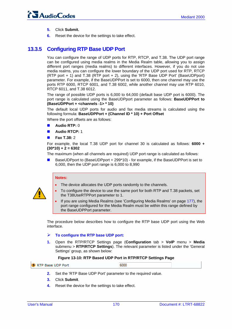
User's Manual 170 Document #: LTRT-68822
Mediant 2000
5. Click Submit. 6. Reset the device for the settings to take effect.
13.3.5 Configuring RTP Base UDP Port You can configure the range of UDP ports for RTP, RTCP, and T.38. The UDP port range can be configured using media realms in the Media Realm table, allowing you to assign different port ranges (media realms) to different interfaces. However, if you do not use media realms, you can configure the lower boundary of the UDP port used for RTP, RTCP (RTP port + 1) and T.38 (RTP port + 2), using the 'RTP Base UDP Port' (BaseUDPport) parameter. For example, if the BaseUDPPort is set to 6000, then one channel may use the ports RTP 6000, RTCP 6001, and T.38 6002, while another channel may use RTP 6010, RTCP 6011, and T.38 6012. The range of possible UDP ports is 6,000 to 64,000 (default base UDP port is 6000). The port range is calculated using the BaseUDPport parameter as follows: BaseUDPPort to (BaseUDPPort + <channels -1> * 10) The default local UDP ports for audio and fax media streams is calculated using the following formula: BaseUDPPort + (Channel ID * 10) + Port Offset Where the port offsets are as follows: Audio RTP: 0 Audio RTCP: 1 Fax T.38: 2 For example, the local T.38 UDP port for channel 30 is calculated as follows: 6000 + (30*10) + 2 = 6302 The maximum (when all channels are required) UDP port range is calculated as follows: BaseUDPport to (BaseUDPport + 299*10) - for example, if the BaseUDPPort is set to
6,000, then the UDP port range is 6,000 to 8,990
Notes:
• The device allocates the UDP ports randomly to the channels. • To configure the device to use the same port for both RTP and T.38 packets, set
the T38UseRTPPort parameter to 1. • If you are using Media Realms (see 'Configuring Media Realms' on page 177), the
port range configured for the Media Realm must be within this range defined by the BaseUDPPort parameter.
The procedure below describes how to configure the RTP base UDP port using the Web interface.
To configure the RTP base UDP port:
1. Open the RTP/RTCP Settings page (Configuration tab > VoIP menu > Media submenu > RTP/RTCP Settings). The relevant parameter is listed under the 'General Settings' group, as shown below:
Figure 13-10: RTP Based UDP Port in RTP/RTCP Settings Page
2. Set the 'RTP Base UDP Port' parameter to the required value. 3. Click Submit. 4. Reset the device for the settings to take effect.

Version 6.6 171 Mediant 2000
User's Manual 13. Media
13.4 Configuring IP Media Settings This section describes the configuration of various IP media features.
13.4.1 Answer Machine Detector (AMD) The device provides answering machine detection (AMD) capabilities that can detect, for example, whether a human voice or an answering machine is answering the call. AMD is useful for automatic dialing applications. The AMD feature is configured in the IPMedia Settings page (Configuration tab > VoIP > Media > IPMedia Settings), as shown below:
Figure 13-11: AMD Parameters in the IPMedia Settings Page
Before you can use the AMD feature, you must enable it as described in the procedure below:
To enable the AMD feature:
1. Set the 'IPMedia Detectors' parameter (EnableDSPIPMDetectors) to Enable. 2. To enable voice detection once the AMD detects the answering machine, set the ini
file parameter, EnableVoiceDetection to 1. The device supports up to four AMD parameter suites, where each parameter suite defines the AMD sensitivity levels of detection. The detection sensitivity levels can range from 0 to 15, depending on the parameter suite. The level is selected using the 'Answer Machine Detector Sensitivity Level' parameter (AMDSensitivityLevel) parameter. The Parameter Suite(s) can be loaded to the device in the Web interface as an auxiliary file (see 'Loading Auxiliary Files' on page 399) or loaded remotely through the ini file using the AMDSensitivityFileName and AMDSensitivityFileUrl parameters. You can also configure AMD per call, based on the called number or Trunk Group. This is achieved by configuring AMD for a specific IP Profile and then assigning the IP Profile to a Trunk Group in the Inbound IP Routing table (PSTNPrefix parameter). The device also supports the detection of beeps at the end of an answering machine message. This allows users of third-party, Application servers to leave voice messages after an answering machine plays a “beep” sound. The device supports the following methods for detecting and reporting beeps: Using the AMD detector: This beep detector is integrated in the existing AMD
feature. The beep detection timeout and beep detection sensitivity are configurable using the AMDBeepDetectionTimeout and AMDBeepDetectionSensitivity parameters, respectively. To enable the AMD beep detection, the X-Detect header in the received INVITE message must include “Request=AMD”, and the AMDBeepDetectionMode parameter must be set to 1 or 2. If set to 1, the beep is detected only after Answering

User's Manual 172 Document #: LTRT-68822
Mediant 2000
Machine detection. If set to 2, the beep is detected even if the Answering Machine was not detected.
Using the Call Progress Tone detector: To enable this detection mode, the X-Detect header in the received INVITE message must include “Request=CPT”, and one or several beep tones (Tone Type #46) must be configured in the regular CPT file.
The device reports beep detection by sending a SIP INFO message containing a body with one of the following values: Type=AMD and SubType=Beep Type=CPT and SubType=Beep Upon AMD activation, the device can send a SIP INFO message to an Application server notifying it of one of the following: Human voice has been detected Answering machine has been detected Silence (i.e., no voice detected) has been detected The detected AMD type (e.g., voice) and success of detecting it correctly are also sent in CDR and Syslog messages.
Note: You can configure the device to disconnect IP-to-Tel calls upon detection of an answering machine on the Tel side, using the AMDmode parameter.
The table below shows the success rates of the AMD feature for correctly detecting live and fax calls:
Approximate AMD Detection Normal Sensitivity (Based on North American English)
AMD Detection Sensitivity
Performance
Success Rate for Live Calls Success Rate for Answering Machine
0 (Best for Answering Machine)
- -
1 82.56% 97.10%
2 85.87% 96.43%
3 (Default) 88.57% 94.76%
4 88.94% 94.31%
5 90.42% 91.64%
6 90.66% 91.30%
7 (Best for Live Calls)
94.72% 76.14%

Version 6.6 173 Mediant 2000
User's Manual 13. Media
Approximate AMD Detection High Sensitivity (Based on North American English)
AMD Detection Sensitivity
Performance
Success Rate for Live Calls Success Rate for Answering Machine
0 (Best for Answering Machine)
72% 97%
1 77% 96%
2 79% 95%
3 80% 95%
4 84% 94%
5 86% 93%
6 87% 92%
7 88% 91%
8 (default) 90% 89%
9 90% 88%
10 91% 87%
11 94% 78%
12 94% 73%
13 95% 65%
14 96% 62%
15 (Best for Live Calls)
97% 46%
Note: The device's AMD feature is based on voice detection for North American English. If you want to implement AMD in a different language or region, you must provide AudioCodes with a database of recorded voices in the language on which the device's AMD mechanism can base its voice detector algorithms for detecting these voices. The data needed for an accurate calibration should be recorded under the following guidelines:
• Statistical accuracy: The number of recordings should be large (i.e., about 100) and varied. The calls must be made to different people, at different times. The calls must be made in the specific location in which the device's AMD mechanism is to operate.
• Real-life recording: The recordings should simulate real-life answering of a person picking up the phone without the caller speaking (until the AMD decision).
• Normal environment interferences: The environment should almost simulate real-life scenarios, i.e., not sterile but not too noisy either. Interferences, for example, could include background noises of other people talking, spikes, and car noises.
The SIP call flows below show an example of implementing the device's AMD feature. This scenario example allows a third-party Application server to play a recorded voice message to an answering machine.

User's Manual 174 Document #: LTRT-68822
Mediant 2000
1. Upon detection by the device of the answering machine, the device sends a SIP INFO message to the Application server: INFO sip:[email protected]:5060 SIP/2.0 Via: SIP/2.0/UDP 172.22.168.249;branch=z9hG4bKac1566945480 Max-Forwards: 70 From: sut <sip:[email protected]:5060>;tag=1c1505895240 To: sipp <sip:[email protected]:5060>;tag=1 Call-ID: [email protected] CSeq: 1 INFO Contact: <sip:[email protected]> Supported: em,timer,replaces,path,resource-priority Allow: REGISTER,OPTIONS,INVITE,ACK,CANCEL,BYE,NOTIFY,PRACK,REFER,INFO,SUBSCRIBE,UPDATE User-Agent: Audiocodes-Sip-Gateway/v.6.40A.040.004 Content-Type: application/x-detect Content-Length: 30 Type= AMD SubType= AUTOMATA
2. The device then detects the start of voice (i.e., the greeting message of the answering machine), and then sends the following to the Application server: INFO sip:[email protected]:5060 SIP/2.0 Via: SIP/2.0/UDP 172.22.168.249;branch=z9hG4bKac482466515 Max-Forwards: 70 From: sut <sip:[email protected]:5060>;tag=1c419779142 To: sipp <sip:[email protected]:5060>;tag=1 Call-ID: [email protected] CSeq: 1 INFO Contact: <sip:[email protected]> Supported: em,timer,replaces,path,resource-priority Allow: REGISTER,OPTIONS,INVITE,ACK,CANCEL,BYE,NOTIFY,PRACK,REFER,INFO,SUBSCRIBE,UPDATE User-Agent: Audiocodes-Sip-Gateway/v.6.40A.040.004 Content-Type: application/x-detect Content-Length: 34 Type= PTT SubType= SPEECH-START
3. Upon detection of the end of voice (i.e., end of the greeting message of the answering machine), the device sends the Application server the following: INFO sip:[email protected]:5060 SIP/2.0 Via: SIP/2.0/UDP 172.22.168.249;branch=z9hG4bKac482466515 Max-Forwards: 70 From: sut <sip:[email protected]:5060>;tag=1c419779142 To: sipp <sip:[email protected]:5060>;tag=1 Call-ID: [email protected] CSeq: 1 INFO Contact: <sip:[email protected]> Supported: em,timer,replaces,path,resource-priority Allow: REGISTER,OPTIONS,INVITE,ACK,CANCEL,BYE,NOTIFY,PRACK,REFER,INFO,SUBSCRIBE,UPDATE User-Agent: Audiocodes-Sip-Gateway/v.6.40A.040.004 Content-Type: application/x-detect Content-Length: 34 Type= PTT SubType= SPEECH-END
4. The Application server now sends its message to the answering message.

Version 6.6 175 Mediant 2000
User's Manual 13. Media
If the device detects voice and not an answering machine, the SIP INFO message includes: Type= AMD SubType= VOICE
If the device detects silence, the SIP INFO message includes the SubType SILENT.
Note: For information on Syslog fields for AMD, see 'Syslog Fields for Automatic Machine Detection' on page 478.
13.4.2 Automatic Gain Control (AGC) Automatic Gain Control (AGC) adjusts the energy of the output signal to a required level (volume). This feature compensates for near-far gain differences. AGC estimates the energy of the incoming signal from the IP or PSTN, determined by the 'AGC Redirection' parameter, calculates the essential gain, and then performs amplification. Feedback ensures that the output signal is not clipped. You can configure the required Gain Slope in decibels per second using the 'AGC Slope' parameter and the required signal energy threshold using the 'AGC Target Energy' parameter. When the AGC first detects an incoming signal, it begins operating in Fast Mode, which allows the AGC to adapt quickly when a conversation starts. This means that the Gain Slope is 8 dB/sec for the first 1.5 seconds. After this period, the Gain Slope is changed to the user-defined value. You can disable or enable the AGC's Fast Mode feature, using the ini file parameter AGCDisableFastAdaptation. After Fast Mode is used, the signal should be off for two minutes in order to have the feature turned on again.
Note: AGC is a customer ordered feature and thus, must be included in the Software License Key installed on the device.
The procedure below describes how to configure AGC using the Web interface:
To configure AGC using the Web interface: 1. Open the IPMedia Settings page (Configuration tab > VoIP menu > Media submenu
> IPMedia Settings). The AGC parameters are shown in the figure below:
Figure 13-12: AGC Parameters in IPMedia Settings Page
2. Configure the following parameters:
• 'Enable AGC' (EnableAGC) - Enables the AGC mechanism. • 'AGC Slope' (AGCGainSlope) - Determines the AGC convergence rate. • 'AGC Redirection' (AGCRedirection) - Determines the AGC direction. • 'AGC Target Energy' - Defines the signal energy value (dBm) that the AGC
attempts to attain. 3. Click Submit to apply your settings.

User's Manual 176 Document #: LTRT-68822
Mediant 2000
Note: Below are additional AGC parameters:
• AGCMinGain - Defines the minimum gain (in dB) by the AGC when activated • AGCMaxGain - Defines the maximum gain (in dB) by the AGC when activated. • AGCDisableFastAdaptation - Enables the AGC Fast Adaptation mode
13.5 Configuring DSP Templates The DSP Template determines the coders that can be used by the device and various other functionalities. For a list of DSP templates and the maximum number of channels supported by each coder, see 'DSP Templates' on page 695. You can select a single DSP Template or you can select two DSP Templates and define the percentage of DSP resources allocated per DSP Template. For example, you can assign DSP Template 1 to 50% of the device's DSPs, and DSP Template 2 to the remaining 50%.
Notes:
• The DSP Templates table must be used only when two concurrent DSP templates are required. When a single DSP template is required, use the 'DSP Version Template Number' parameter to select the template.
• If no entries are defined, the device uses the default DSP template (i.e., Template 0).
• A single DSP Template can also be configured using the ini file parameter, DSPVersionTemplateNumber.
• The DSP Templates table can also be configured using the table ini file parameter, DSPTemplates.
To select a DSP Template(s):
1. To use a single DSP Template: a. Open the General Settings page (Configuration tab > VoIP menu > Media >
General Media Settings).
Figure 13-13: Defining Single DSP Template in General Settings Page
b. In the 'DSP Version Template Number' field, enter the required DSP Template
number. c. Click Submit. d. Reset the device with a flash burn for the settings to take effect (see 'Saving
Configuration' on page 396). 2. To use two DSP Templates:
a. Open the DSP Templates page (Configuration tab > VoIP menu > Media submenu > DSP Templates).

Version 6.6 177 Mediant 2000
User's Manual 13. Media
b. Click the Add button; the following dialog box appears:
Figure 13-14: DSP Templates Page - Add Record Dialog Box
c. Configure the parameters as required. For a description of the parameters, see
the table below. d. Click Submit. e. Reset the device with a flash burn for the settings to take effect (see Saving
Configuration on page 396).
DSP Templates Table Parameter Descriptions
Parameter Description
DSP Template Number [DspTemplates_DspTemplateNumber]
Define the DSP Template number.
DSP Resources Percentage [DspTemplates_DspResourcesPercentage]
Define the percentage of DSP resources allocated for the specified template. The default is 50%.
13.6 Configuring Media Realms The Media Realm Table page allows you to define a pool of up to 64 SIP media interfaces, termed Media Realms. Media Realms allow you to divide a Media-type interface, which is configured in the Multiple Interface table, into several realms, where each realm is specified by a UDP port range. You can also define the maximum number of sessions per Media Realm. Once configured, Media Realms can be assigned to IP Groups (see 'Configuring IP Groups' on page 204) or SRDs (see 'Configuring SRD Table' on page 201). Once you have configured a Media Realm, you can configure it with the following: Bandwidth management (see 'Configuring Bandwidth Management per Media Realm'
on page 179)
Notes:
• If different Media Realms are assigned to an IP Group and to an SRD, the IP Group’s Media Realm takes precedence.
• For this setting to take effect, a device reset is required. • The Media Realm table can also be configured using the table ini file parameter,
CpMediaRealm.

User's Manual 178 Document #: LTRT-68822
Mediant 2000
To define a Media Realm:
1. Open the Media Realm Table page (Configuration tab > VoIP menu > Media submenu > Media Realm Configuration).
2. Click the Add button; the following appears:
Figure 13-15: Media Realm Page - Add Record Dialog Box
3. Configure the parameters as required. See the table below for a description of each
parameter 4. Click Submit to apply your settings. 5. Reset the device to save the changes to flash memory (see 'Saving Configuration' on
page 396).
Media Realm Table Parameter Descriptions
Parameter Description
Index [CpMediaRealm_Index]
Defines the required table index number.
Media Realm Name [CpMediaRealm_MediaRealmName]
Defines an arbitrary, identifiable name for the Media Realm. The valid value is a string of up to 40 characters. Notes: This parameter is mandatory. The name assigned to the Media Realm must be unique. This Media Realm name is used in the SRD and IP Groups table.
IPv4 Interface Name [CpMediaRealm_IPv4IF]
Assigns an IPv4 interface to the Media Realm. This is name of the interface as configured for the Interface Name field in the Multiple Interface table.
Port Range Start [CpMediaRealm_PortRangeStart]
Defines the starting port for the range of Media interface UDP ports. Notes: You must either configure all media realms with port ranges or all
without; not some with and some without. The available UDP port range is calculated using the BaseUDPport
parameter: BaseUDPport to BaseUDPport + 299*10
Port ranges over 60,000 must not be used. Media Realms must not have overlapping port ranges.

Version 6.6 179 Mediant 2000
User's Manual 13. Media
Parameter Description
Number of Media Session Legs [CpMediaRealm_MediaSessionLeg]
Defines the number of media sessions associated with the range of ports. This is the number of media sessions available in the port range. For example, 100 ports correspond to 10 media sessions, since ports are allocated in chunks of 10.
Port Range End [CpMediaRealm_PortRangeEnd]
Read-only field displaying the ending port for the range of Media interface UDP ports. This field is calculated by adding the 'Media Session Leg' field (multiplied by the port chunk size) to the 'Port Range Start' field. A value appears once a row has been successfully added to the table.
Is Default [CpMediaRealm_IsDefault]
Defines the Media Realm as the default Media Realm. This default Media Realm is used when no Media Realm is configured for an IP Group or SRD for a specific call. [0] No (default) [1] Yes Notes: This parameter can be set to Yes for only one defined Media Realm. If this parameter is not configured, then the first Media Realm in the
table is used as the default. If the table is not configured, then the default Media Realm includes all
the configured media interfaces.
13.6.1 Configuring Bandwidth Management per Media Realm Bandwidth management enables you to configure bandwidth utilization thresholds per Media Realm which when exceeded, the device can do one of the following: Generate an appropriate SNMP alarm, which is cleared when the bandwidth utilization
returns to normal. Block any additional calls on the Media Realm. Bandwidth management includes the following bandwidth utilization states: Normal High threshold Critical threshold When a transition occurs between two bandwidth threshold states, based on threshold and hysteresis values, the device executes the configured action. The transition possibilities include Normal-High threshold state changes and High-Critical threshold state changes. Thus, up to two thresholds can be configured per Media Realm; one for each state transition.
Notes:
• This feature is available only if the device is installed with the relevant Software License Key.
• For your bandwidth management settings to take effect, you must reset the device.
• You can also use the BWManagement ini file parameter to configure bandwidth management per Media Realm.

User's Manual 180 Document #: LTRT-68822
Mediant 2000
To configure bandwidth management rules per Media Realm:
1. Open the Media Realm Table page (Configuration tab > VoIP menu > Media submenu > Media Realm Configuration).
2. Select the Media Realm for which you want to configure bandwidth management rules, and then click the Bandwidth Management link; the Bandwidth Management page appears.
3. Click the Add button; the following dialog box appears:
Figure 13-16: Bandwidth Management Page - Add record Dialog Box
The figure above shows an example where if the bandwidth for this Media Realm reaches 41,000 Bps (i.e., 40,000 plus 1,000 hysteresis), the device blocks any additional calls. If the bandwidth later decreases to 39,000 Bps (i.e., 40,000 minus 1,000 hysteresis), the device allows additional calls.
4. Configure the parameters as required. See the table below for a description of each parameter.
5. Click Submit to apply your settings. 6. Reset the device for your settings to take effect.
Bandwidth Management Parameter Descriptions
Parameter Description
Index BWManagement_ThresholdIndex]
Defines the index of the table row entry. This index determines the bandwidth threshold type for the rule: [0] High Threshold Rule [1] Critical Threshold Rule
Rule Action [BWManagement_RuleAction]
Defines the action that the device performs when the configured threshold is exceeded: [0] Report Only (default) [1] No more calls
Threshold [BWManagement_Threshold]
Defines the bandwidth threshold in bytes per second (Bps). The default is 0.
Hysteresis [BWManagement_Hysteresis]
Defines the bandwidth fluctuation (change) from the threshold value at which the device performs the configured action. The default is 0.

Version 6.6 181 Mediant 2000
User's Manual 13. Media
13.7 Configuring Media Security The device supports Secured RTP (SRTP) according to RFC 3711. SRTP is used to encrypt RTP and RTCP transport for protecting VoIP traffic. SRTP requires a key exchange mechanism that is performed according to RFC 4568 – “Session Description Protocol (SDP) Security Descriptions for Media Streams”. The key exchange is done by adding a 'crypto' attribute to the SDP. This attribute is used (by both sides) to declare the various supported cipher suites and to attach the encryption key. If negotiation of the encryption data is successful, the call is established. SRTP supports the following cipher suites (all other suites are ignored): AES_CM_128_HMAC_SHA1_32 AES_CM_128_HMAC_SHA1_80 When the device is the offering side, it generates an MKI of a size configured by the 'Master Key Identifier (MKI) Size' parameter. The length of the MKI is limited to four bytes. If the remote side sends a longer MKI, the key is ignored. The key lifetime field is not supported. However, if it is included in the key it is ignored and the call does not fail. The device supports the following session parameters (as defined in RFC 4568, SDP Security Descriptions for Media Streams): UNENCRYPTED_SRTP UNENCRYPTED_SRTCP UNAUTHENTICATED_SRTP Session parameters should be the same for the local and remote sides. When the device is the offering side, the session parameters are configured by the following parameter - 'Authentication On Transmitted RTP Packets', 'Encryption On Transmitted RTP Packets, and 'Encryption On Transmitted RTCP Packets'. When the device is the answering side, the device adjusts these parameters according to the remote offering. Unsupported session parameters are ignored, and do not cause a call failure. Below is an example of crypto attributes usage: a=crypto:1 AES_CM_128_HMAC_SHA1_80 inline:PsKoMpHlCg+b5X0YLuSvNrImEh/dAe a=crypto:2 AES_CM_128_HMAC_SHA1_32 inline:IsPtLoGkBf9a+c6XVzRuMqHlDnEiAd
The device also supports symmetric MKI negotiation, whereby it can be configured to forward the MKI size received in the SDP offer crypto line in the SDP answer crypto line. To configure the device's mode of operation if negotiation of the cipher suite fails, use the 'Media Security Behavior' parameter. This parameter can be set to enforce SRTP, whereby incoming calls that don’t include encryption information are rejected.
Notes:
• For a detailed description of the SRTP parameters, see SRTP Parameters on page 530.
• When SRTP is used, the channel capacity may be reduced.

User's Manual 182 Document #: LTRT-68822
Mediant 2000
To configure media security:
1. Open the Media Security page (Configuration tab > VoIP menu > Media submenu > Media Security).
2. Configure the parameters as required. 3. Click Submit to apply your changes. 4. To save the changes to flash memory, see 'Saving Configuration' on page 396.

Version 6.6 183 Mediant 2000
User's Manual 14. Services
14 Services This section describes configuration for various supported services.
14.1 Routing Based on LDAP Active Directory Queries The device supports Lightweight Directory Access Protocol (LDAP), enabling call routing decisions based on information stored on a third-party LDAP server (or Microsoft’s Active Directory™ enterprise directory server). This feature enables the usage of a single common, popular database to manage and maintain information regarding user’s availability, presence, and location.
14.1.1 Configuring the LDAP Server The basic LDAP mechanism is described below: Connection: The device connects and binds to the remote LDAP server either during
the service’s initialization (at device start-up) or whenever the LDAP server's IP address and port is changed. Service makes 10 attempts to connect and bind to the remote LDAP server with a timeout of 20 seconds between attempts. If connection fails, the service remains in disconnected state until either the LDAP server's IP address or port is changed. If connection to the LDAP server later fails, the service attempts to reconnect, as described previously. The SNMP alarm acLDAPLostConnection is sent when connection is broken. Upon successful reconnection, the alarm is cleared. Binding to the LDAP server can be anonymous or not. For anonymous binding, the LDAPBindDN and LDAPPassword parameters must not be defined or set to an empty string. The address of the LDAP server can be a DNS name / FQDN configured by the LDAPServerDomainName parameter, or an IP address configured by the LDAPServerIP parameter.
Note: If you configure an FQDN, make sure that the LDAPServerIP parameter is left empty.
Search: For the device to run a search using the LDAP service, the path to the
directory’s subtree (or DN) where the search is to be done must be configured using the LDAPSearchDN parameter. Up to three DNs can be configured. The search key, or filter in LDAP references, which defines the exact DN to be found and one or more attributes whose values should be returned, must also be defined. If connection to the LDAP server is disrupted during the search, all search requests are dropped and an alarm indicating a failed status is sent to client applications.
The LDAP Settings page is used for configuring the LDAP server parameters. For a full description of these parameters, see 'Configuration Parameters Reference' on page 503.

User's Manual 184 Document #: LTRT-68822
Mediant 2000
To configure the LDAP server parameters:
1. Open the LDAP Settings page (Configuration tab > VoIP menu > Services submenu > LDAP Settings).
Figure 14-1: LDAP Settings Page
The read-only 'LDAP Server Status' field displays one of the following possibilities: • "Not Applicable" • "Connection Broken" • "Connecting" • "Connected"
2. Configure the parameters as required. 3. Click Submit to apply your changes. 4. To save the changes to flash memory, see 'Saving Configuration' on page 396.
14.1.2 Configuring the Device's LDAP Cache The device provides an option for storing recent LDAP queries and responses in its local cache. The cache is used for subsequent queries and/or in case of LDAP server failure. The advantage of enabling this feature includes the following: Improves routing decision performance by using local cache for subsequent LDAP
queries Reduces number of queries performed on an LDAP server and corresponding
bandwidth consumption Provides partial survivability in case of intermittent LDAP server failure (or network
isolation)

Version 6.6 185 Mediant 2000
User's Manual 14. Services
The handling of LDAP queries with the LDAP cache is shown in the flowchart below:
Figure 14-2: LDAP Query Process with Local LDAP Cache
The LDAP Settings page is used for configuring the LDAP cache parameters.
Notes:
• The LDAP cache parameters are available only if you have enabled the LDAP service (see 'Configuring the LDAP Server' on page 183).
• If on the first LDAP query, the result fails for at least one attribute and is successful for at least one, the partial result is cached. However, for subsequent queries, the device does not use the partially cached result, but does a new query with the LDAP server again.
• For a full description of the cache parameters, see 'Configuration Parameters Reference' on page 503.

User's Manual 186 Document #: LTRT-68822
Mediant 2000
To configure the LDAP cache parameters:
1. Open the LDAP Settings page (Configuration tab > VoIP menu > Services submenu > LDAP Settings).
Figure 14-3: LDAP Settings Page - Cache Parameters
2. Configure the parameters as required. 3. Click Submit to apply your changes. 4. To save the changes to flash memory, see 'Saving Configuration' on page 396. The LDAP Settings page also provides you with the following buttons: LDAP Refresh Cache By Key: Refreshes a saved LDAP entry response in the cache
of a specified LDAP search key. If a request with the specified key exists in the cache, the request is resent to the LDAP server.
LDAP Clear All Cache: Removes all LDAP entries in the cache.
14.1.3 Active Directory based Tel-to-IP Routing for Microsoft Lync Typically, enterprises wishing to deploy Microsoft® Lync™ Server 2010 (formerly known as Office Communication Server 2007) are faced with a complex, call routing dial plan when migrating users from their existing PBX or IP PBX to the Lync Server 2010 platform. As more and more end-users migrate to the new voice system, dialing plan management and PBX link capacity can be adversely impacted. To resolve this issue, enterprises can employ Microsoft's Active Directory (AD), which provides a central database to manage and maintain information regarding user’s availability, presence, and location. The device supports Tel-to-IP call routing decisions based on information stored on the AD. Based on queries sent to the AD, the device can route the Tel call to one of the following IP domains: Lync client (formally OCS) - users connected to Lync Server 2010 through the
Mediation Server PBX or IP PBX - users not yet migrated to Lync Server 2010 Mobile - mobile number Private - private telephone line for Lync users (in addition to the primary telephone
line)
14.1.3.1 Querying the AD and Routing Priority The device queries the AD using the initial destination number (i.e., called number). The query can return up to four user phone numbers, each pertaining to one of the IP domains (i.e., private number, Lync / OCS number, PBX / IP PBX number, and mobile number).

Version 6.6 187 Mediant 2000
User's Manual 14. Services
The configuration parameters listed in the table below are used to configure the query attribute keys that defines the AD attribute that you wish to query in the AD:
Parameters for Configuring Query Attribute Key
Parameter Queried User Domain (Attribute) in AD Query or Query Result Example
MSLDAPPBXNumAttributeName
PBX or IP PBX number (e.g., "telephoneNumber" - default)
telephoneNumber= +3233554447
MSLDAPOCSNumAttributeName Mediation Server / Lync client number (e.g.,
"msRTCSIP-line")
MSLDAPMobileNumAttributeName Mobile number (e.g., "mobile") mobile=+3247647156
MSLDAPPrivateNumAttributeName
Any attribute (e.g., "msRTCSIP-PrivateLine") Note: Used only if set to same value as Primary or Secondary key.
msRTCSIP-PrivateLine= +3233554480
MSLDAPPrimaryKey Primary Key query search instead of PBX key - can be any AD attribute
msRTCSIP-PrivateLine= +3233554480
MSLDAPSecondaryKey Secondary Key query key search if Primary Key fails - can be any attribute
-
The process for querying the AD and subsequent routing based on the query results is as follows: 1. If the Primary Key is configured, it uses the defined string as a primary key instead of
the one defined in MSLDAPPBXNumAttributeName. It requests the attributes which are described below.
2. If the primary query is not found in the AD and the Secondary Key is configured, it does a second query for the destination number using a second AD attribute key name, configured by the MSLDAPSecondaryKey parameter.
3. If none of the queries are successful, it routes the call to the original dialed destination number according to the routing rule matching the "LDAP_ERR" destination prefix number value, or rejects the call with a SIP 404 "Not Found" response.
4. For each query (primary or secondary), it requests to query the following attributes (if they’re not configured as an empty string): • MSLDAPPBXNumAttributeName • MSLDAPOCSNumAttributeName • MSLDAPMobileNumAttributeName In addition, it queries the special attribute defined in MSLDAPPrivateNumAttributeName, only if the query key (primary or secondary) is equal to its value.
5. If the query is found: The AD returns up to four attributes - Lync / OCS, PBX / IP PBX, private (only if it equals Primary or Secondary key), and mobile.

User's Manual 188 Document #: LTRT-68822
Mediant 2000
6. The device adds unique prefix keywords to the query results in order to identify the query type (i.e., IP domain). These prefixes are used as the prefix destination number value in the Outbound IP Routing table to denote the IP domains: • "PRIVATE" (PRIVATE:<private_number>): used to match a routing rule based on
query results of the private number (MSLDAPPrivateNumAttributeName) • "OCS" (OCS:<Lync_number>): used to match a routing rule based on query
results of the Lync client number (MSLDAPOCSNumAttributeName) • "PBX" (PBX:<PBX_number>): used to match a routing rule based on query
results of the PBX / IP PBX number (MSLDAPPBXNumAttributeName) • "MOBILE" (MOBILE:<mobile_number>): used to match a routing rule based on
query results of the mobile number (MSLDAPMobileNumAttributeName) • "LDAP_ERR": used to match a routing rule based on a failed query result when
no attribute is found in the AD
Note: These prefixes are involved only in the routing and manipulation processes; they are not used as the final destination number.
7. The device uses the Outbound IP Routing table to route the call based on the LDAP
query result. The device routes the call according to the following priority: 1. Private line: If the query is done for the private attribute and it's found, then the
device routes the call according to this attribute. 2. Mediation Server SIP address (Lync / OCS): If the private attribute does not
exist or is not queried, then the device routes the call to the Mediation Server (which then routes the call to the Lync client).
3. PBX / IP PBX: If the Lync / OCS client is not found in the AD, it routes the call to the PBX / IP PBX.
4. Mobile number: If the Lync / OCS client (or Mediation Server) is unavailable (e.g., SIP response 404 "Not Found" upon INVITE sent to Lync client), and the PBX / IP PBX is also unavailable, then the device routes the call to the user's mobile number (if exists in the AD).
5. Alternative route: If the call routing to all the above fails (e.g., due to unavailable destination - call busy), the device can route the call to an alternative destination if an alternative routing rule is configured.
6. "Redundant" route: If the query failed (i.e., no attribute found in the AD), the device uses the routing rule matching the "LDAP_ERR" prefix destination number value.
Note: For Enterprises implementing a PBX / IP PBX system, but yet to migrate to Lync Server 2010, if the PBX / IP PBX system is unavailable or has failed, the device uses the AD query result for the user’s mobile phone number, routing the call through the PSTN to the mobile destination.

Version 6.6 189 Mediant 2000
User's Manual 14. Services
The flowchart below summarizes the device's process for querying the AD and routing the call based on the query results:
Figure 14-4: LDAP Query Flowchart
Note: If you are using the device's local LDAP cache, see 'Configuring the Device's LDAP Cache' on page 184 for the LDAP query process.
14.1.3.2 Configuring AD-Based Routing Rules The procedure below describes how to configure Tel-to-IP routing based on LDAP queries.
To configure LDAP-based Tel-to-IP routing for Lync Server 2010:
1. Configure the LDAP server parameters, as described in 'Configuring the LDAP Server' on page 183.
2. Configure the AD attribute names used in the LDAP query: a. Open the Advanced Parameters page (Configuration tab > VoIP menu > SIP
Definitions submenu > Advanced Parameters).
Figure 14-5: LDAP Parameters for Microsoft Lync Server 2010
b. Configure the LDAP attribute names as desired.

User's Manual 190 Document #: LTRT-68822
Mediant 2000
3. Configure AD-based Tel-to-IP routing rules: a. Open the Outbound IP Routing Table page (Configuration tab > VoIP menu >
GW and IP to IP submenu > Routing > Tel to IP Routing). For more information, see Configuring Outbound IP Routing Table on page 309.
b. Configure query-result routing rules for each IP domain (private, PBX / IP PBX, Lync / OCS clients, and mobile), using the LDAP keywords (case-sensitive) for the prefix destination number: ♦ PRIVATE: Private number ♦ OCS: Lync / OCS client number ♦ PBX: PBX / IP PBX number ♦ MOBILE: Mobile number ♦ LDAP_ERR: LDAP query failure
c. Configure a routing rule for routing the initial Tel call to the LDAP server, using the value "LDAP" for denoting the IP address of the LDAP server.
d. For alternative routing, enable the alternative routing mechanism and configure corresponding SIP reasons for alternative routing. For this feature, alternative routing starts from the table row located under the LDAP query row.
The table below shows an example for configuring AD-based Tel-to-IP routing rules in the Outbound IP Routing Table:
AD-Based Tel-to-IP Routing Rule Configuration Examples
Index Dest. Phone Prefix Dest. IP Address
1 PRIVATE: 10.33.45.60
2 PBX: 10.33.45.65
3 OCS: 10.33.45.68
4 MOBILE: 10.33.45.100
5 LDAP_ERR 10.33.45.80
6 * LDAP
7 * 10.33.45.72
The configured routing rule example is explained below: Rule 1: Sends call to private telephone line (at 10.33.45.60) upon successful AD
query result for the private attribute. Rule 2: Sends call to IP PBX (at 10.33.45.65) upon successful AD query result for the
PBX attribute. Rule 3: Sends call to Lync client (i.e., Mediation Server at 10.33.45.68) upon
successful AD query result for the Lync attribute. Rule 4: Sends call to user's mobile phone number (to PSTN through the device's IP
address at 10.33.45.100) upon successful AD query result for the Mobile attribute. Rule 5: Sends call to IP address of device (10.33.45.80) if AD query failure (e.g., no
response from LDAP server or attribute not found). Rule 6: Sends query for original destination number of received call to the LDAP
server.

Version 6.6 191 Mediant 2000
User's Manual 14. Services
Rule 7: Alternative routing rule that sends the call of original dialed number to IP destination 10.33.45.72. This rule is applied in any of the following cases • LDAP functionality is disabled. • LDAP query is successful but call fails (due to, for example, busy line) to all the
relevant attribute destinations (private, Lync, PBX, and mobile), and a relevant Tel-to-IP Release Reason (see Alternative Routing for Tel-to-IP Calls on page 322) has been configured.
Once the device receives the original incoming call, the first rule that it uses is Rule 6, which queries the AD server. When the AD replies, the device searches the table, from the first rule down, for the matching destination phone prefix (i.e., "PRIVATE:, "PBX:", "OCS:", "MOBILE:", and "LDAP_ERR:"), and then sends the call to the appropriate destination.
14.1.3.3 Querying the AD for Calling Name The device can be configured to retrieve the calling name (display name) from Microsoft Active Directory (AD) for Tel-to-IP calls that are received without a calling name. The device queries the AD, based on the Calling Number search key and searches for the calling name attribute configured by the parameter, MSLDAPDisplayNameAttrName (e.g., “displayName”). The device uses the resultant calling name as the display name in the SIP From header of the sent INVITE message. To configure this feature, the following keywords are used in the Calling Name Manipulation Table for Tel -> IP Calls table for the 'Prefix/Suffix to Add' fields, which can be combined with other characters: "$LDAP-PBX": starts LDAP query using the MSLDAPPBXAttrName parameter as the
search key "$LDAP-MOBILE": starts LDAP query using MSLDAPMobileAttrName parameter as
the search key If the source (calling) number of the Tel-to-IP call matches the PBX / MOBILE (e.g., "telephoneNumber" and "mobile") number in the AD server, the device uses the resultant Display Name instead of the keyword(s). For example, assume the following configuration in the Calling Name Manipulation Table for Tel -> IP Calls: 'Source Prefix' field is set to "4". 'Prefix to Add' field is set to "$LDAP-PBX Office". If the calling number is 4046 and the resultant LDAP query display name is "John Doe", the device sends the INVITE message with the following From header: From: John Doe <sip:[email protected]>\
Notes:
• The Calling Name Manipulation Table for Tel -> IP Calls table uses the numbers before manipulation, as inputs.
• The LDAP query uses the calling number after source number manipulation, as the search key value.

User's Manual 192 Document #: LTRT-68822
Mediant 2000
14.2 Least Cost Routing This section provides a description of the device's least cost routing (LCR) feature and how to configure it.
14.2.1 Overview The LCR feature enables the device to choose the outbound IP destination routing rule based on lowest call cost. This is useful in that it enables service providers to optimize routing costs for customers. For example, you may wish to define different call costs for local and international calls, or different call costs for weekends and weekdays (specifying even the time of call). The device sends the calculated cost of the call to a Syslog server (as Information messages), thereby enabling billing by third-party vendors. LCR is implemented by defining Cost Groups and assigning them to routing rules in the Outbound IP Routing table. The device searches this routing table for matching routing rules, and then selects the rule with the lowest call cost. If two routing rules have identical costs, then the rule appearing higher up in the table is used (i.e., first-matched rule). If a selected route is unavailable, the device selects the next least-cost routing rule. However, even if a matched rule is not assigned a Cost Group, the device can select it as the preferred route over other matched rules with Cost Groups. This is determined according to the settings of the Default Cost parameter in the Routing Rule Groups table. The Cost Group defines a fixed connection cost (connection cost) and a charge per minute (minute cost). Cost Groups can also be configured with time segments (time bands), which define connection cost and minute cost based on specific days of the week and time of day (e.g., from Saturday through Sunday, between 6:00 and 18:00). If multiple time bands are configured per Cost Group and a call spans multiple time bands, the call cost is calculated using only the time band in which the call was initially established. In addition to Cost Groups, the device can calculate the call cost using an optional, user-defined average call duration value. The logic in using this option is that a Cost Group may be cheap if the call duration is short, but due to its high minute cost, may prove very expensive if the duration is lengthy. Thus, together with Cost Groups, the device can use this option to determine least cost routing. The device calculates the Cost Group call cost as follows: Total Call Cost = Connection Cost + (Minute Cost * Average Call Duration). The below table shows an example of call cost when taking into consideration call duration. This example shows four defined Cost Groups and the total call cost if the average call duration is 10 minutes:
Call Cost Comparison between Cost Groups for different Call Durations
Cost Group Connection Cost Minute Cost
Total Call Cost per Duration
1 Minute 10 Minutes
A 1 6 7 61
B 0 10 10 100
C 0.3 8 8.3 80.3
D 6 1 7 16
If four matching routing rules are located in the routing table and each one is assigned a different Cost Group as listed in the table above, then the rule assigned Cost Group "D" is selected. Note that for one minute, Cost Groups "A" and "D" are identical, but due to the average call duration, Cost Group "D" is cheaper. Therefore, average call duration is an important factor in determining the cheapest routing role.

Version 6.6 193 Mediant 2000
User's Manual 14. Services
Below are a few examples of how you can implement LCR: Example 1: This example uses two different Cost Groups for routing local calls and
international calls: Two Cost Groups are configured as shown below:
Cost Group Connection Cost Minute Cost
1. "Local Calls" 2 1
2. "International Calls" 6 3
The Cost Groups are assigned to routing rules for local and international calls in the Outbound IP Routing table:
Routing Index Dest Phone Prefix Destination IP Cost Group ID
1 2000 x.x.x.x 1 "Local Calls"
2 00 x.x.x.x 2 "International Calls"
Example 2: This example shows how the device determines the cheapest routing rule
in the Outbound IP Routing table: The Default Cost parameter (global) in the Routing Rule Groups table is set to Min, meaning that if the device locates other matching LCR routing rules (with Cost Groups assigned), the routing rule without a Cost Group is considered the lowest cost route. • The following Cost Groups are configured:
Cost Group Connection Cost Minute Cost
1. "A" 2 1
2. "B" 6 3
• The Cost Groups are assigned to routing rules in the Outbound IP Routing table:
Routing Index Dest Phone Prefix Destination IP Cost Group ID
1 201 x.x.x.x "A'
2 201 x.x.x.x "B"
3 201 x.x.x.x 0
4 201 x.x.x.x "B"
The device calculates the optimal route in the following index order: 3, 1, 2, and then 4, due to the following logic: • Index 1 - Cost Group "A" has the lowest connection cost and minute cost • Index 2 - Cost Group "B" takes precedence over Index 4 entry based on the first-
matched method rule • Index 3 - no Cost Group is assigned, but as the Default Cost parameter is set to
Min, it is selected as the cheapest route • Index 4 - Cost Group "B" is only second-matched rule (Index 1 is the first)
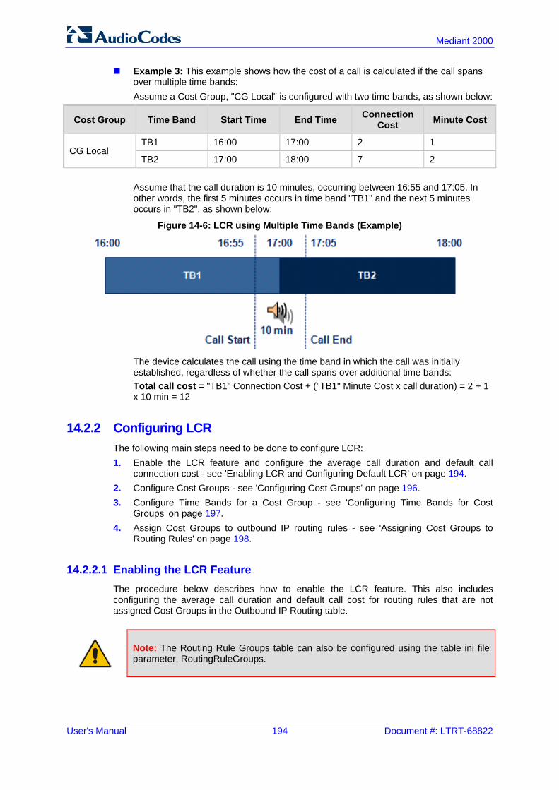
User's Manual 194 Document #: LTRT-68822
Mediant 2000
Example 3: This example shows how the cost of a call is calculated if the call spans over multiple time bands: Assume a Cost Group, "CG Local" is configured with two time bands, as shown below:
Cost Group Time Band Start Time End Time Connection Cost Minute Cost
CG Local TB1 16:00 17:00 2 1
TB2 17:00 18:00 7 2
Assume that the call duration is 10 minutes, occurring between 16:55 and 17:05. In other words, the first 5 minutes occurs in time band "TB1" and the next 5 minutes occurs in "TB2", as shown below:
Figure 14-6: LCR using Multiple Time Bands (Example)
The device calculates the call using the time band in which the call was initially established, regardless of whether the call spans over additional time bands: Total call cost = "TB1" Connection Cost + ("TB1" Minute Cost x call duration) = 2 + 1 x 10 min = 12
14.2.2 Configuring LCR The following main steps need to be done to configure LCR: 1. Enable the LCR feature and configure the average call duration and default call
connection cost - see 'Enabling LCR and Configuring Default LCR' on page 194. 2. Configure Cost Groups - see 'Configuring Cost Groups' on page 196. 3. Configure Time Bands for a Cost Group - see 'Configuring Time Bands for Cost
Groups' on page 197. 4. Assign Cost Groups to outbound IP routing rules - see 'Assigning Cost Groups to
Routing Rules' on page 198.
14.2.2.1 Enabling the LCR Feature The procedure below describes how to enable the LCR feature. This also includes configuring the average call duration and default call cost for routing rules that are not assigned Cost Groups in the Outbound IP Routing table.
Note: The Routing Rule Groups table can also be configured using the table ini file parameter, RoutingRuleGroups.

Version 6.6 195 Mediant 2000
User's Manual 14. Services
To enable LCR:
1. Open the Routing Rule Groups Table page (Configuration tab > VoIP menu > Services submenu > Least Cost Routing > Routing Rule Groups Table).
2. Click the Add button; the Add Record dialog box appears:
Figure 14-7: Routing Rule Groups Table - Add Record
3. Configure the parameters as required. For a description of the parameters, see the
table below. 4. Click Submit; the entry is added to the Routing Rule Groups table.
Routing Rule Groups Table Description
Parameter Description
Index [RoutingRuleGroups_Index]
Defines the table index entry. Note: Only one index entry can be configured.
LCR Enable [RoutingRuleGroups_LCREnable]
Enables the LCR feature: [0] Disabled (default) [1] Enabled
LCR Call Length [RoutingRuleGroups_LCRAverageCallLength]
Defines the average call duration (in minutes) and is used to calculate the variable portion of the call cost. This is useful, for example, when the average call duration spans over multiple time bands. The LCR is calculated as follows: cost = call connect cost + (minute cost * average call duration) The valid value range is 0-65533. The default is 1. For example, assume the following Cost Groups: "Weekend A": call connection cost is 1 and charge per minute is 6.
Therefore, a call of 1 minute cost 7 units. "Weekend_ B": call connection cost is 6 and charge per minute is 1.
Therefore, a call of 1 minute cost 7 units. Therefore, for calls under one minute, "Weekend A" carries the lower cost. However, if the average call duration is more than one minute, then "Weekend B" carries the lower cost.
Default Cost [RoutingRuleGroups_LCRDefaultCost]
Determines whether routing rules in the Outbound IP Routing table without an assigned Cost Group are considered a higher cost or lower cost route compared to other matched routing rules that are assigned Cost Groups. [0] Lowest Cost = If the device locates other matching LCR routing
rules, this routing rule is considered the lowest cost route and therefore, it is selected as the route to use (default.)
[1] Highest Cost = If the device locates other matching LCR routing

User's Manual 196 Document #: LTRT-68822
Mediant 2000
Parameter Description
rules, this routing rule is considered as the highest cost route and therefore, is not used or used only if the other cheaper routes are unavailable.
Note: If more than one valid routing rule without a defined Cost Group exists, the device selects the first-matched rule.
14.2.2.2 Configuring Cost Groups The procedure below describes how to configure Cost Groups. Cost Groups are defined with a fixed call connection cost and a call rate (charge per minute). Once configured, you can configure Time Bands for each Cost Group. Up to 10 Cost Groups can be configured.
Note: The Cost Group table can also be configured using the table ini file parameter, CostGroupTable.
To configure Cost Groups:
1. Open the Cost Group Table page (Configuration tab > VoIP menu > Services submenu > Least Cost Routing > Cost Group Table).
2. Click the Add button; the Add Record dialog box appears:
3. Configure the parameters as required. For a description of the parameters, see the
table below. 4. Click Submit; the entry is added to the Cost Group table.
Cost Group Table Description
Parameter Description
Index [CostGroupTable_Index]
Defines the table index entry.
Cost Group Name [CostGroupTable_CostGroupName]
Defines an arbitrary name for the Cost Group. The valid value is a string of up to 30 characters. Note: Each Cost Group must have a unique name.

Version 6.6 197 Mediant 2000
User's Manual 14. Services
Parameter Description
Default Connect Cost [CostGroupTable_DefaultConnectionCost]
Defines the call connection cost (added as a fixed charge to the call) for a call outside the time bands. The valid value range is 0-65533. The default is 0. Note: When calculating the cost of a call, if the current time of the call is not within a time band configured for the Cost Group, then this default connection cost is used.
Default Time Cost [CostGroupTable_DefaultMinuteCost]
Defines the call charge per minute for a call outside the time bands. The valid value range is 0-65533. The default is 0. Note: When calculating the cost of a call, if the current time of the call is not within a time band configured for the Cost Group, then this default charge per minute is used.
14.2.2.3 Configuring Time Bands for Cost Groups The procedure below describes how to configure Time Bands for a Cost Group. The time band defines the day and time range for which the time band is applicable (e.g., from Saturday 05:00 to Sunday 24:00) as well as the fixed call connection charge and call rate per minute for this interval. Up to 70 time bands can be configured, and up to 21 time bands can be assigned to each Cost Group.
Notes:
• You cannot define overlapping time bands. • The Time Band table can also be configured using the table ini file parameter,
CostGroupTimebands.
To configure Time Bands for a Cost Group: 1. Open the Cost Group Table page (Configuration tab > VoIP menu > Services
submenu > Least Cost Routing > Cost Group Table). 2. Select a Cost Group for which you want to assign Time Bands, and then click the
Time Band link located below the table; the Time Band table for the selected Cost Group appears.
3. Click the Add button; the Add Record dialog box appears:
4. Configure the parameters as required. For a description of the parameters, see the
table below. 5. Click Submit; the entry is added to the Time Band table for the relevant Cost Group.

User's Manual 198 Document #: LTRT-68822
Mediant 2000
Time Band Table Description
Parameter Description
Index [CostGroupTimebands_TimebandIndex]
Defines the table index entry.
Start Time [CostGroupTimebands_StartTime]
Defines the day and time of day from when this time band is applicable. The format is ddd:hh:mm (e.g., sun:06:00), where: ddd is the day (i.e., sun, mon, tue, wed, thu, fri, or sat) hh and mm denote the time of day, where hh is the hour (00-23) and
mm the minutes (00-59)
End Time [CostGroupTimebands_EndTime]
Defines the day and time of day until when this time band is applicable. For a description of the valid values, see the parameter above.
Connection Cost [CostGroupTimebands_ConnectionCost]
Defines the call connection cost during this time band. This is added as a fixed charge to the call. The valid value range is 0-65533. The default is 0. Note: The entered value must be a whole number (i.e., not a decimal).
Minute Cost [CostGroupTimebands_MinuteCost]
Defines the call cost per minute charge during this timeband. The valid value range is 0-65533. The default is 0. Note: The entered value must be a whole number (i.e., not a decimal).
14.2.2.4 Assigning Cost Groups to Routing Rules Once you have configured your Cost Groups, you need to assign them to routing rules in the Outbound IP Routing table - see Configuring Outbound IP Routing Table on page 309.

Version 6.6 199 Mediant 2000
User's Manual 15. Enabling Applications
15 Enabling Applications The device supports the following main applications: Stand-Alone Survivability (SAS) application IP-to-IP application The procedure below describes how to enable these applications. Once an application is enabled, the Web GUI provides menus and parameter fields relevant to the application.
Notes:
• This page displays the application only if the device is installed with the relevant Software License Key supporting the application (see 'Software License Key' on page 415).
• For configuring the SAS application, see 'Stand-Alone Survivability (SAS) Application' on page 355.
• For an overview of the IP-to-IP application and configuration examples, see IP-to-IP Routing Application on page 245.
• For enabling an application, a device reset is required.
To enable an application:
1. Open the Applications Enabling page (Configuration tab > VoIP menu > Applications Enabling submenu > Applications Enabling).
2. From the relevant application drop-down list, select Enable. 3. Save (burn) the changes to the device's flash memory with a device reset (see 'Saving
Configuration' on page 396).

User's Manual 200 Document #: LTRT-68822
Mediant 2000
Reader's Notes

Version 6.6 201 Mediant 2000
User's Manual 16. Control Network
16 Control Network This section describes configuration of the network at the SIP control level.
16.1 Configuring SRD Table The SRD Settings page allows you to configure up to 32 signaling routing domains (SRD). An SRD is configured with a unique name and assigned a Media Realm. An SRD is a set of definitions together creating multiple, virtual multi-service IP gateways: Multiple and different SIP signaling interfaces (SRD associated with a SIP Interface)
and RTP media (associated with a Media Realm) for multiple Layer-3 networks. Can operate with multiple gateway customers that may reside either in the same or in
different Layer-3 networks as the device. This allows separation of signaling traffic between different customers. In such a scenario, the device is configured with multiple SRD's.
Typically, one SRD is defined for each group of SIP UAs (e.g. proxies, IP phones, application servers, gateways, and softswitches) that communicate with each other. This provides these entities with VoIP services that reside on the same Layer-3 network (must be able to communicate without traversing NAT devices and must not have overlapping IP addresses). Routing from one SRD to another is possible, whereby each routing destination (IP Group or destination address) indicates the SRD to which it belongs. Once configured, you can use the SRD as follows: Associate it with a SIP Interface (see 'Configuring SIP Interface Table' on page 202) Associate it with an IP Group (see 'Configuring IP Groups' on page 204) Associate it with a Proxy Set (see 'Configuring Proxy Sets Table' on page 209) Define it as a Classification rule for the incoming SIP request (see Configuring
Classification Rules) Use it as a destination IP-to-IP routing rule (see 'Configuring Outbound IP Routing
Table' on page 309) The SRD Settings page also displays the IP Groups, Proxy Sets, and SIP Interfaces associated with a selected SRD index.
Notes:
• On the SRD Settings page, you can also configure a SIP Interface in the SIP Interface table, instead of navigating to the SIP Interface Table page as described in 'Configuring SIP Interface Table' on page 202.
• The SRD table can also be configured using the table ini file parameter, SRD.
To configure SRDs:
1. Open the SRD Settings page (Configuration tab > VoIP menu > Control Network submenu > SRD Table).
2. From the 'SRD Index' drop-down list, select an index for the SRD, and then configure
it according to the table below.

User's Manual 202 Document #: LTRT-68822
Mediant 2000
3. Click Submit to apply your changes. 4. To save the changes to flash memory, see 'Saving Configuration' on page 396.
SRD Table Parameters
Parameter Description
SRD Name [SRD_Name]
Mandatory descriptive name of the SRD. The valid value can be a string of up to 21 characters.
Media Realm [SRD_MediaRealm]
Defines the Media Realm associated with the SRD. The entered string value must be identical (and case-sensitive) to the Media Realm name configured in the Media Realm table (see 'Configuring Media Realms' on page 177). The valid value is a string of up to 40 characters. Notes: If the Media Realm is later deleted from the Media Realm table, then
this value becomes invalid in the SRD table. For configuring Media Realms, see 'Configuring Media Realms' on
page 177.
16.2 Configuring SIP Interface Table The SIP Interface table allows you to configure up to 32 SIP Interfaces. The SIP Interface defines a listening port and type (UDP, TCP, or TLS) for SIP signaling traffic on a specific logical IP network interface configured for the device (in the Multiple Interface table). The SIP Interface is configured for a specific application (i.e., Gateway\IP-to-IP, and SAS) and associated with an SRD. For each SIP Interface, you can assign a SIP message policy, enable TLS mutual authentication, enable TCP keepalive, and determine the SIP response sent upon classification failure. SIP Interfaces can be used, for example, for the following: Using SIP signaling interfaces per call leg (i.e., each SIP entity communicates with a
specific SRD). Using different SIP listening ports for a single or for multiple IP network interfaces. Differentiating between applications by creating SIP Interfaces per application. Separating signaling traffic between networks (e.g., different customers) to use
different routing tables, manipulations, SIP definitions, and so on.
Note: The SIP Interface table can also be configured using the table ini file parameter, SIPInterface.
To configure the SIP Interface table:
1. Open the SIP Interface Table page (Configuration tab > VoIP menu > Control Network submenu > SIP Interface Table).
2. Click the Add button; the following dialog box appears:

Version 6.6 203 Mediant 2000
User's Manual 16. Control Network
3. Click Submit to apply your settings.
SIP Interface Table Parameters
Parameter Description
Network Interface [SIPInterface_NetworkInterface]
Defines the Control-type IP network interface that you want to associate with the SIP Interface. This value string must be identical (including case-sensitive) to that configured in the 'Interface Name' field of the Multiple Interface table (see 'Configuring IP Network Interfaces' on page 106). The default is not configured. Note: SIP Interfaces that are assigned to a specific SRD must be defined with the same network interface. For example, if you define three SIP Interfaces for SRD ID #8, all these SIP Interfaces must be defined with the same network interface (e.g., "SIP1").
Application Type [SIPInterface_ApplicationType]
Defines the application type associated with the SIP Interface. [0] GW/IP2IP (default) = Gateway / IP-to-IP application. [1] SAS = Stand-Alone Survivability (SAS) application.
UDP Port [SIPInterface_UDPPort]
Defines the listening and source UDP port. The valid range is 1 to 65534. The default is 5060. Notes: This port must be outside of the RTP port range. Each SIP Interface must have a unique signaling port (i.e., no two SIP
Interfaces can share the same port - no port overlapping).
TCP Port [SIPInterface_TCPPort]
Defines the listening TCP port. The valid range is 1 to 65534. The default is 5060. Notes: This port must be outside of the RTP port range. Each SIP Interface must have a unique signaling port (i.e., no two SIP
Interfaces can share the same port - no port overlapping).
TLS Port [SIPInterface_TLSPort]
Defines the listening TLS port. The valid range is 1 to 65534. The default is 5061. Notes:

User's Manual 204 Document #: LTRT-68822
Mediant 2000
Parameter Description
This port must be outside of the RTP port range. Each SIP Interface must have a unique signaling port (i.e., no two SIP
Interfaces can share the same port - no port overlapping).
SRD [SIPInterface_SRD]
Assigns an SRD ID to the SIP Interface. The default is 0. Notes: Each SRD can be associated with up to two SIP Interfaces, where
each SIP Interface pertains to a different Application Type (GW/IP-to-IP, SAS).
SIP Interfaces that are assigned to a specific SRD must be defined with the same network interface. For example, if you define three SIP Interfaces for SRD ID #8, all these SIP Interfaces must be defined with the same network interface (e.g., "SIP1").
To configure SRDs, see 'Configuring SRD Table' on page 201.
Message Policy [SIPInterface_MessagePolicy]
Assigns a SIP message policy to the SIP interface. Note: To configure SIP message policies, see 'Configuring SIP Message Policy Rules'.
TLS Mutual Authentication [SIPInterface_TLSMutualAuthentication]
Enables TLS mutual authentication per SIP Interface. [-1] Not Configured = (Default) The SIPSRequireClientCertificate
global parameter setting is applied. [0] Disable = Device does not request the client certificate for TLS
connection. [1] Enable = Device requires receipt and verification of the client
certificate to establish the TLS connection.
TCP Keepalive Enable [SIPInterface_TCPKeepaliveEnable] CLI: tcp-keepalive-enable
Enables the TCP Keep-Alive mechanism with the IP entity on this SIP interface. TCP keepalive can be used, for example, to keep a NAT entry open for clients located behind a NAT server or simply to check that the connection to the IP entity is available. [0] No (default) [1] Yes Note: For configuring TCP keepalive, use the following ini file parameters: TCP TCPKeepAliveTime, TCPKeepAliveInterval, and TCPKeepAliveRetry.
16.3 Configuring IP Groups The IP Group Table page allows you to create up to 32 logical IP entities called IP Groups. An IP Group is an entity with a set of definitions such as a Proxy Set ID (see 'Configuring Proxy Sets Table' on page 209), which represents the IP address of the IP Group. For the Gateway/IP-to-IP application, IP Groups are used for the following: SIP dialog registration and authentication (digest user/password) of a specific IP
Group (Served IP Group, e.g., corporate IP-PBX) with another IP Group (Serving IP Group, e.g., ITSP). This is configured in the Account table (see Configuring Account Table on page 215).

Version 6.6 205 Mediant 2000
User's Manual 16. Control Network
Call routing rules: • Outgoing IP calls (IP-to-IP or Tel-to-IP): The IP Group identifies the source of the
call and is used as the destination of the outgoing IP call (defined in the Outbound IP Routing Table). For Tel-to-IP calls, the IP Group (Serving IP Group) can be used as the IP destination to where all SIP dialogs that are initiated from a Trunk Group are sent (defined in Configuring Trunk Group Settings on page 281).
• Incoming IP calls (IP-to-IP or IP-to-Tel): The IP Group identifies the source of the IP call.
• Number Manipulation rules to IP: The IP Group is used to associate the rule with specific calls identified by IP Group.
Notes:
• IP Group ID 0 cannot be used. This IP Group is set to default values and is used by the device when IP Groups are not implemented.
• When operating with multiple IP Groups, the default Proxy server must not be used (i.e., the parameter IsProxyUsed must be set to 0).
• You can also configure the IP Groups table using the table ini file parameter, IPGroup (see 'Configuration Parameters Reference' on page 503).
To configure IP Groups:
1. Open the IP Group Table page (Configuration tab > VoIP menu > Control Network submenu > IP Group Table).
2. Click the Add button: the following dialog box appears:
3. Configure the IP Group parameters according to the table below. 4. Click Submit. 5. To save the changes to flash memory, see 'Saving Configuration' on page 396.

User's Manual 206 Document #: LTRT-68822
Mediant 2000
IP Group Parameters
Parameter Description
Common Parameters
Type [IPGroup_Type]
Defines the type of IP Group: [0] Server = Used when the destination address, configured by the
Proxy Set, of the IP Group (e.g., ITSP, Proxy, IP-PBX, or Application server) is known.
[1] User = Represents a group of users such as IP phones and softphones where their location is dynamically obtained by the device when REGISTER requests and responses traverse (or are terminated) by the device. These users are considered remote (far-end) users. Typically, this IP Group is configured with a Serving IP Group that represents an IP-PBX, Application or Proxy server that serves this User-type IP Group. Each SIP request sent by a user of this IP Group is proxied to the Serving IP Group. For registrations, the device updates its internal database with the AOR and contacts of the users. Digest authentication using SIP 401/407 responses (if needed) is performed by the Serving IP Group. The device forwards these responses directly to the SIP users. To route a call to a registered user, a rule must be configured in the Outbound IP Routing Table. The device searches the dynamic database (by using the request URI) for an entry that matches a registered AOR or Contact. Once an entry is found, the IP destination is obtained from this entry, and a SIP request is sent to the destination. The device also supports NAT traversal for the SIP clients located behind NAT. In this case, the device must be defined with a global IP address.
Note: This field is applicable only to the IP-to-IP application.
Description [IPGroup_Description]
Defines a brief description for the IP Group. The valid value is a string of up to 29 characters. The default is an empty field.
Proxy Set ID [IPGroup_ProxySetId]
Assigns a Proxy Set ID to the IP Group. All INVITE messages destined to this IP Group are sent to the IP address configured for the Proxy Set. Notes: Proxy Set ID 0 must not be used; this is the device's default Proxy. The Proxy Set is applicable only to Server-type IP Groups. The SRD configured for this Proxy Set in the Proxy Set table is
automatically assigned to this IP Group (see the 'SRD' field below). To configure Proxy Sets, see 'Configuring Proxy Sets Table' on page
209.
SIP Group Name [IPGroup_SIPGroupName]
Defines the SIP Request-URI host name used in INVITE and REGISTER messages sent to this IP Group, or the host name in the From header of INVITE messages received from this IP Group. The valid value is a string of up to 100 characters. The default is an empty field. Notes: If this parameter is not configured, the value of the global parameter,
ProxyName is used instead (see 'Configuring Proxy and Registration Parameters' on page 218).

Version 6.6 207 Mediant 2000
User's Manual 16. Control Network
Parameter Description
If the IP Group is of User type, this parameter is used internally as a host name in the Request-URI for Tel-to-IP initiated calls. For example, if an incoming call from the device's T1 trunk is routed to a User-type IP Group, the device first creates the Request-URI (<destination_number>@<SIP Group Name>), and then it searches the internal database for a match.
Contact User [IPGroup_ContactUser]
Defines the user part of the From, To, and Contact headers of SIP REGISTER messages, and the user part of the Contact header of INVITE messages received from this IP Group and forwarded by the device to another IP Group. Notes: This parameter is applicable only to Server-type IP Groups. This parameter is overridden by the ‘Contact User’ parameter in the
‘Account’ table (see 'Configuring Account Table' on page 215).
Local Host Name [IPGroup_ContactName]
Defines the host name (string) that the device uses in the SIP message's Via and Contact headers. This is typically used to define an FQDN as the host name. The device uses this string for Via and Contact headers in outgoing INVITE messages to a specific IP Group, and the Contact header in SIP 18x and 200 OK responses for incoming INVITE messages from a specific IP Group. The Inbound IP Routing table can be used to identify the source IP Group from where the INVITE message was received. If this parameter is not configured (default), these headers are populated with the device's dotted-decimal IP address of the network interface on which the message is sent. Note: To ensure proper device handling, this parameter should be a valid FQDN.
SRD [IPGroup_SRD]
Assigns an SRD to the IP Group. The default is 0. Notes: For this parameter to take effect, a device reset is required. To configure SRDs, see Configuring SRD Table on page 201. For Server-type IP Groups, if you assign the IP Group with a Proxy
Set ID (in the 'Proxy Set ID' field), the SRD field is automatically set to the SRD value assigned to the Proxy Set in the Proxy Set table.
Media Realm Name [IPGroup_MediaRealm]
Assigns a Media Realm to the IP Group. The string value must be identical (including case-sensitive) to the Media Realm name defined in the Media Realm table. Notes: For this parameter to take effect, a device reset is required. If the Media Realm is later deleted from the Media Realm table, then
this value becomes invalid. For configuring Media Realms, see Configuring Media Realms on
page 177.
IP Profile ID [IPGroup_ProfileId]
Assigns an IP Profile to the IP Group. The default is 0. Note: To configure IP Profiles, see 'Configuring IP Profiles' on page 235.
Gateway Parameters
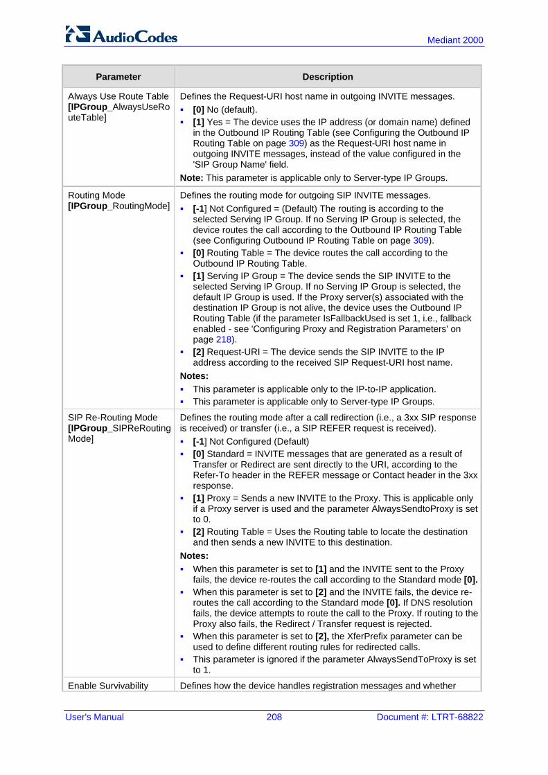
User's Manual 208 Document #: LTRT-68822
Mediant 2000
Parameter Description
Always Use Route Table [IPGroup_AlwaysUseRouteTable]
Defines the Request-URI host name in outgoing INVITE messages. [0] No (default). [1] Yes = The device uses the IP address (or domain name) defined
in the Outbound IP Routing Table (see Configuring the Outbound IP Routing Table on page 309) as the Request-URI host name in outgoing INVITE messages, instead of the value configured in the 'SIP Group Name' field.
Note: This parameter is applicable only to Server-type IP Groups.
Routing Mode [IPGroup_RoutingMode]
Defines the routing mode for outgoing SIP INVITE messages. [-1] Not Configured = (Default) The routing is according to the
selected Serving IP Group. If no Serving IP Group is selected, the device routes the call according to the Outbound IP Routing Table (see Configuring Outbound IP Routing Table on page 309).
[0] Routing Table = The device routes the call according to the Outbound IP Routing Table.
[1] Serving IP Group = The device sends the SIP INVITE to the selected Serving IP Group. If no Serving IP Group is selected, the default IP Group is used. If the Proxy server(s) associated with the destination IP Group is not alive, the device uses the Outbound IP Routing Table (if the parameter IsFallbackUsed is set 1, i.e., fallback enabled - see 'Configuring Proxy and Registration Parameters' on page 218).
[2] Request-URI = The device sends the SIP INVITE to the IP address according to the received SIP Request-URI host name.
Notes: This parameter is applicable only to the IP-to-IP application. This parameter is applicable only to Server-type IP Groups.
SIP Re-Routing Mode [IPGroup_SIPReRoutingMode]
Defines the routing mode after a call redirection (i.e., a 3xx SIP response is received) or transfer (i.e., a SIP REFER request is received). [-1] Not Configured (Default) [0] Standard = INVITE messages that are generated as a result of
Transfer or Redirect are sent directly to the URI, according to the Refer-To header in the REFER message or Contact header in the 3xx response.
[1] Proxy = Sends a new INVITE to the Proxy. This is applicable only if a Proxy server is used and the parameter AlwaysSendtoProxy is set to 0.
[2] Routing Table = Uses the Routing table to locate the destination and then sends a new INVITE to this destination.
Notes: When this parameter is set to [1] and the INVITE sent to the Proxy
fails, the device re-routes the call according to the Standard mode [0]. When this parameter is set to [2] and the INVITE fails, the device re-
routes the call according to the Standard mode [0]. If DNS resolution fails, the device attempts to route the call to the Proxy. If routing to the Proxy also fails, the Redirect / Transfer request is rejected.
When this parameter is set to [2], the XferPrefix parameter can be used to define different routing rules for redirected calls.
This parameter is ignored if the parameter AlwaysSendToProxy is set to 1.
Enable Survivability Defines how the device handles registration messages and whether

Version 6.6 209 Mediant 2000
User's Manual 16. Control Network
Parameter Description
[IPGroup_EnableSurvivability]
Survivability mode is enabled for User-type IP Groups. [0] Disable (default). [1] Enable if Necessary = Survivability mode is enabled only if the
Serving IP Group is unavailable. The device saves in its Registration database the registration messages sent by the clients (e.g., IP phones) belonging to the User-type IP Group. If communication with the Serving IP Group (e.g., IP-PBX) fails, the User-type IP Group enters into Survivability mode in which the device uses its database for routing calls between the clients of the User-type IP Group. In Survivability mode, the RTP packets between the clients always traverse through the device, and new registrations can also be processed. When the Serving IP Group is available again, the device returns to normal mode, sending INVITE and REGISTER messages to the Serving IP Group.
[2] Always Enable = Survivability mode is always enabled. The communication with the Serving IP Group is always considered as failed. The device uses its database for routing calls between the clients of the User-type IP Group.
[3] Always Terminate Register = The registration messages received from the clients are saved in the device's registration database without forwarding them to the proxy server. Upon receipt of the registration message, the device returns a SIP 200 OK to the client.
Notes: This parameter is applicable only to the IP-to-IP application. This parameter is applicable only to User-type IP Groups.
Serving IP Group ID [IPGroup_ServingIPGroup]
If configured, INVITE messages initiated from the IP Group are sent to this Serving IP Group (range 1 to 9). In other words, the INVITEs are sent to the address defined for the Proxy Set associated with this Serving IP Group. The Request-URI host name in the INVITE messages are set to the value of the ‘SIP Group Name’ parameter defined for the Serving IP Group. Notes: This parameter is applicable only to the IP-to-IP application. If the PreferRouteTable parameter is set to 1, the routing rules in the
Outbound IP Routing Table take precedence over this ‘Serving IP Group ID’ parameter.
If this parameter is not configured, the INVITE messages are sent to the default Proxy or according to the ‘Outbound IP Routing Table.
16.4 Configuring Proxy Sets Table The Proxy Sets Table page allows you to define Proxy Sets. A Proxy Set is a group of Proxy servers defined by IP address or fully qualified domain name (FQDN). You can define up to 32 Proxy Sets, each with up to five Proxy server addresses. For each Proxy server address you can define the transport type (i.e., UDP, TCP, or TLS). In addition, Proxy load balancing and redundancy mechanisms can be applied per Proxy Set if it contains more than one Proxy address. Proxy Sets can later be assigned to Server-type IP Groups (see 'Configuring IP Groups' on page 204). When the device sends an INVITE message to an IP Group, it is sent to the IP address or domain name defined for the Proxy Set that is associated with the IP Group. In other words, the Proxy Set represents the destination of the call. Typically, for IP-to-IP call

User's Manual 210 Document #: LTRT-68822
Mediant 2000
routing, at least two Proxy Sets are defined for call destination – one for each leg (IP Group) of the call (i.e., both directions). For example, one Proxy Set for the Internet Telephony Service provider (ITSP) interfacing with one 'leg' of the device and another Proxy Set for the second SIP entity (e.g., ITSP) interfacing with the other 'leg' of the device.
Notes:
• Proxy Sets can be assigned only to Server-type IP Groups. • The Proxy Set table can also be configured using two complementary tables:
- Proxy Set ID with IP addresses: Table ini file parameter, ProxyIP. - Attributes for the Proxy Set: Table ini file parameter, ProxySet.
To configure Proxy Sets:
1. Open the Proxy Sets Table page (Configuration tab > VoIP menu > Control Network submenu > Proxy Sets Table).
Figure 16-1: Proxy Sets Table Page
2. From the 'Proxy Set ID' drop-down list, select an ID for the desired group. 3. Configure the Proxy parameters, as required. For a description of the parameters, see
the table below. 4. Click Submit. 5. To save the changes to flash memory, see 'Saving Configuration' on page 396.
Proxy Sets Table Parameters
Parameter Description
Web: Proxy Set ID EMS: Index [ProxySet_Index]
Defines the Proxy Set identification number. The valid value is 0 to 31. Proxy Set ID 0 is used as the default Proxy Set. Note: Although not recommended, you can use both default Proxy Set (ID 0) and IP Groups for call routing. For example, in the Trunk Group Settings

Version 6.6 211 Mediant 2000
User's Manual 16. Control Network
Parameter Description
page (see Configuring Trunk Group Settings on page 281) you can configure a Serving IP Group to where you want to route specific Trunk Group channels, and all other device channels then use the default Proxy Set. You can also use IP Groups in the Outbound IP Routing Table (see Configuring the Outbound IP Routing Table on page 309) to configure the default Proxy Set if the parameter PreferRouteTable is set to 1. To summarize, if the default Proxy Set is used, the INVITE message is sent according to the following preferences: To the Trunk Group's Serving IP Group ID, as defined in the Trunk
Group Settings table. According to the Outbound IP Routing Table if the parameter
PreferRouteTable is set to 1. To the default Proxy. Typically, when IP Groups are used, there is no need to use the default Proxy and all routing and registration rules can be configured using IP Groups and the Account tables (see 'Configuring Account Table' on page 215).
Proxy Address [ProxyIp_IpAddress]
Defines the address (and optionally, port number) of the Proxy server. Up to five addresses can be configured per Proxy Set. The address can be defined as an IP address in dotted-decimal notation (e.g., 201.10.8.1) or as an FQDN. You can also specify the selected port in the format, <IP address>:<port>. If you enable Proxy Redundancy (by setting the parameter EnableProxyKeepAlive to 1 or 2), the device can operate with multiple Proxy servers. If there is no response from the first (primary) Proxy defined in the list, the device attempts to communicate with the other (redundant) Proxies in the list. When a redundant Proxy is located, the device either continues operating with it until the next failure occurs or reverts to the primary Proxy (refer to the parameter ProxyRedundancyMode). If none of the Proxy servers respond, the device goes over the list again. The device also provides real-time switching (Hot-Swap mode) between the primary and redundant proxies (refer to the parameter IsProxyHotSwap). If the first Proxy doesn't respond to the INVITE message, the same INVITE message is immediately sent to the next Proxy in the list. The same logic applies to REGISTER messages (if RegistrarIP is not defined). Notes: If EnableProxyKeepAlive is set to 1 or 2, the device monitors the
connection with the Proxies by using keep-alive messages (OPTIONS or REGISTER).
To use Proxy Redundancy, you must specify one or more redundant Proxies.
When a port number is specified (e.g., domain.com:5080), DNS NAPTR/SRV queries aren't performed, even if ProxyDNSQueryType is set to 1 or 2.
Transport Type [ProxyIp_TransportType]
Defines the transport type of the proxy server. [0] UDP [1] TCP [2] TLS [-1] = Undefined Note: If no transport type is selected, the value of the global parameter

User's Manual 212 Document #: LTRT-68822
Mediant 2000
Parameter Description
SIPTransportType is used.
Web/EMS: Enable Proxy Keep Alive [ProxySet_EnableProxyKeepAlive]
Enables the Keep-Alive mechanism with the Proxy server(s). [0] Disable (default). [1] Using Options = Enables Keep-Alive with Proxy using SIP OPTIONS
messages. [2] Using Register = Enables Keep-Alive with Proxy using SIP
REGISTER messages. If set to 'Using Options', the SIP OPTIONS message is sent every user-defined interval (configured by the parameter ProxyKeepAliveTime). If set to 'Using Register', the SIP REGISTER message is sent every user-defined interval (configured by the RegistrationTime parameter for the Gateway/IP-to-IP application). Any response from the Proxy, either success (200 OK) or failure (4xx response) is considered as if the Proxy is communicating correctly. Notes: For Survivability mode for User-type IP Groups, this parameter must be
enabled (1 or 2). This parameter must be set to 'Using Options' when Proxy redundancy
is used. When this parameter is set to 'Using Register', the homing redundancy
mode is disabled. When the active proxy doesn't respond to INVITE messages sent by the
device, the proxy is tagged as 'offline'. The behavior is similar to a Keep-Alive (OPTIONS or REGISTER) failure.
If this parameter is enabled and the proxy uses the TCP/TLS transport type, you can enable CRLF Keep-Alive mechanism, using the UsePingPongKeepAlive parameter.
Web: Proxy Keep Alive Time EMS: Keep Alive Time [ProxySet_ProxyKeepAliveTime]
Defines the Proxy keep-alive time interval (in seconds) between Keep-Alive messages. The valid range is 5 to 2,000,000. The default is 60. Note: This parameter is applicable only if the parameter EnableProxyKeepAlive is set to 1 (OPTIONS). When the parameter EnableProxyKeepAlive is set to 2 (REGISTER), the time interval between Keep-Alive messages is determined by the RegistrationTime parameter for the Gateway/IP-to-IP application.
Web: Proxy Load Balancing Method EMS: Load Balancing Method [ProxySet_ProxyLoadBalancingMethod]
Enables the Proxy Load Balancing mechanism per Proxy Set ID. [0] Disable = Load Balancing is disabled (default) [1] Round Robin [2] Random Weights When the Round Robin algorithm is used, a list of all possible Proxy IP addresses is compiled. This list includes all IP addresses per Proxy Set, after necessary DNS resolutions (including NAPTR and SRV, if configured). After this list is compiled, the Proxy Keep-Alive mechanism (according to parameters EnableProxyKeepAlive and ProxyKeepAliveTime) tags each entry as 'offline' or 'online'. Load balancing is only performed on Proxy servers that are tagged as 'online'. All outgoing messages are equally distributed across the list of IP addresses. REGISTER messages are also distributed unless a RegistrarIP is configured. The IP addresses list is refreshed according to ProxyIPListRefreshTime. If a change in the order of the entries in the list occurs, all load statistics are

Version 6.6 213 Mediant 2000
User's Manual 16. Control Network
Parameter Description
erased and balancing starts over again. When the Random Weights algorithm is used, the outgoing requests are not distributed equally among the Proxies. The weights are received from the DNS server by using SRV records. The device sends the requests in such a fashion that each Proxy receives a percentage of the requests according to its' assigned weight. A single FQDN should be configured as a Proxy IP address. The Random Weights Load Balancing is not used in the following scenarios: The Proxy Set includes more than one Proxy IP address. The only Proxy defined is an IP address and not an FQDN. SRV is not enabled (DNSQueryType). The SRV response includes several records with a different Priority
value.
Web/EMS: Is Proxy Hot-Swap [ProxySet_IsProxyHotSwap]
Enables the Proxy Hot-Swap redundancy mode. [0] No (default) [1] Yes If Proxy Hot-Swap is enabled, the SIP INVITE/REGISTER message is initially sent to the first Proxy/Registrar server. If there is no response from the first Proxy/Registrar server after a specific number of retransmissions (configured by the parameter HotSwapRtx), the message is resent to the next redundant Proxy/Registrar server.
Web/EMS: Redundancy Mode [ProxySet_ProxyRedundancyMode]
Determines whether the device switches back to the primary Proxy after using a redundant Proxy. [-1] Not configured = (Default) The global parameter,
ProxyRedundancyMode applies. [0] Parking = The device continues operating with a redundant (now
active) Proxy until the next failure, after which it operates with the next redundant Proxy.
[1] Homing = The device always attempts to operate with the primary Proxy server (i.e., switches back to the primary Proxy whenever it's available).
Notes: To use the Proxy Redundancy mechanism, you need to enable the
keep-alive with Proxy option, by setting the parameter EnableProxyKeepAlive to 1 or 2.
If this parameter is configured, then the global parameter is ignored.
Web/EMS: SRD Index [ProxySet_ProxySet_SRD]
Defines the SRD associated with the Proxy Set ID. The default is SRD 0. Notes: For this parameter to take effect, a device reset is required. To configure SRDs, see Configuring SRD Table on page 201.

User's Manual 214 Document #: LTRT-68822
Mediant 2000
Reader's Notes

Version 6.6 215 Mediant 2000
User's Manual 17. SIP Definitions
17 SIP Definitions This section describes configuration of SIP parameters.
17.1 Configuring SIP Parameters Many of the stand-alone SIP parameters associated with various features can be configured in the following pages: SIP General Parameters page: Provides SIP parameters for configuring general SIP
features. To access this page, use the following path: Configuration tab > VoIP menu > SIP Definitions > General Parameters.
SIP Advanced Parameters page: Provides SIP parameters for configuring advanced SIP features. To access this page, use the following path: Configuration tab > VoIP menu > SIP Definitions > Advanced Parameters.
For a description of these parameters, refer to the section corresponding to the feature or see 'Configuration Parameters Reference' on page 503.
17.2 Configuring Account Table The Account Table page lets you define up to 32 Accounts per ("served") Trunk Group or source ("served") IP Group. Accounts are used to register and/or digest authenticate a Trunk Group or served IP Group, using a username and password, to a destination ("serving") IP Group. For example, the device can use the Account table to register an IP PBX, which is connected to the device, to an ITSP. The device sends the registration requests to the Proxy Set ID (see 'Configuring Proxy Sets Table' on page 209) that is associated with the serving IP Group. A Trunk Group or served IP Group can register to more than one serving IP Group (e.g., multiple ITSPs). This is done by configuring multiple entries in the Account table for the same Trunk Group or served IP Group, but with different serving IP Groups, user name/password, host name, and contact user values. When using the Account table to register a Trunk Group, if all trunks belonging to the Trunk Group are down, the device un-registers the trunks. If any trunk belonging to the Trunk Group is returned to service, the device registers them again. This ensures, for example, that the Proxy does not send INVITEs to trunks that are out of service. If registration to an IP Group fails for all accounts of a specific Trunk Group and if this Trunk Group includes all the channels in the Trunk Group, the Trunk Group is set to Out-Of-Service if the OOSOnRegistrationFail parameter is set to 1 (see 'Proxy & Registration Parameters' on page 218).
Notes:
• For viewing Account registration status, see Viewing Endpoint Registration Status on page 452.
• The Account table can also be configured using the table ini file parameter, Account.
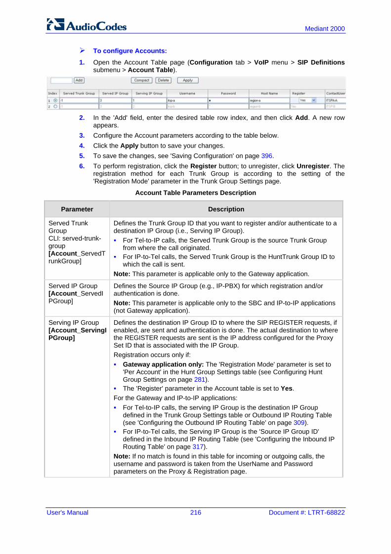
User's Manual 216 Document #: LTRT-68822
Mediant 2000
To configure Accounts:
1. Open the Account Table page (Configuration tab > VoIP menu > SIP Definitions submenu > Account Table).
2. In the 'Add' field, enter the desired table row index, and then click Add. A new row
appears. 3. Configure the Account parameters according to the table below. 4. Click the Apply button to save your changes. 5. To save the changes, see 'Saving Configuration' on page 396. 6. To perform registration, click the Register button; to unregister, click Unregister. The
registration method for each Trunk Group is according to the setting of the 'Registration Mode' parameter in the Trunk Group Settings page.
Account Table Parameters Description
Parameter Description
Served Trunk Group CLI: served-trunk-group [Account_ServedTrunkGroup]
Defines the Trunk Group ID that you want to register and/or authenticate to a destination IP Group (i.e., Serving IP Group). For Tel-to-IP calls, the Served Trunk Group is the source Trunk Group
from where the call originated. For IP-to-Tel calls, the Served Trunk Group is the HuntTrunk Group ID to
which the call is sent. Note: This parameter is applicable only to the Gateway application.
Served IP Group [Account_ServedIPGroup]
Defines the Source IP Group (e.g., IP-PBX) for which registration and/or authentication is done. Note: This parameter is applicable only to the SBC and IP-to-IP applications (not Gateway application).
Serving IP Group [Account_ServingIPGroup]
Defines the destination IP Group ID to where the SIP REGISTER requests, if enabled, are sent and authentication is done. The actual destination to where the REGISTER requests are sent is the IP address configured for the Proxy Set ID that is associated with the IP Group. Registration occurs only if: Gateway application only: The 'Registration Mode' parameter is set to
'Per Account' in the Hunt Group Settings table (see Configuring Hunt Group Settings on page 281).
The 'Register' parameter in the Account table is set to Yes. For the Gateway and IP-to-IP applications: For Tel-to-IP calls, the serving IP Group is the destination IP Group
defined in the Trunk Group Settings table or Outbound IP Routing Table (see 'Configuring the Outbound IP Routing Table' on page 309).
For IP-to-Tel calls, the Serving IP Group is the 'Source IP Group ID' defined in the Inbound IP Routing Table (see 'Configuring the Inbound IP Routing Table' on page 317).
Note: If no match is found in this table for incoming or outgoing calls, the username and password is taken from the UserName and Password parameters on the Proxy & Registration page.

Version 6.6 217 Mediant 2000
User's Manual 17. SIP Definitions
Parameter Description
Username [Account_Username]
Defines the digest MD5 Authentication user name. The valid value is a string of up to 50 characters.
Password [Account_Password]
Defines the digest MD5 Authentication password. The valid value is a string of up to 50 characters. Note: After you click the Apply button, this password is displayed as an asterisk (*).
Host Name [Account_HostName]
Defines the Address of Record (AOR) host name. It appears in REGISTER From/To headers as ContactUser@HostName. For successful registrations, this host name is also included in the INVITE request's From header URI. This parameter can be up to 49 characters. Note: If this parameter is not configured or if registration fails, the 'SIP Group Name' parameter configured in the IP Group table is used instead.
Register [Account_Register]
Enables registration. [0] No (Default) [1] Yes When enabled, the device sends REGISTER requests to the Serving IP Group. The host name (i.e., host name in SIP From/To headers) and Contact User (user in From/To and Contact headers) are taken from this table upon successful registration. See the example below: REGISTER sip:xyz SIP/2.0 Via: SIP/2.0/UDP 10.33.37.78;branch=z9hG4bKac1397582418 From: <sip:ContactUser@HostName>;tag=1c1397576231 To: <sip: ContactUser@HostName > Call-ID: [email protected] CSeq: 1 REGISTER Contact: <sip:[email protected]>;expires=3600 Expires: 3600 User-Agent: Sip-Gateway/v.6.00A.008.002 Content-Length: 0
Notes: To activate registration, you also need to set the parameter 'Registration
Mode' to 'Per Account' in the Trunk Group Settings table for the specific Trunk Group.
The Trunk Group account registration is not affected by the parameter IsRegisterNeeded.
Contact User [Account_ContactUser]
Defines the AOR user name. This appears in REGISTER From/To headers as ContactUser@HostName, and in INVITE/200 OK Contact headers as ContactUser@<device's IP address>. Notes: If this parameter is not configured, the 'Contact User' parameter in the IP
Group table is used instead. If registration fails, then the user part in the INVITE Contact header
contains the source party number.
Application Type [Account_ApplicationType]
Defines the application type: [0] GW/IP2IP = (Default) Gateway and IP-to-IP application.

User's Manual 218 Document #: LTRT-68822
Mediant 2000
17.3 Configuring Proxy and Registration Parameters The Proxy & Registration page allows you to configure the Proxy server and registration parameters. For a description of the parameters appearing on this page, see 'Configuration Parameters Reference' on page 503.
Note: To view the registration status of endpoints with a SIP Registrar/Proxy server, see Viewing Endpoint Registration Status on page 452.
To configure the Proxy and registration parameters:
1. Open the Proxy & Registration page (Configuration tab > VoIP menu > SIP Definitions submenu > Proxy & Registration).
2. Configure the parameters as required. 3. Click Submit to apply your changes.

Version 6.6 219 Mediant 2000
User's Manual 17. SIP Definitions
To register or un-register the device to a Proxy/Registrar: Click the Register button to register. Click Un-Register button to un-register. Instead of registering the entire device, you can register specific entities as listed below by using the Register button located on the page in which these entities are configured: Trunk Groups - Trunk Group Table page (see Configuring Trunk Group Table on page
279) Accounts - Account table (see 'Configuring Account Table' on page 215)
Click the Proxy Set Table button to Open the Proxy Sets Table page to configure groups of proxy addresses. Alternatively, you can open this page from the Proxy Sets Table page item (see 'Configuring Proxy Sets Table' on page 209 for a description of this page).
17.3.1 SIP Message Authentication Example The device supports basic and digest (MD5) authentication types, according to SIP RFC 3261 standard. A proxy server might require authentication before forwarding an INVITE message. A Registrar/Proxy server may also require authentication for client registration. A proxy replies to an unauthenticated INVITE with a 407 Proxy Authorization Required response, containing a Proxy-Authenticate header with the form of the challenge. After sending an ACK for the 407, the user agent can then re-send the INVITE with a Proxy-Authorization header containing the credentials. User agents, Redirect or Registrar servers typically use the SIP 401 Unauthorized response to challenge authentication containing a WWW-Authenticate header, and expect the re-INVITE to contain an Authorization header. The following example shows the Digest Authentication procedure, including computation of user agent credentials: 1. The REGISTER request is sent to a Registrar/Proxy server for registration:
REGISTER sip:10.2.2.222 SIP/2.0 Via: SIP/2.0/UDP 10.1.1.200 From: <sip: [email protected]>;tag=1c17940 To: <sip: [email protected]> Call-ID: [email protected] User-Agent: Sip-Gateway/Mediant 2000/v.6.60.010.006 CSeq: 1 REGISTER Contact: sip:[email protected]: Expires:3600
2. Upon receipt of this request, the Registrar/Proxy returns a 401 Unauthorized response: SIP/2.0 401 Unauthorized Via: SIP/2.0/UDP 10.2.1.200 From: <sip:[email protected] >;tag=1c17940 To: <sip:[email protected] > Call-ID: [email protected] Cseq: 1 REGISTER Date: Mon, 30 Jul 2012 15:33:54 GMT Server: Columbia-SIP-Server/1.17 Content-Length: 0 WWW-Authenticate: Digest realm="audiocodes.com", nonce="11432d6bce58ddf02e3b5e1c77c010d2", stale=FALSE, algorithm=MD5
User's Manual 220 Document #: LTRT-68822
Mediant 2000
3. According to the sub-header present in the WWW-Authenticate header, the correct REGISTER request is created.
4. Since the algorithm is MD5: • The username is equal to the endpoint phone number "122". • The realm return by the proxy is "audiocodes.com". • The password from the ini file is "AudioCodes". • The equation to be evaluated is "122:audiocodes.com:AudioCodes". According to
the RFC, this part is called A1. • The MD5 algorithm is run on this equation and stored for future usage. • The result is "a8f17d4b41ab8dab6c95d3c14e34a9e1".
5. The par called A2 needs to be evaluated: • The method type is "REGISTER". • Using SIP protocol "sip". • Proxy IP from ini file is "10.2.2.222". • The equation to be evaluated is "REGISTER:sip:10.2.2.222". • The MD5 algorithm is run on this equation and stored for future usage. • The result is "a9a031cfddcb10d91c8e7b4926086f7e".
6. Final stage: • A1 result: The nonce from the proxy response is
"11432d6bce58ddf02e3b5e1c77c010d2". • A2 result: The equation to be evaluated is
"A1:11432d6bce58ddf02e3b5e1c77c010d2:A2". • The MD5 algorithm is run on this equation. The outcome of the calculation is the
response needed by the device to register with the Proxy. • The response is "b9c45d0234a5abf5ddf5c704029b38cf". At this time, a new REGISTER request is issued with the following response: REGISTER sip:10.2.2.222 SIP/2.0 Via: SIP/2.0/UDP 10.1.1.200 From: <sip: [email protected]>;tag=1c23940 To: <sip: [email protected]> Call-ID: [email protected] Server: Audiocodes-Sip-Gateway/Mediant 2000/v.6.60.010.006 CSeq: 1 REGISTER Contact: sip:[email protected]: Expires:3600 Authorization: Digest, username: 122, realm="audiocodes.com”, nonce="11432d6bce58ddf02e3b5e1c77c010d2", uri=”10.2.2.222”, response=“b9c45d0234a5abf5ddf5c704029b38cf”
7. Upon receiving this request and if accepted by the Proxy, the Proxy returns a 200 OK response, completing the registration transaction: SIP/2.0 200 OK Via: SIP/2.0/UDP 10.1.1.200 From: <sip: [email protected]>;tag=1c23940 To: <sip: [email protected]> Call-ID: [email protected] Cseq: 1 REGISTER Date: Thu, 26 Jul 2012 09:34:42 GMT Server: Columbia-SIP-Server/1.17 Content-Length: 0
Version 6.6 221 Mediant 2000
User's Manual 17. SIP Definitions
Contact: <sip:[email protected]>; expires="Thu, 26 Jul 2012 10:34:42 GMT"; action=proxy; q=1.00 Contact: <[email protected]:>; expires="Tue, 19 Jan 2038 03:14:07 GMT"; action=proxy; q=0.00 Expires: Thu, 26 Jul 2012 10:34:42 GMT
17.4 Configuring SIP Message Manipulation The Message Manipulations page allows you to define up to 100 SIP message manipulation rules. Each manipulation rule can be assigned any Manipulation Set ID (0 to 19), enabling you to create groups (sets) of manipulation rules whereby rules of a group are configured with the same Manipulation Set ID number. To use these Manipulation Sets, you need to assign them to IP Groups in the IP Group table (see 'Configuring IP Groups' on page 204) where they can be applied to inbound and/or outbound SIP messages. SIP message manipulation enables the normalization of SIP messaging fields between communicating network segments. For example, it allows service providers to design their own policies on the SIP messaging fields that must be present before a SIP call enters their network. Similarly, enterprises and small businesses may have policies for the information that can enter or leave their networks for policy or security reasons from a service provider. The manipulations can also be implemented to resolve incompatibilities between SIP devices inside the enterprise network. SIP message manipulation supports the following: Addition of new headers. Removal of headers ("Black list"). Modification of header components - value, header value (e.g., URI value of the P-
Asserted-Identity header can be copied to the From header), call's parameter values. Deletion of SIP body (e.g., if a message body isn’t supported at the destination
network this body is removed). Translating one SIP response code to another. Topology hiding (generally present in SIP headers such as Via, Record Route, Route
and Service-Route). Configurable identity hiding (information related to identity of subscribers for example,
P-Asserted-Identity, Referred-By, Identity and Identity-Info). Apply conditions per rule - the condition can be on parts of the message or call’s
parameters. Multiple manipulation rules on the same SIP message. The manipulation can be performed on message type (Method, Request/Response, and Response type) and multiple manipulation rules can be configured for the same SIP message. For the Gateway / IP-to-IP application, manipulation rules can be assigned as follows: Manipulating inbound SIP INVITE messages: The Manipulation Set ID is selected
using the "global" parameter, GWInboundManipulationSet. If this parameter is not configured, then no manipulation is done.
Manipulating outbound SIP INVITE messages: The Manipulation Set ID is selected using the following logic: a. According to the settings of the 'Outbound Message Manipulation Set' parameter
configured for the destination IP Group (in the IP Group table). In other words, manipulation can be done per destination IP Group. If this parameter is not configured, see below.
b. According to the settings of the "global" parameter, GWOutboundManipulationSet. If this parameter is not configured, no manipulation is done.
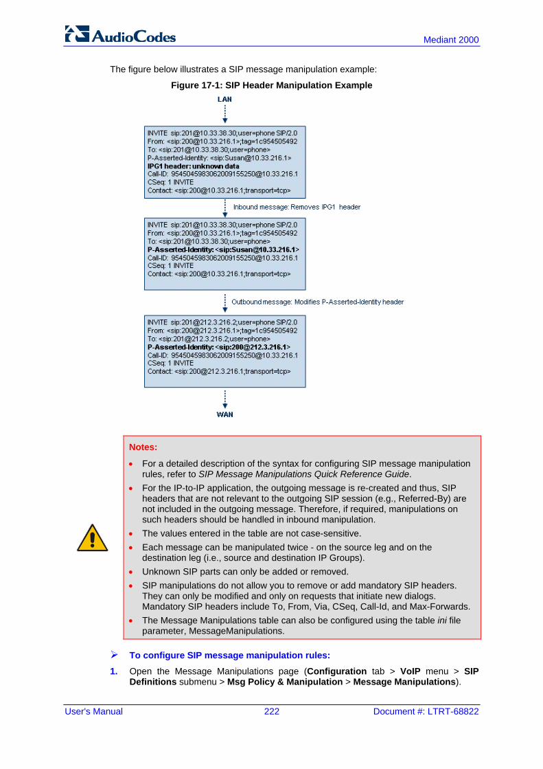
User's Manual 222 Document #: LTRT-68822
Mediant 2000
The figure below illustrates a SIP message manipulation example:
Figure 17-1: SIP Header Manipulation Example
Notes:
• For a detailed description of the syntax for configuring SIP message manipulation rules, refer to SIP Message Manipulations Quick Reference Guide.
• For the IP-to-IP application, the outgoing message is re-created and thus, SIP headers that are not relevant to the outgoing SIP session (e.g., Referred-By) are not included in the outgoing message. Therefore, if required, manipulations on such headers should be handled in inbound manipulation.
• The values entered in the table are not case-sensitive. • Each message can be manipulated twice - on the source leg and on the
destination leg (i.e., source and destination IP Groups). • Unknown SIP parts can only be added or removed. • SIP manipulations do not allow you to remove or add mandatory SIP headers.
They can only be modified and only on requests that initiate new dialogs. Mandatory SIP headers include To, From, Via, CSeq, Call-Id, and Max-Forwards.
• The Message Manipulations table can also be configured using the table ini file parameter, MessageManipulations.
To configure SIP message manipulation rules:
1. Open the Message Manipulations page (Configuration tab > VoIP menu > SIP Definitions submenu > Msg Policy & Manipulation > Message Manipulations).

Version 6.6 223 Mediant 2000
User's Manual 17. SIP Definitions
2. Click the Add button; the following dialog box appears:
Figure 17-2: Message Manipulations Table - Add Record Dialog Box
3. Configure the SIP message manipulation rule as required. See the table below for a
description of each parameter. 4. Click Submit to apply your changes. The figure below displays an example of configured message manipulation rules: Index 0 - adds the suffix ".com" to the host part of the To header. Index 1 - changes the user part of the From header to the user part of the P-Asserted-
ID. Index 2 - changes the user part of the SIP From header to "200". Index 3 - if the user part of the From header equals "unknown", then it is changed
according to the srcIPGroup call’s parameter. Index 4 - removes the Priority header from an incoming INVITE message.
Figure 17-3: Message Manipulations Page
Message Manipulations Parameters
Parameter Description
Index [MessageManipulations_Index]
Defines the table row index for the rule. The valid value is 0 to 99. The default is 0. Note: Each rule must be configured with a unique index.
Manipulation Set ID CLI: manipulation-set-id [MessageManipulations_ManSetID]
Defines a Manipulation Set ID for the rule. You can define the same Manipulation Set ID for multiple rules to create a group of rules. The Manipulation Set ID is used to assign the manipulation rules to an IP Group (in the IP Group table) for inbound and/or outbound messages. The valid value is 0 to 19. The default is 0.
Matching Characteristics

User's Manual 224 Document #: LTRT-68822
Mediant 2000
Parameter Description
Message Type [MessageManipulations_MessageType]
Defines the SIP message type that you want to manipulate. The valid value is a string denoting the SIP message. For example: Empty = rule applies to all messages Invite = rule applies to all INVITE requests and responses Invite.Request = rule applies to INVITE requests Invite.Response = rule applies to INVITE responses subscribe.response.2xx = rule applies to SUBSCRIBE confirmation
responses Note: Currently, SIP 100 Trying messages cannot be manipulated.
Condition [MessageManipulations_Condition]
Defines the condition that must exist for the rule to apply. The valid value is a string. For example: header.from.url.user== '100' (indicates that the user part of the From
header must have the value "100") header.contact.param.expires > '3600' header.to.url.host contains 'domain' param.call.dst.user != '100'
Operation
Action Subject [MessageManipulations_ActionSubject]
Defines the SIP header upon which the manipulation is performed.
Action Type [MessageManipulations_ActionType]
Defines the type of manipulation. [0] Add (default) = adds new header/param/body (header or
parameter elements). [1] Remove = removes header/param/body (header or parameter
elements). [2] Modify = sets element to the new value (all element types). [3] Add Prefix = adds value at the beginning of the string (string
element only). [4] Add Suffix = adds value at the end of the string (string element
only). [5] Remove Suffix = removes value from the end of the string (string
element only). [6] Remove Prefix = removes value from the beginning of the string
(string element only).
Action Value [MessageManipulations_ActionValue]
Defines a value (string) that you want to use in the manipulation. The syntax is as follows: string/<message-element>/<call-param> + string/<message-element>/<call-param> For example: 'itsp.com' header.from.url.user param.call.dst.user param.call.dst.host + '.com' param.call.src.user + '<' + header.from.url.user + '@' + header.p-
asserted-id.url.host + '>'

Version 6.6 225 Mediant 2000
User's Manual 17. SIP Definitions
Parameter Description
Note: Only single quotation marks must be used.
Row Role [MessageManipulations_RowRole]
Determines which condition must be used for the rule of this table row. [0] Use Current Condition = The condition entered in this row must be
matched in order to perform the defined action (default). [1] Use Previous Condition = The condition of the rule configured
directly above this row must be used in order to perform the defined action. This option allows you to configure multiple actions for the same condition.
Note: When multiple manipulations rules apply to the same header, the next rule applies to the result string of the previous rule.
17.5 Configuring SIP Message Policy Rules You can configure SIP message policy rules for blocking (blacklist) unwanted incoming SIP messages or allowing (whitelist) receipt of desired messages. This feature allows you to define legal and illegal characteristics of a SIP message. Message policies can be applied globally (default) or per signaling domain by assigning it to a SIP interface in the SIP Interface table (see 'Configuring SIP Interface Table' on page 202). This feature is helpful against VoIP fuzzing (also known as robustness testing), which sends different types of packets to its "victims" for finding bugs and vulnerabilities. For example, the attacker might try sending a SIP message containing either an over-sized parameter or too many occurrences of a parameter. Each message policy rule can be configured with the following: Maximum message length Maximum SIP header length Maximum message body length Maximum number of headers Maximum number of bodies Option to send 400 "Bad Request" response if message request is rejected Blacklist and whitelist for defined SIP methods (e.g., INVITE) Blacklist and whitelist for defined SIP bodies
Note: The Message Policy table can also be configured using the table ini file parameter, MessagePolicy.

User's Manual 226 Document #: LTRT-68822
Mediant 2000
To configure SIP message policy rules:
1. Open the Message Policy Table page (Configuration tab > VoIP menu > SIP Definitions > Msg Policy & Manipulation > Message Policy Table).
2. Click the Add button; the Add Record dialog box appears:
Figure 17-4: Message Policy Table - Add Record Dialog Box
The policy defined above limits SIP messages to 32,768 characters, headers to 256 characters, bodies to 512 characters, number of headers to 16, and only permits two bodies. Invalid requests are rejected. Only INVITE and BYE requests are permitted and there are no restrictions on bodies.
3. Configure the SIP message policy rule as required. See the table below for a description of each parameter.
4. Click Submit to apply your changes. 5. To save the changes to flash memory, see 'Saving Configuration' on page 396.
SIP Message Policy Parameters
Parameter Description
Index [MessagePolicy_Index]
Defines the table index entry.
Max Message Length [MessagePolicy_MaxMessageLength]
Defines the maximum SIP message length. The valid value is up to 32,768 characters. The default is 32,768.
Max Header Length [MessagePolicy_MaxHeaderLength]
Defines the maximum SIP header length. The valid value is up to 512 characters. The default is 512.
Max Body Length [MessagePolicy_MaxBodyLength]
Defines the maximum SIP message body length. This is the value of the Content-Length header. The valid value is up to 1,024 characters. The default is 1,024.
Max Num Headers [MessagePolicy_MaxNumHeaders]
Defines the maximum number of SIP headers. The valid value is any number up to 32. The default is 32. Note: The device supports up to 20 SIP Record-Route headers that can be received in a SIP INVITE request or 200 OK response. If it receives more than this, it responds with a SIP 513 'Message Too Large' response.

Version 6.6 227 Mediant 2000
User's Manual 17. SIP Definitions
Parameter Description
Max Num Bodies [MessagePolicy_MaxNumBodies]
Defines the maximum number of bodies (e.g., SDP) in the SIP message. The valid value is any number up to 8. The default is 8.
Send Rejection [MessagePolicy_SendRejection]
Determines whether the device sends a 400 "Bad Request" response if a message request is rejected. [0] Policy Reject = (Default) If the message is a request, then the
device sends a response to reject the request. [1] Policy Drop = The device ignores the message without sending
any response.
Method List [MessagePolicy_MethodList]
Defines the SIP methods (e.g., INVITE\BYE) to which the rule applies. The syntax for entering the methods is as follows: Methods must be separated by a backslash (\). The entered value is not case sensitive.
Method List Type [MessagePolicy_MethodListType]
Determines the policy for the SIP methods. [0] Policy Blacklist = The specified methods (in the 'Method List' field)
are rejected by the policy. [1] Policy Whitelist = (Default) The specified methods (in the 'Method
List' field) are allowed by the policy.
Body List [MessagePolicy_BodyList]
Defines the SIP body (i.e., value of the Content-Type header) to which the rule applies.
Body List Type [MessagePolicy_BodyListType]
Determines the policy for the defined SIP body. [0] Policy Blacklist =The specified SIP body (in the 'Body List' field) is
rejected by the policy. [1] Policy Whitelist = (Default) The specified SIP body (in the 'Body
List' field) is allowed by the policy.

User's Manual 228 Document #: LTRT-68822
Mediant 2000
Reader's Notes

Version 6.6 229 Mediant 2000
User's Manual 18. Coders and Profiles
18 Coders and Profiles This section describes configuration of the coders and SIP profiles parameters.
18.1 Configuring Coders The Coders page allows you to configure up to 10 voice coders for the device. Each coder can be configured with packetization time (ptime), bit rate, payload type, and silence suppression. The first coder configured in the table has the highest priority and is used by the device whenever possible. If the remote side cannot use the first coder, the device attempts to use the next coder in the table, and so on.
Notes:
• A specific coder can only be configured once in the table. • If packetization time and/or rate are not specified, the default is applied. • Only the packetization time of the first coder in the coder list is declared in
INVITE/200 OK SDP, even if multiple coders are defined. • The device always uses the packetization time requested by the remote side for
sending RTP packets. If not specified, the packetization time is assigned the default value.
• The value of several fields is hard-coded according to common standards (e.g., payload type of G.711 U-law is always 0). Other values can be set dynamically. If no value is specified for a dynamic field, a default is assigned. If a value is specified for a hard-coded field, the value is ignored.
• If silence suppression is not configured for a coder, the settings of the EnableSilenceCompression parameter is used.
• Both GSM-FR and MS-GSM coders use Payload Type 3. When using SDP, it isn’t possible to differentiate between the two. Therefore, it is recommended not to select both coders simultaneously.
• For G.729, it's also possible to select silence suppression without adaptations. • If G.729 is selected and silence suppression is disabled, the device includes
'annexb=no' in the SDP of the relevant SIP messages. If silence suppression is enabled or set to 'Enable w/o Adaptations', 'annexb=yes' is included. An exception to this logic is when the remote gateway is a Cisco device (IsCiscoSCEMode).
• For defining groups of coders, which can be assigned to Tel and IP Profiles, see 'Configuring Coder Groups' on page 232.
• For information on V.152 and implementation of T.38 and VBD coders, see 'Supporting V.152 Implementation' on page 164.
• The Coders table can also be configured using the table ini file parameter, CodersGroup.

User's Manual 230 Document #: LTRT-68822
Mediant 2000
To configure the device's coders:
1. Open the Coders page (Configuration tab > VoIP menu > Coders and Profiles submenu > Coders).
Figure 18-1: Coders Table Page
2. From the 'Coder Name' drop-down list, select the required coder. 3. From the 'Packetization Time' drop-down list, select the packetization time (in msec)
for the selected coder. The packetization time determines how many coder payloads are combined into a single RTP packet.
4. From the 'Rate' drop-down list, select the bit rate (in kbps) for the selected coder. 5. In the 'Payload Type' field, if the payload type (i.e., format of the RTP payload) for the
selected coder is dynamic, enter a value from 0 to 120 (payload types of 'well-known' coders cannot be modified).
6. From the 'Silence Suppression' drop-down list, enable or disable the silence suppression option for the selected coder.
7. Repeat steps 2 through 6 for the next optional coders. 8. Click Submit. 9. To save the changes to flash memory, see 'Saving Configuration' on page 396. The table below lists the supported coders:
Supported Coders
Coder Name Packetization Time (msec)
Rate (kbps) Payload Type
Silence Suppression
G.711 A-law [g711Alaw64k]
10, 20 (default), 30, 40, 50, 60, 80, 100, 120
64 8 [0] Disable [1] Enable
G.711 U-law [g711Ulaw64k]
10, 20 (default), 30, 40, 50, 60, 80, 100, 120
64 0 [0] Disable [1] Enable
G.711A-law_VBD [g711AlawVbd]
10, 20 (default), 30, 40, 50, 60, 80, 100, 120
64 Dynamic (0-127) Default is 180
N/A
G.711U-law_VBD [g711UlawVbd]
10, 20 (default), 30, 40, 50, 60, 80, 100, 120
64 Dynamic (0-127) Default is 120
N/A
G.723.1 [g7231]
30 (default), 60, 90, 120, 150
[0] 5.3 (default)
[1] 6.3
4 [0] Disable [1] Enable

Version 6.6 231 Mediant 2000
User's Manual 18. Coders and Profiles
Coder Name Packetization Time (msec)
Rate (kbps) Payload Type
Silence Suppression
G.726 [g726]
10, 20 (default), 30, 40, 50, 60, 80, 100, 120
[0] 16 [1] 24 [2] 32
(default) [3] 40
Dynamic (0-127) Default is 23
[0] Disable [1] Enable
G.727 ADPCM 10, 20 (default), 30, 40, 50, 60, 80, 100, 120
16, 24, 32, 40 Dynamic (0-127)
[0] Disable [1] Enable
G.729 [g729]
10, 20 (default), 30, 40, 50, 60, 80, 100
8 18 [0] Disable [1] Enable [2] Enable
w/o Adaptations
GSM-FR [gsmFullRate]
20 (default), 40, 60, 80 13 3 [0] Disable [1] Enable
GSM-EFR [gsmEnhancedFullRate]
0, 20 (default), 30, 40, 50, 60, 80, 100
12.2 Dynamic (0-127)
[0] Disable [1] Enable
MS-GSM [gsmMS]
40 (default) 13 3 [0] Disable [1] Enable
AMR [Amr]
20 (default) [0] 4.75 [1] 5.15 [2] 5.90 [3] 6.70 [4] 7.40 [5] 7.95 [6] 10.2 [7] 12.2
(default)
Dynamic (0-127)
[0] Disable [1] Enable
QCELP [QCELP]
20 (default), 40, 60, 80, 100, 120
13 12 [0] Disable [1] Enable
EVRC [Evrc]
20 (default), 40,60, 80, 100 [0] Variable (default)
[1] 1/8 [3] 1/2 [4] Full
Dynamic (0-127)
[0] Disable [1] Enable
iLBC [iLBC]
20 (default), 40, 60, 80, 100, 120
15 (default) Dynamic (0-127)
[0] Disable [1] Enable
30 (default), 60, 90, 120 13
Transparent [Transparent]
10, 20 (default), 40, 60, 80, 100, 120
64 Dynamic (0-127)
[0] Disable [1] Enable
T.38 [t38fax]
N/A N/A N/A N/A

User's Manual 232 Document #: LTRT-68822
Mediant 2000
18.2 Configuring Coder Groups The Coder Group Settings page allows you to define up to 10 groups of coders (termed Coder Groups). For each Coder Group, you can define up to 10 coders configured with packetization time (ptime), rate, payload type, and silence suppression. The first coder in the Coder Group table has the highest priority and is used by the device whenever possible. If the remote side cannot use the first coder, the device attempts to use the next coder, and so on. Coder Groups can be used as follows: Assigned to Tel Profiles in the Tel Profiles table (see Configuring Tel Profiles on page
233). Assigned to IP Profiles in the IP Profiles table (see 'Configuring IP Profiles' on page
235).
Notes:
• A specific coder can be selected only once per Coder Group. • For a list of supported coders, see 'Configuring Coders' on page 229. • The Coder Group Settings table can also be configured using the table ini file
parameter, CodersGroup.
To configure Coder Groups:
1. Open the Coder Group Settings page (Configuration tab > VoIP menu > Coders and Profiles submenu > Coders Group Settings).
Figure 18-2: Coder Group Settings Page
2. From the 'Coder Group ID' drop-down list, select a Coder Group ID. 3. From the 'Coder Name' drop-down list, select the first coder for the Coder Group. 4. From the 'Packetization Time' drop-down list, select the packetization time (in msec)
for the coder. The packetization time determines how many coder payloads are combined into a single RTP packet.
5. From the 'Rate' drop-down list, select the bit rate (in kbps) for the coder you selected. 6. In the 'Payload Type' field, if the payload type (i.e., format of the RTP payload) for the
coder you selected is dynamic, enter a value from 0 to 120 (payload types of common coders cannot be modified).
7. From the 'Silence Suppression' drop-down list, enable or disable the silence suppression option for the coder you selected.

Version 6.6 233 Mediant 2000
User's Manual 18. Coders and Profiles
8. Repeat steps 3 through 7 for the next coders (optional). 9. Repeat steps 2 through 8 for the next coder group (optional). 10. Click Submit to apply your changes.
18.3 Configuring Tel Profile The Tel Profile Settings table allows you to define up to nine configuration profiles for Tel calls. These profiles are termed Tel Profiles. The Tel Profile Settings table contains a list of parameters, which can also be configured globally for all calls using their corresponding "global" parameters. The only difference between the Tel Profile parameters and the global parameters regarding description may be their default values. Tel Profiles provide high-level adaptation when the device interworks between different equipment and protocols (at both the Tel and IP sides), each of which may require different handling by the device. Once configured, Tel Profiles can be assigned to specific channels (trunks). Therefore, Tel Profiles enable you to assign special configuration settings for device handling of specific calls. For example, if specific channels require the use of the G.711 coder, you can configure a Tel Profile with this coder and assign it to these channels. Tel Profiles are assigned to channels in the Trunk Group Table (see Configuring the Trunk Group Table on page 279)). The procedure below describes how to configure Tel Profiles using the Web interface.
Note: Tel Profiles can also be configured using the table ini file parameter, TelProfile (see 'Configuration Parameters Reference' on page 503)

User's Manual 234 Document #: LTRT-68822
Mediant 2000
To configure Tel Profiles:
1. Open the Tel Profile Settings page (Configuration tab > VoIP menu > Coders and Profiles submenu > Tel Profile Settings).
Figure 18-3: Tel Profile Settings Page
2. From the 'Profile ID' drop-down list, select the Tel Profile index. 3. In the 'Profile Name' field, enter an arbitrary name that enables you to easily identify
the Tel Profile. 4. From the 'Profile Preference' drop-down list, select the priority of the Tel Profile, where
1 is the lowest priority and 20 the highest. If both IP and Tel profiles apply to the same call, the coders and other common parameters (noted by an asterisk in the description of the parameter TelProfile) of the preferred Profile are applied to that call. If the Preference of the Tel and IP Profiles is identical, the Tel Profile parameters are applied. Note: If the coder lists of both IP and Tel Profiles apply to the same call, only the coders common to both are used. The order of the coders is determined by the preference.

Version 6.6 235 Mediant 2000
User's Manual 18. Coders and Profiles
5. Configure the parameters as required. For a description of each parameter, refer to the corresponding "global" parameter.
6. Click Submit to apply your changes.
18.4 Configuring IP Profiles The IP Profile Settings table allows you to define up to nine IP Profiles. An IP Profile is a set of special call configuration behaviors relating to signaling (e.g., SIP message terminations such as REFER) and media (e.g., coder used) applied to specific IP calls (inbound and/or outbound). Therefore, IP Profiles provide high-level adaptation when the device interworks between different IP entities (for Tel and IP sides), each of which may require different handling by the device. For example, if a specific IP entity uses the G.711 coder only, you can configure an IP Profile with G.711 for this IP entity. Many of the parameters in the IP Profile Settings table have a corresponding "global" parameter. If an IP Profile is not associated with specific calls, the settings of the global parameters are applied to these calls. IP Profiles can be assigned to the following configuration elements: IP Groups - see Configuring IP Groups on page 204 Outbound IP routing rules (for Gateway / IP-to-IP application) - see Configuring
Outbound IP Routing Table on page 309 Inbound IP routing rules (for Gateway / IP-to-IP application) - see Configuring Inbound
IP Routing Table on page 317 The device selects the IP Profile as follows: If different IP Profiles (not default) are assigned to the same specific calls in all these
tables, the device uses the IP Profile that has the highest preference level (as set in the 'Profile Preference' field). If they have the same preference level, the device uses the IP Profile assigned in the IP Group table.
If different IP Profiles are assigned to these tables and one table is set to the default IP Profile, the device uses the IP Profile that is not the default.
Notes:
• IP Profiles can also be implemented when using a Proxy server (when the AlwaysUseRouteTable parameter is set to 1).
• RxDTMFOption configures the received DTMF negotiation method: [-1] not configured, use the global parameter; [0] don’t declare RFC 2833; [1] declare RFC 2833 payload type is SDP.
• You can also configure IP Profiles using the table ini file parameter, IPProfile (see Configuration Parameters Reference on page 503).

User's Manual 236 Document #: LTRT-68822
Mediant 2000
To configure IP Profiles:
1. Open the IP Profile Settings page (Configuration tab > VoIP menu > Coders and Profiles submenu > IP Profile Settings).
2. From the 'Profile ID' drop-down list, select the IP Profile index. 3. In the 'Profile Name' field, enter an arbitrary name that allows you to easily identify the
IP Profile. 4. From the 'Profile Preference' drop-down list, select the priority of the IP Profile, where
'1' is the lowest priority and '20' is the highest. If both IP and Tel profiles apply to the same call, the coders and other common parameters (noted by an asterisk) of the preferred Profile are applied to that call. If the Preference of the Tel and IP Profiles is identical, the Tel Profile parameters are applied. Note: If the coder lists of both IP and Tel Profiles apply to the same call, only the coders common to both are used. The order of the coders is determined by the preference.
5. Configure the parameters as required. 6. Click Submit to apply your changes.
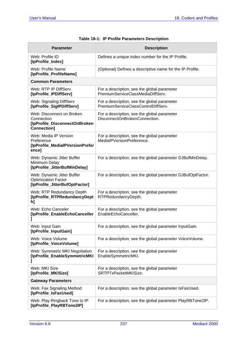
Version 6.6 237 Mediant 2000
User's Manual 18. Coders and Profiles
Table 18-1: IP Profile Parameters Description
Parameter Description
Web: Profile ID [IpProfile_Index]
Defines a unique index number for the IP Profile.
Web: Profile Name [IpProfile_ProfileName]
(Optional) Defines a descriptive name for the IP Profile.
Common Parameters
Web: RTP IP DiffServ [IpProfile_IPDiffServ]
For a description, see the global parameter PremiumServiceClassMediaDiffServ.
Web: Signaling DiffServ [IpProfile_SigIPDiffServ]
For a description, see the global parameter PremiumServiceClassControlDiffServ.
Web: Disconnect on Broken Connection [IpProfile_DisconnectOnBrokenConnection]
For a description, see the global parameter DisconnectOnBrokenConnection.
Web: Media IP Version Preference [IpProfile_MediaIPVersionPreference]
For a description, see the global parameter MediaIPVersionPreference.
Web: Dynamic Jitter Buffer Minimum Delay [IpProfile_JitterBufMinDelay]
For a description, see the global parameter DJBufMinDelay.
Web: Dynamic Jitter Buffer Optimization Factor [IpProfile_JitterBufOptFactor]
For a description, see the global parameter DJBufOptFactor.
Web: RTP Redundancy Depth [IpProfile_RTPRedundancyDepth]
For a description, see the global parameter RTPRedundancyDepth.
Web: Echo Canceler [IpProfile_EnableEchoCanceller]
For a description, see the global parameter EnableEchoCanceller.
Web: Input Gain [IpProfile_InputGain]
For a description, see the global parameter InputGain.
Web: Voice Volume [IpProfile_VoiceVolume]
For a description, see the global parameter VoiceVolume.
Web: Symmetric MKI Negotiation [IpProfile_EnableSymmetricMKI]
For a description, see the global parameter EnableSymmetricMKI.
Web: MKI Size [IpProfile_MKISize]
For a description, see the global parameter SRTPTxPacketMKISize.
Gateway Parameters
Web: Fax Signaling Method [IpProfile_IsFaxUsed]
For a description, see the global parameter IsFaxUsed.
Web: Play Ringback Tone to IP [IpProfile_PlayRBTone2IP]
For a description, see the global parameter PlayRBTone2IP.
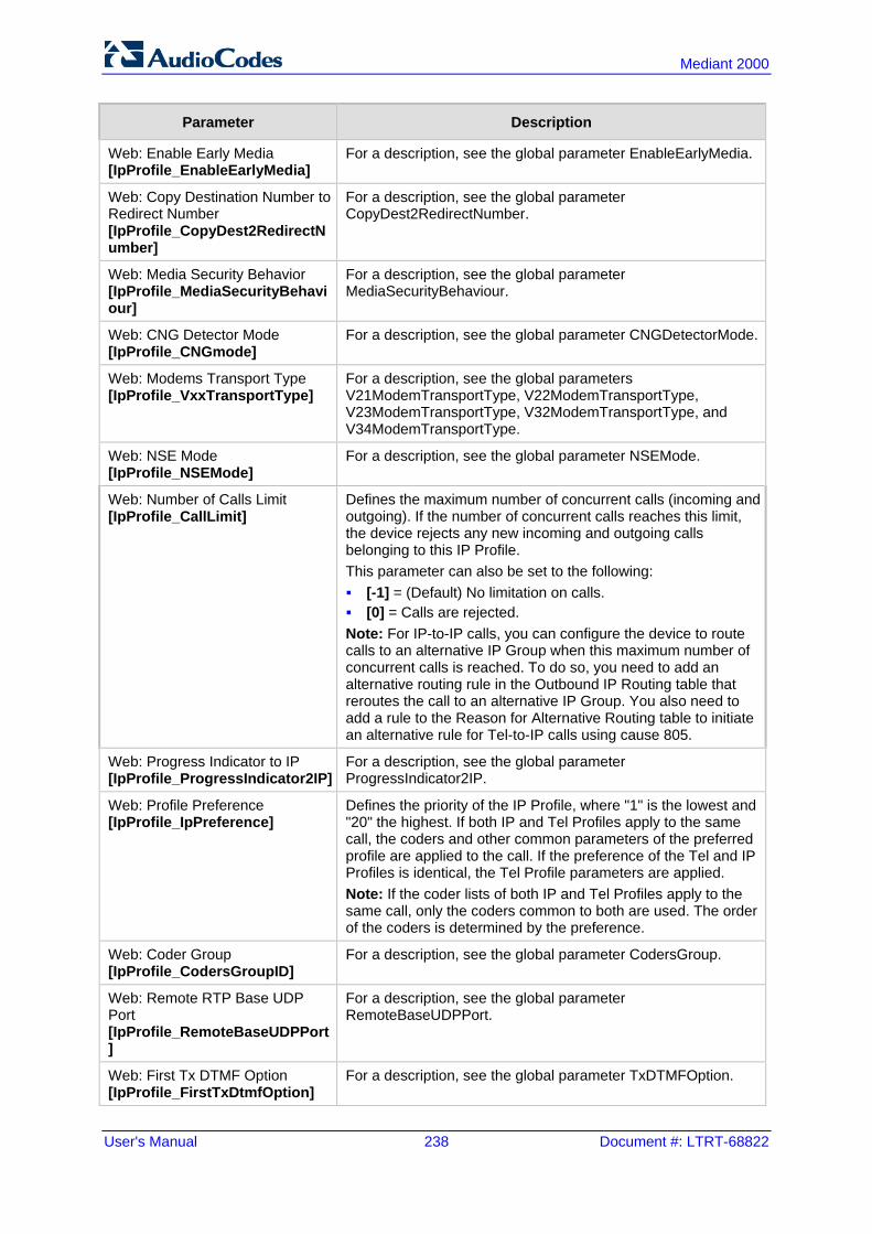
User's Manual 238 Document #: LTRT-68822
Mediant 2000
Parameter Description
Web: Enable Early Media [IpProfile_EnableEarlyMedia]
For a description, see the global parameter EnableEarlyMedia.
Web: Copy Destination Number to Redirect Number [IpProfile_CopyDest2RedirectNumber]
For a description, see the global parameter CopyDest2RedirectNumber.
Web: Media Security Behavior [IpProfile_MediaSecurityBehaviour]
For a description, see the global parameter MediaSecurityBehaviour.
Web: CNG Detector Mode [IpProfile_CNGmode]
For a description, see the global parameter CNGDetectorMode.
Web: Modems Transport Type [IpProfile_VxxTransportType]
For a description, see the global parameters V21ModemTransportType, V22ModemTransportType, V23ModemTransportType, V32ModemTransportType, and V34ModemTransportType.
Web: NSE Mode [IpProfile_NSEMode]
For a description, see the global parameter NSEMode.
Web: Number of Calls Limit [IpProfile_CallLimit]
Defines the maximum number of concurrent calls (incoming and outgoing). If the number of concurrent calls reaches this limit, the device rejects any new incoming and outgoing calls belonging to this IP Profile. This parameter can also be set to the following: [-1] = (Default) No limitation on calls. [0] = Calls are rejected. Note: For IP-to-IP calls, you can configure the device to route calls to an alternative IP Group when this maximum number of concurrent calls is reached. To do so, you need to add an alternative routing rule in the Outbound IP Routing table that reroutes the call to an alternative IP Group. You also need to add a rule to the Reason for Alternative Routing table to initiate an alternative rule for Tel-to-IP calls using cause 805.
Web: Progress Indicator to IP [IpProfile_ProgressIndicator2IP]
For a description, see the global parameter ProgressIndicator2IP.
Web: Profile Preference [IpProfile_IpPreference]
Defines the priority of the IP Profile, where "1" is the lowest and "20" the highest. If both IP and Tel Profiles apply to the same call, the coders and other common parameters of the preferred profile are applied to the call. If the preference of the Tel and IP Profiles is identical, the Tel Profile parameters are applied. Note: If the coder lists of both IP and Tel Profiles apply to the same call, only the coders common to both are used. The order of the coders is determined by the preference.
Web: Coder Group [IpProfile_CodersGroupID]
For a description, see the global parameter CodersGroup.
Web: Remote RTP Base UDP Port [IpProfile_RemoteBaseUDPPort]
For a description, see the global parameter RemoteBaseUDPPort.
Web: First Tx DTMF Option [IpProfile_FirstTxDtmfOption]
For a description, see the global parameter TxDTMFOption.

Version 6.6 239 Mediant 2000
User's Manual 18. Coders and Profiles
Parameter Description
Web: Second Tx DTMF Option [IpProfile_SecondTxDtmfOption]
For a description, see the global parameter TxDTMFOption.
Web: Declare RFC 2833 in SDP [IpProfile_RxDTMFOption]
For a description, see the global parameter RxDTMFOption.
Web: Add IE In SETUP [IpProfile_AddIEInSetup]
For a description, see the global parameter AddIEinSetup.
Web: AMD Sensitivity Level [IpProfile_AMDSensitivityParameterSuit]
For a description, see the global parameter AMDSensitivityLevel.
Web: AMD Sensitivity Level [IpProfile_AMDSensitivityLevel]
For a description, see the global parameter AMDSensitivityLevel.
Web: AMD Max Greeting Time [IpProfile_AMDMaxGreetingTime]
For a description, see the global parameter AMDMaxGreetingTime.
Web: AMD Max Post Silence Greeting Time [IpProfile_AMDMaxPostSilenceGreetingTime]
For a description, see the global parameter AMDMaxPostGreetingSilenceTime.
Web: Enable QSIG Tunneling [IpProfile_EnableQSIGTunneling]
For a description, see the global parameter EnableQSIGTunneling.
Web: Enable Hold [IpProfile_EnableHold]
For a description, see the global parameter EnableHold.
[IpProfile_EnableEarly183] For a description, see the global parameter EnableEarly183.
[IpProfile_EarlyAnswerTimeout] For a description, see the global parameter EarlyAnswerTimeout.

User's Manual 240 Document #: LTRT-68822
Mediant 2000
Reader's Notes

Part V Gateway and IP-to-IP Application


Version 6.6 243 Mediant 2000
User's Manual 19. Introduction
19 Introduction This section describes configuration of the Gateway and IP-to-IP applications. The Gateway application refers to IP-to-Tel (PSTN) call routing and vice versa. The IP-to-IP application refers to call routing of calls received from the IP and forwarded to an IP destination. For a description of the IP-to-IP application, see IP-to-IP Routing Application on page 245.
Notes:
• In some areas of the Web interface, the term "GW" and "IP2IP" application refers to the Gateway and IP-to-IP applications, respectively.
• The terms IP-to-Tel and Tel-to-IP refer to the direction of the call relative to the device. IP-to-Tel refers to calls received from the IP network and destined to the PSTN/PBX (i.e., telephone connected directly or indirectly to the device); Tel-to-IP refers to calls received from the PSTN/PBX, and destined for the IP network.

User's Manual 244 Document #: LTRT-68822
Mediant 2000
Reader's Notes

Version 6.6 245 Mediant 2000
User's Manual 20. IP-to-IP Routing Application
20 IP-to-IP Routing Application The device's IP-to-IP application supports IP-to-IP VoIP call routing (or SIP Trunking). The IP-to-IP call routing application enables enterprises to seamlessly connect their IP-based PBX (IP-PBX) to SIP trunks, typically provided by Internet Telephony Service Providers (ITSP). The device enables the enterprise to communicate with the PSTN network (local and overseas) through the ITSP, which interfaces directly with the PSTN. Therefore, the IP-to-IP application enables enterprises to replace the bundles of physical PSTN wires with SIP trunks provided by ITSPs and use VoIP to communicate within and outside the enterprise network using its standard Internet connection. At the same time, the device can also provide an interface with the traditional PSTN network, enabling PSTN fallback in case of IP connection failure with the ITSPs. The device also supports multiple SIP Trunking. This can be useful in scenarios where if a connection to one ITSP fails, the call can immediately be transferred to another ITSP. In addition, by allowing multiple SIP trunks where each trunk is designated a specific ITSP, the device can route calls to an ITSP based on call destination (e.g., country code). In addition to providing VoIP communication within the enterprise's LAN, the device enables the enterprise to communicate outside of the corporate LAN using SIP Trunking. This includes remote (roaming) IP-PBX users, for example, employees using their laptops to communicate with one another from anywhere in the world such as at airports. The IP-to-IP application can be implemented by enterprises in the following example scenarios: VoIP between an enterprise's headquarters and remote branch offices VoIP between an enterprise and the PSTN through an ITSP The IP-to-IP call routing capability is feature-rich, allowing interoperability with different ITSPs: Easy and smooth integration with multiple ITSP SIP trunks. Supports SIP registration and authentication with ITSP servers (on behalf of the
enterprise's IP telephony system) even if the enterprise's IP telephony system does no support registration and authentication.
Supports SIP-over-UDP, SIP-over-TCP, and SIP-over-TLS transport protocols, one of which is generally required by the ITSP.
Provides alternative routing to different destinations (to another ITSP or the PSTN) when the connection with an ITSP network is down.
Provides fallback to the legacy PSTN telephone network upon Internet connection failure.
Provides Transcoding from G.711 to G.729 coder with the ITSP for bandwidth reduction.
Supports SRTP, providing voice traffic security toward the ITSP. IP-to-IP routing can be used in combination with the regular Gateway application. For
example, an incoming IP call can be sent to an E1/T1 span or it can be forwarded to an IP destination.
Therefore, the device provides the ideal interface between the enterprise IP-PBX and the ITSP SIP trunk. The device's IP-to-IP application handles and terminates SIP methods and responses at each leg independently: Initiating-dialog INVITE: terminated at one leg and initiated on the other leg,
180\182\183\200\4xx uses the same logic and same limitations, in some cases the result may be a different response code.
OPTIONS: terminated at each leg independently. INFO: only specific INFO’s (such as DTMF) are handled; other types are omitted.

User's Manual 246 Document #: LTRT-68822
Mediant 2000
UPDATE: terminated at each leg independently and may cause only changes in the RTP flow - Hold\Retrieve are the only exceptions that traverse the two legs.
Re-INVITE: terminated at each leg independently and may cause only changes in the RTP flow - Hold\Retrieve are the only exceptions that traverse the two legs.
PRACK: terminated at each leg independently. REFER (within a dialog): terminated at each leg independently. 3xx Responses: terminated at each leg independently. 401\407 responses to initial INVITE: in case the back-to-back session is associated
with an Account, the responses is terminated at the receiving leg; in other cases, the responses are passed transparently.
REGISTER: handled only in cases associated with a User-type IP Group - Contact, To, From specific parameters are omitted.
20.1 Theory of Operation The device's IP-to-IP SIP session is performed by implementing Back-to-Back User Agent (B2BUA). The device acts as a user agent for both ends (legs) of the SIP call (from call establishment to termination). The session negotiation is performed independently for each call leg, using global parameters such as coders or using IP Profiles associated with each call leg to assign different configuration behaviors for these two IP-to-IP call legs. If transcoding is required, the RTP streams for IP-to-IP calls traverse the device and two DSP channels are allocated per IP-to-IP session. Therefore, the maximum number of IP-to-IP sessions is 120 (corresponding to a maximum of 240 media channels that can be designated for IP-to-IP call routing is). If transcoding is not needed, the device also supports up to 120 IP-to-IP sessions. The device also supports NAT traversal for SIP clients behind NAT, where the device is defined with a global IP address. The figure below provides a simplified illustration of the device's handling of IP-to-IP call routing:
Figure 20-1: Basic Schema of the Device's IP-to-IP Call Handling
The basic IP-to-IP call handling process can be summarized as follows: 1. Incoming IP calls are identified as belonging to a specific logical entity in the network
referred to as a Source IP Group, according to Inbound IP Routing rules. 2. The Source IP Group is sent to a specific IP Group referred to as a Destination IP
Group; the IP destination address being as configured by the Proxy Set associated with the Destination IP Group.
3. Number manipulation can be done on inbound and outbound legs. The following subsections discuss the main terms associated with the IP-to-IP call routing application.
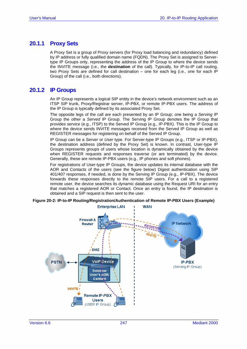
Version 6.6 247 Mediant 2000
User's Manual 20. IP-to-IP Routing Application
20.1.1 Proxy Sets A Proxy Set is a group of Proxy servers (for Proxy load balancing and redundancy) defined by IP address or fully qualified domain name (FQDN). The Proxy Set is assigned to Server-type IP Groups only, representing the address of the IP Group to where the device sends the INVITE message (i.e., the destination of the call). Typically, for IP-to-IP call routing, two Proxy Sets are defined for call destination – one for each leg (i.e., one for each IP Group) of the call (i.e., both directions).
20.1.2 IP Groups An IP Group represents a logical SIP entity in the device's network environment such as an ITSP SIP trunk, Proxy/Registrar server, IP-PBX, or remote IP-PBX users. The address of the IP Group is typically defined by its associated Proxy Set. The opposite legs of the call are each presented by an IP Group; one being a Serving IP Group the other a Served IP Group. The Serving IP Group denotes the IP Group that provides service (e.g., ITSP) to the Served IP Group (e.g., IP-PBX). This is the IP Group to where the device sends INVITE messages received from the Served IP Group as well as REGISTER messages for registering on behalf of the Served IP Group. IP Group can be a Server or User type. For Server-type IP Groups (e.g., ITSP or IP-PBX), the destination address (defined by the Proxy Set) is known. In contrast, User-type IP Groups represents groups of users whose location is dynamically obtained by the device when REGISTER requests and responses traverse (or are terminated) by the device. Generally, these are remote IP-PBX users (e.g., IP phones and soft phones). For registrations of User-type IP Groups, the device updates its internal database with the AOR and Contacts of the users (see the figure below) Digest authentication using SIP 401/407 responses, if needed, is done by the Serving IP Group (e.g., IP-PBX). The device forwards these responses directly to the remote SIP users. For a call to a registered remote user, the device searches its dynamic database using the Request URI for an entry that matches a registered AOR or Contact. Once an entry is found, the IP destination is obtained and a SIP request is then sent to the user.
Figure 20-2: IP-to-IP Routing/Registration/Authentication of Remote IP-PBX Users (Example)

User's Manual 248 Document #: LTRT-68822
Mediant 2000
The device also supports the IP-to-IP call routing Survivability mode feature (see the figure below) for User-type IP Groups. The device stores in its database REGISTER messages sent by the clients of the User-type IP Group. If communication with the Serving IP Group (e.g., IP-PBX) fails, the User-type IP Group enters into Survivability mode in which the device uses its database for routing calls between the clients of the User-type IP Group. The RTP packets between the clients traverse through the device. When the Serving IP Group is available again, the device returns to normal mode, sending INVITE and REGISTER messages to the Serving IP Group.
Figure 20-3: IP-to-IP Routing for IP-PBX Remote Users in Survivability Mode (Example)
20.1.3 Inbound and Outbound IP Routing Rules The device's IP-to-IP call routing is performed using the following two routing rule stages: 1. Inbound IP Routing Mapping Rule: Identifies the received call as an IP-to-IP call
based on various characteristics such as the call's source IP address, and assigns it to an IP Group.
2. Outbound IP Routing Mapping Rule: Determines the destination (i.e., IP address) to where the incoming call associated with a specific source IP Group is finally routed. The destination address is typically denoted by another IP Group (destination IP Group) and therefore, the call is sent to the IP address that is defined by the Proxy Set associated with this IP Group. If the destination is a User-type IP Group, the device searches for a match between the request-URI of the received INVITE to an AOR registration record in the device's database. If a match is found, the INVITE is sent to the IP address of the registered contact.

Version 6.6 249 Mediant 2000
User's Manual 20. IP-to-IP Routing Application
20.1.4 Accounts Accounts are used by the device to register to a Serving IP Group (e.g., an ITSP) on behalf of a Served IP Group (e.g., IP-PBX). This is necessary for ITSPs that require registration to provide services. Accounts are also used for defining user name and password for digest authentication (with or without registration) if required by the ITSP. Multiple Accounts per Served IP Group can be configured for registration to more than one Serving IP Group (e.g., an IP-PBX that requires registering to multiple ITSP's).
Figure 20-4: Registration with Multiple ITSP's on Behalf of IP-PBX
20.2 IP-to-IP Routing Configuration Example This section provides step-by-step procedures for configuring IP-to-IP call routing. These procedures are based on the setup example described below. In this example, the device serves as the communication interface between the enterprise's IP-PBX (located on the LAN) and the following network entities: ITSP SIP trunks (located on the WAN) Remote IP-PBX users (located on the WAN) Local PSTN network Calls from the Enterprise are routed according to destination. This example assumes the following: The device has the public IP address 212.25.125.136 and is connected to the
enterprise's firewall/NAT demilitarized zone (DMZ) network, providing the interface between the IP-PBX, and two ITSP's and the local PSTN.
The enterprise has an IP-PBX located behind a Firewall/NAT: • IP-PBX IP address: 10.15.4.211 • Transport protocol: UDP • Voice coder: G.711 • IP-PBX users: 4-digit length extension number and served by two ITSPs. • The enterprise also includes remote IP-PBX users that communicate with the IP-
PBX via the device. All dialed calls from the IP-PBX consisting of four digits starting with digit "4" are routed to the remote IP-PBX users.
Using SIP trunks, the IP-PBX connects (via the device) to two different ITSP's: • ITSP-A:
♦ Implements Proxy servers with fully qualified domain names (FQDN): "Proxy1.ITSP-A" and "Proxy2.ITSP-B", using TLS.
♦ Allocates a range of PSTN numbers beginning with +1919, which is

User's Manual 250 Document #: LTRT-68822
Mediant 2000
assigned to a range of IP-PBX users. ♦ Voice coder: G.723.
• ITSP-B: ♦ Implements Proxy servers with IP addresses 216.182.224.202 and
216.182.225.202, using TCP. ♦ Allocates a range of PSTN numbers beginning with 0200, which is assigned
to a range of IP-PBX users. ♦ Voice coder: G.723.
Registration and authentication is required by both ITSP's, which is performed by the device on behalf of the IP-PBX. The SIP REGISTER messages use different URI's (host name and contact user) in the From, To, and Contact headers per ITSP as well as username and password authentication.
Outgoing calls from IP-PBX users are routed according to destination: • If the calls are dialed with the prefix "+81", they are routed to ITSP-A (Region A). • If the calls are dialed with the prefix "9", they are routed to the local PSTN
network. • For all other destinations, the calls are routed to ITSP-B.
The device is also connected to the PSTN through a traditional T1 ISDN trunk for local incoming and outgoing calls. Calls dialed from the enterprise's IP-PBX with prefix '9' are sent to the local PSTN. In addition, in case of Internet interruption and loss of connection with the ITSP trunks, all calls are rerouted to the PSTN.
The figure below provides an illustration of this example scenario:
Figure 20-5: SIP Trunking Setup Scenario Example
The steps for configuring the device according to the scenario above can be summarized as follows: Enable the IP-to-IP feature (see 'Step 1: Enable the IP-to-IP Capabilities' on page
251).

Version 6.6 251 Mediant 2000
User's Manual 20. IP-to-IP Routing Application
Configure the number of media channels (see 'Step 2: Configure the Number of Media Channels' on page 251).
Configure a Trunk Group for interfacing with the local PSTN (see 'Step 3: Define a Trunk Group for the Local PSTN' on page 252).
Configure Proxy Sets (see 'Step 4: Configure the Proxy Sets' on page 252). Configure IP Groups (see 'Step 5: Configure the IP Groups' on page 254). Configure Registration Accounts (see 'Step 6: Configure the Account Table' on page
255). Configure IP Profiles (see 'Step 7: Configure IP Profiles for Voice Coders' on page
256). Configure inbound IP routing rules (see 'Step 8: Configure Inbound IP Routing' on
page 257). Configure outbound IP routing rules (see 'Step 9: Configure Outbound IP Routing' on
page 259). Configure destination phone number manipulation (see 'Step 10: Configure
Destination Phone Number Manipulation' on page 260).
20.2.1 Step 1: Enable the IP-to-IP Capabilities This step describes how to enable the device's IP-to-IP application.
To enable IP-to-IP capabilities:
1. Open the Applications Enabling page (Configuration tab > VoIP menu > Applications Enabling submenu > Applications Enabling).
2. From the 'IP to IP Application' drop-down list, select Enable. 3. Click Submit. 4. Save the setting to flash memory ("burn") with a device reset.
Note: For the IP-to-IP Application feature, the device must also be installed with the appropriate Software License Key.
20.2.2 Step 2: Configure the Number of Media Channels The number of media channels represents the number of digital signaling processors (DSP) channels that the device allocates to IP-to-IP calls. The remaining DSP channels can be used for PSTN calls. Two IP media channels are used per IP-to-IP call.
To configure the number of media channels:
1. Open the IP Media Settings page (Configuration tab > VoIP menu > IP Media > IP Media Settings).
Figure 20-6: Defining Required Media Channels
2. In the 'Number of Media Channels' field, enter the required number of media channels
(in the example above, "120" to enable up to 60 IP-to-IP calls). 3. Click Submit.

User's Manual 252 Document #: LTRT-68822
Mediant 2000
4. Save the settings to flash memory ("burn") with a device reset (see 'Saving Configuration' on page 396).
20.2.3 Step 3: Define a Trunk Group for the Local PSTN For incoming and outgoing local PSTN calls with the IP-PBX, you need to define the Trunk Group ID (#1) for the T1 ISDN trunk connecting the device to the local PSTN. This Trunk Group is also used for alternative routing to the PSTN if connectivity with the ITSP fails.
To configure the Trunk Group for local PSTN:
1. Open the Trunk Group Table page (Configuration tab > VoIP menu > GW and IP to IP > Trunk Group > Trunk Group).
2. Configure Trunk Group ID #1 (as shown in the figure below): • From the 'From Trunk' and 'To Trunk' drop-down lists, select 1 to indicate Trunk 1
for this Trunk Group. • In the 'Channels' field, enter the Trunk channels or ports assigned to the Trunk
Group (e.g. 1-31 for E1 and 1-24 for T1). • In the 'Phone Number' field, enter any phone number (logical) for this Trunk (e.g.
1000). • In the 'Trunk Group ID' field, enter "1" as the ID for this Trunk Group.
Figure 20-7: Defining a Trunk Group for PSTN
3. Configure the Trunk in the Trunk Settings page (Configuration tab > VoIP menu >
PSTN > Trunk Settings).
20.2.4 Step 4: Configure the Proxy Sets The Proxy Sets represent the actual destination (IP address or FQDN) to which the call is routed. These Proxy Sets are later assigned to IP Groups (see 'Step 5: Configure the IP Groups' on page 254). This step describes how to configure the following Proxy Sets: Proxy Set ID #1 with two FQDN's for ITSP-A Proxy Set ID #2 with two IP addresses for ITSP-B Proxy Set ID #3 with an IP address for the IP-PBX
To configure the Proxy Sets: 1. Open the Proxy Sets Table page (Configuration tab > VoIP menu > Control
Network > Proxy Sets Table). 2. Configure Proxy Set ID #1 for ITSP-A:
a. From the 'Proxy Set ID' drop-down list, select 1.

Version 6.6 253 Mediant 2000
User's Manual 20. IP-to-IP Routing Application
b. In the 'Proxy Address' column, enter the FQDN of ITSP-A SIP trunk Proxy servers (e.g., "Proxy1.ITSP-A" and "Proxy2. ITSP-A").
c. From the 'Transport Type' drop-down list corresponding to the Proxy addresses entered above, select TLS.
d. In the 'Enable Proxy Keep Alive' drop-down list, select Using Options, and then in the 'Proxy Load Balancing Method' drop-down list, select Round Robin.
Figure 20-8: Proxy Set ID #1 for ITSP-A
3. Configure Proxy Set ID #2 for ITSP-B:
a. From the 'Proxy Set ID' drop-down list, select 2. b. In the 'Proxy Address' column, enter the IP addresses of the ITSP-B SIP trunk
(e.g., "216.182.224.202" and "216.182.225.202"). c. From the 'Transport Type' drop-down list corresponding to the IP address entered
above, select UDP. d. In the 'Enable Proxy Keep Alive' drop-down list, select "Using Options", and then
in the 'Proxy Load Balancing Method' drop-down list, select Round Robin.
Figure 20-9: Proxy Set ID #2 for ITSP-B
4. Configure Proxy Set ID #3 for the IP-PBX:
a. From the 'Proxy Set ID' drop-down list, select 3.

User's Manual 254 Document #: LTRT-68822
Mediant 2000
b. In the 'Proxy Address' column, enter the IP address of the IP-PBX (e.g., "10.15.4.211").
c. From the 'Transport Type' drop-down list corresponding to the IP address entered above, select UDP".
d. In the 'Enable Proxy Keep Alive' drop-down list, select Using Options. This is used in Survivability mode for remote IP-PBX users.
Figure 20-10: Proxy Set ID #3 for the IP-PBX
20.2.5 Step 5: Configure the IP Groups This step describes how to create the IP Groups for the following entities in the network: ITSP-A SIP trunk ITSP-B SIP trunk IP-PBX server IP-PBX remote users These IP Groups are later used by the device for routing calls.
To configure the IP Groups: 1. Open the IP Group Table page (Configuration tab > VoIP menu > Control Network
> IP Group Table). 2. Define IP Group #1 for ITSP-A:
a. From the 'Type' drop-down list, select Server. b. In the 'Description' field, type an arbitrary name for the IP Group (e.g., ITSP A). c. From the 'Proxy Set ID' drop-down lists, select 1 (represents the IP addresses,
configured in , for communicating with this IP Group). d. In the 'SIP Group Name' field, enter the host name sent in the SIP Request
From\To headers for this IP Group, as required by ITSP-A (e.g., RegionA). e. Contact User = name that is sent in the SIP Request's Contact header for this IP
Group (e.g., ITSP-A). 3. Define IP Group #2 for ITSP-B:
a. From the 'Type' drop-down list, select Server. b. In the 'Description' field, type an arbitrary name for the IP Group (e.g., ITSP B). c. From the 'Proxy Set ID' drop-down lists, select 2 (represents the IP addresses,
configured in , for communicating with this IP Group). d. In the 'SIP Group Name' field, enter the host name sent in SIP Request From\To
headers for this IP Group, as required by ITSP-B (e.g., RegionB).

Version 6.6 255 Mediant 2000
User's Manual 20. IP-to-IP Routing Application
e. Contact User = name that is sent in the SIP Request Contact header for this IP Group (e.g., ITSP-B).
4. Define IP Group #3 for the IP-PBX: a. From the 'Type' drop-down list, select Server. b. In the 'Description' field, type an arbitrary name for the IP Group (e.g., IP-PBX). c. From the 'Proxy Set ID' drop-down lists, select 3 (represents the IP address,
configured in , for communicating with this IP Group). d. In the 'SIP Group Name' field, enter the host name that is sent in SIP Request
From\To headers for this IP Group (e.g., IPPBX). e. Contact User = name that is sent in the SIP Request Contact header for this IP
Group (e.g., PBXUSER). 5. Define IP Group #4 for the remote IP-PBX users:
a. From the 'Type' drop-down list, select User. b. In the 'Description' field, type an arbitrary name for the IP Group (e.g., IP-PBX). c. In the 'SIP Group Name' field, enter the host name that is used internal in the
device's database for this IP Group (e.g., RemoteIPPBXusers). d. From the 'Serving IP Group ID' drop-down list, select 3 (i.e. the IP Group for the
IP-PBX).
Note: No Serving IP Groups are defined for ITSP-A and ITSP-B. Instead, the Outbound IP Routing table (see 'Step 9: Configure Outbound IP Routing' on page 259) is used to configure outbound IP call routing for calls originating from these ITSP IP Groups.
20.2.6 Step 6: Configure the Account Table The Account table is used by the device to register to an ITSP on behalf of the IP-PBX. As described previously, the ITSP requires registration and authentication to provide service. For the example, the Served IP Group is the IP-PBX (IP Group ID #3) and the Serving IP Groups are the two ITSPs (IP Groups #1 and #2).
To configure the Account table:
1. Open the Account Table page (Configuration tab > VoIP menu > SIP Definitions > Account Table).
Figure 20-11: Defining Accounts for Registration
2. Configure Account ID #1 for IP-PBX authentication and registration with ITSP-A:
• In the 'Served IP Group' field, enter "3" to indicate that authentication is performed on behalf of IP Group #3 (i.e., the IP-PBX).

User's Manual 256 Document #: LTRT-68822
Mediant 2000
• In the 'Serving IP Group' field, enter "1" to indicate that registration/authentication is with IP Group #1 (i.e., ITSP-A).
• In the 'Username', enter the SIP username for authentication supplied by ITSP-A (e.g., itsp_a).
• In the 'Password' field, enter the SIP password for authentication supplied by ITSP-A (e.g., 12345).
• In the 'Register' field, enter "1" to enable registration with ITSP-A. 3. Configure Account ID #2 for IP-PBX registration) with ITSP-B Registrar server:
• In the 'Served IP Group' field, enter "3" to indicate that registration is performed on behalf of IP Group #3 (i.e., the IP-PBX).
• In the 'Serving IP Group' field, enter "2" to indicate that registration is with IP Group #3 (e.g., ITSP-B).
• In the 'Username', enter the SIP username for the registration/authentication supplied by ITSP-B (e.g., itsp_b).
• In the 'Password' field, enter the SIP password for registration/authentication supplied by ITSP-B (e.g., 11111).
• In the 'Register' field, enter "1" to enable registration with ITSP-B.
20.2.7 Step 7: Configure IP Profiles for Voice Coders Since different voice coders are used by the IP-PBX (G.711) and the ITSPs (G.723), you need to define two IP Profiles: Profile ID #1 - configured with G.711 for the IP-PBX Profile ID #2 - configured with G.723 for the ITSPs These profiles are later used in the Inbound IP Routing table and Outbound IP Routing table.
To configure IP Profiles for voice coders:
1. Open the Coder Group Settings page (Configuration tab > VoIP menu > Coders and Profiles > Coders Group Settings)
2. Configure Coder Group ID #1 for the IP-PBX (as shown in the figure below): a. From the 'Coder Group ID' drop-down list, select 1. b. From the 'Coder Name' drop-down list, select G.711A-law. c. Click Submit.
Figure 20-12: Defining Coder Group ID 1
3. Configure Coder Group ID #2 for the ITSP's (as shown in the figure below):
a. From the 'Coder Group ID' drop-down list, select 2. b. From the 'Coder Name' drop-down list, select G.723.1.

Version 6.6 257 Mediant 2000
User's Manual 20. IP-to-IP Routing Application
c. Click Submit.
Figure 20-13: Defining Coder Group ID 2
4. Open the IP Profile Settings page (Configuration tab > VoIP menu > Coders and
Profiles > IP Profile Settings). 5. Configure Profile ID #1 for the IP-PBX (as shown below):
a. From the 'Profile ID' drop-down list, select 1. b. From the 'Coder Group' drop-down list, select Coder Group 1. c. Click Submit.
Figure 20-14: Defining IP Profile ID 1
6. Configure Profile ID #2 for the ITSP's:
a. From the 'Profile ID' drop-down list, select 2. b. From the 'Coder Group' drop-down list, select Coder Group 2. c. Click Submit.
20.2.8 Step 8: Configure Inbound IP Routing This step defines how to configure the device for routing inbound (i.e., received) IP-to-IP calls. The table in which this is configured uses the IP Groups that you defined in 'Step 5: Configure the IP Groups' on page 254.

User's Manual 258 Document #: LTRT-68822
Mediant 2000
To configure inbound IP routing:
1. Open the Inbound IP Routing Table page (Configuration tab > VoIP menu > GW and IP to IP submenu > Routing submenu > IP to Trunk Group Routing).
Figure 20-15: Defining Inbound IP Routing Rules
2. Index #1: routes calls with prefix 9 (i.e., local calls) dialed from IP-PBX users to the
local PSTN: • 'Dest Phone Prefix': enter "9" for the dialing prefix for local calls. • 'Trunk Group ID': enter "1" to indicate that these calls are routed to the Trunk
(belonging to Trunk Group #1) connected between the device and the local PSTN network.
3. Index #2: identifies IP calls received from the IP-PBX as IP-to-IP calls and assigns them to the IP Group ID configured for the IP-PBX: • 'Dest Phone Prefix': enter the asterisk (*) symbol to indicate all destinations. • 'Source IP Address': enter the IP address of the IP-PBX (i.e., 10.15.4.211). • 'Trunk Group ID': enter "-1" to indicate that these calls are IP-to-IP calls. • 'IP Profile ID': enter "1" to assign these calls to Profile ID #1 to use G.711. • 'Source IP Group ID': enter "3" to assign these calls to the IP Group pertaining to
the IP-PBX. 4. Index #3: identifies IP calls received from ITSP-A as IP-to-IP calls and assigns them
to the IP Group ID configured for ITSP-A: • 'Dest Phone Prefix': ITSP-A assigns the Enterprise a range of numbers that start
with +1919. Enter this prefix to indicate calls received from this ITSP. • 'Trunk Group ID': enter "-1" to indicate that these calls are IP-to-IP calls. • 'IP Profile ID': enter "2" to assign these calls to Profile ID #2 to use G.723. • 'Source IP Group ID': enter "1" to assign these calls to IP Group pertaining to
ITSP-A. 5. Index #4: identifies IP calls received from ITSP-B as IP-to-IP calls and assigns them
to the IP Group ID configured for ITSP-B: • 'Dest Phone Prefix': ITSP-B assigns the Enterprise a range of numbers that start
with 0200. Enter this prefix to indicate calls coming from this ITSP. • 'Trunk Group ID': enter "-1" to indicate that these calls are IP-to-IP calls. • 'IP Profile ID': enter "2" to assign these calls to Profile ID #2 to use G.723. • 'Source IP Group ID': enter "2" to assign these calls to IP Group pertaining to
ITSP-B. 6. Index #5: identifies all IP calls received from IP-PBX remote users:
• 'Source Host Prefix': enter "PBXuser". This is the host name that appears in the From header of the Request URI received from remote IP-PBX users.
• 'Trunk Group ID': enter "-1" to indicate that these calls are IP-to-IP calls.

Version 6.6 259 Mediant 2000
User's Manual 20. IP-to-IP Routing Application
• 'Source IP Group ID': enter "4" to assign these calls to the IP Group pertaining to the remote IP-PBX users.
7. Index #6: is used for alternative routing. This configuration identifies all IP calls received from the IP-PBX and which can't reach the ITSP's servers (e.g. loss of connection with ITSP's) and routes them to the local PSTN network: • 'Dest Phone Prefix': enter the asterisk (*) symbol to indicate all destinations. • 'Source IP Address': enter the IP address of the IP-PBX (i.e., 10.15.4.211). • 'Trunk Group ID': enter "1" to route these calls to the Trunk Group ID configured
for the Trunk connected to the device and interfacing with the local PSTN. • 'Source IP Group ID': enter "-1" to indicate that these calls are not assigned to
any source IP Group.
20.2.9 Step 9: Configure Outbound IP Routing This step defines how to configure the device for routing outbound (i.e., sent) IP-to-IP calls. In our example scenario, calls from both ITSP's must be routed to the IP-PBX, while outgoing calls from IP-PBX users must be routed according to destination. If the calls are destined to the Japanese market, then they are routed to ITSP-B; for all other destinations, the calls are routed to ITSP-A. This configuration uses the IP Groups defined in 'Step 5: Configure the IP Groups' on page 254 and IP Profiles defined in 'Step 7: Configure IP Profiles for Voice Coders' on page 256.
To configure outbound IP routing rules:
1. Open the Outbound IP Routing Table page (Configuration tab > VoIP menu > GW and IP to IP > Routing > Tel to IP Routing).
2. Configure Index #1 to route IP calls received from ITSP-A to the IP-PBX: • 'Source IP Group ID': select 1 to indicate received (inbound) calls identified as
belonging to the IP Group configured for ITSP-A. • 'Dest Phone Prefix' and 'Source Phone Prefix' : enter the asterisk (*) symbol to
indicate all destinations and callers respectively. • 'Dest IP Group ID': select 3 to indicate the destination IP Group to where these
calls are sent, i.e., to the IP-PBX. • 'IP Profile ID': enter "2" to indicate the IP Profile configured for G.723.
3. Configure Index #2 to route IP calls received from ITSP-B to the IP-PBX: • 'Source IP Group ID': select 2 to indicate received (inbound) calls identified as
belonging to the IP Group configured for ITSP-B. • 'Dest Phone Prefix' and 'Source Phone Prefix': enter the asterisk (*) symbol to
indicate all destinations and callers respectively. • 'Dest IP Group ID': select 3 to indicate the destination IP Group to where these
calls are sent, i.e., to the IP-PBX. • 'IP Profile ID': enter "2" to indicate the IP Profile configured for G.723.
4. Configure Index #3 to route calls received from the local PSTN network to the IP-PBX: • 'Source Trunk Group ID': enter "1" to indicate calls received on the trunk
connecting the device to the local PSTN network. • 'Dest IP Group ID': select 3 to indicate the destination IP Group to where the calls
must be sent, i.e., to the IP-PBX. 5. Configure Index #4 to route IP calls received from the IP-PBX to ITSP-A:
• 'Source IP Group ID': select 3 to indicate received (inbound) calls identified as belonging to the IP Group configured for the IP-PBX.
• 'Dest Phone Prefix': enter "+81" to indicate calls to Japan (i.e., with prefix +81).

User's Manual 260 Document #: LTRT-68822
Mediant 2000
• 'Source Phone Prefix': enter the asterisk (*) symbol to indicate all sources. • 'Dest IP Group ID': select 1 to indicate the destination IP Group to where the calls
must be sent, i.e., to ITSP-A. • 'IP Profile ID': enter "1" to indicate the IP Profile configured for G.711.
6. Configure Index #5 to route IP calls received from the IP-PBX to ITSP-B: • 'Source IP Group ID': select 3 to indicate received (inbound) calls identified as
belonging to the IP Group configured for the IP-PBX. • 'Dest Phone Prefix' and 'Source Phone Prefix': enter the asterisk (*) symbol to
indicate all destinations (besides Japan) and all sources respectively. • 'Dest IP Group ID': select 2 to indicate the destination IP Group to where the calls
must be sent, i.e., to ITSP-A. • 'IP Profile ID': enter "1" to indicate the IP Profile configured for G.711.
7. Configure Index #6 to route dialed calls (four digits starting with digit 4) from IP-PBX to remote IP-PBX users. The device searches its database for the remote users registered number, and then sends an INVITE to the remote user's IP address (listed in the database): • 'Source IP Group ID': select 3 to indicate received (inbound) calls identified as
belonging to the IP Group configured for the IP-PBX. • 'Dest Phone Prefix': enter the "4xxx#" to indicate all calls dialed from IP-PBX that
include four digits and start with the digit 4. • 'Dest IP Group ID': select 4 to indicate the destination IP Group to where the calls
must be sent, i.e., to remote IP-PBX users. • 'IP Profile ID': enter "1" to indicate the IP Profile configured for G.711.
20.2.10 Step 10: Configure Destination Phone Number Manipulation This step defines how to manipulate the destination phone number. The IP-PBX users in our example scenario use a 4-digit extension number. The incoming calls from the ITSP's have different prefixes and different lengths. This manipulation leaves only the four digits of the user's destination number coming from the ITSP's.
To configure destination phone number manipulation rules:
1. Open the Destination Phone Number Manipulation Table for IP -> Tel calls page (Configuration tab > VoIP menu > GW and IP to IP > Manipulations > Dest Number Tel->IP).
2. Configure Index #1 to manipulate destination number of IP calls received from ITSP-A. The phone number of calls received with prefix +1919 (i.e., from ITSP-A) are removed except for the last four digits: • 'Destination Prefix': enter the prefix "+1919". • 'Source Prefix': enter the asterisk (*) symbol to indicate all sources. • 'Number of Digits to Leave': enter "4" to leave only the last four digits.
3. Configure Index #2 to manipulate destination number of IP calls received from ITSP-B. The phone number of calls received with prefix 0200 (i.e., from ITSP-B) are removed except for the last four digits: • 'Destination Prefix': enter the prefix "0200". • 'Source Prefix': enter the asterisk (*) symbol to indicate all sources. • 'Number of Digits to Leave': enter "4" to leave only the last four digits.

Version 6.6 261 Mediant 2000
User's Manual 21. Digital PSTN
21 Digital PSTN This section describes the configuration of the public switched telephone network (PSTN) related parameters.
21.1 Configuring Trunk Settings The Trunk Settings page allows you to configure the device's trunks. This includes selecting the PSTN protocol and configuring related parameters. This page also provides the following features: Taking a Trunk Out of Service: Some parameters can be configured when the trunk
is in service, while others require you to take the trunk out of service. This is done by
clicking the Stop button. Once you have "stopped" a trunk, all current calls are dropped and no new calls can be made on the trunk.
Deactivating a Trunk: You can deactivate a trunk for maintenance. This is done by
clicking the Deactivate button. Deactivation temporarily disconnects (logically) the trunk from the PSTN network. Upon trunk deactivation, the device generates an AIS alarm on the trunk to the far-end. As a result, an RAI alarm signal may be received by the device. A subsequent trunk activation, done by clicking the
Activate button, reconnects the trunk to the PSTN network and clears the AIS alarm. Trunk deactivation is typically used for maintenance such as checking the trunk's physical integrity.
Creating a Loopback Line: You can create (and remove) remote loopback for DS1
lines. This is done by clicking the Create Loopback button. To
remove the loopback, click the Remove Loopback button.
Notes:
• To delete a previously configured trunk, set the 'Protocol Type' parameter to NONE.
• For a description of the trunk parameters, see 'PSTN Parameters' on page 619. • During trunk deactivation, you cannot configure trunks. • You cannot activate or deactivate a stopped trunk. • If the trunk can’t be stopped because it provides the device’s clock (assuming the
device is synchronized with the E1/T1 clock), assign a different E1/T1 trunk to provide the device’s clock or enable ‘TDM Bus PSTN Auto Clock’ in the TDM Bus Settings page (see 'TDM and Timing' on page 263).
• If the ‘Protocol Type’ parameter is set to NONE (i.e., no protocol type is selected) and no other trunks have been configured, after selecting a PRI protocol type you must reset the device.
• The displayed parameters depend on the protocol selected. • All PRI trunks of the device must be of the same line type (i.e., E1 or T1).
However, different variants of the same line type can be configured on different trunks, for example, E1 Euro ISDN and E1 CAS (subject to the constraints in the device's Release Notes).
• If the protocol type is CAS, you can assign or modify a dial plan (in the 'Dial Plan' field) and perform this without stopping the trunk.

User's Manual 262 Document #: LTRT-68822
Mediant 2000
To configure trunks:
1. Open the Trunk Settings page (Configuration tab > VoIP menu > PSTN submenu > Trunk Settings).
Figure 21-1: Trunk Settings Page (Partial Display)
On the top of the page, a bar with Trunk number icons displays the status of each trunk, according to the following color codes: • Grey: Disabled • Green: Active • Yellow: RAI alarm (also appears when you deactivate a Trunk by clicking the
Deactivate button) • Red: LOS/LOF alarm • Blue: AIS alarm • Orange: D-channel alarm (ISDN only)
2. Select the trunk that you want to configure by clicking the desired Trunk number icon. The bar initially displays the first eight trunk number icons (i.e., trunks 1 through 8). To scroll through the trunk number icons (i.e., view the next/last or previous/first group of eight trunks), see the figure below:
Figure 21-2: Trunk Scroll Bar (Used Only as an Example)

Version 6.6 263 Mediant 2000
User's Manual 21. Digital PSTN
Note: If the Trunk scroll bar displays all available trunks, the scroll bar buttons are unavailable.
After you have selected a trunk, the following is displayed: • The read-only 'Trunk ID' field displays the selected trunk number. • The read-only ‘Trunk Configuration State’ displays the state of the trunk ('Active'
or 'Inactive'). • The displayed parameters pertain to the selected trunk only.
3. Click the Stop Trunk button (located at the bottom of the page) to take the trunk out of service so that you can configure the currently grayed out (unavailable) parameters. (Skip this step if you want to configure parameters that are available when the trunk is active). The stopped trunk is indicated by the following: • The ‘Trunk Configuration State’ field displays ‘Inactive’.
• The Stop Trunk button is replaced by the Apply Trunk Settings button.
When all trunks are stopped, the Apply to All Trunks button also appears. • All the parameters are available and can be modified.
4. Configure the trunk parameters as required. 5. Click the Apply Trunk Settings button to apply the changes to the selected trunk (or
click Apply to All Trunks to apply the changes to all trunks); the Stop Trunk button replaces Apply Trunk Settings and the ‘Trunk Configuration State’ displays 'Active'.
6. To save the changes to flash memory, see 'Saving Configuration' on page 396. 7. To reset the device, see 'Resetting the Device' on page 393.
21.2 TDM and Timing This section describes the configuration of the TDM and clock timing parameters.
21.2.1 Configuring TDM Bus Settings The TDM page allows you to configure the device's Time-Division Multiplexing (TDM) bus settings. For a description of these parameters, see 'PSTN Parameters' on page 619.
To configure the TDM Bus settings:
1. Open the TDM page (Configuration tab > VoIP menu > TDM > TDM Bus Settings).
Figure 21-3: TDM Bus Settings Page
2. Configure the parameters as required.
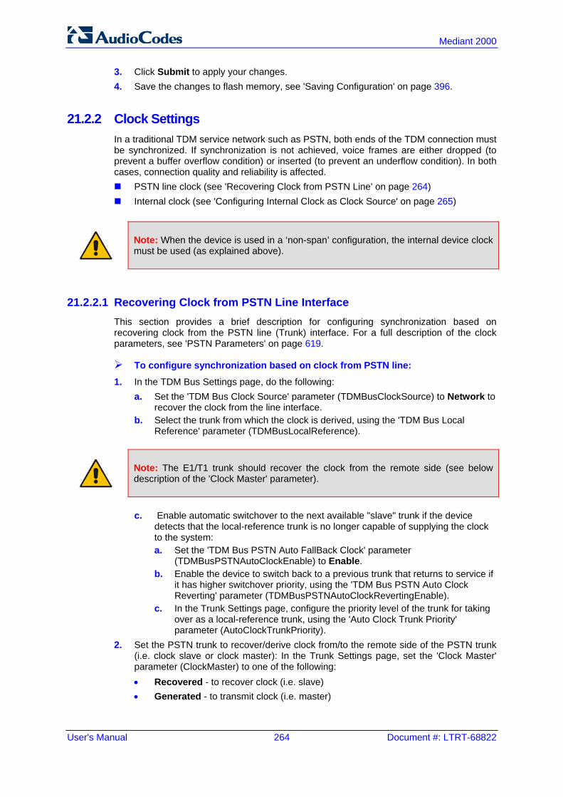
User's Manual 264 Document #: LTRT-68822
Mediant 2000
3. Click Submit to apply your changes. 4. Save the changes to flash memory, see 'Saving Configuration' on page 396.
21.2.2 Clock Settings In a traditional TDM service network such as PSTN, both ends of the TDM connection must be synchronized. If synchronization is not achieved, voice frames are either dropped (to prevent a buffer overflow condition) or inserted (to prevent an underflow condition). In both cases, connection quality and reliability is affected. PSTN line clock (see 'Recovering Clock from PSTN Line' on page 264) Internal clock (see 'Configuring Internal Clock as Clock Source' on page 265)
Note: When the device is used in a ‘non-span’ configuration, the internal device clock must be used (as explained above).
21.2.2.1 Recovering Clock from PSTN Line Interface This section provides a brief description for configuring synchronization based on recovering clock from the PSTN line (Trunk) interface. For a full description of the clock parameters, see 'PSTN Parameters' on page 619.
To configure synchronization based on clock from PSTN line:
1. In the TDM Bus Settings page, do the following: a. Set the 'TDM Bus Clock Source' parameter (TDMBusClockSource) to Network to
recover the clock from the line interface. b. Select the trunk from which the clock is derived, using the 'TDM Bus Local
Reference' parameter (TDMBusLocalReference).
Note: The E1/T1 trunk should recover the clock from the remote side (see below description of the 'Clock Master' parameter).
c. Enable automatic switchover to the next available "slave" trunk if the device
detects that the local-reference trunk is no longer capable of supplying the clock to the system: a. Set the 'TDM Bus PSTN Auto FallBack Clock' parameter
(TDMBusPSTNAutoClockEnable) to Enable. b. Enable the device to switch back to a previous trunk that returns to service if
it has higher switchover priority, using the 'TDM Bus PSTN Auto Clock Reverting' parameter (TDMBusPSTNAutoClockRevertingEnable).
c. In the Trunk Settings page, configure the priority level of the trunk for taking over as a local-reference trunk, using the 'Auto Clock Trunk Priority' parameter (AutoClockTrunkPriority).
2. Set the PSTN trunk to recover/derive clock from/to the remote side of the PSTN trunk (i.e. clock slave or clock master): In the Trunk Settings page, set the 'Clock Master' parameter (ClockMaster) to one of the following: • Recovered - to recover clock (i.e. slave) • Generated - to transmit clock (i.e. master)

Version 6.6 265 Mediant 2000
User's Manual 21. Digital PSTN
21.2.2.2 Configuring Internal Clock as Clock Source This section describes how to configure the device to use its internal clock source. The internal clock source is a stratum 4E-compliant clock source. When the device has no line interfaces, the device should be configured in this mode.
To configure internal clock as clock source:
1. Set the clock source to be from the device's internal oscillator. In the TDM Bus Settings page, set the 'TDM Bus Clock Source' parameter (TDMBusClockSource) to Internal.
2. Set the line to drive the clock on all trunks: In the Trunk Settings page, set the 'Clock Master' parameter (ClockMaster) to Generated (for all trunks).
21.3 Configuring CAS State Machines The CAS State Machine page allows you to modify various timers and other basic parameters to define the initialization of the CAS state machine without changing the state machine itself (no compilation is required). The change doesn't affect the state machine itself, but rather the configuration. The CAS table used can be chosen in two ways (using the parameter CasChannelIndex): Single CAS table per trunk Different CAS table per group of B-channels in a trunk
To modify the CAS state machine parameters:
1. Open the CAS State Machine page (Configuration tab > VoIP menu > PSTN submenu > CAS State Machines).
Figure 21-4: CAS State Machine Page
2. Ensure that the trunk is inactive. The trunk number displayed in the 'Related Trunks'
field must be green. If it is red, indicating that the trunk is active, click the trunk number to open the Trunk Settings page (see 'Configuring Trunk Settings' on page 261), select the required Trunk number icon, and then click Stop Trunk.
3. In the CAS State Machine page, modify the required parameters according to the table below.
4. Once you have completed the configuration, activate the trunk if required in the Trunk Settings page, by clicking the trunk number in the 'Related Trunks' field, and in the Trunk Settings page, select the required Trunk number icon, and then click Apply Trunk Settings.
5. Click Submit, and then reset the device (see 'Resetting the Device' on page 393).
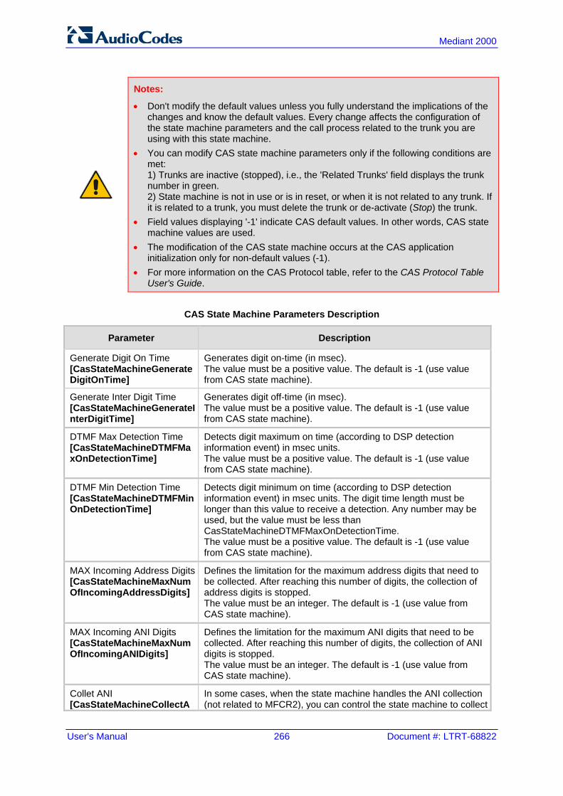
User's Manual 266 Document #: LTRT-68822
Mediant 2000
Notes:
• Don't modify the default values unless you fully understand the implications of the changes and know the default values. Every change affects the configuration of the state machine parameters and the call process related to the trunk you are using with this state machine.
• You can modify CAS state machine parameters only if the following conditions are met: 1) Trunks are inactive (stopped), i.e., the 'Related Trunks' field displays the trunk number in green. 2) State machine is not in use or is in reset, or when it is not related to any trunk. If it is related to a trunk, you must delete the trunk or de-activate (Stop) the trunk.
• Field values displaying '-1' indicate CAS default values. In other words, CAS state machine values are used.
• The modification of the CAS state machine occurs at the CAS application initialization only for non-default values (-1).
• For more information on the CAS Protocol table, refer to the CAS Protocol Table User's Guide.
CAS State Machine Parameters Description
Parameter Description
Generate Digit On Time [CasStateMachineGenerateDigitOnTime]
Generates digit on-time (in msec). The value must be a positive value. The default is -1 (use value from CAS state machine).
Generate Inter Digit Time [CasStateMachineGenerateInterDigitTime]
Generates digit off-time (in msec). The value must be a positive value. The default is -1 (use value from CAS state machine).
DTMF Max Detection Time [CasStateMachineDTMFMaxOnDetectionTime]
Detects digit maximum on time (according to DSP detection information event) in msec units. The value must be a positive value. The default is -1 (use value from CAS state machine).
DTMF Min Detection Time [CasStateMachineDTMFMinOnDetectionTime]
Detects digit minimum on time (according to DSP detection information event) in msec units. The digit time length must be longer than this value to receive a detection. Any number may be used, but the value must be less than CasStateMachineDTMFMaxOnDetectionTime. The value must be a positive value. The default is -1 (use value from CAS state machine).
MAX Incoming Address Digits [CasStateMachineMaxNumOfIncomingAddressDigits]
Defines the limitation for the maximum address digits that need to be collected. After reaching this number of digits, the collection of address digits is stopped. The value must be an integer. The default is -1 (use value from CAS state machine).
MAX Incoming ANI Digits [CasStateMachineMaxNumOfIncomingANIDigits]
Defines the limitation for the maximum ANI digits that need to be collected. After reaching this number of digits, the collection of ANI digits is stopped. The value must be an integer. The default is -1 (use value from CAS state machine).
Collet ANI [CasStateMachineCollectA
In some cases, when the state machine handles the ANI collection (not related to MFCR2), you can control the state machine to collect

Version 6.6 267 Mediant 2000
User's Manual 21. Digital PSTN
Parameter Description
NI] ANI or discard ANI. [0] No = Don't collect ANI. [1] Yes = Collect ANI. [-1] Default = Default value - use value from CAS state machine.
Digit Signaling System [CasStateMachineDigitSignalingSystem]
Defines which Signaling System to use in both directions (detection\generation). [0] DTMF = Uses DTMF signaling. [1] MF = Uses MF signaling (default). [-1] Default = Default value - use value from CAS state machine.
21.4 Configuring Digital Gateway Parameters The Digital Gateway Parameters page allows you to configure miscellaneous digital parameters. For a description of these parameters, see 'Configuration Parameters Reference' on page 503.
To configure the digital gateway parameters:
1. Open the Digital Gateway Parameters page (Configuration tab > VoIP menu > GW and IP to IP submenu > Digital Gateway submenu > Digital Gateway Parameters).
Figure 21-5: Digital Gateway Parameters Page
2. Configure the parameters as required.
User's Manual 268 Document #: LTRT-68822
Mediant 2000
3. Click Submit to apply your changes. 4. To save the changes to flash memory, see 'Saving Configuration' on page 396.
21.5 Tunneling Applications This section discusses the device's support for VoIP tunneling applications.
21.5.1 TDM Tunneling The device's TDM Tunneling feature allows you to tunnel groups of digital trunk spans or timeslots (B-channels) over the IP network. TDM Tunneling utilizes the device's internal routing (without Proxy control) capabilities to receive voice and data streams from TDM (E1/T1/J1/) spans or individual timeslots, convert them into packets, and then transmit them over the IP network (using point-to-point or point-to-multipoint device distributions). A device opposite it (or several devices when point-to-multipoint distribution is used) converts the IP packets back into TDM traffic. Each timeslot can be targeted to any other timeslot within a trunk in the opposite device. When TDM Tunneling is enabled (the parameter EnableTDMoverIP is set to '1') on the originating device, the originating device automatically initiates SIP calls from all enabled B-channels belonging to the E1/T1/J1 spans that are configured with the protocol type ‘Transparent’ (for ISDN trunks) or ‘Raw CAS’ (for CAS trunks). The called number of each call is the internal phone number of the B-channel from where the call originates. The Inbound IP Routing Table is used to define the destination IP address of the terminating device. The terminating device automatically answers these calls if its E1/T1 protocol type is set to ‘Transparent’ (ProtocolType = 5) or ‘Raw CAS’ (ProtocolType = 3 for T1 and 9 for E1) and the parameter ChannelSelectMode is set to 0 (By Phone Number).
Note: It's possible to configure both devices to also operate in symmetric mode. To do so, set EnableTDMOverIP to 1 and configure the Outbound IP Routing Table in both devices. In this mode, each device (after it's reset) initiates calls to the second device. The first call for each B-channel is answered by the second device.
The device continuously monitors the established connections. If for some reason, one or more calls are released, the device automatically re-establishes these ‘broken’ connections. When a failure in a physical trunk or in the IP network occurs, the device re-establishes the tunneling connections when the network is restored.
Note: It's recommended to use the keep-alive mechanism for each connection, by activating the ‘session expires’ timeout and using Re-INVITE messages.
The device supports the configuration (TDMoIPInitiateInviteTime and TDMoIPInviteRetryTime parameters) of the following timers for the TDM-over-IP tunneling application: Time between successive INVITEs sent from the same E1/T1 trunk. Time between call release and the new INVITE that is sent on the same channel. The
call can be released if the device receives a 4xx or 5xx response. By utilizing the ‘Profiles’ mechanism (see 'Coders and Profiles' on page 229), you can configure the TDM Tunneling feature to choose different settings based on a timeslot or groups of timeslots. For example, you can use low-bit-rate vocoders to transport voice and ‘Transparent’ coder to transport data (e.g., for D-channel). You can also use Profiles to
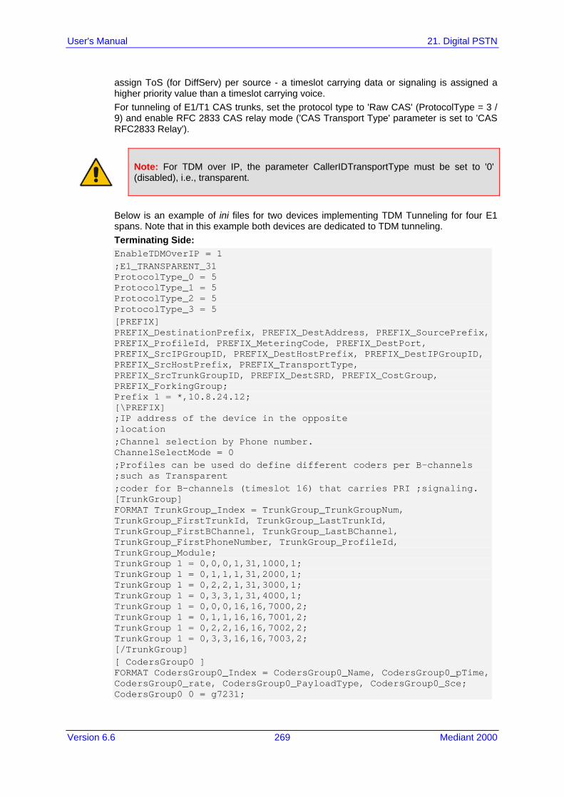
Version 6.6 269 Mediant 2000
User's Manual 21. Digital PSTN
assign ToS (for DiffServ) per source - a timeslot carrying data or signaling is assigned a higher priority value than a timeslot carrying voice. For tunneling of E1/T1 CAS trunks, set the protocol type to 'Raw CAS' (ProtocolType = 3 / 9) and enable RFC 2833 CAS relay mode ('CAS Transport Type' parameter is set to 'CAS RFC2833 Relay').
Note: For TDM over IP, the parameter CallerIDTransportType must be set to '0' (disabled), i.e., transparent.
Below is an example of ini files for two devices implementing TDM Tunneling for four E1 spans. Note that in this example both devices are dedicated to TDM tunneling. Terminating Side: EnableTDMOverIP = 1 ;E1_TRANSPARENT_31 ProtocolType_0 = 5 ProtocolType_1 = 5 ProtocolType_2 = 5 ProtocolType_3 = 5 [PREFIX] PREFIX_DestinationPrefix, PREFIX_DestAddress, PREFIX_SourcePrefix, PREFIX_ProfileId, PREFIX_MeteringCode, PREFIX_DestPort, PREFIX_SrcIPGroupID, PREFIX_DestHostPrefix, PREFIX_DestIPGroupID, PREFIX_SrcHostPrefix, PREFIX_TransportType, PREFIX_SrcTrunkGroupID, PREFIX_DestSRD, PREFIX_CostGroup, PREFIX_ForkingGroup; Prefix 1 = *,10.8.24.12; [\PREFIX] ;IP address of the device in the opposite ;location ;Channel selection by Phone number. ChannelSelectMode = 0 ;Profiles can be used do define different coders per B-channels ;such as Transparent ;coder for B-channels (timeslot 16) that carries PRI ;signaling. [TrunkGroup] FORMAT TrunkGroup_Index = TrunkGroup_TrunkGroupNum, TrunkGroup_FirstTrunkId, TrunkGroup_LastTrunkId, TrunkGroup_FirstBChannel, TrunkGroup_LastBChannel, TrunkGroup_FirstPhoneNumber, TrunkGroup_ProfileId, TrunkGroup_Module; TrunkGroup 1 = 0,0,0,1,31,1000,1; TrunkGroup 1 = 0,1,1,1,31,2000,1; TrunkGroup 1 = 0,2,2,1,31,3000,1; TrunkGroup 1 = 0,3,3,1,31,4000,1; TrunkGroup 1 = 0,0,0,16,16,7000,2; TrunkGroup 1 = 0,1,1,16,16,7001,2; TrunkGroup 1 = 0,2,2,16,16,7002,2; TrunkGroup 1 = 0,3,3,16,16,7003,2; [/TrunkGroup] [ CodersGroup0 ] FORMAT CodersGroup0_Index = CodersGroup0_Name, CodersGroup0_pTime, CodersGroup0_rate, CodersGroup0_PayloadType, CodersGroup0_Sce; CodersGroup0 0 = g7231;

User's Manual 270 Document #: LTRT-68822
Mediant 2000
CodersGroup0 1 = Transparent; [ \CodersGroup0 ] [TelProfile] FORMAT TelProfile_Index = TelProfile_ProfileName, TelProfile_TelPreference, TelProfile_CodersGroupID, TelProfile_IsFaxUsed, TelProfile_JitterBufMinDelay, TelProfile_JitterBufOptFactor, TelProfile_IPDiffServ, TelProfile_SigIPDiffServ, TelProfile_DtmfVolume, TelProfile_InputGain, TelProfile_VoiceVolume, TelProfile_EnableReversePolarity, TelProfile_EnableCurrentDisconnect, TelProfile_EnableDigitDelivery, TelProfile_EnableEC, TelProfile_MWIAnalog, TelProfile_MWIDisplay, TelProfile_FlashHookPeriod, TelProfile_EnableEarlyMedia, TelProfile_ProgressIndicator2IP; TelProfile 1 = voice,$$,1,$$,$$,$$,$$,$$,$$,$$; TelProfile 2 = data,$$,2,$$,$$,$$,$$,$$,$$,$$; [\TelProfile]
Originating Side: ;E1_TRANSPARENT_31 ProtocolType_0 = 5 ProtocolType_1 = 5 ProtocolType_2 = 5 ProtocolType_3 = 5 ;Channel selection by Phone number. ChannelSelectMode = 0 [TrunkGroup] FORMAT TrunkGroup_Index = TrunkGroup_TrunkGroupNum, TrunkGroup_FirstTrunkId, TrunkGroup_LastTrunkId, TrunkGroup_FirstBChannel, TrunkGroup_LastBChannel, TrunkGroup_FirstPhoneNumber, TrunkGroup_ProfileId, TrunkGroup_Module; TrunkGroup 0 = 0,0,0,1,31,1000,1; TrunkGroup 0 = 0,1,1,1,31,2000,1; TrunkGroup 0 = 0,2,2,1,31,3000,1; TrunkGroup 0 = 0,3,1,31,4000,1; TrunkGroup 0 = 0,0,0,16,16,7000,2; TrunkGroup 0 = 0,1,1,16,16,7001,2; TrunkGroup 0 = 0,2,2,16,16,7002,2; TrunkGroup 0 = 0,3,3,16,16,7003,2; [\TrunkGroup] [ CodersGroup0 ] FORMAT CodersGroup0_Index = CodersGroup0_Name, CodersGroup0_pTime, CodersGroup0_rate, CodersGroup0_PayloadType, CodersGroup0_Sce; CodersGroup0 0 = g7231; CodersGroup0 1 = Transparent; [ \CodersGroup0 ] [TelProfile] FORMAT TelProfile_Index = TelProfile_ProfileName, TelProfile_TelPreference, TelProfile_CodersGroupID, TelProfile_IsFaxUsed, TelProfile_JitterBufMinDelay, TelProfile_JitterBufOptFactor, TelProfile_IPDiffServ, TelProfile_SigIPDiffServ, TelProfile_DtmfVolume, TelProfile_InputGain, TelProfile_VoiceVolume, TelProfile_EnableReversePolarity, TelProfile_EnableCurrentDisconnect, TelProfile_EnableDigitDelivery, TelProfile_EnableEC, TelProfile_MWIAnalog, TelProfile_MWIDisplay,

Version 6.6 271 Mediant 2000
User's Manual 21. Digital PSTN
TelProfile_FlashHookPeriod, TelProfile_EnableEarlyMedia, TelProfile_ProgressIndicator2IP; TelProfile_1 = voice,$$,1,$$,$$,$$,$$,$$,$$,$$ TelProfile_2 = data,$$,2,$$,$$,$$,$$,$$,$$,$$ [\TelProfile]
21.5.1.1 DSP Pattern Detector For TDM tunneling applications, you can use the DSP pattern detector feature to initiate the echo canceller at call start. The device can be configured to support detection of a specific one-byte idle data pattern transmitted over digital E1/T1 timeslots. The device can be configured to detect up to four different one-byte data patterns. When the defined idle data pattern is detected, the channel resets its echo canceller.
To configure DSP pattern detector:
1. In the IPMedia Settings page (Configuration tab > VoIP menu > Media > IPMedia Settings), do the following: a. Set the 'IPMedia Detectors' parameter (EnableDSPIPMDetectors) to Enable. b. Set the 'Enable Pattern Detector' parameter (EnablePatternDetector) to Enable.
2. Configure the number (e.g., 5) of consecutive patterns to trigger the pattern detection event, using the ini file parameter, PDThreshold.
3. Configure the patterns that can be detected by the Pattern Detector, using the ini file parameter, PDPattern. For example: PDPattern = 84, 85, 212, 213 ; for idle patterns 54, 55, D4 and D5
21.5.2 QSIG Tunneling The device supports QSIG tunneling over SIP, according to IETF Internet-Draft draft-elwell-sipping-qsig-tunnel-03 ("Tunnelling of QSIG over SIP") and ECMA-355/ISO/IEC 22535. This is applicable to all ISDN variants. QSIG tunneling can be applied to all calls or to specific calls using IP Profiles. QSIG tunneling sends all QSIG messages as raw data in corresponding SIP messages using a dedicated message body. This is used, for example, to enable two QSIG subscribers connected to the same or different QSIG PBX to communicate with each other over an IP network. Tunneling is supported in both directions (Tel-to-IP and IP-to-Tel). The term tunneling means that messages are transferred ‘as is’ to the remote side without being converted (QSIG > SIP > QSIG). The advantage of tunneling over QSIG-to-SIP interworking is that by using interworking, QSIG functionality can only be partially achieved. When tunneling is used, all QSIG capabilities are supported and the tunneling medium (the SIP network) does not need to process these messages. QSIG messages are transferred in SIP messages in a separate Multipurpose Internet Mail Extensions (MIME) body. Therefore, if a message contains more than one body (e.g., SDP and QSIG), multipart MIME must be used. The Content-Type of the QSIG tunneled message is ‘application/QSIG’. The device also adds a Content-Disposition header in the following format: Content-Disposition: signal; handling=required.
QSIG tunneling is done as follows: Call setup (originating device): The QSIG Setup request is encapsulated in the SIP
INVITE message without being altered. After the SIP INVITE request is sent, the device does not encapsulate the subsequent QSIG message until a SIP 200 OK response is received. If the originating device receives a 4xx, 5xx, or 6xx response, it disconnects the QSIG call with a ‘no route to destination’ cause.

User's Manual 272 Document #: LTRT-68822
Mediant 2000
Call setup (terminating device): After the terminating device receives a SIP INVITE request with a 'Content-Type: application/QSIG', it sends the encapsulated QSIG Setup message to the Tel side and sends a 200 OK response (no 1xx response is sent) to IP. The 200 OK response includes an encapsulated QSIG Call Proceeding message (without waiting for a Call Proceeding message from the Tel side). If tunneling is disabled and the incoming INVITE includes a QSIG body, a 415 response is sent.
Mid-call communication: After the SIP connection is established, all QSIG messages are encapsulated in SIP INFO messages.
Call tear-down: The SIP connection is terminated once the QSIG call is complete. The Release Complete message is encapsulated in the SIP BYE message that terminates the session.
To enable QSIG tunneling:
1. In the Digital Gateway Parameters page (Configuration tab > VoIP menu > GW and IP to IP > Digital Gateway > Digital Gateway Parameters), set the 'Enable QSIG Tunneling' parameter (EnableQSIGTunneling) to Enable on the originating and terminating devices.
2. Configure the QSIGTunnelingMode parameter for defining the format of encapsulated QSIG message data in the SIP message MIME body (0 for ASCII presentation; 1 for binary encoding).
3. Set the ISDNDuplicateQ931BuffMode parameter to 128 to duplicate all messages. 4. Set the ISDNInCallsBehavior parameter to 4096. 5. Set the ISDNRxOverlap parameter to 0 for tunneling of QSIG overlap-dialed digits
(see below for description). The configuration of the ISDNInCallsBehavior and ISDNRxOverlap parameters allows tunneling of QSIG overlap-dialed digits (Tel to IP). In this configuration, the device delays the sending of the QSIG Setup Ack message upon receipt of the QSIG Setup message. Instead, the device sends the Setup Ack message to QSIG only when it receives the SIP INFO message with Setup Ack encapsulated in its MIME body. The PBX sends QSIG Information messages (to complete the Called Party Number) only after it receives the Setup Ack. The device relays these Information messages encapsulated in SIP INFO messages to the remote party.
21.6 ISDN Non-Facility Associated Signaling (NFAS) In regular T1 ISDN trunks, a single 64 kbps channel carries signaling for the other 23 B-channels of that particular T1 trunk. This channel is called the D-channel and usually resides on timeslot # 24. ISDN Non-Facility Associated Signaling (NFAS) enables the use of a single D-channel to control multiple PRI interfaces. With NFAS it is possible to define a group of T1 trunks, called an NFAS group, in which a single D-channel carries ISDN signaling messages for the entire group. The NFAS group’s B-channels are used to carry traffic such as voice or data. The NFAS mechanism also enables definition of a backup D-channel on a different T1 trunk, to be used if the primary D-channel fails. The device supports up to 12 NFAS groups. Each group can comprise up to 8 T1 trunks and each group must contain different T1 trunks. Each T1 trunk is called an "NFAS member". The T1 trunk whose D-channel is used for signaling is called the "Primary NFAS Trunk". The T1 trunk whose D-channel is used for backup signaling is called the "Backup NFAS Trunk". The primary and backup trunks each carry 23 B-channels while all other NFAS trunks each carry 24 B-channels. The NFAS group is identified by an NFAS GroupID number (possible values are 1 to 12). To assign a number of T1 trunks to the same NFAS group, use the NFASGroupNumber_x = groupID (where x is the physical trunk ID (0 to the maximum number of trunks) or the Web interface (see 'Configuring Trunk Settings' on page 261).

Version 6.6 273 Mediant 2000
User's Manual 21. Digital PSTN
The parameter DchConfig_x = Trunk_type defines the type of NFAS trunk. Trunk_type is set to 0 for the primary trunk, to 1 for the backup trunk, and to 2 for an ordinary NFAS trunk. ‘x’ denotes the physical trunk ID (0 to the maximum number of trunks). You can also use the Web interface (see 'Configuring Trunk Settings' on page 261). For example, to assign the first four T1 trunks to NFAS group #1, in which trunk #0 is the primary trunk and trunk #1 is the backup trunk, use the following configuration: NFASGroupNumber_0 = 1 NFASGroupNumber_1 = 1 NFASGroupNumber_2 = 1 NFASGroupNumber_3 = 1 DchConfig_0 = 0 ;Primary T1 trunk DchConfig_1 = 1 ;Backup T1 trunk DchConfig_2 = 2 ;24 B-channel NFAS trunk DchConfig_3 = 2 ;24 B-channel NFAS trunk
The NFAS parameters are described in 'PSTN Parameters' on page 619.
21.6.1 NFAS Interface ID Several ISDN switches require an additional configuration parameter per T1 trunk that is called ‘Interface Identifier’. In NFAS T1 trunks, the Interface Identifier is sent explicitly in Q.931 Setup / Channel Identification IE for all NFAS trunks, except for the B-channels of the Primary trunk (see note below). The Interface ID can be defined per member (T1 trunk) of the NFAS group, and must be coordinated with the configuration of the Switch. The default value of the Interface ID is identical to the number of the physical T1 trunk (0 for the first trunk, 1 for the second T1 trunk, and so on, up to the maximum number of trunks). To define an explicit Interface ID for a T1 trunk (that is different from the default), use the following parameters: ISDNIBehavior_x = 512 (x = 0 to the maximum number of trunks identifying the
device's physical trunk) ISDNNFASInterfaceID_x = ID (x = 0 to 255)
Notes:
• Usually the Interface Identifier is included in the Q.931 Setup/Channel Identification IE only on T1 trunks that doesn’t contain the D-channel. Calls initiated on B-channels of the Primary T1 trunk, by default, don’t contain the Interface Identifier. Setting the parameter ISDNIBehavior_x to 2048’ forces the inclusion of the Channel Identifier parameter also for the Primary trunk.
• The parameter ISDNNFASInterfaceID_x = ID can define the ‘Interface ID’ for any Primary T1 trunk, even if the T1 trunk is not a part of an NFAS group. However, to include the Interface Identifier in Q.931 Setup/Channel Identification IE configure ISDNIBehavior_x = 2048 in the ini file.
21.6.2 Working with DMS-100 Switches The DMS-100 switch requires the following NFAS Interface ID definitions: InterfaceID #0 for the Primary trunk InterfaceID #1 for the Backup trunk InterfaceID #2 for a 24 B-channel T1 trunk InterfaceID #3 for a 24 B-channel T1 trunk, and so on for subsequent T1 trunks

User's Manual 274 Document #: LTRT-68822
Mediant 2000
For example, if four T1 trunks on a device are configured as a single NFAS group with Primary and Backup T1 trunks that is used with a DMS-100 switch, the following parameters should be used: NFASGroupNumber_0 = 1 NFASGroupNumber_1 = 1 NFASGroupNumber_2 = 1 NFASGroupNumber_3 = 1 DchConfig_0 = 0 ;Primary T1 trunk DchConfig_1 = 1 ;Backup T1 trunk DchConfig_2 = 2 ;B-Channel NFAS trunk DchConfig_3 = 2 ;B-channel NFAS trunk
If there is no NFAS Backup trunk, the following configuration should be used: ISDNNFASInterfaceID_0 = 0 ISDNNFASInterfaceID_1 = 2 ISDNNFASInterfaceID_2 = 3 ISDNNFASInterfaceID_3 = 4 ISDNIBehavior = 512 ;This parameter should be added because of ;ISDNNFASInterfaceID coniguration above NFASGroupNumber_0 = 1 NFASGroupNumber_1 = 1 NFASGroupNumber_2 = 1 NFASGroupNumber_3 = 1 DchConfig_0 = 0 ;Primary T1 trunk DchConfig_1 = 2 ;B-Channel NFAS trunk DchConfig_2 = 2 ;B-Channel NFAS trunk DchConfig_3 = 2 ;B-channel NFAS trunk
21.6.3 Creating an NFAS-Related Trunk Configuration The procedures for creating and deleting an NFAS group must be performed in the correct order, as described below.
To create an NFAS Group:
1. If there’s a backup (‘secondary’) trunk for this group, it must be configured first. 2. Configure the primary trunk before configuring any NFAS (‘slave’) trunk. 3. Configure NFAS (‘slave’) trunks.
To stop / delete an NFAS Group: 1. Stop or delete (by setting ProtocolType to 0, i.e., 'None') all NFAS (‘slave’) trunks. 2. Stop or delete (by setting ProtocolType to 0, i.e., 'None') the backup trunk if a backup
trunk exists. 3. Stop or delete (by setting ProtocolType to 0, i.e., 'None') the primary trunk.
Notes:
• All trunks in the group must be configured with the same values for trunk parameters TerminationSide, ProtocolType, FramingMethod, and LineCode.
• After stopping or deleting the backup trunk, delete the group and then reconfigure it.

Version 6.6 275 Mediant 2000
User's Manual 21. Digital PSTN
21.6.4 Performing Manual D-Channel Switchover in NFAS Group If an NFAS group is configured with two D-channels (Primary and Backup), you can do a manual switchover between these D-channels.
To manually switchover from active to standby D-channel:
1. Open the NFAS Group & D-Channel Status page (Status & Diagnostics tab > VoIP Status menu > NFAS Group & D-Channel Status).
2. Select the required NFAS group, and then click the Switch Activity button.
Notes:
• The Switch Activity button is unavailable (i.e, grayed out) if a switchover cannot be done due to, for example, alarms or unsuitable states.
• This feature is applicable only to T1 ISDN protocols supporting NFAS, and only if the NFAS group is configured with two D-channels.
21.7 ISDN Overlap Dialing Overlap dialing is a dialing scheme used by several ISDN variants to send and/or receive called number digits one after the other (or several at a time). This is in contrast to en-bloc dialing in which a complete number is sent in one message. ISDN overlap dialing is applicaable to PRI and BRI. The device supports the following ISDN overlap dialing methods: Collects ISDN called party number digits and then sends the SIP INVITE to the IP side
with the complete destination number (see 'Collecting ISDN Digits and Sending Complete Number in SIP' on page 275)
Interworks ISDN overlap dialing with SIP, according to RFC 3578 (see 'Interworking ISDN Overlap Dialing with SIP According to RFC 3578' on page 276)
21.7.1 Collecting ISDN Digits and Sending Complete Number in SIP The device can support an overlap dialing mode whereby the device collects the called party number digits from ISDN Q.931 Information messages or DTMF signals, and then sends a SIP INVITE message to the IP side containing the complete destination number. ISDN overlap dialing for incoming ISDN calls can be configured for the entire device or per E1/T1 trunk. This is configured using the global, ISDNRxOverlap parameter or the ISDNRxOverlap_x parameter (where x denotes the trunk number), respectively. By default (see the ISDNINCallsBehavior parameter), the device plays a dial tone to the ISDN user side when it receives an empty called number from the ISDN. In this scenario, the device includes the Progress Indicator in the SetupAck ISDN message that it sends to the ISDN side. The device can also mute in-band DTMF detection until it receives the complete destination number from the ISDN. This is configured using the MuteDTMFInOverlap parameter. The Information digits can be sent in-band in the voice stream, or out-of-band using Q.931 Information messages. If Q.931 Information messages are used, the DTMF in-band detector must be disabled. Note that when at least one digit is received in the ISDN Setup message, the device stops playing a dial tone. The device stops collecting digits (from the ISDN) upon the following scenarios: The device receives a Sending Complete IE in the ISDN Setup or Information

User's Manual 276 Document #: LTRT-68822
Mediant 2000
messages, indicating no more digits. The timeout between received digits expires (configured by the TimeBetweenDigits
parameter). The maximum number of received digits has been reached (configured by the
MaxDigits parameter). A match is found with the defined digit map (configured by the DigitMapping
parameter). Relevant parameters (described in 'PSTN Parameters' on page 619): ISDNRxOverlap_x = 1 (can be configured per trunk) TimeBetweenDigits MaxDigits MuteDTMFInOverlap DigitMapping For configuring ISDN overlap dialing using the Web interface, see 'Configuring Trunk Settings' on page 261.
21.7.2 Interworking ISDN Overlap Dialing with SIP According to RFC 3578 The device supports the interworking of ISDN overlap dialing to SIP and vice versa, according to RFC 3578. Interworking ISDN overlap dialing to SIP (Tel to IP): The device sends collected
digits each time it receives them (initially from the ISDN Setup message and then from subsequent Q.931 Information messages) to the IP side, using subsequent SIP INVITE messages. You can also define the minimum number of overlap digits to collect before sending the first SIP message (INVITE) for routing the call, using the MinOverlapDigitsForRouting parameter.
Interworking SIP to ISDN overlap dialing (IP to Tel): For each received SIP INVITE pertaining to the same dialog session, the device sends an ISDN Setup message (and subsequent Q.931 Information messages) with the collected digits to the Tel side. For all subsequent INVITEs received, the device sends a SIP 484 "Address Incomplete" response to the IP in order to maintain the current dialog session and to receive additional digits from subsequent INVITEs.
Relevant parameters (described in 'PSTN Parameters' on page 619): ISDNRxOverlap = 2 ISDNTxOverlap ISDNOutCallsBehavior = 2 MinOverlapDigitsForRouting TimeBetweenDigits MaxDigits DigitMapping MuteDTMFInOverlap For configuring ISDN overlap dialing using the Web interface, see 'Configuring Trunk Settings' on page 261.

Version 6.6 277 Mediant 2000
User's Manual 21. Digital PSTN
21.8 Redirect Number and Calling Name (Display) The following tables define the device's redirect number and calling name (Display) support for various ISDN variants according to NT (Network Termination) / TE (Termination Equipment) interface direction:
Calling Name (Display)
NT/TE Interface DMS-100 NI-2 4/5ESS Euro ISDN QSIG
NT-to-TE Yes Yes Yes Yes Yes
TE-to-NT Yes Yes Yes No Yes
Redirect Number
NT/TE Interface DMS-100 NI-2 4/5ESS Euro ISDN QSIG
NT-to-TE Yes Yes Yes Yes Yes
TE-to-NT Yes Yes Yes Yes* Yes
* When using ETSI DivertingLegInformation2 in a Facility IE (not Redirecting Number IE).

User's Manual 278 Document #: LTRT-68822
Mediant 2000
Reader's Notes

Version 6.6 279 Mediant 2000
User's Manual 22. Trunk Group
22 Trunk Group This section describes the configuration of the device's channels, which includes assigning them to Trunk Groups.
22.1 Configuring Trunk Group Table The Trunk Group Table page allows you to define up to 120 Trunk Groups. A Trunk Group is a logical group of physical trunks and channels that are assigned a Trunk Group ID. The Trunk Group can include multiple trunks and ranges of channels. To enable and activate the channels of the device, Trunk Groups need to be defined and with telephone numbers. Channels that are not defined in this table are disabled. The Trunk Groups are later used for routing IP-to-Tel and Tel-to-IP calls.
Notes:
• After you have configured a Trunk Group, you must configure the Inbound IP Routing Table rules (see 'Configuring Inbound IP Routing Table' on page 317) to route incoming IP calls to the Trunk Group. If you do not configure this, calls cannot be established.
• To select the method on how incoming calls are routed to channels within a Trunk Group, see 'Configuring Trunk Group Settings' on page 281.
• The Trunk Group Table can also be configured using the table ini file parameter, TrunkGroup_x to (see 'Number Manipulation Parameters' on page 669).
To configure the Trunk Group Table:
1. Open the Trunk Group Table page (Configuration tab > VoIP menu > GW and IP to IP submenu > Trunk Group > Trunk Group).
Figure 22-1: Trunk Group Table Page
2. Configure the Trunk Group as required. For a description of the parameters, see the
table below. 3. Click Submit to apply your changes. 4. To save the changes to the flash memory, see 'Saving Configuration' on page 396. 5. To register the Trunk Groups, click the Register button. To unregister the Trunk
Groups, click Unregister. The registration method for each Trunk Group is according to the 'Registration Mode' parameter in the Trunk Group Settings page (see

User's Manual 280 Document #: LTRT-68822
Mediant 2000
'Configuring Trunk Group Settings' on page 281).
Trunk Group Table Parameters
Parameter Description
From Trunk [TrunkGroup_FirstTrunkId]
Defines the starting physical Trunk number in the Trunk Group. The number of listed Trunks depends on the device's hardware configuration.
To Trunk [TrunkGroup_LastTrunkId]
Defines the ending physical Trunk number in the Trunk Group. The number of listed Trunks depends on the device's hardware configuration.
Channels [TrunkGroup_FirstBChannel] [TrunkGroup_LastBChannel]
Defines the device's Trunk B-channels. To enable channels, enter the channel numbers. You can enter a range of channels by using the syntax n-m, where n represents the lower channel number and m the higher channel number. For example, "1-4" specifies channels 1 through 4. Notes: The number of defined channels must not exceed the maximum
number of the Trunk’s B-channels. To represent all the Trunk's B-channels, enter a single asterisk (*).
Phone Number [TrunkGroup_FirstPhoneNumber]
Defines the telephone number(s) of the channels. The valid value can be up to 50 characters. For a range of channels, enter only the first telephone number. Subsequent channels are assigned the next consecutive telephone number. For example, if you enter 400 for channels 1 to 4, then channel 1 is assigned phone number 400, channel 2 is assigned phone number 401, and so on. These numbers are also used for channel allocation for IP-to-Tel calls if the Trunk Group’s ‘Channel Select Mode’ parameter is set to By Dest Phone Number. Notes: If this field includes alphabetical characters and the phone number
is defined for a range of channels (e.g., 1-4), then the phone number must end with a number (e.g., 'user1').
This field is optional for interfaces. The logical numbers defined in this field are used when an incoming PSTN/PBX call doesn't contain the calling number or called number (the latter being determined by the ReplaceEmptyDstWithPortNumber parameter). These numbers are used to replace them.
Trunk Group ID [TrunkGroup_TrunkGroupNum]
Defines the Trunk Group ID for the specified channels. The same Trunk Group ID can be assigned to more than one group of channels. If an IP-to-Tel call is assigned to a Trunk Group, the IP call is routed to the channel(s) pertaining to that Trunk Group ID. The valid value can be 0 to 119.
Tel Profile ID [TrunkGroup_ProfileId]
Assigns a Tel Profile ID to the Trunk Group. Note: For configuring Tel Profiles, see 'Configuring Tel Profiles' on page 233.

Version 6.6 281 Mediant 2000
User's Manual 22. Trunk Group
22.2 Configuring Trunk Group Settings The Trunk Group Settings allows you to configure the following per Trunk Group: Channel select method by which IP-to-Tel calls are assigned to the Trunk Group's
channels. Registration method for registering Trunk Groups to selected Serving IP Group IDs.
Notes:
• For configuring Trunk Groups, see Configuring Trunk Group Table on page 279. • The Trunk Group Settings table can also be configured using the table ini file
parameter, TrunkGroupSettings (see 'Number Manipulation Parameters' on page 669).
To configure the Trunk Group Settings table: 1. Open the Trunk Group Settings page (Configuration tab > VoIP menu > GW and IP
to IP submenu > Trunk Group > Trunk Group Settings).
2. From the 'Index' drop-down list, select the range of entries that you want to edit. 3. Configure the Trunk Group as required. For a description of the parameters, see the
table below. 4. Click Submit to apply your changes. 5. To save the changes to flash memory, see 'Saving Configuration' on page 396.
Trunk Group Settings Parameters Description
Parameter Description
Trunk Group ID [TrunkGroupSettings_TrunkGroupId]
Defines the Trunk Group ID that you want to configure.
Channel Select Mode [TrunkGroupSettings_ChannelSelectMode]
Defines the method by which IP-to-Tel calls are assigned to the channels of the Trunk Group. [0] By Dest Phone Number = The channel is selected according
to the called (destination) number. If the number is not located, the call is released. If the channel is unavailable (e.g., busy), the call is put on call waiting (if call waiting is enabled and no other call is on call waiting); otherwise, the call is released.

User's Manual 282 Document #: LTRT-68822
Mediant 2000
Parameter Description
[1] Cyclic Ascending = The next available channel in the Trunk Group, in ascending cyclic order is selected. After the device reaches the highest channel number in the Trunk Group, it selects the lowest channel number in the Trunk Group, and then starts ascending again.
[2] Ascending = The lowest available channel in the Trunk Group is selected, and if unavailable, the next higher channel is selected.
[3] Cyclic Descending = The next available channel in descending cyclic order is selected. The next lower channel number in the Trunk Group is always selected. When the device reaches the lowest channel number in the Trunk Group, it selects the highest channel number in the Trunk Group, and then starts descending again.
[4] Descending = The highest available channel in the Trunk Group is selected, and if unavailable, the next lower channel is selected.
[5] Dest Number + Cyclic Ascending = The channel is selected according to the called number. If the called number isn't found, the next available channel in ascending cyclic order is selected. Note: If the called number is located, but the port associated with the number is busy, the call is released.
[6] By Source Phone Number = The channel is selected according to the calling number.
[7] Trunk Cyclic Ascending = The channel from the first channel of the next trunk (adjacent to the trunk from which the previous channel was selected) is selected.
[8] Trunk & Channel Cyclic Ascending = The device implements the Trunk Cyclic Ascending and Cyclic Ascending methods to select the channel. This method selects the next physical trunk in the Trunk Group, and then selects the B-channel of this trunk according to the Cyclic Ascending method (i.e., selects the channel after the last allocated channel). For example, if the Trunk Group includes two physical trunks, 0 and 1: For the first incoming call, the first channel of Trunk 0 is
selected. For the second incoming call, the first channel of Trunk 1 is
selected. For the third incoming call, the second channel of Trunk 0 is
selected. [11] Dest Number + Ascending = The device allocates a channels
to incoming IP-to-Tel calls as follows: a. The device attempts to route the call to the channel that is
associated with the destination (called) number. If located, the call is sent to that channel.
b. If the number is not located or the channel is unavailable (e.g., busy), the device searches in ascending order for the next available channel in the Trunk Group. If located, the call is sent to that channel.
c. If all the channels are unavailable, the call is released. Note: If this parameter is not configured for the Trunk Group, then its channel select method is according to the global parameter, ChannelSelectMode.
Registration Mode Defines the registration method for the Trunk Group:
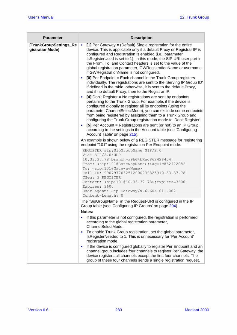
Version 6.6 283 Mediant 2000
User's Manual 22. Trunk Group
Parameter Description
[TrunkGroupSettings_RegistrationMode]
[1] Per Gateway = (Default) Single registration for the entire device. This is applicable only if a default Proxy or Registrar IP is configured and Registration is enabled (i.e., parameter IsRegisterUsed is set to 1). In this mode, the SIP URI user part in the From, To, and Contact headers is set to the value of the global registration parameter, GWRegistrationName or username if GWRegistrationName is not configured.
[0] Per Endpoint = Each channel in the Trunk Group registers individually. The registrations are sent to the 'Serving IP Group ID' if defined in the table, otherwise, it is sent to the default Proxy, and if no default Proxy, then to the Registrar IP.
[4] Don't Register = No registrations are sent by endpoints pertaining to the Trunk Group. For example, if the device is configured globally to register all its endpoints (using the parameter ChannelSelectMode), you can exclude some endpoints from being registered by assigning them to a Trunk Group and configuring the Trunk Group registration mode to 'Don't Register'.
[5] Per Account = Registrations are sent (or not) to an IP Group, according to the settings in the Account table (see 'Configuring Account Table' on page 215).
An example is shown below of a REGISTER message for registering endpoint "101" using the registration Per Endpoint mode: REGISTER sip:SipGroupName SIP/2.0 Via: SIP/2.0/UDP 10.33.37.78;branch=z9hG4bKac862428454 From: <sip:101@GatewayName>;tag=1c862422082 To: <sip:101@GatewayName> Call-ID: [email protected] CSeq: 3 REGISTER Contact: <sip:[email protected]>;expires=3600 Expires: 3600 User-Agent: Sip-Gateway/v.6.60A.011.002 Content-Length: 0
The "SipGroupName" in the Request-URI is configured in the IP Group table (see 'Configuring IP Groups' on page 204). Notes: If this parameter is not configured, the registration is performed
according to the global registration parameter, ChannelSelectMode.
To enable Trunk Group registration, set the global parameter, IsRegisterNeeded to 1. This is unnecessary for 'Per Account' registration mode.
If the device is configured globally to register Per Endpoint and an channel group includes four channels to register Per Gateway, the device registers all channels except the first four channels. The group of these four channels sends a single registration request.

User's Manual 284 Document #: LTRT-68822
Mediant 2000
Parameter Description
Serving IP Group ID [TrunkGroupSettings_ServingIPGroup]
Assigns an IP Group to where INVITE messages received from this Trunk Group are sent. The actual destination to where these INVITE messages are sent is according to the Proxy Set ID associated with the IP Group. The Request-URI host name in the INVITE and REGISTER messages (except for 'Per Account' registration modes) is set to the value of the 'SIP Group Name' parameter configured in the IP Group table (see 'Configuring IP Groups' on page 204). Notes: If this parameter is not configured, the INVITE messages are sent
to the default Proxy or according to the Outbound IP Routing Table (see 'Configuring Outbound IP Routing Table' on page 309).
If the PreferRouteTable parameter is set to 1 (see 'Configuring Proxy and Registration Parameters' on page 218), the routing rules in the Outbound IP Routing table take precedence over the selected Serving IP Group ID.
Gateway Name [TrunkGroupSettings_GatewayName]
Defines the host name for the SIP From header in INVITE messages and for the From/To headers in REGISTER requests. Note: If this parameter is not configured, the global parameter, SIPGatewayName is used.
Contact User [TrunkGroupSettings_ContactUser]
Defines the user part for the SIP Contact URI in INVITE messages and for the From, To, and Contact headers in REGISTER requests. Notes: This parameter is applicable only if the 'Registration Mode'
parameter is set to 'Per Account' and registration through the Account table is successful.
If registration fails, the user part in the INVITE Contact header is set to the source party number.
The 'Contact User' parameter in the Account table overrides this parameter (see 'Configuring Account Table' on page 215).
Trunk Group Name [TrunkGroupSettings_TrunkGroupName]
Defines a name for the Trunk Group. This name represents the Trunk Group in the SIP 'tgrp' parameter of the outgoing INVITE messages (according to RFC 4904). For example: sip:+16305550100;tgrp=TG-1;[email protected];user=phone
The valid value can be a string of up to 20 characters. By default, no name is configured. Notes: If this parameter is not configured, the Trunk Group decimal
number is used in the SIP 'tgrp' parameter. This feature is enabled by any of the following parameters: UseSIPtgrp UseBroadsoftDTG
Currently, this parameter can only be configured using the ini file.

Version 6.6 285 Mediant 2000
User's Manual 22. Trunk Group
Parameter Description
MWI Interrogation Type [TrunkGroupSettings_MWIInterrogationType]
Defines MWI QSIG-to-IP interworking for interrogating MWI supplementary services: [255] Not Configured [0] None = Disables the feature. [1] Use Activate Only = MWI Interrogation messages are not sent
and only "passively" responds to MWI Activate requests from the PBX.
[2] Result Not Used = MWI Interrogation messages are sent, but the result is not used. Instead, the device waits for MWI Activate requests from the PBX.
[3] Use Result = MWI Interrogation messages are sent, its results are used, and the MWI Activate requests are used. MWI Activate requests are interworked to SIP NOTIFY MWI messages. The SIP NOTIFY messages are sent to the IP Group defined by the NotificationIPGroupID parameter.
Note: This parameter appears in the table only if the VoiceMailInterface parameter is set to 3 (QSIG). Configuring Voice Mail on page 354.

User's Manual 286 Document #: LTRT-68822
Mediant 2000
Reader's Notes

Version 6.6 287 Mediant 2000
User's Manual 23. Manipulation
23 Manipulation This section describes the configuration of various manipulation processes.
23.1 Configuring General Settings The General Settings page allows you to configure general manipulation parameters. For a description of the parameters appearing on this page, see 'Configuration Parameters Reference' on page 503.
To configure the general manipulation parameters: 1. Open the General Settings page (Configuration tab > VoIP menu > GW and IP to IP
submenu > Manipulations submenu >General Settings).
Figure 23-1: General Settings Page
2. Configure the parameters as required. 3. Click Submit to apply your changes.
23.2 Configuring Source/Destination Number Manipulation Rules You can configure rules for manipulating destination and/or source telephone numbers for IP-to-Tel and Tel-to-IP calls. The following number manipulation tables are used for this: Tel-to-IP calls:
• Destination Phone Number Manipulation Table for Tel > IP Calls table (up to 120 entries)
• Source Phone Number Manipulation Table for Tel > IP Calls table (up to 120 entries)
IP-to-Tel calls: • Destination Phone Number Manipulation Table for IP > Tel Calls table (up to 120
entries) • Source Phone Number Manipulation Table for IP > Tel Calls table (up to 120
entries) The number manipulation tables provide two configuration areas: Matching characteristics (Rule) of incoming call, for example, prefix of destination
number. Manipulation operation (Action), for example, remove user-defined number of digits
from the left of the number. If the incoming call matches the characteristics of a rule, then its manipulation action is applied. The device searches a matching manipulation rule starting from the first entry (i.e., top of the table). In other words, a rule at the top of the table takes precedence over a rule defined lower down in the table. Therefore, define more specific rules above more generic rules. For example, if you enter 551 in Index 1 and 55 in Index 2, the device applies rule 1 to numbers that start with 551 and applies rule 2 to numbers that start with 550, 552, 553,

User's Manual 288 Document #: LTRT-68822
Mediant 2000
and so on until 559. However, if you enter 55 in Index 1 and 551 in Index 2, the device applies rule 1 to all numbers that start with 55, including numbers that start with 551. You can perform a second "round" (additional) of destination (NumberMapIP2Tel parameter) and source (SourceNumberMapIP2Tel parameter) number manipulations for IP-to-Tel calls on an already manipulated number. The initial and additional number manipulation rules are both configured in these tables. The additional manipulation is performed on the initially manipulated number. Therefore, for complex number manipulation schemes, you only need to configure relatively few manipulation rules in these tables (that would otherwise require many rules). This feature is enabled using the following parameters: PerformAdditionalIP2TELSourceManipulation for source number manipulation PerformAdditionalIP2TELDestinationManipulation for destination number manipulation Telephone number manipulation can be useful, for example, for the following: Stripping or adding dialing plan digits from or to the number, respectively. For
example, a user may need to first dial 9 before dialing the phone number to indicate an external line. This number 9 can then be removed by number manipulation before the call is setup.
Allowing or blocking Caller ID information according to destination or source prefixes. Assigning Numbering Plan Indicator (NPI) and Type of Numbering (TON) to IP-to-Tel
calls. The device can use a single global setting for NPI/TON classification or it can use the setting in the manipulation tables on a call-by-call basis.
Notes:
• Number manipulation can occur before or after a routing decision is made. For example, you can route a call to a specific Trunk Group according to its original number, and then you can remove or add a prefix to that number before it is routed. To determine when number manipulation is performed, configure the 'IP to Tel Routing Mode' parameter (RouteModeIP2Tel) described in 'Configuring Inbound IP Routing Table' on page 317, and 'Tel to IP Routing Mode' parameter (RouteModeTel2IP) described in 'Configuring Outbound IP Routing Table' on page 309.
• The device manipulates the number in the following order: 1) strips digits from the left of the number, 2) strips digits from the right of the number, 3) retains the defined number of digits, 4) adds the defined prefix, and then 5) adds the defined suffix.
• The source/destination number manipulation tables can also be configured using the ini file: 1) Destination Phone Number Manipulation Table for IP > Tel Calls table: NumberMapIP2Tel (ini) 2) Destination Phone Number Manipulation Table for Tel > IP Calls table: NumberMapTel2IP (ini) 3) Source Phone Number Manipulation Table for IP > Tel Calls table: SourceNumberMapIP2Tel (ini) 4) Source Phone Number Manipulation Table for Tel > IP Calls table: SourceNumberMapTel2IP (ini)
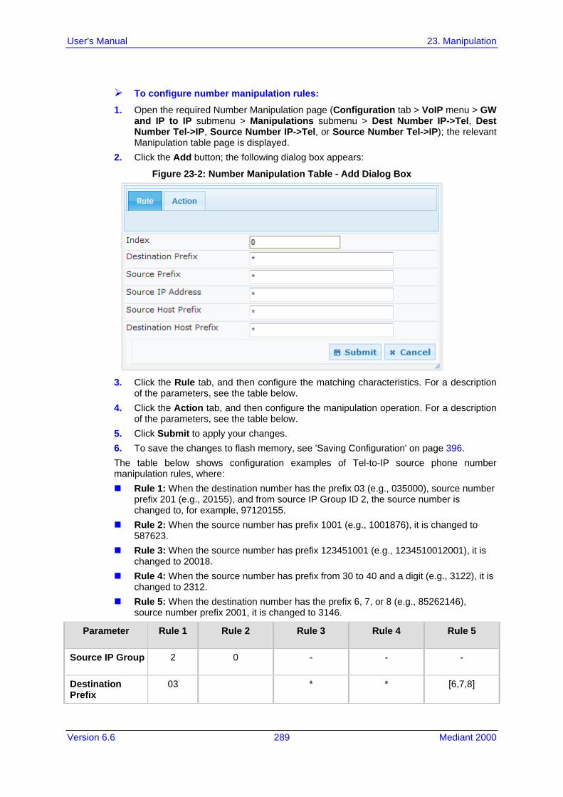
Version 6.6 289 Mediant 2000
User's Manual 23. Manipulation
To configure number manipulation rules:
1. Open the required Number Manipulation page (Configuration tab > VoIP menu > GW and IP to IP submenu > Manipulations submenu > Dest Number IP->Tel, Dest Number Tel->IP, Source Number IP->Tel, or Source Number Tel->IP); the relevant Manipulation table page is displayed.
2. Click the Add button; the following dialog box appears:
Figure 23-2: Number Manipulation Table - Add Dialog Box
3. Click the Rule tab, and then configure the matching characteristics. For a description
of the parameters, see the table below. 4. Click the Action tab, and then configure the manipulation operation. For a description
of the parameters, see the table below. 5. Click Submit to apply your changes. 6. To save the changes to flash memory, see 'Saving Configuration' on page 396. The table below shows configuration examples of Tel-to-IP source phone number manipulation rules, where: Rule 1: When the destination number has the prefix 03 (e.g., 035000), source number
prefix 201 (e.g., 20155), and from source IP Group ID 2, the source number is changed to, for example, 97120155.
Rule 2: When the source number has prefix 1001 (e.g., 1001876), it is changed to 587623.
Rule 3: When the source number has prefix 123451001 (e.g., 1234510012001), it is changed to 20018.
Rule 4: When the source number has prefix from 30 to 40 and a digit (e.g., 3122), it is changed to 2312.
Rule 5: When the destination number has the prefix 6, 7, or 8 (e.g., 85262146), source number prefix 2001, it is changed to 3146.
Parameter Rule 1 Rule 2 Rule 3 Rule 4 Rule 5
Source IP Group 2 0 - - -
Destination Prefix
03 * * [6,7,8]

User's Manual 290 Document #: LTRT-68822
Mediant 2000
Parameter Rule 1 Rule 2 Rule 3 Rule 4 Rule 5
Source Prefix 201 1001 123451001# [30-40]x 2001
Stripped Digits from Left
- 4 - - 5
Stripped Digits from Right
- - - 1 -
Prefix to Add 971 5 - 2 3
Suffix to Add - 23 8 - -
Number of Digits to Leave
- - 4 - -
Presentation Allowed Restricted - - -
Number Manipulation Parameters Description
Parameter Description
Matching Characteristics (Rule)
Web: Destination Prefix EMS: Prefix [DestinationPrefix]
Defines the destination (called) telephone number prefix and/or suffix. You can use special notations for denoting the prefix. For example, [100-199](100,101,105) denotes a number that starts with 100 to 199 and ends with 100, 101 or 105. You can also use the $ sign to denote calls without a called number. For a description of available notations, see 'Dialing Plan Notation for Routing and Manipulation Tables' on page 501.
Web/EMS: Source Prefix [SourcePrefix]
Defines the source (calling) telephone number prefix and/or suffix. You can use special notations for denoting the prefix. For example, [100-199](100,101,105) denotes a number that starts with 100 to 199 and ends with 100, 101 or 105. You can also use the $ sign to denote calls without a calling number. For a description of available notations, see 'Dialing Plan Notation for Routing and Manipulation Tables' on page 501.
Web/EMS: Source IP Address [SourceAddress]
Defines the source IP address of the caller. This is obtained from the Contact header in the INVITE message. Notes: This parameter is applicable only to the number manipulation
tables for IP-to-Tel calls. The source IP address can include the 'x' wildcard to represent
single digits. For example: 10.8.8.xx represents all IP addresses between 10.8.8.10 to 10.8.8.99.
The source IP address can include the asterisk (*) wildcard to represent any number between 0 and 255. For example, 10.8.8.* represents all IP addresses between 10.8.8.0 and 10.8.8.255.
Web: Source Host Prefix [SrcHost]
Defines the URI host name prefix of the incoming SIP INVITE message in the From header. Notes: This parameter is applicable only to the number manipulation
tables for IP-to-Tel calls. The asterisk (*) wildcard can be used to denote any prefix. If the P-Asserted-Identity header is present in the incoming INVITE

Version 6.6 291 Mediant 2000
User's Manual 23. Manipulation
Parameter Description
message, then the value of this parameter is compared to the P-Asserted-Identity URI host name (instead of the From header).
Web: Destination Host Prefix [DestHost]
Defines the Request-URI host name prefix of the incoming SIP INVITE message. Notes: This parameter is applicable only to the number manipulation
tables for IP-to-Tel calls. The asterisk (*) wildcard can be used to denote any prefix.
Web: Source Trunk Group [SrcTrunkGroupID]
Defines the source Trunk Group ID for Tel-to-IP calls. To denote all Trunk Groups, leave this field empty. Notes: The value -1 indicates that this field is ignored in the rule. This parameter is applicable only to the number manipulation
tables for Tel-to-IP calls. For IP-to-IP call routing, this parameter is not required (i.e., leave
the field empty).
Web: Source IP Group [SrcIPGroupID]
Defines the IP Group from where the IP call originated. Typically, the IP Group of an incoming INVITE is determined or classified using the Inbound IP Routing Table. If not used (i.e., any IP Group), leave the field empty. Notes: The value -1 indicates that this field is ignored. This parameter is applicable only to the number manipulation
tables for Tel-to-IP calls. If this Source IP Group has a Serving IP Group, then all calls from
this Source IP Group are sent to the Serving IP Group. In this scenario, this table is used only if the PreferRouteTable parameter is set to 1.
Web: Destination IP Group [DestIPGroupID]
Defines the IP Group to where the call is sent. Notes: The value -1 indicates that this field is ignored. This parameter is applicable only to the Destination Phone Number
Manipulation Table for Tel -> IP Calls.
Operation (Action)
Web: Stripped Digits From Left EMS: Number Of Stripped Digits [RemoveFromLeft]
Defines the number of digits to remove from the left of the telephone number prefix. For example, if you enter 3 and the phone number is 5551234, the new phone number is 1234.
Web: Stripped Digits From Right EMS: Number Of Stripped Digits [RemoveFromRight]
Defines the number of digits to remove from the right of the telephone number prefix. For example, if you enter 3 and the phone number is 5551234, the new phone number is 5551.
Web: Prefix to Add EMS: Prefix/Suffix To Add [Prefix2Add]
Defines the number or string that you want added to the front of the telephone number. For example, if you enter 9 and the phone number is 1234, the new number is 91234.
Web: Suffix to Add Defines the number or string that you want added to the end of the

User's Manual 292 Document #: LTRT-68822
Mediant 2000
Parameter Description
EMS: Prefix/Suffix To Add [Suffix2Add]
telephone number. For example, if you enter 00 and the phone number is 1234, the new number is 123400.
Web/EMS: Number of Digits to Leave [LeaveFromRight]
Defines the number of digits that you want to keep from the right of the phone number. For example, if you enter 4 and the phone number is 00165751234, then the new number is 1234.
Web: NPI EMS: Number Plan [NumberPlan]
Defines the Numbering Plan Indicator (NPI). [0] Unknown (default) [9] Private [1] E.164 Public [-1] Not Configured = value received from PSTN/IP is used Notes: This parameter is applicable only to number manipulation tables
for IP-to-Tel calls. NPI can be used in the SIP Remote-Party-ID header by using the
EnableRPIHeader and AddTON2RPI parameters. For more information on available NPI/TON values, see
Numbering Plans and Type of Number on page 307.
Web: TON EMS: Number Type [NumberType]
Defines the Type of Number (TON). If you selected 'Unknown' for the NPI, you can select Unknown [0]. If you selected 'Private' for the NPI, you can select Unknown [0],
Level 2 Regional [1], Level 1 Regional [2], PISN Specific [3] or Level 0 Regional (Local) [4].
If you selected 'E.164 Public' for the NPI, you can select Unknown [0], International [1], National [2], Network Specific [3], Subscriber [4] or Abbreviated [6].
The default is 'Unknown'. Notes: This parameter is applicable only to number manipulation tables
for IP-to-Tel calls. TON can be used in the SIP Remote-Party-ID header by using the
EnableRPIHeader and AddTON2RPI parameters. For more information on available NPI/TON values, see
Numbering Plans and Type of Number on page 307.
Web: Presentation EMS: Is Presentation Restricted [IsPresentationRestricted]
Enables caller ID. [0] Allowed = Sends Caller ID information when a call is made
using these destination/source prefixes. [1] Restricted = Restricts Caller ID information for these prefixes. Notes: This field is applicable only to number manipulation tables for
source phone number manipulation. If this field is set to Restricted and the 'Asserted Identity Mode'
(AssertedIdMode) parameter is set to Add P-Asserted-Identity, the From header in the INVITE message includes the following: From: 'anonymous' <sip: [email protected]> and 'privacy: id' header.

Version 6.6 293 Mediant 2000
User's Manual 23. Manipulation
23.3 Manipulating Number Prefix The device supports a notation for adding a prefix where part of the prefix is first extracted from a user-defined location in the original destination or source number. This notation is entered in the 'Prefix to Add' field in the Number Manipulation tables (see 'Configuring Source/Destination Number Manipulation' on page 287): x[n,l]y... where, x = any number of characters/digits to add at the beginning of the number (i.e. first
digits in the prefix). [n,l] = defines the location in the original destination or source number where the digits
y are added: • n = location (number of digits counted from the left of the number) of a specific
string in the original destination or source number. • l = number of digits that this string includes.
y = prefix to add at the specified location. For example, assume that you want to manipulate an incoming IP call with destination number +5492028888888 (area code 202 and phone number 8888888) to the number 0202158888888. To perform such a manipulation, the following configuration is required in the Number Manipulation table: 1. The following notation is used in the 'Prefix to Add' field:
0[5,3]15 where, • 0 is the number to add at the beginning of the original destination number. • [5,3] denotes a string that is located after (and including) the fifth character (i.e.,
the first '2' in the example) of the original destination number, and its length being three digits (i.e., the area code 202, in the example).
• 15 is the number to add immediately after the string denoted by [5,3] - in other words, 15 is added after (i.e. to the right of) the digits 202.
2. The first seven digits from the left are removed from the original number, by entering "7" in the 'Stripped Digits From Left' field.
Example of Configured Rule for Manipulating Prefix using Special Notation
Parameter Rule 1
Destination Prefix
+5492028888888
Source Prefix *
Source IP Address
*
Stripped Digits from Left
7
Prefix to Add 0[5,3]15
In this configuration example, the following manipulation process occurs: 1. The prefix is calculated as 020215. 2. The first seven digits from the left are removed from the original number, thereby
changing the number to 8888888. 3. The prefix that was previously calculated is then added.

User's Manual 294 Document #: LTRT-68822
Mediant 2000
23.4 SIP Calling Name Manipulations The Calling Name Manipulations Tel2IP and Calling Name Manipulations IP2Tel tables allow you to configure up to 120 manipulation rules for manipulating the calling name (i.e., caller ID) in SIP messages. This can include modifying or removing the calling name. SIP calling name manipulation is applicable to Tel-to-IP and IP-to-Tel calls. For example, assume that an incoming SIP INVITE message includes the following header: P-Asserted-Identity: "company:john" sip:[email protected]
Using the Calling Name Manipulations IP2Tel table, the text "company" can be changed to "worker" in the outgoing INVITE, as shown below: P-Asserted-Identity: "worker:john" sip:[email protected]
The calling name manipulation tables provide two configuration areas: Matching characteristics (Rule) of incoming call, for example, prefix of destination
number. Manipulation operation (Action), for example, remove user-defined number of digits
from the left of the calling name. If the incoming call matches the characteristics of a rule, then its manipulation action is applied.
Notes:
• For configuring the Calling Name Manipulation Table for Tel > IP Calls table for retrieving calling name (display name) from an Active Directory using LDAP queries, see 'Querying the AD for Calling Name' on page 191.
• The Calling Name Manipulations Tel2IP table can also be configured using the table ini file parameter, CallingNameMapTel2Ip.
• The Calling Name Manipulations IP2Tel table can also be configured using the table ini file parameter, CallingNameMapIp2Tel.
To configure calling name manipulation rules:
1. Open the required Calling Name Manipulations page (Configuration tab > VoIP menu > GW and IP to IP submenu > Manipulations > Calling Name IP->Tel or Calling Name Tel->IP).
2. Click the Add button; the following dialog box appears:
Figure 23-3: Calling Name Manipulation IP2Tel - Rule Tab
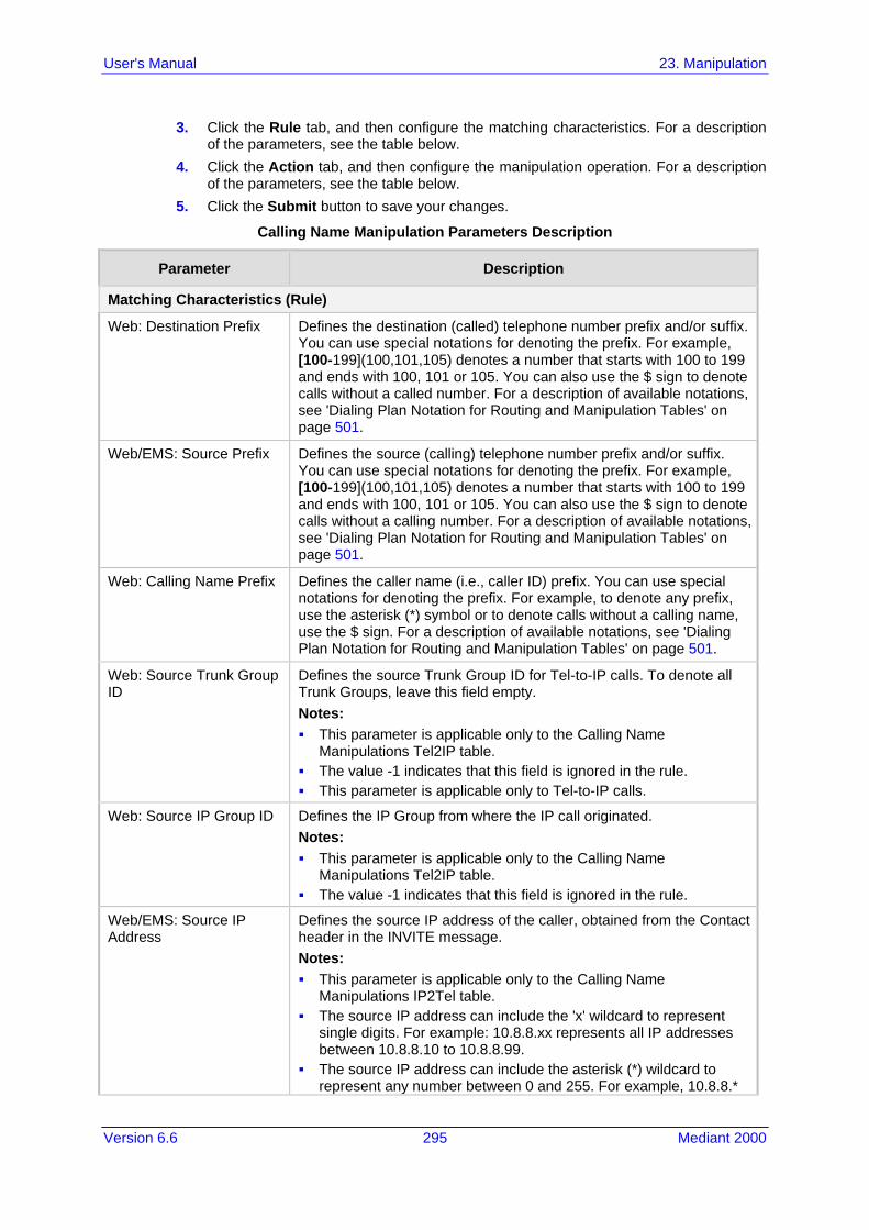
Version 6.6 295 Mediant 2000
User's Manual 23. Manipulation
3. Click the Rule tab, and then configure the matching characteristics. For a description of the parameters, see the table below.
4. Click the Action tab, and then configure the manipulation operation. For a description of the parameters, see the table below.
5. Click the Submit button to save your changes.
Calling Name Manipulation Parameters Description
Parameter Description
Matching Characteristics (Rule)
Web: Destination Prefix
Defines the destination (called) telephone number prefix and/or suffix. You can use special notations for denoting the prefix. For example, [100-199](100,101,105) denotes a number that starts with 100 to 199 and ends with 100, 101 or 105. You can also use the $ sign to denote calls without a called number. For a description of available notations, see 'Dialing Plan Notation for Routing and Manipulation Tables' on page 501.
Web/EMS: Source Prefix
Defines the source (calling) telephone number prefix and/or suffix. You can use special notations for denoting the prefix. For example, [100-199](100,101,105) denotes a number that starts with 100 to 199 and ends with 100, 101 or 105. You can also use the $ sign to denote calls without a calling number. For a description of available notations, see 'Dialing Plan Notation for Routing and Manipulation Tables' on page 501.
Web: Calling Name Prefix
Defines the caller name (i.e., caller ID) prefix. You can use special notations for denoting the prefix. For example, to denote any prefix, use the asterisk (*) symbol or to denote calls without a calling name, use the $ sign. For a description of available notations, see 'Dialing Plan Notation for Routing and Manipulation Tables' on page 501.
Web: Source Trunk Group ID
Defines the source Trunk Group ID for Tel-to-IP calls. To denote all Trunk Groups, leave this field empty. Notes: This parameter is applicable only to the Calling Name
Manipulations Tel2IP table. The value -1 indicates that this field is ignored in the rule. This parameter is applicable only to Tel-to-IP calls.
Web: Source IP Group ID
Defines the IP Group from where the IP call originated. Notes: This parameter is applicable only to the Calling Name
Manipulations Tel2IP table. The value -1 indicates that this field is ignored in the rule.
Web/EMS: Source IP Address
Defines the source IP address of the caller, obtained from the Contact header in the INVITE message. Notes: This parameter is applicable only to the Calling Name
Manipulations IP2Tel table. The source IP address can include the 'x' wildcard to represent
single digits. For example: 10.8.8.xx represents all IP addresses between 10.8.8.10 to 10.8.8.99.
The source IP address can include the asterisk (*) wildcard to represent any number between 0 and 255. For example, 10.8.8.*

User's Manual 296 Document #: LTRT-68822
Mediant 2000
Parameter Description
represents all IP addresses between 10.8.8.0 and 10.8.8.255.
Web: Source Host Prefix
Defines the URI host name prefix of the incoming SIP INVITE message in the From header. Notes: This parameter is applicable only to the Calling Name
Manipulations IP2Tel table. The asterisk (*) wildcard can be used to denote any prefix. If the P-Asserted-Identity header is present in the incoming INVITE
message, then the value of this parameter is compared to the P-Asserted-Identity URI host name (instead of the From header).
Web: Destination Host Prefix
Defines the Request-URI host name prefix of the incoming SIP INVITE message. Notes: This parameter is applicable only to the Calling Name
Manipulations IP2Tel table. The asterisk (*) wildcard can be used to denote any prefix.
Operation (Action)
Web: Stripped Digits From Left EMS: Number Of Stripped Digits
Defines the number of characters to remove from the left of the calling name. For example, if you enter 3 and the calling name is "company:john", the new calling name is "pany:john".
Web: Stripped Digits From Right EMS: Number Of Stripped Digits
Defines the number of characters to remove from the right of the calling name. For example, if you enter 3 and the calling name is "company:name", the new name is "company:n".
Web/EMS: Number of Digits to Leave
Defines the number of characters that you want to keep from the right of the calling name. For example, if you enter 4 and the calling name is "company:name", the new name is "name".
Web: Prefix to Add EMS: Prefix/Suffix To Add
Defines the number or string to add at the front of the calling name. For example, if you enter ITSP and the calling name is "company:name", the new name is ITSPcompany:john".
Web: Suffix to Add EMS: Prefix/Suffix To Add
Defines the number or string to add at the end of the calling name. For example, if you enter 00 and calling name is "company:name", the new name is "company:name00".
23.5 Configuring Redirect Number IP to Tel You can configure rules for manipulating the redirect number received in the incoming message: IP-to-Tel redirect number manipulation: You can manipulate the value of the received
SIP Diversion, Resource-Priority, or History-Info headers, which is then added to the Redirecting Number Information Element (IE) in the ISDN Setup message sent to the Tel side. This also includes the reason for the call redirection. This is configured in the Redirect Number IP > Tel table.
Tel-to-IP redirect number manipulation: You can manipulate the prefix of the redirect number, received from the Tel side, in the outgoing SIP Diversion, Resource-Priority,

Version 6.6 297 Mediant 2000
User's Manual 23. Manipulation
or History-Info headers sent to the IP side. This is configured in the Redirect Number Tel > IP table.
The redirect number manipulation tables provide two configuration areas: Matching characteristics (Rule) of incoming call, for example, prefix of redirect
number. Manipulation operation (Action), for example, remove user-defined number of digits
from the left of the redirect number. If the incoming call matches the characteristics of a rule, then its manipulation action is applied.
Notes:
• If the device copies the received destination number to the outgoing SIP redirect number (enabled by the CopyDest2RedirectNumber parameter), then no redirect number Tel-to-IP manipulation is done.
• The manipulation rules are done in the following order: Stripped Digits From Left, Stripped Digits From Right, Number of Digits to Leave, Prefix to Add, and then Suffix to Add.
• The Redirect Prefix parameter is used before it is manipulated. • The redirect number manipulation tables can also be configured using the ini file:
- Redirect Number IP to Tel table: RedirectNumberMapIp2Tel (ini) - Redirect Number Tel to IP table: RedirectNumberMapTel2Ip (ini)
To configure redirect number manipulation rules:
1. Open the required redirect number manipulation table (Configuration tab > VoIP menu > GW and IP to IP submenu > Manipulations > Redirect Number Tel > IP or Redirect Number IP > Tel).
2. Click the Add button; the following dialog box appears (e.g., Redirect Number Tel > IP table):
Figure 23-4: Redirect Number Manipulation (e.g., Tel to IP)
3. Click the Rule tab, and then configure the matching characteristics. For a description
of the parameters, see the table below. 4. Click the Action tab, and then configure the manipulation operation. For a description
of the parameters, see the table below. 5. Click Submit to apply your settings.

User's Manual 298 Document #: LTRT-68822
Mediant 2000
Redirect Number Manipulation Parameters Description
Parameter Description
Matching Characteristics (Rule)
Web/EMS: Redirect Prefix [RedirectPrefix]
Defines the redirect telephone number prefix. To denote any number, use the wildcard asterisk (*) symbol.
Web/EMS: Destination Prefix [DestinationPrefix]
Defines the destination (called) telephone number prefix. To denote any number, use the wildcard asterisk (*) symbol. For manipulating the diverting and redirected numbers for call diversion, you can use the strings "DN" and "RN" to denote the destination prefix of these numbers. For more information, see Manipulating Redirected and Diverted Numbers for Call Diversion on page 300.
Web: Source Trunk Group ID [SrcTrunkGroupID]
Defines the Trunk Group from where the Tel call is received. To denote any Trunk Group, leave this field empty. Notes: This parameter is applicable only to the Redirect Number Tel > IP
table. The value -1 indicates that this field is ignored in the rule. For IP-to-IP call routing, this parameter is not relevant.
Source IP Group ID [SrcIPGroupID]
Defines the IP Group from where the IP call originated. Typically, the IP Group of an incoming INVITE is determined or classified by the Inbound IP Routing Table. If not used (i.e., any IP Group), leave the field empty. Notes: This parameter is applicable only to the Redirect Number Tel > IP
table. This parameter is applicable only to the IP-to-IP application. The value -1 indicates that it is ignored in the rule.
Web/EMS: Source IP Address [SourceAddress]
Defines the IP address of the caller. This is obtained from the Contact header in the INVITE message. Notes: This parameter is applicable only to the Redirect Number IP > Tel
table. The source IP address can include the following wildcards: "x": represents single digits. For example, 10.8.8.xx denotes all
addresses between 10.8.8.10 and 10.8.8.99. "*": represents any number between 0 and 255. For example,
10.8.8.* denotes all addresses between 10.8.8.0 and 10.8.8.255.
Web: Source Host Prefix [SrcHost]
Defines the URI host name prefix of the incoming SIP INVITE message in the From header. Notes: This parameter is applicable only to the Redirect Number IP > Tel
table. Use the wildcard asterisk (*) symbol to denote any prefix. If the P-Asserted-Identity header is present in the incoming INVITE
message, then the value of this parameter is compared to the P-Asserted-Identity URI host name (instead of to the From header).
Web: Destination Host Prefix
Defines the Request-URI host name prefix of the incoming SIP INVITE message.

Version 6.6 299 Mediant 2000
User's Manual 23. Manipulation
Parameter Description
[DestHost] Notes: This parameter is applicable only to the Redirect Number IP > Tel
table. Use the wildcard asterisk (*) symbol to denote any prefix.
Operation (Action)
Web: Stripped Digits From Left EMS: Remove From Left [RemoveFromLeft]
Defines the number of digits to remove from the left of the redirect number prefix. For example, if you enter 3 and the redirect number is 5551234, the new number is 1234.
Web: Stripped Digits From Right EMS: Remove From Right [RemoveFromRight]
Defines the number of digits to remove from the right of the redirect number prefix. For example, if you enter 3 and the redirect number is 5551234, the new number is 5551.
Web/EMS: Number of Digits to Leave [LeaveFromRight]
Defines the number of digits that you want to retain from the right of the redirect number.
Web/EMS: Prefix to Add [Prefix2Add]
Defines the number or string that you want added to the front of the redirect number. For example, if you enter 9 and the redirect number is 1234, the new number is 91234.
Web/EMS: Suffix to Add [Suffix2Add]
Defines the number or string that you want added to the end of the redirect number. For example, if you enter 00 and the redirect number is 1234, the new number is 123400.
Web: Presentation EMS: Is Presentation Restricted [IsPresentationRestricted]
Enables caller ID. [0] Allowed = Sends Caller ID information when a call is made
using these destination / source prefixes. [1] Restricted = Restricts Caller ID information for these prefixes. Note: If 'Presentation' is set to 'Restricted' and the AssertedIdMode parameter is set to Add P-Asserted-Identity, the From header in the INVITE message includes the following: From: 'anonymous' <sip: [email protected]> and 'privacy: id' header.
Web: TON EMS: Number Type [NumberType]
Defines the Type of Number (TON). The default is 'Unknown' [0]. If you select 'Unknown' for the NPI, you can select Unknown [0]. If you select 'Private' for the NPI, you can select Unknown [0],
International [1], National [2], Network Specific [3] or Subscriber [4].
If you select 'E.164 Public' for the NPI, you can select Unknown [0], International [1], National [2], Network Specific [3], Subscriber [4] or Abbreviated [6].
Notes: This parameter is applicable only to the Redirect Number IP > Tel
table. For more information on available NPI/TON values, see
Numbering Plans and Type of Number on page 307.

User's Manual 300 Document #: LTRT-68822
Mediant 2000
Parameter Description
Web: NPI EMS: Number Plan [NumberPlan]
Defines the Numbering Plan Indicator (NPI). [0] Unknown (default) [9] Private [1] E.164 Public [-1] Not Configured = value received from PSTN/IP is used Notes: This parameter is applicable only to the Redirect Number IP > Tel
table. For more information on available NPI/TON values, see
Numbering Plans and Type of Number on page 307.
23.6 Manipulating Redirected and Diverted Numbers for Call Diversion You can configure manipulation rules to manipulate the Diverted-to and Diverting numbers received in the incoming Call Redirection Facility message for call diversion, which is interworked to outgoing SIP 302 responses. This feature is applicable to the Euro ISDN and QSIG variants, and to IP-to-Tel calls. The incoming redirection Facility message includes, among other parameters, the Diverted-to number and Diverting number. The Diverted-to number (i.e., new destination) is mapped to the user part in the Contact header of the SIP 302 response. The Diverting number is mapped to the user part in the Diversion header of the SIP 302 response. These two numbers can be manipulated by entering the following special strings in the 'Destination Prefix' field of the Redirect Number Tel -> IP manipulation table: "RN" - used in the rule to manipulate the Redirected number (i.e., originally called
number or Diverting number). "DN" - used in the rule to manipulate the Diverted-to number (i.e., the new called
number or destination). This manipulation is done on the user part in the Contact header of the SIP 302 response.
For example, assume the following required manipulation: Manipulate Redirected number 6001 (originally called number) to 6005 Manipulate Diverted-to number 8002 (the new called number or destination) to 8005 The configuration in the Redirect Number Tel -> IP manipulation table is as follows:
Redirect Number Configuration Example
Parameter Rule 1 Rule 2
Destination Prefix RN DN
Redirect Prefix 6 8
Stripped Digits From Right 1 1
Suffix to Add 5 5
Number of Digits to Leave 5 -

Version 6.6 301 Mediant 2000
User's Manual 23. Manipulation
After the above manipulation is done, the device sends the following outgoing SIP 302 response: SIP/2.0 302 Moved Temporarily Via: SIP/2.0/TLS 10.33.45.68;branch=z9hG4bKac54132643;alias From: "MP118 1" <sip:[email protected]>;tag=1c54119560 To: <sip:[email protected];user=phone>;tag=1c664560944 Call-ID: [email protected] CSeq: 1 INVITE Contact: <sip:[email protected];user=phone> Supported: em,timer,replaces,path,early-session,resource-priority Allow: REGISTER,OPTIONS,INVITE,ACK,CANCEL,BYE,NOTIFY,PRACK,REFER,INFO,SUBSCRIBE,UPDATE Diversion: <tel:6005>;reason=unknown;counter=1 Server: Audiocodes-Sip-Gateway-IPmedia 260_UN/v.6.20A.043.001 Reason: SIP ;cause=302 ;text="302 Moved Temporarily" Content-Length: 0
23.7 Mapping NPI/TON to SIP Phone-Context The Phone-Context table page allows you to map Numbering Plan Indication (NPI) and Type of Number (TON) to the SIP 'phone-context' parameter. The 'phone-context' parameter appears in the standard SIP headers where a phone number is used (i.e., Request-URI, To, From, and Diversion). When a call is received from the ISDN side, the NPI and TON are compared against the table and the matching 'phone-context' value is used in the outgoing SIP INVITE message. The same mapping occurs when an INVITE with a 'phone-context' parameter is received. For example, for a Tel-to-IP call with NPI/TON set as E164 National (values 1/2), the device sends the following SIP INVITE URI: sip:12365432;phone-context= na.e.164.nt.com
This is configured for entry 3 in the figure below. In the opposite direction (IP-to-Tel call), if the incoming INVITE contains this 'phone-context' (e.g. "phone-context= na.e.164.nt.com"), the NPI/TON of the called number in the outgoing Setup message is changed to E164 National.
To configure NPI/TON to SIP phone-context rules: 1. Open the Phone Context Table page (Configuration tab > VoIP menu > GW and IP
to IP submenu > Manipulations > Phone Context).
Figure 23-5: Phone Context Table Page
2. Configure the parameters as required. For a description of the parameters, see the

User's Manual 302 Document #: LTRT-68822
Mediant 2000
table below. 3. Click Submit to apply your changes. 4. To save the changes to flash memory, see 'Saving Configuration' on page 396.
Notes:
• You can configure multiple rows with the same NPI/TON or same SIP 'phone-context'. In such a configuration, a Tel-to-IP call uses the first matching rule in the table.
• The Phone Context table can also be configured using the table ini file parameter, PhoneContext (see 'Number Manipulation Parameters' on page 669).
Phone-Context Parameters Description
Parameter Description
Add Phone Context As Prefix [AddPhoneContextAsPrefix]
Determines whether the received SIP 'phone-context' parameter is added as a prefix to the outgoing ISDN Setup message with called and calling numbers. [0] Disable (default) [1] Enable
NPI [PhoneContext_Npi]
Defines the Number Plan Indicator (NPI). [0] Unknown (default) [1] E.164 Public [9] Private For a detailed list of the available NPI/TON values, see Numbering Plans and Type of Number on page 307.
TON [PhoneContext_Ton]
Defines the Type of Number (TON). If you selected Unknown as the NPI, you can select Unknown [0]. If you selected Private as the NPI, you can select one of the
following: [0] Unknown [1] Level 2 Regional [2] Level 1 Regional [3] PSTN Specific [4] Level 0 Regional (Local)
If you selected E.164 Public as the NPI, you can select one of the following: [0] Unknown [1] International [2] National [3] Network Specific [4] Subscriber [6] Abbreviated
Phone Context [PhoneContext_Context]
Defines the SIP 'phone-context' URI parameter.
23.8 Configuring Release Cause Mapping The Release Cause Mapping table allows you to map up to 12 different ISDN ITU-T Q.850 cause codes, which indicate reasons for ISDN call failure, to SIP response codes, and vice

Version 6.6 303 Mediant 2000
User's Manual 23. Manipulation
versa. This allows you to override the default release cause mappings between ISDN and SIP, as described in 'Fixed Mapping of ISDN Release Reason to SIP Response' on page 305 and 'Fixed Mapping of SIP Response to ISDN Release Reason' on page 303.
Notes:
• For Tel-to-IP calls, you can also map the less commonly used SIP responses to a single default ISDN Release Cause, using the DefaultCauseMapISDN2IP parameter. This parameter defines a default ISDN Cause that is always used except when the following Release Causes are received: Normal Call Clearing (16), User Busy (17), No User Responding (18) or No Answer from User (19).
• The release cause mapping tables can also be configured using the ini file: 1) Release Cause Mapping from ISDN to SIP table: CauseMapISDN2SIP (ini). 2) Release Cause Mapping from SIP to ISDN table:CauseMapSIP2ISDN (ini).
To configure Release Cause mapping:
1. Open the Release Cause Mapping page (Configuration tab > VoIP menu > GW and IP to IP submenu > Manipulations > Release Cause Mapping).
Figure 23-6: Release Cause Mapping Page
2. In the 'Release Cause Mapping from ISDN to SIP' group, map different Q.850 Release
Causes to SIP Responses. 3. In the 'Release Cause Mapping from SIP to ISDN' group, map different SIP
Responses to Q.850 Release Causes. 4. Click Submit to apply your changes.
23.8.1 Fixed Mapping of SIP Response to ISDN Release Reason The following table describes the mapping of SIP response to ISDN release reason.
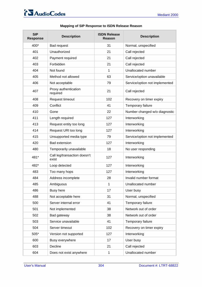
User's Manual 304 Document #: LTRT-68822
Mediant 2000
Mapping of SIP Response to ISDN Release Reason
SIP Response Description ISDN Release
Reason Description
400* Bad request 31 Normal, unspecified
401 Unauthorized 21 Call rejected
402 Payment required 21 Call rejected
403 Forbidden 21 Call rejected
404 Not found 1 Unallocated number
405 Method not allowed 63 Service/option unavailable
406 Not acceptable 79 Service/option not implemented
407 Proxy authentication required 21 Call rejected
408 Request timeout 102 Recovery on timer expiry
409 Conflict 41 Temporary failure
410 Gone 22 Number changed w/o diagnostic
411 Length required 127 Interworking
413 Request entity too long 127 Interworking
414 Request URI too long 127 Interworking
415 Unsupported media type 79 Service/option not implemented
420 Bad extension 127 Interworking
480 Temporarily unavailable 18 No user responding
481* Call leg/transaction doesn’t exist 127 Interworking
482* Loop detected 127 Interworking
483 Too many hops 127 Interworking
484 Address incomplete 28 Invalid number format
485 Ambiguous 1 Unallocated number
486 Busy here 17 User busy
488 Not acceptable here 31 Normal, unspecified
500 Server internal error 41 Temporary failure
501 Not implemented 38 Network out of order
502 Bad gateway 38 Network out of order
503 Service unavailable 41 Temporary failure
504 Server timeout 102 Recovery on timer expiry
505* Version not supported 127 Interworking
600 Busy everywhere 17 User busy
603 Decline 21 Call rejected
604 Does not exist anywhere 1 Unallocated number

Version 6.6 305 Mediant 2000
User's Manual 23. Manipulation
SIP Response Description ISDN Release
Reason Description
606* Not acceptable 38 Network out of order
* Messages and responses were created because the ‘ISUP to SIP Mapping’ draft does not specify their cause code mapping.
23.8.2 Fixed Mapping of ISDN Release Reason to SIP Response The following table describes the mapping of ISDN release reason to SIP response.
Mapping of ISDN Release Reason to SIP Response
ISDN Release Reason Description SIP
Response Description
1 Unallocated number 404 Not found
2 No route to network 404 Not found
3 No route to destination 404 Not found
6 Channel unacceptable 406* Not acceptable
7 Call awarded and being delivered in an established channel 500 Server internal error
16 Normal call clearing -* BYE
17 User busy 486 Busy here
18 No user responding 408 Request timeout
19 No answer from the user 480 Temporarily unavailable
21 Call rejected 403 Forbidden
22 Number changed w/o diagnostic 410 Gone
26 Non-selected user clearing 404 Not found
27 Destination out of order 502 Bad gateway
28 Address incomplete 484 Address incomplete
29 Facility rejected 501 Not implemented
30 Response to status enquiry 501* Not implemented
31 Normal unspecified 480 Temporarily unavailable
34 No circuit available 503 Service unavailable
38 Network out of order 503 Service unavailable
41 Temporary failure 503 Service unavailable
42 Switching equipment congestion 503 Service unavailable
43 Access information discarded 502* Bad gateway
44 Requested channel not available 503* Service unavailable
47 Resource unavailable 503 Service unavailable
49 QoS unavailable 503* Service unavailable
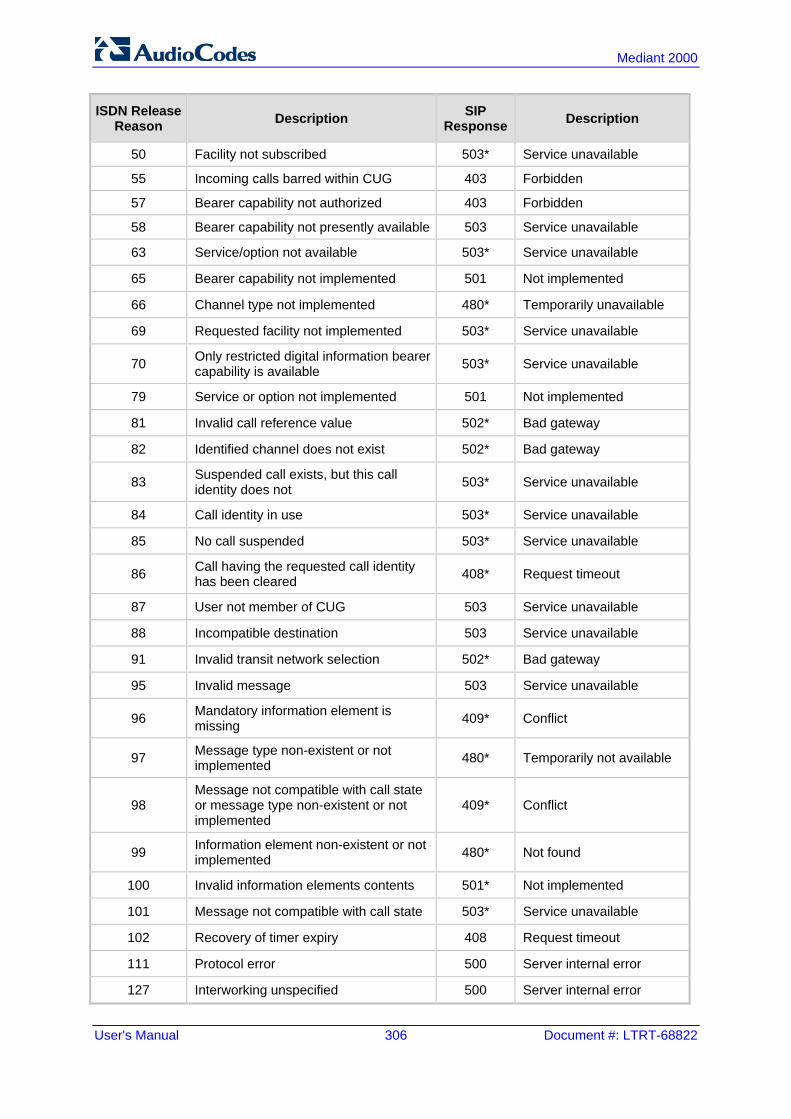
User's Manual 306 Document #: LTRT-68822
Mediant 2000
ISDN Release Reason Description SIP
Response Description
50 Facility not subscribed 503* Service unavailable
55 Incoming calls barred within CUG 403 Forbidden
57 Bearer capability not authorized 403 Forbidden
58 Bearer capability not presently available 503 Service unavailable
63 Service/option not available 503* Service unavailable
65 Bearer capability not implemented 501 Not implemented
66 Channel type not implemented 480* Temporarily unavailable
69 Requested facility not implemented 503* Service unavailable
70 Only restricted digital information bearer capability is available 503* Service unavailable
79 Service or option not implemented 501 Not implemented
81 Invalid call reference value 502* Bad gateway
82 Identified channel does not exist 502* Bad gateway
83 Suspended call exists, but this call identity does not 503* Service unavailable
84 Call identity in use 503* Service unavailable
85 No call suspended 503* Service unavailable
86 Call having the requested call identity has been cleared 408* Request timeout
87 User not member of CUG 503 Service unavailable
88 Incompatible destination 503 Service unavailable
91 Invalid transit network selection 502* Bad gateway
95 Invalid message 503 Service unavailable
96 Mandatory information element is missing 409* Conflict
97 Message type non-existent or not implemented 480* Temporarily not available
98 Message not compatible with call state or message type non-existent or not implemented
409* Conflict
99 Information element non-existent or not implemented 480* Not found
100 Invalid information elements contents 501* Not implemented
101 Message not compatible with call state 503* Service unavailable
102 Recovery of timer expiry 408 Request timeout
111 Protocol error 500 Server internal error
127 Interworking unspecified 500 Server internal error

Version 6.6 307 Mediant 2000
User's Manual 23. Manipulation
* Messages and responses were created because the ‘ISUP to SIP Mapping’ draft doesn’t specify their cause code mapping.
23.8.3 Reason Header The device supports the SIP Reason header according to RFC 3326. The Reason header conveys information describing the disconnection cause of a call: Sending Reason header: If a call is disconnected from the Tel side (ISDN), the
Reason header is set to the received Q.850 cause in the appropriate message (BYE/CANCEL/final failure response) and sent to the SIP side. If the call is disconnected because of a SIP reason, the Reason header is set to the appropriate SIP response.
Receiving Reason header: If a call is disconnected from the IP side and the SIP message includes the Reason header, it is sent to the Tel side according to the following logic: • If the Reason header includes a Q.850 cause, it is sent as is. • If the Reason header includes a SIP response:
♦ If the message is a final response, the response status code is translated to Q.850 format and passed to ISDN.
♦ If the message isn’t a final response, it is translated to a Q.850 cause. • When the Reason header is received twice (i.e., SIP Reason and Q.850), the
Q.850 takes precedence over the SIP reason and is sent to the Tel side.
23.9 Numbering Plans and Type of Number The IP-to-Tel destination or source number manipulation tables allow you to classify numbers by their Numbering Plan Indication (NPI) and Type of Number (TON). The device supports all NPI/TON classifications used in the ETSI ISDN variant, as shown in the table below:
NPI/TON Values for ETSI ISDN Variant
NPI TON Description
Unknown [0] Unknown [0] A valid classification, but one that has no information about the numbering plan.
E.164 Public [1]
Unknown [0] A public number in E.164 format, but no information on what kind of E.164 number.
International [1] A public number in complete international E.164 format, e.g., 16135551234.
National [2] A public number in complete national E.164 format, e.g., 6135551234.
Network Specific [3] The type of number "network specific number" is used to indicate administration / service number specific to the serving network, e.g., used to access an operator.
Subscriber [4] A public number in complete E.164 format representing a local subscriber, e.g., 5551234.
Abbreviated [6] The support of this code is network dependent. The number provided in this information element

User's Manual 308 Document #: LTRT-68822
Mediant 2000
NPI TON Description
presents a shorthand representation of the complete number in the specified numbering plan as supported by the network.
Private [9] Unknown [0] A private number, but with no further information about the numbering plan.
Level 2 Regional [1]
Level 1 Regional [2] A private number with a location, e.g., 3932200.
PISN Specific [3]
Level 0 Regional (local) [4] A private local extension number, e.g., 2200.
For NI-2 and DMS-100 ISDN variants, the valid combinations of TON and NPI for calling and called numbers include (Plan/Type): 0/0 - Unknown/Unknown 1/1 - International number in ISDN/Telephony numbering plan 1/2 - National number in ISDN/Telephony numbering plan 1/4 - Subscriber (local) number in ISDN/Telephony numbering plan 9/4 - Subscriber (local) number in Private numbering plan

Version 6.6 309 Mediant 2000
User's Manual 24. Routing
24 Routing This section describes the configuration of call routing rules.
24.1 Configuring General Routing Parameters The Routing General Parameters page allows you to configure general routing parameters. For a description of these parameters, see 'Configuration Parameters Reference' on page 503.
To configure general routing parameters: 1. Open the Routing General Parameters page (Configuration tab > VoIP menu > GW
and IP to IP submenu > Routing submenu > General Parameters).
Figure 24-1: Routing General Parameters Page
2. Configure the parameters as required. 3. Click Submit to apply your changes.
24.2 Configuring Outbound IP Routing Table The Outbound IP Routing Table page allows you to configure up to 180 Tel-to-IP or outbound IP call routing rules. The device uses these rules to route calls from the Tel or IP to a user-defined IP destination. The Outbound IP Routing Table table provides two configuration areas: Matching Characteristics: Characteristics of the incoming call. If the call
characteristics match a table entry, the routing rule is used to route the call to the specified destination. One or more characteristics can be defined for the rule: • Source IP Group (to which the call belongs) • Source and destination Request-URI host name prefix • Source Trunk Group (from where the call is received) • Source (calling) and destination (called) telephone number prefix and suffix • Source and destination Request-URI host name prefix

User's Manual 310 Document #: LTRT-68822
Mediant 2000
Destination: If the call matches the configured characteristics, the device routes the call to an IP destination. If no characteristics match is found in the table, the call is rejected. The destination can be any of the following: • IP address in dotted-decimal notation. • Fully Qualified Domain Name (FQDN). • E.164 Telephone Number Mapping (ENUM service - NRENum.net or e164.arpa). • Lightweight Directory Access Protocol (LDAP). For a description, see 'Routing
Based on LDAP Active Directory Queries' on page 183. • IP Group, where the call is routed to the IP address configured for the Proxy Set
or SRD associated with the IP Group (configured in 'Configuring IP Groups' on page 204). If the device is configured with multiple SRDs, you can also indicate (in the table's 'Dest. SRD' field) the destination SRD for routing to one of the following destination types - IP address, FQDN, ENUM, or LDAP. If the SRD is not specified, then the default SRD (0) is used. In scenarios where routing is to an IP Group, the destination SRD is obtained from the SRD associated with the IP Group (in the IP Group table). The specified destination SRD determines the: ♦ Destination SIP interface (SIP port and control IP interface) - important when
using multiple SIP control VLANs ♦ Media Realm (port and IP interface for media / RTP voice) ♦ Other SRD-related interfaces and features on which the call is routed
Since each call must have a destination IP Group (even in cases where the destination type is not to an IP Group), in cases when the IP Group is not specified, the SRD's default IP Group is used, which is the first configured IP Group that belongs to the SRD.
Figure 24-2: Locating SRD

Version 6.6 311 Mediant 2000
User's Manual 24. Routing
Notes: When using a proxy server, you do not need to configure this table, unless you require one of the following:
• Fallback (alternative) routing if communication is lost with the proxy server. • IP security, whereby the device routes only received calls whose source IP
addresses are defined in this table. IP security is enabled using the SecureCallsFromIP parameter.
• Filter Calls to IP feature: the device checks this table before a call is routed to the proxy server. However, if the number is not allowed, i.e., the number does not exist in the table or a Call Restriction (see below) routing rule is applied, the call is released.
• Obtain different SIP URI host names (per called number). • Assign IP Profiles to calls. • For this table to take precedence over a proxy for routing calls, you need to set the
parameter PreferRouteTable to 1. The device checks the 'Destination IP Address' field in this table for a match with the outgoing call; a proxy is used only if a match is not found.
In addition to basic outbound IP routing, this table supports the following features: Least Cost Routing (LCR): If the LCR feature is enabled, the device searches the
routing table for matching routing rules and then selects the one with the lowest call cost. The call cost of the routing rule is done by assigning it a Cost Group. For configuring Cost Groups, see 'Least Cost Routing' on page 192. If two routing rules have identical costs, then the rule appearing higher up in the table (i.e., first-matched rule) is used. If a selected route is unavailable, the device uses the next least-cost routing rule. However, even if a matched rule is not assigned a Cost Group, the device can select it as the preferred route over other matched routing rules with Cost Groups, according to the settings of the LCR parameter, LCRDefaultCost (see 'Enabling LCR and Configuring Default LCR' on page 194).
Call Forking: If the Tel-to-IP Call Forking feature is enabled, the device can send a Tel call to multiple IP destinations. An incoming Tel call with multiple matched routing rules (e.g., all with the same source prefix numbers) can be sent (forked) to multiple IP destinations if the rules are defined with a Forking Group in the table. The call is established with the first IP destination that answers the call.
Call Restriction: Rejects calls whose matching routing rule is configured with the destination IP address of 0.0.0.0.
Always Use Routing Table: Even if a proxy server is used, the SIP Request-URI host name in the outgoing INVITE message is obtained from this table. Using this feature, you can assign a different SIP URI host name for different called and/or calling numbers. This feature is enabled using the AlwaysUseRouteTable parameter.
IP Profiles: IP Profiles can be assigned to destination addresses (also when a proxy is used).
Alternative Routing (when a proxy isn't used): An alternative IP destination can be configured for a specific call. To associate an alternative IP address to a called telephone number prefix, assign it with an additional entry with a different IP address, or use an FQDN that resolves into two IP addresses. For more information on alternative routing, see 'Alternative Routing for Tel-to-IP Calls' on page 322.
Notes:
• Outbound IP routing can be performed before or after number manipulation. This is configured using the RouteModeTel2IP parameter, as described below.

User's Manual 312 Document #: LTRT-68822
Mediant 2000
• The Outbound IP Routing Table can also be configured using the table ini file parameter, Prefix.
To configure Tel-to-IP or outbound IP routing rules:
1. Open the Outbound IP Routing Table page (Configuration tab > VoIP menu > GW and IP to IP submenu > Routing > Tel to IP Routing).
Figure 24-3: Outbound IP Routing Page
2. From the 'Routing Index' drop-down list, select the range of entries that you want to
add. 3. Configure the routing rule as required. For a description of the parameters, see the
table below. 4. Click Submit to apply your changes. 5. To save the changes to flash memory, see 'Saving Configuration' on page 396. The table below shows configuration examples of Tel-to-IP or outbound IP routing rules, where: Rule 1 and 2 (Least Cost Routing rule): For both rules, the called (destination)
phone number prefix is 10, the caller's (source) phone number prefix is 100, and the call is assigned IP Profile ID 1. However, Rule 1 is assigned a cheaper Cost Group than Rule 2, and therefore, the call is sent to the destination IP address (10.33.45.63) associated with Rule 1.
Rule 3 (IP Group destination rule): For all callers (*), if the called phone number prefix is 20, the call is sent to IP Group 1 (whose destination is the IP address configured for its associated Proxy Set ID).
Rule 4 (domain name destination rule): If the called phone number prefix is 5, 7, 8, or 9 and the caller belongs to Trunk Group ID 1, the call is sent to domain.com.
Rule 5 (block rule): For all callers (*), if the called phone number prefix is 00, the call is rejected (discarded).
Rule 6, 7, and 8 (Forking Group rule): For all callers (*), if the called phone number prefix is 100, the call is sent to Rule 7 and 9 (belonging to Forking Group "1"). If their destinations are unavailable and alternative routing is enabled, the call is sent to Rule 8 (Forking Group "2").
Rule 9 (IP-to-IP rule): If an incoming IP call from Source IP Group 2 with domain.com as source host prefix in its SIP Request-URI, the IP call is sent to IP address 10.33.45.65.

Version 6.6 313 Mediant 2000
User's Manual 24. Routing
Example of Tel-to-IP Source Phone Number Manipulation Rules
Parameter Rule 1 Rule 2 Rule 3 Rule 4 Rule 5 Rule 6 Rule 7 Rule 8 Rule 9
Src. IP Group ID
- - - - - - - - 2
Src. Trunk Group ID
* 0 1 - - - - - -
Src. Host Prefix
- - - - - - - - domain.com
Src. Trunk Group ID
- - * 1 - * * * -
Dest. Phone Prefix
10 10 20 [5,7-9] 00 100 100 100 *
Source Phone Prefix
100 100 * * * * * * *
Dest. IP Address
10.33.45.63
10.33.45.50
- domain.com
0.0.0.0 10.33.45.68
10.33.45.67
domain.com
10.33.45.65
Dest IP Group ID
- - 1 - - - - - -
IP Profile ID
1 1 - - - - - - -
Cost Group ID
Weekend
Weekend_B
- - - - - - -
Forking Group
- - - 1 2 1 -
Tel-to-IP / Outbound IP Routing Table Parameters
Parameter Description
Matching Call Characteristics
Web/EMS: Tel to IP Routing Mode [RouteModeTel2IP]
Determines whether to route received calls to an IP destination before or after manipulation of the destination number. [0] Route calls before manipulation = Calls are routed before the number
manipulation rules are applied (default). [1] Route calls after manipulation = Calls are routed after the number
manipulation rules are applied. Notes: This parameter is not applicable if outbound proxy routing is used. For number manipulation, see 'Configuring Source/Destination Number
Manipulation' on page 287.
Web: Src. IP Group ID EMS: Source IP Group ID [PREFIX_SrcIPGrou
Defines the IP Group from where the incoming IP call is received. Typically, the IP Group of an incoming INVITE is determined according to the Inbound IP Routing Table. Notes:

User's Manual 314 Document #: LTRT-68822
Mediant 2000
Parameter Description
pID] This parameter is applicable only to the IP-to-IP routing application. To denote all IP Groups, leave this field empty. If this IP Group has a Serving IP Group, then all calls from this IP Group
are sent to the Serving IP Group. In such a scenario, this routing table is used only if the parameter PreferRouteTable is set to 1.
Web: Src. Host Prefix EMS: Source Host Prefix [PREFIX_SrcHostPrefix]
Defines the prefix of the SIP Request-URI host name in the From header of the incoming SIP INVITE message. Notes: To denote any prefix, use the asterisk (*) symbol. This parameter is applicable only to the IP-to-IP routing application.
Web: Dest. Host Prefix EMS: Destination Host Prefix [PREFIX_DestHostPrefix]
Defines the SIP Request-URI host name prefix of the incoming SIP INVITE message. Notes: To denote any prefix, use the asterisk (*) symbol. This parameter is applicable only for IP-to-IP routing application.
Web: Src. Trunk Group ID EMS: Source Trunk Group ID [PREFIX_SrcTrunkGroupID]
Defines the Trunk Group from where the call is received. Notes: To denote any Trunk Group, use the asterisk (*) symbol. This parameter is applicable only to the Gateway application.
Web: Dest. Phone Prefix EMS: Destination Phone Prefix [PREFIX_DestinationPrefix]
Defines the prefix and/or suffix of the called (destination) telephone number. The suffix is enclosed in parenthesis after the suffix value. You can use special notations for denoting the prefix. For example, [100-199](100,101,105) denotes a number that starts with 100 to 199 and ends with 100, 101 or 105. To denote any prefix, use the asterisk (*) symbol or to denote calls without a called number, use the $ sign. For a description of available notations, see 'Dialing Plan Notation for Routing and Manipulation Tables' on page 501. The number can include up to 50 digits. Notes: For LDAP-based routing, enter the LDAP query keyword as the prefix
number to denote the IP domain: "PRIVATE" = Private number "OCS" = Lync / OCS client number "PBX" = PBX / IP PBX number "MOBILE" = Mobile number "LDAP_ERR" = LDAP query failure For more information, see Routing Based on LDAP Active Directory Queries on page 183.
If you want to configure re-routing of ISDN Tel-to-IP calls to fax destinations, you need to enter the value string "FAX" (case-sensitive) as the destination phone prefix. For more information regarding this feature, see the FaxReroutingMode parameter.
Web/EMS: Source Phone Prefix [PREFIX_SourcePrefix]
Defines the prefix and/or suffix of the calling (source) telephone number. You can use special notations for denoting the prefix. For example, [100-199](100,101,105) denotes a number that starts with 100 to 199 and ends with 100, 101 or 105. To denote any prefix, use the asterisk (*) symbol or to denote calls without a calling number, use the $ sign. For a description of available notations, see 'Dialing Plan Notation for Routing and Manipulation

Version 6.6 315 Mediant 2000
User's Manual 24. Routing
Parameter Description
Tables' on page 501. The number can include up to 50 digits.
Operation (IP Destination)
Web: Dest. IP Address EMS: Address [PREFIX_DestAddress]
Defines the IP address (in dotted-decimal notation or FQDN) to where the call is sent. If an FQDN is used (e.g., domain.com), DNS resolution is done according to the DNSQueryType parameter. For ENUM-based routing, enter the string value "ENUM". The device sends an ENUM query containing the destination phone number to an external DNS server, configured in the Multiple Interface table. The ENUM reply includes a SIP URI which is used as the Request-URI in the subsequent outgoing INVITE and for routing (if a proxy is not used). To configure the type of ENUM service (e.g., e164.arpa), use the EnumService parameter. For LDAP-based routing, enter the string value "LDAP" for denoting the IP address of the LDAP server. For more information, see Routing Based on LDAP Active Directory Queries on page 183. Notes: This field and any value assigned to it is ignored if you have configured a
destination IP Group for this routing rule (in the 'Dest IP Group ID' field). To reject calls, enter the IP address 0.0.0.0. For example, if you want to
prohibit international calls, then in the 'Dest Phone Prefix' field, enter 00 and in the 'Dest IP Address' field, enter 0.0.0.0.
For routing calls between phones connected to the device (i.e., local routing), enter the device's IP address.
When the device's IP address is unknown (e.g., when DHCP is used), enter IP address 127.0.0.1.
When using domain names, enter the DNS server's IP address or alternatively, configure these names in the Internal DNS table (see 'Configuring the Internal DNS Table' on page 120).
The IP address can include the following wildcards: "x": represents single digits. For example, 10.8.8.xx denotes all
addresses between 10.8.8.10 and 10.8.8.99. "*": represents any number between 0 and 255. For example,
10.8.8.* denotes all addresses between 10.8.8.0 and 10.8.8.255. Web: Port EMS: Destination Port [PREFIX_DestPort]
Defines the destination port to where you want to route the call.
Web/EMS: Transport Type [PREFIX_TransportType]
Defines the transport layer type for sending the IP call: [-1] Not Configured [0] UDP [1] TCP [2] TLS Note: When set to Not Configured (-1), the transport type defined by the SIPTransportType parameter is used.
Web: Dest IP Group ID EMS: Destination IP Group ID [PREFIX_DestIPGroupID]
Defines the IP Group to where you want to route the call. The SIP INVITE message is sent to the IP address defined for the Proxy Set ID associated with the IP Group. Notes: If you select an IP Group, you do not need to configure a destination IP
address. However, if both parameters are configured in this table, the

User's Manual 316 Document #: LTRT-68822
Mediant 2000
Parameter Description
INVITE message is sent only to the IP Group (and not the defined IP address).
If the destination is a User-type IP Group, the device searches for a match between the Request-URI (of the received INVITE) to an AOR registration record in the device's database. The INVITE is then sent to the IP address of the registered contact.
If the parameter AlwaysUseRouteTable is set to 1 (see 'Configuring IP Groups' on page 204), then the Request-URI host name in the INVITE message is set to the value defined for the parameter 'Dest. IP Address' (above); otherwise, if no IP address is defined, it is set to the value of the parameter 'SIP Group Name' (defined in the IP Group table).
This parameter is used as the 'Serving IP Group' in the Account table for acquiring authentication user/password for this call (see 'Configuring Account Table' on page 215).
For defining Proxy Set ID's, see 'Configuring Proxy Sets Table' on page 209.
Dest SRD [PREFIX_DestSRD]
Defines the SRD to where you want to route the call. The actual destination is defined by the Proxy Set associated with the SRD. This allows you to route the call to a specific SIP Media Realm and SIP Interface. To configure SRD's, see Configuring SRD Table on page 201.
IP Profile ID [PREFIX_ProfileId]
Assigns an IP Profile ID to this IP destination call. This allows you to assign numerous configuration attributes (e.g., voice codes) per routing rule. To configure IP Profiles, see 'Configuring IP Profiles' on page 235.
Status Displays the connectivity status of the routing rule's IP destination. If there is connectivity with the destination, this field displays "OK" and the device uses this routing rule if required. The routing rule is not used if any of the following is displayed: "n/a" = The destination IP Group is unavailable "No Connectivity" = No connection with the destination (no response to
the ping or SIP OPTIONS). "QoS Low" = Poor Quality of Service (QoS) of the destination. "DNS Error" = No DNS resolution. This status is applicable only when a
domain name is used (instead of an IP address). "Unavailable" = The destination is unreachable due to networking issues.
Cost Group ID [PREFIX_CostGroup]
Assigns a Cost Group with the routing rule for determining the cost of the call. To configure Cost Groups, see 'Configuring Cost Groups' on page 196.
Forking Group [PREFIX_ForkingGroup]
Defines a forking group ID for the routing rule. This enables forking of incoming Tel calls to two or more IP destinations. The device sends simultaneous INVITE messages and handles multiple SIP dialogs until one of the calls is answered. When a call is answered, the other calls are dropped. If all matched routing rules belong to the same Forking Group number, the device sends an INVITE to all the destinations belonging to this group and according to the following logic: If matched routing rules belong to different Forking Groups, the device
sends the call to the Forking Group of the first matched routing rule. If the call cannot be established with any of the destinations associated with this Forking Group and alternative routing is enabled, the device forks the call to the Forking Group of the next matched routing rules as long as the Forking Group is defined with a higher number than the previous Forking Group. For example:

Version 6.6 317 Mediant 2000
User's Manual 24. Routing
Parameter Description
Table index entries 1 and 2 are defined with Forking Group "1", and index entries 3 and 4 with Forking Group "2": The device first sends the call according to index entries 1 and 2, and if unavailable and alternative routing is enabled, sends the call according to index entries 3 and 4.
Table index entry 1 is defined with Forking Group "2", and index entries 2, 3, and 4 with Forking Group "1": The device sends the call according to index entry 1 only and ignores the other index entries even if the destination is unavailable and alternative routing is enabled. This is because the subsequent index entries are defined with a Forking Group number that is lower than that of index entry 1.
Table index entry 1 is defined with Forking Group "1", index entry 2 with Forking Group "2", and index entries 3 and 4 with Forking Group "1": The device first sends the call according to index entries 1, 3, and 4 (all belonging to Forking Group "1"), and if the destination is unavailable and alternative routing is enabled, the device sends the call according to index entry 2.
Table index entry 1 is defined with Forking Group "1", index entry 2 with Forking Group "3", index entry 3 with Forking Group "2", and index entry 4 with Forking Group "1": The device first sends the call according to index entries 1 and 4 (all belonging to Forking Group "1"), and if the destination is unavailable and alternative routing is enabled, the device sends the call according to index entry 2 (Forking Group "3"). Even if index entry 2 is unavailable and alternative routing is enabled, the device ignores index entry 3 because it belongs to a Forking Group that is lower than index entry 2.
Notes: To enable Tel-to-IP call forking, you must set the 'Tel2IP Call Forking
Mode' (Tel2IPCallForkingMode) parameter to Enable. You can implement Forking Groups when the destination is an LDAP
server or a domain name using DNS. In such scenarios, the INVITE is sent to all the queried LDAP or resolved IP addresses respectively. You can also use LDAP routing rules with standard routing rules for Forking Groups.
24.3 Configuring Inbound IP Routing Table The Inbound IP Routing Table page allows you to configure up to 24 inbound call routing rules: For IP-to-IP routing: The table is used to identify an incoming call as an IP-to-IP call
and subsequently, to assign the call to an IP Group, referred to as a source IP Group. These IP-to-IP calls can later be routed to an outbound destination IP Group (see Configuring Outbound IP Routing Table on page 309).
For IP-to-Tel routing: This table is used to route incoming IP calls to Trunk Groups. The specific channel pertaining to the Trunk Group to which the call is routed is determined according to the Trunk Group's channel selection mode. The channel selection mode can be defined per Trunk Group (see 'Configuring Trunk Group Settings' on page 281) or for all Trunk Groups using the global parameter ChannelSelectMode.
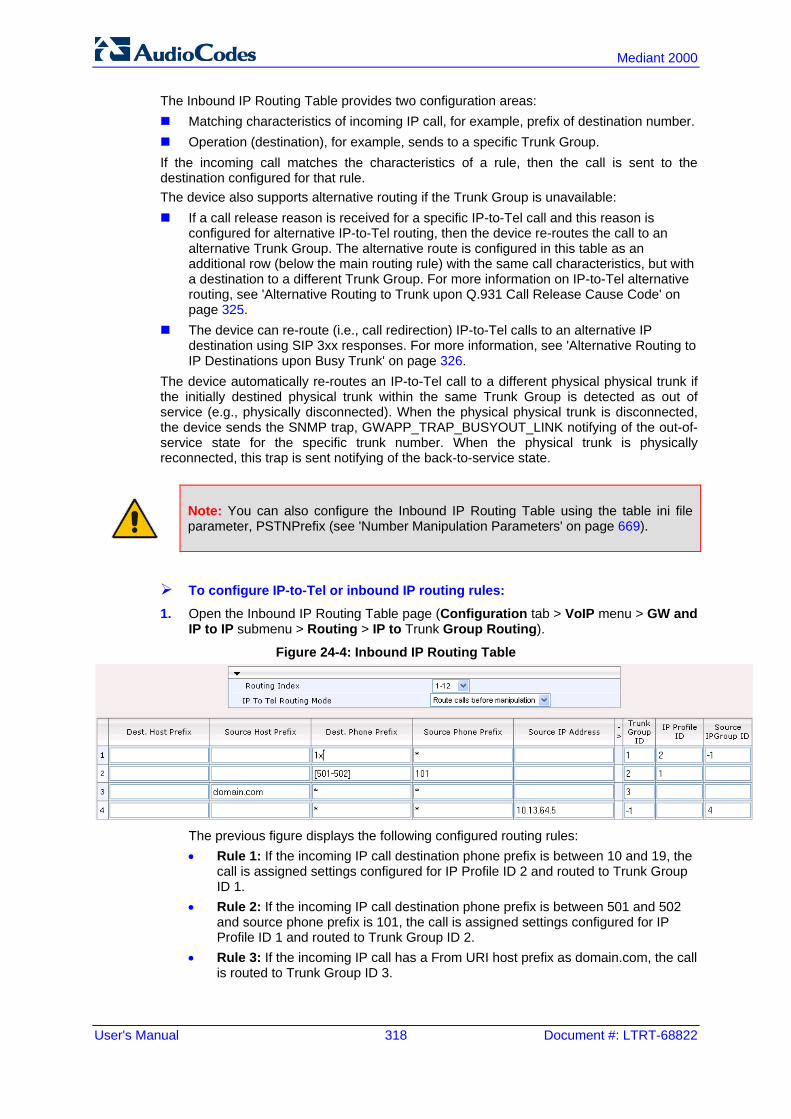
User's Manual 318 Document #: LTRT-68822
Mediant 2000
The Inbound IP Routing Table provides two configuration areas: Matching characteristics of incoming IP call, for example, prefix of destination number. Operation (destination), for example, sends to a specific Trunk Group. If the incoming call matches the characteristics of a rule, then the call is sent to the destination configured for that rule. The device also supports alternative routing if the Trunk Group is unavailable: If a call release reason is received for a specific IP-to-Tel call and this reason is
configured for alternative IP-to-Tel routing, then the device re-routes the call to an alternative Trunk Group. The alternative route is configured in this table as an additional row (below the main routing rule) with the same call characteristics, but with a destination to a different Trunk Group. For more information on IP-to-Tel alternative routing, see 'Alternative Routing to Trunk upon Q.931 Call Release Cause Code' on page 325.
The device can re-route (i.e., call redirection) IP-to-Tel calls to an alternative IP destination using SIP 3xx responses. For more information, see 'Alternative Routing to IP Destinations upon Busy Trunk' on page 326.
The device automatically re-routes an IP-to-Tel call to a different physical physical trunk if the initially destined physical trunk within the same Trunk Group is detected as out of service (e.g., physically disconnected). When the physical physical trunk is disconnected, the device sends the SNMP trap, GWAPP_TRAP_BUSYOUT_LINK notifying of the out-of-service state for the specific trunk number. When the physical trunk is physically reconnected, this trap is sent notifying of the back-to-service state.
Note: You can also configure the Inbound IP Routing Table using the table ini file parameter, PSTNPrefix (see 'Number Manipulation Parameters' on page 669).
To configure IP-to-Tel or inbound IP routing rules:
1. Open the Inbound IP Routing Table page (Configuration tab > VoIP menu > GW and IP to IP submenu > Routing > IP to Trunk Group Routing).
Figure 24-4: Inbound IP Routing Table
The previous figure displays the following configured routing rules: • Rule 1: If the incoming IP call destination phone prefix is between 10 and 19, the
call is assigned settings configured for IP Profile ID 2 and routed to Trunk Group ID 1.
• Rule 2: If the incoming IP call destination phone prefix is between 501 and 502 and source phone prefix is 101, the call is assigned settings configured for IP Profile ID 1 and routed to Trunk Group ID 2.
• Rule 3: If the incoming IP call has a From URI host prefix as domain.com, the call is routed to Trunk Group ID 3.
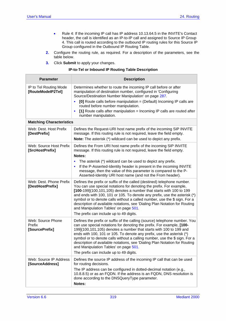
Version 6.6 319 Mediant 2000
User's Manual 24. Routing
• Rule 4: If the incoming IP call has IP address 10.13.64.5 in the INVITE's Contact header, the call is identified as an IP-to-IP call and assigned to Source IP Group 4. This call is routed according to the outbound IP routing rules for this Source IP Group configured in the Outbound IP Routing Table.
2. Configure the routing rule, as required. For a description of the parameters, see the table below.
3. Click Submit to apply your changes.
IP-to-Tel or Inbound IP Routing Table Description
Parameter Description
IP to Tel Routing Mode [RouteModeIP2Tel]
Determines whether to route the incoming IP call before or after manipulation of destination number, configured in 'Configuring Source/Destination Number Manipulation' on page 287. [0] Route calls before manipulation = (Default) Incoming IP calls are
routed before number manipulation. [1] Route calls after manipulation = Incoming IP calls are routed after
number manipulation.
Matching Characteristics
Web: Dest. Host Prefix [DestPrefix]
Defines the Request-URI host name prefix of the incoming SIP INVITE message. If this routing rule is not required, leave the field empty. Note: The asterisk (*) wildcard can be used to depict any prefix.
Web: Source Host Prefix [SrcHostPrefix]
Defines the From URI host name prefix of the incoming SIP INVITE message. If this routing rule is not required, leave the field empty. Notes: The asterisk (*) wildcard can be used to depict any prefix. If the P-Asserted-Identity header is present in the incoming INVITE
message, then the value of this parameter is compared to the P-Asserted-Identity URI host name (and not the From header).
Web: Dest. Phone Prefix [DestHostPrefix]
Defines the prefix or suffix of the called (destined) telephone number. You can use special notations for denoting the prefix. For example, [100-199](100,101,105) denotes a number that starts with 100 to 199 and ends with 100, 101 or 105. To denote any prefix, use the asterisk (*) symbol or to denote calls without a called number, use the $ sign. For a description of available notations, see 'Dialing Plan Notation for Routing and Manipulation Tables' on page 501. The prefix can include up to 49 digits.
Web: Source Phone Prefix [SourcePrefix]
Defines the prefix or suffix of the calling (source) telephone number. You can use special notations for denoting the prefix. For example, [100-199](100,101,105) denotes a number that starts with 100 to 199 and ends with 100, 101 or 105. To denote any prefix, use the asterisk (*) symbol or to denote calls without a calling number, use the $ sign. For a description of available notations, see 'Dialing Plan Notation for Routing and Manipulation Tables' on page 501. The prefix can include up to 49 digits.
Web: Source IP Address [SourceAddress]
Defines the source IP address of the incoming IP call that can be used for routing decisions. The IP address can be configured in dotted-decimal notation (e.g., 10.8.8.5) or as an FQDN. If the address is an FQDN, DNS resolution is done according to the DNSQueryType parameter. Notes:

User's Manual 320 Document #: LTRT-68822
Mediant 2000
Parameter Description
The source IP address is obtained from the Contact header in the INVITE message.
You can configure from where the source IP address is obtained, using the SourceIPAddressInput parameter.
The source IP address can include the following wildcards: "x": denotes single digits. For example, 10.8.8.xx represents all
the addresses between 10.8.8.10 and 10.8.8.99. "*": denotes any number between 0 and 255. For example,
10.8.8.* represents all addresses between 10.8.8.0 and 10.8.8.255.
Source SRD ID [SrcSRDID]
Defines the SRD from which the incoming packet is received. Notes: When the incoming INVITE matches the SRD in the routing rule, if
the 'Source IP Group ID' parameter (see below) is defined and it is associated with a different SRD, the incoming SIP call is rejected. If the 'Source IP Group ID' parameter is not defined, the SRD's default IP Group is used. If there is no valid source IP Group, the call is rejected.
Currently, this parameter can only be configured using the ini file.
Operation (Destination)
Web: Trunk Group ID [TrunkGroupId]
For IP-to-Tel calls: Defines the Trunk Group to where the incoming SIP call is sent. For IP-to-IP calls: Identifies the call as an IP-to-IP call if this parameter is set to -1.
Web: Trunk ID [TrunkId]
Defines the Trunk to where the incoming SIP call is sent. Notes: If both 'Trunk Group ID' and 'Trunk ID' parameters are configured in
the table, the routing is done according to the 'Trunk Group ID' parameter.
The method for selecting the trunk's channel to which the IP call is sent is configured by the global parameter, ChannelSelectMode.
Currently, this field can only be configured using the ini file.
Web: IP Profile ID [ProfileId]
Assigns an IP Profile (configured in 'Configuring IP Profiles' on page 235) to the call.
Web: Source IP Group ID [SrcIPGroupID]
For IP-to-Tel calls: Defines the IP Group associated with the incoming IP call. This is the IP Group that sent the INVITE message. This IP Group can later be used as the 'Serving IP Group' in the Account table for obtaining authentication user name/password for this call (see 'Configuring Account Table' on page 215). For IP-to-IP calls: Assigns the IP Group to the incoming IP call. This IP Group can later be used for outbound IP routing and as the 'Serving IP Group' in the Account table for obtaining authentication user name/password for this call (see Configuring Account Table on page 215).
24.4 IP Destinations Connectivity Feature The device can be configured to check the integrity of the connectivity to IP destinations of Tel-to-IP routing rules in the Outbound IP Routing table. The IP Connectivity feature can be used for the Alternative Routing feature, whereby the device attempts to re-route calls from

Version 6.6 321 Mediant 2000
User's Manual 24. Routing
unavailable Tel-to-IP routing destinations to available ones (see 'Alternative Routing Based on IP Connectivity' on page 322). The device supports the following methods for checking the connectivity of IP destinations: Network Connectivity: The device checks the network connectivity of the IP
destination using one of the following methods configured by the 'Alt Routing Tel to IP Connectivity Method' parameter: • Ping: The device periodically (every seven seconds) pings the IP destination. • SIP OPTIONS: The device sends "keep-alive" SIP OPTIONS messages to the IP
destination. If the device receives a SIP 200 OK in response, it considers the destination as available. If the destination does not respond to the OPTIONS message, then it is considered unavailable. You can configure the time interval for sending these OPTIONS messages, using the 'Alt Routing Tel to IP Keep Alive Time' parameter.
These parameters are configured in the Routing General Parameters page (Configuration tab > VoIP menu > GW and IP to IP > Routing > General Parameters), as shown below:
Figure 24-5: IP Connectivity Method in Routing General Parameters Page
Quality of Service (QoS): You can enable the device to check the QoS of IP
destinations. The device measures the QoS according to RTCP statistics of previously established calls with the IP destination. The RTCP includes packet delay (in milliseconds) and packet loss (in percentage). If these measured statistics exceed a user-defined threshold, the destination is considered unavailable. Note that if call statistics is not received within two minutes, the QoS data is reset. These thresholds are configured using the following parameters: • 'Max Allowed Packet Loss for Alt Routing' (IPConnQoSMaxAllowedPL): defines
the threshold value for packet loss after which the IP destination is considered unavailable.
• 'Max Allowed Delay for Alt Routing' (IPConnQoSMaxAllowedDelay): defines the threshold value for packet delay after which the IP destination is considered unavailable
These parameters are configured in the Routing General Parameters page, as shown below:
Figure 24-6: IP QoS Thresholds in Routing General Parameters Page
DNS Resolution: When a host name (FQDN) is used (instead of an IP address) for
the IP destination, it is resolved into an IP address by a DNS server. The device checks network connectivity and QoS of the resolved IP address. If the DNS host name is unresolved, the device considers the connectivity of the IP destination as unavailable.
You can view the connectivity status of IP destinations in the following Web interface pages: Outbound IP Routing Table: The connectivity status of the IP destination per routing
rule is displayed in the 'Status' column. For more information, see 'Configuring Outbound IP Routing Table' on page 309.
IP Connectivity: This page displays a more informative connectivity status of the IP destinations used in Tel-to-IP routing rules in the Outbound IP Routing table. For viewing this page, see 'Viewing IP Connectivity' on page 454.

User's Manual 322 Document #: LTRT-68822
Mediant 2000
24.5 Alternative Routing for Tel-to-IP Calls The device supports various alternative Tel-to-IP call routing methods, as described in this section.
24.5.1 Alternative Routing Based on IP Connectivity You can configure the device to do alternative Tel-to-IP call routing based on IP connectivity. When the connectivity state of an IP destination is unavailable, the device attempts to re-route the Tel-to-IP call to an alternative IP destination. It does this by searching for the next call matching rule (e.g., phone number prefix) in the Outbound IP Routing table.
Notes:
• Alternative routing based on IP connectivity is applicable only when a proxy server is not used.
• As the device searches the Outbound IP Routing table for a matching rule starting from the top, you must configure the main routing rule above the alternative routing rules.
• You can configure up to two alternative routing rules. • For configuring Tel-to-IP routing rules in the Outbound IP Routing table, see
'Configuring Outbound IP Routing Table' on page 309.
The device searches for an alternative IP destination when any of the following connectivity states are detected with the IP destination of the initial Tel-to-IP routing rule: No response received from a ping or from SIP OPTIONS messages. This depends on
the chosen method for checking IP connectivity. Poor QoS according to the configured thresholds for packet loss and delay. Unresolved DNS, if the configured IP destination is a domain name (or FQDN). If the
domain name is resolved into two IP addresses, the timeout for INVITE re-transmissions can be configured using the HotSwapRtx parameter. For example, if you set this parameter to 3, the device attempts up to three times to route the call to the first IP address and if unsuccessful, it attempts up to three times to re-route it to the second resolved IP address.
The connectivity status of the IP destination is displayed in the 'Status' column of the Outbound IP Routing table per routing rule. If it displays a status other than "ok", then the device considers the IP destination as unavailable and attempts to re-route the call to an alternative destination. For more information on the IP connectivity methods and on viewing IP connectivity status, see 'IP Destinations Connectivity Feature' on page 320. The table below shows an example of alternative routing where the device uses an available alternative routing rule in the Outbound IP Routing table to re-route the initial Tel-to-IP call.
Alternative Routing based on IP Connectivity Example
Destination Phone Prefix IP Destination IP Connectivity
Status Rule Used?
Main Route 40 10.33.45.68 "No Connectivity" No
Alternative Route #1 40 10.33.45.70 "QoS Low" No
Alternative Route #2 40 10.33.45.72 "ok" Yes

Version 6.6 323 Mediant 2000
User's Manual 24. Routing
The steps for configuring alternative Tel-to-IP routing based on IP connectivity are summarized below.
To configure alternative Tel-to-IP routing based on IP connectivity:
1. In the Outbound IP Routing table, add alternative Tel-to-IP routing rules for specific calls.
2. In the Routing General Parameters page (Configuration tab > VoIP menu > GW and IP to IP > Routing > General Parameters), do the following: a. Enable alternative routing based on IP connectivity, by setting the 'Enable Alt
Routing Tel to IP AltRouting' (Tel2IPEnable) parameter to Enable. b. Configure the IP connectivity reason for triggering alternative routing, by setting
the 'Alt Routing Tel to IP Mode' parameter (AltRoutingTel2IPMode) to one of the following: ♦ Ping or SIP OPTIONS failure ♦ Poor QoS ♦ Ping or SIP OPTIONS failure, poor QoS, or unresolved DNS
24.5.2 Alternative Routing Based on SIP Responses You can configure the device to do alternative routing based on the received SIP response. If the SIP response code reflects an error (i.e., 4xx, 5xx, or 6xx) and you have configured this specific response code as a trigger for alternative routing, then the device attempts to re-route the call to an alternative destination. You can configure up to five SIP response codes for triggering alternative routing. This is done in the Reasons for Alternative Routing table, explained in this section. Typically, the device performs alternative routing when there is no response at all to an INVITE message after a user-defined number of INVITE re-transmissions, configured using the SIPMaxRtx parameter. In such a scenario, the device issues itself the SIP response code 408 "Request Timeout". If this release code is defined in the Reasons for Alternative Routing table, then alternative routing is done. Depending on configuration, the alternative routing is done using one of the following configuration entities: Outbound IP Routing Rules: You can configure up to two alternative routing rules in
the table. If the initial, main routing rule destination is unavailable, the device searches the table (starting from the top) for the next call matching rule (e.g., destination phone number), and if available attempts to re-route the call to the IP destination configured for this alternative routing rule. The table below shows an example of alternative routing where the device uses the first available alternative routing rule to re-route the initial, unsuccessful Tel-to-IP call destination.
Alternative Routing based on SIP Response Code Example
Destination Phone Prefix IP Destination SIP Response Rule Used?
Main Route 40 10.33.45.68 408 Request Timeout
No
Alternative Route #1 40 10.33.45.70 486 Busy Here No
Alternative Route #2 40 10.33.45.72 200 OK Yes

User's Manual 324 Document #: LTRT-68822
Mediant 2000
Proxy Sets: Proxy Sets are used for Server-type IP Groups (e.g., an IP PBX) and define the actual IP destination (IP address or FQDN) of the server. As you can define up to five IP destinations per Proxy Set, the device supports proxy redundancy, which works together with the alternative routing feature. If the destination of a routing rule in the Outbound IP Routing table is an IP Group, the device routes the call to the IP destination configured for the Proxy Set associated with the IP Group. If the first IP destination of the Proxy Set is unavailable, the device attempts to re-route the call to the next proxy destination, and so on until an available IP destination is located. To enable the Proxy Redundancy feature, set the IsProxyHotSwap parameter to 1 (per Proxy Set) and set the EnableProxyKeepAlive to 1. When the Proxy Redundancy feature is enabled, the device continually monitors the connection with the proxies by using keep-alive messages (SIP OPTIONS). The device sends these messages every user-defined interval (ProxyKeepAliveTime parameter). Any response from the proxy, either success (200 OK) or failure (4xx response) is considered as if the proxy is communicating. If there is no response from the first (primary) proxy after a user-defined number of re-transmissions (re-INVITEs) configured using the HotSwapRtx parameter, the device attempts to communicate (using the same INVITE) with the next configured (redundant) proxy in the list, and so on until an available redundant proxy is located. The device’s behavior can then be one of the following, depending on the ProxyRedundancyMode parameter setting: • The device continues operating with the redundant proxy (now active) until the
next failure occurs, after which it switches to the next redundant proxy. This is referred to as Parking mode.
• The device always attempts to operate with the primary proxy. In other words, it switches back to the primary proxy whenever it's available again. This is referred to as Homing mode.
If none of the proxy servers respond, the device goes over the list again. The steps for configuring alternative Tel-to-IP routing based on SIP response codes are summarized below.
To configure alternative Tel-to-IP routing based on SIP response codes: 1. Enable alternative routing based on SIP responses, by setting the 'Redundant Routing
Mode' parameter to one of the following: • Routing Table for using the Outbound IP Routing table for alternative routing. • Proxy for using the Proxy Set redundancy feature for alternative routing.
2. If you are using the Outbound IP Routing table, configure alternative routing rules with identical call matching characteristics, but with different IP destinations. If you are using the Proxy Set, configure redundant proxies.
3. Define SIP response codes (call failure reasons) that invoke alternative Tel-to-IP routing: a. Open the Reasons for Alternative Routing page (Configuration tab > VoIP menu
> GW and IP to IP submenu > Routing submenu > Alternative Routing Reasons).
Figure 24-7: Tel to IP Reasons - Reasons for Alternative Routing Page
b. Under the 'Tel to IP Reasons' group, select up to five different SIP response
codes (call failure reasons) that invoke alternative Tel-to-IP routing. c. Click Submit.

Version 6.6 325 Mediant 2000
User's Manual 24. Routing
24.5.3 PSTN Fallback The PSTN Fallback feature enables the device to re-route a Tel-to-IP call to the legacy PSTN using one of its trunks if the IP destination is unavailable. For example, if poor voice quality is detected over the IP network, the device attempts to re-route the call to the PSTN. The steps for configuring alternative Tel-to-IP routing to the legacy PSTN are summarized below.
To configure alternative Tel-to-IP routing to the legacy PSTN: 1. Configure an alternative routing rule in the Outbound IP Routing table with the same
call matching characteristics (e.g., phone number destination), but where the destination is the IP address of the device itself.
2. Configure an IP-to-Tel routing rule in the Inbound IP Routing table to route calls received from the device (i.e., its IP address) to a specific Trunk Group connected to the PSTN. This configuration is necessary as the re-routed call is now considered an IP-to-Tel call. For configuring IP-to-Tel routing rules, see 'Configuring the Inbound IP Routing Table' on page 317.
24.6 Alternative Routing for IP-to-Tel Calls The device supports alternative IP-to-Tel call routing, as described in this section.
24.6.1 Alternative Routing to Trunk upon Q.931 Call Release Cause Code You can configure the device to do alternative IP-to-Tel call routing based on the received ISDN Q.931 cause code. If an IP-to-Tel call is rejected or disconnected on the Tel side as a result of a specific ISDN Q.931 release cause code that is listed in the Reasons for Alternative Routing table, the device searches for an alternative IP-to-Tel routing rule in the Inbound IP Routing table and sends it to the alternative Trunk Group. For example, you can enable alternative IP-to-Tel routing for scenarios where the initial Tel destination is busy and a Q.931 Cause Code No. 17 is received (or for other call releases that issue the default Cause Code No. 3). You can also configure a default release cause code that the device issues itself upon the following scenarios: The device initiates a call release whose cause is unknown. No free channels (i.e., busy) in the Trunk Group. No appropriate routing rule located in the Inbound IP Routing table to the Trunk
Group. Phone number is not found in the Inbound IP Routing table. By default, it is set to Cause Code No. 3 (No Route to Destination). This default cause code can be changed using the 'Default Release Cause' parameter located in the Advanced Parameters page (Configuration tab > VoIP menu > SIP Definitions > Advanced Parameters). To enable alternative routing based on Q.931 cause code, you need to define this cause code in the Reasons for Alternative Routing table.

User's Manual 326 Document #: LTRT-68822
Mediant 2000
To configure alternative Trunk Group routing based on Q.931 cause codes:
1. In the Proxy & Registration page, set the 'Redundant Routing Mode' parameter to Routing Table so that the device uses the Inbound IP Routing table for alternative routing.
2. In the Inbound IP Routing table, configure alternative routing rules with the same call matching characteristics, but with different Trunk Group destinations.
3. Configure up to five Q.931 cause codes that invoke alternative IP-to-Tel routing: a. Open the Reasons for Alternative Routing page (Configuration tab > VoIP menu
> GW and IP to IP > Routing > Alternative Routing Reasons).
Figure 24-8: IP to Tel Reasons - Reasons for Alternative Routing Page
b. Under the 'IP to Tel Reasons' group, select the desired Q.931 cause codes. c. Click Submit to apply your changes.
Notes:
• You can configure up to two alternative routing rules in the Inbound IP Routing table.
• If a Trunk is disconnected or not synchronized, the device issues itself the internal Cause Code No. 27. This cause code is mapped (by default) to SIP 502.
• The default release cause is described in the Q.931 notation and is translated to corresponding SIP 40x or 50x values (e.g., Cause Code No. 3 to SIP 404, and Cause Code No. 34 to SIP 503).
• For mapping SIP-to-Q.931 and Q.931-to-SIP release causes, see Configuring Release Cause Mapping on page 302.
• For configuring IP-to-Tel routing rules in the Inbound IP Routing table, see 'Configuring Inbound IP Routing Table' on page 317.
• The Reasons for Alternative Routing IP to Tel table can also be configured using the table ini file parameter, AltRouteCauseIP2Tel.
24.6.2 Alternative Routing to an IP Destination upon a Busy Trunk You can configure the device to forward (i.e., call redirection) IP-to-Tel calls to an alternative IP destination using SIP 3xx responses. This can be done upon the following scenario: Trunk Group has no free channels (i.e., “busy”). This feature is configured per Trunk Group and is configured in the Forward on Busy Trunk Destination table, as described in this section. The alternative destination can be defined as a host name or as a SIP Request-URI user name and host part (i.e., user@host). For example, the below configuration forwards IP-to-Tel calls to destination user “112” at host IP address 10.13.4.12, port 5060, using transport protocol TCP, if Trunk Group ID 2 is unavailable: ForwardOnBusyTrunkDest 1 = 2, [email protected]:5060;transport=tcp;

Version 6.6 327 Mediant 2000
User's Manual 24. Routing
When configured with user@host, the original destination number is replaced by the user part. The device forwards calls using this table only if no alternative IP-to-Tel routing rule has been configured in the Inbound IP Routing table or alternative routing fails and one of the following reasons in the SIP Diversion header of 3xx messages exists: “out-of-service” - all trunks are unavailable/disconnected "unavailable": All trunks are busy or unavailable
Note: You can also configure the Forward on Busy Trunk Destination table using the table ini file parameter, ForwardOnBusyTrunkDest.
To configure Forward on Busy Trunk Destination rules: 1. Open the Forward on Busy Trunk Destination page (Configuration tab > VoIP menu
> GW and IP to IP > Routing > Forward on Busy Trunk).
Figure 24-9: Forward on Busy Trunk Destination Page
The figure above displays a configuration that forwards IP-to-Tel calls destined for Trunk Group ID 1 to destination IP address 10.13.5.67 if the conditions mentioned earlier exist.
2. Configure the table as required, and then click Submit to apply your changes. 3. Save the changes to the device's flash memory with a device reset (see 'Saving
Configuration' on page 396).
Forward on Busy Trunk Destination Description Parameters
Parameter Description
Trunk Group ID [ForwardOnBusyTrunkDest_TrunkGroupId]
Defines the Trunk Group ID to which the IP call is destined to.
Forward Destination [ForwardOnBusyTrunkDest_ForwardDestination]
Defines the alternative IP destination for the call used if the Trunk Group is busy or unavailable. The valid value can be an IP address in dotted-decimal notation, an FQDN, or a SIP Request-URI user name and host part (i.e., user@host). The following syntax can also be used: host:port;transport=xxx (i.e., IP address, port and transport type). Note: When configured with a user@host, the original destination number is replaced by the user part.

User's Manual 328 Document #: LTRT-68822
Mediant 2000
Reader's Notes
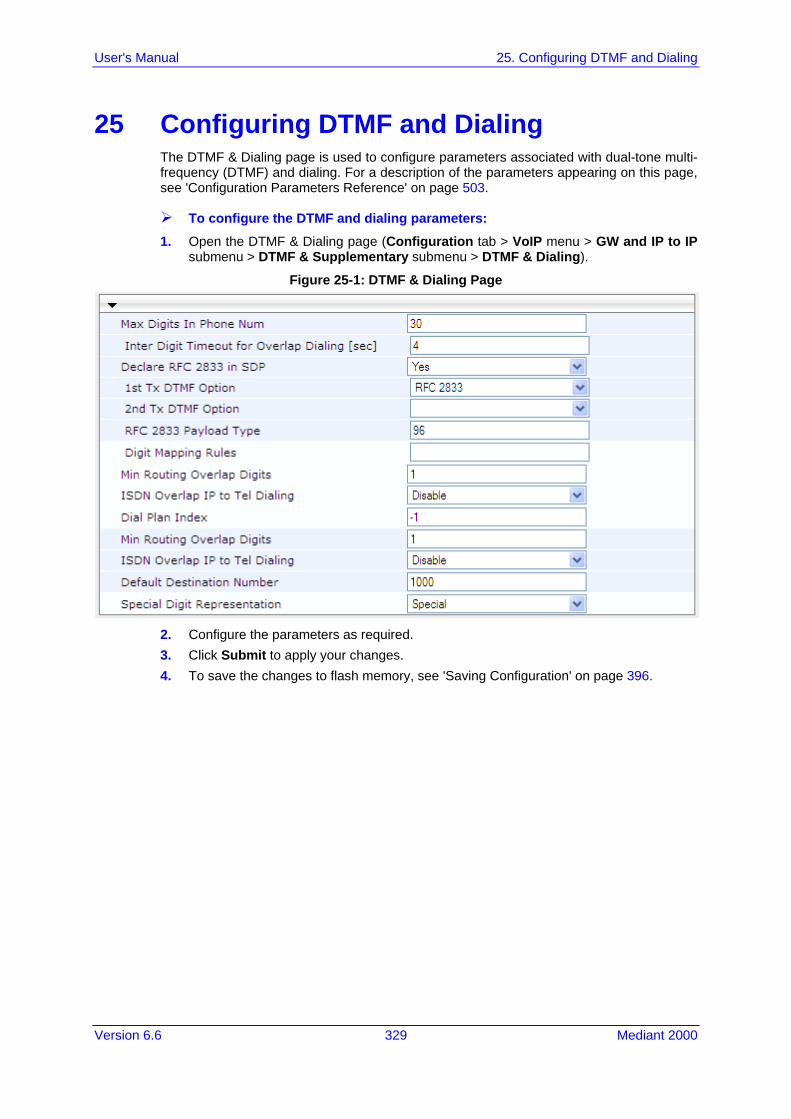
Version 6.6 329 Mediant 2000
User's Manual 25. Configuring DTMF and Dialing
25 Configuring DTMF and Dialing The DTMF & Dialing page is used to configure parameters associated with dual-tone multi-frequency (DTMF) and dialing. For a description of the parameters appearing on this page, see 'Configuration Parameters Reference' on page 503.
To configure the DTMF and dialing parameters: 1. Open the DTMF & Dialing page (Configuration tab > VoIP menu > GW and IP to IP
submenu > DTMF & Supplementary submenu > DTMF & Dialing).
Figure 25-1: DTMF & Dialing Page
2. Configure the parameters as required. 3. Click Submit to apply your changes. 4. To save the changes to flash memory, see 'Saving Configuration' on page 396.

User's Manual 330 Document #: LTRT-68822
Mediant 2000
25.1 Dialing Plan Features This section describes various dialing plan features supported by the device.
25.1.1 Digit Mapping Digit map pattern rules are used for Tel-to-IP ISDN overlap dialing (by setting the ISDNRxOverlap parameter to 1) to reduce the dialing period. For more information on digit maps for ISDN overlapping, see ISDN Overlap Dialing on page 275. The device collects digits until a match is found in the user-defined digit pattern (e.g., for closed numbering schemes). The device stops collecting digits and starts sending the digits (collected number) when any one of the following scenarios occur: Maximum number of digits is received. You can define (using the MaxDigits
parameter) the maximum number of collected destination number digits that can be received from the Tel side by the device. When the number of collected digits reaches the maximum (or a digit map pattern is matched), the device uses these digits for the called destination number.
Inter-digit timeout expires (e.g., for open numbering schemes). This is defined using the TimeBetweenDigits parameter. This is the time that the device waits between each received digit. When this inter-digit timeout expires, the device uses the collected digits to dial the called destination number.
Digit string (i.e., dialed number) matches one of the patterns defined in the digit map. Digit map (pattern) rules are defined using the DigitMapping parameter. The digit map pattern can contain up to 52 options (rules), each separated by a vertical bar ("|"). The maximum length of the entire digit pattern is 152 characters. The available notations are described in the table below:
Digit Map Pattern Notations
Notation Description
[n-m] Range of numbers (not letters).
. (single dot) Repeat digits until next notation (e.g., T).
x Any single digit.
T Dial timeout (configured by the TimeBetweenDigits parameter).
S Short timer (configured by the TimeBetweenDigits parameter; default is two seconds) that can be used when a specific rule is defined after a more general rule. For example, if the digit map is 99|998, then the digit collection is terminated after the first two 9 digits are received. Therefore, the second rule of 998 can never be matched. But when the digit map is 99s|998, then after dialing the first two 9 digits, the device waits another two seconds within which the caller can enter the digit 8.
Below is an example of a digit map pattern containing eight rules: DigitMapping = 11xS|00[1-7]xxx|8xxxxxxx|#xxxxxxx|*xx|91xxxxxxxxxx|9011x|xx.T
In the example, the rule "00[1-7]xxx" denotes dialed numbers that begin with 00, and then any digit from 1 through 7, followed by three digits (of any number). Once the device receives these digits, it does not wait for additional digits, but starts sending the collected digits (dialed number) immediately.
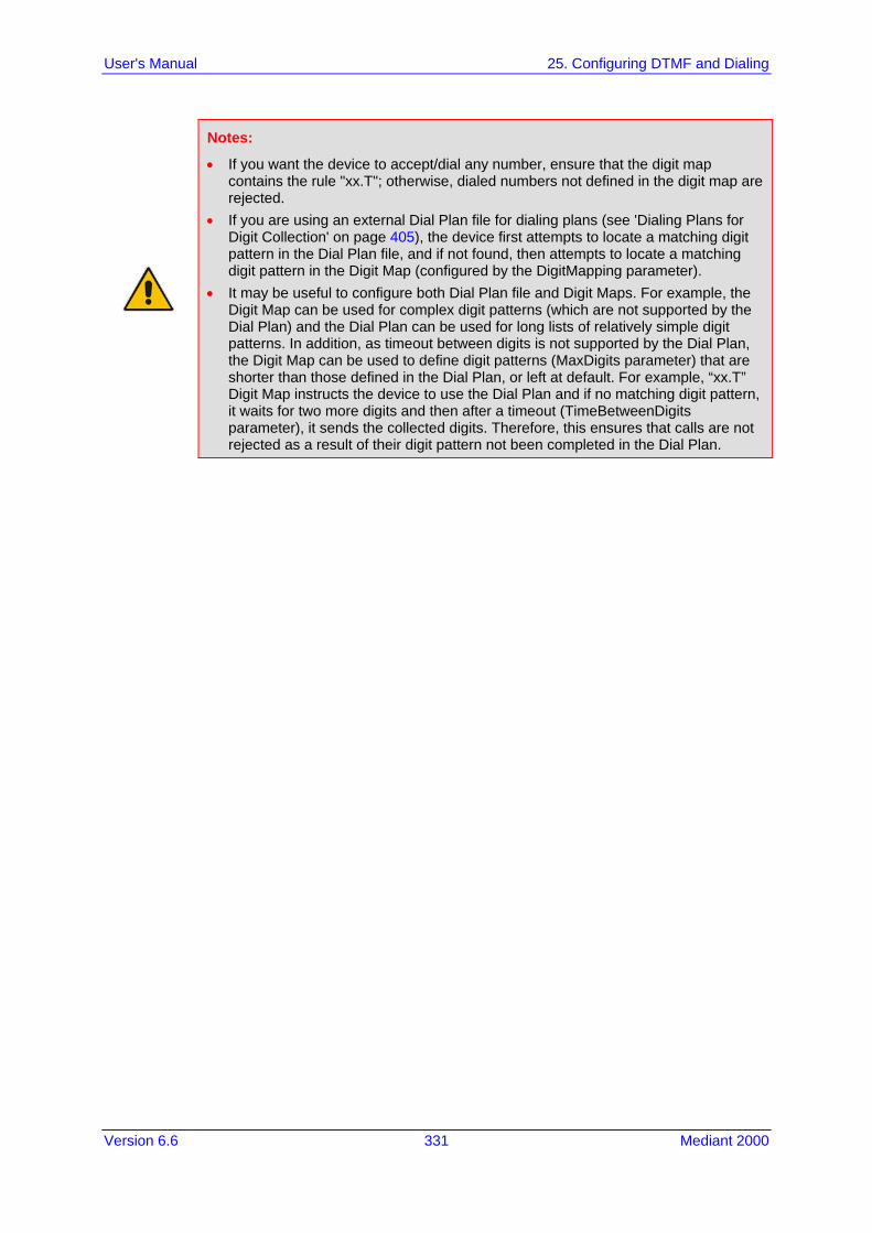
Version 6.6 331 Mediant 2000
User's Manual 25. Configuring DTMF and Dialing
Notes:
• If you want the device to accept/dial any number, ensure that the digit map contains the rule "xx.T"; otherwise, dialed numbers not defined in the digit map are rejected.
• If you are using an external Dial Plan file for dialing plans (see 'Dialing Plans for Digit Collection' on page 405), the device first attempts to locate a matching digit pattern in the Dial Plan file, and if not found, then attempts to locate a matching digit pattern in the Digit Map (configured by the DigitMapping parameter).
• It may be useful to configure both Dial Plan file and Digit Maps. For example, the Digit Map can be used for complex digit patterns (which are not supported by the Dial Plan) and the Dial Plan can be used for long lists of relatively simple digit patterns. In addition, as timeout between digits is not supported by the Dial Plan, the Digit Map can be used to define digit patterns (MaxDigits parameter) that are shorter than those defined in the Dial Plan, or left at default. For example, “xx.T” Digit Map instructs the device to use the Dial Plan and if no matching digit pattern, it waits for two more digits and then after a timeout (TimeBetweenDigits parameter), it sends the collected digits. Therefore, this ensures that calls are not rejected as a result of their digit pattern not been completed in the Dial Plan.

User's Manual 332 Document #: LTRT-68822
Mediant 2000
25.1.2 External Dial Plan File The device can be loaded with a Dial Plan file with user-defined dialing plans. For more information, see 'Dial Plan File' on page 404.

Version 6.6 333 Mediant 2000
User's Manual 26. Configuring Supplementary Services
26 Configuring Supplementary Services This section describes SIP supplementary services that can enhance your telephone service.
Notes:
• All call participants must support the specific supplementary service that is used. • When working with certain application servers (such as BroadSoft’s BroadWorks)
in client server mode (the application server controls all supplementary services and keypad features by itself), the device's supplementary services must be disabled.
• The device's SIP users are only required to enable the Hold and Transfer features. By default, the Call Forward (supporting 30x redirecting responses) and Call Waiting (receipt of 182 response) features are enabled.
The Supplementary Services page is used to configure many of the discussed supplementary services parameters. For a description of the parameters appearing on this page, see 'Configuration Parameters Reference' on page 503.
To configure supplementary services parameters:
1. Open the Supplementary Services page (Configuration tab > VoIP menu > GW and IP to IP submenu > DTMF & Supplementary submenu > Supplementary Services).
Figure 26-1: Supplementary Services Page
2. Configure the parameters as required. 3. Click Submit to apply your changes, or click the Subscribe to MWI or Unsubscribe
to MWI buttons to save your changes and to subscribe / unsubscribe to the MWI server.
4. To save the changes to flash memory, see 'Saving Configuration' on page 396.

User's Manual 334 Document #: LTRT-68822
Mediant 2000
26.1 Call Hold and Retrieve Call Hold and Retrieve: The party that initiates the hold is called the holding party; the other party is called the
held party. The device can't initiate Call Hold, but it can respond to hold requests and as such, it's a held party.
After a successful Hold, the holding party hears a dial tone (HELD_TONE defined in the device's Call Progress Tones file).
After a successful retrieve, the voice is connected again. The hold and retrieve functionalities are implemented by re-INVITE messages. The IP
address 0.0.0.0 as the connection IP address or the string ‘a=inactive’ in the received re-INVITE SDP cause the device to enter Hold state and to play the held tone (configured in the device) to the PBX/PSTN. If the string ‘a=sendonly’ is received in the SDP message, the device stops sending RTP packets, but continues to listen to the incoming RTP packets. Usually, the remote party plays, in this scenario, Music on Hold (MOH) and the device forwards the MOH to the held party.
You can also configure the device to keep a call on-hold for a user-defined time after which the call is disconnected, using the HeldTimeout parameter.
26.2 Call Transfer This section describes the device's support for call transfer types.
26.2.1 Consultation Call Transfer The device supports Consultation Call Transfer. The common method to perform a consultation transfer is described in the following example, which assumes three call parties: Party A = transferring Party B = transferred Party C = transferred to 1. A Calls B. 2. B answers. 3. A presses the hook-flash button and places B on-hold (party B hears a hold tone). 4. A dials C. 5. After A completes dialing C, A can perform the transfer by on-hooking the A phone. 6. After the transfer is complete, B and C parties are engaged in a call. The transfer can be initiated at any of the following stages of the call between A and C: Just after completing dialing C phone number - transfer from setup While hearing ringback – transfer from alert While speaking to C - transfer from active
The Explicit Call Transfer (ECT, according to ETS-300-367, 368, 369) supplementary service is supported for PRI trunks. This service provides the served user who has two calls to ask the network to connect these two calls together and release its connection to both parties. The two calls can be incoming or outgoing calls. This service is similar to NI2 Two B-Channel Transfer (TBCT) Supplementary Service. The main difference is that in ECT one of the calls must be in HELD state.

Version 6.6 335 Mediant 2000
User's Manual 26. Configuring Supplementary Services
26.2.2 Consultation Transfer for QSIG Path Replacement The device can interwork consultation call transfer requests for ISDN QSIG-to-IP calls. When the device receives a request for a consultation call transfer from the PBX, the device sends a SIP REFER message with a Replaces header to the SIP UA to transfer it to another SIP UA. Once the two SIP UA parties are successfully connected, the device requests the PBX to disconnect the ISDN call, thereby freeing resources on the PBX. For example, assume legacy PBX user "A" has two established calls connected through the device – one with remote SIP UA "B" and the other with SIP UA "C". In this scenario, user "A" initiates a consultation call transfer to connect "B" with "C". The device receives the consultation call transfer request from the PBX and then connects "B" with "C", by sending "B" a REFER message with a Replaces header (i.e., replace caller "A" with "C"). Upon receipt of a SIP NOTIFY 200 message in response to the REFER, the device sends a Q.931 Disconnect messages to the PBX, notifying the PBX that it can disconnect the ISDN calls (of user "A"). This feature is enabled by the QSIGPathReplacementMode parameter.
26.2.3 Blind Call Transfer Blind call transfer is done (using SIP REFER messages) after a call is established between call parties A and B, and party A decides to immediately transfer the call to C without first speaking to C. The result of the transfer is a call between B and C (similar to consultation transfer, but skipping the consultation stage). You can also use the ManipulateIP2PSTNReferTo parameter to manipulate the destination number according to the number received in the SIP Refer-To header. This is applicable to all types of blind transfers to the PSTN (e.g., TBCT, ECT, RLT, QSIG, FXO, and CAS). During blind transfer, the device initiates a new call to the PSTN and the destination number of this call can be manipulated if this parameter is enabled. The following is an example of such a blind transfer: 1. IP phone "A" calls PSTN phone "B", and the call is established. 2. "A" performs a blind transfer to PSTN phone "C". It does this as follows:
a. "A" sends a SIP REFER message (with the phone number of "C" in the Refer-To header) to the device.
b. The device sends a Q.931 Setup message to "C". This feature enables manipulating the called party number in this outgoing Setup message.
The manipulation is done as follows: 1. If you configure a value for the xferPrefix parameter, then this value (string) is added
as a prefix to the number in the Refer-To header. 2. This called party number is then manipulated using the IP-to-Tel Destination Phone
Number Manipulation table. 3. The source number of the transferred call is taken from the original call, according to
its initial direction: • Tel-to-IP call: source number of the original call. • IP-to-Tel call: destination number of the original call. • If the UseReferredByForCallingNumber parameter is set to 1, the source number
is taken from the SIP Referred-By header if included in the received SIP REFER message.
This source number can also be used as the value for the 'Source Prefix' field in the IP-to-Tel Destination Phone Number Manipulation table. The local IP address is used as the value for the 'Source IP Address' field.
User's Manual 336 Document #: LTRT-68822
Mediant 2000
Note: Manipulation using the ManipulateIP2PSTNReferTo parameter does not affect IP-to-Trunk Group routing rules.
26.3 Call Forward The device supports Call Deflection (ETS-300-207-1) for Euro ISDN and QSIG (ETSI TS 102 393) for Network and User sides, which provides IP-ISDN interworking of call forwarding (call diversion) when the device receives a SIP 302 response. Call forward performed by the SIP side: Upon receipt of a Facility message with Call Rerouting IE from the PSTN, the device initiates a SIP transfer process by sending a SIP 302 (including the Call Rerouting destination number) to the IP in response to the remote SIP entity's INVITE message. The device then responds with a Disconnect message to the PSTN side. Call forward performed by the PSTN side: When the device sends the INVITE message to the remote SIP entity and receives a SIP 302 response, the device sends a Facility message with the same IE mentioned above to the PSTN, and waits for the PSTN side to disconnect the call. This is configured using the CallReroutingMode.
Notes:
• When call forward is initiated, the device sends a SIP 302 response with a contact that contains the phone number from the forward table and its corresponding IP address from the routing table (or when a proxy is used, the proxy’s IP address).
• For receiving call forward, the device handles SIP 3xx responses for redirecting calls with a new contact.
26.4 Message Waiting Indication The device supports Message Waiting Indication (MWI) according to IETF RFC 3842, including SUBSCRIBE to an MWI server.
Note: For more information on IP voice mail configuration, refer to the IP Voice Mail CPE Configuration Guide.
To configure MWI, use the following parameters: EnableMWI MWIServerIP, or MWISubscribeIPGroupID and ProxySet EnableMWISubscription MWIExpirationTime SubscribeRetryTime SubscriptionMode VoiceMailInterface EnableVMURI

Version 6.6 337 Mediant 2000
User's Manual 26. Configuring Supplementary Services
The device supports the following MWI features: Euro-ISDN MWI: The device supports Euro-ISDN MWI for IP-to-Tel calls. The device
interworks SIP MWI NOTIFY messages to Euro-ISDN Facility information element (IE) MWI messages. This is supported by setting the VoiceMailInterface parameter to 8.
QSIG MWI: The device also supports the interworking of QSIG MWI to IP (in addition to interworking of SIP MWI NOTIFY to QSIG Facility MWI messages). This provides interworking between an ISDN PBX with voicemail capabilities and a softswitch, which requires information on the number of messages waiting for a specific user. This support is configured using the TrunkGroupSettings_MWIInterrogationType parameter(in the Trunk Group Settings table), which determines the device's handling of MWI Interrogation messages. The process for sending the MWI status upon request from a softswitch is as follows: 1. The softswitch sends a SIP SUBSCRIBE message to the device. 2. The device responds by sending an empty SIP NOTIFY to the softswitch, and
then sending an ISDN Setup message with Facility IE containing an MWI Interrogation request to the PBX.
3. The PBX responds by sending to the device an ISDN Connect message containing Facility IE with an MWI Interrogation result, which includes the number of voice messages waiting for the specific user.
4. The device sends another SIP NOTIFY to the softswitch, containing this MWI information.
5. The SIP NOTIFY messages are sent to the IP Group defined by the NotificationIPGroupID parameter.
In addition, when a change in the status occurs (e.g., a new voice message is waiting or the user has retrieved a message from the voice mail), the PBX initiates an ISDN Setup message with Facility IE containing an MWI Activate request, which includes the new number of voice messages waiting for the user. The device forwards this information to the softswitch by sending a SIP NOTIFY. Depending on the PBX support, the MWIInterrogationType parameter can be configured to handle these MWI Interrogation messages in different ways. For example, some PBXs support only the MWI Activate request (and not MWI Interrogation request). Some support both these requests. Therefore, the device can be configured to disable this feature, or enable it with one of the following support: • Responds to MWI Activate requests from the PBX by sending SIP NOTIFY MWI
messages (i.e., does not send MWI Interrogation messages). • Send MWI Interrogation message, but don't use its result. Instead, wait for MWI
Activate requests from the PBX. • Send MWI Interrogation message, use its result, and use the MWI Activate
requests.
User's Manual 338 Document #: LTRT-68822
Mediant 2000
26.5 Emergency E911 Phone Number Services This section describes the device's support for emergency phone number services.
26.5.1 Pre-empting Existing Calls for E911 IP-to-Tel Calls If the device receives an E911 call from the IP network destined to the Tel, and there are unavailable channels (e.g., all busy), the device terminates one of the calls (arbitrary) and then sends the E911 call to that channel. The preemption is done only on a channel pertaining to the same Trunk Group for which the E911 call was initially destined and if the channel select mode (configured by the ChannelSelectMode parameter) is set to a value other than “By Dest Number” (0). The preemption is done only if the incoming IP-to-Tel call is identified as an emergency call. The device identifies emergency calls by one of the following: The destination number of the IP call matches one of the numbers defined by the
EmergencyNumbers parameter. For E911, you must defined this parameter with the value "911".
The Priority header of the incoming SIP INVITE message contains the “emergency” value.
Emergency pre-emption of calls can be enabled for all calls, using the global parameter CallPriorityMode, or for specific calls using the Tel Profile parameter CallPriorityMode.
Notes:
• For Trunk Groups configured with call preemption, all must be configured to MLPP [1] or all configured to Emergency [2]. In other words, you cannot set some trunks to [1] and some to [2].
• The global parameter must be set to the same value as that of the Tel Profile parameter; otherwise, the Tel Profile parameter is not applied.
• If you configure call preemption using the global parameter and a new Tel Profile is subsequently added, the TelProfile_CallPriorityMode parameter automatically acquires the same setting as well.
• This feature is applicable to CAS and ISDN interfaces.
26.5.2 Enhanced 9-1-1 Support for Lync Server 2010 The Enhanced 9-1-1 (E9-1-1) service is becoming the mandatory emergency service required in many countries around the world. The E9-1-1 service, based on its predecessor 911, enables emergency operators to pinpoint the location (granular location) of callers who dial the 9-1-1 emergency telephone number. Today, most enterprises implement an IP-based infrastructure providing a VoIP network with fixed and nomadic users, allowing connectivity anywhere with any device. This, together with an often deployed multi-line telephone system (MLTS) poses a challenge for E9-1-1 due to the difficulty in accurately locating the E9-1-1 caller. This section describes the E9-1-1 solution provided by Microsoft Lync Server 2010 (hereafter referred to as Lync Server 2010), and the deployed AudioCodes ELIN Gateway which provides the ISDN (or CAMA) connectivity to the PSTN-based E9-1-1 emergency providers. This section also describes the configuration of AudioCodes ELIN Gateway for interoperating between the Lync Server 2010 environment and the E9-1-1 emergency provider.

Version 6.6 339 Mediant 2000
User's Manual 26. Configuring Supplementary Services
26.5.2.1 About E9-1-1 Services E9-1-1 is a national emergency service for many countries, enabling E9-1-1 operators to automatically identify the geographical location and phone number of a 911 caller. In E9-1-1, the 911 caller is routed to the nearest E9-1-1 operator, termed public safety answering point (PSAP) based on the location of the caller. Automatic identification of the caller's location and phone number reduces the time spent on requesting this information from the 911 caller. Therefore, the E9-1-1 service enables the PSAP to quickly dispatch the relevant emergency services (for example, fire department or police) to the caller's location. Even if the call prematurely disconnects, the operator has sufficient information to call back the 911 caller. The figure below illustrates the routing of an E9-1-1 call to the PSAP:
Figure 26-2: Call Flow of E9-1-1 to PSTN-Based Emergency Services Provider
1. The VoIP user dials 9-1-1. 2. The call is eventually sent to the PSTN through a PSTN Gateway. 3. The PSTN identifies the call is an emergency call and sends it to an E9-1-1 Selective
Router in the Emergency Services provider's network. 4. The E9-1-1 Selective Router determines the geographical location of the caller by
requesting this information from an Automatic Location Identification (ALI) database based on the phone number or Automatic Number Identifier (ANI) of the 911 caller. Exact location information is also supplied by the Master Street Address Guide (MSAG) database, which is a companion database to the ALI database. Phone companies and public safety agencies collaborate beforehand to create master maps that match phone numbers, addresses and cross streets to their corresponding PSAP. This MSAG is the official record of valid streets (with exact spelling), street number ranges, and other address elements with which the service providers are required to update their ALI databases.
5. The E9-1-1 Selective Router sends the call to the appropriate PSAP based on the retrieved location information from the ALI.
6. The PSAP operator dispatches the relevant emergency services to the E9-1-1 caller.

User's Manual 340 Document #: LTRT-68822
Mediant 2000
26.5.2.2 Microsoft Lync Server 2010 and E9-1-1 Microsoft Lync Server 2010 enables Enterprise voice users to access its unified communications platform from virtually anywhere and through many different devices. This, together with a deployed MLTS, poses a challenge for E9-1-1 due to the difficulty in accurately locating the E9-1-1 caller. However, Lync Server 2010 offers an innovative solution to solving Enterprises E9-1-1 location problems.
26.5.2.2.1 Gathering Location Information of Lync 2010 Clients for 911 Calls
When a Microsoft® Lync™ 2010 client (hereafter referred to as Lync 2010 client) is enabled for E9-1-1, the location data that is stored on the client is sent during an emergency call. This stored location information is acquired automatically from the Microsoft Location Information Server (LIS). The LIS stores the location of each network element in the enterprise. Immediately after the Lync 2010 client registration process or when the operating system detects a network connection change, each Lync 2010 client submits a request to the LIS for a location. If the LIS is able to resolve a location address for the client request, it returns the address in a location response. Each client then caches this information. When the Lync 2010 client dials 9-1-1, this location information is then included as part of the emergency call and used by the Emergency Services provider to route the call to the correct PSAP. The gathering of location information in the Lync Server 2010 network is illustrated in the figure below:
Figure 26-3: Microsoft Lync Server 2010 Client Acquiring Location Information
1. The Administrator provisions the LIS database with the location of each network
element in the Enterprise. The location is a civic address, which can include contextual in-building and company information. In other words, it associates a specific network entity (for example, a WAP) with a physical location in the Enterprise (for example, Floor 2, Wing A, and the Enterprise's street address). For more information on populating the LIS database, see 'Adding ELINs to the Location Information Server' on page 342.
2. The Administrator validates addresses with the Emergency Services provider's MSAG –a companion database to the ALI database. This ensures that the civic address is valid as an official address (e.g., correct address spelling).
3. The Lync 2010 client initiates a location request to the LIS under the following circumstances: • Immediately after startup and registering the user with Lync Server 2010 • Approximately every four hours after initial registration

Version 6.6 341 Mediant 2000
User's Manual 26. Configuring Supplementary Services
• Whenever a network connection change is detected (such as roaming to a new WAP)
The Lync 2010 client includes in its location request the following known network connectivity information: • Always included:
♦ IPv4 subnet ♦ Media Access Control (MAC) address
• Depends on network connectivity: ♦ Wireless access point (WAP) Basic Service Set Identifier (BSSID) ♦ Link Layer Discovery Protocol-Media Endpoint Discovery (LLDP-MED)
chassis ID and port ID For a Lync 2010 client that moves inside the corporate network such as a soft phone on a laptop that connects wirelessly to the corporate network, Lync Server 2010 can determine which subnet the phone belongs to or which WAP / SSID is currently serving the soft-client.
4. The LIS queries the published locations for a location and if a match is found, returns the location information to the client. The matching order is as follows: • WAP BSSID • LLDP switch / port • LLDP switch • Subnet • MAC address This logic ensures that for any client that is connected by a wireless connection, a match is first attempted based on the hardware address of its connected access point. The logic is for the match to be based on the most detailed location. The subnet generally provides the least detail. If no match is found in the LIS for WAP BSSID, LLDP switch / port, LLDP switch, or subnet, the LIS proxies the MAC address to an integrated Simple Network Management Protocol (SNMP) scanning application. Using SNMP may benefit some organizations for the following reasons: • LLDP is not supported by Lync Server 2010 so this provides a mechanism for soft
phones to acquire detailed location information. • Installed Layer-2 switches may not support LLDP.
If there is no match and the LIS cannot determine the location, the user may be prompted to manually enter the location. For example, the client may be located in an undefined subnet, at home, in a coffee shop or anywhere else outside the network. When a user manually provides a location, the location is mapped based on the MAC address of the default gateway of the client’s network and stored on the client. When the client returns to any previously stored location, the client is automatically set to that location. A user can also manually select any location stored in the local users table and manage existing entries.

User's Manual 342 Document #: LTRT-68822
Mediant 2000
26.5.2.2.2 Adding ELINs to the Location Information Server
As mentioned in the previous section, the Administrator needs to populate the Location Information Server (LIS) database with a network wire map, which maps the Enterprise's network elements to civic addresses. Once done, it can automatically locate clients within a network. You can add addresses individually to the LIS or in a batch using a comma-separated value (CSV) file containing the column formats listed in the table below.
Columns in the LIS Database
Network Element Columns
Wireless access point <BSSID>,<Description>,<Location>,<CompanyName>,<HouseNumber>,<HouseNumberSuffix>,<PreDirectional>,…<StreetName>,<StreetSuffix>,<PostDirectional>,<City>,<State>,<PostalCode>,<Country>
Subnet <Subnet>,<Description>,<Location>,<CompanyName>,<HouseNumber>,<HouseNumberSuffix>,<PreDirectional>,…<StreetName>,<StreetSuffix>,<PostDirectional>,<City>,<State>,<PostalCode>,<Country>
Port <ChassisID>,<PortIDSubType>,<PortID>,<Description>,<Location>,<CompanyName>,<HouseNumber>,<HouseNumberSuffix>,…<PreDirectional>,<StreetName>,<StreetSuffix>,<PostDirectional>,<City>,<State>,<PostalCode>,<Country>
Switch <ChassisID>,<Description>,<Location>,<CompanyName>,<HouseNumber>,<HouseNumberSuffix>,<PreDirectional>,…<StreetName>,<StreetSuffix>,<PostDirectional>,<City>,<State>,<PostalCode>,<Country>
For the ELIN number to be included in the SIP INVITE (XML-based PIDF-LO message) sent by the Mediation Server to the ELIN Gateway, the Administrator must add the ELIN number to the <CompanyName> column (shown in the table above in bold typeface). As the ELIN Gateway supports up to five ELINs per PIDF-LO, the <CompanyName> column can be populated with up to this number of ELINs, each separated by a semicolon. The digits of each ELIN can be separated by hyphens (xxx-xxx-xxx) or they can be adjacent (xxxxxxxxx). When the ELIN Gateway receives the SIP INVITE, it extracts the ELINs from the NAM field in the PIDF-LO (e.g., <ca:NAM>1111-222-333; 1234567890 </ca:NAM>), which corresponds to the <CompanyName> column of the LIS. If you do not populate the location database, and the Lync Server 2010 location policy, Location Required is set to Yes or Disclaimer, the user will be prompted to enter a location manually.
26.5.2.2.3 Passing Location Information to the PSTN Emergency Provider
When a Lync 2010 client, enabled for E9-1-1 emergency services, dials 9-1-1, the location data and callback information stored on the client is sent with the call through the Mediation Server to a PSTN-based Emergency Services provider. The Emergency Services provider then routes the call to the nearest and most appropriate PSAP based on the location information contained within the call. Lync Server 2010 passes the location information of the Lync 2010 client in an IETF-standard format - Presence Information Data Format - Location Object (PIDF-LO)–in a SIP INVITE message. However, this content cannot be sent on the PSTN network using ISDN PRI due to protocol limitations. To overcome this, Enterprises using PSTN Gateways can divide their office space into Emergency Response Locations (ERLs) and assign a dedicated Emergency Location Identification Number (ELIN) to each ERL (or zone). When Lync Server 2010 sends a SIP INVITE message with the PIDF-LO to the PSTN Gateway, it can parse the content and translate the calling number to an appropriate ELIN. The PSTN
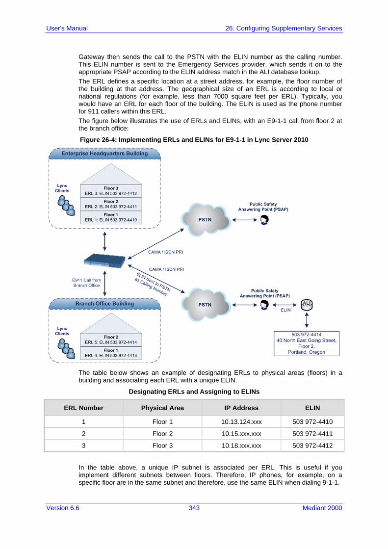
Version 6.6 343 Mediant 2000
User's Manual 26. Configuring Supplementary Services
Gateway then sends the call to the PSTN with the ELIN number as the calling number. This ELIN number is sent to the Emergency Services provider, which sends it on to the appropriate PSAP according to the ELIN address match in the ALI database lookup. The ERL defines a specific location at a street address, for example, the floor number of the building at that address. The geographical size of an ERL is according to local or national regulations (for example, less than 7000 square feet per ERL). Typically, you would have an ERL for each floor of the building. The ELIN is used as the phone number for 911 callers within this ERL. The figure below illustrates the use of ERLs and ELINs, with an E9-1-1 call from floor 2 at the branch office:
Figure 26-4: Implementing ERLs and ELINs for E9-1-1 in Lync Server 2010
The table below shows an example of designating ERLs to physical areas (floors) in a building and associating each ERL with a unique ELIN.
Designating ERLs and Assigning to ELINs
ERL Number Physical Area IP Address ELIN
1 Floor 1 10.13.124.xxx 503 972-4410
2 Floor 2 10.15.xxx.xxx 503 972-4411
3 Floor 3 10.18.xxx.xxx 503 972-4412
In the table above, a unique IP subnet is associated per ERL. This is useful if you implement different subnets between floors. Therefore, IP phones, for example, on a specific floor are in the same subnet and therefore, use the same ELIN when dialing 9-1-1.

User's Manual 344 Document #: LTRT-68822
Mediant 2000
26.5.2.3 AudioCodes ELIN Gateway for Lync Server 2010 E9-1-1 Calls to PSTN The Microsoft Mediation Server sends the location information of the E9-1-1 caller in the XML-based PIDF-LO body contained in the SIP INVITE message. However, this content cannot be sent on the PSTN network using ISDN PRI due to protocol limitations. To solve this issue, Lync Server 2010 requires a PSTN Gateway (ELIN Gateway) to send the E9-1-1 call to the PSTN. When Lync Server 2010 sends the PIDF-LO to the PSTN Gateway, it parses the content and translates the calling number to an appropriate ELIN. This ensures that the call is routed to an appropriate PSAP, based on ELIN-address match lookup in the Emergency Services provider's ALI database. The figure below illustrates an AudioCodes ELIN Gateway deployed in the Lync Server 2010 environment for handling E9-1-1 calls between the Enterprise and the PSTN.
Figure 26-5: AudioCodes ELIN Gateway for E9-1-1 in Lync Server 2010 Environment
26.5.2.3.1 Detecting and Handling E9-1-1 Calls
The ELIN Gateway identifies E9-1-1 calls and translates their incoming E9-1-1 calling numbers into ELIN numbers, sent toward the PSAP. The ELIN Gateway handles the received E9-1-1 calls as follows: 1. The ELIN Gateway identifies E9-1-1 calls if the incoming SIP INVITE message
contains a PIDF-LO XML message body. This is indicated in the SIP Content-Type header, as shown below: Content-Type: application/pidf+xml
2. The ELIN Gateway extracts the ELIN number(s) from the "NAM" field in the XML message. The "NAM" field corresponds to the <CompanyName> column in the Location Information Server (LIS). The ELIN Gateway supports up to five ELIN numbers per XML message. The ELINs are separated by a semicolon. The digits of the ELIN number can be separated by hyphens (xxx-xxx-xxx) or they can be adjacent (xxxxxxxxx), as shown below: <ca:NAM>1111-222-333; 1234567890 </ca:NAM>
3. The ELIN Gateway saves the From header value of the SIP INVITE message in its ELIN database table (Call From column). The ELIN table is used for PSAP callback, as discussed later in 'PSAP Callback to Lync 2010 Clients for Dropped E9-1-1 Calls' on page 346. The ELIN table also stores the following information: • ELIN: ELIN number

Version 6.6 345 Mediant 2000
User's Manual 26. Configuring Supplementary Services
• Time: Time at which the original E9-1-1 call was terminated with the PSAP • Count: Number of E9-1-1 calls currently using this ELIN An example of the ELIN database table is shown below:
ELIN Time Count Index Call From
4257275678 22:11:52 0 2 4258359333
4257275999 22:11:57 0 3 4258359444
4257275615 22:12:03 0 0 4258359555
4257275616 22:11:45 0 1 4258359777
The ELIN table stores this information for a user-defined period (see 'Configuring the E9-1-1 Callback Timeout' on page 348), starting from when the E9-1-1 call, established with the PSAP, terminates. After this time expires, the table entry with its ELIN is disregarded and no longer used (for PSAP callback). Therefore, table entries of only the most recently terminated E9-1-1 callers are considered in the ELIN table. The maximum entries in the ELIN table depend on the AudioCodes ELIN Gateway deployed in the Lync Server 2010 environment: • Mediant 1000 Series and Mediant 2000: 100 entries • Mediant 3000: 300 entries
4. The ELIN Gateway uses the ELIN number as the E9-1-1 calling number and sends it in the ISDN Setup message (as an ANI / Calling Party Number) to the PSTN.
An example of a SIP INVITE message received from an E9-1-1 caller is shown below. The SIP Content-Type header indicating the PIDF-LO, and the NAM field listing the ELINs are shown in bold typeface. INVITE sip:911;[email protected];user=phone SIP/2.0 From: "voip_911_user1"<sip:[email protected]>;epid=1D19090AED;tag=d04d65d924 To: <sip:911;[email protected];user=phone> CSeq: 8 INVITE Call-ID: e6828be1-1cdd-4fb0-bdda-cda7faf46df4 VIA: SIP/2.0/TLS 192.168.0.244:57918;branch=z9hG4bK528b7ad7 CONTACT: <sip:[email protected];opaque=user:epid:R4bCDaUj51a06PUbkraS0QAA;gruu>;text;audio;video;image PRIORITY: emergency CONTENT-TYPE: multipart/mixed; boundary= ------=_NextPart_000_4A6D_01CAB3D6.7519F890 geolocation: <cid:[email protected]>;inserted-by="sip:voip_911_user1@contoso .com" Message-Body: ------=_NextPart_000_4A6D_01CAB3D6.7519F890 Content-Type: application/sdp ; charset=utf-8 v=0 o=- 0 0 IN IP4 Client s=session c=IN IP4 Client t=0 0 m=audio 30684 RTP/AVP 114 111 112 115 116 4 3 8 0 106 97

User's Manual 346 Document #: LTRT-68822
Mediant 2000
c=IN IP4 172.29.105.23 a=rtcp:60423 a=label:Audio a=rtpmap:3 GSM/8000/1 a=rtpmap:101 telephone-event/8000 a=fmtp:101 0-16 a=rtpmap:0 PCMU/8000 a=rtpmap:8 PCMA/8000 a=ptime:20 ------=_NextPart_000_4A6D_01CAB3D6.7519F890 Content-Type: application/pidf+xml Content-ID: <[email protected]> <?xml version="1.0" encoding="utf-8"?> <presence xmlns="urn:ietf:params:xml:ns:pidf" xmlns:gp="urn:ietf:params:xml:ns:pidf:geopriv10" xmlns:bp="urn:ietf:params:xml:ns:pidf:geopriv10:basicPolicy" xmlns:ca="urn:ietf:params:xml:ns:pidf:geopriv10:civicAddr" xmlns:ms="urn:schema:Rtc.LIS.msftE911PidfExtn.2008" entity="sip:[email protected]"><tuple id="0"><status><gp:geopriv><gp:location-info><ca:civicAddress><ca:country>US</ca:country><ca:A1>WA</ca:A1><ca:A3>Redmond</ca:A3><ca:RD>163rd</ca:RD><ca:STS>Ave</ca:STS><ca:POD>NE</ca:POD><ca:HNO>3910</ca:HNO><ca:LOC>40/4451</ca:LOC> <ca:NAM>1111-222-333; 1234567890 </ca:NAM> <ca:PC>98052</ca:PC></ca:civicAddress></gp:location-info><gp:usage-rules><bp:retransmission-allowed>true</bp:retransmission-allowed></gp:usage-rules></gp:geopriv><ms:msftE911PidfExtn><ms:ConferenceUri>sip:[email protected];user=phone</ms:ConferenceUri><ms:ConferenceMode>twoway</ms:ConferenceMode><LocationPolicyTagID xmlns="urn:schema:Rtc.Lis.LocationPolicyTagID.2008">user-tagid</LocationPolicyTagID ></ms:msftE911PidfExtn></status><timestamp>1991-09-22T13:37:31.03</timestamp></tuple></presence> ------=_NextPart_000_4A6D_01CAB3D6.7519F890--
26.5.2.3.2 Pre-empting Existing Calls for E9-1-1 Calls
If the ELIN Gateway receives an E9-1-1 call from the IP network and there are unavailable channels (for example, all busy), the ELIN Gateway immediately terminates one of the non-E9-1-1 calls (arbitrary) and accepts the E9-1-1 call on the freed channel. The preemption is done only on a channel pertaining to the same Trunk Group for which the E9-1-1 call was initially destined. For example, if an E9-1-1 call is destined for Trunk Group #2 and all the channels belonging to this group are busy, the ELIN Gateway terminates one of the calls in this group to free a channel for accepting the E9-1-1 call. This feature is initiated only if the received SIP INVITE message contains a Priority header set to "emergency", as shown below: PRIORITY: emergency
26.5.2.3.3 PSAP Callback to Lync 2010 Clients for Dropped E9-1-1 Calls
As the E9-1-1 service automatically provides all the contact information of the E9-1-1 caller to the PSAP, the PSAP operator can call back the E9-1-1 caller. This is especially useful in cases where the caller disconnects prematurely. However, as the Enterprise sends ELINs

Version 6.6 347 Mediant 2000
User's Manual 26. Configuring Supplementary Services
to the PSAP for E9-1-1 calls, a callback can only reach the original E9-1-1 caller using the ELIN Gateway to translate the ELIN number back into the E9-1-1 caller's extension number. In the ELIN table of the ELIN Gateway, the temporarily stored From header value of the SIP INVITE message originally received from the E9-1-1 caller is used for PSAP callback. When the PSAP makes a callback to the E9-1-1 caller, the ELIN Gateway translates the called number (i.e., ELIN) received from the PSAP to the corresponding E9-1-1 caller's extension number as matched in the ELIN table. The handling of PSAP callbacks by the ELIN Gateway is as follows: 1. When the ELIN Gateway receives any call from the PSTN, it searches the ELIN table
for an ELIN that corresponds to the received Called Party Number in the incoming PSTN call.
2. If a match is found in the ELIN table, it routes the call to the Mediation Sever by sending a SIP INVITE, where the values of the To and Request-URI are taken from the value of the original From header that is stored in the ELIN table (in the Call From column).
3. The ELIN Gateway updates the Time in the ELIN table. (The Count is not affected). The PSAP callback can be done only within a user-defined timeout (see 'Configuring the E9-1-1 Callback Timeout' on page 348) started from after the original E9-1-1 call established with the PSAP is terminated. After this time expires, the table entry with its ELIN is disregarded and no longer used (for PSAP callback). Therefore, table entries of only the most recently terminated E9-1-1 callers are considered in the ELIN table. If the PSAP callback is done after this timeout expires, the ELIN Gateway is unable to route the call to the E9-1-1 caller and instead, either sends it as a regular call or most likely, rejects it if there are no matching routing rules. However, if another E9-1-1 caller has subsequently been processed with the same ELIN number, then the PSAP callback is routed to this new E9-1-1 caller. In scenarios where the same ELIN number is being used by multiple E9-1-1 callers, upon receipt of a PSAP callback, the ELIN Gateway sends the call to the most recent E9-1-1 caller. For example, if the ELIN number "4257275678" is being used by three E9-1-1 callers, as shown in the table below, then when a PSAP callback is received, the ELIN Gateway sends it to the E9-1-1 caller with phone number "4258359555".
Choosing Caller of ELIN
ELIN Time Call From
4257275678 11:00 4258359333
4257275678 11:01 4258359444
4257275678 11:03 4258359555
26.5.2.3.4 Selecting ELIN for Multiple Calls within Same ERL
The ELIN Gateway supports the receipt of up to five ELIN numbers in the XML message of each incoming SIP INVITE message. As discussed in the preceding sections, the ELIN Gateway sends the ELIN number as the E9-1-1 calling number to the PSTN-based emergency provider. If the XML message contains more than one ELIN number, the ELIN Gateway chooses the ELIN according to the following logic: If the first ELIN in the list is not being used by other active calls, it chooses this ELIN. If the first ELIN in the list is being used by another active call, the ELIN Gateway skips
to the next ELIN in the list, and so on until it finds an ELIN that is not being used and sends this ELIN.
If all the ELINs in the list are in use by active calls, the ELIN Gateway selects the ELIN

User's Manual 348 Document #: LTRT-68822
Mediant 2000
number as follows: 1. The ELIN with the lowest count (i.e., lowest number of active calls currently using
this ELIN). 2. If the count between ELINs is identical, the ELIN Gateway selects the ELIN with
the greatest amount of time passed since the original E9-1-1 call using this ELIN was terminated with the PSAP. For example, if E9-1-1 caller using ELIN 4257275678 was terminated at 11:01 and E9-1-1 caller using ELIN 4257275670 was terminated at 11:03, then the ELIN Gateway selects ELIN 4257275678.
In this scenario, multiple E9-1-1 calls will be sent with the same ELIN.
26.5.2.3.5 Location Based Emergency Routing
The device supports location-based emergency routing (E-911) in Lync Server 2010. This ensures that E-911 calls from remote branches are routed to emergency providers that are relevant to the geographical area in which the remote branch callers are physically located. To support this, the device enables routing and SIP header / number manipulation of such emergency calls based on the geographical location of the caller. The device manipulates the received destination number (i.e., 911) from the remote branch callers, into a destination number of an emergency provider that is relevant to the geographical area in which the remote branch office is located.
26.5.2.4 Configuring AudioCodes ELIN Gateway This section describes E9-1-1 configuration of the AudioCodes ELIN Gateway deployed in the Lync Server 2010 environment.
26.5.2.4.1 Enabling the E9-1-1 Feature
By default, the E9-1-1 feature in the ELIN Gateway for Lync Server 2010 is disabled. To enable it, the following ini file parameter setting must be done: E911Gateway = 1
26.5.2.4.2 Configuring the E9-1-1 Callback Timeout
The PSAP can use the ELIN to call back the E9-1-1 caller within a user-defined time interval (in minutes) from when the initial call established with the PSAP has been terminated. By default, an ELIN can be used for PSAP callback within 30 minutes after the call is terminated. You can change this interval, by using the following ini file parameter: E911CallbackTimeout = <time value> ; where <time value > can be any value from 0 through 60
26.5.2.4.3 Configuring the SIP Release Cause Code for Failed E9-1-1 Calls
When a Lync 2010 client makes an emergency call, the call is routed through the Microsoft Mediation Server to the ELIN Gateway, which sends it on to the PSTN. In some scenarios, the call may not be established due to either the PSTN (for example, the destination is busy or not found) or ELIN Gateway (for example, lack of resources or an internal error). In such a scenario, the Mediation Server requires that the ELIN Gateway "reject" the call with the SIP release cause code 503 "Service Unavailable" instead of the designated release call. Such a release cause code enables the Mediation Server to issue a failover to another entity (for example, another ELIN Gateway), instead of retrying the call or returning the release call to the user. To support this requirement, the ELIN Gateway can be configured to send the 503 "Service Unavailable" release cause code instead of SIP 4xx if an emergency call cannot be established. To enable this support, the following ini file parameter setting must be done:

Version 6.6 349 Mediant 2000
User's Manual 26. Configuring Supplementary Services
Note: This can also be configured using the ini file parameter, EmergencySpecialReleaseCause.
To enable SIP response 503 upon failed E911:
1. Open the Advanced Parameters page (Configuration tab > VoIP menu > SIP Definitions > Advanced Parameters).
2. From the 'Emergency Special Release Cause' drop-down list, select Enable.
26.5.2.4.4 Configuring Location-Based Emergency Routing
The device identifies callers by their ELIN numbers contained in the PIDF-LO XML body of the received SIP INVITE message. To configure the manipulation rule for location-based emergency routing, the ELIN number is used as the source prefix in the Destination Phone Number Manipulation Table for Tel -> IP Calls table. To identify this source prefix as an E-911 ELIN number, the "ELIN" string is added in front of the source prefix number, for example, "ELIN1234567890". For example, assume an E-9-1-1 call is received for destination [email protected] and the ELIN number is 1234567890; to create the new destination as [email protected], the destination number is manipulated using the manipulation table by adding prefix 1550 and suffix 5000.
To configure location-based emergency routing: 1. Enable location-based emergency routing, by loading an ini file to the device with the
following parameter setting: E911Gateway = 2
2. In the Destination Phone Number Manipulation Table for Tel -> IP Calls table (Configuration tab > VoIP menu > GW and IP to IP submenu > Manipulations > Dest Number Tel->IP), configure the following fields: • Under the Rule tab:
♦ 'Source Prefix': ELIN<ELIN source number> • Under the Action tab:
♦ Configure the manipulation action as required
26.5.2.4.5 Viewing the ELIN Table
You can view the ELIN table of the ELIN Gateway. Using Syslog, by invoking the following Web command shell:
SIP / GateWay / E911Dump
26.6 Multilevel Precedence and Preemption The device supports Multilevel Precedence and Preemption (MLPP) service. MLPP is a call priority scheme, which does the following: Assigns a precedence level (priority level) to specific phone calls or messages. Allows higher priority calls (precedence call) and messages to preempt lower priority
calls and messages (i.e., terminates existing lower priority calls) that are recognized within a user-defined domain (MLPP domain ID). The domain specifies the collection of devices and resources that are associated with an MLPP subscriber. When an MLPP subscriber that belongs to a particular domain places a precedence call to

User's Manual 350 Document #: LTRT-68822
Mediant 2000
another MLPP subscriber that belongs to the same domain, MLPP service can preempt the existing call that the called MLPP subscriber is on for a higher-precedence call. MLPP service availability does not apply across different domains.
MLPP is typically used in the military where, for example, high-ranking personnel can preempt active calls during network stress scenarios such as a national emergency or degraded network situations. MLPP can be enabled for all calls, using the global parameter, CallPriorityMode, or for specific calls using the Tel Profile parameter, CallPriorityMode.
Notes:
• For Trunk Groups configured with call preemption, all must be configured to MLPP [1] or all configured to Emergency [2]. In other words, you cannot set some trunks to [1] and some to [2].
• The global parameter must be set to the same value as that of the Tel Profile parameter; otherwise, the Tel Profile parameter is not applied.
• If you configure call preemption using the global parameter and a new Tel Profile is subsequently added, the TelProfile_CallPriorityMode parameter automatically acquires the same setting as well.
The Resource Priority value in the Resource-Priority SIP header can be any one of those listed in the table below. A default MLPP call Precedence Level (configured by the SIPDefaultCallPriority parameter) is used if the incoming SIP INVITE or PRI Setup message contains an invalid priority or Precedence Level value respectively. For each MLPP call priority level, the Multiple Differentiated Services Code Points (DSCP) can be set to a value from 0 to 63.
MLPP Call Priority Levels (Precedence) and DSCP Configuration Parameters
MLPP Precedence Level Precedence Level in Resource-Priority SIP Header
DSCP Configuration Parameter
0 (lowest) routine MLPPRoutineRTPDSCP
2 priority MLPPPriorityRTPDSCP
4 immediate MLPPImmediateRTPDSCP
6 flash MLPPFlashRTPDSCP
8 flash-override MLPPFlashOverRTPDSCP
9 (highest) flash-override-override MLPPFlashOverOverRTPDSCP
The device automatically interworks the network identity digits (NI) in the ISDN Q.931 Precedence Information Element (IE) to the network domain subfield of the INVITE's Resource-Priority header, and vice versa. The SIP Resource-Priority header contains two fields, namespace and priority. The namespace is subdivided into two subfields, network-domain and precedence-domain. Below is an example of a Resource-Priority header whose network-domain subfield is "uc", r-priority field is "priority" (2), and precedence-domain subfield is "000000": Resource-Priority: uc-000000.2 The MLPP Q.931 Setup message contains the Precedence IE. The NI digits are presented by four nibbles found in octets 5 and 6. The device checks the NI digits according to the translation table of the Department of Defense (DoD) Unified Capabilities (UC) Requirements (UCR 2008, Changes 3) document, as shown below:

Version 6.6 351 Mediant 2000
User's Manual 26. Configuring Supplementary Services
NI Digits in ISDN Precedence
Level IE Network Domain in SIP Resource-Priority Header
0000 uc
0001 cuc
0002 dod
0003 nato
Notes:
• If the received ISDN message contains NI digits that are not listed in the translation table, the device sets the network-domain to "uc" in the outgoing SIP message.
• If the received SIP message contains a network-domain value that is not listed in the translation table, the device sets the NI digits to "0000" in the outgoing ISDN message.
• If the received ISDN message does not contain a Precedence IE, you can configure the namespace value - dsn (default), dod, drsn, uc, or cuc - in the SIP Resource-Priority header of the outgoing INVITE message. This is done using the MLPPDefaultNamespace parameter. You can also configure up to 32 user-defined namespaces, using the table ini file parameter, ResourcePriorityNetworkDomains. Once defined, you need to set the MLPPDefaultNamespace parameter value to the desired table row index.
By default, the device maps the received Resource-Priority field of the SIP Resource-Priority header to the outgoing ISDN PRI Precedence Level (priority level) field as follows: If the network-domain field in the Resource-Priority header is "uc", then the device
sets the Precedence Level field in the ISDN PRI Precedence Level IE according to Table 5.3.2.12-4 (Mapping of RPH r-priority Field to PRI Precedence Level Value):
Mapping of SIP Resource-Priority Header to PRI Precedence Level for MLPP
MLPP Precedence Level PRI Precedence Level SIP Resource-Priority Header Field
Routine 4 0
Priority 3 2
Immediate 2 4
Flash 1 6
Flash Override 0 8
If the network-domain field in the Resource-Priority header is any value other than "uc", then the device sets the Precedence Level field to "0 1 0 0" (i.e., "routine").
This can be modified using the EnableIp2TelInterworkingtable field of the ini file parameter, ResourcePriorityNetworkDomains.
Notes:
• If required, you can exclude the "resource-priority” tag from the SIP Require header in INVITE messages for Tel-to-IP calls when MLPP priority call handling is

User's Manual 352 Document #: LTRT-68822
Mediant 2000
used. This is configured using the RPRequired parameter. • For a complete list of the MLPP parameters, see 'MLPP and Emergency Call
Parameters' on page 613.
26.6.1 MLPP Preemption Events in SIP Reason Header The device sends the SIP Reason header (as defined in RFC 4411) to indicate the reason and type of a preemption event. The device sends a SIP BYE or CANCEL request, or SIP 480, 486, 488 response (as appropriate) with a Reason header whose Reason-params can includes one of the following preemption cause classes: Reason: preemption ;cause=1 ;text=”UA Preemption” Reason: preemption ;cause=2 ;text=”Reserved Resources Preempted” Reason: preemption ;cause=3 ;text=”Generic Preemption” Reason: preemption ;cause=4 ;text=”Non-IP Preemption”
This Reason cause code indicates that the session preemption has occurred in a non-IP portion of the infrastructure. The device sends this code in the following scenarios: • The device performs a network preemption of a busy call (when a high priority
call is received), the device sends a SIP BYE or CANCEL request with this Reason cause code.
• The device performs a preemption of a B-channel for a Tel-to-IP outbound call request from the softswitch for which it has not received an answer response (e.g., Connect), and the following sequence of events occurs: a. The device sends a Q.931 DISCONNECT over the ISDN MLPP PRI to the
partner switch to preempt the remote end instrument. b. The device sends a 488 (Not Acceptable Here) response with this Reason
cause code. Reason: preemption; cause=5; text=”Network Preemption”
This Reason cause code indicates preempted events in the network. Within the Defense Switched Network (DSN) network, the following SIP request messages and response codes for specific call scenarios have been identified for signaling this preemption cause: • SIP:BYE - If an active call is being preempted by another call • CANCEL - If an outgoing call is being preempted by another call • 480 (Temporarily Unavailable), 486 (User Busy), 488 (Not Acceptable Here) -
Due to incoming calls being preempted by another call. The device receives SIP requests with preemption reason cause=5 in the following cases: • The softswitch performs a network preemption of an active call - the following
sequence of events occurs: a. The softswitch sends the device a SIP BYE request with this Reason cause
code. b. The device initiates the release procedures for the B-channel associated
with the call request and maps the preemption cause to PRI Cause = #8 ‘Preemption’. This value indicates that the call is being preempted. For PRI, it also indicates that the B-channel is not reserved for reuse.
c. The device sends a SIP 200 OK in response to the received BYE, before the SIP end instrument can proceed with the higher precedence call.
• The softswitch performs a network preemption of an outbound call request for the device that has not received a SIP 2xx response - the following sequence of events occur:

Version 6.6 353 Mediant 2000
User's Manual 26. Configuring Supplementary Services
a. The softswitch sends the device a SIP 488 (Not Acceptable Here) response code with this Reason cause code. The device initiates the release procedures for the B-channel associated with the call request and maps the preemption cause to PRI Cause = #8 ‘Preemption’.
b. The device deactivates any user signaling (e.g., ringback tone) and when the call is terminated, it sends a SIP ACK message to the softswitch.
26.6.2 Precedence Ring Tone You can configure the duration for which the device plays a preemption tone to the Tel and IP sides if a call is preempted, using the PreemptionToneDuration parameter.
26.7 Advice of Charge Services for Euro ISDN Advice of charge (AOC) is a pre-billing function that tasks the rating engine with calculating the cost of using a service and relaying that information back to the customer thus, allowing users to obtain charging information for all calls during the call (AOC-D) or at the end of the call (AOC-E), or both. The AOC-D and AOC-E messages are part of the Facility Information Element (IE) message: AOC-D message—ISDN Advice of Charge information sent during a call. The
message is sent periodically to subscribers of AOC during-call services. AOC-E message—ISDN Advice of Charge information sent at the end of a call. The device supports the sending of AoC messages for Tel-to-IP calls, providing billing applications with the number of charged units. This feature can typically be implemented in the hotel industry, where external calls made by guests can be billed accurately. In such a setup, the device is connected on one side to a PBX through an E1 line (Euro ISDN), and on the other side to a SIP trunk provided by an ITSP. When a call is made by a guest, the device first sends an AOC-D Facility message to the PBX indicating the connection charge unit, and then sends subsequent AOC-D messages every user-defined interval to indicate the charge unit during the call. When the call ends, the device sends an AoC-E Facility message to the PBX indicating the total number of charged units. To configure AoC: 1. Ensure that the PSTN protocol for the E1 trunk line is Euro ISDN and set to network
side. 2. Ensure that the date and time of the device is correct. For accuracy, it is
recommended to use an NTP server to obtain the date and time. 3. Enable the AoC service, using the EnableAOC parameter. 4. Configure charge codes in the Charge Code table (ChargeCode). Note that in the
Charge Code table, the table fields are as follows: • 'End Time' - time at which this charge code ends • 'Pulse Interval' - time between every sent AOC-D Facility message • 'Pulses On Answer' - number of charging units in first generated AOC-D Facility
message 5. Assign the charge code index to the desired routing rule in the Outbound IP Routing
table (see 'Configuring Outbound IP Routing Table' on page 309).

User's Manual 354 Document #: LTRT-68822
Mediant 2000
26.8 Configuring Voice Mail The Voice Mail Settings page allows you to configure the voice mail parameters. For a description of these parameters, see 'Configuration Parameters Reference' on page 503.
Notes:
• The Voice Mail Settings page is available only for CAS interfaces. • For more information on configuring voice mail, refer to the CPE Configuration
Guide for Voice Mail User's Manual.
To configure the Voice Mail parameters:
1. Open the Voice Mail Settings page (Configuration tab > VoIP menu > GW and IP to IP > Advanced Applications > Voice Mail Settings).
Figure 26-6: Voice Mail Settings Page
2. Configure the parameters as required. 3. Click Submit to apply your changes. 4. To save the changes to flash memory, see 'Saving Configuration' on page 396.

Part VI Stand-Alone Survivability Application


Version 6.6 357 Mediant 2000
User's Manual 27. Overview
27 Overview The device's Stand-Alone Survivability (SAS) feature ensures telephony communication continuity (survivability) for enterprises using hosted IP services (such as IP Centrex) or IP-PBX in cases of failure of these entities. In case of failure of the IP Centrex, IP-PBX servers (or even WAN connection and access Internet modem), the enterprise typically loses its internal telephony service at any branch, between its offices, and with the external environment. Typically, these failures also lead to the inability to make emergency calls (e.g., 911 in North America). Despite these possible points of failure, the device's SAS feature ensures that the enterprise's telephony services (e.g., SIP IP phones or soft phones) are maintained, by routing calls to the PSTN (i.e., providing PSTN fallback).
Notes:
• The SAS application is available only if the device is installed with the SAS Software License Key.
• Throughput this section, the term user agent (UA) refers to the enterprise's LAN phone user (i.e., SIP telephony entities such as IP phones).
• Throughout this section, the term proxy or proxy server refers to the enterprise's centralized IP Centrex or IP-PBX.
• Throughout this section, the term SAS refers to the SAS application running on the device.
27.1 SAS Operating Modes The device's SAS application can be implemented in one of the following main modes: Outbound Proxy: In this mode, SAS receives SIP REGISTER requests from the
enterprise's UAs and forwards these requests to the external proxy (i.e., outbound proxy). When a connection with the external proxy fails, SAS enters SAS emergency state and serves as a proxy, by handling internal call routing for the enterprise's UAs - routing calls between UAs and if setup, routing calls between UAs and the PSTN. For more information, see 'SAS Outbound Mode' on page 358.
Redundant Proxy: In this mode, the enterprise's UAs register with the external proxy and establish calls directly through the external proxy, without traversing SAS (or the device per se'). Only when connection with the proxy fails, do the UAs register with SAS, serving now as the UAs redundant proxy. SAS then handles the calls between UAs, and between the UAs and the PSTN (if setup). This mode is operational only during SAS in emergency state. This mode can be implemented, for example, for proxies that accept only SIP messages that are sent directly from the UAs. For more information, see 'SAS Redundant Mode' on page 359.
Note: It is recommended to implement the SAS outbound mode.

User's Manual 358 Document #: LTRT-68822
Mediant 2000
27.1.1 SAS Outbound Mode This section describes the SAS outbound mode, which includes the following states: Normal state (see 'Normal State' on page 358) Emergency state (see 'Emergency State' on page 358)
27.1.1.1 Normal State In normal state, SAS receives REGISTER requests from the enterprise's UAs and forwards them to the external proxy (i.e., outbound proxy). Once the proxy replies with a SIP 200 OK, the device records the Contact and address of record (AOR) of the UAs in its internal SAS registration database. Therefore, in this mode, SAS maintains a database of all the registered UAs in the network. SAS also continuously maintains a keep-alive mechanism toward the external proxy, using SIP OPTIONS messages. The figure below illustrates the operation of SAS outbound mode in normal state:
Figure 27-1: SAS Outbound Mode in Normal State (Example)
27.1.1.2 Emergency State When a connection with the external proxy fails (detected by the device's keep-alive messages), the device enters SAS emergency state. The device serves as a proxy for the UAs, by handling internal call routing of the UAs (within the LAN enterprise).
Note: SAS can also enter Emergency state if no response is received from the proxy for sent OPTIONS, INVITE, or REGISTER messages. To configure this, set the SASEnteringEmergencyMode parameter to 1.
When the device receives calls, it searches its SAS registration database to locate the destination address (according to AOR or Contact). If the destination address is not found, SAS forwards the call to the default gateway. Typically, the default gateway is defined as the device itself (on which SAS is running), and if the device has PSTN interfaces, the enterprise preserves its capability for outgoing calls (from UAs to the PSTN network).

Version 6.6 359 Mediant 2000
User's Manual 27. Overview
The routing logic of SAS in emergency state is described in detail in 'SAS Routing in Emergency State' on page 363. The figure below illustrates the operation of SAS outbound mode in emergency state:
Figure 27-2: SAS Outbound Mode in Emergency State (Example)
When emergency state is active, SAS continuously attempts to communicate with the external proxy, using keep-alive SIP OPTIONS. Once connection to the proxy returns, the device exits SAS emergency state and returns to SAS normal state, as explained in 'Exiting Emergency and Returning to Normal State' on page 360.
27.1.2 SAS Redundant Mode In SAS redundant mode, the enterprise's UAs register with the external proxy and establish calls directly through it, without traversing SAS (or the device per se'). Only when connection with the proxy fails, do the UAs register with SAS, serving now as the UAs redundant proxy. SAS then handles the calls between UAs, and between the UAs and the PSTN (if setup). This mode is operational only during SAS in emergency state.
Note: In this SAS deployment, the UAs (e.g., IP phones) must support configuration for primary and secondary proxy servers (i.e., proxy redundancy), as well as homing. Homing allows the UAs to switch back to the primary server from the secondary proxy once the connection to the primary server returns (UAs check this using keep-alive messages to the primary server). If homing is not supported by the UAs, you can configure SAS to ignore messages received from UAs in normal state (the 'SAS Survivability Mode' parameter must be set to 'Always Emergency' / 2) and thereby, “force” the UAs to switch back to their primary proxy.

User's Manual 360 Document #: LTRT-68822
Mediant 2000
27.1.2.1 Normal State In normal state, the UAs register and operate directly with the external proxy.
Figure 27-3: SAS Redundant Mode in Normal State (Example)
27.1.2.2 Emergency State If the UAs detect that their primary (external) proxy does not respond, they immediately register to SAS and start routing calls to it.
Figure 27-4: SAS Redundant Mode in Emergency State (Example)
27.1.2.3 Exiting Emergency and Returning to Normal State Once the connection with the primary proxy is re-established, the following occurs: UAs: Switch back to operate with the primary proxy. SAS: Ignores REGISTER requests from the UAs, forcing the UAs to switch back to
the primary proxy. Note: This is applicable only if the 'SAS Survivability Mode' parameter is set to 'Always Emergency' (2).

Version 6.6 361 Mediant 2000
User's Manual 27. Overview
27.2 SAS Routing This section provides flowcharts describing the routing logic for SAS in normal and emergency states.
27.2.1 SAS Routing in Normal State The flowchart below displays the routing logic for SAS in normal state for INVITE messages received from UAs:
Figure 27-5: Flowchart of INVITE from UA's in SAS Normal State
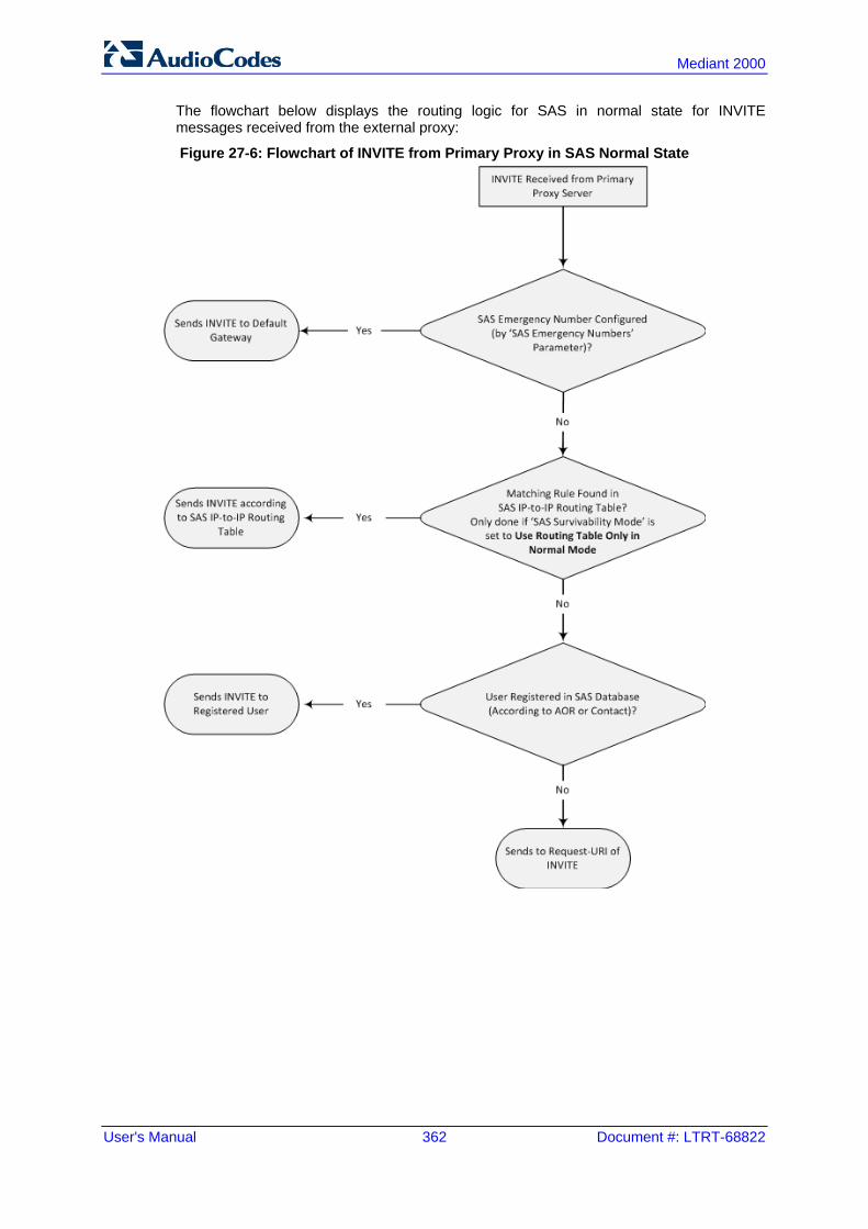
User's Manual 362 Document #: LTRT-68822
Mediant 2000
The flowchart below displays the routing logic for SAS in normal state for INVITE messages received from the external proxy:
Figure 27-6: Flowchart of INVITE from Primary Proxy in SAS Normal State

Version 6.6 363 Mediant 2000
User's Manual 27. Overview
27.2.2 SAS Routing in Emergency State The flowchart below shows the routing logic for SAS in emergency state:
Figure 27-7: Flowchart for SAS Emergency State

User's Manual 364 Document #: LTRT-68822
Mediant 2000
Reader's Notes

Version 6.6 365 Mediant 2000
User's Manual 28. SAS Configuration
28 SAS Configuration SAS supports various configuration possibilities, depending on how the device is deployed in the network and the network architecture requirements. This section provides step-by-step procedures on configuring the SAS application, using the device's Web interface. The SAS configuration includes the following: General SAS configuration that is common to all SAS deployment types (see 'General
SAS Configuration' on page 365) SAS outbound mode (see 'Configuring SAS Outbound Mode' on page 368) SAS redundant mode (see 'Configuring SAS Redundant Mode' on page 369) Gateway and SAS applications deployed together (see 'Configuring Gateway
Application with SAS' on page 369) Optional, advanced SAS features (see 'Advanced SAS Configuration' on page 372)
28.1 General SAS Configuration This section describes the general configuration required for the SAS application. This configuration is applicable to all SAS modes.
28.1.1 Enabling the SAS Application Before you can configure SAS, you need to enable the SAS application on the device. Once enabled, the SAS menu and related pages appear in the device's Web interface.
Note: The SAS application is available only if the device is installed with the SAS Software License Key. If your device is not installed with the SAS feature, contact your AudioCodes representative.
To enable the SAS application:
1. Open the Applications Enabling page (Configuration tab > VoIP menu > Applications Enabling > Applications Enabling).
2. From the 'SAS Application' drop-down list, select Enable.
3. Click Submit. 4. Save the changes to the flash memory with a device reset.

User's Manual 366 Document #: LTRT-68822
Mediant 2000
28.1.2 Configuring Common SAS Parameters The procedure below describes how to configure SAS settings that are common to all SAS modes. This includes various SAS parameters as well as configuring the Proxy Set for the SAS proxy (if required). The SAS Proxy Set ID defines the address of the UAs' external proxy.
To configure common SAS settings:
1. Open the SAS Configuration page (Configuration tab > VoIP menu > SAS > Stand Alone Survivability).
2. Define the port used for sending and receiving SAS messages. This can be any of the following port types: • UDP port - defined in the 'SAS Local SIP UDP Port' field • TCP port - defined in the 'SAS Local SIP TCP Port' field • TLS port - defined in the 'SAS Local SIP TLS Port' field
Note: This SAS port must be different than the device's local gateway port (i.e., that defined for the 'SIP UDP/TCP/TLS Local Port' parameter in the SIP General Parameters page - Configuration tab > VoIP menu > SIP Definitions > General Parameters).
3. In the 'SAS Default Gateway IP' field, define the IP address and port (in the format
x.x.x.x:port) of the device (i.e., Gateway application). Note that the port of the device is defined by the parameter ‘SIP UDP Local Port’ (refer to the note in Step 2 above).
4. In the 'SAS Registration Time' field, define the value for the SIP Expires header, which is sent in the 200 OK response to an incoming REGISTER message when SAS is in emergency state.
5. From the 'SAS Binding Mode' drop-down list, select the database binding mode: • 0-URI: If the incoming AOR in the REGISTER request uses a ‘tel:’ URI or
‘user=phone’, the binding is done according to the Request-URI user part only. Otherwise, the binding is done according to the entire Request-URI (i.e., user and host parts - user@host).
• 1-User Part Only: Binding is done according to the user part only. You must select 1-User Part Only in cases where the UA sends REGISTER messages as SIP URI, but the INVITE messages sent to this UA include a Tel URI. For example, when the AOR of an incoming REGISTER is sip:[email protected], SAS adds the entire SIP URI (e.g., sip:[email protected]) to its database (when the parameter is set to '0-URI'). However, if a subsequent Request-URI of an INVITE message for this UA arrives with sip:[email protected] user=phone, SAS searches its database for "3200", which it does not find. Alternatively, when this parameter is set to '1-User Part Only', then upon receiving a REGISTER message with sip:[email protected], SAS adds only the user part (i.e., "3200") to its database. Therefore, if a Request-URI of an INVITE message for this UA arrives with sip:[email protected] user=phone, SAS can successfully locate the UA in its database.

Version 6.6 367 Mediant 2000
User's Manual 28. SAS Configuration
Figure 28-1: Configuring Common Settings
6. In the 'SAS Proxy Set' field, enter the Proxy Set used for SAS. The SAS Proxy Set
must be defined only for the following SAS modes: • Outbound mode: In SAS normal state, SAS forwards REGISTER and INVITE
messages received from the UAs to the proxy servers defined in this Proxy Set. • Redundant mode and only if UAs don't support homing: SAS sends keep-
alive messages to this proxy and if it detects that the proxy connection has resumed, it ignores the REGISTER messages received from the UAs, forcing them to send their messages directly to the proxy.
If you define a SAS Proxy Set ID, you must configure the Proxy Set as described in Step 8 below.
7. Click Submit to apply your settings. 8. If you defined a SAS Proxy Set ID in Step 6 above, then you must configure the SAS
Proxy Set ID: a. Open the Proxy Sets Table page (Configuration tab > VoIP menu > Control
Networks > Proxy Set Table). b. From the 'Proxy Set ID' drop-down list, select the required Proxy Set ID.
Notes:
• The selected Proxy Set ID number must be the same as that specified in the 'SAS Proxy Set' field in the 'SAS Configuration page (see Step 6).
• Do not use Proxy Set ID 0.
a. In the 'Proxy Address' field, enter the IP address of the external proxy server.

User's Manual 368 Document #: LTRT-68822
Mediant 2000
b. From the 'Enable Proxy Keep Alive' drop-down list, select Using Options. This instructs the device to send SIP OPTIONS messages to the proxy for the keep-alive mechanism.
Figure 28-2: Defining SAS Proxy Server
c. Click Submit to apply your settings.
28.2 Configuring SAS Outbound Mode This section describes how to configure the SAS outbound mode. These settings are in addition to the ones described in 'Configuring Common SAS Parameters' on page 366.
Note: The VoIP CPEs (such as IP phones or residential gateways) need to be defined so that their proxy and registrar destination addresses and ports are the same as that configured for the device's SAS IP address and SAS local SIP port. In some cases, on the UAs, it is also required to define SAS as their outbound proxy, meaning that messages sent by the UAs include the host part of the external proxy, but are sent (on Layer 3/4) to the IP address / UDP port of SAS.
To configure SAS outbound mode: 1. Open the SAS Configuration page (Configuration tab > VoIP menu > SAS > Stand
Alone Survivability). 2. From the 'SAS Survivability Mode' drop-down list, select Standard. 3. Click Submit.

Version 6.6 369 Mediant 2000
User's Manual 28. SAS Configuration
28.3 Configuring SAS Redundant Mode This section describes how to configure the SAS redundant mode. These settings are in addition to the ones described in 'Configuring Common SAS Parameters' on page 366.
Note: The VoIP CPEs (such as IP phones or residential gateways) need to be defined so that their primary proxy is the external proxy, and their redundant proxy destination addresses and port is the same as that configured for the device's SAS IP address and SAS SIP port.
To configure SAS redundant mode:
1. Open the SAS Configuration page (Configuration tab > VoIP menu > SAS > Stand Alone Survivability).
2. From the 'SAS Survivability Mode' drop-down list, select one of the following, depending on whether the UAs support homing (i.e., they always attempt to operate with the primary proxy, and if using the redundant proxy, they switch back to the primary proxy whenever it's available): • UAs support homing: Select Always Emergency. This is because SAS does
not need to communicate with the primary proxy of the UAs; SAS serves only as the redundant proxy of the UAs. When the UAs detect that their primary proxy is available, they automatically resume communication with it instead of with SAS.
• UAs do not support homing: Select Ignore REGISTER. SAS uses the keep-alive mechanism to detect availability of the primary proxy (defined by the SAS Proxy Set). If the connection with the primary proxy resumes, SAS ignores the messages received from the UAs, forcing them to send their messages directly to the primary proxy.
3. Click Submit.
28.4 Configuring Gateway Application with SAS If you want to run both the Gateway and SAS applications on the device, the configuration described in this section is required. The configuration steps depend on whether the Gateway application is operating with SAS in outbound mode or SAS in redundant mode.
Note: The Gateway application must use the same SAS operation mode as the SIP UAs. For example, if the UAs use the SAS application as a redundant proxy (i.e., SAS redundancy mode), then the Gateway application must do the same.
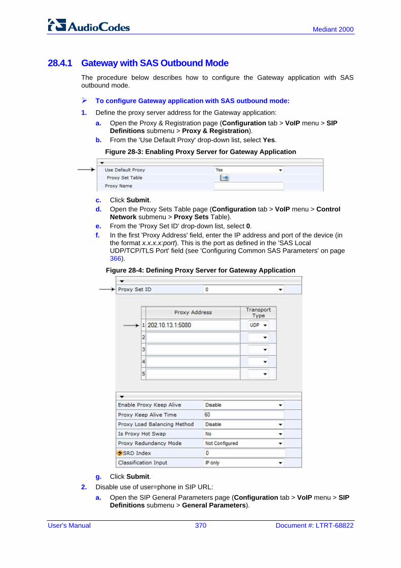
User's Manual 370 Document #: LTRT-68822
Mediant 2000
28.4.1 Gateway with SAS Outbound Mode The procedure below describes how to configure the Gateway application with SAS outbound mode.
To configure Gateway application with SAS outbound mode: 1. Define the proxy server address for the Gateway application:
a. Open the Proxy & Registration page (Configuration tab > VoIP menu > SIP Definitions submenu > Proxy & Registration).
b. From the 'Use Default Proxy' drop-down list, select Yes.
Figure 28-3: Enabling Proxy Server for Gateway Application
c. Click Submit. d. Open the Proxy Sets Table page (Configuration tab > VoIP menu > Control
Network submenu > Proxy Sets Table). e. From the 'Proxy Set ID' drop-down list, select 0. f. In the first 'Proxy Address' field, enter the IP address and port of the device (in
the format x.x.x.x:port). This is the port as defined in the 'SAS Local UDP/TCP/TLS Port' field (see 'Configuring Common SAS Parameters' on page 366).
Figure 28-4: Defining Proxy Server for Gateway Application
g. Click Submit.
2. Disable use of user=phone in SIP URL: a. Open the SIP General Parameters page (Configuration tab > VoIP menu > SIP
Definitions submenu > General Parameters).

Version 6.6 371 Mediant 2000
User's Manual 28. SAS Configuration
b. From the 'Use user=phone in SIP URL' drop-down list, select No. This instructs the Gateway application not to use user=phone in the SIP URL and therefore, REGISTER and INVITE messages use SIP URI. (By default, REGISTER messages are sent with sip uri and INVITE messages with tel uri.)
Figure 28-5: Disabling user=phone in SIP URL
c. Click Submit.
28.4.2 Gateway with SAS Redundant Mode The procedure below describes how to configure the Gateway application with SAS redundant mode.
To configure Gateway application with SAS redundant mode:
1. Define the proxy servers for the Gateway application: a. Open the Proxy & Registration page (Configuration tab > VoIP menu > SIP
Definitions submenu > Proxy & Registration). b. From the 'Use Default Proxy' drop-down list, select Yes.
Figure 28-6: Enabling Proxy Server for Gateway Application
c. Click Submit. d. Open the Proxy Sets Table page (Configuration tab > VoIP menu > Control
Network submenu > Proxy Sets Table). e. From the 'Proxy Set ID' drop-down list, select 0. f. In the first 'Proxy Address' field, enter the IP address of the external proxy server. g. In the second 'Proxy Address' field, enter the IP address and port of the device (in
the format x.x.x.x:port). This is the same port as defined in the 'SAS Local UDP/TCP/TLS Port' field (see 'Configuring Common SAS Parameters' on page 366).

User's Manual 372 Document #: LTRT-68822
Mediant 2000
h. From the 'Proxy Redundancy Mode' drop-down list, select Homing.
Figure 28-7: Defining Proxy Servers for Gateway Application
i. Click Submit.
2. Disable the use of user=phone in the SIP URL: a. Open the SIP General Parameters page (Configuration tab > VoIP menu > SIP
Definitions submenu > General Parameters). b. From the 'Use user=phone in SIP URL' drop-down list, select No. This instructs
the Gateway application not to use user=phone in SIP URL and therefore, REGISTER and INVITE messages use SIP URI. (By default, REGISTER messages are sent with sip uri and INVITE messages with tel uri.)
c. Click Submit.
28.5 Advanced SAS Configuration This section describes the configuration of advanced SAS features that can optionally be implemented in your SAS deployment.
28.5.1 Manipulating URI user part of Incoming REGISTER There are scenarios in which the UAs register to the proxy server with their full phone number (for example, "976653434"), but can receive two types of INVITE messages (calls): INVITEs whose destination is the UAs' full number (when the call arrives from outside
the enterprise) INVITES whose destination is the last four digits of the UAs' phone number ("3434" in
our example) when it is an internal call within the enterprise Therefore, it is important that the device registers the UAs in the SAS registered database with their extension numbers (for example, "3434") in addition to their full numbers. To do this, you can define a manipulation rule to manipulate the SIP Request-URI user part of the AOR (in the To header) in incoming REGISTER requests. Once manipulated, it is saved in this manipulated format in the SAS registered users database in addition to the original (un-manipulated) AOR.
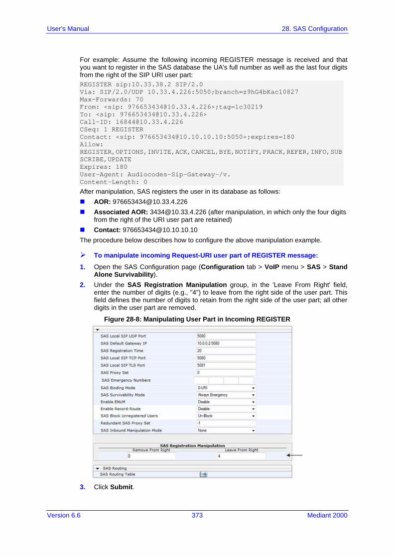
Version 6.6 373 Mediant 2000
User's Manual 28. SAS Configuration
For example: Assume the following incoming REGISTER message is received and that you want to register in the SAS database the UA's full number as well as the last four digits from the right of the SIP URI user part: REGISTER sip:10.33.38.2 SIP/2.0 Via: SIP/2.0/UDP 10.33.4.226:5050;branch=z9hG4bKac10827 Max-Forwards: 70 From: <sip: [email protected]>;tag=1c30219 To: <sip: [email protected]> Call-ID: [email protected] CSeq: 1 REGISTER Contact: <sip: [email protected]:5050>;expires=180 Allow: REGISTER,OPTIONS,INVITE,ACK,CANCEL,BYE,NOTIFY,PRACK,REFER,INFO,SUBSCRIBE,UPDATE Expires: 180 User-Agent: Audiocodes-Sip-Gateway-/v. Content-Length: 0
After manipulation, SAS registers the user in its database as follows: AOR: [email protected] Associated AOR: [email protected] (after manipulation, in which only the four digits
from the right of the URI user part are retained) Contact: [email protected] The procedure below describes how to configure the above manipulation example.
To manipulate incoming Request-URI user part of REGISTER message:
1. Open the SAS Configuration page (Configuration tab > VoIP menu > SAS > Stand Alone Survivability).
2. Under the SAS Registration Manipulation group, in the 'Leave From Right' field, enter the number of digits (e.g., "4") to leave from the right side of the user part. This field defines the number of digits to retain from the right side of the user part; all other digits in the user part are removed.
Figure 28-8: Manipulating User Part in Incoming REGISTER
3. Click Submit.
User's Manual 374 Document #: LTRT-68822
Mediant 2000
Notes:
• The device first does manipulation according to the Remove From Right parameter and only then according to the Leave From Right parameter.
• Only one manipulation rule can be configured. • You can also configure SAS registration manipulation using the table ini file
parameter, SASRegistrationManipulation.
28.5.2 Manipulating Destination Number of Incoming INVITE You can define a manipulation rule to manipulate the destination number in the Request-URI of incoming INVITE messages when SAS is in emergency state. This is required, for example, if the call is destined to a registered user but the destination number in the received INVITE is not the number assigned to the registered user in the SAS registration database. To overcome this and successfully route the call, you can define manipulation rules to change the INVITE's destination number so that it matches that of the registered user in the database. This is done using the IP to IP Inbound Manipulation table. For example, in SAS emergency state, assume an incoming INVITE has a destination number "7001234" which is destined to a user registered in the SAS database as "552155551234". In this scenario, the received destination number needs to be manipulated to the number "552155551234". The outgoing INVITE sent by the device then also contains this number in the Request-URI user part. In normal state, the numbers are not manipulated. In this state, SAS searches the number 552155551234 in its database and if found, it sends the INVITE containing this number to the UA.
To manipulate the destination number in SAS emergency state:
1. Open the SAS Configuration page (Configuration tab > VoIP menu > SAS > Stand Alone Survivability).
2. From the 'SAS Inbound Manipulation Mode' (SASInboundManipulationMode) drop-down list, select Emergency Only.
3. Click Submit; the SAS Inbound Manipulation Mode Table button appears on the page.
4. Click this button to open the IP to IP Inbound Manipulation page. 5. Add your SAS manipulation rule as required. See the table below for descriptions of
the parameters. 6. Click Submit to save your changes.
Notes:
• The following fields in the IP to IP Inbound Manipulation table are not applicable to SAS and must be left at their default values: - 'Additional Manipulation' - default is 0 - 'Manipulation Purpose' - default is Normal - 'Source IP Group' - default is -1
• The IP to IP Inbound Manipulation table can also be configured using the table ini file parameter, IPInboundManipulation.

Version 6.6 375 Mediant 2000
User's Manual 28. SAS Configuration
SAS IP to IP Inbound Manipulation Parameters
Parameter Description
Matching Characteristics (Rule)
Additional Manipulation [IPInboundManipulation_IsAdditionalManipulation]
Determines whether additional SIP URI user part manipulation is done for the table entry rule listed directly above it. [0] No = (Default) Regular manipulation rule (not done in addition to
the rule above it). [1] Yes = If the above row entry rule matched the call, consider this
row entry as a match as well and perform the manipulation specified by this rule.
Note: Additional manipulation can only be done on a different SIP URI, source or destination, to the rule configured in the row above as configured by the 'Manipulated URI' parameter (see below).
Manipulation Purpose [IPInboundManipulation_ManipulationPurpose]
Defines the purpose of the manipulation: [0] Normal = (Default) Inbound manipulations affect the routing input
and source and/or destination number. [1] Routing input only = Inbound manipulations affect the routing input
only, retaining the original source and destination number.
Source IP Group ID [IPInboundManipulation_SrcIpGroup]
Defines the IP Group from where the incoming INVITE is received. For any IP Group, enter the value "-1".
Source Username Prefix [IPInboundManipulation_SrcUsernamePrefix]
Defines the prefix of the source SIP URI user name (usually in the From header). For any prefix, enter the asterisk "*" symbol (default). Note: The prefix can be a single digit or a range of digits. For available notations, see 'Dialing Plan Notation for Routing and Manipulation' on page 501.
Source Host [IPInboundManipulation_SrcHost]
Defines the source SIP URI host name - full name (usually in the From header). For any host name, enter the asterisk "*" symbol (default).
Destination Username Prefix [IPInboundManipulation_DestUsernamePrefix]
Defines the prefix of the destination SIP URI user name (usually in the Request-URI). For any prefix, enter the asterisk "*" symbol (default). Note: The prefix can be a single digit or a range of digits. For available notations, see 'Dialing Plan Notation for Routing and Manipulation' on page 501.
Destination Host [IPInboundManipulation_DestHost]
Defines the destination SIP URI host name - full name (usually in the Request URI). For any host name, enter the asterisk "*" symbol (default).
Request Type [IPInboundManipulation_RequestType]
Defines the SIP request type to which the manipulation rule is applied. [0] All = (Default) All SIP messages. [1] INVITE = All SIP messages except REGISTER and SUBSCRIBE. [2] REGISTER = Only REGISTER messages. [3] SUBSCRIBE = Only SUBSCRIBE messages. [4] INVITE and REGISTER = All SIP messages except SUBSCRIBE. [5] INVITE and SUBSCRIBE = All SIP messages except REGISTER.
Manipulated URI Determines whether the source or destination SIP URI user part is
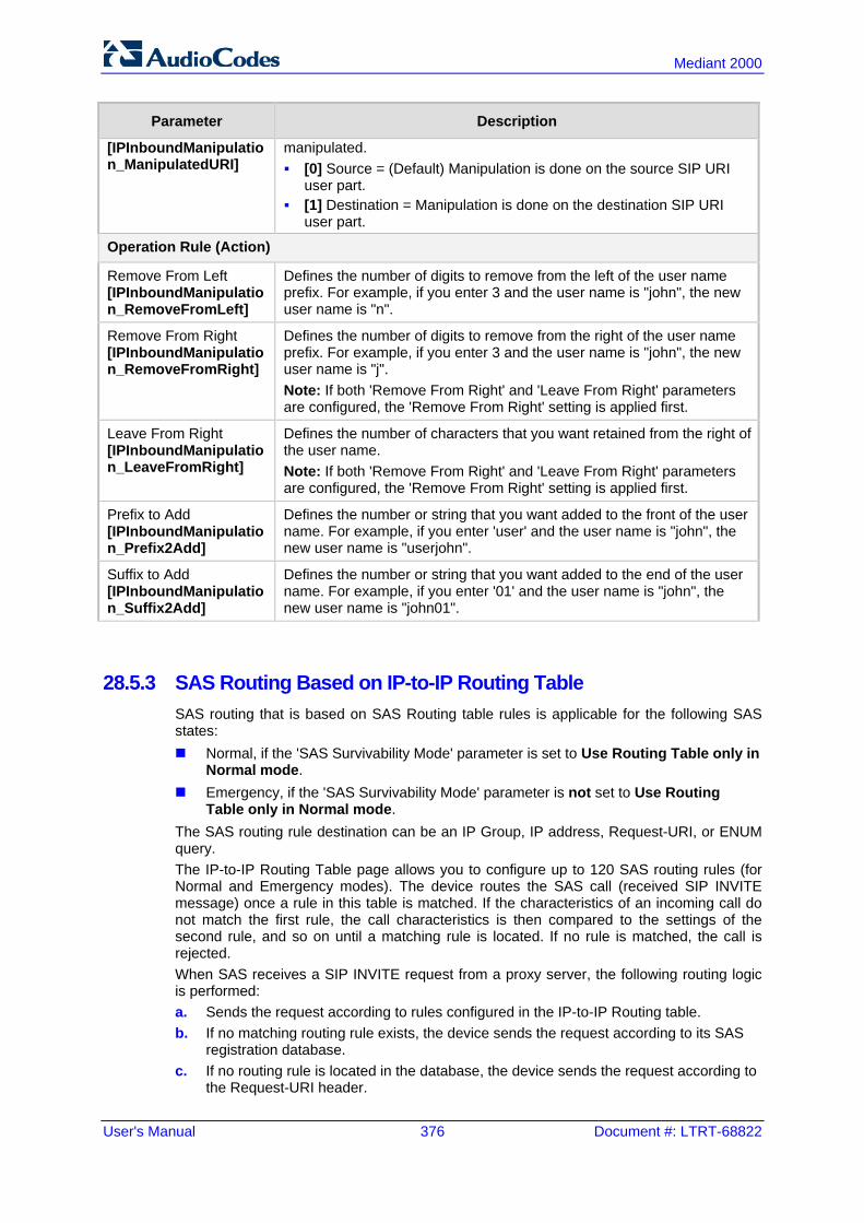
User's Manual 376 Document #: LTRT-68822
Mediant 2000
Parameter Description
[IPInboundManipulation_ManipulatedURI]
manipulated. [0] Source = (Default) Manipulation is done on the source SIP URI
user part. [1] Destination = Manipulation is done on the destination SIP URI
user part.
Operation Rule (Action)
Remove From Left [IPInboundManipulation_RemoveFromLeft]
Defines the number of digits to remove from the left of the user name prefix. For example, if you enter 3 and the user name is "john", the new user name is "n".
Remove From Right [IPInboundManipulation_RemoveFromRight]
Defines the number of digits to remove from the right of the user name prefix. For example, if you enter 3 and the user name is "john", the new user name is "j". Note: If both 'Remove From Right' and 'Leave From Right' parameters are configured, the 'Remove From Right' setting is applied first.
Leave From Right [IPInboundManipulation_LeaveFromRight]
Defines the number of characters that you want retained from the right of the user name. Note: If both 'Remove From Right' and 'Leave From Right' parameters are configured, the 'Remove From Right' setting is applied first.
Prefix to Add [IPInboundManipulation_Prefix2Add]
Defines the number or string that you want added to the front of the user name. For example, if you enter 'user' and the user name is "john", the new user name is "userjohn".
Suffix to Add [IPInboundManipulation_Suffix2Add]
Defines the number or string that you want added to the end of the user name. For example, if you enter '01' and the user name is "john", the new user name is "john01".
28.5.3 SAS Routing Based on IP-to-IP Routing Table SAS routing that is based on SAS Routing table rules is applicable for the following SAS states: Normal, if the 'SAS Survivability Mode' parameter is set to Use Routing Table only in
Normal mode. Emergency, if the 'SAS Survivability Mode' parameter is not set to Use Routing
Table only in Normal mode. The SAS routing rule destination can be an IP Group, IP address, Request-URI, or ENUM query. The IP-to-IP Routing Table page allows you to configure up to 120 SAS routing rules (for Normal and Emergency modes). The device routes the SAS call (received SIP INVITE message) once a rule in this table is matched. If the characteristics of an incoming call do not match the first rule, the call characteristics is then compared to the settings of the second rule, and so on until a matching rule is located. If no rule is matched, the call is rejected. When SAS receives a SIP INVITE request from a proxy server, the following routing logic is performed: a. Sends the request according to rules configured in the IP-to-IP Routing table. b. If no matching routing rule exists, the device sends the request according to its SAS
registration database. c. If no routing rule is located in the database, the device sends the request according to
the Request-URI header.

Version 6.6 377 Mediant 2000
User's Manual 28. SAS Configuration
Note: The IP-to-IP Routing table can also be configured using the table ini file parameter, IP2IPRouting (see 'Configuration Parameters Reference' on page 503).
To configure the IP-to-IP Routing table for SAS:
1. In the SAS Configuration page, click the SAS Routing Table button; the IP-to-IP Routing Table page appears.
2. Click Add; the Add Record dialog box appears:
Figure 28-9: Add Record Dialog Box of SAS IP2IP Routing Page
3. Configure the rule according to the table below. 4. Click Submit to apply your changes. 5. To save the changes to flash memory, see 'Saving Configuration' on page 396.
Note: The following parameters are not applicable to SAS and must be ignored:
• 'Source IP Group ID' • 'Destination IP Group ID' • 'Destination SRD ID' • 'Alternative Route Options'

User's Manual 378 Document #: LTRT-68822
Mediant 2000
SAS IP-to-IP Routing Table Parameters
Parameter Description
Matching Characteristics
Source Username Prefix [IP2IPRouting_SrcUsernamePrefix]
Defines the prefix of the user part of the incoming SIP dialog's source URI (usually the From URI). You can use special notations for denoting the prefix. For example, to denote any prefix, use the asterisk (*) symbol; to denote calls without a user part in the URI, use the $ sign. For available notations, see 'Dialing Plan Notation for Routing and Manipulation' on page 501. The default is * (i.e., any prefix).
Source Host [IP2IPRouting_SrcHost]
Defines the host part of the incoming SIP dialog's source URI (usually the From URI). If this rule is not required, leave the field empty. To denote any host name, use the asterisk (*) symbol (default).
Destination Username Prefix [IP2IPRouting_DestUsernamePrefix]
Defines the prefix of the incoming SIP dialog's destination URI (usually the Request URI) user part. You can use special notations for denoting the prefix. For example, to denote any prefix, use the asterisk (*) symbol; to denote calls without a user part in the URI, use the $ sign. For available notations, see 'Dialing Plan Notation for Routing and Manipulation' on page 501. The default is * (i.e., any prefix).
Destination Host [IP2IPRouting_DestHost]
Defines the host part of the incoming SIP dialog’s destination URI (usually the Request-URI). If this rule is not required, leave the field empty. The asterisk (*) symbol (default) can be used to denote any destination host.
Message Condition [IP2IPRouting_MessageCondition]
Selects a Message Condition rule. To configure Message Condition rules, see Configuring Condition Rules.
ReRoute IP Group ID [IP2IPRouting_ReRouteIPGroupID]
Defines the IP Group that initiated (sent) the SIP redirect response (e.g., 3xx) or REFER message. This field is typically used for re-routing requests (e.g., INVITEs) when interworking is required for SIP 3xx redirect responses or REFER messages (for more information, see Interworking SIP 3xx Redirect Responses and Interworking SIP REFER Messages, respectively). This parameter functions together with the 'Call Trigger' field (see below). The default is -1 (i.e., not configured).
Call Trigger [IP2IPRouting_Trigger]
Defines the reason (i.e, trigger) for re-routing the SIP request: [0] Any = (Default) This routing rule is used for all scenarios (re-
routes and non-re-routes). [1] 3xx = Re-routes the request if it was triggered as a result of a SIP
3xx response. [2] REFER = Re-routes the INVITE if it was triggered as a result of a
REFER request. [3] 3xx or REFER = Applies to options [1] and [2]. [4] Initial only = This routing rule is used for regular requests that the
device forwards to the destination. This rule is not used for re-routing of requests triggered by the receipt of REFER or 3xx.

Version 6.6 379 Mediant 2000
User's Manual 28. SAS Configuration
Parameter Description
Operation Routing Rule
Destination Type [IP2IPRouting_DestType]
Determines the destination type to which the outgoing SIP dialog is sent. [0] IP Group = (Default) The SIP dialog is sent to the IP Group’s
Proxy Set (SERVER-type IP Group) or registered contact from the database (if USER-type IP Group).
[1] Dest Address = The SIP dialog is sent to the address configured in the following fields: 'Destination SRD ID', 'Destination Address', 'Destination Port', and 'Destination Transport Type'.
[2] Request URI = The SIP dialog is sent to the address indicated in the incoming Request-URI. If the fields 'Destination Port' and 'Destination Transport Type' are configured, the incoming Request-URI parameters are overridden and these fields take precedence.
[3] ENUM = An ENUM query is sent to include the destination address. If the fields 'Destination Port' and 'Destination Transport Type' are configured, the incoming Request-URI parameters are overridden and these fields take precedence.
[4] Hunt Group = Used for call center survivability. For more information, see Call Survivability for Call Centers.
[5] Dial Plan = The IP destination is determined by a Dial Plan index of the loaded Dial Plan file. The syntax of the Dial Plan index in the Dial Plan file is as follows: <destination / called prefix number>,0,<IP destination> Note that the second parameter "0" is ignored. An example of a configured Dial Plan (# 6) in the Dial Plan file is shown below: [ PLAN6 ] 200,0,10.33.8.52 ; called prefix 200 is routed to destination 10.33.8.52 201,0,10.33.8.52 300,0,itsp.com ; called prefix 300 is routed to destination itsp.com
Once the Dial Plan is defined, you need to assign it (0 to 7) to the routing rule as the destination in the 'Destination Address' parameter, where "0" denotes [PLAN1], "1" denotes [PLAN2], and so on.
[7] LDAP = LDAP-based routing.
Destination IP Group ID [IP2IPRouting_DestIPGroupID]
Defines the IP Group ID to where you want to route the call. The SIP dialog messages are sent to the IP address defined for the Proxy Set associated with this IP Group. If you select an IP Group, it is unnecessary to configure a destination IP address (in the 'Destination Address' field). However, if both parameters are configured, then the IP Group takes precedence. If the destination IP Group is of USER type, the device searches for a match between the Request-URI (of the received SIP dialog) to an AOR registration record in the device's database. The SIP dialog is then sent to the IP address of the registered contact. The default is -1. Notes: This parameter is only relevant if the parameter 'Destination Type' is
set to 'IP Group'. However, regardless of the settings of the parameter 'Destination Type', the IP Group is still used - only for determining the IP Profile or outgoing SRD. If neither IP Group nor SRD are defined in this table, the destination SRD is determined according to the source SRD associated with the Source IP Group (configured in the IP Group

User's Manual 380 Document #: LTRT-68822
Mediant 2000
Parameter Description
table, see 'Configuring IP Groups' on page 204). If this table does not define an IP Group but only an SRD, then the first IP Group associated with this SRD (in the IP Group table) is used.
If the selected destination IP Group ID is type SERVER, the request is routed according to the IP Group addresses.
If the selected destination IP Group ID is type USER, the request is routed according to the IP Group specific database (i.e., only to registered users of the selected database).
If the selected destination IP Group ID is ANY USER ([-2]), the request is routed according to the general database (i.e., any matching registered user).
Destination Address [IP2IPRouting_DestAddress]
Defines the destination IP address (or domain name, e.g., domain.com) to where the call is sent. If ENUM-based routing is used (i.e., the 'Destination Type' parameter is set to ENUM) this parameter defines the IP address or domain name (FQDN) of the ENUM service, for example, e164.arpa, e164.customer.net, or NRENum.net. The device sends the ENUM query containing the destination phone number to an external DNS server, configured in the Multiple Interface table. The ENUM reply includes a SIP URI (user@host) which is used as the destination Request-URI in this routing table. Notes: This parameter is applicable only if the parameter 'Destination Type'
is set to 'Dest Address' [1] or ENUM [3]. When using domain names, enter a DNS server IP address or
alternatively, define these names in the 'Internal DNS Table' (see 'Configuring the Internal SRV Table' on page 122).
Destination Port [IP2IPRouting_DestPort]
Defines the destination port to where the call is sent.
Destination Transport Type [IP2IPRouting_DestTransportType]
Defines the transport layer type for sending the call: [-1] Not Configured (default) [0] UDP [1] TCP [2] TLS Note: When this parameter is set to -1, the transport type is determined by the parameter SIPTransportType.
Cost Group [IP2IPRouting_CostGroup]
Assigns a Cost Group to the routing rule for determining the cost of the call. To configure Cost Groups, see 'Configuring Cost Groups' on page 196. By default, no Cost Group is assigned to the rule.

Version 6.6 381 Mediant 2000
User's Manual 28. SAS Configuration
28.5.4 Blocking Calls from Unregistered SAS Users To prevent malicious calls, for example, service theft, it is recommended to configure the feature for blocking SIP INVITE messages received from SAS users that are not registered in the SAS database. This applies to SAS in normal and emergency states.
To block calls from unregistered SAS users: 1. Open the SAS Configuration page (Configuration tab > VoIP menu > SAS Stand
Alone Survivability). 2. From the 'SAS Block Unregistered Users' drop-down list, select Block. 3. Click Submit to apply your changes.
28.5.5 Configuring SAS Emergency Calls You can configure SAS to route emergency calls (such as 911 in North America) directly to the PSTN through its E1/T1 trunk. Thus, even during a communication failure with the external proxy, enterprise UAs can still make emergency calls. You can define up to four emergency numbers, where each number can include up to four digits. When SAS receives a SIP INVITE (from a UA) that includes one of the user-defined emergency numbers in the SIP user part, it forwards the INVITE directly to the default gateway (see 'SAS Routing in Emergency State' on page 363). The default gateway is defined in the 'SAS Default Gateway IP' field, and this is the device itself. The device then sends the call directly to the PSTN. This feature is applicable to SAS in normal and emergency states.
To configure SAS emergency numbers:
1. Open the SAS Configuration page (Configuration tab > VoIP menu > SAS > Stand Alone Survivability).
2. In the ‘SAS Default Gateway IP' field, define the IP address and port (in the format x.x.x.x:port) of the device (Gateway application).
Note: The port of the device is defined in the 'SIP UDP/TCP/TLS Local Port' field in the SIP General Parameters page (Configuration tab > VoIP menu > SIP Definitions > General Parameters).

User's Manual 382 Document #: LTRT-68822
Mediant 2000
3. In the 'SAS Emergency Numbers' field, enter an emergency number in each field box.
Figure 28-10: Configuring SAS Emergency Numbers
4. Click Submit to apply your changes.
28.5.6 Adding SIP Record-Route Header to SIP INVITE You can configure SAS to add the SIP Record-Route header to SIP requests (e.g. INVITE) received from enterprise UAs. SAS then sends the request with this header to the proxy. The Record-Route header includes the IP address of the SAS application. This ensures that future requests in the SIP dialog session from the proxy to the UAs are routed through the SAS application. If not configured, future request within the dialog from the proxy are sent directly to the UAs (and do not traverse SAS). When this feature is enabled, the SIP Record-Route header includes the URI "lr" parameter, indicating loose routing, as shown in the following example: Record-Route: <sip:server10.biloxi.com;lr>
Note: This feature is applicable only to the SAS Outbound mode.
To enable the Record-Route header:
1. Open the SAS Configuration page (Configuration tab > VoIP menu > SAS > Stand Alone Survivability).
2. From the ‘Enable Record-Route' drop-down list, select Enable. 3. Click Submit to apply your changes.
28.5.7 Re-using TCP Connections You can enable the SAS application to re-use the same TCP connection for sessions (multiple SIP requests / responses) with the same SIP UA. The benefits of this feature include less CPU and memory usage because fewer TCP connections are open and reduced network congestion. For example, assume User A sends a REGISTER message to SAS with transport=TCP, and User B sends an INVITE message to A using SAS. In this scenario, the SAS application forwards the INVITE request using the same TCP connection that User A initially opened with the REGISTER message.

Version 6.6 383 Mediant 2000
User's Manual 28. SAS Configuration
To re-use TCP connection sessions in SAS
1. Open the SAS Configuration page (Configuration tab > VoIP menu > SAS > Stand Alone Survivability).
2. From the ‘SAS Connection Reuse' drop-down list, select Enable. 3. Click Submit to apply your changes.
28.5.8 Replacing Contact Header for SIP Messages You can configure SAS to change the SIP Contact header so that it points to the SAS host. This ensures that in the message, the top-most SIP Via header and the Contact header point to the same host.
Notes:
• This feature is applicable only to the SAS Outbound mode. • The device may become overloaded if this feature is enabled, as all incoming SIP
dialog requests traverse the SAS application.
Currently, this feature can be configured only by the ini file parameter, SASEnableContactReplace: [0] (Default): Disable - when relaying requests, SAS adds a new Via header (with the
IP address of the SAS application) as the top-most Via header and retains the original Contact header. Thus, the top-most Via header and the Contact header point to different hosts.
[1]: Enable - SAS changes the Contact header so that it points to the SAS host and therefore, the top-most Via header and the Contact header point to the same host.

User's Manual 384 Document #: LTRT-68822
Mediant 2000
28.6 Viewing Registered SAS Users You can view all the users that are registered in the SAS registration database. This is displayed in the 'SAS/SBC Registered Users page, as described in 'Viewing Registered Users' on page 451.
Note: You can increase the maximum number of registered SAS users, by implementing the SAS Cascading feature, as described in 'SAS Cascading' on page 385.

Version 6.6 385 Mediant 2000
User's Manual 29. SAS Cascading
29 SAS Cascading The SAS Cascading feature allows you to increase the number of SAS users above the maximum supported by the SAS gateway. This is achieved by deploying multiple SAS gateways in the network. For example, if the SAS gateway supports up to 600 users, but your enterprise has 1,500 users, you can deploy three SAS gateways to accommodate all users: the first SAS gateway can service 600 registered users, the second SAS gateway the next 600 registered users, and the third SAS gateway the rest (i.e., 300 registered users). In SAS Cascading, the SAS gateway first attempts to locate the called user in its SAS registration database. Only if the user is not located, does the SAS gateway send it on to the next SAS gateway according to the SAS Cascading configuration. There are two methods for configuring SAS Cascading. This depends on whether the users can be identified according to their phone extension numbers: SAS Routing Table: If users can be identified with unique phone extension numbers,
then the SAS Routing table is used to configure SAS Cascading. This SAS Cascading method routes calls directly to the SAS Gateway (defined by IP address) to which the called SAS user is registered. The following is an example of a SAS Cascading deployment of users with unique phone extension numbers: • users registered to the first SAS gateway start with extension number “40” • users registered to the second SAS gateway start with extension number “20” • users registered to the third SAS gateway start with extension number “30” The SAS Routing table rules for SAS Cascading are created using the destination (called) extension number prefix (e.g., “30”) and the destination IP address of the SAS gateway to which the called user is registered. Such SAS routing rules must be configured at each SAS gateway to allow routing between the SAS users. The routing logic for SAS Cascading is similar to SAS routing in Emergency state (see the flowchart in 'SAS Routing in Emergency State' on page 363). For a description on the SAS Routing table, see 'SAS Routing Based on IP-to-IP Routing Table' on page 376. The figure below illustrates an example of a SAS Cascading call flow configured using the SAS Routing table. In this example, a call is routed from SAS Gateway (A) user to a user on SAS Gateway (B).
Figure 29-1: SAS Cascading Using SAS Routing Table - Example

User's Manual 386 Document #: LTRT-68822
Mediant 2000
SAS Redundancy mode: If users cannot be distinguished (i.e., associated to a specific SAS gateway), then the SAS Redundancy feature is used to configure SAS Cascading. This mode routes the call in a loop fashion, from one SAS gateway to the next, until the user is located. Each SAS gateway serves as the redundant SAS gateway (“redundant SAS proxy server”) for the previous SAS gateway (in a one-way direction). For example, if a user calls a user that is not registered on the same SAS gateway, the call is routed to the second SAS gateway, and if not located, it is sent to the third SAS gateway. If the called user is not located on the third (or last) SAS gateway, it is then routed back to the initial SAS gateway, which then routes the call to the default gateway (i.e., to the PSTN). Each SAS gateway adds its IP address to the SIP via header in the INVITE message before sending it to the next (“redundant”) SAS gateway. If the SAS gateway receives an INVITE and its IP address appears in the SIP via header, it sends it to the default gateway (and not to the next SAS gateway), as defined by the SASDefaultGatewayIP parameter. Therefore, this mode of operation prevents looping between SAS gateways when a user is not located on any of the SAS gateways. The figure below illustrates an example of a SAS Cascading call flow when configured using the SAS Redundancy feature. In this example, a call is initiated from a SAS Gateway (A) user to a user that is not located on any SAS gateway. The call is subsequently routed to the PSTN.
Figure 29-2: SAS Cascading Using SAS Redundancy Mode - Example

Part VII IP Media Capabilities


Version 6.6 389 Mediant 2000
User's Manual 30. Transcoding using Third-Party Call Control
30 Transcoding using Third-Party Call Control The device supports transcoding using a third-party call control Application server. This support is provided by the following: Using RFC 4117 (see 'Using RFC 4117' on page 389)
Note: Transcoding can also be implemented using the IP-to-IP application.
30.1 Using RFC 4117 The device supports RFC 4117 - Transcoding Services Invocation in the Session Initiation Protocol (SIP) Using Third Party Call Control (3pcc) - providing transcoding services (i.e., acting as a transcoding server). This is used in scenarios where two SIP User Agents (UA) would like to establish a session, but do not have a common coder or media type. When such incompatibilities are found, the UAs need to invoke transcoding services to successfully establish the session. Note that transcoding can also be performed using NetAnn, according to RFC 4240. To enable the RFC 4117 feature, the parameter EnableRFC4117Transcoding must be set to 1 (and the device must be reset). The 3pcc call flow is as follows: The device receives from one of the UAs, a single INVITE with an SDP containing two media lines. Each media represents the capabilities of each of the two UAs. The device needs to find a match for both of the media, and opens two channels with two different media ports to the different UAs. The device performs transcoding between the two voice calls. In the example below, an Application Server sends a special INVITE that consists of two media lines to perform transcoding between G.711 and G.729: m=audio 20000 RTP/AVP 0 c=IN IP4 A.example.com m=audio 40000 RTP/AVP 18 c=IN IP4 B.example.com

User's Manual 390 Document #: LTRT-68822
Mediant 2000
Reader's Notes

Part VIII Maintenance


Version 6.6 393 Mediant 2000
User's Manual 31. Basic Maintenance
31 Basic Maintenance The Maintenance Actions page allows you to perform the following: Reset the device - see 'Resetting the Device' on page 393 Lock and unlock the device - see 'Locking and Unlocking the Device' on page 395 Save configuration to the device's flash memory - see 'Saving Configuration' on page
396
To access the Maintenance Actions page, do one of the following: On the toolbar, click the Device Actions button, and then from the drop-down menu,
choose Reset. On the Navigation bar, click the Maintenance tab, and then in the Navigation tree,
select the Maintenance menu and choose Maintenance Actions.
Figure 31-1: Maintenance Actions Page
31.1 Resetting the Device The Maintenance Actions page allows you to remotely reset the device. In addition, before resetting the device, you can choose the following options: Save the device's current configuration to the device's flash memory (non-volatile). Perform a graceful shutdown, whereby device reset starts only after a user-defined
time (i.e., timeout) or after no more active traffic exists (the earliest thereof).
Notes:
• Throughout the Web interface, parameters displayed with a lightning symbol are not applied on-the-fly and require that you reset the device for them to take effect.
• When you modify parameters that require a device reset, once you click the Submit button in the relevant page, the toolbar displays "Reset" (see 'Toolbar Description' on page 38) to indicate that a device reset is required.
• After you reset the device, the Web GUI is displayed in Basic view (see 'Displaying Navigation Tree in Basic and Full View' on page 39).

User's Manual 394 Document #: LTRT-68822
Mediant 2000
To reset the device:
1. Open the Maintenance Actions page (see 'Basic Maintenance' on page 393). 2. Under the 'Reset Configuration' group, from the 'Burn To FLASH' drop-down list,
select one of the following options: • Yes: The device's current configuration is saved (burned) to the flash memory
prior to reset (default). • No: Resets the device without saving the current configuration to flash (discards
all unsaved modifications). 3. Under the 'Reset Configuration' group, from the 'Graceful Option' drop-down list,
select one of the following options: • Yes: Reset starts only after the user-defined time in the 'Shutdown Timeout' field
(see Step 4) expires or after no more active traffic exists (the earliest thereof). In addition, no new traffic is accepted.
• No: Reset starts regardless of traffic, and any existing traffic is terminated at once.
4. In the 'Shutdown Timeout' field (relevant only if the 'Graceful Option' in the previous step is set to Yes), enter the time after which the device resets. Note that if no traffic exists and the time has not yet expired, the device resets.
5. Click the Reset button; a confirmation message box appears, requesting you to confirm.
Figure 31-2: Reset Confirmation Message Box
6. Click OK to confirm device reset; if the parameter 'Graceful Option' is set to Yes (in
Step 3), the reset is delayed and a screen displaying the number of remaining calls and time is displayed. When the device begins to reset, a message appears notifying you of this.
31.2 Remotely Resetting Device using SIP NOTIFY The device can be remotely reset upon the receipt of a SIP NOTIFY that includes an Event header set to 'check-sync;reboot=true', as shown in the example below: NOTIFY sip:<user>@<dsthost> SIP/2.0 To: sip:<user>@<dsthost> From: sip:sipsak@<srchost> CSeq: 10 NOTIFY Call-ID: 1234@<srchost> Event: check-sync;reboot=true

Version 6.6 395 Mediant 2000
User's Manual 31. Basic Maintenance
To enable remote reset upon receipt of SIP NOTIFY:
1. Open the Advanced Parameters page (Configuration tab > VoIP menu > SIP Definitions > Advanced Parameters).
2. Under the Misc Parameters group, set the 'SIP Remote Rest' parameter to Enable. 3. Click Submit.
Note: This SIP Event header value is proprietary to AudioCodes.
31.3 Locking and Unlocking the Device The Lock and Unlock option allows you to lock the device so that it doesn't accept any new calls and maintains only the current calls. This is useful when, for example, you are uploading new software files to the device and you don't want any traffic to interfere with the process.
To lock the device:
1. Open the Maintenance Actions page (see 'Basic Maintenance' on page 393). 2. Under the 'LOCK / UNLOCK' group, from the 'Graceful Option' drop-down list, select
one of the following options: • Yes: The device is 'locked' only after the user-defined time in the 'Lock Timeout'
field (see Step 3) expires or no more active traffic exists (the earliest thereof). In addition, no new traffic is accepted.
• No: The device is 'locked' regardless of traffic. Any existing traffic is terminated immediately.
Note: These options are only available if the current status of the device is in the Unlock state.
3. In the 'Lock Timeout' field (relevant only if the parameter 'Graceful Option' in the previous step is set to Yes), enter the time (in seconds) after which the device locks. Note that if no traffic exists and the time has not yet expired, the device locks.
4. Click the LOCK button; a confirmation message box appears requesting you to confirm device Lock.
Figure 31-3: Device Lock Confirmation Message Box
5. Click OK to confirm device Lock; if 'Graceful Option' is set to Yes, the lock is delayed
and a screen displaying the number of remaining calls and time is displayed. Otherwise, the lock process begins immediately. The Current Admin State' field displays the current state - "LOCKED" or "UNLOCKED".

User's Manual 396 Document #: LTRT-68822
Mediant 2000
To unlock the device: 1. Open the Maintenance Actions page (see 'Maintenance Actions' on page 393). 2. Under the 'LOCK / UNLOCK' group, click the UNLOCK button. Unlock starts
immediately and the device accepts new incoming calls.
Note: The Home page's General Information pane displays whether the device is locked or unlocked (see 'Viewing the Home Page' on page 57).
31.4 Saving Configuration The Maintenance Actions page allows you to save (burn) the current parameter configuration (including loaded auxiliary files) to the device's non-volatile memory (i.e., flash). The parameter modifications that you make throughout the Web interface's pages are temporarily saved (to the volatile memory - RAM) when you click the Submit button on these pages. Parameter settings that are saved only to the device's RAM revert to their previous settings after a hardware/software reset (or power failure). Therefore, to ensure that your configuration changes are retained, you must save them to the device's flash memory using the burn option described below.
To save the changes to the non-volatile flash memory : 1. Open the Maintenance Actions page (see 'Basic Maintenance' on page 393). 2. Under the 'Save Configuration' group, click the BURN button; a confirmation message
appears when the configuration successfully saves.
Notes:
• Saving configuration to the non-volatile memory may disrupt current traffic on the device. To avoid this, disable all new traffic before saving, by performing a graceful lock (see 'Locking and Unlocking the Device' on page 395).
• Throughout the Web interface, parameters displayed with the lightning symbol are not applied on-the-fly and require that you reset the device for them to take effect (see 'Resetting the Device' on page 393).
• The Home page's General Information pane displays whether the device is currently "burning" the configuration (see 'Viewing the Home Page' on page 57).

Version 6.6 397 Mediant 2000
User's Manual 32. Restarting a B-Channel
32 Restarting a B-Channel You can restart a specific B-channel belonging to an ISDN or CAS trunk, using the SNMP MIB variable, acTrunkISDNCommonRestartBChannel or the EMS management tool (refer to the EMS User's Manual). This may be useful, for example, for troubleshooting specific voice channels.
Notes:
• If a voice call is currently in progress on the B-channel, it is disconnected when the B-channel is restarted.
• B-channel restart can only be done if the D-channel of the trunk to which it belongs is synchronized (Layer 2).
• B-channel restart does not affect the B-channel's configuration.

User's Manual 398 Document #: LTRT-68822
Mediant 2000
Reader's Notes

Version 6.6 399 Mediant 2000
User's Manual 33. Software Upgrade
33 Software Upgrade The Software Update menu allows you to do the following: Load Auxiliary Files (see 'Loading Auxiliary Files' on page 399) Load Software License Key (see 'Software License Key' on page 415) Upgrade the Device using the Software Upgrade Wizard (see 'Software Upgrade
Wizard' on page 419) Load/save Configuration File (see 'Backing Up and Loading Configuration File' on
page 422)
33.1 Loading Auxiliary Files Various Auxiliary files can be installed on the device. These Auxiliary files provide the device with additional configuration settings. The table below lists the different types of Auxiliary files:
Auxiliary Files
File Description
INI Configures the device. The Web interface enables practically full device provisioning. However, some features may only be configured by ini file or you may wish to configure your device using the ini file. For more information on using the ini file to configure the device, see 'INI File-Based Management' on page 89.
CAS CAS auxiliary files containing the CAS Protocol definitions for CAS-terminated trunks (for various types of CAS signaling). You can use the supplied files or construct your own files. Up to eight different CAS files can be installed on the device. For more information, see CAS Files on page 404.
Call Progress Tones
Region-specific, telephone exchange-dependent file that contains the Call Progress Tones (CPT) levels and frequencies for the device. The default CPT file is U.S.A. For more information, see 'Call Progress Tones File' on page 401.
Prerecorded Tones
The Prerecorded Tones (PRT) file enhances the device's capabilities of playing a wide range of telephone exchange tones that cannot be defined in the CPT file. For more information, see Prerecorded Tones File on page 403.
Dial Plan Provides dialing plans, for example, to know when to stop collecting dialed digits and start forwarding them or for obtaining the destination IP address for outbound IP routing. For more information, see 'Dial Plan File' on page 404.
User Info The User Information file maps PBX extensions to IP numbers. This file can be used to represent PBX extensions as IP phones in the global 'IP world'. For more information, see 'User Information File' on page 410.
AMD Sensitivity Answer Machine Detector (AMD) Sensitivity file containing the AMD Sensitivity suites. For more information, see AMD Sensitivity File on page 412.
The Auxiliary files can be loaded to the device using one of the following methods: Web interface. TFTP: This is done by specifying the name of the Auxiliary file in an ini file (see
Auxiliary and Configuration Files Parameters) and then loading the ini file to the device. The Auxiliary files listed in the ini file are then automatically loaded through

User's Manual 400 Document #: LTRT-68822
Mediant 2000
TFTP during device startup. If the ini file does not contain a specific auxiliary file type, the device uses the last auxiliary file of that type that was stored on its non-volatile memory.
Notes:
• You can schedule automatic loading of updated auxiliary files using HTTP/HTTPS, FTP, or NFS. For more information on automatic updates, see 'Automatic Update' on page 423.
• When loading an ini file using this Web page, parameters that are excluded from the loaded ini file retain their current settings (incremental).
• Saving an auxiliary file to flash memory may disrupt traffic on the device. To avoid this, disable all traffic on the device by performing a graceful lock as described in 'Locking and Unlocking the Device' on page 395.
• For deleting auxiliary files, see 'Viewing Device Information' on page 437.
The procedure below describes how to load Auxiliary files using the Web interface.
To load auxiliary files to the device using the Web interface: 1. Open the Load Auxiliary Files page (Maintenance tab > Software Update menu >
Load Auxiliary Files).
Note: The appearance of certain file load fields depends on the installed Software License Key.

Version 6.6 401 Mediant 2000
User's Manual 33. Software Upgrade
2. Click the Browse button corresponding to the file type that you want to load, navigate to the folder in which the file is located, and then click Open; the name and path of the file appear in the field next to the Browse button.
3. Click the Load File button corresponding to the file you want to load. 4. Repeat steps 2 through 3 for each file you want to load. 5. Save the loaded auxiliary files to flash memory, see 'Saving Configuration' on page
396 and reset the device (if you have loaded a Call Progress Tones file), see 'Resetting the Device' on page 393.
You can also load auxiliary files using an ini file that is loaded to the device with BootP. Each auxiliary file has a specific ini file parameter that specifies the name of the auxiliary file that you want to load to the device with the ini file. For a description of these ini file parameters, see Auxiliary and Configuration Files Parameters.
To load auxiliary files using an ini file:
1. In the ini file, define the auxiliary files to be loaded to the device. You can also define in the ini file whether the loaded files must be stored in the non-volatile memory so that the TFTP process is not required every time the device boots up.
2. Save the auxiliary files and the ini file in the same directory on your local PC. 3. Invoke a BootP/TFTP session; the ini and associated auxiliary files are loaded to the
device.
33.1.1 Call Progress Tones File The Call Progress Tones (CPT) auxiliary file includes the definitions of the Call Progress Tones (levels and frequencies) that are detected / generated by the device. You can use one of the supplied auxiliary files (.dat file format) or create your own file. To create your own file, it's recommended to modify the supplied usa_tone.ini file (in any standard text editor) to suit your specific requirements and then convert the modified ini file into binary format, using AudioCodes DConvert utility. For a description on converting a CPT ini file into a binary dat file, refer to the DConvert Utility User's Guide.
Note: Only the dat file format can be loaded to the device.
You can create up to 32 different Call Progress Tones, each with frequency and format attributes. The frequency attribute can be single or dual-frequency (in the range of 300 to 1980 Hz) or an Amplitude Modulated (AM). Up to 64 different frequencies are supported. Only eight AM tones, in the range of 1 to 128 kHz, can be configured (the detection range is limited to 1 to 50 kHz). Note that when a tone is composed of a single frequency, the second frequency field must be set to zero. The format attribute can be one of the following: Continuous: A steady non-interrupted sound (e.g., a dial tone). Only the 'First Signal
On time' should be specified. All other on and off periods must be set to zero. In this case, the parameter specifies the detection period. For example, if it equals 300, the tone is detected after 3 seconds (300 x 10 msec). The minimum detection time is 100 msec.
Cadence: A repeating sequence of on and off sounds. Up to four different sets of on/off periods can be specified.
Burst: A single sound followed by silence. Only the 'First Signal On time' and 'First Signal Off time' should be specified. All other on and off periods must be set to zero.

User's Manual 402 Document #: LTRT-68822
Mediant 2000
The burst tone is detected after the off time is completed. You can specify several tones of the same type. These additional tones are used only for tone detection. Generation of a specific tone conforms to the first definition of the specific tone. For example, you can define an additional dial tone by appending the second dial tone's definition lines to the first tone definition in the ini file. The device reports dial tone detection if either of the two tones is detected. The Call Progress Tones section of the ini file comprises the following segments: [NUMBER OF CALL PROGRESS TONES]: Contains the following key:
'Number of Call Progress Tones' defining the number of Call Progress Tones that are defined in the file.
[CALL PROGRESS TONE #X]: containing the Xth tone definition, starting from 0 and not exceeding the number of Call Progress Tones less 1 defined in the first section (e.g., if 10 tones, then it is 0 to 9), using the following keys: • Tone Type: Call Progress Tone types:
♦ [1] Dial Tone ♦ [2] Ringback Tone ♦ [3] Busy Tone ♦ [4] Congestion Tone ♦ [6] Warning Tone ♦ [7] Reorder Tone ♦ [17] Call Waiting Ringback Tone - heard by the calling party ♦ [18] Comfort Tone ♦ [23] Hold Tone ♦ [46] Beep Tone
• Tone Modulation Type: Amplitude Modulated (1) or regular (0) • Tone Form: The tone's format can be one of the following:
♦ Continuous (1) ♦ Cadence (2) ♦ Burst (3)
• Low Freq [Hz]: Frequency (in Hz) of the lower tone component in case of dual frequency tone, or the frequency of the tone in case of single tone. This is not relevant to AM tones.
• High Freq [Hz: Frequency (in Hz) of the higher tone component in case of dual frequency tone, or zero (0) in case of single tone (not relevant to AM tones).
• Low Freq Level [-dBm]: Generation level 0 dBm to -31 dBm in dBm (not relevant to AM tones).
• High Freq Level: Generation level of 0 to -31 dBm. The value should be set to 32 in the case of a single tone (not relevant to AM tones).
• First Signal On Time [10 msec]: 'Signal On' period (in 10 msec units) for the first cadence on-off cycle. For continuous tones, this parameter defines the detection period. For burst tones, it defines the tone's duration.
• First Signal Off Time [10 msec]: 'Signal Off' period (in 10 msec units) for the first cadence on-off cycle (for cadence tones). For burst tones, this parameter defines the off time required after the burst tone ends and the tone detection is reported. For continuous tones, this parameter is ignored.
• Second Signal On Time [10 msec]: 'Signal On' period (in 10 msec units) for the second cadence on-off cycle. Can be omitted if there isn't a second cadence.
• Second Signal Off Time [10 msec]: 'Signal Off' period (in 10 msec units) for the second cadence on-off cycle. Can be omitted if there isn't a second cadence.
• Third Signal On Time [10 msec]: 'Signal On' period (in 10 msec units) for the third cadence on-off cycle. Can be omitted if there isn't a third cadence.

Version 6.6 403 Mediant 2000
User's Manual 33. Software Upgrade
• Third Signal Off Time [10 msec]: 'Signal Off' period (in 10 msec units) for the third cadence on-off cycle. Can be omitted if there isn't a third cadence.
• Fourth Signal On Time [10 msec]: 'Signal On' period (in 10 msec units) for the fourth cadence on-off cycle. Can be omitted if there isn't a fourth cadence.
• Fourth Signal Off Time [10 msec]: 'Signal Off' period (in 10 msec units) for the fourth cadence on-off cycle. Can be omitted if there isn't a fourth cadence.
• Carrier Freq [Hz]: Frequency of the carrier signal for AM tones. • Modulation Freq [Hz]: Frequency of the modulated signal for AM tones (valid
range from 1 to 128 Hz). • Signal Level [-dBm]: Level of the tone for AM tones. • AM Factor [steps of 0.02]: Amplitude modulation factor (valid range from 1 to
50). Recommended values from 10 to 25.
Notes:
• When the same frequency is used for a continuous tone and a cadence tone, the 'Signal On Time' parameter of the continuous tone must have a value that is greater than the 'Signal On Time' parameter of the cadence tone. Otherwise, the continuous tone is detected instead of the cadence tone.
• The tones frequency must differ by at least 40 Hz between defined tones.
For example, to configure the dial tone to 440 Hz only, enter the following text: [NUMBER OF CALL PROGRESS TONES] Number of Call Progress Tones=1 #Dial Tone [CALL PROGRESS TONE #0] Tone Type=1 Tone Form =1 (continuous) Low Freq [Hz]=440 High Freq [Hz]=0 Low Freq Level [-dBm]=10 (-10 dBm) High Freq Level [-dBm]=32 (use 32 only if a single tone is required) First Signal On Time [10msec]=300; the dial tone is detected after 3 sec First Signal Off Time [10msec]=0 Second Signal On Time [10msec]=0 Second Signal Off Time [10msec]=0
33.1.2 Prerecorded Tones File The CPT file mechanism has several limitations such as a limited number of predefined tones and a limited number of frequency integrations in one tone. To overcome these limitations and provide tone generation capability that is more flexible, the Prerecorded Tones (PRT) file can be used. If a specific prerecorded tone exists in the PRT file, it takes precedence over the same tone that exists in the CPT file and is played instead of it.
Note: The PRT are used only for generation of tones. Detection of tones is performed according to the CPT file.
User's Manual 404 Document #: LTRT-68822
Mediant 2000
The PRT is a .dat file containing a set of prerecorded tones that can be played by the device. Up to 40 tones (totaling approximately 10 minutes) can be stored in a single PRT file on the device's flash memory. The prerecorded tones are prepared offline using standard recording utilities (such as CoolEditTM) and combined into a single file, using AudioCodes DConvert utility (refer to DConvert Utility User's Guide for more information). The raw data files must be recorded with the following characteristics: Coders: G.711 A-law or G.711 µ-law Rate: 8 kHz Resolution: 8-bit Channels: mono Once created, the PRT file can then be loaded to the device using AudioCodes' AcBootP utility or the Web interface (see 'Loading Auxiliary Files' on page 399). The prerecorded tones are played repeatedly. This allows you to record only part of the tone and then play the tone for the full duration. For example, if a tone has a cadence of 2 seconds on and 4 seconds off, the recorded file should contain only these 6 seconds. The PRT module repeatedly plays this cadence for the configured duration. Similarly, a continuous tone can be played by repeating only part of it.
33.1.3 CAS Files The CAS auxiliary files contain the CAS Protocol definitions that are used for CAS-terminated trunks. You can use the supplied files or construct your own files. Up to eight files can be loaded to the device. Different files can be assigned to different trunks (CASTableIndex_x) and different CAS tables can be assigned to different B-channels (CASChannelIndex). The CAS files can be loaded to the device using the Web interface or ini file (see 'Loading Auxiliary Files' on page 399).
Note: All CAS files loaded together must belong to the same Trunk Type (i.e., either E1 or T1).
33.1.4 Dial Plan File The Dial Plan file can be used for various digit mapping features, as described in this section.
33.1.4.1 Creating a Dial Plan File Creating a Dial Plan file is similar between all Dial Plan features. The main difference is the syntax used in the Dial Plan file and the method for selecting the Dial Plan index to use for the specific feature. The Dial Plan file is a text-based file that can contain up to eight Dial Plans (Dial Plan indices) and up to 8,000 rules (lines). The general syntax rules for the Dial Plan file are as follows (syntax specific to the feature is described in the respective section): Each Dial Plan index must begin with a Dial Plan name enclosed in square brackets
"[...]" on a new line. Each line under the Dial Plan index defines a rule. Empty lines are ignored. Lines beginning with a semicolon ";" are ignored. The semicolon can be used for
comments.

Version 6.6 405 Mediant 2000
User's Manual 33. Software Upgrade
To create a Dial Plan file: 1. Create a new file using a text-based editor (such as Notepad) and configure your Dial
Plans, as required. 2. Save the file with the ini file extension name (e.g., mydialplanfile.ini). 3. Convert the ini file to a dat binary file, using AudioCodes DConvert utility. For more
information, refer to DConvert Utility User's Guide. 4. Install the converted file on the device, as described in 'Loading Auxiliary Files' on
page 399. 5. Select the Dial Plan index that you want to use. This depends on the feature and is
described in the respective section.
33.1.4.2 Dialing Plans for Digit Collection The device enables you to configure multiple dialing plans in an external Dial Plan file, which can be installed on the device. If a Dial Plan file is implemented, the device first attempts to locate a matching digit pattern in a specified Dial Plan index listed in the file and if not found, attempts to locate a matching digit pattern in the Digit Map. The Digit Map is configured by the 'Digit Mapping Rules' parameter, located in the DTMF & Dialing page (Configuration tab > VoIP menu > GW and IP to IP > DTMF and Supplementary > DTMF & Dialing). The Dial Plan is used for the following: ISDN Overlap Dialing (Tel-to-IP calls): The file allows the device to know when digit
collection ends, after which it starts sending all the collected (or dialed) digits in the outgoing INVITE message. This also provides enhanced digit mapping.
CAS E1 MF-CR2 (Tel-to-IP calls): Useful for E1 MF-CR2 variants that do not support I-15 terminating digits (e.g., in Brazil and Mexico). The Dial Plan file allows the device to detect end-of-dialing in such cases. The CasTrunkDialPlanName_x ini file parameter determines which dial plan (in the Dial Plan file) to use for a specific trunk.
Notes:
• To use the Dial Plan file, you must also use a special CAS .dat file that supports this feature. For more information, contact your AudioCodes sales representative.
• For E1 CAS MFC-R2 variants, which don't support terminating digit for the called party number, usually I-15, the Dial Plan file and the DigitMapping parameter are ignored. Instead, you can define a Dial Plan template per trunk using the parameter CasTrunkDialPlanName_x.
The Dial Plan file can contain up to eight Dial Plans (Dial Plan indices), with a total of up to 8,000 dialing rules (lines) of distinct prefixes (e.g. area codes, international telephone number patterns) for the PSTN to which the device is connected. The Dial Plan file is created in a textual ini file with the following syntax: <called number prefix>,<total digits to wait before sending>
Each new Dial Plan index begins with a Dial Plan name enclosed in square brackets "[...]" on a new line.
Each line under the Dial Plan index defines a dialing prefix and the number of digits expected to follow that prefix. The prefix is separated by a comma "," from the number of additional digits.
The prefix can include numerical ranges in the format [x-y], as well as multiple numerical ranges [n-m][x-y] (no comma between them).
The prefix can include the asterisk "*" and number "#" signs.

User's Manual 406 Document #: LTRT-68822
Mediant 2000
The number of additional digits can include a numerical range in the format x-y. Empty lines are ignored. Lines beginning with a semicolon ";" are ignored. The semicolon can be used for
comments. Below shows an example of a Dial Plan file (in ini-file format), containing two dial plans: ; Example of dial-plan configuration. ; This file contains two dial plans: [ PLAN1 ] ; Destination cellular area codes 052, 054, and 050 with 8 digits. 052,8 054,8 050,8 ; Defines International prefixes 00, 012, 014. ; The number following these prefixes may ; be 7 to 14 digits in length. 00,7-14 012,7-14 014,7-14 ; Defines emergency number 911. No additional digits are expected. 911,0 [ PLAN2 ] ; Defines area codes 02, 03, 04. ; In these area codes, phone numbers have 7 digits. 0[2-4],7 ; Operator services starting with a star: *41, *42, *43. ; No additional digits are expected. *4[1-3],0
The procedure below provides a summary on how to create a Dial Plan file and select the required Dial Plan index.
To create a Dial Plan file: 1. Create a new file using a text-based editor (such as Notepad) and configure your Dial
Plans, as required. 2. Save the file with the ini file extension name (e.g., mydialplans.ini). 3. Convert the ini file to a dat binary file, using AudioCodes DConvert utility. For more
information, refer to DConvert Utility User's Guide. 4. Install the converted file on the device, as described in 'Loading Auxiliary Files' on
page 399. 5. The required Dial Plan is selected using the 'Dial Plan Index' parameter. This
parameter can be set to 0 through 7, where 0 denotes PLAN1, 1 denotes PLAN2, and so on.
Version 6.6 407 Mediant 2000
User's Manual 33. Software Upgrade
Notes:
• The Dial Plan file must not contain overlapping prefixes. Attempting to process an overlapping configuration by the DConvert utility results in an error message specifying the problematic line.
• The Dial Plan index can be selected globally for all calls (as described in the previous procedure), or per specific calls using Tel Profiles.
• It may be useful to configure both Dial Plan file and Digit Maps. For example, the Digit Map can be used for complex digit patterns (which are not supported by the Dial Plan) and the Dial Plan can be used for long lists of relatively simple digit patterns. In addition, as timeout between digits is not supported by the Dial Plan, the Digit Map can be used to configure digit patterns that are shorter than those defined in the Dial Plan or left at default (MaxDigits parameter). For example, the “xx.T” digit map instructs the device to use the Dial Plan and if no matching digit pattern is found, it waits for two more digits and then after a timeout (TimeBetweenDigits parameter), it sends the collected digits. Therefore, this ensures that calls are not rejected as a result of their digit pattern not been completed in the Dial Plan.
• By default, if no matching digit pattern is found in both the Dial Plan and Digit Map, the device rejects the call. However, if you set the DisableStrictDialPlan parameter to 1, the device attempts to complete the call using the MaxDigits and TimeBetweenDigits parameters. In such a setup, it collects the number of digits configured by the MaxDigits parameters. If more digits are received, it ignores the settings of this parameter and collects the digits until the inter-digit timeout configured by the TimeBetweenDigits parameter is exceeded.
33.1.4.3 Dial Plan Prefix Tags for IP-to-Tel Routing The device supports the use of string labels (or "tags") in the external Dial Plan file for tagging incoming IP-to-Tel calls. The special “tag” is added as a prefix to the called party number, and then the Inbound IP Routing Table uses this “tag” instead of the original prefix. Manipulation is then performed after routing in the Manipulation table, which strips the “tag” characters before sending the call to the endpoint. This feature resolves the limitation of entries in the Inbound IP Routing Table (IP-to-Tel call routing) for scenarios in which many different routing rules are required. For example, a city may have many different area codes, some for local calls and others for long distance calls (e.g. 425-202-xxxx for local calls, but 425-200-xxxx for long distance calls). For using tags, the Dial Plan file is defined as follows: Number of dial plan (text) Dial string prefix (ranges can be defined in brackets) User-defined routing tag (text) The example configuration below assumes a scenario where multiple prefixes exist for local and long distance calls:

User's Manual 408 Document #: LTRT-68822
Mediant 2000
To use Dial Plan file routing tags:
1. Load an ini file to the device that selects Dial Plan index (e.g., 1) for routing tags, as shown below: IP2TelTaggingDestDialPlanIndex = 0
2. Define the external Dial Plan file with two routing tags (as shown below): • "LOCL" - for local calls • "LONG" - for long distance calls [ PLAN1 ] 42520[3-5],0,LOCL 425207,0,LOCL 42529,0,LOCL 425200,0,LONG 425100,0,LONG
For example, if an incoming IP call to destination prefix 425203 is received, the device adds the prefix tag "LOCL" as specified in the Dial Plan file, resulting in the number "LOCL425203".
3. Assign the different tag prefixes to different Trunk Groups in the Inbound IP Routing Table (Configuration tab > VoIP menu > GW and IP to IP > Routing > IP to Trunk Group Routing): • The Dest. Phone Prefix' field is set to the value "LOCL" and this rule is assigned
to a local Trunk Group (e.g. Trunk Group ID 1). • The Dest. Phone Prefix' field is set to the value "LONG" and this rule is assigned
to a long distance Trunk Group (e.g. Trunk Group ID 2).
Figure 33-1: Configuring Dial Plan File Label for IP-to-Tel Routing
The above routing rules are configured to be performed before manipulation (described in the step below).
4. Configure manipulation in the Destination Phone Number Manipulation Table for IP to Tel Calls table (Configuration tab > VoIP menu > GW and IP to IP submenu > Manipulations submenu > Dest Number IP->Tel) for removing the first four characters of the called party number “tag” (in our example, "LOCL" and "LONG"): • The Destination Prefix' field is set to the value "LOCL" and the 'Stripped Digits
From Left' field is set to '4'. • The Destination Prefix' field is set to the value "LONG" and the 'Stripped Digits
From Left' field is set to '4'.
Figure 33-2: Configuring Manipulation for Removing Label

Version 6.6 409 Mediant 2000
User's Manual 33. Software Upgrade
33.1.4.4 Obtaining IP Destination from Dial Plan File You can use a Dial Plan index listed in a loaded Dial Plan file for determining the IP destination of Tel-to-IP /IP-to-IP calls. This enables the mapping of called numbers to IP addresses (in dotted-decimal notation) or FQDNs (up to 15 characters).
To configure routing to an IP destination based on Dial Plan:
1. Create the Dial Plan file. The syntax of the Dial Plan index for this feature is as follows: <destination / called prefix number>,0,<IP destination>
Note that the second parameter "0" is not used and ignored. An example of a configured Dial Plan (# 6) in the Dial Plan file is shown below: [ PLAN6 ] 200,0,10.33.8.52 ; called prefix 200 is routed to 10.33.8.52 201,0,10.33.8.52 300,0,itsp.com ; called prefix 300 is routed to itsp.com
2. Convert the file to a loadable file and then load it to the device. 3. Assign the Dial Plan index to the required routing rule:
• Tel-to-IP or IP-to-IP Calls: In the Outbound IP Routing table, do the following: ♦ In the 'Destination Address' field, enter the required Dial Plan index using the
following syntax: DialPlan<index> Where "DialPlan0" denotes [PLAN1] in the Dial Plan file, "DialPlan1" denotes [PLAN2], and so on.
Note: The "DialPlan" string is case-sensitive.
33.1.4.5 Modifying ISDN-to-IP Calling Party Number The device can use the Dial Plan file to change the Calling Party Number value (source number) of the incoming ISDN call when sending to IP. For this feature, the Dial Plan file supports the following syntax: <ISDN Calling Party Number>,0,<new calling number> The first number contains the calling party number (or its prefix) received in the ISDN
call SETUP message. The source number can also be a range, using the syntax [x-y] in the Dial Plan file. This number is used as the display name in the From header of the outgoing INVITE.
The second number must always be set to "0". The third number is a string of up to 12 characters containing the mapped number that
is used as the URI user part in the From and Contact headers of the outgoing INVITE. The Dial Plan index used in the Dial Plan file for this feature is defined by the Tel2IPSourceNumberMappingDialPlanIndex parameter. An example of such a configuration in the Dial Plan file is shown below: [ PLAN1 ] ; specific received number changed to 04343434181.

User's Manual 410 Document #: LTRT-68822
Mediant 2000
0567811181,0,04343434181 ; number range that changes to 04343434181. 056788118[2-4],0,04343434181
If we take the first Dial Plan rule in the example above (i.e., "0567811181,0,04343434181"), the received Calling Number Party of 0567811181 is changed to 04343434181 and sent to the IP with a SIP INVITE as follows: Via: SIP/2.0/UDP 211.192.160.214:5060;branch=z9hG4bK3157667347 From: <sip:[email protected]:5060>;tag=de0004b1 To: sip:[email protected]:5060 Call-ID: [email protected] CSeq: 1 INVITE Contact:<sip:[email protected]:5060;transport=udp>
The initial Dial Plan text file must be converted to *.dat file format using the DConvert utility. This is done by clicking the DConvert's Process Dial Plan File button. For more information, refer to DConvert Utility User's Guide. You can load this *.dat file to the device using the Web interface (see 'Loading Auxiliary Files' on page 399), AcBootP utility, or using the Auto-update mechanism from an external HTTP server.
Notes:
• Tel-to-IP routing is performed on the original source number if the parameter 'Tel to IP Routing Mode' is set to 'Route calls before manipulation'.
• Tel-to-IP routing is performed on the modified source number as defined in the Dial Plan file, if the parameter 'Tel To IP Routing Mode' is set to 'Route calls after manipulation'.
• Source number Tel-to-IP manipulation is performed on the modified source number as defined in the Dial Plan file.
33.1.5 User Information File This section describes the various uses of the User Info file. You can load the User Info file using any of the following methods: Web interface (see 'Loading Auxiliary Files' on page 399) ini file - using the UserInfoFileName parameter, e.g., UserInfoFileName =
'UserInformationFile.txt' (see 'Auxiliary and Configuration File Name Parameters' on page 692)
Automatic update mechanism - using the UserInfoFileURL parameter, e.g., UserInfoFileUrl = 'http://192.168.0.250/Audiocodes/ UserInformationFile.txt' (see 'Automatic Update Mechanism' on page 423)
33.1.5.1 User Information File for PBX Extensions and "Global" Numbers The User Info file contains a User Info table that can be used for the following Gateway-related: Mapping (Manipulating) PBX Extension Numbers with Global Phone Numbers:
maps PBX extension number, connected to the device, with any "global" phone number (alphanumerical) for the IP side. In this context, the "global" phone number serves as a routing identifier for calls in the "IP world" and the PBX extension uses this mapping to emulate the behavior of an IP phone. This feature is especially useful in scenarios where unique or non-consecutive number translation per PBX is needed. This number manipulation feature supports the following call directions:

Version 6.6 411 Mediant 2000
User's Manual 33. Software Upgrade
• IP-to-Tel Calls: Maps the called "global" number (in the Request-URI user part) to the PBX extension number. For example, if the device receives an IP call destined for "global" number 638002, it changes this called number to the PBX extension number 402, and then sends the call to the PBX extension on the Tel side.
Note: If you have configured regular IP-to-Tel manipulation rules (see 'Configuring Source/Destination Number Manipulation' on page 287), the device applies these rules before applying the mapping rules of the User Info table.
• Tel-to-IP Calls: Maps the calling (source) PBX extension to the "global" number.
For example, if the device receives a Tel call from PBX extension 402, it changes this calling number to 638002, and then sends call to the IP side with this calling number. In addition to the "global" phone number, the display name (caller ID) configured for the PBX user in the User Info table is used in the SIP From header.
Note: If you have configured regular Tel-to-IP manipulation rules (see 'Configuring Source/Destination Number Manipulation' on page 287), the device applies these rules before applying the mapping rules of the User Info table.
• IP-to-IP Calls: Maps SIP From (calling number) and To (called number) of IP PBX
extension numbers with "global" numbers. For example, if the device receives a call from IP PBX extension number 402 (calling / SIP From) that is destined to IP PBX extension number 403 (called / SIP To), the device changes both these numbers into their "global" numbers 638002 and 638003, respectively.
Registering Users: The device can register each PBX user configured in the User Info table. For each user, the device sends a SIP REGISTER to an external IP-based Registrar server, using the "global" number in the From/To headers. If authentication is necessary for registration, the device sends the user's username and password, configured in the User Info table, in the SIP MD5 Authorization header.
Notes:
• To enable the User Info table, see 'Enabling the User Info Table' on page 412. • To modify the Use Info table, you need to load a new User Info table containing
your modifications. To enable user registration, set the following parameters on the Proxy & Registration page (Configuration tab > VoIP menu > SIP Definitions > Proxy & Registration) as shown: √ 'Enable Registration' parameter set to Enable (IsRegisterNeeded is set to
1). √ 'Registration Mode' parameter set to Per Endpoint (AuthenticationMode is
set to 0).
The User Info file is a text-based file that you can create using any text-based program such as Notepad. To add mapping rules to this file, use the following syntax: [ GW ] FORMAT PBXExtensionNum,GlobalPhoneNum,DisplayName,UserName,Password
Where: PBXExtensionNum is the PBX extension number (up to 10 characters) GlobalPhoneNum is the "global" phone number (up to 20 characters) for the IP side

User's Manual 412 Document #: LTRT-68822
Mediant 2000
DisplayName is the Caller ID (string of up to 30 characters) of the PBX extension UserName is the username (string of up to 40 characters) for registering the user
when authentication is necessary Password is the password (string of up to 20 characters) for registering the user when
authentication is necessary Each line in the file represents a mapping rule of a single PBX extension user. You can add up to 1,000 mapping rules. The maximum size of the User Info file is 108,000 bytes for digital interfaces.
Note: Make sure that the last line in the User Info file ends with a carriage return (i.e., by pressing the <Enter> key).
An example of a configured User Info file is shown below: [ GW ] FORMAT PBXExtensionNum,GlobalPhoneNum,DisplayName,UserName,Password 401 , 638001 , Mike , miked , 1234 402 , 638002 , Lee , leep, 4321 403 , 638003 , Sue , suer, 8790 404 , 638004 , John , johnd, 7694 405 , 638005 , Pam , pame, 3928 406 , 638006 , Steve , steveg, 1119 407 , 638007 , Fred , frede, 8142 408 , 638008 , Maggie , maggiea , 9807
33.1.5.2 Enabling the User Info Table The procedure below describes how to load a User Info file to the device and enable the use of the User Info table:
To enable the User Info table:
1. Open the Advanced Parameters page (Configuration tab > VoIP menu > SIP Definitions > Advanced Parameters).
2. Set the 'Enable User-Information Usage' parameter to Enable.
33.1.6 AMD Sensitivity File The AMD Sensitivity file allows you to configure the device with different AMD Sensitivity suites. You can load the device with up to four AMD Sensitivity suites. Each suite can be configured to a different language, country or region, thereby fine tuning the detection algorithm of the DSP according to requirements. The structure of the file can be viewed in the example below. Each file consists of at least one parameter suite with its suite ID. Each parameter suite consists of up to 16 sensitivity levels, where each level possessing 3 coefficients A, B and C. When loading a new parameter suite, the existing parameter suite with the same ID is overwritten. The file is created in .xml format and installed on the device as a binary file (with a .dat extension). The XML to binary file format is processed by AudioCodes DConvert utility. For more information, refer to DConvert Utility User's Guide. The file can be installed on the device in the following ways: TFTP at initialization time, by setting the ini file parameter AMDSensitivityFileName
with the .dat file name, and adding the file to the TFTP directory.
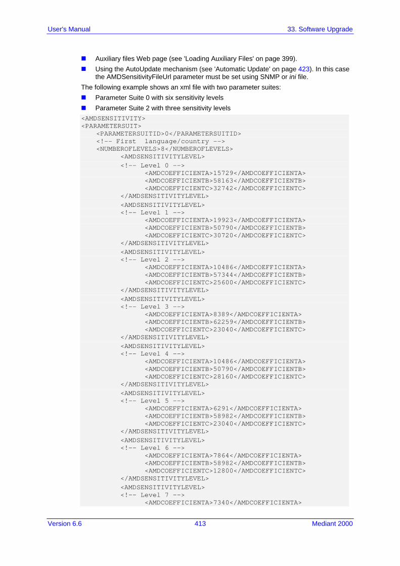
Version 6.6 413 Mediant 2000
User's Manual 33. Software Upgrade
Auxiliary files Web page (see 'Loading Auxiliary Files' on page 399). Using the AutoUpdate mechanism (see 'Automatic Update' on page 423). In this case
the AMDSensitivityFileUrl parameter must be set using SNMP or ini file. The following example shows an xml file with two parameter suites: Parameter Suite 0 with six sensitivity levels Parameter Suite 2 with three sensitivity levels <AMDSENSITIVITY> <PARAMETERSUIT> <PARAMETERSUITID>0</PARAMETERSUITID> <!-- First language/country --> <NUMBEROFLEVELS>8</NUMBEROFLEVELS> <AMDSENSITIVITYLEVEL> <!-- Level 0 --> <AMDCOEFFICIENTA>15729</AMDCOEFFICIENTA> <AMDCOEFFICIENTB>58163</AMDCOEFFICIENTB> <AMDCOEFFICIENTC>32742</AMDCOEFFICIENTC> </AMDSENSITIVITYLEVEL> <AMDSENSITIVITYLEVEL> <!-- Level 1 --> <AMDCOEFFICIENTA>19923</AMDCOEFFICIENTA> <AMDCOEFFICIENTB>50790</AMDCOEFFICIENTB> <AMDCOEFFICIENTC>30720</AMDCOEFFICIENTC> </AMDSENSITIVITYLEVEL> <AMDSENSITIVITYLEVEL> <!-- Level 2 --> <AMDCOEFFICIENTA>10486</AMDCOEFFICIENTA> <AMDCOEFFICIENTB>57344</AMDCOEFFICIENTB> <AMDCOEFFICIENTC>25600</AMDCOEFFICIENTC> </AMDSENSITIVITYLEVEL> <AMDSENSITIVITYLEVEL> <!-- Level 3 --> <AMDCOEFFICIENTA>8389</AMDCOEFFICIENTA> <AMDCOEFFICIENTB>62259</AMDCOEFFICIENTB> <AMDCOEFFICIENTC>23040</AMDCOEFFICIENTC> </AMDSENSITIVITYLEVEL> <AMDSENSITIVITYLEVEL> <!-- Level 4 --> <AMDCOEFFICIENTA>10486</AMDCOEFFICIENTA> <AMDCOEFFICIENTB>50790</AMDCOEFFICIENTB> <AMDCOEFFICIENTC>28160</AMDCOEFFICIENTC> </AMDSENSITIVITYLEVEL> <AMDSENSITIVITYLEVEL> <!-- Level 5 --> <AMDCOEFFICIENTA>6291</AMDCOEFFICIENTA> <AMDCOEFFICIENTB>58982</AMDCOEFFICIENTB> <AMDCOEFFICIENTC>23040</AMDCOEFFICIENTC> </AMDSENSITIVITYLEVEL> <AMDSENSITIVITYLEVEL> <!-- Level 6 --> <AMDCOEFFICIENTA>7864</AMDCOEFFICIENTA> <AMDCOEFFICIENTB>58982</AMDCOEFFICIENTB> <AMDCOEFFICIENTC>12800</AMDCOEFFICIENTC> </AMDSENSITIVITYLEVEL> <AMDSENSITIVITYLEVEL> <!-- Level 7 --> <AMDCOEFFICIENTA>7340</AMDCOEFFICIENTA>

User's Manual 414 Document #: LTRT-68822
Mediant 2000
<AMDCOEFFICIENTB>64717</AMDCOEFFICIENTB> <AMDCOEFFICIENTC>3840</AMDCOEFFICIENTC> </AMDSENSITIVITYLEVEL> </PARAMETERSUIT> <PARAMETERSUIT> <PARAMETERSUITID>2</PARAMETERSUITID> <!-- Second language/country --> <NUMBEROFLEVELS>3</NUMBEROFLEVELS> <AMDSENSITIVITYLEVEL> <!-- Level 0 --> <AMDCOEFFICIENTA>15729</AMDCOEFFICIENTA> <AMDCOEFFICIENTB>58163</AMDCOEFFICIENTB> <AMDCOEFFICIENTC>32742</AMDCOEFFICIENTC> </AMDSENSITIVITYLEVEL> <AMDSENSITIVITYLEVEL> <!-- Level 1 --> <AMDCOEFFICIENTA>5243</AMDCOEFFICIENTA> <AMDCOEFFICIENTB>9830</AMDCOEFFICIENTB> <AMDCOEFFICIENTC>24320</AMDCOEFFICIENTC> </AMDSENSITIVITYLEVEL> <AMDSENSITIVITYLEVEL> <!-- Level 2 --> <AMDCOEFFICIENTA>13107</AMDCOEFFICIENTA> <AMDCOEFFICIENTB>61440</AMDCOEFFICIENTB> <AMDCOEFFICIENTC>26880</AMDCOEFFICIENTC> </AMDSENSITIVITYLEVEL> </PARAMETERSUIT> </AMDSENSITIVITY>

Version 6.6 415 Mediant 2000
User's Manual 33. Software Upgrade
33.2 Software License Key The device is shipped with a pre-installed Software License Key for each of its TrunkPack Modules (TPM), which determines the device's supported features, capabilities, and available resources. You can upgrade or change your device's supported features by purchasing and installing a new Software License Key to match your requirements.
Notes:
• Each TPM utilizes a unique key. • The availability of certain Web pages depends on the installed Software License
Key.
33.2.1 Obtaining the Software License Key File Before you can install a new Software License Key, you need to obtain a Software License Key file for your device with the required features from your AudioCodes representative. The Software License Key is an encrypted key in string format that is associated with the device's serial number ("S/N") and supplied in a text-based file. If you need a Software License Key for more than one device, the Software License Key file can include multiple Software License Keys (see figure below). In such cases, each Software License Key in the file is associated with a unique serial number identifying the specific device. When loading such a Software License Key file, the device installs only the Software License Key that is associated with its serial number.
Figure 3: Software License Key File with Multiple S/N Lines
To obtain a Software License Key:
1. Make a note of the MAC address and/or serial number of the device: a. Open the Device Information page (Status & Diagnostics tab > System Status
menu > Device Information). b. The MAC address is displayed in the “MAC Address” field and the serial number
in the “Serial Number” field. 2. If you need a Software License Key for more than one device, repeat Step 1 for each
device. 3. Request the required Software License Key from your AudioCodes representative and
provide them with the MAC address and/or serial number of the device(s). 4. When you receive the new Software License Key file, check the file as follows:
a. Open the file with any text-based program such as Notepad. b. Verify that the first line displays "[LicenseKeys]". c. Verify that the file contains one or more lines in the following format:

User's Manual 416 Document #: LTRT-68822
Mediant 2000
"S/N<serial number of the first or second module> = <Software License Key string>". For example: "S/N370604 = jCx6r5tovCIKaBBbhPtT53Yj..."
d. Verify that the "S/N" value reflects the serial number of your device. If you have multiple Software License Keys, ensure that each "S/N" value corresponds to a device.
Warning: Do not modify the contents of the Software License Key file.
5. Install the Software License Key on the device as described in 'Installing the Software
License Key' on page 416.
33.2.2 Installing the Software License Key Once you have received your Software License Key file from your AudioCodes representative, you can install it on the device using one of the following management tools: Web interface - see 'Installing Software License Key using Web Interface' on page 417 AudioCodes AcBootP utility - see Installing Software License Key using AcBootP on
page 418 AudioCodes EMS - refer to the EMS User’s Manual or EMS Product Description
Note: When you install a new Software License Key, it is loaded to the device's non-volatile flash memory and overwrites the previously installed Software License Key.

Version 6.6 417 Mediant 2000
User's Manual 33. Software Upgrade
33.2.2.1 Installing Software License Key using Web Interface The procedure below describes how to install the Software License Key using the Web interface.
To install the Software License Key using the Web interface:
1. Open the Software Upgrade Key Status page (Maintenance tab > Software Update menu > Software Upgrade Key).
2. As a precaution, backup the Software License Key currently installed on the device. If
the new Software License Key does not comply with your requirements, you can re-load this backup to restore the device's original capabilities. a. In the 'Current Key' field, select the entire text string and copy it to any standard
text file (e.g., Notepad). b. Save the text file with any file name and file extension (e.g., key.txt) to a folder on
your computer. 3. Depending on whether you are loading a Software License Key file with a single
Software License Key (i.e., one "S/N") or with multiple Software License Keys (i.e., more than one "S/N"), do one of the following: • Loading a File with a Single Software License Key:
a. Open the Software License Key file using a text-based program such as Notepad.
b. Copy-and-paste the string from the file to the 'Add a Software License Key' field.
c. Click the Add Key button. • Loading a File with Multiple Software License Keys:
a. In the 'Load Upgrade Key file ...' field, click the Browse button and navigate to the folder in which the Software License Key file is located on your computer.
b. Click Load File; the new key is installed on the device. If the Software License Key is valid, it is burned to the device's flash memory and displayed in the 'Current Key' field.

User's Manual 418 Document #: LTRT-68822
Mediant 2000
4. Verify that the Software License Key was successfully installed, by doing one of the following: • In the Software Upgrade Key Status page, check that the listed features and
capabilities activated by the installed Software License Key match those that were ordered.
• Access the Syslog server and ensure that the following message appears in the Syslog server: "S/N___ Key Was Updated. The Board Needs to be Reloaded with ini file\n"
5. Reset the device; the new capabilities and resources enabled by the Software License Key are active.
Note: If the Syslog server indicates that the Software License Key was unsuccessfully loaded (i.e., the "SN_" line is blank), do the following preliminary troubleshooting procedures:
1. Open the Software License Key file and check that the "S/N" line appears. If it does not appear, contact AudioCodes.
2. Verify that you have loaded the correct file. Open the file and ensure that the first line displays "[LicenseKeys]".
3. Verify that the content of the file has not been altered.
33.2.2.2 Installing Software License Key using BootP/TFTP The procedure below describes how to install a Software License Key using AudioCodes AcBootP utility.
Notes:
• When loading the Software License Key file, a cmp file must also be loaded during this BootP process.
• For more information on using the AcBootP utility, refer to the document AcBootP Utility User's Guide.
To install a Software License Key using the AcBootP utility:
1. Change the file extension name of the Software License Key file from .txt to .ini. 2. Place the Software License Key file in the same folder in which the device's cmp file is
located. 3. Start the AcBootP utility. 4. Click the Client Configuration tab, and then from the 'INI File' drop-down list, select
the Software License Key file. 5. From the 'BootP File' drop-down list, select the device's cmp file. 6. Configure the initial BootP/TFTP parameters as required, and then click Apply. 7. Reset the device; the cmp and Software License Key files are loaded to the device.

Version 6.6 419 Mediant 2000
User's Manual 33. Software Upgrade
33.3 Software Upgrade Wizard The Software Upgrade Wizard allows you to upgrade the device's firmware. The firmware file has the .cmp file extension name. The wizard also enables you to load an ini file and/or auxiliary files (typically loaded using the Load Auxiliary File page described in 'Loading Auxiliary Files' on page 399). However, it is mandatory when using the wizard to first load a .cmp file to the device. You can then choose to also load an ini file and/or auxiliary files, but this cannot be done without first loading a .cmp file. For the ini and each auxiliary file type, you can choose to load a new file or not load a file but use the existing file (i.e., maintain existing configuration) running on the device.
Warning: The Software Upgrade Wizard requires the device to be reset at the end of the process, which may disrupt traffic. To avoid this, disable all traffic on the device before initiating the wizard by performing a graceful lock (see 'Basic Maintenance' on page 393).
Notes:
• You can get the latest software files from AudioCodes Web site at http://www.audiocodes.com/downloads.
• Before upgrading the device, it is recommended that you save a copy of the device's configuration settings (i.e., ini file) to your computer. If an upgrade failure occurs, you can then restore your configuration settings by uploading the backup file to the device. For saving and restoring configuration, see 'Backing Up and Loading Configuration File' on page 422.
• If you wish to also load an ini or auxiliary file, it is mandatory to first load a .cmp file.
• When you activate the wizard, the rest of the Web interface is unavailable. After the files are successfully loaded, access to the full Web interface is restored.
• If you upgraded your .cmp and the "SW version mismatch" message appears in the Syslog or Web interface, then your Software License Key does not support the new .cmp file version. If this occurs, contact AudioCodes support for assistance.
• If you use the wizard to load an ini file, parameters excluded from the ini file are assigned default values (according to the .cmp file running on the device) thereby, overriding values previously defined for these parameters.
• You can schedule automatic loading of these files using HTTP/HTTPS, FTP, or NFS (see 'Automatic Update' on page 423).
To load files using the Software Upgrade Wizard:
1. Stop all traffic on the device using the Graceful Lock feature (refer to the warning bulletin above).
2. Open the Software Upgrade wizard, by performing one of the following: • Select the Maintenance tab, click the Software Update menu, and then click
Software Upgrade Wizard.

User's Manual 420 Document #: LTRT-68822
Mediant 2000
• On the toolbar, click Device Actions, and then choose Software Upgrade Wizard.
Figure 33-4: Start Software Upgrade Wizard Screen
3. Click the Start Software Upgrade button; the wizard starts, requesting you to
browses to a .cmp file for uploading.
Note: At this stage, you can quit the Software Update Wizard, by clicking Cancel , without requiring a device reset. However, once you start uploading a cmp file, the process must be completed with a device reset. If you choose to quit the process in any of the subsequent pages, the device resets.
4. Click the Browse button, navigate to the .cmp file, and then click Load File; a
progress bar appears displaying the status of the loading process. When the .cmp file is successfully loaded to the device, a message appears notifying you of this.
5. If you want to load only a .cmp file, then click the Reset button to reset the device with the newly loaded .cmp file, utilizing the existing configuration (ini) and auxiliary files. To load additional files, skip to the next Step.
Note: Device reset may take a few minutes depending on cmp file version (this may even take up to 10 minutes).
6. Click the Next button; the wizard page for loading an ini file appears. You can now perform one of the following: • Load a new ini file: Click Browse, navigate to the ini file, and then click Send
File; the ini file is loaded to the device and you're notified as to a successful loading.
• Retain the existing configuration (ini file): Do not select an ini file, and ensure that the 'Use existing configuration' check box is selected (default).
• Return the device's configuration settings to factory defaults: Do not select an ini file, and clear the 'Use existing configuration' check box.

Version 6.6 421 Mediant 2000
User's Manual 33. Software Upgrade
7. Click the Next button to progress to the relevant wizard pages for loading the
desired auxiliary files. To return to the previous wizard page, click the Back button. As you navigate between wizard pages, the relevant file type corresponding to the Wizard page is highlighted in the left pane.
8. When you have completed loading all the desired files, click the Next button until the last wizard page appears ("FINISH" is highlighted in the left pane).
9. Click the Reset button to complete the upgrade process; the device 'burns' the newly loaded files to flash memory and then resets the device.
Note: Device reset may take a few minutes (depending on .cmp file version, this may even take up to 30 minutes).
After the device resets, the End of Process wizard page appears displaying the new .cmp and auxiliary files loaded to the device.
Figure 33-5: Software Upgrade Process Completed Successfully
10. Click End Process to close the wizard; the Web Login dialog box appears. 11. Enter your login user name and password, and then click OK; a message box appears
informing you of the new .cmp file. 12. Click OK; the Web interface becomes active, reflecting the upgraded device.
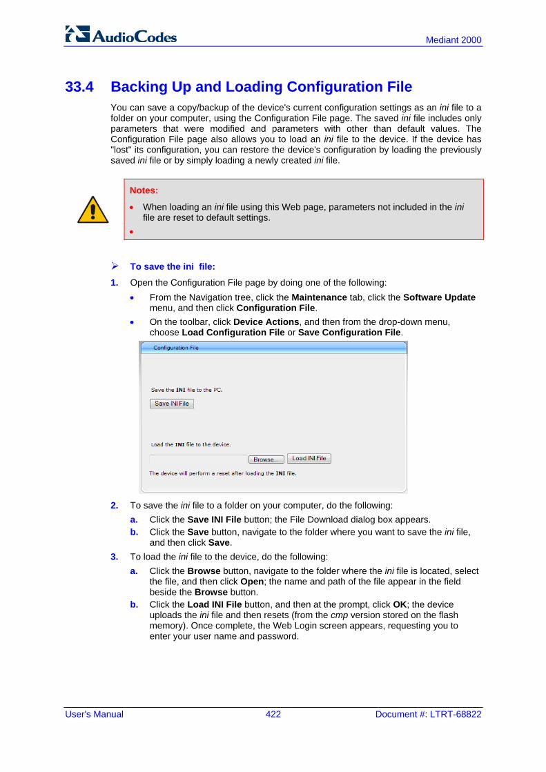
User's Manual 422 Document #: LTRT-68822
Mediant 2000
33.4 Backing Up and Loading Configuration File You can save a copy/backup of the device's current configuration settings as an ini file to a folder on your computer, using the Configuration File page. The saved ini file includes only parameters that were modified and parameters with other than default values. The Configuration File page also allows you to load an ini file to the device. If the device has "lost" its configuration, you can restore the device's configuration by loading the previously saved ini file or by simply loading a newly created ini file.
Notes:
• When loading an ini file using this Web page, parameters not included in the ini file are reset to default settings.
•
To save the ini file:
1. Open the Configuration File page by doing one of the following: • From the Navigation tree, click the Maintenance tab, click the Software Update
menu, and then click Configuration File. • On the toolbar, click Device Actions, and then from the drop-down menu,
choose Load Configuration File or Save Configuration File.
2. To save the ini file to a folder on your computer, do the following:
a. Click the Save INI File button; the File Download dialog box appears. b. Click the Save button, navigate to the folder where you want to save the ini file,
and then click Save. 3. To load the ini file to the device, do the following:
a. Click the Browse button, navigate to the folder where the ini file is located, select the file, and then click Open; the name and path of the file appear in the field beside the Browse button.
b. Click the Load INI File button, and then at the prompt, click OK; the device uploads the ini file and then resets (from the cmp version stored on the flash memory). Once complete, the Web Login screen appears, requesting you to enter your user name and password.

Version 6.6 423 Mediant 2000
User's Manual 34. Automatic Update
34 Automatic Update Automatic provisioning is useful for large-scale deployment of devices. In some cases, the devices are shipped to the end customer directly from the manufacturer. In other cases, they may pass through a staging warehouse. Configuration may occur at the staging warehouse or at the end-customer premises. The devices may be pre-configured during the manufacturing process (commonly known as private labeling). Typically, a two-stage configuration process is implemented such that initial configuration includes only basic configuration, while the final configuration is done when the device is deployed in a live network. Automatic provisioning can be used to update the following files: Software file (cmp) Auxiliary files (e.g., Call Progress Tones) Configuration file (ini) The Automatic Update mechanism is applied per file, using specific parameters that define the URLs to the servers where the files are located, and the file names (see Automatic Update Parameters on page 693). These files can be stored on any standard Web, FTP, or NFS server and can be loaded periodically to the device using HTTP, HTTPS, FTP, or NFS. This mechanism can be used even for devices that are installed behind NAT and firewalls. The Automatic Update mechanism can be triggered by the following: Upon device startup. At a user-defined time of day (e.g., 18:00), configured by the ini file parameter
AutoUpdatePredefinedTime. Periodically (e.g., every 60 minutes), configured by the ini file parameter
AutoUpdateFrequency. Upon startup but before the device is operational, if the Secure Startup feature is
enabled (see 'Loading Files Securely (Disabling TFTP)' on page 431). Upon receipt of a special SIP Notify message (see 'Remotely Triggering Auto Update
using SIP NOTIFY' on page 432) When implementing Automatic Updates using HTTP/S, the device determines whether the file on the provisioning server is an updated one as follows: Configuration file: The device checks the timestamp according to the HTTP server
response. Cyclical Redundancy Check (CRC) is only checked if the AUPDCheckIfIniChanged parameter is enabled. The device downloads the configuration file only if it was modified since the last successful configuration update.
Software file (cmp): The device first downloads the file and then checks if its version number is different from the software version file currently stored on the device's flash memory.
Auxiliary files (e.g., CPT): These files are updated only once. To update the auxiliary file again, you must modify the settings of the related parameter that configures its URL.
34.1 BootP Request and DHCP Discovery upon Device Initialization
After the device powers up or is physically reset, it broadcasts a BootP request to the network. If it receives a reply from a BootP server, it changes its network parameters (IP address, subnet mask and default gateway address) to the values provided. If there is no reply from a BootP server and if DHCP is enabled (DHCPEnable = 1), the device initiates a standard DHCP procedure to configure its network parameters.

User's Manual 424 Document #: LTRT-68822
Mediant 2000
After changing the network parameters, the device attempts to load the device's firmware file (cmp) and various configuration files from the TFTP server’s IP address received from the BootP/DHCP server. If a TFTP server’s IP address isn’t received, the device attempts to load the cmp file and / or configuration files from a preconfigured TFTP server. Thus, the device can obtain its network parameters from BootP or DHCP servers, and its software and configuration files from a different TFTP server (preconfigured in the ini configuration file). If BootP/DHCP servers are not found or when the device is reset using the Web interface or SNMP, it retains its network parameters and attempts to load the cmp file and / or configuration files from a preconfigured TFTP server. If a preconfigured TFTP server doesn’t exist, the device operates using the existing software and configuration files on its flash memory.
Figure 34-1: BootP Request and DHCP Discovery upon Startup
Note: By default, the duration between BootP/DHCP requests sent by the device is one second (configured by the BootPDelay ini file parameter). By default, the number of requests is three (configured by the BootPRetries ini file parameter).
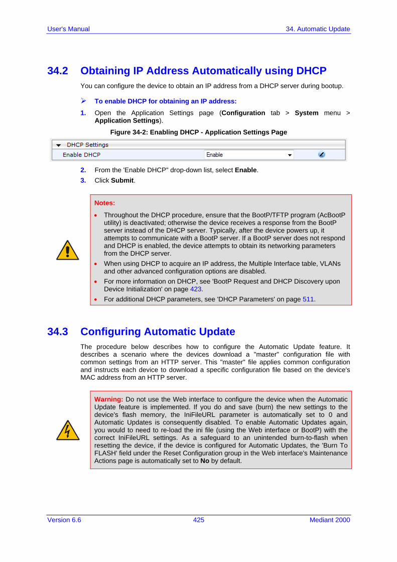
Version 6.6 425 Mediant 2000
User's Manual 34. Automatic Update
34.2 Obtaining IP Address Automatically using DHCP You can configure the device to obtain an IP address from a DHCP server during bootup.
To enable DHCP for obtaining an IP address:
1. Open the Application Settings page (Configuration tab > System menu > Application Settings).
Figure 34-2: Enabling DHCP - Application Settings Page
2. From the 'Enable DHCP" drop-down list, select Enable. 3. Click Submit.
Notes:
• Throughout the DHCP procedure, ensure that the BootP/TFTP program (AcBootP utility) is deactivated; otherwise the device receives a response from the BootP server instead of the DHCP server. Typically, after the device powers up, it attempts to communicate with a BootP server. If a BootP server does not respond and DHCP is enabled, the device attempts to obtain its networking parameters from the DHCP server.
• When using DHCP to acquire an IP address, the Multiple Interface table, VLANs and other advanced configuration options are disabled.
• For more information on DHCP, see 'BootP Request and DHCP Discovery upon Device Initialization' on page 423.
• For additional DHCP parameters, see 'DHCP Parameters' on page 511.
34.3 Configuring Automatic Update The procedure below describes how to configure the Automatic Update feature. It describes a scenario where the devices download a "master" configuration file with common settings from an HTTP server. This "master" file applies common configuration and instructs each device to download a specific configuration file based on the device's MAC address from an HTTP server.
Warning: Do not use the Web interface to configure the device when the Automatic Update feature is implemented. If you do and save (burn) the new settings to the device's flash memory, the IniFileURL parameter is automatically set to 0 and Automatic Updates is consequently disabled. To enable Automatic Updates again, you would to need to re-load the ini file (using the Web interface or BootP) with the correct IniFileURL settings. As a safeguard to an unintended burn-to-flash when resetting the device, if the device is configured for Automatic Updates, the 'Burn To FLASH' field under the Reset Configuration group in the Web interface's Maintenance Actions page is automatically set to No by default.

User's Manual 426 Document #: LTRT-68822
Mediant 2000
Note: For a description of all the Automatic Update ini file parameters, see Automatic Update Parameters on page 693.
To configure the Automatic Update feature (ini file example):
1. Setup a Web server (e.g., http://www.corp.com) and place all the required configuration files on this server.
2. For each device, preconfigure the following parameter (DHCP / DNS are assumed): IniFileURL = 'http://www.corp.com/master_configuration.ini'
3. Create a file named master_configuration.ini with the following text: # Common configuration for all devices # ------------------------------------ CptFileURL = 'http://www.corp.com/call_progress.dat' # Check for updates every 60 minutes AutoUpdateFrequency = 60 # Additional configuration per device # ----------------------------------- # Each device loads a file named based on its MAC address # (e.g., config_00908F033512.ini) IniFileURL = 'http://www.corp.com/config_<MAC>.ini' # Reset the device after configuration is updated. # The device resets after all files are processed. ResetNow = 1
You can modify the master_configuration.ini file (or any of the config_<MAC>.ini files) at any time. The device queries for the latest version every 60 minutes and applies the new settings immediately.
4. For additional security, use HTTPS or FTPS. The device supports HTTPS (RFC 2818) and FTPS using the AUTH TLS method <draft-murray-auth-ftp-ssl-16>.
5. To download configuration files from an NFS server, the NFS file system parameters should be defined in the ini file. The following is an example of an ini file for downloading files from NFS servers using NFS version 2: # Define NFS servers for Automatic Update [ NFSServers ] FORMAT NFSServers_Index = NFSServers_HostOrIP, NFSServers_RootPath, NFSServers_NfsVersion; NFSServers 1 = 10.31.2.10, /usr/share, 2 ; NFSServers 2 = 192.168.100.7, /d/shared, 2 ; [ \NFSServers ] CptFileUrl = 'file://10.31.2.10/usr/share/public/usa_tones.dat' VpFileUrl = 'file://192.168.100.7/d/shared/gateways/voiceprompt.dat'
The following ini file example can be used to activate the Automatic Update mechanism. # DNS is required for specifying domain names in URLs [ InterfaceTable ] FORMAT InterfaceTable_Index = InterfaceTable_ApplicationTypes, InterfaceTable_InterfaceMode, InterfaceTable_IPAddress, InterfaceTable_PrefixLength, InterfaceTable_Gateway, InterfaceTable_VlanID, InterfaceTable_InterfaceName, InterfaceTable_PrimaryDNSServerIPAddress, InterfaceTable_SecondaryDNSServerIPAddress, InterfaceTable_UnderlyingInterface; InterfaceTable 0 = 6, 10, 10.13.4.12, 16, 10.13.0.1, 1, Mng,

Version 6.6 427 Mediant 2000
User's Manual 34. Automatic Update
10.1.1.11, 0.0.0.0, ; [ \InterfaceTable ] # Load an extra configuration ini file using HTTP IniFileURL = 'http://webserver.corp.com/Gateway/inifile.ini' # Load Call Progress Tones file using HTTPS CptFileUrl = 'https://10.31.2.17/usa_tones.dat' # Load Voice Prompts file using FTPS with user ‘root’ and password ‘wheel’ VPFileUrl = 'ftps://root:[email protected]/vp.dat' # Update every day at 03:00 AM AutoUpdatePredefinedTime = '03:00' # Note: The cmp file isn’t updated since it's disabled by default (AutoUpdateCmpFile).
Notes:
• The Automatic Update mechanism assumes that the external Web server conforms to the HTTP standard. If the Web server ignores the If-Modified-Since header, or doesn’t provide the current date and time during the HTTP 200 OK response, the device may reset itself repeatedly. To overcome this problem, modify the update frequency, using the AutoUpdateFrequency parameter.
• To load a different configuration file (ini file) per device, add the string "<MAC>" to the URL (e.g., IniFileURL = 'http://www.corp.com/config_<MAC>.ini'). This mnemonic is replaced with the device's hardware MAC address, resulting in an ini file name request that contains the device's MAC address (e.g., config_00908F033512.ini).
• To prevent the device from accidentally upgrading its software, by default the Automatic Update feature does not apply a downloaded cmp file even if its URL was configured (using the CmpFileURL parameter). To enable this, set the AutoUpdateCmpFile parameter to 1.
• To enable the device to automatically reset after an ini file has been loaded, set the ResetNow parameter to 1. This is important if the downloaded configuration file includes parameters that require a device reset for its settings to be applied.
• By default, parameters that are not included in the downloaded configuration file are set to default. To retain the current settings of these parameters, set the SetDefaultOnINIFileProcess parameter to 0.
34.4 Automatic Configuration Methods This section describes available methods that can be used for automatic device configuration.
34.4.1 Local Configuration Server with BootP/TFTP Local configuration server with BootP/TFTP provides an easy and efficient method for automatic configuration, where configuration occurs at a staging warehouse, as described below: 1. Install AudioCodes AcBootP/TFTP utility program on a computer located in a staging
warehouse. 2. Prepare a standard configuration ini file and place it in the TFTP directory. 3. Enter the MAC address of each device in the AcBootP utility. 4. For each device added in the BootP utility, select the cmp and ini file in the 'BootP File'
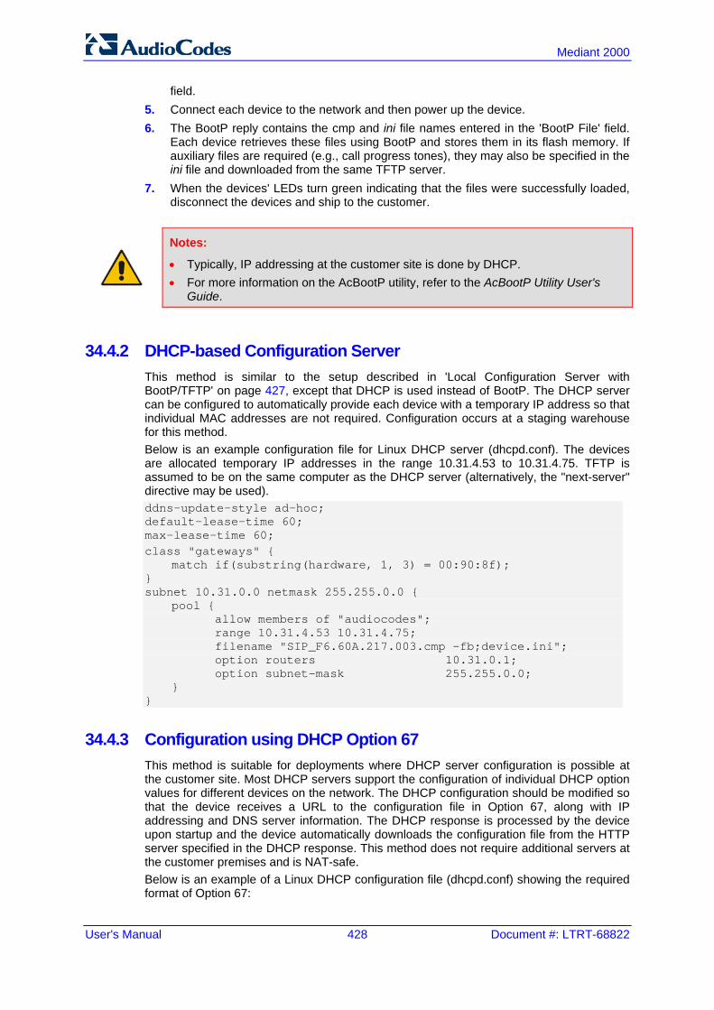
User's Manual 428 Document #: LTRT-68822
Mediant 2000
field. 5. Connect each device to the network and then power up the device. 6. The BootP reply contains the cmp and ini file names entered in the 'BootP File' field.
Each device retrieves these files using BootP and stores them in its flash memory. If auxiliary files are required (e.g., call progress tones), they may also be specified in the ini file and downloaded from the same TFTP server.
7. When the devices' LEDs turn green indicating that the files were successfully loaded, disconnect the devices and ship to the customer.
Notes:
• Typically, IP addressing at the customer site is done by DHCP. • For more information on the AcBootP utility, refer to the AcBootP Utility User's
Guide.
34.4.2 DHCP-based Configuration Server This method is similar to the setup described in 'Local Configuration Server with BootP/TFTP' on page 427, except that DHCP is used instead of BootP. The DHCP server can be configured to automatically provide each device with a temporary IP address so that individual MAC addresses are not required. Configuration occurs at a staging warehouse for this method. Below is an example configuration file for Linux DHCP server (dhcpd.conf). The devices are allocated temporary IP addresses in the range 10.31.4.53 to 10.31.4.75. TFTP is assumed to be on the same computer as the DHCP server (alternatively, the "next-server" directive may be used). ddns-update-style ad-hoc; default-lease-time 60; max-lease-time 60; class "gateways" { match if(substring(hardware, 1, 3) = 00:90:8f); } subnet 10.31.0.0 netmask 255.255.0.0 { pool { allow members of "audiocodes"; range 10.31.4.53 10.31.4.75; filename "SIP_F6.60A.217.003.cmp –fb;device.ini"; option routers 10.31.0.1; option subnet-mask 255.255.0.0; } }
34.4.3 Configuration using DHCP Option 67 This method is suitable for deployments where DHCP server configuration is possible at the customer site. Most DHCP servers support the configuration of individual DHCP option values for different devices on the network. The DHCP configuration should be modified so that the device receives a URL to the configuration file in Option 67, along with IP addressing and DNS server information. The DHCP response is processed by the device upon startup and the device automatically downloads the configuration file from the HTTP server specified in the DHCP response. This method does not require additional servers at the customer premises and is NAT-safe. Below is an example of a Linux DHCP configuration file (dhcpd.conf) showing the required format of Option 67:

Version 6.6 429 Mediant 2000
User's Manual 34. Automatic Update
ddns-update-style ad-hoc; default-lease-time 3600; max-lease-time 3600; class "audiocodes" { match if(substring(hardware, 1, 3) = 00:90:8f); } subnet 10.31.0.0 netmask 255.255.0.0 { pool { allow members of "audiocodes"; range 10.31.4.53 10.31.4.75; option routers 10.31.0.1; option subnet-mask 255.255.0.0; option domain-name-servers 10.1.0.11; option bootfile-name "INI=http://www.corp.com/master.ini"; option dhcp-parameter-request-list 1,3,6,51,67; } }
34.4.4 TFTP Configuration using DHCP Option 66 This method is suitable when the customer's network contains a provisioning TFTP server for all network equipment, without being able to distinguish between AudioCodes and non-AudioCodes devices. Upon startup, the device searches for Option 66 in the DHCP response from the DHCP server. If Option 66 contains a valid IP address, the device attempts to download through TFTP a file with a name that contains the device's MAC address (e.g., 00908f0130aa.ini). This method requires a provisioning server at the customer premises. This method loads the configuration file to the device as a one-time action. The download is only repeated if the device is manually restored to factory defaults (by pressing the hardware reset button while the Ethernet cable is not connected) and DHCP is enabled (see note below).
Notes:
• For TFTP configuration using DHCP Option 66, enable DHCP on your device: DHCPEnable = 1 and DHCPRequestTFTPParams = 1.
• Access to the core network using TFTP is not NAT-safe.
34.4.5 HTTP-based Automatic Updates An HTTP/S server can be placed in the customer's network where configuration and software updates are available for download. This does not require additional servers at the customer premises and is NAT-safe. For example, assume the core network HTTPS server is https://www.corp.com. A master configuration ini file should be placed on the server, e.g., https://www.corp.com/gateways/master.ini. This file could point to additional ini files, auxiliary files (e.g., call progress tones), and software files (cmp), all on the same HTTP server or different HTTP servers in the network. The main advantage of this method is that the HTTP configuration can be checked periodically when the device is deployed at the customer site. HTTP(S) is not sensitive to NAT devices, enabling configuration whenever needed without on-site intervention. For additional security, the URL may contain a different port, and username and password.

User's Manual 430 Document #: LTRT-68822
Mediant 2000
The devices should only be pre-configured with the URL of the initial ini file, using one of the following methods: Methods described in 'DHCP-based Configuration Server' on page 428 or above, via
TFTP at a staging warehouse. The configuration URL is configured using the IniFileURL parameter.
Private labeling. Using DHCP Option 67 (see 'Configuration using DHCP Option 67' on page 428). Manually on-site, using the Web interface. When the device is deployed at the customer site, local DHCP server provides the devices with IP addressing and DNS server information. From the URL provided in the DHCP response, the device can then contact the HTTP server at the core network and automatically download its configuration. The URL can be a simple file name or contain the device's MAC or IP address, e.g.: http://corp.com/config-<MAC>.ini - which becomes, for example,
http://corp.com/config-00908f030012.ini http://corp.com/<IP>/config.ini - which becomes, for example,
http://corp.com/192.168.0.7/config.ini
34.4.6 Configuration using FTP or NFS Some networks block access to HTTP(S). The Automatic Update feature provides limited support for FTP/FTPS connectivity. Periodic polling for updates is not possible since these protocols don't support conditional fetching, i.e., updating files only if it is changed on the server. The only difference between this method and those described in 'HTTP-based Automatic Updates' on page 429 and 'Configuration using DHCP Option 67' on page 428 is that the protocol in the URL is "ftp" (instead of "http").
Notes:
• Unlike FTP, NFS is not NAT-safe. • NFS v2/v3 is also supported.
34.4.7 Configuration using AudioCodes EMS AudioCodes EMS server functions as a core-network provisioning server. The device's SNMP Manager should be configured with the IP address of the EMS server, using one of the methods detailed in the previous sections. As soon as a registered device contacts the EMS server through SNMP, the EMS server handles all required configuration automatically, upgrading software as needed. This alternative method doesn't require additional servers at the customer premises, and is NAT-safe.

Version 6.6 431 Mediant 2000
User's Manual 34. Automatic Update
34.5 Loading Files Securely (Disabling TFTP) The TFTP protocol is not considered secure and some network operators block it using a firewall. It is possible to disable TFTP completely, using the ini file parameter EnableSecureStartup (set to 1). This way, secure protocols such as HTTPS may be used to fetch the device configuration.
To download the ini file to the device using HTTPS instead of TFTP: 1. Prepare the device's configuration file on an HTTPS server and obtain a URL to the
file (e.g., https://192.168.100.53/gateways.ini). 2. Enable DHCP, if necessary. 3. Enable SSH and connect to it. 4. In the CLI, use the ini file parameters IniFileURL (for defining the URL of the
configuration file) and EnableSecureStartup (for disabling TFTP), and then restart the device with the new configuration: /conf/scp IniFileURL https://192.168.100.53/gateways.ini /conf/scp EnableSecureStartup 1 /conf/sar bootp
Note: Once Secure Startup has been enabled, it can only be disabled by setting EnableSecureStartup to 0 using the CLI. Loading a new ini file using BootP/TFTP is not possible until EnableSecureStartup is disabled.
User's Manual 432 Document #: LTRT-68822
Mediant 2000
34.6 Remotely Triggering Auto Update using SIP NOTIFY The device can be remotely triggered to start the Automatic Update process upon receipt of a SIP NOTIFY that includes an Event header set to 'check-sync;reboot=false', as shown in the example below: NOTIFY sip:<user>@<dsthost> SIP/2.0 To: sip:<user>@<dsthost> From: sip:sipsak@<srchost> CSeq: 10 NOTIFY Call-ID: 1234@<srchost> Event: check-sync;reboot=false
For this feature to function, Automatic Update must be enabled on the device. In other words, it must have a loaded ini file with the Automatic Update settings.
To enable remote trigger of Auto Update upon receipt of SIP NOTIFY: 1. Open the Advanced Parameters page (Configuration tab > VoIP menu > SIP
Definitions > Advanced Parameters). 2. Under the Misc Parameters group, set the 'SIP Remote Reset' parameter to Enable. 3. Click Submit.
Note: This SIP Event header value is proprietary to AudioCodes.

Version 6.6 433 Mediant 2000
User's Manual 35. Restoring Factory Defaults
35 Restoring Factory Defaults You can restore the device's configuration to factory defaults using one of the following methods: CLI (see 'Restoring Defaults using CLI' on page 433) Loading an empty ini file (see 'Restoring Defaults using an ini File' on page 434)
35.1 Restoring Defaults using CLI The device can be restored to factory defaults using CLI, as described in the procedure below.
To restore factory defaults using CLI:
1. Establish a Telnet session with the device. 2. At the CLI prompt, type the following command to access the configuration mode, and
then press Enter: # conf
3. At the prompt, type the following command to reset the device to default settings, and then press Enter: /CONFiguration> RestoreFactorySettings
4. At the prompt, type the following command to confirm reset to default settings, and then press Enter: /CONFiguration> RestoreFactorySettings APPROVED
User's Manual 434 Document #: LTRT-68822
Mediant 2000
35.2 Restoring Defaults using an ini File You can restore the device to factory default settings by loading an empty ini file to the device. This is done using the Web interface's Configuration File page (see 'Backing Up and Loading Configuration File' on page 422). If the ini file does include content (e.g., parameters), ensure that they are on lines beginning with comment signs (i.e., semicolons ";") so that the device ignores them.
Note: The only settings that are not restored to default are the management (OAMP) IP address and the Web interface's login user name and password.

Part IX Status, Performance Monitoring and Reporting


Version 6.6 437 Mediant 2000
User's Manual 36. System Status
36 System Status This section describes how to view various system statuses.
36.1 Viewing Device Information The Device Information page displays various hardware and software information of the device. This page also lists any Auxiliary files that have been installed on the device and allows you to remove them.
To access the Device Information page: Open the Device Information page (Status & Diagnostics tab > System Status
menu > Device Information).
To delete a loaded file: Click the Delete button corresponding to the file that you want to delete. Deleting a file
takes effect only after device reset (see 'Resetting the Device' on page 393).

User's Manual 438 Document #: LTRT-68822
Mediant 2000
36.2 Viewing Ethernet Port Information The Ethernet Port Information page displays read-only information on the Ethernet port connections.
Note: The Ethernet Port Information page can also be accessed from the Home page (see 'Viewing the Home Page' on page 57).
To view Ethernet port information:
Open the Ethernet Port Information page (Status & Diagnostics tab > System Status menu > Ethernet Port Information).
Ethernet Port Information Parameters
Parameter Description
Active Port Displays the active Ethernet port (1 or 2).
Port Duplex Mode Displays whether the port is in half or duplex mode.
Port Speed Displays the speed (in Mbps) of the Ethernet port.

Version 6.6 439 Mediant 2000
User's Manual 37. Carrier-Grade Alarms
37 Carrier-Grade Alarms This section describes how to view the following types of alarms: Active alarms - see 'Viewing Active Alarms' on page 439 Alarm history - see 'Viewing Alarm History' on page 439
37.1 Viewing Active Alarms The Active Alarms page displays a list of currently active alarms. You can also access this page from the Home page (see 'Viewing the Home Page' on page 57).
To view the list of active alarms:
Open the Active Alarms page (Status & Diagnostics tab > System Status menu > Carrier-Grade Alarms > Active Alarms).
For each alarm, the following information is provided: Severity: severity level of the alarm:
• Critical (red) • Major (orange) • Minor (yellow)
Source: unit from which the alarm was raised Description: brief explanation of the alarm Date: date and time that the alarm was generated You can view the next 20 alarms (if exist), by clicking the Go to page button.
37.2 Viewing Alarm History The Alarms History page displays a list of alarms that have been raised and traps that have been cleared.
To view the list of history alarms:
Open the Alarms History page (Status & Diagnostics tab > System Status menu > Carrier-Grade Alarms > Alarms History).
For each alarm, the following information is provided: Severity: severity level of the alarm:
• Critical (red) • Major (range) • Minor (yellow) • Cleared (green)
Source: unit from which the alarm was raised

User's Manual 440 Document #: LTRT-68822
Mediant 2000
Description: brief explanation of the alarm Date: date and time that the alarm was generated You can view the next 20 alarms (if exist), by clicking the Go to page button.
To delete all the alarms in the table:
1. Click the Delete History Table button; a confirmation message box appears. 2. Click OK to confirm.
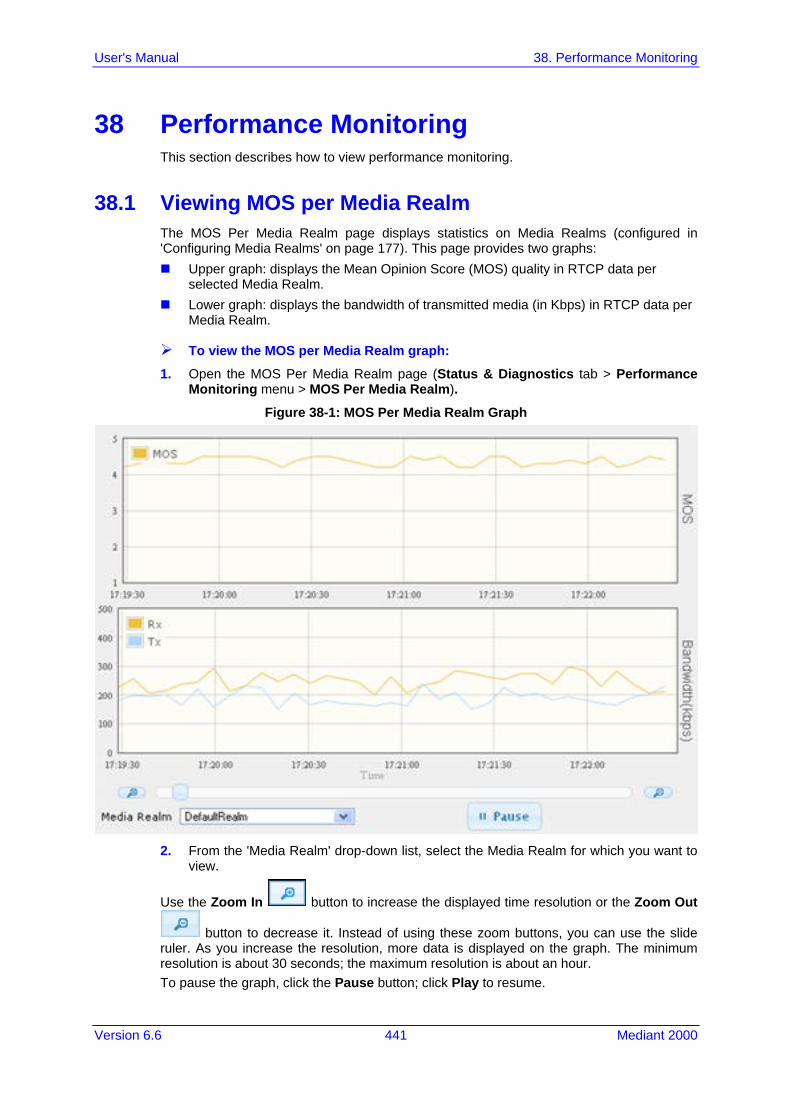
Version 6.6 441 Mediant 2000
User's Manual 38. Performance Monitoring
38 Performance Monitoring This section describes how to view performance monitoring.
38.1 Viewing MOS per Media Realm The MOS Per Media Realm page displays statistics on Media Realms (configured in 'Configuring Media Realms' on page 177). This page provides two graphs: Upper graph: displays the Mean Opinion Score (MOS) quality in RTCP data per
selected Media Realm. Lower graph: displays the bandwidth of transmitted media (in Kbps) in RTCP data per
Media Realm.
To view the MOS per Media Realm graph:
1. Open the MOS Per Media Realm page (Status & Diagnostics tab > Performance Monitoring menu > MOS Per Media Realm).
Figure 38-1: MOS Per Media Realm Graph
2. From the 'Media Realm' drop-down list, select the Media Realm for which you want to
view.
Use the Zoom In button to increase the displayed time resolution or the Zoom Out
button to decrease it. Instead of using these zoom buttons, you can use the slide ruler. As you increase the resolution, more data is displayed on the graph. The minimum resolution is about 30 seconds; the maximum resolution is about an hour. To pause the graph, click the Pause button; click Play to resume.

User's Manual 442 Document #: LTRT-68822
Mediant 2000
38.2 Viewing Trunk Utilization The Trunk Utilization page provides an X-Y graph that displays the number of active channels per trunk over time. The x-axis indicates the time; the y-axis indicates the number of active trunk channels.
Note: If you navigate to a different page, the data displayed in the graph and all its settings are cleared.
To view the number of active trunk channels
1. Open the Trunk Utilization page (Status & Diagnostics tab > Performance Monitoring menu > Trunk Utilization).
Figure 38-2: Trunk Utilization Page
2. From the 'Trunk' drop-down list, select the trunk for which you want to view active
channels.

Version 6.6 443 Mediant 2000
User's Manual 38. Performance Monitoring
For more graph functionality, see the following table:
Additional Graph Functionality for Trunk Utilization
Button Description
Add button Displays additional trunks in the graph. Up to five trunks can be displayed simultaneously in the graph. To view another trunk, click this button and then from the new 'Trunk' drop-down list, select the required trunk. Each trunk is displayed in a different color, according to the legend shown in the top-left corner of the graph.
Remove button Removes the selected trunk display from the graph.
Disable check box Hides or shows an already selected trunk. Select this check box to temporarily hide the trunk display; clear this check box to show the trunk. This is useful if you do not want to remove the trunk entirely (using the Remove button).
Get Most Active button Displays only the trunk with the most active channels (i.e., trunk with the most calls).
Pause button Pauses the display in the graph.
Play button Resumes the display in the graph.
Zoom slide ruler and buttons
Increases or reduces the trunk utilization display resolution concerning
time. The Zoom In button increases the time resolution; the
Zoom Out button decreases it. Instead of using the buttons, you can use the slide ruler. As you increase the resolution, more data is displayed on the graph. The minimum resolution is about 30 seconds; the maximum resolution is about an hour.

User's Manual 444 Document #: LTRT-68822
Mediant 2000
Reader's Notes

Version 6.6 445 Mediant 2000
User's Manual 39. VoIP Status
39 VoIP Status This section describes how to view VoIP status and statistics.
39.1 Viewing Trunks & Channels Status The Trunks & Channels Status page displays the status of the device's trunks and corresponding channels. It also enables you to view trunk configuration and channel information.
To view the status of the device's trunks and channels: 1. Open the Trunks & Channels Status page (Status & Diagnostics tab > VoIP Status
menu > Trunks & Channels Status). The page displays the first eight trunks and their channels:
Note: The number of displayed trunks and channels depends on configuration.
The status of the trunks is depicted by color-coded icons, as described in the table below:
Description of Color-Coded Icons for Trunk Status
Icon
Color
Trunk
Label
Gray Disabled
Green Active - OK
Yellow RAI Alarm
Red LOS / LOF Alarm
Blue AIS Alarm
Light Orange D-Channel Alarm
Dark Orange NFAS Alarm

User's Manual 446 Document #: LTRT-68822
Mediant 2000
Icon
Color
Trunk
Purple Lower Layer Down (DS3 physical layer is disabled)
The status of the channels is depicted by color-coded icons, as described in the table below:
Description of Color-Coded Icons for Channel Status
Icon Color Label Description
Light blue Inactive Channel is configured, but currently has no calls
Green Active Call in progress (RTP traffic) and no alarms
Purple SS7 Channel is configured for SS7 Note: Currently, SS7 is not supported.
Gray Non Voice Channel is not configured
Blue ISDN Signaling
Channel is configured as a D-channel
Yellow CAS Blocked
-
Dark Orange Maintenance B-channel has been intentionally taken out of service due to maintenance
Red Out Of Service
B-channel is out of service
2. To view the next consecutive eight trunks, click the Go To Page icon, described in
the figure below:
Figure 39-1: Example of a Selected Page Icon for Displaying Trunks 17-24

Version 6.6 447 Mediant 2000
User's Manual 39. VoIP Status
3. To view detailed information on a specific trunk's channel, click the required channel icon; the Basic Channel Information page appears, displaying information under the Basic tab (displayed in green):
Figure 39-2: Basic Channel Information Page
To view additional channel information, click the required tab (SIP, RTP/RTCP, and Voice Settings).
4. To view the settings of a specific trunk, click the required trunk icon, and then from the shortcut menu, choose Port Settings; the Trunk Settings page opens, displaying the trunk's settings. If needed, you can modify the settings (see 'Configuring Trunk Settings' on page 261).
39.2 Viewing NFAS Groups and D-Channel Status The NFAS Group & D-Channel Status page displays the status of the device's D-channels and NFAS groups. The status of a D-channel and NFAS group can be "In Service" or "Out of Service". This page also indicates whether the D-channel is a primary or backup D-channel. This page also enables you to manually switchover between active and standby D-channels belonging to the same NFAS group. This is done using the Switch Activity button. For more information, see 'Performing Manual D-Channel Switchover in NFAS Group' on page 275.
Note: This page is applicable only to T1 ISDN protocols supporting NFAS, and only if the NFAS group is configured with two D-channels.

User's Manual 448 Document #: LTRT-68822
Mediant 2000
To view the status of the D-channels and NFAS groups:
Open the NFAS Group & D-Channel Status page (Status & Diagnostics tab > VoIP Status menu > NFAS Group & D-Channel Status).
Figure 39-3: NFAS Group & D-Channel Status Page
39.3 Viewing Active IP Interfaces The IP Interface Status page displays the device's active IP interfaces that are listed in the Multiple Interface Table page (see 'Configuring IP Network Interfaces' on page 106).
To view the active IP network interfaces: Open the IP Interface Status page (Status & Diagnostics tab > VoIP Status menu >
IP Interface Status).

Version 6.6 449 Mediant 2000
User's Manual 39. VoIP Status
39.4 Viewing Performance Statistics The Basic Statistics page provides read-only, device performance statistics. This page is refreshed every 60 seconds. The duration that the currently displayed statistics has been collected is displayed above the statistics table.
To view performance statistics:
Open the Basic Statistics page (Status & Diagnostics tab > VoIP Status menu > Performance Statistics).
Figure 39-4: Basic Statistics Page
The duration that the displayed statistics were collected is displayed in seconds above the table. To reset the performance statistics to zero, click the Reset Statistics button.
39.5 Viewing Call Counters The IP to Tel Calls Count page and Tel to IP Calls Count page provide you with statistical information on incoming (IP-to-Tel) and outgoing (Tel-to-IP) calls. The statistical information is updated according to the release reason that is received after a call is terminated (during the same time as the end-of-call Call Detail Record or CDR message is sent). The release reason can be viewed in the 'Termination Reason' field in the CDR message. You can reset the statistical data displayed on the page (i.e., refresh the display), by clicking the Reset Counters button located below the table.
To view IP-to-Tel and Tel-to-IP call counters:
Open the Call Counters page that you want to view (Status & Diagnostics tab > VoIP Status menu > IP to Tel Calls Count or Tel to IP Calls Count); the figure below shows the IP to Tel Calls Count page.
Figure 39-5: Calls Count Page

User's Manual 450 Document #: LTRT-68822
Mediant 2000
The fields in this page are described in the following table:
Call Counters Description
Counter Description
Number of Attempted Calls
Indicates the number of attempted calls. It is composed of established and failed calls. The number of established calls is represented by the 'Number of Established Calls' counter. The number of failed calls is represented by the failed-call counters. Only one of the established / failed call counters is incremented every time.
Number of Established Calls
Indicates the number of established calls. It is incremented as a result of one of the following release reasons if the duration of the call is greater than zero: GWAPP_REASON_NOT_RELEVANT (0) GWAPP_NORMAL_CALL_CLEAR (16) GWAPP_NORMAL_UNSPECIFIED (31)
And the internal reasons: RELEASE_BECAUSE_UNKNOWN_REASON RELEASE_BECAUSE_REMOTE_CANCEL_CALL RELEASE_BECAUSE_MANUAL_DISC RELEASE_BECAUSE_SILENCE_DISC RELEASE_BECAUSE_DISCONNECT_CODE Note: When the duration of the call is zero, the release reason GWAPP_NORMAL_CALL_CLEAR increments the 'Number of Failed Calls due to No Answer' counter. The rest of the release reasons increment the 'Number of Failed Calls due to Other Failures' counter.
Percentage of Successful Calls (ASR)
The percentage of established calls from attempted calls.
Number of Calls Terminated due to a Busy Line
Indicates the number of calls that failed as a result of a busy line. It is incremented as a result of the following release reason: GWAPP_USER_BUSY (17)
Number of Calls Terminated due to No Answer
Indicates the number of calls that weren't answered. It's incremented as a result of one of the following release reasons: GWAPP_NO_USER_RESPONDING (18) GWAPP_NO_ANSWER_FROM_USER_ALERTED (19) GWAPP_NORMAL_CALL_CLEAR (16) (when the call duration is
zero)
Number of Calls Terminated due to Forward
Indicates the number of calls that were terminated due to a call forward. The counter is incremented as a result of the following release reason: RELEASE_BECAUSE_FORWARD
Number of Failed Calls due to No Route
Indicates the number of calls whose destinations weren't found. It is incremented as a result of one of the following release reasons: GWAPP_UNASSIGNED_NUMBER (1) GWAPP_NO_ROUTE_TO_DESTINATION (3)
Number of Failed Calls due to No Matched Capabilities
Indicates the number of calls that failed due to mismatched device capabilities. It is incremented as a result of an internal identification of capability mismatch. This mismatch is reflected to CDR via the value of the parameter DefaultReleaseReason (default is GWAPP_NO_ROUTE_TO_DESTINATION (3)) or by the GWAPP_SERVICE_NOT_IMPLEMENTED_UNSPECIFIED (79) reason.

Version 6.6 451 Mediant 2000
User's Manual 39. VoIP Status
Counter Description
Number of Failed Calls due to No Resources
Indicates the number of calls that failed due to unavailable resources or a device lock. The counter is incremented as a result of one of the following release reasons: GWAPP_RESOURCE_UNAVAILABLE_UNSPECIFIED RELEASE_BECAUSE_GW_LOCKED
Number of Failed Calls due to Other Failures
This counter is incremented as a result of calls that failed due to reasons not covered by the other counters.
Average Call Duration (ACD) [sec]
The average call duration (ACD) in seconds of established calls. The ACD value is refreshed every 15 minutes and therefore, this value reflects the average duration of all established calls made within a 15 minute period.
Attempted Fax Calls Counter
Indicates the number of attempted fax calls.
Successful Fax Calls Counter
Indicates the number of successful fax calls.
39.6 Viewing Registered Users The SAS/SBC Registered Users page displays a list of registered SAS users recorded in the device's database.
To view registered SAS users: Open the Registration Status page (Status & Diagnostics tab > VoIP Status menu >
Registered Users).
Figure 39-6: SAS Registered Users Page
SAS Registered Users Parameters
Column Name Description
Address of Record
An address-of-record (AOR) is a SIP or SIPS URI that points to a domain with a location service that can map the URI to another URI (Contact) where the user might be available.
Contact SIP URI that can be used to contact that specific instance of the User Agent for subsequent requests.

User's Manual 452 Document #: LTRT-68822
Mediant 2000
39.7 Viewing Registration Status The Registration Status page displays whether the device as a whole and SIP Accounts are registered to a SIP Registrar/Proxy server.
To view the registration status:
Open the Registration Status page (Status & Diagnostics tab > VoIP Status menu > Registration Status).
Figure 39-7: Registration Status Page
Registered Per Gateway:
• "YES" = Registration is per device • "NO"= Registration is not per device
Accounts Registration Status: registration status based on the Accounts table (configured in 'Configuring Account Table' on page 215): • Group Type: type of served group - Trunk Group or IP Group • Group Name: name of the served group, if applicable • Status: indicates whether or not the group is registered ("Registered" or
"Unregistered")
Note: The registration mode (i.e., per device, endpoint, account. or no registration) is configured in the Trunk Group Settings table (see 'Configuring Trunk Group Settings' on page 281) or using the TrunkGroupSettings ini file parameter.

Version 6.6 453 Mediant 2000
User's Manual 39. VoIP Status
39.8 Viewing Call Routing Status The Call Routing Status page provides you with information on the current routing method used by the device. This information includes the IP address and FQDN (if used) of the Proxy server with which the device currently operates.
To view call routing status:
Open the Call Routing Status page (Status & Diagnostics tab > VoIP Status menu > Call Routing Status).
Figure 39-8: Call Routing Status Page
Call Routing Status Parameters
Parameter Description
Call-Routing Method Proxy/GK = Proxy server is used to route calls. Routing Table = The Outbound IP Routing Table is used to route
calls.
IP Address Not Used = Proxy server isn't defined. IP address and FQDN (if exists) of the Proxy server with which the
device currently operates.
State N/A = Proxy server isn't defined. OK = Communication with the Proxy server is in order. Fail = No response from any of the defined Proxies.

User's Manual 454 Document #: LTRT-68822
Mediant 2000
39.9 Viewing IP Connectivity The IP Connectivity page displays on-line, read-only network diagnostic connectivity information on all destination IP addresses configured in the Outbound IP Routing Table page (see 'Configuring Outbound IP Routing Table' on page 309).
Note: The information in columns 'Quality Status' and 'Quality Info' (per IP address) is reset if two minutes elapse without a call to that destination.
To view IP connectivity information: 1. In the Routing General Parameters page, set the 'Enable Alt Routing Tel to IP'
parameter (AltRoutingTel2IPMode) to Enable or Status Only (see 'Configuring General Routing Parameters' on page 309).
2. Open the IP Connectivity page (Status & Diagnostics tab > VoIP Status menu > IP Connectivity).
Figure 39-9: IP Connectivity Page
IP Connectivity Parameters
Column Name Description
IP Address The IP address can be one of the following: IP address defined as the destination IP address in the Outbound IP
Routing Table. IP address resolved from the host name defined as the destination IP
address in the Outbound IP Routing Table.
Host Name Host name (or IP address) as defined in the Outbound IP Routing Table.
Connectivity Method
The method according to which the destination IP address is queried periodically (ICMP ping or SIP OPTIONS request).
Connectivity Status
The status of the IP address' connectivity according to the method in the 'Connectivity Method' field. OK = Remote side responds to periodic connectivity queries. Lost = Remote side didn't respond for a short period.
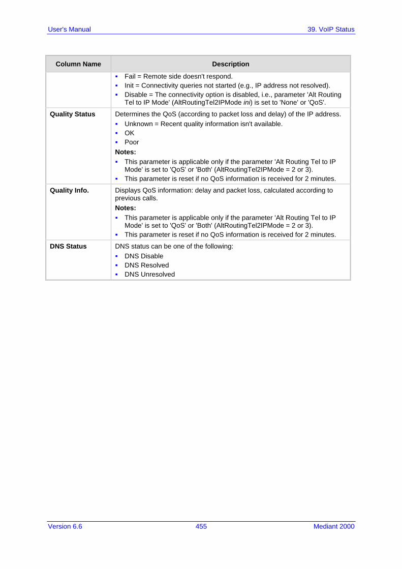
Version 6.6 455 Mediant 2000
User's Manual 39. VoIP Status
Column Name Description
Fail = Remote side doesn't respond. Init = Connectivity queries not started (e.g., IP address not resolved). Disable = The connectivity option is disabled, i.e., parameter 'Alt Routing
Tel to IP Mode' (AltRoutingTel2IPMode ini) is set to 'None' or 'QoS'.
Quality Status Determines the QoS (according to packet loss and delay) of the IP address. Unknown = Recent quality information isn't available. OK Poor Notes: This parameter is applicable only if the parameter 'Alt Routing Tel to IP
Mode' is set to 'QoS' or 'Both' (AltRoutingTel2IPMode = 2 or 3). This parameter is reset if no QoS information is received for 2 minutes.
Quality Info. Displays QoS information: delay and packet loss, calculated according to previous calls. Notes: This parameter is applicable only if the parameter 'Alt Routing Tel to IP
Mode' is set to 'QoS' or 'Both' (AltRoutingTel2IPMode = 2 or 3). This parameter is reset if no QoS information is received for 2 minutes.
DNS Status DNS status can be one of the following: DNS Disable DNS Resolved DNS Unresolved

User's Manual 456 Document #: LTRT-68822
Mediant 2000
Reader's Notes

Version 6.6 457 Mediant 2000
User's Manual 40. Reporting Information to External Party
40 Reporting Information to External Party This section describes features for reporting various information to an external party.
40.1 RTP Control Protocol Extended Reports (RTCP XR) RTP Control Protocol Extended Reports (RTCP XR) is a VoIP management control that defines a set of metrics containing information for assessing VoIP call quality and for diagnosing problems. RTCP XR (RFC 3611) extends the RTCP reports defined in RFC 3550 by providing additional VoIP metrics. RTCP XR information publishing is implemented in the device according to <draft-johnston-sipping-rtcp-summary-07>. This draft defines how a SIP User Agent (UA) publishes the detailed information to a defined collector. RTCP XR measures VoIP call quality such as packet loss, delay, signal / noise / echo levels, estimated R-factor, and mean opinion score (MOS). RTCP XR measures these parameters using metrics as listed in the table below.
Note: RTCP XR is a customer ordered feature and thus, must be included in the Software License Key installed on the device.
RTCP XR messages containing key call-quality-related metrics are exchanged periodically (user-defined) between the device and the SIP UA. This allows an analyzer to monitor these metrics midstream, or a device to retrieve them using SNMP. The device can send RTCP XR reports to an Event State Compositor (ESC) server using PUBLISH messages. These reports can be sent at the end of each call and according to a user-defined interval between consecutive reports.
RTCP XR Published VoIP Metrics
Group Metric Name
General Start Timestamp
Stop Timestamp
Call-ID
Local Address (IP, Port & SSRC)
Remote Address (IP, Port & SSRC)
Session Description Payload Type
Payload Description
Sample Rate
Frame Duration
Frame Octets
Frames per Packets
Packet Loss Concealment
Silence Suppression State
Jitter Buffer Jitter Buffer Adaptive
Jitter Buffer Rate

User's Manual 458 Document #: LTRT-68822
Mediant 2000
Group Metric Name
Jitter Buffer Nominal
Jitter Buffer Max
Jitter Buffer Abs Max
Packet Loss Network Packet Loss Rate
Jitter Buffer Discard Rate
Burst Gap Loss Burst Loss Density
Burst Duration
Gap Loss Density
Gap Duration
Minimum Gap Threshold
Delay Round Trip Delay
End System Delay
One Way Delay
Interarrival Jitter
Min Absolute Jitter
Signal
Signal Level
Noise Level
Residual Echo Return Noise
Quality Estimates Listening Quality R
RLQ Est. Algorithm
Conversational Quality R
RCQ Est. Algorithm
External R In
Ext. R In Est. Algorithm
External R Out
Ext. R Out Est. Algorithm
MOS-LQ
MOS-LQ Est. Algorithm
MOS-CQ
MOS-CQ Est. Algorithm
QoE Est. Algorithm

Version 6.6 459 Mediant 2000
User's Manual 40. Reporting Information to External Party
To configure RTCP XR:
1. Open the RTP/RTCP Settings page (Configuration tab > VoIP menu > Media > RTP/RTCP Settings). The RTCP XR parameters are listed under the 'RTCP XR Settings' group, as shown below:
Figure 40-1: RTCP XR Parameters in RTP/RTCP Settings Page
2. Configure the RTCP XR parameters, as required:
• 'Enable RTCP XR' (VQMonEnable) - enables voice quality monitoring and RTCP XR.
• 'Minimum Gap Size' (VQMonGMin) - defines the voice quality monitoring - minimum gap size (number of frames).
• 'Burst Threshold' (VQMonBurstHR) - defines the voice quality monitoring - excessive burst alert threshold.
• 'Delay Threshold' (VQMonDelayTHR) - defines the voice quality monitoring - excessive delay alert threshold.
• 'R-Value Delay Threshold' (VQMonEOCRValTHR) - defines the voice quality monitoring - end of call low quality alert threshold.
• 'RTCP XR Report Mode' (RTCPXRReportMode) - determines whether RTCP XR reports are sent to the ESC and defines the interval in which they are sent.
• 'RTCP XR Packet Interval' (RTCPInterval) - defines the time interval between adjacent RTCP reports.
• 'Disable RTCP XR Interval Randomization' (DisableRTCPRandomize) - determines whether RTCP report intervals are randomized or whether each report interval accords exactly to the parameter RTCPInterval.
• 'RTCP XR Collection Server' (RTCPXREscIP) - defines the IP address of the Event State Compositor (ESC).
• 'RTCP XR Collection Server Transport Type' (RTCPXRESCTransportType) - determines the transport layer for outgoing SIP dialogs initiated by the device to the RTCP XR Collection Server.
3. Click Submit. 4. Reset the device for the settings to take effect.

User's Manual 460 Document #: LTRT-68822
Mediant 2000
40.2 Generating Call Detail Records The Call Detail Record (CDR) contains vital statistic information on calls made from the device. The device can be configured to generate and report CDRs for various stages of the call, including SIP messages and/or media. You can configure when CDRs for a call are generated, for example, only at the end of the call or only at the start and end of the call. Once generated, the device sends the CDRs to a user-defined Syslog server. The CDR Syslog message complies with RFC 3161 and is identified by Facility 17 (local1) and Severity 6 (Informational). For CDR in RADIUS format, see 'RADIUS Accounting CDR Attributes' on page 467.
40.2.1 Configuring CDR Reporting The procedure below describes how to configure CDR reporting.
To configure CDR reporting:
1. Enable the Syslog feature for sending log messages generated ty the device to a collecting log message server. For more information, see 'Configuring Syslog' on page 479.
2. Open the Advanced Parameters page (Configuration tab > VoIP menu > SIP Definitions > Advanced Parameters). The CDR parameters appear under the 'CDR and Debug' group, as shown below:
Figure 40-2: CDR Parameters in Advanced Parameters Page
3. Configure the parameters as required. For a description of the parameters, see
'Syslog, CDR and Debug Parameters' on page 522. 4. Click Submit.
Note: If the CDR server IP address is not configured, the CDRs are sent to the Syslog server, configured in 'Configuring Syslog' on page 479.

Version 6.6 461 Mediant 2000
User's Manual 40. Reporting Information to External Party
40.2.2 CDR Field Description This section describes the CDR fields that are generated by the device.
40.2.2.1 CDR Fields for Gateway/IP-to-IP Application The CDR fields for the Gateway / IP-to-IP application are listed in the table below.
CDR Fields for Gateway/IP-to-IP Application
Field Name Description
GWReportType Report type: CALL_START CALL_CONNECT CALL_END
Cid Port number
SessionId SIP session identifier
Trunk Physical trunk number Note: This field is applicable only to the Gateway application.
BChan Selected B-channel Note: This field is applicable only to the Gateway application.
ConId SIP conference ID Note: This field is applicable only to the Gateway application.
TG Trunk Group ID Note: This field is applicable only to the Gateway application.
EPTyp Endpoint type: FXO FXS EANDM ISDN CAS DAA IPMEDIA NETANN STREAMING TRANSPARENT MSCML VXML IP2IP
Orig Call originator: LCL (Tel side) RMT (IP side)
SourceIp Source IP address
DestIp Destination IP address

User's Manual 462 Document #: LTRT-68822
Mediant 2000
Field Name Description
TON Source phone number type Note: This field is applicable only to the Gateway application.
NPI Source phone number plan Note: This field is applicable only to the Gateway application.
SrcPhoneNum Source phone number
SrcNumBeforeMap Source number before manipulation
TON Destination phone number type Note: This field is applicable only to the Gateway application.
NPI Destination phone number plan Note: This field is applicable only to the Gateway application.
DstPhoneNum Destination phone number
DstNumBeforeMap Destination number before manipulation
Durat Call duration
Coder Selected coder
Intrv Packet interval
RtpIp RTP IP address
Port Remote RTP port
TrmSd Initiator of call release (IP, Tel, or Unknown)
TrmReason SIP call termination reason (see 'Release Reasons in CDR' on page 464)
Fax Fax transaction during call
InPackets Number of incoming packets
OutPackets Number of outgoing packets
PackLoss Local packet loss
RemotePackLoss Number of outgoing lost packets
SIPCalld Unique SIP call ID
SetupTime Call setup time
ConnectTime Call connect time
ReleaseTime Call release time
RTPdelay RTP delay
RTPjitter RTP jitter
RTPssrc Local RTP SSRC
RemoteRTPssrc Remote RTP SSRC
RedirectReason Redirect reason
TON Redirection phone number type Note: This field is applicable only to the Gateway application.
NPI Redirection phone number plan Note: This field is applicable only to the Gateway application.
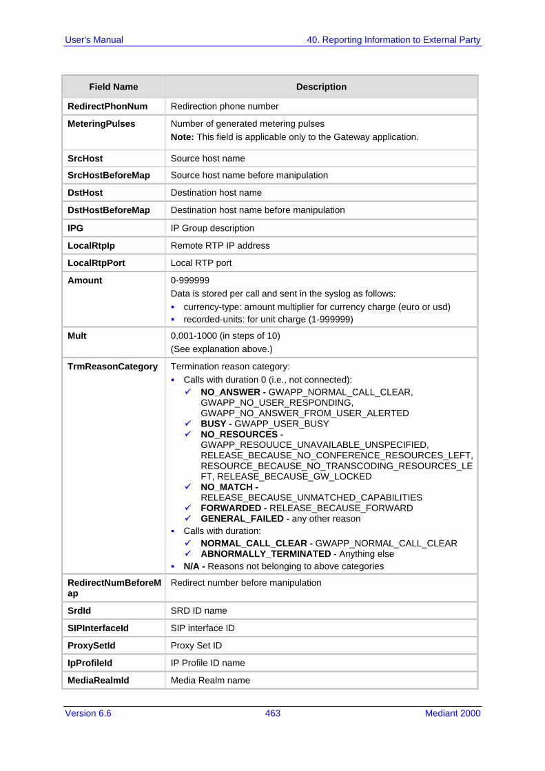
Version 6.6 463 Mediant 2000
User's Manual 40. Reporting Information to External Party
Field Name Description
RedirectPhonNum Redirection phone number
MeteringPulses Number of generated metering pulses Note: This field is applicable only to the Gateway application.
SrcHost Source host name
SrcHostBeforeMap Source host name before manipulation
DstHost Destination host name
DstHostBeforeMap Destination host name before manipulation
IPG IP Group description
LocalRtpIp Remote RTP IP address
LocalRtpPort Local RTP port
Amount 0-999999 Data is stored per call and sent in the syslog as follows: currency-type: amount multiplier for currency charge (euro or usd) recorded-units: for unit charge (1-999999)
Mult 0,001-1000 (in steps of 10) (See explanation above.)
TrmReasonCategory Termination reason category: Calls with duration 0 (i.e., not connected): NO_ANSWER - GWAPP_NORMAL_CALL_CLEAR,
GWAPP_NO_USER_RESPONDING, GWAPP_NO_ANSWER_FROM_USER_ALERTED
BUSY - GWAPP_USER_BUSY NO_RESOURCES -
GWAPP_RESOUUCE_UNAVAILABLE_UNSPECIFIED, RELEASE_BECAUSE_NO_CONFERENCE_RESOURCES_LEFT, RESOURCE_BECAUSE_NO_TRANSCODING_RESOURCES_LEFT, RELEASE_BECAUSE_GW_LOCKED
NO_MATCH - RELEASE_BECAUSE_UNMATCHED_CAPABILITIES
FORWARDED - RELEASE_BECAUSE_FORWARD GENERAL_FAILED - any other reason
Calls with duration: NORMAL_CALL_CLEAR - GWAPP_NORMAL_CALL_CLEAR ABNORMALLY_TERMINATED - Anything else
N/A - Reasons not belonging to above categories
RedirectNumBeforeMap
Redirect number before manipulation
SrdId SRD ID name
SIPInterfaceId SIP interface ID
ProxySetId Proxy Set ID
IpProfileId IP Profile ID name
MediaRealmId Media Realm name

User's Manual 464 Document #: LTRT-68822
Mediant 2000
Field Name Description
SigTransportType SIP signaling transport type (UDP, TCP, or TLS)
TxRTPIPDiffServ Media IP DiffServ
TxSigIPDiffServ Signaling IP DiffServ
LocalRFactor Local R-factor
RemoteRFactor Remote R-factor
LocalMosCQ Local MOS for conversation quality
RemoteMosCQ Remote MOS for conversation quality
SigSourcePort SIP source port
SigDestPort SIP destination port
MediaType Media type - audio, video, or text
AMD Information relating to the Automatic Machine Detection (AMD) feature: V - voice A - answer machine S - silence U - unknown
% Information relating to AMD that shows the success that the answering type (probability) was correctly detected
SIPTrmReason SIP call termination reason (BYE, CANCEL, or SIP error codes, e.g., 404)
SipTermDesc Description of SIP termination reason: SIP Reason header, if exists, for example: SIP ;cause=200 ;text="Call
completed elsewhere". If no SIP Reason header exists, the description is taken from the
reason text, if exists, of the SIP response code, for example: "417 Unknown Resource-Priority".
If no reason text exists in the SIP response code, the description is taken from an internal SIP response mapping mechanism. For example, if the device receives a SIP response "422", it sends in the CDR "422 Session Interval Too Small method" as the description.
PstnTermReason Q.850 protocol termination reason (0-127).
LatchedRtpIp Remote IP address of the incoming RTP stream that the device "latched" on to as a result of the RTP latching mechanism for NAT traversal.
LatchedRtpPort Remote RTP port of the incoming RTP stream that the device "latched" on to as a result of the RTP latching mechanism for NAT traversal.
40.2.2.2 Release Reasons in CDR The possible reasons for call termination for the Gateway / IP-to-IP application which is represented in the CDR field TrmReason are listed below: "REASON N/A" "RELEASE_BECAUSE_NORMAL_CALL_DROP" "RELEASE_BECAUSE_DESTINATION_UNREACHABLE" "RELEASE_BECAUSE_DESTINATION_BUSY" "RELEASE_BECAUSE_NOANSWER"

Version 6.6 465 Mediant 2000
User's Manual 40. Reporting Information to External Party
"RELEASE_BECAUSE_UNKNOWN_REASON" "RELEASE_BECAUSE_REMOTE_CANCEL_CALL" "RELEASE_BECAUSE_UNMATCHED_CAPABILITIES" "RELEASE_BECAUSE_UNMATCHED_CREDENTIALS" "RELEASE_BECAUSE_UNABLE_TO_HANDLE_REMOTE_REQUEST" "RELEASE_BECAUSE_NO_CONFERENCE_RESOURCES_LEFT" "RELEASE_BECAUSE_CONFERENCE_FULL" "RELEASE_BECAUSE_VOICE_PROMPT_PLAY_ENDED" "RELEASE_BECAUSE_VOICE_PROMPT_NOT_FOUND" "RELEASE_BECAUSE_TRUNK_DISCONNECTED" "RELEASE_BECAUSE_RSRC_PROBLEM" "RELEASE_BECAUSE_MANUAL_DISC" "RELEASE_BECAUSE_SILENCE_DISC" "RELEASE_BECAUSE_RTP_CONN_BROKEN" "RELEASE_BECAUSE_DISCONNECT_CODE" "RELEASE_BECAUSE_GW_LOCKED" "RELEASE_BECAUSE_NORTEL_XFER_SUCCESS" "RELEASE_BECAUSE_FAIL" "RELEASE_BECAUSE_FORWARD" "RELEASE_BECAUSE_ANONYMOUS_SOURCE" "RELEASE_BECAUSE_IP_PROFILE_CALL_LIMIT" "GWAPP_UNASSIGNED_NUMBER" "GWAPP_NO_ROUTE_TO_TRANSIT_NET" "GWAPP_NO_ROUTE_TO_DESTINATION" "GWAPP_CHANNEL_UNACCEPTABLE" "GWAPP_CALL_AWARDED_AND " "GWAPP_PREEMPTION" "PREEMPTION_CIRCUIT_RESERVED_FOR_REUSE" "GWAPP_NORMAL_CALL_CLEAR" "GWAPP_USER_BUSY" "GWAPP_NO_USER_RESPONDING" "GWAPP_NO_ANSWER_FROM_USER_ALERTED" "MFCR2_ACCEPT_CALL" "GWAPP_CALL_REJECTED" "GWAPP_NUMBER_CHANGED" "GWAPP_NON_SELECTED_USER_CLEARING" "GWAPP_INVALID_NUMBER_FORMAT" "GWAPP_FACILITY_REJECT" "GWAPP_RESPONSE_TO_STATUS_ENQUIRY" "GWAPP_NORMAL_UNSPECIFIED" "GWAPP_CIRCUIT_CONGESTION" "GWAPP_USER_CONGESTION" "GWAPP_NO_CIRCUIT_AVAILABLE" "GWAPP_NETWORK_OUT_OF_ORDER"

User's Manual 466 Document #: LTRT-68822
Mediant 2000
"GWAPP_NETWORK_TEMPORARY_FAILURE" "GWAPP_NETWORK_CONGESTION" "GWAPP_ACCESS_INFORMATION_DISCARDED" "GWAPP_REQUESTED_CIRCUIT_NOT_AVAILABLE" "GWAPP_RESOURCE_UNAVAILABLE_UNSPECIFIED" "GWAPP_PERM_FR_MODE_CONN_OUT_OF_S" "GWAPP_PERM_FR_MODE_CONN_OPERATIONAL" "GWAPP_PRECEDENCE_CALL_BLOCKED"
• "RELEASE_BECAUSE_PREEMPTION_ANALOG_CIRCUIT_RESERVED_FOR_REUSE"
• "RELEASE_BECAUSE_PRECEDENCE_CALL_BLOCKED" "GWAPP_QUALITY_OF_SERVICE_UNAVAILABLE" "GWAPP_REQUESTED_FAC_NOT_SUBSCRIBED" "GWAPP_BC_NOT_AUTHORIZED" "GWAPP_BC_NOT_PRESENTLY_AVAILABLE" "GWAPP_SERVICE_NOT_AVAILABLE" "GWAPP_CUG_OUT_CALLS_BARRED" "GWAPP_CUG_INC_CALLS_BARRED" "GWAPP_ACCES_INFO_SUBS_CLASS_INCONS" "GWAPP_BC_NOT_IMPLEMENTED" "GWAPP_CHANNEL_TYPE_NOT_IMPLEMENTED" "GWAPP_REQUESTED_FAC_NOT_IMPLEMENTED" "GWAPP_ONLY_RESTRICTED_INFO_BEARER" "GWAPP_SERVICE_NOT_IMPLEMENTED_UNSPECIFIED" "GWAPP_INVALID_CALL_REF" "GWAPP_IDENTIFIED_CHANNEL_NOT_EXIST" "GWAPP_SUSPENDED_CALL_BUT_CALL_ID_NOT_EXIST" "GWAPP_CALL_ID_IN_USE" "GWAPP_NO_CALL_SUSPENDED" "GWAPP_CALL_HAVING_CALL_ID_CLEARED" "GWAPP_INCOMPATIBLE_DESTINATION" "GWAPP_INVALID_TRANSIT_NETWORK_SELECTION" "GWAPP_INVALID_MESSAGE_UNSPECIFIED" "GWAPP_NOT_CUG_MEMBER" "GWAPP_CUG_NON_EXISTENT" "GWAPP_MANDATORY_IE_MISSING" "GWAPP_MESSAGE_TYPE_NON_EXISTENT" "GWAPP_MESSAGE_STATE_INCONSISTENCY" "GWAPP_NON_EXISTENT_IE" "GWAPP_INVALID_IE_CONTENT" "GWAPP_MESSAGE_NOT_COMPATIBLE" "GWAPP_RECOVERY_ON_TIMER_EXPIRY" "GWAPP_PROTOCOL_ERROR_UNSPECIFIED" "GWAPP_INTERWORKING_UNSPECIFIED" "GWAPP_UKNOWN_ERROR"

Version 6.6 467 Mediant 2000
User's Manual 40. Reporting Information to External Party
"RELEASE_BECAUSE_HELD_TIMEOUT"
40.3 Configuring RADIUS Accounting The device can send accounting data of SIP calls as call detail records (CDR) to a RADIUS Accounting server. The device can send the accounting messages to the RADIUS server upon call release, call connection and release, or call setup and release. For a list of the CDR attributes, see the table following the procedure below.
Notes:
• For RADIUS accounting settings to take effect, you must save the settings to flash memory with a device reset.
• For a description of the RADIUS accounting parameters, see 'RADIUS Parameters' on page 539.
To configure RADIUS accounting: 1. Open the RADIUS Parameters page (Configuration tab > VoIP menu > SIP
Definitions submenu > RADIUS Parameters Settings).
Figure 40-3: RADIUS Accounting Parameters Page
2. Configure the parameters as required. 3. Click Submit. 4. For your settings to take effect, reset the device with a flash burn. The table below describes the RADIUS Accounting CDR attributes included in the communication packets transmitted between the device and a RADIUS server.
Supported RADIUS Accounting CDR Attributes
Attribute Number
Attribute Name
Vendor Specific Attribute (VSA) No.
Purpose Value Format Example AAA
Request Attributes
1 user-name - Account number or calling party number or blank
String up to 15 digits long
5421385747
Start Acc Stop Acc
4 nas-ip-address
- IP address of the requesting device
Numeric 192.168.14.43
Start Acc Stop Acc
6 service-type - Type of service requested
Numeric 1: login Start Acc Stop Acc

User's Manual 468 Document #: LTRT-68822
Mediant 2000
Attribute Number
Attribute Name
Vendor Specific Attribute (VSA) No.
Purpose Value Format Example AAA
26 h323-incoming-conf-id
1 SIP call identifier Up to 32 octets
- Start Acc Stop Acc
26 h323-remote-address
23 IP address of the remote gateway
Numeric - Stop Acc
26 h323-conf-id 24 H.323/SIP call identifier
Up to 32 octets
- Start Acc Stop Acc
26 h323-setup-time
25 Setup time in NTP format 1
String - Start Acc Stop Acc
26 h323-call-origin
26 The call’s originator: Answering (IP) or Originator (PSTN)
String Answer, Originate etc
Start Acc Stop Acc
26 h323-call-type
27 Protocol type or family used on this leg of the call
String VoIP Start Acc Stop Acc
26 h323-connect-time
28 Connect time in NTP format
String - Stop Acc
26 h323-disconnect-time
29 Disconnect time in NTP format
String - Stop Acc
26 H323-Disconnect-Cause
30 Q.931 disconnect cause code
Numeric - Stop Acc
26 h323-gw-id 33 Name of the gateway String SIPIDString Start Acc Stop Acc
26 sip-call-id 34 SIP Call ID String [email protected]
Start Acc Stop Acc
26 call-terminator
35 The call's terminator: PSTN-terminated call (Yes); IP-terminated call (No).
String Yes, No Stop Acc
30 called-station-id
- Destination phone number
String 8004567145
Start Acc
31 calling-station-id
- Calling Party Number (ANI)
String 5135672127
Start Acc Stop Acc
40 acct-status-type
- Account Request Type (start or stop) Note: ‘start’ isn’t supported on the Calling Card application.
Numeric 1: start, 2: stop
Start Acc Stop Acc
41 acct-delay-time
- No. of seconds tried in sending a particular record
Numeric 5 Start Acc Stop Acc

Version 6.6 469 Mediant 2000
User's Manual 40. Reporting Information to External Party
Attribute Number
Attribute Name
Vendor Specific Attribute (VSA) No.
Purpose Value Format Example AAA
42 acct-input-octets
- Number of octets received for that call duration
Numeric - Stop Acc
43 acct-output-octets
- Number of octets sent for that call duration
Numeric - Stop Acc
44 acct-session-id
- A unique accounting identifier - match start & stop
String 34832 Start Acc Stop Acc
46 acct-session-time
- For how many seconds the user received the service
Numeric - Stop Acc
47 acct-input-packets
- Number of packets received during the call
Numeric - Stop Acc
48 acct-oputput-packets
- Number of packets sent during the call
Numeric - Stop Acc
61 nas-port-type - Physical port type of device on which the call is active
String 0: Asynchronous
Start Acc Stop Acc
Response Attributes
26 h323-return-code
103 The reason for failing authentication (0 = ok, other number failed)
Numeric 0 Request accepted
Stop Acc
44 acct-session-id
- A unique accounting identifier – match start & stop
String - Stop Acc
Below is an example of RADIUS Accounting, where the non-standard parameters are preceded with brackets: Accounting-Request (361) user-name = 111 acct-session-id = 1 nas-ip-address = 212.179.22.213 nas-port-type = 0 acct-status-type = 2 acct-input-octets = 4841 acct-output-octets = 8800 acct-session-time = 1 acct-input-packets = 122 acct-output-packets = 220 called-station-id = 201 calling-station-id = 202 // Accounting non-standard parameters: (4923 33) h323-gw-id = (4923 23) h323-remote-address = 212.179.22.214 (4923 1) h323-ivr-out = h323-incoming-conf-id:02102944 600a1899

User's Manual 470 Document #: LTRT-68822
Mediant 2000
3fd61009 0e2f3cc5 (4923 30) h323-disconnect-cause = 22 (0x16) (4923 27) h323-call-type = VOIP (4923 26) h323-call-origin = Originate (4923 24) h323-conf-id = 02102944 600a1899 3fd61009 0e2f3cc5
40.4 Event Notification using X-Detect Header The device supports the sending of notifications to a remote party notifying the occurrence (or detection) of certain events on the media stream. Event detection and notifications is performed using the SIP X-Detect message header and only when establishing a SIP dialog. For supporting some events, certain device configurations need to be performed. The table below lists the supported event types (and subtypes) and the corresponding device configurations, if required:
Supported X-Detect Event Types
Events Type Subtype Required Configuration
AMD voice automatic
silence unknown
beep
EnableDSPIPMDetectors = 1 AMDTimeout = 2000 (msec) For AMD beep detection, AMDBeepDetectionMode = 1 or 2
CPT SIT-NC SIT-IC SIT-VC SIT-RO
Busy Reorder Ringtone
beep
SITDetectorEnable = 1 UserDefinedToneDetectorEnable = 1 Notes: Ensure that the CPT file is configured with the
required tone type. On beep detection, a SIP INFO message is sent
with type AMD/CPT and subtype beep. The beep detection must be started using regular
X-detect extension, with AMD or CPT request.
FAX CED (IsFaxUsed ≠ 0) or (IsFaxUsed = 0, and FaxTransportMode ≠ 0)
modem VxxModemTransportType = 3
PTT voice-start voice-end
EnableDSPIPMDetectors = 1
The device can detect and report the following Special Information Tones (SIT) types from the PSTN: SIT-NC (No Circuit found) SIT-IC (Operator Intercept) SIT-VC (Vacant Circuit - non-registered number) SIT-RO (Reorder - System Busy) There are additional three SIT tones that are detected as one of the above SIT tones: The NC* SIT tone is detected as NC The RO* SIT tone is detected as RO The IO* SIT tone is detected as VC

Version 6.6 471 Mediant 2000
User's Manual 40. Reporting Information to External Party
The device can map these SIT tones to a Q.850 cause and then map them to SIP 5xx/4xx responses, using the parameters SITQ850Cause, SITQ850CauseForNC, SITQ850CauseForIC, SITQ850CauseForVC, and SITQ850CauseForRO.
Special Information Tones (SITs) Reported by the device
Special Information Tones (SITs)
Name
Description First Tone Frequency Duration
Second Tone Frequency Duration
Third Tone Frequency Duration
(Hz) (ms) (Hz) (ms) (Hz) (ms)
NC1 No circuit found 985.2 380 1428.5 380 1776.7 380
IC Operator intercept 913.8 274 1370.6 274 1776.7 380
VC Vacant circuit (non registered number)
985.2 380 1370.6 274 1776.7 380
RO1 Reorder (system busy) 913.8 274 1428.5 380 1776.7 380
NC* - 913.8 380 1370.6 380 1776.7 380
RO* - 985.2 274 1370.6 380 1776.7 380
IO* - 913.8 380 1428.5 274 1776.7 380
For example: INFO sip:[email protected] SIP/2.0 Via: SIP/2.0/UDP 10.33.45.65;branch=z9hG4bKac2042168670 Max-Forwards: 70 From: <sip:[email protected];user=phone>;tag=1c1915542705 To: <sip:[email protected];user=phone>;tag=WQJNIDDPCOKAPIDSCOTG Call-ID: [email protected] CSeq: 1 INFO Contact: <sip:[email protected]> Supported: em,timer,replaces,path,resource-priority Content-Type: application/x-detect Content-Length: 28 Type= CPT SubType= SIT-IC
The X-Detect event notification process is as follows: 1. For IP-to-Tel or Tel-to-IP calls, the device receives a SIP request message (using the
X-Detect header) that the remote party wishes to detect events on the media stream. For incoming (IP-to-Tel) calls, the request must be indicated in the initial INVITE and responded to either in the 183 response (for early dialogs) or in the 200 OK response (for confirmed dialogs).
2. Once the device receives such a request, it sends a SIP response message (using the X-Detect header) to the remote party, listing all supported events that can be detected. The absence of the X-Detect header indicates that no detections are available.
3. Each time the device detects a supported event, the event is notified to the remote party by sending an INFO message with the following message body: • Content-Type: application/X-DETECT • Type = [AMD | CPT | FAX | PTT…] • Subtype = xxx (according to the defined subtypes of each type)
Below is an example of SIP messages using the X-Detect header: INVITE sip:[email protected];user=phone SIP/2.0 Via: SIP/2.0/UDP 10.33.2.53;branch=z9hG4bKac5906

User's Manual 472 Document #: LTRT-68822
Mediant 2000
Max-Forwards: 70 From: "anonymous" <sip:[email protected]>;tag=1c25298 To: <sip:[email protected];user=phone> Call-ID: [email protected] CSeq: 1 INVITE Contact: <sip:[email protected]> X- Detect: Request=CPT,FAX SIP/2.0 200 OK Via: SIP/2.0/UDP 10.33.2.53;branch=z9hG4bKac5906 From: "anonymous" <sip:[email protected]>;tag=1c25298 To: <sip:[email protected];user=phone>;tag=1c19282 Call-ID: [email protected] CSeq: 1 INVITE Contact: <sip:[email protected]> X- Detect: Response=CPT,FAX INFO sip:[email protected];user=phone SIP/2.0 Via: SIP/2.0/UDP 10.33.2.53;branch=z9hG4bKac5906 Max-Forwards: 70 From: "anonymous" <sip:[email protected]>;tag=1c25298 To: <sip:[email protected];user=phone> Call-ID: [email protected] CSeq: 1 INVITE Contact: <sip:[email protected]> X- Detect: Response=CPT,FAX Content-Type: Application/X-Detect Content-Length: xxx Type = CPT Subtype = SIT
40.5 Querying Device Channel Resources using SIP OPTIONS The device reports its maximum and available channel resources in SIP 200 OK responses upon receipt of SIP OPTIONS messages. The device sends this information in the SIP X-Resources header with the following parameters: telchs: Specifies the total telephone channels and the number of free (available)
telephone channels. mediachs: Not applicable. Below is an example of the X-Resources: X-Resources: telchs= 140/100;mediachs=0/0 In the example above, "telchs" specifies the number of available channels and the number of occupied channels (100 channels are occupied and 140 channels are available).

Part X Diagnostics


Version 6.6 475 Mediant 2000
User's Manual 41. Syslog and Debug Recordings
41 Syslog and Debug Recordings Syslog is an event notification protocol that enables a device to send event notification messages across IP networks to event message collectors, also known as Syslog servers. The device contains an embedded Syslog client, which sends error reports / events that it generates to a remote Syslog server using the IP / UDP protocol. This information is a collection of error, warning, and system messages that records every internal operation of the device. For receiving Syslog messages generated by the device, you can use any of the following Syslog servers: Device's embedded Syslog server: The device provides an embedded Syslog
server, which is accessed through the Web interface. This provides limited Syslog server functionality.
Wireshark: Third-party network protocol analyzer (http://www.wireshark.org). Third-party, Syslog server: Any third-party Syslog server program that enables
filtering of messages according to parameters such as priority, IP sender address, time, and date.
41.1 Syslog Message Format The Syslog message is sent from the device to a Syslog server as an ASCII (American Standard Code for Information Interchange) message. Syslog uses UDP as its underlying transport layer mechanism. By default, UDP port 514 is assigned to Syslog, but this can be changed (see 'Configuring Syslog' on page 479). Below is an example of a Syslog message: 13:10:57.811 : 10.13.4.12 : NOTICE : [S=235][SID:1034099026] ( lgr_flow)(63 ) UdpTransportObject#0- Adding socket event for address 10.33.2.42:5060 [Time: 04-19-2012@18:29:39]
Syslog Message Format Description
Message Item Description
Message Types Syslog generates the following types of messages: ERROR: Indicates that a problem has been identified that
requires immediate handling. WARNING: Indicates an error that might occur if measures
are not taken to prevent it. NOTICE: Indicates that an unusual event has occurred. INFO: Indicates an operational message. DEBUG: Messages used for debugging. Notes: The INFO and DEBUG messages are required only for
advanced debugging. Therefore, by default, they are not sent by the device.
When viewing Syslog messages in the Web interface, these message types are color coded.
Message Sequence Number [S=<number>]
Syslog messages are sequentially numbered in the format [S=<number>], for example, "[S=643]". A skip in the number sequence of messages indicates a loss of message packets. For example, in the below Syslog message generation, messages 238 through 300 were not received. In other words, three Syslog messages were lost
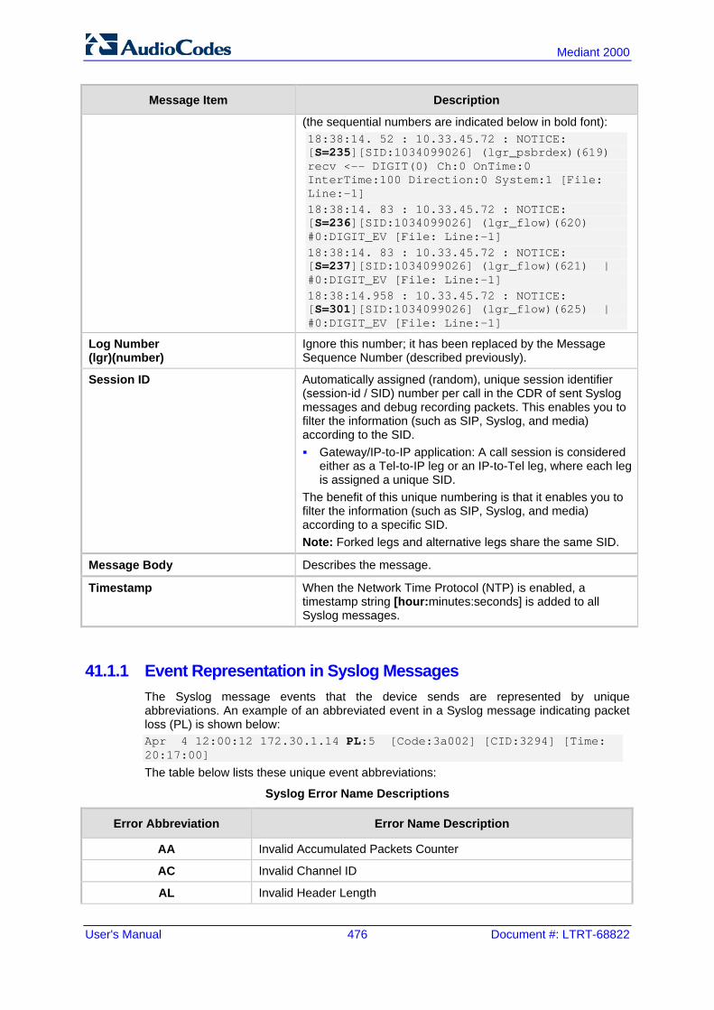
User's Manual 476 Document #: LTRT-68822
Mediant 2000
Message Item Description
(the sequential numbers are indicated below in bold font): 18:38:14. 52 : 10.33.45.72 : NOTICE: [S=235][SID:1034099026] (lgr_psbrdex)(619) recv <-- DIGIT(0) Ch:0 OnTime:0 InterTime:100 Direction:0 System:1 [File: Line:-1] 18:38:14. 83 : 10.33.45.72 : NOTICE: [S=236][SID:1034099026] (lgr_flow)(620) #0:DIGIT_EV [File: Line:-1] 18:38:14. 83 : 10.33.45.72 : NOTICE: [S=237][SID:1034099026] (lgr_flow)(621) | #0:DIGIT_EV [File: Line:-1] 18:38:14.958 : 10.33.45.72 : NOTICE: [S=301][SID:1034099026] (lgr_flow)(625) | #0:DIGIT_EV [File: Line:-1]
Log Number (lgr)(number)
Ignore this number; it has been replaced by the Message Sequence Number (described previously).
Session ID Automatically assigned (random), unique session identifier (session-id / SID) number per call in the CDR of sent Syslog messages and debug recording packets. This enables you to filter the information (such as SIP, Syslog, and media) according to the SID. Gateway/IP-to-IP application: A call session is considered
either as a Tel-to-IP leg or an IP-to-Tel leg, where each leg is assigned a unique SID.
The benefit of this unique numbering is that it enables you to filter the information (such as SIP, Syslog, and media) according to a specific SID. Note: Forked legs and alternative legs share the same SID.
Message Body Describes the message.
Timestamp When the Network Time Protocol (NTP) is enabled, a timestamp string [hour:minutes:seconds] is added to all Syslog messages.
41.1.1 Event Representation in Syslog Messages The Syslog message events that the device sends are represented by unique abbreviations. An example of an abbreviated event in a Syslog message indicating packet loss (PL) is shown below: Apr 4 12:00:12 172.30.1.14 PL:5 [Code:3a002] [CID:3294] [Time: 20:17:00]
The table below lists these unique event abbreviations:
Syslog Error Name Descriptions
Error Abbreviation Error Name Description
AA Invalid Accumulated Packets Counter
AC Invalid Channel ID
AL Invalid Header Length

Version 6.6 477 Mediant 2000
User's Manual 41. Syslog and Debug Recordings
Error Abbreviation Error Name Description
AO Invalid Codec Type
AP Unknown Aggregation Payload Type
AR Invalid Routing Flag Received
AT Simple Aggregation Packets Lost
CC Command Checksum Error
CE Invalid Cell Coder Code
CS Command Sequence Error
ES 8 sec Timeout Before Disconnect
HO Host Received Overrun
IA Invalid AMR Payload
IC Invalid CID Error
IG Invalid G723 Code
IP Invalid payload length
IR Invalid RTCP Packet
IS Invalid SID Length
LC Transmitter Received Illegal Command
LF Lost Fax Frames In High Speed Mode
LM Lost Modem Frames In High Speed Mode
MI Misalignment Error
MR Modem Relay Is Not Supported
OR DSP JB Overrun
PH Packet Header Error
PL RTP Packet Loss
RB Counts the number of BFI Frames Received From The Host
RD No Available Release Descriptor
RO RTP Reorder
RP Unknown RTP Payload Type
RS RTP SSRC Error
UF Unrecognized Fax Relay Command
AA Invalid Accumulated Packets Counter
AC Invalid Channel ID
AL Invalid Header Length
AO Invalid Codec Type
AP Unknown Aggregation Payload Type
AR Invalid Routing Flag Received

User's Manual 478 Document #: LTRT-68822
Mediant 2000
41.1.2 Identifying AudioCodes Syslog Messages using Facility Levels The device’s Syslog messages can easily be identified and distinguished from Syslog messages from other equipment, by setting its Facility level. The Facility levels of the device's Syslog messages are numerically coded with decimal values. Facility level may use any of the "local use" facilities (0 through 7), according to RFC 3164. Implementing Facility levels is useful, for example, if you collect the device’s as well as other equipments’ Syslog messages on the same server. Therefore, in addition to filtering Syslog messages according to IP address, the messages can be filtered according to Facility level. The Facility level is configured using the SyslogFacility ini file parameter, which provides the following options:
Syslog Facility Levels
Numerical Value Facility Level
16 (default) local use 0 (local0)
17 local use 1 (local1)
18 local use 2 (local2)
19 local use 3 (local3)
20 local use 4 (local4)
21 local use 5 (local5)
22 local use 6 (local6)
23 local use 7 (local7)
Syslog messages begin with a less-than ("<") character, followed by a number, which is followed by a greater-than (">") character. This is optionally followed by a single ASCII space. The number is known as the Priority and represents both the Facility level and the Severity level. A Syslog message with Facility level 16 is shown below: Facility: LOCAL0 - reserved for local use (16)
41.1.3 Syslog Fields for Automatic Machine Detection The Syslog message can include information relating to the Automatic Machine Detection (AMD) feature. AMD is used to detect whether a human voice, a fax machine, silence, or beeps have answered the call on the remote side. This feature is applicable only to the Gateway application. AMDSignal – this field can acquire one of the following values:
• voice • answer machine • silence • unknown
AMDDecisionProbability – probability success that correctly detects answering type Below is an example of such a Syslog message with AMD information: CallMachine:EVENT_DETECTED_EV - AMDSignal = <type – V/A/S/U>, AMDDecisionProbability = <percentage> %
If there is no AMD detection, the AMDSignal field is shown empty (i.e. AMDSignal = ).

Version 6.6 479 Mediant 2000
User's Manual 41. Syslog and Debug Recordings
41.1.4 SNMP Alarms in Syslog Messages SNMP alerts are sent to the Syslog server using the following formats: Raised Alarms: RAISE-ALARM: <Alarm Name>; Textual Description: <Textual
Description>; Severity <Alarm Severity>; Source <Alarm Source>; Unique ID: <Alarm Unique ID >. If additional information exists in the alarm, then these are also added: Additional Info1:/ Additional Info2:/ Additional Info3 The Messages’ Severity is as follows:
Syslog Message Severity
ITU Perceived Severity (SNMP Alarm’s Severity)
AudioCodes' Syslog Severity
Critical RecoverableMsg
Major RecoverableMsg
Minor RecoverableMsg
Warning Notice
Indeterminate Notice
Cleared Notice
Cleared Alarms: CLEAR-ALARM: <Alarm Name>; Textual Description: <Textual
Description>; Severity <Alarm Severity>; Source <Alarm Source>; Unique ID: <Alarm Unique ID >; If exists Additional Info1:/ Additional Info2:/ Additional Info3:
41.2 Configuring Syslog Settings The procedure below describes how to configure Syslog. This includes defining the Syslog server address as well as selecting the activities on the device (for example, a parameter value change) that you want reported to the server.
Notes:
• For configuring CDR reporting, see 'Configuring CDR Reporting' on page 460. • For viewing Syslog messages in the Web interface, see 'Viewing Syslog
Messages' on page 484. • For a detailed description on the Syslog parameters, see 'Syslog, CDR and Debug
Parameters' on page 522.
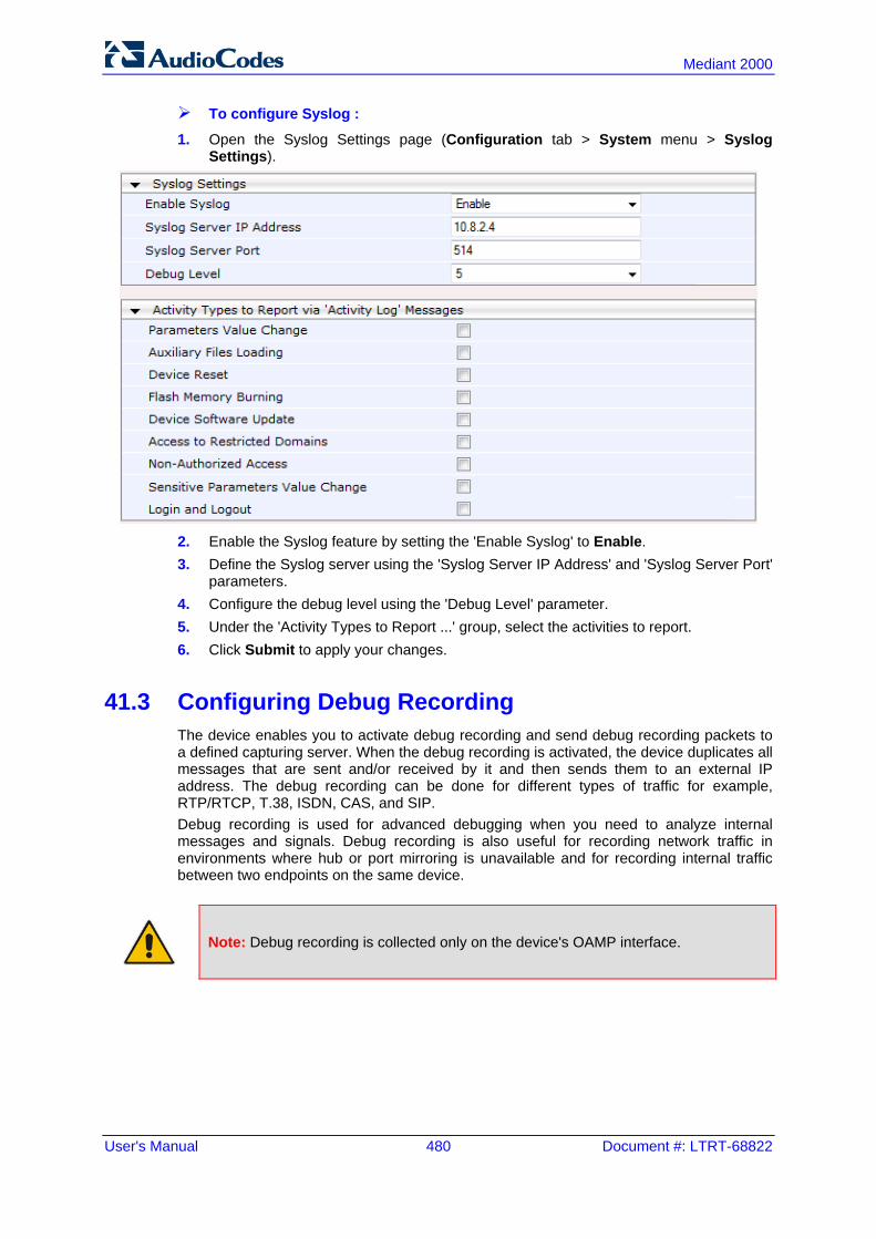
User's Manual 480 Document #: LTRT-68822
Mediant 2000
To configure Syslog :
1. Open the Syslog Settings page (Configuration tab > System menu > Syslog Settings).
2. Enable the Syslog feature by setting the 'Enable Syslog' to Enable. 3. Define the Syslog server using the 'Syslog Server IP Address' and 'Syslog Server Port'
parameters. 4. Configure the debug level using the 'Debug Level' parameter. 5. Under the 'Activity Types to Report ...' group, select the activities to report. 6. Click Submit to apply your changes.
41.3 Configuring Debug Recording The device enables you to activate debug recording and send debug recording packets to a defined capturing server. When the debug recording is activated, the device duplicates all messages that are sent and/or received by it and then sends them to an external IP address. The debug recording can be done for different types of traffic for example, RTP/RTCP, T.38, ISDN, CAS, and SIP. Debug recording is used for advanced debugging when you need to analyze internal messages and signals. Debug recording is also useful for recording network traffic in environments where hub or port mirroring is unavailable and for recording internal traffic between two endpoints on the same device.
Note: Debug recording is collected only on the device's OAMP interface.

Version 6.6 481 Mediant 2000
User's Manual 41. Syslog and Debug Recordings
To configure and activate debug recording:
1. Open the Logging Settings page (Configuration tab > System menu > Logging > Logging Settings).
Figure 41-1: Logging Settings Page
2. Configure the debug capturing server using the 'Debug Recording Destination IP' and
'Debug Recording Destination Port' parameters. 3. From the 'Debug Recording Status' drop-down list, select Start to start the debug
recording or Stop to end the recording. 4. Click Submit to apply your changes.
41.4 Filtering Syslog Messages and Debug Recordings The device can filter Syslog messages and debug recording (DR) packets, sent by the device to a Syslog server and packet capturing application (such as Wireshark) respectively. This can be useful to reduce CPU consumption and minimize negative impact on VoIP performance. You can configure up to 30 filtering rules, each based on a selected filtering criteria (e.g., an IP Group). Each filtering criteria can be configured with a range. For example, you can filter Syslog messages for IP Groups 1 through 4. For each filter criteria, you can enable or disable Syslog messages and debug recording. Debug recording can also be filtered using various filtering criteria such as SIP signaling or signaling and media.
To configure logging filtering rules:
1. Open the Logging Filters Table page (Configuration tab > System menu > Logging > Logging Filters Table).
2. Click the Add button; the Add Record dialog box appears:
Figure 41-2: Logging Filters Table - Add Record Dialog Box
3. Configure the logging filter, as required. See the table below for a description of the
parameters. 4. Click Submit to save your changes.

User's Manual 482 Document #: LTRT-68822
Mediant 2000
Notes:
• To configure the Syslog debug level, use the 'Debug Level' parameter (see 'Configuring Syslog' on page 479).
• The Logging Filters table can also be configured using the table ini file parameter, LoggingFilters.
Logging Filters Table Parameters Description
Parameter Description
Filter Type CLI: filter-type [LoggingFilters_Type]
Defines the filter criteria. [1] Any (default) [2] Trunk ID = Filters according to a specified Trunk ID (applicable only
to the Gateway application). [3] Trunk Group ID = Filters according to a specified Trunk Group ID
(Applicable only to the Gateway/IP-to-IP application). [4] Trunk & B-channel = Filters according to a specified Trunk and B-
channel (applicable only to the Gateway/IP-to-IP application). [6] Tel-to-IP = Filters according to a specified Tel-to-IP routing rule listed
in the Outbound IP Routing table (applicable only to the Gateway/IP-to-IP application).
[7] IP-to-Tel = Filters according to a specified IP-to-Tel routing rule listed in the Inbound IP Routing table (applicable only to the Gateway/IP-to-IP application).
[8] IP Group = Filters according to a specified IP Group ID listed in the IP Group table.
[9] SRD = Filters according to a specified SRD ID listed in the SRD table.
[12] User = Filters according to a specified user defined by username or user@host.
[13] IP Trace = Filters according to a specified IP network trace wireshark-like expression. For a detailed description on configuring IP traces, see 'Filtering IP Network Traces' on page 483.
Value CLI: value [LoggingFilters_Value]
Defines the value of the selected filtering type in the 'Filter Type' parameter. The value can be the following: A single value A range, using a hyphen "-" between the two values, e.g., "1-3" Multiple, non-contiguous values, using commas "," between each value,
e.g., "1,3,9" Trunks pertaining to a module, using the syntax module number/port or
port, for example: "1/2", means module 1, port 2 "1/[2-4]", means module 1, ports 2 through 4
Any to indicate all For IP trace expressions, see e 'Filtering IP Network Traces' on page
483
Syslog [LoggingFilters_Syslog]
Enables Syslog messages for the defined logging filter: [0] Disable (default) [1] Enable

Version 6.6 483 Mediant 2000
User's Manual 41. Syslog and Debug Recordings
Parameter Description
Capture Type [LoggingFilters_CaptureType]
Enables debug recordings for the defined logging filter and defines what to record: [0] None (default) [1] Signaling = Information related to signaling such as SIP signaling
messages, Syslog, CDR, and the device's internal processing messages.
[2] Signaling & Media = Signaling and media (RTP/RTCP/T.38). [3] Signaling & Media & PCM = Signaling, media, and PCM (voice
signals from and to TDM). [4] PSTN trace = ISDN and CAS traces - applicable only for Trunk-
related filters.
41.4.1 Filtering IP Network Traces You can filter Syslog and debug recording messages for IP network traces, by setting the 'Filter Type' parameter to IP Trace in the Logging Filters table. IP traces are used to record any IP stream that is not associated with media (RTP/RTCP), according to destination and/or source IP address, or port and Layer-4 protocol (UDP, TCP or any other IP type as defined by http://www.iana.com). When the IP Trace option is selected, only the ‘Value’ parameter is applicable; the 'Syslog' and 'Capture Type' parameters are not relevant. The 'Value' parameter configures the Wireshark-like filtering expressions for your IP trace. The following Wireshark-like expressions are supported:
Supported Wireshark-like Expressions for 'Value' Parameter
Expression Description
ip.src, ip.dst Source and destination IP address
ip.addr IP address - up to two IP addresses can be entered
ip.proto IP protocol type (PDU) entered as an enumeration value (e.g., 1 is ICMP, 6 is TCP, 17 is UDP)
udp, tcp, icmp, sip, ldap, http, https Single expressions for protocol type
udp.port, tcp.port Transport layer
udp.srcport, tcp.srcport Transport layer for source port
udp.dstport, tcp.dstport Transport layer for destination port
and, &&, ==, <, > Between expressions
Below are examples of configured expressions for the 'Value' parameter: udp && ip.addr==10.8.6.55 ip.src==10.8.6.55 && udp.port>=5000 and udp.port<6000 ip.dst==10.8.0.1/16 ip.addr==10.8.6.40

User's Manual 484 Document #: LTRT-68822
Mediant 2000
For conditions requiring the "or" / "||" expression, add multiple table rows. For example, the Wireshark condition "(ip.src == 1.1.1.1 or ip.src == 2.2.2.2) and ip.dst == 3.3.3.3" can be configured using the following two table row entries: 1. ip.src == 1.1.1.1 and ip.dst == 3.3.3.3 2. ip.src == 2.2.2.2 and ip.dst == 3.3.3.3
Note: If the 'Value' field is left empty, the device will record all IP traffic types.
41.5 Viewing Syslog Messages You can use the following tools to view the Syslog messages sent by the device: Web interface's Message Log page (see below). Any third-party Syslog server (e.g., Wireshark). The procedure below describes how to view Syslog messages in the Web interface.
Notes:
• It's not recommended to keep a Message Log session open for a prolonged period. This may cause the device to overload. For prolonged (and detailed) debugging, use an external Syslog server.
• You can select the Syslog messages in this page, and copy and paste them into a text editor such as Notepad. This text file (txt) can then be sent to AudioCodes Technical Support for diagnosis and troubleshooting.
To activate the Web interface's Message Log:
1. Enable Syslog (see 'Configuring Syslog' on page 479). 2. Open the Message Log page (Status & Diagnostics tab > System Status menu >
Message Log); the Message Log page is displayed and the log is activated.
Figure 41-3: Message Log Page
The displayed logged messages are color-coded as follows: • Yellow - fatal error message • Blue - recoverable error message (i.e., non-fatal error) • Black - notice message
To stop and clear the Message Log:
Close the Message Log page by accessing any another page in the Web interface.

Version 6.6 485 Mediant 2000
User's Manual 41. Syslog and Debug Recordings
41.6 Collecting Debug Recording Messages To collect debug recording packets, the open source program Wireshark is used. AudioCodes proprietary plug-in files for Wireshark, which are shipped in your software kit, are also required.
Notes:
• The default debug recording port is 925. You can change the port in Wireshark (Edit menu > Preferences > Protocols > AC DR).
• The plug-ins are per major software release and are applicable to Wireshark Ver. 1.62.
• The plug-ins are backward compatible. • From Wireshark Ver. 99.08, the tpncp.dat file must be located in the folder,
...WireShark\tpncp.
To install Wireshark and the plug-ins for debug recording:
1. Install Wireshark on your computer. The Wireshark program can be downloaded from http://www.wireshark.org.
2. Copy the supplied AudioCodes plug-in files to the directory in which you installed Wireshark, as follows:
Copy this file To this folder
...\dtds\cdr.dtd Wireshark\dtds\
...\plugins\1.6.2\*.dll Wireshark\plugins\1.6.2
...\tpncp\tpncp.dat Wireshark\tpncp
3. Start Wireshark. 4. In the Filter field, type "acdr" (see the figure below) to view the debug recording
messages. Note that the source IP address of the messages is always the OAMP IP address of the device.
The device adds the header "AUDIOCODES DEBUG RECORDING" to each debug recording message, as shown below:

User's Manual 486 Document #: LTRT-68822
Mediant 2000
For ISDN trace messages, the additional header, "NetBricks Trace" is added below the "AUDIOCODES DEBUG RECORDING" header, as shown in the example below: AUDIOCODES DEBUG RECORDING NetBricks Trace System time: 3559 Direction: Message received from internal server queue (73) From (Entity origination ID): DL_D (DL LAPD Q.921) (100) To (Entity destination ID): PH_D (D channel physical) (68) Primitive code: 67 NAI (Network Access ID): 0 -> number of trunk SAPI: 1 Connection ID: 0 Congestion flag: 0 Allocated message: 2 Allocated buffer: 3 Allocated timer cell: 141 IT Message stack counter: 120 IT Buffer stack counter: 120 Message congestion counter: 0 Buffer congestion counter: 0 IT Stack message congestion counter: 0 IT Stack buffer congestion counter: 0 Pointer to message: 689 Pointer to buffer: 0 Data size: 33 Link Access Procedure, Channel D (LAPD) Q.931 Protocol discriminator: Q.931 Call reference value length: 2 Call reference flag: Message sent from originating side Call reference value: 0300 - > can be used as a filter to identify entire ISDN call Message type: SETUP (0x05) Bearer capability Channel identification Calling party number: '201' Called party number: '102' Sending complete
For CAS trace messages, the additional header "CAS Trace" is added below the "AUDIOCODES DEBUG RECORDING" header, as shown in the example below: AUDIOCODES DEBUG RECORDING CAS Trace Timer: 1145504439 From: DSP (0) Current State: 7 Event: EV_DIAL_ENDED (15) Next State: -1 Function Use: Unknown (-1) Parameter 1: -1 Parameter 2: -1 Parameter 3: -1 Trunk Number: 3 BChannel Number: 23 Call Handle: 0

Version 6.6 487 Mediant 2000
User's Manual 42. Self-Testing
42 Self-Testing The device features the following self-testing modes to identify faulty hardware components: Detailed Test (Configurable): This test verifies the correct functioning of the different
hardware components on the device. This test is done when the device is taken out of service (i.e., not in regular service for processing calls). The test is performed on startup when initialization of the device completes. To enable this test, set the ini file parameter, EnableDiagnostics to 1 or 2, and then reset the device. Upon completion of the test and if the test fails, the device sends information on the test results of each hardware component to the Syslog server. The following hardware components are tested: • RAM - when EnableDiagnostics = 1 or 2 • Flash memory - when EnableDiagnostics = 1 or 2 • DSPs - when EnableDiagnostics = 1 or 2 • Physical Ethernet ports - when EnableDiagnostics = 1 or 2
Notes:
• To return the device to regular operation and service, disable the test by setting the ini file parameter, EnableDiagnostics to 0, and then reset the device.
• While the test is enabled, ignore errors sent to the Syslog server.
Startup Test (automatic): This hardware test has minor impact in real-time. While this test is executed, the regular operation of the device is disabled. If an error is detected, an error message is sent to the Syslog.
Periodic Test (automatic): This test monitors the device during run-time. This test is performed after startup, even when there is full traffic on the device (quality is not degraded). This is a short test phase in which the only error detected and reported is failure in initializing hardware components or malfunction in running hardware components. If an error is detected, an error message is sent to the Syslog.

User's Manual 488 Document #: LTRT-68822
Mediant 2000
Reader's Notes
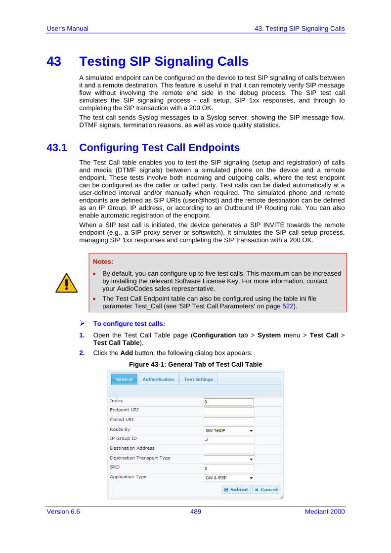
Version 6.6 489 Mediant 2000
User's Manual 43. Testing SIP Signaling Calls
43 Testing SIP Signaling Calls A simulated endpoint can be configured on the device to test SIP signaling of calls between it and a remote destination. This feature is useful in that it can remotely verify SIP message flow without involving the remote end side in the debug process. The SIP test call simulates the SIP signaling process - call setup, SIP 1xx responses, and through to completing the SIP transaction with a 200 OK. The test call sends Syslog messages to a Syslog server, showing the SIP message flow, DTMF signals, termination reasons, as well as voice quality statistics.
43.1 Configuring Test Call Endpoints The Test Call table enables you to test the SIP signaling (setup and registration) of calls and media (DTMF signals) between a simulated phone on the device and a remote endpoint. These tests involve both incoming and outgoing calls, where the test endpoint can be configured as the caller or called party. Test calls can be dialed automatically at a user-defined interval and/or manually when required. The simulated phone and remote endpoints are defined as SIP URIs (user@host) and the remote destination can be defined as an IP Group, IP address, or according to an Outbound IP Routing rule. You can also enable automatic registration of the endpoint. When a SIP test call is initiated, the device generates a SIP INVITE towards the remote endpoint (e.g., a SIP proxy server or softswitch). It simulates the SIP call setup process, managing SIP 1xx responses and completing the SIP transaction with a 200 OK.
Notes:
• By default, you can configure up to five test calls. This maximum can be increased by installing the relevant Software License Key. For more information, contact your AudioCodes sales representative.
• The Test Call Endpoint table can also be configured using the table ini file parameter Test_Call (see 'SIP Test Call Parameters' on page 522).
To configure test calls: 1. Open the Test Call Table page (Configuration tab > System menu > Test Call >
Test Call Table). 2. Click the Add button; the following dialog box appears:
Figure 43-1: General Tab of Test Call Table

User's Manual 490 Document #: LTRT-68822
Mediant 2000
3. Configure the test endpoint parameters as desired. See the table below for a description of these parameters.
4. Click Submit to apply your settings.
Test Call Table Parameters
Parameter Description
General Tab
Endpoint URI [Test_Call_EndpointURI]
Defines the endpoint's URI. This can be defined as a user or user@host. The device identifies this endpoint only by the URI's user part. The URI's host part is used in the SIP From header in REGISTER requests. The valid value is a string of up to 150 characters. By default, this parameter is not configured.
Called URI [Test_Call_CalledURI]
Defines the destination (called) URI (user@host). The valid value is a string of up to 150 characters. By default, this parameter is not configured.
Route By [Test_Call_DestType]
Defines the type of routing method. This applies to incoming and outgoing calls. [0] GW Tel2IP = (Default) Calls are matched by (or routed to) an SRD
and Application type (defined in the SRD and Application Type parameters below).
[1] IP Group = Calls are matched by (or routed to) an IP Group ID. [2] Dest Address = Calls are matched by (or routed to) an SRD and
application type. Notes: For REGISTER messages, the option [0] cannot be used as the routing
method. For REGISTER messages, if option [1] is used, only Server-type IP
Groups can be used.
IP Group ID [Test_Call_IPGroupID]
Defines the IP Group ID to which the test call is sent or from which it is received. Notes: This parameter is applicable only if option [1] is configured for the 'Route
By' parameter. This IP Group is used for incoming and outgoing calls.
Destination Address [Test_Call_DestAddress]
Defines the destination host. This can be defined as an IP address[:port] or DNS name[:port]. Note: This parameter is applicable only if the 'Route By' parameter is set to [2] (Dest Address).
Destination Transport Type [Test_Call_DestTransportType]
Defines the transport type for outgoing calls. [-1] Not configured (default) [0] UDP [1] TCP [2] TLS Note: This parameter is applicable only if the 'Route By' parameter is set to [2] (Dest Address).

Version 6.6 491 Mediant 2000
User's Manual 43. Testing SIP Signaling Calls
Parameter Description
SRD [Test_Call_SRD]
Defines the SRD for the endpoint. The default is SRD 0. Note: This parameter is applicable only if the 'Route By' parameter is set any option except [1] (IP Group).
Application Type [Test_Call_ApplicationType]
Defines the application type for the endpoint. This, in effect, associates the IP Group and SRD to a specific SIP interface. [0] GW & IP2IP (default)
Authentication Tab Note: These parameters are applicable only if the test endpoint is set to Caller (see the 'Call Party' parameter).
Auto Register [Test_Call_AutoRegister]
Enables automatic registration of the endpoint. The endpoint can register to the device itself or to the 'Destination Address' or 'IP Group ID' parameter settings (see above). [0] False (default) [1] True
User Name [Test_Call_UserName]
Defines the authentication username. By default, no username is defined.
Password [Test_Call_Password]
Defines the authentication password. By default, no password is defined.
Test Settings Tab
Call Party [Test_Call_CallParty]
Defines whether the test endpoint is the initiator or receiving side of the test call. [0] Caller (default) [1] Called
Maximum Channels for Session [Test_Call_MaxChannels]
Defines the maximum number of concurrent channels for the test session. For example, if you have configured an endpoint "101" and you set this parameter to "3", the device automatically creates three simulated endpoints - "101", "102" and "103" (i.e., consecutive endpoint URIs are assigned). The default is 1.
Call Duration [Test_Call_CallDuration]
Defines the call duration (in seconds). The valid value is -1 to 100000. The default is 20. A value of 0 means infinite. A value of -1 means that the parameter value is automatically calculated according to the values of the 'Calls per Second' and 'Maximum Channels for Session' parameters. Note: This parameter is applicable only if 'Call Party' is set to Caller.
Calls per Second [Test_Call_CallsPerSecond]
Defines the number of calls per second. Note: This parameter is applicable only if 'Call Party' is set to Caller.

User's Manual 492 Document #: LTRT-68822
Mediant 2000
Parameter Description
Test Mode [Test_Call_TestMode]
Defines the test session mode. [0] Once = (Default) The test runs until the lowest value between the
following is reached: Maximum channels is reached for the test session, configured by
'Maximum Channels for Session'. Call duration ('Call Duration') multiplied by calls per second ('Calls
per Second'). Test duration expires, configured by 'Test Duration'.
[1] Continuous = The test runs until the configured test duration is reached. If it reaches the maximum channels configured for the test session (in the 'Maximum Channels for Session'), it waits until the configured call duration of a currently established tested call expires before making the next test call. In this way, the test session stays within the configured maximum channels.
Note: This parameter is applicable only if 'Call Party' is set to Caller.
Test Duration [Test_Call_TestDuration]
Defines the test duration (in minutes). The valid value is 0 to 100000. The default is 0 (i.e., unlimited). Note: This parameter is applicable only if 'Call Party' is set to Caller.
Play [Test_Call_Play]
Enables playing a user-defined DTMF signal to the answered side of the call. [0] Disable (default) [1] DTMF To configure the played DTMF signal, see 'Configuring DTMF Tones for Test Calls' on page 494. Notes: To configure the DTMF signaling type (e.g., out-of-band or in-band) use
the 'DTMF Transport Type' parameter (see 'Configuring DTMF Transport Types' on page 167).
This parameter is applicable only if 'Call Party' is set to Caller. Schedule Interval [Test_Call_ScheduleInterval]
Defines the interval (in minutes) between automatic outgoing test calls. The valid value range is 0 to 100000. The default is 0 (i.e., scheduling is disabled). Note: This parameter is applicable only if 'Call Party' is set to Caller.
43.1.1 Starting, Stopping and Restarting Test Calls The procedure below describes how to start, stop, and restart test calls.
To start, stop, and restart a test call:
1. In the Test Call table, select the required test call entry; the Actions button appears above the table.
2. From the Actions drop-down list, choose the required command: • Dial: starts the test call (this action is applicable only if the test call party is the
caller). • Drop Call: stops the test call. • Restart: ends all established calls and then starts the test call session again.

Version 6.6 493 Mediant 2000
User's Manual 43. Testing SIP Signaling Calls
The status of the test call is displayed in the 'Test Status' field of the Test Call table: "Idle": test call is not active. "Scheduled": test call is planned to run (according to 'Schedule Interval' parameter
settings) "Running": test call has been started (i.e., the Dial command was clicked) "Receiving": test call has been automatically activated by calls received for the test
call endpoint from the remote endpoint (when all these calls end, the status returns to "Idle")
"Terminating": test call is in the process of terminating the currently established calls (this occurs if the Drop Call command is clicked to stop the test)
"Done": test call has been successfully completed (or was prematurely stopped by clicking the Drop Call command)
A more detailed description of this field is displayed below the table when you click the Show/Hide button (see 'Viewing Test Call Statistics' on page 493.
43.1.2 Viewing Test Call Statistics In addition to viewing a brief status description of the test call in the 'Test Status' field (as described in 'Starting, Stopping and Restarting Test Calls' on page 492), you can also view a more detailed status description which includes test call statistics.
To view statistics of a test call: 1. Open the Test Call Table page (Configuration tab > System menu > Test Call >
Test Call Table). 2. Select the test call table entry whose call statistics you want to view. 3. Click the Show/Hide button; the call statistics are displayed in the Test Statistics
pane located below the table, as shown in the figure below:
Figure 43-2: Viewing Test Call Statistics
The 'Test Statistics' pane displays the following test session information: Elapsed Time: Duration of the test call since it was started (or restarted). Active Calls: The number of currently active test calls. Call Attempts: The number of calls that were attempted. Total Established Calls: The total number of calls that were successfully established. Total Failed Attempts: The total number of calls that failed to be established.

User's Manual 494 Document #: LTRT-68822
Mediant 2000
Remote Disconnections Count: Number of calls that were disconnected by the remote side.
Average CPS: The average calls per second. Test Status: Displays the status (brief description) as displayed in the 'Test Status'
field (see 'Starting, Stopping and Restarting Test Calls' on page 492). Detailed Status: Displays a detailed description of the test call status::
• "Idle": The test call is currently not active. • "Scheduled - Established Calls: <established calls>, ASR: <%>": The test call is
planned to run (according to 'Schedule Interval' parameter settings) and also shows the following summary of completed test calls: ♦ Total number of test calls that were established. ♦ Number of successfully answered calls out of the total number of calls
attempted (ASR). • "Running (Calls: <number of active calls>, ASR: <%>)": The test call has been
started (i.e., the Dial command was clicked) and shows the following: ♦ Number of currently active test calls. ♦ Number of successfully answered calls out of the total number of calls
attempted (Answer Seizure Ratio or ASR). • "Receiving (<number of active calls>)": The test call has been automatically
activated by calls received for this configured test call endpoint from the configured remote endpoint. When all these calls terminate, the status returns to "Idle".
• "Terminating (<number of active calls>)": The Drop Call command has been clicked to stop the test call and the test call is in the process of terminating the currently active test calls.
• "Done - Established Calls: <established calls>, ASR: <%>": The test call has been successfully completed (or was prematurely stopped by clicking the Drop Call command) and shows the following: ♦ Total number of test calls that were established. ♦ Number of successfully answered calls out of the total number of calls
attempted (ASR).
Note: On the receiving side, when the first call is accepted in "Idle" state, statistics are reset.
43.2 Configuring DTMF Tones for Test Calls By default, no DTMF signal is played to an answered test call (incoming or outgoing). However, you can enable this per configured test call in the Test Call table (see 'Configuring Test Call Endpoints' on page 489). If enabled, the default DTMF signal that is played is "3212333". You can change this as described below.
Notes:
• The DTMF signaling type (e.g., out-of-band or in-band) can be configured using the 'DTMF Transport Type' parameter. For more information, see 'Configuring DTMF Transport Types' on page 167.
• To generate DTMF tones, the device's DSP resources are required.

Version 6.6 495 Mediant 2000
User's Manual 43. Testing SIP Signaling Calls
To configure the played DTMF signal to answered test call:
1. Open the Test Call Settings page (Configuration tab > System menu > Test Call > Test Call Settings).
2. In the 'Test Call DTMF String' field, enter the DTMF string (up to 15 digits). 3. Click Submit.
43.3 Configuring Basic Test Call The Basic Test Call feature tests incoming Gateway / IP-to-IP calls from a remote SIP endpoint to a simulated test endpoint on the device. The only required configuration is to assign a prefix number (test call ID) to the simulated endpoint. All incoming calls with this called (destination) prefix number is identified as a test call and sent to the simulated endpoint. The figure below displays a basic test call example.
Figure 43-3: Incoming Test Call Example
To configure basic call testing:
1. Open the Test Call Settings page (Configuration tab > System menu > Test Call > Test Call Settings).
Figure 43-4: Test Call Settings Page
2. In the 'Test Call ID' field, enter a prefix for the simulated endpoint. 3. Click Submit to apply your settings.
Notes:
• The Basic Test Call feature tests incoming calls only and is initiated only upon receipt of incoming calls with the configured prefix.
• For a full description of this parameter, see 'SIP Test Call Parameters' on page 522.
• This call test is done on all SIP interfaces.

User's Manual 496 Document #: LTRT-68822
Mediant 2000
43.4 Test Call Configuration Examples Below are a few examples of test call configurations. Single Test Call Scenario: This example describes the configuration of a simple test
call scenario that includes a single test call between a simulated test endpoint on the device and a remote endpoint.
Figure 43-5: Single Test Call Example
• Test Call table configuration:
♦ Endpoint URI: "101" ♦ Called URI: "201" ♦ Route By: Dest Address ♦ Destination Address: "10.30.40.01" ♦ Call Party: Caller ♦ Test Mode: Once (default)
Alternatively, if you want to route the test call using the Outbound IP Routing table for the Gateway / IP-to-IP application, configure the following: • Test Call table configuration:
♦ Endpoint URI: [email protected] ♦ Route By: GW Tel2IP ♦ Called URI: [email protected] ♦ Call Party: Caller
• Outbound IP Routing table configuration: ♦ Dest. Phone Prefix: 201 (i.e., the Called URI user-part) ♦ Source Phone Prefix: 101 (i.e., the Endpoint URI user-part) ♦ Dest. IP Address: 10.30.40.1
Batch Test Call Scenario: This example describes the configuration of a batch test call setup for scheduled and continuous call testing of multiple endpoints. The test call is done between two AudioCodes devices - Device A and Device B - with simulated test endpoints. This eliminates the need for phone users, who would otherwise need to answer and end calls many times for batch testing. The calls are initiated from Device A, where Device B serves as the remote answering endpoint.

Version 6.6 497 Mediant 2000
User's Manual 43. Testing SIP Signaling Calls
Figure 43-6: Batch Test Call Example
• Test Call table configuration at Device A:
♦ Endpoint URI: "101" ♦ Called URI: "201" ♦ Route By: Dest Address ♦ Destination Address: "10.13.4.12" ♦ Call Party: Caller ♦ Maximum Channels for Session: "3" (this setting configures three endpoints -
"101", "102" and "103) ♦ Call Duration: "5" (seconds) ♦ Calls per Sec: "1" ♦ Test Mode: Continuous ♦ Test Duration: "3" (minutes) ♦ Schedule Interval: "180" (minutes)
• Test Call table configuration at Device B: ♦ Endpoint URI: "201" ♦ Call Party: Caller ♦ Maximum Channels for Session: "3" (this setting configures three endpoints -
"201", "202" and "203) Registration Test Call Scenario: This example describes the configuration for testing
the registration and authentication (i.e., username and password) process of a simulated test endpoint on the device with an external proxy/registrar server. This is useful, for example, for verifying that endpoints located in the LAN can register with an external proxy and subsequently, communicate with one another.

User's Manual 498 Document #: LTRT-68822
Mediant 2000
Figure 43-7: Test Call Registration Example
This example assumes that you have configured your device for communication between LAN phone users such as IP Groups to represent the device (10.13.4.12) and the proxy server, and IP-to-IP routing rules to route calls between these IP Groups. • Test Call table configuration:
♦ Endpoint URI: "101" ♦ Called URI: "itsp" ♦ Route By: Dest Address ♦ Destination Address: "10.13.4.12" (this is the IP address of the device itself) ♦ Auto Register: Enable ♦ User Name: "testuser" ♦ Password: "12345" ♦ Call Party: Caller

Part XI Appendix


Version 6.6 501 Mediant 2000
User's Manual 44. Dialing Plan Notation for Routing and Manipulation
44 Dialing Plan Notation for Routing and Manipulation The device supports flexible dialing plan notations for denoting the prefix and/or suffix source and/or destination numbers and SIP URI user names in the routing and manipulation tables.
Dialing Plan Notations for Prefixes and Suffixes
Notation Description
x (letter "x") Denotes any single digit.
# (pound symbol) When used at the end of a prefix, it denotes the end of a number. For example, 54324xx# represents a 7-digit number that starts with the digits 54324.
When used anywhere in the suffix, it is part of the number. For example, (3#45) can represent the number string, 123#45.
* (asterisk symbol) When used in the prefix, it denotes any number. When used in the suffix, it is part of the number. For example, (3*45) can
represent the number string, 123*45.
$ (dollar sign) Denotes an empty prefix for incoming IP calls that do not have a user part in the Request-URI, or for incoming Tel calls that do not have a called or calling number. This is used for the following matching criteria: Source and Destination Phone Prefix Source and Destination Username Source and Destination Calling Name Prefix
Range of Digits Notes: Dial plans denoting a prefix that is a range must be enclosed in square brackets, e.g., [4-8] or
23xx[456]. Dial plans denoting a prefix that is not a range is not enclosed, e.g., 12345#. Dial plans denoting a suffix must be enclosed in parenthesis, e.g., (4) and (4-8). Dial plans denoting a suffix that include multiple ranges, the range must be enclosed in square
brackets, e.g., (23xx[4,5,6]). An example for entering a combined prefix and suffix dial plan - assume you want to match a rule
whose destination phone prefix is 4 to 8, and suffix is 234, 235, or 236. The entered value would be the following: [4-8](23[4,5,6]).
[n-m] or (n-m) Represents a range of numbers, for example: To depict numbers from 5551200 to 5551300: Prefix: [5551200-5551300]# Suffix: (5551200-5551300)
To depict numbers from 123100 to 123200: Prefix: 123[100-200] Suffix: (123[100-200])
To depict prefix and suffix numbers together: 03(100): for any number that starts with 03 and ends with 100. [100-199](100,101,105): for a number that starts with 100 to 199 and
ends with 100, 101 or 105. 03(abc): for any number that starts with 03 and ends with abc. 03(5xx): for any number that starts with 03 and ends with 5xx. 03(400,401,405): for any number that starts with 03 and ends with
400 or 401 or 405.
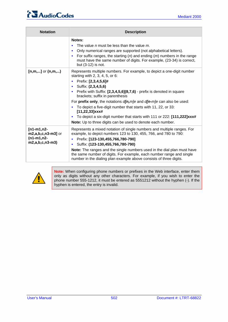
User's Manual 502 Document #: LTRT-68822
Mediant 2000
Notation Description
Notes: The value n must be less than the value m. Only numerical ranges are supported (not alphabetical letters). For suffix ranges, the starting (n) and ending (m) numbers in the range
must have the same number of digits. For example, (23-34) is correct, but (3-12) is not.
[n,m,...] or (n,m,...) Represents multiple numbers. For example, to depict a one-digit number starting with 2, 3, 4, 5, or 6: Prefix: [2,3,4,5,6]# Suffix: (2,3,4,5,6) Prefix with Suffix: [2,3,4,5,6](8,7,6) - prefix is denoted in square
brackets; suffix in parenthesis For prefix only, the notations d[n,m]e and d[n-m]e can also be used: To depict a five-digit number that starts with 11, 22, or 33:
[11,22,33]xxx# To depict a six-digit number that starts with 111 or 222: [111,222]xxx# Note: Up to three digits can be used to denote each number.
[n1-m1,n2-m2,a,b,c,n3-m3] or (n1-m1,n2-m2,a,b,c,n3-m3)
Represents a mixed notation of single numbers and multiple ranges. For example, to depict numbers 123 to 130, 455, 766, and 780 to 790: Prefix: [123-130,455,766,780-790] Suffix: (123-130,455,766,780-790) Note: The ranges and the single numbers used in the dial plan must have the same number of digits. For example, each number range and single number in the dialing plan example above consists of three digits.
Note: When configuring phone numbers or prefixes in the Web interface, enter them only as digits without any other characters. For example, if you wish to enter the phone number 555-1212, it must be entered as 5551212 without the hyphen (-). If the hyphen is entered, the entry is invalid.

Version 6.6 503 Mediant 2000
User's Manual 45. Configuration Parameters Reference
45 Configuration Parameters Reference The device's configuration parameters, default values, and their descriptions are documented in this section.
Note: Parameters and values enclosed in square brackets [...] represent the ini file parameters and their enumeration values.
45.1 Networking Parameters This subsection describes the device's networking parameters.
45.1.1 Ethernet Parameters The Ethernet parameters are described in the table below.
Ethernet Parameters
Parameter Description
EMS: Physical Configuration [EthernetPhyConfiguration]
Defines the Ethernet connection mode type. [0] = 10Base-T half-duplex [1] = 10Base-T full-duplex [2] = 100Base-TX half-duplex [3] = 100Base-TX full-duplex [4] = (Default) Auto-negotiate Note: For this parameter to take effect, a device reset is required.
[MIIRedundancyEnable] Enables the Ethernet Interface Redundancy feature. When enabled, the device performs a switchover to the second (redundant) Ethernet port upon upon sensing a link failure in the primary Ethernet port. When disabled, the device operates with a single port (i.e. no redundancy support). [0] = Disable [1] = (Default) Enable For more information on Ethernet interface redundancy, see Ethernet Interface Redundancy on page 105. Note: For this parameter to take effect, a device reset is required.

User's Manual 504 Document #: LTRT-68822
Mediant 2000
45.1.2 Multiple VoIP Network Interfaces and VLAN Parameters The IP network interfaces and VLAN parameters are described in the table below.
IP Network Interfaces and VLAN Parameters
Parameter Description
Multiple Interface Table
Web: Multiple Interface Table EMS: IP Interface Settings [InterfaceTable]
This table parameter configures the Multiple Interface table. The format of this parameter is as follows: [InterfaceTable] FORMAT InterfaceTable_Index = InterfaceTable_ApplicationTypes, InterfaceTable_InterfaceMode, InterfaceTable_IPAddress, InterfaceTable_PrefixLength, InterfaceTable_Gateway, InterfaceTable_VlanID, InterfaceTable_InterfaceName, InterfaceTable_PrimaryDNSServerIPAddress, InterfaceTable_SecondaryDNSServerIPAddress, InterfaceTable_UnderlyingInterface; [\InterfaceTable] For example: InterfaceTable 0 = 0, 0, 192.168.85.14, 16, 0.0.0.0, 1, Management; InterfaceTable 1 = 2, 0, 200.200.85.14, 24, 0.0.0.0, 200, Control; InterfaceTable 2 = 1, 0, 211.211.85.14, 24, 211.211.85.1, 211, Media; The above example, configures three network interfaces (OAMP, Control, and Media). Notes: For this parameter to take effect, a device reset is required. For a description of this parameter, see 'Configuring IP Network
Interfaces' on page 106.
Single IP Network Parameters
Web: IP Address EMS: Local IP Address [LocalOAMIPAddress]
Defines the device's source IP address of the operations, administration, maintenance, and provisioning (OAMP) interface when operating in a single interface scenario without a Multiple Interface table. The default is 0.0.0.0. Note: For this parameter to take effect, a device reset is required.
Web: Subnet Mask EMS: OAM Subnet Mask [LocalOAMSubnetMask]
Defines the device's subnet mask of the OAMP interface when operating in a single interface scenario without a Multiple Interface table. The default subnet mask is 0.0.0.0. Note: For this parameter to take effect, a device reset is required.
Web: Default Gateway Address EMS: Local Def GW [LocalOAMDefaultGW]
Defines the Default Gateway of the OAMP interface when operating in a single interface scenario without a Multiple Interface table.
VLAN Parameters
Web/EMS: VLAN Mode [VLANMode]
Enables VLANs tagging (IEEE 802.1Q). [0] Disable (default) [1] Enable Notes:

Version 6.6 505 Mediant 2000
User's Manual 45. Configuration Parameters Reference
Parameter Description
For this parameter to take effect, a device reset is required. To operate with multiple network interfaces, VLANs must be
enabled. VLANs are available only when booting the device from flash. When
booting using BootP/DHCP protocols, VLANs are disabled to allow easier maintenance access. In this scenario, multiple network interface capabilities are unavailable.
Web/EMS: Native VLAN ID [VLANNativeVLANID]
Defines the Native VLAN ID. This is the VLAN ID to which untagged incoming traffic is assigned. Outgoing packets sent to this VLAN are sent only with a priority tag (VLAN ID = 0). When the Native VLAN ID is equal to one of the VLAN IDs listed in the Multiple Interface table (and VLANs are enabled), untagged incoming traffic is considered as incoming traffic for that interface. Outgoing traffic sent from this interface is sent with the priority tag (tagged with VLAN ID = 0). When the Native VLAN ID is different to any value in the 'VLAN ID' column in the table, untagged incoming traffic is discarded and all outgoing traffic is tagged. The default Native VLAN ID is 1. Note: If this parameter is not configured (i.e., default is 1) and one of the interfaces has a VLAN ID set to 1, this interface is still considered the ‘Native’ VLAN. If you do not wish to have a ‘Native’ VLAN ID and want to use VLAN ID 1, set this parameter to a value other than any VLAN ID in the table.
[EnableNTPasOAM] Defines the application type for Network Time Protocol (NTP) services. [1] = OAMP (default) [0] = Control Note: For this parameter to take effect, a device reset is required.
[VLANSendNonTaggedOnNative]
Determines whether to send non-tagged packets on the native VLAN. [0] = (Default) Sends priority tag packets. [1] = Sends regular packets (with no VLAN tag). Note: For this parameter to take effect, a device reset is required.
45.1.3 Routing Parameters The IP network routing parameters are described in the table below.
IP Network Routing Parameters
Parameter Description
Web: Disable ICMP Redirects [DisableICMPRedirects]
Determines whether the device accepts or ignores ICMP Redirect messages. [0] Disable = (Default) ICMP Redirect messages are handled by the
device. [1] Enable = ICMP Redirect messages are ignored.
Static IP Routing Table
Web/EMS: IP Routing Table
Defines up to 30 static IP routing rules for the device. These rules can be associated with IP interfaces defined in the Multiple Interface table (InterfaceTable parameter). The routing decision for sending the
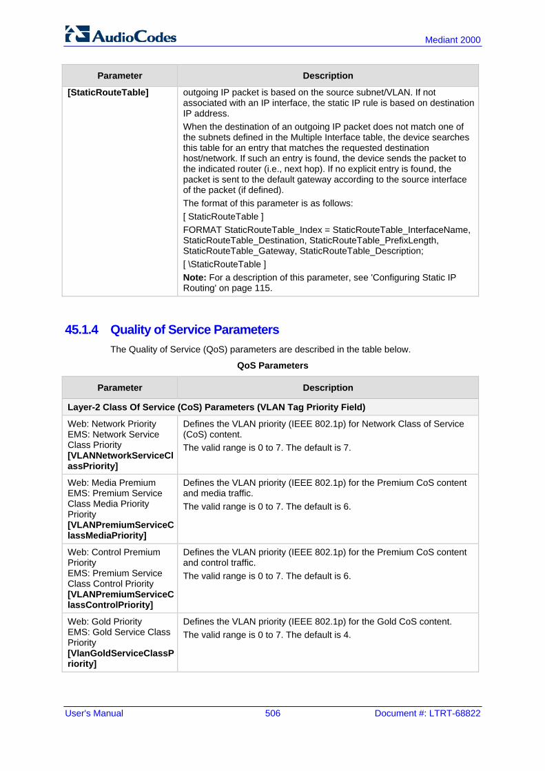
User's Manual 506 Document #: LTRT-68822
Mediant 2000
Parameter Description
[StaticRouteTable] outgoing IP packet is based on the source subnet/VLAN. If not associated with an IP interface, the static IP rule is based on destination IP address. When the destination of an outgoing IP packet does not match one of the subnets defined in the Multiple Interface table, the device searches this table for an entry that matches the requested destination host/network. If such an entry is found, the device sends the packet to the indicated router (i.e., next hop). If no explicit entry is found, the packet is sent to the default gateway according to the source interface of the packet (if defined). The format of this parameter is as follows: [ StaticRouteTable ] FORMAT StaticRouteTable_Index = StaticRouteTable_InterfaceName, StaticRouteTable_Destination, StaticRouteTable_PrefixLength, StaticRouteTable_Gateway, StaticRouteTable_Description; [ \StaticRouteTable ] Note: For a description of this parameter, see 'Configuring Static IP Routing' on page 115.
45.1.4 Quality of Service Parameters The Quality of Service (QoS) parameters are described in the table below.
QoS Parameters
Parameter Description
Layer-2 Class Of Service (CoS) Parameters (VLAN Tag Priority Field)
Web: Network Priority EMS: Network Service Class Priority [VLANNetworkServiceClassPriority]
Defines the VLAN priority (IEEE 802.1p) for Network Class of Service (CoS) content. The valid range is 0 to 7. The default is 7.
Web: Media Premium EMS: Premium Service Class Media Priority Priority [VLANPremiumServiceClassMediaPriority]
Defines the VLAN priority (IEEE 802.1p) for the Premium CoS content and media traffic. The valid range is 0 to 7. The default is 6.
Web: Control Premium Priority EMS: Premium Service Class Control Priority [VLANPremiumServiceClassControlPriority]
Defines the VLAN priority (IEEE 802.1p) for the Premium CoS content and control traffic. The valid range is 0 to 7. The default is 6.
Web: Gold Priority EMS: Gold Service Class Priority [VlanGoldServiceClassPriority]
Defines the VLAN priority (IEEE 802.1p) for the Gold CoS content. The valid range is 0 to 7. The default is 4.

Version 6.6 507 Mediant 2000
User's Manual 45. Configuration Parameters Reference
Parameter Description
Web: Bronze Priority EMS: Bronze Service Class Priority [VLANBronzeServiceClassPriority]
Defines the VLAN priority (IEEE 802.1p) for the Bronze CoS content. The valid range is 0 to 7. The default is 2.
Layer-3 Class of Service (TOS/DiffServ) Parameters
Web: Network QoS EMS: Network Service Class Diff Serv [NetworkServiceClassDiffServ]
Defines the Differentiated Services (DiffServ) value for Network CoS content. The valid range is 0 to 63. The default is 48. Note: For this parameter to take effect, a device reset is required.
Web: Media Premium QoS EMS: Premium Service Class Media Diff Serv [PremiumServiceClassMediaDiffServ]
Defines the DiffServ value for Premium Media CoS content (only if IPDiffServ is not set in the selected IP Profile). The valid range is 0 to 63. The default is 46. Note: The value for the Premium Control DiffServ is determined by the following (according to priority): IPDiffServ value in the selected IP Profile (IPProfile parameter). PremiumServiceClassMediaDiffServ.
Web: Control Premium QoS EMS: Premium Service Class Control Diff Serv [PremiumServiceClassControlDiffServ]
Defines the DiffServ value for Premium Control CoS content (Call Control applications) - only if ControlIPDiffserv is not set in the selected IP Profile. The valid range is 0 to 63. The default is 40. Notes: The value for the Premium Control DiffServ is determined by the
following (according to priority): SiglPDiffserv value in the selected IP Profile (IPProfile
parameter). PremiumServiceClassControlDiffServ.
Web: Gold QoS EMS: Gold Service Class Diff Serv [GoldServiceClassDiffServ]
Defines the DiffServ value for the Gold CoS content (Streaming applications). The valid range is 0 to 63. The default is 26.
Web: Bronze QoS EMS: Bronze Service Class Diff Serv [BronzeServiceClassDiffServ]
Defines the DiffServ value for the Bronze CoS content (OAMP applications). The valid range is 0 to 63. The default is 10.

User's Manual 508 Document #: LTRT-68822
Mediant 2000
45.1.5 NAT and STUN Parameters The Network Address Translation (NAT) and Simple Traversal of UDP through NAT (STUN) parameters are described in the table below.
NAT and STUN Parameters
Parameter Description
STUN Parameters
Web: Enable STUN EMS: STUN Enable [EnableSTUN]
Enables Simple Traversal of UDP through NATs (STUN). [0] Disable (default) [1] Enable When enabled, the device functions as a STUN client and communicates with a STUN server located in the public Internet. STUN is used to discover whether the device is located behind a NAT and the type of NAT. It is also used to determine the IP addresses and port numbers that the NAT assigns to outgoing signaling messages (using SIP) and media streams (using RTP, RTCP and T.38). STUN works with many existing NAT types and does not require any special behavior from them. Notes: For this parameter to take effect, a device reset is required. For defining the STUN server domain name, use the parameter
STUNServerDomainName. For more information on STUN, see Configuring STUN on page 126.
Web: STUN Server Primary IP EMS: Primary Server IP [STUNServerPrimaryIP]
Defines the IP address of the primary STUN server. The valid range is the legal IP addresses. The default is 0.0.0.0. Note: For this parameter to take effect, a device reset is required.
Web: STUN Server Secondary IP EMS: Secondary Server IP [STUNServerSecondaryIP]
Defines the IP address of the secondary STUN server. The valid range is the legal IP addresses. The default is 0.0.0.0. Note: For this parameter to take effect, a device reset is required.
[STUNServerDomainName]
Defines the domain name for the Simple Traversal of User Datagram Protocol (STUN) server's address (used for retrieving all STUN servers with an SRV query). The STUN client can perform the required SRV query to resolve this domain name to an IP address and port, sort the server list, and use the servers according to the sorted list. Notes: For this parameter to take effect, a device reset is required. Use either the STUNServerPrimaryIP or the
STUNServerDomainName parameter, with priority to the first one.
NAT Parameters
Web/EMS: NAT Traversal [DisableNAT]
Enables the NAT mechanism. For more information, see 'First Incoming Packet Mechanism' on page 129. [0] Enable [1] Disable (default)
Web: NAT IP Address EMS: Static NAT IP
Defines the global (public) IP address of the device to enable static NAT between the device and the Internet.

Version 6.6 509 Mediant 2000
User's Manual 45. Configuration Parameters Reference
Parameter Description
Address [StaticNatIP]
Note: For this parameter to take effect, a device reset is required.
EMS: Binding Life Time [NATBindingDefaultTimeout]
Defines the default NAT binding lifetime in seconds. STUN refreshes the binding information after this time expires. The valid range is 0 to 2,592,000. The default is 30. Note: For this parameter to take effect, a device reset is required.
[EnableIPAddrTranslation]
Enables IP address translation for RTP, RTCP, and T.38 packets. [0] = Disable IP address translation. [1] = (Default) Enable IP address translation. [2] = Enable IP address translation for RTP Multiplexing
(ThroughPacket™). [3] = Enable IP address translation for all protocols (RTP, RTCP,
T.38 and RTP Multiplexing). When enabled, the device compares the source IP address of the first incoming packet to the remote IP address stated in the opening of the channel. If the two IP addresses don't match, the NAT mechanism is activated. Consequently, the remote IP address of the outgoing stream is replaced by the source IP address of the first incoming packet. Notes: The NAT mechanism must be enabled for this parameter to take
effect (i.e., the parameter DisableNAT is set to 0). For information on RTP Multiplexing, see RTP Multiplexing
(ThroughPacket) on page 169.
[EnableUDPPortTranslation]
Enables UDP port translation. [0] = (Default) Disables UDP port translation. [1] = Enables UDP port translation. The device compares the source
UDP port of the first incoming packet to the remote UDP port stated in the opening of the channel. If the two UDP ports don't match, the NAT mechanism is activated. Consequently, the remote UDP port of the outgoing stream is replaced by the source UDP port of the first incoming packet.
Notes: For this parameter to take effect, a device reset is required. The NAT mechanism and the IP address translation must be
enabled for this parameter to take effect (i.e., set the parameter DisableNAT to 0 and the parameter EnableIpAddrTranslation to 1).
45.1.6 NFS Parameters The Network File Systems (NFS) configuration parameters are described in the table below.
NFS Parameters
Parameter Description
[NFSBasePort]
Defines the start of the range of numbers used for local UDP ports used by the NFS client. The maximum number of local ports is maximum channels plus maximum NFS servers. The valid range is 0 to 65535. The default is 47000.

User's Manual 510 Document #: LTRT-68822
Mediant 2000
Parameter Description
NFS Table
Web: NFS Table EMS: NFS Settings [NFSServers]
This table parameter defines up to 16 NFS file systems so that the device can access a remote server's shared files and directories for loading cmp, ini, and auxiliary files (using the Automatic Update mechanism). The format of this table ini file parameter is as follows: [NFSServers] FORMAT NFSServers_Index = NFSServers_HostOrIP, NFSServers_RootPath, NFSServers_NfsVersion, NFSServers_AuthType, NFSServers_UID, NFSServers_GID, NFSServers_VlanType; [\NFSServers] For example: NFSServers 1 = 101.1.13, /audio1, 3, 1, 0, 1, 1; Note: For a detailed description of this table, see 'Configuring NFS Settings' on page 123.
45.1.7 DNS Parameters The Domain name System (DNS) parameters are described in the table below.
DNS Parameters
Parameter Description
Internal DNS Table
Web: Internal DNS Table EMS: DNS Information [DNS2IP]
This table parameter defines the internal DNS table for resolving host names into IP addresses. Up to four different IP addresses (in dotted-decimal notation) can be assigned to a host name. The format of this parameter is as follows: [Dns2Ip] FORMAT Dns2Ip_Index = Dns2Ip_DomainName, Dns2Ip_FirstIpAddress, Dns2Ip_SecondIpAddress, Dns2Ip_ThirdIpAddress, Dns2Ip_FourthIpAddress; [\Dns2Ip] For example: Dns2Ip 0 = DnsName, 1.1.1.1, 2.2.2.2, 3.3.3.3, 4.4.4.4; Note: For a detailed description of this table parameter, see 'Configuring the Internal DNS Table' on page 120.
Internal SRV Table
Web: Internal SRV Table EMS: DNS Information [SRV2IP]
This table parameter defines the internal SRV table for resolving host names into DNS A-Records. Three different A-Records can be assigned to a host name. Each A-Record contains the host name, priority, weight, and port. The format of this parameter is as follows: [SRV2IP] FORMAT SRV2IP_Index = SRV2IP_InternalDomain, SRV2IP_TransportType, SRV2IP_Dns1, SRV2IP_Priority1, SRV2IP_Weight1, SRV2IP_Port1, SRV2IP_Dns2, SRV2IP_Priority2, SRV2IP_Weight2, SRV2IP_Port2, SRV2IP_Dns3, SRV2IP_Priority3, SRV2IP_Weight3, SRV2IP_Port3; [\SRV2IP]

Version 6.6 511 Mediant 2000
User's Manual 45. Configuration Parameters Reference
Parameter Description
For example: SRV2IP 0 = SrvDomain,0,Dnsname1,1,1,500,Dnsname2,2,2,501,$$,0,0,0; Note: For a detailed description of this table parameter, see 'Configuring the Internal SRV Table' on page 122.
45.1.8 DHCP Parameters The Dynamic Host Control Protocol (DHCP) parameters are described in the table below.
DHCP Parameters
Parameter Description
Web: Enable DHCP EMS: DHCP Enable [DHCPEnable]
Enables Dynamic Host Control Protocol (DHCP) functionality. [0] Disable (default) [1] Enable After the device powers up, it attempts to communicate with a BootP server. If a BootP server does not respond and DHCP is enabled, then the device attempts to obtain its IP address and other networking parameters from the DHCP server. Notes: For this parameter to take effect, a device reset is required. After you enable the DHCP server, do the following:
a. Enable DHCP and save the configuration. b. Perform a cold reset using the device's hardware reset button
(soft reset using the Web interface doesn't trigger the BootP/DHCP procedure and this parameter reverts to 'Disable').
Throughout the DHCP procedure, the BootP/TFTP application must be deactivated; otherwise the device receives a response from the BootP server instead of from the DHCP server.
This parameter is a special 'Hidden' parameter. Once defined and saved in flash memory, its assigned value doesn't revert to its default even if the parameter doesn't appear in the ini file.
EMS: DHCP Speed Factor [DHCPSpeedFactor]
Defines the DHCP renewal speed. [0] = Disable [1] = (Default) Normal [2] to [10] = Fast When set to 0, the DHCP lease renewal is disabled. Otherwise, the renewal time is divided by this factor. Some DHCP-enabled routers perform better when set to 4. Note: For this parameter to take effect, a device reset is required.
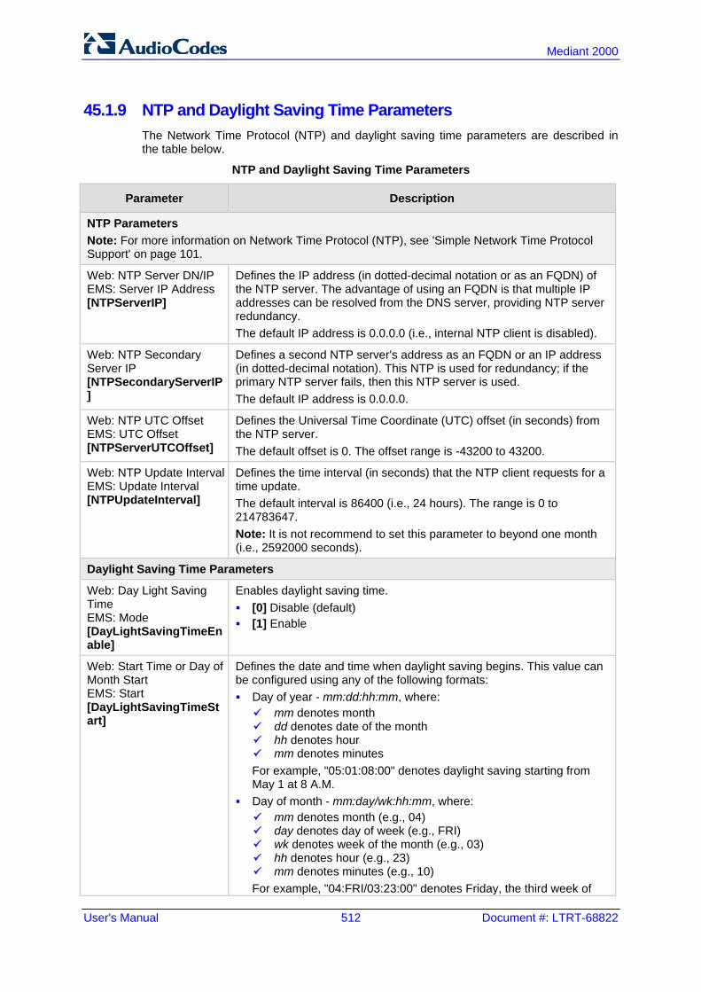
User's Manual 512 Document #: LTRT-68822
Mediant 2000
45.1.9 NTP and Daylight Saving Time Parameters The Network Time Protocol (NTP) and daylight saving time parameters are described in the table below.
NTP and Daylight Saving Time Parameters
Parameter Description
NTP Parameters Note: For more information on Network Time Protocol (NTP), see 'Simple Network Time Protocol Support' on page 101.
Web: NTP Server DN/IP EMS: Server IP Address [NTPServerIP]
Defines the IP address (in dotted-decimal notation or as an FQDN) of the NTP server. The advantage of using an FQDN is that multiple IP addresses can be resolved from the DNS server, providing NTP server redundancy. The default IP address is 0.0.0.0 (i.e., internal NTP client is disabled).
Web: NTP Secondary Server IP [NTPSecondaryServerIP]
Defines a second NTP server's address as an FQDN or an IP address (in dotted-decimal notation). This NTP is used for redundancy; if the primary NTP server fails, then this NTP server is used. The default IP address is 0.0.0.0.
Web: NTP UTC Offset EMS: UTC Offset [NTPServerUTCOffset]
Defines the Universal Time Coordinate (UTC) offset (in seconds) from the NTP server. The default offset is 0. The offset range is -43200 to 43200.
Web: NTP Update Interval EMS: Update Interval [NTPUpdateInterval]
Defines the time interval (in seconds) that the NTP client requests for a time update. The default interval is 86400 (i.e., 24 hours). The range is 0 to 214783647. Note: It is not recommend to set this parameter to beyond one month (i.e., 2592000 seconds).
Daylight Saving Time Parameters
Web: Day Light Saving Time EMS: Mode [DayLightSavingTimeEnable]
Enables daylight saving time. [0] Disable (default) [1] Enable
Web: Start Time or Day of Month Start EMS: Start [DayLightSavingTimeStart]
Defines the date and time when daylight saving begins. This value can be configured using any of the following formats: Day of year - mm:dd:hh:mm, where: mm denotes month dd denotes date of the month hh denotes hour mm denotes minutes For example, "05:01:08:00" denotes daylight saving starting from May 1 at 8 A.M.
Day of month - mm:day/wk:hh:mm, where: mm denotes month (e.g., 04) day denotes day of week (e.g., FRI) wk denotes week of the month (e.g., 03) hh denotes hour (e.g., 23) mm denotes minutes (e.g., 10) For example, "04:FRI/03:23:00" denotes Friday, the third week of

Version 6.6 513 Mediant 2000
User's Manual 45. Configuration Parameters Reference
Parameter Description
April, at 11 P.M. The week field can be 1-5, where 5 denotes the last occurrence of the specified day in the specified month. For example, "04:FRI/05:23:00" denotes the last Friday of April, at 11 P.M.
Web: End Time or Day of Month End EMS: End [DayLightSavingTimeEnd]
Defines the date and time when daylight saving ends. For a description of the format of this value, see the DayLightSavingTimeStart parameter.
Web/EMS: Offset [DayLightSavingTimeOffset]
Defines the daylight saving time offset (in minutes). The valid range is 0 to 120. The default is 60.
45.2 Management Parameters This subsection describes the device's Web and Telnet parameters.
45.2.1 General Parameters The general management parameters are described in the table below.
General Management Parameters
Parameter Description
Web: Web and Telnet Access List Table EMS: Web Access Addresses [WebAccessList_x]
This table configures up to ten IP addresses that are permitted to access the device's Web interface and Telnet interfaces. Access from an undefined IP address is denied. When no IP addresses are defined in this table, this security feature is inactive (i.e., the device can be accessed from any IP address). The default is 0.0.0.0 (i.e., the device can be accessed from any IP address). For example: WebAccessList_0 = 10.13.2.66 WebAccessList_1 = 10.13.77.7 For a description of this parameter, see 'Configuring Web and Telnet Access List' on page 68.
45.2.2 Web Parameters The Web parameters are described in the table below.
Web Parameters
Parameter Description
Web: Password Change Interval [WebUserPassChangeInterval]
Defines the duration (in minutes) of the validity of Web login passwords. When this duration expires, the password of the Web user must be changed. The valid value is 0 to 100000, where 0 means that the password is always valid. The default is 1140.

User's Manual 514 Document #: LTRT-68822
Mediant 2000
Parameter Description
Note: This parameter is applicable only when using the Web Users table, where the default value of the 'Password Age' parameter in the Web Users table inherits this parameter's value.
Web: User inactivity timer [UserInactivityTimer]
Defines the duration (in days) for which a user has not logged in to the Web interface, after which the status of the user becomes inactive and can no longer access the Web interface. These users can only log in to the Web interface if their status is changed (to New or Valid) by a System Administrator or Master user. The valid value is 0 to 10000, where 0 means inactive. The default is 90. Note: This parameter is applicable only when using the Web Users table.
Web: Session Timeout [WebSessionTimeout]
Defines the duration (in minutes) of Web inactivity of a logged-in user, after which the user is automatically logged off the Web interface. The valid value is 0-100000, where 0 means no timeout. The default is 15. Note: This parameter can apply to all users, or per user when set in the Web Users table.
Web: Deny Access On Fail Count [DenyAccessOnFailCount]
Defines the maximum number of failed login attempts, after which the requesting IP address is blocked. The valid value range is 0 to 10. The values 0 and 1 mean immediate block. The default is 3.
Web: Deny Authentication Timer EMS: WEB Deny Authentication Timer [DenyAuthenticationTimer]
Defines the duration (in seconds) for which login to the Web interface is denied from a specific IP address (for all users) when the number of failed login attempts has exceeded the maximum. This maximum is defined by the DenyAccessOnFailCount parameter. Only after this time expires can users attempt to login from this same IP address. The valid value is 0 to 100000, where 0 means that login is not denied regardless of number of failed login attempts. The default is 60.
Web: Display Login Information [DisplayLoginInformation]
Enables display of user's login information on each successful login attempt. [0] = Disable (default) [1] = Enable
[EnableMgmtTwoFactorAuthentication]
Enables Web login authentication using a third-party, smart card. [0] = Disable (default) [1] = Enable When enabled, the device retrieves the Web user’s login username from the smart card, which is automatically displayed (read-only) in the Web Login screen; the user is then required to provide only the login password. Typically, a TLS connection is established between the smart card and the device’s Web interface, and a RADIUS server is implemented to authenticate the password with the username. Thus, this feature implements a two-factor authentication - what the user has (the physical card) and what the user knows (i.e., the login password).
EMS: HTTPS Port [HTTPport]
Defines the LAN HTTP port for Web management (default is 80). To enable Web management from the LAN, configure the desired port. Note: For this parameter to take effect, a device reset is required.
EMS: Disable WEB Determines whether the entire Web interface is read-only.
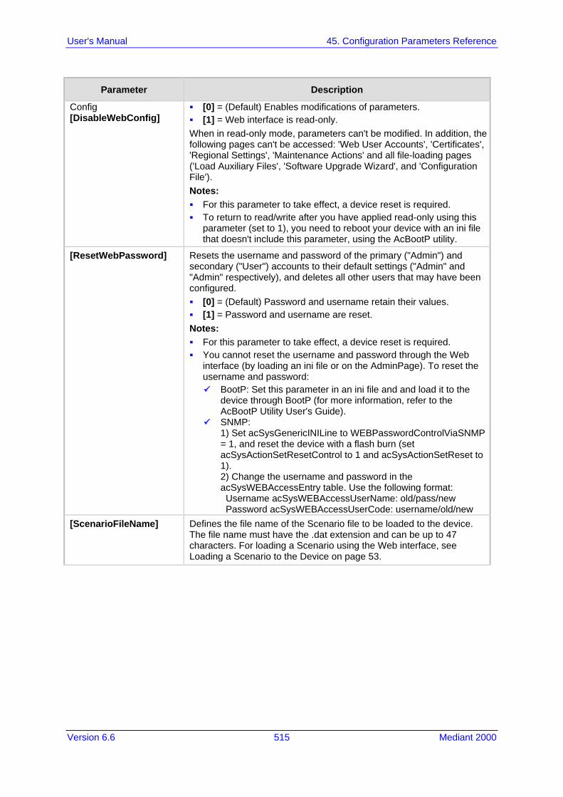
Version 6.6 515 Mediant 2000
User's Manual 45. Configuration Parameters Reference
Parameter Description
Config [DisableWebConfig]
[0] = (Default) Enables modifications of parameters. [1] = Web interface is read-only. When in read-only mode, parameters can't be modified. In addition, the following pages can't be accessed: 'Web User Accounts', 'Certificates', 'Regional Settings', 'Maintenance Actions' and all file-loading pages ('Load Auxiliary Files', 'Software Upgrade Wizard', and 'Configuration File'). Notes: For this parameter to take effect, a device reset is required. To return to read/write after you have applied read-only using this
parameter (set to 1), you need to reboot your device with an ini file that doesn't include this parameter, using the AcBootP utility.
[ResetWebPassword] Resets the username and password of the primary ("Admin") and secondary ("User") accounts to their default settings ("Admin" and "Admin" respectively), and deletes all other users that may have been configured. [0] = (Default) Password and username retain their values. [1] = Password and username are reset. Notes: For this parameter to take effect, a device reset is required. You cannot reset the username and password through the Web
interface (by loading an ini file or on the AdminPage). To reset the username and password: BootP: Set this parameter in an ini file and and load it to the
device through BootP (for more information, refer to the AcBootP Utility User's Guide).
SNMP: 1) Set acSysGenericINILine to WEBPasswordControlViaSNMP = 1, and reset the device with a flash burn (set acSysActionSetResetControl to 1 and acSysActionSetReset to 1). 2) Change the username and password in the acSysWEBAccessEntry table. Use the following format: Username acSysWEBAccessUserName: old/pass/new Password acSysWEBAccessUserCode: username/old/new
[ScenarioFileName] Defines the file name of the Scenario file to be loaded to the device. The file name must have the .dat extension and can be up to 47 characters. For loading a Scenario using the Web interface, see Loading a Scenario to the Device on page 53.

User's Manual 516 Document #: LTRT-68822
Mediant 2000
Parameter Description
[WelcomeMessage] Enables and defines a Welcome message that appears on the Web Login page for logging in to the Web interface. The format of this parameter is as follows: [WelcomeMessage ] FORMAT WelcomeMessage_Index = WelcomeMessage_Text [\WelcomeMessage] For Example: FORMAT WelcomeMessage_Index = WelcomeMessage_Text WelcomeMessage 1 = "**********************************" ; WelcomeMessage 2 = "********* This is a Welcome message ***" ; WelcomeMessage 3 = "**********************************" ; Notes: Each index row represents a line of text in the Welcome message
box. Up to 20 lines (or rows) of text can be defined. The configured text message must be enclosed in double quotation
marks (i.e., "..."). If this parameter is not configured, no Welcome message is
displayed.
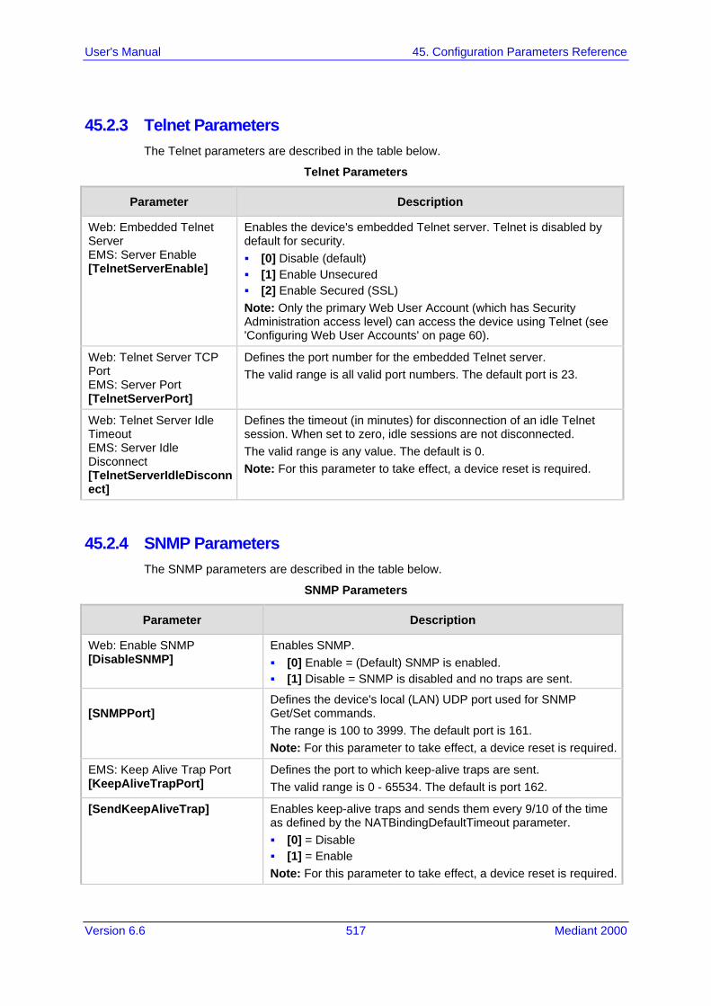
Version 6.6 517 Mediant 2000
User's Manual 45. Configuration Parameters Reference
45.2.3 Telnet Parameters The Telnet parameters are described in the table below.
Telnet Parameters
Parameter Description
Web: Embedded Telnet Server EMS: Server Enable [TelnetServerEnable]
Enables the device's embedded Telnet server. Telnet is disabled by default for security. [0] Disable (default) [1] Enable Unsecured [2] Enable Secured (SSL) Note: Only the primary Web User Account (which has Security Administration access level) can access the device using Telnet (see 'Configuring Web User Accounts' on page 60).
Web: Telnet Server TCP Port EMS: Server Port [TelnetServerPort]
Defines the port number for the embedded Telnet server. The valid range is all valid port numbers. The default port is 23.
Web: Telnet Server Idle Timeout EMS: Server Idle Disconnect [TelnetServerIdleDisconnect]
Defines the timeout (in minutes) for disconnection of an idle Telnet session. When set to zero, idle sessions are not disconnected. The valid range is any value. The default is 0. Note: For this parameter to take effect, a device reset is required.
45.2.4 SNMP Parameters The SNMP parameters are described in the table below.
SNMP Parameters
Parameter Description
Web: Enable SNMP [DisableSNMP]
Enables SNMP. [0] Enable = (Default) SNMP is enabled. [1] Disable = SNMP is disabled and no traps are sent.
[SNMPPort]
Defines the device's local (LAN) UDP port used for SNMP Get/Set commands. The range is 100 to 3999. The default port is 161. Note: For this parameter to take effect, a device reset is required.
EMS: Keep Alive Trap Port [KeepAliveTrapPort]
Defines the port to which keep-alive traps are sent. The valid range is 0 - 65534. The default is port 162.
[SendKeepAliveTrap] Enables keep-alive traps and sends them every 9/10 of the time as defined by the NATBindingDefaultTimeout parameter. [0] = Disable [1] = Enable Note: For this parameter to take effect, a device reset is required.

User's Manual 518 Document #: LTRT-68822
Mediant 2000
Parameter Description
[SNMPSysOid]
Defines the base product system OID. The default is eSNMP_AC_PRODUCT_BASE_OID_D. Note: For this parameter to take effect, a device reset is required.
[SNMPTrapEnterpriseOid] Defines the Trap Enterprise OID. The default is eSNMP_AC_ENTERPRISE_OID. The inner shift of the trap in the AcTrap subtree is added to the end of the OID in this parameter. Note: For this parameter to take effect, a device reset is required.
[acUserInputAlarmDescription]
Defines the description of the input alarm.
[acUserInputAlarmSeverity] Defines the severity of the input alarm.
[AlarmHistoryTableMaxSize] Defines the maximum number of rows in the Alarm History table. This parameter can be controlled by the Config Global Entry Limit MIB (located in the Notification Log MIB). The valid range is 50 to 1000. The default is 500. Note: For this parameter to take effect, a device reset is required.
[SNMPEngineIDString]
Defines the SNMP engine ID for SNMPv2/SNMPv3 agents. This is used for authenticating a user attempting to access the SNMP agent on the device. The ID can be a string of up to 36 characters. The default is 00:00:00:00:00:00:00:00:00:00:00:00 (12 Hex octets characters). The provided key must be set with 12 Hex values delimited by a colon (":") in the format xx:xx:...:xx. For example, 00:11:22:33:44:55:66:77:88:99:aa:bb Notes: For this parameter to take effect, a device reset is required. Before setting this parameter, all SNMPv3 users must be
deleted; otherwise, the parameter setting is ignored. If the supplied key does not pass validation of the 12 Hex
values input or it is set with the default value, the engine ID is generated according to RFC 3411.
Web: SNMP Trap Destination Parameters EMS: Network > SNMP Managers Table Note: Up to five SNMP trap managers can be defined.
SNMP Manager [SNMPManagerIsUsed_x]
Determines the validity of the parameters (IP address and port number) of the corresponding SNMP Manager used to receive SNMP traps. [0] (Check box cleared) = Disabled (default) [1] (Check box selected) = Enabled
Web: IP Address EMS: Address [SNMPManagerTableIP_x]
Defines the IP address of the remote host used as an SNMP Manager. The device sends SNMP traps to this IP address. Enter the IP address in dotted-decimal notation, e.g., 108.10.1.255.
Web: Trap Port EMS: Port [SNMPManagerTrapPort_x]
Defines the port number of the remote SNMP Manager. The device sends SNMP traps to this port. The valid SNMP trap port range is 100 to 4000. The default port is 162.

Version 6.6 519 Mediant 2000
User's Manual 45. Configuration Parameters Reference
Parameter Description
Web: Trap Enable [SNMPManagerTrapSendingEnable_x]
Enables the sending of traps to the corresponding SNMP manager. [0] Disable = Sending is disabled. [1] Enable = (Default) Sending is enabled.
Web: Trap User [SNMPManagerTrapUser_x]
Defines the SNMPv3 USM user or SNMPv2 user to associate with the trap destination. This determines the trap format, authentication level, and encryption level. By default, it is associated with the SNMPv2 user (SNMP trap community string). The valid value is a string.
Web: Trap Manager Host Name [SNMPTrapManagerHostName]
Defines an FQDN of the remote host used as an SNMP manager. The resolved IP address replaces the last entry in the Trap Manager table (defined by the SNMPManagerTableIP parameter) and the last trap manager entry of snmpTargetAddrTable in the snmpTargetMIB. For example: 'mngr.corp.mycompany.com'. The valid range is a string of up to 99 characters.
SNMP Community String Parameters
Community String [SNMPReadOnlyCommunityString_x]
Defines up to five read-only SNMP community strings (up to 19 characters each). The default string is 'public'.
Community String [SNMPReadWriteCommunityString_x]
Defines up to five read/write SNMP community strings (up to 19 characters each). The default string is 'private'.
Trap Community String [SNMPTrapCommunityString]
Defines the Community string used in traps (up to 19 characters). The default string is 'trapuser'.
SNMP Trusted Managers Table
Web: SNMP Trusted Managers [SNMPTrustedMgr_x]
Defines up to five IP addresses of remote trusted SNMP managers from which the SNMP agent accepts and processes SNMP Get and Set requests. Notes: By default, the SNMP agent accepts SNMP Get and Set
requests from any IP address, as long as the correct community string is used in the request. Security can be enhanced by using Trusted Managers, which is an IP address from which the SNMP agent accepts and processes SNMP requests.
If no values are assigned to these parameters any manager can access the device.
Trusted managers can work with all community strings.
SNMP V3 Users Table
Web/EMS: SNMP V3 Users [SNMPUsers]
This parameter table defines SNMP v3 users. The format of this parameter is as follows: [SNMPUsers] FORMAT SNMPUsers_Index = SNMPUsers_Username, SNMPUsers_AuthProtocol, SNMPUsers_PrivProtocol, SNMPUsers_AuthKey, SNMPUsers_PrivKey, SNMPUsers_Group; [\SNMPUsers]

User's Manual 520 Document #: LTRT-68822
Mediant 2000
Parameter Description
For example: SNMPUsers 1 = v3admin1, 1, 0, myauthkey, -, 1; The example above configures user 'v3admin1' with security level authNoPriv(2), authentication protocol MD5, authentication text password 'myauthkey', and ReadWriteGroup2. Note: For a description of this table, see 'Configuring SNMP V3 Users' on page 84.
45.3 Debugging and Diagnostics Parameters This subsection describes the device's debugging and diagnostic parameters.
45.3.1 General Parameters The general debugging and diagnostic parameters are described in the table below.
General Debugging and Diagnostic Parameters
Parameter Description
EMS: Enable Diagnostics [EnableDiagnostics]
Determines the method for verifying correct functioning of the different hardware components on the device. On completion of the check and if the test fails, the device sends information on the test results of each hardware component to the Syslog server. [0] = (Default) Rapid and Enhanced self-test mode. [1] = Detailed self-test mode (full test of DSPs, PCM, Switch, LAN,
PHY and Flash). [2] = A quicker version of the Detailed self-test mode (full test of
DSPs, PCM, Switch, LAN, PHY, but partial test of Flash). Note: For this parameter to take effect, a device reset is required.
Web: Enable LAN Watchdog [EnableLanWatchDog]
Enables the LAN watchdog feature. [0] Disable (default) [1] Enable When LAN watchdog is enabled, the device's overall communication integrity is checked periodically. If no communication is detected for about three minutes, the device performs a self test: If the self-test succeeds, the problem is a logical link down (i.e.,
Ethernet cable disconnected on the switch side) and the Busy Out mechanism is activated if enabled (i.e., the parameter EnableBusyOut is set to 1).
If the self-test fails, the device restarts to overcome internal fatal communication error.
Notes: For this parameter to take effect, a device reset is required. Enable LAN watchdog is relevant only if the Ethernet connection is
full duplex.
Web: Delay After Reset [sec] [GWAppDelayTime]
Defines the time interval (in seconds) that the device's operation is delayed after a reset. The valid range is 0 to 45. The default is 7 seconds.

Version 6.6 521 Mediant 2000
User's Manual 45. Configuration Parameters Reference
Parameter Description
Note: This feature helps overcome connection problems caused by some LAN routers or IP configuration parameters' modifications by a DHCP server.
[EnableAutoRAITransmitBER]
Enables the device to send a remote alarm indication (RAI) when the bit error rate (BER) is greater than 0.001. [0] Disable (default) [1] Enable

User's Manual 522 Document #: LTRT-68822
Mediant 2000
45.3.2 SIP Test Call Parameters The SIP Signaling Test Call parameters are described in the table below.
SIP Test Call Parameters
Parameter Description
Web: Test Call DTMF String [TestCallDtmfString]
Defines the DTMF tone that is played for answered test calls (incoming and outgoing). The DTMF string can be up to 15 strings. The default is "3212333". An empty string means that no DTMF is played.
Web: Test Call ID [TestCallID]
Defines the test call prefix number (ID) of the simulated phone on the device. Incoming calls received with this called prefix number are identified as test calls. This can be any string of up to 15 characters. By default, no number is defined. Note: This parameter is only for testing incoming calls destined to this prefix number.
Test Call Table
Web: Test Call Table [Test_Call]
Defines the local and remote endpoints to be tested. [Test_Call] FORMAT Test_Call_Index = Test_Call_EndpointURI, Test_Call_CalledURI, Test_Call_RouteBy, Test_Call_IPGroupID, Test_Call_DestAddress, Test_Call_DestTransportType, Test_Call_SRD, Test_Call_ApplicationType, Test_Call_AutoRegister, Test_Call_UserName, Test_Call_Password, Test_Call_CallParty, Test_Call_MaxChannels, Test_Call_CallDuration, Test_Call_CallsPerSecond, Test_Call_TestMode, Test_Call_TestDuration, Test_Call_Play, Test_Call_ScheduleInterval; [\Test_Call] Note: For a description of this table, see 'Configuring Test Calls' on page 489.
45.3.3 Syslog, CDR and Debug Parameters The Syslog, CDR and debug parameters are described in the table below.
Syslog, CDR and Debug Parameters
Parameter Description
Web: Enable Syslog EMS: Syslog enable [EnableSyslog]
Determines whether the device sends logs and error messages (e.g., CDRs) generated by the device to a Syslog server. [0] Disable (default) [1] Enable Notes: If you enable Syslog, you must enter an IP address of the Syslog
server (using the SyslogServerIP parameter). Syslog messages may increase the network traffic. To configure Syslog SIP message logging levels, use the
GwDebugLevel parameter.

Version 6.6 523 Mediant 2000
User's Manual 45. Configuration Parameters Reference
Parameter Description
Web/EMS: Syslog Server IP Address [SyslogServerIP]
Defines the IP address (in dotted-decimal notation) of the computer on which the Syslog server is running. The Syslog server is an application designed to collect the logs and error messages generated by the device. The default IP address is 0.0.0.0.
Web: Syslog Server Port EMS: Syslog Server Port Number [SyslogServerPort]
Defines the UDP port of the Syslog server. The valid range is 0 to 65,535. The default port is 514.
[MaxBundleSyslogLength]
Defines the maximum size (in bytes) threshold of logged Syslog messages bundled into a single UDP packet, after which they are sent to a Syslog server. The valid value range is 0 to 1220 (where 0 indicates that no bundling occurs). The default is 1220. Note: This parameter is applicable only if the GWDebugLevel parameter is set to 7.
Web: CDR Server IP Address EMS: IP Address of CDR Server [CDRSyslogServerIP]
Defines the destination IP address to where CDR logs are sent. The default is a null string, which causes CDR messages to be sent with all Syslog messages to the Syslog server. Notes: The CDR messages are sent to UDP port 514 (default Syslog port). This mechanism is active only when Syslog is enabled (i.e., the
parameter EnableSyslog is set to 1).
Web/EMS: CDR Report Level [CDRReportLevel]
Enables media- and signaling-related CDRs to be sent to a Syslog server and determines the call stage at which they are sent. [0] None = (Default) CDRs are not used. [1] End Call = CDR is sent to the Syslog server at the end of each
call. [2] Start & End Call = CDR report is sent to Syslog at the start and
end of each call. [3] Connect & End Call = CDR report is sent to Syslog at
connection and at the end of each call. [4] Start & End & Connect Call = CDR report is sent to Syslog at
the start, at connection, and at the end of each call. Notes: The CDR Syslog message complies with RFC 3161 and is
identified by: Facility = 17 (local1) and Severity = 6 (Informational). This mechanism is active only when Syslog is enabled (i.e., the
parameter EnableSyslog is set to 1).
Web/EMS: Debug Level [GwDebugLevel]
Defines the Syslog debug logging level. [0] 0 = (Default) Debug is disabled. [1] 1 = Flow debugging is enabled. [5] 5 = Flow, device interface, stack interface, session manager,
and device interface expanded debugging are enabled. [7] 7 = This option is recommended when the device is running
under "heavy" traffic. In this mode: The Syslog debug level automatically changes between level 5,
level 1, and level 0, depending on the device's CPU consumption so that VoIP traffic isn’t affected.

User's Manual 524 Document #: LTRT-68822
Mediant 2000
Parameter Description
Syslog messages are bundled into a single UDP packet, after which they are sent to a Syslog server (bundling size is determined by the MaxBundleSyslogLength parameter). Bundling reduces the number of UDP Syslog packets, thereby improving CPU utilization.
Note that when this option is used, in order to read Syslog messages with Wireshark, a special plug-in (i.e., acsyslog.dll) must be used. Once the plug-in is installed, the Syslog messages are decoded as "AC SYSLOG" and are dispalyed using the ‘acsyslog’ filter instead of the regular ‘syslog’ filter.
Notes: This parameter is typically set to 5 if debug traces are required.
However, in cases of heavy traffic, option 7 is recommended. Options 2, 3, 4, and 6 are not recommended.
Web: Syslog Facility Number EMS: SyslogFacility [SyslogFacility]
Defines the Facility level (0 through 7) of the device’s Syslog messages, according to RFC 3164. This allows you to identify Syslog messages generated by the device. This is useful, for example, if you collect the device’s and other equipments’ Syslog messages, at one single server. The device’s Syslog messages can easily be identified and distinguished from other Syslog messages by its Facility level. Therefore, in addition to filtering Syslog messages according to IP address, the messages can be filtered according to Facility level. [16] = (Default) local use 0 (local0) [17] = local use 1 (local1) [18] = local use 2 (local2) [19] = local use 3 (local3) [20] = local use 4 (local4) [21] = local use 5 (local5) [22] = local use 6 (local6) [23] = local use 7 (local7)
Web: Activity Types to Report via Activity Log Messages [ActivityListToLog]
Defines the Activity Log mechanism of the device, which sends log messages to a Syslog server for reporting certain types of Web operations according to the below user-defined filters. [pvc] Parameters Value Change = Changes made on-the-fly to
parameters. Note that the ini file parameter, EnableParametersMonitoring can also be used to set this option, using values [0] (disable) or [1] (enable).
[afl] Auxiliary Files Loading = Loading of auxiliary files. [dr] Device Reset = Reset of device via the 'Maintenance Actions
page. Note: For this option to take effect, a device reset is required.
[fb] Flash Memory Burning = Burning of files or parameters to flash (in 'Maintenance Actions page).
[swu] Device Software Update = cmp file loading via the Software Upgrade Wizard.
[ard] Access to Restricted Domains = Access to restricted domains, which include the following Web pages: (1) ini parameters (AdminPage) (2) General Security Settings (3) Configuration File (4) IP Security Proposal / IP Security Associations Tables (5) Software Upgrade Key Status (6) Firewall Settings

Version 6.6 525 Mediant 2000
User's Manual 45. Configuration Parameters Reference
Parameter Description
(7) Web & Telnet Access List (8) WEB User Accounts
[naa] Non-Authorized Access = Attempt to access the Web interface with a false or empty user name or password.
[spc] Sensitive Parameters Value Change = Changes made to sensitive parameters: (1) IP Address (2) Subnet Mask (3) Default Gateway IP Address (4) ActivityListToLog
[ll] Login and Logout = Every login and logout attempt. For example: ActivityListToLog = 'pvc', 'afl', 'dr', 'fb', 'swu', 'ard', 'naa', 'spc' Note: For the ini file, values must be enclosed in single quotation marks.
[FacilityTrace]
Enables ISDN traces of Facility Information Elements (IE) for ISDN call diagnostics. This allows you to trace all the parameters contained in the Facility IE and view them in the Syslog. [0] Disable (default) [1] Enable Note: For this feature to be functional, the GWDebugLevel parameter must be enabled (i.e., set to at least level 1).
Web: Debug Recording Destination IP [DebugRecordingDestIP]
Defines the IP address of the server for capturing debug recording.
Web: Debug Recording Destination Port [DebugRecordingDestPort]
Defines the UDP port of the server for capturing debug recording. The default is 925.
Debug Recording Status [DebugRecordingStatus]
Activates or de-activates debug recording. [0] Stop (default) [1] Start
Logging Filters Table
Web: Logging Filters Table [LoggingFilters]
This table parameter defines logging filtering rules for Syslog messages and debug recordings. The format of this parameter is as follows: [ LoggingFilters ] FORMAT LoggingFilters_Index = LoggingFilters_Type, LoggingFilters_Value, LoggingFilters_Syslog, LoggingFilters_CaptureType; [ \LoggingFilters ] Note: For a detailed description of this table, see 'Filtering Syslog Messages and Debug Recordings' on page 481.

User's Manual 526 Document #: LTRT-68822
Mediant 2000
45.3.4 Resource Allocation Indication Parameters The Resource Allocation Indication (RAI) parameters are described in the table below.
RAI Parameters
Parameter Description
[EnableRAI] Enables RAI alarm generation if the device's busy endpoints exceed a user-defined threshold. [0] = (Default) Disable RAI (Resource Available Indication) service. [1] = RAI service enabled and an SNMP
'acBoardCallResourcesAlarm' Alarm Trap is sent.
[RAIHighThreshold] Defines the high threshold percentage of total calls that are active (busy endpoints). When the percentage of the device's busy endpoints exceeds this high threshold, the device sends the SNMP acBoardCallResourcesAlarm alarm trap with a 'major' alarm status. The range is 0 to 100. The default is 90. Note: The percentage of busy endpoints is calculated by dividing the number of busy endpoints by the total number of “enabled” endpoints (trunks are physically connected and synchronized with no alarms and endpoints are defined in the Trunk Group Table).
[RAILowThreshold] Defines the low threshold percentage of total calls that are active (busy endpoints). When the percentage of the device's busy endpoints falls below this low threshold, the device sends an SNMP acBoardCallResourcesAlarm alarm trap with a 'cleared' alarm status. The range is 0 to 100%. The default is 90%.
[RAILoopTime] Defines the time interval (in seconds) that the device periodically checks call resource availability. The valid range is 1 to 200. The default is 10.
45.3.5 BootP Parameters The BootP parameters are described in the table below. The BootP parameters are special 'hidden' parameters. Once defined and saved in the device's flash memory, they are used even if they don't appear in the ini file.
BootP Parameters
Parameter Description
[BootPRetries] Note: For this parameter to take effect, a device reset is required. This parameter is used to:
Defines the number of BootP requests that the device sends during start-up. The device stops sending BootP requests when either BootP reply is received or number of retries is reached. [1] = 1 BootP retry, 1 sec. [2] = 2 BootP retries, 3 sec. [3] = (Default) 3 BootP retries,
Defines the number of DHCP packets that the device sends. If after all packets are sent there's still no reply, the device loads from flash. [1] = 4 DHCP packets [2] = 5 DHCP packets [3] = (Default) 6 DHCP packets

Version 6.6 527 Mediant 2000
User's Manual 45. Configuration Parameters Reference
Parameter Description
6 sec. [4] = 10 BootP retries, 30 sec. [5] = 20 BootP retries, 60 sec. [6] = 40 BootP retries, 120 sec. [7] = 100 BootP retries, 300
sec. [15] = BootP retries
indefinitely.
[4] = 7 DHCP packets [5] = 8 DHCP packets [6] = 9 DHCP packets [7] = 10 DHCP packets [15] = 18 DHCP packets
[BootPSelectiveEnable] Enables the Selective BootP mechanism. [1] = Enabled [0] = Disabled (default) The Selective BootP mechanism (available from Boot version 1.92) enables the device's integral BootP client to filter unsolicited BootP/DHCP replies (accepts only BootP replies that contain the text 'AUDC' in the vendor specific information field). This option is useful in environments where enterprise BootP/DHCP servers provide undesired responses to the device's BootP requests. Notes: For this parameter to take effect, a device reset is required. When working with DHCP (i.e., the parameter DHCPEnable is set to
1), the selective BootP feature must be disabled.
[BootPDelay] Defines the interval between the device's startup and the first BootP/DHCP request that is issued by the device. [1] = (Default) 1 second [2] = 3 second [3] = 6 second [4] = 30 second [5] = 60 second Note: For this parameter to take effect, a device reset is required.
[ExtBootPReqEnable] Determines whether the device uses the Vendor Specific Information field in the BootP request to provide device-related initial startup information. [0] = (Default) Disabled. [1] = Enables extended information to be sent in BootP requests.
The device uses the Vendor Specific Information field in the BootP request to provide device-related initial startup information such as device type, current IP address, software version. For a full list of the Vendor Specific Information fields, refer to the AcBootP Utility User's Guide. The AcBootP utility displays this information in the 'Client Info' column.
Notes: For this parameter to take effect, a device reset is required. This option is not available on DHCP servers.

User's Manual 528 Document #: LTRT-68822
Mediant 2000
45.4 Security Parameters This subsection describes the device's security parameters.
45.4.1 General Parameters The general security parameters are described in the table below.
General Security Parameters
Parameter Description
[EnableSecureStartup] Enables the Secure Startup mode. In this mode, downloading the ini file to the device is restricted to a URL provided in initial configuration (see the parameter IniFileURL) or using DHCP. [0] Disable (default). [1] Enable = disables TFTP and allows secure protocols such as
HTTPS to fetch the device configuration. Note: For this parameter to take effect, a device reset is required.
Firewall Table
Web/EMS: Internal Firewall Parameters [AccessList]
This table parameter defines the device's access list (firewall), which defines network traffic filtering rules. The format of this parameter is as follows: [AccessList] FORMAT AccessList_Index = AccessList_Source_IP, AccessList_Source_Port, AccessList_PrefixLen, AccessList_Source_Port, AccessList_Start_Port, AccessList_End_Port, AccessList_Protocol, AccessList_Use_Specific_Interface, AccessList_Interface_ID, AccessList_Packet_Size, AccessList_Byte_Rate, AccessList_Byte_Burst, AccessList_Allow_Type; [\AccessList] For example: AccessList 10 = mgmt.customer.com, , , 32, 0, 80, tcp, 1, OAMP, 0, 0, 0, allow; AccessList 22 = 10.4.0.0, , , 16, 4000, 9000, any, 0, , 0, 0, 0, block; In the example above, Rule #10 allows traffic from the host ‘mgmt.customer.com’ destined to TCP ports 0 to 80 on interface OAMP (OAMP). Rule #22 blocks traffic from the subnet 10.4.xxx.yyy destined to ports 4000 to 9000. Note: For a description of this table, see 'Configuring Firewall Settings' on page 133.

Version 6.6 529 Mediant 2000
User's Manual 45. Configuration Parameters Reference
45.4.2 HTTPS Parameters The Secure Hypertext Transport Protocol (HTTPS) parameters are described in the table below.
HTTPS Parameters
Parameter Description
Web: Secured Web Connection (HTTPS) EMS: HTTPS Only [HTTPSOnly]
Determines the protocol used to access the Web interface. [0] HTTP and HTTPS (default). [1] HTTPs Only = Unencrypted HTTP packets are blocked. Note: For this parameter to take effect, a device reset is required.
EMS: HTTPS Port [HTTPSPort]
Defines the local Secured HTTPS port of the device. This parameter allows secure remote device Web management from the LAN. To enable secure Web management from the LAN, configure the desired port. The valid range is 1 to 65535 (other restrictions may apply within this range). The default port is 443. Note: For this parameter to take effect, a device reset is required.
Web/EMS: HTTPS Cipher String [HTTPSCipherString]
Defines the Cipher string for HTTPS (in OpenSSL cipher list format). For the valid range values, refer to URL http://www.openssl.org/docs/apps/ciphers.html. The default is ‘RC4:EXP’ (Export encryption algorithms). For example, use ‘ALL’ for all ciphers suites (e.g., for ARIA encryption for TLS). The only ciphers available are RC4 and DES, and the cipher bit strength is limited to 56 bits. Notes: For this parameter to take effect, a device reset is required. If the “Strong Encryption” Software License Key is enabled, the
default of this parameter is changed to ‘RC4:EXP’, enabling RC-128bit encryption.
The value ‘ALL’ can be configured only if the “Strong Encryption” Software License Key is enabled.
Web: HTTP Authentication Mode EMS: Web Authentication Mode [WebAuthMode]
Determines the authentication mode used for the Web interface. [0] Basic Mode = (Default) Basic authentication (clear text) is used. [1] Web Based Authentication = Digest authentication (MD5) is used. Note: If you enable RADIUS login (i.e., the WebRADIUSLogin parameter is set to 1), you must set the WebAuthMode parameter to Basic Mode [0].
Web: Requires Client Certificates for HTTPS connection [HTTPSRequireClientCertificate]
Determines whether client certificates are required for HTTPS connection. [0] Disable = (Default) Client certificates are not required. [1] Enable = Client certificates are required. The client certificate must
be preloaded to the device and its matching private key must be installed on the managing PC. Time and date must be correctly set on the device for the client certificate to be verified.
Notes: For this parameter to take effect, a device reset is required. For a description on implementing client certificates, see 'Client
Certificates' on page 98.

User's Manual 530 Document #: LTRT-68822
Mediant 2000
Parameter Description
[HTTPSRootFileName] Defines the name of the HTTPS trusted root certificate file to be loaded using TFTP. The file must be in base64-encoded PEM (Privacy Enhanced Mail) format. The valid range is a 47-character string. Note: This parameter is applicable only when the device is loaded using BootP/TFTP.
[HTTPSPkeyFileName] Defines the name of a private key file (in unencrypted PEM format) to be loaded from the TFTP server.
[HTTPSCertFileName] Defines the name of the HTTPS server certificate file to be loaded using TFTP. The file must be in base64-encoded PEM format. The valid range is a 47-character string. Note: This parameter is only applicable when the device is loaded using BootP/TFTP.
45.4.3 SRTP Parameters The Secure Real-Time Transport Protocol (SRTP) parameters are described in the table below.
SRTP Parameters
Parameter Description
Web: Media Security EMS: Enable Media Security [EnableMediaSecurity]
Enables Secure Real-Time Transport Protocol (SRTP). [0] Disable = (Default) SRTP is disabled. [1] Enable = SRTP is enabled. Note: For this parameter to take effect, a device reset is required.
Web/EMS: Media Security Behavior [MediaSecurityBehaviour]
Determines the device's mode of operation when SRTP is used (i.e., when the parameter EnableMediaSecurity is set to 1). [0] Preferable = (Default) The device initiates encrypted calls.
However, if negotiation of the cipher suite fails, an unencrypted call is established. Incoming calls that don't include encryption information are accepted.
[1] Mandatory = The device initiates encrypted calls, but if negotiation of the cipher suite fails, the call is terminated. Incoming calls that don't include encryption information are rejected.
[2] Disable = The IP Profile for which this parameter is set does not support encrypted calls (i.e., SRTP).
[3] Preferable - Single Media = The device sends SDP with a single media ('m=') line only (e.g., m=audio 6000 RTP/AVP 4 0 70 96) with RTP/AVP and crypto keys. The remote UA can respond with SRTP or RTP parameters: If the remote SIP UA does not support SRTP, it uses RTP
and ignores the crypto lines. In the opposite direction, if the device receives an SDP offer
with a single media (as shown above), it responds with SRTP (RTP/SAVP) if the EnableMediaSecurity parameter is set to 1. If SRTP is not supported (i.e., EnableMediaSecurity is set to 0), it responds with RTP.
Notes:

Version 6.6 531 Mediant 2000
User's Manual 45. Configuration Parameters Reference
Parameter Description
Before configuring this parameter, set the EnableMediaSecurity parameter to 1.
If this parameter is set to Preferable [3] and two 'm=' lines are received in the SDP offer, the device prefers the SAVP (secure audio video profile) regardless of the order in the SDP.
Option [2] Disable is applicable only to IP Profiles. This parameter can also be configured per IP Profile, using the
IPProfile parameter (see 'Configuring IP Profiles' on page 235).
Web: Master Key Identifier (MKI) Size EMS: Packet MKI Size [SRTPTxPacketMKISize]
Defines the size (in bytes) of the Master Key Identifier (MKI) in SRTP Tx packets. The range is 0 to 4. The default is 0 (i.e., new keys are generated without MKI). Notes: For the GW/IP-to-IP application, the device only initiates the MKI
size. You can also configure MKI size in an IP Profile.
Web:Symmetric MKI Negotiation EMS: Enable Symmetric MKI [EnableSymmetricMKI]
Enables symmetric MKI negotiation. [0] Disable = (Default) The device includes the MKI in its 200 OK
response according to the SRTPTxPacketMKISize parameter (if set to 0, then it is not included; if set to any other value, it is included with this value).
[1] Enable = The answer crypto line contains (or excludes) an MKI value according to the selected crypto line in the offer. For example, assume that the device receives an INVITE containing the following two crypto lines in SDP:
a=crypto:2 AES_CM_128_HMAC_SHA1_80 inline:TAaxNnQt8/qLQMnDuG4vxYfWl6K7eBK/ufk04pR4|2^31|1:1 a=crypto:3 AES_CM_128_HMAC_SHA1_80 inline:bnuYZnMxSfUiGitviWJZmzr7OF3AiRO0l5Vnh0kH|2^31
The first crypto line includes the MKI parameter "1:1". In the 200 OK response, the device selects one of the crypto lines (i.e., '2' or '3'). Typically, it selects the first line that supports the crypto suite. If the device selects crypto line '2', it includes the MKI parameter in its answer SDP, for example:
a=crypto:2 AES_CM_128_HMAC_SHA1_80 inline:R1VyA1xV/qwBjkEklu4kSJyl3wCtYeZLq1/QFuxw|2^31|1:1
If the device selects a crypto line that does not contain the MKI parameter, then the MKI parameter is not included in the crypto line in the SDP answer (even if the SRTPTxPacketMKISize parameter is set to any value other than 0).
Notes: To enable symmetric MKI, the SRTPTxPacketMKISize parameter
must be set to any value other than 0. You can also enable MKI negotiation per IP Profile.
Web/EMS: SRTP offered Suites [SRTPofferedSuites]
Defines the offered crypto suites (cipher encryption algorithms) for SRTP. [0] = (Default) All available crypto suites. [1] CIPHER SUITES AES CM 128 HMAC SHA1 80 = device uses

User's Manual 532 Document #: LTRT-68822
Mediant 2000
Parameter Description
AES-CM encryption with a 128-bit key and HMAC-SHA1 message authentication with a 80-bit tag.
[2] CIPHER SUITES AES CM 128 HMAC SHA1 32 = device uses AES-CM encryption with a 128-bit key and HMAC-SHA1 message authentication with a 32-bit tag.
Note: This parameter also affects the selection of the crypto in the device's answer. For example, if the device receives an offer with two crypto lines containing HMAC_SHA1_80 and HMAC_SHA_32, it uses the HMAC_SHA_32 key in its SIP 200 OK response if the parameter is set to 2.
Web: Disable Authentication On Transmitted RTP Packets EMS: RTP AuthenticationDisable Tx [RTPAuthenticationDisableTx]
Enables authentication on transmitted RTP packets in a secured RTP session. [0] Enable (default) [1] Disable
Web: Disable Encryption On Transmitted RTP Packets EMS: RTP EncryptionDisable Tx [RTPEncryptionDisableTx]
Enables encryption on transmitted RTP packets in a secured RTP session. [0] Enable (default) [1] Disable
Web: Disable Encryption On Transmitted RTCP Packets EMS: RTCP EncryptionDisable Tx [RTCPEncryptionDisableTx]
Enables encryption on transmitted RTCP packets in a secured RTP session. [0] Enable (default) [1] Disable
[ResetSRTPStateUponRekey]
Enables synchronization of the SRTP state between the device and a server when a new SRTP key is generated upon a SIP session expire. This feature ensures that the roll-over counter (ROC), one of the parameters used in the SRTP encryption/decryption process of the SRTP packets, is synchronized on both sides for transmit and receive packets. [0] = (Default) Disabled. ROC is not reset on the device side. [1] = Enabled. If the session expires causing a session refresh
through a re-INVITE, the device or server generates a new key and the device resets the ROC index (and other SRTP fields) as done by the server, resulting in a synchronized SRTP.
Notes: This feature can also be configured for an IP Profile. If this feature is disabled and the server resets the ROC upon a
re-key generation, one-way voice may occur.

Version 6.6 533 Mediant 2000
User's Manual 45. Configuration Parameters Reference
45.4.4 TLS Parameters The Transport Layer Security (TLS) parameters are described in the table below.
TLS Parameters
Parameter Description
Web/EMS: TLS Version [TLSVersion]
Determines the supported versions of SSL/TLS (Secure Socket Layer/Transport Layer Security. [0] SSL 2.0-3.0 and TLS 1.0 = (Default) SSL 2.0, SSL 3.0, and TLS
1.0 are supported. [1] TLS 1.0 Only = only TLS 1.0 is used. When set to 0, SSL/TLS handshakes always start with SSL 2.0 and switch to TLS 1.0 if both peers support it. When set to 1, TLS 1.0 is the only version supported; clients attempting to contact the device using SSL 2.0 are rejected. Note: For this parameter to take effect, a device reset is required.
Web: TLS Client Re-Handshake Interval EMS: TLS Re Handshake Interval [TLSReHandshakeInterval]
Defines the time interval (in minutes) between TLS Re-Handshakes initiated by the device. The interval range is 0 to 1,500 minutes. The default is 0 (i.e., no TLS Re-Handshake).
Web: TLS Mutual Authentication EMS: SIPS Require Client Certificate [SIPSRequireClientCertificate]
Determines the device's behavior when acting as a server for TLS connections. [0] Disable = (Default) The device does not request the client
certificate. [1] Enable = The device requires receipt and verification of the client
certificate to establish the TLS connection. Notes: For this parameter to take effect, a device reset is required. The SIPS certificate files can be changed using the parameters
HTTPSCertFileName and HTTPSRootFileName.
Web/EMS: Peer Host Name Verification Mode [PeerHostNameVerificationMode]
Determines whether the device verifies the Subject Name of a remote certificate when establishing TLS connections. [0] Disable (default). [1] Server Only = Verify Subject Name only when acting as a client
for the TLS connection. [2] Server & Client = Verify Subject Name when acting as a server or
client for the TLS connection. When a remote certificate is received and this parameter is not disabled, the value of SubjectAltName is compared with the list of available Proxies. If a match is found for any of the configured Proxies, the TLS connection is established. The comparison is performed if the SubjectAltName is either a DNS name (DNSName) or an IP address. If no match is found and the SubjectAltName is marked as ‘critical’, the TLS connection is not established. If DNSName is used, the certificate can also use wildcards (‘*’) to replace parts of the domain name. If the SubjectAltName is not marked as ‘critical’ and there is no match, the CN value of the SubjectName field is compared with the parameter

User's Manual 534 Document #: LTRT-68822
Mediant 2000
Parameter Description
TLSRemoteSubjectName. If a match is found, the connection is established. Otherwise, the connection is terminated. Note: If you set this parameter to [2] (Server & Client), for this functionality to operate, you also need to set the SIPSRequireClientCertificate parameter to [1] (Enable).
Web: TLS Client Verify Server Certificate EMS: Verify Server Certificate [VerifyServerCertificate]
Determines whether the device, when acting as a client for TLS connections, verifies the Server certificate. The certificate is verified with the Root CA information. [0] Disable (default) [1] Enable Note: If Subject Name verification is necessary, the parameter PeerHostNameVerificationMode must be used as well.
Web: Strict Certificate Extension Validation [RequireStrictCert]
Enables the validation of the extensions (keyUsage and extentedKeyUsage) of peer certificates. This validation ensures that the signing CA is authorized to sign certificates and that the end-entity certificate is authorized to negotiate a secure TLS connection. [0] Disable (default) [1] Enable
Web/EMS: TLS Remote Subject Name [TLSRemoteSubjectName]
Defines the Subject Name that is compared with the name defined in the remote side certificate when establishing TLS connections. If the SubjectAltName of the received certificate is not equal to any of the defined Proxies Host names/IP addresses and is not marked as 'critical', the Common Name (CN) of the Subject field is compared with this value. If not equal, the TLS connection is not established. If the CN uses a domain name, the certificate can also use wildcards (‘*’) to replace parts of the domain name. The valid range is a string of up to 49 characters. Note: This parameter is applicable only if the parameter PeerHostNameVerificationMode is set to 1 or 2.
Web: Client Cipher String [TLSClientCipherString]
Defines the cipher-suite string for TLS clients. The valid value is up to 255 strings. The default is "ALL:!ADH". For example: TLSClientCipherString = 'EXP' This parameter complements the HTTPSCipherString parameter (which affects TLS servers). For possible values and additional details, refer to: http://www.openssl.org/docs/apps/ciphers.html
[TLSPkeySize]
Defines the key size (in bits) for RSA public-key encryption for newly self-signed generated keys for SSH. [512] [768] [1024] (default) [2048]
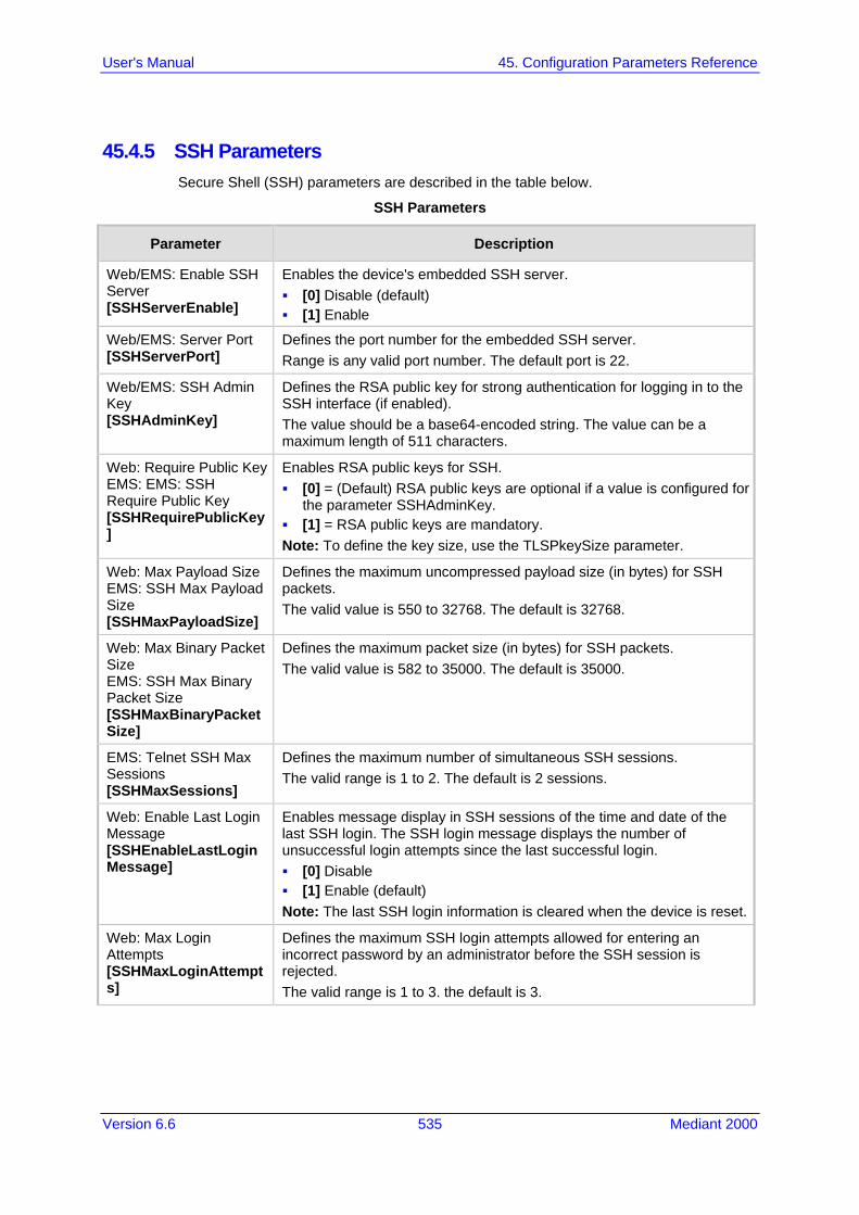
Version 6.6 535 Mediant 2000
User's Manual 45. Configuration Parameters Reference
45.4.5 SSH Parameters Secure Shell (SSH) parameters are described in the table below.
SSH Parameters
Parameter Description
Web/EMS: Enable SSH Server [SSHServerEnable]
Enables the device's embedded SSH server. [0] Disable (default) [1] Enable
Web/EMS: Server Port [SSHServerPort]
Defines the port number for the embedded SSH server. Range is any valid port number. The default port is 22.
Web/EMS: SSH Admin Key [SSHAdminKey]
Defines the RSA public key for strong authentication for logging in to the SSH interface (if enabled). The value should be a base64-encoded string. The value can be a maximum length of 511 characters.
Web: Require Public Key EMS: EMS: SSH Require Public Key [SSHRequirePublicKey]
Enables RSA public keys for SSH. [0] = (Default) RSA public keys are optional if a value is configured for
the parameter SSHAdminKey. [1] = RSA public keys are mandatory. Note: To define the key size, use the TLSPkeySize parameter.
Web: Max Payload Size EMS: SSH Max Payload Size [SSHMaxPayloadSize]
Defines the maximum uncompressed payload size (in bytes) for SSH packets. The valid value is 550 to 32768. The default is 32768.
Web: Max Binary Packet Size EMS: SSH Max Binary Packet Size [SSHMaxBinaryPacketSize]
Defines the maximum packet size (in bytes) for SSH packets. The valid value is 582 to 35000. The default is 35000.
EMS: Telnet SSH Max Sessions [SSHMaxSessions]
Defines the maximum number of simultaneous SSH sessions. The valid range is 1 to 2. The default is 2 sessions.
Web: Enable Last Login Message [SSHEnableLastLoginMessage]
Enables message display in SSH sessions of the time and date of the last SSH login. The SSH login message displays the number of unsuccessful login attempts since the last successful login. [0] Disable [1] Enable (default) Note: The last SSH login information is cleared when the device is reset.
Web: Max Login Attempts [SSHMaxLoginAttempts]
Defines the maximum SSH login attempts allowed for entering an incorrect password by an administrator before the SSH session is rejected. The valid range is 1 to 3. the default is 3.

User's Manual 536 Document #: LTRT-68822
Mediant 2000
45.4.6 IPSec Parameters The Internet Protocol security (IPSec) parameters are described in the table below.
IPSec Parameters
Parameter Description
IPSec Parameters
Web: Enable IP Security EMS: IPSec Enable [EnableIPSec]
Enables IPSec on the device. [0] Disable (default) [1] Enable Note: For this parameter to take effect, a device reset is required.
Web: IKE Certificate Ext Validate [IKEcertificateExtValidate]
Enables the validation of the extensions (keyUsage and extentedKeyUsage) of peer certificates. This validation ensures that the signing CA is authorized to sign certificates and that the end-entity certificate is authorized to negotiate a secure IPSec connection. [[0] Disable (default) [1] Enable
IPSec Associations Table
Web: IP Security Associations Table EMS: IPSec SA Table [IPSecSATable]
This table parameter defines the IPSec SA table. This table allows you to configure the Internet Key Exchange (IKE) and IP Security (IPSec) protocols. You can define up to 20 IPSec peers. The format of this parameter is as follows: [ IPsecSATable ] FORMAT IPsecSATable_Index = IPsecSATable_RemoteEndpointAddressOrName, IPsecSATable_AuthenticationMethod, IPsecSATable_SharedKey, IPsecSATable_SourcePort, IPsecSATable_DestPort, IPsecSATable_Protocol, IPsecSATable_Phase1SaLifetimeInSec, IPsecSATable_Phase2SaLifetimeInSec, IPsecSATable_Phase2SaLifetimeInKB, IPsecSATable_DPDmode, IPsecSATable_IPsecMode, IPsecSATable_RemoteTunnelAddress, IPsecSATable_RemoteSubnetIPAddress, IPsecSATable_RemoteSubnetPrefixLength, IPsecSATable_InterfaceName; [ \IPsecSATable ] For example: IPsecSATable 1 = 0, 10.3.2.73, 0, 123456789, 0, 0, 0, 0, 28800, 3600, ; In the above example, a single IPSec/IKE peer (10.3.2.73) is configured. Pre-shared key authentication is selected, with the pre-shared key set to 123456789. In addition, a lifetime of 28800 seconds is selected for IKE and a lifetime of 3600 seconds is selected for IPSec. Note: For a detailed description of this table, see 'Configuring IP Security Associations Table' on page 140.
IPSec Proposal Table
Web: IP Security Proposal Table EMS: IPSec Proposal Table [IPSecProposalTable]
This table parameter defines up to four IKE proposal settings, where each proposal defines an encryption algorithm, an authentication algorithm, and a Diffie-Hellman group identifier. [ IPsecProposalTable ] FORMAT IPsecProposalTable_Index = IPsecProposalTable_EncryptionAlgorithm, IPsecProposalTable_AuthenticationAlgorithm,

Version 6.6 537 Mediant 2000
User's Manual 45. Configuration Parameters Reference
Parameter Description
IPsecProposalTable_DHGroup; [ \IPsecProposalTable ] For example: IPsecProposalTable 0 = 3, 2, 1; IPsecProposalTable 1 = 2, 2, 1; In the example above, two proposals are defined: Proposal 0: AES, SHA1, DH group 2 Proposal 1: 3DES, SHA1, DH group 2 Note: For a detailed description of this table, see 'Configuring IP Security Proposal Table' on page 137.
45.4.7 OCSP Parameters The Online Certificate Status Protocol (OCSP) parameters are described in the table below.
OCSP Parameters
Parameter Description
Web: Enable OCSP Server EMS: OCSP Enable [OCSPEnable]
Enables or disables certificate checking using OCSP. [0] Disable (default) [1] Enable
Web: Primary Server IP EMS: OCSP Server IP [OCSPServerIP]
Defines the IP address of the OCSP server. The default IP address is 0.0.0.0.
Web: Secondary Server IP [OCSPSecondaryServerIP]
Defines the IP address (in dotted-decimal notation) of the secondary OCSP server (optional). The default IP address is 0.0.0.0.
Web: Server Port EMS: OCSP Server Port [OCSPServerPort]
Defines the OCSP server's TCP port number. The default port number is 2560.
Web: Default Response When Server Unreachable EMS: OCSP Default Response [OCSPDefaultResponse]
Determines the default OCSP behavior when the server cannot be contacted. [0] Reject = (Default) Rejects peer certificate. [1] Allow = Allows peer certificate.

User's Manual 538 Document #: LTRT-68822
Mediant 2000
45.4.8 IDS Parameters The Intrusion Detection System (IDS) parameters are described in the table below.
Table 45-1: IDS Parameters
Parameter Description
Web: Intrusion Detection System (IDS) CLI: enable-ids [EnableIDS]
Enables the IDS feature. [0] Disable (default) [1] Enable Note: For this parameter to take effect, a device reset is required.
CLI: ids-clear-period [IDSAlarmClearPeriod]
Defines the interval (in seconds) after which an IDS alarm is cleared from the Active Alarms table if no thresholds are crossed during this time. However, this "quiet" period must be at least twice the Threshold Window value. For example, if IDSAlarmClearPeriod is set to 20 sec and the Threshold Window is set to 15 sec, the IDSAlarmClearPeriod parameter is ignored and the alarm is cleared only after 30 seconds (2 x 15 sec). The valid value is 0 to 86400. The default is 300.
IDS Policy Table
Web: IDS Policy Table [IDSPolicy]
Defines IDS Policies. The format of the ini file parameter is: [ IDSPolicy ] FORMAT IDSPolicy_Index = IDSPolicy_Name, IDSPolicy_Description; [ \IDSPolicy ] For a detailed description of this table, see 'Configuring IDS Policies' on page 145.
IDS Rule Table
Web: IDS Rule Table [IDSRule]
Defines rules for the IDS Policies. The format of the ini file parameter is: [ IDSRule ] FORMAT IDSRule_Index = IDSRule_Policy, IDSRule_RuleID, IDSRule_Reason, IDSRule_ThresholdScope, IDSRule_ThresholdWindow, IDSRule_MinorAlarmThreshold, IDSRule_MajorAlarmThreshold, IDSRule_CriticalAlarmThreshold; [ \IDSRule ] For a detailed description of this table, see 'Configuring IDS Policies' on page 145.
IDS Match Table
Web: IDS Match Table [IDSMatch]
Defines target rules per IDS Policy. The format of the ini file parameter is: [ IDSMatch ] FORMAT IDSMatch_Index = IDSMatch_SIPInterface, IDSMatch_ProxySet, IDSMatch_Subnet, IDSMatch_Policy; [ \IDSMatch ] For a detailed description of this table, see 'Assigning IDS Policies' on page 148.

Version 6.6 539 Mediant 2000
User's Manual 45. Configuration Parameters Reference
45.5 RADIUS Parameters The RADIUS parameters are described in the table below. For supported RADIUS attributes, see 'RADIUS Accounting CDR Attributes' on page 467.
RADIUS Parameters
Parameter Description
RADIUS Accounting Parameters
Web: Enable RADIUS Access Control [EnableRADIUS]
Enables the RADIUS application. [0] Disable (Default) [1] Enable Note: For this parameter to take effect, a device reset is required.
Web: Accounting Server IP Address [RADIUSAccServerIP]
Defines the IP address of the RADIUS accounting server.
Web: Accounting Port [RADIUSAccPort]
Defines the port of the RADIUS accounting server. The default is 1646.
Web/EMS: RADIUS Accounting Type [RADIUSAccountingType]
Determines when the RADIUS accounting messages are sent to the RADIUS accounting server. [0] At Call Release = (Default) Sent at call release only. [1] At Connect & Release = Sent at call connect and release. [2] At Setup & Release = Sent at call setup and release.
Web: AAA Indications EMS: Indications [AAAIndications]
Determines the Authentication, Authorization and Accounting (AAA) indications. [0] None = (Default) No indications. [3] Accounting Only = Only accounting indications are used.
General RADIUS Parameters
Web: Use RADIUS for Web/Telnet Login EMS: Web Use Radius Login [WebRADIUSLogin]
Enables RADIUS queries for Web and Telnet login authentication. When enabled, logging into the device's Web and Telnet embedded servers is done through a RADIUS server. The device communicates with a user-defined RADIUS server and verifies the given username and password against a remote database, in a secure manner. [0] Disable (default) [1] Enable Notes: For RADIUS login authentication to function, you also need to set
the following parameters: EnableRADIUS = 1 (Enable) WebAuthMode = 0 (Basic Mode)
RADIUS authentication requires HTTP basic authentication, where the username and password are transmitted in clear text over the network. Therefore, it's recommended to set the HTTPSOnly parameter to 1 in order to force the use of HTTPS, since the transport is encrypted.
If using RADIUS authentication to log into the CLI, only the primary Web User Account, which has Security Administration access level, can access the device's CLI (see 'Configuring Web User Accounts'

User's Manual 540 Document #: LTRT-68822
Mediant 2000
Parameter Description
on page 60).
Web: RADIUS Authentication Server IP Address EMS: RADIUS Auth Server IP [RADIUSAuthServerIP]
Defines the IP address of the RADIUS authentication server. Note: For this parameter to take effect, a device reset is required.
Web: RADIUS Authentication Server Port EMS: RADIUS Auth Server Port [RADIUSAuthPort]
Defines the port of the RADIUS Authentication Server. Note: For this parameter to take effect, a device reset is required.
Web: RADIUS Shared Secret EMS: RADIUS Auth Server Secret [SharedSecret]
Defines the 'Secret' used to authenticate the device to the RADIUS server. This should be a cryptically strong password.
RADIUS Authentication Parameters
Web: Default Access Level [DefaultAccessLevel]
Defines the default access level for the device when the RADIUS (authentication) response doesn't include an access level attribute. The valid range is 0 to 255. The default is 200 (i.e., Security Administrator).
Web: Device Behavior Upon RADIUS Timeout [BehaviorUponRadiusTimeout]
Defines the device's response upon a RADIUS timeout. [0] Deny Access = Denies access. [1] Verify Access Locally = (Default) Checks password locally.
Web: Local RADIUS Password Cache Mode [RadiusLocalCacheMode]
Determines the device's mode of operation regarding the timer (configured by the parameter RadiusLocalCacheTimeout) that determines the validity of the user name and password (verified by the RADIUS server). [0] Absolute Expiry Timer = When you access a Web page, the
timeout doesn't reset, instead it continues decreasing. [1] Reset Timer Upon Access = (Default) Upon each access to a
Web page, the timeout always resets (reverts to the initial value configured by RadiusLocalCacheTimeout).
Web: Local RADIUS Password Cache Timeout [RadiusLocalCacheTimeout]
Defines the time (in seconds) the locally stored user name and password (verified by the RADIUS server) are valid. When this time expires, the user name and password become invalid and a must be re-verified with the RADIUS server. The valid range is 1 to 0xFFFFFF. The default is 300 (5 minutes). [-1] = Never expires. [0] = Each request requires RADIUS authentication.
Web: RADIUS VSA Vendor ID [RadiusVSAVendorID]
Defines the vendor ID that the device accepts when parsing a RADIUS response packet. The valid range is 0 to 0xFFFFFFFF. The default is 5003.
Web: RADIUS VSA Access Level Attribute [RadiusVSAAccessAttribute]
Defines the code that indicates the access level attribute in the Vendor Specific Attributes (VSA) section of the received RADIUS packet. The valid range is 0 to 255. The default is 35.

Version 6.6 541 Mediant 2000
User's Manual 45. Configuration Parameters Reference
Parameter Description
[MaxRADIUSSessions] Defines the number of concurrent calls that can communicate with the RADIUS server (optional). The valid range is 0 to 240. The default is 240.
EMS: RADIUS Auth Number of Retries [RADIUSRetransmission]
Defines the number of retransmission retries. The valid range is 1 to 10. The default is 3.
[RadiusTO] Defines the time interval (measured in seconds) that the device waits for a response before a RADIUS retransmission is issued. The valid range is 1 to 30. The default is 10.
45.6 SIP Media Realm Parameters The Media Realm parameters are described in the table below.
Media Realm Parameters
Parameter Description
Media Realm Table
Web: Media Realm Table EMS: VoIP > Media > Media Realm [CpMediaRealm]
This table parameter defines the Media Realm table. The Media Realm table allows you to divide a Media-type interface (defined in the Multiple Interface table) into several realms, where each realm is specified by a UDP port range. The format of this parameter is as follows: [CpMediaRealm] FORMAT CpMediaRealm_Index = CpMediaRealm_MediaRealmName, CpMediaRealm_IPv4IF, CpMediaRealm_IPv6IF, CpMediaRealm_PortRangeStart, CpMediaRealm_MediaSessionLeg, CpMediaRealm_PortRangeEnd, CpMediaRealm_TransRateRatio, CpMediaRealm_IsDefault; [\CpMediaRealm] For example, CpMediaRealm 1 = Mrealm1, Voice, , 6600, 20, 6790, , 1; CpMediaRealm 2 = Mrealm2, Voice, , 6800, 10, 6890; , 0; Notes: For this parameter to take effect, a device reset is required. For a detailed description of this table, see 'Configuring Media
Realms' on page 177.
Bandwidth Management per Media Realm Table
Web: Bandwidth Management [BWManagement]
This table parameter defines bandwidth management rules per Media Realm. The format of this parameter is as follows: [ BWManagement ] FORMAT BWManagement_Index = BWManagement_MediaRealmIndex, BWManagement_ThresholdIndex, BWManagement_RuleAction, BWManagement_Threshold, BWManagement_Hysteresis;

User's Manual 542 Document #: LTRT-68822
Mediant 2000
Parameter Description
[ \BWManagement ] Where ThresholdIndex is the bandwidth threshold rule type: [0] High Threshold Rule [1] Critical Threshold Rule Notes: For this parameter to take effect, a device reset is required. This table can include up to two row entries (where 0 is the first
index). For a detailed description of this table, see 'Configuring Bandwidth
Management per Media Realm' on page 179.
45.7 Control Network Parameters
45.7.1 IP Group, Proxy, Registration and Authentication Parameters The proxy server, registration and authentication SIP parameters are described in the table below.
Proxy, Registration and Authentication SIP Parameters
Parameter Description
IP Group Table
Web: IP Group Table EMS: Endpoints > IP Group [IPGroup]
This table configures IP Groups. The ini file format of this parameter is as follows: [IPGroup] FORMAT IPGroup_Index = IPGroup_Type, IPGroup_Description, IPGroup_ProxySetId, IPGroup_SIPGroupName, IPGroup_ContactUser, IPGroup_EnableSurvivability, IPGroup_ServingIPGroup, IPGroup_SipReRoutingMode, IPGroup_AlwaysUseRouteTable, IPGroup_RoutingMode, IPGroup_SRD, IPGroup_MediaRealm, IPGroup_ClassifyByProxySet, IPGroup_ProfileId, IPGroup_MaxNumOfRegUsers, IPGroup_InboundManSet, IPGroup_OutboundManSet, IPGroup_RegistrationMode, IPGroup_AuthenticationMode, IPGroup_MethodList, IPGroup_EnableSBCClientForking, IPGroup_SourceUriInput, IPGroup_DestUriInput, IPGroup_ContactName; [/IPGroup] Notes: For this parameter to take effect, a device reset is required. For a description of this table, see 'Configuring IP Groups' on page
204.
Account Table
Web: Account Table EMS: SIP Endpoints > Account [Account]
This table parameter configures the Account table for registering and/or authenticating (digest) Trunk Groups or IP Groups (e.g., an IP-PBX) to another Serving IP Group (e.g., an Internet Telephony Service Provider - ITSP). The format of this parameter is as follows: [Account] FORMAT Account_Index = Account_ServedTrunkGroup, Account_ServedIPGroup, Account_ServingIPGroup,

Version 6.6 543 Mediant 2000
User's Manual 45. Configuration Parameters Reference
Parameter Description
Account_Username, Account_Password, Account_HostName, Account_Register, Account_ContactUser, Account_ApplicationType; [\Account] For example: Account 1 = 1, -1, 1, user, 1234, acl, 1, ITSP1; Note: For a detailed description of this table, see 'Configuring Account Table' on page 215.
Proxy Registration Parameters
Web: Use Default Proxy EMS: Proxy Used [IsProxyUsed]
Enables the use of a SIP proxy server. [0] No = (Default) Proxy isn't used and instead, the internal routing
table is used. [1] Yes = Proxy server is used. Define the IP address of the proxy
server in the Proxy Sets table (see 'Configuring Proxy Sets Table' on page 209).
Note: If you are not using a proxy server, you must define outbound IP call routing rules in the Outbound IP Routing Table (described in Configuring Outbound IP Routing Table on page 309).
Web/EMS: Proxy Name [ProxyName]
Defines the Home Proxy domain name. If specified, this name is used as the Request-URI in REGISTER, INVITE and other SIP messages, and as the host part of the To header in INVITE messages. If not specified, the Proxy IP address is used instead. The valid value is a string of up to 49 characters. Note: This parameter functions together with the UseProxyIPasHost parameter.
Web: Use Proxy IP as Host [UseProxyIPasHost]
Enables the use of the proxy server's IP address (in dotted-decimal notation) as the host name in SIP From and To headers in REGISTER requests. [0] Disable (default) [1] Enable If this parameter is disabled and the device registers to an IP Group (i.e., proxy server), it uses the string configured by the ProxyName parameter as the host name in the REGISTER's Request-URI and uses the string configured by the IP Group table parameter, SIPGroupName as the host name in the To and From headers. If the IP Group is configured with a Proxy Set that has multiple IP addresses, all the REGISTER messages sent to these proxies are sent with the same host name. Note: If this parameter is disabled and the ProxyName parameter is not configured, the proxy's IP address is used as the host name in the REGISTER Request-URI.
Web: Redundancy Mode EMS: Proxy Redundancy Mode [ProxyRedundancyMode]
Determines whether the device switches back to the primary Proxy after using a redundant Proxy. [0] Parking = (Default) The device continues working with a
redundant (now active) Proxy until the next failure, after which it works with the next redundant Proxy.
[1] Homing = The device always tries to work with the primary Proxy server (i.e., switches back to the primary Proxy whenever it's available).
Note: To use this Proxy Redundancy mechanism, you need to enable the keep-alive with Proxy option, by setting the parameter

User's Manual 544 Document #: LTRT-68822
Mediant 2000
Parameter Description
EnableProxyKeepAlive to 1 or 2.
Web: Proxy IP List Refresh Time EMS: IP List Refresh Time [ProxyIPListRefreshTime]
Defines the time interval (in seconds) between each Proxy IP list refresh. The range is 5 to 2,000,000. The default interval is 60.
Web: Enable Fallback to Routing Table EMS: Fallback Used [IsFallbackUsed]
Determines whether the device falls back to the Outbound IP Routing Table for call routing when Proxy servers are unavailable. [0] Disable = (Default) Fallback is not used. [1] Enable = The Outbound IP Routing Table is used when Proxy
servers are unavailable. When the device falls back to the Outbound IP Routing Table, it continues scanning for a Proxy. When the device locates an active Proxy, it switches from internal routing back to Proxy routing. Note: To enable the redundant Proxies mechanism, set the parameter EnableProxyKeepAlive to 1 or 2.
Web/EMS: Prefer Routing Table [PreferRouteTable]
Determines whether the device's internal routing table takes precedence over a Proxy for routing calls. [0] No = (Default) Only a Proxy server is used to route calls. [1] Yes = The device checks the routing rules in the Outbound IP
Routing Table for a match with the Tel-to-IP call. Only if a match is not found is a Proxy used.
Web/EMS: Always Use Proxy [AlwaysSendToProxy]
Determines whether the device sends SIP messages and responses through a Proxy server. [0] Disable = (Default) Use standard SIP routing rules. [1] Enable = All SIP messages and responses are sent to the Proxy
server. Note: This parameter is applicable only if a Proxy server is used (i.e., the parameter IsProxyUsed is set to 1).
Web: SIP ReRouting Mode EMS: SIP Re-Routing Mode [SIPReroutingMode]
Determines the routing mode after a call redirection (i.e., a 3xx SIP response is received) or transfer (i.e., a SIP REFER request is received). [0] Standard = (Default) INVITE messages that are generated as a
result of Transfer or Redirect are sent directly to the URI, according to the Refer-To header in the REFER message, or Contact header in the 3xx response.
[1] Proxy = Sends a new INVITE to the Proxy. Note: This option is applicable only if a Proxy server is used and the parameter AlwaysSendtoProxy is set to 0.
[2] Routing Table = Uses the Routing table to locate the destination and then sends a new INVITE to this destination.
Notes: When this parameter is set to [1] and the INVITE sent to the Proxy
fails, the device re-routes the call according to the Standard mode [0].
When this parameter is set to [2] and the INVITE fails, the device re-routes the call according to the Standard mode [0]. If DNS resolution fails, the device attempts to route the call to the Proxy. If routing to the Proxy also fails, the Redirect/Transfer request is rejected.
When this parameter is set to [2], the XferPrefix parameter can be

Version 6.6 545 Mediant 2000
User's Manual 45. Configuration Parameters Reference
Parameter Description
used to define different routing rules for redirect calls. This parameter is disregarded if the parameter AlwaysSendToProxy
is set to 1.
Web/EMS: DNS Query Type [DNSQueryType]
Enables the use of DNS Naming Authority Pointer (NAPTR) and Service Record (SRV) queries to resolve Proxy and Registrar servers and to resolve all domain names that appear in the SIP Contact and Record-Route headers. [0] A-Record (default) [1] SRV [2] NAPTR If set to A-Record [0], no NAPTR or SRV queries are performed. If set to SRV [1] and the Proxy/Registrar IP address parameter, Contact/Record-Route headers, or IP address defined in the Routing tables contain a domain name, an SRV query is performed. The device uses the first host name received from the SRV query. The device then performs a DNS A-record query for the host name to locate an IP address. If set to NAPTR [2], an NAPTR query is performed. If it is successful, an SRV query is sent according to the information received in the NAPTR response. If the NAPTR query fails, an SRV query is performed according to the configured transport type. If the Proxy/Registrar IP address parameter, the domain name in the Contact/Record-Route headers, or the IP address defined in the Routing tables contain a domain name with port definition, the device performs a regular DNS A-record query. If a specific Transport Type is defined, a NAPTR query is not performed. Note: To enable NAPTR/SRV queries for Proxy servers only, use the parameter ProxyDNSQueryType.
Web: Proxy DNS Query Type [ProxyDNSQueryType]
Enables the use of DNS Naming Authority Pointer (NAPTR) and Service Record (SRV) queries to discover Proxy servers. [0] A-Record (default) [1] SRV [2] NAPTR If set to A-Record [0], no NAPTR or SRV queries are performed. If set to SRV [1] and the Proxy IP address parameter contains a domain name without port definition (e.g., ProxyIP = domain.com), an SRV query is performed. The SRV query returns up to four Proxy host names and their weights. The device then performs DNS A-record queries for each Proxy host name (according to the received weights) to locate up to four Proxy IP addresses. Therefore, if the first SRV query returns two domain names and the A-record queries return two IP addresses each, no additional searches are performed. If set to NAPTR [2], an NAPTR query is performed. If it is successful, an SRV query is sent according to the information received in the NAPTR response. If the NAPTR query fails, an SRV query is performed according to the configured transport type. If the Proxy IP address parameter contains a domain name with port definition (e.g., ProxyIP = domain.com:5080), the device performs a regular DNS A-record query. If a specific Transport Type is defined, a NAPTR query is not

User's Manual 546 Document #: LTRT-68822
Mediant 2000
Parameter Description
performed. Note: When enabled, NAPTR/SRV queries are used to discover Proxy servers even if the parameter DNSQueryType is disabled.
Web/EMS: Use Gateway Name for OPTIONS [UseGatewayNameForOptions]
Determines whether the device uses its IP address or gateway name in keep-alive SIP OPTIONS messages. [0] No = (Default) Use the device's IP address in keep-alive
OPTIONS messages. [1] Yes = Use 'Gateway Name' (SIPGatewayName) in keep-alive
OPTIONS messages. The OPTIONS Request-URI host part contains either the device's IP address or a string defined by the parameter SIPGatewayName. The device uses the OPTIONS request as a keep-alive message to its primary and redundant Proxies (i.e., the parameter EnableProxyKeepAlive is set to 1).
Web/EMS: User Name [UserName]
Defines the user name used for registration and Basic/Digest authentication with a Proxy/Registrar server. The default is an empty string. Note: This parameter is applicable only if single device registration is used (i.e., the parameter AuthenticationMode is set to authentication per gateway).
Web/EMS: Password [Password]
Defines the password for Basic/Digest authentication with a Proxy/Registrar server. A single password is used for all device ports. The default is 'Default_Passwd'.
Web/EMS: Cnonce [Cnonce]
Defines the Cnonce string used by the SIP server and client to provide mutual authentication. The value is free format, i.e., 'Cnonce = 0a4f113b'. The default is 'Default_Cnonce'.
Web/EMS: Mutual Authentication Mode [MutualAuthenticationMode]
Determines the device's mode of operation when Authentication and Key Agreement (AKA) Digest Authentication is used. [0] Optional = (Default) Incoming requests that don't include AKA
authentication information are accepted. [1] Mandatory = Incoming requests that don't include AKA
authentication information are rejected.
Web/EMS: Challenge Caching Mode [SIPChallengeCachingMode]
Determines the mode for Challenge Caching, which reduces the number of SIP messages transmitted through the network. The first request to the Proxy is sent without authorization. The Proxy sends a 401/407 response with a challenge. This response is saved for further uses. A new request is re-sent with the appropriate credentials. Subsequent requests to the Proxy are automatically sent with credentials (calculated from the saved challenge). If the Proxy doesn't accept the new request and sends another challenge, the old challenge is replaced with the new one. [0] None = (Default) Challenges are not cached. Every new request
is sent without preliminary authorization. If the request is challenged, a new request with authorization data is sent.
[1] INVITE Only = Challenges issued for INVITE requests are cached. This prevents a mixture of REGISTER and INVITE authorizations.

Version 6.6 547 Mediant 2000
User's Manual 45. Configuration Parameters Reference
Parameter Description
[2] Full = Caches all challenges from the proxies. Note: Challenge Caching is used with all proxies and not only with the active one.
Proxy IP Table
Web: Proxy IP Table EMS: Proxy IP [ProxyIP]
This table parameter configures the Proxy Set table with Proxy Set IDs, each with up to five Proxy server IP addresses (or fully qualified domain name/FQDN). Each Proxy Set can be defined with a transport type (UDP, TCP, or TLS). The format of this parameter is as follows: [ProxyIP] FORMAT ProxyIp_Index = ProxyIp_IpAddress, ProxyIp_TransportType, ProxyIp_ProxySetId; [\ProxyIP] For example: ProxyIp 0 = 10.33.37.77, -1, 0; ProxyIp 1 = 10.8.8.10, 0, 2; ProxyIp 2 = 10.5.6.7, -1, 1; Notes: To assign various attributes (such as Proxy Load Balancing) per
Proxy Set ID, use the parameter ProxySet. For a description of this table, see 'Configuring Proxy Sets Table' on
page 209.
Proxy Set Table
Web: Proxy Set Table EMS: Proxy Set [ProxySet]
This table parameter configures the Proxy Set ID table. It is used in conjunction with the ProxyIP table ini file parameter, which defines the IP addresses per Proxy Set ID. The ProxySet table ini file parameter defines additional attributes per Proxy Set ID. This includes, for example, Proxy keep-alive and load balancing and redundancy mechanisms (if a Proxy Set contains more than one proxy address). The format of this parameter is as follows: [ProxySet] FORMAT ProxySet_Index = ProxySet_EnableProxyKeepAlive, ProxySet_ProxyKeepAliveTime, ProxySet_ProxyLoadBalancingMethod, ProxySet_IsProxyHotSwap, ProxySet_SRD, ProxySet_ClassificationInput, ProxySet_ProxyRedundancyMode; [\ProxySet] For example: ProxySet 0 = 0, 60, 0, 0, 0, , 1; ProxySet 1 = 1, 60, 1, 0, 1, , 0; Notes: For configuring the Proxy Set IDs and their IP addresses, use the
parameter ProxyIP. For a description of this table, see 'Configuring Proxy Sets Table' on
page 209.
Registrar Parameters
Web: Enable Registration EMS: Is Register Needed [IsRegisterNeeded]
Enables the device to register to a Proxy/Registrar server. [0] Disable = (Default) The device doesn't register to Proxy/Registrar
server. [1] Enable = The device registers to Proxy/Registrar server when the
device is powered up and at every user-defined interval (configured

User's Manual 548 Document #: LTRT-68822
Mediant 2000
Parameter Description
by the parameter RegistrationTime). Note: The device sends a REGISTER request for each channel or for the entire device (according to the AuthenticationMode parameter).
Web/EMS: Registrar Name [RegistrarName]
Defines the Registrar domain name. If specified, the name is used as the Request-URI in REGISTER messages. If it isn't specified (default), the Registrar IP address, or Proxy name or IP address is used instead. The valid range is up to 100 characters.
Web: Registrar IP Address EMS: Registrar IP [RegistrarIP]
Defines the IP address (or FQDN) and port number (optional) of the Registrar server. The IP address is in dotted-decimal notation, e.g., 201.10.8.1:<5080>. Notes: If not specified, the REGISTER request is sent to the primary Proxy
server. When a port number is specified, DNS NAPTR/SRV queries aren't
performed, even if the parameter DNSQueryType is set to 1 or 2. If the parameter RegistrarIP is set to an FQDN and is resolved to
multiple addresses, the device also provides real-time switching (hotswap mode) between different Registrar IP addresses (the parameter IsProxyHotSwap is set to 1). If the first Registrar doesn't respond to the REGISTER message, the same REGISTER message is sent immediately to the next Proxy. To allow this mechanism, the parameter EnableProxyKeepAlive must be set to 0.
When a specific transport type is defined using the parameter RegistrarTransportType, a DNS NAPTR query is not performed even if the parameter DNSQueryType is set to 2.
Web/EMS: Registrar Transport Type [RegistrarTransportType]
Determines the transport layer used for outgoing SIP dialogs initiated by the device to the Registrar. [-1] Not Configured (default) [0] UDP [1] TCP [2] TLS Note: When set to ‘Not Configured’, the value of the parameter SIPTransportType is used.
Web/EMS: Registration Time [RegistrationTime]
Defines the time interval (in seconds) for registering to a Proxy server. The value is used in the SIP Expires header. This parameter also defines the time interval between Keep-Alive messages when the parameter EnableProxyKeepAlive is set to 2 (REGISTER). Typically, the device registers every 3,600 sec (i.e., one hour). The device resumes registration according to the parameter RegistrationTimeDivider. The valid range is 10 to 2,000,000. The default is 180.
Web: Re-registration Timing [%] EMS: Time Divider [RegistrationTimeDivider]
Defines the re-registration timing (in percentage). The timing is a percentage of the re-register timing set by the Registrar server. The valid range is 50 to 100. The default is 50. For example: If this parameter is set to 70% and the Registration Expires time is 3600, the device re-sends its registration request after 3600 x 70% (i.e., 2520 sec). Note: This parameter may be overridden if the parameter RegistrationTimeThreshold is greater than 0.

Version 6.6 549 Mediant 2000
User's Manual 45. Configuration Parameters Reference
Parameter Description
Web/EMS: Registration Retry Time [RegistrationRetryTime]
Defines the time interval (in seconds) after which a registration request is re-sent if registration fails with a 4xx response or if there is no response from the Proxy/Registrar server. The default is 30 seconds. The range is 10 to 3600.
Web: Registration Time Threshold EMS: Time Threshold [RegistrationTimeThreshold]
Defines a threshold (in seconds) for re-registration timing. If this parameter is greater than 0, but lower than the computed re-registration timing (according to the parameter RegistrationTimeDivider), the re-registration timing is set to the following: timing set by the Registration server in the SIP Expires header minus the value of the parameter RegistrationTimeThreshold. The valid range is 0 to 2,000,000. The default is 0.
Web: Re-register On INVITE Failure EMS: Register On Invite Failure [RegisterOnInviteFailure]
Enables immediate re-registration if no response is received for an INVITE request sent by the device. [0] Disable (default) [1] Enable When enabled, the device immediately expires its re-registration timer and commences re-registration to the same Proxy upon any of the following scenarios: The response to an INVITE request is 407 (Proxy Authentication
Required) without an authentication header included. The remote SIP UA abandons a call before the device has received
any provisional response (indicative of an outbound proxy server failure).
The remote SIP UA abandons a call and the only provisional response the device has received for the call is 100 Trying (indicative of a home proxy server failure, i.e., the failure of a proxy in the route after the outbound proxy).
The device terminates a call due to the expiration of RFC 3261 Timer B or due to the receipt of a 408 (Request Timeout) response and the device has not received any provisional response for the call (indicative of an outbound proxy server failure).
The device terminates a call due to the receipt of a 408 (Request Timeout) response and the only provisional response the device has received for the call is the 100 Trying provisional response (indicative of a home proxy server failure).
Web: ReRegister On Connection Failure EMS: Re Register On Connection Failure [ReRegisterOnConnectionFailure]
Enables the device to perform SIP re-registration upon TCP/TLS connection failure. [0] Disable (default) [1] Enable
Web: Gateway Registration Name EMS: Name [GWRegistrationName]
Defines the user name that is used in the From and To headers in SIP REGISTER messages. If no value is specified (default) for this parameter, the UserName parameter is used instead. Note: This parameter is applicable only for single registration per device (i.e., AuthenticationMode is set to 1). When the device registers each channel separately (i.e., AuthenticationMode is set to 0), the user name is set to the channel's phone number.
Web/EMS: Registration Mode
Determines the device's registration and authentication method. [0] Per Endpoint = Registration and authentication is performed

User's Manual 550 Document #: LTRT-68822
Mediant 2000
Parameter Description
[AuthenticationMode] separately for each B-channel. [1] Per Gateway = (Default) Single registration and authentication for
the entire device. This is typically used for and digital modules.
Web: Set Out-Of-Service On Registration Failure EMS: Set OOS On Registration Fail [OOSOnRegistrationFail]
Enables setting the , trunk, or entire device (i.e., all endpoints) to out-of-service if registration fails. [0] Disable (default) [1] Enable If the registration is per endpoint (i.e., AuthenticationMode is set to 0) or per Account (see Configuring Trunk Group Settings on page 281) and a specific endpoint/Account registration fails (SIP 4xx or no response), then that endpoint is set to out-of-service until a success response is received in a subsequent registration request. When the registration is per the entire device (i.e., AuthenticationMode is set to 1) and registration fails, all endpoints are set to out-of-service. If all the Accounts of a specific Trunk Group fail registration and if the Trunk Group comprises a complete trunk, then the entire trunk is set to out-of-service.
[UnregistrationMode]
Enables the device to perform explicit unregisters. [0] Disable (default) [1] Enable = The device sends an asterisk ("*") value in the SIP
Contact header, instructing the Registrar server to remove all previous registration bindings. The device removes SIP User Agent (UA) registration bindings in a Registrar, according to RFC 3261. Registrations are soft state and expire unless refreshed, but they can also be explicitly removed. A client can attempt to influence the expiration interval selected by the Registrar. A UA requests the immediate removal of a binding by specifying an expiration interval of "0" for that contact address in a REGISTER request. UA's should support this mechanism so that bindings can be removed before their expiration interval has passed. Use of the "*" Contact header field value allows a registering UA to remove all bindings associated with an address-of-record (AOR) without knowing their precise values.
Note: The REGISTER-specific Contact header field value of "*" applies to all registrations, but it can only be used if the Expires header field is present with a value of "0".
Web/EMS: Add Empty Authorization Header [EmptyAuthorizationHeader]
Enables the inclusion of the SIP Authorization header in initial registration (REGISTER) requests sent by the device. [0] Disable (default) [1] Enable The Authorization header carries the credentials of a user agent (UA) in a request to a server. The sent REGISTER message populates the Authorization header with the following parameters: username - set to the value of the private user identity realm - set to the domain name of the home network uri - set to the SIP URI of the domain name of the home network nonce - set to an empty value response - set to an empty value For example:

Version 6.6 551 Mediant 2000
User's Manual 45. Configuration Parameters Reference
Parameter Description
Authorization: Digest [email protected], realm=”home1.net”, nonce=””, response=”e56131d19580cd833064787ecc”
Note: This registration header is according to the IMS 3GPP TS24.229 and PKT-SP-24.220 specifications.
Web: Add initial Route Header [InitialRouteHeader]
Enables the inclusion of the SIP Route header in initial registration or re-registration (REGISTER) requests sent by the device. [0] Disable (default) [1] Enable When the device sends a REGISTER message, the Route header includes either the Proxy's FQDN, or IP address and port according to the configured Proxy Set, for example: Route: <sip:10.10.10.10;lr;transport=udp>
or Route: <sip: pcscf-gm.ims.rr.com;lr;transport=udp>
EMS: Ping Pong Keep Alive [UsePingPongKeepAlive]
Enables the use of the carriage-return and line-feed sequences (CRLF) Keep-Alive mechanism, according to RFC 5626 “Managing Client-Initiated Connections in the Session Initiation Protocol (SIP)” for reliable, connection-orientated transport types such as TCP. [0] Disable (default) [1] Enable The SIP user agent/client (i.e., device) uses a simple periodic message as a keep-alive mechanism to keep their flow to the proxy or registrar alive (used for example, to keep NAT bindings open). For connection-oriented transports such as TCP/TLS this is based on CRLF. This mechanism uses a client-to-server "ping" keep-alive and a corresponding server-to-client "pong" message. This ping-pong sequence allows the client, and optionally the server, to tell if its flow is still active and useful for SIP traffic. If the client does not receive a pong in response to its ping, it declares the flow “dead” and opens a new flow in its place. In the CRLF Keep-Alive mechanism the client periodically (defined by the PingPongKeepAliveTime parameter) sends a double-CRLF (the "ping") then waits to receive a single CRLF (the "pong"). If the client does not receive a "pong" within an appropriate amount of time, it considers the flow failed. Note: The device sends a CRLF message to the Proxy Set only if the Proxy Keep-Alive feature (EnableProxyKeepAlive parameter) is enabled and its transport type is set to TCP or TLS. The device first sends a SIP OPTION message to establish the TCP/TLS connection and if it receives any SIP response, it continues sending the CRLF keep-alive sequences.
EMS: Ping Pong Keep Alive Time [PingPongKeepAliveTime]
Defines the periodic interval (in seconds) after which a “ping” (double-CRLF) keep-alive is sent to a proxy/registrar, using the CRLF Keep-Alive mechanism. The default range is 5 to 2,000,000. The default is 120. The device uses the range of 80-100% of this user-defined value as the actual interval. For example, if the parameter value is set to 200 sec, the interval used is any random time between 160 to 200 seconds. This prevents an “avalanche” of keep-alive by multiple SIP UAs to a specific server.

User's Manual 552 Document #: LTRT-68822
Mediant 2000
45.7.2 Network Application Parameters The SIP network application parameters are described in the table below.
SIP Network Application Parameters
Parameter Description
Signaling Routing Domain Table
Web: SRD Settings EMS: SRD Table [SRD]
This table parameter configures the Signaling Routing Domain (SRD) table. The format of this parameter is as follows: [SRD] FORMAT SRD_Index = SRD_Name, SRD_MediaRealm, SRD_IntraSRDMediaAnchoring, SRD_BlockUnRegUsers, SRD_MaxNumOfRegUsers, SRD_EnableUnAuthenticatedRegistrations; [\SRD] For example: SRD 1 = LAN1_SRD, Mrealm1, 0, 1, 15, 1; SRD 2 = LAN2_SRD, Mrealm2, 0, 1, 15, 1; Notes: The following parameters are not applicable:
IntraSRDMediaAnchoring, BlockUnRegUsers, MaxNumOfRegUsers, and EnableUnAuthenticatedRegistrations.
For a detailed description of this table, see 'Configuring SRD Table' on page 201.
SIP Interface Table
Web: SIP Interface Table EMS: SIP Interfaces Table [SIPInterface]
This table parameter configures the SIP Interface table. The SIP Interface represents a SIP signaling entity, comprising ports (UDP, TCP, and TLS) and associated with a specific IP interface and an SRD ID. The format of this parameter is as follows: [SIPInterface] FORMAT SIPInterface_Index = SIPInterface_NetworkInterface, SIPInterface_ApplicationType, SIPInterface_UDPPort, SIPInterface_TCPPort, SIPInterface_TLSPort, SIPInterface_SRD, SIPInterface_MessagePolicy, SIPInterface_TLSMutualAuthentication, SIPInterface_TCPKeepaliveEnable, SIPInterface_ClassificationFailureResponseType; [\SIPInterface] Note: For a detailed description of this table, see 'Configuring SIP Interface Table' on page 202.
TCP Keep Alive Idle Time [TCPKeepAliveTime]
Defines the interval (in sec) between the last data packet sent and the first keep-alive probe to send. The valid value is 10 to 65,000. The default is 60. Notes: Simple ACKs such as keep-alives are not considered data packets. TCP keepalive is enabled per SIP Interface in the SIP Interface
table.
TCP Keep Alive Interval Time [TCPKeepAliveInterval]
Defines the interval (in sec) between consecutive keep-alive probes, regardless of what the connection has exchanged in the meantime. The valid value is 10 to 65,000. The default is 10.

Version 6.6 553 Mediant 2000
User's Manual 45. Configuration Parameters Reference
Parameter Description
Note: TCP keepalive is enabled per SIP Interface in the SIP Interface table.
TCP Keep Alive Retry Number [TCPKeepAliveRetry]
Defines the number of unacknowledged keep-alive probes to send before considering the connection down. The valid value is 1 to 100. The default is 5. Note: TCP keepalive is enabled per SIP Interface in the SIP Interface table.
NAT Translation Table
Web: NAT Translation Table [NATTranslation]
This table parameter defines NAT rules for translating source IP addresses per VoIP interface (SIP control and RTP media traffic) into NAT IP addresses. This allows, for example, the separation of VoIP traffic between different ISTP’s, and topology hiding (of internal IP addresses to the “public” network). Each IP interface (configured in the Multiple Interface table - InterfaceTable parameter) can be associated with a NAT rule in this table, translating the source IP address and port of the outgoing packet into the NAT address (IP address and port range). The format of this parameter is as follows: [ NATTranslation ] FORMAT NATTranslation_Index = NATTranslation_SourceIPInterfaceName, NATTranslation_TargetIPAddress, NATTranslation_SourceStartPort, NATTranslation_SourceEndPort, NATTranslation_TargetStartPort, NATTranslation_TargetEndPort; [ \NATTranslation ] Note: For a detailed description of this table, see 'Configuring NAT Translation per IP Interface' on page 127.
45.8 General SIP Parameters The general SIP parameters are described in the table below.
General SIP Parameters
Parameter Description
Web: SIP Remote Reset CLI: sip-remote-reset [EnableSIPRemoteReset]
Enables a specific device action upon the receipt of a SIP NOTIFY request, where the action depends on the value received in the Event header. [0] Disable (default) [1] Enable The action depends on the Event header value: 'check-sync;reboot=false': triggers the regular Automatic Update
feature (if Automatic Update has been enabled on the device) 'check-sync;reboot=true': triggers a device reset Note: The Event header value is proprietary to AudioCodes.
Web/EMS: Max SIP Message Length [KB] [MaxSIPMessageLength
Defines the maximum size (in Kbytes) for each SIP message that can be sent over the network. The device rejects messages exceeding this user-defined size.
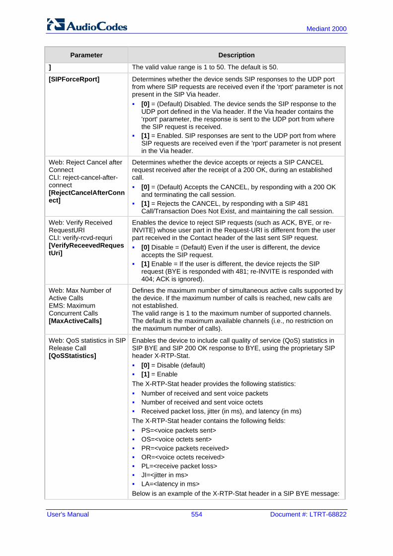
User's Manual 554 Document #: LTRT-68822
Mediant 2000
Parameter Description
] The valid value range is 1 to 50. The default is 50.
[SIPForceRport] Determines whether the device sends SIP responses to the UDP port from where SIP requests are received even if the 'rport' parameter is not present in the SIP Via header. [0] = (Default) Disabled. The device sends the SIP response to the
UDP port defined in the Via header. If the Via header contains the 'rport' parameter, the response is sent to the UDP port from where the SIP request is received.
[1] = Enabled. SIP responses are sent to the UDP port from where SIP requests are received even if the 'rport' parameter is not present in the Via header.
Web: Reject Cancel after Connect CLI: reject-cancel-after-connect [RejectCancelAfterConnect]
Determines whether the device accepts or rejects a SIP CANCEL request received after the receipt of a 200 OK, during an established call. [0] = (Default) Accepts the CANCEL, by responding with a 200 OK
and terminating the call session. [1] = Rejects the CANCEL, by responding with a SIP 481
Call/Transaction Does Not Exist, and maintaining the call session.
Web: Verify Received RequestURI CLI: verify-rcvd-requri [VerifyReceevedRequestUri]
Enables the device to reject SIP requests (such as ACK, BYE, or re-INVITE) whose user part in the Request-URI is different from the user part received in the Contact header of the last sent SIP request. [0] Disable = (Default) Even if the user is different, the device
accepts the SIP request. [1] Enable = If the user is different, the device rejects the SIP
request (BYE is responded with 481; re-INVITE is responded with 404; ACK is ignored).
Web: Max Number of Active Calls EMS: Maximum Concurrent Calls [MaxActiveCalls]
Defines the maximum number of simultaneous active calls supported by the device. If the maximum number of calls is reached, new calls are not established. The valid range is 1 to the maximum number of supported channels. The default is the maximum available channels (i.e., no restriction on the maximum number of calls).
Web: QoS statistics in SIP Release Call [QoSStatistics]
Enables the device to include call quality of service (QoS) statistics in SIP BYE and SIP 200 OK response to BYE, using the proprietary SIP header X-RTP-Stat. [0] = Disable (default) [1] = Enable The X-RTP-Stat header provides the following statistics: Number of received and sent voice packets Number of received and sent voice octets Received packet loss, jitter (in ms), and latency (in ms) The X-RTP-Stat header contains the following fields: PS=<voice packets sent> OS=<voice octets sent> PR=<voice packets received> OR=<voice octets received> PL=<receive packet loss> JI=<jitter in ms> LA=<latency in ms> Below is an example of the X-RTP-Stat header in a SIP BYE message:

Version 6.6 555 Mediant 2000
User's Manual 45. Configuration Parameters Reference
Parameter Description
BYE sip:[email protected] SIP/2.0 Via: SIP/2.0/UDP 10.33.4.126;branch=z9hG4bKac2127550866 Max-Forwards: 70 From: <sip:[email protected];user=phone>;tag=1c2113553324 To: <sip:[email protected]>;tag=1c991751121 Call-ID: [email protected] CSeq: 1 BYE X-RTP-Stat: PS=207;OS=49680;;PR=314;OR=50240;PL=0;JI=600;LA=40; Supported: em,timer,replaces,path,resource-priority Allow: REGISTER,OPTIONS,INVITE,ACK,CANCEL,BYE,NOTIFY,PRACK,REFER,INFO,SUBSCRIBE,UPDATE User-Agent: Sip-Gateway-/v.6.2A.008.006 Reason: Q.850 ;cause=16 ;text="local" Content-Length: 0
Web/EMS: PRACK Mode [PrackMode]
Determines the PRACK (Provisional Acknowledgment) mechanism mode for SIP 1xx reliable responses. [0] Disable [1] Supported (default) [2] Required Notes: The Supported and Required headers contain the '100rel' tag. The device sends PRACK messages if 180/183 responses are
received with '100rel' in the Supported or Required headers.
Web/EMS: Enable Early Media [EnableEarlyMedia]
Enables the Early Media feature. Enables the device to send a 18x response with SDP instead of a 18x, allowing the media stream to be established prior to the answering of the call. [0] Disable (default) [1] Enable The inclusion of the SDP in the 18x response depends on the ISDN Progress Indicator (PI). The SDP is sent only if PI is set to 1 or 8 in the received Proceeding, Alerting, or Progress PRI messages. See also the ProgressIndicator2IP parameter, which if set to 1 or 8, the device behaves as if it received the ISDN messages with the PI. For the CAS protocol: See the ProgressIndicator2IP parameter. For the ISDN protocol: Sending a 183 response depends on the
ISDN PI. It is sent only if PI is set to 1 or 8 in the received Proceeding or Alerting PRI messages. Sending 183 response also depends on the ReleaseIP2ISDNCallOnProgressWithCause parameter, which must be set to any value except 2.
Notes: See also the IgnoreAlertAfterEarlyMedia parameter. This parameter
allows, for example, to interwork Alert + PI to SIP 183 + SDP instead of 180 + SDP.
You can also configure early SIP 183 response immediately upon receipt of an INVITE, using the EnableEarly183 parameter.

User's Manual 556 Document #: LTRT-68822
Mediant 2000
Parameter Description
This feature can also be configured as an IP Profile and/or Tel Profile.
Web/EMS: Enable Early 183 [EnableEarly183]
Enables the device to send SIP 183 responses with SDP to the IP upon receipt of INVITE messages. This parameter is applicable to IP-to-Tel (ISDN) and IP-to-IP calls, and applies to all calls. [0] Disable (default) [1] Enable IP-to-Tel calls: By sending the 183 response, the device opens
an RTP channel before receiving the "progress" tone from the ISDN side. The device sends RTP packets immediately upon receipt of an ISDN Progress, Alerting with Progress indicator, or Connect message according to the initial negotiation without sending the 183 response again, thereby saving response time and avoiding early media clipping.
IP-to-IP calls: Sending the 183 response enables SIP servers that require a stream of early media, to keep sessions open.
Notes: To enable this feature, set the EnableEarlyMedia parameter to 1. When the BChannelNegotiation parameter is set to a non-Exclusive
value (Preferred or Any), the EnableEarly183 parameter is ignored and a SIP 183 is not sent upon receipt of an INVITE. In such a case, you can set the ProgressIndicator2IP parameter to 1 (PI = 1) for the device to send a SIP 183 upon receipt of an ISDN Call Proceeding message.
This feature can also be configured in an IP Profile.
[IgnoreAlertAfterEarlyMedia]
Determines the device's interworking of Alerting messages from PRI to SIP. [0] = Disabled (default) [1] = Enabled When enabled, if the device sends a 183 response with an SDP (due to a received ISDN Progress or Proceeding with PI messages) and an Alerting message is then received from the Tel side (with or without Progress Indicator), the device does not send an additional 18x response, and the voice channel remains open. However, if the device did not send a 183 with an SDP and it receives an Alert without PI, the device sends a 180 (without SDP). If it receives an Alert with PI it sends a 183with an SDP. When disabled, the device sends additional 18x responses as a result of receiving Alerting and Progress messages, regardless of whether or not a 18x response was already sent. Note: This parameter is applicable only if the EnableEarlyMedia parameter is set to 1 (i.e., enabled).
Web: 183 Message Behavior EMS: SIP 183 Behaviour [SIP183Behaviour]
Defines the ISDN message that is sent when the 183 Session Progress message is received for IP-to-Tel calls. [0] Progress = (Default) The device sends a Progress message. [1] Alert = The device sends an Alerting message (upon receipt of a
183 response) instead of an ISDN Progress message.
[ReleaseIP2ISDNCallOnProgressWithCause]
Typically, if an Q.931 Progress message with a Cause is received from the PSTN for an outgoing IP-to-ISDN call and the EnableEarlyMedia parameter is set to 1 (i.e., the Early Media feature is enabled), the device interworks the Progress to 183 + SDP to enable the originating party to hear the PSTN announcement about the call failure.

Version 6.6 557 Mediant 2000
User's Manual 45. Configuration Parameters Reference
Parameter Description
Conversely, if EnableEarlyMedia is set to 0, the device disconnects the call by sending a SIP 4xx response to the originating party. However, if the ReleaseIP2ISDNCallOnProgressWithCause parameter is set to 1, then the device sends a SIP 4xx response even if the EnableEarlyMedia parameter is set to 1. [0] = (Default) If a Progress with Cause message is received from
the PSTN for an outgoing IP-to-ISDN call, the device does not disconnect the call by sending a SIP 4xx response to the originating party.
[1] = The device sends a SIP 4xx response when the EnableEarlyMedia parameter is set to 0.
[2] = The device always sends a SIP 4xx response, even if he EnableEarlyMedia parameter is set to 1.
Web: Session-Expires Time EMS: Sip Session Expires [SIPSessionExpires]
Defines the numerical value sent in the Session-Expires header in the first INVITE request or response (if the call is answered). The valid range is 1 to 86,400 sec. The default is 0 (i.e., the Session-Expires header is disabled).
Web: Minimum Session-Expires EMS: Minimal Session Refresh Value [MinSE]
Defines the time (in seconds) that is used in the Min-SE header. This header defines the minimum time that the user agent refreshes the session. The valid range is 10 to 100,000. The default is 90.
Web/EMS: Session Expires Disconnect Time CLI: session-exp-disconnect-time [SessionExpiresDisconnectTime]
Defines a session expiry timeout. The device disconnects the session (sends a SIP BYE) if the refresher does not send a refresh request before one-third (1/3) of the session expires time, or before the time configured by this parameter (the minimum of the two). The valid range is 0 to 32 (in seconds). The default is 32.
Web/EMS: Session Expires Method [SessionExpiresMethod]
Determines the SIP method used for session-timer updates. [0] Re-INVITE = (Default) Uses Re-INVITE messages for session-
timer updates. [1] UPDATE = Uses UPDATE messages. Notes: The device can receive session-timer refreshes using both methods. The UPDATE message used for session-timer is excluded from the
SDP body.
[RemoveToTagInFailureResponse]
Determines whether the device removes the ‘to’ header tag from final SIP failure responses to INVITE transactions. [0] = (Default) Do not remove tag. [1] = Remove tag.
[EnableRTCPAttribute] Enables the use of the 'rtcp' attribute in the outgoing SDP. [0] = Disable (default) [1] = Enable
EMS: Options User Part [OPTIONSUserPart]
Defines the user part value of the Request-URI for outgoing SIP OPTIONS requests. If no value is configured, the configuration parameter ‘Username’ valueis used. A special value is ‘empty’, indicating that no user part in the Request-

User's Manual 558 Document #: LTRT-68822
Mediant 2000
Parameter Description
URI (host part only) is used. The valid range is a 30-character string. The default is an empty string (‘’).
Web: TDM Over IP Minimum Calls For Trunk Activation EMS: TDM Over IP Min Calls For Trunk Activation [TDMOverIPMinCallsForTrunkActivation]
Defines the minimal number of SIP dialogs that must be established when using TDM Tunneling to consider the specific trunk as active. When using TDM Tunneling, if calls from this defined number of B-channels pertaining to a specific Trunk fail (i.e., SIP dialogs are not correctly set up), an AIS alarm is sent on this trunk toward the PSTN and all current calls are dropped. The originator gateway continues the INVITE attempts. When this number of calls succeed (i.e., SIP dialogs are correctly set up), the AIS alarm is cleared. The valid range is 0 to 31. The default is 0 (i.e., don't send AIS alarms).
[TDMoIPInitiateInviteTime]
Defines the time (in msec) between the first INVITE issued within the same trunk when implementing the TDM tunneling application. The valid value range is 500 to 1000. The default is 500.
[TDMoIPInviteRetryTime]
Defines the time (in msec) between call release and a new INVITE when implementing the TDM tunneling application. The valid value range is 10,000 to 20,000. The default is 10,000.
Web: Fax Signaling Method EMS: Fax Used [IsFaxUsed]
Determines the SIP signaling method for establishing and transmitting a fax session after a fax is detected. [0] No Fax = (Default) No fax negotiation using SIP signaling. Fax
transport method is according to the parameter FaxTransportMode. [1] T.38 Relay = Initiates T.38 fax relay. [2] G.711 Transport = Initiates fax/modem using the coder G.711 A-
law/Mu-law with adaptations (see Note below). [3] Fax Fallback = Initiates T.38 fax relay. If the T.38 negotiation
fails, the device re-initiates a fax session using the coder G.711 A-law/µ-law with adaptations (see the Note below).
Notes: Fax adaptations (for options 2 and 3): Echo Canceller = On Silence Compression = Off Echo Canceller Non-Linear Processor Mode = Off Dynamic Jitter Buffer Minimum Delay = 40 Dynamic Jitter Buffer Optimization Factor = 13
If the device initiates a fax session using G.711 (option 2 and possibly 3), a 'gpmd' attribute is added to the SDP in the following format: For A-law: 'a=gpmd:8 vbd=yes;ecan=on' For µ-law: 'a=gpmd:0 vbd=yes;ecan=on'
When this parameter is set to 1, 2, or 3, the parameter FaxTransportMode is ignored.
When this parameter is set to 0, T.38 might still be used without the control protocol's involvement. To completely disable T.38, set FaxTransportMode to a value other than 1.
This parameter can also be configured per IP Profile (using the IPProfile parameter).
For more information on fax transport methods, see 'Fax/Modem Transport Modes' on page 156.
[HandleG711asVBD] Enables the handling of G.711 as G.711 VBD coder.

Version 6.6 559 Mediant 2000
User's Manual 45. Configuration Parameters Reference
Parameter Description
[0] = (Default) Disable. The device negotiates G.711 as a regular audio coder and sends an answer only with G.729 coder. For example, if the device is configured with G.729 and G.711 VBD coders and it receives an INVITE with an SDP offer containing G.729 and “regular” G.711 coders, it sends an SDP answer containing only the G.729 coder.
[1] = Enable. The device assumes that the G.711 coder received in the INVITE SDP offer is a VBD coder. For example, if the device is configured with G.729 and G.711 VBD coders and it receives an INVITE with an SDP offer containing G.729 and “regular” G.711 coders, it sends an SDP answer containing G.729 and G.711 VBD coders, allowing a subsequent bypass (passthrough) session if fax/modem signals are detected during the call.
Note: This parameter is applicable only if G.711 VBD coder(s) with regular G.711 payload types 0 or 8 are configured for the device (using the CodersGroup parameter).
[FaxVBDBehavior]
Determines the device's fax transport behavior when G.711 VBD coder is negotiated at call start. [0] = (Default) If the device is configured with a VBD coder (see the
CodersGroup parameter) and is negotiated OK at call start, then both fax and modem signals are sent over RTP using the bypass payload type (and no mid-call VBD or T.38 Re-INVITEs occur).
[1] = If the IsFaxUsed parameter is set to 1, the channel opens with the FaxTransportMode parameter set to 1 (relay). This is required to detect mid-call fax tones and to send T.38 Re-INVITE messages upon fax detection. If the remote party supports T.38, the fax is relayed over T.38.
Notes: If VBD coder negotiation fails at call start and if the IsFaxUsed
parameter is set to 1 (or 3), then the channel opens with the FaxTransportMode parameter set to 1 (relay) to allow future detection of fax tones and sending of T.38 Re-INVITES. In such a scenario, the FaxVBDBehavior parameter has no effect.
This feature can be used only if the remote party supports T.38 fax relay; otherwise, the fax fails.
[NoAudioPayloadType] Defines the payload type of the outgoing SDP offer. The valid value range is 96 to 127 (dynamic payload type). The default is 0 (i.e. NoAudio is not supported). For example, if set to 120, the following is added to the INVITE SDP: a=rtpmap:120 NoAudio/8000\r\n
Note: For incoming SDP offers, NoAudio is always supported.
Web: SIP Transport Type EMS: Transport Type [SIPTransportType]
Determines the default transport layer for outgoing SIP calls initiated by the device. [0] UDP (default) [1] TCP [2] TLS (SIPS) Notes: It's recommended to use TLS for communication with a SIP Proxy
and not for direct device-to-device communication. For received calls (i.e., incoming), the device accepts all these
protocols.

User's Manual 560 Document #: LTRT-68822
Mediant 2000
Parameter Description
The value of this parameter is also used by the SAS application as the default transport layer for outgoing SIP calls.
Web: SIP UDP Local Port EMS: Local SIP Port [LocalSIPPort]
Defines the local UDP port for SIP messages. The valid range is 1 to 65534. The default is 5060.
Web: SIP TCP Local Port EMS: TCP Local SIP Port [TCPLocalSIPPort]
Defines the local TCP port for SIP messages. The valid range is 1 to 65535. The default is 5060.
Web: SIP TLS Local Port EMS: TLS Local SIP Port [TLSLocalSIPPort]
Defines the local TLS port for SIP messages. The valid range is 1 to 65535. The default is 5061. Note: The value of this parameter must be different from the value of the parameter TCPLocalSIPPort.
Web/EMS: Enable SIPS [EnableSIPS]
Enables secured SIP (SIPS URI) connections over multiple hops. [0] Disable (default) [1] Enable When the SIPTransportType parameter is set to 2 (i.e., TLS) and the parameter EnableSIPS is disabled, TLS is used for the next network hop only. When the parameter SIPTransportType is set to 2 or 1 (i.e., TCP or TLS) and EnableSIPS is enabled, TLS is used through the entire connection (over multiple hops). Note: If this parameter is enabled and the parameter SIPTransportType is set to 0 (i.e., UDP), the connection fails.
Web/EMS: Enable TCP Connection Reuse [EnableTCPConnectionReuse]
Enables the reuse of the same TCP connection for all calls to the same destination. [0] Disable = Uses a separate TCP connection for each call. [1] Enable = (Default) Uses the same TCP connection for all calls. Note: For the SAS application, this feature is configured using the SASConnectionReuse parameter.
Web: Fake TCP alias [FakeTCPalias]
Enables the re-use of the same TCP/TLS connection for sessions with the same user, even if the "alias" parameter is not present in the SIP Via header of the first INVITE. [0] Disable = (Default) TCP/TLS connection reuse is done only if the
"alias" parameter is present in the Via header of the first INVITE. [1] Enable Note: To enable TCP/TLS connection re-use, set the EnableTCPConnectionReuse parameter to 1.
Web/EMS: Reliable Connection Persistent Mode [ReliableConnectionPersistentMode]
Enables setting of all TCP/TLS connections as persistent and therefore, not released. [0] = (Default) Disable. All TCP connections (except those that are
set to a proxy IP) are released if not used by any SIP dialog\transaction.
[1] = Enable - TCP connections to all destinations are persistent and not released unless the device reaches 70% of its maximum TCP resources.
While trying to send a SIP message connection, reuse policy determines whether live connections to the specific destination are re-used. Persistent TCP connection ensures less network traffic due to fewer setting up and tearing down of TCP connections and reduced latency

Version 6.6 561 Mediant 2000
User's Manual 45. Configuration Parameters Reference
Parameter Description
on subsequent requests due to avoidance of initial TCP handshake. For TLS, persistent connection may reduce the number of costly TLS handshakes to establish security associations, in addition to the initial TCP connection set up. Note: If the destination is a Proxy server, the TCP/TLS connection is persistent regardless of the settings of this parameter.
Web/EMS: TCP Timeout [SIPTCPTimeout]
Defines the Timer B (INVITE transaction timeout timer) and Timer F (non-INVITE transaction timeout timer), as defined in RFC 3261, when the SIP Transport Type is TCP. The valid range is 0 to 40 sec. The default is 64 multiplied by the SipT1Rtx parameter value. For example, if SipT1Rtx is set to 500 msec, then the default of SIPTCPTimeout is 32 sec.
Web: SIP Destination Port EMS: Destination Port [SIPDestinationPort]
Defines the SIP destination port for sending initial SIP requests. The valid range is 1 to 65534. The default port is 5060. Note: SIP responses are sent to the port specified in the Via header.
Web: Use user=phone in SIP URL EMS: Is User Phone [IsUserPhone]
Determines whether the 'user=phone' string is added to the SIP URI and SIP To header. [0] No = 'user=phone' string is not added. [1] Yes = (Default) 'user=phone' string is part of the SIP URI and SIP
To header.
Web: Use user=phone in From Header EMS: Is User Phone In From [IsUserPhoneInFrom]
Determines whether the 'user=phone' string is added to the From and Contact SIP headers. [0] No = (Default) Doesn't add 'user=phone' string. [1] Yes = 'user=phone' string is part of the From and Contact
headers.
Web: Use Tel URI for Asserted Identity [UseTelURIForAssertedID]
Determines the format of the URI in the P-Asserted-Identity and P-Preferred-Identity headers. [0] Disable = (Default) 'sip:' [1] Enable = 'tel:'
Web: Tel to IP No Answer Timeout EMS: IP Alert Timeout [IPAlertTimeout]
Defines the time (in seconds) that the device waits for a 200 OK response from the called party (IP side) after sending an INVITE message. If the timer expires, the call is released. The valid range is 0 to 3600. The default is 180.
Web: Enable Remote Party ID EMS: Enable RPI Header [EnableRPIheader]
Enables Remote-Party-Identity headers for calling and called numbers for Tel-to-IP calls. [0] Disable (default). [1] Enable = Remote-Party-Identity headers are generated in SIP
INVITE messages for both called and calling numbers.

User's Manual 562 Document #: LTRT-68822
Mediant 2000
Parameter Description
Web: Enable History-Info Header EMS: Enable History Info [EnableHistoryInfo]
Enables usage of the History-Info header. [0] Disable (default) [1] Enable User Agent Client (UAC) Behavior: Initial request: The History-Info header is equal to the Request-URI.
If a PSTN Redirect number is received, it is added as an additional History-Info header with an appropriate reason.
Upon receiving the final failure response, the device copies the History-Info as is, adds the reason of the failure response to the last entry, and concatenates a new destination to it (if an additional request is sent). The order of the reasons is as follows: a. Q.850 Reason b. SIP Reason c. SIP Response code
Upon receiving the final response (success or failure), the device searches for a Redirect reason in the History-Info (i.e., 3xx/4xx SIP reason). If found, it is passed to ISDN according to the following table:
SIP Reason Code ISDN Redirecting Reason 302 - Moved Temporarily Call Forward Universal (CFU)
408 - Request Timeout Call Forward No Answer (CFNA)
480 - Temporarily Unavailable
487 - Request Terminated
486 - Busy Here Call Forward Busy (CFB)
600 - Busy Everywhere
If history reason is a Q.850 reason, it is translated to the SIP reason (according to the SIP-ISDN tables) and then to ISDN Redirect reason according to the table above.
User Agent Server (UAS) Behavior: The History-Info header is sent only in the final response. Upon receiving a request with History-Info, the UAS checks the
policy in the request. If a 'session', 'header', or 'history' policy tag is found, the (final) response is sent without History-Info; otherwise, it is copied from the request.
Web: Use Tgrp Information EMS: Use SIP Tgrp [UseSIPTgrp]
Determines whether the SIP 'tgrp' parameter is used. This SIP parameter specifies the Trunk Group to which the call belongs (according to RFC 4904). For example, the SIP message below indicates that the call belongs to Trunk Group ID 1: INVITE sip::+16305550100;tgrp=1;[email protected];user=phone SIP/2.0 [0] Disable = (Default) The 'tgrp' parameter isn't used. [1] Send Only = The Trunk Group number or name (configured in
the Trunk Group Settings) is added to the 'tgrp' parameter value in the Contact header of outgoing SIP messages. If a Trunk Group number / name is not associated with the call, the 'tgrp' parameter isn't included. If a 'tgrp' value is specified in incoming messages, it is ignored.
[2] Send and Receive = The functionality of outgoing SIP messages is identical to the functionality described for option [1]. In addition, for incoming SIP INVITEs, if the Request-URI includes a 'tgrp'

Version 6.6 563 Mediant 2000
User's Manual 45. Configuration Parameters Reference
Parameter Description
parameter, the device routes the call according to that value (if possible). The Contact header in the outgoing SIP INVITE (Tel-to-IP call) contains "tgrp=<source trunk group ID>;trunk-context=<gateway IP address>”. The <source trunk group ID> is the Trunk Group ID where incoming calls from Tel is received. For IP-Tel calls, the SIP 200 OK device's response contains “tgrp=<destination trunk group ID>;trunk-context=<gateway IP address>”. The <destination trunk group ID> is the Trunk Group ID used for outgoing Tel calls. The <gateway IP address> in “trunk-context” can be configured using the SIPGatewayName parameter.
[3] Hotline = Interworks the hotline "Off Hook Indicator" parameter between SIP and ISDN: For IP-to-ISDN calls:
- The device interworks the SIP tgrp=hotline parameter (received in INVITE) to ISDN Setup with the Off Hook Indicator IE of “Voice”, and “Speech” Bearer Capability IE. Note that the Off Hook Indicator IE is described in UCR 2008 specifications. - The device interworks the SIP tgrp=hotline-ccdata parameter (received in INVITE) to ISDN Setup with an Off Hook Indicator IE of “Data”, and with “Unrestricted 64k” Bearer Capability IE. The following is an example of the INVITE with tgrp=hotline-ccdata:
INVITE sip:1234567;tgrp=hotline-ccdata;[email protected] For ISDN-to-IP calls:
- The device interworks ISDN Setup with an Off Hook Indicator of “Voice” to SIP INVITE with “tgrp=hotline;trunk-context=dsn.mil” in the Contact header. - The device interworks ISDN Setup with an Off Hook indicator of “Data” to SIP INVITE with “tgrp=hotline-ccdata;trunk-context=dsn.mil” in the Contact header. - If ISDN Setup does not contain an Off Hook Indicator IE and the Bearer Capability IE contains “Unrestricted 64k”, the outgoing INVITE includes “tgrp=ccdata;trunk-context=dsn.mil”. If the Bearer Capability IE contains “Speech”, the INVITE in this case does not contain tgrp and trunk-context parameters.
[4] Hotline Extended = Interworks the ISDN Setup message’s hotline "OffHook Indicator" Information Element (IE) to SIP INVITE’s Request-URI and Contact headers. (Note: For IP-to-ISDN calls, the device handles the call as described in option [3].) The device interworks ISDN Setup with an Off Hook Indicator of
“Voice” to SIP INVITE Request-URI and Contact header with “tgrp=hotline;trunk-context=dsn.mil”.
The device interworks ISDN Setup with an Off Hook indicator of “Data” to SIP INVITE Request-URI and Contact header with “tgrp=hotline-ccdata;trunk-context=dsn.mil”.
If ISDN Setup does not contain an Off Hook Indicator IE and the Bearer Capability IE contains “Unrestricted 64k”, the outgoing INVITE Request-URI and Contact header includes “tgrp=ccdata;trunk-context=dsn.mil”. If the Bearer Capability IE contains “Speech”, the INVITE in this case does not contain tgrp and trunk-context parameters.
Note: IP-to-Tel configuration (using the PSTNPrefix parameter) overrides the 'tgrp' parameter in incoming INVITE messages.

User's Manual 564 Document #: LTRT-68822
Mediant 2000
Parameter Description
Web/EMS: TGRP Routing Precedence [TGRProutingPrecedence]
Determines the precedence method for routing IP-to-Tel calls - according to the Inbound IP Routing Table or according to the SIP 'tgrp' parameter. [0] = (Default) IP-to-Tel routing is determined by the Inbound IP
Routing Table (PSTNPrefix parameter). If a matching rule is not found in this table, the device uses the Trunk Group parameters for routing the call.
[1] = The device first places precedence on the 'tgrp' parameter for IP-to-Tel routing. If the received INVITE Request-URI does not contain the 'tgrp' parameter or if the Trunk Group number is not defined, then the Inbound IP Routing Table is used for routing the call.
Below is an example of an INVITE Request-URI with the 'tgrp' parameter, indicating that the IP call should be routed to Trunk Group 7: INVITE sip:200;tgrp=7;[email protected];user=phone SIP/2.0
Notes: For enabling routing based on the 'tgrp' parameter, the UseSIPTgrp
parameter must be set to 2. For IP-to-Tel routing based on the 'dtg' parameter (instead of the
'tgrp' parameter), use the parameter UseBroadsoftDTG.
[UseBroadsoftDTG]
Determines whether the device uses the 'dtg' parameter for routing IP-to-Tel calls to a specific Trunk Group. [0] Disable (default) [1] Enable When this parameter is enabled, if the Request-URI in the received SIP INVITE includes the 'dtg' parameter, the device routes the call to the Trunk Group according to its value. This parameter is used instead of the 'tgrp/trunk-context' parameters. The 'dtg' parameter appears in the INVITE Request-URI (and in the To header). For example, the received SIP message below routes the call to Trunk Group ID 56: INVITE sip:[email protected];dtg=56;user=phone SIP/2.0
Note: If the Trunk Group is not found based on the 'dtg' parameter, the Inbound IP Routing Table is used instead for routing the call to the appropriate Trunk Group.
Web/EMS: Enable GRUU [EnableGRUU]
Determines whether the Globally Routable User Agent URIs (GRUU) mechanism is used, according to RFC 5627. This is used for obtaining a GRUU from a registrar and for communicating a GRUU to a peer within a dialog. [0] Disable (default) [1] Enable A GRUU is a SIP URI that routes to an instance-specific UA and can be reachable from anywhere. There are a number of contexts in which it is desirable to have an identifier that addresses a single UA (using GRUU) rather than the group of UA’s indicated by an Address of Record (AOR). For example, in call transfer where user A is talking to user B, and user A wants to transfer the call to user C. User A sends a REFER to user C: REFER sip:[email protected] SIP/2.0 From: sip:[email protected];tag=99asd To: sip:[email protected]

Version 6.6 565 Mediant 2000
User's Manual 45. Configuration Parameters Reference
Parameter Description
Refer-To: (URI that identifies B's UA)
The Refer-To header needs to contain a URI that user C can use to place a call to user B. This call needs to route to the specific UA instance that user B is using to talk to user A. User B should provide user A with a URI that has to be usable by anyone. It needs to be a GRUU. Obtaining a GRUU: The mechanism for obtaining a GRUU is through
registrations. A UA can obtain a GRUU by generating a REGISTER request containing a Supported header field with the value “gruu”. The UA includes a “+sip.instance” Contact header parameter of each contact for which the GRUU is desired. This Contact parameter contains a globally unique ID that identifies the UA instance. The global unique ID is created from one of the following: If the REGISTER is per the device’s client (endpoint), it is the
MAC address concatenated with the phone number of the client. If the REGISTER is per device, it is the MAC address only. When using TP, “User Info” can be used for registering per
endpoint. Thus, each endpoint can get a unique id – its phone number. The globally unique ID in TP is the MAC address concatenated with the phone number of the endpoint.
If the remote server doesn’t support GRUU, it ignores the parameters of the GRUU. Otherwise, if the remote side also supports GRUU, the REGISTER responses contain the “gruu” parameter in each Contact header. This parameter contains a SIP or SIPS URI that represents a GRUU corresponding to the UA instance that registered the contact. The server provides the same GRUU for the same AOR and instance-id when sending REGISTER again after registration expiration. RFC 5627 specifies that the remote target is a GRUU target if its’ Contact URL has the "gr" parameter with or without a value. Using GRUU: The UA can place the GRUU in any header field that
can contain a URI. It must use the GRUU in the following messages: INVITE request, its 2xx response, SUBSCRIBE request, its 2xx response, NOTIFY request, REFER request and its 2xx response.
EMS: Is CISCO Sce Mode [IsCiscoSCEMode]
Determines whether a Cisco gateway exists at the remote side. [0] = (Default) No Cisco gateway exists at the remote side. [1] = A Cisco gateway exists at the remote side. When a Cisco gateway exists at the remote side, the device must set the value of the 'annexb' parameter of the fmtp attribute in the SDP to 'no'. This logic is used if the parameter EnableSilenceCompression is set to 2 (enable without adaptation). In this case, Silence Suppression is used on the channel but not declared in the SDP. Note: The IsCiscoSCEMode parameter is applicable only when the selected coder is G.729.
Web: User-Agent Information EMS: User Agent Display Info [UserAgentDisplayInfo]
Defines the string that is used in the SIP User-Agent and Server response headers. When configured, the string <UserAgentDisplayInfo value>/software version' is used, for example: User-Agent: myproduct/v.6.40.010.006
If not configured, the default string, <AudioCodes product-name>/software version' is used, for example: User-Agent: Audiocodes-Sip-Gateway-Mediant 2000/v.6.40.010.006
The maximum string length is 50 characters.

User's Manual 566 Document #: LTRT-68822
Mediant 2000
Parameter Description
Note: The software version number and preceding forward slash (/) cannot be modified. Therefore, it is recommended not to include a forward slash in the parameter's value (to avoid two forward slashes in the SIP header, which may cause problems).
Web/EMS: SDP Session Owner [SIPSDPSessionOwner]
Defines the value of the Owner line ('o' field) in outgoing SDP messages. The valid range is a string of up to 39 characters. The default is 'AudiocodesGW'. For example: o=AudiocodesGW 1145023829 1145023705 IN IP4 10.33.4.126
[EnableSDPVersionNegotiation]
Enables the device to ignore new SDP re-offers (from the media negotiation perspective) in certain scenarios (such as session expires). According to RFC 3264, once an SDP session is established, a new SDP offer is considered a new offer only when the SDP origin value is incremented. In scenarios such as session expires, SDP negotiation is irrelevant and thus, the origin field is not changed. Even though some SIP devices don’t follow this behavior and don’t increment the origin value even in scenarios where they want to re-negotiate, the device can assume that the remote party operates according to RFC 3264, and in cases where the origin field is not incremented, the device does not re-negotiate SDP capabilities. [0] Disable = (Default) The device negotiates any new SDP re-offer,
regardless of the origin field. [1] Enable = The device negotiates only an SDP re-offer with an
incremented origin field.
Web/EMS: Subject [SIPSubject]
Defines the Subject header value in outgoing INVITE messages. If not specified, the Subject header isn't included (default). The maximum length is up to 50 characters.
[CoderPriorityNegotiation]
Defines the priority for coder negotiation in the incoming SDP offer, between the device's or remote UA's coder list. [0] = (Default) Coder negotiation is given higher priority to the
remote UA's list of supported coders. [1] = Coder negotiation is given higher priority to the device's (local)
supported coders list. Note: This parameter is applicable only to the Gateway/IP-to-IP
application.
Web: Send All Coders on Retrieve [SendAllCodersOnRetrieve]
Enables coder re-negotiation in the sent re-INVITE for retrieving an on-hold call. [0] Disable = (Default) Sends only the initially chosen coder when
the call was first established and then put on-hold. [1] Enable = Includes all supported coders in the SDP of the re-
INVITE sent to the call made un-hold (retrieved). The used coder is therefore, re-negotiated.
This parameter is useful in the following call scenario example: 1 Party A calls party B and coder G.711 is chosen. 2 Party B is put on-hold while Party A blind transfers Party B to Party
C. 3 Party C answers and Party B is made un-hold. However, as Party C
supports only G.729 coder, re-negotiation of the supported coder is required.

Version 6.6 567 Mediant 2000
User's Manual 45. Configuration Parameters Reference
Parameter Description
Web: Multiple Packetization Time Format EMS: Multi Ptime Format [MultiPtimeFormat]
Determines whether the 'mptime' attribute is included in the outgoing SDP. [0] None = (Default) Disabled. [1] PacketCable = Includes the 'mptime' attribute in the outgoing
SDP - PacketCable-defined format. The mptime' attribute enables the device to define a separate packetization period for each negotiated coder in the SDP. The 'mptime' attribute is only included if this parameter is enabled even if the remote side includes it in the SDP offer. Upon receipt, each coder receives its 'ptime' value in the following precedence: from 'mptime' attribute, from 'ptime' attribute, and then from default value.
EMS: Enable P Time [EnablePtime]
Determines whether the 'ptime' attribute is included in the SDP. [0] = Remove the 'ptime' attribute from SDP. [1] = (Default) Include the 'ptime' attribute in SDP.
Web/EMS: 3xx Behavior [3xxBehavior]
Determines the device's behavior regarding call identifiers when a 3xx response is received for an outgoing INVITE request. The device can either use the same call identifiers (Call-ID, To, and From tags) or change them in the new initiated INVITE. [0] Forward = (Default) Use different call identifiers for a redirected
INVITE message. [1] Redirect = Use the same call identifiers.
Web/EMS: Enable P-Charging Vector [EnablePChargingVector]
Enables the inclusion of the P-Charging-Vector header to all outgoing INVITE messages. [0] Disable (default) [1] Enable
Web/EMS: Retry-After Time [RetryAfterTime]
Defines the time (in seconds) used in the Retry-After header when a 503 (Service Unavailable) response is generated by the device. The time range is 0 to 3,600. The default is 0.
Web/EMS: Fake Retry After [sec] [FakeRetryAfter]
Determines whether the device, upon receipt of a SIP 503 response without a Retry-After header, behaves as if the 503 response included a Retry-After header and with the period (in seconds) specified by this parameter. [0] Disable (default) Any positive value (in seconds) for defining the period When enabled, this feature allows the device to operate with Proxy servers that do not include the Retry-After SIP header in SIP 503 (Service Unavailable) responses to indicate an unavailable service. The Retry-After header is used with the 503 (Service Unavailable) response to indicate how long the service is expected to be unavailable to the requesting SIP client. The device maintains a list of available proxies, by using the Keep-Alive mechanism. The device checks the availability of proxies by sending SIP OPTIONS every keep-alive timeout to all proxies. If the device receives a SIP 503 response to an INVITE, it also marks that the proxy is out of service for the defined "Retry-After" period.
Web/EMS: Enable P-Associated-URI Header [EnablePAssociatedURIHeader]
Determines the device usage of the P-Associated-URI header. This header can be received in 200 OK responses to REGISTER requests. When enabled, the first URI in the P-Associated-URI header is used in subsequent requests as the From/P-Asserted-Identity headers value.

User's Manual 568 Document #: LTRT-68822
Mediant 2000
Parameter Description
[0] Disable (default) [1] Enable Note: P-Associated-URIs in registration responses is handled only if the device is registered per endpoint (using the User Information file).
Web/EMS: Source Number Preference [SourceNumberPreference]
Determines from which SIP header the source (calling) number is obtained in incoming INVITE messages. If not configured (i.e., empty string) or if any string other than "From"
or "Pai2" is configured, the calling number is obtained from a specific header using the following logic: a. P-Preferred-Identity header. b. If the above header is not present, then the first P-Asserted-
Identity header is used. c. If the above header is not present, then the Remote-Party-ID
header is used. d. If the above header is not present, then the From header is
used. "From" = The calling number is obtained from the From header. "Pai2" = The calling number is obtained using the following logic:
a. If a P-Preferred-Identity header is present, the number is obtained from it.
b. If no P-Preferred-Identity header is present and two P-Asserted-Identity headers are present, the number is obtained from the second P-Asserted-Identity header.
c. If only one P-Asserted-Identity header is present, the calling number is obtained from it.
Notes: The "From" and "Pai2" values are not case-sensitive. Once a URL is selected, all the calling party parameters are set from
this header. If P-Asserted-Identity is selected and the Privacy header is set to 'id', the calling number is assumed restricted.
[SelectSourceHeaderForCalledNumber]
Determines the SIP header used for obtaining the called number (destination) for IP-to-Tel calls. [0] Request-URI header = (Default) Obtains the destination number
from the user part of the Request-URI. [1] To header = Obtains the destination number from the user part of
the To header. [2] P-Called-Party-ID header = Obtains the destination number from
the P-Called-Party-ID header.
Web/EMS: Forking Handling Mode [ForkingHandlingMode]
Determines how the device handles the receipt of multiple SIP 18x forking responses for Tel-to-IP calls. The forking 18x response is the response with a different SIP to-tag than the previous 18x response. These responses are typically generated (initiated) by Proxy / Application servers that perform call forking, sending the device's originating INVITE (received from SIP clients) to several destinations, using the same CallID. [0] Parallel handling = (Default) If SIP 18x with SDP is received, the
device opens a voice stream according to the received SDP and disregards any subsequently received 18x forking responses (with or without SDP). If the first response is 180 without SDP, the device responds according to the PlayRBTone2TEL parameter and disregards the subsequent forking 18x responses.
[1] Sequential handling = If 18x with SDP is received, the device opens a voice stream according to the received SDP. The device re-

Version 6.6 569 Mediant 2000
User's Manual 45. Configuration Parameters Reference
Parameter Description
opens the stream according to subsequently received 18x responses with SDP, or plays a ringback tone if 180 response without SDP is received. If the first received response is 180 without SDP, the device responds according to the PlayRBTone2TEL parameter and processes the subsequent 18x forking responses.
Note: Regardless of this parameter setting, once a SIP 200 OK response is received, the device uses the RTP information and re-opens the voice stream, if necessary.
Web: Forking Timeout [ForkingTimeOut]
Defines the timeout (in seconds) that is started after the first SIP 2xx response has been received for a User Agent when a Proxy server performs call forking (Proxy server forwards the INVITE to multiple SIP User Agents). The device sends a SIP ACK and BYE in response to any additional SIP 2xx received from the Proxy within this timeout. Once this timeout elapses, the device ignores any subsequent SIP 2xx. The number of supported forking calls per channel is 20. In other words, for an INVITE message, the device can receive up to 20 forking responses from the Proxy server. The valid range is 0 to 30. The default is 30.
Web: Tel2IP Call Forking Mode [Tel2IPCallForkingMode]
Enables Tel-to-IP call forking, whereby a Tel call can be routed to multiple IP destinations. [0] Disable (default) [1] Enable Note: Once enabled, routing rules must be assigned Forking Groups in the Outbound IP Routing table.
Web/EMS: Enable Reason Header [EnableReasonHeader]
Enables the usage of the SIP Reason header. [0] Disable [1] Enable (default)
Web/EMS: Gateway Name CLI: gw-name [SIPGatewayName]
Defines a name for the device (e.g., device123.com). This name is used as the host part of the SIP URI in the From header. If not specified, the device's IP address is used instead (default). Notes: Ensure that the parameter value is the one with which the Proxy has
been configured with to identify the device. This parameter can also be configured for an IP Group (in the IP
Group table).
[ZeroSDPHandling] Determines the device's response to an incoming SDP that includes an IP address of 0.0.0.0 in the SDP's Connection Information field (i.e., "c=IN IP4 0.0.0.0"). [0] = (Default) Sets the IP address of the outgoing SDP's c= field to
0.0.0.0. [1] = Sets the IP address of the outgoing SDP c= field to the IP
address of the device. If the incoming SDP doesn’t contain the "a=inactive" line, the returned SDP contains the "a=recvonly" line.
Web/EMS: Enable Delayed Offer [EnableDelayedOffer]
Determines whether the device sends the initial INVITE message with or without an SDP. Sending the first INVITE without SDP is typically done by clients for obtaining the far-end's full list of capabilities before sending their own offer. (An alternative method for obtaining the list of supported capabilities is by using SIP OPTIONS, which is not supported by every SIP agent.) [0] Disable = (Default) The device sends the initial INVITE message

User's Manual 570 Document #: LTRT-68822
Mediant 2000
Parameter Description
with an SDP. [1] Enable = The device sends the initial INVITE message without an
SDP.
[DisableCryptoLifeTimeInSDP]
Enables the device to send "a=crypto" lines without the lifetime parameter in the SDP. For example, if the SDP contains "a=crypto:12 AES_CM_128_HMAC_SHA1_80 inline:hhQe10yZRcRcpIFPkH5xYY9R1de37ogh9G1MpvNp|2^31", it removes the lifetime parameter "2^31". [0] Disable (default) [1] Enable
Web/EMS: Enable Contact Restriction [EnableContactRestriction]
Determines whether the device sets the Contact header of outgoing INVITE requests to ‘anonymous’ for restricted calls. [0] Disable (default) [1] Enable
[AnonymousMode]
Determines whether the device's IP address is used as the URI host part instead of "anonymous.invalid" in the INVITE's From header for Tel-to-IP calls. [0] = (Default) If the device receives a call from the Tel with blocked
caller ID, it sends an INVITE with From: “anonymous”<[email protected]>
[1] = The device's IP address is used as the URI host part instead of "anonymous.invalid".
This parameter may be useful, for example, for service providers who identify their SIP Trunking customers by their source phone number or IP address, reflected in the From header of the SIP INVITE. Therefore, even customers blocking their Caller ID can be identified by the service provider. Typically, if the device receives a call with blocked Caller ID from the PSTN side (e.g., Trunk connected to a PBX), it sends an INVITE to the IP with a From header as follows: From: “anonymous” <[email protected]>. This is in accordance with RFC 3325. However, when this parameter is set to 1, the device replaces the "anonymous.invalid" with its IP address.
EMS: P Asserted User Name [PAssertedUserName]
Defines a 'representative number' (up to 50 characters) that is used as the user part of the Request-URI in the P-Asserted-Identity header of an outgoing INVITE for Tel-to-IP calls. The default is null.
EMS: Use URL In Refer To Header [UseAORInReferToHeader]
Defines the source for the SIP URI set in the Refer-To header of outgoing REFER messages. [0] = (Default) Use SIP URI from Contact header of the initial call. [1] = Use SIP URI from To/From header of the initial call.
Web: Enable User-Information Usage [EnableUserInfoUsage]
Enables the usage of the User Information, which is loaded to the device in the User Information auxiliary file. For a description on User Information, see 'Loading Auxiliary Files' on page 399. [0] Disable (default) [1] Enable Note: For this parameter to take effect, a device reset is required.
[HandleReasonHeader] Determines whether the device uses the value of the incoming SIP Reason header for Release Reason mapping. [0] = Disregard Reason header in incoming SIP messages. [1] = (Default) Use the Reason header value for Release Reason

Version 6.6 571 Mediant 2000
User's Manual 45. Configuration Parameters Reference
Parameter Description
mapping.
[EnableSilenceSuppInSDP]
Determines the device's behavior upon receipt of SIP Re-INVITE messages that include the SDP's 'silencesupp:off' attribute. [0] = (Default) Disregard the 'silecesupp' attribute. [1] = Handle incoming Re-INVITE messages that include the
'silencesupp:off' attribute in the SDP as a request to switch to the Voice-Band-Data (VBD) mode. In addition, the device includes the attribute 'a=silencesupp:off' in its SDP offer.
Note: This parameter is applicable only if the G.711 coder is used.
[EnableRport] Enables the usage of the 'rport' parameter in the Via header. [0] = Disabled (default) [1] = Enabled The device adds an 'rport' parameter to the Via header of each outgoing SIP message. The first Proxy that receives this message sets the 'rport' value of the response to the actual port from where the request was received. This method is used, for example, to enable the device to identify its port mapping outside a NAT. If the Via header doesn't include the 'rport' parameter, the destination port of the response is obtained from the host part of the Via header. If the Via header includes the 'rport' parameter without a port value, the destination port of the response is the source port of the incoming request. If the Via header includes 'rport' with a port value (e.g., rport=1001), the destination port of the response is the port indicated in the 'rport' parmeter.
Web: Enable X-Channel Header EMS: X Channel Header [XChannelHeader]
Determines whether the SIP X-Channel header is added to SIP messages for providing information on the physical Trunk/B-channel on which the call is received or placed. [0] Disable = (Default) X-Channel header is not used. [1] Enable = X-Channel header is generated by the device and sent
in INVITE messages and 180, 183, and 200 OK SIP responses. The header includes the Trunk number, B-channel, and the device's IP address. For example, 'x-channel: DS/DS1-5/8;IP=192.168.13.1', where: 'DS/DS-1' is a constant string '5' is the Trunk number '8' is the B-channel 'IP=192.168.13.1' is the device's IP address
Web/EMS: Progress Indicator to IP [ProgressIndicator2IP]
[-1] Not Configured = for ISDN spans, the progress indicator (PI) that is received in ISDN Proceeding, Progress, and Alerting messages is used as described in the options below. (default)
[0] No PI = For IP-to-Tel calls, the device sends 180 Ringing SIP response to IP after receiving ISDN Alerting or (for CAS) after placing a call to PBX/PSTN.
[1] PI =1, [8] PI =8: For IP-to-Tel calls, if the parameter EnableEarlyMedia is set to 1, the device sends 180 Ringing with SDP in response to an ISDN Alerting or it sends a 183 Session Progress message with SDP in response to only the first received ISDN Proceeding or Progress message after a call is placed to PBX/PSTN over the trunk.
Note: This parameter can also be configured per IP Profile (using the
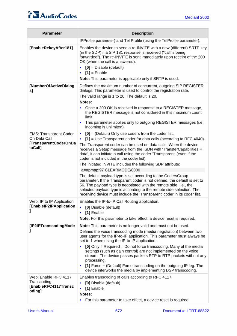
User's Manual 572 Document #: LTRT-68822
Mediant 2000
Parameter Description
IPProfile parameter) and Tel Profile (using the TelProfile parameter).
[EnableRekeyAfter181] Enables the device to send a re-INVITE with a new (different) SRTP key (in the SDP) if a SIP 181 response is received ("call is being forwarded"). The re-INVITE is sent immediately upon receipt of the 200 OK (when the call is answered). [0] = Disable (default) [1] = Enable Note: This parameter is applicable only if SRTP is used.
[NumberOfActiveDialogs]
Defines the maximum number of concurrent, outgoing SIP REGISTER dialogs. This parameter is used to control the registration rate. The valid range is 1 to 20. The default is 20. Notes: Once a 200 OK is received in response to a REGISTER message,
the REGISTER message is not considered in this maximum count limit.
This parameter applies only to outgoing REGISTER messages (i.e., incoming is unlimited).
EMS: Transparent Coder On Data Call [TransparentCoderOnDataCall]
[0] = (Default) Only use coders from the coder list. [1] = Use Transparent coder for data calls (according to RFC 4040). The Transparent coder can be used on data calls. When the device receives a Setup message from the ISDN with 'TransferCapabilities = data', it can initiate a call using the coder 'Transparent' (even if the coder is not included in the coder list). The initiated INVITE includes the following SDP attribute: a=rtpmap:97 CLEARMODE/8000
The default payload type is set according to the CodersGroup parameter. If the Transparent coder is not defined, the default is set to 56. The payload type is negotiated with the remote side, i.e., the selected payload type is according to the remote side selection. The receiving device must include the 'Transparent' coder in its coder list.
Web: IP to IP Application [EnableIP2IPApplication]
Enables the IP-to-IP Call Routing application. [0] Disable (default) [1] Enable Note: For this parameter to take effect, a device reset is required.
[IP2IPTranscodingMode]
Note: This parameter is no longer valid and must not be used. Defines the voice transcoding mode (media negotiation) between two user agents for the IP-to-IP application. This parameter must always be set to 1 when using the IP-to-IP application. [0] Only if Required = Do not force transcoding. Many of the media
settings (such as gain control) are not implemented on the voice stream. The device passes packets RTP to RTP packets without any processing.
[1] Force = (Default) Force transcoding on the outgoing IP leg. The device interworks the media by implementing DSP transcoding.
Web: Enable RFC 4117 Transcoding [EnableRFC4117Transcoding]
Enables transcoding of calls according to RFC 4117. [0] Disable (default) [1] Enable Notes: For this parameter to take effect, a device reset is required.
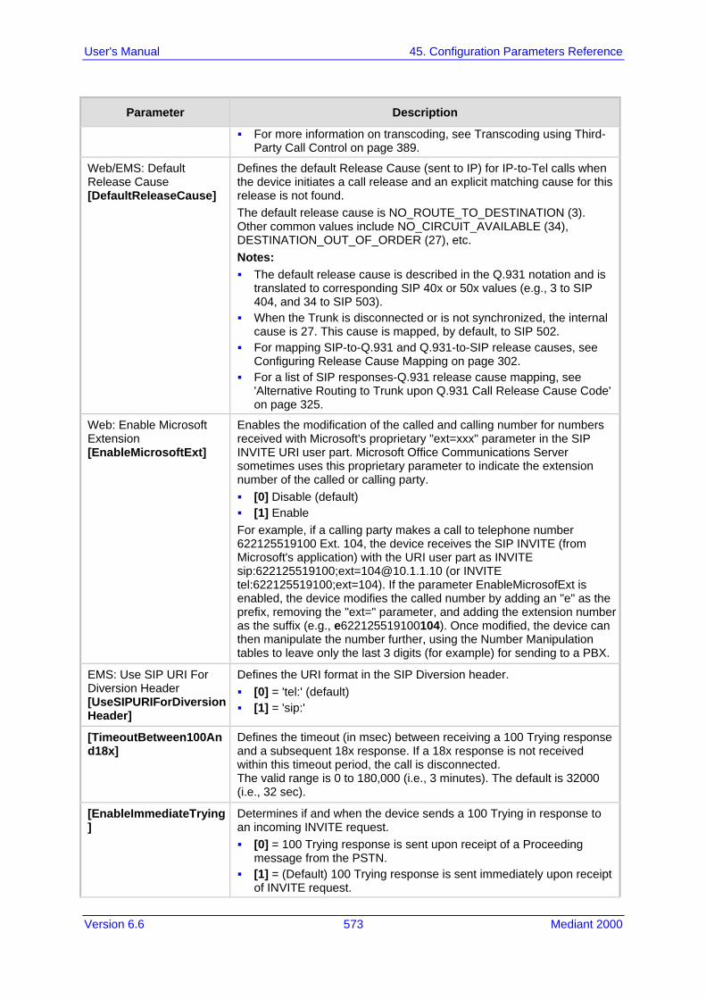
Version 6.6 573 Mediant 2000
User's Manual 45. Configuration Parameters Reference
Parameter Description
For more information on transcoding, see Transcoding using Third-Party Call Control on page 389.
Web/EMS: Default Release Cause [DefaultReleaseCause]
Defines the default Release Cause (sent to IP) for IP-to-Tel calls when the device initiates a call release and an explicit matching cause for this release is not found. The default release cause is NO_ROUTE_TO_DESTINATION (3). Other common values include NO_CIRCUIT_AVAILABLE (34), DESTINATION_OUT_OF_ORDER (27), etc. Notes: The default release cause is described in the Q.931 notation and is
translated to corresponding SIP 40x or 50x values (e.g., 3 to SIP 404, and 34 to SIP 503).
When the Trunk is disconnected or is not synchronized, the internal cause is 27. This cause is mapped, by default, to SIP 502.
For mapping SIP-to-Q.931 and Q.931-to-SIP release causes, see Configuring Release Cause Mapping on page 302.
For a list of SIP responses-Q.931 release cause mapping, see 'Alternative Routing to Trunk upon Q.931 Call Release Cause Code' on page 325.
Web: Enable Microsoft Extension [EnableMicrosoftExt]
Enables the modification of the called and calling number for numbers received with Microsoft's proprietary "ext=xxx" parameter in the SIP INVITE URI user part. Microsoft Office Communications Server sometimes uses this proprietary parameter to indicate the extension number of the called or calling party. [0] Disable (default) [1] Enable For example, if a calling party makes a call to telephone number 622125519100 Ext. 104, the device receives the SIP INVITE (from Microsoft's application) with the URI user part as INVITE sip:622125519100;[email protected] (or INVITE tel:622125519100;ext=104). If the parameter EnableMicrosofExt is enabled, the device modifies the called number by adding an "e" as the prefix, removing the "ext=" parameter, and adding the extension number as the suffix (e.g., e622125519100104). Once modified, the device can then manipulate the number further, using the Number Manipulation tables to leave only the last 3 digits (for example) for sending to a PBX.
EMS: Use SIP URI For Diversion Header [UseSIPURIForDiversionHeader]
Defines the URI format in the SIP Diversion header. [0] = 'tel:' (default) [1] = 'sip:'
[TimeoutBetween100And18x]
Defines the timeout (in msec) between receiving a 100 Trying response and a subsequent 18x response. If a 18x response is not received within this timeout period, the call is disconnected. The valid range is 0 to 180,000 (i.e., 3 minutes). The default is 32000 (i.e., 32 sec).
[EnableImmediateTrying]
Determines if and when the device sends a 100 Trying in response to an incoming INVITE request. [0] = 100 Trying response is sent upon receipt of a Proceeding
message from the PSTN. [1] = (Default) 100 Trying response is sent immediately upon receipt
of INVITE request.

User's Manual 574 Document #: LTRT-68822
Mediant 2000
Parameter Description
[TransparentCoderPresentation]
Determines the format of the Transparent coder representation in the SDP. [0] = clearmode (default) [1] = X-CCD
[IgnoreRemoteSDPMKI] Determines whether the device ignores the Master Key Identifier (MKI) if present in the SDP received from the remote side. [0] Disable (default) [1] Enable
[TrunkStatusReportingMode]
Determines whether the device responds to SIP OPTIONS if all the trunks pertaining to Trunk Group #1 are down or busy. [0] Disable (default) [1] Enable = If all the trunks pertaining to Trunk Group #1 are down
or busy, the device does not respond to received SIP OPTIONS.
Web: Comfort Noise Generation Negotiation EMS: Comfort Noise Generation [ComfortNoiseNegotiation]
Enables negotiation and usage of Comfort Noise (CN). [0] Disable [1] Enable (default) The use of CN is indicated by including a payload type for CN on the media description line of the SDP. The device can use CN with a codec whose RTP time stamp clock rate is 8,000 Hz (G.711/G.726). The static payload type 13 is used. The use of CN is negotiated between sides. Therefore, if the remote side doesn't support CN, it is not used. Regardless of the device's settings, it always attempts to adapt to the remote SIP UA's request for CNG, as described below. To determine CNG support, the device uses the ComfortNoiseNegotiation parameter and the codec’s SCE (silence suppression setting) using the CodersGroup parameter. If the ComfortNoiseNegotiation parameter is enabled, then the following occurs: If the device is the initiator, it sends a “CN” in the SDP only if the
SCE of the codec is enabled. If the remote UA responds with a “CN” in the SDP, then CNG occurs; otherwise, CNG does not occur.
If the device is the receiver and the remote SIP UA does not send a “CN” in the SDP, then no CNG occurs. If the remote side sends a “CN”, the device attempts to be compatible with the remote side and even if the codec’s SCE is disabled, CNG occurs.
If the ComfortNoiseNegotiation parameter is disabled, then the device does not send “CN” in the SDP. However, if the codec’s SCE is enabled, then CNG occurs.
[SDPEcanFormat]
Defines the echo canceller format in the outgoing SDP. The 'ecan' attribute is used in the SDP to indicate the use of echo cancellation. [0] = (Default) The 'ecan' attribute appears on the 'a=gpmd' line. [1] = The 'ecan' attribute appears as a separate attribute. [2] = The 'ecan' attribute is not included in the SDP. [3] = The 'ecan' attribute and the 'vbd' parameter are not included in
the SDP. Note: This parameter is applicable only when the IsFaxUsed parameter is set to 2, and for re-INVITE messages generated by the device as result of modem or fax tone detection.

Version 6.6 575 Mediant 2000
User's Manual 45. Configuration Parameters Reference
Parameter Description
Web/EMS: First Call Ringback Tone ID [FirstCallRBTId]
Defines the index of the first ringback tone in the CPT file. This option enables an Application server to request the device to play a distinctive ringback tone to the calling party according to the destination of the call. The tone is played according to the Alert-Info header received in the 180 Ringing SIP response (the value of the Alert-Info header is added to the value of this parameter). The valid range is -1 to 1,000. The default is -1 (i.e., play standard ringback tone). Notes: It is assumed that all ringback tones are defined in sequence in the
CPT file. In case of an MLPP call, the device uses the value of this parameter
plus 1 as the index of the ringback tone in the CPT file (e.g., if this value is set to 1, then the index is 2, i.e., 1 + 1).
Web: Reanswer Time EMS: Regret Time [RegretTime]
Defines the time period the device waits for an MFC R2 Resume (Reanswer) signal once a Suspend (Clear back) signal is received from the PBX. If this timer expires, the call is released. Note that this is applicable only to the MFC-R2 CAS Brazil variant. The valid range is 0 to 255 (in seconds). The default is 0.
Web: PSTN Alert Timeout EMS: Trunk PSTN Alert Timeout [PSTNAlertTimeout]
Defines the Alert Timeout (in seconds) for calls sent to the PSTN. This timer is used between the time a Setup message is sent to the Tel side (IP-to-Tel call establishment) and a Connect message is received. If an Alerting message is received, the timer is restarted. If the timer expires before the call is answered, the device disconnects the call and sends a SIP 408 request timeout response to the SIP party that initiated the call. The valid value range is 1 to 600 (in seconds). The default is 180. Note: If per trunk configuration (using TrunkPSTNAlertTimeout) is set to other than default, the PSTNAlertTimeout parameter value is overridden.
Web/EMS: RTP Only Mode [RTPOnlyMode]
Enables the device to send and receive RTP packets to and from remote endpoints without the need to establish a SIP session. The remote IP address is determined according to the Outbound IP Routing table (Prefix parameter). The port is the same port as the local RTP port (configured by the BaseUDPPort parameter and the channel on which the call is received). [0] Disable (default) [1] Transmit & Receive = Send and receive RTP packets. [2] Transmit Only= Send RTP packets only. [3] Receive Only= Receive RTP packets only. Notes: To activate the RTP Only feature without using ISDN / CAS
signaling, you must do the following: Configure E1/T1 Transparent protocol type (set the ProtocoType
parameter to 5 or 6). Enable the TDM-over-IP feature (set the EnableTDMoverIP
parameter to 1). To configure the RTP Only mode per trunk, use the
RTPOnlyModeForTrunk_x parameter. If per trunk configuration (using the RTPOnlyModeForTrunk_x
parameter) is set to a value other than the default, the RTPOnlyMode parameter value is ignored.
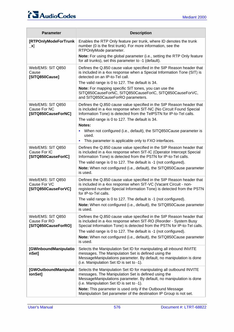
User's Manual 576 Document #: LTRT-68822
Mediant 2000
Parameter Description
[RTPOnlyModeForTrunk_x]
Enables the RTP Only feature per trunk, where ID denotes the trunk number (0 is the first trunk). For more information, see the RTPOnlyMode parameter. Note: For using the global parameter (i.e., setting the RTP Only feature for all trunks), set this parameter to -1 (default).
Web/EMS: SIT Q850 Cause [SITQ850Cause]
Defines the Q.850 cause value specified in the SIP Reason header that is included in a 4xx response when a Special Information Tone (SIT) is detected on an IP-to-Tel call. The valid range is 0 to 127. The default is 34. Note: For mapping specific SIT tones, you can use the SITQ850CauseForNC, SITQ850CauseForIC, SITQ850CauseForVC, and SITQ850CauseForRO parameters.
Web/EMS: SIT Q850 Cause For NC [SITQ850CauseForNC]
Defines the Q.850 cause value specified in the SIP Reason header that is included in a 4xx response when SIT-NC (No Circuit Found Special Information Tone) is detected from the TelPSTN for IP-to-Tel calls. The valid range is 0 to 127. The default is 34. Notes: When not configured (i.e., default), the SITQ850Cause parameter is
used. This parameter is applicable only to FXO interfaces.
Web/EMS: SIT Q850 Cause For IC [SITQ850CauseForIC]
Defines the Q.850 cause value specified in the SIP Reason header that is included in a 4xx response when SIT-IC (Operator Intercept Special Information Tone) is detected from the PSTN for IP-to-Tel calls. The valid range is 0 to 127. The default is -1 (not configured). Note: When not configured (i.e., default), the SITQ850Cause parameter is used.
Web/EMS: SIT Q850 Cause For VC [SITQ850CauseForVC]
Defines the Q.850 cause value specified in the SIP Reason header that is included in a 4xx response when SIT-VC (Vacant Circuit - non-registered number Special Information Tone) is detected from the PSTN for IP-to-Tel calls. The valid range is 0 to 127. The default is -1 (not configured). Note: When not configured (i.e., default), the SITQ850Cause parameter is used.
Web/EMS: SIT Q850 Cause For RO [SITQ850CauseForRO]
Defines the Q.850 cause value specified in the SIP Reason header that is included in a 4xx response when SIT-RO (Reorder - System Busy Special Information Tone) is detected from the PSTN for IP-to-Tel calls. The valid range is 0 to 127. The default is -1 (not configured). Note: When not configured (i.e., default), the SITQ850Cause parameter is used.
[GWInboundManipulationSet]
Selects the Manipulation Set ID for manipulating all inbound INVITE messages. The Manipulation Set is defined using the MessageManipulations parameter. By default, no manipulation is done (i.e. Manipulation Set ID is set to -1).
[GWOutboundManipulationSet]
Selects the Manipulation Set ID for manipulating all outbound INVITE messages. The Manipulation Set is defined using the MessageManipulations parameter. By default, no manipulation is done (i.e. Manipulation Set ID is set to -1). Note: This parameter is used only if the Outbound Message Manipulation Set parameter of the destination IP Group is not set.
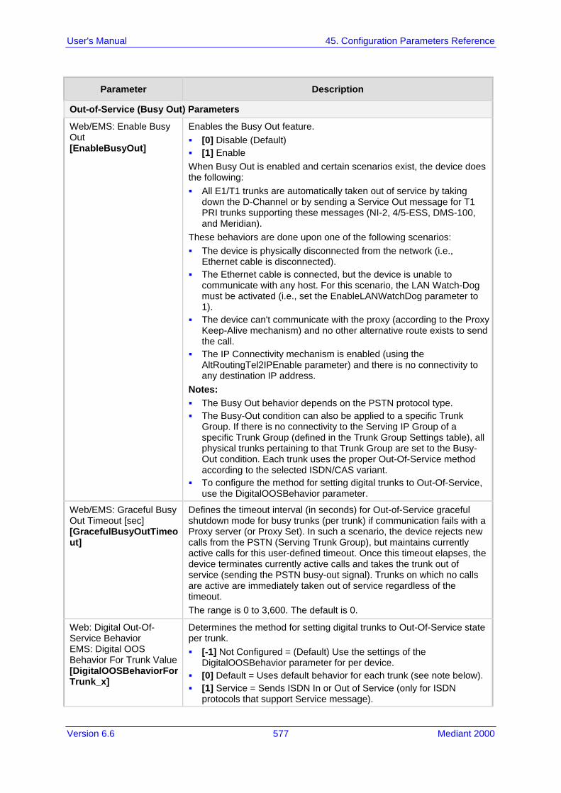
Version 6.6 577 Mediant 2000
User's Manual 45. Configuration Parameters Reference
Parameter Description
Out-of-Service (Busy Out) Parameters
Web/EMS: Enable Busy Out [EnableBusyOut]
Enables the Busy Out feature. [0] Disable (Default) [1] Enable When Busy Out is enabled and certain scenarios exist, the device does the following: All E1/T1 trunks are automatically taken out of service by taking
down the D-Channel or by sending a Service Out message for T1 PRI trunks supporting these messages (NI-2, 4/5-ESS, DMS-100, and Meridian).
These behaviors are done upon one of the following scenarios: The device is physically disconnected from the network (i.e.,
Ethernet cable is disconnected). The Ethernet cable is connected, but the device is unable to
communicate with any host. For this scenario, the LAN Watch-Dog must be activated (i.e., set the EnableLANWatchDog parameter to 1).
The device can't communicate with the proxy (according to the Proxy Keep-Alive mechanism) and no other alternative route exists to send the call.
The IP Connectivity mechanism is enabled (using the AltRoutingTel2IPEnable parameter) and there is no connectivity to any destination IP address.
Notes: The Busy Out behavior depends on the PSTN protocol type. The Busy-Out condition can also be applied to a specific Trunk
Group. If there is no connectivity to the Serving IP Group of a specific Trunk Group (defined in the Trunk Group Settings table), all physical trunks pertaining to that Trunk Group are set to the Busy-Out condition. Each trunk uses the proper Out-Of-Service method according to the selected ISDN/CAS variant.
To configure the method for setting digital trunks to Out-Of-Service, use the DigitalOOSBehavior parameter.
Web/EMS: Graceful Busy Out Timeout [sec] [GracefulBusyOutTimeout]
Defines the timeout interval (in seconds) for Out-of-Service graceful shutdown mode for busy trunks (per trunk) if communication fails with a Proxy server (or Proxy Set). In such a scenario, the device rejects new calls from the PSTN (Serving Trunk Group), but maintains currently active calls for this user-defined timeout. Once this timeout elapses, the device terminates currently active calls and takes the trunk out of service (sending the PSTN busy-out signal). Trunks on which no calls are active are immediately taken out of service regardless of the timeout. The range is 0 to 3,600. The default is 0.
Web: Digital Out-Of-Service Behavior EMS: Digital OOS Behavior For Trunk Value [DigitalOOSBehaviorFor Trunk_x]
Determines the method for setting digital trunks to Out-Of-Service state per trunk. [-1] Not Configured = (Default) Use the settings of the
DigitalOOSBehavior parameter for per device. [0] Default = Uses default behavior for each trunk (see note below). [1] Service = Sends ISDN In or Out of Service (only for ISDN
protocols that support Service message).

User's Manual 578 Document #: LTRT-68822
Mediant 2000
Parameter Description
[2] D-Channel = Takes D-Channel down or up (ISDN only). [3] Alarm = Sends or clears PSTN AIS Alarm (ISDN and CAS). [4] Block = Blocks trunk (CAS only). Notes: This parameter is applicable only if the parameter EnableBusyOut is
set to 1. The default behavior (value 0) is as follows: ISDN: Use Service messages on supporting variants and use
Alarm on non-supporting variants. CAS: Use Alarm.
When updating this parameter value at run-time, you must stop the trunk and then restart it for the update to take effect.
To determine the method for setting Out-Of-Service state for all trunks (i.e., per device), use the DigitalOOSBehavior parameter.
The x in the ini file parameter name denotes the trunk number, where 0 is Trunk 1.
Web: Digital Out-Of-Service Behavior [DigitalOOSBehavior]
Determines the method for setting digital trunks to Out-of-Service state. This configuration applies to all the device's trunks. For a description of this parameter's options, see the DigitalOOSBehaviorForTrunk_x parameter. Notes: To configure the method for setting Out-of-Service state per trunk,
use the DigitalOOSBehaviorForTrunk_x parameter. To configure the timeout interval (in seconds) for Out-of-Service
graceful shutdown mode for busy trunks if communication fails with a Proxy server (or Proxy Set), use the GracefulBusyOutTimeout parameter.
Retransmission Parameters
Web: SIP T1 Retransmission Timer [msec] EMS: T1 RTX [SipT1Rtx]
Defines the time interval (in msec) between the first transmission of a SIP message and the first retransmission of the same message. The default is 500. Note: The time interval between subsequent retransmissions of the same SIP message starts with SipT1Rtx. For INVITE requests, it is multiplied by two for each new retransmitted message. For all other SIP messages, it is multiplied by two until SipT2Rtx. For example, assuming SipT1Rtx = 500 and SipT2Rtx = 4000: The first retransmission is sent after 500 msec. The second retransmission is sent after 1000 (2*500) msec. The third retransmission is sent after 2000 (2*1000) msec. The fourth retransmission and subsequent retransmissions until
SIPMaxRtx are sent after 4000 (2*2000) msec.
Web: SIP T2 Retransmission Timer [msec] EMS: T2 RTX [SipT2Rtx]
Defines the maximum interval (in msec) between retransmissions of SIP messages (except for INVITE requests). The default is 4000. Note: The time interval between subsequent retransmissions of the same SIP message starts with SipT1Rtx and is multiplied by two until SipT2Rtx.
Web: SIP Maximum RTX EMS: Max RTX [SIPMaxRtx]
Defines the maximum number of UDP transmissions of SIP messages (first transmission plus retransmissions). The range is 1 to 30. The default is 7.

Version 6.6 579 Mediant 2000
User's Manual 45. Configuration Parameters Reference
Parameter Description
Web: Number of RTX Before Hot-Swap EMS: Proxy Hot Swap Rtx [HotSwapRtx]
Defines the number of retransmitted INVITE/REGISTER messages before the call is routed (hot swap) to another Proxy/Registrar. The valid range is 1 to 30. The default is 3. Note: This parameter is also used for alternative routing. If a domain name in the Outbound IP Routing Table is resolved into two IP addresses, and if there is no response for HotSwapRtx retransmissions to the INVITE message that is sent to the first IP address, the device immediately initiates a call to the second IP address.
SIP Message Manipulations Table
Web: Message Manipulations EMS: Message Manipulations [MessageManipulations]
This table parameter defines manipulation rules for SIP header messages. The format of this parameter is as follows: [ MessageManipulations] FORMAT MessageManipulations_Index = MessageManipulations_ManSetID, MessageManipulations_MessageType, MessageManipulations_Condition, MessageManipulations_ActionSubject, MessageManipulations_ActionType, MessageManipulations_ActionValue, MessageManipulations_RowRole; [\MessageManipulations] For example, the below configuration changes the user part of the SIP From header to 200: MessageManipulations 1 = 0, Invite.Request, , Header.From.Url.User, 2, 200, 0; Note: For a detailed description of this table, see 'Configuring SIP Message Manipulation' on page 221.
Message Policy Table
Web: Message Policy Table [MessagePolicy]
This table parameter configures SIP message policy rules for blocking (blacklist) unwanted incoming SIP messages or allowing (whitelist) receipt of desired messages. The format of this parameter is as follows: [MessagePolicy] FORMAT MessagePolicy_Index = MessagePolicy_Policy, MessagePolicy_MaxMessageLength, MessagePolicy_MaxHeaderLength, MessagePoliy_MaxBodyLength, MessagePolicy_MaxNumHeaders, MessagePolicy_MaxNumBodies, MessagePolicy_SendRejection, MessagePolicy_MethodListType, MessagePolicy_MethodList, MessagePolicy_BodyListType, MessagePolicy_BodyList; [/MessagePolicy] Note: For a detailed description of this table, see 'Configuring SIP Message Policy Rules'.

User's Manual 580 Document #: LTRT-68822
Mediant 2000
45.9 Coders and Profile Parameters The profile parameters are described in the table below.
Profile Parameters
Parameter Description
Coders Table / Coder Groups Table
Web: Coders Table/Coder Group Settings EMS: Coders Group [CodersGroup0] [CodersGroup1] [CodersGroup2] [CodersGroup3] [CodersGroup4] [CodersGroup5] [CodersGroup6] [CodersGroup7] [CodersGroup8] [CodersGroup9]
This table parameter defines the device's coders. Each group can consist of up to 10 coders. The first Coder Group is the default coder list and the default Coder Group. The format of this parameter is as follows: [ CodersGroup<0-9> ] FORMAT CodersGroup0_Index = CodersGroup0_Name, CodersGroup0_pTime, CodersGroup0_rate, CodersGroup0_PayloadType, CodersGroup0_Sce; [ \CodersGroup<0-9 ] For example, below are defined two Coder Groups (0 and 1): [ CodersGroup0 ] FORMAT CodersGroup0_Index = CodersGroup0_Name, CodersGroup0_pTime, CodersGroup0_rate, CodersGroup0_PayloadType, CodersGroup0_Sce; CodersGroup0 0 = g711Alaw64k, 20, 0, 255, 0; CodersGroup0 1 = eg711Ulaw, 10, 0, 71, 0; CodersGroup0 2 = eg711Ulaw, 10, 0, 71, 0; [ \CodersGroup0 ] [ CodersGroup1 ] FORMAT CodersGroup1_Index = CodersGroup1_Name, CodersGroup1_pTime, CodersGroup1_rate, CodersGroup1_PayloadType, CodersGroup1_Sce; CodersGroup1 0 = Transparent, 20, 0, 56, 0; CodersGroup1 1 = g726, 20, 0, 23, 0; [ \CodersGroup1 ]
Notes: For a list of supported coders and a detailed description of this table,
see Configuring Coders on page 229. The coder name is case-sensitive.
IP Profile Table
Web: IP Profile Settings EMS: Protocol Definition > IP Profile [IPProfile]
This table parameter configures the IP Profile table. Each IP Profile ID includes a set of parameters (which are typically configured separately using their individual "global" parameters). You can later assign these IP Profiles to outbound IP routing rules (Prefix parameter), inbound IP routing rules and IP Groups. The format of this parameter is as follows: [IPProfile] FORMAT IpProfile_Index = IpProfile_ProfileName, IpProfile_IpPreference, IpProfile_CodersGroupID, IpProfile_IsFaxUsed, IpProfile_JitterBufMinDelay, IpProfile_JitterBufOptFactor, IpProfile_IPDiffServ, IpProfile_SigIPDiffServ, IpProfile_SCE, IpProfile_RTPRedundancyDepth, IpProfile_RemoteBaseUDPPort, IpProfile_CNGmode, IpProfile_VxxTransportType, IpProfile_NSEMode, IpProfile_IsDTMFUsed, IpProfile_PlayRBTone2IP, IpProfile_EnableEarlyMedia, IpProfile_ProgressIndicator2IP, IpProfile_EnableEchoCanceller, IpProfile_CopyDest2RedirectNumber,

Version 6.6 581 Mediant 2000
User's Manual 45. Configuration Parameters Reference
Parameter Description
IpProfile_MediaSecurityBehaviour, IpProfile_CallLimit, IpProfile_DisconnectOnBrokenConnection, IpProfile_FirstTxDtmfOption, IpProfile_SecondTxDtmfOption, IpProfile_RxDTMFOption, IpProfile_EnableHold, IpProfile_InputGain, IpProfile_VoiceVolume, IpProfile_AddIEInSetup, IpProfile_SBCExtensionCodersGroupID, IpProfile_MediaIPVersionPreference, IpProfile_TranscodingMode, IpProfile_SBCAllowedCodersGroupID, IpProfile_SBCAllowedCodersMode, IpProfile_SBCMediaSecurityBehaviour, IpProfile_SBCRFC2833Behavior, IpProfile_SBCAlternativeDTMFMethod, IpProfile_SBCAssertIdentity, IpProfile_AMDSensitivityParameterSuit, IpProfile_AMDSensitivityLevel, IpProfile_AMDMaxGreetingTime, IpProfile_AMDMaxPostSilenceGreetingTime, IpProfile_SBCDiversionMode, IpProfile_SBCHistoryInfoMode, IpProfile_EnableQSIGTunneling, IpProfile_SBCFaxCodersGroupID, IpProfile_SBCFaxBehavior, IpProfile_SBCFaxOfferMode, IpProfile_SBCFaxAnswerMode, IpProfile_SbcPrackMode, IpProfile_SBCSessionExpiresMode, IpProfile_SBCRemoteUpdateSupport, IpProfile_SBCRemoteReinviteSupport, IpProfile_SBCRemoteDelayedOfferSupport, IpProfile_SBCRemoteReferBehavior, IpProfile_SBCRemote3xxBehavior, IpProfile_SBCRemoteMultiple18xSupport, IpProfile_SBCRemoteEarlyMediaResponseType, IpProfile_SBCRemoteEarlyMediaSupport, IpProfile_EnableSymmetricMKI, IpProfile_MKISize, IpProfile_SBCEnforceMKISize, IpProfile_SBCRemoteEarlyMediaRTP, IpProfile_SBCRemoteSupportsRFC3960, IpProfile_SBCRemoteCanPlayRingback, IpProfile_EnableEarly183, IpProfile_EarlyAnswerTimeout, IpProfile_SBC2833DTMFPayloadType, IpProfile_SBCUserRegistrationTime, IpProfile_ResetSRTPStateUponRekey, IpProfile_AmdMode, IpProfile_SBCReliableHeldToneSource, IpProfile_SBCPlayHeldTone, IpProfile_SBCRemoteHoldFormat, IpProfile_DelayTimeForInvite; [\IPProfile] Note: For a description of this table, see 'Configuring IP Profiles' on page 235.
Tel Profile Table
Web: Tel Profile Settings EMS: Protocol Definition > Telephony Profile [TelProfile]
This table parameter configures the Tel Profile table. Each Tel Profile ID includes a set of parameters (which are typically configured separately using their individual, "global" parameters). You can later assign these Tel Profile IDs to other elements such as in the Trunk Group TableEndpoint Phone Number table (TrunkGroup parameter). Therefore, Tel Profiles allow you to apply the same settings of a group of parameters to multiple channels, or apply specific settings to different channels. The format of this parameter is as follows: [TelProfile] FORMAT TelProfile_Index = TelProfile_ProfileName, TelProfile_TelPreference, TelProfile_CodersGroupID, TelProfile_IsFaxUsed, TelProfile_JitterBufMinDelay, TelProfile_JitterBufOptFactor, TelProfile_IPDiffServ, TelProfile_SigIPDiffServ, TelProfile_DtmfVolume, TelProfile_InputGain, TelProfile_VoiceVolume, TelProfile_EnableReversePolarity,
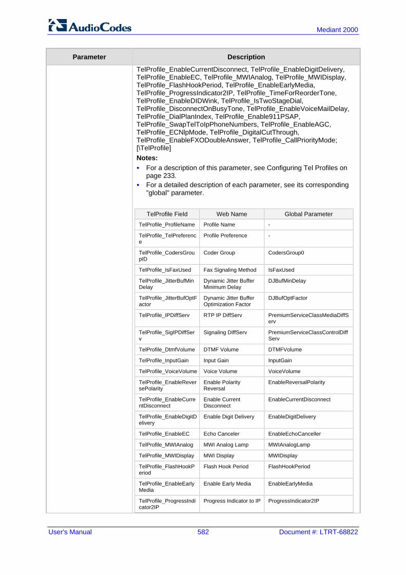
User's Manual 582 Document #: LTRT-68822
Mediant 2000
Parameter Description
TelProfile_EnableCurrentDisconnect, TelProfile_EnableDigitDelivery, TelProfile_EnableEC, TelProfile_MWIAnalog, TelProfile_MWIDisplay, TelProfile_FlashHookPeriod, TelProfile_EnableEarlyMedia, TelProfile_ProgressIndicator2IP, TelProfile_TimeForReorderTone, TelProfile_EnableDIDWink, TelProfile_IsTwoStageDial, TelProfile_DisconnectOnBusyTone, TelProfile_EnableVoiceMailDelay, TelProfile_DialPlanIndex, TelProfile_Enable911PSAP, TelProfile_SwapTelToIpPhoneNumbers, TelProfile_EnableAGC, TelProfile_ECNlpMode, TelProfile_DigitalCutThrough, TelProfile_EnableFXODoubleAnswer, TelProfile_CallPriorityMode; [\TelProfile] Notes: For a description of this parameter, see Configuring Tel Profiles on
page 233. For a detailed description of each parameter, see its corresponding
"global" parameter.
TelProfile Field Web Name Global Parameter
TelProfile_ProfileName Profile Name -
TelProfile_TelPreference
Profile Preference -
TelProfile_CodersGroupID
Coder Group CodersGroup0
TelProfile_IsFaxUsed Fax Signaling Method IsFaxUsed
TelProfile_JitterBufMinDelay
Dynamic Jitter Buffer Minimum Delay
DJBufMinDelay
TelProfile_JitterBufOptFactor
Dynamic Jitter Buffer Optimization Factor
DJBufOptFactor
TelProfile_IPDiffServ RTP IP DiffServ PremiumServiceClassMediaDiffServ
TelProfile_SigIPDiffServ
Signaling DiffServ PremiumServiceClassControlDiffServ
TelProfile_DtmfVolume DTMF Volume DTMFVolume
TelProfile_InputGain Input Gain InputGain
TelProfile_VoiceVolume Voice Volume VoiceVolume
TelProfile_EnableReversePolarity
Enable Polarity Reversal
EnableReversalPolarity
TelProfile_EnableCurrentDisconnect
Enable Current Disconnect
EnableCurrentDisconnect
TelProfile_EnableDigitDelivery
Enable Digit Delivery EnableDigitDelivery
TelProfile_EnableEC Echo Canceler EnableEchoCanceller
TelProfile_MWIAnalog MWI Analog Lamp MWIAnalogLamp
TelProfile_MWIDisplay MWI Display MWIDisplay
TelProfile_FlashHookPeriod
Flash Hook Period FlashHookPeriod
TelProfile_EnableEarlyMedia
Enable Early Media EnableEarlyMedia
TelProfile_ProgressIndicator2IP
Progress Indicator to IP ProgressIndicator2IP

Version 6.6 583 Mediant 2000
User's Manual 45. Configuration Parameters Reference
Parameter Description
TelProfile_TimeForReorderTone
Time For Reorder Tone TimeForReorderTone
TelProfile_EnableDIDWink
Enable DID Wink EnableDIDWink
TelProfile_IsTwoStageDial
Dialing Mode IsTwoStageDial
TelProfile_DisconnectOnBusyTone
Disconnect Call on Detection of Busy Tone
DisconnectOnBusyTone
TelProfile_EnableVoiceMailDelay
Enable Voice Mail Delay
-
TelProfile_DialPlanIndex
Dial Plan Index DialPlanIndex
TelProfile_Enable911PSAP
Enable 911 PSAP Enable911PSAP
TelProfile_SwapTelToIpPhoneNumbers
Swap Tel To IP Phone Numbers
SwapTEl2IPCalled&CallingNumbers
TelProfile_EnableAGC Enable AGC EnableAGC
TelProfile_ECNlpMode EC NLP Mode ECNLPMode
TelProfile_DigitalCutThrough
- DigitalCutThrough
TelProfile_EnableFXODoubleAnswer
- EnableFXODoubleAnswer
TelProfile_CallPriorityMode
- CallPriorityMode
45.10 Channel Parameters This subsection describes the device's channel parameters.
45.10.1 Voice Parameters The voice parameters are described in the table below.
Voice Parameters
Parameter Description
Web/EMS: Input Gain [InputGain]
Defines the pulse-code modulation (PCM) input gain control (in decibels). This parameter sets the level for the received (PSTN-to-IP) signal. The valid range is -32 to 31 dB. The default is 0 dB. Note: This parameter can also be configured in an IP Profile and/or a Tel Profile.
Web: Voice Volume EMS: Volume (dB) [VoiceVolume]
Defines the voice gain control (in decibels). This parameter sets the level for the transmitted (IP-to-PSTN) signal. The valid range is -32 to 31 dB. The default is 0 dB. Note: This parameter can also be configured in an IP Profile and/or a Tel Profile.

User's Manual 584 Document #: LTRT-68822
Mediant 2000
Parameter Description
EMS: Payload Format [VoicePayloadFormat]
Determines the bit ordering of the G.726/G.727 voice payload format. [0] = (Default) Little Endian [1] = Big Endian Note: To ensure high voice quality when using G.726/G.727, both communicating ends should use the same endianness format. Therefore, when the device communicates with a third-party entity that uses the G.726/G.727 voice coder and voice quality is poor, change the settings of this parameter (between Big Endian and Little Endian).
Web: MF Transport Type [MFTransportType]
Currently, not supported.
Web: Enable Answer Detector [EnableAnswerDetector]
Currently, not supported.
Web: Answer Detector Activity Delay [AnswerDetectorActivityDelay]
Defines the time (in 100-msec resolution) between activating the Answer Detector and the time that the detector actually starts to operate. The valid range is 0 to 1023. The default is 0.
Web: Answer Detector Silence Time [AnswerDetectorSilenceTime]
Currently, not supported.
Web: Answer Detector Redirection [AnswerDetectorRedirection]
Currently, not supported.
Web: Answer Detector Sensitivity EMS: Sensitivity [AnswerDetectorSensitivity]
Defines the Answer Detector sensitivity. The range is 0 (most sensitive) to 2 (least sensitive). The default is 0.
Web: Silence Suppression EMS: Silence Compression Mode [EnableSilenceCompression]
Determines the Silence Suppression support. Silence Suppression is a method for conserving bandwidth on VoIP calls by not sending packets when silence is detected. [0] Disable = (Default) Silence Suppression is disabled. [1] Enable = Silence Suppression is enabled. [2] Enable without Adaptation = A single silence packet is sent
during a silence period (applicable only to G.729). Note: If the selected coder is G.729, the value of the 'annexb' parameter of the fmtp attribute in the SDP is determined by the following rules: If EnableSilenceCompression is 0: 'annexb=no'. If EnableSilenceCompression is 1: 'annexb=yes'. If EnableSilenceCompression is 2 and IsCiscoSCEMode is 0:
'annexb=yes'. If EnableSilenceCompression is 2 and IsCiscoSCEMode is 1:
'annexb=no'. Note: This parameter can also be configured in an IP Profile.
Web: Echo Canceler EMS: Echo Canceller Enable [EnableEchoCanceller]
Enables echo cancellation (i.e., echo from voice calls is removed). [0] Disable [1] Enable (default) Note: This parameter can also be configured in an IP Profile

Version 6.6 585 Mediant 2000
User's Manual 45. Configuration Parameters Reference
Parameter Description
and/or a Tel Profile.
Web: Max Echo Canceller Length [MaxEchoCancellerLength]
Defines the maximum Echo Canceler Length (in msec), which is the maximum echo path delay (tail length) for which the echo canceller is designed to operate: [0] Default = (Default) Based on various internal device
settings to attain maximum channel capacity [11] 64 msec [22] 128 msec Notes: For this parameter to take effect, a device reset is required. Using 128 msec may reduce channel capacity. For example:
with DSP Template 0 and number of spans 4, the capacity is reduced from 120 to 100. The reduction depends on the combination of “DSP Template” and “Number of Spans”. For accurate figures, see DSP Templates on page 695.
It is unnecessary to configure the parameter EchoCancellerLength, as it automatically acquires its value from this parameter.
EMS: Echo Canceller Hybrid Loss [ECHybridLoss]
Defines the four-wire to two-wire worst-case Hybrid loss, the ratio between the signal level sent to the hybrid and the echo level returning from the hybrid. [0] = (Default) 6 dB [1] = N/A [2] = 0 dB [3] = 3 dB
EMS: ECN lp Mode [ECNLPMode]
Defines the echo cancellation Non-Linear Processing (NLP) mode. [0] = (Default) NLP adapts according to echo changes [1] = Disables NLP [2] = Silence output NLP Note: This parameter can also be configured in a Tel Profile.
[EchoCancellerAggressiveNLP]
Enables the Aggressive NLP at the first 0.5 second of the call. [0] = Disable [1] = (Default) Enable. The echo is removed only in the first
half of a second of the incoming IP signal. Note: For this parameter to take effect, a device reset is required.
[RTPSIDCoeffNum]
Defines the number of spectral coefficients added to an SID packet being sent according to RFC 3389. The valid values are [0] (default), [4], [6], [8] and [10].

User's Manual 586 Document #: LTRT-68822
Mediant 2000
45.10.2 Coder Parameters The coder parameters are described in the table below.
Coder Parameters
Parameter Description
[EnableEVRCVAD] Enables the EVRC voice activity detector. [0] = Disable (default) [1] = Enable Note: Supported for EVRC and EVRC-B coders.
EMS: VBR Coder DTX Min [EVRCDTXMin]
Defines the minimum gap between two SID frames when using the EVRC voice activity detector. Units are in EVRC frame size (20 msec). The range is 0 to 20000. The default is 12. Note: Supported for EVRC and EVRC-B coders.
EMS: VBR Coder DTX Max [EVRCDTXMax]
Defines the maximum gap between two SID frames when using the EVRC voice activity detector. Units are in EVRC frame size (20 msec). The range is 0 to 20000. The default is 32. Note: This parameter is applicable only to EVRC and EVRC-B coders.
EMS: VBR Coder Header Format [VBRCoderHeaderFormat]
Determines the format of the RTP header for VBR coders. [0] = (Default) Payload only (no header, TOC, or m-factor) -
similar to RFC 3558 Header Free format. [1] = Supports RFC 2658 - 1 byte for interleaving header
(always 0), TOC, no m-factor. [2] = Payload including TOC only, allow m-factor. [3] = RFC 3558 Interleave/Bundled format.
EMS: VBR Coder Hangover [VBRCoderHangover]
Defines the required number of silence frames at the beginning of each silence period when using the VBR coder silence suppression. The range is 0 to 255. The default is 1.
EMS: AMR Coder Header Format [AMRCoderHeaderFormat]
Determines the payload format of the AMR header. [0] = Non-standard multiple frames packing in a single RTP
frame. Each frame has a CMR and TOC header. [1] = AMR frame according to RFC 3267 bundling. [2] = AMR frame according to RFC 3267 interleaving. [3] = AMR is passed using the AMR IF2 format. Note: Bandwidth Efficient mode is not supported; the mode is always Octet-aligned.
DSP Templates Table
Web: DSP Template Mix Table EMS: VoP Media Provisioning > General Settings [DSPTemplates]
This table parameter allows the device to use a combination of two DSP templates and determines the percentage of DSP resources allocated per DSP template. The format of this parameter is as follows: [DspTemplates] FORMAT DspTemplates_Index = DspTemplates_DspTemplateNumber,

Version 6.6 587 Mediant 2000
User's Manual 45. Configuration Parameters Reference
Parameter Description
DspTemplates_DspResourcesPercentage; [\DspTemplates] For example, to load DSP Template 1 to 50% of the DSPs, and DSP Template 2 to the remaining 50%, the table is configured as follows: DspTemplates 0 = 1, 50; DspTemplates 1 = 2, 50; Notes: The DSPVersionTemplateNumber parameter is ignored when
the DSPTemplates parameter is configured. For a list of supported DSP templates, see DSP Templates on
page 695.
Web: DSP Version Template Number EMS: Version Template Number [DSPVersionTemplateNumber]
Determines the DSP template used by the device. Each DSP template supports specific coders, channel capacity, and features. The default is DSP Template 0. You can load different DSP templates to digital modules using the syntax DSPVersionTemplateNumber=xy where: y = 0 to 5 for DSP templates of digital modules Notes: For this parameter to take effect, a device reset is required. For a list of supported DSP templates, see DSP Templates on
page 695.
45.10.3 DTMF Parameters The dual-tone multi-frequency (DTMF) parameters are described in the table below.
DTMF Parameters
Parameter Description
Web/EMS: DTMF Transport Type [DTMFTransportType]
Determines the DTMF transport type. [0] Mute DTMF = DTMF digits are removed from the voice
stream and are not relayed to remote side. [2] Transparent DTMF = DTMF digits remain in the voice
stream. [3] RFC 2833 Relay DTMF = (Default) DTMF digits are
removed from the voice stream and are relayed to remote side according to RFC 2833.
[7] RFC 2833 Relay Decoder Mute = DTMF digits are sent according to RFC 2833 and muted when received.
Note: This parameter is automatically updated if the parameters TxDTMFOption or RxDTMFOption are configured.
Web: DTMF Volume (-31 to 0 dB) EMS: DTMF Volume (dBm) [DTMFVolume]
Defines the DTMF gain control value (in decibels) to the PSTN side. The valid range is -31 to 0 dB. The default is -11 dB. Note: This parameter can also be configured in a Tel Profile.
Web: DTMF Generation Twist Defines the range (in decibels) between the high and low
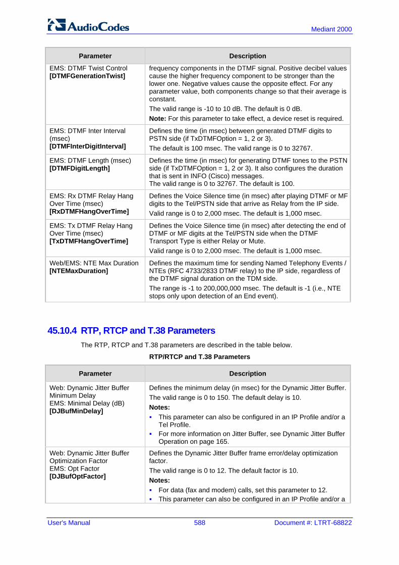
User's Manual 588 Document #: LTRT-68822
Mediant 2000
Parameter Description
EMS: DTMF Twist Control [DTMFGenerationTwist]
frequency components in the DTMF signal. Positive decibel values cause the higher frequency component to be stronger than the lower one. Negative values cause the opposite effect. For any parameter value, both components change so that their average is constant. The valid range is -10 to 10 dB. The default is 0 dB. Note: For this parameter to take effect, a device reset is required.
EMS: DTMF Inter Interval (msec) [DTMFInterDigitInterval]
Defines the time (in msec) between generated DTMF digits to PSTN side (if TxDTMFOption = 1, 2 or 3). The default is 100 msec. The valid range is 0 to 32767.
EMS: DTMF Length (msec) [DTMFDigitLength]
Defines the time (in msec) for generating DTMF tones to the PSTN side (if TxDTMFOption = 1, 2 or 3). It also configures the duration that is sent in INFO (Cisco) messages. The valid range is 0 to 32767. The default is 100.
EMS: Rx DTMF Relay Hang Over Time (msec) [RxDTMFHangOverTime]
Defines the Voice Silence time (in msec) after playing DTMF or MF digits to the Tel/PSTN side that arrive as Relay from the IP side. Valid range is 0 to 2,000 msec. The default is 1,000 msec.
EMS: Tx DTMF Relay Hang Over Time (msec) [TxDTMFHangOverTime]
Defines the Voice Silence time (in msec) after detecting the end of DTMF or MF digits at the Tel/PSTN side when the DTMF Transport Type is either Relay or Mute. Valid range is 0 to 2,000 msec. The default is 1,000 msec.
Web/EMS: NTE Max Duration [NTEMaxDuration]
Defines the maximum time for sending Named Telephony Events / NTEs (RFC 4733/2833 DTMF relay) to the IP side, regardless of the DTMF signal duration on the TDM side. The range is -1 to 200,000,000 msec. The default is -1 (i.e., NTE stops only upon detection of an End event).
45.10.4 RTP, RTCP and T.38 Parameters The RTP, RTCP and T.38 parameters are described in the table below.
RTP/RTCP and T.38 Parameters
Parameter Description
Web: Dynamic Jitter Buffer Minimum Delay EMS: Minimal Delay (dB) [DJBufMinDelay]
Defines the minimum delay (in msec) for the Dynamic Jitter Buffer. The valid range is 0 to 150. The default delay is 10. Notes: This parameter can also be configured in an IP Profile and/or a
Tel Profile. For more information on Jitter Buffer, see Dynamic Jitter Buffer
Operation on page 165.
Web: Dynamic Jitter Buffer Optimization Factor EMS: Opt Factor [DJBufOptFactor]
Defines the Dynamic Jitter Buffer frame error/delay optimization factor. The valid range is 0 to 12. The default factor is 10. Notes: For data (fax and modem) calls, set this parameter to 12. This parameter can also be configured in an IP Profile and/or a

Version 6.6 589 Mediant 2000
User's Manual 45. Configuration Parameters Reference
Parameter Description
Tel Profile. For more information on Jitter Buffer, see Dynamic Jitter Buffer
Operation on page 165.
Web: RTP Redundancy Depth EMS: Redundancy Depth [RTPRedundancyDepth]
Enables the device to generate RFC 2198 redundant packets. This can be used for packet loss where the missing information (audio) can be reconstructed at the receiver's end from the redundant data that arrives in subsequent packets. This is required, for example, in wireless networks where a high percentage (up to 50%) of packet loss can be experienced. [0] 0 = (Default) Disable. [1] 1 = Enable - previous voice payload packet is added to
current packet. Notes: When enabled, you can configure the payload type, using the
RFC2198PayloadType parameter. The RTP redundancy dynamic payload type can be included in
the SDP, by using the EnableRTPRedundancyNegotiation parameter.
This parameter can also be configured in an IP Profile.
Web: Enable RTP Redundancy Negotiation [EnableRTPRedundancyNegotiation]
Enables the device to include the RTP redundancy dynamic payload type in the SDP, according to RFC 2198. [0] Disable (default) [1] Enable When enabled, the device includes in the SDP message the RTP payload type "RED" and the payload type configured by the parameter RFC2198PayloadType. a=rtpmap:<PT> RED/8000
Where <PT> is the payload type as defined by RFC2198PayloadType. The device sends the INVITE message with "a=rtpmap:<PT> RED/8000" and responds with a 18x/200 OK and "a=rtpmap:<PT> RED/8000" in the SDP. Notes: For this feature to be functional, you must also set the
parameter RTPRedundancyDepth to 1 (i.e., enabled). Currently, the negotiation of “RED” payload type is not
supported and therefore, it should be configured to the same PT value for both parties.
Web: RFC 2198 Payload Type EMS: Redundancy Payload Type [RFC2198PayloadType]
Defines the RTP redundancy packet payload type according to RFC 2198. The range is 96 to 127. The default is 104. Note: This parameter is applicable only if the parameter RTPRedundancyDepth is set to 1.
Web: Packing Factor EMS: Packetization Factor [RTPPackingFactor]
N/A. Controlled internally by the device according to the selected coder.
Web/EMS: Basic RTP Packet Interval [BasicRTPPacketInterval]
N/A. Controlled internally by the device according to the selected coder.

User's Manual 590 Document #: LTRT-68822
Mediant 2000
Parameter Description
Web: RTP Directional Control [RTPDirectionControl]
N/A. Controlled internally by the device according to the selected coder.
Web/EMS: RFC 2833 TX Payload Type [RFC2833TxPayloadType]
Defines the Tx RFC 2833 DTMF relay dynamic payload type. The valid range is 96 to 99, and 106 to 127. The default is 96. The 100, 102 to 105 range is allocated for proprietary usage. Notes: Certain vendors (e.g., Cisco) use payload type 101 for RFC
2833. When RFC 2833 payload type negotiation is used (i.e., the
parameter TxDTMFOption is set to 4), this payload type is used for the received DTMF packets. If negotiation isn't used, this payload type is used for receive and for transmit.
Web/EMS: RFC 2833 RX Payload Type [RFC2833RxPayloadType]
Defines the Rx RFC 2833 DTMF relay dynamic payload type. The valid range is 96 to 99, and 106 to 127. The default is 96. The 100, 102 to 105 range is allocated for proprietary usage. Notes: Certain vendors (e.g., Cisco) use payload type 101 for RFC
2833. When RFC 2833 payload type negotiation is used (i.e., the
parameter TxDTMFOption is set to 4), this payload type is used for the received DTMF packets. If negotiation isn't used, this payload type is used for receive and for transmit.
[EnableDetectRemoteMACChange]
Determines whether the device changes the RTP packets according to the MAC address of received RTP packets and according to Gratuitous Address Resolution Protocol (GARP) messages. [0] = Nothing is changed. [1] = If the device receives RTP packets with a different source
MAC address (than the MAC address of the transmitted RTP packets), then it sends RTP packets to this MAC address and removes this IP entry from the device's ARP cache table.
[2] = (Default) The device uses the received GARP packets to change the MAC address of the transmitted RTP packets.
[3] = Options 1 and 2 are used. Notes: For this parameter to take effect, a device reset is required. If the device is located in a network subnet which is connected
to other gateways using a router that uses Virtual Router Redundancy Protocol (VRRP) for redundancy, then set this parameter to 0 or 2.
Web: RTP Base UDP Port EMS: Base UDP Port [BaseUDPport]
Defines the lower boundary of the UDP port used for RTP, RTCP (RTP port + 1) and T.38 (RTP port + 2). For example, if the Base UDP Port is set to 6000, then one channel may use the ports RTP 6000, RTCP 6001, and T.38 6002, while another channel may use RTP 6010, RTCP 6011, and T.38 6012, and so on. The range of possible UDP ports is 6,000 to 64,000. The default base UDP port is 6000. Once this parameter is configured, the UDP port range (lower to upper boundary) is calculated as follows: BaseUDPport to (BaseUDPport + 299*10)

Version 6.6 591 Mediant 2000
User's Manual 45. Configuration Parameters Reference
Parameter Description
Notes: For this parameter to take effect, a device reset is required. The UDP ports are allocated randomly to channels. You can define a UDP port range per Media Realm (see
Configuring Media Realms on page 177). If RTP Base UDP Port is not a factor of 10, the following
message is generated: 'invalid local RTP port'.
Web: Remote RTP Base UDP Port EMS: Remote Base UDP Port [RemoteBaseUDPPort]
Defines the lower boundary of UDP ports used for RTP, RTCP and T.38 by a remote device. If this parameter is set to a non-zero value, ThroughPacket™ (RTP multiplexing) is enabled. The device uses this parameter (and BaseUDPPort) to identify and distribute the payloads from the received multiplexed IP packet to the relevant channels. The valid range is the range of possible UDP ports: 6,000 to 64,000. The default is 0 (i.e., RTP multiplexing is disabled). Notes: The value of this parameter on the local device must equal the
value of BaseUDPPort on the remote device. To enable RTP multiplexing, the parameters
L1L1ComplexTxUDPPort and L1L1ComplexRxUDPPort must be set to a non-zero value.
When VLANs are used, RTP multiplexing is not supported. This parameter can also be configured in an IP Profile. For more information on RTP multiplexing, see RTP
Multiplexing (ThroughPacket) on page 169.
Web: RTP Multiplexing Local UDP Port [L1L1ComplexTxUDPPort]
Defines the local (source) UDP port for outgoing multiplexed RTP packets, for RTP multiplexing. The valid value is the range of possible UDP ports: 6,000 to 64,000. The default is 0 (i.e., RTP multiplexing is disabled). Note: For this parameter to take effect, a device reset is required.
Web: RTP Multiplexing Remote UDP Port [L1L1ComplexRxUDPPort]
Defines the remote UDP port to where the multiplexed RTP packets are sent and the local UDP port for incoming multiplexed RTP packets, for RTP multiplexing. The valid value is the range of possible UDP ports: 6,000 to 64,000. The default is 0 (i.e., RTP multiplexing is disabled). Notes: For this parameter to take effect, a device reset is required. All devices that participate in the same RTP multiplexing
session must use this same port.
EMS: No Op Enable [NoOpEnable]
Enables the transmission of RTP or T.38 No-Op packets. [0] = Disable (default) [1] = Enable This mechanism ensures that the NAT binding remains open during RTP or T.38 silence periods.
EMS: No Op Interval [NoOpInterval]
Defines the time interval in which RTP or T.38 No-Op packets are sent in the case of silence (no RTP/T.38 traffic) when No-Op packet transmission is enabled. The valid range is 20 to 65,000 msec. The default is 10,000. Note: To enable No-Op packet transmission, use the NoOpEnable

User's Manual 592 Document #: LTRT-68822
Mediant 2000
Parameter Description
parameter.
EMS: No Op Payload Type [RTPNoOpPayloadType]
Defines the payload type of No-Op packets. The valid range is 96 to 127 (for the range of Dynamic RTP Payload Type for all types of non hard-coded RTP Payload types, refer to RFC 3551). The default is 120. Note: When defining this parameter, ensure that it doesn't cause collision with other payload types.
[RTCPActivationMode]
Disables RTCP traffic when there is no RTP traffic. This feature is useful, for example, to stop RTCP traffic that is typically sent when calls are put on hold (by an INVITE with 'a=inactive' in the SDP). [0] Active Always = (Default) RTCP is active even during
inactive RTP periods, i.e., when the media is in 'recvonly' or 'inactive' mode.
[1] Inactive Only If RTP Inactive = No RTCP is sent when RTP is inactive.
RTP Control Protocol Extended Reports (RTCP XR) Parameters
Web: Enable RTCP XR EMS: RTCP XR Enable [VQMonEnable]
Enables voice quality monitoring and RTCP XR, according to Internet-Draft draft-ietf-sipping-rtcp-summary-13. [0] Disable (default) [1] Enable Note: For this parameter to take effect, a device reset is required.
Web: Minimum Gap Size EMS: GMin [VQMonGMin]
Defines the voice quality monitoring - minimum gap size (number of frames). The default is 16.
Web/EMS: Burst Threshold [VQMonBurstHR]
Defines the voice quality monitoring - excessive burst alert threshold. The default is -1 (i.e., no alerts are issued).
Web/EMS: Delay Threshold [VQMonDelayTHR]
Defines the voice quality monitoring - excessive delay alert threshold. The default is -1 (i.e., no alerts are issued).
Web: R-Value Delay Threshold EMS: End of Call Rval Delay Threshold [VQMonEOCRValTHR]
Defines the voice quality monitoring - end of call low quality alert threshold. The default is -1 (i.e., no alerts are issued).
Web: RTCP XR Packet Interval EMS: Packet Interval [RTCPInterval]
Defines the time interval (in msec) between adjacent RTCP reports. The valid value range is 0 to 65,535. The default is 5,000.
Web: Disable RTCP XR Interval Randomization EMS: Disable Interval Randomization [DisableRTCPRandomize]
Determines whether RTCP report intervals are randomized or whether each report interval accords exactly to the parameter RTCPInterval. [0] Disable = (Default) Randomize [1] Enable = No Randomize
EMS: RTCP XR Collection Server Transport Type [RTCPXRESCTransportType]
Defines the transport layer used for outgoing SIP dialogs initiated by the device to the RTCP XR Collection Server. [-1] Not Configured (default) [0] UDP [1] TCP

Version 6.6 593 Mediant 2000
User's Manual 45. Configuration Parameters Reference
Parameter Description
[2] TLS Note: When set to [-1], the value of the SIPTransportType parameter is used.
Web: RTCP XR Collection Server EMS: Esc IP [RTCPXREscIP]
Defines the IP address of the Event State Compositor (ESC). The device sends RTCP XR reports to this server, using SIP PUBLISH messages. The address can be configured as a numerical IP address or as a domain name.
Web: RTCP XR Report Mode EMS: Report Mode [RTCPXRReportMode]
Determines whether RTCP XR reports are sent to the Event State Compositor (ESC) and defines the interval at which they are sent. [0] Disable = (Default) RTCP XR reports are not sent to the
ESC. [1] End Call = RTCP XR reports are sent to the ESC at the end
of each call. [2] End Call & Periodic = RTCP XR reports are sent to the ESC
at the end of each call and periodically according to the RTCPInterval parameter.
45.11 Gateway and IP-to-IP Parameters
45.11.1 Fax and Modem Parameters The fax and modem parameters are described in the table below.
Fax and Modem Parameters
Parameter Description
Web: Fax Transport Mode EMS: Transport Mode [FaxTransportMode]
Determines the fax transport mode used by the device. [0] Disable = transparent mode [1] T.38 Relay (default) [2] Bypass [3] Events Only Note: This parameter is overridden by the parameter IsFaxUsed. If the parameter IsFaxUsed is set to 1 (T.38 Relay) or 3 (Fax Fallback), then FaxTransportMode is always set to 1 (T.38 relay).
Web: V.21 Modem Transport Type EMS: V21 Transport [V21ModemTransportType]
Determines the V.21 modem transport type. [0] Disable = (Default) Disable (Transparent) [2] Enable Bypass [3] Events Only = Transparent with Events Note: This parameter can also be configured in an IP Profile.
Web: V.22 Modem Transport Type EMS: V22 Transport [V22ModemTransportType]
Determines the V.22 modem transport type. [0] Disable = Disable (Transparent) [2] Enable Bypass (default) [3] Events Only = Transparent with Events Note: This parameter can also be configured in an IP Profile.
Web: V.23 Modem Transport Type EMS: V23 Transport
Determines the V.23 modem transport type. [0] Disable = Disable (Transparent)

User's Manual 594 Document #: LTRT-68822
Mediant 2000
Parameter Description
[V23ModemTransportType] [2] Enable Bypass (default) [3] Events Only = Transparent with Events Note: This parameter can also be configured in an IP Profile.
Web: V.32 Modem Transport Type EMS: V32 Transport [V32ModemTransportType]
Determines the V.32 modem transport type. [0] Disable = Disable (Transparent) [2] Enable Bypass (default) [3] Events Only = Transparent with Events Notes: This parameter applies only to V.32 and V.32bis modems. This parameter can also be configured in an IP Profile.
Web: V.34 Modem Transport Type EMS: V34 Transport [V34ModemTransportType]
Determines the V.90/V.34 modem transport type. [0] Disable = Disable (Transparent) [2] Enable Bypass (default) [3] Events Only = Transparent with Events Note: This parameter can also be configured in an IP Profile.
EMS: Bell Transport Type [BellModemTransportType]
Determines the Bell modem transport method. [0] = Transparent (default) [2] = Bypass [3] = Transparent with events
Web/EMS: Fax CNG Mode [FaxCNGMode]
Determines the device's handling of fax relay upon detection of a fax CNG tone from originating faxes. [0] Doesn't send T.38 Re-INVITE = (Default) SIP re-INVITE is
not sent. [1] Sends on CNG tone = Sends a SIP re-INVITE with T.38
parameters in SDP to the terminating fax upon detection of a fax CNG tone, if the CNGDetectorMode parameter is set to 1.
Notes: This feature is applicable only if the IsFaxUsed parameter is set
to [1] or [3]. The device also sends T.38 re-INVITE if the CNGDetectorMode
parameter is set to [2], regardless of the FaxCNGMode parameter settings.
Web/EMS: CNG Detector Mode [CNGDetectorMode]
Determines whether the device detects the fax calling tone (CNG). [0] Disable = (Default) The originating device doesn’t detect
CNG; the CNG signal passes transparently to the remote side. [1] Relay = CNG is detected on the originating side. CNG
packets are sent to the remote side according to T.38 (if IsFaxUsed = 1) and the fax session is started. A SIP Re-INVITE message isn’t sent and the fax session starts by the terminating device. This option is useful, for example, when the originating device is located behind a firewall that blocks incoming T.38 packets on ports that have not yet received T.38 packets from the internal network (i.e., originating device). To also send a Re-INVITE message upon detection of a fax CNG tone in this mode, set the parameter FaxCNGMode to 1.
[2] Events Only = CNG is detected on the originating side and a fax session is started by the originating side using the Re-INVITE message. Usually, T.38 fax session starts when the ‘preamble’ signal is detected by the answering side. Some SIP devices don’t support the detection of this fax signal on the

Version 6.6 595 Mediant 2000
User's Manual 45. Configuration Parameters Reference
Parameter Description
answering side and thus, in these cases it is possible to configure the device to start the T.38 fax session when the CNG tone is detected by the originating side. However, this mode is not recommended.
Note: This parameter can also be configured in an IP Profile.
Web: Fax Relay Enhanced Redundancy Depth EMS: Enhanced Relay Redundancy Depth [FaxRelayEnhancedRedundancyDepth]
Defines the number of times that control packets are retransmitted when using the T.38 standard. The valid range is 0 to 4. The default is 0.
Web: Fax Relay Redundancy Depth EMS: Relay Redundancy Depth [FaxRelayRedundancyDepth]
Defines the number of times that each fax relay payload is retransmitted to the network. [0] = (Default) No redundancy [1] = One packet redundancy [2] = Two packet redundancy Note: This parameter is applicable only to non-V.21 packets.
Web: Fax Relay Max Rate (bps) EMS: Relay Max Rate [FaxRelayMaxRate]
Defines the maximum rate (in bps) at which fax relay messages are transmitted (outgoing calls). [0] 2400 = 2.4 kbps [1] 4800 = 4.8 kbps [2] 7200 = 7.2 kbps [3] 9600 = 9.6 kbps [4] 12000 = 12.0 kbps [5] 14400 = 14.4 kbps (default) Note: The rate is negotiated between both sides (i.e., the device adapts to the capabilities of the remote side). Negotiation of the T.38 maximum supported fax data rate is provided in SIP’s SDP T38MaxBitRate parameter. The negotiated T38MaxBitRate is the minimum rate supported between the local and remote endpoints.
Web: Fax Relay ECM Enable EMS: Relay ECM Enable [FaxRelayECMEnable]
Enables Error Correction Mode (ECM) mode during fax relay. [0] Disable [1] Enable (default)
Web: Fax/Modem Bypass Coder Type EMS: Coder Type [FaxModemBypassCoderType]
Determines the coder used by the device when performing fax/modem bypass. Typically, high-bit-rate coders such as G.711 should be used. [0] G.711Alaw= (Default) G.711 A-law 64 [1] G.711Mulaw = G.711 µ-law
Web: Fax/Modem Bypass Packing Factor EMS: Packetization Period [FaxModemBypassM]
Defines the number (20 msec) of coder payloads used to generate a fax/modem bypass packet. The valid range is 1, 2, or 3 coder payloads. The default is 1 coder payload.
[FaxModemNTEMode]
Determines whether the device sends RFC 2833 ANS/ANSam events upon detection of fax and/or modem Answer tones (i.e., CED tone). [0] = Disabled (default) [1] = Enabled
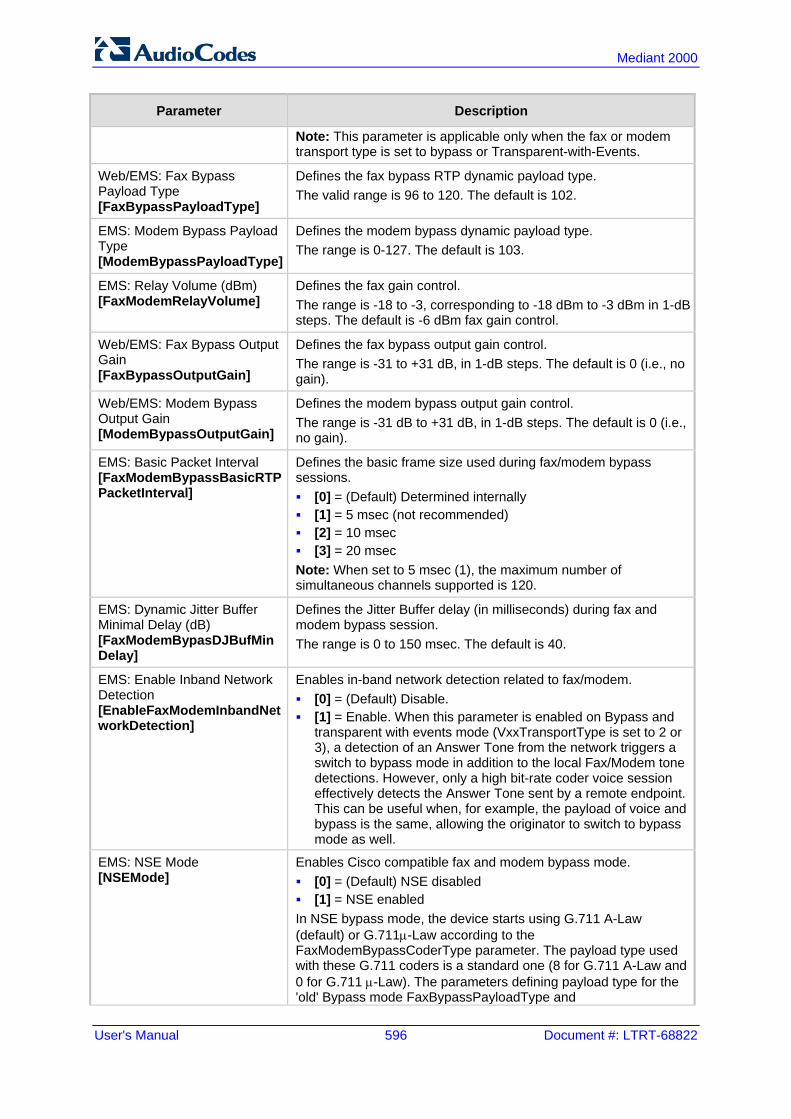
User's Manual 596 Document #: LTRT-68822
Mediant 2000
Parameter Description
Note: This parameter is applicable only when the fax or modem transport type is set to bypass or Transparent-with-Events.
Web/EMS: Fax Bypass Payload Type [FaxBypassPayloadType]
Defines the fax bypass RTP dynamic payload type. The valid range is 96 to 120. The default is 102.
EMS: Modem Bypass Payload Type [ModemBypassPayloadType]
Defines the modem bypass dynamic payload type. The range is 0-127. The default is 103.
EMS: Relay Volume (dBm) [FaxModemRelayVolume]
Defines the fax gain control. The range is -18 to -3, corresponding to -18 dBm to -3 dBm in 1-dB steps. The default is -6 dBm fax gain control.
Web/EMS: Fax Bypass Output Gain [FaxBypassOutputGain]
Defines the fax bypass output gain control. The range is -31 to +31 dB, in 1-dB steps. The default is 0 (i.e., no gain).
Web/EMS: Modem Bypass Output Gain [ModemBypassOutputGain]
Defines the modem bypass output gain control. The range is -31 dB to +31 dB, in 1-dB steps. The default is 0 (i.e., no gain).
EMS: Basic Packet Interval [FaxModemBypassBasicRTPPacketInterval]
Defines the basic frame size used during fax/modem bypass sessions. [0] = (Default) Determined internally [1] = 5 msec (not recommended) [2] = 10 msec [3] = 20 msec Note: When set to 5 msec (1), the maximum number of simultaneous channels supported is 120.
EMS: Dynamic Jitter Buffer Minimal Delay (dB) [FaxModemBypasDJBufMinDelay]
Defines the Jitter Buffer delay (in milliseconds) during fax and modem bypass session. The range is 0 to 150 msec. The default is 40.
EMS: Enable Inband Network Detection [EnableFaxModemInbandNetworkDetection]
Enables in-band network detection related to fax/modem. [0] = (Default) Disable. [1] = Enable. When this parameter is enabled on Bypass and
transparent with events mode (VxxTransportType is set to 2 or 3), a detection of an Answer Tone from the network triggers a switch to bypass mode in addition to the local Fax/Modem tone detections. However, only a high bit-rate coder voice session effectively detects the Answer Tone sent by a remote endpoint. This can be useful when, for example, the payload of voice and bypass is the same, allowing the originator to switch to bypass mode as well.
EMS: NSE Mode [NSEMode]
Enables Cisco compatible fax and modem bypass mode. [0] = (Default) NSE disabled [1] = NSE enabled In NSE bypass mode, the device starts using G.711 A-Law (default) or G.711µ-Law according to the FaxModemBypassCoderType parameter. The payload type used with these G.711 coders is a standard one (8 for G.711 A-Law and 0 for G.711 µ-Law). The parameters defining payload type for the 'old' Bypass mode FaxBypassPayloadType and

Version 6.6 597 Mediant 2000
User's Manual 45. Configuration Parameters Reference
Parameter Description
ModemBypassPayloadType are not used with NSE Bypass. The bypass packet interval is selected according to the FaxModemBypassBasicRtpPacketInterval parameter. Notes: This feature can be used only if the VxxModemTransportType
parameter is set to 2 (Bypass). If NSE mode is enabled, the SDP contains the following line:
'a=rtpmap:100 X-NSE/8000'. To use this feature: The Cisco gateway must include the following definition:
'modem passthrough nse payload-type 100 codec g711alaw'.
Set the Modem transport type to Bypass mode (VxxModemTransportType is set to 2) for all modems.
Configure the gateway parameter NSEPayloadType = 100. This parameter can also be configured in an IP Profile.
EMS: NSE Payload Type [NSEPayloadType]
Defines the NSE payload type for Cisco Bypass compatible mode. The valid range is 96-127. The default is 105. Note: Cisco gateways usually use NSE payload type of 100.
EMS: T38 Use RTP Port [T38UseRTPPort]
Defines the port (with relation to RTP port) for sending and receiving T.38 packets. [0] = (Default) Use the RTP port +2 to send/receive T.38
packets. [1] = Use the same port as the RTP port to send/receive T.38
packets. Notes: For this parameter to take effect, you must reset the device. When the device is configured to use V.152 to negotiate audio
and T.38 coders, the UDP port published in SDP for RTP and for T38 must be different. Therefore, set the T38UseRTPPort parameter to 0.
Web/EMS: T.38 Max Datagram Size [T38MaxDatagramSize]
Defines the maximum size of a T.38 datagram that the device can receive. This value is included in the outgoing SDP when T.38 is used. The valid range is 120 to 600. The default is 238.
Web/EMS: T38 Fax Max Buffer [T38FaxMaxBufferSize]
Defines the maximum size (in bytes) of the device's T.38 buffer. This value is included in the outgoing SDP when T.38 is used for fax relay over IP. The valid range is 500 to 3000. The default is 1024.
Web: Detect Fax on Answer Tone EMS: Enables Detection of FAX on Answer Tone [DetFaxOnAnswerTone]
Determines when the device initiates a T.38 session for fax transmission. [0] Initiate T.38 on Preamble = (Default) The device to which
the called fax is connected initiates a T.38 session on receiving Preamble signal from the fax.
[1] Initiate T.38 on CED = The device to which the called fax is connected initiates a T.38 session on receiving a CED answer tone from the fax. This option can only be used to relay fax signals, as the device sends T.38 Re-INVITE on detection of any fax/modem Answer tone (2100 Hz, amplitude modulated 2100 Hz, or 2100 Hz with phase reversals). The modem signal

User's Manual 598 Document #: LTRT-68822
Mediant 2000
Parameter Description
fails when using T.38 for fax relay. Note: This parameters is applicable only if the parameter IsFaxUsed is set to 1 (T.38 Relay) or 3 (Fax Fallback).
Web: T38 Fax Session Immediate Start [T38FaxSessionImmediateStart]
Enables fax transmission of T.38 "no-signal" packets to the terminating fax machine. [0] Disable (default) [1] Immediate Start on Fax = Device activates T.38 fax relay
upon receipt of a re-INVITE with T.38 only in the SDP. [2] Immediate Start on Fax & Voice = Device activates T.38 fax
relay upon receipt of a re-INVITE with T.38 and audio media in the SDP.
This parameter is used for transmission from fax machines connected to the device and located inside a NAT. Generally, the firewall blocks T.38 (and other) packets received from the WAN, unless the device behind NAT sends at least one IP packet from the LAN to the WAN through the firewall. If the firewall blocks T.38 packets sent from the termination IP fax, the fax fails. To overcome this, the device sends No-Op (“no-signal”) packets to open a pinhole in the NAT for the answering fax machine. The originating fax does not wait for an answer, but immediately starts sending T.38 packets to the terminating fax machine. Note: To enable No-Op packet transmission, use the NoOpEnable and NoOpInterval parameters.
45.11.2 DTMF and Hook-Flash Parameters The DTMF and hook-flash parameters are described in the table below.
DTMF and Hook-Flash Parameters
Parameter Description
Hook-Flash Parameters
Web/EMS: Hook-Flash Code [HookFlashCode]
Defines the digit pattern used by the PBX to indicate a Hook Flash event. When this pattern is detected from the Tel side, the device responds as if a Hook Flash event has occurred and sends a SIP INFO message if the HookFlashOption parameter is set to 1, 5, 6, or 7 (indicating a Hook Flash). If configured and a Hook Flash indication is received from the IP side, the device generates this pattern to the Tel side. The valid range is a 25-character string. The default is a null string. Note: This parameter can also be configured in a Tel Profile.
Web/EMS: Hook-Flash Option [HookFlashOption]
Determines the hook-flash transport type (i.e., method by which hook-flash is sent and received). This feature is applicable only if the HookFlashCode parameter is configured. [0] Not Supported = (Default) Hook-Flash indication is not sent. [1] INFO = Sends proprietary INFO message (Broadsoft) with
Hook-Flash indication. The device sends the INFO message as follows:
Content-Type: application/broadsoft; version=1.0 Content-Length: 17

Version 6.6 599 Mediant 2000
User's Manual 45. Configuration Parameters Reference
Parameter Description
event flashhook [4] RFC 2833 = This option is currently not supported. [5] INFO (Lucent) = Sends proprietary SIP INFO message with
Hook-Flash indication. The device sends the INFO message as follows:
Content-Type: application/hook-flash Content-Length: 11 signal=hf [6] INFO (NetCentrex) = Sends proprietary SIP INFO message
with Hook-Flash indication. The device sends the INFO message as follows:
Content-Type: application/dtmf-relay Signal=16
Where 16 is the DTMF code for hook flash. [7] INFO (HUAWAEI) = Sends a SIP INFO message with Hook-
Flash indication. The device sends the INFO message as follows: Content-Length: 17 Content-Type: application/sscc event=flashhook
Note: The device can interwork DTMF HookFlashCode to SIP INFO messages with Hook Flash indication.
DTMF Parameters
EMS: Use End of DTMF [MGCPDTMFDetectionPoint]
Determines when the detection of DTMF events is notified. [0] = DTMF event is reported at the end of a detected DTMF digit. [1] = (Default) DTMF event is reported at the start of a detected
DTMF digit.
Web: Declare RFC 2833 in SDP EMS: Rx DTMF Option [RxDTMFOption]
Defines the supported receive DTMF negotiation method. [0] No = Don't declare RFC 2833 telephony-event parameter in
SDP. [3] Yes = (Default) Declare RFC 2833 telephony-event parameter
in SDP. The device is always receptive to RFC 2833 DTMF relay packets. Therefore, it is always correct to include the 'telephony-event' parameter as default in the SDP. However, some devices use the absence of the 'telephony-event' in the SDP to decide to send DTMF digits in-band using G.711 coder. If this is the case, you can set this parameter to 0. Note: This parameter can also be configured in an IP Profile.
Tx DTMF Option Table
Web/EMS: Tx DTMF Option [TxDTMFOption]
This table parameter configures up to two preferred transmit DTMF negotiation methods. The format of this parameter is as follows: [TxDTMFOption] FORMAT TxDTMFOption_Index = TxDTMFOption_Type; [\TxDTMFOption] Where Type is: [0] Not Supported = (Default) No negotiation - DTMF digits are
sent according to the parameters DTMFTransportType and RFC2833PayloadType.
[1] INFO (Nortel) = Sends DTMF digits according to IETF Internet-

User's Manual 600 Document #: LTRT-68822
Mediant 2000
Parameter Description
Draft draft-choudhuri-sip-info-digit-00. [2] NOTIFY = Sends DTMF digits according to IETF Internet-Draft
draft-mahy-sipping-signaled-digits-01. [3] INFO (Cisco) = Sends DTMF digits according to Cisco format. [4] RFC 2833. [5] INFO (Korea) = Sends DTMF digits according to Korea
Telecom format. For example: TxDTMFOption 0 = 1; TxDTMFOption 1 = 3; Notes: DTMF negotiation methods are prioritized according to the order of
their appearance. When out-of-band DTMF transfer is used ([1], [2], [3], or [5]), the
parameter DTMFTransportType is automatically set to 0 (DTMF digits are erased from the RTP stream).
When RFC 2833 (4) is selected, the device: a. Negotiates RFC 2833 payload type using local and remote
SDPs. b. Sends DTMF packets using RFC 2833 payload type according
to the payload type in the received SDP. c. Expects to receive RFC 2833 packets with the same payload
type as configured by the parameter RFC2833PayloadType. d. Removes DTMF digits in transparent mode (as part of the
voice stream). When TxDTMFOption is set to 0, the RFC 2833 payload type is set
according to the parameter RFC2833PayloadType for both transmit and receive.
The table ini file parameter TxDTMFOption can be repeated twice for configuring the DTMF transmit methods.
This parameter can also be configured in an IP Profile.
[DisableAutoDTMFMute] Enables the automatic muting of DTMF digits when out-of-band DTMF transmission is used. [0] = (Default) Automatic mute is used. [1] = No automatic mute of in-band DTMF. When this parameter is set to 1, the DTMF transport type is set according to the parameter DTMFTransportType and the DTMF digits aren't muted if out-of-band DTMF mode is selected (TxDTMFOption set to 1, 2 or 3). This enables the sending of DTMF digits in-band (transparent of RFC 2833) in addition to out-of-band DTMF messages. Note: Usually this mode is not recommended.
Web/EMS: Enable Digit Delivery to IP [EnableDigitDelivery2IP]
Enables the Digit Delivery feature whereby DTMF digits are sent to the destination IP address after the Tel-to-IP call is answered. [0] Disable (default). [1] Enable = Enable digit delivery to IP. To enable this feature, modify the called number to include at least one 'p' character. The device uses the digits before the 'p' character in the initial INVITE message. After the call is answered, the device waits for the required time (number of 'p' multiplied by 1.5 seconds), and then sends the rest of the DTMF digits using the method chosen (in-band or out-of-band).

Version 6.6 601 Mediant 2000
User's Manual 45. Configuration Parameters Reference
Parameter Description
Notes: For this parameter to take effect, a device reset is required. The called number can include several 'p' characters (1.5 seconds
pause), for example, 1001pp699, 8888p9p300.
Web: Enable Digit Delivery to Tel EMS: Enable Digit Delivery [EnableDigitDelivery]
Enables the Digit Delivery feature, which sends DTMF digits of the called number to the device's B-channel (phone line) after the call is answered for IP-to-Tel calls. [0] Disable (default). [1] Enable = Enable Digit Delivery feature for the device (two-
stage dialing). If the called number in IP-to-Tel call includes the characters 'w' or 'p', the device places a call with the first part of the called number (before 'w' or 'p') and plays DTMF digits after the call is answered. If the character 'w' is used, the device waits for detection of a dial tone before it starts playing DTMF digits. For example, if the called number is '1007766p100', the device places a call with 1007766 as the destination number, then after the call is answered it waits 1.5 seconds ('p') and plays the rest of the number (100) as DTMF digits. Additional examples: 1664wpp102, 66644ppp503, and 7774w100pp200. Notes: For this parameter to take effect, a device reset is required. This parameter can also be configured in a Tel Profile.
Web: Special Digit Representation EMS: Use Digit For Special DTMF [UseDigitForSpecialDTMF]
Defines the representation for ‘special’ digits (‘*’ and ‘#’) that are used for out-of-band DTMF signaling (using SIP INFO/NOTIFY). [0] Special = (Default) Uses the strings ‘*’ and ‘#’. [1] Numeric = Uses the numerical values 10 and 11.
45.11.3 Digit Collection and Dial Plan Parameters The digit collection and dial plan parameters are described in the table below.
Digit Collection and Dial Plan Parameters
Parameter Description
Web/EMS: Dial Plan Index [DialPlanIndex]
Defines the Dial Plan index to use in the external Dial Plan file. The Dial Plan file is loaded to the device as a .dat file (converted using the DConvert utility). The Dial Plan index can be defined globally or per Tel Profile. The valid value range is 0 to 7, where 0 denotes PLAN1, 1 denotes PLAN2, and so on. The default is -1, indicating that no Dial Plan

User's Manual 602 Document #: LTRT-68822
Mediant 2000
Parameter Description
file is used. Notes: If this parameter is configured to select a Dial Plan index, the
settings of the parameter DigitMapping are ignored. If this parameter is configured to select a Dial Plan index from
an external Dial Plan file, the device first attempts to locate a matching digit pattern in the Dial Plan file, and if not found, then attempts to locate a matching digit pattern in the Digit Map rules configured by the DigitMapping parameter.
This parameter is applicable also to ISDN with overlap dialing. For E1 CAS MFC-R2 variants (which don't support terminating
digit for the called party number, usually I-15), this parameter and the DigitMapping parameter are ignored. Instead, you can define a Dial Plan template per trunk using the parameter CasTrunkDialPlanName_x (or in the Trunk Settings page).
This parameter can also be configured in a Tel Profile. For more information on the Dial Plan file, see 'Dialing Plans for
Digit Collection' on page 405.
[Tel2IPSourceNumberMappingDialPlanIndex]
Defines the Dial Plan index in the external Dial Plan file for the Tel-to-IP Source Number Mapping feature. The valid value range is 0 to 7, defining the Dial Plan index [Plan x] in the Dial Plan file. The default is -1 (disabled). For more information on this feature, see 'Modifying ISDN-to-IP Calling Party Number' on page 409.
Web: Digit Mapping Rules EMS: Digit Map Pat terns [DigitMapping]
Defines the digit map pattern (used to reduce the dialing period when ISDN overlap dialing). If the digit string (i.e., dialed number) matches one of the patterns in the digit map, the device stops collecting digits and establishes a call with the collected number. The digit map pattern can contain up to 52 options (rules), each separated by a vertical bar (|). The maximum length of the entire digit pattern is 152 characters. The available notations include the following: [n-m]: Range of numbers (not letters). . (single dot): Repeat digits until next notation (e.g., T). x: Any single digit. T: Dial timeout (configured by the TimeBetweenDigits
parameter). S: Short timer (configured by the TimeBetweenDigits
parameter; default is two seconds) that can be used when a specific rule is defined after a more general rule. For example, if the digit map is 99|998, then the digit collection is terminated after the first two 9 digits are received. Therefore, the second rule of 998 can never be matched. But when the digit map is 99s|998, then after dialing the first two 9 digits, the device waits another two seconds within which the caller can enter the digit 8.
An example of a digit map is shown below: 11xS|00T|[1-7]xxx|8xxxxxxx|#xxxxxxx|*xx|91xxxxxxxxxx|9011x.T In the example above, the last rule can apply to International numbers: 9 for dialing tone, 011 Country Code, and then any number of digits for the local number ('x.'). Notes: For ISDN interfaces, the digit map mechanism is applicable

Version 6.6 603 Mediant 2000
User's Manual 45. Configuration Parameters Reference
Parameter Description
only when ISDN overlap dialing is used (ISDNRxOverlap is set to 1).
If the DialPlanIndex parameter is configured (to select a Dial Plan index), then the device first attempts to locate a matching digit pattern in the Dial Plan file, and if not found, then attempts to locate a matching digit pattern in the Digit Map rules configured by the DigitMapping parameter.
For more information on digit mapping, see 'Digit Mapping' on page 330.
Web: Max Digits in Phone Num EMS: Max Digits in Phone Number [MaxDigits]
Defines the maximum number of collected destination number digits that can be received from the Tel side when Tel-to-IP ISDN overlap dialing is performed. When the number of collected digits reaches this maximum, the device uses these digits for the called destination number. The valid range is 1 to 49. The default is 30. Note: Instead of using this parameter, Digit Mapping rules can be configured.
Web: Inter Digit Timeout for Overlap Dialing [sec] EMS: Interdigit Timeout (Sec) [TimeBetweenDigits]
Defines the time (in seconds) that the device waits between digits that are received from the PSTN or IP during overlap dialing. When this inter-digit timeout expires, the device uses the collected digits to dial the called destination number. The valid range is 1 to 10. The default is 4.
45.11.4 Voice Mail Parameters The voice mail parameters are described in the table below. For more information on the Voice Mail application, refer to the CPE Configuration Guide for Voice Mail.
Voice Mail Parameters
Parameter Description
Web/EMS: Voice Mail Interface [VoiceMailInterface]
Enables the device's Voice Mail application and determines the communication method used between the PBX and the device. [0] None (default) [1] DTMF [2] SMDI [3] QSIG [4] SETUP Only = Applicable only to ISDN. [5] MATRA/AASTRA QSIG [6] QSIG SIEMENS = QSIG MWI activate and deactivate
messages include Siemens Manufacturer Specific Information (MSI)
[7] IP2IP = The device's IP-to-IP application is used for interworking between an IP Voice Mail server and the device. This is implemented for sending unsolicited SIP NOTIFY messages received from the Voice Mail server to an IP Group (configured using the NotificationIPGroupID parameter).
[8] ETSI = Euro ISDN, according to ETS 300 745-1 V1.2.4, section 9.5.1.1. Enables MWI interworking from IP to Tel, typically used for BRI phones.

User's Manual 604 Document #: LTRT-68822
Mediant 2000
Parameter Description
Note: To disable voice mail per Trunk Group, you can use a Tel Profile with the EnableVoiceMailDelay parameter set to disabled (0). This eliminates the phenomenon of call delay on Trunks not implementing voice mail when voice mail is enabled using this global parameter.
Web: Enable VoiceMail URI EMS: Enable VMURI [EnableVMURI]
Enables the interworking of target and cause for redirection from Tel to IP and vice versa, according to RFC 4468. [0] Disable (default) [1] Enable Upon receipt of an ISDN Setup message with Redirect values, the device maps the Redirect phone number to the SIP 'target' parameter and the Redirect number reason to the SIP 'cause' parameter in the Request-URI. Redirecting Reason >> SIP Response Code Unknown >> 404 User busy >> 486 No reply >> 408 Deflection >> 487/480 Unconditional >> 302 Others >> 302 If the device receives a Request-URI that includes a 'target' and 'cause' parameter, the 'target' is mapped to the Redirect phone number and the 'cause' is mapped to the Redirect number reason.
[WaitForBusyTime] Defines the time (in msec) that the device waits to detect busy and/or reorder tones. This feature is used for semi-supervised PBX call transfers (i.e., the LineTransferMode parameter is set to 2). The valid value range is 0 to 20000 (i.e., 20 sec). The default is 2000 (i.e., 2 sec).
Web/EMS: Line Transfer Mode [LineTransferMode]
Defines the call transfer method used by the device. This parameter is applicable to as well as E1/T1 CAS call transfer if the TrunkTransferMode_x parameter is set to 3 (CAS Normal) or 1 (CAS NFA). [0] None = (Default) IP. [1] Blind = PBX blind transfer: E1/T1 CAS: When a SIP REFER message is received, the
device performs a blind transfer, by performing a CAS wink, waiting a user-defined time (configured by the WaitForDialTime parameter), dialing the Refer-To number, and then releasing the call. The PBX performs the transfer internally.
[2] Semi Supervised = PBX semi-supervised transfer: the user-defined interval set by the WaitForBusyTime
parameter), E1/T1 CAS: The device performs a CAS wink, waits a user-
defined time (configured by the WaitForDialTime parameter), and then dials the Refer-To number. If during the user-defined interval set by the WaitForBusyTime parameter, no busy or reorder tones are detected, the device completes the call

Version 6.6 605 Mediant 2000
User's Manual 45. Configuration Parameters Reference
Parameter Description
transfer by releasing the line. If during this interval, the device detects these tones, the transfer operation is cancelled, the device sends a SIP NOTIFY message with a failure reason (e.g., 486 if a busy tone is detected), and then generates an additional wink toward the CAS line to restore connection with the original call.
[3] Supervised = PBX Supervised transfer: E1/T1 CAS: The device performs a supervised transfer to the
PBX. The device performs a CAS wink, waits a user-defined time (configured by the WaitForDialTime parameter), and then dials the Refer-To number. The device completes the call transfer by releasing the line only after detection of the transferred party answer. To enable answer supervision, you also need to do the following: 1) Enable voice detection (i.e., set the EnableVoiceDetection parameter to 1). 2) Set the EnableDSPIPMDetectors parameter to 1. 3) Install the IPMDetector DSP option Software License Key.
SMDI Parameters
Web/EMS: Enable SMDI [SMDI]
Enables Simplified Message Desk Interface (SMDI) interface on the device. [0] Disable = (Default) Normal serial [1] Enable (Bellcore) [2] Ericsson MD-110 [3] NEC (ICS) Note: For this parameter to take effect, a device reset is required.
Web/EMS: SMDI Timeout [SMDITimeOut]
Defines the time (in msec) that the device waits for an SMDI Call Status message before or after a Setup message is received. This parameter synchronizes the SMDI and analog CAS interfaces. If the timeout expires and only an SMDI message is received, the SMDI message is dropped. If the timeout expires and only a Setup message is received, the call is established. The valid range is 0 to 10000 (i.e., 10 seconds). The default is 2000.
Message Waiting Indication (MWI) Parameters
Web: MWI Off Digit Pattern EMS: MWI Off Code [MWIOffCode]
Defines the digit code used by the device to notify the PBX that there are no messages waiting for a specific extension. This code is added as prefix to the dialed number. The valid range is a 25-character string.
Web: MWI On Digit Pattern EMS: MWI On Code [MWIOnCode]
Defines the digit code used by the device to notify the PBX of messages waiting for a specific extension. This code is added as prefix to the dialed number. The valid range is a 25-character string.
Web: MWI Suffix Pattern EMS: MWI Suffix Code [MWISuffixCode]
Defines the digit code used by the device as a suffix for 'MWI On Digit Pattern' and 'MWI Off Digit Pattern'. This suffix is added to the generated DTMF string after the extension number. The valid range is a 25-character string.
Web: MWI Source Number EMS: MWI Source Name [MWISourceNumber]
Defines the calling party's phone number used in the Q.931 MWI Setup message to PSTN. If not configured, the channel's phone number is used as the calling number.

User's Manual 606 Document #: LTRT-68822
Mediant 2000
Parameter Description
[MWISubscribeIPGroupID]
Defines the IP Group ID used when subscribing to an MWI server. The 'The SIP Group Name' field value of the IP Group table is used as the Request-URI host name in the outgoing MWI SIP SUBSCRIBE message. The request is sent to the IP address defined for the Proxy Set that is associated with the IP Group. The Proxy Set's capabilities such as proxy redundancy and load balancing are also applied to the message. For example, if the 'SIP Group Name' field of the IP Group is set to "company.com", the device sends the following SUBSCRIBE message: SUBSCRIBE sip:company.com...
Instead of: SUBSCRIBE sip:10.33.10.10...
Note: If this parameter is not configured, the MWI SUBSCRIBE message is sent to the MWI server as defined by the MWIServerIP parameter.
[NotificationIPGroupID] Defines the IP Group ID to which the device sends SIP NOTIFY MWI messages. Notes: This is used for MWI Interrogation. For more information on the
interworking of QSIG MWI to IP, see Message Waiting Indication on page 336.
To determine the handling method of MWI Interrogation messages, use the TrunkGroupSettings_MWIInterrogationType, parameter (in the Trunk Group Settings table).
[MWIQsigMsgCentreldIDPartyNumber]
Defines the Message Centred ID party number used for QSIG MWI messages. If not configured (default), the parameter is not included in MWI (activate and deactivate) QSIG messages. The valid value is a string.
Digit Patterns The following digit pattern parameters apply only to voice mail applications that use the DTMF communication method. For the available pattern syntaxes, refer to the CPE Configuration Guide for Voice Mail.
Web: Forward on Busy Digit Pattern (Internal) EMS: Digit Pattern Forward On Busy [DigitPatternForwardOnBusy]
Defines the digit pattern used by the PBX to indicate 'call forward on busy' when the original call is received from an internal extension. The valid range is a 120-character string.
Web: Forward on No Answer Digit Pattern (Internal) EMS: Digit Pattern Forward On No Answer [DigitPatternForwardOnNoAnswer]
Defines the digit pattern used by the PBX to indicate 'call forward on no answer' when the original call is received from an internal extension. The valid range is a 120-character string.

Version 6.6 607 Mediant 2000
User's Manual 45. Configuration Parameters Reference
Parameter Description
Web: Forward on Do Not Disturb Digit Pattern (Internal) EMS: Digit Pattern Forward On DND [DigitPatternForwardOnDND]
Defines the digit pattern used by the PBX to indicate 'call forward on do not disturb' when the original call is received from an internal extension. The valid range is a 120-character string.
Web: Forward on No Reason Digit Pattern (Internal) EMS: Digit Pattern Forward No Reason [DigitPatternForwardNoReason]
Defines the digit pattern used by the PBX to indicate 'call forward with no reason' when the original call is received from an internal extension. The valid range is a 120-character string.
Web: Forward on Busy Digit Pattern (External) EMS: VM Digit Pattern On Busy External [DigitPatternForwardOnBusyExt]
Defines the digit pattern used by the PBX to indicate 'call forward on busy' when the original call is received from an external line (not an internal extension). The valid range is a 120-character string.
Web: Forward on No Answer Digit Pattern (External) EMS: VM Digit Pattern On No Answer Ext [DigitPatternForwardOnNoAnswerExt]
Defines the digit pattern used by the PBX to indicate 'call forward on no answer' when the original call is received from an external line (not an internal extension). The valid range is a 120-character string.
Web: Forward on Do Not Disturb Digit Pattern (External) EMS: VM Digit Pattern On DND External [DigitPatternForwardOnDNDExt]
Defines the digit pattern used by the PBX to indicate 'call forward on do not disturb' when the original call is received from an external line (not an internal extension). The valid range is a 120-character string.
Web: Forward on No Reason Digit Pattern (External) EMS: VM Digit Pattern No Reason External [DigitPatternForwardNoReasonExt]
Defines the digit pattern used by the PBX to indicate 'call forward with no reason' when the original call is received from an external line (not an internal extension). The valid range is a 120-character string.
Web: Internal Call Digit Pattern EMS: Digit Pattern Internal Call [DigitPatternInternalCall]
Defines the digit pattern used by the PBX to indicate an internal call. The valid range is a 120-character string.

User's Manual 608 Document #: LTRT-68822
Mediant 2000
Parameter Description
Web: External Call Digit Pattern EMS: Digit Pattern External Call [DigitPatternExternalCall]
Defines the digit pattern used by the PBX to indicate an external call. The valid range is a 120-character string.
Web: Disconnect Call Digit Pattern EMS: Tel Disconnect Code [TelDisconnectCode]
Defines a digit pattern that when received from the Tel side, indicates the device to disconnect the call. The valid range is a 25-character string.
Web: Digit To Ignore Digit Pattern EMS: Digit To Ignore [DigitPatternDigitToIgnore]
Defines a digit pattern that if received as Src (S) or Redirect (R) numbers is ignored and not added to that number. The valid range is a 25-character string.
45.11.5 Supplementary Services Parameters This subsection describes the device's supplementary telephony services parameters.
45.11.5.1 Caller ID Parameters The caller ID parameters are described in the table below.
Caller ID Parameters
Parameter Description
Web: Asserted Identity Mode EMS: Asserted ID Mode [AssertedIdMode]
Determines whether the SIP header P-Asserted-Identity or P-Preferred-Identity is used in the generated SIP INVITE, 200 OK, or UPDATE request for Caller ID (or privacy). These headers are used to present the originating party's Caller ID. The Caller ID is composed of a Calling Number and a Calling Name (optional). [0] Disabled = (Default) P-Asserted-Identity nor P-Preferred-Identity
headers are not added. [1] Add P-Asserted-Identity [2] Add P-Preferred-Identity The header used also depends on the calling Privacy (allowed or restricted). These headers are used together with the Privacy header. If Caller ID is restricted (i.e., P-Asserted-Identity is not sent), the Privacy header includes the value 'id' ('Privacy: id'). Otherwise, for allowed Caller ID, 'Privacy: none' is used. If Caller ID is restricted (received from PSTN / Tel or configured in the device), the From header is set to <[email protected]>. The 200 OK response can contain the connected party CallerID - Connected Number and Connected Name. For example, if the call is answered by the device, the 200 OK response includes the P-Asserted-Identity with Caller ID. The device interworks (in some ISDN variants), the Connected Party number and name from Q.931 Connect message to SIP 200 OK with the P-Asserted-Identity header. In the opposite direction, if the ISDN device receives a 200 OK with P-Asserted-Identity header, it interworks it to the Connected party

Version 6.6 609 Mediant 2000
User's Manual 45. Configuration Parameters Reference
Parameter Description
number and name in the Q.931 Connect message, including its privacy.
Web/EMS: Use Destination As Connected Number [UseDestinationAsConnectedNumber]
Enables the device to include the Called Party Number, from outgoing Tel calls (after number manipulation), in the SIP P-Asserted-Identity header. The device includes the SIP P-Asserted-Identity header in 180 Ringing and 200 OK responses for IP-to-Tel calls. [0] Disable (default) [1] Enable Notes: If the received Q.931 Connect message contains a Connected
Party Number, this number is used in the P-Asserted-Identity header in 200 OK response.
For this feature, you must also enable the device to include the P-Asserted-Identity header in 180/200 OK responses, by setting the parameter AssertedIDMode to Add P-Asserted-Identity.
This parameter is applicable to ISDN, CAS interfaces.
Web: Caller ID Transport Type EMS: Transport Type [CallerIDTransportType]
Determines the device's behavior for Caller ID detection. [0] Disable = The caller ID signal is not detected - DTMF digits
remain in the voice stream. [1] Relay = (Currently not applicable.) [3] Mute = (Default) The caller ID signal is detected from the PSTN
side and then erased from the voice stream.
Reject Anonymous Calls Per Port Table
[RejectAnonymousCallPerPort]
This table parameter determines whether the device rejects incoming anonymous calls. If enabled, when a device's FXS interface receives an anonymous call, it rejects the call and responds with a SIP 433 (Anonymity Disallowed) response. The format of this parameter is as follows: [RejectAnonymousCallPerPort] FORMAT RejectAnonymousCallPerPort_Index = RejectAnonymousCallPerPort_Enable; [\RejectAnonymousCallPerPort] Where, Enable = accept [0] (default) or reject [1] incoming anonymous
calls. For example: RejectAnonymousCallPerPort 0 = 0; RejectAnonymousCallPerPort 1 = 1; Note: This parameter is applicable only to FXS interfaces.

User's Manual 610 Document #: LTRT-68822
Mediant 2000
45.11.5.2 Call Waiting Parameters The call waiting parameters are described in the table below.
Call Waiting Parameters
Parameter Description
Web/EMS: Enable Call Waiting [EnableCallWaiting]
Enables the Call Waiting feature. [0] Disable [1] Enable (Default) If enabled and the device initiates a Tel-to-IP call to a destination that is busy, it plays a call waiting ringback tone to the caller. The tone is played only if the destination returns a 182 "Queued" SIP response. Note: The device's Call Progress Tones (CPT) file must include a Call Waiting ringback tone.
EMS: Send 180 For Call Waiting [Send180ForCallWaiting]
Determines the SIP response code for indicating Call Waiting. [0] = (Default) Use 182 Queued response to indicate call waiting. [1] = Use 180 Ringing response to indicate call waiting.
45.11.5.3 Call Forwarding Parameters The call forwarding parameters are described in the table below.
Call Forwarding Parameters
Parameter Description
Web: Enable Call Forward [EnableForward]
Enables the Call Forwarding feature. [0] Disable [1] Enable (Default) Note: To use this service, the devices at both ends must support this option.
45.11.5.4 Call Hold Parameters The call hold parameters are described in the table below.
Call Hold Parameters
Parameter Description
Web/EMS: Enable Hold [EnableHold]
Enables interworking of the Hold/Retrieve supplementary service from PRI to SIP. [0] Disable [1] Enable (default) Notes: To support interworking of the Hold/Retrieve supplementary service
from SIP to ISDN (Euro ISDN), set the parameter EnableHold2ISDN to 1.
This parameter can also be configured in an IP Profile.
Web/EMS: Hold Format Determines the format of the SDP in the Re-INVITE hold request.

Version 6.6 611 Mediant 2000
User's Manual 45. Configuration Parameters Reference
Parameter Description
[HoldFormat] [0] 0.0.0.0 = (Default) The SDP "c=" field contains the IP address "0.0.0.0" and the "a=inactive" attribute.
[1] Send Only = The SDP "c=" field contains the device's IP address and the "a=sendonly" attribute.
[2] x.y.z.t = The SDP "c=" field contains the device's IP address and the "a=inactive" attribute.
Notes: The device does not send any RTP packets when it is in hold state. This parameter is applicable only to QSIG and Euro ISDN protocols.
Web/EMS:Held Timeout [HeldTimeout]
Defines the time interval that the device allows for a call to remain on hold. If a Resume (un-hold Re-INVITE) message is received before the timer expires, the call is renewed. If this timer expires, the call is released (terminated). [-1] = (Default) The call is placed on hold indefinitely until the initiator
of the on hold retrieves the call again. [0 - 2400] = Time to wait (in seconds) after which the call is released.
[PlayDTMFduringHold]
Determines whether the device sends DTMF signals (or DTMF SIP INFO message) when a call is on hold. [0] = (Default) Disable. [1] = Enable - If the call is on hold, the device stops playing the Held
tone (if it is played) and sends DTMF: To Tel side: plays DTMF digits according to the received SIP
INFO message(s). (The stopped held tone is not played again.) To IP side: sends DTMF SIP INFO messages to an IP destination
if it detects DTMF digits from the Tel side.
45.11.5.5 Call Transfer Parameters The call transfer parameters are described in the table below.
Call Transfer Parameters
Parameter Description
Web/EMS: Enable Transfer [EnableTransfer]
Enables the Call Transfer feature. [0] Disable [1] Enable = (Default) The device responds to a REFER message
with the Referred-To header to initiate a call transfer. Notes: To use call transfer, the devices at both ends must support this
option. To use call transfer, set the parameter EnableHold to 1.
Web: Transfer Prefix EMS: Logical Prefix For Transferred Call [xferPrefix]
Defines the string that is added as a prefix to the transferred/forwarded called number when the REFER/3xx message is received. Notes: The number manipulation rules apply to the user part of the Refer-To
and/or Contact URI before it is sent in the INVITE message. This parameter can be used to apply different manipulation rules to
differentiate transferred number from the originally dialed number.
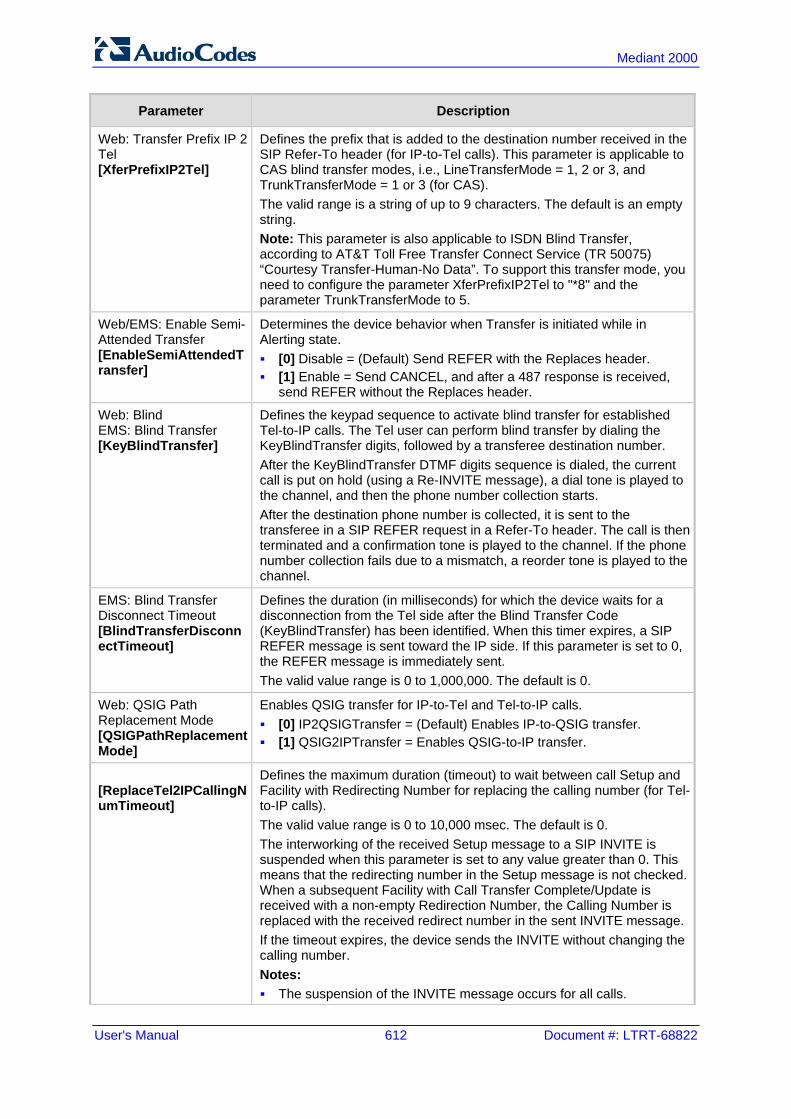
User's Manual 612 Document #: LTRT-68822
Mediant 2000
Parameter Description
Web: Transfer Prefix IP 2 Tel [XferPrefixIP2Tel]
Defines the prefix that is added to the destination number received in the SIP Refer-To header (for IP-to-Tel calls). This parameter is applicable to CAS blind transfer modes, i.e., LineTransferMode = 1, 2 or 3, and TrunkTransferMode = 1 or 3 (for CAS). The valid range is a string of up to 9 characters. The default is an empty string. Note: This parameter is also applicable to ISDN Blind Transfer, according to AT&T Toll Free Transfer Connect Service (TR 50075) “Courtesy Transfer-Human-No Data”. To support this transfer mode, you need to configure the parameter XferPrefixIP2Tel to "*8" and the parameter TrunkTransferMode to 5.
Web/EMS: Enable Semi-Attended Transfer [EnableSemiAttendedTransfer]
Determines the device behavior when Transfer is initiated while in Alerting state. [0] Disable = (Default) Send REFER with the Replaces header. [1] Enable = Send CANCEL, and after a 487 response is received,
send REFER without the Replaces header.
Web: Blind EMS: Blind Transfer [KeyBlindTransfer]
Defines the keypad sequence to activate blind transfer for established Tel-to-IP calls. The Tel user can perform blind transfer by dialing the KeyBlindTransfer digits, followed by a transferee destination number. After the KeyBlindTransfer DTMF digits sequence is dialed, the current call is put on hold (using a Re-INVITE message), a dial tone is played to the channel, and then the phone number collection starts. After the destination phone number is collected, it is sent to the transferee in a SIP REFER request in a Refer-To header. The call is then terminated and a confirmation tone is played to the channel. If the phone number collection fails due to a mismatch, a reorder tone is played to the channel.
EMS: Blind Transfer Disconnect Timeout [BlindTransferDisconnectTimeout]
Defines the duration (in milliseconds) for which the device waits for a disconnection from the Tel side after the Blind Transfer Code (KeyBlindTransfer) has been identified. When this timer expires, a SIP REFER message is sent toward the IP side. If this parameter is set to 0, the REFER message is immediately sent. The valid value range is 0 to 1,000,000. The default is 0.
Web: QSIG Path Replacement Mode [QSIGPathReplacementMode]
Enables QSIG transfer for IP-to-Tel and Tel-to-IP calls. [0] IP2QSIGTransfer = (Default) Enables IP-to-QSIG transfer. [1] QSIG2IPTransfer = Enables QSIG-to-IP transfer.
[ReplaceTel2IPCallingNumTimeout]
Defines the maximum duration (timeout) to wait between call Setup and Facility with Redirecting Number for replacing the calling number (for Tel-to-IP calls). The valid value range is 0 to 10,000 msec. The default is 0. The interworking of the received Setup message to a SIP INVITE is suspended when this parameter is set to any value greater than 0. This means that the redirecting number in the Setup message is not checked. When a subsequent Facility with Call Transfer Complete/Update is received with a non-empty Redirection Number, the Calling Number is replaced with the received redirect number in the sent INVITE message. If the timeout expires, the device sends the INVITE without changing the calling number. Notes: The suspension of the INVITE message occurs for all calls.

Version 6.6 613 Mediant 2000
User's Manual 45. Configuration Parameters Reference
Parameter Description
This parameter is applicable to QSIG.
Web: IP2IP Transfer Mode [IP2IPTransfermode]
Determines the interworking of incoming mid-call SIP REFER messages to outgoing REFER messages, for calls pertaining to the IP-to-IP application. [0] Disable = (Default) Upon receipt of a REFER message, the device
sends an INVITE to the refer-to destination with or without the Replaces header.
[1] Enable = Upon receipt of a REFER message, the device forwards the REFER message and all relevant SIP messages from and to the transferor, to the target destination during call transfer. For consultation call transfer, the REFER message contains a 'replaces' parameter in the Refer-To header. In this case, the outgoing REFER also contains a 'replaces' parameter in the Refer-To header.
Note: This parameter is applicable to blind and consultation call transfers.
45.11.5.6 MLPP and Emergency Call Parameters The Multilevel Precedence and Preemption (MLPP) and emergency E911 call parameters are described in the table below.
MLPP and Emergency E911 Call Parameters
Parameter Description
Web/EMS: Call Priority Mode [CallPriorityMode]
Enables priority call handling for all calls. [0] Disable (default). [1] MLPP = MLPP Priority Call handling is enabled. MLPP prioritizes
call handling whereby the relative importance of various kinds of communications is strictly defined, allowing higher precedence communication at the expense of lower precedence communications. Higher priority calls override less priority calls when, for example, congestion occurs in a network.
[2] Emergency = Preemption of IP-to-Tel E911 emergency calls. If the device receives an E911 call and there are unavailable channels to receive the call, the device terminates one of the channel calls and sends the E911 call to that channel. The preemption is done only on a channel pertaining to the same Trunk Group for which the E911 call was initially destined and if the channel select mode (configured by the ChannelSelectMode parameter) is set to other than “By Dest Number” (0). The preemption is done only if the incoming IP-to-Tel call is identified as an emergency call. The device identifies emergency calls by one of the following: The destination number of the IP call matches one of the
numbers defined by the EmergencyNumbers parameter. (For E911, you must define this parameter with the value "911".)
The incoming SIP INVITE message contains the “emergency” value in the Priority header.
Notes: This parameter is applicable to CAS, and ISDN. MLPP and Emergency services can also be configured in a Tel
Profile.

User's Manual 614 Document #: LTRT-68822
Mediant 2000
Parameter Description
For more information, see 'Pre-empting Existing Call for E911 IP-to-Tel Call' on page 338.
Emergency E911 Parameters
[E911Gateway] Enables Enhanced 9-1-1(E9-1-1) support for ELIN handling in Microsoft Lync Server 2010 environment. [0] = Disable (default) [1] = Enable [2] = Location-based manipulations
[E911CallbackTimeout] Defines the maximum interval within which the PSAP can use the ELIN to call back the E9-1-1 caller. This interval starts from when the initial call established with the PSAP is terminated. The valid range is 1 to 60 (minutes). The default is 30.
Web: Emergency Special Release Cause [EmergencySpecialReleaseCause]
Enables the device to send a SIP 503 "Service Unavailable" response if an emergency call cannot be established (i.e., rejected). This can occur, for example, due to the PSTN (for example, the destination is busy or not found) or ELIN Gateway (for example, lack of resources or an internal error). [0] = Disable (default) [1] = Enable
Web/EMS: Emergency Numbers [EmergencyNumbers]
Defines a list of “emergency” numbers. For CAS, and ISDN: These emergency numbers are used for the preemption of E911 IP-to-Tel calls when there are unavailable or busy channels. In this scenario, the device terminates one of the busy channels and sends the emergency call to this channel. This feature is enabled by setting the CallPriorityMode parameter to 2 (“Emergency”). For a description of this feature, see 'Pre-empting Existing Call for E911 IP-to-Tel Call' on page 338. The list can include up to four different numbers, where each number can be up to four digits long. Example: EmergencyNumbers = ‘100’,’911’,’112’
Multilevel Precedence and Preemption (MLPP) Parameters
Web: MLPP Default Namespace EMS: Default Name Space [MLPPDefaultNamespace]
Determines the namespace used for MLPP calls received from the ISDN side without a Precedence IE and destined for an Application server. This value is used in the Resource-Priority header of the outgoing SIP INVITE request. [1] DSN (default) [2] DOD [3] DRSN [5] UC [7] CUC Note: If the ISDN message contains a Precedence IE, the device automatically interworks the "network identity" digits in the IE to the network domain subfield in the Resource-Priority header. For more information, see Multilevel Precedence and Preemption on page 349.
[ResourcePriorityNetworkDomains]
Defines up to 32 user-defined MLPP network domain names (namespaces). This value is used in the AS-SIP Resource-Priority header of the outgoing SIP INVITE request. This parameter is used in combination with the MLPPDefaultNamespace parameter, where you need to enter the table row index as its value.

Version 6.6 615 Mediant 2000
User's Manual 45. Configuration Parameters Reference
Parameter Description
This parameter is also used for mapping the Resource-Priority field value of the SIP Resource-Priority header to the ISDN PRI Precedence Level IE. The mapping is configured by the field, EnableIp2TelInterworking: Disabled: The network-domain field in the Resource-Priority header
is set to "0 1 0 0" (i.e., "routine") in the Precedence Level field. Enabled: The network-domain field in the Resource-Priority header
is set in the Precedence Level field according to Table 5.3.2.12-4 (Mapping of RPH r-priority Field to PRI Precedence Level Value).
The domain name can be a string of up to 10 characters. The format of this table ini file parameter is as follows: FORMAT ResourcePriorityNetworkDomains_Index = ResourcePriorityNetworkDomains_Name, ResourcePriorityNetworkDomains_EnableIp2TelInterworking; ResourcePriorityNetworkDomains 1 = dsn, 0; ResourcePriorityNetworkDomains 2 = dod, 0; ResourcePriorityNetworkDomains 3 = drsn, 0; ResourcePriorityNetworkDomains 5 = uc, 1; ResourcePriorityNetworkDomains 7 = cuc, 0; [ \ResourcePriorityNetworkDomains ] Notes: Indices 1, 2, 3, 5, and 7 cannot be modified and are defined for DSN,
DOD, DRSN, UC, and CUC, respectively. If the MLPPDefaultNamespace parameter is set to -1, interworking
from PSTN NI digits is done automatically.
Web/EMS: Default Call Priority [SIPDefaultCallPriority]
Determines the default call priority for MLPP calls. [0] 0 = (Default) ROUTINE [2] 2 = PRIORITY [4] 4 = IMMEDIATE [6] 6 = FLASH [8] 8 = FLASH-OVERRIDE [9] 9 = FLASH-OVERRIDE-OVERRIDE If the incoming SIP INVITE request doesn't contain a valid priority value in the SIP Resource-Priority header, the default is used in the Precedence IE (after translation to the relevant ISDN Precedence value) of the outgoing PRI Setup message. If the incoming PRI Setup message doesn't contain a valid Precedence Level value, the default is used in the Resource-Priority header of the outgoing SIP INVITE request. In this scenario, the character string is sent without translation to a numerical value.
Web: MLPP DiffServ EMS: Diff Serv [MLPPDiffserv]
Defines the DiffServ value (differentiated services code point/DSCP) used in IP packets containing SIP messages that are related to MLPP calls. This parameter defines DiffServ for incoming and outgoing MLPP calls with the Resource-Priority header. The valid range is 0 to 63. The default is 50.
Web/EMS: Preemption Tone Duration [PreemptionToneDuration]
Defines the duration (in seconds) in which the device plays a preemption tone to the Tel and IP sides if a call is preempted. The valid range is 0 to 60. The default is 3. Note: If set to 0, no preemption tone is played.

User's Manual 616 Document #: LTRT-68822
Mediant 2000
Parameter Description
Web: MLPP Normalized Service Domain EMS: Normalized Service Domain [MLPPNormalizedServiceDomain]
Defines the MLPP normalized service domain string. If the device receives an MLPP ISDN incoming call, it uses the parameter (if different from ‘FFFFFF’) as a Service domain in the SIP Resource-Priority header in outgoing INVITE messages. If the parameter is configured to ‘FFFFFF’, the Resource-Priority header is set to the MLPP Service Domain obtained from the Precedence IE. The valid value is 6 hexadecimal digits. The default is ‘000000’. Note: This parameter is applicable only to the MLPP NI-2 ISDN variant with CallPriorityMode set to 1.
[MLPPNetworkIdentifier]
Defines the MLPP network identifier (i.e., International prefix or Telephone Country Code/TCC) for IP-to-ISDN calls, according to the UCR 2008 and ITU Q.955 specifications. The valid range is 1 to 999. The default is 1 (i.e., USA). The MLPP network identifier is sent in the Facility IE of the ISDN Setup message. For example: MLPPNetworkIdentifier set to default (i.e., USA, 1): PlaceCall- MLPPNetworkID:0100 MlppServiceDomain:123abc, MlppPrecLevel:5 Fac(1c): 91 a1 15 02 01 05 02 01 19 30 0d 0a 01 05 0a 01 01 04 05 01 00 12 3a bc MLPPNetworkIdentifier set to 490: PlaceCall- MLPPNetworkID:9004 MlppServiceDomain:123abc, MlppPrecLevel:5 Fac(1c): 91 a1 15 02 01 0a 02 01 19 30 0d 0a 01 05 0a 01 01 04 05 90 04 12 3a bc
Web: MLPP Default Service Domain EMS: Default Service Domain [MLPPDefaultServiceDomain]
Defines the MLPP default service domain string. If the device receives a non-MLPP ISDN incoming call (without a Precedence IE), it uses the parameter (if different than “FFFFFF”) as a Service domain in the SIP Resource-Priority header in outgoing (Tel-to-IP calls) INVITE messages. This parameter is used in conjunction with the parameter SIPDefaultCallPriority. If MLPPDefaultServiceDomain is set to 'FFFFFF', the device interworks the non-MLPP ISDN call to non-MLPP SIP call, and the outgoing INVITE does not contain the Resource-Priority header. The valid value is a 6 hexadecimal digits. The default is "000000". Note: This parameter is applicable only to the MLPP NI-2 ISDN variant with CallPriorityMode set to 1.
[RPRequired] Determines whether the SIP resource-priority tag is added in the SIP Require header of the INVITE message for Tel-to-IP calls. [0] Disable = Excludes the SIP resource-priority tag from the SIP
Require header. [1] Enable = (Default) Adds the SIP resource-priority tag in the SIP
Require header. Note: This parameter is applicable only to MLPP priority call handling (i.e., only when the CallPriorityMode parameter is set to 1).

Version 6.6 617 Mediant 2000
User's Manual 45. Configuration Parameters Reference
Parameter Description
Multiple Differentiated Services Code Points (DSCP) per MLPP Call Priority Level (Precedence) Parameters The MLPP service allows placement of priority calls, where properly validated users can preempt (terminate) lower-priority phone calls with higher-priority calls. For each MLPP call priority level, the DSCP can be set to a value from 0 to 63. The Resource Priority value in the Resource-Priority SIP header can be one of the following:
MLPP Precedence Level Precedence Level in Resource-Priority SIP Header
0 (lowest) routine
2 priority
4 immediate
6 flash
8 flash-override
9 (highest) flash-override-override
Web/EMS: RTP DSCP for MLPP Routine [MLPPRoutineRTPDSCP]
Defines the RTP DSCP for MLPP Routine precedence call level. The valid range is -1 to 63. The default is -1. Note: If set to -1, the DiffServ value is taken from the global parameter PremiumServiceClassMediaDiffServ or as defined in IP Profiles per call.
Web/EMS: RTP DSCP for MLPP Priority [MLPPPriorityRTPDSCP]
Defines the RTP DSCP for MLPP Priority precedence call level. The valid range is -1 to 63. The default is -1. Note: If set to -1, the DiffServ value is taken from the global parameter PremiumServiceClassMediaDiffServ or as defined in IP Profiles per call.
Web/EMS: RTP DSCP for MLPP Immediate [MLPPImmediateRTPDSCP]
Defines the RTP DSCP for MLPP Immediate precedence call level. The valid range is -1 to 63. The default is -1. Note: If set to -1, the DiffServ value is taken from the global parameter PremiumServiceClassMediaDiffServ or as defined in IP Profiles per call.
Web/EMS: RTP DSCP for MLPP Flash [MLPPFlashRTPDSCP]
Defines the RTP DSCP for MLPP Flash precedence call level. The valid range is -1 to 63. The default is -1. Note: If set to -1, the DiffServ value is taken from the global parameter PremiumServiceClassMediaDiffServ or as defined in IP Profiles per call.
Web/EMS: RTP DSCP for MLPP Flash Override [MLPPFlashOverRTPDSCP]
Defines the RTP DSCP for MLPP Flash-Override precedence call level. The valid range is -1 to 63. The default is -1. Note: If set to -1, the DiffServ value is taken from the global parameter PremiumServiceClassMediaDiffServ or as defined in IP Profiles per call.
Web/EMS: RTP DSCP for MLPP Flash-Override-Override [MLPPFlashOverOverRTPDSCP]
Defines the RTP DSCP for MLPP Flash-Override-Override precedence call level. The valid range is -1 to 63. The default is -1. Note: If set to -1, the DiffServ value is taken from the global parameter PremiumServiceClassMediaDiffServ or as defined in IP Profiles per call.

User's Manual 618 Document #: LTRT-68822
Mediant 2000
45.11.5.7 Call Cut-Through Parameters The call cut-through parameters are described in the table below.
Call Cut-Through Parameters
Parameter Description
[DigitalCutThrough] Enables PSTN CAS channels/endpoints to receive incoming IP calls even if the B-channels are in off-hook state. [0] Disabled (default) [1] Enabled When enabled, this feature operates as follows: 4 A Tel-to-IP call is established (connected) by the device for a B-
channel. 5 The device receives a SIP BYE (i.e., IP side ends the call) and plays a
reorder tone to the PSTN side for the duration set by the CutThroughTimeForReOrderTone parameter. The device releases the call towards the IP side (sends a SIP 200 OK).
6 The PSTN side, for whatever reason, remains off-hook. 7 If a new IP call is received for this B-channel after the reorder tone has
ended, the device “cuts through” the channel and connects the call immediately (despite the B-channel being in physical off-hook state) without playing a ring tone. If an IP call is received while the reorder tone is played, the device rejects the call.
Notes: If this parameter is disabled and the PSTN side remains in off-hook
state after the IP call ends the call, the device releases the call after 60 seconds.
A special CAS table can be used to report call status events (Active/Idle) to the PSTN side during Cut Through mode.
This feature can also be configured in a Tel Profile and therefore, assigned to specific B-channels that use specific CAS tables.
45.11.5.8 TTY/TDD Parameters The TTY (telephone typewriter) or telecommunications device for the deaf (TDD) is an electronic device for text communication via a telephone line for those with impaired hearing. The TTY/TDD parameters are described in the table below.
TTY Parameters
Parameter Description
EMS: TTY Transport Type [TTYTransportType]
Defines the device's transferring method of TTY signals during a call. [0] = (Default) Disable. [2] = Relay (signals sent over the EVRC codec) - TTY phone
device transfer using In-Band Relay mode for TTY signal transport.
Note: To support TTY Relay (2), you must configure the device to use the EVRC coder.

Version 6.6 619 Mediant 2000
User's Manual 45. Configuration Parameters Reference
45.11.6 PSTN Parameters This subsection describes the device's PSTN parameters.
45.11.6.1 General Parameters The general PSTN parameters are described in the table below.
General PSTN Parameters
Parameter Description
Web/EMS: Protocol Type [ProtocolType]
Defines the PSTN protocol for all the Trunks. To configure the protocol type for a specific Trunk, use the ini file parameter ProtocolType_x: [0] NONE [1] E1 EURO ISDN = ISDN PRI Pan-European (CTR4)
protocol [2] T1 CAS = Common T1 robbed bits protocols including
E&M wink start, E&M immediate start, E&M delay dial/start and loop-start and ground start.
[3] T1 RAW CAS [4] T1 TRANSPARENT = Transparent protocol, where no
signaling is provided by the device. Timeslots 1 to 24 of all trunks are mapped to DSP channels.
[5] E1 TRANSPARENT 31 = Transparent protocol, where no signaling is provided by the device. Timeslots 1 to 31 of each trunk are mapped to DSP channels.
[6] E1 TRANSPARENT 30 = Transparent protocol, where no signaling is provided by the device. Timeslots 1 to 31, excluding time slot 16 of all trunks are mapped to DSP channels.
[7] E1 MFCR2 = Common E1 MFC/R2 CAS protocols (including line signaling and compelled register signaling).
[8] E1 CAS = Common E1 CAS protocols (including line signaling and MF/DTMF address transfer).
[9] E1 RAW CAS [10] T1 NI2 ISDN = National ISDN 2 PRI protocol [11] T1 4ESS ISDN = ISDN PRI protocol for the
Lucent™/AT&T™ 4ESS switch. [12] T1 5ESS 9 ISDN = ISDN PRI protocol for the
Lucent™/AT&T™ 5ESS-9 switch. [13] T1 5ESS 10 ISDN = ISDN PRI protocol for the
Lucent™/AT&T™ 5ESS-10 switch. [14] T1 DMS100 ISDN = ISDN PRI protocol for the Nortel™
DMS switch. [15] J1 TRANSPARENT [16] T1 NTT ISDN = ISDN PRI protocol for the Japan - Nippon
Telegraph Telephone (known also as INS 1500). [17] E1 AUSTEL ISDN = ISDN PRI protocol for the Australian
Telecom. [18] E1 HKT ISDN = ISDN PRI (E1) protocol for the Hong
Kong - HKT. [19] E1 KOR ISDN = ISDN PRI protocol for Korean Operator

User's Manual 620 Document #: LTRT-68822
Mediant 2000
Parameter Description
(similar to ETSI). [20] T1 HKT ISDN = ISDN PRI (T1) protocol for the Hong
Kong - HKT. [21] E1 QSIG = ECMA 143 QSIG over E1 [22] E1 TNZ = ISDN PRI protocol for Telecom New Zealand
(similar to ETSI) [23] T1 QSIG = ECMA 143 QSIG over T1 [30] E1 FRENCH VN6 ISDN = France Telecom VN6 [31] E1 FRENCH VN3 ISDN = France Telecom VN3 [34] T1 EURO ISDN =ISDN PRI protocol for Euro over T1 [35] T1 DMS100 Meridian ISDN = ISDN PRI protocol for the
Nortel™ DMS Meridian switch [36] T1 NI1 ISDN = National ISDN 1 PRI protocol [40] E1 NI2 ISDN = National ISDN 2 PRI protocol over E1 Note: All PRI trunks must be configured as the same line type (either E1 or T1). The device can support different variants of CAS and PRI protocols on different E1/T1 spans (no more than four simultaneous PRI variants).
[ProtocolType_x] Defines the protocol type for a specific trunk ID (where x denotes the Trunk ID and 0 is the first trunk). For more information, see the ProtocolType parameter.
[ISDNTimerT310] Defines the T310 override timer for DMS, Euro ISDN, and ISDN NI2 variants. An ISDN timer is started when a Q.931 Call Proceeding message is received. The timer is stopped when a Q.931 Alerting, Connect, or Disconnect message is received from the other end. If no ISDN Alerting, Progress, or Connect message is received within the duration of T310 timer, the call clears. The valid value range is 0 to 600 seconds. The default is 0 (i.e., use the default timer value according to the protocol's specifications). Notes: For this parameter to take effect, a device reset is required. When both the parameters ISDNDmsTimerT310 and
ISDNTimerT310 are configured, the value of the parameter ISDNTimerT310 prevails.
[ISDNDMSTimerT310] Defines the override T310 timer for the DMS-100 ISDN variant. T310 defines the timeout between the receipt of a Proceeding message and the receipt of an Alerting/Connect message. The valid range is 10 to 30. The default is 10 (seconds). Notes: Instead of configuring this parameter, it is recommended to
use the parameter ISDNTimerT310. This parameter is applicable only to Nortel DMS and Nortel
MERIDIAN PRI variants (ProtocolType = 14 and 35).
[ISDNTimerT301] Defines the override T301 timer (in seconds). The T301 timer is started when a Q.931 Alert message is received. The timer is stopped when a Q.931 Connect/Disconnect message is received from the other side. If no Connect or Disconnect message is received within the duration of T301, the call is cleared. The valid range is 0 to 2400. The default is 0 (i.e., the default T301 timer value - 180 seconds - is used). If set to any other

Version 6.6 621 Mediant 2000
User's Manual 45. Configuration Parameters Reference
Parameter Description
value than 0, it overrides the timer with this value. Notes: For this parameter to take effect, a device reset is required. This parameter is applicable only to the QSIG variant.
[ISDNJapanNTTTimerT3JA] Defines the T3_JA timer (in seconds). This parameter overrides the internal PSTN T301 timeout on the Users Side (TE side). If an outgoing call from the device to ISDN is not answered during this timeout, the call is released. The valid range is 10 to 240. The default is 50. Notes: This timer is also affected by the parameter
PSTNAlertTimeout. This parameter is applicable only to the Japan NTT PRI
variant (ProtocolType = 16).
Web/EMS: Trace Level [TraceLevel]
Defines the trace level: [0] No Trace (default) [1] Full ISDN Trace [2] Layer 3 ISDN Trace [3] Only ISDN Q.931 Messages Trace [4] Layer 3 ISDN No Duplication Trace
Web/EMS: Framing Method [FramingMethod]
Determines the physical framing method for the trunk. [0] Extended Super Frame = (Default) Depends on protocol
type: E1: E1 CRC4 MultiFrame Format extended G.706B (same
as c) T1: T1 Extended Super Frame with CRC6 (same as D)
[1] Super Frame = T1 SuperFrame Format (as B). [a] E1 FRAMING DDF = E1 DoubleFrame Format - CRC4 is
forced to off [b] E1 FRAMING MFF CRC4 = E1 CRC4 MultiFrame Format -
CRC4 is always on [c] E1 FRAMING MFF CRC4 EXT = E1 CRC4 MultiFrame
Format extended G.706B - auto negotiation is on. If the negotiation fails, it changes automatically to CRC4 off (ddf)
[A] T1 FRAMING F4 = T1 4-Frame multiframe. [B] T1 FRAMING F12 = T1 12-Frame multiframe (D4). [C] T1 FRAMING ESF = T1 Extended SuperFrame without
CRC6 [D] T1 FRAMING ESF CRC6 = T1 Extended SuperFrame with
CRC6 [E] T1 FRAMING F72 = T1 72-Frame multiframe (SLC96) [F] T1 FRAMING ESF CRC6 J2 = J1 Extended SuperFrame
with CRC6 (Japan)
[FramingMethod_x] Same as the description for parameter FramingMethod, but for a specific trunk ID (where x denotes the Trunk ID and 0 is the first Trunk).
Web/EMS: Clock Master [ClockMaster]
Determines the Tx clock source of the E1/T1 line. [0] Recovered = (Default) Generate the clock according to the
Rx of the E1/T1 line.

User's Manual 622 Document #: LTRT-68822
Mediant 2000
Parameter Description
[1] Generated = Generate the clock according to the internal TDM bus.
Note: The source of the internal TDM bus clock is determined by the parameter TDMBusClockSource.
[ClockMaster_x] Same as the description for parameter ClockMaster, but for a specific Trunk ID (where x denotes the Trunk ID and 0 is the first Trunk).
Web/EMS: Line Code [LineCode]
Selects B8ZS or AMI for T1 spans, and HDB3 or AMI for E1 spans. [0] B8ZS = (Default) B8ZS line code (for T1 trunks only). [1] AMI = AMI line code. [2] HDB3 = HDB3 line code (for E1 trunks only).
[LineCode_x] Same as the description for parameter LineCode, but for a specific trunk ID (where 0 denotes the first trunk).
[AdminState] Defines the administrative state for all trunks. [0] = Lock the trunk; stops trunk traffic to configure the trunk
protocol type. [1] = Shutting down (read only). [2] = (Default) Unlock the trunk; enables trunk traffic. Notes: For this parameter to take effect, a device reset is required. When the device is locked from the Web interface, this
parameter changes to 0. To define the administrative state per trunk, use the
TrunkAdministrativeState parameter.
[TrunkAdministrativeState_x]
Defines the administrative state per trunk, where x denotes the trunk number. [0] = Lock the trunk; stops trunk traffic to configure the trunk
protocol type. [1] = shutting down (read only). [2] = (Default) Unlock the trunk; enables trunk traffic.
Web/EMS: Line Build Out Loss [LineBuildOut.Loss]
Defines the line build out loss for the selected T1 trunk. [0] 0 dB (default) [1] -7.5 dB [2] -15 dB [3] -22.5 dB Note: This parameter is applicable only to T1 trunks.
[TDMHairPinning] Defines static TDM hair-pinning (cross-connection) performed at initialization. The connection is between trunks with an option to exclude a single B-channel in each trunk. Format example: T0-T1/B3,T2-T3,T4-T5/B2. Note: For this parameter to take effect, a device reset is required.
Web: Enable TDM Tunneling EMS: TDM Over IP [EnableTDMoverIP]
Enables TDM tunneling. [0] Disable (default) [1] Enable When TDM Tunneling is enabled, the originating device

Version 6.6 623 Mediant 2000
User's Manual 45. Configuration Parameters Reference
Parameter Description
automatically initiates SIP calls from all enabled B-channels pertaining to E1/T1/J1 spans that are configured with the 'Transparent' protocol. The called number of each call is the internal phone number of the B-channel from where the call originates. The 'The Inbound IP Routing Table is used to define the destination IP address of the terminating device. The terminating device automatically answers these calls if its E1/T1 protocol is set to 'Transparent' (ProtocolType = 5). Notes: For this parameter to take effect, a device reset is required. For an overview on TDM tunneling, see 'TDM Tunneling' on
page 268.
45.11.6.2 TDM Bus and Clock Timing Parameters The TDM Bus parameters are described in the table below.
TDM Bus and Clock Timing Parameters
Parameter Description
TDM Bus Parameters
Web/EMS: PCM Law Select [PCMLawSelect]
Determines the type of pulse-code modulation (PCM) companding algorithm law in input and output TDM bus. [1] Alaw [3] MuLaw The default is automatically selected according to the Protocol Type of the selected trunk: E1 defaults to ALaw, T1 defaults to MuLaw. If the Protocol Type is set to NONE, the default is MuLaw. Notes: For this parameter to take effect, a device reset is required. Typically, A-Law is used for E1 spans and Mu-Law for T1/J1
spans.
Web/EMS: Idle PCM Pattern [IdlePCMPattern]
Defines the PCM Pattern that is applied to the E1/T1 timeslot (B-channel) when the channel is idle. The range is 0 to 255. The default is set internally according to the Law select 1 (0xFF for Mu-Law; 0x55 for A-law). Note: For this parameter to take effect, a device reset is required.
Web/EMS: Idle ABCD Pattern [IdleABCDPattern]
Defines the ABCD (CAS) Pattern that is applied to the CAS signaling bus when the channel is idle. The valid range is 0x0 to 0xF. The default is -1 (i.e., default pattern is 0000). Notes: For this parameter to take effect, a device reset is required. This parameter is applicable only when using PSTN interface
with CAS protocols.
Web/EMS: TDM Bus Clock Source
Determines the clock source to which the device synchronizes. [1] Internal = (Default) Generate clock from local source.
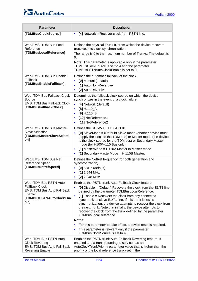
User's Manual 624 Document #: LTRT-68822
Mediant 2000
Parameter Description
[TDMBusClockSource] [4] Network = Recover clock from PSTN line.
Web/EMS: TDM Bus Local Reference [TDMBusLocalReference]
Defines the physical Trunk ID from which the device recovers (receives) its clock synchronization. The range is 0 to the maximum number of Trunks. The default is 0. Note: This parameter is applicable only if the parameter TDMBusClockSource is set to 4 and the parameter TDMBusPSTNAutoClockEnable is set to 0.
Web/EMS: TDM Bus Enable Fallback [TDMBusEnableFallback]
Defines the automatic fallback of the clock. [0] Manual (default) [1] Auto Non-Revertive [2] Auto Revertive
Web: TDM Bus Fallback Clock Source EMS: TDM Bus Fallback Clock [TDMBusFallbackClock]
Determines the fallback clock source on which the device synchronizes in the event of a clock failure. [4] Network (default) [8] H.110_A [9] H.110_B [10] NetReference1 [11] NetReference2
Web/EMS: TDM Bus Master-Slave Selection [TDMBusMasterSlaveSelection]
Defines the SC/MVIP/H.100/H.110. [0] SlaveMode = (Default) Slave mode (another device must
supply the clock to the TDM bus) or Master mode (the device is the clock source for the TDM bus) or Secondary Master mode (for H100/H110 Bus only).
[1] MasterMode = H110A Master in Master mode. [2] SecondaryMasterMode = H.110B Master.
Web/EMS: TDM Bus Net Reference Speed [TDMBusNetrefSpeed]
Defines the NetRef frequency (for both generation and synchronization). [0] 8 kHz (default) [1] 1.544 MHz [2] 2.048 MHz
Web: TDM Bus PSTN Auto FallBack Clock EMS: TDM Bus Auto Fall Back Enable [TDMBusPSTNAutoClockEnable]
Enables the PSTN trunk Auto-Fallback Clock feature. [0] Disable = (Default) Recovers the clock from the E1/T1 line
defined by the parameter TDMBusLocalReference. [1] Enable = Recovers the clock from any connected
synchronized slave E1/T1 line. If this trunk loses its synchronization, the device attempts to recover the clock from the next trunk. Note that initially, the device attempts to recover the clock from the trunk defined by the parameter TDMBusLocalReference.
Notes: For this parameter to take effect, a device reset is required. This parameter is relevant only if the parameter
TDMBusClockSource is set to 4.
Web: TDM Bus PSTN Auto Clock Reverting EMS: TDM Bus Auto Fall Back Reverting Enable
Enables the PSTN trunk Auto-Fallback Reverting feature. If enabled and a trunk returning to service has an AutoClockTrunkPriority parameter value that is higher than the priority of the local reference trunk (set in the
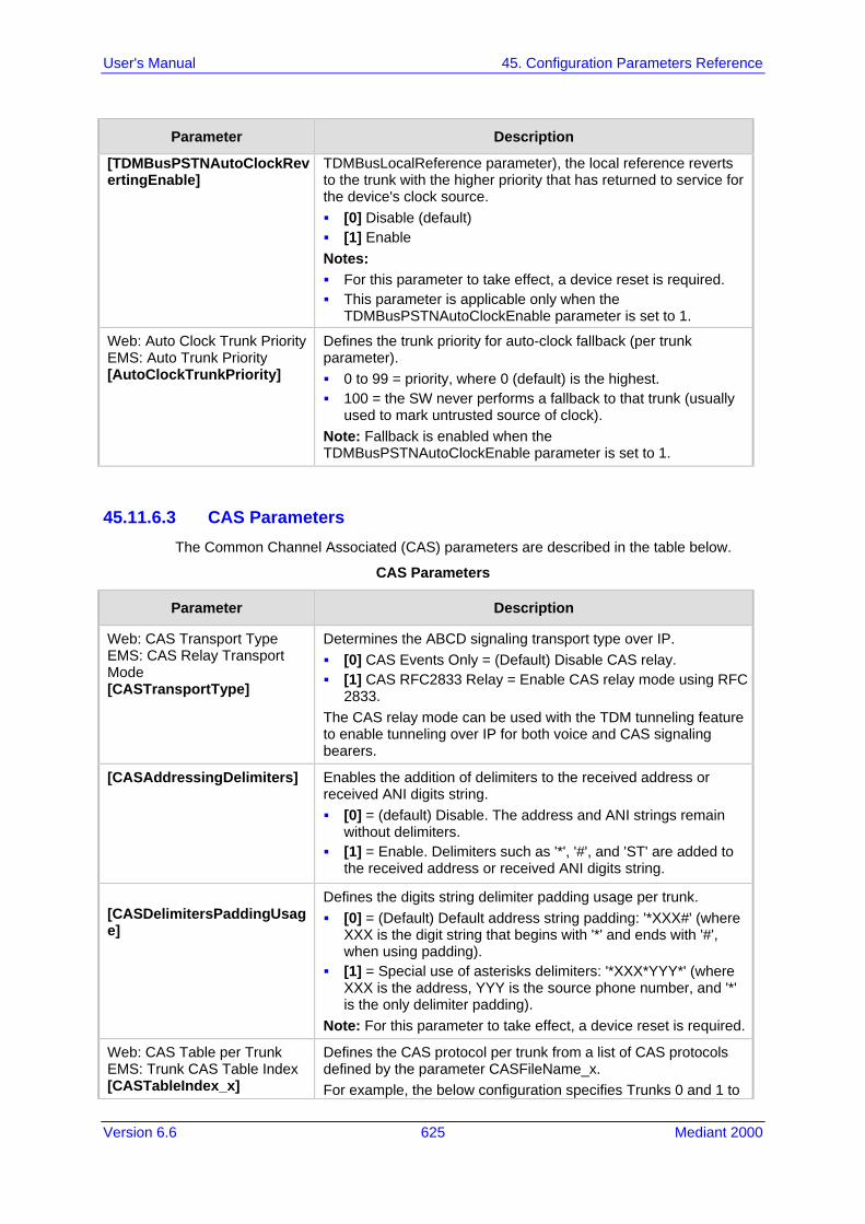
Version 6.6 625 Mediant 2000
User's Manual 45. Configuration Parameters Reference
Parameter Description
[TDMBusPSTNAutoClockRevertingEnable]
TDMBusLocalReference parameter), the local reference reverts to the trunk with the higher priority that has returned to service for the device's clock source. [0] Disable (default) [1] Enable Notes: For this parameter to take effect, a device reset is required. This parameter is applicable only when the
TDMBusPSTNAutoClockEnable parameter is set to 1.
Web: Auto Clock Trunk Priority EMS: Auto Trunk Priority [AutoClockTrunkPriority]
Defines the trunk priority for auto-clock fallback (per trunk parameter). 0 to 99 = priority, where 0 (default) is the highest. 100 = the SW never performs a fallback to that trunk (usually
used to mark untrusted source of clock). Note: Fallback is enabled when the TDMBusPSTNAutoClockEnable parameter is set to 1.
45.11.6.3 CAS Parameters The Common Channel Associated (CAS) parameters are described in the table below.
CAS Parameters
Parameter Description
Web: CAS Transport Type EMS: CAS Relay Transport Mode [CASTransportType]
Determines the ABCD signaling transport type over IP. [0] CAS Events Only = (Default) Disable CAS relay. [1] CAS RFC2833 Relay = Enable CAS relay mode using RFC
2833. The CAS relay mode can be used with the TDM tunneling feature to enable tunneling over IP for both voice and CAS signaling bearers.
[CASAddressingDelimiters] Enables the addition of delimiters to the received address or received ANI digits string. [0] = (default) Disable. The address and ANI strings remain
without delimiters. [1] = Enable. Delimiters such as '*', '#', and 'ST' are added to
the received address or received ANI digits string.
[CASDelimitersPaddingUsage]
Defines the digits string delimiter padding usage per trunk. [0] = (Default) Default address string padding: '*XXX#' (where
XXX is the digit string that begins with '*' and ends with '#', when using padding).
[1] = Special use of asterisks delimiters: '*XXX*YYY*' (where XXX is the address, YYY is the source phone number, and '*' is the only delimiter padding).
Note: For this parameter to take effect, a device reset is required.
Web: CAS Table per Trunk EMS: Trunk CAS Table Index [CASTableIndex_x]
Defines the CAS protocol per trunk from a list of CAS protocols defined by the parameter CASFileName_x. For example, the below configuration specifies Trunks 0 and 1 to

User's Manual 626 Document #: LTRT-68822
Mediant 2000
Parameter Description
use the E&M Winkstart CAS (E_M_WinkTable.dat) protocol, and Trunks 2 and 3 to use the E&M Immediate Start CAS (E_M_ImmediateTable.dat) protocol: CASFileName_0 = 'E_M_WinkTable.dat' CASFileName_1 = 'E_M_ImmediateTable.dat' CASTableIndex_0 = 0 CASTableIndex_1 = 0 CASTableIndex_2 = 1 CASTableIndex_3 = 1
Notes: You can define CAS tables per B-channel using the parameter
CASChannelIndex. The x in the ini file parameter name denotes the trunk number,
where 0 is Trunk 1.
Web: Dial Plan EMS: Dial Plan Name [CASTrunkDialPlanName_x]
Defines the CAS Dial Plan name per trunk. The range is up to 11 characters. For example, the below configures E1_MFCR2 trunk with a single protocol (Trunk 5): ProtocolType_5 = 7 CASFileName_0='R2_Korea_CP_ANI.dat' CASTableIndex_5 = 0 DialPlanFileName = 'DialPlan_USA.dat' CASTrunkDialPlanName_5 = 'AT_T'
Note: The x in the ini file parameter name denotes the trunk number, where 0 is Trunk 1.
[CASFileName_x] Defines the CAS file name (e.g., 'E_M_WinkTable.dat') that defines the CAS protocol, where x denotes the CAS file ID (0-7). It is possible to define up to eight different CAS files by repeating this parameter. Each CAS file can be associated with one or more of the device's trunks, using the parameter CASTableIndex_x. Note: For this parameter to take effect, a device reset is required.
Web/EMS: CAS Table per Channel [CASChannelIndex]
Defines the loaded CAS protocol table index per B-channel pertaining to a CAS trunk. This parameter is assigned a string value and can be set in one of the following two formats: CAS table per channel: Each channel is separated by a
comma and the value entered denotes the CAS table index used for that channel. The syntax is <CAS index>,<CAS index> (e.g., "1,2,1,2…"). For this format, 31 indices must be defined for E1 trunks (including dummy for B-channel 16), or 24 indices for T1 trunks. Below is an example for configuring a T1 CAS trunk (Trunk 5) with several CAS variants:
ProtocolType_5 = 7 CASFILENAME_0='E_M_FGBWinkTable.dat' CASFILENAME_1='E_M_FGDWinkTable.dat' CASFILENAME_2='E_M_WinkTable.txt' CasChannelIndex_5 = ‘0,0,0,1,1,1,2,2,2,0,0,0,1,1,1,0,1,2,0,2,1,2,2,2’ CASDelimitersPaddingUsage_5 = 1 CAS table per channel group: Each channel group is
separated by a colon and each channel is separated by a comma. The syntax is <x-y channel range>:<CAS table index>, (e.g., "1-10:1,11-31:3"). Every B-channel (including 16

Version 6.6 627 Mediant 2000
User's Manual 45. Configuration Parameters Reference
Parameter Description
for E1) must belong to a channel group. Below is an example for configuring an E1 CAS trunk (Trunk 5) with several CAS variants:
ProtocolType_5 = 8 CASFILENAME_2='E1_R2D' CASFILENAME_7= E_M_ImmediateTable_A-Bit.txt' CasChannelIndex_5 = ‘1-10:2,11-20:7,21-31:2’
Notes: To configure this parameter, the trunk must first be stopped. Only one of these formats can be implemented; not both. When this parameter is not configured, a single CAS table for
the entire trunk is used, configured by the parameter CASTableIndex.
[CASTablesNum] Defines how many CAS protocol configurations files are loaded. The valid range is 1 to 8. Note: For this parameter to take effect, a device reset is required.
CAS State Machines Parameters Note: For configuring the CAS State Machine table using the Web interface, see 'Configuring CAS State Machines' on page 265.
Web: Generate Digit On Time [CASStateMachineGenerateDigitOnTime]
Generates digit on-time (in msec). The value must be a positive value. The default is -1.
Web: Generate Inter Digit Time [CASStateMachineGenerateInterDigitTime]
Generates digit off-time (in msec). The value must be a positive value. The default is -1.
Web: DTMF Max Detection Time [CASStateMachineDTMFMaxOnDetectionTime]
Detects digit maximum on time (according to DSP detection information event) in msec units. The value must be a positive value. The default is -1.
Web: DTMF Min Detection Time [CASStateMachineDTMFMinOnDetectionTime]
Detects digit minimum on time (according to DSP detection information event) in msec units. The digit time length must be longer than this value to receive a detection. Any number may be used, but the value must be less than CasStateMachineDTMFMaxOnDetectionTime. The value must be a positive value. The default is -1.
Web: MAX Incoming Address Digits [CASStateMachineMaxNumOfIncomingAddressDigits]
Defines the limitation for the maximum address digits that need to be collected. After reaching this number of digits, the collection of address digits is stopped. The value must be an integer. The default is -1.
Web: MAX Incoming ANI Digits [CASStateMachineMaxNumOfIncomingANIDigits]
Defines the limitation for the maximum ANI digits that need to be collected. After reaching this number of digits, the collection of ANI digits is stopped. The value must be an integer. The default is -1.
Web: Collect ANI [CASStateMachineCollectANI]
In some cases, when the state machine handles the ANI collection (not related to MFCR2), you can enable the state machine to collect ANI or discard ANI. [0] No = Don't collect ANI. [1] Yes = Collect ANI.

User's Manual 628 Document #: LTRT-68822
Mediant 2000
Parameter Description
[-1] Default = Default value.
Web: Digit Signaling System [CASStateMachineDigitSignalingSystem]
Defines which Signaling System to use in both directions (detection\generation). [0] DTMF = DTMF signaling. [1] MF = (Default) MF signaling. [-1] Default = Default value.
45.11.6.4 ISDN Parameters The ISDN parameters are described in the table below.
ISDN Parameters
Parameter Description
Web: ISDN Termination Side EMS: Termination Side [TerminationSide]
Determines the ISDN termination side. [0] User side = (Default) ISDN User Termination Equipment
(TE) side. [1] Network side = ISDN Network Termination (NT) side. Note: Select 'User side' when the PSTN or PBX side is configured as 'Network side' and vice versa. If you don't know the device's ISDN termination side, choose 'User side'. If the D-channel alarm is indicated, choose 'Network Side'.
[TerminationSide_x] Same as the description for parameter TerminationSide, but for a specific trunk ID (where x denotes the Trunk ID and 0 is the first Trunk).
Web/EMS: B-channel Negotiation [BchannelNegotiation]
Determines the ISDN B-Channel negotiation mode. [0] Preferred [1] Exclusive (default) [2] Any Notes: This parameter is applicable only to ISDN protocols. For some ISDN variants, when 'Any' (2) is selected, the Setup
message excludes the Channel Identification IE. The Any' (2) option is applicable only if the following conditions
are met: The parameter TerminationSide is set to 0 ('User side'). The PSTN protocol type (ProtocolType) is configured as
Euro ISDN. NFAS Parameters
Web: NFAS Group Number EMS: Group Number [NFASGroupNumber_x]
Defines the ISDN Non-Facility Associated Signaling (NFAS) group number (NFAS member) per trunk. [0] = (Default) Non-NFAS trunk. [1] to [12] = NFAS group number. Trunks that belong to the same NFAS group have the same number. With NFAS, you can use a single D-channel to control multiple PRI interfaces. Notes: For this parameter to take effect, a device reset is required.

Version 6.6 629 Mediant 2000
User's Manual 45. Configuration Parameters Reference
Parameter Description
This parameter is applicable only to T1 ISDN protocols. The x in the ini file parameter name denotes the trunk number,
where 0 is Trunk 1. For more information on NFAS, see 'ISDN Non-Facility
Associated Signaling (NFAS)' on page 272.
Web/EMS: D-channel Configuration [DChConfig_x]
Defines primary, backup (optional), and B-channels only, per trunk. [0] PRIMARY= (Default) Primary Trunk - contains a D-channel
that is used for signaling. [1] BACKUP = Backup Trunk - contains a backup D-channel
that is used if the primary D-channel fails. [2] NFAS = NFAS Trunk - contains only 24 B-channels,
without a signaling D-channel. Notes: This parameter is applicable only to T1 ISDN protocols. The x in the ini file parameter name denotes the trunk number,
where 0 is Trunk 1.
Web: NFAS Interface ID EMS: ISDN NFAS Interface ID [ISDNNFASInterfaceID_x]
Defines a different Interface ID per T1 trunk. The valid range is 0 to 100. The default interface ID equals the trunk's ID. Notes: To set the NFAS interface ID, configure ISDNIBehavior_x to
include '512' feature per T1 trunk. The x in the ini file parameter name denotes the trunk number,
where 0 is Trunk 1. For more information on NFAS, see 'ISDN Non-Facility
Associated Signaling (NFAS)' on page 272.
Web: Enable ignoring ISDN Disconnect with PI [KeepISDNCallOnDisconnectWithPI]
Allows the device to ignore ISDN Disconnect messages with PI 1 or 8. [1] = The call (in connected state) is not released if a Q.931
Disconnect with PI (PI = 1 or 8) message is received during the call.
[0] = (Default) The call is disconnected.
Web: PI For Setup Message [PIForSetupMsg]
Determines whether and which Progress Indicator (PI) information element (IE) is added to the sent ISDN Setup message. Some ISDN protocols such as NI-2 or Euro ISDN can optionally contain PI = 1 or PI = 3 in the Setup message. [0] = PI is not added (default). [1] = PI 1 is added to a sent ISDN Setup message - call is not
end-to-end ISDN. [3] = PI 3 is added to a sent ISDN Setup message - calling
equipment is not ISDN.
ISDN Flexible Behavior Parameters ISDN protocol is implemented in different switches/PBXs by different vendors. Several implementations may vary slightly from the specification. Therefore, to provide a flexible interface that supports these ISDN variants, the ISDN behavior parameters can be used.
Web/EMS: Incoming Calls Behavior [ISDNInCallsBehavior]
Determines the bit-field used to determine several behavior options that influence how the ISDN Stack INCOMING calls behave.

User's Manual 630 Document #: LTRT-68822
Mediant 2000
Parameter Description
[32] DATA CONN RS = The device automatically sends a Q.931 Connect (answer) message on incoming Tel calls (Q.931 Setup).
[64] VOICE CONN RS = The device sends a Connect (answer) message on incoming Tel calls.
[2048] CHAN ID IN FIRST RS = (Default) The device sends Channel ID in the first response to an incoming Q.931 Call Setup message. Otherwise, the Channel ID is sent only if the device requires changing the proposed Channel ID.
[4096] USER SETUP ACK = The Setup Ack message is sent by the SIP Gateway application layer and not automatically by the PSTN stack. By default, this bit is set.
[8192] CHAN ID IN CALL PROC = The device sends Channel ID in a Q.931 Call Proceeding message.
[65536] PROGR IND IN SETUP ACK = The device includes Progress Indicator (PI=8) in Setup Ack message if an empty called number is received in an incoming Setup message. This option is applicable to the overlap dialing mode. The device also plays a dial tone (for TimeForDialTone) until the next called number digits are received. By default, this is bit is set.
[2147483648] USER SCREEN INDICATOR = When the device receives two Calling Number IE's in the Setup message, the device, by default, uses only one of the numbers according to the following: Network provided, Network provided - the first calling
number is used Network provided, User provided: the first one is used User provided, Network provided: the second one is used User provided, user provided: the first one is used When this bit is configured, the device behaves as follows: Network provided, Network provided: the first calling
number is used Network provided, User provided: the second one is used User provided, Network provided: the first one is used User provided, user provided: the first one is used
Note: When using the ini file to configure the device to support several ISDNInCallsBehavior features, enter a summation of the individual feature values. For example, to support both [2048] and [65536] features, set ISDNInCallsBehavior = 67584 (i.e., 2048 + 65536).
[ISDNInCallsBehavior_x] Same as the description for the parameter ISDNInCallsBehavior, but per trunk (i.e., where x denotes the Trunk ID).
Web/EMS: Q.931 Layer Response Behavior [ISDNIBehavior]
Bit-field used to determine several behavior options that influence the behaviour of the Q.931 protocol. [0] = Disable (default). [1] NO STATUS ON UNKNOWN IE = Q.931 Status message
isn't sent if Q.931 received message contains an unknown/unrecognized IE. By default, the Status message is sent. Note: This value is applicable only to ISDN variants in which sending of Status message is optional.
[2] NO STATUS ON INV OP IE = Q.931 Status message isn't sent if an optional IE with invalid content is received. By default, the Status message is sent.

Version 6.6 631 Mediant 2000
User's Manual 45. Configuration Parameters Reference
Parameter Description
Note: This option is applicable only to ISDN variants in which sending of Status message is optional.
[4] ACCEPT UNKNOWN FAC IE = Accepts unknown/unrecognized Facility IE. Otherwise, the Q.931 message that contains the unknown Facility IE is rejected (default). Note: This option is applicable only to ISDN variants where a complete ASN1 decoding is performed on Facility IE.
[128] SEND USER CONNECT ACK = The Connect ACK message is sent in response to received Q.931 Connect; otherwise, the Connect ACK is not sent. Note: This option is applicable only to Euro ISDN User side outgoing calls.
[512] EXPLICIT INTERFACE ID = Enables to configure T1 NFAS Interface ID (refer to the parameter ISDNNFASInterfaceID_x). Note: This value is applicable only to 4/5ESS, DMS, NI-2 and HKT variants.
[2048] ALWAYS EXPLICIT = Always set the Channel Identification IE to explicit Interface ID, even if the B-channel is on the same trunk as the D-channel. Note: This value is applicable only to 4/5ESS, DMS and NI-2 variants.
[32768] ACCEPT MU LAW =Mu-Law is also accepted in ETSI. [65536] EXPLICIT PRES SCREENING = The calling party
number (octet 3a) is always present even when presentation and screening are at their default. Note: This option is applicable only to ETSI, NI-2, and 5ESS.
[131072] STATUS INCOMPATIBLE STATE = Clears the call on receipt of Q.931 Status with incompatible state. Otherwise, no action is taken (default).
[262144] STATUS ERROR CAUSE = Clear call on receipt of Status according to cause value.
[524288] ACCEPT A LAW =A-Law is also accepted in 5ESS. [2097152] RESTART INDICATION = Upon receipt of a Restart
message, acEV_PSTN_RESTART_CONFIRM is generated. [4194304] FORCED RESTART = On data link (re)initialization,
send RESTART if there is no call. [67108864] NS ACCEPT ANY CAUSE = Accept any Q.850
Cause IE from ISDN. Note: This option is applicable only to Euro ISDN.
[536870912] Alcatel coding for redirect number and display name is accepted by the device. Note: This option is applicable only to QSIG (and relevant for specific Alcatel PBXs such as OXE).
[1073741824] QSI ENCODE INTEGER = If this bit is set, INTEGER ASN.1 type is used in operator coding (compliant to new ECMA standards); otherwise, OBJECT IDENTIFIER ASN.1 type is used. Note: This option is applicable only to QSIG.
[2147483648] 5ESS National Mode For Bch Maintenance = Use the National mode of AT&T 5ESS for B-channel maintenance.

User's Manual 632 Document #: LTRT-68822
Mediant 2000
Parameter Description
Notes: To configure the device to support several ISDNIBehavior
features, enter a summation of the individual feature values. For example, to support both [512] and [2048] features, set the parameter ISDNIBehavior is set to 2560 (i.e., 512 + 2048).
When configuring in the Web interface, to select the options click the arrow button and then for each required option select 1 to enable.
[ISDNIBehavior_x] Same as the description for parameter ISDNIBehavior, but for a specific trunk ID.
Web: General Call Control Behavior EMS: General CC Behavior [ISDNGeneralCCBehavior]
Bit-field for determining several general CC behavior options. To select the options, click the arrow button, and then for each required option, select 1 to enable. The default is 0 (i.e., disable). [2] = Data calls with interworking indication use 64 kbps B-
channels (physical only). [8] REVERSE CHAN ALLOC ALGO = Channel ID allocation
algorithm. [16] = The device clears down the call if it receives a NOTIFY
message specifying 'User-Suspended'. A NOTIFY (User-Suspended) message is used by some networks (e.g., in Italy or Denmark) to indicate that the remote user has cleared the call, especially in the case of a long distance voice call.
[32] CHAN ID 16 ALLOWED = Applies only to ETSI E1 lines (30B+D). Enables handling the differences between the newer QSIG standard (ETS 300-172) and other ETSI-based standards (ETS 300-102 and ETS 300-403) in the conversion of B-channel ID values into timeslot values: In 'regular ETSI' standards, the timeslot is identical to the
B-channel ID value, and the range for both is 1 to 15 and 17 to 31. The D-channel is identified as channel-id #16 and carried into the timeslot #16.
In newer QSIG standards, the channel-id range is 1 to 30, but the timeslot range is still 1 to 15 and 17 to 31. The D-channel is not identified as channel-id #16, but is still carried into the timeslot #16. When this bit is set, the channel ID #16 is considered as a valid B-channel ID, but timeslot values are converted to reflect the range 1 to 15 and 17 to 31. This is the new QSIG mode of operation. When this bit is not set (default), the channel_id #16 is not allowed, as for all ETSI-like standards.
[64] USE T1 PRI = PRI interface type is forced to T1. [128] USE E1 PRI = PRI interface type is forced to E1. [256] START WITH B CHAN OOS = B-channels start in the
Out-Of-Service state (OOS). [512] CHAN ALLOC LOWEST = CC allocates B-channels
starting from the lowest available B-channel id. [1024] CHAN ALLOC HIGHEST = CC allocates B-channels
starting from the highest available B-channel id. [16384] CC_TRANSPARENT_UUI bit: The UUI-protocol
implementation of CC is disabled allowing the application to freely send UUI elements in any primitive, regardless of the UUI-protocol requirements (UUI Implicit Service 1). This allows more flexible application control on the UUI. When this bit is

Version 6.6 633 Mediant 2000
User's Manual 45. Configuration Parameters Reference
Parameter Description
not set (default behavior), CC implements the UUI-protocol as specified in the ETS 300-403 standards for Implicit Service 1.
[65536] GTD5 TBCT = CC implements the VERIZON-GTD-5 Switch variant of the TBCT Supplementary Service, as specified in FSD 01-02-40AG Feature Specification Document from Verizon. Otherwise, TBCT is implemented as specified in GR-2865-CORE specification (default behavior).
Note: When using the ini file to configure the device to support several ISDNGeneralCCBehavior features, add the individual feature values. For example, to support both [16] and [32] features, set ISDNGeneralCCBehavior = 48 (i.e., 16 + 32).
Web/EMS: Outgoing Calls Behavior [ISDNOutCallsBehavior]
Determines several behaviour options (bit fields) that influence the behaviour of the ISDN Stack outgoing calls. To select options, click the arrow button, and then for each required option, select 1 to enable. The default is 0 (i.e., disable). [2] USER SENDING COMPLETE =The default behavior of the
device (when this bit is not set) is to automatically generate the Sending-Complete IE in the Setup message. This behavior is used when overlap dialing is not needed. When overlap dialing is needed, set this bit and the behavior is changed to suit the scenario, i.e., Sending-Complete IE is added when required in the Setup message for Enblock mode or in the last Digit with Overlap mode.
[16] USE MU LAW = The device sends G.711-m-Law in outgoing voice calls. When disabled, the device sends G.711-A-Law in outgoing voice calls. Note: This option is applicable only to the Korean variant.
[128] DIAL WITH KEYPAD = The device uses the Keypad IE to store the called number digits instead of the CALLED_NB IE. Note: This option is applicable only to the Korean variant (Korean network). This is useful for Korean switches that don't accept the CALLED_NB IE.
[256] STORE CHAN ID IN SETUP = The device forces the sending of a Channel-Id IE in an outgoing Setup message even if it's not required by the standard (i.e., optional) and no Channel-Id has been specified in the establishment request. This is useful for improving required compatibility with switches. On PRI lines, it indicates an unused channel ID, preferred only.
[572] USE A LAW = The device sends G.711 A-Law in outgoing voice calls. When disabled, the device sends the default G.711-Law in outgoing voice calls. Note: This option is applicable only to the E10 variant.
[1024] = Numbering plan/type for T1 IP-to-Tel calling numbers are defined according to the manipulation tables or according to the RPID header (default). Otherwise, the plan/type for T1 calls are set according to the length of the calling number.
[2048] = The device accepts any IA5 character in the called_nb and calling_nb strings and sends any IA5 character in the called_nb, and is not restricted to extended digits only (i.e., 0-9,*,#).
[16384] DLCI REVERSED OPTION = Behavior bit used in the IUA interface groups to indicate that the reversed format of the

User's Manual 634 Document #: LTRT-68822
Mediant 2000
Parameter Description
DLCI field must be used. Note: When using the ini file to configure the device to support several ISDNOutCallsBehavior features, add the individual feature values. For example, to support both [2] and [16] features, set ISDNOutCallsBehavior = 18 (i.e., 2 + 16).
[ISDNOutCallsBehavior_x] Same as the description for parameter ISDNOutCallsBehavior, but for a specific trunk ID.
Web: ISDN NS Behaviour 2 [ISDNNSBehaviour2]
Bit-field to determine several behavior options that influence the behavior of the Q.931 protocol. [8] NS BEHAVIOUR2 ANY UUI = Any User to User
Information Element (UUIE) is accepted for any protocol discriminator. This is useful for interoperability with non-standard switches.
[16] NS BEHAVIOUR2 DISPLAY = The Display IE is accepted even if it is not defined in the QSIG ISDN protocol standard. This is applicable only when configuration is QSI.
[64] NS BEHAVIOUR2 FAC REJECT = When this bit is set, the device answers with a Facility IE message with the Reject component on receipt of Facility IE with unknown/invalid Invoke component. This bit is implemented in QSIG and ETSI variants.
[PSTNExtendedParams] Determines the bit map for special PSTN behavior parameters: [0] = (Default) Applicable for NI-2 ISDN and QSIG "Networking
Extensions". This bit (i.e., bit #0) is responsible for the Invoke ID size: If this bit is not set (default), then the Invoke ID size is
always one byte, with a value of 01 to 7f. If this bit is set, then the Invoke ID size is one or two bytes
according to the Invoke ID value. [2] = Applicable to the ROSE format (according to the old
QSIG specifications). This bit (i.e., bit #1) is responsible for the QSIG octet 3. According to the ECMA-165 new version, octet 3 in all QSIG supplementary services Facility messages should be 0x9F = Networking Extensions. However, according to the old version, the value should be 0x91 = ROSE: If this bit is not set (default): 0x9F = Networking
Extensions. If this bit is set: 0x91 = ROSE.
[3] = Use options [0] and [2] above. Note: For this parameter to take effect, a device reset is required.
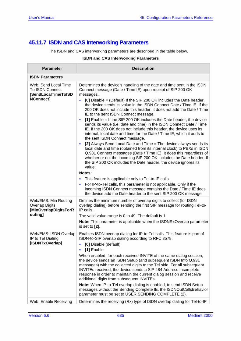
Version 6.6 635 Mediant 2000
User's Manual 45. Configuration Parameters Reference
45.11.7 ISDN and CAS Interworking Parameters The ISDN and CAS interworking parameters are described in the table below.
ISDN and CAS Interworking Parameters
Parameter Description
ISDN Parameters
Web: Send Local Time To ISDN Connect [SendLocalTimeToISDNConnect]
Determines the device's handling of the date and time sent in the ISDN Connect message (Date / Time IE) upon receipt of SIP 200 OK messages. [0] Disable = (Default) If the SIP 200 OK includes the Date header,
the device sends its value in the ISDN Connect Date / Time IE. If the 200 OK does not include this header, it does not add the Date / Time IE to the sent ISDN Connect message.
[1] Enable = If the SIP 200 OK includes the Date header, the device sends its value (i.e. date and time) in the ISDN Connect Date / Time IE. If the 200 OK does not include this header, the device uses its internal, local date and time for the Date / Time IE, which it adds to the sent ISDN Connect message.
[2] Always Send Local Date and Time = The device always sends its local date and time (obtained from its internal clock) to PBXs in ISDN Q.931 Connect messages (Date / Time IE). It does this regardless of whether or not the incoming SIP 200 OK includes the Date header. If the SIP 200 OK includes the Date header, the device ignores its value.
Notes: This feature is applicable only to Tel-to-IP calls. For IP-to-Tel calls, this parameter is not applicable. Only if the
incoming ISDN Connect message contains the Date / Time IE does the device add the Date header to the sent SIP 200 OK message.
Web/EMS: Min Routing Overlap Digits [MinOverlapDigitsForRouting]
Defines the minimum number of overlap digits to collect (for ISDN overlap dialing) before sending the first SIP message for routing Tel-to-IP calls. The valid value range is 0 to 49. The default is 1. Note: This parameter is applicable when the ISDNRxOverlap parameter is set to [2].
Web/EMS: ISDN Overlap IP to Tel Dialing [ISDNTxOverlap]
Enables ISDN overlap dialing for IP-to-Tel calls. This feature is part of ISDN-to-SIP overlap dialing according to RFC 3578. [0] Disable (default) [1] Enable When enabled, for each received INVITE of the same dialog session, the device sends an ISDN Setup (and subsequent ISDN Info Q.931 messages) with the collected digits to the Tel side. For all subsequent INVITEs received, the device sends a SIP 484 Address Incomplete response in order to maintain the current dialog session and receive additional digits from subsequent INVITEs. Note: When IP-to-Tel overlap dialing is enabled, to send ISDN Setup messages without the Sending Complete IE, the ISDNOutCallsBehavior parameter must be set to USER SENDING COMPLETE (2).
Web: Enable Receiving Determines the receiving (Rx) type of ISDN overlap dialing for Tel-to-IP

User's Manual 636 Document #: LTRT-68822
Mediant 2000
Parameter Description
of Overlap Dialing [ISDNRxOverlap_x]
calls, per trunk. [0] None = (Default) Disabled. [1] Local receiving = ISDN Overlap Dialing - the complete number is
sent in the INVITE Request-URI user part. The device receives ISDN called number that is sent in the 'Overlap' mode. The ISDN Setup message is sent to IP only after the number (including the Sending Complete IE) is fully received (via Setup and/or subsequent Info Q.931 messages). In other words, the device waits until it has received all the ISDN signaling messages containing parts of the called number, and only then it sends a SIP INVITE with the entire called number in the Request-URI.
[2] Through SIP = Interworking of ISDN Overlap Dialing to SIP, based on RFC 3578. The device interworks ISDN to SIP by sending digits each time they are received (from Setup and subsequent Info Q.931 messages) to the IP, using subsequent SIP INVITE messages.
Notes: When option [2] is configured, you can define the minimum number
of overlap digits to collect before sending the first SIP message for routing the call, using the MinOverlapDigitsForRouting parameter.
When option [2] is configured, even if SIP 4xx responses are received during this ISDN overlap receiving, the device does not release the call.
The MaxDigits parameter can be used to limit the length of the collected number for ISDN overlap dialing (if Sending Complete is not received).
If a digit map pattern is defined (using the DigitMapping or DialPlanIndex parameters), the device collects digits until a match is found (e.g., for closed numbering schemes) or until a timer expires (e.g., for open numbering schemes). If a match is found (or the timer expires), the digit collection process is terminated even if Sending Complete is not received.
For enabling ISDN overlap dialing for IP-to-Tel calls, use the ISDNTxOverlap parameter.
The x in the ini file parameter name denotes the trunk number, where 0 is Trunk 1.
For more information on ISDN overlap dialing, see 'ISDN Overlap Dialing' on page 275.
[ISDNRxOverlap]
Same as the description for parameter ISDNRxOverlap_x, but for all trunks.
Web/EMS: Mute DTMF In Overlap [MuteDTMFInOverlap]
Enables the muting of in-band DTMF detection until the device receives the complete destination number from the ISDN (for Tel-to-IP calls). In other words, the device does not accept DTMF digits received in the voice stream from the PSTN, but only accepts digits from ISDN Info messages. [0] Don't Mute (default). [1] Mute DTMF in Overlap Dialing = The device ignores in-band
DTMF digits received during ISDN overlap dialing (disables the DTMF in-band detector).
Note: This parameter is applicable to ISDN Overlap mode only when dialed numbers are sent using Q.931 Information messages.
[ConnectedNumberTyp Defines the Numbering Type of the ISDN Q.931 Connected Number IE that the device sends in the Connect message to the ISDN (for Tel-to-IP

Version 6.6 637 Mediant 2000
User's Manual 45. Configuration Parameters Reference
Parameter Description
e] calls). This is interworked from the P-Asserted-Identity header in SIP 200 OK. The default is [0] (i.e., unknown).
[ConnectedNumberPlan]
Defines the Numbering Plan of the ISDN Q.931 Connected Number IE that the device sends in the Connect message to the ISDN (for Tel-to-IP calls). This is interworked from the P-Asserted-Identity header in SIP 200 OK. The default is [0] (i.e., unknown).
Web/EMS: Enable ISDN Tunneling Tel to IP [EnableISDNTunnelingTel2IP]
Enables ISDN Tunneling. [0] Disable (default). [1] Using Header = Enable ISDN Tunneling from ISDN PRI to SIP
using a proprietary SIP header. [2] Using Body = Enable ISDN Tunneling from ISDN PRI to SIP
using a dedicated message body. When ISDN Tunneling is enabled, the device sends all ISDN PRI messages using the correlated SIP messages. The ISDN Setup message is tunneled using SIP INVITE, all mid-call messages are tunneled using SIP INFO, and ISDN Disconnect/Release message is tunneled using SIP BYE messages. The raw data from the ISDN is inserted into a proprietary SIP header (X-ISDNTunnelingInfo) or a dedicated message body (application/isdn) in the SIP messages. Notes: For this feature to function, you must set the parameter
ISDNDuplicateQ931BuffMode to 128 (i.e., duplicate all messages). ISDN tunneling is applicable for all ISDN variants as well as QSIG.
Web/EMS: Enable ISDN Tunneling IP to Tel [EnableISDNTunnelingIP2Tel]
Enables ISDN Tunneling for IP-to-Tel calls. [0] Disable (default) [1] Enable ISDN Tunneling from IP to ISDN When ISDN Tunneling is enabled, the device extracts raw data received in the proprietary SIP header, x-isdntunnelinginfo, or a dedicated message body (application/isdn) in the SIP message and then sends the data in an ISDN message to the PSTN. If the raw data in this SIP header is suffixed with the string "ADDE", then the raw data is extracted and added as Informational Elements (IE) in the outgoing Q.931 message. The tunneling of the x-isdntunnelinginfo SIP header with IEs is converted from INVITE, 180, and 200 OK SIP messages to Q.931 SETUP, ALERT, and CONNECT respectively. For example, if the following SIP header is received, x-isdntunnelinginfo: ADDE1C269FAA 06 800100820100A10F020136 0201F0A00702010102021F69
then it is added as an IE to the outgoing Q.931 message as 1C269FAA 06 800100820100A10F020136 0201F0A00702010102021F69, where, for example, "1C269F" is a 26 byte length Facility IE. Note: This feature is similar to that of the AddIEinSetup parameter. If both parameters are configured, the x-isdntunneling parameter takes precedence.
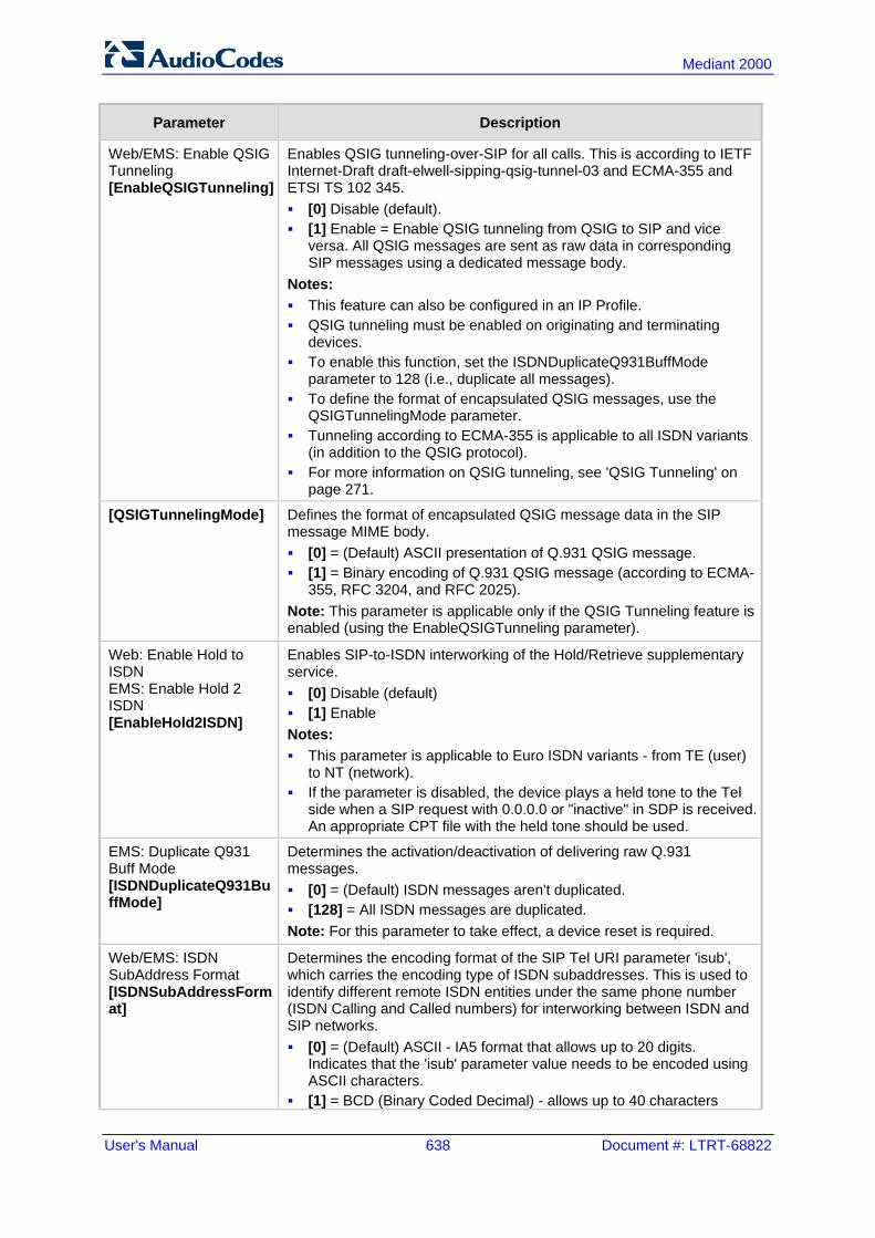
User's Manual 638 Document #: LTRT-68822
Mediant 2000
Parameter Description
Web/EMS: Enable QSIG Tunneling [EnableQSIGTunneling]
Enables QSIG tunneling-over-SIP for all calls. This is according to IETF Internet-Draft draft-elwell-sipping-qsig-tunnel-03 and ECMA-355 and ETSI TS 102 345. [0] Disable (default). [1] Enable = Enable QSIG tunneling from QSIG to SIP and vice
versa. All QSIG messages are sent as raw data in corresponding SIP messages using a dedicated message body.
Notes: This feature can also be configured in an IP Profile. QSIG tunneling must be enabled on originating and terminating
devices. To enable this function, set the ISDNDuplicateQ931BuffMode
parameter to 128 (i.e., duplicate all messages). To define the format of encapsulated QSIG messages, use the
QSIGTunnelingMode parameter. Tunneling according to ECMA-355 is applicable to all ISDN variants
(in addition to the QSIG protocol). For more information on QSIG tunneling, see 'QSIG Tunneling' on
page 271.
[QSIGTunnelingMode] Defines the format of encapsulated QSIG message data in the SIP message MIME body. [0] = (Default) ASCII presentation of Q.931 QSIG message. [1] = Binary encoding of Q.931 QSIG message (according to ECMA-
355, RFC 3204, and RFC 2025). Note: This parameter is applicable only if the QSIG Tunneling feature is enabled (using the EnableQSIGTunneling parameter).
Web: Enable Hold to ISDN EMS: Enable Hold 2 ISDN [EnableHold2ISDN]
Enables SIP-to-ISDN interworking of the Hold/Retrieve supplementary service. [0] Disable (default) [1] Enable Notes: This parameter is applicable to Euro ISDN variants - from TE (user)
to NT (network). If the parameter is disabled, the device plays a held tone to the Tel
side when a SIP request with 0.0.0.0 or "inactive" in SDP is received. An appropriate CPT file with the held tone should be used.
EMS: Duplicate Q931 Buff Mode [ISDNDuplicateQ931BuffMode]
Determines the activation/deactivation of delivering raw Q.931 messages. [0] = (Default) ISDN messages aren't duplicated. [128] = All ISDN messages are duplicated. Note: For this parameter to take effect, a device reset is required.
Web/EMS: ISDN SubAddress Format [ISDNSubAddressFormat]
Determines the encoding format of the SIP Tel URI parameter 'isub', which carries the encoding type of ISDN subaddresses. This is used to identify different remote ISDN entities under the same phone number (ISDN Calling and Called numbers) for interworking between ISDN and SIP networks. [0] = (Default) ASCII - IA5 format that allows up to 20 digits.
Indicates that the 'isub' parameter value needs to be encoded using ASCII characters.
[1] = BCD (Binary Coded Decimal) - allows up to 40 characters

Version 6.6 639 Mediant 2000
User's Manual 45. Configuration Parameters Reference
Parameter Description
(digits and letters). Indicates that the 'isub' parameter value needs to be encoded using BCD when translated to an ISDN message.
[2] = User Specified For IP-to-Tel calls, if the incoming SIP INVITE message includes subaddress values in the 'isub' parameter for the Called Number (in the Request-URI) and/or the Calling Number (in the From header), these values are mapped to the outgoing ISDN Setup message. If the incoming ISDN Setup message includes 'subaddress' values for the Called Number and/or the Calling Number, these values are mapped to the outgoing SIP INVITE message's ‘isub’ parameter in accordance with RFC 4715.
[IgnoreISDNSubaddress]
Determines whether the device ignores the Subaddress from the incoming ISDN Called and Calling numbers when sending to IP. [0] = (Default) If an incoming ISDN Q.931 Setup message contains a
Called/Calling Number Subaddress, the Subaddress is interworked to the SIP 'isub' parameter according to RFC.
[1] = The device removes the ISDN Subaddress and does not include the 'isub' parameter in the Request-URI and does not process INVITEs with this parameter.
[ISUBNumberOfDigits] Defines the number of digits (from the end) that the device takes from the called number (received from the IP) for the isub number (in the sent ISDN Setup message). This feature is only applicable for IP-to-ISDN calls. The valid value range is 0 to 36. The default is 0. This feature operates as follows: 1 If an isub parameter is received in the Request-URI, for example,
INVITE sip:9565645;[email protected]:user=phone SIP/2.0 then the isub value is sent in the ISDN Setup message as the destination subaddress.
2 If the isub parameter is not received in the user part of the Request-URI, the device searches for it in the URI parameters of the To header, for example, To: "Alex" <sip: [email protected];isub=1234> If present, the isub value is sent in the ISDN Setup message as the destination subaddress.
3 If the isub parameter is not present in the Request-URI header nor To header, the device does the following: If the called number (that appears in the user part of the
Request-URI) starts with zero (0), for example, INVITE sip:[email protected]:user=phone SIP/2.0 then the device maps this called number to the destination number of the ISDN Setup message, and the destination subaddress in this ISDN Setup message remains empty.
If the called number (that appears in the user part of the Request-URI) does not start with zero, for example, INVITE sip:[email protected]:user=phone SIP/2.0 then the device maps this called number to the destination number of the ISDN Setup message, and the destination subaddress in this ISDN Setup message then contains y digits from the end of the called number. The y number of digits can be configured using the ISUBNumberOfDigits parameter. The default value of ISUBNumberOfDigits is 0, thus, if this parameter

User's Manual 640 Document #: LTRT-68822
Mediant 2000
Parameter Description
is not configured, and 1) and 2) scenarios (described above) have not provided an isub value, the subaddress remains empty.
Web: Default Cause Mapping From ISDN to SIP [DefaultCauseMapISDN2IP]
Defines a single default ISDN release cause that is used (in ISDN-to-IP calls) instead of all received release causes, except when the following Q.931 cause values are received: Normal Call Clearing (16), User Busy (17), No User Responding (18), or No Answer from User (19). The range is any valid Q.931 release cause (0 to 127). The default is 0 (i.e., not configured - static mapping is used).
Release Cause Mapping from ISDN to SIP Table
Web: Release Cause Mapping Table EMS: ISDN to SIP Cause Mapping [CauseMapISDN2SIP]
This table parameter maps ISDN Q.850 Release Causes to SIP responses. The format of this parameter is as follows: [CauseMapISDN2SIP] FORMAT CauseMapISDN2SIP_Index = CauseMapISDN2SIP_IsdnReleaseCause, CauseMapISDN2SIP_SipResponse; [\CauseMapISDN2SIP] Where, IsdnReleaseCause = Q.850 Release Cause SipResponse = SIP Response For example: CauseMapISDN2SIP 0 = 50,480; CauseMapISDN2SIP 0 = 6,406; When a Release Cause is received (from the PSTN side), the device searches this mapping table for a match. If the Q.850 Release Cause is found, the SIP response assigned to it is sent to the IP side. If no match is found, the default static mapping is used. Note: This parameter can appear up to 12 times.
Release Cause Mapping from SIP to ISDN Table
Web: Release Cause Mapping Table EMS: SIP to ISDN Cause Mapping [CauseMapSIP2ISDN]
This table parameter maps SIP responses to Q.850 Release Causes. The format of this parameter is as follows: [CauseMapSIP2ISDN] FORMAT CauseMapSIP2ISDN_Index = CauseMapSIP2ISDN_SipResponse, CauseMapSIP2ISDN_IsdnReleaseCause; [\CauseMapSIP2ISDN] Where, SipResponse = SIP Response IsdnReleaseCause = Q.850 Release Cause For example: CauseMapSIP2ISDN 0 = 480,50; CauseMapSIP2ISDN 0 = 404,3; When a SIP response is received (from the IP side), the device searches this mapping table for a match. If the SIP response is found, the Q.850 Release Cause assigned to it is sent to the PSTN. If no match is found, the default static mapping is used. Note: This parameter can appear up to 12 times.
Web/EMS: Enable Calling Party Category [EnableCallingPartyCategory]
Determines whether Calling Party Category (CPC) is mapped between SIP and PRI. [0] Disable = (Default) Don't relay the CPC between SIP and PRI.

Version 6.6 641 Mediant 2000
User's Manual 45. Configuration Parameters Reference
Parameter Description
[1] Enable = The CPC is relayed between SIP and PRI. If enabled, the CPC received in the Originating Line Information (OLI) IE of an incoming ISDN Setup message is relayed to the From/P-Asserted-Identity headers using the 'cpc' parameter in the outgoing INVITE message, and vice versa. For example (calling party is a payphone): From:<sip:2000;[email protected]>;tag=1c1806157451
Note: This feature is applicable only to the NI-2 PRI variant.
[UserToUserHeaderFormat]
Defines the interworking between the SIP INVITE's User-to-User header and the ISDN User-to-User (UU) IE data. [0] = (Default) SIP header format: X-UserToUser. [1] = SIP header format: User-to-User with Protocol Discriminator
(pd) attribute (according to IETF Internet-Draft draft-johnston-sipping-cc-uui-04). For example:
User-to-User=3030373435313734313635353b313233343b3834;pd=4 [2] = SIP header format: User-to-User with encoding=hex at the end
and pd embedded as the first byte (according to IETF Internet-Draft draft-johnston-sipping-cc-uui-03). For example:
User-to-User=043030373435313734313635353b313233343b3834; encoding=hex
where "04" at the beginning of this message is the pd. [3] = Interworks the SIP User-to-User header containing text format
to ISDN UUIE in hexadecimal format, and vice versa. For example: SIP Header in text format:
User-to-User=01800213027b712a;NULL;4582166;
Translated to hexadecimal in the ISDN UUIE: 303138303032313330323762373132613b4e554c4c3b343538323136363b
The Protocol Discriminator (pd) used in UUIE is "04" (IUA characters).
Note: This parameter is applicable for Tel-to-IP and IP-to-Tel calls.
Web/EMS: Remove CLI when Restricted [RemoveCLIWhenRestricted]
Determines (for IP-to-Tel calls) whether the Calling Number and Calling Name IEs are removed from the ISDN Setup message if the presentation is set to Restricted. [0] No = (Default) IE's are not removed. [1] Yes = IE's are removed.
Web/EMS: Remove Calling Name [RemoveCallingName]
Enables the device to remove the Calling Name from SIP-to-ISDN calls for all trunks. [0] Disable = (Default) Does not remove Calling Name. [1] Enable = Removes Calling Name. Note: Some PSTN switches / PBXs may not be configured to support the receipt of the “Calling Name” information. These switches might respond to an ISDN Setup message (including the Calling Name) with an ISDN "REQUESTED_FAC_NOT_SUBSCRIBED" failure. This parameter can be set to Enable (1) to remove the “Calling Name” from SIP-to-ISDN calls and allow the call to proceed.

User's Manual 642 Document #: LTRT-68822
Mediant 2000
Parameter Description
Web: Remove Calling Name EMS: Remove Calling Name For Trunk Mode [RemoveCallingNameForTrunk_x]
Enables the device to remove the Calling Name per trunk for SIP-to-ISDN calls. [-1] Use Global Parameter = (Default) Settings of the global
parameter RemoveCallingName are used. [0] Disable = Does not remove Calling Name. [1] Enable = Remove Calling Name. Note: The x in the ini file parameter name denotes the trunk number, where 0 is Trunk 1.
Web/EMS: Progress Indicator to ISDN [ProgressIndicator2ISDN_x]
Determines the Progress Indicator (PI) to ISDN, per trunk. [-1] Not Configured = (Default) The PI in ISDN messages is set
according to the parameter PlayRBTone2Tel. [0] No PI = PI is not sent to ISDN. [1] PI = 1; [8] PI = 8: The PI value is sent to PSTN in
Q.931/Proceeding and Alerting messages. Typically, the PSTN/PBX cuts through the audio channel without playing local ringback tone, enabling the originating party to hear remote Call Progress Tones or network announcements.
Note: The x in the ini file parameter name denotes the trunk number, where 0 is Trunk 1.
Web: Set PI in Rx Disconnect Message EMS: Set PI For Disconnect Msg [PIForDisconnectMsg_x]
Defines the device's behavior when a Disconnect message is received from the ISDN before a Connect message is received, per trunk. [-1] Not Configured = (Default) Sends a 183 SIP response according
to the received progress indicator (PI) in the ISDN Disconnect message. If PI = 1 or 8, the device sends a 183 response, enabling the PSTN to play a voice announcement to the IP side. If there isn't a PI in the Disconnect message, the call is released.
[0] No PI = Doesn't send a 183 response to IP. The call is released. [1] PI = 1; [8] PI = 8: Sends a 183 response to IP. Note: The x in the ini file parameter name denotes the trunk number, where 0 is Trunk 1.
EMS: Connect On Progress Ind [ConnectOnProgressInd]
Enables the play of announcements from IP to PSTN without the need to answer the Tel-to-IP call. It can be used with PSTN networks that don't support the opening of a TDM channel before an ISDN Connect message is received. [0] = (Default) Connect message isn't sent after SIP 183 Session
Progress message is received. [1] = Connect message is sent after SIP 183 Session Progress
message is received.
Web: Local ISDN Ringback Tone Source EMS: Local ISDN RB Source [LocalISDNRBSource_x]
Determines whether the ringback tone is played to the ISDN by the PBX/PSTN or by the device, per trunk. [0] PBX = (Default) PBX/PSTN. [1] Gateway = The device plays the ringback tone. Notes: This parameter is applicable to ISDN protocols. This parameter is used together with the parameter
PlayRBTone2Trunk. The x in the ini file parameter name denotes the trunk number,
where 0 is Trunk 1.
Web/EMS: PSTN Alert Timeout
Defines the Alert Timeout (ISDN T301 timer) in seconds for outgoing calls to PSTN, per trunk. This timer is used between the time that an

Version 6.6 643 Mediant 2000
User's Manual 45. Configuration Parameters Reference
Parameter Description
[TrunkPSTNAlertTimeout_x]
ISDN Setup message is sent to the Tel side (IP-to-Tel call establishment) and a Connect message is received. If Alerting is received, the timer is restarted. The range is 1 to 600. The default is 180. Note: The x in the ini file parameter name denotes the trunk number, where 0 is Trunk 1.
Web: B-Channel Negotiation EMS: B-Channel Negotiation For Trunk Mode [BChannelNegotiationForTrunk_x]
Determines the ISDN B-channel negotiation mode, per trunk. [-1] Not Configured = (Default) Use per device configuration of the
BChannelNegotiation parameter. [0] Preferred. [1] Exclusive. [2] Any. Notes: This parameter is applicable to ISDN protocols. The option ‘Any’ is only applicable if TerminationSide is set to 0 (i.e.,
User side). The x in the ini file parameter name denotes the trunk number,
where 0 is Trunk 1.
[SendISDNServiceAfterRestart]
Enables the device to send an ISDN SERVice message per trunk upon device reset. The messsage (transmitted on the trunk's D-channel) indicates the availability of the trunk's B-channels (i.e., trunk in service). [0] = Disable (default) [0] = Enable
EMS: Support Redirect InFacility [SupportRedirectInFacility]
Determines whether the Redirect Number is retrieved from the Facility IE. [0] = (Default) Not supported. [1] = Supports partial retrieval of Redirect Number (number only)
from the Facility IE in ISDN Setup messages. This is applicable to Redirect Number according to ECMA-173 Call Diversion Supplementary Services.
Note: To enable this feature, the parameter ISDNDuplicateQ931BuffMode must be set to 1.
[CallReroutingMode]
Determines whether ISDN call rerouting (call forward) is performed by the PSTN instead of by the SIP side. This call forwarding is based on Call Deflection for Euro ISDN (ETS-300-207-1) and QSIG (ETSI TS 102 393). [0] Disable (default). [1] Enable = Enables ISDN call rerouting. When the device sends
the INVITE message to the remote SIP entity and receives a SIP 302 response with a Contact header containing a URI host name that is the same as the device's IP address, the device sends a Facility message with a Call Rerouting invoke method to the ISDN and waits for the PSTN side to disconnect the call.
Note: When this parameter is enabled, ensure that you configure in the Inbound IP Routing Table (PSTNPrefix ini file parameter) a rule to route the redirected call (using the user part from the 302 Contact header) to the same Trunk Group from where the incoming Tel-to-IP call was received.

User's Manual 644 Document #: LTRT-68822
Mediant 2000
Parameter Description
EMS: Enable CIC [EnableCIC]
Determines whether the Carrier Identification Code (CIC) is relayed to ISDN. [0] = (Default) Do not relay the Carrier Identification Code (CIC) to
ISDN. [1] = CIC is relayed to the ISDN in Transit Network Selection (TNS)
IE. If enabled, the CIC code (received in an INVITE Request-URI) is included in a TNS IE in the ISDN Setup message. For example: INVITE sip:555666;[email protected] sip/2.0. Notes: This feature is supported only for SIP-to-ISDN calls. The parameter AddCicAsPrefix can be used to add the CIC as a
prefix to the destination phone number for routing IP-to-Tel calls.
EMS: Enable AOC [EnableAOC]
Determines whether ISDN Advice of Charge (AOC) messages are interworked with SIP. [0] = (Default) Not used. [1] = AOC messages are interworked to SIP (in receive direction)
and sent to the PSTN in the transmit direction. The device supports both the receipt and sending of ISDN (Euro ISDN) AOC messages: AOC messages can be received during a call (Facility messages) or
at the end of a call (Disconnect or Release messages). The device converts the AOC messages into SIP INFO (during a call) and BYE (end of a call) messages, using a proprietary AOC SIP header. The device supports both Currency and Pulse AOC messages.
AOC messages can be sent during a call (Facility messages) or at the end of a call (Disconnect or Release messages). This is done by assigning the Charge Code index to the desired routing rule in the Outbound IP Routing table. For more information, see 'Advice of Charge Services for Euro ISDN' on page 353.
Web: IPMedia Detectors EMS: DSP Detectors Enable [EnableDSPIPMDetectors]
Enables the device's DSP detectors. [0] = Disable (default) [1] = Enable Notes: For this parameter to take effect, a device reset is required. The device's Software License Key must contain the 'IPMDetector'
DSP option. When enabled (1), the number of available channels is reduced by a
factor of 5/6. For example, a device with 8 E1 spans, capacity is reduced to 6 spans (180 channels), while a device with 8 T1 spans, capacity remains the same (192 channels).
Web: Add IE in SETUP EMS: IE To Be Added In Q.931 Setup [AddIEinSetup]
Adds an optional Information Element (IE) data (in hex format) to ISDN Setup messages. For example, to add IE '0x20,0x02,0x00,0xe1', enter the value "200200e1". Notes: This IE is sent from the Trunk Group IDs that are defined by the
parameter SendIEonTG. You can configure different IE data for Trunk Groups by defining this
parameter for different IP Profiles (using the IPProfile parameter) and then assigning the required IP Profile ID in the Inbound IP Routing Table (PSTNPrefix).
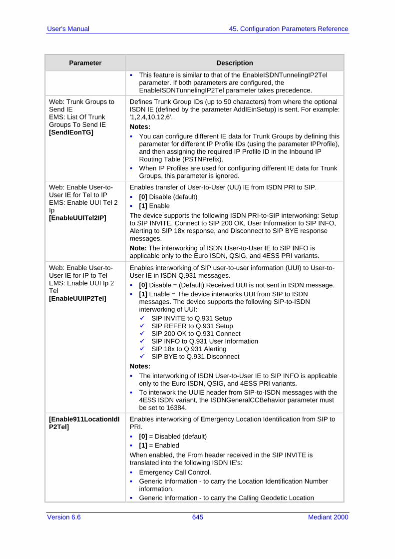
Version 6.6 645 Mediant 2000
User's Manual 45. Configuration Parameters Reference
Parameter Description
This feature is similar to that of the EnableISDNTunnelingIP2Tel parameter. If both parameters are configured, the EnableISDNTunnelingIP2Tel parameter takes precedence.
Web: Trunk Groups to Send IE EMS: List Of Trunk Groups To Send IE [SendIEonTG]
Defines Trunk Group IDs (up to 50 characters) from where the optional ISDN IE (defined by the parameter AddIEinSetup) is sent. For example: '1,2,4,10,12,6'. Notes: You can configure different IE data for Trunk Groups by defining this
parameter for different IP Profile IDs (using the parameter IPProfile), and then assigning the required IP Profile ID in the Inbound IP Routing Table (PSTNPrefix).
When IP Profiles are used for configuring different IE data for Trunk Groups, this parameter is ignored.
Web: Enable User-to-User IE for Tel to IP EMS: Enable UUI Tel 2 Ip [EnableUUITel2IP]
Enables transfer of User-to-User (UU) IE from ISDN PRI to SIP. [0] Disable (default) [1] Enable The device supports the following ISDN PRI-to-SIP interworking: Setup to SIP INVITE, Connect to SIP 200 OK, User Information to SIP INFO, Alerting to SIP 18x response, and Disconnect to SIP BYE response messages. Note: The interworking of ISDN User-to-User IE to SIP INFO is applicable only to the Euro ISDN, QSIG, and 4ESS PRI variants.
Web: Enable User-to-User IE for IP to Tel EMS: Enable UUI Ip 2 Tel [EnableUUIIP2Tel]
Enables interworking of SIP user-to-user information (UUI) to User-to-User IE in ISDN Q.931 messages. [0] Disable = (Default) Received UUI is not sent in ISDN message. [1] Enable = The device interworks UUI from SIP to ISDN
messages. The device supports the following SIP-to-ISDN interworking of UUI: SIP INVITE to Q.931 Setup SIP REFER to Q.931 Setup SIP 200 OK to Q.931 Connect SIP INFO to Q.931 User Information SIP 18x to Q.931 Alerting SIP BYE to Q.931 Disconnect
Notes: The interworking of ISDN User-to-User IE to SIP INFO is applicable
only to the Euro ISDN, QSIG, and 4ESS PRI variants. To interwork the UUIE header from SIP-to-ISDN messages with the
4ESS ISDN variant, the ISDNGeneralCCBehavior parameter must be set to 16384.
[Enable911LocationIdIP2Tel]
Enables interworking of Emergency Location Identification from SIP to PRI. [0] = Disabled (default) [1] = Enabled When enabled, the From header received in the SIP INVITE is translated into the following ISDN IE's: Emergency Call Control. Generic Information - to carry the Location Identification Number
information. Generic Information - to carry the Calling Geodetic Location

User's Manual 646 Document #: LTRT-68822
Mediant 2000
Parameter Description
information. Note: This capability is applicable only to the NI-2 ISDN variant.
[EarlyAnswerTimeout]
Defines the duration (in seconds) that the device waits for an ISDN Connect message from the called party (Tel side), started from when it sends a Setup message. If this timer expires, the call is answered by sending a SIP 200 OK message (to the IP side). The valid range is 0 to 2400. The default is 0 (i.e., disabled). Note: This parameter can be configured per IP Profile.
Web/EMS: Trunk Transfer Mode [TrunkTransferMode]
Determines the trunk transfer method (for all trunks) when a SIP REFER message is received. The transfer method depends on the Trunk's PSTN protocol (configured by the parameter ProtocolType) and is applicable only when one of these protocols are used:
PSTN Protocol Transfer Method (Described Below)
E1 Euro ISDN [1] ECT [2] or InBand [5]
E1 QSIG [21], T1 QSIG [23]
Single Step Transfer [4], Path Replacement Transfer [2], or InBand [5]
T1 NI2 ISDN [10], T1 4ESS ISDN [11], T1 5ESS 9 ISDN [12]
TBCT [2] or InBand [5]
T1 DMS-100 ISDN [14] RTL [2] or InBand [5]
T1 RAW CAS [3], T1 CAS [2], E1 CAS [8], E1 RAW CAS [9]
[1] CAS NFA DMS-100 or [3] CAS Normal transfer
T1 DMS-100 Meridian ISDN [35]
RTL [2] or InBand [5]
The valid values of this parameter are described below: [0] = Not supported (default). [1] = Supports CAS NFA DMS-100 transfer. When a SIP REFER
message is received, the device performs a Blind Transfer by executing a CAS Wink, waits for an acknowledged Wink from the remote side, dials the Refer-to number to the switch, and then releases the call. Note: A specific NFA CAS table is required.
[2] = Supports ISDN transfer - Release Link Trunk (RLT) (DMS-100), Two B Channel Transfer (TBCT) (NI2), Explicit Call Transfer (ECT) (EURO ISDN), and Path Replacement (QSIG). When a SIP REFER message is received, the device performs a transfer by sending Facility messages to the PBX with the necessary information on the call's legs to be connected. The different ISDN variants use slightly different methods (using Facility messages) to perform the transfer. Notes: For RLT ISDN transfer, the parameter
SendISDNTransferOnConnect must be set to 1. The parameter SendISDNTransferOnConnect can be used to
define if the TBCT/ECT transfer is performed after receipt of Alerting or Connect messages. For RLT, the transfer is always done after receipt of Connect (SendISDNTransferOnConnect is set to 1).

Version 6.6 647 Mediant 2000
User's Manual 45. Configuration Parameters Reference
Parameter Description
This transfer can be performed between B-channels from different trunks or Trunk Groups, by using the parameter EnableTransferAcrossTrunkGroups.
The device initiates the ECT process after receiving a SIP REFER message only for trunks that are configured to User side.
[3] = Supports CAS Normal transfer. When a SIP REFER message is received, the device performs a Blind Transfer by executing a CAS Wink, dialing the Refer-to number to the switch, and then releasing the call.
[4] = Supports QSIG Single Step transfer: IP-to-Tel: When a SIP REFER message is received, the device performs a transfer by sending a Facility message to the PBX, initiating Single Step transfer. Once a success return result is received, the transfer is completed. Tel-to-IP: When a Facility message initiating Single Step transfer is received from the PBX, a SIP REFER message is sent to the IP side.
[5] = IP-to-Tel Blind Transfer mode supported for ISDN protocols and implemented according to AT&T Toll Free Transfer Connect Service (TR 50075) “Courtesy Transfer-Human-No Data”. When the device receives a SIP REFER message, it performs a blind transfer by first dialing the DTMF digits (transfer prefix) defined by the parameter XferPrefixIP2Tel (configured to "*8" for AT&T service), and then (after 500 msec) the device dials the DTMF of the number (referred) from the Refer-To header sip:URI userpart. If the hostpart of the Refer-To sip:URI contains the device's IP address, and if the Trunk Group selected according to the IP to Tel Routing table is the same Trunk Group as the original call, then the device performs the in-band DTMF transfer; otherwise, the device sends the INVITE according to regular transfer rules. After completing the in-band transfer, the device waits for the ISDN Disconnect message. If the Disconnect message is received during the first 5 seconds, the device sends a SIP NOTIFY with 200 OK message; otherwise, the device sends a NOTIFY with 4xx message.
[6] = Supports AT&T toll free out-of-band blind transfer for trunks configured with the 4ESS ISDN protocol. AT&T courtesy transfer is a supplementary service which enables a user (e.g., user "A") to transform an established call between it and user "B" into a new call between users "B" and "C", whereby user "A" does not have a call established with user "C" prior to call transfer. The device handles this feature as follows: IP-to-Tel (user side): When a SIP REFER message is received,
the device initiates a transfer by sending a Facility message to the PBX.
Tel-to-IP (network side): When a Facility message initiating an out-of-band blind transfer is received from the PBX, the device sends a SIP REFER message to the IP side (if the EnableNetworkISDNTransfer parameter is set to 1).
Note: For configuring trunk transfer mode per trunk, use the parameter TrunkTransferMode_X.
[TrunkTransferMode_X]
Determines the trunk transfer mode per trunk (where x is the Trunk ID). For configuring trunk transfer mode for all trunks and for a description of the parameter options, refer to the parameter TrunkTransferMode.
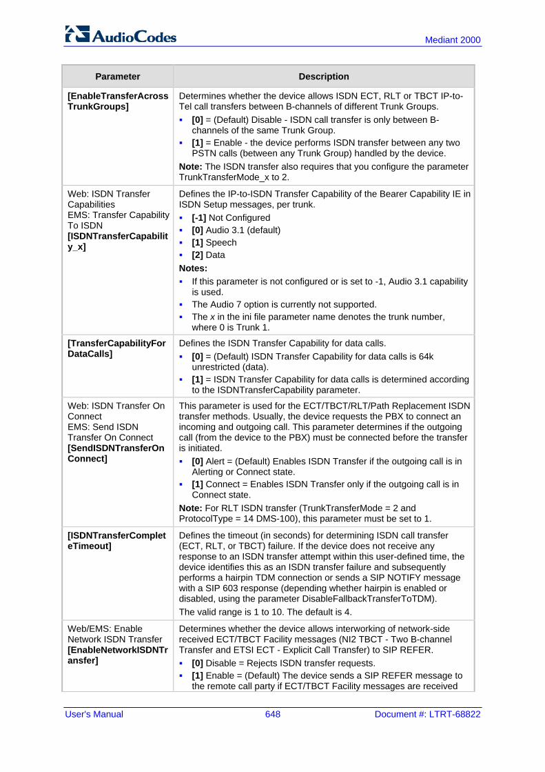
User's Manual 648 Document #: LTRT-68822
Mediant 2000
Parameter Description
[EnableTransferAcrossTrunkGroups]
Determines whether the device allows ISDN ECT, RLT or TBCT IP-to-Tel call transfers between B-channels of different Trunk Groups. [0] = (Default) Disable - ISDN call transfer is only between B-
channels of the same Trunk Group. [1] = Enable - the device performs ISDN transfer between any two
PSTN calls (between any Trunk Group) handled by the device. Note: The ISDN transfer also requires that you configure the parameter TrunkTransferMode_x to 2.
Web: ISDN Transfer Capabilities EMS: Transfer Capability To ISDN [ISDNTransferCapability_x]
Defines the IP-to-ISDN Transfer Capability of the Bearer Capability IE in ISDN Setup messages, per trunk. [-1] Not Configured [0] Audio 3.1 (default) [1] Speech [2] Data Notes: If this parameter is not configured or is set to -1, Audio 3.1 capability
is used. The Audio 7 option is currently not supported. The x in the ini file parameter name denotes the trunk number,
where 0 is Trunk 1.
[TransferCapabilityForDataCalls]
Defines the ISDN Transfer Capability for data calls. [0] = (Default) ISDN Transfer Capability for data calls is 64k
unrestricted (data). [1] = ISDN Transfer Capability for data calls is determined according
to the ISDNTransferCapability parameter.
Web: ISDN Transfer On Connect EMS: Send ISDN Transfer On Connect [SendISDNTransferOnConnect]
This parameter is used for the ECT/TBCT/RLT/Path Replacement ISDN transfer methods. Usually, the device requests the PBX to connect an incoming and outgoing call. This parameter determines if the outgoing call (from the device to the PBX) must be connected before the transfer is initiated. [0] Alert = (Default) Enables ISDN Transfer if the outgoing call is in
Alerting or Connect state. [1] Connect = Enables ISDN Transfer only if the outgoing call is in
Connect state. Note: For RLT ISDN transfer (TrunkTransferMode = 2 and ProtocolType = 14 DMS-100), this parameter must be set to 1.
[ISDNTransferCompleteTimeout]
Defines the timeout (in seconds) for determining ISDN call transfer (ECT, RLT, or TBCT) failure. If the device does not receive any response to an ISDN transfer attempt within this user-defined time, the device identifies this as an ISDN transfer failure and subsequently performs a hairpin TDM connection or sends a SIP NOTIFY message with a SIP 603 response (depending whether hairpin is enabled or disabled, using the parameter DisableFallbackTransferToTDM). The valid range is 1 to 10. The default is 4.
Web/EMS: Enable Network ISDN Transfer [EnableNetworkISDNTransfer]
Determines whether the device allows interworking of network-side received ECT/TBCT Facility messages (NI2 TBCT - Two B-channel Transfer and ETSI ECT - Explicit Call Transfer) to SIP REFER. [0] Disable = Rejects ISDN transfer requests. [1] Enable = (Default) The device sends a SIP REFER message to
the remote call party if ECT/TBCT Facility messages are received

Version 6.6 649 Mediant 2000
User's Manual 45. Configuration Parameters Reference
Parameter Description
from the ISDN side (e.g., from a PBX).
[DisableFallbackTransferToTDM]
Enables "hairpin" TDM transfer upon ISDN (ECT, RLT, or TBCT) call transfer failure. When this feature is enabled and an ISDN call transfer failure occurs, the device sends a SIP NOTIFY message with a SIP 603 Decline response. [0] = (Default) The device performs a hairpin TDM transfer upon
ISDN call transfer. [1] = Hairpin TDM transfer is disabled.
Web: Enable QSIG Transfer Update [EnableQSIGTransferUpdate]
Determines whether the device interworks QSIG Facility messages with CallTranferComplete or CallTransferUpdate invoke application protocol data units (APDU) to SIP UPDATE messages with P-Asserted-Identity and optional Privacy headers. This feature is supported for IP-to-Tel and Tel-to-IP calls. [0] Disable = (Default) Ignores QSIG Facility messages with
CallTranferComplete or CallTransferUpdate invokes. [1] Enable For example, assume A and C are PBX call parties and B is the SIP IP phone: 1 A calls B; B answers the call. 2 A places B on hold and calls C; C answers the call. 3 A performs a call transfer (the transfer is done internally by the PBX);
B and C are connected to one another. In the above example, the PBX updates B that it is now talking with C. The PBX updates this by sending a QSIG Facility message with CallTranferComplete invoke APDU. The device interworks this message to a SIP UPDATE message containing a P-Asserted-Identity header with the number and name derived from the QSIG CallTranferComplete RedirectionNumber and RedirectionName. Notes: For IP-to-Tel calls, the RedirectionNumber and RedirectionName in
the CallTRansferComplete invoke is derived from the P-Asserted-Identity and Privacy headers in the received SIP INFO message.
To include the P-Asserted-Identity header in outgoing SIP UPDATE messages, set the AssertedIDMode parameter to Add P-Asserted-Identity.
EMS: CAS Detection Of Hook Flash [CASSendHookFlash]
Enables sending Wink signal toward CAS trunks. [0] = Disable (default) [1] = Enable If the device receives a mid-call SIP INFO message with flashhook event body (as shown below) and this parameter is set to 1, the device generates a wink signal toward the CAS trunk. The CAS wink signal is done by changing the A bit from 1 to 0, and then back to 1 for 450 msec. INFO sip:[email protected]:5060 SIP/2.0 Via: SIP/2.0/UDP 192.168.13.2:5060 From: <sip:[email protected]:5060> To: <sip:[email protected]:5060>;tag=132878796-1040067870294 Call-ID: [email protected] CSeq:2 INFO
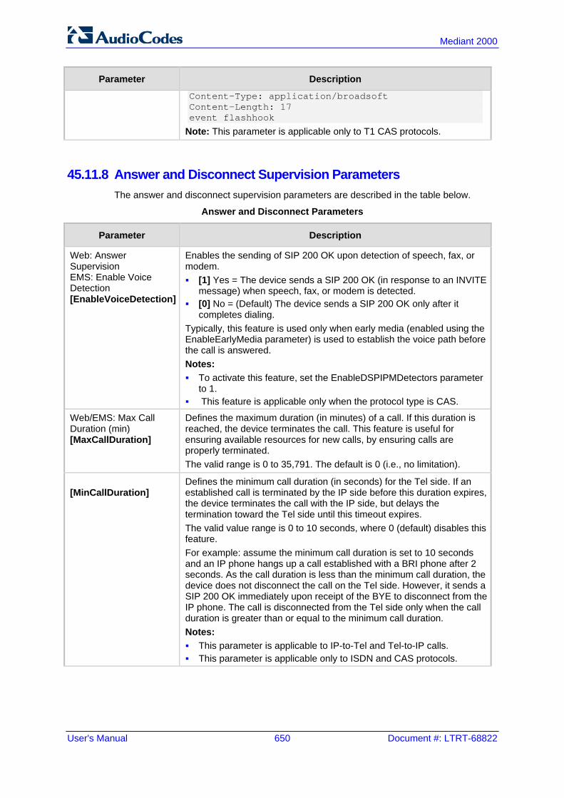
User's Manual 650 Document #: LTRT-68822
Mediant 2000
Parameter Description
Content-Type: application/broadsoft Content-Length: 17 event flashhook
Note: This parameter is applicable only to T1 CAS protocols.
45.11.8 Answer and Disconnect Supervision Parameters The answer and disconnect supervision parameters are described in the table below.
Answer and Disconnect Parameters
Parameter Description
Web: Answer Supervision EMS: Enable Voice Detection [EnableVoiceDetection]
Enables the sending of SIP 200 OK upon detection of speech, fax, or modem. [1] Yes = The device sends a SIP 200 OK (in response to an INVITE
message) when speech, fax, or modem is detected. [0] No = (Default) The device sends a SIP 200 OK only after it
completes dialing. Typically, this feature is used only when early media (enabled using the EnableEarlyMedia parameter) is used to establish the voice path before the call is answered. Notes: To activate this feature, set the EnableDSPIPMDetectors parameter
to 1. This feature is applicable only when the protocol type is CAS.
Web/EMS: Max Call Duration (min) [MaxCallDuration]
Defines the maximum duration (in minutes) of a call. If this duration is reached, the device terminates the call. This feature is useful for ensuring available resources for new calls, by ensuring calls are properly terminated. The valid range is 0 to 35,791. The default is 0 (i.e., no limitation).
[MinCallDuration]
Defines the minimum call duration (in seconds) for the Tel side. If an established call is terminated by the IP side before this duration expires, the device terminates the call with the IP side, but delays the termination toward the Tel side until this timeout expires. The valid value range is 0 to 10 seconds, where 0 (default) disables this feature. For example: assume the minimum call duration is set to 10 seconds and an IP phone hangs up a call established with a BRI phone after 2 seconds. As the call duration is less than the minimum call duration, the device does not disconnect the call on the Tel side. However, it sends a SIP 200 OK immediately upon receipt of the BYE to disconnect from the IP phone. The call is disconnected from the Tel side only when the call duration is greater than or equal to the minimum call duration. Notes: This parameter is applicable to IP-to-Tel and Tel-to-IP calls. This parameter is applicable only to ISDN and CAS protocols.
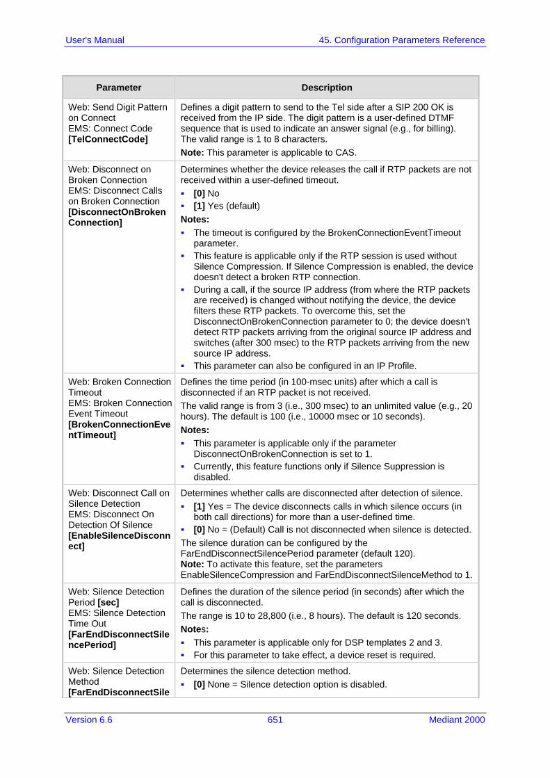
Version 6.6 651 Mediant 2000
User's Manual 45. Configuration Parameters Reference
Parameter Description
Web: Send Digit Pattern on Connect EMS: Connect Code [TelConnectCode]
Defines a digit pattern to send to the Tel side after a SIP 200 OK is received from the IP side. The digit pattern is a user-defined DTMF sequence that is used to indicate an answer signal (e.g., for billing). The valid range is 1 to 8 characters. Note: This parameter is applicable to CAS.
Web: Disconnect on Broken Connection EMS: Disconnect Calls on Broken Connection [DisconnectOnBrokenConnection]
Determines whether the device releases the call if RTP packets are not received within a user-defined timeout. [0] No [1] Yes (default) Notes: The timeout is configured by the BrokenConnectionEventTimeout
parameter. This feature is applicable only if the RTP session is used without
Silence Compression. If Silence Compression is enabled, the device doesn't detect a broken RTP connection.
During a call, if the source IP address (from where the RTP packets are received) is changed without notifying the device, the device filters these RTP packets. To overcome this, set the DisconnectOnBrokenConnection parameter to 0; the device doesn't detect RTP packets arriving from the original source IP address and switches (after 300 msec) to the RTP packets arriving from the new source IP address.
This parameter can also be configured in an IP Profile.
Web: Broken Connection Timeout EMS: Broken Connection Event Timeout [BrokenConnectionEventTimeout]
Defines the time period (in 100-msec units) after which a call is disconnected if an RTP packet is not received. The valid range is from 3 (i.e., 300 msec) to an unlimited value (e.g., 20 hours). The default is 100 (i.e., 10000 msec or 10 seconds). Notes: This parameter is applicable only if the parameter
DisconnectOnBrokenConnection is set to 1. Currently, this feature functions only if Silence Suppression is
disabled.
Web: Disconnect Call on Silence Detection EMS: Disconnect On Detection Of Silence [EnableSilenceDisconnect]
Determines whether calls are disconnected after detection of silence. [1] Yes = The device disconnects calls in which silence occurs (in
both call directions) for more than a user-defined time. [0] No = (Default) Call is not disconnected when silence is detected. The silence duration can be configured by the FarEndDisconnectSilencePeriod parameter (default 120). Note: To activate this feature, set the parameters EnableSilenceCompression and FarEndDisconnectSilenceMethod to 1.
Web: Silence Detection Period [sec] EMS: Silence Detection Time Out [FarEndDisconnectSilencePeriod]
Defines the duration of the silence period (in seconds) after which the call is disconnected. The range is 10 to 28,800 (i.e., 8 hours). The default is 120 seconds. Notes: This parameter is applicable only for DSP templates 2 and 3. For this parameter to take effect, a device reset is required.
Web: Silence Detection Method [FarEndDisconnectSile
Determines the silence detection method. [0] None = Silence detection option is disabled.

User's Manual 652 Document #: LTRT-68822
Mediant 2000
Parameter Description
nceMethod] [1] Packets Count = According to packet count. Note: For this parameter to take effect, a device reset is required.
[FarEndDisconnectSilenceThreshold]
Defines the threshold of the packet count (in percentages) below which is considered silence by the device. The valid range is 1 to 100%. The default is 8%. Notes: This parameter is applicable only if silence is detected according to
packet count (FarEndDisconnectSilenceMethod is set to 1). For this parameter to take effect, a device reset is required.
[BrokenConnectionDuringSilence]
Enables the generation of the BrokenConnection event during a silence period if the channel’s NoOp feature is enabled (using the parameter NoOpEnable) and if the channel stops receiving NoOp RTP packets. [0] Disable (default) [1] Enable
Web: Trunk Alarm Call Disconnect Timeout [TrunkAlarmCallDisconnectTimeout]
Defines the duration (in seconds) to wait after an E1/T1 trunk "Red" alarm (LOS / LOF) is raised, before the device disconnects the SIP call. If this timeout expires and the alarm is still raised, the device sends a SIP BYE message to terminate the call. If the alarm is cleared before this timeout expires, the call is not terminated, but continues as normal. The range is 1 to 3600. The default is 0 (20 for E1 and 40 for T1).
Web: Disconnect Call on Busy Tone Detection (ISDN) EMS: Isdn Disconnect On Busy Tone [ISDNDisconnectOnBusyTone]
Determines whether a call is disconnected upon detection of a busy tone (for ISDN). [0] Disable = (Default) Do not disconnect call upon detection of busy
tone. [1] Enable = Disconnect call upon detection of busy tone. Notes: This parameter is applicable only to ISDN protocols. IP-to-ISDN calls are disconnected on detection of SIT tones only in
call alert state. If the call is in connected state, the SIT does not disconnect the calls. Detection of busy or reorder tones disconnects the IP-to-ISDN calls also in call connected state.
For IP-to-CAS calls, detection of busy, reorder, or SIT tones disconnect the calls in any call state.
Web: Disconnect Call on Busy Tone Detection (CAS) EMS: Disconnect On Detection End Tones [DisconnectOnBusyTone]
Determines whether a call is disconnected upon detection of a busy tone. [0] Disable = Call is not disconnected upon detection of a busy tone. [1] Enable = (Default) Call is released upon detection of busy or
reorder (fast busy) tone. Notes: This parameter is applicable only to CAS protocols. This parameter is also applicable to the IP-to-IP application. This parameter can also be configured in a Tel Profile.
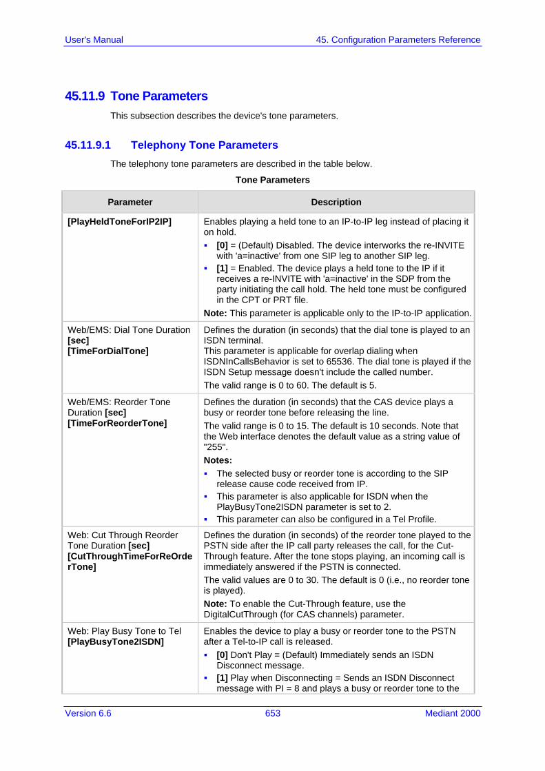
Version 6.6 653 Mediant 2000
User's Manual 45. Configuration Parameters Reference
45.11.9 Tone Parameters This subsection describes the device's tone parameters.
45.11.9.1 Telephony Tone Parameters The telephony tone parameters are described in the table below.
Tone Parameters
Parameter Description
[PlayHeldToneForIP2IP] Enables playing a held tone to an IP-to-IP leg instead of placing it on hold. [0] = (Default) Disabled. The device interworks the re-INVITE
with 'a=inactive' from one SIP leg to another SIP leg. [1] = Enabled. The device plays a held tone to the IP if it
receives a re-INVITE with 'a=inactive' in the SDP from the party initiating the call hold. The held tone must be configured in the CPT or PRT file.
Note: This parameter is applicable only to the IP-to-IP application.
Web/EMS: Dial Tone Duration [sec] [TimeForDialTone]
Defines the duration (in seconds) that the dial tone is played to an ISDN terminal. This parameter is applicable for overlap dialing when ISDNInCallsBehavior is set to 65536. The dial tone is played if the ISDN Setup message doesn't include the called number. The valid range is 0 to 60. The default is 5.
Web/EMS: Reorder Tone Duration [sec] [TimeForReorderTone]
Defines the duration (in seconds) that the CAS device plays a busy or reorder tone before releasing the line. The valid range is 0 to 15. The default is 10 seconds. Note that the Web interface denotes the default value as a string value of "255". Notes: The selected busy or reorder tone is according to the SIP
release cause code received from IP. This parameter is also applicable for ISDN when the
PlayBusyTone2ISDN parameter is set to 2. This parameter can also be configured in a Tel Profile.
Web: Cut Through Reorder Tone Duration [sec] [CutThroughTimeForReOrderTone]
Defines the duration (in seconds) of the reorder tone played to the PSTN side after the IP call party releases the call, for the Cut-Through feature. After the tone stops playing, an incoming call is immediately answered if the PSTN is connected. The valid values are 0 to 30. The default is 0 (i.e., no reorder tone is played). Note: To enable the Cut-Through feature, use the DigitalCutThrough (for CAS channels) parameter.
Web: Play Busy Tone to Tel [PlayBusyTone2ISDN]
Enables the device to play a busy or reorder tone to the PSTN after a Tel-to-IP call is released. [0] Don't Play = (Default) Immediately sends an ISDN
Disconnect message. [1] Play when Disconnecting = Sends an ISDN Disconnect
message with PI = 8 and plays a busy or reorder tone to the

User's Manual 654 Document #: LTRT-68822
Mediant 2000
Parameter Description
PSTN (depending on the release cause). [2] Play before Disconnect = Delays the sending of an ISDN
Disconnect message for a user-defined time (configured by the TimeForReorderTone parameter) and plays a busy or reorder tone to the PSTN. This is applicable only if the call is released from the IP [Busy Here (486) or Not Found (404)] before it reaches the Connect state; otherwise, the Disconnect message is sent immediately and no tones are played.
Web: Play Ringback Tone to Tel EMS: Play Ring Back Tone To Tel [PlayRBTone2Tel]
Determines the playing method of the ringback tone to the Trunk (for digital interfaces) side.This parameter applies to all trunks that are not configured by the PlayRBTone2Trunk parameter (which defines ringback tone per Trunk). [0] Don't Play = The device configured for ISDN / CAS doesn't play a
ringback tone. No PI is sent to the ISDN unless the ProgressIndicator2ISDN_x parameter is configured differently.
[1] Play on Local = The device configured for CAS plays a local ringback tone
to the PSTN upon receipt of a SIP 180 Ringing response (with or without SDP). Note that the receipt of a 183 response does not cause the device configured for CAS to play a ringback tone (unless the SIP183Behaviour parameter is set to 1). The device configured for ISDN operates according to the LocalISDNRBSource parameter: 1) If the device receives a 180 Ringing response (with or without SDP) and the LocalISDNRBSource parameter is set to 1, it plays a ringback tone and sends an ISDN Alert with PI = 8 (unless the ProgressIndicator2ISDN_x parameter is configured differently). 2) If the LocalISDNRBSource parameter is set to 0, the device doesn't play a ringback tone and an Alert message without PI is sent to the ISDN. In this case, the PBX / PSTN plays the ringback tone to the originating terminal. Note that the receipt of a 183 response does not cause the device configured for ISDN to play a ringback tone; the device issues a Progress message (unless SIP183Behaviour is set to 1). If the SIP183Behaviour parameter is set to 1, the 183 response is handled the same way as a 180 Ringing response.
[2] Prefer IP = (Default): Plays according to 'Early Media'. If a SIP 180 response is
received and the voice channel is already open (due to a previous 183 early media response or due to an SDP in the current 180 response), the device configured for ISDN / CAS doesn't play the ringback tone; PI = 8 is sent in an ISDN Alert message (unless the ProgressIndicator2ISDN_x parameter is configured differently). If a 180 response is received, but the 'early media' voice channel is not opened, the device configured for CAS plays a ringback tone to the PSTN. The device configured for ISDN operates according to the LocalISDNRBSource parameter: 1) If LocalISDNRBSource is set to 1, the device plays a ringback tone and sends an ISDN Alert with PI = 8 to the

Version 6.6 655 Mediant 2000
User's Manual 45. Configuration Parameters Reference
Parameter Description
ISDN (unless the ProgressIndicator2ISDN_x parameter is configured differently). 2) If LocalISDNRBSource is set to 0, the device doesn't play a ringback tone. No PI is sent in the ISDN Alert message (unless the ProgressIndicator2ISDN_x parameter is configured differently). In this case, the PBX / PSTN plays a ringback tone to the originating terminal. Note that the receipt of a 183 response results in an ISDN Progress message (unless SIP183Behaviour is set to 1). If SIP183Behaviour is set to 1 (183 is handled the same way as a 180 + SDP), the device sends an Alert message with PI = 8, without playing a ringback tone.
[3] Play Local Until Remote Media Arrive = Plays a ringback tone according to received media. The behaviour is similar to [2]. If a SIP 180 response is received and the voice channel is already open (due to a previous 183 early media response or due to an SDP in the current 180 response), the device plays a local ringback tone if there are no prior received RTP packets. The device stops playing the local ringback tone as soon as it starts receiving RTP packets. At this stage, if the device receives additional 18x responses, it does not resume playing the local ringback tone. Note that for ISDN trunks, this option is applicable only if the LocalISDNRBSource parameter is set to 1.
Note: This parameter is applicable to the Gateway and IP-to-IP applications.
Web: Play Ringback Tone to Trunk [PlayRBTone2Trunk_x]
Determines the playing method of the ringback tone to the trunk side per trunk. [-1] Not configured = (Default) The settings of the
PlayRBTone2Tel parameter is used. [0] Don't Play = When the device is configured for ISDN /
CAS, it doesn't play a ringback tone. No Progress Indicator (PI) is sent to the ISDN unless the ProgressIndicator2ISDN_ID parameter is configured differently.
[1] Play on Local = When the device is configured for CAS, it plays a local ringback tone to the PSTN upon receipt of a SIP 180 Ringing response (with or without SDP). Note that the receipt of a SIP 183 response does not cause the device configured for CAS to play a ringback tone (unless the SIP183Behaviour parameter is set to 1). When the device is configured for ISDN, it operates according to the LocalISDNRBSource parameter, as follows: If the device receives a SIP 180 Ringing response (with or
without SDP) and the LocalISDNRBSource parameter is set to 1, it plays a ringback tone and sends an ISDN Alert with PI = 8 (unless the ProgressIndicator2ISDN_ID parameter is configured differently).
If the LocalISDNRBSource parameter is set to 0, the device doesn't play a ringback tone and an Alert message without PI is sent to the ISDN. In this case, the PBX / PSTN plays the ringback tone to the originating terminal. Note that the receipt of a 183 response does not cause the device to play a ringback tone; the device sends a Progress message (unless SIP183Behaviour is set to 1). If

User's Manual 656 Document #: LTRT-68822
Mediant 2000
Parameter Description
the SIP183Behaviour parameter is set to 1, the 183 response is handled the same way as a 180 Ringing response.
[2] Prefer IP = Plays according to 'Early Media'. If a SIP 180 response is received and the voice channel is already open (due to a previous 183 early media response or due to an SDP in the current 180 response), the device configured for ISDN / CAS doesn't play the ringback tone; PI = 8 is sent in an ISDN Alert message (unless the ProgressIndicator2ISDN_ID parameter is configured differently). If a 180 response is received, but the 'early media' voice channel is not opened, the device configured for CAS plays a ringback tone to the PSTN. The device configured for ISDN operates according to the LocalISDNRBSource parameter: If LocalISDNRBSource is set to 1, the device plays a
ringback tone and sends an ISDN Alert with PI = 8 to the ISDN (unless the ProgressIndicator2ISDN_ID parameter is configured differently).
If LocalISDNRBSource is set to 0, the device doesn't play a ringback tone. No PI is sent in the ISDN Alert message (unless the ProgressIndicator2ISDN_ID parameter is configured differently). In this case, the PBX / PSTN plays a ringback tone to the originating terminal. Note that the receipt of a 183 response results in an ISDN Progress message (unless SIP183Behaviour is set to 1). If SIP183Behaviour is set to 1 (183 is handled the same way as a 180 with SDP), the device sends an Alert message with PI = 8 without playing a ringback tone.
[3] Play Local Until Remote Media Arrive = Plays tone according to received media. The behaviour is similar to option [2]. If a SIP 180 response is received and the voice channel is already open (due to a previous 183 early media response or due to an SDP in the current 180 response), the device plays a local ringback tone if there are no prior received RTP packets. The device stops playing the local ringback tone as soon as it starts receiving RTP packets. At this stage, if the device receives additional 18x responses, it does not resume playing the local ringback tone. Note that for ISDN trunks, this option is applicable only if LocalISDNRBSource is set to 1.
Notes: This parameter is applicable only to the Gateway (GW)
application (i.e., not the IP-to-IP application). The x in the ini file parameter name denotes the trunk number,
where 0 is Trunk 1.
Web: Play Ringback Tone to IP EMS: Play Ring Back Tone To IP [PlayRBTone2IP]
Determines whether the device plays a ringback tone to the IP side for IP-to-Tel calls. [0] Don't Play = (Default) Ringback tone isn't played. [1] Play = Ringback tone is played after SIP 183 session
progress response is sent. If configured to 1 ('Play') and EnableEarlyMedia is set to 1, the device plays a ringback tone according to the following: For CAS interfaces: the device opens a voice channel, sends
a 183+SDP response, and then plays a ringback tone to IP. For ISDN interfaces: if a Progress or an Alerting message with
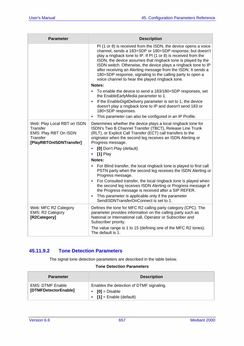
Version 6.6 657 Mediant 2000
User's Manual 45. Configuration Parameters Reference
Parameter Description
PI (1 or 8) is received from the ISDN, the device opens a voice channel, sends a 183+SDP or 180+SDP response, but doesn't play a ringback tone to IP. If PI (1 or 8) is received from the ISDN, the device assumes that ringback tone is played by the ISDN switch. Otherwise, the device plays a ringback tone to IP after receiving an Alerting message from the ISDN. It sends a 180+SDP response, signaling to the calling party to open a voice channel to hear the played ringback tone.
Notes: To enable the device to send a 183/180+SDP responses, set
the EnableEarlyMedia parameter to 1. If the EnableDigitDelivery parameter is set to 1, the device
doesn't play a ringback tone to IP and doesn't send 183 or 180+SDP responses.
This parameter can also be configured in an IP Profile.
Web: Play Local RBT on ISDN Transfer EMS: Play RBT On ISDN Transfer [PlayRBTOnISDNTransfer]
Determines whether the device plays a local ringback tone for ISDN's Two B Channel Transfer (TBCT), Release Line Trunk (RLT), or Explicit Call Transfer (ECT) call transfers to the originator when the second leg receives an ISDN Alerting or Progress message. [0] Don't Play (default) [1] Play Notes: For Blind transfer, the local ringback tone is played to first call
PSTN party when the second leg receives the ISDN Alerting or Progress message.
For Consulted transfer, the local ringback tone is played when the second leg receives ISDN Alerting or Progress message if the Progress message is received after a SIP REFER.
This parameter is applicable only if the parameter SendISDNTransferOnConnect is set to 1.
Web: MFC R2 Category EMS: R2 Category [R2Category]
Defines the tone for MFC R2 calling party category (CPC). The parameter provides information on the calling party such as National or International call, Operator or Subscriber and Subscriber priority. The value range is 1 to 15 (defining one of the MFC R2 tones). The default is 1.
45.11.9.2 Tone Detection Parameters The signal tone detection parameters are described in the table below.
Tone Detection Parameters
Parameter Description
EMS: DTMF Enable [DTMFDetectorEnable]
Enables the detection of DTMF signaling. [0] = Disable [1] = Enable (default)
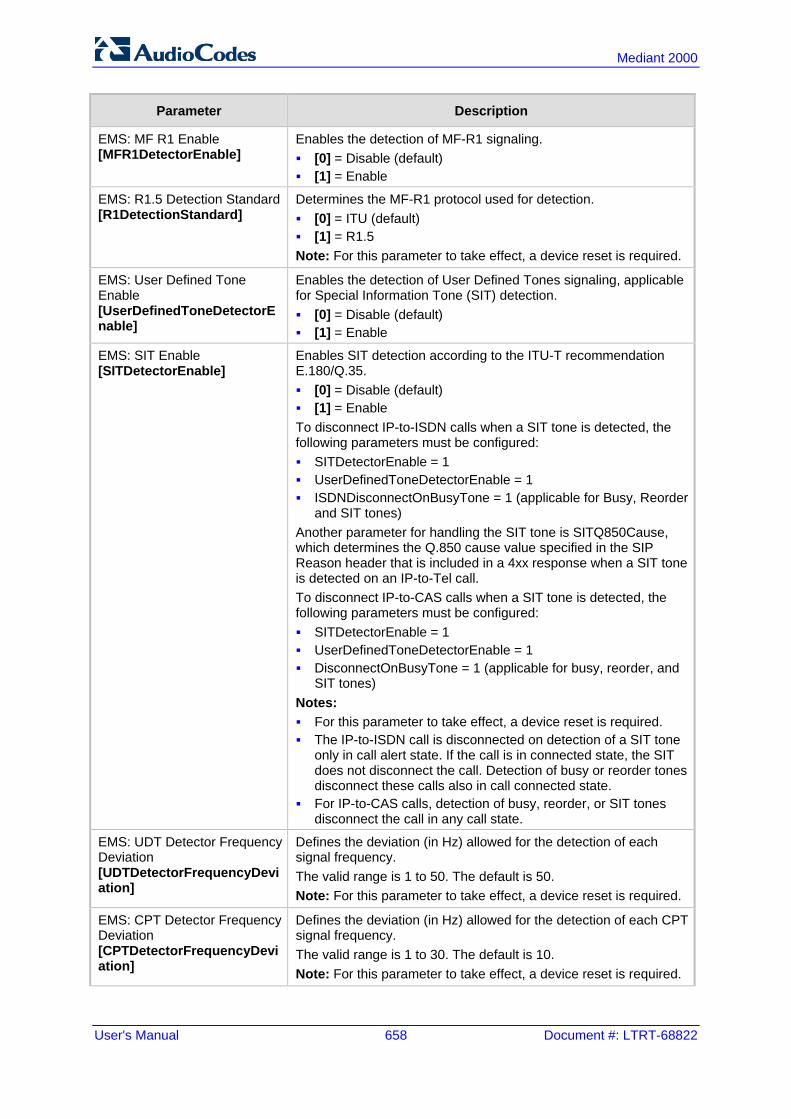
User's Manual 658 Document #: LTRT-68822
Mediant 2000
Parameter Description
EMS: MF R1 Enable [MFR1DetectorEnable]
Enables the detection of MF-R1 signaling. [0] = Disable (default) [1] = Enable
EMS: R1.5 Detection Standard [R1DetectionStandard]
Determines the MF-R1 protocol used for detection. [0] = ITU (default) [1] = R1.5 Note: For this parameter to take effect, a device reset is required.
EMS: User Defined Tone Enable [UserDefinedToneDetectorEnable]
Enables the detection of User Defined Tones signaling, applicable for Special Information Tone (SIT) detection. [0] = Disable (default) [1] = Enable
EMS: SIT Enable [SITDetectorEnable]
Enables SIT detection according to the ITU-T recommendation E.180/Q.35. [0] = Disable (default) [1] = Enable To disconnect IP-to-ISDN calls when a SIT tone is detected, the following parameters must be configured: SITDetectorEnable = 1 UserDefinedToneDetectorEnable = 1 ISDNDisconnectOnBusyTone = 1 (applicable for Busy, Reorder
and SIT tones) Another parameter for handling the SIT tone is SITQ850Cause, which determines the Q.850 cause value specified in the SIP Reason header that is included in a 4xx response when a SIT tone is detected on an IP-to-Tel call. To disconnect IP-to-CAS calls when a SIT tone is detected, the following parameters must be configured: SITDetectorEnable = 1 UserDefinedToneDetectorEnable = 1 DisconnectOnBusyTone = 1 (applicable for busy, reorder, and
SIT tones) Notes: For this parameter to take effect, a device reset is required. The IP-to-ISDN call is disconnected on detection of a SIT tone
only in call alert state. If the call is in connected state, the SIT does not disconnect the call. Detection of busy or reorder tones disconnect these calls also in call connected state.
For IP-to-CAS calls, detection of busy, reorder, or SIT tones disconnect the call in any call state.
EMS: UDT Detector Frequency Deviation [UDTDetectorFrequencyDeviation]
Defines the deviation (in Hz) allowed for the detection of each signal frequency. The valid range is 1 to 50. The default is 50. Note: For this parameter to take effect, a device reset is required.
EMS: CPT Detector Frequency Deviation [CPTDetectorFrequencyDeviation]
Defines the deviation (in Hz) allowed for the detection of each CPT signal frequency. The valid range is 1 to 30. The default is 10. Note: For this parameter to take effect, a device reset is required.

Version 6.6 659 Mediant 2000
User's Manual 45. Configuration Parameters Reference
45.11.9.3 Metering Tone Parameters The metering tone parameters are described in the table below.
Metering Tone Parameters
Parameter Description
Web: Generate Metering Tones EMS: Metering Mode [PayPhoneMeteringMode]
Determines the method used to configure the metering tones that are generated to the Tel side. [0] Disable = (Default) Metering tones aren't generated. [1] Internal Table = Metering tones are generated according to the
device's Charge Code table (using the ChargeCode parameter). Notes: This parameter is applicable only to ISDN Euro trunks for sending
AOC Facility messages (see Advice of Charge Services for Euro ISDN on page 353).
If you select 'Internal Table', you must configure the Charge Codes table, using the ChargeCode parameter.
Charge Codes Table
[ChargeCode] This table parameter configures metering tones and their time intervals that the E1 trunk (EuroISDN) sends in AOC Facility messages to the PSTN (i.e., PBX). The format of this parameter is as follows: [ChargeCode] FORMAT ChargeCode_Index = ChargeCode_EndTime1, ChargeCode_PulseInterval1, ChargeCode_PulsesOnAnswer1, ChargeCode_EndTime2, ChargeCode_PulseInterval2, ChargeCode_PulsesOnAnswer2, ChargeCode_EndTime3, ChargeCode_PulseInterval3, ChargeCode_PulsesOnAnswer3, ChargeCode_EndTime4, ChargeCode_PulseInterval4, ChargeCode_PulsesOnAnswer4; [\ChargeCode] Where, EndTime = Period (1 - 4) end time. PulseInterval = Period (1 - 4) pulse interval. PulsesOnAnswer = Period (1 - 4) pulses on answer. For example: ChargeCode 1 = 7,30,1,14,20,2,20,15,1,0,60,1; ChargeCode 2 = 5,60,1,14,20,1,0,60,1; ChargeCode 3 = 0,60,1; ChargeCode 0 = 6, 3, 1, 12, 2, 1, 18, 5, 2, 0, 2, 1; Note: To associate a configured Charge Code to an outgoing Tel-to-IP call, use the Outbound IP Routing Table.

User's Manual 660 Document #: LTRT-68822
Mediant 2000
45.11.10 Trunk Groups and Routing Parameters The routing parameters are described in the table below.
Routing Parameters
Parameter Description
Trunk Group Table
Web: Trunk Group Table EMS: SIP Endpoints > Phones [TrunkGroup]
This table parameter configures and activates the device's Trunk channels. This is done by defining telephone numbers and assigning them to Trunk Groups. The format of this parameter is shown below: [TrunkGroup] FORMAT TrunkGroup_Index = TrunkGroup_TrunkGroupNum, TrunkGroup_FirstTrunkId, TrunkGroup_FirstBChannel, TrunkGroup_LastBChannel, TrunkGroup_FirstPhoneNumber, TrunkGroup_ProfileId, TrunkGroup_LastTrunkId, TrunkGroup_Module; [\TrunkGroup] For example: The configuration below assigns Trunk 1 B-channels 1-31 (E1 span) to Trunk Group ID 1: TrunkGroup 0 = 1, 0, 1, 31, 5610, 0, 0, 0; Notes: Trunk Group ID 1 is denoted as 0 in the table. For a description of this table, seeConfiguring Trunk Group Table
on page 279.
Trunk Group Settings
Web: Trunk Group Settings EMS: SIP Routing > Hunt Group [TrunkGroupSettings]
This table parameter configures the rules for channel allocation per Trunk Group. The format of this parameter is as follows: [TrunkGroupSettings] FORMAT TrunkGroupSettings_Index = TrunkGroupSettings_TrunkGroupId, TrunkGroupSettings_ChannelSelectMode, TrunkGroupSettings_RegistrationMode, TrunkGroupSettings_GatewayName, TrunkGroupSettings_ContactUser, TrunkGroupSettings_ServingIPGroup, TrunkGroupSettings_MWIInterrogationType, TrunkGroupSettings_TrunkGroupName; [\TrunkGroupSettings] For example: TrunkGroupSettings 0 = 1, 0, 5, branch-hq, user, 1, 255, ; TrunkGroupSettings 1 = 2, 1, 0, localname, user1, 2, 255, ; Note: For a description of this table, see 'Configuring Trunk Group Settings' on page 281.
Web: Channel Select Mode EMS: Channel Selection Mode [ChannelSelectMode]
Defines the method for allocating incoming IP-to-Tel calls to a channel for all Trunk Groups. [0] By Dest Phone Number (default) [1] Cyclic Ascending [2] Ascending [3] Cyclic Descending [4] Descending [5] Dest Number + Cyclic Ascending.

Version 6.6 661 Mediant 2000
User's Manual 45. Configuration Parameters Reference
Parameter Description
[6] By Source Phone Number [7] Trunk Cyclic Ascending [8] Trunk & Channel Cyclic Ascending [11] Dest Number + Ascending Notes: For a detailed description of the parameter's options, see
'Configuring Trunk Group Settings' on page 281. Channel select mode per Trunk Group can be configured in the
Trunk Group Settings (see 'Configuring Trunk Group Settings' on page 281).
Web: Default Destination Number [DefaultNumber]
Defines the default destination phone number, which is used if the received message doesn't contain a called party number and no phone number is configured in the Trunk Group Table' (see Configuring the Trunk Group Table on page 279). This parameter is used as a starting number for the list of channels comprising all the device's Trunk Groups. The default is 1000.
Web: Source IP Address Input [SourceIPAddressInput]
Determines which IP address the device uses to determine the source of incoming INVITE messages for IP-to-Tel routing. [-1] = (Default) Auto Decision - if the IP-to-IP feature is enabled,
this parameter is automatically set to Layer 3 Source IP. If the IP-to-IP feature is disabled, this parameter is automatically set to SIP Contact Header (1).
[0] SIP Contact Header = The IP address in the Contact header of the incoming INVITE message is used.
[1] Layer 3 Source IP = The actual IP address (Layer 3) from where the SIP packet was received is used.
Web: Use Source Number As Display Name EMS: Display Name [UseSourceNumberAsDisplayName]
Determines the use of Tel Source Number and Display Name for Tel-to-IP calls. [0] No = (Default) If a Tel Display Name is received, the Tel
Source Number is used as the IP Source Number and the Tel Display Name is used as the IP Display Name. If no Display Name is received from the Tel side, the IP Display Name remains empty.
[1] Yes = If a Tel Display Name is received, the Tel Source Number is used as the IP Source Number and the Tel Display Name is used as the IP Display Name. If no Display Name is received from the Tel side, the Tel Source Number is used as the IP Source Number and also as the IP Display Name.
[2] Overwrite = The Tel Source Number is used as the IP Source Number and also as the IP Display Name (even if the received Tel Display Name is not empty).
[3] Original = Similar to option [2], except that the operation is done before regular calling number manipulation.
Web/EMS: Use Display Name as Source Number [UseDisplayNameAsSourceNumber]
Determines the use of Source Number and Display Name for IP-to-Tel calls. [0] No = (Default) If IP Display Name is received, the IP Source
Number is used as the Tel Source Number and the IP Display Name is used as the Tel Display Name. If no Display Name is received from IP, the Tel Display Name remains empty.
[1] Yes = If an IP Display Name is received, it is used as the Tel

User's Manual 662 Document #: LTRT-68822
Mediant 2000
Parameter Description
Source Number and also as the Tel Display Name, and Presentation is set to Allowed (0). If no Display Name is received from IP, the IP Source Number is used as the Tel Source Number and Presentation is set to Restricted (1).
For example: When 'From: 100 <sip:[email protected]>' is received, the outgoing Source Number and Display Name are set to '100' and the Presentation is set to Allowed (0). When 'From: <sip:[email protected]>' is received, the outgoing Source Number is set to '100' and the Presentation is set to Restricted (1).
Web: Use Routing Table for Host Names and Profiles EMS: Use Routing Table For Host Names [AlwaysUseRouteTable]
Determines whether to use the device's routing table to obtain the URI host name and optionally, an IP profile (per call) even if a Proxy server is used. [0] Disable = (Default) Don't use internal routing table. [1] Enable = Use the Outbound IP Routing Table. Notes: This parameter appears only if the 'Use Default Proxy' parameter
is enabled. The domain name is used instead of a Proxy name or IP address
in the INVITE SIP URI.
Web/EMS: Tel to IP Routing Mode [RouteModeTel2IP]
For a description of this parameter, see 'Configuring Outbound IP Routing Table' on page 309.
Outbound IP Routing Table
Web: Outbound IP Routing Table EMS: SIP Routing > Tel to IP [Prefix]
This table parameter configures the Outbound IP Routing Table for routing Tel-to-IP and IP-to-IP calls. The format of this parameter is as follows: [PREFIX] FORMAT PREFIX_Index = PREFIX_DestinationPrefix, PREFIX_DestAddress, PREFIX_SourcePrefix, PREFIX_ProfileId, PREFIX_MeteringCode, PREFIX_DestPort, PREFIX_SrcIPGroupID, PREFIX_DestHostPrefix, PREFIX_DestIPGroupID, PREFIX_SrcHostPrefix, PREFIX_TransportType, PREFIX_SrcTrunkGroupID, PREFIX_DestSRD, PREFIX_CostGroup, PREFIX_ForkingGroup; [\PREFIX] For example: PREFIX 0 = *, domain.com, *, 0, 255, $$, -1, , 1, , -1, -1, -1,,; PREFIX 1 = 20, 10.33.37.77, *, 0, 255, $$, -1, , 2, , 0, -1,,; Note: For a detailed description of this table, see 'Configuring Outbound IP Routing Table' on page 309.
Inbound IP Routing Table
Web: Inbound IP Routing Table EMS: SIP Routing > IP to Hunt [PSTNPrefix]
This table parameter configures the routing of IP-to-Trunk Groups (or inbound IP Groups). The format of this parameter is as follows: [PSTNPrefix] ORMAT PstnPrefix_Index = PstnPrefix_DestPrefix, PstnPrefix_TrunkGroupId, PstnPrefix_SourcePrefix, PstnPrefix_SourceAddress, PstnPrefix_ProfileId, PstnPrefix_SrcIPGroupID, PstnPrefix_DestHostPrefix, PstnPrefix_SrcHostPrefix, PstnPrefix_SrcSRDID, PstnPrefix_TrunkId;

Version 6.6 663 Mediant 2000
User's Manual 45. Configuration Parameters Reference
Parameter Description
[\PSTNPrefix] For example: PstnPrefix 0 = 100, 1, 200, *, 0, 2, , , ,; PstnPrefix 1 = *, 2, *, , 1, 3, acl, joe, , ,; Note: For a detailed description of this table, see 'Configuring Inbound IP Routing Table' on page 317.
Web/EMS: IP to Tel Routing Mode [RouteModeIP2Tel]
Determines whether to route IP calls to the Trunk Group (or IP Group) before or after manipulation of the destination number (configured in 'Configuring Source/Destination Number Manipulation Rules' on page 287). [0] Route calls before manipulation = (Default) Calls are routed
before the number manipulation rules are applied. [1] Route calls after manipulation = Calls are routed after the
number manipulation rules are applied.
Web: IP Security EMS: Secure Call From IP [SecureCallsFromIP]
Determines the device's policy on accepting or blocking SIP calls (IP-to-Tel calls). This is useful in preventing unwanted SIP calls, SIP messages, and/or VoIP spam. [0] Disable = (Default) The device accepts all SIP calls. [1] Secure Incoming calls = The device accepts SIP calls (i.e.,
calls from the IP side) only from IP addresses that are defined in the Outbound IP Routing Table or Proxy Set table, or IP addresses resolved from DNS servers from FQDN values defined in the Proxy Set table. All other incoming calls are rejected.
[2] Secure All calls = The device accepts SIP calls only from IP addresses (in dotted-decimal notation format) that are defined in the Outbound IP Routing Table table or Proxy Set table, and rejects all other incoming calls. In addition, if an FQDN is defined in the routing table or Proxy Set table, the call is allowed to be sent only if the resolved DNS IP address appears in one of these tables; otherwise, the call is rejected. Therefore, the difference between this option and option [1] is that this option is concerned only about numerical IP addresses that are defined in the tables.
Note: If this parameter is set to [1] or [2], when using Proxies or Proxy Sets, it is unnecessary to configure the Proxy IP addresses in the routing table. The device allows SIP calls received from the Proxy IP addresses even if these addresses are not configured in the routing table.
Web/EMS: Filter Calls to IP [FilterCalls2IP]
Enables filtering of Tel-to-IP calls when a Proxy is used (i.e., IsProxyUsed parameter is set to 1 - see 'Configuring Proxy and Registration Parameters' on page 218). [0] Don't Filter = (Default) The device doesn't filter calls when
using a Proxy. [1] Filter = Filtering is enabled. When this parameter is enabled and a Proxy is used, the device first checks the Outbound IP Routing Table before making a call through the Proxy. If the number is not allowed (i.e., number isn't listed in the table or a call restriction routing rule of IP address 0.0.0.0 is applied), the call is released. Note: When no Proxy is used, this parameter must be disabled and filtering is according to the Outbound IP Routing Table.
Determines the Dial Plan index in the external Dial Plan file (.dat) in

User's Manual 664 Document #: LTRT-68822
Mediant 2000
Parameter Description
[IP2TelTaggingDestDialPlanIndex]
which string labels ("tags") are defined for tagging incoming IP-to-Tel calls. The special “tag” is added as a prefix to the called party number, and then the Inbound IP Routing Table uses this “tag” instead of the original prefix. Manipulation is then performed (after routing) in the Manipulation table which strips the “tag” characters before sending the call to the endpoint. The valid values are 0 to 7, where 0 denotes PLAN1, 1 denotes PLAN2, and so on. The default is -1 (i.e., no dial plan file used). The routing label can be up to 9 (text) characters. Notes: The routing must be configured to be performed before
manipulation. For more information on this feature, see Dial Plan Prefix Tags for
IP-to-Tel Routing on page 407.
[EnableETSIDiversion]
Determines the method in which the Redirect Number is sent to the Tel side. [0] = (Default) Q.931 Redirecting Number Information Element
(IE). [1] = ETSI DivertingLegInformation2 in a Facility IE.
Web: Add CIC [AddCicAsPrefix]
Determines whether to add the Carrier Identification Code (CIC) as a prefix to the destination phone number for IP-to-Tel calls. When this parameter is enabled, the 'cic' parameter in the incoming SIP INVITE can be used for IP-to-Tel routing decisions. It routes the call to the appropriate Trunk Group based on this parameter's value. [0] No (default) [1] Yes The SIP 'cic' parameter enables the transmission of the 'cic' parameter from the SIP network to the ISDN. The 'cic' parameter is a three- or four-digit code used in routing tables to identify the network that serves the remote user when a call is routed over many different networks. The 'cic' parameter is carried in the SIP INVITE and maps to the ISDN Transit Network Selection Information Element (TNS IE) in the outgoing ISDN Setup message (if the EnableCIC parameter is set to 1). The TNS IE identifies the requested transportation networks and allows different providers equal access support, based on customer choice. For example, as a result of receiving the below INVITE, the destination number after number manipulation is cic+167895550001: INVITE sip:5550001;[email protected]:5060;user=phone SIP/2.0 Note: After the cic prefix is added, the Inbound IP Routing Table can be used to route this call to a specific Trunk Group. The Destination Number IP to Tel Manipulation table must be used to remove this prefix before placing the call to the ISDN.

Version 6.6 665 Mediant 2000
User's Manual 45. Configuration Parameters Reference
Parameter Description
[FaxReroutingMode] Enables re-routing of Tel-to-IP calls that are identified as fax calls. If a CNG tone is detected on the Tel side of a Tel-to-IP call, the prefix string "FAX" is appended to the destination number before routing and manipulation. If you enter the string value, "FAX" as the destination number in the Outbound IP Routing table, the routing rule is used to route the call and the destination number manipulation mechanism is used to remove the "FAX" prefix, if required. Note that the "FAX" prefix string in routing and manipulation tables is case-sensitive. If the initial INVITE used to establish the voice call (not fax) was already sent, a CANCEL (if not connected yet) or a BYE (if already connected) is sent to release the voice call. [0] Disable (default) [1] Rerouting without Delay [2] Progress and Delay = Incoming ISDN calls are delayed until a
CNG tone detection or timeout, set by the FaxReroutingDelay parameter. If the EnableComfortTone parameter is set to 1, a Q.931 Progress message with Protocol Discriminator set to 1 is sent to the PSTN and a comfort tone is played accordingly to the PSTN. When the timeout expires, the device sends an INVITE to a specific IP Group or to a fax server, according to the Outbound IP Routing table rules. This option is applicable only to ISDN.
[3] Connect and Delay = Incoming ISDN calls are delayed until a CNG tone detection or timeout, set by the FaxReroutingDelay parameter. A Q.931 Connect message is sent to the PSTN. If the EnableComfortTone parameter is set to 1, a comfort tone is played to the PSTN. When the timeout expires, the device sends an INVITE to a specific IP Group or to a fax server according to the Outbound IP Routing table rules. This option is applicable only to ISDN.
Note: This parameter has replaced the EnableFaxRerouting parameter. For backward compatibility, the EnableFaxRerouting parameter set to 1 is equivalent to the FaxReroutingMode parameter set to 1.
[FaxReroutingDelay] Defines the maximum time interval (in seconds) that the device waits for CNG detection before re-routing calls identified as fax calls to fax destinations (terminating fax machine). The valid value range is 1-10. The default is 5.

User's Manual 666 Document #: LTRT-68822
Mediant 2000
45.11.11 IP Connectivity Parameters The IP connectivity parameters are described in the table below.
IP Connectivity Parameters
Parameter Description
Web: Enable Alt Routing Tel to IP EMS: Enable Alternative Routing [AltRoutingTel2IPEnable]
Enables the Alternative Routing feature for Tel-to-IP calls. [0] Disable = (Default) Disables the Alternative Routing feature. [1] Enable = Enables the Alternative Routing feature. [2] Status Only = The Alternative Routing feature is disabled, but
read-only information on the QoS of the destination IP addresses is provided.
Web: Alt Routing Tel to IP Mode EMS: Alternative Routing Mode [AltRoutingTel2IPMode]
Determines the IP Connectivity event(s) reason for triggering Alternative Routing. [0] None = Alternative routing is not used. [1] Connectivity = Alternative routing is performed if a ping or SIP
OPTIONS message to the initial destination fails (determined according to the AltRoutingTel2IPConnMethod parameter).
[2] QoS = Alternative routing is performed if poor QoS is detected. [3] Both = (Default) Alternative routing is performed if either ping or
SIP OPTIONS to initial destination fails, poor QoS is detected, or the DNS host name is not resolved.
Notes: QoS is quantified according to delay and packet loss calculated
according to previous calls. QoS statistics are reset if no new data is received within two minutes.
To receive quality information (displayed in the 'Quality Status' and 'Quality Info.' fields in 'Viewing IP Connectivity' on page 454) per destination, this parameter must be set to 2 or 3.
Web: Alt Routing Tel to IP Connectivity Method EMS: Alternative Routing Telephone to IP Connection Method [AltRoutingTel2IPConnMethod]
Determines the method used by the device for periodically querying the connectivity status of a destination IP address. [0] ICMP Ping = (Default) Internet Control Message Protocol
(ICMP) ping messages. [1] SIP OPTIONS = The remote destination is considered offline if
the latest OPTIONS transaction timed out. Any response to an OPTIONS request, even if indicating an error, brings the connectivity status to online.
Web: Alt Routing Tel to IP Keep Alive Time EMS: Alternative Routing Keep Alive Time [AltRoutingTel2IPKeepAliveTime]
Defines the time interval (in seconds) between SIP OPTIONS Keep-Alive messages used for the IP Connectivity application. The valid range is 5 to 2,000,000. The default is 60.
Web: Max Allowed Packet Loss for Alt Routing [%] [IPConnQoSMaxAllowedPL]
Defines the packet loss (in percentage) at which the IP connection is considered a failure and Alternative Routing mechanism is activated. The default is 20%.
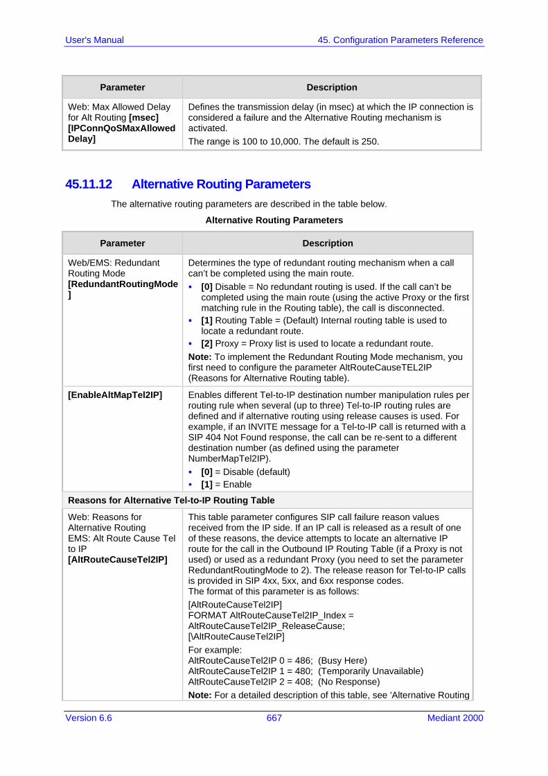
Version 6.6 667 Mediant 2000
User's Manual 45. Configuration Parameters Reference
Parameter Description
Web: Max Allowed Delay for Alt Routing [msec] [IPConnQoSMaxAllowedDelay]
Defines the transmission delay (in msec) at which the IP connection is considered a failure and the Alternative Routing mechanism is activated. The range is 100 to 10,000. The default is 250.
45.11.12 Alternative Routing Parameters The alternative routing parameters are described in the table below.
Alternative Routing Parameters
Parameter Description
Web/EMS: Redundant Routing Mode [RedundantRoutingMode]
Determines the type of redundant routing mechanism when a call can’t be completed using the main route. [0] Disable = No redundant routing is used. If the call can’t be
completed using the main route (using the active Proxy or the first matching rule in the Routing table), the call is disconnected.
[1] Routing Table = (Default) Internal routing table is used to locate a redundant route.
[2] Proxy = Proxy list is used to locate a redundant route. Note: To implement the Redundant Routing Mode mechanism, you first need to configure the parameter AltRouteCauseTEL2IP (Reasons for Alternative Routing table).
[EnableAltMapTel2IP] Enables different Tel-to-IP destination number manipulation rules per routing rule when several (up to three) Tel-to-IP routing rules are defined and if alternative routing using release causes is used. For example, if an INVITE message for a Tel-to-IP call is returned with a SIP 404 Not Found response, the call can be re-sent to a different destination number (as defined using the parameter NumberMapTel2IP). [0] = Disable (default) [1] = Enable
Reasons for Alternative Tel-to-IP Routing Table
Web: Reasons for Alternative Routing EMS: Alt Route Cause Tel to IP [AltRouteCauseTel2IP]
This table parameter configures SIP call failure reason values received from the IP side. If an IP call is released as a result of one of these reasons, the device attempts to locate an alternative IP route for the call in the Outbound IP Routing Table (if a Proxy is not used) or used as a redundant Proxy (you need to set the parameter RedundantRoutingMode to 2). The release reason for Tel-to-IP calls is provided in SIP 4xx, 5xx, and 6xx response codes. The format of this parameter is as follows: [AltRouteCauseTel2IP] FORMAT AltRouteCauseTel2IP_Index = AltRouteCauseTel2IP_ReleaseCause; [\AltRouteCauseTel2IP] For example: AltRouteCauseTel2IP 0 = 486; (Busy Here) AltRouteCauseTel2IP 1 = 480; (Temporarily Unavailable) AltRouteCauseTel2IP 2 = 408; (No Response) Note: For a detailed description of this table, see 'Alternative Routing

User's Manual 668 Document #: LTRT-68822
Mediant 2000
Parameter Description
Based on SIP Responses' on page 323.
Reasons for Alternative IP-to-Tel Routing Table
Web: Reasons for Alternative IP-to-Tel Routing EMS: Alt Route Cause IP to Tel [AltRouteCauseIP2Tel]
This table parameter configures call failure reason values received from the PSTN side (in Q.931 presentation). If a call is released as a result of one of these reasons, the device attempts to locate an alternative Trunk Group for the call in the Inbound IP Routing Table. The format of this parameter is as follows: [AltRouteCauseIP2Tel] FORMAT AltRouteCauseIP2Tel_Index = AltRouteCauseIP2Tel_ReleaseCause; [\AltRouteCauseIP2Tel] For example: AltRouteCauseIP2Tel 0 = 3 (No Route to Destination) AltRouteCauseIP2Tel 1 = 1 (Unallocated Number) AltRouteCauseIP2Tel 2 = 17 (Busy Here) AltRouteCauseIP2Tel 2 = 27 (Destination Out of Order) Note: For a detailed description of this table, see 'Alternative Routing to Trunk upon Q.931 Call Release Cause Code' on page 325.
Forward On Busy Trunk Destination Table
Web/EMS: Forward On Busy Trunk Destination [ForwardOnBusyTrunkDest]
This table parameter configures the Forward On Busy Trunk Destination table. This table allows you to define an alternative IP destination if a trunk is busy for IP-to-Tel calls. The format of this parameter is as follows: [ForwardOnBusyTrunkDest] FORMAT ForwardOnBusyTrunkDest_Index = ForwardOnBusyTrunkDest_TrunkGroupId, ForwardOnBusyTrunkDest_ForwardDestination; [\ForwardOnBusyTrunkDest] For example, the below configuration forwards IP-to-Tel calls to destination user “112” at host IP address 10.13.4.12, port 5060, using transport protocol TCP, if Trunk Group ID 2 is unavailable: ForwardOnBusyTrunkDest 1 = 2, [email protected]:5060;transport=tcp; Note: For a detailed description of this table, see 'Alternative Routing to IP Destination upon Busy Trunk' on page 326.

Version 6.6 669 Mediant 2000
User's Manual 45. Configuration Parameters Reference
45.11.13 Number Manipulation Parameters The number manipulation parameters are described in the table below.
Number Manipulation Parameters
Parameter Description
[ManipulateIP2PSTNReferTo]
Enables the manipulation of the called party (destination) number according to the SIP Refer-To header received by the device for TDM (PSTN) blind transfer. The number in the SIP Refer-To header is manipulated for all types of blind transfers to the PSTN (TBCT, ECT, RLT, QSIG, FXO, and CAS). [0] Disable (default) [1] Enable During the blind transfer, the device initiates a new call to the PSTN and the destination number of this call can be manipulated if this parameter is enabled. When enabled, the manipulation is done as follows: 1 If you configure a value for the xferPrefix parameter, then this value
(string) is added as a prefix to the number in the Refer-To header. 2 This called party number is then manipulated using the IP-to-Tel
Destination Phone Number Manipulation table. The source number of the transferred call is taken from the original call, according to its initial direction: Source number of the original call if it is a Tel-to-IP call Destination number of the original call if it is an IP-to-Tel call This source number can also be used as the value for the 'Source Prefix' field in the IP-to-Tel Destination Phone Number Manipulation table. The local IP address is used as the value for the 'Source IP Address' field.
Note: This manipulation does not affect IP-to-Trunk Group routing rules.
Web: Use EndPoint Number As Calling Number Tel2IP EMS: Use EP Number As Calling Number Tel to IP [UseEPNumAsCallingNumTel2IP]
Enables the use of the B-channel number as the calling number (sent in the From field of the INVITE) instead of the number received in the Q.931 Setup message, for Tel-to-IP calls. [0] Disable (default) [1] Enable For example, if the incoming calling party number in the Q.931 Setup message is "12345" and the B-channel number is 17, then the outgoing INVITE From header is set to "17" instead of "12345". Note: When enabled, this feature is applied before routing and manipulation on the source number.
Web: Use EndPoint Number As Calling Number IP2Tel EMS: Use EP Number As Calling Number IP to Tel [UseEPNumAsCallingNumIP2Tel]
Enables the use of the B-channel number as the calling party number (sent in the Q.931 Setup message) instead of the number received in the From header of the INVITE, for IP-to-Tel calls. [0] Disable (default) [1] Enable For example, if the incoming INVITE From header contains "12345" and the destined B-channel number is 17, then the outgoing calling party number in the Q.931 Setup message is set to "17" instead of "12345". Note: When enabled, this feature is applied after routing and manipulation on the source number (i.e., just before sending to the Tel side).

User's Manual 670 Document #: LTRT-68822
Mediant 2000
Parameter Description
Web: Tel2IP Default Redirect Reason [Tel2IPDefaultRedirectReason]
Determines the default redirect reason for Tel-to-IP calls when no redirect reason (or “unknown”) exists in the received Q931 ISDN Setup message. The device includes this default redirect reason in the SIP History-Info header of the outgoing INVITE. If a redirect reason exists in the received Setup message, this parameter is ignored and the device sends the INVITE message with the reason according to the received Setup message. If this parameter is not configured (-1), the outgoing INVITE is sent with the redirect reason as received in the Setup message (if none or “unknown” reason, then without a reason). [-1] Not Configured = (Default) Received redirect reason is not
changed [1] Busy = Call forwarding busy [2] No Reply = Call forwarding no reply [9] DTE Out of Order = Call forwarding DTE out of order [10] Deflection = Call deflection [15] Systematic/Unconditional = Call forward unconditional
Web: Redirect Number SIP to TEL EMS: Set IP To Tel Redirect Screening Indicator [SetIp2TelRedirectScreeningInd]
Determines the value of the Redirect Number screening indicator in ISDN Setup messages. [-1] Not Configured (default) [0] User Provided [1] User Passed [2] User Failed [3] Network Provided
Web: Set IP-to-TEL Redirect Reason [SetIp2TelRedirectReason]
Defines the redirect reason for IP-to-Tel calls. If redirect (diversion) information is received from the IP, the redirect reason is set to the value of this parameter before the device sends it on to the Tel. [-1] Not Configured (default) [0] Unkown [1] Busy [2] No Reply [3] Network Busy [4] Deflection [9] DTE out of Order [10] Forwarding DTE [13] Transfer [14] PickUp [15] Systematic/Unconditional
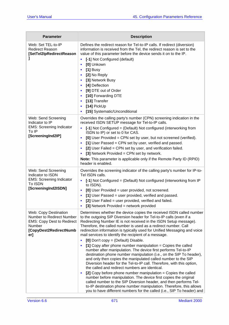
Version 6.6 671 Mediant 2000
User's Manual 45. Configuration Parameters Reference
Parameter Description
Web: Set TEL-to-IP Redirect Reason [SetTel2IpRedirectReason]
Defines the redirect reason for Tel-to-IP calls. If redirect (diversion) information is received from the Tel, the redirect reason is set to the value of this parameter before the device sends it on to the IP. [-1] Not Configured (default) [0] Unkown [1] Busy [2] No Reply [3] Network Busy [4] Deflection [9] DTE out of Order [10] Forwarding DTE [13] Transfer [14] PickUp [15] Systematic/Unconditional
Web: Send Screening Indicator to IP EMS: Screening Indicator To IP [ScreeningInd2IP]
Overrides the calling party's number (CPN) screening indication in the received ISDN SETUP message for Tel-to-IP calls. [-1] Not Configured = (Default) Not configured (interworking from
ISDN to IP) or set to 0 for CAS. [0] User Provided = CPN set by user, but not screened (verified). [1] User Passed = CPN set by user, verified and passed. [2] User Failed = CPN set by user, and verification failed. [3] Network Provided = CPN set by network. Note: This parameter is applicable only if the Remote Party ID (RPID) header is enabled.
Web: Send Screening Indicator to ISDN EMS: Screening Indicator To ISDN [ScreeningInd2ISDN]
Overrides the screening indicator of the calling party's number for IP-to-Tel ISDN calls. [-1] Not Configured = (Default) Not configured (interworking from IP
to ISDN). [0] User Provided = user provided, not screened. [1] User Passed = user provided, verified and passed. [2] User Failed = user provided, verified and failed. [3] Network Provided = network provided
Web: Copy Destination Number to Redirect Number EMS: Copy Dest to Redirect Number [CopyDest2RedirectNumber]
Determines whether the device copies the received ISDN called number to the outgoing SIP Diversion header for Tel-to-IP calls (even if a Redirecting Number IE is not received in the ISDN Setup message). Therefore, the called number is used as a redirect number. Call redirection information is typically used for Unified Messaging and voice mail services to identify the recipient of a message. [0] Don't copy = (Default) Disable. [1] Copy after phone number manipulation = Copies the called
number after manipulation. The device first performs Tel-to-IP destination phone number manipulation (i.e., on the SIP To header), and only then copies the manipulated called number to the SIP Diversion header for the Tel-to-IP call. Therefore, with this option, the called and redirect numbers are identical.
[2] Copy before phone number manipulation = Copies the called number before manipulation. The device first copies the original called number to the SIP Diversion header, and then performs Tel-to-IP destination phone number manipulation. Therefore, this allows you to have different numbers for the called (i.e., SIP To header) and

User's Manual 672 Document #: LTRT-68822
Mediant 2000
Parameter Description
redirect (i.e., SIP Diversion header) numbers. Notes: If the incoming ISDN-to-IP call includes a Redirect Number, this
number is overridden by the new called number if this parameter is set to [1] or [2].
When configured in an IP Profile, this parameter can also be used for IP-to-Tel calls. The device can overwrite the redirect number with the destination number from the received SIP INVITE message in the outgoing ISDN call. This is achieved by assigning an IP Profile (IPProfile parameter) defined with the CopyDest2RedirectNumber parameter set to 1, to the IP-to-Tel Routing table (PSTNPrefix parameter). Even if there is no SIP Diversion or History header in the incoming INVITE message, the outgoing Q.931 Setup message will contain a redirect number.
This parameter can also be configured in an IP Profile.
[ReplaceCallingWithRedirectNumber]
Enables the replacement of the calling number with the redirect number for ISDN-to-IP calls. [0] = Disable (default) [1] = The calling name is removed and left blank. The outgoing
INVITE message excludes the redirect number that was used to replace the calling number. The replacement is done only if a redirect number is present in the incoming Tel call.
[2] = Manipulation is done on the new calling party number (after manipulation of the original calling party number, using the Tel2IPSourceNumberMappingDialPlanIndex parameter), but before the regular calling or redirect number manipulation: If a redirect number exists, it replaces the calling party number.
If there is no redirect number, the calling number is left unchanged.
If there is a calling “display” name, it remains unchanged. The redirect number remains unchanged and is included in the
SIP Diversion header. Web/EMS: Add Trunk Group ID as Prefix [AddTrunkGroupAsPrefix]
Determines whether the Trunk Group ID is added as a prefix to the destination phone number (i.e., called number) for Tel-to-IP calls. [0] No = (Default) Don't add Trunk Group ID as prefix. [1] Yes = Add Trunk Group ID as prefix to called number. Notes: This option can be used to define various routing rules. To use this feature, you must configure the Trunk Group IDs (see
Configuring Trunk Group Table on page 279).
Web: Add Trunk ID as Prefix EMS: Add Port ID As Prefix [AddPortAsPrefix]
Determines whether or not the port numberTrunk ID is added as a prefix to the called (destination) number for Tel-to-IP calls. [0] No (Default) [1] Yes If enabled, the device adds the following prefix to the called phone number: port number Trunk ID (single digit in the range 1 to 8). This option can be used to define various routing rules.
Web/EMS: Add Trunk Group ID as Prefix to Source [AddTrunkGroupAsPrefix
Determines whether the device adds the Trunk Group ID (from where the call originated) as the prefix to the calling number (i.e. source number). [0] No (default)

Version 6.6 673 Mediant 2000
User's Manual 45. Configuration Parameters Reference
Parameter Description
ToSource] [1] Yes
Web: Replace Empty Destination with B-channel Phone Number EMS: Replace Empty Dst With Port Number [ReplaceEmptyDstWithPortNumber]
Determines whether the internal channel number is used as the destination number if the called number is missing. [0] No (default) [1] Yes Note: This parameter is applicable only to Tel-to-IP calls and if the called number is missing.
[CopyDestOnEmptySource]
Determines whether the destination number is copied to the source number if no source number is present, for Tel-to-IP calls. [0] = (Default) Source Number is left empty. [1] = If the Source Number of a Tel-to-IP call is empty, the
Destination Number is copied to the Source Number.
Web: Add NPI and TON to Calling Number EMS: Add NPI And TON As Prefix To Calling Number [AddNPIandTON2CallingNumber]
Determines whether the Numbering Plan Indicator (NPI) and Type of Numbering (TON) are added to the Calling Number for Tel-to-IP calls. [0] No = (Default) Do not change the Calling Number. [1] Yes = Add NPI and TON to the Calling Number ISDN Tel-to-IP
call. For example: After receiving a Calling Number of 555, NPI of 1, and TON of 3, the modified number becomes 13555. This number can later be used for manipulation and routing.
Web: Add NPI and TON to Called Number EMS: Add NPI And TON As Prefix To Called Number [AddNPIandTON2CalledNumber]
Determines whether NPI and TON are added to the Called Number for Tel-to-IP calls. [0] No = (Default) Do not change the Called Number. [1] Yes = Add NPI and TON to the Called Number of ISDN Tel-to-IP
call. For example: After receiving a Called Number of 555, NPI of 1 and TON of 3, the modified number becomes 13555. This number can later be used for manipulation and routing.
Web: Add NPI and TON to Redirect Number [AddNPIandTON2RedirectNumber]
Determines whether the NPI and TON values are added as the prefix to the Redirect number in INVITE messages' Diversion or History-Info headers, for ISDN Tel-to-IP calls. [0] Yes (Default) [1] No
Web: IP to Tel Remove Routing Table Prefix EMS: Remove Prefix [RemovePrefix]
Determines whether or not the device removes the prefix (as configured in the Inbound IP Routing Table - see 'Configuring Inbound IP Routing Table' on page 317) from the destination number for IP-to-Tel calls, before sending it to the Tel. [0] No (default) [1] Yes For example: To route an incoming IP-to-Tel call with destination number "21100", the Inbound IP Routing Table is scanned for a matching prefix. If such a prefix is found (e.g., "21"), then before the call is routed to the corresponding Trunk Group, the prefix "21" is removed from the original number, and therefore, only "100" remains. Notes: This parameter is applicable only if number manipulation is
performed after call routing for IP-to-Tel calls (i.e., RouteModeIP2Tel parameter is set to 0).
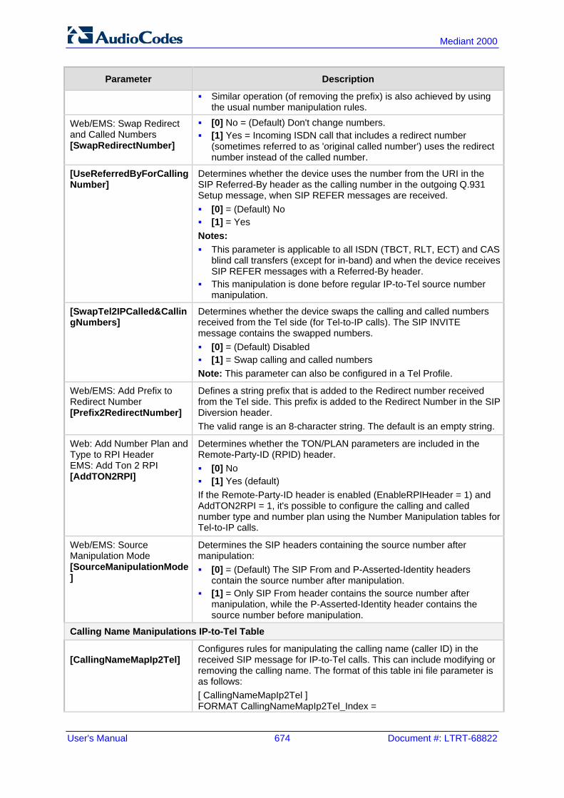
User's Manual 674 Document #: LTRT-68822
Mediant 2000
Parameter Description
Similar operation (of removing the prefix) is also achieved by using the usual number manipulation rules.
Web/EMS: Swap Redirect and Called Numbers [SwapRedirectNumber]
[0] No = (Default) Don't change numbers. [1] Yes = Incoming ISDN call that includes a redirect number
(sometimes referred to as 'original called number') uses the redirect number instead of the called number.
[UseReferredByForCallingNumber]
Determines whether the device uses the number from the URI in the SIP Referred-By header as the calling number in the outgoing Q.931 Setup message, when SIP REFER messages are received. [0] = (Default) No [1] = Yes Notes: This parameter is applicable to all ISDN (TBCT, RLT, ECT) and CAS
blind call transfers (except for in-band) and when the device receives SIP REFER messages with a Referred-By header.
This manipulation is done before regular IP-to-Tel source number manipulation.
[SwapTel2IPCalled&CallingNumbers]
Determines whether the device swaps the calling and called numbers received from the Tel side (for Tel-to-IP calls). The SIP INVITE message contains the swapped numbers. [0] = (Default) Disabled [1] = Swap calling and called numbers Note: This parameter can also be configured in a Tel Profile.
Web/EMS: Add Prefix to Redirect Number [Prefix2RedirectNumber]
Defines a string prefix that is added to the Redirect number received from the Tel side. This prefix is added to the Redirect Number in the SIP Diversion header. The valid range is an 8-character string. The default is an empty string.
Web: Add Number Plan and Type to RPI Header EMS: Add Ton 2 RPI [AddTON2RPI]
Determines whether the TON/PLAN parameters are included in the Remote-Party-ID (RPID) header. [0] No [1] Yes (default) If the Remote-Party-ID header is enabled (EnableRPIHeader = 1) and AddTON2RPI = 1, it's possible to configure the calling and called number type and number plan using the Number Manipulation tables for Tel-to-IP calls.
Web/EMS: Source Manipulation Mode [SourceManipulationMode]
Determines the SIP headers containing the source number after manipulation: [0] = (Default) The SIP From and P-Asserted-Identity headers
contain the source number after manipulation. [1] = Only SIP From header contains the source number after
manipulation, while the P-Asserted-Identity header contains the source number before manipulation.
Calling Name Manipulations IP-to-Tel Table
[CallingNameMapIp2Tel]
Configures rules for manipulating the calling name (caller ID) in the received SIP message for IP-to-Tel calls. This can include modifying or removing the calling name. The format of this table ini file parameter is as follows: [ CallingNameMapIp2Tel ] FORMAT CallingNameMapIp2Tel_Index =
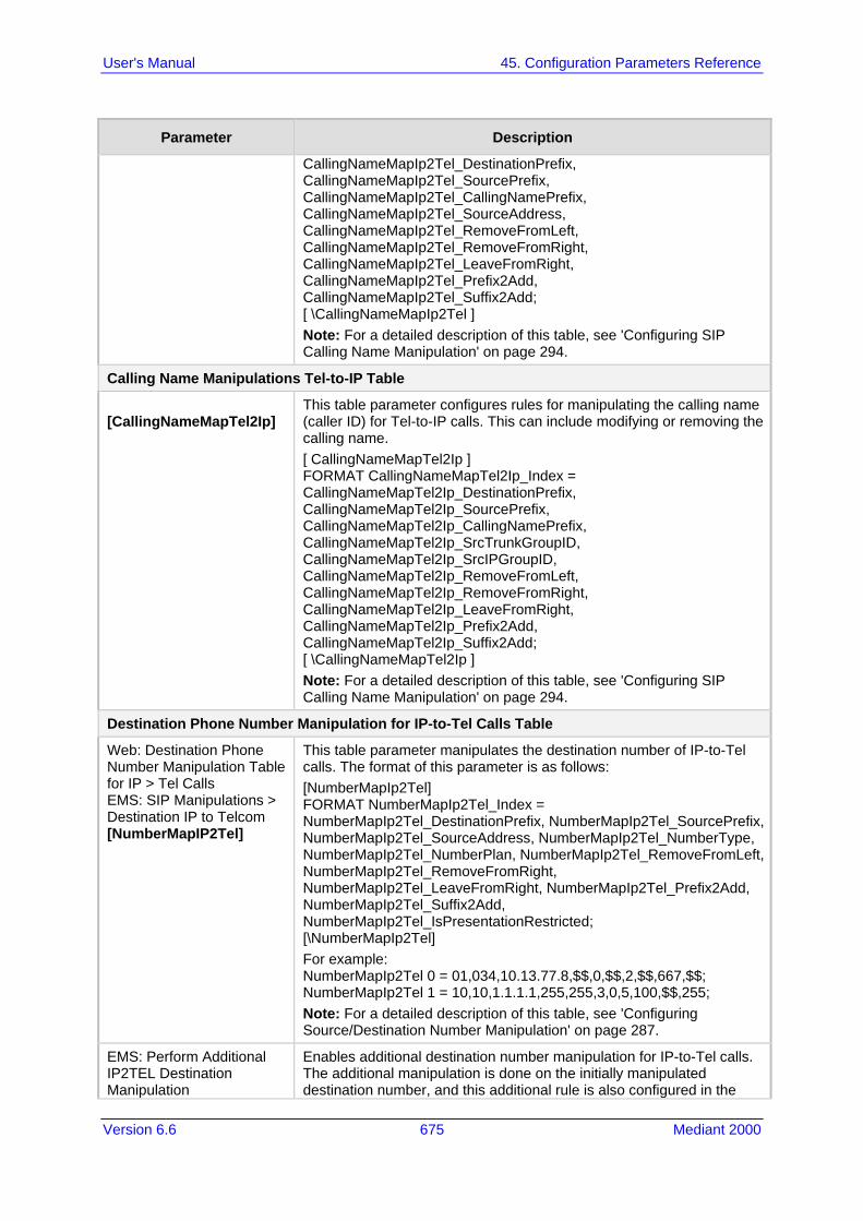
Version 6.6 675 Mediant 2000
User's Manual 45. Configuration Parameters Reference
Parameter Description
CallingNameMapIp2Tel_DestinationPrefix, CallingNameMapIp2Tel_SourcePrefix, CallingNameMapIp2Tel_CallingNamePrefix, CallingNameMapIp2Tel_SourceAddress, CallingNameMapIp2Tel_RemoveFromLeft, CallingNameMapIp2Tel_RemoveFromRight, CallingNameMapIp2Tel_LeaveFromRight, CallingNameMapIp2Tel_Prefix2Add, CallingNameMapIp2Tel_Suffix2Add; [ \CallingNameMapIp2Tel ] Note: For a detailed description of this table, see 'Configuring SIP Calling Name Manipulation' on page 294.
Calling Name Manipulations Tel-to-IP Table
[CallingNameMapTel2Ip]
This table parameter configures rules for manipulating the calling name (caller ID) for Tel-to-IP calls. This can include modifying or removing the calling name. [ CallingNameMapTel2Ip ] FORMAT CallingNameMapTel2Ip_Index = CallingNameMapTel2Ip_DestinationPrefix, CallingNameMapTel2Ip_SourcePrefix, CallingNameMapTel2Ip_CallingNamePrefix, CallingNameMapTel2Ip_SrcTrunkGroupID, CallingNameMapTel2Ip_SrcIPGroupID, CallingNameMapTel2Ip_RemoveFromLeft, CallingNameMapTel2Ip_RemoveFromRight, CallingNameMapTel2Ip_LeaveFromRight, CallingNameMapTel2Ip_Prefix2Add, CallingNameMapTel2Ip_Suffix2Add; [ \CallingNameMapTel2Ip ] Note: For a detailed description of this table, see 'Configuring SIP Calling Name Manipulation' on page 294.
Destination Phone Number Manipulation for IP-to-Tel Calls Table
Web: Destination Phone Number Manipulation Table for IP > Tel Calls EMS: SIP Manipulations > Destination IP to Telcom [NumberMapIP2Tel]
This table parameter manipulates the destination number of IP-to-Tel calls. The format of this parameter is as follows: [NumberMapIp2Tel] FORMAT NumberMapIp2Tel_Index = NumberMapIp2Tel_DestinationPrefix, NumberMapIp2Tel_SourcePrefix, NumberMapIp2Tel_SourceAddress, NumberMapIp2Tel_NumberType, NumberMapIp2Tel_NumberPlan, NumberMapIp2Tel_RemoveFromLeft, NumberMapIp2Tel_RemoveFromRight, NumberMapIp2Tel_LeaveFromRight, NumberMapIp2Tel_Prefix2Add, NumberMapIp2Tel_Suffix2Add, NumberMapIp2Tel_IsPresentationRestricted; [\NumberMapIp2Tel] For example: NumberMapIp2Tel 0 = 01,034,10.13.77.8,$$,0,$$,2,$$,667,$$; NumberMapIp2Tel 1 = 10,10,1.1.1.1,255,255,3,0,5,100,$$,255; Note: For a detailed description of this table, see 'Configuring Source/Destination Number Manipulation' on page 287.
EMS: Perform Additional IP2TEL Destination Manipulation
Enables additional destination number manipulation for IP-to-Tel calls. The additional manipulation is done on the initially manipulated destination number, and this additional rule is also configured in the

User's Manual 676 Document #: LTRT-68822
Mediant 2000
Parameter Description
[PerformAdditionalIP2TELDestinationManipulation]
manipulation table (NumberMapIP2Tel parameter). This enables you to configure only a few manipulation rules for complex number manipulation requirements (that generally require many rules). [0] = Disable (default) [1] = Enable
Destination Phone Number Manipulation for Tel-to-IP Calls Table
Web: Destination Phone Number Manipulation Table for Tel > IP Calls EMS: SIP Manipulations > Destination Telcom to IPs [NumberMapTel2IP]
This table parameter manipulates the destination number of Tel-to-IP calls. The format of this parameter is as follows: [NumberMapTel2Ip] FORMAT NumberMapTel2Ip_Index = NumberMapTel2Ip_DestinationPrefix, NumberMapTel2Ip_SourcePrefix, NumberMapTel2Ip_SourceAddress, NumberMapTel2Ip_NumberType, NumberMapTel2Ip_NumberPlan, NumberMapTel2Ip_RemoveFromLeft, NumberMapTel2Ip_RemoveFromRight, NumberMapTel2Ip_LeaveFromRight, NumberMapTel2Ip_Prefix2Add, NumberMapTel2Ip_Suffix2Add, NumberMapTel2Ip_IsPresentationRestricted, NumberMapTel2Ip_SrcTrunkGroupID, NumberMapTel2Ip_ SrcIPGroupID; [\NumberMapTel2Ip] For example: NumberMapTel2Ip 0 = 01,$$,*,0,0,2,$$,$$,971,$$,$$,$$,$$; NumberMapTel2Ip 1 = 10,10,*,255,255,3,0,5,100,$$,255,$$,$$; Note: For a detailed description of this table, see 'Configuring Source/Destination Number Manipulation' on page 287.
Source Phone Number Manipulation for IP-to-Tel Calls Table
Web: Source Phone Number Manipulation Table for IP > Tel Calls EMS: SIP Manipulations > Source IP to Telcom [SourceNumberMapIP2Tel]
This parameter table manipulates the source number for IP-to-Tel calls. The format of this parameter is as follows: [SourceNumberMapIp2Tel] FORMAT SourceNumberMapIp2Tel_Index = SourceNumberMapIp2Tel_DestinationPrefix, SourceNumberMapIp2Tel_SourcePrefix, SourceNumberMapIp2Tel_SourceAddress, SourceNumberMapIp2Tel_NumberType, SourceNumberMapIp2Tel_NumberPlan, SourceNumberMapIp2Tel_RemoveFromLeft, SourceNumberMapIp2Tel_RemoveFromRight, SourceNumberMapIp2Tel_LeaveFromRight, SourceNumberMapIp2Tel_Prefix2Add, SourceNumberMapIp2Tel_Suffix2Add, SourceNumberMapIp2Tel_IsPresentationRestricted; [\SourceNumberMapIp2Tel] For example: SourceNumberMapIp2Tel 0 = 22,03,$$,$$,$$,$$,2,667,$$,$$; SourceNumberMapIp2Tel 1 = 034,01,1.1.1.1,$$,0,2,$$,$$,972,$$,10; Note: For a detailed description of this table, see 'Configuring Source/Destination Number Manipulation' on page 287.
EMS: Perform Additional IP2TEL Source Manipulation [PerformAdditionalIP2TELSourceManipulation]
Enables additional source number manipulation for IP-to-Tel calls. The additional manipulation is done on the initially manipulated source number, and this additional rule is also configured in the manipulation table (SourceNumberMapIP2Tel parameter). This enables you to configure only a few manipulation rules for complex number

Version 6.6 677 Mediant 2000
User's Manual 45. Configuration Parameters Reference
Parameter Description
manipulation requirements (that generally require many rules). [0] = Disable (default) [1] = Enable
Source Phone Number Manipulation for Tel-to-IP Calls Table
Web: Source Phone Number Manipulation Table for Tel > IP Calls EMS: SIP Manipulations > Source Telcom to IP [SourceNumberMapTel2IP]
This table parameter manipulates the source phone number for Tel-to-IP calls. The format of this parameter is as follows: [SourceNumberMapTel2Ip] FORMAT SourceNumberMapTel2Ip_Index = SourceNumberMapTel2Ip_DestinationPrefix, SourceNumberMapTel2Ip_SourcePrefix, SourceNumberMapTel2Ip_SourceAddress, SourceNumberMapTel2Ip_NumberType, SourceNumberMapTel2Ip_NumberPlan, SourceNumberMapTel2Ip_RemoveFromLeft, SourceNumberMapTel2Ip_RemoveFromRight, SourceNumberMapTel2Ip_LeaveFromRight, SourceNumberMapTel2Ip_Prefix2Add, SourceNumberMapTel2Ip_Suffix2Add, SourceNumberMapTel2Ip_IsPresentationRestricted, NumberMapTel2Ip_SrcTrunkGroupID, NumberMapTel2Ip_SrcIPGroupID; [\SourceNumberMapTel2Ip] For example: SourceNumberMapTel2Ip 0 = 22,03,$$,0,0,$$,2,$$,667,$$,0,$$,$$; SourceNumberMapTel2Ip 0 = 10,10,*,255,255,3,0,5,100,$$,255,$$,$$; Note: For a detailed description of this table, see 'Configuring Source/Destination Number Manipulation' on page 287.
Redirect Number IP -to-Tel Table
Web: Redirect Number IP -> Tel EMS: Redirect Number Map IP to Tel [RedirectNumberMapIp2Tel]
This table parameter manipulates the redirect number for IP-to-Tel calls. The format of this parameter is as follows: [RedirectNumberMapIp2Tel] FORMAT RedirectNumberMapIp2Tel_Index = RedirectNumberMapIp2Tel_DestinationPrefix, RedirectNumberMapIp2Tel_RedirectPrefix, RedirectNumberMapIp2Tel_SourceAddress, RedirectNumberMapIp2Tel_SrcHost, RedirectNumberMapIp2Tel_DestHost, RedirectNumberMapIp2Tel_NumberType, RedirectNumberMapIp2Tel_NumberPlan, RedirectNumberMapIp2Tel_RemoveFromLeft, RedirectNumberMapIp2Tel_RemoveFromRight, RedirectNumberMapIp2Tel_LeaveFromRight, RedirectNumberMapIp2Tel_Prefix2Add, RedirectNumberMapIp2Tel_Suffix2Add, RedirectNumberMapIp2Tel_IsPresentationRestricted; [\RedirectNumberMapIp2Tel] For example: RedirectNumberMapIp2Tel 1 = *, 88, *, , , 1, 1, 2, 0, 255, 9, , 255; Note: For a description of this table, see Configuring Redirect Number Manipulation on page 296.

User's Manual 678 Document #: LTRT-68822
Mediant 2000
Parameter Description
Redirect Number Tel-to-IP Table
Web: Redirect Number Tel -> IP EMS: Redirect Number Map Tel to IP [RedirectNumberMapTel2IP]
This table parameter manipulates the Redirect Number for Tel-to-IP calls. The format of this parameter is as follows: [RedirectNumberMapTel2Ip] FORMAT RedirectNumberMapTel2Ip_Index = RedirectNumberMapTel2Ip_DestinationPrefix, RedirectNumberMapTel2Ip_RedirectPrefix, RedirectNumberMapTel2Ip_RemoveFromLeft, RedirectNumberMapTel2Ip_RemoveFromRight, RedirectNumberMapTel2Ip_LeaveFromRight, RedirectNumberMapTel2Ip_Prefix2Add, RedirectNumberMapTel2Ip_Suffix2Add, RedirectNumberMapTel2Ip_IsPresentationRestricted, RedirectNumberMapTel2Ip_SrcTrunkGroupID, RedirectNumberMapTel2Ip_SrcIPGroupID; [\RedirectNumberMapTel2Ip] For example: RedirectNumberMapTel2Ip 1 = *, *, 4, 0, 255, , , 255, -1, -1; Note: For a description of this table, see 'Configuring Redirect Number Manipulation' on page 296.
Phone Context Table
Web: Phone Context Table EMS: SIP Manipulations > Phone Context [PhoneContext]
This table parameter configures the Phone Context table. This parameter maps NPI and TON to the SIP 'phone-context' parameter, and vice versa. The format for this parameter is as follows: [PhoneContext] FORMAT PhoneContext_Index = PhoneContext_Npi, PhoneContext_Ton, PhoneContext_Context; [\PhoneContext] For example: PhoneContext 0 = 0,0,unknown.com PhoneContext 1 = 1,1,host.com PhoneContext 2 = 9,1,na.e164.host.com Note: For a detailed description of this table, see 'Mapping NPI/TON to SIP Phone-Context' on page 301.
Web/EMS: Add Phone Context As Prefix [AddPhoneContextAsPrefix]
Determines whether the received Phone-Context parameter is added as a prefix to the outgoing ISDN Setup message withCalled and Calling numbers. [0] Disable (default) [1] Enable
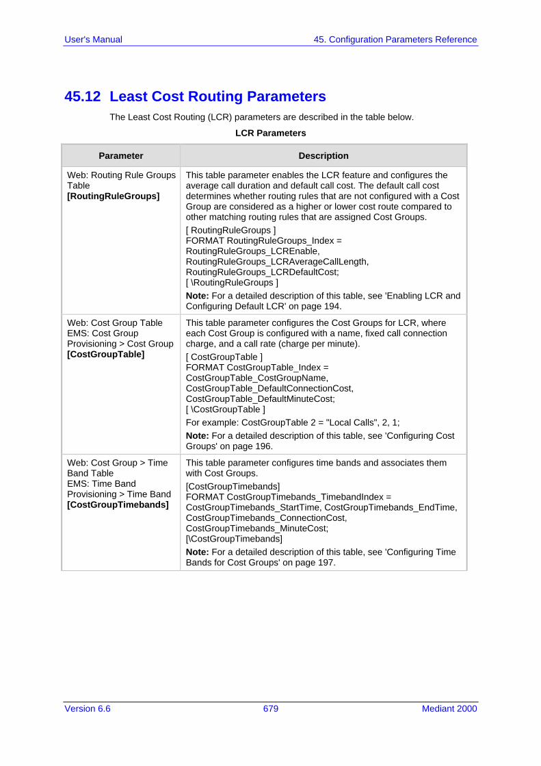
Version 6.6 679 Mediant 2000
User's Manual 45. Configuration Parameters Reference
45.12 Least Cost Routing Parameters The Least Cost Routing (LCR) parameters are described in the table below.
LCR Parameters
Parameter Description
Web: Routing Rule Groups Table [RoutingRuleGroups]
This table parameter enables the LCR feature and configures the average call duration and default call cost. The default call cost determines whether routing rules that are not configured with a Cost Group are considered as a higher or lower cost route compared to other matching routing rules that are assigned Cost Groups. [ RoutingRuleGroups ] FORMAT RoutingRuleGroups_Index = RoutingRuleGroups_LCREnable, RoutingRuleGroups_LCRAverageCallLength, RoutingRuleGroups_LCRDefaultCost; [ \RoutingRuleGroups ] Note: For a detailed description of this table, see 'Enabling LCR and Configuring Default LCR' on page 194.
Web: Cost Group Table EMS: Cost Group Provisioning > Cost Group [CostGroupTable]
This table parameter configures the Cost Groups for LCR, where each Cost Group is configured with a name, fixed call connection charge, and a call rate (charge per minute). [ CostGroupTable ] FORMAT CostGroupTable_Index = CostGroupTable_CostGroupName, CostGroupTable_DefaultConnectionCost, CostGroupTable_DefaultMinuteCost; [ \CostGroupTable ] For example: CostGroupTable 2 = "Local Calls", 2, 1; Note: For a detailed description of this table, see 'Configuring Cost Groups' on page 196.
Web: Cost Group > Time Band Table EMS: Time Band Provisioning > Time Band [CostGroupTimebands]
This table parameter configures time bands and associates them with Cost Groups. [CostGroupTimebands] FORMAT CostGroupTimebands_TimebandIndex = CostGroupTimebands_StartTime, CostGroupTimebands_EndTime, CostGroupTimebands_ConnectionCost, CostGroupTimebands_MinuteCost; [\CostGroupTimebands] Note: For a detailed description of this table, see 'Configuring Time Bands for Cost Groups' on page 197.

User's Manual 680 Document #: LTRT-68822
Mediant 2000
45.13 LDAP Parameters The Lightweight Directory Access Protocol (LDAP) parameters are described in the table below. For more information on routing based on LDAP, see 'Routing Based on LDAP Active Directory Queries' on page 183.
LDAP Parameters
Parameter Description
Web: LDAP Service [LDAPServiceEnable]
Enables the LDAP feature. [0] Disable (default) [1] Enable Note: For this parameter to take effect, a device reset is required.
Web: LDAP Server IP EMS: Server Ip [LDAPServerIP]
Defines the LDAP server's address as an IP address (in dotted-decimal notation, e.g., 192.10.1.255). The default is 0.0.0.0.
Web: LDAP Server Port EMS: Server Port [LDAPServerPort]
Defines the LDAP server's port number. The valid value range is 0 to 65535. The default port number is 389.
Web: LDAP Server Domain Name EMS: Server Domain Name [LDAPServerDomainName]
Defines the host name (FQDN) of the LDAP server. The device tries to connect to the LDAP server according to the IP address list received in the DNS query. If there is no connection to the LDAP server or the connection to the LDAP server fails, the device tries to connect to the LDAP server with the next IP address in the DNS query list. Note: The 'LDAP Server IP' parameter takes precedence over this parameter. Thus, if you want to use an FQDN, keep the 'LDAP Server IP' parameter empty.
Web: LDAP Password EMS: Password [LDAPPassword]
Defines the LDAP server's user password.
Web: LDAP Bind DN EMS: Bind DN [LDAPBindDN]
Defines the LDAP server's bind Distinguished Name (DN). This is used as the username during connection and binding to the server. For example: LDAPBindDN = "CN=Search user,OU=Labs,DC=OCSR2,DC=local" Note: The DN is used to uniquely name an Active Directory object.
Web: LDAP Search Dn EMS: Search DN [LDAPSearchDN]
Defines up to three search DNs for LDAP search queries. These are the DN subtrees where the search is done. This parameter is mandatory for the search. The format of this parameter is as follows: [LdapSearchDNs ] FORMAT LdapSearchDNs_Index = LdapSearchDNs_Base_Path; [ \LdapSearchDNs ] For example: LdapSearchDNs 0 = "CN=Search user,OU=NY,DC=OCSR2,DC=local"; LdapSearchDNs 1 = "CN=Search user,OU=SF,DC=OCSR2,DC=local"; In this example, the DN path is defined by the LDAP names, cn (common name), ou (organizational unit) and dc (domain component).

Version 6.6 681 Mediant 2000
User's Manual 45. Configuration Parameters Reference
Parameter Description
Note: If you configure multiple DNs, you can specify whether the search is done sequentially or in parallel, using the LDAPSearchDNsinParallel parameter.
[LDAPSearchDNsinParallel]
Defines the LDAP query DN search method in the AD database if multiple search DNs are configured, using the LDAPSearchDNs parameter. [0] Sequential = If the first DN search fails, the search is done on
the next configured DN, and so on. [1] Parallel (Default)
Web: LDAP Server Max Respond Time EMS: Server Max Respond Time [LDAPServerMaxRespondTime]
Defines the time (in seconds) that the device waits for LDAP server responses. The valid value range is 0 to 86400. The default is 3000.
[LDAPDebugMode] Determines whether to enable the LDAP task debug messages. This is used for providing debug information regarding LDAP tasks. The valid value range is 0 to 3. The default is 0.
Web: MS LDAP OCS Number attribute name EMS: LDAP ocs Number Attribute Name [MSLDAPOCSNumAttributeName]
Defines the name of the attribute that represents the user OCS number in the Microsoft AD database. The valid value is a string of up to 49 characters. The default is "msRTCSIP-PrimaryUserAddress".
Web: MS LDAP PBX Number attribute name [MSLDAPPBXNumAttributeName]
Defines the name of the attribute that represents the user PBX number in the Microsoft AD database. The valid value is a string of up to 49 characters. The default is "telephoneNumber".
Web: MS LDAP MOBILE Number attribute name [MSLDAPMobileNumAttributeName]
Defines the name of the attribute that represents the user Mobile number in the Microsoft AD database. The valid value is a string of up to 49 characters. The default is "mobile".
[MSLDAPPrivateNumAttributeName]
Defines the name of the attribute that represents the user's private number in the AD. If this value equals the value of the MSLDAPPrimaryKey or MSLDAPSecondaryKey parameter, then the device queries the AD for the destination number in this private attribute name; otherwise, this parameter is not used as a search key. The default is "msRTCSIP-PrivateLine".
CLI: ldap-display-nm-attr [MSLDAPDisplayNameAttributeName]
Defines the attribute name that represents the Calling Name in the AD for LDAP queries based on calling number. The valid value is a string of up to 49 characters. The default is "displayName".
[MSLDAPPrimaryKey]
Defines the name of the attribute used as a query search key for the destination number in the AD. This is used instead of the "PBX" attribute name (configured by the MSLDAPPBXNumAttributeName parameter). The default is not configured.

User's Manual 682 Document #: LTRT-68822
Mediant 2000
Parameter Description
[MSLDAPSecondaryKey]
Defines the name of the attribute used as the second query search key for the destination number in the AD, if the primary search key or PBX search is not found.
LDAP Cache Service [LDAPCacheEnable]
Enables the LDAP cache service. [0] Disable (default) [1] Enable Notes: For this parameter to take effect, a device reset is required. For more information on LDAP caching, see 'Configuring the
Device's LDAP Cache' on page 184.
LDAP Cache Entry Timeout [LDAPCacheEntryTimeout]
Defines the duration (in minutes) that an entry in the LDAP cache is valid. If the timeout expires, the cached entry is only used if there is no connectivity with the LDAP server. The default is 1200.
LDAP Cache Entry Removal Timeout [LDAPCacheEntryRemovalTimeout]
Defines the duration (in hours) after which the LDAP entry is removed from the cache. The default is 0.
45.14 Standalone Survivability Parameters The Stand-alone Survivability (SAS) parameters are described in the table below.
SAS Parameters
Parameter Description
Web: Enable SAS EMS: Enable [EnableSAS]
Enables the Stand-Alone Survivability (SAS) feature. [0] Disable (default) [1] Enable When enabled, the device receives the registration requests from different SIP entities in the local network and then forwards them to the defined proxy. If the connection to the proxy fails ('Emergency Mode'), the device serves as a proxy by allowing calls internal to the local network or outgoing to PSTN. Note: For this parameter to take effect, a device reset is required.
Web: SAS Local SIP UDP Port EMS: Local SIP UDP [SASLocalSIPUDPPort]
Defines the local UDP port for sending and receiving SIP messages for SAS. The SIP entities in the local network need to send the registration requests to this port. When forwarding the requests to the proxy ('Normal Mode'), this port serves as the source port. The valid range is 1 to 65,534. The default is 5080.
Web: SAS Default Gateway IP EMS: Default Gateway IP [SASDefaultGatewayIP]
Defines the Default Gateway used in SAS 'Emergency Mode'. When an incoming SIP INVITE is received and the destination Address-Of-Record is not included in the SAS database, the request is immediately sent to this default gateway. The address can be configured as an IP address (dotted-decimal notation) or as a domain name (up to 49 characters). You can also configure the IP address with a destination port, e.g., "10.1.2.3:5060". The default is a null string, i.e., the local IP address of the gateway.

Version 6.6 683 Mediant 2000
User's Manual 45. Configuration Parameters Reference
Parameter Description
Web: SAS Registration Time EMS: Registration Time [SASRegistrationTime]
Defines the value of the SIP Expires header that is sent in a 200 OK response to an incoming REGISTER message when in SAS 'Emergency Mode'. The valid range is 10 to 2,000,000. The default is 20.
Web: SAS Local SIP TCP Port EMS: Local SIP TCP Port [SASLocalSIPTCPPort]
Defines the local TCP port used to send/receive SIP messages for the SAS application. The SIP entities in the local network need to send the registration requests to this port. When forwarding the requests to the proxy ('Normal Mode'), this port serves as the source port. The valid range is 1 to 65,534. The default is 5080.
Web: SAS Local SIP TLS Port EMS: Local SIP TLS Port [SASLocalSIPTLSPort]
Defines the local TLS port used to send/receive SIP messages for the SAS application. The SIP entities in the local network need to send the registration requests to this port. When forwarding the requests to the proxy ('Normal Mode'), this port serves as the source port. The valid range is 1 to 65,534. The default is 5081.
Web: SAS Connection Reuse [SASConnectionReuse]
Enables the re-use of the same TCP connection for sessions with the same user in the SAS application. [0] Disable [1] Enable (default) The device can use the same TCP connection for multiple SIP requests / responses for a specific SIP UA. The benefits of this feature include less CPU and memory usage because fewer TCP connections are open and reduced network congestion. For example, assume the following: User A sends a REGISTER message to SAS with transport=TCP. User B sends an INVITE message to A using SAS. In this scenario, the SAS application forwards the INVITE request using the TCP connection that User A initially opened with the REGISTER message.
Web/EMS: Enable Record-Route [SASEnableRecordRoute]
Determines whether the device's SAS application adds the SIP Record-Route header to SIP requests. This ensures that SIP messages traverse the device's SAS agent by including the SAS IP address in the Record-Route header. [0] Disable (default) [1] Enable The Record-Route header is inserted in a request by a SAS proxy to force future requests in the dialog session to be routed through the SAS agent. Each traversed proxy in the path can insert this header, causing all future dialogs in the session to pass through it as well. When this feature is enabled, the SIP Record-Route header includes the URI "lr" parameter, indicating loose routing, for example: Record-Route: <sip:server10.biloxi.com;lr>
Web: SAS Proxy Set EMS: Proxy Set [SASProxySet]
Defines the Proxy Set (index number) used in SAS Normal mode to forward REGISTER and INVITE requests from users that are served by the SAS application. The valid range is 0 to 5. The default is 0 (i.e., default Proxy Set).
Web: Redundant SAS Proxy Set EMS: Redundant Proxy Set
Defines the Proxy Set (index number) used in SAS Emergency mode for fallback when the user is not found in the Registered Users database. Each time a new SIP request arrives, the SAS application checks whether the user is listed in the registration database. If the

User's Manual 684 Document #: LTRT-68822
Mediant 2000
Parameter Description
[RedundantSASProxySet]
user is located in the database, the request is sent to the user. If the user is not found, the request is forwarded to the next redundant SAS defined in the Redundant SAS Proxy Set. If that SAS Proxy IP appears in the Via header of the request, it is not forwarded (thereby, preventing loops in the request's course). If no such redundant SAS exists, the SAS sends the request to its default gateway (configured by the parameter SASDefaultGatewayIP). The valid range is -1 to 5. The default is -1 (i.e., no redundant Proxy Set).
Web/EMS: SAS Block Unregistered Users [SASBlockUnRegUsers]
Determines whether the device rejects SIP INVITE requests received from unregistered SAS users. This applies to SAS Normal and Emergency modes. [0] Un-Block = (Default) Allow INVITE from unregistered SAS
users. [1] Block = Reject dialog-establishment requests from un-registered
SAS users.
[SASEnableContactReplace]
Enables the device to change the SIP Contact header so that it points to the SAS host and therefore, the top-most SIP Via header and the Contact header point to the same host. [0] (default) = Disable - when relaying requests, the SAS agent
adds a new Via header (with the SAS IP address) as the top-most Via header and retains the original Contact header. Thus, the top-most Via header and the Contact header point to different hosts.
[1] = Enable - the device changes the Contact header so that it points to the SAS host and therefore, the top-most Via header and the Contact header point to the same host.
Note: Operating in this mode causes all incoming dialog requests to traverse the SAS, which may cause load problems.
Web: SAS Survivability Mode EMS: Survivability Mode [SASSurvivabilityMode]
Determines the Survivability mode used by the SAS application. [0] Standard = (Default) Incoming INVITE and REGISTER requests
are forwarded to the defined Proxy list of SASProxySet in Normal mode and handled by the SAS application in Emergency mode.
[1] Always Emergency = The SAS application does not use Keep-Alive messages towards the SASProxySet, instead it always operates in Emergency mode (as if no Proxy in the SASProxySet is available).
[2] Ignore Register = Use regular SAS Normal/Emergency logic (same as option [0]), but when in Normal mode incoming REGISTER requests are ignored.
[3] Auto-answer REGISTER = When in Normal mode, the device responds to received REGISTER requests by sending a SIP 200 OK (instead of relaying the registration requests to a Proxy), and enters the registrations in its SAS database.
[4] Use Routing Table only in Normal mode = The device uses the IP-to-IP Routing table to route IP-to-IP SAS calls only when in SAS Normal mode (and is unavailable when SAS is in Emergency mode). This allows routing of SAS IP-to-IP calls to different destinations (and not only to the SAS Proxy Set).
Web: SAS Subscribe Response [SASSubscribeResponse]
Defines the SIP response upon receipt of a SUBSCRIBE message when SAS is in Emergency mode. For example, if this parameter is set to "200", then SAS sends a SIP 200 OK in response to a SUBSCRIBE message, when in Emergency mode.
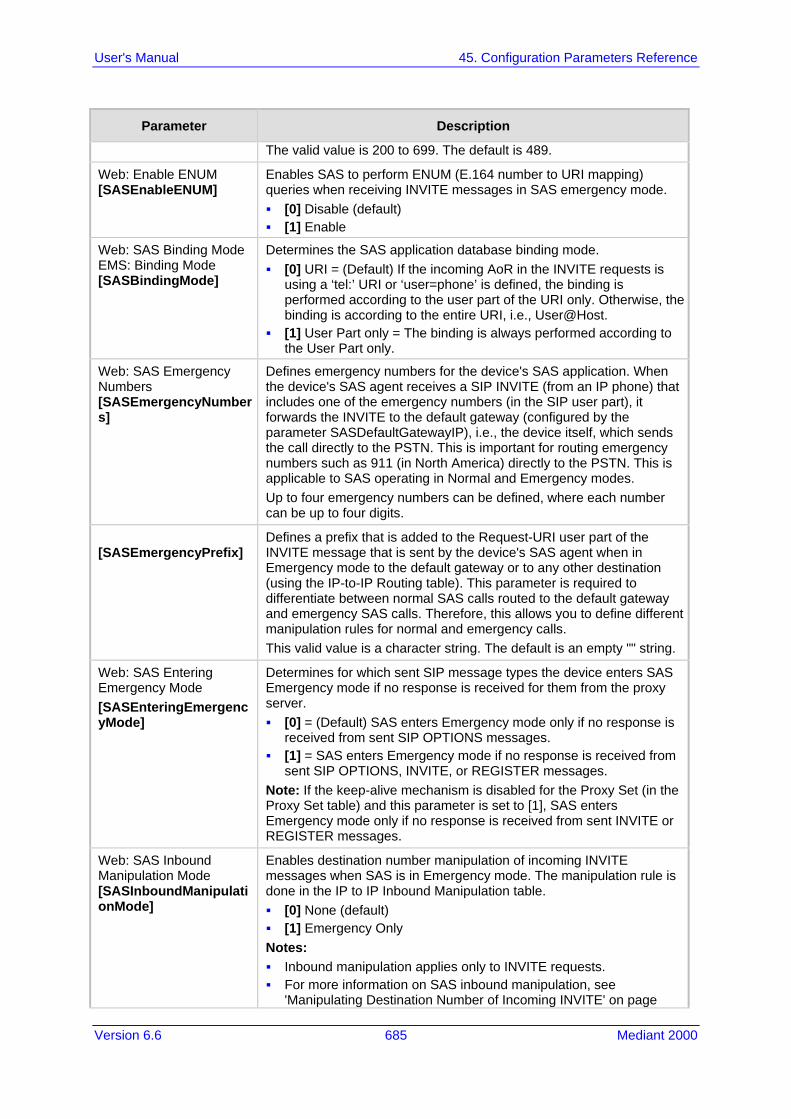
Version 6.6 685 Mediant 2000
User's Manual 45. Configuration Parameters Reference
Parameter Description
The valid value is 200 to 699. The default is 489.
Web: Enable ENUM [SASEnableENUM]
Enables SAS to perform ENUM (E.164 number to URI mapping) queries when receiving INVITE messages in SAS emergency mode. [0] Disable (default) [1] Enable
Web: SAS Binding Mode EMS: Binding Mode [SASBindingMode]
Determines the SAS application database binding mode. [0] URI = (Default) If the incoming AoR in the INVITE requests is
using a ‘tel:’ URI or ‘user=phone’ is defined, the binding is performed according to the user part of the URI only. Otherwise, the binding is according to the entire URI, i.e., User@Host.
[1] User Part only = The binding is always performed according to the User Part only.
Web: SAS Emergency Numbers [SASEmergencyNumbers]
Defines emergency numbers for the device's SAS application. When the device's SAS agent receives a SIP INVITE (from an IP phone) that includes one of the emergency numbers (in the SIP user part), it forwards the INVITE to the default gateway (configured by the parameter SASDefaultGatewayIP), i.e., the device itself, which sends the call directly to the PSTN. This is important for routing emergency numbers such as 911 (in North America) directly to the PSTN. This is applicable to SAS operating in Normal and Emergency modes. Up to four emergency numbers can be defined, where each number can be up to four digits.
[SASEmergencyPrefix]
Defines a prefix that is added to the Request-URI user part of the INVITE message that is sent by the device's SAS agent when in Emergency mode to the default gateway or to any other destination (using the IP-to-IP Routing table). This parameter is required to differentiate between normal SAS calls routed to the default gateway and emergency SAS calls. Therefore, this allows you to define different manipulation rules for normal and emergency calls. This valid value is a character string. The default is an empty "" string.
Web: SAS Entering Emergency Mode [SASEnteringEmergencyMode]
Determines for which sent SIP message types the device enters SAS Emergency mode if no response is received for them from the proxy server. [0] = (Default) SAS enters Emergency mode only if no response is
received from sent SIP OPTIONS messages. [1] = SAS enters Emergency mode if no response is received from
sent SIP OPTIONS, INVITE, or REGISTER messages. Note: If the keep-alive mechanism is disabled for the Proxy Set (in the Proxy Set table) and this parameter is set to [1], SAS enters Emergency mode only if no response is received from sent INVITE or REGISTER messages.
Web: SAS Inbound Manipulation Mode [SASInboundManipulationMode]
Enables destination number manipulation of incoming INVITE messages when SAS is in Emergency mode. The manipulation rule is done in the IP to IP Inbound Manipulation table. [0] None (default) [1] Emergency Only Notes: Inbound manipulation applies only to INVITE requests. For more information on SAS inbound manipulation, see
'Manipulating Destination Number of Incoming INVITE' on page
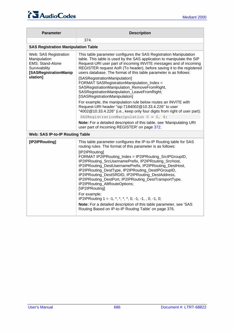
User's Manual 686 Document #: LTRT-68822
Mediant 2000
Parameter Description
374.
SAS Registration Manipulation Table
Web: SAS Registration Manipulation EMS: Stand-Alone Survivability [SASRegistrationManipulation]
This table parameter configures the SAS Registration Manipulation table. This table is used by the SAS application to manipulate the SIP Request-URI user part of incoming INVITE messages and of incoming REGISTER request AoR (To header), before saving it to the registered users database. The format of this table parameter is as follows: [SASRegistrationManipulation] FORMAT SASRegistrationManipulation_Index = SASRegistrationManipulation_RemoveFromRight, SASRegistrationManipulation_LeaveFromRight; [\SASRegistrationManipulation] For example, the manipulation rule below routes an INVITE with Request-URI header "sip:[email protected]" to user "[email protected]" (i.e., keep only four digits from right of user part): SASRegistrationManipulation 0 = 0, 4;
Note: For a detailed description of this table, see 'Manipulating URI user part of Incoming REGISTER' on page 372.
Web: SAS IP-to-IP Routing Table
[IP2IPRouting] This table parameter configures the IP-to-IP Routing table for SAS routing rules. The format of this parameter is as follows: [IP2IPRouting] FORMAT IP2IPRouting_Index = IP2IPRouting_SrcIPGroupID, IP2IPRouting_SrcUsernamePrefix, IP2IPRouting_SrcHost, IP2IPRouting_DestUsernamePrefix, IP2IPRouting_DestHost, IP2IPRouting_DestType, IP2IPRouting_DestIPGroupID, IP2IPRouting_DestSRDID, IP2IPRouting_DestAddress, IP2IPRouting_DestPort, IP2IPRouting_DestTransportType, IP2IPRouting_AltRouteOptions; [\IP2IPRouting] For example: IP2IPRouting 1 = -1, *, *, *, *, 0, -1, -1, , 0, -1, 0; Note: For a detailed description of this table parameter, see 'SAS Routing Based on IP-to-IP Routing Table' on page 376.

Version 6.6 687 Mediant 2000
User's Manual 45. Configuration Parameters Reference
45.15 IP Media Parameters The IP media parameters are described in the table below.
IP Media Parameters
Parameter Description
Web: Number of Media Channels EMS: Media Channels [MediaChannels]
Defines the maximum number of DSP channels allocated for various functionalities such as IP-to-IP sessions. The RTP streams for IP-to-IP calls always transverse the device and two DSP channels are allocated per IP-to-IP session. Therefore, the maximum number of media channels for IP-to-IP calls is 240, corresponding to 120 IP-to-IP calls. The default is 0. Notes: For this parameter to take effect, a device reset is required. Other DSP channels can be used for PSTN interfaces.
Automatic Gain Control (AGC) Parameters
Web: Enable AGC EMS: AGC Enable [EnableAGC]
Enables the AGC mechanism. The AGC mechanism adjusts the level of the received signal to maintain a steady (configurable) volume level. [0] Disable (default) [1] Enable Notes: This parameter can also be configured in a Tel Profile. For a description of AGC, see Automatic Gain Control (AGC) on
page 175.
Web: AGC Slope EMS: Gain Slope [AGCGainSlope]
Determines the AGC convergence rate: [0] 0 = 0.25 dB/sec [1] 1 = 0.50 dB/sec [2] 2 = 0.75 dB/sec [3] 3 = 1.00 dB/sec (default) [4] 4 = 1.25 dB/sec [5] 5 = 1.50 dB/sec [6] 6 = 1.75 dB/sec [7] 7 = 2.00 dB/sec [8] 8 = 2.50 dB/sec [9] 9 = 3.00 dB/sec [10] 10 = 3.50 dB/sec [11] 11 = 4.00 dB/sec [12] 12 = 4.50 dB/sec [13] 13 = 5.00 dB/sec [14] 14 = 5.50 dB/sec [15] 15 = 6.00 dB/sec [16] 16 = 7.00 dB/sec [17] 17 = 8.00 dB/sec [18] 18 = 9.00 dB/sec [19] 19 = 10.00 dB/sec [20] 20 = 11.00 dB/sec

User's Manual 688 Document #: LTRT-68822
Mediant 2000
Parameter Description
[21] 21 = 12.00 dB/sec [22] 22 = 13.00 dB/sec [23] 23 = 14.00 dB/sec [24] 24 = 15.00 dB/sec [25] 25 = 20.00 dB/sec [26] 26 = 25.00 dB/sec [27] 27 = 30.00 dB/sec [28] 28 = 35.00 dB/sec [29] 29 = 40.00 dB/sec [30] 30 = 50.00 dB/sec [31] 31 = 70.00 dB/sec
Web: AGC Redirection EMS: Redirection [AGCRedirection]
Determines the AGC direction. [0] 0 = (Default) AGC works on signals from the TDM side. [1] 1 = AGC works on signals from the IP side.
Web: AGC Target Energy EMS: Target Energy [AGCTargetEnergy]
Defines the signal energy value (dBm) that the AGC attempts to attain. The valid range is 0 to -63 dBm. The default is -19 dBm.
EMS: Minimal Gain [AGCMinGain]
Defines the minimum gain (in dB) by the AGC when activated. The range is 0 to -31. The default is -20. Note: For this parameter to take effect, a device reset is required.
EMS: Maximal Gain [AGCMaxGain]
Defines the maximum gain (in dB) by the AGC when activated. The range is 0 to 18. The default is 15. Note: For this parameter to take effect, a device reset is required.
EMS: Disable Fast Adaptation [AGCDisableFastAdaptation]
Enables the AGC Fast Adaptation mode. [0] = Disable (default) [1] = Enable Note: For this parameter to take effect, a device reset is required.
Answer Machine Detector (AMD) Parameters
Web: Web: Answer Machine Detector Sensitivity Parameter Suit [AMDSensitivityParameterSuit]
Determines the AMD Parameter Suite that you want the device to use. [0] = (Default) USA Parameter Suite with 8 detection sensitivity
levels (from 0 to 7). [1] = USA Parameter Suite with high detection sensitivity
resolution (16 sensitivity levels, from 0 to 15). [2]-[3] = Other countries parameter suites with up to 16 sensitivity
levels. Notes: The sensitivity level is selected by the AMDSensitivityLevel
parameter. This parameter can also be configured in an IP Profile.
Web: Answer Machine Detector Sensitivity Level [AMDSensitivityLevel]
Defines the AMD detection sensitivity level of the selected AMD Parameter Suite. The valid value range is 0 (for best detection of an answering machine) to 15 (for best detection of a live call). The default is 8. Notes: This parameter is applicable only if the
AMDSensitivityParameterSuit parameter is set to any option other

Version 6.6 689 Mediant 2000
User's Manual 45. Configuration Parameters Reference
Parameter Description
than 0. This parameter can also be configured in an IP Profile.
Web: Answer Machine Detector Sensitivity EMS: Sensitivity [AMDDetectionSensitivity]
Defines the AMD detection sensitivity level of the selected Parameter Suite. AMD can be useful in automatic dialing applications. In some of these applications, it is important to detect if a human voice or an answering machine is answering the call. AMD can be activated and de-activated only after a channel is already open. The valid value range is 0 to 7, where 0 is the best detection for answering machines and 7 is the best detection for live calls (i.e., voice detection). The default is 3. Notes: This parameter is applicable only if the
AMDSensitivityParameterSuit parameter is set to 0. To enable the AMD feature, set the EnableDSPIPMDetectors
parameter to 1. For more information on AMD, see Answer Machine Detector
(AMD) on page 171.
Web: AMD Sensitivity File [AMDSensitivityFileName]
Defines the name of the AMD Sensitivity file that contains the AMD Parameter Suites. Notes: This file must be in binary format (.dat). You can use the DConvert
utility to convert the original file format from XML to .dat. You can load this file using the Web interface (see Loading
Auxiliary Files on page 399).
[AMDSensitivityFileUrl] Defines the URL path to the AMD Sensitivity file for downloading from a remote server.
[AMDMinimumVoiceLength]
Defines the AMD minimum voice activity detection duration (in 5-ms units). Voice activity duration below this threshold is ignored and considered as non-voice. The valid value range is 10 to 100. The default is 42 (i.e., 210 ms).
EMS: AMD Max Greeting Time [AMDMaxGreetingTime]
Defines the maximum duration to detect greeting message. Note: This parameter can also be configured in an IP Profile.
EMS: AMD Max Post Silence Greeting Time [AMDMaxPostGreetingSilenceTime]
Defines the maximum duration of silence from after the greeting time is over (defined by AMDMaxGreetingTime) until the AMD decision. Note: This parameter can also be configured in an IP Profile.
EMS: Time Out [AMDTimeout]
Defines the timeout (in msec) between receiving Connect messages from the ISDN and sending AMD results. The valid range is 1 to 30,000. The default is 2,000 (i.e., 2 seconds).
Web/EMS: AMD Beep Detection Mode [AMDBeepDetectionMode]
Determines the AMD beep detection mode. This mode detects the beeps played at the end of an answering machine message, by using the X-Detect header extension. The device sends a SIP INFO message containing the field values Type=AMD and SubType=Beep. This feature allows users of certain third-party, Application server to leave a voice message after an answering machine plays the “beep”. [0] Disabled (default)

User's Manual 690 Document #: LTRT-68822
Mediant 2000
Parameter Description
[1] Start After AMD [2] Start Immediately
Web: Answer Machine Detector Beep Detection Timeout EMS: Beep Detection Timeout [AMDBeepDetectionTimeout]
Defines the AMD beep detection timeout (i.e., the duration that the beep detector functions from when detection is initiated). This is used for detecting beeps at the end of an answering machine message. The valid value is in units of 100 milliseconds, from 0 to 1638. The default is 200 (i.e., 20 seconds).
Web: Answer Machine Detector Beep Detection Sensitivity EMS: Beep Detection Sensitivity [AMDBeepDetectionSensitivity]
Defines the AMD beep detection sensitivity for detecting beeps at the end of an answering machine message. The valid value is 0 to 3, where 0 (default) is the least sensitive.
Web: AMD mode CLI: amd-mode [AMDmode]
Enables the device to disconnect the IP-to-Tel call upon detection of an answering machine on the Tel side (i.e., AMD). In such a scenario, the device sends a SIP BYE message upon AMD. [0] = (Default) Device does not disconnect call upon detection of
an answering machine. [1] = Device disconnects call upon detection of an answering
machine. Notes: This feature does not need the receipt of the SIP X-Detect header
in the incoming INVITE to activate the AMD. This feature can also be configured for an IP Profile.
Energy Detector Parameters
Enable Energy Detector [EnableEnergyDetector]
Enables the Energy Detector feature. This feature generates events (notifications) when the signal received from the PSTN is higher or lower than a user-defined threshold (defined by the EnergyDetectorThreshold parameter). [0] Disable (default) [1] Enable
Energy Detector Quality Factor [EnergyDetectorQualityFactor]
Defines the Energy Detector's sensitivity level. The valid range is 0 to 10, where 0 is the lowest sensitivity and 10 the highest sensitivity. The default is 4.
Energy Detector Threshold [EnergyDetectorThreshold]
Defines the Energy Detector's threshold. A signal below or above this threshold invokes an 'Above' or 'Below' event. The threshold is calculated as follows: Actual Threshold = -44 dBm + (EnergyDetectorThreshold * 6) The valid value range is 0 to 7. The default is 3 (i.e., -26 dBm).
Pattern Detection Parameters Note: For an overview on the pattern detector feature for TDM tunneling, see DSP Pattern Detector on page 271.

Version 6.6 691 Mediant 2000
User's Manual 45. Configuration Parameters Reference
Parameter Description
Web: Enable Pattern Detector [EnablePatternDetector]
Enables the Pattern Detector (PD) feature. [0] Disable (default) [1] Enable
[PDPattern] Defines the patterns that can be detected by the Pattern Detector. The valid range is 0 to 0xFF. Note: For this parameter to take effect, a device reset is required.
[PDThreshold] Defines the number of consecutive patterns to trigger the pattern detection event. The valid range is 0 to 31. The default is 5. Note: For this parameter to take effect, a device reset is required.
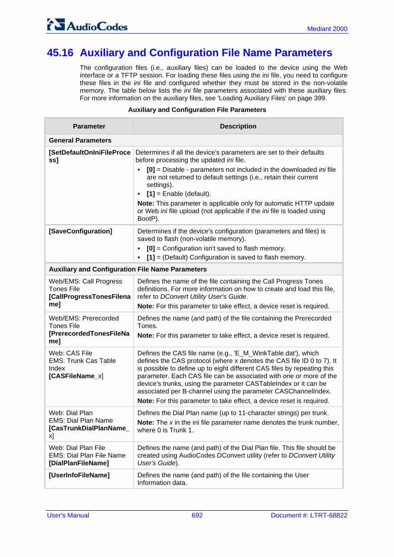
User's Manual 692 Document #: LTRT-68822
Mediant 2000
45.16 Auxiliary and Configuration File Name Parameters The configuration files (i.e., auxiliary files) can be loaded to the device using the Web interface or a TFTP session. For loading these files using the ini file, you need to configure these files in the ini file and configured whether they must be stored in the non-volatile memory. The table below lists the ini file parameters associated with these auxiliary files. For more information on the auxiliary files, see 'Loading Auxiliary Files' on page 399.
Auxiliary and Configuration File Parameters
Parameter Description
General Parameters
[SetDefaultOnIniFileProcess]
Determines if all the device's parameters are set to their defaults before processing the updated ini file. [0] = Disable - parameters not included in the downloaded ini file
are not returned to default settings (i.e., retain their current settings).
[1] = Enable (default). Note: This parameter is applicable only for automatic HTTP update or Web ini file upload (not applicable if the ini file is loaded using BootP).
[SaveConfiguration] Determines if the device's configuration (parameters and files) is saved to flash (non-volatile memory). [0] = Configuration isn't saved to flash memory. [1] = (Default) Configuration is saved to flash memory.
Auxiliary and Configuration File Name Parameters
Web/EMS: Call Progress Tones File [CallProgressTonesFilename]
Defines the name of the file containing the Call Progress Tones definitions. For more information on how to create and load this file, refer to DConvert Utility User's Guide. Note: For this parameter to take effect, a device reset is required.
Web/EMS: Prerecorded Tones File [PrerecordedTonesFileName]
Defines the name (and path) of the file containing the Prerecorded Tones. Note: For this parameter to take effect, a device reset is required.
Web: CAS File EMS: Trunk Cas Table Index [CASFileName_x]
Defines the CAS file name (e.g., 'E_M_WinkTable.dat'), which defines the CAS protocol (where x denotes the CAS file ID 0 to 7). It is possible to define up to eight different CAS files by repeating this parameter. Each CAS file can be associated with one or more of the device's trunks, using the parameter CASTableIndex or it can be associated per B-channel using the parameter CASChannelIndex. Note: For this parameter to take effect, a device reset is required.
Web: Dial Plan EMS: Dial Plan Name [CasTrunkDialPlanName_x]
Defines the Dial Plan name (up to 11-character strings) per trunk. Note: The x in the ini file parameter name denotes the trunk number, where 0 is Trunk 1.
Web: Dial Plan File EMS: Dial Plan File Name [DialPlanFileName]
Defines the name (and path) of the Dial Plan file. This file should be created using AudioCodes DConvert utility (refer to DConvert Utility User's Guide).
[UserInfoFileName] Defines the name (and path) of the file containing the User Information data.

Version 6.6 693 Mediant 2000
User's Manual 45. Configuration Parameters Reference
45.17 Automatic Update Parameters The automatic update of software and configuration files parameters are described in the table below.
Automatic Update of Software and Configuration Files Parameters
Parameter Description
General Automatic Update Parameters
[AutoUpdateCmpFile] Enables the Automatic Update mechanism for the cmp file. [0] = (Default) The Automatic Update mechanism doesn't apply to
the cmp file. [1] = The Automatic Update mechanism includes the cmp file. Note: For this parameter to take effect, a device reset is required.
[AutoUpdateFrequency]
Defines the number of minutes that the device waits between automatic updates. The default is 0 (i.e., the update at fixed intervals mechanism is disabled). Note: For this parameter to take effect, a device reset is required.
[AutoUpdatePredefinedTime]
Defines schedules (time of day) for automatic updates. The format of this parameter is: 'HH:MM', where HH denotes the hour and MM the minutes, for example, 20:18. Notes: For this parameter to take effect, a device reset is required. The actual update time is randomized by five minutes to reduce the
load on the Web servers.
EMS: AUPD Verify Certificates [AUPDVerifyCertificates]
Determines whether the Automatic Update mechanism verifies server certificates when using HTTPS. [0] = Disable (default) [1] = Enable
[AUPDCheckIfIniChanged]
Determines whether the Automatic Update mechanism performs CRC checking to determine if the ini file has changed prior to processing. [0] = (Default) Do not check CRC. The ini file is loaded whenever the
server provides it. [1] = Check CRC for the entire file. Any change, including line order,
causes the ini file to be re-processed. [2] = Check CRC for individual lines. Use this option when the HTTP
server scrambles the order of lines in the provided ini file.
[ResetNow] Invokes an immediate device reset. This option can be used to activate offline (i.e., not on-the-fly) parameters that are loaded using the parameter IniFileUrl. [0] = (Default) The immediate restart mechanism is disabled. [1] = The device immediately resets after an ini file with this
parameter set to 1 is loaded.
Software/Configuration File URL Path for Automatic Update Parameters
[CmpFileURL] Defines the name of the cmp file and the path to the server (IP address or FQDN) from where the device can load the cmp file and update itself. The cmp file can be loaded using HTTP/HTTPS, FTP, FTPS, or NFS. For example: http://192.168.0.1/filename

User's Manual 694 Document #: LTRT-68822
Mediant 2000
Parameter Description
Notes: For this parameter to take effect, a device reset is required. When this parameter is configured, the device always loads the cmp
file after it is reset. The cmp file is validated before it's burned to flash. The checksum of
the cmp file is also compared to the previously burnt checksum to avoid unnecessary resets.
The maximum length of the URL address is 255 characters.
[IniFileURL] Defines the name of the ini file and the path to the server (IP address or FQDN) on which it is located. The ini file can be loaded using HTTP/HTTPS, FTP, FTPS, or NFS. For example: http://192.168.0.1/filename http://192.8.77.13/config<MAC> https://<username>:<password>@<IP address>/<file name> Notes: For this parameter to take effect, a device reset is required. When using HTTP or HTTPS, the date and time of the ini file are
validated. Only more recently dated ini files are loaded. The optional string <MAC> is replaced with the device's MAC
address. Therefore, the device requests an ini file name that contains its MAC address. This option allows the loading of specific configurations for specific devices.
The maximum length of the URL address is 99 characters.
[PrtFileURL] Defines the name of the Prerecorded Tones (PRT) file and the path to the server (IP address or FQDN) on which it is located. For example: http://server_name/file, https://server_name/file. Note: The maximum length of the URL address is 99 characters.
[CptFileURL] Defines the name of the CPT file and the path to the server (IP address or FQDN) on which it is located. For example: http://server_name/file, https://server_name/file. Note: The maximum length of the URL address is 99 characters.
[CasFileURL] Defines the name of the CAS file and the path to the server (IP address or FQDN) on which it is located. For example: http://server_name/file, https://server_name/file. Note: The maximum length of the URL address is 99 characters.
[TLSRootFileUrl] Defines the name of the TLS trusted root certificate file and the URL from where it can be downloaded. Note: For this parameter to take effect, a device reset is required.
[TLSCertFileUrl] Defines the name of the TLS certificate file and the URL from where it can be downloaded. Note: For this parameter to take effect, a device reset is required.
[TLSPkeyFileUrl] Defines the URL for downloading a TLS private key file using the Automatic Update facility.
[UserInfoFileURL] Defines the name of the User Information file and the path to the server (IP address or FQDN) on which it is located. For example: http://server_name/file, https://server_name/file Note: The maximum length of the URL address is 99 characters.

Version 6.6 695 Mediant 2000
User's Manual 46. DSP Templates
46 DSP Templates This section lists the DSP templates supported by the device. Each DSP template provides support for specific voice coders (as well as channel capacity and various features).
Notes:
• DSP templates 1 and 2 are not supported on reduced hardware assemblies (i.e., one or two trunks).
• To select the DSP Template that you want to use on the device, see Configuring DSP Templates on page 176.
• Installation and use of voice coders is subject to obtaining the appropriate license and royalty payments.
• The number of channels refers to the maximum channel capacity of the device. • For additional DSP templates, contact your AudioCodes representative.
DSP Firmware Templates
DSP Template
0 1 2 5
Number of Channels
Default Setting 480 320 240 240
With 128 ms EC 400 320 240 240
With SRTP 400 - 160 240
With IPM Detectors 400 320 240 240
With IPM Detectors & SRTP 320 - 160 240
Voice Coder
Transparent Yes Yes Yes Yes
G.711 A/m-law PCM Yes Yes Yes Yes
G.727 Yes Yes Yes Yes
G.726 ADPCM Yes Yes Yes Yes
G.723.1 Yes - - -
G.729 A, B Yes Yes Yes -
GSM FR Yes Yes - -
MS GSM Yes Yes - -
EVRC - - Yes -
QCELP - - Yes -
AMR - Yes - -
GSM EFR - Yes - -
iLBC - - - Yes

User's Manual 696 Document #: LTRT-68822
Mediant 2000
Reader's Notes
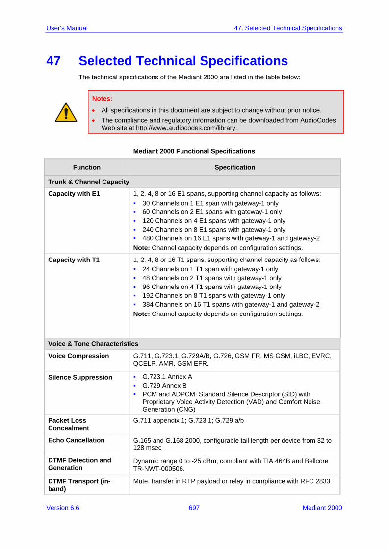
Version 6.6 697 Mediant 2000
User's Manual 47. Selected Technical Specifications
47 Selected Technical Specifications The technical specifications of the Mediant 2000 are listed in the table below:
Notes:
• All specifications in this document are subject to change without prior notice. • The compliance and regulatory information can be downloaded from AudioCodes
Web site at http://www.audiocodes.com/library.
Mediant 2000 Functional Specifications
Function Specification
Trunk & Channel Capacity
Capacity with E1
1, 2, 4, 8 or 16 E1 spans, supporting channel capacity as follows: 30 Channels on 1 E1 span with gateway-1 only 60 Channels on 2 E1 spans with gateway-1 only 120 Channels on 4 E1 spans with gateway-1 only 240 Channels on 8 E1 spans with gateway-1 only 480 Channels on 16 E1 spans with gateway-1 and gateway-2 Note: Channel capacity depends on configuration settings.
Capacity with T1 1, 2, 4, 8 or 16 T1 spans, supporting channel capacity as follows: 24 Channels on 1 T1 span with gateway-1 only 48 Channels on 2 T1 spans with gateway-1 only 96 Channels on 4 T1 spans with gateway-1 only 192 Channels on 8 T1 spans with gateway-1 only 384 Channels on 16 T1 spans with gateway-1 and gateway-2 Note: Channel capacity depends on configuration settings.
Voice & Tone Characteristics
Voice Compression G.711, G.723.1, G.729A/B, G.726, GSM FR, MS GSM, iLBC, EVRC, QCELP, AMR, GSM EFR.
Silence Suppression G.723.1 Annex A G.729 Annex B PCM and ADPCM: Standard Silence Descriptor (SID) with
Proprietary Voice Activity Detection (VAD) and Comfort Noise Generation (CNG)
Packet Loss Concealment
G.711 appendix 1; G.723.1; G.729 a/b
Echo Cancellation G.165 and G.168 2000, configurable tail length per device from 32 to 128 msec
DTMF Detection and Generation
Dynamic range 0 to -25 dBm, compliant with TIA 464B and Bellcore TR-NWT-000506.
DTMF Transport (in-band)
Mute, transfer in RTP payload or relay in compliance with RFC 2833

User's Manual 698 Document #: LTRT-68822
Mediant 2000
Function Specification
Answer Detector Answer detection
Answer Machine Detector
Detects whether voice or an answering machine is answering the call. Note: When implementing Answer Machine Detector, channel capacity may be reduced.
Call Progress Tone Detection and Generation
32 tones: single tone, dual tones or AM tones, programmable frequency & amplitude; 64 frequencies in the range 300 to 1980 Hz, 1 to 4 cadences per tone, up to 4 sets of ON/OFF periods
Input Gain Control -32 dB to +31 dB in steps of 1 dB
Output Gain Control -32 dB to +31 dB in steps of 1 dB
Stand Alone Survivability (SAS) Application
SAS SAS ensures call continuity between LAN SIP clients upon connectivity failure with IP Centrex services (e.g., WAN IP PBX).
Max. Capacity
Registered Users (IP-to-IP, SAS)
250
Transcoding Sessions (IP-to-IP Application)
120
TLS Sessions 100
Fax and Modem Transport Modes
Real time Fax Relay Group 3 real-time fax relay up to 14400 bps with automatic fallback Tolerant network delay (up to 9 seconds round trip delay) T.30 (PSTN) and T.38 (IP) compliant (real-time fax) CNG tone detection & Relay per T.38 Answer tone (CED or AnsAm) detection & Relay per T.38
Fax Transparency Automatic fax bypass (pass-through) to G.711, ADPCM or NSE bypass mode
Modem Transparency Automatic switching (pass-through) to PCM, ADPCM or NSE bypass mode for modem signals (V.34 or V.90 modem detection)
Protocols
VoIP Signaling Protocol SIP RFC 3261
Communication Protocols
RTP/RTCP packetization IP stack (UDP, TCP, RTP) Remote Software load (TFTP, HTTP and HTTPS)
Telephony Protocols PRI (ETSI Euro ISDN, ANSI NI2, 4/5ESS, DMS-100, QSIG, Japan INS1500, Australian Telecom, New Zealand Telecom, Hong Kong Variant, Korean MIC)
E1/T1 CAS protocols: MFC R2, E&M wink start Immediate start, delay start, loop start, ground start Feature Group B, D for E1/T1
In-Band Signaling DTMF (TIA 464A) MF-R1, MFC R2 User-defined Call Progress Tones

Version 6.6 699 Mediant 2000
User's Manual 47. Selected Technical Specifications
Function Specification
Interfaces
Telephony Interface 1, 2, 4, 8 or 16 E1/T1/J1 Balanced 120/100 Ohm, or 75 Ohm using a BNC to RJ-45 dual E1/T1 G.703 Balun adapter. Note: The following Balun adaptors were tested and certified by AudioCodes: Manufacture Name: AC&E (Part Number: B04040072) Manufacture Name: RIT (Part Number: R3712271)
Network Interface Two 10/100Base-TX, half or full duplex with auto-negotiation
LED Indicators
LED Indications on Front Panel Power, ACT/Fail, T1/E1 status, Ethernet status, Swap ready indication
Connectors & Switches
Rear Panel
Trunks 1 to 8 and 9 to 16 Two 50-pin female Telco connectors (DDK57AE-40500-21D) or 8 RJ-48c connectors for trunks 1 to 8 only
Ethernet 1 and 2 Two 10/100Base-TX, RJ-45 shielded connectors
AC Power Standard IEC320 Appliance inlet Dual (fully redundant) power supply (optional)
DC Power 2-pin terminal block (screw connection type) suitable for field wiring applications connecting DC Power connector MSTB2.5/2-STF (5.08 mm) from Phoenix Contact
Bonding and earthing: 6-32-UNC screw is provided - correct ring terminal and 16 AWG wire minimum must be used
Or crimp connection (see note below) Note: To meet UL approval, customers must fulfill the criteria below: 2-pin terminal block (crimp connection type) comprising a Phoenix Contact Adaptor: Shroud MSTBC2,5/2-STZF-5,08 Contacts: MSTBC-MT0,5-1,0 Cable: 18 AWG x 1.5 m length
Physical
AC Power Supply Single universal power supply 100-240V 1.5A max, 50-60 Hz Dual redundant power supply (optional)
AC Power Consumption 1 or 2 span: 39.7 W 4 spans: 42.1 W (approx.) 8 spans: 45.3 W 16 spans: 61.5 W
DC Power Supply (optional)
36 to 72 VDC (nominal 48 VDC), 4A max, floating input
DC Power Consumption 1 or 2 span: 28.8 W 4 spans: 32.8 W 8 spans: 36.4 W
Environmental (DC) Operating Temp: 0 to 40°C (32 to 104°F) Short Term Operating Temp (per NEBS): 0 to 55°C (32 to 131°F)
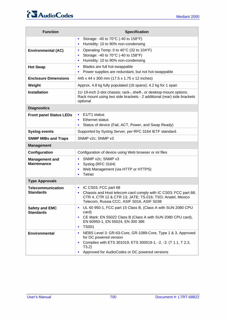
User's Manual 700 Document #: LTRT-68822
Mediant 2000
Function Specification
Storage: -40 to 70°C (-40 to 158°F) Humidity: 10 to 90% non-condensing
Environmental (AC) Operating Temp: 0 to 40°C (32 to 104°F) Storage: -40 to 70°C (-40 to 158°F) Humidity: 10 to 90% non-condensing
Hot Swap Blades are full hot-swappable Power supplies are redundant, but not hot-swappable
Enclosure Dimensions 445 x 44 x 300 mm (17.5 x 1.75 x 12 inches)
Weight Approx. 4.8 kg fully populated (16 spans); 4.2 kg for 1 span
Installation 1U 19-inch 2-slot chassis; rack-, shelf-, or desktop-mount options. Rack mount using two side brackets - 2 additional (rear) side brackets optional
Diagnostics
Front panel Status LEDs E1/T1 status Ethernet status Status of device (Fail, ACT, Power, and Swap Ready)
Syslog events Supported by Syslog Server, per RFC 3164 IETF standard.
SNMP MIBs and Traps SNMP v2c; SNMP v3
Management
Configuration Configuration of device using Web browser or ini files
Management and Maintenance
SNMP v2c; SNMP v3 Syslog (RFC 3164) Web Management (via HTTP or HTTPS) Telnet
Type Approvals
Telecommunication Standards
IC CS03; FCC part 68 Chassis and Host telecom card comply with IC CS03; FCC part 68;
CTR 4, CTR 12 & CTR 13; JATE; TS.016; TSO; Anatel, Mexico Telecom, Russia CCC, ASIF S016, ASIF S038
Safety and EMC Standards
UL 60 950-1, FCC part 15 Class B, (Class A with SUN 2080 CPU card)
CE Mark: EN 55022 Class B (Class A with SUN 2080 CPU card), EN 60950-1, EN 55024, EN 300 386
TS001
Environmental NEBS Level 3: GR-63-Core, GR-1089-Core, Type 1 & 3. Approved for DC powered version
Complies with ETS 301019; ETS 300019-1, -2, -3. (T 1.1, T 2.3, T3.2)
Approved for AudioCodes or DC powered versions


User's Manual Ver. 6.6
www.audiocodes.com