User’s manual and Technical description - ABB s manual and Technical description Feeder...
96
User’s manual and Technical description Feeder Protection Relay REF601 CEI
Transcript of User’s manual and Technical description - ABB s manual and Technical description Feeder...
User’s manual and Technical description Feeder Protection Relay
REF601 CEI
Document ID: 1MDU07205-YN
Issued: 30.09.2010
Revision:F
Product version:1.0 SP1
Copyright 2009 – ABB. All rights reserved

1MDU07205-YN rev. F
REF601 CEI
User’s manual 3
Copyright
This document and parts thereof must not be reproduced or copied without written permission from ABB and the contents thereof must not be imparted to a third party, nor used for any unauthorized purpose. The software or hardware described in this document is furnished under a license and may be used, cop-ied, or disclosed only in accordance with the terms of such license.
Trademarks
ABB is a registered trademark of ABB Group. All other brand or product names
mentioned in this document may be trademarks or registered trademarks of their
respective holders.
Guarantee
Please inquire about the terms of guarantee from your nearest ABB representa-tive.
ABB Ltd.
Distribution Automation
Maneja Works,
Vadodara - 390 013, India
Phone +91 265 2604386
Fax +91 265 2638922
www.abb.com/substationautomation

1MDU07205-YN rev. F
REF601 CEI
User’s manual 4
Disclaimer
The data, examples and diagrams in this manual are included solely for the concept or product description and are not to be deemed as a statement of guaranteed prop-erties. All persons responsible for applying the equipment addressed in this manual must satisfy themselves that each intended application is suitable and acceptable, including that any applicable safety or other operational requirements are complied with. In particular, any risks in applications where a system failure and/or product failure would create a risk for harm to property or persons (including but not limited to personal injuries or death) shall be the sole responsibility of the person or entity applying the equipment, and those so responsible are hereby requested to ensure that all measures are taken to exclude or mitigate such risks. This document has been carefully checked by ABB but deviations cannot be completely ruled out. In case any errors are detected, the reader is kindly requested to notify the manufac-turer. Other than under explicit contractual commitments, in no event shall ABB be responsible or liable for any loss or damage resulting from the use of this manual or the application of the equipment.

1MDU07205-YN rev. F
REF601 CEI
User’s manual 5
Conformity
This product complies with the directive of the Council of the European Communities on the approximation of the laws of the Member States relating to electromagnetic compatibility (EMC Council Directive 2004/108/EC) and concerning electrical equip-ment for use within specifi ed voltage limits (Low-voltage directive 2006/95/ EC). This conformity is the result of a test conducted by ABB in accordance with Article 10 of the directive in agreement with the product standards EN 50263 and EN 60255-26 for the EMC directive, and with the product standards EN 60255-6 and EN 60255-27 for the low voltage directive. The IED is designed in accordance with the international standards of the IEC 60255 series.

1MDU07205-YN rev. F
REF601 CEI
User’s manual 6
Table of contents
Table of contents
Introduction…………………………………...………9
This manual.........……………………..………………………...9
Intended audience.………………………………..……………9
Document Revison History...…………………………………..9
Document symbol & conventions..………………………….10
REF601 CEI overview.......…………………...……11
Overview............………….………………………..…………...11
Product version history….……………………………..………12
Operational functionality...……………………………………..12
Basic Functions...........................……………….…………….12
Power supply..................………………………….……………15
Technical data ...……………………………...……17
Dimensions..…….………………….…………………………..17
Power supply......……....……………………………..……… 17
Energizing inputs……....……………………………..……… 17
Binary input………………………….……………………...…..18
Output....................................……………….………………..18
Protection Functions.…..……………………………..……….19
Degree of protection..……...……………………..………...…20
Environmental tests and conditions….………………………21
Mechanical tests……………………………………………….22
Insulation and mechanical tests………………….…………..22
Electromagnetic compatibility tests………………………….22
Section 1
Section 2
Section 3

1MDU07205-YN rev. F
REF601 CEI
User’s manual 7
Table of contents
Protection Functions............………....……...…25
Three Phase Current Protection....……...……………..……25
Earth Fault Protection………………………..…………….…25
Three Phase In Rush Detector.........………..…………….…26
Output & Inputs..........................................…………..….…27
Breaker control & Trip Command Operation.......……….…27
Signal Diagram.......................................…………….…..…30
Protection characteristics.................................……………32
Menu structures & LHMI navigation…….......34
Local HMI....…………...…………………..……………..……34
Navigation..…………………………..………….………….…36
Main Menu............……...…………..………..…………….…37
Authorization....…………………….………………………….38
Measurement......................................................…..…..….39
Recorded data.....................................................………….40
Events................................................................…..……....41
Settings..............................................................................43
Confi guration......................................................................47
Test.....................................................................................51
Test - Calibration................................................................52
Functional Test...................................................................61
Access Level.....................................................…..……....63
Version info.........................................................................64
Section 4
Section 5
1MDU07205-YN rev. F
REF601 CEI
User’s manual 8
Table of contents
Installation………..…….....………...……………65
Unpacking and inspecting the device..…………….....……65
Storage...................…..……………..………….………….…65
Checking environmental conditions and mounting space..66
Mounting the relay………………………………………….…66
Relay Wiring..............………………..….………………….…67
Relay mounting dimension..………..….………………….…67
Relay connection digram....................................................69
Bonding of sensor cable shield...........................................70
Relay ordering information...................……………......……73
Section 6
Serial communication.....................……………74
Modbus protocol overview...................……………......……74
Wiring......................…..……………..………….………….…74
Modbus RTU message format............................................75
Modbus RTU function codes..…………………………….…77
Exception response..………………..….………………….…84
Serial communication parameters....….………………….…87
Communication troubleshooting.........................................95
Section 7

1MDU07205-YN rev. F
REF601 CEI
User’s manual 9
Introduction
Section 1 Introduction
1.1 This manual
This manual contains application and functionality descriptions and connection diagrams, input and output signals, setting parameters and technical data. The manual can be used as a technical reference during the engineering phase, installation and commissioning phase, and during normal service. The manual can also be used when calculating settings. Instructions on how to operate the IED during normal service once it has been commissioned and it can be used to fi nd out how to handle disturbances or how to view calculated and measured network data in order to determine the cause of a fault
1.2 Intended Audience
This manual addresses system engineers, installation and commissioning person-nel, who use technical data during engineering, installation and commissioning, and in normal service. system engineer must have a thorough knowledge of protection systems, protection equipment, protection functions and the confi gured functional logics in the IEDs. The installation and commissioning personnel must have a basic knowledge in handling electronic equipment.
This manual addresses Protection and control engineer responsible for planning, pre-engineering and engineering. The protection and control engineer must be experienced in electrical power engineering and have knowledge of related technology, such as communication and protocols.
The manual also addresses the operator, who operates the IED on a daily basis. The operator must be trained in and have a basic knowledge of how to operate protection equipment. The manual contains terms and expressions commonly used to describe this kind of equipment.
1.3 Document Revision History
Document version Release date Document history
A 17.03.2009 Document released
B 17.04.2009 Document released
C 21.04.2009 Document released
D 25.05.2009 Document released
E 07.08.2009 Document released
F 30.09.2010 Document released

1MDU07205-YN rev. F
REF601 CEI
User’s manual 10
1.4 Document Symbol and Conventions
Dangerous voltages can occur on the connectors, even though the auxiliary voltage has been disconnected.
National and local electrical safety regulations must always be followed.
The device contains components which are sensitive to Electrostatic discharge. Unnecessary touching of electronic components must therefore be avoided.
Only a competent electrician is allowed to carry out the electrical installation.
Non-observance can result in death, personal injury or substantial property damage
Breaking the sealing tape on the upper handle of the device will result in loss of warranty and proper operation will no longer be guaranteed.
When the plug-in unit has been detached from the case, do not touch the inside of the case. The relay case internals may contain high voltage potential and touching these may cause personal injury.
Introduction
1.4.1 Safety information
This publication includes the following icons that point out safety-related conditions or other important information:
1.4.2 Functions,codes & Symbols
Protection IEC code ANSI code
Three-phase non-directional overcurrent, low-set stage
3I> 51
Three-phase non-directional overcurrent, high-set stage
3I>> 50 / 51
Three-phase non-directional overcurrent, very high-set stage
3I>>> 50 / 51
Non-directional earth-fault, low-set stage Io> 51N
Non-directional earth-fault, high-set stage Io>> 50N/51N
Three phase transformer inrush detector 3I2f> 68

1MDU07205-YN rev. F
REF601 CEI
User’s manual 11
Section 2 REF601 CEI overview
2.1 Overview
REF601 CEI overview
REF601 is a dedicated feeder protection relay, intended for the protection, measure-ment and supervision of utility substations and industrial power systems. Engineered from the ground up, the relay is inspired by and is compatible with the Rogowski coil sensor for current measurement. The new feeder protection relay is designed to un-leash the advantages of current sensors for protection and control in medium voltage applications.
The REF601 features compact size and ease of use. The features include:
. Sensor input for phase current
. External CBCT input for earth current
. Three-stage overcurrent protection
. Two-stage earth-fault protection
. Magnetizing inrush detection
. Control of circuit breaker
. Local and remote control
. Five event logs
. Two fault records of analogue value
. Non-resettable trip counter
. On-line measurements
. Comprehensive local HMI
. Universal auxiliary supply rating
. Circuit breaker or panel mounting
. Optional Modbus communication
. Non-volatile memory
. Access control
. Self-supervision
. Built-in test functionality

1MDU07205-YN rev. F
REF601 CEI
User’s manual 12
2.2 Product version history
Product version Release date Product history
1.0 20.03.2009 Product released
1.0 SP1 21.08.2009 Service Pack released
2.3 Operational Functionality
2.4 Basic Functions
REF601 CEI overview
2.3.1 S 2.3.1 Standard confi gurationStandard confi guration
The IED is available with one standard confi guration. The table indicates
the functions supported by the IED
2.3.2 onOptional Function
• Modbus RTU
2.4.1 Self Supervision
The IED is provided with an extensive self-supervision system which continuously supervises the software and the electronics. It handles run-time fault situations and informs the user about an existing fault via the LHMI and the communication.
When in an IED internal fault is detected, the green Ready LED ceases to glow and the self-supervision output contact is activated. Internal fault indications have the highest priority on the LHMI. None of the other LHMI indications can override the internal fault indication. An indication about the fault is also shown as a message on the LHMI. The text IRF with an additional text message, a code is shown to indicate the fault type.
The user can try to eliminate the fault by restarting the IED. If the fault is still found, the IED stays in internal fault mode. All other output contacts are released and locked for the internal fault. The IED continues to perform internal tests during the fault situation.
Protection IEC code ANSI code
Three-phase non-directional overcurrent, low-set stage
3I> 51
Three-phase non-directional overcurrent, high-set stage
3I>> 50 / 51
Three-phase non-directional overcurrent, very high-set stage
3I>>> 50 / 51
Non-directional earth-fault, low-set stage Io> 51N
Non-directional earth-fault, high-set stage Io>> 50N/51N
Three phase transformer inrush detector 3I2f> 68

1MDU07205-YN rev. F
REF601 CEI
User’s manual 13
REF601 CEI overview
If an internal fault disappears, the green Ready LED starts glowing and the IED
returns to the normal service state. The fault indication message remains on the
LCD until manually cleared.
The self-supervision signal output operates on the closed circuit principle. Under normal conditions the relay is energized and the contact gap 5-6 in connector XK2 is closed. If the auxiliary power supply fail or an internal fault is detected, the contact gap 5-6 is opened.
Fig. 1 – Output Contact
5
6UnitReady
5
6
ReadyCondition
IRFCondition
1MDU07205-YN rev. F
REF601 CEI
User’s manual 14
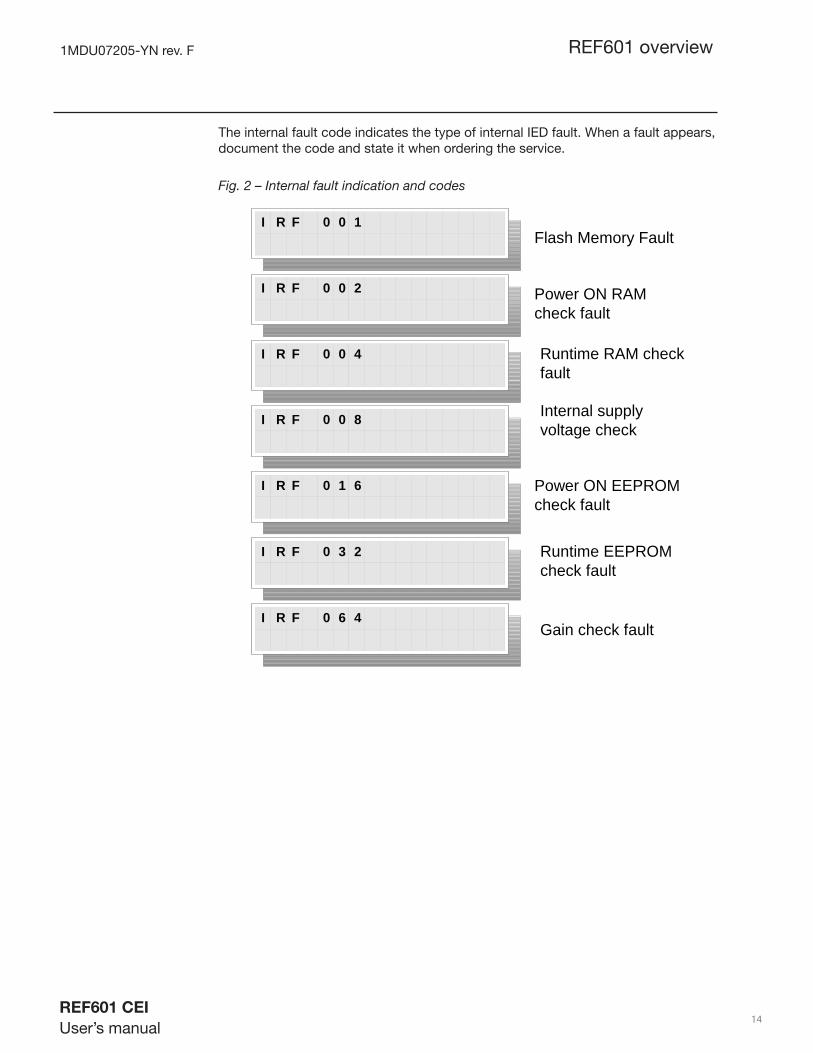
The internal fault code indicates the type of internal IED fault. When a fault appears, document the code and state it when ordering the service.
Fig. 2 – Internal fault indication and codes
REF601 overview
Flash Memory Fault
Power ON RAMcheck fault
Power ON EEPROMcheck fault
Internal supplyvoltage check
Gain check fault
Runtime RAM checkfault
I R F 0 0 1
I R F 0 0 2
I R F 0 0 4
I R F 0 0 8
I R F 0 1 6
I R F 0 3 2
I R F 0 6 4
Runtime EEPROMcheck fault

1MDU07205-YN rev. F
REF601 CEI
User’s manual 15
2.4.2 Recorded data & Trip counter
The relay stores records of analog values for two trip events in non-volatile memory. The fault recording is triggered by the trip signal of protection function. A sample of analog value is recorded for every power frequency cycle. Fifteen such samples are recorded, fi ve before the trip and ten after the trip event. These records enable the user to analyze the two most recent power system events. Each record includes the current values for three phases and earth current. The oldest recording is lost when a new fault recording is made.
The relay records the number of phase and earth fault trip events into dedicated trip counters. These trip counters can not be reset by the user and are stored in non-volatile memory. The recorded information is store in non-volatile memory and can be accessed locally via the user interface on the relay front panel and can be uploaded for subsequent fault analysis.
2.4.3 Event Log
To collect sequence-of-events (SoE) information, the relay incorporates a non-volatile memory to store fi ve event logs. Each event log includes a snapshot of Analog values, Protection operation status, Binary I/O status and Relay fault code. The event logs are stored sequentially, the most recent being fi rst and so on. The non-volatile memory retains its data also in case the relay temporarily loses its auxiliary supply.
The event log facilitates detailed pre- and post-fault analysis of feeder faults and dis-turbances. The SoE information can be accessed locally via the user interface on the relay front panel or remotely via the communication interface of the relay.
2.4.4 Access Control
To protect the relay from unauthorized access and to maintain the integrity of informa-tion, the relay is armed with a three level, role-based user authentication system with individual password for the operator, engineer and administrator level. The password is a combination of different navigation keys.
2.5 Power Supply
To be able to operate the relay needs a secured auxiliary voltage supply. The power supply module forms the voltages required by the protection relay module and the auxiliary relays.
The power supply board is having universal 24-240V AC / DC input voltage range. It is galvanically isolated switch mode power supply. It is implemented using fl y-back topology where output voltages (+12V and -15V) are obtained using an isolation transformer. The output voltages are sensed through optical isolation
REF601 overview

1MDU07205-YN rev. F
REF601 CEI
User’s manual 16
Uaux
+ 12 V 1A Slow
24...240V AC / DC
- 15 V
Fig. 3 – Power supply unit input / output of relay REF601
Unit is able to accept a wide voltage range as following:
Description Range Tolérance Frequency Insulation
Input Voltage Power
24…240Vdc*
24…240Vac
70%…+120%
85%…+110% 50Hz
Galvanic, 2kV rms
* Ripple up to 12% has to be acceptable to the unit.
REF601 overview

1MDU07205-YN rev. F
REF601 CEI
User’s manual 17
Technical data
Section 3 Technical data
Power Supply
Uaux
nominal 24...240 V AC, 50 Hz24...240 V DC
Uaux
variation 85...110% of Un (20.4...264 V AC)70...120% of Un (16.8...288 V DC)
Burden of auxiliary voltage supplyunder quiescent (Pq)/operatingcondition
< 5.0 VA
Ripple in the DC auxiliary voltage Max 12% of the DC value (at frequency of 100 Hz)
Maximum interruption time in theauxiliary DC voltage withoutresetting the relay
50 ms at Uaux rated
Dimensions
Width frame 130.0 mm, case 121.5 mm
Height frame 160.0 mm,case 151.5 mm
Depth case 92 mm, 101 mm with terminal
Weight relay 1.2 kg
Energizing inputs
Rated frequency 50 Hz ± 5 Hz
Phase current inputs
Input type Rogowski coil sensor
Nominal primary current In(amp) selection
80A , 250A
Rated transformation ratio, Kra
250A / 0.15V at 50Hz 250A / 0.18V at 60Hz
Linear current measurement range
8 A - 25 kA
Earth current input Input type Current Transformer
Rated current, In 40 / 1A
Burden at rated current < 0.1 VA at 1A
Linear current measuring range
0.025 x In - 12.5 x In
Thermal withstand capability:• Continuously• For 1 s
5 A100 A
Dynamic current withstand:• Half-wave value 250 A

1MDU07205-YN rev. F
REF601 CEI
User’s manual 18
Technical data
Binary inputs
Rated voltage 24...240 V AC / DC
Operating range 85...110% of Un for AC70...120% of Un for DC
Current drain 2...20 mA
Power consumption/input <0.5 W
Input sensing time 100 msec
Trip2 output ( Normally open contact )
Rated voltage 240 V AC / DC
Continuous carry 6 A at 250V AC
Make and carry for 3.0 s 8 A at 24V DC
Make and carry 0.5 s 10 A at 24V DC
Breaking capacity when the control-circuit timeconstant L/R<40 ms at 30 / 220 V DC
4 A/0.15 A
Minimum contact load 100 mA at 24 V AC / DC
Signal output ( O/C, E/F Trip, Unit ready, Breaker close )
Rated voltage 240 V AC / DC
Continuous contact carry 6 A at 250V AC
Make and carry for 3.0 s 8 A at 24V DC
Make and carry 0.5 s 10 A at 24V DC
Breaking capacity when the control-circuit timeconstant L/R<40 ms at 30 / 220 V DC
4 A/0.15 A
Minimum contact load 100 mA at 24 V AC / DC
Output relays
Trip1 output ( Normally closed contact )
Rated voltage 240 V AC / DC
Continuous contact carry 8 A at 250V AC
Make and carry for 3.0 s 15 A at 24V DC
Make and carry 0.5 s 30 A at 24V DC
Breaking capacity when the control-circuit timeconstant L/R<40 ms, at 35 / 220 V DC
5 A/ 0.2 A
Minimum contact load 100 mA at 24 V AC / DC

1MDU07205-YN rev. F
REF601 CEI
User’s manual 19
Technical data
Protection functions
Three-phase non-directional overcurrent protection
Low-set stage I > Setting range of pick-up current
0.2...1.2 x In in steps of 0.05, Excludable
Setting range of time multipler ‘ k ‘
0.1...1.6, in steps of 0.1
Inverse time characteristics IEC 60255-3: Very inverse,
Accuracy of pick-up current NA (Only VI Curve)
Accuracy of operate time IDMT characteristic
class E(5) or ± 30 msec
Reset ratio IDMT : 0.96
High-set stage I >> Setting range of pick-up current
0.2...5 x In in steps of 0.1, Excludable
Operation mode Defi nite time
Operate time t >> 0.05...1 sec in steps of 0.05
Accuracy of pick-up current ± 10% of set value
Accuracy of operate time ± 5% of set value or ± 30 msec
Reset ratio 0.98
Very High-set stage I >>>
Setting range of pick-up current
0.8...15 x In in steps of 0.2, Excludable
Operation mode Defi nite time
Operate time t >>> 0.05...0.2 sec in steps of 0.05
Accuracy of pick-up current ± 10% of set value
Accuracy of operate time ± 5% of set value or ± 30 msec
Reset ratio 0.98

1MDU07205-YN rev. F
REF601 CEI
User’s manual 20
Technical data
Non-directional earth-fault protection
Low-set stage Io > Nominal value of earth current 1 A
Measurement range 0.025 In ...12.5 In 1)
Setting range for External earth fault measurement
0.025..0.5 x In in steps of 0.0125, Excludable
Operate time at DT mode to > 0.1...1 sec insteps of 0.05
Accuracy of pick-up current ± 5% of set value
Accuracy of operate time : DMT characteristic
± 5% of set value or ± 30 msec
Reset ratio 0.98
High-set stage Io >>
Setting range 0.25...12.5 x In in steps of 0.25, Excludable
Operation mode Defi nite time
Operate time to >> 0.05...0.2 in steps of 0.05
Accuracy of pick-up current ± 15% of set value
Accuracy of operate time ± 5% of set value or ± 30 msec
Reset ratio 0.98 1) Earth current measurement makes use of the external core balance CT input for currents upto 7 In.When the measured current exceeds 7 In , measurement switches from external input to internal vector summation mode. Conversely, when the measured current reduces to a level below 6 In, measurement switches from internal to external CT input mode. The automatic swicthing of measurement modes, allows a wide dynamic measurement range of 1 : 500 .
Transformer inrush detection
Inrush threshold value 0.2...20 x In
Ratio Setting 30%...50%
Degree of protection of fl ush-mounted relay
Front side IP 42
Sides with connection terminal IP 20
1MDU07205-YN rev. F
REF601 CEI
User’s manual 21
Technical data
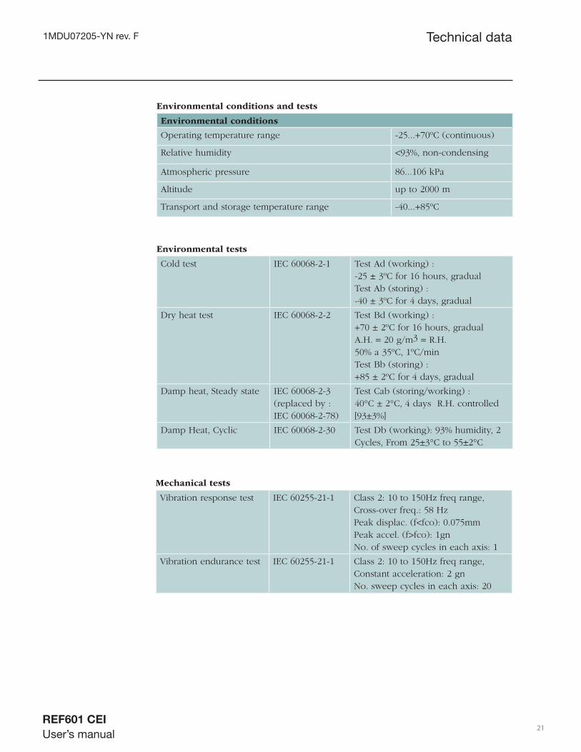
Environmental conditions and tests
Environmental conditions
Operating temperature range -25...+70ºC (continuous)
Relative humidity <93%, non-condensing
Atmospheric pressure 86...106 kPa
Altitude up to 2000 m
Transport and storage temperature range -40...+85ºC
Environmental tests
Cold test IEC 60068-2-1 Test Ad (working) : -25 ± 3ºC for 16 hours, gradual Test Ab (storing) : -40 ± 3ºC for 4 days, gradual
Dry heat test IEC 60068-2-2 Test Bd (working) : +70 ± 2ºC for 16 hours, gradual A.H. = 20 g/m3 = R.H. 50% a 35ºC, 1ºC/min Test Bb (storing) : +85 ± 2ºC for 4 days, gradual
Damp heat, Steady state IEC 60068-2-3 (replaced by : IEC 60068-2-78)
Test Cab (storing/working) : 40°C ± 2°C, 4 days R.H. controlled [93±3%]
Damp Heat, Cyclic IEC 60068-2-30 Test Db (working): 93% humidity, 2 Cycles, From 25±3°C to 55±2°C
Mechanical tests
Vibration response test IEC 60255-21-1 Class 2: 10 to 150Hz freq range, Cross-over freq.: 58 Hz Peak displac. (f<fco): 0.075mm Peak accel. (f>fco): 1gn No. of sweep cycles in each axis: 1
Vibration endurance test IEC 60255-21-1 Class 2: 10 to 150Hz freq range, Constant acceleration: 2 gn No. sweep cycles in each axis: 20
1MDU07205-YN rev. F
REF601 CEI
User’s manual 22
Technical data
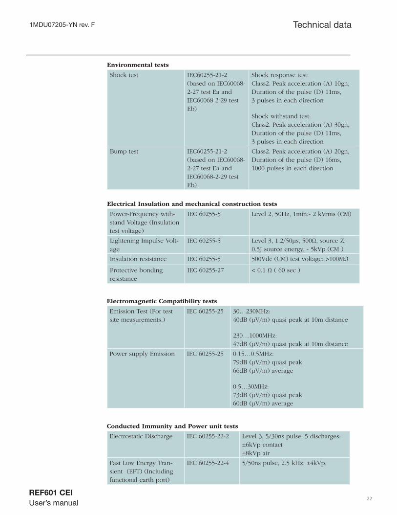
Environmental tests
Shock test IEC60255-21-2 (based on IEC60068-2-27 test Ea and IEC60068-2-29 test Eb)
Shock response test: Class2. Peak acceleration (A) 10gn, Duration of the pulse (D) 11ms, 3 pulses in each direction
Shock withstand test: Class2. Peak acceleration (A) 30gn, Duration of the pulse (D) 11ms, 3 pulses in each direction
Bump test IEC60255-21-2 (based on IEC60068-2-27 test Ea and IEC60068-2-29 test Eb)
Class2. Peak acceleration (A) 20gn, Duration of the pulse (D) 16ms, 1000 pulses in each direction
Electrical Insulation and mechanical construction tests
Power-Frequency with-stand Voltage (Insulation test voltage)
IEC 60255-5 Level 2, 50Hz, 1min:- 2 kVrms (CM)
Lightening Impulse Volt-age
IEC 60255-5 Level 3, 1.2/50μs, 500Ω, source Z, 0.5J source energy, - 5kVp (CM )
Insulation resistance IEC 60255-5 500Vdc (CM) test voltage: >100MΩ
Protective bonding resistance
IEC 60255-27 < 0.1 Ω ( 60 sec )
Electromagnetic Compatibility tests
Emission Test (For test site measurements,)
IEC 60255-25 30…230MHz: 40dB (μV/m) quasi peak at 10m distance
230…1000MHz: 47dB (μV/m) quasi peak at 10m distance
Power supply Emission IEC 60255-25 0.15…0.5MHz: 79dB (μV/m) quasi peak 66dB (μV/m) average
0.5…30MHz: 73dB (μV/m) quasi peak 60dB (μV/m) average
Conducted Immunity and Power unit tests
Electrostatic Discharge IEC 60255-22-2 Level 3, 5/30ns pulse, 5 discharges: ±6kVp contact ±8kVp air
Fast Low Energy Tran-sient (EFT) (Including functional earth port)
IEC 60255-22-4 5/50ns pulse, 2.5 kHz, ±4kVp,

1MDU07205-YN rev. F
REF601 CEI
User’s manual 23
Technical data
Conducted Immunity and Power unit tests
Slow High Energy Tran-sient (Surge1.2/50us Volt-age pulse)
IEC 61000-4-5 IEC 60255-22-5
1.2/50μs pulse ±4kVp (L-Gnd) ±2kVp (L-L)
Radio-Frequency distur-bance (Including func-tional earth port)
IEC 60255-22-6 Level 3, 0.15…80MHz, step 1%, AM 80% @ 1kHz,.: 10Vrms/unmod (CM), Spot freq 27MHz 68Mhz
Voltage Dips.,Short Inter-ruptions (ac)
IEC 61000-4-11 100% (10mS and 30mS),70% and 40%
Voltage Variation immu-nity tests (ac)
IEC 61000-4-11 Voltage Test level 70%
Damped Oscillatory Waves (HFD)
IEC 61000-4-12 Level 3 1 MHz , 10 transients:± 2.5kVp (CM) , ± 1kVp (DM)
Ripple Voltage IEC 60255-11 IEC 61000-4-17
Level 3: 10% Un 50, 300 Hz ripple freq.
Voltage Drop, Supply Interruption and voltage variations on d.c. input power port (immunity tests)
IEC61000-4-29 100% @ 50ms
Power Frequency Immu-nity Test
IEC60255-22-7 Class A : CM: 300Vrms DM: 150Vrms
Radiated Immunity Tests
Radio-Frequency Electro-magnetic Field (Ampli-tude modulated)
IEC 60255-22-3 80…1000MHz, AM 80% @ 1kHz, horizontal and verti-cal polarization: - 10V/m Spot freq: 80, 160, 450, 900MHz, AM 80% @1kHz
Radio-Frequency Elec-tromagnetic Field from digital radio telephones(Pulse Modul.)
IEC 60255-22-3 Level 4, 900 ± 5MHz, PWM 100% @ 200Hz, 50% D.C.: - 10V/m (10s Dwell time)

1MDU07205-YN rev. F
REF601 CEI
User’s manual 24
Technical data
Magnetic immunity tests
Power-Frequency Magnetic Field
IEC 61000-4-8 Level 5, X-Y-Z axis : -100A/m continuously -1000A/m short time
Pulse Magnetic Field IEC 61000-4-9 Level 5, 5 positive and 5 negative, 8/20μs pulses every 10s:- 1000 A/m
Contact tests
Make and carry IEC 60255-23 (Replaced by IEC61810-2, Ed.1.0)
Signaling : 10A@24VDC for 0.5s and 8A@24VDC for 3s Tripping : 30A@24V DC for 0.5S and 15A@24VDC for 3S
Breaking capacity for d.c., L/R ≤ 40 ms
IEC 60255-23 Signaling: 0.15A@220VDC and 4.5A @30VDC Tripping: 0.2A@220VDC and 5.5A@35VDC
Make and Break capacity for resistive load
IEC 60255-23 Signaling: 6A @240V ac Tripping: 8A@240V ac
Mechanical durability IEC 60255-6 10,000 operations ; tripping and sign-aling contacts
EMC compliance
Complies with the EMC directive 2004/108/EC
Standards EN 60255-26 (2004)
RoHS compliance
Complies with the RoHS directive 2002/95/EC
Data communication ( optional )
Protocol : Modbus RTU Communication port : RS485 4-wire
Product safety
Complies with the LV directive 2006/95/EC
Standards EN 60255-27 (2005), EN 60255-6 (1994)

1MDU07205-YN rev. F
REF601 CEI
User’s manual 25
Section 4 Protection Functions
4.1 Three Phase Current Protection
4.1.1 Functionality
The three-phase overcurrent protection is used as one-phase, two-phase or three-phase non-directional overcurrent and short-circuit protection for feeders.
The function starts when the current exceeds the set limit. The operate time char-acteristics for low stage is only IDMT (VI) and high stage is defi nite time (DT) defi nite minimum.The instantaneous stage always operates with the DT characteristic.
In the DT mode, the function operates after a predefi ned operate time and resets when the fault current disappears. The IDMT mode provides current-dependent timer characteristics
4.1.2 Principle of Operation
The three-phase overcurrent unit continuously measures the phase currents of the protected object. On detection of a fault the relay starts, trips the circuit breaker, pro-vides alarm, records fault data etc. in accordance with the application
REF601 has overcurrent protection with low set, high set and very high set module.
The product support IDMT times (VI Curve) in low set (I>) while high set (I>>) and Very high set (I>>>) supports to DMT timings. As the fault current exceeds the set value, trip time counting is started and start LED on front panel of relay glows ON. If fault current falls down below the drop-off value of set current for 40 ms before trip time gets complete, start LED will be turned off and trip count will become zero. Trip time will start from zero for next time when the fault current exceeds the set value again. After a healthy trip, Start LED will be turned off and again if fault current exceeds threshold, start LED will be turned ON again.
In case of healthy trip, after trip time get elapsed relay generates the trip command which operates the Trip relay contacts as per user selected product variant. Two LED indications on front plate of relay i.e. Trip (common trip indication) and Trip Ip and one signaling contact (XK2.3 –XK2.4) will also be activated for user as Trip indication.
4.2 Earth Fault Protection
4.2.1 Functionality
The earth-fault function is used as non-directional earth-fault protection for feeders. The function starts and operates when the set current exceeds the set limit.
Protection Functions

1MDU07205-YN rev. F
REF601 CEI
User’s manual 26
The relay can measure earth current by internal calculation and also by external core balance current transformer input. Separate earth fault input is available in relay which can be connected to core-balance current transformer of 1A secondary.
The operate time characteristic for low stage and high stage has only defi nite time (DT) . The instantaneous stage always operates with the DT characteristic. In the DT mode, the function operates after a predefi ned operate time and resets when the fault current disappears.
4.2.2 Principle of Operation
REF601 has earth fault protection with low set and high set module. Earth fault modules operates the protection as soon as fault current exceeds the set value of current. It supports only DMT timing while highset supports to DMT timings.
As the fault current exceeds the set value, trip time counting is started and start LED on front panel of relay glows ON. If fault current falls down below the drop-off value of set current for 40 ms before trip time gets complete, start LED will be turned off and trip count will become zero. Trip time will start from zero next time when the fault current exceeds the set value again. After a healthy trip, Start LED will be turned off and again if fault current exceeds threshold, start LED will be turned ON again
In case of healthy fault generation, after trip time get elapsed relay generates the trip command which operates the Trip relay contacts as per user selected product variant. Two LED indications on front plate of relay i.e. Trip (common trip indication) and Trip Io and one signaling contact (XK2.1 –XK2.2) will also be generated for user as Trip indication.
4.3 Three Phase Inrush Detector
The transformer inrush detection is used to coordinate transformer inrush situations in distribution networks.
Transformer inrush detection is based on the following principle: the output signal is activated once the numerically derived ratio of second harmonic current I_2H and the fundamental frequency current I_1H exceeds the set value.
The operate time characteristic for the function is of defi nite time (DT) type. When applying overcurrent protection to the MV side of the power transformer, it is neces-sary that the protection system remains inoperative during transformer energization, when a large primary current fl ows for a short period during switch on. The REF601 employs the most proven technique of blocking based on measured value of second harmonic content to make the protection immune to magnetizing inrush.
Protection Functions
1MDU07205-YN rev. F
REF601 CEI
User’s manual 27
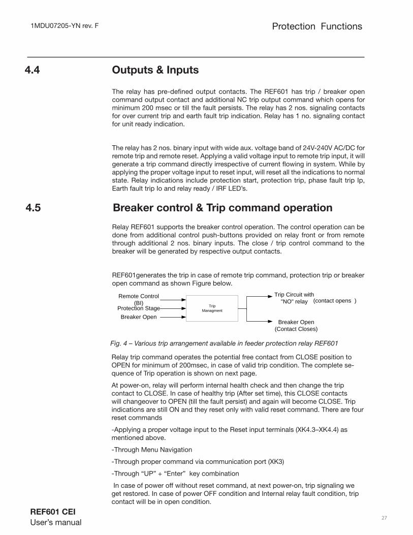
Fig. 4 – Various trip arrangement available in feeder protection relay REF601
4.4 Outputs & Inputs
The relay has pre-defi ned output contacts. The REF601 has trip / breaker open command output contact and additional NC trip output command which opens for minimum 200 msec or till the fault persists. The relay has 2 nos. signaling contacts for over current trip and earth fault trip indication. Relay has 1 no. signaling contact for unit ready indication.
The relay has 2 nos. binary input with wide aux. voltage band of 24V-240V AC/DC for remote trip and remote reset. Applying a valid voltage input to remote trip input, it will generate a trip command directly irrespective of current fl owing in system. While by applying the proper voltage input to reset input, will reset all the indications to normal state. Relay indications include protection start, protection trip, phase fault trip Ip, Earth fault trip Io and relay ready / IRF LED’s.
4.5 Breaker control & Trip command operation
Relay REF601 supports the breaker control operation. The control operation can be done from additional control push-buttons provided on relay front or from remote through additional 2 nos. binary inputs. The close / trip control command to the breaker will be generated by respective output contacts.
REF601generates the trip in case of remote trip command, protection trip or breaker open command as shown Figure below.
Protection Functions
TripManagment
Remote Control(BI)
Breaker Open(Contact Closes)
(contact opens )Trip Circuit with
"NO" relayProtection Stage
Breaker Open
Relay trip command operates the potential free contact from CLOSE position to OPEN for minimum of 200msec, in case of valid trip condition. The complete se-quence of Trip operation is shown on next page.
At power-on, relay will perform internal health check and then change the trip contact to CLOSE. In case of healthy trip (After set time), this CLOSE contacts will changeover to OPEN (till the fault persist) and again will become CLOSE. Trip indications are still ON and they reset only with valid reset command. There are four reset commands
-Applying a proper voltage input to the Reset input terminals (XK4.3–XK4.4) as mentioned above.
-Through Menu Navigation
-Through proper command via communication port (XK3)
-Through “UP” + “Enter” key combination
In case of power off without reset command, at next power-on, trip signaling we get restored. In case of power OFF condition and Internal relay fault condition, trip contact will be in open condition.
1MDU07205-YN rev. F
REF601 CEI
User’s manual 28
Protection Functions
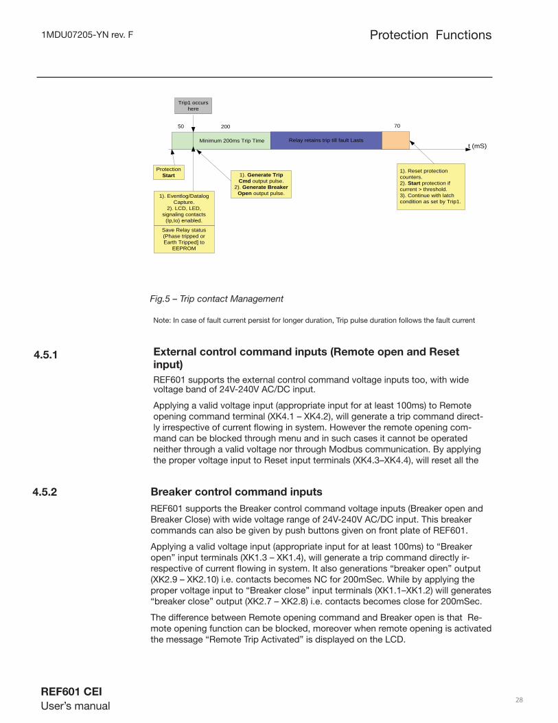
1). Generate Trip Cmd output pulse.
2). Generate Breaker Open output pulse.
Protection Start
1). Eventlog/Datalog Capture.
2). LCD, LED, signaling contacts
(Ip,Io) enabled.
Trip1 occurs here
Minimum 200ms Trip Time
50 200
Save Relay status (Phase tripped or Earth Tripped] to
EEPROM
t (mS)
1). Reset protection counters.2). Start protection if current > threshold.3). Continue with latch condition as set by Trip1.
70
Relay retains trip till fault Lasts
Fig.5 – Trip contact Management
Note: In case of fault current persist for longer duration, Trip pulse duration follows the fault current
External control command inputs (Remote open and Reset
input)
REF601 supports the external control command voltage inputs too, with wide voltage band of 24V-240V AC/DC input.
Applying a valid voltage input (appropriate input for at least 100ms) to Remote opening command terminal (XK4.1 – XK4.2), will generate a trip command direct-ly irrespective of current fl owing in system. However the remote opening com-mand can be blocked through menu and in such cases it cannot be operated neither through a valid voltage nor through Modbus communication. By applying the proper voltage input to Reset input terminals (XK4.3–XK4.4), will reset all the
Breaker control command inputs
REF601 supports the Breaker control command voltage inputs (Breaker open and Breaker Close) with wide voltage range of 24V-240V AC/DC input. This breaker commands can also be given by push buttons given on front plate of REF601.
Applying a valid voltage input (appropriate input for at least 100ms) to “Breaker open” input terminals (XK1.3 – XK1.4), will generate a trip command directly ir-respective of current fl owing in system. It also generations “breaker open” output (XK2.9 – XK2.10) i.e. contacts becomes NC for 200mSec. While by applying the proper voltage input to “Breaker close” input terminals (XK1.1–XK1.2) will generates “breaker close” output (XK2.7 – XK2.8) i.e. contacts becomes close for 200mSec.
The difference between Remote opening command and Breaker open is that Re-mote opening function can be blocked, moreover when remote opening is activated the message “Remote Trip Activated” is displayed on the LCD.
4.5.1
4.5.2
1MDU07205-YN rev. F
REF601 CEI
User’s manual 29
Protection Functions
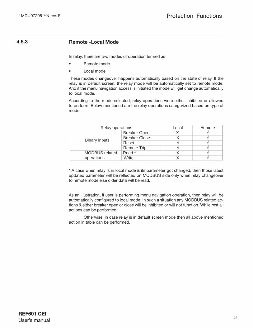
Remote -Local Mode4.5.3
In relay, there are two modes of operation termed as
• Remote mode
• Local mode
These modes changeover happens automatically based on the state of relay. If the relay is in default screen, the relay mode will be automatically set to remote mode. And if the menu navigation access is initiated the mode will get change automatically to local mode.
According to the mode selected, relay operations were either inhibited or allowed to perform. Below mentioned are the relay operations categorized based on type of mode:
Relay operations Local emote
Breaker Open X Breaker Close X Reset Binary inputs
Remote Trip Read * X MODBUS related
operations Write X
R
* A case when relay is in local mode & its parameter got changed, then those latest updated parameter will be refl ected on MODBUS side only when relay changeover to remote mode else older data will be read.
As an illustration, if user is performing menu navigation operation, then relay will be automatically confi gured to local mode. In such a situation any MODBUS related ac-tions & either breaker open or close will be inhibited or will not function. While rest all actions can be performed.
Otherwise, in case relay is in default screen mode then all above mentioned action in table can be performed.

1MDU07205-YN rev. F
REF601 CEI
User’s manual 30
Protection Functions
4.6 Signal Diagram
The fi gure below schematically illustrates the analogue input, binary input / output and LED indications.
Fig. 6 – Signal diagram of relay REF601
Analogue input:
o L1, L2, L3 Energizing sensor input for phase L1, L2, L3
o Io Earth current input 1A through CBCT for external
earth measurement
Trip 2 / BreakerOpen command
Breaker Close command
BreakerOpen
BreakerClose
RemoteOpen
ResetInput
I>L1L2L3 I>,,I>>,I>>>
Signalling
I>>
I>>>
Io
t>
K
t>>
Trip Ip
Io>>
to>
K
to>>
Io> Trip Io
Io>,Io>>Signalling
Trip
Start
Ready
Unitready
Trip 1
1MDU07205-YN rev. F
REF601 CEI
User’s manual 31
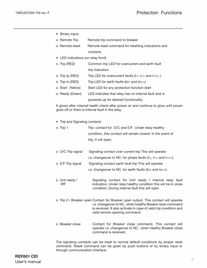
o Unit ready / Signaling contact for Unit ready / internal relay fault IRF indication. Under relay healthy condition this will be in close . condition. During internal fault this will open
o Trip 2 / Breaker open
o Breaker close
The signaling contacts can be reset to normal default conditions by proper reset command. Reset command can be given by push buttons or by binary input or through communication interface.
Contact for Breaker open output. This contact will operate i.e. changeover to NC , when healthy Breaker open command is received. It also activate in case of valid trip condition and valid remote opening command.
Contact for Breaker close command. This contact will operate i.e. changeover to NC , when healthy Breaker close command is received.
Protection Functions
Binary input: •
o Remote Trip Remote trip command to breaker
o Remote reset Remote reset command for resetting indications and
contacts
LED indications (on relay front) •
o Trip (RED) Common trip LED for overcurrent and earth fault
trip indication
o Trip Ip (RED) Trip LED for overcurrent faults (I>, I>> and I>>> )
o Trip Io (RED) Trip LED for earth faults (Io> and Io>>)
o Start (Yellow) Start LED for any protection function start
o Ready (Green) LED indicates that relay has no internal fault and is
powered up for desired functionality
It glows after internal health check after power on and continue to glow until power goes off or there is internal fault in the relay
Trip and Signaling contacts •
o Trip 1 Trip contact for O/C and E/F. Under relay healthy
condition, this contact will remain closed. In the event of
trip, it will open.
o O/C Trip signal Signaling contact over current trip This will operate
i.e. changeover to NC, for phase faults (I>, I>> and I>>>)
o E/F Trip signal Signaling contact earth fault trip This will operate
i.e. changeover to NC, for earth faults (Io> and Io>>)

1MDU07205-YN rev. F
REF601 CEI
User’s manual 32
4.7 Protection characteristics
4.7.1 Time / Current characteristics
REF601 offers three-stage overcurrent and two stage earth-fault protection functions. The low-set stage of overcurrent protection is equipped with standard Inverse-defi nite Minimum Time (IDMT) characteristics - Very Inverse (VI), while the low set stage of earth-fault protection has a DMT characteristics for better co-ordination with rest of the network. The high-set and very high-set stages for over current protection and high stage earth fault protection come with DMT characteristics.
When IDMT characteristic has been selected, the operating time of the stage will be a function of the current; the higher the current, the shorter the operating time. The stage includes seven time/current curve sets – four according to the BS 142 and IEC 60255 standards namely normal inverse, very inverse, extremely inverse and long-time inverse and one special curve, named RI type curve.
4.7.2 IEC characteristics
The relationship between current and time for standard normal inverse, very inverse, extremely inverse and long-time inverse complies with the BS 142.1966 and IEC 60255-3 standards and can be expressed as follows:
where,
t = operate time in seconds
K = time multiplier
I = measured current value
I set = set start current value
The slope of the time/current characteristics shall be determined by the
constants à and ß as indicated below:
1)(*
−=
a
b
IsetI
Kt ß
Slope of the time/current curve set à ß
Very inverse 1.0 13.5
Protection Functions
In case of REF601, accuracy class 5 is applicable. The details of accuracy points as per BS: 142:1966 are given below:
I/I> Very Inverse2 2.34E5 1.26E7 ---10 1.01E20 1.00E
Note: E stands for accuracy class i.e. in this case it is 5 for phase and external earth fault whereas for internal earth fault the accuracy class is 7.5
1MDU07205-YN rev. F
REF601 CEI
User’s manual 33
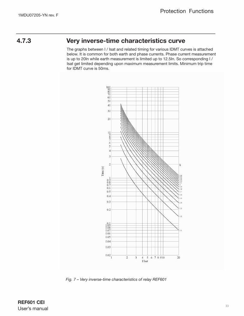
4.7.3 Very inverse-time characteristics curve
Fig. 7 – Very inverse-time characteristics of relay REF601
Protection Functions
The graphs between I / Isat and related timing for various IDMT curves is attached below. It is common for both earth and phase currents. Phase current measurement is up to 20In while earth measurement is limited up to 12.5In. So corresponding I / Isat get limited depending upon maximum measurement limits. Minimum trip time for IDMT curve is 50ms.

1MDU07205-YN rev. F
REF601 CEI
User’s manual 34
Menu structure & LHMI Navigation
Section 5 Menu Structures & LHMI Navigation
5.1 Local HMI
The local HMI of the relay contains following elements:
. LCD display
.Navigation buttons
. LED indicators
The LHMI is used for setting, monitoring and controlling.
Fig. 8 – Local HMI of relay REF601
1MDU07205-YN rev. F
REF601 CEI
User’s manual 35
Menu structure & LHMI Navigation
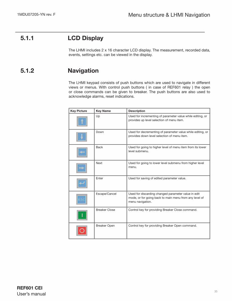
5.1.1 LCD Display
The LHMI includes 2 x 16 character LCD display. The measurement, recorded data, events, settings etc. can be viewed in the display.
5.1.2 Navigation
The LHMI keypad consists of push buttons which are used to navigate in different views or menus. With control push buttons ( in case of REF601 relay ) the open or close commands can be given to breaker. The push buttons are also used to acknowledge alarms, reset indications.
Key Picture Key Name Description
Up Used for incrementing of parameter value while editing, or provides up level selection of menu item.
Down Used for decrementing of parameter value while editing, or provides down level selection of menu item.
Back Used for going to higher level of menu item from its lower level submenu.
Next Used for going to lower level submenu from higher level menu.
Enter Used for saving of edited parameter value.
Escape/Cancel Used for discarding changed parameter value in edit mode, or for going back to main menu from any level of menu navigation.
Breaker Close Control key for providing Breaker Close command.
Breaker Open Control key for providing Breaker Open command.
1MDU07205-YN rev. F
REF601 CEI
User’s manual 36
Menu structure & LHMI Navigation
5.1.3 Indication LEDs
The LHMI includes three protection indicators above the display: Ready, Start and Trip. Additionally there are also 2 LEDs for phase & earth fault indication on front of the LHMI.
5.2 LHMI menu navigation
5.2.1 Default screen
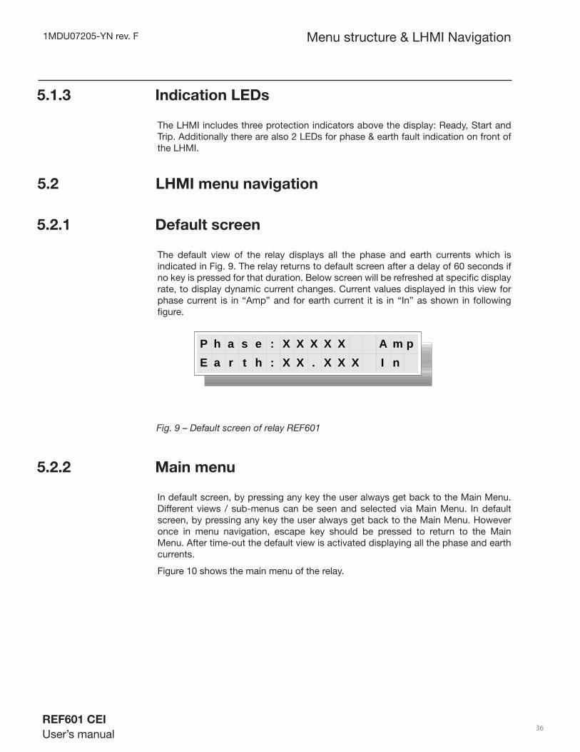
The default view of the relay displays all the phase and earth currents which is indicated in Fig. 9. The relay returns to default screen after a delay of 60 seconds if no key is pressed for that duration. Below screen will be refreshed at specifi c display rate, to display dynamic current changes. Current values displayed in this view for phase current is in “Amp” and for earth current it is in “In” as shown in following fi gure.
Fig. 9 – Default screen of relay REF601
5.2.2 Main menu
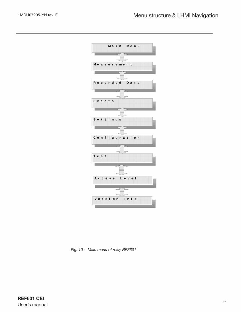
In default screen, by pressing any key the user always get back to the Main Menu. Different views / sub-menus can be seen and selected via Main Menu. In default screen, by pressing any key the user always get back to the Main Menu. However once in menu navigation, escape key should be pressed to return to the Main Menu. After time-out the default view is activated displaying all the phase and earth currents.
Figure 10 shows the main menu of the relay.
P h a s e : X X X X X A m pE a r t h : X X . X X X I n
1MDU07205-YN rev. F
REF601 CEI
User’s manual 37
Menu structure & LHMI Navigation
Fig. 10 - Main menu of relay REF601
M a i n M e n u
M e a s u r e m e n t
R e c o r d e d D a t a
E v e n t s
S e t t i n g s
C o n f i g u r a t i o n
T e s t
V e r s i o n I n f o
A c c e s s L e v e l

1MDU07205-YN rev. F
REF601 CEI
User’s manual 38
5.2.3 Authorization
Menu structure & LHMI Navigation
The user categories have been predefi ned for the LHMI, each with different rights and default passwords.
Fig.11- Login process of relay REF601
The user can select from different levels depending on which role he has and where he has an access to (e.g. setting level & administrator). Whenever any key is pressed by the user from the default view, a password screen pops up. Password needs to be entered here as the combination of two keys(The keys need to be pressed for min 3-5 seconds). In case of wrong password being entered by the user, password screen is displayed and no action is taken. Depending on the password entered, only particular menus will be accessible and others will be hidden to the user or edit mode can be disabled. Only the admin level user has access to all the menus & sub-menus and access to editing of relay parameters.
P a s s w o r d : X XS e t t i n g U s e r
P a s s w o r d : X XA d m i n U s e r
P a s s w o r d : If password entered is of admin level
If password entered is of setting level
P a s s w o r d : X XO p e r a t o r U s e r
If password entered is of operator level
Sr. No. FeatureAdmin
User LevelSetting User
LevelOperator
User Level1 Password editing Yes No No2 Relay confi guration editing Yes No No
3COM Board parameter editing
Yes Yes No
4 Protection settings editing Yes Yes No5 Menu Viewing Yes Yes Yes
6 Password key comibationBack +Down
Up + Back
other than Admin / setting password
1MDU07205-YN rev. F
REF601 CEI
User’s manual 39
Menu structure & LHMI Navigation
5.2.4 Menu - Measurement
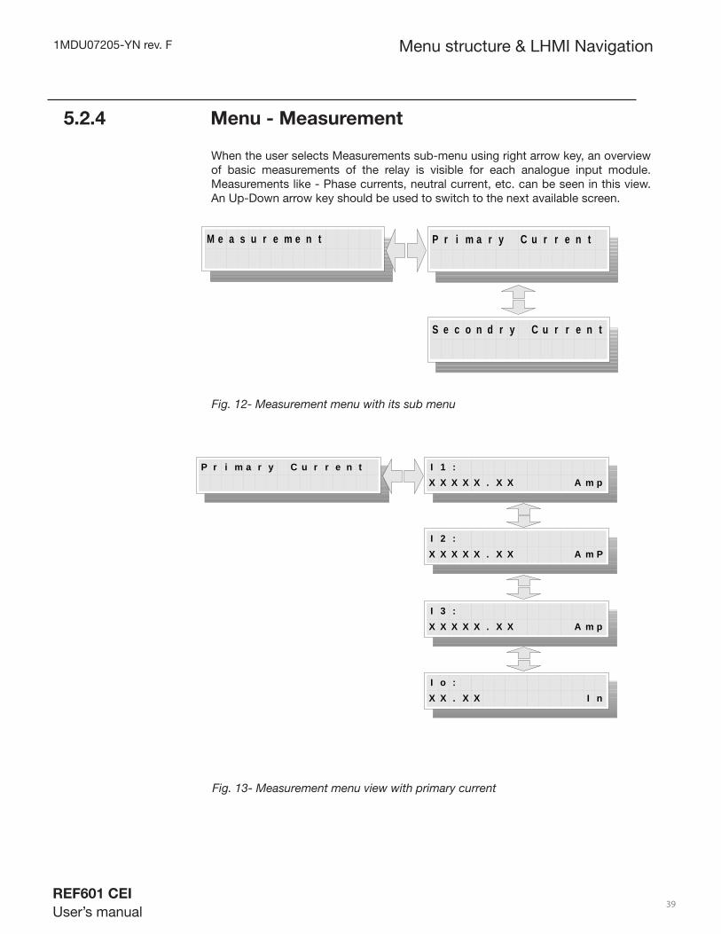
When the user selects Measurements sub-menu using right arrow key, an overview of basic measurements of the relay is visible for each analogue input module. Measurements like - Phase currents, neutral current, etc. can be seen in this view. An Up-Down arrow key should be used to switch to the next available screen.
Fig. 12- Measurement menu with its sub menu
Fig. 13- Measurement menu view with primary current
M e a s u r e e n tm P r i m a r y C u r r e n t
S e c o n d r y C u r r e n t
P r i m a r y C u r r e n t I 1 :X X X X X . X X A m p
I 2 :X X X X X . X X A m P
I 3 :X X X X X . X X A m p
I o :X X . X X I n

1MDU07205-YN rev. F
REF601 CEI
User’s manual 40
S e c o n d r y C u r r e n t I 1 : X X . X X I nI 2 : X X . X X I n
I 3 : X X . X X I nI o : X X . X X I n
Fig. 14- Measurement menu view with secondary current
5.2.5 Menu – Recorded data
User can select Recording Data for viewing with the right arrow key as shown in the fi gure 15 and can select current display or trip counter view through the up/down arrow key. In Recorded Current block, user can see the current values for 15 different instants around trip event occurrence. Data recording for two trips is provided in block 1 and block 2, third trip data is saved in block 1 by overwriting previous data. In the Trip Counter block, user can view the value of phase trip counter and earth trip counter through up/down keys. The user cannot reset these counter values.
Menu structure & LHMI Navigation
R e c o r d e d D a t a R e c o r d e d C u r r e n t
T r i p C o u n t e r
Fig. 15- Recorded data menu with its sub menu
B l o c k 1
B l o c k 2
R e c o r d e d C u r r e n t

1MDU07205-YN rev. F
REF601 CEI
User’s manual 41
Menu structure & LHMI Navigation
B l o c k 1
B l o c k 2
I 1 : X X . X X I 2 : X X . X XI 3 : X X . X X I o : X X . X X
I 1 : X X . X X I 2 : X X . X XI 3 : X X . X X I o : X X . X X
T r i p C o u n t e rP h a s e T r i p : x x x x
T r i p C o u n t e r
0 0 0 0
9 9 9 9 T r i p C o u n t e rE a r t h T r i p : x x x x
Fig. 16 - Recorded data sub menu view
5.2.6 Menu – Events
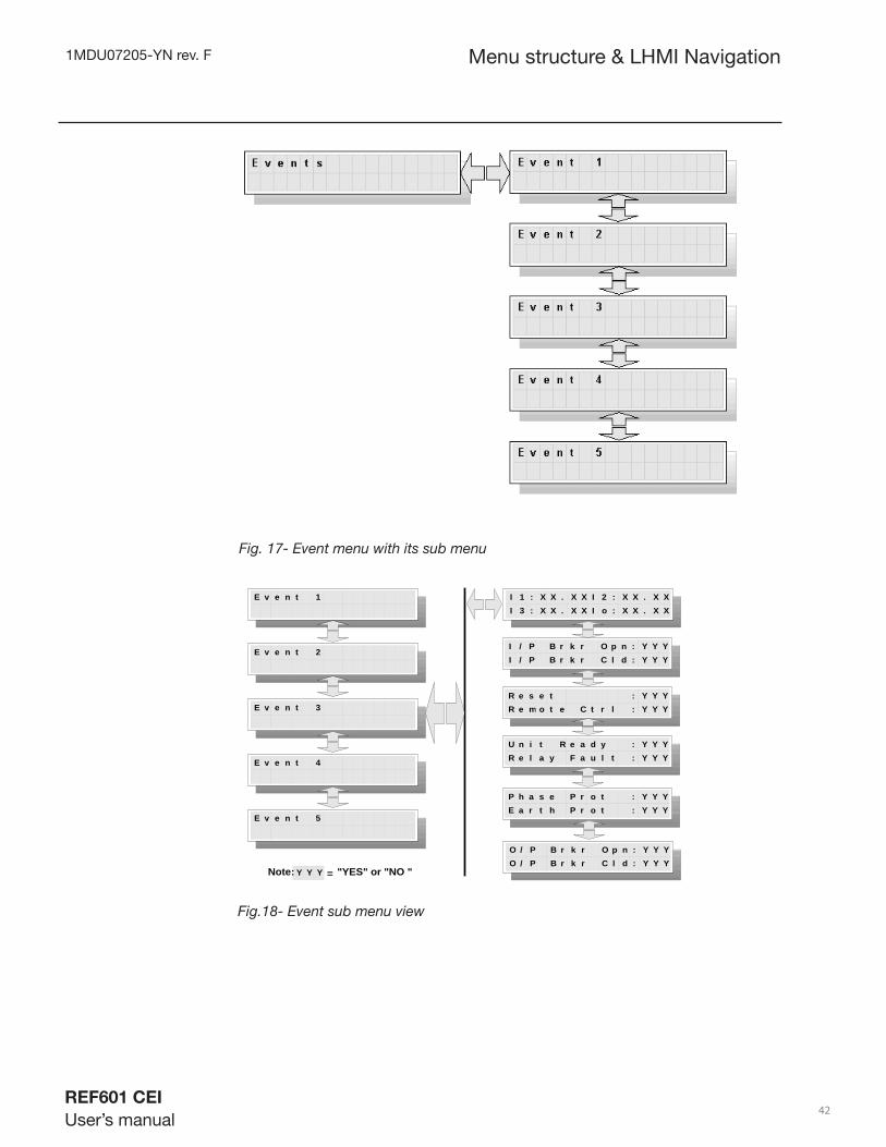
User can select Events with the right arrow key as shown in following fi gure 17 and select any event 1…. 5 through the up/down arrow key. In Events, user can see the trip values of the currents, binary input status for breaker open, binary input status for breaker close, binary input status for reset, binary input status for remote trip control, unit ready status, internal relay fault (IRF) status, phase protection trip status and earth protection trip status which is shown in following fi gure. ‘Event 1’ will always contain data for the most recent event and ‘Event 2’ previous trip event and so on.
1MDU07205-YN rev. F
REF601 CEI
User’s manual 42
Menu structure & LHMI Navigation
Fig. 17- Event menu with its sub menu
Fig.18- Event sub menu view
E v e n t 1
E v e n t 2
I 1 : X X . X X I 2 : X X . X XI 3 : X X . X X I o : X X . X X
I / P B r k r O p n : Y Y YI / P B r k r C l d : Y Y Y
R e s e t : Y Y YR e m o t e C t r l : Y Y Y
U n i t R e a d y : Y Y YR e l a y F a u l t : Y Y Y
P h a s e P r o t : Y Y YE a r t h P r o t : Y Y Y
E v e n t 3
E v e n t 4
E v e n t 5
O / P B r k r O p n : Y Y YO / P B r k r C l d : Y Y Y
Y Y YNote: = "YES" or "NO "

1MDU07205-YN rev. F
REF601 CEI
User’s manual 43
Menu structure & LHMI Navigation
5.2.7 Menu – Settings
Only Setting level and Admin level users can modify parameters in this menu. This menu provides the settings for various protection stages as shown in fi gure 19. User can use the right arrow key for the selection of the particular menu item and up/down arrow key is used to select particular settings of that protection stage. In order to edit any settings, user has to press Cancel & Enter keys simultaneously. Once user selects the required settings of the protection stage, user has to press “Enter” button to save selected settings, or press “Cancel” key to discard modifi cation done.
Depending on the type of protection stage selected, and the Curve selected, either the value of Time or the value of K will be displayed. For example, selection of DT Curve will display Isat and Time. Selection of IDMT Curve will display Isat and K.
User can select curve “VI” for I> & DT for Io> .
• For “Low Set I>” setting, Isat value can be changed from 0.2 to 1.2 In in steps of 0.05, K value can be changed from 0.1 to 1.6 in steps of 0.1.
• Similarly for “High Set I>>” setting, Isat value can be changed from 0.2 to 5 In in steps of 0.1 and Time value can be changed from 0.05 to 1 sec in steps of 0.05.
• For “Very High Set I>>>”, Isat value can be changed from 0.8 to 15.0 In in steps of 0.2 and Time value can be changed from 0.05 to 0.2 sec in steps of 0.05.
• For “Low Set Io>”, Isat value can be changed from 0.025 to 0.5 In in steps of 0.0125 and Time value can be changed from 0.05 to 1 sec in steps of 0.05.
• For “High Set Io>>”, Isat value range is 0.25 to 12.5 In in steps of 0.25 and Time value can be changed from 0.05 to 0.2 sec in steps of 0.05.

1MDU07205-YN rev. F
REF601 CEI
User’s manual 44
S e t t i n g s L o w S e t I >
H i g h S e t I > >
V e r y H i g h S e t I > > >
L o w S e t I o >
H i g h S e t I o > >
C o m P a r a m e t e r s
Fig. 19- Setting menu with its sub menu
Menu structure & LHMI Navigation
Fig. 20-Setting menu with its sub menu protection stage Low-set over current
B e l g i u m R I
E I
L I
V I
N I
D B = 5T
D T
L o w S e t I > L o w S e t I >C u r v e : X X X X X X X X X
L o w S e t I >I s a t : X X . X X X I n
L o w S e t I >T i m e : X X . X X s e c
L o w S e t I >K : X X . X X or
*
* For CEI 0-16, only "VI" available

1MDU07205-YN rev. F
REF601 CEI
User’s manual 45
Fig. 21- Setting menu with sub menu protection stage High-set over current
Menu structure & LHMI Navigation
Fig. 22- Setting sub menu protection stage Very High-set over current
Fig. 23- Setting menu with its sub menu protection stage Low-set earth-fault
H i g h S e t I > > H i g h S e t I > >I s a t : X X . X X X I n
H i g h S e t I > >T i m e : X X . X X s e c
V e r y H i g h S e t I > > > V e r y H i g h S e t I > > >I s a t : X X . X X I n
V e r y H i g h S e t I > > >T i m e : X X . X X s e c
This sub-menu itemavailable in CEI 0-16
version only
B e l g i u m R I
E I
L I
V I
N I
D B = 5T
D T
L o w S e t I o > L o w S e t I o >C u r v e : X X X X X X X X X
L o w S e t I o >I s a t : X X . X X X I n
L o w S e t I o >T i m e : X X . X X s e c
L o w S e t I o >K : X X . X X or
*
* For CEI 0-16,only "DT" available

1MDU07205-YN rev. F
REF601 CEI
User’s manual 46
Fig. 24- Setting menu with sub menu protection stage High-set earth-fault
Menu structure & LHMI Navigation
C o m P a r a m e t e r s C o m P a r a m e t e r sB a u d R a t e : X X X X X
C o m P a r a m e t e r sR e l a y A d d r : X X X
1 9 2 0 0
3 8 4 0 0
4 8 0 0
9 6 0 0
2 4 0 0
C o m P a r a m e t e r sP a r i t y : X X X X
N o n e
O d d
E v e n
0 0 1
2 4 7
Fig. 25- Setting menu with sub menu communication setting (optional feature)
H i g h S e t I o > > H i g h S e t I o > >I s a t : X X . X X X I n
H i g h S e t I o > >T i m e : X X . X X s e c

1MDU07205-YN rev. F
REF601 CEI
User’s manual 47
5.2.8 Menu – Confi guration
Menu structure & LHMI Navigation
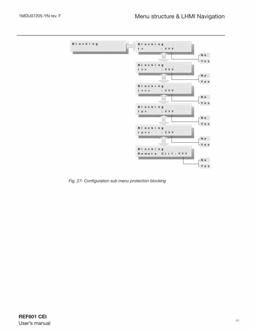
This menu item basically provides the confi guration of below:
-Blocking of particular protection stage or remote trip activation
- Relay confi guration settings like Nominal current selection , Product Type Selection & -Earth current calculation method
- Inrush protection related settings
- Selection for loading factory settings (protection parameters only)
- Protection Reset
- Sensor Constant
Fig. 26 indicates the menu navigation for the sub menu and it’s display view. Pressing right arrow key can activate submenu and selection from among the available list is done using up/down arrow keys. Activating edit mode by pressing Enter and Cancel button together can change any settings parameter. Also settings parameter of confi guration menu item can be edited by optional communication card via MODBUS protocol if “COM Admin Level parameter” is selected “YES”.
Protection reset action, other than through menu navigation, can be performed on simultaneous press of “UP” & “ENTER” key combination. The key combination needs to be pressed for approx. 5 sec in case of at default screen on relay else immediate reset action will take place after pressing key combination.
Fig. 26- Confi guration menu with sub menu
N o
Y e s
C o n f i g u r a t i o n B l o c k i n g
S e t t i n g s
I n r u s h
F a c t o r y S e t t i n g s L o a d : y y y
N o
Y e s P r o t e c t i o n R e s e t y y y
S e n s
o r C o n t a n t
s
1MDU07205-YN rev. F
REF601 CEI
User’s manual 48
Menu structure & LHMI Navigation
B l o c k i n gI > : Y Y Y
B l o c k i n g
B l o c k i n gI > > : Y Y Y
B l o c k i n gI > > > : Y Y Y
B l o c k i n gI o > : Y Y Y
B l o c k i n gI o > > : Y Y Y
B l o c k i n gR e m o t e C t r l : Y Y Y
N o
Y e s
N o
Y e s
N o
Y e s
N o
Y e s
N o
Y e s
N o
Y e s
Fig. 27- Confi guration sub menu protection blocking
1MDU07205-YN rev. F
REF601 CEI
User’s manual 49
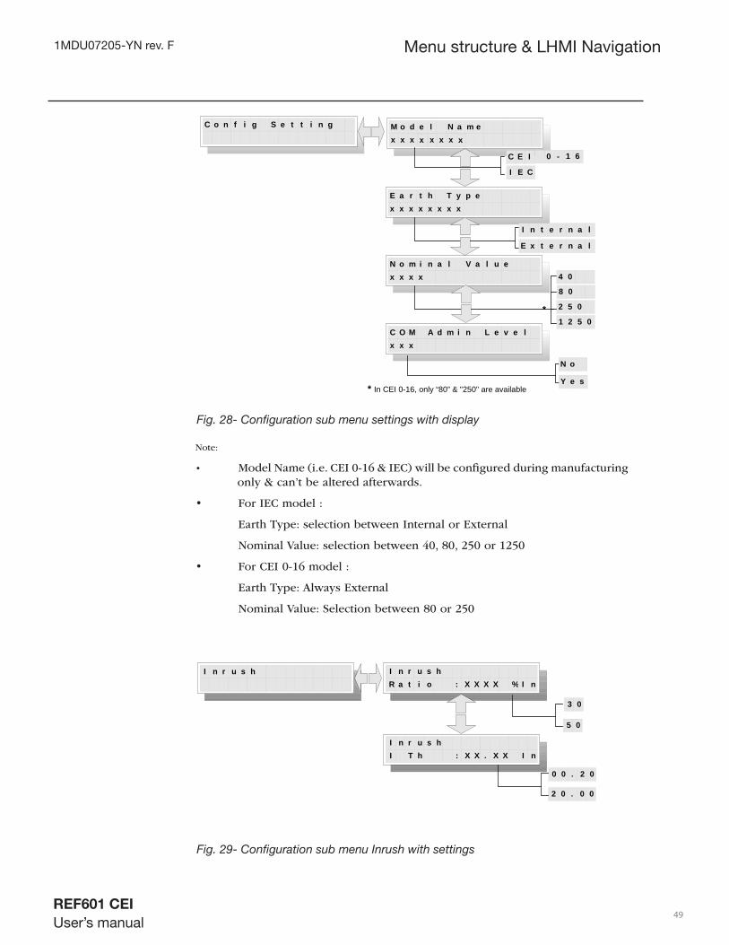
Fig. 28- Confi guration sub menu settings with display
Menu structure & LHMI Navigation
I n r u s h
I n r u s hI T h : X X . X X I n
0 0 . 2 0
2 0 . 0 0
I n r u s hR a t i o : X X X X % nI
3 0
5 0
Fig. 29- Confi guration sub menu Inrush with settings
Note:
• Model Name (i.e. CEI 0-16 & IEC) will be confi gured during manufacturing only & can’t be altered afterwards.
• For IEC model :
Earth Type: selection between Internal or External
Nominal Value: selection between 40, 80, 250 or 1250
• For CEI 0-16 model :
Earth Type: Always External
Nominal Value: Selection between 80 or 250
M o d e l N a m e x x x
E a r t h T y p e x x x x x x x x
C E I
I E C
I n t e r n a l
E x t e r n a l
N o m i n a l V a l u e x x x x
2 5 0
8 0
4 0
1 2 5 0
C o n f i g S e t t i n g
C O M A d m i n L e v e l x x x
N o
Y e s
x x x x x
0 - 1 6
*
* In CEI 0-16, only “80” & "250" are available
1MDU07205-YN rev. F
REF601 CEI
User’s manual 50
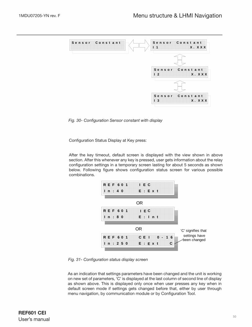
Confi guration Status Display at Key press:
After the key timeout, default screen is displayed with the view shown in above section. After this whenever any key is pressed, user gets information about the relay confi guration settings in a temporary screen lasting for about 5 seconds as shown below. Following fi gure shows confi guration status screen for various possible combinations.
Fig. 31- Confi guration status display screen
As an indication that settings parameters have been changed and the unit is working on new set of parameters, ‘C’ is displayed at the last column of second line of display as shown above. This is displayed only once when user presses any key when in default screen mode if settings gets changed before that, either by user through menu navigation, by communication module or by Confi guration Tool.
S e n s o r C o n s t a n t S e n s o r C o n s t a n tI 1 X . X X X
S e n s o r C o n s t a n tI 2 X . X X X
S e n s o r C o n s t a n tI 3 X . X X X
Fig. 30- Confi guration Sensor constant with display
Menu structure & LHMI Navigation
R E F 6 0 1 I E CI n : 4 0 E : E x t
R E F 6 0 1 CI n : 8 0 E : I n t
R E F 6 0 1 C E I 0 - 1 6I n : 2 5 0 E : t C
OR
OR 'C' signifies thatsettings havebeen changed
I E
E x

1MDU07205-YN rev. F
REF601 CEI
User’s manual 51
5.2.9 Menu – Test
Menu structure & LHMI Navigation
This menu item basically provides the calibration, test of various I/P –O/P ports and LED indications for various events. User needs extra hardware to check the functionality of some of the submenu items in this menu. Pressing right arrow key can activate submenu and selection from among the available list is done using up/down arrow keys. Activating edit mode by pressing Save and Cancel button together can provide selection of particular test. The details of functions available in test mode is described as under:
-Test -> Calibration: Enables Calibration process for current sensors. User can select or skip particular channel’s calibration process using interactive menu selection.
- Test -> Hardware: Enables Internal Hardware Tests, which includes LCD check, Keyboard check, Binary Inputs check, Binary Output check, LEDs check, EEPROM check. User can skip particular checks using interactive menu selection.
- Test -> Trip Output: Enables testing of Trip command output and Breaker Open output to ensure proper working of trip signaling chain.
- Test -> Functional: Enables protection function tests by loading different preset protection-settings. User can select particular set of protection settings from the list of available group.
T e s t T e s tC a l i b r a t i o n : Y Y Y
N o
Y e s
T e s tH a r d w a r e : Y Y Y
N o
Y e s
T e s tF u n c t i o n a l T e s t
T e s tT r i p O u t p u t : Y Y Y
N o
Y e s
Fig. 32 Test menu with sub menu
1MDU07205-YN rev. F
REF601 CEI
User’s manual 52
5.2.9.1 Sub menu – Calibration
Menu structure & LHMI Navigation
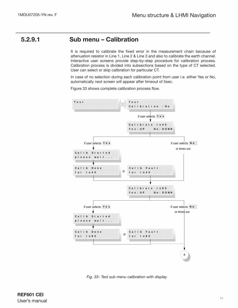
It is required to calibrate the fi xed error in the measurement chain because of attenuation resistor in Line 1, Line 2 & Line 3 and also to calibrate the earth channel. Interactive user screens provide step-by-step procedure for calibration process. Calibration process is divided into subsections based on the type of CT selected. User can select or skip calibration for particular CT.
In case of no selection during each calibration point from user i.e. either Yes or No, automatically next screen will appear after timeout of 5sec.
Figure 33 shows complete calibration process fl ow.
Fig. 33- Test sub menu calibration with display
A
T e s t
T e s t C a l i b r a t i o n : N o
C a l i b r a t e I n 4 0 Y e s : U P N o : D O W N
Y e sif user selects
C a l i b S t a r t e d p l e a s e w a i t . . .
C a l i b D o n e f o r I n 4 0
C a l i b F a u l t f o r I n 4 0
C a l i b r a t e I n 8 0 Y e s : U P N o : D O W N
C a l i b S t a r t e d p l e a s e w a i t . . .
C a l i b D o n e f o r I n 8 0
C a l i b F a u l t f o r I n 8 0
or
Y e sif user selects N o if user selects
Y e sif user selects N o if user selects
or
or times out
or times out

1MDU07205-YN rev. F
REF601 CEI
User’s manual 53
Menu structure & LHMI Navigation
Fig. 33-Test sub menu calibration with display ( contd. )
C a l i b r a t e I n 2 5 0 Y e s : U P N o : D O W N
C a l i b S t a r t e d p l e a s e w a i t . . .
C a l i b D o n e f o r I n 2 5 0
C a l i b F a u l t f o r I n 2 5 0
C a l i b r a t e I n 1 2 5 0Y e s : U P N o : D O W N
C a l i b S t a r t e d p l e a s e w a i t . . .
C a l i b D o n e f o r I n 1 2 5 0
C a l i b F a u l t f o r I n 1 2 5 0
or
Y e sif user selects N o if user selects
Y e sif user selects N o if user selects
or
A
B
or times out
or times out

1MDU07205-YN rev. F
REF601 CEI
User’s manual 54
Menu structure & LHMI Navigation
Fig. 33- Test sub menu calibration with display ( contd. )
Several hardware modules can be tested through this menu. Interactive procedure through key inputs and LCD output provides user interface. The following compo-nents on the Digital PCBA can be tested:
• LCD Test
• Keyboard Test
• LED Test
• Binary Inputs Test
• Binary Outputs Test
• Serial EEPROM Test
During each test wherever confi rmation from user is asked to continue test se-quence, if no selection from user, automatically after 5 sec timeout test sequence will move to next screen.
For binary input tests, timeout between one test to another binary input test is 10 sec. And during binary output test each output will toggle for 100msec ON & 100 msec OFF
Each test procedure provides test result messages and interactive user selections on LCD.
5.2.9.2 Sub menu – Hardware Testing
C a l i b r a t e E a r t h Y e s : U P N o : D O W N
C a l i b S t a r t e d p l e a s e w a i t . . .
C a l i b D o n e f o r I n E a r t h
C a l i b F a u l t f o r I n E a r t h
C a l i b C o m p l e t e R e s t a r t i n g . . .
or
Y e sif user selects N o if user selects
B
Exit
Calib complete
or times out

1MDU07205-YN rev. F
REF601 CEI
User’s manual 55
if user selects NOor timesout
if user selects YES
T e s t T e s tH a r d w a r e : N o
L C D T E S T
L C D T e s tL C D T e s t
L C D T e s tL C D T e s t
T e s t C o n t i n u e ?Y E S : U P N O : D O W N
K e y b o a r d T e s t
P r e s s B A C K K e y
if user presses BACK key key not pressed ortimesout
T e s t S u c c e s s f u l
A
Startif user selects YES
Repeat Test
T e s t F a i l e d
Fig.34- Hardware Test menu with its display view.
Menu structure & LHMI Navigation
1MDU07205-YN rev. F
REF601 CEI
User’s manual 56
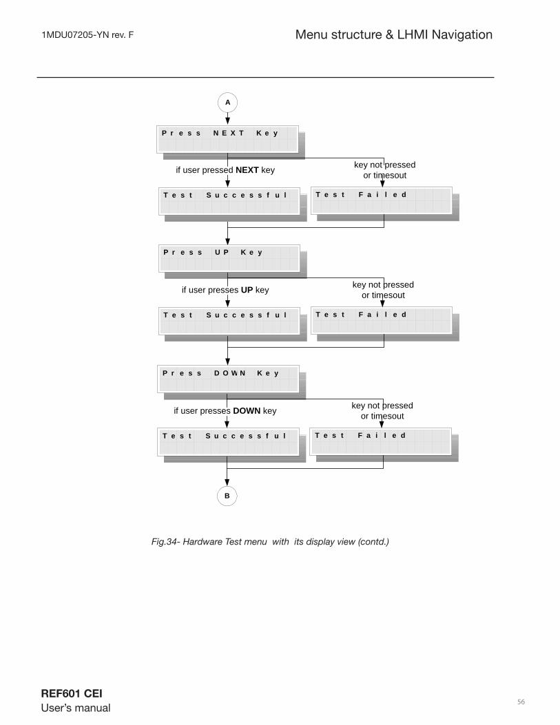
P r e s s N E X T K e y
A
if user pressed NEXT key key not pressedor timesout
T e s t S u c c e s s f u l T e s t F a i l e d
P r e s s U P K e y
if user presses UP key key not pressedor timesout
T e s t S u c c e s s f u l T e s t F a i l e d
P r e s s D O W N K e y
if user presses DOWN key key not pressedor timesout
T e s t S u c c e s s f u l T e s t F a i l e d
B
Fig.34- Hardware Test menu with its display view (contd.)
Menu structure & LHMI Navigation

1MDU07205-YN rev. F
REF601 CEI
User’s manual 57
B
P r e s s E N T E R K e y
if user presses ENTER key key not pressedor timesout
T e s t S u c c e s s f u l T e s t F a i l e d
P r e s s C A N C E L K e y
if user presses CANCEL key key not pressedor timesout
T e s t S u c c e s s f u l T e s t F a i l e d
P r e s s B r e a k e r -O p e n K e y
if BO key pressed key not pressedor timesout
T e s t S u c c e s s f u l T e s t F a i l e d
C
Fig.34- Hardware Test menu with its display view (contd.)
Menu structure & LHMI Navigation

1MDU07205-YN rev. F
REF601 CEI
User’s manual 58
C
P r e s s B r e a k e r -C l o s e K e y
if BC key is pressed key not pressedor timesout
T e s t S u c c e s s f u l T e s t F a i l e d
if user selects YES
T e s t C o n t i n u e ?Y E S : U P N O : D O W N
if user selects NOor timesout
B i n a r y I n p u t sT e s t
D
Repeat Test
E n a b l e R e m o t eC o n t r o l I n p u t
if activated if not activatedor timesout
T e s t S u c c e s s f u l T e s t F a i l e d
Fig.34- Hardware Test menu with its display view (contd.)
Menu structure & LHMI Navigation

1MDU07205-YN rev. F
REF601 CEI
User’s manual 59
D
if activated if not activatedor timesout
T e s t S u c c e s s f u l T e s t F a i l e d
E
E n a b l e B r e a k e rO p e n I n p u t
E n a b l e R e s e tI n p u t
if activated if not activatedor timesout
T e s t S u c c e s s f u l T e s t F a i l e d
E n a b l e B r e a k e rC l o s e I n p u t
if activated if not activatedor timesout
T e s t S u c c e s s f u l T e s t F a i l e d
Fig.34- Hardware Test menu with its display view (contd.)
Menu structure & LHMI Navigation

1MDU07205-YN rev. F
REF601 CEI
User’s manual 60
E
if user selects YES
T e s t C o n t i n u e ?Y E S : U P N O : D O W N
if user selects NOor timesout
B i n a r y O u t p u tT e s t
Toggle output portpins
T e s t C o n t i n u e ?Y E S : U P N O : D O W N
if user selects YES if user selects NOor timesout
L E D T E S T
toggle LEDs
RepeatTest
RepeatTest
FF
T e s t C o n t i n u e ?Y E S : U P N O : D O W N
if user selects YES if user selects NOor timesout
T e s t R e p e a t ?Y E S : U P N O : D O W N
E E P R O M S e l f T e s t
if EEPROM healthy if EEPROM not healthy
E E P R O M S e l f T e s tE E P R O M H e a l t h y
E E P R O M S e l f T e s tE E P R O M F a u l t y
if user selects YES if user selects NOor timesout
ExitStart
RepeatTest
RepeatTest
Fig.34- Hardware Test menu with its display view (contd.)
Menu structure & LHMI Navigation

1MDU07205-YN rev. F
REF601 CEI
User’s manual 61
5.2.9.3 Trip Output Test
This submenu selection provides testing of trip circuit connected to the product. Pulse of defi nite duration will be generated at the trip command output port of the product, which energizes the trip coil connected therein. This action is not of latch-ing nature, and lasts only for the specifi ed duration (200msec low pulse in case of Normally Open type trip circuit contacts.
5.2.9.4 Functional Test
This menu provides selection of one of the several protection parameter groups available in the product. User is required to connect specifi c hardware and apply typical current signals to specifi ed phase/earth inputs. Protection algorithm then can be run with the selected protection parameter group and trip signaling timings can be observed on either on LEDs or optionally on CRO.
F u n c t i o n a l T e s t F u n c t i o n a l T e s tS G 0 1 : Y Y Y
N o
Y e s
F u n c t i o n a l T e s tS G 1 7 : Y Y Y
N o
Y e s
Fig.35- Functional test with its display view
Menu structure & LHMI Navigation

1MDU07205-YN rev. F
REF601 CEI
User’s manual 62
Following table shows the functional test group parameter values.
Menu structure & LHMI Navigation
SG Parameter SG Parameter
1Curve: VIK = 0.1
I> = 0.2 In10
Curve: DT I0> = 0.2 In
t0> = 0.2 sec
2Curve: VIK = 0.1
I> = 0.5 In11
Curve: DT I0> = 0.5 In
t0> = 0.05 sec
3Curve: VIK = 0.1
I> = 1.2 In12
Curve: DT I0> = 0.1 In
t0> = 0.2 sec
4I>>> = 0.8 In
t>>> = 0.05 sec13
Curve: DT I0> = 0.025 Int0> = 0.05 sec
5I>>> = 5.0 In
t>>> = 0.05 sec14
Curve: DT I0> = 0.4 In
t0> = 0.3 sec
6I>>> = 5.0 In
t>>> = 0.2 sec15
I0>> = 0.25 Int0>> = 0.05 sec
7I>> = 0.2 In
t>> = 0.05 sec16
I0>> = 1.0 Int0>> = 0.2 sec
8I>> = 2.1 In
t>> = 0.3 sec17
I0>> = 2.0 Int0>> = 0.1 sec
9I>> = 4.2 In
t>> = 0.5 sec
1MDU07205-YN rev. F
REF601 CEI
User’s manual 63
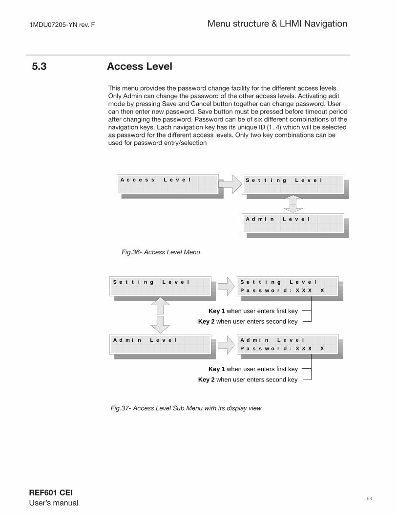
5.3 Access Level
This menu provides the password change facility for the different access levels. Only Admin can change the password of the other access levels. Activating edit mode by pressing Save and Cancel button together can change password. User can then enter new password. Save button must be pressed before timeout period after changing the password. Password can be of six different combinations of the navigation keys. Each navigation key has its unique ID (1..4) which will be selected as password for the different access levels. Only two key combinations can be used for password entry/selection
A c c e s s L e v e l S e t t i n g L e v e l
A d m i n L e v e l
Fig.36- Access Level Menu
S e t t i n g L e v e l
A d m i n L e v e l
S e t t i n g L e v e lP a s s w o r d : X X X X
A d m i n L e v e lP a s s w o r d : X X X X
Key 1 when user enters first key
Key 2 when user enters second key
Key 1 when user enters first key
Key 2 when user enters second key
Fig.37- Access Level Sub Menu with its display view
Menu structure & LHMI Navigation

1MDU07205-YN rev. F
REF601 CEI
User’s manual 64
5.4 Version Info
This menu provides information regarding the Product type selected, Software version being presently loaded into the product, Model name, Nominal current value selected, and the type of trip circuit present.
Fig.38– Version Info Display
Menu structure & LHMI Navigation
V e r s i o n I n f o P r o d u c t N a ex x x 6 0 1
m
S o f t a r e V e r s i o nx x . x x
w
o d e l N a ex x x
mM
N o i n a l V a l u ex x x x
m
T r i p C i r c u i tx x x x x x x x x x x x x
A
B
C
D
EE
REF 601A
XX.XXB
C CEI 0-16IEC
D 40802501250
Normally Open
x x x x
*
* For CEI 0-16, only"250" available

1MDU07205-YN rev. F
REF601 CEI
User’s manual 65
Section 6 Installation and commissioning
6.1 Unpacking and inspecting the device
REF601 products, although of robust construction, require careful handling prior to installation on site. The delivered products should always be examined to ensure that no damage has been sustained during transit.
Remove transport packing carefully without force. Appropriate tools needs to be used.
Check the relay for transport damages. If the product has been damaged, a claim should be made to the transport contractor and the local representative of ABB should be promptly notifi ed. Compare the type designation of the product with the ordering information to verify that you have received the right product.
Electrostatic discharge (ESD)
The products contain components that are sensitive to electrostatic discharge. The electronic circuits are well protected by the relay case and therefore the rear panel may not be removed.
Installation and commissioning
6.2 Storage
On receipt, the apparatus must be carefully unpacked and checked as described under chap. 7.1. Should installation not be carried out immediately, the apparatus must be repacked using the original packing material. Should the original packing material no longer be available, store the apparatus in a dry, dust-free, covered area which is non corrosive and has a temperature of between – 40 °C and + 85 °C.

1MDU07205-YN rev. F
REF601 CEI
User’s manual 66
Installation and commissioning
6.3 Checking environmental conditions and
mounting space
The mechanical and electrical environmental conditions at the installation site must be within the limits described in the technical data.
- Avoid installation in dusty, damp places.
Avoid places susceptible to rapid temperature variations, powerful vibrations and shocks, surge voltages of high amplitude and fast rise time, strong induced magnetic fi elds or similar extreme conditions.
- Check that suffi cient space is available.
To allow access for maintenance and future modifi cations a suffi cient space is needed in front and at side of the relay.
- Suitably qualifi ed personnel with adequate knowledge of the apparatus must carry out all the installation operations.
- The relay should be disconnected before carrying out any work on relay.
6.4 Mounting the relay
The relay is available in two mounting version:
• Flush (panel) mounting
• Breaker mounting
The space requirement of mounting:
Overall dimensions (H x W x D) : 160 x 130 x 101 mm
Cutout dimensions (H x W) : 151.5 x 121.5 mm
Weight : 1.2 kg
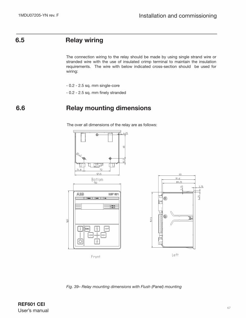
1MDU07205-YN rev. F
REF601 CEI
User’s manual 67
Installation and commissioning
6.5 Relay wiring
The connection wiring to the relay should be made by using single strand wire or stranded wire with the use of insulated crimp terminal to maintain the insulation requirements. The wire with below indicated cross-section should be used for wiring:
- 0.2 - 2.5 sq. mm single-core
- 0.2 - 2.5 sq. mm fi nely stranded
6.6 Relay mounting dimensions
The over all dimensions of the relay are as follows:
Fig. 39– Relay mounting dimensions with Flush (Panel) mounting
160
130 89,25
4,3
4,25
65
12,2
121,5
24,8 72
3,75
2,75
151,5
4,25
91,6
101
Front Left
Bottom

1MDU07205-YN rev. F
REF601 CEI
User’s manual 68
Installation and commissioning
The relay also have breaker mounting version. The details of the same are indicated in Figure 37:
Fig. 40 – Relay mounting dimensions with Breaker mounting
A
A
4,3
121,5
24,8 72
65
12,2
Bottom
Top
Cross Recessed Pan head Screws M4X10Plain Washer,Normal Series M4
Front Left
SECTION A-A SEE DETAIL A
Mounting plate
DETAIL ASCALE 2:1
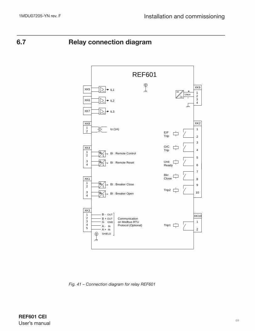
1MDU07205-YN rev. F
REF601 CEI
User’s manual 69
6.7 Relay connection diagram
Installation and commissioning
Fig. 41 – Connection diagram for relay REF601
REF601
XK5
XK6
XK7
IL1DIFF
IL2DIFF
IL3DIFF
XK812
Io (1A)
XK412
BI : Remote Control
34
BI : Remote Reset
XK112
BI : Breaker Close
34
BI : Breaker Open
Uaux 12
XK9
34
XK10
1
2Trip1
XK2
1
2E/F Trip
3
4
5
6
O/CTrip
UnitReady
7
8Bkr.Close
9
10Trip2
XK312
45
3
B - OUT
B + OUTG GND
A - INA + IN
on Modbus RTUCommunication
Protocol (Optional)
SHIELD

1MDU07205-YN rev. F
REF601 CEI
User’s manual 70
6.8 Bonding of Sensor Cable Shield
6.8 .1 Shield connection at relay side
Remove the isolation of the sensor cable for the specifi c section at relay side.• About 15 cm before the connector, typical.
The braid to be mounted at the rear of the relay at the mechanical support.•
Insert into braid and close it•
Tighten screws and check that cable didn’t get sandwich or damaged through • misalignment
This shall result in a short and big area connection of the sensor cable shield to • the chassis resp. GND
The braid shall have a similar construction as shown on image below•
Fig. - Braid for 3 Sensor Cable
Installation and commissioning
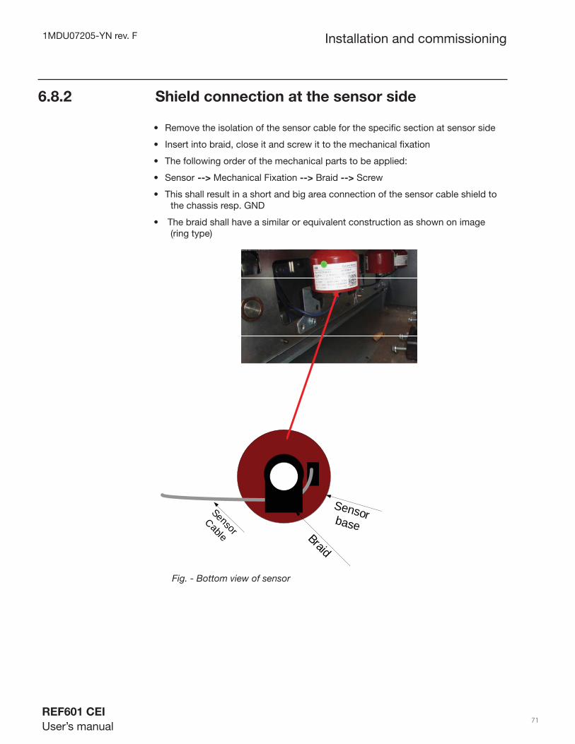
1MDU07205-YN rev. F
REF601 CEI
User’s manual 71
6.8 .2 Shield connection at the sensor side
Remove the isolation of the sensor cable for the specifi c section at sensor side•
Insert into braid, close it and screw it to the mechanical fi xation•
The following order of the mechanical parts to be applied:•
Sensor• --> Mechanical Fixation --> Braid --> Screw
This shall result in a short and big area connection of the sensor cable shield to • the chassis resp. GND
The braid shall have a similar or equivalent construction as shown on image • (ring type)
Sensor baseSensor
Cable Braid
Fig. - Bottom view of sensor
Installation and commissioning

1MDU07205-YN rev. F
REF601 CEI
User’s manual 72
6.8 .3 Segregation of Voltage Indicator System
VI Cables to be moved on the right side in case of UniSec. See Picture•
A coupling path between cables for I/O , Power Supply and the cables for • voltage indicator should be avoided.
A typical segregation of 40cm shall be considered•
Move Right to Segregate
VI CablesI/O Signals
Installation and commissioning

1MDU07205-YN rev. F
REF601 CEI
User’s manual 73
6.9 Relay ordering information
Installation and commissioning
The relay is available in four variant. The ordering code of the relay is as below:
Fig. Figure 42 – Ordering details of relay REF601
Specifi c sensors needs to be used along with the relays. The ordering details for the same can be available from sensor data sheet no. 1YMA583791R0001-4.
REF601 J A A 4 6 A A 1 X B
# DESCRIPTION
1 Relay type
REF601 REF601
2 Standard
CEI 0-16 J
3,4 Analog input / output
3 sensor and ground CT AA
5,6 Binary input / output
4BI + 6 BO 46
REF601 J A A 4 6 A A 1 X B
# DESCRIPTION
7 Serial communication
with RS485 A
None N
8 Communication protocol
MODBUS RTU A
None N
9 Power supply
24...240V AC 1
10 Vacant digit
Vaccant X
11 Version
Version 1.0 SP1 B
Example code: REF601 J A A 4 6 A A 1 X B
Your ordering code:
Digit (#) 1 2 3 4 5 6 7 8 9 10 11
Code

1MDU07205-YN rev. F
REF601 CEI
User’s manual 74
Serial Communication
Section 7 Serial communication
7.1 Modbus Protocol Overview
The Modbus protocol was fi rst introduced by Modicon Inc. The protocol determines how each controller connected to the Modbus network will recognize a message addressed to it. It also determines the task to be performed and extracts any data or other information contained in the message. If a reply is required, the controller will construct a reply message and send it using the Modbus protocol.
The communication technique used in the Modbus protocol is a master-slave technique. This means that only one device can be the master and initiate transactions, while other devices connected to the network are slaves and can accordingly not initiate any transactions.
7.2.1 Communication Connector
The relay equipped with the communication board which provides an RS485 communication ports for Modbus RTU communication support. The communication port allows the relay REF601 to network with up to 31 other slave REF601 devices on a Modbus RTU link.
The below diagram shows the connection details for networking of the relay to PC.
7.2 Wiring
REF6011 2 3 4 5
B-B+GND
A+A-
REF6011 2 3 4 5
REF6011 2 3 4 5
RS485 / RS232Convertor
Tx+ Tx- Rx+ Rx- G
MODBUS Master
Fig. 43– Connection details for MODBUS RTU communication
1MDU07205-YN rev. F
REF601 CEI
User’s manual 75
7.2.2 RS-485 Serial Communication
When connecting the REF 601 to an RS485 communication link, you must use termination resistors at each end of link.
As a reference, cable number 9842 from Belden (4 wire cable) or any equivalent cable can be used to for the RS485 connection.
7.3 Modbus RTU message format
7.3.1 Modbus message RTU framing:
For Modbus serial line using the RTU (Remote Terminal Unit) mode, each 8–bit byte in a message contains two 4–bit hexadecimal characters. The main advantage of this mode is that its greater character density allows better data throughput than ASCII mode for the same baud rate. Each message must be transmitted in a continuous stream of characters.
The format for each byte (11 bits) in RTU mode is:
Coding System: 8–bit binary
Bits per Byte: 1 start bit8 data bits, least signifi cant bit sent fi rst1 bit for parity completion1 stop bit
Parity: Even, other modes (odd parity, no parity). The default parity mode must be even parity.
Baud rate: default 19200, Baud rates supported are 2400,4800,9600,19200,38400
Remark: The use of no parity requires 2 stop bits.
A Modbus message is placed by the transmitting device into a frame that has a known beginning and ending point. This allows devices that receive a new frame to begin at the start of the message, and to know when the message is completed. Partial messages must be detected and errors must be set as a result.In RTU mode, message frames are separated by a silent interval of at least 3.5 character times this time interval is called t3,5.
Serial Communication

1MDU07205-YN rev. F
REF601 CEI
User’s manual 76
Start
3.5 Char
Address
8 bits
Function
8 bits
Data
N x 8 bits
CRC Check
16 bits
End
3.5 Char
The entire message frame must be transmitted as a continuous stream of characters. If a silent interval of more than 1.5 character times occurs between two characters, the message frame is declared incomplete and should be discarded by the receiver.
Frame 1
3.5character
3.5character
4.5character
Frame 2 Frame 3
Fig. 44 – RTU Message Frame
7.3.2 CRC Checking:
The RTU mode includes an error–checking fi eld that is based on a cyclical redundancy checking (CRC) method performed on the message contents. The CRC fi eld checks the contents of the entire message. It is applied regardless of any parity checking method used for the individual characters of the message.
The CRC fi eld contains a 16–bit value implemented as two 8–bit bytes. The CRC fi eld is appended to the message as the last fi eld in the message. When this is done, the low–order byte of the fi eld is appended fi rst, followed by the high–order byte. The CRC high–order byte is the last byte to be sent in the message.
Serial Communication

1MDU07205-YN rev. F
REF601 CEI
User’s manual 77
7.4 Modbus RTU function codes
Table 1 & 2 below lists the Modbus RTU Function Code defi nitions, the maximum number of registers allowed per request.
Table 1 : Modbus RTU function codes defi nitions
Function CodeName Usage
Dec Hex
03 / 04 03/04
Read Holding Registers /Read Input Registers
Read Data in 16-bit register format ( high / low). Used to read process data. Registers are consecutive and are imaged from the instrument to the host.
05 05Change digital
output
Change the state of a digital output
06 06Preset Single
Register
Write data in 16-bit integer format ( high /low ) only.
08 08 Loop back Test
Used for diagnostic testing of the communications port.
16 10Preset Multiple
Registers
Write data in 16-bit format ( high / low ). Used to write integer and fl oating point override data. Registers are consecutive and are imaged from the host to the instrument.
70 46Read Module
settings
Read baud rate, parity and relay address settings.
Function Code Maximum number of resistorsDec Hex
03 03 1604 04 1605 05 0408 08 08
Table 2 : Maximum number of resistors allowable per request
Serial Communication
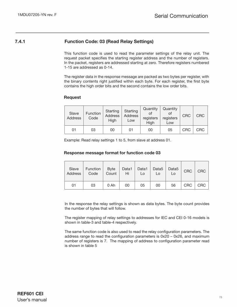
1MDU07205-YN rev. F
REF601 CEI
User’s manual 78
7.4.1 Function Code: 03 (Read Relay Settings)
This function code is used to read the parameter settings of the relay unit. The request packet specifi es the starting register address and the number of registers. In the packet, registers are addressed starting at zero. Therefore registers numbered 1-15 are addressed as 0-14.
The register data in the response message are packed as two bytes per register, with the binary contents right justifi ed within each byte. For each register, the fi rst byte contains the high order bits and the second contains the low order bits.
SlaveAddress
FunctionCode
StartingAddress
High
StartingAddress
Low
Quantity of
registers High
Quantity of
registers Low
CRC CRC
01 03 00 01 00 05 CRC CRC
Request
Example: Read relay settings 1 to 5, from slave at address 01.
SlaveAddress
FunctionCode
Byte Count
Data1 Hi
Data1 Lo
Data5 Lo
Data5 Lo
CRC CRC
01 03 0 Ah 00 05 00 56 CRC CRC
Response message format for function code 03
In the response the relay settings is shown as data bytes. The byte count provides the number of bytes that will follow.
The register mapping of relay settings to addresses for IEC and CEI 0-16 models is shown in table-3 and table-4 respectively.
The same function code is also used to read the relay confi guration parameters. The address range to read the confi guration parameters is 0x20 – 0x26, and maximum number of registers is 7. The mapping of address to confi guration parameter read is shown in table 5
Serial Communication
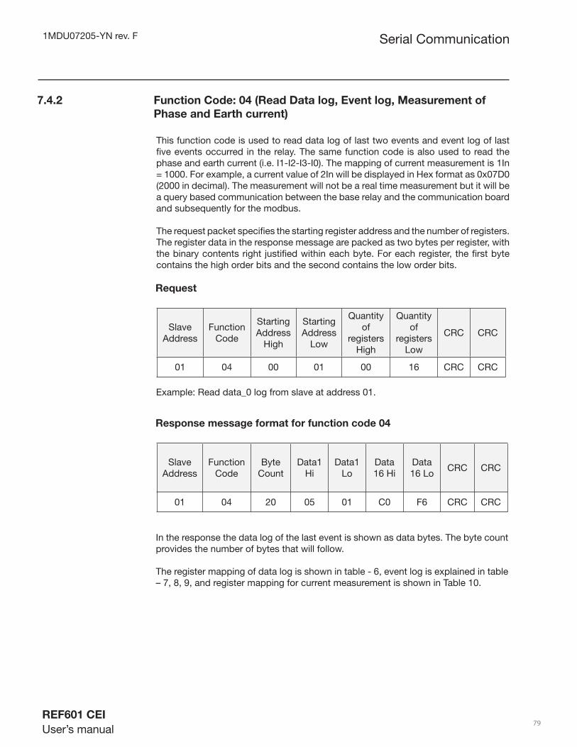
1MDU07205-YN rev. F
REF601 CEI
User’s manual 79
7.4.2 Function Code: 04 (Read Data log, Event log, Measurement of
Phase and Earth current)
This function code is used to read data log of last two events and event log of last fi ve events occurred in the relay. The same function code is also used to read the phase and earth current (i.e. I1-I2-I3-I0). The mapping of current measurement is 1In = 1000. For example, a current value of 2In will be displayed in Hex format as 0x07D0 (2000 in decimal). The measurement will not be a real time measurement but it will be a query based communication between the base relay and the communication board and subsequently for the modbus.
The request packet specifi es the starting register address and the number of registers. The register data in the response message are packed as two bytes per register, with the binary contents right justifi ed within each byte. For each register, the fi rst byte contains the high order bits and the second contains the low order bits.
SlaveAddress
FunctionCode
StartingAddress
High
StartingAddress
Low
Quantity of
registers High
Quantity of
registers Low
CRC CRC
01 04 00 01 00 16 CRC CRC
Request
Example: Read data_0 log from slave at address 01.
SlaveAddress
FunctionCode
Byte Count
Data1 Hi
Data1 Lo
Data 16 Hi
Data 16 Lo
CRC CRC
01 04 20 05 01 C0 F6 CRC CRC
Response message format for function code 04
In the response the data log of the last event is shown as data bytes. The byte count provides the number of bytes that will follow.
The register mapping of data log is shown in table - 6, event log is explained in table – 7, 8, 9, and register mapping for current measurement is shown in Table 10.
Serial Communication

1MDU07205-YN rev. F
REF601 CEI
User’s manual 80
7.4.3 Function Code: 05 (Change Digital output)
This function code is used to enable digital output in a relay device. The possible digital outputs are listed in table 11. A value of 0xFF00 or 0x0000 requests the output to be enabled or disabled. However, in the commands implemented for REF601, writing a value 0x0000 will have no effect, since there are no such operations that need to be disabled.
The normal response is an echo of the request, returned after the coil state has been written. A value other then 0xFF00 or 0x0000 will generate an exception for illegal data value and any address other then those mentioned in Table 11 will generate an exception of illegal data address.
SlaveAddress
FunctionCode
OutputAddress
High
OutputAddress
Low
Output value High
Output value Low
CRC CRC
01 05 00 01 FFh 00 CRC CRC
Request
Example: Change the breaker close output
Response message format for function code 0x05
SlaveAddress
FunctionCode
OutputAddress
High
OutputAddress
Low
Output value High
Output value Low
CRC CRC
01 0E 00 01 FFh 00 CRC CRC
Serial Communication

1MDU07205-YN rev. F
REF601 CEI
User’s manual 81
This function code is used to change single setting of relay device. The request packet specifi es the address of the register to be written. The normal response is an echo of the request, returned after the register contents have been written.
For editing the settings of the relay, refer table 3 and 4 for IEC version and CEI 0-16 version respectively. The same function code is also used for editing the confi guration of the relay.The confi guration parameters that can be edited through the MODBUS include the Nominal Value Type selection between 40,80,250,1250 and Earth Type (Internal-External) for the IEC version of relay, For the CEI 0-16 version, the Earth type is non-editable and is fi xed. The Nominal Value Type selection allowed is only 80 & 250. The Nominal Value Type cannot be changed to 40 & 1250.For editing confi guration parameters of the relay, refer Table 12 for address and data values.
7.4.4 Function Code: 06 (Write single register-Change relay setting)
SlaveAddress
FunctionCode
StartingAddress
High
StartingAddress
Low
Setting value high
Setting value low
CRC CRC
01 06 00 05 00 0 Ah CRC CRC
Request
Example: Write 0Ah value to resistor value with address 0x0005 on slave at add. 01
Response message format for function code 06
SlaveAddress
FunctionCode
StartingAddress
High
StartingAddress
Low
Setting value high
Setting value low
CRC CRC
01 06 00 05 00 0 Ah CRC CRC
Serial Communication

1MDU07205-YN rev. F
REF601 CEI
User’s manual 82
7.4.5 Function Code: 08 (Diagnostics - Loop back message)
Echoes received query message. Message can be any length from 4 to 16 bytes.
SlaveAddress
FunctionCode
Any data, length limited from 4 to 16 bytes
CRC CRC
01 08 01 02 03 04 CRC CRC
Request
Response
SlaveAddress
FunctionCode
Any data, length limited from 4 to 16 bytes
CRC CRC
01 08 01 02 03 04 CRC CRC
7.4.6 Function Code: 70 ( 46h ) (Read Module settings)
This function code is used to read the settings of the module. The following sub-function codes are supported.
Sub-function Code Description
01 Read the module address
02
Read the communication settings – Baud rate
03
Read the communication settings – Parity
Serial Communication
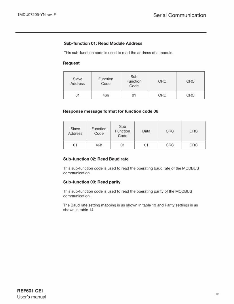
1MDU07205-YN rev. F
REF601 CEI
User’s manual 83
Sub-function 01: Read Module Address This sub-function code is used to read the address of a module.
SlaveAddress
FunctionCode
Sub Function
CodeCRC CRC
01 46h 01 CRC CRC
Request
Response message format for function code 06
SlaveAddress
FunctionCode
Sub Function
CodeData CRC CRC
01 46h 01 01 CRC CRC
Sub-function 02: Read Baud rate This sub-function code is used to read the operating baud rate of the MODBUS communication.
Sub-function 03: Read parity This sub-function code is used to read the operating parity of the MODBUS communication.
The Baud rate setting mapping is as shown in table 13 and Parity settings is as shown in table 14.
Serial Communication
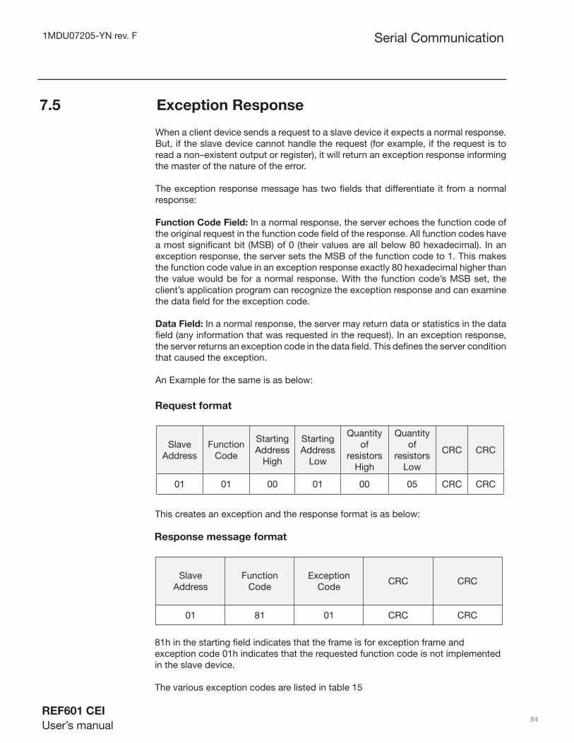
1MDU07205-YN rev. F
REF601 CEI
User’s manual 84
7.5 Exception Response
When a client device sends a request to a slave device it expects a normal response. But, if the slave device cannot handle the request (for example, if the request is to read a non–existent output or register), it will return an exception response informing the master of the nature of the error.
The exception response message has two fi elds that differentiate it from a normal response:
Function Code Field: In a normal response, the server echoes the function code of the original request in the function code fi eld of the response. All function codes have a most signifi cant bit (MSB) of 0 (their values are all below 80 hexadecimal). In an exception response, the server sets the MSB of the function code to 1. This makes the function code value in an exception response exactly 80 hexadecimal higher than the value would be for a normal response. With the function code’s MSB set, the client’s application program can recognize the exception response and can examine the data fi eld for the exception code.
Data Field: In a normal response, the server may return data or statistics in the data fi eld (any information that was requested in the request). In an exception response, the server returns an exception code in the data fi eld. This defi nes the server condition that caused the exception.
An Example for the same is as below:
SlaveAddress
FunctionCode
Starting Address
High
Starting Address
Low
Quantity of
resistors High
Quantity of
resistors Low
CRC CRC
01 01 00 01 00 05 CRC CRC
Request format
This creates an exception and the response format is as below:
SlaveAddress
FunctionCode
Exception Code
CRC CRC
01 81 01 CRC CRC
Response message format
81h in the starting fi eld indicates that the frame is for exception frame and exception code 01h indicates that the requested function code is not implemented in the slave device. The various exception codes are listed in table 15
Serial Communication
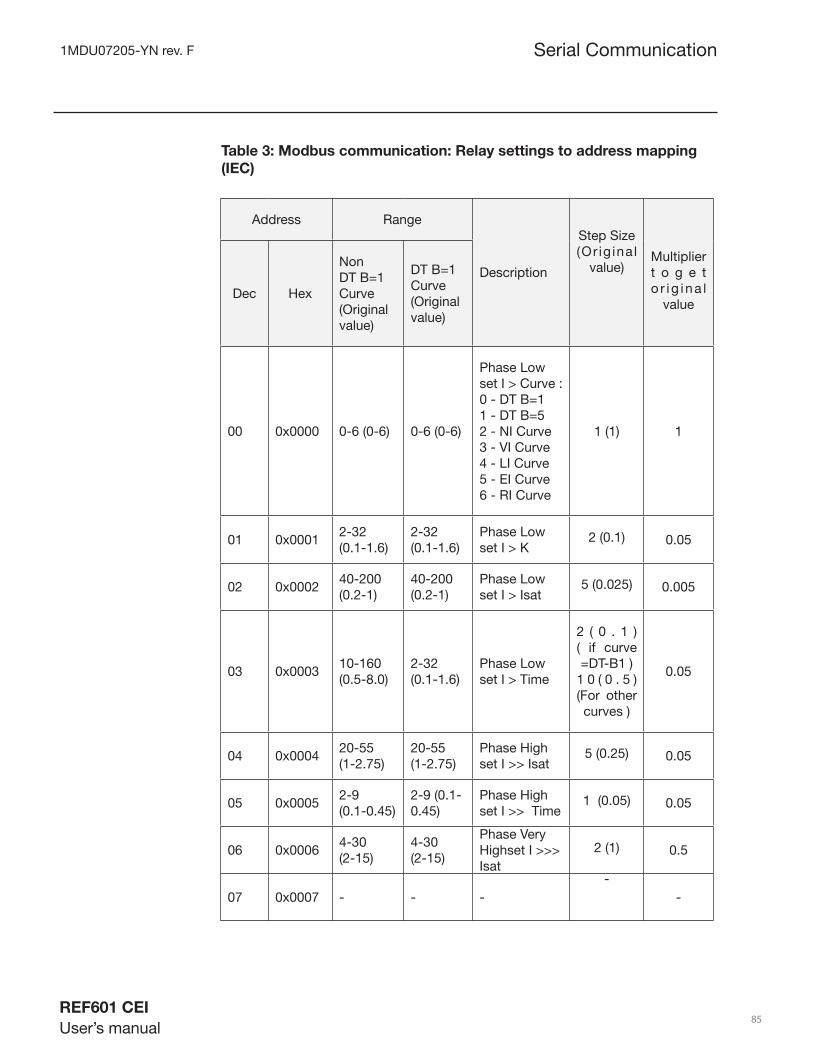
1MDU07205-YN rev. F
REF601 CEI
User’s manual 85
Table 3: Modbus communication: Relay settings to address mapping
(IEC)
Address
Range
Description
Step Size(Or ig inal
value)Multiplier t o g e t o r ig ina l
valueDec Hex
Non DT B=1 Curve (Original value)
DT B=1 Curve (Original value)
00 0x0000 0-6 (0-6) 0-6 (0-6)
Phase Low set I > Curve :0 - DT B=11 - DT B=52 - NI Curve3 - VI Curve4 - LI Curve5 - EI Curve6 - RI Curve
1 (1) 1
01 0x00012-32 (0.1-1.6)
2-32 (0.1-1.6)
Phase Low set I > K
2 (0.1) 0.05
02 0x000240-200 (0.2-1)
40-200 (0.2-1)
Phase Low set I > Isat
5 (0.025) 0.005
03 0x000310-160 (0.5-8.0)
2-32 (0.1-1.6)
Phase Low set I > Time
2 ( 0 . 1 ) ( if curve =DT-B1 )
1 0 ( 0 . 5 ) (For other curves )
0.05
04 0x000420-55 (1-2.75)
20-55 (1-2.75)
Phase High set I >> Isat
5 (0.25) 0.05
05 0x00052-9 (0.1-0.45)
2-9 (0.1-0.45)
Phase High set I >> Time
1 (0.05) 0.05
06 0x00064-30 (2-15)
4-30 (2-15)
Phase Very Highset I >>>Isat
2 (1) 0.5
07 0x0007 - - --
-
Serial Communication

1MDU07205-YN rev. F
REF601 CEI
User’s manual 86
Table 3: Modbus communication: Relay settings to address mapping
(IEC) Cont...
Address
Range
Description
Step Size(Or ig inal
value)Multiplier t o g e t o r ig ina l
valueDec Hex
Non DT B=1 Curve (Original value)
DT B=1 Curve (Original value)
08 0x0008 0-6 (0-6) 0-6 (0-6)
Earth Low set Io > Curve :0 - DT B=11 - DT B=52 - NI Curve3 - VI Curve4 - LI Curve5 - EI Curve6 - RI Curve
1 (1) 1
09 0x00092-32 (0.1-1.6)
2-32 (0.1-1.6)
Earth Low set Io > K
2 (0.1) 0.05
10 0x000A
1-20 (0.05-1) Earth=Ex4-20 (0.2-1) Earth=In
1-20 (0.05-1)
Earth Low set Io > Isat
1 (0.05)0.05
11 0x000B10-160 (0.5-8.0)
2-32 (0.1-1.6)
Earth Low set Io > Time
2 ( 0 . 1 ) ( if curve =DT-B1 )
1 0 ( 0 . 5 ) (For other curves )
0.05
12 0x000C10-80 (0.5-4)
10-80 (0.5-4)
Earth High set Io >> Isat
5 (0.25) 0.05
13 0x000D0-15 (0-0.75)
0-15 (0-0.75)
Earth High set Io >> Time
1 (0.05) 0.05
14 0x000E2-200 (0.2-20)
2-200 (0.2-20)
Inrush current threshold
1 (0.1) 0.10
15 0x000F30-50 (30-50)
30-50 (30-50)
Inrush ratio
5(5) 1
Serial Communication

1MDU07205-YN rev. F
REF601 CEI
User’s manual 87
Address
Range
Description
Step Size
( O r i g i n a l value)
M u l t i p l i e r to get original
valueDec Hex (Original value)
00 0x0000 3(3)
Phase Low set I > Curve :3 - VI Curve
-
1
01 0x0001 2-32 (0.1-1.6)Phase Low set I > K
2 (0.1) 0.05
02 0x0002 20-120 (0.2-1.2)Phase Low set I > Isat
5 (0.05) 0.01
03 0x0003 -Phase Low set I > Time
04 0x0004 10-250 (0.2-5)Phase High set I >> Isat
5 (0.1) 0.02
05 0x0005 1-20 (0.05-1)Phase High set I >> Time
1 (0.05) 0.05
06 0x0006 8-150 (0.8-15)Phase Very Highset I >>>Isat
2 (0.2) 0.1
07 0x0007 1-4 (0.05 - 0.2)Phase Very Highset I >>>Time
1(0.05) 0.05
08 0x0008 0(0)Earth lowset Io> Curve 0-DT B=1
- -
09 0x0009 -Earth lowset Io> k - -
10 0x000A2-40 (0.025 - 0.5)
Earth lowset Io> Isat 1(0.0125) 0.0125
11 0x000B 1-20(0.05-1)Earth lowset Io> Time 1(0.05) 0.05
12 0x000C5-250(0.25 - 12.5)
Earth Highset Io>> Isat 5(0.25) 0.05
13 0x000D 1-4(0.05 - 0.2)Earth Highset Io>> Time 1 (0.05) 0.05
14 0x000E 2-200 (0.2 -20)Inrush Current Threshold
1(0.1) 0.1
15 0x000F 30 -50 (30-50) Inrush ratio 5(5) 1
Table 4: MODBUS comm. Relay settings to address mapping (CEI 0-16)
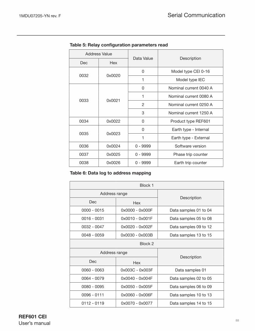
1MDU07205-YN rev. F
REF601 CEI
User’s manual 88
Table 5: Relay confi guration parameters read
Address ValueData Value Description
Dec Hex
0032 0x00200 Model type CEI 0-16
1 Model type IEC
0033 0x0021
0 Nominal current 0040 A
1 Nominal current 0080 A
2 Nominal current 0250 A
3 Nominal current 1250 A
0034 0x0022 0 Product type REF601
0035 0x00230 Earth type - Internal
1 Earth type - External
0036 0x0024 0 - 9999 Software version
0037 0x0025 0 - 9999 Phase trip counter
0038 0x0026 0 - 9999 Earth trip counter
Table 6: Data log to address mapping
Block 1
Address rangeDescription
Dec Hex
0000 - 0015 0x0000 - 0x000F Data samples 01 to 04
0016 - 0031 0x0010 - 0x001F Data samples 05 to 08
0032 - 0047 0x0020 - 0x002F Data samples 09 to 12
0048 - 0059 0x0030 - 0x003B Data samples 13 to 15
Block 2
Address rangeDescription
Dec Hex
0060 - 0063 0x003C - 0x003F Data samples 01
0064 - 0079 0x0040 - 0x004F Data samples 02 to 05
0080 - 0095 0x0050 - 0x005F Data samples 06 to 09
0096 - 0111 0x0060 - 0x006F Data samples 10 to 13
0112 - 0119 0x0070 - 0x0077 Data samples 14 to 15
Serial Communication
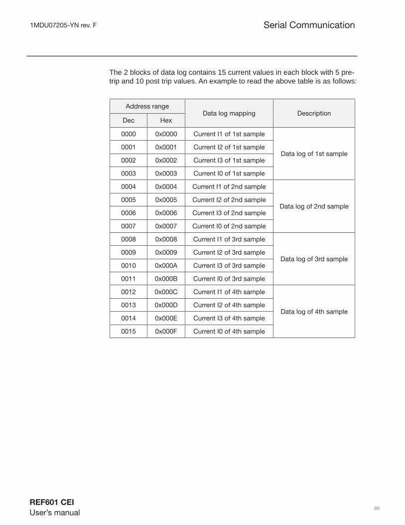
1MDU07205-YN rev. F
REF601 CEI
User’s manual 89
The 2 blocks of data log contains 15 current values in each block with 5 pre-trip and 10 post trip values. An example to read the above table is as follows:
Address rangeData log mapping Description
Dec Hex
0000 0x0000 Current I1 of 1st sample
Data log of 1st sample0001 0x0001 Current I2 of 1st sample
0002 0x0002 Current I3 of 1st sample
0003 0x0003 Current I0 of 1st sample
0004 0x0004 Current I1 of 2nd sample
Data log of 2nd sample0005 0x0005 Current I2 of 2nd sample
0006 0x0006 Current I3 of 2nd sample
0007 0x0007 Current I0 of 2nd sample
0008 0x0008 Current I1 of 3rd sample
Data log of 3rd sample0009 0x0009 Current I2 of 3rd sample
0010 0x000A Current I3 of 3rd sample
0011 0x000B Current I0 of 3rd sample
0012 0x000C Current I1 of 4th sample
Data log of 4th sample0013 0x000D Current I2 of 4th sample
0014 0x000E Current I3 of 4th sample
0015 0x000F Current I0 of 4th sample
Serial Communication
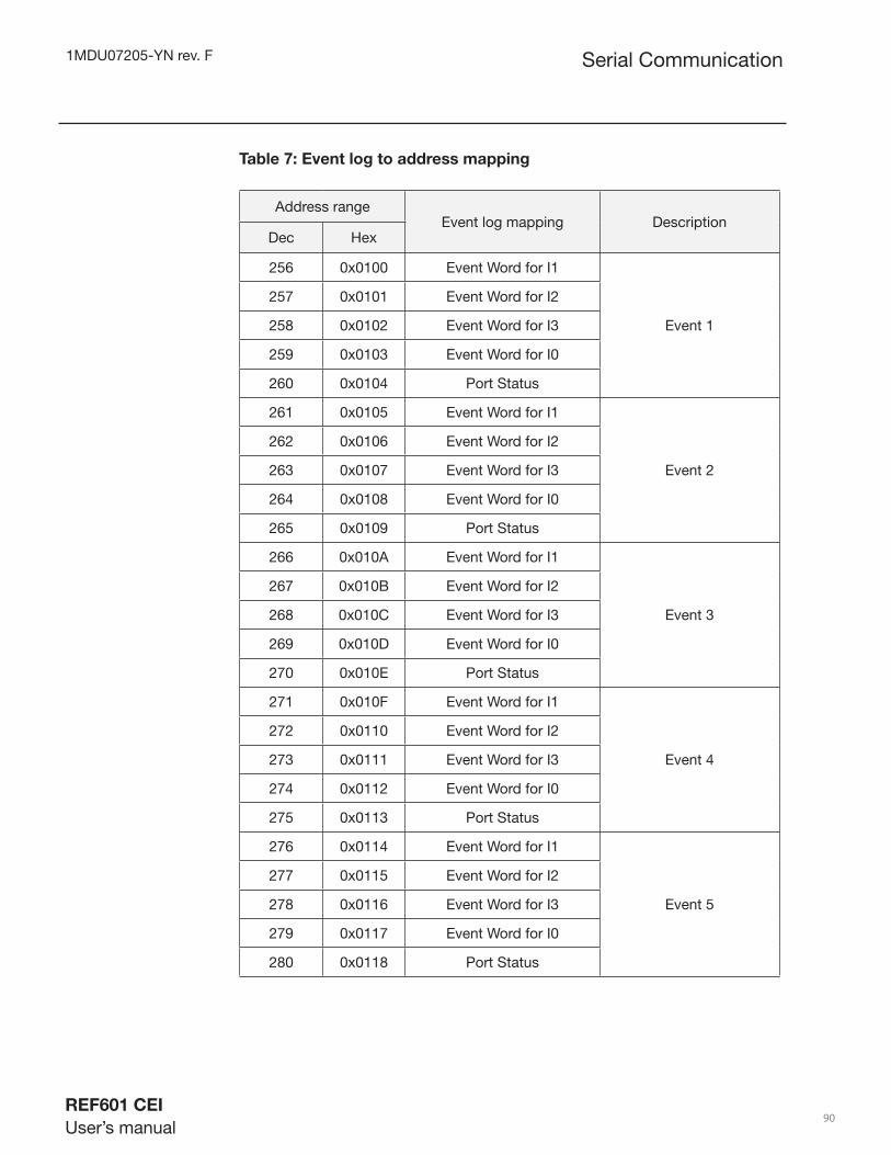
1MDU07205-YN rev. F
REF601 CEI
User’s manual 90
Table 7: Event log to address mapping
Address rangeEvent log mapping Description
Dec Hex
256 0x0100 Event Word for I1
Event 1
257 0x0101 Event Word for I2
258 0x0102 Event Word for I3
259 0x0103 Event Word for I0
260 0x0104 Port Status
261 0x0105 Event Word for I1
Event 2
262 0x0106 Event Word for I2
263 0x0107 Event Word for I3
264 0x0108 Event Word for I0
265 0x0109 Port Status
266 0x010A Event Word for I1
Event 3
267 0x010B Event Word for I2
268 0x010C Event Word for I3
269 0x010D Event Word for I0
270 0x010E Port Status
271 0x010F Event Word for I1
Event 4
272 0x0110 Event Word for I2
273 0x0111 Event Word for I3
274 0x0112 Event Word for I0
275 0x0113 Port Status
276 0x0114 Event Word for I1
Event 5
277 0x0115 Event Word for I2
278 0x0116 Event Word for I3
279 0x0117 Event Word for I0
280 0x0118 Port Status
Serial Communication

1MDU07205-YN rev. F
REF601 CEI
User’s manual 91
Each event log from event 1 to event 5 contains the current values of I1-I2-I3-I0 and port status at the time of event, as shown in the following table. It should be noted that each event has to be read in group of fi ve words only, i.e. starting address has to be one of 0x0100, 0x0105, 0x010A, 0x010F or 0x0114, with length 5 so as to give the event log data.
The below table shows the mapping of individual register with its address:
ValueAddress range
Event log mappingDec Hex
Event word for 0 0 - 65535 0-0xFFFF Event on current I1
Event word for 1 0 - 65535 0-0xFFFF Event on current I2
Event word for 2 0 - 65535 0-0xFFFF Event on current I3
Event word for 3 0 - 65535 0-0xFFFF Event on current Io
Event word for 4 0 - 1023 0-0xFFFF Port Status as per table 9
Table 8: Event log data to address mapping - description
The port status is a 2 byte fi eld where bit positions 0 – 7 form the byte 1 and bit position 8-9 forms byte 2.
7 6 5 4 3 2 1 0
Byte 1:
- - - - - - 9 8
Byte 2:
Serial Communication

1MDU07205-YN rev. F
REF601 CEI
User’s manual 92
Table 9: Event log - Port status mapping
Bit position Value ( 1=on, 0=off ) Description
0 0 - 1 Input breaker open
1 0 - 1 Input breaker closed
2 0 - 1 Input reset
3 0 - 1 Remote control
4 0 - 1 Unit ready
5 0 - 1 IRF output
6 0 - 1 Phase protection
7 0 - 1 Earth protection
8 0 - 1 Output breaker open
9 0 - 1 Output breaker close
Address range Data rangeData log mapping
Dec Hex Dec Hex
0512 0x0200 0 - 65535 0-0xFFFF Current measurement on I1
0513 0x0201 0 - 65535 0-0xFFFF Current measurement on I2
0514 0x0202 0 - 65535 0-0xFFFF Current measurement on I3
0515 0x0203 0 - 65535 0-0xFFFF Current measurement on Io
Table 10: Current measurement address mapping
CH#Address
Data log mappingDec Hex
01 00 0x00 Breaker open
02 01 0x01 Breaker close
03 02 0x02 Reset protection command
04 03 0x03 Remote trip command
Table 11: Digital output channel to address mapping
Serial Communication

1MDU07205-YN rev. F
REF601 CEI
User’s manual 93
AddressData Value Data log mapping
Dec Hex
IEC MODE
0033 0x0021
0 Nominal current 0040A
1 Nominal current 0080A
2 Nominal current 0250A
3 Nominal current 1250A
0035 0x00230 Earth type - Internal
1 Earth type - External
CEI MODE
Table 12: Relay confi guration write
Baud Rate response value Description
0 2400 baud
1 4800 baud
2 9600 baud
3 19200 baud
0 38400 baud
Table 13: Baud rate mapping
Parity response value Description
0 None parity
1 Odd parity
2 Even parity
Table 14: Parity mapping
Serial Communication
0033 0x00211 Nominal current 0080A
2 Nominal current 0250A
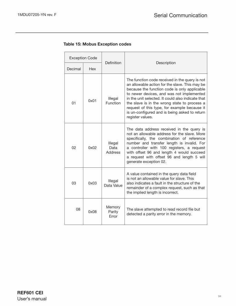
1MDU07205-YN rev. F
REF601 CEI
User’s manual 94
Exception Code
Defi nition Description Decimal
Hex
010x01
Illegal Function
The function code received in the query is not an allowable action for the slave. This may be because the function code is only applicable to newer devices, and was not implemented in the unit selected. It could also indicate that the slave is in the wrong state to process a request of this type, for example because it is un-confi gured and is being asked to return register values.
02 0x02Illegal Data
Address
The data address received in the query is not an allowable address for the slave. More specifi cally, the combination of reference number and transfer length is invalid. For a controller with 100 registers, a request with offset 96 and length 4 would succeed a request with offset 96 and length 5 will generate exception 02.
03 0x03Illegal
Data Value
A value contained in the query data fi eld is not an allowable value for slave. This also indicates a fault in the structure of the remainder of a complex request, such as that the implied length is incorrect.
08
0x08Memory
Parity Error
The slave attempted to read record fi le but detected a parity error in the memory.
Table 15: Mobus Exception codes
Serial Communication
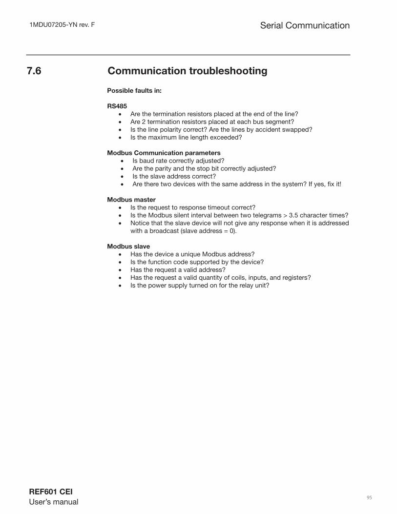
1MDU07205-YN rev. F
REF601 CEI
User’s manual 95
Possible faults in:
RS485
Are the termination resistors placed at the end of the line?• Are 2 termination resistors placed at each bus segment?• Is the line polarity correct? Are the lines by accident swapped?• Is the maximum line length exceeded?•
Modbus Communication parameters
Is baud rate correctly adjusted?• Are the parity and the stop bit correctly adjusted?• Is the slave address correct?• Are there two devices with the same address in the system? If yes, fi x it!•
Modbus master
Is the request to response timeout correct?• Is the Modbus silent interval between two telegrams > 3.5 character times?• Notice that the slave device will not give any response when it is addressed • with a broadcast (slave address = 0).
Modbus slave
Has the device a unique Modbus address?• Is the function code supported by the device?• Has the request a valid address?• Has the request a valid quantity of coils, inputs, and registers?• Is the power supply turned on for the relay unit?•
7.6 Communication troubleshooting
Serial Communication

ABB Ltd.Distribution AutomationManeja Works,Vadodara - 390 013, IndiaPhone +91 265 2604386Fax +91 265 2638922www.abb.com/substationautomation
1M
DU
0720
5-YN
F/3
0 Se
p 2
010
Copyright 2009- ABB