User’s Guide SPSVT26xx-10x - Transition Networks€™s Guide SPSVT26xx-10x ... SPS-2460-SA...
9
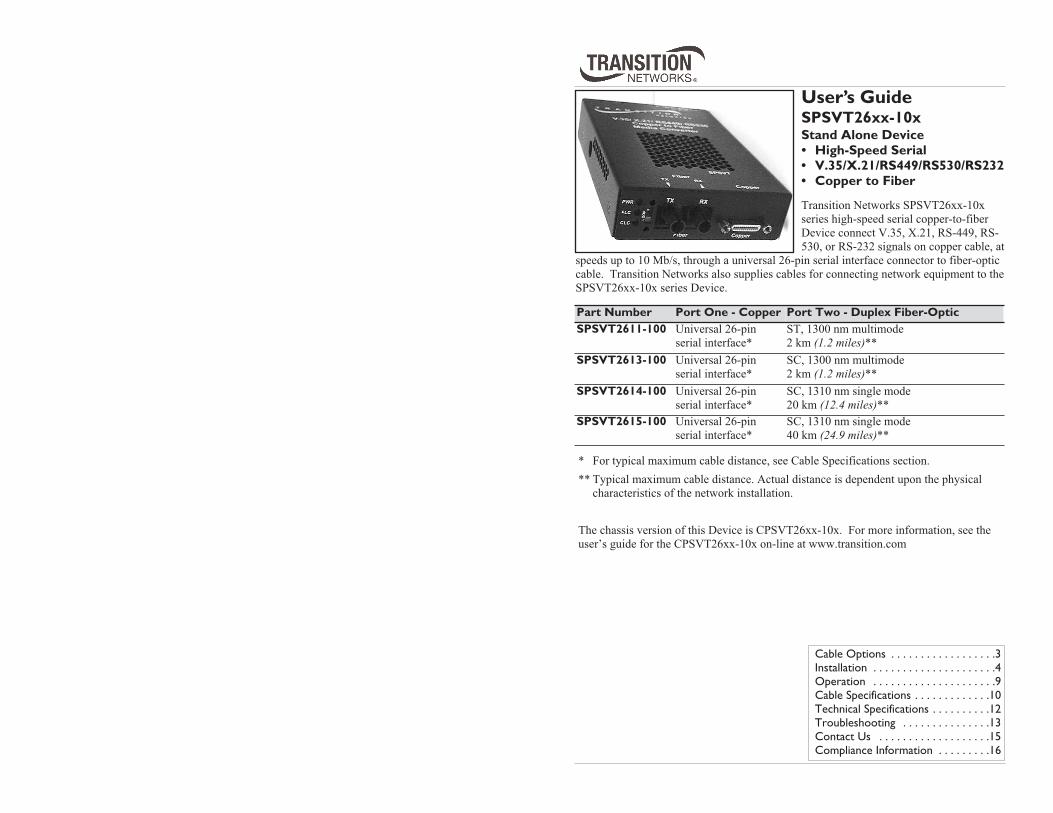
User’s Guide SPSVT26xx-10x Stand Alone Device • High-Speed Serial • V.35/X.21/RS449/RS530/RS232 • Copper to Fiber Transition Networks SPSVT26xx-10x series high-speed serial copper-to-fiber Device connect V.35, X.21, RS-449, RS- 530, or RS-232 signals on copper cable, at speeds up to 10 Mb/s, through a universal 26-pin serial interface connector to fiber-optic cable. Transition Networks also supplies cables for connecting network equipment to the SPSVT26xx-10x series Device. Cable Options . . . . . . . . . . . . . . . . . .3 Installation . . . . . . . . . . . . . . . . . . . . .4 Operation . . . . . . . . . . . . . . . . . . . . .9 Cable Specifications . . . . . . . . . . . . .10 Technical Specifications . . . . . . . . . .12 Troubleshooting . . . . . . . . . . . . . . .13 Contact Us . . . . . . . . . . . . . . . . . . .15 Compliance Information . . . . . . . . .16 Part Number Port One - Copper Port Two - Duplex Fiber-Optic SPSVT2611-100 Universal 26-pin serial interface* ST, 1300 nm multimode 2 km (1.2 miles)** SPSVT2613-100 Universal 26-pin serial interface* SC, 1300 nm multimode 2 km (1.2 miles)** SPSVT2614-100 Universal 26-pin serial interface* SC, 1310 nm single mode 20 km (12.4 miles)** SPSVT2615-100 Universal 26-pin serial interface* SC, 1310 nm single mode 40 km (24.9 miles)** * For typical maximum cable distance, see Cable Specifications section. ** Typical maximum cable distance. Actual distance is dependent upon the physical characteristics of the network installation. The chassis version of this Device is CPSVT26xx-10x. For more information, see the user’s guide for the CPSVT26xx-10x on-line at www.transition.com
Transcript of User’s Guide SPSVT26xx-10x - Transition Networks€™s Guide SPSVT26xx-10x ... SPS-2460-SA...
User’s GuideSPSVT26xx-10x Stand Alone Device• High-Speed Serial• V.35/X.21/RS449/RS530/RS232• Copper to Fiber
Transition Networks SPSVT26xx-10x
series high-speed serial copper-to-fiber
Device connect V.35, X.21, RS-449, RS-
530, or RS-232 signals on copper cable, at
speeds up to 10 Mb/s, through a universal 26-pin serial interface connector to fiber-optic
cable. Transition Networks also supplies cables for connecting network equipment to the
SPSVT26xx-10x series Device.
Cable Options . . . . . . . . . . . . . . . . . .3
Installation . . . . . . . . . . . . . . . . . . . . .4
Operation . . . . . . . . . . . . . . . . . . . . .9
Cable Specifications . . . . . . . . . . . . .10
Technical Specifications . . . . . . . . . .12
Troubleshooting . . . . . . . . . . . . . . .13
Contact Us . . . . . . . . . . . . . . . . . . .15
Compliance Information . . . . . . . . .16
Part Number Port One - Copper Port Two - Duplex Fiber-OpticSPSVT2611-100 Universal 26-pin
serial interface*
ST, 1300 nm multimode
2 km (1.2 miles)**SPSVT2613-100 Universal 26-pin
serial interface*
SC, 1300 nm multimode
2 km (1.2 miles)**SPSVT2614-100 Universal 26-pin
serial interface*
SC, 1310 nm single mode
20 km (12.4 miles)**SPSVT2615-100 Universal 26-pin
serial interface*
SC, 1310 nm single mode
40 km (24.9 miles)**
* For typical maximum cable distance, see Cable Specifications section.
** Typical maximum cable distance. Actual distance is dependent upon the physical
characteristics of the network installation.
The chassis version of this Device is CPSVT26xx-10x. For more information, see the
user’s guide for the CPSVT26xx-10x on-line at www.transition.com

2
SPSVT26xx-10x
24-hour Technical Support: 1-800-260-1312 International: 00-1-952-941-7600
* For typical maximum cable distance, see the Cable Specifications section in this
manual.
** Typical maximum cable distance. Actual distance is dependent upon the physical
characteristics of the network installation.
Optional Accessories (sold separately)
Part Number Port One - Copper Port Two - Single Fiber-Optic
SPSVT2629-100 Universal 26-pin
serial interface*
SC, single mode 1310 TX / 1550nm RX
20 km (12.4 miles)**SPSVT2629-101 Universal 26-pin
serial interface*
SC, single mode 1550 TX / 1310nm RX
20 km (12.4 miles)**The SPSVT2629-100 and the -101 are intended to be installed in
the same network where one is the local Device and the other is the
remote Device.
SPSVT2629-102 Universal 26-pin
serial interface*
SC, single mode 1310 TX / 1550nm RX
40 km (24.8 miles)**SPSVT2629-103 Universal 26-pin
serial interface*
SC, single mode 1550 TX / 1310nm RX
40 km (24.8 miles)**The SPSVT2629-102 and the -103 are intended to be installed in
the same network where one is the local Device and the other is the
remote Device.
Part Number DescriptionSPS-2460-SA Optional External Power Supply; 24-60VDC Stand-Alone
Output: 12.25VDC @ 1.0 A
SPS-2460-PS Optional External Power Supply; 24-60VDC Piggy-back
Output: 12.25VDC @ 1.0 A
E-MCR-05 12-Slot Device Rack (includes universal internal power supply)19.0" x 15.0" x 4.75" (483 mm x 381 mm x 121 mm)
WMBL Optional Wall Mount Brackets; 4.0 in. (102 mm)
WMBV Optional Vertical Mount Bracket; 5.0 in. (127 mm)
WMBD Optional DIN Rail Mount Bracket; 5.0 in. (127 mm)
WMBD-F Optional DIN Rail Mount Bracket (flat); 3.3in. (84 mm)
Cable OptionsSupported Cable Options
The table below lists the interface standards and the cable options that are supported
for the SPSVT26xx-10x Device.
Each cable (available from Transition Networks) is 3 meters in length and has a
male universal 26-pin serial connector at one end. The connector at the other end is
listed in the table.
Maximum Cable LengthsThe table below lists the recommended maximum cable lengths for each of the cable
options at various data rates.
[email protected] -- Click the “Transition Now” link for a live Web chat. 3
Part Number Function Connector Type35DTE-3 V.35 DTE 34-pin Rectangular Male
35DCE-3 V.35 DCE 34-pin Rectangular Female
21DTE-3 X.21 DTE 15-pin D-sub Male
21DCE-3 X.21 DCE 15-pin D-sub Female
232DTE-3 RS-232 DTE 25-pin D-sub Male
232DCE-3 RS-232 DCE 25-pin D-sub Female
449DTE-3 RS-449 DTE 37-pin D-sub Male
449DCE-3 RS-449 DCE 37-pin D-sub Female
530DTE-3 RS-530 DTE 25-pin D-sub Male
530DCE-3 RS-530 DCE 25-pin D-sub Female
Data Rate V.35, RS-449, or RS-530 X.21 RS232C10 Mb/s 10 m (35 ft.) N/A N/A
6 Mb/s 19 m (65 ft.) N/A N/A
2 Mb/s 45 m (150 ft.) 15 m (50 ft.) N/A
1 Mb/s 90 m (300 ft.) 30 m (100 ft.) N/A
512 Kb/s 180 m (600 ft.) 60 m (200 ft.) N/A
256 kb/s 365 m (1200 ft.) 120 m (400 ft.) N/A
128 Kb/s 730 m (2400 ft.) 240 m (800 ft.) N/A
56 Kb/s 910 m (3000 ft.) 480 m (1600 ft.) 3 m (10 ft.)1.2 Kb/s 910 m (3000 ft.) 910 m (3000 ft.) 15 m (50 ft.)
N/A = Not Applicable. The rates are not specified for the interface in question.

4
SPSVT26xx-10x
24-hour Technical Support: 1-800-260-1312 International: 00-1-952-941-7600
InstallationCAUTION: Wear a grounding device and observe electrostatic discharge
precautions when setting the switches and jumpers. Failure to observe this caution
could result in damage to, and subsequent failure of, the Device.
Set the Terminal Timing SwitchThe 16-position terminal timing switch, located on the side of the Device, allows
the network administrator to configure the Device for various network conditions.
To set the terminal timing switch, insert a small, flat-blade screwdriver or a similar
device into the recessed arrow on the switch. Gently rotate the switch to the
position required for the site installation.
This table lists the conditions for each setting of the terminal timing switch:
* Setting “F” overrides the software mode and sets the Device to asynchronousmode.
Terminal Timing Switch Setting
0 - TT = Receive CLK 8 - 768 Kb/s
1 - 56 Kb/s 9 - 1024 Kb/s
2 - 64 Kb/s A - 1544 Kb/s
3 - 112 Kb/s B - 2048 Kb/s
4 - 128 Kb/s C - 3072 Kb/s
5 - 256 Kb/s D - 4096 Kb/s
6 - 384 Kb/s E - 6144 Kb/s
7 - 512 Kb/s F - Asynchronous Mode*
[email protected] -- Click the “Transition Now” link for a live Web chat. 5
Data Path
Data Path
InternalLogic
Normal Mode Loop-Back Mode
Data Path
Data Path
InternalLogic
Installation — Continued
Set the Loop-Back SwitchThe loop-back switch is located on the front panel of the Device and is used to
debug network faults. (See “Troubleshooting” section for examples.) To set the switch, use a small flat-blade screwdriver or a similar device.
Normal Set the switch to “Norm” for normal
operation.
Loop-back Set the switch to “Loop” to enable both
fiber and copper loop-back.
The two drawings below illustrate the data path for both normal mode and loop-
back mode:
TxD (1,14)
(To DCD on other Converter)
(From DCD on other Converter)
Loopback Mode
High Speed Serial ConverterRxD (5,18)TxCE (2,15)
RxC (4,17)
TxC (3,16)
RTS (8,9)
CTS (10,11)
DTR (7,20)
DSR (12,25)
DCD (6,19)
LL(13)
Norm Loop
Norm Loop
Normal Operation
Fiber & Copper Loop Back
The drawing below indicates the data path during loop-back mode for each of the
pins on the copper 26-pin connector.

6
SPSVT26xx-10x
24-hour Technical Support: 1-800-260-1312 International: 00-1-952-941-7600
Installation — Continued
Set the JumpersThe SPSVT26xx-10x has three jumpers located on the circuit board inside the
Device housing. To set any of the three jumpers:
1. Using a small screwdriver, remove the four (4) screws that secure the cover
and carefully remove the cover from the Device.
2. Locate the jumper(s) on the circuit board.
3. Using small needle-nosed pliers or similar device, move the jumper(s) to the
desired position(s).
4. Carefully replace the cover on the Device and replace the four (4) screws that
secure the cover to the Device.
Hardware/Software Jumper (J4)The Hardware/Software jumper (J4) is located on the
circuit board and is the jumper that is nearest the rear
connector of the Device (see the photo to the right).
Hardware The terminal timing switch controls the
terminal timing function. The loop-back
switch controls the loop-back function.
Software The terminal timing switch and the loop-back
switch are disabled. These two functions are
controlled by the most-recently saved, on-
board microprocessor settings.
Note: Setting the terminal timing switch to “F” overrides the software mode and
sets the Device to asynchronous mode.
Remote Management The SPSVT26xx-10x stand-alone Device can be remotely managed by the
CPSVT26xx-10x, the chassis version of the Device.
For example, a local CPSVT2611-100 Device (that is installed in a managedTransition Networks PointSystem™ chassis) is connected, via fiber, to a remote
SPSVT2611-100 Device. An example of a managed single-fiber network has a
local CPSVT2629-100 Device connected, via fiber, to a remote SPSVT2629-101.
Note: In a managed network, both the local and remote Devices must be set to
“software” mode (see above). For more information, see the SNMP section in the CPSVT26xx-10x user’s guide
on-line at: www.transition.com.
Software Mode
Hardware ModeH S
H S
J4
J4
Rear
Con
nect
or
[email protected] -- Click the “Transition Now” link for a live Web chat. 7
Installation — Continued
Receive (RX) Clock Polarity Jumper (J6)The RX Clock Polarity jumper (J6), located near the front panel of the circuit board,
selects the polarity of the receive clock.
Position A The receive data is sampled on the rising
edge of the receive clock.
Position B The receive data is sampled on the falling
edge of the receive clock.
Transmit (TX) Clock Polarity Jumper (J7)The TX Clock Polarity jumper (J7), also located near the
front panel of the circuit board, selects the polarity of the
transmit clock.
Position A The transmit data is sampled on the rising
edge of the receive clock.
Position B The transmit data is sampled on the falling
edge of the receive clock.
This drawing illustrates “rising edge” and “falling edge” for clock polarity.
Raising Edge Clock
Falling Edge Clock
Clock
Data
Clock
Data
Position B
J6
Position A
J6
Position B
J7
Position A
J7
J7- TX Clock Polarity Jumper
J6- RX Clock Polarity Jumper
Fron
t Pan
el

8
SPSVT26xx-10x
24-hour Technical Support: 1-800-260-1312 International: 00-1-952-941-7600
Installation — Continued
Install the Fiber Cable 1. Locate or build fiber optic cable with male, two-stranded TX to RX connectors
installed at both ends.
2. Connect the fiber cables to the SPSVT26xx-10x Device as described:
• Connect the male TX cable connector to the female TX port.
• Connect the male RX cable connector to the female RX port.
3. Connect the fiber cables to the other device (another Device, hub, etc.) as
described:
• Connect the male TX cable connector to the female RX port.
• Connect the male RX cable connector to the female TX port.
Install the Copper Cable1. Connect the high-speed serial cable to the Device by connecting the cable’s
copper connector to the Device’s copper port.
2. Ensure that the cable screwlocks are tightened securely. Failure to observe this
caution could cause data transfer to fail.
3. Connect the other end of the high-speed serial cable to the other network
device (cable router, CSU, etc.).
RX
TX TX
RX
Device Device
[email protected] -- Click the “Transition Now” link for a live Web chat. 9
Installation — Continued
Power the Device AC1. Install the power adapter cord to the back of the Device.
2. Connect the power adapter plug to AC power.
3. Verify that the Device is powered by observing the illuminated LED power
indicator light.
DCConsult the user’s guide for the Transition Networks SPS2460-xx DC external
power supply for powering the Device.
Operation Status LEDs
Use the status LEDs to monitor the SPSVT26xx-10x Device operation in the
network.
PWR (on) The Device is connected to external power.
FL (on) The fiber link is up.
(flashing) The fiber link is in loop-back mode.
CL (on) The copper link is up.
(flashing) The copper link is in loop-back mode.
(In asynchronous mode, the CL LED may flash if the data rates fall below300 cycles per second.)
CopperFiber
RXTX
NORM
LOOP
CL
FL
PWR

10
SPSVT26xx-10x
24-hour Technical Support: 1-800-260-1312 International: 00-1-952-941-7600
Cable SpecificationsFiber Cable
Bit Error Rate: <10-9
Single mode fiber (recommended): 9 µm
Multimode fiber (recommended): 62.5/125 µm
Multimode fiber (optional): 100/140, 85/140, 50/125 µm
SPSVT2611-100 1300 nm multimode
Fiber Optic Transmitter Power: min: -19.0 dBm max: -14.0 dBm
Fiber Optic Receiver Sensitivity: min: -30.0 dBm max: -14.0 dBm
Link Budget: 11.0 dB
SPSVT2613-100 1300 nm multimode
Fiber Optic Transmitter Power: min: -19.0 dBm max: -14.0 dBm
Fiber Optic Receiver Sensitivity: min: -30.0 dBm max: -14.0 dBm
Link Budget: 11.0 dB
SPSVT2614-100 1310 nm single mode
Fiber-optic Transmitter Power: min: -15.0 dBm max: -8.0 dBm
Fiber-optic Receiver Sensitivity: min: -31.0 dBm max: -8.0 dBm
Link Budget: 16.0 dB
SPSVT2615-100 1310 nm single mode
Fiber Optic Transmitter Power: min: -8.0 dBm max: -2.0 dBm
Fiber Optic Receiver Sensitivity: min: -34.0 dBm max: -7.0 dBm
Link Budget: 26.0 dB
SPSVT2629-100 1310 nm (TX) / 1550 nm (RX) simplex
Fiber-optic Transmitter Power: min: -13.0 dBm max: -6.0 dBm
Fiber-optic Receiver Sensitivity: min: -32.0 dBm max: -3.0 dBm
Link Budget: 19.0 dB
SPSVT2629-101 1550 nm (TX) / 1310 nm (RX) simplex
Fiber-optic Transmitter Power: min: -13.0 dBm max: -6.0 dBm
Fiber-optic Receiver Sensitivity: min: -32.0 dBm max: -3.0 dBm
Link Budget: 19.0 dB
SPSVT2629-102 1310 nm (TX) / 1550 nm (RX) simplex
Fiber-optic Transmitter Power: min: -8.0 dBm max: -3.0 dBm
Fiber-optic Receiver Sensitivity: min: -33.0 dBm max: -3.0 dBm
Link Budget: 25.0 dB
SPSVT2629-103 1550 nm (TX) / 1310 nm (RX) simplex
Fiber-optic Transmitter Power: min: -8.0 dBm max: -3.0 dBm
Fiber-optic Receiver Sensitivity: min: -33.0 dBm max: -3.0 dBm
Link Budget: 25.0 dB
The fiber optic transmitters on this device meet Class I Laser safety requirements per
IEC-825/CDRH standards and comply with 21 CFR1040.10 and 21CFR1040.11.
[email protected] -- Click the “Transition Now” link for a live Web chat. 11
Cable Specifications — Continued
Copper Cable • Copper twisted-pair, 28 AWG, 120 Ohm, 12 pf/foot capacitance (max)• Nominal DC resistance: 65.0 ohms per 1000 feet (each conductor)• Shield type: Aluminum Foil-Polyester Tape/Braid Shield with drain wire
• Standard Cable length: 3 m (10 ft.)
The five high-speed serial cables (available from Transition Networks) that are
compatible with the 26-pin copper port on the SPSVT26xx-10x Device are the
following:
• RS-232
• RS-449
• V.35
• X.21
• RS-530
Note: Please refer to the cable specifications documentation on-line at
www.transition.com.

12
SPSVT26xx-10x
24-hour Technical Support: 1-800-260-1312 International: 00-1-952-941-7600
Technical SpecificationsFor use with Transition Networks Model SPSVT26xx-10x or equivalent.
Data Rate: 1.2 Kb/s to 10 Mb/s
Dimensions: 3.25" x 1.0" x 4.8" (82mm x 25mm x 122mm)Weight: 10 oz. (283 g) approximately
Power Consumption: 5.0 Watts
MTBF (w/power supply): 41,660 hours (MIL-HDBK-217F)114,580 hours (Bellcore)
Power Supply: 12.25VDC @ 1.0A, 100-240 VAC (~1.0A), 15W max
Environment: Tmra*: 0 to 50°C (32 to 122°F)Storage Temperature: -15 to 65°C (5 to 149°F)Humidity: 10 to 90%, non condensing
Warranty: Lifetime
*Manufacturer’s rated ambient temperature.
The information in this user’s guide is subject to change. For the most up-to-date
information on the SPSVT26xx-10x Device, see the user’s guide on-line at
www.transition.com.
Product is certified by the manufacturer to comply with DHHS Rule 21/CFR,
Subchapter J applicable at the date of manufacture.
CAUTION: Visible and invisible laser radiation when open. Do not stare into beam or
view directly with optical instruments.
CAUTION: Use of controls, adjustments or the performance of procedures other than
those specified herein may result in hazardous radiation exposure.
13 [email protected] -- Click the “Transition Now” link for a live Web chat.
TroubleshootingIf the Device fails, isolate and correct the fault by determining the answers to the
following questions and then taking the indicated action:
1. Is the PWR LED on the Device illuminated?NO
• Is the power adapter the proper type of voltage and cycle frequency for the
AC outlet?
• Is the power adapter installed in the Device and in the outlet?
• Contact Tech Support: 800-260-1312, Int’l: 00-1-952-941-7600.
YES
• Proceed to step 2.
2. Is the CL LED on the Device illuminated?NO
• Are the copper cables connected properly?
• Is the device attached to the Device via the copper cable working properly?
• Contact Tech Support: 800-260-1312, Int’l: 00-1-952-941-7600.
YES
• Proceed to step 3.
3. Is the FL LED on the Device illuminated?NO
• Check the fiber cables for proper connection.
• Verify that the TX and RX cables on the Device are connected to the RX and
TX ports, respectively, on the other device.
• Are both Devices (connected via the fiber cables) in the same mode
(synchronous or asynchronous)?• Contact Tech Support: 800-260-1312, Int’l: 00-1-952-941-7600.
YES
• Proceed to step 4.
4. Are the CL and FL LEDs on the Device flashing (indicating loop-backmode)?NO
• Disable the loop-back function. In hardware mode, set the loop-back switch
to NORM (normal). In software mode, click “disable” in the loop-back
function.
• Contact Tech Support: 800-260-1312, Int’l: 00-1-952-941-7600.
YES
• Proceed to step 5.
5. Is data transfer failing?YES
• Are the clock input and output polarity correct?
• Are the correct copper cables installed for the data format?
• Is the mode on the other device correct (synchronous/asynchronous)?• Contact Tech Support: 800-260-1312, Int’l: 00-1-952-941-7600.
No
• Proceed to step 6.
14
SPSVT26xx-10x
24-hour Technical Support: 1-800-260-1312 International: 00-1-952-941-7600
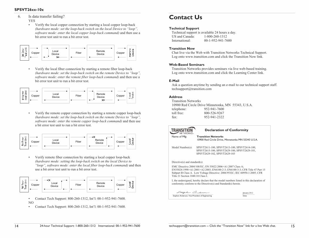
6. Is data transfer failing? YES
• Verify the local copper connection by starting a local copper loop-back
(hardware mode: set the loop-back switch on the local Device to “loop”,software mode: enter the local copper loop-back command) and then use a
bit error test unit to run a bit error test.
• Verify the local fiber connection by starting a remote fiber loop-back
(hardware mode: set the loop-back switch on the remote Device to “loop”,software mode: enter the remote fiber loop-back command) and then use a
bit error test unit to run a bit error test.
• Verify the remote copper connection by starting a remote copper loop-back
(hardware mode: set the loop-back switch on the remote Device to “loop”,software mode: enter the remote copper loop-back command) and then use
a bit error test unit to run a bit error test.
• Verify remote fiber connection by starting a local copper loop-back
(hardware mode: setting the loop-back switch on the local Device to“loop”, software mode: enter the local fiber loop-back command) and then
use a bit error test unit to run a bit error test.
• Contact Tech Support: 800-260-1312, Int’l: 00-1-952-941-7600.
NO
• Contact Tech Support: 800-260-1312, Int’l: 00-1-952-941-7600.
reppoCrebiFreppoCLocal
DeviceRemoteDevice
reppoCrebiFreppoC RemoteDevice
LocalDevice
reppoCrebiFreppoC LocalDevice
RemoteDevice
reppoCrebiFreppoC RemoteDevice
LocalDevice
Declaration of Conformity
Name of Mfg: Transition Networks 10900 Red Circle Drive, Minnetonka MN 55343 U.S.A.
Model Number(s): SPSVT2611-100, SPSVT2613-100, SPSVT2614-100,
SPSVT2615-100, SPSVT2629-100, SPSVT2629-101,
SPSVT2629-102, SPSVT2629-103
Directive(s) and standard(s):
EMC Directive 2004/108/EC; EN 55022:2006+A1:2007 Class A;
EN55024:1998+A1:2001+A2:2003; EN6100-2-3; EN6100-3-3; CFR Title 47 Part 15
Subpart B Class A. Low Voltage Directive: 2006/95/EC; IEC 60950-1:2005; CFR
Title 21 Section 1040.10 Class I.
I, the undersigned, hereby declare that the model numbers listed in this declaration of
conformity conform to the Directive(s) and Standard(s) herein.
January 2012
Stephen Anderson, Vice-President of Engineering Date
[email protected] -- Click the “Transition Now” link for a live Web chat. 15
Contact Us
Technical SupportTechnical support is available 24 hours a day.
US and Canada: 1-800-260-1312
International: 00-1-952-941-7600
Transition NowChat live via the Web with Transition Networks Technical Support.
Log onto www.transition.com and click the Transition Now link.
Web-Based SeminarsTransition Networks provides seminars via live web-based training.
Log onto www.transition.com and click the Learning Center link.
E-MailAsk a question anytime by sending an e-mail to our technical support staff.
AddressTransition Networks
10900 Red Circle Drive Minnetonka, MN 55343, U.S.A.
telephone: 952-941-7600
toll free: 800-526-9267
fax: 952-941-2322
16
Compliance InformationCISPR22/EN55022 Class A + EN55024CE MarkFCC RegulationsThis equipment has been tested and found to comply with the limits for a Class A digital device,
pursuant to part 15 of the FCC rules. These limits are designed to provide reasonable protection
against harmful interference when the equipment is operated in a commercial environment. This
equipment generates, uses, and can radiate radio frequency energy and, if not installed and used in
accordance with the instruction manual, may cause harmful interference to radio communications.
Operation of this equipment in a residential area is likely to cause harmful interference, in which
case the user will be required to correct the interference at the user's own expense.
Canadian RegulationsThis digital apparatus does not exceed the Class A limits for radio noise for digital apparatus set out
on the radio interference regulations of the Canadian Department of Communications.
Le présent appareil numérique n'émet pas de bruits radioélectriques dépassant les limites applicables
aux appareils numériques de la Class A prescrites dans le Règlement sur le brouillage
radioélectrique édicté par le ministère des Communications du Canada.
European Regulations
WarningThis is a Class A product. In a domestic environment this product may cause radio interference in
which case the user may be required to take adequate measures.
Achtung !Dieses ist ein Gerät der Funkstörgrenzwertklasse A. In Wohnbereichen können bei Betrieb dieses
Gerätes Rundfunkstörungen auftreten. In diesem Fäll ist der Benutzer für Gegenmaßnahmen
verantwortlich.
Attention !Ceci est un produit de Classe A. Dans un environment domestique, ce produit risque de créer des
interférences radioélectriques, il appartiendra alors à l'utilsateur de prende les measures spécifiques
appropriées.
Trademark NoticeAll trademarks and registered trademarks are the property of their respective owners.
Copyright Restrictions© 2003 - 2010 Transition Networks.
All rights reserved. No part of this work may be reproduced or used in any form or by any means -
graphic, electronic, or mechanical - without written permission from Transition Networks.
Printed in the U.S.A.
33236.G
CAUTION: RJ connectors are NOT INTENDED FOR CONNECTION TO THE
PUBLIC TELEPHONE NETWORK. Failure to observe this caution could result in
damage to the public telephone network.
Der Anschluss dieses Gerätes an ein öffentlickes Telekommunikationsnetz in den EG-
Mitgliedstaaten verstösst gegen die jeweligen einzelstaatlichen Gesetze zur Anwendung der
Richtlinie 91/263/EWG zur Angleichung der Rechtsvorschriften der Mitgliedstaaten über
Telekommunikationsendeinrichtungen einschliesslich der gegenseitigen Anerkennung ihrer
Konformität.
In accordance with European Union Directive 2002/96/EC of the European Parliament and
of the Council of 27 January 2003, Transition Networks will accept post usage returns of
this product for proper disposal. The contact information for this activity can be found in
the 'Contact Us' portion of this document.