User's Guide for Electronic Levels...
106
User's Guide for Electronic Levels with Translev and WinDesc Version 2.0 March 2013 Bruce L Servary, Jr. Engineering Division (ED) Center for Operational Oceanographic Products and Services (CO-OPS) National Ocean Service (NOS) National Oceanic and Atmospheric Administration (NOAA)
Transcript of User's Guide for Electronic Levels...
User's Guide for Electronic Levels
with
Translev and
WinDesc
Version 2.0 March 2013 Bruce L Servary, Jr. Engineering Division (ED) Center for Operational Oceanographic Products and Services (CO-OPS) National Ocean Service (NOS) National Oceanic and Atmospheric Administration (NOAA)

Acknowledgements
Bruce Servary would like to thank the following people for their timely and comprehensive input to this document:
Dave Hatcher Phillip Robillard Drew Maczko Clyde Kakazu Artara Johnson Chris Metzger Keith Brkich Lynn Asbeck
Thomas Landon Your comments and suggestions have been invaluable, and the high quality of this document is, in large part, thanks to you.
User's Guide for Electronic Levels With Translev and WinDesc, March 2013 Page ii
Table of Contents
1 Standards and Field Procedures ............................................ 1 1.1 Terminology .................................................................................................. 1 1.2 Use of Even Number of Setups for Multiple Rods ....................................... 1 1.3 Differences with Previous Methods .............................................................. 1 1.4 Install the Required Programs ....................................................................... 2 1.5 Create a Water Level Station Project Folder ................................................ 2 1.6 Register Your Equipment .............................................................................. 2 1.7 Internet Connection ....................................................................................... 2 1.8 WinDesc & Translev Version Control .......................................................... 2 1.9 Reference Documents ................................................................................... 3
2 Guidelines for Using the NGS Bench Mark Description Program ................................................................................. 4
2.1 The NGS DESC Program ............................................................................. 4 2.2 The NGS WinDesc Program ......................................................................... 4
2.2.1 Starting WinDesc ............................................................................................ 5 2.2.2 Update *.DAT Files ........................................................................................ 6 2.2.3 Enter/Edit Project Data .................................................................................. 8 2.2.4 Entering Descriptive Data ............................................................................ 13 2.2.5 Create *.Inx File ........................................................................................... 23 2.2.6 Exit WinDesc................................................................................................. 25
3 Procedures for Levelling with the Wild NA3000 Series .... 26 3.1 Configuration Parameters ........................................................................... 26 3.2 Battery Power Management ........................................................................ 27 3.3 Run Rod Level Bubble and Level Collimation Checks .............................. 27 3.4 Erase REC-Module ..................................................................................... 29 3.5 Enter the initial Codes ................................................................................. 29 3.6 Run the START LEVELLING program ..................................................... 31 3.7 Use the CONT(inue) LEVELLING program ............................................. 31 3.8 Special Functions ........................................................................................ 34 3.9 Potential Problems ...................................................................................... 35
4 Procedures for levelling with the Wild DNA03 series ....... 37 4.1 Navigating the DNA03 Keypad .................................................................. 37 4.2 Navigating the DNA03 Screens .................................................................. 37
4.2.1 Programs Screen .......................................................................................... 38
User's Guide for Electronic Levels With Translev and WinDesc, March 2013 Page iii
4.2.2 Menu Screen ................................................................................................. 38 4.2.3 Data Manager Screen ................................................................................... 38 4.2.4 Measure Mode Screen .................................................................................. 39 4.2.5 Functions Screen .......................................................................................... 39
4.3 Setting Configuration Parameters ............................................................... 40 4.3.1 Configure All Settings ................................................................................... 40
4.3.1.1 System Settings ............................................................................................... 40 4.3.1.2 Measuring Settings .......................................................................................... 41 4.3.1.3 Communication Settings ................................................................................. 41 4.3.1.4 Units Settings .................................................................................................. 42 4.3.1.5 Date/Time Settings .......................................................................................... 42
4.3.2 Measure Mode Settings ................................................................................. 42 4.3.3 PtID & INCREMENT Settings ...................................................................... 43
4.4 Erase Data from Memory ............................................................................ 43 4.5 Run Rod Level Bubble and Level Collimation Checks .............................. 44
4.5.1 Rod Level Bubble Check ............................................................................... 44 4.5.2 Level Collimation Check ............................................................................... 44
4.6 Levelling to Bench Marks ........................................................................... 49 4.6.1 Set/Check Instrument Tolerances ................................................................. 49 4.6.2 Set Up First Line ........................................................................................... 51 4.6.3 Enter Start of Day Codes .............................................................................. 52 4.6.4 Start Levelling ............................................................................................... 53 4.6.5 Manual Entries ............................................................................................. 59
5 Procedures for Processing Level Data with Translev ......... 61 5.1 The NGS Translev Program ........................................................................ 61 5.2 Update *.DAT Files .................................................................................... 63 5.3 Processing Level Data from the NA3000 Series Instrument ...................... 65
5.3.1 Download the Levelling Data to a PC or Diskette ....................................... 66 5.3.2 Edit The XXXXXXX.RAW File To Correct Or Remove Any Known Mistakes
...................................................................................................................... 66 5.3.3 Process the NA3000 Series Level Data ........................................................ 66
5.4 Processing Level Data from the DNA03 Series Instrument ....................... 75 5.4.1 Download the Levelling Data to a PC .......................................................... 75
5.4.1.1 Using the Data Card ........................................................................................ 75 5.4.1.2 Using the USB Cable ...................................................................................... 76
5.4.2 Process the DNA03 Level Data .................................................................... 76
Appendix A - Programs Required on Personal Computer (PC) 87
Appendix B - Program Error Message Lists ............................. 88
Appendix C - Screen Shots of WinDesc’s Data Entry Form .... 89
User's Guide for Electronic Levels With Translev and WinDesc, March 2013 Page iv

Appendix D - Guide For Inserting Photos into WinDesc ......... 92
Appendix E - DNA03 Level Procedure Reference Guide ........ 94
Appendix F - WinDesc Field Guide ......................................... 97
Appendix G - TransLev Field Guide ........................................ 98
Appendix H - Transferring NGS Data Sheets to Create a Water Level Description File......................................................... 99
Appendix I - Converting DESC generated *.HA files to WinDesc *.DES files ........................................................ 100
Appendix J – WinDesc & Translev Output Files to be Submitted to CO-OPS ........................................................................ 101
User's Guide for Electronic Levels With Translev and WinDesc, March 2013 Page v
1 Standards and Field Procedures This document provides the standards and procedures required to perform vertical control levels with the electronic digital/barcode levelling systems at water level stations that adhere to the standards set forth for all Center for Operational Oceanographic Products and Services (CO-OPS) stations. It is intended to supplement Reference 1. This document only addresses those standards and specifications that differ from conventional three wire level methods covered by Reference 1. Electronic levelling performed at water level stations shall adhere to Federal Geodetic Control Subcommittee (FGCS) Standards and Specifications. Any requirement not addressed is unchanged. 1.1 Terminology In CO-OPS, a station refers to a water level, meteorological, or currents station, but in the NGS Bluebook a station is defined as the level equipment position, level section, or the bench mark. In this document the terms setup(s) and bench mark(s) will be used instead of the NGS preferred “Station”. 1.2 Use of Even Number of Setups for Multiple Rods When two Invar rods are used, the difference of staff zero-point errors must be taken into account. The rod zero-point difference is nullified if levelling for a section between two bench marks is ended (on a bench mark) using the same rod upon which it was started. This is possible only with an even number of levelling setups between the two bench marks. Thus, if feasible, for every section between two bench marks, use the same rod on both bench marks by having an even number of levelling setups. However, if the first mark encountered in the levelling run is in close proximity to the primary sensor, the use of two setups may be impractical. 1.3 Differences with Previous Methods Field standards and procedures differ from the previous methods for the following: FGCS standards state that a minimum of 3 readings with a standard deviation equal to or less than 0.1 mm shall be taken to obtain a complete observation. If after 3 readings are taken, the standard deviation exceeds 0.1 mm, the readings shall continue to be taken until the standard deviation decreases to less than 0.1 mm, or the observation shall be repeated with a different or shorter setup. NOTE: This standard may be impossible to meet when levels are conducted on piers subject to heavy wind or wave action, or other inherently unstable platforms, that can be encountered while levelling at a water level station. Under such conditions, the following procedure shall be followed: Continue to take multiple readings as long as the standard deviation exhibits a decreasing trend. Accept the measurement when the standard deviation levels off and additional readings do not decrease it.
User's Guide for Electronic Levels With Translev and WinDesc, March 2013 Page 1

1.4 Install the Required Programs Appendix A lists the software programs that need to be installed on the personal computers of those generating description files and processing level runs. To provide consistency throughout CO-OPS, including CO-OPS IDIQ contractors, install the software in the folder C:\NGS-Apps. This will facilitate the resolution of any issues that arise regarding the correct operation of the software. Note: Google Earth does not have to be installed in this folder. 1.5 Create a Water Level Station Project Folder Create a project folder on the laptop for holding all the level files. This is the folder to navigate to when using WinDesc and Translev. The main folder should be named using the station number. Under that folder should be at least two subdirectories: One for levels, and one for photos. 1.6 Register Your Equipment For Translev to properly process the level data from your instrument and rods, they must be registered with NGS and added to the Inst.dat and Rods.dat files. To do this, submit the following information to CO-OPS through your task manager if you are a CO-OPS contractor, or directly to the Engineering Division.
Ownership: Name of Business Instrument: Make, Model, Date of Manufacture Rods: Make, Model, Lengths and Graduations (Bar-code or Optical) and both a paper copy and a digital (electronic) supplied calibration report for each rod.
The Engineering Division will forward this information to the appropriate NGS official who will verify the information and update the instrument and rod data files. 1.7 Internet Connection Both WinDesc and Translev have a variety of helpful tools that require an internet connection. Since many of the tools are graphics intensive, a high speed connection is recommended. Standard use of the programs for bench mark description and level data processing does not requires an internet connection 1.8 WinDesc & Translev Version Control This version of the manual along with screen prints is based on WinDesc version 4.17.07, and Translev version 4.17.06, which are/were the current versions available through the update function of each program when this manual was being revised. Likely by the time it is finalized there will be newer versions. Any differences in screen shots should be forwarded to the Engineering Divisions Engineering Development Branch Chief. When sufficient changes are collected, and incremental version of this document will be released. The author of these programs provides incremental program changes which can be updated without the user requiring administrative privileges on their PC. This ensures that everyone has
User's Guide for Electronic Levels With Translev and WinDesc, March 2013 Page 2

the latest version of the software. If the user has not used WinDesc or Translev for over a week, the program will prompt the user to upgrade the next time it is executed. The user needs to just choose “Yes” from the pop-up reminder window and the program will check for the latest version and download and install if a newer version is available. Otherwise, the program is updated through the WebTools drop down menu by choosing Update, then Program. 1.9 Reference Documents The following reference documents are referred to or provide supplemental information to this User’s Guide.
(1) User’s Guide for the Installation of Bench Marks and Leveling Requirements for Water Level Stations, October 1987.
(2) Input Formats and Specifications of the National Geodetic Survey Data Base (NGS Bluebook), September 1994.
(3) Leica DNA03 User Manual, Version 1.2 (4) User’s Guide for Writing Bench Mark Descriptions, Updated January 2011. (5) Attachment R, Requirements for Digital Photographs of Survey Control, NGS, January
2008. (6) The WinDesc program Help function (7) The Translev program Help function (8) Leica DNA03 Field Manual, Version 1.1
References (6) & (7), the help functions for WinDesc and Translev are indispensable in creating this document and in troubleshooting errors that may occur during leveling runs with the DNA03 equipment. They will be kept current as the programs are revised and updated, and are the “Go To” references for help in decoding any of the errors that may occur when creating description files and processing level runs.
User's Guide for Electronic Levels With Translev and WinDesc, March 2013 Page 3

2 Guidelines for Using the NGS Bench Mark Description Program
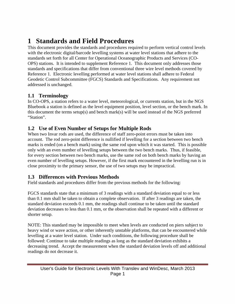
2.1 The NGS DESC Program The bench mark description program DESC.EXE is one of the suite of VFPROC programs available from NGS. NGS no longer accepts bench mark descriptions generated using this program. See the previous version of this manual: User's Guide for Electronic Levels Updated January 2003. 2.2 The NGS WinDesc Program WinDesc is the NGS approved software program for Windows-based computers for the purpose of creating, editing, and submitting recovery information for a bench marks(s). All bench mark descriptions for water level stations are required to be generated by this program. This section is a guide to the use of this software program for bench mark description management for all surveying at water level stations which follow CO-OPS standards. There are many tools available in the WinDesc program. This section will only cover what is necessary to create a description file that can be used to process levels at all CO-OPS stations. The program comes with an extensive help file (See Reference 6) which in itself is a manual on all the functions. As the user gets familiar with WinDesc, they should feel free to explore the many utilities designed to enhance creating a bench mark description file. Prior to using the WinDesc program, the Defaults.txt file should be edited. This will save some data entries in the future by entering information that is redundant each time you use WinDesc. Navigate to the WinDesc folder on your PC. Right click on the Defaults.txt file and click Edit. This will open the Defaults.txt file in Notepad, allowing you to enter data. Navigate to Agency and enter “CO-OPS”, or your agency name. Next, navigate to COP (Chief of Party) and enter your initials. Finally, navigate to Units and enter "METERS". The following screen shows the Defaults.txt with the three lines filled out.
User's Guide for Electronic Levels With Translev and WinDesc, March 2013 Page 4
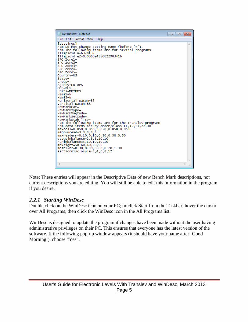
Note: These entries will appear in the Descriptive Data of new Bench Mark descriptions, not current descriptions you are editing. You will still be able to edit this information in the program if you desire. 2.2.1 Starting WinDesc Double click on the WinDesc icon on your PC; or click Start from the Taskbar, hover the cursor over All Programs, then click the WinDesc icon in the All Programs list. WinDesc is designed to update the program if changes have been made without the user having administrative privileges on their PC. This ensures that everyone has the latest version of the software. If the following pop-up window appears (it should have your name after ‘Good Morning’), choose “Yes”.
User's Guide for Electronic Levels With Translev and WinDesc, March 2013 Page 5
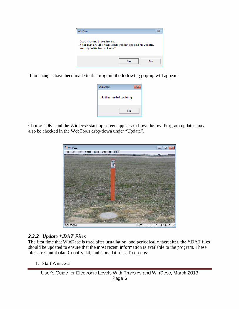
If no changes have been made to the program the following pop-up will appear:
Choose “OK” and the WinDesc start-up screen appear as shown below. Program updates may also be checked in the WebTools drop-down under “Update”.
2.2.2 Update *.DAT Files The first time that WinDesc is used after installation, and periodically thereafter, the *.DAT files should be updated to ensure that the most recent information is available to the program. These files are Contrib.dat, Country.dat, and Cors.dat files. To do this:
1. Start WinDesc
User's Guide for Electronic Levels With Translev and WinDesc, March 2013 Page 6
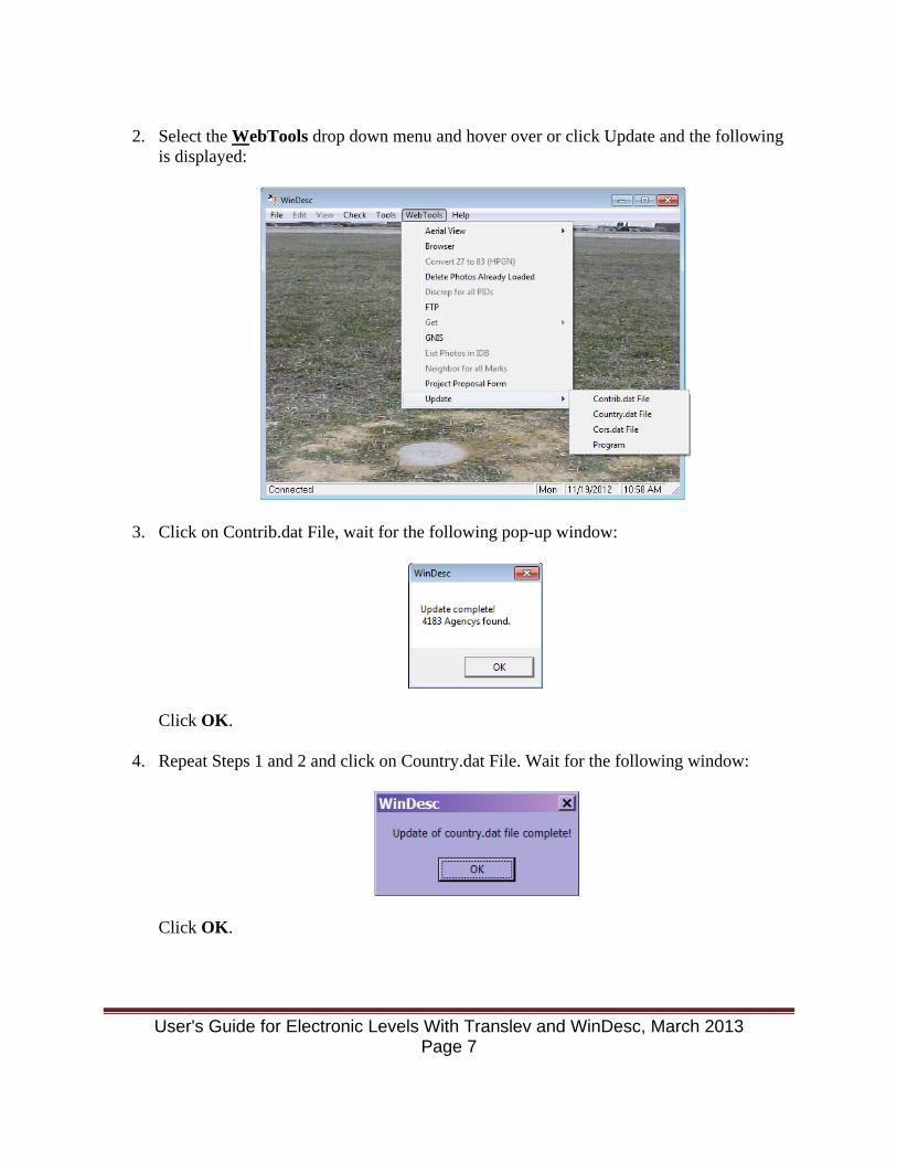
2. Select the WebTools drop down menu and hover over or click Update and the following
is displayed:
3. Click on Contrib.dat File, wait for the following pop-up window:
Click OK.
4. Repeat Steps 1 and 2 and click on Country.dat File. Wait for the following window:
Click OK.
User's Guide for Electronic Levels With Translev and WinDesc, March 2013 Page 7
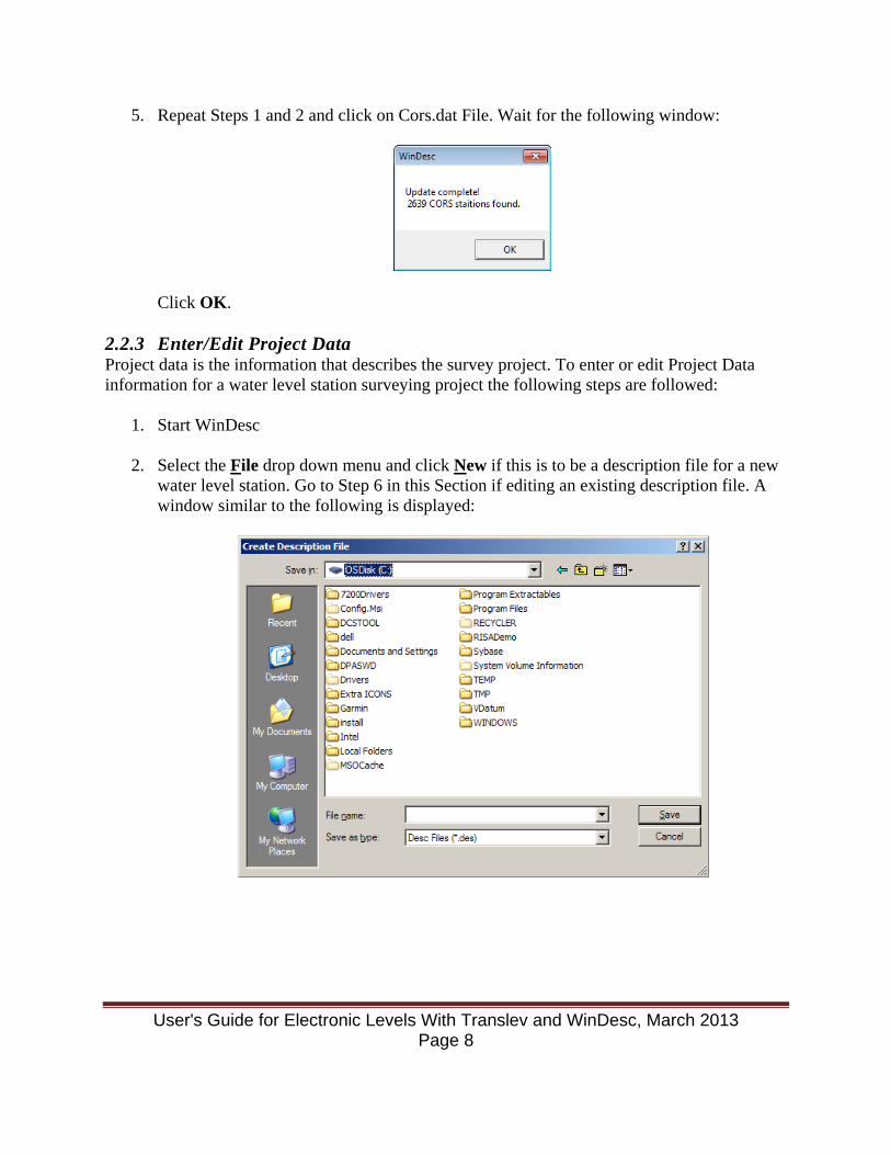
5. Repeat Steps 1 and 2 and click on Cors.dat File. Wait for the following window:
Click OK. 2.2.3 Enter/Edit Project Data Project data is the information that describes the survey project. To enter or edit Project Data information for a water level station surveying project the following steps are followed:
1. Start WinDesc
2. Select the File drop down menu and click New if this is to be a description file for a new water level station. Go to Step 6 in this Section if editing an existing description file. A window similar to the following is displayed:
User's Guide for Electronic Levels With Translev and WinDesc, March 2013 Page 8

3. Use the drop down in the Save in: field to navigate to the drive and folder where the description file is to be created. Type the file name in the File name: field and click Save. The following Data Set Information window is displayed:
For a new station all these fields will be blank. Navigation is accomplished by a mouse click in the field, the TAB key or the Enter key to the next field. The shift key is not needed as all text entries are automatically capitalized. Use the drop down lists to make choices for those fields with drop down lists. Typing is allowed in all fields, but using the drop downs ensures correct data. The fields in the above window shall be filled out as follows:
Job Code: SL for tide stations and SI for lake stations State: Choose the state abbreviation for the project location from the
drop down list Agcy Cat Code: Choose A - National Agencies Agcy symb: Choose CO-OPS (even if you’re a contractor) Agency Name: Automatically filled out based on Agcy symb selection Accession Code: Choose L
User's Guide for Electronic Levels With Translev and WinDesc, March 2013 Page 9
No.: The Line Number after the “L” (available in Project Instructions or from the annual list received by ED from NGS)
Line/Part: The Part Number (available in Project Instructions) VDatum: 00 - Unknown Code 29 - National Geodetic Vertical Datum of 1929 (NGVD29) 55 - Superseded International Great Lakes Datum of 1955 85 - International Great Lakes Datum (IGLD) of 1985 88 - North American Vertical Datum of 1988 (NAVD88) AS - American Samoa Vertical Datum of 2002 (ASVD02) GU - Guam Vertical Datum of 2004 (GUVD04) LT - Local Tidal Datum (This will always apply for sea level
stations) NM - Northern Marianas Vertical Datum of 2003 PR - Puerto Rico Vertical Datum 2002 (PRVD02) VI - Virgin Islands Vertical datum of 2009 (VIVD09)
Enter this code only if certain that a valid tie has been made to one of these datums. Leave blank or enter 00 if unknown.
C.O.P. Name: The name of the Party Chief Initials: The Party Chief’s initials Proj. Title: On the first line enter: YYYY LEVELS TO TIDE STATIONS IN <State name> (for tide stations). or YYYY LEVELS TO WATER LEVEL STATIONS ON <body
of water> (for lake stations). (where YYYY is the four digit year e.g.1999.) Press CTRL-Enter to get to second line, then add: XXX XXXX Station Name (where XXX XXXX is the 7 digit station number) Examples:
2010 LEVELS TO TIDE STATIONS IN MARYLAND 857 4680 BALTIMORE 2010 LEVELS TO WATER LEVEL STATIONS ON LAKE ERIE 906 3038 ERIE
User's Guide for Electronic Levels With Translev and WinDesc, March 2013 Page 10
Com: Enter project comments. Government contractors would enter their company name here. Use Enter to get to the second text line. Long text lines will automatically word wrap to the next line.
Photo Directory: This identifies where photos are located on the computer, and
is helpful when renaming and labelling the photos. The user may have to click on any one of the photos to have the location identified by WinDesc. Field crews should ensure this field is blank before submittal, as the folder on the crew laptop will be different than the folder on the HQ desktop. If data exists in this field, please highlight it and delete it.
Horizontal Order: & Class: Leave blank. Highlight and delete if not blank. Vertical Order: Choose 2 for 2nd order levels or 3 for 3rd order levels Class: Choose 1 for 2nd Order; leave blank for 3rd Order Latitude/Longitude Minimum/Maximum: If these fields are blank and there are bench marks with
latitudes and longitude associated with this *.des file, press compute and the fields will be automatically filled out. If this is a new station, there are no bench mark descriptions with latitude and longitude, so leave blank. After entering descriptions with valid latitudes and longitudes, edit this screen and press compute to fill these fields.
Plotting Shift (sec): Leave blank Elevation: Leave blank
4. Click OK
5. The Additional Project Data window opens:
User's Guide for Electronic Levels With Translev and WinDesc, March 2013 Page 11
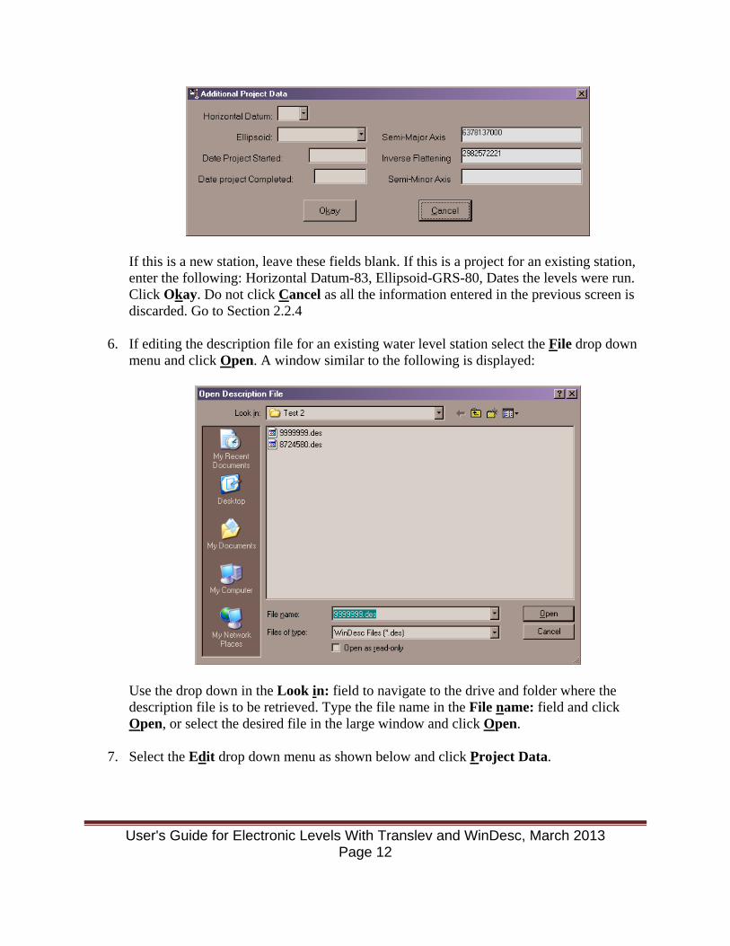
If this is a new station, leave these fields blank. If this is a project for an existing station, enter the following: Horizontal Datum-83, Ellipsoid-GRS-80, Dates the levels were run. Click Okay. Do not click Cancel as all the information entered in the previous screen is discarded. Go to Section 2.2.4
6. If editing the description file for an existing water level station select the File drop down
menu and click Open. A window similar to the following is displayed:
Use the drop down in the Look in: field to navigate to the drive and folder where the description file is to be retrieved. Type the file name in the File name: field and click Open, or select the desired file in the large window and click Open.
7. Select the Edit drop down menu as shown below and click Project Data.
User's Guide for Electronic Levels With Translev and WinDesc, March 2013 Page 12

The Data Set Information window described in Step 3 of this Section is displayed.
8. Many of the fields in the Data Set Information window will be filled out. Correct those entries that are applicable for the current survey project following the format detailed in Step 3 above.
9. Repeat Steps 4 and 5. 2.2.4 Entering Descriptive Data Descriptive Data is the specific information that fully describes a bench mark. This includes location, type of bench mark, and “How To Reach” directions. This section covers entering bench mark descriptive data for each bench mark installed and levelled during a water level station installation.
1. Start WinDesc and open the description file as in Step 6 in Section 2.2.3 if not still open from entering Project Data.
2. Select the Edit drop down menu and click Descriptive Data.
User's Guide for Electronic Levels With Translev and WinDesc, March 2013 Page 13
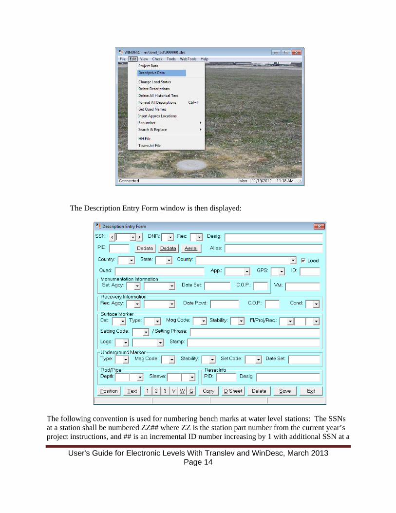
The Description Entry Form window is then displayed:
The following convention is used for numbering bench marks at water level stations: The SSNs at a station shall be numbered ZZ## where ZZ is the station part number from the current year’s project instructions, and ## is an incremental ID number increasing by 1 with additional SSN at a
User's Guide for Electronic Levels With Translev and WinDesc, March 2013 Page 14
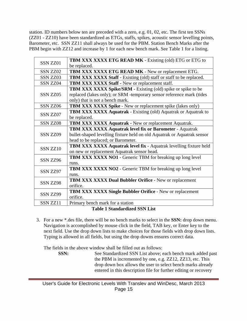
station. ID numbers below ten are preceded with a zero, e.g. 01, 02, etc. The first ten SSNs (ZZ01 - ZZ10) have been standardized as ETGs, staffs, spikes, acoustic sensor levelling points, Barometer, etc. SSN ZZ11 shall always be used for the PBM. Station Bench Marks after the PBM begin with ZZ12 and increase by 1 for each new bench mark. See Table 1 for a listing.
SSN ZZ01 TBM XXX XXXX ETG READ MK - Existing (old) ETG or ETG to be replaced.
SSN ZZ02 TBM XXX XXXX ETG READ MK - New or replacement ETG. SSN ZZ03 TBM XXX XXXX Staff - Existing (old) staff or staff to be replaced. SSN ZZ04 TBM XXX XXXX Staff - New or replacement staff.
SSN ZZ05 TBM XXX XXXX Spike/SRM - Existing (old) spike or spike to be replaced (lakes only); or SRM -temporary sensor reference mark (tides only) that is not a bench mark.
SSN ZZ06 TBM XXX XXXX Spike - New or replacement spike (lakes only)
SSN ZZ07 TBM XXX XXXX Aquatrak - Existing (old) Aquatrak or Aquatrak to be replaced.
SSN ZZ08 TBM XXX XXXX Aquatrak - New or replacement Aquatrak.
SSN ZZ09 TBM XXX XXXX Aquatrak level fix or Barometer - Aquatrak bullet-shaped levelling fixture held on old Aquatrak or Aquatrak sensor head to be replaced; or Barometer.
SSN ZZ10 TBM XXX XXXX Aquatrak level fix - Aquatrak levelling fixture held on new or replacement Aquatrak sensor head.
SSN ZZ96 TBM XXX XXXX NO1 - Generic TBM for breaking up long level runs.
SSN ZZ97 TBM XXX XXXX NO2 - Generic TBM for breaking up long level runs.
SSN ZZ98 TBM XXX XXXX Dual Bubbler Orifice - New or replacement orifice.
SSN ZZ99 TBM XXX XXXX Single Bubbler Orifice - New or replacement orifice.
SSN ZZ11 Primary bench mark for a station Table 1 Standardized SSN List
3. For a new *.des file, there will be no bench marks to select in the SSN: drop down menu.
Navigation is accomplished by mouse click in the field, TAB key, or Enter key to the next field. Use the drop down lists to make choices for those fields with drop down lists. Typing is allowed in all fields, but using the drop downs ensures correct data. The fields in the above window shall be filled out as follows:
SSN: See Standardized SSN List above; each bench mark added past the PBM is incremented by one, e.g. ZZ12, ZZ13, etc. This drop down box allows the user to select bench marks already entered in this description file for further editing or recovery
User's Guide for Electronic Levels With Translev and WinDesc, March 2013 Page 15
notation. Conversely, the < and > boxes on either side of the drop down box will save the current description and move to the previous or next description, respectively.
DNR: D for new bench mark information, N for bench marks with a
PID# not recovered, or R for bench mark recovery.Instead of N for bench marks without a PID#, enter 'R’ in DNR, ‘F' in Rec:, and in the Text enter 'FOUND DESTROYED' or 'NOT RECOVERED' with Cond: of 'O' See Appendix C for screen shots of the Description Entry Form as it changes based on which DNR code is selected.
Rec: F - Select this option when submitting a full description for a
bench mark not in the NGS database (no PID# - see PID field below).
M - Select this option when a survey point is already in the NGS database and has been recovered as described (no changes to descriptive fields or text).
T - Select this option when a survey point already in the NGS database requires changes to the descriptive fields or text.
See Appendix C for screen shots of the Description Entry Form as it changes based on which DNR code is selected.
Desig: Enter the bench mark designation. For a new mark, this will be
the station number plus the letter from the stamping, for example: 999 9999 A. Do not change a designation already assigned by NGS.
PID: The NGS PID (not the OPUS DB PID) for the bench mark.
There will be no PID for a new mark.
This button imports the description and data for a bench mark from a DSDATA sheet file.
This button imports the description and data for a bench mark
directly from the NGS website. This function requires that a PID, or the State and County, be filled out in the Description Entry Form window.
This button views the bench mark location in Google Earth.
This function requires that the position be filled out in the Description Entry Form window.
Aerial
Dsdata
Dsdata
User's Guide for Electronic Levels With Translev and WinDesc, March 2013 Page 16
Alias: This field is used when a bench mark is stamped and designated with one name but commonly or locally known by another name. Fill in this field only if necessary for improved identification of the bench mark.
Country: The Country where the bench mark is located. Use drop down
list to choose the country. State: The State where the bench mark is located. Use drop down list
to choose the state. County: The County where the bench mark is located. The drop down
list is populated with the counties available for the state chosen in State: Use this list to choose the county.
Load Uncheck this field. For use when data is to be submitted to
NGS. This will only be done when a two mark tie has been verified by field or HQ personnel.
Quad: Leave blank. Quad is filled in after entering horizontal
position. App: Enter T for all non-Great Lakes stations. Enter W for Great
Lakes stations. GPS: Use the drop down list to choose Y - yes, mark is suitable for
GPS use; N - no, mark is not suitable for GPS use, or - unknown GPS usage for mark
ID: Leave blank
VMNum: Enter the CO-OPS vertical mark number as given on the
published bench mark sheet, or from the CO-OPS Data
Monumentation Information Set. Agcy: The agency that set the bench mark, if known. If there is an
agency name cast in the bench mark, use that for setting agency. This field has a drop down list which should have most setting agencies possible.
Date Set: The date the bench mark was set, if known. The current date is
already displayed. Change if mark set on a different date, or clear this field if the date is unknown.
C.O.P.: The Party Chief’s initials, if known.
User's Guide for Electronic Levels With Translev and WinDesc, March 2013 Page 17
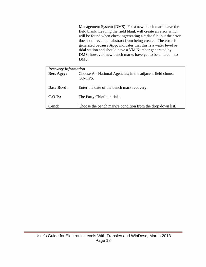
Management System (DMS). For a new bench mark leave the field blank. Leaving the field blank will create an error which will be found when checking/creating a *.dsc file, but the error does not prevent an abstract from being created. The error is generated because App: indicates that this is a water level or tidal station and should have a VM Number generated by DMS; however, new bench marks have yet to be entered into DMS.
Recovery Information Rec. Agcy: Choose A - National Agencies; in the adjacent field choose
CO-OPS. Date Rcvd: Enter the date of the bench mark recovery. C.O.P.: The Party Chief’s initials. Cond: Choose the bench mark’s condition from the drop down list.
User's Guide for Electronic Levels With Translev and WinDesc, March 2013 Page 18
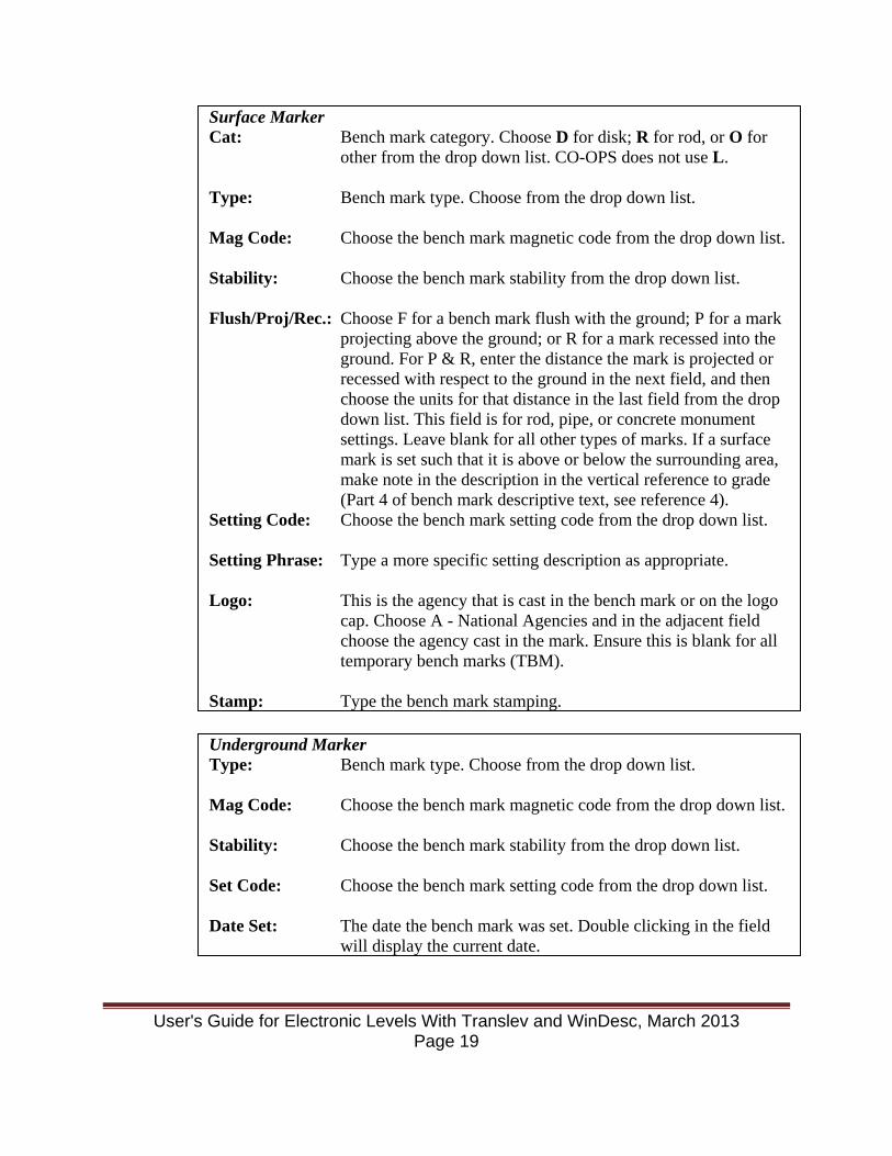
Surface Marker Cat: Bench mark category. Choose D for disk; R for rod, or O for
other from the drop down list. CO-OPS does not use L. Type: Bench mark type. Choose from the drop down list. Mag Code: Choose the bench mark magnetic code from the drop down list. Stability: Choose the bench mark stability from the drop down list. Flush/Proj/Rec.: Choose F for a bench mark flush with the ground; P for a mark
projecting above the ground; or R for a mark recessed into the ground. For P & R, enter the distance the mark is projected or recessed with respect to the ground in the next field, and then choose the units for that distance in the last field from the drop down list. This field is for rod, pipe, or concrete monument settings. Leave blank for all other types of marks. If a surface mark is set such that it is above or below the surrounding area, make note in the description in the vertical reference to grade (Part 4 of bench mark descriptive text, see reference 4).
Setting Code: Choose the bench mark setting code from the drop down list. Setting Phrase: Type a more specific setting description as appropriate. Logo: This is the agency that is cast in the bench mark or on the logo
cap. Choose A - National Agencies and in the adjacent field choose the agency cast in the mark. Ensure this is blank for all temporary bench marks (TBM).
Stamp: Type the bench mark stamping.
Underground Marker Type: Bench mark type. Choose from the drop down list. Mag Code: Choose the bench mark magnetic code from the drop down list. Stability: Choose the bench mark stability from the drop down list. Set Code: Choose the bench mark setting code from the drop down list. Date Set: The date the bench mark was set. Double clicking in the field
will display the current date.
User's Guide for Electronic Levels With Translev and WinDesc, March 2013 Page 19

This button opens the Positional Data Window similar to the figure below.
Enter latitude and longitude information in the Horizontal Data window to the tenth of a second from a handheld GPS. Handheld GPS units come with either patch antennas or quadrifilar antennas. The proper method for holding the GPS unit is vertically if the unit has a quadrifilar antenna, or horizontally if the unit has a patch antenna. Holding the unit otherwise will degrade the reception of the satellite signals and reduce the accuracy of the position obtained. The Garmin GPSmap 76S units used by CO-OPS have quadrifilar antennas. The latitude format is DDMMSS.s in the first field and N/S in the second field. The longitude format is DDDMMSS.s in the first field and W/E in the second field. Newer handheld GPS units may get positions to the hundredth of a second. If the
Rod/Pipe Depth: The depth the rod or pipe has been driven in tenths of meters. Sleeve: The length of the greased sleeve of a 3D mark in tenths of
meters.
Reset Info PID: The NGS PID (not OPUS DB PID) for the bench mark. Desig: The new designation of the reset bench mark.
Position
User's Guide for Electronic Levels With Translev and WinDesc, March 2013 Page 20

hand held GPS unit being used allows this, enter the positions in hundredths of a second, e.g. DDMMSS.ss. Always select O-Other from the Source: drop down list. The DATUM field should be entered as “83” (otherwise a message will appear requesting an entry. An entry for the datum is always needed.) The ORDER field should be “4 (fourth order)”. Technique should be “W” for hand-held GPS positions, and “X” for static GPS positions. Click Close.
This button opens the Descriptive Text window. A window
similar to the following is displayed:
There are two tabs to this window – Historical Descriptive Text and New Descriptive Text. If text has been imported from a DSDATA sheet or from NGS via the internet, there will be historical text. For a new bench mark both will be blank. Enter the bench mark description as detailed in Reference 4. Before leaving this window it is good practice to format and spell check the text. These are performed by pressing the buttons at the bottom of the Descriptive Text window.
These buttons allow pictures of the bench mark to be selected,
labelled, and viewed using the photo directory entered in the
Text
1 2 3 V W G
User's Guide for Electronic Levels With Translev and WinDesc, March 2013 Page 21
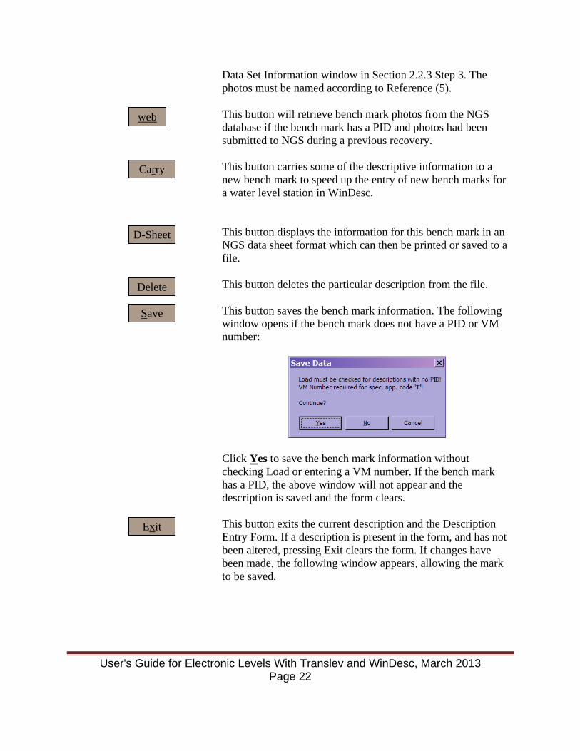
Data Set Information window in Section 2.2.3 Step 3. The photos must be named according to Reference (5).
This button will retrieve bench mark photos from the NGS
database if the bench mark has a PID and photos had been submitted to NGS during a previous recovery.
This button carries some of the descriptive information to a
new bench mark to speed up the entry of new bench marks for a water level station in WinDesc.
This button displays the information for this bench mark in an
NGS data sheet format which can then be printed or saved to a file.
This button deletes the particular description from the file. This button saves the bench mark information. The following
window opens if the bench mark does not have a PID or VM number:
Click Yes to save the bench mark information without checking Load or entering a VM number. If the bench mark has a PID, the above window will not appear and the description is saved and the form clears.
This button exits the current description and the Description Entry Form. If a description is present in the form, and has not been altered, pressing Exit clears the form. If changes have been made, the following window appears, allowing the mark to be saved.
web
Carry
D-Sheet
Delete
Save
Exit
User's Guide for Electronic Levels With Translev and WinDesc, March 2013 Page 22

Follow the Save button procedures above to save the changes or click No to exit without saving. If the form is empty, clicking Exit closes the Description Entry Form and returns to the main WinDesc window.
4. There are also some helpful function keys available during the entry of the bench mark information in this window. The following function keys are available once data has been entered in the SSN: and D/R: fields for a new mark or a previously described mark that has been selected from the SSN: list.
F1 The F1 key opens the WinDesc help file. The help file is comprehensive and provides greater detail for many of the items discussed in this manual.
F4 The F4 key will show the Err file generated after the *.dsc has
been created. This eases making corrections to the bench mark description
F5 Once the position has been entered for a mark, this function
will display the neighboring bench marks found in the NGS database. This function requires an internet connection.
F6 This function displays the discrepancies between the *.des file
being worked on and the NGS database for bench marks with a PID#. This uses the latest saved copy of the *.des file so if changes have been made to the bench mark description, they must be saved to be used in this discrepancy check.
F7 Produces the same output as F6, but in a table format. F10 This function displays the sections of the Description Entry
Form that disappear when the D/R: and RecCode: codes are entered.
2.2.5 Create *.Inx File After entering and recovering all the bench marks at a water level station, generate a *.inx file. This is done by:
User's Guide for Electronic Levels With Translev and WinDesc, March 2013 Page 23
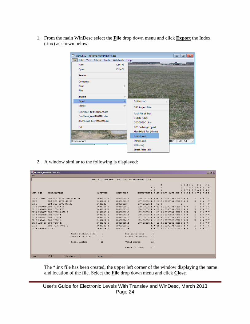
1. From the main WinDesc select the File drop down menu and click Export the Index
(.inx) as shown below:
2. A window similar to the following is displayed:
The *.inx file has been created, the upper left corner of the window displaying the name and location of the file. Select the File drop down menu and click Close.
User's Guide for Electronic Levels With Translev and WinDesc, March 2013 Page 24
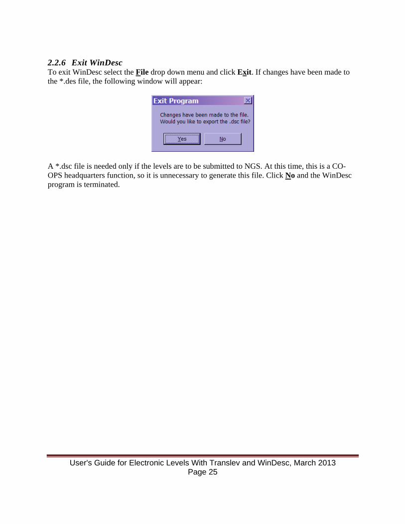
2.2.6 Exit WinDesc To exit WinDesc select the File drop down menu and click Exit. If changes have been made to the *.des file, the following window will appear:
A *.dsc file is needed only if the levels are to be submitted to NGS. At this time, this is a CO-OPS headquarters function, so it is unnecessary to generate this file. Click No and the WinDesc program is terminated.
User's Guide for Electronic Levels With Translev and WinDesc, March 2013 Page 25
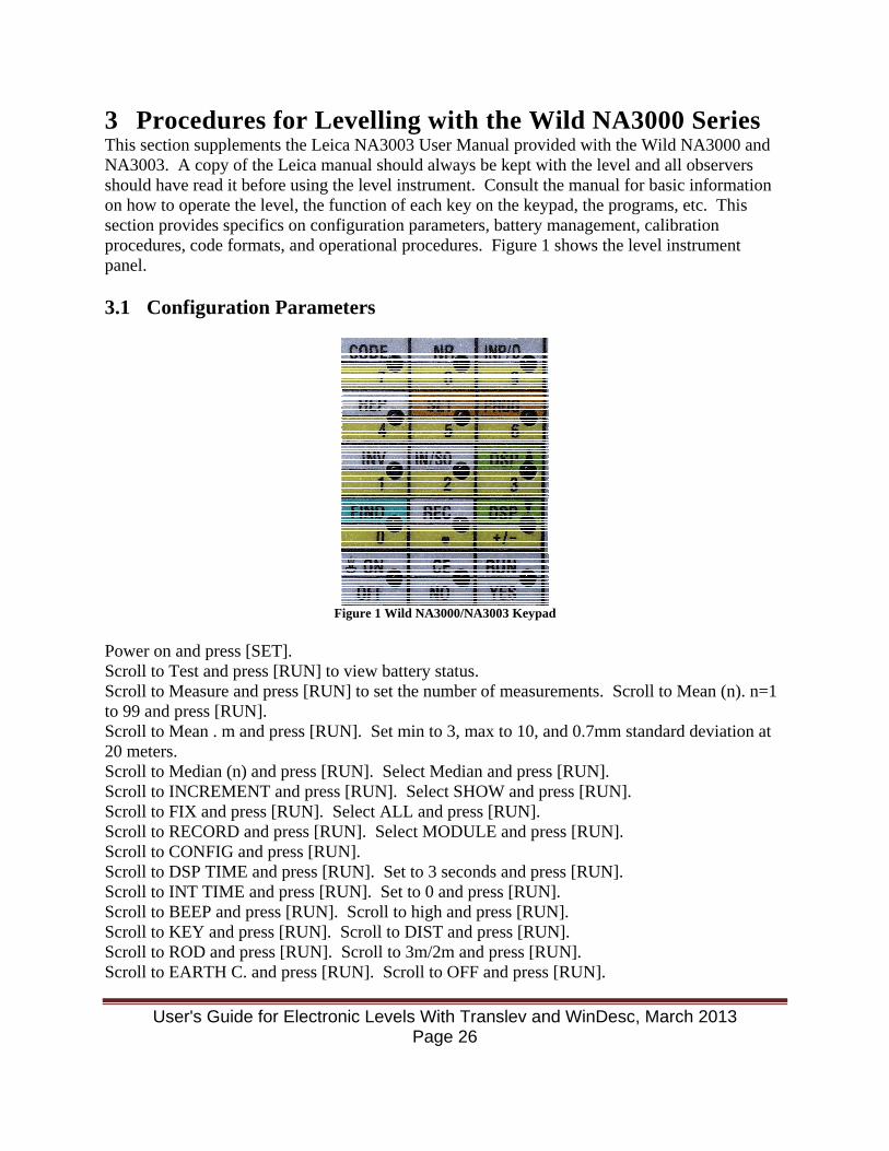
3 Procedures for Levelling with the Wild NA3000 Series This section supplements the Leica NA3003 User Manual provided with the Wild NA3000 and NA3003. A copy of the Leica manual should always be kept with the level and all observers should have read it before using the level instrument. Consult the manual for basic information on how to operate the level, the function of each key on the keypad, the programs, etc. This section provides specifics on configuration parameters, battery management, calibration procedures, code formats, and operational procedures. Figure 1 shows the level instrument panel. 3.1 Configuration Parameters
Figure 1 Wild NA3000/NA3003 Keypad
Power on and press [SET]. Scroll to Test and press [RUN] to view battery status. Scroll to Measure and press [RUN] to set the number of measurements. Scroll to Mean (n). n=1 to 99 and press [RUN]. Scroll to Mean . m and press [RUN]. Set min to 3, max to 10, and 0.7mm standard deviation at 20 meters. Scroll to Median (n) and press [RUN]. Select Median and press [RUN]. Scroll to INCREMENT and press [RUN]. Select SHOW and press [RUN]. Scroll to FIX and press [RUN]. Select ALL and press [RUN]. Scroll to RECORD and press [RUN]. Select MODULE and press [RUN]. Scroll to CONFIG and press [RUN]. Scroll to DSP TIME and press [RUN]. Set to 3 seconds and press [RUN]. Scroll to INT TIME and press [RUN]. Set to 0 and press [RUN]. Scroll to BEEP and press [RUN]. Scroll to high and press [RUN]. Scroll to KEY and press [RUN]. Scroll to DIST and press [RUN]. Scroll to ROD and press [RUN]. Scroll to 3m/2m and press [RUN]. Scroll to EARTH C. and press [RUN]. Scroll to OFF and press [RUN].
User's Guide for Electronic Levels With Translev and WinDesc, March 2013 Page 26

Scroll to ACCURACY and press [RUN]. Scroll to standard and press [RUN]. Scroll to TOL and press [RUN]. Scroll to Input dist. tol and press [RUN]. Key in 5.0 m and press [RUN]. Key in 0.3 station tolerance and press [RUN]. Scroll to AUTO OFF and press [RUN]. Scroll to 5 minutes and press [RUN]. Scroll to UNIT and press [RUN]. Scroll to m and press [RUN]. 3.2 Battery Power Management Two rechargeable batteries and a charger have been provided with each level. Battery instructions are covered in section 14 of the Leica NA3003 User Manual. The most important thing to remember is: Run the batteries down as low as possible before recharging or always discharge first when using the Intelligent charger. These batteries can develop a "memory" if proper recharging procedures are not followed. A sign that this is happening is if the batteries will no longer attain the maximum charge levels (8-9). If this starts to happen, discharge the battery(s) all the way down to 0, and then put on a full 14 hour recharge. This may have to be repeated several times. The best way to discharge the batteries is to disable the AUTO-OFF parameter (see previous section) and leave the level turned on with the backlight activated (Leica manual Section 3.1.2). Do not forget to re-enable the AUTO-OFF parameter to 5 min before placing the level back into service. An intelligent charger is also available (GKL23) that will automatically first discharge the battery and then fully charge it. Consult the Leica GKL23/GKL23-1 User Manual for further information on operating the charger. Note that the GKL23 will not work with the batteries originally supplied with the NA3000 level, but it will work with NA 3003 levels. 3.3 Run Rod Level Bubble and Level Collimation Checks Check all rod level bubbles with the level instrument to ensure vertical accuracy and adjust if necessary:
• Level the instrument and have the rod person set up a rod on a stable highpoint where the majority of the rod can be seen when looking through the instrument.
• First, have the rod person set up the rod facing the level, and ensure the rod's level bubble is centered by adjusting the rod's struts. Using the level's vertical cross-hair as a reference, turn the level so that the cross-hair is parallel to a vertical surface on the rod, such as the outside edge of the rod. If the rod surface is not parallel to the level's cross-hair, the rod needs to be adjusted. Instruct the rod person to adjust the rod, using the struts, until the rod is parallel to the level's cross-hair. If the bubble is touching, or out of, the centering circle it must be adjusted. The rod person will then adjust the rod's level bubble so that the bubble is again centered using the following procedure.
• Next, have the rod person hold the staff sideways to the level. Using the level's vertical cross-hair as a reference, instruct the rod person to hold the rod perfectly vertical. If the bubble is touching, or out of, the centering circle it must be adjusted.
User's Guide for Electronic Levels With Translev and WinDesc, March 2013 Page 27

• Repeat the above procedure until the rod is plumb in both directions and further rod adjustment is not required.
To adjust the circular level bubble: If the circular level bubble of the level equipment needs adjustment, first secure the rod using struts. Then with a plumb bob, check the verticality of the rod from two observation directions at right angles to one another. Then use the three adjustment screws beneath the circular level to bring the bubble into the middle. Make sure the bubble stays in the middle, when the rod is turned at two different directions at right angles to each other. The level shall have a collimation check performed:
• at the start of each day's levelling; • at the start of each new station level run; • or any time the level is subjected to substantial shock, vibration, etc.
When bringing the level out into a significantly different thermal environment, allow at least a half-hour for adjustment to ambient temperature, as a sudden thermal change can affect the collimation check. Instructions on performing the collimation check are contained in the Leica NA3003 User Manual Section 7.1. The level has a self-contained program that will automatically compute the error and expects a specific collimation method be used. Lay out a course following the 1/3-2/3 (15 m - 30 m) course illustrated in the Leica NA3003 User Manual. Using the COLLIM option of the CONFIG submenu as shown on page 12, the operator should first confirm that the absolute collimation error (absColl) presently stored in the instrument is 0.0". If not, note the displayed value, and inform OET prior to next use. The instrument should be returned to Leica for adjustment of the stored collimation error. Next, run the collimation check following the instructions contained in the manual and the prompts provided by the level’s A X X B collimation program. When the last reading has been taken, the instrument will ask whether or not to compute a new collimation error (compute Coll?). Answer yes and record the value (CollDif). This value is required later on when entering code information into the level. A value less than or equal to +/- 10.0 seconds meets the standard while any value larger than +/- 10.0 seconds exceeds it. The program will then ask if you wish to store the new value (store newColl?). ALWAYS ANSWER NO! If you mistakenly answer yes, make a note and inform OET. The stored collimation error should always be 0.0.
User's Guide for Electronic Levels With Translev and WinDesc, March 2013 Page 28

If the collimation check fails, rerun it for verification. First, double-check the course setup for proper layout. If the instrument was recently brought out from a much different thermal environment, give it additional time to adjust to the ambient temperature. If the level continues to fail the collimation check, record the last value determined, continue on with the levels, and notify OET. There is no way to adjust the level in the field, it must be returned to Leica for adjustment. 3.4 Erase REC-Module Instructions on how to use the ERASE DATA program to erase the REC-Module are contained in the Leica NA3003 User Manual Section 7.3. The password is 951. The REC-Module is the levelling data storage media used by the instrument. In general, the REC-Module should be erased before starting to perform the levels, assuming any existing data has already been downloaded and saved on floppy diskette(s). If this step is omitted, the new data will be appended to the end of the existing data file, and will be downloaded as one file. The file will then have to be edited to remove the previously existing data. If levels at a station are performed over several days, it is permissible not to erase the REC-Module each day and allow new data to append onto the REC-Module. Alternatively, if substantial editing is required to correct the file downloaded from the first day’s levelling, it may be desirable to copy the files onto a laptop and then erase the REC-Module before continuing the levels. Later you can merge the downloaded files together. 3.5 Enter the initial Codes Prior to running the START LEVELLING program, it is necessary to enter several data code blocks that contain various types of information. Instructions on entering data codes are in the Leica NA3003 User Manual Section 8.5, or on the laminated card that can be made in-house from Table 2 below for the levelling operations. Code definitions are summarized in Table 2. The codes have been changed from what was used when processing the level data with PROC-GIF. Translev uses the same code numbers, but with different information entered for each code. Be mindful of the differences for processing NA3003 survey data with Translev.
User's Guide for Electronic Levels With Translev and WinDesc, March 2013 Page 29
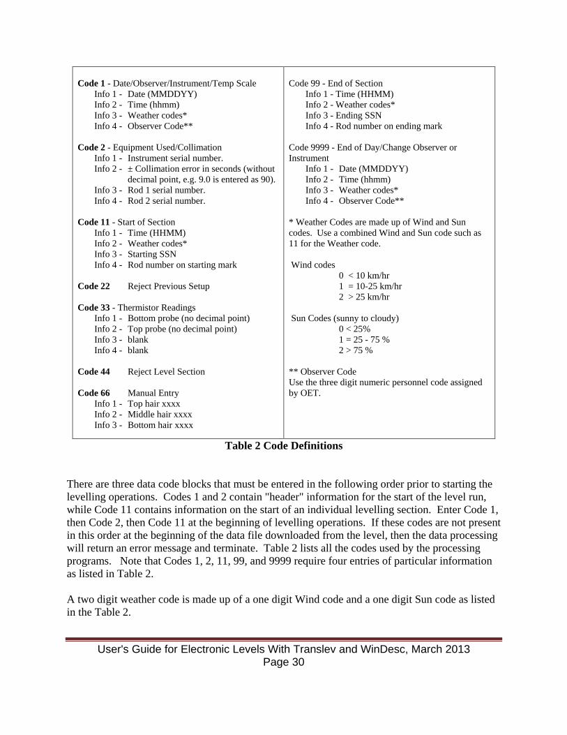
Code 1 - Date/Observer/Instrument/Temp Scale
Info 1 - Date (MMDDYY) Info 2 - Time (hhmm) Info 3 - Weather codes* Info 4 - Observer Code**
Code 2 - Equipment Used/Collimation
Info 1 - Instrument serial number. Info 2 - ± Collimation error in seconds (without
decimal point, e.g. 9.0 is entered as 90). Info 3 - Rod 1 serial number. Info 4 - Rod 2 serial number.
Code 11 - Start of Section
Info 1 - Time (HHMM) Info 2 - Weather codes* Info 3 - Starting SSN Info 4 - Rod number on starting mark
Code 22 Reject Previous Setup Code 33 - Thermistor Readings
Info 1 - Bottom probe (no decimal point) Info 2 - Top probe (no decimal point) Info 3 - blank Info 4 - blank
Code 44 Reject Level Section Code 66 Manual Entry
Info 1 - Top hair xxxx Info 2 - Middle hair xxxx Info 3 - Bottom hair xxxx
Code 99 - End of Section
Info 1 - Time (HHMM) Info 2 - Weather codes* Info 3 - Ending SSN Info 4 - Rod number on ending mark
Code 9999 - End of Day/Change Observer or Instrument
Info 1 - Date (MMDDYY) Info 2 - Time (hhmm) Info 3 - Weather codes* Info 4 - Observer Code**
* Weather Codes are made up of Wind and Sun codes. Use a combined Wind and Sun code such as 11 for the Weather code. Wind codes
0 < 10 km/hr 1 = 10-25 km/hr 2 > 25 km/hr
Sun Codes (sunny to cloudy)
0 < 25% 1 = 25 - 75 % 2 > 75 %
** Observer Code Use the three digit numeric personnel code assigned by OET.
Table 2 Code Definitions There are three data code blocks that must be entered in the following order prior to starting the levelling operations. Codes 1 and 2 contain "header" information for the start of the level run, while Code 11 contains information on the start of an individual levelling section. Enter Code 1, then Code 2, then Code 11 at the beginning of levelling operations. If these codes are not present in this order at the beginning of the data file downloaded from the level, then the data processing will return an error message and terminate. Table 2 lists all the codes used by the processing programs. Note that Codes 1, 2, 11, 99, and 9999 require four entries of particular information as listed in Table 2. A two digit weather code is made up of a one digit Wind code and a one digit Sun code as listed in the Table 2.
User's Guide for Electronic Levels With Translev and WinDesc, March 2013 Page 30
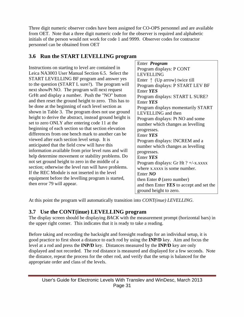
Three digit numeric observer codes have been assigned for CO-OPS personnel and are available from OET. Note that a three digit numeric code for the observer is required and alphabetic initials of the person would not work for code 1 and 9999. Observer codes for contractor personnel can be obtained from OET 3.6 Run the START LEVELLING program Instructions on starting to level are contained in Leica NA3003 User Manual Section 6.5. Select the START LEVELLING BF program and answer yes to the question (START L sure?). The program will next showPt NO. The program will next request GrHt and display a number. Push the "NO" button and then reset the ground height to zero. This has to be done at the beginning of each level section as shown in Table 3. The program does not use ground height to derive the abstract, instead ground height is set to zero ONLY after entering code 11 at the beginning of each section so that section elevation differences from one bench mark to another can be viewed after each section level setup. It is anticipated that the field crew will have this information available from prior level runs and will help determine movement or stability problems. Do not set ground height to zero in the middle of a section; otherwise the level run will have problems. If the REC Module is not inserted in the level equipment before the levelling program is started, then error 79 will appear. At this point the program will automatically transition into CONT(inue) LEVELLING. 3.7 Use the CONT(inue) LEVELLING program The display screen should be displaying BACK with the measurement prompt (horizontal bars) in the upper right corner. This indicates that it is ready to take a reading. Before taking and recording the backsight and foresight readings for an individual setup, it is good practice to first shoot a distance to each rod by using the INP/D key. Aim and focus the level at a rod and press the INP/D key. Distances measured by the INP/D key are only displayed and not recorded. The rod distance is measured and displayed for a few seconds. Note the distance, repeat the process for the other rod, and verify that the setup is balanced for the appropriate order and class of the levels.
Enter Program Program displays: P CONT LEVELLING Enter ↑ (Up arrow) twice till Program displays: P START LEV BF Enter YES Program displays: START L SURE? Enter YES Program displays momentarily START LEVELLING and then Program displays: Pt NO and some number which changes as levelling progresses. Enter YES Program displays: INCREM and a number which changes as levelling progresses. Enter YES Program displays: Gr Ht ? +/-x.xxxx where x.xxxx is some number. Enter NO then Enter 0 (zero number) and then Enter YES to accept and set the ground height to zero.
User's Guide for Electronic Levels With Translev and WinDesc, March 2013 Page 31

NOTE: The instrument does not check the setup balance against the allowable during the actual level run. If the setup is unbalanced, an error message will be generated later when the data is being processed. Another good reason to first measure both rod distances is that it verifies that the level can read the rods. Sometimes obstructions, shadows, glare, etc. can prevent the level from locking in on a rod that at first glance appears to be readily visible. Spotting and resolving any sighting problems before recording a backsight can save time. For very short distance setups, verify that the total distance is greater than 5 meters. Although the level will successfully record setups less than 5 meters apart, they are not allowed by NGS, and the processing software will return an error message. The key phrase here is “total distance”, which is the sum of the backsight (BS) and foresight (FS). For situations where the BS (or FS) is less than 2.5 m, unbalance the FS (or BS whichever is appropriate) so as to take the reading. The unbalanced BS/FS is allowed in this special situation. To compensate for the unbalanced BS/FS setup, on the next setup adjust the FS/BS distance such that the total of all backsights and the total of all foresights shall be within tolerance. There are two knobs on the right side of the level when pointing at the rod that are used for focusing and positioning the reticule on the barcoded rods. The larger knob zooms in or out and brings the barcoded rod readings in focus, whereas the smaller knob provides micrometer adjustment for centering the reticule on the rod either from the left or right. Always center the reticule vertically on the rod before taking a reading. Also, the equipment must be level, i.e. the bubble must be in the center before taking any reading. Generally, make sure the level bubble stays in center at two directions 90° apart. A good way to start centering the level bubble is to turn the level first perpendicular to the direction of levelling and center the bubble; then rotate the level and point it to BS/FS and make sure the bubble stays in the center. Then check the BS/FS distances by hitting INP/D key. The backsight or foresight measurement is taken by aiming and focusing the level on a rod and pushing the red measurement button on the right side of the level. A series of arrows (>>>>) are shown on the screen as the level locks in on the rod and determines a measurement. This typically takes about 4 seconds, but can take longer if the level is having trouble reading the rod for some reason.
User's Guide for Electronic Levels With Translev and WinDesc, March 2013 Page 32
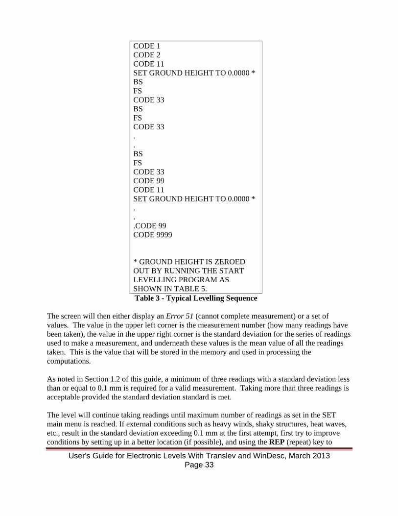
CODE 1 CODE 2 CODE 11 SET GROUND HEIGHT TO 0.0000 * BS FS CODE 33 BS FS CODE 33 . . BS FS CODE 33 CODE 99 CODE 11 SET GROUND HEIGHT TO 0.0000 * . . .CODE 99 CODE 9999 * GROUND HEIGHT IS ZEROED OUT BY RUNNING THE START LEVELLING PROGRAM AS SHOWN IN TABLE 5. Table 3 - Typical Levelling Sequence
The screen will then either display an Error 51 (cannot complete measurement) or a set of values. The value in the upper left corner is the measurement number (how many readings have been taken), the value in the upper right corner is the standard deviation for the series of readings used to make a measurement, and underneath these values is the mean value of all the readings taken. This is the value that will be stored in the memory and used in processing the computations. As noted in Section 1.2 of this guide, a minimum of three readings with a standard deviation less than or equal to 0.1 mm is required for a valid measurement. Taking more than three readings is acceptable provided the standard deviation standard is met. The level will continue taking readings until maximum number of readings as set in the SET main menu is reached. If external conditions such as heavy winds, shaky structures, heat waves, etc., result in the standard deviation exceeding 0.1 mm at the first attempt, first try to improve conditions by setting up in a better location (if possible), and using the REP (repeat) key to
User's Guide for Electronic Levels With Translev and WinDesc, March 2013 Page 33
repeat the measurement, or at a better time of the day (if possible). If this is not possible, or the readings again exceed the 0.1 mm standard, continue to take multiple readings and watch the standard deviation trend. If additional readings result in the standard deviation exhibiting a decreasing trend, continue the readings until the 0.1 mm limit is met, or until the standard deviation levels off, or the maximum number of sample limit is reached. Accept the measurement by pressing yes on the level keypad when the standard deviation levels off and additional readings do not decrease it. It may be necessary to repeat an individual shot a number of times due to occasional standard deviation spikes caused by a sudden wind gust, traffic vibration, etc. After completing each foresight measurement and prior to moving the level, enter a Code 33 to record the temperature gradient for the setup. Failure to enter the code will generate an error message during processing. Continue running setups until the foresight measurement falls on a survey point. After entering a Code 33, enter a Code 99, which contains information about the end of an individual levelling section. For successive setups/sections, repeat the above process until the survey is completed. NOTE: Always end or start the survey on a survey point. Code 11 indicates beginning of a level section from a bench mark or an Aquatrak Levelling Point (ALP) and Code 99 indicates the ending of a level section on a bench mark or ALP. Thus, a pair of Codes 11 to 99 indicates a level section from a bench mark/ALP to another bench mark/ALP. After Code 11 information has been entered, the ground height needs to be set to zero as listed in Table 3. Intermediate points within a section, where the rod is held on a turning point, only require Code 33 entries. Before the levelling equipment is moved from one bench mark to another a code 33 needs to be entered and bottom and top temperature readings in that order need to be recorded. At the end of the survey or the end of the day, enter a Code 9999, which contains information about the end of the entire survey. If the survey spans several days, enter a Code 9999 at the end of each day's survey, and enter Codes 1, 2, and 11 to start the next day's survey. 3.8 Special Functions If levels must be terminated in the middle of a section, enter a Code 44. This will tell the data processing software to ignore the preceding values. Re-enter the Code 11 and begin again, or enter a Code 9999 to end the survey. In cases where a vertical mark is too high for the instrument to reach, it is possible for the instrument to read the 60 cm scale upside down. Before taking the measurement, press the INV button and a small i will appear on the instrument screen next to the measurement prompt symbol, and will slowly blink. The instrument is now expecting an inverted rod/scale and an Error 51 will appear if the rod/scale is not held upside down. The INV button must be pressed again to switch the instrument back to normal operation.
User's Guide for Electronic Levels With Translev and WinDesc, March 2013 Page 34
If the barcode rods or scale cannot be used, it is possible to use the instrument to read three wires from a conventional rod, steel rule, or downshot steel tape. A single reading and distance can be entered into the instrument by using the INP button.
• The observer should first read the rule/tape and write down the three wire values. The observer should then check the thread intervals for closure and, if they close, compute the mean and the distance.
• The observer should next enter a Code 66 (see Table 2). • To use the INP button, it is first necessary to change the KEY parameter in the CONFIG
submenu from dist to input as described in Section 3.1. Instructions on how to use the INP button are contained in Leica NA3003 User Manual Section 8.4.
• At the ROD FR prompt, enter the mean rod reading in meters to the mm level, using the decimal point (X.XXX m). At the Dist prompt, enter the computed distance in meters to the cm level, using the decimal point (X.XX m). Remember the units are set to meters in CONFIG submenu as shown in Section 3.1. All length entries must be in meters.
Reset the KEY parameter in the CONFIG submenu back to dist from input before performing the next electronic measurement. Section 3.1 of the Leica information manual provides further information about the constants used in reading the staff and distance measurement by eye and optical distance measurement. 3.9 Potential Problems This section addresses problems that may occur in the field. Section 11 of the Leica NA3003 User Manual contains a complete list of Error Codes and definitions that the instrument will display when some problem occurs. For convenience, Table 4 contains a partial list of the most common Error codes listed in Section 11. Section 12 of the Leica NA3003 User Manual discusses in detail many of the typical causes that can result in an Error 51 and how to rectify them. The Error 51 message is the most commonly encountered problem in the course of performing a survey; however, as experience is gained with the Wild NA3003, many of the problems can be anticipated and corrected prior to taking a reading.
User's Guide for Electronic Levels With Translev and WinDesc, March 2013 Page 35
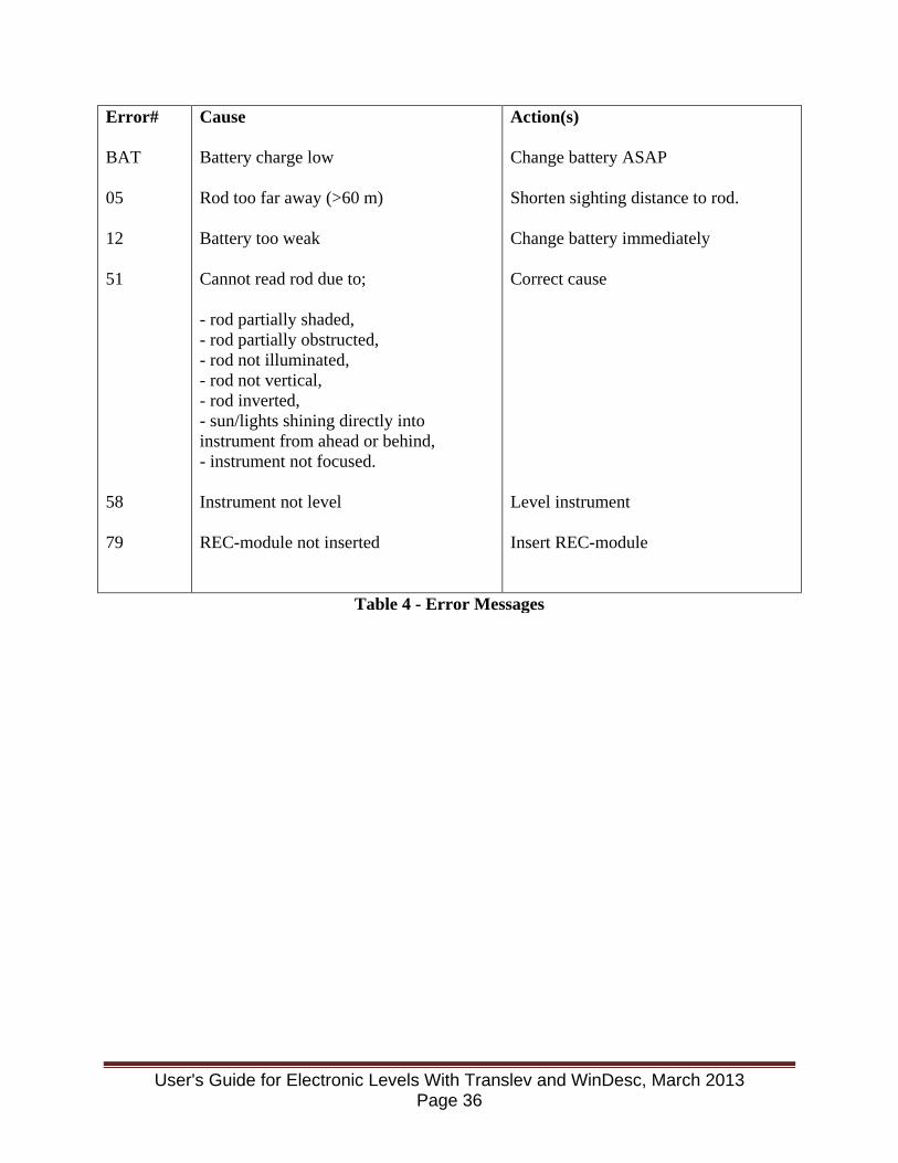
Error# BAT 05 12 51 58 79
Cause Battery charge low Rod too far away (>60 m) Battery too weak Cannot read rod due to; - rod partially shaded, - rod partially obstructed, - rod not illuminated, - rod not vertical, - rod inverted, - sun/lights shining directly into instrument from ahead or behind, - instrument not focused. Instrument not level REC-module not inserted
Action(s) Change battery ASAP Shorten sighting distance to rod. Change battery immediately Correct cause Level instrument Insert REC-module
Table 4 - Error Messages
User's Guide for Electronic Levels With Translev and WinDesc, March 2013 Page 36
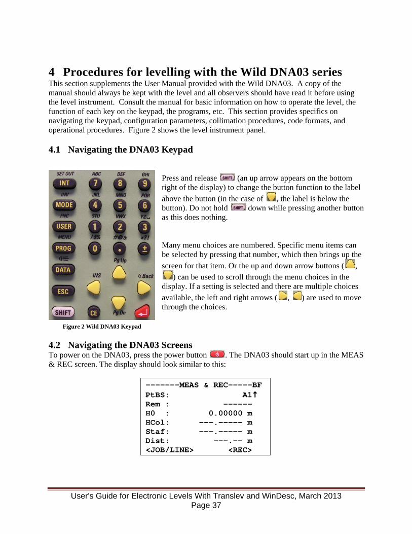
4 Procedures for levelling with the Wild DNA03 series This section supplements the User Manual provided with the Wild DNA03. A copy of the manual should always be kept with the level and all observers should have read it before using the level instrument. Consult the manual for basic information on how to operate the level, the function of each key on the keypad, the programs, etc. This section provides specifics on navigating the keypad, configuration parameters, collimation procedures, code formats, and operational procedures. Figure 2 shows the level instrument panel. 4.1 Navigating the DNA03 Keypad
Press and release (an up arrow appears on the bottom right of the display) to change the button function to the label above the button (in the case of , the label is below the button). Do not hold down while pressing another button as this does nothing. Many menu choices are numbered. Specific menu items can be selected by pressing that number, which then brings up the screen for that item. Or the up and down arrow buttons ( ,
) can be used to scroll through the menu choices in the display. If a setting is selected and there are multiple choices available, the left and right arrows ( , ) are used to move through the choices.
4.2 Navigating the DNA03 Screens To power on the DNA03, press the power button . The DNA03 should start up in the MEAS & REC screen. The display should look similar to this:
-------MEAS & REC-----BF PtBS: A1 Rem : ------ H0 : 0.00000 m HCol: ---.----- m Staf: ---.----- m Dist: ---.-- m <JOB/LINE> <REC>
Figure 2 Wild DNA03 Keypad
User's Guide for Electronic Levels With Translev and WinDesc, March 2013 Page 37
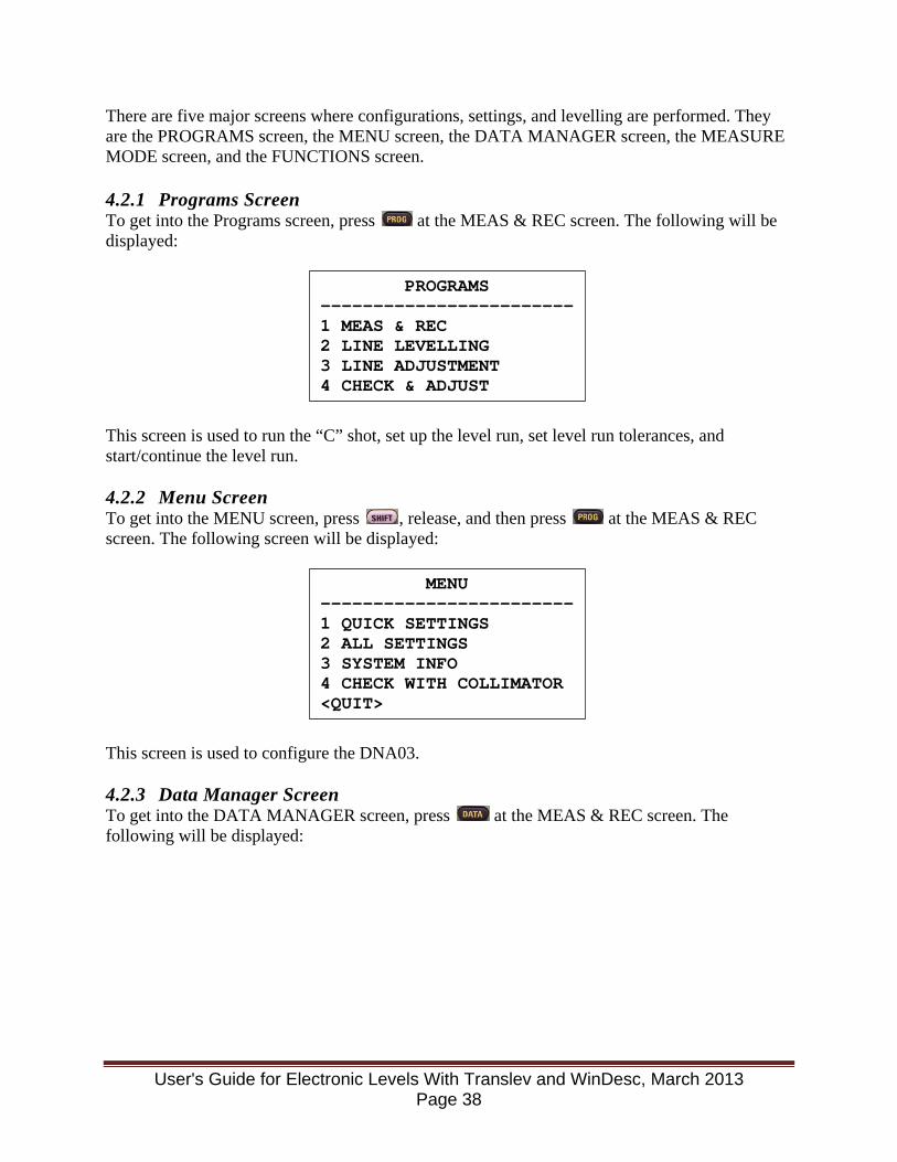
There are five major screens where configurations, settings, and levelling are performed. They are the PROGRAMS screen, the MENU screen, the DATA MANAGER screen, the MEASURE MODE screen, and the FUNCTIONS screen. 4.2.1 Programs Screen To get into the Programs screen, press at the MEAS & REC screen. The following will be displayed:
This screen is used to run the “C” shot, set up the level run, set level run tolerances, and start/continue the level run. 4.2.2 Menu Screen To get into the MENU screen, press , release, and then press at the MEAS & REC screen. The following screen will be displayed:
This screen is used to configure the DNA03. 4.2.3 Data Manager Screen To get into the DATA MANAGER screen, press at the MEAS & REC screen. The following will be displayed:
PROGRAMS ------------------------ 1 MEAS & REC 2 LINE LEVELLING 3 LINE ADJUSTMENT 4 CHECK & ADJUST
MENU ------------------------ 1 QUICK SETTINGS 2 ALL SETTINGS 3 SYSTEM INFO 4 CHECK WITH COLLIMATOR <QUIT>
User's Guide for Electronic Levels With Translev and WinDesc, March 2013 Page 38
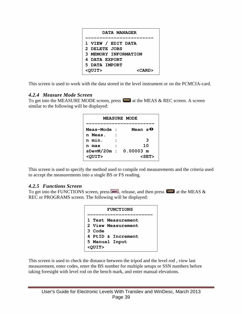
This screen is used to work with the data stored in the level instrument or on the PCMCIA-card. 4.2.4 Measure Mode Screen To get into the MEASURE MODE screen, press at the MEAS & REC screen. A screen similar to the following will be displayed:
This screen is used to specify the method used to compile rod measurements and the criteria used to accept the measurements into a single BS or FS reading. 4.2.5 Functions Screen To get into the FUNCTIONS screen, press , release, and then press at the MEAS & REC or PROGRAMS screen. The following will be displayed:
This screen is used to check the distance between the tripod and the level rod , view last measurement, enter codes, enter the BS number for multiple setups or SSN numbers before taking foresight with level rod on the bench mark, and enter manual elevations.
DATA MANAGER ------------------------ 1 VIEW / EDIT DATA 2 DELETE JOBS 3 MEMORY INFORMATION 4 DATA EXPORT 5 DATA IMPORT <QUIT> <CARD>
MEASURE MODE ------------------------ Meas-Mode : Mean s n Meas. : n min. : 3 n max : 10 sDevM/20m : 0.00003 m <QUIT> <SET>
FUNCTIONS ----------------------- 1 Test Measurement 2 View Measurement 3 Code 4 PtID & Increment 5 Manual Input <QUIT>
User's Guide for Electronic Levels With Translev and WinDesc, March 2013 Page 39
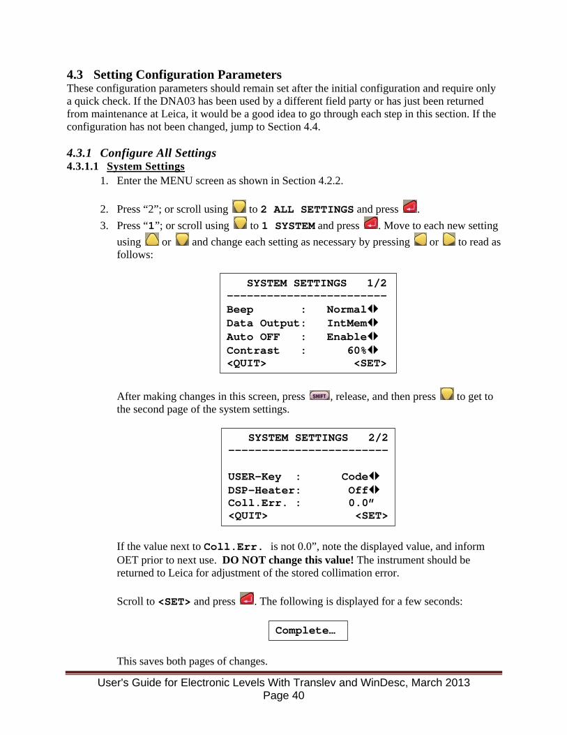
4.3 Setting Configuration Parameters These configuration parameters should remain set after the initial configuration and require only a quick check. If the DNA03 has been used by a different field party or has just been returned from maintenance at Leica, it would be a good idea to go through each step in this section. If the configuration has not been changed, jump to Section 4.4. 4.3.1 Configure All Settings 4.3.1.1 System Settings
1. Enter the MENU screen as shown in Section 4.2.2.
2. Press “2”; or scroll using to 2 ALL SETTINGS and press . 3. Press “1”; or scroll using to 1 SYSTEM and press . Move to each new setting
using or and change each setting as necessary by pressing or to read as follows:
After making changes in this screen, press , release, and then press to get to the second page of the system settings.
If the value next to Coll.Err. is not 0.0”, note the displayed value, and inform OET prior to next use. DO NOT change this value! The instrument should be returned to Leica for adjustment of the stored collimation error. Scroll to <SET> and press . The following is displayed for a few seconds:
This saves both pages of changes.
SYSTEM SETTINGS 1/2 ------------------------ Beep : Normal Data Output: IntMem Auto OFF : Enable Contrast : 60% <QUIT> <SET>
SYSTEM SETTINGS 2/2 ------------------------ USER-Key : Code DSP-Heater: Off Coll.Err. : 0.0” <QUIT> <SET>
Complete…
User's Guide for Electronic Levels With Translev and WinDesc, March 2013 Page 40
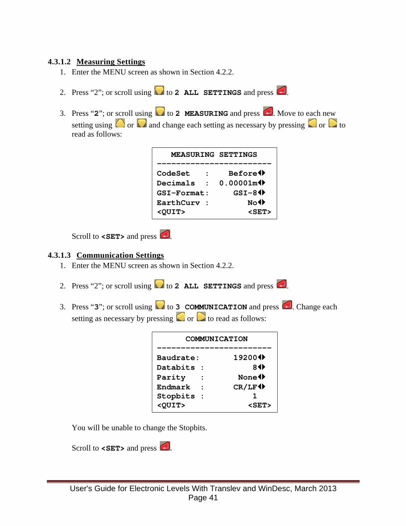
4.3.1.2 Measuring Settings
1. Enter the MENU screen as shown in Section 4.2.2.
2. Press “2”; or scroll using to 2 ALL SETTINGS and press .
3. Press “2”; or scroll using to 2 MEASURING and press . Move to each new setting using or and change each setting as necessary by pressing or to read as follows:
Scroll to <SET> and press .
4.3.1.3 Communication Settings 1. Enter the MENU screen as shown in Section 4.2.2.
2. Press “2”; or scroll using to 2 ALL SETTINGS and press .
3. Press “3”; or scroll using to 3 COMMUNICATION and press . Change each
setting as necessary by pressing or to read as follows:
You will be unable to change the Stopbits. Scroll to <SET> and press .
MEASURING SETTINGS ------------------------ CodeSet : Before Decimals : 0.00001m GSI-Format: GSI-8 EarthCurv : No <QUIT> <SET>
COMMUNICATION ------------------------ Baudrate: 19200 Databits : 8 Parity : None Endmark : CR/LF Stopbits : 1 <QUIT> <SET>
User's Guide for Electronic Levels With Translev and WinDesc, March 2013 Page 41

4.3.1.4 Units Settings 1. Enter the MENU screen as shown in Section 4.2.2.
2. Press “2”; or scroll using to 2 ALL SETTINGS and press .
3. Press “4”; or scroll using to 4 UNITS and press . Change each setting as
necessary by pressing or to read as follows:
Scroll to <SET> and press .
4.3.1.5 Date/Time Settings 1. Enter the MENU screen as shown in Section 4.2.2.
2. Press “2”; or scroll using to 2 ALL SETTINGS and press .
3. Press “5”; or scroll using to 5 DATE/TIME and press . The following is
displayed, where DD is the day, MM is the month, YYYY is the year, HH is the hour, MM are the minutes, and SS are the seconds:
Change the date or time as necessary. Date must be entered as DD.MM.YYYY. Time must be entered as HH:MM:SS. Use the number keys to enter the values. The cursor jumps over the period/colon between day/month/year or hour/minute/second, so do not press the period or colon. Enter a future time, scroll to <SET> and press when that time is reached.
4.3.2 Measure Mode Settings 1. Enter the MEASURE MODE screen as shown in Section 4.2.4.
2. Move to each new setting using or and change each setting as necessary by
pressing or , or entering the value to read as follows:
SET UNITS ------------------------ Distance : metre Temp. : °C <QUIT> <SET>
SET DATE / TIME ------------------------ Date : DD.MM.YYYY Time<24h>: HH:MM:SS <QUIT> <SET>
User's Guide for Electronic Levels With Translev and WinDesc, March 2013 Page 42
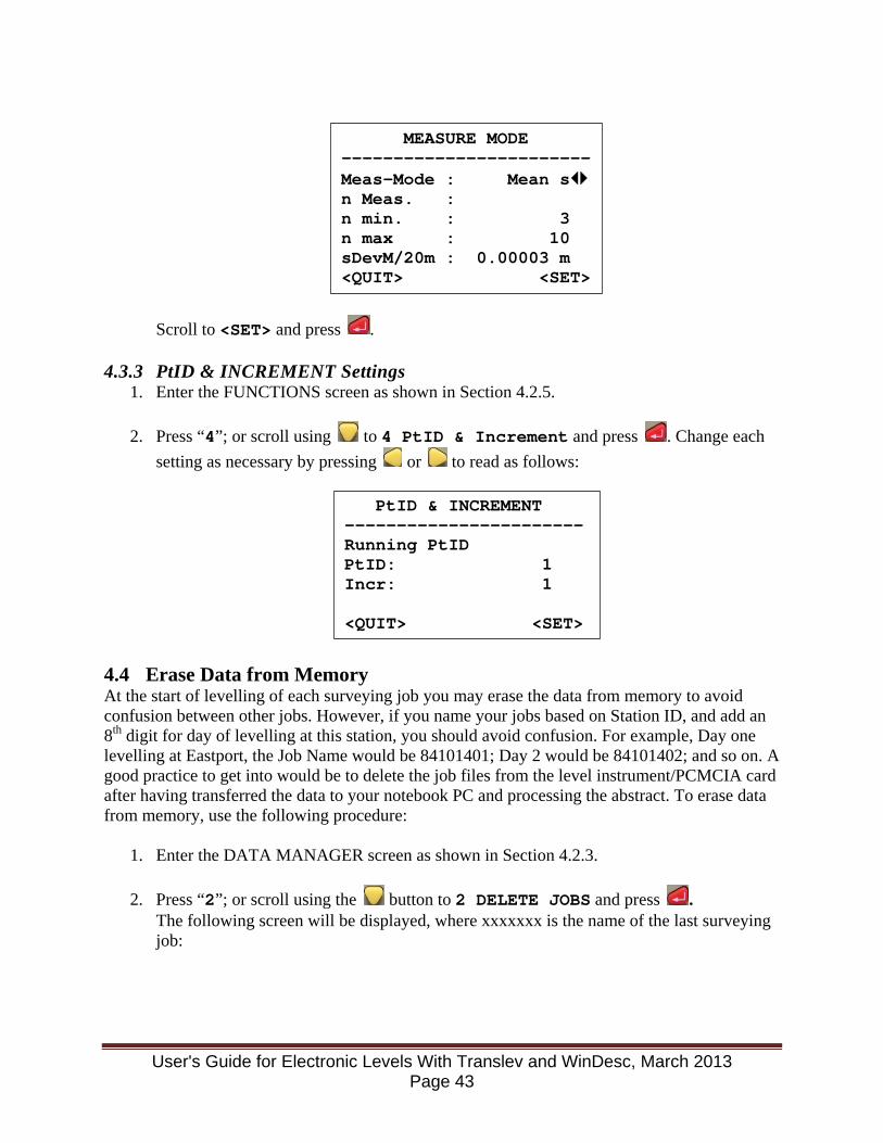
Scroll to <SET> and press .
4.3.3 PtID & INCREMENT Settings 1. Enter the FUNCTIONS screen as shown in Section 4.2.5.
2. Press “4”; or scroll using to 4 PtID & Increment and press . Change each
setting as necessary by pressing or to read as follows:
4.4 Erase Data from Memory At the start of levelling of each surveying job you may erase the data from memory to avoid confusion between other jobs. However, if you name your jobs based on Station ID, and add an 8th digit for day of levelling at this station, you should avoid confusion. For example, Day one levelling at Eastport, the Job Name would be 84101401; Day 2 would be 84101402; and so on. A good practice to get into would be to delete the job files from the level instrument/PCMCIA card after having transferred the data to your notebook PC and processing the abstract. To erase data from memory, use the following procedure:
1. Enter the DATA MANAGER screen as shown in Section 4.2.3.
2. Press “2”; or scroll using the button to 2 DELETE JOBS and press . The following screen will be displayed, where xxxxxxx is the name of the last surveying job:
MEASURE MODE ------------------------ Meas-Mode : Mean s n Meas. : n min. : 3 n max : 10 sDevM/20m : 0.00003 m <QUIT> <SET>
PtID & INCREMENT ----------------------- Running PtID PtID: 1 Incr: 1 <QUIT> <SET>
User's Guide for Electronic Levels With Translev and WinDesc, March 2013 Page 43

3. Scroll using the , and or button to <DEL-ALL> and press . The following screen will be displayed:
4. Scroll using the or button to <YES> and press . 4.5 Run Rod Level Bubble and Level Collimation Checks 4.5.1 Rod Level Bubble Check The procedures for performing the Rod Level Bubble Check are detailed in Section 3.3. 4.5.2 Level Collimation Check The level shall have a collimation check performed:
• at the start of each day's levelling; • at the start of each new station level run; • any time the level is subjected to substantial shock, vibration, etc.
When bringing the level out into a significantly different thermal environment, allow at least a half-hour for adjustment to ambient temperature, as a sudden thermal change can affect the collimation check. The temperature may be checked by comparing the Instr. Temp under SYSTEM INFO below to the upper thermistor. If the temperatures are within 2º the instrument has acclimated to the outside air. Lay out a course following the Förstner procedure as illustrated in the Reference 3, page 94, or the Reference 8, page 24. This method is also known as the 1/3-2/3 procedure. The level rods should be separated at least 45 meters for the best results. This places the instrument setups at 15 m and 30 m. The operator should first confirm that 0.0” is the absolute collimation error stored in the instrument if this hasn’t been checked up to this point. This is done by the following:
DELETE DATA / JOBS ------------------------ Job : xxxxxxx Data: MEASUREMENTS <QUIT> <DEL-ALL> <DEL>
Deletes all Jobs And Codelist of Internal Memory! <can last up to 2 min.> <NO> <YES>
User's Guide for Electronic Levels With Translev and WinDesc, March 2013 Page 44
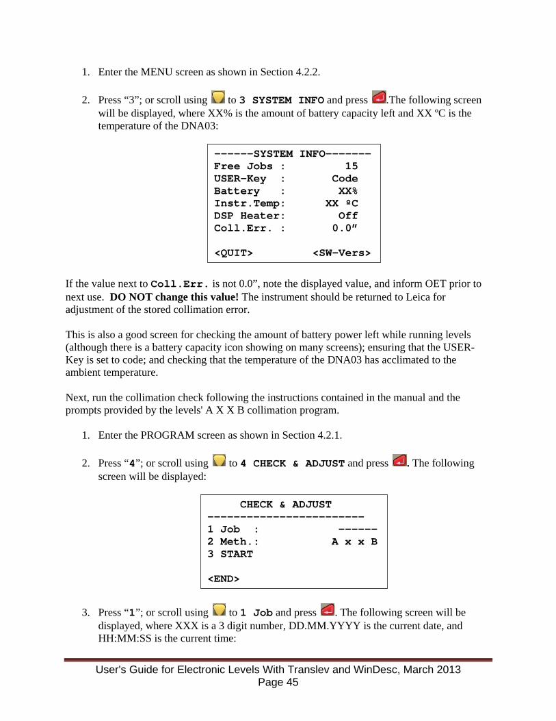
1. Enter the MENU screen as shown in Section 4.2.2.
2. Press “3”; or scroll using to 3 SYSTEM INFO and press .The following screen will be displayed, where XX% is the amount of battery capacity left and XX ºC is the temperature of the DNA03:
If the value next to Coll.Err. is not 0.0”, note the displayed value, and inform OET prior to next use. DO NOT change this value! The instrument should be returned to Leica for adjustment of the stored collimation error. This is also a good screen for checking the amount of battery power left while running levels (although there is a battery capacity icon showing on many screens); ensuring that the USER-Key is set to code; and checking that the temperature of the DNA03 has acclimated to the ambient temperature. Next, run the collimation check following the instructions contained in the manual and the prompts provided by the levels' A X X B collimation program.
1. Enter the PROGRAM screen as shown in Section 4.2.1.
2. Press “4”; or scroll using to 4 CHECK & ADJUST and press . The following screen will be displayed:
3. Press “1”; or scroll using to 1 Job and press . The following screen will be displayed, where XXX is a 3 digit number, DD.MM.YYYY is the current date, and HH:MM:SS is the current time:
------SYSTEM INFO------- Free Jobs : 15 USER-Key : Code Battery : XX% Instr.Temp: XX ºC DSP Heater: Off Coll.Err. : 0.0” <QUIT> <SW-Vers>
CHECK & ADJUST ------------------------ 1 Job : ------ 2 Meth.: A x x B 3 START <END>
User's Guide for Electronic Levels With Translev and WinDesc, March 2013 Page 45
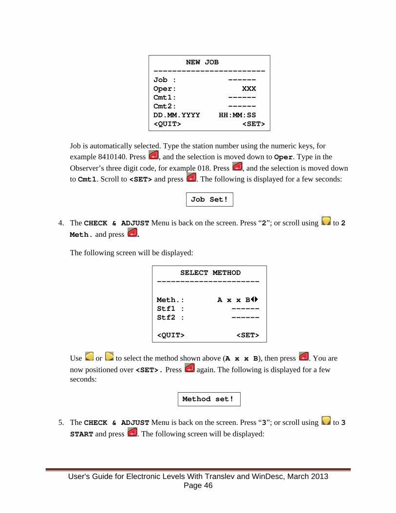
Job is automatically selected. Type the station number using the numeric keys, for example 8410140. Press , and the selection is moved down to Oper. Type in the Observer’s three digit code, for example 018. Press , and the selection is moved down to Cmt1. Scroll to <SET> and press . The following is displayed for a few seconds:
4. The CHECK & ADJUST Menu is back on the screen. Press “2”; or scroll using to 2 Meth. and press .
The following screen will be displayed:
Use or to select the method shown above (A x x B), then press . You are now positioned over <SET>. Press again. The following is displayed for a few seconds:
5. The CHECK & ADJUST Menu is back on the screen. Press “3”; or scroll using to 3 START and press . The following screen will be displayed:
NEW JOB ------------------------ Job : ------ Oper: XXX Cmt1: ------ Cmt2: ------ DD.MM.YYYY HH:MM:SS <QUIT> <SET>
Job Set!
SELECT METHOD ---------------------- Meth.: A x x B Stf1 : ------ Stf2 : ------ <QUIT> <SET>
Method set!
User's Guide for Electronic Levels With Translev and WinDesc, March 2013 Page 46
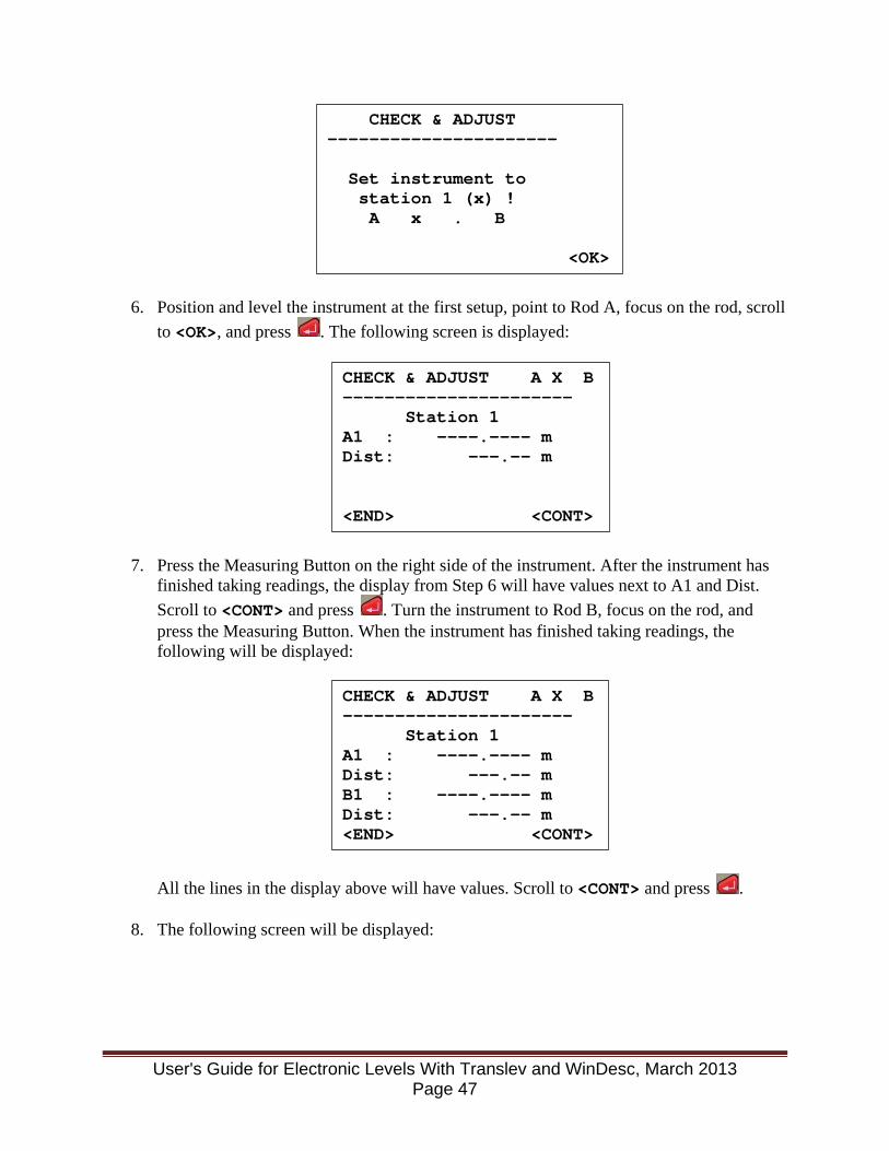
6. Position and level the instrument at the first setup, point to Rod A, focus on the rod, scroll to <OK>, and press . The following screen is displayed:
7. Press the Measuring Button on the right side of the instrument. After the instrument has finished taking readings, the display from Step 6 will have values next to A1 and Dist. Scroll to <CONT> and press . Turn the instrument to Rod B, focus on the rod, and press the Measuring Button. When the instrument has finished taking readings, the following will be displayed:
All the lines in the display above will have values. Scroll to <CONT> and press .
8. The following screen will be displayed:
CHECK & ADJUST ---------------------- Set instrument to station 1 (x) ! A x . B
<OK>
CHECK & ADJUST A X B ---------------------- Station 1 A1 : ----.---- m Dist: ---.-- m <END> <CONT>
CHECK & ADJUST A X B ---------------------- Station 1 A1 : ----.---- m Dist: ---.-- m B1 : ----.---- m Dist: ---.-- m <END> <CONT>
User's Guide for Electronic Levels With Translev and WinDesc, March 2013 Page 47
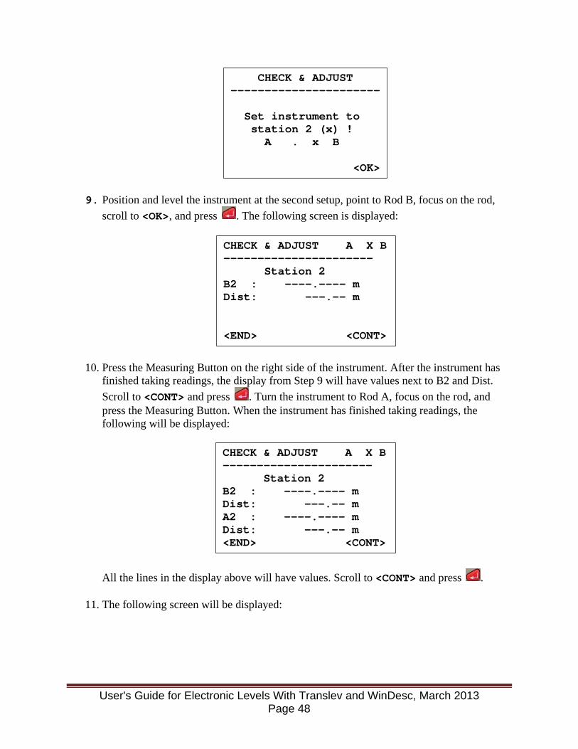
9. Position and level the instrument at the second setup, point to Rod B, focus on the rod, scroll to <OK>, and press . The following screen is displayed:
10. Press the Measuring Button on the right side of the instrument. After the instrument has finished taking readings, the display from Step 9 will have values next to B2 and Dist. Scroll to <CONT> and press . Turn the instrument to Rod A, focus on the rod, and press the Measuring Button. When the instrument has finished taking readings, the following will be displayed:
All the lines in the display above will have values. Scroll to <CONT> and press .
11. The following screen will be displayed:
CHECK & ADJUST ---------------------- Set instrument to station 2 (x) ! A . x B <OK>
CHECK & ADJUST A X B ---------------------- Station 2 B2 : ----.---- m Dist: ---.-- m <END> <CONT>
CHECK & ADJUST A X B ---------------------- Station 2 B2 : ----.---- m Dist: ---.-- m A2 : ----.---- m Dist: ---.-- m <END> <CONT>
User's Guide for Electronic Levels With Translev and WinDesc, March 2013 Page 48
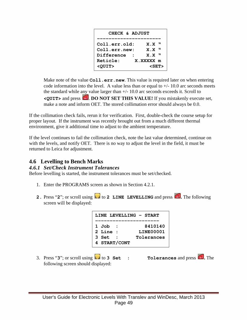
Make note of the value Coll.err.new. This value is required later on when entering code information into the level. A value less than or equal to +/- 10.0 arc seconds meets the standard while any value larger than +/- 10.0 arc seconds exceeds it. Scroll to <QUIT> and press . DO NOT SET THIS VALUE! If you mistakenly execute set, make a note and inform OET. The stored collimation error should always be 0.0.
If the collimation check fails, rerun it for verification. First, double-check the course setup for proper layout. If the instrument was recently brought out from a much different thermal environment, give it additional time to adjust to the ambient temperature. If the level continues to fail the collimation check, note the last value determined, continue on with the levels, and notify OET. There is no way to adjust the level in the field, it must be returned to Leica for adjustment. 4.6 Levelling to Bench Marks 4.6.1 Set/Check Instrument Tolerances Before levelling is started, the instrument tolerances must be set/checked.
1. Enter the PROGRAMS screen as shown in Section 4.2.1.
2. Press “2”; or scroll using to 2 LINE LEVELLING and press . The following screen will be displayed:
3. Press “3”; or scroll using to 3 Set : Tolerances and press . The following screen should displayed:
CHECK & ADJUST ---------------------- Coll.err.old: X.X “ Coll.err.new: X.X “ Difference : X.X “ Reticle: X.XXXXX m <QUIT> <SET>
LINE LEVELLING - START ---------------------- 1 Job : 8410140 2 Line : LINE00001 3 Set : Tolerances 4 START/CONT
User's Guide for Electronic Levels With Translev and WinDesc, March 2013 Page 49

If OFF, scroll to each item using , and use or to change the tolerance from OFF to ON. All tolerances should be ON when finished.
4. Use to scroll over to <LIMITS>. Press and the following screen is displayed:
For 2nd Order, Class 1:
For 3rd Order:
If your display screen does not match this for the order of levels you are running, scroll to the values that are different using and change the value to the one shown above. Scroll to <SET> and press . You are returned to the SET TOLERANCES display. Again, scroll to <SET> and press . The following is displayed for a few seconds:
----- SET TOLERANCES ----- Precise : ON DistBal : ON MaxDist : ON StafEnds: ON <QUIT> <LIMITS> <SET>
---- ENTER TOLERANCES ---- TDistBal: 5.00 m MaxDist : 60.00 m StafHigh: 2.90000 m StafLow : 0.50000 m <BACK> <DEFLT> <SET>
---- ENTER TOLERANCES ---- TDistBal: 10.00 m MaxDist : 90.00 m StafHigh: 2.90000 m StafLow : 0.50000 m <BACK> <DEFLT> <SET>
Tolerances set!
User's Guide for Electronic Levels With Translev and WinDesc, March 2013 Page 50
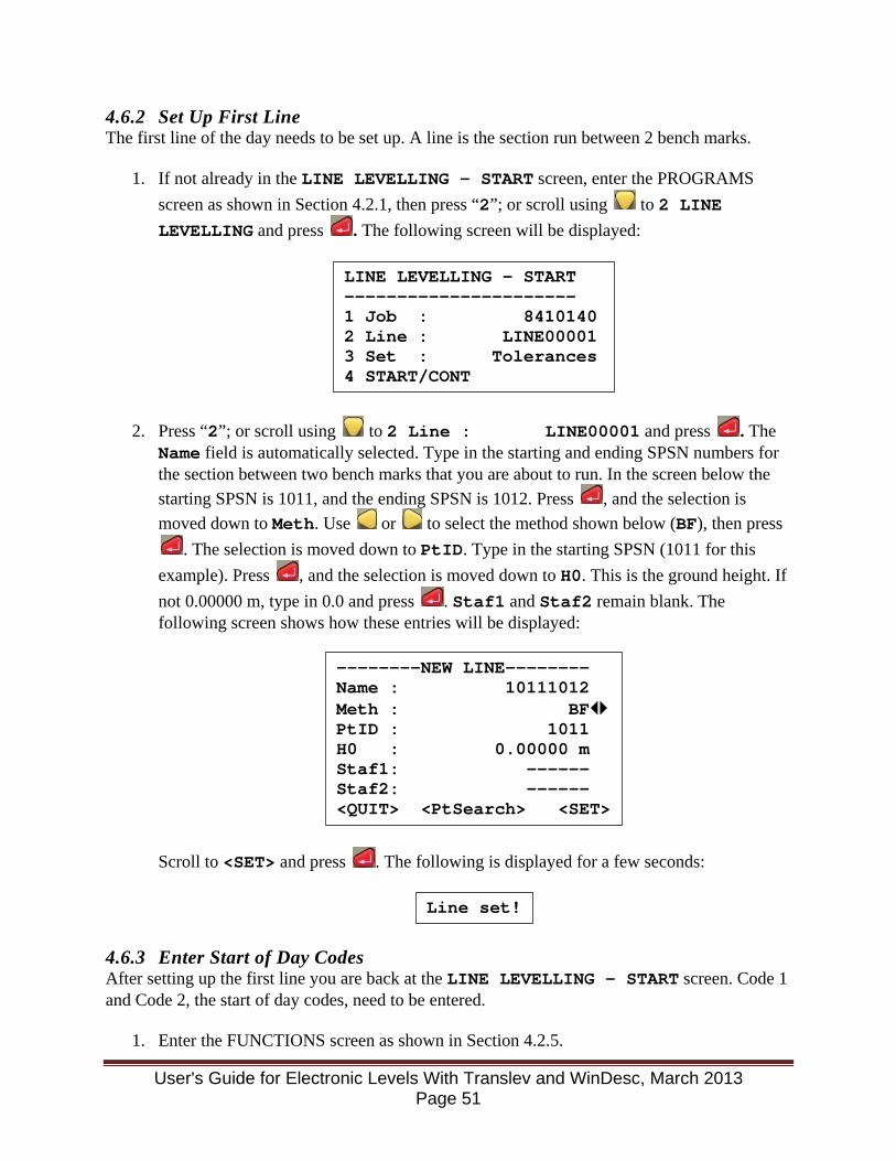
4.6.2 Set Up First Line The first line of the day needs to be set up. A line is the section run between 2 bench marks.
1. If not already in the LINE LEVELLING - START screen, enter the PROGRAMS screen as shown in Section 4.2.1, then press “2”; or scroll using to 2 LINE LEVELLING and press . The following screen will be displayed:
2. Press “2”; or scroll using to 2 Line : LINE00001 and press . The Name field is automatically selected. Type in the starting and ending SPSN numbers for the section between two bench marks that you are about to run. In the screen below the starting SPSN is 1011, and the ending SPSN is 1012. Press , and the selection is moved down to Meth. Use or to select the method shown below (BF), then press
. The selection is moved down to PtID. Type in the starting SPSN (1011 for this example). Press , and the selection is moved down to H0. This is the ground height. If not 0.00000 m, type in 0.0 and press . Staf1 and Staf2 remain blank. The following screen shows how these entries will be displayed:
Scroll to <SET> and press . The following is displayed for a few seconds:
4.6.3 Enter Start of Day Codes After setting up the first line you are back at the LINE LEVELLING - START screen. Code 1 and Code 2, the start of day codes, need to be entered.
1. Enter the FUNCTIONS screen as shown in Section 4.2.5.
LINE LEVELLING - START ---------------------- 1 Job : 8410140 2 Line : LINE00001 3 Set : Tolerances 4 START/CONT
--------NEW LINE-------- Name : 10111012 Meth : BF PtID : 1011 H0 : 0.00000 m Staf1: ------ Staf2: ------ <QUIT> <PtSearch> <SET>
Line set!
User's Guide for Electronic Levels With Translev and WinDesc, March 2013 Page 51

2. Press “3”; or scroll using to 3 Code and press . The following screen will be
displayed:
3. Scroll to each item using , and enter information from the keypad. Enter the following information for each line, pressing after each entry. For letters, press , and using the letter labels above each number key, enter the letter needed by pressing each key multiple times until the correct letter is shown. For example “DNA03” is entered by pressing , the number 8, the number 5 twice, the number 7, , the number 0, and finally the number 3. Shift will remain active for entering as many letters as needed, and is deactivated by pressing again. The keypad then goes back to numeric mode.
After entering Info4 and pressing , the cursor is positioned over <REC>. Press . The following is displayed for a few seconds: Code recorded!
4. Repeat Steps 1, 2, and 3 and enter the following information for Code 2:
After entering Info4 and pressing , the cursor is positioned over <REC>. Press . The following is displayed for a few seconds:
CODE & ATTR ENTRY 1/2 ---------------------- Code : ------ Info1: ------ Info2: ------ Info3: ------ Info4: ------ <QUIT> <REC>
Code 1 - Date/Observer/Instrument/Temp Scale. Info 1 - Date (MMDDYY) Info 2 - Observer number (1 to 999) Info 3 - Instrument model number (DNA03) Info 4 - Temperature scale (0 for C., 1 for F.)
Code 2 - Equipment Used/Collimation Info 1 - Instrument serial number. Info 2 - ± Collimation error in seconds (without decimal point, e.g. 9.0 is entered as 90). Info 3 - Rod 1 serial number. Info 4 - Rod 2 serial number.
User's Guide for Electronic Levels With Translev and WinDesc, March 2013 Page 52
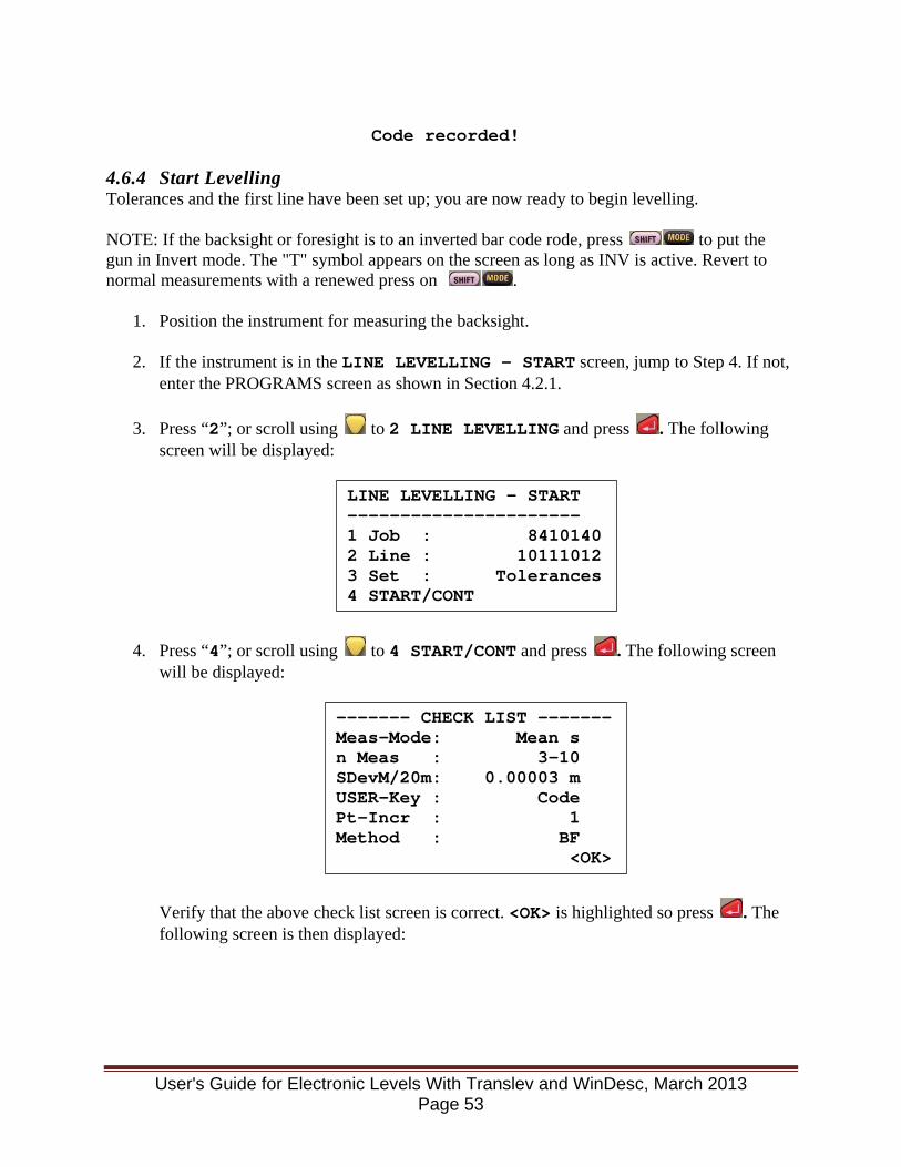
Code recorded!
4.6.4 Start Levelling Tolerances and the first line have been set up; you are now ready to begin levelling. NOTE: If the backsight or foresight is to an inverted bar code rode, press to put the gun in Invert mode. The "T" symbol appears on the screen as long as INV is active. Revert to normal measurements with a renewed press on .
1. Position the instrument for measuring the backsight.
2. If the instrument is in the LINE LEVELLING - START screen, jump to Step 4. If not, enter the PROGRAMS screen as shown in Section 4.2.1.
3. Press “2”; or scroll using to 2 LINE LEVELLING and press . The following screen will be displayed:
4. Press “4”; or scroll using to 4 START/CONT and press . The following screen will be displayed:
Verify that the above check list screen is correct. <OK> is highlighted so press . The following screen is then displayed:
LINE LEVELLING - START ---------------------- 1 Job : 8410140 2 Line : 10111012 3 Set : Tolerances 4 START/CONT
------- CHECK LIST ------- Meas-Mode: Mean s n Meas : 3-10 SDevM/20m: 0.00003 m USER-Key : Code Pt-Incr : 1 Method : BF <OK>
User's Guide for Electronic Levels With Translev and WinDesc, March 2013 Page 53
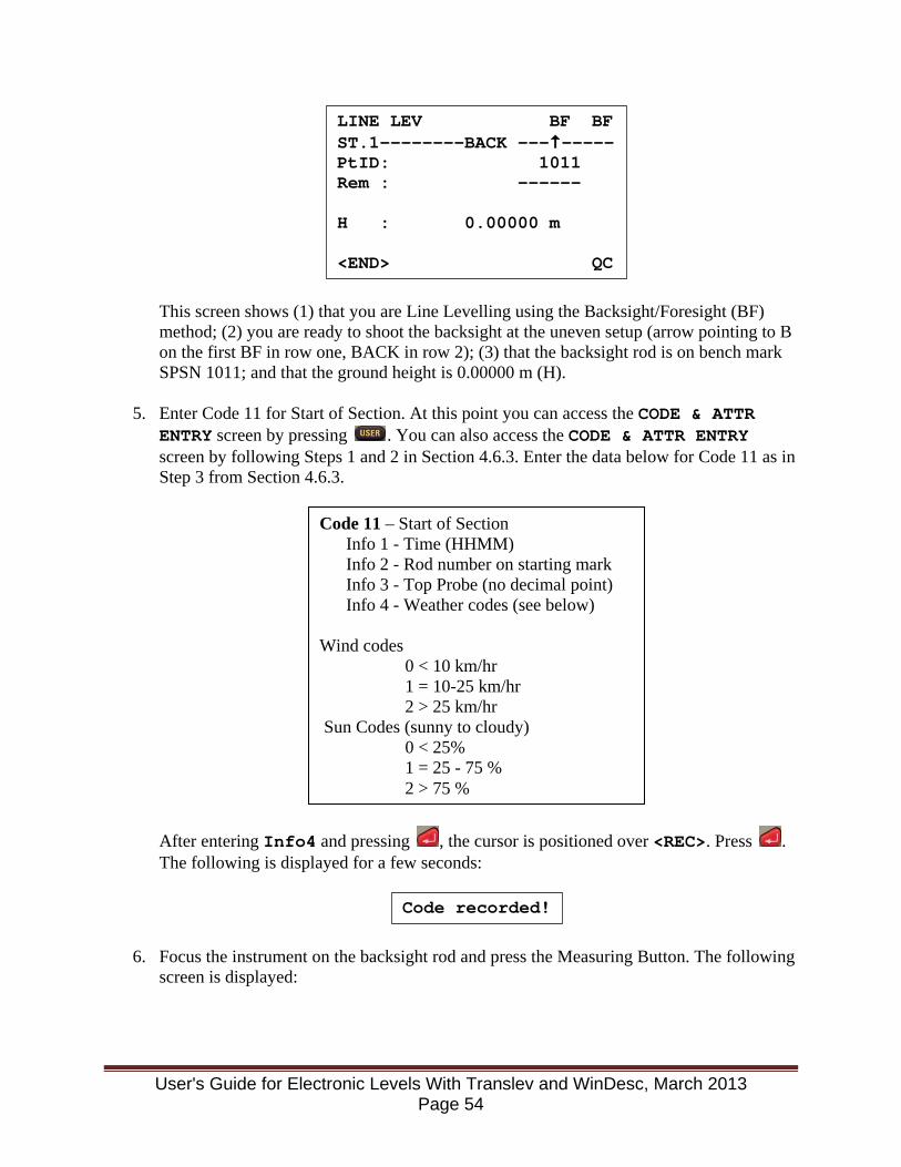
This screen shows (1) that you are Line Levelling using the Backsight/Foresight (BF) method; (2) you are ready to shoot the backsight at the uneven setup (arrow pointing to B on the first BF in row one, BACK in row 2); (3) that the backsight rod is on bench mark SPSN 1011; and that the ground height is 0.00000 m (H).
5. Enter Code 11 for Start of Section. At this point you can access the CODE & ATTR ENTRY screen by pressing . You can also access the CODE & ATTR ENTRY screen by following Steps 1 and 2 in Section 4.6.3. Enter the data below for Code 11 as in Step 3 from Section 4.6.3.
After entering Info4 and pressing , the cursor is positioned over <REC>. Press . The following is displayed for a few seconds:
6. Focus the instrument on the backsight rod and press the Measuring Button. The following screen is displayed:
LINE LEV BF BF ST.1--------BACK -------- PtID: 1011 Rem : ------ H : 0.00000 m <END> QC
Code 11 – Start of Section Info 1 - Time (HHMM) Info 2 - Rod number on starting mark Info 3 - Top Probe (no decimal point) Info 4 - Weather codes (see below)
Wind codes 0 < 10 km/hr 1 = 10-25 km/hr 2 > 25 km/hr Sun Codes (sunny to cloudy) 0 < 25% 1 = 25 - 75 % 2 > 75 %
Code recorded!
User's Guide for Electronic Levels With Translev and WinDesc, March 2013 Page 54
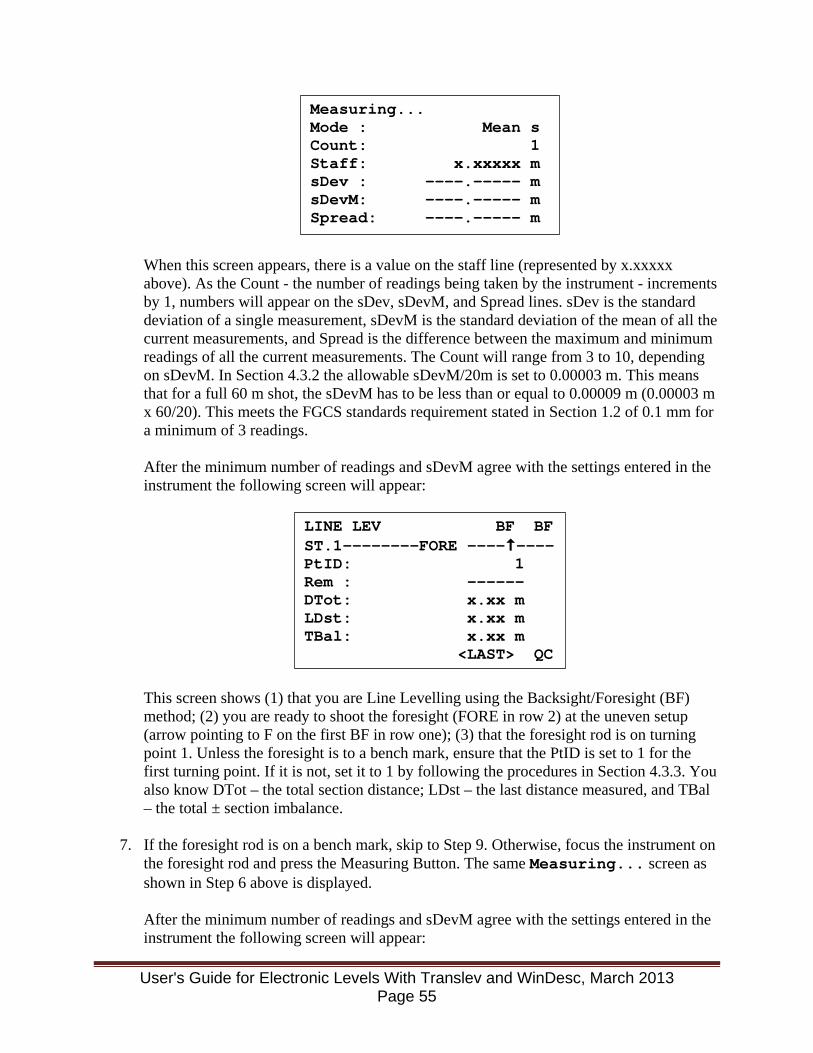
When this screen appears, there is a value on the staff line (represented by x.xxxxx above). As the Count - the number of readings being taken by the instrument - increments by 1, numbers will appear on the sDev, sDevM, and Spread lines. sDev is the standard deviation of a single measurement, sDevM is the standard deviation of the mean of all the current measurements, and Spread is the difference between the maximum and minimum readings of all the current measurements. The Count will range from 3 to 10, depending on sDevM. In Section 4.3.2 the allowable sDevM/20m is set to 0.00003 m. This means that for a full 60 m shot, the sDevM has to be less than or equal to 0.00009 m (0.00003 m x 60/20). This meets the FGCS standards requirement stated in Section 1.2 of 0.1 mm for a minimum of 3 readings. After the minimum number of readings and sDevM agree with the settings entered in the instrument the following screen will appear:
This screen shows (1) that you are Line Levelling using the Backsight/Foresight (BF) method; (2) you are ready to shoot the foresight (FORE in row 2) at the uneven setup (arrow pointing to F on the first BF in row one); (3) that the foresight rod is on turning point 1. Unless the foresight is to a bench mark, ensure that the PtID is set to 1 for the first turning point. If it is not, set it to 1 by following the procedures in Section 4.3.3. You also know DTot – the total section distance; LDst – the last distance measured, and TBal – the total ± section imbalance.
7. If the foresight rod is on a bench mark, skip to Step 9. Otherwise, focus the instrument on the foresight rod and press the Measuring Button. The same Measuring... screen as shown in Step 6 above is displayed.
After the minimum number of readings and sDevM agree with the settings entered in the instrument the following screen will appear:
Measuring... Mode : Mean s Count: 1 Staff: x.xxxxx m sDev : ----.----- m sDevM: ----.----- m Spread: ----.----- m
LINE LEV BF BF ST.1--------FORE -------- PtID: 1 Rem : ------ DTot: x.xx m LDst: x.xx m TBal: x.xx m <LAST> QC
User's Guide for Electronic Levels With Translev and WinDesc, March 2013 Page 55
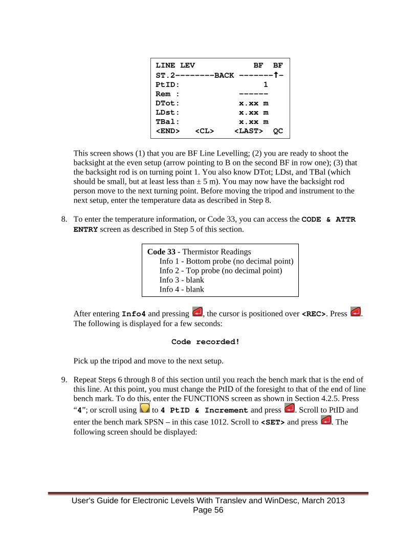
This screen shows (1) that you are BF Line Levelling; (2) you are ready to shoot the backsight at the even setup (arrow pointing to B on the second BF in row one); (3) that the backsight rod is on turning point 1. You also know DTot; LDst, and TBal (which should be small, but at least less than ± 5 m). You may now have the backsight rod person move to the next turning point. Before moving the tripod and instrument to the next setup, enter the temperature data as described in Step 8.
8. To enter the temperature information, or Code 33, you can access the CODE & ATTR ENTRY screen as described in Step 5 of this section.
After entering Info4 and pressing , the cursor is positioned over <REC>. Press . The following is displayed for a few seconds: Code recorded! Pick up the tripod and move to the next setup.
9. Repeat Steps 6 through 8 of this section until you reach the bench mark that is the end of this line. At this point, you must change the PtID of the foresight to that of the end of line bench mark. To do this, enter the FUNCTIONS screen as shown in Section 4.2.5. Press “4”; or scroll using to 4 PtID & Increment and press . Scroll to PtID and enter the bench mark SPSN – in this case 1012. Scroll to <SET> and press . The following screen should be displayed:
LINE LEV BF BF ST.2--------BACK -------- PtID: 1 Rem : ------ DTot: x.xx m LDst: x.xx m TBal: x.xx m <END> <CL> <LAST> QC
Code 33 - Thermistor Readings Info 1 - Bottom probe (no decimal point) Info 2 - Top probe (no decimal point) Info 3 - blank Info 4 - blank
User's Guide for Electronic Levels With Translev and WinDesc, March 2013 Page 56
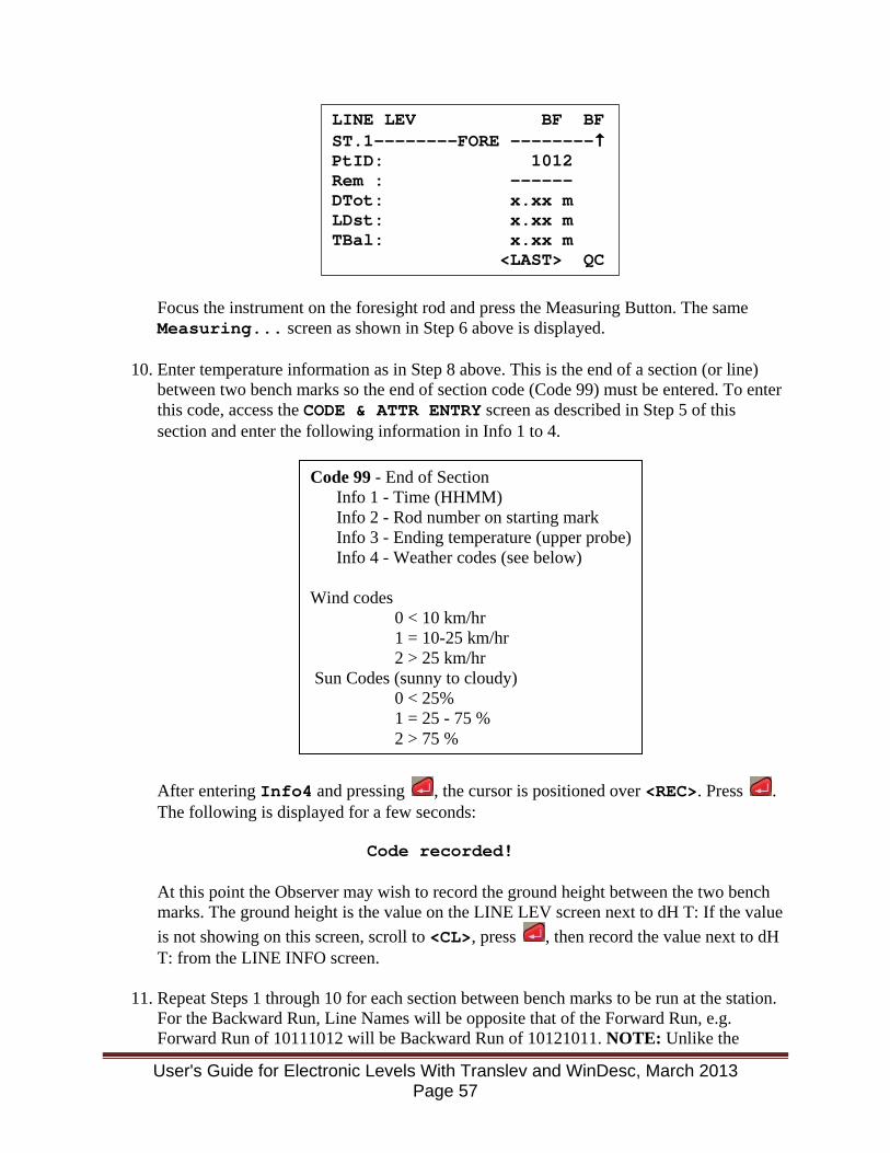
Focus the instrument on the foresight rod and press the Measuring Button. The same Measuring... screen as shown in Step 6 above is displayed.
10. Enter temperature information as in Step 8 above. This is the end of a section (or line) between two bench marks so the end of section code (Code 99) must be entered. To enter this code, access the CODE & ATTR ENTRY screen as described in Step 5 of this section and enter the following information in Info 1 to 4.
After entering Info4 and pressing , the cursor is positioned over <REC>. Press . The following is displayed for a few seconds: Code recorded! At this point the Observer may wish to record the ground height between the two bench marks. The ground height is the value on the LINE LEV screen next to dH T: If the value is not showing on this screen, scroll to <CL>, press , then record the value next to dH T: from the LINE INFO screen.
11. Repeat Steps 1 through 10 for each section between bench marks to be run at the station. For the Backward Run, Line Names will be opposite that of the Forward Run, e.g. Forward Run of 10111012 will be Backward Run of 10121011. NOTE: Unlike the
LINE LEV BF BF ST.1--------FORE -------- PtID: 1012 Rem : ------ DTot: x.xx m LDst: x.xx m TBal: x.xx m <LAST> QC
Code 99 - End of Section Info 1 - Time (HHMM) Info 2 - Rod number on starting mark Info 3 - Ending temperature (upper probe) Info 4 - Weather codes (see below)
Wind codes 0 < 10 km/hr 1 = 10-25 km/hr 2 > 25 km/hr Sun Codes (sunny to cloudy) 0 < 25% 1 = 25 - 75 % 2 > 75 %
User's Guide for Electronic Levels With Translev and WinDesc, March 2013 Page 57

procedure for the previous version of digital levelling with the NA3000 & NA3003, do not enter Codes 33/99/11 in succession before starting the next section. Steps 2 through 4 must be performed before Step 5 – entering Code 11.
12. At the end of the day, or if the Observer or instrument is changed, Code 9999 must be entered. To enter this code, access the CODE & ATTR ENTRY screen as described in Step 5 of this section and enter the following information in Info 1 to 4.
After entering Info4 and pressing , the cursor is positioned over <REC>. Press . The following is displayed for a few seconds:
4.6.5 Manual Entries In the event a backsight or foresight is read manually from a steel tape or calibrated scale and has to be entered manually in the DNA03 level instrument the following procedure must be followed:
1. If the manual input to be performed is a backsight, go to step 2. If the input is a foresight, proceed by measuring the backsight using the bar code rode and the digital levelling procedures.
2. Enter the Functions Screen as shown in Section 4.2.5 Press “5”; or scroll using to 5 Manual Input and press .
3. The following screen is displayed:
4. Hold the zero point of the steel tape or scale on the point an elevation is desired. It is suggested that a metric tape or scale be used to minimize calculations. Remember the input to the gun has to be in meters.
Code 9999 - End of Day/Change Observer or Instrument Info 1 - blank Info 2 - blank Info 3 - blank Info 4 - blank
Code recorded!
Manual Input ----------------------- Staff: 0.00000 m Dist : 0.00 m <QUIT> <CONT>
User's Guide for Electronic Levels With Translev and WinDesc, March 2013 Page 58
5. Observe and make note of the elevations at each of the three wires. Average these three
readings. This will be the “Staff” value to be manually input into the gun. If the tape/staff is inverted, the value is entered as a negative number.
6. Subtract the top wire reading from the bottom wire reading. This is the Stadia Interval as described in Reference 1, page 40-41. Multiply the stadia interval by the stadia factor, which is 100 for the DNA03. The resulting value is the distance to the tape/scale in the units of the tape/scale. This means if the scale is in inches, your distance is in inches, etc. Perform any additional calculations needed to convert the value into meters. This value is the “Dist” to be manually input into the gun.
7. Enter the Staff: value, scroll down with , and enter the Dist : value. Scroll to <CONT> and press .
8. Enter the temperatures, then continue the level run using digital levelling procedures.
User's Guide for Electronic Levels With Translev and WinDesc, March 2013 Page 59
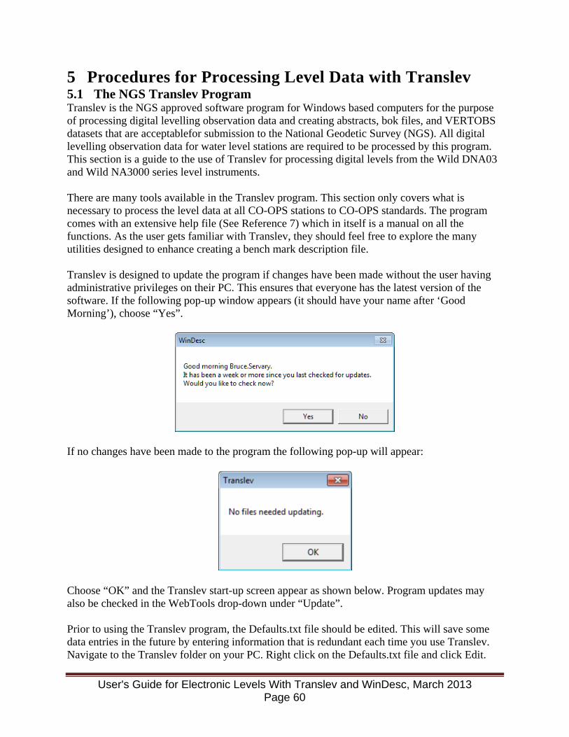
5 Procedures for Processing Level Data with Translev 5.1 The NGS Translev Program Translev is the NGS approved software program for Windows based computers for the purpose of processing digital levelling observation data and creating abstracts, bok files, and VERTOBS datasets that are acceptablefor submission to the National Geodetic Survey (NGS). All digital levelling observation data for water level stations are required to be processed by this program. This section is a guide to the use of Translev for processing digital levels from the Wild DNA03 and Wild NA3000 series level instruments. There are many tools available in the Translev program. This section only covers what is necessary to process the level data at all CO-OPS stations to CO-OPS standards. The program comes with an extensive help file (See Reference 7) which in itself is a manual on all the functions. As the user gets familiar with Translev, they should feel free to explore the many utilities designed to enhance creating a bench mark description file. Translev is designed to update the program if changes have been made without the user having administrative privileges on their PC. This ensures that everyone has the latest version of the software. If the following pop-up window appears (it should have your name after ‘Good Morning’), choose “Yes”.
If no changes have been made to the program the following pop-up will appear:
Choose “OK” and the Translev start-up screen appear as shown below. Program updates may also be checked in the WebTools drop-down under “Update”. Prior to using the Translev program, the Defaults.txt file should be edited. This will save some data entries in the future by entering information that is redundant each time you use Translev. Navigate to the Translev folder on your PC. Right click on the Defaults.txt file and click Edit.
User's Guide for Electronic Levels With Translev and WinDesc, March 2013 Page 60
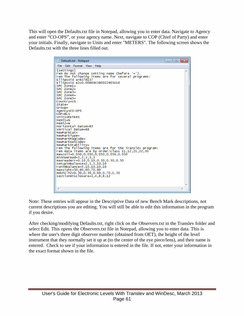
This will open the Defaults.txt file in Notepad, allowing you to enter data. Navigate to Agency and enter “CO-OPS”, or your agency name. Next, navigate to COP (Chief of Party) and enter your initials. Finally, navigate to Units and enter "METERS". The following screen shows the Defaults.txt with the three lines filled out.
Note: These entries will appear in the Descriptive Data of new Bench Mark descriptions, not current descriptions you are editing. You will still be able to edit this information in the program if you desire. After checking/modifying Defaults.txt, right click on the Observers.txt in the Translev folder and select Edit. This opens the Observers.txt file in Notepad, allowing you to enter data. This is where the user's three digit observer number (obtained from OET), the height of the level instrument that they normally set it up at (to the center of the eye piece/lens), and their name is entered. Check to see if your information is entered in the file. If not, enter your information in the exact format shown in the file.
User's Guide for Electronic Levels With Translev and WinDesc, March 2013 Page 61

5.2 Update *.DAT Files The first time that Translev is used after installation, and periodically thereafter, the *.DAT files should be updated to insure that the most recent information is available to the program. These files are Contrib.dat, Country.dat, Inst.dat, and Rods.dat files. To do this:
1. Start Translev
2. Select the WebTools drop down menu and hover over or click Update and the following is displayed:
User's Guide for Electronic Levels With Translev and WinDesc, March 2013 Page 62
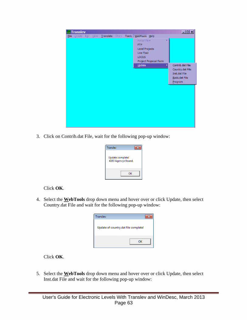
3. Click on Contrib.dat File, wait for the following pop-up window:
Click OK.
4. Select the WebTools drop down menu and hover over or click Update, then select Country.dat File and wait for the following pop-up window:
Click OK.
5. Select the WebTools drop down menu and hover over or click Update, then select Inst.dat File and wait for the following pop-up window:
User's Guide for Electronic Levels With Translev and WinDesc, March 2013 Page 63

Click Yes.
6. The following window is displayed:
Click OK.
7. Select the WebTools drop down menu and hover over or click Update, then select Rods.dat:
Click Yes.
8. The following window is displayed:
Click OK.
9. Exit and restart Translev 5.3 Processing Level Data from the NA3000 Series Instrument This section covers transferring the data from the Wild REC-module to a PC by using the Wild GIF-10 and using NGS software to process the levelling data. The NGS data processing
User's Guide for Electronic Levels With Translev and WinDesc, March 2013 Page 64
software works in conjunction with the NGS bench mark description software, and requires the description file (XXXXXXX.DES) to generate the abstract file. 5.3.1 Download the Levelling Data to a PC or Diskette
• Connect the GIF-10 module to the PC using the cable from the GIF-10 to the PC RS232 port.
• Insert the REC MODULE into the GIF-10. • Turn on the PC; navigate into the folder where the level data is to be processed. • Turn on the GIF-10 and ensure that the cursor is on the "SEND" command displayed in
the LCD window. • Run the GIF10 executable file and follow prompts;
o Select menu option 1 - DATA FROM REC MODULE TO PC. o Select submenu option 3 - ON DISK. o Reply 1 to request for REC File Number. o Reply 1 to request for Start Block Number. o Reply 999 to request for End Block Number. o Reply XXXXXXX.RAW to request for Output File Number to be saved in the
folder you navigated to above. The .RAW extension is required for use with Translev. When you hit ENTER key after the last question, you should see the data scroll across the PC screen and the GIF-10 module window showing the file and block numbers being transferred.
• Select option 8 END PROGRAM, this completes the data download. Turn off the GIF-10 and disconnect the GIF-10 from the PC.
5.3.2 Edit The XXXXXXX.RAW File To Correct Or Remove Any Known Mistakes • Make a copy of the XXXXXXX.RAW file before editing; call it XXXXXXXo.RAW for
the original file. • Use a text editor, such as notepad, to edit the .RAW file. If using Word or some other
word processor program be sure to save the .RAW file as an ASCII (DOS) text file. 5.3.3 Process the NA3000 Series Level Data To process the level data collected using a Leica NA3000/NA3003 Digital Level, two files must be present in the project folder in order to process levels using Translev:
XXXXXXX.DES - BM description file from WinDesc XXXXXXX.RAW - Raw level data file downloaded from instrument in Section 5.3.1
Matching SSN numbers must be used in the *.des file in order for the levelling data and bench mark descriptions to be properly matched up. If the *.des file does not exist, but the older, *.HA file does, there are procedures for converting the *.HA file to a format readable by WinDesc. These procedures are outlined in Appendix I. The following are the procedures to use to process the level data:
User's Guide for Electronic Levels With Translev and WinDesc, March 2013 Page 65
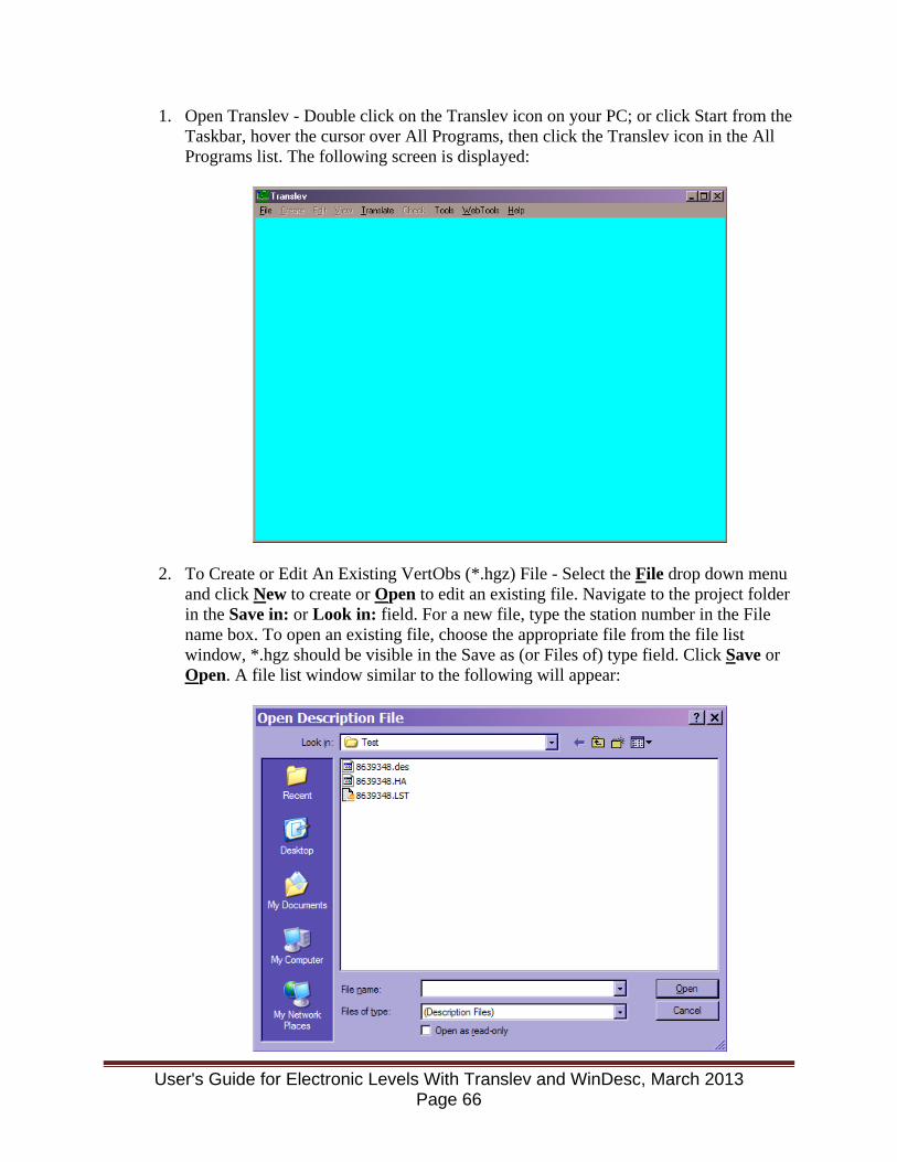
1. Open Translev - Double click on the Translev icon on your PC; or click Start from the Taskbar, hover the cursor over All Programs, then click the Translev icon in the All Programs list. The following screen is displayed:
2. To Create or Edit An Existing VertObs (*.hgz) File - Select the File drop down menu and click New to create or Open to edit an existing file. Navigate to the project folder in the Save in: or Look in: field. For a new file, type the station number in the File name box. To open an existing file, choose the appropriate file from the file list window, *.hgz should be visible in the Save as (or Files of) type field. Click Save or Open. A file list window similar to the following will appear:
User's Guide for Electronic Levels With Translev and WinDesc, March 2013 Page 66
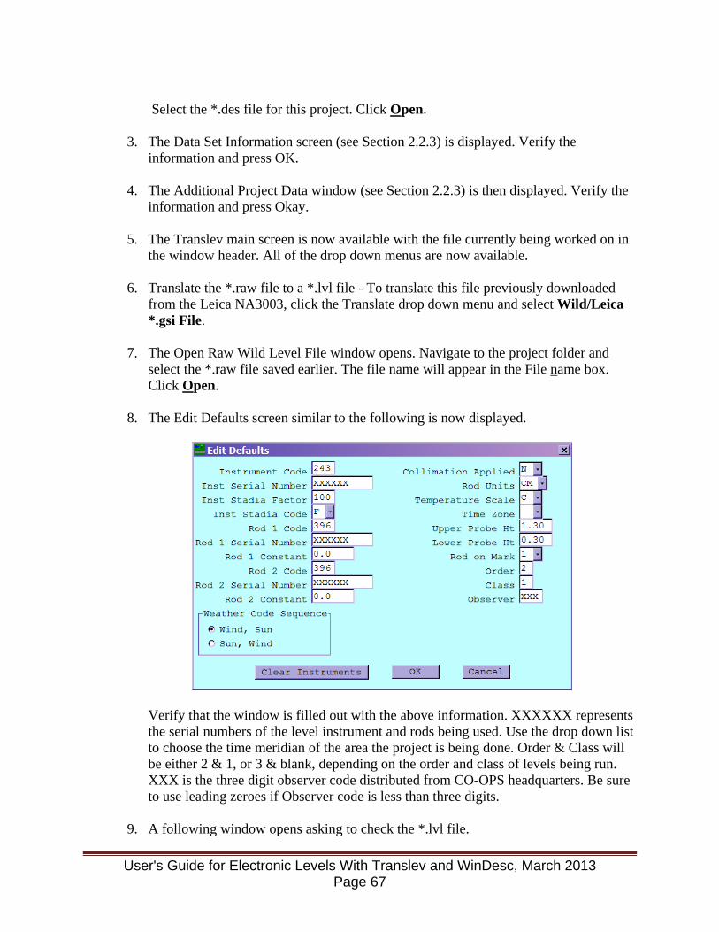
Select the *.des file for this project. Click Open.
3. The Data Set Information screen (see Section 2.2.3) is displayed. Verify the
information and press OK.
4. The Additional Project Data window (see Section 2.2.3) is then displayed. Verify the information and press Okay.
5. The Translev main screen is now available with the file currently being worked on in the window header. All of the drop down menus are now available.
6. Translate the *.raw file to a *.lvl file - To translate this file previously downloaded from the Leica NA3003, click the Translate drop down menu and select Wild/Leica *.gsi File.
7. The Open Raw Wild Level File window opens. Navigate to the project folder and select the *.raw file saved earlier. The file name will appear in the File name box. Click Open.
8. The Edit Defaults screen similar to the following is now displayed.
Verify that the window is filled out with the above information. XXXXXX represents the serial numbers of the level instrument and rods being used. Use the drop down list to choose the time meridian of the area the project is being done. Order & Class will be either 2 & 1, or 3 & blank, depending on the order and class of levels being run. XXX is the three digit observer code distributed from CO-OPS headquarters. Be sure to use leading zeroes if Observer code is less than three digits.
9. A following window opens asking to check the *.lvl file.
User's Guide for Electronic Levels With Translev and WinDesc, March 2013 Page 67
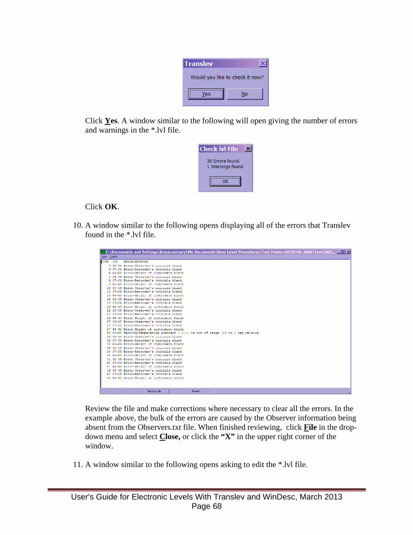
Click Yes. A window similar to the following will open giving the number of errors and warnings in the *.lvl file.
Click OK.
10. A window similar to the following opens displaying all of the errors that Translev
found in the *.lvl file.
Review the file and make corrections where necessary to clear all the errors. In the example above, the bulk of the errors are caused by the Observer information being absent from the Observers.txt file. When finished reviewing, click File in the drop-down menu and select Close, or click the “X” in the upper right corner of the window.
11. A window similar to the following opens asking to edit the *.lvl file.
User's Guide for Electronic Levels With Translev and WinDesc, March 2013 Page 68
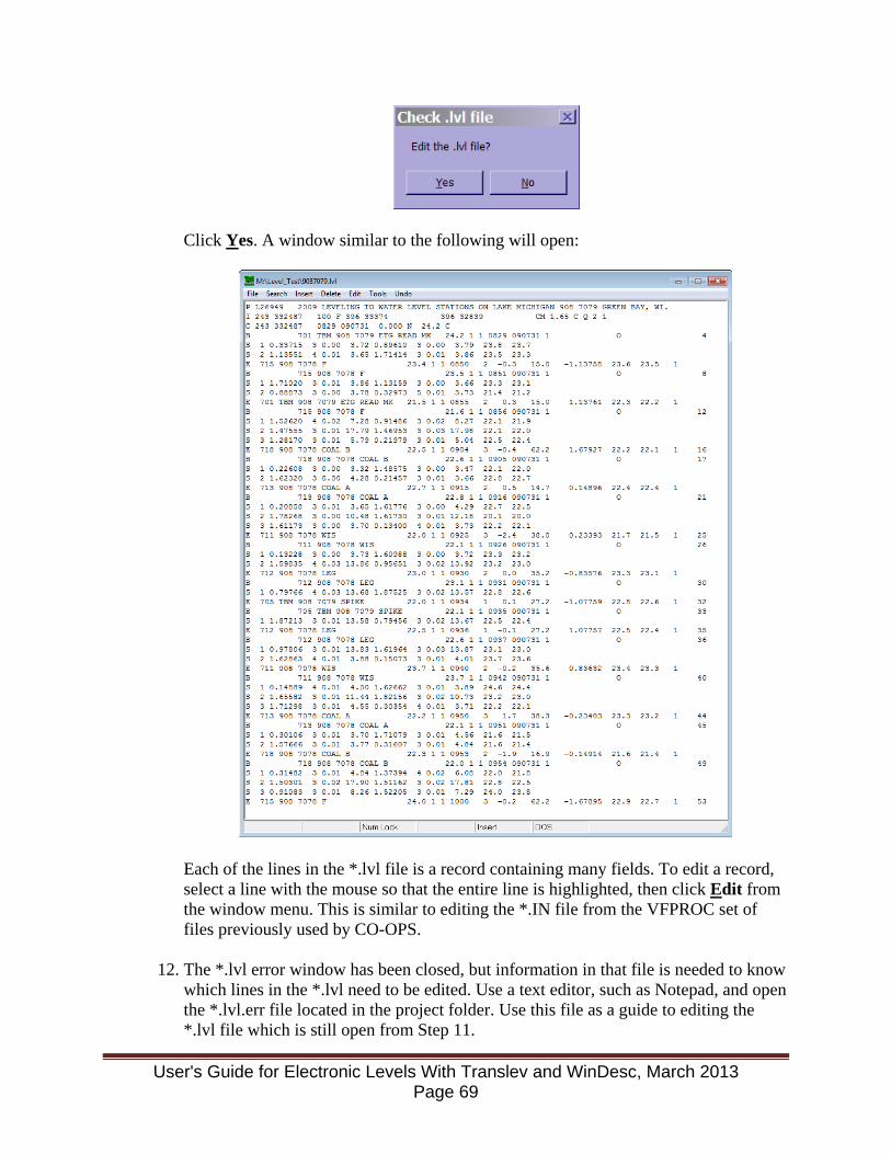
Click Yes. A window similar to the following will open:
Each of the lines in the *.lvl file is a record containing many fields. To edit a record, select a line with the mouse so that the entire line is highlighted, then click Edit from the window menu. This is similar to editing the *.IN file from the VFPROC set of files previously used by CO-OPS.
12. The *.lvl error window has been closed, but information in that file is needed to know which lines in the *.lvl need to be edited. Use a text editor, such as Notepad, and open the *.lvl.err file located in the project folder. Use this file as a guide to editing the *.lvl file which is still open from Step 11.
User's Guide for Electronic Levels With Translev and WinDesc, March 2013 Page 69

13. Edit the *.lvl file and fix as many errors as possible. The window below is similar to
that which opens when a line is selected and Edit is clicked on the menu:
When edits are complete, click File in the drop-down menu and select Save. Next, click File in the drop-down menu and select Close.
14. Recheck the recently edited *.lvl file by selecting Check from the main Translev window and picking Lvl file. An Open lvl File window similar to that shown below will open:
User's Guide for Electronic Levels With Translev and WinDesc, March 2013 Page 70
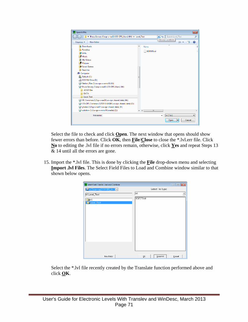
Select the file to check and click Open. The next window that opens should show fewer errors than before. Click OK, then File/Close to close the *.lvl.err file. Click No to editing the .lvl file if no errors remain, otherwise, click Yes and repeat Steps 13 & 14 until all the errors are gone.
15. Import the *.lvl file. This is done by clicking the File drop-down menu and selecting Import .lvl Files. The Select Field Files to Load and Combine window similar to that shown below opens.
Select the *.lvl file recently created by the Translate function performed above and click OK.
User's Guide for Electronic Levels With Translev and WinDesc, March 2013 Page 71
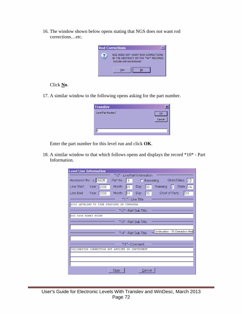
16. The window shown below opens stating that NGS does not want rod corrections…etc.
Click No.
17. A similar window to the following opens asking for the part number.
Enter the part number for this level run and click OK.
18. A similar window to that which follows opens and displays the record *10* - Part
Information.
User's Guide for Electronic Levels With Translev and WinDesc, March 2013 Page 72
Verify the information contained in the boxes and add any additional information required. If the Station ID and Name are at the end of *11* - Line Title:, move them from *11* to *12* - Part Sub Title: using cut and paste. This is because stations with long names will be truncated on the abstract. Click Okay.
The following window opens stating Processing Complete!
Click OK.
19. Create An Abstract - Click the Create drop-down menu and select Abstract (.abs) File.
20. The Abstract window opens. The part number is displayed and the window is
requesting the Starting and Ending bench marks and the starting elevation of the starting mark. The Starting Bench Mark is the station PBM; the Starting Elevation is the PBM elevation above station datum; and the Ending Bench Mark is the Aquatrak, ETG, or other water level sensor that is generally included in the level run. There is no need to type in the SPSN of the bench marks as there is a drop down menu for the marks. Choose the start and end bench marks and enter the start elevation and click Okay.
21. The following window opens:
Click No.
22. The abstract is created and a window opens displaying the abstract. From this window the abstract may be printed by selecting the File drop down menu and clicking Print.
23. Exit the abstract by clicking File in the drop-down menu and selecting Close.
24. Exit Translev by clicking File in the drop-down menu and selecting Exit.
User's Guide for Electronic Levels With Translev and WinDesc, March 2013 Page 73
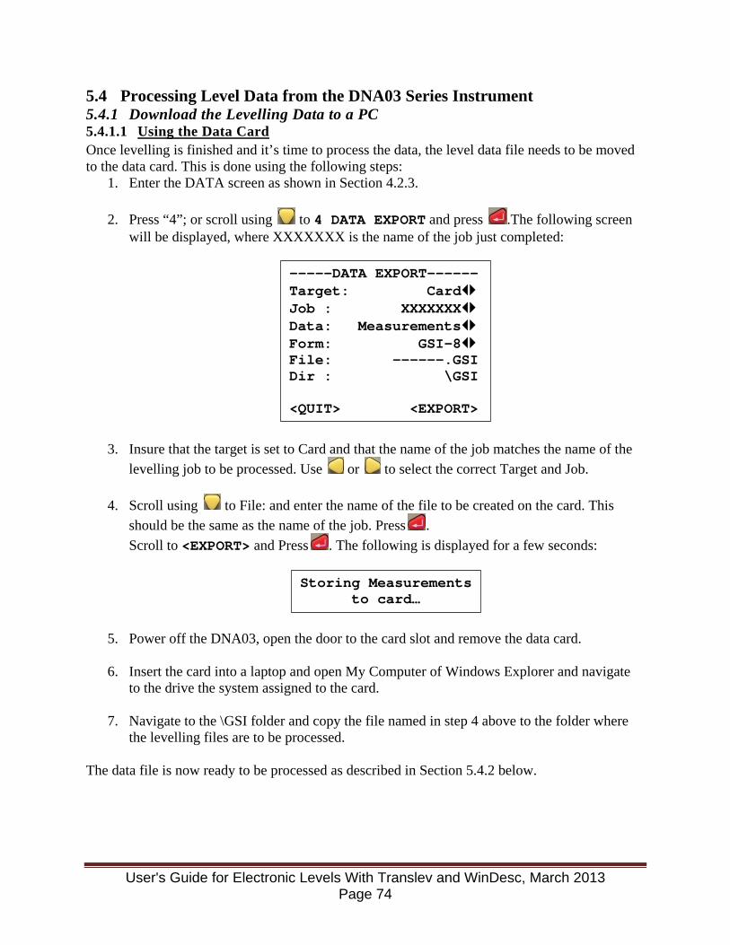
5.4 Processing Level Data from the DNA03 Series Instrument 5.4.1 Download the Levelling Data to a PC 5.4.1.1 Using the Data Card Once levelling is finished and it’s time to process the data, the level data file needs to be moved to the data card. This is done using the following steps:
1. Enter the DATA screen as shown in Section 4.2.3.
2. Press “4”; or scroll using to 4 DATA EXPORT and press .The following screen will be displayed, where XXXXXXX is the name of the job just completed:
3. Insure that the target is set to Card and that the name of the job matches the name of the levelling job to be processed. Use or to select the correct Target and Job.
4. Scroll using to File: and enter the name of the file to be created on the card. This should be the same as the name of the job. Press . Scroll to <EXPORT> and Press . The following is displayed for a few seconds:
5. Power off the DNA03, open the door to the card slot and remove the data card.
6. Insert the card into a laptop and open My Computer of Windows Explorer and navigate to the drive the system assigned to the card.
7. Navigate to the \GSI folder and copy the file named in step 4 above to the folder where
the levelling files are to be processed.
The data file is now ready to be processed as described in Section 5.4.2 below.
-----DATA EXPORT------ Target: Card Job : XXXXXXX Data: Measurements Form: GSI-8 File: ------.GSI Dir : \GSI <QUIT> <EXPORT>
Storing Measurements to card…
User's Guide for Electronic Levels With Translev and WinDesc, March 2013 Page 74
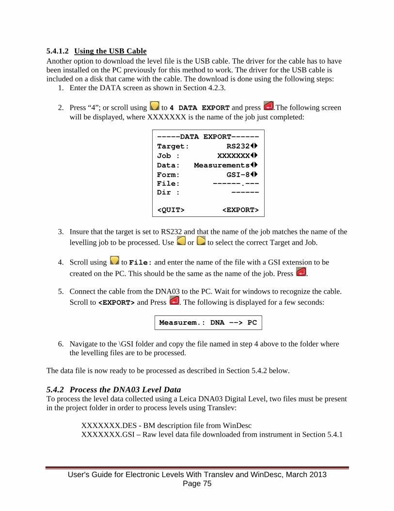
5.4.1.2 Using the USB Cable Another option to download the level file is the USB cable. The driver for the cable has to have been installed on the PC previously for this method to work. The driver for the USB cable is included on a disk that came with the cable. The download is done using the following steps:
1. Enter the DATA screen as shown in Section 4.2.3.
2. Press “4”; or scroll using to 4 DATA EXPORT and press .The following screen will be displayed, where XXXXXXX is the name of the job just completed:
3. Insure that the target is set to RS232 and that the name of the job matches the name of the levelling job to be processed. Use or to select the correct Target and Job.
4. Scroll using to File: and enter the name of the file with a GSI extension to be created on the PC. This should be the same as the name of the job. Press .
5. Connect the cable from the DNA03 to the PC. Wait for windows to recognize the cable. Scroll to <EXPORT> and Press . The following is displayed for a few seconds:
6. Navigate to the \GSI folder and copy the file named in step 4 above to the folder where the levelling files are to be processed.
The data file is now ready to be processed as described in Section 5.4.2 below. 5.4.2 Process the DNA03 Level Data To process the level data collected using a Leica DNA03 Digital Level, two files must be present in the project folder in order to process levels using Translev:
XXXXXXX.DES - BM description file from WinDesc XXXXXXX.GSI – Raw level data file downloaded from instrument in Section 5.4.1
-----DATA EXPORT------ Target: RS232 Job : XXXXXXX Data: Measurements Form: GSI-8 File: ------.--- Dir : ------ <QUIT> <EXPORT>
Measurem.: DNA --> PC
User's Guide for Electronic Levels With Translev and WinDesc, March 2013 Page 75
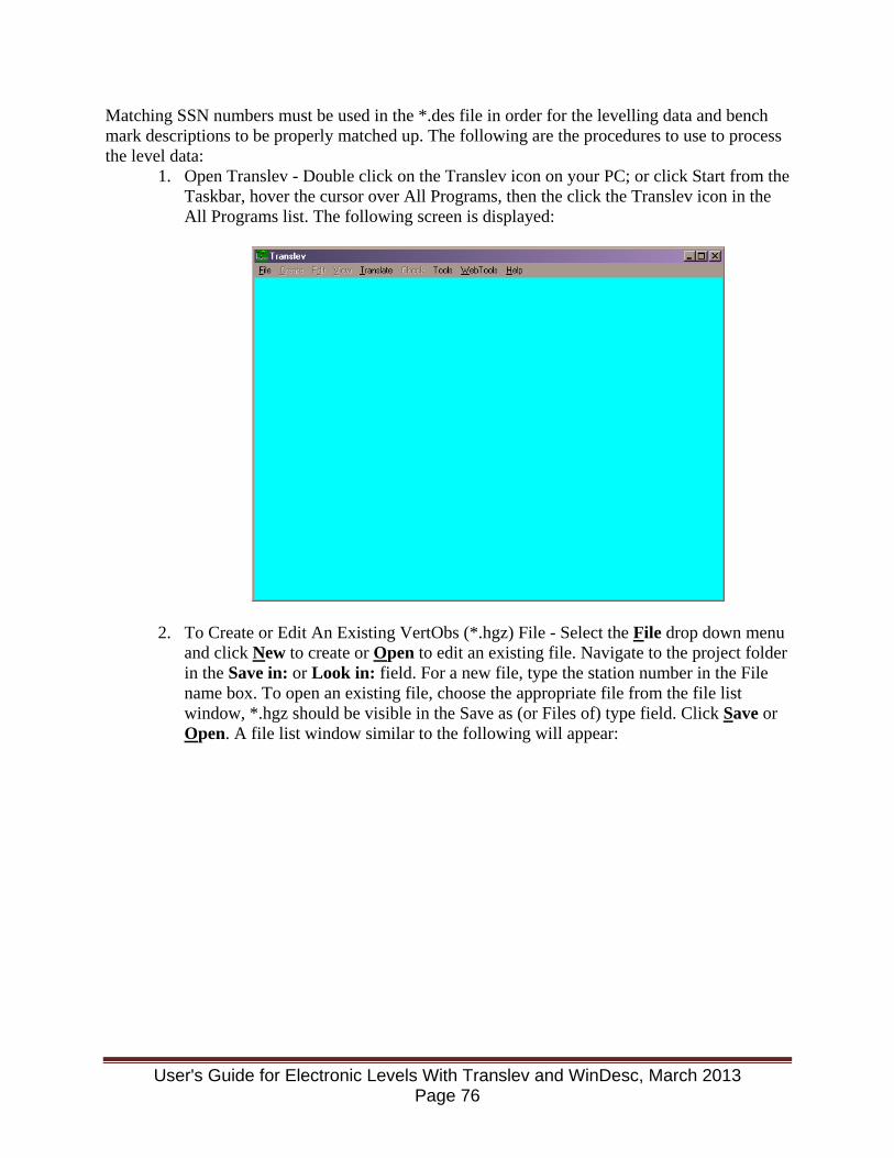
Matching SSN numbers must be used in the *.des file in order for the levelling data and bench mark descriptions to be properly matched up. The following are the procedures to use to process the level data:
1. Open Translev - Double click on the Translev icon on your PC; or click Start from the Taskbar, hover the cursor over All Programs, then the click the Translev icon in the All Programs list. The following screen is displayed:
2. To Create or Edit An Existing VertObs (*.hgz) File - Select the File drop down menu and click New to create or Open to edit an existing file. Navigate to the project folder in the Save in: or Look in: field. For a new file, type the station number in the File name box. To open an existing file, choose the appropriate file from the file list window, *.hgz should be visible in the Save as (or Files of) type field. Click Save or Open. A file list window similar to the following will appear:
User's Guide for Electronic Levels With Translev and WinDesc, March 2013 Page 76
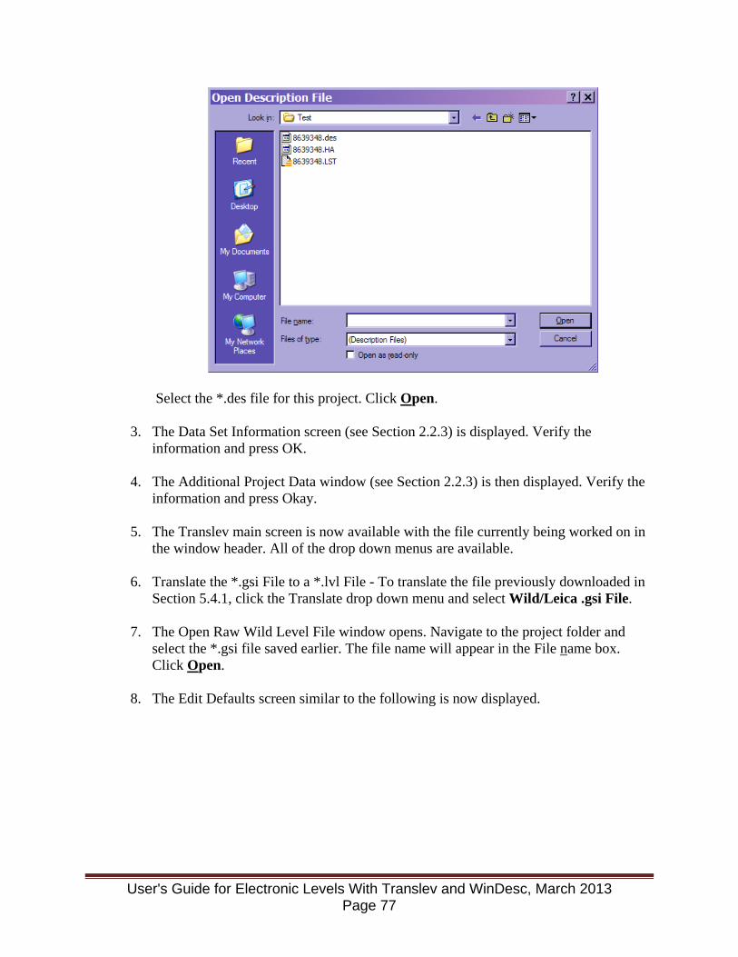
Select the *.des file for this project. Click Open.
3. The Data Set Information screen (see Section 2.2.3) is displayed. Verify the information and press OK.
4. The Additional Project Data window (see Section 2.2.3) is then displayed. Verify the information and press Okay.
5. The Translev main screen is now available with the file currently being worked on in
the window header. All of the drop down menus are available.
6. Translate the *.gsi File to a *.lvl File - To translate the file previously downloaded in Section 5.4.1, click the Translate drop down menu and select Wild/Leica .gsi File.
7. The Open Raw Wild Level File window opens. Navigate to the project folder and
select the *.gsi file saved earlier. The file name will appear in the File name box. Click Open.
8. The Edit Defaults screen similar to the following is now displayed.
User's Guide for Electronic Levels With Translev and WinDesc, March 2013 Page 77
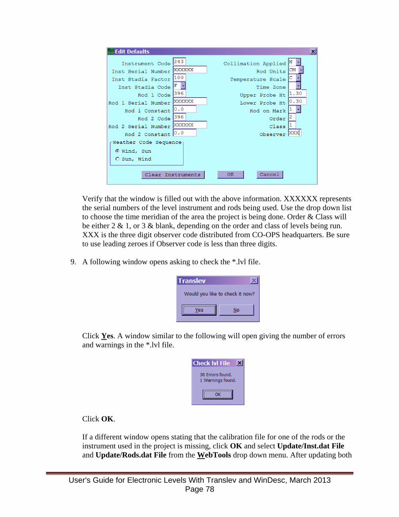
Verify that the window is filled out with the above information. XXXXXX represents the serial numbers of the level instrument and rods being used. Use the drop down list to choose the time meridian of the area the project is being done. Order & Class will be either 2 & 1, or 3 & blank, depending on the order and class of levels being run. XXX is the three digit observer code distributed from CO-OPS headquarters. Be sure to use leading zeroes if Observer code is less than three digits.
9. A following window opens asking to check the *.lvl file.
Click Yes. A window similar to the following will open giving the number of errors and warnings in the *.lvl file.
Click OK. If a different window opens stating that the calibration file for one of the rods or the instrument used in the project is missing, click OK and select Update/Inst.dat File and Update/Rods.dat File from the WebTools drop down menu. After updating both
User's Guide for Electronic Levels With Translev and WinDesc, March 2013 Page 78

*.dat files, restart Translev, open the appropriate *.hgz file, then select Lvl file from the Check drop down menu.
10. A window similar to the following opens displaying all of the errors that Translev found in the *.lvl file.
Review the file and make corrections where necessary to clear all the errors. In the example above, the bulk of the errors are caused by the Observer information being absent from the Observers.txt file. When finished reviewing, click File in the drop-down menu and select Close, or click the “X” in the upper right corner of the window.
11. A window similar to the following opens asking to edit the *.lvl file.
Click Yes.
User's Guide for Electronic Levels With Translev and WinDesc, March 2013 Page 79
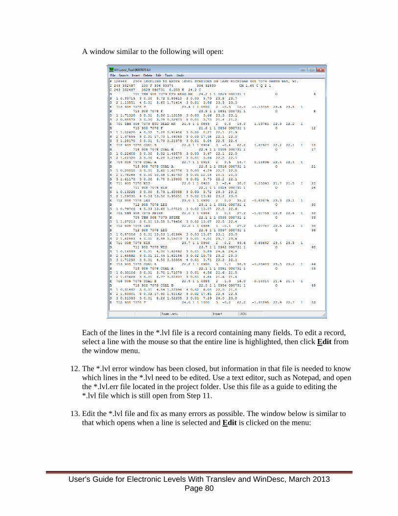
A window similar to the following will open:
Each of the lines in the *.lvl file is a record containing many fields. To edit a record, select a line with the mouse so that the entire line is highlighted, then click Edit from the window menu.
12. The *.lvl error window has been closed, but information in that file is needed to know which lines in the *.lvl need to be edited. Use a text editor, such as Notepad, and open the *.lvl.err file located in the project folder. Use this file as a guide to editing the *.lvl file which is still open from Step 11.
13. Edit the *.lvl file and fix as many errors as possible. The window below is similar to that which opens when a line is selected and Edit is clicked on the menu:
User's Guide for Electronic Levels With Translev and WinDesc, March 2013 Page 80

When edits are complete, click File in the drop-down menu and select Save. Next, click File in the drop-down menu and select Close.
14. Recheck the recently edited *.lvl file by selecting Check from the main Translev window and picking Lvl file. An Open lvl File window similar to that shown below will open:
User's Guide for Electronic Levels With Translev and WinDesc, March 2013 Page 81
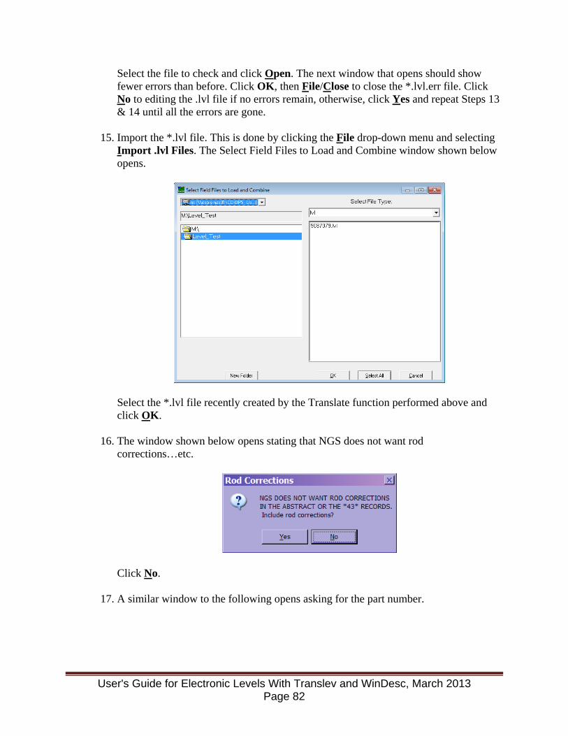
Select the file to check and click Open. The next window that opens should show fewer errors than before. Click OK, then File/Close to close the *.lvl.err file. Click No to editing the .lvl file if no errors remain, otherwise, click Yes and repeat Steps 13 & 14 until all the errors are gone.
15. Import the *.lvl file. This is done by clicking the File drop-down menu and selecting Import .lvl Files. The Select Field Files to Load and Combine window shown below opens.
Select the *.lvl file recently created by the Translate function performed above and click OK.
16. The window shown below opens stating that NGS does not want rod corrections…etc.
Click No.
17. A similar window to the following opens asking for the part number.
User's Guide for Electronic Levels With Translev and WinDesc, March 2013 Page 82
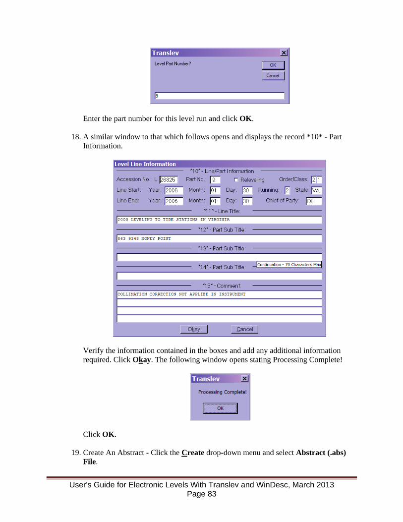
Enter the part number for this level run and click OK.
18. A similar window to that which follows opens and displays the record *10* - Part
Information.
Verify the information contained in the boxes and add any additional information required. Click Okay. The following window opens stating Processing Complete!
Click OK.
19. Create An Abstract - Click the Create drop-down menu and select Abstract (.abs) File.
User's Guide for Electronic Levels With Translev and WinDesc, March 2013 Page 83
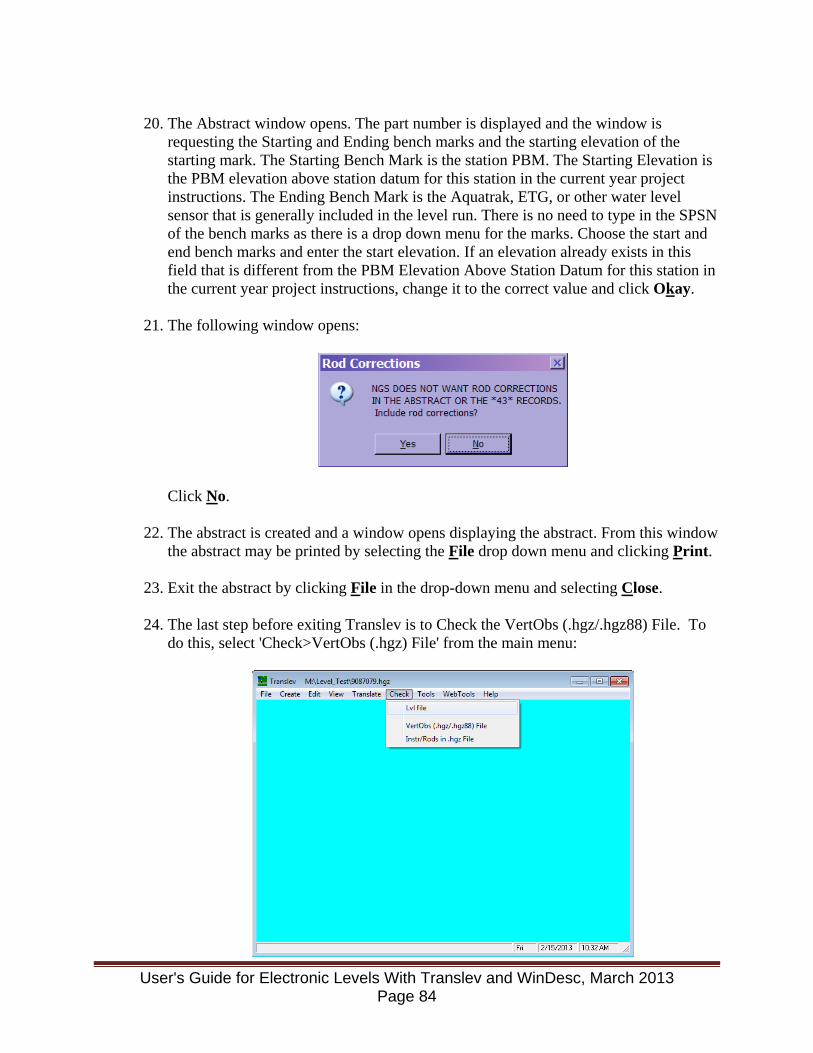
20. The Abstract window opens. The part number is displayed and the window is
requesting the Starting and Ending bench marks and the starting elevation of the starting mark. The Starting Bench Mark is the station PBM. The Starting Elevation is the PBM elevation above station datum for this station in the current year project instructions. The Ending Bench Mark is the Aquatrak, ETG, or other water level sensor that is generally included in the level run. There is no need to type in the SPSN of the bench marks as there is a drop down menu for the marks. Choose the start and end bench marks and enter the start elevation. If an elevation already exists in this field that is different from the PBM Elevation Above Station Datum for this station in the current year project instructions, change it to the correct value and click Okay.
21. The following window opens:
Click No.
22. The abstract is created and a window opens displaying the abstract. From this window the abstract may be printed by selecting the File drop down menu and clicking Print.
23. Exit the abstract by clicking File in the drop-down menu and selecting Close. 24. The last step before exiting Translev is to Check the VertObs (.hgz/.hgz88) File. To
do this, select 'Check>VertObs (.hgz) File' from the main menu:
User's Guide for Electronic Levels With Translev and WinDesc, March 2013
Page 84
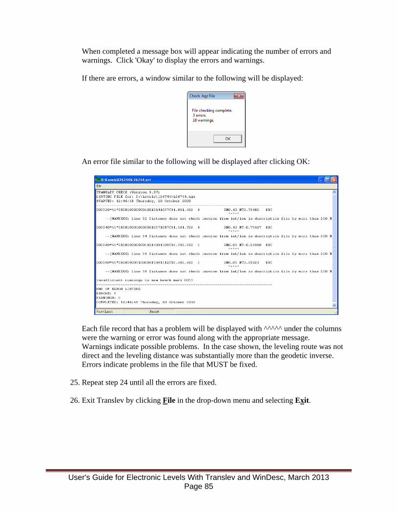
When completed a message box will appear indicating the number of errors and warnings. Click 'Okay' to display the errors and warnings. If there are errors, a window similar to the following will be displayed:
An error file similar to the following will be displayed after clicking OK:
Each file record that has a problem will be displayed with ^^^^^ under the columns were the warning or error was found along with the appropriate message. Warnings indicate possible problems. In the case shown, the leveling route was not direct and the leveling distance was substantially more than the geodetic inverse. Errors indicate problems in the file that MUST be fixed.
25. Repeat step 24 until all the errors are fixed.
26. Exit Translev by clicking File in the drop-down menu and selecting Exit.
User's Guide for Electronic Levels With Translev and WinDesc, March 2013 Page 85

Appendix A - Programs Required on Personal Computer (PC) The following programs are required installations on the personal computers of those generating description files using the programs required by the National Geodetic Survey (NGS). Descriptions courtesy of the NGS web site. To provide consistency throughout CO-OPS, including CO-OPS IDIQ contractors, install the following software in the folder C:\NGS-Apps. This will facilitate the resolution of any issues that arise regarding the correct operation of the software. Note: Google Earth does not have to be installed in this folder. WinDesc - NGS supported Description Entry Software. The latest version is located on http://www.ngs.noaa.gov/PC_PROD/pc_prod.shtml Translev - This program facilitates the process of editing, formatting and checking digital levelling observation data and creates abstracts, bok files, and VertObs datasets for submission to the NGS. The program includes many built-in functions such as predicting temperature differences, refraction corrections, rod corrections and plotting. Also included are routines for editing *.lvl files and VertObs files. The latest version is located on http://www.ngs.noaa.gov/PC_PROD/pc_prod.shtml DSWORLD - DSWorld plots NGS network points by state, county and type (vertical or horizontal) in Google Earth. Google Earth must be installed prior to running DSWorld. NOTE: Because of changes to NGS web offerings, older versions of DSWorld no longer function. Please upgrade to the latest release (2.05 or better). The latest version is located on http://www.ngs.noaa.gov/PC_PROD/PARTNERS/index.shtml Google Earth - This application is supported by ISD and installed on the personal computers of those using the levelling programs.
User's Guide for Electronic Levels With Translev and WinDesc, March 2013 Page 86

Appendix B - Program Error Message Lists
Refer to the Help functions in References (6) and (7) for the most up to date listing of the program error messages. The Help function will also be the first stop in determining the method of fixing those errors.
User's Guide for Electronic Levels With Translev and WinDesc, March 2013 Page 87

Appendix C - Screen Shots of WinDesc’s Data Entry Form The following are screen shots of the Data Entry Form which change based on the DNR and Rec codes entered. Note the window title changes depending on which code has been entered. Case 1 – Original description of a new mark. Code D
User's Guide for Electronic Levels With Translev and WinDesc, March 2013 Page 88
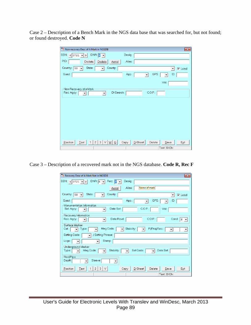
Case 2 – Description of a Bench Mark in the NGS data base that was searched for, but not found; or found destroyed. Code N
Case 3 – Description of a recovered mark not in the NGS database. Code R, Rec F
User's Guide for Electronic Levels With Translev and WinDesc, March 2013 Page 89
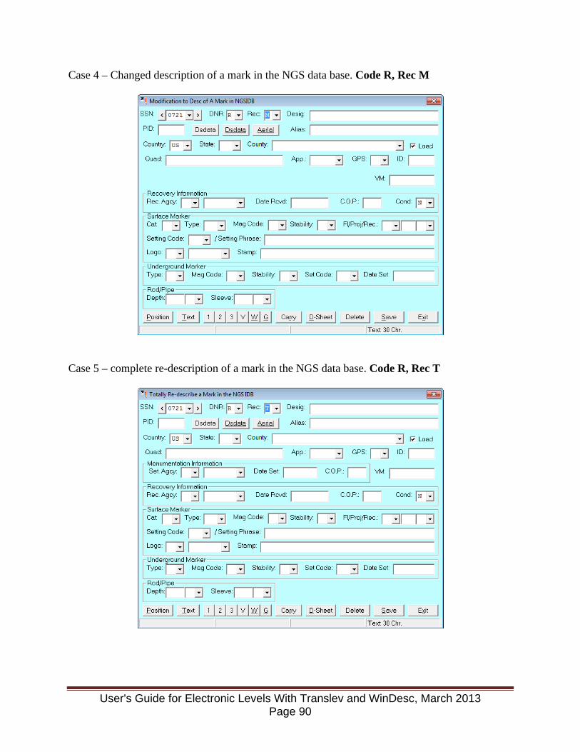
Case 4 – Changed description of a mark in the NGS data base. Code R, Rec M
Case 5 – complete re-description of a mark in the NGS data base. Code R, Rec T
User's Guide for Electronic Levels With Translev and WinDesc, March 2013 Page 90
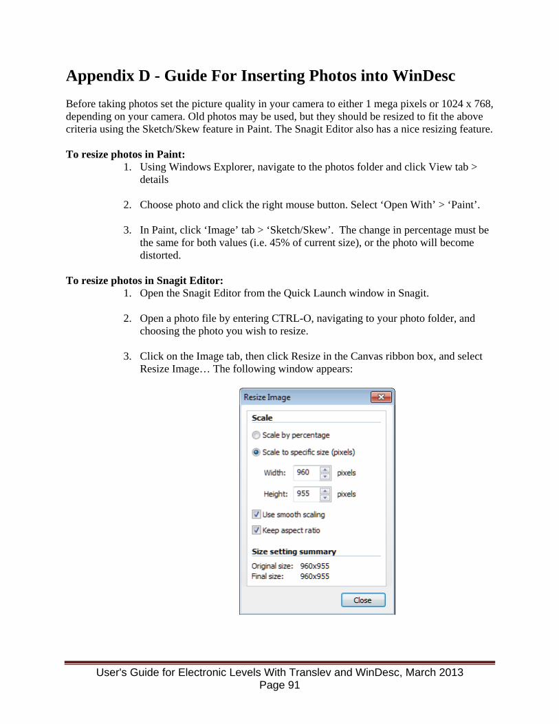
Appendix D - Guide For Inserting Photos into WinDesc Before taking photos set the picture quality in your camera to either 1 mega pixels or 1024 x 768, depending on your camera. Old photos may be used, but they should be resized to fit the above criteria using the Sketch/Skew feature in Paint. The Snagit Editor also has a nice resizing feature.
To resize photos in Paint:
1. Using Windows Explorer, navigate to the photos folder and click View tab > details
2. Choose photo and click the right mouse button. Select ‘Open With’ > ‘Paint’.
3. In Paint, click ‘Image’ tab > ‘Sketch/Skew’. The change in percentage must be the same for both values (i.e. 45% of current size), or the photo will become distorted.
To resize photos in Snagit Editor:
1. Open the Snagit Editor from the Quick Launch window in Snagit.
2. Open a photo file by entering CTRL-O, navigating to your photo folder, and choosing the photo you wish to resize.
3. Click on the Image tab, then click Resize in the Canvas ribbon box, and select Resize Image… The following window appears:
User's Guide for Electronic Levels With Translev and WinDesc, March 2013 Page 91
Select Scale to specific size (pixels), and adjust the width and height to be within 1024x768. Keep the other boxes checked as shown in the picture above and the photo will not become distorted.
4. Save the resized photo. Naming and Labelling Photos:
1. Update description information before using. This will help to ensure that the data WinDesc uses to rename photos is correct.
2. Choose the appropriate photo for the button (1 = face, 2 = tripod height, 3 = directional photos.
3. Rename the photo when prompted. Ensure Renamed information given by WinDesc is correct before clicking OK. Ensure button 3 photos have the direction entered after the photo number (i.e. PID, BM Designation, 3NNW, date). Hint: clicking on the View tab brings up Google Earth and helps you identify the direction if you don’t know it.
4. Labelling photos: for button 1 and 2 photos use: Edit tab > Standard Label and button 3 photos use: Edit tab > Custom Label. The direction (i.e. NNW) should be added after the photo number for button 3 photos (i.e. BM Designation, PID, 3W, date). The direction should be added when the info is highlighted in blue. All labels should be placed at the bottom of the photo, and centered from left to right by moving the numbered box to the above location and pressing Enter.
5. After labelling each photo, go to ‘File’ > Save & Exit
User's Guide for Electronic Levels With Translev and WinDesc, March 2013 Page 92

Appendix E - DNA03 Level Procedure Reference Guide
Print the next two pages on the front and back of a sheet of paper and laminate.
User's Guide for Electronic Levels With Translev and WinDesc, March 2013 Page 93
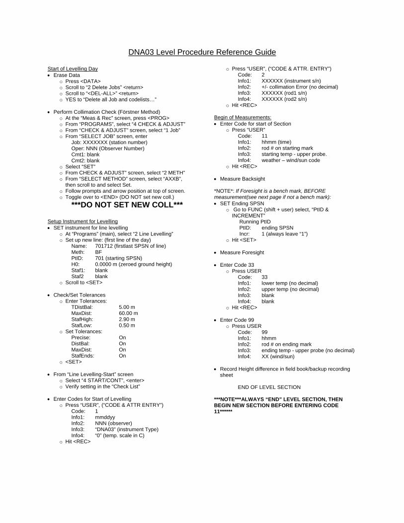
DNA03 Level Procedure Reference Guide
Start of Levelling Day • Erase Data
o Press <DATA> o Scroll to “2 Delete Jobs” <return> o Scroll to “<DEL-ALL>” <return> o YES to “Delete all Job and codelists…”
• Perform Collimation Check (Förstner Method)
o At the “Meas & Rec” screen, press <PROG> o From “PROGRAMS”, select “4 CHECK & ADJUST” o From “CHECK & ADJUST” screen, select “1 Job” o From “SELECT JOB” screen, enter
Job: XXXXXXX (station number) Oper: NNN (Observer Number) Cmt1: blank Cmt2: blank
o Select “SET” o From CHECK & ADJUST” screen, select “2 METH” o From “SELECT METHOD” screen, select “AXXB”,
then scroll to and select Set. o Follow prompts and arrow position at top of screen. o Toggle over to <END> (DO NOT set new coll.)
***DO NOT SET NEW COLL***
Setup Instrument for Levelling • SET instrument for line levelling
o At “Programs” (main), select “2 Line Levelling” o Set up new line: (first line of the day)
Name: 701712 (firstlast SPSN of line) Meth: BF PtID: 701 (starting SPSN) H0: 0.0000 m (zeroed ground height) Staf1: blank Staf2 blank
o Scroll to <SET> • Check/Set Tolerances
o Enter Tolerances: TDistBal: 5.00 m MaxDist: 60.00 m StafHigh: 2.90 m StafLow: 0.50 m
o Set Tolerances: Precise: On DistBal: On MaxDist: On StafEnds: On
o <SET> • From “Line Levelling-Start” screen
o Select “4 START/CONT”, <enter> o Verify setting in the “Check List”
• Enter Codes for Start of Levelling
o Press “USER”, (“CODE & ATTR ENTRY”) Code: 1 Info1: mmddyy Info2: NNN (observer) Info3: “DNA03” (instrument Type) Info4: “0” (temp. scale in C)
o Hit <REC>
o Press “USER”, (“CODE & ATTR. ENTRY”) Code: 2 Info1: XXXXXX (instrument s/n) Info2: +/- collimation Error (no decimal) Info3: XXXXXX (rod1 s/n) Info4: XXXXXX (rod2 s/n)
o Hit <REC> Begin of Measurements: • Enter Code for start of Section
o Press “USER” Code: 11 Info1: hhmm (time) Info2: rod # on starting mark Info3: starting temp - upper probe. Info4: weather – wind/sun code
o Hit <REC> • Measure Backsight *NOTE*: If Foresight is a bench mark, BEFORE measurement(see next page if not a bench mark): • SET Ending SPSN
o Go to FUNC (shift + user) select, “PtID & INCREMENT”
Running PtID PtID: ending SPSN Incr: 1 (always leave “1”)
o Hit <SET> • Measure Foresight • Enter Code 33
o Press USER Code: 33 Info1: lower temp (no decimal) Info2: upper temp (no decimal) Info3: blank Info4: blank
o Hit <REC> • Enter Code 99
o Press USER Code: 99 Info1: hhmm Info2: rod # on ending mark Info3: ending temp - upper probe (no decimal) Info4: XX (wind/sun) • Record Height difference in field book/backup recording
sheet END OF LEVEL SECTION ***NOTE***ALWAYS “END” LEVEL SECTION, THEN BEGIN NEW SECTION BEFORE ENTERING CODE 11******
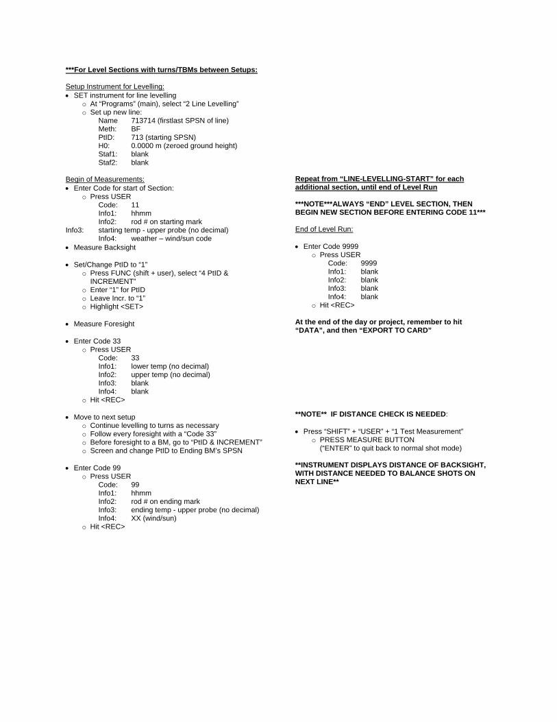
***For Level Sections with turns/TBMs between Setups: Setup Instrument for Levelling: • SET instrument for line levelling
o At “Programs” (main), select “2 Line Levelling” o Set up new line:
Name 713714 (firstlast SPSN of line) Meth: BF PtID: 713 (starting SPSN) H0: 0.0000 m (zeroed ground height) Staf1: blank Staf2: blank Begin of Measurements: • Enter Code for start of Section:
o Press USER Code: 11
Info1: hhmm Info2: rod # on starting mark Info3: starting temp - upper probe (no decimal) Info4: weather – wind/sun code • Measure Backsight • Set/Change PtID to “1”
o Press FUNC (shift + user), select “4 PtID & INCREMENT”
o Enter “1” for PtID o Leave Incr. to “1” o Highlight <SET>
• Measure Foresight • Enter Code 33
o Press USER Code: 33 Info1: lower temp (no decimal) Info2: upper temp (no decimal) Info3: blank Info4: blank
o Hit <REC> • Move to next setup
o Continue levelling to turns as necessary o Follow every foresight with a “Code 33” o Before foresight to a BM, go to “PtID & INCREMENT” o Screen and change PtID to Ending BM’s SPSN
• Enter Code 99
o Press USER Code: 99 Info1: hhmm Info2: rod # on ending mark Info3: ending temp - upper probe (no decimal) Info4: XX (wind/sun)
o Hit <REC>
Repeat from “LINE-LEVELLING-START” for each additional section, until end of Level Run ***NOTE***ALWAYS “END” LEVEL SECTION, THEN BEGIN NEW SECTION BEFORE ENTERING CODE 11*** End of Level Run: • Enter Code 9999
o Press USER Code: 9999 Info1: blank Info2: blank Info3: blank Info4: blank
o Hit <REC> At the end of the day or project, remember to hit “DATA”, and then “EXPORT TO CARD” **NOTE** IF DISTANCE CHECK IS NEEDED: • Press “SHIFT” + “USER” + “1 Test Measurement”
o PRESS MEASURE BUTTON (“ENTER” to quit back to normal shot mode)
**INSTRUMENT DISPLAYS DISTANCE OF BACKSIGHT, WITH DISTANCE NEEDED TO BALANCE SHOTS ON NEXT LINE**
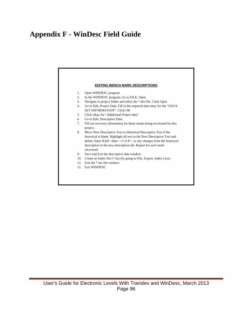
Appendix F - WinDesc Field Guide
EDITING BENCH MARK DESCRIPTIONS
1. Open WINDESC program 2. In the WINDESC program, Go to FILE, Open. 3. Navigate to project folder and select the *.des file. Click Open 4. Go to Edit, Project Data. Fill in the required data entry for the “DATA
SET INFORMATION”. Click OK 5. Click Okay for “Additional Project data” 6. Go to Edit, Descriptive Data. 7. Fill out recovery information for those marks being recovered for this
project. 8. Move New Descriptive Text to Historical Descriptive Text if the
historical is blank. Highlight all text in the New Descriptive Text and delete. Enter RAD <date> <C.O.P>, or any changes from the historical description in the new description tab. Repeat for each mark recovered.
9. Save and Exit the descriptive data window. 10. Create an Index file (*.inx) by going to File, Export, Index (.inx) 11. Exit the *.inx file window. 12. Exit WINDESC
User's Guide for Electronic Levels With Translev and WinDesc, March 2013 Page 96
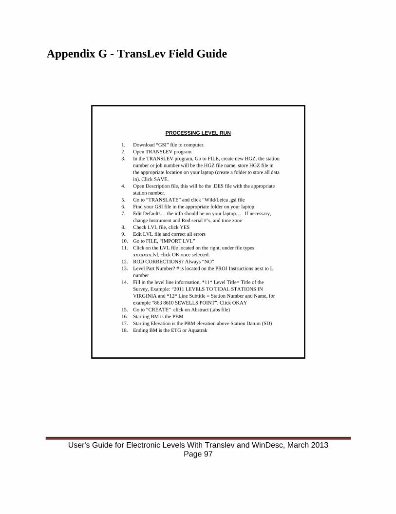
Appendix G - TransLev Field Guide
PROCESSING LEVEL RUN
1. Download “GSI” file to computer. 2. Open TRANSLEV program 3. In the TRANSLEV program, Go to FILE, create new HGZ, the station
number or job number will be the HGZ file name, store HGZ file in the appropriate location on your laptop (create a folder to store all data in). Click SAVE.
4. Open Description file, this will be the .DES file with the appropriate station number.
5. Go to “TRANSLATE” and click “Wild/Leica .gsi file 6. Find your GSI file in the appropriate folder on your laptop 7. Edit Defaults… the info should be on your laptop… If necessary,
change Instrument and Rod serial #’s, and time zone 8. Check LVL file, click YES 9. Edit LVL file and correct all errors 10. Go to FILE, “IMPORT LVL” 11. Click on the LVL file located on the right, under file types:
xxxxxxx.lvl, click OK once selected. 12. ROD CORRECTIONS? Always “NO” 13. Level Part Number? # is located on the PROJ Instructions next to L
number 14. Fill in the level line information, *11* Level Title= Title of the
Survey, Example: “2011 LEVELS TO TIDAL STATIONS IN VIRGINIA and *12* Line Subtitle = Station Number and Name, for example “863 8610 SEWELLS POINT”. Click OKAY
15. Go to “CREATE” click on Abstract (.abs file) 16. Starting BM is the PBM 17. Starting Elevation is the PBM elevation above Station Datum (SD) 18. Ending BM is the ETG or Aquatrak
User's Guide for Electronic Levels With Translev and WinDesc, March 2013 Page 97

Appendix H - Transferring NGS Data Sheets to Create a Water Level Description File These steps will describe how to create a *.des file for a new station based on the latitude and longitude of the station measured at the site during the reconnaissance or scaled from a chart. It is a good idea to have the PIDs of previously recovered bench marks from the recon, or a list of PIDs of the most likely bench marks to be found in the area based on a previous retrieval of datasheets from NGS. The procedure below does a lat/lon/radius search from the NGS database, and there could be quite a large number of bench marks downloaded during the search. The list of PIDs will help keep the marks desired for the *.des file. • Start WinDesc • Open or create a *.des for the station where you need to create bench mark descriptions from
NGS data sheets. • Enter Project Data for the station as described in Section 2.2.2. Exit to the main WinDesc
window. • From the File drop down list select Import/From Internet/By Lat, Lon, Radius • Enter the latitude and longitude for the water level station and enter 1 for the radius. Click
OK • Check all the boxes and click Okay • Click Any Vertical under Type of Control and Any under Stability. Click Okay • Enter the starting SSN. The SSNs will be changed when the descriptions are edited, so
starting number does not matter except if adding to a *.des file that already has marks. Pick a number that is larger than the largest SSN already in the *.des file. Click OK.
• A window opens informing how many marks have been found. To continue to retrieve the datasheet information into WinDesc, click Yes.
• After the datasheets have been retrieved, a window opens displaying: Done! Click OK. • From the Edit drop down list select Delete Descriptions. A window opens showing all the
bench mark descriptions that have been imported into the *.des file. Using the list of probable/recovered marks from the recon or earlier NGS search, select all of the marks to delete and press OK. Multiple marks are chosen by holding down the Shift key to select a range or by holding down the Ctrl key to select individual marks throughout the list.
• Use the procedures in Section 2.2.3 to edit the bench mark information. Change the SSN: numbers to match the part number and standardized SSN list from the table in that Section.
User's Guide for Electronic Levels With Translev and WinDesc, March 2013 Page 98

Appendix I - Converting DESC generated *.HA files to WinDesc *.DES files *.HA files that have been created with the DESC program can be converted to WinDesc *.DES files. The procedure for doing this is as follows:
1. Copy the *.HA file to the drive and folder where you wish to create the *.DES file. 2. Start a Command Prompt (DOS) window. 3. Navigate to the drive and folder where the *.HA file to convert is located. 4. Type READFILE and press enter. 5. Select Read an *.HA file 6. Enter the file name of the *.HA file to be converted & press enter 7. Enter the file name of the file to be created using *.LST as the extension 8. Press F10. 9. Select Output by SSN 10. Select Exit 11. Close DOS window 12. Start WinDesc 13. Select File drop down and click Open 14. Navigate to the folder the new *.LST file resides in the Look In: field of the Open
window 15. Choose Unified Description Files (*.lst) in the Files of type: field 16. Select the file to convert in the files window. 17. Click Open 18. Enter US for Country Code 19. A window should appear announcing the creation of the *.des file 20. Select Edit drop down and click Project Data. 21. Ensure all relevant information is filled out as detailed in Step 2 of Section 2.2.3. 22. Select Edit drop down and click Descriptive Data 23. Ensure all relevant information is filled out as detailed in Step 3 of Section 2.2.4. 24. Select Text and copy the main description to the New Descriptive Text window. 25. Save description 26. Repeat steps 23 to 26 for all bench mark descriptions 27. Exit WinDesc
User's Guide for Electronic Levels With Translev and WinDesc, March 2013 Page 99
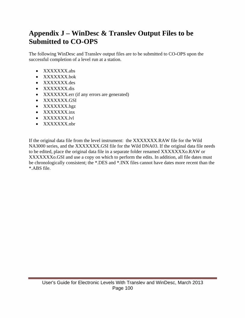
Appendix J – WinDesc & Translev Output Files to be Submitted to CO-OPS The following WinDesc and Translev output files are to be submitted to CO-OPS upon the successful completion of a level run at a station.
• XXXXXXX.abs • XXXXXXX.bok • XXXXXXX.des • XXXXXXX.dis • XXXXXXX.err (if any errors are generated) • XXXXXXX.GSI • XXXXXXX.hgz • XXXXXXX.inx • XXXXXXX.lvl • XXXXXXX.nbr
If the original data file from the level instrument: the XXXXXXX.RAW file for the Wild NA3000 series, and the XXXXXXX.GSI file for the Wild DNA03. If the original data file needs to be edited, place the original data file in a separate folder renamed XXXXXXXo.RAW or XXXXXXXo.GSI and use a copy on which to perform the edits. In addition, all file dates must be chronologically consistent; the *.DES and *.INX files cannot have dates more recent than the *.ABS file.
User's Guide for Electronic Levels With Translev and WinDesc, March 2013 Page 100

Last Page
User's Guide for Electronic Levels With Translev and WinDesc, March 2013 Page 101