USER’S GUIDE AND MAINTENANCE MANUAL FOR DLB-2000 & DG...
18
USER’S GUIDE AND MAINTENANCE MANUAL FOR DLB-2000 & DG-2000 LUG SHAFTS ENG
-
Upload
nguyenkhanh -
Category
Documents
-
view
215 -
download
0
Transcript of USER’S GUIDE AND MAINTENANCE MANUAL FOR DLB-2000 & DG...
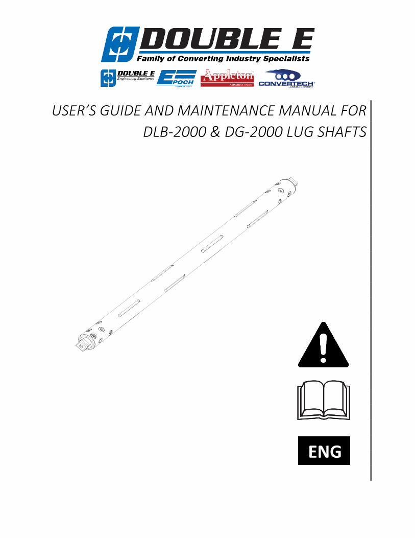
USER’S GUIDE AND MAINTENANCE MANUAL FOR
DLB-2000 & DG-2000 LUG SHAFTS
ENG

www.ee-co.com DLB-2000 & DG-2000 User Manual Page 2 of 18
USER’S GUIDE AND MAINTENANCE MANUAL FOR DG-2000 & DLB-2000 LUG SHAFTS
Version 1.1
June 14, 2018
Copyright © 2018 Double E Company, LLC
All rights reserved.
This publication cannot be reproduced, completely or partially, without prior written authorization from Double E Company. Double E Company's
products are subject to frequent changes due to updates and improvements. Therefore, the information included in this publication can undergo
modifications without notice. Double E Company appreciates any feedback relating to possible mistakes or omissions.

www.ee-co.com DLB-2000 & DG-2000 User Manual Page 3 of 18
A. INTRODUCTION .
A.1 Introduction
We thank you for choosing Double E Company DLB-2000 or DG-2000 lug shafts and are pleased to have
you as a customer. We are confident that our product will provide you with years of satisfaction. For
optimal performance, please use and maintain your DLB-2000 or DG-2000 lug shafts as outlined in this
manual.
We recommend that you read this manual carefully and refer to it whenever a problem may arise. Our
Technical Support department is also always available for advice and assistance. This manual describes the
installation, operation, usage precautions, and detailed information about this product’s accessories and
options.
The product must be used according to the instructions. Keep this manual as a reference for the future.
Double E Company reserves the right, at any time, to make changes (without any obligation of revision),
felt to be useful for the product improvement or for any constructive or commercial reason. Copying,
buffering and transmission in any form (electronic, mechanical, by photocopying, translating or others) of
this publication is forbidden without express Double E Company authorization.
Double E Company refuses any responsibility in case supplied shafts are set at work before the machine
where they are going to be fitted has been declared to be in accordance with provision of the law 89/392
and its subsequent modifications.
www.ee-co.com DLB-2000 & DG-2000 User Manual Page 4 of 18
A.2 Table of Contents
A. INTRODUCTION ......................................................................................................................................... 3
A.1 Introduction ........................................................................................................................................ 3
A.2 Table of Contents ................................................................................................................................ 4
A.3 Important ............................................................................................................................................ 5
A.4 Warranty ............................................................................................................................................. 5
B. SAFETY . ......................................................................................... 5
B.1 Safety Instruction - Symbology ............................................................................................................ 5
B.2 Safe Operation of Equipment .............................................................................................................. 6
C. TERMINOLOGY .......................................................................................................................................... 7
C.1 Lug Shaft Components ........................................................................................................................ 7
D. OPERATING INSTRUCTIONS ...................................................................................................................... 8
D.1 Inflation/Deflation ............................................................................................................................... 8
E. PRODUCT SPECIFICATIONS ........................................................................................................................ 8
E.1 Technical Specifications ....................................................................................................................... 8
F. MAINTENANCE .......................................................................................................................................... 9
F.1 Routine Inspection ............................................................................................................................... 9
F.2 Annual Maintenance ........................................................................................................................... 9
F.3 Non-Routine Maintenance .................................................................................................................. 9
F.4 Decommissioning ................................................................................................................................ 9
F.5 Product Storage ................................................................................................................................... 9
G. REPLACEMENT OF COMPONENTS . ....................................................................................... 10
G.1 Bladder Assembly Replacement ........................................................................................................ 10
G.2 Lug Replacement .............................................................................................................................. 13
G.3 Journal Replacement ........................................................................................................................ 13
H. TROUBLESHOOTING ................................................................................................................................ 15
H.1 Troubleshooting ................................................................................................................................ 15
I. MANUFACTURER'S DECLARATION ............................................................................................................ 16
J. RETURNS .................................................................................................................................................. 16
www.ee-co.com DLB-2000 & DG-2000 User Manual Page 5 of 18
A.3 Important • Do not use this product before having read and understood the whole content of this manual.
• Double E Company has done everything possible to make this manual complete and correct.
• Please transfer this manual to subsequent users if the product is lent or sold.
• Should this documentation or the warning labels applied on the device be lost or damaged, please
request replacements from the supplying company.
A.4 Warranty
See general terms of sale. Our standard warranty is available on our website at www.ee-co.com.
B. SAFETY .
B.1 Safety Instruction - Symbology
• For safe operation of the DLB-2000 & DG-2000 lug shafts, carefully read these safety instructions before
use.
• Follow every WARNING and ATTENTION note, described in this section, as they are extremely important
for safety.
• In this manual, warnings and are indicated by the following signal word conventions.
Indicates a potentially dangerous situation that, if not avoided, is almost
certain to cause serious injuries or death.
Indicates a potentially dangerous situation that, if not avoided, can
cause moderate to serious injuries, or even death.
Indicates a potentially dangerous situation that, if not avoided, can
cause minor to moderate injuries or damage to the equipment.
Highlights information needed to ensure the proper use of this device.

www.ee-co.com DLB-2000 & DG-2000 User Manual Page 6 of 18
B.2 Safe Operation of Equipment Double E Company designs and manufactures lug shafts with maximum
safety in mind. Please take careful note of the following rules for safe
operation:
• Double E recommends always using the shaft carefully without abusing it. Avoid strong collisions and/or
accidental impacts with foreign bodies. These collisions can damage the shaft’s external gripping
elements or body.
• There is risk of injury or pinching from the rotation of this shaft during un/winding. Keep sufficient
distance during un/winding and do not touch any part of the shaft during rotation.
• Do not wear loose hair or clothing near rotating shaft for risk of entanglement.
• Avoid unnecessary emergency braking.
• Do not cantilever the shaft during winding or roll unloading unless stated in the customer approval
drawing.
• Do not use the lug shaft in working conditions different than stated in the specifications table or on any
notes on the approval drawing.
• Do not exceed the operating loads of the shaft as specified on the customer quotation and/or approval
drawing. This voids shaft warranty and can be unsafe.
• Make sure all fasteners are in place and torqued to the appropriate specification before operation.
• All replacement parts on this shaft should be original equipment supplied by the Double E Company.
Visually inspect the lug shaft prior to each use:
• Check the body for any cracks or excessive wear in the metal housing or sleeve.
• Check unsleeved carbon fiber shafts for any cracks, excessive wear, or nicks in excess of 1/16in deep
and 1/2in long.
• Check the lugs for any cracks or excessive wear.
• Check the journals for any cracks or excessive wear.
In the event that any of the above conditions are identified, do not put the shaft in service and contact Double
E Company Technical Support at 508-588-8099 extension 571.
www.ee-co.com DLB-2000 & DG-2000 User Manual Page 7 of 18
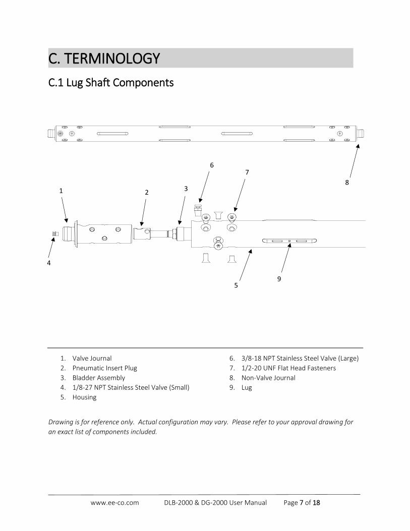
C. TERMINOLOGY .
C.1 Lug Shaft Components
1. Valve Journal
2. Pneumatic Insert Plug
3. Bladder Assembly
4. 1/8-27 NPT Stainless Steel Valve (Small)
5. Housing
6. 3/8-18 NPT Stainless Steel Valve (Large)
7. 1/2-20 UNF Flat Head Fasteners
8. Non-Valve Journal
9. Lug
Drawing is for reference only. Actual configuration may vary. Please refer to your approval drawing for
an exact list of components included.
6
5
1
7
4
3 2
9
8

www.ee-co.com DLB-2000 & DG-2000 User Manual Page 8 of 18
D. OPERATING INSTRUCTIONS .
D.1 Inflation/Deflation
Do not inflate or deflate shaft while it is rotating.
To inflate the shaft, press the tip of the Double E Inflation Tool into the air valve. Squeeze the Inflation Gun
while maintaining firm contact between the tip and the air valve for at least 30 seconds. This will ensure
that the shaft is fully inflated prior to use. Refer to your specific assembly drawing for the correct air
pressure for normal operation. In most cases, the shaft should be operated at a minimum of 80psi (5.5
bar) and should not exceed 100psi (7 bar).
Most Double E DLB-2000 and DG-2000 lug shafts are equipped with a single air valve. Refer to your
assembly drawing for the exact location of inflation air valves on the lug shaft.
Cores should completely cover the lugs when the shaft is inflated. In the event that the production core
length does not cover all of the lugs, “empty” or “dummy” cores should be used to cover exposed lugs.
This prevents over inflation of the bladder which can lead to premature wear.
To deflate the shaft, depress the air valve with the tip of the inflate/deflate tool for at least 30 seconds to
allow all the air to fully exhaust from the shaft. Never use a finger to release air from the shaft.
Never try to remove cores from the shaft without fully deflating the shaft.
This can cause serious damage to the core, lugs, and body of the lug shaft.
E. PRODUCT SPECIFICATIONS .
E.1 Technical Specifications
Do not exceed the operating parameters of the lug shaft as specified on
the assembly drawing. This voids shaft guarantees and can cause serious
injury.
Please refer to the approval drawing for the operating parameters and limits of your lug shaft.

www.ee-co.com DLB-2000 & DG-2000 User Manual Page 9 of 18
F. MAINTENANCE .
F.1 Routine Inspection
Perform routine inspection weekly. Routine inspection can usually be accomplished without disassembly
or removal of the shaft from the machine. The purpose of routine inspection is to ensure that the shaft is
functioning properly prior to being used in the machine. Check the pneumatic system to ensure that all of
the lugs expand and contract properly and that the lugs are free of defects, chips, or any foreign debris.
Additionally, inspect the lug slots to make sure that there is no foreign debris, such as a dust buildup, that
may impair the proper functionality of the shaft. Ensure that all fasteners are tightened properly and are
not missing.
F.2 Annual Maintenance
Perform annual inspection/maintenance yearly. Ensure that all fasteners are tightened properly and that
the journals and lugs are installed per shaft assembly drawing. If present, grease all bearing assemblies per
assembly drawing. Replace any lugs if uneven or excessive wear is seen. Inspect all lug slots and ensure
that there is no cracking or elongation of the slot. If you have a DLB-2000 carbon fiber shaft with exposed
carbon fiber, closely inspect the exposed carbon fiber and ensure it is free of cracks, splinters, excessive
wear, or delamination of the carbon fiber composite.
F.3 Non-Routine Maintenance
If the product is used under normal conditions and inspected regularly, it is rare that any non-routine or
extraordinary maintenance will be needed. In the event that it is necessary, it is recommended that you
contact Double E Company Technical Support at 508-588-8099 extension 571.
F.4 Decommissioning
If the product is withdrawn or removed from service, it is necessary to make all at-risk components
harmless through proper demolition. These operations must be carried out in accordance with the
provisions existing in the nation or locale in which the product will be disposed.
F.5 Product Storage
All Double E shafts should be carefully stored when not in use. To ensure maximum performance, Double
E shafts should be rested on padded surfaces to protect the metal or carbon fiber components. Storage
locations should be in cool, dry environments away from high levels of human or vehicle traffic.

www.ee-co.com DLB-2000 & DG-2000 User Manual Page 10 of 18
G. REPLACEMENT OF COMPONENTS .
G.1 Bladder Assembly Replacement
Always fully deflate shaft prior to performing any maintenance on the
bladder assemblies. Shaft should be secured to a work surface before
performing any maintenance.
1. Secure lugs in fully expanded position using Lug Wedge Assemblies; Double E Part Number 001-14596-1, 001-14596-2, or 001-14596-3 (contact Double E for exact number).
2. If the bladder cannot be inflated, insert a fastener in the threaded hole on each lug to pull it above the surface of the shaft and secure the lugs in the fully expanded position using Lug Wedge Assemblies.
3. If the bladder was inflated in step 1, deflate the bladder. Remove the air valve if it is a side valve configuration (see approval drawing).
4. Remove the valve journal by removing the 1/2-20 UNF fasteners. On 3in and 70mm shafts, it is possible that the pneumatic plug may come out with the journal. This is normal.
Note: A small amount of heat can be applied to the head of the fastener if necessary to break the Loctite®. Do not apply heat to the housing as this may damage the shaft.
5. Slide the bladder assembly out of the shaft body.
3in and 70mm Shafts Double E Company sells both complete bladder assemblies and bladder material on its own. If you have purchased a complete bladder assembly, please continue to step 14. If you purchased bladder material only and will reuse existing hardware, please continue below.
1. With the bladder assembly removed from the housing, remove the hex head nut on both ends and
remove the bladder plugs and pneumatic insert. Discard the old bladder material.
Pneumatic Insert Plug
Ferrule
O-rings
Pneumatic Insert
Jam Nut Lock Washer
Bladder Material
www.ee-co.com DLB-2000 & DG-2000 User Manual Page 11 of 18
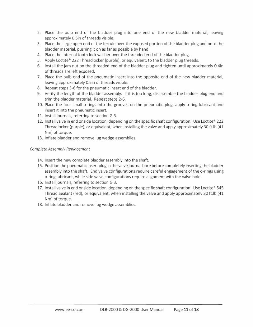
2. Place the bulb end of the bladder plug into one end of the new bladder material, leaving approximately 0.5in of threads visible.
3. Place the large open end of the ferrule over the exposed portion of the bladder plug and onto the bladder material, pushing it on as far as possible by hand.
4. Place the internal tooth lock washer over the threaded end of the bladder plug. 5. Apply Loctite® 222 Threadlocker (purple), or equivalent, to the bladder plug threads. 6. Install the jam nut on the threaded end of the bladder plug and tighten until approximately 0.4in
of threads are left exposed. 7. Place the bulb end of the pneumatic insert into the opposite end of the new bladder material,
leaving approximately 0.5in of threads visible. 8. Repeat steps 3-6 for the pneumatic insert end of the bladder. 9. Verify the length of the bladder assembly. If it is too long, disassemble the bladder plug end and
trim the bladder material. Repeat steps 2-6. 10. Place the four small o-rings into the grooves on the pneumatic plug, apply o-ring lubricant and
insert it into the pneumatic insert. 11. Install journals, referring to section G.3. 12. Install valve in end or side location, depending on the specific shaft configuration. Use Loctite® 222
Threadlocker (purple), or equivalent, when installing the valve and apply approximately 30 ft.lb (41 Nm) of torque.
13. Inflate bladder and remove lug wedge assemblies.
Complete Assembly Replacement
14. Insert the new complete bladder assembly into the shaft. 15. Position the pneumatic insert plug in the valve journal bore before completely inserting the bladder
assembly into the shaft. End valve configurations require careful engagement of the o-rings using o-ring lubricant, while side valve configurations require alignment with the valve hole.
16. Install journals, referring to section G.3. 17. Install valve in end or side location, depending on the specific shaft configuration. Use Loctite® 545
Thread Sealant (red), or equivalent, when installing the valve and apply approximately 30 ft.lb (41 Nm) of torque.
18. Inflate bladder and remove lug wedge assemblies.

www.ee-co.com DLB-2000 & DG-2000 User Manual Page 12 of 18
4in through 6in Shafts
1. With the bladder assembly removed from the housing, remove the existing hose or band-it clamps from the bladder assembly. Discard the used clamps.
2. Remove the aluminum pneumatic insert and plug from the old bladder assembly, leaving the o-rings in place.
3. Slide new band-it clamps over the new bladder material, insert the aluminum pneumatic insert and plug, and tighten with the Band-It Tensioning/Crimping Tool (Double E Part number 999-754-0002).
4. Insert the new bladder assembly into the shaft housing. 5. Position the bladder assembly pneumatic insert into the valve journal before completely inserting
the bladder assembly into the shaft. End valve configurations require careful engagement of the o-rings using o-ring lubricant, while side valve configurations require alignment with the valve hole.
6. Install journals, referring to section G.3. 7. Install valve in end or side location, depending on the specific shaft configuration. Use Loctite® 545
Thread Sealant (red), or equivalent, when installing the valve and apply approximately 30 ft.lb (41 Nm) of torque.
8. Inflate bladder and remove lug wedge assemblies.
Pneumatic Insert
Bladder Sleeve
Band-It Clamp
O-rings
Bladder Material

www.ee-co.com DLB-2000 & DG-2000 User Manual Page 13 of 18
G.2 Lug Replacement
Always fully deflate shaft prior to performing any maintenance on the
lugs. Shaft should be secured to a work surface before performing any
maintenance.
Some shafts have lugs with modified bases on one end. These modified lugs are noticeable without special measurements to make an identification. If your shaft has such a configuration, ensure that the outermost lugs have the modified end oriented towards the journal.
Disassembly
1. Secure lugs in fully expanded position using Lug Wedge Assemblies; Double E Part Number 001-14596-1, 001-14596-2, or 001-14596-3 (contact Double E for exact number).
2. If the bladder cannot be inflated, insert a fastener in the threaded hole on each lug to pull it above the surface of the shaft and secure the lugs in the fully expanded position using Lug Wedge Assemblies.
3. If the bladder was inflated in step 1, deflate the bladder and remove one of the journals, referring to section G.3. In longer shafts, removing both journals will increase the access to the lugs.
4. Remove the bladder. 5. One at a time, release the lug from the Lug Wedge Assembly and slide it out of the shaft. Installation
1. Rotate the shaft housing so that a row of lug slots is oriented in the down position. 2. Install lugs, one at a time, by sliding it into the housing until it drops into the lug slot. For long
shafts, Double E recommends the use of a bar to push and guide the lug into the housing. 3. Secure each lug with a Lug Wedge Assembly once in place. 4. Repeat steps 1-3 for each row of lug slots. 5. Install bladder according to section G.1. 6. Install journals according to section G.3.
G.3 Journal Replacement
Always fully deflate shaft prior to performing any maintenance on the
journals. Shaft should be secured to a work surface before performing
any maintenance.
If journal is removed for the purpose of bladder and/or lug replacement,
secure all lugs as described in section G.2. Otherwise, deflate the
bladder such that the retracted lugs secure the position of the bladder
prior to journal removal.

www.ee-co.com DLB-2000 & DG-2000 User Manual Page 14 of 18
Journal Removal Side Valve and Non-Valve Journal Configurations 1. To permit the removal of a side valve configured journal, first remove the valve. 2. Remove journal fasteners with an Allen wrench for 1/2-20 UNF fasteners. Because Loctite® 222
Threadlocker (purple) is used during the installation of the fasteners, removal can require an approximated 50 ft.lbs (68 Nm) of torque. Use a high leverage wrench to do so.
Note: A small amount of heat can be applied to the head of the fastener if necessary to break the Loctite®. Do not apply heat to the housing as this may damage the shaft.
3. Extract the journal from the shaft. In some cases, the journal may be difficult to remove. In this case, utilize the 1/2-13 UNC extraction thread found on the end of most journals to facilitate removal. Refer to your specific approval drawing for details.
End Valve Journal Configurations 1. Remove journal fasteners with an Allen wrench for 1/2-20 UNF fasteners. Because Loctite® 222
Threadlocker (purple), or equivalent, is used during the installation of the fasteners, removal can require an approximated 50 ft.lbs (68 Nm) of torque. Use a high leverage wrench to do so.
Note: A small amount of heat can be applied to the head of the fastener if necessary to break the Loctite®. Do not apply heat to the housing as this may damage the shaft.
2. Extract the journal from the shaft. In some cases, the journal may be difficult to remove. In this case, an appropriate bearing puller or slide hammer can be utilized to aid in journal removal.
Journal Installation
Side Valve and Non-Valve Journal Configurations 1. Install journal with all fastener holes and valve hole (if applicable) aligned. 2. Clean all flat head fasteners and apply Loctite® 222 Threadlocker (purple), or equivalent, to each
fastener. 3. Install each fastener, applying approximately 50 ft.lbs (69 Nm) of torque. In most configurations, there
are two fastener lengths, 0.75in and 1.0in. Install the 1.0in long fasteners first. End Valve Journal Configurations 1. Carefully engage the bladder assembly in the journal bore. 2. Align all fastener holes and pneumatic insert and install journal. 3. Clean all flat head fasteners and apply Loctite® 222 Threadlocker (purple), or equivalent, to each
fastener. 4. Install each fastener, applying approximately 50 ft.lbs (69 Nm) of torque. In most configurations, there
are two fastener lengths, 0.75in and 1.0in. Install the 1.0in long fasteners first.
www.ee-co.com DLB-2000 & DG-2000 User Manual Page 15 of 18
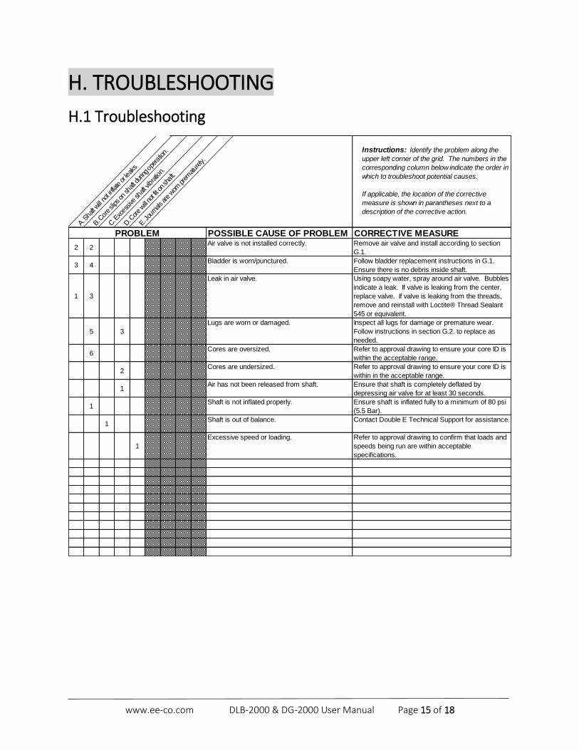
H. TROUBLESHOOTING
H.1 Troubleshooting
A. Sha
ft will
not inflate or lea
ks.
B. Cor
e slips on
shaft d
uring op
eration.
C. E
xces
sive
shaft v
ibratio
n.
D. C
ore will no
t fit on
sha
ft.
E. Jou
rnals are worn prem
atur
ely.
Instructions: Identify the problem along the
upper left corner of the grid. The numbers in the
corresponding column below indicate the order in
which to troubleshoot potential causes.
If applicable, the location of the corrective
measure is shown in parantheses next to a
description of the corrective action.
POSSIBLE CAUSE OF PROBLEM CORRECTIVE MEASURE
2 2Air valve is not installed correctly. Remove air valve and install according to section
G.1.
3 4Bladder is worn/punctured. Follow bladder replacement instructions in G.1.
Ensure there is no debris inside shaft.
1 3
Leak in air valve. Using soapy water, spray around air valve. Bubbles
indicate a leak. If valve is leaking from the center,
replace valve. If valve is leaking from the threads,
remove and reinstall with Loctite® Thread Sealant
545 or equivalent.
5 3
Lugs are worn or damaged. Inspect all lugs for damage or premature wear.
Follow instructions in section G.2. to replace as
needed.
6Cores are oversized. Refer to approval drawing to ensure your core ID is
within the acceptable range.
2Cores are undersized. Refer to approval drawing to ensure your core ID is
within in the acceptable range.
1Air has not been released from shaft. Ensure that shaft is completely deflated by
depressing air valve for at least 30 seconds.
1Shaft is not inflated properly. Ensure shaft is inflated fully to a minimum of 80 psi
(5.5 Bar).
1Shaft is out of balance. Contact Double E Technical Support for assistance.
1
Excessive speed or loading. Refer to approval drawing to confirm that loads and
speeds being run are within acceptable
specifications.
PROBLEM
www.ee-co.com DLB-2000 & DG-2000 User Manual Page 16 of 18
I. MANUFACTURER'S DECLARATION . Buyer shall afford Double E Company prompt and reasonable opportunity to inspect any goods as to which
a claim is made and Double E Company shall have the right of final determination of the cause and existence
of any defect under this warranty. No material may be returned to Double E Company without Double E
Company‘s express prior permission in the form of a return authorization number.
Correction of non-conformities, in the manner and for the period provided above, shall constitute
fulfillment of all liabilities of Double E Company to Buyer with respect for the goods, whether based on
contract, negligence, strict tort, or otherwise.
J. RETURNS . Warranty and non-warranty returns are initiated through the issuance of a return material authorization
(RMA) number from an authorized Double E Company sales or service/support representative. This can be
obtained by calling Double E Company in West Bridgewater, MA at 508-588-8099.
The RMA number should be clearly evident on the shipping label and/or invoice and the package should be
shipped freight prepaid. If questions arise or if additional information is required, please call the Inside Sales
department at 508-588-8099
Product returns should be sent to the address below:
Double E Company, LLC 319 Manley Street West Bridgewater, MA 02379 ATTN: RMA # __________

www.ee-co.com DLB-2000 & DG-2000 User Manual Page 17 of 18
NOTES
______________________________________________
______________________________________________
______________________________________________
______________________________________________
______________________________________________
______________________________________________
______________________________________________
______________________________________________
______________________________________________
______________________________________________
______________________________________________
______________________________________________
______________________________________________
______________________________________________
______________________________________________
______________________________________________
______________________________________________
______________________________________________
______________________________________________
______________________________________________
______________________________________________

www.ee-co.com DLB-2000 & DG-2000 User Manual Page 18 of 18
Copyright © 2018 Double E Company, LLC
All rights reserved.
This publication cannot be reproduced, completely or partially, without prior written authorization from Double E Company. Double E Company's
products are subject to frequent changes due to updates and improvements. Therefore, the information included in this publication can undergo
modifications without notice. Double E Company appreciates any feedback relating to possible mistakes or omissions.