User's 3 Series Manual FOUNDATION Fieldbus Communication ... · • Yokogawa makes no warranty of...
196
User's Manual IM 01R04B05-00E-E, additional manual to IM 01R04B04-00x-E Rota Yokogawa GmbH & Co. KG Rheinstr. 8 D-79664 Wehr Germany IM 01R04B05-00E-E ©Copyright July 2005 (Rü) 5th edition, April 2015 (Rü) 3 Series FOUNDATION Fieldbus Communication Type Coriolis Mass Flow and Density Meter Integral Type RCCT3 Remote Type RCCF31 + RCCS3
Transcript of User's 3 Series Manual FOUNDATION Fieldbus Communication ... · • Yokogawa makes no warranty of...

User'sManual
IM 01R04B05-00E-E, additional manual to IM 01R04B04-00x-E
Rota Yokogawa GmbH & Co. KGRheinstr. 8D-79664 WehrGermany
IM 01R04B05-00E-E©Copyright July 2005 (Rü)5th edition, April 2015 (Rü)
3 SeriesFOUNDATION Fieldbus Communication TypeCoriolis Mass Flow and Density MeterIntegral Type RCCT3Remote Type RCCF31 + RCCS3

Blank Page

CONTENTS
i IM 01R04B05-00E-E 5th edition April 01, 2015 -00All Rights Reserved. Copyright © 2005, Rota Yokogawa
Contents
1. INTRODUCTION ..................................................................................1-1
1.1 Using the Coriolis Flowmeter Safely .............................................................1-2
1.2 Warranty ...........................................................................................................1-3
1.3 Instruction according EMC ............................................................................1-3
1.4 ATEX Documentation ......................................................................................1-4
1.5 Disposal, Cleaning and Return ......................................................................1-5
2. AMPLIFIER FOR FOUNDATION FIELDBUS COMMUNICATION .....2-1
3. ABOUT FOUNDATION FIELDBUS .....................................................3-1
3.1 Outline ..............................................................................................................3-1
3.2 Internal Structure of ROTAMASS ..................................................................3-1
3.2.1 System/Network Management VFD ............................................................................3-1
3.2.2 Function Block VFD ............................................................................................. 3-1
3.3 Logical Structure of Each Block ...................................................................3-2
3.4 Wiring System Configuration .........................................................................3-2
4. Getting Started ....................................................................................4-1
4.1 Connection of Devices ...................................................................................4-1
4.2 Host Setting ......................................................................................................4-3
4.3 Power-on of ROTAMASS and Bus ..................................................................4-3
4.4 Integration od DD .............................................................................................4-3
4.5 Reading the Parameters ..................................................................................4-4
4.6 Continous Record of Values ...........................................................................4-4
4.7 Generation of Alarm .........................................................................................4-4

CONTENTS
iiIM 01R04B05-00E-E 5th edition April 01, 2015 -00 All Rights Reserved. Copyright © 2005, Rota Yokogawa
5. CONFIGURATION ................................................................................5-1
5.1 Network Design ...............................................................................................5-1
5.2 Network Definition ..........................................................................................5-1
5.3 Function Block Link Definitions ....................................................................5-2
5.4 Setting of Tags and Addresses .................................................................................... 5-3
5.5 Communication Setting ..................................................................................5-4
5.5.1 VCR Setting .......................................................................................................... 5-4
5.5.2 Function Block Execution Control .........................................................................5-5
5.6 Block Setting ...................................................................................................5-5
5.6.1 Link Objects ......................................................................................................... 5-5
5.6.2 Trend Objects ....................................................................................................... 5-6
5.6.3 View Objects ......................................................................................................... 5-6
5.6.4 AI Function Block Parameters .......................................................................... 5-16
5.6.5 Transducer Block Parameters .......................................................................... 5-18
6. IN-PROCESS OPERATION .................................................................6-1
6.1 Mode Transition ...............................................................................................6-1
6.2 Generation of Alarm .......................................................................................6-1
6.2.1 Indication of Alarm .............................................................................................. 6-1
6.2.2 Alarms and Events .............................................................................................. 6-3
6.3 Simulation Function........................................................................................6-3
7. DEVICE STATUS ..................................................................................7-1
8. GENERAL SPECIFICATIONS .............................................................8-1

CONTENTS
iii IM 01R04B05-00E-E 5th edition April 01, 2015 -00All Rights Reserved. Copyright © 2005, Rota Yokogawa
9. EXPLOSION PROTECTED TYPE INSTRUMENTS ............................9-1
9.1 ATEX ................................................................................................................9-1
9.1.1 Technical Data ...................................................................................................... 9-1
9.1.2 Installation ............................................................................................................ 9-5
9.1.3 Operation .............................................................................................................. 9-7
9.1.4 Maintenance and repair ....................................................................................... 9-7
9.1.5 Ex-relevant marking on name plate.................................................................... 9-7
9.2 FM ...................................................................................................................9-10
9.2.1 Technical Data .................................................................................................... 9-10
9.2.4 Ex-relevant marking on name plate ................................................................. 9-14
9.3 IECEx ..............................................................................................................9-18
9.3.1 Technical Data .................................................................................................... 9-18
9.3.2 Installation .......................................................................................................... 9-21
9.3.3 Operation ............................................................................................................ 9-22
9.3.4 Maintenance and repair .................................................................................... 9-22
9.3.5 Ex-relevant marking on name plate ................................................................. 9-22
9.3.6 I.S. fieldbus system complying with FISCO (only /EF4) ................................ 9-24
9.4 INMETRO (Brazil) ..........................................................................................9-25
9.5 NEPSI (China) ................................................................................................9-25
9.6 Gost approval ................................................................................................9-25

CONTENTS
ivIM 01R04B05-00E-E 5th edition April 01, 2015 -00 All Rights Reserved. Copyright © 2005, Rota Yokogawa
APPENDIX 1. LIST OF PARAMETERS FOR EACH BLOCK OF ROTA-MASS .......................................................................................................A-1
A1.1 Resource Block ............................................................................................A-1
A1.2 Al Function Block ........................................................................................A-4
A1.3 Transducer Block .........................................................................................A-8
A1.4 Integrator (IT) Block ................................................................................... A-16
A1.4.1 Schematic Diagram of Integrator Block ................................................ A-16
A1.4.2 Input process Section ..................................................................................A-17
A1.4.2.1 Determining Input Value Statuses ................................................................A-17
A1.4.2.2 Converting the Rate .......................................................................................A-17
A1.4.2.3 Converting Accumulation .............................................................................A-18
A1.4.2.4 Determining the Input Flow Direction ......................................................A-18
A1.4.3 Adder ......................................................................................................... A-18
A1.4.3.1 Status of Value after Addition .......................................................................A-18
A1.4.3.2 Addition ...........................................................................................................A-19
A1.4.4 Integrator .................................................................................................. A-19
A1.4.5 Output Process ........................................................................................A-21
A1.4.5.1 Status Determination .....................................................................................A-21
A1.4.5.2 Determining the Output Value ......................................................................A-22
A1.4.5.3 Mode Handling ...............................................................................................A-23
A1.4.6 Reset .........................................................................................................A-23
A1.4.6.1 Reset Trigger ..................................................................................................A-23
A1.4.6.2 Reset Timing ...................................................................................................A-23
A1.4.6.3 Reset Process ................................................................................................A-24
A1.4.7 List of Integrator Block Parameters .......................................................A-25

CONTENTS
v IM 01R04B05-00E-E 5th edition April 01, 2015 -00All Rights Reserved. Copyright © 2005, Rota Yokogawa
APPENDIX 2. APPLICATION, SETTING AND CHANGE OF BASIC ........PARAMETERS .......................................................................................A-27
A2.1 Applications and Selection of Basic Parameters ..................................A-27
A2.2 Setting and Change of Basic Parameters ..............................................A-28
A2.3 Setting the AI Function Blocks ................................................................A-28
A2.4 Setting the Transducer Block ...................................................................A-30
APPENDIX 3. OPERATION OF EACH PARAMETER IN FAILURE MODE ................................................................................................................A-33
APPENDIX 4. FUNCTION DIAGRAMS OF FUNCTION BLOCKS .....A-45
A4.1 AI Function Block ......................................................................................A-45
APPENDIX 5. PID BLOCK ...................................................................A-47
A5.1 Function Diagram ......................................................................................A-47
A5.2 Functions of PID Block .............................................................................A-47
A5.3 Parameters of PID Block ..........................................................................A-48
A5.4 PID Computation Details ..........................................................................A-50
A5.4.1 PV-proportional and -derivative Type PID (I-PD) Control Algorithm versus PV-derivative Type PID (PI-D) Control Algorithm ............................................................A-50
A5.4.2 PID Control Parameters ..................................................................................A-50
A5.5 Control Output ............................................................................................A-50
A5.5.1 Velocity Type Output Action ...........................................................................A-50
A5.6 Direction of Control Action .......................................................................A-50
A5.7 Control Action Bypass ...............................................................................A-51
A5.8 Feed-forward ...............................................................................................A-51
A5.9 Block Modes ...............................................................................................A-51
A5.9.1 Mode Transitions .............................................................................................A-52
A5.10 Bumpless Transfer ...................................................................................A-52
A5.11 Setpoint Limiters .....................................................................................A-52
A5.11.1 When PID Block Is in AUTO Mode ...............................................................A-52
A5.11.2 When PID Block Is in CAS or RCAS Mode ..................................................A-52
A5.12 External-output Tracking .........................................................................A-53

CONTENTS
viIM 01R04B05-00E-E 5th edition April 01, 2015 -00 All Rights Reserved. Copyright © 2005, Rota Yokogawa
A5.13 Measured-value Tracking ........................................................................A-53
A5.13.1 CONTROL_OPTS ...........................................................................................A-53
A5.14 Initialization and Manual Fallback (IMAN) ............................................A-53
A5.15 Manual Fallback .......................................................................................A-54
A5.15.1 STATUS_OPTS ...............................................................................................A-54
A5.16 Auto Fallback ...........................................................................................A-54
A5.17 Mode Shedding upon Computer Failure ...............................................A-54
A5.17.1 SHED_OPT ......................................................................................................A-54
A5.18 Alarms .......................................................................................................A-55
A5.18.1 Block Alarm (BLOCK_ALM)..........................................................................A-55
A5.19 Example of Block Connections .............................................................A-55
APPENDIX 6. SOFTWARE DOWNLOAD .............................................A-57
A6.1 Benefits of Software Download.................................................................A-57
A6.2 Specifications .............................................................................................A-57
A6.3 Preparations for Software Downloading ....................................................... A-57
A6.4 Software Download Sequence ..................................................................A-58
A6.5 Download Files ...........................................................................................A-58
A6.6 Steps after Activating a Field Device ........................................................A-59
A6.7 Troubleshooting ..........................................................................................A-60
A6.8 Resource Block’s Parameters Relating to Software Download .............A-60
A6.9 System/Network Management VFD Parameters Relating to Software Down-load .......................................................................................................................A-62
A6.10 Comments on System/Network Management VFD Parameters Relating to Software Download .............................................................................................A-63
APPENDIX 7. LINK MASTER FUNCTIONS .........................................A-65
A7.1 Link Active Scheduler ...............................................................................A-65
A7.2 Link Master .................................................................................................A-65
A7.3 Transfer of LAS ...........................................................................................A-66
A7.4 LM Functions ..............................................................................................A-67
A7.5 LM Parameters ...........................................................................................A-68

CONTENTS
vii IM 01R04B05-00E-E 5th edition April 01, 2015 -00All Rights Reserved. Copyright © 2005, Rota Yokogawa
A7.5.1 LM Parameter List ............................................................................................A-68
A7.5.2 Descriptions for LM Parameters ....................................................................A-70
A7.6 FAQs ............................................................................................................A-72
APPENDIX 8. DEVICEVIEWER WINDOW EXECUTED FROM FIELDMATE AND PRM (Plant Resource Manager) ................................................A-75

CONTENTS
viiiIM 01R04B05-00E-E 5th edition April 01, 2015 -00 All Rights Reserved. Copyright © 2005, Rota Yokogawa
Blank Page

1. INTRODUCTION
1-1All Rights Reserved. Copyright © 2005, Rota Yokogawa IM 01R04B05-00E-E 5th edition April 01, 2015 -00
This instrument has been adjusted at the factory before shipment.
To ensure correct use of the instrument, please read this manual thoroughly and fully understand how to operate the instrument before operating it.
NOTE
This manual describes the hardware and soft-ware configurations of the Rotamass Coriolis Massflowmeter.
Regarding This User's Manual
•Thismanualshouldbeprovidedtotheenduser.•Beforeuse,readthismanualthoroughlytocom-
prehend its contents.•Thecontentsofthismanualmaybechanged
without prior notice.•Allrightsarereserved.Nopartofthismanual
may be reproduced in any form without Yokoga-wa's written permission.
•Yokogawamakesnowarrantyofanykindwithregard to this material, including, but not limited to, implied warranties of merchantability and suitability for a particular purpose.
•Allreasonableefforthasbeenmadetoensurethe accuracy of the contents of this manual. However, if any errors or omissions are found, please inform Yokogawa.
•Yokogawaassumesnoresponsibilitiesforthisproduct except as stated in the warranty.
•Pleasenotethatthisuser'smanualmaynotberevised for any specification changes, construc-tion changes or operating part changes that are not considered to affect function or performance.
•Ifthecustomeroranythirdpartyisharmedbythe use of this product, Yokogawa assumes no responsibility for any such harm owing to any defects in the product which were not predict-able, or for any indirect damages.
Safety and Modification Precautions
•Thefollowinggeneralsafetyprecautionsmustbe observed during all phases of operation, service, and repair of this instrument. Failure to comply with these precautions or with specific WARNINGS given elsewhere in this manual violates safety standards of design, manufacture, and intended use of the instrument. Yokogawa assumes no liability for the customer's failure to comply with these requirements. If this instru-ment is used in a manner not specified in this manual, the protection provided by this instru-ment may be impaired.
•Thefollowingsafetysymbolmarksareusedinthis user's manual and instrument.
WARNING
A WARNING sign denotes a hazard. It calls at-tention to procedure, practice, condition or the like, which, if not correctly performed or adhered to, could result in injury or death of personnel.
CAUTION
A CAUTION sign denotes a hazard. It calls at-tention to procedure, practice, condition or the like, which, if not correctly performed or adhered to, could result in damage to or destruction of part or all of the product.
IMPORTANT
An IMPORTANT sign denotes that attention is required to avoid damage to the instrument or system failure.
NOTE
A NOTE sign denotes information necessary for essential understanding of operation and fea-tures.
1. INTRODUCTION
1. INTRODUCTION
1-2 All Rights Reserved. Copyright © 2005, Rota YokogawaIM 01R04B05-00E-E 5th edition April 01, 2015 -00
(3) Operation•Donotopenthecoveruntilthepowerhasbeen
off for at least 10 minutes. Only expert engi-neer or skilled personnel are permitted to open the cover.
(4) Maintenance•MaintenanceontheCoriolisflowmetershould
be performed by expert engineer or skilled personnel. No operator shall be permitted to perform any operations relating to maintenance.
•Alwaysconformtomaintenanceproceduresoutlined in this manual. If necessary, contact Yokogawa.
•Careshouldbetakentopreventthebuildupof dirt, dust or other substances on the display panel glass or data plate. If these surfaces do get dirty, wipe them clean with a soft dry cloth.
(5) European Pressure Equipment Directive (PED)
•WhenusingtheinstrumentasaPED-compliant product, be sure to read Chapter 10 before
use.(6)HazardousDutyTypeInstruments•
For explosion proof type instruments the
description in chapter 9 "EXPLO-
SION PROTECT-
ED TYPE INSTRUMENT" has priority to the other descriptions in this instruction manual. •AllinstructionmanualsforATEXExrelated products are available in English, German and French. Should you require Ex related instructions in your local language, you should contact your nearest Yokogawa office or representative. •Onlytrainedpersonalshouldinstalland maintain instruments in hazardous areas. •Theprotectivegroundingterminal must be connected to a suitable IS grounding system. •Avoidmechanicalgeneratedsparkswhile working on the equipment and peripherally devices in hazardous areas.
Protective grounding terminal
Functional grounding terminal (This terminal should not be used as a pro-tective grounding terminal.)
Alternating current
Direct current
1.1 Using the Coriolis Flowmeter Safely
WARNING
(1) Installation•InstallationoftheCoriolisflowmetermustbe
performed by expert engineer or skilled person-nel. No operator shall be permitted to perform procedures relating to installation.
•TheCoriolisflowmeterisaheavyinstrument.Be careful that no damage is caused to person-nel through accidentally dropping it, or by exert-ing excessive force on the Coriolis flowmeter. When moving the Coriolis flowmeter, always use a trolley and have at least two people carry it.
•WhentheCoriolisflowmeterisprocessinghotfluids, the instrument itself may become
extremely hot. Take sufficient care not to get burnt.
•Wherethefluidbeingprocessedisatoxicsubstance, avoid contact with the fluid and avoid inhaling any residual gas, even after the instrument has been taken off the line for main-tenance and so forth.
•Allproceduresrelatingtoinstallationmustcom-ply with the electrical code of the country where it is used.
(2) Wiring•ThewiringoftheCoriolisflowmetermustbe
performed by expert engineer or skilled person-nel. No operator shall be permitted to perform procedures relating to wiring.
•Whenconnectingthewiring,checkthatthesupply voltage is within the range of the voltage specified for this instrument before connecting the power cable. In addition, check that no voltage is applied to the power cable before connecting the wiring.
•Theprotectivegroundingmustbeconnectedsecurely at the terminal with the mark to avoid danger to personnel.
FOUNDATION is a registered trademark of Field-bus FOUNDATION.

1. INTRODUCTION
1-3All Rights Reserved. Copyright © 2005, Rota Yokogawa IM 01R04B05-00E-E 5th edition April 01, 2015 -00
1.2 Warranty•Thewarrantytermsofthisinstrumentthatare
guaranteed are described in the quotation. We will make any repairs that may become neces-sary during the guaranteed term free of charge.
•Pleasecontactoursalesofficeifthisinstrumentrequires repair.
•Iftheinstrumentisfaulty,contactuswithcom-plete details about the problem and the length of time it has been faulty, and state the model and serial number. We would appreciate the inclu-sion of drawings or additional information.
•Theresultsofourexaminationwilldeterminewhether the meter will be repaired free of charge or on an at-cost basis.
The guarantee will not apply in the following cases:
•Damageduetonegligenceorinsufficientmain-tenance on the part of the customer.
•Problemsordamageresultingfromhandling,operation or storage that violates the intended use and specifications.
•Problemsthatresultfromusingorperformingmaintenance on the instrument in a location that does not comply with the installation location specified by Yokogawa.
•Problemsordamageresultingfromrepairsormodifications not performed by Yokogawa or someone authorized by Yokogawa.
•Problemsordamageresultingfrominappropri-ate installation after delivery.
•Problemsordamageresultingfromdisasterssuch as fires, earthquakes, storms, floods, or lightning strikes and external causes.
1.3 Instruction according EMC
The ROTAMASS Coriolis flowmeter is conform to the European EMC Guideline and fulfills the following standards:
EN 61326-1: 2006;
EN 61326-2-3: 2006;
EN 61000-3-2: 2006;
EN 61000-3-3: 1995+A1+A2 ROTAMASS is a class A product and should be used and installed properly according to the EMC Class A requirements.
Restriction on Use of Radio Transceiver :
IMPORTANT
Although the products has been designed to resist high frequency electrical noise, if a radio transceiver is used near the flowmeter or its external wiring, the transmitter may be affected by high frequency noise pickup. To test for such effects, bring the transceiver in use slowly from a distance of several meters from the flowmeter, and observe the measurement loop for noise effects. Thereafter, always use the transceiver outside the area affected by noise.
Installation
The function ground terminal or the PE-terminal have to be connected to protective ground to ensure electro-magnetic interference protection.
To ensure the EMC specifications the following
measures must be carried out :
1. Put the power cables through the ferrite core
clamp before connecting to the terminals as shown
in chapter ´ Installation ´(Power supply wiring).
2. Put the I/O- cables through the ferrite core
clamp before connecting to the terminals as shown
in chapter ´ Installation ´(Power supply wiring).
3. Connect protective ground conductor of power
supply to PE-terminal in the terminal box (see
chapter ´ Installation ´(Power supply wiring).
4. In case of Explosion proof type instrument, fur-
ther requirements are described in chapter 9
“EXPLOSION PROTECTED TYPE INSTRUMENTS”.
The description in this chapter is prior to other de-
scriptions in this instruction manual.
CAUTION

1. INTRODUCTION
1-4 All Rights Reserved. Copyright © 2005, Rota YokogawaIM 01R04B05-00E-E 5th edition April 01, 2015 -00
1.4 ATEX DocumentationThis is only applicable to the countries in European Union.
GB
DK
I
E
NL
SF
P
F
D
S
LT
LV
PL
EST
SLO
H
BG
RO
M
CZ
SK
GR

1. INTRODUCTION
1-5All Rights Reserved. Copyright © 2005, Rota Yokogawa IM 01R04B05-00E-E 5th edition April 01, 2015 -00
1.5 Disposal, Cleaning and Return
For safe use
WARNING
If the process fluid is harmful to personnel, handle
the instrument carefully even after it has been
removed from the process line for maintenance or
other purposes. Exercise extreme care to prevent
the fluid from coming into contact with human skin
and to avoid inhaling any residual gas. Before
sending it to the Seller for examination and/or
repair please clean the instrument thoroughly and
make sure, that no harmful chemicals are in or
at the meter. If the instrument contains unknown
fluids the Seller will send it back to the Purchaser
for cleaning on their cost.
WARNING
ROTAMASS might be heavy instruments. Please
give attention to prevent that persons are not in-
jured by carrying or installing. It is preferable when
carrying the instrument to use a cart and be done
by two or more persons. When removing the in-
strument from hazardous processes, avoid contact
with the fluid and the interior of the meter.
the failure occurred. It will be helpful if schematic
diagrams and/or records of data are attached to
the failed instrument. Whether or not the failed
instrument should be repaired free of charge shall
be left solely to the discretion of the Seller as a
result of an inspection by the Seller.
The Purchaser shall not be entitled to receive re-
pair services from the Seller free of charge, even
during the warranty period, if the malfunction or
damage is due to improper and/or inadequate
maintenance of the instrument in question by the
Purchaser handling, use or storage of the instru-
ment in question beyond the design and/or speci-
fications requirements, use of the instrument in
question in a location no conforming to the condi-
tions specified in the Seller’s General Specification
or Instruction Manual retrofitting and/or repair by
an other party than the Seller or a party to whom
the Seller has entrusted repair services. improper
relocation of the instrument in question after
delivery reason of force measure such as fires,
earthquakes, storms/ floods, thunder/lightning, or
other reasons not attributable to the instrument in
question.
For disposal and recycling please refer to your na-
tional regulations.
Please find following help. After remove of all
products rests the instruments can be disassem-
bled and the parts treated different.
Naming: R = recycling, D = disposal, Sd = special
disposal, Na = not applicable Name
of product
Body Converter housing
Cover with window
Elec-tron-ics
Rota-mass
SS R Al R Al + Glass
D Sd
In case of return of flowmeters to Yokogawa for
testing or repair purposes please fillout one of the
following forms and send it with the equipment to
YOKOGAWA.
Warranty
The warranty of the instruments shall cover the
period noted on the quotation presented to the
purchaser at the time of purchase. The Seller shall
repair the instrument free of charge when the fail-
ure occurred during the warranty period.
All inquiries on instrument failure should be direct-
ed to the Seller’s sales representative from whom
you purchased the instrument or your nearest
sales office of the Seller.
Should the instrument fail, contact the Seller,
specifying the model and instrument number of the
product in question. Be specific in describing
details on the failure and the process in which

1. INTRODUCTION
1-6 All Rights Reserved. Copyright © 2005, Rota YokogawaIM 01R04B05-00E-E 5th edition April 01, 2015 -00
Receiver : Sender :
Delivery Note (for EU-Countries) Date :
Ref. REPAIR for serial no. __________________________
We are sending following type of articlevia forwarding agent : Yusen Air ; Raunheim/Frankfurt
Item Article Unit Price Total Price
Type (MS-Code)________________________________ € __________ €__________
Charges for airworthy packingand delivery FOB €___________
Total value € ___________
Value for customs purpose only € _________
(nominal value)
(current value)
Gross weight . _____________________kgNet weight : _____________________kgCustoms Tariff No. : _____________________Country og origin : Federal Republic of Germany
Delivery note 2-fold accompanies the goods
SPECIMEN Certificate
Company : ________________________ Address : ______________________Department : ________________________ Name : ______________________Telephone : ________________________ Fax : ______________________ The attached flow meter:
Type : ______________________________ Order- or Serial No. ___________
has been operated with following liquids: ___________________________________________
Because the liquid is water-endangering toxic caustic flammablewe have
checked, that all cavities in the flowmeter are free from such substances flushed out and neutralised all cavities in the flowmeter
Please check applicable descriptionWe confirm that there is no risk to man or enviroment through any residual liquid containes in this flowmeter.
Date : _____________________ Signature : _______________________
Company stamp:

1. INTRODUCTION
1-7All Rights Reserved. Copyright © 2005, Rota Yokogawa IM 01R04B05-00E-E 5th edition April 01, 2015 -00
Receiver : Sender :
PROFORMA INVOICE (for Third-party-Countries) Date :
Ref. REPAIR for serial no. __________________________
We are sending following type of articlevia forwarding agent : Yusen Air ; Raunheim/Frankfurt
Item Article Unit Price Total Price
Type (MS-Code)________________________________ € __________ €__________
Charges for airworthy packingand delivery FOB €___________
Total value € ___________
Value for customs purpose only € _________
(nominal value)
(current value)
Gross weight . _____________________kgNet weight : _____________________kgCustoms Tariff No. : _____________________Country og origin : Federal Republic of Germany
Delivery note 2-fold accompanies the goods
SPECIMEN Certificate
Company : ________________________ Address : ______________________Department : ________________________ Name : ______________________Telephone : ________________________ Fax : ______________________ The attached flow meter:
Type : ______________________________ Order- or Serial No. ___________
has been operated with following liquids: ___________________________________________
Because the liquid is water-endangering toxic caustic flammablewe have
checked, that all cavities in the flowmeter are free from such substances flushed out and neutralised all cavities in the flowmeter
Please check applicable descriptionWe confirm that there is no risk to man or enviroment through any residual liquid containes in this flowmeter.
Date : _____________________ Signature : _______________________
Company stamp:

1. INTRODUCTION
1-8 All Rights Reserved. Copyright © 2005, Rota YokogawaIM 01R04B05-00E-E 5th edition April 01, 2015 -00
Blank Page

2. AMPLIFIER FOR FIELDBUS COMMUNICATION
2-1All Rights Reserved. Copyright © 2005, Rota Yokogawa IM 01R04B05-00E-E 5th edition April 01, 2015 -00
Refer to IM 01R04B04-00E for the details of the amplifier. This section encompasses topics ap-plicable to only the Fieldbus communication type.
(1) The FOUNDATION Fieldbus communication type has no local key access function.
(2) The FOUNDATION Fieldbus communication type has no HART terminal connection pin.
(3) The FOUNDATION Fieldbus communication type has a simulation function. The SIMU-LATE_ENABLE jumper is mounted on the amplifier. Refer to Section 6.3, “Simulation Function” for details of the simulation function.
FF Board
Cable to display
JP1 (Simulate_Enable)
Std
Simu
F0201.EPS
Figure 2.1 Amplifier for FOUNDATION Field-bus Communication
2. AMPLIFIER FOR FOUNDATION FIELD-BUS COMMUNICATION

2. AMPLIFIER FOR FIELDBUS COMMUNICATION
2-2 All Rights Reserved. Copyright © 2005, Rota YokogawaIM 01R04B05-00E-E 5th edition April 01, 2015 -00
Blank Page

3. ABOUT FIELDBUS
3-1All Rights Reserved. Copyright © 2005, Rota Yokogawa IM 01R04B05-00E-E 5th edition April 01, 2015 -00
3. ABOUT FOUNDATION FIELDBUS
3.1 OutlineFieldbus is a bi-directional digital communica-tion protocol for field devices, which offers an advancement in implementation technologies for process control systems and is widely employed by numerous field devices.
The FOUNDATION Fieldbus communication type of the Rotamass employs the specification standardized by the FOUNDATION Fieldbus, and provides interoperability between Yokogawa devices and those produced by other manufactur-ers. Featuring 6 AI and two IT function blocks in each, the Fieldbus communication type’s software enables a flexible instrumentation system to be implemented.
For information on other features, engineering, de-sign, construction work, startup and maintenance of Fieldbus, refer to “Fieldbus Technical Informa-tion” (TI 38K3A01-01E).
3.2 Internal Structure of ROTAMASS
Each Rotamass contains two Virtual Field Devices (VFDs) that share the following functions.
3.2.1 System/Network Management VFD
• SetsnodeaddressesandPhysicalDevicetags(PD Tag) necessary for communication.
• Controlstheexecutionoffunctionblocks.• Managesoperationparametersandcom-
munication resources (Virtual Communication Relationship: VCR).
3.2.2 Function Block VFD
(1) Resource (RS) block
• ManagesthestatusofRotamasshardware.• Automaticallyinformsthehostofanydetected
faults or other problems.
(2) Transducer (TB) block
• Convertstheflowsensoroutputtothemassflow rate signal and transfers to an AI function block (AI1).
- Converts the flow sensor output to the process fluid density and transfers to an AI function block (AI3).
- Converts temperature sensor output to the process fluid temperature and transfers to an AI function block (AI4).
- Calculates the volumetric flow rate from the fluid density and the mass flow rate and transfers to an AI function block (AI2).
(3) AI function blocks (six)
• TheAIblocksconditionrawdatafromthetransducer block, including scaling and damp-ing (with a first-order lag), and allow input simulation.
• AI1outputsmassflowratesignals,andAI2outputs volumetric flow rate signals.
• AI3outputsdensitysignals,andAI4outputstemperature signals.
• AI5outputsconcentrationmeasurementsignals (option), and AI6 outputs net flow rate signals (option).
(4) IT Integrator blocks (two)
• IT1totalizesmass-,volumeornetflowrate.• IT2totalizesmass-,volumeornetflowrate.
(5) PID function block (optional)
• PerformsthePIDcomputationbasedonthedeviation of the measured value from the set-point.

3. ABOUT FIELDBUS
3-2 All Rights Reserved. Copyright © 2005, Rota YokogawaIM 01R04B05-00E-E 5th edition April 01, 2015 -00
3.3 Logical Structure of Each Block
F0301.EPS
RotamassSystem/network management VFD
Function block VFD
PD tag
Resource block
Block tag
Parameters
Communication parameters
VCR
Link master
Function block execution schedule
Tem
p. s
en
sor
PID function block (optional)
IT 2 Integrator block
IT 1 Integratorblock
OU
T
AI5 function block
OU
T
AI6 function block
Node address
Sensor input
Sen
sor
Co
ils
Ou
tpu
t
OU
T
OU
T
Sensor input
Block tag
Parameters
Transducer block
Software downloadfunction (optional)
AI4 function block
OU
T
AI3 function block
OU
T
AI2 function block
OU
T
AI1 function block
Block tag
Parameters
OU
T
Figure 3.1 Logical Structure of Each Block
Various parameters, the node address, and the PD tag shown in Figure 3.1 must be set before using the device. Refer to Chapter 4 for the set-ting procedures.
3.4 Wiring System Confi-guration
The number of devices that can be connected to a single bus and the cable length vary depending on system design. When constructing systems, both the basic and overall design must be care-fully considered to allow device performance to be fully exhibited.

4. GETTING STARTED
4-1All Rights Reserved. Copyright © 2005, Rota Yokogawa IM 01R04B05-00E-E 5th edition April 01, 2015 -00
4. Getting StartedFieldbus is fully dependent upon digital communi-cationprotocol and differs in operation from conventional4 to 20 mA transmission and the HARTcommunication protocol. It is recommended thatnovice users use fieldbus devices in accordancewith the procedures described in this section. Theprocedures assume that fieldbus devices will beset up on a bench of an instrument shop.
4.1 Connection of De-vices
The following instruments are required for use with Fieldbus devices:
• Fieldbus Communication Signal: Fieldbus requires a dedicated power supply. It is recommended that current capacity be well over the total value of the maximum current consumed by all devices (including the host). Conventional DC current cannot be used as is.
• Terminator: Fieldbus requires two terminators. Refer to the supplier for details of terminators that are attached to the host.
• Field devices: Connect your Fieldbus communication type ROTAMASS RCCT3 to a fieldbus. Two or more ROTAMASS RCCT3 and other field devices can be connected. For the terminal assignment on the ROTAMASS RCCT3, see Table 4.1.
Table 4.1 Terminal Connection for ROTAMASS RCCT3
Terminal Symbols Description
Fieldbus communication signal
Ground TerminalF0401.EPS
+
–
N.C.N.C.N.C.N.C.N.C.N.C.FF out FF out
L/+N/-G
Power supply
• Host: Used for accessing field devices. A dedicated host (such as DCS) is used for an instrumentation line while dedicated communication tools are used for experimental purposes. For operation of the host, refer to the instruction manual for each host. No details of the host are explained in the rest of this manual.
• Cable: Used for connecting devices. Refer to “Fieldbus Technical Information” (TI 38K3A01-01E) for details of instrumentation cabling. If the total length of the cable is in a range of 2 to 3 meters for laboratory or other experimental use, the following simplified cable (a twisted pair wire with a cross section of 0.9 mm2 or more and cycle period of within 5 cm (2 inches) may be used). Termination processing depends on the type of device being deployed. For the ROTAMASS, clamp terminal are used. Some hosts require a connector.
Refer to Yokogawa when making arrangements to purchase the recommended equipment. Connect the devices as shown in Figure 4.1.Connect the terminators at both ends of the trunk, with a minimum length of the spur laid for connection.
The polarity of signal and power must be maintained.
Fieldbus powersupply
Terminator
Terminator
HOST
F0402.EPS
ROTAMASS
Figure 4.1 Device Connection
Before using a Fieldbus configuration tool otherthan the existing host, confirm it does not affectthe loop functionality in which all devices arealready installed in operation. Disconnect the relevantcontrol loop from the bus if necessary.

4. GETTING STARTED
4-2 All Rights Reserved. Copyright © 2005, Rota YokogawaIM 01R04B05-00E-E 5th edition April 01, 2015 -00
IMPORTANT
Connecting a Fieldbus configuration tool to a loop with its existing host may cause commu-nication datascrambles resulting in a functional disorder or a system failure.
Installation diagrams:[Integral type]
Terminator
Rotamass(Flowmeter)
FFout+
FFout–
+–
+–
Field Instrument
Field Instrument
L/+
N/–
Power supply
AC or DC
F0404E.EPS
[Remote type]
Terminator
RCCF31(Converter)
FFout+
FFout–
+–
+–
Field Instrument
Field Instrument
RCCS3(Detector)
D+D-S1+S1-S2+S2-TP1TP2TP3COM
L/+
N/–
Power supply
AC or DC
D+D-S1+S1-S2+S2-TP1TP2TP3COM
Remote CableRCCY3
Outer shield
Connected shieldsof cable pairs
to COM-terminal
F0405E.EPS

4. GETTING STARTED
4-3All Rights Reserved. Copyright © 2005, Rota Yokogawa IM 01R04B05-00E-E 5th edition April 01, 2015 -00
4.2 Host SettingTo activate Fieldbus, the following settings are required for the host.
IMPORTANT
Do not turn off the main power supply and fieldbus power supply immediately after setting.When the parameters are saved to the EEPROM, the redundant processing is executed for the improvement of reliability. If the power is turned off within 60 seconds after setting is made, the modified parameters are not saved and the set-tings may return to the original values.
Table 4.2 Operation Parameters
Figure 4.2 Available Address Range
T0401.EPS
Symbol Parameter Description and Settings
V (ST) Slot-Time Set 4 or greater value.
V (MID) Minimum-Inter-PDU-
Delay
Set 4 or greater value.
V (MRD)Maximum-Response-
Delay
Set so that V (MRD) 3 V
(ST) is 12 or greater
V (FUN) First-Unpolled-Node Indicate the address next
to the address range used
by the host. Set 0x15 or
greater.
V (NUN) Number-of-
consecutive-
Unpolled-Nodes
Unused address range.
Rotamass addess is
factory set to 0xF6. Set
this address to be within
the range of BASIC device
in Figure 4.2.
Bridge device
Not used
0x10
0x00
0x0F
0x140x13
0xF70xF8
0xFB0xFC
0xFF
V(FUN)
V(FUN)+V(NUN)Rotamass (0xF6)
LM device
Unused V(NUN)
Note 1: LM device: with bus control function (Link Master function)Note 2: BASIC device: without bus control function
BASIC device
Default address
Portable device address
F0403.EPS
4.3 Power-on of ROTAMASS and Bus
Turn on the power to the host, bus, andROTAMASS. If any segments do not light, or if acurrent anomaly occurs, check the voltage of thepower supply for the ROTAMASS.
Using the host device display function, check thatthe ROTAMASS is in operation on the bus. Unlessotherwise specified, the following settings arein effect when shipped from the factory.
PD tag: FT1004Node address: 246 (hexadecimal F6)Device ID: 594543000Dxxxxxxxx (xxxxxxxx = atotal of 8 alphanumeric characters)
If no ROTAMASS is detected, check the availableaddress range. If the node address andPD Tag are not specified when ordering, defaultvalue is factory set. If two or more ROTAMASSare connected at a time with default value, onlyone ROTAMASS will be detected from hostas ROTAMASS have the same initial address.Connect the ROTAMASS one by one and set aunique address for each.
4.4 Integration od DDIf the host supports DD (Device Description), theDD of the ROTA MASS needs to be installed.Check if host has the following directory under itsdefault DD directory.
594543000D (594543 is the manufacturer number of Yokogawa Electric Corporation, and 000D is the ROTAMASS device number, respectively.)If this directory is not found, the DD for theROTAMASS has not yet been installed. Createthis directory and copy the DD files (0m0n.ffo and0m0n.sym to be supplied separately where m andn are numerals) to it. If you do not have the DDfiles for the ROTA MASS, you can download themvia Internet fromhttp://www.yokogawa.com/fld/FIELDBUS/fld-field-bus-01en.htmOnce the DD is installed in the directory, thename and attribute of all parameters of theROTA MASS are displayed.
Off-line configuration is possible using the capabili-ties file.

4. GETTING STARTED
4-4 All Rights Reserved. Copyright © 2005, Rota YokogawaIM 01R04B05-00E-E 5th edition April 01, 2015 -00
When using a capabilities (CFF) file, make sureyou use the right file for the intended device. TheROTA MASS is offered in two types in terms ofcapabilities:(1) Without LC1 option: Featuring six AI function blocks and two IT function blocks(2) With LC1 option: A PID function block is addedUsing the wrong CFF file may result in an errorwhen downloading the configured data to thedevice. Also, use the right DD files that accommo-date the revision of the intended device.
4.5 Reading the Parame-ters
To read ROTAMASS parameters, select the AIblock of the ROTAMASS from the host screenand read the OUT parameter. The current flowrate is displayed. Check that MODE_BLOCK ofthe function block and resource block is set toAUTO .
4.6 Continous Record of Values
If the host has a function of continuously recordingthe indications, use this function to list theindications (values). Depending on the host beingused, it may be necessary to set the schedule ofPublish (the function that transmits the indicationon a periodic basis).
4.7 Generation of AlarmIf the host is allowed to receive alarms, generationof an alarm can be attempted from theROTAMASS. In this case, set the reception ofalarms on the host side. ROTAMASS’s VCR-7 isfactory-set for this purpose. For practical purposes,all alarms are placed in a disabled status; forthis reason, it is recommended that you first useone of these alarms on a trial basis. Set the valueof link object-3 (index 30002) as “0, 299, 0, 6, 0”.Refer to section 5.6.1 Link Object for details.Since the LO_PRI parameter (index 4029) of theAI block is set to “0”, try setting this value to “3”.Select the Write function from the host in operation,specify an index or variable name, and write“3” to it.
The LO_LIM parameter (index 4030) of the AIblock determines the limit at which the lowerbound alarm for the process value is given. Inusual cases, a very small value is set to this limit.Set smaller value than 100% value of XD_SCALE(same unit). Since the flow rate is almost 0, alower bound alarm is raised. Check that the alarmcan be received at the host. When the alarm isconfirmed, transmission of the alarm is suspended.
This chapter briefly explained how to connect theROTAMASS to a fieldbus and start using it. Inorder to take full advantage of the performanceand functionality of the device, it is recommendedthat it be read together with Chapter 5, wheredescribes how to use the ROTAMASS.

5. CONFIGURATION
5-1All Rights Reserved. Copyright © 2005, Rota Yokogawa IM 01R04B05-00E-E 5th edition April 01, 2015 -00
5. CONFIGURATION
This chapter contains information on how to adapt the function and performance of the ROTAMASS to suit specific applications. Because two or more devices are connected to Fieldbus, settings in-cluding the requirements of all devices need to be determined. Practically, the following steps must be taken.
(1) Network design
Determines the devices to be connected to Fieldbus and checks the capacity of the power supply.
(2) Network definition
Determines the PD tag and node addresses for all devices.
(3) Definition of combining function blocks
Determines the method for combination be-tween each function block.
(4) Setting tags and addresses
Sets the PD Tag and node addresses one by one for each device.
(5) Communication setting
Sets the link between communication param-eters and function blocks.
(6) Block setting
Sets the parameters for function blocks.
The following section describes each step of the procedure in the order given. Using a dedicated configuration tool allows the procedure to be significantly simplified. This section describes the procedure to be assigned for a host which has relatively simple functions. Refer to Appendix 6 when the ROTAMASS is used as Link Master (option).
5.1 Network DesignSelect the devices to be connected to the Field-bus network. The following instruments are neces-sary for operation of Fieldbus.
• Power supply
Fieldbus requires a dedicated power supply. It is recommended that current capacity be well over the total value of the maximum current consumed by all devices (including the host).
Conventional DC current cannot be used as power supply.
• Terminator
Fieldbus requires two terminators. Refer to the supplier for details of terminators that are at-tached to the host.
• Field devices
Connect the field devices necessary for instru-mentation. the ROTAMASS has passed the interoperability test conducted by The Fieldbus Foundation. In order to properly start Fieldbus, it is recommended that the devices used sat-isfy the requirements of the above test.
• Host
Used for accessing field devices. A minimum of one device with bus control function is needed.
• Cable
Used for connecting devices. Refer to Fieldbus Technical Information (TI 38K3A01-01E) for details of instrumentation cabling. Provide a cable sufficiently long to connect all devices. For field branch cabling, use terminal boards or a connection box as required.
First, check the capacity of the power supply. The power supply capacity must be greater than the sum of the maximum current consumed by all devices to be connected to Fieldbus. For the ROTAMASS, the maximum current (power supply voltage: 9 to 32 VDC) is 15 mA. The cable must have the spur in a minimum length with termina-tors installed at both ends of the trunk.
5.2 Network DefinitionBefore connection of devices with Fieldbus, define the Fieldbus network. Allocate PD tags and node addresses to all devices (excluding such passive devices as terminators).
PD tags are the same as conventional tag num-bers assigned to devices. Up to 32 alphanumeric characters may be used for definition of the PD tag for each device. Use hyphens as delimiters as required.

5. CONFIGURATION
5-2 All Rights Reserved. Copyright © 2005, Rota YokogawaIM 01R04B05-00E-E 5th edition April 01, 2015 -00
Node addresses are used to locate devices for communication purposes. Since a PD tag is too long for a data value, the host substitutes the node addressed for PD tags in communication. Node addresses can be set to numbers in a range of decimal 16 to 247 (hexadecimal 10 to F7). As-sign devices having link master functionality (i.e., LM devices) from the smallest address number (0x10) in order, and other devices (i.e., basic de-vices) from the largest (0xF7). Assign an address in the range for basic devices to a ROTAMASS. Only when using a ROTAMASS with the optional LM functionality as an LM device, assign an ad-dress in the range for LM devices to it. These address ranges are determined by the following parameters.
Table 5.1 Parameters for Setting Address Range
T0501.EPS
V (FUN) First-Unpolled-Node Indicates the address next to the address range used for the host or other LM device.
V (NUN) Number-of-consecutive-Unpolled-Node
Unused address range
Symbol Parameters Description
Any devices within an address range written as “Unused” in Figure 5.1 cannot join the fieldbus. Other address ranges are periodically scanned to find any devices newly joining the fieldbus. Do not widen the available address ranges unneces-sarily; the fieldbus communication performance may be severely degraded.
Bridge device
Unused
0x100x0F
0x00
0x140x13
0xF70xF8
0xFB0xFC
0xFF
V(FUN)
V(FUN)+V(NUN)
LM devices
Unused V(NUN)
Basic devices
Default addresses
Portable device addresses
F0501.EPS
Figure 5.1 Available Range of Node Addresses
To ensure stable operation of Fieldbus, determine the operation parameters and set them to the LM devices. While the parameters in Table 5.2 are to be set, the worst-case value of all the devices to be connected to the same Fieldbus must be used. Refer to the specification of each device for details. Table 5.2 lists ROTAMASS specification values.
Table 5.2 Operation Parameter Values of ROTAMASS to be Set to LM Device
Indicates the time necessary for immediate reply of the device. Unit of time is in octets (256 µs). Set maximum specification for all devices. For a Rotamass, set a value of 4 or greater.
T0502.EPS
Symbol Parameters Description and S ettingsV (ST) Slot-Time
V (MID) Minimum-Inter-PDU-Delay
Minimum value of communication data intervals. Unit of time is in octets (256 µs). Set the maximum specification for all devices. For a Rotamass, set a value of 4 or greater.
V (MRD) Maximum-Response-Delay
The worst case time elapsed until a reply is recorded. The unit is Slot-time; set the value so that V (MRD) 3V (ST) is the maximum value of the specification for all devices. For a Rotamass, value of V(MRD)3V (ST) must be 12 or greater.
5.3 Function Block Link Definitions
Link the input/output parameters of function blocks to each other as necessary. For a ROTAMASS, the output parameters of six AI blocks (OUTs), two integrator blocks and input/output parameters of an optional PID block should be linked to pa-rameters of different function blocks. Specifically, link settings must be written to the link object in the ROTAMASS For details, refer to Section 5.6, “Block Setting.” It is also possible to read values from the host at appropriate intervals instead of linking the outputs of ROTAMASS’s function blocks to other blocks.
The linked blocks need to be executed synchro-nously with other blocks and the communication schedule. In this case, change the schedule of the ROTAMASS according to Table 5.3, in which factory settings are shown in parentheses.
5. CONFIGURATION
5-3All Rights Reserved. Copyright © 2005, Rota Yokogawa IM 01R04B05-00E-E 5th edition April 01, 2015 -00
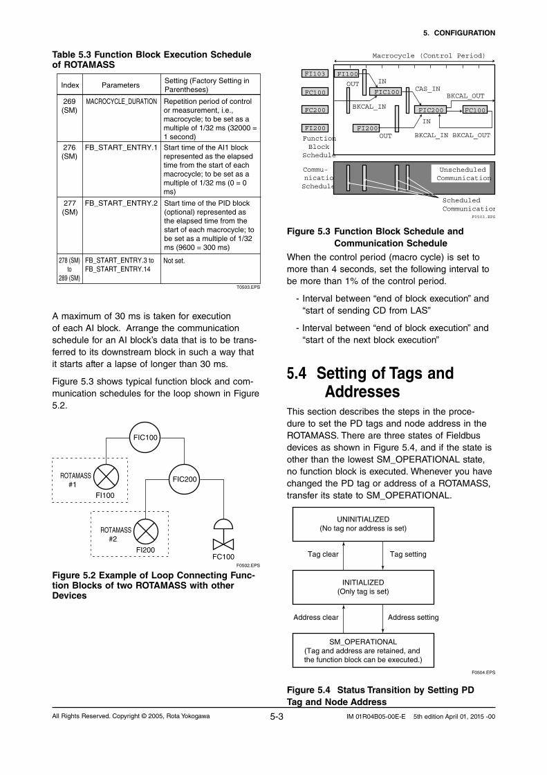
Table 5.3 Function Block Execution Schedule of ROTAMASS
T0503.EPS
Index ParametersSetting (Factory Setting in Parentheses)
269 (SM)
MACROCYCLE_DURATION Repetition period of control or measurement, i.e., macrocycle; to be set as a multiple of 1/32 ms (32000 = 1 second)
276 (SM)
FB_START_ENTRY.1 Start time of the AI1 block represented as the elapsed time from the start of each macrocycle; to be set as a multiple of 1/32 ms (0 = 0 ms)
277 (SM)
FB_START_ENTRY.2 Start time of the PID block (optional) represented as the elapsed time from the start of each macrocycle; to be set as a multiple of 1/32 ms (9600 = 300 ms)
278 (SM) to
289 (SM)
FB_START_ENTRY.3 toFB_START_ENTRY.14
Not set.
A maximum of 30 ms is taken for execution of each AI block. Arrange the communication schedule for an AI block’s data that is to be trans-ferred to its downstream block in such a way that it starts after a lapse of longer than 30 ms.
Figure 5.3 shows typical function block and com-munication schedules for the loop shown in Figure 5.2.
F0502.EPS
FIC100
FIC200
FC100FI200
ROTAMASS#2
FI100
ROTAMASS#1
Figure 5.2 Example of Loop Connecting Func-tion Blocks of two ROTAMASS with other Devices
FI103 FI100
FC100 FIC100
FC200 FIC200 FC100
FI200 FI200
Function Block
Schedule
Commu-nicationSchedule
OUT IN
OUT
CAS_INBKCAL_OUT
BKCAL_IN
BKCAL_IN
BKCAL_OUT
IN
Unscheduled Communication
Scheduled Communication
F0503.EPS
Macrocycle (Control Period)
Figure 5.3 Function Block Schedule and Communication Schedule
When the control period (macro cycle) is set to more than 4 seconds, set the following interval to be more than 1% of the control period.
- Interval between “end of block execution” and “start of sending CD from LAS”
- Interval between “end of block execution” and “start of the next block execution”
5.4 Setting of Tags and Addresses
This section describes the steps in the proce-dure to set the PD tags and node address in the ROTAMASS. There are three states of Fieldbus devices as shown in Figure 5.4, and if the state is other than the lowest SM_OPERATIONAL state, no function block is executed. Whenever you have changed the PD tag or address of a ROTAMASS, transfer its state to SM_OPERATIONAL.
UNINITIALIZED(No tag nor address is set)
Tag clear Tag setting
INITIALIZED(Only tag is set)
SM_OPERATIONAL(Tag and address are retained, and the function block can be executed.)
Address clear
F0504.EPS
Address setting
Figure 5.4 Status Transition by Setting PDTag and Node Address

5. CONFIGURATION
5-4 All Rights Reserved. Copyright © 2005, Rota YokogawaIM 01R04B05-00E-E 5th edition April 01, 2015 -00
In each ROTAMASS, the PD tag and node ad-dress are set to “FT1004” and 246 (hexadecimal F6), respectively, before shipment from the factory unless otherwise specified. To change only the node address, clear the address once and then set a new node address. To set the PD tag, first clear the node address and clear the PD tag, then set the PD tag and node address again.Devices whose node address was cleared will await at the default address (randomly chosen from a range of 248 to 251, or from hexadecimal F8 to FB). At the same time, it is necessary to specify the device ID in order to correctly specify the device. The device ID of the ROTAMASS is 594543000Dxxxxxxxx. (The xxxxxxxx at the end of the above device ID is a total of 8 alphanumeric characters.)
5.5 Communication Set-ting
To set the communication function, it is necessary to change the database residing in SM (System Management)-VFD.
5.5.1 VCR Setting
Set VCR (Virtual Communication Relationship), which specifies the called party for communication and resources. Each ROTAMASS has 33 VCRs whose application can be changed, except for the first VCR, which is used for management.
Each ROTAMASS has VCRs of four types:
Server (QUB) VCR A server responds to requests from a host.
This communication needs data exchange. This type of communication is called QUB (Queued User-triggered Bidirectional) VCR.
Source (QUU) VCR A source multicasts alarms or trends to other
devices. This type of communication is called QUU (Queued User-triggered Unidirectional) VCR.
Publisher (BNU) VCR A publisher multicasts outputs of the AI blocks,
IT blocks, and PID block to other function blocks. This type of communication is called BNU (Buffered Network-triggered Unidirection-al) VCR.
Subscriber (BNU) VCR A subscriber receives output of another func-
tion block(s) by PID block.Each VCR has the parameters listed in Table 5.4. Parameters must be changed together for each
VCR because modification for each parameter may cause a contradiction.
Table 5.4 VCR Static Entry
T0504-1.EPS
Sub-index
Parameter Description
1 FasArTypeAndRole Indicates the type and role of communication (VCR). The following 4 types are used for the Rotamass.0x32: Server (Responds to
requests from host.)0x44: Source (Transmits
alarm or trend.)0x66: Publisher (Sends AI,
DI block output to other blocks.)
0x76: Subscriber (Receives output of other blocks by PID block.)
2 FasDllLocalAddr Sets the local address to specify a VCR in the Rotamass. A range of 20 to F7 in hexadecimal.
3 FasDllConfiguredRemoteAddr
Sets the node address of the called party for communication and the address (DLSAP or DLCEP) used to specify VCR in that address. For DLSAP or DLCEP, a range of 20 to F7 in hexadecimal is used. Addresses in Subindex 2 and 3 need to be set to the same contents of the VCR as the called party (local and remote are reversed).
4 FasDllSDAP Specifies the quality of communication. Usually, one of the following types is set.0x2B: Server0x01: Source (Alert)0x03: Source (Trend)0x91: Publisher/Subscriber
5 FasDllMaxConfirmDelayOnConnect
To establish connection for communication, a maximum wait time for the called party's response is set in ms. Typical value is 60 secounds (60000).
6 FasDllMaxConfirmDelayOnData
For request of data, a maximum wait time for the called party's response is set in ms. Typical value is 60 secounds (60000).
7 FasDllMaxDlsduSize Specifies maximum DL Service Data unit Size (DLSDU). Set 256 for Server and Trend VCR, and 64 for other VCRs.
8 FasDllResidualActivitySupported
Specifies whether connection is monitored. Set TRUE (0xff) for Server. This parameter is not used for other communication.
9 FasDllTimelinessClass Not used for the Rotamass
10 FasDllPublisherTimeWindowSize
Not used for the Rotamass.
11 FasDllPublisherSynchronizaingDlcep
Not used for the Rotamass.

5. CONFIGURATION
5-5All Rights Reserved. Copyright © 2005, Rota Yokogawa IM 01R04B05-00E-E 5th edition April 01, 2015 -00
T0504-2.EPS
13 FasDllSubscriberSynchronizationDlcep
Not used for the Rotamass.
14 FmsVfdId Sets VFD for the Rotamass to be used. 0x1: System/network
management VFD0x1234: Function block
VFD
15 FmsMaxOutstandingServiceCalling
Set 0 to Server. It is not used for other applications.
16 FmsMaxOutstandingServiceCalled
Set 1 to Server. It is not used for other applications.
17 FmsFeaturesSupported
Indicates the type of services in the application layer. In the Rotamass, it is automatically set according to specific applications.
Sub-index Parameter Description
12 FasDllSubscriberTimeWindowSize
Not used for the Rotamass.
These 33 VCRs are factory-set as shown in Table 5.5.
Table 5.5 VCR List
T0505.EPS
Index(SM)
VCR Number Factory S etting
293 For system management (Fixed)1
294 Server (LocalAddr = 0xF3)2
295 Server (LocalAddr = 0xF4)3
296 Server (LocalAddr = 0xF7)4
297 Trend Source (LocalAddr = 0x07, Remote Address=0x111)
5
298 Publisher (LocalAddr = 0x20)6
299 Alert Source (LocalAddr = 0x07, Remote Address=0x110)
7
300 Server (LocalAddr = 0xF9)8
9 to 33 Not set301 to 325
5.5.2 Function Block Execution Control
According to the instructions given in Section 5.3, set the execution cycle of the function blocks and schedule of execution.
5.6 Block SettingSet the parameter for function block VFD.
5.6.1 Link Objects
A link object combines the data voluntarily sent by the function block with VCR. Each ROTAMASS has 40 link objects. A single link object speci-fies one combination. Each link object has the parameters listed in Table 5.6. Parameters must be changed together for each VCR because the modifications made to each parameter may cause inconsistent operation.
Table 5.6 Link Object Parameters
T0506.EPS
Sub-index Parameters Description
1 LocalIndex Sets the index of function block parameters to be combined; set “0” for Trend and Alert.
2 VcrNumber Sets the index of VCR to be combined. If set to “0”, this link object is not used.
3 RemoteIndex Not used in the Rotamass. Set to “0”.
5 StaleCountLimit
4 ServiceOperation Set one of the following. Set only one each for link object for Alert or Trend.0: Undefined2: Publisher3: Subscriber6: Alert7: TrendSet the maximum number of consecutive stale input values which may be received before the input status is set to BAD. To avoid the unnecessary mode transition caused when the data is not correctly received by subscriber, set this parameter to “2” or more.
Link objects are not factory-set. Set link objects as shown in Table 5.7.
Table 5.7 Settings of Link Objects (example)
T0507.EPS
Index Link Object # Settings(example)
30000 AI. OUT VCR#61
30001 2
30002 3
30003 to 30039 No used4 to 40
Trend VCR#5
Alert VCR#7

5. CONFIGURATION
5-6 All Rights Reserved. Copyright © 2005, Rota YokogawaIM 01R04B05-00E-E 5th edition April 01, 2015 -00
5.6.2 Trend Objects
It is possible to make settings so that a function block automatically transmits the trend. For this, each ROTAMASS has ten trend objects: eight for trends of analog parameters and two for discrete parameters. For each trend object, specify a sin-gle parameter, the trend of which is to be trans-mitted. Each trend object has the parameters listed in Table 5.8. For the first four parameters, setting is mandatory. Before writing parameter settings to a trend object, parameter WRITE_LOCK of the resource block must be modified to unlock the write-lock.
Table 5.8 Parameters for Trend Objects
T0508.EPS
Sub-index Parameters Description
1 Block Index Sets the leading index of the function block that takes a trend.
2 Parameter Relative Index
Sets the index of parameters taking a trend by a value relative to the beginning of the function block. In the Rotamass, the following three types of trends are possible. 7: PV 8: OUT19: FIELD_VAL
3 Sample Type Specifies how trends are taken. Choose one of the following 2 types:1: Sampled upon
execution of a function block.
2: The average value is sampled.
4 Sample Interval Specifies sampling intervals in units of 1/32 ms. Set the integer multiple of the function block execution cycle.
5 Last Update The last sampling time.
6 to 21 List of Status Status part of a sampled parameter.
21 to 37 List of Samples Data part of a sampled parameter.
Ten trend objects are not factory-set.
Table 5.9 Trend Objects
T0509.EPS
Index Parameter Factory Setting
32000 to 32007
32008
32009
TREND_DIS.1
TREND_DIS.2
TREND_FLT.1 to TREND_FLT.8
Not set.
Not set (these parameters are used with a DI block or optional PID block).
F0505.EPS
AI2 OUT
AI1 OUT
FBODAlert
Trend
VCR
DLSAPDLCEP
Fieldbus Cable
RO
TA
MA
SS
0xF8 0xF3 0xF4 0xF7 0xF9 0x20 0x07
#1 #2 #3 #4 #8 #6 #7 #5
#1 #3 #2
DI2OUTDI1
OUT
System Management Information Base (SMIB)
Network Management Information Base (NMIB)
Resource block
Transducer block
Link object
Host 1 Host 2 Device
Figure 5.5 Examle of Default Configuration
5.6.3 View Objects
View objects are used to group parameters. This reduces the load of data transactions. Each ROTAMASS supports four view objects for each of the resource block, transducer block, six AI blocks, two IT blocks, and PID block (optional). Each view object contains a group of the param-eters listed in Tables 5.11 to 5.14.
Table 5.10 Purpose of Each View Object
VIEW_1
VIEW_2
VIEW_3
VIEW_4
Set of all the dynamic parameters.
Description
Set of dynamic parameters required by operator for plant operation. (PV, SV, OUT, Mode etc.)
Set of static parameters which need to be shown to plant operator at once. (Range etc.)
Set of static parameters for configuration or maintenance.
T0510.EPS

5. CONFIGURATION
5-7All Rights Reserved. Copyright © 2005, Rota Yokogawa IM 01R04B05-00E-E 5th edition April 01, 2015 -00
Table 5.11 View Objects for Resource Block
1 ST_REV 2 2 2 2
2 TAG_DESC
3 STRATEGY 2
4 ALERT_KEY 1
5 MODE_BLK 4 4
6 BLOCK_ERR 2 2
7 RS_STATE 1 1
8 TEST_RW
9 DD_RESOURCE
10 MANUFAC_ID 4
11 DEV_TYPE 2
12 DEV_REV 1
13 DD_REV 1
14 GRANT_DENY 2
15 HARD_TYPES 2
16 RESTART
17 FEATURES 2
18 FEATURE_SEL 2
19 CYCLE_TYPE 1
20 CYCLE_SEL 1
21 MIN_CYCLE_T 4
22 MEMORY_SIZE 2
23 NV_CYCLE_T 4
24 FREE_SPA CE 4
25 FREE_TIME 4 4
26 SHED_RCAS 4
27 SHED_ROUT 4
28 FAIL_SAFE 1 1
29 SET_FSAFE
30 CLR_FSAFE
31 MAX_NOTIFY 4
32 LIM_NOTIFY 4
33 CONFIRM_TIME 4
34 WRITE_LOCK 1
35 UPDATE_EVT
36 BLOCK_ALM
37 ALARM_SUM 8 8
38 ACK_OPTION 2
39 WRITE_PRI 1
40 WRITE_ALM
41 ITK_VER
42 SOFT_REV
43 SOFT_DESC
44 SIM_ENABLE_MSG
45 DEVICE_STATUS_1 4
46 DEVICE_STATUS_2 4
47 DEVICE_STATUS_3 4
48 DEVICE_STATUS_4 4
49 DEVICE_STATUS_5 4
50 DEVICE_STATUS_6 4
51 DEVICE_STATUS_7 4
52 DEVICE_STATUS_8 4
Total bytes 22 32 54 31T0511.EPS
Relative Index Parameter Mnemonic
VIEW1
VIEW2
VIEW3
VIEW4

5. CONFIGURATION
5-8 All Rights Reserved. Copyright © 2005, Rota YokogawaIM 01R04B05-00E-E 5th edition April 01, 2015 -00
Table 5.12 View Objects for Transducer BlockIn
dex
(D
evic
e R
evis
ion
2)
Ind
ex
(Dev
ice
Rev
isio
n 1
)P
aram
eter
VIE
W_1
VIE
W_2
VIE
W_
3 1
VIE
W_
3 2
VIE
W_
3 3
VIE
W_
4 1
VIE
W_
4 2
VIE
W_
4 3
VIE
W_
4 4
VIE
W_
4 5
VIE
W_
4 6
VIE
W_
4 7
VIE
W_
4 8
VIE
W_
4 9
11
ST
_RE
V2
22
22
22
22
22
22
2
22
TAG
_DE
SC
33
ST
RAT
EG
Y
2
44
ALE
RT
_KE
Y
1
55
MO
DE
_BLK
4
4
66
BLO
CK
_ER
R2
2
77
UP
DAT
E_E
VT
88
BLO
CK
_ALM
99
TR
AN
SD
UC
ER
_DIR
EC
TOR
Y
1010
TR
AN
SD
UC
ER
_TY
PE
22
2
2
1111
XD
_ER
RO
R1
1
1
1212
CO
LLE
CT
ION
_DIR
EC
TOR
Y
1313
CA
L_P
OIN
T_H
I
4
4
1414
CA
L_P
OIN
T_L
O
4
4
1515
CA
L_M
IN_S
PAN
4
1616
CA
L_U
NIT
2
1717
SE
NS
OR
_TY
PE
2
1818
SE
NS
OR
_RA
NG
E
11
1919
SE
NS
OR
_SN
32
2020
SE
NS
OR
_CA
L_M
ET
HO
D
1
2121
SE
NS
OR
_CA
L_LO
C
32
2222
SE
NS
OR
_CA
L_D
ATE
7
2323
SE
NS
OR
_CA
L_W
HO
32
2424
LIN
_TY
PE
1
2525
MA
SS
_FLO
W_V
ALU
E5
5
2626
MA
SS
_FLO
W_V
ALU
E_R
AN
GE
11
2727
MA
SS
_FLO
W_V
ALU
E_F
TIM
E
4
2828
MA
SS
_FLO
W_L
OW
CU
T
4
2929
VO
LUM
E_F
LOW
_V
ALU
E5
5
3030
VO
LUM
E_F
LOW
_VA
LUE
_RA
NG
E
11
3131
VO
LUM
E_F
LOW
_VA
LUE
_FT
IME
4
3232
VO
LUM
E_F
LOW
_LO
WC
UT
4
3333
DE
NS
ITY
_VA
LUE
5
5
3434
DE
NS
ITY
_VA
LUE
_RA
NG
E
11
3535
DE
NS
ITY
_VA
LUE
_FT
IME
4

5. CONFIGURATION
5-9All Rights Reserved. Copyright © 2005, Rota Yokogawa IM 01R04B05-00E-E 5th edition April 01, 2015 -00
Ind
ex
(Dev
ice
Rev
isio
n 2
)
Ind
ex
(Dev
ice
Rev
isio
n 1
)P
aram
eter
VIE
W_1
VIE
W_2
VIE
W_
3 1
VIE
W_
3 2
VIE
W_
3 3
VIE
W_
4 1
VIE
W_
4 2
VIE
W_
4 3
VIE
W_
4 4
VIE
W_
4 5
VIE
W_
4 6
VIE
W_
4 7
VIE
W_
4 8
VIE
W_
4 9
3636
DE
NS
ITY
_LO
WC
UT
4
3737
TE
MP
ER
ATU
RE
_V
ALU
E5
5
3838
TE
MP
ER
ATU
RE
_V
ALU
E_R
AN
GE
11
3939
TE
MP
ER
ATU
RE
_VA
LUE
_FT
IME
4
4040
CO
NC
EN
TR
_ME
AS
_VA
LUE
5
5
4141
CO
NC
EN
TR
_ME
AS
_VA
LUE
_RA
NG
E
11
4242
CO
NC
EN
TR
_ME
AS
_VA
LUE
_FT
IME
4
4343
CO
NC
EN
TR
_ME
AS
_LO
WC
UT
4
4444
NE
T_F
LOW
_VA
LUE
5
5
4545
NE
T_F
LOW
_VA
LUE
_RA
NG
E
11
4646
NE
T_F
LOW
_VA
LUE
_FT
IME
4
4747
NE
T_F
LOW
_LO
WC
UT
4
48
VE
LOC
ITY
_VA
LUE
4
4
49
VE
LOC
ITY
_UN
ITS
_IN
DE
X
2
5048
DIS
P_S
ELE
CT
_1
1
5149
DIS
P_S
ELE
CT
_2
1
5250
DIS
P_S
ELE
CT
_3
1
5351
DIS
P_S
ELE
CT
_4
1
5452
DIS
P_D
EC
IMA
L_M
AS
S_F
LOW
1
5553
DIS
P_D
EC
IMA
L_V
OLU
ME
_FLO
W
1
5654
DIS
P_D
EC
IMA
L_D
EN
SIT
Y
1
5755
DIS
P_D
EC
IMA
L_T
EM
PE
RAT
UR
E
1
5856
DIS
P_D
EC
IMA
L_C
ON
CE
NT
R_M
EA
S
1
5957
DIS
P_D
EC
IMA
L_N
ET
_FLO
W
1
6058
DIS
P_D
EC
IMA
L_IT
1
1
6159
DIS
P_D
EC
IMA
L_IT
2
1
6260
DIS
P_I
T1_
UN
ITS
_IN
DE
X
2
6361
DIS
P_I
T2_
UN
ITS
_IN
DE
X
2
6462
DIS
P_C
ON
TR
AS
T
1
6563
DIS
P_P
ER
IOD
1
6664
DIS
P_L
AN
GU
AG
E
1
6765
FLO
W_D
IRE
CT
ION
1
6866
BI_
DIR
EC
TIO
N
1
6967
AU
TO_Z
ER
O_T
IME
1
7068
AU
TO_Z
ER
O_E
XE
1

5. CONFIGURATION
5-10 All Rights Reserved. Copyright © 2005, Rota YokogawaIM 01R04B05-00E-E 5th edition April 01, 2015 -00
Ind
ex
(Dev
ice
Rev
isio
n 2
)
Ind
ex
(Dev
ice
Rev
isio
n 1
)P
aram
eter
VIE
W_1
VIE
W_2
VIE
W_
3 1
VIE
W_
3 2
VIE
W_
3 3
VIE
W_
4 1
VIE
W_
4 2
VIE
W_
4 3
VIE
W_
4 4
VIE
W_
4 5
VIE
W_
4 6
VIE
W_
4 7
VIE
W_
4 8
VIE
W_
4 9
7169
AU
TOZ
ER
O_V
ALU
E
4
7270
AU
TOZ
ER
O_F
LUC
TU
ATIO
N
4
7371
AZ
_IN
IT_M
AS
S_F
LOW
4
7472
AZ
_IN
IT_D
EN
SIT
Y
4
7573
AZ
_IN
IT_T
EM
P
4
7674
MA
SS
_FLO
W_F
IX_V
AL_
SE
L
1
7775
MA
SS
_FLO
W_F
IXE
D_V
ALU
E
4
7876
DE
NS
ITY
_FIX
_VA
L_S
EL
1
7977
RE
FE
RE
NC
E_D
EN
SIT
Y
4
80
DE
NS
ITY
_OF
FS
ET
4
8178
TE
MP
_FIX
_VA
L_S
ELE
CT
1
8279
TE
MP
_FIX
ED
_VA
LUE
4
8380
TE
MP
_GA
IN
4
8481
SE
NS
OR
_MO
DE
L
1
8582
SK
20
4
8683
SK
T
4
8784
RV
4
8885
QN
OM
4
8986
KD
4
9087
FL2
0
4
9188
FT
C1
4
9289
FT
CK
4
9390
SK
P
4
9491
FP
C
4
95
SK
TK
4
96
SK
PT
4
97
FP
TC
4
98
FQ
C1
4
99
FQ
C2
4
100
92P
RE
SS
UR
E
4
101
93P
RE
SS
UR
E_U
NIT
2
102
94S
LUG
_ALA
RM
_SE
LEC
T
1
103
95D
RIV
E_G
AIN
4
104
96S
LUG
_CR
ITE
RIA
4
105
97S
LUG
_DU
RAT
ION
4
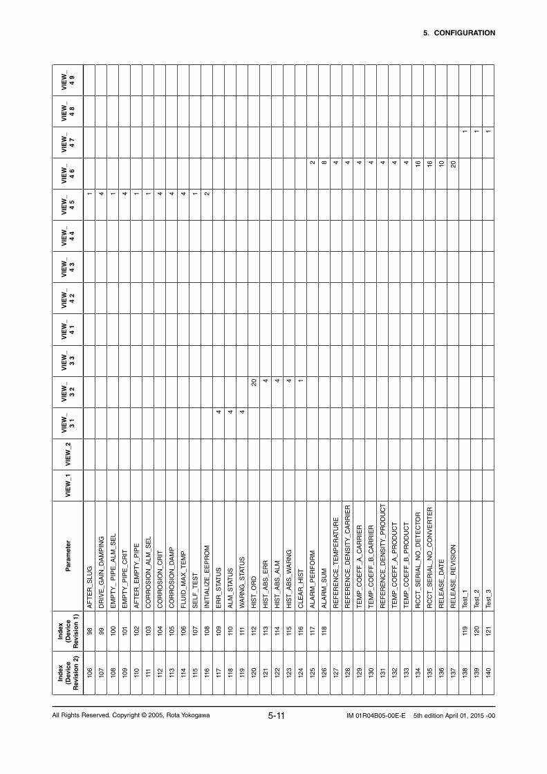
5. CONFIGURATION
5-11All Rights Reserved. Copyright © 2005, Rota Yokogawa IM 01R04B05-00E-E 5th edition April 01, 2015 -00
Ind
ex
(Dev
ice
Rev
isio
n 2
)
Ind
ex
(Dev
ice
Rev
isio
n 1
)P
aram
eter
VIE
W_1
VIE
W_2
VIE
W_
3 1
VIE
W_
3 2
VIE
W_
3 3
VIE
W_
4 1
VIE
W_
4 2
VIE
W_
4 3
VIE
W_
4 4
VIE
W_
4 5
VIE
W_
4 6
VIE
W_
4 7
VIE
W_
4 8
VIE
W_
4 9
106
98A
FT
ER
_SLU
G
1
107
99D
RIV
E_G
AIN
_DA
MP
ING
4
108
100
EM
PT
Y_
PIP
E_A
LM_S
EL
1
109
101
EM
PT
Y_P
IPE
_CR
IT
4
110
102
AF
TE
R_E
MP
TY
_PIP
E
1
111
103
CO
RR
OS
ION
_ALM
_SE
L
1
112
104
CO
RR
OS
ION
_CR
IT
4
113
105
CO
RR
OS
ION
_DA
MP
4
114
106
FLU
ID_M
AX
_TE
MP
4
115
107
SE
LF_T
ES
T
1
116
108
INIT
IALI
ZE
_EE
PR
OM
2
117
109
ER
R_S
TAT
US
4
118
110
ALM
_STA
TU
S
4
119
111
WA
RN
G_S
TAT
US
4
120
112
HIS
T_O
RD
20
121
113
HIS
T_A
BS
_ER
R
4
122
114
HIS
T_A
BS
_ALM
4
123
115
HIS
T_A
BS
_WA
RN
G
4
124
116
CLE
AR
_HIS
T
1
125
117
ALA
RM
_PE
RF
OR
M
2
126
118
ALA
RM
_SU
M
8
127
R
EF
ER
EN
CE
_TE
MP
ER
ATU
RE
4
128
R
EF
ER
EN
CE
_DE
NS
ITY
_CA
RR
IER
4
129
T
EM
P_C
OE
FF
_A_C
AR
RIE
R
4
130
T
EM
P_C
OE
FF
_B_C
AR
RIE
R
4
131
R
EF
ER
EN
CE
_DE
NS
ITY
_PR
OD
UC
T
4
132
T
EM
P_C
OE
FF
_A_P
RO
DU
CT
4
133
T
EM
P_C
OE
FF
_B_P
RO
DU
CT
4
134
R
CC
T_S
ER
IAL_
NO
_DE
TE
CTO
R
16
135
R
CC
T_S
ER
IAL_
NO
_CO
NV
ER
TE
R
16
136
R
ELE
AS
E_D
ATE
10
137
R
ELE
AS
E_R
EV
ISIO
N
20
138
119
Test
_1
1
139
120
Test
_2
1
140
121
Test
_3
1

5. CONFIGURATION
5-12 All Rights Reserved. Copyright © 2005, Rota YokogawaIM 01R04B05-00E-E 5th edition April 01, 2015 -00
Ind
ex
(Dev
ice
Rev
isio
n 2
)
Ind
ex
(Dev
ice
Rev
isio
n 1
)P
aram
eter
VIE
W_1
VIE
W_2
VIE
W_
3 1
VIE
W_
3 2
VIE
W_
3 3
VIE
W_
4 1
VIE
W_
4 2
VIE
W_
4 3
VIE
W_
4 4
VIE
W_
4 5
VIE
W_
4 6
VIE
W_
4 7
VIE
W_
4 8
VIE
W_
4 9
141
122
Test
_4
4
142
123
Test
_5
4
143
124
Test
_6
4
144
125
Test
_7
4
145
126
Test
_8
4
146
127
Test
_9
4
147
128
Test
_10
4
148
129
Test
_11
4
149
130
Test
_12
1
150
131
Test
_13
4
151
132
Test
_14
4
152
133
Test
_15
4
153
134
Test
_16
4
154
135
Test
_17
4
155
136
Test
_18
1
156
137
Test
_19
4
157
138
Test
_20
4
158
139
Test
_21
1
159
140
Test
_22
1
160
141
Test
_23
4
161
142
Test
_24
1
162
143
Test
_25
4
163
144
Test
_26
4
164
145
Test
_27
22
165
146
Test
_28
1
166
147
Test
_29
1
167
148
Test
_30
1
168
149
Test
_31
1
169
Te
st_6
2
4
170
Te
st_6
3
4
171
Te
st_6
4
1
172
Te
st_6
5
1
173
Te
st_6
6
4
174
Te
st_6
7
4
175
Te
st_6
8
2

5. CONFIGURATION
5-13All Rights Reserved. Copyright © 2005, Rota Yokogawa IM 01R04B05-00E-E 5th edition April 01, 2015 -00
Ind
ex
(Dev
ice
Rev
isio
n 2
)
Ind
ex
(Dev
ice
Rev
isio
n 1
)P
aram
eter
VIE
W_1
VIE
W_2
VIE
W_
3 1
VIE
W_
3 2
VIE
W_
3 3
VIE
W_
4 1
VIE
W_
4 2
VIE
W_
4 3
VIE
W_
4 4
VIE
W_
4 5
VIE
W_
4 6
VIE
W_
4 7
VIE
W_
4 8
VIE
W_
4 9
176
Te
st_6
9
4
177
Te
st_7
0
1
178
150
Test
_32
2
179
151
Test
_33
4
180
152
Test
_34
1
181
153
Test
_35
1
182
154
Test
_36
1
183
155
Test
_37
2
184
156
Test
_38
1
185
157
Test
_39
1
186
158
Test
_40
4
187
159
Test
_41
4
188
160
Test
_42
4
189
161
Test
_43
4
190
162
Test
_44
4
191
163
Test
_45
4
192
164
Test
_46
1
193
165
Test
_47
4
194
166
Test
_48
1
195
Te
st_7
1
4
196
Te
st_7
2
4
197
Te
st_7
3
4
198
Te
st_7
4
4
199
Te
st_7
5
4
200
Te
st_7
6
4
201
Te
st_7
7
4
202
Te
st_7
8
4
203
Te
st_7
9
4
204
Te
st_8
0
4
205
Te
st_8
1
4
206
Te
st_8
2
4
207
167
Test
_49
32
208
168
Test
_50
32
209
169
Test
_51
32
210
170
Test
_52
2

5. CONFIGURATION
5-14 All Rights Reserved. Copyright © 2005, Rota YokogawaIM 01R04B05-00E-E 5th edition April 01, 2015 -00
Ind
ex
(Dev
ice
Rev
isio
n 2
)
Ind
ex
(Dev
ice
Rev
isio
n 1
)P
aram
eter
VIE
W_1
VIE
W_2
VIE
W_
3 1
VIE
W_
3 2
VIE
W_
3 3
VIE
W_
4 1
VIE
W_
4 2
VIE
W_
4 3
VIE
W_
4 4
VIE
W_
4 5
VIE
W_
4 6
VIE
W_
4 7
VIE
W_
4 8
VIE
W_
4 9
211
171
Test
_53
4
212
172
Test
_54
213
173
Test
_55
214
174
Test
_56
215
175
Test
_57
216
176
Test
_58
2
217
177
Test
_59
2
218
178
Test
_60
219
179
Test
_61
1
45
1265
9238
6775
7487
101
102
9893
73

5. CONFIGURATION
5-15All Rights Reserved. Copyright © 2005, Rota Yokogawa IM 01R04B05-00E-E 5th edition April 01, 2015 -00
T0513.EPS
1 ST_REV 2 2 2 2
2 TAG_DESC
3 STRATEGY 2
4 ALERT_KEY 1
5 MODE_BLK 4 4
6 BLOCK_ERR 2 2
7 PV 5 5
8 OUT 5 5
9 SIMULATE
10 XD_SCALE 11
11 OUT_SCALE 11
12 GRANT_DENY 2
13 IO_OPTS 2
14 STATUS_OPTS 2
15 CHANNEL 2
16 L_TYPE 1
17 LOW_CUT 4
18 PV_FTIME 4
19 FIELD_VAL 5 5
20 UPDATE_EVP
21 BLOCK_ALM
22 ALARM_SUM 8 8
23 ACK_OPTION 2
24 ALARM_HYS 4
25 HI_HI_PRI 1
26 HI_HI_LIM 4
27 HI_PRI 1
28 HI_LIM 4
29 LO_PRI 1
30 LO_LIM 4
31 LO_LO_PRI 1
32 LO_LO_LIM 4
33 HI_HI_ALM
34 HI_ALM
35 LO_ALM
36 LO_LO_ALM
Total bytes 31 26 31 46
Relative Index Parameter Mnemonic
VIEW1
VIEW2
VIEW3
VIEW4
Table 5.13 View Objects for the AI Function Blocks Table 5.14 View Objects for PID Function Block (Optional)
T0515-1.EPS
1 ST_REV 2 2 2 2
2 TAG_DESC
3 STRATEGY 2
4 ALERT_KEY 1
5 MODE_BLK 4 4
6 BLOCK_ERR 2 2
7 PV 5 5
8 SP 5 5
9 OUT 5 5
10 PV_SCALE 11
11 OUT_SCALE 11
12 GRANT_DENY 2
13 CONTROL_OPTS 2
14 STATUS_OPTS 2
15 IN 5
16 PV_FTIME 4
17 BYPASS 1
18 CAS_IN 5 5
19 SP_RATE_DN 4
20 SP_RATE_UP 4
21 SP_HI_LIM 4
22 SP_LO_LIM 4
23 GAIN 4
24 RESET 4
25 BAL_TIME 4
26 RATE 4
27 BKCAL_IN 5
28 OUT_HI_LIM 4
29 OUT_LO_LIM 4
30 BKCAL_HYS 4
31 BKCAL_OUT 5
32 RCAS_IN 5
33 ROUT_IN 5
34 SHED_OPT 1
35 RCAS_OUT 5
36 ROUT_OUT 5
37 TRK_SCALE 11
38 TRK_IN_D 2 2
39 TRK_VAL 5 5
40 FF_VAL 5
Relative Index Parameter Mnemonic
VIEW1
VIEW2
VIEW3
VIEW4
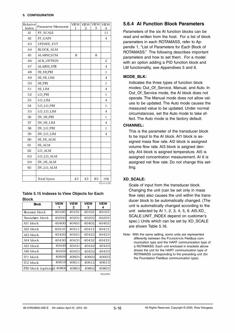
5. CONFIGURATION
5-16 All Rights Reserved. Copyright © 2005, Rota YokogawaIM 01R04B05-00E-E 5th edition April 01, 2015 -00
T0515-2.EPS
41 FF_SCALE 11
42 FF_GAIN 4
43 UPDATE_EVT
44 BLOCK_ALM
45 ALARM_SUM 8 8
46 ACK_OPTION 2
47 ALARM_HYS 4
48 HI_HI_PRI 1
49 HI_HI_LIM 4
50 HI_PRI 1
51 HI_LIM 4
52 LO_PRI 1
53 LO_LIM 4
54 LO_LO_PRI 1
55 LO_LO_LIM 4
56 DV_HI_PRI 1
57 DV_HI_LIM 4
58 DV_LO_PRI 1
59 DV_LO_LIM 4
60 HI_HI_ALM
61 HI_ALM
62 LO_ALM
63 LO_LO_ALM
64 DV_HI_ALM
65 DV_LO_ALM
Total bytes 43 43 83 104
Relative Index Parameter Mnemonic
VIEW1
VIEW2
VIEW3
VIEW4
Table 5.15 Indexes to View Objects for Each Block
T0516.EPS
40420
40430
40410
40400
40432
40422
40431
40412
40200
40421
40411
40102
40401
40100 40101
40201
40423
AI4 block
AI3 block
40402
AI2 block 40413
40433
40403
4020340202Transducer block
AI1 block
Resource block
PID block (optional) 40800 40801 40802 40803
40103
VIEW1
VIEW2
VIEW3
VIEW4
Block
IT2 block
IT1 block
AI5 block
AI6 block
40440 40441 40442 40443
40450 40451 40452 40453
40600 40601 40602 40603
40610 40611 40612 40613
5.6.4 AI Function Block Parameters
Parameters of the six AI function blocks can be read and written from the host. For a list of block parameters in each ROTAMASS, refer to Ap-pendix 1, “List of Parameters for Each Block of ROTAMASS.” The following describes important parameters and how to set them. For a model with an option adding a PID function block and LM functionality, see Appendixes 5 and 6.
MODE_BLK:
Indicates the three types of function block modes; Out_Of_Service, Manual, and Auto. In Out_Of_Service mode, the AI block does not operate. The Manual mode does not allow val-ues to be updated. The Auto mode causes the measured value to be updated. Under normal circumstances, set the Auto mode to take ef-fect. The Auto mode is the factory default.
CHANNEL:
This is the parameter of the transducer block to be input to the AI block. AI1 block is as-signed mass flow rate. AI2 block is assigned volume flow rate. AI3 block is asigned den-sity. AI4 block is asigned temperature. AI5 is assigned concentration measurement. AI 6 is assigned net flow rate. Do not change this set-ting.
XD_SCALE:
Scale of input from the transducer block. Changing the unit (can be set only in mass flow rate) also causes the unit within the trans-ducer block to be automatically changed. (The unit is automatically changed according to the unit selected by AI 1, 2, 3, 4, 5, 6. AI5.XD_SCALE.UNIT_INDEX depend on customer’s spec.) Units which can be set by XD_SCALE are shown Table 5.16.
Note: With the same setting, some units are represented differently between the FOUNDATION Fieldbus com-munication type and the HART communication type of a ROTAMASS. Each unit enclosed in brackets above shows the unit for the HART communication type of ROTAMASS corresponding to the preceding unit (for the Foundation Fieldbus communication type).

5. CONFIGURATION
5-17All Rights Reserved. Copyright © 2005, Rota Yokogawa IM 01R04B05-00E-E 5th edition April 01, 2015 -00
Table 5.16 Available UnitsItem Block Available Units
XD_SCALE
AI1(Channel 1: PV)
Mass Flow
1318:g/sec1319:g/min1320:g/h1322:kg/s1323:kg/min1324:kg/h1327:t/min1328:t/h1330:lb/s1331:lb/min1332:lb/h
AI2(Channel 2: SV)
Volume Flow
1511:cucm/s
Uni
ts s
elec
tabl
e w
hen
‘FIX
ED
DE
NS
ITY
’ is
sele
cted
Uni
ts s
elec
tabl
e w
hen
‘Gas
’ mea
sure
men
t (/
GA
) is
sel
ecte
d
1512:cucm/min1513:cucm/h1351:l/s1352:l/min1353:l/h1347:cum/s1348:cum/min1349:cum/h1362:gal/s1363:gal/min1364:gal/h1356:cuft/s1357:cuft/min1358:cuft/h1371:bbl/s1372:bbl/min1373:bbl/h1374:bbl/d1367:Impgal/s1368:Impgal/min1369:Impgal/h
Standard Volume Flow
1537:Sl/s1538:Sl/min1539:Sl/h65524:Scuft/s1360:Scuft/min1361:Scuft/h1527:Scum/s1528:Scum/min1529:Scum/h
NormalVolume Flow
1532:Nl/s1533:Nl/min1534:Nl/h1522:Ncum/s1523:Ncum/min1524:Ncum/h
AI3(Channel 3: TV)
Density
1104:g/ml
‘Gas
’ or
‘Liq
uid’
Whe
n C
once
ntra
tion
‘Sta
ndar
d’ o
r ‘N
et
Oil’
is
sel
ecte
d.
1103:kg/l1097:kg/cum1108:lb/gal1107:lb/cuft1100:g/cc1111:H-Baume1112:L-Baume1113:degAPI
AI4(Channel 4:
QV)Temperature
1000:Kelvin1001:degC1002:degF

5. CONFIGURATION
5-18 All Rights Reserved. Copyright © 2005, Rota YokogawaIM 01R04B05-00E-E 5th edition April 01, 2015 -00
OUT_SCALE:
Sets the range of output (from 0% to 100%). Available units for OUT_SCALE are the Table 5.16 units for XD_SCALE.
L_TYPE:
Specifies the operation function of the AI blocks. The factory default is “Direct”, so the input delivered to CHANNEL is directly re-flected on OUT. If set to “Indirect”, scaling by XD_SCALE and OUT_SCALE is carried out and is reflected on OUT. “Indirect SQRT” is not used for ROTAMASS.
PV_FTIME:
Sets the time constant of the damping function within the AI blocks (primary delay) in seconds.
Alarm Priority:
Indicates the priority of the process alarm. If a value of 3 or greater is set, an alarm is trans-mitted. The factory default is 0. Four types of alarm can be set: HI_PRI, HI_HI_PRI, LO_PRI, and LO_LO_PRI.
Alarm Threshold:
Sets the threshold at which a process alarm is generated. The factory default setting is a value that does not generate an alarm. Four types of alarm can be set: HI_LIM, HI_HI_LIM, LO_LIM, and LO_LO_LIM.
XD_SCALE
AI5(Channel 5: 5V)
Concentration
1426:degBrix (°Brix)
‘Sta
nd-
ard’
or
‘N
et O
il’
‘Adv
ance
d’
(acc
. to
cus-
tom
er’s
spe
c,
read
onl
y)
65520:WT-%65521:Vol-%1343:WT-% sol1344:Vol-% sol1111:H-Baume1112:L-Baume1113:degAPI
AI6(Channel 6: 6V)
Net Flow
1318:g/sec1319:g/min1320:g/h1322:kg/s1323:kg/min1324:kg/h1327:t/min1328:t/h1330:lb/s1331:lb/min1332:lb/h
OUT_SCALE AI1 to AI6 1342:%
5.6.5 Transducer Block Parameters
The transducer block sets function specific to the flow rate measurement of the ROTAMASS. For a list of block parameters in each ROTAMASS, refer to Appendix 1, “List of Parameters for Each Block of ROTAMASS.” The following describes impor-tant parameters and how to set them.
Parameters for Zero Tuning
1) AUTO_ZERO_TIME (Relative Index 69)
Defines the duration of the auto zero func-tion as follows:
1 = 3 Minute
2 = 30 Seconds
2) AUTO_ZERO_EXE (Relative Index 70)
Starts the auto zero function to be per-formed as follows:
1 = Not Execute
2 = Execute
Parameters for Primary Variable
3) MASS_FLOW_VALUE_FTIME (Relative Index 27)
Defines the damping time constant for the mass flow rate to be input to the flow rate calculation.
Setting range: 0.1 to 200 (seconds)
Default: 3 (seconds)

5. CONFIGURATION
5-19All Rights Reserved. Copyright © 2005, Rota Yokogawa IM 01R04B05-00E-E 5th edition April 01, 2015 -00
11) BI_DIRECTION (Relative Index 68)
Enables the ROTAMASS to measure the flow in bi- or uni-direction mode. The sign of the calculated flow rate values depends on the flow direction.
Setting range: Bi-Direction; Uni-Direction
Default: Bi-Direction
Parameters for local Display
12) DISP_SELECT_1 (Relative Index 50)
Selects the data to be displayed on the first line of the LCD indicator, as follows (Default : Massflow) :
1 = AI1 OUT = Massflow: Actual mass flow rate
2 = AI2 OUT = Volumeflow: Actual volume flow rate
3 = AI3 OUT = Density: Actual density value
4 = AI4 OUT = Temperature: Actual temperature value
5 = AI5 OUT = Conc Meas:
Actual calculated concentration value
6 = AI6 OUT = Netflow: Actual net flow rate
7 = IT1 OUT = IT1: Integrator 1 totalized value
8 = IT2 OUT = IT2: Integrator 2 totalized value
9 = VELOCITY: Actual medium´s velocity
6) VOLUME_FLOW_LOWCUT (Relative Index 32)
Sets the low cutoff volume flow rate level.
Setting range: Minimum flow rate 0 to 10% of VOLUME_FLOW_VALUE_RANGE. EU_100. The default value is 0 %.
Unit: As selected in AI2.XD_SCALE.UNITS_INDEX
Parameters for Tertiary Variable
7) DENSITY_VALUE_FTIME (Relative Index 35)
Defines the damping time constant for the density to be input to the density calculation.
Setting range: 0.1 to 200 (seconds)
Default: 3 (seconds)
8) DENSITY_LOWCUT (Relative Index 36)
Sets the low cutoff density level.
Setting range: Minimum value 0 to 10% of DENSITY_VALUE_RANGE.EU_100. The default value is 0 %.
Unit: As selected in AI3.XD_SCALE.UNITS_INDEX
Parameters for Quaternary Variable
9) TEMPERATUR_VALUE_FTIME (Relative Index 39)
Defines the damping time constant for the temperature to be input to the temperature calculation.
4) MASS_FLOW_LOWCUT (Relative Index 28)
Sets the low cutoff mass flow rate level.
Setting range: Minimum flow rate 0 to 10% of MASS_FLOW_VALUE_RANGE. EU_100. The default value is 0 %.
Unit: As selected in AI1.XD_SCALE.UNITS_INDEX
Parameters for Secondary Variable
5) VOLUME_FLOW_VALUE_FTIME (Relative Index 31)
Defines the damping time constant for the volume flow rate to be input to the flow rate calculation.
Setting range: 0.1 to 200 (seconds)
Default: 3 (seconds)
Setting range: 0.1 to 200 (seconds)
Default: 3 (seconds)
Parameters for flow direction
10) FLOW_DIRECTION (Relative Index 67)
Defines the direction of the flow and deter-mines the sign of the calculated flow rate values.
Setting range: Forward; Reverse
Default: Forward

5. CONFIGURATION
5-20 All Rights Reserved. Copyright © 2005, Rota YokogawaIM 01R04B05-00E-E 5th edition April 01, 2015 -00
13) DISP_SELECT_2
(Relative Index 51)Selects the data to be displayed on the second line of the LCD indicator, as fol-lows:
see DISP_SELECT_1
255 : None
14) DISP_SELECT_3 (Relative Index 52)
Selects the data to be displayed on the third line of the LCD indicator, as follows:
see DISP_SELECT_1
255 : None
15) DISP_SELECT_4 (Relative Index 53)
Selects the data to be displayed on the fourth line of the LCD indicator, as follows:
see DISP_SELECT_1
255 : None
16) DISP_DECIMAL_MASS_FLOW (Relative Index 54)
Selects the format of the mass flow value to be displayed on the LCD indicator, as follows:
1 = xxxxxxx: No decimal point (7 digits)
2 = xxxxx.X: 1 digit after DP resolution
3 = xxxx.XX: 2 digit after DP resolution
4 = xxx.XXX: 3 digit after DP resolution
5 = xx.XXXX: 4 digit after DP resolution
6 = x.XXXXX: 5 digit after DP resolution
17) DISP_DECIMAL_VOLUME_FLOW (Relative Index 55)
Selects the format of the volume flow value to be displayed on the LCD indica-tor, as follows:
see DISP_DECIMAL_MASS_FLOW
18) DISP_DECIMAL_DENSITY (Relative Index 56)
Selects the format of the density value to be displayed on the LCD indicator, as follows:
see DISP_DECIMAL_MASS_FLOW
19) DISP_DECIMAL_TEMPERATURE (Relative Index 57)
Selects the format of the temperature value to be displayed on the LCD indica-tor, as follows:
see DISP_DECIMAL_MASS_FLOW
20) DISP_DECIMAL_IT1 (Relative Index 60)
Selects the format of the interator 1 value to be displayed on the LCD indicator, as follows:
1 = xxxxxxxx: No decimal point (8 digits)
2 = xxxxxx.X: 1 digit after DP resolution
3 = xxxxx.XX: 2 digit after DP resolution
4 = xxxx.XXX: 3 digit after DP resolution
5 = xxx.XXXX: 4 digit after DP resolution
6 = xx.XXXXX: 5 digit after DP resolution
7 = x.XXXXXX: 6 digit after DP resolution
21) DISP_DECIMAL_IT2 (Relative Index 61)
Selects the format of the interator 2 value to be displayed on the LCD indicator, as follows:
see DISP_DECIMAL_IT1
22) DISPLAY_CONTRAST (Relative Index 64)
Sets the display contrast of the LCD indi-cator.
Setting range: 0 to 23
Default: 4
23) DISPLAY_PERIOD (Relative Index 65)
Sets the display refresh cycle of the LCD indicator.
Setting range: 0.5sec; 1sec; 2sec
Default: 1sec
24) DISPLAY_LANGUAGE (Relative Index 66)
Sets the display language for the indica-tion of error, alarms and warning on the LCD indicator.
Setting range: English; German; French
Default: English

5. CONFIGURATION
5-21All Rights Reserved. Copyright © 2005, Rota Yokogawa IM 01R04B05-00E-E 5th edition April 01, 2015 -00
25) VELOCITY_UNITS_INDEX (Relative Index 49)
Defines the unit of the medium velocity in the tube. Velocity is zero if gas measure-ment is selected.
Setting range: m/s, ft/s
Default: m/s
Parameters for 5th Variable (Option /Cxx)
26) CONCENTR_MEAS_VALUE_FTIME (Relative Index 42)
Defines the damping time constant for the concentration meas value to be input to the concentration calculation.
Setting range: 0.1 to 200 (seconds)
Default: 10 (seconds)
27) CONCENTR_MEAS_LOWCUT (Relative Index 43)
Sets the low cutoff concentration level.
Setting range: Minimum flow rate 0 to 10% of CONCENTR_MEAS_VALUE_RANGE. EU_100. The default value is 0 %.
Unit: As selected in AI5.XD_SCALE.UNITS_INDEX
Parameters for 6th Variable (Option /Cxx)
28) NET_FLOW_VALUE_FTIME (Relative Index 46)
Defines the damping time constant for the net flow rate to be input to the flow rate calculation.
Setting range: 0.1 to 200 (seconds)
Default: 3 (seconds)
29) NET_FLOW_VALUE_LOWCUT (Relative Index 47)
Sets the low cutoff net flow rate level.
Setting range: Minimum flow rate 0 to 10% of NET_FLOW_VALUE_RANGE. EU_100. The default value is 0 %.
Unit: As selected in AI6.XD_SCALE.UNITS_INDEX

5. CONFIGURATION
5-22 All Rights Reserved. Copyright © 2005, Rota YokogawaIM 01R04B05-00E-E 5th edition April 01, 2015 -00
TB120: HIST_ORD
Kind Hex Name Description
None 0x0000 No error
Error 0x0101 E-01 Frequency Fault
0x0102 E-02 Signal Fault
0x0103 E-03 EEPROM Fault
0x0104 E-04 CPU Fault
0x0105 E-05 DSP Fault
0x0106 E-06 Sensor 1 Signal Fault
0x0107 E-07 Sensor 2 Signal Fault
0x0108 E-08 Temp Sensor Fault
Alarm 0x020E A-14 Slug Detection
0x020F A-15 Empty Pipe Detection
0x0210 A-16 Corrosion Detection
Warning 0x0301 W-01 Density Lower 0.3 kg/l
0x0302 W-02 Fixed Dens selected (Density only)
0x0303 W-03 Fixed Temp selected
0x0304 W-04 Fixed Mass flow selected (MF only)
0x0306 W-06 Autozero Value out of Range
0x0307 W-07 Autozero Fluctuation out of Range
TB121: HIST_ABS_ERR and TB117: ERR_STATUSKind Hex Name Description
Error 0x00000001 E-01 Frequency Fault
0x00000002 E-02 Signal Fault
0x00000004 E-03 EEPROM Fault
0x00000008 E-04 CPU Fault
0x00000010 E-05 DSP Fault
0x00000020 E-06 Sensor 1 Signal Fault
0x00000040 E-07 Sensor 2 Signal Fault
0x00000080 E-08 Temp Sensor Fault
TB122: HIST_ABS_ALM and TB118: ALM_STATUS Kind Hex Name Description
Alarm 0x00002000 A-14 Slug Detection
0x00004000 A-15 Empty Pipe Detection
0x00008000 A-16 Corrosion Detection
TB123: HIST_ABS_WARNG and TB119: WARNG_STATUSKind Hex Name Description
Warning 0x00000001 W-01 Density Lower 0.3 kg/l
0x00000002 W-02 Fixed Dens selected (Density only)
0x00000004 W-03 Fixed Temp selected
0x00000008 W-04 Fixed Mass flow selected (MF only)
0x00000020 W-06 Autozero Value out of Range
0x00000040 W-07 Autozero Fluctuation out of Range
0x00000000 No error/alarm/
warning
Parameter for indication of actual and history errors, alarms and warnings

6. IN-PROCESS OPERATION
6-1All Rights Reserved. Copyright © 2005, Rota Yokogawa IM 01R04B05-00E-E 5th edition April 01, 2015 -00
6. IN-PROCESS OPERATION
This chapter describes the procedure performed when changing the operation of the function block of the ROTAMASS in process.
6.1 Mode TransitionWhen the function block mode is changed to Out_Of_Service, the function block pauses and a block alarm is issued.
When the function block mode is changed to Manual, the function block suspends updating of output values. In this case alone, it is possible to write a value to the OUT parameter of the block for output. Note that no parameter status can be changed.
6.2 Generation of Alarm6.2.1 Indication of Alarm
When the self-diagnostics function indicates that a device is faulty, an alarm (device alarm) is issued from the resource block. When an error (block er-ror) is detected in each function block or an error in the process value (process alarm) is detected, an alarm is issued from each block. If an LCD indicator is installed, the error number is displayed as E-xx, the alarm number is displayed a A-xx and the warning is displayed as W-xx. If two or more alarms are issued, multiple error numbers are displayed in 2-second intervals.
Figure 6.1 Alarm Identification on Indicator
The error details corresponding to alarm indica-tions on the LCD indicator and whether or not switches are provided to disable the correspond-ing alarms are shown in Table 6.1. For the alarms for which an alarm mask switch is pro-vided, the default alarm settings are also shown. Those alarms for which an alarm mask switch is not provided are enabled at all times. For how to modify these mask switch statuses, see Appendix 3, “Operation of Each Parameter in Failure Mode.”
F0601.EP
E m p t yp i p e d e t e c t i
A - 1 5 : F i l l p i p eo nA l a r m

6. IN-PROCESS OPERATION
6-2 All Rights Reserved. Copyright © 2005, Rota YokogawaIM 01R04B05-00E-E 5th edition April 01, 2015 -00
Table 6.1 Alarm Indications and Alarm Mask Switches
Name
E-01 Frequency Fault
E-02 Signal Fault
E-03 EEPROM Fault
E-04 CPU Fault
E-05 DSP Fault
E-06 Sensor 1 Signal Fault
E-07 Sensor 2 Signal Fault
E-08 Temp Sensor Fault
E-09 Download Incomplete
E-10 Download Fail
E-11 Serial Communication Error1
E-12 Serial Communication Error2
A-14 Slug Detection
A-15 Empty Pipe Detection
A-16 Corrosion Detection
W-01 Density Lower 0.3kg/l
W-02 Fixed Dens Selected
W-03 Fixed Temp Selected
W-04 Fixed Mass Flow Selected
W-06 Autozero Value out of Range
W-07 Autozero Fluctuation out of Range
W-08 PD/Freq Simulation Active
A-20 All FB Non-Schedule
A-21 RS O/S ModeA-22 TB O/S ModeA-23 AI1 FB O/S ModeA-24 AI2 FB O/S ModeA-25 AI3 FB O/S ModeA-26 AI4 FB O/S ModeA-27 AI5 FB O/S ModeA-28 AI6 FB O/S ModeA-29 IT1 FB O/S ModeA-30 IT2 FB O/S ModeA-31 PID FB O/S ModeA-41 Display out of rangeW-21 AI1 FB Man ModeW-22 AI2 FB Man ModeW-23 AI3 FB Man ModeW-24 AI4 FB Man ModeW-25 AI5 FB Man ModeW-26 AI6 FB Man ModeW-27 IT1 FB Man ModeW-28 IT2 FB Man ModeW-41 AI1 Sim. enabled W-42 AI2 Sim. enabledW-43 AI3 Sim. enabledW-44 AI4 Sim. enabledW-45 AI5 Sim. enabledW-46 AI6 Sim. enabledW-51 AI1 Non-ScheduleW-52 AI2 Non-ScheduleW-53 AI3 Non-ScheduleW-54 AI4 Non-ScheduleW-55 AI5 Non-ScheduleW-56 AI6 Non-ScheduleW-57 IT1 Non-ScheduleW-58 IT2 Non-ScheduleW-61 PID Bypass ModeW-62 PID FB Error1W-63 PID FB Error2W-71 IT1 Low Clock PerW-72 IT2 Low Clock PerW-73 IT1 Last OUT Not SavedW-74 IT2 Last OUT Not Saved
Alarm mask SW
Not provided
Not providedNot provided
Not provided
Not provided
Not provided
Not provided
Not provided
Not provided
Not provided
Not providedNot provided
Provided (OFF)
Provided (OFF)Provided (OFF)
Not provided
Not provided
Not provided
Not provided
Provided (OFF)
Provided (OFF)Provided (OFF)
Not provided
Not provided
Not providedProvided (ON)
Provided (ON)
Provided (ON)
Provided (ON)
Provided (ON)
Provided (ON)
Provided (ON)
Provided (ON)
Provided (OFF)
Provided (OFF)
Provided (OFF)
Provided (OFF)Provided (OFF)
Provided (OFF)
Provided (OFF)Provided (OFF)
Provided (OFF)
Provided (OFF)
Provided (OFF)
Provided (OFF)
Provided (OFF)
Provided (OFF)
Provided (OFF)
Provided (OFF)
Provided (OFF)
Provided (OFF)
Provided (OFF)
Provided (OFF)Provided (OFF)
Provided (OFF)
Provided (OFF)
Provided (OFF)
Provided (OFF)
Provided (OFF)Provided (OFF)
Provided (OFF)
Provided (OFF)
Provided (OFF)
Provided (OFF)
T0601.EPS

6. IN-PROCESS OPERATION
6-3All Rights Reserved. Copyright © 2005, Rota Yokogawa IM 01R04B05-00E-E 5th edition April 01, 2015 -00
6.2.2 Alarms and Events
Each ROTAMASS can report the following alarms and events as alerts.
Analog Alerts (Generated when a process value exceeds threshold)By AI Block: Hi-Hi Alarm, Hi Alarm,
Low Alarm, Low-Low Alarm
Discrets Alerts (Generated when an abnormal condition is detected)By Resource Block: Block Alarm, Write AlarmBy Transducer Block: Block AlarmBy AI, IT, PID Block: Block Alarm
Update Alerts (Generated when a important (re-storable) parameter is updated)By Resource Block: Update EventBy Transducer Block: Update EventBy AI, IT, PID Block: Update Event
An alert has the following structure:
Table 6.2 Alert ObjectSubindex
ParameterName
Explanation
Ana
log
Ale
rt
Dis
cret
eA
lert
Upd
ate
Ale
rt
Block Index Index of block from whichalert is generated
1 1 1
Alert Key Alert Key copied from the block
2 2 2
StandardType
Type of the alert3 3 3
4 4 4
5 5 5
6 6 6
Mft Type Alert Name identified bymanufacturer specific DD
MessageType
Priority Priority of the alarm
Reason of alert notification
7 7 7 Time Stamp Time when this alert is firstdetected
8 8 Subcode Enumerated cause of thisalert
9 9 Value Value of referenced data
10 10 RelativeIndex
Relative Index of referenced data
8 StaticRevision
Value of static revision(ST_REV) of the block
911 11 Unit Index Unit code of referenced data
T0602.EPS
6.3 Simulation FunctionThe simulation function simulates the input of a function block and lets it operate as if the data was received from the transducer block. It is pos-sible to conduct testing for the downstream func-tion blocks or alarm processes.
A SIMULATE_ENABLE jumper switch is mounted on the ROTAMASS amplifier. This is to prevent the accidental operation of this function. When this is switched on, simulation is enabled. (See Figure 6.2.) To initiate the same action from a re-mote terminal, if REMOTE LOOP TEST SWITCH is written to SIM_ENABLE_MSG (index 1044) pa-rameter of the resource block, the resulting action is the same as is taken when the above switch is on. Note that this parameter value is lost when the power is turned off. In simulation enabled status, an alarm is generated from the resource block, and other device alarms will be masked; for this reason the simulation must be disabled im-mediately after using this function.
The SIMULATE parameter of AI block consists of the elements listed in Table 6.3 below.
Table 6.3 SIMULATE Parameter
T0603.EPS
Sub-index Parameters Description
1 Simulate Status Sets the data status to be simulated.
2 Simulate Value Sets the value of the data to be simulated.
3 Transducer Status Displays the data status from the transducer block. It cannot be changed.
4 Transducer Value Displays the data value from the transducer block. It cannot be changed.
5 Simulate En/Disable Controls the simulation function of this block. 1: Disabled (standard) 2: Active(simulation)
When Simulate En/Disable in Table 6.3 above is set to “Active”, the applicable function block uses the simulation value set in this parameter instead of the data from the transducer block. This setting can be used for propagation of the status to the trailing blocks, generation of a process alarm, and as an operation test for trailing blocks.
Figure 6.2 SIMULATE_ENABLE Jumper Position
F0602.EPS
Std
Simu
JP1
Set to "Standard" during normal opertion

6. IN-PROCESS OPERATION
6-4 All Rights Reserved. Copyright © 2005, Rota YokogawaIM 01R04B05-00E-E 5th edition April 01, 2015 -00
Blank Page

7. DEVICE STATUS
7-1All Rights Reserved. Copyright © 2005, Rota Yokogawa IM 01R04B05-00E-E 5th edition April 01, 2015 -00
7. DEVICE STATUSIn a ROTAMASS, the current device statuses and error details are represented by parameters DEVICE_STATUS_1 to DEVICE_STATUS_5 (indexes 1045 to 1048) inside the resource statuses.
Table 7.1 Contents of RS-DEVICE_STATUS_1 (Index 1045)
Hexadecimal Display through DD Description
0x02000000 E-10 Download Fail
0x01000000 E-09 Download Incomplete
0x00800000 Sim. enable Jumper On
0x00400000 A-21 RS in O/S mode
0x00080000 E-03 EEPROM (FB) fault
0x00008000 Link Obj.1/17/33 not open
0x00004000 Link Obj.2/18/34 not open
0x00002000 Link Obj.3/19/35 not open
0x00001000 Link Obj.4/20/36 not open
0x00000800 Link Obj.5/21/37 not open
0x00000400 Link Obj.6/22/38 not open
0x00000200 Link Obj.7/23/39 not open
0x00000100 Link Obj.8/24/40 not open
0x00000080 Link Obj.9/25 not open
0x00000040 Link Obj.10/26 not open
0x00000020 Link Obj.11/27 not open
0x00000010 Link Obj.12/28 not open
0x00000008 Link Obj.13/29 not open
0x00000004 Link Obj.14/30 not open
0x00000002 Link Obj.15/31 not open
0x00000001 Link Obj.16/32 not open
T0701.EPS

7. DEVICE STATUS
7-2 All Rights Reserved. Copyright © 2005, Rota YokogawaIM 01R04B05-00E-E 5th edition April 01, 2015 -00
Table 7.2 Contents of RS-DEVICE_STATUS_2 (Index 1046)
Hexadecimal Display through DD Description
0x20000000 E-12 Serial communication error2
0x10000000 E-11 Serial communication error1
0x00800000 E-08 Temp. Sensor Fault
0x00400000 E-07 Sensor 2 Signal Fault
0x00200000 E-06 Sensor 1 Signal Fault
0x00100000 E-05 DSP Fault
0x00080000 E-04 CPU Fault
0x00040000 E-03 EEPROM (HART) Fault
0x00020000 E-02 Signal Fault
0x00010000 E-01 Frequency Fault
0x00000200 W-08 PD/Freq. Simulation Active
0x00000100 W-07 Autozero Fluctuation out of Range
0x00000080 W-06 Autozero Value out of Range
0x00000040 W-04 Fixed Mass Flow Selected
0x00000020 W-03 Fixed Temp. Selected
0x00000010 W-02 Fixed Dens. Selected
0x00000008 W-01 Density lower 0.3kg/l
0x00000004 A-16 Corrosion Detection
0x00000002 A-15 Empty Pipe Detection
0x00000001 A-14 Slug DetectionT0702.EPS
Table 7.3 Contents of RS-DEVICE_STATUS_3 (Index 1046)
Hexadecimal Display through DD Description
0x00800000 A-20 All FB Non-Schedule
0x00400000 A-22 TB O/S Mode
0x00010000 A-41 Display out of Range
T0703.EPS
Hexadecimal Display through DD Description
0x00800000 W-28 IT2 FB Man. Mode
0x00400000 W-27 IT1 FB Man. Mode
0x00200000 W-26 AI6 FB Man. Mode
0x00100000 W-25 AI5 FB Man. Mode
0x00080000 W-24 AI4 FB Man. Mode
0x00040000 W-23 AI3 FB Man. Mode
0x00020000 W-22 AI2 FB Man. Mode
0x00010000 W-21 AI1 FB Man. Mode
0x00000100 A-31 PID FB O/S Mode
0x00000080 A-30 IT2 FB O/S Mode
0x00000040 A-29 IT1 FB O/S Mode
0x00000020 A-28 AI6 FB O/S Mode
0x00000010 A-27 AI5 FB O/S Mode
0x00000008 A-26 AI4 FB O/S Mode
0x00000004 A-25 AI3 FB O/S Mode
0x00000002 A-24 AI2 FB O/S Mode
0x00000001 A-23 AI1 FB O/S Mode
T0704.EPS
Table 7.4 Contents of RS-DEVICE_STATUS_4 (Index 1046)

7. DEVICE STATUS
7-3All Rights Reserved. Copyright © 2005, Rota Yokogawa IM 01R04B05-00E-E 5th edition April 01, 2015 -00
Table 7.5 Contents of RS-DEVICE_STATUS_5 (Index 1046)
Hexadecimal Display through DD Description
0x20000000 W-72 IT2 Low Clock Per.
0x10000000 W-71 IT1 Low Clock Per.
0x08000000 W-74 IT2 Last Out Not Saved
0x04000000 W-73 IT1 Last Out Not Savedt
0x00800000 W-58 IT2 Non-Schedule
0x00400000 W-57 IT1 Non-Schedule
0x00200000 W-56 AI6 Non-Schedule
0x00100000 W-55 AI5 Non-Schedule
0x00080000 W-54 AI4 Non-Schedule
0x00040000 W-53 AI3 Non-Schedule
0x00020000 W-52 AI2 Non-Schedule
0x00010000 W-51 AI1 Non-Schedule
0x00008000 W-63 PID FB Error2
0x00004000 W-62 PID FB Error1
0x00002000 W-61 PID Bypass mode
0x00000020 W-46 AI6 Sim. enabled
0x00000010 W-45 AI5 Sim. enabled
0x00000008 W-44 AI4 Sim. enabled
0x00000004 W-43 AI3 Sim. enabled
0x00000002 W-42 AI2 Sim. enabled
0x00000001 W-41 AI1 Sim. enabled
T0705.EPS

7. DEVICE STATUS
7-4 All Rights Reserved. Copyright © 2005, Rota YokogawaIM 01R04B05-00E-E 5th edition April 01, 2015 -00
Blank Page

8. GENERAL SPECIFICATIONS
8-1All Rights Reserved. Copyright © 2005, Rota Yokogawa IM 01R04B05-00E-E 5th edition April 01, 2015 -00
8. GENERAL SPECIFICATIONS
Qnom is the water flow rate at about 1 bar pressure drop.The flowmeter has a default low cut of 0.05% of Qnom.
Accuracy of mass flow (refer to table 2): Liquid RCCS30LR - 39/XR: ± 0.1% of flow rate ± zero stability / flow rate *100% Gas (option /GA): ± 0.5% of flow rate ± zero stability / flow rate *100%
Accuracy of volume flow : SQRT ( (mass flow error in %)² + (density error in %)²)
Accuracy based on the frequency output includes the combined effects of repeatability, linearity and hysteresis.
Repeatability for liquids: ± 0.05% ± (zero stability/2) / flow rate *100%
Table 2 : Zero Stability
ModelRCCS30
LR RCCS30 RCCS31 RCCS32 RCCS33
kg/h 0.003 0.005 0.0085 0.019 0.048
lb/h 0.006 0.011 0.018 0.04 0.105
Model RCC34 RCC36 RCC38 RCC39 RCC39 /IR
RCC39 /XR
kg/h 0.15 0.5 1.6 5 13 25
lb/h 0.33 1.1 3.5 11 28.6 55
PERFORMANCE SPECIFICATIONSModel- Remote detector RCCS30LR to 33: 2 tubes, low flow de-sign - Remote detector RCCS34 to 39/XR : 2 tube design - Remote field-mount converter RCCF31- Integral type RCCT34 to 39/XR: 2 tube design
Fluid to be measured : Liquid, gas or slurry
Measurement Items : Mass flow, density, temperature and derived from these values: concentration, volume flow and net flowMass Flow MeasurementTable 1: measuring range
ModelRCCS30
LRRCCS30 RCCS31 RCCS32 RCCS33
Qmax t/h 0.04 0.094 0.3 0.6 1.5lb/h 88 207 661 1322 3307
Qnom t/h 0.021 0.045 0.17 0.37 0.95lb/h 46 99 374 815 2094
Model RCC34 RCC36 RCC38 RCC39RCC39
/IRRCC39
/XR
Qmaxt/h 5 17 50 170 300 600
lb/h 11023 37478 110231 374785 661386 1322773
Qnomt/h 3 10 32 100 250 500
lb/h 6613 22046 70547 220462 551155 1102311
Pressure DependencyThe stiffness of the ROTAMASS tubes is slightly line pressure dependent. The static pressure effect of mass flow and density can be corrected by setting the static pressure manually via menu.
Table 3 : Static pressure effect on mass flow (if not corrected)
ModelRCCS30
LR RCCS30 RCCS31 RCCS32 RCCS33
% of rate per bar / (psi)
SH0.00000 /(0.0)
0.00000 /(0.0)
0.00012 /(0.0017)
0.00246 / (0.0356)
0.0035 / (0.105)
HC ---- ---- ---- ---- ----
Model RCC34 RCC36 RCCv38 RCC39 RCC39 /IR
% of rate per bar / (psi)
SL0.00081 /
(0.011)0.00346 / (0.050)
0.00950 / (0.137)
0.01058 / (0.153)
0.0047 / (0.068)
HC0.00084 /
(0.012)0.00336 / (0.048)
0.00896 / (0.129)
0.00808 / (0.117)
0.00287 / (0.041)
Model RCC39 /XR
% of rate per bar / (psi)
SL0.00740 / (0.107)
HC ----
Density MeasurementAdjustment with water and air at calibration temperature.Measuring range: RCCS30LR - 38: 0.3 kg/l to 5 kg/l RCC39 -39/XR : 0.3 kg/l to 2 kg/lNo density measurement for gas applications.With option /K4 thermal stabilization is acquired.For further details about the option /K6 please refer to “special calibrations” on page 3.Calibration condition standard Density : 0.9 kg/l ≤ r ≤ 1.1 kg/l Temp. Fluid : 22.5°C ± 12.5°C Flow Rate : about 0.2 * Qnom as defined for each modelCalibration condition for /K6: Density : 0.7 kg/l ≤ r ≤ 1.65 kg/l Temp. Fluid : 20°C ≤ T ≤ 80°C Temp. Ambient : 20°C ± 3K Flow Rate : about 0.2 * Qnom as defined for each model
Table 4: Accuracy (at calibration conditions):
Model Standard Option /K4 Option /K6
RCCS30LR 0.02 g/cm³ *) ------ ------
RCCS30 0.008 g/cm³ *) ------ ------
RCCS31 0.004 g/cm³ 0.001 g/cm³ ------
RCCS32 0.004 g/cm³ 0.001 g/cm³ 0.0005 g/cm³
RCCS33 0.004 g/cm³ 0.001 g/cm³ 0.0005 g/cm³
RCC34 0.003 g/cm³ 0.001 g/cm³ 0.0005 g/cm³
RCC36 0.0022 g/cm³ 0.001 g/cm³ 0.0005 g/cm³
RCC38 0.0015 g/cm³ 0.001 g/cm³ 0.0005 g/cm³
RCC39 0.0015 g/cm³ 0.001 g/cm³ 0.0005 g/cm³
RCC39/IR 0.0015 g/cm³ ------ ------
RCC39/XR 0.0015 g/cm³ ------ ------ Repeatability: RCCS32-33, RCC34-39/XR : ± 0.0005 g/cm³ (Std, /K4)Static pressure effect: Compensated if static pressure is set in the menu.
-1.0-0.9-0.8-0.7-0.6-0.5-0.4-0.3-0.2-0.1
00.10.20.30.40.50.60.70.80.91.0
0 50 100 150
Flow in % of Qnom
Erro
r in
%
F10.EPS

8. GENERAL SPECIFICATIONS
8-2 All Rights Reserved. Copyright © 2005, Rota YokogawaIM 01R04B05-00E-E 5th edition April 01, 2015 -00
Specification of high performance density measurement option /K6: Density calibration Density range : 0.3 to 2.5 kg/l Ambient temp. range : -10°C to 50°C (14°F to 122°F) Process temp. range Standard: -50°C to 150°C (58°F to 302°F) Process temp. range /HT: 150°C to 350°C (302°F to 662°F) Minimum flow rate for specified accuracy: - RCC36 to RCC39 : 700 kg/h (1543 lb/h) - RCC34 : 140 kg/h (308 lb/h) - RCCS33 : 90 kg/h (198 lb/h) - RCCS32 : 37 kg/h (81 lb/h) Maximum flow rate : Qnom Repeatability : ±0.0002 g/cm³ Temperature measurement: ±(0.5°C+0.002*abs(Tmedium-20°C)) (not /HT) ±(0.5°C+0.008*abs(Tmedium-20°C)) (/HT) Density accuracy : only for liquids, one phase Process temperature influence : ±0.000015 g/cm³ * abs(Tmedium-20°C)
Temperature Measurement Temperature measuring range of converter :Standard, /LT, /MT : -200°C to 230°C (-328°F to 448°F)Option /HT : 0°C to 350°C (32°F to 662°F)Accuracy:Standard (-70°C to 150°C / -94°F to 302°F) : ±(0.5°C+0.005*abs(Tmedium-20°C))Option /LT (-200°C to 150°C / -328°F to 302°F) : ±(1.0°C+0.008*abs(Tmedium-20°C))Option /MT (-70°C to 260°C / -94°F to 500°F) : ±(0.5°C+0.005*abs(Tmedium-20°C))Option /HT (0°C to 350°C / 32°F to 662°F) : ±(1.0°C+0.008*abs(Tmedium-20°C))For process temperatures more than 80°C (176°F) higher/lower than ambient temperature the detector should be insulated to maintain optimum accuracy.
Heat Tracing Heating with heat carrier, insulation and protection housing. Typically the max. surface temperature at the protection housing from inner heating is 40°C (at Tamb = 20°C). Above 150°C (302°F) process temperature insulation from the manufacturer is recommended. However up to 230°C (446°F) process temperature the customer can insulate the detector himself. For this case order option /S2.Option /T1 : only insulation and protection Option /T2 : insulation, protection and heating line Option /T3 : like /T2 but with ventilationProcess connection for the heat carrier fluid (see table 10):for D-type flanges : EN DN 15 PN 40 Form B1for A-type flanges : ANSI ½ - 150 lbs.for J-type flanges : JIS DN15 10KMax. pressure : PN 40Protection class : IP54, install roof protectedFor fluid temperatures below -70°C select option /LT.
Calibration for Liquids and Gases The ROTAMASS flowmeters are always factory calibrated with water. Calibration Conditions: - Water : 22.5°C ± 12.5°C (72.5°F ± 22.5°F)- Ambient temperature : 22.5°C ± 12.5°C (72.5°F ± 22.5°F)- Process pressure : 1 to 2 bar abs- Installation: RCCS30LR to RCC38 vertical RCC39 to RCCS39/XR horizontal All specifications are based on above mentioned calibration reference conditions, a flow calibration protocol is attached to each instrument.
Special Calibrations - Mass-/Volume flow calibration with factory certificate (option /K2): Calibration with water at customer specified flow values according calibration order sheet.- Mass-/Volume flow calibration with/DAkkS certificate EN17025 (option /K5): Calibration with water at customer specified flow values according calibration order sheet.- Density calibration with factory certificate (option /K6): Adjustment and check with 3 different fluids, fluid temperature influence adjustment for low ambient temperature influence and thermal treatment for long term density measurement stability, improved temperature measurement accuracy (see also page 12).
Dual Seal Approval (Option /DS)- Conform with ANSI/ISA-12.27.01.- To be ordered if compliance with ANSI/ISA 12.27.01 is required.- Up to ANSI class 900 line pressure.- Only with FM approval option.- For liquid application the leakage detection is realized by software in the converter.- For gas application options /GA and /RD (rupture disk) are mandatory. - Rupture disk is only for annunciation.
NORMAL OPERATING CONDITIONSAmbient Temperature Ranges - Remote detector RCCS3: Standard : -50°C to +80°C (-58°F to 176°F) Option /LT : -50°C to +80°C (-58°F to 176°F) Option /MT : -50°C to +80°C (-58°F to 176°F) Option /HT : -50°C to +65°C (-58°F to 149°F) (up to 280°C (536°F) medium temperature) -50°C to +55°C (-58°F to 131°F) (up to 350°C (662°F) medium temperature) Terminal box temperature should not exceed 100°C - Remote converter RCCF31 and integral type RCCT3: Display operating range : -20°C to +55°C (-4°F to 131°F) Electronic operating range : -40°C to +55°C (-40°F to 131°F) Cold start : above -30°C (-22°F) Where meters are mounted in direct sunlight, it is recom-mended to install a sunshade. This is particularly important in countries with high ambient temperatures.
Ambient Humidity Range : 0 to 95% RH
Process Temperature Ranges
Detector : - RCCS30LR to 33 : -50°C to 150°C (-58°F to 302°F) - RCCS30LR to 33 /MT : -50°C to 260°C (-58°F to 500°F) - RCCS34 to 39/XR : -70°C to 150°C (-94°F to 302°F) - RCCS34 to 39/XR /LT : -200°C to 150°C (-328°F to 302°F) - RCCS34 to 39/XR /MT : -70°C to 230°C (-94°F to 446°F) (Range 150°C - 230°C (302°F to 446°F) recommended with /T option)- RCCS34 to 39/IR /HT : 0°C to 350°C (32°F to 662°F) (only with /T option or with /S2 and customer insulation)- RCCS39/XR /HT : 0°C to 350°C (32°F to 662°F) (only with /S2 and customer insulation)Integral type :- RCCT34 to 39/XR : -50°C to 150°C (-58°F to 302°F)
For use in hazardous area see “Hazardous Area Specifications”

8. GENERAL SPECIFICATIONS
8-3All Rights Reserved. Copyright © 2005, Rota Yokogawa IM 01R04B05-00E-E 5th edition April 01, 2015 -00
Model Gas content limit
RCCS30LR to RCCS32 no limitation
RCCS33 non-Ex type no limitation
RCCS33 Ex type approx. 35%
RCC34 no limitation
RCC36 approx. 50%
RCC38 approx. 30%
RCC39 approx. 7%
RCC39/IR approx. 3%
RCC39/XR (with /HP) approx. 2%
With option /HP the gas content range are improved.With liquid/gas mixtures the specified mass flow accuracy will not be achieved.For short time aeration a function can be activated to keep the current outputs constant during the aeration time.
Secondary ContainmentModel Typical rupture
pressureOption /J1
pressure test *)RCCS30LR-33 65 bar / (942 psi) ---RCC34-36 120 bar / (1740 psi) 60 bar / (870 psi)RCC38 120 bar / (1740 psi) 40 bar / (580 psi)RCC39 80 bar / (1160 psi) 10 bar / (145 psi)RCC39/IR 50 bar / (725 psi) ---RCC39/XR on request ---RCC39/XR/HT 50 bar / (725 psi) ---
*) Pressure test with safety factor S=1.1If the detector housing is exposed to a pressure close to the rupture pressure it will deform and measurement will be strongly influenced. Therefore the pressure test of the hous-ing (option /J1) can only be done at the pressure where de-formation does not happen.
Other 2 Phase Flow, liquid/solid and liquid/liquidTwo phase flow can generate minus span errors. The errors are proportional to the difference in density between the 2 phases and the amount of the second phase. If the particles (or droplets) are very small no errors will be generated.
Heat Carrier Fluid Temperature Ranges(Option /T2 or /T3 only for remote type RCCS30LR to 39/IR)- Standard : 0°C to 150°C (32°F to 302°F) - With option /MT (RCCS30LR to 33) : 0°C to 200°C (32°F to 392°F) - With option /MT (RCCS34 to 39/IR) : 0°C to 230°C (32°F to 446°F) - With option /HT : 0°C to 350°C (32°F to 662°F)
Process Pressure RangeIn dependance of the process connections s. table 9.On request following maximum pressure up to 27°C (RT=Room Temp.):
Material wetted parts SH [bar] / (psi)
SL [bar] / (psi)
HC [bar] / (psi)
RCCS30LR 400 / (5801) ---- ----
RCCS30 400 / (5801) ---- ----
RCCS31 350 / (5076) ---- ----
RCCS32 285 / (4183) ---- ----
RCCS33 285 / (4183) ---- ----
RCCS34 / RCCT34 ---- 260 / (3770) 385 / (5583)
RCCS36 / RCCT36 ---- 210 / (3045) 315 / (4568)
RCCS38 / RCCT38 ---- 175 / (2538) 260 / (3770)
RCCS39 / RCCT39 ---- 135 / (1958) 260 / (3770)
RCCS39/IR / RCCT39/IR ---- 110 / (1595) 180 / (2610)
RCCS39/XR / RCCT39/XR ---- 95 / (1377) ----
For higher medium temperatures maximum tube pressure needs to be derated as follows : up to 50°C (122°F) : 4% derating 51 to 100°C (123.8°F to 212°F) : 11% derating 101 to 150°C (213.8°F to 302°F) : 20% derating 151 to 230°C (303.8°F to 446°F) : 30% derating 231 to 350°C (447.8°F to 662°F) : 38% deratingHigher pressure on request.Higher pressure on request.The maximum process pressure of a single instrument is giv-en by the lower value either of the process connections (table 9) or tubes. The maximum temperature and process pressure range of an instrument are marked on the nameplate as TS and PS.The given temperature/pressure ranges are calculated and approved without corrosion or erosion effects. The customer is fully responsible of selecting proper materials which with-stand corrosive or erosive conditions. In case of heavy cor-rosion and/or erosion the instrument may not withstand the pressure and an incident may happen with human and/or en-vironmental harm. Yokogawa will not take any liability regarding damage caused by corrosion / erosion. If corrosion / erosion may happen, the user has to check periodically if the neces-sary wall thickness is still in place.
Gas Content Range for Liquid/Gas Mixtures Gas content limit is defined as the amount of gas in a liquid/gas mixture which generates an error in the converter. The gas content limit is dependent on viscosity, surface tension and bubble size of the liquid/gas mixture. Furthermore it is highly flow rate dependent (the higher the flow rate, the lower the gas content range). The stated values are for a flow of 50% of Qnom and water/air without /HP:

8. GENERAL SPECIFICATIONS
8-4 All Rights Reserved. Copyright © 2005, Rota YokogawaIM 01R04B05-00E-E 5th edition April 01, 2015 -00
MECHANICAL SPECIFICATIONSProtection Class - RCCT3 : IP66/67- RCCF31 : IP66/67- RCCS3 : IP66/67
Materials- Detector housing : Stainless steel 304/1.4301- Detector terminal box : 316L/1.4404 - Detector gas filling plug: 1.4305- Detector insulation housing : Stainless steel 304/1.4301- Detector rupture disk (/RD) : 316L - Field- mount converter housing : Aluminium alloy with Polyurethane corrosion-resistant coating or epoxy coating (option /X1) - Field- mount converter mounting bracket: : Stainless steel 304/1.4301- Name plates : Stainless steel 304/1.4301 Coating Color- Converter case : Mint green
Wetted Parts- RCCs30LR to 33 : Measuring tubes : Ni-Alloy C-22/2.4602 Process connections : 316L / 1.4404- RCC34 to 39/IR : Measuring tubes and process connection : 316L / 1.4404/1.4435 or Measuring tubes and flange face : Ni-Alloy C-22/2.4602- RCC39/XR : Measuring tubes and process connection : 316L/1.4404/1.4435
Table 5 : Diameter of measuring tubes
TypeRCCS30
LRRCCS30 RCCS31 RCCS32 RCCS33
Inner diameter
mm 0.9 1.2 2.1 3 4.5
inches 0.035 0.047 0.083 0.118 0.177
Wall thickness
mm 0.15 0.2 0.25 0.25 0.4
inches 0.006 0.008 0.009 0.009 0.016
Type RCC34 RCC36 RCC38 RCC39RCC39
/IRRCC39
/XR
Inner diameter
mm 7.7 13.4 22.1 37.2 54.5 82.50
inches 0.303 0.528 0.870 1.485 2.146 3.248
Wall thickness
mm 0.89 1.24 1.65 2.6 2.9 3.2
inches 0.035 0.049 0.065 0.102 0.114 0.126
Pressure Equipment Directive 97/23/ECDetectors comply with Directive 97/23EC on Pressure Equipment for fluid group 1 and 2.
CRN : CRN 0F12074.5 Approved process connections see table 12
Vibration Test : Acc. IEC 60068-2-64
ELECTRICAL SPECIFICATIONSPower Supply - AC- type : 90 V to 264 V 90 V to 250 V for use in hazardous area- DC- type : 20.5 V to 28.8 V Power consumption : max. 25 VA / 10 WExternal circuit breaker rating : 5 A, 250 V (The converter doesn’t feature an installed power switch).
Fuse on Base Board :- AC- type : 2 A, T, breaking capacity 1500A- DC- type : 2 A, T, breaking capacity 1500A
Isolation Resistance of ConverterWhen surge arrestors are removed- between power and ground terminal: 100 MΩ / 500 V DC- between power and I/O terminals : 20 MΩ / 100 V DC- between I/O terminals and ground : 20 MΩ / 100 V DC
Dielectric StrengthWhen surge arrestors are removed- between power and ground terminal : 1,500 V AC for 1 minute
Lightning ProtectionArresters (2000 A) are inside the converter for power supply lines.
Vibration TestAcc. IEC 60068-2-64
Electromagnetic CompatibilityAcc. EN 61326-1: 2006 EN 61326-2-3: 2006 EN 61000-3-2: 2006 EN 61000-3-3: 2008
Safety Requirement Standards EN 61010-1: 2010 EN 61010-2-030: 2011 Overvoltage category: II Pollution degree: 2
REMOTE CABLE RCCY03 SPECIFICATION3x Coaxial + 1 x 3 AWG20, shielded, twisted; overall shielding; flame propagation acc. IEC 60332-1.We recommend to use only the original cable provided by Yokogawa. In case of local cable purchasing, please contact Yokoga-wa for specification. Table 6 : Cable specifications
Model code Temperature range
Wire gauge Resistance of loop
Capacitance wire/wire
Capacitance wire/shield
Inductance wire/wire
RCCY031-50 to +105°C-58°F to 221°F
CoaxialAWG 20
37 Ω/km 70 Ω/km
120 nF/km145 nF/km
132 nF/km290 nF/km
0.175 mH/km0.70 mH/km
RCCY032-50 to +105°C-58°F to 221°F
CoaxialAWG 20
37 Ω/km 70 Ω/km
120 nF/km145 nF/km
132 nF/km290 nF/km
0.175 mH/km0.70 mH/km
RCCY033-50 to +105°C-58°F to 221°F
CoaxialAWG 20
37 Ω/km 70 Ω/km
120 nF/km145 nF/km
132 nF/km290 nF/km
0.175 mH/km0.70 mH/km
RCCY034 -50 to +105°C-58°F to 221°F
CoaxialAWG 20
37 Ω/km 70 Ω/km
120 nF/km145 nF/km
132 nF/km290 nF/km
0.175 mH/km0.70 mH/km

8. GENERAL SPECIFICATIONS
8-5All Rights Reserved. Copyright © 2005, Rota Yokogawa IM 01R04B05-00E-E 5th edition April 01, 2015 -00
Supply Voltage of Communication Line- 9 V to 32 V DC for general purpose and flame-proof (/KF3) type - 9 V to 24 V DC for intrinsic safe FF-output type (Entity model)- 9 V to 17.5 V DC for intrinsic safe FF-output type (FISCO model) No performance effect of power supply.
Output and Input SignalDigital communication signal based on FOUNDATION Fieldbus™ protocol.
Condition of Communication Line - Supply voltage: 9 to 32 V DC - Current draw: 15.0 mA (max)
Functional Specifications :- Functional specifications for Fieldbus communication conform to the standard specification (H1) of FOUNDATION™ Fieldbus.
Function Block :- Four AI function blocks: AI 1 monitors the mass flow rate AI 2 monitors the volume flow rate AI 3 monitors the density AI 4 monitors the temperature
- Two additional AI function blocks (with option /C): AI 5 monitors the measured concentration AI 6 monitors the net flow rate
- One PID block (for a model with /LC1 option)- Two IT function blocks: IT 1 totalized mass-, volume- or net flow rate IT 2 totalized mass-, volume- or net flow rate
Update Period :- Mass flow value: 100 ms- Density, temperature: 100 ms
Function Block Execution Time
Block name
Number Execution time
Note
AI 6 < 30 ms For mass flow, Volume flow, Density, Temperature, Con-centration measurement, Net flow
PID 1 < 50 ms Applicable when option /LC1 is selected
IT 2 < 30 ms For mass total, Volume total, Net total
Link Master function :- Link Master (LM) function is supported. See ‘Ordering information’.
Hazardous area specificationsATEX Remote detector RCCS30LR... 33 (Option /KS1):- KEMA 01ATEX 1075 X- Intrinsically safe- II 2G Ex ib IIB/IIC T1 ... T6 Gb- II 2D Ex ib IIIC Txxx Db (xxx = max. surface temperature see below)- Max. surface temperature : Standard : 150°C (302°F) /MT : 260°C (500°F) - Degree of protection : IP66/67- Ambient humidity : 0 to 95% RH- Ambient temperature range : -50°C to +80°C (-58°F to 176°F)- Process temperature range : Standard : -50°C to 150°C (-58°F to 302°F) Option /MT : -50°C to 260°C (-58°F to 500°F) - Heat carrier fluid temperature range Standard : 0°C to 150°C (32°F to 302°F) Option /MT : 0°C to 200°C (32°F to 392°F) Remote detector RCCS34 ... 39/XR (Option /KS1):- KEMA 01ATEX 1075 X- Intrinsically safe- II 2G Ex ib IIB/IIC T1 ... T6 Gb- II 2D Ex ib IIIC Txxx Db (xxx = max. surface temperature see below)- Max. surface temperature : Standard + /LT : 150°C (302°F) /MT : 220°C (500°F) /HT : 350°C (662°F)- Degree of protection : IP66/67- Ambient humidity : 0 to 95% RH- Ambient temperature range Standard , option /LT and option /MT : -50°C to +80°C (-58°F to 176°F) Option /HT (process temperature < 280°C (536°F) : -50°C to +65°C (-58°F to 149°F) Option /HT (process temperature < 350°C (662°F) : -50°C to +55°C (-58°F to 131°F)- Process temperature range : Standard : -50°C to 150°C (-58°F to 302°F) Option /LT : -200°C to 150°C (-328°F to 302°F) Option /MT : -50°C to 220°C (-58°F to 428°F) Option /HT : 0°C to 350°C (32°F to 662°F)- Heat carrier fluid temperature range Standard : 0°C to 150°C -32°F to 302°F) Option /MT : 0°C to 220°C (32°F to 428°F) Option /HT : 0°C to 350°C (32°F to 662°F)
Remote converter RCCF31 (option /KF3) :- KEMA 02ATEX 2183 X- Flame proof with Intrinsically safe connection to detector (ib)- II 2G Ex d [ib] IIC T6 Gb or Ex d e [ib] IIC T6 Gb- II 2G Ex d [ib] IIB T6 Gb or Ex d e [ib] IIB T6 Gb with option /HP- II 2D Ex tb [ib] IIIC T75°C Db- Max. surface temperature : 75°C (167°F)- Degree of protection : IP66/67- Power supply : 90 to 250 V AC, 50/60 Hz or 20.5 to 28.8 V DC- Power consumption : max. 25 VA / 10 W- Ambient humidity : 0 to 95% RH- Ambient temperature range: -40°C to +55°C (-40°F to 131°F)

8. GENERAL SPECIFICATIONS
8-6 All Rights Reserved. Copyright © 2005, Rota YokogawaIM 01R04B05-00E-E 5th edition April 01, 2015 -00
Remote converter RCCF31 (Option /KF4) :- KEMA 02ATEX 2183 X- Flame proof with Intrinsically safe connection to detector (ib)- Additional intrinsic safe FOUNDATION™ fieldbus..- II 2 (1) G Ex d [ia Ga] [ib] IIC T6 Gb or Ex d e [ia Ga] [ib] IIC T6 Gb- II 2 (1) G Ex d [ia IIC Ga] [ib] IIB T6 Gb or Ex d e [ia IIC Ga] [ib] IIB T6 Gb with option /HP- II 2 (1) D Ex tb [ia Da] [ib] IIIC T75°C Db- Max. surface temperature : 75°C (167°F)- Degree of protection : IP66/67- Power supply : 90 to 250 V AC, 50/60 Hz or 20.5 to 28.8 V DC- Power consumption : max. 25 VA / 10 W- Ambient humidity : 0 to 95% RH- Ambient temperature range: -40°C to +55°C (-40°F to 131°F)
Integral type RCCT34 ... 39/XR (option /KF3) :- KEMA 02ATEX 2183 X- Flame proof with Intrinsically safe connection to detector (ib)- II 2G Ex d ib IIC T6...T3 Gb or Ex d e ib IIC T6...T3 Gb- II 2G Ex d ib IIB T6...T3 Gb or Ex d e ib IIB T6...T3 Gb with option /HP- II 2D Ex ib tb IIIC T150°C Db- Max. surface temperature : 150°C (302°F)- Degree of protection : IP66/67- Power supply : 90 to 250 V AC, 50/60 Hz or 20.5 to 28.8 V DC- Power consumption : max. 25 VA / 10 W- Ambient humidity : 0 to 95% RH- Ambient temperature range: -40°C to +55°C (-40°F to 131°F)
Integral type RCCT34 ... 39/XR (option /KF4) :- KEMA 02ATEX 2183 X- Flame proof with Intrinsically safe connection to detector (ib)- Additional intrinsic safe FOUNDATION™ fieldbus.- II 2 (1) G Ex d ib [ia Ga] IIC T6...T3 Gb or Ex d e ib [ia Ga] IIC T6...T3 Gb- II 2 (1) G Ex d ib [ia IIC Ga] IIB T6...T3 Gb or Ex d e ib [ia IIC Ga] IIB T6...T3 Gb with option /HP- II 2 (1) D Ex ib tb [ia Da] IIIC T150°C Db- Max. surface temperature : 150°C (302°F)- Degree of protection : IP66/67- Power supply : 90 to 250 V AC, 50/60 Hz or 20.5 to 28.8 V DC- Power consumption : max. 25 VA / 10 W- Ambient humidity : 0 to 95% RH- Ambient temperature range: -40°C to +55°C (-40°F to 131°F)- Process temperature range : -50°C to 150°C (-58°F to 302°F)
Electrical data remote detector RCCS30LR ... 33 :- Driving circuit : terminals D+ and D Ex ib IIC : Ui = 16 V; Ii = 53 mA; Pi = 0.212 W Li = 4.2 mH; Ci = negligible small Ex ib IIB : Ui = 16 V; Ii = 153 mA; Pi = 0.612 W Li = 4.2 mH; Ci = negligible small - Sensor circuits: terminals S1+ and S1- or S2+ and S2- Ex ib IIC : Ui = 16 V; Ii = 80 mA; Pi = 0.32 W Li = 4.2 mH; Ci = negligible small - Temperature sensor circuit : terminals TP1, TP2, TP3 Ex ib IIC : Ui = 16 V; Ii = 50 mA; Pi = 0.2 W Li = negligible small; Ci = negligible small
Electrical data remote detector RCCS34 ... 39/XR :- Driving circuit : terminals D+ and D Ex ib IIC : Ui = 16 V; Ii = 53 mA; Pi = 0.212 W Li = 3.2 mH; Ci = negligible small Ex ib IIB : Ui = 16 V; Ii = 153 mA; Pi = 0.612 W Li = 3.2 mH; Ci = negligible small - Sensor circuits: terminals S1+ and S1- or S2+ and S2- Ex ib IIC : Ui = 16 V; Ii = 80 mA; Pi = 0.32 W Li = 2.1 mH; Ci = negligible small - Temperature sensor circuit : terminals TP1, TP2, TP3 Ex ib IIC : Ui = 16 V; Ii = 50 mA; Pi = 0.2 W Li = negligible small; Ci = negligible small
Electrical data remote converter RCCF31 and converter of Intergral type RCCT3 :- Driving circuit : terminals D+ / D- Ex [ib] IIC : Uo = 14.5 V; Io = 47 mA; Po = 0.171 W Lo = 15 mH; Co = 0.65 µF Ex [ib] IIB : Uo = 11.7 V; Io = 124 mA; Po = 0.363 W Lo = 8 mH; Co = 10.3 µF - Sensor circuits: terminals S1+/ S1- or S2+ / S2- Ex [ib] IIB/IIC : Uo = 14.5 V; Io = 47 mA; Po = 0.171 W Ex [ib] IIC : Lo = 15 mH; Co = 0.65 µF Ex [ib] IIB : Lo = 60 mH; Co = 4.07 µF- Temperature sensor circuit : terminals TP1, TP2, TP3 Ex [ib] IIB/IIC : Uo = 13.3 V; Io =40 mA; Po = 0.133 W Ex [ib] IIC : Lo = 20 mH; Co =0.91 µF Ex [ib] IIB : Lo = 80 mH; Co =5.6 µF- Fieldbus output (only option /KF4) : FISCO model: Ex [ia] IIC: Ui = 17.5 V; Ii = 380 mA; Pi = 5.32 W Li = 1.6 µH; Ci = 2.7 nF Ex [ia] IIB: Ui = 17.5 V; Ii = 460 mA; Pi = 5.32 W Li = 1.6 µH; Ci = 2.7 nF Entity model: Ex [ia] IIC: Ui = 24 V; Ii = 250 mA; Pi = 1.2 W Li = 1.6 µH; Ci = 2.7 nF
For temperature classification see table 7.
FM (For USA and Canada)Remote detector RCCS30LR ... 39/XR (option /FS1) :- Intrinsically safe- AEx ia IIC, Class 1, Zone 0- IS Class I, Division 1, Groups A, B, C, D T6- DIP Class II / III, Division 1, Groups E, F, G- IP67 / NEMA 4X - Ambient temperature range : -50°C to +80°C (-58°F to 176°F)
Remote converter RCCF31 (option /FF3) :- Housing explosion proof- Provides Intrinsically safe detector circuits- AEx [ia] IIC, Class I, Zone 1, T6 - AEx [ia] IIB, Class I, Zone 1, T6 with option /HP- Class I, Division 1, Groups A, B, C, D- Class I, Division 1, Groups C, D with option /HP- Class II / III, Division 1, Groups E, F, G - AIS Class I / II / III, Division 1, Groups A, B, C, D, E, F, G - AIS Class I / II / III, Division 1, Groups C, D, E, F, G with option /HP- IP67 / NEMA 4X- Ambient temperature range : -40°C to +50°C (-40°F to 122°F)
Integral type RCCT34 ... 39/XR (option /FF3) :- Housing explosion proof- AEx d [ia] IIC, Class I, Zone 1, T6 - AEx d [ia] IIB, Class I, Zone 1, T6 with option /HP- Class I, Division 1, Groups A, B, C, D - Class I, Division 1, Groups C, D with option /HP- Class II / III, Division 1, Groups E, F, G - IP67 / NEMA 4X- Ambient temperature range : -40°C to +50°C

8. GENERAL SPECIFICATIONS
8-7All Rights Reserved. Copyright © 2005, Rota Yokogawa IM 01R04B05-00E-E 5th edition April 01, 2015 -00
Process temperature range :- Standard : -50°C to 150°C / -58°F to 302°F- with option /LT : -200°C to 150°C / -328°F to 302°F- with option /MT (RCCS30LR...33) : -50°C to 260°C / -58°F to 500°F- with option /MT (RCC34...39/XR) : -50°C to 220°C / -58°F to 428°F- with option /HT : 0°C to 350°C / 32°F to 662°F
Heat carrier fluid temperature range :- Standard : 0°C to 150°C / 32°F to 302°F- with option /MT (RCCS30LR...33) : -50°C to 200°C / -58°F to 392°F- with option /MT (RCC34...39/XR) : -50°C to 220°C / -58°F to 428°F- with option /HT : 0°C to 350°C / 32°F to 662°F
Electrical data remote detector RCCS30LR ... 33 :- Driving circuit : terminals D+ and D Groups A-D: Ui = 16 V; Ii = 53 mA; Pi = 0.212 W Li = 4.2 mH; Ci = negligible small Groups C,D: Ui = 16 V; Ii = 153 mA; Pi = 0.612 W Li = 4.2 mH; Ci = negligible small - Sensor circuits: terminals S1+ and S1- or S2+ and S2- Ui = 16 V; Ii = 80 mA; Pi = 0.32 W Li = 4.2 mH;Ci = negligible small - Temperature sensor circuit : terminals TP1, TP2, TP3 Ui = 16 V; Ii = 50 mA; Pi = 0.2 W Li = negligible small; Ci = negligible small
Electrical data remote detector RCCS34 ... 39/XR :- Driving circuit : terminals D+ and D Groups A-D: Ui = 16 V; Ii = 53 mA; Pi = 0.212 W Li = 3.2mH; Ci = negligible small Groups C,D: Ui = 16 V; Ii = 153 mA; Pi = 0.612 W Li = 3.2mH; Ci = negligible small - Sensor circuits: terminals S1+ and S1- or S2+ and S2- Ui = 16 V; Ii = 80 mA; Pi = 0.32 W Li = 2.1 mH;Ci = negligible small - Temperature sensor circuit : terminals TP1, TP2, TP3 Ui = 16 V; Ii = 50 mA; Pi = 0.2 W Li = negligible small; Ci = negligible small
Electrical data remote converter RCCF31, and converter of Intergral type RCCT3 :- Driving circuit : terminals D+ / D- Uo = 14.5 V; Io = 47 mA; Po = 0.171 W Lo = 15 mH; Co = 0.65 µF - Driving circuit : terminals D+ / D- with option /HP Uo = 11.7 V; Io = 124 mA; Po = 0.363 W Lo = 8 mH; Co = 10.3 µF- Sensor circuits: terminals S1+/ S1- or S2+ / S2- Uo = 14.5 V; Io = 47 mA; Po = 0.171 W Lo = 15 mH; Co = 0.65 µF - Temperature sensor circuit : terminals TP1,TP2, TP3 Uo = 13.3 V; Io = 40 mA; Po = 0.133 W Lo = 20 mH; Co = 0.91 µF
The remote converter RCCF31 has a T6 temperature class rating for operation at ambient temperature up to +50°C / +122°F.Special conditions :- ROTAMASS with FM approval is only available with ANSI 1/2” NPT cable conduit connection “A”.- The flowmeter must be connected to the potential equalization system.- For AC-version maximum power supply is 250V AC. - Use conduit seals within 18 inches for power supply- and
IO- cable entries at RCCT3 / RCCF31For temperature classification see table 7.
IECEx APPROVALCertificate: IECEx KEM 06.0031XRemote detector RCCS30LR ... 33 (Option /ES1):- Intrinsically safe- Ex ib IIB/IIC T1 ... T6 Gb- Ex ib IIIC Txxx Db (xxx = max. surface temperature see below)- Max. surface temperature : Standard : 150°C (302°F) /MT : 260°C (500°F) - Degree of protection : IP66/67- Ambient humidity : 0 to 95% RH- Ambient temperature range : -50°C to +80°C (-58°F to 176°F)- Process temperature range : Standard : -50°C to 150°C (-58°F to 302°F) Option /MT : -50°C to 260°C (-58°F to 500°F) - Heat carrier fluid temperature range Standard : 0°C to 150°C (32°F to 302°F) Option /MT : 0°C to 200°C (32°F to 392°F) Remote detector RCCS34 ... 39/XR (Option /ES1):- Intrinsically safe- Ex ib IIB/IIC T1 ... T6 Gb- Ex ib IIIC Txxx Db (xxx = max. surface temperature see below)-Max. surface temperature : Standard + /LT : 150°C (302°F) /MT : 220°C (500°F) /HT : 350°C (662°F)- Degree of protection : IP66/67- Ambient humidity : 0 to 95% RH- Ambient temperature range Standard , option /LT and option /MT : -50°C to +80°C (-58°F to 176°F) Option /HT (process temperature < 280°C (536°F) : -50°C to +65°C (-58°F to 149°F) Option /HT (process temperature < 350°C (662°F) : -50°C to +55°C (-58°F to 131°F)- Process temperature range : Standard : -50°C to 150°C (-58°F to 302°F) Option /LT : -200°C to 150°C (-328°F to 302°F) Option /MT : -50°C to 220°C (-58°F to 428°F) Option /HT : 0°C to 350°C (32°F to 662°F)- Heat carrier fluid temperature range Standard : 0°C to 150°C (32°F to 302°F) Option /MT : 0°C to 220°C (32°F to 428°F) Option /HT : 0°C to 350°C (32°F to 662°F)
Remote converter RCCF31 (Option /EF3) :- Flame proof with Intrinsically safe connection to detector (ib)- Ex d [ib] IIC T6 Gb or Ex d e [ib] IIC T6 Gb- Ex d [ib] IIB T6 Gb or Ex d e [ib] IIB T6 Gb with option /HP- Ex tb [ib] IIIC T75°C Db- Max. surface temperature : 75°C (167°F)- Degree of protection : IP66/67- Power supply : 90 to 250 V AC, 50/60 Hz or 20.5 to 28.8 V DC- Power consumption : max. 25 VA / 10 W- Ambient humidity : 0 to 95% RH- Ambient temperature range: -40°C to +55°C (-40°F to 131°F)

8. GENERAL SPECIFICATIONS
8-8 All Rights Reserved. Copyright © 2005, Rota YokogawaIM 01R04B05-00E-E 5th edition April 01, 2015 -00
Remote converter RCCF31 (option /EF4) :- Flame proof with Intrinsically safe connection to detector (ib)- Additional intrinsic FOUNDATION™ fieldbus.- Ex d [ia Ga] [ib] IIC T6 Gb or Ex d e [ia Ga] [ib] IIC T6 Gb- Ex d [ia IIC Ga] [ib] IIB T6 Gb or Ex d e [ia IIC Ga] [ib] IIB T6 Gb with option /HP- Ex tb [ia Da] [ib] IIIC T75°C Db- Max. surface temperature : 75°C (167°F)- Degree of protection : IP66/67- Power supply : 90 to 250 V AC, 50/60 Hz or 20.5 to 28.8 V DC- Power consumption : max. 25 VA / 10 W- Ambient humidity : 0 to 95% RH- Ambient temperature range: -40°C to +55°C (-40°F to 131°F)
Integral type RCCT34 ... 39/XR (option /EF3) :- Flame proof with Intrinsically safe connection to detector (ib) Ex d e ib IIC T6...T3 Gb- Ex d ib IIB T6...T3 Gb or Ex d e ib IIB T6...T3 Gb with option /HP- Ex ib tb IIIC T150°C Db- Max. surface temperature : 150°C (302°F)- Degree of protection : IP66/67- Power supply : 90 to 250 V AC, 50/60 Hz or 20.5 to 28.8 V DC- Power consumption : max. 25 VA / 10 W- Ambient humidity : 0 to 95% RH- Ambient temperature range: -40°C to +55°C (-40°F to 131°F)
Integral type RCCT34 ... 39/XR (option /EF4) :- Flame proof with Intrinsically safe connection to detector (ib)- Additional intrinsic safe FOUNDATION™ fieldbus.- Ex d ib [ia Ga] IIC T6...T3 Gb or Ex d e ib [ia Ga] IIC T6...T3 Gb- Ex d ib [ia IIC Ga] IIB T6...T3 Gb or Ex d e ib [ia IIC Ga] IIB T6...T3 Gb with option /HP- Ex ib tb [ia Da] IIIC T150°C Db- Max. surface temperature : 150°C (302°F)- Degree of protection : IP66/67- Power supply : 90 to 250 V AC, 50/60 Hz or 20.5 to 28.8 V DC- Power consumption : max. 25 VA / 10 W- Ambient humidity : 0 to 95% RH- Ambient temperature range: -40°C to +55°C (-40°F to 131°F)- Process temperature range : -50°C to 150°C (-58°F to 302°F)
Electrical data remote detector RCCS30LR ... 33 :- Driving circuit : terminals D+ and D Ex ib IIC : Ui = 16 V; Ii = 53 mA; Pi = 0.212 W Li = 4.2 mH; Ci = negligible small Ex ib IIB : Ui = 16 V; Ii = 153 mA; Pi = 0.612 W Li = 4.2 mH; Ci = negligible small - Sensor circuits: terminals S1+ and S1- or S2+ and S2- Ex ib IIC : Ui = 16 V; Ii = 80 mA; Pi = 0.32 W Li = 4.2 mH; Ci = negligible small - Temperature sensor circuit : terminals TP1, TP2, TP3 Ex ib IIC : Ui = 16 V; Ii = 50 mA; Pi = 0.2 W Li = negligible small; Ci = negligible small
Electrical data remote detector RCCS34 ... 39/XR :- Driving circuit : terminals D+ and D Ex ib IIC : Ui = 16 V; Ii = 53 mA; Pi = 0.212 W Li = 3.2 mH; Ci = negligible small Ex ib IIB : Ui = 16 V; Ii = 153 mA; Pi = 0.612 W Li = 3.2 mH; Ci = negligible small - Sensor circuits: terminals S1+ and S1- or S2+ and S2- Ex ib IIC : Ui = 16 V; Ii = 80 mA; Pi = 0.32 W Li = 2.1 mH; Ci = negligible small - Temperature sensor circuit : terminals TP1, TP2, TP3 Ex ib IIC : Ui = 16 V; Ii = 50 mA; Pi = 0.2 W Li = negligible small; Ci = negligible small
Electrical data remote converter RCCF31 and converter of intergral type RCCT3 :- Driving circuit : terminals D+ / D- Ex [ib] IIC : Uo = 14.5 V; Io = 47 mA; Po = 0.171 W Lo = 15 mH; Co = 0.65 µF Ex [ib] IIB : Uo = 11.7 V; Io = 124 mA; Po = 0.363 W Lo = 8 mH; Co = 10.3 µF - Sensor circuits: terminals S1+/ S1- or S2+ / S2- Ex [ib] IIB/IIC :Uo = 14.5 V; Io = 47 mA; Po = 0.171 W Ex [ib] IIC : Lo = 15 mH; Co = 0.65 µF Ex [ib] IIB : Lo = 60 mH; Co = 4.0 7µF

8. GENERAL SPECIFICATIONS
8-9All Rights Reserved. Copyright © 2005, Rota Yokogawa IM 01R04B05-00E-E 5th edition April 01, 2015 -00
- Temperature sensor circuit : terminals TP1, TP2, TP3 Ex [ib] IIB/IIC :Uo = 13.3 V; Io =40 mA; Po = 0.133 W Ex [ib] IIC : Lo = 20 mH; Co =0.91 µF Ex [ib] IIB : Lo = 80 mH; Co =5.6 µF- Fieldbus output (only option /EF4) : FISCO model: Ex [ia] IIC: Ui = 17.5 V; Ii = 380 mA; Pi = 5.32 W Li = 1.6 µH; Ci = 2.7 nF Ex [ia] IIB: Ui = 17.5 V; Ii = 460 mA; Pi = 5.32 W Li = 1.6 µH; Ci = 2.7 nF Entity model: Ex [ia] IIC: Ui = 24 V; Ii = 250 mA; Pi = 1.2 W Li = 1.6 µH; Ci = 2.7 nF
For temperature classification see table 7.
INMETRO APPROVAL (For Brazil)RCCS3 with option /US1 same as IECEx /ES1RCCT3 with options /UF3 ... /UF4 same as IECEx /EF3 ... /EF4RCCF31 with options /UF3 ... /UF4 same as IECEx /EF3 ... /EF4Same parameters and specifications as IECEx approval.
NEPSI APPROVAL (For China)Certificate GYJ12.1381XRCCS3 with option /NS1, RCCT3 with options /NF3 ... /NF4, RCCF31 with options /NF3 ... /NF4 Same parameters and specifications as IECEx approval except NEPSI has no dust proof certification.
KOSHA APPROVAL (For Korea)Same parameters and specifications as IECEx approval.Meter with IECEx option must be ordered.
EAC APPROVAL (For Russia, Kazakhstan, Belorussia)Certificate RU C-DE.ГБ08.B.00208RCCS3 with option /GS1RCCT3 with options /GF3 or /GF4 RCCF31 with options /GF3 or /GF4 Same parameters and specifications as IECEx approval.
METROLOGICAL REGULATION IN CIS AND EAC COUNTRIESRussia, Kazakhstan, Uzbekistan, Ukraine and Belorussia are members of CIS.ROTAMASS has “Pattern Approval Certificate of Measuring Instruments” and is registered as a measuring instrument in Russia, Kazakhstan, Uzbekistan. Option /QR1 is for Russia.Option /QR2 is for Kazakhstan .Option /QR3 is for Uzbekistan.For the Ukraine the test certificate of Rota Yokogawa is suffi-cient. Therefore no special option exists. For Belorussia Rota Yokogawa has no “Pattern Approval Certificate”, that means devices which need primary verification should be calibrated in Belorussia by Belorussian special bodies. Therefore no special option exists.
Russia, Kazakhstan and Belorussia are covered by EAC.For export to CIS and EAC countries please contact your Yokogawa representative.
For customer insulation of RCCS30LR to 39/XR the following must be regarded :The table "with factory insulation" is calculated with 80 mm insulation and k-factor = 0.4 W/m2K.If your insulation data are worse than these use table "without insulation" !
Table 7 : Temperature classification for ATEX, FM, IECEx, INMETRO, NEPSI and KOSHA certified flowmeter
RCCS30LR to RCCS33 without insulation
RCCS30LR to RCCS33 with factory insulation
Temp. class Max. ambient temperature
Max. process temperature
Max. ambient temperature
Max. process temperature
T6 50°C / 122°F 60°C / 140°F 60°C / 140°F 60°C / 140°F
T5 50°C / 122°F 80°C / 176°F 80°C / 176°F 90°C / 194°F
T480°C / 176°F50°C / 122°F
100°C / 212°F120°C / 248°F
80°C / 176°F 130°C / 266°F
T3 80°C / 176°F 180°C / 356°F 80°C / 176°F 180°C / 356°F
T2 80°C / 176°F 260°C / 500°F 80°C / 176°F 260°C / 500°F
T1 80°C / 176°F 260°C / 500°F 80°C / 176°F 260°C / 500°F
RCCS34 to RCCS39/XRwithout insulation
RCCS34 to RCCS39/XRwith factory insulation
RCCT34 to RCCT39/XR
Temp. class Max. ambient temperature
Max. process temperature
Max. ambient temperature
Max. process temperature
Max. ambient temperature
Max. process temperature
T6 40°C / 104°F 40°C / 104°F 65°C / 149°F 65°C / 149°F 55°C / 122°F 65°C / 149°F
T5 55°C / 131°F 55°C / 131°F 75°C / 167°F 75°C / 167°F 55°C / 122°F 80°C / 176°F
T480°C / 176°F40°C / 104°F
100°C / 212°F120°C / 248°F
70°C / 158°F 115°C / 239°F 55°C / 122°F 115°C / 239°F
T380°C / 176°F40°C / 104°F
160°C / 320°F180°C / 356°F
70°C / 158°F 180°C / 356°F 55°C / 122°F 150°C / 302°F
T2 80°C / 176°F 220°C / 428°F 65°C /149°F 275°C / 527°F 55°C / 122°F 150°C / 302°F
T1 80°C / 176°F 220°C / 428°F 45°C / 113°F 350°C / 662°F 55°C / 122°F 150°C / 302°F

8. GENERAL SPECIFICATIONS
8-10 All Rights Reserved. Copyright © 2005, Rota YokogawaIM 01R04B05-00E-E 5th edition April 01, 2015 -00
Planning and Installation Hints
Design RangeIt is the responsibility of the user to use the instrument with-in the given design range. Erosion and corrosion influence the accuracy and may restrict the temperature / pressure range. Therefore corrosion and erosion should be avoided.
Installation The flowmeter can be installed vertically, horizontally or in any other position, as long as the measuring tubes are completely filled with the measured liquid during measure-ment.
Redundant InstallationIf two flowmeters of the same size are installed in series mutual interference called cross talk may take place. Cross talk occurs due to the fact that both meters have the same resonance frequency. If serial installation is planned please contact your Yokogawa representative who can ensure that a frequency adjustment is made to one of the meters at the factory.
SizingThe measuring range and accuracy are virtually indepen-dent of fluid conditions and size of the connecting pipe. Select a suitable nominal size from pressure loss calcula-tion. Check whether the measuring range and accuracy at minimal flow fit the application. The calculations of the pressure loss are based on newtonian fluids. For correct calculation please contact your local Yokogawa representative.
Sanitary Applications For sanitary applications select process connection S2, S4 or S8. The wetted surface will be Ra ≤ 1.6µm. However, if option /SF is selected the surface roughness will be Ra < 0.8µm and with /SF2 a certificate with a 3- point roughness measurement is delivered. The EHEDG certificate shows that ROTAMASS conforms to the EHEDG criteria regarding the capability to be cleaned by a CIP process. The evaluation does not include the process connections and seals.
CavitationTo avoid cavitation keep the back pressure of the fluid sufficiently above the vapor pressure of the fluid. For low viscous fluids following condition should be fulfilled at the given temperature:
pback > pvapor + 0.7*∆p
With ∆p = pressure loss
Long Term StabilityTo get stable deflection of the tubes by the coriolis forces the stiffness and therefore the wall thickness has to kept constant during measuring. With corrosion or erosion the meter factor is drifting with time and recalibration is necessary. Select the suitable resistant tube material for the process!
Recalibration ServiceYokogawa offers full recalibration service, if necessary with a certificate traceable to German national standards. Please contact your Yokogawa affiliate or directly Rota Yokogawa, Germany.
Heat Tracing and InsulationBasically the detector can be insulated by the customer.To be sure not to overheat the connection box choose one of /T options (insulation or heat tracing from Yokogawa) or /S2. For process temperatures between 150°C (302°F) and 230°C (446°F) (RCCS34 - 39/XR) or 260°C (500°F) (RCC-S30LR - 33) choose /MT option and remote installation. If Rotamass detector with /MT or /HT is not insulated, the accuracy specification can not be guaranteed. The converter should not be exceeded more than 50°C (122°F). Therefore never insulate the converter and keep the neck free from insulation too. Yokogawa will not take any liability regarding customer insulation.
Relations between Options /MT, /HT, /S2 and /T ( /T1, /T2, /T3)The meters with high temperature options (/MT, /HT) can be insulated either by the customer by using option /S2 (prolonged neck) or by the factory through options /TThe /T options already include the option /S2 so that the /S2 option can not be selected in case of the /T options.If the meter is not properly insulated by the customer, the accuracy specification can not be guaranteed.
Installation above 100°C (212°F) Process TemperatureTo provide enough cooling the instrument should be installed vertically or horizontally with the converter down. This is recommended for size RCC36 and larger without /T option.
Installation below 0°C (32°F) Process TemperatureThe detector can be insulated to prevent ice capping either by the customer or by the manufacturer. Ask your Yokogawa representative for special insulation. If the customer wants to insulate by themselves a closed cell foam as insulation material is recommended to avoid water siphon. In this case option /S2 should be selected. For temperatures below -70°C (-94°F) option /LT is recommended (on request).
Zero Adjustment FunctionZero point can be adjusted by FF- communication when the fluid is stopped and the detector filled. To ensure no flow conditions isolation valves should be installed. To achieve the specified accuracy a zero should be performed at process conditions (temperature, pressure).
Pressure / Temperature dependencies of process connectionsSee also process pressure range in chapter ”Normal operation conditions”.
Concentration Measurement for LiquidsThe Standard Concentration Measurement (option /CST) is suitable for concentration measurement of emulsions or suspensions, where the density of the solid is assumed to be fix. It can also be used for (mainly low concentration) solutions if the two fluids are not strongly interacting. The density change of the liquid components due to temperature can normally be described with a linear or quadratic function with very high accuracy within the desired measurement range. The coefficients of these function (linear and quadratic thermal expansion coefficients) must be either known or have to be determined prior to using this function. For interacting liquids the Advanced Concentration Measurement options should be used, these options can be ordered using the appropriate /Cconcentration measurement option. For more information please see TI 01R04B04-04E-E “Concentration Measurement with ROTAMASS”.

8. GENERAL SPECIFICATIONS
8-11All Rights Reserved. Copyright © 2005, Rota Yokogawa IM 01R04B05-00E-E 5th edition April 01, 2015 -00
Rupture DiskThe rupture disk is used as annunciation method in the case of tube rupture preferable for high pressure gas service. Prac-tically a tube rupture (Dual Seal) of ROTAMASS is not known to the manufacturer. For large sizes it cannot be expected that the full line pressure can be released via the rupture disk. If this is requested please contact Yokogawa for a special execution.
Explosion Proof Concept The detector is intrinsic safe Ex ib, the converter RCCT and RCCF31 are flame (explosion) proof. The driving power from converter to detector is limited and protected by an intrinsically safe barrier, which is part of the converter. The barrier is protecting the detector either for gas group IIC or IIB (option /HP).
Option /HPWith option /HP the detector driving power is higher which is benefit to 2 phase flow. This is also true for non hazardous applications.
Gas MeasurementFor gas applications please choose the option /GA.Density reading below 0.3 kg/l is not possible. Volume flow is calculated by using the fix density value stored in „Reference density“. Based on the selection of the gas density, the following volume flow rates can be calculated; standard, reference, normal. Besides, the corresponding volume flow rate units can be se-lected. Some functions are unavailable for gas measurement, including concentration measurement, empty pipe, slug or corrosion detection.Good and stress free installation is mandatory for a stable Zero. Attention to resonance phenomenons has to be taken if gas com-pressors are used in the pipe. Flow noise has to be avoided.
Overview density-/volume flow measurement:
Option Accuracy Certificate Description Application
Standard ± 0.0015 g/cm³ to± 0.008 g/cm³
Standard (mass flow) factory calibration certificate
- Standard adjustment with water and air- Density constants given in mass flow certificate
- Process medium and environment are approximately at room temperature, the density range is 0.9 kg/l to 1.1 kg/l
Option /K4 ± 0.001 g/cm³ Standard (mass flow) factory calibration certificate
- Thermal treatment of the sensor and special hardware design- Standard adjustment with water and air- Density constants given in mass flow certificate
- Improved volume flow accuracy- Process medium up to 150°C, for higher temperature select option /MT or /HT- Density range is 0.9 kg/l to 1.1 kg/l
Option /K6 ± 0.0005 g/cm³ Separate factory density calibration certificate
- Thermal treatment of the sensor and special hardware design - Density calibration with 3 different liquids- Individual adjustment of the fluid temperature dependency
- Density and concentration measurement in addition to the mass flow:- Process medium up to 150°C, for higher temperature select option /HT- Density range 0.3 kg/l to 2 kg/l- Best volume flow accuracy
Batch Process The specified mass flow accuracy applies if the batch process is >1 minute. For shorter batch time (Dt in s) the accuracy decreases with the quare root of 60/Dt.For short batches the opening and closing times of the valves have to be greater than 2 seconds.
Density Measurement There are 3 levels of density measurement. The standard adjustment and /K4 delivers an accuracy up to 0.001 g/cm³, if the fluid density is around 1 kg/l. However, at elevated temperatures the density error may increase. For option /K4 the instrument is preheated ensuring long term stability. However, if high density stability is needed at high tem-peratures option /HT is recommended. Option /K6 includes preheating, a full calibration at 3 different densities, increased temperature measurement specification and individual adjustment of the fluid temperature dependency. Multi-phase flow can generate higher deviations. The higher the density differences of the single components are the more likely it is that a negative density error is generated. Aeration has to be avoided fully to receive good density measure-ment. For more information please see TI 01R04B04-05E ”Den-sity Measurement with ROTAMASS”.Note: Density specification under calibration condition only with flow direction “forward” according the arrow on the meter.

8. GENERAL SPECIFICATIONS
8-12 All Rights Reserved. Copyright © 2005, Rota YokogawaIM 01R04B05-00E-E 5th edition April 01, 2015 -00
Table 9 : Pressure rating
Type of process connectionProcess Temperature
RT 3) 50°C 100°C 150°C 200°C 250°C 300°C 350°C A1 2) Flange acc. ASME B16.5 Class 150 19 bar 18.4 bar 16.2 bar 14.8 bar 13.7 bar 12.1 bar 10.2 bar 8.4 barA2 2) Flange acc. ASME B16.5 Class 300 49.6 bar 48.1 bar 42.2 bar 38.5 bar 35.7 bar 33.4 bar 31.6 bar 30.3 barA3 2) Flange acc. ASME B16.5 Class 600 excl. RCC39/XR 99.3 bar 96.2 bar 84.4 bar 77 bar 71.3 bar 66.8 bar 63.2 bar 60.7 barA3 2) Flange acc. ASME B16.5 Class 600 for RCC39/XR 95 bar 89 bar 80 bar 73 bar 67 bar 62 bar 59 bar 58 barA4 2) Flange acc. ASME B16.5 Class 900 without /DS 148.9 bar 144.3 bar 126.6 bar 115.5 bar 107 bar 100.1 bar 94.9 bar 91 bar
A4 2) 4) Flange acc. ASME B16.5 Class 900 with /DS 130 bar 126 bar 110.5 bar 100.8 bar 93.4 bar 87.4 bar 82.9 bar 79.4 barA5 2) Flange acc. ASME B16.5 Class 1500 excl. RCC36 248.2 bar 240.6 bar 211 bar 192.5 bar 178.3 bar 166.9 bar 158.1 bar 151.6 barA5 2) Flange acc. ASME B16.5 Class 1500 for RCC36 210 bar 203 bar 176 bar 160 bar 148 bar 140 bar 133 bar 128 barD2 1) Flange acc. EN 1092-1 PN 16 16 bar 15.6 bar 14.2 bar 12.8 bar 11.7 bar 10.9 bar 10.3 bar 9.9 barD4 1) Flange acc. EN 1092-1 PN 40 40 bar 39.1 bar 35.6 bar 32.0 bar 29.3 bar 27.2 bar 25.8 bar 24.7 barD5 1) Flange acc. EN 1092-1 PN 63 63 bar 61.6 bar 56.0 bar 50.4 bar 46.2 bar 42.8 bar 40.6 bar 38.9 barD6 1) Flange acc. EN 1092-1 PN 100 100 bar 97.7 bar 94.7 bar 80.0 bar 73.3 bar 68.0 bar 64.4 bar 61.8 barG9 1) Internal thread RCCS30LR ... 33 285 bar 271 bar 247 bar 227 bar 208 bar 183 bar ----------------------------
T9 1) Internal thread NPT RCCS30LR ... 33 285 bar 271 bar 247 bar 227 bar 208 bar 183 bar ----------------------------
G9 1) 4) Internal thread RCCS34 260 bar 251 bar 231 bar 208 bar 190 bar 178 bar 167 bar 160 barT9 1) 4) Internal thread NPT RCCS34 260 bar 251 bar 231 bar 208 bar 190 bar 178 bar 167 bar 160 bar
Process Temperatureup to 120°C 220°C 300°C 350°C
J1 1) Flange acc. JIS B 2220 10K 14 bar 12 bar 10 bar ------J2 1) Flange acc. JIS B 2220 20K 34 bar 31 bar 29 bar 26 bar
Process Temperatureup to 140°C *)
S2 1)
Pipe connection up to DN 40
acc. DIN 11851 DN 50 to DN 100
above DN 100
40 bar*) under the restriction using suitable gasket
materials25 bar
16 bar
Process Temperatureup to 150°C **)
S4 1) Clamp connection up to DN 50
acc. DIN 32676 above DN 5016 bar
**) under the restriction using suitable gasket materials
10 bar
S8 1) Clamp acc. Mini-Clamp up to 1/2” 16 bar
Clamp acc. Tri-Clamp® up to 2” above 2”
16 bar 10 bar
Type of process connectionProcess Temperature
RT 3) 120°F 210°F 300°F 390°F 480°F 570°F 660°FA1 2) Flange acc. ASME B16.5 Class 150 276 psi 267 psi 235 psi 215 psi 199 psi 175 psi 148 psi 122 psiA2 2) Flange acc. ASME B16.5 Class 300 719 psi 698 psi 612 psi 558 psi 518 psi 484 psi 458 psi 439 psiA3 2) Flange acc. ASME B16.5 Class 600 excl. RCC39/XR 1440 psi 1395 psi 1224 psi 1117 psi 1034 psi 969 psi 917 psi 880 psiA3 2) Flange acc. ASME B16.5 Class 600 for RCC39/XR 1378 psi 1291 psi 1160 psi 1059 psi 972 psi 899 psi 856 psi 841 psiA4 2) Flange acc. ASME B16.5 Class 900 without /DS 2160 psi 2093 psi 1836 psi 1675 psi 1552 psi 1452 psi 1376 psi 1320 psi
A4 2) 4) Flange acc. ASME B16.5 Class 900 with/DS 1885 psi 1827 psi 1602 psi 1461 psi 1354 psi 1267 psi 1202 psi 1151 psiA5 2) Flange acc. ASME B16.5 Class 1500 excl. RCC36 3600 psi 3490 psi 3060 psi 2792 psi 2586 psi 2421 psi 2293 psi 2199 psiA5 2) Flange acc. ASME B16.5 Class 1500 for RCC36 3046 psi 2944 psi 2553 psi 2321 psi 2147 psi 2031 psi 1929 psi 1856 psiD2 1) Flange acc. EN 1092-1 PN 16 232 psi 226 psi 206 psi 186 psi 170 psi 158 psi 149 psi 144 psiD4 1) Flange acc. EN 1092-1 PN 40 580 psi 567 psi 516 psi 464 psi 425 psi 394 psi 374 psi 358 psiD5 1) Flange acc. EN 1092-1 PN 63 914 psi 893 psi 812 psi 731 psi 670 psi 621 psi 589 psi 564 psiD6 1) Flange acc. EN 1092-1 PN 100 1450 psi 1417 psi 1417 psi 1160 psi 1063 psi 986 psi 934 psi 896 psiG9 1) Internal thread RCCS30LR ... 33 4133 psi 3930 psi 3582 psi 3292 psi 3016 psi 2653 psi ----------------------------T9 1) Internal thread NPT RCCS30LR ... 33 4133 psi 3930 psi 3582 psi 3292 psi 3016 psi 2653 psi ----------------------------
G9 1) 4) Internal thread RCCS34 3770 psi 3640 psi 3350 psi 3016 psi 2755 psi 2581 psi 2422 psi 2320 psiT9 1) 4) Internal thread NPT RCCS34 3770 psi 3640 psi 3350 psi 3016 psi 2755 psi 2581 psi 2422 psi 2320 psi
Process Temperatureup to 248°F 428°F 572°F 662°F
J1 1) Flange acc. JIS B 2220 10K 1203 psi 174 psi 145 psi ------J2 1) Flange acc. JIS B 2220 20K 493 psi 449 psi 420 psi 377 psi
Process Temperatureup to 284°F) *)
S2 1)
Pipe connection up to DN 40
acc. DIN 11851 DN 50 to DN 100
above DN 100
580 psi*) under the restriction using suitable gasket
materials362 psi
232 psi
Process Temperatureup to 302°F **)
S4 1) Clamp connection up to DN 50acc. DIN 32676 above DN 50
232 psi
**) under the restriction using suitable gasket materials
145 psi
S8 1) Clamp acc. Mini-Clamp up to 1/2” 232 psi
Clamp acc. Tri-Clamp® up to 2” above 2”
232 psi145 psi
1) process connection material: 1.4404 / 1.4435 (equivalent to group 2.3 material AISI 316L acc. ASME B16.5)2) process connection material: 1.4401/1.4404 AISI 316/316L3) RT = Room Temperature; EN1092: -10°C to 50°C; ASME B16.5: -29°C to 38°C4) for option /DS max. pressure according A4. ASME class 900 13% derated

8. GENERAL SPECIFICATIONS
8-13All Rights Reserved. Copyright © 2005, Rota Yokogawa IM 01R04B05-00E-E 5th edition April 01, 2015 -00
Factory Setting
Parameter legend: (1) XD_SCALE: Defines the input values from the transducer block (input range of sensor) corresponding to 0% and 100% span values from the inside calculation of the AI function blocks. The values set as the mass flow span, volume flow span, density span and temperature span are stored in this parameter in the RCCT3/RCCF31. Concentration span and net flow span can be set in this parameter under option /Cxx. (2) OUT_SCALE: Output scaling parameter. Defines the output values corresponding to 0% and 100% span values from the inside calculation of the AI function blocks. (3) PV_FTIME: Time constant of the damping function within the AI blocks is set to 0 s. (4) L_TYPE: Determines if the values passed by the transducer block to the AI block may be used directly (Direct) or if the value is in different units and must be converted linearly (Indirect Linear) using the input range defined by XD_SCALE and the associated output range (OUT_SCALE).
ORDERING INFORMATION 1. Model, suffix codes, and optional codes2. Option /PS - Software Tag (PD_TAG) - Node Address - Operation Function Class: ‚Basic‘ or ‚Link Master‘ - Operating Range and Units (XD_SCALE) - Operating Damping Time (TB: PV_FTIME) - Operating Lowcut Value (TB: LOWCUT) - Output Scale and Units (OUT_SCALE) - Output Mode (L_TYPE): ‚Direct‘ or ‚Indirect‘ - TB Parameter LANGUAGE - TB Parameter DISP_SELECT_n - TB Parameter BI_DIRECTION
Alternatively, not in combination with /PS:3. Option /BT3 - Software Tag (PD_TAG) - Node Address
Item Settings
Tag number (Tag plate, option /BG) As specified in order 1)
Software tag (PD_TAG) Set to “FT1004” by default unless otherwise specified when ordered 2)
Node address Set to 0xF6 (246) by default unless otherwise specified when ordered 3)
1) Specified tag number is engraved on the stainless steel plate: Up to 16 letters using any alphanumeric and symbols of -,. and /. 2) Specified software tag number is entered in the amplifier memory: Up to 32 letters using any alphanumeric and symbols of -,. and /. 3) Range of node address: 0x00 to 0xFF (0 to 255).
Item Settings
Operation Functional Class Set to ‘BASIC” unless otherwise specified when ordered
Analog Input Function Block AI1 Mass Flow AI2 Volume Flow AI3 Density AI4 Temperature
Upper and lower operating range range and unit (XD_SCALE)
The range range will be set to the mass flow rate range specified on the order sheet (/PS) or to 0 to Qmax 1) if the order sheet is not supplied.
The range range will be set to the volume flow rate range specified on the order sheet (/PS) or to 0 to Qvmax 2) if the order sheet is notsupplied.
The range range will be set to the density range specified on the order sheet (/PS) or to 0 to 1.5 kg/l if the order sheet is not supplied.
The range range will be set to the temperature range specified on the order sheet (/PS) or to 0 to 150 °C if the order sheet is not supplied.
Upper and lower output range range and unit (OUT_SCALE)
Damping time constant (TB-Block) 3 s 3 s 3 s 3 s
Analog Input Function Block AI5 Concentration Measurement AI6 Net Flow
Upper and lower operating range range and unit (XD_SCALE)
The range range will be set to the concentration measurement range specified on the order sheet (/PS) or to 0 to 100 WT-% if the order sheet is not supplied. The unit depends on the selected concentration.
The range range will be set to the net flow rate range specified on the order sheet (/PS) or to 0 to Qmax *1 if the order sheet is not supplied.Upper and lower output range range and unit
OUT_SCALE)
Damping time constant (TB-Block) 10 s 3 s
Output mode (L-Type) “Direct” for all AI blocks unless otherwise specified when ordered
1) Qmax see table 1 2) Qvmax = Qmax * 3.3 for liquids

8. GENERAL SPECIFICATIONS
8-14 All Rights Reserved. Copyright © 2005, Rota YokogawaIM 01R04B05-00E-E 5th edition April 01, 2015 -00
Note: The flange dimensions depend on size and pressure rating of the flange.
Model L1 L2 L3 H1 H2 H3 H4 W1 W2 Weight
RCCT34mm
(inches)see table 11 272 (10.7) 212 (8.35) 177 (6.97) 214 (8.43) 279 (11) 80 (3.15) 60 (2.36) 80 (3.15)
13-24 kg (29-53 lbs)
RCCT36mm
(inches)see table 11 400 (15.7) 266 (10.5) 230 (9.06) 214 (8.43) 279 (11) 80 (3.15) 76 (2.99) 90 (3.54)
18-38 kg (40-84 lbs)
RCCT38mm
(inches)see table 11 490 (19.3) 267 (10.5) 269 (10.6) 224 (8.82) 289 (11.4) 100 (3.94) 89 (3.5) 110 (4.33)
28-53 kg (62-117
lbs)
RCCT39mm
(inches)see table 11 850 (33.5) 379 (14.9) 370 (14.6) 240 (9.45) 306 (12) 135 (5.31) 129 (5.08) 160 (6.3)
63-106 kg (139-233
lbs)
Dimensions in mm (inches). Weights with smallest and biggest flanges.
DIMENSIONSIntegral Type RCCT34, RCCT36, RCCT38, RCCT39
L2
L3
H1
H3
H4
52(2
.05)
85 (3.35)
147 (5.79)
H2
266 (10.5)
32 (1.26) 50 (1.97) 30(1.18)
49 (1
.93)
Ø 12
3 (4
.84)
W1
L1 ± 5 (0.2)
122 (4.8) 144 (5.67)
W2
With Display
Without Display
147 (5.79)
266 (10.5)
32 (1.26) 30 (1.18) 30(1.18)
49(1
.93)
Ø 12
3 (4
.84)

8. GENERAL SPECIFICATIONS
8-15All Rights Reserved. Copyright © 2005, Rota Yokogawa IM 01R04B05-00E-E 5th edition April 01, 2015 -00
Integral Type RCCT39/XR
L1 ± 5 (0.2) (see table 11)
128
0 (5
0.39
)
269(10.59)
R300
(11.81)
280
(11.
02)
280
(11.
02)
230(9.05)
52 (2.0
4)
240
(9.4
4)
380
(14.
96)
Weigth 293...374 kg (645-823 lbs)
Dimensions in mm (inches). Weights with smallest and biggest flanges
Integral Type RCCT39/IR-/V2
Dimensions in mm (inches). Weights with smallest and biggest flanges
(see table 11)
Weigth 98...152 kg (215... 334 lbs)
(21.
9)(1
2.87
)
(18.
43)
(10.
31)
(2.5
6)
(2.0
5)
(5.87)
(3.41)
(6.9
3)(6
.93)
(27.19)
(35.12)
(0.2)
(6.63)
(4.8
4)
(1.9
4)
(10.6)
(4.86) (5.74)
(1.94)(4.86)

8. GENERAL SPECIFICATIONS
8-16 All Rights Reserved. Copyright © 2005, Rota YokogawaIM 01R04B05-00E-E 5th edition April 01, 2015 -00
Remote field-mount Converter RCCF31
201(
7.91
)
305
(12)
75 (2.95)
85 (3.34)
148 (5.82)
64 (2.5
1)12
0(4
.72)
17 (0
.66)
Ø12
3(4.
84)
91.6
(3.6
)
32(1.25)
29(1.14)
29(1.14)
Ø102 (4.01)
124(4.88)
122(4.80)
122
(4.8
0)
201(
7.91
)
305
(12)
75 (2.95)
85 (3.34)
148 (5.82)
64(2
.51)
120
(4.7
2)17
(0.6
6)
122
(4.8
0)
Ø102 (4.01)Ø
123
(4.8
4)
91.6
(3.6
)
32(1.25)
29(1.14)
49(1.92)
144 (5.66) 122 (4.80)
Weight with bracket: 5.5 kg (12.1 lbs) (depends on type)
With Display
Without Display
Dimensions in mm (inches)

8. GENERAL SPECIFICATIONS
8-17All Rights Reserved. Copyright © 2005, Rota Yokogawa IM 01R04B05-00E-E 5th edition April 01, 2015 -00
Remote Detector RCCS34, RCCS36, RCCS38, RCCS39
Note: The flange dimensions depend on size and pressure rating of the flange.
Model L1 L2 L3 H1 W1 W2 H4 H5 H6 Weight
RCCS34mm
(inches)see table 11 272 (10.7) 212 (8.35) 177 (6.97) 60 (2.36) 80 (3.15) 80 (3.15) 138 (5.43) 218 (8.58)
10-21 kg (22-46 lbs)
RCCS36mm
(inches)see table 11 400 (15.7) 266 (10.5) 230 (9.06) 76 (2.99) 90 (3.54) 80 (3.15) 138 (5.43) 218 (8.58)
15-35 kg (33-77 lbs)
RCCS38mm
(inches)see table 11 490 (19.3) 267 (10.5) 269 (10.6) 89 (3.5) 110 (4.33) 100 (3.94) 148 (5.82) 228 (8.97)
25-50 kg (55-110 lbs)
RCCS39mm
(inches)see table 11
850 (33.5)
379 (14.9) 370 (14.6) 129 (5.08) 160 (6.3) 135 (5.31) 166 (6.53) 245 (9.65)60-103 kg (132-227 lbs)
Dimensions in mm (inches)..Weights with smallest and biggest flanges.
L1
± 3
s. t
able
11
150
110
111 (RCCS30LR)111 (RCCS30)99 (RCCS31)89 (RCCS32)55 (RCCS33)
180
150
210
Ø8,5
25 20 29
126
Ø89
25 57 46
Ø10
2 98
Option /PD Mounting set for DN50 tube Weight 6...18kg (13...40lbs)
L1 ± 5 (0.2)
L2
L3 W1
H1
H5
Ø102 (4.01)
98 (3
.85)
80(3
.14)
H6
W2
Ø102 (4.01)
H4
Option /S2
Dimensions in mm
Remote Detector RCCS30LR, RCCS30, RCCS31, RCCS32, RCCS33

8. GENERAL SPECIFICATIONS
8-18 All Rights Reserved. Copyright © 2005, Rota YokogawaIM 01R04B05-00E-E 5th edition April 01, 2015 -00
Remote Detector RCCS39/IR- /V2
Dimensions in mm (inches). Weights with smallest and biggest flanges
Weight 95...149 kg (209...328 lbs)
(see table 11)(0.2)
(6.9
3)(6
.93)
(27.19)
(35.12)
(3.8
5)
(4.02)
(21.
9)
(21.
9)(1
0.47
)
(2.2
.8)
(4.02)
(7.3
2)
(6.63) Option /S2
Remote Detector RCCS39/XR
320
(12.
6)
Ø102 (4.01)
58
280
(11.
02)
280
(11.
02)
750 (29.52)
L1 ± 5 (0.2) (see table 11)
98 (3.8
6)
230(9.05)
238
(9.3
7)90
0(3
5.43
)
900
(35.
43)
Ø102
1140 (44.88)
(2.2
8)
(4.01)Weight 290...371 kg (639...815 lbs)
Option /S2
Dimensions in mm (inches). Weights with smallest and biggest flanges

8. GENERAL SPECIFICATIONS
8-19All Rights Reserved. Copyright © 2005, Rota Yokogawa IM 01R04B05-00E-E 5th edition April 01, 2015 -00
Remote Detector RCCS39/XR with option /HT
280
(11.
02)
178
(7.0
)
683 (26.88)
1140 (44.88)
L1 ± 5 (0.2) (see table 11)
891
(35.
07)
317
(12.
48)
273(10.74)
280
(11.
02)
58
68 (2.6
8)Ø50
Ø102
Weight 290...370 kg
(1.96)
(2.67)
(4.01)
(2.2
8)
(639...815 lbs)
Option /S2
Dimensions in mm (inches). Weights with smallest and biggest flanges

8. GENERAL SPECIFICATIONS
8-20 All Rights Reserved. Copyright © 2005, Rota YokogawaIM 01R04B05-00E-E 5th edition April 01, 2015 -00
Note: The flange dimensions depend on size and pressure rating of the flange.
Model L1 L4 L5 D1 D2 H6 H7 H8 H9 W3 Weight
RCCS34mm
(inches)see table 11
420 (16.53)
310 (12.20)
200 (7.87)
330 (12.99)
218 (8.58)
411 (16.81)
273 (10.74)
138 (5.43)
240 (9.44)
19-33 kg (42-73 lbs)
RCCS36mm
(inches)see table 11
540 (21.25)
439 (17.28)
250 (9.84)
380 (14.96)
218 (8.58)
464 (18.26)
326 (12.83)
138 (5.43)
260 (10.23)
27-50 kg (59-110 lbs)
RCCS38mm
(inches)see table 11
640 (25.19)
530 (20.86)
250 (9.84)
430 (16.92)
228 (8.97)
524 (20.62)
376 (14.80)
148 (5.82)
260 (10.23)
39-67 kg (86-147 lbs)
RCCS39mm
(inches)see table 11
1000 (39.37)
894 (35.19)
350 (13.77)
545 (21.45)
245 (9.65)
668 (26.29)
503 (19.80)
165 (6.49)
302 (11.88)
96-142 kg (211-312 lbs)
RCCS39/IR
mm(inches)
see table 111050
(41.34)944
(37.16)350
(13.77)677
(26.65)266
(10.47)944
(37.16)625
(24.61)193 (7.6)
342 (13.46)
138-195 kg (303-429 lbs)
Dimensions in mm (inches). Weights with smallest and biggest flanges including insulation cover and heat tracing. Standard heating connection according table 10.
H7
H8
H9
H6
D1
± 5
(0.2
)
D2
± 5
(0.2
)
Ø102 (4.01)
L5
L1 ± 5 (0.2)
W3
L4 ± 5 (0.2) Ventilationoption /T3
Heating connection
option /T2 or /T3
Process connection
Remote Detector RCCS34, RCCS36, RCCS38, RCCS39, RCCS39/IR- /V2 with option /T (Insulation / Heating)

8. GENERAL SPECIFICATIONS
8-21All Rights Reserved. Copyright © 2005, Rota Yokogawa IM 01R04B05-00E-E 5th edition April 01, 2015 -00
Adapter 1/2” NPT - G1/2 (Option /AD2)
Table 10: Heat tracing connection types depending on process connection type
Process connection Standard heating connection *)
A ASME ½” - 150
D EN DN 15 PN 40
J JIS 10K DN15
S2 ; S4 EN DN 15 PN 40
S8 ASME ½” - 150
G9 EN DN 15 PN 40
T9 ASME ½” - 150
*) others on request
Weight in kg (lbs) without flangeWeight in kg (lbs) with flange
(01A1)/T1 /T2 /T3 /T1 /T2 /T38.7
(19.2)11.5
(25.3)12.5 (27.5)
9.5 (21)
12.3 (27.1)
13.3 (29.3)
N1 N2 ØD[mm (in.)]
B[mm (in.)]
ØC[mm (in.)]
L1[[mm (in.)]
L2[mm (in.)]
L [mm (in.)]
Weight[kg (lbs)]
1/2´´ NPT G1/2´´ 15 (0.59) 27 (1.06) 30 (1.18) 19 (0.74) 23 (0.90) 45 (1.77) 0.07 (0.003)
180 (7.08)
270 (10.62)
350
(13.
77)
134
(5.2
7)
299
(11.
77)42
5 (1
6.73
)
176 (6.93)
160 (6.29)
Ø102
(4.0
1)
L1 ± 3 (0.1) s. table 11
Heating connectionoption /T2 or /T3
Ventilation option /T3
Remote Detector RCCS30LR, RCCS30, RCCS31, RCCS32, RCCS33 with option /T (Insulation / Heating)

8. GENERAL SPECIFICATIONS
8-22 All Rights Reserved. Copyright © 2005, Rota YokogawaIM 01R04B05-00E-E 5th edition April 01, 2015 -00
MODEL, SUFFIX AND OPTION CODESIntegral Type RCCT3, Model and Suffix Code :Model Suffix Code Description Restrictions
RCCT34RCCT36RCCT38RCCT39RCCT39/IRRCCT39/XR
Nominal Value : 3 t/h = 50 kg/min (110,2 lbs/min)Nominal Value : 10 t/h = 170 kg/min (374.78 lbs/min) Nominal Value : 32 t/h = 533 kg/min (1175 lbs/min)Nominal Value : 100 t/h = 1670 kg/min (3681.72 lbs/min)Nominal Value : 250 t/h = 4170 kg/min (9193.27 lbs/min)Nominal Value : 500 t/h = 8340 kg/min (18386.55 lbs/min)
only with /V2only with /HP
Power supply -A-D
90 - 264 V AC24 V DC
Indicator direction H1H2V0N0
Detector installation horizontal, tubes down, recom. for liquid serviceDetector installation horizontal, tubes up, recommended. for gas service /GADetector installation verticalWithout indicator
Cable conduit connection MA
M20 x 1, female thread with cable glandsANSI ½” NPT, female thread without cable glands
not with /FF3
Process connection size 1) 2301020405060810121520
¾”DN 15, ½”DN 25, 1”DN 40, 1½”DN 50, 2”DN 65, 2½”DN 80, 3”DN 100, 4”DN 125, 5”DN 150, 6”DN 200, 8”
see table 11see table 11see table 11see table 11see table 11see table 11see table 11see table 11see table 11see table 11see table 11
Process connection rating and style 1) A1A2A3A4A5D2D4D5D6J1J2S2S4S8G9T9
ASME flange class 150, process connection dim. + facing acc. ASME B16.5ASME flange class 300, process connection dim. + facing acc. ASME B16.5ASME flange class 600, process connection dim. + facing acc. ASME B16.5ASME flange class 900, process connection dim. + facing acc. ASME B16.5ASME flange class 1500, process connection dim. + facing acc. ASME B16.5EN flange PN 16, process connection dim. + facing acc. EN 1092-1 Form B1EN flange PN 40, process connection dim. + facing acc. EN 1092-1 Form B1EN flange PN 63, process connection dim. + facing acc. EN 1092-1 Form B2EN flange PN 100, process connection dim. + facing acc. EN 1092-1 Form B2JIS flange 10K, JIS B 2220JIS flange 20K, JIS B 2220Thread acc. DIN 11851Clamp, process connection dimensions acc. DIN 32676Clamp, process connection dim. acc. Tri-Clover® (Tri-Clamp®) and ½” Mini ClampG, female threadNPT, female thread
see table 11see table 11see table 11see table 11see table 11see table 11see table 11see table 11see table 11see table 11see table 11see table 11see table 11see table 11see table 11see table 11
Material of wetted parts 1) SLHC
Stainless steel 316L (1.4404)Hastelloy C-22 (2.4602) only RCCT34 to 39/IR
1) see selection table „Process connection and materials“ (table 11)
Integral Type RCCT3, Option Code :Options Option
codeDescription Restrictions
Fieldbus Communication /FB /LC1 /EE /BT3
Digital communication (FOUNDATION™ Fieldbus protocol)Provides a PID control function block Provides software download capability With customer specified tag number of FF- communication + node address in converter
max. 32 digits software tag + node address;not with /PS
Hazardous Area Approvals /KF3 /KF4 /FF3 /EF3 /EF4 /UF3 /UF4 /NF3/NF4/GF3/GF4
ATEX Flame proof converter + Intrinsically safe detector ATEX Flame proof converter + Intrinsically safe detector + Intrinsically safe fieldbus FM approval for USA + Canada, Flame proof converter + Intrinsically safe detector IECEx Flame proof converter + Intrinsically safe detector IECEx Flame proof converter + Intrinsically safe detector + Intrinsically safe fieldbus INMETRO Flame proof converter + Intrinsically safe detector INMETRO Flame proof converter + Intrinsically safe detector + Intrinsically safe fieldbusNEPSI Flame proof converter + Intrinsically safe detector NEPSI Flame proof converter + Intrinsically safe detector + Intrinsically safe fieldbus EAC Flame proof converter + Intrinsically safe detector + FF-outputEAC Flame proof converter + Intrinsically safe detector + Intrinsically safe FF- output
with /HP not for gas group IICwith /HP not for gas group IIC only with cable conduit “A”; with /HP not for groups A and B with /HP not for gas group IIC with /HP not for gas group IIC with /HP not for gas group IIC with /HP not for gas group IIC with /HP not for gas group IIC with /HP not for gas group IICwith /HP for gas group IIB; only with /VEwith /HP for gas group IIB; only with /VE
GOST /QR1/QR2/QR3
Primary Calibration and Test Confirmation valid in Russia Primary Calibration and Test Confirmation valid in Kazakhstan Primary Calibration and Test Confirmation valid in Uzbekistan
see page 10; only with /VEsee page 10; only with /VEsee page 10
Dual Seal Approval /DS/RD
Dual Seal approval (conform with ANSI/ISA-12.27.01)Rupture disk, rupture pressure 20 bar, nominal diameter 8 mm
only with /FF3; not with process connection A5;preferable with /GA, mandatory if /DS+/GA is selected

8. GENERAL SPECIFICATIONS
8-23All Rights Reserved. Copyright © 2005, Rota Yokogawa IM 01R04B05-00E-E 5th edition April 01, 2015 -00
Integral Type RCCT3, Option Code (continued) :Options Option
codeDescription Restrictions
High Driving Power /HP High Driving Power; recommended for RCCT36 to 39, strongly recommended for RCCT39/IR 1) , Please see „ Hazardous Area Specifications“
mandatory for RCCT39/XR
Tag Number /BG With customer specified tag number on name plate max. 16 digits; numbers 0 to 9, latin alphabet, characters: +,- ,* , / and space
Flange Facing /DN /EN/FN /RJ
Flange with safety grooves acc. to EN 1092-1 form DFlange with spigot acc. to EN 1092-1 form EFlange with recess acc. to EN 1092-1 form FRing Type Joint Flanges
only for D2 to D6; not HConly for D2 to D6; not HConly for D2 to D6; not HConly for A3, A4, A5; not HC
Gas Measurement /GA Gas measurement, special factory adjustments and settings to be conform with ANSI/ISA-12.27.01 select /RD; not with /Q20
Special Calibration /K2 2)
/K4 /K5 2)
/K6
Custom 5 pts mass-/volume-flow calibration using water with factory certificate (traceable to German national standards)Density adjustment + thermal treatment; (accuracy: 0.001 g/cm³) Custom 10 pts mass-/volume-flow calibration using water with DAkkS certificate (according EN-17025:2005)Density calibration with 3 different fluids incl. individual temperature compensation with certificate (accuracy: 0.0005 g/cm³)
only RCCT34 to 39; not with /GA
only RCCT34 to 39; not with /GA
Certificates /P2/P3/P6/P8/H1/WP
/L2
/L3/L4
Certificate of compliance with the order acc. to EN 10204:2004 -2.1Test Report acc. to EN10204:2004-2.2(QIC) including the content of option /P2Material certificate acc. to EN 10204: 2004 -3.1Pressure test report measuring systemOil and fat free for wetted surface acc. to ASTM G93-03 level CWPS acc. DIN EN ISO 15609-1 (Welding Procedure Specification)WPQR acc. DIN EN ISO 15614-1 (Welding Procedure Qualification Record)WQC acc. DIN EN 287-1 (Welder Qualification Certificate)Calibration certificate level 2: Declaration and the Calibration Equipment List are issued Calibration certificate level 3: Declaration and the Primary Standard List are issued Calibration certificate level 4: Declaration and the Yokogawa Measuring Instruments Control System are issued
only for butt weld between process connection and flow divider; not for material HC
Sanitary Type /SF1
/SF2/SA/SE
Surface roughness Ra = 0.8 µm
As /SF1 + Test report roughness of wetted partsAs /SF2 + 3A- declaration of conformity and 3A- markAs /SF2 + EHEDG certificate
only RCCT34 to 39; not with RCCT34 /K4 and RCCT34 / K6; only process connections S2, S4, S8;as /SF1as /SF1, but not with process connection S2as /SF1, but not with process connection S2
Customer Presetting /PS Presetting sheet with customer data has to be issued with the order; not with /BT3
Housing Pressure Test /J1 Rupture pressure proof test and certificate (see page 4) not for RCCT39/XR
X-Ray Examination /RT X-ray examination of flange welding RCCT34 with /K4 or /K6 only one-sided; not with HC
PMI Certificate /PM6 PMI Test on wetted parts
Dye Penetrant Test /PT Dye Penetrant Test acc. DIN EN ISO 3452-1 at the weldings of the process connection, with certificate
Epoxy Coating /X1 Epoxy coating of converter housing
Concentration Measurement 3) /CST/C
Standard concentration measurementAdvanced concentration measurement, details see table „Advanced Concentration Measurement Options“
not with /GA, /Cnot with /GA, /CST
Version IR /V2 Version 2 always with RCCT39/IR
Delivery to Korea /KC With KC-mark for Korea
Eurasian Conformity /VE With EAC- mark with hazardous area approval only with /GFCable glands /AD2 2 pcs ANSI 1/2“ NPT / G1/2 adapter only with cable conduit “A”
Instruction Manuals /IE/ID/IF
Quantity of instruction manuals in EnglishQuantity of instruction manuals in GermanQuantity of instruction manuals in French
= 1 to 3 selectable 4)
= 1 to 3 selectable 4)
= 1 to 3 selectable 4)
Special order /Z Special design must be specification an extra sheet1) For gas application /GA RCCT39/XR can also be ordered without /HP.2) Calibration order sheet must be delivered with the order. This is available on the Flow Center Page at Coriolis/RCC3/Technical Information. Volume calibration: Mass flow calibration converted by density to volume flow.3) Measuring tube PAMI test is performed per delivery batch.3) For detailed information please see TI 01R04B04-04E-E. Concentration measurement is recommended with option /K6.4) If no instruction manual is selected, only a DVD with instruction manuals is shipped with the instrument. More than 3 manuals of one language on request.

8. GENERAL SPECIFICATIONS
8-24 All Rights Reserved. Copyright © 2005, Rota YokogawaIM 01R04B05-00E-E 5th edition April 01, 2015 -00
Remote Detector RCCS3, Model and Suffix Code :Model Suffix Code Description Restrictions
RCCS30LRRCCS30RCCS31RCCS32RCCS33RCCS34RCCS36RCCS38RCCS39RCCS39/IRRCCS39/XR
Nominal Value : 0.021 t/h = 0.35 kg/min (0.77 lbs/min)Nominal Value : 0.045 t/h = 0.75 kg/min (1.65 lbs/min)Nominal Value : 0.17 t/h = 2.8 kg/min (6.17 lbs/min)Nominal Value : 0.37 t/h = 6.2 kg/min (13.66 lbs/min)Nominal Value : 0.95 t/h = 16 kg/min (35.27 lbs/min)Nominal Value : 3 t/h = 50 kg/min (110,2 lbs/min)Nominal Value : 10 t/h = 170 kg/min (374.78 lbs/min) Nominal Value : 32 t/h = 533 kg/min (1175 lbs/min)Nominal Value : 100 t/h = 1670 kg/min (3681.72 lbs/min)Nominal Value : 250 t/h = 4170 kg/min (9193.27 lbs/min)Nominal Value : 500 t/h = 8340 kg/min (18386.55 lbs/min)
only with /V2select affiliated RCCF31 with /HP
Cable conduit connection -M-A
M20 x 1, female thread with cable glandsANSI ½” NPT, female thread only with cable gland for detector connection
not with /FS1
Process connection size 1) 410123020405060810121520
¼”DN 15, ½” ¾”DN 25, 1”DN 40, 1½”DN 50, 2”DN 65, 2½”DN 80, 3”DN 100, 4”DN 125, 5”DN 150, 6”DN 200, 8”
see table 11see table 11see table 11see table 11see table 11see table 11see table 11see table 11see table 11see table 11see table 11see table 11
Process connection rating and style 1) A1A2A3A4A5D2D4D5D6J1J2S2S4S8G9T9
ASME flange class 150, process connection dim. + facing acc. ASME B16.5ASME flange class 300, process connection dim. + facing acc. ASME B16.5ASME flange class 600, process connection dim. + facing acc. ASME B16.5ASME flange class 900, process connection dim. + facing acc. ASME B16.5ASME flange class 1500, process connection dim. + facing acc. ASME B16.5EN flange PN 16, process connection dim. + facing acc. EN 1092-1 Form B1EN flange PN 40, process connection dim. + facing acc. EN 1092-1 Form B1EN flange PN 63, process connection dim. + facing acc. EN 1092-1 Form B2EN flange PN 100, process connection dim. + facing acc. EN 1092-1 Form B2JIS flange 10K, JIS B 2220JIS flange 20K, JIS B 2220Thread acc. DIN 11851Clamp, process connection dimensions acc. DIN 32676Clamp, process connection dim. acc. Tri-Clover® (Tri-Clamp®) and ½” Mini ClampG, female threadNPT, female thread
see table 11see table 11see table 11see table 11see table 11see table 11see table 11see table 11see table 11see table 11see table 11see table 11see table 11see table 11see table 11see table 11
Material of wetted parts 1) SHSLHC
316L (1.4404) and Hastelloy C-22 (2.4602) for tubeStainless steel 316L (1.4404)Hastelloy C-22 (2.4602)
only RCCS30LR to 33only RCCS34 to 39/XRonly RCCS34 to 39/IR
1) see selection table „Process connection and materials“ (table 11)

8. GENERAL SPECIFICATIONS
8-25All Rights Reserved. Copyright © 2005, Rota Yokogawa IM 01R04B05-00E-E 5th edition April 01, 2015 -00
Remote Detector RCCS3, Option Code :Options Option
codeDescription Restrictions
Hazardous Area Approvals 1) /KS1/FS1/ES1/US1/NS1/GS1
ATEX intrinsicallyally safe approvalFM intrinsicallyally safe approval for USA + CanadaIECEx intrinsicallyally safe approvalINMETRO intrinsicallyally safe approval for BrazilNEPSI intrinsicallyally safe approval for ChinaEAC intrinsicallyally safe approval
only with cable conduit “A”
only with /VE
GOST 1) /QR1/QR2/QR3
Primary Calibration and Test Confirmation valid in Russia Primary Calibration and Test Confirmation valid in Kazakhstan Primary Calibration and Test Confirmation valid in Uzbekistan
see page 10; not with RCCS30LR; only with /VEsee page 10; not with RCCS30LR; only with /VEsee page 10; not with RCCS30LR
Dual Seal Approval /DS
/RD
Dual Seal approval (conform with ANSI/ISA-12.27.01)
Rupture disk, rupture pressure 20 bar, nominal diameter 8 mm
only RCCS34 to 39/XR; only with /FS1; not with process connection A5only RCCS34 to 39/XR, preferable with /GA, not with /T1, /T2, /T3, mandatory if /DS + /GA is selected
Tag Number /BG With customer specified tag number on name plate max. 16 digits
Flange Facing /DN
/EN
/FN
/RJ
Flange with safety grooves acc. to EN 1092-1 form D
Flange with spigot acc. to EN 1092-1 form E
Flange with recess acc. to EN 1092-1 form F
Ring Type Joint Flanges
only for D2 to D6; not HC, for RCCS30LR only for 01D4 or 01D6only for D2 to D6; not HC, for RCCS30LR only for 01D4 or 01D6only for D2 to D6; not HC, for RCCS30LR only for 01D4 or 01D6only for A3, A4, A5; not HC, for RCCS30LR only for 01A3 or 01A5
Gas Measurement /GA Gas measurement, special factory adjustments and settings select affiliated RCCF31 with /GA;to be conform with ANSI/ISA-12.27.01 select /RD; not with /Q20
Low temperature version /LT -200°C ≤ Tmedium ≤ 150°C (-328°F to 302°F) for RCCS34 to 39/XR; not with /MT, /HT, /Q01, /T1, /T2, /T3 ;in combination with Hazardous Area Approval only with /S2
Extended temperature range /MT -70°C ≤ Tmedium ≤ 230°C (-94°F to 446°F)-50°C ≤ Tmedium ≤ 260°C (-58°F to 500°F)
for RCCS34 to 39/XR; always with /S2 or /T1, /T2, /T3 ; for RCCS30LR to 33, always with /S2 or /T1, /T2, /T3
High temperature version /HT Tmedium up to 350°C (662°F) RCCS34 to 39/XR; only with/T1, /T2, /T3 or /S2 (cus-tomer insulation required); RCCS39/XR only with /S2
Special Calibration /K2 3)
/K4 /K5 3)
/K6
Custom 5 pts mass-/volume-flow calibration using water with factory certificate (traceable to German national standards)Density adjustment + thermal treatment; (accuracy: 0.001 g/cm³) Custom 10 pts mass-/volume-flow calibration using water with DAkkS certificate (according EN-17025:2005)Density calibration with 3 different fluids incl. individual temperature compensation with certificate (accuracy: 0.0005 g/cm³)
only in combination with converter RCCF31
only RCCS31 to 39; not with /GAonly in combination with converter RCCF31
only RCCS32 to 39; not with /GA; not with /LT; not with /MT; only available if converter is also ordered
Certificates /P2/P3/P6/P8/H1/WP
/L2
/L3/L4
Certificate of compliance with the order acc. to EN 10204:2004 -2.1Test Report acc. to EN10204:2004-2.2(QIC) including the content of option /P2 Material certificate acc to EN 10204: 2004 -3.1Pressure test report measuring systemOil and fat free for wetted surface acc. to ASTM G93-03 level CWPS acc. DIN EN ISO 15609-1 (Welding Procedure Specification)WPQR acc. DIN EN ISO 15614-1 (Welding Procedure Qualification Record)WQC acc. DIN EN 287-1 (Welder Qualification Certificate)Calibration certificate level 2: Declaration and the Calibration Equipment List are issued Calibration certificate level 3: Declaration and the Primary Standard List are issued Calibration certificate level 4: Declaration and the Yokogawa Measuring Instruments Control System are issued
only for butt weld between process connection and flow divider; not for HC
Sanitary Type /SF1
/SF2/SA/SE
Surface roughness Ra = 0.8 µm
As /SF1 + Test report roughness of wetted partsAs /SF2 + 3A- declaration of conformity and 3A- markAs /SF2 + EHEDG- certificate
only RCCS34 to 39; not with RCCS34 /K4, RCCS34 / K6 and RCCS34 /LT ; only process connections S2, S4, S8as /SF1as /SF1, but not with process connection S2as /SF1, but not with process connection S2
Mounting set /PD 2 inch pipe mounting set, recommended for RCCS30LR and RCCS30 only RCCS30LR to 33; not with /THousing Pressure Test /J1 Rupture pressure proof test and certificate (see page 4) not for RCCS30LR to 33 + RCCS39/XR
Customer insulation / Heating /S2 Terminal box on extension for high or low process temperature not with /T1, /T2, /T3
Factory Insulating / Heating /T1/T2/T3
InsulationInsulation + Heat carrier heatingInsulation + Heat carrier heating with ventilation (purge)
not for RCCS39/XRnot for RCCS39/XRnot for RCCS39/XR
X-Ray Examination /RT X-ray examination of flange welding RCCS30LR to 33 and RCCS34 with /K4, /K6 or /LT only one-sided; not with HC
PMI Certificate /PM4/PM6
PMI Test on wetted parts RCCS30LR to 33 4)
PMI Test on wetted parts RCCS34 to 39/XR not RCCS34 to 39/XRnot RCCS30LR to 33
Dye Penetrant Test /PT Dye Penetrant Test acc. DIN EN ISO 3452-1 at the weldings of the process connection, with certificate
Stainless steel cable gland /BS Cable gland stainless steel
Version IR /V2 Version 2 always with RCCS39/IR
Delivery to Korea /KC With KC-mark for Korea
Eurasian Conformity /VE With EAC- mark with hazardous area approval only with /GS1
Special order /Z Special design must be specification an extra sheet1) Select affiliated converter RCCF31 with the same approval type (e.g. ATEX).2) Calibration order sheet must be delivered with the order. This is available on the Flow Center Page at Coriolis/RCC3/Technical Information. Volume calibration: Mass flow calibration converted by density to volume flow.
3) Measuring tube PMI test is performed per delivery batch.

8. GENERAL SPECIFICATIONS
8-26 All Rights Reserved. Copyright © 2005, Rota YokogawaIM 01R04B05-00E-E 5th edition April 01, 2015 -00
Remote field-mount Converter RCCF31, Model, Suffix and Option Code :Model Suffix Code Option
CodeDescription Restrictions
RCCF31 Remote field-mount converter to be connected to RCCS3;when ordered without detector combination option /NC must be selected
Power supply -A-D
90 - 264 V AC24 V DC
Indicator direction H2N0
With indicatorWithout indicator
Cable conduit connection MA
M20 x 1, female thread with cable glandsANSI ½” NPT, female thread, only cable gland for detector connection
not with /FF3
Fieldbus Communication /FB /LC1 /EE /BT3
Digital communication (Foundation™ Fieldbus protocol) Provides a PID control function block Provides software download capability With customer specified tag number of FF- communication + node address in converter
max. 32 digits software tag + node address ;not with /PS
Hazardous Area Approvals 1) /KF3 /KF4 /FF3
/EF3 /EF4 /UF3 /UF4/NF3/NF4/GF3/GF4
ATEX Flame proof converter + Intrinsically safe detector outputATEX Flame proof converter + Intrinsically safe detector + Intrinsically safe fieldbus FM approval for USA+Canada, Flame proof converter + Intrinsically safe detector
IECEx Flame proof converter + Intrinsically safe detector IECEx Flame proof converter + Intrinsically safe detector + Intrinsically safe fieldbusINMETRO Flame proof converter + Intrinsically safe detector INMETRO Flame proof converter + Intrinsically safe detector + Intrinsically safe fieldbusNEPSI Flame proof converter + Intrinsically safe detector outputNEPSI Flame proof converter + Intrinsically safe detector + Intrinsically safe fieldbusEAC Flame proof converter + Intrinsically safe detector output + FF outputEAC Flame proof converter + Intrinsically safe detector output + Intrinsically safe FF- output
with /HP for gas group IIB with /HP for gas group IIB only with cable conduit “A”; with /HP not for groups A and B with /HP for gas group IIB with /HP for gas group IIB with /HP for gas group IIB with /HP for gas group IIB with /HP for gas group IIB with /HP for gas group IIB with /HP for gas group IIB, only with /VEwith /HP for gas group IIB, only with /VE
GOST 1) /QR1/QR2/QR3
Primary Calibration and Test Confirmation valid in Russia Primary Calibration and Test Confirmation valid in Kazakhstan Primary Calibration and Test Confirmation valid in Uzbekistan
see page 10; only with /VEsee page 10; only with /VEsee page 10
High Driving Power /HP High Driving Power, recommended for combination with RCCS36 to 39, strongly recommended for combination with RCCS39/IR, Please see „ Hazardous Area Specifications“
mandatory for combination with RCCS39/XR
Tag Number /BG With customer specified tag number on name plate max. 16 digits; numbers 0 to 9, latin alphabet, characters: +,- ,* , / and space
Gas Measurement /GA Gas measurement, special factory adjustments and settings select affiliated RCCS3 with /GA
Combination with RCCS39/XR /XR Combination with RCCS39/XR mandatory for combination with RCCS39/XR
No Combination /NC No combination with detector
Customer Presetting /PS Presetting sheet with customer data has to be issued with the order; not with /BT3
Epoxy Coating /X1 Epoxy coating of converter housing
Cable glands /AD2 2 pcs ANSI 1/2“ NPT / G1/2 adapter only with cable conduit “A”
Concentration Measurement 2) /CST/C
Standard concentration measurementAdvanced concentration measurement, details see table „Advanced Concentration Measurement Options“
not with /GA, /Cnot with /GA, /CST
Delivery to Korea /KC With KC-mark for Korea
Eurasian Conformity /VE With EAC- mark with hazardous area approval only with /GFCertificates /P2
/P3Certificate of compliance with the order acc. to EN 10204:2004 -2.1Test Report acc. to EN10204:2004-2.2(QIC) including the content of option /P2
Instruction Manuals /IE/ID/IF
Quantity of instruction manuals in EnglishQuantity of instruction manuals in GermanQuantity of instruction manuals in French
= 1 to 3 selectable 5)
= 1 to 3 selectable 5)
= 1 to 3 selectable 5)
Special order /Z Special design must be specification an extra sheet
1) Select affiliated RCCS3 with the same approval type (e.g. /KF with /KS1).2) For detailed information please see TI 01R04B04-04E-E. Option /K6 of RCCS3 is recommended with concentration measurement. 3) If no instruction manual is selected, only a DVD with instruction manuals is shipped with the instrument. More than 3 manuals of one language on request.4) RCCF31 in combination with RCCS39/XR with gas application /GA can also be ordered without /HP.

8. GENERAL SPECIFICATIONS
8-27All Rights Reserved. Copyright © 2005, Rota Yokogawa IM 01R04B05-00E-E 5th edition April 01, 2015 -00
Remote Cable RCCY03 to connect RCCF31/CR31 with RCCS3 Model, Suffix and Option Code :Model Suffix Code Option
CodeDescription Restrictions
RCCY031RCCY032RCCY033RCCY034
Length in “meter”Length in “feet”Length in “meter”Length in “feet”
max. ambient temperature 70°C (158°F); with /FFx or /FS1: 50°C (122°F)max. ambient temperature 70°C (158°F); with /FFx or /FS1: 50°C (122°F)max. ambient temperature 105°C (221°F); with /FFx or /FS1: 85°C (185°F)max. ambient temperature 105°C (221°F); with /FFx or /FS1: 85°C (185°F)
Cable ends -0-1
No termination, with one termination kitTerminated
Cable length L Enter the length max. 300m / 999ftthe following lengths can be ordered (e.g. 3m = L003):RCCY031-0: 3m, 5m, 10m, 15m, 30m, 50m, 100m, 150m, 200m, 250m, 300mRCCY031-1: 3m, 5m, 10m, 15m, 30m, 50mRCCY032-0: 10ft, 15ft, 30ft, 50ft, 100ft, 150ft, 300ft, 500ft, 1000ftRCCY032-1: 10ft, 15ft, 30ft, 50ft, 100ft, 150ftRCCY033-0: 3m, 5m, 10m, 15m, 30m, 50m, 100m, 150m, 300mRCCY033-1: 3m, 5m, 10m, 15m, 30m, 50mRCCY034-0: 10ft, 15ft, 30ft, 50ft, 100ft, 150ft, 300ft, 500ft, 1000ftRCCY034-1: 10ft, 15ft, 30ft, 50ft, 100ft, 150ft
Options:Hazardous area installation
Termination kitsQuick delivery
/KS1/NS1/TK/QD
Blue cable for Ex-i indicationBlue cable for Ex-i indication (China)Quantity of additional termination kitsDelivery within 24 hours from factory
= 01 to 99only L003, L005, L010
Advanced Concentration Measurement Options (others on request), recommended with Option /K6:Option Display Components Concentration
rangeTemp. range Source of concentration- / density table
/C00 --- --- --- --- Advanced concentration measurement function.There are no pre-defined concentration setups (coefficients are set to zero). The concentration coefficients will be set by customer making use of either FieldMate or the stand- alone concentration tool and manual entry by HHT. For more information, please contact your regional Yokogawa office.
/C01 °Brix Sugar / Water 0 - 85 °Brix 0 - 80°C(32 - 176°F)
PTB- Messages 100 5/90:„The density of watery Saccarose solutions after the introduction of the international temperature scale of 1990 (ITS1990)“ Table 5
/C02 WT% NaOH / Water 2 - 50 WT% 0 - 100°C (32 - 212°F)
D´Ans-Lax, Handbook for chemists and physicists Vol.1, 3rd edition, 1967
/C03 WT% KOH / Water 0 - 60 WT% 54 - 100°C(129 - 212°F)
D´Ans-Lax, Handbook for chemists and physicists Vol.1, 3rd edition, 1967
/C04 WT% NH4NO3 / Water 1 - 50 WT% 0 - 80°C(32 - 176°F)
Data table on request
/C05 WT% NH4NO3 / Water 20 - 70 WT% 20 - 100°C (68 - 212°F)
Data table on request
/C06 1) WT% HCl / Water 22 - 34 WT% 20 - 40°C(68 - 104°F)
D´Ans-Lax, Handbook for chemists and physicists Vol.1, 3rd edition, 1967
/C07 WT% HNO3 / Water 50 - 67 WT% 10 - 60°C(50 - 140°F)
Data table on request
/C09 WT% H2O2 / Water 30 - 75 WT% 4 - 44°C(39.2 - 111.2°F)
Data table on request
/C10 WT% Ethylene Glycol / Water
10 - 50 WT% -20 - 40°C(-4 - 104°F)
Data table on request
/C11 WT% Amylum = starch / Water
33 - 43 WT% 35 - 45°C(95 - 113°F)
Data table on request
/C12 WT% Methanol / Water 35 - 60 WT% 0 - 40°C(32 - 104°F)
Data table on request
/C20 VOL% Alcohol / Water 55 - 100 VOL% 10 - 40°C(50 - 104°F)
Data table on request
/C21 °Brix Sugar / Water 40 - 80 °Brix 75 - 100°C(167 - 212°F)
Data table on request
/C30 WT% Alcohol / Water 66 - 100 WT% 15 - 40°C(59 - 104°F)
Standard Copersucar 1967
/C37 WT% Alcohol / Water 66 - 100 WT% 10 - 40°C(50 - 104°F)
Brazilian Standard ABNT
/C38 VOL% Alcohol / Water 73 - 100 VOL% 10 - 40°C(50 - 104°F)
Brazilian Standard ABNT
1) only with material HC
RELATED INSTRUMENTS The customer should prepare instrument maintenance tool, terminator, fieldbus power supply etc.
Safety barrier for version with intrinsic safe FF-output (option /KF4, /EF4, /NF4, /GF4) See web page www.yokogawa.com/fbs/Interoperability/fbs-accessories-en.htm

8. GENERAL SPECIFICATIONS
8-28 All Rights Reserved. Copyright © 2005, Rota YokogawaIM 01R04B05-00E-E 5th edition April 01, 2015 -00
Table 11 : Selection Table Process Connection and Materials, Installation Length in mm
RCCS30LR
RCCS30-33
RCCS34RCCT34
RCCS36RCCT36
RCCS38RCCT38
RCCS39RCCT39
RCCS39/IRRCCT39/IR
RCCS39/XRRCCT39/XR
SH SH SL HC SL HC SL HC SL HC SL HC SL HC
Fla
ng
es a
cco
rdin
g to
AS
ME
B16
.5
01A1 ½“-150 240 240 370 ---- ---- ---- ---- ---- ---- ---- ---- ---- ---- ----01A2 ½“-300 240 240 370 ---- ---- ---- ---- ---- ---- ---- ---- ---- ---- ----01A3 ½“-600 250 250 380 ---- ---- ---- ---- ---- ---- ---- ---- ---- ---- ----01A5 ½“-900/1500 270 270 400 ---- ---- ---- ---- ---- ---- ---- ---- ---- ---- ----02A1 1“-150 ---- 240 370 390 500 ---- ---- ---- ---- ---- ---- ---- ---- ----02A2 1“-300 ---- 240 370 390 500 ---- ---- ---- ---- ---- ---- ---- ---- ----02A3 1“-600 ---- 260 390 390 520 ---- ---- ---- ---- ---- ---- ---- ---- ----02A5 1“-900/1500 ---- 320 450 400 540 ---- ---- ---- ---- ---- ---- ---- ---- ----04A1 1½“-150 ---- 250 380 390 500 520 600 ---- ---- ---- ---- ---- ---- ----04A2 1½“-300 ---- 250 380 390 510 520 600 ---- ---- ---- ---- ---- ---- ----04A3 1½“-600 ---- 270 400 400 530 530 620 ---- ---- ---- ---- ---- ---- ----04A4 1½“-900 ---- ---- ---- ---- ---- ---- 640 ---- ---- ---- ---- ---- ---- ----04A5 1½“-900/1500 ---- 340 470 ---- 600 ---- ---- ---- ---- ---- ---- ---- ---- ----05A1 2“-150 ---- ---- ---- 390 510 520 600 620 ---- ---- ---- ---- ---- ----05A2 2“-300 ---- ---- ---- 390 510 520 600 620 ---- ---- ---- ---- ---- ----05A3 2“-600 ---- ---- ---- 400 540 540 630 630 ---- ---- ---- ---- ---- ----05A4 2“-900 ---- ---- ---- ---- ---- ---- 720 ---- ---- ---- ---- ---- ---- ----05A5 2“-900/1500 ---- ---- ---- ---- 660 ---- ---- ---- ---- ---- ---- ---- ---- ----06A1 2½“-150 ---- ---- ---- ---- ---- ---- 610 620 ---- ---- ---- ---- ---- ----06A2 2½“-300 ---- ---- ---- ---- ---- ---- 610 620 ---- ---- ---- ---- ---- ----06A3 2½“-600 ---- ---- ---- ---- ---- ---- 640 640 ---- ---- ---- ---- ---- ----06A4 2½“-900 ---- ---- ---- ---- ---- ---- 760 ---- ---- ---- ---- ---- ---- ----08A1 3“-150 ---- ---- ---- ---- ---- ---- 610 620 1000 1020 ---- ---- ---- ----08A2 3“-300 ---- ---- ---- ---- ---- ---- 620 620 1000 1020 ---- ---- ---- ----08A3 3“-600 ---- ---- ---- ---- ---- ---- 640 640 1000 1025 ---- ---- ---- ----08A4 3“-900 ---- ---- ---- ---- ---- ---- 760 ---- ---- ---- ---- ---- ---- ----10A1 4“-150 ---- ---- ---- ---- ---- ---- ---- ---- 1000 1020 1100 ---- ---- ----10A2 4“-300 ---- ---- ---- ---- ---- ---- ---- ---- 1000 1020 1100 ---- ---- ----10A3 4“-600 ---- ---- ---- ---- ---- ---- ---- ---- 1030 1030 1100 ---- ---- ----12A1 5“-150 ---- ---- ---- ---- ---- ---- ---- ---- 1000 1020 1100 1100 ---- ----12A2 5“-300 ---- ---- ---- ---- ---- ---- ---- ---- 1000 1020 1100 1100 ---- ----12A3 5“-600 ---- ---- ---- ---- ---- ---- ---- ---- 1040 1040 1160 1110 ---- ----15A1 6“-150 ---- ---- ---- ---- ---- ---- ---- ---- ---- ---- 1100 1100 1350 ----15A2 6“-300 ---- ---- ---- ---- ---- ---- ---- ---- ---- ---- 1100 1100 1350 ----15A3 6“-600 ---- ---- ---- ---- ---- ---- ---- ---- ---- ---- 1200 1120 1390 ----20A1 8“-150 ---- ---- ---- ---- ---- ---- ---- ---- ---- ---- 1140 1100 1350 ----20A2 8“-300 ---- ---- ---- ---- ---- ---- ---- ---- ---- ---- 1140 1100 1350 ----20A3 8“-600 ---- ---- ---- ---- ---- ---- ---- ---- ---- ---- ---- ---- 1440 ----
Fla
ng
es a
cco
rdin
g to
EN
109
2-1
01D4 DN 15 PN 40 240 240 370 ---- ---- ---- ---- ---- ---- ---- ---- ---- ---- ----01D6 DN 15 PN 100 250 250 380 ---- ---- ---- ---- ---- ---- ---- ---- ---- ---- ----02D4 DN 25 PN 40 ---- 240 370 390 500 520 ---- ---- ---- ---- ---- ---- ---- ----02D6 DN 25 PN 100 ---- 260 390 ---- 520 ---- ---- ---- ---- ---- ---- ---- ---- ----04D4 DN 40 PN 40 ---- 240 370 390 500 520 600 ---- ---- ---- ---- ---- ---- ----04D6 DN 40 PN 100 ---- 320 450 ---- 560 ---- 620 ---- ---- ---- ---- ---- ---- ----05D4 DN 50 PN 40 ---- ---- ---- ---- 500 520 600 620 ---- ---- ---- ---- ---- ----05D5 DN 50 PN 63 ---- ---- ---- ---- 520 ---- 620 ---- ---- ---- ---- ---- ---- ----05D6 DN 50 PN 100 ---- ---- ---- ---- 590 ---- 660 ---- ---- ---- ---- ---- ---- ----05D7 DN 50 PN 160 ---- ---- ---- ---- 590 ---- 660 ---- ---- ---- ---- ---- ---- ----08D4 DN 80 PN 40 ---- ---- ---- ---- ---- ---- 610 620 1000 1020 ---- ---- ---- ----08D5 DN 80 PN 63 ---- ---- ---- ---- ---- ---- 620 ---- 1000 ---- ---- ---- ---- ----08D6 DN 80 PN 100 ---- ---- ---- ---- ---- ---- 730 ---- 1000 ---- ---- ---- ---- ----10D2 DN 100 PN 16 ---- ---- ---- ---- ---- ---- ---- ---- 1000 ---- 1100 ---- ---- ----10D4 DN 100 PN 40 ---- ---- ---- ---- ---- ---- ---- ---- 1000 1020 1100 ---- ---- ----10D5 DN 100 PN 63 ---- ---- ---- ---- ---- ---- ---- ---- 1000 ---- 1100 ---- ---- ----10D6 DN 100 PN 100 ---- ---- ---- ---- ---- ---- ---- ---- 1050 ---- 1100 ---- ---- ----12D2 DN 125 PN 16 ---- ---- ---- ---- ---- ---- ---- ---- 1000 1020 1100 1100 ---- ----12D4 DN 125 PN 40 ---- ---- ---- ---- ---- ---- ---- ---- 1000 1020 1100 1100 ---- ----12D5 DN 125 PN 63 ---- ---- ---- ---- ---- ---- ---- ---- 1000 ---- 1100 1100 ---- ----12D6 DN 125 PN 100 ---- ---- ---- ---- ---- ---- ---- ---- 1100 ---- 1140 1100 ---- ----12D7 DN 125 PN 160 ---- ---- ---- ---- ---- ---- ---- ---- ---- ---- ---- 1100 ---- ----15D2 DN 150 PN 16 ---- ---- ---- ---- ---- ---- ---- ---- ---- ---- 1100 1100 1350 ----15D4 DN 150 PN 40 ---- ---- ---- ---- ---- ---- ---- ---- ---- ---- 1100 1100 1350 ----15D5 DN 150 PN 63 ---- ---- ---- ---- ---- ---- ---- ---- ---- ---- 1140 ---- 1350 ----15D6 DN 150 PN 100 ---- ---- ---- ---- ---- ---- ---- ---- ---- ---- 1180 ---- ---- ----20D2 DN 200 PN 16 ---- ---- ---- ---- ---- ---- ---- ---- ---- ---- ---- ---- 1350 ----20D4 DN 200 PN 40 ---- ---- ---- ---- ---- ---- ---- ---- ---- ---- ---- ---- 1350 ----20D5 DN 200 PN 63 ---- ---- ---- ---- ---- ---- ---- ---- ---- ---- ---- ---- 1350 ----

8. GENERAL SPECIFICATIONS
8-29All Rights Reserved. Copyright © 2005, Rota Yokogawa IM 01R04B05-00E-E 5th edition April 01, 2015 -00
Table 11 : Selection Table Process Connection and Materials, Installation Length in mm (continued)
RCCS30-33
RCCS34RCCT34
RCCS36RCCT36
RCCS38RCCT38
RCCS39RCCT39
RCCS39/IRRCCT39/IR
RCCS39/XRRCCT39/XR
SH SL HC SL HC SL HC SL HC SL HC SL HC
Fla
ng
es a
cco
rdin
g to
JIS
B 2
220
01J1 DN 15 10K ---- 240 370 ---- ---- ---- ---- ---- ---- ---- ---- ---- ---- ----01J2 DN 15 20K ---- 240 370 ---- ---- ---- ---- ---- ---- ---- ---- ---- ---- ----02J1 DN 25 10K ---- 240 370 390 500 ---- ---- ---- ---- ---- ---- ---- ---- ----02J2 DN 25 20K ---- 240 370 390 500 ---- ---- ---- ---- ---- ---- ---- ---- ----04J1 DN 40 10K ---- 240 370 390 500 520 600 ---- ---- ---- ---- ---- ---- ----04J2 DN 40 20K ---- 240 370 390 500 520 600 ---- ---- ---- ---- ---- ---- ----05J1 DN 50 10K ---- ---- ---- ---- 500 520 600 620 ---- ---- ---- ---- ---- ----05J2 DN 50 20K ---- ---- ---- ---- 500 520 600 620 ---- ---- ---- ---- ---- ----08J1 DN 80 10K ---- ---- ---- ---- ---- ---- 600 620 1000 1020 ---- ---- ---- ----08J2 DN 80 20K ---- ---- ---- ---- ---- ---- 610 620 1000 1020 ---- ---- ---- ----10J1 DN 100 10K ---- ---- ---- ---- ---- ---- ---- ---- 1000 1020 1100 ---- ---- ----10J2 DN 100 20K ---- ---- ---- ---- ---- ---- ---- ---- 1000 1020 1100 ---- ---- ----
12J1 DN 125 10K ---- ---- ---- ---- ---- ---- ---- ---- 1000 1020 1100 1100 ---- ----
12J2 DN 125 20K ---- ---- ---- ---- ---- ---- ---- ---- 1000 1020 1100 1100 ---- ----15J1 DN 150 10K ---- ---- ---- ---- ---- ---- ---- ---- ---- ---- 1100 1100 ---- ----15J2 DN 150 20K ---- ---- ---- ---- ---- ---- ---- ---- ---- ---- 1100 1100 ---- ----
Cla
mp
DIN
01S4 DN 15 ---- 240 ---- ---- ---- ---- ---- ---- ---- ---- ---- ---- ---- ----02S4 DN 25 ---- 240 370 ---- ---- ---- ---- ---- ---- ---- ---- ---- ---- ----04S4 DN 40 ---- 240 370 ---- 500 ---- ---- ---- ---- ---- ---- ---- ---- ----05S4 DN 50 ---- ---- ---- ---- 500 ---- 600 ---- ---- ---- ---- ---- ---- ----06S4 DN 65 ---- ---- ---- ---- ---- ---- 600 ---- ---- ---- ---- ---- ---- ----10S4 DN 100 ---- ---- ---- ---- ---- ---- ---- ---- 1000 ---- ---- ---- ---- ----
Tri-
Cla
mp
01S8 ½“ ---- 240 ---- ---- ---- ---- ---- ---- ---- ---- ---- ---- ---- ----02S8 1“ ---- 240 370 ---- ---- ---- ---- ---- ---- ---- ---- ---- ---- ----04S8 1½“ ---- 240 370 ---- 500 ---- ---- ---- ---- ---- ---- ---- ---- ----05S8 2“ ---- ---- ---- ---- 500 ---- 600 ---- ---- ---- ---- ---- ---- ----08S8 3“ ---- ---- ---- ---- ---- ---- 600 ---- ---- ---- ---- ---- ---- ----10S8 4“ ---- ---- ---- ---- ---- ---- ---- ---- 1000 ---- ---- ---- ---- ----
DIN
1185
1 02S2 DN 25 ---- 240 370 ---- ---- ---- ---- ---- ---- ---- ---- ---- ---- ----04S2 DN 40 ---- ---- ---- ---- 500 ---- ---- ---- ---- ---- ---- ---- ---- ----05S2 DN 50 ---- ---- ---- ---- ---- ---- 600 ---- ---- ---- ---- ---- ---- ----10S2 DN 100 ---- ---- ---- ---- ---- ---- ---- ---- 1000 ---- ---- ---- ---- ----
Th
read
41G9 G¼“ female ---- 260 ---- ---- ---- ---- ---- ---- ---- ---- ---- ---- ---- ----01G9 G½“ female ---- 260 390 ---- ---- ---- ---- ---- ---- ---- ---- ---- ---- ----23G9 G¾“ female ---- 260 390 ---- ---- ---- ---- ---- ---- ---- ---- ---- ---- ----41T9 NPT¼“ female ---- 260 ---- ---- ---- ---- ---- ---- ---- ---- ---- ---- ---- ----01T9 NPT½“ female ---- 260 390 ---- ---- ---- ---- ---- ---- ---- ---- ---- ---- ----23T9 NPT¾“ female ---- 260 390 ---- ---- ---- ---- ---- ---- ---- ---- ---- ---- ----

8. GENERAL SPECIFICATIONS
8-30 All Rights Reserved. Copyright © 2005, Rota YokogawaIM 01R04B05-00E-E 5th edition April 01, 2015 -00
Table 11 : Selection Table Process Connection and Materials, Installation Length in inchRCCS30LR
RCCS30-33
RCCS34RCCT34
RCCS36RCCT36
RCCS38RCCT38
RCCS39RCCT39
RCCS39/IRRCCT39/IR
RCCS39/XRRCCT39/XR
SH SH SL HC SL HC SL HC SL HC SL HC SL HC
Fla
ng
es a
cco
rdin
g to
AS
ME
B16
.5
01A1 ½“-150 9.45 9.45 14.57 ---- ---- ---- ---- ---- ---- ---- ---- ---- ---- ----01A2 ½“-300 9.45 9.45 14.57 ---- ---- ---- ---- ---- ---- ---- ---- ---- ---- ----01A3 ½“-600 9.84 9.84 14.96 ---- ---- ---- ---- ---- ---- ---- ---- ---- ---- ----01A5 ½“-900/1500 10.63 10.63 15.75 ---- ---- ---- ---- ---- ---- ---- ---- ---- ---- ----02A1 1“-150 ---- 9.45 14.57 15.35 19.69 ---- ---- ---- ---- ---- ---- ---- ---- ----02A2 1“-300 ---- 9.45 14.57 15.35 19.69 ---- ---- ---- ---- ---- ---- ---- ---- ----02A3 1“-600 ---- 10.24 15.35 15.35 20.47 ---- ---- ---- ---- ---- ---- ---- ---- ----02A5 1“-900/1500 ---- 12.6 17.72 15.75 21.26 ---- ---- ---- ---- ---- ---- ---- ---- ----04A1 1½“-150 ---- 9.84 14.96 15.35 19.69 20.47 23.62 ---- ---- ---- ---- ---- ---- ----04A2 1½“-300 ---- 9.84 14.96 15.35 20.08 20.47 23.62 ---- ---- ---- ---- ---- ---- ----04A3 1½“-600 ---- 10.63 15.75 15.75 20.87 20.87 24.21 ---- ---- ---- ---- ---- ---- ----04A4 1½“-900 ---- ---- ---- ---- ---- ---- 25.2 ---- ---- ---- ---- ---- ---- ----04A5 1½“-900/1500 ---- 13.39 18.5 ---- 23.62 ---- ---- ---- ---- ---- ---- ---- ---- ----05A1 2“-150 ---- ---- ---- 15.35 20.08 20.47 23.62 24.21 ---- ---- ---- ---- ---- ----05A2 2“-300 ---- ---- ---- 15.35 20.08 20.47 23.62 24.21 ---- ---- ---- ---- ---- ----05A3 2“-600 ---- ---- ---- 15.75 21.26 21.26 24.8 24.8 ---- ---- ---- ---- ---- ----05A4 2“-900 ---- ---- ---- ---- ---- ---- 28.35 ---- ---- ---- ---- ---- ---- ----05A5 2“-900/1500 ---- ---- ---- ---- 25.98 ---- ---- ---- ---- ---- ---- ---- ---- ----06A1 2½“-150 ---- ---- ---- ---- ---- ---- 24.02 24.21 ---- ---- ---- ---- ---- ----06A2 2½“-300 ---- ---- ---- ---- ---- ---- 24.02 24.21 ---- ---- ---- ---- ---- ----06A3 2½“-600 ---- ---- ---- ---- ---- ---- 25.2 25.2 ---- ---- ---- ---- ---- ----06A4 2½“-900 ---- ---- ---- ---- ---- ---- 29.92 ---- ---- ---- ---- ---- ---- ----08A1 3“-150 ---- ---- ---- ---- ---- ---- 24.02 24.21 39.37 40.16 ---- ---- ---- ----08A2 3“-300 ---- ---- ---- ---- ---- ---- 24.21 24.21 39.37 40.16 ---- ---- ---- ----08A3 3“-600 ---- ---- ---- ---- ---- ---- 25.2 25.2 39.37 40.35 ---- ---- ---- ----08A4 3“-900 ---- ---- ---- ---- ---- ---- 29.92 ---- ---- ---- ---- ---- ---- ----10A1 4“-150 ---- ---- ---- ---- ---- ---- ---- ---- 39.37 40.16 43.31 ---- ---- ----10A2 4“-300 ---- ---- ---- ---- ---- ---- ---- ---- 39.37 40.16 43.31 ---- ---- ----10A3 4“-600 ---- ---- ---- ---- ---- ---- ---- ---- 40.55 40.55 43.31 ---- ---- ----12A1 5“-150 ---- ---- ---- ---- ---- ---- ---- ---- 39.37 40.16 43.31 43.31 ---- ----12A2 5“-300 ---- ---- ---- ---- ---- ---- ---- ---- 39.37 40.16 43.31 43.31 ---- ----12A3 5“-600 ---- ---- ---- ---- ---- ---- ---- ---- 40.94 40.94 45.67 43.31 ---- ----15A1 6“-150 ---- ---- ---- ---- ---- ---- ---- ---- ---- ---- 43.31 43.31 53.15 ----15A2 6“-300 ---- ---- ---- ---- ---- ---- ---- ---- ---- ---- 43.31 43.31 53.15 ----15A3 6“-600 ---- ---- ---- ---- ---- ---- ---- ---- ---- ---- 47.2 43.31 54.72 ----20A1 8“-150 ---- ---- ---- ---- ---- ---- ---- ---- ---- ---- 44.9 43.31 53.15 ----20A2 8“-300 ---- ---- ---- ---- ---- ---- ---- ---- ---- ---- 44.9 43.31 53.15 ----20A3 8“-600 ---- ---- ---- ---- ---- ---- ---- ---- ---- ---- ---- ---- 56.69 ----
Fla
ng
es a
cco
rdin
g to
EN
109
2-1
01D4 DN 15 PN 40 9.45 9.45 14.57 ---- ---- ---- ---- ---- ---- ---- ---- ---- ---- ----01D6 DN 15 PN 100 9.84 9.84 14.96 ---- ---- ---- ---- ---- ---- ---- ---- ---- ---- ----02D4 DN 25 PN 40 ---- 9.45 14.57 15.35 19.69 20.47 ---- ---- ---- ---- ---- ---- ---- ----02D6 DN 25 PN 100 ---- 10.24 15.35 ---- 20.47 ---- ---- ---- ---- ---- ---- ---- ---- ----04D4 DN 40 PN 40 ---- 9.45 14.57 15.35 19.69 20.47 23.62 ---- ---- ---- ---- ---- ---- ----04D6 DN 40 PN 100 ---- 12.6 17.72 ---- 22.05 ---- 24.41 ---- ---- ---- ---- ---- ---- ----05D4 DN 50 PN 40 ---- ---- ---- ---- 19.69 20.47 23.62 24.41 ---- ---- ---- ---- ---- ----05D5 DN 50 PN 63 ---- ---- ---- ---- 20.47 ---- 24.41 ---- ---- ---- ---- ---- ---- ----05D6 DN 50 PN 100 ---- ---- ---- ---- 23.23 ---- 25.98 ---- ---- ---- ---- ---- ---- ----05D7 DN 50 PN 160 ---- ---- ---- ---- 23.23 ---- 25.98 ---- ---- ---- ---- ---- ---- ----08D4 DN 80 PN 40 ---- ---- ---- ---- ---- ---- 24.02 24.41 39.37 40.16 ---- ---- ---- ----08D5 DN 80 PN 63 ---- ---- ---- ---- ---- ---- 24.41 ---- 39.37 ---- ---- ---- ---- ----08D6 DN 80 PN 100 ---- ---- ---- ---- ---- ---- 28.74 ---- 39.37 ---- ---- ---- ---- ----10D2 DN 100 PN 16 ---- ---- ---- ---- ---- ---- ---- ---- 39.37 ---- 43.31 ---- ---- ----10D4 DN 100 PN 40 ---- ---- ---- ---- ---- ---- ---- ---- 39.37 40.16 43.31 ---- ---- ----10D5 DN 100 PN 63 ---- ---- ---- ---- ---- ---- ---- ---- 39.37 ---- 43.31 ---- ---- ----10D6 DN 100 PN 100 ---- ---- ---- ---- ---- ---- ---- ---- 41.34 ---- 43.31 ---- ---- ----12D2 DN 125 PN 16 ---- ---- ---- ---- ---- ---- ---- ---- 39.37 40.16 43.31 43.31 ---- ----12D4 DN 125 PN 40 ---- ---- ---- ---- ---- ---- ---- ---- 39.37 40.16 43.31 43.31 ---- ----12D5 DN 125 PN 63 ---- ---- ---- ---- ---- ---- ---- ---- 39.37 ---- 43.31 43.31 ---- ----12D6 DN 125 PN 100 ---- ---- ---- ---- ---- ---- ---- ---- 43.31 ---- 44.88 43.31 ---- ----12D7 DN 125 PN 160 ---- ---- ---- ---- ---- ---- ---- ---- ---- ---- ---- 43.31 ---- ----15D2 DN 150 PN 16 ---- ---- ---- ---- ---- ---- ---- ---- ---- ---- 43.31 43.31 53.15 ----15D4 DN 150 PN 40 ---- ---- ---- ---- ---- ---- ---- ---- ---- ---- 43.31 43.31 53.15 ----15D5 DN 150 PN 63 ---- ---- ---- ---- ---- ---- ---- ---- ---- ---- 44.88 ---- 53.15 ----15D6 DN 150 PN 100 ---- ---- ---- ---- ---- ---- ---- ---- ---- ---- 46.46 ---- ---- ----20D2 DN 200 PN 16 ---- ---- ---- ---- ---- ---- ---- ---- ---- ---- ---- ---- 53.15 ----20D4 DN 200 PN 40 ---- ---- ---- ---- ---- ---- ---- ---- ---- ---- ---- ---- 53.15 ----20D5 DN 200 PN 63 ---- ---- ---- ---- ---- ---- ---- ---- ---- ---- ---- ---- 53.15 ----

8. GENERAL SPECIFICATIONS
8-31All Rights Reserved. Copyright © 2005, Rota Yokogawa IM 01R04B05-00E-E 5th edition April 01, 2015 -00
Table 11 : Selection Table Process Connection and Materials, Installation Length in inch (continued)
RCCS30-33
RCCS34RCCT34
RCCS36RCCT36
RCCS38RCCT38
RCCS39RCCT39
RCCS39RCCT39/IR
RCCS39RCCT39/XR
SH SL HC SL HC SL HC SL HC SL HC SL HC
Fla
ng
es a
cco
rdin
g to
JIS
B 2
220
01J1 DN 15 10K ---- 9.45 14.57 ---- ---- ---- ---- ---- ---- ---- ---- ---- ---- ----01J2 DN 15 20K ---- 9.45 14.57 ---- ---- ---- ---- ---- ---- ---- ---- ---- ---- ----02J1 DN 25 10K ---- 9.45 14.57 15.35 19.69 ---- ---- ---- ---- ---- ---- ---- ---- ----02J2 DN 25 20K ---- 9.45 14.57 15.35 19.69 ---- ---- ---- ---- ---- ---- ---- ---- ----04J1 DN 40 10K ---- 9.45 14.57 15.35 19.69 20.47 23.62 ---- ---- ---- ---- ---- ---- ----04J2 DN 40 20K ---- 9.45 14.57 15.35 19.69 20.47 23.62 ---- ---- ---- ---- ---- ---- ----05J1 DN 50 10K ---- ---- ---- ---- 19.69 20.47 23.62 24.41 ---- ---- ---- ---- ---- ----05J2 DN 50 20K ---- ---- ---- ---- 19.69 20.47 23.62 24.41 ---- ---- ---- ---- ---- ----08J1 DN 80 10K ---- ---- ---- ---- ---- ---- 23.62 24.41 39.37 40.16 ---- ---- ---- ----08J2 DN 80 20K ---- ---- ---- ---- ---- ---- 24.02 24.41 39.37 40.16 ---- ---- ---- ----
10J1 DN 100 10K ---- ---- ---- ---- ---- ---- ---- ---- 39.37 40.16 43.31 ---- ---- ----10J2 DN 100 20K ---- ---- ---- ---- ---- ---- ---- ---- 39.37 40.16 43.31 ---- ---- ----12J1 DN 125 10K ---- ---- ---- ---- ---- ---- ---- ---- 39.37 40.16 43.31 43.31 ---- ----
12J2 DN 125 20K ---- ---- ---- ---- ---- ---- ---- ---- 39.37 40.16 43.31 43.31 ---- ----15J1 DN 150 10K ---- ---- ---- ---- ---- ---- ---- ---- ---- ---- 43.31 43.31 ---- ----15J2 DN 150 20K ---- ---- ---- ---- ---- ---- ---- ---- ---- ---- 43.31 43.31 ---- ----
Cla
mp
DIN
01S4 DN 15 ---- 9.45 ---- ---- ---- ---- ---- ---- ---- ---- ---- ---- ---- ----02S4 DN 25 ---- 9.45 14.57 ---- ---- ---- ---- ---- ---- ---- ---- ---- ---- ----
04S4 DN 40 ---- 9.45 14.57 ---- 19.69 ---- ---- ---- ---- ---- ---- ---- ---- ----
05S4 DN 50 ---- ---- ---- ---- 19.69 ---- 23.62 ---- ---- ---- ---- ---- ---- ----06S4 DN 65 ---- ---- ---- ---- ---- ---- 23.62 ---- ---- ---- ---- ---- ---- ----10S4 DN 100 ---- ---- ---- ---- ---- ---- ---- ---- 39.37 ---- ---- ---- ---- ----
Tri-
Cla
mp
01S8 ½“ ---- 9.45 ---- ---- ---- ---- ---- ---- ---- ---- ---- ---- ---- ----02S8 1“ ---- 9.45 14.57 ---- ---- ---- ---- ---- ---- ---- ---- ---- ---- ----04S8 1½“ ---- 9.45 14.57 ---- 19.69 ---- ---- ---- ---- ---- ---- ---- ---- ----05S8 2“ ---- ---- ---- ---- 19.69 ---- 23.62 ---- ---- ---- ---- ---- ---- ----08S8 3“ ---- ---- ---- ---- ---- ---- 23.62 ---- ---- ---- ---- ---- ---- ----10S8 4“ ---- ---- ---- ---- ---- ---- ---- ---- 39.37 ---- ---- ---- ---- ----
DIN
1185
1 02S2 DN 25 ---- 9.45 14.57 ---- ---- ---- ---- ---- ---- ---- ---- ---- ---- ----04S2 DN 40 ---- ---- ---- ---- 19.69 ---- ---- ---- ---- ---- ---- ---- ---- ----05S2 DN 50 ---- ---- ---- ---- ---- ---- 23.62 ---- ---- ---- ---- ---- ---- ----10S2 DN 100 ---- ---- ---- ---- ---- ---- ---- ---- 39.37 ---- ---- ---- ---- ----
Th
read
41G9 G¼“ female ---- 10.24 ---- ---- ---- ---- ---- ---- ---- ---- ---- ---- ---- ----01G9 G½“ female ---- 10.24 15.35 ---- ---- ---- ---- ---- ---- ---- ---- ---- ---- ----23G9 G¾“ female ---- 10.24 15.35 ---- ---- ---- ---- ---- ---- ---- ---- ---- ---- ----41T9 NPT¼“ female ---- 10.24 ---- ---- ---- ---- ---- ---- ---- ---- ---- ---- ---- ----01T9 NPT½“ female ---- 10.24 15.35 ---- ---- ---- ---- ---- ---- ---- ---- ---- ---- ----23T9 NPT¾“ female ---- 10.24 15.35 ---- ---- ---- ---- ---- ---- ---- ---- ---- ---- ----

8. GENERAL SPECIFICATIONS
8-32 All Rights Reserved. Copyright © 2005, Rota YokogawaIM 01R04B05-00E-E 5th edition April 01, 2015 -00
Table 12 : CRN approved process connections
RCCS34RCCT34
RCCS36RCCT36
RCCS38RCCT38
RCCS39RCCT39
RCCS39/IRRCCT39/IR
SL HC SL HC SL HC SL HC SL
Fla
ng
es a
cco
rdin
g to
AS
ME
B16
.5
01A1 ½“-150 X ---- ---- ---- ---- ---- ---- ---- ----01A2 ½“-300 X ---- ---- ---- ---- ---- ---- ---- ----01A3 ½“-600 X ---- ---- ---- ---- ---- ---- ---- ----01A5 ½“-900/1500 X ---- ---- ---- ---- ---- ---- ---- ----02A1 1“-150 X X X ---- ---- ---- ---- ---- ----02A2 1“-300 X X X ---- ---- ---- ---- ---- ----02A3 1“-600 X ---- X ---- ---- ---- ---- ---- ----02A5 1“-900/1500 X ---- X ---- ---- ---- ---- ---- ----04A1 1½“-150 X X X X X ---- ---- ---- ----04A2 1½“-300 X X X X X ---- ---- ---- ----04A3 1½“-600 X ---- X ---- X ---- ---- ---- ----04A4 1½“-900 ---- ---- X ---- X ---- ---- ---- ----04A5 1½“-900/1500 X ---- X ---- ---- ---- ---- ---- ----05A1 2“-150 ---- ---- X X X X ---- ---- ----05A2 2“-300 ---- ---- X X X X ---- ---- ----05A3 2“-600 ---- ---- X ---- X ---- ---- ---- ----05A4 2“-900 ---- ---- ---- ---- X ---- ---- ---- ----05A5 2“-900/1500 ---- ---- X ---- ---- ---- ---- ---- ----06A1 2½“-150 ---- ---- ---- ---- X X ---- ---- ----06A2 2½“-300 ---- ---- ---- ---- X X ---- ---- ----06A3 2½“-600 ---- ---- ---- ---- X ---- ---- ---- ----06A4 2½“-900 ---- ---- ---- ---- X ---- ---- ---- ----08A1 3“-150 ---- ---- ---- ---- X X X X ----08A2 3“-300 ---- ---- ---- ---- X X X X ----08A3 3“-600 ---- ---- ---- ---- X ---- ---- ---- ----08A4 3“-900 ---- ---- ---- ---- X ---- ---- ---- ----10A1 4“-150 ---- ---- ---- ---- ---- ---- X X X10A2 4“-300 ---- ---- ---- ---- ---- ---- X X X10A3 4“-600 ---- ---- ---- ---- ---- ---- ---- ---- ----12A1 5“-150 ---- ---- ---- ---- ---- ---- X X X12A2 5“-300 ---- ---- ---- ---- ---- ---- X X X12A3 5“-600 ---- ---- ---- ---- ---- ---- ---- ---- ----15A1 6“-150 ---- ---- ---- ---- ---- ---- ---- ---- X15A2 6“-300 ---- ---- ---- ---- ---- ---- ---- ---- X
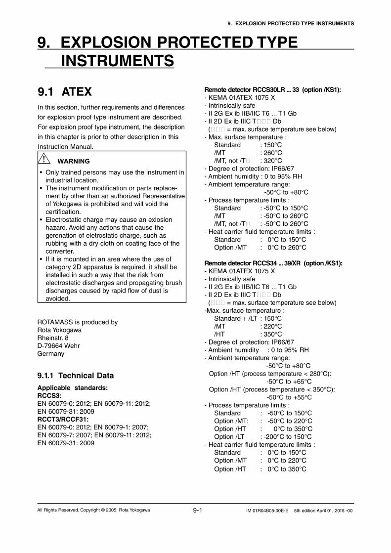
9. EXPLOSION PROTECTED TYPE INSTRUMENTS
9-1All Rights Reserved. Copyright © 2005, Rota Yokogawa IM 01R04B05-00E-E 5th edition April 01, 2015 -00
9. EXPLOSION PROTECTED TYPE INSTRUMENTS
9.1 ATEX In this section, further requirements and differences
for explosion proof type instrument are described.
For explosion proof type instrument, the description
in this chapter is prior to other description in this
Instruction Manual.
• Only trained persons may use the instrument in industrial location.•Theinstrumentmodificationorpartsreplace- ment by other than an authorized Representative of Yokogawa is prohibited and will void the certification. •Electrostaticchargemaycauseanexlosion hazard. Avoid any actions that cause the gerenation of eletrostatic charge, such as rubbing with a dry cloth on coating face of the converter.•Ifitismountedinanareawheretheuseof category 2D apparatus is required, it shall be installed in such a way that the risk from electrostatic discharges and propagating brush discharges caused by rapid flow of dust is avoided.
WARNING
ROTAMASS is produced byRota YokogawaRheinstr. 8D-79664 WehrGermany
9.1.1 Technical Data
Applicable standards:RCCS3:EN 60079-0: 2012; EN 60079-11: 2012; EN 60079-31: 2009RCCT3/RCCF31:EN 60079-0: 2012; EN 60079-1: 2007; EN 60079-7: 2007; EN 60079-11: 2012; EN 60079-31: 2009
Remote detector RCCS30LR ... 33 (option /KS1):- KEMA 01ATEX 1075 X- Intrinsically safe- II 2G Ex ib IIB/IIC T6 ... T1 Gb- II 2D Ex ib IIIC T Db ( = max. surface temperature see below)- Max. surface temperature : Standard : 150°C /MT : 260°C /MT, not /T : 320°C - Degree of protection: IP66/67- Ambient humidity : 0 to 95% RH- Ambient temperature range: -50°C to +80°C- Process temperature limits : Standard : -50°C to 150°C /MT : -50°C to 260°C /MT, not /T : -50°C to 260°C- Heat carrier fluid temperature limits : Standard : 0°C to 150°C Option /MT : 0°C to 260°C
Remote detector RCCS34 ... 39/XR (option /KS1):- KEMA 01ATEX 1075 X- Intrinsically safe- II 2G Ex ib IIB/IIC T6 ... T1 Gb- II 2D Ex ib IIIC T Db ( = max. surface temperature see below)-Max. surface temperature : Standard + /LT : 150°C /MT : 220°C /HT : 350°C - Degree of protection: IP66/67- Ambient humidity : 0 to 95% RH- Ambient temperature range: -50°C to +80°C Option /HT (process temperature < 280°C): -50°C to +65°C Option /HT (process temperature < 350°C): -50°C to +55°C- Process temperature limits : Standard : -50°C to 150°C Option /MT: : -50°C to 220°C Option /HT : 0°C to 350°C Option /LT : -200°C to 150°C- Heat carrier fluid temperature limits : Standard : 0°C to 150°C Option /MT : 0°C to 220°C Option /HT : 0°C to 350°C

9. EXPLOSION PROTECTED TYPE INSTRUMENTS
9-2 All Rights Reserved. Copyright © 2005, Rota YokogawaIM 01R04B05-00E-E 5th edition April 01, 2015 -00
Remote converter RCCF31 (option /KF3):- KEMA 02ATEX 2183 X- Flame proof with intrinsic safe connection to detector (ib)- II 2G Ex d [ib] IIC T6 Gb or Ex d e [ib] IIC T6 Gb- II 2G Ex d [ib] IIB T6 Gb or Ex d e [ib] IIB T6 Gb with option /HP- II 2D Ex tb [ib] IIIC T75°C Db- Max. surface temperature: 75°C- Degree of protection : IP66/67- Power supply : 90 to 250 V AC, 50/60 Hz 20.5 to 28.8 V DC- Power consumption : max. 25 VA / 10 W- Ambient humidity : 0 to 95% RH- Ambient temperature range: -40°C to +55°C
Remote converter RCCF31 (option /KF4):- KEMA 02ATEX 2183 X- Flame proof with intrinsic safe connection to detector (ib)- Additional intrinsic safe FF-output (ia). Ex d e [ia Ga] [ib] IIC T6 Gb- II 2 (1) G Ex d [ia IIC Ga] [ib] IIB T6 Gb or Ex d e [ia IIC Ga] [ib] IIB T6 Gb with option /HP- II 2 (1) D Ex tb [ia Da] [ib] IIIC T75°C Db- Max. surface temperature: 75°C- Degree of protection : IP66/67- Power supply : 90 to 250 V AC, 50/60 Hz 20.5 to 28.8 V DC- Power consumption : max. 25 VA / 10 W- Ambient humidity : 0 to 95% RH- Ambient temperature range : -40°C to +55°C
Integral type RCCT34 ... 39/XR (option /KF3):- KEMA 02ATEX 2183 X- Flame proof with intrinsic safe connection to detector (ib)- II 2G Ex d ib IIC T6...T3 Gb or Ex d e ib IIC T6...T3 G- II 2G Ex d ib IIB T6...T3 Gb or Ex d e ib IIB T6...T3 Gb with option /HP- II 2G Ex d ib op is IIC T6...T3 Gb - II 2D Ex ib tb IIIC T150°C Db- Max. surface temperature : 150°C- Degree of protection : IP66/67- Power supply : 90 to 250 V AC, 50/60 Hz 20.5 to 28.8 V DC- Power consumption : max. 25 VA / 10 W- Ambient humidity : 0 to 95% RH- Ambient temperature range : -40°C to +55°C- Process temperature limits : -50°C to 150°C
Integral type RCCT34 ... 39/XR (option /KF4):- KEMA 02ATEX 2183 X- Flame proof with intrinsic safe connection to detector (ib)- Additional intrinsic safe FF-output (ia).- II 2 (1) G Ex d ib [ia Ga] IIC T6...T3 Gb or Ex d e ib [ia Ga] IIC T6...T3 Gb- II 2 (1) G Ex d ib [ia IIC Ga] IIB T6...T3 Gb or Ex d e ib [ia IIC Ga] IIB T6...T3 Gb with option /HP- II 2 (1) D Ex ib tb [ia Da] IIIC T150°C Db- Max. surface temperature : 150°C- Degree of protection : IP66/67- Power supply: 90 to 250 V AC, 50/60 Hz 20.5 to 28.8 V DC- Power consumption : max. 25 VA / 10 W- Ambient humidity : 0 to 95% RH- Ambient temperature range : -40°C to +55°C- Process temperature limits : -50°C to 150°C
The electronics of RCCT3 and RCCF31 are placed in a pressure tight section of the converter housing Ex d. The kind of protection of the terminal enclosure is “e”, but can become “d” by using Ex-d certified cable glands.
Electrical data remote detector RCCS30LR ... 33:
- Driving circuit : terminals D+ / D-
Ex ib IIC : Ui = 16 V; Ii = 53 mA; Pi = 0.212 W
Li = 4.2 mH; Ci = negl. small
Ex ib IIB : Ui = 16 V; Ii = 153 mA; Pi = 0.612 W Li = 4.2 mH; Ci = negl. small
- Sensor circuits: terminals S1+/ S1- or S2+ / S2-
Ex ib IIC : Ui = 16 V; Ii = 80 mA; Pi = 0.32 W
Li = 4.2 mH; Ci = negl. small
- Temp. sensor circuit : terminals TP1, TP2, TP3
Ex ib IIC : Ui = 16 V; Ii = 50 mA; Pi = 0.2 W
Li = negligible small
Ci = negligible small
Electrical data remote detector RCCS34 ... 39/XR :
- Driving circuit : terminals D+ / D
Ex ib IIC : Ui = 16 V; Ii = 53 mA; Pi = 0.212 W Li = 3.2 mH; Ci = negligible small
Ex ib IIB : Ui = 16 V; Ii = 153 mA; Pi = 0.612 W Li = 3.2 mH; Ci = negligible small
- Sensor circuits: terminals S1+/ S1- or S2+ / S2-
Ex ib IIC : Ui = 16 V; Ii = 80 mA; Pi = 0.32 W
Li = 2.1 mH; Ci = negligible small
- Temp. sensor circuit : terminals TP1, TP2, TP3
Ex ib IIC : Ui = 16 V; Ii = 50 mA; Pi = 0.2 W
Li = negligible small
Ci = negligible small

9. EXPLOSION PROTECTED TYPE INSTRUMENTS
9-3All Rights Reserved. Copyright © 2005, Rota Yokogawa IM 01R04B05-00E-E 5th edition April 01, 2015 -00
Coherence between temperature class, ambient- and medium temperature / temperature of heat carrier:RCCS30LR to RCCS33
without insulationRCCS30LR to RCCS33 with factory insulation
Temp. class
Max. ambient temperature
Max. process temperature
Max. ambient temperature
Max. process temperature
T6 50°C / 122°F 60°C / 140°F 60°C / 140°F 60°C / 140°F
T5 50°C / 122°F 80°C / 176°F 80°C / 176°F 90°C / 194°F
T480°C / 176°F 50°C / 122°F
100°C / 212°F120°C / 248°F
80°C / 176°F 130°C / 266°F
T3 80°C / 176°F 180°C / 356°F 80°C / 176°F 180°C / 356°F
T2 80°C / 176°F 260°C / 500°F 80°C / 176°F 260°C / 500°F
T1 80°C / 176°F 260°C / 608°F 80°C / 176°F 260°C / 500°F
RCCS34 to RCCS39/XR without insulation
RCCS34 to RCCS39/XR with factory insulation
RCCT34 to RCCT39/XR
Temp. class
Max. ambient temperature
Max. process temperature
Max. ambient temperature
Max. process temperature
Max. ambient temperature
Max. process temperature
T6 40°C / 104°F 40°C / 104°F 65°C / 149°C 65°C / 149°F 50°C / 122°F 65°C / 149°C
T5 55°C / 131°F 55°C / 131°F 75°C / 167°F 75°C / 167°F 50°C / 122°F 80°C / 176°F
T480°C / 176°F40°C / 104°F
100°C / 212°F120°C / 248°F
70°C / 158°F 115°C / 239°F 50°C / 122°F 115°C / 239°F
T380°C / 176°F40°C / 104°F
160°C / 320°F180°C / 356°F
70°C / 158°F 180°C / 356°F 50°C / 122°F 150°C / 302°F
T2 80°C / 176°F 220°C / 428°F 65°C /149°F 275°C / 527°F
T1 45°C / 113°F 350°C / 662°F
For customer insulation of RCCS30 to 39/XR the following must be regarded : The table "with factory insulation" is calculated with 80 mm insulation and k-factor = 0.4 W/m2K. If your insulation data are worse than these use table "without insulation" !
NOTE
Electrical data remote converter RCCF31 and converter of intergral type RCCT3:
- Driving circuit : terminals D+ / D-
Ex ib IIC : Uo = 14.5 V; Io = 47 mA; Po = 0.171 W
Lo = 15 mH; Co = 0.65 µF
Ex ib IIB : Uo = 11.7 V; Io = 124 mA; Po = 0.363 W
Lo = 8 mH; Co = 10.3 µF
- Sensor circuits: terminals S1+/ S1- or S2+ / S2-
Ex ib IIC : Uo = 14.5 V; Io = 47 mA; Po = 0.171 W
Lo = 15 mH; Co = 0.65 µF
- Temperature sensor circuit : terminals TP1,TP2, TP3
Ex ib IIC : Uo = 13.3 V; Io = 40 mA; Po = 0.133 W
Lo = 20 mH; Co =0.91 µF- Fieldbus output (only option /KF4) : FISCO model: Ex [ia] IIC: Ui = 17.5 V; Ii = 380 mA; Pi = 5.32 W Li = 1.6 µH; Ci = 2.7 nF Ex [ia] IIB: Ui = 17.5 V; Ii = 460 mA; Pi = 5.32 W Li = 1.6 µH; Ci = 2.7 nF Entity model: Ex [ia] IIC: Ui = 24 V; Ii = 250 mA; Pi = 1.2 W Li = 1.6 µH; Ci = 2.7 nF

9. EXPLOSION PROTECTED TYPE INSTRUMENTS
9-4 All Rights Reserved. Copyright © 2005, Rota YokogawaIM 01R04B05-00E-E 5th edition April 01, 2015 -00
Flame proof (Ex d) relevant threads at converter housing and covers:
No. Position of thread Pitch Thread form + quality of pitch
Threads engaged
Depth of engagement
(1) case Thread on electronic/display side 2 mm medium, 6H 1) ≥ 6 12 mm(1) cover Thread on electronic/display side 2 mm medium, 6g 1) ≥ 6 12 mm(2) case Thread on terminal box side 2 mm medium, 6H 1) ≥ 6 12 mm(2) cover Thread on terminal box side 2 mm medium, 6g 1) ≥ 6 12 mm(3) M Thread for cable glands M20 x 1.5 1.5 mm medium, 6H 1) ≥ 10 17 mm(3) A/F Thread for cable glands 1/2 ´´ NPT 1.814 mm 2) 6.5 ± 1 13.605 mm
1) acc. ISO 965-1 and ISO 965-3 2) acc. ANSI B 1.20.1
If terminal enclosure is used as Ex e, the threads (2) and (3) in above table must be not be regarded.
Marking of Ex d covers
The cover with glass window is marked inside with an "Ex"- label as shown below:
F94.EPS
(1) (2)
(3)

9. EXPLOSION PROTECTED TYPE INSTRUMENTS
9-5All Rights Reserved. Copyright © 2005, Rota Yokogawa IM 01R04B05-00E-E 5th edition April 01, 2015 -00
1. Ex type of ROTAMASS must be connected to the suitable IS earthing system (see installation diagram). Converter case must have connection to the potential equalisation facility. If the connecting process tubing is part of the potential equalisation, no additional connection is required.
2. Use the certified cable glands, suitable for the conditions of use. The delivered cable glands are only for Ex e use. For Ex d use d-type cable glands.
3. Please confirm that the ground terminal (inside the terminal enclosure) is firmly connected by means of a clip-on eye-let.4. Ex-e terminals for power supply and I/O-lines are designed for cables with cross section of 0.08 mm²
(AWG 28) to 2.5 mm² (AWG12). The strip length must be 5 to 6 mm (0.2 to 0.24 in).
9.1.2 Installation
Installation diagrams for ROTAMASS with/KF3 see in chapter 9.2.2.Integral type RCCT3
WARNING
Cable glands for power- and I/O-cables :RCCT3-M : Ex e types are enclosed. These cable glands can also be used for “dust application” (D). Use ATEX-certified Ex d cable glands for Ex d condition.RCCT3-A : No cable glands are enclosed. Use the ATEX-certified cable glands, suitable for the conditions of use (Ex de or Ex d or dust application).
For “dust application” (D) use cable glands with minimum IP67 protection !
[Integral type]
Terminator
Rotamass(Flowmeter)
FFout+
FFout–
+–
+–
Field Instrument
Field Instrument
Safe Area
Hazardous Area
Terminator
L/+
N/–
Safe Area
Power supply
AC or DC
F09105.EPS
Safety barrier
Installation diagram /KF4 :

9. EXPLOSION PROTECTED TYPE INSTRUMENTS
9-6 All Rights Reserved. Copyright © 2005, Rota YokogawaIM 01R04B05-00E-E 5th edition April 01, 2015 -00
Remote type RCCF31 with RCCS3
WARNING 1. Ex type RCCF31 and RCCS3 must be connected to the suitable IS earthing system
(see installation diagram). Converter and detector case must have connection to the potential
equalisation facility.
2. Use the certified cable glands, suitable for the conditions of use.
3. Please confirm that the ground terminal (inside the terminal enclosure) is firmly connected by
means of a clip-on eye-let.4. Ex-e terminals for power supply and I/O-lines are designed for cables with cross section of 0.08 mm²
(AWG 28) to 2.5 mm² (AWG22). The strip length must be 5 to 6 mm (0.2 to 0.24 in).
5. For EMC technical reasons the case of the detector is connected to the case of the converter via
the shielding of the interconnecting cable.
Cable glands for power- and I/O-cables :RCCF31-M : Ex e types are enclosed. These cable glands can also be used for “dust application” (D). Use ATEX-certified Ex d cable glands for Ex d condition.RCCF31-A : No cable glands are enclosed. Use the ATEX-certified cable glands, suitable for the conditions of use (Ex de or Ex d or dust application)
For “dust application” (D) use cable glands with minimum IP67 protection !
Cable glands for detector connection terminal :RCCF31-M : Cable glands are fitted in the concerning thread. This cable gland can be used for “dust application” (D). RCCF31-A : Cable glands are enclosed. This cable gland can also be used for “dust application” (D).
Installation diagram /KF4 :
The inner shields (shields of the cable pairs) are connected together to COM –terminal on converter side.
The outer shield of the cable is connected on both sides to the cases by cable gland.
[Remote type]
Terminator
RCCF31(Converter)
FFout+
FFout–
+–
+–
Field Instrument
Field Instrument
Safe Area
Hazardous Area
Terminator
RCCS3(Detector)
D+D-S1+S1-S2+S2-TP1TP2TP3COM
L/+
N/–
Power supply
AC or DC
D+D-S1+S1-S2+S2-TP1TP2TP3COM
Remote CableRCCY03
Outer shield
Connected shieldsof cable pairs
to COM-terminal
F09106.EPS
Safety barrier

9. EXPLOSION PROTECTED TYPE INSTRUMENTS
9-7All Rights Reserved. Copyright © 2005, Rota Yokogawa IM 01R04B05-00E-E 5th edition April 01, 2015 -00
9.1.3 Operation
If the cover of the converter case has to be opened, following instructions must be followed.
WARNING 1. Confirm that the power cables to the instrument are disconnected.
2. Wait 15 minutes after power is turned off before opening the covers.
3. The covers of display side and terminal box are fixed with special screws, please use Hexagonal
Wrench to open the covers.
4. Be sure to lock the cover with special screw using the Hexagonal Wrench after tightening the cover.
5. Before starting the operation again, be sure to lock the cover with the locking screws.
6. Take care not to generate mechanical spark when access to the instrument and peripheral devices in
hazardous locations
7. Prohibition of specification changes and modifications. Users are prohibited from making any
modifications of specifications or physical configuration, such as adding or changing the configuration
of external wiring ports.
9.1.4 Maintenance and repair
WARNING The instrument modification of parts replacement by other than authorized representatives of YOKOGAWA is prohibited and will void the certification.
9.1.5 Ex-relevant marking on name plateRCCT3 option /KF3:KEMA 02 ATEX 2183XII 2 G Ex d ib IIC T6...T3 Gb or II 2 G Ex d e ib IIC T6...T3 GbII 2 D Ex ib tb IIIC T150°C DbDIODE SAFETY BARRIER Um : 250Vac/dcTEMP. CLASS T6 T5 T4 T3 PROCESS TEMP. 65 80 115 150°C ENCLOSURE: IP66/67SEE CERTIFICATE FOR DATA
WARNINGWAIT 15 MIN. AFTER POWER-DISCONNECTIONBEFORE OPENING THE ENCLOSURE.
RCCT3 option /KF4:KEMA 02 ATEX 2183XII 2 (1) G Ex d ib [ia Ga] IIC T6...T3 Gb orII 2 (1) G Ex d e ib [ia Ga] IIC T6...T3 GbII 2 (1) D Ex ib tb [ia Da] IIIC T150°C DbDIODE SAFETY BARRIER Um : 250Vac/dcTEMP. CLASS T6 T5 T4 T3 PROCESS TEMP. 65 80 115 150°C ENCLOSURE: IP66/67SEE CERTIFICATE FOR DATA
WARNINGWAIT 15 MIN. AFTER POWER-DISCONNECTION BEFORE OPENING THE ENCLOSURE.
RCCT3 option /KF3 + /HP:KEMA 02 ATEX 2183XII 2 G Ex d ib IIB T6...T3 Gb or II 2 G Ex d e ib IIB T6...T3 GbII 2 D Ex ib tb IIIC T150°C DbDIODE SAFETY BARRIER Um : 250Vac/dcTEMP. CLASS T6 T5 T4 T3 PROCESS TEMP. 65 80 115 150°C ENCLOSURE: IP66/67SEE CERTIFICATE FOR DATA
WARNINGWAIT 15 MIN. AFTER POWER-DISCONNECTIONBEFORE OPENING THE ENCLOSURE.
RCCT3 option /KF4 + /HP:KEMA 02 ATEX 2183XII 2 (1) G Ex d ib [ia IIC Ga] IIB T6...T3 Gb orII 2 (1) G Ex d e ib [ia IIC Ga] IIB T6...T3 Gb II 2 (1) D Ex ib tb [ia Da] IIIC T150°C DbDIODE SAFETY BARRIER Um : 250Vac/dcTEMP. CLASS T6 T5 T4 T3 PROCESS TEMP. 65 80 115 150°C ENCLOSURE: IP66/67SEE CERTIFICATE FOR DATA
WARNINGWAIT 15 MIN. AFTER POWER-DISCONNECTION BEFORE OPENING THE ENCLOSURE.

9. EXPLOSION PROTECTED TYPE INSTRUMENTS
9-8 All Rights Reserved. Copyright © 2005, Rota YokogawaIM 01R04B05-00E-E 5th edition April 01, 2015 -00
RCCF31 option /KF3:KEMA 02 ATEX 2183XII 2 G Ex d [ib] IIC T6 Gb or II 2 G Ex d e [ib] IIC T6 GbII 2 D Ex tb [ib] IIIC T75°C DbDIODE SAFETY BARRIER Um : 250Vac/dcENCLOSURE: IP66/67SEE CERTIFICATE FOR DATA
WARNINGWAIT 15 MIN. AFTER POWER-DISCONNECTIONBEFORE OPENING THE ENCLOSURE.
RCCF31 option /KF4 with display:KEMA 02 ATEX 2183XII 2 (1) G Ex d [ia Ga] [ib] IIC T6 Gb or II 2 (1) G Ex d e [ia Ga] [ib] IIC T6 GbII 2 (1) D Ex tb [ia Da] [ib] IIIC T75°C DbDIODE SAFETY BARRIER Um : 250Vac/dcENCLOSURE: IP66/67SEE CERTIFICATE FOR DATA
WARNINGWAIT 15 MIN. AFTER POWER-DISCONNECTIONBEFORE OPENING THE ENCLOSURE.
RCCS34 to 39/XR option /KS1:KEMA 01 ATEX 1075XII 2 G Ex ib IB/IIC T6...T1 GbII 2 D Ex ib IIIC T150°C Db IP66/67 SEE CERTIFICATE FOR DATA
RCCS34 to 39/XR option /KS1 + /MT:KEMA 01 ATEX 1075XII 2 G Ex ib IB/IIC T6...T1 GbII 2 D Ex ib IIIC T220°C Db IP66/67SEE CERTIFICATE FOR DATA
RCCS34 to 39/XR option /KS1 + /HT:KEMA 01 ATEX 1075XII 2 G Ex ib IB/IIC T6...T1 GbII 2 D Ex ib IIIC T350°C Db IP66/67SEE CERTIFICATE FOR DATA
RCCF31 option /KF3 + /HP:KEMA 02 ATEX 2183XII 2 G Ex d [ib] IIB T6 Gb or II 2 G Ex d e [ib] IIB T6 GbII 2 D Ex tb [ib] IIIC T75°C DbDIODE SAFETY BARRIER Um : 250Vac/dc ENCLOSURE: IP66/67SEE CERTIFICATE FOR DATA
WARNINGWAIT 15 MIN. AFTER POWER-DISCONNECTIONBEFORE OPENING THE ENCLOSURE.
RCCF31 option /KF4 + /HP with display:KEMA 02 ATEX 2183XII 2 (1) G Ex d [ia IIC Ga] [ib] IIB T6 Gb or II 2 (1) G Ex d e [ia IIC Ga] [ib] IIB T6 GbII 2 (1) D Ex tb [ia Da] [ib] IIIC T75°C DbDIODE SAFETY BARRIER Um : 250Vac/dc ENCLOSURE: IP66/67SEE CERTIFICATE FOR DATA
WARNINGWAIT 15 MIN. AFTER POWER-DISCONNECTION BEFORE OPENING THE ENCLOSURE.
RCCS30LR to 33 option /KS1:KEMA 01 ATEX 1075XII 2 G Ex ib IB/IIC T6...T1 GbII 2 D Ex ib IIIC T150°C Db IP66/67 SEE CERTIFICATE FOR DATA
RCCS30LR to 33 option /KS1 + /MT:KEMA 01 ATEX 1075XII 2 G Ex ib IB/IIC T6...T1 GbII 2 D Ex ib IIIC T260°C Db IP66/67 SEE CERTIFICATE FOR DATA

9. EXPLOSION PROTECTED TYPE INSTRUMENTS
9-9All Rights Reserved. Copyright © 2005, Rota Yokogawa IM 01R04B05-00E-E 5th edition April 01, 2015 -00
Supposable Bus Cable
The cable used to interconnect the FF-devices needs to comply with the following parameters:
loop resistance R’: 15...150 Ω/km inductance per unit length Lc: 0.4...1 mH/km capacitance per unit length Cc: 80...200 nF/km C’ = C’ line/line + 0.5 C’ line/screen, if both
lines are floating or C’ = C’ line/line + C’ line/screen, if the screen is
connected to one line length of spur cable: max. 30 m (IIC and IIB ) length of trunk cable: max. 1 km (IIC) or 5 km
(IIB)
Terminators
The terminator must be certified by a notified body as FISCO model and at each end of the trunk cable an approved line terminator with the follow-ing parameters is suitable:
R = 90...100 Ω C = 0...2.2 µF (0.8 ... 1.2 µF is required in op-
eration)The resistor must be infallible according to IEC 60079-11.
Number of Devices
The number of devices (max. 32) possible on a fieldbus link depends on factors such as the power consumption of each device, the type of cable used, use of repeaters, etc.

9. EXPLOSION PROTECTED TYPE INSTRUMENTS
9-10 All Rights Reserved. Copyright © 2005, Rota YokogawaIM 01R04B05-00E-E 5th edition April 01, 2015 -00
9.2 FMApplicable standards:FM3600: 2011, FM3610: 2010, FM3810: 2005,ANSI/NEMA 250: 1991, IEC 60529: 1999, ANSI/ISA 60079-0: 2009, ANSI/ISA 60079-11: 2009,CSA-C22.2 No.157,: 1992 CSA-C22.2 No.25: 1992,CSA-C22.2 No.30: 1988, CSA-C22.2 No.0.5: 1982,CSA-C22.2 No.142: 1987, CSA-C22.2 No.0.4: 1982, CSA-C22.2 No.94: 1991
9.2.1 Technical Data
Remote detector RCCS30 ... 39/XR (option /FS1):- Intrinsically safe- AEx ia IIC, Class 1, Zone 0- IS Class I, Division 1, Groups A,B,C,D T6- DIP Class II / III, Division 1, Groups E,F,G- IP67 / NEMA 4X
Remote converter RCCF31 (option /FF3):- Housing explosion proof- Provides intrinsically safe detector circuits- AEx [ia] IIC, Class I, Zone 1, T6 - AEx [ia] IIB, Class I, Zone 1, T6 with option /HP- Class I, Division 1, Groups A,B,C,D- Class I, Division 1, Groups C,D with option /HP- Class II / III, Division 1, Groups E,F,G - AIS Class I / II / III, Division 1, Groups A,B,C,D, E,F,G - AIS Class I / II / III, Division 1, Groups C,D,E,F,G with /HP- IP67 / NEMA 4X- Ambient temperature range : −40°C to +50°C
Integral type RCCT34 .. 39/IR (option /FF3):- Housing explosion proof- AEx d [ia] IIC, Class I, Zone 1, T6 - AEx [ia] IIB, Class I, Zone 1, T6 with option /HP- Class I, Division 1, Groups A,B,C,D- Class I, Division 1, Groups C,D with option /HP- Class II / III, Division 1, Groups E,F,G - IP67 / NEMA 4X- Ambient temperature range : −40°C to +50°C
Temperature classification :The remote converter RCCF31 has a T6 temperature class rating for operation at ambient temperature up to +50°C / +122°F.- Standard : -50°C to 150°C / -58°F to 302°F- with option /LT : -200°C to 150°C / -328°F to 302°F- with option /MT (RCCS30LR...33) : -50°C to 260°C / -58°F to 500°F- with option /MT (RCCx34...39/XR) : -50°C to 220°C / -58°F to 428°F- with option /HT : 0°C to 350°C / 32°F to 662°F
Electrical data Remote converter RCCF31,and converter of Integral type RCCT3 :
- Driving circuit : terminals D+ / D-
Uo = 14.5 V; Io = 47 mA; Po = 0.171 W
Lo = 15 mH; Co = 0.65 µF
- Driving circuit : terminals D+ / D- with option /HP
Uo = 11.7 V; Io = 124 mA; Po = 0.363 W
Lo = 8 mH; Co = 10.3 µF
- Sensor circuits: terminals S1+/ S1- or S2+ / S2-
Uo = 14.5 V; Io = 47 mA; Po = 0.363 W
Lo = 15 mH; Co = 0.65 µF
- Temperature sensor circuit : terminals TP1,TP2, TP3
Uo = 13.3 V; Io =40 mA; Po = 0.133 W
Lo = 20 mH; Co =0.91 µF
Electrical data Remote detector RCCS30 ... 33:
- Driving circuit : terminals D+ and D
Ui = 16 V; Ii = 53 mA; Pi = 0.212 W Li = 4.2 mH; Ci = negligible small
- Driving circuit : terminals D+ / D- with option /HP
Ui = 16 V; Ii = 153 mA; Pi = 0.612 W
Li = 4.2 mH; Ci = negligible small
- Sensor circuits: terminals S1+ / S1- or S2+ /S2-
Ui = 16 V; Ii = 80 mA; Pi = 0.32 W
Li = 4.2 mH; Ci = negligible small
- Temperature sensor circuit : terminals TP1,TP2, TP3
Ui = 16 V; Ii =50 mA; Pi = 0.2 W
Li = negligible small; Ci = negligible small
Electrical data Remote detector RCCS34 ... 39/XR:
- Driving circuit : terminals D+ and D
Ui = 16 V; Ii = 53 mA; Pi = 0.212 W
Li = 3.2 mH; Ci = negligible small
- Driving circuit : terminals D+ / D- with option /HP
Ui = 16 V; Ii = 153 mA; Pi = 0.612 W
Li = 3.2 mH; Ci = negligible small
- Sensor circuits: terminals S1+ / S1- or S2+ /S2-
Ui = 16 V; Ii = 80 mA; Pi = 0.32 W
Li = 2.1 mH; Ci = negligible small
- Temperature sensor circuit : terminals TP1,TP2, TP3
Ui = 16 V; Ii =50 mA; Pi = 0.2 W
Li = negligible small; Ci = negligible small

9. EXPLOSION PROTECTED TYPE INSTRUMENTS
9-11All Rights Reserved. Copyright © 2005, Rota Yokogawa IM 01R04B05-00E-E 5th edition April 01, 2015 -00
Temperature classification :The remote converter RCCF31 has a T6 temperature class rating for operation at ambient temperature up to +50°C / +122°F.
Coherence between temperature class, ambient- and medium temperature / temperature of heat carrier:RCCS30LR to RCCS33
without insulationRCCS30LR to RCCS33 with factory insulation
Temp. class
Max. ambient temperature
Max. process temperature
Max. ambient temperature
Max. process temperature
T6 50°C / 122°F 60°C / 140°F 60°C / 140°F 60°C / 140°F
T5 50°C / 122°F 80°C / 176°F 80°C / 176°F 90°C / 194°F
T480°C / 176°F 50°C / 122°F
100°C / 212°F120°C / 248°F
80°C / 176°F 130°C / 266°F
T3 80°C / 176°F 180°C / 356°F 80°C / 176°F 180°C / 356°F
T2 80°C / 176°F 260°C / 500°F 80°C / 176°F 260°C / 500°F
T1 80°C / 176°F 260°C / 608°F 80°C / 176°F 260°C / 500°F
RCCS34 to RCCS39/XR without insulation
RCCS34 to RCCS39/XR with factory insulation
RCCT34 to RCCT39/XR
Temp. class
Max. ambient temperature
Max. process temperature
Max. ambient temperature
Max. process temperature
Max. ambient temperature
Max. process temperature
T6 40°C / 104°F 40°C / 104°F 65°C / 149°C 65°C / 149°F 50°C / 122°F 65°C / 149°C
T5 55°C / 131°F 55°C / 131°F 75°C / 167°F 75°C / 167°F 50°C / 122°F 80°C / 176°F
T480°C / 176°F40°C / 104°F
100°C / 212°F120°C / 248°F
70°C / 158°F 115°C / 239°F 50°C / 122°F 115°C / 239°F
T380°C / 176°F40°C / 104°F
160°C / 320°F180°C / 356°F
70°C / 158°F 180°C / 356°F 50°C / 122°F 150°C / 302°F
T2 80°C / 176°F 220°C / 428°F 65°C /149°F 275°C / 527°F
T1 45°C / 113°F 350°C / 662°F
For customer insulation of RCCS34 to 39/IR the following must be regarded : The table "with factory insulation" is calculated with 80 mm insulation and k-factor = 0.4 W/m2K. If your insulation data are worse than these use table "without insulation" !
9.2.2 InstallationIntegral type RCCT3 :
L/+N/-G
Power supply
I/O control
Hazardous area Safe area
I/O
Rotamass RCCT3
F91.EPS
Term
inal B
ox
NOTE

9. EXPLOSION PROTECTED TYPE INSTRUMENTS
9-12 All Rights Reserved. Copyright © 2005, Rota YokogawaIM 01R04B05-00E-E 5th edition April 01, 2015 -00
- The flowmeter must be connected to the potential equalization system. For remote type Converter and detector case must have connection to the potential equalisation facility
- For remote type at ambient temperature up to 60°C / 140°F use remote cable RCCY031 or RCCY032. - For remote type at ambient temperature up to 80°C / 176°F use remote cable RCCY033. - Maximum length of remote cable is 300 m/999 ft. - Specified maximum ambient temperature of cables (power supply-, I/O- and remote cable) must be 20°C
/ 41°F above maximum ambient temperature of flowmeter. - For AC-version maximum power supply is 250 V AC. - Install according National Electrical Code. Intrinsically safe circuits must be installed according NEC ANSI /
NPFA 70 amd ISA RP 12.6. - Use certified XP (explosion proof) cable glands for power supply and I/O. - Please confirm that the ground terminal (inside the terminal enclosure) is firmly connected by means of a
clip-on eye-let. - For EMC technical reasons the case of the detector is connected to the case of the converter via the shielding of the interconnecting cable.
CAUTION
Installation of separate intrinsic safe ground for Remote type RCCS3 with RCCF31 (see Control Drawing 8300027) :- Remove the stopping plug on detector connecting side and replace it by a dust proofed cable gland.- Open the cover on detector connecting side of RCCF31.- Remove the cable between COM- terminal and the ground screw.- Put the intrinsic safe ground cable through the new installed cable gland.- Connect the IS-ground cable to the COM- terminal.- Install the remote cable between detector RCCS3 and converter RCCF31 as shown in this chapter.
Remote type RCCS3 with RCCF31 :
L/+N/-G
Power supply
I/O control
Hazardous area Safe area
I/O
RCCF31RCCS3
D+
D-
S1+S1-
S2+S2-
TP1TP2
TP3
D+
D-
S1+S1-
S2+S2-
TP1TP2
TP3COM
Exclusive remote cable RCCY03x
F92.EPS
Term
inal B
ox

9. EXPLOSION PROTECTED TYPE INSTRUMENTS
9-13All Rights Reserved. Copyright © 2005, Rota Yokogawa IM 01R04B05-00E-E 5th edition April 01, 2015 -00
WARNING
9.2.3 General warnings
- Substitution of components may impair intrinsic safety ! - Only trained persons may use the instrument in industrial location. - The instrument modification of parts replacement by other than authorized representatives of YOKOGAWA
is prohibited and will void the certification.
- If the cover of the converter case has to be opened, following instructions must be followed:
- Confirm that the power cables to the instrument are disconnected.
- Wait 15 minutes after power is turned off before opening the covers.
- The covers of display side and terminal box are fixed with special screws, please use Hexagonal Wrench
to open the covers.
- Be sure to lock the cover with special screw using the Hexagonal Wrench after tightening the cover .
- Before starting the operation again, be sure to lock the cover with the locking screws.
- Prohibition of specification changes and modifications. Users are prohibited from making any
modifications of specifications or physical configuration, such as adding or changing the configuration of
external wiring ports.
Marking of Ex d covers
The cover with glass window is marked inside with an "Ex"- label as shown below:

9. EXPLOSION PROTECTED TYPE INSTRUMENTS
9-14 All Rights Reserved. Copyright © 2005, Rota YokogawaIM 01R04B05-00E-E 5th edition April 01, 2015 -00
9.2.4 Ex-relevant marking on name plateRCCT3 option /FF3:Control Drawing No. 8300026Class I, Division 1; Group A, B, C, DClass II / III, Division 1, Group E, F, GAEx d [ia] IIC, Class I, Zone 1, T6Conduit Seals required within 18 inches.Use Conductors rated 70°CTYPE NEMA 4X, IP67
WARNINGWAIT 15 MIN. AFTER POWER-DISCONNECTIONBEFORE OPENING THE ENCLOSURE.
RCCF31 option /FF3:Control Drawing No. 8300027Class I, Division 1; Group A, B, C,DAIS Class I / II / III, Division 1, Group A, B, C, D, E, F, GClass II / III, Division 1, Group E, F, GAEx d [ia] IIC, Class I, Zone 1, T6Conduit Seals required within 18 inches.Use Conductors rated 70°CTYPE NEMA 4X, IP67
WARNINGWAIT 15 MIN. AFTER POWER-DISCONNECTIONBEFORE OPENING THE ENCLOSURE.
RCCT3 option /FF3 /DS:Control Drawing No. 8300026Class I, Division 1; Group A, B, C, DClass II / III, Division 1, Group E, F, GAEx d [ia] IIC, Class I, Zone 1, T6Conduit Seals required within 18 inches.Use Conductors rated 70°CTYPE NEMA 4X, IP67
WARNINGWAIT 15 MIN. AFTER POWER-DISCONNECTIONBEFORE OPENING THE ENCLOSURE.Dual Seal
RCCS3 option /FS1:Control Drawing No. 8300027IS Class I, Division 1; Group A, B, C, D, T6Class II / III, Division 1, Group E, F, GAEx ia IIC, Class I, Zone 0Use Conductors rated 20°C above max. ambient temperatureTYPE NEMA 4X, IP67Temperature Class see Control Drawing
RCCT3 option /FF3 /HP:Control Drawing No. 8300026Class I, Division 1; Group C, DClass II / III, Division 1, Group E, F, GAEx d [ia] IIB, Class I, Zone 1, T6Conduit Seals required within 18 inches.Use Conductors rated 70°CTYPE NEMA 4X, IP67
WARNINGWAIT 15 MIN. AFTER POWER-DISCONNECTIONBEFORE OPENING THE ENCLOSURE.
RCCF31 option /FF3 /HP:Control Drawing No. 8300027Class I, Division 1; Group C, DAIS Class I / II / III, Division 1, Group C, D, E, F, GClass II / III, Division 1, Group E, F, GAEx d [ia] IIB, Class I, Zone 1, T6Conduit Seals required within 18 inches.Use Conductors rated 70°CTYPE NEMA 4X, IP67
WARNINGWAIT 15 MIN. AFTER POWER-DISCONNECTIONBEFORE OPENING THE ENCLOSURE.
RCCT3 option /FF3 /HP /DS:Control Drawing No. 8300026Class I, Division 1; Group C, DClass II / III, Division 1, Group E, F, GAEx d [ia] IIB, Class I, Zone 1, T6Conduit Seals required within 18 inches.Use Conductors rated 70°CTYPE NEMA 4X, IP67
WARNINGWAIT 15 MIN. AFTER POWER-DISCONNECTIONBEFORE OPENING THE ENCLOSURE.Dual Seal
RCCS3 option /FS1 /DS:Control Drawing No. 8300027IS Class I, Division 1; Group A, B, C, D, T6Class II / III, Division 1, Group E, F, GAEx ia IIC, Class I, Zone 0Use Conductors rated 20°C above max. ambient temperatureTYPE NEMA 4X, IP67Temperature Class see Control DrawingDual Seal

9. EXPLOSION PROTECTED TYPE INSTRUMENTS
9-15All Rights Reserved. Copyright © 2005, Rota Yokogawa IM 01R04B05-00E-E 5th edition April 01, 2015 -00
9.2.5 Control drawings
1 18300026
FM/CSA CONTROL DRAWINGROTAMASS RCCT3
Butz09.02.200509.02.2005 Rü
L/+N/-G
CKECKED
DRAWED
UPDATE No.Rev.
aDATE EDITOR CHECKED
TITEL:
79664 WEHR YOKOGAWA
NAMEDATE
DWG. No.:
RCCT34 to RCCT39/XR Temp.class
T6 ≤ 50°C / 122°F ≤ 65°C / 149°F T5 ≤ 50°C / 122°F ≤ 80°C / 176°F T4 ≤ 50°C / 122°F ≤ 115°C / 239°F T3 ≤ 50°C / 122°F ≤ 150°C / 302°F
NPT 1/2"
Hazardous Locations :
Class I Division 1 Groups A,B,C,D or Class I Zone 1 Group IIC Class I Division 1 Groups C,D or Class I Zone 1 Group IIB (option /HP)and Class II and III Division 1 Groups E,F,G
The minimum ambient temperature is -40°C / -40°F
WARNING : Substitution of components may impair intrinsic safety.
Note :- For AC-version maximum power supply is 250V AC.- For DC-version maximum power supply is 28.8V DC. - The installation must be in accordance with the national electrical code, NFPA70, article 504 to 510
and ANSI/ISA RP 12.06.01.- The non intrinsically safe terminals must not be connected to any device that uses or generates more
than 250Vrms or dc unless it has been determined that the voltage was adequately isolated.- Installation must be in accordance with the Canadian Electrical Code, when installed in Canada.
Max.Medium temperature or temperature ofheat carrier
Max.Ambienttemperature
Power supply
I/O control
HAZARDOUS LOCATION NON HAZARDOUS LOCATION
I/O
Rotamass RCCT3
GERMANY
b ---------- 1.9.05 Butz Rü c ---------- 5.3.07 Butz Rü
Temperature classification :
Installation :

9. EXPLOSION PROTECTED TYPE INSTRUMENTS
9-16 All Rights Reserved. Copyright © 2005, Rota YokogawaIM 01R04B05-00E-E 5th edition April 01, 2015 -00

9. EXPLOSION PROTECTED TYPE INSTRUMENTS
9-17All Rights Reserved. Copyright © 2005, Rota Yokogawa IM 01R04B05-00E-E 5th edition April 01, 2015 -00

9. EXPLOSION PROTECTED TYPE INSTRUMENTS
9-18 All Rights Reserved. Copyright © 2005, Rota YokogawaIM 01R04B05-00E-E 5th edition April 01, 2015 -00
9.3 IECExIn this section, further requirements and differences
for explosion proof type instrument are described.
For explosion proof type instrument, the descrip-
tion in this chapter is prior to other description in
this Instruction Manual.
WARNING
• Only trained persons may use the instrument in industrial location.•Theinstrumentmodificationorpartsreplace- ment by other than an authorized Representative of Yokogawa is prohibited and will void the certification. •Electrostaticchargemaycauseanexlosion hazard. Avoid any actions that cause the gerenation of eletrostatic charge, such as rubbing with a dry cloth on coating face of the converter.•Ifitismountedinanareawheretheuseof category 2D apparatus is required, it shall be installed in such a way that the risk from electrostatic discharges and propagating brush discharges caused by rapid flow of dust is avoided.
ROTAMASS is produced byRota YokogawaRheinstr. 8D-79664 WehrGermany
9.3.1 Technical Data
Applicable Standard: RCCS3: IEC 60079-0: 2011; IEC 60079-11: 2011; IEC 60079-31:2008 RCCT3/RCCF31/RCCR31: IEC 60079-0: 2011, IEC 60079-1: 2007, IEC 60079-7: 2006, IEC 60079-11: 2011, IEC 60079-31:2008 Certificate: IECEx KEM 06.0031X
Remote detector RCCS30LR ... 33 (option /ES1):- Intrinsically safe- Ex ib IIB/IIC T6 ... T1 Gb- Ex ib IIIC T Db ( = max. surface temperature see below)- Max. surface temperature : Standard : 150°C /MT : 260°C /MT, not /T : 320°C - Degree of protection: IP66/67- Ambient humidity : 0 to 95% RH- Ambient temperature range: -50°C to +80°C- Process temperature limits : Standard : -50°C to 150°C /MT : -50°C to 260°C /MT, not /T : -50°C to 260°C- Heat carrier fluid temperature limits : Standard : 0°C to 150°C Option /MT : 0°C to 260°C
Remote detector RCCS34 ... 39/XR (option /ES1):- Intrinsically safe- Ex ib IIB/IIC T6 ... T1 Gb- Ex ib IIIC T Db ( = max. surface temperature see below)-Max. surface temperature : Standard + /LT : 150°C /MT : 220°C /HT : 350°C - Degree of protection: IP66/67- Ambient humidity : 0 to 95% RH- Ambient temperature range: -50°C to +80°C Option /HT (process temperature < 280°C): -50°C to +65°C Option /HT (process temperature < 350°C): -50°C to +55°C- Process temperature limits : Standard : -50°C to 150°C Option /MT: : -50°C to 220°C Option /HT : 0°C to 350°C Option /LT : -200°C to 150°C- Heat carrier fluid temperature limits : Standard : 0°C to 150°C Option /MT : 0°C to 220°C Option /HT : 0°C to 350°C

9. EXPLOSION PROTECTED TYPE INSTRUMENTS
9-19All Rights Reserved. Copyright © 2005, Rota Yokogawa IM 01R04B05-00E-E 5th edition April 01, 2015 -00
Remote converter RCCF31 (option /EF3):- Flame proof with intrinsic safe connection to detector (ib)- Ex d [ib] IIC T6 Gb or Ex d e [ib] IIC T6 Gb- Ex d [ib] IIB T6 Gb or Ex d e [ib] IIB T6 Gb with option /HP- Ex tb [ib] IIIC T75°C Db- Max. surface temperature: 75°C- Degree of protection : IP66/67- Power supply : 90 to 250 V AC, 50/60 Hz 20.5 to 28.8 V DC- Power consumption : max. 25 VA / 10 W- Ambient humidity : 0 to 95% RH
- Ambient temperature range: -40°C to +55°C
Remote converter RCCF31 (option /EF4):- Flame proof with intrinsic safe connection to detector (ib)- Additional intrinsic safe FF- output (ia).- Ex d [ib] [ia Ga] IIC T6 Gb or Ex d e [ib] [ia Ga] IIC T6 Gb- Ex d [ib] [ia IIC Ga] IIB T6 Gb or Ex d e [ia IIC Ga] [ib] IIB T6 Gb with option /HP- Ex tb [ia Da] [ib] IIIC T75°C Db- Max. surface temperature: 75°C- Degree of protection : IP66/67- Power supply : 90 to 250 V AC, 50/60 Hz 20.5 to 28.8 V DC- Power consumption : max. 25 VA / 10 W- Ambient humidity : 0 to 95% RH- Ambient temperature range : -40°C to +55°C
Integral type RCCT34 ... 39/XR (option /EF3):- Flame proof with intrinsic safe connection to detector (ib)- Ex d ib IIC T6...T3 Gb or Ex d e ib IIC T6...T3 Gb- Ex d ib IIB T6...T3 Gb or Ex d e ib IIB T6...T3 Gb with option /HP- Ex ib tb IIIC T150°C Db- Max. surface temperature : 150°C- Degree of protection : IP66/67- Power supply : 90 to 250 V AC, 50/60 Hz 20.5 to 28.8 V DC- Power consumption : max. 25 VA / 10 W- Ambient humidity : 0 to 95% RH- Ambient temperature range : -40°C to +55°C- Process temperature limits : -50°C to 150°C
Integral type RCCT34 ... 39/XR (option /EF4):- Flame proof with intrinsic safe connection to detector (ib)- Additional intrinsic safe FF- output (ia).- Ex d ib [ia Ga] IIC T6...T3 Gb or Ex d e ib [ia Ga] IIC T6...T3 Gb- Ex d ib [ia IICGa] IIB T6...T3 Gb or Ex d e ib [ia IIC Ga] IIB T6...T3 Gb with option /HP- Ex ib tb [ia Da] IIIC T150°C Db- Max. surface temperature : 150°C- Degree of protection : IP66/67- Power supply: 90 to 250 V AC, 50/60 Hz 20.5 to 28.8 V DC- Power consumption : max. 25 VA / 10 W- Ambient humidity : 0 to 95% RH- Ambient temperature range : -40°C to +55°C- Process temperature limits : -50°C to 150°C
The electronics of RCCT3 and RCCF31 are placed in a pressure tight section of the converter housing Ex d. The kind of protection of the terminal enclosure is “e”, but can become “d” by using Ex-d certified cable glands.
Electrical data remote detector RCCS30LR ... 33:
- Driving circuit : terminals D+ / D-
Ex ib IIC : Ui = 16 V; Ii = 53 mA; Pi = 0.212 W
Li = 4.2 mH; Ci = negl. small
Ex ib IIB : Ui = 16 V; Ii = 153 mA; Pi = 0.612 W Li = 4.2 mH; Ci = negl. small
- Sensor circuits: terminals S1+/ S1- or S2+ / S2-
Ex ib IIC : Ui = 16 V; Ii = 80 mA; Pi = 0.32 W
Li = 4.2 mH; Ci = negl. small
- Temp. sensor circuit : terminals TP1, TP2, TP3
Ex ib IIC : Ui = 16 V; Ii = 50 mA; Pi = 0.2 W
Li = negligible small
Ci = negligible small
Electrical data remote detector RCCS34 ... 39/XR :
- Driving circuit : terminals D+ / D
Ex ib IIC : Ui = 16 V; Ii = 53 mA; Pi = 0.212 W Li = 3.2 mH; Ci = negligible small
Ex ib IIB : Ui = 16 V; Ii = 153 mA; Pi = 0.612 W Li = 3.2 mH; Ci = negligible small
- Sensor circuits: terminals S1+/ S1- or S2+ / S2-
Ex ib IIC : Ui = 16 V; Ii = 80 mA; Pi = 0.32 W
Li = 2.1 mH; Ci = negligible small
- Temp. sensor circuit : terminals TP1, TP2, TP3
Ex ib IIC : Ui = 16 V; Ii = 50 mA; Pi = 0.2 W
Li = negligible small
Ci = negligible small

9. EXPLOSION PROTECTED TYPE INSTRUMENTS
9-20 All Rights Reserved. Copyright © 2005, Rota YokogawaIM 01R04B05-00E-E 5th edition April 01, 2015 -00
Temperature classification :The remote converter RCCF31 has a T6 temperature class rating for operation at ambient temperature up to +50°C.
Coherence between temperature class, ambient- and medium temperature / temperature of heat carrier:RCCS30LR to RCCS33
without insulationRCCS30LR to RCCS33 with factory insulation
Temp. class
Max. ambient temperature
Max. process temperature
Max. ambient temperature
Max. process temperature
T6 50°C / 122°F 60°C / 140°F 60°C / 140°F 60°C / 140°F
T5 50°C / 122°F 80°C / 176°F 80°C / 176°F 90°C / 194°F
T480°C / 176°F 50°C / 122°F
100°C / 212°F120°C / 248°F
80°C / 176°F 130°C / 266°F
T3 80°C / 176°F 180°C / 356°F 80°C / 176°F 180°C / 356°F
T2 80°C / 176°F 260°C / 500°F 80°C / 176°F 260°C / 500°F
T1 80°C / 176°F 260°C / 608°F 80°C / 176°F 260°C / 500°F
RCCS34 to RCCS39/XR without insulation
RCCS34 to RCCS39/XR with factory insulation
RCCT34 to RCCT39/XR
Temp. class
Max. ambient temperature
Max. process temperature
Max. ambient temperature
Max. process temperature
Max. ambient temperature
Max. process temperature
T6 40°C / 104°F 40°C / 104°F 65°C / 149°C 65°C / 149°F 50°C / 122°F 65°C / 149°C
T5 55°C / 131°F 55°C / 131°F 75°C / 167°F 75°C / 167°F 50°C / 122°F 80°C / 176°F
T480°C / 176°F40°C / 104°F
100°C / 212°F120°C / 248°F
70°C / 158°F 115°C / 239°F 50°C / 122°F 115°C / 239°F
T380°C / 176°F40°C / 104°F
160°C / 320°F180°C / 356°F
70°C / 158°F 180°C / 356°F 50°C / 122°F 150°C / 302°F
T2 80°C / 176°F 220°C / 428°F 65°C /149°F 275°C / 527°F
T1 45°C / 113°F 350°C / 662°F
For customer insulation of RCCS34 to 39/IR the following must be regarded : The table "with factory insulation" is calculated with 80 mm insulation and k-factor = 0.4 W/m2K. If your insulation data are worse than these use table "without insulation" !
NOTE
Marking of Ex d covers
The cover with glass window is marked inside with
an "Ex"- label as shown below:
Electrical data remote converter RCCF31, RCCR31 and converter of Intergral type RCCT3:
- Driving circuit : terminals D+ / D-
Ex ib IIC : Uo = 14.5 V; Io = 47 mA; Po = 0.171 W
Lo = 15 mH; Co = 0.65 µF
Ex ib IIB : Uo = 11.7 V; Io = 124 mA; Po = 0.363 W
Lo = 8 mH; Co = 10.3 µF
- Sensor circuits: terminals S1+/ S1- or S2+ / S2-
Ex ib IIC : Uo = 14.5 V; Io = 47 mA; Po = 0.171 W
Lo = 15 mH; Co = 0.65 µF
- Temperature sensor circuit : terminals TP1,TP2, TP3
Ex ib IIC : Uo = 13.3 V; Io = 40 mA; Po = 0.133 W
Lo = 20 mH; Co =0.91 µF- Fieldbus output (only option /KF4) : FISCO model: Ex [ia] IIC: Ui = 17.5 V; Ii = 380 mA; Pi = 5.32 W Li = 1.6 µH; Ci = 2.7 nF Ex [ia] IIB: Ui = 17.5 V; Ii = 460 mA; Pi = 5.32 W Li = 1.6 µH; Ci = 2.7 nF Entity model: Ex [ia] IIC: Ui = 24 V; Ii = 250 mA; Pi = 1.2 W Li = 1.6 µH; Ci = 2.7 nF

9. EXPLOSION PROTECTED TYPE INSTRUMENTS
9-21All Rights Reserved. Copyright © 2005, Rota Yokogawa IM 01R04B05-00E-E 5th edition April 01, 2015 -00
9.3.2 Installation
Remote type RCCF31 /EF4 with RCCS3 /ES1
Installation for ROTAMASS with /EF3 see in chapter 9.2.2.Integral type RCCT3 /EF4
[Integral type]
Terminator
Rotamass(Flowmeter)
FFout+
FFout–
+–
+–
Field Instrument
Field Instrument
Safe Area
Hazardous Area
Terminator
L/+
N/–
Safe Area
Power supply
AC or DC
F09105.EPS
Safety barrier
[Remote type]
Terminator
RCCF31(Converter)
FFout+
FFout–
+–
+–
Field Instrument
Field Instrument
Safe Area
Hazardous Area
Terminator
RCCS3(Detector)
D+D-S1+S1-S2+S2-TP1TP2TP3COM
L/+
N/–
Power supply
AC or DC
D+D-S1+S1-S2+S2-TP1TP2TP3COM
Remote CableRCCY03
Outer shield
Connected shieldsof cable pairs
to COM-terminal
F09106.EPS
Safety barrier

9. EXPLOSION PROTECTED TYPE INSTRUMENTS
9-22 All Rights Reserved. Copyright © 2005, Rota YokogawaIM 01R04B05-00E-E 5th edition April 01, 2015 -00
9.3.3 Operation
If the cover of the converter case has to be opened, following instructions must be followed.
CAUTION
9.3.4 Maintenance and repair
WARNING The instrument modification of parts replacement by other than authorized representatives of YOKOGAWA is prohibited and will void the certification.
9.3.5 Ex-relevant marking on name plate
1. Confirm that the power cables to the instrument are disconnected.
2. Wait 15 minutes after power is turned off before opening the covers.
3. The covers of display side and terminal box are fixed with special screws, please use Hexagonal
Wrench to open the covers.
4. Be sure to lock the cover with special screw using the Hexagonal Wrench after tightening the cover.
5. Before starting the operation again, be sure to lock the cover with the locking screws.
6. Prohibition of specification changes and modifications. Users are prohibited from making any
modifications of specifications or physical configuration, such as adding or changing the configuration
of external wiring ports.
RCCT3 option /EF3:IECEx KEM 06.0031XEx d ib IIC T6...T3 Gb or Ex d e ib IIC T6...T3 GbEx ib tb IIIC T150°C DbDIODE SAFETY BARRIER Um : 250Vac/dcTEMP. CLASS T6 T5 T4 T3 PROCESS TEMP. 65 80 115 150°C ENCLOSURE: IP66/67SEE CERTIFICATE FOR DATA
WARNINGWAIT 15 MIN. AFTER POWER-DISCONNECTIONBEFORE OPENING THE ENCLOSURE.
RCCT3 option /EF4 with display:IECEx KEM 06.0031XEx d ib [ia Ga] IIC T6...T3 Gb or Ex d e ib [ia Ga] IIC T6...T3 GbEx ib tb [ia Da] IIIC T150°C DbDIODE SAFETY BARRIER Um : 250Vac/dcTEMP. CLASS T6 T5 T4 T3 PROCESS TEMP. 65 80 115 150°C ENCLOSURE: IP66/67SEE CERTIFICATE FOR DATA
WARNINGWAIT 15 MIN. AFTER POWER-DISCONNECTION BEFORE OPENING THE ENCLOSURE.
RCCT3 option /EF3 + /HP:IECEx KEM 06.0031XEx d ib IIB T6...T3 Gb or Ex d e ib IIB T6...T3 GbEx ib tb IIIC T150°C DbDIODE SAFETY BARRIER Um : 250Vac/dcTEMP. CLASS T6 T5 T4 T3 PROCESS TEMP. 65 80 115 150°C ENCLOSURE: IP66/67SEE CERTIFICATE FOR DATA
WARNINGWAIT 15 MIN. AFTER POWER-DISCONNECTIONBEFORE OPENING THE ENCLOSURE.
RCCT3 option /EF4 + /HP with display:IECEx KEM 06.0031XEx d ib [ia IIC Ga] IIB T6...T3 Gb or Ex d e ib [ia IIC Ga] IIB T6...T3 GbEx ib tb [ia Da] IIIC T150°C DbDIODE SAFETY BARRIER Um : 250Vac/dcTEMP. CLASS T6 T5 T4 T3 PROCESS TEMP. 65 80 115 150°C ENCLOSURE: IP66/67SEE CERTIFICATE FOR DATA
WARNINGWAIT 15 MIN. AFTER POWER-DISCONNECTION BEFORE OPENING THE ENCLOSURE.

9. EXPLOSION PROTECTED TYPE INSTRUMENTS
9-23All Rights Reserved. Copyright © 2005, Rota Yokogawa IM 01R04B05-00E-E 5th edition April 01, 2015 -00
RCCF31 option /EF3:IECEx KEM 06.0031XEx d [ib] IIC T6 Gb or Ex d e [ib] IIC T6 GbEx tb [ib] IIIC T75°C Db ENCLOSURE: IP66/67SEE CERTIFICATE FOR DATA
WARNINGWAIT 15 MIN. AFTER POWER-DISCONNECTIONBEFORE OPENING THE ENCLOSURE.
RCCF31 option /EF4:IECEx KEM 06.0031XEx d [ib] [ia Ga] IIC T6 Gb or Ex d e [ib] [ia Ga] IIC T6 GbEx tb [ia Da] [ib] IIIC T75°C DbDIODE SAFETY BARRIER Um : 250Vac/dcENCLOSURE: IP66/67SEE CERTIFICATE FOR DATA
WARNINGWAIT 15 MIN. AFTER POWER-DISCONNECTIONBEFORE OPENING THE ENCLOSURE.
RCCS34 to 39/XR option /ES1:IECEx KEM 06.0031XEx ib IIB/IIC T6...T1 Gb Ex ib IIIC T150°C Db IP66/67 SEE CERTIFICATE FOR DATA
RCCS34 to 39/XR option /ES1 + /MT:IECEx KEM 06.0031XEx ib IIB/IIC T6...T1 Gb Ex ib IIIC T220°C Db IP66/67SEE CERTIFICATE FOR DATA
RCCS34 to 39/XR option /ES1 + /HT:IECEx KEM 06.0031XEx ib IIB/IIC T6...T1 GbEx ib IIIC T350°C Db IP66/67SEE CERTIFICATE FOR DATA
RCCF31 option /EF3 + /HP:IECEx KEM 06.0031XEx d i[b[ IIB T6 Gb or Ex d e [ib] IIB T6 GbEx tb [ib] IIIC T75°C DbENCLOSURE: IP66/67SEE CERTIFICATE FOR DATA
WARNINGWAIT 15 MIN. AFTER POWER-DISCONNECTIONBEFORE OPENING THE ENCLOSURE.
RCCF31 option /EF4 + /HP:IECEx KEM 06.0031XEx d [ib] [ia IIC Ga] IIB T6 Gb or Ex d e [ib] [ia IIC Ga] IIB T6 GbEx tb [ia Da] [ib] IIIC T75°C DbDIODE SAFETY BARRIER Um : 250Vac/dc ENCLOSURE: IP66/67SEE CERTIFICATE FOR DATA
WARNINGWAIT 15 MIN. AFTER POWER-DISCONNECTION BEFORE OPENING THE ENCLOSURE.
RCCS30LR to 33 option /ES1:IECEx KEM 06.0031XEx ib IIB/IIC T6...T1 Gb Ex ib IIIC T150°C Db IP66/67 SEE CERTIFICATE FOR DATA
RCCS30LR to 33 option /ES1 + /MT:IECEx KEM 06.0031XEx ib IIB/IIC T6...T1 Gb Ex ib IIIC T260°C Db IP66/67 SEE CERTIFICATE FOR DATA

9. EXPLOSION PROTECTED TYPE INSTRUMENTS
9-24 All Rights Reserved. Copyright © 2005, Rota YokogawaIM 01R04B05-00E-E 5th edition April 01, 2015 -00
9.3.6 I.S. fieldbus system complying with FISCO (only /EF4)
The criterion for such interconnection is that the voltage (Ui), the current (Ii) and the power (Pi), which in-trinsically safe apparatus can receive, must be equal or greater than the voltage (Uo), the current (Io) and the power (Po) which can be provided by the associated apparatus (supply unit). Po ≤ Pi, Uo ≤ Ui, Io≤ Ii.
In addition, the maximum unprotected residual capacitance (Ci) and inductance (Li) of each apparatus (other than the terminators) connected to the fieldbus line must be equal or less than 5 nF and 10 µH respectively. Ci ≤ 5 nF, Li ≤ 10uH
Supply unit
The supply unit must be certified by a notify body as FISCO model and following trapezoidal or rectangular output characteristic is used.
Uo = 14... 17.5 V (I.S. maximum value)
Io based on spark test result or other assessment,
ex. 133 mA for Uo = 15 V (Group IIC, rectangular characteristic)
No specification of Lo and Co in the certificate and on the label.
Cable
The cable used to interconnect the devices needs to comply with the following parameters:
loop resistance R’: 15...150 Ω/km inductance per unit length Lc: 0.4...1 mH/km capacitance per unit length Cc: 80...200 nF/km C’ = C’ line/line + 0.5 C’ line/screen, if both lines are floating or C’ = C’ line/line + C’ line/screen, if the screen is connected to one line length of spur cable: max. 30 m (IIC and IIB ) length of trunk cable: max. 1 km (IIC) or 5 km (IIB)
Terminators
The terminator must be certified by a notified body as FISCO model and at each end of the trunk cable an approved line terminator with the following parameters is suitable:
R = 90...100 Ω C = 0...2.2 µF (0.8 ... 1.2 µF is required in operation)The resistor must be infallible according to IEC 60079-11.
Number of Devices
The number of devices (max. 32) possible on a fieldbus link depends on factors such as the power con-sumption of each device, the type of cable used, use of repeaters, etc.

9. EXPLOSION PROTECTED TYPE INSTRUMENTS
9-25All Rights Reserved. Copyright © 2005, Rota Yokogawa IM 01R04B05-00E-E 5th edition April 01, 2015 -00
9.4 INMETRO (Brazil)RCCS3 with option /US1 same as IECEx /ES1RCCT3 with options /UF3 ... /UF4 same as IECEx EF3 ... /EF4RCCF31 with options /UF3 ... /UF4 same as IECEx EF3 ... /EF4Same parameters and specifications as IECEx approval. See chapter 9.3.
9.5 NEPSI (China)Certificate GYJ12.1381XRCCS3 with option /NS1 same as IECEx /ES1 RCCT3 with options /NF3 ... /NF4 same as IECEx EF3 ... /EF4RCCF31 with options /NF3 ... /NF4 same as IECEx EF3 ... /EF4 Same parameters and specifications as IECEx approval except NEPSI approval does not cover dust proof.
9.6 EAC (Russia, Kazakhstan, Belorussia)Certificate RU C-DE.ГБ08.B.00208RCCS3 with option /GS1, RCCT3 with options /GF3 or /GF4, RCCF31 with options /GF3 or /GF4.Same parameters and specifications as ATEX approval with the exception that EAC approval does not cover dust proof.

9. EXPLOSION PROTECTED TYPE INSTRUMENTS
9-26 All Rights Reserved. Copyright © 2005, Rota YokogawaIM 01R04B05-00E-E 5th edition April 01, 2015 -00
Blank Page

APPENDIX 1. LIST OF PARAMETERS FOR EACH BLOCK OF ROTAMASS
A-1All Rights Reserved. Copyright © 2005, Rota Yokogawa IM 01R04B05-00E-E 5th edition April 01, 2015 -00
APPENDIX 1. LIST OF PARAMETERS FOR EACH BLOCK OF ROTAMASS
Note: The Write Mode column contains the modes in which each parameter is write enabled.O/S: Write enabled in O/S mode.MAN: Write enabled in Man mode and O/S mode.AUTO: Write enabled in Auto mode, Man mode, and O/S mode.
A1.1 Resource BlockRelative
IndexIndex Parameter Name Factory Default Write
ModeExplanation
0 1000 Block Header Tag: “RS” Block Tag=O/S
Information on this block such as Block Tag, DD Revision, Execution Time etc.
1 1001 ST_REV - - The revision level of the static data associated with the resource block. The revision value will be incremented each time a static parameter value in this block is changed.
2 1002 TAG_DESC (Spaces) AUTO The user description of the intended application of the block
3 1003 STRATEGY 1 AUTO The strategy field can be used to identify grouping of blocks. This data is not checked or processed by the block.
4 1004 ALERT_KEY 1 AUTO The identification number of the plant unit. This information may be used in the host for sorting alarms, etc.
5 1005 MODE_BLK - AUTO The actual, target, permitted, and normal modes of the block.
6 1006 BLOCK_ERR 0 - This parameter reflects the error status associated with hardware or software components associated with a block. It is a bit string, so that multiple errors may be shown.
7 1007 RS_STATE - - State of the resource block state machine.8 1008 TEST_RW 0 AUTO Read /write test parameter used only for
conformance testing and simulation9 1009 DD_RESOURCE (SPACES) - String identifying the tag of the resource
which contains the Device Description for this resource
10 1010 MANUFAC_ID 0x594543 - Manufacturer identification number-used by an interface device to locate the DD file for the resource.
11 1011 DEV_TYPE 13 - Manufacturer`s model number associated with the resource-used by interface devices to locate the DD file for the resource.
12 1012 DEV_REV 2 * - Manufacturer revision number associated with the resource-used by an interface de-vice to locate the DD file for the resource.
13 1013 DD_REV 1 * - Revision of the DD associated with the resource-used by an interface device to locate the DD file for the resource.
14 1014 GRANT_DENY - AUTO Options for controlling access of host com-puter and local control panels to operating, tuning and alarm parameters of the block
15 1015 HARD_TYPES 0x0001(Scalar input)
- The types of hardware available as channel number bit0: Scalar inputbit1: Scalar outputbit2: Discrete inputbit3: Discrete output
* Status on July 2010; xxx_REV can change due to further development

APPENDIX 1. LIST OF PARAMETERS FOR EACH BLOCK OF ROTAMASS
A-2 All Rights Reserved. Copyright © 2005, Rota YokogawaIM 01R04B05-00E-E 5th edition April 01, 2015 -00
16 1016 RESTART - - Allows a manual restart to be initiated. Several degrees of restart are possible. They are 1: Run, 2: Restart resource, 3: Restart with defaults and 4: Restart processor.
17 1017 FEATURES 0x000a (Soft write lock supported Report supported)
- Used to show supported resource block options. for the Rotamass.
18 1018 FEATURE_SEL 0x000a (Soft write lock supported Report supported)
AUTO Used to select resource block options,bit0: Scheduledbit2: Event drivenbit2: Manufacturer specified
19 1019 CYCLE_TYPE 0x0001 (Sched-uled)
- Identifies the block execution methods available for this resource.
20 1020 CYCLE_SEL 0x0001 (Sched-uled)
AUTO Used to select the block execution method for this resource.
21 1021 MIN_CYCLE_T 3200 - Time duration of the shortest cycle interval of which the resource is capable.
22 1022 MEMORY_SIZE 0 - Available configuration memory in the emp-ty resource. To be checked before attempting a down load.
23 1023 NV_CYCLE_T 0 - Interval between writing copies of NV parameters to non-volatile memory. Zero means never.
24 1024 FREE_SPACE 0 - Percent of memory available for further configuration. ROTAMASS has zero which means a preconfigured resource.
25 1025 FREE_TIME 0 - Percent of the block processing time that is free to process additional blocks. Sup-ported only with PID function.
26 1026 SHED_RCAS 640000 (20s) AUTO Time duration at which to give up on com-puter writes to function block Rcas locations. Supported only with PID function.
27 1027 SHED_ROUT 640000 (20s) AUTO Time duration at which to give up oncomputer writes to function block Rout locations. Supported only with PID function.
28 1028 FAULT_STATE 1 - Condition set by loss of communication to an output block, failure promoted to an output block or a physical contact. When fail-safe condition is set, then output function blocks will perform their FSAFE actions. Supported only with PID function.
29 1029 SET_FSTATE 1 (OFF) AUTO Allows the fail-safe condition to be manually initiated by selecting Set. Supported only with PID function.
30 1030 CLR_FSTATE 1 (OFF) AUTO Writing a Clear to this parameter will clear the device fail-safe state if the field condition, if any, has cleared. Supported only with PID function.
31 1031 MAX_NOTIFY 3 - Maximum number of unconfirmed notify messages possible.
32 1032 LIM_NOTIFY 3 AUTO Maximum number of unconfirmed alert no-tify messages allowed.
33 1033 CONFIRM_TIME 640000 (20s) AUTO The minimum time between retries of alert reports.
34 1034 WRITE_LOCK Not locked AUTO If set, no writes from anywhere are allowed, except to clear WRITE_LOCK. Block inputs will continue to be updated.1: Not locked, 2: Locked
35 1035 UPDATE_EVT - - This alert is generated by any change to the static data.

APPENDIX 1. LIST OF PARAMETERS FOR EACH BLOCK OF ROTAMASS
A-3All Rights Reserved. Copyright © 2005, Rota Yokogawa IM 01R04B05-00E-E 5th edition April 01, 2015 -00
36 1036 BLOCK_ALM - - The block alarm is used for all configura-tion, hardware, connection failure or system problems in the block. The cause of the alert is entered in the subcode field. The first alert to become active will set the Active status in the Status attribute. As soon as the Unreported status is cleared by the alert reporting task, another block alert may be reported without clearing the Active status, if the sub code has changed.
37 1037 ALARM_SUM - - The current alert status, unacknowledged states, unreported states, and disabled states of the alarms associated with the function block.
38 1038 ACK_OPTION 0xffff AUTO39 1039 WRITE_PRI 0 AUTO Priority of the alarm generated by clearing
the write lock. 0, 1, 3 to 1540 1040 WRITE_ALM - - This alert is generated if the write lock pa-
rameter is cleared.41 1041 ITK_VER 5 * - Version number of inter operability test by
Fieldbus Foundation applied to Rotamass.42 1042 SOFT_REV - - Rotamass software revision number.43 1043 SOFT_DESC - Yokogawa internal use.44 1044 SIM_ENABLE_MSG (Spaces) AUTO Software switch for simulation function.45 1045 DEVICE_STATUS_1 - - Device Status (VRC setting etc.)46 1046 DEVICE_STATUS_2 - - Sensor failure etc.47 1047 DEVICE_STATUS_3 - - Device status (function block setting)48 1048 DEVICE_STATUS_4 - - Device status (function block setting)49 1049 DEVICE_STATUS_5 - - Device status (function block setting)50 150 DEVICE_STATUS_6 - - Not used for Rotamass.51 1051 DEVICE_STATUS_7 - - Not used for Rotamass.52 1052 DEVICE_STATUS_8 - - Not used for Rotamass.53 1053 SOFTDWN_PROTECT 0x01 - Defines whether to accept software
downloads.0x01: unprotected0x01: protected
54 1054 SOFTDWN_FORMAT 0x01 - Selects the software download method. 0x01: Standard
55 1055 SOFTDWN_COUNT 0 - Indicates the number of times the internal FlashROM was erased.
56 1056 SOFTDWN_ACT_AREA 0 - Indicates the ROM number of the currently working FlashROM.
57 1057 SOFTDWN_MOD_REV 1,0,0,0,0,0,0,0,0 - Indicates the software module revision erature value on the LCD display.
58 1058 SOFTDWN_ERROR 0 - Indicates the error during a software download.
* Status on July 2010; ITK_VER can change due to further development

APPENDIX 1. LIST OF PARAMETERS FOR EACH BLOCK OF ROTAMASS
A-4 All Rights Reserved. Copyright © 2005, Rota YokogawaIM 01R04B05-00E-E 5th edition April 01, 2015 -00
A1.2 Al Function BlockParameter for massflow (AI1), volumeflow (AI2), density (AI3) and temperature (AI4) :
TA0102-1.EPS
AUTO
Rel.Index
Index Parameter Name FactoryDefault
Write Mode
Explanation
AUTO
AUTO
O/S
Value = MAN
AUTO
40000
1
2
3
4
5
6
7
8
9
10
11
12
13
14
15
4001
4002
4003
4004
4005
4006
4007
4008
4009
4010
4011
4012
4013
4014
TAG: AI1, AI2, AI3 or AI4
0x0000
0
—
—
0 —
Disabled
0x00
AUTO
4015
Block Header
ST_REV 0
SIMULATE
TAG_DESC
STRATEGY
ALERT_KEY
MODE_BLK
BLOCK_ERR
PV
OUT
XD_SCALE
OUT_SCALE
GRANT_DENY
IO_OPTS
STATUS_OPTS
Specified atthe time oforder
1
AUTO
(spaces)
1
16 4016
CHANNEL
L_TYPE Direct (1)
1 (AI1)2 (AI2)3 (AI3)4 (AI4)
0
AUTO
O/S
AI1 AI2
4100
4101
4102
4103
4104
4105
4106
4107
4108
4109
4110
4111
4112
4113
4114
4215
4116
Information on this block such as Block Tag, DD Revision, Execution Time etc.
The revision level of the static data associated with the function block. The revision value will be incremented each time a static parameter value in the block is changed.
The user description of the intended application of the block.
The strategy field can be used to identify grouping of blocks. This data is not checked or processed by the block.
The identification number of the plant unit. This information may be used in the host for sorting alarms, etc.
The actual, target, permitted, and normal modes of the block.
This parameter reflects the error status associated with the hardware or software components associated with a block. It is a bit string, so that multiple errors may be shown.
Either the primary analog value for use in executing the function, or a process value associated with it.May also be calculated from the READBACK value of an AO block.
Allows the transducer analog input or output to the block to be manually supplied when simulate is enabled. When simulation is disabled, the simulate value and status track the actual value and status.
1=Disabled, 2=Active
The high and low scale values, engineering units code, and number of digits to the right of the decimal point to be used in displaying the OUT parameter and parameters which have the same scaling as OUT. Refer to 5.6.4 AI Function Block Parameters for the unit available.
The primary analog value calculated as a result of executing the function.
Options for controlling access of host computers and local control panels to operating, tuning and alarm parameters of the block.
Options which the user may select to alter input and output block processing. bit 6: Low cutoff
Options which the user may select in the block processing of status. bit 3: Propagate Failure Forward, bit 8: Uncertain if Man mode.
The high and low scale values, engineering units code, and number of digits to the right of the decimal point used with the value obtained from the transducer for a specified channel. Refer to 5.6.4 AI Function Block Parameters for the unit available.0 to 65535 (The number lies except decimal point)
0
O/S
O/S
O/S The number of the logical hardware channel that is connected to this I/O block. This information defines the transducer to be used going to or from the physical world.
Determines if the values passed by the transducer blockto the AI block may be used directliy (Direct (1)) or if the value is in different units and must be converted lineary (Indirect (2), or with square root (Ind Sqr Root (3)) using theinput range defined by the transducer and the associated output range. "Indirect Square Root" is not used forRotamass.
MAN
Block Tag = O/S
AI3 AI4
4200 4300
4201
4202
4203
4204
4205
4206
4207
4208
4209
4210
4211
4212
4213
4214
4115
4216
4301
4302
4303
4304
4305
4306
4307
4308
4309
4310
4311
4312
4313
4314
4315
4316
Specified atthe time oforder

APPENDIX 1. LIST OF PARAMETERS FOR EACH BLOCK OF ROTAMASS
A-5All Rights Reserved. Copyright © 2005, Rota Yokogawa IM 01R04B05-00E-E 5th edition April 01, 2015 -00
TA0102-2.EPS
1) Initial value: All limits are set to plus or minus infinity (+INF or -INF), which is the same as no limit. IEEE 754-1985 defines the floating point representation of plus and minus infinity.
AUTO
Rel.Index
IndexParameter Name
FactoryDefault
Write Mode
Explanation
AUTO
AUTO
AUTO
AUTO
17
18
19
20
21
22
23
24
2526
272829
303132
—
0.0 (AI1)0.0 (AI2)0.0 (AI3)0.0 (AI4)
0
— —
0
—
AUTO
LOW_CUT
PV_FTIME 0
HI_HI_LIM
FIELD_VAL
UPDATE_EVT
BLOCK_ALM
ALARM_SUM
ACK_OPTION
ALARM_HYS
HI_HI_PRI
HI_PRIHI_LIM
LO_PRILO_LIMLO_LO_PRI
1. #INF 1) AUTO
0xffff
0.5%
33LO_LO_LIMHI_HI_ALM
AUTO
AI1 AI2
4117
4118
4119
4120
4121
4122
4123
4124
41254126
4127412841294130413141324133
4017
4018
4019
4020
4021
4022
4023
4024
40254026
4027402840294030403140324033
Raw value of the field device in percent of thePV range, with a status reflecting the Transducer condition, before signal characterization (L_TYPE), filtering (PV_FTIME), or low cut (LOW_CUT).
The block alarm is used for all configuration, hardware, connection failure or system problems in the block. The cause of the alert is entered in the subcode field. The first alert to become active will set the Active status in the Status attribute. As soon as the Unreported status is cleared by the alert reporting task, another block alert may be reported without clearing the Active status, if the subcode has changed.
The current alert status, unacknowledged states, unreported states, and disabled states of the alarms associated with the function block.
Selection of whether alarms associated with the block will be automatically acknowledged.
Amount the PV must return within the alarm limits before the alarm condition clears. Alarm Hysteresis is expressed as a percent of the PV span. 0 to 50
Priority of the high high alarm. 0, 1, 3 to 15
Priority of the high alarm. 0, 1, 3 to 15The setting for high alarm in engineering units. Priority of the low alarm. 0, 1, 3 to 15
The setting for the low alarm in engineering units.Priority of the low low alarm. 0, 1, 3 to 15The setting of the low low alarm in engineering units. The status for high high alarm and its associated time stamp.The status for high alarm and its associated time stamp.The status of the low alarm and its associated time stamp.
The status of the low low alarm and its associated time stamp.
This alert is generated by any change to the static data.
Sets low cut point of output. This low cut value become available by setting "Low cutoff" to "IO-OPTS".
Time constant of a single exponential filter for the PV, in seconds.
The setting for high high alarm in engineering units.
— —
— —
AUTO0
AUTOAUTO
34 HI_ALM4134403435 LO_ALM41354035
36 LO_LO_ALM41364036
1. #INF 1)
-1. #INF 1) 0-1. #INF 1) AUTO
—
——
—
AI3 AI4
4217
4218
4219
4220
4221
4222
4223
4224
42254226
422742284229423042314232423342344235
4236
4317
4318
4319
4320
4321
4322
4323
4324
43254326
432743284329433043314332433343344335
4336

APPENDIX 1. LIST OF PARAMETERS FOR EACH BLOCK OF ROTAMASS
A-6 All Rights Reserved. Copyright © 2005, Rota YokogawaIM 01R04B05-00E-E 5th edition April 01, 2015 -00
TA0102-3.EPS
AUTO
Rel.Index
Index Parameter Name FactoryDefault
Write Mode
Explanation
AUTO
AUTO
O/S
Value = MAN
AUTO
0
1
2
3
4
5
6
7
8
9
10
11
12
13
14
15
TAG:AI5 or AI6
0x0000
0
—
—
0 —
Disabled
0x00
AUTO
Block Header
ST_REV 0
SIMULATE
TAG_DESC
STRATEGY
ALERT_KEY
MODE_BLK
BLOCK_ERR
PV
OUT
XD_SCALE
OUT_SCALE
GRANT_DENY
IO_OPTS
STATUS_OPTS
Specified at the time of order
1
AUTO
(spaces)
1
16
CHANNEL
L_TYPE Direct (1)
5 (AI5)6 (AI6)
0
AUTO
O/S
AI5 AI6
Information on this block such as Block Tag, DD Revision, Execution Time etc.
The revision level of the static data associated with the function block. The revision value will be incremented each time a static parameter value in the block is changed.
The user description of the intended application of the block.
The strategy field can be used to identify grouping of blocks. This data is not checked or processed by the block.
The identification number of the plant unit. This information may be used in the host for sorting alarms, etc.
The actual, target, permitted, and normal modes of the block.
This parameter reflects the error status associated with the hardware or software components associated with a block. It is a bit string, so that multiple errors may be shown.
Either the primary analog value for use in executing the function, or a process value associated with it.May also be calculated from the READBACK value of an AO block.
Allows the transducer analog input or output to the block to be manually supplied when simulate is enabled. When simulation is disabled, the simulate value and status track the actual value and status.
1=Disabled, 2=Active
The high and low scale values, engineering units code, and number of digits to the right of the decimal point to be used in displaying the OUT parameter and parameters which have the same scaling as OUT. Refer to 5.6.4 AI Function Block Parameters for the unit available.
The primary analog value calculated as a result of executing the function.
Options for controlling access of host computers and local control panels to operating, tuning and alarm parameters of the block.
Options which the user may select to alter input and output block processing. bit 6: Low cutoff
Options which the user may select in the block processing of status. bit 3: Propagate Failure Forward, bit 8: Uncertain if Man mode.
The high and low scale values, engineering units code, and number of digits to the right of the decimal point used with the value obtained from the transducer for a specified channel. Refer to 5.6.4 AI Function Block Parameters for the unit available.0 to 65535 (The number lies except decimal point)
0
O/S
O/S
O/S The number of the logical hardware channel that is connected to this I/O block. This information defines the transducer to be used going to or from the physical world.
MAN
Block Tag = O/S
Specified at the time of order
4401
4402
4403
4404
4405
4406
4407
4408
4409
4410
4411
4412
4413
4414
4415
4416
4400
4501
4502
4503
4504
4505
4506
4507
4508
4509
4510
4511
4512
4513
4514
4515
4516
4500
Determines if the values passed by the transducer blockto the AI block may be used directliy (Direct (1)) or if the value is in different units and must be converted lineary (Indirect (2), or with square root (Ind Sqr Root (3)) using theinput range defined by the transducer and the associated output range. "Indirect Square Root" is not used forRotamass.
Parameter for option /Cxx concentration measurement (AI5) and netflow (AI6) :

APPENDIX 1. LIST OF PARAMETERS FOR EACH BLOCK OF ROTAMASS
A-7All Rights Reserved. Copyright © 2005, Rota Yokogawa IM 01R04B05-00E-E 5th edition April 01, 2015 -00
TA0102-4.EPS
1) Initial value: All limits are set to plus or minus infinity (+INF or -INF), which is the same as no limit. IEEE 754-1985 defines the floating point representation of plus and minus infinity.
AUTO
Rel.Index
IndexParameter Name
FactoryDefault
Write Mode
Explanation
AUTO
AUTO
AUTO
AUTO
17
18
19
20
21
22
23
24
2526272829
303132
—
0.0 (AI5)0.0 (AI6)
0
— —
0
—
AUTO
LOW_CUT
PV_FTIME 0
HI_HI_LIM
FIELD_VAL
UPDATE_EVT
BLOCK_ALM
ALARM_SUM
ACK_OPTION
ALARM_HYS
HI_HI_PRI
HI_PRIHI_LIM
LO_PRILO_LIMLO_LO_PRI
1. #INF 1)
AUTO
0xffff
0.5%
33LO_LO_LIMHI_HI_ALM
AUTO
AI5 AI6
Raw value of the field device in percent of thePV range, with a status reflecting the Transducer condition, before signal characterization (L_TYPE), filtering (PV_FTIME), or low cut (LOW_CUT).
The block alarm is used for all configuration, hardware, connection failure or system problems in the block. The cause of the alert is entered in the subcode field. The first alert to become active will set the Active status in the Status attribute. As soon as the Unreported status is cleared by the alert reporting task, another block alert may be reported without clearing the Active status, if the subcode has changed.
The current alert status, unacknowledged states, unreported states, and disabled states of the alarms associated with the function block.
Selection of whether alarms associated with the block will be automatically acknowledged.
Amount the PV must return within the alarm limits before the alarm condition clears. Alarm Hysteresis is expressed as a percent of the PV span. 0 to 50
Priority of the high high alarm. 0, 1, 3 to 15
Priority of the high alarm. 0, 1, 3 to 15The setting for high alarm in engineering units.Priority of the low alarm. 0, 1, 3 to 15
The setting for the low alarm in engineering units.Priority of the low low alarm. 0, 1, 3 to 15The setting of the low low alarm in engineering units. The status for high high alarm and its associated time stamp.The status for high alarm and its associated time stamp.The status of the low alarm and its associated time stamp.
The status of the low low alarm and its associated time stamp.
This alert is generated by any change to the static data.
Sets low cut point of output. This low cut value become available by setting "Low cutoff" to "IO-OPTS".
Time constant of a single exponential filter for the PV, in seconds.
The setting for high high alarm in engineering units.
— —
— —
AUTO0
AUTOAUTO
34 HI_ALM35 LO_ALM36 LO_LO_ALM
1. #INF 1)
-1. #INF 1)
0-1. #INF 1) AUTO
—
——
—
4417
4418
4419
4420
4421
4422
4423
4424
44254426442744284429443044314432443344344435
4436
4517
4518
4519
4520
4521
4522
4523
4524
45254526452745284529453045314532453345344535
4536
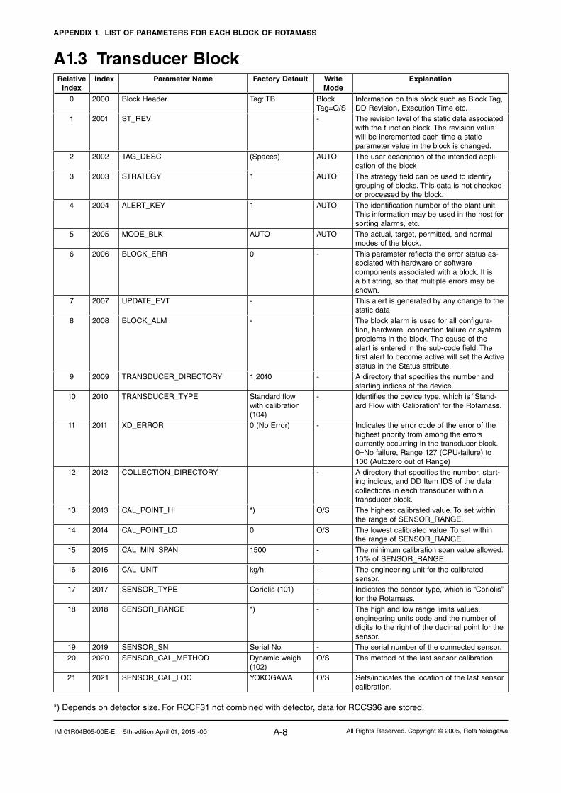
APPENDIX 1. LIST OF PARAMETERS FOR EACH BLOCK OF ROTAMASS
A-8 All Rights Reserved. Copyright © 2005, Rota YokogawaIM 01R04B05-00E-E 5th edition April 01, 2015 -00
A1.3 Transducer BlockRelative
IndexIndex Parameter Name Factory Default Write
ModeExplanation
0 2000 Block Header Tag: TB Block Tag=O/S
Information on this block such as Block Tag, DD Revision, Execution Time etc.
1 2001 ST_REV - The revision level of the static data associated with the function block. The revision value will be incremented each time a static parameter value in the block is changed.
2 2002 TAG_DESC (Spaces) AUTO The user description of the intended appli-cation of the block
3 2003 STRATEGY 1 AUTO The strategy field can be used to identify grouping of blocks. This data is not checked or processed by the block.
4 2004 ALERT_KEY 1 AUTO The identification number of the plant unit. This information may be used in the host for sorting alarms, etc.
5 2005 MODE_BLK AUTO AUTO The actual, target, permitted, and normal modes of the block.
6 2006 BLOCK_ERR 0 - This parameter reflects the error status as-sociated with hardware or software components associated with a block. It is a bit string, so that multiple errors may be shown.
7 2007 UPDATE_EVT - This alert is generated by any change to the static data
8 2008 BLOCK_ALM - The block alarm is used for all configura-tion, hardware, connection failure or system problems in the block. The cause of the alert is entered in the sub-code field. The first alert to become active will set the Active status in the Status attribute.
9 2009 TRANSDUCER_DIRECTORY 1,2010 - A directory that specifies the number and starting indices of the device.
10 2010 TRANSDUCER_TYPE Standard flow with calibration (104)
- Identifies the device type, which is “Stand-ard Flow with Calibration” for the Rotamass.
11 2011 XD_ERROR 0 (No Error) - Indicates the error code of the error of the highest priority from among the errors currently occurring in the transducer block.0=No failure, Range 127 (CPU-failure) to 100 (Autozero out of Range)
12 2012 COLLECTION_DIRECTORY - A directory that specifies the number, start-ing indices, and DD Item IDS of the data collections in each transducer within a transducer block.
13 2013 CAL_POINT_HI *) O/S The highest calibrated value. To set within the range of SENSOR_RANGE.
14 2014 CAL_POINT_LO 0 O/S The lowest calibrated value. To set within the range of SENSOR_RANGE.
15 2015 CAL_MIN_SPAN 1500 - The minimum calibration span value allowed. 10% of SENSOR_RANGE.
16 2016 CAL_UNIT kg/h - The engineering unit for the calibrated sensor.
17 2017 SENSOR_TYPE Coriolis (101) - Indicates the sensor type, which is “Coriolis” for the Rotamass.
18 2018 SENSOR_RANGE *) - The high and low range limits values, engineering units code and the number of digits to the right of the decimal point for the sensor.
19 2019 SENSOR_SN Serial No. - The serial number of the connected sensor.20 2020 SENSOR_CAL_METHOD Dynamic weigh
(102)O/S The method of the last sensor calibration
21 2021 SENSOR_CAL_LOC YOKOGAWA O/S Sets/indicates the location of the last sensor calibration.
*) Depends on detector size. For RCCF31 not combined with detector, data for RCCS36 are stored.

APPENDIX 1. LIST OF PARAMETERS FOR EACH BLOCK OF ROTAMASS
A-9All Rights Reserved. Copyright © 2005, Rota Yokogawa IM 01R04B05-00E-E 5th edition April 01, 2015 -00
Relative Index
Index Parameter Name Factory Default Write Mode
Explanation
22 2022 SENSOR_CAL_DATE - O/S Sets/indicates the dates of the last sensor calibration.
23 2023 SENSOR_CAL_WHO YOKOGAWA O/S Sets/indicates the name of the person responsible for the last sensor calibration.
24 2024 LIN_TYPE linear with input(1)
- The linearization type of sensor output. Rotamass is “linear with input”.
25 2025 MASS_FLOW_VALUE 0 - Mass flow value26 2026 MASS_FLOW_VALUE_RANGE *) - Mass flow value range. Depends on
detector size.27 2027 MASS_FLOW_VALUE_FTIME 3 s - Time constant of damping for the mass flow
rate calculation. Setting range: 0.1 to 200 s28 2028 MASS_FLOW_LOWCUT 0 O/S Low cut value of the mass flow.
Setting range 0 to 10% of MASS_FLOW_VALUE_RANGE.EU100
29 2029 VOLUME_FLOW_VALUE - - Volume flow value30 2030 VOLUME_FLOW_VALUE_RANGE *) - Volume flow value range. Depends on
detector size.31 2031 VOLUME_FLOW_VALUE_FTIME 3 s Time constant of damping for the volume
flow rate calculation. Setting range: 0.1 to 200 s
32 2032 VOLUME_FLOW_LOWCUT 0 O/S Lowcut value of the volume flow. Setting range 0 to 10% of VOLUME_FLOW_VALUE_RANGE.EU100
33 2033 DENSITY_VALUE - - Density flow value34 2034 DENSITY _VALUE_RANGE 5 kg/l - Density value range35 2035 DENSITY_VALUE_FTIME 3 s - Time constant of damping for the density
calculation. Setting range: 0.1 to 200s36 2036 DENSITY_LOWCUT 0 O/S Lowcut value of the density. Setting range
0 to 10% of DENSITY_VALUE_RANGE.EU100
37 2037 TEMPERATURE_VALUE - - Temperature value38 2038 TEMPERATURE _VALUE_RANGE 230°C - Range of temperature value. Standard
version: -200 to 230°C; High temperature version: 0 to 400°C.
39 2039 TEMPERATURE _VALUE_ FTIME 3 s - Time constant of damping for the temperature calculation. Setting range: 0.1 to 200s
40 2040 CONCENTR_MEAS_VALUE - - Concentration measurement value41 2041 CONCENTR_MEAS_VALUE_RANGE 100 - Range of concentration measurement.42 2042 CONCENTR_MEAS_VALUE_ FTIME 10s - Time constant of damping for the
concentration measurement calculation. Setting range: 0.1 to 200 s
43 2043 CONCENTR_MEAS_ LOWCUT 0 O/S Lowcut value of the concentration measure-ment. Setting range 0 to 10% of CONCENTR_MEAS_VALUE_RANGE.EU100
44 2044 NET_FLOW_VALUE - - Net flow value45 2045 NET_FLOW_VALUE_RANGE *) - Netflow value range. Depend on detector
size.46 2046 NET_FLOW_VALUE_ FTIME 3s - Time constant of damping for the net flow
rate calculation. Setting range: 0.1 to 200s47 2047 NET_FLOW_ LOWCUT 0 O/S Low cut value of the net flow. Setting range
0 to 10% of NET_FLOW_VALUE_RANGE.EU100
48 2048 VELOCITY_VALUE 0.0 – The Velocity of the Medium Not available for gas measurement (/GA)
49 2049 VELOCITY_UNITS_INDEX m/sec O/S This parameter shows the unit of the Velocity; Range: m/s or ft/s
50 2050 DISPLAY_SELECT_1 Mass flow - Value displayed on the 1st line of the LCD display.
51 2051 DISPLAY_SELECT_2 Volume flow - Value displayed on the 2nd line of the LCD display.
52 2052 DISPLAY_SELECT_3 Density - Value displayed on the 3rd line of the LCD display.
53 2053 DISPLAY_SELECT_4 Temperature - Value displayed on the 4th line of the LCD display.
*) Depends on detector size. For RCCF31 not combined with detector, data for RCCS36 are stored.

APPENDIX 1. LIST OF PARAMETERS FOR EACH BLOCK OF ROTAMASS
A-10 All Rights Reserved. Copyright © 2005, Rota YokogawaIM 01R04B05-00E-E 5th edition April 01, 2015 -00
Relative Index
Index Parameter Name Factory Default Write Mode
Explanation
54 2054 DISP_DECIMAL_MASS_FLOW xxxx.XX - The decimal point position of the mass flow value on the LCD display.
55 2055 DISP_DECIMAL_VOLUME_FLOW xxxx.XX - The decimal point position of the volume flow value on the LCD display.
56 2056 DISP_DECIMAL_DENSITY xx.XXXX - The decimal point position of the density value on the LCD display.
57 2057 DISP_DECIMAL_TEMPERATURE xxxxx.X - The decimal point position of the temperature value on the LCD display.
58 2058 DISP_DECIMAL_CONCENTR_MEAS xxxx.XX - The decimal point position of the concentration measurement value on the LCD display.
59 2059 DISP_DECIMAL_NET_FLOW xxxx.XX - The decimal point position of the net flow value on the LCD display.
60 2060 DISP_DECIMAL_IT1 xxxxx.XX - The decimal point position of the OUT value of IT1 block on the LCD display.
61 2061 DISP_DECIMAL_IT2 xxxxx.XX - The decimal point position of the OUT value of IT2 block on the LCD display.
62 2062 DISP_IT1_UNITS_INDEX None - The unit index of the OUT value of IT1 block on the LCD display.
63 2063 DISP_IT2_UNITS_INDEX None - The unit index of the OUT value of IT2 block on the LCD display.
64 2064 DISP_CONTRAST 4 - The contrast of the LCD display.65 2065 DISP_PERIOD 1 s - The update cycle of the LCD display.66 2066 DISP_LANGUAGE English - The language on the LCD display.67 2067 FLOW_DIRECTION Forward O/S Direction of flow68 2068 BI_DIRECTION Bi-direction O/S Selects the Bi-direction mode (bi-direction/
uni-direction).69 2069 AUTO_ZERO_TIME 3 min O/S Defines the execution time of the autozero
function.70 2070 AUTO_ZERO_EXE Not Execute O/S A user can execute the autozero performing
by this parameter.After autozero execution is completed, this value returns to “Not Execute” automatically. The execution time is defined by AUTO_ZERO_TIME.
71 2071 AUTO_ZERO_VALUE Set after adjust-ment
- Indicates the result value of the autozero execution.
72 2072 AUTO_ZERO_FLUCTUATION Set after adjust-ment
- Indicates the factory autozero range.
73 2073 AZ_INIT_MASS_FLOW Set after adjust-ment
- Indicates the last autozero value for mass flow.
74 2074 AZ_INIT_DENSITY Set after adjust-ment
- Indicates the density at the last autozero for mass flow.
75 2075 AZ_INIT_TEMP Set after adjust-ment
- Indicates the temperature at the last autozero for mass flow.
76 2076 MASS_FLOW_FIX_VAL_SEL Inhibit O/S This parameter enables the function of MASS_FLOW_FIXED_VALUE.When the value is “Inhibit”, the function of MASS_FLOW_FIXED_VALUE does not perform.When the value is “Enable”, the function of MASS_FLOW_FIXED_VALUE performs.
77 2077 MASS_FLOW_FIXED_VALUE 0.0 t/h O/S This parameter indicates a fix mass flow value. The set value is added to the autozero value.
78 2078 DENSITY_FIX_VAL_SEL Inhibit O/S This parameter enables the function of REFERENCE_DENSITY.When the value is “Inhibit” the function does not perform. When the value is “Enabled” the function performs.If gas measurement (/GA) is ordered, this parameter is “Enabled”.

APPENDIX 1. LIST OF PARAMETERS FOR EACH BLOCK OF ROTAMASS
A-11All Rights Reserved. Copyright © 2005, Rota Yokogawa IM 01R04B05-00E-E 5th edition April 01, 2015 -00
Relative Index
Index Parameter Name Factory Default Write Mode
Explanation
79 2079 REFERENCE_DENSITY 1.0 kg/l O/S This parameter indicates a reference density value. When the value of DENSITY_FIX_VAL is “Inhibit” users can not change this value and this function does not perform. When the value is “Enabled” users can change this value and this parameter is used as reference density for calculation of volume flow.
80 2080 DENSITY_OFFSET 0 g/l O/S This parameter indicates a density offset value.
81 2081 TEMP_FIX_VAL_SELECT Inhibit O/S This parameter enables the function of TEMP_FIXED_VALUE.When the value is “Inhibit”, the function of TEMP_FIXED_VALUE does not perform.When the value is “Enable”, the function of TEMP_FIXED_VALUE performs.
82 2082 TEMP_FIXED_VALUE 30°C O/S This parameter indicates a fix temperature value. When the value of TEMP_FIX_VAL is “Inhibit” users can not change this value and this function does not perform. When the value of TEMP_FIX_VAL is “Enable” users can change this value and this parameter is set to the temperature value.
83 2083 TEMP_GAIN 1.00 O/S This parameter defines the value of tem-perature gain. The function allows correction of the temperature measurement for better accuracy in mass flow and density for very high and low temperatures.
84 2084 SENSOR_MODEL *) This parameter defines the sensor model. When a user changes the value the follow-ing parameters return to default automati-cally:SENSOR_RANGE,MASS_FLOW_VALUE_RANGE,VOLUME_FLOW_VALUE_RANGE,NET_FLOW_VALUE_RANGE,SK20, SKT, RV, QNOM,KD, FL20, FTC1, FTCK, SKP, FPC, SKTK, SKPT, FPTC, FQC1, FQC2,AUTOZERO_RANGE,FLUCTUATION_RANGE
85 2085 SK20 *) O/S Defines the sensor constant at 20°C. The valid range and the default value de-pend on the selected sensor model.
86 2086 SKT *) O/S Defines a linear temperature coefficient of the sensor constant SK20. The valid range and the default value de-pend on the selected sensor model.
87 2087 RV *) O/S Defines a density correction factor. The valid range and the default value de-pend on the selected sensor model.
88 2088 QNOM *) O/S Defines the water flow rate of about 1 bar pressure drop.The valid range and the default value de-pend on the selected sensor model.
89 2089 KD *) O/S Defines a density calibration constant. The valid range and the default value de-pend on the selected sensor model.
90 2090 FL20 *) O/S Defines a response frequency of the tubes filled with air at 20°C. The valid range and the default value de-pend on the selected sensor model.
*) Depends on detector size. For RCCF31 not combined with detector, data for RCCS36 are stored.

APPENDIX 1. LIST OF PARAMETERS FOR EACH BLOCK OF ROTAMASS
A-12 All Rights Reserved. Copyright © 2005, Rota YokogawaIM 01R04B05-00E-E 5th edition April 01, 2015 -00
Relative Index
Index Parameter Name Factory Default Write Mode
Explanation
91 2091 FTC1 *) O/S Defines a linear temperature coefficient of the frequency at roh = 1. The valid range and the default value de-pend on the selected sensor model.
92 2092 FTCK *) O/S Defines a quadratic temperature coefficient of the frequency at roh = 1. The valid range and the default value de-pend on the selected sensor model.
93 2093 SKP *) O/S Defines a linear pressure coefficient of the sensor constant SK20. The valid range and the default value de-pend on the selected sensor model.
94 2094 FPC *) O/S Defines a linear pressure coefficient of the frequency. The valid range and the default value de-pend on the selected sensor model.
95 2095 SKTK *) O/S Defines a quadratic temperature coefficient of the sensor constant SK20. The valid range and the default value de-pend on the selected sensor model.
96 2096 SKPT *) O/S Defines a quadratic pressure coefficient of the sensor constant SK20. The valid range and the default value de-pend on the selected sensor model.
97 2097 FPTC *) O/S Defines a temperature - pressure coefficient of the frequency. The valid range and the default value de-pend on the selected sensor model.
98 2098 FQC1 *) O/S Defines a linear flow coefficient of the fre-quency. The valid range and the default value de-pend on the selected sensor model.
99 2099 FQC2 *) O/S Defines a quadratic flow coefficient of the frequency. The valid range and the default value de-pend on the selected sensor model.
100 2100 PRESSURE 0.0 bar O/S Sets the pressure value for correction with SKP and FPC.
101 2101 PRESSURE_UNIT bar O/S This parameter shows the unit of PRESSURE; range bar or psi.
102 2102 SLUG_ALARM_SELECT Not apply O/S This parameter enables the following functions.DRIVE_GAIN,SLUG_CRITERIASLUG_DURATIONAFTER_SLUGDRIVE_GAIN_DAMPINGWhen the value is “Not Apply”, they do not perform.When the value is “Apply”, they perform.If gas measurement is ordered, this parameter is not available. The value is “Not apply”.
103 2103 DRIVE_GAIN - - This parameter indicates a drive gain value. When the value of SLUG_ALARM_SELECT is “Not Apply” this function does not perform.
104 2104 SLUG_CRITERIA 11 V O/S This parameter indicates a level of drive gain when an alarm should happen. When the value of SLUG_ALARM_SELECT is “Not Apply”, users can not change this value. Range 0 to 11 V.
*) Depends on detector size. For RCCF31 not combined with detector, data for RCCS36 are stored.

APPENDIX 1. LIST OF PARAMETERS FOR EACH BLOCK OF ROTAMASS
A-13All Rights Reserved. Copyright © 2005, Rota Yokogawa IM 01R04B05-00E-E 5th edition April 01, 2015 -00
Relative Index
Index Parameter Name Factory Default Write Mode
Explanation
105 2105 SLUG_DURATION 1 s O/S Indicates a slug duration time. When the value of SLUG_ALARM_SELECT is “Not Apply”, users cannot change this value. Range 0 to 120sec.
106 2106 AFTER_SLUG Measured value O/S Selects the behaviour of the output mass flow after slug alarm has happened. When the parameter is selected -“Measured Value”, the output mass flow is the measured value.-“Hold”, the output mass flow is the value before the slug alarm happened.When the value of SLUG_ALARM_SE-LECT is “Not Apply”, users cannot change this value.
107 2107 DRIVE_GAIN_DAMPING 1 s O/S Indicates a drive gain damping time to get a constant drive gain level. When the value of SLUG_ALARM_SELECT is “Not Apply”, users can not change this value. Range 0 to 200sec.
108 2108 EMPTY_PIPE_ALM_SEL Inhibit O/S When the value is set to “Empty Pipe sel” this parameter enables:EMPTY_PIPE_CRIT (Crit < density),AFTER_EMPTY_PIPE.
When the value is set to “Dual Seal Sel”, this parameter enables:EMPTY_PIPE_CRIT (Crit > density),AFTER_EMPTY_PIPE.
When the value is “Inhibit” they do not per-form. If gas measurement (/GA) is ordered, this parameter is not available.
109 2109 EMPTY_PIPE_CRIT 0.0 kg/l O/S Indicates the empty pipe criteria when EMPTY_PIPE_ALM_SELECT is set to “Empty Pipe Sel” (Crit < actual density).
Indicates the dual seal criteria when EMPTY_PIPE_ALM_SELECT is set to “Dual Seal Sel” (Crit > actual density).
110 2110 AFTER_EMPTY_PIPE Mass flow = zero O/S Selects the behaviour of the output mass flow after empty pipe alarm or dual seal alarm has happened. When the parameter is selected-“Mass flow=zero”, the output mass flow is zero.-“Measured Value”, the output mass flow is the measured value.-“Hold”, the output mass flow is the value before the empty pipe alarm happened.When the value of EMPTY_PIPE_ALM_SE-LECT is “Not Apply”, users cannot change this value.
111 2111 CORROSION_ALM_SEL Not Apply O/S This parameter enables the functions of CORROSION_CRIT and CORROSION_DAMP.When this value is “Not Apply” they do not perform.When this value is “Apply” they do perform.If gas measurement is ordered, this parameter is not available. The value is “Not Apply”.
112 2112 CORROSION_CRIT 1.5 kg/l O/S Indicate the corrosion criteria value. When the value of CORROSION_ALM_SEL is “Not Apply”, users cannot change this value. Range 0 to 5kg/l. Unit depends on DENSITY_VALUE_RANGE units index.
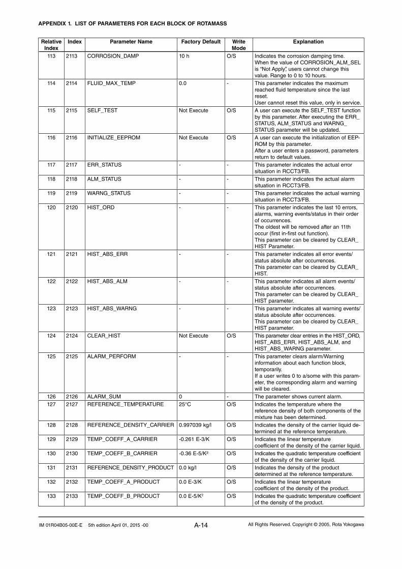
APPENDIX 1. LIST OF PARAMETERS FOR EACH BLOCK OF ROTAMASS
A-14 All Rights Reserved. Copyright © 2005, Rota YokogawaIM 01R04B05-00E-E 5th edition April 01, 2015 -00
Relative Index
Index Parameter Name Factory Default Write Mode
Explanation
113 2113 CORROSION_DAMP 10 h O/S Indicates the corrosion damping time.When the value of CORROSION_ALM_SEL is “Not Apply”, users cannot change this value. Range to 0 to 10 hours.
114 2114 FLUID_MAX_TEMP 0.0 - This parameter indicates the maximum reached fluid temperature since the last reset.User cannot reset this value, only in service.
115 2115 SELF_TEST Not Execute O/S A user can execute the SELF_TEST function by this parameter. After executing the ERR_STATUS, ALM_STATUS and WARNG_STATUS parameter will be updated.
116 2116 INITIALIZE_EEPROM Not Execute O/S A user can execute the initialization of EEP-ROM by this parameter.After a user enters a password, parameters return to default values.
117 2117 ERR_STATUS - - This parameter indicates the actual error situation in RCCT3/FB.
118 2118 ALM_STATUS - - This parameter indicates the actual alarm situation in RCCT3/FB.
119 2119 WARNG_STATUS - - This parameter indicates the actual warning situation in RCCT3/FB.
120 2120 HIST_ORD - - This parameter indicates the last 10 errors, alarms, warning events/status in their order of occurrences.The oldest will be removed after an 11th occur (first in-first out function).This parameter can be cleared by CLEAR_HIST Parameter.
121 2121 HIST_ABS_ERR - - This parameter indicates all error events/status absolute after occurrences.This parameter can be cleared by CLEAR_HIST.
122 2122 HIST_ABS_ALM - - This parameter indicates all alarm events/status absolute after occurrences.This parameter can be cleared by CLEAR_HIST parameter.
123 2123 HIST_ABS_WARNG - - This parameter indicates all warning events/status absolute after occurrences.This parameter can be cleared by CLEAR_HIST parameter.
124 2124 CLEAR_HIST Not Execute O/S This parameter clear entries in the HIST_ORD, HIST_ABS_ERR, HIST_ABS_ALM, and HIST_ABS_WARNG parameter.
125 2125 ALARM_PERFORM - - This parameter clears alarm/Warning information about each function block, temporarily.If a user writes 0 to a/some with this param-eter, the corresponding alarm and warning will be cleared.
126 2126 ALARM_SUM 0 - The parameter shows current alarm.127 2127 REFERENCE_TEMPERATURE 25°C O/S Indicates the temperature where the
reference density of both components of the mixture has been determined.
128 2128 REFERENCE_DENSITY_CARRIER 0.997039 kg/l O/S Indicates the density of the carrier liquid de-termined at the reference temperature.
129 2129 TEMP_COEFF_A_CARRIER -0.261 E-3/K O/S Indicates the linear temperature coefficient of the density of the carrier liquid.
130 2130 TEMP_COEFF_B_CARRIER -0.36 E-5/K² O/S Indicates the quadratic temperature coefficient of the density of the carrier liquid.
131 2131 REFERENCE_DENSITY_PRODUCT 0.0 kg/l O/S Indicates the density of the product determined at the reference temperature.
132 2132 TEMP_COEFF_A_PRODUCT 0.0 E-3/K O/S Indicates the linear temperature coefficient of the density of the product.
133 2133 TEMP_COEFF_B_PRODUCT 0.0 E-5/K2 O/S Indicates the quadratic temperature coefficient of the density of the product.

APPENDIX 1. LIST OF PARAMETERS FOR EACH BLOCK OF ROTAMASS
A-15All Rights Reserved. Copyright © 2005, Rota Yokogawa IM 01R04B05-00E-E 5th edition April 01, 2015 -00
Relative Index
Index Parameter Name Factory Default Write Mode
Explanation
134 2134 RCCT_SERIAL_NO_DETECTOR - O/S This parameter indicates the serial number of the detector.
135 2135 RCCT_SERIAL_NO_CONVERTER - O/S This parameter indicates the serial number of the converter.
136 2136 RELEASE_DATE - - This parameter indicates the release date of the converter.
137 2137 RELEASE_REVISION - - This parameter indicates the release revision of the converter.
138to
219
TEST_1toTEST_82
Service parameters, not open to customer

APPENDIX 1. LIST OF PARAMETERS FOR EACH BLOCK OF ROTAMASS
A-16 All Rights Reserved. Copyright © 2005, Rota YokogawaIM 01R04B05-00E-E 5th edition April 01, 2015 -00
A1.4 Integrator (IT) BlockThe Integrator (IT) block adds two main inputs and integrates them for output. The block compares the integrated and accumulated value of TOTAL_SP and PRE_TRIP and generates discrete output signals. OUT_TRIP or OUT_PTRIP when the limits are reached.The output ia as represented by the following equation (for counting upward and rate conversion).
OUT.Value = Integration start value + TotalTotal = Total + Current IntegralCurrent Integral = (x + y) *∆t x: IN_1 value whose unit has been converted y: IN_2 value whose unit has been converted ∆t: block execution period
A1.4.1 Schematic Diagram of Integrator BlockThe following shows the schematic diagram of the integrator block
Figure A2.1 Integrator block
IN_1: Block input 1 (value and status) IN_2: Block input 2 (value and status)REV_FLOW1: Indicates whether the sign of IN_1 is reversed. It is a discrete signal.REV_FLOW2: Indicates whether the sign of IN_2 is reversed. It is a discrete signal.RESET_IN: Resets the integrated values. It is a discrete signal.RESET_CONFIRM: Reset confirmation input. It is a discrete signal.OUT: Block output (value and status)OUT_PTRIP: Set if the target value exceedsPRE_TRIP: It is a discrete signalOUT_TRIP: Set if the target value exceedsTOTAL_SP (or 0): It is a discrete signal.The integration block is classified into the following five sections for each function:• Inputprocesssection:Determinestheinputvalue status, converts the rate and accumulation, and deter-
mines the input flow direction.• Adder:Addsthetwoinputs.• Integrator:Integratestheresultoftheadderintotheintegratedvalue.• Outputprocesssection:Determinesthestatusandvalueofteachoutputparameter.• Resetprocesssection:Resetstheintegratedvalues.
OUT
IN_1
RESET_IN
REV_FLOW1
–1
TIME_UNIT2
IN_2
REV_FLOW2 PULSE_VAL2
–1
UNIT_CONVOP_CMD_INT
(RESET)
INTEG_OPTS(CARRY)
Reverse
Forward
Forward
OUT_PTRIP
OUT_TRIP
INTEG_OPTS(FLOW TYPE)
Add
Compare
Compare
TOTAL / RTOTAL
Integrate
INTEG_TYPE
INTEG_OPTS (QUALITY)
GOOD_LIM
UNCERT_LIM
CLOCK_PER
N_RESET
MAN
MAN
MAN
Convert Rate
Convert Accum
Convert Rate
Convert Accum
TOTAL_SP
PRE_TRIP
INTEG_OPTS(INPUT TYPE)
PULSE_VAL1
TIME_UNIT1
INTEG_OPTS(INPUT TYPE)
RESET_CONFIRM
Reverse
FA0201.EPS

APPENDIX 1. LIST OF PARAMETERS FOR EACH BLOCK OF ROTAMASS
A-17All Rights Reserved. Copyright © 2005, Rota Yokogawa IM 01R04B05-00E-E 5th edition April 01, 2015 -00
A1.4.2 Input process SectionWhen executed, the Integrator block first performs input processing in the order of:"Determining input status" ==> Converting rate or Accum ==> " Determining the input flow direction"
Switching between Convert Rate and Convert Accum is made using bit 0 (for IN_1) or bit 1 (for IN_2) of INTEG_OPTS. INTEG_OPTS is one of the system parameters and should be set by the user. The values of IN_1 and IN_2 are not retained if the power is turned OFF.
A1.4.2.1 Determining Input Value Statuses
The following shows the correlation between the statuses of input parameters (IN_1 , IN_2) and the sta-tuses if Input values used in the Integration block.
Statuses of Input Parameters (IN_1, IN_2)
Bit 4 of INTEG_OPTS(Use Uncertain)
Bit 5* of INTEG_OPTS(Use Bad)
Status of Input Values Handled in IT Block
Good Irrelevant Irrelevant Good
Bad Irrelevant H (=1) Good
Bad Irrelevant L (=0) Bad
Uncertain H (=1) Irrelevant Good
Uncertain L (=0) Irrelevant BadTA0201.EPS
For addition (see A2.3), if the status of an input value is "BAD" the "GOOD" value just before the status changed to "BAD" is used.
* Even if the Use Bad option is used, changing the internal status to "GOOD" the value of "GOOD" just before the status change to "BAD" is used.
A1.4.2.2 Converting the Rate
The following describes an example of rate con-version.
In rate conversion, firstly convert the unit of two inputs to that based on seconds.
Next, convert the unit of the inputs to the same units to be added together. The unit of IN_2 is standardized to that of IN_1. Then, calculates a weight, volume or energy by multiplying each input value and block execution time. Because unit in-formation is not input to the Integrator block as an input value, the user must input in advance tuned values to the TIME_UNIT1/2 and UNIT_CONV parameters.
TIME_UNIT1sec:1
min:60hour:3600day:86400
input1
kg/hour
input2
lb/s kg/s kg
increment2
increment1
lb/minlb: pounds
Converts the unit into that based on seconds
Standardizes the unit of IN_2 to that of IN_1.Because "lb/s" is converted into "kg/s" in this example, the input 2 value is multiplied by 0.453. (1 lb = 0.453 kg)
UNIT_CONVx [conversion factor](Conversion factor:
0.453 in this example)
Converts the unit into that based on seconds
TIME_UNIT2sec:1
min:60hour:3600day:86400
kg/s kg 3 block execution time
3 block execution time
FA0202.EPS
Figure A2.2 Increment Calculation with Rate Input

APPENDIX 1. LIST OF PARAMETERS FOR EACH BLOCK OF ROTAMASS
A-18 All Rights Reserved. Copyright © 2005, Rota YokogawaIM 01R04B05-00E-E 5th edition April 01, 2015 -00
A1.4.2.3 Converting Accumulation
This following describes an example of accumulation conversion.
In accumulation conversion the difference between the value executed previously and the value ex-ecuted this time is integrated or accumulated. This conversion applies when the output of a function block used as a counter is input to the input pro-cess of the Integrator block.
In order to convert the rate of change of an input to a value with an engineering unit, the user must configure the factor of conversion to the appro-priate engineering unit in the PULSE_VAL1 and PULSE_VAL2 parameters.
Moreover, the unit of IN_2 is standardized to that of IN_1 in the same way as rate conversion. Thus, the user must also set an appropriate value to UNIT_CONV.
input1
counts number of pulse kg
kg/pulse
increment1
increment2
lb/pulse
input2
counts number of pulse lb kg
[Current read value] – [Previous read value]
[Current read value] – [Previous read value]
PULSE_VAL1(#19)3 [pulse value1]
PULSE_VAL2(#20)3 [pulse value2]
UNIT_CONV(#18)3 [conversion factor]
FA0203.EPS
Figure A2.3 Increment Calculation with Counter Input
A1.4.2.4 Determining the Input Flow Direction
The Integrator block also considers the input flow direction. Information about the input flow direc-tion is contained in REV_FLOW1 ans REV_FLOW2 (0: FORWARD, 1: REVERSE).
In input processing, the sign of the value after rate and accumulation conversion is reversed if the REV_FLOW1 and REV_FLOW2 parameters are set to REVERSE. When determination of the flow direction of two input values is complete, these two inputs are passed to the adder. The settings in REV_FLOW will be retained even if power is turned OFF.
A1.4.3 AdderWhen input processing is complete, two argu-ments that have been rate and accumulate converted will be passed to the adder. The adder adds these two values according to the option.
A1.4.3.1 Status of Value after Addition
If one of the statuses of two arguments is "BAD" or if two of them are both "BAD", the status of the value after addition becomes "BAD". In this case, the value of "GOOD" just before the status changed to "BAD" is used as the addition value (see A2.1).
When the statuses of two arguments are both "GOOD" the status of the value after addition becomes "GOOD". In this case, the status of the value after addition will be used for the status applied to Integration.

APPENDIX 1. LIST OF PARAMETERS FOR EACH BLOCK OF ROTAMASS
A-19All Rights Reserved. Copyright © 2005, Rota Yokogawa IM 01R04B05-00E-E 5th edition April 01, 2015 -00
A1.4.3.2 Addition
The following three options are available for additions.
• TOTAL:Addstwoargumentsvaluesasis.• FORWARD:Addstwoargumentvalues,
regarding a negative value as "0".• REVERSE:Addstwoargumentvalues,
regarding a positive value as "0".You can choose these options using bit 2 and bit
3 of INTEG_OPTS as follows:
The result of the adder is passed to the integrator. If only one of the inputs is connected, the value of s non-connected input will be ignored.
When bit 7 of INTEG_OPTS (Add zero if bad) has been set, if the status of a value after addition is "BAD", the value after addition (increment) becomes "0".
A1.4.4 IntegratorWhen addition is complete, its result will be passed to the integrator.Integration consists of combination of a reset method and counting au/down. These are the fol-lowing seven integration types, which can be set using INTEG_TYPE. 1. UP_AUTO: Counts up with automatic reset when TOTALSP is reached. 2. UP_DEM: Counts up with demand reset. 3. DN_AUTO: Counts down with automatic reset when zero is reached. 4. DN_DEM: Counts down with demand reset. 5. PERIODIC: Counts up and is reset periodically according to CLOCK_PER. 6. DEMAND: Counts up and is reset on demand. 7. PER&DEM: Counts up and is reset periodically or on demand.
Each type of integration is independently run as a function.
Bit 2 of INTEG_OPTS (Flow Forward)
Bit 3 of INTEG_OPTS (Flow Reverse)
Adder Options
H H TOTAL
L L TOTAL
H L FORWARD
L H REVERSETA0202.EPS
These are the following 4 types of integration values: 1. Total: Integrates the result of the adder as is 2. ATotal: Integrates the absolute value of the result of the adder. 3. Rtotal: Integrates the absolute value of the result of the adder only if the status of the result is "BAD". This value is used for the RTOTAL value. 4. AccTotal: Am extension function. The result of the adder is integrated as is and will not be reset.
The value is used for the ACCUM_TOTAL (expand parameter) value.The table A2.1 shows the details of INTEG_TYPE.
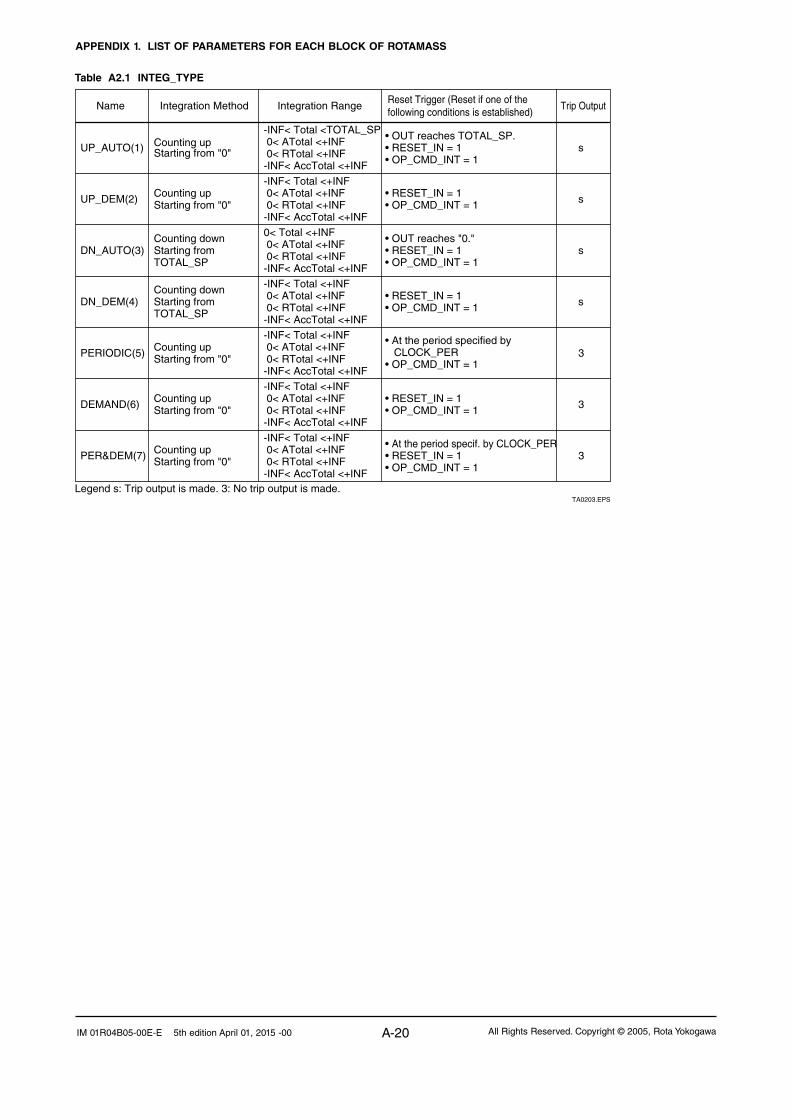
APPENDIX 1. LIST OF PARAMETERS FOR EACH BLOCK OF ROTAMASS
A-20 All Rights Reserved. Copyright © 2005, Rota YokogawaIM 01R04B05-00E-E 5th edition April 01, 2015 -00
Table A2.1 INTEG_TYPE
Name Integration Method Integration Range Reset Trigger (Reset if one of the following conditions is established)
Trip Output
UP_AUTO(1) Counting upStarting from "0"
-INF< Total <TOTAL_SP 0< ATotal <+INF 0< RTotal <+INF-INF< AccTotal <+INF
• OUT reaches TOTAL_SP.• RESET_IN = 1• OP_CMD_INT = 1
s
UP_DEM(2) Counting upStarting from "0"
-INF< Total <+INF 0< ATotal <+INF 0< RTotal <+INF-INF< AccTotal <+INF
• RESET_IN = 1• OP_CMD_INT = 1 s
DN_AUTO(3)Counting downStarting from TOTAL_SP
0< Total <+INF 0< ATotal <+INF 0< RTotal <+INF-INF< AccTotal <+INF
• OUT reaches "0."• RESET_IN = 1• OP_CMD_INT = 1
s
DN_DEM(4)Counting downStarting from TOTAL_SP
-INF< Total <+INF 0< ATotal <+INF 0< RTotal <+INF-INF< AccTotal <+INF
• RESET_IN = 1• OP_CMD_INT = 1 s
PERIODIC(5) Counting upStarting from "0"
-INF< Total <+INF 0< ATotal <+INF 0< RTotal <+INF-INF< AccTotal <+INF
• At the period specified by CLOCK_PER• OP_CMD_INT = 1
3
DEMAND(6) Counting upStarting from "0"
-INF< Total <+INF 0< ATotal <+INF 0< RTotal <+INF-INF< AccTotal <+INF
• RESET_IN = 1• OP_CMD_INT = 1 3
PER&DEM(7)
Legend s: Trip output is made. 3: No trip output is made.
Counting upStarting from "0"
-INF< Total <+INF 0< ATotal <+INF 0< RTotal <+INF-INF< AccTotal <+INF
• At the period specif. by CLOCK_PER• RESET_IN = 1• OP_CMD_INT = 1
3
TA0203.EPS

APPENDIX 1. LIST OF PARAMETERS FOR EACH BLOCK OF ROTAMASS
A-21All Rights Reserved. Copyright © 2005, Rota Yokogawa IM 01R04B05-00E-E 5th edition April 01, 2015 -00
A1.4.5 Output ProcessThere are the following three output parameters:
1. OUT 2. OUT_TRIP 3. OUT_PTRIP
Parameters OUT_TRIP and OUT_PTRIP are used only when INTEG_TYPE is a value from 1 to 4.In case of Integrator block related memory failed, the status of OUT_TRIP, OUT_PTRIP becomes "Bad-Device-Failure".
OUT.Value, OUT_TRIP.Status and OUT_PTRIP.Status are determined by the ratio of the "GOOD" integrated values to all integrated values, which is stored in PCT_INCL (0% to100%). The user must set the threshold value of each status to UNCERT_LIM and GOOD_LIM.
The integrator block determines the status of the output using the three parameters:PCT_LIM, UNCERT_LIM and GOOD_LIM.• PCT_INCL>=GOODLIM==>Good• UNCERT_LIM<=PCT_INCL<GOOD_LIM
==> Uncertain• PCT_INCL<UNCERT-LIM==>Bad
If INTEG_TYPE is 5, 6 or 7, the status of the trip output becomes "Good-NS-Constant".
0% UNCERT_LIM GOOD_LIM 100%PCT_INCL
GOODUncertainBad
PCT_INCL=1003(1 - (msp of RTotal)/(msp of ATotal))msp of RTotal: RTotal value that is converted into a short floating-point numbermsp of ATotal: ATotal value that is converted into a short floating-point numberRTotal: Integrated value of the absolute values of the increments whose status is badATotal: Integrated value of the absolute values of the increments regardless of the output status
FA0204.EPS
Figure A2.4 Status of OUT_TRIP and OUT_PTRIP Outputs
A1.4.5.1 Status Determination
The same criteria for determining the status of the output of the Integrator block are used in common for the above three parameters.
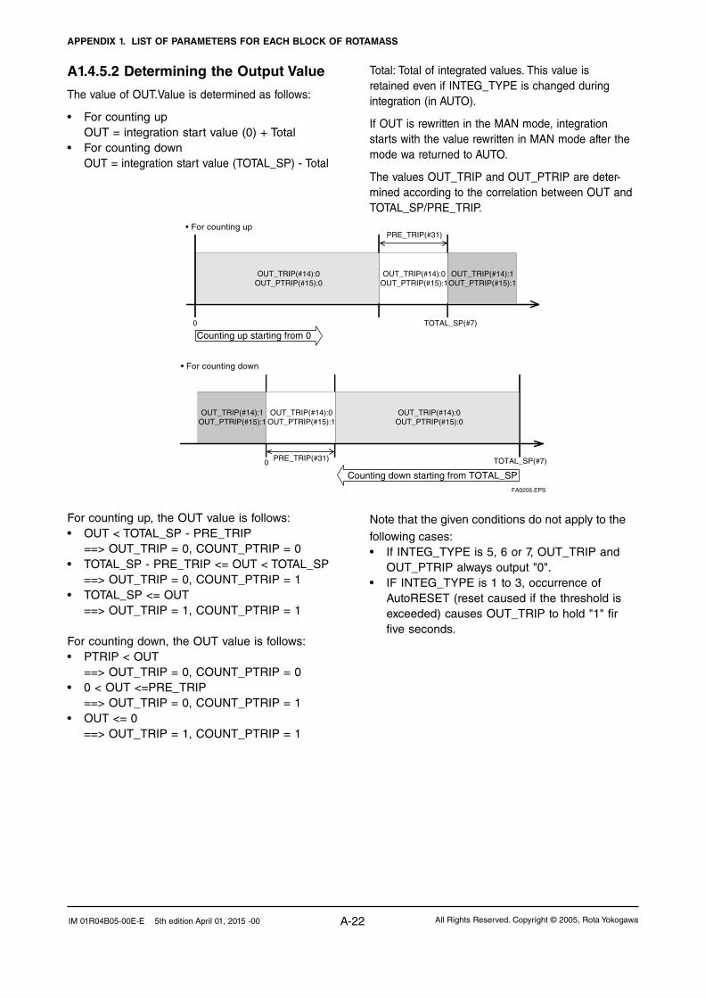
APPENDIX 1. LIST OF PARAMETERS FOR EACH BLOCK OF ROTAMASS
A-22 All Rights Reserved. Copyright © 2005, Rota YokogawaIM 01R04B05-00E-E 5th edition April 01, 2015 -00
A1.4.5.2 Determining the Output Value
The value of OUT.Value is determined as follows:
• Forcountingup OUT = integration start value (0) + Total• Forcountingdown OUT = integration start value (TOTAL_SP) - Total
For counting up, the OUT value is follows:• OUT<TOTAL_SP-PRE_TRIP ==> OUT_TRIP = 0, COUNT_PTRIP = 0• TOTAL_SP - PRE_TRIP <= OUT < TOTAL_SP ==> OUT_TRIP = 0, COUNT_PTRIP = 1• TOTAL_SP<=OUT ==> OUT_TRIP = 1, COUNT_PTRIP = 1
For counting down, the OUT value is follows:• PTRIP<OUT ==> OUT_TRIP = 0, COUNT_PTRIP = 0• 0<OUT<=PRE_TRIP ==> OUT_TRIP = 0, COUNT_PTRIP = 1• OUT<=0 ==> OUT_TRIP = 1, COUNT_PTRIP = 1
OUT_TRIP(#14):0OUT_PTRIP(#15):0
OUT_TRIP(#14):1OUT_PTRIP(#15):1
Counting up starting from 0
• For counting upPRE_TRIP(#31)
OUT_TRIP(#14):0OUT_PTRIP(#15):0
OUT_TRIP(#14):0OUT_PTRIP(#15):1
OUT_TRIP(#14):1OUT_PTRIP(#15):1
• For counting down
Counting down starting from TOTAL_SP
PRE_TRIP(#31)0
0 TOTAL_SP(#7)
TOTAL_SP(#7)
FA0205.EPS
OUT_TRIP(#14):0OUT_PTRIP(#15):1
Total: Total of integrated values. This value is retained even if INTEG_TYPE is changed during integration (in AUTO).
If OUT is rewritten in the MAN mode, integration starts with the value rewritten in MAN mode after the mode wa returned to AUTO.
The values OUT_TRIP and OUT_PTRIP are deter-mined according to the correlation between OUT and TOTAL_SP/PRE_TRIP.
Note that the given conditions do not apply to the following cases:• IfINTEG_TYPEis5,6or7,OUT_TRIPand
OUT_PTRIP always output "0".• IFINTEG_TYPEis1to3,occurrenceof
AutoRESET (reset caused if the threshold is exceeded) causes OUT_TRIP to hold "1" fir five seconds.

APPENDIX 1. LIST OF PARAMETERS FOR EACH BLOCK OF ROTAMASS
A-23All Rights Reserved. Copyright © 2005, Rota Yokogawa IM 01R04B05-00E-E 5th edition April 01, 2015 -00
A1.4.5.3 Mode Handling
If you rewrite the value in OUT and RTOTAL, while the mode is in MAN or O/S, N_RESET is incremented.
Mode Action Output
Normal action Normal output
Integration calculation is stopped. OUT will not be updated unless you set a value to it. No reset is accepted.
You may rewrite a value in OUT. If no value is rewritten, the value just before running in AUTO is held. When the mode returns to AUTO, integration starts with the written value or the value just before running in AUTO.
Automatic (AUTO)
Manual (MAN)
Out of Service (O/S)
TA0204.EPS
A1.4.6 ResetA1.4.6.1 Reset Trigger
There are the following five types of reset triggers:
1. An integrated value exceeds TOTAL_SP.
2. An integrated value fall below "0".
3. RESET_IN is "H".
4. Every period specified in CLOCK_PER (for more information see CLOCK_PER in A2.6.2.).
5. OP_CMD_INT is "1".
The table A2.2 shows the correlation between INTEG_TYPE and RESET triggers.
Table A2.2 RESET Triggers
When OP_CMD_INT has become "H" and a reset was made, OP_CMD_INT automatically returns to "L".
Even if RESET_IN becomes "H", activating a reset, RESET_IN does not automatically return to "L".
The RESET_IN setting will not be retained if the power is turned to OFF.
TA0205.EPS
A1.4.6.2 Reset Timing
All items are reset during execution of the function block. Therefore, the minimum period of a reset is the block execution period.
• 5-secondruleIf a reset is made, the next reset will not be accepted for 5 seconds after that.Even if UP_AUTO (or DN_AUTO) is activated and TOTAL_SP (or 0) is reached within 5 seconds, the next reset will nit be made for 5 secondes from the previous reset.• CLOCK_PERIf INTEG_TYPE is PERIODIC (5) or PER&DEM (7) a reset is made at the period (sec) set to the CLOCK_PER parameter.If the value in CLOCK_PER is smaller than the function block´s execution period. bit 1 of BLOCK_ERR "Block Configuration Error) is set.

APPENDIX 1. LIST OF PARAMETERS FOR EACH BLOCK OF ROTAMASS
A-24 All Rights Reserved. Copyright © 2005, Rota YokogawaIM 01R04B05-00E-E 5th edition April 01, 2015 -00
A1.4.6.3 Reset Process
The basic reset process sequence is as follows.
1. Snapshot
2. Clearing the integrated values
3. Reset count increment
4. Judging OUT_TRIP and OUT_PTRIP (see A2.5)
1) Snapshot
Saves the following values in the specified param-eters before clearing the integrated values. These values will be retained until the next reset is made.
STOTAL = Total
SRTOTAL = RTotal
SSP = TOTAL_SP
2) Clearing the integrated values
The reset process clears the total. ATotal and RTotal values in the internal registers.
Total = 0
ATotal = 0
RTotal = 0
3) Reset count increment
Each time a reset is made, the N_RESET parameter will be incremented.
The high limit is 999,999 and if this limit is exceeded, the count returns to "0".
4) Judging OUT_TRIP and OUT_PTRIP (see A2.5)
OUT_TRIP and OUT_PTRIP are judged again on the basis of the cleared integrated values.
There atre three options relating to a reset:
i Confirm reset (bit 8 of INTEG_OPTS)
ii Carry (bit 6 of INTEG_OPTS)
iii Generate reset event (bit 9 of INTEG_OPTS)
i Confirm reset (bit 8 of INTEG_OPTS)
If this option is enabled, the next reset is rejected until "1" is set to RESET_CONFIRM.
ii Carry (bit 6 of INTEG_OPTS)
If this option is enabled while INTEG_TYPE is UP_AUTO or DN_AUTO, the value exceeding the threshold at a reset will bw carried into the next integration.
If INTEG_TYPE is any setting other than UP_AUTO or DN_AUTO, this option is irrelevant.
iii Generate reset event (bit 9 of INTEG_OPTS)
If this option is enabled, an alert event is generated if a reset occurs.

APPENDIX 1. LIST OF PARAMETERS FOR EACH BLOCK OF ROTAMASS
A-25All Rights Reserved. Copyright © 2005, Rota Yokogawa IM 01R04B05-00E-E 5th edition April 01, 2015 -00
A1.4.7 List of Integrator Block Parameters
TA0206-1.EPS
IndexParameter
NameInitialValue
WriteMode
Definition
OUT
IN_1
IN_2
SSP
0
1
2
3
4
5
6
7
8
9
10
11
12
13
14
15
16
17
18
19
20
21
22
23
24
25
26
27
28
29
0 2 2 2 2
1 2 3 4
2
1
4 4
2 2
4 4
5 5
2
11
2
5 5
5 5
2 2
2 2
1
1
4
4
4
2 2
2 2
2 2
4
4 4
4
4
1
2
Spaces
1
1
0
1000000.0
1000000.00.0
m3(1034)0
0
0
0.0
0.0
0
0
sec(1)
sec(1)
1.0
1.0
1.0
0
0
0
0.0
0.0
0.0
0.0
UP_AUTO(1)
030004
Block Tag=o/s
MAN
OS
MAN
MAN
MAN
MAN
MAN
—
—
Auto
Auto
Auto
Auto
Auto
Auto
Auto
Auto
Auto
View
BLOCK_HEADER
ST_REV
TAG_DESC
STRATEGY
ALERT_KEY
MODE_BLK
BLOCK_ERR
TOTAL_SP
OUT_RANGE
GRANT_DENY
STATUS_OPTS
OUT_TRIP
OUT_PTRIP
TIME_UNIT1
TIME_UNIT2
UNIT_CONV
PULSE_VAL1
PULSE_VAL2
REV_FLOW1
REV_FLOW2
RESET_IN
STOTAL
RTOTAL
SRTOTAL
INTEG_TYPE
INTEG_OPTS
Information relating to this function block, such as block tag, DD revision, execution timeThe revision level of the set parameters associated with the Integrator block
Stores comments describing tag information.
The strategy field is used by a high-level system to identify the function block.
Key information used to identify the location at which an alert occurred
Integrator block mode. O/S, MAN, and AUTO are supported.
Indicates the active error conditions associated with the function block in bit strings.
The setpoint of an integrated value or a start value for counting down
The block output
Set scaling for output display. This does not affect operation of the function block. It is used for making memos.
The parameter for checking if various operations have been executed
Allows you to select a status-related option.The Integrator block uses "Uncertain if Man mode" only.
Inputs flow (Rate, Accum) signals from the AI block or PI block.
An output parameter informing the user that the integrated value has exceeded the setpoint
An output parameter informing the user that the integrated value is reaching the setpoint
Set the time unit of the rate (kg/s, lb/min, kg/h ... etc.) of the corresponding IN.
Set the factor for converting the number of pulses for the corresponding IN into an appropriate engineering unit.
Selector switch used to specify the fluid flow direction (forward/reverse) with respect to the corresponding IN
The parameter that receives a reset request from an external block to reset the integrated values
Indicates the snapshot of OUT just before a reset.
Indicates the integrated value of the absolute values of the increments if the input status is "Bad."
Indicates the snapshot of RTOTAL just before a reset.
Indicates the snapshot of TOTAL_SP just before a reset.
Integration Type Setting
Specifies an integration optional function.
Value Name Description1 UP_AUTO Counts up and is automatically reset when TOTAL_SP is reached.2 UP_DEM Counts up and is reset as demanded.3 DN_AUTO Counts down and is automatically reset when "0" is reached.4 DN_DEM Counts down and is reset as demanded.5 PERIODIC Counts up and is reset at periods specified in CLOCK_PER.6 DEMAND Counts up and is reset as demanded.7 PER&DEM Reset periodically or as demanded.
bit Option Name Description0 Input 1 accumulate Selects Rate or Accum input of IN_1.1 Input 2 accumulate Selects Rate or Accum input of IN_2.2 Flow forward Integrates forward flow (interprets reverse flow as zero).*3 Flow reverse Integrates reverse flow (interprets forward flow as zero).*
4 Use uncertainUses an input value of IN_1 or IN_2 whose status is "Uncertain" regarding it as a value of "Good."
7 Add zero if bad Interprets an increment as zero if the status of the increment is "Bad."
9 Generate reset event Generates an alert event at reset.
* If both forward and reverse flows are enabled or disabled, both forward and reverse flows are integrated.
10z15 Reserved
5 Use badUses an input value of IN_1 or IN_2 whose status is "Bad" regarding it as a value of "Good."
6 Carry Carries over an excess exceeding the threshold at reset to the next integration. (Note that this does not apply to UP_AUTO or DN_AUTO.)
8 Confirm resetAfter a reset, rejects the next reset until "Confirm" is set to RESET_CONFIRM.
Specify the unit conversion factor for standardizing the unit of IN_2 into that of IN_1.
IT1:TAG="IT1"IT2:TAG="IT2"

APPENDIX 1. LIST OF PARAMETERS FOR EACH BLOCK OF ROTAMASS
A-26 All Rights Reserved. Copyright © 2005, Rota YokogawaIM 01R04B05-00E-E 5th edition April 01, 2015 -00
TA0206-2.EPS
CLOCK_PER 86400.0[sec] Specify the period at which a periodic reset is made.
PRE_TRIP 100000.0 Set an allowance applied before an integrated value exceeds the setpoint.
N_RESET 0.0 Indicates the number of resets in the range of 0 to 999999.
PCT_INCL 0.0[%]
0.0[%]
0.0[%]
The ratio of "the integrated values of the absolute values of the increments whose status is Good" to the "integrated values of the absolute values of the increments irrelevant to the status" (Equation)
GOOD_LIMThe threshold value of the ratio of "the integrated values of the increments whose status is Good" to all integrated values in which the status of OUT is "Good"
UNCERT_LIM The threshold value of the ratio of "the integrated values of the increments whose status is Good" to all the integrated values in which the status of OUT is "Uncertain"
OP_CMD_INT 0
0.0
Operator command that resets integrated values
OUTAGE_LIMMaximum time for which values can be retained in the event of power failure.It does not effect the block operation.
RESET_CONFIRM 0Reset confirmation input, which is enabled when the Confirm reset option of INTEG_OPTS is chosen
UPDATE_EVT Indicates event information if an update event occurs.
BLOCK_ALM
1
000
11
1000
Indicates alarm information if a block alarm occurs.
30
31
32
33
34
35
36
37
38
39
40
41 ACCUM_TOTAL 0.0 Accumulated integrated values (no extension parameter is reset)
4
4
4 4
4 4
4
4
1 1
4
2 2
4
IndexParameter
NameInitialValue
WriteMode
Definition1 2 3 4
View
Auto
Auto
Auto
Auto
Auto
Auto
Auto
Auto

APPENDIX 2. APPLICATION, SETTING AND CHANGE OF BASIC PARAMETERS
A-27All Rights Reserved. Copyright © 2005, Rota Yokogawa IM 01R04B05-00E-E 5th edition April 01, 2015 -00
APPENDIX 2. APPLICATION, SETTING AND CHANGE OF BASIC PARAMETERS
A2.1 Applications and Selection of Basic Parameters
TA0201.EPS
Setting Item (applicable parameters) Summary
Calibration range setup(XD_SCALE of AI block)
Output mode setup(L- TYPE of AI block)
Output scale setup(OUT_SCALE of AI block)
Simulation setup(SIMULATE of AI/DI block)
Output signal low cut mode setup(MASS_FLOW_LOW_CUT of TB block)
Damping time constant setup(MASS_FLOW_VALUE_FTIME of TB block)
Tag numbers
LCD display setup(DISP_PERIOD of TB block)
Set the physical (PD) tag and blocking tags. Up to 32 alphanumeric characters can be set
for each of these tags. refer to Section 5.4, „Setting of tags and Addresse“.
Sets the range of inputs from the transducer block corresponding to the 0% and 100%
points in operation within the AI1 function block. The maximumflow rate range on an order
sheet is the factoty default setting.
Set four data: the unit of the range, the input value at the 0% point (always for Rotamass),
the input value at the 100% point (equal to the flow span), and the decimal point position.
Set the scale of output corresponding to the 0% and 100% points in operation with the AI
function block. It is possible to set a unit, and scale that differ from the measuring range.
Set four data: the unit of the scale, the output value at the 0% point (i.e. the lower output
scale limit), the output value at the 100% point (i.e the upper output scale limit), and the
decimal point position.
Select the calculation function of each AI function block from the following:
- Direct: The output function of the transducer block is directly output only via
filtering without scaling and square root extraction (in the range set in
XD_SCALE).
- Indirect: Proportional scaling is applied to the the input of AI function bloc, and the
result is output (in the range set in OUT_SCALE).
-IndirectSQRT:Squre root extraction is applied to the the input of AI function bloc, and the
result is output (in the range set in OUT_SCALE). This setting is not used
for Rotamass.
This output mode setting also applies to the scale and unit of indications on the LCD-indicator.
Set the time constant of damping in seconds. Thesetting of MASS_FLOW_VALUE_FTIME
affects not only the flow rate but also the totalization. In comparison, the setting of parameter
PV_TIME in an AI function block works as the damping time constant for the AI Blockґs OUT.
As the damping feature of the flowmeter itself, it is advisable to use
MASS_FLOW_VALUE_FTIME.
This setup is used for zeroing flow rate readings in a low flow rate area. The value of
MASS_FLOW_LOW_CUT (the cutoff level) is set in the same unit as that for
MASS_FLOW_VALUE_RANGE. In comparision, the setting of parameter LOW_CUT in
in an AI function block works as a low cutoff level setting the AI blockґs OUT. As the low
cutoff feature of the flowmeter itself, it is advisible to us MASS_FLOW_LOW_CUT.
Simulation of each AI/IT block can be performed in such a way that the value and status of
the input to the block can be set arbitrarily. Use this function for loop checks or the like.
Refer to Section 6.3, „Simulation Function“.
Set the units of data to be displayedon the LCD, and the display refresh cycle. Adjust
DISPLAY_PERIOD to improve legibility such as when used in a low temperature
enviroment causing hard-to-read indications.

APPENDIX 2. APPLICATION, SETTING AND CHANGE OF BASIC PARAMETERS
A-28 All Rights Reserved. Copyright © 2005, Rota YokogawaIM 01R04B05-00E-E 5th edition April 01, 2015 -00
A2.2 Setting and Change of Basic Parameters
This section describes the procedure taken to set and change the parameters for each block. Ob-taining access to each parameter differs depend-ing on the configuration system used. For details, refer to the instruction manual for each configura-tion system.
Access the parameter to be set or changed.
Make setting or change in accordance with each parameter.
Set the Target of block mode (MODE_BLK) back to Auto (*Note 2).
Access the block mode (MODE_BLK) of each block.
FA0201.EPS
Set the Target (*Note 1) of block mode (MODE_BLK) to Auto, Man or O/S (*Note 2) according to the Write Mode of the parameter to be set or changed.
Note 1: Block mode consists of the following four modes that are controlled by the universal parameter that displays the running condition of each block.Target: Sets the operating condition of the block.Actual: Indicates the current operating condition.Permit: Indicates the operating condition that the block
is allowed to take.Normal: Indicates the operating condition that the block
will usually take.Note 2: The followings are the operating conditions which the
individual blocks will take.
TA0202.EPS
Automatic (Auto)
Manual (Man)
AI Function Blocks
Transducer Block
Resource Block
Out of Service (O/S)
Yes
Yes
Yes
Yes
Yes
Yes
Yes
Note: Refer to Appendix 1, “List of parameters for each block of ROTAMASS” for details of the Write Mode for each block.
A2.3 Setting the AI Func-tion Blocks
Each ROTAMASS contains six AI function blocks (AI1 to AI6) having independent parameters.Set up the parameters of each AI block you use, indi-vidually as necessary.
The AI1 block performs the mass flow rate output calculation.
(1)-1. Setting the calibration range
FA0202.EPS
Access the XD_SCALE parameter.Set the required unit in Unit Index of XD_SCALE. Set the upper range limit in EU at 100% of XD_SCALE. Set the lower range limit in EU at 0% of XD_SCALE.
Example:To measure 0 to 100t/h, Set t/h (1328)*1 in Units Index of XD_SCALE, Set 100 in EU at 100% of XD_SCALE, and Set 0 in EU at 0% of XD_SCALE.
(1)-2. Setting the output scale
FA0203.EPS
Access the OUT_SCALE parameter.Set the required unit in Unit Index of OUT_SCALE.
Set the output value corresponding to the upper range limit in EU at 100% of OUT_SCALE. Set the output value corresponding to the lower range limit in EU at 0% of OUT_SCALE.
Example:To set the output range to 0.00 to 100000.00kg/h, Set kg/h( 1324)*1 in Units Index of OUT_SCALE,
Set 100000 in EU at 100% of OUT_SCALE, Set 0 in EU at 0% of OUT_SCALE.
The AI2 block performs the volume flow out-put calculation.
(2)-1. Setting the calibration range
FA0202.EPS
Access the XD_SCALE parameter.Set the required unit in Unit Index of XD_SCALE. Set the upper range limit in EU at 100% of XD_SCALE. Set the lower range limit in EU at 0% of XD_SCALE.

APPENDIX 2. APPLICATION, SETTING AND CHANGE OF BASIC PARAMETERS
A-29All Rights Reserved. Copyright © 2005, Rota Yokogawa IM 01R04B05-00E-E 5th edition April 01, 2015 -00
Example:To measure 0 to 10m³/h, Set m3/h (1349)*1 in Units Index of XD_SCALE, Set 10 in EU at 100% of XD_SCALE, and Set 0 in EU at 0% of XD_SCALE.
(2)-2. Setting the output scale
FA0203.EPS
Access the OUT_SCALE parameter.Set the required unit in Unit Index of OUT_SCALE.
Set the output value corresponding to the upper range limit in EU at 100% of OUT_SCALE. Set the output value corresponding to the lower range limit in EU at 0% of OUT_SCALE.
Example:To set the output range to 0.00 to 10000.00l/h, Set l/h (1353)*1 in Units Index of OUT_SCALE,
Set 10000 in EU at 100% of OUT_SCALE, Set 0 in EU at 0% of OUT_SCALE.
The AI3 block performs the density output calculation.
(3)-1. Setting the calibration range
FA0202.EPS
Access the XD_SCALE parameter.Set the required unit in Unit Index of XD_SCALE. Set the upper range limit in EU at 100% of XD_SCALE. Set the lower range limit in EU at 0% of XD_SCALE.
Example:To measure 0.0 to 1.5kg/l, Set kg/l (1103)*1 in Units Index of XD_SCALE, Set 1.5 in EU at 100% of XD_SCALE, and Set 0 in EU at 0% of XD_SCALE.
(3)-2. Setting the output scale
FA0203.EPS
Access the OUT_SCALE parameter.Set the required unit in Unit Index of OUT_SCALE.
Set the output value corresponding to the upper range limit in EU at 100% of OUT_SCALE. Set the output value corresponding to the lower range limit in EU at 0% of OUT_SCALE.
Example:To set the output range to 0 to 1500kg/m³, Set kg/m³ (1097)*1 in Units Index of OUT_SCALE,
Set 1500 in EU at 100% of OUT_SCALE, Set 0 in EU at 0% of OUT_SCALE.
The AI4 block performs the temperature output calculation
(4)-1. Setting the calibration range
FA0204.EPS
Access the XD_SCALE parameter.Set the required unit in Unit Index of XD_SCALE.
Set the upper range limit in EU at 100% of XD_SCALE. Set the lower range limit in EU at 0% of XD_SCALE.
Example: To measure 0 to 200°C, Set °C (1001)*1 in Unit Index of XD_SCALE. Set 200 in EU at 100% of XD_SCALE. Set 0 in EU at 0% of XD_SCALE.
(4)-2. Setting the output scale
FA0205.EPS
Access the OUT_SCALE parameter.Set the required unit in Unit Index of OUT_SCALE Set the output value corresponding to the upper range limit in EU at 100% of OUT_SCALE. Set the output value corresponding to the lower range limit in EU at 0% of OUT_SCALE.
Example: To set the output range to 0 to 200°C, Set °C (1001)*1 in Unit Index of XD_SCALE. Set 200 in EU at 100% of XD_SCALE. Set 0 in EU at 0% of XD_SCALE. *1: Each unit is expressed using a 4-digit
numeric code. Refer to Section 5.6.4, “AI Function Block Parameters.”
(5) Setting the output mode
FA0206.EPS
Access the L_TYPE parameterSet the output mode : 1: Direct (Sensor output value) 2 : Indirect (Linear output value)

APPENDIX 2. APPLICATION, SETTING AND CHANGE OF BASIC PARAMETERS
A-30 All Rights Reserved. Copyright © 2005, Rota YokogawaIM 01R04B05-00E-E 5th edition April 01, 2015 -00
(6) Simulation
Perform simulation of each AI function block by setting the desired value and status of the input to the block.
FA0207.EPS
Access the SIMULATE Value element of SIMULATE and set the desired input value.
Access the SIMULATE Status element of SIMULATE and set the desired status code.
Access the En/Disable element of the SIMULATE parameter to enable simulation.
1: Disabled 2: Active
REMOTE LOOP TEST SWITCH is written to SIM_ENABLE_MSG (index 1044) parameter of the resource block.
If simulation is enabled, AI block uses SIMU-LATE Status and SIMULATE Value as the input, and if disabled, the AI block uses Trans-ducer Status and Transducer Value as input.
Refer to Section 6.3, “Simulation Function.”
A2.4 Setting the Trans-ducer Block
To access the ROTAMASS-specific functions in the transducer block, the Device Description (DD) for the ROTAMASS needs to have been installed in the configuration tool used. For installation, refer to Section 4.4, “Integration of DD.”
(1) Setting the damping time constant
(2) Setting the output low cutoff level
(3) Continue with setting of
VOL
DENS
TEMP
according (1) and (2)
(4) Setting up the LCD display
Select the data to be displayed on the LCD indi-cator and the display refresh cycle.
F A0212.EPS
First select the data to be displayed on the four lines of the LCD. Use the DISP_SELECT_1/2/3/4parameter and select an item:
1: Mass flow rate Actual mass flow rate inthe specified unit
2: Volume flow rate
3: Density value
4: Temperature
Actual volume flow rate inthe specified unitActual density value inthe specified unitActual temperature valuein the specified unit
5: Concentration (Option)
Actual concentrationvalue in the specified unit
6: Net flow rate (Option)
Actual net flow rate inthe specified unit
7: Integrator 1 Totalized value of mass, volume or net in the specified unit
8: Integrator 2 Totalized value of mass, volume or net in the specified unit
9: Velocity The velocity of the medium(for liquids only)
10: None No value will be displayed(Not possible for line 1)
FA208.EPS
Access the MASS_FLOW_VALUE_FTIMEparameter. Set the damping time constant(in units of seconds).
FA0209.EPS
Access the MASS_FLOW_LOWCUT parameter.Set the cut off level of the mass flow rate output.

APPENDIX 2. APPLICATION, SETTING AND CHANGE OF BASIC PARAMETERS
A-31All Rights Reserved. Copyright © 2005, Rota Yokogawa IM 01R04B05-00E-E 5th edition April 01, 2015 -00
The DISP_SELECT_1, DISP_SELECT_2, DISP_SELECT_3 and DISP_SELECT_4 parameter settings in the transducer (TR) block, and the L_TYPE settings in the AI1, AI2, AI3, AI4, AI5 and AI6 blocks determine which data items, and their values and units, are displayed on the LCD indicator, as shown in the following tables. Please refer to A4.1.
Display on Upper Row of LCD Indicator
= DIRECT
As specified by XD_SCALE Units
OUT.Value of AI2
As specified by the parameterDISP_DECIMAL_MASS_FLOW
= DIRECT
Index of AI2
OUT.Value of AI1
DISP_SELECT_x
= DIRECT
Displayed Value, Display Unit, and Display Format
L_TYPE of AI3
L_TYPE of AI2
Value
Format
Unit
Unit
Format
Value
Value
= INDIRECT
OUT.Value of AI2 (scaled based on
OUT.Value of AI1 (scaled based on = INDIRECT
= INDIRECT
VOLUMEFLOW RATE
Unit
DENSITY
MASSFLOW RATE
L_TYPE of AI1
TA0203.EPS
OUT.Value of AI3
TEMPERATURE
L_TYPE of AI4 = DIRECT = INDIRECT
OUT.Value of AI4 Value
Unit
DISP_DECIMAL_MASS_FLOW
DISP_DECIMAL_VOLUME_FLOW
Index of AI1 Index of AI1
XD_SCALE and OUT_SCALE)
XD_SCALE and OUT_SCALE)
Index of AI2
OUT.Value of AI3 (scaled based on XD_SCALE and OUT_SCALE)
Index of AI3
As specified by the parameter DISP_DECIMAL_DENSITY
As specified by OUT_SCALE UnitsIndex of AI4
As specified by the parameter DISP_DECIMAL_TEMPERATUREDISP_DECIMAL_TEMPERATURE
Index of AI4
DISP_DECIMAL_DENSITY
DISP_DECIMAL_VOLUME_FLOW
Index of AI3
Format
Format
As specified by XD_SCALE Units
As specified by the parameter
As specified by OUT_SCALE Units
As specified by XD_SCALE Units As specified by OUT_SCALE Units
As specified by the parameter As specified by the parameter
As specified by OUT_SCALE Units
As specified by the parameter
As specified by XD_SCALE Units
As specified by the parameter
OUT.Value of AI4 (scaled based on XD_SCALE and OUT_SCALE])
= DIRECTL_TYPE of AI5
Value
= INDIRECT
Unit
CONCENTRATIONMEASUREMENT(option Cxx)
OUT.Value of AI5
NETFLOWRATE(option Cxx)
L_TYPE of AI6 = DIRECT = INDIRECT
OUT.Value of AI6Value
Unit
OUT.Value of AI5 (scaled based on XD_SCALE and OUT_SCALE)
Index of AI5
As specified by the parameter DISP_DECIMAL_CONCENTRATION
As specified by OUT_SCALE UnitsIndex of AI6
As specified by the parameter DISP_DECIMAL_NET_FLOWDISP_DECIMAL_NET_FLOW
Index of AI6
DISP_DECIMAL_CONCENTRATIONFormat
Format
As specified by Concentr_Meas_Unitin TB (Factory set)
As specified by OUT_SCALE Units
As specified by the parameter
As specified by XD_SCALE Units
As specified by the parameter
OUT.Value of AI6 (scaled based on XD_SCALE and OUT_SCALE)

APPENDIX 2. APPLICATION, SETTING AND CHANGE OF BASIC PARAMETERS
A-32 All Rights Reserved. Copyright © 2005, Rota YokogawaIM 01R04B05-00E-E 5th edition April 01, 2015 -00
Blank Page

APPENDIX 3. OPERATION OF EACH PARAMETER IN FAILURE MODE
A-33All Rights Reserved. Copyright © 2005, Rota Yokogawa IM 01R04B05-00E-E 5th edition April 01, 2015 -00
APPENDIX 3. OPERATION OF EACH PARAMETER IN FAILURE MODE
1. Parameter Values upon Failure
See table on next pages.

APPENDIX 3. OPERATION OF EACH PARAMETER IN FAILURE MODE
A-34 All Rights Reserved. Copyright © 2005, Rota YokogawaIM 01R04B05-00E-E 5th edition April 01, 2015 -00
** T
rans
duce
r B
lock
... P
V =
Mas
sFlo
w, S
V =
Vol
umeF
low
, TV
= D
enci
ty, Q
V =
Tem
pert
ure,
5V
= C
once
ntra
tion,
6V
= N
etF
low
ALA
RM
D
ispl
ayC
onte
nt
RS
Blo
ck
TB
Blo
ck
Func
tion
Func
tion
Func
tion
Func
tion
Func
tion
Func
tion
Blo
ck A
I 1B
lock
AI 2
Blo
ck A
I 3B
lock
AI 4
Blo
ck A
I 5B
lock
AI 6
E-0
1Fr
eque
ncy
Failu
re
(f <
Fre
q lo
w li
mit
or
f
> F
req
high
lim
it)
BLO
CK
_ER
R=
Oth
erB
LOC
K_E
RR
=
Inpu
t Fai
lure
/BA
D s
tatu
sB
LOC
K_E
RR
=
Inpu
t Fai
lure
/BA
D s
tatu
sB
LOC
K_E
RR
=
Inpu
t Fai
lure
/BA
D s
tatu
s–
BLO
CK
_ER
R
= In
put F
ailu
re/B
AD
sta
tus
BLO
CK
_ER
R
= In
put F
ailu
re/B
AD
sta
tus
XD
_ER
RO
R =
Fre
quen
cy F
ailu
re
PV.
STA
TU
S=
BA
D: S
enso
r Fa
ilure
PV.
STA
TU
S=
BA
D: S
enso
r Fa
ilure
OU
T.S
TAT
US
= B
AD
Sen
sor
Failu
re
SV.
STA
TU
S=
BA
D: S
enso
r Fa
ilure
PV.
STA
TU
S=
BA
D: S
enso
r Fa
ilure
OU
T.S
TAT
US
= B
AD
Sen
sor
Failu
re
TV.
STA
TU
S=
BA
D: S
enso
r Fa
ilure
PV.
STA
TU
S=
BA
D: S
enso
r Fa
ilure
OU
T.S
TAT
US
= B
AD
Sen
sor
Failu
re
–– –
5V. S
TAT
US
=B
AD
: Sen
sor
Failu
reP
V. S
TAT
US
=B
AD
: Sen
sor
Failu
reO
UT.
STA
TU
S=
BA
D S
enso
r Fa
ilure
6V. S
TAT
US
=B
AD
: Sen
sor
Failu
reP
V. S
TAT
US
=B
AD
: Sen
sor
Failu
re
OU
T.S
TAT
US
= B
AD
Sen
sor
Failu
re
E-0
2S
igna
l Fai
lure
(
∆φ
< P
D lo
w li
mit
or
∆φ
> P
D h
igh
limit)
BLO
CK
_ER
R=
Oth
erB
LOC
K_E
RR
=
Inpu
t Fai
lure
/BA
D s
tatu
sB
LOC
K_E
RR
=
Inpu
t Fai
lure
/BA
D s
tatu
sB
LOC
K_E
RR
=
Inpu
t Fai
lure
/BA
D s
tatu
s–
BLO
CK
_ER
R
= In
put F
ailu
re/B
AD
sta
tus
BLO
CK
_ER
R
= In
put F
ailu
re/B
AD
sta
tus
XD
_ER
RO
R =
Sig
nal F
ailu
re
PV.
STA
TU
S=
BA
D: S
enso
r Fa
ilure
PV.
STA
TU
S=
BA
D: S
enso
r Fa
ilure
OU
T.S
TAT
US
= B
AD
Sen
sor
Failu
re
SV.
STA
TU
S=
BA
D: S
enso
r Fa
ilure
PV.
STA
TU
S=
BA
D: S
enso
r Fa
ilure
OU
T.S
TAT
US
= B
AD
Sen
sor
Failu
re
TV.
STA
TU
S=
BA
D: S
enso
r Fa
ilure
PV.
STA
TU
S=
BA
D: S
enso
r Fa
ilure
OU
T.S
TAT
US
= B
AD
Sen
sor
Failu
re
–– –
5V. S
TAT
US
=B
AD
: Sen
sor
Failu
reP
V. S
TAT
US
=B
AD
: Sen
sor
Failu
reO
UT.
STA
TU
S=
BA
D S
enso
r Fa
ilure
6V. S
TAT
US
=B
AD
: Sen
sor
Failu
reP
V. S
TAT
US
=B
AD
: Sen
sor
Failu
re
OU
T.S
TAT
US
= B
AD
Sen
sor
Failu
re
E-0
3E
EP
RO
M F
ailu
reB
LOC
K_E
RR
=
Lost
Sta
tic D
ata
or
Lost
NV
Dat
a
BLO
CK
_ER
R=
Oth
erB
LOC
K_E
RR
=
Inpu
t Fai
lure
/BA
D s
tatu
sB
LOC
K_E
RR
=
Inpu
t Fai
lure
/BA
D s
tatu
sB
LOC
K_E
RR
=
Inpu
t Fai
lure
/BA
D s
tatu
sB
LOC
K_E
RR
=
Inpu
t Fai
lure
/BA
D s
tatu
sB
LOC
K_E
RR
=
Inpu
t Fai
lure
/BA
D s
tatu
sB
LOC
K_E
RR
=
Inpu
t Fai
lure
/BA
D s
tatu
sX
D_E
RR
OR
= E
EP
RO
M F
ailu
re
PV.
STA
TU
S=
BA
D: D
evic
e Fa
ilure
PV.
STA
TU
S=
BA
D: D
evic
e Fa
ilure
O
UT.
STA
TU
S=
BA
D D
evic
e Fa
ilure
SV.
STA
TU
S=
BA
D: D
evic
e Fa
ilure
P
V. S
TAT
US
=B
AD
: Dev
ice
Failu
re
OU
T.S
TAT
US
= B
AD
Dev
ice
Failu
re
TV.
STA
TU
S=
BA
D: D
evic
e Fa
ilure
P
V. S
TAT
US
=B
AD
: Dev
ice
Failu
re
OU
T.S
TAT
US
= B
AD
Dev
ice
Failu
re
QV.
STA
TU
S=
BA
D: D
evic
e Fa
ilure
P
V. S
TAT
US
=B
AD
: Dev
ice
Failu
re
OU
T.S
TAT
US
= B
AD
Dev
ice
Failu
re
5V. S
TAT
US
=B
AD
: Dev
ice
Failu
re
PV.
STA
TU
S=
BA
D: D
evic
e Fa
ilure
OU
T.S
TAT
US
= B
AD
Dev
ice
Failu
re
6V. S
TAT
US
=B
AD
: Dev
ice
Failu
re
PV.
STA
TU
S=
BA
D: D
evic
e Fa
ilure
OU
T.S
TAT
US
= B
AD
Dev
ice
Failu
re

APPENDIX 3. OPERATION OF EACH PARAMETER IN FAILURE MODE
A-35All Rights Reserved. Copyright © 2005, Rota Yokogawa IM 01R04B05-00E-E 5th edition April 01, 2015 -00
E-0
4C
PU
Fai
lure
BLO
CK
_ER
R=
Oth
erB
LOC
K_E
RR
=
Inpu
t Fai
lure
/BA
D s
tatu
sB
LOC
K_E
RR
=
Inpu
t Fai
lure
/BA
D s
tatu
sB
LOC
K_E
RR
=
Inpu
t Fai
lure
/BA
D s
tatu
sB
LOC
K_E
RR
=
Inpu
t Fai
lure
/BA
D s
tatu
sB
LOC
K_E
RR
=
Inpu
t Fai
lure
/BA
D s
tatu
sB
LOC
K_E
RR
=
Inpu
t Fai
lure
/BA
D s
tatu
sX
D_E
RR
OR
= C
PU
Fai
lure
PV.
STA
TU
S=
BA
D: D
evic
e Fa
ilure
PV.
STA
TU
S=
BA
D: D
evic
e Fa
ilure
OU
T.S
TAT
US
= B
AD
Dev
ice
Failu
re
SV.
STA
TU
S=
BA
D: D
evic
e Fa
ilure
PV.
STA
TU
S=
BA
D: D
evic
e Fa
ilure
OU
T.S
TAT
US
= B
AD
Dev
ice
Failu
re
TV.
STA
TU
S=
BA
D: D
evic
e Fa
ilure
PV.
STA
TU
S=
BA
D: D
evic
e Fa
ilure
OU
T.S
TAT
US
= B
AD
Dev
ice
Failu
re
QV.
STA
TU
S=
BA
D: D
evic
e Fa
ilure
PV.
STA
TU
S=
BA
D: D
evic
e Fa
ilure
OU
T.S
TAT
US
= B
AD
Dev
ice
Failu
re
5V. S
TAT
US
=B
AD
: Dev
ice
Failu
reP
V. S
TAT
US
=B
AD
: Dev
ice
Failu
reO
UT.
STA
TU
S=
BA
D D
evic
e Fa
ilure
6V. S
TAT
US
=B
AD
: Dev
ice
Failu
reP
V. S
TAT
US
=B
AD
: Dev
ice
Failu
re
OU
T.S
TAT
US
= B
AD
Dev
ice
Failu
re
E-0
5D
SP
Fai
lure
BLO
CK
_ER
R=
Oth
erB
LOC
K_E
RR
=
Inpu
t Fai
lure
/BA
D s
tatu
sB
LOC
K_E
RR
=
Inpu
t Fai
lure
/BA
D s
tatu
sB
LOC
K_E
RR
=
Inpu
t Fai
lure
/BA
D s
tatu
sB
LOC
K_E
RR
=
Inpu
t Fai
lure
/BA
D s
tatu
sB
LOC
K_E
RR
=
Inpu
t Fai
lure
/BA
D s
tatu
sB
LOC
K_E
RR
=
Inpu
t Fai
lure
/BA
D s
tatu
sX
D_E
RR
OR
= D
SP
Fai
lure
PV.
STA
TU
S=
BA
D :D
evic
e Fa
ilure
PV.
STA
TU
S=
BA
D: D
evic
e Fa
ilure
OU
T.S
TAT
US
= B
AD
Dev
ice
Failu
re
SV.
STA
TU
S=
BA
D: D
evic
e Fa
ilure
PV.
STA
TU
S=
BA
D: D
evic
e Fa
ilure
OU
T.S
TAT
US
= B
AD
Dev
ice
Failu
re
TV.
STA
TU
S=
BA
D: D
evic
e Fa
ilure
PV.
STA
TU
S=
BA
D: D
evic
e Fa
ilure
OU
T.S
TAT
US
= B
AD
Dev
ice
Failu
re
QV.
STA
TU
S=
BA
D: D
evic
e Fa
ilure
PV.
STA
TU
S=
BA
D: D
evic
e Fa
ilure
OU
T.S
TAT
US
= B
AD
Dev
ice
Failu
re
5V. S
TAT
US
=B
AD
: Dev
ice
Failu
reP
V. S
TAT
US
=B
AD
: Dev
ice
Failu
reO
UT.
STA
TU
S=
BA
D D
evic
e Fa
ilure
6V. S
TAT
US
=B
AD
: Dev
ice
Failu
reP
V. S
TAT
US
=B
AD
: Dev
ice
Failu
re
OU
T.S
TAT
US
= B
AD
Dev
ice
Failu
re
E-0
6S
enso
r1 S
igna
l Fa
ilure
(S
1 <
7%
of n
orm
al
Driv
e A
mpl
itude
)
BLO
CK
_ER
R=
Oth
erB
LOC
K_E
RR
=
Inpu
t Fai
lure
/BA
D s
tatu
sB
LOC
K_E
RR
=
Inpu
t Fai
lure
/BA
D s
tatu
sB
LOC
K_E
RR
=
Inpu
t Fai
lure
/BA
D s
tatu
s–
BLO
CK
_ER
R
= In
put F
ailu
re/B
AD
sta
tus
BLO
CK
_ER
R
= In
put F
ailu
re/B
AD
sta
tus
XD
_ER
RO
R =
Sen
sor
1 S
igna
l fau
lt
PV.
STA
TU
S=
BA
D: S
enso
r Fa
ilure
PV.
STA
TU
S=
BA
D: S
enso
r Fa
ilure
OU
T.S
TAT
US
= B
AD
Sen
sor
Failu
re
SV.
STA
TU
S=
BA
D: S
enso
r Fa
ilure
PV.
STA
TU
S=
BA
D: S
enso
r Fa
ilure
OU
T.S
TAT
US
= B
AD
Sen
sor
Failu
re
TV.
STA
TU
S=
BA
D: S
enso
r Fa
ilure
PV.
STA
TU
S=
BA
D: S
enso
r Fa
ilure
OU
T.S
TAT
US
= B
AD
Sen
sor
Failu
re
–– –
5V. S
TAT
US
=B
AD
: Sen
sor
Failu
reP
V. S
TAT
US
=B
AD
: Sen
sor
Failu
reO
UT.
STA
TU
S=
BA
D S
enso
r Fa
ilure
6V. S
TAT
US
=B
AD
: Sen
sor
Failu
reP
V. S
TAT
US
=B
AD
: Sen
sor
Failu
re
OU
T.S
TAT
US
= B
AD
Sen
sor
Failu
re
E-0
7S
enso
r2 S
igna
l Fa
ilure
(S
2 <
7%
of n
orm
al
Driv
e A
mpl
itude
)
BLO
CK
_ER
R=
Oth
erB
LOC
K_E
RR
=
Inpu
t Fai
lure
/BA
D s
tatu
sB
LOC
K_E
RR
=
Inpu
t Fai
lure
/BA
D s
tatu
sB
LOC
K_E
RR
=
Inpu
t Fai
lure
/BA
D s
tatu
s–
BLO
CK
_ER
R
= In
put F
ailu
re/B
AD
sta
tus
BLO
CK
_ER
R
= In
put F
ailu
re/B
AD
sta
tus
XD
_ER
RO
R =
Sen
sor
2 S
igna
l fau
lt
PV.
STA
TU
S=
BA
D: S
enso
r Fa
ilure
PV.
STA
TU
S=
BA
D: S
enso
r Fa
ilure
OU
T.S
TAT
US
= B
AD
Sen
sor
Failu
re
SV.
STA
TU
S=
BA
D: S
enso
r Fa
ilure
PV.
STA
TU
S=
BA
D: S
enso
r Fa
ilure
OU
T.S
TAT
US
= B
AD
Sen
sor
Failu
re
TV.
STA
TU
S=
BA
D: S
enso
r Fa
ilure
PV.
STA
TU
S=
BA
D: S
enso
r Fa
ilure
OU
T.S
TAT
US
= B
AD
Sen
sor
Failu
re
–– –
5V. S
TAT
US
=B
AD
: Sen
sor
Failu
reP
V. S
TAT
US
=B
AD
: Sen
sor
Failu
reO
UT.
STA
TU
S=
BA
D S
enso
r Fa
ilure
6V. S
TAT
US
=B
AD
: Sen
sor
Failu
reP
V. S
TAT
US
=B
AD
: Sen
sor
Failu
re
OU
T.S
TAT
US
= B
AD
Sen
sor
Failu
re

APPENDIX 3. OPERATION OF EACH PARAMETER IN FAILURE MODE
A-36 All Rights Reserved. Copyright © 2005, Rota YokogawaIM 01R04B05-00E-E 5th edition April 01, 2015 -00
E-0
8Te
mp
Sen
sor
Failu
re
(T<
-210
°C
or
T
>45
0°C
)
BLO
CK
_ER
R=
Oth
erB
LOC
K_E
RR
=
Inpu
t Fai
lure
/BA
D s
tatu
sB
LOC
K_E
RR
=
Inpu
t Fai
lure
/BA
D s
tatu
sB
LOC
K_E
RR
=
Inpu
t Fai
lure
/BA
D s
tatu
sB
LOC
K_E
RR
=
Inpu
t Fai
lure
/BA
D s
tatu
sB
LOC
K_E
RR
=
Inpu
t Fai
lure
/BA
D s
tatu
sB
LOC
K_E
RR
=
Inpu
t Fai
lure
/BA
D s
tatu
sX
D_E
RR
OR
= T
emp
Sen
sor
faul
t
PV.
STA
TU
S=
BA
D: S
enso
r Fa
ilure
PV.
STA
TU
S=
BA
D: S
enso
r Fa
ilure
OU
T.S
TAT
US
= B
AD
Sen
sor
Failu
re
SV.
STA
TU
S=
BA
D S
enso
r Fa
ilure
PV.
STA
TU
S=
BA
D: S
enso
r Fa
ilure
OU
T.S
TAT
US
= B
AD
Sen
sor
Failu
re
TV.
STA
TU
S=
BA
D S
enso
r Fa
ilure
PV.
STA
TU
S=
BA
D: S
enso
r Fa
ilure
OU
T.S
TAT
US
= B
AD
Sen
sor
Failu
re
QV.
STA
TU
S=
BA
D: S
enso
r Fa
ilure
PV.
STA
TU
S=
BA
D: S
enso
r Fa
ilure
OU
T.S
TAT
US
= B
AD
Sen
sor
Failu
re
5V. S
TAT
US
=B
AD
: Sen
sor
Failu
reP
V. S
TAT
US
=B
AD
: Sen
sor
Failu
reO
UT.
STA
TU
S=
BA
D S
enso
r Fa
ilure
6V. S
TAT
US
=B
AD
: Sen
sor
Failu
reP
V. S
TAT
US
=B
AD
: Sen
sor
Failu
re
OU
T.S
TAT
US
= B
AD
Sen
sor
Failu
re
E-0
9S
oftD
L In
com
plet
eB
LOC
K_E
RR
=
Mem
ory
Failu
re– –
– –– –
– –– –
– –
– –
E-1
0S
oftD
L Fa
ilure
BLO
CK
_ER
R
= M
emor
y Fa
ilure
– –– –
– –– –
– –– –
– –
E-1
1S
eria
l Com
. Err
or1
BLO
CK
_ER
R=
othe
rB
LOC
K_E
RR
=
Inpu
t Fai
lure
/BA
D s
tatu
sB
LOC
K_E
RR
=
Inpu
t Fai
lure
/BA
D s
tatu
sB
LOC
K_E
RR
=
Inpu
t Fai
lure
/BA
D s
tatu
sB
LOC
K_E
RR
=
Inpu
t Fai
lure
/BA
D s
tatu
sB
LOC
K_E
RR
=
Inpu
t Fai
lure
/BA
D s
tatu
sB
LOC
K_E
RR
=
Inpu
t Fai
lure
/BA
D s
tatu
sX
D_E
RR
OR
=
Ser
ial C
omm
unic
atio
n E
rror
1
PV.
STA
TU
S=
BA
D: D
evic
e Fa
ilure
PV.
STA
TU
S=
BA
D: D
evic
e Fa
ilure
OU
T.S
TAT
US
= B
AD
Dev
ice
Failu
re
SV.
STA
TU
S=
BA
D: D
evic
e Fa
ilure
PV.
STA
TU
S=
BA
D: D
evic
e Fa
ilure
OU
T.S
TAT
US
= B
AD
Dev
ice
Failu
re
TV.
STA
TU
S=
BA
D: D
evic
e Fa
ilure
PV.
STA
TU
S=
BA
D: D
evic
e Fa
ilure
OU
T.S
TAT
US
= B
AD
Dev
ice
Failu
re
QV.
STA
TU
S=
BA
D: D
evic
e Fa
ilure
PV.
STA
TU
S=
BA
D: D
evic
e Fa
ilure
OU
T.S
TAT
US
= B
AD
Dev
ice
Failu
re
5V. S
TAT
US
=B
AD
: Dev
ice
Failu
reP
V. S
TAT
US
=B
AD
: Dev
ice
Failu
reO
UT.
STA
TU
S=
BA
D D
evic
e Fa
ilure
6V. S
TAT
US
=B
AD
: Dev
ice
Failu
reP
V. S
TAT
US
=B
AD
: Dev
ice
Failu
re
OU
T.S
TAT
US
= B
AD
Dev
ice
Failu
re

APPENDIX 3. OPERATION OF EACH PARAMETER IN FAILURE MODE
A-37All Rights Reserved. Copyright © 2005, Rota Yokogawa IM 01R04B05-00E-E 5th edition April 01, 2015 -00
E-1
2S
eria
l Com
. Err
or2
BLO
CK
_ER
R=
othe
rB
LOC
K_E
RR
=
Inpu
t Fai
lure
/BA
D s
tatu
sB
LOC
K_E
RR
=
Inpu
t Fai
lure
/BA
D s
tatu
sB
LOC
K_E
RR
=
Inpu
t Fai
lure
/BA
D s
tatu
sB
LOC
K_E
RR
=
Inpu
t Fai
lure
/BA
D s
tatu
sB
LOC
K_E
RR
=
Inpu
t Fai
lure
/BA
D s
tatu
sB
LOC
K_E
RR
=
Inpu
t Fai
lure
/BA
D s
tatu
sX
D_E
RR
OR
=
Ser
ial C
omm
unic
atio
n E
rror
2
PV.
STA
TU
S=
BA
D: D
evic
e Fa
ilure
PV.
STA
TU
S=
BA
D: D
evic
e Fa
ilure
OU
T.S
TAT
US
= B
AD
Dev
ice
Failu
re
SV.
STA
TU
S=
BA
D: D
evic
e Fa
ilure
PV.
STA
TU
S=
BA
D: D
evic
e Fa
ilure
OU
T.S
TAT
US
= B
AD
Dev
ice
Failu
re
TV.
STA
TU
S=
BA
D: D
evic
e Fa
ilure
PV.
STA
TU
S=
BA
D: D
evic
e Fa
ilure
OU
T.S
TAT
US
= B
AD
Dev
ice
Failu
re
QV.
STA
TU
S=
BA
D: D
evic
e Fa
ilure
PV.
STA
TU
S=
BA
D: D
evic
e Fa
ilure
OU
T.S
TAT
US
= B
AD
Dev
ice
Failu
re
5V. S
TAT
US
=B
AD
: Dev
ice
Failu
reP
V. S
TAT
US
=B
AD
: Dev
ice
Failu
reO
UT.
STA
TU
S=
BA
D D
evic
e Fa
ilure
6V. S
TAT
US
=B
AD
: Dev
ice
Failu
reP
V. S
TAT
US
=B
AD
: Dev
ice
Failu
re
OU
T.S
TAT
US
= B
AD
Dev
ice
Failu
re
Abn
orm
al B
oot
Pro
cess
BLO
CK
_ER
R
= M
emor
y Fa
ilure
– –– –
– –– –
– –– –
– –
Sim
.ena
ble
Jmpr
On
(Sim
ulat
ion
Sw
itch
ON
)
BLO
CK
_ER
R
= S
imul
atio
n A
ctiv
e
– –– –
– –– –
– –– –
– –

APPENDIX 3. OPERATION OF EACH PARAMETER IN FAILURE MODE
A-38 All Rights Reserved. Copyright © 2005, Rota YokogawaIM 01R04B05-00E-E 5th edition April 01, 2015 -00
A-1
4S
lug
Det
ectio
nB
LOC
K_E
RR
= O
ther
XD
_ER
RO
R=
Slu
g de
tect
ed
PV.
STA
TU
S=
UN
CE
RTA
IN:
Sen
sor
Con
vers
ion
not A
ccur
ate
PV.
STA
TU
S=
UN
CE
RTA
IN:
Sen
sor
Con
vers
ion
not A
ccur
ate
OU
T. S
TAT
US
= U
NC
ER
TAIN
: S
enso
r C
onve
rsio
n no
t Acc
urat
e
SV.
STA
TU
S=
UN
CE
RTA
IN:
Sen
sor
Con
vers
ion
not A
ccur
ate
PV.
STA
TU
S=
UN
CE
RTA
IN:
Sen
sor
Con
vers
ion
not A
ccur
ate
OU
T. S
TAT
US
= U
NC
ER
TAIN
: S
enso
r C
onve
rsio
n no
t Acc
urat
e
TV.
STA
TU
S=
UN
CE
RTA
IN:
Sen
sor
Con
vers
ion
not A
ccur
ate
PV.
STA
TU
S=
UN
CE
RTA
IN:
Sen
sor
Con
vers
ion
not A
ccur
ate
OU
T. S
TAT
US
= U
NC
ER
TAIN
: S
enso
r C
onve
rsio
n no
t Acc
urat
e
–– –
5V. S
TAT
US
= U
NC
ER
TAIN
: S
enso
r C
onve
rsio
n no
t Acc
urat
e
PV.
STA
TU
S=
UN
CE
RTA
IN:
Sen
sor
Con
vers
ion
not A
ccur
ate
OU
T. S
TAT
US
= U
NC
ER
TAIN
: S
enso
r C
onve
rsio
n no
t Acc
urat
e
6V. S
TAT
US
= U
NC
ER
TAIN
: S
enso
r C
onve
rsio
n no
t Acc
urat
e
PV.
STA
TU
S=
UN
CE
RTA
IN:
Sen
sor
Con
vers
ion
not A
ccur
ate
OU
T. S
TAT
US
= U
NC
ER
TAIN
: S
enso
r C
onve
rsio
n no
t Acc
urat
e
A-1
5E
mpt
y P
ipe
Det
ectio
n (F
low
tube
is n
ot
fille
d w
ith fl
uid.
)
BLO
CK
_ER
R=
Oth
er
BLO
CK
_ER
R
= In
put F
ailu
re/B
AD
sta
tus
BLO
CK
_ER
R
= In
put F
ailu
re/B
AD
sta
tus
BLO
CK
_ER
R
= In
put F
ailu
re/B
AD
sta
tus
–B
LOC
K_E
RR
=
Inpu
t Fai
lure
/BA
D s
tatu
sB
LOC
K_E
RR
=
Inpu
t Fai
lure
/BA
D s
tatu
sX
D_E
RR
OR
= E
mpt
y pi
pe d
etec
ted
PV.
STA
TU
S=
BA
D: N
on s
peci
ficP
V. S
TAT
US
= B
AD
: Non
spe
cific
OU
T. S
TAT
US
= B
AD
: Non
spe
cific
SV.
STA
TU
S=
BA
D: N
on s
peci
ficP
V. S
TAT
US
= B
AD
: Non
spe
cific
OU
T. S
TAT
US
= B
AD
: Non
spe
cific
TV.
STA
TU
S=
BA
D: N
on s
peci
ficP
V. S
TAT
US
= B
AD
: Non
spe
cific
OU
T. S
TAT
US
= B
AD
: Non
spe
cific
–– –
5V. S
TAT
US
= B
AD
: Non
spe
cific
PV.
STA
TU
S=
BA
D: N
on s
peci
ficO
UT.
STA
TU
S=
BA
D: N
on s
peci
fic
6V. S
TAT
US
= B
AD
: Non
spe
cific
PV.
STA
TU
S=
BA
D: N
on s
peci
ficO
UT.
STA
TU
S=
BA
D: N
on s
peci
ficA
-16
Cor
rosi
on D
etec
tion
BLO
CK
_ER
R=
Oth
erX
D_E
RR
OR
= C
orro
sion
det
ecte
dW
-01
Den
sity
Low
er
0.3k
g/l
Act
ive,
if:
„TB
108:
EM
PT
Y_
PIP
E_A
LM_S
EL“
is
set
to
„Em
pty
Pip
e se
l“
BLO
CK
_ER
R=
Oth
erB
LOC
K_E
RR
=
Inpu
t Fai
lure
/BA
D s
tatu
sB
LOC
K_E
RR
=
Inpu
t Fai
lure
/BA
D s
tatu
sB
LOC
K_E
RR
=
Inpu
t Fai
lure
/BA
D s
tatu
s–
BLO
CK
_ER
R
= In
put F
ailu
re/B
AD
sta
tus
BLO
CK
_ER
R
= In
put F
ailu
re/B
AD
sta
tus
XD
_ER
RO
R=
Den
sity
low
er 0
.3 k
g/l
PV.
STA
TU
S=
BA
D: N
on s
peci
ficP
V. S
TAT
US
= B
AD
: Non
spe
cific
OU
T. S
TAT
US
= B
AD
: Non
spe
cific
SV.
STA
TU
S=
BA
D: N
on s
peci
ficP
V. S
TAT
US
= B
AD
: Non
spe
cific
OU
T. S
TAT
US
= B
AD
: Non
spe
cific
TV.
STA
TU
S=
BA
D: N
on s
peci
ficP
V. S
TAT
US
= B
AD
: Non
spe
cific
OU
T. S
TAT
US
= B
AD
: Non
spe
cific
–– –
5V. S
TAT
US
= B
AD
: Non
spe
cific
PV.
STA
TU
S=
BA
D: N
on s
peci
ficO
UT.
STA
TU
S=
BA
D: N
on s
peci
fic
6V. S
TAT
US
= B
AD
: Non
spe
cific
PV.
STA
TU
S=
BA
D: N
on s
peci
ficO
UT.
STA
TU
S=
BA
D: N
on s
peci
fic

APPENDIX 3. OPERATION OF EACH PARAMETER IN FAILURE MODE
A-39All Rights Reserved. Copyright © 2005, Rota Yokogawa IM 01R04B05-00E-E 5th edition April 01, 2015 -00
W-0
2F
ixed
Den
s S
elec
ted
–– –
–– –
TV.
STA
TU
S=
GO
OD
: N
on-S
peci
fic, C
ON
ST
PV.
STA
TU
S=
GO
OD
: N
on-S
peci
fic, C
ON
ST
OU
T. S
TAT
US
= G
OO
D:
Non
-Spe
cific
, CO
NS
T
–– –
–– –
–– –
W-0
3F
ixed
Tem
p S
elec
ted
–– –
–– –
–– –
QV.
STA
TU
S=
GO
OD
: N
on-S
peci
fic, C
ON
ST
PV.
STA
TU
S=
GO
OD
: N
on-S
peci
fic, C
ON
ST
OU
T. S
TAT
US
= G
OO
D:
Non
-Spe
cific
, CO
NS
T
–– –
–– –
W-0
4F
ixed
Mas
s F
low
S
elec
ted
PV.
STA
TU
S=
GO
OD
: N
on-S
peci
fic, C
ON
ST
PV.
STA
TU
S=
GO
OD
: N
on-S
peci
fic, C
ON
ST
OU
T. S
TAT
US
= G
OO
D:
Non
-Spe
cific
, CO
NS
T
–– –
–– –
–– –
–– –
–– –
W-0
6A
utoz
ero
Val
ue o
ut
of R
ange
BLO
CK
_ER
R=
Oth
er
XD
_ER
RO
R
= A
utoz
ero
valu
e ou
t of r
ange
–– –
–– –
–– –
–– –
–– –
–– –

APPENDIX 3. OPERATION OF EACH PARAMETER IN FAILURE MODE
A-40 All Rights Reserved. Copyright © 2005, Rota YokogawaIM 01R04B05-00E-E 5th edition April 01, 2015 -00
W-0
7A
utoz
ero
Flu
ct o
ut o
f R
ange
BLO
CK
_ER
R=
Oth
er
XD
_ER
RO
R
= A
utoz
ero
fluct
uatio
n ou
t of r
ange
–– –
–– –
–– –
–– –
–– –
–– –
W-0
8P
D /
Freq
Sim
ulat
ion
Act
ive
––
––
––
–– –
– –
–– –
–– –
–– –
–– –
–– –
A-2
0A
ll F
B N
on-S
ched
ule
––
––
––
–
A-2
1R
S in
O/S
Mod
eB
LOC
K_E
RR
=
Out
of S
ervi
ce–
––
––
––
– PV.
STA
TU
S=
BA
D: N
on s
peci
ficP
V. S
TAT
US
= (
hold
)O
UT.
STA
TU
S=
BA
D: O
ut o
f Ser
vice
SV.
STA
TU
S=
BA
D: N
on s
peci
ficP
V. S
TAT
US
= (
hold
)O
UT.
STA
TU
S=
BA
D: O
ut o
f Ser
vice
TV.
STA
TU
S=
BA
D: N
on s
peci
ficP
V. S
TAT
US
= (
hold
)O
UT.
STA
TU
S=
BA
D: O
ut o
f Ser
vice
QV.
STA
TU
S=
BA
D: N
on s
peci
ficP
V. S
TAT
US
= (
hold
)O
UT.
STA
TU
S=
BA
D: O
ut o
f Ser
vice
5V. S
TAT
US
= B
AD
: Non
spe
cific
PV.
STA
TU
S=
(ho
ld)
OU
T. S
TAT
US
= B
AD
: Out
of S
ervi
ce
6V. S
TAT
US
= B
AD
: Non
spe
cific
PV.
STA
TU
S=
(ho
ld)
OU
T. S
TAT
US
= B
AD
: Out
of S
ervi
ce

APPENDIX 3. OPERATION OF EACH PARAMETER IN FAILURE MODE
A-41All Rights Reserved. Copyright © 2005, Rota Yokogawa IM 01R04B05-00E-E 5th edition April 01, 2015 -00
A-2
2T
B in
O/S
Mod
eB
LOC
K_E
RR
= O
ut o
f Ser
vice
––
––
––
– PV.
STA
TU
S=
BA
D: O
ut o
f Ser
vice
PV.
STA
TU
S=
BA
D: N
on s
peci
ficO
UT.
STA
TU
S=
BA
D: N
on s
peci
fic
SV.
STA
TU
S=
BA
D: O
ut o
f Ser
vice
PV.
STA
TU
S=
BA
D: N
on s
peci
ficO
UT.
STA
TU
S=
BA
D: N
on s
peci
fic
TV.
STA
TU
S=
BA
D: O
ut o
f Ser
vice
PV.
STA
TU
S=
BA
D: N
on s
peci
ficO
UT.
STA
TU
S=
BA
D: N
on s
peci
fic
QV.
STA
TU
S=
BA
D: O
ut o
f Ser
vice
PV.
STA
TU
S=
BA
D: N
on s
peci
ficO
UT.
STA
TU
S=
BA
D: N
on s
peci
fic
5V. S
TAT
US
= B
AD
: Out
of S
ervi
ceP
V. S
TAT
US
= B
AD
: Non
spe
cific
OU
T. S
TAT
US
= B
AD
: Non
spe
cific
6V. S
TAT
US
= B
AD
: Out
of S
ervi
ceP
V. S
TAT
US
= B
AD
: Non
spe
cific
OU
T. S
TAT
US
= B
AD
: Non
spe
cific
A-2
3A
I1 in
O/S
Mod
e–
BLO
CK
_ER
RO
R=
Out
of S
ervi
ce–
––
––
– –P
V. S
TAT
US
= (
hold
)O
UT.
STA
TU
S=
BA
D: O
ut o
f Ser
vice
–– –
–– –
–– –
–– –
–– –
A-2
4A
I2 in
O/S
Mod
e–
–B
LOC
K_E
RR
OR
= O
ut o
f Ser
vice
––
––
– –– –
–P
V. S
TAT
US
= (
hold
)O
UT.
STA
TU
S=
BA
D: O
ut o
f Ser
vice
–– –
–– –
–– –
–– –
A-2
5A
I3 in
O/S
Mod
e–
––
BLO
CK
_ER
RO
R=
Out
of S
ervi
ce–
––
– –– –
–– –
–P
V. S
TAT
US
= (
hold
)O
UT.
STA
TU
S=
BA
D: O
ut o
f Ser
vice
–– –
–– –
–– –

APPENDIX 3. OPERATION OF EACH PARAMETER IN FAILURE MODE
A-42 All Rights Reserved. Copyright © 2005, Rota YokogawaIM 01R04B05-00E-E 5th edition April 01, 2015 -00
A-2
6A
I4 in
O/S
Mod
e–
––
–B
LOC
K_E
RR
OR
= O
ut o
f Ser
vice
––
– –– –
–– –
–– –
–P
V. S
TAT
US
= (
hold
)O
UT.
STA
TU
S=
BA
D: O
ut o
f Ser
vice
–– –
–– –
A-2
7A
I5 in
O/S
Mod
e–
––
––
BLO
CK
_ER
RO
R=
Out
of S
ervi
ce–
– –– –
–– –
–– –
–– –
–P
V. S
TAT
US
= (
hold
)O
UT.
STA
TU
S=
BA
D: O
ut o
f Ser
vice
–– –
A-2
8 A
I6 in
O/S
Mod
e–
––
––
–B
LOC
K_E
RR
OR
= O
ut o
f Ser
vice
– –– –
–– –
–– –
–– –
–– –
–P
V. S
TAT
US
= (
hold
)
OU
T. S
TAT
US
= B
AD
: Out
of S
ervi
ce
A-2
9IT
1 in
O/S
Mod
e–
––
––
––
A-3
0IT
2 in
O/S
Mod
e–
––
––
––
A-3
1P
ID in
O/S
Mod
e–
––
––
––
A-4
1D
ispl
ay o
ut o
f Ran
ge–
––
––
––
W-2
1A
I1 in
Man
Mod
e–
––
––
––
W-2
2A
I2 in
Man
Mod
e–
––
––
––
W-2
3A
I3 in
Man
Mod
e–
––
––
––

APPENDIX 3. OPERATION OF EACH PARAMETER IN FAILURE MODE
A-43All Rights Reserved. Copyright © 2005, Rota Yokogawa IM 01R04B05-00E-E 5th edition April 01, 2015 -00
W-2
4A
I4 in
Man
Mod
e–
––
––
––
W-2
5A
I5 in
Man
Mod
e–
––
––
––
W-2
6A
I6 in
Man
Mod
e–
––
––
––
W-2
7IT
1 in
Man
Mod
e–
––
––
––
W-2
8IT
2 in
Man
Mod
e–
––
––
––
––
––
––
–
W-4
1A
I1 S
imul
atio
n A
ctiv
eB
LOC
K_E
RR
=
Sim
ulat
ion
Act
ive
–B
LOC
K_E
RR
=
Sim
ulat
ion
Act
ive
––
––
–
W-4
2A
I2 S
imul
atio
n A
ctiv
eB
LOC
K_E
RR
=
Sim
ulat
ion
Act
ive
––
BLO
CK
_ER
R=
S
imul
atio
n A
ctiv
e–
––
–
W-4
3A
I3 S
imul
atio
n A
ctiv
eB
LOC
K_E
RR
=
Sim
ulat
ion
Act
ive
––
–B
LOC
K_E
RR
=
Sim
ulat
ion
Act
ive
––
–
W-4
4A
I4 S
imul
atio
n A
ctiv
eB
LOC
K_E
RR
=
Sim
ulat
ion
Act
ive
––
––
BLO
CK
_ER
R=
S
imul
atio
n A
ctiv
e–
–
W-4
5A
I5 S
imul
atio
n A
ctiv
eB
LOC
K_E
RR
=
Sim
ulat
ion
Act
ive
––
––
–B
LOC
K_E
RR
=
Sim
ulat
ion
Act
ive
–
W-4
6A
I6 S
imul
atio
n A
ctiv
eB
LOC
K_E
RR
=
Sim
ulat
ion
Act
ive
––
––
––
BLO
CK
_ER
R=
S
imul
atio
n A
ctiv
e
W-5
1A
I1 N
ot S
ched
uled
––
––
––
–
W-5
2A
I2 N
ot S
ched
uled
––
––
––
–
W-5
3A
I3 N
ot S
ched
uled
––
––
––
–
W-5
4A
I4 N
ot S
ched
uled
––
––
––
–
W-5
5A
I5 N
ot S
ched
uled
––
––
––
–
W-5
6A
I6 N
ot S
ched
uled
––
––
––
–
W-5
7IT
1 N
ot S
ched
uled
––
––
––
–
W-5
8IT
2 N
ot S
ched
uled
––
––
––
–
W-6
1P
ID in
Byp
ass
Mod
e–
––
––
––
W-6
2P
ID F
B E
rror
1–
––
––
––
W-6
3P
ID F
B E
rror
2–
––
––
––
W-7
1IT
1 C
onf.
Err
––
––
––
–
W-7
2IT
2 C
onf.
Err
––
––
––
–
W-7
3
IT1
Tota
l Bac
kup
Err
––
––
––
–
W-7
4
IT2
Tota
l Bac
kup
Err
––
––
––
–

APPENDIX 3. OPERATION OF EACH PARAMETER IN FAILURE MODE
A-44 All Rights Reserved. Copyright © 2005, Rota YokogawaIM 01R04B05-00E-E 5th edition April 01, 2015 -00
2. Alarm Mask Switch Settings
Some alarms can be disabled and enabled us-ing switches in parameter ALARM_PERFORM inside the transducer block as explained below.
(1) Setting As shown in the following table, the indi-
vidual bits of ALARM_PERFORM at relative index 125 act as switches to disable and enable particular alarms. Write zeros to the respective bits to disable desired alarms, or write ones to enable them.
(2) Default Values See the table below. .
TA0303.EPS
unused bit
unused bit
unused bit
unused bit
unused bit
unused bit
unused bit
PID
IT2
IT1
AI6
AI5
AI4
AI3
AI2(A-24,W-22,W-42,W52)
AI1(A-23,W-21,W-41,W51)
Factory Default
(0 = Disable; 1 = Enable)
Bit 15
Bit 14
Bit 13
Bit 12
Bit 11
Bit 10
Bit 9
Bit 8
Bit 7
Bit 6
Bit 5
Bit 4
Bit 3
Bit 2
Bit 1
Bit 0
Bit in ALARM_PERFORM Corresponding Alarms
0
0
0
0
0
0
0
0
0
0
0
0
0
These default bit statuses comprise 0xxxxx as the default value of ALARM_PERFORM

APPENDIX 4. FUNCTION DIAGRAMS OF FUNCTION BLOCKS
A-45All Rights Reserved. Copyright © 2005, Rota Yokogawa IM 01R04B05-00E-E 5th edition April 01, 2015 -00
APPENDIX 4. FUNCTION DIAGRAMS OF FUNCTION BLOCKS
A4.1 AI Function Block
FA0401.EPS
AITransducer OUT
Figure A4-1. Input/Output of AI Block
Output
OUT
FIELD_VAL.Value L_TYPE
/100
/100
Ind.Sqr Root
Indirect
Direct
Simulate
SIMULATE
Scaling
XD_SCALE
Scaling
OUT_SCALE
Alarms
HI/LO
MODE
Filter
PV_FTIMECHANNEL PV
Cutoff LOW_CUT
FA0402.EPS
Figure A4-2. Function Diagram of AI Block
Calculation of Output value:
FIELD_VAL.Value = 100*(TB value - XD_SCALE.EU0) / (XD_SCALE.EU100 - XD_SCALE.EU0)
AI Parameter L_TYPE (Relative Index 16):Direct: PV.Value (OUT.Value) = TB valueIndirect: PV.Value (OUT.Value) = (FIELD_VAL.Value/100) * (OUT_SCALE.EU100 - OUT_SCALE.EU0) + OUT_SCALE.EU0Indirect Sqr Root: PV.Value (OUT.Value) = sqrt(FIELD_VAL.Value/100) * (OUT_SCALE.EU100 - OUT_SCALE.EU0)+ OUT_SCALE.EU0

APPENDIX 4. FUNCTION DIAGRAMS OF FUNCTION BLOCKS
A-46 All Rights Reserved. Copyright © 2005, Rota YokogawaIM 01R04B05-00E-E 5th edition April 01, 2015 -00
Blank Page
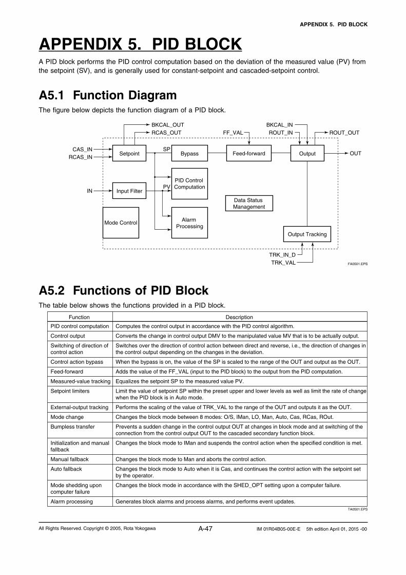
APPENDIX 5. PID BLOCK
A-47All Rights Reserved. Copyright © 2005, Rota Yokogawa IM 01R04B05-00E-E 5th edition April 01, 2015 -00
APPENDIX 5. PID BLOCKA PID block performs the PID control computation based on the deviation of the measured value (PV) from the setpoint (SV), and is generally used for constant-setpoint and cascaded-setpoint control.
A5.1 Function DiagramThe figure below depicts the function diagram of a PID block.
Setpoint OutputBypass
Input Filter
PID Control Computation
Alarm Processing
Mode Control
Feed-forward
Data Status Management
Output Tracking
CAS_IN
BKCAL_OUTRCAS_OUT
BKCAL_INROUT_IN ROUT_OUTFF_VAL
RCAS_IN
TRK_IN_DTRK_VAL
IN
OUT
PV
SP
FA0501.EPS
A5.2 Functions of PID BlockThe table below shows the functions provided in a PID block.
PID control computation
Control output
Switching of direction of control action
Control action bypass
Feed-forward
Measured-value tracking
Setpoint limiters
External-output tracking
Mode change
Bumpless transfer
Initialization and manual fallback
Manual fallback
Auto fallback
Mode shedding upon computer failure
Alarm processing
Function Description
Computes the control output in accordance with the PID control algorithm.
Converts the change in control output DMV to the manipulated value MV that is to be actually output.
Switches over the direction of control action between direct and reverse, i.e., the direction of changes in the control output depending on the changes in the deviation.
When the bypass is on, the value of the SP is scaled to the range of the OUT and output as the OUT.
Adds the value of the FF_VAL (input to the PID block) to the output from the PID computation.
Equalizes the setpoint SP to the measured value PV.
Limit the value of setpoint SP within the preset upper and lower levels as well as limit the rate of change when the PID block is in Auto mode.
Performs the scaling of the value of TRK_VAL to the range of the OUT and outputs it as the OUT.
Changes the block mode between 8 modes: O/S, IMan, LO, Man, Auto, Cas, RCas, ROut.
Prevents a sudden change in the control output OUT at changes in block mode and at switching of the connection from the control output OUT to the cascaded secondary function block.
Changes the block mode to IMan and suspends the control action when the specified condition is met.
Changes the block mode to Man and aborts the control action.
Changes the block mode to Auto when it is Cas, and continues the control action with the setpoint set by the operator.
Changes the block mode in accordance with the SHED_OPT setting upon a computer failure.
Generates block alarms and process alarms, and performs event updates. TA0501.EPS

APPENDIX 5. PID BLOCK
A-48 All Rights Reserved. Copyright © 2005, Rota YokogawaIM 01R04B05-00E-E 5th edition April 01, 2015 -00
A5.3 Parameters of PID BlockNOTE: In the table below, the Write column shows the modes in which the respective parameters can be written. A blank in the Write column indicates that the corresponding parameter can be written in all modes of the PID block. A dash (–) indicates that the corresponding parameter cannot be written in any mode.
0
1
2
3
4
5
6
7
8
9
10
11
12
13
14
15
16
17
18
19
20
21
22
23
24
25
26
27
28
29
30
31
32
33
Index Default (factory setting)
Parameter Name
Valid RangeWrite Description
Block Header
ST_REV
TAG_DESC
STRATEGY
ALERT_KEY
MODE_BLK
BLOCK_ERR
PV
SP
OUT
PV_SCALE
OUT_SCALE
GRANT_DENY
CONTROL_OPTS
STATUS_OPTS
IN
PV_FTIME
BYPASS
CAS_IN
SP_RATE_DN
SP_RATE_UP
SP_HI_LIM
SP_LO_LIM
GAIN
RESET
BAL_TIME
RATE
BKCAL_IN
OUT_HI_LIM
OUT_LO_LIM
BKCAL_HYS
BKCAL_OUT
RCAS_IN
ROUT_IN
TAG: “PID”
(blank)
0
1
0
1000
1342 (%)1
1000
1342 (%)1
0
0
0
0
0sec
1 (off)
0
1.#INF 1)
1.#INF 1)
100
0
1
10
0
0
0
100
0
0.5 (%)
0
0
0
Block Tag= O/S
---
---
---
AUTO
MAN
O/S
O/S
AUTO
O/S
O/S
AUTO
MAN
---
Same as that for an AI block.
Same as that for an AI block.
Same as that for an AI block.
Same as that for an AI block.
Same as that for an AI block.
Same as that for an AI block.
Measured value; the non-dimensional value that is converted from the input (IN) value based on the PV_SCALE values and filtered.
Setpoint
Output
Upper and lower scale limit values used for scaling of the input (IN) value.
Upper and lower scale limit values used for scaling of the control output (OUT) value to the values in the engineering unit.
Same as that for an AI block.
Setting for control action. See Section A5.13 for details.
See Section A5.15 for details.
Controlled-value input
Time constant (in seconds) of the first-order lag filter applied to IN
Whether to bypass the control computation. 1 (off): Do not bypass.2 (on): Bypass.
Cascade setpoint
Rate-of-decrease limit for setpoint (SP)
Rate-of-increase limit for setpoint (SP)
Upper limit for setpoint (SP)
Lower limit for setpoint (SP)
Proportional gain (= 100 / proportional band)
Integration time (seconds)
Unused
Derivative time (seconds)
Read-back of control output
Upper limit for control output (OUT)
Lower limit for control output (OUT)
Hysteresis for release from a limit for OUT.status
Read-back value to be sent to the BKCAL_IN in the upper block
Remote setpoint set from a computer, etc.
Remote control output value set from a computer, etc.
1 to 255
PV_SCALE 10%
Non-negative
1, 2
Positive
Positive
PV_SCALE 10%
PV_SCALE 10%
Positive
Positive
OUT_SCALE 10%
OUT_SCALE 10%
0 to 50%
TA0502-1.EPS
1) Initial value: All limits are set to plus or minus infinity (+INF or -INF), which is the same as no limit. IEEE 754-1985 defines the floating point representation of plus and minus infinity.

APPENDIX 5. PID BLOCK
A-49All Rights Reserved. Copyright © 2005, Rota Yokogawa IM 01R04B05-00E-E 5th edition April 01, 2015 -00
34
35
36
37
38
39
40
41
42
43
44
45
46
47
48
49
50
51
52
53
54
55
56
57
58
59
60
61
62
63
64
65
Index Default (factory setting)
Parameter Name
Valid RangeWrite Description
SHED_OPT
RCAS_OUT
ROUT_OUT
TRK_SCALE
TRK_IN_D
TRK_VAL
FF_VAL
FF_SCALE
FF_GAIN
UPDATE_EVT
BLOCK_ALM
ALARM_SUM
ACK_OPTION
ALARM_HYS
HI_HI_PRI
HI_HI_LIM
HI_PRI
HI_LIM
LO_PRI
LO_LIM
LO_LO_PRI
LO_LO_LIM
DV_HI_PRI
DV_HI_LIM
DV_LO_PRI
DV_LO_LIM
HI_HI_ALM
HI_ALM
LO_ALM
LO_LO_ALM
DV_HI_ALM
DV_LO_ALM
0
0
0
1000
13421
0
0
0
1000
13421
0
Enable
0
0.5%
0
1. #INF 1)
0
1. #INF 1)
0
-1. #INF 1)
0
-1. #INF 1)
0
1. #INF 1)
0
-1. #INF 1)
---
---
---
---
---
---
---
---
MAN
MAN
MAN
---
---
---
---
---
---
---
---
Action to be performed in the event of mode shedding.SHED_OPT defines the changes to be made to MODE.BLK.target and MODE.BLK.actual when the value of RCAS_IN.status or ROUT_IN.status becomes Bad if MODE_BLK.actual = RCas or ROut. See Section A5.17.1 for details.
Remote setpoint sent to a computer, etc.
Remote control output value
Upper and lower scale limits used to convert the output tracking value (TRK_VAL) to non-dimensional.
Switch for output tracking. See Section A5.12 for details.
Output tracking value (TRK_VAL)When MODE_BLK.actual = LO, the value scaled from the TRK_VAL value is set in OUT.
Feedforward input value. The FF_VAL value is scaled to a value with the same scale as for OUT, multiplied by the FF_GAIN value, and then added to the output of the PID computation.
Scale limits used for converting the FF_VAL value to a non-dimensional value.
Gain for FF_VAL
Same as that for an AI block.
Same as that for an AI block.
Same as that for an AI block.
Same as that for an AI block.
Hysteresis for alarm detection and resetting to prevent each alarm from occurring and recovering repeatedly within a short time.
Priority order of HI_HI_ALM alarm
Setting for HI_HI_ALM alarm
Priority order of HI_ALM alarm
Setting for HI_ALM alarm
Priority order of LO_ALM alarm
Setting for LO_ALM alarm
Priority order of LO_LO_ALM alarm
Setting for LO_LO_ALM alarm
Priority order of DV_HI_ALM alarm
Setting for DV_HI_ALM alarm
Priority order of DV_LO_ALM alarm
Setting for DV_LO_ALM alarm
Alarm that is generated when the PV value has exceeded the HI_HI_LIM value and whose priority order* is defined in HI_HI_PRI. * Priority order: Only one alarm is generated at a time. When two or more alarms occur at the same time, the alarm having the highest priority order is generated. When the PV value has decreased below [HI_HI_LIM – ALM_HYS], HI_HI_ALM is reset.
As above
As aboveReset when the PV value has increased above [LO_LIM + ALM_HYS].
As above
Alarm that is generated when the value of [PV - SP] has exceeded the DV_HI_LIM value. Other features are the same as HI_HI_ALM.
Alarm that is generated when the value of [PV - SP] has decreased below the DV_LO_LIM value. Other features are the same as LO_LO_ALM.
0 to 50%
0 to 15
PV_SCALE
0 to 15
PV_SCALE
0 to 15
PV_SCALE
0 to 15
PV_SCALE
0 to 15
0 to 15
TA0502-2.EPS1) Initial value: All limits are set to plus or minus infinity (+INF or -INF), which is the same as no limit. IEEE 754-1985 defines the floating point representation of plus and minus infinity.

APPENDIX 5. PID BLOCK
A-50 All Rights Reserved. Copyright © 2005, Rota YokogawaIM 01R04B05-00E-E 5th edition April 01, 2015 -00
A5.4 PID Computation Details
For PID control, the PID block in a ROTAMASS employs the PV-proportional and -derivative type PID control algorithm (referred to as the I-PD control algorithm), or the PV-derivative type PID control algorithm (referred to as the PI-D control algorithm) depending on the mode, as described below.
A5.4.1 PV-proportional and -derivative Type PID (I-PD) Control Algo-rithm versus PV-derivative Type PID (PI-D) Control Algorithm
The I-PD control algorithm, which is expressed by the equation below, ensures control stability against sudden changes in the setpoint, such as when the user enters a new setpoint value. The I-PD algorithm also ensures excellent controllabil-ity by performing proportional, integral, and deriva-tive control actions in response to changes of characteristics in the controlled process, changes in load, and occurrences of disturbances.
When the PID block is in Auto or RCas mode, this I-PD algorithm is used for control. In Cas mode, however, the PV-derivative type PID (PI-D) algo-rithm takes over since the response to setpoint changes is more important. The control algorithm in use thus switches over automatically in line with the mode transitions. The following shows the ba-sic computation formulas of these algorithms.
PV-proportional and -derivative (I-PD) control algorithm:
∆MVn = K ∆PVn + (PVn – SPn) + ∆(∆PVn)∆TTi
Td∆T
PV-derivative (PI-D) control algorithm:
∆MVn = K ∆(PVn – SPn) + (PVn – SPn) + ∆(∆PVn)Td∆T
∆TTi
Where,
DMVn = change in control output DPVn = change in measured (controlled) value
= PVn - PVn-1 DT = control period = period_of_execution
in Block Header K = proportional gain = GAIN (= 100/pro-
portional band) TI = integral time = RESET TD = derivative time = RATE
The subscripts, n and n-1, represent the time of sampling such that PVn and PVn-1 denote the PV value sampled most recently and the PV value sampled at the preceding control period, respec-tively.
A5.4.2 PID Control Parameters
The table below shows the PID control param-eters.
Parameter Description Valid Range
GAIN
RESET
RATE
Proportional gain
Integral time
Derivative time
0.05 to 20
0.1 to 10,000 (seconds)
0 to infinity (seconds)TA0503.EPS
A5.5 Control OutputThe final control output value, MV, is computed based on the change in control output ÐMVn, which is calculated at each control period in ac-cordance with the aforementioned algorithm. The PID block in a ROTAMASS performs the velocity type output action for the control output.
A5.5.1 Velocity Type Output Action
The PID block determines the control output (OUT) value by adding the change in control out-put calculated in the current control period, DMVn, to the value read back from the output destination, BKCAL_IN. This velocity type output action can be expressed as:
OUT = BKCAL_IN – DMVn’
where DMVn’ is DMVn scaled based on PV_SCALE and OUT_SCALE.
Note: MV indicates the PID computation result.
A5.6 Direction of Control Action
The direction of the control action is determined by the Direct Acting setting in CONTROL_OPTS.
Value of Direct Acting Resulting Action
The output increases when the input PV is greater than the setpoint SP.
The output decreases when the input PV is greater than the setpoint SP.
True
False
TA0504.EPS

APPENDIX 5. PID BLOCK
A-51All Rights Reserved. Copyright © 2005, Rota Yokogawa IM 01R04B05-00E-E 5th edition April 01, 2015 -00
A5.7 Control Action By-pass
The PID control computation can be bypassed so as to set the SP value in the control output OUT as shown below. Setting BYPASS to “On” bypasses the PID control computation.
SetpointControl
Feed- forward
CAS_IN
FilterIN PV
BYPASS
SP
RCAS_IN
Output OUT
FA0502.EPS
A5.8 Feed-forwardFeed-forward is an action to add a compensa-tion input signal FF_VAL to the output of the PID control computation, and is typically used for feed-forward control. The following figure illustrates the action.
PID computation
FF_SCALEOUT_SCALE
PV OUT
FF_VAL
FF_GAIN
FA0503.EPS
A5.9 Block ModesThe block mode is set in the parameter MODE_BLK.
Stipulates the target mode to which the PID block transfers.
Indicates the current mode of the PID block.
Stipulates all the modes that the PID block can enter. The PID block is prohibited to enter any mode other than those set in this element.
Stipulates the mode in which the PID block normally resides.
MODE_BLK
Target
Actual
Permitted
Normal
TA0505.EPS
There are eight modes for a PID block as shown below.
Block Mode
Description
Remote output mode, in which the PID block outputs the value set in ROUT_IN.
Remote cascade mode, in which the PID block carries out the PID control computation based on the setpoint (SP) set via the remote cascade connection, such as from a computer, and outputs the computed result.
Cascade mode, in which the PID block carries out the PID control computation based on the setpoint (SP) set from another fieldbus function block, and outputs the computed result.
The PID block carries out automatic control and outputs the result computed by the PID control computation.
Manual mode, in which the PID block outputs the value set by the user manually.
The PID block outputs the value set in TRK_VAL.
Initialization and manual mode, in which the control action is suspended. The PID block enters this mode when the specified condition is met (see Section A5.14).
Out of service mode, in which neither the control computation nor action is carried out, and the output is kept at the value that was output before the PID block entered into O/S mode.
ROut
RCas
Cas
Auto
Man
LO
IMan
O/S
TA0506.EPS

APPENDIX 5. PID BLOCK
A-52 All Rights Reserved. Copyright © 2005, Rota YokogawaIM 01R04B05-00E-E 5th edition April 01, 2015 -00
A5.9.1 Mode TransitionsTransition
Destination Mode
Condition NOT Conditions
1. If O/S is set in MODE_ BLK.target (or if O/S is set in target inside the resource block)
2. If the specified condition is met (see Section A5.14)
3. If Track Enable is specified in CONTROL_OPTS and the value of TRK_IN_D is true
4. If Man is set in MODE_ BLK.target or if IN.status (input status) is Bad
5. If Auto is set in MODE_ BLK.target - AND - if IN.status (input status) is not Bad
6. If Cas is set in MODE_ BLK.target - AND - if neither IN.status (input status) nor CAS_IN.status is Bad.
7. If RCas is set in MODE_ BLK.target - AND - if neither IN.status (input status) nor RCAS_IN.status is Bad.
8. If ROut is set in MODE_ BLK.target - AND - if ROUT_IN.status (input status) is not Bad
9. If RCAS_IN.status or ROUT_ IN.status is Bad (indicating a computer failure; see Section A5.17.1 for details)
NOT if condition 1 is met
NOT if either or both of conditions 1 and 2 are met
NOT if any one or more of conditions 1 to 3 are met
NOT if any one or more of conditions 1 to 3 are met
NOT if any one or more of conditions 1 to 3 are met
NOT if any one or more of conditions 1 to 3 are met.
NOT if any one or more of conditions 1 to 3 are met.
O/S
IMan
LO
Man
Auto*
Cas*, **
RCas*, **
ROut*, **
In accordance with the SHED_OPT setting
TA0507.EPS
* To activate mode transitions to AUTO, CAS, RCAS, and ROUT, the respective target modes must be set beforehand to MODE_BLK.permitted.
** A transition to CAS, RCAS, or ROUT requires that initialization of the cascade connection has been completed.
A5.10 Bumpless TransferPrevents a sudden change in the control output OUT at changes in block mode (MODE_BLK) and at switching of the connection from the control output OUT to the cascaded secondary function block. The action to perform a bumpless transfer differs depending on the MODE_BLK values.
A5.11 Setpoint LimitersActive setpoint limiters that limit the changes in the SP value, differ depending on the block mode as follows.
A5.11.1 When PID Block Is in AUTO Mode
When the value of MODE_BLK is AUTO, the four types of limiters are in force: high limit, low limit, rate-of-increase limit, and rate-of-decrease limit.
Setpoint High/Low Limits
• AvaluelargerthanthevalueofSP_HI_LIMcannot be set for SP.
• AvaluesmallerthanthevalueofSP_LO_LIMcannot be set for SP.
Setpoint Rate Limits
The setpoint rate limits are used to restrict the magnitude of changes in the SP value so as to change the SP value gradually towards a new setpoint.
• AnincreaseoftheSPvalueateachexecutionperiod (period of execution in the Block Head-er) is limited to the value of SP_RATE_UP.
• AdecreaseoftheSPvalueateachexecutionperiod (period of execution in the Block Head-er) is limited to the value of SP_RATE_DOWN.
A5.11.2 When PID Block Is in CAS or RCAS Mode
By selecting Obey SP Limits if Cas or RCas in CONTROL_OPTS (see Section A5.13.1), the setpoint high/low limits can be put into force also when the value of MODE_BLK is CAS or RCAS.

APPENDIX 5. PID BLOCK
A-53All Rights Reserved. Copyright © 2005, Rota Yokogawa IM 01R04B05-00E-E 5th edition April 01, 2015 -00
A5.12 External-output Tracking
External tracking is an action of outputting the value of the remote output TRK_VAL set from outside the PID block, as illustrated in the figure below. External tracking is performed when the block mode is LO.
TRK_SCALEOUT_SCALE
TRK_VAL
OUT
TRK_IN_D
LO mode
PID control computation result
FA0504.EPS
To change the block mode to LO:
(1) Select Track Enable in CONTROL_OPTS. (2) Set TRK_IN_D to true. However, to change the block mode from MAN to LO, Track in Manual must also be specified in CONTROL_OPTS.
A5.13 Measured-value Tracking
Measured-value tracking, also referred to as SP-PV tracking, is an action to equalize the setpoint SP to the measured value PV when the block mode (MODE_BLK.actual) is MAN in order to pre-vent a sudden change in control output from being caused by a mode change to AUTO.
While a cascade primary control block is perform-ing the automatic or cascade control (in the AUTO or CAS mode), when the mode of its secondary control block is changed from CAS to AUTO, the cascade connection is opened and the control action of the primary block stops. The SP of the primary controller can be equalized to its cascade input signal CAS_IN also in this case.
The settings for measured-value tracking are made in the parameter CONTROL_OPTS, as shown in the table below.
A5.13.1 CONTROL_OPTSOptions in
CONTROL_OPTSDescription
This parameter allows BYPASS to be set.
Equalizes SP to PV when MODE_BLK.target is set to Man.
Equalizes SP to PV when MODE_BLK.target is set to ROut.
Equalizes SP to PV when actual is set to LO or IMAN.
Equalizes SP to RCAS_IN when MODE_BLK.target is set to RCas, and to CAS_IN when MODE_BLK.target is set to Cas when the actual mode of the block is IMan,LO, Man or ROut.
Set the PID block to a direct acting controller.
This enables the external tracking function. The value in TRK_VAL will replace the value of OUT if TRK_IN_D becomes true and the target mode is not Man.
This enables TRK_VAL to replace the value of OUT when the target mode is Manand TRK_IN_D is true. The actual mode will then be LO.
Sets the value of PV in BKCAL_OUT and RCAS_OUT, instead of the value of SP.
Puts the setpoint high/low limits in force in the Cas or RCas mode.
Disables the high/low limits for OUT in the Man mode.
Bypass Enable
SP-PV Track in Man
SP-PV Track in ROut
SP-PV Track in LO or IMan
SP-PV Track retained Target
Direct Acting
Track Enable
Track in Manual
Use PV for BKCAL_OUT
Obey SP limits if Cas or RCas
No OUT limits in Manual
TA0508.EPS
A5.14 Initialization and Manual Fallback (IMAN)
Initialization and manual fallback denotes a set of actions in which a PID block changes mode to IMAN (initialization and manual) and suspends the control action. Initialization and manual fallback takes place automatically as a means of abnor-mality handling when the following condition is met:
• ThequalitycomponentofBKCAL_IN.statusisBad.
- OR -
• ThequalitycomponentofBKCAL_IN.statusisGood (c)
- AND - The sub-status component of BKCAL_IN.status
is FSA, LO, NI, or IR. The user cannot manually change the mode to IMAN. A mode transition to IMAN occurs only when the condition above is met.

APPENDIX 5. PID BLOCK
A-54 All Rights Reserved. Copyright © 2005, Rota YokogawaIM 01R04B05-00E-E 5th edition April 01, 2015 -00
A5.15 Manual FallbackManual fallback denotes an action in which a PID block changes mode to MAN (manual) and sus-pends the control action. Manual fallback takes place automatically as a means of abnormality handling when the following condition is met:
• IN.statusisBadexceptwhenthecontrolactionbypass is on.
To enable the manual fallback action to take place when the above condition is met, Target to Manual if BAD IN must be specified beforehand in STATUS_OPTS.
The table below shows the options in STATUS_OPTS.
A5.15.1 STATUS_OPTSOptions in
STATUS_OPTS Description
Sets the sub-status component of OUT.status to IFS if IN.status is Bad except when PID control bypass is on.
Sets the sub-status component of OUT.status to IFS if CAS_IN.status is Bad.
Does not regard IN as being in Bad status when IN.status is Uncertain (to prevent mode transitions from being affected when it is Uncertain).
Automatically changes the value of MODE_BLK.target to MAN when IN falls into Bad status.
Automatically changes the value of MODE_BLK.target to Auto (or to Man if Auto is not set in Permitted) when CAS_IN falls into Bad status.
IFS if BAD IN
IFS if BAD CAS IN
Use Uncertain as Good
Target to Manual if BAD IN
Target to next permitted mode if BAD CAS IN
TA0509.EPS
A5.16 Auto FallbackAuto fallback denotes an action in which a PID block changes mode from CAS (cascade) to AUTO (automatic) and continues automatic PID control with the user-set setpoint. Auto fallback takes place automatically when the following con-dition is met:
• IN.status(datastatusofIN)isBadexceptwhen the control action bypass is on.
To enable the manual fallback action to take place when the above condition is met:
• TargettonextpermittedmodeifBADCASIN must be previously specified in STATUS_OPTS.
- AND -
• AUTOmustbepreviouslysetinMODE_BLK.permitted.
A5.17 Mode Shedding upon Computer Fai-lure
When the data status of RCAS_IN or ROUT_IN, which is the setting received from a computer as the setpoint SP, falls to Bad while the PID block is running in the RCAS (remote cascade) or ROUT (remote output) mode, the mode shedding occurs in accordance with the settings in SHED_OPT.
A5.17.1 SHED_OPT
The SHED_OPT setting stipulates the specifica-tions of mode shedding as shown below. Only one can be set.
Available Setting for SHED_OPT
Actions upon Computer Failure
Sets MODE_BLK.actual to Cas*, and leaves MODE_BLK.target unchanged.
Sets both MODE_BLK.actual and MODE_BLK.target to Cas*.
Sets MODE_BLK.actual to Auto**, and leaves MODE_BLK.target unchanged.
Sets both MODE_BLK.actual and MODE_BLK.target to Auto**.
Sets MODE_BLK.actual to Man, and leaves MODE_BLK.target unchanged.
Sets both MODE_BLK.actual and MODE_BLK.target to Man.
If Cas is in MODE_BLK.target, sets MODE_BLK.actual to Cas*, and leaves MODE_BLK.target unchanged.If Cas is not set in MODE_BLK.target, sets MODE_BLK.actual to Auto**, and leaves MODE_BLK.target unchanged.
If Cas is set in MODE_BLK.target, sets both MODE_BLK.actual and MODE_BLK.target to Cas*. If Cas is not set in MODE_BLK.target, sets MODE_BLK.actual to Auto**, and MODE_BLK.target to Cas.
Normal shed, normal return
Normal shed, no return
Shed to Auto, normal return
Shed to Auto, no return
Shed to Manual, normal return
Shed to Manual, no return
Shed to retained target, normal return
Shed to retained target, no return
TA0510.EPS

APPENDIX 5. PID BLOCK
A-55All Rights Reserved. Copyright © 2005, Rota Yokogawa IM 01R04B05-00E-E 5th edition April 01, 2015 -00
* The modes to which a PID block can transfer are limited to those set in MODE_BLK.permit-ted, and the priority levels of modes are as shown below. In fact, if Normal shed, normal return is set for SHED_OPT, detection of a computer failure causes MODE_BLK.actual to change to CAS, AUTO, or MAN, whichever is set in MODE_BLK.permitted and has the low-est priority level.
MAN Higher priority levelAUTOCASRCASROUT Lower priorty level
** Only if Auto is included in MODE_BLK.permit-ted. If the block upstream of the PID block in question is a control block, mode transitions of the PID block to CAS occur in the following sequence due to initialization of the cascade connection: RCAS or ROUT ∅ AUTO ∅ CAS.
A5.18 AlarmsThere are two kinds of alarms generated by a PID block: block and process alarms.
A5.18.1 Block Alarm (BLOCK_ALM)
The block alarm BLOCK_ALM is generated upon occurrence of either of the following errors (values set in BLOCK_ERR) and notifies the content of BLOCK_ERR.
Value of BLOCK_ERR
Condition
IN.status of the PID block is either of the following: • Bad-Device Failure• Bad-Sensor Failure
MODE_BLK.target of the PID block is O/S.
Input Failure
Out of ServiceTA0511.EPS
A5.18.2 Process Alarms
There are six types of process alarms. Only one process alarm can be generated at the same time, and the process alarm having the highest priority level from among those occurring at the same time is generated. The priority level is set for each process alarm type.
Parameter Containing
Priority Level Setting
Cause of OccurrenceProcess Alarm
Occurs when the PV increases above the HI_HI_LIM value.
Occurs when the PV increases above HI_LIM value.
Occurs when the PV decreases below the LO_LIM value.
Occurs when the PV decreases below the LO_LO_LIM value.
Occurs when the value of [PV - SP] increases above the DV_HI_LIM value.
Occurs when the value of [PV - SP] decreases below the DV_LO_LIM value.
HI_HI_PRI
HI_PRI
LO_PRI
LO_LO_LIM
DV_HI_PRI
DV_LO_PRI
HI_HI_ALM
HI_ALM
LO_ALM
LO_LO_ALM
DV_HI_ALM
DV_LO_ALM
TA0512.EPS
A5.19 Example of Block Connections
PID
BKCAL_IN OUT
IN
AO
BKCAL_OUT
CAS_IN
AI
OUT
FA0506.EPS

APPENDIX 5. PID BLOCK
A-56 All Rights Reserved. Copyright © 2005, Rota YokogawaIM 01R04B05-00E-E 5th edition April 01, 2015 -00
When configuring a simple PID control loop by combining a ROTAMASS with a fieldbus valve positioner that contains an AO block, follow the procedure below to make the settings of the cor-responding fieldbus function blocks:
1. Connect the AI block and PID block of the ROTAMASS, and the AO block of the valve positioner as shown above.
2. Set MODE_BLK.target of the PID block to O/S, and then set GAIN, RESET, and RATE to ap-propriate values.
3. Check that the value of MODE_BLK.actual of the AI block is AUTO.
4. Set MODE_BLK.target of the AO block to CAS|AUTO (meaning "CAS and AUTO").
5. Check that the value of BKCAL_IN.status of the PID block is not Bad.
6. Check that the value of IN.status of the PID block is not Bad.
7. Check that AUTO is set in MODE_BLK.permit-ted of the PID block.
8. Set MODE_BLK.target of the PID block to AUTO.
When finishing all steps in order, the PID block and AO block exchange the respective informa-tion and initialize the cascade connection. Con-sequently, the value of MODE_BLK.actual of the PID block changes to AUTO and automatic PID control starts.
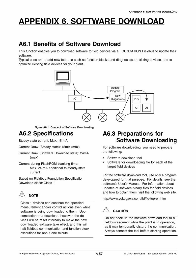
APPENDIX 6. SOFTWARE DOWNLOAD
A-57All Rights Reserved. Copyright © 2005, Rota Yokogawa IM 01R04B05-00E-E 5th edition April 01, 2015 -00
APPENDIX 6. SOFTWARE DOWNLOAD
A6.2 SpecificationsSteady-state current: Max. 15 mA
Current Draw (Steady-state): 15mA (max)
Current Draw (Software Download state): 24mA (max)
Current during FlashROM blanking time: Max. 24 mA additional to steady-state current
Based on Fieldbus Foundation Specification Download class: Class 1
NOTE
Class 1 devices can continue the specified measurement and/or control actions even while software is being downloaded to them. Upon completion of a download, however, the de-vices will be reset internally to make the new, downloaded software take effect, and this will halt fieldbus communication and function block executions for about one minute.
A6.3 Preparations for Software Downloading
For software downloading, you need to prepare the following:
• Softwaredownloadtool• Softwarefordownloadingfileforeachofthe
target field devices
For the software download tool, use only a program developped for that purpose. For details, see the software’s User’s Manual. For information about updates of software binary files for field devices and how to obtain them, visit the following web site.
http://www.yokogawa.com/fld/fld-top-en.htm
CAUTION
Do not hook up the software download tool to a fieldbus segment while the plant is in operation, as it may temporarily disturb the communication. Always connect the tool before starting operation.
A6.1 Benefits of Software DownloadThis function enables you to download software to field devices via a FOUNDATION Fieldbus to update their software. Typical uses are to add new features such as function blocks and diagnostics to existing devices, and to optimize existing field devices for your plant.
PID
AI AI
Update Program
New DiagnosticsI/O
Figure A6.1 Concept of Software Downloading

APPENDIX 6. SOFTWARE DOWNLOAD
A-58 All Rights Reserved. Copyright © 2005, Rota YokogawaIM 01R04B05-00E-E 5th edition April 01, 2015 -00
NOTE
The download tool can not execute download-ing during other system connects to the system/ network management VFD of the device.
A6.4 Software Download Sequence
The flowchart below outlines the software down-load procedure. Although the time taken for the entire procedure varies depending on the size of the field bus device’s software, it generally take about 20 minutes where there is a one-to-one connection between a fieldbus device and down-load tool, and longer when multiple field devices are connected to the fieldbus.
FA0102.EPS
Start download tool
Select file(s)
Select device(s)
Carry out download
Activate device(s)Activate the device(s) to startwith new software
Transmit the software to the fielddevice(s)
Select the device(s) to which youwant to download software
Select the software file(s) you want to download
Figure A6.2 Flow of Software Download Procedure
CAUTION
Carrying out a software download leaves the PD tag, node address, and transducer block calibration parameters that are retained in the nonvolatile memory inside the target device, but may reset other parameters to the defaults (except a minor update that does not change the number of parameters). Hence, where necessary, save the parameters using an engineering tool, parameter setting utility, or the like before carrying out a software download, and then reconfigure the field device(s) after the download. For details, see Section A6.6.
CAUTION
The current dissipation of the target field device increases transitorily immediately after a down-load due to erasing of the FlashROM’s contents. Use a fieldbus power supply which has sufficient capacity to cover such increases in feed current.
CAUTION
Upon completion of the activation, the target fieldbus device performs resetting internally, which temporarily halts fieldbus communication and function block executions. Be especially careful about a valve positioner; the output air pressure will fall to the minimum level (i.e., zero).
CAUTION
Do not turn off the power to a field device or disconnect the download tool during a download or activation. The device may fail as a result.
NOTE
Be careful about the noise on the fieldbus link. If the fieldbus is noisy, the downloading may take a very long time or fail.
A6.5 Download FilesDownload files have the following filenames (with the filename extension of “.ffd”). Take care to choose the correct download file for the target field device:
“594543” + device family + “_” + device type + “_” + domain name + “_” + software name + “_” + software revision + “.ffd”
For example, the name of the download file for the Rotamass may have the following name:
594543000D_000D_ROTAMASS_ORIGINAL_R201.ffd
Refer to A6.10(3) DOMAIN_HEADER about each keyword of the file name.
The device type is “000D” for the Rotamass .

APPENDIX 6. SOFTWARE DOWNLOAD
A-57All Rights Reserved. Copyright © 2005, Rota Yokogawa IM 01R04B05-00E-E 5th edition April 01, 2015 -00
The software name is “ORIGINAL” or “UPDATE.” The former indicates an original file and the latter an update file. Whenever performing a download to update the device revision, obtain the original file. In general, an addition to the parameters or blocks requires a device revision update.
A6.6 Steps after Activating a Field Device
When the communication with a field device has recovered after activating the device, check using the download tool that the software revision of the field device has been updated accordingly. The value of SOFT_REV of the resource block indicates the software revision.
The PD tag, node address, and transducer block calibration parameters that are retained in the nonvolatile memory inside the target device will remain unchanged after a software download. However, after a software update which causes an addition to the block parameters or blocks, or to the system/network management VFD parameters, some parameters may be reset to the defaults, thus requiring parameter setup and engineering again. For details, see the table below.
Also note that a change in the number of parameters or blocks requires the DD and capabilities files corresponding to the new software revision.
Table A6.1 Actions after Software Update
TA0101.EPS
Adds a block.
Adds a block parameter.
Does not change the number
of parameters.
Changes the number of
system/network management
VFD parameters.
ActionContents of Software Update
Setup of the added
parameter needed.
Re-setup of parameters not
needed.
Reengineering and setup of
the added block’s
parameters needed.
Reengineering needed.
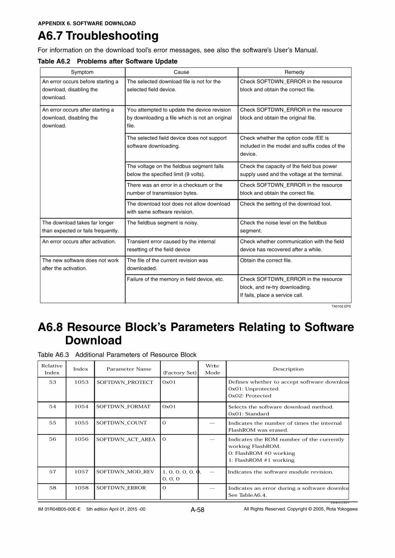
APPENDIX 6. SOFTWARE DOWNLOAD
A-58 All Rights Reserved. Copyright © 2005, Rota YokogawaIM 01R04B05-00E-E 5th edition April 01, 2015 -00
A6.8 Resource Block’s Parameters Relating to Software Download
Table A6.3 Additional Parameters of Resource Block
TA0103.EPS
Relative
IndexIndex Parameter Name
(Factory Set)
Write
ModeDescription
SOFTDWN_PROTECT
1, 0, 0, 0, 0, 0,
0, 0, 0
SOFTDWN_ACT_AREA
Defines whether to accept software download
0x01: Unprotected
0x02: Protected
Selects the software download method.
0x01: Standard
Indicates the number of times the internal
FlashROM was erased.
Indicates the ROM number of the currently
working FlashROM.
0: FlashROM #0 working
1: FlashROM #1 working
Indicates the software module revision.
Indicates an error during a software downloa
See Table A6.4.
1057
1055
1056
SOFTDWN_MOD_REV
—
—
—
1054
1053
0
SOFTDWN_FORMAT
SOFTDWN_COUNT
0x01
0x01
0
56
57
55
54
53
1058 —SOFTDWN_ERROR 058
A6.7 TroubleshootingFor information on the download tool’s error messages, see also the software’s User’s Manual.
Table A6.2 Problems after Software Update
Symptom Cause Remedy
An error occurs before starting a
download, disabling the
download.
The selected download file is not for the
selected field device.
Check SOFTDWN_ERROR in the resource
block and obtain the correct file.
An error occurs after starting a
download, disabling the
download.
You attempted to update the device revision
by downloading a file which is not an original
file.
Check SOFTDWN_ERROR in the resource
block and obtain the original file.
The selected field device does not support
software downloading.
Check whether the option code /EE is
included in the model and suffix codes of the
device.
The voltage on the fieldbus segment falls
below the specified limit (9 volts).
Check the capacity of the field bus power
supply used and the voltage at the terminal.
There was an error in a checksum or the
number of transmission bytes.
Check SOFTDWN_ERROR in the resource
block and obtain the correct file.
The download takes far longer
than expected or fails frequently.
The fieldbus segment is noisy.
An error occurs after activation.
Check the noise level on the fieldbus
segment.
Transient error caused by the internal
resetting of the field device
Check whether communication with the field
device has recovered after a while.
The new software does not work
after the activation.
The file of the current revision was
downloaded.
Obtain the correct file.
Failure of the memory in field device, etc. Check SOFTDWN_ERROR in the resource
block, and re-try downloading.
If fails, place a service call.
TA0102.EPS
The download tool does not allow download
with same software revision.
Check the setting of the download tool.

APPENDIX 6. SOFTWARE DOWNLOAD
A-57All Rights Reserved. Copyright © 2005, Rota Yokogawa IM 01R04B05-00E-E 5th edition April 01, 2015 -00
Table A6.4 Download Error Codes
TA0104.EPS
Error Code Detail
0
32768
32769
32770
32771
32772
32773
32774
32775
32776
32777
32778
32779
32780
32781
32782
32783
32784
32785
32786
32787
32788
32789
32790
32791
32792
32793
32794
32795
32796
32797
32798
32799
32800
32801
36863
No error
Unsupported header version
Abnormal header size
Abnormal manufacturer ID
Abnormal device family
Abnormal device revision
Abnormal vendor specification version
Abnormal number of modules
Abnormal number of bytes in module 1
Abnormal number of bytes in module 2
Device error in module 1
Checksum error in module 1
Checksum error in file
Unused
Write-prohibited area in FlashROM
Verification error during FlashROM writing
Polling error during FlashROM erasing
Polling time-out during FlashROM erasing
Polling error during FlashROM writing
Polling time-out during FlashROM writing
FlashROM driver undefined number error
File endcode error
File type error (UPDATE, ORIGINAL)
FlashROM driver undefined number error
On-start state error (other than DWNLD_NOT_READY)
Start segment error in module 1
Binary file error
Binary file error
Device error in module 2
Detection of EEPROM state other than backup after activation
Checksum error in module 2
Not in DWNLD_READY state when receiving GenericDomainInitiate
Not in DWNLD_OK state when receiving GenericDomainTerminate
Not in DOWNLOADING state when receiving GenericDomainSegment
Firmware error
Unused
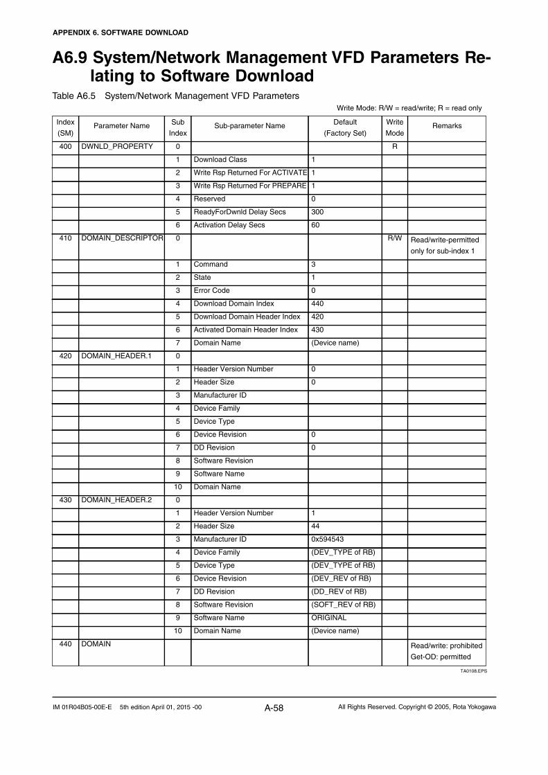
APPENDIX 6. SOFTWARE DOWNLOAD
A-58 All Rights Reserved. Copyright © 2005, Rota YokogawaIM 01R04B05-00E-E 5th edition April 01, 2015 -00
A6.9 System/Network Management VFD Parameters Re-lating to Software Download
Table A6.5 System/Network Management VFD Parameters
TA0108.EPS
Write Mode: R/W = read/write; R = read only
0
(Device name)
0
0
430
60
300
1
9
440
0
3
(DD_REV of RB)
ORIGINAL
(SOFT_REV of RB)
(DEV_REV of RB)
(Device name)
(DEV_TYPE of RB)
10 Domain Name
0
(DEV_TYPE of RB)
0x594543
1
44
420
DOMAIN_HEADER.1
DOMAIN_HEADER.2
0DWNLD_PROPERTY
1
1
1
DOMAIN_DESCRIPTOR
0
2
Activated Domain Header Index
Error Code
Domain Name
Download Domain Index
Download Domain Header Index
Header Size
Header Version Number
State
Reserved
ReadyForDwnld Delay Secs
Write Rsp Returned For PREPARE
Activation Delay Secs
Command
Manufacturer ID
Device Type
Write Rsp Returned For ACTIVATE
Device Family
Manufacturer ID
Device Revision
Software Name
Header Size
DD Revision
Software Revision
DD Revision
Software Revision
Device Revision
Device Family
Device Type
Header Version Number
Software Name
Domain Name
3
7
10
9
6
8
3
5
4
5
2
6
0
7
4
1
3
Download Class
5
6
0
4
3
1
2
2
6
5
7
0
1
1
4
8
Index
(SM)
440 DOMAIN Read/write: prohibited
Get-OD: permitted
420
430
Read/write-permitted
only for sub-index 1
RemarksParameter Name Sub
Index
400
Sub-parameter Name
410 R/W
R
Write
Mode
Default
(Factory Set)
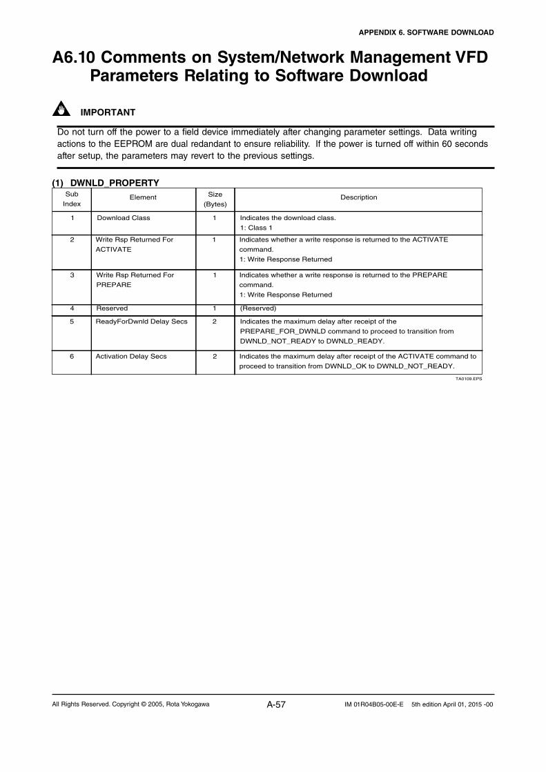
APPENDIX 6. SOFTWARE DOWNLOAD
A-57All Rights Reserved. Copyright © 2005, Rota Yokogawa IM 01R04B05-00E-E 5th edition April 01, 2015 -00
A6.10 Comments on System/Network Management VFD Parameters Relating to Software Download
IMPORTANT
Do not turn off the power to a field device immediately after changing parameter settings. Data writing actions to the EEPROM are dual redandant to ensure reliability. If the power is turned off within 60 seconds after setup, the parameters may revert to the previous settings.
(1) DWNLD_PROPERTY
TA0109.EPS
Sub
IndexElement Size
(Bytes)Description
Download Class Indicates the download class.
1: Class 1
1 1
Write Rsp Returned For
ACTIVATE
Indicates whether a write response is returned to the ACTIVATE
command.
1: Write Response Returned
12
Write Rsp Returned For
PREPARE
Indicates whether a write response is returned to the PREPARE
command.
1: Write Response Returned
Reserved (Reserved)
ReadyForDwnld Delay Secs Indicates the maximum delay after receipt of the
PREPARE_FOR_DWNLD command to proceed to transition from
DWNLD_NOT_READY to DWNLD_READY.
Activation Delay Secs Indicates the maximum delay after receipt of the ACTIVATE command to
proceed to transition from DWNLD_OK to DWNLD_NOT_READY.
1
1
2
26
5
4
3

APPENDIX 6. SOFTWARE DOWNLOAD
A-58 All Rights Reserved. Copyright © 2005, Rota YokogawaIM 01R04B05-00E-E 5th edition April 01, 2015 -00
(2) DOMAIN_DESCRIPTOR
TA0110.EPS
Sub
IndexElement Size
(Bytes)Description
Command Reads/writes software download commands.
1: PREPARE_FOR_DWNLD (instruction of download preparation)
2: ACTIVATE (activation instruction)
3: CANCEL_DWNLD (instruction of download cancellation)
1 1
12
2
4
4
6
5
4
3
Indicates the current download status.
1: DWNLD_NOT_READY (download not ready)
2: DWNLD_PREPARING (download under preparation)
3: DWNLD_READY (ready for download)
4: DWNLD_OK (download complete)
5: DOWNLOADING (download underway)
6: CHECKSUM_FAIL (not used in this product)
7: FMS_DOWNLOAD_FAIL (failure during download)
8: DWNLD_INCOMPLETE (download error detected at restart)
9: VCR_FAIL (not used in this product)
10: OTHER (download error other than 6 and 7 detected)
State
Error Code Indicates the error during a download and activation.
0: success, configuration retained (download successfully completed)
32768 - 65535: Download error (See Table 4 for error codes.)
Download Domain Index Indicates the index number of the domain for software downloading.
Download Domain Header
Index
Indicates the index number of the domain header to which the download
is performing.
Activated Domain Header
Index
Indicates the index numbers of the domain header currently running.
Indicates the domain name. With this product, Domain Name indicates
the field device name.
Domain Name7 8
4
(3) DOMAIN_HEADER
TA0111.EPS
Sub
IndexElement Size
(Bytes)Description
Header Version Number Indicates the version number of the header. 1 2
22
6
4
4
6
5
4
3
Indicates the header size. Header Size
Manufacturer ID Indicates the value of resource block’s MANUFAC_ID (manufacturer ID)
as character string data.
Device Family Indicates the device family. With this product, Device Family indicates the
value of resource block’s DEV_TYPE as character string data.
Device Type Indicates the value of resource block’s DEV_TYPE as character string
data.
Device Revision Indicates the value of resource block’s DEV_REV.
Indicates the value of resource block’s DD_REV. DD Revision7 1
1
8 Software Revision Indicates the value of resource block’s SOFT_REV.8
89 Software Name Indicates the attribute of the binary file. With this product, Software Name
indicates either of the following:
“ORIGINAL” followed by one space: Original file
“UPDATE” followed by two spaces: Update file
810 Domain Name Indicates the domain name. With this product, Domain Name indicates
the field device name.

APPENDIX 7. LINK MASTER FUNCTIONS
A-65All Rights Reserved. Copyright © 2005, Rota Yokogawa IM 01R04B05-00E-E 5th edition April 01, 2015 -00
APPENDIX 7. LINK MASTER FUNCTIONS
A7.1 Link Active SchedulerA link active scheduler (LAS) is a deterministic, centralized bus scheduler that can control communications on an H1 fieldbus segment. There is only one LAS on an H1 fieldbus segment.
A ROTAMASS supports the following LAS functions.
• PNtransmission:Identifiesafieldbusdevicenewlyconnectedtothesamefieldbussegment.PNisshort for Probe Node.
• PTtransmission:Passesatokengoverningtherighttotransmit,toafieldbusdeviceonthesameseg-ment. PT is short for Pass Token.
• CDtransmission:Carryoutascheduledtransmissiontoafieldbusdeviceonthesamesegment.CDisshort for Compel Data.
• Timesynchronization:Periodicallytransmitsthetimedatatoallfieldbusdevicesonthesegmentandreturns the time data in response to a request from a device.
• Livelistequalization:Sendsthelivelistdatatolinkmastersonthesamesegment.• LAStransfer:TransferstherighttobetheLASonthesegmenttoanotherlinkmaster.
A7.2 Link MasterA link master (LM) is any device containing a link active scheduler. There must be at least one LM on a segment. When the LAS on a segment has failed, another LM on the same segment starts working as the LAS.
LMNode address:
0x15SlotTime = 5
LMNode address:
0x16SlotTime = 5
Node address: 0x10SlotTime = 5
Basic deviceNode address:
0xF1
Basic deviceNode address:
0xF2
Basic deviceNode address:
0xF3
Basic deviceNode address:
0xF4
LAS
There are 3 LMs on this segment. LM
FA0601.EPS
Figure A7-1. Example of Fieldbus configuration-3 LMs on Same Segment

APPENDIX 7. LINK MASTER FUNCTIONS
A-66 All Rights Reserved. Copyright © 2005, Rota YokogawaIM 01R04B05-00E-E 5th edition April 01, 2015 -00
A7.3 Transfer of LASThere are two procedures for an LM to become the LAS:
• IftheLMwhosevalueof[V(ST)3V(TN)]isthesmallestonasegment,withtheexceptionofthecurrentLAS, judges that there is no LAS on the segment, in such a case as when the segment has started up or when the current LAS has failed, the LM declares itself as the LAS, then becomes the LAS. (With this procedure, an LM backs up the LAS as shown in the following figure.)
• TheLMwhosevalueof[V(ST)3V(TN)]isthesmallestonasegment,withtheexceptionofthecurrentLAS, requests the LAS on the same segment to transfer the right of being the LAS, then becomes the LAS.
LMNode address:
0x15SlotTime = 5
LMNode address:
0x16SlotTime = 5
Node address: 0x10SlotTime = 5
Basic deviceNode address:
0xF1
Basic deviceNode address:
0xF2
Basic deviceNode address:
0xF3
Basic deviceNode address:
0xF4
LAS
LAS
In the event that the current LAS in this segment (node address 0x10) fails, the LM with the address of 0x15 takes its place to become the LAS.
LM
FA0602.EPS
Figure A7-2. Backup of LAS
To set up a ROTAMASS as a device that is capable of backing up the LAS, follow the procedure below.
NOTE: When changing the settings in a ROTAMASS, add the ROTAMASS to the segment in which an LAS is running. After making chang-es to the settings, do not turn off the power to the ROTAMASS for at least 60 seconds.
(1) Set the node address of the ROTAMASS. In general, use an address from 0x10 to
[V(FUN) – 1].
Not used
LM device
Not used
Basic device
Default address
Portable-device address
V (FUN)
V (FUN) + V (NUN)
V (NUN)
0xFF
0xFD0xFC0xF80xF7
0x10
0x00
FA0603.EPS
Figure A7-3. Node Address Ranges
(2) In the LAS settings of the ROTAMASS, set the values of V(ST), V(MRD), and V(MID) to the same as the respective lowest capability values in all the devices within the segment. An example is shown below.
Sub-index
Element Device1
Device2
Device3
Description
1
3
6
SlotTime MaxResponse Delay
MinInterPdu Delay
4
3
4
8
6
8
10
3
12
20
5
10
Capability valuefor V(ST)
Capability valuefor V(MRD)
Capability valuefor V(MID)
TA0601.EPS
DlmeBasicInfo (Rotamass Index xxx (SM)
Rota-mass
In this case, set SlotTime, MaxResponseTime, and MinInterPduDelay as follows:
Subinde x Element
Configu redLink Settings Record (Rotamass Index xxx (SM)
DescriptionSetting (Default)
V (ST)
V (MRD)
V (MID)
20
6
12
(4095)
(5)
(12)
SlotTime
MaxResponseDelay
MinInterPduDelay
1
3
6TA0602.EPS
(3) In the LAS settings of the ROTAMASS, set the values of V(FUN) and V(NUN) so that they include the node addresses of all nodes within the same segment. (See also Figure A7-3.)

APPENDIX 7. LINK MASTER FUNCTIONS
A-67All Rights Reserved. Copyright © 2005, Rota Yokogawa IM 01R04B05-00E-E 5th edition April 01, 2015 -00
Subinde x Element
ConfiguredLink Settings Record (Rotamass Index xxx (SM)
DescriptionDefault Value
V (FUN)
V (NUN)
0x25
0xBA
FirstUnpolledNodeId
NumConsecUnpolledNodeId
4
7TA0603.EPS
A7.4 LM FunctionsNo. Function Description
LM initialization
Startup of other nodes (PN and Node Activation SPDU transmissions)
PT transmission (including final bit monitoring)
CD transmission
Time synchronization
Domain download server
Live list equalization
LAS transfer
Reading/writing of NMIB for LM
Round Trip Delay Reply (RR)Reply to DLPDU
Long address
1
2
3
4
5
6
7
8
9
10
11
TA0604.EPS
When a fieldbus segment starts, the LM with the smallest [V(ST) × V(TN)] value within the segment becomes the LAS. At all times, each LM is checking whether or not a carrier is on the segment.
Transmits a PN (Probe Node) message, and Node Activation SPDU message to devices which return a new PR (Probe Response) message.
Passes a PT (Pass Token) message to devices included in the live list sequentially, and monitors the RT (Return Token) and final bit returned in reply to the PT.
Transmits a CD (Compel Data) message at the scheduled times.
Supports periodic TD (Time Distribution) transmissions and transmissions of a reply to a CT (Compel Time).
Sets the schedule data. The schedule data can be equalized only when the Domain Download command is carried out from outside the LM in question. (The version of the schedule is usually monitored, but no action takes place, even when it changes.)
Transmits SPDU messages to LMs to equalize live lists.
Transfers the right of being the LAS to another LM.
See Section A6.5.
Not yet supported in the current version.
Not yet supported in the current version.

APPENDIX 7. LINK MASTER FUNCTIONS
A-66 All Rights Reserved. Copyright © 2005, Rota YokogawaIM 01R04B05-00E-E 5th edition April 01, 2015 -00
A7.5 LM ParametersA7.5.1 LM Parameter ListThe tables below show LM parameters of a ROTAMASS.
362
363
364
365
366
367
368
369
0
1 MaxSchedulingOverhead
2 DefMinTokenDelegTime
3 DefTokenHoldTime
4 TargetTokenRotTime
5 LinkMaintTokHoldTime
6 TimeDistributionPeriod
7 MaximumInactivityToClaimLasDelay
8 LasDatabaseStatusSpduDistributionPeriod
0
1 Element1
2 Element2
3 Element3
4 Element4
5 Element5
6 Element6
7 Element7
8 Element8
0
1 SlotTime
2 PerDlpduPhlOverhead
3 MaxResponseDelay
4 FirstUnpolledNodeId
5 ThisLink
6 MinInterPduDelay
7 NumConseeUnpolledNodeId
8 PreambleExtension
9 PostTransGapExtension
10 MaxInterChanSignalSkew
11 TimeSyncClass
0
1 SlotTime
2 PerDlpduPhlOverhead
3 MaxResponseDelay
4 FirstUnpolledNodeId
5 ThisLink
6 MinInterPduDelay
7 NumConseeUnpolledNodeId
8 PreambleExtension
9 PostTransGapExtension
10 MaxInterChanSignalSkew
11 TimeSyncClass
0x04
0
100
300
4096
400
5000
8
6000
–
–
0x0000×16, 0x012c×16
0x012c×5, 0x0000×27
0x0000×32
0x0000×32
0x0000×32
0x0000×32
0x0000×31, 0x012c
0x012c×32
0x02
4095
4
5
37
0
12
186
2
1
0
4
LAS: True = 0xFF; non-LAS: False = 0x00
0x01 (basic device); 0x02 (LM)
Settings for LAS
RW
RW
RW
R
RW
RW
R
RW
TA0605-1.EPS
Meanings of Access column entries: RW = read/write possible; R = read only
DLME_LINK_MASTER_CAPABILITIES_VARIABLE
DLME_LINK_MASTER_INFO_RECORD
PRIMARY_LINK_MASTER_FLAG_VARIABLE
LIVE_LIST_STATUS_ARRAY_VARIABLE
MAX_TOKEN_HOLD_TIME_ARRAY
BOOT_OPERAT_FUNCTIONAL_CLASS
CURRENT_LINK_SETTING_RECORD
CONFIGURED_LINK_SETTING_RECORD
Index(SM)
Sub-parameter NameAccess(Sub Index)Parameter Name
Default Factory Setting Remarks

APPENDIX 7. LINK MASTER FUNCTIONS
A-69All Rights Reserved. Copyright © 2005, Rota Yokogawa IM 01R04B05-00E-E 5th edition April 01, 2015 -00
370
371
372
373
374
375
376
377
378
0
1 ChannelStatisticsSupported
2 MediumAndDataRatesSupported
3 IecVersion
4 NumOfChannels
5 PowerMode
0
1 channel-1
2 channel-2
3 channel-3
4 channel-4
5 channel-5
6 channel-6
7 channel-7
8 channel-8
0
1 InterfaceMode
2 LoopBackMode
3 XmitEnabled
4 RcvEnabled
5 PreferredReceiveChannel
6 MediaTypeSelected
7 ReceiveSelect
0
1 NumOfSchedules
2 NumOfSubSchedulesPerSchedule
3 ActiveScheduleVersion
4 ActiveSheduleOdIndex
5 ActiveScheduleStartingTime
0
1 Version
2 MacrocycleDuration
3 TimeResolution
0
1 Version
2 MacrocycleDuration
3 TimeResolution
0x00
0x4900000000000000
1 (0x1)
1 (0x1)
0 (0x0)
0 (0x0)
128 (0x80)
128 (0x80)
128 (0x80)
128 (0x80)
128 (0x80)
128 (0x80)
128 (0x80)
0 (0x0)
0 (0x0)
1 (0x1)
1 (0x1)
1 (0x1)
73 (0x49)
1 (0x1)
0
1
0
0
0
0
0
0
0
0
0
Read/write impossible. Get-OD possible.
Read/write impossible. Get-OD possible.
R
R
R
RW
R
R
R
TA0605-2.EPS
Index(SM)
Sub-parameter NameAccess(Sub Index)Parameter Name
Default Factory Setting
Remarks
PLME_BASIC_CHARACTERISTICS
CHANNEL_STATES
PLME_BASIC_INFO
LINK_SCHEDULE_ACTIVATION_VARIABLE
LINK_SCHEDULE_LIST_CHARACTERISTICS_RECORD
DLME_SCHEDULE_DESCRIPTOR.1
DLME_SCHEDULE_DESCRIPTOR.2
DOMAIN.1
DOMAIN.2

APPENDIX 7. LINK MASTER FUNCTIONS
A-66 All Rights Reserved. Copyright © 2005, Rota YokogawaIM 01R04B05-00E-E 5th edition April 01, 2015 -00
A7.5.2 Descriptions for LM Parameters
The following describes LM parameters of a ROTAMASS transmitter.
NOTE: Do not turn off the power to the ROTAMASS for 60 seconds after making a change to its parameter set-tings.
(1) DlmeLinkMasterCapabilitiesVariable
MeaningBit
PositionValueDescription
1
0
0
LAS Schedule in Non-volatile Memory
Last Values Record Supported
Link Master Statistics Record Supported
Whether the LAS schedule can (= 1) or cannot (= 0) be saved to the non-volatile memory
Whether to support (= 1) or not to support (= 0) LastValuesRecord.
Whether to support (= 1) or not to support (= 0) DlmeLinkMasterStatisticsRecord.
B3: 0x04
B2: 0x02
B1: 0x01
TA0606.EPS
(2) DlmeLinkMasterInfoRecord
ElementSub-index
Descrip-tion
Size[bytes]
1
2
2
2
2
4
2
2
V(MSO)
V(DMDT)
V(DTHT)
V(TTRT)
V(LTHT)
V(TDP)
V(MICD)
V(LDDP)
MaxSchedulingOverhead
DefMinTokenDelegTime
DefTokenHoldTime
TargetTokenRotTime
LinkMaintTokHoldTime
TimeDistributionPeriod
MaximumInactivityToClaimLasDelay
LasDatabaseStatusSpduDistributionPeriod
1
2
3
4
5
6
7
8TA0607.EPS
(3) PrimaryLinkMasterFlagVariable
Explicitly declares the LAS. Writing “true” (0xFF) to this parameter in a device causes that de-vice to attempt to become the LAS. However, a request of writing “true” to this parameter in a device is rejected if the value of the same param-eter in any other device that has a smaller node address within the same segment is true.
(4) LiveListStatusArrayVariable
A 32-byte variable, in which each bit represents the status of whether a device on the same seg-ment is live or not. The leading bit corresponds to the device address 0x00, and final bit to 0xFF. The value of LiveListStatusArrayVariable in the case where devices having the addresses 0x10 and 0x15 in the fieldbus segment is shown below.
0x00 00 84 00 00 00 00 00 00 00 00 00 00 00 00 00 00 00 00 00 00 00 00 00 00 00 00 00 00 00 00 00 Bit correspondences: 0 0 0 0 0 0 0 0 0 0 0 0x00 0 0 0 0 0 1 0 0 0 0 1 0 0... 0x10 0x15
(5) MaxTokenHoldTimeArray
An 8- by 64-byte array variable, in which each set of 2 bytes represents the delegation time (set as an octet time) assigned to a device. The delega-tion time denotes a time period that is given to a device by means of a PT message sent from the LAS within each token circulation cycle.
The leading 2 bytes correspond to the device address 0x00, and the final 2 bytes to the device address 0xFF. Specify the subindex to access this parameter.
(6) BootOperatFunctionalClass
Writing 1 to this parameter in a device and restart-ing the device causes the device to start as a basic device. On the contrary, writing 2 to this parameter and restarting the device causes the device to start as an LM.
(7) CurrentLinkSettingRecord and Config-uredLinkSettingsRecord
CurrentLinkSettingRecord indicates the bus pa-rameter settings currently used. ConfiguredLink-SettingsRecord indicates the bus parameter settings to be used when the device becomes the LAS. Thus, when a device is the LAS, its Cur-rentLinkSettingRecord and ConfiguredLinkSetting-sRecord have the same values.
ElementSub-index
Descrip-tion
Size[bytes]
2
1
1
1
2
1
1
1
1
1
1
V(ST)
V(PhLO)
V(MRD)
V(FUN)
V(TL)
V(MID)
V(NUN)
V(PhPE)
V(PhGE)
V(PhIS)
V(TSC)
SlotTime
PerDlpduPhlOverhead
MaxResponseDelay
FirstUnpolledNodeId
ThisLink
MinInterPduDelay
NumConsecUnpolledNodeId
PreambleExtension
PostTransGapExtension
MaxInterChanSignalSkew
TimeSyncClass
1
2
3
4
5
6
7
8
9
10
11TA0608.EPS

APPENDIX 7. LINK MASTER FUNCTIONS
A-71All Rights Reserved. Copyright © 2005, Rota Yokogawa IM 01R04B05-00E-E 5th edition April 01, 2015 -00
(8) DlmeBasicInfo
Element DescriptionSub-index
Size[bytes]
2
1
1
1
2
1
1
1
1
1
Indicates the capability value for V(ST) of the device.
V(PhLO)
Indicates the capability value for V(MRD) of the device.
V(TN), node address
V(TL), link-id
Indicates the capability value for V(MID) of the device.
Indicates the capability value for V(TSC) of the device.
V(PhPE)
V(PhGE)
V(PhIS)
SlotTime
PerDlpduPhlOverhead
MaxResponseDelay
ThisNode
ThisLink
MinInterPduDelay
TimeSyncClass
PreambleExtension
PostTransGapExtension
MaxInterChanSignalSkew
1
2
3
4
5
6
7
8
9
10TA0609.EPS
(9) PlmeBasicCharacteristics
Element Value DescriptionSub-index
Size[bytes]
1
8
2
1
1
Statistics data are not supported.
Wire medium, voltage mode, and 31.25 kbps are supported.
IEC 4.3 is supported.
0: Bus-powered; 1: Self-powered
ChannelStatisticsSupported
MediumAndDataRatesSupported
IceVersion
NumOfChannels
PowerMode
0
0x49 00 00 00 00 00 00 00
0x0403
1
0
1
2
3
4
5
TA0610.EPS
(10) ChannelStates
Element Value DescriptionSub-index
Size[bytes]
1
1
1
1
1
1
1
1
In Use, No Bad since last read, No Silent since last read, No Jabber since last read, Tx Good, Rx Good
Unused
Unused
Unused
Unused
Unused
Unused
Unused
Channel 1
Channel 2
Channel 3
Channel 4
Channel 5
Channel 6
Channel 7
Channel 8
0x00
0x80
0x80
0x80
0x80
0x80
0x80
0x80
1
2
3
4
5
6
7
8TA0611.EPS
(11) PlmeBasicInfo
Element Value DescriptionSub-index
Size[bytes]
1
1
1
1
1
1
1
0: Half duplex; 1: Full duplex
0: Disabled; 1: MAU; 2: MDS
Channel 1 is enabled.
Channel 1 is enabled.
Channel 1 is used for reception.
Wire medium, voltage mode, and 31.25 kbps are selected.
Channel 1 is used for reception.
InterfaceMode
LoopBackMode
XmitEnabled
RcvEnebled
PreferredReceiveChannel
MediaTypeSelected
ReceiveSelect
0
0
0x01
0x01
0x01
0x49
0x01
1
2
3
4
5
6
7
TA0612.EPS
(12) LinkScheduleActivationVariable
Writing the version number of an LAS sched-ule, which has already been downloaded to the domain, to this parameter causes the correspond-ing schedule to be executed. On the other hand, writing 0 to this parameter stops execution of the active schedule.
(13) LinkScheduleListCharacteristicsRecord
Element DescriptionSub-index
Size[bytes]
1
1
2
2
6
Indicates the total number of LAS schedules that have been downloaded to the domain.
Indicates the maximum number of sub-schedules an LAS schedule can contain. (This is fixed to 1 in the Yokogawa communication stacks.)
Indicates the version number of the schedule currently executed.
Indicates the index number of the domain that stores the schedule currently executed.
Indicates the time when the current schedule began being executed.
NumOfSchedules
NumOfSub SchedulesPerSchedule
ActiveScheduleVersion
ActiveScheduleOdIndex
ActiveScheduleStaringTime
1
2
3
4
5
TA0613.EPS

APPENDIX 7. LINK MASTER FUNCTIONS
A-66 All Rights Reserved. Copyright © 2005, Rota YokogawaIM 01R04B05-00E-E 5th edition April 01, 2015 -00
(14) DlmeScheduleDescriptor
This parameter exists for the same number as the total number of domains, and each describes the LAS schedule downloaded to the correspond-ing domain. For the domain to which a schedule has not yet been downloaded, the values in this parameter are all zeros.
Element DescriptionSub-index
Size[bytes]
2
4
2
Indicates the version number of the LAS schedule downloaded to the corresponding domain.
Indicates the macro cycle of the LAS schedule downloaded to the corresponding domain.
Indicates the time resolution that is required to execute the LAS schedule downloaded to the corresponding domain.
Version
MacrocycleDuration
TimeResolution
1
2
3
TA0614.EPS
(15) Domain
Read/write: impossible; get-OD: possible
Carrying out the GenericDomainDownload com-mand from a host writes an LAS schedule to the domain.
A7.6 FAQsQ1. When the LAS stops, a ROTAMASS does
not back it up by becoming the LAS. Why?
A1-1. Is that ROTAMASS running as an LM? Check that the value of BootOperatFunc-tionalClass (index 367) is 2 (indicating that it is an LM).
A1-2. Check the values of V(ST) and V(TN) in all LMs on the segment and confirm that the following condition is met:
ROTAMASS Other LMs
V(ST) 3 V(TN) < V(ST) 3 V(TN)
Q2. How can I make a ROTAMASS become the LAS?
A2-1. Check that the version numbers of the ac-tive schedules in the current LAS and the ROTAMASS are the same by reading:
LinkScheduleListChar-acteristicsRecord
(index 374 for a ROTAMASS)
- ActiveScheduleVersion (subindex 3)
A2-2. Make the ROTAMASS declare itself as and become the LAS by writing:
• 0x00(false)toPrimaryLinkMaster-FlagVariable in the current LAS; and
• 0xFF(true)toPrimaryLinkMasterFlagVari-able (index 364) in the ROTAMASS.
Q3. On a segment where a ROTAMASS works as the LAS, another device cannot be connected. Why?
A3-1. Check the following bus parameters that in-dicate the bus parameter as being the LAS for the ROTAMASS and the capabilities of being the LAS for the device that cannot be connected:
• V(ST),V(MID),andV(MRD)ofROTAMASS: ConfiguredLinkSettingsRe-cord (index 369)
• V(ST),V(MID),andV(MRD)ofproblem-atic device: DlmeBasicInfo
Then, confirm that the following conditions are met:
ROTAMASS Problematic Device
V(ST) > V(ST) V(MID) > V(MID) V(MRD) > V(MRD)
A3-2. Check that the node address of the prob-lematic device does not lie within either 0x00 to 0x10 or the range of unused (unpolled) node addresses determined by the ROTAMASS LM parameter settings, which is 0x00 to 0x10 or V(FUN) to V(FUN) + V(NUM). (Refer to Section 5.2, “Network Definition.”)
Q4. The LCD keeps showing “— — —”. It is presumed that an LAS does not exist on the bus or the ROTAMASS cannot estab-lish communication with the LAS. What should be done?
A4-1. Check that an LAS is connected on the bus. (When using the ROTAMASS as the LAS [which requires an option], perform steps (1) to (3) in Section A6-3.)
A4-2. Make the parameters in the current LAS match the capabilities parameter in the

APPENDIX 7. LINK MASTER FUNCTIONS
A-73All Rights Reserved. Copyright © 2005, Rota Yokogawa IM 01R04B05-00E-E 5th edition April 01, 2015 -00
ROTAMASS as follows (refer to Section 5.2, “Network Definition”):
LAS ROTAMASS
V(ST) > V(ST) ž 4 V(MID) > V(MID) ž 4 V(MRD) > V(MRD) ž 12
A4-3. Check that the ROTAMASS is assigned an appropriate address. The address of the ROTAMASS must not lie within either 0x00 to 0x10 or the range of unused (unpolled) node addresses determined by the cur-rent LAS’s LM parameter settings, which is V(FUN) to V(FUN) + V(NUM). (Refer to Section 5.2, “Network Definition.”)

APPENDIX 7. LINK MASTER FUNCTIONS
A-66 All Rights Reserved. Copyright © 2005, Rota YokogawaIM 01R04B05-00E-E 5th edition April 01, 2015 -00
Blank Page

APPENDIX 8. DEVICEVIEWER WINDOW EXECUTED FROM FIELDMATE AND PRM
A-75All Rights Reserved. Copyright © 2005, Rota Yokogawa IM 01R04B05-00E-E 5th edition April 01, 2015 -00
APPENDIX 8. DEVICEVIEWER WINDOW EXECUTED FROM FIELDMATE AND PRM (Plant Resource Manager)
With DeviceViewer, it is possible to display whether or not the hardware status and configuration are nor-mal as the result of self-diagnosis performed by an FF-H1 device. (Please refer to IM 33Y05Q10-01E.)
The following figure shows an example of the DeviceViewer window displayed for the ROTAMASS module.
Figure A8.1 Hardware Failure
Table A8.1 Hardware FailureEEPROM Failure(E-03) Error EEPROM (Fieldbus) failed. (E-03)
[Remedy]: Contact the nearest office or service center.
EEPROM Failure(E-03) Error EEPROM (HART) failed. (E-03) [Remedy]: Contact the nearest office or service center.
CPU Failure(E-04) Error CPU Microprocessor failed. (E-04) [Remedy]: Contact the nearest office or service center.
DSP Failure(E-05) Error DSP Microprocessor failed. (E-05) [Remedy]: Contact the nearest office or service center.
Serial Com. Failure1(E-11) Error Serial communication 1 failed. (E-11) [Remedy]: Contact the nearest office or service center.
Serial Com. Failure2(E-12) Error Serial communication 2 failed. (E-12) [Remedy]: Contact the nearest office or service center.

APPENDIX 8. DEVICEVIEWER WINDOW EXECUTED FROM FIELDMATE AND PRM
A-76 All Rights Reserved. Copyright © 2005, Rota YokogawaIM 01R04B05-00E-E 5th edition April 01, 2015 -00
Table A8.2 Transducer StatusFrequency Failure(E-01) Error Driving frequency out of range. (E-01). (f < Frequency low limit, or f > Frequency high limit)
[Remedy]: Check cable (remote) and detector.
Signal Failure(E-02) Error Phase difference out of range. (E-02). (deltaPHI < Phase Difference low limit, or deltaPHI > Phase Difference high limit) [Remedy]: Check cable (remote) and detector.
Sensor 1 Signal Failure(E-06) Error Sensor 1 signal too small. (E-06). (S1 < 7% of Drive Amplitude for 3 min) [Remedy]: Check cable (remote) and detector.
Sensor 2 Signal Failure(E-07) Error Sensor 2 signal too small. (E-07). (S2 < 7% of Drive Amplitude for 3 min) [Remedy]: Check cable (remote) and detector.
Temp Sensor Failure(E-08) Error Temperature sensor failed. (E-08). (T<-210degC, or T>450degC) [Remedy]: Check cable (remote) and detector. Check temperature.
SoftDL Incomplete(E-09) Error Software download is incomplete. (E-09) [Remedy]: Check the cables, power and RB Softdown Error(RB.SOFTDWN_ERROR).
SoftDL Failure(E-10) Error Software download failed. (E-10) [Remedy]: Check the download file and RB Softdown Error(RB.SOFTDWN_ERROR).
Abnormal Boot Process Error Abnormal boot processing was detected at the time of starting. [Remedy]: Check the cables, power and RB Softdown Error(RB.SOFTDWN_ERROR).
Slug Detection(A-14) Alarm Slug criterion is reached. (A-14) [Remedy]: Reduce gas bubbles in medium.
Empty Pipe Detection(A-15) Alarm Empty Pipe criterion is reached. (A-15) [Remedy]: Fill pipe.
Corrosion Detection(A-16) Alarm Corrosion criterion is reached. (A-16) [Remedy]: Change detector.
Density Lower 0.3kg/l(W-01) Warning Density lower than 0.3kg/l. (W-01) [Remedy]: Fill detector with fluid.
Fixed Dens Selected(W-02) Warning Reference density is enabled. (W-02) [Remedy]: Set TB Density Fixed Value Selection (TB.DENSITY_FIX_VAL_SEL) to inhibit.
Fixed Temp Selected(W-03) Warning Temperature fixed value is enabled. (W-03) [Remedy]: Set TB Temperature Fixed Value Selection (TB.TEMP_FIX_VAL_SELECT) to inhibit.
Fixed Mass Flow Selected(W-04) Warning Mass flow fixed value is enabled. (W-04) [Remedy]: Set TB Mass Flow Fixed Value Selection (TB.MASS_FLOW_FIX_VAL_SEL) to inhibit.
Autozero Value out of Range(W-6) Warning Autozero value is out of the internal detector depending range. (W-06) [Remedy]: Stop flow during autozero. Check detector installation.
Autozero Fluct out of Range(W-7) Warning Autozero fluctuation is out of the internal detector depending range. (W-07) [Remedy]: Stop flow during autozero. Check electrical installation, vibration and density.
PD/Freq Simulation Active(W-08) Warning Fixed frequency or fixed phase difference is enabled. (W-08) [Remedy]: Set TB Sensor Simulation (TB.SENSOR_SIMULATION) to inhibit.
Figure A8.2 Transducer Status

APPENDIX 8. DEVICEVIEWER WINDOW EXECUTED FROM FIELDMATE AND PRM
A-77All Rights Reserved. Copyright © 2005, Rota Yokogawa IM 01R04B05-00E-E 5th edition April 01, 2015 -00
Figure A8.3 Configuration (Mandatory)
Table A8.3 Configuration (Mandatory)RB in O/S Mode(A-21) Alarm Resource Block is in O/S mode. (A-21)
[Remedy]: Change the RB Block Mode.Target(RB.MODE_BLK.Target) to Auto mode.
TB in O/S Mode(A-22 Alarm Transducer Block is in O/S mode. (A-22) [Remedy]: Change the TB Block Mode.Target(TB.MODE_BLK.Target) to Auto mode.
AI1 in O/S Mode(A-23) Alarm AI1 Block is in O/S mode. (A-23) [Remedy]: Change the AI1 Block Mode.Target(AI1.MODE_BLK.Target) to Auto or other mode. In addition, check that RB Block Mode.Actual(RB.MODE_BLK.Actual) is set to Auto mode. If it is an unused function, set ALARM_PERFORM bit0 to 0.
AI2 in O/S Mode(A-24) Alarm AI2 Block is in O/S mode. (A-24) [Remedy]: Change the AI2 Block Mode.Target(AI2.MODE_BLK.Target) to Auto or other mode. In addition, check that RB Block Mode.Actual(RB.MODE_BLK.Actual) is set to Auto mode. If it is an unused function, set ALARM_PERFORM bit1 to 0.
AI3 in O/S Mode(A-25) Alarm AI3 Block is in O/S mode. (A-25) [Remedy]: Change the AI3 Block Mode.Target(AI3.MODE_BLK.Target) to Auto or other mode. In addition, check that RB Block Mode.Actual(RB.MODE_BLK.Actual) is set to Auto mode. If it is an unused function, set ALARM_PERFORM bit2 to 0.
AI4 in O/S Mode(A-26) Alarm AI4 Block is in O/S mode. (A-26) [Remedy]: Change the AI4 Block Mode.Target(AI4.MODE_BLK.Target) to Auto or other mode. In addition, check that RB Block Mode.Actual(RB.MODE_BLK.Actual) is set to Auto mode. If it is an unused function, set ALARM_PERFORM bit3 to 0.
Display out of Range(A-41) Alarm Display value is out of range. (A-41) [Remedy]: Change decimal point.
AI1 in Man Mode(W-21) Warning AI1 Block is in Man mode. (W-21) [Remedy]: Change the AI1 Block Mode.Target(AI1.MODE_BLK.Target) to Auto or other mode.
AI2 in Man Mode(W-22) Warning AI2 Block is in Man mode. (W-22) [Remedy]: Change the AI2 Block Mode.Target(AI2.MODE_BLK.Target) to Auto or other mode.
AI3 in Man Mode(W-23) Warning AI3 Block is in Man mode. (W-23) [Remedy]: Change the AI3 Block Mode.Target(AI3.MODE_BLK.Target) to Auto or other mode.
AI4 in Man Mode(W-24) Warning AI4 Block is in Man mode. (W-24) [Remedy]: Change the AI4 Block Mode.Target(AI4.MODE_BLK.Target) to Auto or other mode.
AI1 Simulation Active(W-41) Warning AI1 Block is simulation mode. (W-41) [Remedy]: Change the AI1 Simulation En/Disable(AI1.SIMULATE.SIMULATE_ENABLE) to Disabled.
AI2 Simulation Active(W-42) Warning AI2 Block is simulation mode. (W-42) [Remedy]: Change the AI2 Simulation En/Disable(AI2.SIMULATE.SIMULATE_ENABLE) to Disabled.
AI3 Simulation Active(W-43) Warning AI3 Block is simulation mode. (W-43) [Remedy]: Change the AI3 Simulation En/Disable(AI3.SIMULATE.SIMULATE_ENABLE) to Disabled.
AI4 Simulation Active(W-44) Warning AI4 Block is simulation mode. (W-44) [Remedy]: Change the AI4 Simulation En/Disable(AI4.SIMULATE.SIMULATE_ENABLE) to Disabled.
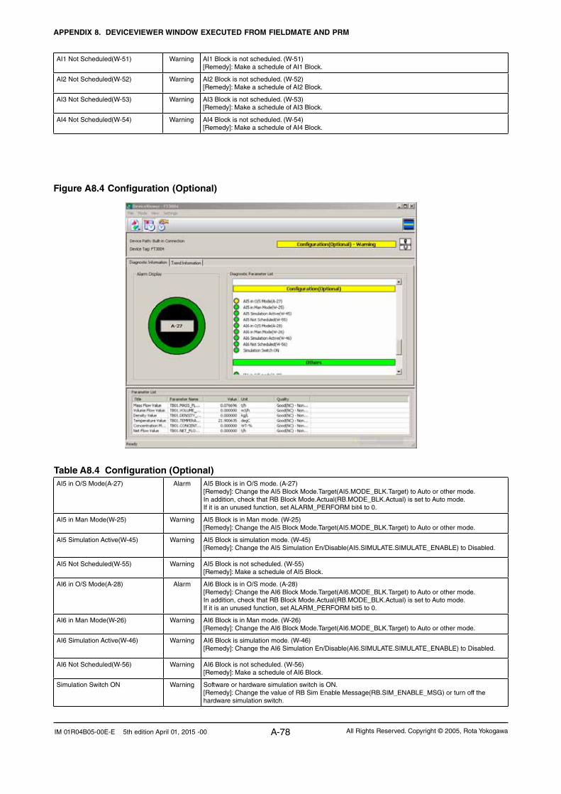
APPENDIX 8. DEVICEVIEWER WINDOW EXECUTED FROM FIELDMATE AND PRM
A-78 All Rights Reserved. Copyright © 2005, Rota YokogawaIM 01R04B05-00E-E 5th edition April 01, 2015 -00
Table A8.4 Configuration (Optional)AI5 in O/S Mode(A-27) Alarm AI5 Block is in O/S mode. (A-27)
[Remedy]: Change the AI5 Block Mode.Target(AI5.MODE_BLK.Target) to Auto or other mode. In addition, check that RB Block Mode.Actual(RB.MODE_BLK.Actual) is set to Auto mode. If it is an unused function, set ALARM_PERFORM bit4 to 0.
AI5 in Man Mode(W-25) Warning AI5 Block is in Man mode. (W-25) [Remedy]: Change the AI5 Block Mode.Target(AI5.MODE_BLK.Target) to Auto or other mode.
AI5 Simulation Active(W-45) Warning AI5 Block is simulation mode. (W-45) [Remedy]: Change the AI5 Simulation En/Disable(AI5.SIMULATE.SIMULATE_ENABLE) to Disabled.
AI5 Not Scheduled(W-55) Warning AI5 Block is not scheduled. (W-55) [Remedy]: Make a schedule of AI5 Block.
AI6 in O/S Mode(A-28) Alarm AI6 Block is in O/S mode. (A-28) [Remedy]: Change the AI6 Block Mode.Target(AI6.MODE_BLK.Target) to Auto or other mode. In addition, check that RB Block Mode.Actual(RB.MODE_BLK.Actual) is set to Auto mode. If it is an unused function, set ALARM_PERFORM bit5 to 0.
AI6 in Man Mode(W-26) Warning AI6 Block is in Man mode. (W-26) [Remedy]: Change the AI6 Block Mode.Target(AI6.MODE_BLK.Target) to Auto or other mode.
AI6 Simulation Active(W-46) Warning AI6 Block is simulation mode. (W-46) [Remedy]: Change the AI6 Simulation En/Disable(AI6.SIMULATE.SIMULATE_ENABLE) to Disabled.
AI6 Not Scheduled(W-56) Warning AI6 Block is not scheduled. (W-56) [Remedy]: Make a schedule of AI6 Block.
Simulation Switch ON Warning Software or hardware simulation switch is ON. [Remedy]: Change the value of RB Sim Enable Message(RB.SIM_ENABLE_MSG) or turn off the hardware simulation switch.
Figure A8.4 Configuration (Optional)
AI1 Not Scheduled(W-51) Warning AI1 Block is not scheduled. (W-51) [Remedy]: Make a schedule of AI1 Block.
AI2 Not Scheduled(W-52) Warning AI2 Block is not scheduled. (W-52) [Remedy]: Make a schedule of AI2 Block.
AI3 Not Scheduled(W-53) Warning AI3 Block is not scheduled. (W-53) [Remedy]: Make a schedule of AI3 Block.
AI4 Not Scheduled(W-54) Warning AI4 Block is not scheduled. (W-54) [Remedy]: Make a schedule of AI4 Block.

APPENDIX 8. DEVICEVIEWER WINDOW EXECUTED FROM FIELDMATE AND PRM
A-79All Rights Reserved. Copyright © 2005, Rota Yokogawa IM 01R04B05-00E-E 5th edition April 01, 2015 -00
Figure A8.5 Others
Table A8.5 OthersIT1 in O/S mode(A-29) Alarm IT1 Block is in O/S mode. (A-29)
[Remedy]: Change the IT1 Block Mode.Target(IT1.MODE_BLK.Target) to Auto or other mode. In addition, check that RB Block Mode.Actual(RB.MODE_BLK.Actual) is set to Auto mode. If it is an unused function, set ALARM_PERFORM bit6 to 0.
IT1 in Man mode(W-27) Warning IT1 Block is in Man mode. (W-27) [Remedy]: Change the IT1 Block Mode.Target(IT1.MODE_BLK.Target) to Auto or other mode.
IT1 Not Scheduled(W-57) Warning IT1 Block is not scheduled. (W-57) [Remedy]: Make a schedule of IT1 Block.
IT1 Conf. Err(W-71) Warning IT1 Clock Period(IT1.CLOCK_PER) is smaller than IT1 Period of Execution(EXECUTION_PERIOD). (W-71) [Remedy]: Change the value as IT1 Clock Period(IT1.CLOCK_PER) is larger than IT1 Period of Execution(EXECUTION_PERIOD).
IT1 Total Backup Err(W-73) Warning IT1 Total Backup failed. Last IT1 Output.Value(IT1.LAST.VALUE) could not save. (W-73) [Remedy]: Contact the nearest office or service center.
IT2 in O/S mode(A-30) Alarm IT2 Block is in O/S mode. (A-30) [Remedy]: Change the IT2 Block Mode.Target(IT2.MODE_BLK.Target) to Auto or other mode. In addition, check that RB Block Mode.Actual(RB.MODE_BLK.Actual) is set to Auto mode. If it is an unused function, set ALARM_PERFORM bit7 to 0.
IT2 in Man mode(W-28) Warning IT2 Block is in Man mode. (W-28) [Remedy]: Change the IT2 Block Mode.Target(IT2.MODE_BLK.Target) to Auto or other mode.
IT2 Not Scheduled(W-58) Warning IT2 Block is not scheduled. (W-58) [Remedy]: Make a schedule of IT2 Block.
IT2 Conf. Err(W-72) Warning IT2 Clock Period(IT2.CLOCK_PER) is smaller than IT2 Period of Execution(EXECUTION_PERIOD). (W-72) [Remedy]: Change the value as IT2 Clock Period(IT2.CLOCK_PER) is larger than IT2 Period of Execution(EXECUTION_PERIOD).
IT2 Total Backup Err(W-74) Warning IT2 Total Backup failed. Last IT2 Output.Value(IT2.LAST.VALUE) could not save. (W-74) [Remedy]: Contact the nearest office or service center.
PID in O/S mode(A-31) Alarm PID Block is in O/S mode. (A-31) [Remedy]: Change the PID Block Mode.Target(PID.MODE_BLK.Target) to Auto or other mode. In addition, check that RB Block Mode.Actual(RB.MODE_BLK.Actual) is set to Auto mode. If it is an unused function, set ALARM_PERFORM bit8 to 0.
PID in Bypass Mode(W-61) Warning PID Block is in Bypass mode. (W-61) [Remedy]: Change the value of Bypass(PID.BYPASS) to OFF.

APPENDIX 8. DEVICEVIEWER WINDOW EXECUTED FROM FIELDMATE AND PRM
A-80 All Rights Reserved. Copyright © 2005, Rota YokogawaIM 01R04B05-00E-E 5th edition April 01, 2015 -00
Table A8.6 Additional InformationMass Flow Value TB01.MASS_FLOW_VALUE FLOAT Mass flow value with status in Transducer Block
Volume Flow Value TB01.VOLUME_FLOW_VALUE FLOAT Volume flow value with status in Transducer Block
Density Value TB01.DENSITY_VALUE FLOAT Density value with status in Transducer Block
Temperature Value TB01.TEMPERATURE_VALUE FLOAT Temperature value with status in Transducer Block
Concentration Meas. Value TB01.CONCENTR_MEAS_VALUE FLOAT Concentration meas. value with status in Transducer Block. (Option /Cxx)
Net Flow Value TB01.NET_FLOW_VALUE FLOAT Net flow value with status in Transducer Block. (Option /Cxx)

All Rights Reserved. Copyright © 2005, Rota Yokogawa IM 01R04B05-00E-E 5th edition April 01, 2015 -00
Blank Page

All Rights Reserved. Copyright © 2005, Rota YokogawaIM 01R04B05-00E-E 5th edition April 01, 2015 -00
Subject to change without notice
Yokogawa has an extensive sales and distribution network. Please refer to the European website (www.yokogawa.com/eu) to contact your nearest representative.
Euroweg 23825 HD AMERSFOORTThe Netherlandswww.yokogawa.com/eu
YOKOGAWA ELECTRIC CORPORATIONWorld Headquarters9-32, Nakacho 2-chome, Musashino-shiTokyo 180-8750Japanwww.yokogawa.com
YOKOGAWA CORPORATION OF AMERICA2 Dart RoadNewnan GA 30265USAwww.yokogawa.com/us
YOKOGAWA ELECTRIC ASIA Pte. LTD.5 Bedok South RoadSingapore 469270Singaporewww.yokogawa.com/sg
YOKOGAWA CHINA CO. LTD.3F Tower D Cartelo Crocodile BuildingNo.568 West Tianshan Road Changing DistrictShanghai, Chinawww.yokogawa.com/cn
YOKOGAWA MIDDLE EAST B.S.C.(c)P.O. Box 10070, ManamaBuilding 577, Road 2516, Busaiteen 225Muharraq, Bahrainwww.yokogawa.com/bh


![Profibus PA Fieldbus Display [ Revision 2 ] and Fieldbus ... Instruments... · Profibus PA Fieldbus Display [ Revision 2 ] and Fieldbus Indicator Fieldbus Interface Guide. ... Siemens](https://static.fdocuments.in/doc/165x107/5b2fe38e7f8b9ae16e8da83d/profibus-pa-fieldbus-display-revision-2-and-fieldbus-instruments.jpg)