User’s Guidefiles.vivid-illumination.com/downloads/projector_user_manual/EPSO… · Indicates...
80
User’s Guide
Transcript of User’s Guidefiles.vivid-illumination.com/downloads/projector_user_manual/EPSO… · Indicates...

User’s Guide

1
h re accessories or optional equipment a
t care is not taken.
ow regarding a topic.
und. Click on the page number to
of this symbol appears in the orresponding entry in the
bered steps.
ontrol.
Not
Win
en "unit" or "projector" appears in the text of this User’s Guide, it may refer to items which addition to the main projector unit itself.
Indicates procedures which may result in damage or injury if sufficien
Indicates additional information and points which may be useful to kn
Indicates a page where useful information regarding a topic can be fodisplay that page.
Indicates that an explanation of the underlined word or words in frontglossary of terms. Click the underlined word or words to display the c"Glossary" section of the "Appendices". s page 68
Indicates operating methods and the order of operations.The procedure indicated should be carried out in the order of the num
[ (Name) ] Indicates the name of the buttons on the control panel or the remote cExample: [Esc] button
" (Menu Name) " Indicates configuration menu items.Example: "Image"-"Brightness"
s
PROCEDURE
ations Used in This Guide
cCaution:
QTip:
g

2Con
ProPar
sj
j
un
........................................................ 26ord Protect) .......................................... 26 Function............................................... 29
Menu ............................................. 32........................................................ 33............................................................... 33............................................................... 34............................................................... 36............................................................... 37............................................................... 39............................................................... 40
........................................................ 42
........................................................ 44
............................................................... 44rovide No Help ...................................... 47
........................................................ 56r ............................................................ 56........................................................ 57............................................................... 57s ............................................................ 58........................................................ 64
AdjuAd
AdCh
UsefFu
tents
jector Features..................................................................4t Names and Functions.....................................................6Front/Top .................................................................................... 6Control Panel .............................................................................. 7Rear (EMP-X3)........................................................................... 8Rear (EMP-82/62)....................................................................... 9Base........................................................................................... 10Remote Control ......................................................................... 11
ting and changing the imageusting the Image Quality .................................................13Adjusting Computer Images and RGB Video Images.............. 13Selecting the Projection Quality (Color Mode) ........................ 15usting the Volume ...........................................................17anging the Projected Image (Source Search)..................18Automatically Detect Incoming Signals and Change the Projected Image (Source Search)....................................... 18
Changing Directly from the Remote Control............................ 18
l Functionsctions for Enhancing Projection......................................20
Pausing the Image and Sound (A/V Mute) ............................... 20Freezing the Image (Freeze) ..................................................... 20Changing the Aspect Ratio (Resizing)...................................... 21Displaying the Pointer (Pointer) ............................................... 21Enlarging Part of the Image (E-Zoom) ..................................... 22Using the Remote Control to Operate the Mouse Pointer (Wireless Mouse)..................................................................... 23
Security functions.........Preventing theft (PasswOperation Button Lock
Configuration MenuUsing the ConfigurationList of Functions...........
"Image" Menu ............"Signal" Menu ............"Settings" Menu ........."Extended" Menu ......."Info" Menu................"Reset" Menu .............
TroubleshootingUsing the Help .............Problems Solving .........
Reading the IndicatorsWhen the Indicators P
AppendicesInstallation....................
Setting Up the ProjectoMaintenance ................
Cleaning .....................Replacing Consumable
Saving a User's Logo ...

3Conte
Co
OpGloLis
LisSpeApp
Ind
nts
nnecting to External Output Equipment ...........................66Connecting to an External Monitor........................................... 66Connecting to an external speaker (when using the EMP-82/62)................................................... 66
tional Accessories and Consumables..............................67ssary ...............................................................................68
t of ESC/VP21 Commands ..............................................70Command List........................................................................... 70Cable Layouts ........................................................................... 70USB Connection Setup ............................................................. 71t of Supported Monitor Displays.......................................72cifications .......................................................................73earance ..........................................................................76
EMP-X3 .................................................................................... 76EMP-82/62................................................................................ 77ex.....................................................................................78

4Pro
Yoin
h
le
m
c
eo
jector power on and off a “Beep” soundse power is turned on, after the cooling downfirmation buzzer beeps twice. Once you hear
ep twice, you can unplug the power cable.
P-82/62 only)eates a comfortable volume for a classroom org about 30 people without having to use an
P-82/62 only)ideo input ports allowing you to connect twoment at the same time. Also, the projector has
computers and video equipment so the audioen the image is changed.
Colou
su
TbyAth
SSina
EFoje
Al
Y
Direc
Ease
jector Features
u can enjoy images of "Photos", "Presentations", "Games", and so on,the optimum colour tone by choosing the most suitable mode for yourrroundings. s page 15
e direct power on function means you can turn the projector on simply plugging the power cable into the electrical outlet. s page 38so, with the instant-off function you can finish quickly by unplugging power cable immediately after use.
ource search allows you to easily choose the image to projectply by pressing the "Source Search" button, the connected picture sig-
l is automatically detected and projected.
asy to use, big button control panelr ease of use, buttons are classified and arranged according to their pro-tion and adjustment functions. s page 7
single foot design means you do not have to make any difficult veling adjustmentsu can easily make height adjustments with one hand.
When you turn the proA “Beep” sounds when thperiod has finished the conthe confirmation buzzer be
Built-in 5W speaker (EMThe built-in 5W speaker crconference room containinexternal speaker.
Extensive interface (EMThe EMP-82/62 has four vcomputers and video equipaudio input ports for bothswitches automatically wh
r Mode
t Power On & Instant Off
of Use
Setup Projection in Progress Troubleshooting

5Projec
MYo
Oth
Thwh
Secu
tor Features
anage users with password protectu can set up a password to restrict the use of the projector. s page 26
peration lock stops the use of all control panel buttons except for e Power buttonis can prevent your settings being changed by accident or on purpose,en using the projector at an event, at a school, and so on. s page 29
rity Function

6Par
Fron
• Remote control light-receiving area Receives signals from the remote control.
• Lens coverAttach when not using the projector to prevent the lens from becoming dirty or damaged.
• Focus ring Adjusts the image focus.e
to
c
c
• Security lock ( ) s page 69
• Zoom ringAdjusts the image size.
• Con
• Air
c CauDo nimmeproje
• LamOpenproje
t Names and Functions
t/Top
trol panel s page 7
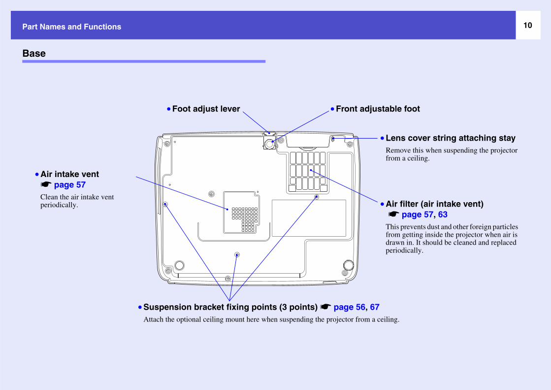
• Front adjustable footExtend and retract to adjust the projection angle when the projector is placed on a surface such as a shelf.
• Foot adjust leverPull out the foot lever to extend and retract the front foot.
xhaust vent
ion:t touch the exhaust vent diately after projecting, or while ting, since it becomes hot.
p cover s page 59 this cover when replacing the tor's lamp.
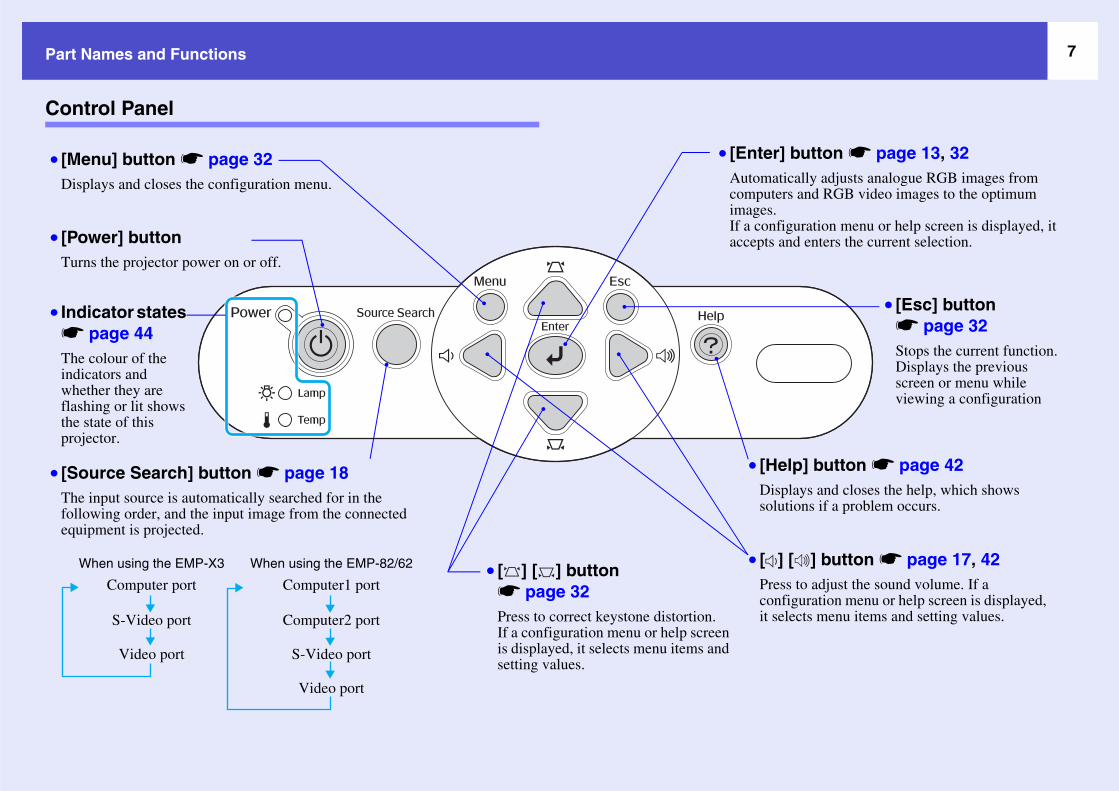
7Part N
Cont
• [PowTurn
elp] button s page 42splays and closes the help, which shows utions if a problem occurs.
• [MeDisp
• [Esc] button s page 32Stops the current function.Displays the previous screen or menu while viewing a configuration
• [SouThe ifolloequip
W
] button s page 13, 32tically adjusts analogue RGB images from ers and RGB video images to the optimum
figuration menu or help screen is displayed, it and enters the current selection.
] [ ] button s page 17, 42ss to adjust the sound volume. If a figuration menu or help screen is displayed, elects menu items and setting values.
• Indis pThe cindicwhetflashthe sproje
ames and Functions
rol Panel
er] button s the projector power on or off.
• [HDisol
nu] button s page 32lays and closes the configuration menu.
rce Search] button s page 18nput source is automatically searched for in the wing order, and the input image from the connected ment is projected.
Computer port
S-Video port
Video port
Computer2 port
S-Video port
Video port
Computer1 port
hen using the EMP-X3 When using the EMP-82/62
• [EnterAutomacomputimages.If a conaccepts
• [ ] [ ] button s page 32Press to correct keystone distortion.If a configuration menu or help screen is displayed, it selects menu items and setting values.
• [Preconit s
cator states age 44
olour of the ators and her they are ing or lit shows tate of this ctor.

8Part N
Rear
• Remote control light-receiving area Receives signals from the remote control.
• PowConn
• ComInputcompcompsourc
B port s page 23, 70nects the projector to a computer via the
Bg cable when using the wireless mouse ction.mputer images cannot be projected using the USB cable to connect the puter.
• MonOutpRGBexterconnfeatusigna
r
• Rea
ames and Functions
(EMP-X3)
er inlet ects to the power cable.
puter port s analogue RGB video signals from a uter and RGB video signals and onent videog signals from other video es.
• Video port Inputs composite videog signals to the projector from other video sources.
• S-Video port Inputs S-Videog signals to the projector from other video sources.
• USConUSfunCoby com
itor Out port s page 66uts the projected computer's analogue signals or RGB video signals to an nal monitor from the source that is ected to the Computer port. This re is not available for video equipment ls.
• Speake
r adjustable foot • Audio portInput audio signals from connected external equipment.When you are connecting two or more pieces of external equipment that use the same input port, you need to disconnect one before connecting the other, or use an audio selector.

9Part N
Rear
• Remote control light-receiving areaReceives signals from the remote control.•
o port composite videog signals to the projector from video sources.
eo port ts S-Videog signals to the projector
port s page 23, 70cts the projector to a computer via the USBg when using the wireless mouse function.uter images cannot be projected by the tor by using the USB cable to connect the
uter.
• MoOutsignmoComvid
• Speaker
• AuThisele
o port used to input audio signals from the equipment connected to the S-Video or Video port.
• AuThifromcon
•
• CoInpfromsignsign
ames and Functions
(EMP-82/62)
Power inlet Connects to the power cable.
• Computer2 port Inputs analogue RGB video signals from a computer and RGB video signals and component videog signals from other video sources. • Vide
Inputsother
• S-Vid• Inpu
• USBConnecable Compprojeccomp
nitor Out port s page 66puts the projected computer's analogue RGB als or RGB video signals to an external
nitor from the source that is connected to the puter1 port. This feature is not available for
eo equipment signals.
• RS-232C port s page 71Connects the projector to a computer using an RS-232C cable. This port is for control use and should not normally be used.
dio Out port s outputs the audio signals from the currently-cted input source to external speakers.
• AudiThis isthat is
dio port s is used to input audio signals
the equipment that is nected to the Computer1 port.
• Audio port This is used to input audio signals from the equipment that is connected to the Computer2 port.
Rear adjustable foot
mputer1 port uts analogue RGB video signals
a computer and RGB video als and component videog als from other video sources.
10Part N
Base
Air filter (air intake vent) s page 57, 63This prevents dust and other foreign particles from getting inside the projector when air is drawn in. It should be cleaned and replaced periodically.
iling.
table foot
Lens cover string attaching stayRemove this when suspending the projector from a ceiling.
• As
Cp
ames and Functions
•
• Suspension bracket fixing points (3 points) s page 56, 67Attach the optional ceiling mount here when suspending the projector from a ce
• Front adjus
•
• Foot adjust lever
ir intake vent page 57
lean the air intake vent eriodically.

11Part N
Remo
ThIf
• [Vi
• [S-
c buttons s page 26
control light-emitting area
• [A/
• [E-
• [En
• [Es
• [Au
button s page 32
] button
Mode] button s page 15
tons s page 24, 32
] button s page 20
• [Pa
• [Co ] button s page 21
• [Po
] button s page 18
utton s page 42
e] buttons s page 17
utton s page 26
• [Co
• [Co
ames and Functions
te Control
e following explains the functions shown in the illustration of the EMP-82/62 remote control.you position the over the button icon or button name, a description of that button will appear.
deo] button s page 18
Video] button s page 18
• Numeri
• Remote
V Mute] button s page 20
Zoom] button ( ) ( ) s page 22
ter] button s page 24, 32
c] button s page 24, 32
to] button s page 13
• [Menu]
• [Power
• [Color
• [ ] but
• [Freeze
ge down] [Page up] buttons s page 24
mputer1] button (EMP-82/62 only) s page 18 • [Resize
inter] button s page 21
• [Search
• [Help] b
• [Volum
• [Num] b
mputer2] button (EMP-82/62 only) s page 18
mputer] button (EMP-X3 only) s page 18

Adj g an ageThis chapt to adjust the n and so on, and also how to change the image.
Adjusti e Quality• Adjus r Images an
•Auto .....................•Adju g .................•Adju .....................
• Select tion Quality(Colo
lume.......................................... 17
rojected Image (Source Search) ..
etect Incoming Signals and Change the (Source Search)18ly from the Remote Control................... 18
ustiner explains how
ng the Imagting Computematic Setup ......sting the Trackinsting the Sync...ing the Projecr Mode)15
d changing the imquality of the image, the volume, the colour mode selectio
.............................. 13d RGB Video Images.....13
............................................. 13
............................................. 13
............................................. 14
Adjusting the Vo
Changing the P18
• Automatically DProjected Image
• Changing Direct
13Adj
Adju
Aut
t
Ar i
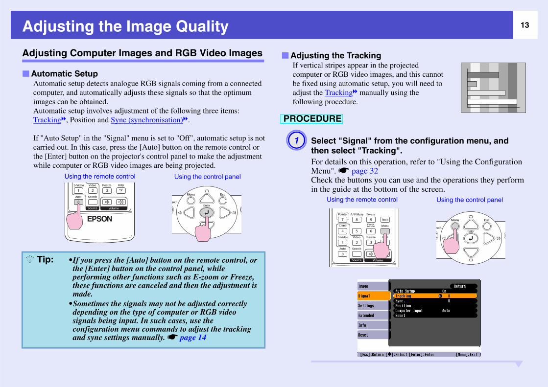
he projected ges, and this cannot up, you will need to lly using the
om the configuration menu, and ing".eration, refer to "Using the Configuration
u can use and the operations they perform ttom of the screen.
Aut
ontrol Using the control panel
i
comimaAuTra
If "carthewh
Q T
usting the Image Quality
sting Computer Images and RGB Video Images
omatic setup detects analogue RGB signals coming from a connected puter, and automatically adjusts these signals so that the optimum ges can be obtained.omatic setup involves adjustment of the following three items:ckingg, Position and Sync (synchronisation)g.
uto Setup" in the "Signal" menu is set to "Off", automatic setup is not ied out. In this case, press the [Auto] button on the remote control or [Enter] button on the projector's control panel to make the adjustment le computer or RGB video images are being projected.
If vertical stripes appear in tcomputer or RGB video imabe fixed using automatic setadjust the Trackingg manuafollowing procedure.
Select "Signal" frthen select "TrackFor details on this opMenu". s page 32Check the buttons yoin the guide at the bo
omatic Setup
•If you press the [Auto] button on the remote control, or the [Enter] button on the control panel, while performing other functions such as E-zoom or Freeze, these functions are canceled and then the adjustment is made.
•Sometimes the signals may not be adjusted correctly depending on the type of computer or RGB video signals being input. In such cases, use the configuration menu commands to adjust the tracking and sync settings manually. s page 14
Using the remote control Using the control panel
Adjusting the Tracking
A1
Using the remote c
PROCEDURE
p:

14Adjus
terference appear in ges, and this cannot up, you will need to tion)g manually re.
om the configuration menu, and .".eration, refer to "Using the Configuration
u can use and the operations they perform ttom of the screen.
A2
A3ontrol Using the control panel
Q Ti
ting the Image Quality
Adjust the tracking until the vertical stripes disappear from the image.
The tracking value increases or decreases each time a button is pressed.
Press the [Menu] button to exit the configuration menu.
If flickering, fuzziness or incomputer or RGB video imabe fixed using automatic setadjust the Sync (synchronisausing the following procedu
Select "Signal" frthen select "SyncFor details on this opMenu". s page 32Check the buttons yoin the guide at the bo
The image will flash when continuous tracking adjustment is carried out, but this is normal.
Using the remote control Using the control panel
Adjusting the Sync
PROCEDURE
A1
Using the remote c
p:

15Adjus
on Quality
olour modes are available for use depending images that are being projected. You can easily uality simply by selecting the colour mode that images. The brightness of the images will lour mode is selected.
A2
A3
Applicationand RGB video images are being input)ivid and brought into contrast. Ideal for projecting as photos, in a bright room.t video, S-video, or composite video images are
ivid and brought to life. Ideal for watching TV so on in a bright room.resentations in a bright roomtural tone. Ideal for watching films in a dark room.ising dark gradations. Ideal for playing video room.hat conform to the sRGB colour standardrojecting onto a blackboard (green board), this images a natural tint, just like when projecting
Q Ti
ting the Image Quality
Adjust the synchronization until the horizontal noise disappears from the image.
The sync value increases or decreases each time a button is pressed.
Press the [Menu] button to exit the configuration menu.
Selecting the Projecti(Color Mode)
The following seven preset con the characteristics of the obtain the optimum image qcorresponds to the projectedvary depending on which co
•If you adjust the sync without adjusting the trackingg first, it will not be possible to get the best adjustment results. Incorrect tracking adjustment may not be noticeable with some types of picture. However, pictures with lots of lines and shading will tend to show incorrect tracking adjustments more clearly, so check the tracking adjustment first.
•Flickering and fuzziness may also occur when the brightness, contrastg, sharpness, zoom, and keystone correction settings are adjusted.
Using the remote control Using the control panel
ModePhoto (When computer
The images are vstill pictures, such
Sports (When componenbeing input)The images are vprogrammes and
Presentation Ideal for giving pTheatre Gives images a naGame Excels at emphas
games in a brightsRGBg Ideal for images tBlackboard Even if you are p
setting gives youronto a screenp:

16Adjus
EacfollThetimdispsett
PRO
Q Ti
ting the Image Quality
h time you press the button, the colour modes change in the owing order. current setting appears in the top-right corner of the screen each e the colour mode is changed. While the colour mode name is layed on the screen, it does not change to the next colour mode
ing unless you press the button.
The colour mode can also be set using the "Color Mode" command in the "Image" menu. s page 33
CEDURE
Remote control
p:

17Adj
The vo
eu
PRO
i
WhandThadj
Q T
usting the Volume
lume of the projector's built-in speaker can be adjusted as follows.
en the button is pressed to the [ ] side, the volume increases, when it is pressed to the [ ] side, the volume decreases. volume gauge appears on the screen when the volume is being sted.
•If the value displayed in the gauge on the screen stops changing when the volume is being adjusted, it indicates that the limit for volume adjustment has been reached.
•The volume can also be adjusted using the configuration menu. s page 36
CEDURE
Using the remote control Using the control panel
p:
18Cha
Autothe P
Thee
m the Remote Control
rol to change directly to the target input
eo equipment is connected, start
screen is displayed when only the picture d now is input, or when no picture signal an choose the input source from this
When using the EMP-X3
Changes to the image from the Video port.
Remote Control
det
PRO
A1
A2
nging the Projected Image (Source Search)
matically Detect Incoming Signals and Change rojected Image (Source Search)
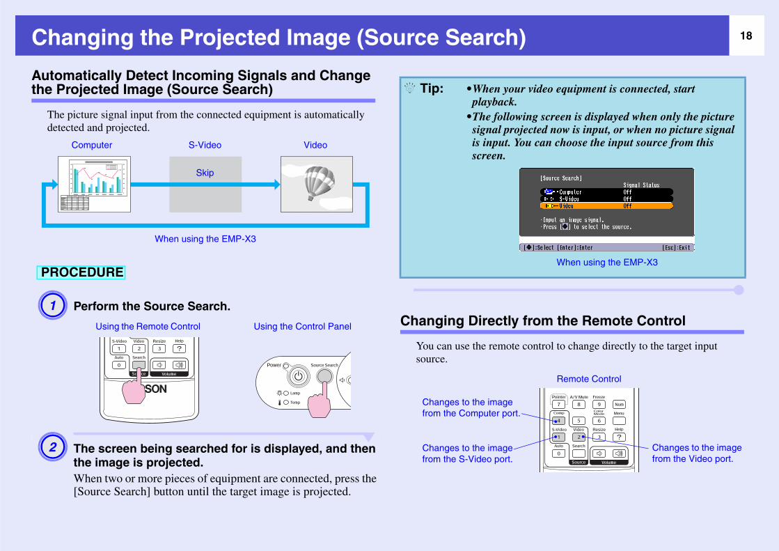
picture signal input from the connected equipment is automatically cted and projected.
Perform the Source Search.
The screen being searched for is displayed, and then the image is projected.When two or more pieces of equipment are connected, press the [Source Search] button until the target image is projected.
Changing Directly fro
You can use the remote contsource.
Computer S-Video Video
Skip
When using the EMP-X3
CEDURE
Using the Remote Control Using the Control Panel
•When your vidplayback.
•The following signal projecteis input. You cscreen.
Changes to the image from the Computer port.
Changes to the image from the S-Video port.
Q Tip:

Useful FunThis chapter explains useful functi ns.
Functio cin• Pausi Sou• Freez eeze• Chan atio• Displa (Po• Enlar mag• Using trol
(Wire
ns............................................... 26 (Password Protect) ................................. 26Protect is Enabled ............................................26 Protect ............................................................27n Lock Function...................................... 29
ns for Enhanng the Image anding the Image (Frging the Aspect Rying the Pointer
ging Part of the I the Remote Conless Mouse)23
ctionsons for giving presentations and so on, and the security functio
g Projection ................. 20nd (A/V Mute) .......................20) ...............................................20 (Resizing)...............................21inter) ........................................21e (E-Zoom) .............................22to Operate the Mouse Pointer
Security functio• Preventing theft
•When Password •Setting Password
• Operation Butto

20Fun
Paus
Formom
a
u
reeze)
to project even when the screen is frozen. You such as changing files, without projecting any
n or off by pressing the [Freeze] button.
t stop.he image on the screen is frozen, the ontinues to project, and so it is not
ume projection from the point where it
reeze] button also clears configuration and help messages.ction still works while the E-Zoom ng used.
i
youdet
Yo
PRO
Q T
ctions for Enhancing Projection
ing the Image and Sound (A/V Mute)
example, this can be used if you want to pause the projection for a ent and focus the audience’s attention on what you are saying. Or if
are making a computer presentation and you do not want to show ils, such as selecting different files.
can turn this function on or off by pressing the [A/V Mute] button.
Freezing the Image (F
The source image continuescan still perform operations images.
You can turn this function o
•If you use this function when projecting moving images, the images and sound will still continue to be played back by the source, and you cannot return to the point where the A/V mute function was activated.
•The screen display in A/V mute can be chosen from black, blue, or a logo by using "Extended" -"Display" - "A/V Mute" in the configuration menu.
CEDURE
Remote control
•Sound does no•Even though timage source cpossible to reswas paused.
•Pressing the [Fmenu displays
•The freeze funfunction is bei
PROCEDURE
Remote control
p:
Q Tip:

21Functi
Chan
ThicomproImaview
The
r (Pointer)
ointer icon on the projected image, and helps a you are talking about.
r.
the button the pointer appears or
PROl
Q Ti
ons for Enhancing Projection
ging the Aspect Ratio (Resizing)
s function changes the aspect ratiog of images from 4:3 to 16:9 when ponent videog, S-Videog, or composite videog images are being
jected. ges which have been recorded in digital video or onto DVDs can be ed in 16:9 wide-screen format.
display is changed whenever you press the button.
Displaying the Pointe
This allows you to move a pyou draw attention to the are
Display the pointe
Each time you pressdisappears.
You can also make this setting using the "Resize" command in the "Signal" menu.
When images in squeeze mode are projected at 16:9
When images in Squeeze modeg are projected at 4:3
CEDURE
Remote control
PROCEDURE
A1Remote contro
p:

22Functi
Image (E-Zoom)
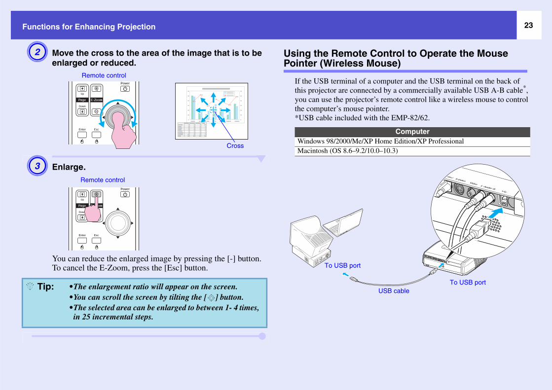
t to see images in greater detail, such as graphs
A2
ol
Q Ti
ons for Enhancing Projection
Move the pointer icon. Enlarging Part of the
This is useful when you wanand details in a table.
Start E-Zoom.
You can use the "Pointer Shape" command in the "Settings" menu to change the shape of the pointer to one of three different shapes. s page 36
Pointer icon
Remote control
PROCEDURE
A1Remote contr
p:
23Functi
ntrol to Operate the Mouse se)
puter and the USB terminal on the back of by a commercially available USB A-B cable*, emote control like a wireless mouse to control er.e EMP-82/62.
A2
A3
Computerme Edition/XP Professional10.3)
SB cableTo USB port
Q Ti
ons for Enhancing Projection
Move the cross to the area of the image that is to be enlarged or reduced.
Enlarge.
You can reduce the enlarged image by pressing the [-] button.To cancel the E-Zoom, press the [Esc] button.
Using the Remote CoPointer (Wireless Mou
If the USB terminal of a comthis projector are connected you can use the projector’s rthe computer’s mouse point*USB cable included with th
•The enlargement ratio will appear on the screen.•You can scroll the screen by tilting the [ ] button.•The selected area can be enlarged to between 1- 4 times, in 25 incremental steps.
Remote control
Cross
Remote control
Windows 98/2000/Me/XP HoMacintosh (OS 8.6–9.2/10.0–
U
To USB port
p:

24Functi
n made, the mouse pointer can be operated as
ter Mouse clicks
This is useful for displaying the previous or next slide in a PowerPoint slideshow.
Double-click: Press twice in rapid succession.
Left click Right click
tton tton.n to
To previous slide
To next slide
Q Ti
ons for Enhancing Projection
Once the connection has beefollows.•The USB cable can only be connected to computers
with a standard USB interface. If using a computer which is running Windows, the computer must have had a full version of Windows 98/2000/Me/XP Home Edition/XP Professional installed. If the computer is running a version of Windows 98/2000/Me/XP Home Edition/XP Professional that has been upgraded from an earlier version of Windows, correct operation cannot be guaranteed.
•It may not be possible to use the mouse function under some versions of both the Windows and Macintosh operating systems.
•Some computer settings may have to be changed in order for the mouse function to be used. Consult the documentation for the computer for further details.
Moving the mouse poin
Drag and drop
1. Hold down the [Enter] buand tilt and drag the [ ] bu2. Release the [Enter] buttodrop at the desired location.
p:
25Functi
Q Ti
ons for Enhancing Projection
•If the mouse button settings are set to reverse on the computer, the operation of the remote control buttons will also be reversed.
•The wireless mouse function cannot be used while the following functions are being used.· While a configuration menu is being displayed · While a help menu is being displayed· While the E-Zoom function is being used· While a user's logo is being captured· Pointer function· While adjusting sound volume
p:

26Sec
Preve
Whthe
e
r
r
connected to the electrical outlet and turn the t is in standby mode, projection will start screen appearing. The password entry screen the power is turned on for the first time after connected and then reconnected. If Direct you are using a circuit breaker or similar to the password entry screen will be displayed the ned on after the power supply is restored.
password is entered three times in message "The projector’s operation will
ll be displayed for approximately five hen the projector will switch to standby appens, disconnect the power plug from utlet and then reinsert it and turn the er back on. A window requesting you to ord will be displayed, so enter the
rd.to forget the password, make a note of the e: xxxxx" number that appears in the en and contact the nearest address "International Warranty Conditions" afety Instructions/World-Wide Warranty
.e to repeat the above operation and input sword thirty times, the following message ed and the projector will not accept es any more.
r’s operation will be locked. Contact the s provided in the "International ditions" section of the Safety orld Wide Warranty Terms booklet."
powFurscrpur
WWhcabcar
Whto esta
Wh
urity functions
nting theft (Password Protect)
en the Password Protect function is activated, people who do not know password will not be able to use the projector to project images, if the er has been disconnected since the password was last entered correctly.
thermore, the user's logo that is displayed on the background of the en cannot be changed. This is effective against theft. At the time of
chase, the password protection function is not enabled.
hen "Power On Protect" is enabled (On)en the power is turned on for the first time after the projector's power le is connected to an electrical outlet, or when Direct Power On is ied out, the following password entry screen will be displayed.
ile holding down the [Num] button, press the numeric keypad buttons nter the password. If the password is entered correctly, projection will t.
If you leave the power cableprojector's power on when iwithout the password entry will only be displayed whenthe power cable has been disPower On is set to "On" andcentrally control the power, first time the projector is tur
en Password Protect is Enabled
Remote control
Numeric buttons
Keep Pressed
•If an incorrectsuccession, thebe locked." wiminutes, and tmode. If this hthe electrical oprojector's powenter the passwcorrect passwoIf you happen "Request CodPassword screprovided in thesection of the STerms booklet
•If you continuthe wrong paswill be displaypassword entri"The projectonearest addresWarranty ConInstructions/W
Q Tip:

27Secur
WTheturnset eactotaproIf "Pdispelecthe
WIf aopecha• Ca• W
"E"B
• W"O
to set Password Protect.
reeze] button for approximately 5
ct" menu will be displayed.
rotect" on.n Protect", and then press the [Enter]
d then press the [Enter] button.button.
ect
otect has already been enabled, the reen will be displayed.
d has been entered correctly, the tect" menu will be displayed.
ssword Protect is enabled" page 26otect is set to "On", attach the accessory ect sticker to your preferred position on s a theft-prevention measure.
l
ity functions
hen "Password Timer" is set to "On" and "Timer" is used password entry screen will not be displayed at all when the power is ed on until the length of time that has been set has elapsed. When the
length of time has elapsed, the password entry screen will be displayed h time the power is turned on. The length of time referred to here is the l illumination time for the projector's lamp from the point when the jector's menu is closed.
assword Timer" is set to "Off", the password entry screen will be layed each time the power plug is disconnected and reinserted from the trical outlet. If the projector’s power is on when it is in standby mode, password entry screen will not be displayed.
hen "User’s Logo Protect" is enabled (On)n attempt is made to carry out any of the following user logo rations, a message is displayed and the setting cannot be changed. To nge the setting, set "User’s Logo Protect" to "Off" first. s page 28pturing a user's logohen the "Extended" - "Display" - "Display Background" menu , or the xtended" - "Display" - "A/V Mute" menu, is changed from "Logo" to lack" or "Blue", or changed from "Black" or "Blue" to "Logo".hen the "Extended" - "Display" - "Startup Screen" menu ("On" or ff") is changed.
Use the following procedure
Hold down the [Fseconds.The "Password Prote
Turn "Power On P(1) Select "Power O
button.(2) Select "On", an(3) Press the [Esc]
Setting Password Prot
•If Password Pr"Password" scIf the passwor"Password Pros "When Pa
•If Password PrPassword Protthe projector a
PROCEDURE
A1
Remote contro
A2
Q Tip:

28Secur
rd.rd, select "Password" and then press the
hange the password?" will be displayed, and then press the [Enter] button. The or the password is "0000", but you should our own desired password. If you select shown at step 1 will be displayed again.own the [Num] button, use the numeric to enter a 4-digit number. The number displayed as "* * * *". Once four digits ed, the confirmation screen will be
ssword.he new password is stored." will be
u enter the password incorrectly, a message d prompting you to re-enter the password.
A3
A4
ity functions
Turn "Password Timer" on.If you don't use this setting, proceed to step 4.(1) Select "Password Timer", and then press the [Enter]
button.(2) Select "On", and then press the [Enter] button.(3) Press the [Esc] button.(4) Select "Timer" and then press the [Enter] button.(5) While holding down the [Num] button, use the numeric
keypad buttons to enter the setting time within the range of 1 to 9999 hours and then press the [Enter] button.If you make a mistake entering the time, press the [Esc] button and re-enter the time.When you have finished using the "Password Protect" menu, the countdown for the elapsed time will start.
Turn "User’s Logo Protect" on.(1) Select "User’s Logo Protect", and then press the [Enter]
button.(2) Select "On", and then press the [Enter] button.(3) Press the [Esc] button.
Enter the passwo(1) To set a passwo
[Enter] button.(2) The message "C
so select "Yes" default setting fchange this to y"No", the screen
(3) While holding dkeypad buttons entered will be have been enterdisplayed.
(4) Re-enter the paThe message "Tdisplayed. If yowill be displaye
A5

29Secur
Oper
ThiThiprosuc
f the buttons on the control panel except an be operated.
PRO
A1Using the control panelontrol
ity functions
ation Button Lock Function
s function locks the buttons on the projector's control panel.s function is useful at times such as during show events so that only jection is carried out deactivating all buttons operation, or in places h as schools to limit the range of buttons that can be operated.
From the configuration menu, select "Settings" - "Operation Lock".For details on this operation, refer to "Using the Configuration Menu". s page 32Check the buttons you can use and the operations they perform in the guide at the bottom of the screen.
Set to "On".If set to "On", none othe [Power] button c
CEDURE
Using the remote control Using the control panel
A2
Using the remote c

30Secur
A3
Q Ti
ity functions
When the confirmation message is displayed, select "Yes".The control panel buttons will be locked in accordance with the selected setting.
There are two methods to cancel the projector's control panel lock.•Using remote control, change the "Settings" - "Operation Lock" in the configuration menu to "Off" .
•Hold down the projector's [Enter] button continuously for about 7 seconds, a message will be displayed and the lock will be cancelled.
p:

ConfiguratioThis chapter explains how to use the co
Using t e
List of F ....• "Ima .....• "Sign .....• "Setti .....• "Exte .....• "Info .....• "Rese .....
he Configuration M
unctions.............ge" Menu......................al" Menu......................ngs" Menu...................nded" Menu ................" Menu .........................t" Menu.......................
n Menunfiguration menu and its functions.
nu........................... 32
................................ 33..........................................33..........................................34..........................................36..........................................37..........................................39..........................................40

32Usi
A1
Using the remote control
Using the control panel
Select the setting to change.
Buttons used
ng the Configuration Menu
Selecting from the top menu
Changing theselected item
A3Selecting from the sub menu
A2
Top menu
Sub menu (Settings)
guide

33Lis
"Imag
The ls are saved separately for each source.
b
t
a
the image tint.
select "Low", images appear reddish. "Image" menu.)
rom 5000 K to 10000 K. (EMP-82/62 only)
"Image" menu.)
Comp videog/ S-Videog
Su
Color
Brigh
Contr
Color
Tint
Sharp
Color(EMP
ColorAdjus
Reset
t of Functions
e" Menu
items that can be set will vary depending on the input source that is currently being projected. Setting detai
-menu Function
Mode Select the quality of the image to suit your surroundings. s page 15
ness Adjusts the image brightness.
stg Adjusts the difference between light and shade in the images.
Saturation Adjusts the colour saturation for the images.
(Adjustment is only possible when component video or NTSC signals are being input.) Adjust
ness Adjusts the image sharpness.
Temp.g-X3 only)
You can adjust the overall tint of images. If you select "High", images appear bluish, and if you(This item cannot be selected if "sRGBg" has been selected as the "Color Mode" setting in the
tmentAdjusts the red, green, and blue colour strength of the image.Abs. Color Temp.: You can adjust the overall tint of images. You can adjust tints in 10 stages fRed: Adjust the saturation of the red component.Green: Adjusts the saturation of the green component.Blue: Adjusts the saturation of the blue component.(This item cannot be selected if "sRGBg" has been selected as the "Color Mode" setting in the
Resets all adjustment values for the "Image" menu functions to their default settings.If you would like to return all menu items to their default, see "Reset All". s page 40
uter/RGB video Component videog/ Composite
Screen shot from EMP-X3 Screen shot from EMP-X3

34List of
"Sign
Th ails are saved separately for each source.
Sub-
Auto S nput source is changed is turned "On" or
Track
Sync.g 14
Positio
Progremages with a large amount of movement. viewing still images.
CompInput X3 on connected equipment manually.
CompInput 82/62 connected equipment manually.
CompInput 82/62 connected equipment manually.
Comp osite videog/ S-Videog
Functions
al" Menu
e items that can be set will vary depending on the input source that is currently being projected. Setting det
menu Function
etup Selects whether the automatic adjustment function for automatically optimising images when the i"Off". s page 13
ingg Adjusts computer images when vertical stripes appear in the images. s page 13
Adjusts computer images when flickering, fuzziness or interference appear in the images. s page
n Moves the image display position vertically and horizontally.
ssive (Adjustment is only possible when composite Video or S-Video signals are being input.)Off: IP conversion is carried out for each field in the screen. This is ideal for using when viewing iOn: Interlacedg (i) signals are converted into progressiveg (p) signals. This is ideal for using when
uter (EMP-ly)
Selects the input signal in accordance with the equipment that is connected to the Computer port.If set to "Auto" the input signal is set automatically in accordance with the connected equipment.If the colours do not appear correctly when you select "Auto", select the appropriate signal for the
uter1 (EMP-only)
Selects the input signal in accordance with the equipment that is connected to the Computer1 port.If set to "Auto" the input signal is set automatically in accordance with the connected equipment.If the colours do not appear correctly when you select "Auto", select the appropriate signal for the
uter2 (EMP-only)
Selects the input signal in accordance with the equipment that is connected to the Computer2 port.If set to "Auto" the input signal is set automatically in accordance with the connected equipment.If the colours do not appear correctly when you select "Auto", select the appropriate signal for the
uter/RGB video Component videog Comp
Screen shot from EMP-X3 Screen shot from EMP-X3

35List of
Video
e projected images or no images appear when
Resize
Reset t", "Computer1 Input", and "Computer2
Sub-
Functions
Signal (Adjustment is only possible when composite video/S-Video signals are being input.)Sets the video signal format.With the "Auto" function, image signals are recognized automatically. If interference appears in thyou select "Auto", select the appropriate signal manually.
Sets the aspect ratiog for projected images. s page 21
Resets all adjustment values on the "Signal" menu to their default settings, except "Computer InpuInput".If you would like to return all menu items to their default, see "Reset All". s page 40
menu Function

36List of
"Sett
Sub-
Keysto
Auto Keysto(EMPonly)
Off" when the projector is tilted vertically.ront". If it is set to something other than
OperaLock
r] button will be disabled. s page 29
PointeShape
BrightContro room or onto a small screen.
ed and noise produced during projection are ption: about an 35 W decrease, lamp life:
Volum
Reset
Functions
ings" Menu
menu Function
ne Corrects vertical keystone distortion in images.
ne -82/62
Sets the function for automatically detecting the projector angle and correcting keystone "On" or "This function is only enabled when the "Projection" command in the "Extended" menu is set to "F"Front", this menu cannot be selected.
tion When set to "On", the operation of all buttons on the projector's control panel except for the [Powe
r The shape of the pointer can be selected. s page 21Pointer 1: Pointer 2: Pointer 3:
ness l
This lets you set the lamp brightness to one of two settings.Select "Low" if the images being projected are too bright such as when projecting images in a darkWhen "Low" is selected, the brightness of the images is reduced, the amount of electricity consumreduced, and the lamp's operating life is extended. Also the fan noise is reduced. (Electrical consumabout 1.5 times longer, Fan noise: about 20% reduction)
e Adjusts the volume. s page 17
Resets all adjustment values on the "Settings" menu to their default settings.If you would like to return all menu items to their default, see "Reset All". s page 40
Screen shot from EMP-X3 Screen shot from EMP-82/62

37List of
"Exte
Sub-
Displa
("On") or not displayed ("Off") at times such
n)/ or not displayed when starting (Off). The
User’s 64
Projec
in the following ways.
Functions
nded" Menu
menu Function
y This lets you make settings related to the projector's display.Message:
Sets whether the input source name or colour mode name or a message is displayed on the screenas when the input source or colour mode is changed or when no image signals are being input.
Display Background:Sets the screen status to "Black", "Blue", or "Logo" when no image signals are being input.
Startup Screen:The startup screen (the image projected when starting the projector) is displayed when starting (Osetting is enabled after turning the power supply off and then back on.
A/V Mute:You can choose the Screen display in A/V mute from "Black", "Blue", and "Logo".
Logo Change the user's logo that is displayed as a background and displayed during A/V Mute. s page
tion Sets the projection position for the projector. s page 56"Front" "Front / Ceiling" "Rear" "Rear / Ceiling"
By holding down the [A/V Mute] button for about 5 seconds, you can change the projection setup Front Front CeilingRear Rear Ceiling
Screen shot from EMP-X3 Screen shot from EMP-82/62

38List of
Opera
den surges of electricity that may occur when
out for approximately 30 minutes while no
Link 2(EMPonly)
s finished.
StandbMode(EMPonly)
function while the projector is in standby
sconnecting the power plug and reinserting it
COM (EMPonly)
nication with a computer.
Langu
Reset de") to their default settings.
Sub-
* EMP tions such as turning the power on and off and switc
To us s. (As of May, 2005)For d
AdapCable
For thhttp:/
Functions
tion Direct Power On:Sets whether direct power on is enabled ("On") or disabled ("Off").When you set to "On" and leave the power cable connected to a wall socket, be aware of that sudpower comes back on after a power outage may cause the projector to turn on automatically.
Sleep Mode:Sets whether projection stops automatically ("On") or not ("Off") when no operations are carriedimage signals are being input.
High Altitude Mode:When using above an altitude of about 1500m, set to "On".
1L -X3
Sets whether the EMP Link 21L utility software is being used or not.To enable the EMP Link 21L, turn the projector's power off and wait until the cool down period ha
y
-82/62
Set to "Network On" to use network monitoring and control functions and the standby monitor outmode.If you change the setting, the new setting will be enabled after the power is turned off.•We provide softwares* for network monitoring and controlling projectors.•When set to "Network On", the Power indicator will flash orange and then remain orange after diinto the electrical outlet.
Port-82/62
This can be set to either "RS-232C" or "USB", depending on the port that is being used for commuIf you change the setting, the new setting will be enabled after the power is turned off.
age Sets the language for message displays.
Returns "Display" and "Operation" settings in the "Extended" menu (except for "High Altitude MoIf you would like to return all menu items to their default, see "Reset All". s page 40
menu Function
Monitor : Allows you to monitor multiple projectors on the network and control them all at once using funching input sources.
e the EMP Monitor, an adapter and cable for conversion are required. The followings are available productetails on the products, visit LANTRONIX's website.
ters: UDS100, UDS200 (LANTRONIX) s: For the UDS100 RS-232C cable (straight, mini D-Sub9pin female/mini D-Sub25pin male)
For the UDS200 RS-232C cable (cross, mini D-Sub9pin female/mini D-Sub9pin female)
e detailed and current information about the software, please visit the following website./esupport.epson-europe.com/downloads/en/

39List of
"Info
Let
Sub-
Lampg time from 0 to 10 hours will be displayed as
Sourc
Input
Resolu
Video
RefresRateg
Sync.g e nearest address provided in the booklet.
Comp
Functions
" Menu
s you check the status of the image signals being projected and the status of the projector. (Display only)
menu Function
Hours Shows the cumulative lamp operating time.If it reaches the lamp warning time, the characters are displayed in yellow. The cumulative operatin"0H". From "10H" onwards, the display will be in units of 1 hour.
e Displays the input source which is currently being projected.
Signal Displays the input signal settings. (Does not appear when the input source is composite video or S-video.)
tion Displays the input resolution. (Does not appear when the input source is composite video or S-video.)
Signal Shows the video signal format.(Not displayed for computer, RGB video, or component video images.)
h Displays the refresh rate. (Does not appear when the input source is composite video or S-video.)
Info Information from this menu may be required when you ask for service from your dealer or from th"International Warranty Conditions" section of the Safety Instructions/World Wide Warranty Terms(Does not appear when the input source is composite video or S-video.)
uter/RGB Video/Component videog Composite videog/ S-Videog

40List of
"Res
Sub-
Reset "Language" settings will not be reset to their
Reset Hours
lace the lamp.
Functions
et" Menu
menu Function
All Resets all items in all menus to their default settings.The "Computer Input", "Computer1 Input", "Computer2 Input", "User’s Logo", "Lamp Hours" anddefaults.
Lamp Clear the cumulative lamp operating time and reset to "0H". Perform this procedure when you rep

TroubleshooThis chapter describes how to identify p
Using t .............
Problem .............• Read rs..............
•Powe red.............•Lam r flashes or
• When Provide N•Prob ages .........•Prob ion starts...•Othe ..................
he Help........
s Solving...ing the Indicator indicator lights
p or Temp indicato the Indicators
lems relating to imlems when projectr problems ...........
tingroblems and what to do if a problem is found.
................................ 42
................................ 44..........................................44............................................. 44ange .................................... 45o Help ..............................47............................................. 48............................................. 53............................................. 53

42Usi
If a prodisplayquestio
m.
tion.
Using the control panelontrol
Using the control panelontrol
PRO
A1
ng the Help
blem occurs with the projector, the Help function uses on-screen s to assist you in solving the problem. It uses a series of menus in a n and answer format.
Display the Help menu.
Select a menu ite
Confirm the selec
CEDURE
Using the control panelUsing the remote control
A2
Using the remote c
A3Using the remote c

43Using
A4
A5
Q Ti
the Help
Repeat the operations in steps 2 and 3 to proceed through the menu to more detailed items.
Press the [Help] button to exit the help menu.
If the Help function does not provide a solution to the problem, refer to "Problem Solving" � page 44
p:

44Pro
If you a ators" below.If the in page 47
e r.
elied normally.
: lit : flashing : off
Status
from the electrical outlet, and contact your ational Warranty Conditions" section of the klet.
from the electrical outlet, and contact your ational Warranty Conditions" section of the klet.
hen the status light is in this condition.
complete, the indicator will stop flashing.
w
Read
Th
ThIf a
Pow
Po
Po
blems Solving
re having a problem with the projector, first check the projector's indicators and refer to "Reading the Indicdicators do not show clearly what the problem might be, refer to "When the Indicators Provide No Help". s
ing the Indicators
projector is provided with the following three indicators which indicate the operating status of the projecto
following tables show what the indicators mean and how to remedy problems that they indicate.ll indicators are switched off, check that the power cable is connected correctly and that power is being supp
er indicator lights redStatus Cause Remedy or
Internal error Stop using the projector, disconnect the power cabledealer or the nearest address provided in the "InternSafety Instructions/World-Wide Warranty Terms boo
Fan related error/Sensor error
Stop using the projector, disconnect the power cabledealer or the nearest address provided in the "InternSafety Instructions/World-Wide Warranty Terms boo
Indicates the operating status of the projector.
Orange : Standby condition Projection starts again when the [Power] button is pressed.You can disconnect the power plug from the electrical outlet w
Green : Warm-up in progress Warm-up time is approximately 30 seconds. After warm-up is
Green : Projection in progress
Indicates the projection lamp status.
Indicates the internal temperature status.
Abnormal
Red
Red
Red
er
Red
Red
wer

45Proble
will stop. Wait for about 5 minutes. After mode, so check the following two points. power back on.ar, and that the projector is not positioned
s page 57, 63ontinues to overheat or the indicators continue sing the projector, disconnect the power cable
earest address provided in the "International ns/World-Wide Warranty Terms booklet.
59n the power on. If the lamp still does not turn
jector and disconnect the power cable from nearest address provided in the "International ons/World-Wide Warranty Terms booklet
ontact your local dealer for further advice. If es of broken glass. (Projection cannot be
installed. If the lamp or lamp cover is not
e sure you set the "High Altitude Mode" to
Lam : lit : flashing : off
tatus
ses too high again, projection will stop
ear and that they are not up against a surface
s page 57, 63
: lit : flashing : off
tatus
Po
Pow
Pow
ms Solving
High temperature error(overheating)
The lamp will turn off automatically and projection about 5 minutes the projector will switch to standbyAfter checking, press the [Power] button to turn the •Check that the air filter and air exhaust vent are cleagainst a wall.
•If the air filters are blocked, clean or replace them.If this does not solve the problem and the projector cto show a problem when the power is turned on, stop ufrom the wall outlet, and contact your dealer or the nWarranty Conditions" section of the Safety Instructio
Lamp problemLamp timer failureLamp cover is open
Take out the lamp and check if it is broken. s pageIf the lamp is not broken, put it back in and then turon, replace it with a new lamp.If this does not solve the problem, stop using the prothe electrical outlet. Then contact your dealer or the Warranty Conditions" section of the Safety Instructi
If the lamp is broken replace it with a new lamp, or creplacing the lamp yourself, be careful to avoid pieccarried out until the lamp is replaced.)
Check that the lamp and the lamp cover are securelysecurely installed, the lamp will not switch on.
When using above an altitude of about 1500 m, mak"On".
p or Temp indicator flashes orangeStatus Cause Remedy or S
High temperature warning (This is not an abnormality, but if the temperature riautomatically.)•Check that the air filters and air exhaust vent are clsuch as a wall.
•If the air filters are clogged, clean or replace them.
Status Cause Remedy or S
Red
Red
wer
Red
Red
er
Warning
Red
Orange
er

46Proble
e replacement period, the possibility that the h a new one as soon as possible. The Power r status at the time.
refer to "When the Indicators Provide No
dealer or the nearest address provided in ranty Terms booklet.
: lit : flashing : off
Status
Po
Q Ti
ms Solving
Lamp replacement notification Replace the lamp with a new one. s page 59If you continue to use the lamp after it has passed thlamp may break will increase. Replace the lamp witindicator status will vary depending on the projecto
•If the projector is not operating properly even though the indicators are all showing normal, Help" on the following page.
•If an indicator is showing a status which does not appear in the previous tables, contact yourthe "International Warranty Conditions" section of the Safety Instructions/World-Wide War
Status Cause Remedy or
Orange
wer
p:

47Proble
When
If a ch problem.
n s page 53
rd or the e 53
es not work
on starts
ms Solving
the Indicators Provide No Help
ny of the following problems occur and the indicators do not offer a solution, refer to the pages given for ea
No images appear s page 48Projection does not start, the projection area is completely black, the projection area is completely blue, and so on.
Projection stops automatically s page 48
The message "Not Supported." is displayed s page 49
The message "No Signal." is displayed s page 49
Images are fuzzy or out of focus s page 50
Interference or distortion appear in images s page 50Problems such as interference, distortion or black & white checked patterns appear.
Image is truncated (large) or small s page 51Only part of the image is displayed.
Image colours are not right s page 52The whole image appears purplish or greenish, images are black & white, colours appear dull, and so on.(Computer monitors and LCD screens have different colour reproduction performance, so that the colours projected by the projector and the colours appearing on the monitor may not necessarily match, but this is not a sign of a problem.)
Images appear dark s page 52
Nothing appears on the external monitor s page 53
Problems relating to images
Power does not turn o
No sound can be heasound is faint s pag
The remote control dos page 54
Problems when projecti
Other problems

48Proble
N
P
Pro
Wa
Ar being supplied normally. Connect the
Is el the mute. s page 20
Habe
Is ely black.
Arco
the projector, use the "Video Signal" menu nal" s page 35
Is n", the lamp turns off automatically if no deo signal is being input. The Power indicator e power on. If you do not want sleep mode to ded" - "Operation" - "Sleep Mode"
O
ms Solving
o images appear
rojection stops automatically
blems relating to images
Check Remedy
s the [Power] button pressed? Press the [Power] button to turn the power on.
e the indicators switched off? The power cable is not connected correctly or power is notprojector's power cable correctly.Check that your power supply socket is working.
A/V Mute mode active? Press the [A/V Mute] button on the remote control to canc
ve the configuration menu settings en made correctly?
Reset all of the settings. "Reset" - "Reset All" s page 40
the projected image completely black? Some input images, such as screen savers, may be complet
e the image signal format settings rrect?
If a composite videog or S-Videog source is connected to command to select the signal format. "Signal" - "Video Sig
Check Remedy
"Sleep Mode" set to "On"? When the "Sleep Mode" menu command has been set to "Ooperations are carried out for about 30 minutes while no viis lit orange at this time. Press the [Power] button to turn thbe used, change the "Sleep Mode" setting to "Off". "Extens page 38
nly when projecting computer images
Only when projecting images from a video source

49Proble
T
T
Arco
the projector, use the "Video Signal" menu nal" s page 35
Dores
or details on changing the resolution and uter.
Ar rely connected.
Hase
mote control or the [Source Search] button on e the image. s page 18
Is so
Arpro
LCD monitor or to the accessory monitor, well as the computer's own monitor. For some ally, they no longer appear on the LCD
al output" or "Connecting an external
on, the function [Fn] key that switches the urn the power for the projector and the
O
ms Solving
he message "Not Supported." is displayed
he message "No Signal." is displayed
Check Remedy
e the image signal format settings rrect?
If a composite videog or S-Videog source is connected to command to select the signal format. "Signal" - "Video Sig
es the mode match the frequency and olution of the image signals?
Refer to the documentation provided with your computer ffrequency of the image signals being output from the comp"List of Supported Monitor Displays" s page 72
Check Remedy
e the cables connected correctly? Check that all of the cables required for projection are secu
s the correct video input port been lected?
Press the [Computer], [S-Video] or [Video] button on the rethe remote control or the projector's control panel to chang
the power for the computer or video urce turned on?
Turn the power on for the devices.
e the image signals being output to the jector?
If the image signals are only being output to the computer'syou need to change the output to an external destination as computer models, when the image signals are output externmonitor or accessory monitor. s Computer documentation, under a title such as "Externmonitor"If the connection is made while the power is already turnedcomputer's video signal to external output may not work. Tcomputer off and then back on again.
Only when projecting images from a video source
nly when projecting computer images
Only when projecting images from a laptop computer or computer with a built-in LCD screen

50Proble
Im
In
Ha
Is
Is rom 86 cm to 1071 cm. When using EMP-82/
Is lar
tone correction.
Ha to a warm environment or if sudden ambient surface of the lens, and this may cause the roximately one hour before it is to be used. If
t for the condensation to disappear.
Arco
the projector, use the "Video Signal" menu nal" s page 35
Ar rely connected.
Is fect the signals. Use the accessory cables and
Ha patible with this projector. puter documentation
Hase
] button on the projector's control panel to n adjusted correctly after using automatic ." and "Tracking" functions. s page 13, 14
O
C
ms Solving
ages are fuzzy or out of focus
terference or distortion appear in images
Check Remedy
s the focus been adjusted correctly? Turn the focus ring on the projector to adjust the focus.
the lens cover still attached? Remove the lens cover.
the projector at the correct distance? The recommended projection distance for EMP-62 ranges fX3, the distance ranges from 87 cm to 1080 cm.
the keystone adjustment value too ge?
Decrease the projection angle to reduce the amount of keys
s condensation formed on the lens? If the projector is suddenly taken from a cold environment temperature changes occur, condensation may form on the images to appear fuzzy. Set the projector up in the room appcondensation forms on the lens, turn the power off and wai
Check Remedy
e the image signal format settings rrect?
If a composite videog or S-Videog source is connected to command to select the signal format. "Signal" - "Video Sig
e the cables connected correctly? Check that all of the cables required for projection are secu
an extension cable being used? If an extension cable is used, electrical interference may afcheck if this helps.
s the correct resolution been selected? Set the computer so that the signals that are output are com"List of Supported Monitor Displays" s page 72 s Com
ve the "Sync.g" and "Trackingg" ttings been adjusted correctly?
Press the [Auto] button on the remote control or the [Entercarry out automatic adjustment. If the images have not beeadjustment, you can make the adjustments using the "Sync
Only when projecting images from a video source
nly when projecting computer images
omputer and RGB video signals only

51Proble
Im
Haco
1
Is E-
-Zoom function. s page 22
Haco
ages are being projected, press the [Auto] ojector's control panel to carry out automatic
e automatic setup function, adjust the setting
r or RGB video images are being input, adjust "Signal" - "Position" s page 34
Hadis
of the computer's Control Panel, the projector creen. To display the whole of the image on omputer video driver documentation
Ha patible with this projector. puter documentation
O
O
ms Solving
age is truncated (large) or small
Check Remedy
s the "Aspect ratiog" been set rrectly?
Press the [Resize] button on the remote control. s page 2
the image still being enlarged by the Zoom function?
Press the [Esc] button on the remote control to cancel the E
s the "Position" setting been adjusted rrectly?
If analogue RGB images from a computer or RGB video imbutton on the remote control or the [Enter] button on the pradjustment.If the images have not been correctly adjusted after using thmanually using the "Position" menu command.If signals other than analogue RGB images from a computethe setting manually using the "Position" menu command.
s the computer been set for dual play?
If dual display has been activated in the Display Properties will only project about half of the image on the computer sthe computer screen, turn off the dual display setting. s C
s the correct resolution been selected? Set the computer so that the signals that are output are com"List of Supported Monitor Displays" s page 72 s Com
nly when projecting computer images
nly when projecting computer images

52Proble
Im
Im
Dosig
the projector, use the "Video Signal" menu
Haco
ss. "Image" - "Brightness" s page 33
Ar rely connected.
Haco
Image" - "Contrast" s page 33
Ha olour. "Image" - "Color Adjustment"
Haad
adjust the colour and tint. "Image" - "Color
Habe
ands to adjust the brightness and luminance.s Control" s page 36
Haco
Image" - "Contrast" s page 33
Is ill become darker and the colour quality will laced with a new one. s page 59
ms Solving
age colours are not right
ages appear dark
Check Remedy
the input signal settings match the nals from the connected device?
If a composite videog or S-Videog source is connected to command to select the video signal format."Signal" - "Video Signal" s page 35
s the image brightness been adjusted rrectly?
Use the "Brightness" menu command to adjust the brightne
e the cables connected correctly? Check that all of the cables required for projection are secu
s the image contrastg been adjusted rrectly?
Use the "Contrast" menu command to adjust the contrast. "
s the colour been adjusted correctly? Use the "Color Adjustment" menu command to adjust the cs page 33
ve the colour saturation and tint been justed correctly?
Use the "Color Saturation" and "Tint" menu commands to Saturation", "Tint" s page 33
Check Remedy
ve the image brightness and luminance en adjusted correctly?
Use the "Brightness" and "Brightness Control" menu comm"Image" - "Brightness" s page 33 "Settings" - "Brightnes
s the image contrastg been adjusted rrectly?
Use the "Contrast" menu command to adjust the contrast. "
the lamp due for replacement? When the lamp is nearly due for replacement, the images wbecome poorer. When this happens, the lamp should be rep
Only when projecting images from a video source

53Proble
N
P
N
ArCoon
tor are those from the Computer port. You tor. s page 66
ArCo82
tor are those from the Computer1 port. You tor. s page 66
Pro
Ha
Ar being supplied. Connect the power cable to
ing supplied.
Dopo
power cable may be defective. Reinsert the he projector, disconnect the power cable from the "International Warranty Conditions" ms booklet.
Oth
Is
Hami
Is l the A/V mute function. s page 20
ms Solving
othing appears on the external monitor
ower does not turn on
o sound can be heard or the sound is faint
Check Remedy
e images from a port other than the mputer port being projected? (EMP-X3 ly)
The only images that can be displayed on an external monicannot output video equipment images to an external moni
e images from a port other than the mputer1 port being projected? (EMP-/62 only)
The only images that can be displayed on an external monicannot output video equipment images to an external moni
blems when projection starts
Check Remedy
ve you pressed the [Power] button? Press the [Power] button to turn the power on.
e all of the indicators switched off? The power cable is not connected correctly or power is notthe projector correctly. Alternatively, check the circuit breaker to see if power is be
the indicators turn off and on when the wer cable is touched?
There is probably a poor contact in the power cable, or thepower cable. If this does not solve the problem, stop using tthe wall outlet and contact the nearest address provided in section of the Safety Instructions/World-Wide Warranty Ter
er problems
Check Remedy
the audio source connected correctly? Check that the cable is connected to the Audio port.
s the volume been adjusted to the nimum setting?
Adjust the volume so that sound can be heard. s page 17
A/V Mute mode active? Press the [A/V Mute] button on the remote control to cance

54Proble
T
Is facrec
ceiving area.y ±30º horizontally and approximately ±15º
Is pro
y 6m.
Is flurem
t shine onto the remote control light-receiving
Arba
d the correct way around. s page 58
Hafor
for more than 30 seconds, the remote control urpose of this is to prevent the batteries from he remote control. on will resume.
ms Solving
he remote control does not work
Check Remedy
the remote control light-emitting area ing towards the remote control light-eiving area when it is operated?
Face the remote control towards the remote control light-reThe operating angle for the remote control is approximatelvertically.
the remote control too far from the jector?
The operating range for the remote control is approximatel
direct sunlight or strong light from orescent lamps shining onto the
ote control light-receiving area?
Set the projector up in a location where strong light will noarea.
e the batteries dead, or have the tteries been inserted correctly?
Insert new batteries, while making sure that they are inserte
s a remote control button been pressed more than 30 seconds?
If any of the buttons on the remote control are pressed downstops sending signals (remote control's sleep mode) . The pbeing consumed due to something being placed on top of tWhen the button is released, normal remote control operati

AppendiThis chapter provides inform the projector.
Installa• Settin
Mainten• Clean
•Clea•Clea•Clea
• Repla•Repl•Lam•Repl•Rese•Repl
Saving
Connec• Conn• Conn
82/62
Optiona•Optio•Cons
......................................... 68
mands............................. 70..................................................... 70..................................................... 70..........................................................70/62 only)..........................................71
..................................................... 71
itor Displays .................. 72..........................................................72..........................................................72..........................................................72
......................................... 73
......................................... 75..................................................... 75..................................................... 76
......................................... 78
tion...............g Up the Project
ance ............ing .....................
ning the Projector'sning the Lens ........ning the Air Filterscing Consumabl
acing the batteries.p Replacement Peracing the Lamp.....tting the Lamp Opeacing the Air Filter
a User's Log
ting to Exterecting to an Exteecting to an exte)66
l Accessorienal Accessories ...umables................
cesation on maintenance procedures to ensure the best level of performance from
............................................ 56or .....................................................56
............................................ 57..........................................................57 Surface................................................ 57.............................................................. 57 and Air Intake Vent ............................. 57es......................................................58.............................................................. 58iod......................................................... 59.............................................................. 59rating Time.......................................... 62............................................................. 63
o ......................................... 64
nal Output Equipment ...... 66rnal Monitor...................................66rnal speaker (when using the EMP-
s and Consumables ......... 67.............................................................. 67.............................................................. 67
Glossary......................
List of ESC/VP21 Com• Command List ...............• Cable Layouts ................
•USB connection................•Serial connection (EMP-82
• USB Connection Setup..
List of Supported Mon•Computer/RGB Video ......•Component Video.............•Composite Video/S-Video
Specifications.............
Appearance.................• EMP-X3..........................• EMP-82/62......................
Index............................

56Ins
Settin
Theallo
tion is required for suspending the projector ct your supplier if you would like to use this tional ceiling mount is required when ceiling. s page 67
r
ng projection or projection using a n, set the "Projection" command in the u to match the installation method.
ront/Ceiling projection)
ing a translucent screen
a
• F
• R
c C
tallation
g Up the Projector
projector supports the following four different projection methods, wing you to choose the best method for displaying your images.
* A special method of installafrom a ceiling. Please containstallation method. The opinstalling the projector on a
•Before setting up the projector, make sure you read the separate SafetyInstructions/World-Wide Warranty Terms first.
•Do not set this projector up on its side to carry out projection,otherwise malfunctions may occur.
ont projection (Front projection)
ear projection using a translucent screen (Rear projection)
When using ceilitranslucent scree"Extended" mens page 37
• Front/ceiling projection (F
• Rear/ceiling projection us(Rear/Ceiling projection)
ution:
Q Tip:

57Ma
This sereplacin
Clean
u
h
th
e
er or the air outlet, it can cause the internal to rise, and this can lead to problems with the optical engine's service life.clean these parts at least once every three ften than this if using the projector in ents.
a
and Air Intake Vent
are broken or if the warning message they have been cleaned, they should be ce with a new air filter. See "Replacing s page 63
a
a
Yopro
CleIf tconclowit
Usgen
Cle
Cle
c C
c C
c C
intenance
ction describes maintenance tasks such as cleaning the projector and g consumable parts.
ing
should clean the projector if it becomes dirty or if the quality of jected images starts to deteriorate.
an the projector's surface by wiping it gently with a soft cloth.e projector is particularly dirty, moisten the cloth with water
taining a small amount of neutral detergent, and then firmly wring the h dry before using it to wipe the projector's surface. Then wipe it again a soft, dry cloth.
a commercially-available air blower, or use a lens cleaning paper to tly wipe the lens.
If dust collects on the air filttemperature of the projectoroperation and shortening of It is recommended that you months. Clean them more oparticularly dusty environm
Make sure you read the separate Safety Instructions/World-Wide Warranty Terms before cleaning.
aning the Projector's Surface
Do not use volatile substances such as wax, alcohol or thinner to clean the projector's surface. These can cause the projector to warp and make the coating finish peel off.
aning the Lens
Do not rub the lens with harsh materials or subject the lens to shocks, as it can easily become damaged.
ution:
Cleaning the Air Filters
If the air filtersreappears afterreplaced. Replathe Air Filter".
ution:
ution:
Q Tip:

58Mainte
Repla
Thiand
If dopebattAA
s.of the (+) and (–) marks inside the battery the batteries are inserted the correct way.
ry cover.partment cover until it clicks into place.
Rep
PRO
A1
c Ca
nance
cing Consumables
s section explains how to replace the remote control batteries, the lamp, the air filters.
elays in the responsiveness of the remote control occur or if it does not rate after it has been used for some time, it probably means that the eries are becoming flat. Replace the batteries. Have two spare A-size alkali batteries ready to use when required.
Remove the battery cover.While pushing the catch of the battery compartment cover, lift the cover up.
Insert the batterieCheck the positions holder to ensure that
Replace the battePress the battery com
lacing the batteries
Make sure you read the Safety Instructions/World-Wide Warranty Terms before handling the batteries.
CEDURE
Catch
A2
A3ution:

59Mainte
It is
• Thpr
.
• W
• Th
Lamement message is set to appear after the s of time in order to maintain the initial uality of the projected images. trol" s page 36
ntinuously at high brightness: Approx.
ntinuously at low brightness: Approx.
o use the lamp after this period, the lamp breaking becomes greater. When ment message appears, replace the one as soon as possible, even if it is still
e characteristics of the lamp and on en used, the lamp may become darker before the lamp warning message uld always have a spare lamp ready in
.ler for a spare lamp.
cing the lamp because it has stopped ssible that the lamp is broken. lamp of a projector which has been eiling, you should always assume that en and be extremely careful when mp cover.mp has cooled down sufficiently before mp cover. To give the lamp enough time er turning off the power, wait for about
nance
time to replace the lamp when:
e message "Replace the Lamp." appears on the screen when ojection starts
hen the Lamp indicator is flashing orange
e projected image gets darker or starts to deteriorate
p Replacement Period
A message will be displayed.
Flashing orange
•The lamp replacfollowing periodbrightness and q"Brightness Con· When used co
1900 hours· When used co
2900 hours•If you continue tpossibility of thethe lamp replacelamp with a newworking.
•Depending on ththe way it has beor stop working appears. You shocase it is needed
•Contact your dea
Replacing the Lamp
•If you are replaworking, it is poIf replacing theinstalled on a cthe lamp is brokremoving the la
•Wait until the laremoving the lato cool down aftone hour.
c Caution:
Q Tip:
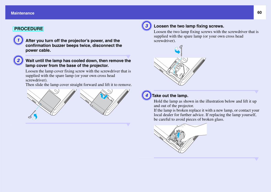
60Mainte
mp fixing screws. fixing screws with the screwdriver that is re lamp (or your own cross head
wn in the illustration below and lift it up tor. replace it with a new lamp, or contact your er advice. If replacing the lamp yourself, ieces of broken glass.
A1PRO
A2
nance
After you turn off the projector’s power, and the confirmation buzzer beeps twice, disconnect the power cable.
Wait until the lamp has cooled down, then remove the lamp cover from the base of the projector.Loosen the lamp cover fixing screw with the screwdriver that is supplied with the spare lamp (or your own cross head screwdriver).Then slide the lamp cover straight forward and lift it to remove.
Loosen the two laLoosen the two lampsupplied with the spascrewdriver).
Take out the lamp.Hold the lamp as shoand out of the projecIf the lamp is brokenlocal dealer for furthbe careful to avoid p
CEDURE A3
A4
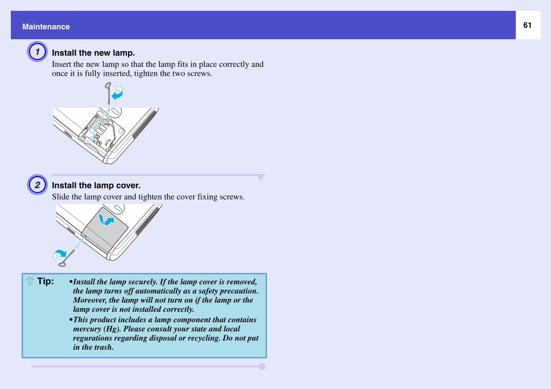
61Mainte
A1
A2
Q Ti
nance
Install the new lamp.Insert the new lamp so that the lamp fits in place correctly and once it is fully inserted, tighten the two screws.
Install the lamp cover.Slide the lamp cover and tighten the cover fixing screws.
•Install the lamp securely. If the lamp cover is removed, the lamp turns off automatically as a safety precaution. Moreover, the lamp will not turn on if the lamp or the lamp cover is not installed correctly.
•This product includes a lamp component that contains mercury (Hg). Please consult your state and local regurations regarding disposal or recycling. Do not put in the trash.
p:

62Mainte
TheopepoinThewith
m the configuration menu, and then p Hours". eration, refer to "Using the Configuration
u can use, and the operations they at the bottom of the screen.
appears, select "Yes".time will then be reset.
Res
PRO
A1
ontrol Using the control panelQ Ti
nance
projector has a built-in counter which keeps track of the lamp rating time. When the cumulative operating time reaches a certain t, it causes the replacement warning message to be displayed. refore, the counter needs to be reset after the lamp has been replaced a new one. You can do this using the configuration menu.
Connect the power cable and turn on the projector.
Select "Reset" froselect "Reset LamFor details on this opMenu". s page 32Check the buttons yoperform, in the guide
When "Execute?"The lamp operating
etting the Lamp Operating Time
Do not reset the lamp operating time except after the lamp has been replaced, otherwise the lamp replacement period will not be indicated correctly.
CEDURE
A2
Using the remote c
A3
p:

63Mainte
If thhavThe
filter.vers in from the outside and push them in place.
Rep
PRO
A1
A2 air filters properly in accordance with lations.: Polycarbonate, ABS plastichane foam
nance
e air filters are broken or if the warning message reappears after they e been cleaned, they should be replaced. air filter can be replaced even if the projector is installed on a ceiling.
After you turn off the projector’s power, and the confirmation buzzer beeps twice, disconnect the power cable.
Remove the air filter.Put your finger into the recess of the air filter and slide it forward to remove it.
Install the new airSlide the air filter countil they click into
lacing the Air Filter
CEDURE
Recess
Dispose of usedyour local reguAir filter frameFilter: Polyuret
A3
Q Tip:

64Sav
You can " from the configuration menu, and ’s Logo". eration, refer to "Using the Configuration
on the remote control or the control panel operations they perform, in the guide at the .
Logo Protect" function of "Password to "On", a message is displayed and the not be recorded. To record a user's logo,
go Protect" to "Off" first. s page 28rection, E-Zoom and so on, have been e function currently being performed is n the "User’s Logo" menu is selected.
Q Ti
PRO
A1
ing a User's Logo
record the image that is currently being projected as a user's logo.
Project the image you would like to use as the user’s logo, and then display the configuration menu.
Select "Extendedthen select "UserFor details on this opMenu". s page 32Check which buttonsyou can use, and the bottom of the screen
When a user's logo is recorded, the previous user's logo will be erased.
CEDURE
Using the remote control Using the control panel
•If the "User’s Protect" is setuser's logo canset "User’s Lo
•If keystone corcarried out, thcancelled whe
A2p:
Q Tip:

65Saving
image?" appears, select "Yes".
ate from the Zoom rate setting
image?" is displayed, select "Yes".be saved. Once the image has been saved, eted." will be displayed.
A3
A4
n be saved at up to 400 × 300 dots in size.
r's logo may take a few moments (about o not use the projector or any other are connected to the projector while the eing saved, otherwise it may result in ctor operation.logo has been saved, the logo setting rned to the factory default.
Q Ti
a User's Logo
When "Choose this image as the User's Logo?" appears, select "Yes".
The image to be recorded and a selection marquee box will be displayed. Move the marquee box to select the part of the image to use.
When "Select this
Select the zoom rscreen.
When "Save this The image will then the message "Compl
When you press the [Enter] button on either the remote control or the projector's control panel, the image signal will be displayed at their original resolution, so if a signal with a resolution that is different from the panel resolution of the projector is projected, or if a video image is being projected, the display size will change.
Using the remote control Using the control panel
User's logos ca
•Saving the use15 seconds). Dsources whichuser's logo is berrors in proje
•Once a user's cannot be retu
A5
A6
A7
p:
Q Tip:
Q Tip:

66Con
Conn
Anabein
shmnn
rnal speaker (when using the
ith built-in amplifiers to the projector's Audio fuller quality of sound.le audio cable with pin jack ⇔ stereo mini jack
gs that match the ports for the external audio
t
ini-jack audio cable is inserted into the the sound will be output to external und will be output from the projector's at this time.
able available)
To Audio Out port
t
i
compropreIf tCoComo
Moni
Q T
necting to External Output Equipment
ecting to an External Monitor
logue RGB images and RGB video images from a computer that are g input to the Computer/Computer1 port can be viewed on an external puter monitor at the same time they are being projected by the
jector, so that the images can be checked at times such as when giving entations.e images being projected are from a source that is connected to the puter2 port, these images cannot be output to an external monitor.
nect the external monitor using the cable that is provided with the itor.
Connecting to an exteEMP-82/62)
You can connect speakers wOut port in order to enjoy a Use a commercially-availab(3.5 mm) plugs or similar.Use an audio cable with pluequipment.
•Component video, S-Video, and composite video images cannot be output to an external monitor.
•The setting gauge for keystone correction and the configuration menus and help menus are not output to the external monitor.
Cable provided with monitor To Monitor Out port (black)
or port
When a stereo mAudio Out port,speakers. No sobuilt-in speaker
Audio c(commercially
To external audio equipmen
p: Q Tip:

67Op
The fol t as of September, 2005. Details of accessories are sub
Op
t
m
m
o
tnwn
we
lamps.
air filters.
* Apu
SoftUse 60" s80" s100"Porta50" pA coVGA(1.8 ThisVGA(3 mVGA(20 mUse projeCom(3 mUse CeiliUse CeiliPipePipePipeUse vene
tional Accessories and Consumables
lowing optional accessories are available for purchase if required. This list of optional accessories is currenject to change without notice. Varies depending on country of purchase.
special method of installation is required in order to suspend the rojector from a ceiling. Please contact your dealer if you would like to se this installation method.
tional Accessories
carrying case ELPKS16his case if you need to carry the projector by hand.creen ELPSC07creen ELPSC08 screen ELPSC10ble roll-type screens. (Aspect ratiog 4:3)ortable screen ELPSC06 pact screen which can be carried easily. (Aspect ratio 4:3)
-HD15 PC cable ELPKC02 (6 ft.) - for mini D-Sub 15-pin/mini D-Sub 15-pin)
is the same as the computer cable supplied with the projector.-HD15 PC cable ELPKC09(9.8 ft.) - for mini D-Sub 15-pin/mini D-Sub 15-pin)-HD15 PC cable ELPKC10 (65.6 ft.) - for mini D-Sub 15-pin/mini D-Sub 15-pin)ne of these longer cables if the computer cable supplied with the ctor is too short.ponent video cable ELPKC19(9.8 ft.) - for mini D-Sub 15-pin/RCA male × 3)o connect a component videog source.g mount * ELPMB18hen installing the projector on a ceiling.g plate* ELPFC03
370 (370 mm (14.57 in.)/silver)* ELPFP04 570 (570 mm (22.44 in.)/silver)* ELPFP05 770 (770 mm (30.31 in.)/silver)* ELPFP06
hen installing the projector on a high ceiling or a ceiling with r panels.
Consumables
Spare lamp ELPLP34Use as a replacement for used Filter kit ELPAF08(2 air filters)Use as a replacement for used

68Glo
The fol not explained in the text of this guide itself. Further informa
As aspect ratio of 16:9 and appear elongated. The
e is high, the colours take on a bluish tinge. If the
eparated, in order to provide better image quality. dependent signals: Y (luminance signal), and Pb
ixed together. The type of signals commonly used
are contained in the colour bar are overlapped to
ased or decreased in order to make text and his particular property of an image is called
annel format which uses two speakers. Dolby aker two rear speakers and a sub-woofer. systems which satisfy the following conditions.lacedg)
t orizontal lines which are displayed in sequence The even-numbered lines and odd-numbered lines
s scanned sequentially from top to bottom to create
colour for an extremely short time. Because of this, ight-emitting element. The number of refresh (Hz).evision systems which do not satisfy the conditions
Co
Co
Co
Co
Do
HD
In
Pr
Re
SD
ssary
lowing is an explanation of some of the terms used in this guide which may be unfamiliar or which are tion can be obtained by referring to other commercially-available publications.
pect ratio The ratio between an image's length and its height. HDTV images have anaspect ratio for standard images is 4:3.
lor Temp. The temperature of an object that is emitting light. If the colour temperaturcolour temperature is lower, the colours take on a reddish tinge.
mponent video Video signals which have the video brightness signals and colour signals sIn high-definition TV (HDTV), it refers to images which consist of three inand Pr (colour difference signals).
mposite video Video signals which have the video brightness signals and colour signals mby household video equipment (NTSC, PAL and SECAM formats). The carrier signal Y (luminance signal) and chroma (colour) signal which form a single signal.
ntrast The relative brightness of the light and dark areas of an image can be incregraphics stand out more clearly, or to make them appear softer. Adjusting t"contrast adjustment".
lby Digital A sound format developed by Dolby Laboratories. Normal stereo is a 2-chDigital is a 6-channel (5.1-channel) system which adds to this a centre spe
TV An abbreviation for High-Definition Television. It refers to high-definition•Vertical resolution of 750p or 1125i or greater (p = progressiveg, i = inter•Screen aspect ratiog of 16:9•Dolby Digitalg audio reception and playback (or output)
erlaced A method of image scanning whereby the image data is divided into fine hstarting from left to right and then from the top to the bottom of the screen.are displayed alternately.
ogressive A method of image scanning whereby the image data from a single image ia single image.
fresh rate The light-emitting element of a display maintains the same luminosity and the image must be scanned many times per second in order to refresh the loperations per second is called the "refresh rate", and is expressed in hertz
TV An abbreviation for Standard Definition Television. It refers to standard telfor High-Definition Television.

69Gloss
Se ilable theft-prevention cable can be passed tible with the Microsaver Security System
Sq l direction so that they are stored on the
restored to their original 16:9 format.sR s which are reproduced by video equipment
he connected source has a sRGB mode, set
SV s which is used by IBM PC/AT-compatible
S- rated in order to provide better image quality. al), and C (colour signal).
SX ots which is used by IBM PC/AT-compatible
Sy requency. If the projector frequency does not cess of matching the phases of these signals sation". If the signals are not synchronized,
Tra requency. If the projector frequency does not cess of matching the frequency of these
carried out correctly, wide vertical stripes will
US rsonal computers to peripheral devices which
VG s which is used by IBM PC/AT-compatible
XG ts which is used by IBM PC/AT-compatible
ary
curity lock A device consisting of a projector case with a hole in it that a commercially-avathrough in order to secure the device to a table or pillar. This projector is compamanufactured by Kensington.
ueeze mode In this mode, wide-screen images in 16:9 mode are compressed in the horizontarecording medium as 4:3 images.When these images are played back by the projector in squeeze mode, they are
GB An international standard for colour intervals that was formulated so that colourcan be handled easily by computer operating systems (OS) and the Internet. If tboth the projector and the connected signal source to sRGB.
GA A type of video signal with a resolution of 800 (horizontal) × 600 (vertical) dotcomputers.
Video A video signal which has the luminance component and colour component sepaIt refers to images which consist of two independent signals: Y (luminance sign
GA A type of video signal with a resolution of 1280 (horizontal) × 1024 (vertical) dcomputers.
nc (synchronisation) The signals output from computers and RGB video equipment have a specific fmatch this frequency, the resulting images will not be of a good quality. The pro(the relative position of the crests and troughs in the signal) is called "synchroniproblems such as flickering, blurriness and horizontal interference can occur.
cking The signals output from computers and RGB video equipment have a specific fmatch this frequency, the resulting images will not be of a good quality. The prosignals (the number of crests in the signal) is called "tracking". If tracking is not appear in the projected images.
B An abbreviation for Universal Serial Bus. USB is an interface for connecting peonly support relatively low data transmission speeds.
A A type of video signal with a resolution of 640 (horizontal) × 480 (vertical) dotcomputers.
A A type of video signal with a resolution of 1024 (horizontal) × 768 (vertical) docomputers.

70Lis
Com
Whand
n
o
o
B)
l
l
<At the computer>
turWhnexIf cerr* Wc
Power
Signa
A/V M
A/V M
Signa
t of ESC/VP21 Commands
mand List
en a power on command is sent to the projector, the power will turn on the projector will change to warm-up mode. When the power has ed on, a colon ":" (3Ah) will be returned.en the projector executes a command, it returns a ":" and waits for the t command to be sent.ommand processing terminates with an error, the projector outputs an r message and then returns the ":" code.
hen issuing any of the above commands, tack a Carriage Return (CR) de (0Dh) on to the end.
Cable Layouts
Connector shape: USB (type
Item Command
ON/OFFON PWR ONOFF PWR OFF
selection
Computer (Auto) SOURCE 1FComputer SOURCE 11Component Video SOURCE 14Video SOURCE 41S-Video SOURCE 42
ute ON/OFFON MUTE ONOFF MUTE OFF
ute SelectionBlack MSEL 00Blue MSEL 01User’s Logo MSEL 02
ItemCommand
Computer1 port
Computer2 port
selectionComputer (Auto) SOURCE 1F SOURCE 2FComputer SOURCE 11 SOURCE 21Component Video SOURCE 14 SOURCE 24
USB connection
<At the projector>
(type B)

71List of
p
ctor using ESC/VP21 commands via a USB eparations must be carried out.
B driver (USB-COM Driver) from the o your computer.
s.n-europe.com/downloads/en/
aded USB driver onto your
s displayed on the download screen.
"On" in the "Extended" menu.2>"COM port" in the "Extended" menu.
r's power off.
ctor after the confirmation buzzer
power has turned back on, communication n will then be possible.
Ser
• C
• P
<A
ect the power cable before the uzzer beeps twice, the communication nged.
ESC/VP21 Commands
USB Connection Setu
In order to control the projeconnection, the following pr
Download the USEPSON website tThe URL is as follow http://esupport.epso
Install the downlocomputer.Read the instruction
<Using EMP-X3>Set "Link21L" to <Using EMP-82/6Select "USB" for
Turn the projecto
Turn off this projebeeps twice.Once the projector's via a USB Connectio
ial connection (EMP-82/62 only)
onnector shape : D-Sub 9 pin (male)
rojector input connector : Control (RS-232C)
<At computer>
t projector> (PC serial cable) <At computer> Signal Function
GND 5 5 GND GND Signal wire ground
RD 2 3 TD TD Transmit data
TD 3 2 RD RD Receive data
DTR 4 6 DSR DSR Data set ready
DSR 6 4 DTR DTR Data terminal ready
<At projector>
If you disconnconfirmation bport is not cha
PROCEDURE
A1
A2
A3
A4
A5
c Caution:
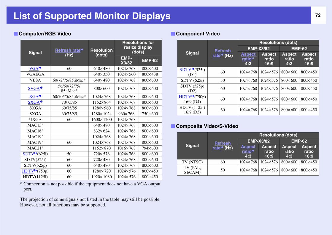
72Lis
o
ew
Com
V
D
DDD
)
Resolutions (dots)EMP-X3/82 EMP-62
Aspect ratiog
4:3
Aspect ratio 16:9
Aspect ratio 4:3
Aspect ratio 16:9
1024× 768 1024× 576 800× 600 800× 450
1024× 768 1024× 576 800× 600 800× 450
1024× 768 1024× 576 800× 600 800× 450
1024× 768 1024× 576 800× 600 800× 450
1024× 768 1024× 576 800× 600 800× 450
eo
)
Resolutions (dots)EMP-X3/82 EMP-62
Aspect ratiog
4:3
Aspect ratio 16:9
Aspect ratio 4:3
Aspect ratio 16:9
1024× 768 1024× 576 800× 600 800× 450
1024× 768 1024× 576 800× 600 800× 450
* Cp
ThHo
SSS
HH
t of Supported Monitor Displays
onnection is not possible if the equipment does not have a VGA output rt.
projection of some signals not listed in the table may still be possible. ever, not all functions may be supported.
puter/RGB Video
Signal Refresh rateg (Hz)
Resolution (dots)
Resolutions for resize display
(dots)EMP-X3/82 EMP-62
VGAg 60 640× 480 1024× 768 800× 600GAEGA 640× 350 1024× 560 800× 438VESA 60/72/75/85,iMac* 640× 480 1024× 768 800× 600
SVGAg 56/60/72/75/85,iMac* 800× 600 1024× 768 800× 600
XGAg 60/70/75/85,iMac* 1024× 768 1024× 768 800× 600SXGAg 70/75/85 1152× 864 1024× 768 800× 600SXGA 60/75/85 1280× 960 1024× 768 800× 600SXGA 60/75/85 1280× 1024 960× 768 750× 600UXGA 60 1600× 1200 1024× 768 -
MAC13" 640× 480 1024× 768 800× 600MAC16" 832× 624 1024× 768 800× 600MAC19" 1024× 768 1024× 768 800× 600MAC19" 60 1024× 768 1024× 768 800× 600MAC21" 1152× 870 1016× 768 794× 600TVg(625i) 50 720× 576 1024× 768 800× 600
DTV(525i) 60 720× 480 1024× 768 800× 600TV(525p) 60 640× 480 1024× 768 800× 600TVg(750p) 60 1280× 720 1024× 576 800× 450TV(1125i) 60 1920× 1080 1024× 576 800× 450
Component Video
Signal Refreshrateg (Hz
SDTVg(525i)(D1)
60
SDTV (625i) 50SDTV (525p)
(D2) 60
HDTVg(750p) 16:9 (D4)
60
HDTV (1125i) 16:9 (D3) 60
Composite Video/S-Vid
Signal Refreshrateg (Hz
TV (NTSC) 60TV (PAL, SECAM) 50

73Spe
ProduDimePane
a
s
aa
h
ngle of tilt
you use it when it is tilted more than 30°, it uld be damaged and cause an accident.
e USB interface complies with the USB 1.1 ndard. e USB connector is not guaranteed to operate rrectly with all USB-compatible devices.
Pixelworks DNXTM ICs are used in this Projector.
0°- 30° 0°- 30°
0°- 30° 0°- 30°
DisplReso
FocuZoomLampMax.SpeaPowe
OperOperStoraWeigConn
Operating: 240W(100 to 240 V area)Standby: 5.0W(100 to 240 V area)
ting altitude 0 - 2280 m (0 - 7500 ft)ting temperature +5 – +35ºC (No condensation)
ge temperature -10 – +60ºC (No condensation)t Approx. 2.6 kg Approx. 2.7 kg
ectors Computer/Computer 1
1 Mini D-Sub 15-pin(female) Blue
Audio Input 1 RCA pin jack Stereo mini jackComputer 2 1 - Mini D-Sub 15-pin (female) BlueAudio Input 1 - Stereo mini jackS-Video 1 Mini DIN 4-pinAudio Input 1 RCA pin jackVideo 1 RCA pin jackAudio Input 1 RCA pin jackUSB* 1 USB connector (B series)RS-232C 1 - D-Sub 9-pin (male)Monitor Out 1 Mini D-Sub 15-pin (female) BlackAudio Out 1 Stereo mini jack
* ThstaThco
cifications
ct name EMP-X3 EMP-82 EMP-62nsions 327 (W) × 86 (H) × 246 (D) mm (not including feet and speaker)l size 0.6 inchesy method Polysilicon TFT active matrix
lution XGAg 786,432 pixels (1,024 (W) × 768 (H) dots) × 3
SVGAg 480,000 pixels (800 (W) × 600 (H) dots) × 3
adjustment Manual adjustment Manual (approx. 1:1.2) (light source) UHE lamp, 170 W, Model No.: ELPLP34audio output 1W monaural 5W monauralker 1r supply 100-240VAC 50/60Hz 2.9-1.2A
Power Consumption
A
Ifco

74Specif
Sa
USU
CaC
Eu
ications
fety
AL60950 3rd EditionnadaSA C22.2 No.60950ropean CommunityThe Low Voltage Directive (73/23/EEC)IEC60950 3rd Edition
EMC
USAFCC Part 15B Class B (DoC)
CanadaICES-003 Class B
European CommunityThe EMC Directive (89/336/EEC)
EN55022 Class BEN55024IEC/EN61000-3-2IEC/EN61000-3-3
Australia/New ZealandAS/NZS CISPR 22:2002 Class B
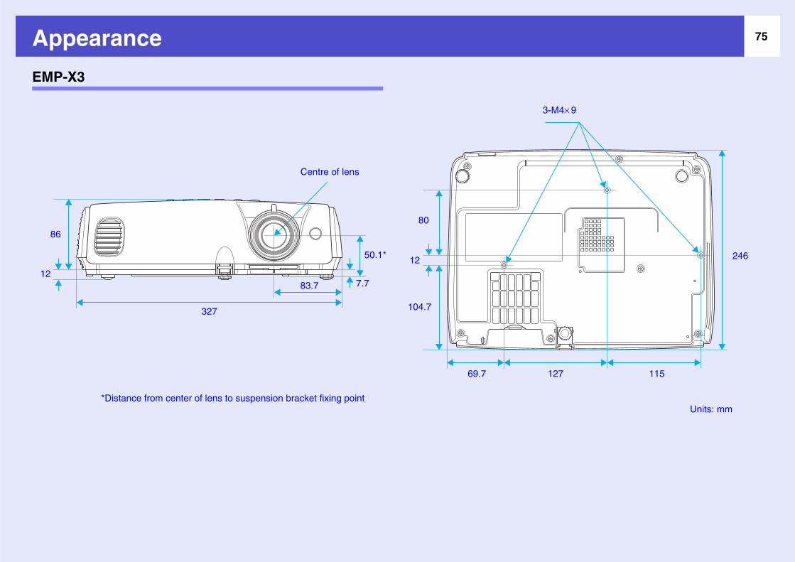
75App
EMP-
Units: mm
M4× 9
11527
246
86
12
earance
X3
3-
1
80
12
104.7327
83.7
50.1*
7.7
Centre of lens
69.7
*Distance from center of lens to suspension bracket fixing point
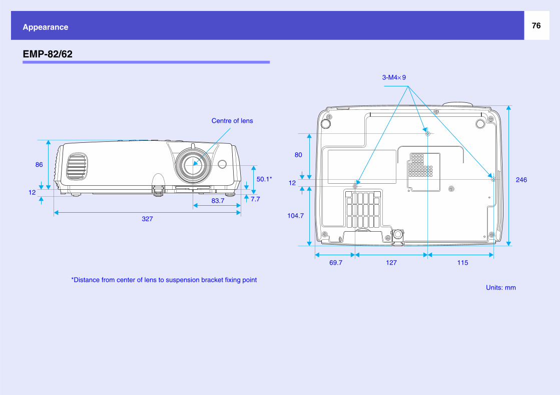
76Appea
EMP-
Units: mm
M4× 9
11527
86
12
246
rance
82/62
3-
1
80
12
104.7327
83.7
50.1*
7.7
Centre of lens
69.7
*Distance from center of lens to suspension bracket fixing point

77Ind
A
Air exh
Air filte
a
o
O
p
n
n
n
n
n
A
M
S
T
P
.. 15
.. 68
.. 72
.. 42
.. 38
.. 33
.. 44
.. 39
.. 39
.. 36
.... 6
.. 39
.. 44
.. 59
.. 38
.... 6
Link 21L.......................................38
Low...............................................36
M
Menu.............................................32
Message ........................................37
Monitor Out port ........................ 8, 9
Mouse pointer...............................24
N
Numeric buttons ...........................11
O
Operating temperature..................73
Operation......................................38
Operation Lock....................... 29, 36
Optional accessories .....................67
Overheating ..................................45
P
Part Names and Functions..............6
Password Protect ..........................26
Password Protect stickers .............27
Photo.............................................15
Pointer ..........................................21
Pointer Shape................................36
Air int
Angle
Aspect
Audio
Audio
Auto K
Auto S
A/V M
B
Blackb
Bright
Bright
C
Cleani
Cleani
Cleani
Color
Color
Color
Color
COM
Compu
ex
aust vent............................. 6
r ....................................... 10
ke vent ............................. 10
f tilt.................................. 73
ratio.................................. 21
ut port............................... 9
ort................................... 8, 9
eystone ............................. 36
etup .............................. 13, 34
ute..................................... 20
oard................................... 15
ess .................................... 33
ess Control....................... 36
g the Air Filter................. 57
g the Lens ........................ 57
g the Projector Surface .... 57
djustment ........................ 33
ode............................. 15, 33
aturation........................... 33
emp.................................. 33
ort .................................... 38
ter1 Input.......................... 34
Computer1 port ..............................9
Computer2 Input ..........................34
Computer2 port ..............................9
Computer Input ............................34
Computer port ................................8
Configuration Menu .....................32
Connectors......................................8
Consumables ................................67
Contrast ........................................33
Control Panel..................................7
Cross.............................................23
D
Direct Power On...........................38
Display .........................................37
Display Background.....................37
E
ESC/VP21 ....................................70
"Extended" Menu .........................37
E-Zoom ........................................22
F
Focus ring.......................................6
Freeze ...........................................20
Front adjustable foot ......................6
G
Game..........................................
Glossary .....................................
H
HDTV ........................................
Help function .............................
High Altitude Mode...................
I
"Image" Menu............................
Indicator .....................................
"Info" Menu ...............................
Input Signal................................
K
Keystone ....................................
L
Lamp cover ................................
Lamp Hours ...............................
Lamp indicator...........................
Lamp replacement period ..........
Language....................................
Lens cover..................................

78Index
Port ....
Positio
Power
Power
Power
Present
Problem
Progres
Project
R
Rear ad
Refresh
Remote
Remote11
Remote6, ......
Replac
Replac
Replac
Reques
Reset A
Reset L
"Reset"
Resized
Resolu
RS-232
... 15
... 33
... 32
3, 34
... 56
... 71
..8, 9
... 64
... 27
..8, 9
5, 39
7, 36
... 21
... 23
..... 6
............................................ 9
n ................................... 13, 34
indicator............................ 44
inlet.................................. 8, 9
On Protect......................... 26
ation ................................. 15
Solving .......................... 44
sive .................................. 34
ion..................................... 37
justable foot .................... 8, 9
Rate ................................ 39
Control ...................... 11, 23
control light-emitting area..
control light-receiving area......................................... 8, 9
ing the Air Filter ............... 63
ing the batteries ................ 58
ing the Lamp..................... 59
t Code............................... 26
ll ...................................... 40
amp Hours .................. 40, 62
Menu............................... 40
display ............................ 72
tion............................... 39, 72
C port................................. 9
S
Search...........................................11
Security lock...................................6
"Settings" Menu ...........................36
Setting Up the Projector ...............56
Sharpness......................................33
"Signal" Menu..............................34
Sleep Mode...................................38
Source...........................................39
Source Search........................... 7, 18
Speaker....................................... 8, 9
Specifications ...............................73
Sports............................................15
Squeeze mode...............................21
sRGB............................................15
Standby Mode ..............................38
Startup Screen ..............................37
Storage temperature .....................73
Sub menu......................................32
Supported Monitor Displays ........72
Suspension bracket fixing point .. 10,
75
S-Video port ............................... 8, 9
Sync........................................ 14, 34
Sync. Info .....................................39
T
Temp indicator .............................44
Theatre ......................................
Tint............................................
Top menu ..................................
Tracking..................................1
Translucent screen ....................
U
USB connection ........................
USB port ...................................
User’s Logo ..............................
User’s Logo Protect ..................
V
Video port .................................
Video Signal ...........................3
Volume ...................................1
W
Wide-screen Projection.............
Wireless Mouse ........................
Z
Zoom ring .................................

79
All rigstored electrothe pripatent containfrom th
Neitheto the pcosts, oof: accmodifiU.S.) foperati
SEIKOdamagconsumProducCORP
ark of SEIKO EPSON CORPORATION. registered trademarks of Apple
of International Business Machines
GA are trademarks or registered oration in the United States of America.
y Laboratories.emarks of Pixelworks, Inc.
rein are also for identification purposes f their respective owners. EPSON those marks.
e software.
hts reserved. No part of this publication may be reproduced, in a retrieval system, or transmitted in any form or by any means, nic, mechanical, photocopying, recording, or otherwise, without or written permission of SEIKO EPSON CORPORATION. No liability is assumed with respect to the use of the information ed herein. Neither is any liability assumed for damages resulting e use of the information contained herein.
r SEIKO EPSON CORPORATION nor its affiliates shall be liable urchaser of this product or third parties for damages, losses, r expenses incurred by the purchaser or third parties as a result
ident, misuse, or abuse of this product or unauthorized cations, repairs, or alterations to this product, or (excluding the ailure to strictly comply with SEIKO EPSON CORPORATION’s ng and maintenance instructions.
EPSON CORPORATION shall not be liable against any es or problems arising from the use of any options or any able products other than those designated as Original EPSON
ts or EPSON Approved Products by SEIKO EPSON ORATION.
General Notice: EPSON is a registered trMacintosh, Mac and iMaComputer, Inc.IBM is a registered tradeCorporation.Windows, Windows NT trademarks of MicrosoftDolby is a trademark of Pixelworks and DNX are
Other product names useonly and may be trademadisclaims any and all rigThis product uses open s
SEIKO EPSON CORPORATION 2005. All rights reser
ademc are
mark
and V CorpDolb trad
d herks o
hts inourc
ved.