User Manual - University of Ljubljanaantena.fe.uni-lj.si/literatura/Razno/Sweep/razvoj/Hittite PLL...
12
PLL & PLL with Integrated VCO Evaluation Kit User Manual Software & Hardware Installation For All Hittite PLLs & PLL with Integrated VCO Products 20 Alpha Road Chelmsford, MA 01824 Phone: 978-250-3343 • Fax: 978-250-3373 • [email protected] Order On-Line at: www.hittite.com Receive the latest product releases - click on “My Subscription” Analog, Digital & Mixed-Signal ICs, Modules, Subsystems & Instrumentation Part # 128340 Rev C - v02.1110 ECN# CP100301
Transcript of User Manual - University of Ljubljanaantena.fe.uni-lj.si/literatura/Razno/Sweep/razvoj/Hittite PLL...
PLL & PLL with Integrated VCO Evaluation Kit
User ManualSoftware & Hardware Installation
For All Hittite PLLs & PLL with Integrated VCO Products
20 Alpha Road Chelmsford, MA 01824Phone: 978-250-3343 • Fax: 978-250-3373 • [email protected]
Order On-Line at: www.hittite.com Receive the latest product releases - click on “My Subscription”
Analog, Digital & Mixed-Signal ICs, Modules, Subsystems & Instrumentation
Part #
128340Rev C - v02.1110
ECN# CP100301
2
Rev C - 02.1110
Order On-Line: www.hittite.com. For technical application questions: Phone: 978-250-3343 or [email protected]
PLL & PLL with Integrated VCO Evaluation Kit User Manual
NoticeHittite Microwave Corporation has prepared this manual for use by Hittite personnel and customers as a guide for the proper instal-
lation, operation, and maintenance of Hittite equipment and computer programs. The drawings, specifications, and information con-
tained herein are the property of Hittite Microwave Corporation, and any unauthorized use or disclosure of these drawings, specifica-
tions, and information is prohibited; they shall not be reproduced, copied, or used in whole or in part as the basis for manufacture or
sale of the equipment or software programs without the prior written consent of Hittite Microwave Corporation.
Table of Contents
1. Introduction. . . . . . . . . . . . . . . . . . . . . . . . . . . . . . . . . . . . . . . . . . . . . . . . . . . . . . . . . . . . . . . . . . . . . . . . . . . .3
2. Package Contents. . . . . . . . . . . . . . . . . . . . . . . . . . . . . . . . . . . . . . . . . . . . . . . . . . . . . . . . . . . . . . . . . . . . . . .3
3. Operating Environment . . . . . . . . . . . . . . . . . . . . . . . . . . . . . . . . . . . . . . . . . . . . . . . . . . . . . . . . . . . . . . . . . .3
4. Setup and Installation . . . . . . . . . . . . . . . . . . . . . . . . . . . . . . . . . . . . . . . . . . . . . . . . . . . . . . . . . . . . . . . . . . .4
5. PLL Programming. . . . . . . . . . . . . . . . . . . . . . . . . . . . . . . . . . . . . . . . . . . . . . . . . . . . . . . . . . . . . . . . . . . . . . .7
6. Hittite PLL Design Tool . . . . . . . . . . . . . . . . . . . . . . . . . . . . . . . . . . . . . . . . . . . . . . . . . . . . . . . . . . . . . . . . .10
7. Technical Support. . . . . . . . . . . . . . . . . . . . . . . . . . . . . . . . . . . . . . . . . . . . . . . . . . . . . . . . . . . . . . . . . . . . . .10
3
Rev C - 02.1110
Order On-Line: www.hittite.com. For technical application questions: Phone: 978-250-3343 or [email protected]
PLL & PLL with Integrated VCO Evaluation Kit User Manual
1. Introduction
This document provides basic instructions for getting started with Hittite PLL & PLL with Integrated VCO Evaluation Kit. Hittite PLL & PLL with Integrated VCO Evaluation Kit consists of hardware and software that allows users to control Hittite PLL evaluation boards and observe and test full functionality and performance of Hittite PLLs and PLLs with Integrated VCOs.
Note: For most up-to-date software download and information please visit www.hittite.com.
2. Package Contents
2.1 Hardware
Verify that all the items listed in Table 1 are included in the shipment.
Item Quantity
PLL Evaluation Board 1
USB Interface Board 1
6’ USB A Male to USB B Male Cable 1
CD ROM (Contains User Manual and software) 1
Table 1: Packing List2.2 Software
1. Hittite PLL Eval Software
• Enables users to communicate with and control Hittite PLLs and PLL with integrated VCOs with their PCs, and observe full functionality and performance of all Hittite PLLs and PLLs with integrated VCOs
2. Hittite PLL Design Software
• Is a powerful tool that can aid in the design and performance analysis of all Hittite’s PLLs
3. Operating Environment
The PLL & PLL with Integrated VCO Evaluation Kit is designed for use in a laboratory setting at ambient room temperature (25°C) and is not protected against moisture. The USB Interface Board has an ESD rating of +/-3000V, however the HMC PLLs may have a lower rating (check the product’s datasheet for its specific ESD rating). Use appropriate ESD procedures and precautionary measures when handling all electronic hardware.
4
Rev C - 02.1110
Order On-Line: www.hittite.com. For technical application questions: Phone: 978-250-3343 or [email protected]
PLL & PLL with Integrated VCO Evaluation Kit User Manual
4. Setup and Installation
4.1 User Provided Equipment
In addition to the items provided in the PLL & PLL with Integrated VCO Evaluation Kit, the user must provide the following equipment to communicate with the PLL under test.
• DC Power Supply
• DC Cables
• Computer (PC) with Standard USB port
• For detailed specifications regarding operating system and software requirements please visit www.hittite.com
4.2 Software Installation
Note: Installing/Uninstalling the Hittite PLL Evaluation Software & Hittite PLL Design Software requires administrative privileges
1. Hittite PLL Evaluation Software Installation
To install/uninstall Hittite PLL Evaluation Software double click on “Hittite PLL Eval Software Installer.exe” that was downloaded from www.hittite.com, or provided with a CD, and follow the installation/uninstallation wizard.
2. Hittite PLL Design Software Installation
To install/uninstall Hittite PLL Design Software, log in as administrator and right click on “Hittite PLL Design Software Installer.exe” that was downloaded from www.hittite.com, or provided with a CD, and select ‘Run as Administrator,’ and follow the installation/uninstallation wizard.
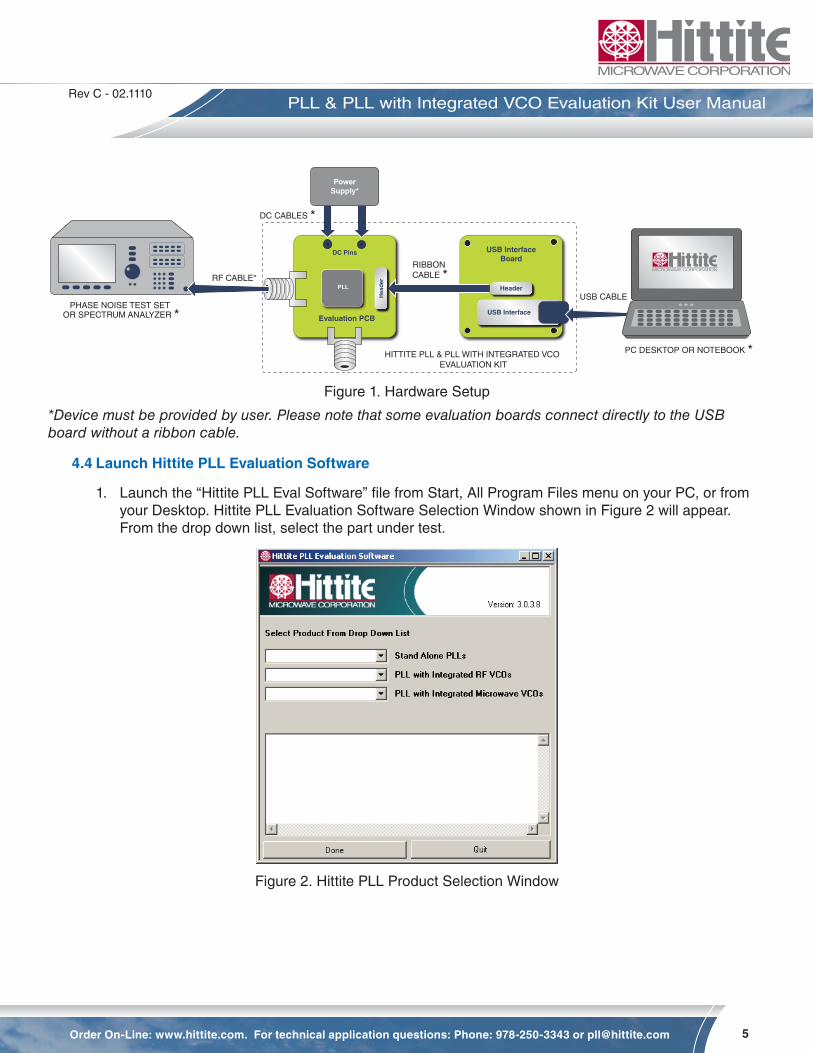
4.3 Hardware Setup
Setup all hardware according to Figure 1.
1. Setup the evaluation board
a. Set the DC power supply to +5.5V and connect to the evaluation board. Some evaluation boards require a second higher power supply to operate. The evaluation board power connections are all labelled with the required voltage.
b. Connect Phase Noise Test Set or Spectrum Analyzer to the evaluation board through an RF cable.
2. Plug the header connector of the USB Interface board into the header connector of the evaluation board or use the ribbon cable (provided with some evaluation kits).
3. Connect the USB Interface Board to the USB port of the PC through the USB Cable provided with the kit.
5
Rev C - 02.1110
Order On-Line: www.hittite.com. For technical application questions: Phone: 978-250-3343 or [email protected]
PLL & PLL with Integrated VCO Evaluation Kit User Manual
Evaluation PCB
RIBBON CABLE *
USB InterfaceBoard
USB Interface
Header
Hea
der
PLL
PowerSupply*
USB CABLE
DC CABLES *
PC DESKTOP OR NOTEBOOK *
DC Pins
RF CABLE*
PHASE NOISE TEST SET OR SPECTRUM ANALYZER *
HITTITE PLL & PLL WITH INTEGRATED VCO EVALUATION KIT
Figure 1. Hardware Setup
*Device must be provided by user. Please note that some evaluation boards connect directly to the USB board without a ribbon cable.
4.4 Launch Hittite PLL Evaluation Software
1. Launch the “Hittite PLL Eval Software” file from Start, All Program Files menu on your PC, or from your Desktop. Hittite PLL Evaluation Software Selection Window shown in Figure 2 will appear. From the drop down list, select the part under test.
Figure 2. Hittite PLL Product Selection Window
6
Rev C - 02.1110
Order On-Line: www.hittite.com. For technical application questions: Phone: 978-250-3343 or [email protected]
PLL & PLL with Integrated VCO Evaluation Kit User Manual
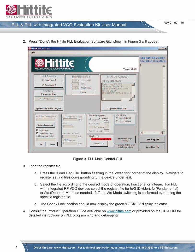
2. Press “Done”, the Hittite PLL Evaluation Software GUI shown in Figure 3 will appear.
Figure 3. PLL Main Control GUI
3. Load the register file.
a. Press the “Load Reg File” button flashing in the lower right corner of the display. Navigate to register setting files corresponding to the device under test.
b. Select the file according to the desired mode of operation, Fractional or Integer. For PLL with Integrated RF VCO devices select the register file for fo/2 (Divider), fo (Fundamental) or 2fo (Doubler) Mode as needed. fo/2, fo, 2fo Mode switching is performed by running the specific register file.
c. The Check Lock section should now display the green ‘LOCKED’ display indicator.
4. Consult the Product Operation Guide available on www.hittite.com or provided on the CD-ROM for detailed instructions on PLL programming and debugging.
7
Rev C - 02.1110
Order On-Line: www.hittite.com. For technical application questions: Phone: 978-250-3343 or [email protected]
PLL & PLL with Integrated VCO Evaluation Kit User Manual
5. PLL Programming
5.1 Frequency Selection
To program the PLL to a desired frequency, enter the frequency in the “OUT Freq Desired” box and press the “Update Frequency” button (Reference divider and VCO divider registers are only updated when the “Update Frequency” button is pressed).
The “OUT Freq (Actual)” box displays the frequency that the PLL is actually generating. The “Error” box displays the frequency error between the desired and actual frequencies.
5.2 External or Internal Fixed Dividers
Often, there will be dividers and/or doublers used between the VCO and the PLL’s prescaler, and/or between the VCO and the measurement equipment. For the GUI to calculate the correct N for the PLL, it needs to know the ratio between the “OUT Freq Desired” and the prescaler input. For standard Hittite parts, in “Auto” mode, the SW determines the value based on the selected part number, and the programmed register settings. If the user is using external dividers or multipliers, however, the “Manual Override” should be selected, and the frequency relationship between the VCO and output, and VCO and Prescaler need to be specified by the user.
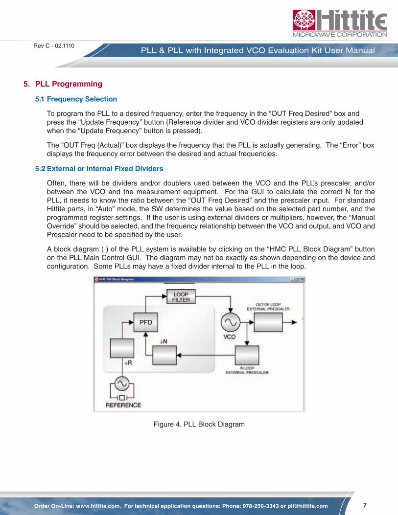
A block diagram ( ) of the PLL system is available by clicking on the “HMC PLL Block Diagram” button on the PLL Main Control GUI. The diagram may not be exactly as shown depending on the device and configuration. Some PLLs may have a fixed divider internal to the PLL in the loop.
Figure 4. PLL Block Diagram

8
Rev C - 02.1110
Order On-Line: www.hittite.com. For technical application questions: Phone: 978-250-3343 or [email protected]
PLL & PLL with Integrated VCO Evaluation Kit User Manual
5.3 Frequency Step in Channel Size
To step up/down in frequency, enter the desired frequency step size in MHz in the “OUT Freq Step” window and press the “Up”/”Down” button.
5.4 Fractional Mode
To operate in Fractional Mode, check the “Frac Mode” box. It is recommended to run the provided register file for the desired mode (Fractional or Integer) for best spectral performance as there are other registers that need configuring when changing between these two modes.
5.5 Frequency Scan
A convenient Scan feature is included to find the locking range of the PLL/VCO combination. Press the “Scan VCO Frequency” button and select “Start Scan” to use the default start scan parameters. The software will start programming different frequencies looking for lock, sweeping out the operating frequency range. The upper, lower and center frequencies are reported on the form.
5.6 Check Lock
The “LOCKED”/”UNLOCKED” indicator is updated every time the “Update Frequency” button is pressed. You can confirm the locked state at any time by pressing the “Check Lock” button.
5.7 Frequency Hopping
When performing settling time measurements, the PLL can also be configured to hop between two specified frequencies entered in the “Frequency Hop” window. The “Dwell Time” is not well calibrated and only offers a crude time estimation. It should not be relied upon for accurate hop timing.
5.8 Register Read/Write
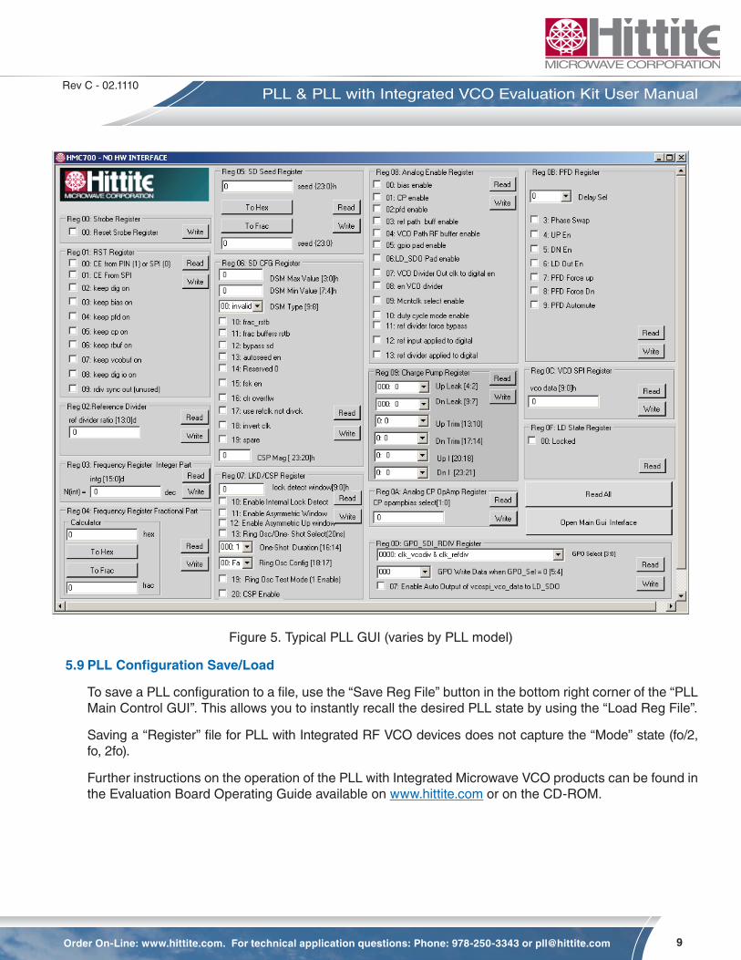
“SPI Read/Write” buttons provide direct register read/write capability in Hex. These are debug tools. To observe all the detailed register states, click the “Open Detailed GUI” button and the window in Figure 5 will open. Each register is controlled by its own “Read” and “Write” button in its sub-panel. Changes made by clicking on any check box are only implemented upon clicking that register’s “Write” button. Similarly a panel is only updated after the “Read” button is clicked.
9
Rev C - 02.1110
Order On-Line: www.hittite.com. For technical application questions: Phone: 978-250-3343 or [email protected]
PLL & PLL with Integrated VCO Evaluation Kit User Manual
Figure 5. Typical PLL GUI (varies by PLL model)
5.9 PLL Configuration Save/Load
To save a PLL configuration to a file, use the “Save Reg File” button in the bottom right corner of the “PLL Main Control GUI”. This allows you to instantly recall the desired PLL state by using the “Load Reg File”.
Saving a “Register” file for PLL with Integrated RF VCO devices does not capture the “Mode” state (fo/2, fo, 2fo).
Further instructions on the operation of the PLL with Integrated Microwave VCO products can be found in the Evaluation Board Operating Guide available on www.hittite.com or on the CD-ROM.
10
Rev C - 02.1110
Order On-Line: www.hittite.com. For technical application questions: Phone: 978-250-3343 or [email protected]
PLL & PLL with Integrated VCO Evaluation Kit User Manual
6. Hittite PLL Design Tool
Hittite PLL Design Software is a powerful tool that can be used to model and analyze performance of Hittite’s PLLs. The tool can be used to:
• Model Integer and Fractional-N PLL performance
• Design loop filter component values
• Model and analyze individual and composite noise contributions
• Model frequency and phase settling time
The PLL Design & Analysis Tool uses MathWorks’ MCR (Matlab Compiler Runtime) Library which is included in the installation package. Hittite Microwave Corporation’s limited rights to the deployment of MCR are governed by a license agreement between Hittite Microwave Corporation and MathWorks.
6.1 Using the Hittite PLL Design & Analysis Tool
1. The Hittite PLL Design tool requires parameters to be initialized before running a simulation. From the main software window select File, Open and select the appropriate .mat or .pll file.
2. Enter/modify design parameters to tailor the simulation to your requirements (VCO frequency, PFD frequency, Loop BW, Phase Margin, etc.). Press the ‘Compute’ button in the lower right corner to graphically display simulated performance data.
3. Design an optimal loop filter by clicking on the Filter Design button to open the Loop Filter Design dialog. The Loop Filter Design tool provides various loop filter topology options and configurations.
4. Edit individual noise contributors ranging from crystal oscillator, reference path, phase detector, VCO, RF divider, operational amplifier, delta-sigma modulator, etc. by clicking on Noise Contributors button.
a. Model and simulate the effect of VCO gain variation across VCO tuning range.
b. Model and analyze the effect of power supply noise on the loop performance from various PLL components.
5. View graphical displays of various modelled performance metrics by choosing the desired category from the Select Plot Type drop down menu.
6. Observe modelled loop parameters summary from Loop Parameters display.
7. Generate detailed HTML reports outlining simulation setup and resulting performance by selecting Generate Reports from the Tools menu.
7. Technical Support
Please contact [email protected] for any questions. Hittite Microwave provides local direct support in many areas around the world. Please see the “Contact Us” page at www.hittite.com.
11
Rev C - 02.1110
Order On-Line: www.hittite.com. For technical application questions: Phone: 978-250-3343 or [email protected]
PLL & PLL with Integrated VCO Evaluation Kit User Manual

20 Alpha Road Chelmsford, MA 01824Phone: 978-250-3343 • Fax: 978-250-3373 • [email protected]
Order On-Line at: www.hittite.com Receive the latest product releases - click on “My Subscription”