
User Manual, ThorCam Application Software
50
ThorCam User Guide
Transcript of User Manual, ThorCam Application Software

ThorCam
User Guide

ThorCam User Guide
Table of Contents
Chapter 1 Safety................................................................................................................................... 1
1.1. Warning Symbol Definitions ........................................................................................ 1
1.2. Precautions ................................................................................................................... 1
1.3. Tool Tips ....................................................................................................................... 1
1.4. Accessories and Customization .................................................................................. 1
Chapter 2 Description ......................................................................................................................... 2
2.1. Introduction ................................................................................................................... 2 2.1.1. Optional Items ....................................................................................................................... 2 2.1.2. Recommended System Requirements ................................................................................. 2
Chapter 3 Using ThorCam .................................................................................................................. 3
3.1. Launching the application ........................................................................................... 3
3.2. The Live Window .......................................................................................................... 4
3.3. Scientific Camera Controls .......................................................................................... 4
3.3.1. Start/Stop Capture .................................................................................................. 4
3.3.2. Snapshot ........................................................................................................................ 4
3.3.3. Start/Stop Record .................................................................................................... 4
3.3.4. Rotate 90 Degrees ................................................................................................. 5
3.3.5. Mirror Flip Horizontal or Vertical ............................................................................ 5
3.3.6. Camera Settings (Scientific Cameras) .......................................................................... 6
3.3.7. Info ............................................................................................................................... 15
3.3.8. Tool Tips and Announcements ................................................................................. 15
3.3.9. Camera Settings (Compact Scientific Cameras) ......................................................... 16
3.4. DCx-Series Camera Controls ..................................................................................... 20
3.4.1. Load/Save Camera Settings ........................................................................................ 20
3.4.2. Start Capture ............................................................................................................... 20
3.4.3. Snapshot ...................................................................................................................... 20
3.4.4. Start Continuous Trigger ............................................................................................. 20
3.4.5. Snapshot Trigger ......................................................................................................... 21
3.4.6. Start/Stop Record ........................................................................................................ 21
3.4.7. Camera Settings (DCx-Series Cameras) .................................................................... 21
3.5. Common Control and Analysis Tools ....................................................................... 26 3.5.1. Pan/Zoom ............................................................................................................................ 26
3.5.2. Timed Series ................................................................................................................ 26
3.5.3. Save Image .................................................................................................................. 26

ThorCam User Guide
3.5.4. Image Save Configuration Tool ................................................................................... 27
3.5.5. Browse Saved Images ................................................................................................. 28
3.5.6. Histogram .................................................................................................................... 28
3.5.7. Horizontal Line Profile ................................................................................................. 30
3.5.8. Vertical Line Profile ...................................................................................................... 30
3.5.9. Pixel Peeker ................................................................................................................. 31
3.5.10. Analysis ROI ........................................................................................................ 31
3.5.11. Tally Counter ............................................................................................................... 31
3.5.12. , , Image Resize: Fit to Window, Display 1:1, Display 1:2 ................................ 31
3.5.13. Reticle .......................................................................................................................... 31
3.5.14. Display Settings ........................................................................................................... 31
3.5.15. Plug-ins ........................................................................................................................ 32
3.6. Common Annotation functions ................................................................................. 33
3.6.1. , , , Draw Freehand, Line, Rectangle, Circle ............................................... 33
3.6.2. Draw Text ..................................................................................................................... 33
3.6.3. Measure ........................................................................................................................ 33
3.6.4. Choose Annotation Color ............................................................................................ 33
3.6.5. Undo Last Annotation ................................................................................................... 33
3.7. Reading Saved Images ............................................................................................... 33
3.7.1. Multi-Page TIFF sequence Playback Controls .............................. 34 3.7.2. Analysis of saved images .................................................................................................... 34
Chapter 4 Appendix ........................................................................................................................... 35
4.1. Appendix A: Plug-ins ................................................................................................. 35
4.2. Appendix B: Pseudocolor .......................................................................................... 40
4.3. Appendix C: Polarization Tools ................................................................................. 42 4.3.1. Selection and display of Polarization Parameters............................................................... 42 4.3.2. Expression of Polarization Parameter Numerical Values ................................................... 43
4.4. Appendix D: TIFF Metadata Tags .............................................................................. 45
Chapter 5 Thorlabs Worldwide Contacts ........................................................................................ 46
ThorCam User Guide Chapter 1: Safety
Rev. U, December 8, 2021 Page 1
Chapter 1 Safety
1.1. Warning Symbol Definitions
Below is a list of warning symbols you may encounter in this manual
Caution: Risk of Electric Shock
Caution: Risk of data loss and damage to operating system
1.2. Precautions
Please read the instruction manual for your ThorCam-compatible instrument carefully before using with ThorCam. All statements regarding safety and technical specifications will only apply when the unit is operated correctly.
1.3. Tool Tips
When encountering this symbol while operating the ThorCam graphical user interface, hover your mouse over it to enable tool tips that include suggestions for using specific features and functions. See section 3.3.8
1.4. Accessories and Customization
Although the system is easily adapted for custom interfaces, to achieve the listed specifications this system should only be used with accessories provided by Thorlabs. Any modification or servicing by unqualified personnel renders the warranty null and void, leaving Thorlabs free of liability. Please contact Thorlabs for questions on customization.

ThorCam User Guide Chapter 2: Description
Page 2 ITN000493-D02
Chapter 2 Description
2.1. Introduction
This manual is a functional overview of the ThorCam software application, and is meant to be a companion to your camera’s User Manual.
ThorCam works with the general-purpose DCU- and DCC-series cameras and the high-performance Scientific and Compact Scientific cameras.
ThorCam is installed as part of your camera software installation process. Please follow the instructions in the User Manual or Quick Start Guide that accompanied your camera.
2.1.1. Optional Items
• Auxiliary I/O Patch cable – The auxiliary connector on the camera allows the user to access optional camera control and internal status signals. Please consult your camera’s manual for details.
2.1.2. Recommended System Requirements
• Operating System: Windows® 7, 10, and 11 (32 and 64 Bit)a
• Processor (CPU): ≥3.0 GHz Intel Core (i5 or Higher)b
• Memory (RAM): ≥8 GB
• Hard Drive: ≥500 GB (SATA) Solid State Drive (SSD)c
• Graphics Card: Dedicated Adapter with ≥256 MB RAMd
• Motherboard:
▪ USB 3.0 (-USB) Cameras: Integrated Intel USB 3.0 Controller
or One Unused PCIe x1 Slot (for Item # USB3-PCIE)
▪ GigE (-GE) Cameras: One Unused PCIe x1 Slot
▪ Camera Link (-CL) Cameras: One Unused PCIe x4/x8/x16 Slot
a- Windows® 8.1 is no longer supported. b- Intel Core i3 processors and mobile versions of Intel processors may not satisfy the requirements. c- We recommend a solid state drive (SSD) for more reliable streaming to disk during image sequence storage. d- On-board/integrated graphics solutions present on Intel Core i5 and i7 processors are also acceptable.

ThorCam User Guide Chapter 3: Using ThorCam
Rev. U, December 8, 2021 Page 3
Chapter 3 Using ThorCam
3.1. Launching the application
To start the camera, launch the ThorCam application. The following splash screen will momentarily appear:
Followed immediately by this window:
When the camera is recognized, it will appear in the pull-down menu as shown below:
If the camera does not appear, check that the power supply is turned on and the camera is properly connected to the computer. Gigabit Ethernet cameras can take 20-30 seconds to register on the network after power is applied. Select Refresh to check for the presence of the camera.
Next, select the camera from the pull-down menu. Any or all cameras can be operated simultaneously after selection from this menu. Each time a camera is selected, the Live window for the chosen camera will appear. The window border is color-coded with a random border color to facilitate association of multiple camera Live windows with their settings and analysis windows. The discovery menu lists the camera name and serial number. The camera name matches the camera model by default, but can be changed by the user. See section 3.3.7

ThorCam User Guide Chapter 3: Using ThorCam
Page 4 ITN000493-D02
3.2. The Live Window
The Live window is the main window for the camera and the one in which images are displayed.
There are a few differences between Live window tool icons and functions for the scientific-grade and DCU-series cameras. This was done to maintain a familiar interface for current DCU-series camera owners while tailoring scientific-grade camera functionality to those customers. The scientific-grade Live window is shown below.
3.3. Scientific Camera Controls
The following controls are specific to the scientific-grade Live window. The DCU specific controls will be covered separately in section 3.4, followed by the controls that are common to both GUIs in section 3.5.
3.3.1. Start/Stop Capture
Commences capture according to the camera settings. When clicked, the start capture button changes to the stop capture button.
3.3.2. Snapshot
Takes a single snapshot from camera with the current camera settings.
3.3.3. Start/Stop Record
Commences recording of capture to a Motion JPEG AVI or multipage TIFF file. The AVI file is saved as a scaled 24-bit image, while the TIFF is saved a variety of formats (bit depth and grayscale/color depends on camera model). When clicked, the start record button changes to stop record. While recording, REC is visible in the upper left corner of the image.
If the “Quick Save” feature has NOT been selected (See Sections 3.5.3 and 3.5.4.) you will be prompted for a file name and location using the native Windows Save As dialog window, otherwise the recording will immediately start - saving to the parameters set-up in the Save Configuration Tool (See Section 3.5.4.).

ThorCam User Guide Chapter 3: Using ThorCam
Rev. U, December 8, 2021 Page 5
3.3.4. Rotate 90 Degrees
Rotates the image in the viewing window clockwise and counter-clockwise in 90 degree steps. This feature will apply when saving images and video captures. The current rotation angle is displayed along the bottom of the Live window.
3.3.5. Mirror Flip Horizontal or Vertical
These two icons will mirror the current image from left to right (Horizontal Flip) or from top-to-bottom (Vertical Flip). This feature will apply when saving images and video captures.
ThorCam User Guide Chapter 3: Using ThorCam
Page 6 ITN000493-D02
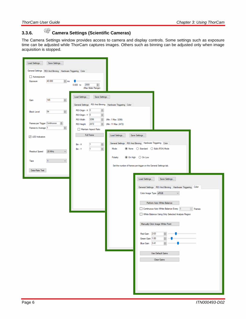
3.3.6. Camera Settings (Scientific Cameras)
The Camera Settings window provides access to camera and display controls. Some settings such as exposure time can be adjusted while ThorCam captures images. Others such as binning can be adjusted only when image acquisition is stopped.
ThorCam User Guide Chapter 3: Using ThorCam
Rev. U, December 8, 2021 Page 7
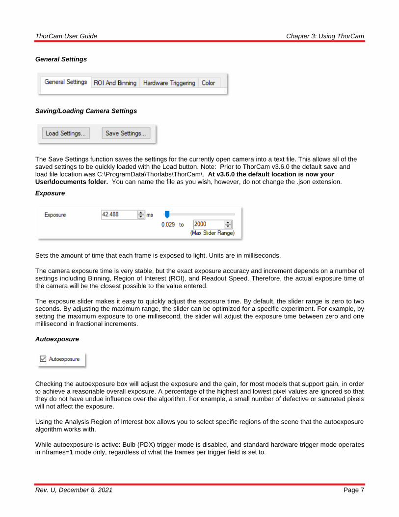
General Settings
Saving/Loading Camera Settings
The Save Settings function saves the settings for the currently open camera into a text file. This allows all of the saved settings to be quickly loaded with the Load button. Note: Prior to ThorCam v3.6.0 the default save and load file location was C:\ProgramData\Thorlabs\ThorCam\. At v3.6.0 the default location is now your User\documents folder. You can name the file as you wish, however, do not change the .json extension.
Exposure
Sets the amount of time that each frame is exposed to light. Units are in milliseconds.
The camera exposure time is very stable, but the exact exposure accuracy and increment depends on a number of settings including Binning, Region of Interest (ROI), and Readout Speed. Therefore, the actual exposure time of the camera will be the closest possible to the value entered.
The exposure slider makes it easy to quickly adjust the exposure time. By default, the slider range is zero to two seconds. By adjusting the maximum range, the slider can be optimized for a specific experiment. For example, by setting the maximum exposure to one millisecond, the slider will adjust the exposure time between zero and one millisecond in fractional increments.
Autoexposure
Checking the autoexposure box will adjust the exposure and the gain, for most models that support gain, in order to achieve a reasonable overall exposure. A percentage of the highest and lowest pixel values are ignored so that they do not have undue influence over the algorithm. For example, a small number of defective or saturated pixels will not affect the exposure.
Using the Analysis Region of Interest box allows you to select specific regions of the scene that the autoexposure algorithm works with.
While autoexposure is active: Bulb (PDX) trigger mode is disabled, and standard hardware trigger mode operates in nframes=1 mode only, regardless of what the frames per trigger field is set to.
ThorCam User Guide Chapter 3: Using ThorCam
Page 8 ITN000493-D02
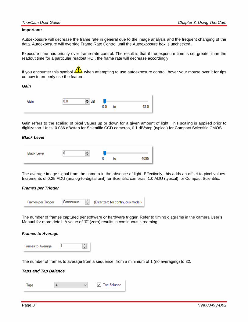
Important:
Autoexposure will decrease the frame rate in general due to the image analysis and the frequent changing of the data. Autoexposure will override Frame Rate Control until the Autoexposure box is unchecked.
Exposure time has priority over frame-rate control. The result is that if the exposure time is set greater than the readout time for a particular readout ROI, the frame rate will decrease accordingly.
If you encounter this symbol when attempting to use autoexposure control, hover your mouse over it for tips on how to properly use the feature.
Gain
Gain refers to the scaling of pixel values up or down for a given amount of light. This scaling is applied prior to digitization. Units: 0.036 dB/step for Scientific CCD cameras, 0.1 dB/step (typical) for Compact Scientific CMOS.
Black Level
The average image signal from the camera in the absence of light. Effectively, this adds an offset to pixel values. Increments of 0.25 ADU (analog-to-digital unit) for Scientific cameras, 1.0 ADU (typical) for Compact Scientific.
Frames per Trigger
The number of frames captured per software or hardware trigger. Refer to timing diagrams in the camera User’s Manual for more detail. A value of “0” (zero) results in continuous streaming.
Frames to Average
The number of frames to average from a sequence, from a minimum of 1 (no averaging) to 32.
Taps and Tap Balance

ThorCam User Guide Chapter 3: Using ThorCam
Rev. U, December 8, 2021 Page 9
Taps: For cameras with multi-tap readout capabilities only. This control sets the number of taps used to read out the CCD, using more taps will provide faster frame rates.
Tap Balance: For multi-tap cameras operating with two or more taps only. Applies a factory-calibrated equalization to each tap to remove the visible “seam” due to natural differences in the signal level for each CCD tap. Tap balance is meant to provide a visually pleasing image and is not absolute. Under extreme contrast stretching and/or camera settings residual tap-to-tap differences can be observed. This is not a malfunction. The 1501x Series cameras will not display the Tap Balance function since they are single tap cameras.
NIR Boost
The 1501x Series cameras provide a special function called NIR Boost that allows for a slight increase of the spectral response of the camera into the near IR wavelengths. This feature is only visible on the monochrome cameras, and color cameras operating in the Unprocessed Image Type. Refer to the Scientific Camera User’s Guide for more information. The check box for NIR Boost is located under the General Settings tab when available - replacing the Tap Balance option.
LED Indicators
The USB3.0 Series cameras provide a special function to allow the user to control the two LED indicators on the rear panel of the camera. If the box is checked, the LEDs will be turned on. Cycling power to the camera will result in the LEDs, by default, being turned on.
Cooling Mode
For scientific CCD cameras with the thermoelectric cooler option only. Turns on or off the camera thermoelectric cooler.
Readout Speed
Selectable 20 MHz or 40 MHz. Faster readout speed results in higher achievable frame rates at the cost of slightly higher readout noise in general.
Data Rate Test
The Data Rate Test button is only active on USB 3.0 Scientific cameras. Running this test will help determine the maximum Clock and Taps settings that your host computer is capable of operating at. Pressing the button will stop any current acquisitions and open the following window:

ThorCam User Guide Chapter 3: Using ThorCam
Page 10 ITN000493-D02
Pressing the Start Test button will commence the test. The Progress bar will indicate the status of the test. Once it has completed, the Speed Gauge window will show the maximum capabilities of your USB 3.0 system. You may choose to use the maximum settings by pressing the Use Result button, or you can simply close the window by clicking on the X.
ROI/Bin Settings
Origin-X and Origin-Y set the origin, or upper left corner of the Region of Interest (ROI). Width and Height determine the width and height of the region of interest. The Full Frame button resets the Region of Interest to the maximum CCD sensing area indicated next to the Width and Height labels.
Width and Height not only sets the size of the data stored in memory and to disk, but it also determines the region that is read from the CCD sensor in the camera. Specifically, only the Height changes the readout area on the CCD. The Width is truncated in software. As a result, Height entries that reduce the vertical size of the region also increase the readout of the chip and vice versa. This increase in readout speed is not directly proportional to ROI vertical size due to overhead in the readout process. ROI does not impact the noise floor.
ThorCam User Guide Chapter 3: Using ThorCam
Rev. U, December 8, 2021 Page 11
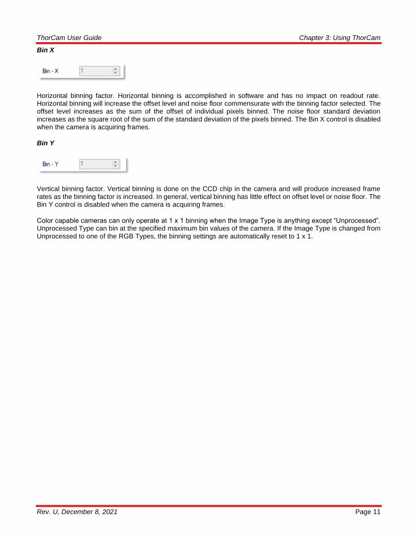
Bin X
Horizontal binning factor. Horizontal binning is accomplished in software and has no impact on readout rate. Horizontal binning will increase the offset level and noise floor commensurate with the binning factor selected. The offset level increases as the sum of the offset of individual pixels binned. The noise floor standard deviation increases as the square root of the sum of the standard deviation of the pixels binned. The Bin X control is disabled when the camera is acquiring frames.
Bin Y
Vertical binning factor. Vertical binning is done on the CCD chip in the camera and will produce increased frame rates as the binning factor is increased. In general, vertical binning has little effect on offset level or noise floor. The Bin Y control is disabled when the camera is acquiring frames.
Color capable cameras can only operate at 1 x 1 binning when the Image Type is anything except “Unprocessed”. Unprocessed Type can bin at the specified maximum bin values of the camera. If the Image Type is changed from Unprocessed to one of the RGB Types, the binning settings are automatically reset to 1 x 1.

ThorCam User Guide Chapter 3: Using ThorCam
Page 12 ITN000493-D02
Hardware Triggering
Mode
Selects the method of triggering the camera. Please see your camera manual for detailed timing diagrams of the exposure modes.
None
Trigger is generated by ThorCam (e.g. pressing the capture button will capture the number of frames in Frames per Trigger setting above.
Standard
Trigger is provided through the camera hardware auxiliary connector. Capture is triggered by the rising or falling edge of the trigger signal according to the HW Trigger Polarity setting, with the exposure value according to the Exposure setting. See also: Frame Rate Control (only available on certain camera models) and Autoexposure.
Bulb (PDX) mode
Trigger is provided through the camera hardware auxiliary connector. Capture is triggered by the rising or falling edge of the trigger signal according to the HW Trigger Polarity setting, with an exposure dependent on the trigger pulse width. See also: Frame Rate Control (only available on certain camera models) and Autoexposure.
Hardware Trigger Polarity
This setting controls whether the camera will respond to the Low-to-High transition of the external trigger (On High) or to the High-to-Low transition of the trigger (On Low).
ThorCam User Guide Chapter 3: Using ThorCam
Rev. U, December 8, 2021 Page 13
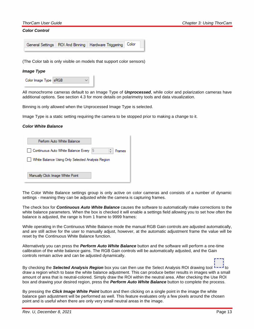
Color Control
(The Color tab is only visible on models that support color sensors)
Image Type
All monochrome cameras default to an Image Type of Unprocessed, while color and polarization cameras have additional options. See section 4.3 for more details on polarimetry tools and data visualization.
Binning is only allowed when the Unprocessed Image Type is selected.
Image Type is a static setting requiring the camera to be stopped prior to making a change to it.
Color White Balance
The Color White Balance settings group is only active on color cameras and consists of a number of dynamic settings - meaning they can be adjusted while the camera is capturing frames.
The check box for Continuous Auto White Balance causes the software to automatically make corrections to the white balance parameters. When the box is checked it will enable a settings field allowing you to set how often the balance is adjusted, the range is from 1 frame to 9999 frames:
While operating in the Continuous White Balance mode the manual RGB Gain controls are adjusted automatically, and are still active for the user to manually adjust, however, at the automatic adjustment frame the value will be reset by the Continuous White Balance function.
Alternatively you can press the Perform Auto White Balance button and the software will perform a one-time calibration of the white balance gains. The RGB Gain controls will be automatically adjusted, and the Gain controls remain active and can be adjusted dynamically.
By checking the Selected Analysis Region box you can then use the Select Analysis ROI drawing tool to draw a region which to base the white balance adjustment. This can produce better results in images with a small amount of area that is neutral-colored. Simply draw the ROI within the neutral area. After checking the Use ROI box and drawing your desired region, press the Perform Auto White Balance button to complete the process. By pressing the Click Image White Point button and then clicking on a single point in the image the white balance gain adjustment will be performed as well. This feature evaluates only a few pixels around the chosen point and is useful when there are only very small neutral areas in the image.
ThorCam User Guide Chapter 3: Using ThorCam
Page 14 ITN000493-D02
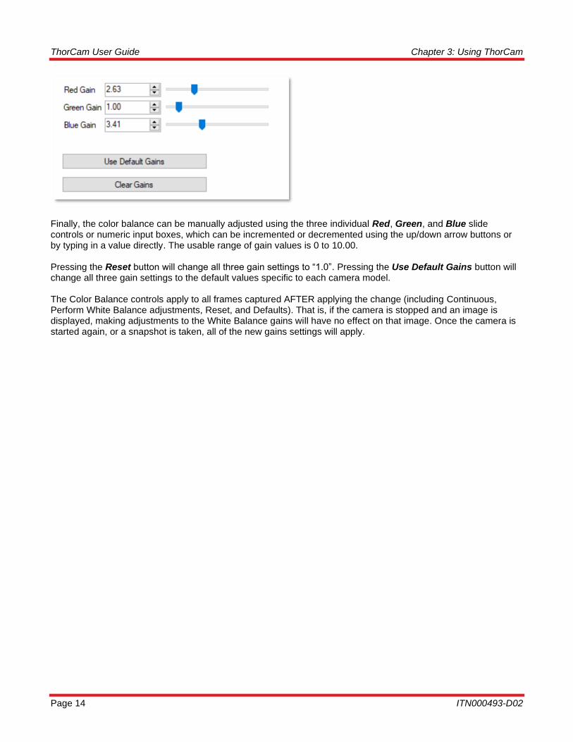
Finally, the color balance can be manually adjusted using the three individual Red, Green, and Blue slide controls or numeric input boxes, which can be incremented or decremented using the up/down arrow buttons or by typing in a value directly. The usable range of gain values is 0 to 10.00. Pressing the Reset button will change all three gain settings to “1.0”. Pressing the Use Default Gains button will change all three gain settings to the default values specific to each camera model. The Color Balance controls apply to all frames captured AFTER applying the change (including Continuous, Perform White Balance adjustments, Reset, and Defaults). That is, if the camera is stopped and an image is displayed, making adjustments to the White Balance gains will have no effect on that image. Once the camera is started again, or a snapshot is taken, all of the new gains settings will apply.

ThorCam User Guide Chapter 3: Using ThorCam
Rev. U, December 8, 2021 Page 15
3.3.7. Info
Provides information pertaining to the camera, such as the camera name, serial number, model, and various embedded firmware version numbers. All TSI cameras are shipped with the Camera Name the same as the Model number. The Info window allows the user to change the camera name to any alpha-numeric format of 31 characters or less, including spaces and special characters. NOTE: Once the camera name has been changed you must close the Live window and cycle power to the camera before the change will take effect in ThorCam.
3.3.8. Tool Tips and Announcements
If you encounter this symbol when attempting to use various controls, hover your mouse over it for tips on how to properly use the feature.
Hover your mouse over any of the features in the camera settings dialog for a brief description of that feature.
Depending on the camera model, various announcements may be displayed along the lower GUI window. The example below would occur when a cooled CMOS camera’s power supply is disconnected. Other announcements include a “Pending” acquisition status, and tips for when operating Equal Exposure Pulse, as well as the path information of an image that is being saved.

ThorCam User Guide Chapter 3: Using ThorCam
Page 16 ITN000493-D02
3.3.9. Camera Settings (Compact Scientific Cameras)
The Camera Settings window for the Compact Scientific family of cameras provides access to camera and display controls. While being quite similar to the Scientific Camera settings, there are a few differences that are discussed here, otherwise please refer to the Scientific Camera settings descriptions above.
ThorCam User Guide Chapter 3: Using ThorCam
Rev. U, December 8, 2021 Page 17
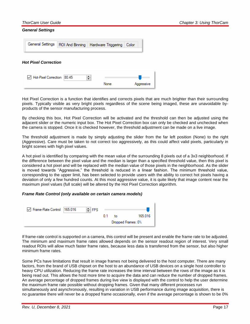
General Settings
Hot Pixel Correction
Hot Pixel Correction is a function that identifies and corrects pixels that are much brighter than their surrounding pixels. Typically visible as very bright pixels regardless of the scene being imaged, these are unavoidable by-products of the sensor manufacturing process.
By checking this box, Hot Pixel Correction will be activated and the threshold can then be adjusted using the adjacent slider or the numeric input box. The Hot Pixel Correction box can only be checked and unchecked when the camera is stopped. Once it is checked however, the threshold adjustment can be made on a live image.
The threshold adjustment is made by simply adjusting the slider from the far left position (None) to the right (Aggressive). Care must be taken to not correct too aggressively, as this could affect valid pixels, particularly in bright scenes with high pixel values.
A hot pixel is identified by comparing with the mean value of the surrounding 8 pixels out of a 3x3 neighborhood. If the difference between the pixel value and the median is larger than a specified threshold value, then this pixel is considered a hot pixel and will be replaced with the median value of those pixels in the neighborhood. As the slider is moved towards “Aggressive,” the threshold is reduced in a linear fashion. The minimum threshold value, corresponding to the upper limit, has been selected to provide users with the ability to correct hot pixels having a deviation of only a few hundred counts. At this most aggressive value, it is quite likely that image content near the maximum pixel values (full scale) will be altered by the Hot Pixel Correction algorithm.
Frame Rate Control (only available on certain camera models)
If frame-rate control is supported on a camera, this control will be present and enable the frame rate to be adjusted. The minimum and maximum frame rates allowed depends on the sensor readout region of interest. Very small readout ROIs will allow much faster frame rates, because less data is transferred from the sensor, but also higher minimum frame rates.
Some PCs have limitations that result in image frames not being delivered to the host computer. There are many factors, from the brand of USB chipset on the host to an abundance of USB devices on a single host controller to heavy CPU utilization. Reducing the frame rate increases the time interval between the rows of the image as it is being read out. This allows the host more time to acquire the data and can reduce the number of dropped frames. An average percentage of dropped frames during live view is displayed with the control to help the user determine the maximum frame rate possible without dropping frames. Given that many different processes run simultaneously and asynchronously, resulting in variation in USB performance during image acquisition, there is no guarantee there will never be a dropped frame occasionally, even if the average percentage is shown to be 0%
ThorCam User Guide Chapter 3: Using ThorCam
Page 18 ITN000493-D02
The frame-rate control can also be used to adjust frame rate to perform a timed sequence, or time lapse, with better accuracy than that of the "timed series" feature in ThorCam.
When the Frame Rate Control box is unchecked the camera will operate at its maximum FPS for the given settings of Exposure, ROI and Binning. When the box is checked the adjustment slider is enabled, as is the numeric input field and increment/decrement arrows. Adjust the FPS until the Dropped Frames percentage reduces to 0%.
Standard external hardware triggering with frame-rate control is only allowed when frames per trigger is set to 0 (continuous) – allowing you to start a continuous video stream with a single external trigger event. Single frame triggered acquisition is not allowed. Bulb (PDX) mode triggering is not allowed at all when using frame-rate control.
If you encounter this symbol when attempting to use frame-rate control, hover your mouse over it for tips on how to properly use the feature.
Optimization (CS2100M-USB and CC215M only)
Image optimization can be achieved using the Optimization selections. A choice of “Low read-noise” sets the cameras master clock to a lower frequency, thereby reducing the read-noise. A choice of “High frame rate” increases the master clock, resulting in a higher frame rate. This function is only available on Quantalux sCMOS models.
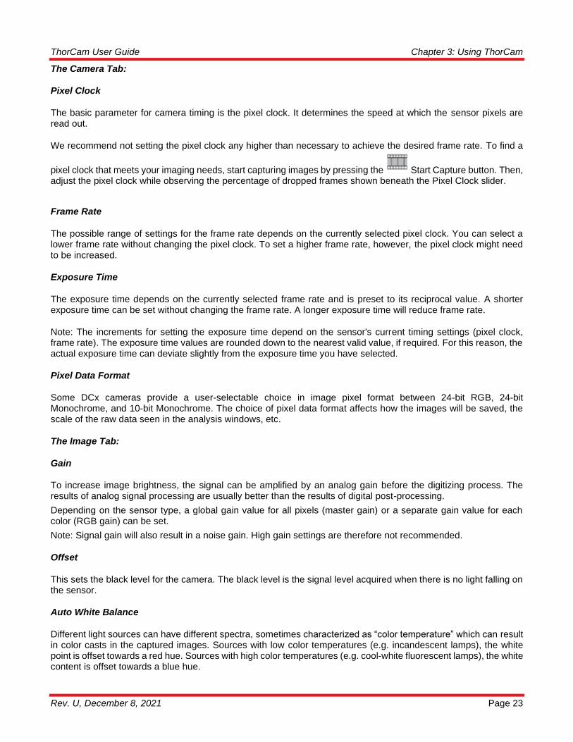
Equal Exposure Pulse (CS2100M-USB and CC215M only)
The Equal-Exposure Pulse is an output signal available on the Quantalux sCMOS camera’s I/O connector (refer to the Camera User Manuals for details on this connector). When the Equal-Exposure Pulse (EEP) box is checked, the Strobe_Out signal on the I/O connector is reconfigured to be active only after the sensor’s “rolling reset” function has completed. The signal will remain active (logical high) until the sensor’s “rolling readout” function begins. This means that the EEP signal is high only during the time when all of the sensor’s pixels are simultaneously integrating.
The Equal-Exposure Pulse can only be produced when the exposure time is greater than the frame period - defined as 1/fps. Exposure time, Optimization rate, and ROI all determine the final fps, so varying combinations of all will determine when the signal can be produced.
When a user checks the Equal-Exposure Pulse (EEP) selection box, all camera settings parameters are greyed out and held in their current state. Based on these parameters AND the value in the EEP Pulse Width (ms) input box, ThorCam calculates the exposure setting required to produce an Equal Exposure pulse of the duration entered into the EEP Pulse Width (ms) input box. This new total exposure value will be shown in the greyed out Exposure (ms) box.
The EEP Pulse Width (ms) value is the only parameter that can be changed when the Equal-Exposure Pulse box is checked. In order to make adjustments to other parameters you must first uncheck the Equal-Exposure Pulse box.
The Equal-Exposure Pulse is primarily meant to be used to control a light source that will expose a scene for a precise duration only when all pixels are integrating charge. The result is a more consistent exposure across the entire sensor. The user must keep in mind that the Exposure (ms) setting in the Camera Settings dialog will not be

ThorCam User Guide Chapter 3: Using ThorCam
Rev. U, December 8, 2021 Page 19
the effective exposure produced from the external light source. The effective exposure will be the value in the EEP Pulse Width (ms) setting.
For example, a Quantalux at full frame ROI, with an Optimization setting of Low read-noise, and the EEP Pulse Width (ms) time in the Setting window set to 10.0mS, will have an effective exposure of 10mS, even though your adjusted Exposure (ms) setting will be 43.3mS.
Be aware that the Equal-Exposure Pulse has no bearing on continuously illuminated scenes, and the resulting exposure will be whatever the actual Exposure (ms) time is set to. Please refer to the Compact Camera User Manual for additional timing diagrams and related information.
The minimum EEP Pulse Width is 1 ms, with increments of 0.1 ms thereafter. This function is only available on Quantalux sCMOS models.
Gain and Black Level Controls
The Gain control for most Compact Scientific cameras accepts values from 0 to 48.0 dB. The Black Level offset control accepts values from 0 to 4095.
CS135 models provide four discreet gain settings of -7.5 dB, -5.6 dB, 0 dB (default), and 5.3 dB. These settings can only be changed using the mouse scroll wheel or the up/down arrow buttons on your keyboard or in the Settings window Gain parameter.
CS135 models do not have Black Level control. Quantalux sCMOS models do not have Gain or Black Level control.

ThorCam User Guide Chapter 3: Using ThorCam
Page 20 ITN000493-D02
3.4. DCx-Series Camera Controls
3.4.1. Load/Save Camera Settings
Specific camera settings can be saved in, and retrieved from a Thorlabs Camera Profile (.tcp) file. This icon allows you to name the file and save it to a suitable folder on the host computer. The file will contain information from the
camera settings dialog only.
3.4.2. Start Capture
Commences capture according to capture settings. Clicking again stops capture.
3.4.3. Snapshot
Takes a single-frame capture.
3.4.4. Start Continuous Trigger
Arms the camera for capture using external hardware trigger. See camera user manual for further information.

ThorCam User Guide Chapter 3: Using ThorCam
Rev. U, December 8, 2021 Page 21
3.4.5. Snapshot Trigger
Arms the camera for single capture using external hardware trigger. See camera user manual for further information.
3.4.6. Start/Stop Record
Commences recording of capture to a Motion JPEG AVI (in 24-bit RGB mode) or multipage TIFF file (in 10-bit Monochrome mode). The recording dialog box (for both AVI and TIFF) gives you the option of limiting the recording size by setting the maximum number of frames or the maximum file size in MB.
The actual record is commenced in the Record Movie dialog box by pressing the “Record” button. The Record button then changes to a “Stop” button. Press this button to stop the recording.
The Save Path Preview is informational only and shows where the recording will be saved. To change this location
press the icon and you will be redirected to the Save Configuration dialog (See Sections 3.5.3 and 3.5.4.)
The file type, format, location, and name of the stored image can be viewed or changed in the Save Configuration dialog.
3.4.7. Camera Settings (DCx-Series Cameras)
Launches the Camera Settings window to allow control of camera parameters.

ThorCam User Guide Chapter 3: Using ThorCam
Page 22 ITN000493-D02
ThorCam User Guide Chapter 3: Using ThorCam
Rev. U, December 8, 2021 Page 23
The Camera Tab:
Pixel Clock
The basic parameter for camera timing is the pixel clock. It determines the speed at which the sensor pixels are read out.
We recommend not setting the pixel clock any higher than necessary to achieve the desired frame rate. To find a
pixel clock that meets your imaging needs, start capturing images by pressing the Start Capture button. Then, adjust the pixel clock while observing the percentage of dropped frames shown beneath the Pixel Clock slider.
Frame Rate
The possible range of settings for the frame rate depends on the currently selected pixel clock. You can select a lower frame rate without changing the pixel clock. To set a higher frame rate, however, the pixel clock might need to be increased.
Exposure Time
The exposure time depends on the currently selected frame rate and is preset to its reciprocal value. A shorter exposure time can be set without changing the frame rate. A longer exposure time will reduce frame rate.
Note: The increments for setting the exposure time depend on the sensor's current timing settings (pixel clock, frame rate). The exposure time values are rounded down to the nearest valid value, if required. For this reason, the actual exposure time can deviate slightly from the exposure time you have selected.
Pixel Data Format
Some DCx cameras provide a user-selectable choice in image pixel format between 24-bit RGB, 24-bit Monochrome, and 10-bit Monochrome. The choice of pixel data format affects how the images will be saved, the scale of the raw data seen in the analysis windows, etc.
The Image Tab:
Gain
To increase image brightness, the signal can be amplified by an analog gain before the digitizing process. The results of analog signal processing are usually better than the results of digital post-processing.
Depending on the sensor type, a global gain value for all pixels (master gain) or a separate gain value for each color (RGB gain) can be set.
Note: Signal gain will also result in a noise gain. High gain settings are therefore not recommended.
Offset
This sets the black level for the camera. The black level is the signal level acquired when there is no light falling on the sensor.
Auto White Balance
Different light sources can have different spectra, sometimes characterized as “color temperature” which can result in color casts in the captured images. Sources with low color temperatures (e.g. incandescent lamps), the white point is offset towards a red hue. Sources with high color temperatures (e.g. cool-white fluorescent lamps), the white content is offset towards a blue hue.
ThorCam User Guide Chapter 3: Using ThorCam
Page 24 ITN000493-D02
The white balance control feature uses the RGB gain settings of the camera to correct the white level. This is achieved by adjusting the gain controls within the 0-100 % range until the red or blue channel matches the average brightness of the green channel. In order to manually influence the color rendering, you can adjust the setpoint values for the red and blue channels relative to the green channel by using an offset value.
Gamma
Applies a digital gamma correction in software which applies a gamma characteristic to the image. Sensor gamma applies additional gamma correction in hardware if the camera model supports it.
The Image Enhancement Tab:
Edge Enhancement
This function enables/disables a software edge-enhancement filter. This function results in a higher computer CPU load.
Color Saturation
Adjusts the color saturation in software. In the U channel, this information results from the difference between the blue level and Y (luminance), in the V channel from the difference between the red level and Y.
Sensor Hot Pixel Correction
During the manufacture of our cameras, all sensors that will be used in DCx Cameras are checked for hot pixels. In the process, images are taken with a darkened sensor and long exposure times. Pixels with a brightness higher than a specific value are classified as hot pixels. Hot Pixel Correction suppresses these pixel values.
Area of Interest (AOI)
Using this function, you can set the size and position of an area of interest (AOI) within an image. In this case, only data included in this AOI will be read out and transferred to the computer. The smaller partial image enables the camera to use a higher frame rate. Note: Area of interest is sometimes called region of interest (ROI).
The Binning/Subsampling Tab:
Binning
Binning is a function that averages or adds multiple sensor pixels to obtain a single value. This reduces the amount of data to be transferred and enables higher camera frame rates. The captured image has a lower resolution but still the same field of view compared to the full-resolution image. This mode can be used as a fast preview mode for high-resolution cameras.
Subsampling
Subsampling is a technique that skips multiple sensor pixels when reading out image data. This reduces the amount of data to be transferred and enables higher camera frame rates. The captured image has a lower resolution but still the same field of view compared to the full-resolution image. This mode can be used as a fast preview mode for high-resolution cameras.
The Shutter Tab:
Global Shutter
On a global shutter sensor, all pixel rows are reset and then exposed simultaneously. At the end of the exposure, all rows are simultaneously moved to a darkened area of the sensor. The pixels are then read out row by row.

ThorCam User Guide Chapter 3: Using ThorCam
Rev. U, December 8, 2021 Page 25
Exposing all pixels simultaneously has the advantage that fast-moving objects can be captured without geometric distortions. Sensors that use the global shutter system are more complex in design than rolling shutter sensors.
All CCD sensors as well as some CMOS sensors use the global shutter method.
Rolling Shutter
With the rolling shutter method, the pixel rows are reset and exposed one row after another. At the end of the exposure, the lines are read out sequentially. As this results in a time delay between the exposure of the first and the last sensor rows, captured images of moving objects are distorted.
To counteract this effect, the DCx Camera software provides a global flash window where you set the time by which flash activation is delayed. You can also specify the flash duration. This allows implementing a global flash functionality which exposes all rows of a rolling shutter sensor simultaneously.
Rolling Shutter with Global Start
Some rolling shutter sensors also provide a global start mode, which starts exposure of all rows simultaneously. For best results, use a flash for this mode. No light is allowed to fall on the sensor outside the flash period because otherwise the image brightness will be distributed unevenly.
Log Mode
Log mode is a special mode in some camera models that defines a threshold at which the linear response of the camera switches over to a logarithmic response.
The Trigger Tab:
Trigger
In trigger mode, the camera is on standby until it receives an electrical input signal telling it to start acquisition. The Trigger settings tab allows you to set the delay time between the trigger and start of acquisition, whether the trigger is a rising or falling edge, and how long the camera should wait for a trigger signal before timing out.
The Input/Output Tab:
The input/output tab allows you to setup hardware input/output signals with camera. Not all cameras support all features.
ThorCam User Guide Chapter 3: Using ThorCam
Page 26 ITN000493-D02
3.5. Common Control and Analysis Tools
3.5.1. Pan/Zoom
To pan the image, left click and hold the left mouse button. Drag to pan around the image.
To zoom, use the mouse wheel to zoom in and out. This applies to both the DCU-series and scientific-grade Live windows.
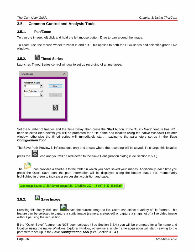
3.5.2. Timed Series
Launches Timed Series control window to set up recording of a time lapse.
Set the Number of Images and the Time Delay, then press the Start button. If the “Quick Save” feature has NOT been selected (see below) you will be prompted for a file name and location using the native Windows Explorer window, otherwise the timed series will immediately start - saving to the parameters set-up in the Save Configuration Tool.
The Save Path Preview is informational only and shows where the recording will be saved. To change this location
press the icon and you will be redirected to the Save Configuration dialog (See Section 3.5.4.).
The icon provides a short-cut to the folder in which you have saved your images. Additionally, each time you press the Quick Save icon, the path information will be displayed along the bottom status bar, momentarily highlighted in green to indicate a successful acquisition and save.
3.5.3. Save Image
Pressing this floppy disk icon saves the current image to file. Users can select a variety of file formats. This feature can be selected to capture a static image (camera is stopped) or capture a snapshot of a live video image without pausing the acquisition.
If the “Quick Save” feature has NOT been selected (See Section 3.5.4.) you will be prompted for a file name and location using the native Windows Explorer window, otherwise a single frame acquisition will start - saving to the parameters set-up in the Save Configuration Tool (See Section 3.5.4.).

ThorCam User Guide Chapter 3: Using ThorCam
Rev. U, December 8, 2021 Page 27
The icon provides a short-cut to the folder in which you have saved your images. Additionally, each time you
press the Save Image icon , the path information will be displayed along the bottom status bar, momentarily highlighted in green to indicate a successful acquisition and save.
Annotations and display settings are not saved in TIFF images. Use PNG or JPEG formats if annotation is to be saved.
PNG and JPEG formats are provided in order to save an image as displayed. Both display rendering (contrast) and annotations are preserved. PNG or Portable Network Graphics file format converts the image in 8 bits/pixel/color uncompressed. This results in larger images but with no loss of quality relative to the image as it is displayed in the Live window. JPEG format also saves the image in 8 bits/pixel/color, but the image is JPEG-compressed. This will create much smaller files. Use JPEG for casual documentation or email.
3.5.4. Image Save Configuration Tool
The file type, format, location, and name of a stored image can be viewed or changed in the Save Configuration dialog. The default path is the Window’s Users\Pictures folder with a default image prefix of “image”. Using the Configuration set-up you can change the image name (Image Prefix), and browse to any folder you wish to save to, provided you have write-access privileges. The parameter fields are only active when the Quick Save box is checked.
The first recording captured will have a file name consisting of the Image Filename Prefix appended with a timestamp. As additional recordings are captured and saved they will be automatically appended with an increasing timestamp.
The save path displayed in the path preview can be the actual location an image or recording is to be saved to, but the file name is not guaranteed. It is possible that another image or recording of the same name has been previously saved to the same path displayed in the path preview. When this happens the existing file will not be overwritten and ThorCam will save the new image or recording using the naming scheme previously outlined. The actual file name will be displayed on the status bar of the Live window.
Leaving the Quick Save box checked allows you to capture images using the Save Image Icon without having to browse to a location to save each image.
ThorCam User Guide Chapter 3: Using ThorCam
Page 28 ITN000493-D02
By checking the Disable live view while recording box you can disable the live image while a recording is being made. This will reduce the instances of dropped frames while recording. This feature is available for all Timed Series & Record choices except “8-bit Motion-JPEG with Annotations (*avi)”.
Note: Images with > 8 bits/pixel are often not properly rendered in imaging programs such as Microsoft photo viewer. To properly display them you should open them in the ThorCam viewer (see 3.7) or a capable imaging application such as ImageJ or IrfanView.
All Save Configuration settings are retained and apply to all subsequent ThorCam sessions.
3.5.5. Browse Saved Images
The Browse Saved Images icon provides a shortcut to your current location for saving Recordings, Time Series, and Quick Save Images.
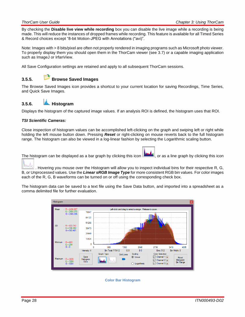
3.5.6. Histogram
Displays the histogram of the captured image values. If an analysis ROI is defined, the histogram uses that ROI.
TSI Scientific Cameras:
Close inspection of histogram values can be accomplished left-clicking on the graph and swiping left or right while holding the left mouse button down. Pressing Reset or right-clicking on mouse reverts back to the full histogram range. The histogram can also be viewed in a log-linear fashion by selecting the Logarithmic scaling button.
The histogram can be displayed as a bar graph by clicking this icon , or as a line graph by clicking this icon
. Hovering you mouse over the Histogram will allow you to inspect individual bins for their respective R, G, B, or Unprocessed values. Use the Linear sRGB Image Type for more consistent RGB bin values. For color images each of the R, G, B waveforms can be turned on or off using the corresponding check box.
The histogram data can be saved to a text file using the Save Data button, and imported into a spreadsheet as a comma delimited file for further evaluation.
Color Bar Histogram
ThorCam User Guide Chapter 3: Using ThorCam
Rev. U, December 8, 2021 Page 29
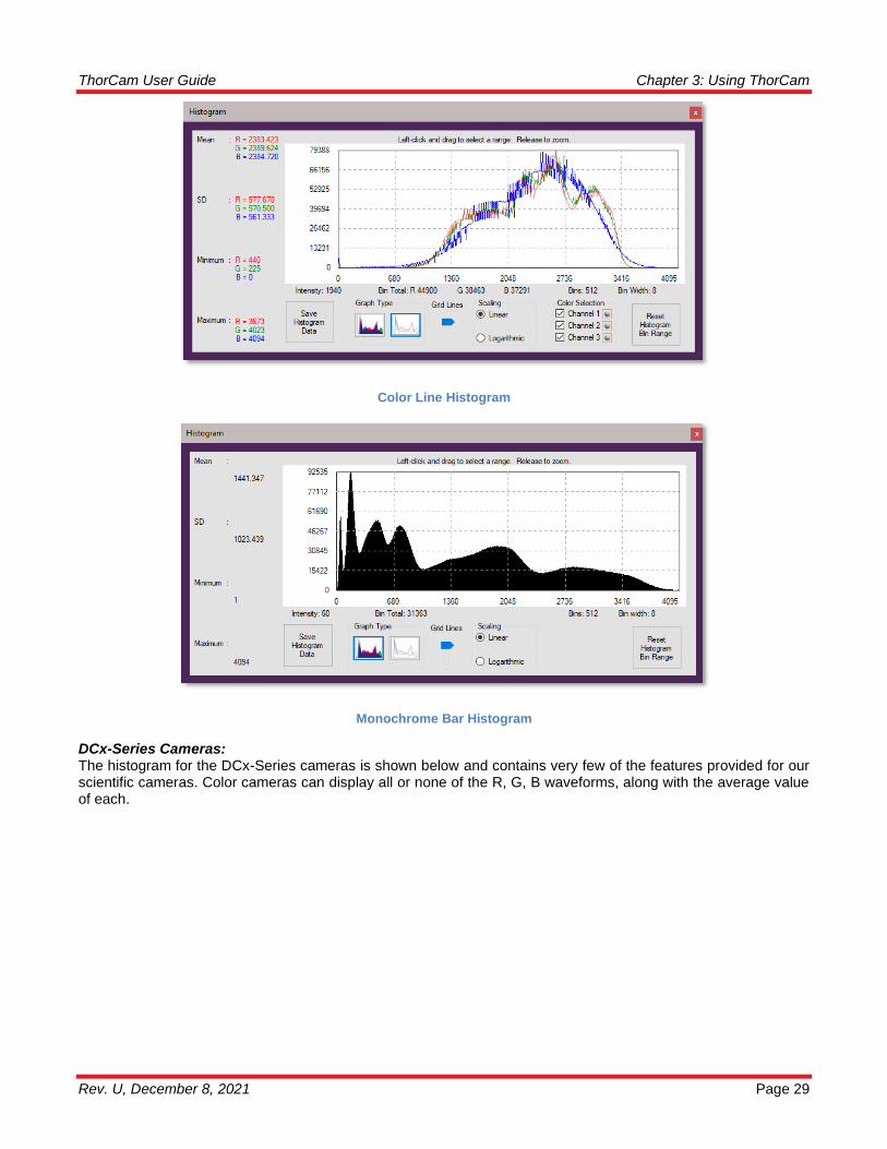
Color Line Histogram
Monochrome Bar Histogram
DCx-Series Cameras: The histogram for the DCx-Series cameras is shown below and contains very few of the features provided for our scientific cameras. Color cameras can display all or none of the R, G, B waveforms, along with the average value of each.

ThorCam User Guide Chapter 3: Using ThorCam
Page 30 ITN000493-D02
DCx-Series Histogram
A note about histograms: Due to the method that the histogram values are calculated, in conjunction with the various color balancing gains applied to the digital data received from the camera, there may be certain conditions that result in a histogram having the appearance of missing data bits. This is not an indication of poor image processing from the camera and only a side-effect of the complexities of the graphical representation of the data.
3.5.7. Horizontal Line Profile
Draws a horizontal line across the image and displays the values of the pixels along the line in a separate window. The position of the line can be moved by left-clicking anywhere in the image. With your cursor anywhere within the profile graph, a set of cross-hairs appear allowing you to measure the intensity of specific pixels. For color cameras, individual R, G, B plots can be viewed or turned-off by checking the appropriate box. Clicking on the Horizontal Line Profile icon a second time removes the line and window.
3.5.8. Vertical Line Profile
Draws a vertical line across the image and displays the values of the pixels along the line in a separate window. The position of the line can be moved by left-clicking anywhere in the image. Other functionality is the same as the Horizontal Line Profile. Clicking on the Vertical Line Profile icon a second time removes the line and window.
ThorCam User Guide Chapter 3: Using ThorCam
Rev. U, December 8, 2021 Page 31
3.5.9. Pixel Peeker
Shows the user the value of the pixel that the mouse is currently over (gray box in center), as well as pixel values in the surrounding neighborhood. This window is resizable to allow viewing of a smaller/larger neighborhood.
3.5.10. Analysis ROI
Allows a rectangular region to be drawn in the image for analysis such as histogram, mean, and standard deviation, auto-scaling of the image display, and autoexposure control. Right-click to de-select. Note: The DCU-series cameras crop the visible area when an ROI is selected. Right clicking un-crops. For v3.6.0 and higher, the analysis box shows the ROI offset pixel coordinates and rectangle dimensions.
3.5.11. Tally Counter
Launches a tally counter window that allows counting and marking objects in the image. Hold the shift key and left-click to count/mark. Releasing shift key pauses counting and resumes normal dragging and zooming to allow interactivity with the image in between counting.
3.5.12. , , Image Resize: Fit to Window, Display 1:1, Display 1:2
Fits image to window, maps each display pixel to each camera pixel, maps each display pixel to every 2 camera pixels.
3.5.13. Reticle
Places a reticle cross-hair target in center of image for visual reference.
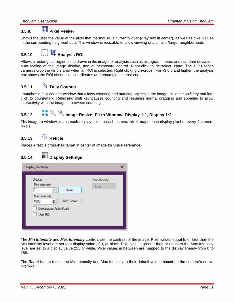
3.5.14. Display Settings
The Min Intensity and Max Intensity controls set the contrast of the image. Pixel values equal to or less than the Min intensity level are set to a display value of 0, or black. Pixel values greater than or equal to the Max Intensity level are set to a display value 255 or white. Pixel values in between are mapped to the display linearly from 0 to 255.
The Reset button resets the Min Intensity and Max Intensity to their default values based on the camera’s native bits/pixel.

ThorCam User Guide Chapter 3: Using ThorCam
Page 32 ITN000493-D02
The Auto-Scale sets the Min Intensity and Max Intensity according to the image data captured at the time the button is clicked. Auto-Scale ignores extreme outlying values so that the values are not influenced by one or a small number of pixels.
Continuous Auto-scale performs Auto-scale on each frame as they are rendered.
Use ROI works in conjunction with the Analysis ROI tool (See 3.5.10). Draw a box around the specific area of the image that you wish to have the Auto-scale values calculated from.
Pseudocolor provides a means of visualizing subtle intensity differences in a greyscale image. Selecting one of the seventeen options from the drop down menu will colorize a monochrome image by substituting a unique color for each intensity level. See Section 4.2. – Appendix B for details. Full-scale indicators changes the brightest (top 1% of full-scale) and darkest (bottom 1% of full-scale) pixels to red and blue respectively for images from the polarization sensitive camera CS505MUP1 only.
3.5.15. Plug-ins
Identifies and launches plug-in windows if plug-ins are installed. See 4.1 – Appendix A for details.
ThorCam User Guide Chapter 3: Using ThorCam
Rev. U, December 8, 2021 Page 33
3.6. Common Annotation functions
Image annotation functions are accessed from the toolbar on the left side of the Live window. The user can select whether or not to save annotations in the Save As or Quick Save dialogs. Not all formats support annotation.
3.6.1. , , , Draw Freehand, Line, Rectangle, Circle
Clicking on any one enters the annotation mode for that graphical element. Multiple graphical objects can be drawn in succession, and annotation mode persists until either right-click or icon is clicked again to disable. Deletion of each graphical item is done in order using successive clicks of the Undo Last Annotation icon.
3.6.2. Draw Text
Clicking on the Draw Text icon enters annotation mode for text. Next click on the desired location for the text, which will bring up the text annotation box. Enter text and select font size. Click OK to place text. Multiple text objects can be placed in succession, and text annotation persists until either right-click the Draw Text icon is clicked again to disable.
3.6.3. Measure
Enters measurement mode. Click on image location to begin measurement. Drag to draw line. Release to end measurement. Result is displayed in units of pixels. Multiple measurements can be made in succession, and measurement mode persists until either right-click or Measurement icon is clicked again. Use Undo Last Annotation to delete.
3.6.4. Choose Annotation Color
Launches a color-picker window for annotations. Color choice does not affect prior annotation.
3.6.5. Undo Last Annotation
Deletes the last annotation in the image. Successive clicks will delete multiple annotations in reverse order.
3.7. Reading Saved Images
Caution: Not all imaging programs preserve custom TIFF tags. Thorlabs metadata might not be preserved if the ThorCam TIFF file is processed and saved by a third-party program.
The TIFF standard does not allow for bit depths between 8 and 16 and therefore we use a custom tag for the bit depth. This is not recognized by third-party programs and the image might be rendered dark. When a TIFF file is opened by ThorCam the relevant bits per pixel parameter is read from that custom tag in order to properly display the image. Other metadata stored within custom tags in the TIFF file include various camera settings. See Appendix 4.4 – TIFF Metadata Tags

ThorCam User Guide Chapter 3: Using ThorCam
Page 34 ITN000493-D02
Saved images can be viewed in ThorCam by loading them using the File->Load Image command in the main ThorCam window:
3.7.1. Multi-Page TIFF sequence Playback Controls
Sequences from scientific-grade cameras are stored in multi-page TIFF format in order to preserve the high-precision, unaltered image data. A multi-page TIFF file is a single file that contains multiple images. ThorCam will read back the multi-page TIFF files it generates during the Record or Timed Series modes and provides a set of simple controls to play the sequence, step forward or backward one frame at a time, or advance to the beginning or end of the sequence using the control buttons shown above.
3.7.2. Analysis of saved images
ThorCam offers the same analysis/annotation functionality for loaded images that it has for live images.

ThorCam User Guide Chapter 4: Appendix
Rev. U, December 8, 2021 Page 35
Chapter 4 Appendix
4.1. Appendix A: Plug-ins
Plug-ins are small, application specific programs provided with ThorCam that allow a user to perform specialized tasks that are not provided in the main ThorCam application. They are accessed by clicking on the Plug-in icon along the top row of function icons. There is currently a limited number of Plug-ins that come standard with the ThorCam installation. More may be added as the need arises.
The TSI Overlay Plug-in The TSI Overlay Plug-in is used in conjunction with the Thorlabs Scientific Imaging Two Camera Adapters 2CM1 or 2CM2. The 2CM1 and 2CM2 are two-way camera microscope mounts that can be used in a variety of ways to simultaneously image the output of a microscope split by a dichroic mirror or a plate beam splitter to two cameras. The TSI Overlay Plug-in provides a number of controls to aid in visualizing the outputs of both cameras. This plug-in only works with TSI Scientific Cameras.
Set-up
Prior to working in the TSI Overlay Plug-in, you must first focus and align the cameras you intend to use. Refer to the 2CM1 & 2CM2 Two Camera Mount User Guide for details on mounting your cameras. Open the ThorCam Software. A small window will pop up telling you how many cameras you have connected. It should register two available cameras; if they are not both showing up, hit the refresh button. Make a note of the serial number associated with each of the two cameras and their respective positions on the 2CM1 or 2CM2 (Refer to 3.3.7 for information on renaming each camera with a more descriptive identifier). The transmitted image is being captured by the camera mounted to the CXY2 while the reflected image is captured by the camera mounted to the LCP02R. Either camera can be used as the Background image, but it is most common to use the transmitted image as the Background Image. From the GUI for the desired background image, open the Two Camera Overlay from the plug-in tab at the top of the window. Click on each of the two available cameras to open their image view windows. Hit the “Play” button in the upper left corner of each window to start live image capture. Depending on the light level used for excitation and the filter/mirror configuration used for your application, the exposure time and contrast levels may need to be adjusted on each camera to capture the desired image. Note: setting too long of an exposure time will greatly decrease the frame rate capture of the camera and make the output image choppy in real-time during alignment and adjustment.
Now you will adjust each camera individually to properly focus the image onto the image sensor. This is accomplished by making slight adjustments to the depth that the ER1 cage rods are inserted into the CXY2 and the LCP02R. Start with the cameras flush against their respective mounts (e.g. with the ER1 cage rods fully inserted). Apply a light amount of pressure to the cage rods with the set screws, just enough that there is a slight resistance to changing the inserted rod depth. By using the embedded line profile tool in the toolbar of the ThorCam Software (see 3.5.7) in conjunction with visual inspection of the output image on the screen you can fine tune the focus of each camera’s output image. Bring the image into focus by incrementally sliding the camera away from its mount. When the image is in focus, the peaks of the line profile histogram will be at their tallest and narrowest readings, meaning the greatest amplitude and smallest variance. At this point the output image should appear in its crispest form on the screen. Once this is done for both cameras, tighten the cage rods; you are now ready to align the transmitted and reflected images in overlay.
Alignment
In order to align the transmitted and reflected images you will use the TSI Overlay Plug-in. Click on the “Plug-In” button on the toolbar of the transmitted image window and click on “Two Camera Overlay.” When this is done a “TSI Overlay Plug-In” window will open. Choose the second camera from the drop-down list and click on “Start.” Depending on how the reflected image is flipped, you will need to click on either the “Flip Horizontal” or “Flip Vertical” box of the reflected image to orient the two images in the same manner on the screen. Now, using the X & Y plane adjustment knobs on the CXY2 and the rotation adjustment knob on the LCP02R, you can position the two images so that they are perfectly overlaid.

ThorCam User Guide Chapter 4: Appendix
Page 36 ITN000493-D02
(L) Original Background Image; (R) False colored background image with reflected image overlaid
Operation
The main window of the TSI Overlay Plug-in is used to initiate Overlays, Single Image Saves and Recordings from two TSI cameras.
From the ThorCam main menu window (see section 3.1) select the two cameras you will be working with from the drop down selection. You will now have two instances of the imaging GUI open - one for each camera. Determine which camera will be used for the Background image and open the TSI Overlay Plug-in from that camera’s GUI. The name and serial number of the other camera will now be listed in the Overlay section of the plug-in screen.
The main window of the TSI Overlay Plug-in is used to initiate Overlays, Single Image Saves and Recordings from two TSI cameras.
ThorCam User Guide Chapter 4: Appendix
Rev. U, December 8, 2021 Page 37
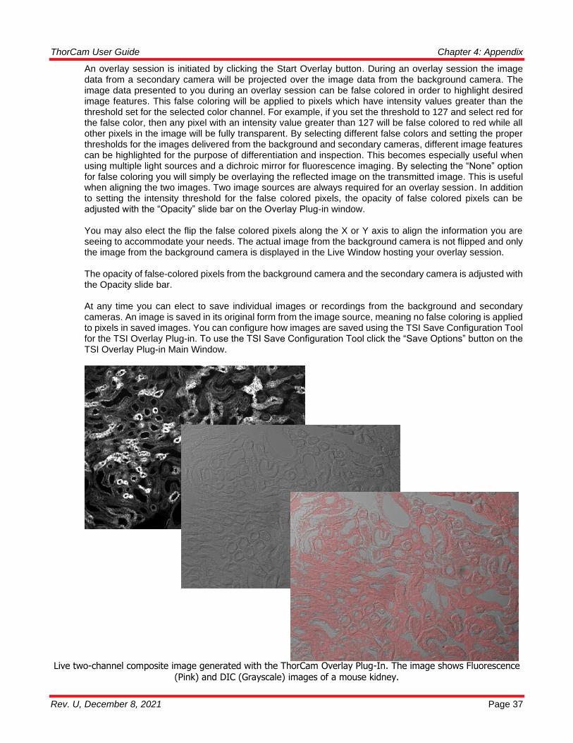
An overlay session is initiated by clicking the Start Overlay button. During an overlay session the image data from a secondary camera will be projected over the image data from the background camera. The image data presented to you during an overlay session can be false colored in order to highlight desired image features. This false coloring will be applied to pixels which have intensity values greater than the threshold set for the selected color channel. For example, if you set the threshold to 127 and select red for the false color, then any pixel with an intensity value greater than 127 will be false colored to red while all other pixels in the image will be fully transparent. By selecting different false colors and setting the proper thresholds for the images delivered from the background and secondary cameras, different image features can be highlighted for the purpose of differentiation and inspection. This becomes especially useful when using multiple light sources and a dichroic mirror for fluorescence imaging. By selecting the “None” option for false coloring you will simply be overlaying the reflected image on the transmitted image. This is useful when aligning the two images. Two image sources are always required for an overlay session. In addition to setting the intensity threshold for the false colored pixels, the opacity of false colored pixels can be adjusted with the “Opacity” slide bar on the Overlay Plug-in window.
You may also elect the flip the false colored pixels along the X or Y axis to align the information you are seeing to accommodate your needs. The actual image from the background camera is not flipped and only the image from the background camera is displayed in the Live Window hosting your overlay session.
The opacity of false-colored pixels from the background camera and the secondary camera is adjusted with the Opacity slide bar.
At any time you can elect to save individual images or recordings from the background and secondary cameras. An image is saved in its original form from the image source, meaning no false coloring is applied to pixels in saved images. You can configure how images are saved using the TSI Save Configuration Tool for the TSI Overlay Plug-in. To use the TSI Save Configuration Tool click the “Save Options” button on the TSI Overlay Plug-in Main Window.
Live two-channel composite image generated with the ThorCam Overlay Plug-In. The image shows Fluorescence (Pink) and DIC (Grayscale) images of a mouse kidney.

ThorCam User Guide Chapter 4: Appendix
Page 38 ITN000493-D02
TSI Overlay Plug-in Save Configuration Tool:
The TSI Save Configuration Tool is used to configure how individual images and recordings are saved when using the TSI Overlay Plug-in. You may configure the saving of both individual images and recordings. To configure how individual images are saved’ select an option from the Single Image Format drop-down box. You will notice that annotations are supported when saving images to the PNG or JPG format, however, only 8 bits per color channel is supported when using these image formats. If you require greater fidelity in your images then it is suggested that you use the 16-bit TIFF image format. To configure how recordings are saved, select an option from the Recording Format drop-down box. Annotations are not supported for recordings. If you require smaller files when recording then it is suggested that you select the Motion-JPEG format and save your recording to an AVI file. If you require greater image fidelity then it is suggested you select the Multipage TIF format and save your recording to a TIFF file. Be aware the Motion-JPEG format uses 8 bits per pixel and are compressed using lossy JPEG compression, while the Multipage TIF format uses 16 bits per pixel and are not compressed, resulting in substantially larger files. You may select where your images are saved by directly entering a valid path to your desired save folder or by clicking the Browse button and navigating to it. Be aware that you must have write permission at the selected save location. You may define a file prefix for the artifacts you wish to save. This prefix can be any valid file name. If the filename is already in use at your save location then ThorCam will attempt to generate an unused filename automatically using your requested prefix as a base. ThorCam will append a numeric suffix to your prefix when attempting to generate an unused filename for you. For example if “myFile.tif” already exists at your save location then “myFile_1.tif” will be generated and then “myFIle_2.tif” until an unused filename is discovered or it is determined that it is not possible to generate a unique filename automatically for you. The TSI Overlay Plug-in will always append a suffix to your filename’s prefix using the following convention: Suffix = _C[Camera number]_F[Frame Number]_Z000.[File Extension] Ex. _C1_F0001_Z000.tif Filename = prefix + suffix Ex. Prefix = myImage Suffix = _C1_F0001_Z000.tif Filename = myImage_C1_F0001_Z000.tif
ThorCam User Guide Chapter 4: Appendix
Rev. U, December 8, 2021 Page 39
This convention is used to make it easier for you to identify from which camera a saved image originated and which frame number associates two images from two cameras. Be aware the frame number used is always that from the background camera. The,”_Z000,” portion of the suffix is reserved for future use by Thorlabs. As you select image formats, save locations, and the prefixes for filenames, you will see a preview of the filename generated for you. The actual name of your file is not knowable until the moment your data is stored, because frame numbers are not constant and there is no way to pre-determine whether a filename is already in use at your selected location. The preview is provided to help you understand where your images will be saved and how they will be named, but it cannot tell you absolutely what a saved image will be named at any given moment. All overlay configuration settings are retained and apply to all subsequent ThorCam sessions.

ThorCam User Guide Chapter 4: Appendix
Page 40 ITN000493-D02
4.2. Appendix B: Pseudocolor
In the Display Settings menu option you will find the Pseudocolor selections. Pseudocolor provides a means of visualizing subtle intensity differences in a greyscale image. Selecting one of the options from the drop down menu will colorize a monochrome image by substituting a unique color for each intensity level. A few examples are shown below.

ThorCam User Guide Chapter 4: Appendix
Rev. U, December 8, 2021 Page 41
There is a folder in the ThorCam installation folder that is for Pseudocolor look-up tables (LUTs). The typical path is C:\Program Files\Thorlabs\Scientific Imaging\ThorCam\LUTs. New and custom LUTs can be added to this folder, as long as they are in the correct format, and will automatically be added to the Pseudocolor drop down menu. There is a readme file in the same LUTs folder that explains how to do this. A Pseudocolor look-up table is a table of red, green, and blue values from 0-255 that correspond to the grey intensity value. To add a new LUT simply save the LUT file into the ThorCam installation LUT folder and restart ThorCam. Each LUT should have the file extension ".lut" in order to be recognized and used. LUTs will also have to be in the correct format. The installed LUTs show formats which are acceptable: The format should have each row of the file including the index, red, green, then blue values (integers
from 0-255) in that order. Any text/characters other than numbers will be ignored. More LUTs can be downloaded from ImageJ at https://imagej.nih.gov/ij/download/luts/ or a custom created LUT can be added to this folder. Existing LUTs can be edited using a text editor such as Notepad++, an example is shown below.
ThorCam User Guide Chapter 4: Appendix
Page 42 ITN000493-D02
4.3. Appendix C: Polarization Tools
4.3.1. Selection and display of Polarization Parameters
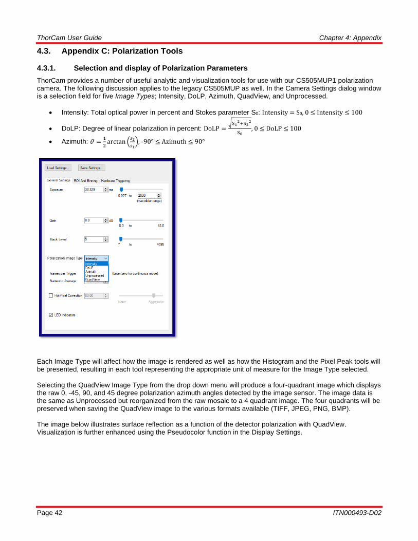
ThorCam provides a number of useful analytic and visualization tools for use with our CS505MUP1 polarization camera. The following discussion applies to the legacy CS505MUP as well. In the Camera Settings dialog window is a selection field for five Image Types; Intensity, DoLP, Azimuth, QuadView, and Unprocessed.
• Intensity: Total optical power in percent and Stokes parameter S0: Intensity = S0, 0 ≤ Intensity ≤ 100
• DoLP: Degree of linear polarization in percent: DoLP =√S1
2+S22
S0, 0 ≤ DoLP ≤ 100
• Azimuth: 𝜗 =1
2arctan (
𝑠2
𝑠1), -90° ≤ Azimuth ≤ 90°
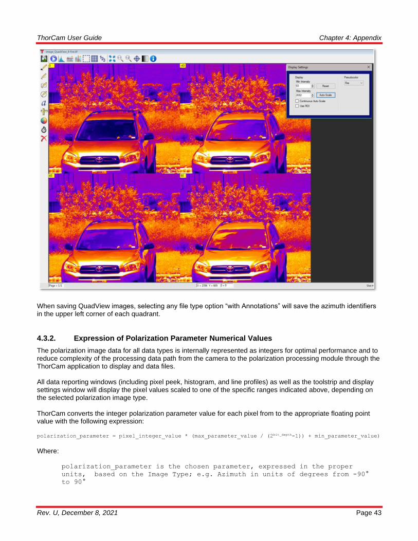
Each Image Type will affect how the image is rendered as well as how the Histogram and the Pixel Peak tools will be presented, resulting in each tool representing the appropriate unit of measure for the Image Type selected. Selecting the QuadView Image Type from the drop down menu will produce a four-quadrant image which displays the raw 0, -45, 90, and 45 degree polarization azimuth angles detected by the image sensor. The image data is the same as Unprocessed but reorganized from the raw mosaic to a 4 quadrant image. The four quadrants will be preserved when saving the QuadView image to the various formats available (TIFF, JPEG, PNG, BMP). The image below illustrates surface reflection as a function of the detector polarization with QuadView. Visualization is further enhanced using the Pseudocolor function in the Display Settings.
ThorCam User Guide Chapter 4: Appendix
Rev. U, December 8, 2021 Page 43
When saving QuadView images, selecting any file type option “with Annotations” will save the azimuth identifiers in the upper left corner of each quadrant.
4.3.2. Expression of Polarization Parameter Numerical Values
The polarization image data for all data types is internally represented as integers for optimal performance and to reduce complexity of the processing data path from the camera to the polarization processing module through the ThorCam application to display and data files. All data reporting windows (including pixel peek, histogram, and line profiles) as well as the toolstrip and display settings window will display the pixel values scaled to one of the specific ranges indicated above, depending on the selected polarization image type. ThorCam converts the integer polarization parameter value for each pixel from to the appropriate floating point value with the following expression: polarization_parameter = pixel_integer_value * (max_parameter_value / (2bit_depth-1)) + min_parameter_value)
Where:
polarization_parameter is the chosen parameter, expressed in the proper
units, based on the Image Type; e.g. Azimuth in units of degrees from -90°
to 90°
ThorCam User Guide Chapter 4: Appendix
Page 44 ITN000493-D02
bit_depth equals the number of bits per pixel that the camera delivers; e.g.
12 for the CS505MUP1)
pixel_integer_value is the integer value for a given pixel delivered from the
camera processing software
max_parameter_value: the maximum value for the polarization parameter
expressed in the proper units minus the min_parameter_value;
e.g. 90-(-90) = 180
min_parameter_value: the minimum value for the polarization parameter
expressed in the proper units; e.g. -90
e.g. pixel_integer_value = 4000 for an Azimuth image on the CS505MUP1:
polarization_parameter = 4000 * (180 / (4096 – 1)) + -90 ≈ 85.82°
Polarization TIFF image data are saved to the file as integers, and a custom TIFF tag is created, TSI_POLARIZATION_IMAGE_TYPE, that contains the Image Type (Azimuth, Intensity, or DoLP). The saved filename will also include a suffix indicating the Image Type. When such an image is loaded into the ThorCam image viewer (see 3.7) it will be displayed in the appropriate units using the same expression above. This feature only applies to images saved as 16-bit TIFF without Annotations, or 8-bit TIFF without Annotations, in all other cases the current displayed image is saved as-rendered, without the custom TIFF tag. See 3.5.4 If an 8-bit or 16-bit TIFF polarization image without annotations is read into a program other than ThorCam, the custom TIFF tag will not be recognized, and any data conversion to the floating point polarization values and units will need to be performed on the integer data using the expression above.

ThorCam User Guide Chapter 4: Appendix
Rev. U, December 8, 2021 Page 45
4.4. Appendix D: TIFF Metadata Tags
In a TIFF file format, metadata is appended to an image as a Tag-Value pair. The TSI custom tag values are listed below after their corresponding parameters. A user can scan through the metadata looking for specific tags, each of which are followed by 4 bytes of data pertinent to that tag. Metadata Parameter Tag Value TSI_SIGNIFICANT_BITS_INT 32768 TSI_BIN_X_INT 32770 TSI_BIN_Y_INT 32771 TSI_ROI_ORIGIN_X_INT 32772 TSI_ROI_ORIGIN_Y_INT 32773 TSI_ROI_PIXELS_X_INT 32774 TSI_ROI_PIXELS_Y_INT 32775 TSI_PIXEL_CLOCK_HZ_INT 32777 TSI_NUM_TAPS_INT 32778 TSI_FRAME_NUMBER_INT 32779 TSI_POLARIZATION_IMAGE_TYPE 32780 TSI_TIME_STAMP_RELATIVE_NS_HIGH_BITS 32781 TSI_TIME_STAMP_RELATIVE_NS_LOW_BITS 32782 (Timestamp is in nanoseconds and is a 64-bit value formed by combining the low and high-bit data values)
While most of the above parameters are self-explanatory and their associated data are easily interpreted by a TIFF reader, the TSI_POLARIZATION_IMAGE_TYPE data decodes to the following information: 0 = Intensity
1 = DoLP
2 = Azimuth
3 = Unprocessed
4 = QuadView

ThorCam User Guide Chapter 5: Thorlabs Worldwide Contacts
Page 46 ITN000493-D02
Chapter 5 Thorlabs Worldwide Contacts
For technical support or sales inquiries, please visit us at www.thorlabs.com/contact for our most up-to-
date contact information.

ThorCam User Guide Chapter 5: Thorlabs Worldwide Contacts
Rev. U, December 8, 2021 Page 1
www.thorlabs.com

![Atmel AT02657: XMEGA-E5 Xplained Software User Guideww1.microchip.com/downloads/en/AppNotes/Atmel... · Atmel AT02657: XMEGA-E5 Xplained Software User Guide [APPLICATION NOTE] 42085A−AVR−04/2013](https://static.fdocuments.in/doc/165x107/5f88ba81f6b36722b04d705d/atmel-at02657-xmega-e5-xplained-software-user-atmel-at02657-xmega-e5-xplained.jpg)