User Manual Template - DJO Global · Taurus 1 Bobath NA NA NA NA Taurus 2 Bobath 75 NA NA NA...
36
MONTANE TABLE LINE DJO is an ISO 13485 Certified Company Moving Rehabilitation Forward™ 2 SECTION TABLES 3520 Tatras 2 Section 120V (2 wheels/2 legs) 3521 Tatras 2 Section 120V (4 wheels) 3522 Tatras 2 Section 230V (2 wheels/2 legs) 3525 Tatras Gerlach 2 Section 230V (4 wheels) 3 SECTION TABLES 3530 Atlas 3 Section 120V (2 wheels/2 legs) 3531 Atlas 3 Section 120V (4 wheels) 3532 Atlas 3 Section 120V (Postural Drainage–2 wheels/2 legs) 3533 Atlas 3 Section 120V (Postural Drainage–4 wheels) 3535 Atlas 3 Section 230V (2 wheels/2 legs) 3536 Atlas 3 Section 230V (4 wheels) 3537 Atlas 3 Section 230V (Postural Drainage–2 wheels/2 legs) 3538 Atlas 3 Section 230V (Postural Drainage–4 wheels) 5 SECTION TABLES 3550 Alps 5 Section 120V (2 wheels/2 legs) 3551 Alps 5 Section 120V (4 wheels) 3552 Alps 5 Section 120V (Postural Drainage–2 wheels/2 legs) 3553 Alps 5 Section 120V (Postural Drainage–4 wheels) 3555 Alps 5 Section 230V (2 wheels/2 legs) 3556 Alps 5 Section 230V (4 wheels) 3557 Alps 5 Section 230V (Postural Drainage–2 wheels/2 legs) 3558 Alps 5 Section 230V (Postural Drainage–4 wheels) 7 SECTION TABLES 3570 Andes 7 Section 120V (2 wheels/2 legs) 3571 Andes 7 Section 120V (4 wheels) 3572 Andes 7 Section 120V (Postural Drainage–2 wheels/2 legs) 3573 Andes 7 Section 120V (Postural Drainage–4 wheels) 3575 Andes 7 Section 230V (2 wheels/2 legs) 3576 Andes 7 Section 230V (4 wheels) 3577 Andes 7 Section 230V (Postural Drainage–2 wheels/2 legs) 3578 Andes 7 Section 230V (Postural Drainage–4 wheels) EXAMINATION TABLES 3590 Dolomites 2 Section 120V Examination 3591 Dolomites 2 Section 120V Examination 3592 Dolomites 2 Section 230V Examination 3593 Dolomites 2 Section 230V Examination BOBATH TABLES 3580 Taurus 1 Section 120V (4 Wheels) 3581 Taurus 2 Section 120V (4 Wheels) 3582 Taurus 1 Section 230V (4 Wheels) 3583 Taurus 2 Section 230V (4 Wheels) User Manual
Transcript of User Manual Template - DJO Global · Taurus 1 Bobath NA NA NA NA Taurus 2 Bobath 75 NA NA NA...
MONTANE TABLE LINE
DJO is an ISO 13485 Certified Company
Moving Rehabilitation Forward™ 2 SECTION TABLES 3520 Tatras 2 Section 120V (2 wheels/2 legs) 3521 Tatras 2 Section 120V (4 wheels) 3522 Tatras 2 Section 230V (2 wheels/2 legs)3525 Tatras Gerlach 2 Section 230V (4 wheels)3 SECTION TABLES 3530 Atlas 3 Section 120V (2 wheels/2 legs) 3531 Atlas 3 Section 120V (4 wheels) 3532 Atlas 3 Section 120V (Postural Drainage–2 wheels/2 legs) 3533 Atlas 3 Section 120V (Postural Drainage–4 wheels) 3535 Atlas 3 Section 230V (2 wheels/2 legs) 3536 Atlas 3 Section 230V (4 wheels) 3537 Atlas 3 Section 230V (Postural Drainage–2 wheels/2 legs) 3538 Atlas 3 Section 230V (Postural Drainage–4 wheels) 5 SECTION TABLES 3550 Alps 5 Section 120V (2 wheels/2 legs) 3551 Alps 5 Section 120V (4 wheels) 3552 Alps 5 Section 120V (Postural Drainage–2 wheels/2 legs) 3553 Alps 5 Section 120V (Postural Drainage–4 wheels) 3555 Alps 5 Section 230V (2 wheels/2 legs) 3556 Alps 5 Section 230V (4 wheels) 3557 Alps 5 Section 230V (Postural Drainage–2 wheels/2 legs) 3558 Alps 5 Section 230V (Postural Drainage–4 wheels) 7 SECTION TABLES 3570 Andes 7 Section 120V (2 wheels/2 legs) 3571 Andes 7 Section 120V (4 wheels) 3572 Andes 7 Section 120V (Postural Drainage–2 wheels/2 legs) 3573 Andes 7 Section 120V (Postural Drainage–4 wheels) 3575 Andes 7 Section 230V (2 wheels/2 legs) 3576 Andes 7 Section 230V (4 wheels) 3577 Andes 7 Section 230V (Postural Drainage–2 wheels/2 legs) 3578 Andes 7 Section 230V (Postural Drainage–4 wheels) EXAMINATION TABLES 3590 Dolomites 2 Section 120V Examination 3591 Dolomites 2 Section 120V Examination 3592 Dolomites 2 Section 230V Examination 3593 Dolomites 2 Section 230V Examination BOBATH TABLES 3580 Taurus 1 Section 120V (4 Wheels) 3581 Taurus 2 Section 120V (4 Wheels) 3582 Taurus 1 Section 230V (4 Wheels) 3583 Taurus 2 Section 230V (4 Wheels)
User Manual

i
TABLE OF CONTENTS
1. FOREWORD . . . . . . . . . . . . . . . . . . . . . . . . . . . . . . . . . . . 1 Product Description . . . . . . . . . . . . . . . . . . . . . . . . . . . . . . . . . . . . . . . . . . . . 1 2. PRECAUTIONS . . . . . . . . . . . . . . . . . . . . . . . . . . . . . . . . 2 Safety Precautions . . . . . . . . . . . . . . . . . . . . . . . . . . . . . . . . . . . . . . . . . . . . . . 5 3. MONTANE TABLE LINE. . . . . . . . . . . . . . . . . . . . . . . . . . . . . . . . . 7 Tatras 2 Section Table . . . . . . . . . . . . . . . . . . . . . . . . . . . . . . . . . . . . . . . . . . 7
Atlas 3 Section Table . . . . . . . . . . . . . . . . . . . . . . . . . . . . . . . . . . . . . . . . . . . 8
Alps 5 Section Table . . . . . . . . . . . . . . . . . . . . . . . . . . . . . . . . . . . . . . . . . . . 9
Andes 7 Section Table . . . . . . . . . . . . . . . . . . . . . . . . . . . . . . . . . . . . . . . . 10
Dolomites 2 Section Examination Table . . . . . . . . . . . . . . . . . . . . . . . . 11
Taurus 1 Section Bobath Table . . . . . . . . . . . . . . . . . . . . . . . . . . . . . . . . 12
Taurus 2 Section Bobath Table . . . . . . . . . . . . . . . . . . . . . . . . . . . . . . . . . 13
3. DESIGN AND FUNCTION . . . . . . . . . . . . . . . . . . . . . 14 Components of the Montane Table . . . . . . . . . . . . . . . . . . . . . . . . . . . . 14 . .
Accessories and Auxiliary Equipment . . . . . . . . . . . . . . . . . . . . . . . . . . 14
4. NOMENCLATURE . . . . . . . . . . . . . . . . . . . . . . . . . . . . 15 Description of Device Markings . . . . . . . . . . . . . . . . . . . . . . . . . . . . . . . 15 5. SPECIFICATIONS . . . . . . . . . . . . . . . . . . . . . . . . . . . . . 16 Table Specifications . . . . . . . . . . . . . . . . . . . . . . . . . . . . . . . . . . . . . . . . . . . 16
6. TECHNICAL SPECIFICATIONS. . . . . . . . . . . . . . . . . . 19 Electromagnetic Compatibility Tables . . . . . . . . . . . . . . . . . . . . . . . . . 19
7. SETUP . . . . . . . . . . . . . . . . . . . . . . . . . . . . . . . . . . . . . . . 23 Contents of the Carton . . . . . . . . . . . . . . . . . . . . . . . . . . . . . . . . . . . . . . . . 23 8. OPERATION . . . . . . . . . . . . . . . . . . . . . . . . . . . . . . . . . 26 Relocating the Table . . . . . . . . . . . . . . . . . . . . . . . . . . . . . . . . . . . . . . . . . . . 26 . .
Adjusting the Table . . . . . . . . . . . . . . . . . . . . . . . . . . . . . . . . . . . . . . . . . . . . 27 . .
Adjusting Table Sections . . . . . . . . . . . . . . . . . . . . . . . . . . . . . . . . . . . . . . 28
9. MAINTENANCE. . . . . . . . . . . . . . . . . . . . . . . . . . . . . . . 29 Cleaning the Upholstery . . . . . . . . . . . . . . . . . . . . . . . . . . . . . . . . . . . . . . 29 . .
Lubricating Points . . . . . . . . . . . . . . . . . . . . . . . . . . . . . . . . . . . . . . . . . . . . . 30
Checking actuators . . . . . . . . . . . . . . . . . . . . . . . . . . . . . . . . . . . . . . . . . . . . 30 . .
Checking the Gas Springs (Struts) . . . . . . . . . . . . . . . . . . . . . . . . . . . . . 30 . .
Periodic Check of Electrical Safety . . . . . . . . . . . . . . . . . . . . . . . . . . . . . 30
Service . . . . . . . . . . . . . . . . . . . . . . . . . . . . . . . . . . . . . . . . . . . . . . . . . . . . . . . . 30
10. WARRANTY . . . . . . . . . . . . . . . . . . . . . . . . . . . . . . . . . 31
*The MONTANE table name is specific to DJO tables manufactured by
MEDEN-INMED exclusively for DJO

Montane Table Line
1
This manual has been written for the owners and operators of the Montane Table Line . It contains general instructions for operation, precautionary instructions, and maintenance recommendations . In order to obtain maximum life and efficiency from your Montane Table, and to assist in the proper operation of the unit, read and understand this manual thoroughly . The specifications put forth in this manual were in effect at the time of the publication . However, owing to DJO, LLC’s policy of continuous improvement, changes to these specifications may be made at any time without obligation on the part of DJO, LLC . Before administering any treatment to a patient, you should become acquainted with the operating procedures, as well as the cautions, warnings, and dangers . Consult other resources for additional information regarding the application of physiotherapy .
Product DescriptionThe Montane Tables were designed specifically for the purpose of aiding in the administration of manual therapy techniques and physiotherapy . Enhanced with a boo-merang mechanism base, Montane Tables provide a smooth, vertical lift while maintaining a stable surface for the patient .
© 2011 DJO, LLC Vista, California, USA . Any use of editorial, pictorial, or layout composition of this publication without express written consent from DJO, LLC is strictly prohibited . This publication was written, illustrated, and prepared for distribution by DJO, LLC .
FOREWORD
Head Section Articulates Up
Head Section Articulates Down
Optional Postural Drainage
Foot Section Articulates Up
Tatras 2 Section 40 70 NA NA
Atlas 3 Section 40 70 30 85
Alps 5 Section 40 70 30 85
Andes 7 Section 40 70 30 85
Dolomites 2 Section Examination 85 20 NA NA
Taurus 1 Bobath NA NA NA NA
Taurus 2 Bobath 75 NA NA NA
Comfortable seated patient positioning can be achieved with the use of the articulating table sections .

Montane Table Line
2
The precautionary instructions found in this section and throughout this manual are indicated by specific symbols . Understand these symbols and their definitions before operating this equipment . The definitions of these symbols are as follows:
CAUTION Text with a “CAUTION” indicator will explain possible safety infractions that could have the potential to cause minor to moderate injury or damage to equipment .
WARNING Text with a “WARNING” indicator will explain possible safety infractions that will potentially cause serious injury and equipment damage .
DANGER Text with a “DANGER” indicator will explain possible safety infractions that are imminently hazardous situations that would result in death or serious injury .
PRECAUTIONARY INSTRUCTIONS
PRECAUTIONS
BIOHAZARD Text with a “BIOHAZARD" indicator will explain possible safety infractions that could cause bio-hazardous conditions if the table is not properly cleaned after each use .
NOTE Throughout this manual "NOTE" may be found . These notes are helpful information to aid in the particular area or function being described .
CAUTION
DANGER
WARNING

Montane Table Line
3
• Read, understand, and practice the precautionary and operating instructions found in this manual . Know the limitations and hazards associated with your treatment table . Observe any and all precautionary and operational decals placed on the unit .
• DO NOT operate this table in an environment where other devices are being used that intentionally radiate electromagnetic energy in an unshielded manner . Portable and mobile RF communications equipment can affect Medical Electrical Equipment .
• This table generates, uses, and can radiate radio frequency energy and, if not installed and used in accordance with the instructions, may cause harmful interference to other devices in the vicinity . However, there is no guarantee that interference will not occur in a particular installation . Harmful
interference to other devices can be determined by turning this table on and off . Try to correct the interference using one or more of the following: reorient or relocate the receiving device, increase the separation between the equipment, connect the table to an outlet on a different circuit from that which the other device(s) are con-nected, and consult the DJO, LLC Service Department for help .
• Keep table out of high moisture environments .• This table should be operated, transported, and stored in temperatures
between -10° C to + 45° C, with max humidity of 75% (no precipitation) .• Do not exceed table weight capacity of 150 kg (330 lbs) .• Support the table section(s) when making any adjustments .
PRECAUTIONS
• CAUTION: Federal law restricts this table to sale by, or on the order of, a licensed practitioner .
• The Montane Table Range should not be used adjacent to or stacked with other equipment, and if adjacent or stacked use is necessary, the table should be observed to verify normal operation in the configuration in which it will be used .
• Do not leave the table unlocked and unattended at any time .• Disconnect the table from the power source before attempting any maintenance, installation, removal or replacement procedures to prevent
electrical shock and possible damage to the table .• Do not sit or allow patients to sit on the head or wing sections of the table .
• This table should be operated, transported, and stored in temperatures between -10° C to+ 45° C, with max humidity of 75% (no precipitation) . Support the table section(s) when making any adjustments . • Do not transport the table over rough or outdoor surfaces . The retractable caster system could become damaged and inoperable . • Inspect cables, connectors and casters before each use . • To avoid the risk of electric shock, the table must only be connected to grounded electrical service . Do not use any extension cords and/or multiple
outlet extension cords . • Do not use a table with a power cord other than provided by the manufacturer . • A licensed practitioner must be familiar with all instructions contained in this manual before administering therapy .
WARNING
CAUTION CAUTION

Montane Table Line
4
PRECAUTIONS
• Never place your hands and feet near the working mechanism of the table when making any and all adjustments to height or table sections . Moving parts could cause pinch points .
• Use only accessories that are specially designed for the Montane Table Line . Do not use accessories manufactured by other companies on the Montane
Table Line . DJO is not responsible for any consequence resulting from using products manufactured by other companies . The use of other accessories or cables may result in increased emissions or decreased immunity of the
Montane Table .• When making adjustments to the table sections, make certain the patient
weight is supported before adjusting .• Never transport a patient on the Montane Table . These tables are not designed
to support a patient during transport .• This device should be kept out of the reach of children .• Do not smoke on or around the table .• Do not allow any unsupervised patient access to the table .• The casters should be locked before the loading or unloading of a patient . Do not reposition or allow the patient to get on or off the table while the casters are unlocked .• This table should only be operated under the prescription and
supervision of a licensed medical practitioner that is familiar with the precautionary measures and operational functions associated with the table
being used .
• This table should be operated by a clinician that has read and fully understands this document .
• On rare occasions, use of the table can result in transient skin reactions such as rash, inflammation or irritation . These skin reactions may be the result of individual sensitivity to the mild antibacterial cleaning materials used on the table or the material of the table cushions . Advise the patient of this possibility before starting treatment . If a visible skin reaction does occur, discontinue patient treatment and consult the prescribing physician .
• Should the Montane Table Mains Power Cord become frayed/damaged or if a caster is broken, immediately stop use of the table and contact the Dealer or DJO for service .
• Do not allow any person, object, or device to be under the table while the table is in operation .• Always clean the table after each use with a soft cloth dampened
with water and a mild antibacterial detergent . Do not use abrasive cleansers .
WARNINGWARNING
DANGER

Montane Table Line
5
SAFETY PRECAUTIONS
Do not overload Montane Table . Patient weight may not exceed 150 kg.
In case the electrical system or the actuator cover comes in contact with liquid of any kind, immediately pull the power supply plug out of the mains socket and contact the manufacturer’s service department . Protect electrical systems from contact with liquids (e .g . beverages, water, cleaning and disinfection preparations) .
Do not put a load on the head and foot sections as shown below.
Do not sit on the movable elements of the head and chest sections!
CAUTION

Montane Table Line
6
CAUTION
SAFETY PRECAUTIONS
The manufacturer shall not assume liability for damages resulting from improper (not compliant with conditions provided in this Operation Manual) use of the Montane Table Line .
Do not lower the table with its front section folded down! Lowering the table to the lowest possible position while its head section is deflected or in the down position may cause a collision between the head section and the lower frame elements. This can result in blocking the height adjustment mechanism . Permanent and irreversible damage to the structure of the table may occur!

Montane Table Line
7
TATRAS 2 SECTION TABLE
MONTANE TABLE LINE
46 cm( 18 in )
201 cm ( 79 in )
69 cm( 27 in )
155 cm( 61 in )
HEAD SECTION
FOOT SECTION
HEAD REST RELEASE HANDLE
UP / DOWN CONTROL BAR
LEG
CASTER
LEG
CASTER

Montane Table Line
8
ATLAS 3 SECTION TABLE
MONTANE TABLE LINE
54 cm(21.3 in)
101 cm(39.8 in)
46 cm(18.1 in)
201 cm(79.1 in)
69 cm(27.2 in)
POSTURAL DRAIN SWITCH
CHEST SECTION
FOOT SECTION
FOOT SECTION ELEVATION HANDLE
HEAD SECTION
HEAD REST RELEASE HANDLE
LEG
CASTER CASTERUP / DOWN CONTROL BAR
LEG

Montane Table Line
9
ALPS 5 SECTION TABLE
MONTANE TABLE LINE
54 cm(21.3 in)
101 cm(39.8 in)
46 cm(18.1 in)
201 cm(79.1 in)
69 cm(27.2 in)
CHEST SECTION
FOOT SECTION
HEAD REST RELEASE HANDLE
HEAD SECTION
FOOT SECTION ELEVATION HANDLE
LEG LEG
CASTER UP / DOWN CONTROL BARCASTER
HEAD REST RELEASE HANDLE

Montane Table Line
10
ANDES 7 SECTION TABLE
MONTANE TABLE LINE
54 cm(21.3 in)
101 cm(39.8 in)
46 cm(18.1 in)
201 cm(79.1 in)
69 cm(27.2 in)
CHEST SECTIONFOOT SECTION
HEAD SECTION
ARMREST SECTION
SHOULDER WINGPOSTURAL DRAIN SWITCH
FOOT SECTION ELEVATION HANDLE
LEG
CASTER UP / DOWN CONTROL BAR
LEG
CASTER
HEAD REST RELEASE HANDLE

Montane Table Line
11
DOLOMITES 2 SECTION EXAMINATION TABLE
MONTANE TABLE LINE
69 cm( 27 in )
201 cm ( 79 in )
69 cm( 27 in )
129 cm( 51 in )
FOOT SECTIONHEAD SECTION
HEAD REST RELEASE HANDLE
LEG LEG
CASTER CASTER
UP / DOWN CONTROL BAR
SIDE RAILINGS
PAPER TOWEL HOLDER

Montane Table Line
12
120 cm( 47 in )
200 cm( 79 in )
TAURUS 1 SECTION BOBATH TABLE
MONTANE TABLE LINE
TABLE TOP
LEG LEG
CASTER CASTER

Montane Table Line
13
120 cm( 47 in )
200 cm( 79 in )
80 cm( 31 in )
TAURUS 2 SECTION BOBATH TABLE
MONTANE TABLE LINE
FOOT SECTION
HEAD SECTION
HEAD REST RELEASE HANDLE
LEG LEG
CASTER CASTER

Montane Table Line
14
DESIGN AND FUNCTION
The frame of the table is made of welded steel sections coated with powder paint . It includes the following components:
COMPONENTS OF THE MONTANE TABLE
1. Bottom Frame—A support base for the whole unit with a foot-operated height adjustment switch assembly
– 2 Wheels/2 Legs: With two small wheels and two legs
– 4 Wheels: With four legs and four casters lifted by means of a foot-operated lever
2. Upper Frame—A base for the table top, with an electric actuator for height adjustment
3. Table Top—Allows patients to assume comfortable position for the treatment with the possibility of manual adjustment of elevation and depression angles of the head, chest, and/or foot sections (depending on the type of table)
4. Front/Head Section—With angle adjustment and a breathing hole
5. ACCESS LOCK—Lock the height adjustment function
ACCESSORIES AND AUXILIARY EQUIPMENTEach type of table is provided with a breathing opening in its head section and has rails for fastening the stabilizing belts in the foot sections .
4
4 Wheel Option
2 Wheels / 2 Legs
2
1
3

Montane Table Line
15
NOMENCLATUREDESCRIPTION OF DEVICE MARKINGS
Class II Equipment
Postural Drain Elevation
Council Directive 2002/96/EC concerning Waste Electrical and Electronic (WEEE). Indicates a requirement not to dispose of WEEE as munici-pal waste. Contact your local distributor for information regarding disposal of the unit and accessories.
DOWN
UP
The markings on the Montane Table Line are assurance of its conformity to the highest applicable standards of medical equipment safety and electromagnetic compatibility . One or more of the following markings may appear on the device:
Certified to CAN/CSA Standard C22.2
No. 601.1-M90w/A2
Meets Directive93/42/EEC
Warning: Pinch Point
Consult Instructions For Use
Type B Applied Part
Prescription Only

Montane Table Line
16
SPECIFICATIONSTABLE SPECIFICATIONS
Parameter
Voltage Frequency,Current Consumption:
100-240/50-60 Hz/3-1,5 A
Fuses: None
Duty Cycle: 2 minutes "on"/18 minutes "off"
Table Length (Head to Toe): 201 cm (79 in)
Table Height 49- 101 cm(19-40in)
Electrical Safety Classification Functionally Earthed
Class I
Electrical Type: TypeB

Montane Table Line
17
SPECIFICATIONSTABLE SPECIFICATIONS
Technical DataMontane Table Line
Tatras Atlas Alps Andes Atlas PD Alps PD Andes PD
Length of the
Table Top
[cm]
Head Section
46 46 46 46 46 46 46
Chest Section
– 54 54 54 54 54 54
Foot Section
155 101 101 101 101 101 101
Total 201
Angle Adjustment
(Elevation:
Depression)
[Degrees]
Head Section
40:70 40:70 40:70 40:70 40:70 40:70 40:70
Chest Section
30:00 30:00 30:00
Foot Section
85:0 85:0 85:0 85:30 85:30 85:30
Height Adjustment
[cm]
Minimum 49
Maximum 97,…,101
Technical Parameters of Montane Table Line
(continued)

Montane Table Line
18
SPECIFICATIONSTABLE SPECIFICATIONS – (continued)
Technical DataMontane Table Line
Tatras Atlas Alps Andes Atlas PD Alps PD Andes PD
Width of the Table [cm]
Standard: Approx 69cm (27in) Wide: Approx 76cm (30in)
Total Load [kg] Not More Than 300Kg (660LBs)
SWL Not More Than 225Kg (495LBs)
Electrical Security of the
Actuator
Protection Class I
Protection Level IP54
Ambient conditions
(relative temperature,
humidity, air pressure
Work +10°C to +40°C, 30% to 75% (no precipitation), 700-1060 hPa
Storage +5°C to +45°C, max 75% (no precipitation), 700-1060 hPa
Transport –10°C to +45°C, 20% to 95% (no precipitation), 700-1060 hPa

Montane Table Line
19
TECHNICAL SPECIFICATIONSTABLE 1: GUIDANCE AND MANUFACTURER'S DECLARATION – ELECTROMAGNETIC EMISSIONSThe Montane Tables are intended for use in the electromagnetic environment specified below . The customer or the user of the Montane Tables should assure that it is used in such an environment .
Emission Tests Compliance Electromagnetic Environment – Guidance
RF emissions CISPR 11
Group 1 The equipment* uses RF energy only for its internal function. Therefore, its RF emissions are very low and are not likely to cause any interference in nearby electronic equipment.
RF emissions CISPR 11
Class B
The equipment* is suitable for use in all establishments, including domestic establishments and those directly connected to the public low-voltage power supply network that supplies buildings used for domestic purposes.
Harmonic emissions IEC61000-3-2
Class A
Voltage fluctuations/ flicker emissions IEC61000-3-3
Complies
WARNING: Use of this equipment adjacent to or stacked with other equipment should be avoided because it could result in improper operation . If such use is necessary, this equipment and the other equipment should be observed to verify that they are operating normally .
WARNING: Use of accessories, transducers and cables other than those specified or provided by the manufacturer of this equipment could result in increased electromagnetic emissions or decreased electromagnetic immunity of this equipment and result in improper operation .
WARNING: In case of± 15 kV electrostatic discharge (ESD), this equipment may be damaged and electric height adjustment will not be possible, but it does not present an unacceptable risk .

Montane Table Line
20
TECHNICAL SPECIFICATIONS
Immunity Test
IEC 60601Test Level
Compliance Level Electromagnetic Environment – Guidance
Electrostaticdischarge (ESD)IEC61000-4-2
IEC60601 test level± 2/4/8/15 kV (air)
± 8 kV (contact) ± 2/4/8/15 kV (air)
Floors should be wood, concrete or ceramic tile. If floors are covered with synthetic material, the relative humidity should be at least 30%.
Electrical fast transient/burst IEC 61000-4-4
±2 kV for powersupply lines100 kHz
±2 kV for powersupply lines100 kHz
Mains power quality should be that of a typical commercial or hospital environment.
SurgeIEC61000-4-5
± 1 kV line(s) to line(s)± 2 kV line(s) to earth
± 1 kV line(s) to line(s)± 2 kV line(s) to earth
Mains power quality should be that of a typical commercial or hospital environment.
Voltage dips, shortinterruptionsand voltage variations on power supplyinput lines IEC 61000-4-11
0% UT; 0,5 cycle at0°, 45°, go0, 135°,180°, 225°, 270°and 315°
0% UT; 1 cycle and 70 o/o UT; 25/30cycles (50/60Hz) 1 phase: at 0°
0% UT; 250/300cycles (50/60Hz)
0% UT; 0,5 cycle at 0°, 45°, go0, 135°, 180°, 225°, 270° and 315°
0% UT; 1 cycle and 70 o/o UT; 25/30 cycles (50/60Hz) 1 phase: at 0°
0% UT; 250/300cycles (50/60Hz)
Mains power quality should be that of a typical commercial or hospital environment. If the user of the equipment* requires continued operation during power mains interruptions, it is recommended that the equipment* be powered from an uninterruptible power supply or a battery.
Power frequency (50/60 Hz magnetic field IEC 61000-4-8
30Nmz 30NmzPower frequency magnetic fields should be at levels characteristic of a typical location in a typical commercial or hospital environment.
TABLE 2 & 3: GUIDANCE AND MANUFACTURER'S DECLARATION – ELECTROMAGNETIC EMISSIONSThe Montane Tables are intended for use in the electromagnetic environment specified below . The customer or the user of equipment* should assure that it is used in such an environment .
NOTE: UT is the a .c . mains voltage prior to application of the test level .

Montane Table Line
21
TECHNICAL SPECIFICATIONSTABLE 2 & 3: GUIDANCE AND MANUFACTURER'S DECLARATION – ELECTROMAGNETIC IMMUNITY – (continued)
Immunity Test
IEC 60601Test Level
Compliance Level
Electromagnetic Environment – Guidance
Conducted RFIEC61000-4-6
Conducted RFEC 61000-4·6
3V 0,15 MHz-80MHz 6 V in ISM bands between 0, 15 MHz and 80MHz 80%AMat1 kHz
3V 0,15 MHz-80 MHz 6 Vin ISM bands between 0, 15 MHz and80 MHz 80%AMat1 kHz
3V 0,15 MHz-80 MHz 6 Vin ISM bands between 0,15 MHz and 80MHz 80%AMat1 kHz
3V 0,15 MHz-80 MHz 6 Vin ISM bands between 0, 15 MHz and80MHz 80 % AM at 1 kHz
Portable and mobile RF communications equipment should be used no closer to any part of the equipment*, including cables, than the recommended separation distance calculated from the equation applicable to the frequency of the transmitter.
Recommended separation distanced=1,2 √Pd=1,2 √P 80 MHz to 800 MHzd=2,3 √P 800 MHz to 2,7 GHzwhere P is the maximum output power rating of the transmitter in watts (W) according totransmitter manufacturer and d is the recommended separation distance in meters (m).
Portable and mobile RF communications equipment should be used no closer to any part of the equipment*, including cables, than the recommended separation distance calculated from the equation applicable to the frequency of the transmitter.
Field strengths from fixed RF transmitters, as determined by an electromagnetic site survey,' should be less than the compliance level in each frequency range.b Interference may occur in the vicinity of equipment marked with the following symbol:
WARNING: Portable RF communications equipment (including peripherals such as antenna cables and external antennas) should be used no closer than 30 cm (12 inches) to any part of the equipment*, including cables specified by the manufacturer. Otherwise, degradatiob of the performance of this equipment could result.

Montane Table Line
22
TECHNICAL SPECIFICATIONS
Rated Maximum Output Power of Transmitter [W]
Separation Distance According to Frequency of Transmitter [m]
150 kHz to 80 MHz , d =1,2√P 80 MHz to 800 MHz, d = 1,2√P 800 MHz to 2.7 GHz , d = 2,3√P
0,01 0,12 0,12 0,23
0,1 0,37 0,37 0,74
1 1,2 1,2 2,3
10 3,7 3,7 7,4
100 12 12 23
NOTE 1: At 80 MHz and 800 MHz, the higher frequency range applies . NOTE 2: These guidelines may not apply in all situations Electromagnetic propagation is affected by absorption and reflection from structures, objects and people .
a Field strengths from fixed transmitters, such as base stations for radio (cellular/cordless) telephones and land mobile radios, amateur radio, AM and FM radio broadcast and TV broadcast cannot be predicted theoretically with accuracy . To assess the electromagnetic environment due to fixed RF transmitters, an electromagnetic site survey should be considered . If the measured field strength in the location in which the Montane Tables are used exceeds the applicable RF compliance level above, the Montane Tables should be observed to verify normal operation . If abnormal performance is observed, additional measures may be necessary, such as reorienting or relocating the Montane Tables . b Over the frequency range 150 kHz to 80 MHz, field strengths should be less than 3 V/m .
TABLE 4: RECOMMENDED SEPARATION DISTANCES BETWEEN PORTABLE AND MOBILE RF COMMUNICATIONS EQUIPMENT AND THE MONTANE TABLESThe equipment* is intended for use in an electromagnetic environment in which radiated RF disturbances are controlled . The customer or the user of the equipment* can help prevent electromagnetic interference by maintaining a minimum distance between portable and mobile RF communications equipment (transmitters) and the equipment* as recommended below, according to the maximum output power of the communications equipment .
For transmitters rated at a maximum output power not listed above, the recommended separation distance d in meters (m) can be estimated using the equation applicable to the frequency of the transmitter, where P is the maximum output power rating of the transmitter in watts (W) according to the transmitter manufacturer .
NOTE 1: At 80 MHz and 800 MHz, the separation distance for the higher frequency range applies . NOTE 2: These guidelines may not apply in all situations . Electromagnetic propagation is affected by absorption and reflection from structures, objects, and people .

Montane Table Line
23
Contents of Carton:
• Montane Table
• CD User Manual
SETUPCONTENTS OF CARTON
After removing top and side panels of shipping carton, you may notice metal bands or plastic straps . These are used to secure various sections of the table and must be removed before the table can be lifted out . The table must be lifted directly upward in order to clear all shipping restraints .
Detach the table from the crate by cutting the tie-straps and unwrap .
Remove the additional materials from the carton .
Visually inspect the table and Elevation Lever for damage . Report any damage to the carrier immediately .
A MINIMUM OF TWO PEOPLE WILL BE REQUIRED TO LIFT AND MOVE THE TABLE. TABLE SHOULD BE LIFTED BY THE BASE FRAME.
• Carefully remove the box from around the table and cushions . If a knife is used to open the box, use caution so as not to cause damage to the cushions .
• Do not lift the table by the Head Section or under the foot pedals on each end .
WARNING
Montane Table Line
24
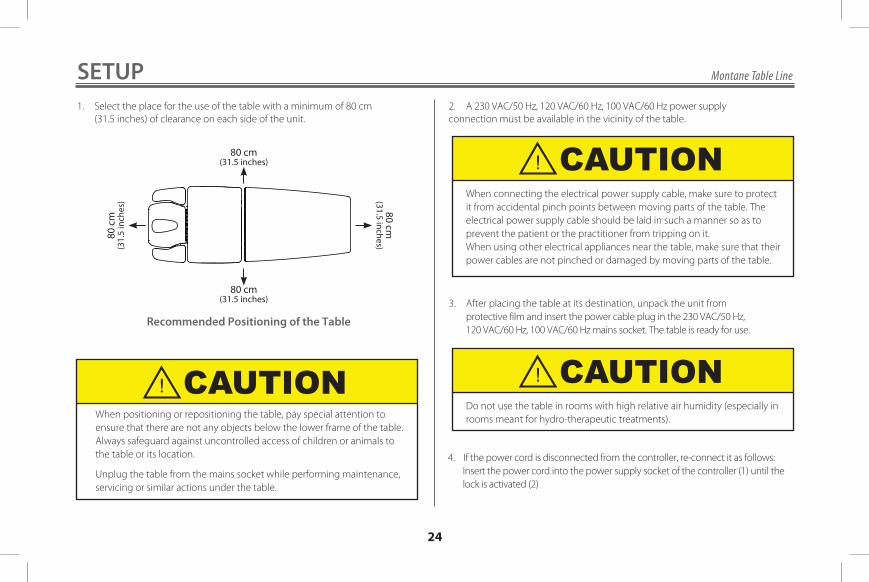
SETUP1 . Select the place for the use of the table with a minimum of 80 cm (31 .5 inches) of clearance on each side of the unit .
Recommended Positioning of the Table
When positioning or repositioning the table, pay special attention to ensure that there are not any objects below the lower frame of the table . Always safeguard against uncontrolled access of children or animals to the table or its location .
Unplug the table from the mains socket while performing maintenance, servicing or similar actions under the table .
2 . A 230 VAC/50 Hz, 120 VAC/60 Hz, 100 VAC/60 Hz power supply connection must be available in the vicinity of the table .
3 . After placing the table at its destination, unpack the unit from protective film and insert the power cable plug in the 230 VAC/50 Hz, 120 VAC/60 Hz, 100 VAC/60 Hz mains socket . The table is ready for use .
4 . If the power cord is disconnected from the controller, re-connect it as follows: Insert the power cord into the power supply socket of the controller (1) until the lock is activated (2)
When connecting the electrical power supply cable, make sure to protect it from accidental pinch points between moving parts of the table . The electrical power supply cable should be laid in such a manner so as to prevent the patient or the practitioner from tripping on it .When using other electrical appliances near the table, make sure that their power cables are not pinched or damaged by moving parts of the table .
Do not use the table in rooms with high relative air humidity (especially in rooms meant for hydro-therapeutic treatments) .
80 cm (31.5 inches)
80 cm (31.5 inches)
80 c
m
(31.
5 in
ches
)
80 cm
(31.5 inches)
CAUTION
CAUTION
CAUTION

Montane Table Line
25
SETUP
MONTANE tables are equipped with a locking mechanism for access to the height adjustment function . The adjustment function is locked when key CD is removed from slot 0 and LED® flashes every 0 .7 seconds . Height adjustment is possible when key CD is in slot 0 and the LED® is continuously lit .
Disconnecting the power cord Mechanism performance/access lock
Locked Work
5 . Access lock .
Connecting the power cord Before disconnecting the power cord from the controller, make sure that the mains plug is removed from the mains power outlet, then press the lock (2) with the screwdriver (3) and pull the power cord out of the power socket (1) .
Always remove the key from the lock before leaving the workstation, preventing unauthorized persons from starting the table control function . Then check it is locked, by testing the height movement of the table .
CAUTION

Montane Table Line
26
OPERATIONRELOCATING THE TABLE
2 . The 2 wheel / 2 leg frame type has two feet at the head rest side of the table and two wheels at the foot side of the table . The table can be moved about by lifting it by the head rest (be careful not to press the strut level!) and transport the table using the two wheels on the foot side .
Figure 3 Moving the
Montane Table
A – Work
B – Transport
C – Lift Lever
A
B
C
• Never transport a patient on the Montane Table . This table is not de-signed to support a patient during transport .
• Before changing the location of the table, make sure that the mains plug of the power cord is removed from the AC outlet and protected against accidental damage during relocation .
WARNINGMoving the Table
1 . The Montane Table with the optional 4 caster system includes a foot lever (see C in Figure 3) which can be set in two positions:
Work (A) – With the table resting on its feet, which can be adjusted for leveling (by screwing the foot in and out) caster should be approximately 0 .5 cm above the floor (including possible uneveness) . Transport (B) – With the table resting on 4 casters enabling it to be transported .

Montane Table Line
27
The height adjustment is done by means of a foot-controlled frame located at the bottom of the table . To lift the table, push the foot controller frame in the direction of the head rest (marked as B in the picture below) . To lower it, push the foot controller frame in the direction of the leg rest (marked as A in the same picture) . The table will continue to rise or fall as long as the foot controller frame is kept in its left-most or right-most position . The actuator switches off automatically when the table reaches it minimum or maximum position . In order to change the elevation/depression angle of the front (rear) section of the table, pull the handle of the gas spring lock to disengage it (see Figure 4 – item C), set the required position of the section and release the handle to lock the spring again .
OPERATIONADJUSTING THE TABLE
A – Lowering B – Raising C – Gas Spring's Position Lock Handle 1 – A hole for fixing the stabilizing bolster in the central section 2 – Two holes for fixing the stabilizing bolsters in the front section
Figure 4 – Controlling Elements of the Montane Table
A
B
A
B
21
C
C

Montane Table Line
28
OPERATION
• When making adjustments to the table sections, make certain the patient is removed before adjusting .
• Never place your hands or feet near the working mechanism of the table when making any and all adjustments to height or table sections . Moving parts could cause pinch points .
ADJUSTING TABLE SECTIONS
Adjusting the Postural Drainage Press the Postural Drainage Switch (located on both sides of the unit) to raise the Chest and Back Sections to the desired angle for Postural Drainage (illustration below) .
Before using postural drainage function, bolsters if being used, should be removed from mounting holes in front and middle section of table .
WARNING
CAUTION

Montane Table Line
29
CAUTION
1 . Clean and maintain the upholstery surfaces in the following way: – clean regularly with warm water and mild detergent (e .g . soap) solution using a soft cloth (do not use abrasive cleansers) . – rub the more heavily-stained areas with a soft, damp brush – after cleaning, wipe dry with a soft cloth – in case the surface has been stained with ball point pen, lipstick, printing ink, etc ., remove the stain immediately by rubbing it with a soft cloth 2 . Avoid extensive wetting of the surface of the table 3 . Disinfect the upholstery and other surfaces using a mild anti-bacterial detergent
MAINTENANCECLEANING THE UPHOLSTERY
We recommend to clean and/or disinfect the upholstered surfaces and other parts of the tables after each use to ensure proper hygiene level .
4 . Never use: – cleaning paste, wax, sprays – strong detergents, solvents and cleaning agents containing solvents, cleaning preparations for natural leather .
Use of such preparations may cause stiffening and breakages of the cover material as well as adverse change of the glossy finish of the upholstery surface which is not covered by the warranty!
5 . Sterilization with the use of the UV rays does not affect the surface of the upholstery .
Before cleaning the table, make sure that the electrical power supply cable has been disconnected from the power supply in the room .
CAUTION

Montane Table Line
30
1 . Clean the metal parts with a soft, damp sponge . Wipe the parts dry immediately after cleaning .
2 . All movable joints must be lubricated every six months or when experiencing squeaks or other noise . We recommend using any available aftermarket lubricants . Protect the upholstered parts from contact with the lubricants and remove any excess amounts or leaks of these with a dry cloth .
3 . Check the threaded joints periodically every six months and remove loose connections with a Phillips screwdriver, hex keys (no 4, 5 and 6) and flat spanners (10 and 27 mm) . Report all loose connections that cannot be removed to the manufacturer's authorized service and stop using the table until the cause of the problem is resolved .
CHECKING ACTUATORSMONTANE tables are equipped with electric actuators with push function (spline), allowing height adjustment . The electric actuators should be inspected once every quarter for proper action and for any sounds other than normal operation, such as strokes, squeaks, scuffs . Any defects in the operation of the actuator should be reported immediately to DJO for technical service, and operation of the table stopped until the cause of the fault has been removed .
CHECKING THE GAS SPRINGS (STRUTS)Montane tables are equipped with gas springs for easy adjustment of the front section inclination angle . To ensure proper performance of the gas springs, check the springs visually for leaks every 3 months . Any perceived performance deficiency or leak must be reported to DJO for technical service immediately .
PERIODIC CHECK OF ELECTRICAL SAFETYAt least once every 2 years, and each time after the breakdown/ repair of the actuator/ table automation, the user's technical service must perform or commission a table review for electrical safety .
MAINTENANCELUBRICATING POINTS

Montane Table Line
31
Should the Montane Tables require service, warranty or repair, please contact the selling dealer or your local DJO Customer Service .
SERVICEEU Directive on Waste Electrical and Elec-tronic Equipment (WEEE) ensures that prod-uct is appropriately disposed of or recycled at the end of its life.
At least once every 2 years, and each time after the breakdown/ repair of the actuator/ table automation, the user's technical service must perform or commission a table review for electrical safety .
The minimum scope of the review should include:
- check for mechanical damage to the wiring of the table; - check for mechanical damage to the controller enclosure and actuators; - electrical safety tests are performed according to PN-EN 62353 Protective earth resistance should be performed at the point G), shown in Fig 10
MAINTENANCE
Measuring point of the earth resistance

Montane Table Line
32
TROUBLESHOOTING
Failure indication Possible cause Action to be taken
The adjustment mechanism does not work - the LED is off
Exceeded the continuous work cycle
If necessary, take the patient off the table with the user's help. To restart the controller, remove the mains plug from the mains electrical outlet in the room and the access lock from the socket and wait for a minimum 1 h. Then connect the table to the mains socket and if the LED is on, you can start working with the table.
Disconnected power cordCheck if the power cord is plugged into the power supply socket of the controller and the AC outlet.
Control mechanism interrupts operation-LED is on
Exceeded safe working load Reduce the load on the table.
If fault symptoms persist, stop using the table, unplug the power cord, remove the lock and contact the supplier or the manufacturer .

Montane Table Line
33
WARRANTYDJO, LLC (“Company”), warrants that the Montane Tables (“Products”) are free of defects in material and workmanship . This warranty shall remain in effect for two years (24 months) for the cushions and three years (36 months) for the base frame and motor from the date of original consumer purchase . If this Product fails to function during the warranty period due to a defect in material or workmanship, at the Company's option, the Company or selling dealer will repair or replace this Product without charge within a period of thirty days from the date on which the Product is returned to the Company or the dealer .
All repairs to the Product must be performed by a service center certified by the Company . Any modifications or repairs performed by unauthorized centers or groups will void this warranty .
This Warranty Does Not Cover: • Replacement parts or labor furnished by anyone other than the Company, the selling dealer, or a service technician certified by the Company . • Defects or damage caused by labor furnished by someone other than Company, the selling dealer, or a certified Company service technician . • Any malfunction or failure in the Product caused by product misuse, including, but not limited to, the failure to provide reasonable and required maintenance or any use that is inconsistent with the Product User Manual .
DJO, LLC is not responsible for injury or damage resulting from modifications or service performed by non-authorized DJO, LLC service personnel .
COMPANY SHALL NOT BE LIABLE IN ANY EVENT FOR INCIDENTAL OR CONSEQUENTIAL DAMAGES.
Some locations do not allow the exclusion or limitation of incidental or consequential damages, so the above limitation or exclusion may not apply to you . To obtain service from Company or the selling dealer under this warranty:
1 . A written claim must be made within the warranty period to the Company or the selling dealer .
2 . The Product must be returned to the Company or the selling dealer by the owner . This warranty gives you specific, legal rights and you may also have other rights which vary from location to location . The Company does not authorize any person or representative to create for it any other obligation or liability in connection with the sale of the Product . Any representation or agreement not contained in the warranty shall be void and of no effect .
THE FOREGOING WARRANTY IS IN LIEU OF ALL OTHER WARRANTIES, EXPRESSED OR IMPLIED, INCLUDING ANY WARRANTY OR MERCHANTABILITY OR FITNESS FOR A PARTICULAR PURPOSE.

DJO is an ISO 13485 Certified Company
Meden-Inmedul. Wenedow 275-847 KoszalinPoland
T: 1.800.494.3395 USADJOGLOBAL.COM© 2019 DJO, LLC. All rights reserved.Made for DJO, LLCDJO is an ISO 13485 Certified Company
13-4322_E English


![[PPT]PRINCIPLES OF BOBATH APPROACH - · Web viewPRINCIPLES OF BOBATH APPROACH BY – GAJANAN BHALERAO What is Bobath therapy? Bobath therapy is an interdisciplinary approach to the](https://static.fdocuments.in/doc/165x107/5aadbe627f8b9a9c2e8eb866/pptprinciples-of-bobath-approach-viewprinciples-of-bobath-approach-by-.jpg)