Optical Audio Reproduction for Stereo Phonograph Records by Using White-light Interferometry
User Manual

USER MANUAL > CONTENTS
CONTENTSI. INTRODUCTION 5
1. To install the Bluetooth dongle 82. Installing the software 8
II. TO START A PROTOCOL 11
III. TO INSERT AN ANCILLARY LENS 17
IV. TESTS 21
1. To start a test 232. Read the answers 25
a. Relaxation accommodation test 26b. Allen Acuity test 26c. Letters or figures and latent farsightedness acuity test 26d. HOTV Acuity test 28e. Landolt acuity test 29f. Landolt 2 acuity test 29g. “E” Snellen acuity test 30h. Tumbling E acuity test 30i. Tumbling E acuity test 31j. Astigmatism test 32k. Ametropia test 32l. Color vision test: Ishihara 33m. Color vision test: Discs 33n. Color vision test: Tumbling E 34o. Test for sensitivity to contrasts: Three levels 34p. Fusion test 35q. Fusion test: Boxes 35r. Phoria test 35s. Phoria test: Notes of music (side) 36t. Phoria test: Notes of music (vertical) 36u. Stereoscopic acuity test: Depth perception 37v. Stereoscopic acuity test: Road signs 38w. Peripheral field test 38x. Test of the horizontal and vertical peripheral field (optional) 39y. Glare recovery test (optional) 39z. Ultra central field test (optional) 41
V. SETTINGS 43
1. To set up the monitoring software (tablet or PC) 46a. To choose a language 47b. To manage the user accounts 48c. Creating or modifying a protocol 51d. To create data exchange folders 56e. To manage software updates 56f. Setting up the tests 59g. To set up the medical centre information 60h. To delete data 61
2. To set up the device (viewer) 62a. To connect the monitoring software to the device 63b. To choose the language 64
USER MANUAL > CONTENTS
c. To set-up the screen 65d. To manage the licenses 66e. To select the voice synthesis 67
VI. STARTING WITH A PATIENT 69
1. Import existing patient 712. Creating a new profile 72
a. Identity of the Patient 72b. Correction worn and the patient's work environment 73
3. To create an anonymous patient 74
VII. MAIN MENU 77
LIST OF ERRORS 81
TECHNICAL DATA 83
1. The device 842. Accessory list 843. Environment 84
GENERAL INFORMATION 85
1. Symbols 862. Modifications 873. Declaration of conformity 874. Materials and products 875. Safety instructions 87
GLOSSARY 91

I. INTRODUCTION

USER MANUAL > INTRODUCTION
6 Optec Plus > V4 - 04.17
USER MANUAL > INTRODUCTION
Optec Plus > V4 - 04.17 7
1.2.3.4.5.6.7.8.9.
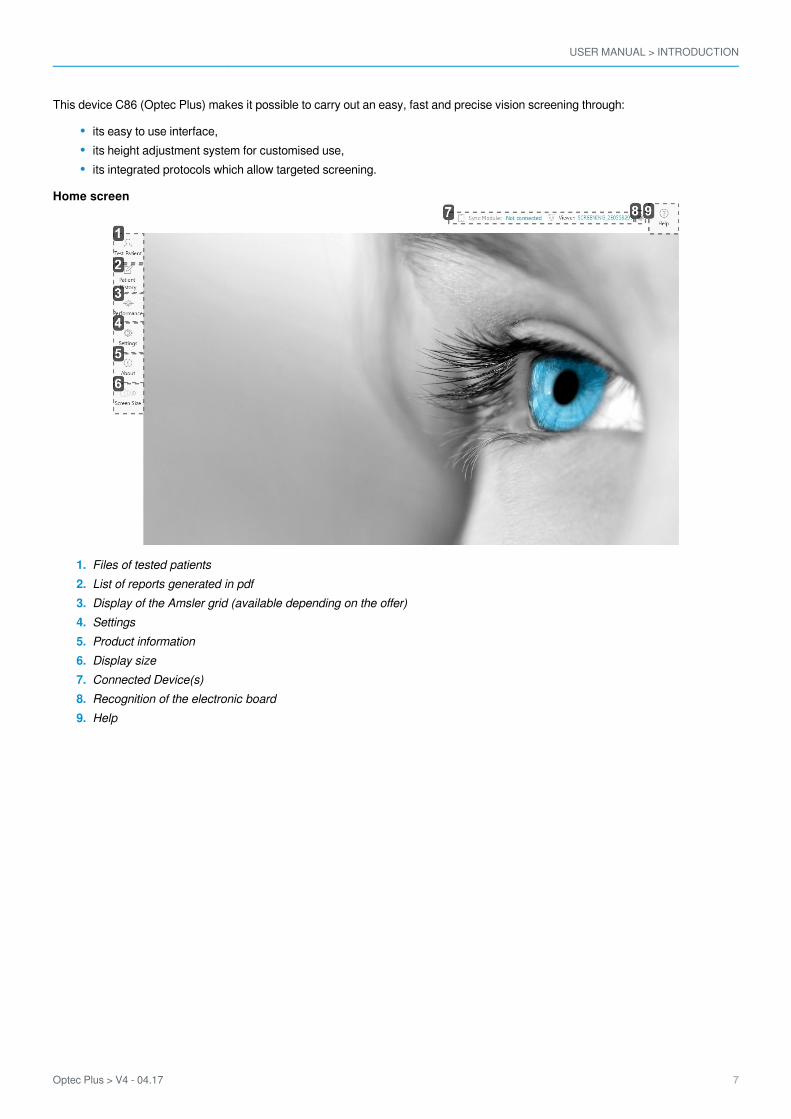
This device C86 (Optec Plus) makes it possible to carry out an easy, fast and precise vision screening through:
its easy to use interface,its height adjustment system for customised use,its integrated protocols which allow targeted screening.
Home screen
Files of tested patientsList of reports generated in pdfDisplay of the Amsler grid (available depending on the offer)SettingsProduct informationDisplay sizeConnected Device(s)Recognition of the electronic boardHelp

USER MANUAL > INTRODUCTION
8 Optec Plus > V4 - 04.17
2
1
2
1
1.2.
1. To install the Bluetooth dongle
In order to be able to use the device, you must synchronize it with your computer by using the Bluetooth dongle provided.
If you do not use medical software and you are equipped with an Elite tablet you do not need to install the Bluetooth key.
Insert the Bluetooth dongle into one of your computer’s USB ports.
According to your operating system version:An installation window is displayed > Click on nextThe installation is carried out automatically
> Once the installation is complete, the icon is displayed at the bottom of your screen.
If the Bluetooth key does not install automatically, insert the USB key provided with the device and install theBluetooth directory program.
Start the device software.
See .Installing the software (p.8)
2. Installing the software
A USB stick is provided with the device. It contains the software. You must install it on your computer before being able to use it orstart tests.
Insert the Bluetooth key into one of your computer’s USB ports.
Open the file and double-click on the software.
The Bluetooth dongle is installed automatically.>
A new folder is displayed in the file explorer list.>
USER MANUAL > INTRODUCTION
Optec Plus > V4 - 04.17 9
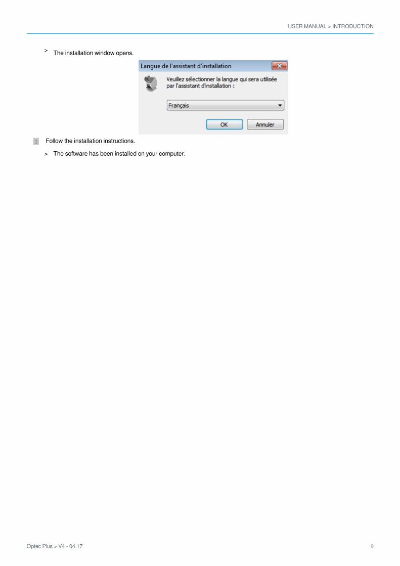
3 Follow the installation instructions.
The installation window opens.>
The software has been installed on your computer.>

USER MANUAL > INTRODUCTION
10 Optec Plus > V4 - 04.17

II. TO START A PROTOCOL

USER MANUAL > TO START A PROTOCOL
12 Optec Plus > V4 - 04.17

USER MANUAL > TO START A PROTOCOL
Optec Plus > V4 - 04.17 13
1
1.2.3.
The Protocols menu lets you start a series of tests for targeted screening. The user can adjust the font size.
If you have the automatic mode option, you can choose to only display the automatic protocols by clicking on the Only, in the top right hand side of the screen (according to your product version and model).display automatic protocols function
You can view all the tests within a protocol by clicking on .The following screen will appear:
Select a protocol by clicking on (manual protocol).
Night vision (mesopic) activationPeripheral glare allowing the glare sensitivity to be setDisplay of acuities on black or white background
The first protocol test starts.>
USER MANUAL > TO START A PROTOCOL
14 Optec Plus > V4 - 04.17
3
2
For protocol tests, day vision is activated by default. However, there is also a night version available.
Night vision (mesopic) and the peripheral glare are available only if the options were bought and activated.
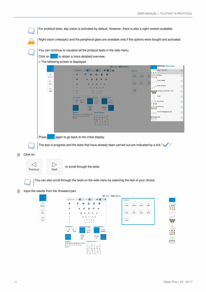
You can continue to visualize all the protocol tests in the side menu.
Click on to obtain a more detailed overview.> The following screen is displayed.
Press again to go back to the initial display.
The test in progress and the tests that have already been carried out are indicated by a tick " ."
Click on:
to scroll through the tests.
You can also scroll through the tests on the side menu by selecting the test of your choice.
Input the results from the part.Answers

USER MANUAL > TO START A PROTOCOL
Optec Plus > V4 - 04.17 15
5
4
1.
2.3.
Click on:
once the protocol is finished.
This page allows you:to choose if the patient takes the test with or without glasses (doctor’s decision), this must be done beforestarting the protocols and tests, it will appear on the results page,to access the test list and be able to launch them one after the other; or to select a protocol from the list,to modify information about the subject, to view an information summary or to finish with the patient.
Then, press on:
If you need to complete a test or to carry out a new one, you can press on:
if not click on
The results report for completed tests opens (unit protocols and/or tests as well as information about the patient).
You can export (XML file), send (PDF) or print these results.
You are redirected towards the main menu.>

USER MANUAL > TO START A PROTOCOL
16 Optec Plus > V4 - 04.17

III. TO INSERT AN ANCILLARY LENS

USER MANUAL > TO INSERT AN ANCILLARY LENS
18 Optec Plus > V4 - 04.17
USER MANUAL > TO INSERT AN ANCILLARY LENS
Optec Plus > V4 - 04.17 19
4
3
2
1
The use:
of two ancillary lens +1.75 and +2.25 is necessary for the screening test of latent farsightedness.of two ancillary lens VI 31 inch and VI 26 inch is necessary for the screening test of mid-distance vision.
Insert the ancillary lens into the device then remove once the test has been carried out.
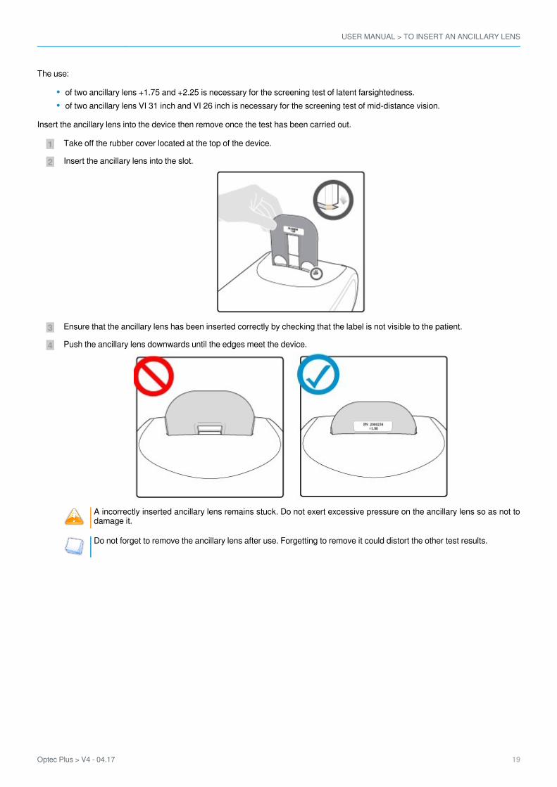
Take off the rubber cover located at the top of the device.
Insert the ancillary lens into the slot.
Ensure that the ancillary lens has been inserted correctly by checking that the label is not visible to the patient.
Push the ancillary lens downwards until the edges meet the device.
A incorrectly inserted ancillary lens remains stuck. Do not exert excessive pressure on the ancillary lens so as not todamage it.
Do not forget to remove the ancillary lens after use. Forgetting to remove it could distort the other test results.

USER MANUAL > TO INSERT AN ANCILLARY LENS
20 Optec Plus > V4 - 04.17

IV. TESTS

USER MANUAL > TESTS
22 Optec Plus > V4 - 04.17

USER MANUAL > TESTS
Optec Plus > V4 - 04.17 23
2
1
The management menu allows you:Tests
to start a test (p.23),to read the results (p.25).
1. To start a test
You can choose to complete tests outside the suggested protocols.
To do this:
Press:
Select a test by pressing on .
The list of the tests appears:>
The window opens.Test settings >

USER MANUAL > TESTS
24 Optec Plus > V4 - 04.17
4
3
A guideline appears in the display square.Two guidelines framed in red indicate the elements to be selected so the test is displayed.
Select:
- the eye to be tested,
Right eye
Left eye
Binocular
- distance,
Near vision
Mid-distance vision
Far vision
- the acuities if necessary,
1 to 3/10
4 to 12/10
The range of acuities selected by default runs from 4 to 12/10:
Press for a random display of the optotypes.This function is available on the following tests:
Letters or figures and latent farsightedness acuity test (p.26)Color vision test: Ishihara (p.33) (random display of groups of characters)Test for sensitivity to contrasts: Three levels (p.34) (random display of letters and/or figures)Stereoscopic acuity test: Depth perception. (p.37) (random display of dots)
The test overview is displayed only once all the settings have been selected.
Input the results obtained in the part . Answers
The test starts.>
USER MANUAL > TESTS
Optec Plus > V4 - 04.17 25
5
1.2.
Press:
once the test is finished to return to the list of tests.
2. Read the answers
This menu lets you know for each test:
which question to ask the patient,what is the result of the test.
Test list
Relaxation accommodation test (p.26)Allen Acuity test (p.26)Letters or figures and latent farsightedness acuity test (p.26)HOTV Acuity test (p.28)Landolt acuity test (p.29)Landolt 2 acuity test (p.29)“E” Snellen acuity test (p.30)Tumbling acuity test (p.30)Tumbling E acuity test (p.31)Astigmatism test (p.32)Ametropia test (p.32)Color vision test: Ishihara (p.33)Color vision test: Discs (p.33)Color vision test: Tumbling E (p.34)Test for sensitivity to contrasts: Three levels (p.34)Fusion test (p.35)Fusion test: Boxes (p.35)Phoria test (p.35)Phoria test: Music (side) (p.36)Phoria test: Music (vertical) (p.36)Stereoscopic acuity test: Depth perception (p.37)Stereoscopic acuity test: Road signs (p.38)Peripheral field test (p.38)Test of the horizontal and vertical peripheral field (p.39)Recovery from glare test (p.39)Ultra central field test (optional) (p.41)
USER MANUAL > TESTS
26 Optec Plus > V4 - 04.17
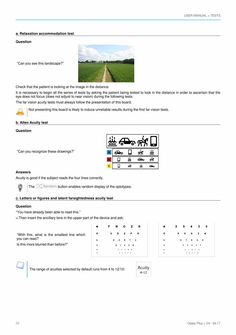
a. Relaxation accommodation test
Question
“Can you see this landscape?”
Check that the patient is looking at the image in the distance.It is necessary to begin all the series of tests by asking the patient being tested to look in the distance in order to ascertain that theeye does not focus (does not adjust to near vision) during the following tests.The far vision acuity tests must always follow the presentation of this board.
Not presenting this board is likely to induce unreliable results during the first far vision tests.
b. Allen Acuity test
Question
“Can you recognize these drawings?”
AnswersAcuity is good if the subject reads the four lines correctly.
The button enables random display of the optotypes.
c. Letters or figures and latent farsightedness acuity test
Question“You have already been able to read this.”> Then insert the ancillary lens in the upper part of the device and ask:
“With this, what is the smallest line whichyou can read?Is this more blurred than before?”
The range of acuities selected by default runs from 4 to 12/10:

USER MANUAL > TESTS
Optec Plus > V4 - 04.17 27
If the patient cannot read anything, press on:
to call the acuities of 1 with 3/10° and ask the question again:
“What are the smallest letters you can read? You can guess if you are not sure of your answer.”AnswersThe answer is valid when 4/5 letters (or figures) are read correctly.If the operator has the impression that the patient reads figures better than letters (for example: results from a previous test on figuresor bad knowledge of the alphabet: illiteracy), press on:
to use the optotype table with the figures.
Press:
to return to the optotype table with the letters.
Press for a random display of the optotypes.You can configure the acuities display, for that refer to the section: Set up the monitoring software > Set up the tests (p.59)
Press a second time on:
or to display the line of optotypes corresponding to the acuity of your choice.
Choose the line to be displayed via the screen below:
Make hesitant people make a guess.
USER MANUAL > TESTS
28 Optec Plus > V4 - 04.17
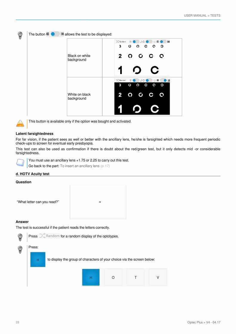
The button allows the test to be displayed:
Black on whitebackground
White on blackbackground
This button is available only if the option was bought and activated.
Latent farsightednessFor far vision, if the patient sees as well or better with the ancillary lens, he/she is farsighted which needs more frequent periodiccheck-ups to screen for eventual early presbyopia.This test can also be used as confirmation if there is doubt about the red/green test, but it only detects mid -or considerablefarsightedness.
You must use an ancillary lens +1.75 or 2.25 to carry out this test.Go back to the part: To insert an ancillary lens (p.17)
d. HOTV Acuity test
Question
“What letter can you read?”
AnswerThe test is successful if the patient reads the letters correctly.
Press for a random display of the optotypes.
Press:
to display the group of characters of your choice via the screen below:

USER MANUAL > TESTS
Optec Plus > V4 - 04.17 29
Press:
to display the line of optotypes corresponding to the acuity of your choice:
e. Landolt acuity test
Question
“Can you give the direction of the opening to the broken ring: at the top,below, on the left, or on the right, or then in which oblique direction?You can guess if you are not sure of your answer.”
In case of doubt, ask the subject to point in the direction of the opening. Encourage hesitant people to take a guess.
The subjects who are not accustomed to reading the letters (or the figures) will have less difficulty with the Landolt rings or “brokenrings” in so far as they are quite lateralized.
f. Landolt 2 acuity test
Question
“In each frame, there are three split rings and a full ring. Can you tell mewhich one is the full ring?“
People who are not used to reading the letters (or figures) will have less difficulty with the Landolt rings or “broken rings” as they arewell lateralized.

USER MANUAL > TESTS
30 Optec Plus > V4 - 04.17
g. “E” Snellen acuity test
Questions
“Can you give the direction of the opening of the E? Above, below, towardsthe left or the right-hand side?You can guess if you are not sure of your answer.”
People who are not used to reading letters (or figures) will have less difficulty with the letters E as long as they are lateralized well.
Use the “Raskin E” test rather than the “Snellen E” test.
Encourage hesitant people to take a guess.If in doubt, ask them to point in the direction of the lines.
h. Tumbling E acuity test
Question
“Can you give the direction of the opening of the E? Above, below, towardsthe left or the right-hand side?You can guess if you are not sure of your answer.”
People who are not used to reading letters (or figures) will have less difficulty with the letters E as long as they are lateralized well.
Use the “Tumbling E” test rather than the “Snellen E” test.
Encourage hesitant people to take a guess.If in doubt, ask them to point in the direction of the lines.
USER MANUAL > TESTS
Optec Plus > V4 - 04.17 31
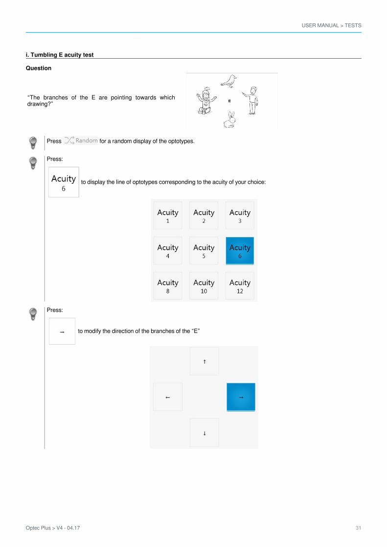
i. Tumbling E acuity test
Question
“The branches of the E are pointing towards whichdrawing?”
Press for a random display of the optotypes.
Press:
to display the line of optotypes corresponding to the acuity of your choice:
Press:
to modify the direction of the branches of the “E”
USER MANUAL > TESTS
32 Optec Plus > V4 - 04.17
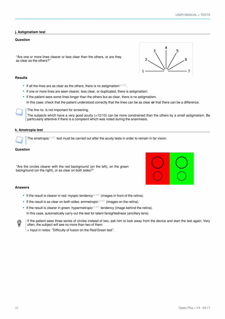
j. Astigmatism test
Question
“Are one or more lines clearer or less clear than the others, or are theyas clear as the others?”
Results
If all the lines are as clear as the others, there is no .astigmatism(p.92)
If one or more lines are seen clearer, less clear, or duplicated, there is astigmatism.If the patient sees some lines longer than the others but as clear, there is no astigmatism.In this case: check that the patient understood correctly that the lines can be as clear that there can be a difference.or
The line no. is not important for screening.The subjects which have a very good acuity (>12/10) can be more constrained than the others by a small astigmatism. Beparticularly attentive if there is a complaint which was noted during the anamnesis.
k. Ametropia test
The test must be carried out after the acuity tests in order to remain in far vision.ametropia(p.92)
Question
“Are the circles clearer with the red background (on the left), on the greenbackground (on the right), or as clear on both sides?”
Answers
If the result is clearer in red: (images in front of the retina).myopic tendency(p.92)
If the result is as clear on both sides: (images on the retina).emmetropic(p.92)
If the result is clearer in green: tendency (image behind the retina).hypermetropic(p.92)
In this case, automatically carry out the test for latent farsightedness (ancillary lens).
If the patient sees three series of circles instead of two, ask him to look away from the device and start the test again. Veryoften, the subject will see no more than two of them.> Input in notes: “Difficulty of fusion on the Red/Green test”.
USER MANUAL > TESTS
Optec Plus > V4 - 04.17 33
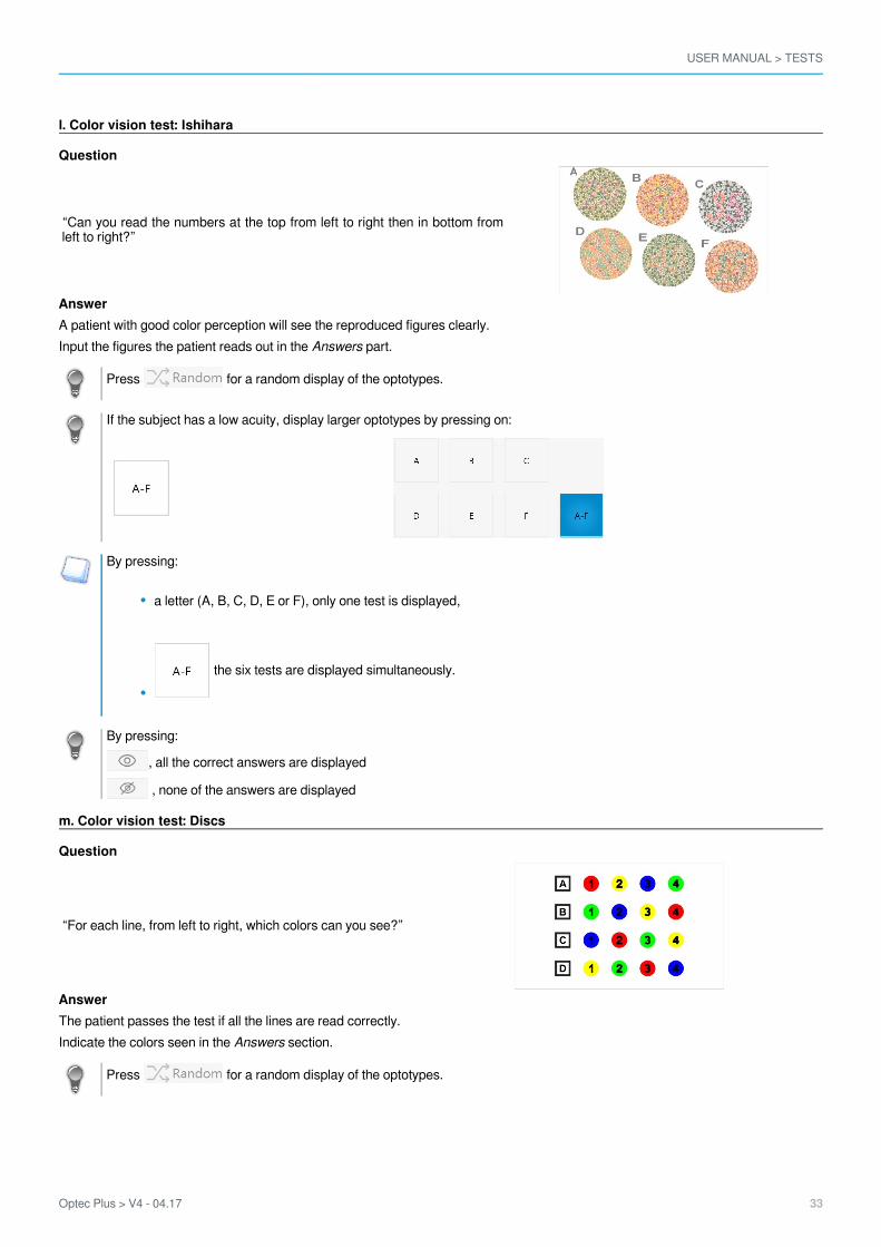
l. Color vision test: Ishihara
Question
“Can you read the numbers at the top from left to right then in bottom fromleft to right?”
AnswerA patient with good color perception will see the reproduced figures clearly.Input the figures the patient reads out in the part.Answers
Press for a random display of the optotypes.
If the subject has a low acuity, display larger optotypes by pressing on:
By pressing:
a letter (A, B, C, D, E or F), only one test is displayed,
the six tests are displayed simultaneously.
By pressing:
, all the correct answers are displayed
, none of the answers are displayed
m. Color vision test: Discs
Question
“For each line, from left to right, which colors can you see?”
AnswerThe patient passes the test if all the lines are read correctly.Indicate the colors seen in the section.Answers
Press for a random display of the optotypes.
USER MANUAL > TESTS
34 Optec Plus > V4 - 04.17
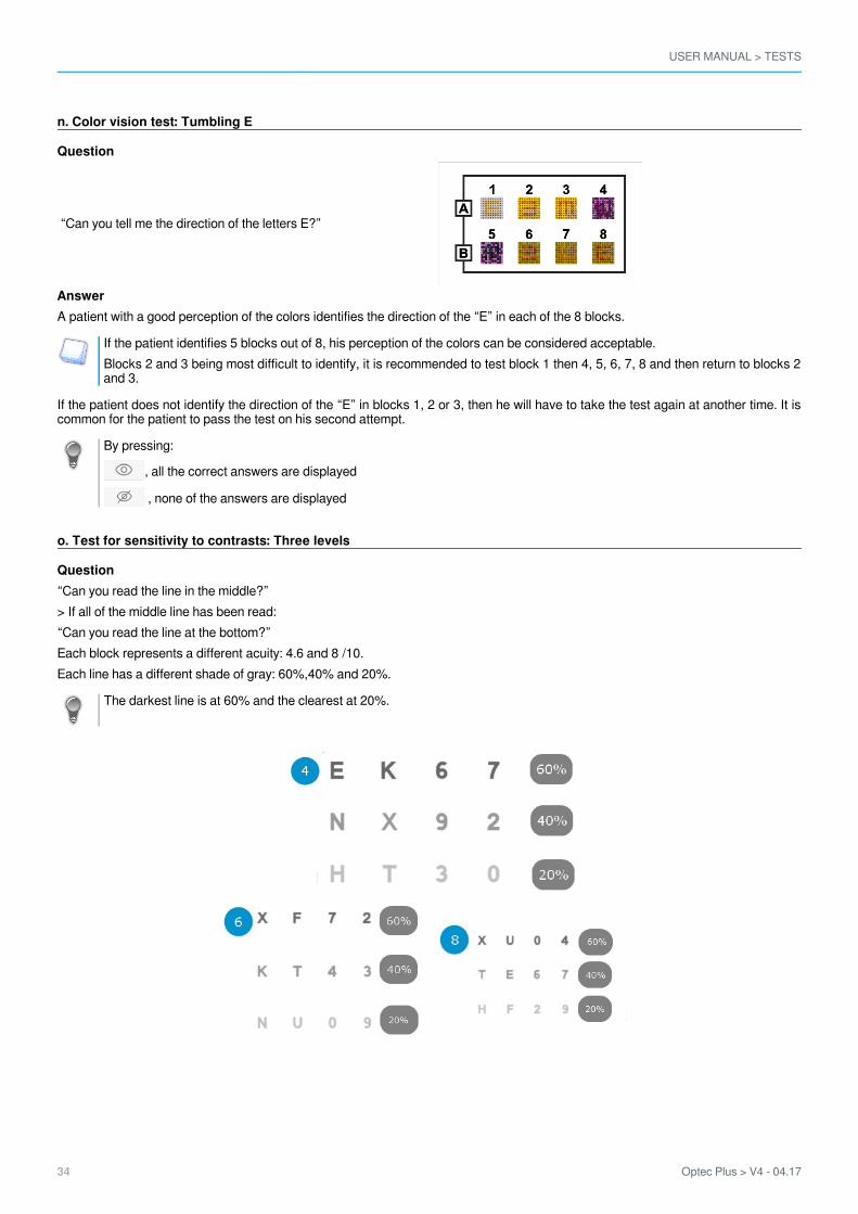
n. Color vision test: Tumbling E
Question
“Can you tell me the direction of the letters E?”
AnswerA patient with a good perception of the colors identifies the direction of the “E” in each of the 8 blocks.
If the patient identifies 5 blocks out of 8, his perception of the colors can be considered acceptable.Blocks 2 and 3 being most difficult to identify, it is recommended to test block 1 then 4, 5, 6, 7, 8 and then return to blocks 2and 3.
If the patient does not identify the direction of the “E” in blocks 1, 2 or 3, then he will have to take the test again at another time. It iscommon for the patient to pass the test on his second attempt.
By pressing:
, all the correct answers are displayed
, none of the answers are displayed
o. Test for sensitivity to contrasts: Three levels
Question“Can you read the line in the middle?”> If all of the middle line has been read:“Can you read the line at the bottom?”Each block represents a different acuity: 4.6 and 8 /10.Each line has a different shade of gray: 60%,40% and 20%.
The darkest line is at 60% and the clearest at 20%.
USER MANUAL > TESTS
Optec Plus > V4 - 04.17 35
AnswersSensitivity to contrasts is correct when the patient reads the 4 letters at 6/10 with 40% of gray.
Refer to the conversion table to match the various acuity scales and the types of notation. This table is available on the USBkey.
Press for a random display of the optotypes.
p. Fusion test
Question
“Can you see the line at the top?”“Is it on the left, on the right, or does it continue on the lowerline?”“How many crosses can you see?”
AnswersFusion is good if the patient only sees one image of the line at the top, the line in the lower part, only one cross and two triangles.The subject can say that the two lines are almost aligned, but with a very slight offset while seeing only one cross.If in doubt, fusion can be considered acceptable: microstrabism.
Do not carry out this test if the patient is monophtalme or amblyopic (important difference in acuity between the two eyes dueto a so-called “lazy” eye).
q. Fusion test: Boxes
Question
“How much boxes do you see?”
AnswerFusion is good if the patient sees three boxes.
The test can be carried out only in binocular vision.
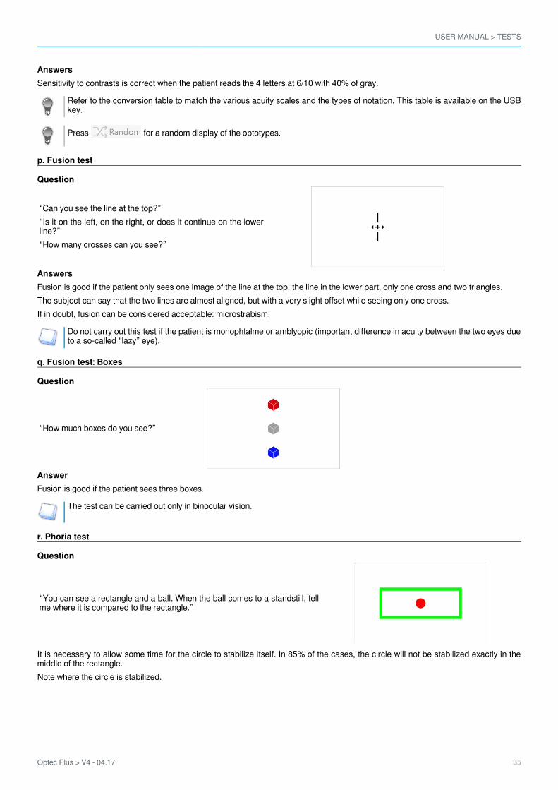
r. Phoria test
Question
“You can see a rectangle and a ball. When the ball comes to a standstill, tellme where it is compared to the rectangle.”
It is necessary to allow some time for the circle to stabilize itself. In 85% of the cases, the circle will not be stabilized exactly in themiddle of the rectangle.Note where the circle is stabilized.
USER MANUAL > TESTS
36 Optec Plus > V4 - 04.17
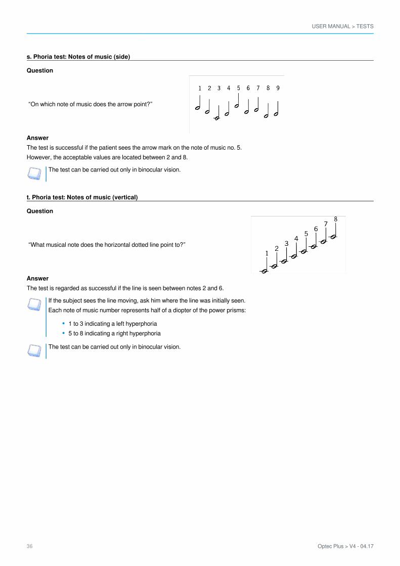
s. Phoria test: Notes of music (side)
Question
“On which note of music does the arrow point?”
AnswerThe test is successful if the patient sees the arrow mark on the note of music no. 5.However, the acceptable values are located between 2 and 8.
The test can be carried out only in binocular vision.
t. Phoria test: Notes of music (vertical)
Question
“What musical note does the horizontal dotted line point to?”
AnswerThe test is regarded as successful if the line is seen between notes 2 and 6.
If the subject sees the line moving, ask him where the line was initially seen.Each note of music number represents half of a diopter of the power prisms:
1 to 3 indicating a left hyperphoria5 to 8 indicating a right hyperphoria
The test can be carried out only in binocular vision.

USER MANUAL > TESTS
Optec Plus > V4 - 04.17 37
u. Stereoscopic acuity test: Depth perception
Question
“Can you see that in the drawing number 1, the point on the left is closerto you? What is in the other drawings”?
It is possible to modify the angles of relief by clicking on:
or
By selecting:
the reliefs will be more difficult to locate.
AnswerThe answer is correct when the dot is seen nearer or at the same level as the rest of the drawing. It is wrong when the dot is seen onthe sides.It should be checked systematically whether the dot is seen correctly in depth.
Sometimes some people have difficulty understanding the test. In this case, one can “sacrifice” the first answer: say whichpoint is in relief and ask the subject if he sees that it is closer to him than the rest of the drawing or if he sees this pointshifted on the sides.
Press for a random display of the points.
By pressing:
, all the correct answers are displayed
, none of the answers are displayed
By clicking on the button on the right of visual, you indicate that the patient does not see the point in relief but that it moves.
USER MANUAL > TESTS
38 Optec Plus > V4 - 04.17
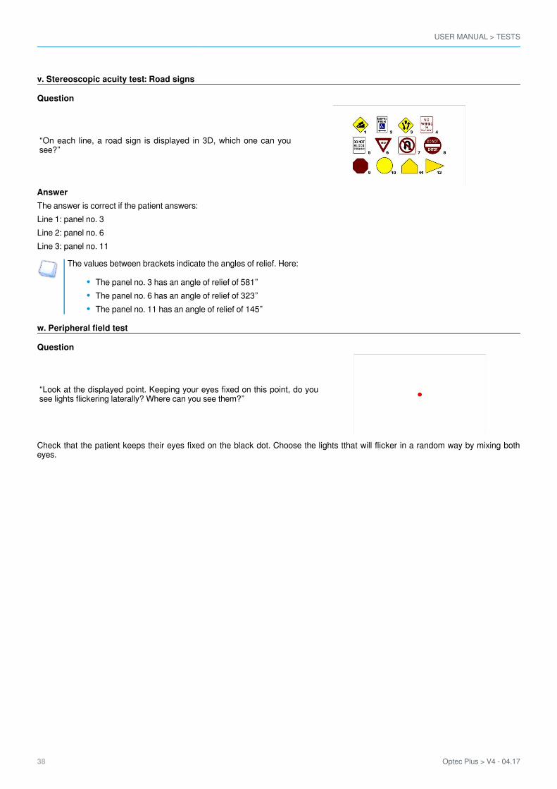
v. Stereoscopic acuity test: Road signs
Question
“On each line, a road sign is displayed in 3D, which one can yousee?”
AnswerThe answer is correct if the patient answers:Line 1: panel no. 3Line 2: panel no. 6Line 3: panel no. 11
The values between brackets indicate the angles of relief. Here:
The panel no. 3 has an angle of relief of 581”The panel no. 6 has an angle of relief of 323”The panel no. 11 has an angle of relief of 145”
w. Peripheral field test
Question
“Look at the displayed point. Keeping your eyes fixed on this point, do yousee lights flickering laterally? Where can you see them?”
Check that the patient keeps their eyes fixed on the black dot. Choose the lights tthat will flicker in a random way by mixing botheyes.

USER MANUAL > TESTS
Optec Plus > V4 - 04.17 39
1.2.3.4.5.
x. Test of the horizontal and vertical peripheral field (optional)
Before starting this test:
Use the LED peripheral mask, available in a special kitTurn off the machinePlug the peripheral mask into the product, in the plug designed for this purposeMagnetise the mask below the forehead rest, in the notchesTurn on the machine
Question“Look at the displayed point. While keeping your eyes fixed on this point, you see lights blinking in the periphery of your vision. Wherecan you see them?”Check that the patient keeps their eyes fixed on the black dot. Choose the lights that should be blinking by using the diagramdisplayed on your screen.
By clicking on one of the bulbs, the following window is displayed:
By clicking on:
, the bulb briefly lights up then goes out. If the technician is not sure that the patient saw the bulb, it is possible to relight it byclicking on this button.
, the lit LED is seen by the patient. It is displayed in green on the screen.
, the lit LED is not seen by the patient. It is displayed in red on the screen.

USER MANUAL > TESTS
40 Optec Plus > V4 - 04.17
y. Glare recovery test (optional)
Before starting this test it is important to set up:
Eye selection:
Distance selection:
Once these two choices have been selected, the answers section is no longer grey.
Question“Stare at the centre of the lamp, without looking away”.
Let the subject know that a bright light will dazzle him for a few seconds.
Click on the answer box to start the glare test.The calculation starts.
Once the glare test is finished, the following screen is displayed:

USER MANUAL > TESTS
Optec Plus > V4 - 04.17 41
1.2.
Question“Tell me how many dots are displayed”.> A stop watch starts.
The display of the points and the start of the stop watch are simultaneous.
Click in the answers section, to stop the stop watch when the subject gives his answer.
Answer
Recovery time in secondsAge of patient
The result of the time of recovery from the glare test is displayed in the graph.
If the dot appears in the blue area then glare recovery time is fine.
The dot is not displayed if the patient is anonymous.
z. Ultra central field test (optional)
Before starting this test it is important to set up:
Eye selection:
Distance selection:
QuestionLook at the displayed point. While keeping your eyes fixed on this point, you see lights blinking in the periphery of your vision. Wherecan you see them?”Check that the patient keeps their eyes fixed on the black dot. Choose the lights that should be blinking by using the diagramdisplayed on your screen.

USER MANUAL > TESTS
42 Optec Plus > V4 - 04.17
The enabled bulbs can be lit according to the position of the fixing point.When you click on the bulb area, it is enabled and the fixing point can be moved. You can turn the light bulb on by clicking onit.
When you click on one of the bulbs, the following window is displayed:
By clicking on:
, the bulb briefly lights up then goes out. If the technician is not sure that the patient saw the bulb, it is possible to relight it byclicking on this button.
, the lit LED is seen by the patient. It is displayed in green on the screen.
, the lit LED is not seen by the patient. It is displayed in red on the screen.

V. SETTINGS

USER MANUAL > SETTINGS
44 Optec Plus > V4 - 04.17

USER MANUAL > SETTINGS
Optec Plus > V4 - 04.17 45
1.2.3.
The menu allows you to:Settings
to set up the monitoring software (tablet or PC) (p.46)to set up the device (viewer) (p.62)
Driving software settingDevice settingPC synchronisation software setting
USER MANUAL > SETTINGS
46 Optec Plus > V4 - 04.17
2
1
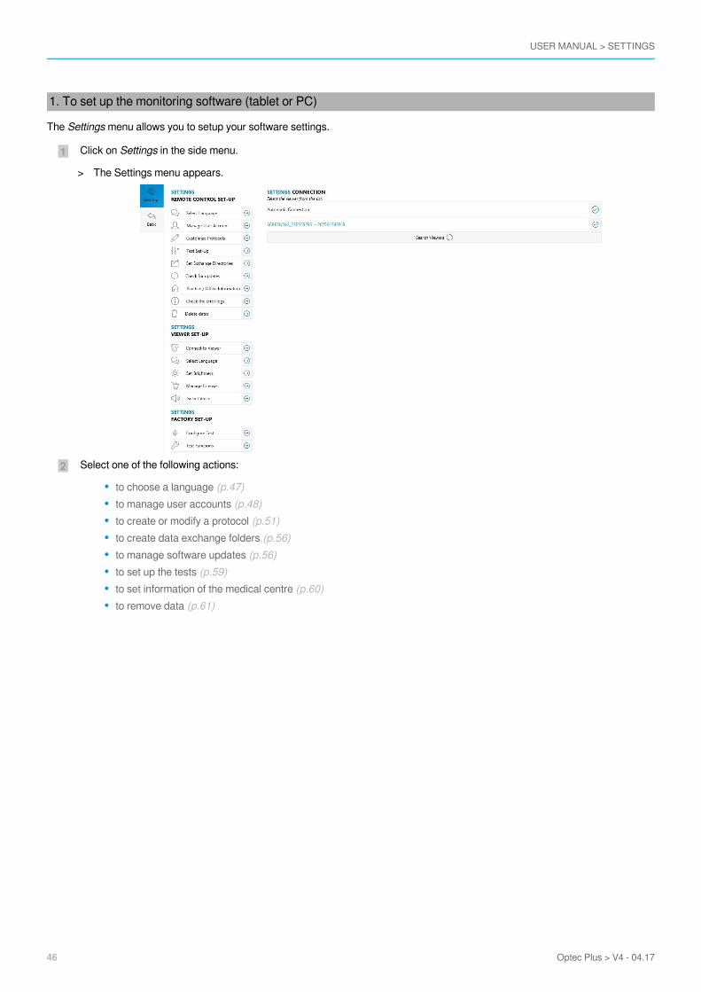
1. To set up the monitoring software (tablet or PC)
The menu allows you to setup your software settings.Settings
Click on in the side menu.Settings
Select one of the following actions:
to choose a language (p.47)to manage user accounts (p.48)to create or modify a protocol (p.51)to create data exchange folders (p.56)to manage software updates (p.56)to set up the tests (p.59)to set information of the medical centre (p.60)to remove data (p.61)
The Settings menu appears.>
USER MANUAL > SETTINGS
Optec Plus > V4 - 04.17 47
2
1
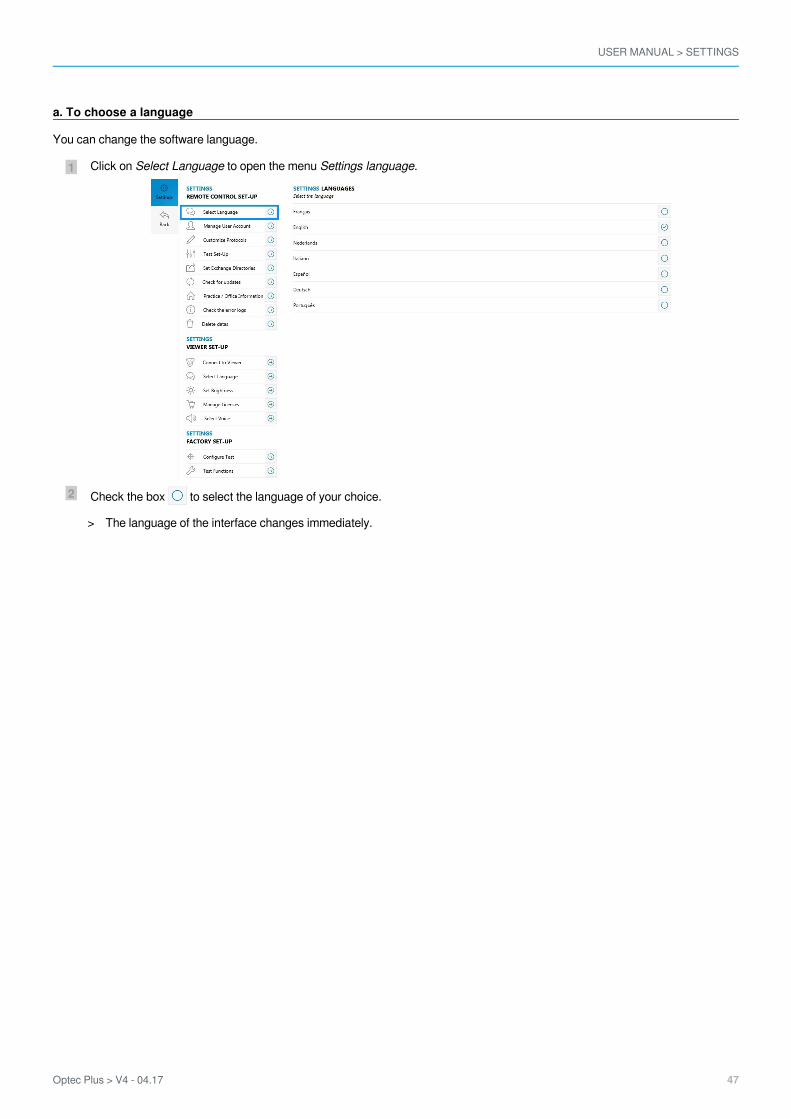
a. To choose a language
You can change the software language.
Click on to open the menu .Select Language Settings language
Check the box to select the language of your choice.
The language of the interface changes immediately.>
USER MANUAL > SETTINGS
48 Optec Plus > V4 - 04.17
2
1
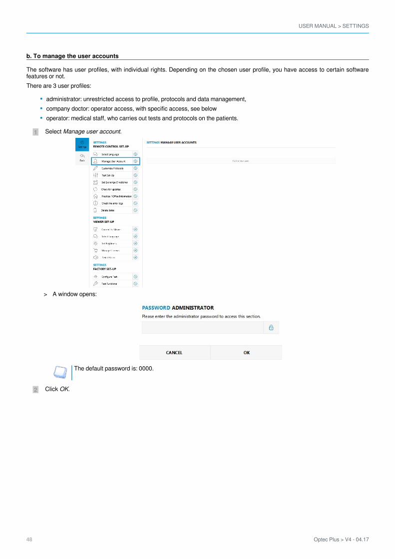
b. To manage the user accounts
The software has user profiles, with individual rights. Depending on the chosen user profile, you have access to certain softwarefeatures or not.There are 3 user profiles:
administrator: unrestricted access to profile, protocols and data management,company doctor: operator access, with specific access, see belowoperator: medical staff, who carries out tests and protocols on the patients.
Select .Manage user account
The default password is: 0000.
Click .OK
A window opens:>
USER MANUAL > SETTINGS
Optec Plus > V4 - 04.17 49
4
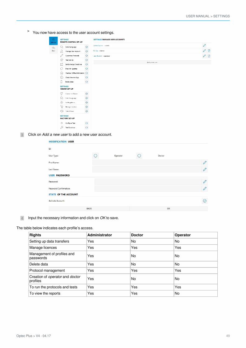
3 Click on to add a new user account.Add a new user
Input the necessary information and click on to save. OK
The table below indicates each profile’s access.
Rights Administrator Doctor OperatorSetting up data transfers Yes No NoManage licences Yes Yes YesManagement of profiles andpasswords Yes No No
Delete data Yes No NoProtocol management Yes Yes YesCreation of and operator doctorprofiles Yes No No
To run the protocols and tests Yes Yes YesTo view the reports Yes Yes No
You now have access to the user account settings.>
USER MANUAL > SETTINGS
50 Optec Plus > V4 - 04.17
4
3
2
1
4
3
2
1
4
3
2
1
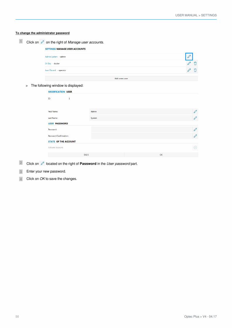
To change the administrator password
Click on on the right of .Manage user accounts
Click on located on the right of in the part.Password User password
Enter your new password.
Click on to save the changes.OK
The following window is displayed:>

USER MANUAL > SETTINGS
Optec Plus > V4 - 04.17 51
3
2
1
c. Creating or modifying a protocol
You can create your own test protocol. There are two types of protocols available:
The you allow to create a list of tests and to display them using the software launched on your computer manual protocolsor the Elite tablet. You move manually from test to test by clicking on:
then once the protocol is finished.
The also allow you to put together a series of tests compatible with the automatic mode. Once theautomatic protocolsprotocol has been started, moving from one test to the other as well as stopping the protocol is done automatically (accordingto the version and the model of your product).
Select .Customize Protocols
Select .Create a new protocol
If you wish:
to modify an existing protocol, click on located on the right of the protocol to be modified then, carry outthe changes while following the same procedure used to create a protocol.
to display a protocol, check the box if not un-check the box.
Enter the name of your protocol and choose if it will be automatic or manual and static or random.
You can constantly modify or remove your protocols by clicking on or .
A window is displayed.>

USER MANUAL > SETTINGS
52 Optec Plus > V4 - 04.17
5
4
1.2.
3.4.
5.
6.
Press .OK
Protocol nameAddition of guidelinePossibility of adding new vocal setpoints (if automatic mode is activated), a window is displayed (if manual mode isactivated):
TestsMode
automatic (if function available)mode
Type of boardstatic: for each test and each eye/distance combination, the same board is displayedrandom: for each test, if this one allows it, the display of the boards is random
Save the protocolDrag and drop the tests (and/or vocal setpoints) to be integrated into the entitled right part .My protocol
Carefully select the test by pressing .
The vocal setpoints are to be chosen among the list proposed by the software (if the function available).
The protocol editor opens.>
USER MANUAL > SETTINGS
Optec Plus > V4 - 04.17 53
6
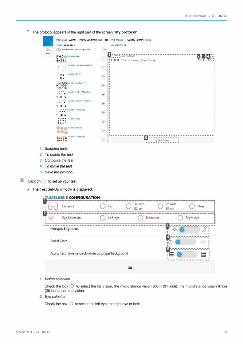
1.2.3.4.5.
1.
2.
3.
Selected testsTo delete the testConfigure the testTo move the testSave the protocol
Click on to set up your test.
Vision selection
Check the box to select the far vision, the mid-distance vision 80cm (31 inch), the mid-distance vision 67cm(26 inch), the near vision.Eye selection
Check the box to select the left eye, the right eye or both.
The protocol appears in the right part of the screen “ ".My protocol>
The Test Set-Up window is displayed.>

USER MANUAL > SETTINGS
54 Optec Plus > V4 - 04.17
7
3.
4.
5.
Selection of day or night visionClick on the button to select day or night vision.(Only available if the option is activated).
Glare resistance selectionClick on the button to select the glare resistance.(Only available if the option is activated).Selection of reversed acuityClick on the button to display acuities: black on white background or white on black background(Only available if the option is activated).
Click .OK
Your choices are displayed on the screen.>
USER MANUAL > SETTINGS
Optec Plus > V4 - 04.17 55
8
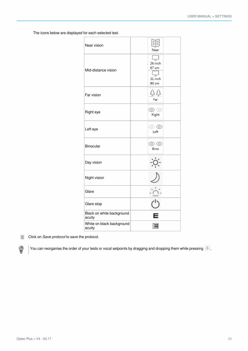
The icons below are displayed for each selected test.
Near vision
Mid-distance vision
Far vision
Right eye
Left eye
Binocular
Day vision
Night vision
Glare
Glare stop
Black on white backgroundacuityWhite on black backgroundacuity
Click on to save the protocol.Save protocol
You can reorganise the order of your tests or vocal setpoints by dragging and dropping them while pressing .
USER MANUAL > SETTINGS
56 Optec Plus > V4 - 04.17
1
5
4
3
2
1
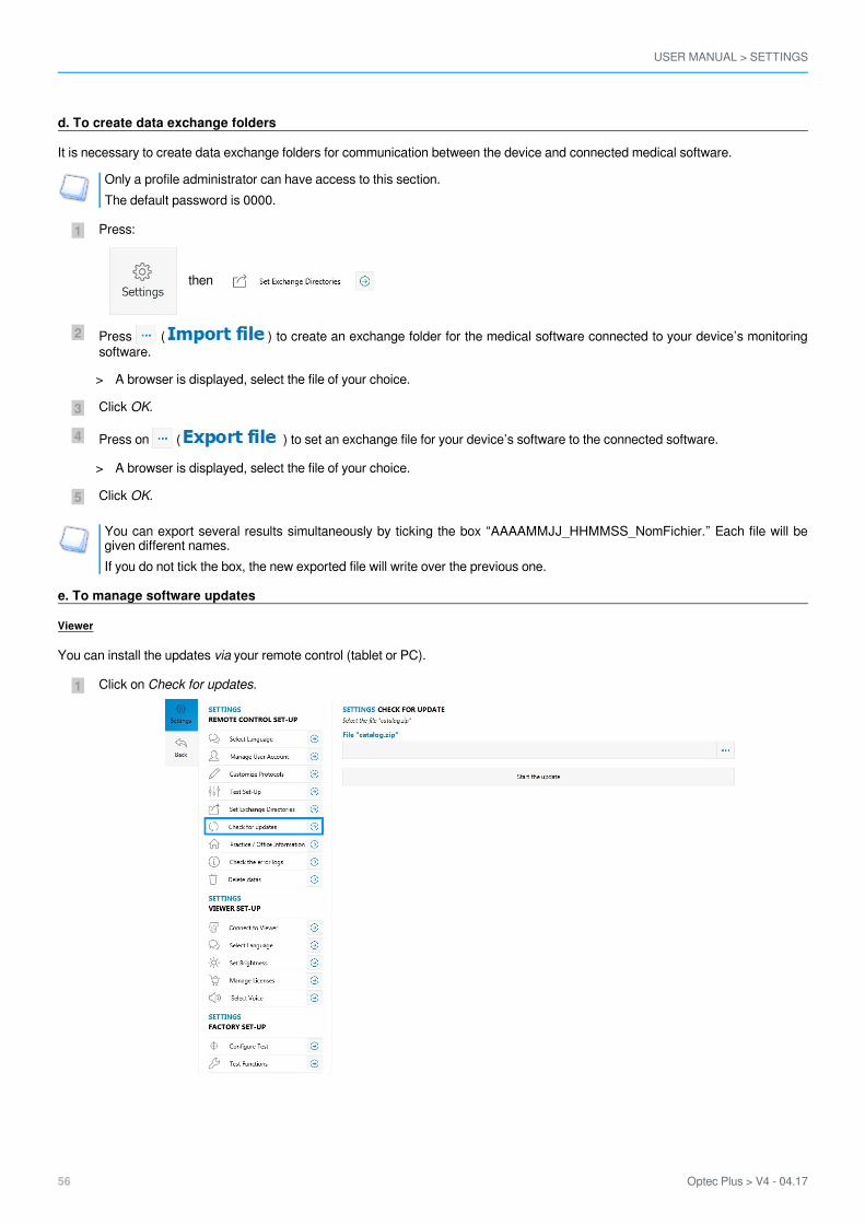
d. To create data exchange folders
It is necessary to create data exchange folders for communication between the device and connected medical software.
Only a profile administrator can have access to this section.The default password is 0000.
Press:
then
Press ( ) to create an exchange folder for the medical software connected to your device’s monitoringsoftware.
Click .OK
Press on ( ) to set an exchange file for your device’s software to the connected software.
Click .OK
You can export several results simultaneously by ticking the box “AAAAMMJJ_HHMMSS_NomFichier.” Each file will begiven different names.If you do not tick the box, the new exported file will write over the previous one.
e. To manage software updates
Viewer
You can install the updates your remote control (tablet or PC).via
Click on .Check for updates
A browser is displayed, select the file of your choice.>
A browser is displayed, select the file of your choice.>
USER MANUAL > SETTINGS
Optec Plus > V4 - 04.17 57
4
3
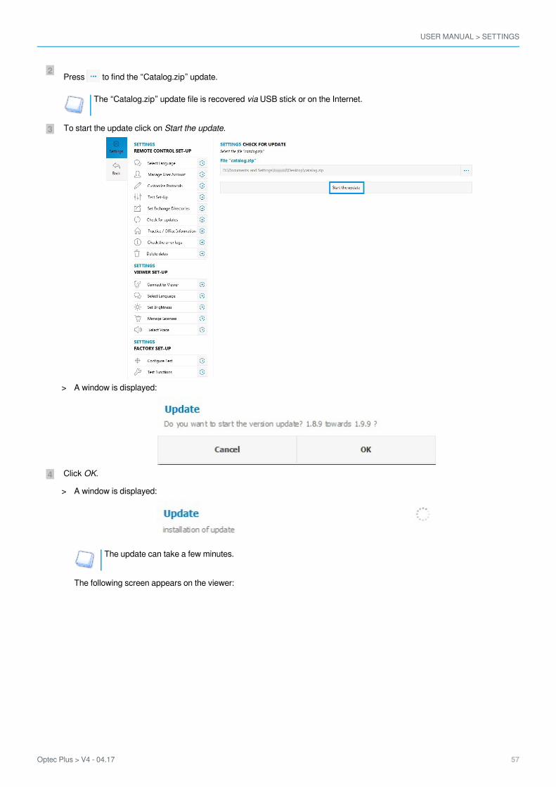
2Press to find the “Catalog.zip” update.
The “Catalog.zip” update file is recovered USB stick or on the Internet.via
To start the update click on .Start the update
Click .OK
The update can take a few minutes.
The following screen appears on the viewer:
A window is displayed:>
A window is displayed:>

USER MANUAL > SETTINGS
58 Optec Plus > V4 - 04.17
5 Click on to finalize the update.Install
Once the update has finished, restart the device.
PC remote control
To install PC remote control updates, you must first uninstall the old versions. You will then be able to install the new version byfollowing the steps of the section.Software Installer (p.8)

USER MANUAL > SETTINGS
Optec Plus > V4 - 04.17 59
1.
2.
3.
4.
5.
6.
7.
f. Setting up the tests
The allows you to manage the patient information you intend to input and display.Test Set-Up
Display the identity section of the patient
If you un-check the box : when you click on , the screen “Patient identification” will not appear.Test patientDisplay information section of the patient
If you untick the box: when you click on , the “Patient information” screen will not be displayed.Test patientDisplay sizeAllows you to choose the display size the test reports: small or largeDisplay fontAllows you to choose the type of font for the display:
ArialSquare
Display of the format of acuitiesAllows you to choose the format of acuities:
In xx/10 (by default)In 20/xxIn 6/xx
Display of the white optotypes on black background
If you check the box: the optotypes will be displayed in white on black backgroundOrder reversal of the acuities displayIf you:
Check the box : the optotypes will be displayed from largest (on top) to the smallest (on bottom)
Un-check the box : the optotypes will be displayed from the smallest (on top) to the largest (on bottom)
Click on the features you wish to activate: the icon appears close to the activated features.
USER MANUAL > SETTINGS
60 Optec Plus > V4 - 04.17
3
2
1
3
2
1
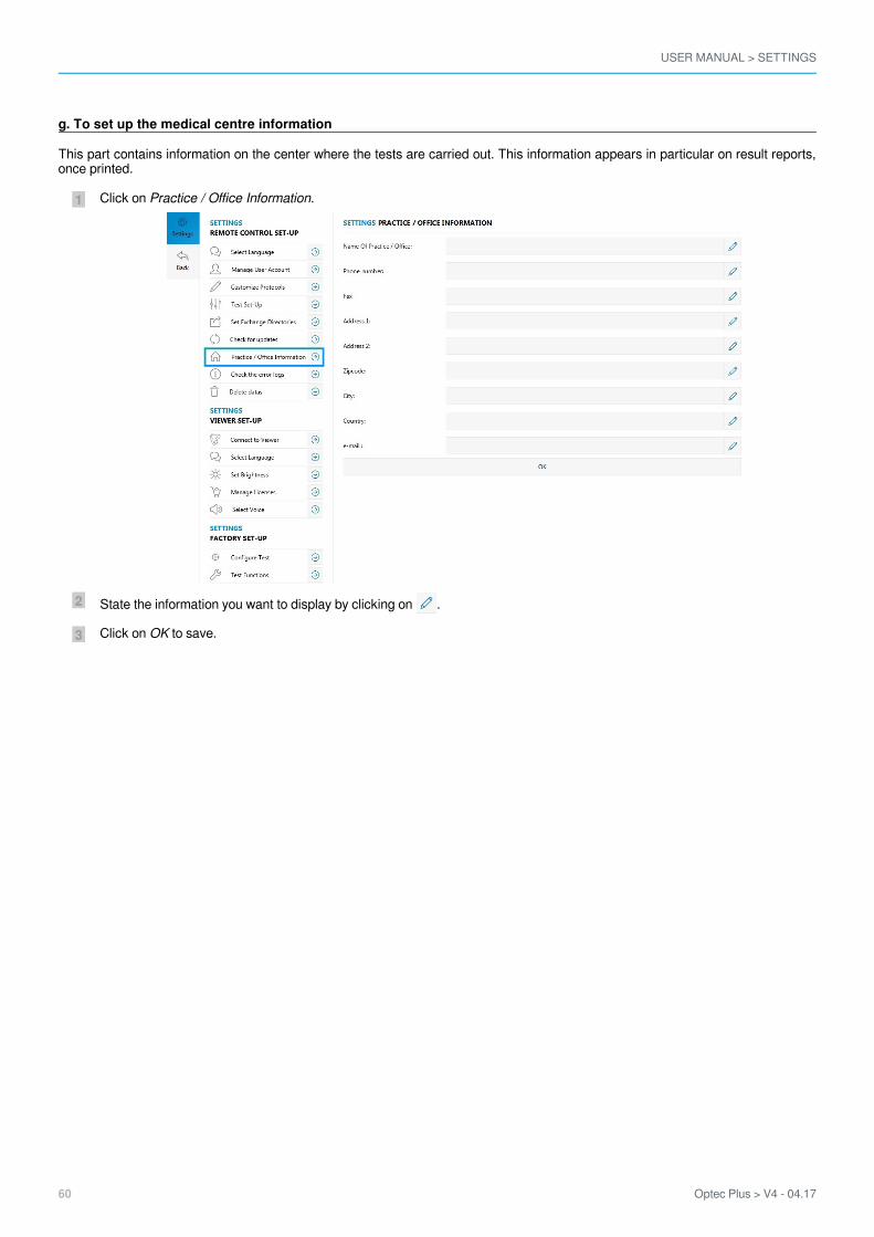
g. To set up the medical centre information
This part contains information on the center where the tests are carried out. This information appears in particular on result reports,once printed.
Click on .Practice / Office Information
State the information you want to display by clicking on .
Click on to save.OK
USER MANUAL > SETTINGS
Optec Plus > V4 - 04.17 61
3
2
1
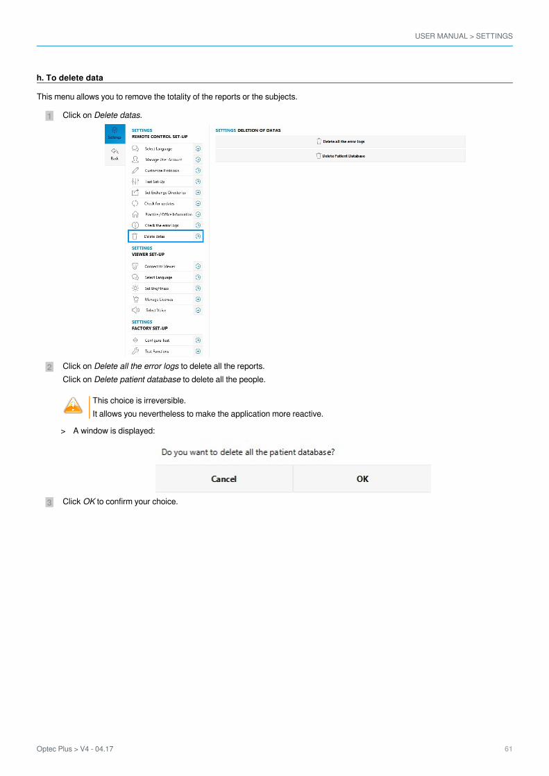
h. To delete data
This menu allows you to remove the totality of the reports or the subjects.
Click on .Delete datas
Click on to delete all the reports.Delete all the error logsClick on to delete all the people.Delete patient database
This choice is irreversible.It allows you nevertheless to make the application more reactive.
Click to confirm your choice.OK
A window is displayed:>
USER MANUAL > SETTINGS
62 Optec Plus > V4 - 04.17
2
1
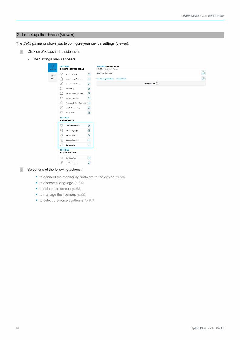
2. To set up the device (viewer)
The menu allows you to configure your device settings (viewer).Settings
Click on in the side menu.Settings
Select one of the following actions:
to connect the monitoring software to the device (p.63)to choose a language (p.64)to set-up the screen (p.65)to manage the licenses (p.66)to select the voice synthesis (p.67)
The Settings menu appears:>
USER MANUAL > SETTINGS
Optec Plus > V4 - 04.17 63
4
3
2
1
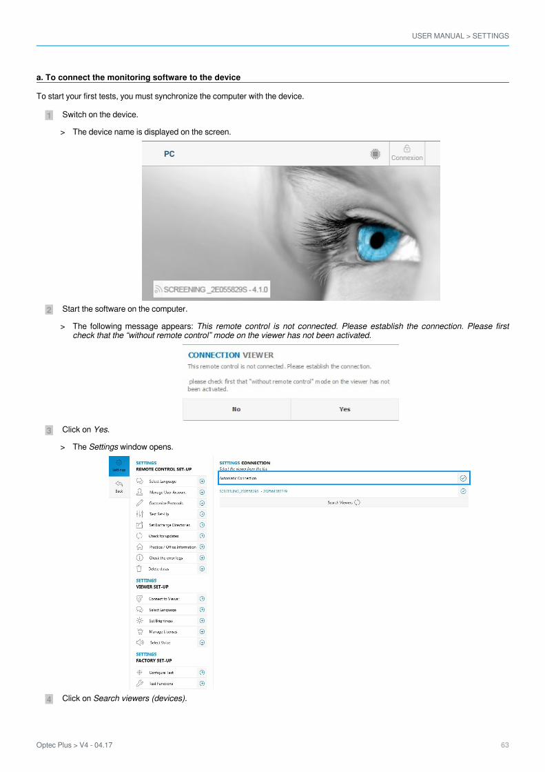
a. To connect the monitoring software to the device
To start your first tests, you must synchronize the computer with the device.
Switch on the device.
Start the software on the computer.
Click on .Yes
Click on Search viewers (devices).
The device name is displayed on the screen.>
The following message appears: This remote control is not connected. Please establish the connection. Please firstcheck that the “without remote control” mode on the viewer has not been activated.
>
The window opens.Settings>
USER MANUAL > SETTINGS
64 Optec Plus > V4 - 04.17
2
1
5
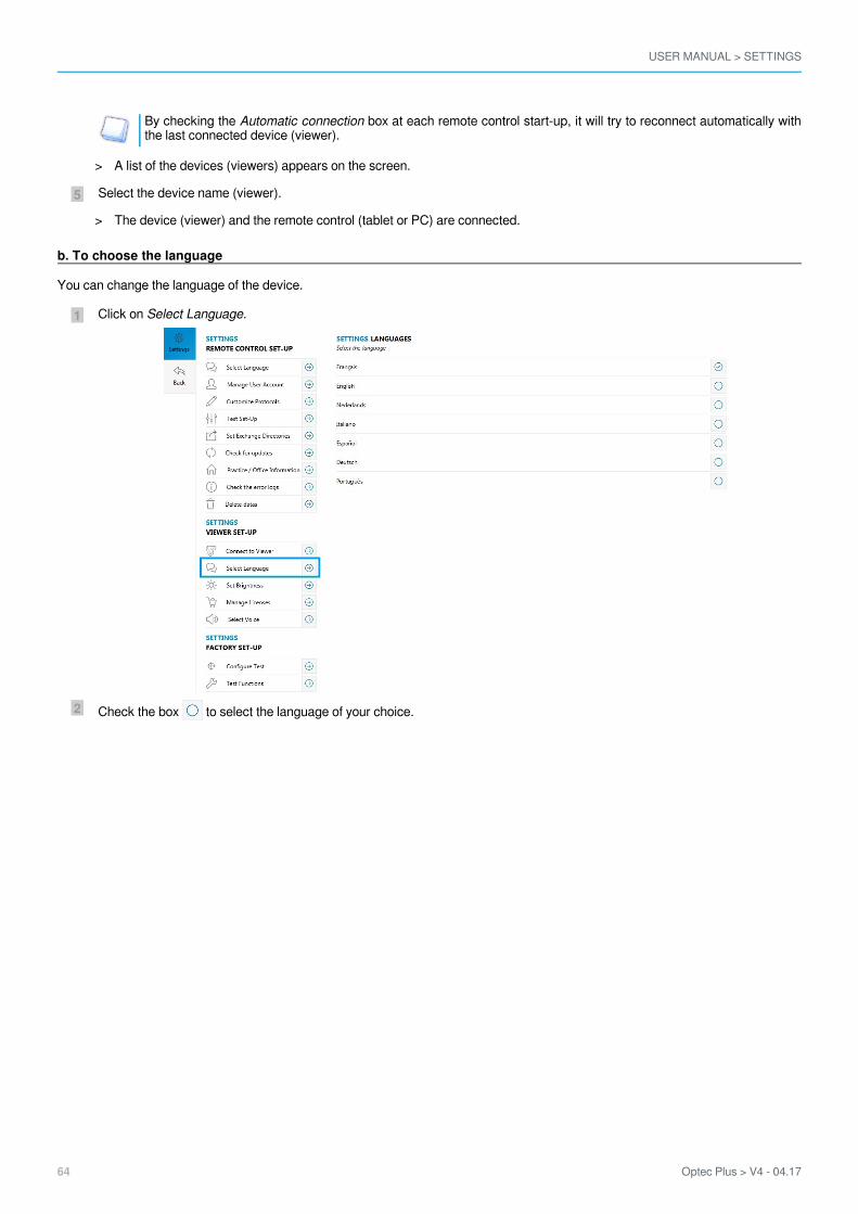
By checking the box at each remote control start-up, it will try to reconnect automatically withAutomatic connectionthe last connected device (viewer).
Select the device name (viewer).
b. To choose the language
You can change the language of the device.
Click on .Select Language
Check the box to select the language of your choice.
A list of the devices (viewers) appears on the screen.>
The device (viewer) and the remote control (tablet or PC) are connected.>

USER MANUAL > SETTINGS
Optec Plus > V4 - 04.17 65
2
1
c. To set-up the screen
The menu allows you to manage the screen brightness of the device.Settings
Click on .Set brightness
Select the logo and slide it from left to right to increase or decrease the brightness.
USER MANUAL > SETTINGS
66 Optec Plus > V4 - 04.17
4
3
2
1
4
3
2
1
4
3
2
1
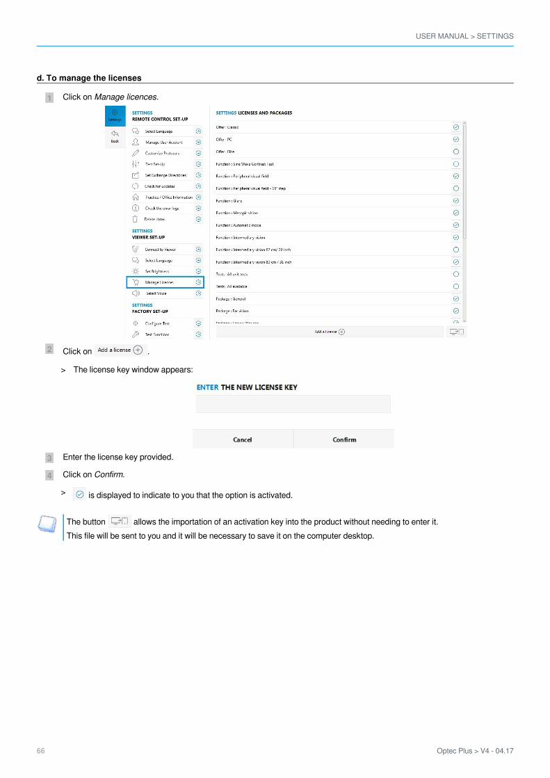
d. To manage the licenses
Click on Manage licences.
Click on .
Enter the license key provided.
Click on .Confirm
The button allows the importation of an activation key into the product without needing to enter it.This file will be sent to you and it will be necessary to save it on the computer desktop.
The license key window appears:>
is displayed to indicate to you that the option is activated.>
USER MANUAL > SETTINGS
Optec Plus > V4 - 04.17 67
2
1
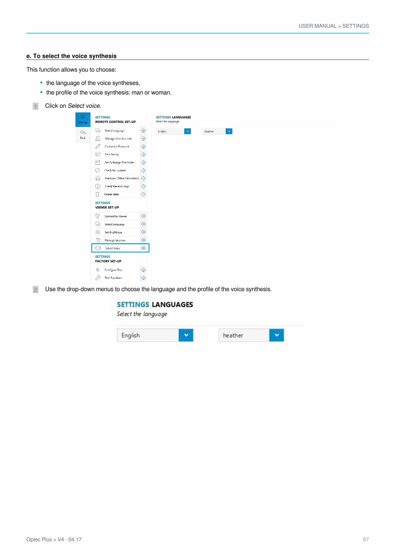
e. To select the voice synthesis
This function allows you to choose:
the language of the voice syntheses,the profile of the voice synthesis: man or woman.
Click on .Select voice
Use the drop-down menus to choose the language and the profile of the voice synthesis.

USER MANUAL > SETTINGS
68 Optec Plus > V4 - 04.17

VI. STARTING WITH A PATIENT

USER MANUAL > STARTING WITH A PATIENT
70 Optec Plus > V4 - 04.17
USER MANUAL > STARTING WITH A PATIENT
Optec Plus > V4 - 04.17 71
1
2
1
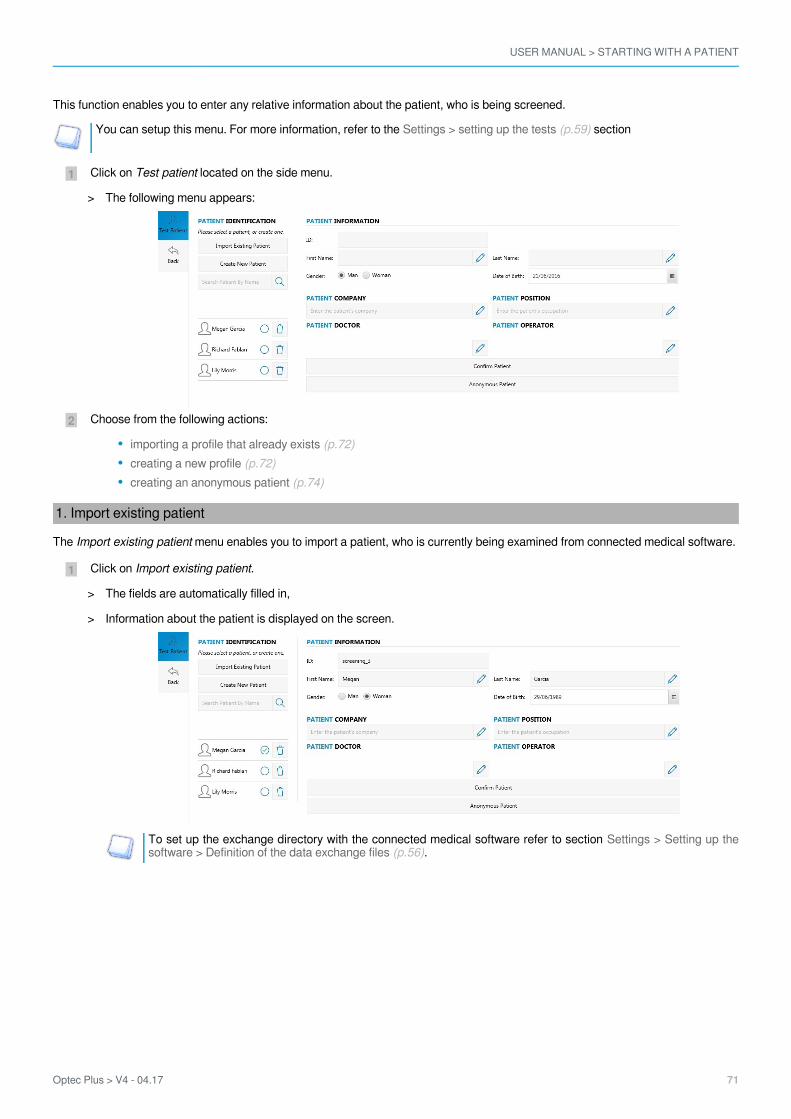
This function enables you to enter any relative information about the patient, who is being screened.
You can setup this menu. For more information, refer to the sectionSettings > setting up the tests (p.59)
Click on located on the side menu.Test patient
Choose from the following actions:
importing a profile that already exists (p.72)creating a new profile (p.72)creating an anonymous patient (p.74)
1. Import existing patient
The menu enables you to import a patient, who is currently being examined from connected medical software.Import existing patient
Click on .Import existing patient
To set up the exchange directory with the connected medical software refer to section Settings > Setting up the.software > Definition of the data exchange files (p.56)
The following menu appears:>
The fields are automatically filled in,>
Information about the patient is displayed on the screen.>

USER MANUAL > STARTING WITH A PATIENT
72 Optec Plus > V4 - 04.17
1.2.3.4.5.6.7.
8.
9.
2. Creating a new profile
The menu allows you to input information about the patient to be tested:Create new patient
identity of the Patient (p.72)correction worn and the patient’s work environment (p.73)
a. Identity of the Patient
Number identifying the patientFirst name:NameSexDate of BirthCompanyJob
Press to enter job position held.Occupational Health doctor
Press on to select the registered medical practitioner.It is necessary to complete the user profiles beforehand in menuSettings > Managing user accounts (p.48)Operator
Press on to select the relevant operator.It is necessary to complete the user profiles beforehand in menuSettings > Managing user accounts (p.48)
> Press on to save information about the identity of the patient.
At any time you can edit the information relating to the subject by clicking on .
USER MANUAL > STARTING WITH A PATIENT
Optec Plus > V4 - 04.17 73
1.
2.
3.
4.
5.
6.
7.
8.
9.10.11.12.
13.
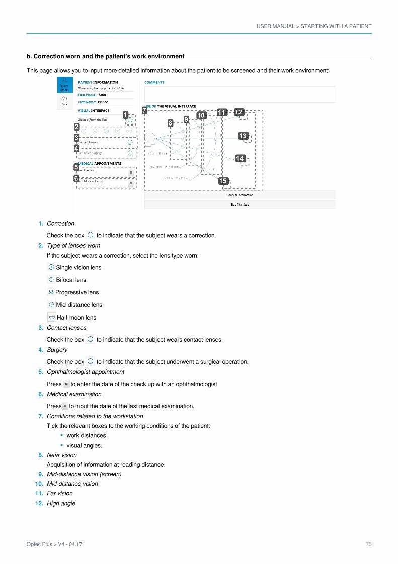
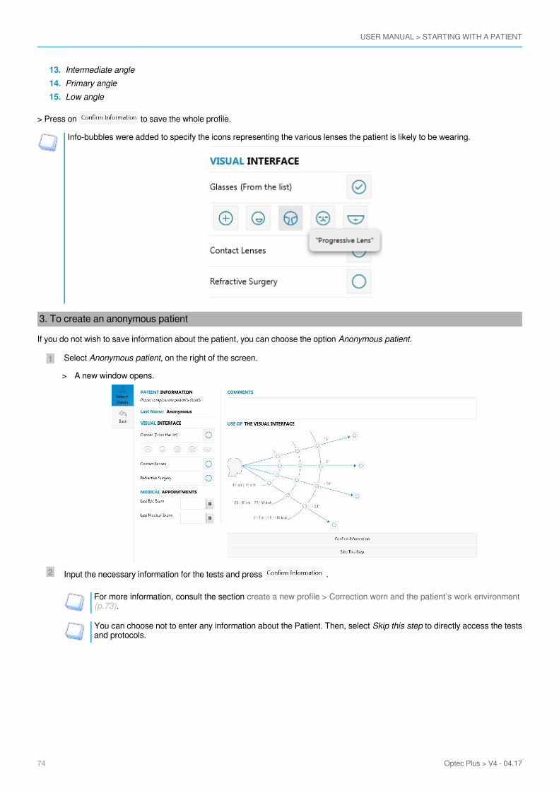
b. Correction worn and the patient's work environment
This page allows you to input more detailed information about the patient to be screened and their work environment:
Correction
Check the box to indicate that the subject wears a correction.Type of lenses wornIf the subject wears a correction, select the lens type worn:
Single vision lens
Bifocal lens
Progressive lens
Mid-distance lens
Half-moon lensContact lenses
Check the box to indicate that the subject wears contact lenses.Surgery
Check the box to indicate that the subject underwent a surgical operation.Ophthalmologist appointment
Press to enter the date of the check up with an ophthalmologistMedical examination
Press to input the date of the last medical examination.Conditions related to the workstationTick the relevant boxes to the working conditions of the patient:
work distances,visual angles.
Near visionAcquisition of information at reading distance.Mid-distance vision (screen)Mid-distance visionFar visionHigh angle
USER MANUAL > STARTING WITH A PATIENT
74 Optec Plus > V4 - 04.17
2
1
13.14.15.
Intermediate anglePrimary angleLow angle
> Press on to save the whole profile.
Info-bubbles were added to specify the icons representing the various lenses the patient is likely to be wearing.
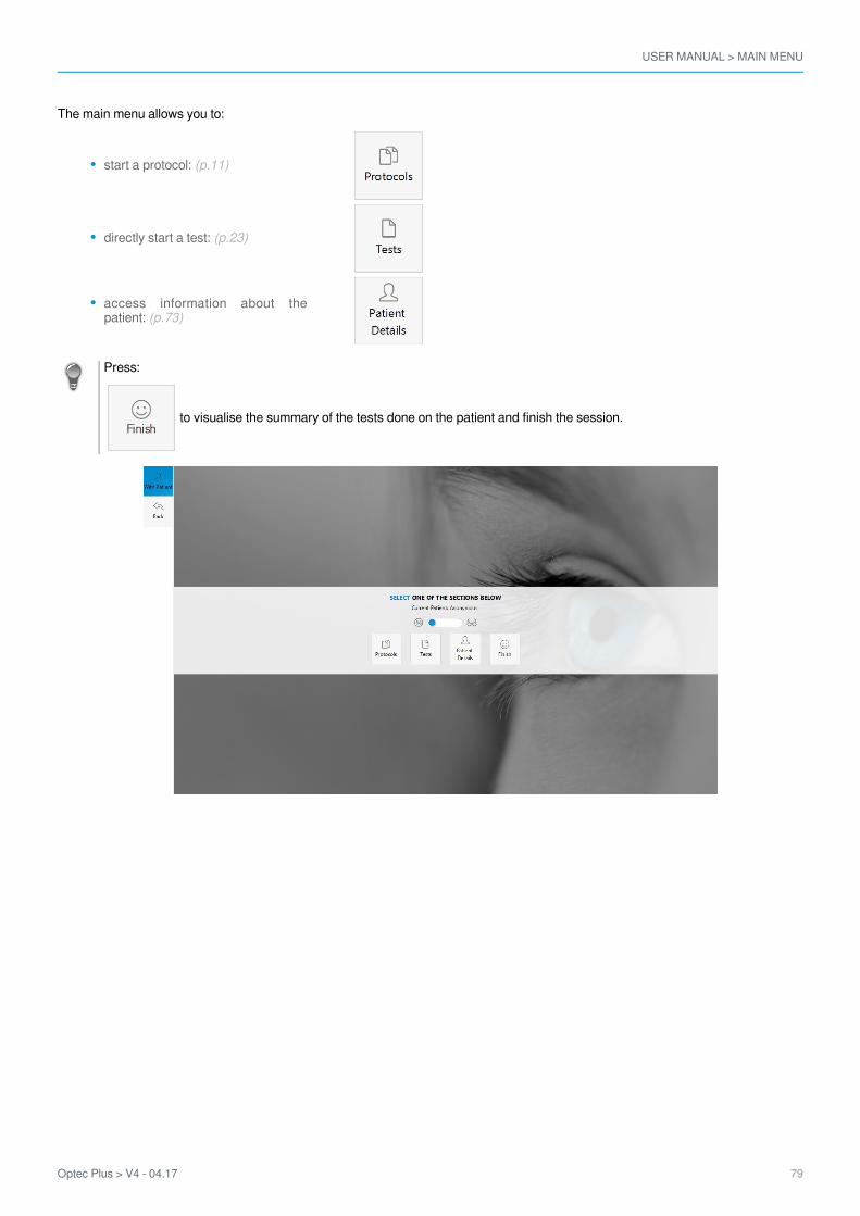
3. To create an anonymous patient
If you do not wish to save information about the patient, you can choose the option .Anonymous patient
Select , on the right of the screen.Anonymous patient
Input the necessary information for the tests and press .
For more information, consult the section create a new profile > Correction worn and the patient’s work environment.(p.73)
You can choose not to enter any information about the Patient. Then, select to directly access the testsSkip this stepand protocols.
A new window opens.>

USER MANUAL > STARTING WITH A PATIENT
Optec Plus > V4 - 04.17 75
You are redirected towards the main menu.>

USER MANUAL > STARTING WITH A PATIENT
76 Optec Plus > V4 - 04.17

VII. MAIN MENU

USER MANUAL > MAIN MENU
78 Optec Plus > V4 - 04.17
USER MANUAL > MAIN MENU
Optec Plus > V4 - 04.17 79
The main menu allows you to:
start a protocol: (p.11)
directly start a test: (p.23)
access information about thepatient: (p.73)
Press:
to visualise the summary of the tests done on the patient and finish the session.

USER MANUAL > MAIN MENU
80 Optec Plus > V4 - 04.17

LIST OF ERRORS
USER MANUAL > LIST OF ERRORS
82 Optec Plus > V4 - 04.17
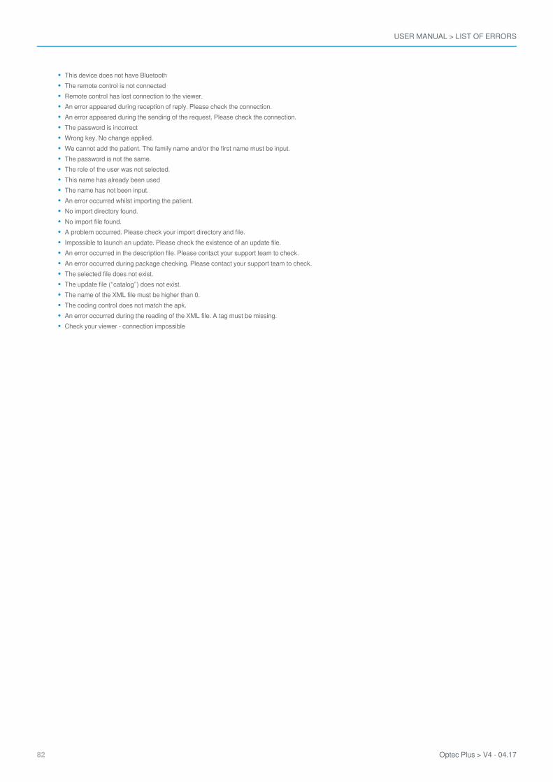
This device does not have BluetoothThe remote control is not connectedRemote control has lost connection to the viewer.An error appeared during reception of reply. Please check the connection.An error appeared during the sending of the request. Please check the connection.The password is incorrectWrong key. No change applied.We cannot add the patient. The family name and/or the first name must be input.The password is not the same.The role of the user was not selected.This name has already been usedThe name has not been input.An error occurred whilst importing the patient.No import directory found.No import file found.A problem occurred. Please check your import directory and file.Impossible to launch an update. Please check the existence of an update file.An error occurred in the description file. Please contact your support team to check.An error occurred during package checking. Please contact your support team to check.The selected file does not exist.The update file (“catalog”) does not exist.The name of the XML file must be higher than 0.The coding control does not match the apk.An error occurred during the reading of the XML file. A tag must be missing.Check your viewer - connection impossible

TECHNICAL DATA

USER MANUAL > TECHNICAL DATA
84 Optec Plus > V4 - 04.17
This device is a class I medical device without measurement function.
The device
Dimensions: 483 x 283 x 456 (mm) or 19.0 x 11.2 x 18.0 (in)Weight: 6.700 Kg or 15 lbPower supply:
AC Input : 100-240 VAC, 1.9A max, 47-63 Hz DC input : 24.0 V, 2.70AMaximum output power: 65W
Product: Input 24V, 50VA
Accessory list
Microfibre clothSupply ref. MVC 65 NR 24E and cord (cable length: 1.50m)Protective coverAncillary lenses*: Europe +1.00 δ/ USA +1.75 δ, +2.25 δ/VI (Mid-distance vision)USB keyBluetooth keyHeadset (cable length: 1 m)*LED peripheral mask*Transportation case*Ancillary lens Kit VI (67cm and 80 cm) *Automatic option*(*) These options are included or at extra cost.
Environment
The temperature and relative humidity of the room where you use your digital system must lie within the following limits:Operation:
Storage:
temperature of +10°C (+50°F) to +40°C (+104°F) humidity: 30% to 75%
temperature of -5°C (+23°F) to 50°C (+122°F) humidity: 25% to 95%Altitude: < 2,000 m (6,562 ft)Degree of pollution: 2
Avoid sudden changes in temperature and relative humidity and install your system:
away from direct sunlight,away from all heat sources,away from any strong magnetic fields,away from all chemical products, corrosive vapours and liquids
Do not place anything on the device. Avoid exposing the equipment to vibration or impact.

GENERAL INFORMATION
USER MANUAL > GENERAL INFORMATION
86 Optec Plus > V4 - 04.17
Description of the symbols (p.86)Modifications (p.87)Compliance (p.87)Materials and products (p.87)Security (p.87)
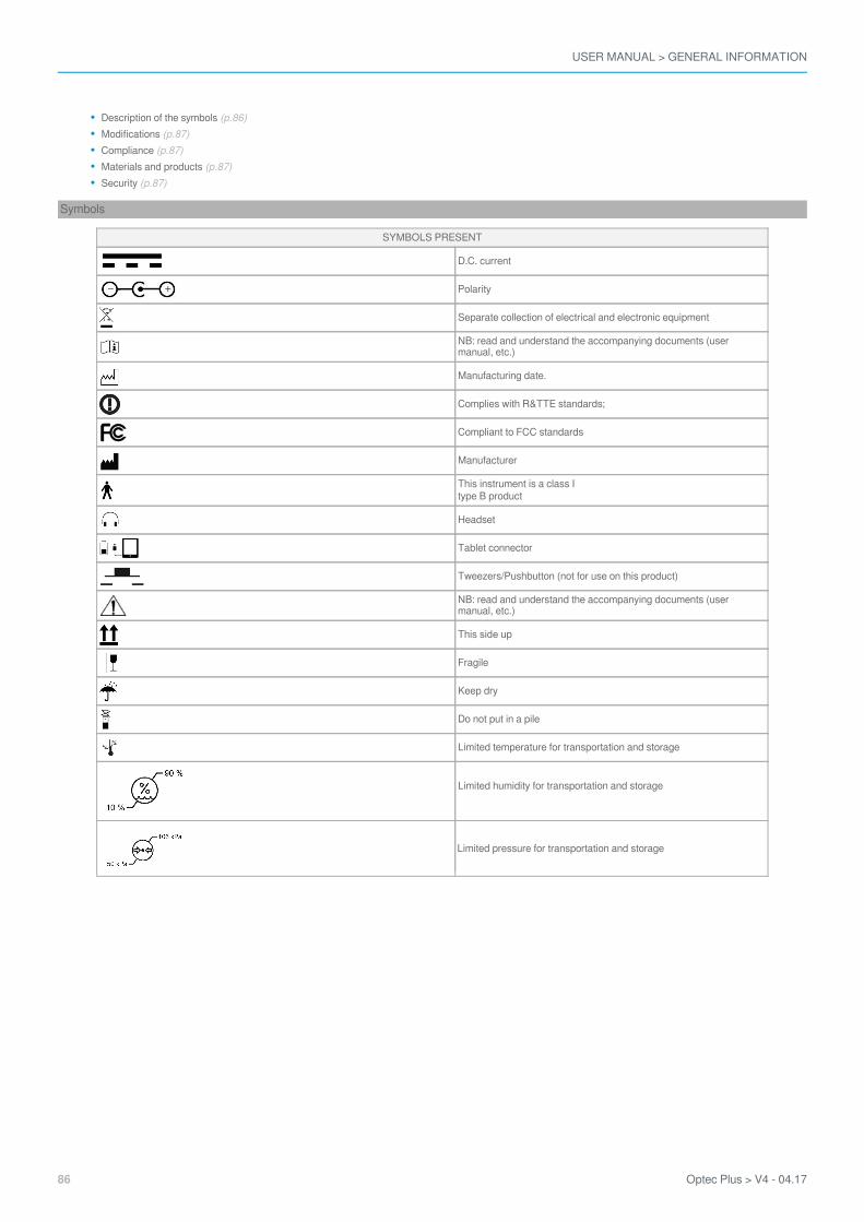
Symbols
SYMBOLS PRESENT
D.C. current
Polarity
Separate collection of electrical and electronic equipment
NB: read and understand the accompanying documents (usermanual, etc.)
Manufacturing date.
Complies with R&TTE standards;
Compliant to FCC standards
Manufacturer
This instrument is a class Itype B product
Headset
Tablet connector
Tweezers/Pushbutton (not for use on this product)
NB: read and understand the accompanying documents (usermanual, etc.)
This side up
Fragile
Keep dry
Do not put in a pile
Limited temperature for transportation and storage
Limited humidity for transportation and storage
Limited pressure for transportation and storage
USER MANUAL > GENERAL INFORMATION
Optec Plus > V4 - 04.17 87
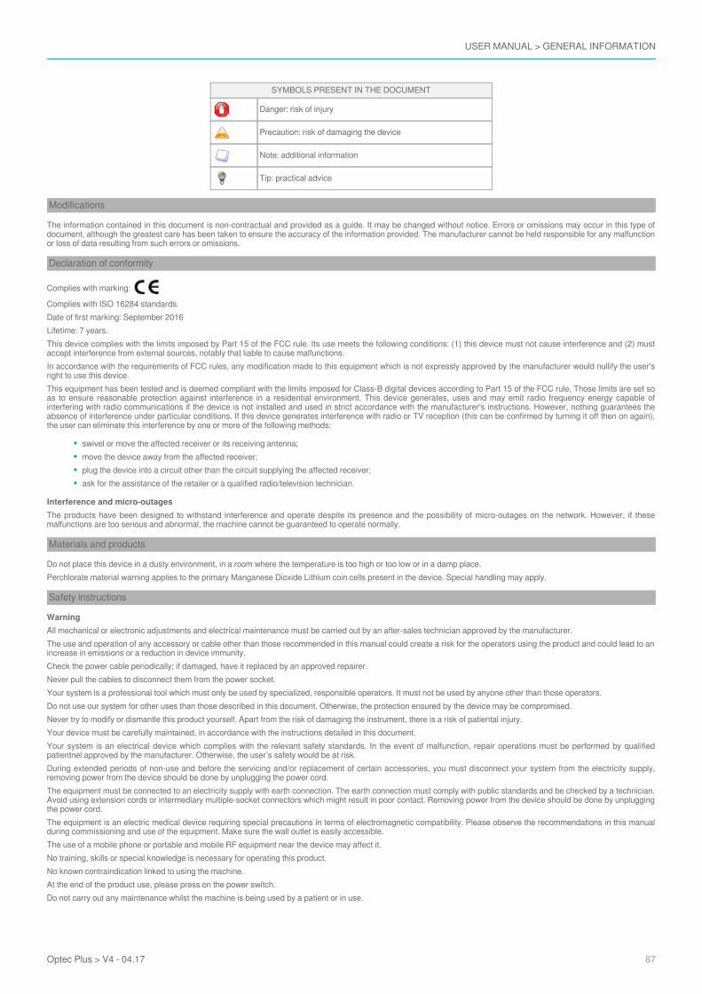
SYMBOLS PRESENT IN THE DOCUMENT
Danger: risk of injury
Precaution: risk of damaging the device
Note: additional information
Tip: practical advice
Modifications
The information contained in this document is non-contractual and provided as a guide. It may be changed without notice. Errors or omissions may occur in this type ofdocument, although the greatest care has been taken to ensure the accuracy of the information provided. The manufacturer cannot be held responsible for any malfunctionor loss of data resulting from such errors or omissions.
Declaration of conformity
Complies with marking:
Complies with ISO 16284 standards.Date of first marking: September 2016Lifetime: 7 years.This device complies with the limits imposed by Part 15 of the FCC rule. Its use meets the following conditions: (1) this device must not cause interference and (2) mustaccept interference from external sources, notably that liable to cause malfunctions.In accordance with the requirements of FCC rules, any modification made to this equipment which is not expressly approved by the manufacturer would nullify the user'sright to use this device.This equipment has been tested and is deemed compliant with the limits imposed for Class-B digital devices according to Part 15 of the FCC rule. Those limits are set soas to ensure reasonable protection against interference in a residential environment. This device generates, uses and may emit radio frequency energy capable ofinterfering with radio communications if the device is not installed and used in strict accordance with the manufacturer's instructions. However, nothing guarantees theabsence of interference under particular conditions. If this device generates interference with radio or TV reception (this can be confirmed by turning it off then on again),the user can eliminate this interference by one or more of the following methods:
swivel or move the affected receiver or its receiving antenna;move the device away from the affected receiver;plug the device into a circuit other than the circuit supplying the affected receiver;ask for the assistance of the retailer or a qualified radio/television technician.
Interference and micro-outagesThe products have been designed to withstand interference and operate despite its presence and the possibility of micro-outages on the network. However, if thesemalfunctions are too serious and abnormal, the machine cannot be guaranteed to operate normally.
Materials and products
Do not place this device in a dusty environment, in a room where the temperature is too high or too low or in a damp place.Perchlorate material warning applies to the primary Manganese Dioxide Lithium coin cells present in the device. Special handling may apply.
Safety instructions
WarningAll mechanical or electronic adjustments and electrical maintenance must be carried out by an after-sales technician approved by the manufacturer.The use and operation of any accessory or cable other than those recommended in this manual could create a risk for the operators using the product and could lead to anincrease in emissions or a reduction in device immunity.Check the power cable periodically; if damaged, have it replaced by an approved repairer.Never pull the cables to disconnect them from the power socket.Your system is a professional tool which must only be used by specialized, responsible operators. It must not be used by anyone other than those operators.Do not use our system for other uses than those described in this document. Otherwise, the protection ensured by the device may be compromised.Never try to modify or dismantle this product yourself. Apart from the risk of damaging the instrument, there is a risk of patiental injury.Your device must be carefully maintained, in accordance with the instructions detailed in this document.Your system is an electrical device which complies with the relevant safety standards. In the event of malfunction, repair operations must be performed by qualifiedpatientnel approved by the manufacturer. Otherwise, the user’s safety would be at risk.During extended periods of non-use and before the servicing and/or replacement of certain accessories, you must disconnect your system from the electricity supply,removing power from the device should be done by unplugging the power cord.The equipment must be connected to an electricity supply with earth connection. The earth connection must comply with public standards and be checked by a technician.Avoid using extension cords or intermediary multiple-socket connectors which might result in poor contact. Removing power from the device should be done by unpluggingthe power cord.The equipment is an electric medical device requiring special precautions in terms of electromagnetic compatibility. Please observe the recommendations in this manualduring commissioning and use of the equipment. Make sure the wall outlet is easily accessible.The use of a mobile phone or portable and mobile RF equipment near the device may affect it.No training, skills or special knowledge is necessary for operating this product.No known contraindication linked to using the machine.At the end of the product use, please press on the power switch.Do not carry out any maintenance whilst the machine is being used by a patient or in use.
USER MANUAL > GENERAL INFORMATION
88 Optec Plus > V4 - 04.17
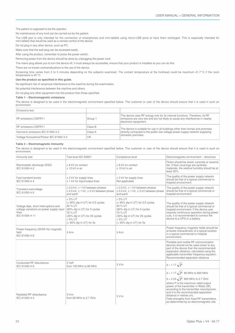
The patient is supposed to be the operator.No maintenance of any kind can be carried out by the patient.The USB port is only intended for the connection of smartphones and mini-tablets using micro-USB ports to have them recharged. This is especially intended formini-tablets that would be used as a remote control of the device.Do not plug in any other device, such as PC.Make sure that the wall plug can be accessed easily.After using the product, remember to press the power switch.Removing power from the device should be done by unplugging the power cord.The mains plug allows you to turn the device off, it must always be accessible, ensure that your product is installed so you can do this.There are no known contraindications to the use of the device.Screening time varies from 2 to 5 minutes depending on the subjects examined. The contact temperature at the forehead could be maximum 41,7°C if the roomtemperature is 40°C.Use the product as specified in this guide.No significant risk of reciprocal interference to the machine during the examination.No potential interference between the machine and others.Do not plug any other equipment into this product than those specified.Table 1 – Electromagnetic emissionsThe device is designed to be used in the electromagnetic environment specified below. The customer or user of the device should ensure that it is used in such anenvironment.
Emissions test
RF emissions CISPR11 Group 1The device uses RF energy only for its internal functions. Therefore, its RFemissions are very low and are not likely to cause any interference in nearbyelectronic equipment.
RF emissions CISPR11 Class BThe device is suitable for use in all buildings other than homes and premisesdirectly connected to the public low voltage power supply network supplyingdomestic premises.
Harmonic emissions IEC 61000-3-2 Class A
Voltage fluctuations/Flicker IEC 61000-3-3 OK
Table 2 – Electromagnetic immunityThe device is designed to be used in the electromagnetic environment specified below. The customer or user of the device should ensure that it is used in such anenvironment.
Immunity test Test level IEC 60601 Compliance level Electromagnetic environment – directives
Electrostatic discharge (ESD)IEC 61000-4-2
± 8 kV on contact± 15 kV in air
± 8 kV on contact± 15 kV in air
Floors should be wood, concrete or ceramictile. If floor coverings are syntheticmaterials, the relative humidity should be atleast 30%.
Fast transient burstsIEC 61000-4-4
± 2 kV for supply lines± 1 kV for input/output lines
± 2 kV for supply linesNot applicable
The quality of the power supply networkshould be that of a typical commercial orhospital environment.
Transient overvoltageIEC 61000-4-5
± 0.5 kV, ± 1 kV between phases± 0.5 kV, ± 1 kV, ± 2 kV between phaseand earth
± 0.5 kV, ± 1 kV between phases± 0.5 kV, ± 1 kV, ± 2 kV between phaseand earth
The quality of the power supply networkshould be that of a typical commercial orhospital environment.
Voltage dips, short interruptions andvoltage variations on power supply inputlinesIEC 61000-4-11
< 5% UT(> 95% dip in UT) for 0.5 cycles40 % UT(60% dip in UT) for 5 cycles70 % UT(30% dip in UT) for 25 cycles< 5% UT(> 95% dip in UT) for 5s
< 5% UT(> 95% dip in UT) for 0.5 cycles40 % UT(60% dip in UT) for 5 cycles70 % UT(30% dip in UT) for 25 cycles< 5% UT(> 95% dip in UT) for 5s
The quality of the power supply networkshould be that of a typical commercial orhospital environment. If the device userrequires continuous operation during powercuts, it is recommended to connect thedevice to a UPS or a battery.
Power frequency (50/60 Hz) magneticfieldIEC 61000-4-8
3 A/m 3 A/mPower frequency magnetic fields should beat levels characteristic of a typical locationin a typical commercial or hospitalenvironment.
Portable and mobile RF communicationdevices should not be used closer to anypart of the device than the recommendedseparation distance, calculated using theapplicable transmitter frequency equation.Recommended separation distance
Conducted RF disturbanceIEC 61000-4-6
3 Vefffrom 150 MHz to 80 MHz 3 V/m d = 1.17
Radiated RF disturbanceIEC 61000-4-3
3 V/mfrom 80 MHz to 2.7 GHz 3 V/m
d = 1.17 80 MHz to 800 MHz
d = 2.33 800 MHz to 2.7 GHzwhere P is the maximum rated outputpower of the transmitter in Watts (W),according to the transmitter manufacturer,and d is the recommended separationdistance in metres (m).Field strengths from fixed RF transmitters,as determined by an electromagnetic site
USER MANUAL > GENERAL INFORMATION
Optec Plus > V4 - 04.17 89
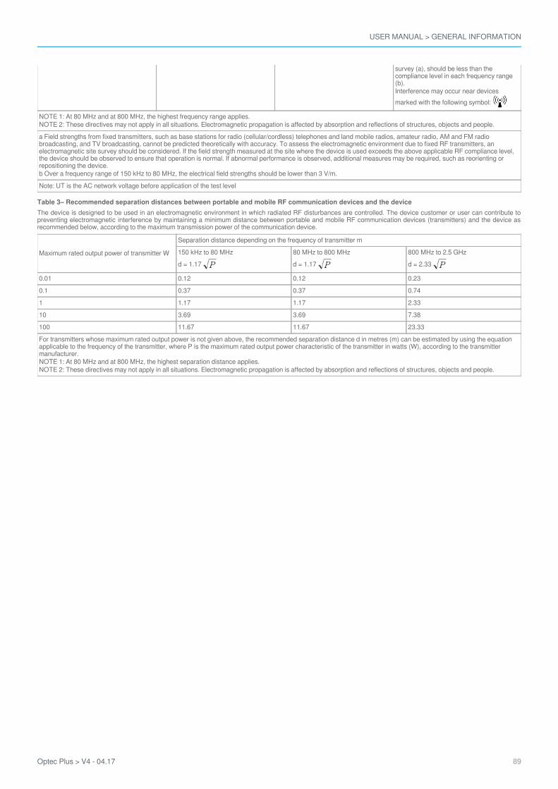
survey (a), should be less than thecompliance level in each frequency range(b).Interference may occur near devicesmarked with the following symbol:
NOTE 1: At 80 MHz and at 800 MHz, the highest frequency range applies.NOTE 2: These directives may not apply in all situations. Electromagnetic propagation is affected by absorption and reflections of structures, objects and people.
a Field strengths from fixed transmitters, such as base stations for radio (cellular/cordless) telephones and land mobile radios, amateur radio, AM and FM radiobroadcasting, and TV broadcasting, cannot be predicted theoretically with accuracy. To assess the electromagnetic environment due to fixed RF transmitters, anelectromagnetic site survey should be considered. If the field strength measured at the site where the device is used exceeds the above applicable RF compliance level,the device should be observed to ensure that operation is normal. If abnormal performance is observed, additional measures may be required, such as reorienting orrepositioning the device.b Over a frequency range of 150 kHz to 80 MHz, the electrical field strengths should be lower than 3 V/m.
Note: UT is the AC network voltage before application of the test level
Table 3– Recommended separation distances between portable and mobile RF communication devices and the deviceThe device is designed to be used in an electromagnetic environment in which radiated RF disturbances are controlled. The device customer or user can contribute topreventing electromagnetic interference by maintaining a minimum distance between portable and mobile RF communication devices (transmitters) and the device asrecommended below, according to the maximum transmission power of the communication device.
Maximum rated output power of transmitter W
Separation distance depending on the frequency of transmitter m
150 kHz to 80 MHzd = 1.17
80 MHz to 800 MHzd = 1.17
800 MHz to 2.5 GHzd = 2.33
0.01 0.12 0.12 0.23
0.1 0.37 0.37 0.74
1 1.17 1.17 2.33
10 3.69 3.69 7.38
100 11.67 11.67 23.33
For transmitters whose maximum rated output power is not given above, the recommended separation distance d in metres (m) can be estimated by using the equationapplicable to the frequency of the transmitter, where P is the maximum rated output power characteristic of the transmitter in watts (W), according to the transmittermanufacturer.NOTE 1: At 80 MHz and at 800 MHz, the highest separation distance applies.NOTE 2: These directives may not apply in all situations. Electromagnetic propagation is affected by absorption and reflections of structures, objects and people.

USER MANUAL > GENERAL INFORMATION
90 Optec Plus > V4 - 04.17

GLOSSARY
USER MANUAL > GLOSSARY
92 Optec Plus > V4 - 04.17
AMETROPIAAny eye is known as being emmetropic (from the Greek: “ametros”: not conforming to measurement, and “ops”: to see) when itpresents a refraction anomaly characterized by the fact that the image of a distant object is not formed on the retina of the eye in itsunfocussed state but in front of or behind it.
If the image is formed in front of the retina, the eye is called myopic.If the image is formed behind the retina, the eye is called farsighted.If the image is formed differently according to the meridian lines, the eye is known as astigmatic.
ANAMNESISFrom the Greek “Anamnêsis”: to remember.Before any refraction examination, it is necessary to proceed to the anamnesis or the detailed history of the case history of the patientin order to be aware of the symptoms, which caused this person to consult. Collecting this information is invaluable and allows thevision test to be carried out in an orderly manner.Initially, the operator should try to understand why the person has come to consult with some open-ended questions to the patient,like:
Why did you decide to come and see us?What visibility problems bother you?
You should then try to get the patient to specify their visibility problems and in particular:
The true nature of the problem: eyestrain, fuzzy vision, double vision?
The distance at which it occurs: far, mid-distance, close to, or on the sides?
etc.
ASTIGMATISMAn eye is called astigmatic, when it presents a variable power according to the meridian lines and thus presents an ametropia whichvaries according to the meridian lines.A astigmatic eye is by definition ametropic and all combinations are possible: it may be short-sighted or farsighted in all the meridianlines (composed astigmatism), emmetropic in a meridian line and myopic or farsighted in the other (simple astigmatism), myopic in ameridian line and farsighted in the other (mixed astigmatism).The principle behind the correction of the astigmatic eye is to place an astigmatic lens of varying strength depending on the meridianlines in the opposite direction to the astigmatism of the eye.EMMETROPIAAn eye is called emmetropic (from the Greek: “emmetropos”: proportioned and “ops”: to see) when the image of an object adinfinitum is formed on the retina of the eye in its unfocussed state. The image of distant objects is formed on the retina, inverted; theemmetropic eye sees clearly without focusing.FARSIGHTEDNESSThe farsighted eye or hyperope (from the Greek “hyper”: beyond and “ops”: to see), is the eye in which the image is formed behindthe retina.The principle of correction is to introduce in front of the farsighted eye a lens of positive strength which moves the image forwardsand repositions it on the retina.MYOPIAThe short-sighted eye (from the Latin myops” or literally “meaning Greek “muôps” who squints the eyes”) is the eye in which theimage of an object located ad infinitum is formed before retina.The principle of correction is to introduce in front of the short-sighted eye a lens of negative strength which makes the image moveback and repositions it on the retina.

USER MANUAL > GLOSSARY
Optec Plus > V4 - 04.17 93

Stereo Optical Company, Inc.8600 W Catalpa Ave., Suite 703, Chicago, IL 60656 - USA
EC representative: Essilor InternationalCompagnie Générale d'Optique S.A.
Head Office: 147 rue de Paris - 94220 Charenton-le-Pont France 772 049 618 RCS Créteil - www.essilor.com