User Manual - SMA FUEL SAVE CONTROLLER 2files.sma.de/dl/26900/FSC20-BA-en-21.pdf · User Manual SMA...
110
FUEL SAVE CONTROLLER User Manual SMA FUEL SAVE CONTROLLER 2.0 FSC20-BA-en-21 | 100590-00.03 | Version 2.1 ENGLISH
Transcript of User Manual - SMA FUEL SAVE CONTROLLER 2files.sma.de/dl/26900/FSC20-BA-en-21.pdf · User Manual SMA...

FUEL SAVE CONTROLLER
User ManualSMA FUEL SAVE CONTROLLER 2.0
FSC20-BA-en-21 | 100590-00.03 | Version 2.1ENGLISH

Legal ProvisionsThe information contained in these documents is property of SMA Solar Technology AG. Any publication, whether inwhole or in part, requires prior written approval by SMA Solar Technology AG. Internal reproduction used solely forthe purpose of product evaluation or other proper use is allowed and does not require prior approval.
SMA WarrantyYou can download the current warranty conditions from the Internet at www.SMA-Solar.com.
Software licensesYou will find the software licenses for the installed software modules on the Internet at www.SMA-Solar.com.
TrademarksAll trademarks are recognized, even if not explicitly identified as such. Missing designations do not mean that aproduct or brand is not a registered trademark.Modbus® is a registered trademark of Schneider Electric and is licensed by the Modbus Organization, Inc.The SunSpec logo and the name SunSpec Alliance are trademarks of the SunSpec Alliance, Inc.QR Code is a registered trademark of DENSO WAVE INCORPORATED.Phillips® and Pozidriv® are registered trademarks of Phillips Screw Company.Torx® is a registered trademark of Acument Global Technologies, Inc.
SMA Solar Technology AGSonnenallee 134266 NiestetalGermanyTel. +49 561 9522-0Fax +49 561 9522-100www.SMA.deEmail: [email protected]
Status: 5/15/2017Copyright © 2017 SMA Solar Technology AG. All rights reserved.
Legal Provisions SMA Solar Technology AG
User ManualFSC20-BA-en-212
Table of Contents1 Information on this Document..................................................................................................... 6
1.1 Validity ............................................................................................................................................................. 61.2 Target Group ................................................................................................................................................... 61.3 Additional Information..................................................................................................................................... 61.4 Symbols............................................................................................................................................................ 61.5 Typographies ................................................................................................................................................... 71.6 Nomenclature .................................................................................................................................................. 7
2 Safety ............................................................................................................................................ 82.1 Intended Use.................................................................................................................................................... 82.2 Safety Information ........................................................................................................................................... 8
3 Product Description ...................................................................................................................... 103.1 Functions........................................................................................................................................................... 103.2 Structure ........................................................................................................................................................... 123.3 Key Switch ....................................................................................................................................................... 123.4 Light Repeaters................................................................................................................................................. 123.5 Type Label........................................................................................................................................................ 13
4 User Interface ............................................................................................................................... 144.1 Requirements for the user interface display ................................................................................................... 144.2 User Groups and User Rights ......................................................................................................................... 144.3 Requirements for a Secure System Password ................................................................................................ 144.4 Design of the User Interface ........................................................................................................................... 154.5 Buttons in the header....................................................................................................................................... 164.6 Home Page for User Group "User" ................................................................................................................ 174.7 Home Page for User Group "Installer" ........................................................................................................... 184.8 Configuration Wizard ..................................................................................................................................... 18
4.8.1 Structure of the Configuration Wizard ........................................................................................................... 184.8.2 Buttons in the Configuration Wizard .............................................................................................................. 194.8.3 Setting Parameters ........................................................................................................................................... 20
5 Getting Started ............................................................................................................................. 215.1 Logging In and Out of the User Interface ...................................................................................................... 215.2 Changing Passwords....................................................................................................................................... 225.3 Setting the User Interface Language .............................................................................................................. 225.4 Setting the System Time................................................................................................................................... 235.5 Setting Up Access via the Internet .................................................................................................................. 24
6 System Monitoring ....................................................................................................................... 266.1 Retrieving Display Values of the Entire PV Diesel Hybrid System................................................................. 266.2 Retrieving Genset Display Values................................................................................................................... 276.3 Retrieving PV Power Plant Display Values...................................................................................................... 306.4 Retrieving Storage System Display Values..................................................................................................... 326.5 Retrieving Display Values from Measurement Devices ................................................................................. 336.6 Viewing Data Records via the PV Diesel Hybrid System .............................................................................. 356.7 Monitoring the status of the digital switching inputs and outputs................................................................. 376.8 Device Information .......................................................................................................................................... 39
Table of ContentsSMA Solar Technology AG
User Manual 3FSC20-BA-en-21

6.9 Processing Status Messages ........................................................................................................................... 406.10 Operating Mode and Setpoints ..................................................................................................................... 42
6.10.1 Overview of Operating Modes and Setpoints .............................................................................................. 426.10.2 Displaying Setpoints and Actual Values......................................................................................................... 446.10.3 Configuring the Operating Mode................................................................................................................... 446.10.4 Specification of Setpoints for PV Power Plant by SCADA System ................................................................ 45
7 System Settings............................................................................................................................. 467.1 Configuring the Utility Grid............................................................................................................................. 467.2 Settings for the gensets.................................................................................................................................... 46
7.2.1 Parameters for Gensets with Genset Controller ComAp IG-/IS-NTC........................................................... 467.2.2 Parameters for Gensets with the Genset Controller DEIF AGC .................................................................... 487.2.3 Parameters for Gensets with Genset Controller DSE8610 ........................................................................... 497.2.4 Parameters for gensets with genset controller easYgen-3000 via the CAN network ................................. 507.2.5 Parameters for Gensets with Genset Controller easYgen-3000 via the ESENET Gateway ....................... 517.2.6 Parameters for Gensets without the Genset Controller.................................................................................. 527.2.7 Configuring Gensets ........................................................................................................................................ 53
7.3 Configuring the PV Power Plant ...................................................................................................................... 547.4 Setting the Storage System ............................................................................................................................. 577.5 Settings on the Measurement Devices ........................................................................................................... 59
7.5.1 Making General Settings on Measurement Devices ..................................................................................... 597.5.2 Making Detailed Settings on Measurement Devices for Internal Measurement Modules of the SMA
Fuel Save Controller ....................................................................................................................................... 617.5.3 Making Detailed Settings on Measurement Devices for Data Acquisition Modules................................... 647.5.4 Activating/Deactivating Devices..................................................................................................................... 66
7.6 Setting the Temperature and Irradiation Sensors .......................................................................................... 677.7 Configuring Stop of the Fuel Save Controller via Switch Input DI 7 ............................................................ 687.8 Handling System Settings................................................................................................................................ 71
7.8.1 Ending System Settings .................................................................................................................................... 717.8.2 Saving System Settings .................................................................................................................................... 717.8.3 Loading System Settings .................................................................................................................................. 727.8.4 Deleting System Settings.................................................................................................................................. 73
8 System Control ............................................................................................................................. 748.1 Genset control ................................................................................................................................................. 74
8.1.1 Configuring the Minimum Genset Load Threshold ........................................................................................ 748.1.2 Configuring Reverse Power Protection of the Gensets .................................................................................. 768.1.3 Setting the Supply of Sufficient Reserve Power via Gensets ......................................................................... 78
8.2 Controlling the PV power plant....................................................................................................................... 828.2.1 Setting the Power Factor Control for the Gensets Using the Reactive Power Release of the PV Inverters . 828.2.2 Setting the Control of the PV Power Plant Reactive Power According to Electrical Load............................ 858.2.3 Configuring MPP Calculation for PV Power Plant .......................................................................................... 88
8.3 Controlling the Battery Inverter ....................................................................................................................... 908.3.1 Setting the State-Of-Charge Control of the Battery........................................................................................ 908.3.2 Setting the Setpoints for the Storage System According to the Rise and Drop of PV Power ...................... 928.3.3 Setting the Charge/Discharge of the Battery According to the Rise/Drop in PV Power............................. 94
8.4 Controlling the Fuel Save Controller .............................................................................................................. 968.4.1 Configuring Setpoint Change Rate for PV inverters and Gensets................................................................. 968.4.2 Options for Specifying the Reserve Power Setpoint of the Gensets ............................................................. 988.4.3 Configuring PV Power Plant Management..................................................................................................... 99
Table of Contents SMA Solar Technology AG
User ManualFSC20-BA-en-214
8.5 Setting the Control of the Grid Feed-In ..........................................................................................................101
9 System History..............................................................................................................................1039.1 Overview of the Data Structure ......................................................................................................................1039.2 Viewing System History Data..........................................................................................................................103
10 Starting and Stopping the System ..............................................................................................10410.1 Stopping the SMA Fuel Save Controller and PV Power Plant ......................................................................10410.2 Starting the PV Power Plant and SMA Fuel Save Controller ........................................................................10410.3 Restarting the SMA Fuel Save Controller and PV Power Plant.....................................................................10510.4 Installing a Valid Software License.................................................................................................................106
11 Cleaning........................................................................................................................................107
12 Contact ..........................................................................................................................................108
Table of ContentsSMA Solar Technology AG
User Manual 5FSC20-BA-en-21

1 Information on this Document
1.1 ValidityThis document is valid for the device type “FSC-20-M” (SMA Fuel Save Controller 2.0) from software version 2.06.
1.2 Target GroupThe tasks described in this document must only be performed by qualified persons. Qualified persons must have thefollowing skills:
• Training in how to deal with the dangers and risks associated with installing and using electrical devices andinstallations
• Training in the installation and commissioning of electrical devices and installations• Knowledge of all applicable standards and directives• Knowledge of how the SMA Fuel Save Controller works and is operated• Knowledge of and compliance with this document and all safety information
1.3 Additional InformationLinks to additional information can be found at www.SMA-Solar.com:
Document title and content Document type
SMA FUEL SAVE CONTROLLER Modbus® InterfaceInformation on the commissioning and configuration of the SMA Modbus inter-face
Technical Information
"Gensets in PV Diesel Hybrid Systems with SMA Fuel Save Controller 2.0"Communication interface requirements and Genset Controller configuration
Technical Information
1.4 SymbolsSymbol Explanation
Indicates a hazardous situation which, if not avoided, will result in death or serious injury
Indicates a hazardous situation which, if not avoided, can result in death or serious injury
Indicates a hazardous situation which, if not avoided, can result in minor or moderate injury
Indicates a situation which, if not avoided, can result in property damage
Information that is important for a specific topic or goal, but is not safety-relevant
Indicates a requirement for meeting a specific goal
Desired result
A problem that might occur
1 Information on this Document SMA Solar Technology AG
User ManualFSC20-BA-en-216

1.5 TypographiesTypography Use Example
bold • Display messages• Parameter• Terminals• Slots• Elements to be selected• Elements to be entered
• Connect the insulated conductorsto the terminals X703:1 toX703:6.
• In the Select language drop-down list, select the desiredlanguage.
> • Several elements that are to be selected • Open the dialog box ChangePassword via the following pathSettings > Change Password.
[Button][Key]
• Button that is to be selected or clickedon
• Press the button [Change myPassword].
1.6 NomenclatureComplete designation Designation in this document
SMA Fuel Save Controller 2.0 Fuel Save Controller
Sunny Tripower, Sunny Central CP XT, Sunny Central Storage Inverters
Electric generator with combustion engine Genset
System for the regulation and control of electric generators with com-bustion engine
Genset controller
1 Information on this DocumentSMA Solar Technology AG
User Manual 7FSC20-BA-en-21

2 Safety
2.1 Intended UseTogether with SMA inverters, the Fuel Save Controller is a system solution for the installation of PV diesel hybridsystems through the integration of PV power plants into local utility grids based on gensets. The Fuel Save Controllercontinuously monitors the power output of the SMA inverters as well as the operating state of the gensets and loads.On this basis, the SMA Fuel Save Controller controls the SMA inverters and adjusts its output power, where necessary.This will ensure a stabile operation of the PV diesel hybrid system.Only use gensets in conjunction with the Fuel Save Controller which fulfill the reverse power limits of theFuel Save Controller.The power management and the communication interface of the gensets must be compatible with theFuel Save Controller for optimal operation of the PV diesel hybrid system. Therefore, the combined use of theFuel Save Controller and the gensets must be coordinated with SMA Solar Technology AG (see technical information"Gensets in PV Diesel Hybrid Systems with SMA Fuel Save Controller 2.0").The current and voltage measuring of the SMA Fuel Save Controller is designed for four-conductor utility grids withthree line conductors and one neutral conductor as well as for three-conductor utility grids with three line conductors. Ifanother grid type is used, the connection of the current transformers must be coordinated with SMA Solar TechnologyAG.The Fuel Save Controller has a Modbus/TCP and CAN interface for communicating with peripheral devices. Ensurethat all communication between the Fuel Save Controller and the gensets takes place via either the Modbus/TCPinterface or the CAN interface.The inverter data must only be retrieved via the Fuel Save Controller. During commissioning, the correct setup of thesystem network is documented. Unauthorized configuration changes of the system network after commissioning willresult in any warranty or warranty claims becoming null and void.The product is suitable for indoor and outdoor use.Use this product only in accordance with the information provided in the enclosed documentation and with the locallyapplicable standards and directives. Any other application may cause personal injury or property damage.Alterations to the product, e.g. changes or modifications, are only permitted with the express written permission ofSMA Solar Technology AG. Unauthorized alterations will void guarantee and warranty claims and in most casesterminate the operating license. SMA Solar Technology AG shall not be held liable for any damage caused by suchchanges.Any use of the product other than that described in the Intended Use section does not qualify as the intended use.The enclosed documentation is an integral part of this product. Keep the documentation in a convenient place forfuture reference and observe all instructions contained therein.Suitable personal protective equipment has to be worn by all persons working on or with the product.The type label must remain permanently attached to the product.
2.2 Safety InformationThis section contains safety information that must be observed at all times when working on or with the product.To prevent personal injury and property damage and to ensure long-term operation of the product, read this sectioncarefully and observe all safety information at all times.
2 Safety SMA Solar Technology AG
User ManualFSC20-BA-en-218

Danger to life from electric shock due to live voltageDanger of electric shock if work is executed incorrectly or under fault conditions. An electric shock can lead to deathor serious injury.
• Disconnect the supply voltage and the measuring cables for the current- and voltage measurement beforeperforming any work on the Fuel Save Controller.
• Observe the five safety rules when disconnecting the supply voltage:– Disconnect from voltage sources.– Ensure that the device cannot be reconnected.– Ensure that no voltage is present.– Ground and short-circuit the device.– Cover and isolate any adjacent live components.
Damage to the inverters, gensets or loads due to unauthorized accessParameters of the Fuel Save Controller can be set incorrectly due to unauthorized access. When parameters are setincorrectly, technical thresholds are being exceeded. An exceeding of technical thresholds can lead to damage ofthe inverters, gensets or loads.
• Protect the Fuel Save Controller from unauthorized access.• Remove the key from the door locks and from the key switch.• Store the keys in a safe place.• Ensure that only qualified persons are able to set parameters on the Fuel Save Controller.• Ensure that access via port forwarding from the external network to the router is deactivated in the
Fuel Save Controller.
Property damage due to dust intrusion and moisture penetrationDust intrusion or moisture penetration can damage the Fuel Save Controller.
• Protect the Fuel Save Controller against dust and moisture.• Do not open the Fuel Save Controller at high humidity or high dust levels.• Close the enclosure after performing any work on the Fuel Save Controller.• Only use the supplied cable glands when inserting cables into the Fuel Save Controller.
Destruction of gensets due to customer communication with the inverterThe network capacities within the system network are reserved for communication between the Fuel Save Controllerand the inverter. The system network can be overloaded due to unauthorized customer communication with theinverters. Control commands of the Fuel Save Controller cannot be sent to the inverter anymore when the systemnetwork is overloaded. This may lead to reverse currents and the destruction of gensets.
• Only operate the system network as documented in the acceptance test during commissioning.• The inverter data can only be requested via Fuel Save Controller.
2 SafetySMA Solar Technology AG
User Manual 9FSC20-BA-en-21

3 Product Description
3.1 FunctionsTogether with SMA inverters, the Fuel Save Controller is a system solution for the installation of PV diesel hybridsystems through the integration of PV power plants into local utility grids based on gensets. The Fuel Save Controllercontinuously monitors the power output of the SMA inverters as well as the operating state of the gensets and loads.On this basis, the SMA Fuel Save Controller controls the SMA inverters and adjusts its output power, where necessary.This will ensure a stabile operation of the PV diesel hybrid system.
SCADA
GENSETS
InternetModbus TCP
AC
*
*
SUNNY CENTRALSTORAGE
DATA ACQUISITIONMODULE
SENSOREN
FUEL SAVECONTROLLER
SMA PV INVERTERWITH PV ARRAY
LOADS
UTILITY GRID(OPTIONAL)
Data transmission
MeasurementBattery system optional
Figure 1: Regulation principle of PV systems with Fuel Save Controller
The Fuel Save Controller performs the following tasks:• Monitoring the power and operating state of the gensets• Monitoring the loads and state of the local grid• Calculating suitable values for the maximum power of the inverters according to defined parameter settings and
the current status of gensets and loads• Control and communication interface to the inverters• Internal logging of all relevant system data (e.g. for local and remote monitoring)• Emergency shutdown of the PV inverters under fault conditions in the PV diesel hybrid system
The basic configuration enables communication with one higher-level genset control system and inverters of theSunny Tripower and Sunny Central CP series. Further devices (e.g. inverters of the Sunny Central Storage series) canbe installed in consultation with SMA Solar Technology AG. To ensure system stability at all times, theFuel Save Controller uses Modbus/TCP or CAN to monitor whether the gensets are connected to the local utility gridand what level of active power and reactive power the gensets are feeding into the grid.
3 Product Description SMA Solar Technology AG
User ManualFSC20-BA-en-2110

The Fuel Save Controller is equipped with a Modbus/TCP interface for local and remote monitoring as well as for thecommunication with peripheral devices. Depending on the configuration, it is possible to communicate with thefollowing peripheral devices:
• A higher-level control system with up to eight gensets• Controllers for up to eight gensets
The power management and the communication interface of the gensets must be compatible with theFuel Save Controller for optimal operation of the PV diesel hybrid system. Therefore, the combined use of theFuel Save Controller and the gensets must be coordinated withSMA Solar Technology AG (see technicalinformation "Gensets in PV Diesel Hybrid Systems with SMA Fuel Save Controller 2.0").
• up to 64 inverters• a remote monitoring system (SCADA or user interface/FTP)
The Fuel Save Controller is also equipped with a CAN interface for communicating with up to eight gensets. Ensurethat all communication between the Fuel Save Controller and the gensets takes place via either the Modbus/TCPinterface or the CAN interface. The Fuel Save Controller is not designed to communicate with gensets via the Modbus/TCP interface and CAN interface at the same time.In combination with the system specifications defined during commissioning and the data from the load measurementsand grid analyses, the Fuel Save Controller calculates power values for active power and reactive power suitable forthe inverters. The power values are transmitted as setpoints to the PV inverters.For local and remote monitoring, the Fuel Save Controller logs data on the power and operating state of the invertersand the loads, and the power and operating state of the gensets. The logged data is saved in CSV format for100 days and can be accessed via the integrated FTP server.The Fuel Save Controller is equipped with up to three internal measurement modules. Each measuring module has onemeasuring system for voltage measurement and two measuring systems for current measurement. All measuringsystems records the measuring values via three conductors. During network analysis, the Fuel Save Controller uses themeasured values. Further measuring systems can be implemented via an optional Data Acquisition Module inconsultation with SMA Solar Technology AG.During commissioning of the Fuel Save Controller, the user has the possibility to activate various functions for stableand reliable operation such as minimum genset loading and power control range. In addition, it is possible to remotelymonitor all relevant measurement data, process data and the current system status by means of SCADA or a web-based interface.
3 Product DescriptionSMA Solar Technology AG
User Manual 11FSC20-BA-en-21

3.2 Structure
FUEL SAVE CONTROLLER
A
B
C
Figure 2: Fuel Save Controller
Position Designation
A Key switch
B Operation light repeater
C Warning light repeater
3.3 Key SwitchPosition Description
Start The Fuel Save Controller can be started via the Start position.
Stop Before the Fuel Save Controller can be stopped, ensure that the the current reserve power ofthe gensets is sufficient for supplying the power required by the loads. Genset overload mayresult in destruction of the gensets (see Section 10.1 "Stopping the SMA Fuel Save Controllerand PV Power Plant", page 104).The Fuel Save Controller can be stopped Stopposition.
3.4 Light RepeatersThe Operation und Warning light repeaters indicate the current status of the Fuel Save Controller.
Operationlight repeater
Warning lightrepeater
Operating state Description
Both light repeater are flashingalternately.
BOOT The Fuel Save Controller is starting.
INIT The Fuel Save Controller establishes the communicationto the other devices in PV diesel hybrid system.
Flashing every1 seconds
Off STANDBY The Fuel Save Controller is in standby mode.
3 Product Description SMA Solar Technology AG
User ManualFSC20-BA-en-2112

Operationlight repeater
Warning lightrepeater
Operating state Description
Flashing every0.5 seconds
Off MANUAL The Fuel Save Controller is in manual mode. The setpointvalues for the active and reactive power of the invertersare set via the user interface of the Fuel Save Controller.
glowing Off OPERATE The Fuel Save Controller is in automatic mode and speci-fies the setpoints for the active and reactive power of theinverters. If the Fuel Save Controller is connected to aSCADA system, it will use the setpoints from the SCADAsystem in automatic mode.
glowing Flashing every1 seconds
SAFETY The Fuel Save Controller has switched to a safe state fol-lowing an error. The PV power can be reduced com-pared with operation in automatic mode.
Off glowing ERROR An error has occurred in the Fuel Save Controller. Auto-matic operation of the PV diesel hybrid system is inter-rupted.
3.5 Type LabelThe type label clearly identifies the product. The type label is located on the right-hand side of the enclosure. You willfind the following information on the type label:
• Device type (Type)• Serial number (Serial No.)
You will require the information on the type label to use the product safely and when seeking customer support fromService (see Section 12 "Contact", page 108).
Symbols on the Type Label
Symbol Explanation
Danger to life due to electric shockThe product operates at high voltages. All work on the product must be carried out by qualifiedpersons only.
Beware of a danger zoneThis warning symbol indicates a danger zone. Be particularly vigilant and cautious when workingon the product.
Observe the documentationObserve all documentation supplied with the product.
WEEE designationDo not dispose of the product together with the household waste but in accordance with the dis-posal regulations for electronic waste applicable at the installation site.
3 Product DescriptionSMA Solar Technology AG
User Manual 13FSC20-BA-en-21

4 User Interface
4.1 Requirements for the user interface display☐ A computer for displaying the user interface must be available.☐ The computer must be connected to the SMA Fuel Save Controller via Ethernet.☐ A web browser must be installed on the computer.☐ JavaScript must be enabled in the web browser.☐ In the operating system and in the web browser, anti-aliasing must be activated.☐ The IP address of the Fuel Save Controller sent from the DHCP server to the local network of the PV system
operator must be known.
Supported web browsers:• Microsoft Internet Explorer from version 9• Google Chrome from version 40
Display resolution:• Minimum: 800 pixels x 600 pixels• Recommended: from 1280 pixels x 1024 pixels
4.2 User Groups and User RightsThe SMA Fuel Save Controller distinguishes between the user groups User and Installer.
User rights User group
User Installer
Retrieve values of the PV diesel hybrid system and its subsystems, e.g.the gensets, the PV power plant or the load controller (see Section 6"System Monitoring", page 26)
✓ ✓
Set parameters of the PV diesel hybrid system (see Section 7 "SystemSettings", page 46)
– ✓
Save, load and delete system settings (see Section 7, page 46) – ✓
Set control functions of the PV diesel hybrid system and subsystems(see Section 8 "System Control", page 74)
– ✓
Retrieve data for acquisition of measured values (see Section 9 "Sys-tem History", page 103)
✓ ✓
Retrieve event and error messages (see Section 9 "System History",page 103)
– ✓
4.3 Requirements for a Secure System PasswordThe system password entered for your user group when you log into the Fuel Save Controller user interface for the firsttime is a default system password. For security reasons, you should change the default system password as soon aspossible following commissioning (see Section 5.2, page 22).
4 User Interface SMA Solar Technology AG
User ManualFSC20-BA-en-2114
You can increase the security of your system password with the following measures:• Select system passwords containing at least eight characters.• Use combinations of upper-case and lower-case letters, special characters and numbers.• Do not use names or common words (e.g., "dog", "cat", "house").• For the system password, avoid using words that have any personal relevance to you such as the names of
persons or pets, personnel numbers, identification numbers or car license plates.• Do not repeat names or words (e.g., "househouse" or "catcat").• Do not use combinations of numbers or letters in the same order as they appear on your keyboard (e.g.,
"12345", "qwert").
4.4 Design of the User Interface
A
BD
C
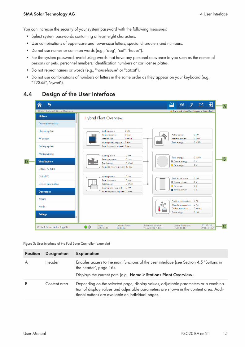
Figure 3: User interface of the Fuel Save Controller (example)
Position Designation Explanation
A Header Enables access to the main functions of the user interface (see Section 4.5 "Buttons inthe header", page 16).Displays the current path (e.g., Home > Stations Plant Overview).
B Content area Depending on the selected page, display values, adjustable parameters or a combina-tion of display values and adjustable parameters are shown in the content area. Addi-tional buttons are available on individual pages.
4 User InterfaceSMA Solar Technology AG
User Manual 15FSC20-BA-en-21
Position Designation Explanation
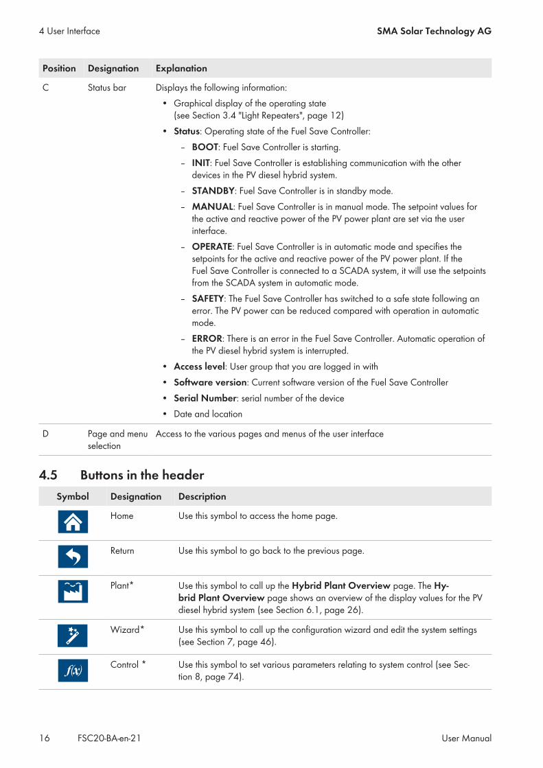
C Status bar Displays the following information:• Graphical display of the operating state
(see Section 3.4 "Light Repeaters", page 12)• Status: Operating state of the Fuel Save Controller:
– BOOT: Fuel Save Controller is starting.– INIT: Fuel Save Controller is establishing communication with the other
devices in the PV diesel hybrid system.– STANDBY: Fuel Save Controller is in standby mode.– MANUAL: Fuel Save Controller is in manual mode. The setpoint values for
the active and reactive power of the PV power plant are set via the userinterface.
– OPERATE: Fuel Save Controller is in automatic mode and specifies thesetpoints for the active and reactive power of the PV power plant. If theFuel Save Controller is connected to a SCADA system, it will use the setpointsfrom the SCADA system in automatic mode.
– SAFETY: The Fuel Save Controller has switched to a safe state following anerror. The PV power can be reduced compared with operation in automaticmode.
– ERROR: There is an error in the Fuel Save Controller. Automatic operation ofthe PV diesel hybrid system is interrupted.
• Access level: User group that you are logged in with• Software version: Current software version of the Fuel Save Controller• Serial Number: serial number of the device• Date and location
D Page and menuselection
Access to the various pages and menus of the user interface
4.5 Buttons in the headerSymbol Designation Description
Home Use this symbol to access the home page.
Return Use this symbol to go back to the previous page.
Plant* Use this symbol to call up the Hybrid Plant Overview page. The Hy-brid Plant Overview page shows an overview of the display values for the PVdiesel hybrid system (see Section 6.1, page 26).
Wizard* Use this symbol to call up the configuration wizard and edit the system settings(see Section 7, page 46).
Control * Use this symbol to set various parameters relating to system control (see Sec-tion 8, page 74).
4 User Interface SMA Solar Technology AG
User ManualFSC20-BA-en-2116
Symbol Designation Description
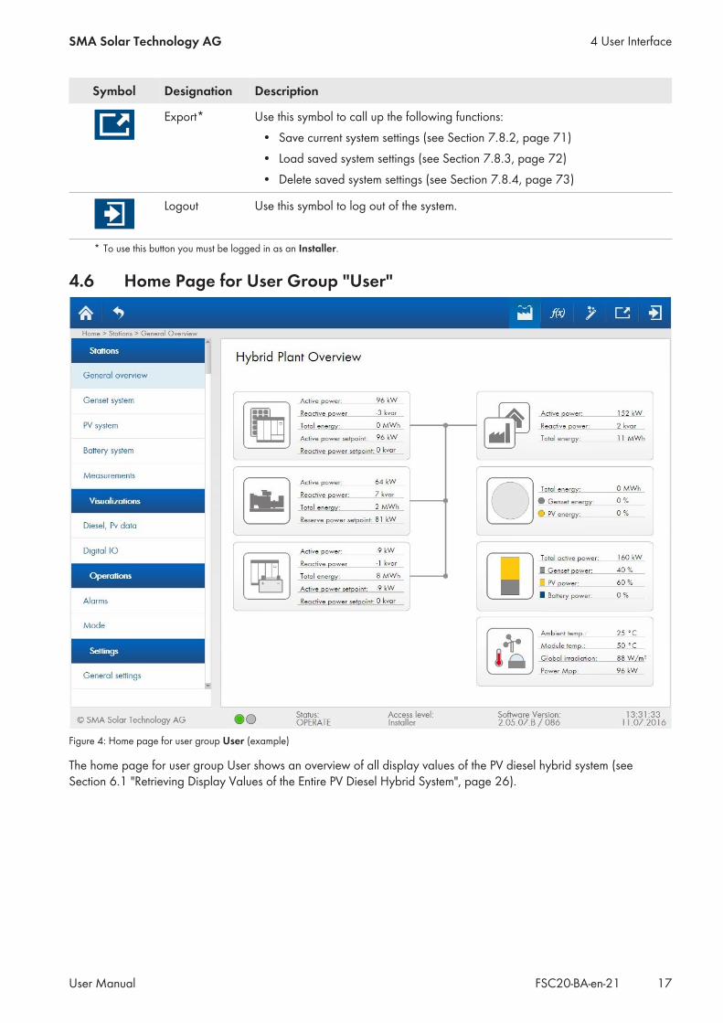
Export* Use this symbol to call up the following functions:• Save current system settings (see Section 7.8.2, page 71)• Load saved system settings (see Section 7.8.3, page 72)• Delete saved system settings (see Section 7.8.4, page 73)
Logout Use this symbol to log out of the system.
* To use this button you must be logged in as an Installer.
4.6 Home Page for User Group "User"
Figure 4: Home page for user group User (example)
The home page for user group User shows an overview of all display values of the PV diesel hybrid system (seeSection 6.1 "Retrieving Display Values of the Entire PV Diesel Hybrid System", page 26).
4 User InterfaceSMA Solar Technology AG
User Manual 17FSC20-BA-en-21
4.7 Home Page for User Group "Installer"
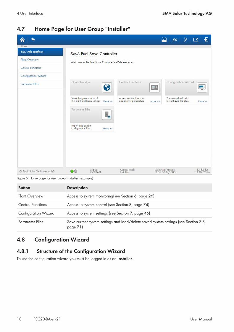
Figure 5: Home page for user group Installer (example)
Button Description
Plant Overview Access to system monitoring(see Section 6, page 26)
Control Functions Access to system control (see Section 8, page 74)
Configuration Wizard Access to system settings (see Section 7, page 46)
Parameter Files Save current system settings and load/delete saved system settings (see Section 7.8,page 71)
4.8 Configuration Wizard
4.8.1 Structure of the Configuration WizardTo use the configuration wizard you must be logged in as an Installer.
4 User Interface SMA Solar Technology AG
User ManualFSC20-BA-en-2118

B
A
Figure 6: Home page of the configuration wizard (example)
Position Designation Explanation
A Automatic configuration The automatic configuration wizard guides you through the configurationof the entire PV diesel hybrid system. During initial commissioning of the PVdiesel hybrid system the automatic configuration wizard must be run com-pletely. In the Manual configuration area the completion status for eachsubsystem is displayed in %. Once the completion status has reached100% for all subsystems, automatic configuration is completed.
B Manual configuration After initial commissioning, use the manual configuration wizard to carryout settings on individual subsystems:
• Utility grid (see Section 7.1, page 46)• Gensets (see Section 7.2.7, page 53)• PV power plant (see Section 7.3, page 54)• Storage system (see Section 7.4, page 57)• Measurement devices (see Section 7.5, page 59)• Temperature and irradiation sensors (see Section 7.6, page 67)• Digital inputs and outputs (see Section 7.7, page 68)
In addition, the manual configuration wizard provides an overview of thecurrent system settings.
4.8.2 Buttons in the Configuration WizardTo use the configuration wizard you must be logged in as an Installer.
Button Description
Add new item Add device type, e.g. a type of inverter
4 User InterfaceSMA Solar Technology AG
User Manual 19FSC20-BA-en-21

Button Description
Adjust Adjust configuration of a subsystem
Apply Save system settingsThis saves all system settings in the active dialog. If you exit the active dialogwithout saving the system settings, any system settings made since the last savewill be discarded.
Continue Wizard Continue to the next dialog
Delete config. Delete configuration of a subsystem
Discard Discard system settingsAny system settings made in the active dialog and not saved by pressing the Ap-ply button will be discarded.
Done Close the active dialog and switch to the overview of current system settings
Remove item Remove device type, e.g. a type of inverter
Start Start automatic configuration wizard
View Show overview of current system settings
4.8.3 Setting Parameters
Risk of damage to devices by entry of incorrect parametersIncorrect parameters may damage devices and result in system malfunctions in the PV diesel hybrid system. Alladjustable parameters are protected by the password of the user group Installer.
• Only a qualified person is permitted to set and adjust parameters.• Only give the password for the user group Installer to qualified persons.• Change the default passwords as soon as possible.• Read the description of the parameters carefully and follow all instructions relating to the settings options of the
parameters.
Procedure:1. Log in as Installer (see Section 5.1, page 21).2. Select a menu via the page and menu selection.3. Select desired parameter in the content area:
• To change parameters with an entry field, enter new values and press Enter after each entry.By pressing Enter, the entered value is adopted in the user interface of the Fuel Save Controller.
• To change parameters with a checkbox, activate the required checkbox.• To change parameters with a drop-down list, select the desired value in the appropriate drop-down list.
4. If the border of the input field flashes red, check the input and set the parameter to a valid value. To do this,repeat the previous step.
5. To adopt current parameter settings in the control of the Fuel Save Controller, select the [Apply] button.6. To discard current parameter settings, select the [Discard] button.
4 User Interface SMA Solar Technology AG
User ManualFSC20-BA-en-2120
5 Getting Started
5.1 Logging In and Out of the User Interface
Log in
User group Default password
User 0000
Installer 1111
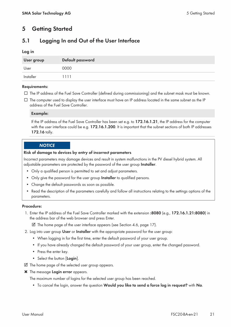
Requirements:☐ The IP address of the Fuel Save Controller (defined during commissioning) and the subnet mask must be known.☐ The computer used to display the user interface must have an IP address located in the same subnet as the IP
address of the Fuel Save Controller.
Example:
If the IP address of the Fuel Save Controller has been set e.g. to 172.16.1.21, the IP address for the computerwith the user interface could be e.g. 172.16.1.200. It is important that the subnet sections of both IP addresses172.16 tally.
Risk of damage to devices by entry of incorrect parametersIncorrect parameters may damage devices and result in system malfunctions in the PV diesel hybrid system. Alladjustable parameters are protected by the password of the user group Installer.
• Only a qualified person is permitted to set and adjust parameters.• Only give the password for the user group Installer to qualified persons.• Change the default passwords as soon as possible.• Read the description of the parameters carefully and follow all instructions relating to the settings options of the
parameters.
Procedure:1. Enter the IP address of the Fuel Save Controller marked with the extension :8080 (e.g., 172.16.1.21:8080) in
the address bar of the web browser and press Enter.☑ The home page of the user interface appears (see Section 4.6, page 17).
2. Log into user group User or Installer with the appropriate password for the user group:• When logging in for the first time, enter the default password of your user group.• If you have already changed the default password of your user group, enter the changed password.• Press the enter key.• Select the button [Login].
☑ The home page of the selected user group appears.✖ The message Login error appears.
The maximum number of logins for the selected user group has been reached.• To cancel the login, answer the question Would you like to send a force log in request? with No.
5 Getting StartedSMA Solar Technology AG
User Manual 21FSC20-BA-en-21
• To resume the login, answer the question Would you like to send a force log in request? with Yes. Thisnotifies users that are already logged in of your request. You will then receive a message regarding thesuccess or failure of your request.
Log outA maximum of 5 Usersand 1 Installer can be logged into the user interface of the Fuel Save Controllersimultaneously. Users are not automatically logged out by closing the web browser. Therefore we recommend alwayslogging out of the user interface prior to closing the web browser.If a user has not shown any activity on the user interface for more than 30 minutes, this user will be warned that he isabout to be logged out automatically. If this warning is not acknowledged within 10 seconds, the user is automaticallylogged out.
Procedure:• Click the logout link in the header.
5.2 Changing Passwords
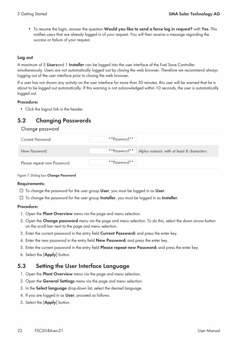
Figure 7: Dialog box Change Password
Requirements:☐ To change the password for the user group User, you must be logged in as User.☐ To change the password for the user group Installer, you must be logged in as Installer.
Procedure:1. Open the Plant Overview menu via the page and menu selection.2. Open the Change password menu via the page and menu selection. To do this, select the down arrow button
on the scroll bar next to the page and menu selection.3. Enter the current password in the entry field Current Password: and press the enter key.4. Enter the new password in the entry field New Password: and press the enter key.5. Enter the current password in the entry field Please repeat new Password: and press the enter key.6. Select the [Apply] button.
5.3 Setting the User Interface Language1. Open the Plant Overview menu via the page and menu selection.2. Open the General Settings menu via the page and menu selection.3. In the Select language drop-down list, select the desired language.4. If you are logged in as User, proceed as follows:5. Select the [Apply] button.
5 Getting Started SMA Solar Technology AG
User ManualFSC20-BA-en-2122
5.4 Setting the System Time
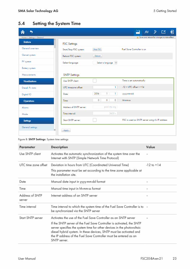
Figure 8: SNTP Settings: System time settings
Parameter Description Value
Use SNTP client Activates the automatic synchronization of the system time over theInternet with SNTP (Simple Network Time Protocol)
–
UTC time zone offset Deviation in hours from UTC (Coordinated Universal Time)This parameter must be set according to the time zone applicable atthe installation site.
-12 to +14
Date Manual date input in yyyy-mm-dd format –
Time Manual time input in hh-mm-ss format –
Address of SNTPserver
Internet address of an SNTP server –
Time interval Time interval to which the system time of the Fuel Save Controller is tobe synchronized via the SNTP server
–
Start SNTP server Activates the use of the Fuel Save Controller as an SNTP serverIf the SNTP server of the Fuel Save Controller is activated, the SNTPserver specifies the system time for other devices in the photovoltaicdiesel hybrid system. In these devices, SNTP must be activated andthe IP address of the Fuel Save Controller must be entered as anSNTP server.
–
5 Getting StartedSMA Solar Technology AG
User Manual 23FSC20-BA-en-21
Procedure:1. Open the Plant Overview menu via the page and menu selection.2. Open the General Settings menu via the page and menu selection.3. Set the parameter UTC time zone offset according to the local time zone (see Section 4.8.3, page 20).4. Carry out the following steps to arrange for the system time to be specified automatically:
• Activate the Use SNTP client checkbox.• Set the parameters Address of SNTP server and Time interval to the desired values.
5. Carry out the following steps in order to set the system time manually:• Deactivate the Use SNTP client checkbox.• Set the parameters Date and Time to the desired values.
6. In order to set the Fuel Save Controller for use as an SNTP server for other devices, activate the Start SNTPserver checkbox.
7. Select the [Apply] button.
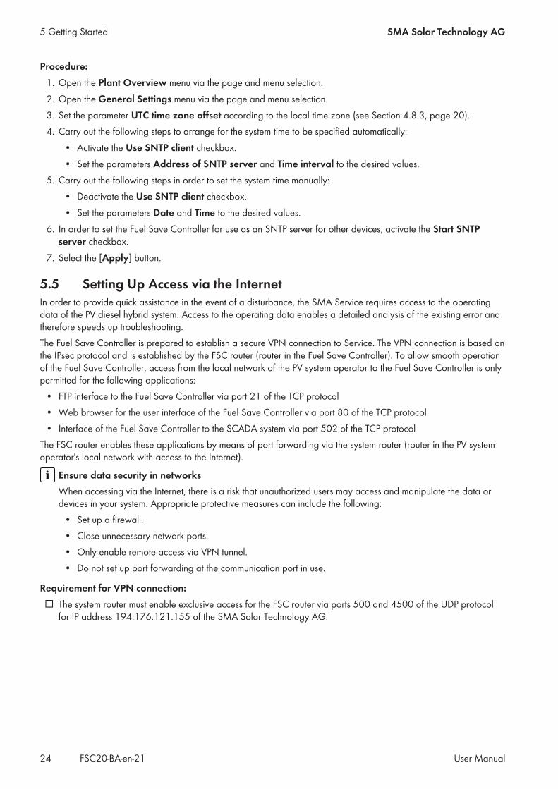
5.5 Setting Up Access via the InternetIn order to provide quick assistance in the event of a disturbance, the SMA Service requires access to the operatingdata of the PV diesel hybrid system. Access to the operating data enables a detailed analysis of the existing error andtherefore speeds up troubleshooting.The Fuel Save Controller is prepared to establish a secure VPN connection to Service. The VPN connection is based onthe IPsec protocol and is established by the FSC router (router in the Fuel Save Controller). To allow smooth operationof the Fuel Save Controller, access from the local network of the PV system operator to the Fuel Save Controller is onlypermitted for the following applications:
• FTP interface to the Fuel Save Controller via port 21 of the TCP protocol• Web browser for the user interface of the Fuel Save Controller via port 80 of the TCP protocol• Interface of the Fuel Save Controller to the SCADA system via port 502 of the TCP protocol
The FSC router enables these applications by means of port forwarding via the system router (router in the PV systemoperator's local network with access to the Internet).
Ensure data security in networksWhen accessing via the Internet, there is a risk that unauthorized users may access and manipulate the data ordevices in your system. Appropriate protective measures can include the following:
• Set up a firewall.• Close unnecessary network ports.• Only enable remote access via VPN tunnel.• Do not set up port forwarding at the communication port in use.
Requirement for VPN connection:☐ The system router must enable exclusive access for the FSC router via ports 500 and 4500 of the UDP protocol
for IP address 194.176.121.155 of the SMA Solar Technology AG.
5 Getting Started SMA Solar Technology AG
User ManualFSC20-BA-en-2124

Destruction of gensets due to customer communication with the inverterThe network capacities within the system network are reserved for communication between the Fuel Save Controllerand the inverter. The system network can be overloaded due to unauthorized customer communication with theinverters. Control commands of the Fuel Save Controller cannot be sent to the inverter anymore when the systemnetwork is overloaded. This may lead to reverse currents and the destruction of gensets.
• Only operate the system network as documented in the acceptance test during commissioning.• The inverter data can only be requested via Fuel Save Controller.
Procedure:1. Configure the system router so that the secure VPN connection of the Fuel Save Controller is enabled for Service.2. Make sure that the FSC router has established an Internet connection.3. Call Service (see Section 12 "Contact", page 108).☑ Service will check whether the FSC router has established a VPN connection.
5 Getting StartedSMA Solar Technology AG
User Manual 25FSC20-BA-en-21

6 System Monitoring
6.1 Retrieving Display Values of the Entire PV Diesel Hybrid SystemOverview of the display values
AG
FB
C
D
E
Figure 9: Hybrid Plant Overview: Overview of the display values for the PV diesel hybrid system (example)
Position Display group Display value Description
A Load Active power Current active power of the loads in kW
Reactive power Current reactive power of the loads in kvar
Total energy Energy consumed by the loads in MWh
B Distribution of electricalenergy
Total energy Energy consumed by the loads in MWh
Genset energy Share of genset energy consumed by the loads in %
PV energy Share of the load energy consumption supplied bythe PV power plant, in %
C Distribution of electricalpower
Total active power Active power currently consumed by the loads inkW
Genset power Share of genset active power currently consumed bythe loads in %
PV power Share of PV power plant active power currently con-sumed by the loads in %
6 System Monitoring SMA Solar Technology AG
User ManualFSC20-BA-en-2126

Position Display group Display value Description
D Irradiation and temper-ature sensors
Ambient temp. Ambient temperature in °C
Module temp. Temperature of the PV modules in °C
Global irradiation PV solar irradiation in W/m2
Power MPP Active power output at the maximum power point
E Storage system Active Power Current active power of the storage system in kW
Reactive power Current reactive power of the storage system in kVAr
Total energy Energy of the storage system fed into the hybrid gridin MWh
Active Power setpoint Current setpoint for the active power of the storagesystem in kW
Reactive power setpoint Current setpoint for the reactive power of the stor-age system in kVAr
F Gensets Active power Current active power of the gensets in kW
Reactive power Current reactive power of the gensets in kvar
Total energy Genset energy fed into the hybrid grid in MWh
Reserve power setpoint Setpoint for the reserve power of the gensets
G PV power plant Active power Current active power of the PV power plant in kW
Reactive power Current reactive power of the PV power plant in kvar
Total energy PV power plant energy fed into the hybrid grid inMWh
Active power setpoint Setpoint for the active power of the PV power plant
Reactive power setpoint Setpoint for the reactive power of the PV powerplant
Procedure:1. To do this you must be logged in as Installer: Go to the menu Plant Overview via the page and menu selection.2. Choose Stations > General Overview via the page and menu selection.
6.2 Retrieving Genset Display ValuesThe Generator system overview page contains the display values for all of the gensets in the PV diesel hybridsystem. The genset names are assigned during commissioning.
6 System MonitoringSMA Solar Technology AG
User Manual 27FSC20-BA-en-21
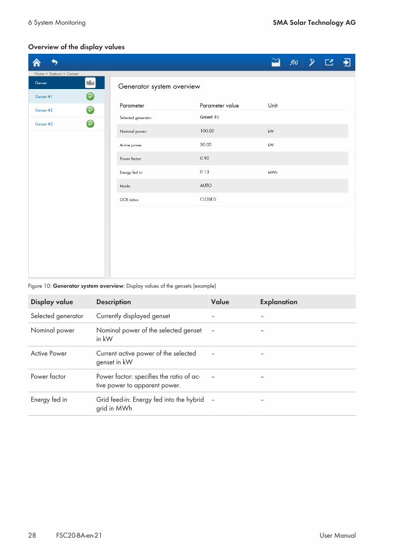
Overview of the display values
Figure 10: Generator system overview: Display values of the gensets (example)
Display value Description Value Explanation
Selected generator Currently displayed genset – –
Nominal power Nominal power of the selected gensetin kW
– –
Active Power Current active power of the selectedgenset in kW
– –
Power factor Power factor: specifies the ratio of ac-tive power to apparent power.
– –
Energy fed in Grid feed-in: Energy fed into the hybridgrid in MWh
– –
6 System Monitoring SMA Solar Technology AG
User ManualFSC20-BA-en-2128
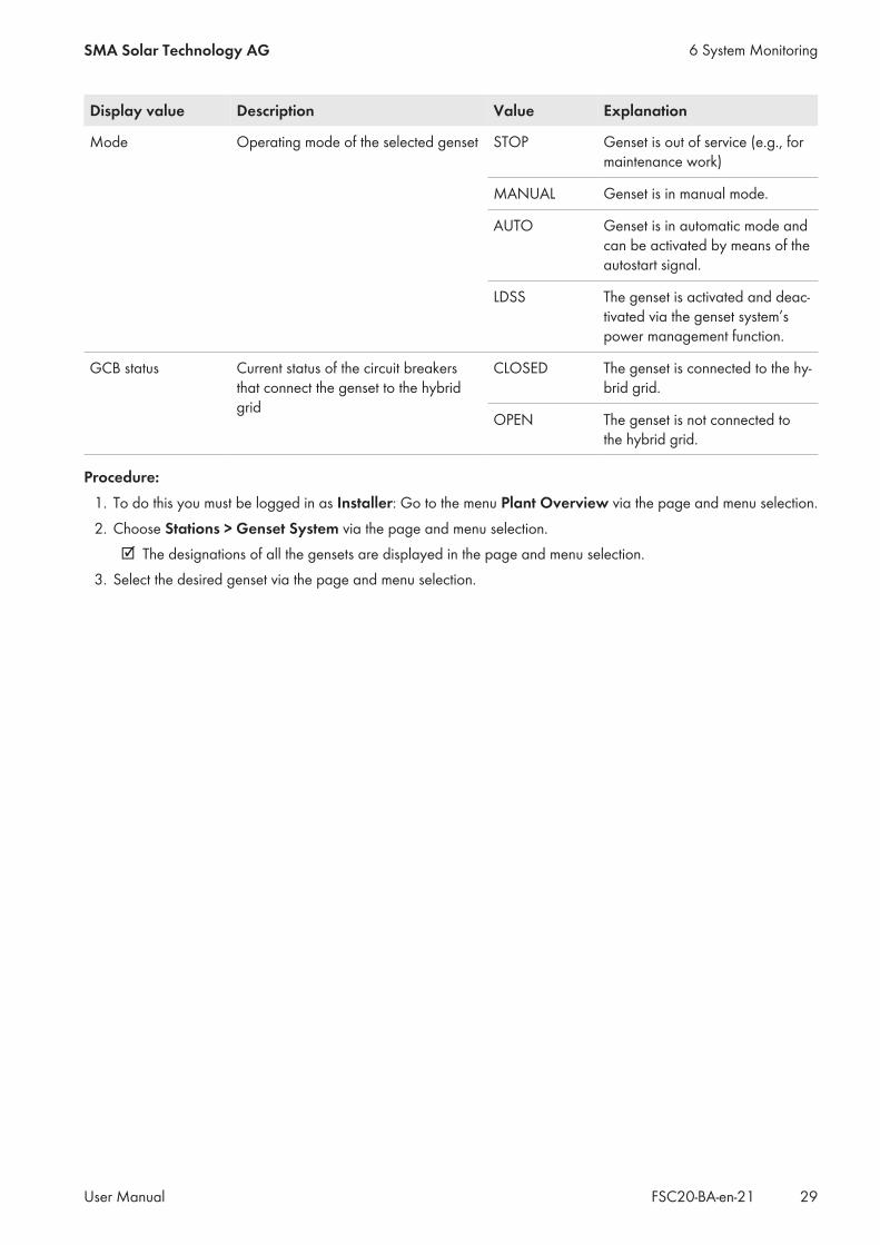
Display value Description Value Explanation
Mode Operating mode of the selected genset STOP Genset is out of service (e.g., formaintenance work)
MANUAL Genset is in manual mode.
AUTO Genset is in automatic mode andcan be activated by means of theautostart signal.
LDSS The genset is activated and deac-tivated via the genset system’spower management function.
GCB status Current status of the circuit breakersthat connect the genset to the hybridgrid
CLOSED The genset is connected to the hy-brid grid.
OPEN The genset is not connected tothe hybrid grid.
Procedure:1. To do this you must be logged in as Installer: Go to the menu Plant Overview via the page and menu selection.2. Choose Stations > Genset System via the page and menu selection.
☑ The designations of all the gensets are displayed in the page and menu selection.3. Select the desired genset via the page and menu selection.
6 System MonitoringSMA Solar Technology AG
User Manual 29FSC20-BA-en-21
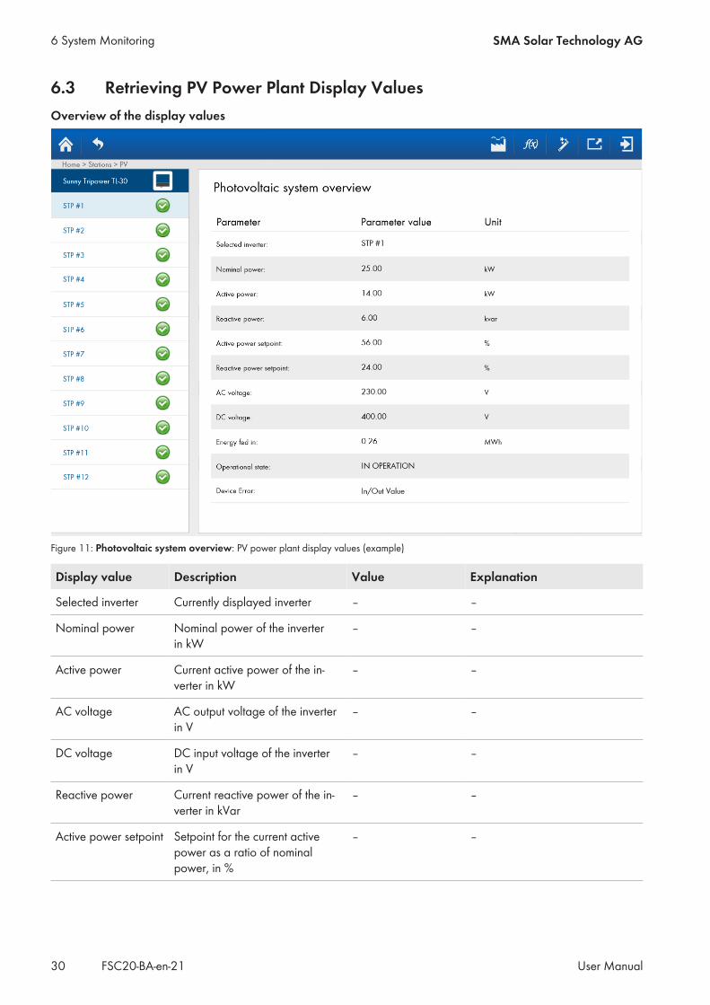
6.3 Retrieving PV Power Plant Display ValuesOverview of the display values
Figure 11: Photovoltaic system overview: PV power plant display values (example)
Display value Description Value Explanation
Selected inverter Currently displayed inverter – –
Nominal power Nominal power of the inverterin kW
– –
Active power Current active power of the in-verter in kW
– –
AC voltage AC output voltage of the inverterin V
– –
DC voltage DC input voltage of the inverterin V
– –
Reactive power Current reactive power of the in-verter in kVar
– –
Active power setpoint Setpoint for the current activepower as a ratio of nominalpower, in %
– –
6 System Monitoring SMA Solar Technology AG
User ManualFSC20-BA-en-2130

Display value Description Value Explanation
Reactive power set-point
Setpoint for the current reactivepower as a ratio of nominalpower, in %
– –
Energy fed in Grid feed-in: Energy fed into thehybrid grid in MWh
– –
Operational state Current operating mode of the in-verter
STOP The inverter is switched off.
WAIT FOR DC The inverter is waiting for DC in-put voltage.
WAIT FOR AC The inverter is waiting for anavailable local grid at the ACoutput.
COM ERROR Communication between inverterand Fuel Save Controller hasfailed.
WAIT FOR SET-POINT
The inverter is waiting for a set-point from the Fuel Save Con-troller.
IN OPERATION The inverter is feeding in.
WARNING A warning has occurred in the in-verter.
ERROR An error has occurred in the in-verter.
Device Error Error in the inverter – See inverter documentation
Procedure:1. To do this you must be logged in as Installer: Go to the menu Plant Overview via the page and menu selection.2. Choose Stations > PV System via the page and menu selection.
☑ The designations of all the inverters are displayed in the page and menu selection.3. Select the desired inverter via the page and menu selection.
6 System MonitoringSMA Solar Technology AG
User Manual 31FSC20-BA-en-21

6.4 Retrieving Storage System Display ValuesThe display values can only be retrieved on this page if a battery inverter has been installed.
Figure 12: Storage system display values
Display value Description Value Explanation
Selected inverter Currently displayed battery in-verter
– –
State of Charge(SOC)
State of charge of the battery in%
– –
Active Power Current active power of the bat-tery inverter in kW
– –
Reactive Power Current reactive power of thebattery inverter in kVAr
– –
Active power setpoint Setpoint for the active power ofthe battery inverter in kW
– –
Reactive power set-point
Setpoint for the reactive power ofthe battery inverter in kVAr
– –
Maximum activepower charge
Maximum charge power of thebattery inverter in kW
– –
Maximum activepower discharge
Maximum discharge power ofthe battery inverter in kW
– –
6 System Monitoring SMA Solar Technology AG
User ManualFSC20-BA-en-2132

Display value Description Value Explanation
BSC operation modestatus
Operating mode of the BatterySystem ControllerThe Battery System Controller isthe communication interface ofthe battery inverter to the BatteryManagement System and theFuel Save Controller.
STOP The storage system is switchedoff.
WAIT The storage system is verifying itsconnection conditions.
PQ The storage system is connectedand is processing the active andreactive power setpoints.
FAILURE An error has occurred in the stor-age system.
UNKNOWN The status of the storage systemcannot be read.
Device status Status of the battery inverter STOP The battery inverter is switchedoff.
IN OPERATION The battery inverter is feeding in.
ERROR An error has occurred in the bat-tery inverter.
WAIT The battery inverter is waiting forsetpoints.
WARNING A warning has occurred in thebattery inverter.
COM ERROR An error has occurred in the com-munication between the batteryinverter and the Fuel Save Con-troller.
Device error code Storage system error For information on potential causes or corrective mea-sures, see the documentation for the battery inverter
6.5 Retrieving Display Values from Measurement DevicesThe values obtained from the measurement modules of the Fuel Save Controller are displayed on the Measurementsystem overview page.
6 System MonitoringSMA Solar Technology AG
User Manual 33FSC20-BA-en-21

Overview of the display values
Figure 13: Display values of the measurement device (example)
Display value Description Value Explanation
Selected measure-ment device
Currently displayed measurementsystem
Internal Measure-ment
Measurement devices connecteddirectly to the Fuel Save Con-troller.
DAQ Measurement devices connectedto the Fuel Save Controller via aData Acquisition Module.
Active power Calculated total active power inkW
– –
Active power L1/L2/L3
Calculated active power for L1/L2/L3
– –
Reactive power Calculated reactive power inkvar
– –
Cos phi L1/L2/L3 Calculated power factor for L1/L2/L3
– –
Frequency Measured frequency in Hz – –
Voltage Measured voltage in V – –
Energy consumed Energy consumption – –
6 System Monitoring SMA Solar Technology AG
User ManualFSC20-BA-en-2134

Display value Description Value Explanation
Energy delivered Energy generation – –
Digital Input #1 Status of the digital input 1 on theData Acquisition Module
OPEN The digital input is switched off(contact is open).
CLOSED The digital input is switched on(contact is closed).
Digital Input #2 Status of the digital input 2 on theData Acquisition Module
OPEN The digital input is switched off(contact is open).
CLOSED The digital input is switched on(contact is closed).
List of measured de-vices
List containing all the devices inthe PV diesel hybrid system towhich the currently displayedmeasurement device is assigned.
– –
Procedure:1. To do this you must be logged in as Installer: Select the menu Plant Overview via the page and menu
selection.2. Select Stations > Measurements via the page and menu selection.
☑ The designations of all the measurement systems are displayed in the page and menu selection.3. Select Internal Measurement or DAQ from the page and menu selection.4. Select the [Show] button in the List of measured device bar.5. In the Selected measurement points menu, select the desired measurement system and select the [Close]
button.
6.6 Viewing Data Records via the PV Diesel Hybrid SystemOn the Historical Data page, the SMA Fuel Save Controller depicts a selection of power values over time. Differentanalysis periods can be selected here:
• the last minute• the last 5 minutes• the last hour• the last 24 hours
6 System MonitoringSMA Solar Technology AG
User Manual 35FSC20-BA-en-21
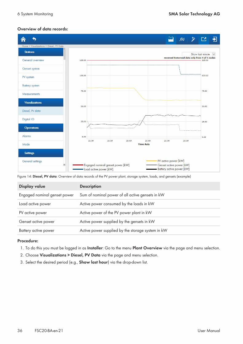
Overview of data records:
Figure 14: Diesel, PV data: Overview of data records of the PV power plant, storage system, loads, and gensets (example)
Display value Description
Engaged nominal genset power Sum of nominal power of all active gensets in kW
Load active power Active power consumed by the loads in kW
PV active power Active power of the PV power plant in kW
Genset active power Active power supplied by the gensets in kW
Battery active power Active power supplied by the storage system in kW
Procedure:1. To do this you must be logged in as Installer: Go to the menu Plant Overview via the page and menu selection.2. Choose Visualizations > Diesel, PV Data via the page and menu selection.3. Select the desired period (e.g., Show last hour) via the drop-down list.
6 System Monitoring SMA Solar Technology AG
User ManualFSC20-BA-en-2136
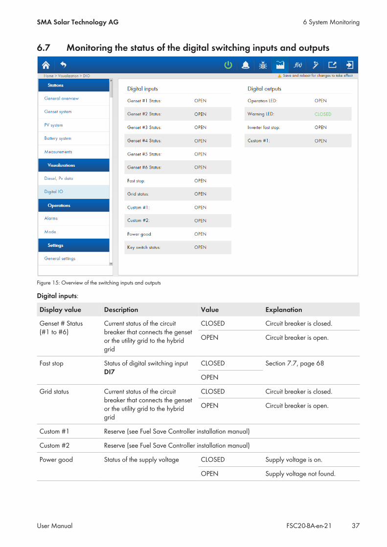
6.7 Monitoring the status of the digital switching inputs and outputs
Figure 15: Overview of the switching inputs and outputs
Digital inputs:
Display value Description Value Explanation
Genset # Status(#1 to #6)
Current status of the circuitbreaker that connects the gensetor the utility grid to the hybridgrid
CLOSED Circuit breaker is closed.
OPEN Circuit breaker is open.
Fast stop Status of digital switching inputDI7
CLOSED Section 7.7, page 68
OPEN
Grid status Current status of the circuitbreaker that connects the gensetor the utility grid to the hybridgrid
CLOSED Circuit breaker is closed.
OPEN Circuit breaker is open.
Custom #1 Reserve (see Fuel Save Controller installation manual)
Custom #2 Reserve (see Fuel Save Controller installation manual)
Power good Status of the supply voltage CLOSED Supply voltage is on.
OPEN Supply voltage not found.
6 System MonitoringSMA Solar Technology AG
User Manual 37FSC20-BA-en-21

Display value Description Value Explanation
Key switch status Status of key switch CLOSED The key switch is in the Start po-sition.
OPEN The key switch is in the Stop posi-tion.
Digital outputs:
Display value Description Value Explanation
Operation LED Status of the Operation light re-peater
CLOSED The light repeater is lit up.
OPEN The light repeater is off.
Warning LED Status of the Warning light re-peater
CLOSED The light repeater is lit up.
OPEN The light repeater is off.
Inverter fast stop Status of the signal generator fordisconnecting the PV power plantfrom the local utility grid
CLOSED The values CLOSED and OPENare determined when connectingthe contactors to the switchingoutputs of the Fuel Save Con-troller (see the Fuel Save Con-troller installation manual).
OPEN
Custom #1 Status of the signal generator forconnecting the PV power plantfrom the local utility grid
CLOSED
OPEN
Procedure:1. To do this you must be logged in as Installer: Go to the menu Plant Overview via the page and menu selection.2. Choose Visualizations > Digital IO via the page and menu selection.
6 System Monitoring SMA Solar Technology AG
User ManualFSC20-BA-en-2138

6.8 Device Information
Figure 16: Device information overview
Name line Description
FSC serial number Indication of the serial number of the Fuel Save Controller
State of the application Display of the status of the Fuel Save Controller application
MSys Version Indication of the installed version of the operating system
CPU temperature Display of the processor temperature in the Fuel Save Controller
6 System MonitoringSMA Solar Technology AG
User Manual 39FSC20-BA-en-21

6.9 Processing Status Messages
Figure 17: Alarm list in the SMA Fuel Save Controller (example)
Name of the column Description
Timestamp Time at which the message was recorded:
Status Event
WarningIf a warning occurs, automatic operation of the PV diesel hybrid system is contin-ued.
ErrorIf an error occurs, automatic operation of the PV diesel hybrid system is discontin-ued.
Warning or error no longer exists.
Event, warning or error has occurred.
Code Four-digit number of the reported event, warning or error
Description Description of the reported event, warning or error
6 System Monitoring SMA Solar Technology AG
User ManualFSC20-BA-en-2140

Using the scrollbarIf not all messages can be displayed on the user interface, a scrollbar appears on the Alarm list page. You canonly use this scrollbar by means of the arrow keys.
• To call up messages recorded at an earlier time, press the up row key.• To call up messages recorded at a later time, press the down arrow key.
Procedure:1. To do this you must be logged in as Installer: Go to the menu Plant Overview via the page and menu selection.2. Choose Operations > Alarms via the page and menu selection.3. Select the required message types. To do this, activate the checkboxes displayed below all the required message
types, and deactivate the checkboxes for all message types that are not required.
Example: Calling up errors and warningsFinally, in order to display the errors and warnings, perform the following steps:
• Activate the Errors and Warnings checkboxes.• Deactivate the Info, Battery events, System events, Genset events, PV events, and Meas events
checkboxes.
4. Processing reported errors:• Ascertain and remove the cause of the error. To do so, contact the SMA Service Line (see Section 12,
page 108).• Once the cause of the error has been eliminated, acknowledge the error message. To do so, select the
[Acknowledge] button.5. Ascertain the causes of reported warnings and take corrective action. To do so, contact the SMA Service Line (see
Section 12, page 108).6. To acknowledge reported warnings or events, select the [Acknowledge] button.
6 System MonitoringSMA Solar Technology AG
User Manual 41FSC20-BA-en-21

6.10 Operating Mode and Setpoints
6.10.1 Overview of Operating Modes and Setpoints
BA
DC
Figure 18: Overview of current operating state of the Fuel Save Controller (example)
6 System Monitoring SMA Solar Technology AG
User ManualFSC20-BA-en-2142

Position Display group Parameters /Functions
Description
A Change controlmode
Current opera-tion
Shows the current operating mode of the SMA Fuel Save Con-troller:
• Automatic mode (see Activate automatic mode)The Fuel Save Controller normally operates in Automaticmode.The SMA Fuel Save Controller calculates the setpoints forthe PV power plant, the battery and the reserve power tobe retained by the gensets.
• Manual mode (see Activate manual mode)Manual mode is normally used only when the SMA FuelSave Controller is being commissioned. In Manual mode,the reserve power to be kept by the gensets is specifiedvia the user interface.If the Fuel Save Controller remains five minutes in theoperating mode Manual and no user is logged in, theFuel Save Controller switches automatically to theoperating state Standby via the SLOW STOP mode.
• SLOW STOP modeThe Fuel Save Controller stops the PV inverter (seeSection 10.1, page 104).
Activate auto-matic mode
Activate Automatic mode (see Section 6.10.3, page 44)
Activate man-ual mode
Activate Manual mode (see Section 6.10.3, page 44)
Enable SCADAto send set-points
Activate setpoint specification by a SCADA system (see Sec-tion 6.10.4, page 45)
B System setpoints /system recommenda-tion
Shows the values that the Fuel Save Controller would currentlysend to the genset, PV and battery components if theFuel Save Controller were in automatic mode.
Genset reservepower
Current setpoint for the reserve power of the gensets in kW
PV activepower
Current setpoint for the active power of the PV power plant inkW
PV reactivepower
Current setpoint for the reactive power of the PV power plant inkvar
Battery activepower
Current setpoint for the active power of the storage system inkW
Battery reactivepower
Current setpoint for the reactive power of the storage system inkVAr
6 System MonitoringSMA Solar Technology AG
User Manual 43FSC20-BA-en-21
Position Display group Parameters /Functions
Description
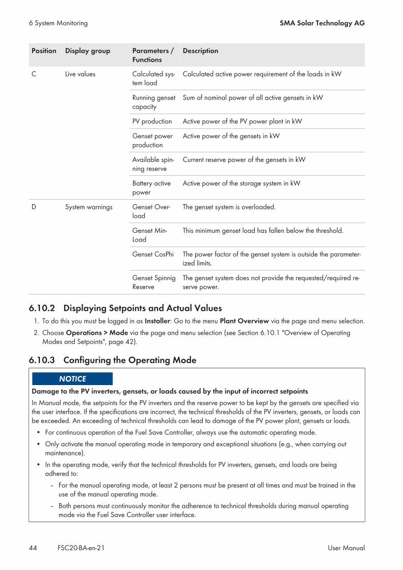
C Live values Calculated sys-tem load
Calculated active power requirement of the loads in kW
Running gensetcapacity
Sum of nominal power of all active gensets in kW
PV production Active power of the PV power plant in kW
Genset powerproduction
Active power of the gensets in kW
Available spin-ning reserve
Current reserve power of the gensets in kW
Battery activepower
Active power of the storage system in kW
D System warnings Genset Over-load
The genset system is overloaded.
Genset Min-Load
This minimum genset load has fallen below the threshold.
Genset CosPhi The power factor of the genset system is outside the parameter-ized limits.
Genset SpinnigReserve
The genset system does not provide the requested/required re-serve power.
6.10.2 Displaying Setpoints and Actual Values1. To do this you must be logged in as Installer: Go to the menu Plant Overview via the page and menu selection.2. Choose Operations > Mode via the page and menu selection (see Section 6.10.1 "Overview of Operating
Modes and Setpoints", page 42).
6.10.3 Configuring the Operating Mode
Damage to the PV inverters, gensets, or loads caused by the input of incorrect setpointsIn Manual mode, the setpoints for the PV inverters and the reserve power to be kept by the gensets are specified viathe user interface. If the specifications are incorrect, the technical thresholds of the PV inverters, gensets, or loads canbe exceeded. An exceeding of technical thresholds can lead to damage of the PV power plant, gensets or loads.
• For continuous operation of the Fuel Save Controller, always use the automatic operating mode.• Only activate the manual operating mode in temporary and exceptional situations (e.g., when carrying out
maintenance).• In the operating mode, verify that the technical thresholds for PV inverters, gensets, and loads are being
adhered to:– For the manual operating mode, at least 2 persons must be present at all times and must be trained in the
use of the manual operating mode.– Both persons must continuously monitor the adherence to technical thresholds during manual operating
mode via the Fuel Save Controller user interface.
6 System Monitoring SMA Solar Technology AG
User ManualFSC20-BA-en-2144
If the Fuel Save Controller remains five minutes in the operating mode Manual and no user is logged in, theFuel Save Controller switches automatically to the operating state Standby via the SLOW STOP mode.
Requirement:☐ You must be logged in as Installer.
Procedure:1. Choose the menu Plant Overview via the page and menu selection.2. Choose Operations > Mode via the page and menu selection (see Section 6.10.1 "Overview of Operating
Modes and Setpoints", page 42).3. Select the [Activate] button in the Activate automatic mode bar
to activate Automatic mode.4. To activate Manual mode, select the [Activate] button in the Activate manual mode bar.5. To deactivate Manual mode, activate Automatic mode or select the logout button in the header.
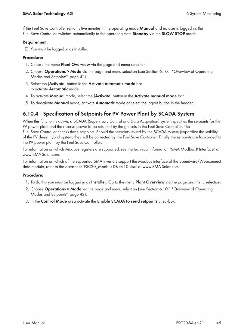
6.10.4 Specification of Setpoints for PV Power Plant by SCADA SystemWhen this function is active, a SCADA (Supervisory Control and Data Acquisition) system specifies the setpoints for thePV power plant and the reserve power to be retained by the gensets in the Fuel Save Controller. TheFuel Save Controller checks these setpoints. Should the setpoints issued by the SCADA system jeopardize the stabilityof the PV diesel hybrid system, they will be corrected by the Fuel Save Controller. Finally the setpoints are forwarded tothe PV power plant by the Fuel Save Controller.For information on which Modbus registers are supported, see the technical information "SMA Modbus® Interface" atwww.SMA-Solar.com.For information on which of the supported SMA inverters support the Modbus interface of the Speedwire/Webconnectdata module, refer to the datasheet "FSC20_Modbus-DB-en-10.xlsx" at www.SMA-Solar.com.
Procedure:1. To do this you must be logged in as Installer: Go to the menu Plant Overview via the page and menu selection.2. Choose Operations > Mode via the page and menu selection (see Section 6.10.1 "Overview of Operating
Modes and Setpoints", page 42).3. In the Control Mode area activate the Enable SCADA to send setpoints checkbox.
6 System MonitoringSMA Solar Technology AG
User Manual 45FSC20-BA-en-21

7 System Settings
7.1 Configuring the Utility GridThe system settings of the Fuel Save Controller can only be adjusted when the Fuel Save Controller is in STANDBY orERROR mode. The operating state STANDBY can be reached by stopping the SMA Fuel Save Controller.
Requirement:☐ You must be logged in as Installer.
Procedure:1. Choose the menu Configuration Wizard via the page and menu selection.2. In the Grid bar, select the [Adjust] button.3. To activate the utility grid connection, set the parameter Enable to Yes.4. To deactivate the utility grid connection, set the parameter Enable to No.5. Select the [Apply] button. This will adopt the setting.6. Select the [Continue wizard] button.7. End the system settings (see Section 7.8.1, page 71).
7.2 Settings for the gensets
7.2.1 Parameters for Gensets with Genset Controller ComAp IG-/IS-NTCGenset general configuration
Parameter Description Value Explanation Defaultvalue
Remainingavailable de-vices
Remaining number of config-urable gensets
– – –
Number of de-vices
Number of installed gensets 0 to 8 – 0
Genset inter-face Type
Type of genset interface* ComAp IG-/IS-NTC Genset controller "ComApIG-NTC / ComAp IS-NTC"with Modbus/TCP commu-nication
None
ComAp accesscode
Password for access to the gensetcontroller
0 to 65535 The maximum length of thepassword is 16 bits.
0
ComAp adminpassword
Administrator password for writeaccess to parameters of thegenset controller
0 to 65535 The maximum length of thepassword is 16 bits.
0
7 System Settings SMA Solar Technology AG
User ManualFSC20-BA-en-2146
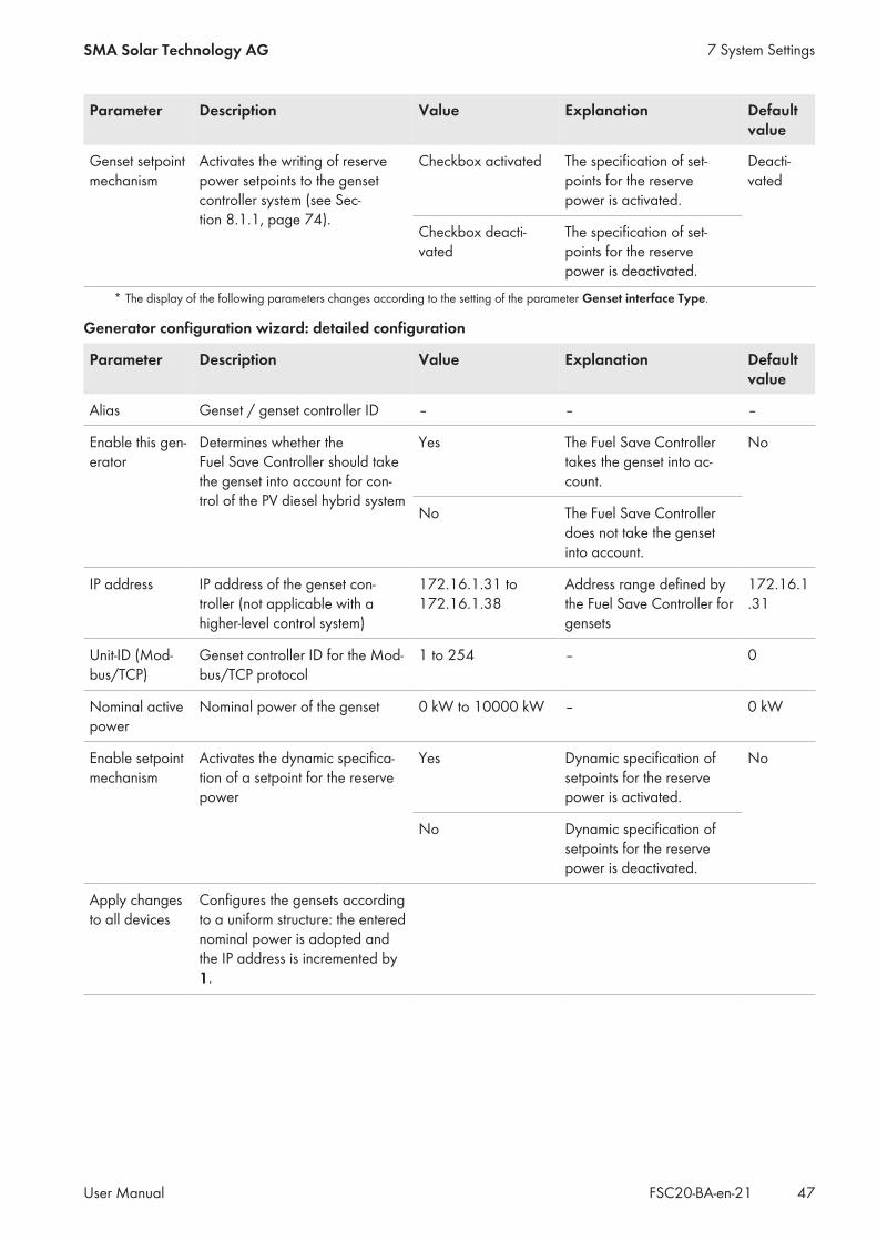
Parameter Description Value Explanation Defaultvalue
Genset setpointmechanism
Activates the writing of reservepower setpoints to the gensetcontroller system (see Sec-tion 8.1.1, page 74).
Checkbox activated The specification of set-points for the reservepower is activated.
Deacti-vated
Checkbox deacti-vated
The specification of set-points for the reservepower is deactivated.
* The display of the following parameters changes according to the setting of the parameter Genset interface Type.
Generator configuration wizard: detailed configuration
Parameter Description Value Explanation Defaultvalue
Alias Genset / genset controller ID – – –
Enable this gen-erator
Determines whether theFuel Save Controller should takethe genset into account for con-trol of the PV diesel hybrid system
Yes The Fuel Save Controllertakes the genset into ac-count.
No
No The Fuel Save Controllerdoes not take the gensetinto account.
IP address IP address of the genset con-troller (not applicable with ahigher-level control system)
172.16.1.31 to172.16.1.38
Address range defined bythe Fuel Save Controller forgensets
172.16.1.31
Unit-ID (Mod-bus/TCP)
Genset controller ID for the Mod-bus/TCP protocol
1 to 254 – 0
Nominal activepower
Nominal power of the genset 0 kW to 10000 kW – 0 kW
Enable setpointmechanism
Activates the dynamic specifica-tion of a setpoint for the reservepower
Yes Dynamic specification ofsetpoints for the reservepower is activated.
No
No Dynamic specification ofsetpoints for the reservepower is deactivated.
Apply changesto all devices
Configures the gensets accordingto a uniform structure: the enterednominal power is adopted andthe IP address is incremented by1.
7 System SettingsSMA Solar Technology AG
User Manual 47FSC20-BA-en-21

7.2.2 Parameters for Gensets with the Genset Controller DEIF AGCGenset general configuration
Parameter Description Value Explanation Defaultvalue
Remainingavailable de-vices
Remaining number of config-urable gensets
– – –
Number of de-vices
Number of installed gensets 0 to 8 – 0
Generator In-terface Type
Type of genset interface* DEIF AGC Genset Controllers of theDEIF AGC Series
None
* The display of the following parameters changes according to the setting of the parameter Genset interface Type.
Generator configuration wizard: detailed configuration
Parameter Description Value Explanation Defaultvalue
Alias Genset / genset controller ID – – –
Enable this gen-erator
Determines whether theFuel Save Controller should takethe genset into account for con-trol of the PV diesel hybrid system
Yes The Fuel Save Controllertakes the genset into ac-count.
No
No The Fuel Save Controllerdoes not take the gensetinto account.
IP address IP address of the genset con-troller (not applicable with ahigher-level control system)
172.16.1.31 to172.16.1.38
Address range defined bythe Fuel Save Controller forgensets
172.16.1.31
Unit-ID (Mod-bus/TCP)
Genset controller ID for the Mod-bus/TCP protocol
1 to 254 – 0
Nominal activepower
Nominal power of the genset 0 kW to 10000 kW – 0 kW
Apply changesto all devices
Activates transfer of the currentsettings for all gensets withGenset Controller DSE8610
Checkbox activated Transfer of current settingsfor all gensets is activated.
Deacti-vated
Checkbox deacti-vated
Transfer of current settingsfor all gensets is deacti-vated.
7 System Settings SMA Solar Technology AG
User ManualFSC20-BA-en-2148

7.2.3 Parameters for Gensets with Genset Controller DSE8610Genset general configuration
Parameter Description Value Explanation Defaultvalue
Remainingavailable de-vices
Remaining number of config-urable gensets
– – –
Number of de-vices
Number of installed gensets 0 to 8 – 0
Generator In-terface Type
Type of genset interface* Deep Sea 8610 Genset Controllers of theDSE8610 Series
None
* The display of the following parameters changes according to the setting of the parameter Genset interface Type.
Generator configuration wizard: detailed configuration
Parameter Description Value Explanation Defaultvalue
Alias Genset / genset controller ID – – –
Enable this gen-erator
Determines whether theFuel Save Controller should takethe genset into account for con-trol of the PV diesel hybrid system
Yes The Fuel Save Controllertakes the genset into ac-count.
No
No The Fuel Save Controllerdoes not take the gensetinto account.
IP address IP address of the genset con-troller (not applicable with ahigher-level control system)
172.16.1.31 to172.16.1.38
Address range defined bythe Fuel Save Controller forgensets
172.16.1.31
Unit-ID (Mod-bus/TCP)
Genset controller ID for the Mod-bus/TCP protocol
1 to 254 – 0
Nominal activepower
Nominal power of the genset 0 kW to 10000 kW – 0 kW
Apply changesto all devices
Activates transfer of the currentsettings for all gensets withGenset Controller DSE8610
Checkbox activated Transfer of current settingsfor all gensets is activated.
Deacti-vated
Checkbox deacti-vated
Transfer of current settingsfor all gensets is deacti-vated.
7 System SettingsSMA Solar Technology AG
User Manual 49FSC20-BA-en-21

7.2.4 Parameters for gensets with genset controller easYgen-3000 via the CANnetwork
Genset general configuration
Parameter Description Value Explanation Defaultvalue
Remainingavailable de-vices
Remaining number of config-urable gensets
– – –
Number of de-vices
Number of installed gensets 0 to 8 – 0
Genset inter-face Type
Type of genset interface Easygen 3000 CAN Genset controller "Wood-ward Easygen 3000" withCAN communication *
None
CAN#1 pass-word
Password for write access to thegenset controller
0 to 9999 For setting the password,refer to manufacturer docu-mentation
–
Genset setpointmechanism
Activates the writing of reservepower setpoints to the gensetcontroller system (see Sec-tion 8.1.1, page 74).
Checkbox activated The specification of set-points for the reservepower is activated
Deacti-vated
Checkbox deacti-vated
The specification of set-points for the reservepower is deactivated
* For settings regarding the genset controller, see technical information "Gensets in PV Diesel Hybrid Systems withSMA Fuel Save Controller 2.0"
Generator configuration wizard: detailed configuration
Parameter Description Value Explanation Defaultvalue
Label Genset / genset controller ID – – –
Enable this gen-erator
Determines whether theFuel Save Controller should takethe genset into account for con-trol of the PV diesel hybrid system
Yes The Fuel Save Controllertakes the genset into ac-count.
No
No The Fuel Save Controllerdoes not take the gensetinto account.
Nominal activepower
Nominal power of the genset 0 kW to 10000 kW – 0 kW
7 System Settings SMA Solar Technology AG
User ManualFSC20-BA-en-2150
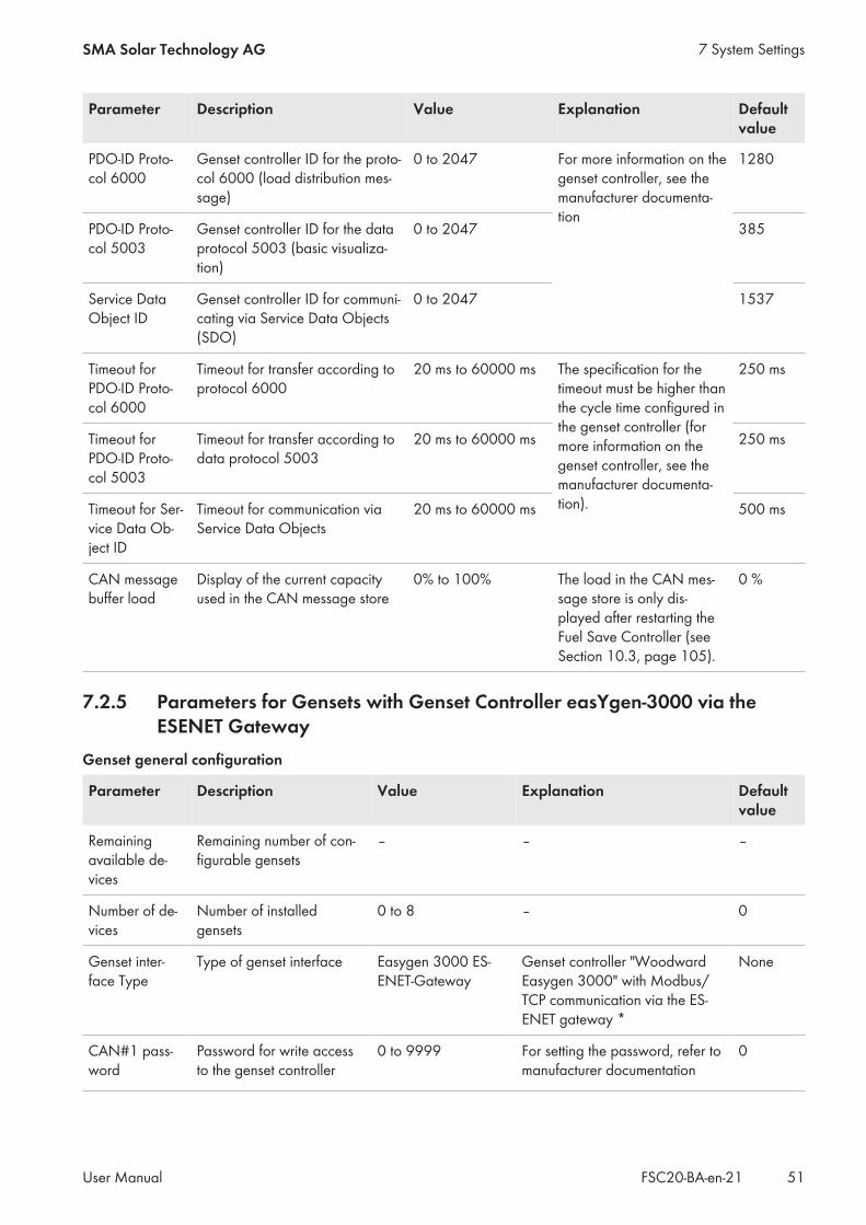
Parameter Description Value Explanation Defaultvalue
PDO-ID Proto-col 6000
Genset controller ID for the proto-col 6000 (load distribution mes-sage)
0 to 2047 For more information on thegenset controller, see themanufacturer documenta-tion
1280
PDO-ID Proto-col 5003
Genset controller ID for the dataprotocol 5003 (basic visualiza-tion)
0 to 2047 385
Service DataObject ID
Genset controller ID for communi-cating via Service Data Objects(SDO)
0 to 2047 1537
Timeout forPDO-ID Proto-col 6000
Timeout for transfer according toprotocol 6000
20 ms to 60000 ms The specification for thetimeout must be higher thanthe cycle time configured inthe genset controller (formore information on thegenset controller, see themanufacturer documenta-tion).
250 ms
Timeout forPDO-ID Proto-col 5003
Timeout for transfer according todata protocol 5003
20 ms to 60000 ms 250 ms
Timeout for Ser-vice Data Ob-ject ID
Timeout for communication viaService Data Objects
20 ms to 60000 ms 500 ms
CAN messagebuffer load
Display of the current capacityused in the CAN message store
0% to 100% The load in the CAN mes-sage store is only dis-played after restarting theFuel Save Controller (seeSection 10.3, page 105).
0 %
7.2.5 Parameters for Gensets with Genset Controller easYgen-3000 via theESENET Gateway
Genset general configuration
Parameter Description Value Explanation Defaultvalue
Remainingavailable de-vices
Remaining number of con-figurable gensets
– – –
Number of de-vices
Number of installedgensets
0 to 8 – 0
Genset inter-face Type
Type of genset interface Easygen 3000 ES-ENET-Gateway
Genset controller "WoodwardEasygen 3000" with Modbus/TCP communication via the ES-ENET gateway *
None
CAN#1 pass-word
Password for write accessto the genset controller
0 to 9999 For setting the password, refer tomanufacturer documentation
0
7 System SettingsSMA Solar Technology AG
User Manual 51FSC20-BA-en-21
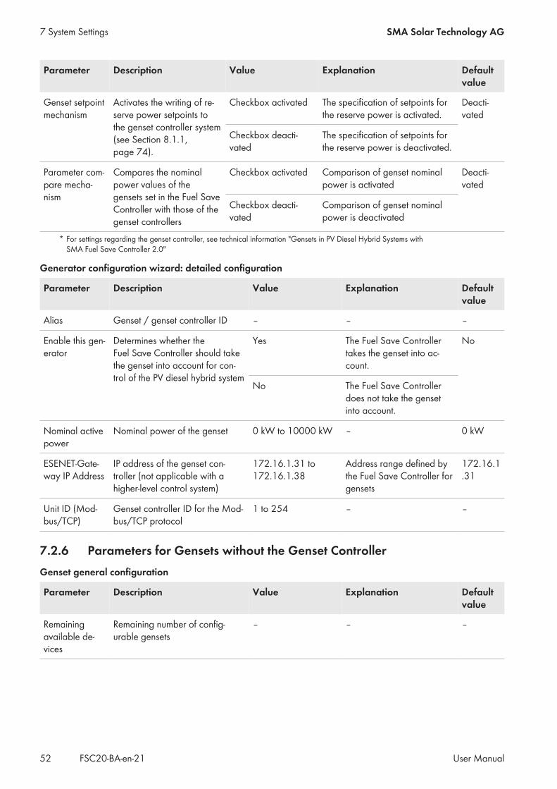
Parameter Description Value Explanation Defaultvalue
Genset setpointmechanism
Activates the writing of re-serve power setpoints tothe genset controller system(see Section 8.1.1,page 74).
Checkbox activated The specification of setpoints forthe reserve power is activated.
Deacti-vated
Checkbox deacti-vated
The specification of setpoints forthe reserve power is deactivated.
Parameter com-pare mecha-nism
Compares the nominalpower values of thegensets set in the Fuel SaveController with those of thegenset controllers
Checkbox activated Comparison of genset nominalpower is activated
Deacti-vated
Checkbox deacti-vated
Comparison of genset nominalpower is deactivated
* For settings regarding the genset controller, see technical information "Gensets in PV Diesel Hybrid Systems withSMA Fuel Save Controller 2.0"
Generator configuration wizard: detailed configuration
Parameter Description Value Explanation Defaultvalue
Alias Genset / genset controller ID – – –
Enable this gen-erator
Determines whether theFuel Save Controller should takethe genset into account for con-trol of the PV diesel hybrid system
Yes The Fuel Save Controllertakes the genset into ac-count.
No
No The Fuel Save Controllerdoes not take the gensetinto account.
Nominal activepower
Nominal power of the genset 0 kW to 10000 kW – 0 kW
ESENET-Gate-way IP Address
IP address of the genset con-troller (not applicable with ahigher-level control system)
172.16.1.31 to172.16.1.38
Address range defined bythe Fuel Save Controller forgensets
172.16.1.31
Unit ID (Mod-bus/TCP)
Genset controller ID for the Mod-bus/TCP protocol
1 to 254 – –
7.2.6 Parameters for Gensets without the Genset ControllerGenset general configuration
Parameter Description Value Explanation Defaultvalue
Remainingavailable de-vices
Remaining number of config-urable gensets
– – –
7 System Settings SMA Solar Technology AG
User ManualFSC20-BA-en-2152

Parameter Description Value Explanation Defaultvalue
Number of de-vices
Number of installed gensets 0 to 8 – 0
Genset inter-face Type
Type of genset interface None The genset is monitored viathe current and voltagemeasurement of theFuel Save Controller. Agenset controller is notused.
None
Generator configuration wizard: detailed configuration
Parameter Description Value Explanation Defaultvalue
Alias Genset ID – – –
Enable this gen-erator
Determines whether theFuel Save Controller should takethe genset into account for con-trol of the PV diesel hybrid system
Yes The Fuel Save Controllertakes the genset into ac-count.
No
No The Fuel Save Controllerdoes not take the gensetinto account.
Nominal activepower
Nominal power of the genset 0 kW to 10000 kW – 0 kW
7.2.7 Configuring GensetsThe system settings of the Fuel Save Controller can only be adjusted when the Fuel Save Controller is in STANDBY orERROR mode. The operating state STANDBY can be reached by stopping the SMA Fuel Save Controller.The system settings for the gensets are located in the menus Genset general configuration andGenerator configuration Wizard: detailed configuration. The displayed parameters depend on which gensetsare used:
• Gensets without genset controllers (see Section 7.2.6, page 52)• Parameters for gensets with genset controller easYgen-3000, connected via the CAN network (see
Section 7.2.4, page 50)• Parameters for gensets with genset controller easYgen-3000, connected via the ESENET gateway (see
Section 7.2.5, page 51)• Gensets with genset controller ComAp IG-/IS-NTC (see Section 7.2.1, page 46)
Requirement:☐ You must be logged in as Installer.
7 System SettingsSMA Solar Technology AG
User Manual 53FSC20-BA-en-21
Destruction of gensets due to insufficient reserve powerOnce the SMA Fuel Save Controller and PV power plant have stopped, the PV power plant is no longer available asenergy supplier. Now only the gensets supply the loads. If the current reserve power of the gensets is insufficient forsupplying the power required by the loads, the gensets become overloaded Sustained overload of the gensets canresult in failure of the power supply and destruction of the gensets.
• Prior to stopping the Fuel Save Controller, always check whether the current reserve power of the gensets issufficient to cover the requirement of the loads.
– If the current reserve power of the gensets is insufficient, switch off the loads or connect additional gensets.This increases the reserve power of the gensets.
• If the power management and the communication interface of the genset is not compatible with theFuel Save Controller, power management must be deactivated on the Fuel Save Controller. In this case, thegensets must be monitored to ensure that sufficient reserve power is retained.
• Make sure that the setpoints for power management on the Fuel Save Controller and the gensets are set to thesame value.
Procedure:1. Choose the menu Configuration Wizard via the page and menu selection.2. In the Genset System bar, select the [Adjust] button.3. Set the parameters in the menu Genset general configuration (see Section 4.8.3, page 20).4. Select the [Continue wizard] button.5. Set the parameters in the menu Generator configuration Wizard: detailed configuration (see Section 4.8.3,
page 20).6. To change a particular parameter for all gensets, activate the Apply changes to all devices checkbox.7. To change a particular parameter for individual gensets, deactivate the Apply changes to all devices
checkbox.8. To continue with system settings, select the [Continue wizard] button.9. Select the [Done] button.
10. End the system settings (see Section 7.8.1, page 71).
7.3 Configuring the PV Power PlantThe system settings of the Fuel Save Controller can only be adjusted when the Fuel Save Controller is in STANDBY orERROR mode. The operating state STANDBY can be reached by stopping the SMA Fuel Save Controller.The system settings for the inverters are located in the menus PV general configuration and PV systemconfiguration wizard.
7 System Settings SMA Solar Technology AG
User ManualFSC20-BA-en-2154
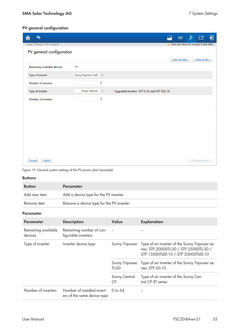
PV general configuration
Figure 19: General system settings of the PV power plant (example)
Buttons
Button Parameter
Add new item Add a device type for the PV inverter
Remove item Remove a device type for the PV inverter
Parameter
Parameter Description Value Explanation
Remaining availabledevices
Remaining number of con-figurable inverters
– –
Type of inverter Inverter device type Sunny Tripower Type of an inverter of the Sunny Tripower se-ries: STP 20000TL-30 / STP 25000TL-30 /STP 15000TLEE-10 / STP 20000TLEE-10
Sunny TripowerTL-60
Type of an inverter of the Sunny Tripower se-ries: STP 60-10
Sunny CentralCP
Type of an inverter of the Sunny Cen-tral CP XT series
Number of inverters Number of installed invert-ers of the same device type
0 to 64 –
7 System SettingsSMA Solar Technology AG
User Manual 55FSC20-BA-en-21

PV detailed configuration
Figure 20: Detailed system settings of the PV power plant (example)
Parameter Description Value Explanation Defaultvalue
Label Type label for identifying the in-verter
– – –
Enable this in-verter
Determines whether theFuel Save Controller should takethe inverter into account in thecontrol of the PV diesel hybridsystem.
Yes The Fuel Save Controllertakes the inverter into ac-count.
No
No The Fuel Save Controllerdoes not take the inverterinto account.
IP address IP address of the inverter 172.16.200.1 to172.16.200.64
Address range defined bythe Fuel Save Controller forinverters
–
Protocol Communication protocol used bythe inverter
Defined by Type ofinverter
See inverter documentation Definedby Typeof in-verterDifferent communica-
tion protocol
Modbus UnitID
Inverter ID for the Modbus/TCPprotocol
126 to 167 See inverter documentation –
7 System Settings SMA Solar Technology AG
User ManualFSC20-BA-en-2156
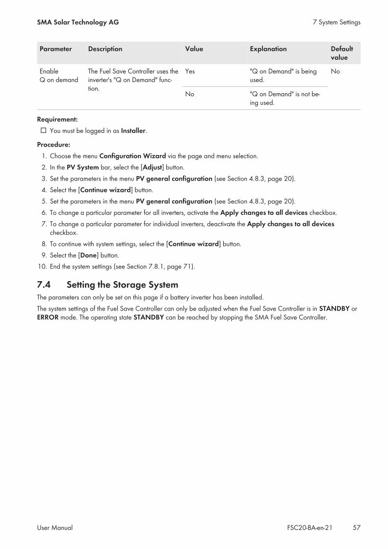
Parameter Description Value Explanation Defaultvalue
EnableQ on demand
The Fuel Save Controller uses theinverter's "Q on Demand" func-tion.
Yes "Q on Demand" is beingused.
No
No "Q on Demand" is not be-ing used.
Requirement:☐ You must be logged in as Installer.
Procedure:1. Choose the menu Configuration Wizard via the page and menu selection.2. In the PV System bar, select the [Adjust] button.3. Set the parameters in the menu PV general configuration (see Section 4.8.3, page 20).4. Select the [Continue wizard] button.5. Set the parameters in the menu PV general configuration (see Section 4.8.3, page 20).6. To change a particular parameter for all inverters, activate the Apply changes to all devices checkbox.7. To change a particular parameter for individual inverters, deactivate the Apply changes to all devices
checkbox.8. To continue with system settings, select the [Continue wizard] button.9. Select the [Done] button.
10. End the system settings (see Section 7.8.1, page 71).
7.4 Setting the Storage SystemThe parameters can only be set on this page if a battery inverter has been installed.The system settings of the Fuel Save Controller can only be adjusted when the Fuel Save Controller is in STANDBY orERROR mode. The operating state STANDBY can be reached by stopping the SMA Fuel Save Controller.
7 System SettingsSMA Solar Technology AG
User Manual 57FSC20-BA-en-21
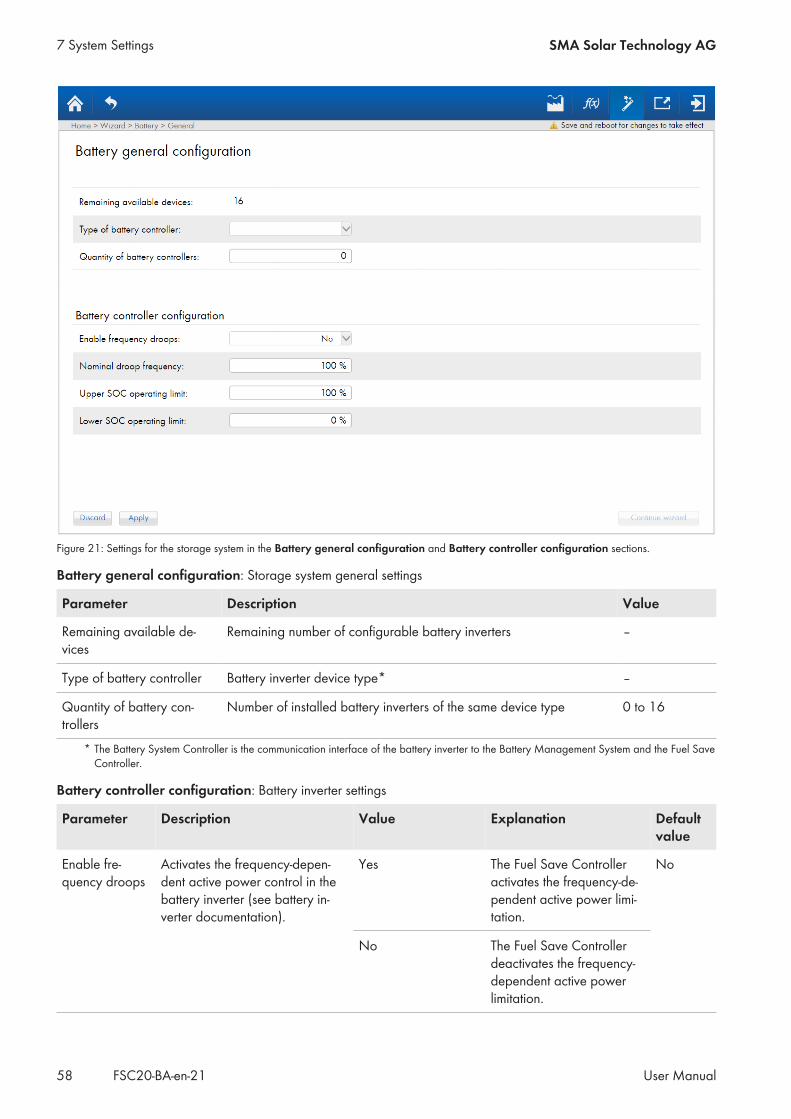
Figure 21: Settings for the storage system in the Battery general configuration and Battery controller configuration sections.
Battery general configuration: Storage system general settings
Parameter Description Value
Remaining available de-vices
Remaining number of configurable battery inverters –
Type of battery controller Battery inverter device type* –
Quantity of battery con-trollers
Number of installed battery inverters of the same device type 0 to 16
* The Battery System Controller is the communication interface of the battery inverter to the Battery Management System and the Fuel SaveController.
Battery controller configuration: Battery inverter settings
Parameter Description Value Explanation Defaultvalue
Enable fre-quency droops
Activates the frequency-depen-dent active power control in thebattery inverter (see battery in-verter documentation).
Yes The Fuel Save Controlleractivates the frequency-de-pendent active power limi-tation.
No
No The Fuel Save Controllerdeactivates the frequency-dependent active powerlimitation.
7 System Settings SMA Solar Technology AG
User ManualFSC20-BA-en-2158

Parameter Description Value Explanation Defaultvalue
Nominal droopfrequency
Power alteration proportionate tothe nominal power of the batteryinverter in the event of deviationfrom the mains nominal fre-quency
0% to 200% – 100 %
Upper SOC op-erating limit
Maximum battery state of chargeIf the maximum battery state ofcharge has been exceeded, thebattery is no longer charged withelectrical energy.
0% to 100% – 100 %
Lower SOC op-erating limit
Minimum battery state of chargeIf the battery state of charge fallsbelow the minimum value, nomore electrical energy is suppliedfrom the battery.
0% to 100% – 0 %
Requirement:☐ You must be logged in as Installer.
Procedure:1. Choose the menu Configuration Wizard via the page and menu selection.2. In the Battery system bar, select the [Adjust] button.3. Set the parameters in the Battery general configuration and Battery controller configuration sections (see
Section 4.8.3, page 20).4. To continue with system settings, select the [Continue wizard] button.5. Select the [Done] button.6. Activate monitoring for the state-of-charge limits Upper SOC operating limit and Lower SOC operating limit
(see Section 8.3.1, page 90).7. End the system settings (see Section 7.8.1, page 71).
7.5 Settings on the Measurement Devices
7.5.1 Making General Settings on Measurement DevicesThe system settings of the Fuel Save Controller can only be adjusted when the Fuel Save Controller is in STANDBY orERROR mode. The operating state STANDBY can be reached by stopping the SMA Fuel Save Controller.
7 System SettingsSMA Solar Technology AG
User Manual 59FSC20-BA-en-21
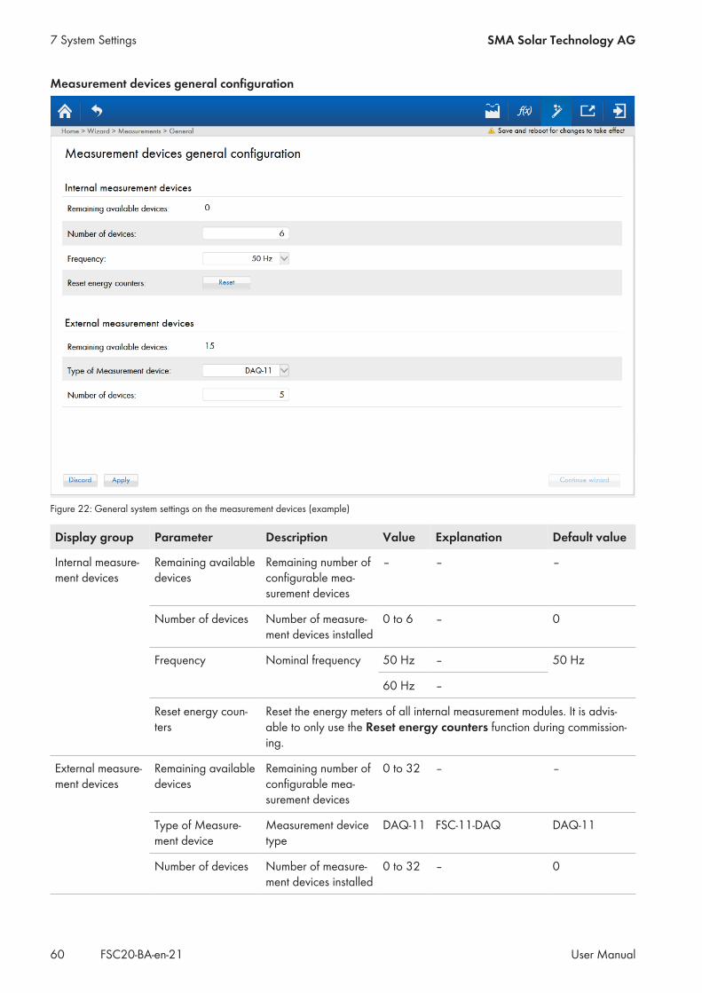
Measurement devices general configuration
Figure 22: General system settings on the measurement devices (example)
Display group Parameter Description Value Explanation Default value
Internal measure-ment devices
Remaining availabledevices
Remaining number ofconfigurable mea-surement devices
– – –
Number of devices Number of measure-ment devices installed
0 to 6 – 0
Frequency Nominal frequency 50 Hz – 50 Hz
60 Hz –
Reset energy coun-ters
Reset the energy meters of all internal measurement modules. It is advis-able to only use the Reset energy counters function during commission-ing.
External measure-ment devices
Remaining availabledevices
Remaining number ofconfigurable mea-surement devices
0 to 32 – –
Type of Measure-ment device
Measurement devicetype
DAQ-11 FSC-11-DAQ DAQ-11
Number of devices Number of measure-ment devices installed
0 to 32 – 0
7 System Settings SMA Solar Technology AG
User ManualFSC20-BA-en-2160
Requirement:☐ You must be logged in as Installer.
Procedure:1. Select the menu Configuration Wizard via the page and menu selection.2. In the Measurement System bar, select the [Adjust] button.3. To configure measurement devices that are connected via the internal measurement modules of the
SMA Fuel Save Controller, perform the following steps:• In the menu Measurement devices general configuration, set the parameters in the area Internal
measurement devices (see SMA Fuel Save Controller user manual).• Select the [Continue wizard] button. Doing so calls up the detailed system settings (see Section 7.5.2,
page 61).4. To configure measurement devices that are connected via a Data Acquisition Module, perform the following
steps:• In the menu Measurement devices general configuration, set the parameters in the area External
measurement devices (see SMA Fuel Save Controller user manual).• Select the [Continue wizard] button. Doing so calls up the detailed system settings (see Section 7.5.3,
page 64).
7.5.2 Making Detailed Settings on Measurement Devices for InternalMeasurement Modules of the SMA Fuel Save Controller
The system settings of the Fuel Save Controller can only be adjusted when the Fuel Save Controller is in STANDBY orERROR mode. The operating state STANDBY can be reached by stopping the SMA Fuel Save Controller.
7 System SettingsSMA Solar Technology AG
User Manual 61FSC20-BA-en-21
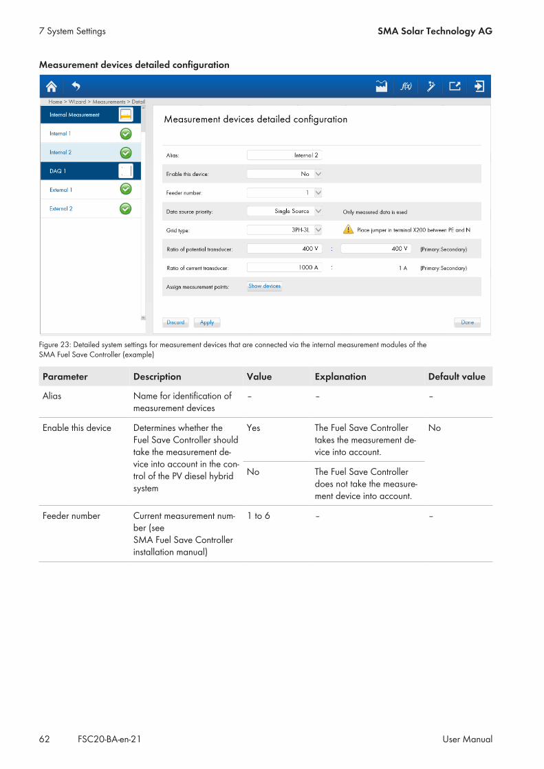
Measurement devices detailed configuration
Figure 23: Detailed system settings for measurement devices that are connected via the internal measurement modules of theSMA Fuel Save Controller (example)
Parameter Description Value Explanation Default value
Alias Name for identification ofmeasurement devices
– – –
Enable this device Determines whether theFuel Save Controller shouldtake the measurement de-vice into account in the con-trol of the PV diesel hybridsystem
Yes The Fuel Save Controllertakes the measurement de-vice into account.
No
No The Fuel Save Controllerdoes not take the measure-ment device into account.
Feeder number Current measurement num-ber (seeSMA Fuel Save Controllerinstallation manual)
1 to 6 – –
7 System Settings SMA Solar Technology AG
User ManualFSC20-BA-en-2162

Parameter Description Value Explanation Default value
Data source priority Use of the measured valuesfrom the Fuel Save Con-troller in the event of a com-munication connection fail-ure
Single source Connection to the devicecarrying out the measure-ments is disabled. Only themeasured values from theFuel Save Controller areused.
–
Second source Connection to the devicecarrying out the measure-ments is enabled. The val-ues communicated by thedevice have priority. If com-munication fails, the mea-sured values from theFuel Save Controller areused.
Measurementpriority
Connection to the devicecarrying out the measure-ments is enabled. The val-ues measured by theFuel Save Controller havepriority. In case of measure-ment failure, the valuescommunicated by the de-vice are used.
Grid type Type of grid used for cur-rent and voltage measure-ment
3PH-3L Three-conductor utility gridwith three line conductors
–
3PH-4L Four-conductor utility gridwith three line conductorsand one neutral conductor
Ratio of potentialtransducer
Transformation ratio forvoltage measurement
The requirements of the measurement inputs must be compliedwith (see installation manual of the Fuel Save Controller).
Ratio of current trans-ducer
Transformation ratio for cur-rent measurement
The requirements of the measurement inputs must be compliedwith (see installation manual of the Fuel Save Controller).
Assign measurementpoints
Overview of the activateddevices, e.g. PV inverters
Devices can be activated or deactivated for the selected mea-surement device via the button [Show devices].
Requirement:☐ You must be logged in as Installer.☐ You must have performed all necessary settings in the area Internal measurement devices in the menu
Measurement devices general configurations (see Section 7.5.1, page 59).
Procedure:1. Set the desired parameters in the menu Measurement devices general configurations (see
SMA Fuel Save Controller user manual).2. To activate or deactivate devices for the selected measurement device, select the button [Show devices] in the
Assign measurement points bar (see Section 7.5.4, page 66).
7 System SettingsSMA Solar Technology AG
User Manual 63FSC20-BA-en-21

3. To continue with system settings, select the [Continue wizard] button.4. Select the [Done] button.5. End the system settings (see Section 7.8.1, page 71).
7.5.3 Making Detailed Settings on Measurement Devices forData Acquisition Modules
The parameters can only be set on this page if a Data Acquisition Module has been installed.The system settings of the Fuel Save Controller can only be adjusted when the Fuel Save Controller is in STANDBY orERROR mode. The operating state STANDBY can be reached by stopping the SMA Fuel Save Controller.
Measurement devices detailed configuration
Figure 24: Detailed system settings for measurement devices that are connected via a Data Acquisition Module (example)
Parameter Description Value Explanation Default value
Alias Name for identification ofmeasurement devices
– – –
Enable this device Determines whether theFuel Save Controller shouldtake the measurement de-vice into account in the con-trol of the PV diesel hybridsystem
Yes The Fuel Save Controllertakes the measurement de-vice into account.
No
No The Fuel Save Controllerdoes not take the measure-ment device into account.
IP address IP address of the Data Ac-quisition Module
172.16.0.0 to172.17.255.255
The IP address of theData Acquisition Module isdefined during commission-ing.
–
7 System Settings SMA Solar Technology AG
User ManualFSC20-BA-en-2164
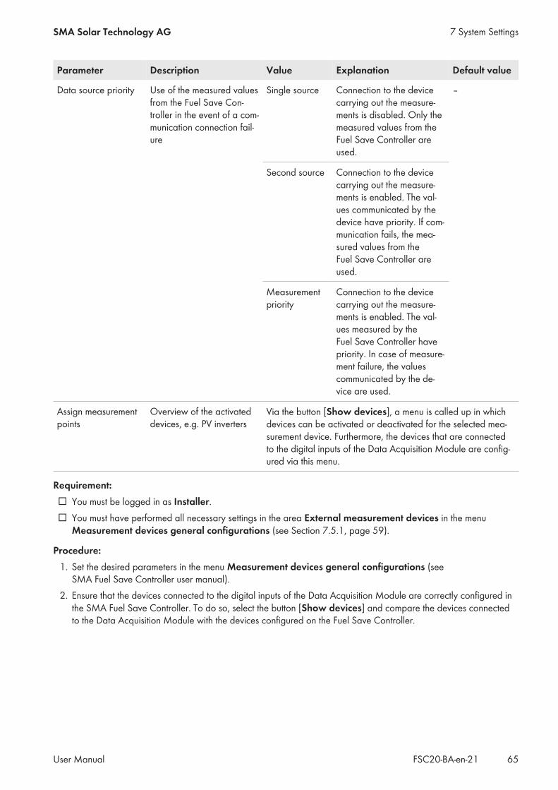
Parameter Description Value Explanation Default value
Data source priority Use of the measured valuesfrom the Fuel Save Con-troller in the event of a com-munication connection fail-ure
Single source Connection to the devicecarrying out the measure-ments is disabled. Only themeasured values from theFuel Save Controller areused.
–
Second source Connection to the devicecarrying out the measure-ments is enabled. The val-ues communicated by thedevice have priority. If com-munication fails, the mea-sured values from theFuel Save Controller areused.
Measurementpriority
Connection to the devicecarrying out the measure-ments is enabled. The val-ues measured by theFuel Save Controller havepriority. In case of measure-ment failure, the valuescommunicated by the de-vice are used.
Assign measurementpoints
Overview of the activateddevices, e.g. PV inverters
Via the button [Show devices], a menu is called up in whichdevices can be activated or deactivated for the selected mea-surement device. Furthermore, the devices that are connectedto the digital inputs of the Data Acquisition Module are config-ured via this menu.
Requirement:☐ You must be logged in as Installer.☐ You must have performed all necessary settings in the area External measurement devices in the menu
Measurement devices general configurations (see Section 7.5.1, page 59).
Procedure:1. Set the desired parameters in the menu Measurement devices general configurations (see
SMA Fuel Save Controller user manual).2. Ensure that the devices connected to the digital inputs of the Data Acquisition Module are correctly configured in
the SMA Fuel Save Controller. To do so, select the button [Show devices] and compare the devices connectedto the Data Acquisition Module with the devices configured on the Fuel Save Controller.
7 System SettingsSMA Solar Technology AG
User Manual 65FSC20-BA-en-21

Example: Configuration of the Digital Inputs of the Data Acquisition Module on theFuel Save Controller
If the genset 1 is connected to digital input DI 1 on the Data Acquisition Module and the utility grid is connectedto digital input DI 2, then the settings on the SMA Fuel Save Controller are correct in this example.If the utility grid is connected to digital input DI 1 on the Data Acquisition Module and the genset 1 is connectedto digital input DI 2, then the settings on the SMA Fuel Save Controller are incorrect in this example. Incorrectlyconfigured devices must be deactivated and reactivated with the correct settings.
3. To activate or deactivate devices for the selected measurement device, select the button [Show devices] in theAssign measurement points bar (see Section 7.5.4, page 66).
4. To continue with system settings, select the [Continue wizard] button.5. Select the [Done] button.6. End the system settings (see Section 7.8.1, page 71).
7.5.4 Activating/Deactivating DevicesThe system settings of the Fuel Save Controller can only be adjusted when the Fuel Save Controller is in STANDBY orERROR mode. The operating state STANDBY can be reached by stopping the SMA Fuel Save Controller.
Requirement:☐ You must be logged in as Installer.
Procedure:1. Select the menu Configuration Wizard via the page and menu selection.2. In the Measurement System bar, click on the button [Adjust].3. In the menu Measurement devices general configuration, first click on the button [Apply] and then on the
button [Continue wizard]. This opens the menu Measurement devices detailed configuration.4. In the Assign measurement points bar, click on the button [Show devices].5. To add a device, perform the following steps:
7 System Settings SMA Solar Technology AG
User ManualFSC20-BA-en-2166

• Select the appropriate subsystem via Select a subsystem.• In the area Select a measurement point select either one available device or all available devices:
– To select one available device, activate the checkbox for this device.– To select all available devices, activate the checkbox Select all.
• Click on the button [Add >>].• Click on the button [Apply and close].
6. To remove a device, perform the following steps:• In the area Select a measurement point select either one active device or all active devices:
– To select one active device, activate the checkbox for this device.– To select all active devices, activate the checkbox Select all.
• Click on the button [<< Remove].• Click on the button [Apply and close].
7.6 Setting the Temperature and Irradiation SensorsThe system settings of the Fuel Save Controller can only be adjusted when the Fuel Save Controller is in STANDBY orERROR mode. The operating state STANDBY can be reached by stopping the SMA Fuel Save Controller.
Meteorologic general configuration
Figure 25: System settings for the temperature and irradiation sensors
Parameter Description Value Explanation Defaultvalue
Remaining availabledevices
Remaining number of config-urable temperature and irradia-tion sensors
– – –
Number of devices Number of temperature and irra-diation sensors installed
0 to 6 – 0
7 System SettingsSMA Solar Technology AG
User Manual 67FSC20-BA-en-21

Parameter Description Value Explanation Defaultvalue
Device type Type of temperature and irradia-tion sensors
SMA Me-teo Sta-tion
Interface to the SMA Cluster Con-troller or SMA Inverter Manager
SMA Me-teo Sta-tion
SMA Me-teo Sta-tion Mod-bus TCP
Only make adjustments afterprior consultation with SMA So-lar Technology AG
SunspecMini MetModel
Communication interface speci-fied according to SunSpec Mod-bus
Requirement:☐ You must be logged in as Installer.
Procedure:1. Choose the menu Configuration Wizard via the page and menu selection.2. In the Meteorological data bar, select the [Adjust] button.3. Set the parameters in the menu Meteorologic general configuration (see Section 4.8.3, page 20).4. To continue with system settings, select the [Continue wizard] button.5. Select the [Done] button.6. End the system settings (see Section 7.8.1, page 71).
7.7 Configuring Stop of the Fuel Save Controller via Switch Input DI 7The system settings of the Fuel Save Controller can only be adjusted when the Fuel Save Controller is in STANDBY orERROR mode. The operating state STANDBY can be reached by stopping the SMA Fuel Save Controller.
7 System Settings SMA Solar Technology AG
User ManualFSC20-BA-en-2168

Figure 26: System settings for digital input and outputs
Digital Input/Output Configuration
Parameter Description Value Explanation Defaultvalue
Use digital in-put 7 to stopthe FSC system
Stop of Fuel SaveController via switchinput DI 7*
Activated Switch input DI 7 is used to stop theFuel Save Controller.When this function is activated, the pa-rameters Signal mode and Stopmode appear.
Activated
Deactivated Switch input DI 7 is not used to stop theFuel Save Controller. The parametersSignal mode and Stop mode disap-pear.
Signal mode Tripping signal orswitching procedure
Normally open Tripping signal is activation of the con-nected signal generator.
Normallyclosed
Normally closed Tripping signal is deactivation of theconnected signal generator.
7 System SettingsSMA Solar Technology AG
User Manual 69FSC20-BA-en-21

Parameter Description Value Explanation Defaultvalue
Stop mode Stop mode Fast stop Fast stop: PV power plant is discon-nected from the utility grid immediately.
Fast stop
Slow Stop Slow stop: the output power of the PVpower plant is reduced gradually andthen the PV power plant is discon-nected from the grid.
* To enable use of this function, switch input DI 7 must be connected (see Fuel Save Controller installation manual).
Custom Inputs
Parameter Description
Custom Input DI9 Freely configurable digital input to which special functions can be assigned:• No function• Feedback from the generator switch of genset 7
Custom Input DI10 Freely configurable digital input to which special functions can be assigned:• No function• Feedback from the generator switch of genset 8
Destruction of gensets due to insufficient reserve powerOnce the SMA Fuel Save Controller and PV power plant have stopped, the PV power plant is no longer available asenergy supplier. Now only the gensets supply the loads. If the current reserve power of the gensets is insufficient forsupplying the power required by the loads, the gensets become overloaded Sustained overload of the gensets canresult in failure of the power supply and destruction of the gensets.
• Check whether the current reserve power of the gensets is sufficient for supplying the power required by theloads.
• If the current reserve power of the gensets is insufficient, switch off the loads or connect additional gensets. Thisincreases the reserve power of the gensets.
• If sufficient reserve power of the gensets cannot be ensured in operation, do not use the switch input DI 7 of theFuel Save Controller (Fast Stop contact of the PV power plant).
Requirement:☐ You must be logged in as Installer.
Procedure:1. Choose the menu Configuration Wizard via the page and menu selection.2. In the Digital Input/Output bar, select the [Adjust] button.3. To enable the stop of the Fuel Save Controller via switch input DI 7, activate checkbox Use digital input 7 to
stop the FSC system.4. To disable the stop of the Fuel Save Controller via switch input DI 7, deactivate checkbox Use digital input 7 to
stop the FSC system.5. If the checkbox Use digital input 7 to stop the FSC system is activated, configure the desired values for
stopping the Fuel Save Controller via switch input DI 7 in the dropdown lists Signal mode and Stop mode.
7 System Settings SMA Solar Technology AG
User ManualFSC20-BA-en-2170
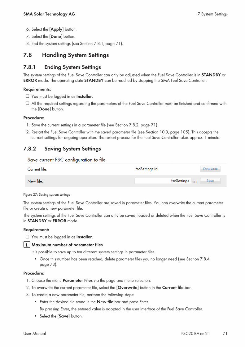
6. Select the [Apply] button.7. Select the [Done] button.8. End the system settings (see Section 7.8.1, page 71).
7.8 Handling System Settings
7.8.1 Ending System SettingsThe system settings of the Fuel Save Controller can only be adjusted when the Fuel Save Controller is in STANDBY orERROR mode. The operating state STANDBY can be reached by stopping the SMA Fuel Save Controller.
Requirements:☐ You must be logged in as Installer.☐ All the required settings regarding the parameters of the Fuel Save Controller must be finished and confirmed with
the [Done] button.
Procedure:1. Save the current settings in a parameter file (see Section 7.8.2, page 71).2. Restart the Fuel Save Controller with the saved parameter file (see Section 10.3, page 105). This accepts the
current settings for ongoing operation. The restart process for the Fuel Save Controller takes approx. 1 minute.
7.8.2 Saving System Settings
Figure 27: Saving system settings
The system settings of the Fuel Save Controller are saved in parameter files. You can overwrite the current parameterfile or create a new parameter file.The system settings of the Fuel Save Controller can only be saved, loaded or deleted when the Fuel Save Controller isin STANDBY or ERROR mode.
Requirement:☐ You must be logged in as Installer.
Maximum number of parameter filesIt is possible to save up to ten different system settings in parameter files.
• Once this number has been reached, delete parameter files you no longer need (see Section 7.8.4,page 73).
Procedure:1. Choose the menu Parameter Files via the page and menu selection.2. To overwrite the current parameter file, select the [Overwrite] button in the Current file bar.3. To create a new parameter file, perform the following steps:
• Enter the desired file name in the New file bar and press Enter.By pressing Enter, the entered value is adopted in the user interface of the Fuel Save Controller.
• Select the [Save] button.
7 System SettingsSMA Solar Technology AG
User Manual 71FSC20-BA-en-21

7.8.3 Loading System Settings
Figure 28: Loading or deleting system settings
The system settings of the Fuel Save Controller can only be saved, loaded or deleted when the Fuel Save Controller isin STANDBY or ERROR mode.After a software update, the Fuel Save Controller restores automatically the system settings from the file that has beensaved last. Due to the newly added parameters in the new software version, the Fuel Save Controller remains in theoperating state ERROR and signals the error 2069 until the system settings are saved again and the system has beenrestarted.The new parameters, which have been added through an update, can be found in the respective release notes that areincluded in the software update package.
Requirements:☐ You must be logged into the user interface as Installer.☐ The Fuel Save Controller and PV power plant must have been stopped (see Section 10.1, page 104).
Power supply failure when the SMA Fuel Save Controller is restartedBefore restarting the SMA Fuel Save Controller, the SMA Fuel Save Controller and PV power plant must be stopped.It can take a few minutes for the SMA Fuel Save Controller and PV power plant to stop because the PV invertershave to reduce their output power slowly. If the PV inverters are still feeding energy to the grid when the SMA FuelSave Controller is restarted, this may cause failure of the power supply.
• Once the SMA Fuel Save Controller has stopped, wait until the PV inverters have reduced their output power tozero. This can take several minutes.
Procedure:1. Choose the menu Parameter Files via the page and menu selection.2. Only if no parameter file is selected, the Fuel Save Controller can be restarted with a parameter file:
• Select a parameter file in the drop-down list File database.• In the Reboot with a selected file bar, select the [Reboot] button.
3. To overwrite the current parameter file, select the [Overwrite] button in the Current file bar.4. Choose the parameter file with the required system settings via the dropdown list File database.5. In the Reboot with a selected file bar, select the [Reboot] button.
7 System Settings SMA Solar Technology AG
User ManualFSC20-BA-en-2172
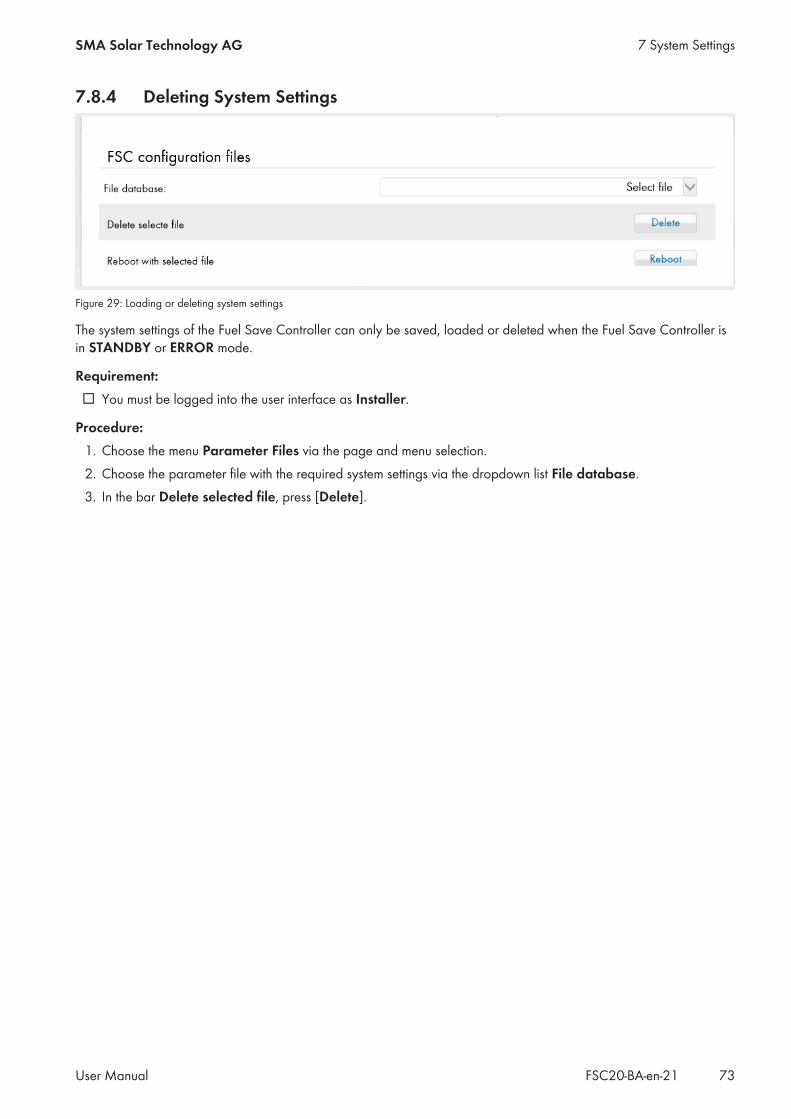
7.8.4 Deleting System Settings
Figure 29: Loading or deleting system settings
The system settings of the Fuel Save Controller can only be saved, loaded or deleted when the Fuel Save Controller isin STANDBY or ERROR mode.
Requirement:☐ You must be logged into the user interface as Installer.
Procedure:1. Choose the menu Parameter Files via the page and menu selection.2. Choose the parameter file with the required system settings via the dropdown list File database.3. In the bar Delete selected file, press [Delete].
7 System SettingsSMA Solar Technology AG
User Manual 73FSC20-BA-en-21

8 System Control
8.1 Genset control
8.1.1 Configuring the Minimum Genset Load ThresholdParameter overview
Figure 30: Minimum Genset Load: Settings regarding the minimum load of the genset
Parameter Description Value Explanation Defaultvalue
DbTolPc Deadband for error output re-lated to the minimum genset load-ing threshold in %.
-100% to 100% – 10 %
DbTolTm Deadband timer for error outputin seconds
0.1 s to 3600 s – 60 s
GenPwrAtMinPc Minimum genset loading of thegenset system in % of the nominalgenset active power
0% to 100% – 30 %
8 System Control SMA Solar Technology AG
User ManualFSC20-BA-en-2174

Parameter Description Value Explanation Defaultvalue
RampTmGenPwrAt-Nom
Ramp time of the change in thenominal genset active power inseconds
1 s to 60 s – 10 s
SpntOfsPc Setpoint offset related to the mini-mum genset loading threshold in%
-100% to 100% – 0 %
Requirement:☐ You must be logged in as Installer.
Procedure:1. Go to Control Functions > Genset control functions > Minimum genset load via the page and menu
selection.2. Set the desired parameters (see Section 4.8.3, page 20).
8 System ControlSMA Solar Technology AG
User Manual 75FSC20-BA-en-21
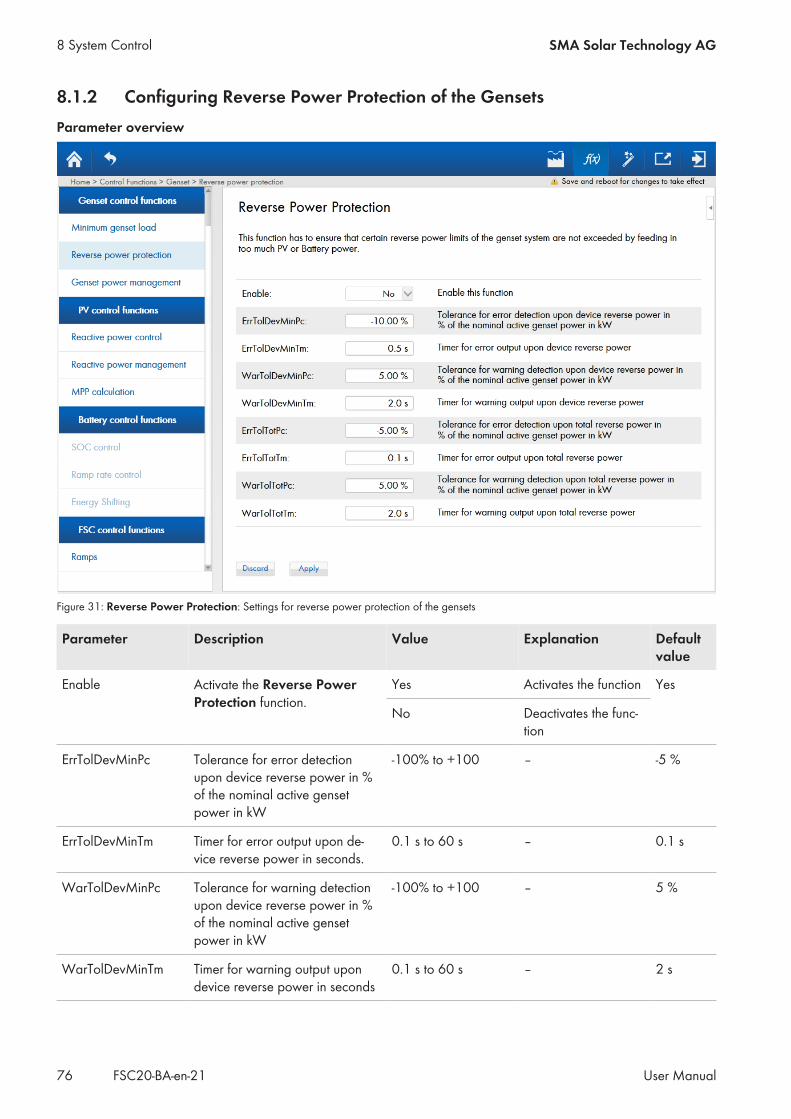
8.1.2 Configuring Reverse Power Protection of the GensetsParameter overview
Figure 31: Reverse Power Protection: Settings for reverse power protection of the gensets
Parameter Description Value Explanation Defaultvalue
Enable Activate the Reverse PowerProtection function.
Yes Activates the function Yes
No Deactivates the func-tion
ErrTolDevMinPc Tolerance for error detectionupon device reverse power in %of the nominal active gensetpower in kW
-100% to +100 – -5 %
ErrTolDevMinTm Timer for error output upon de-vice reverse power in seconds.
0.1 s to 60 s – 0.1 s
WarTolDevMinPc Tolerance for warning detectionupon device reverse power in %of the nominal active gensetpower in kW
-100% to +100 – 5 %
WarTolDevMinTm Timer for warning output upondevice reverse power in seconds
0.1 s to 60 s – 2 s
8 System Control SMA Solar Technology AG
User ManualFSC20-BA-en-2176

Parameter Description Value Explanation Defaultvalue
ErrTolTotPc Tolerance for error detectionupon total reverse power in % ofthe nominal active genset powerin kW
-100% to +100 – -5 %
ErrTolTotTm Timer for error output upon totalreverse power in seconds
0.1 s to 60 s – 0.1 s
WarTolTotPc Tolerance for warning detectionupon total reverse power in % ofthe nominal active genset powerin kW
-100% to +100 – 5 %
WarTolTotTm Timer for warning output upon to-tal reverse power in seconds
0.1 s to 60 s – 2 s
Requirement:☐ You must be logged in as Installer.
Power supply failure caused by unexpected stop of a genset due to reverse power protectionTo ensure that a genset is protected from backfeed damage, reverse power protection must be enabled andconfigured in the Fuel Save Controller and the genset. The parameters on the Fuel Save Controller and the gensetmust be configured so that the reverse power protection is always triggered at the Fuel Save Controller first. If thereverse power protection first triggers in the genset, this results in an unexpected stop of the genset which cannot beforeseen by the Fuel Save Controller. The unexpected stop of a genset may result in a power failure in the entire PVdiesel hybrid system.
• Only use gensets with reverse power protection which fulfill the reverse power limits of the Fuel Save Controller(see installation manual of the SMA Fuel Save Controller).
• Ensure that the reverse power protection of the gensets is always active when operating theFuel Save Controller.
• Adjust the reverse power protection parameters to ensure that reverse power protection always triggers first atthe Fuel Save Controller and only then at the genset.
Procedure:1. Go to Control Functions > Genset control functions > Reverse power management via the page and
menu selection.2. Set the desired parameters (see Section 4.8.3, page 20).
8 System ControlSMA Solar Technology AG
User Manual 77FSC20-BA-en-21

8.1.3 Setting the Supply of Sufficient Reserve Power via GensetsParameter overview
Figure 32: Genset Power Management: Power management of gensets: settings for reserve power
Parameter Description Value Explanation Defaultvalue
Enable Activates the Genset PowerManagement function.
Yes Activates the function Yes
No Deactivates the function
8 System Control SMA Solar Technology AG
User ManualFSC20-BA-en-2178

Parameter Description Value Explanation Defaultvalue
PwrMngmtMode Select the mode for powermanagement (for informationon power management, seetechnical information"Gensets in PV Diesel HybridSystems withSMA Fuel Save Controller2.0")
Off OffIf the function Genset setpointmechanism is activated, thisvalue is recommended (see Sec-tion 7.2.7, page 53)
Off
Relative to theremaininggensets
Relative power management ofgensets as a percentage of theactive genset load: In the case ofswitch-off, the remaining nominalpower of the gensets remainingafter switch-off is taken into ac-count.
Relative to theavailablegensets
Relative power management ofgensets as a percentage of theactive genset load: In the case ofswitch-off, the nominal power ofthe currently active gensets istaken into account.
Absolute PowerManagement
Absolute power management ofgensets to comply with a speci-fied absolute reserve power ofthe total system in kW.
GenTrshldTopPc Switch-on threshold for rela-tive genset power manage-ment in % of the /n activegenset nominal power.
10% to 110% – 90 %
GenTrshldTopAbs Switch-on threshold for abso-lute genset power manage-ment in kW
0 kW to100000 kW
– 10 kW
GenTrshldBotPc Switch-off threshold for rela-tive genset power manage-ment in relation to the activegenset nominal power in %
0% to 90% – 35 %
GenTrshldBotAbs Switch-off threshold for abso-lute genset power manage-ment in kW
0 kW to100000 kW
– 20 kW
SysTmResHigh System timer for detection ofexcessive reserve power pro-vided by the gensets
0 s to 900 s – 300 s
SysDbResHigh System deadband for exces-sive reserve power detectionin % of genset active nominalpower (positive values allevi-ate detection)
-100% to+100%
– 10 %
8 System ControlSMA Solar Technology AG
User Manual 79FSC20-BA-en-21

Parameter Description Value Explanation Defaultvalue
SysTmResLow System timer for detection ofinsufficient reserve power pro-vided by the gensets
0 s to 900 s – 90 s
SysDbResLow System deadband for insuffi-cient reserve power detectionin % of genset active nominalpower (positive values allevi-ate detection)
-100% to+100%
– 10 %
Figure 33: Genset Power Management: Power management of gensets: settings for reserve power (continued)
Parameter Description Value Explanation Defaultvalue
LoadPwrAtResReq Load required spinning reserverequest
0 kW to100000 kW
– 10 kW
8 System Control SMA Solar Technology AG
User ManualFSC20-BA-en-2180

Parameter Description Value Explanation Defaultvalue
SimultaneousPc Simultaneous factor for Gen-PwrAtResSpnt while PV is request-ing more ResPwr in % of LoadP-wrAtResThe value 0% means that theevents do not occur at the sametime. If the events do not occur atthe same time, the Fuel SaveController does not have to pro-vide as much reserve power.
0% to 100% – 50 %
BatPwrAtResMaxPc Percentage of the available re-serve power from battery systemwhich shall be considered for re-serve power management
0% to 120% – 70 %
GenResPwrThrsld Threshold for preventing over-loading of gensets by feeding inbattery reserve power. In relationto the genset's nominal power
50% to 120% 90 %
PvPwrAt-SafeModeMin
Minimum injected active PVpower, if system is in safe mode.
0 kW to100000 kW
– 0 kW
Requirement:☐ You must be logged in as Installer.
Destruction of gensets due to insufficient reserve powerOnce the SMA Fuel Save Controller and PV power plant have stopped, the PV power plant is no longer available asenergy supplier. Now only the gensets supply the loads. If the current reserve power of the gensets is insufficient forsupplying the power required by the loads, the gensets become overloaded Sustained overload of the gensets canresult in failure of the power supply and destruction of the gensets.
• Prior to stopping the Fuel Save Controller, always check whether the current reserve power of the gensets issufficient to cover the requirement of the loads.
– If the current reserve power of the gensets is insufficient, switch off the loads or connect additional gensets.This increases the reserve power of the gensets.
• If the power management and the communication interface of the genset is not compatible with theFuel Save Controller, power management must be deactivated on the Fuel Save Controller. In this case, thegensets must be monitored to ensure that sufficient reserve power is retained.
• Make sure that the setpoints for power management on the Fuel Save Controller and the gensets are set to thesame value.
Procedure:1. Go to Control Functions > Genset control functions > Genset power management via the page and menu
selection.2. Set the desired parameters (see Section 4.8.3, page 20).
8 System ControlSMA Solar Technology AG
User Manual 81FSC20-BA-en-21

8.2 Controlling the PV power plant
8.2.1 Setting the Power Factor Control for the Gensets Using the Reactive PowerRelease of the PV Inverters
Parameter overview
Figure 34: Reactive Power Control: Settings for power factor control of the gensets using the reactive power release of the PV inverters
Parameter Description Value Explanation Defaultvalue
Enable Enables this function. Yes Activates the function* Yes
No Deactivates the function
Point of interest Power factor setpoint for eitherthe genset system or the grid
Genset Control at connectionpoint of the genset sys-tem
Genset
Grid Control at the grid-con-nection point
CosPhiSpnt Power factor setpoint for eitherthe genset system or the grid
0.1 to 1 – 0.9
PropGain Proportional gain for the PI con-troller, a tuning parameter
0 to 10 – 0.1
8 System Control SMA Solar Technology AG
User ManualFSC20-BA-en-2182

Parameter Description Value Explanation Defaultvalue
IntGain Integral gain for the PI controller,a tuning parameter
0 to 10 – 0.1
TrackGain An anti windup parameter.Keep it around 50% of integralgain
0 to 10 – 0.05
BackcalcGain An anti windup parameter.Keep it around 50% of integralgain
0 to 10 – 0.05
EnableFeedForward Enables the feed forward algo-rithm
Yes Activates the feed for-ward
Yes
No Deactivates the feed for-ward
FeedForwardOffset A tuning parameter for the feedforward algorithm
-100000 kVAr to+100000 kVAr
– 0 kVAr
FeedForwardGain A tuning parameter for the feedforward algorithm
0 to 10 – 1
* When the function Reactive Power Control is activated, the function Reactive Power Management must be deactivated (seeSection 8.2.2, page 85).
8 System ControlSMA Solar Technology AG
User Manual 83FSC20-BA-en-21
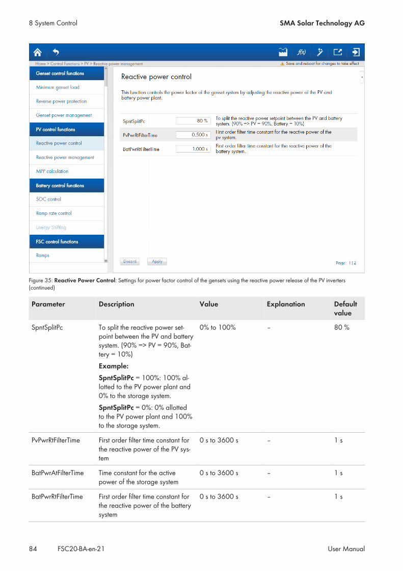
Figure 35: Reactive Power Control: Settings for power factor control of the gensets using the reactive power release of the PV inverters(continued)
Parameter Description Value Explanation Defaultvalue
SpntSplitPc To split the reactive power set-point between the PV and batterysystem. (90% => PV = 90%, Bat-tery = 10%)Example:SpntSplitPc = 100%: 100% al-lotted to the PV power plant and0% to the storage system.SpntSplitPc = 0%: 0% allottedto the PV power plant and 100%to the storage system.
0% to 100% – 80 %
PvPwrRtFilterTime First order filter time constant forthe reactive power of the PV sys-tem
0 s to 3600 s – 1 s
BatPwrAtFilterTime Time constant for the activepower of the storage system
0 s to 3600 s – 1 s
BatPwrRtFilterTime First order filter time constant forthe reactive power of the batterysystem
0 s to 3600 s – 1 s
8 System Control SMA Solar Technology AG
User ManualFSC20-BA-en-2184
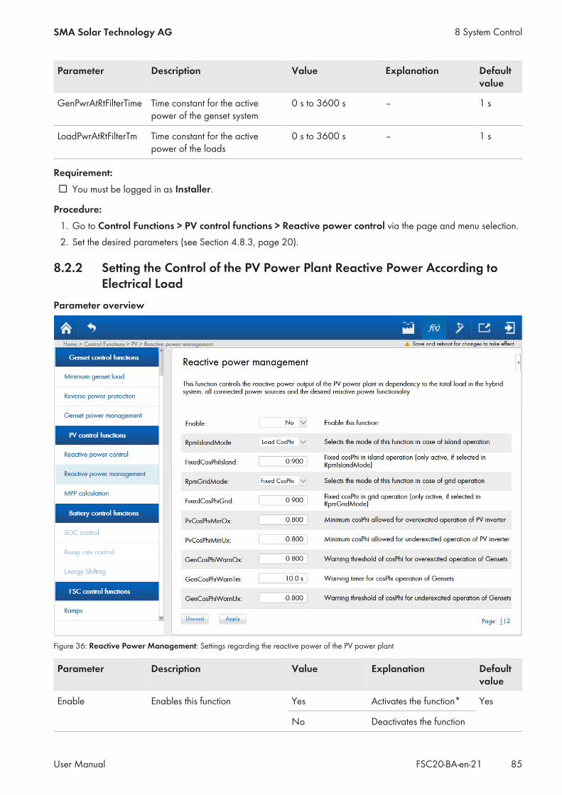
Parameter Description Value Explanation Defaultvalue
GenPwrAtRtFilterTime Time constant for the activepower of the genset system
0 s to 3600 s – 1 s
LoadPwrAtRtFilterTm Time constant for the activepower of the loads
0 s to 3600 s – 1 s
Requirement:☐ You must be logged in as Installer.
Procedure:1. Go to Control Functions > PV control functions > Reactive power control via the page and menu selection.2. Set the desired parameters (see Section 4.8.3, page 20).
8.2.2 Setting the Control of the PV Power Plant Reactive Power According toElectrical Load
Parameter overview
Figure 36: Reactive Power Management: Settings regarding the reactive power of the PV power plant
Parameter Description Value Explanation Defaultvalue
Enable Enables this function Yes Activates the function* Yes
No Deactivates the function
8 System ControlSMA Solar Technology AG
User Manual 85FSC20-BA-en-21
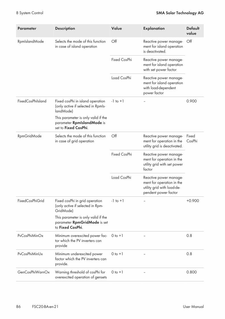
Parameter Description Value Explanation Defaultvalue
RpmIslandMode Selects the mode of this functionin case of island operation
Off Reactive power manage-ment for island operationis deactivated.
Off
Fixed CosPhi Reactive power manage-ment for island operationwith set power factor
Load CosPhi Reactive power manage-ment for island operationwith load-dependentpower factor
FixedCosPhiIsland Fixed cosPhi in island operation(only active if selected in RpmIs-landMode)This parameter is only valid if theparameter RpmIslandMode isset to Fixed CosPhi.
-1 to +1 – 0.900
RpmGridMode Selects the mode of this functionin case of grid operation
Off Reactive power manage-ment for operation in theutility grid is deactivated.
FixedCosPhi
Fixed CosPhi Reactive power manage-ment for operation in theutility grid with set powerfactor
Load CosPhi Reactive power manage-ment for operation in theutility grid with load-de-pendent power factor
FixedCosPhiGrid Fixed cosPhi in grid operation(only active if selected in Rpm-GridMode)This parameter is only valid if theparameter RpmGridMode is setto Fixed CosPhi.
-1 to +1 – +0.900
PvCosPhiMinOx Minimum overexcited power fac-tor which the PV inverters canprovide
0 to +1 – 0.8
PvCosPhiMinUx Minimum underexcited powerfactor which the PV inverters canprovide.
0 to +1 – 0.8
GenCosPhiWarnOx Warning threshold of cosPhi foroverexcited operation of gensets
0 to +1 – 0.800
8 System Control SMA Solar Technology AG
User ManualFSC20-BA-en-2186

Parameter Description Value Explanation Defaultvalue
GenCosPhiWarnTm Warning timer for cosPhi opera-tion of Gensets
0 s to 86400 s – 10.0 s
GenCosPhiWarnUx Warning threshold of cosPhi forunderexcited operation ofgensets
-1 to 0 – -0.800
* When the function Reactive Power Management is activated, the function Reactive Power Control must be deactivated (seeSection 8.2.1, page 82).
Figure 37: Reactive Power Management: Settings regarding the reactive power of the PV power plant (continued)
Parameter Description Value Explanation Defaultvalue
GridCosPhiWarnOx Warning threshold of cosPhi foroverexcited operation of grid
0 to +1 – 0.700
GridCosPhiWarnUx Warning threshold of cosPhi forunderexcited operation of grid
-1 to 0 – -0.700
GridCosPhiWarnTm Warning timer for cosPhi opera-tion of grid
0 s to 86400 s – 10.0 s
FixedCosPhiBat Fixed cosPhi in grid operation(only active if selected in Rpm-GridMode)
0 to 1 – 0.900
8 System ControlSMA Solar Technology AG
User Manual 87FSC20-BA-en-21
Requirement:☐ You must be logged in as Installer.
Procedure:1. Go to Control Functions > PV control functions > Reactive power management via the page and menu
selection.2. Set the desired parameters (see Section 4.8.3, page 20).
8.2.3 Configuring MPP Calculation for PV Power PlantThe accuracy of the determined MPP power is evaluated by the Fuel Save Controller during the run time. Theevaluation results are written to the error and event file and shown on the user interface in the error dialog at the endof the day.One of the three messages are generated once a day:
• #2122 - MPP accuracy: no evaluation due to small PV operation timeToday's operating time of the PV system was too short to carry out a proper evaluation.
• #2123 - MPP accuracy: negative/positive mismatch by xy/xy kWhA negative or positive deviation has occurred during the calculation of the MPP power. The deviation is shown inkWh by xy/xy. A negative deviation means that the MPP calculation is too low. A positive deviation means thatthe MPP calculation is too high.
• #2124 - MPP accuracy: achieved the expected accuracy of 10%The accuracy of the determined MPP lies within the required scope of 10%.
With this information, an adjustment of the parameters of the calculation is possible to increase accuracy.
8 System Control SMA Solar Technology AG
User ManualFSC20-BA-en-2188

Parameter overview
Figure 38: MPP Calculation: Specifications on the MPP calculation for the PV inverters
Parameter Description Value Default value
MppCalcGain In case of an inaccurate calculation of themaximum power point, it can be improved byadjusting this factor.
-1000 to +1000 1
MppCalcOffset In case of an inaccurate calculation of themaximum power point, it can be improved byadjusting this offset.
-100000 to+100000
0
MppNormOpCell-Temp
Normal operating cell temperature of the PVmodules. Use the PV module datasheet as areference.
-100°C to +100°C 25°C
MppPwrTempCoeff Power temperature coefficient of the PV mod-ules. Use the PV module datasheet as a refer-ence.
-10%/°C to +10%/°C
0.1% /°C
SafePctPv Base of MPP power which will always beavailable in case of PV drops in percentageof current MPP power
0% to 100% 20 %
CalcPvPwrAtMpp Estimated MPP power 0 kW to100000 kW
–
8 System ControlSMA Solar Technology AG
User Manual 89FSC20-BA-en-21

Requirement:☐ You must be logged in as Installer.
Procedure:1. Go to Control Functions > PV control functions > MPP calculation via the page and menu selection.2. Set the desired parameters (see Section 4.8.3, page 20).3. Make sure that the parameters MppNormOpCellTemp and MppPwrTempCoeff are set in accordance with
the technical data of the PV module (see manufacturer documentation). Setting the parametersMppNormOpCellTemp and MppPwrTempCoeff in accordance with the technical data of the PV modulesenables a reliable estimation of the PV power from the Fuel Save Controller.
8.3 Controlling the Battery Inverter
8.3.1 Setting the State-Of-Charge Control of the BatteryThe parameters of the function State of charge can only be set if a battery inverter has been installed.
Parameter overview
Figure 39: State of charge: Settings regarding the thresholds for the state of charge of the battery
Parameter Description Value Explanation Defaultvalue
Enable Enables this function Yes Activates the function Yes
No Deactivates the func-tion
8 System Control SMA Solar Technology AG
User ManualFSC20-BA-en-2190
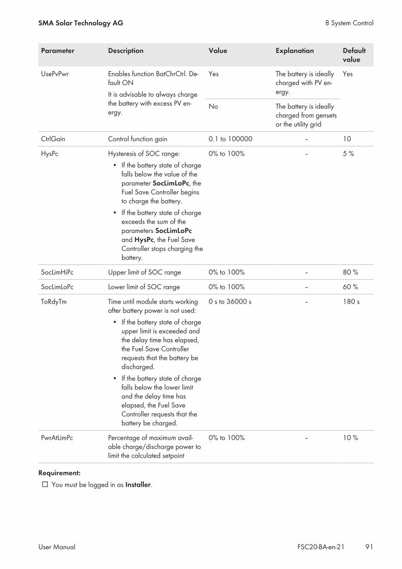
Parameter Description Value Explanation Defaultvalue
UsePvPwr Enables function BatChrCtrl. De-fault ONIt is advisable to always chargethe battery with excess PV en-ergy.
Yes The battery is ideallycharged with PV en-ergy.
Yes
No The battery is ideallycharged from gensetsor the utility grid
CtrlGain Control function gain 0.1 to 100000 – 10
HysPc Hysteresis of SOC range:• If the battery state of charge
falls below the value of theparameter SocLimLoPc, theFuel Save Controller beginsto charge the battery.
• If the battery state of chargeexceeds the sum of theparameters SocLimLoPcand HysPc, the Fuel SaveController stops charging thebattery.
0% to 100% – 5 %
SocLimHiPc Upper limit of SOC range 0% to 100% – 80 %
SocLimLoPc Lower limit of SOC range 0% to 100% – 60 %
ToRdyTm Time until module starts workingafter battery power is not used:
• If the battery state of chargeupper limit is exceeded andthe delay time has elapsed,the Fuel Save Controllerrequests that the battery bedischarged.
• If the battery state of chargefalls below the lower limitand the delay time haselapsed, the Fuel SaveController requests that thebattery be charged.
0 s to 36000 s – 180 s
PwrAtLimPc Percentage of maximum avail-able charge/discharge power tolimit the calculated setpoint
0% to 100% – 10 %
Requirement:☐ You must be logged in as Installer.
8 System ControlSMA Solar Technology AG
User Manual 91FSC20-BA-en-21

Procedure:1. Go to Control Functions > Battery control functions > SOC control via the page and menu selection.2. Set the desired parameters (see Section 4.8.3, page 20).
8.3.2 Setting the Setpoints for the Storage System According to the Rise andDrop of PV Power
The parameters of the function Ramp rate control can only be set if a battery inverter has been installed.
When using a storage system in PV diesel hybrid systems: Measurement of PV power via themeasurement inputs of the Fuel Save ControllerIf a storage system is implemented in the PV diesel hybrid system, the Fuel Save Controller has to calculate thesetpoints of the storage system for the charging and discharging of the battery depending on the PV power. Tocorrectly calculate the setpoints, the Fuel Save Controller requires the data of the PV power in a very hightemporal resolution.For this, a current measurement input and a voltage measurement input of the Fuel Save Controller or of theoptional Data Acquisition Module must be used for capturing the PV power. The data transmitted via the internalcommunication network of the PV diesel hybrid system do not have the required resolution.
8 System Control SMA Solar Technology AG
User ManualFSC20-BA-en-2192
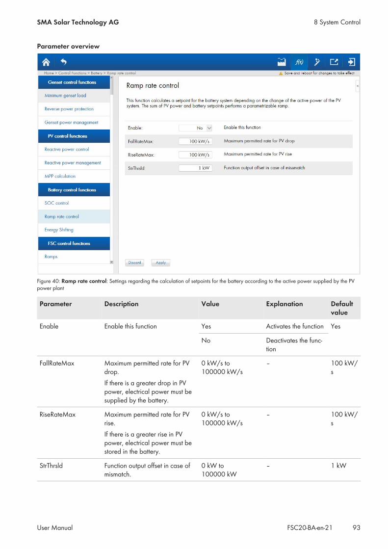
Parameter overview
Figure 40: Ramp rate control: Settings regarding the calculation of setpoints for the battery according to the active power supplied by the PVpower plant
Parameter Description Value Explanation Defaultvalue
Enable Enable this function Yes Activates the function Yes
No Deactivates the func-tion
FallRateMax Maximum permitted rate for PVdrop.If there is a greater drop in PVpower, electrical power must besupplied by the battery.
0 kW/s to100000 kW/s
– 100 kW/s
RiseRateMax Maximum permitted rate for PVrise.If there is a greater rise in PVpower, electrical power must bestored in the battery.
0 kW/s to100000 kW/s
– 100 kW/s
StrThrsld Function output offset in case ofmismatch.
0 kW to100000 kW
– 1 kW
8 System ControlSMA Solar Technology AG
User Manual 93FSC20-BA-en-21

Requirements:☐ You must be logged in as Installer.
Procedure:1. Go to Control Functions > Battery control functions > Ramp rate control via the page and menu selection.2. Set the desired parameters (see Section 4.8.3, page 20).
8.3.3 Setting the Charge/Discharge of the Battery According to the Rise/Drop inPV Power
The parameters of the function Energy Shifting can only be set if a battery inverter has been installed.
Parameter overview
Figure 41: Energy Shifting: Settings for charging the battery using PV energy
Parameter Description Value Explanation Defaultvalue
Enable Enables this function Yes Activates the function Yes
No Deactivates the func-tion
8 System Control SMA Solar Technology AG
User ManualFSC20-BA-en-2194

Parameter Description Value Explanation Defaultvalue
ChrFromPvSpntLimPc Charging the battery from PV islimited by this value based on themaximum charge power of thebattery systemThe battery is charged whenthere is surplus PV energy. Thecharging setpoint of the storagesystem is limited to this value.
0% to 100% – 10 %
DisBatSpntLimPc Amount of power provided bythe battery based on the maxi-mum discharge power of the bat-tery systemThe buffered energy is releasedby the storage system if too littlePV power is available. The set-point for discharging the batteryis limited to this value.
0% to 100% – 10 %
MinDisTm Minimum time for the battery toprovide powerThe energy required must bestored in the battery.
60 s to 200000 s – 1800 s
Requirement:☐ You must be logged in as Installer.
Procedure:1. Go to Control Functions > Battery control functions > Energy Shifting via the page and menu selection.2. Set the desired parameters (see Section 4.8.3, page 20).
8 System ControlSMA Solar Technology AG
User Manual 95FSC20-BA-en-21

8.4 Controlling the Fuel Save Controller
8.4.1 Configuring Setpoint Change Rate for PV inverters and GensetsParameter overview
Figure 42: Ramps: Settings for the setpoint change rate for inverters and gensets
Parameter Description Value Default value
GenPwrMngmtTran-sRamp
Maximum rate of active power setpoint forPV system in case of too low reserve power.
0%/s to 100%/s 5%/s
PvPwrAtFallRateMax Maximum negative rate of the active powersetpoint for PV inverters in percent per sec-ond (%/s) of related nominal inverter power
0%/s to 1000%/s 20%/s
PvPwrAtRiseRateMax Maximum positive rate of the active powersetpoint for PV inverters in percent per sec-ond (%/s) of related nominal inverter power
0%/s to 1000%/s 5%/s
PvPwrRtFallRateMax Maximum negative rate of the active powersetpoint for PV inverters in percent per sec-ond (%/s) of related nominal inverter power
0%/s to 1000%/s 20%/s
PvPwrRtRiseRateMax Maximum positive rate of the reactive powersetpoint for PV inverters in percent per sec-ond (%/s) of related nominal inverter power.
0%/s to 1000%/s 20%/s
8 System Control SMA Solar Technology AG
User ManualFSC20-BA-en-2196
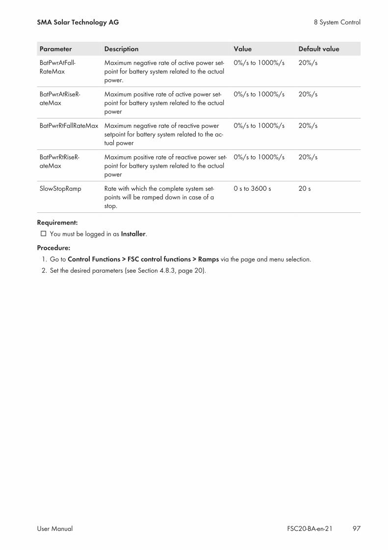
Parameter Description Value Default value
BatPwrAtFall-RateMax
Maximum negative rate of active power set-point for battery system related to the actualpower.
0%/s to 1000%/s 20%/s
BatPwrAtRiseR-ateMax
Maximum positive rate of active power set-point for battery system related to the actualpower
0%/s to 1000%/s 20%/s
BatPwrRtFallRateMax Maximum negative rate of reactive powersetpoint for battery system related to the ac-tual power
0%/s to 1000%/s 20%/s
BatPwrRtRiseR-ateMax
Maximum positive rate of reactive power set-point for battery system related to the actualpower
0%/s to 1000%/s 20%/s
SlowStopRamp Rate with which the complete system set-points will be ramped down in case of astop.
0 s to 3600 s 20 s
Requirement:☐ You must be logged in as Installer.
Procedure:1. Go to Control Functions > FSC control functions > Ramps via the page and menu selection.2. Set the desired parameters (see Section 4.8.3, page 20).
8 System ControlSMA Solar Technology AG
User Manual 97FSC20-BA-en-21

8.4.2 Options for Specifying the Reserve Power Setpoint of the GensetsParameter overview
Figure 43: Genset Setpoints: Specification of setpoints for gensets
Parameter Description Value Default value
GenSpntTrigPctNeg The reserve power setpoint will be transmit-ted immediately to the genset system if a neg-ative change of the setpoint is greater thanthis percentage of the connected nominalGenset power.
0% to 10000% 20 %
GenSpntTrigPctPos The reserve power setpoint will be transmit-ted immediately to the genset system if a pos-itive change of the setpoint is greater thanthis percentage of the connected nominalGenset power.
0% to 10000% 20 %
GenSpntTrigTm The reserve power setpoint for the Gensetsystem will be transmitted /n cyclical afterthis time in seconds.
0.1 s to 3600 s 120 s
Requirement:☐ You must be logged in as Installer.
8 System Control SMA Solar Technology AG
User ManualFSC20-BA-en-2198
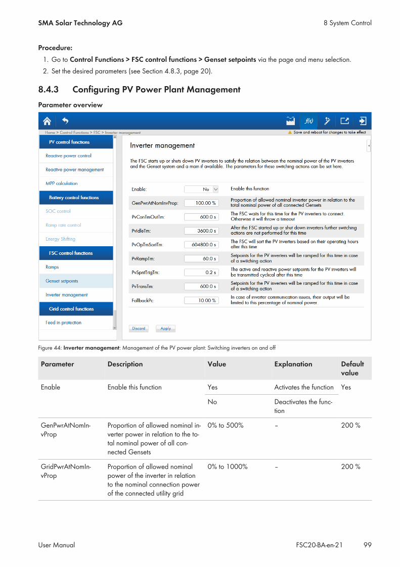
Procedure:1. Go to Control Functions > FSC control functions > Genset setpoints via the page and menu selection.2. Set the desired parameters (see Section 4.8.3, page 20).
8.4.3 Configuring PV Power Plant ManagementParameter overview
Figure 44: Inverter management: Management of the PV power plant: Switching inverters on and off
Parameter Description Value Explanation Defaultvalue
Enable Enable this function Yes Activates the function Yes
No Deactivates the func-tion
GenPwrAtNomIn-vProp
Proportion of allowed nominal in-verter power in relation to the to-tal nominal power of all con-nected Gensets
0% to 500% – 200 %
GridPwrAtNomIn-vProp
Proportion of allowed nominalpower of the inverter in relationto the nominal connection powerof the connected utility grid
0% to 1000% – 200 %
8 System ControlSMA Solar Technology AG
User Manual 99FSC20-BA-en-21

Parameter Description Value Explanation Defaultvalue
PvConTmOutTm The FSC waits for this time in sec-onds for the PV inverters to con-nect. Otherwise it will throw atimeout.
10 s to 86400 s – 600 s
PvIdleTm After the FSC has started up orshut down inverters, furtherswitching actions are not per-formed for this time in seconds.
0 s to 86400 s – 60 s
PvOpTmSortTm The FSC will sort the PV invertersbased on their operating hoursafter the given number of sec-onds.
at least 3600 s – 604800s
PvRampTm Setpoints for the PV inverters willbe ramped for this time in case ofswitching action.
1 s to 300 s – 60 s
PvSpntTrigTm The active and reactive powersetpoints for the PV inverters willbe transmitted cyclical after thistime in seconds.
0.1 s to 3600 s – 0.2 s
PvTransTm Setpoints for the PV inverters willbe ramped for this time in case ofswitching action.
1 s to 604800 s – 600 s
FallbackPc In case of communication issuesto the inverters, they will feed inthis percentage of nominalpower.
1% to 100% – 10 %
Requirement:☐ You must be logged in as Installer.
Power outage due to sudden power fluctuations in the PV power plantIf the communication between the Fuel Save Controller and the inverters is interrupted, the inverters will operateaccording to their fallback settings. When communication is restored, power fluctuations may occur if the fallbacksettings of the inverters deviate from the fallback settings of the Fuel Save Controller. These power fluctuations canresult in failure of the power supply in the PV diesel hybrid system.
• Ensure that the fallback settings of the inverters match the fallback settings of the Fuel Save Controller.
Procedure:1. Go to Control Functions > FSC control functions > Inverter management via the page and menu selection.2. Set the desired parameters (see Section 4.8.3, page 20).
8 System Control SMA Solar Technology AG
User ManualFSC20-BA-en-21100

8.5 Setting the Control of the Grid Feed-InParameter overview
Figure 45: Feed in protection: Settings regarding grid feed-in
Parameter Description Value Explanation Defaultvalue
Enable Enable this function Yes Activates the function Yes
No Deactivates the func-tion
GridReleaseAllPv Inject all PV in case of connectedgrid
Off Deactivates the func-tion
Off
On Activates the function
FipMode Ensure a minimum active powerto be obtained from the grid
Feed in The Fuel Save Con-troller feeds into theutility grid up to thevalue of PwrAtFeed-InMax.
GridMin-Load
GridMinLoad The Fuel Save Con-troller obtains powerfrom the utility grid upthe value of PwrAt-GridMinLoad.
8 System ControlSMA Solar Technology AG
User Manual 101FSC20-BA-en-21

Parameter Description Value Explanation Defaultvalue
PwrAtFeedInMax Maximum feed-in value for activepower in case of active grid con-nection
0 kW to100000 kW
– 0 kW
PwrAtGridMinLoad Minimum load value for activepower in case of active grid con-nection
0 kW to100000 kW
– 0 kW
SpntOfsAbs Function output offset in case ofmismatch
0 kW to100000 kW
– 0 kW
WarTrshldAbs Warning threshold of grid's ac-tive power
0 kW to100000 kW
– 0 kW
ErrTrshldAbs Error threshold of grid's activepower
0 kW to100000 kW
– -10 kW
WarTrshldTm Warning timer of grid's activepowerError timer of grid's active power
0.1 s to 86400 s – 10.0 s
ErrTrshldTm Error timer of grid's active power 0.1 s to 86400 s – 5.0 s
Requirement:☐ You must be logged in as Installer.
Procedure:1. Go to Control Functions > Grid control functions > Feed in protection via the page and menu selection.2. Set the desired parameters (see Section 4.8.3, page 20).
8 System Control SMA Solar Technology AG
User ManualFSC20-BA-en-21102
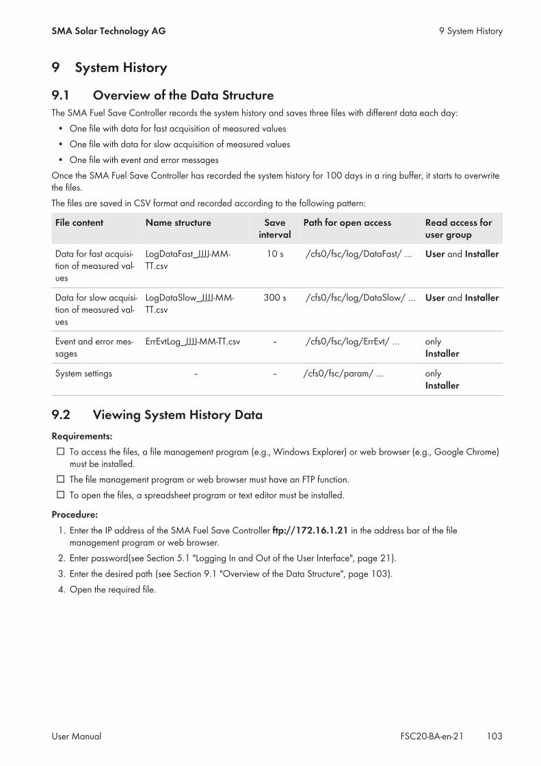
9 System History
9.1 Overview of the Data StructureThe SMA Fuel Save Controller records the system history and saves three files with different data each day:
• One file with data for fast acquisition of measured values• One file with data for slow acquisition of measured values• One file with event and error messages
Once the SMA Fuel Save Controller has recorded the system history for 100 days in a ring buffer, it starts to overwritethe files.The files are saved in CSV format and recorded according to the following pattern:
File content Name structure Saveinterval
Path for open access Read access foruser group
Data for fast acquisi-tion of measured val-ues
LogDataFast_JJJJ-MM-TT.csv
10 s /cfs0/fsc/log/DataFast/ … User and Installer
Data for slow acquisi-tion of measured val-ues
LogDataSlow_JJJJ-MM-TT.csv
300 s /cfs0/fsc/log/DataSlow/ … User and Installer
Event and error mes-sages
ErrEvtLog_JJJJ-MM-TT.csv – /cfs0/fsc/log/ErrEvt/ … only Installer
System settings – – /cfs0/fsc/param/ … only Installer
9.2 Viewing System History DataRequirements:☐ To access the files, a file management program (e.g., Windows Explorer) or web browser (e.g., Google Chrome)
must be installed.☐ The file management program or web browser must have an FTP function.☐ To open the files, a spreadsheet program or text editor must be installed.
Procedure:1. Enter the IP address of the SMA Fuel Save Controller ftp://172.16.1.21 in the address bar of the file
management program or web browser.2. Enter password(see Section 5.1 "Logging In and Out of the User Interface", page 21).3. Enter the desired path (see Section 9.1 "Overview of the Data Structure", page 103).4. Open the required file.
9 System HistorySMA Solar Technology AG
User Manual 103FSC20-BA-en-21
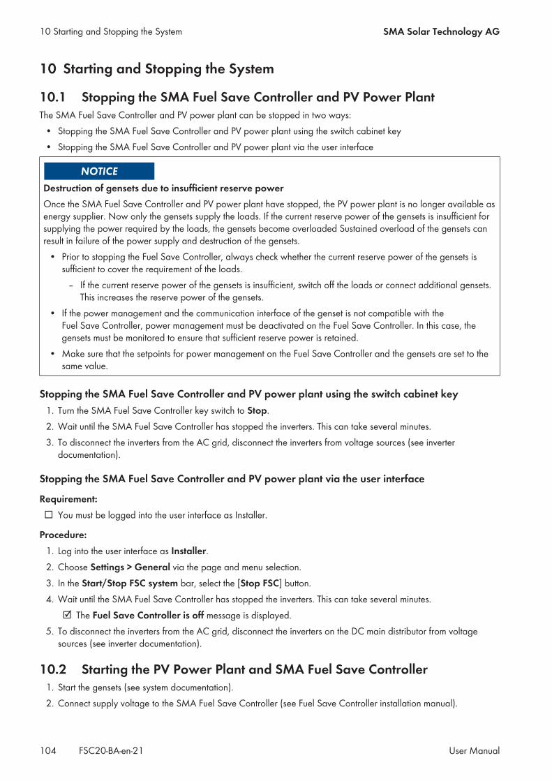
10 Starting and Stopping the System
10.1 Stopping the SMA Fuel Save Controller and PV Power PlantThe SMA Fuel Save Controller and PV power plant can be stopped in two ways:
• Stopping the SMA Fuel Save Controller and PV power plant using the switch cabinet key• Stopping the SMA Fuel Save Controller and PV power plant via the user interface
Destruction of gensets due to insufficient reserve powerOnce the SMA Fuel Save Controller and PV power plant have stopped, the PV power plant is no longer available asenergy supplier. Now only the gensets supply the loads. If the current reserve power of the gensets is insufficient forsupplying the power required by the loads, the gensets become overloaded Sustained overload of the gensets canresult in failure of the power supply and destruction of the gensets.
• Prior to stopping the Fuel Save Controller, always check whether the current reserve power of the gensets issufficient to cover the requirement of the loads.
– If the current reserve power of the gensets is insufficient, switch off the loads or connect additional gensets.This increases the reserve power of the gensets.
• If the power management and the communication interface of the genset is not compatible with theFuel Save Controller, power management must be deactivated on the Fuel Save Controller. In this case, thegensets must be monitored to ensure that sufficient reserve power is retained.
• Make sure that the setpoints for power management on the Fuel Save Controller and the gensets are set to thesame value.
Stopping the SMA Fuel Save Controller and PV power plant using the switch cabinet key1. Turn the SMA Fuel Save Controller key switch to Stop.2. Wait until the SMA Fuel Save Controller has stopped the inverters. This can take several minutes.3. To disconnect the inverters from the AC grid, disconnect the inverters from voltage sources (see inverter
documentation).
Stopping the SMA Fuel Save Controller and PV power plant via the user interface
Requirement:☐ You must be logged into the user interface as Installer.
Procedure:1. Log into the user interface as Installer.2. Choose Settings > General via the page and menu selection.3. In the Start/Stop FSC system bar, select the [Stop FSC] button.4. Wait until the SMA Fuel Save Controller has stopped the inverters. This can take several minutes.
☑ The Fuel Save Controller is off message is displayed.5. To disconnect the inverters from the AC grid, disconnect the inverters on the DC main distributor from voltage
sources (see inverter documentation).
10.2 Starting the PV Power Plant and SMA Fuel Save Controller1. Start the gensets (see system documentation).2. Connect supply voltage to the SMA Fuel Save Controller (see Fuel Save Controller installation manual).
10 Starting and Stopping the System SMA Solar Technology AG
User ManualFSC20-BA-en-21104

3. Connect the current and voltage measurement inputs (see Fuel Save Controller installation manual).4. To start the PV power plant and SMA Fuel Save Controller using the switch cabinet key, turn the SMA Fuel Save
Controller key switch to Start.5. To start the PV power plant and SMA Fuel Save Controller via the user interface, carry out the following steps:
• Log into the user interface as Installer.• Choose Settings > General via the page and menu selection.• In the Start/Stop FSC system bar, select the [Start FSC] button.☑ The Fuel Save Controller is on message is displayed.
6. Connect the PV inverters on the DC main distributor to the AC grid (see inverter documentation).☑ The PV power plant synchronizes to the available AC grid. How long synchronization takes depends on the
current solar irradiation on the PV modules and on the current power required by the loads.☑ The Fuel Save Controller reports the event 2097: Valid product licence found: The Fuel Save Controller is fully
functional.✖ The Fuel Save Controller generates a warning: 2098: No product licence found, 2099: Product licence is
not valid, or 2100: Product licence is empty. This prevents access to the optional functions of theFuel Save Controller.The software license installed may be invalid.
• Install a valid software license (see Section 10.4, page 106).
10.3 Restarting the SMA Fuel Save Controller and PV Power PlantRequirement:☐ You must be logged into the user interface as Installer.☐ The SMA Fuel Save Controller and PV power plant must have been stopped (see Section 10.1, page 104).
Power supply failure when the SMA Fuel Save Controller is restartedBefore restarting the SMA Fuel Save Controller, the SMA Fuel Save Controller and PV power plant must be stopped.It can take a few minutes for the SMA Fuel Save Controller and PV power plant to stop because the PV invertershave to reduce their output power slowly. If the PV inverters are still feeding energy to the grid when the SMA FuelSave Controller is restarted, this may cause failure of the power supply.
• Once the SMA Fuel Save Controller has stopped, wait until the PV inverters have reduced their output power tozero. This can take several minutes.
10 Starting and Stopping the SystemSMA Solar Technology AG
User Manual 105FSC20-BA-en-21

Procedure:1. Choose the menu Plant Overview via the page and menu selection.2. Choose Settings > General via the page and menu selection.3. In the Reboot FSC system bar, select the [Reboot] button.☑ The PV power plant synchronizes to the available AC grid. How long synchronization takes depends on the
current solar irradiation on the PV modules and on the current power required by the loads.☑ The Fuel Save Controller reports the event 2097: Valid product licence found: The Fuel Save Controller is fully
functional.✖ The Fuel Save Controller generates a warning: 2098: No product licence found, 2099: Product licence is
not valid, or 2100: Product licence is empty. This prevents access to the optional functions of theFuel Save Controller.The software license installed may be invalid.
• Install a valid software license (see Section 10.4, page 106).
10.4 Installing a Valid Software LicenseUnder adverse circumstances, the Fuel Save Controller generates a warning: 2098: No product licence found,2099: Product licence is not valid, or 2100: Product licence is empty when starting or restarting.
Cause:The software license installed on the Fuel Save Controller may be damaged or invalid for some other reason.
Corrective measures:1. Request a valid software license from Service (see Section 12, page 108).
☑ You will receive an e-mail with the valid software license with the file fsc.lic.2. Open an FTP client on the computer to display the user interface.3. Connect with the Fuel Save Controller via FTP (e.g., via ftp://172.16.1.21).4. Open the folder cfc0/fsc/newfiles/.5. Copy the file fsc.lic into the folder cfc0/fsc/newfiles/.6. Restart the Fuel Save Controller (see Section 10.3, page 105).
10 Starting and Stopping the System SMA Solar Technology AG
User ManualFSC20-BA-en-21106

11 CleaningAdditionally required maintenance material (not included in the scope of delivery):☐ Use touch-up sticks, paint brushes, spray paint or 2K-PUR acrylic paint to repair minor surface damage.☐ Use touch-up paint or 2K-PUR acrylic paint to repair extensive surface damage.
Danger to life from electric shock due to live voltageDanger of electric shock if work is executed incorrectly or under fault conditions. An electric shock can lead to deathor serious injury.
• Disconnect the supply voltage and the measuring cables for the current- and voltage measurement beforeperforming any work on the Fuel Save Controller.
• Observe the five safety rules when disconnecting the supply voltage:– Disconnect from voltage sources.– Ensure that the device cannot be reconnected.– Ensure that no voltage is present.– Ground and short-circuit the device.– Cover and isolate any adjacent live components.
Damage to the Fuel Save Controller due to moisture penetrationPenetrating moisture can cause short circuits and damage the Fuel Save Controller.
• Use a moist cloth to remove dust. Do not use solvents, abrasives or other corrosive substances.
Procedure:1. Check whether the Fuel Save Controller shows any externally visible damage.
If the Fuel Save Controller shows any externally visible damage, carry out the following measures:• Decommission the SMA Fuel Save Controller (see Fuel Save Controller installation manual).• Contact the SMA Service Line (see Section 12, page 108).
2. Remove coarse dirt contamination from the outside of the enclosure with a soft brush or similar tool.3. Remove dust from the outside of the enclosure using a moist cloth.4. Check the enclosure for corrosion and eliminate if necessary:
• Use touch-up sticks, paint brushes, spray paint or, alternatively, 2K-PUR acrylic paint to repair minor surfacedamage. When doing so, adhere to the relevant instructions of the paint manufacturer.
• Use touch-up paint or 2K-PUR acrylic paint to repair extensive surface damage. When doing so, adhere tothe relevant instructions of the paint manufacturer.
11 CleaningSMA Solar Technology AG
User Manual 107FSC20-BA-en-21
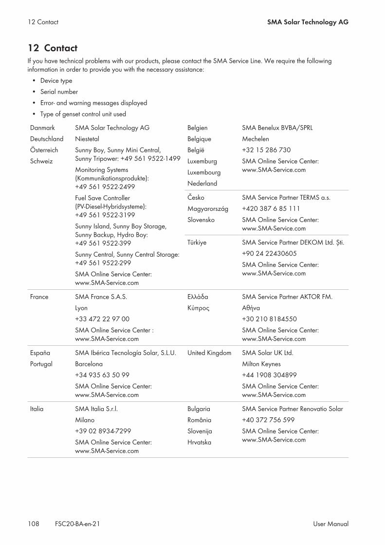
12 ContactIf you have technical problems with our products, please contact the SMA Service Line. We require the followinginformation in order to provide you with the necessary assistance:
• Device type• Serial number• Error- and warning messages displayed• Type of genset control unit used
DanmarkDeutschlandÖsterreichSchweiz
SMA Solar Technology AGNiestetalSunny Boy, Sunny Mini Central,Sunny Tripower: +49 561 9522‑1499Monitoring Systems(Kommunikationsprodukte):+49 561 9522‑2499Fuel Save Controller(PV-Diesel-Hybridsysteme):+49 561 9522-3199Sunny Island, Sunny Boy Storage,Sunny Backup, Hydro Boy:+49 561 9522-399Sunny Central, Sunny Central Storage: +49 561 9522-299SMA Online Service Center:www.SMA-Service.com
BelgienBelgiqueBelgiëLuxemburgLuxembourgNederland
SMA Benelux BVBA/SPRLMechelen+32 15 286 730SMA Online Service Center:www.SMA-Service.com
ČeskoMagyarországSlovensko
SMA Service Partner TERMS a.s.+420 387 6 85 111SMA Online Service Center:www.SMA-Service.com
Türkiye SMA Service Partner DEKOM Ltd. Şti.+90 24 22430605SMA Online Service Center:www.SMA-Service.com
France SMA France S.A.S.Lyon+33 472 22 97 00SMA Online Service Center :www.SMA-Service.com
ΕλλάδαΚύπρος
SMA Service Partner AKTOR FM.Αθήνα+30 210 8184550SMA Online Service Center:www.SMA-Service.com
EspañaPortugal
SMA Ibérica Tecnología Solar, S.L.U.Barcelona+34 935 63 50 99SMA Online Service Center:www.SMA-Service.com
United Kingdom SMA Solar UK Ltd.Milton Keynes+44 1908 304899SMA Online Service Center:www.SMA-Service.com
Italia SMA Italia S.r.l.Milano+39 02 8934-7299SMA Online Service Center:www.SMA-Service.com
BulgariaRomâniaSlovenijaHrvatska
SMA Service Partner Renovatio Solar+40 372 756 599SMA Online Service Center:www.SMA-Service.com
12 Contact SMA Solar Technology AG
User ManualFSC20-BA-en-21108

United ArabEmirates
SMA Middle East LLCAbu Dhabi+971 2234 6177SMA Online Service Center:www.SMA-Service.com
India SMA Solar India Pvt. Ltd.Mumbai+91 22 61713888
SMA Solar (Thailand) Co., Ltd.
+66 2 670 6999
대한민국 SMA Technology Korea Co., Ltd.서울+82-2-520-2666
South Africa SMA Solar Technology South AfricaPty Ltd.Cape Town08600SUNNY (08600 78669)International: +27 (0)21 826 0600SMA Online Service Center:www.SMA-Service.com
ArgentinaBrasilChilePerú
SMA South America SPASantiago de Chile+562 2820 2101
Australia SMA Australia Pty Ltd.SydneyToll free for Australia: 1800 SMA AUS(1800 762 287)International: +61 2 9491 4200
Other countries International SMA Service LineNiestetal00800 SMA SERVICE(+800 762 7378423)
12 ContactSMA Solar Technology AG
User Manual 109FSC20-BA-en-21

www.SMA-Solar.com