User Manual PS2520, PS2520G, PS2521 & PS2521G Programmable...
56
User Manual PS2520, PS2520G, PS2521 & PS2521G Programmable Power Supplies 070-9196-01
Transcript of User Manual PS2520, PS2520G, PS2521 & PS2521G Programmable...

User Manual
PS2520, PS2520G, PS2521 & PS2521GProgrammable Power Supplies
070-9196-01

Copyright � Tektronix, Inc. 1995. All rights reserved.
Tektronix products are covered by U.S. and foreign patents, issued andpending. Information in this publication supercedes that in all previouslypublished material. Specifications and price change privileges reserved.
Printed in the U.S.A.
Tektronix, Inc., P.O. Box 1000, Wilsonville, OR 97070–1000
TEKTRONIX and TEK are registered trademarks of Tektronix, Inc.

WARRANTY
Tektronix warrants that this product will be free from defects in materials andworkmanship for a period of one (1) year from the date of shipment. If any such productproves defective during this warranty period, Tektronix, at its option, either will repair thedefective product without charge for parts and labor, or will provide a replacement inexchange for the defective product.
In order to obtain service under this warranty, Customer must notify Tektronix of the defectbefore the expiration of the warranty period and make suitable arrangements for theperformance of service. Customer shall be responsible for packaging and shipping thedefective product to the service center designated by Tektronix, with shipping chargesprepaid. Tektronix shall pay for the return of the product to Customer if the shipment is toa location within the country in which the Tektronix service center is located. Customershall be responsible for paying all shipping charges, duties, taxes, and any other charges forproducts returned to any other locations.
This warranty shall not apply to any defect, failure or damage caused by improper use orimproper or inadequate maintenance and care. Tektronix shall not be obligated to furnishservice under this warranty a) to repair damage resulting from attempts by personnel otherthan Tektronix representatives to install, repair or service the product; b) to repair damageresulting from improper use or connection to incompatible equipment; or c) to service aproduct that has been modified or integrated with other products when the effect of suchmodification or integration increases the time or difficulty of servicing the product.
THIS WARRANTY IS GIVEN BY TEKTRONIX WITH RESPECT TO THISPRODUCT IN LIEU OF ANY OTHER WARRANTIES, EXPRESSED ORIMPLIED. TEKTRONIX AND ITS VENDORS DISCLAIM ANY IMPLIEDWARRANTIES OF MERCHANTABILITY OR FITNESS FOR A PARTICULARPURPOSE. TEKTRONIX’ RESPONSIBILITY TO REPAIR OR REPLACEDEFECTIVE PRODUCTS IS THE SOLE AND EXCLUSIVE REMEDYPROVIDED TO THE CUSTOMER FOR BREACH OF THIS WARRANTY.TEKTRONIX AND ITS VENDORS WILL NOT BE LIABLE FOR ANYINDIRECT, SPECIAL, INCIDENTAL, OR CONSEQUENTIAL DAMAGESIRRESPECTIVE OF WHETHER TEKTRONIX OR THE VENDOR HASADVANCE NOTICE OF THE POSSIBILITY OF SUCH DAMAGES.


EC Declaration of Conformity
WeTektronix Holland N.V.Marktweg 73A8444 AB HeerenveenThe Netherlands
declare under sole responsibility that thePS2520G Programmable Power Supply
meets the intent of Directive 89/336/EEC for ElectromagneticCompatibility and Low Voltage Directive 73/23/ECC for Product Safety.Compliance was demonstrated to the following specifications as listedin the Official Journal of the European Communities:
EMC Directive 89/336/EEC:EN 55011 Class B Radiated and Conducted EmissionsEN 50081-1 Emissions:
EN 60555-2 AC Power Line Harmonic Emissions
EN 50082-1 Immunity:IEC 801-2 Electrostatic Discharge ImmunityIEC 801-3 RF Electromagnetic Field ImmunityIEC 801-4 Electrical Fast Transient/Burst ImmunityIEC 801-5 Power Line Surge Immunity
“...conformity with the following standards:
following the provisions of the Directives of the Council of theEuropean Union:Low Voltage Directive 73/23/EEC: Amended by 93/68/EEC.”

EC Declaration of Conformity
WeTektronix Holland N.V.Marktweg 73A8444 AB HeerenveenThe Netherlands
declare under sole responsibility that thePS2521G Programmable Power Supply
meets the intent of Directive 89/336/EEC for ElectromagneticCompatibility and Low Voltage Directive 73/23/ECC for Product Safety.Compliance was demonstrated to the following specifications as listedin the Official Journal of the European Communities:
EMC Directive 89/336/EEC:EN 55011 Class A Radiated and Conducted EmissionsEN 50081-1 Emissions:
EN 60555-2 AC Power Line Harmonic Emissions
EN 50082-1 Immunity:IEC 801-2 Electrostatic Discharge ImmunityIEC 801-3 RF Electromagnetic Field ImmunityIEC 801-4 Electrical Fast Transient/Burst ImmunityIEC 801-5 Power Line Surge Immunity
“...conformity with the following standards:
following the provisions of the Directives of the Council of theEuropean Union:Low Voltage Directive 73/23/EEC: Amended by 93/68/EEC.”
PS2520, PS2520G, PS2521 & PS2521G User Manual i
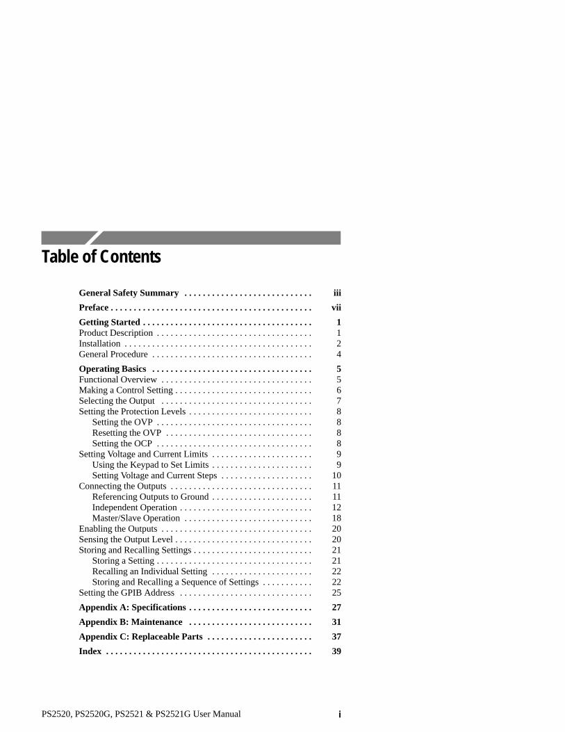
Table of Contents
General Safety Summary iii. . . . . . . . . . . . . . . . . . . . . . . . . . . .
Preface vii. . . . . . . . . . . . . . . . . . . . . . . . . . . . . . . . . . . . . . . . . . . .
Getting Started 1. . . . . . . . . . . . . . . . . . . . . . . . . . . . . . . . . . . . . Product Description 1. . . . . . . . . . . . . . . . . . . . . . . . . . . . . . . . . . Installation 2. . . . . . . . . . . . . . . . . . . . . . . . . . . . . . . . . . . . . . . . . General Procedure 4. . . . . . . . . . . . . . . . . . . . . . . . . . . . . . . . . . .
Operating Basics 5. . . . . . . . . . . . . . . . . . . . . . . . . . . . . . . . . . . Functional Overview 5. . . . . . . . . . . . . . . . . . . . . . . . . . . . . . . . . Making a Control Setting 6. . . . . . . . . . . . . . . . . . . . . . . . . . . . . . Selecting the Output 7. . . . . . . . . . . . . . . . . . . . . . . . . . . . . . . . . Setting the Protection Levels 8. . . . . . . . . . . . . . . . . . . . . . . . . . .
Setting the OVP 8. . . . . . . . . . . . . . . . . . . . . . . . . . . . . . . . . . Resetting the OVP 8. . . . . . . . . . . . . . . . . . . . . . . . . . . . . . . . Setting the OCP 8. . . . . . . . . . . . . . . . . . . . . . . . . . . . . . . . . .
Setting Voltage and Current Limits 9. . . . . . . . . . . . . . . . . . . . . . Using the Keypad to Set Limits 9. . . . . . . . . . . . . . . . . . . . . . Setting Voltage and Current Steps 10. . . . . . . . . . . . . . . . . . . .
Connecting the Outputs 11. . . . . . . . . . . . . . . . . . . . . . . . . . . . . . . Referencing Outputs to Ground 11. . . . . . . . . . . . . . . . . . . . . . Independent Operation 12. . . . . . . . . . . . . . . . . . . . . . . . . . . . . Master/Slave Operation 18. . . . . . . . . . . . . . . . . . . . . . . . . . . .
Enabling the Outputs 20. . . . . . . . . . . . . . . . . . . . . . . . . . . . . . . . . Sensing the Output Level 20. . . . . . . . . . . . . . . . . . . . . . . . . . . . . . Storing and Recalling Settings 21. . . . . . . . . . . . . . . . . . . . . . . . . .
Storing a Setting 21. . . . . . . . . . . . . . . . . . . . . . . . . . . . . . . . . . Recalling an Individual Setting 22. . . . . . . . . . . . . . . . . . . . . . Storing and Recalling a Sequence of Settings 22. . . . . . . . . . .
Setting the GPIB Address 25. . . . . . . . . . . . . . . . . . . . . . . . . . . . .
Appendix A: Specifications 27. . . . . . . . . . . . . . . . . . . . . . . . . . .
Appendix B: Maintenance 31. . . . . . . . . . . . . . . . . . . . . . . . . . .
Appendix C: Replaceable Parts 37. . . . . . . . . . . . . . . . . . . . . . .
Index 39. . . . . . . . . . . . . . . . . . . . . . . . . . . . . . . . . . . . . . . . . . . . .

Table of Contents
ii PS2520, PS2520G, PS2521 & PS2521G User Manual
List of FiguresFigure 1: Changing the Line Voltage Setting 2. . . . . . . . . . . .
Figure 2: Replacing the Line Fuse 3. . . . . . . . . . . . . . . . . . . . .
Figure 3: Front Panel Features 5. . . . . . . . . . . . . . . . . . . . . . . .
Figure 4: Rear Panel Features 6. . . . . . . . . . . . . . . . . . . . . . . .
Figure 5: SHIFT control 7. . . . . . . . . . . . . . . . . . . . . . . . . . . . .
Figure 6: Isolated-Ground Connection 11. . . . . . . . . . . . . . . . .
Figure 7: Examples of Independent Output Connections 13. .
Figure 8: Connecting Power Supplies in Series 14. . . . . . . . . .
Figure 9: Examples of External Series Connections 15. . . . . .
Figure 10: Connecting Power Supplies in Parallel 16. . . . . . . .
Figure 11: Examples of External Parallel Connections 17. . . .
Figure 12: Series-Tracking Operation 19. . . . . . . . . . . . . . . . . .
Figure 13: Parallel-Tracking Operation 19. . . . . . . . . . . . . . . .
Figure 14: Output On/Off Button 20. . . . . . . . . . . . . . . . . . . . .
Figure 15: Connecting the Auxiliary Sense Inputs 21. . . . . . . .
List of TablesTable 1: Maximum Output in Series and Para Modes 18. . . .
Table 2: Operating Characteristics 27. . . . . . . . . . . . . . . . . . . .
Table 3: Electrical Characteristics 29. . . . . . . . . . . . . . . . . . . .
Table 4: Environmental Characteristics 30. . . . . . . . . . . . . . . .
Table 5: Physical Characteristics 30. . . . . . . . . . . . . . . . . . . . .
Table 6: Troubleshooting Steps 33. . . . . . . . . . . . . . . . . . . . . . .
Table 7: Error Messages 34. . . . . . . . . . . . . . . . . . . . . . . . . . . . .
Table 8: Standard Accessories 37. . . . . . . . . . . . . . . . . . . . . . . .
Table 9: Optional Accessories 37. . . . . . . . . . . . . . . . . . . . . . . .
Table 10: Accessory Power Cords 38. . . . . . . . . . . . . . . . . . . . .

PS2520, PS2520G, PS2521 & PS2521G User Manual iii
General Safety Summary
Review the following safety precautions to avoid injury and preventdamage to this product or any products connected to it.
Only qualified personnel should perform service procedures.
Injury Precautions
Use Proper Power Cord
To avoid fire hazard, use only the power cord specified for thisproduct.
Avoid Electric Overload
To avoid electric shock or fire hazard, do not apply a voltage to aterminal that is outside the range specified for that terminal.
Ground the Product
This product is grounded through the grounding conductor of thepower cord. To avoid electric shock, the grounding conductor mustbe connected to earth ground. Before making connections to theinput or output terminals of the product, ensure that the product isproperly grounded.
Do Not Operate Without Covers
To avoid electric shock or fire hazard, do not operate this productwith covers or panels removed.
Use Proper Fuse
To avoid fire hazard, use only the fuse type and rating specified forthis product.

General Safety Summary
iv PS2520, PS2520G, PS2521 & PS2521G User Manual
Do Not Operate in Wet/Damp Conditions
To avoid electric shock, do not operate this product in wet or dampconditions.
Do Not Operate in Explosive Atmosphere
To avoid injury or fire hazard, do not operate this product in anexplosive atmosphere.
Avoid Exposed Circuitry
To avoid injury, remove jewelry such as rings, watches, and othermetallic objects. Do not touch exposed connections and componentswhen power is present.
Product Damage Precautions
Use Proper Power Source
Do not operate this product from a power source that applies morethan the voltage specified.
Use Proper Voltage Setting
Before applying power, ensure that the line selector is in the properposition for the power source being used.
Provide Proper Ventilation
To prevent product overheating, provide proper ventilation.
Do Not Operate With Suspected Failures
If you suspect there is damage to this product, have it inspected byqualified service personnel.
General Safety Summary
PS2520, PS2520G, PS2521 & PS2521G User Manual v
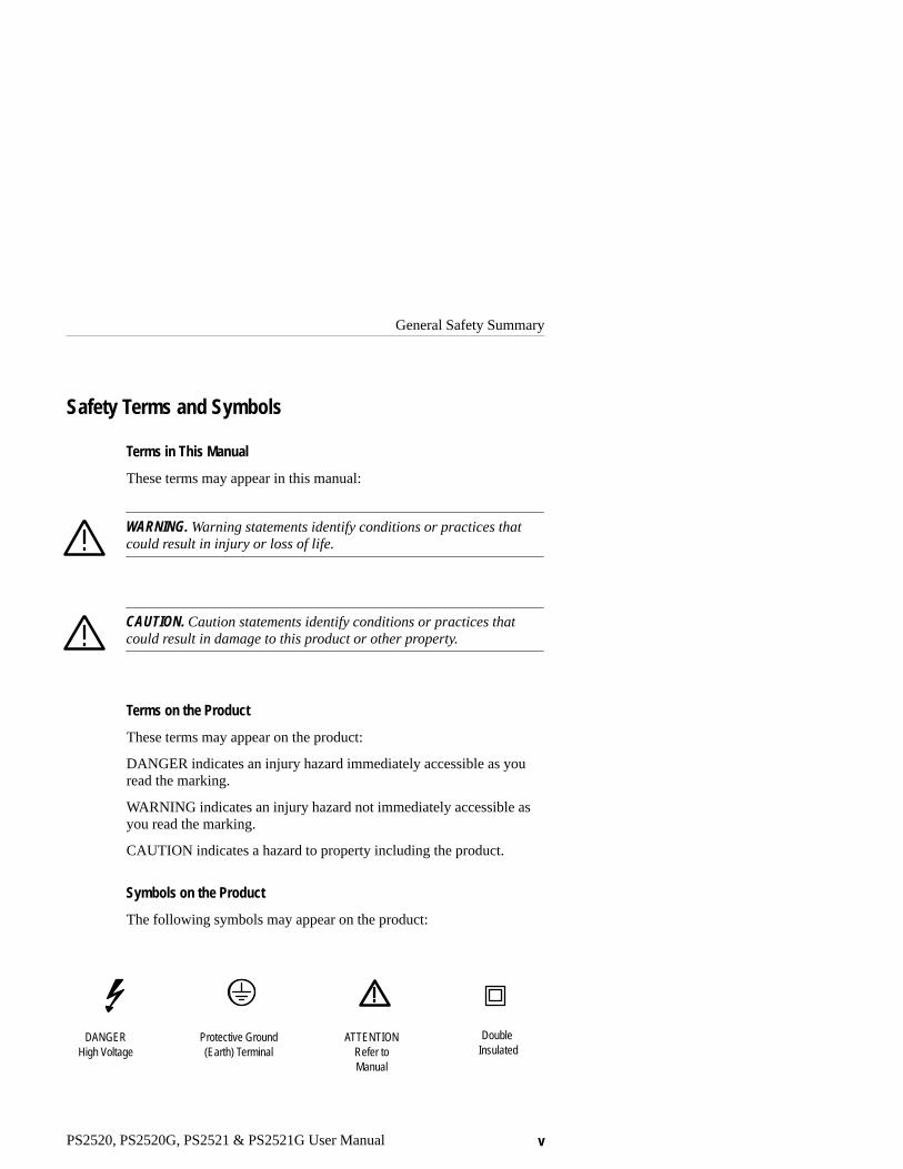
Safety Terms and Symbols
Terms in This Manual
These terms may appear in this manual:
WARNING. Warning statements identify conditions or practices thatcould result in injury or loss of life.
CAUTION. Caution statements identify conditions or practices thatcould result in damage to this product or other property.
Terms on the Product
These terms may appear on the product:
DANGER indicates an injury hazard immediately accessible as youread the marking.
WARNING indicates an injury hazard not immediately accessible asyou read the marking.
CAUTION indicates a hazard to property including the product.
Symbols on the Product
The following symbols may appear on the product:
DANGERHigh Voltage
Protective Ground(Earth) Terminal
ATTENTIONRefer toManual
Double Insulated

General Safety Summary
vi PS2520, PS2520G, PS2521 & PS2521G User Manual
Certifications and Compliances
CSA Certified Power Cords
CSA Certification includes the products and power cords appropriatefor use in the North America power network. All other power cordssupplied are approved for the country of use.

PS2520, PS2520G, PS2521 & PS2521G User Manual vii
Preface
This manual provides installation and operating instructions for thePS2520, PS2520G, PS2521, and PS2521G Programmable PowerSupplies. The manual is organized as follows:
� Getting Started lists the product features, and describes how toinstall the power supply.
� Operating Basics provides an overview of the front and rearpanel and details each operating task step by step. This sectionalso provides a practical example of each control setting.
� The Appendices list product specifications and other referenceinformation.
Refer to the PS2520G and PS2521G Programmer Manual(070-9197-XX) for information on how to set up and use thePS2520G and PS2521G Programmable Power Supplies over theIEEE-488 General Purpose Interface Bus (GPIB).

Preface
viii PS2520, PS2520G, PS2521 & PS2521G User Manual

PS2520, PS2520G, PS2521 & PS2521G User Manual 1
Getting Started
This section describes the features of the PS2520, PS2520G, PS2521,and PS2521G Programmable Power Supplies.
Be sure to set up your power supply using the installation instruc-tions at the end of this section.
Product DescriptionThe PS2520, PS2520G, PS2521, and PS2521G are programmableDC power supplies. All four power supplies have the followingfeatures:
� Three outputs allow independent, series, or parallel operation
� Automatic series or parallel tracking
� Easy to set, push-button controls
� Data entry using the keypad, up/down keys
� Four-digit displays for both voltage and current
� Overvoltage and overcurrent protection
� Display readouts for memory, output, and error code display
� Precision digital-to-analog converter for high resolution
� High stability, low drift output
� Memory storage and recall
� Automatic sequencing with timer
� Diagnostic self-test at power on
In addition, the PS2520G and PS2521G power supplies include aGPIB interface that allows you to program and operate the powersupply from a remote location over the General Purpose InterfaceBus (GPIB).
For a complete list of specifications, refer to Appendix A: Specifica-tions on page 27.

Getting Started
2 PS2520, PS2520G, PS2521 & PS2521G User Manual
InstallationUse the following installation procedure to properly configure andturn on the power supply for the first time:
1. Check the line voltage setting on the rear panel. If the linevoltage setting does not match the line voltage of your area,change the line voltage setting as shown in Figure 1.
Pry open cover with flat-blade screwdriver.
Remove cam drum,rotate to correct
selection, and reinsert.
Figure 1: Changing the Line Voltage Setting
Getting Started
PS2520, PS2520G, PS2521 & PS2521G User Manual 3
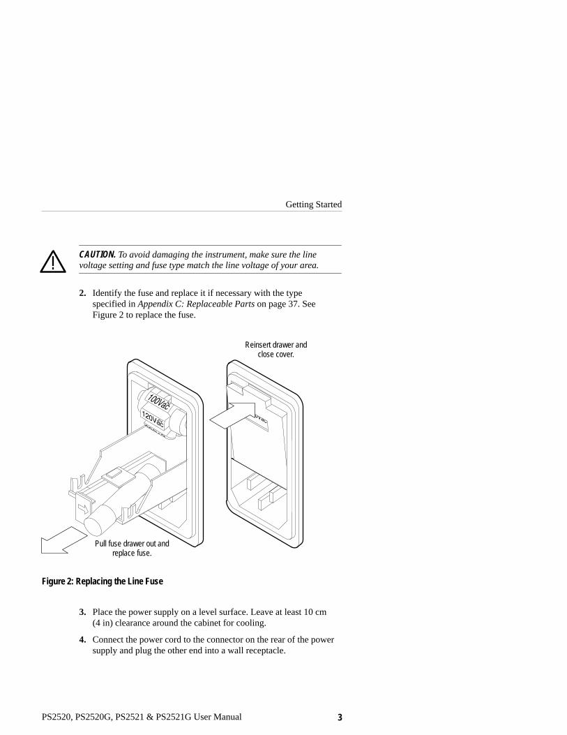
CAUTION. To avoid damaging the instrument, make sure the linevoltage setting and fuse type match the line voltage of your area.
2. Identify the fuse and replace it if necessary with the typespecified in Appendix C: Replaceable Parts on page 37. SeeFigure 2 to replace the fuse.
Pull fuse drawer out andreplace fuse.
Reinsert drawer andclose cover.
Figure 2: Replacing the Line Fuse
3. Place the power supply on a level surface. Leave at least 10 cm(4 in) clearance around the cabinet for cooling.
4. Connect the power cord to the connector on the rear of the powersupply and plug the other end into a wall receptacle.

Getting Started
4 PS2520, PS2520G, PS2521 & PS2521G User Manual
5. Turn the power on. The display indicators will flash briefly. Thevoltage and current readouts show the output settings. You shouldalso hear the cooling fan running whenever the power is on.
The power supply performs a diagnostic self test at power on. If thediagnostic self test detects a problem, the unit displays an error codenumber in the form “Err –xxx.” If you encounter an error code, referto Troubleshooting on page 32.
General ProcedureUse the following general procedure to connect one or more of thepower supply outputs to a load. This procedure allows you to use thepower supply safely. More information about each step is inOperating Basics on page 5.
1. Turn the power supply off and remove any connections on theoutputs.
2. Turn the power supply on.
3. Select the output you want to configure. Refer to Selecting theOutput on page 7.
4. Set the protection levels for the selected output. Refer to Settingthe Protection Levels on page 8.
5. Set the voltage and current limit for the selected output. Refer toSetting Voltage and Current Limits on page 9.
6. Repeat steps 3 through 5 for the remaining outputs.
7. Turn the power supply supply off.
8. Connect the output(s) to the load(s). Refer to Connecting theOutputs on page 11.
9. Turn the power supply on.
10.Enable the outputs. Refer to Enabling the Outputs on page 20.

PS2520, PS2520G, PS2521 & PS2521G User Manual 5
Operating Basics
This section describes how to use the front panel controls and how tomake connections to the power supply.
Functional OverviewFigure 3 illustrates the front panel features of the PS2520, PS2520G,PS2521, and PS2521G Programmable Power Supplies.
MemoryVolts
readoutAmperesreadout
Powerswitch
Outputconnectors
KeypadOutputcontrols
Figure 3: Front Panel Features

Operating Basics
6 PS2520, PS2520G, PS2521 & PS2521G User Manual
Figure 4 illustrates the rear panel features.
Powerconnector
Line voltagesetting
Senseselector
Fuseaccess
Coolingfan
GPIBinterface
(PS2520G and PS2521G only)
Power output and senseinput connectors
Figure 4: Rear Panel Features
Making a Control SettingThe front-panel controls allow you to set or program the amount ofvoltage, current, and protection for each output. To make a controlsetting you must press specific control buttons in the correctsequence. To enter a number, for example, you must select thefunction, enter the number, and then press return (). This manualpresents an entry sequence of this type in the following form:
Press (function) → (number) → (return )

Operating Basics
PS2520, PS2520G, PS2521 & PS2521G User Manual 7
Items that compose the sequence appear in order from left to rightwith arrows separating each item.
An example follows each sequence string to help reinforce yourunderstanding. Examples look like this:
Example: Set the voltage to 2.34 volts.
VOLTS SET → 2.34 → (return )
To select functions that have nomenclature above the output controlbuttons, you must first press the SHIFT button (see Figure 5). Theshift indicator appears and remains active until you enter thefunction.
Example: Reset the OVP.
SHIFT → OVP RESET
Figure 5: SHIFT control
Selecting the OutputYou must select the output before you can set the voltage, current,and protection levels for that output.
Press SHIFT → OUT(n) to select the output.
Example: Select Output 2.
SHIFT → OUT2
The output indicator for Output 2 lights, and you can set the outputlevels.

Operating Basics
8 PS2520, PS2520G, PS2521 & PS2521G User Manual
Setting the Protection LevelsThe OVP (overvoltage protection) and OCP (overcurrent protection)settings protect against supplying excessive voltage or current to anoutput load. If voltage or current reaches the protection level setting,the power supply disables the outputs.
CAUTION. To prevent damaging a circuit under test, set protectionlevels before you apply power to the circuit.
Setting the OVP
The OVP (overvoltage protection) circuit automatically disables theoutput when the voltage on the output reaches the set level.
Press OVP SET → (number) → (return ) to enter the OVP level.
Example: Set the overvoltage protection for Output 1 to 6 volts:
1. SHIFT → OUT1
2. OVP SET → 6 → (return )
Pressing the OVP SET again momentarily displays the OVP leveland allows you to confirm the setting.
Resetting the OVP
Using the previous example, if the Output 1 voltage reaches 6 volts,the power supply automatically disables the output and displays themessage “Err –013.”
To reset the OVP, correct the condition causing the overvoltage andpress SHIFT → OVP RESET
Setting the OCP
Pressing OCP ON (overcurrent protection on) sets the power supply toautomatically disable the outputs upon reaching the current limit.The OCP indicator appears on the display when the OCP is on.

Operating Basics
PS2520, PS2520G, PS2521 & PS2521G User Manual 9
When the OCP circuit disables the output, it displays the message“Err –012”. When this happens, correct the setup and remove theerror message by toggling OCP off and then on again.
When the OCP is not on, the power supply still limits the current tothe set level and reduces the voltage as necessary to control thepower. Refer to the following section for instructions on how to setthe current limit.
Setting Voltage and Current LimitsThe power supplies provide either constant voltage or constantcurrent to a load. The voltage limit, current limit, and the size of theload connected to the output determines whether the power supplyholds the voltage constant or the current constant. The appropriateindicator appears on the display to indicate whether constant voltage(C.V.) or constant current (C.C.) is active.
Using the Keypad to Set Limits
Press VOLTS SET → (number) → (return ) to enter the voltagelimit.
Press CURRENT SET → (number) → (return ) to enter thecurrent limit.
Example: Set the voltage of Output 3 to 4.2 volts with a maximumcurrent of 0.3 amperes.
1. Select Output 3:
SHIFT → OUT3
2. Set the voltage level of the output to 4.2 V:
VOLTS SET → 4.2 → (return )
3. Set the current limit of the output to 0.3 A:
CURRENT SET → .3 → (return )
The power supply keeps the voltage constant if the load does notrequire more than 0.3 amperes. The power supply indicates C.V. onthe display.

Operating Basics
10 PS2520, PS2520G, PS2521 & PS2521G User Manual
Once the load tries to draw more than 0.3 amperes, however, thesupply holds the current to 0.3 amperes (unless OCP is on) andallows the voltage level to vary accordingly. The power supply thenindicates C.C. on the display.
Setting Voltage and Current Steps
The CURRENT and VOLTS (step up) and (step down) arrowkeys allow you to make minor adjustments to the current and voltagesettings.
The STEP SET function determines the amount that the arrow keysincrement or decrement the setting when you press them.
Press STEP SET → VOLTS SET → (number) → (return ) to setthe amount of each voltage step increment and decrement.
Press STEP SET → CURRENT SET → (number) → (return ) toset the amount of each current step increment and decrement.
NOTE. The power supplies permit voltage steps up to 2.000 V andcurrent steps up to 0.200 A.
Example: Set voltage steps to 0.5 V and current steps to 0.1 A.
1. Set voltage steps to 0.5 V:
STEP SET → VOLTS SET → .5 → (return )
2. Set current steps to 0.1 A:
STEP SET → CURRENT SET → .1 → (return )
Press VOLTS to increase (and press VOLTS to decrease) thevoltage limit by steps of 0.5 V.
Press CURRENT to increase (and press CURRENT todecrease) the current limit by steps of 0.1 A.
Press and hold the arrow key to increase the selection speed.

Operating Basics
PS2520, PS2520G, PS2521 & PS2521G User Manual 11
Connecting the OutputsAfter setting the voltage and current limits, turn the power off andconnect the outputs to one or more loads. The binding posts on thefront outputs accept wires, spade lugs, or banana plugs. The rearoutput terminals provide additional output connections. You canmake connections with or without reference to ground to each supplyindependently, in series or in parallel.
WARNING. To avoid electrical shock and damage to circuitsconnected to the outputs, make sure that you turn the power supplyoff before making or changing output connections.
Referencing Outputs to Ground
There are two types of power supply connections in relation toground: isolated ground or ground referenced. Figure 6 shows bothtypes of connections.
Voltage Voltage Voltage
Isolated ground Ground referenced
or
Figure 6: Isolated-Ground Connection
Use an isolated-ground connection when it is unnecessary orundesirable to connect one of the outputs to ground.
To reference an output connection to ground, do one of thefollowing:
� Connect the positive output to the ground terminal to supply anegative voltage across the load.

Operating Basics
12 PS2520, PS2520G, PS2521 & PS2521G User Manual
� Connect the negative output to the ground terminal to supply apositive voltage across the load.
NOTE. The ground post on the power supply internally connects toearth ground through the power supply chassis and line cord.
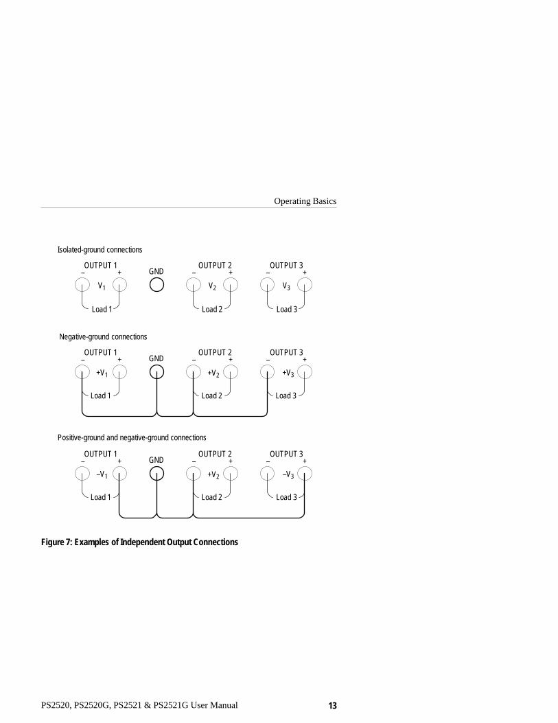
Independent Operation
Independent operation allows you connect each of the three outputsto separate loads or to connect the outputs in series or in parallel withexternal connections. When the outputs are in the independent modeof operation, the SERIES and PARA indicators are not lighted. SeeFigure 7 for examples of independent output connections.
Operating Basics
PS2520, PS2520G, PS2521 & PS2521G User Manual 13
Load 1
OUTPUT 1 OUTPUT 2GND– +
V1 V2
+V2 +V3
Isolated-ground connections
Negative-ground connections
Positive-ground and negative-ground connections
Load 2
– +OUTPUT 3
V3
Load 3
– +
Load 1
OUTPUT 1 OUTPUT 2GND– +
Load 2
– +OUTPUT 3
Load 3
– +
+V1
+V2 –V3
Load 1
OUTPUT 1 OUTPUT 2GND– +
Load 2
– +OUTPUT 3
Load 3
– +
–V1
Figure 7: Examples of Independent Output Connections

Operating Basics
14 PS2520, PS2520G, PS2521 & PS2521G User Manual
External Series Connections. To achieve a potential across the loadthat exceeds the output of a single power supply, connect two ormore power supplies in series. Figure 8 illustrates two independentpower supplies connected in series. Note that the voltages of thepower supplies add together but the currents do not.
� �
35 V, 1 A
20 V, 1 A 15 V, 1 A– + – +
Figure 8: Connecting Power Supplies in Series
WARNING. Voltages more than 60 VDC are a lethal shock hazard tothe user. Be careful when connecting power supplies in series toachieve voltages higher than 60 VDC total or 60 VDC between anyconnection and earth ground.
Refer to Figure 9 for examples of different types of series connec-tions using the three outputs.

Operating Basics
PS2520, PS2520G, PS2521 & PS2521G User Manual 15
VTotal = –(V1 + V2 + V3)
VTotal = V1 = V2 + V3
OUTPUT 1 OUTPUT 2GND– +
V1 V2
V2 V3
Isolated-ground
Negative-ground
Positive-ground
– +OUTPUT 3
V3
– +
OUTPUT 1 OUTPUT 2GND– + – +
OUTPUT 3– +
V1
V2 +V3
OUTPUT 1 OUTPUT 2GND– + – +
OUTPUT 3– +
V1
Load
LoadVTotal = V2 + V3
Load
Figure 9: Examples of External Series Connections

Operating Basics
16 PS2520, PS2520G, PS2521 & PS2521G User Manual
External Parallel Connections. To supply more current than any onesupply can provide individually, connect two or more power suppliesin parallel. Figure 10 illustrates two power supplies externallyconnected in parallel. Note that the currents add together but thevoltages do not. For this example the power supplies are set toindependent and the SERIES and PARA indicators are not lighted.
20 V, 1 A 20 V, 1 A
� �
– + – +
20 V, 2 A
Figure 10: Connecting Power Supplies in Parallel
CAUTION. To avoid damaging the output circuitry of the powersupply, do not apply a voltage across an output that exceeds thevoltage rating of that output.
Refer to Figure 11 for examples of different types of parallelconnections using the three outputs.

Operating Basics
PS2520, PS2520G, PS2521 & PS2521G User Manual 17
OUTPUT 1 OUTPUT 2GND– +
I1 �
Isolated-ground
Negative-ground
Positive-ground
– +OUTPUT 3– +
OUTPUT 1 OUTPUT 2GND– + – +
OUTPUT 3– +
OUTPUT 1 OUTPUT 2GND– + – +
OUTPUT 3– +
Load
Load
Load
�IMaximum = I1Max + I2Max + I3Max
I2 � I3 �
I2 � I3 �
�IMaximum = I2Max + I3Max
I1 �
�IMaximum = I1Max + I2Max + I3Max
I2 � I3 �
Figure 11: Examples of External Parallel Connections

Operating Basics
18 PS2520, PS2520G, PS2521 & PS2521G User Manual
Master/Slave Operation
The SERIES and PARA controls on the front panel allow you tointernally connect Output 1 and Output 2 in series or parallel. Whenyou do this, Output 2 (the master output) sets Output 1 (the slaveoutput) to the same level as the Output 2 setting. These modes ofoperation are also called series tracking and parallel tracking.
Output 3 is always independent. You can connect Output 3 in seriesor parallel with the other outputs by using external connections only.
Table 1 shows the maximum output available for the power suppliesin SERIES and PARA operation
Table 1: Maximum Output in Series and Para Modes
Model Series Para
PS2520, PS2520G 40 V, 2.5 A 20 V, 5 A
PS2521, PS2521G 72 V, 1.5 A 36 V, 3 A
Series Tracking. Select SERIES to internally connect Output 1 andOutput 2 in series. Output 2 is the master.
Press SHIFT → SERIES
The SERIES indicator lights.
Use the Output 2 settings to control the power to the load. TheOutput 2 voltage setting should be one half of the total outputvoltage desired. (The voltage across Output 1 and Output 2 in seriesis twice that of Output 2.) The current setting for Output 2 controlsthe maximum current available to the load. See Figure 12.

Operating Basics
PS2520, PS2520G, PS2521 & PS2521G User Manual 19
GND– + – + – +
Internal connection
MasterSlave
VTotal = VMaster × 2
�IMaximum = IMaster
Figure 12: Series-Tracking Operation
Parallel Tracking. Select PARA to internally connect Output 1 andOutput 2 in parallel. Output 2 is the master.
Press SHIFT → PARA
The PARA indicator lights.
Use the Output 2 settings to control the power to the load. Thevoltage across Output 1 and Output 2 in parallel is the same as theOutput 2 setting. The current available from Output 1 and Output 2in parallel is twice that of the Output 2 setting. See Figure 13.
GND– + – + – +
Internal connection
Internal connection
MasterSlave
VTotal = VMaster
�IMaximum = IMaster × 2
Figure 13: Parallel-Tracking Operation
Operating Basics
20 PS2520, PS2520G, PS2521 & PS2521G User Manual
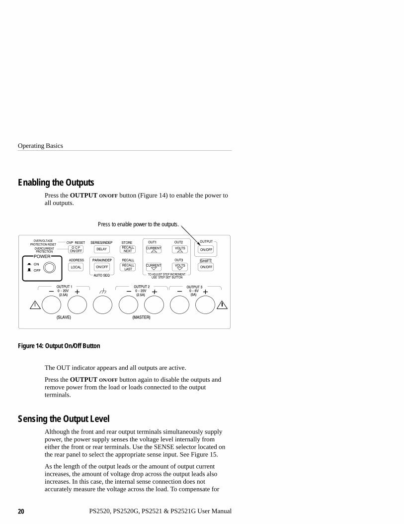
Enabling the OutputsPress the OUTPUT ON/OFF button (Figure 14) to enable the power toall outputs.
Press to enable power to the outputs.
Figure 14: Output On/Off Button
The OUT indicator appears and all outputs are active.
Press the OUTPUT ON/OFF button again to disable the outputs andremove power from the load or loads connected to the outputterminals.
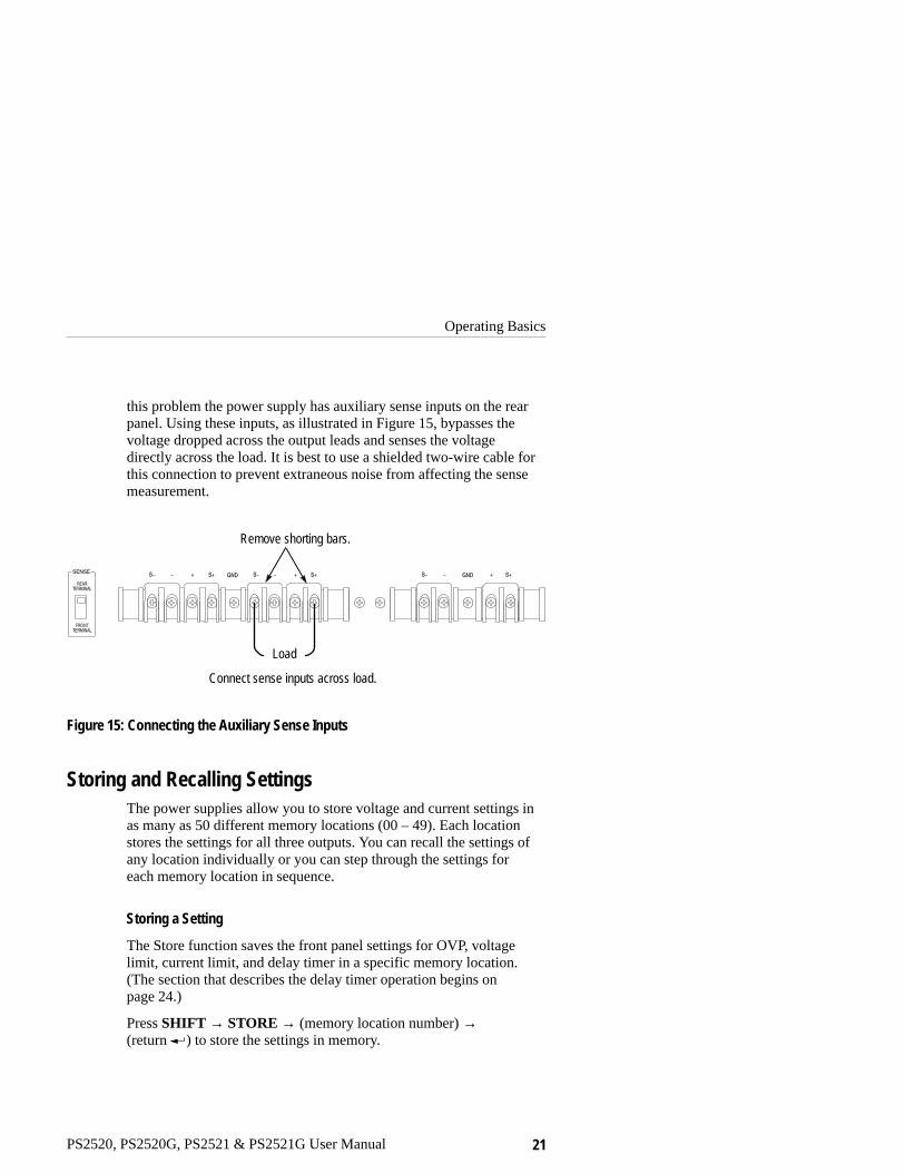
Sensing the Output LevelAlthough the front and rear output terminals simultaneously supplypower, the power supply senses the voltage level internally fromeither the front or rear terminals. Use the SENSE selector located onthe rear panel to select the appropriate sense input. See Figure 15.
As the length of the output leads or the amount of output currentincreases, the amount of voltage drop across the output leads alsoincreases. In this case, the internal sense connection does notaccurately measure the voltage across the load. To compensate for
Operating Basics
PS2520, PS2520G, PS2521 & PS2521G User Manual 21
this problem the power supply has auxiliary sense inputs on the rearpanel. Using these inputs, as illustrated in Figure 15, bypasses thevoltage dropped across the output leads and senses the voltagedirectly across the load. It is best to use a shielded two-wire cable forthis connection to prevent extraneous noise from affecting the sensemeasurement.
Remove shorting bars.
Connect sense inputs across load.
Load
Figure 15: Connecting the Auxiliary Sense Inputs
Storing and Recalling SettingsThe power supplies allow you to store voltage and current settings inas many as 50 different memory locations (00 – 49). Each locationstores the settings for all three outputs. You can recall the settings ofany location individually or you can step through the settings foreach memory location in sequence.
Storing a Setting
The Store function saves the front panel settings for OVP, voltagelimit, current limit, and delay timer in a specific memory location.(The section that describes the delay timer operation begins onpage 24.)
Press SHIFT → STORE → (memory location number) →(return ) to store the settings in memory.

Operating Basics
22 PS2520, PS2520G, PS2521 & PS2521G User Manual
Example: Store the power supply settings for all three outputs inmemory location 01:
SHIFT → STORE → 1 → (return )
Recalling an Individual Setting
The Recall function recalls the settings stored in a specific memorylocation.
Press SHIFT → RECALL → (memory location number) →(return ) to recall a particular setting from memory.
Example: Recall the settings for all three outputs from memorylocation 01:
SHIFT → RECALL → 1 → (return )
Storing and Recalling a Sequence of Settings
To create an automatic test routine, you can program the powersupply to sequence through the settings stored in two or moreconsecutive memory locations. You can recall the sequence of storedsettings either manually or automatically.
Manual Sequencing. Manual sequencing allows you to step throughthe stored settings one at a time by pressing the RECALL NEXT orRECALL LAST buttons.
1. Press SHIFT → STORE → (memory location number) →(return ) to store a setting. Repeat for each new setting, using aconsecutive memory location for each setting.
2. Press SHIFT → RECALL → (first memory location) →(decimal point) → (last memory location) → (return ) tospecify the first through last memory locations in the sequence.
3. Press RECALL NEXT to recall the next memory location in thesequence. Press RECALL LAST to recall the previous memorylocation in the sequence.

Operating Basics
PS2520, PS2520G, PS2521 & PS2521G User Manual 23
Example: Store three new settings for Output 1 and manually recallthe settings in sequence:
� Store 1 V, 0.1 A in memory location 01.
� Store 2 V, 0.15 A in memory location 02.
� Store 3 V, 0.15 A in memory location 03.
� Recall the settings of each memory location in order (01 – 03).
1. Select Output 1:
SHIFT → OUT1
2. Set the voltage limit to 1 V and the current limit to 0.1 A:
VOLTS SET → 1 → (return )
CURRENT SET → .1 → (return )
3. Store this setting in memory location 01:
SHIFT → STORE → 1 → (return )
4. Set the voltage limit to 2 V and the current limit to 0.15 A:
VOLTS SET → 2 → (return )
CURRENT SET → .15 → (return )
5. Store this setting in memory location 02:
SHIFT → STORE → 2 → (return )
6. Store 3 V, 0.15 A in memory location 03:
VOLTS SET → 3 → (return )
SHIFT → STORE → 3 → (return )
Note the current limit setting for location 03 is the same aslocation 02; therefore, you do not have to re-enter the currentlimit setting.
7. Set the sequence for memory locations 01 through 03:
SHIFT → RECALL → 1.3 → (return )

Operating Basics
24 PS2520, PS2520G, PS2521 & PS2521G User Manual
8. Recall the settings in memory locations 01, 02, and 03 in thatorder:
SHIFT → RECALL → 1 → (return )
RECALL NEXT → RECALL NEXT
Pressing RECALL NEXT recalls the next memory location in thesequence. (RECALL LAST recalls the previous memory location.)
Automatic Sequencing. To automatically output a sequence of storedsettings, you must store the delay time along with the other settingsfor each memory location. The minimum delay time setting is1 second; the maximum is 65535 seconds.
1. Press DELAY → (seconds) → (return ) to specify the delaytime for a sequence step.
2. Press SHIFT → STORE → (memory location number) →(return ) to store a setting.
3. Repeat steps 1 and 2 for each new setting, using a consecutivememory location for each setting.
4. Press SHIFT → RECALL → (first memory location) →(decimal point) → (last memory location) → (return ) tospecify the first through last memory locations in the sequence.
5. Press AUTO SEQ ON → OUTPUT ON to automatically outputthe settings in sequence.
Example: Recall the previously stored memory locations 01 and02 and set the delay times for each as follows:01: 3 seconds02: 7 secondsSet the test loop for memory locations 01 and 02.
1. Recall the settings in memory location 01:
SHIFT → RECALL → 1 → (return )
2. Set the delay time to 3 seconds:
DELAY → 3 → (return )
Operating Basics
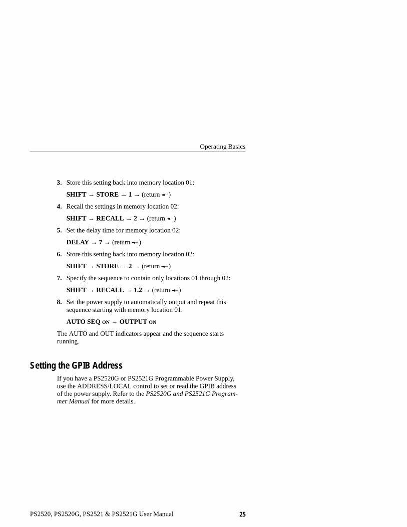
PS2520, PS2520G, PS2521 & PS2521G User Manual 25
3. Store this setting back into memory location 01:
SHIFT → STORE → 1 → (return )
4. Recall the settings in memory location 02:
SHIFT → RECALL → 2 → (return )
5. Set the delay time for memory location 02:
DELAY → 7 → (return )
6. Store this setting back into memory location 02:
SHIFT → STORE → 2 → (return )
7. Specify the sequence to contain only locations 01 through 02:
SHIFT → RECALL → 1.2 → (return )
8. Set the power supply to automatically output and repeat thissequence starting with memory location 01:
AUTO SEQ ON → OUTPUT ON
The AUTO and OUT indicators appear and the sequence startsrunning.
Setting the GPIB AddressIf you have a PS2520G or PS2521G Programmable Power Supply,use the ADDRESS/LOCAL control to set or read the GPIB addressof the power supply. Refer to the PS2520G and PS2521G Program-mer Manual for more details.

Operating Basics
26 PS2520, PS2520G, PS2521 & PS2521G User Manual
PS2520, PS2520G, PS2521 & PS2521G User Manual 27
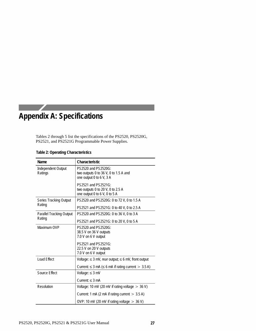
Appendix A: Specifications
Tables 2 through 5 list the specifications of the PS2520, PS2520G,PS2521, and PS2521G Programmable Power Supplies.
Table 2: Operating Characteristics
Name Characteristic
Independent OutputRatings
PS2520 and PS2520G: two outputs 0 to 36 V, 0 to 1.5 A andone output 0 to 6 V, 3 A
PS2521 and PS2521G: two outputs 0 to 20 V, 0 to 2.5 Aone output 0 to 6 V, 0 to 5 A
Series Tracking OutputRating
PS2520 and PS2520G: 0 to 72 V, 0 to 1.5 A
PS2521 and PS2521G: 0 to 40 V, 0 to 2.5 A
Parallel Tracking OutputRating
PS2520 and PS2520G: 0 to 36 V, 0 to 3 A
PS2521 and PS2521G: 0 to 20 V, 0 to 5 A
Maximum OVP PS2520 and PS2520G: 38.5 V on 36 V outputs7.0 V on 6 V output
PS2521 and PS2521G: 22.5 V on 20 V outputs7.0 V on 6 V output
Load Effect Voltage: ≤ 3 mV, rear output; ≤ 6 mV, front output
Current: ≤ 3 mA (≤ 6 mA if rating current � 3.5 A)
Source Effect Voltage: ≤ 3 mV
Current: ≤ 3 mA
Resolution Voltage: 10 mV (20 mV if rating voltage � 36 V)
Current: 1 mA (2 mA if rating current � 3.5 A)
OVP: 10 mV (20 mV if rating voltage � 36 V)

Appendix A: Specifications
28 PS2520, PS2520G, PS2521 & PS2521G User Manual
Table 2: Operating Characteristics (Cont.)
Name Characteristic
Program Accuracy(25 ± 5� C)
Voltage: ≤ 0.05% + 25 mV (+50 mV if rating voltage� 36 V)
Current: ≤ 0.2% + 10 mA
OVP: ≤ 2% + 0.6 V
Ripple and Noise20 Hz to 20 MHz
Voltage Ripple: 1 mVRMS/3 mVp-p
Voltage Noise: 2 mVRMS/30 mVp-p
Current: ≤ 3 mARMS (≤ 5 mARMS if rating current �3.5 A)
Temperature Coefficient(0� C to 40� C)
Voltage: ≤ 100 ppm � 3 mV
Current: ≤ 150 ppm � 3 mA
Readback Resolution Voltage: 10 mV (20 mV if rating voltage � 36 V)
Current: 1 mA (2 mA if rating current � 3.5 A)
Readback Accuracy(25 ± 5� C)
Voltage: ≤ 0.05% + 25 mV (+50 mV if rating voltage� 36 V)
Current: ≤ 0.2% + 10 mA
Response Time 10% to 90% (up): ≤ 100 ms
90% to 10% (down): ≤ 100 ms (≥ 10% rating load)
Readback TemperatureCoefficient
Voltage: ≤ 100 ppm + 10 mV (+20 mV if ratingvoltage � 36 V)
Current: ≤ 150 ppm + 10 mA
Drift1 Voltage: ≤ 0.03% + 6 mV
Current: ≤ 0.1% + 6 mA
Series Tracking
tracking error
load effect
source effect
Voltage: ≤ 0.1% + 50 mV
Voltage: ≤ 50 mV
Voltage: ≤ 3 mV
Appendix A: Specifications
PS2520, PS2520G, PS2521 & PS2521G User Manual 29
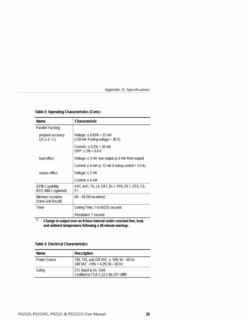
Table 2: Operating Characteristics (Cont.)
Name Characteristic
Parallel Tracking
program accuracy(25 ± 5� C)
load effect
source effect
Voltage: ≤ 0.05% + 25 mV (+50 mV if rating voltage > 36 V)
Current:: ≤ 0.2% + 20 mAOVP: ≤ 2% + 0.6 V
Voltage: ≤ 3 mV rear output (≤ 6 mV front output)
Current: ≤ 6 mA (≤ 12 mA if rating current > 3.5 A)
Voltage: ≤ 3 mV
Current: ≤ 6 mA
GPIB CapabilityIEEE-488.2 (optional)
SH1, AH1, T6, L4, SR1, RL1, PP0, DC1, DT0, C0,E1
Memory Locations(Store and Recall)
00 – 49 (50 locations)
Timer Setting Time: 1 to 65535 seconds
Resolution: 1 second1 Change in output over an 8-hour interval under constant line, load,
and ambient temperature following a 30-minute warmup.
Table 3: Electrical Characteristics
Name Description
Power Source 100, 120, and 220 VAC, ± 10% 50 – 60 Hz240 VAC –10% + 4.2% 50 – 60 Hz
Safety ETL listed to UL 1244Certified to CSA–C22.2 No 231–M89

Appendix A: Specifications
30 PS2520, PS2520G, PS2521 & PS2521G User Manual
Table 4: Environmental Characteristics
Name Description
Storage Temperature –10� C to +70� C (+14� F to +158� F)
Operating Temperature 0� C to +40� C (+32� F to +104� F)
Table 5: Physical Characteristics
Name Description
Overall Dimensions Width: 255 mm (10.0 in)
Height: 145 mm (5.7 in)
Depth: 346 mm (13.6 in)
Weight 10 kg (22 lbs)

PS2520, PS2520G, PS2521 & PS2521G User Manual 31
Appendix B: Maintenance
This appendix provides information for the basic maintenance of thepower supply. Electronic maintenance on the power supply must beperformed by a trained technician. However, an operator can performsome basic and routine maintenance.
CleaningTo clean the power supply, use a soft cloth dampened in a solution ofmild detergent and water. Do not spray cleaner directly onto theinstrument, since it may leak into the cabinet and cause damage.
Do not use chemicals containing benzine, benzene, toluene, xylene,acetone, or similar solvents.
Do not use abrasive cleaners on any portion of the frequency counter.
Warranty ServiceThe power supplies are covered by a standard Tektronix one-yearwarranty. The warranty statement appears at the front of this manual.If the power supply fails during the warranty period, return it toTektronix for free servicing (subject to conditions of the warrantystatement).
To arrange for warranty service or to get an estimate on a productthat is out of warranty, call your local Tektronix office. If you arewithin the continental U.S., you may call 1-800-TEK-WIDE(1-800-835-9433) for assistance. When you call, have the serialnumber of the power supply available. The serial number is locatedon the left side of the rear panel.

Appendix B: Maintenance
32 PS2520, PS2520G, PS2521 & PS2521G User Manual
Repackaging for ShipmentIf your instrument must be returned for servicing, use the originalpacking materials if possible. If the original materials are unfit orunavailable, repackage the power supply in the following manner:
1. Use a sturdy shipping carton made of corrugated cardboard thathas an interior size of at least 15 cm (6 in) greater than theinstrument size in all directions.
2. Enclose the following information:
� Owner’s name and address
� Name and phone number of a person that Tektronix shouldcontact
� Serial number of the instrument
� Description of the problem
3. Completely wrap the power supply with polyethylene sheeting(or equivalent material) to protect the outside finish and keepharmful substances out of the power supply.
4. Cushion the instrument on all sides with 8 cm (3 in) of paddingmaterial or urethane foam tightly packed between the carton andthe instrument.
5. Seal the shipping carton with an industrial stapler or strappingtape.
6. Call your local Tektronix office for shipping instructions. If youare within the continental U.S., you may call 1-800-TEK-WIDE(1-800-835–9433) for assistance.
TroubleshootingIf the power supply does not function properly, refer to Table 6 toeliminate operating faults.

Appendix B: Maintenance
PS2520, PS2520G, PS2521 & PS2521G User Manual 33
WARNING. To prevent electrical shock, unplug the power cord anddisconnect the outputs before changing the line fuse or line voltagesetting.
Table 6: Troubleshooting Steps
Symptom Possible Causes
Supply does not power on � Power cord not connected properly; checkconnections.
� Line voltage selection not correct; checksetting.
� Fuse blown; disconnect line cord and seepage 2 to open cover and replace fuse. Usethe proper fuse for the line voltage setting.See page 37 for fuse part numbers.
No output or incorrectoutput
� Leads not properly connected to the positiveand negative outputs.
� The output is not enabled (“OUT” indicator isnot lighted); press the OUTPUT button.
� The power supply settings are not appropriatefor the output load. The power supply isfunctioning normally by limiting either currentor voltage. Check load or disconnect output toverify.
Error Message (“Err...”) � Setup error; check error number against errordescription in Table 7 on page 34.
� Overvoltage protection tripped; correct thecause and clear error (OVP RESET). Setovervoltage protection to a higher value ifnecessary.
� Overcurrent protection tripped; correct thecause and clear the error (OCP OFF).
The power supply indicates an error in setup or operation bydisplaying the message “Err –xxx” on the front panel. Table 7 listseach message number and explains what the error code means.

Appendix B: Maintenance
34 PS2520, PS2520G, PS2521 & PS2521G User Manual
Table 7: Error Messages
Front PanelError Code Description
0 “No error”
–001 “Self-test failed; CPU test error”
–002 “Self-test failed; RAM test error”
–003 “Self-test failed; ROM test error”
–005 “Self-test failed; DAC/ADC test error”
–012 “Device-specific error; Overcurrent protection error”
–013 “Device-specific error; Overvoltage protection error”
–016 “Data out of range; Voltage too large”
–017 “Data out of range; Current too large”
–018 “Data out of range; Voltage too small”
–019 “Data out of range; Current too small”
–064 “Setting conflict; Timer setting error”
–065 “Setting conflict; Overvoltage protection setting error”
–066 “Setting conflict; Address setting error”
–067 “Setting conflict; Voltage setting error”
–068 “Setting conflict; Current setting error”
–069 “Setting conflict; Recall setting error”
–070 “Setting conflict; Store setting error”
–091 “Device-specific error; Calibration current full-scale error”
–092 “Device-specific error; Calibration voltage full-scale error”

Appendix B: Maintenance
PS2520, PS2520G, PS2521 & PS2521G User Manual 35
Table 7: Error Messages (Cont.)
Front PanelError Code Description
–093 “Device-specific error; Calibration overvoltage protectionfull-scale error”
–094 “Device-specific error; Calibration overvoltage protectionoffset error”

Appendix B: Maintenance
36 PS2520, PS2520G, PS2521 & PS2521G User Manual
PS2520, PS2520G, PS2521 & PS2521G User Manual 37
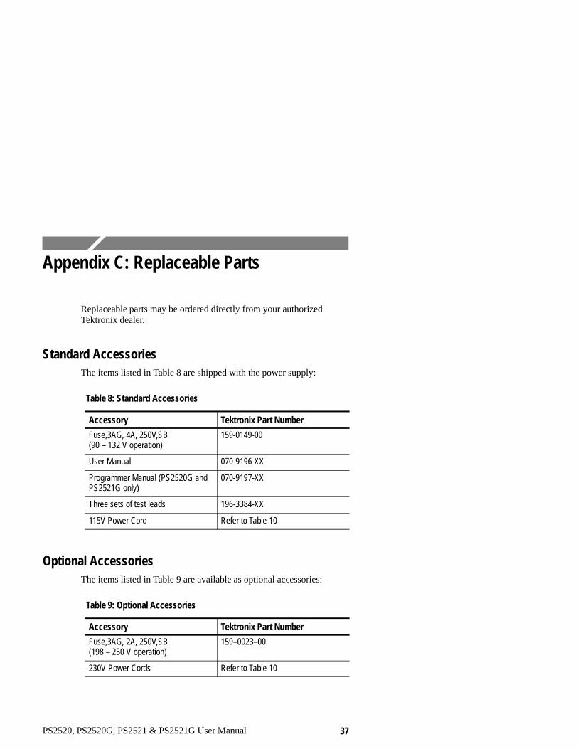
Appendix C: Replaceable Parts
Replaceable parts may be ordered directly from your authorizedTektronix dealer.
Standard AccessoriesThe items listed in Table 8 are shipped with the power supply:
Table 8: Standard Accessories
Accessory Tektronix Part Number
Fuse,3AG, 4A, 250V,SB(90 – 132 V operation)
159-0149-00
User Manual 070-9196-XX
Programmer Manual (PS2520G andPS2521G only)
070-9197-XX
Three sets of test leads 196-3384-XX
115V Power Cord Refer to Table 10
Optional AccessoriesThe items listed in Table 9 are available as optional accessories:
Table 9: Optional Accessories
Accessory Tektronix Part Number
Fuse,3AG, 2A, 250V,SB (198 – 250 V operation)
159–0023–00
230V Power Cords Refer to Table 10

Appendix C: Replaceable Parts
38 PS2520, PS2520G, PS2521 & PS2521G User Manual
The following power cords are available.
Table 10: Accessory Power Cords
Plug Configuration Normal UsageTektronix PartNumber
North America115 V
161-0104-00
Europe230 V
161-0104-06
United Kingdom230 V
161-0104-07
Australia230 V
161-0104-05
North America230 V
161-0104-08
Switzerland230 V
161-0167-00

PS2520, PS2520G, PS2521 & PS2521G User Manual 39
Index
Aaccessories
optional, 37standard, 37
amperes readout, depicted, 5automatic tracking, 18
CC.C., definition of, 9C.V., definition of, 9characteristics
electrical, 29environmental, 30operating, 27physical, 30
cleaning, 31connection
external parallel, 16external series, 14ground referenced, 11isolated ground, 11parallel, depicted, 16
controlsSee also indicatorsADDRESS, 25AUTO SEQ, 25CURRENT (step), 10CURRENT SET, 9DELAY, 24entry sequence, 6front panel, 5keypad, use of, 9LOCAL, 25OCP, 8OUTPUT, 20output selection, 7
OVP RESET, 8OVP SET, 8power switch, 5rear panel, 6RECALL, 22RECALL LAST, 22, 24RECALL NEXT, 22, 24return key, 6sense selector, 20SHIFT, 7STEP SET, 10STORE, 21, 22VOLTS (step), 10VOLTS SET, 9
cooling, clearance, 3cooling fan, depicted, 6current limit, setting level of, 9CURRENT steps, setting, 10
Ddata entry, 6data entry keypad, depicted, 5diagnostics, 4dimensions, physical, 30
Eerror messages, 34
Ffeatures
front panel, 5product, 1rear panel, 6
fuse, replacement, 3

Index
40 PS2520, PS2520G, PS2521 & PS2521G User Manual
fuse access, depicted, 3, 6
GGPIB connector, depicted, 6GPIB option, 1
Iindicators
AUTO, 25C.C., 9C.V., 9front panel depicted, 5GPIB status, 5OCP, 8OUT, 7, 25output, 5PARA, 19SERIES, 18SHIFT, 7
installationfuse, 3power cord, 3
Kkeypad, depicted, 5
Lline voltage selector, depicted, 2, 6
Mmaintenance, 31master/slave operation, 18memory indicator, depicted, 5memory locations
recalling from, 21, 22storing to, 21, 22
OOCP
definition of, 8reset, 8setting level of, 8
optional accessories, 37output
enabling, 20rating, 27sensing level of, 20
output connectorsdepicted, 5, 6methods for connecting, 11
output controls, depicted, 5output modes, independent, 12overcurrent protection, setting level
of, 8overvoltage protection, setting
level of, 8OVP
definition, 8maximum level, 27reset, 8
Ppara operation, depicted, 19parallel tracking, 19power connector, depicted, 6power cord, installation, 3power switch, depicted, 5procedure, general operation, 4
Rrecalling stored settings, 22
Index
PS2520, PS2520G, PS2521 & PS2521G User Manual 41
repackaging, 32replaceable parts, 37
Sselector, line voltage, 2sense inputs, depicted, 6sense selector, depicted, 6sensing output level, procedure for,
20sequence
RECALL, 22STORE, 22
sequencing, automatic, 24series tracking, 18shipment, repackaging for, 32specifications, 27standard accessories, 37status indicators, depicted, 5STEP SET function, procedure for,
10
storing a sequence, 22storing instrument settings, 21
Ttelephone numbers, TEK WIDE,
31, 32tracking, automatic, 18troubleshooting, 32
Vvoltage, setting limit of, 9VOLTS readout, depicted, 5VOLTS steps, setting, 10
Wwarranty service, 31weight, 30

Index
42 PS2520, PS2520G, PS2521 & PS2521G User Manual