User Manual PowerWAVE 5000/TP · PowerWAVE 5000/TP User Manual Pioneering solutions for total power...
74
PowerWAVE 5000/TP User Manual Pioneering solutions for total power protection
Transcript of User Manual PowerWAVE 5000/TP · PowerWAVE 5000/TP User Manual Pioneering solutions for total power...

PowerWAVE 5000/TP
User Manual
Pioneering solutions for total power protection


UPS470-02-03 PW5000TP User Manual UK Dated 12/02/15
Document Control
ISSUE DATE REVISION SUMMARY
470-02-00 06/08/14 Manual revised and issued as 470-02-00
470-02-02 01/12/14 Block diagram errors corrected
470-02-03 12/02/15 Output current ratings corrected in specification

UPS470-02-03 PW5000TP User Manual UK Dated 12/02/15
Uninterruptible Power Supplies Ltd has taken every precaution toproduce an accurate, complete and easy to understand manual and
will therefore assume no responsibility nor liability for direct,indirect or accidental personal or material damage due to any
misinterpretation of or accidental mistakes in this manual.
© 2015 Uninterruptible Power Supplies Ltd
This manual may not be copied nor reproduced without writtenpermission of Uninterruptible Power Supplies Ltd.

Table of Contents
1 Safety1.1 Description of symbols used in this manual 1-11.2 User precautions 1-1
2 Description2.1 Reliability and Quality Standards 2-12.2 PowerWave 5000TP Model Range 2-1
2.2.1 Single/Multi-cabinet configurations 2-22.3 Advanced Design Features 2-2
2.3.1 Input booster technology 2-22.3.2 Flexible battery management 2-22.3.3 Decentralized Parallel Architecture (DPA) 2-2
2.4 Warranty 2-22.5 Extended Warranty 2-32.6 Additional Service/Maintenance Support 2-3
3 Installation3.1 Introduction 3-13.2 Receipt of the UPS 3-1
3.2.1 Site transportation 3-13.2.2 Unpacking the UPS 3-23.2.3 Batteries 3-2
3.3 Storage 3-33.3.1 UPS storage 3-33.3.2 Battery 3-3
3.4 Positioning 3-33.4.1 Planning the installation 3-3
3.5 UPS Power Cabling 3-53.5.1 General requirements (preparation and planning) 3-5
3.6 Connecting the UPS input supply 3-133.6.1 Safety notes 3-133.6.2 Preparation for the input cabling 3-133.6.3 Connecting the UPS input power cables 3-13
3.7 Connecting the UPS output 3-143.7.1 Safety notes 3-143.7.2 Preparation for the output cabling 3-143.7.3 Connecting the UPS output cables 3-15
3.8 Battery connections 3-193.8.1 Remote battery enclosures 3-193.8.2 Connecting the external battery enclosure 3-19
3.9 Multi-module control cabling and configuration 3-213.9.1 Connecting the parallel communication cables (Bus-lines) 3-213.9.2 Module configuration DIP Switch selection 3-22
3.10 Module interfacing facilities 3-233.10.1 JD1 Smart Port – Serial RS 232 and USB Port 3-24
UPS470-02-03 PW5000TP User Manual UK Dated 12/02/15 I

II
3.10.2 X1 Dry Port (volt-free contacts) 3-253.10.3 JR1 / RS485 INTERFACE FOR MULTIDROP 3-253.10.4 X2 Dry Port – Optional Output Interfaces Terminal Block (X2) 3-25
4 Operation4.1 Commissioning 4-14.2 Control Panel 4-1
4.2.1 Power Management Display (PMD) 4-14.2.2 Mimic LED indicators 4-24.2.3 Operator keys 4-2
4.3 Description of the LCD display 4-34.3.1 Status screens 4-34.3.2 Main menu screen 4-44.3.3 Event log menu screen 4-44.3.4 Measurements menu screen 4-44.3.5 Commands menu screen 4-54.3.6 UPS Data menu screen 4-54.3.7 Set-up User menu screen 4-64.3.8 Set-Up Service menu screen 4-6
4.4 Operating Modes 4-74.4.1 On-Line (Inverter) mode 4-74.4.2 Bypass (Line-Interactive) mode 4-74.4.3 Maintenance Bypass Mode 4-84.4.4 Multi-module configuration concept 4-9
4.5 Operating Instructions 4-104.5.1 Transfer to Maintenance Bypass Mode 4-104.5.2 Starting the UPS system from the Maintenance Bypass 4-124.5.3 Complete system shutdown 4-144.5.4 Individual module start/stop procedure 4-15
5 Maintenance5.1 Introduction 5-15.2 System calibration 5-15.3 User responsibilities 5-15.4 Routine maintenance 5-15.5 Battery Testing 5-2
6 Troubleshooting6.1 Alarms 6-16.2 Menu, Commands, Event Log, Measurements, 6-1
6.2.1 Event Log Screen 6-16.2.2 Fault Identification and Rectification Messages and Alarms 6-2
6.3 Contacting Service 6-2
7 Options7.1 Introduction 7-17.2 Remote Emergency Stop facilities 7-17.3 Generator ON facilities 7-27.4 Temperature sensor for temperature-dependant battery charging 7-37.5 WAVEMON Shutdown and Management Software 7-4
7.5.1 Why is UPS Management important? 7-47.5.2 WAVEMON Shutdown and Monitoring Software 7-4
7.6 SNMP CARD/ADAPTOR For Network Management/Remote Monitoring 7-57.7 Modem/Ethernet card / PowerREPORTER™ management software 7-7
UPS470-02-03 PW5000TP User Manual UK Dated 12/02/15

8 Specifications8.1 Mechanical 8-18.2 Input Characteristics 8-28.3 Output Characteristics 8-28.4 Battery Characteristics 8-38.5 Environmental 8-38.6 Heat Dissipation With Non-Linear Loads 8-38.7 Standards 8-48.8 Communication Options 8-48.9 Fuses & Cables Quick Reference 8-5
UPS470-02-03 PW5000TP User Manual UK Dated 12/02/15 III

:
-IV
UPS470-02-03 PW5000TP User Manual UK Dated 12/02/15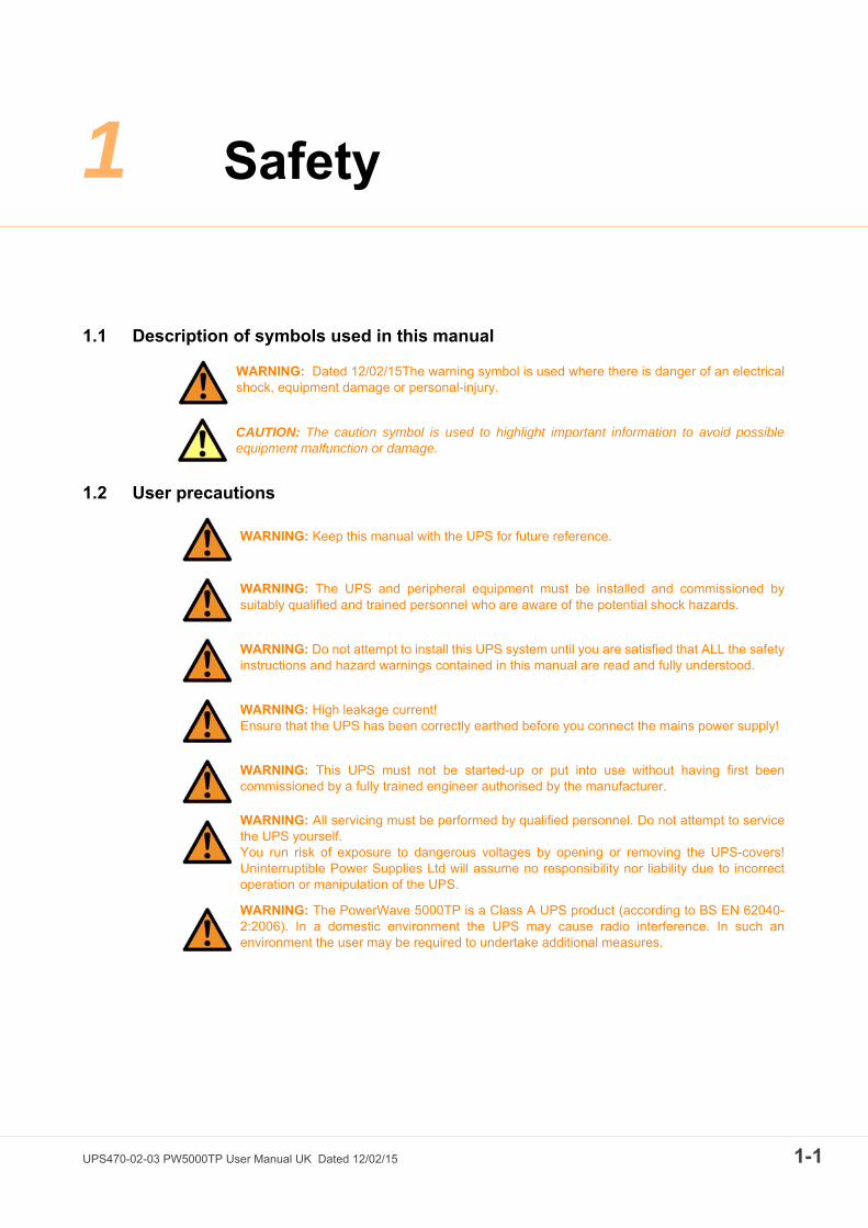
1
UPS470-02-03 PW5000T
Safety
1.1 Description of symbols used in this manual
1.2 User precautions
WARNING: Dated 12/02/15The warning symbol is used where there is danger of an electricalshock, equipment damage or personal-injury.
CAUTION: The caution symbol is used to highlight important information to avoid possibleequipment malfunction or damage.
WARNING: Keep this manual with the UPS for future reference.
WARNING: The UPS and peripheral equipment must be installed and commissioned bysuitably qualified and trained personnel who are aware of the potential shock hazards.
WARNING: Do not attempt to install this UPS system until you are satisfied that ALL the safetyinstructions and hazard warnings contained in this manual are read and fully understood.
WARNING: High leakage current!Ensure that the UPS has been correctly earthed before you connect the mains power supply!
WARNING: This UPS must not be started-up or put into use without having first beencommissioned by a fully trained engineer authorised by the manufacturer.
WARNING: All servicing must be performed by qualified personnel. Do not attempt to servicethe UPS yourself.You run risk of exposure to dangerous voltages by opening or removing the UPS-covers!Uninterruptible Power Supplies Ltd will assume no responsibility nor liability due to incorrectoperation or manipulation of the UPS.
WARNING: The PowerWave 5000TP is a Class A UPS product (according to BS EN 62040-2:2006). In a domestic environment the UPS may cause radio interference. In such anenvironment the user may be required to undertake additional measures.
P User Manual UK Dated 12/02/15 1-1

1: Safety
1-2
UPS470-02-03 PW5000TP User Manual UK Dated 12/02/15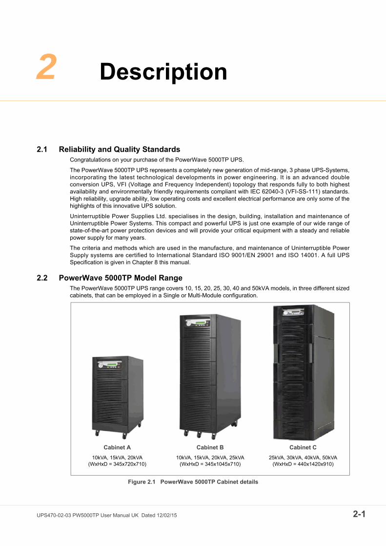
2
UPS470-02-03 PW5000T
Description
2.1 Reliability and Quality StandardsCongratulations on your purchase of the PowerWave 5000TP UPS.
The PowerWave 5000TP UPS represents a completely new generation of mid-range, 3 phase UPS-Systems,incorporating the latest technological developments in power engineering. It is an advanced doubleconversion UPS, VFI (Voltage and Frequency Independent) topology that responds fully to both highestavailability and environmentally friendly requirements compliant with IEC 62040-3 (VFI-SS-111) standards.High reliability, upgrade ability, low operating costs and excellent electrical performance are only some of thehighlights of this innovative UPS solution.
Uninterruptible Power Supplies Ltd. specialises in the design, building, installation and maintenance ofUninterruptible Power Systems. This compact and powerful UPS is just one example of our wide range ofstate-of-the-art power protection devices and will provide your critical equipment with a steady and reliablepower supply for many years.
The criteria and methods which are used in the manufacture, and maintenance of Uninterruptible PowerSupply systems are certified to International Standard ISO 9001/EN 29001 and ISO 14001. A full UPSSpecification is given in Chapter 8 this manual.
2.2 PowerWave 5000TP Model Range The PowerWave 5000TP UPS range covers 10, 15, 20, 25, 30, 40 and 50kVA models, in three different sizedcabinets, that can be employed in a Single or Multi-Module configuration.
Figure 2.1 PowerWave 5000TP Cabinet details
Cabinet A
10kVA, 15kVA, 20kVA(WxHxD = 345x720x710)
Cabinet B
10kVA, 15kVA, 20kVA, 25kVA(WxHxD = 345x1045x710)
Cabinet C
25kVA, 30kVA, 40kVA, 50kVA(WxHxD = 440x1420x910)
P User Manual UK Dated 12/02/15 2-1

2: Description
2-2
2.2.1 Single/Multi-cabinet configurations
The PowerWave 5000TP UPS may be configured to operate as a single cabinet, or several (up to 20)cabinets can be connected in parallel to operate as a multi-module UPS system. A multi-moduleconfiguration is generally used either to increase the system’s total power capacity, or to provide moduleredundancy. This manual describes the installation, configuration and operation of both single and multi-module systems.
Note: Although the UPS single/multi configuration can be modified in the field it is generally specified onordering so that the module can be configured and fully tested in the factory prior to despatch.
2.3 Advanced Design Features
2.3.1 Input booster technology
The UPS module’s inbuilt advanced booster technology results in a perfect sinusoidal input power quality at0.99 input power factor with a harmonic content of 3% THD(i). This leads to a more reliable total systemoperation and savings in generator and transformer sizing, as losses in the windings are minimised. It alsomeans that traditional harmonic filters are no longer required.
The high power factor presented by the UPS on the incoming mains supply minimises cabling and fusingcosts due to the resulting lack of reactive power consumption. This, together with the accompanying lowharmonic currents, provide the following benefits:
• No additional losses in wires and cables.• No extra heating of transformers and generators.• No over sizing of generators.• No false circuit breaker tripping and malfunction.• No erratic operation of computers, telecommunication, monitors, electronic test equipment etc.• No resonance with power factor correction capacitors.
2.3.2 Flexible battery management
This equipment employs a flexible battery management which avoids premature deterioration of battery lifeby advanced management of battery charging and preventive failure diagnostics.
The major benefits are:
• AC-ripple free battery charging due to a dc-dc charger separated from the rectifier and inverter.• Wide range of number of battery blocks (22-50 blocks of 12V; depending on autonomy times).• UPS's wide input voltage operating window extends the battery life due to fewer discharge cycles.• Battery discharge protection caused by load jumps.• Proactive battery protection from false manipulations and inadequate charging voltages.• Proactive battery failure detection thanks to Advanced Battery Diagnosis (ABD) - Algorithm.• User selectable battery tests.• Optional temperature compensated charging to enhance battery life.
2.3.3 Decentralized Parallel Architecture (DPA)
The PowerWave 5000TP system features DPA paralleling technology that provides n+x redundancy withoutintroducing a single-point-of-failure. The modules utilizing the DPA technology are completely autonomousby means of individual power units, bypasses, CPUs, control panels and separate battery configuration.
2.4 WarrantyThe PowerWave 5000TP UPS is supplied with a limited warranty that the UPS and its component parts arefree from defects in materials and workmanship for a period of one year from the date of originalcommissioning or fifteen months from the date of original delivery, whichever is the sooner. This warranty isthe only warranty given and no other warranty, express or implied, is provided.
This warranty is invalidated if the UPS is put into use without having been commissioned by a fully trainedand authorised person. This warranty does not apply to any losses or damages caused by misuse, abuse,
UPS470-02-03 PW5000TP User Manual UK Dated 12/02/15

2: Description
negligence, neglect, unauthorised repair or modification, incorrect installation, inappropriate environment,accident, act of God or inappropriate application.
If the UPS fails to conform to the above within the warranty period then Uninterruptible Power Supplies Ltd..will, at its sole option, repair or replace the UPS. All repaired or replaced parts will remain the property ofUninterruptible Power Supplies Ltd.
As a general policy, Uninterruptible Power Supplies Ltd. does not recommend the use of any of its productsin life support applications where failure or malfunction of the product can be reasonably expected to causefailure of the life support device or to significantly affect it’s safety or effectiveness. Uninterruptible PowerSupplies Ltd. does not recommend the use of any of its products in direct patient care. Uninterruptible PowerSupplies Ltd. will not knowingly sell its products for use in such applications unless it receives in writingassurances satisfactory to Uninterruptible Power Supplies Ltd. that the risks of injury or damage have beenminimized, the customer assumes all such risks and the liability of Uninterruptible Power Supplies Ltd. isadequately protected under the circumstances
2.5 Extended WarrantyThe Standard Warranty may be enhanced by protecting the UPS with an Extended Warranty Agreement(maintenance contract).
An Extended Warranty Agreement enhances the standard warranty by providing the following:
• Regular preventative maintenance inspections.• Guaranteed speed of response to operational problems.• 24 hour telephone support.• Fully comprehensive cover – excluding batteries and capacitors.
Contact the Service Support Hotline on 0800 731 3269 for further details.
2.6 Additional Service/Maintenance SupportIn addition to providing support for the PowerWave 5000TP UPS, Uninterruptible Power Supplies Ltd. areable to provide maintenance and support on a wide range of different UPS products.
If you are interested in an extended warranty for your PowerWave 5000TP UPS, or any other UPS you mayhave, please complete the enquiry form shown opposite and return or FAX to:
CAUTION: The UPS may contain batteries which must be re-charged for a minimum of 24hours every six months to prevent deep-discharging. Batteries that have been, for whateverreason, deep-discharged are not covered by the warranty.
Uninterruptible Power Supplies Ltd.WoodgateBartley Wood Business ParkHookHampshireRG27 9XA
Tel: 01256 3867000800 731 3269 (24 Hr.)
Fax: 01256 386701
Email: [email protected]
UPS470-02-03 PW5000TP User Manual UK Dated 12/02/15 2-3

2: Description
2-4
Thank you for your enquiry, which will receive our prompt attention.If you need to contact us immediately call free on,
Freefone 0800 731 3269
or E-mail us on [email protected]
Uninterruptible Power Supplies Ltd.WoodgateBartley Wood Business ParkHookHampshireRG27 9XA
Tel: 01256 386700
Name: ............................................................................................
Job Title: ............................................................................................
Company: ............................................................................................
Address: ............................................................................................
............................................................................................
............................................................................................
............................................................................................
Post Code ............................................................................................
Tel. ............................................................................................
Fax. ............................................................................................
E-mail ............................................................................................
Please contact me to discuss:
Extended Warranty options for my PowerWave 5000TP UPS
Extended warranty options for my UPS System as below:
Manufacturer:...................................................................
Model Nº:..........................................................................
Rating kVA:.......................................................................
Replacement Batteries......................................................................
Other ..................................................................(please specify)
Fax to: 01256 386701 www.upspower.co.uk
UPS470-02-03 PW5000TP User Manual UK Dated 12/02/15

3
UPS470-02-03 PW5000T
Installation
3.1 IntroductionThis chapter contains all the information necessary for the correct unpacking, positioning, cabling andinstallation of the PowerWave 5000TP UPS.
3.2 Receipt of the UPSThe UPS and accessories are delivered on a specifically designed pallet that is easy to move with a forklift ora pallet jack.
The packing container protects the UPS from mechanical and environmental damage. This protection isfurther increased by wrapping the PowerWave 5000TP UPS with a plastic sheet.
Upon receiving the UPS, carefully examine the packing container and the UPS for any sign of physicaldamage. The outside 'Tip&Tel' (“FRAGILE” and “ARROW”) indicator should be intact if the equipment hasbeen transported in an upright position. In case of rupture (or if they are suspect) inform the carrier andUninterruptible Power Supplies Ltd. immediately.
Ensure that the received UPS corresponds to the description indicated in the delivery note.
3.2.1 Site transportation
If you transport the UPS equipment after it has been off-loaded (for example, for storage or moving to adifferent installation location) please observe the following precautions.
WARNING: All the operations described in this section must be performed by authorisedelectricians or suitably qualified personnel.Uninterruptible Power Supplies Ltd. will take no responsibility for any personal or materialdamage caused by incorrect cabling or operations, or activities which are not carried out instrict accordance with the instructions contained in this manual.
CAUTION: When off loading the UPS always keep it in an upright position.Do not drop the equipment. Do not stack the pallets due to the high-energy batteries involved and the heavy weight.
CAUTION: Visible transport damages must be notified to the carrier immediately after receipt!Other claims for shipping damage must also be filed immediately and the carrier must beinformed within 7 days of receipt of the equipment.Packing materials should be stored for further investigation.
CAUTION: Potential dangers:– Do not tilt the UPS or Battery Cabinet by more than 10° as it might damage the equipment. If the equipment has been tilted do not connect it to the mains electricity supply.– The weight of the UPS system could cause serious injuries to personnel or other equipmentin the surrounding area.
CAUTION: Storage:– The UPS should be stored in the original packing and shipping carton.– The recommended storing temperature for the UPS system and batteries is between +5°Cand +40°C.– The UPS system and the battery sets must be protected from humidity < 90% RH (non-condensing).
P User Manual UK Dated 12/02/15 3-1

3: Installation
3-2
3.2.2 Unpacking the UPS
The cabinets are attached to a shipping pallet, wrapped in polythene and protected by a sturdy cardboardcovering.
1. Ensure that the floor surface islevel and suitable for wheelingand taking the heavy weight.
2. Remove cardboard packingcontainer by pulling it upwards.The packaging will contain awooden ramp.
3. Remove the protective plasticcover and any other packingaround the UPS.
4. Remove the fixings securingthe UPS to the pallet.
5. Position the enclosed ramp (‘A’& ‘B’ cabinets) at the rear sideof the cabinet and roll the UPSdown the ramp.
6. Retain the packaging materialsfor future shipment of the UPS.
7. Examine the UPS for any signof damage and notify yourcarrier or supplier immediatelyif damage is apparent.
Checking the nameplate
Before proceeding, check that the technical specifications on the nameplate, situated on the rear of the UPSor behind the front internal door, corresponds to the purchased material mentioned in the goods deliverynote.
3.2.3 Batteries
The batteries connected to the UPS are usually of a sealed, maintenance-free design. The batteries can bemounted either within the UPS, in an external battery cabinet, or on a bespoke battery rack, depending on therequired autonomy time and paralleling arrangement. For optimum reliability a separate battery string shouldbe connected to each individual UPS. The batteries are usually shipped separately and fitted by amanufacturer-approved engineer when the UPS is commissioned.
If the UPS is delivered without batteries, Uninterruptible Power Supplies Ltd. is not responsible for anydamage or malfunctioning caused to the UPS by the incorrect supply, storage, installation or connection ofbatteries by third parties.
WARNING: The UPS system, the battery cabinet (option) and the batteries are heavy andmay tip during transportation causing serious injury if the unpacking instructions are notfollowed closely.
CAUTION: Before you finally unpack the equipment, remove any additional external shippingpackaging and visually check that the ‘Tip&Tel’ indicator (“FRAGILE” and “ARROW”) on thepacking container is intact.
Figure 3.1 Unpacking cabinets A & B
3
24
UPS470-02-03 PW5000TP User Manual UK Dated 12/02/15

3: Installation
3.3 Storage
3.3.1 UPS storage
If you plan to store the UPS prior to use, it should be kept in a clean, dry environment with an ambienttemperature between -25°C to +70°C and relative humidity of less than 90%. If the UPS is removed from the packing container you must also ensure you protect it from dust.
3.3.2 Battery
The storage capability of the UPS batteries depends greatly on the ambient temperature. It is important not tostore the UPS batteries for longer than 6 months at 20°C, 3 months at 30°C or 2 months at 35°C storagetemperature without recharging the battery.
For longer term storage the battery must be fully recharged every 6 months @20°C.
3.4 Positioning
3.4.1 Planning the installation
A certain amount of pre-planning will help ensure smooth, trouble-free equipment installation. The followingguidelines should be taken into account when planning a suitable UPS location and environment.
1. The equipment must be installed and transported in a upright position.
2. The floor at the installed location and en-route from the off-loading point must be able to safely take theweight of the UPS and battery equipment plus fork lift during transit. The floor material where the UPS isto be located should be non-flammable.
3. The UPS cabinet requires space to bottom/front and back to enable cooling airflow. Allow a minimum of200mm clearance at the back of the cabinet. Suitable ventilation airflow (not exceeding +40°C) must beprovided (See Figure 3.2).
4. All parts of the UPS requiring access for maintenance, servicing and user operation are accessible fromthe front and rear. Reserve a minimum of 900mm space at the front of the UPS cabinet.
5. An ambient temperature of 20°C is recommended to achieve a long battery life.
6. Avoid high ambient temperature, moisture and humidity.
In summary
The UPS should be located where:
a) Humidity (< 90% non-condensing) and temperature (+15°C / +25°C) are within prescribed limits.b) Fire protection standards are respected.c) Cabling can be performed easily.d) A minimum 900mm front accessibility is available for service or periodic maintenance.e) Requested air cooling flow is available.f) The air conditioning system can provide a sufficient amount of air cooling to keep the room at, or
below, the maximum desired temperature.g) No dust or corrosive/explosive gases are present.h) The location is vibration free.i) If the UPS is to be installed in bayed enclosures, partition walls have to be installed.
CAUTION: Sealed batteries must never be stored in a discharged or partially discharged state.Extreme temperature, under-charge, overcharge or over-discharge will destroy the batteries!
Key Point: Note the following:
• Charge the battery both before and after storing.• Always store the batteries in a dry, clean, cool environment in their original packaging.• If the packaging is removed protect the batteries from dust and humidity.
UPS470-02-03 PW5000TP User Manual UK Dated 12/02/15 3-3

3: Installation
3-4
Figure 3.2 UPS Space Recommendations
10kVA 15kVA 20kVA 25kVA 30kVA 40kVA 50kVA
Heat Dissipation with 100% Non-linear Load per range (EN 62040-3)
W 600 900 1100 1400 1700 2300 2900
Heat Dissipation with 100% Non-linear Load per range (EN 62040-3)
BTU/h 2048 3072 3754 4778 5802 7850 9898
Airflow (25°C - 30°C) with 100% Non-linear Load per range (EN 62040-3)
m³/h 150 150 150 150 570 570 570
Heat Dissipation without load W 120 150 150 170 250 300 350
Cabinet A Cabinet B Cabinet C Batt Cab C
Dimensions (WxHxD)mm 345x720x710 345x1045x710 440x1420x910 480x1420x940
Maintenance/Service Accessibility Top, rear, front, left and right side Top, front, left and right side
Positioning Min. 200mm rear space required for ventilation
Input and Output Power Cabling From the bottom at the rear. From the bottom at the front
UPS
Z
Front
V
X
600 mm
600 mm
Access Space
BATTERYCABINET(option)
Front
Y*VX X
Y*
Z
200 mm
900 mm
Z
Y*
*Although the diagram shows 200mm is required at the rear of the cabinet, ‘A’ and ‘B’ cabinets should be cabled such that the cabinet can be pulled forward to give access to the rear connections.
UPS470-02-03 PW5000TP User Manual UK Dated 12/02/15

3: Installation
3.5 UPS Power Cabling
3.5.1 General requirements (preparation and planning)
It is the customer’s responsibility to provide all external fuses, isolators and cables used to connect the UPSinput and output power supplies. The information in this section should help in the planning and preparationof the UPS power cabling.
The UPS input supply and bypass supply should be connected to the utility mains through a LV-Distributionboard and protected by a circuit breaker or fuse. This provides overload protection and also a means ofisolating the UPS from the mains supply when required. Similarly, the UPS output supply should beconnected to the load equipment via a suitably fused output distribution panel.
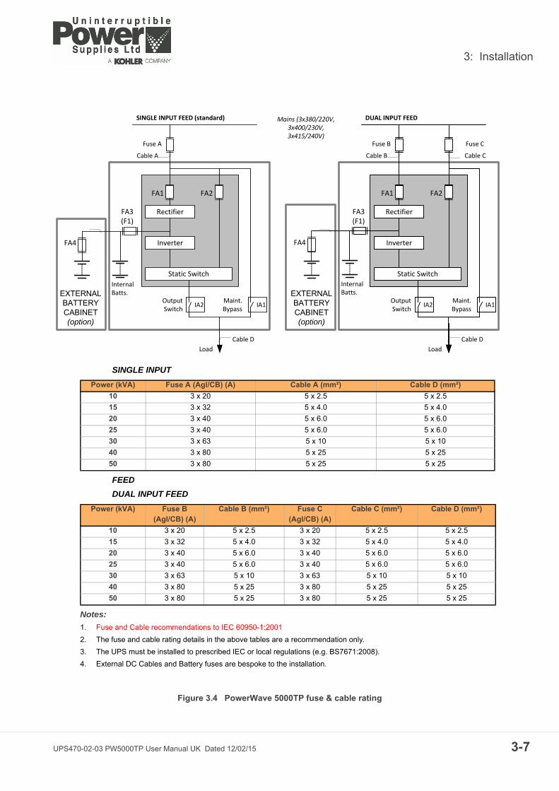
The UPS can be wired with a ‘single feed’ input (standard), whereby the UPS input supply is internallyconnected to the UPS bypass circuit, or it can be wired with a ‘dual feed’ input – where the UPS bypasscircuit is connected to a dedicated ‘bypass’ supply (See Figure 3.4).
Figure 3.4 identifies the UPS input/output cabling requirements and provides information regarding thenecessary fuse and cable ratings, and cable sizing.
Figures 3.6/ 3.7 show details of the power terminal connections within the UPS including connection sizesand recommended tightening torque. This illustration shows that the UPS unit requires the following powercables:
Rectifier (In):
• three-phase (1L1, 1L2, 1L3)• neutral (1N)• protective earth (PE) connection for the rectifier input
Bypass (In) (Dual feed system only):
• three-phase (2L1, 2L2, 2L3) • neutral (2N)• protective earth (PE) connection for the bypass if used as ‘Dual Feed’ input
Load (Out):
• three-phase (3L1, 3L2, 3L3)• neutral (3N)• protective earth (PE) connection for the load output
External Battery:
• Plus (+) • Common (N) • Minus (-)• protective earth (PE) connection for the external batteries• the UPS internal batteries must be disconnected if external batteries are used. Under no
circumstances should external and internal batteries be connected together in parallel.
Key Point: This information is given for guidance only. All fuses, isolators and power cables mustbe rated and installed in accordance with the prescribed IEC standards or local regulation – e.g.BS7671:2008.
UPS470-02-03 PW5000TP User Manual UK Dated 12/02/15 3-5

3: Installation
3-6
Input neutral grounding
Figure 3.3 Input neutral grounding
Key Point: Input neutral is required to operate the rectifier.
In TN-S systems, no 4-pole input switches or circuit breakers should be used. During battery operation the neutral must always be grounded.
0V 230V
UPS
UPS470-02-03 PW5000TP User Manual UK Dated 12/02/15
3: Installation
Figure 3.4 PowerWave 5000TP fuse & cable rating
Rectifier
Inverter
Static Switch
FA1
Fuse B
Load
DUAL INPUT FEED
Cable D
Cable B
Fuse C
Cable C
Rectifier
Inverter
Static Switch
Fuse A
Load
SINGLE INPUT FEED (standard) Mains (3x380/220V,3x400/230V,3x415/240V)
Cable D
Cable A
EXTERNALBATTERYCABINET(option)
FA2FA1 FA2
EXTERNALBATTERYCABINET(option)
FA3(F1)
FA4
Output Switch
Maint.Bypass
IA2 IA1Maint.Bypass
IA2 IA1Output Switch
Internal Batts.
FA4
Internal Batts.
FA3(F1)
SINGLE INPUT
FEED
DUAL INPUT FEED
Notes:
1. Fuse and Cable recommendations to IEC 60950-1:2001
2. The fuse and cable rating details in the above tables are a recommendation only.
3. The UPS must be installed to prescribed IEC or local regulations (e.g. BS7671:2008).
4. External DC Cables and Battery fuses are bespoke to the installation.
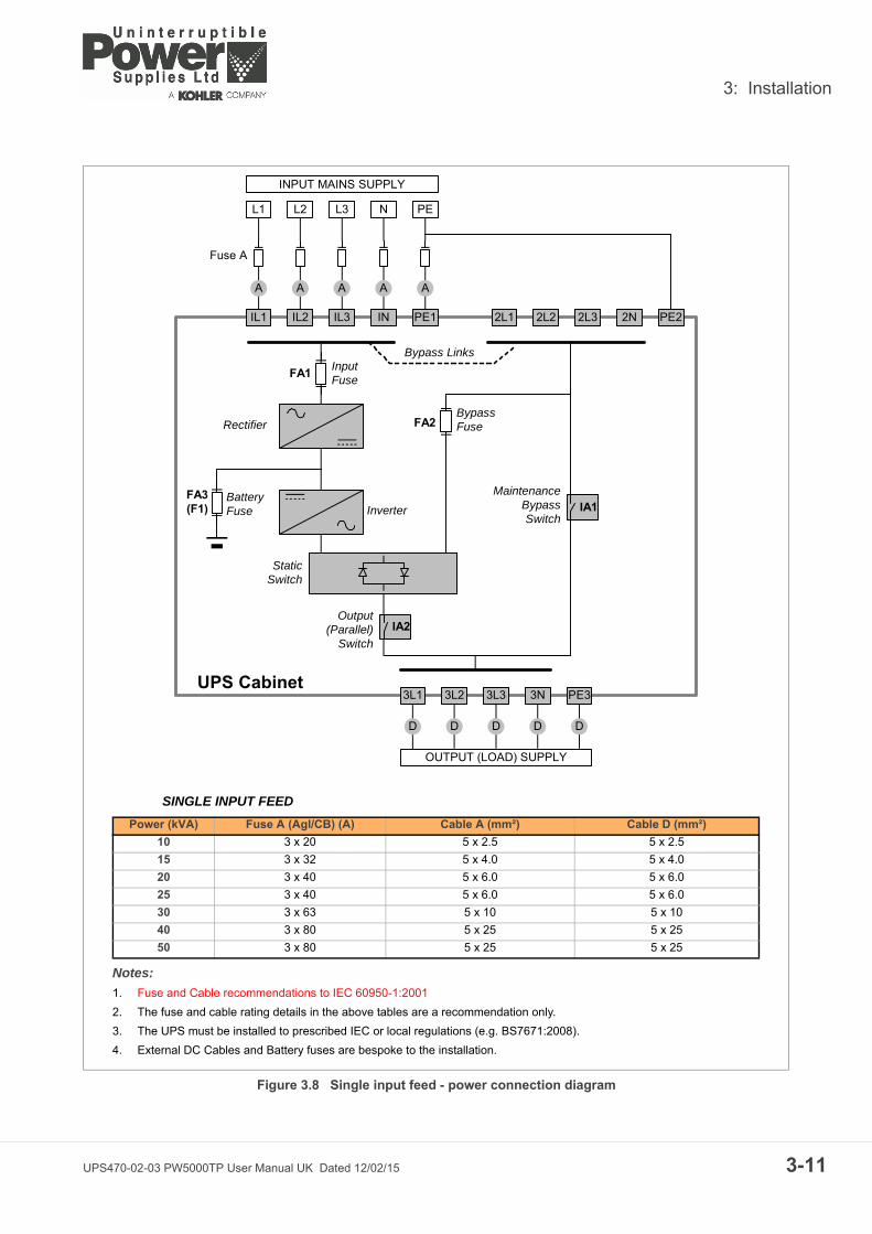
Power (kVA) Fuse A (Agl/CB) (A) Cable A (mm²) Cable D (mm²)
10 3 x 20 5 x 2.5 5 x 2.5
15 3 x 32 5 x 4.0 5 x 4.0
20 3 x 40 5 x 6.0 5 x 6.0
25 3 x 40 5 x 6.0 5 x 6.0
30 3 x 63 5 x 10 5 x 10
40 3 x 80 5 x 25 5 x 25
50 3 x 80 5 x 25 5 x 25
Power (kVA) Fuse B (Agl/CB) (A)
Cable B (mm²) Fuse C(Agl/CB) (A)
Cable C (mm²) Cable D (mm²)
10 3 x 20 5 x 2.5 3 x 20 5 x 2.5 5 x 2.5
15 3 x 32 5 x 4.0 3 x 32 5 x 4.0 5 x 4.0
20 3 x 40 5 x 6.0 3 x 40 5 x 6.0 5 x 6.0
25 3 x 40 5 x 6.0 3 x 40 5 x 6.0 5 x 6.0
30 3 x 63 5 x 10 3 x 63 5 x 10 5 x 10
40 3 x 80 5 x 25 3 x 80 5 x 25 5 x 25
50 3 x 80 5 x 25 3 x 80 5 x 25 5 x 25
UPS470-02-03 PW5000TP User Manual UK Dated 12/02/15 3-7
3: Installation
3-8
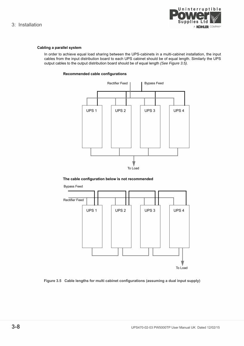
Cabling a parallel system
In order to achieve equal load sharing between the UPS-cabinets in a multi-cabinet installation, the inputcables from the input distribution board to each UPS cabinet should be of equal length. Similarly the UPSoutput cables to the output distribution board should be of equal length (See Figure 3.5).
Figure 3.5 Cable lengths for multi cabinet configurations (assuming a dual input supply)
UPS 1 UPS 2 UPS 3 UPS 4
UPS 1 UPS 2 UPS 3 UPS 4
Recommended cable configurations
The cable configuration below is not recommended
Bypass FeedRectifier Feed
To Load
To Load
Bypass Feed
Rectifier Feed
UPS470-02-03 PW5000TP User Manual UK Dated 12/02/15

3: Installation
Figure 3.6 10-25kVA Connection details
1L1
3L2 3N1L2
1L3
1N
PE
PEPE
FA9FA7
FA11
To Bypass Line Fuses (FA2)
FA23FA24
FA25
PE
Ex.Batt. Earth InputMains BypassMains UPSOutput Earth
3L1 3L3
N+
1L1
3L2 3N1L2
1L3
1N
2L1
2L2
2L3
2N
PE
PEPE
FA9FA7
FA11
To Bypass Line Fuses (FA2)
FA23FA24
FA25
PE
Ex.Batt. Earth InputMains BypassMains UPSOutput Earth
3L1 3L3
N+
UPS Range
Battery (+ / N / -)
+PE
Input Bypass3+N
(N,2L1,2L2,2L3)
Input Rectifier3+N+PE
(N,1L1,1L2,1L3)
Output load3+N+PE
(N,3L1,3L2,3L3)
Max. cable section
admissible
Tightening Torque
(Nm)
10-25kVA 4 x 16 mm2 4 x 16 mm2 5 x 16 mm2 5 x 16 mm2 16 mm2 1.5
Fuse and Cable recommendations to IEC 60950-1:2001The fuse and cable rating details in the above tables are a recommendation only. The UPS must be installed to prescribed IEC or local regulations (e.g. BS7671:2008)
10kVA – 25kVA (Cabinets A & B) Power Connections (Single input feed)
10kVA – 25kVA (Cabinets A & B) Power Connections (Dual input feed)
For models in this power range the external power connections are made to a row of terminals located on the UPS Filter Board which is accessible from the rear of the UPS module.Note that the Single Input configuration requires the bypass line fuses to be connected to FA7/FA9/FA11 on the Filter Board. This is the standard configuration set when leaving the factory unless a dual input configuration is specified.
This illustration shows the connections for a Dual input configurations, with a separate mains supply connected to the Bypass Mains terminals.Note that the Dual Input configuration requires the bypass line fuses to be connected to FA23/FA24/FA25 on the Filter Board. If necessary these cables will be reconfigured by the Commissioning Engineer as part of the commissioning procedure.
UPS470-02-03 PW5000TP User Manual UK Dated 12/02/15 3-9

3: Installation
3-1
Figure 3.7 30-50kVA Connection details
1L1
N+3L23N
1L2 1L3 1N PEPEPE
3L1 3L3
PE
1L1
N+2L1 2L2 2L3 2N 3L23N
1L2 1L3 1N PEPEPE
3L1 3L3
PE
UPS Range
Battery (+ / N / -)
+PE
Input Bypass3+N
(N,2L1,2L2,2L3)
Input Rectifier3+N+PE
(N,1L1,1L2,1L3)
Output load3+N+PE
(N,3L1,3L2,3L3)
Max. cable section
admissible
Tightening Torque
(Nm)
30-50kVA 4 x 35 mm2 4 x 35 mm2 5 x 35 mm2 5 x 35 mm2 35 mm2 3.5
Fuse and Cable recommendations to IEC 60950-1:2001The fuse and cable rating details in the above tables are a recommendation only. The UPS must be installed to prescribed IEC or local regulations (e.g. BS7671:2008)
30kVA – 50kVA
Power Connections
For models in this power range the external power connections are made to a row of terminals blocks mounted on a rail on the front of the UPS module.Note that the Single Input configuration requires three links to be fitted between the input and bypass supply connections, as shown in the above illustration. This is the standard configuration set when leaving the factory unless a dual input configuration is specified.
(Cabinet C)
(Single input feed)
30kVA – 50kVA
Power Connections(Cabinet C)
(Dual input feed)
The above illustration shows the connections for a Dual input configurations, with a separate mains supply connected to the Bypass Mains terminals.Note that the Dual Input configuration requires the links to be removed between in input and bypass terminals. If necessary these cables will be reconfigured by the Commissioning Engineer as part of the commissioning procedure.
3 x input/bypass mains links(for single input feed only)
Input/bypass neutral always linked
0 UPS470-02-03 PW5000TP User Manual UK Dated 12/02/15
3: Installation
Figure 3.8 Single input feed - power connection diagram
FA1
FA3(F1)
Fuse A
Inverter
FA2
UPS Cabinet
StaticSwitch
2L1 2L2 2L3 2N PE2
L1 L2 L3 N PE
A A A A A
IL1 IL2 IL3 IN PE1
INPUT MAINS SUPPLY
Bypass LinksInputFuse
BatteryFuse
BypassFuse
IA2
IA1
Output(Parallel)
Switch
MaintenanceBypassSwitch
D D D D D
3L1 3L2 3L3 3N PE3
OUTPUT (LOAD) SUPPLY
Rectifier
SINGLE INPUT FEED
Notes:
1. Fuse and Cable recommendations to IEC 60950-1:2001
2. The fuse and cable rating details in the above tables are a recommendation only.
3. The UPS must be installed to prescribed IEC or local regulations (e.g. BS7671:2008).
4. External DC Cables and Battery fuses are bespoke to the installation.
Power (kVA) Fuse A (Agl/CB) (A) Cable A (mm²) Cable D (mm²)
10 3 x 20 5 x 2.5 5 x 2.5
15 3 x 32 5 x 4.0 5 x 4.0
20 3 x 40 5 x 6.0 5 x 6.0
25 3 x 40 5 x 6.0 5 x 6.0
30 3 x 63 5 x 10 5 x 10
40 3 x 80 5 x 25 5 x 25
50 3 x 80 5 x 25 5 x 25
UPS470-02-03 PW5000TP User Manual UK Dated 12/02/15 3-11

3: Installation
3-1
Figure 3.9 Dual input feed - power connection diagram
FA1
FA3(F1)
Fuse B
Inverter
FA2
UPS Cabinet
StaticSwitch
L1 L2 L3 N PE
B B B B B
IL1 IL2 IL3 IN PE1
INPUT MAINS SUPPLY
InputFuse
BatteryFuse
BypassFuse
IA2
IA1
Output(Parallel)
Switch
MaintenanceBypassSwitch
D D D D D
3L1 3L2 3L3 3N PE3
OUTPUT (LOAD) SUPPLY
Rectifier
Fuse C
L1 L2 L3 N PE
C C C C C
BYPASS MAINS SUPPLY
2L1 2L2 2L3 2N PE2
DUAL INPUT FEED
Notes:
1. Fuse and Cable recommendations to IEC 60950-1:2001
2. The fuse and cable rating details in the above tables are a recommendation only.
3. The UPS must be installed to prescribed IEC or local regulations (e.g. BS7671:2008).
4. External DC Cables and Battery fuses are bespoke to the installation.
Power (kVA) Fuse B (Agl/CB)(A)
Cable B (mm²) Fuse C(Agl/CB) (A)
Cable C (mm²) Cable D (mm²)
10 3 x 20 5 x 2.5 3 x 20 5 x 2.5 5 x 2.5
15 3 x 32 5 x 4.0 3 x 32 5 x 4.0 5 x 4.0
20 3 x 40 5 x 6.0 3 x 40 5 x 6.0 5 x 6.0
25 3 x 40 5 x 6.0 3 x 40 5 x 6.0 5 x 6.0
30 3 x 63 5 x 10 3 x 63 5 x 10 5 x 10
40 3 x 80 5 x 25 3 x 80 5 x 25 5 x 25
50 3 x 80 5 x 25 3 x 80 5 x 25 5 x 25
2 UPS470-02-03 PW5000TP User Manual UK Dated 12/02/15

3: Installation
3.6 Connecting the UPS input supply
3.6.1 Safety notes
Please ensure you read and understand the following safety notes before you begin the UPS electricalinstallation.
1. All operations detailed in this section must be performed by an authorised electrician or qualifiedpersonnel.
2. Once the electrical installation is completed the initial UPS start-up must be performed by qualifiedpersonnel authorised by the manufacturer.
3. Do not operate the UPS if there is water or moisture present.
4. When carrying out any work on the UPS input power cables you must ensure that the UPS supplies areisolated at the supply distribution panel and, where possible, locked out. Warning notices should beposted where applicable to prevent inadvertent operation of the input supply isolators.
3.6.2 Preparation for the input cabling
Before you start connecting the UPS input cables:
• Ensure that the provided fuses and cables satisfy the ratings shown in Figures 3.4 and 3.6/ 3.7, andare in accordance with the prescribed IEC Standards or local regulations (e.g. BS7671:2008).
• Do not commence this procedure until the UPS is properly installed at its intended location.
3.6.3 Connecting the UPS input power cables
1. To protect personnel during the UPS installation ensure that the connections are performed under thefollowing conditions:
a) No mains voltage is present.b) Loads are shut down and disconnected.c) The UPS is shut down and voltage-free.d) The UPS Maintenance Bypass Isolator IA1 is OFF.e) The UPS Output/Parallel Isolator IA2 is OFF
2. Gain access to the UPS power terminals.
3. Connect the earth cable from the LV-Distribution Board to the protective earth (PE) busbar in the UPS,located adjacent to the power terminals, as shown in Figures 3.10, 3.11, 3.12.
4. The PowerWave 5000TP input supply can be wired for ‘single feed’ (standard) or ‘dual feed’ operation.Connect the input power cable coming from the LV-Distribution Board to the UPS input terminalsfollowing the ‘single input feed’ or ‘dual input feed’ given below.
Single Input Feed
1. Refer to the schematic drawing and connection table in Figure 3.8. Connect the UPS input supply cablesto terminals 1L1, 1L2, 1L3 and 1N on the UPS main terminal block (See Figures 3.6 /3.7). Ensure correct(clockwise) phase rotation.
2. Secure the cables to the fixing rail under the connection terminals.
3. 10kVA – 25kVA Models only: Ensure the bypass cables are connected to the correct terminals on theFilter Board (see Figure 3.6). These will be reconfigured by the commissioning engineer if necessary.
WARNING: Opening or removing the UPS-covers will create the risk of exposure todangerous voltages if power is connected to the UPS.
CAUTION: The input Neutral cable must ALWAYS be connected.
UPS470-02-03 PW5000TP User Manual UK Dated 12/02/15 3-13
3: Installation
3-1
4. 25kVA – 50kVA ‘C’ cabinet models only: Ensure the single input feed links are fitted between the inputand bypass supply terminal (see Figure 3.7).
Dual Input Feed
Refer to the schematic drawing and connection table in Figure 3.9.
1. The UPS is supplied (as standard) with facilities for a single cable feed for the rectifier and bypasssupplies. For a dual feed configuration remove the links between 1L1-2L1; 1L2-2L2; 1L3-2L3 and 1N-2N,on the Input Terminal Block (See Figures 3.6 /3.7).
2. Connect the UPS input supply cables to terminals 1L1, 1L2, 1L3 and 1N on the UPS main terminal block(See Figures 3.6 /3.7). Ensure correct (clockwise) phase rotation.
3. Connect the UPS bypass supply cables to terminals 2L1, 2L2, 2L3 and 2N on the UPS main terminalblock (See Figures 3.6 /3.7). Ensure correct (clockwise) phase rotation.
4. Secure the cables to the fixing rail located below the connection terminals.
5. 10kVA – 25kVA Models only. Ensure the bypass cables are connected to the correct terminals on theFilter Board (see Figure 3.6). These will be reconfigured by the commissioning engineer if necessary.
6. 25kVA – 50kVA ‘C’ cabinet models only: Ensure the single input feed links are removed between theinput and bypass supply terminal (see Figure 3.7). Leave the neutral (N) link in place.
3.7 Connecting the UPS output
3.7.1 Safety notes
Please ensure you read and understand the following safety notes before you begin the UPS electricalinstallation.
1. All operations detailed in this section must be performed by an authorised electrician or qualifiedpersonnel.
2. Once the electrical installation is completed the initial UPS start-up must be performed by qualifiedpersonnel authorised by the manufacturer.
3. Do not operate the UPS if there is water or moisture present.
4. When carrying out any work on the UPS output power cables you must ensure that the UPS output isisolated at the load supply distribution panel, and where possible locked out. Warning notices should beposted where applicable to prevent inadvertent operation of the output supply isolators.
3.7.2 Preparation for the output cabling
Circuit breakers (or equivalent protection) must be fitted between the UPS output and load equipment toprovide additional protection to the UPS in the event of an overload or short circuit, and also provide a meansof isolating individual loads if required.
Before you start connecting the UPS output cables to the load distribution panel:
• Ensure that the potential (maximum) load does not exceed the UPS model output power rating(OUTPUT POWER) on the nameplate.
CAUTION: The input Neutral cable must ALWAYS be connected.
CAUTION: The bypass Neutral cable must ALWAYS be connected.
WARNING: Opening or removing the UPS-covers will create the risk of exposure todangerous voltages if power is connected to the UPS.
4 UPS470-02-03 PW5000TP User Manual UK Dated 12/02/15

3: Installation
• Ensure the output circuit breakers are correctly sized with respect to the load and cable rating.• The maximum total load rating and maximum load rating of the individual load sockets should be
indicated on the output distribution board.• The circuit breakers must comply with the prescribed IEC Standards (e.g. BS7671:2008). It is
recommended that a separate output distribution board is provided for the load.
3.7.3 Connecting the UPS output cables
1. To protect personnel during the UPS installation ensure that the connections are performed under thefollowing conditions:
a) No input mains voltage is present.b) All loads are shut down and isolated.c) The UPS is shut down and voltage-free.d) The UPS Maintenance Bypass Isolator IA1 is OFF (OPEN).e) The UPS Parallel Isolator IA2 is OFF (OPEN).
2. Gain internal access to the UPS and remove the UPS terminal cover.
3. Connect the protective earth cable from the Load Distribution Board to the protective earth (PE) busbarin the UPS – located adjacent to the power terminals, as shown in Figures 3.10, 3.11/ 3.12.
4. Connect the UPS output supply cables to terminals 3L1, 3L2, 3L3 and 3N on the UPS main terminalblock (See Figures 3.6 /3.7). Ensure correct (clockwise) phase rotation.
5. Secure the cables to the fixing rail located below the UPS connection terminals.
6. Ensure the output cables are connected to the correct power terminals on the load distribution panel.
CAUTION: The output Neutral cable must ALWAYS be connected.
UPS470-02-03 PW5000TP User Manual UK Dated 12/02/15 3-15
3: Installation
3-1
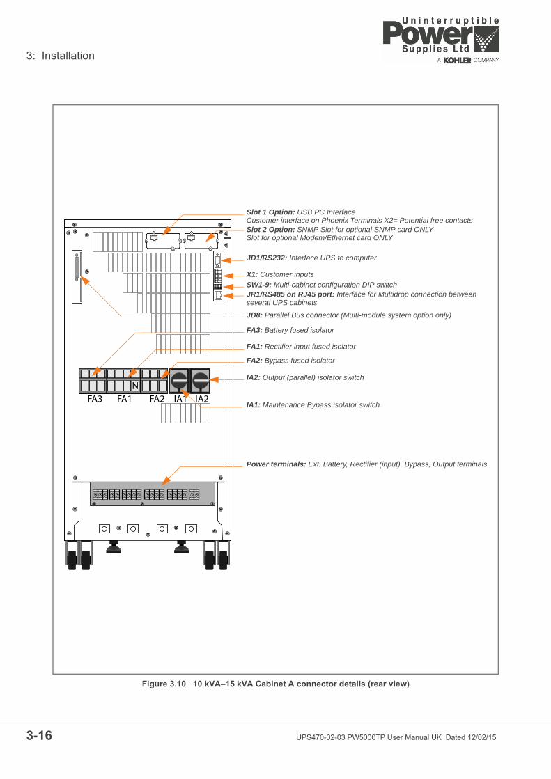
Figure 3.10 10 kVA–15 kVA Cabinet A connector details (rear view)
FA3 FA1N
FA2 IA1 IA2
Slot 1 Option: USB PC InterfaceCustomer interface on Phoenix Terminals X2= Potential free contacts Slot 2 Option: SNMP Slot for optional SNMP card ONLYSlot for optional Modem/Ethernet card ONLY
JD1/RS232: Interface UPS to computer
X1: Customer inputs
JR1/RS485 on RJ45 port: Interface for Multidrop connection between several UPS cabinets
SW1-9: Multi-cabinet configuration DIP switch
JD8: Parallel Bus connector (Multi-module system option only)
FA3: Battery fused isolator
FA1: Rectifier input fused isolator
FA2: Bypass fused isolator
IA2: Output (parallel) isolator switch
IA1: Maintenance Bypass isolator switch
Power terminals: Ext. Battery, Rectifier (input), Bypass, Output terminals
6 UPS470-02-03 PW5000TP User Manual UK Dated 12/02/15
3: Installation
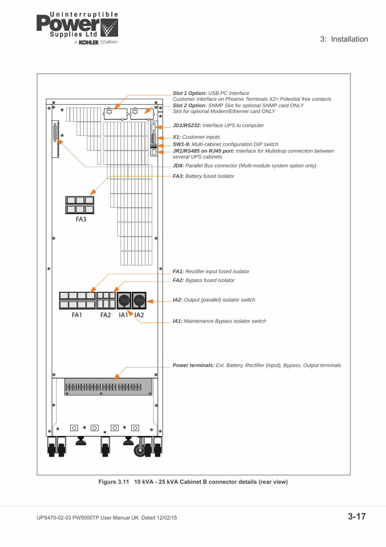
Figure 3.11 10 kVA - 25 kVA Cabinet B connector details (rear view)
FA1 FA2 IA1 IA2
FA3
Slot 1 Option: USB PC InterfaceCustomer interface on Phoenix Terminals X2= Potential free contacts Slot 2 Option: SNMP Slot for optional SNMP card ONLYSlot for optional Modem/Ethernet card ONLY
JD1/RS232: Interface UPS to computer
X1: Customer inputs
JR1/RS485 on RJ45 port: Interface for Multidrop connection between several UPS cabinets
SW1-9: Multi-cabinet configuration DIP switch
JD8: Parallel Bus connector (Multi-module system option only)
FA3: Battery fused isolator
FA1: Rectifier input fused isolator
FA2: Bypass fused isolator
IA2: Output (parallel) isolator switch
IA1: Maintenance Bypass isolator switch
Power terminals: Ext. Battery, Rectifier (input), Bypass, Output terminals
UPS470-02-03 PW5000TP User Manual UK Dated 12/02/15 3-17

3: Installation
3-1
Figure 3.12 25 kVA - 50 kVA Cabinet C connector details (front view)
FA1 FA2
IA2IA1F1
Slot 1 Option: USB PC InterfaceCustomer interface on Phoenix Terminals X2= Potential free contacts
Slot 2 Option: SNMP Slot for optional SNMP card ONLYSlot for optional Modem/Ethernet card ONLY
JD1/RS232: Interface UPS to computer
X1: Customer inputs
JR1/RS485 on RJ45 port: Interface for Multidrop connection between several UPS cabinets
SW1-9: Multi-cabinet configuration DIP switch
JD8: Parallel Bus connector (Multi-module system option only)
F1: Battery fused isolator
FA1: Rectifier input fused isolator
FA2: Bypass fused isolator
IA2: Output (parallel) isolator switch
IA1: Maintenance Bypass isolator switch
Power terminals: Ext. Battery, Rectifier (input), Bypass, Output terminals
8 UPS470-02-03 PW5000TP User Manual UK Dated 12/02/15

3: Installation
3.8 Battery connections.
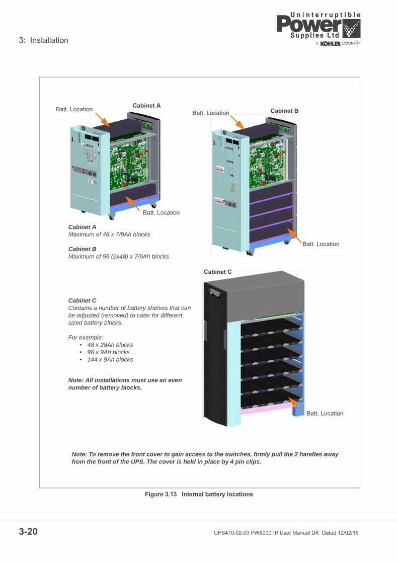
The cabinets are designed to house a number of 12V batteries of various capacities to provide a flexible, self-contained UPS system. Cabinets A & B can accept 7Ah or 9Ah batteries, while cabinet C can acceptbatteries of up to 28Ah. The batteries are connected in up to 48x12V strings and it is possible to connect 2 or3 strings in parallel in Cabinets B & C, as shown in figure 3.13, to enable a range of autonomy times to beachieved.
The final assembly and connection of the battery units will be carried out by the commissioning engineer.
3.8.1 Remote battery enclosures
If the UPS internal batteries are unable to provide the required autonomy times they can be replaced by alarger battery system mounted in a separate, external battery cabinet.
A range of matching battery enclosures are available, designed to suit individual site requirements. In eachcase the battery enclosure is fitted with a suitably rated fused isolator which is connected to the batteryconnection terminals inside the PowerWave 5000TP as shown in (See Figures 3.6 /3.7).
Note: DC fuses and cables are bespoke to the installation.
3.8.2 Connecting the external battery enclosure
To protect personnel during battery installation the connections must be made under the following conditions:
• Mains voltage must be disconnected from the UPS• All loads must be disconnected• The UPS and the external battery terminals must be voltage-free
1. The UPS must be totally shut-down and power-free. Ensure the mains (and bypass) supply is isolated at the UPS input distribution board.
2. Ensure that the MAINTENANCE BYPASS isolator (IA1) is open (OFF).
3. Ensure that the battery isolator/fuses in the external battery cabinet (or racks) are open.
4. Connect the protective earth cable (PE) between the UPS and external battery cabinet.
5. Connect the corresponding +, N, - terminals between the UPS and external battery cabinet.
6. The UPS battery isolator (FA3/F1) connections will require reconfiguring. This must be carried out by thecommissioning engineer.
Note: The DC and Battery fuses and cabling are bespoke to the installation.
WARNING: The final assembly and connection of the battery units must be carried out by thecommissioning engineer. Do not attempt to complete the battery wiring or close the batteryisolators before this system has been commissioned
Key Point: If an external battery system is used, the UPS internal batteries must be disconnected from the system. It is NOT possible to operate the internal and external batteries in parallel.
WARNING: This procedure must be carried out by (or under the supervision of) the systemcommissioning engineer.
UPS470-02-03 PW5000TP User Manual UK Dated 12/02/15 3-19
3: Installation
3-2
Figure 3.13 Internal battery locations
Cabinet AMaximum of 48 x 7/9Ah blocks
Cabinet BMaximum of 96 (2x48) x 7/9Ah blocks
Cabinet CContains a number of battery shelves that can be adjusted (removed) to cater for different sized battery blocks.
For example:• 48 x 28Ah blocks• 96 x 9Ah blocks• 144 x 9Ah blocks
Note: All installations must use an even number of battery blocks.
Cabinet ACabinet B
Cabinet C
Batt. Location
Batt. Location
Batt. Location
Batt. Location
Batt. Location
Note: To remove the front cover to gain access to the switches, firmly pull the 2 handles away from the front of the UPS. The cover is held in place by 4 pin clips.
0 UPS470-02-03 PW5000TP User Manual UK Dated 12/02/15

3: Installation
3.9 Multi-module control cabling and configuration
3.9.1 Connecting the parallel communication cables (Bus-lines)
In order to facilitate various parallel UPS control functions and operations (such as load sharing, frequencysynchronisation, and load transfer) the paralleled UPS modules communicate with each other continuouslyby means of a communication Bus-line which takes the form of a signal cable connected between themodules.
The communication bus cables are daisy-chained between each module, as shown below in figure 3.14.Once the cables are fitted, each module must be configured according to its position in the parallel system.
Note: This will be carried out by the commissioning engineer.
1. Connect the parallel control Bus-lines as follows:
2. Fit the Parallel Adaptor PCB (NW4019) to connector JD8 on all UPS-Cabinets (see Figure 3.10 – 3.12).
3. Set DIP Switch SW2-2 on each Parallel Adaptor according to the UPS cabinet’s position in the parallelconfiguration (See Figure 3.14).
4. Connect a Bus-cable between PORT JD6 of UPS-Cabinet 1 Parallel Adaptor and PORT JD5 of UPS-Cabinet 2 Parallel Adaptor.
5. Connect a Bus-cable between PORT JD6 of UPS-Cabinet 2 Parallel Adaptor and PORT JD5 of UPS-Cabinet 3 Parallel Adaptor.
6. Continue with the above until a Bus-cable is connected to all modules.
Figure 3.14 Bus-lines connections (3 Modules shown)
WARNING: When cabling the UPS cabinets, check with a voltmeter to confirm that eachmodule power terminals are completely voltage free. Check that the Maintenance Bypasses isolator (IA1), Parallel Isolator (IA2) and Bypass Lineisolator (FA2) are open (OFF) on all cabinets.
Master-SlaveOutput
JD6
Master-SlaveInputJD5
UPS-Cabinet 1
Master-SlaveOutput
JD6
Master-SlaveInputJD5
UPS-Cabinet 2
Master-SlaveOutput
JD6
Master-SlaveInputJD5
UPS-Cabinet 3
Parallel Adaptor Parallel Adaptor Parallel Adaptor
SW2-2 SW2-2 SW2-2
Master-SlaveOutput
JD6
Master-SlaveInputJD5
Parallel Adaptor
SW2-2
SW2-2 Configuration
First Unit Middle Unit Last Unit Single Unit
SW 1 OFF OFF ON ON
SW 2 ON OFF OFF ON
UPS470-02-03 PW5000TP User Manual UK Dated 12/02/15 3-21

3: Installation
3-2
3.9.2 Module configuration DIP Switch selection
DIP Switch SW1-9
DIP Switch SW1-9 located on the interface board (PCB NW24080) must be set according to the position ofthe cabinet in a parallel module chain (see Figure 3.10 – 3.12).
The options are:
• Single module• First cabinet.• Middle cabinet (there may be several ‘middle’ cabinets).• Last cabinet.
For PCB NW24080 Dated 19.09.2013:
For PCB NW24080 Dated 26.03.2010:
Key Point: There are two versions of PCB NW24080 in use; the earlier board has a design date of 26.03.2010, and the later board 19.09.2013. DIP Switch SW1-9 configuration setting is slightly different between the two boards, as shown below.
SW1-9 First Cabinet Middle Cabinet Last Cabinet Single Cabinet
1 ON OFF ON ON
2 ON OFF ON ON
3 ON OFF ON ON
4 ON OFF ON ON
5 OFF OFF OFF OFF
6 OFF OFF ON ON
7 ON OFF OFF ON
8 ON OFF ON ON
9 ON OFF ON ON
SW1-9 First Cabinet Middle Cabinet Last Cabinet Single Cabinet
1 ON OFF ON ON
2 ON OFF ON ON
3 ON OFF ON ON
4 ON OFF ON ON
5 ON OFF ON ON
6 OFF OFF ON ON
7 ON OFF OFF ON
8 ON OFF ON ON
9 ON OFF ON ON
2 UPS470-02-03 PW5000TP User Manual UK Dated 12/02/15

3: Installation
3.10 Module interfacing facilitiesEach UPS is provided with communication port and a communication card, which provides systeminformation:
Standard Interface Facilities
JD1 Smart Port – RS232 Sub D9/female interface (UPS system to computer).
X1 Customer input interface (Phoenix terminals).
JR1 RS485 on RJ 45 port – Interface for Multidrop connection between several UPS cabinets.
Optional Facilities
USB PC Interface for remote signalling and automatic computer shutdown.
X2 Customer output interface on Phoenix terminals (Potential free contacts):• Common Alarm• Load On Bypass• Battery Low• Load on Inverter• Mains Failure
SNMP Slot for optional SNMP card ONLYFor monitoring and integration in network management.
UPS470-02-03 PW5000TP User Manual UK Dated 12/02/15 3-23
3: Installation
3-2
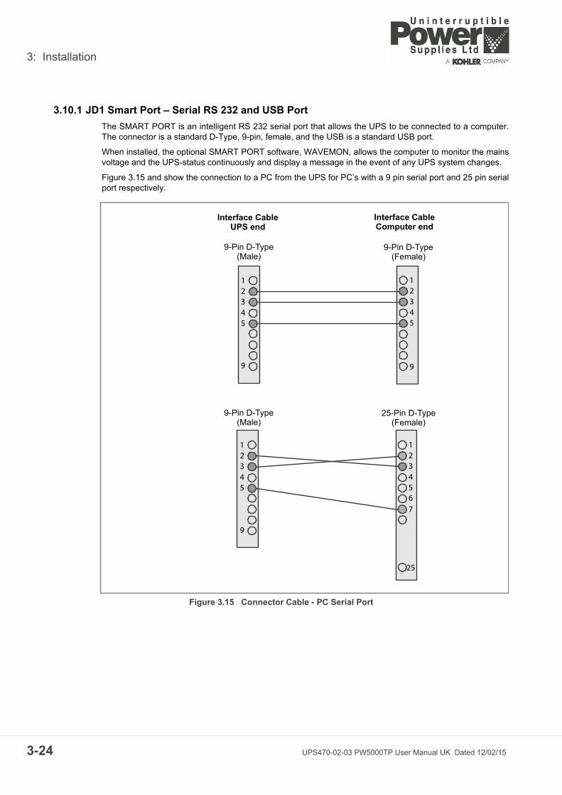
3.10.1 JD1 Smart Port – Serial RS 232 and USB Port
The SMART PORT is an intelligent RS 232 serial port that allows the UPS to be connected to a computer.The connector is a standard D-Type, 9-pin, female, and the USB is a standard USB port.
When installed, the optional SMART PORT software, WAVEMON, allows the computer to monitor the mainsvoltage and the UPS-status continuously and display a message in the event of any UPS system changes.
Figure 3.15 and show the connection to a PC from the UPS for PC’s with a 9 pin serial port and 25 pin serialport respectively.
Figure 3.15 Connector Cable - PC Serial Port
12345
9
12345
9
12345
9
1234567
25
Interface CableUPS end
Interface CableComputer end
9-Pin D-Type(Male)
9-Pin D-Type(Female)
9-Pin D-Type(Male)
25-Pin D-Type(Female)
4 UPS470-02-03 PW5000TP User Manual UK Dated 12/02/15

3: Installation
3.10.2 X1 Dry Port (volt-free contacts)
All the Input and Output interfaces to X1 are connected to Phoenix terminals (cable 0.5mm²)
Connection of Remote Shut down facilities, Generator Operation, Customers specials (see also OPTIONSsection).
3.10.3 JR1 / RS485 INTERFACE FOR MULTIDROP
The Computer Interface JR1 located on the distribution part is an intelligent RS485 serial port that allowssystem information to be gained from all modules which are connected in parallel using the Multidropconnection kit. (For details see user manual Multidrop kit). The connector JR1 is a standard RJ45 port.
3.10.4 X2 Dry Port – Optional Output Interfaces Terminal Block (X2)
Provision of signals for the automatic and orderly shutdown of servers, AS400 or Automation buildingsystems. All voltage free contacts are rated 60 VAC max. and 500 mA max.:
Figure 3.16 Dry Port (X2) Connections
Terminal Contact Signal Function
X1/1 In +12Vdc Customer IN 1 (default as Generator Operation)
X1/2 Gnd Gnd (NC = Generator ON)
X1/3 In +12Vdc Customer IN 2
X1/4 Gnd Gnd (Function on request, to be defined)
X1/5 In +3.3Vdc Battery Temperature
X1/6 Gnd Gnd If connected, the battery charger current is temperature dependent
X1/7 In +12Vdc Remote shutdown
X1/8 Gnd Gnd Do not remove the factory mounted bridge until an external remote shut down is connected
X1/9 In +12Vdc 12Vdc source
X1/10 Gnd Gnd Max 200mA load
Pin Contact Signal Function
1 Alarm MAINS_OK Mains Present
2 Mains Failure
3 Common
4 Message LOAD_ON_INV Load On Inverter
5 Load on Mains (BYPASS MODE)
6 Common
7 Alarm BATT_LOW Battery Low
8 Battery OK
9 Common
10 Message LOAD_ON_MAINS Load On Mains (BYPASS-MODE)
11 Load on Inverter
12 Common
13 Alarm COMMON_ALARM Common Alarm
14 No Alarm Condition
15 Common
UPS470-02-03 PW5000TP User Manual UK Dated 12/02/15 3-25

3: Installation
3-2
6 UPS470-02-03 PW5000TP User Manual UK Dated 12/02/15
4
UPS470-02-03 PW5000T
Operation
4.1 CommissioningThe PowerWave 5000TP UPS is a high quality electronic machine that must be commissioned by a fullytrained and authorised Uninterruptible Power Supplies Ltd. field service engineer before being put into use.
Commissioning the UPS involves connecting the UPS battery, checking the electrical installation andoperating environment of the UPS, performing a controlled start-up and testing of the UPS system, andcustomer training.
4.2 Control PanelThe user-friendly control panel is composed of three parts:
• Power Management Display (PMD)• Mimic LED Indicators• Operating keys
Figure 4.1 Control Panel
4.2.1 Power Management Display (PMD)
The 2 x 20 character LCD Power Management Display simplifies communication with the UPS and alsoprovides UPS monitoring information (See paragraph 4.3).
The menu driven LCD enables the access to:
• The ‘Event register’• Monitoring the input and output voltage, current, frequency & power• Monitoring battery run time• Perform commands such as UPS start-up and shut-down, Load transfer from INVERTER to BYPASS
and vice-versa
WARNING: Any PowerWave 5000TP UPS system not commissioned by an UninterruptiblePower Supplies Ltd. field service engineer must be considered an electrical hazard, andUninterruptible Power Supplies Ltd. accepts no responsibility for its safe operation or thesafety of any personnel. Additionally, the manufacturer's warranty is immediately invalidated ifthe UPS is put into use before it has been correctly commissioned.
Power Management Display (PMD)Mimic LED Indicators Operating Keys
P User Manual UK Dated 12/02/15 4-1

4: Operation
4-2
• Diagnostic (service mode only)• Adjustments and testing (service mode only)
4.2.2 Mimic LED indicators
The mimic diagram indicates the status of the general UPS power flow and change colour between Greenand Red (and OFF) to indicate the UPS operating conditions.
LINE 1 (rectifier) and LINE 2 (bypass) indicate the availability status of the mains power supply.
INVERTER and BYPASS, if green, indicate which of the two sources is supplying the critical load power.
The BATTERY LED indicator flashes when the battery is supplying the load – e.g. following a mains failure.
The ALARM LED is a visual indication of any internal or external alarm condition. When activated, it isaccompanied by an audible alarm.
LED Indication summary
4.2.3 Operator keys
The operator keys allow the user to:
• Make settings and adjustments via the menu driven LCD display• Start-up and shut down the UPS and transfer the load between inverter and bypass• Monitor and display the UPS operating voltages, currents, frequencies and other values on the LCD
display
Key function summary
Indicator Indicator Status Interpretation
LINE 1 GREENRED
Mains availableMains not available
LINE 2 GREENRED
Mains bypass OKMains bypass not OK or not present
ALARM OFFFlashing RED + buzzerRED
No alarm conditionAlarm conditionAlarm condition (has been reset)
INVERTER GREENREDOFF
Load on inverterInverter fault (load not transferable to inverter)Inverter not operating
BY-PASS GREENOFF
Load on bypassBypass not operating
BATTERY GREENREDFlashing GREEN
Battery OKBattery fault or dischargedOn Battery
Keys Function
ON/OFFON/OFF
Used to switch-on or switch-off the UPS (Both keys must be pressed simultaneously for ON/OFF operation).
UP ) Scroll upwards through a displayed menu.
DOWN ( ) Scroll downwards through a displayed menu.
RESET Cancels the audible alarm. If the alarm condition was transient the ALARM LED will also extinguish, otherwise it will remain ON (red).
ENTER Confirms (selects) a chosen menu item.
UPS470-02-03 PW5000TP User Manual UK Dated 12/02/15

4: Operation
ON/OFF Start-up and shutdown buttons
The UPS may be switched ON or OFF by simultaneously pressing both ON/OFF keys on the control panel.This is to prevent accidental UPS start-up or shutdown.
Note: When the UPS is under normal operation, pressing the two ON/OFF buttons simultaneously willimmediately shut down the UPS. In a single module installation this will disconnect the UPS from the load. Ina parallel module system the UPS module will shutdown and the module will effectively be disconnected fromthe parallel load bus; however, the load may or may-not transfer to the bypass supply in the remainingmodules depending on the available module redundancy. To shut down all the modules in a parallel systemyou must press both ON/OFF buttons on every UPS cabinet!
4.3 Description of the LCD display
4.3.1 Status screens
On the right hand side of the LCD there is a 3 digit indicator which shows a module’s position in a multi-module system. The maximum number of modules that can be used in a parallel system is 20.
Note: The definition of the cabinet position is set by the commissioning engineer.
Definition of the module position in a Single/Multi-module chain
The position of a module in a multi-module configuration is set by DIP Switch SW1-9 (see paragraph 3.9.2 onpage 3-22):
• First – First UPS module in the parallel configuration chain• Middle – UPS module in the middle of the parallel configuration chain (there may be more than one
‘middle’ UPS)• Last – UPS module is last in the parallel configuration chain.
If a UPS is operating as a Single module then it is seen as the First and Last in an imaginary chain.
CAUTION: If the ON/OFF buttons are operated (with no redundancy) while the UPS is not inMaintenance Bypass it will interrupt the load power supply.
DESCRIPTION LCD-DISPLAY
1. Load is protected by UPS power supplied by inverter (normal operation). LOAD P01PROTECTED
2. Load is not protected by UPS power –supplied by mains power (load on bypass)
LOAD P01
NOT PROTECTED
3. Load supply interrupted. UPS has been switched off by “ON/OFF” buttons.
LOAD OFF P01
SUPPLY FAILURE
4. The UPS/module is not supplying load. The output switch is open.
LOAD DISCONNECTED P01PARALLEL SWITCH OPEN
S Stands for Single Module. The system consists only of one module.P01 Stands for Parallel Cabinet in a multi-module system and 01 stands for the first cabinet
(MASTER) in the multi-module system.P02 Stands for Parallel Cabinet in a multi-module system and 02 stands for the second Cabinet
(SLAVE) in the multi-module system (the number can range from 02 to 20 depending on the module’s position in the parallel system).
UPS470-02-03 PW5000TP User Manual UK Dated 12/02/15 4-3

4: Operation
4-4
4.3.2 Main menu screen
4.3.3 Event log menu screen
4.3.4 Measurements menu screen
DESCRIPTION LCD-DISPLAY
1. A log of the last 99 events is stored in the Power Management Display (See paragraph 4.3.3).
EVENT LOG
MEASUREMENTS
2. Allows monitoring of voltages, power, frequencies, currents, autonomy etc (See paragraph 4.3.4)
MEASUREMENTS
COMMANDS
3. Enables the commands “Load to inverter”, “Load to bypass” and battery test to be executed (See paragraph 4.3.5).
COMMANDS
SET-UP DATA
4. Allows the UPS personalized information (such as serial number) to be entered (See paragraph 4.3.6).
SET-UP DATA
SET-UP USER
5. Allows user to set up Date/Time, automatic battery test, etc.(See paragraph 4.3.7)
SET-UP USER
SET-UP SERVICE
6. Password-protected area for service engineer use only (See paragraph 4.3.8).
SET-UP SERVICE
DESCRIPTION LCD-DISPLAY
1. Logging Control; a log of the last 99 events is stored in the Power Management Display.
01 05-10-08 14-38-56
LOAD TO INV.
2. Every stored event is identified with a sequential number and time stamp.
02 05-10-08 14-38-59
LOAD TO BYP.
3. By pressing ENTER the code of the event will be displayed. 03 05-10-08 14-39-14
LOAD OFF
DESCRIPTION LCD-DISPLAY
1. Battery Runtime BATT. RUN TIME (MIN) 00h 00mm
2. UPS-Output Frequency OUTPUT FREQUENCY (HZ)50.00
3. Bypass Frequency. BYPASS FREQUENCY (HZ)50.00
4. Battery Voltage BATTERY VOLTAGE (V)
+0.0 - 0.0
5. Battery Charger Current BATT. CHARGE CUR. (A)
+ 0.0 - 0.0
6. Battery Discharge Current. DISCHARGE CURRENT (A)
00.00
7. Rectifier Input Voltage (all three phases) RECTIFIER VOLTAGE (V)
230 230 230
8. Bypass Input Voltage (all three phases) BYPASS VOLTAGE (V)
230 230 230
UPS470-02-03 PW5000TP User Manual UK Dated 12/02/15

4: Operation
4.3.5 Commands menu screen
4.3.6 UPS Data menu screen
9. Output Voltage (all three phases) OUTPUT VOLTAGE (V)230 230 230
10. Output Current (all three phases) OUTPUT CURRENT (A)00.00 00.00 00.00
11. Active Output Power (all three phases) ACTIVE POWER (KW)00.00 00.00 00.00
12. Reactive Output Power (all three phases) REACTIVE POWER (kVAr)00.00 00.00 00.00
13. Apparent Output Power (all three phases) APPARENT POWER (KVA)00.00 00.00 00.00
14. Output Power (all three phases) OUTPUT POWER (%)00.00 00.00 00.00
15. Battery capacity BATT. CAPACITY (%)00
DESCRIPTION LCD-DISPLAY
1. Transfer Load to inverter LOAD TO INVERTER
LOAD TO BYPASS
2. Transfer Load to bypass. LOAD TO BYPASSPERFORM BATT.TEST
3. Battery Test PERFORM BATT.TEST
DESCRIPTION LCD-DISPLAY
1. These general UPS Data are installed at the manufacturing plant. UPS SERIAL NUMBER
nn-nnnnn
2. Manufacturing date DATE OF MANUFACTURE
15-03-11
3. EPROM Version EPROM VERSIONV-000
4. Actual Date and Time DATE TIME
dd-mm-yyyy hh:mm:ss
DESCRIPTION LCD-DISPLAY
UPS470-02-03 PW5000TP User Manual UK Dated 12/02/15 4-5

4: Operation
4-6
4.3.7 Set-up User menu screen
4.3.8 Set-Up Service menu screen
From within the Set-up Service menu a service engineer can adjust the UPS voltages, frequencies, currents,power and autonomies, together with setting up:
• UPS Rated Power• Module configuration S, P01, P02…• Single (standard) or Dual input feed• Frequency-converter, 50/60Hz and 60/50Hz• Synchronisation window (2-4%)
DESCRIPTION LCD-DISPLAY
1. Set-up language SET LANGUAGE
SET DATE AND TIME
ENGLISH
FRANCAISDEUTCH
DUTCH
SPANISHPOLISH
PORTOGUESE
2. Set-up Date and Time SET-UP DATE/TIME
SET-UP BATT. TEST
DD-MM-YY HH-MM-SS
3. Set-up battery test SET-UP BATT. TEST
SET-UP GEN-SET OPER.
DAY OF MONTH
(1-31)
HOUR OF DAY (0-23)
REPETITIVE (Y/N)
YES/NO
4. Set-up operation with Gen-Set SET GENERATOR OP.
BATT.CHARGE LOCK
YES/NO
BYPASS LOCK
YES/NO
DESCRIPTION LCD-DISPLAY
1. This password-protected Menu is reserved for authorized service engineers. It is not to be used by End-Users.
SET-UP SERVICE PASSWORD
2. Type in password PASSWORD*
Key Point: It is essential to enter the password.
UPS470-02-03 PW5000TP User Manual UK Dated 12/02/15

4: Operation
4.4 Operating Modes
4.4.1 On-Line (Inverter) mode
Figure 4.2 On-Line Mode
When the UPS is operating in the On-Line mode the load is supplied through the LINE 1 (RECTIFIER) andINVERTER. This mode provides the highest degree of protection, especially in the event of a mainsdisturbance or failure, and is always recommended if the critical loads (computer systems) will not tolerateany (even very brief) interruption of the supply.
In the unlikely event of an inverter fault or overload condition the UPS will transfer the load automatically, andwithout interruption, to the static bypass supply (transfer time = 0).
4.4.2 Bypass (Line-Interactive) mode
Figure 4.3 Line-Interactive (Bypass Mode)
In the Bypass (Line-Interactive) mode the load is supplied from the bypass mains (LINE 2) and the staticBYPASS. In the event of a mains failure the load is automatically transferred to the inverter within 3 to 5 msec– this is valid for single and parallel module systems. The battery charger remains active in this mode.
Although this mode of operation offers greater efficiency than the On-Line mode, it is recommended only ifthe loads can tolerate interruptions of 3 to 5 ms – which is the transfer time taken to change from Bypassmode to On-Line mode.
WARNING: The On-Line mode must always be used to provide maximum load protection.
LINE 1
LINE 2 BY PASS
INVERTER
BATTERY
LOAD
LED Colour
LINE 1 Green
LINE 2 Green
BY PASS OFF
INVERTER Green
BATTERY Green
LINE 1
LINE 2 BY PASS
INVERTER
BATTERY
LOAD
LED Colour
LINE 1 Green
LINE 2 Green
BY PASS Green
INVERTER OFF
BATTERY Green
UPS470-02-03 PW5000TP User Manual UK Dated 12/02/15 4-7

4: Operation
4-8
4.4.3 Maintenance Bypass Mode
Maintenance bypass operation in a ‘single module’ and ‘1+1 redundant’ system
Figure 4.4 Maintenance Bypass Mode
Each module is fitted with a Maintenance Bypass switch (IA1) which, when closed, connects the UPS moduleoutput terminals directly to the UPS bypass mains supply. In a ‘single module’ or ‘1+1 redundant’ installation,this facility enables a UPS module to be shut down for maintenance or repair whilst maintaining the load onthe raw (unprotected) maintenance bypass supply.
Note: When switching to this mode BOTH the UPS modules in a ‘1+1 redundant’ system must first beselected to the Bypass mode.
The Maintenance Bypass mode is effected by means of the IA1 BYPASS SWITCH:
Maintenance bypass in a multi-module parallel system
In a ‘multi-module’ parallel UPS system the maintenance bypass switch (IA1) in an individual UPS module isnot rated to carry the full system load and should never be closed. In this type of system the maintenancebypass circuit is provided by a single external circuit breaker that wraps around the entire UPS system. Forreasons of safety, and sustaining the load during switchover, the external maintenance bypass circuit breakeris normally interlocked with the UPS input mains supply circuit breaker at the mains distribution panel.
Switch IA1 Effect
ON Maintenance Bypass-Switch Closed (Load on bypass mains)LCD-indication: MAINTENANCE BYP CLOSEDLED Indicators will indicate as shown in table below
OFF Bypass-Switch Open – Normal operating condition (Load on inverter)LCD-indication MAINTENANCE BYP OPEN LED Indicators will indicate as shown in table below.
LED Indicator ON OFF
LINE 1 Green Green
LINE 2 Green Green
BYPASS Green OFF
INVERTER RED ON
BATTERY Green Green
CAUTION: If the UPS is operating in the Maintenance Bypass mode the load will not beprotected in the event of a mains failure. It is therefore strongly recommended to switch over tothe on-line mode or bypass mode as soon as possible.
WARNING: DO NOT CLOSE THE MAINTENANCE BYPASS SWITCH (IA1) ON A UPSMODULE IN A MULTI-MODULE PARALLEL SYSTEM. DOING SO COULD CAUSEPERSONAL INJURY, EQUIPMENT DAMAGE OR INTERRUPT THE LOAD SUPPLY.
MAINS LOAD
MAINTENANCE BYPASS
UPS
Switch IA1
UPS470-02-03 PW5000TP User Manual UK Dated 12/02/15

4: Operation
4.4.4 Multi-module configuration concept
Up to 20 PowerWave 5000TP UPS modules can be connected in parallel to provide increased powercapacity or redundancy operation.
Note: Although the UPS single/multi configuration can be modified in the field it is generally specified onordering so that the module can be configured and fully tested in the factory prior to despatch.
When operating in a parallel system, the PowerWave 5000TP configuration presents a decentralised bypassarchitecture – i.e. each UPS module is provided with its own static bypass. Ribbon cables are connectedbetween adjacent modules to enable ‘system level’ control of load transfer, frequency synchronisation, loadsharing etc.
Within the parallel control system there is always one ‘master’ module with the remaining modules acting as‘slaves’, and if at any time the master goes faulty the next module in the chain (a former slave module) willimmediately take over the role of master, and the former master will switch off. Master/slave configuration isachieved through selector switches located in each cabinet and is set-up during commissioning (Seeparagraph 3.9.2).
.
Parallel Isolator (IA2)
Every UPS-module is provided with an output parallel isolator (IA2) which can be used to take the UPS off-line if required. When IA2 is open it isolates the module’s output from the parallel bus (and therefore from theload) and there is no power being provided by the inverter.
Note: In a redundant module system one (or more) module(s) is permitted to be taken off-line withoutaffecting the remaining, on-line modules. If the number of off-line modules exceeds the system redundancythe load is transferred to bypass.
ON/OFF Start-up and shutdown buttons
The ON/OFF buttons on the Operator Control Panel are used to Start and Stop the UPS module. Once again,when the module is part of a redundant module system, stopping one module using these buttons will shutdown the affected module only, and will not cause the remaining modules to shutdown or necessarily transferthe load to bypass unless the number of shut down modules exceeds the system redundancy.
Load transfer commands
The load is normally transferred between the inverter and bypass supply via the control panel commandsmenu. In a parallel system, if you activate the LOAD TO BYPASS command on any module then all themodules will simultaneously transfer the load to their bypass supply. Conversely, when operating ONBYPASS if you perform the command LOAD TO INVERTER on any module all the UPS modules willsimultaneously transfer the load to their inverters (provided a sufficient number of modules are operating tosatisfy the system redundancy requirements).
IA2 Switch EFFECT
CLOSED (ON) Normal operation (Load power is being supplied by the UPS)
OPEN (OFF) UPS module is isolated from the Parallel Load Bus for maintenance or module replacement (UPS-Module is not supplying load power)
UPS470-02-03 PW5000TP User Manual UK Dated 12/02/15 4-9

4: Operation
4-1
4.5 Operating InstructionsUnder normal operating conditions all the UPS modules in a multi-module system are running, and operatingin the ‘On Line’ (On Inverter) mode.
The following procedures are provided in this section:
How to transfer the load to the Maintenance Bypass and shut down the UPS system for maintenancepurposes – (See paragraph 4.5.1).
How to start up the UPS system and transfer the load from the Maintenance Bypass to the inverters (‘OnLine’ mode) (See paragraph 4.5.2).
How to shut down the entire UPS system (See paragraph 4.5.3).
How to stop and start one module in a redundant multi-module system (See paragraph 4.5.4).
4.5.1 Transfer to Maintenance Bypass Mode
If needed, to perform service or maintenance, it is possible to transfer the load to Maintenance Bypass Modeand power down the UPS module(s) whilst leaving the load connected to the raw bypass mains supply.
This procedure describes the sequence of operations to transfer the load to the Maintenance Bypass supplyand then shut down, and isolate, the UPS Module(s).
Prior to commencing this procedure, check and confirm the following UPS system status (on all cabinets in amulti-module system):
• The mimic panel LED indications should be as per the following table (on all cabinets in a multi-module system):
• The LCD panel should display LOAD PROTECTED. If anything other than LOAD PROTECTED isdisplayed then press the RESET button, and if LOAD PROTECTED is still not displayed there is aproblem with the UPS – seek assistance!
Transferring the UPS to ‘Bypass’ mode:
1. On any one of the UPS module’s mimic panel press the ENTER key once to access the menu system.
2. Using the UP/DOWN keys, move the cursor so that it is adjacent to COMMANDS and then press the ENTERkey.
3. Using the UP/DOWN keys, move the cursor so that it is adjacent to LOAD TO BYPASS and then press theENTER key.
a) The UPS system will transfer the load to static bypass.
4. On all modules in a multi module system check and confirm that:
a) The INVERTER LED has extinguished.b) The BYPASS LED is green.c) The LCD displays LOAD NOT PROTECTED.
WARNING: Before you close the Maintenance Bypass isolator ensure that the UPS isoperating in the Bypass Mode.All the operations in this section must be performed by authorised and trained personnel.
LINE 1
LINE 2 BY PASS
INVERTER
BATTERY
LOAD
LED Colour
LINE 1 Green
LINE 2 Green
BY PASS OFF
INVERTER Green
BATTERY Green
0 UPS470-02-03 PW5000TP User Manual UK Dated 12/02/15
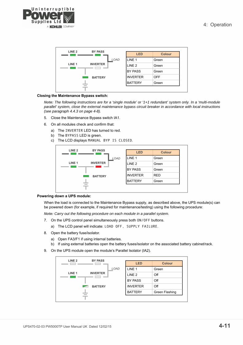
4: Operation
Closing the Maintenance Bypass switch:
Note: The following instructions are for a ‘single module’ or ‘1+1 redundant’ system only. In a ‘multi-moduleparallel’ system, close the external maintenance bypass circuit breaker in accordance with local instructions(see paragraph 4.4.3 on page 4-8).
5. Close the Maintenance Bypass switch IA1.
6. On all modules check and confirm that:
a) The INVERTER LED has turned to red.b) The BYPASS LED is green.c) The LCD displays MANUAL BYP IS CLOSED.
Powering down a UPS module:
When the load is connected to the Maintenance Bypass supply, as described above, the UPS module(s) canbe powered down (for example, if required for maintenance/testing) using the following procedure:
Note: Carry out the following procedure on each module in a parallel system.
7. On the UPS control panel simultaneously press both ON/OFF buttons.
a) The LCD panel will indicate: LOAD OFF, SUPPLY FAILURE.
8. Open the battery fuse/isolator.
a) Open FA3/F1 if using internal batteries.b) If using external batteries open the battery fuses/isolator on the associated battery cabinet/rack.
9. On the UPS module open the module’s Parallel Isolator (IA2).
LINE 1
LINE 2 BY PASS
INVERTER
BATTERY
LOAD
LED Colour
LINE 1 Green
LINE 2 Green
BY PASS Green
INVERTER OFF
BATTERY Green
LINE 1
LINE 2 BY PASS
INVERTER
BATTERY
LOAD
LED Colour
LINE 1 Green
LINE 2 Green
BY PASS Green
INVERTER RED
BATTERY Green
LINE 1
LINE 2 BY PASS
INVERTER
BATTERY
LOAD
LED Colour
LINE 1 Green
LINE 2 Off
BY PASS Off
INVERTER Off
BATTERY Green Flashing
UPS470-02-03 PW5000TP User Manual UK Dated 12/02/15 4-11
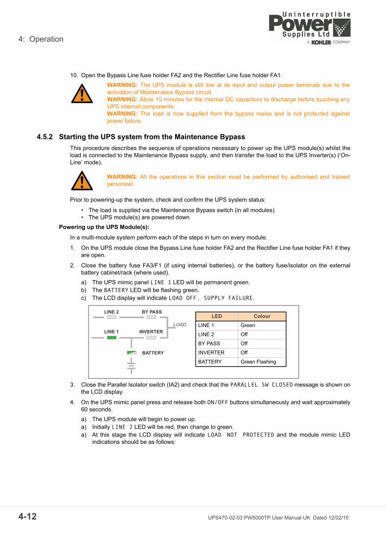
4: Operation
4-1
10. Open the Bypass Line fuse holder FA2 and the Rectifier Line fuse holder FA1.
4.5.2 Starting the UPS system from the Maintenance Bypass
This procedure describes the sequence of operations necessary to power up the UPS module(s) whilst theload is connected to the Maintenance Bypass supply, and then transfer the load to the UPS Inverter(s) (‘On-Line’ mode).
Prior to powering-up the system, check and confirm the UPS system status:
• The load is supplied via the Maintenance Bypass switch (in all modules)• The UPS module(s) are powered down
Powering up the UPS Module(s):
In a multi-module system perform each of the steps in turn on every module.
1. On the UPS module close the Bypass Line fuse holder FA2 and the Rectifier Line fuse holder FA1 if theyare open.
2. Close the battery fuse FA3/F1 (if using internal batteries), or the battery fuse/isolator on the externalbattery cabinet/rack (where used).
a) The UPS mimic panel LINE 1 LED will be permanent green.b) The BATTERY LED will be flashing green.c) The LCD display will indicate LOAD OFF, SUPPLY FAILURE.
3. Close the Parallel Isolator switch (IA2) and check that the PARALLEL SW CLOSED message is shown onthe LCD display.
4. On the UPS mimic panel press and release both ON/OFF buttons simultaneously and wait approximately60 seconds.
a) The UPS module will begin to power up. a) Initially LINE 2 LED will be red, then change to green. a) At this stage the LCD display will indicate LOAD NOT PROTECTED and the module mimic LED
indications should be as follows:
WARNING: The UPS module is still live at its input and output power terminals due to theactivation of Maintenance Bypass circuit.WARNING: Allow 10 minutes for the internal DC capacitors to discharge before touching anyUPS internal components.WARNING: The load is now supplied from the bypass mains and is not protected againstpower failure.
WARNING: All the operations in this section must be performed by authorised and trainedpersonnel.
LINE 1
LINE 2 BY PASS
INVERTER
BATTERY
LOAD
LED Colour
LINE 1 Green
LINE 2 Off
BY PASS Off
INVERTER Off
BATTERY Green Flashing
2 UPS470-02-03 PW5000TP User Manual UK Dated 12/02/15

4: Operation
5. When powering up a multi-module system ensure that ALL the modules are in the state shown abovebefore continuing with this procedure.
Transferring to the UPS from the Maintenance Bypass:
Note: The following instructions are for a ‘single module’ or ‘1+1 redundant’ system only. In a ‘multi-moduleparallel’ system, open the external maintenance bypass circuit breaker in accordance with local instructions(see paragraph 4.4.3 on page 4-8).
6. Ensure that the BYPASS LED is green (on all modules).
7. Open the Maintenance Bypass switch (IA1) (on all modules).
a) The LCD panels will display MANUAL BYPASS OPEN.b) The INVERTER LED will be extinguished.c) An audible alarm will sound.
8. Press the RESET button to cancel the audible alarm (on all modules).
a) The LCD display(s) will now indicate LOAD NOT PROTECTED.
Transferring the load to the inverter:
9. On the Control Panel (of any one module in a multi-module system):
a) Press the UP key once to access the menu system.b) Use the UP/DOWN keys to move the cursor so that it is adjacent to COMMANDS and then press the
ENTER key.c) Use the UP/DOWN keys move the cursor so that it is adjacent to LOAD TO INVERTER and then press
the ENTER key.
10. The UPS system will transfer the load to Inverter (on all modules in a multi-module system).
a) The LCD display(s) will now indicate LOAD PROTECTED.b) Check and confirm that the LED display(s) are as shown below:
LINE 1
LINE 2 BY PASS
INVERTER
BATTERY
LOAD
LED Colour
LINE 1 Green
LINE 2 Green
BY PASS Green
INVERTER RED
BATTERY Green
LINE 1
LINE 2 BY PASS
INVERTER
BATTERY
LOAD
LED Colour
LINE 1 Green
LINE 2 Green
BY PASS Green
INVERTER Off
BATTERY Green
UPS470-02-03 PW5000TP User Manual UK Dated 12/02/15 4-13
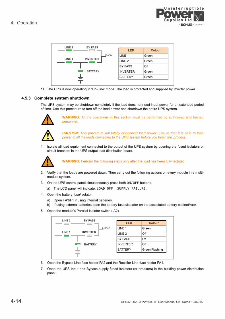
4: Operation
4-1
11. The UPS is now operating in ‘On-Line’ mode. The load is protected and supplied by inverter power.
4.5.3 Complete system shutdown
The UPS system may be shutdown completely if the load does not need input power for an extended periodof time. Use this procedure to turn off the load power and shutdown the entire UPS system.
1. Isolate all load equipment connected to the output of the UPS system by opening the fused isolators orcircuit breakers in the UPS output load distribution board.
2. Verify that the loads are powered down. Then carry out the following actions on every module in a multi-module system.
3. On the UPS control panel simultaneously press both ON/OFF buttons.
a) The LCD panel will indicate: LOAD OFF, SUPPLY FAILURE.
4. Open the battery fuse/isolator.
a) Open FA3/F1 if using internal batteries.b) If using external batteries open the battery fuses/isolator on the associated battery cabinet/rack.
5. Open the module’s Parallel Isolator switch (IA2).
6. Open the Bypass Line fuse holder FA2 and the Rectifier Line fuse holder FA1.
7. Open the UPS Input and Bypass supply fused isolators (or breakers) in the building power distributionpanel.
WARNING: All the operations in this section must be performed by authorised and trainedpersonnel.
CAUTION: This procedure will totally disconnect load power. Ensure that it is safe to losepower to all the loads connected to the UPS system before you begin this process.
WARNING: Perform the following steps only after the load has been fully isolated.
LINE 1
LINE 2 BY PASS
INVERTER
BATTERY
LOAD
LED Colour
LINE 1 Green
LINE 2 Green
BY PASS Off
INVERTER Green
BATTERY Green
LINE 1
LINE 2 BY PASS
INVERTER
BATTERY
LOAD
LED Colour
LINE 1 Green
LINE 2 Off
BY PASS Off
INVERTER Off
BATTERY Green Flashing
4 UPS470-02-03 PW5000TP User Manual UK Dated 12/02/15

4: Operation
8. The UPS is now voltage free.
4.5.4 Individual module start/stop procedure
If a multi-module system is designed with built-in redundancy it is possible to stop and start one modulewithout affecting the operational status of the overall system – e.g. one module can be taken off-line forservicing whilst the remaining modules maintain the protected load supply.
Module start-up:
Use this procedure to start a module and connect it to a multi-module system.
This procedure assumes the following initial conditions:
• UPS input isolators are open on the building’s LV supply switchboard• The fused battery isolator(s) are open • In the UPS cabinet, the fused isolators FA1, FA2 and the parallel isolator (IA2) are open
1. In the UPS cabinet, close the Input supply and Bypass supply fused isolators FA1, FA2 and the ParallelIsolator IA2.
2. Close the UPS input supply isolator at the LV switchboard.
a) The LINE 1 indicator will illuminate green.b) The LCD display will indicate LOAD OFF SUPPLY FAILURE.
Note: If necessary press the RESET button to obtain this display indication.
3. Close the battery fuse/isolator.
a) Close FA3/F1 if using internal batteries.b) If using external batteries close the battery fuses/isolator on the associated battery cabinet/rack.
4. Simultaneously press the two ON/OFF push buttons on the UPS control panel.
a) The UPS will run through an automated start-up sequence accompanied by the following indications:LINE 2 LED lights red then changes to green.INVERTER LED lights green.BATTERY LED lights green (constant).
b) LCD displays the LOAD PROTECTED message.
5. The UPS module is now On Line and connected to the parallel system.
WARNING: Allow 10 minutes for the internal DC capacitors to discharge before touching theUPS internal components.
WARNING: All the operations in this section must be performed by authorised and trainedpersonnel.
LINE 1
LINE 2 BY PASS
INVERTER
BATTERY
LOAD
LED Colour
LINE 1 Green
LINE 2 Green
BY PASS Off
INVERTER Green
BATTERY Green
UPS470-02-03 PW5000TP User Manual UK Dated 12/02/15 4-15

4: Operation
4-1
Module shut-down:
Use this procedure to power down a single module in a redundant module system.
1. Simultaneously press the two ON/OFF buttons on the UPS control panel.
a) The LED display will give the following indications:
2. Open the Parallel Isolator switch IA2.
3. In the UPS Cabinet, open the Input supply and Bypass supply fused isolators FA1 and FA2.
4. Open the battery fuse/isolator.
a) Open FA3/F1 if using internal batteries.b) If using external batteries open the battery fuses/isolator on the associated battery cabinet/rack.
5. Open the UPS input supply isolator and UPS output isolator on the LV Switchboard.
6. The UPS module is now totally shut-down.
LINE 1
LINE 2 BY PASS
INVERTER
BATTERY
LOAD
LED Colour
LINE 1 Green
LINE 2 Off
BY PASS Off
INVERTER Off
BATTERY Green
6 UPS470-02-03 PW5000TP User Manual UK Dated 12/02/15
5
UPS470-02-03 PW5000T
Maintenance
5.1 Introduction
5.2 System calibrationTo ensure optimum UPS operation and continuous, efficient protection of the connected load, it isrecommended that the system’s operating parameters are checked every six months and recalibrated wherenecessary.
The batteries should also be checked every six months, depending on the ambient temperature.
5.3 User responsibilitiesThere are no user-serviceable parts contained within the UPS so the maintenance requirements of the userare minimal. To maximise the useful working life and reliability of the UPS and its batteries, the environmentin which the UPS operates should be kept cool and dust free.
5.4 Routine maintenanceIt is essential that the UPS system and batteries receive regular preventative maintenance inspection tomaximise both the useful working life and the reliability of the UPS system. When the UPS is commissioned,the commissioning field service engineer will attach a service record book to the front of the UPS which willbe used to log the full service history of the UPS.
Preventative maintenance inspections involve working inside the UPS which contains hazardous AC and DCvoltages.
During a preventative maintenance inspection the field service engineer will carry out the following checks:
• Site/environment conditions• Integrity of electrical installation• Cooling airflow• Rectifier operation and calibration• Inverter operation and calibration• Static switch operation• Battery status• Load characteristics• Integrity of alarm and monitoring systems• Operation of all installed options
Preventative maintenance inspections form an integral part of all Extended Warranty Agreements(maintenance contracts) offered by Uninterruptible Power Supplies Ltd.
For further details on Extended Warranty Agreements see Section 2 of this manual.
WARNING: All the operations described in this chapter must be performed by authorisedelectricians or otherwise qualified personnel.
WARNING: Only Uninterruptible Power Supplies Ltd. trained and authorised field serviceengineers are fully aware of all of the hazardous areas within the UPS.
P User Manual UK Dated 12/02/15 5-1

5: Maintenance
5-2
5.5 Battery TestingThe battery test takes approximately 3 minutes and should be performed only if:
• There are no alarm conditions • The battery is fully charged
The battery test procedure can be performed from the UPS front panel and can be carried out independentlyof the operating mode (Off-line or On-line) and whether or not the load is connected.
UPS470-02-03 PW5000TP User Manual UK Dated 12/02/15

6
UPS470-02-03 PW5000T
Troubleshooting
6.1 AlarmsIn the event of an alarm condition the red ALARM LED-indicator will illuminate on the operator control paneland the audible alarm will sound.
In this case proceed as follows:
1. Silence the audible alarm by pressing the RESET button.
2. Identify the cause of the alarm condition by viewing the events register in the main menu (See paragraph4.3.3).
3. In case of doubt please contact Uninterruptible Power Supplies Ltd. on 0800 731 3269.
Fault identification and rectification information is given on the following pages.
6.2 Menu, Commands, Event Log, Measurements,A detailed description of the Menu, Commands, Event Log and Measurements that can be operated anddisplayed on the LCD can be found in Section 4.
6.2.1 Event Log Screen
As you step through the event memory, make a separate note of each alarm condition as this will assist in theidentification of any problems.
DESCRIPTION LCD-DISPLAY
1. Logging Control 01 05-10-00 14-38-56
LOAD TO INV.
2. A log of the last 99 events is stored in the Power Management Display. 02 05-10-00 14-38-59
LOAD TO BYP.
3. All events and alarms are indicated with their date and time of occurrence. 03 05-10-00 14-39-14LOAD OFF
P User Manual UK Dated 12/02/15 6-1
6: Troubleshooting
6-2
6.2.2 Fault Identification and Rectification Messages and Alarms
The major alarm conditions that will be encountered are:
6.3 Contacting ServiceUninterruptible Power Supplies Limited has a service department dedicated to providing routine maintenanceand emergency service cover for your UPS. If you have any queries regarding your UPS please contact us.
We recommend that your UPS is protected by an Extended Warranty Agreement (see Section 2 for details).These agreements assist us in caring for your UPS correctly, ensuring that it is well maintained and attendedto promptly should any problems occur.
Alarm Condition Meaning Suggested Solution
UPS FAULT There is a fault in the UPS and therefore normal operation cannot be guaranteed
Call the authorised service centre for assistance
MAINS BYP/RECT FAULT Mains power supply is outside prescribed tolerance
The input power to UPS is too low, too high, or missing.If site power appears to be OK, check the input circuit breakers etc. supplying the UPS
OUTPUT SHORT There is a short circuit at the output of UPS (on load side)
Check all output connections and repair as required.
OVERLOAD Load exceeds the UPS rated power Identify which piece of equipment is causing the overload and remove it from the UPS.Do not connect laser printers, photocopiers, electric heaters, kettles etc. to the UPS
OVERTEMPERATURE UPS temperature has exceeded the allowed value
Check the ambient temperature of the UPS is less than 30° C.If the ambient temperature is normal call the authorised service centre for assistance.
BATTERY CHARGER OFF The attached battery and the battery charger set-up do not correspond or battery charger fault
Call the authorised service centre for assistance.
INVERTER FAULT Inverter is faulty. Call the authorised service centre for assistance.
SYNCHRON FAULT The inverter and mains are not synchronised. The frequency of the input voltage to the UPS is outside operational limits and the UPS static bypass has been temporarily disabled. Check that generator is connected
BATTERY IN DISCHARGE Battery is near end of autonomy Shutdown load connected to UPS before the UPS switches itself off to protect its batteries
MANUAL BYP IS CLOSED Maintenance Bypass closed. Load supplied by mains
This alarm is only displayed if the UPS is on Maintenance Bypass
Uninterruptible Power Supplies Ltd.WoodgateBartley Wood Business ParkHookHampshireRG27 9XA
Tel: 01256 3867000800 731 3269 (24 Hr.)
Fax: 01256 386701
Email: [email protected]
UPS470-02-03 PW5000TP User Manual UK Dated 12/02/15

7
UPS470-02-03 PW5000T
Options
7.1 IntroductionThe PowerWave 5000TP UPS has the following available options:
• Remote Emergency Stop facilities• Generator On facilities• Temperature sensor for temperature-dependant battery charging• Software for automatic shutdown and monitoring• SNMP Card for network management and remote monitoring• Modem/Ethernet interface for PowerREPORTER™ management software
7.2 Remote Emergency Stop facilitiesThe remote emergency stop facility comprises a normally-closed contact, connected to terminal port X1/7and X1/8 on the communications board, which opens to operate the emergency stop sequence.
Note: Usually the remote emergency stop function is disabled, and it should be activated by a hardware codeon the SETUP SERVICE menu. Please contact your distributor to enable this operation.
To allow removal, maintenance or testing of any remote emergency stop facility without disturbing the normaloperation of the UPS, it is recommended that a terminal block, with linking facilities, is installed between theUPS and the remote emergency stop button.
1. Use a screened cable with 1 pair (section of wires 0.6 mm2) and maximum length of 100 m.
2. Connect the cable as shown in Figure 7.1.
Figure 7.1 Remote Emergency Stop cabling
X1
X1/7X1/8
Remote shutdown
Terminal block
UPS RemoteShutdown Port
P User Manual UK Dated 12/02/15 7-1

7: Options
7-2
7.3 Generator ON facilitiesThe generator ON facility must use a normally-open contact which closes to indicate that a generator isrunning and supplying the UPS input power.
When used, this facility inhibits the operation of the battery charger and/or static bypass while the UPS isbeing supplied from a standby generator. See “Set-up User menu screen” in section 4.3.7.
1. Use a screened cable with 1 pair (section of wires 0.6 mm2) and maximum length of 100 m.
2. Connect the cable as shown in Figure 7.2.
Figure 7.2 Generator ON Connection
X1
X1/1X1/2
Generator Alarm PanelUPS Generator
Port
UPS470-02-03 PW5000TP User Manual UK Dated 12/02/15
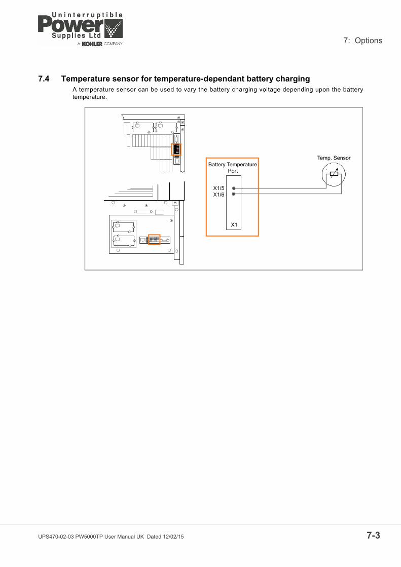
7: Options
7.4 Temperature sensor for temperature-dependant battery chargingA temperature sensor can be used to vary the battery charging voltage depending upon the batterytemperature.
X1
X1/5X1/6
Temp. SensorBattery Temperature
Port
UPS470-02-03 PW5000TP User Manual UK Dated 12/02/15 7-3

7: Options
7-4
7.5 WAVEMON Shutdown and Management Software
7.5.1 Why is UPS Management important?
By combining a UPS with a variety of network management products, such as orderly shutdown software andSNMP adaptors, system-administrators can be assured that their electricity supplies are monitored for powerdisruptions and depleted battery conditions. Such conditions pose the greatest threat through powerdisturbance to valuable computer data by causing possible corruption or loss. By installing UPS/Mainsmonitoring software, administrators are able to monitor the utility power from a central location, allowing earlywarning of problems even across more complex systems like Wide Area Networks (WAN) and EnterpriseWide Networks of multinational companies.
A prolonged mains failure may outlast the battery autonomy of the UPS system. If this situation occurs theUPS management software will initiate an automatic, ‘controlled’ shutdown of the operating system, and soprotect valuable data. Uninterruptible Power Supplies Ltd. offer a wide range of local and remote monitoringand control systems, affording maximum protection for computer systems.
7.5.2 WAVEMON Shutdown and Monitoring Software
WAVEMON is an external monitoring and shutdown software application that is designed to operate withmany of Uninterruptible Power Supplies Ltd. UPS products. The package comprises a software installationCD suitable for most server operating systems, a standard cable set and a user manual
The WAVEMON system can monitor the dry port relay contacts available on terminal block X2, together withan RS232 port (JD11) – both located on the communications card.
When the WAVEMON system is used to monitor the X2 dry port contacts it is necessary to connect the X2
terminals of the UPS to the serial port of the server using a 0.5 mm2 cable.
Figure 7.3 Monitoring screen image.
The main characteristics of WAVEMON software are (assuming RS232 port used):
• Automatic unattended master/slave shutdown in heterogeneous networks• On-screen autonomy time/battery time countdown• On-screen server log off and shutdown procedure• Time and date stamp event log, extensive logging of all UPS activity and power quality data• Scheduled UPS economy mode, service mode, other systems status• Graphical user interface for Windows compatible platforms• Automatic unattended local shutdown• Special modules for the MS-Office software to close and save open documents• Compatible with all optional modules like UPSDIALER, SNMP adaptors, temperature sensors, etc.
UPS470-02-03 PW5000TP User Manual UK Dated 12/02/15

7: Options
The UPS-Management software is a client-/server-application for networks and local workstations. Basically,the WAVEMON application consists of two parts: the server-module of the UPS-Management Software isUPSServ, which communicates via RS-232 cable with the UPS.
Working as a background process the UPSServ collects messages, received from the UPS, interprets themessages and then makes them available to the client-module UPSCli and to any SNMP-basedmanagement station.
When UPSServ detects voltage variations or a power failure it can execute various so called system ‘eventroutines’, which for example may shutdown the server or send a warning to connected users. These systemevent routines are a part of the UPS-Management Software can be adjusted to suit the customer’s demandsdemands.
The UPS management software includes the licence for using the UPS service on one server with one UPSand an unlimited numbers of connected Windows workstations. When operating with two or more servers, alicence is required for every additional server, irrespective of whether the UPS service runs at that location, orif the server is halted by a UPS service via remote command.
The same regulations apply to the use of remote send/receive modules (RCCMD) and multi-server shutdownunder NT, UNIX and other operating systems. The service programs are generally delivered as a single-licence. To use a single CD ROM to shutdown multiple servers you have to purchase additional CD licensekeys.
Parallel/redundant UPS systems are also manageable by the software. The main principle is to introduce ashutdown of a server only when strictly necessary. Correct parallel handling has therefore to manage aparallel system as a whole and always consider the system redundancy. The following statements apply:
• Every alarm on any unit is immediately notified, but a reaction to a serious fault is introduced onlywhen the minimum number of UPS Modules necessary to supply the load exhibits an alarm situation.
• The real battery autonomy time of the (whole) parallel system is computed continuously.• Maintenance on a redundant unit may be executed without affecting the management system
(supervisor).
The PowerWave 5000TP can be integrated in a network in two ways:
1. By means of the server which is being powered by the UPS and is integrated in the network. In most ofthe cases the server is used as sub-agent and you only need the PMC-Software without any SNMPAdapter. You need a standard serial connection between the RS232 JD1 port of the UPS and the RS232port of the computer/server.
2. In some situations it is preferable to interface the network via an SNMP adapter. By this way up to 50computers can be shut down in a RCCMD environment. RCCMD (Remote Console Command) is anadditional software module, which can be triggered by the SNMP device to executes a command(typically a shutdown command) on a remote system.
7.6 SNMP CARD/ADAPTOR For Network Management/Remote MonitoringThe Simple Network Management Protocol (SNMP) is a world-wide standardised communication-protocol. Itis used to monitor any device in the network via simple control language. The UPS-Management Softwarealso provides its data in this SNMP format with its internal software agent. The operating system you areusing must be SNMP compatible. We offer our software with SNMP functionality together with NetWare, OS/2, all Windows NT systems on INTEL and ALPHA.
There are two types of SNMP-Adaptors available: External SNMP-Adaptor and Internal SNMP-Card (bothhave the same functions). Both can manage a parallel system (N modules) and return either global values –which are consistent for the whole parallel system – or specific values from the individual modules.
The SNMP adaptor requires a PC with terminal connections. For normal operation at least one networkconnection (Ethernet) is also required.
UPS470-02-03 PW5000TP User Manual UK Dated 12/02/15 7-5

7: Options
7-6
Figure 7.4 SNMP Adapter
External SNMP Adapter
1. The small (125x70 mm) External SNMP adapter comes withfollowing interfaces:RJ-45 connector for 10/100 Base-T (auto switchable).
2. Serial Port for configuration (COM2) or optional ModBusinterface.
3. Error/Link LED for UPS status.
4. Aux. Port.
5. DIP Switch.
6. Serial Port to the UPS (COM1)
7. DC Supply (9 VDC or 9-36 VDC supply, depending onmodel), from a UPS-backed socket.
Internal SNMP Adapter
The Internal SNMP-Card can be inserted into an appropriateextension slot of the PMC. This adapter communicates via theserial port of the UPS and makes a direct multiple server shutdown possible without additional SNMP management software.
The SNMP adaptor is used to monitor any device in the networkand can be used, utilising the RCCMD send function, for anautomatic network wide shut down or informing connected users.The shut down procedure can be initiated from the remainingtime (downtime) or as countdown timer from the beginning of thealarm. A shut down is therefore possible without extra input fromthe operator, but fully software controlled.
For detailed information please refer to the Software Manualprovided with the WAVEMON CD ROM. This adaptor communicates via the serial port of the UPS andmakes a direct multiple server shut down possible without additional SNMP management software.
RCCMD - Remote Console Command module for a multi-server shutdown. The RCCMD modules areindependent programs that may be activated on the computer that is running UPSMAN. This makes ashutdown call possible in any LAN and WAN, regardless of the network type or operating system.
Ethernet
External SNMPAdapter
Internal SNMP Card
UPS
UPS470-02-03 PW5000TP User Manual UK Dated 12/02/15
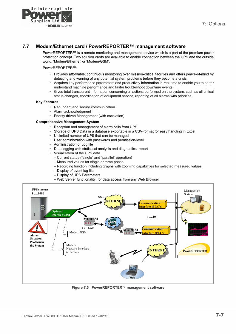
7: Options
7.7 Modem/Ethernet card / PowerREPORTER™ management softwarePowerREPORTER™ is a remote monitoring and management service which is a part of the premium powerprotection concept. Two solution cards are available to enable connection between the UPS and the outsideworld: ‘Modem/Ethernet’ or ‘Modem/GSM’.
PowerREPORTER™:
• Provides affordable, continuous monitoring over mission-critical facilities and offers peace-of-mind bydetecting and warning of any potential system problems before they become a crisis
• Acquires key performance parameters and productivity information in real-time to enable you to betterunderstand machine performance and faster troubleshoot downtime events
• Gives total transparent information concerning all actions performed on the system, such as all criticalstatus changes, coordination of equipment service, reporting of all alarms with priorities
Key Features
• Redundant and secure communication• Alarm acknowledgment• Priority driven Management (with escalation)
Comprehensive Management System
• Reception and management of alarm calls from UPS• Storage of UPS Data in a database exportable in a CSV-format for easy handling in Excel• Unlimited number of UPS that can be managed• User administration with passwords and permission-level• Administration of Log file• Data logging with statistical analysis and diagnostics, report• Visualization of the UPS data
– Current status (“single” and “parallel” operation)– Measured values for single or three phase– Recording function including graphs with zooming capabilities for selected measured values– Display of event log file– Display of UPS Parameters– Web Server functionality, for data access from any Web Browser
Figure 7.5 PowerREPORTER™ management software
MMOODDEEMM
UPS systems 1 ….1000
Alarm Situation Problem in the System
Optional Interface Card
Modem GSM
Modem Network interface (ethernet)
II NNTTEERRNNEETT
MMOODD EEMM
Communication Interface (PLC’s)
1 ….10
Co mmunication Interface (PLC’s)
IINNTTEERRNNEETT
Call back
SSL
Management Station
PowerREPORTER
UPS470-02-03 PW5000TP User Manual UK Dated 12/02/15 7-7

7: Options
7-8
UPS470-02-03 PW5000TP User Manual UK Dated 12/02/15
8
UPS470-02-03 PW5000T
Specifications
8.1 MechanicalCabinet A
Cabinet B
Cabinet C
Module Rating (kVA)
10 15 20
WITHOUT BATTERY ENCLOSUREDimensions (WxHxD)
mm 345 x 720 x 710
Weight (without battery) kg 60 62 64
Weight (with 48x7Ah battery) kg 180 182 184
Weight (with standard packaging) kg +4
Colour Graphite grey (RAL 7024)
Module Rating (kVA)
10 15 20 25
WITHOUT BATTERY ENCLOSUREDimensions (WxHxD)
mm 345 x 1045 x 710
Weight (without battery) kg 88 90 92 94
Weight (with 96x7Ah battery) kg 328 330 332 334
Weight (with standard packaging) kg +5
Colour Graphite grey (RAL 7024)
Module Rating (kVA)
25 30 40 50
WITHOUT BATTERY ENCLOSUREDimensions (WxHxD)
mm 440 x 1420 x 910
Weight (without battery) kg (9Ah/28Ah)151/135
(9Ah/28Ah)160/145
(9Ah/28Ah)165/150
(9Ah/28Ah)170/155
Weight (with 144x7/9Ah battery) kg 540 550 555 560
Weight (with 48x28Ah battery) kg 605 615 620 625
Weight (with standard packaging) kg +5
Colour Graphite grey (RAL 7024)
P User Manual UK Dated 12/02/15 8-1

8: Specifications
8-2
8.2 Input Characteristics
8.3 Output Characteristics
Module Rating (kVA)
10 15 20 25 30 40 50
Nominal Input Voltage V 3x380/220V+N, 3x400V/230V+N, 3x415/240V+N
Input Voltage Tolerance (ref to 3x400/230V) for Loads in %:
V (-23%/+15%) 3x308/177 V to 3x460/264 V for <100% load (-30%/+15%) 3x280/161 V to 3x460/264 V for < 80% load (-40%/+15%) 3x240/138 V to 3x460/264 V for < 60% load
Input Frequency Hz 35 - 70
Input Power Factor PF=0.99 @ 100% load
Inrush Current A max. In
Input Distortion THDi Sine-wave THDi = 3.0% @ 100% load
Max. Input Power with rated output power and charged battery (output pf = 0.9)
kW 9.6 14.4 19.1 23.9 28.7 38.3 47.9
Max. Input Current with rated output power and charged battery (output pf = 0.9)
A 13.9 20.8 27.8 34.7 41.6 55.5 69.4
Max. Input Power with rated output power and discharged battery (output pf = 0.9)
kW 10.5 15.7 21 26.2 31.4 41.9 52.4
Max. Input Current with rated output power and discharged battery (output pf = 0.9)
A 15.2 22.8 30.4 37.9 45.5 60.7 75.9
Module Rating (kVA)
10 15 20 25 30 40 50
Output Rated Power KW 9 13.5 18 22.5 27 36 45
Output Current In @ p.f. 0.9 (400 V) A 14.4 21.7 28.9 36.1 43.3 57.7 72.2
Output Current In @ p.f. 1.0 (400 V) A 13.0 19.5 26.0 32.5 39.0 52.0 65.0
Output Rated Voltage V 3x380/220V or 3x400/230V or 3x415/240V
Output Voltage Stability % Static: < ±1%Dynamic (Step load 0%-100% or 100%-0%) < ±4%
Output Voltage Distortion % With Linear Load < 2%With Non-linear Load (EN62040-3:2001) < 4%
Output Frequency Hz 50 Hz or 60 Hz
Output Frequency Tolerance Deg. Synchronized with mains < ±2%(selectable for bypass operation) or < ±4% Free running ±0.1%
Bypass operation At Nominal Input voltage of 3x400 V ±15%, or 196 V to 264 V ph-N
Permissible Unbalanced Load(All 3 phases regulated independently)
% 100%
Phase Angle Tolerance (With 100% Unbalanced load)
Deg. ±0 deg.
Overload Capability on Inverter % At p.f. 0.9 110% load 10 min. At p.f. 0.9 130% load 1 min. At p.f. 0.8 125% load 10 min. At p.f. 0.8 150% load 1 min.
Output short capability (RMS) A Inverter: up to 3 x In during 40 msBypass: 10 x In during 10 ms
Crest - Factor 3: 1
UPS470-02-03 PW5000TP User Manual UK Dated 12/02/15

8: Specifications
8.4 Battery Characteristics
8.5 Environmental
8.6 Heat Dissipation With Non-Linear Loads
Module Rating (kVA)
10 15 20 25 30 40 50
Cabinet Type A B A B A B B C C C C
Min/Max Number of 12V Battery Blocks per string 22-50* 32-50* 32-50* 32-50* 40-50* 24-50* 32-50* 40-50*
Maximum Battery Charger Current (Amps) 4A 6A
Battery Charging Curve Ripple free; IU (DIN 41773)
Temperature compensation ready Standard (temp. sensor optional)
Battery Test Automatic and periodically (adjustable)
Battery Type Maintenance free VRLA or NiCd
* Depending on the effective load in kW used by the system (numbers shown are for 0.8 - 0.9 pf only)
Module Rating (kVA)
10 15 20 25 30 40 50
Audible Noise with 100% / 50% Load dBA 55/49 55/49 57/49 57/49 58/50 59/50 59/50
Operation temperature °C 0 - 40
Ambient Temperature for Batteries (recommended) °C 20
Storage Temperature °C Between -25 and +70
Battery Storage Time at Ambient Temperature Max. 6 months
Max. altitude (above sea level) m 1000m (3300ft) without de-rating
De-rating factor for use at altitudes above 1000m sea level according (IEC 62040-3)
ALL MODULES
Metres above sea level (m / ft) De-Rating Factor for Power
1500 / 4850 0.95
2000 / 6600 0.91
2500 / 8250 0.86
3000 / 9900 0.82
Relative Air-humidity Max. 95% (non-condensing)
Positional Clearances Front: A minimum of 900mm should be allowed for free passage.Side: 600mm left and right side access is required for service.Rear: A minimum of 200mm is required for cooling air circulation and the unit should be cabled such that it can be pulled forward to allow 600mm rear clearance for service/maintenance.
Accessibility (Operator) 10kVA – 25kVA in type A or B cabinets require front/rear access25kVA – 40kVA in type C cabinets require front access only
Input and Output Power Cabling 10kVA – 25kVA in type A or B cabinets are cabled at the rear25kVA – 40kVA in type C cabinets are cabled at the rear
Efficiency AC-AC up to (at pf=1.0) (depending on UPS power)
Load: 100% 75% 50% 25%
Efficiency: 95.5% 95.5% 95% 94.5%
Eco-Mode efficiency at 100% load % 98%
10kVA 15kVA 20kVA 25kVA 30kVA 40kVA 50kVA
Heat Dissipation with 100% Non-linear Load per range (EN 62040-3)
W 600 900 1100 1400 1700 2300 2900
Heat Dissipation with 100% Non-linear Load per range (EN 62040-3)
BTU/h 2048 3072 3754 4778 5802 7850 9898
Airflow (25°C - 30°C) with 100% Non-linear Load per range (EN 62040-3)
m³/h 150 150 150 150 570 570 570
Heat Dissipation without load W 120 150 150 170 250 300 350
UPS470-02-03 PW5000TP User Manual UK Dated 12/02/15 8-3

8: Specifications
8-4
8.7 Standards
8.8 Communication Options
Module Rating (kVA)
10 15 20 25 30 40 50
Safety IEC/EN 62040-1-1:2003, IEC/EN 60950-1:2001/A11:2004
Electromagnetic Compatibility IEC/EN 62040-2:2005, IEC/EN61000-3-2:2000, IEC/EN61000-6-2:2001,
EMC ClassesC2 domestic or industrial In < 16AC3 industrial In >16A
C2 C3
Performance IEC/EN62040-3:2001
Product certification CE
Degree of protection IP 20
All Modules
Power Management Display (PMD) LCD display
RS232 on Sub-D9 port For monitoring and integration in network management
Customer Interfaces: Inputs (DRY PORTS) • 1 Remote Shut down [EMERGENCY OFF (Normally closed)]• 1 GEN-ON (Normally open)• 1 Programmable Customer's Inputs (Normally open)• 1 Temp. Sensor for Battery Control• 1 12Vdc source (max. 250mA)
RJ45 port For multidrop purpose (optional)
Relay card +USB Including:Customer Interfaces: Outputs (DRY PORTS)
RS232 on USB Port
• Common Alarm• Load on Bypass• Battery Low• Load on Inverter• Mains Failure
For remote signalling and automatic computer shutdown
SNMP Card (slot already included) For monitoring and integration in network management
UPS470-02-03 PW5000TP User Manual UK Dated 12/02/15

8: Specifications
8.9 Fuses & Cables Quick Reference
Rectifier
Inverter
Static Switch
FA1
Fuse B
Load
DUAL INPUT FEED
Cable D
Cable B
Fuse C
Cable C
Rectifier
Inverter
Static Switch
Fuse A
Load
SINGLE INPUT FEED (standard) Mains (3x380/220V,3x400/230V,3x415/240V)
Cable D
Cable A
EXTERNALBATTERYCABINET(option)
FA2FA1 FA2
EXTERNALBATTERYCABINET(option)
FA3(F1)
FA4
Output Switch
Maint.Bypass
IA2 IA1Maint.Bypass
IA2 IA1Output Switch
Internal Batts.
FA4
Internal Batts.
FA3(F1)
SINGLE INPUT
FEED
DUAL INPUT FEED
Notes:
1. Fuse and Cable recommendations to IEC 60950-1:2001
2. The fuse and cable rating details in the above tables are a recommendation only.
3. The UPS must be installed to prescribed IEC or local regulations (e.g. BS7671:2008).
4. External DC Cables and Battery fuses are bespoke to the installation.
Power (kVA) Fuse A (Agl/CB) (A) Cable A (mm²) Cable D (mm²)
10 3 x 20 5 x 2.5 5 x 2.5
15 3 x 32 5 x 4.0 5 x 4.0
20 3 x 40 5 x 6.0 5 x 6.0
25 3 x 40 5 x 6.0 5 x 6.0
30 3 x 63 5 x 10 5 x 10
40 3 x 80 5 x 25 5 x 25
50 3 x 80 5 x 25 5 x 25
Power (kVA) Fuse B (Agl/CB)(A)
Cable B (mm²) Fuse C(Agl/CB)(A)
Cable C (mm²) Cable D (mm²)
10 3 x 20 5 x 2.5 3 x 20 5 x 2.5 5 x 2.5
15 3 x 32 5 x 4.0 3 x 32 5 x 4.0 5 x 4.0
20 3 x 40 5 x 6.0 3 x 40 5 x 6.0 5 x 6.0
25 3 x 40 5 x 6.0 3 x 40 5 x 6.0 5 x 6.0
30 3 x 63 5 x 10 3 x 63 5 x 10 5 x 10
40 3 x 80 5 x 25 3 x 80 5 x 25 5 x 25
50 3 x 80 5 x 25 3 x 80 5 x 25 5 x 25
UPS470-02-03 PW5000TP User Manual UK Dated 12/02/15 8-5

8: Specifications
8-6
UPS470-02-03 PW5000TP User Manual UK Dated 12/02/15