USER MANUAL - Portable Leak Detectors · 2018-03-08 · LACO LEAK DETECTOR MANUAL fl MINITRACER™...
14
MINITRACER ™ PORTABLE SNIFFER USER MANUAL
Transcript of USER MANUAL - Portable Leak Detectors · 2018-03-08 · LACO LEAK DETECTOR MANUAL fl MINITRACER™...

MINITRACER™ PORTABLE SNIFFER
USER MANUAL

ii
© 2018 FLUIDX Equipment, Inc.
CONTACT US
PHONE/FAX
Phone: 801.486.1015 Fax: 801.486.1032
ADDRESS
FLUIDX Equipment, Inc. 139 W. 2260 S. Salt Lake City, UT 84115
www.fluidxinc.com
SMT-07-1006 Rev C
iii
© 2018 FLUIDX Equipment, Inc.
CONTENTS
1. SCOPE .................................................................................... 1
2. OVERVIEW ............................................................................ 1
3. SPECIFICATIONS .................................................................. 2
4. BASIC OPERATION .............................................................. 3
5. LEAK TESTING ...................................................................... 4
6. INSTRUMENT SETTING DESCRIPTIONS ......................... 6
7. NAVIGATING THE MENU .................................................... 7
8. SAMPLE PROCEDURE ......................................................... 8
9. CHARGING THE BATTERY .................................................. 9
10. SENSITIVITY ........................................................................ 9
11. TROUBLESHOOTING ....................................................... 10

LACO LEAK DETECTOR MANUAL - MINITRACER™ PORTABLE SNIFFER
1© 2018 FLUIDX Equipment, Inc.
1. SCOPEThis manual contains operation, maintenance, and troubleshooting information for miniTracer™ portable sniffer leak detector. Our leak detectors are designed to ensure safety when used properly. It is the responsibility of the user to follow safety-related warnings, cautions, notes, and other requirements described in this manual.
2. OVERVIEWThe miniTracer™ is a sensitive, precise leak detector designed for simple operation and exact identification of system leaks in lab and industrial applications. Utilizing thermal conductivity to pinpoint gas leaks from pressurized systems, the highly-sensitive miniTracer™ offers precise detection of gas leaks from pressurized systems.
2.1 PRODUCT INCLUSIONS
• 6’ power cord
• 3 ½” sampling probe
• A thermistor-type thermal conductivity detector (TCD)
• Vibrator-type pump
• Printed circ uit board
2.2 FEATURES
• Dual power source (operates on either 120 volts, 60 Hz, or on a single internal rechargeable Ni-Cd battery)
• An audible tone generator that allows leak testing without visually scanning the meter.
• HI/LO sensitivity settings
• Soap- and solution-free detection
LACO LEAK DETECTOR MANUAL - MINITRACER™ PORTABLE SNIFFER
2© 2018 FLUIDX Equipment, Inc.
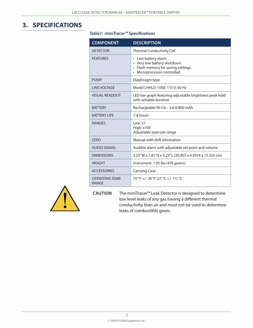
3. SPECIFICATIONSTable1: miniTracer™ Specifications
COMPONENT DESCRIPTION
DETECTOR Thermal Conductivity Cell
FEATURES • Low battery alarm• Very low battery shutdown• Flash memory for saving settings• Microprocessor-controlled
PUMP Diaphragm type
LINE VOLTAGE Model LHHLD-1000: 115 V, 60 Hz
VISUAL READOUT LED bar graph featuring adjustable brightness peak hold with settable duration
BATTERY Rechargeable Ni-Cd – 3.6 V/800 mAh
BATTERY LIFE 7-8 hours
RANGES Low: x1 High: x100 Adjustable span per range
ZERO Manual with drift elimination
AUDIO SIGNAL Audible alarm with adjustable set point and volume
DIMENSIONS 3.25”W x 1.81”H x 5.25” L (20.955 x 4.5974 x 13.335 cm)
WEIGHT Instrument: 1.05 lbs (476 grams)
ACCESSORIES Carrying Case
OPERATING TEMP. RANGE
70 °F +/- 20 °F (21 °C +/- 11) °C
CAUTION The miniTracer™ Leak Detector is designed to determine low level leaks of any gas having a different thermal conductivity than air and must not be used to determine leaks of combustible gases.
LACO LEAK DETECTOR MANUAL - MINITRACER™ PORTABLE SNIFFER
3© 2018 FLUIDX Equipment, Inc.
4. BASIC OPERATION
4.1 FRONT DISPLAY PANELS AND CONTROLS
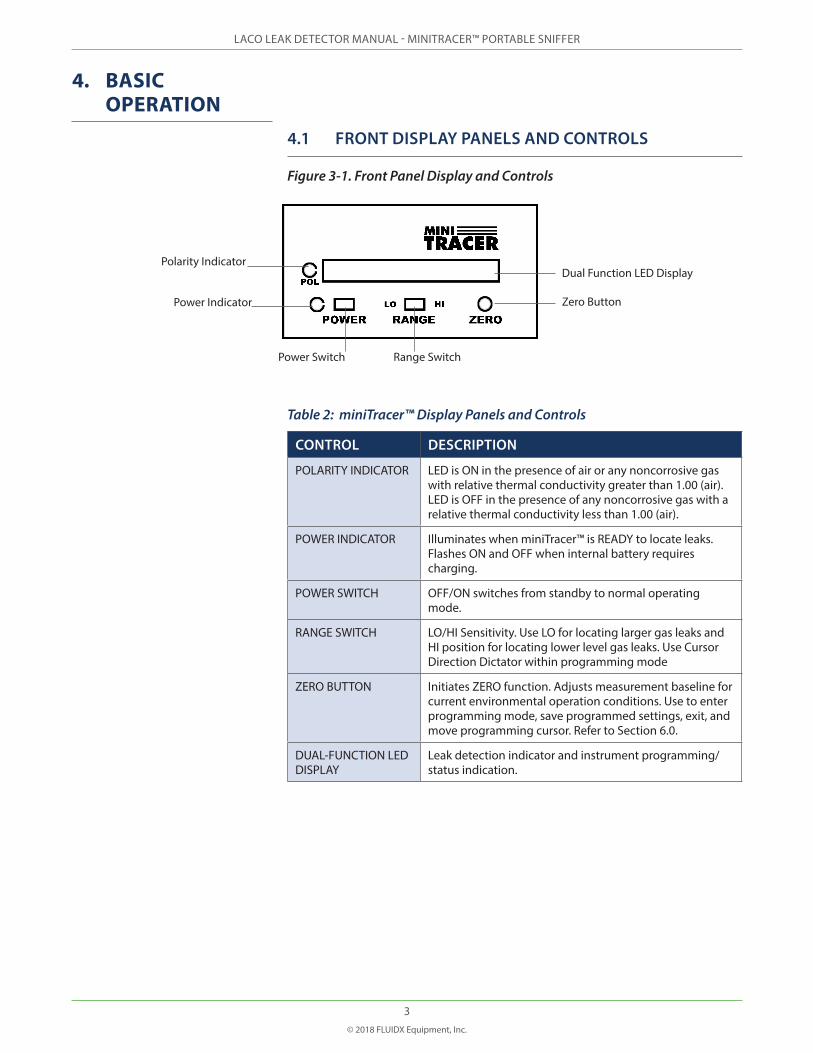
Figure 3-1. Front Panel Display and Controls
Table 2: miniTracer™ Display Panels and Controls
CONTROL DESCRIPTION
POLARITY INDICATOR LED is ON in the presence of air or any noncorrosive gas with relative thermal conductivity greater than 1.00 (air). LED is OFF in the presence of any noncorrosive gas with a relative thermal conductivity less than 1.00 (air).
POWER INDICATOR Illuminates when miniTracer™ is READY to locate leaks. Flashes ON and OFF when internal battery requires charging.
POWER SWITCH OFF/ON switches from standby to normal operating mode.
RANGE SWITCH LO/HI Sensitivity. Use LO for locating larger gas leaks and HI position for locating lower level gas leaks. Use Cursor Direction Dictator within programming mode
ZERO BUTTON Initiates ZERO function. Adjusts measurement baseline for current environmental operation conditions. Use to enter programming mode, save programmed settings, exit, and move programming cursor. Refer to Section 6.0.
DUAL-FUNCTION LED DISPLAY
Leak detection indicator and instrument programming/status indication.
Polarity Indicator
Power Indicator
Power Switch Range Switch
Zero Button
Dual Function LED Display
LACO LEAK DETECTOR MANUAL - MINITRACER™ PORTABLE SNIFFER
4© 2018 FLUIDX Equipment, Inc.
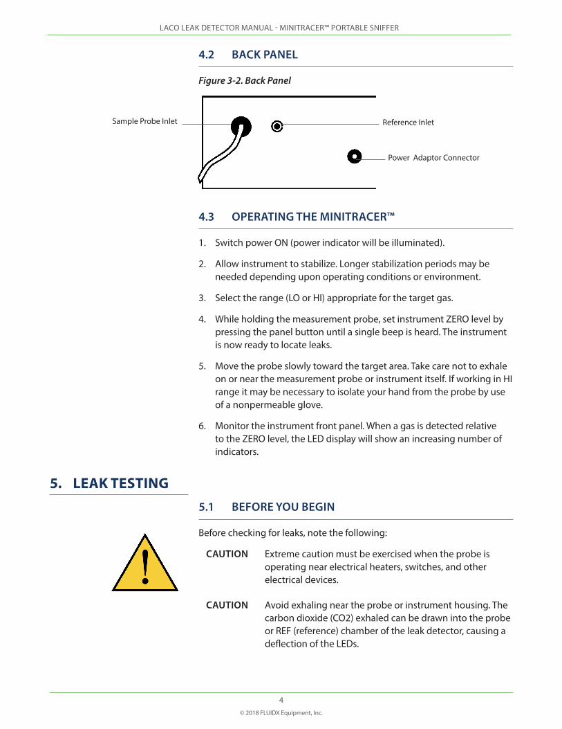
4.2 BACK PANEL
Figure 3-2. Back Panel
4.3 OPERATING THE MINITRACER™
1. Switch power ON (power indicator will be illuminated).
2. Allow instrument to stabilize. Longer stabilization periods may be needed depending upon operating conditions or environment.
3. Select the range (LO or HI) appropriate for the target gas.
4. While holding the measurement probe, set instrument ZERO level by pressing the panel button until a single beep is heard. The instrument is now ready to locate leaks.
5. Move the probe slowly toward the target area. Take care not to exhale on or near the measurement probe or instrument itself. If working in HI range it may be necessary to isolate your hand from the probe by use of a nonpermeable glove.
6. Monitor the instrument front panel. When a gas is detected relative to the ZERO level, the LED display will show an increasing number of indicators.
5. LEAK TESTING5.1 BEFORE YOU BEGIN
Before checking for leaks, note the following:
CAUTION Extreme caution must be exercised when the probe is operating near electrical heaters, switches, and other electrical devices.
CAUTION Avoid exhaling near the probe or instrument housing. The carbon dioxide (CO2) exhaled can be drawn into the probe or REF (reference) chamber of the leak detector, causing a deflection of the LEDs.
Reference InletSample Probe Inlet
Power Adaptor Connector
LACO LEAK DETECTOR MANUAL - MINITRACER™ PORTABLE SNIFFER
5© 2018 FLUIDX Equipment, Inc.
CAUTION When checking for leaks, it is imperative that fittings or suspected leak areas are dry. If the area has previously been checked with a water-based bubble-type solution and has not been dried, low readings (as well as possible detector contamination) will occur. The thermal conductivity of water vapor will counteract the signal from helium leaks. The resulting effect will be relatively no LED or audio signal output.
CAUTION Do not allow moisture to be drawn into the probe!
NOTE If helium (He) is being checked, a leak will cause the LEDs to illuminate to the right with the Polarity Indicator in the ON position, while most other gases or vapors will deflect the LEDs to the right with the Polarity Indicator in the OFF position.
5.2 CHECKING FOR LEAKS
Using the probe, carefully move the tip around and over suspected joints, seals, seams or other areas where leaks occur. The probe must be moved slowly to detect small leaks. The net effect will be no, or low display readings.
5.3 FINDING LEAKS
A leak is indicated if deflection of the LEDs is seen or an audible signal is heard. Remove the probe form the area, allow the LED indicators to reset to zero (manually reset to zero if necessary), and return probe to the suspected location to verify the leak.
For more detailed information on leak detector sensitivity, refer to Section10. SENSITIVITY.
LACO LEAK DETECTOR MANUAL - MINITRACER™ PORTABLE SNIFFER
6© 2018 FLUIDX Equipment, Inc.
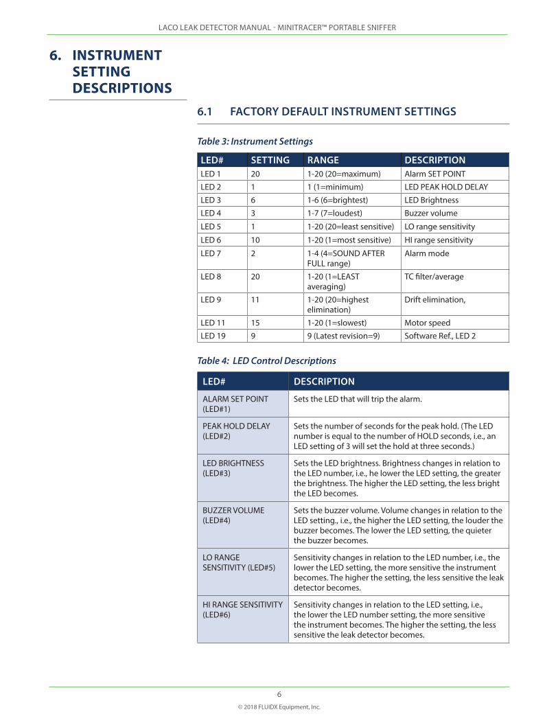
6. INSTRUMENT SETTING DESCRIPTIONS
6.1 FACTORY DEFAULT INSTRUMENT SETTINGS
Table 3: Instrument Settings
LED# SETTING RANGE DESCRIPTIONLED 1 20 1-20 (20=maximum) Alarm SET POINT
LED 2 1 1 (1=minimum) LED PEAK HOLD DELAY
LED 3 6 1-6 (6=brightest) LED Brightness
LED 4 3 1-7 (7=loudest) Buzzer volume
LED 5 1 1-20 (20=least sensitive) LO range sensitivity
LED 6 10 1-20 (1=most sensitive) HI range sensitivity
LED 7 2 1-4 (4=SOUND AFTER FULL range)
Alarm mode
LED 8 20 1-20 (1=LEAST averaging)
TC filter/average
LED 9 11 1-20 (20=highest elimination)
Drift elimination,
LED 11 15 1-20 (1=slowest) Motor speed
LED 19 9 9 (Latest revision=9) Software Ref., LED 2
Table 4: LED Control Descriptions
LED# DESCRIPTION
ALARM SET POINT (LED#1)
Sets the LED that will trip the alarm.
PEAK HOLD DELAY (LED#2)
Sets the number of seconds for the peak hold. (The LED number is equal to the number of HOLD seconds, i.e., an LED setting of 3 will set the hold at three seconds.)
LED BRIGHTNESS (LED#3)
Sets the LED brightness. Brightness changes in relation to the LED number, i.e., he lower the LED setting, the greater the brightness. The higher the LED setting, the less bright the LED becomes.
BUZZER VOLUME (LED#4)
Sets the buzzer volume. Volume changes in relation to the LED setting., i.e., the higher the LED setting, the louder the buzzer becomes. The lower the LED setting, the quieter the buzzer becomes.
LO RANGE SENSITIVITY (LED#5)
Sensitivity changes in relation to the LED number, i.e., the lower the LED setting, the more sensitive the instrument becomes. The higher the setting, the less sensitive the leak detector becomes.
HI RANGE SENSITIVITY (LED#6)
Sensitivity changes in relation to the LED setting, i.e., the lower the LED number setting, the more sensitive the instrument becomes. The higher the setting, the less sensitive the leak detector becomes.

LACO LEAK DETECTOR MANUAL - MINITRACER™ PORTABLE SNIFFER
7© 2018 FLUIDX Equipment, Inc.
LED# DESCRIPTION
ALARM MODE (LED#7) Sets the alarm mode. 1=OFF 2=On (Audio only) 3=N/A 4=N/A
TIME CONSTANT / AVERAGE (LED#8)
Sets the number of measurement samples averaged before a reading is displayed. The higher the setting, the more measurement samples are averaged.
DRIFT ELIMINATION (LED#9)
Acts as a SLOW AUTO ZERO. It is only active when more than 3 LEDs are on. The higher the LED setting, the faster the SLOW AUTO ZERO reacts. At the lowest setting, the fastest SLOW AUTO ZERO reaction is 90 seconds. At the highest setting, the fastest it will react is 14 seconds.
PUMP SPEED (LED#11)
The higher the LED setting, the faster the pump motor runs and is an adjustment of flow through the instrument.
SOFTWARE REVISION (LED #19)
Indicates the current software revision.
7. NAVIGATING THE MENU
7.1 ENTER PROGRAM MODE
Press and hold the Zero button until you hear a double beep (approximately 6 seconds). The first LED will be illuminated signifying the first category.
7.2 CHANGE A CATEGORY
To move to a higher category, place the Range switch in the HI position and momentarily press the Zero button. The next higher LED will illuminate.
To move to a lower category, place the Range switch in the LO range and press the Zero button. The next lower LED will illuminate.
7.3 ENTER A CATEGORY
Press and hold the Zero button until you hear a second beep (approximately three seconds). The current setting for that particular category will be displayed on the LED bar graph.
LACO LEAK DETECTOR MANUAL - MINITRACER™ PORTABLE SNIFFER
8© 2018 FLUIDX Equipment, Inc.
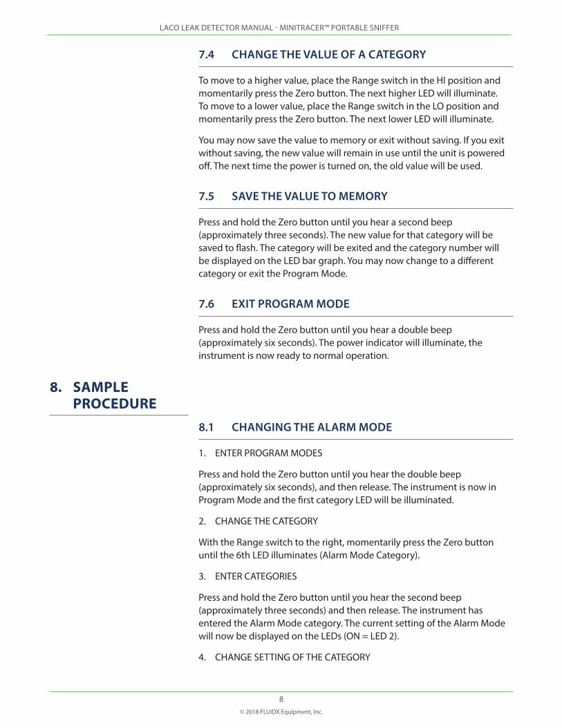
7.4 CHANGE THE VALUE OF A CATEGORY
To move to a higher value, place the Range switch in the HI position and momentarily press the Zero button. The next higher LED will illuminate. To move to a lower value, place the Range switch in the LO position and momentarily press the Zero button. The next lower LED will illuminate.
You may now save the value to memory or exit without saving. If you exit without saving, the new value will remain in use until the unit is powered off. The next time the power is turned on, the old value will be used.
7.5 SAVE THE VALUE TO MEMORY
Press and hold the Zero button until you hear a second beep (approximately three seconds). The new value for that category will be saved to flash. The category will be exited and the category number will be displayed on the LED bar graph. You may now change to a different category or exit the Program Mode.
7.6 EXIT PROGRAM MODE
Press and hold the Zero button until you hear a double beep (approximately six seconds). The power indicator will illuminate, the instrument is now ready to normal operation.
8. SAMPLE PROCEDURE
8.1 CHANGING THE ALARM MODE
1. ENTER PROGRAM MODES
Press and hold the Zero button until you hear the double beep (approximately six seconds), and then release. The instrument is now in Program Mode and the first category LED will be illuminated.
2. CHANGE THE CATEGORY
With the Range switch to the right, momentarily press the Zero button until the 6th LED illuminates (Alarm Mode Category).
3. ENTER CATEGORIES
Press and hold the Zero button until you hear the second beep (approximately three seconds) and then release. The instrument has entered the Alarm Mode category. The current setting of the Alarm Mode will now be displayed on the LEDs (ON = LED 2).
4. CHANGE SETTING OF THE CATEGORY

LACO LEAK DETECTOR MANUAL - MINITRACER™ PORTABLE SNIFFER
9© 2018 FLUIDX Equipment, Inc.
Put the Range switch to the left to go down in value when pressing the Zero button. Momentarily press the Zero button to change the setting to the first LED. The Alarm Mode is now OFF.
5. SAVE TO MEMORY AND EXIT CATEGORY
Press and hold the Zero button until you hear the second beep (approximately three seconds) and then release. The new value has been saved to flash and you have exited the Alarm Mode category. The instrument is still in Program Mode and the category 6 LED will be lit. You can now go to another category and enter it or you can exit Program Mode.
6. EXIT PROGRAM MODE
Press and hold the Zero button until you hear the double beep (approximately six seconds) and then release. You are now out of Program Mode and the leak detector will be under normal operation.
9. CHARGING THE BATTERY
The miniTRACER™ operates off an internal battery. When the battery is discharged, the Power Indicator will begin flashing. The instrument may continue to run when the light is flashing. However, the unit will shut down automatically when the battery is discharged to a point that it will no longer operate correctly. When using the supplied +9 Volt AC adaptor, the instrument will operate and slowly recharge the battery. To fully charge the battery, switch the instrument power OFF and allow to charge for approximately six to seven hours.
10. SENSITIVITYBefore a definition of sensitivity can be resolved, it is necessary to consider the various parameters involved. Sensitivity of an instrument is associated with its ability to detect gaseous mixtures from a filled system maintained at constant concentration.
The leak detector is capable of detecting leaks as small as 10-5 atm cc/ sec. Detecting a leak of this magnitude requires a skilled operator. In many applications, the escape rate is so low that the sample drawn into the detector is diluted if the sample rate is too high. Consider the case of a filled system with definitive volume. Here, if the sample is removed from the volume, it must be replaced if pressure is to remain the same. A tank filled with helium-air will change in concentration if a sample is withdrawn at a constant pressure.
If a leak from a gas-filled system into the atmosphere occurs at ambient temperatures and pressures, it is extremely important it be detected as close to the leak point as possible. The escape rate, if lower than the sampling rate, will be reflected by a deflection of the indicating device,
LACO LEAK DETECTOR MANUAL - MINITRACER™ PORTABLE SNIFFER
10© 2018 FLUIDX Equipment, Inc.
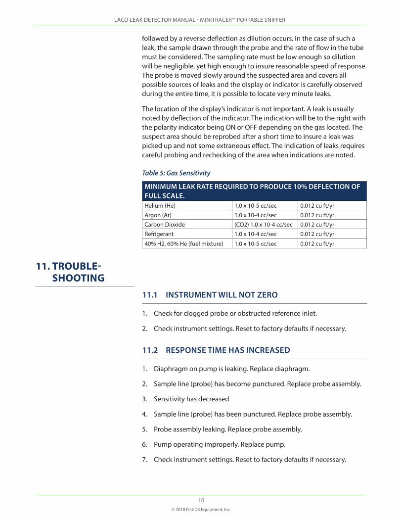
followed by a reverse deflection as dilution occurs. In the case of such a leak, the sample drawn through the probe and the rate of flow in the tube must be considered. The sampling rate must be low enough so dilution will be negligible, yet high enough to insure reasonable speed of response. The probe is moved slowly around the suspected area and covers all possible sources of leaks and the display or indicator is carefully observed during the entire time, it is possible to locate very minute leaks.
The location of the display’s indicator is not important. A leak is usually noted by deflection of the indicator. The indication will be to the right with the polarity indicator being ON or OFF depending on the gas located. The suspect area should be reprobed after a short time to insure a leak was picked up and not some extraneous effect. The indication of leaks requires careful probing and rechecking of the area when indications are noted.
Table 5: Gas Sensitivity
MINIMUM LEAK RATE REQUIRED TO PRODUCE 10% DEFLECTION OF FULL SCALE.Helium (He) 1.0 x 10⁻⁵ cc/sec 0.012 cu ft/yr
Argon (Ar) 1.0 x 10⁻⁴ cc/sec 0.012 cu ft/yr
Carbon Dioxide (CO2) 1.0 x 10⁻⁴ cc/sec 0.012 cu ft/yr
Refrigerant 1.0 x 10⁻⁴ cc/sec 0.012 cu ft/yr
40% H2, 60% He (fuel mixture) 1.0 x 10⁻⁵ cc/sec 0.012 cu ft/yr
11. TROUBLE-SHOOTING
11.1 INSTRUMENT WILL NOT ZERO
1. Check for clogged probe or obstructed reference inlet.
2. Check instrument settings. Reset to factory defaults if necessary.
11.2 RESPONSE TIME HAS INCREASED
1. Diaphragm on pump is leaking. Replace diaphragm.
2. Sample line (probe) has become punctured. Replace probe assembly.
3. Sensitivity has decreased
4. Sample line (probe) has been punctured. Replace probe assembly.
5. Probe assembly leaking. Replace probe assembly.
6. Pump operating improperly. Replace pump.
7. Check instrument settings. Reset to factory defaults if necessary.

LACO LEAK DETECTOR MANUAL - MINITRACER™ PORTABLE SNIFFER
11© 2018 FLUIDX Equipment, Inc.
11.3 REPAIR SERVICE
If repair service is needed, the instrument should be returned to the factory for repair. Before returning the instrument, contact our repair department to obtain a Return Material Authorization number (RMA) and a Health and Safety Declaration form. Instruments returned without these items will not be allowed to enter our facilities.