USER MANUAL - meteobot.com · Page 3 / 22 1 Preparation 1.1 What’s in the box? No Component...
22
Page 1 / 22 USER MANUAL Thank you for buying Meteobot®! This user manual contains instructions for installation, correct operation and de-installation of Meteobot® weather stations. Please read the instructions carefully before you begin – the product warranty depends on the correct installation and operation. 23 November 2017 Version 1.1 Prointegra Ltd. Bulgaria, Varna 9009 2, Todor Penev str. +359 884 833 780 [email protected] www.meteobot.com
Transcript of USER MANUAL - meteobot.com · Page 3 / 22 1 Preparation 1.1 What’s in the box? No Component...

Page 1 / 22
USER MANUAL
Thank you for buying Meteobot®!
This user manual contains instructions for installation, correct operation and de-installation of Meteobot® weather stations.
Please read the instructions carefully before you begin – the product warranty depends on
the correct installation and operation.
23 November 2017 Version 1.1
Prointegra Ltd.
Bulgaria, Varna 9009 2, Todor Penev str. +359 884 833 780
[email protected] www.meteobot.com

Page 2 / 22
Table of Contents
1 Preparation ............................................................................................................................................. 3 1.1 What’s in the box? .......................................................................................................................... 3 1.2 General Overview ........................................................................................................................... 4 1.3 Before you start the installation ...................................................................................................... 5
2 Where to place the weather station? ....................................................................................................... 6 2.1 Sensor for temperature, relative humidity and air pressure ............................................................. 6 2.2 Wind speed sensor .......................................................................................................................... 6 2.3 Rain sensor ..................................................................................................................................... 6 2.4 Solar panel ...................................................................................................................................... 6
3 Installation .............................................................................................................................................. 7 3.1 Pole ................................................................................................................................................ 7 3.2 Box with electronic circuit board ..................................................................................................... 7 3.3 Sensor for temperature, relative humidity and air pressure ............................................................. 8 3.4 Solar panel ...................................................................................................................................... 8 3.5 Rain sensor ..................................................................................................................................... 9 3.6 Wind speed sensor .......................................................................................................................... 9 3.7 Soil temperature sensor ................................................................................................................ 10 3.8 Soil moisture sensor ...................................................................................................................... 10 3.9 Leaf wetness sensor ...................................................................................................................... 12 3.10 Connecting the cables ................................................................................................................... 12 3.11 Cable connection scheme .............................................................................................................. 13
4 Diagnostics ............................................................................................................................................ 14 4.1 Initial startup ................................................................................................................................ 14 4.2 Data transmission ......................................................................................................................... 14 4.3 No GSM coverage.......................................................................................................................... 14 4.4 No connection to the server .......................................................................................................... 14
5 Receiving data from the weather station ............................................................................................... 15 5.1 Install the mobile application ........................................................................................................ 15 5.2 Registering the weather station ..................................................................................................... 15 5.3 Data transfer frequency ................................................................................................................ 15
6 Maintenance ......................................................................................................................................... 16
7 Troubleshooting .................................................................................................................................... 17 7.1 Battery not charging ...................................................................................................................... 17 7.2 The weather station does not send data ........................................................................................ 18 7.3 Missing or incorrect sensor data .................................................................................................... 18
8 Uninstallation ........................................................................................................................................ 19 8.1 Uninstalling the weather station .................................................................................................... 19 8.2 Uninstalling a sensor ..................................................................................................................... 19 8.3 Replacing the battery .................................................................................................................... 19 8.4 Replacing the solar panel .............................................................................................................. 20
9 Technical specifications ......................................................................................................................... 21
10 Protecting the environment ................................................................................................................... 22 10.1 Disposal ........................................................................................................................................ 22 10.2 Battery information ....................................................................................................................... 22

Page 3 / 22
1 Preparation 1.1 What’s in the box?
No Component Meteobot Pro Meteobot Mini
1 Box with electronic circuit board ✔ ✔
2 Rain sensor ✔ ✔
3 Wind speed sensor ✔
4 Solar panel ✔ ✔
5 Air temperature, relative humidity and air pressure sensor
✔
6 Leaf wetness sensor Depending on order
7 Soil temperature sensor ✔ ✔
8 Soil moisture sensor ✔ Depending on order
9 Battery ✔ ✔

Page 4 / 22
1.2 General Overview

Page 5 / 22
1.3 Before you start the installation Please make sure you have:
Pole (e.g. metal tube) with diameter – 4-5 cm, and length – for Meteobot Pro: 3 m,
for Meteobot Mini – 1,50 m;
Ladder;
Mobile phone with Android or iOS;
Data SIM card with SMS service enabled (no voice service is necessary);
Tools;
Hammer (for hammering the tube down in the soil);
Put the soil moisture sensor in clean water for 30 minutes;

Page 6 / 22
2 Where to place the weather station? The weather station should be placed at a location with GSM coverage by your mobile operator. In order to get correct measurements, it is important to place the station:
On an even field and at a location, which is representative for the region;
If there is another object nearby (e.g. tree, building, etc.), the station should be installed at a distance at least 4 times longer than the height of the object. Example: if there is a 5-meter-tall tree nearby, the station should be at least 20 meters away from the tree.
2.1 Sensor for temperature, relative humidity and air pressure At a height 1,25 – 2 m above ground.
AWAY FROM:
Object, emitting heat – e.g. rocks, concrete, asphalt, dark surfaces, roofs, chimneys, air conditioners, air vents;
Water bodies and other objects, which can artificially change the air humidity (e.g. rivers, dams, lakes, etc.).
2.2 Wind speed sensor At a height minimum 2 m above ground;
Above all other sensors.
2.3 Rain sensor At a height 1,10 – 1,90 m above ground;
The upper opening of the sensor should be absolutely horizontal;
IMPORTANT: There should be no water in the sensor, other than natural precipitation.
AWAY FROM:
Sprayers;
Rain-type irrigation systems;
Roofs, tree leaves and other surfaces, from which water could get into the sensor.
2.4 Solar panel Should be facing South;
At an angle 60⁰ relative to the ground. If you do not use the holder in the box, make sure the angle is correct.

Page 7 / 22
3 Installation In this section the installation of Meteobot Pro is described. Because Meteobot Mini has
fewer components, they can be installed higher on the pole.
3.1 Pole Use a pole (metal tube) with diameter – 4-5 cm, and length – for Meteobot Pro: 3 m,
for Meteobot Mini – 1,50 m;
For Meteobot Pro: hammer the pole 1 m in the ground; for Meteobot Mini – 70 cm;
IMPORTANT: Should be perfectly vertical!
3.2 Box with electronic circuit board Install the box by clamping the two metal planks on its back to the pole with two hose
clamps φ40-60 mm;
For Meteobot Pro: the lower edge of the box should be 75 cm below the top of the pole; the box should be facing South;
For Meteobot Mini: the lower edge of the box should be 40 cm below the top of the pole; the box should be facing North.
Page 8 / 22
3.3 Sensor for temperature, relative humidity and air pressure Install the sensor using the lower hose clamp of the box;
The sensor should be facing North (opposite the box).
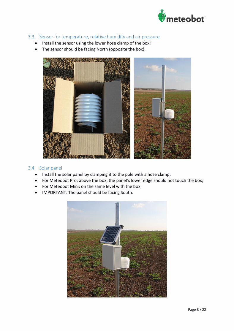
3.4 Solar panel Install the solar panel by clamping it to the pole with a hose clamp;
For Meteobot Pro: above the box; the panel’s lower edge should not touch the box;
For Meteobot Mini: on the same level with the box;
IMPORTANT: The panel should be facing South.

Page 9 / 22
3.5 Rain sensor Install the rain sensor by clamping it to the pole with two hose clamps;
For Meteobot Pro: the top of the sensor should be 5 cm above the top of the pole;
For Meteobot Mini: the top of the sensor should be 20 cm above the top of the pole;
The sensor should be facing East;
IMPORTANT: The upper opening of the sensor should be absolutely horizontal.
3.6 Wind speed sensor Install the sensor at the top of the pole with a single hose clamp;
IMPORTANT: The sensor should be above all other sensors;
The sensor should be facing West.

Page 10 / 22
3.7 Soil temperature sensor Dig a hole in the ground to a desired depth and bury the sensor in it;
IMPORTANT: Compact the soil, so that no air remains around the sensor;
IMPORTANT: Do not thrust the sensor in the ground by force;
IMPORTANT: If there is a risk of rodents, place the sensor cable in a tube or another kind of protective wrapping.
3.8 Soil moisture sensor IMPORTANT: Put the sensor in clean water for 30 minutes before installation;
The sensor should be placed in the plant’s roots;
The location of the sensor should be representative of the field: o The soil conditions (type, slope, etc.) should be similar to the prevailing soil
conditions in the field; o Field edges are not suitable; o The plants, near which the sensor is placed, should be of average size. Too big
or too weak plants are not suitable.
IMPORTANT: If you are going to control an irrigation system with Meteobot®, you should use at least three soil moisture sensors, placed at a same depth at different locations, so that the readings are representative of the field;
Install the sensor by digging a hole in the ground to the desired depth (min. diameter 25 mm) and place the sensor carefully in it;
IMPORTANT: Compact the soil, so that no air remains around the sensor;
If you use a drill/auger, mix some soil with water and pour a little mud in the hole. Then put the sensor at the desired depth and fill the hole with the rest of the mud;
If your weather station has several sensors, repeat the procedure for each of them;
IMPORTANT: Do not thrust the sensor in the ground by force;
IMPORTANT: If the soil above the sensor cracks as a result of drought, compact it;
IMPORTANT: If there is a risk of rodents, place the sensor cable in a tube or another kind of protective wrapping;

Page 11 / 22
The sensor provides correct readings for about 2 years, depending on conditions. Replace it after this period.

Page 12 / 22
3.9 Leaf wetness sensor Fasten the sensor with cable ties near the plant, whose leaf wetness will be measured;
The incline relative to the ground should be about 30⁰;
IMPORTANT: If the sensor gets dirty, clean it with a soft wet cloth;
IMPORTANT: Be careful not to scratch the sensor during installation or cleaning.
3.10 Connecting the cables Open the lid of the box with
a straight screwdriver (-);
Insert the sensor and panel cables in the box through the cable glands (the round openings) in the lower end of the box;
IMPORTANT: Only one cable should pass through a cable gland. Otherwise water may penetrate the glands and the moisture may damage the electronic circuit board.

Page 13 / 22
3.11 Cable connection scheme
1. Install the SIM card in your mobile phone and disable the SIM PIN code; 2. Install the SIM card in the SIM card slot on the electronic circuit board; 3. Place the cable ends in the corresponding socket on the electronic circuit board, as
described on the scheme above. Then screw the socket bolts with a small screwdriver.; 3.1. IMPORTANT: Connect the air temperature, relative humidity and air pressure sensor;
the leaf wetness sensor, and the soil temperature sensor to the electronic circuit board observing the cable colours, as on the scheme;
3.2. For the wind speed sensor, it does not matter which cable is left and which is right. The same applies for the rain sensor and the soil moisture sensor;
4. Place the battery in the box and connect it to the electronic circuit board. IMPORTANT: connect the red cable shoe to the red terminal (+) and the blue cable shoe to the black terminal (-);
5. Connect the solar panel cables to the electronic circuit board one by one, as displayed on the scheme above. IMPORTANT: Be careful not to connect them to each other! If you make a short circuit, the solar panel may get damaged;
6. Close the lid, making sure it fits tightly to the box; 7. Tighten the cable glands (by screwing them clockwise) so that they fit tightly around the
cables; 8. Bind the slack cables to the pole with cable ties.

Page 14 / 22
4 Diagnostics There are three light emitting diodes (LEDs) on the electronic circuit board:
Red and green – on the right;
Red – on the left.
4.1 Initial startup
When power is supplied (i.e. after connecting the battery) the red and greed LEDs on the right glow continually;
After several seconds the red LED on the right goes out, the green LED on the right glows continually, and the red LED on the left start blinking quickly;
When the weather station connects to the GSM network, the green LED on the right goes out, and the red LED on the left starts blinking at longer intervals.
4.2 Data transmission
When the weather station starts transmitting data, first the red LED, then the green LED on the right start glowing;
When the device stops transmitting data, first the green LED on the right goes out, then the red LED on the right goes out.
4.3 No GSM coverage
When the device cannot connect to the GSM network, the red LED on the left blinks quickly, and both LEDs on the right glow continually;
The weather station tries to connect to the GSM network three times one after the other. If it fails, it tries to connect again after one hour.
4.4 No connection to the server
When power is supplied the red and the green LEDs on the right glow continually, after several seconds the red one goes out, the green one glows continually, and the red LED on the left starts blinking quickly. When the device connects to the network, the green LED on the right goes out, and the red LED on the left start blinking at longer intervals;
Then the data transmission itself starts – first the red LED on the right then the green LED on the right start glowing. The red LED on the right stops glowing after the weather station stores the reading from the sensors, and the green LED on the right remains glowing continually – this means that the device cannot connect to the server and send the data to it;
If you encounter this situation, please contact the Meteobot® support team at [email protected].

Page 15 / 22
5 Receiving data from the weather station
In order to start receiving data from your weather station, you need to install the Meteobot® app on your mobile device (smartphone or tablet). If you already have installed the Meteobot® app, go on to the next section: “Registering the weather station”.
5.1 Install the mobile application
Download and install the Meteobot® app from the app on your mobile device. If you start the app for the first time, you will go through the following steps:
Enter your e-mail address. You will receive there a confirmation code. Press “Next”; IMPORTANT: Please use an e-mail address, which you check frequently. In the future you will receive service information about your Meteobot® there;
Check your e-mail for the code and type it / copy it in the next screen. Press “Next”. This ends the initial user registration and you can go on to registering the weather station.
5.2 Registering the weather station
From the app menu (top left on the screen) select „New weather station“, and follow the steps on the screen:
Scan the registration QR code from the weather station label. If your device cannot scan it, press the “Skip” button and type the serial number and the PIN-code from the label in the next screen;
Give your weather station a name, according to your preference;
Wait for your mobile device to determine your current location and then press “Next”;
Give this location a name, according to your preference;
Fill in the sensor configuration data (number, type, depth, etc.) This ends the weather station registration and you can see data from your Meteobot®. Depending on the configuration, you may need to wait for maximum one hour until you receive the first data.
5.3 Data transfer frequency By default, the weather station records data from the sensors every 10 minutes and sends them every hour. IMPORTANT: The more frequently the station sends data, the bigger the power consumption is. During winter the low temperature decreases the useful battery capacity, so too frequent data transmission can deplete the battery.

Page 16 / 22
6 Maintenance
The weather station itself does not need any regular maintenance to work all year round without interruption, but for the normal operation is necessary:
Rain sensor – clean the funnel, if full or dirty;
Leaf wetness sensor – if dirty, clean it with a soft wet cloth. Be careful not to scratch it;
Solar panel – if dirty, clean it with a soft wet cloth. Be careful not to scratch it;
If the pole or the sensors for rain, wind or temperature are tilted, set them up straight – they should be vertical;
If the soil around the soil temperature or moisture sensors gets cracked (e.g. due to drought), compress it. IMPORTANT: There should be no air around those sensors;
The soil moisture sensor provides correct readings for about 2 years, depending on conditions. Replace it after this period;
Monitor the battery level during winter. If it falls below 11.5 V, increase the data transmission interval to 1 hour.

Page 17 / 22
7 Troubleshooting
This section provides solutions in case any problems occur with the weather station. IMPORTANT: Whenever it is necessary to replace a component, always observe the uninstallation instructions in section 8.
7.1 Battery not charging
If the battery voltage chart shows progressive decrease (with no increase), this means that the battery does not get charged. If this happens on sunny days, there is a problem with charging.
№ Cause Solution
1 The solar panel is very dirty Clean the solar panel
2 The solar panel is broken or punctured Replace the solar panel
3 The cable from the solar panel to the box is interrupted
The solar panel cable should be replaced. Disassemble it and send it for service
4 The solar panel cable is incorrectly connected to the electronic circuit board
Connect the cable according to the connection scheme in section 3.11
5 The battery cables are not connected or are connected incorrectly
Connect the cables according to the connection scheme in section 3.11
6 There are none of the problems, listed in p. 1 - 5, but the battery still does not get charged
With a multimeter, measure the voltage between the solar power cables in sunny weather.
If the voltage is above 14 V, replace the battery
If the voltage is below 14 V, replace the solar panel
7 The solar panel and/or the battery were replaced, but the battery still does not get charged
Disassemble the weather station and send the box with the electronic circuit board for service

Page 18 / 22
7.2 The weather station does not send data
№ Cause Solution
1 No GSM coverage Move the weather station to a location with GSM coverage OR install a SIM card from a mobile operator, who has GSM coverage in the area
2 Damaged SIM card Replace the SIM card
3 SIM card bill not paid (in case of own SIM card)
Pay the bill
4 Battery voltage is under 11V See section 7.1 Battery not charging
7.3 Missing or incorrect sensor data
№ Cause Solution
1 A sensor cable is incorrectly connected or not connected at all
Disconnect the solar panel;
Disconnect the battery;
Connect the senor cable according to the cable connection scheme (see section 3.11);
Connect the battery;
Connect the solar panel.
2 The sensor is dirty or stuck Carefully clean the sensor
3 The sensor cable is interrupted or damaged
Replace the sensor
4 The sensor is damaged or broken Replace the sensor
5 The sensor has been replaced, but the problem remains
Disassemble the weather station and send the box with the electronic circuit board for service

Page 19 / 22
8 Uninstallation
When uninstalling the weather station or any components, observe the instructions below.
8.1 Uninstalling the weather station
Open the lid of the box with a straight screwdriver (-);
Unscrew the cable glands;
Unscrew one of the solar panel cables from the electronic circuit board and INSULATE it. Then unscrew the other cable and INSULATE it as well. Withdraw the solar panel cables from the box;
Remove the cable shoes from the battery terminals. Take the battery out of the box;
Unscrew the cables of one of the sensors and withdraw them from the box. Repeat that for all sensors;
Uninstall the components from the pole. IMPORTANT: To take a sensor of the ground, dig it out. Do NOT pull it by the cable.
8.2 Uninstalling a sensor
Open the lid of the box with a straight screwdriver (-);
Unscrew one of the solar panel cables from the electronic circuit board and INSULATE it. Then unscrew the other cable and INSULATE it as well;
Remove the cable shoes from the battery terminals. Take the battery out of the box;
Unscrew the cables of the sensor. Unscrew the respective cable gland. Withdraw the sensor cables from the box. IMPORTANT: If you do not replace the sensor right away, fit a short piece of cable in the cable gland and tighten it. Otherwise water may get into the box and may damage the electronic circuit board;
Uninstall the sensor. IMPORTANT: To take a sensor of the ground, dig it out. Do NOT pull it by the cable;
Put the battery back in the box and connect the cable shoes to the terminals. IMPORTANT: Connect the red cable shoe to the red terminal (+) and the blue cable shoe to the black terminal (-);
Connect the solar panel cables to the electronic circuit board one by one. IMPORTANT: Be careful not to connect them to each other! If you make a short circuit, the solar panel may get damaged;
Close the lid, making sure it fits tightly to the box;
Bind the slack cables to the pole with cable ties.
8.3 Replacing the battery
Open the lid of the box with a straight screwdriver (-);
Unscrew one of the solar panel cables from the electronic circuit board and INSULATE it. Then unscrew the other cable and INSULATE it as well;
Remove the cable shoes from the battery terminals. Take the battery out of the box;
Put a new battery in the box and connect the cable shoes to the terminals. IMPORTANT: Connect the red cable shoe to the red terminal (+) and the blue cable shoe to the black terminal (-);

Page 20 / 22
IMPORTANT: Until you replace the battery, do not connect the solar power cables! The weather station cannot operate without a battery (i.e. with solar panel only);
Connect the solar panel cables to the electronic circuit board one by one. IMPORTANT: Be careful not to connect them to each other! If you make a short circuit, the solar panel may get damaged;
Close the lid, making sure it fits tightly to the box.
8.4 Replacing the solar panel
Open the lid of the box with a straight screwdriver (-);
Unscrew one of the solar panel cables from the electronic circuit board and INSULATE it. Then unscrew the other cable and INSULATE it as well;
Remove the cable shoes from the battery terminals. Take the battery out of the box;
Unscrew the solar power cable gland and withdraw the cable from the box;
Uninstall the solar panel. IMPORTNAT: Until you install a new solar panel, the weather station can operate with battery only for about 30 days. Replace the solar panel as soon as possible!
Install a new solar panel;
Insert the cable of the new solar panel in the box through the cable gland;
Put the battery back in the box and connect the cable shoes to the terminals. IMPORTANT: Connect the red cable shoe to the red terminal (+) and the blue cable shoe to the black terminal (-)
Connect the new solar panel cables to the electronic circuit board one by one. IMPORTANT: Be careful not to connect them to each other! If you make a short circuit, the solar panel may get damaged;
Tighten the cable gland (by screwing it clockwise) so that it fits tightly around the cable;
Close the lid, making sure it fits tightly to the box;
Bind the slack cables to the pole with cable ties.

Page 21 / 22
9 Technical specifications
Sensor Resolution Range Accuracy
Air temperature 0,1 °C -40 °C to +125 °C ± 0,5 °C
Relative air humidity 0,10% 0 - 100% ± 2 %
Barometric pressure 1 hPa 500 - 1100 hPa ± 1 hPa
Wind speed 0,4 m/s 0,9 - 40 m/s ± 0,5 m/s
Wind direction (option) 22,5° 0° - 360° ± 3°
Rain quantity 0,25 l/m2
0,25 l/m2 - ∞ above 0 °C 0,25 l/m2
Rain intensity 0,25 l/h 0,25 - 180 l/h 0,25 l/h
Leaf wetness (option) 2,80% 0 - 100% ± 1,4 %
Soil moisture 0,10% 0 - 100% 0,4 %
Soil temperature 0,1 °C -55 to +125 °C ± 0,5 °C
Solar (photovoltaic) panel 1 V 1 - 21 V ± 0,4 V
Battery Operation range: -28 to +50 °C Operation voltage: 11 - 14,4 V

Page 22 / 22
10 Protecting the environment
10.1 Disposal
This device is marked in accordance with the Waste electric & electronic equipment directive of the European Union. By ensuring the product is disposed of correctly at its end-of-life, you will help prevent potential negative consequences for the environment and human health.
This symbol on the product, on its packaging or on the accompanying documents, indicates that this product shall not be treated as household waste. Instead, it shall be handed over to the applicable collection point for the recycling of electrical and electronic equipment. The recycling of materials will help to conserve natural resources. When disposing of it, observe the local waste disposal regulations. For more detailed information about treating, recovering and recycling of this product, please contact your local Civic Office, your household waste disposal service or the vendor, from whom you purchased the product.
10.2 Battery information
This device contains a lead-acid service-free rechargeable battery. It has been tested for continuous operation in the temperature range -28°C to +50°C. However long exposure to extreme temperatures (below -15°C or above +45°C) decrease battery capacity and life. Never expose the battery to temperature above +55°C. In case the battery has to be replaced, treat the waste battery according to the guidelines in section 10.1 Disposal.