USER MANUAL - MRU
76
62875EN OPTIMA 7 USER MANUAL
Transcript of USER MANUAL - MRU
62875EN
OPTIMA 7
USER MANUAL
USER MANUAL OPTIMA 7
MRU GmbH, D-74172 Neckarsulm 2 / 76
Producer:
Legal notices / Intellectual property rights comments
Original user manual
© 2021 by MRU
No part of this manual my be published in any form (print, fotocopy,
electronic media or any other publication form) without a written
approval by the publisher.
All user trade marks and name mark descriptions, even those which are
not marked as such, are properties of the respective owners.
Edition: 2021-04-19,V3.10.EN

USER MANUAL OPTIMA 7
3 / 76 MRU GmbH, D-74172 Neckarsulm
Table of content
1 Information for product and safety ............................................... 6
1.1. Safety manual ................................................................................................. 6
1.2. Safety precautions ......................................................................................... 6
Ensure safety ................................................................................................... 7
Important general information about the device .............................. 7
1.5. User guideline for rechargeable batteries ............................................ 8
2 Introduction ...................................................................................... 9
2.1. Intended use ................................................................................................... 9
About us ........................................................................................................ 10
Packaging ...................................................................................................... 11
Return of hazardous materials .............................................................. 11
Return of electronic equipment ............................................................ 11
3 Description ...................................................................................... 12
Gas schematics diagram .......................................................................... 12
3.2. The Analyser ................................................................................................. 13
The Condensate separator (water trap) ............................................. 14
3.4. Extraction probes ........................................................................................ 15
4 Operating ........................................................................................ 16
Display ............................................................................................................ 16
Keypad ............................................................................................................ 17
Menu structure ............................................................................................ 18
5 First usage ....................................................................................... 19
5.1. Preparatory steps ....................................................................................... 19
5.2. Analyzer settings ........................................................................................ 19
Setting measurement ................................................................................ 20
Power-On protection ................................................................................ 22
5.5. Setting printer type and print out ........................................................ 22
Setting Bluetooth parameters ................................................................ 23
Setting date and time ............................................................................... 24
Configuring Measurement Programs ................................................. 24
Setting CO limit value ............................................................................... 25
Select fuel types and O2 reference ...................................................... 25
Adding fuels to fuel type selection .............................................................. 26
Setting O2 reference .......................................................................................... 26
Defining user fuels type ........................................................................... 27
Defining measurement window ............................................................ 28
Configuring zoom window ..................................................................... 29
Changing measurement program names.......................................... 29
6 Preparing measurement ................................................................ 30
Ensure power supply ................................................................................. 30
USER MANUAL OPTIMA 7
MRU GmbH, D-74172 Neckarsulm 4 / 76
Automatic Auto-off function ................................................................... 30
Measuring with grid power supply / Battery charging ................. 30
Battery charge condition ......................................................................... 30
Operating temperature ............................................................................ 31
Controlling Condensate separator (water trap) ............................... 31
Connections and tightness ..................................................................... 32
Automatic zero-point setting ................................................................. 32
Repeating the zeroing ...................................................................................... 32
7 Performing measurement ............................................................. 33
Selecting the measuring program ........................................................ 33
Core flow search ......................................................................................... 34
7.3. Measured value display ............................................................................ 35
7.4. Non-continuous draft measurement .................................................. 36
Setting CO-Limit (without purging) ..................................................... 37
CO-purging ................................................................................................... 37
CO/H2 and CO high (optional) .............................................................. 38
Performing Test program ........................................................................ 38
Performing Ambient CO Test ................................................................. 38
Temporary buffer ........................................................................................ 40
Store measured values in the buffer ........................................................... 40
Overwrite measured values in buffer .......................................................... 41
Storing measured values ......................................................................... 41
Printing measurement values ................................................................. 42
Terminate measurement .......................................................................... 43
7.14. Last measurement values ........................................................................ 43
Pressure measurement ............................................................................. 44
7.16. Differential temperature measurement (optional) ......................... 45
8 Data Storage ................................................................................... 46
Organizing data storage .......................................................................... 46
Calling up information about data storage ...................................... 46
Site administration ..................................................................................... 47
Create new site .................................................................................................... 47
View sites ............................................................................................................... 48
Searching site ....................................................................................................... 48
Changing sites ..................................................................................................... 49
Deleting sites ....................................................................................................... 50
Data transfer using SD card .................................................................... 51
Importing sites .................................................................................................... 51
Exporting sites ..................................................................................................... 53
Exporting combustion measurements ........................................................ 53
Exporting differential pressure measurements. ....................................... 54
USER MANUAL OPTIMA 7
5 / 76 MRU GmbH, D-74172 Neckarsulm
Measurement in Data storage ............................................................... 54
Viewing measurements .................................................................................... 54
Deleting measurements ................................................................................... 55
Transferring measurements to SD-Card (Option) .................................. 56
9 Extras / Adjustment ....................................................................... 57
9.1. Service calibration menu ......................................................................... 57
Default settings ........................................................................................... 58
Service values ............................................................................................... 59
Performing leak test .................................................................................. 59
Contents SD card ........................................................................................ 61
9.6. Contents Analyzer information ............................................................. 61
10 Maintenance and care ................................................................ 62
Maintenance ................................................................................................. 62
Service messages ........................................................................................ 62
11 Appendix ...................................................................................... 63
Technical data .............................................................................................. 63
Analysis and calculations ......................................................................... 67
Text input ...................................................................................................... 69
Asking user for decision ........................................................................... 69
Firmware update ......................................................................................... 70
Install the new software version in the analyser ..................................... 70
Performing and checking the update ......................................................... 70
In case of error .................................................................................................... 71
11.6. Using the USB Port .................................................................................... 72
Troubleshooting ......................................................................................... 72
Troubleshooting the analyser ........................................................................ 72
Troubleshooting condensate separator ..................................................... 74
Further options ............................................................................................ 74
Prefilter for high dust concentrations ......................................................... 74
12 Declaration of conformity ......................................................... 75
USER MANUAL OPTIMA 7
MRU GmbH, D-74172 Neckarsulm 6 / 76
1 Information for product and safety
1.1. Safety manual
All general information and safety precautions of MRU products are
listed in the supplied separate safety manual.
Therefore, this manual must be read and observed before the first use
of the instrument.
Instrument-specific safety and warning requirements in this manual are
prefixed before dangerous actions.
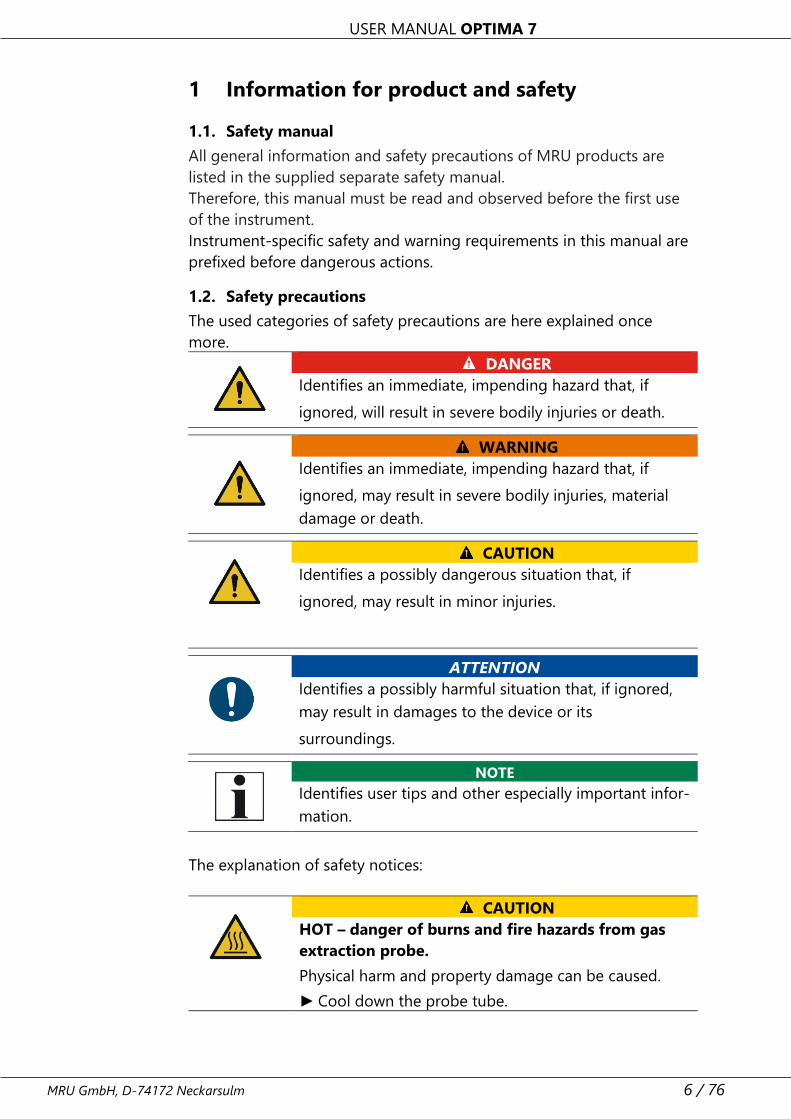
1.2. Safety precautions
The used categories of safety precautions are here explained once
more.
DANGER
Identifies an immediate, impending hazard that, if
ignored, will result in severe bodily injuries or death.
WARNING
Identifies an immediate, impending hazard that, if
ignored, may result in severe bodily injuries, material
damage or death.
CAUTION
Identifies a possibly dangerous situation that, if
ignored, may result in minor injuries.
ATTENTION
Identifies a possibly harmful situation that, if ignored,
may result in damages to the device or its
surroundings.
NOTE
Identifies user tips and other especially important infor-
mation.
The explanation of safety notices:
CAUTION
HOT – danger of burns and fire hazards from gas
extraction probe.
Physical harm and property damage can be caused.
► Cool down the probe tube.
USER MANUAL OPTIMA 7
7 / 76 MRU GmbH, D-74172 Neckarsulm
Ensure safety
► Please read the user manual completely before the first use.
► Only use the analyser for the intended use and within the parameters
specified in the technical data.
► Do not use any violence.
► Avoid falls.
► Do not put the analyser into use, if the housing, power supply unit or
supply leads are damaged.
► Do not store the analyser together with solvents. Do not use
desiccants.
► Only carry out maintenance and service work on this analyser as de-
scribed in the User Manual. Observe the prescribed action steps.
► Operate the analyser only in closed, dry rooms and protect it from
rain and moisture.
► When operating the analyser on mains power, operate it only with
the mains adapter supplied.
► Do not use the metal tube of the gas sampling probe or other metal-
lic parts / accessories as electrical conductors.
► The analyser must not be located in the immediate vicinity of open
fire or great heat.
► The specified temperature range of the gas sampling probe must not
be exceeded, otherwise the probe tube and temperature sensor will
be destroyed.
Important general information about the device
• The analyser is not suitable for long term (continuous) measure-
ments (this is a spot analyser).
• Before using the analyser verify the condition of the various parts of
the analyser, such as the probe, the ambient air conditions, the con-
densate separator, star filter and the connectors for damage and/or
blockages.
• When starting the analyser up it will take between 1 – 3 minutes to
set to zero depending on the condition of the sensors and ambient
conditions. (Zeroing).
• The minimum zeroing time of the analyser to achieve correct meas-
urement values can be expected by 1.5 minutes!
• Exposure to acids; aggressive gases such as Sulphur; vapours such as
thinners, gasoline, alcohol and paint, etc. can damage, reduce the life
of, or destroy the sensors.
• The life of the sensors depends on how they are used, maintained
and treated. Typical average life expectations are: O2 - 2 years; CO -
2 - 3 years and NO - 3 years.
USER MANUAL OPTIMA 7
MRU GmbH, D-74172 Neckarsulm 8 / 76
• The battery life is at least 500 charge-discharge cycles.
With increasing number of charging cycles the battery ca-
pacity (indicated in operating hours) is reduced.
1.5. User guideline for rechargeable batteries
NOTE
The rechargeable batterie is installed inside the ana-
lyser and is not accessible to the end customer. How-
ever, the following instructions must generally be ob-
served when handling lithium-ion rechargeable batter-
ies.
• This rechargeable battery can only be used in this analyser.
• Do not throw the rechargeable battery into a fire, charge it at high
temperatures and store it in a hot environment.
• Do not deform, short-circuit or modify the rechargeable battery.
• The rechargeable battery must not be used in or under water.
• Do not expose the rechargeable battery to strong mechanical forces
and do not throw it.
• Do not cut or squeeze the connecting cables of the rechargeable
battery.
• Do not connect the (+) contact to the (-) contact or metal.
• Non-observance of the above guidelines can cause heat, fire and ex-
plosions
USER MANUAL OPTIMA 7
9 / 76 MRU GmbH, D-74172 Neckarsulm
2 Introduction
• This manual enables you to understand and safely operate this MRU
Analyzer.
• Please read this manual with great vigilant and get familiar with the
product before using it.
• This analyser may only be operated by competent personnel and for
its intended use.
• Please pay special attention to all safety directions and warnings to
prevent personal injuries and damaging of the product.
• We can’t be held responsible for any injuries and/or damages that
occur by not following the instructions in this manual.
• Always keep the manual near you when working with the analyser,
to be able to read instructions as needed. Please ensure to hand
over all documents to when handing the analyser over to others.
2.1. Intended use
The Analyzer analyser is intended for short-term measurement in the
context of emission control measurements and adjustments at small
furnaces. The analyser measures the measurements provided by
VDI4206 and EN50379 metrics and stores them for further processing.
The analyser is specifically not intended as a safety device or personal
protective equipment.
The analyser should not be used as a warning device to warn people
against the presence of harmful gases.
The analyser must be used according to instructions for the intended
use.
Our analysers are checked according to the following regulations:
VDE 0411 (EN61010) and DIN VDE 0701 before they leave the MRU
GmbH factory.
MRU technical products are designed and manufactured according to
DIN 31000/ VDE 1000 and UVV = VBG 4 of the professional guilds for
fine mechanics and electrical engineering.
MRU GmbH assures that the analyser complies to the essential require-
ments of the legal regulations of the member states of the electro-mag-
netic compatibility (89/336/EWG)
WARNING
Risk from manipulations to the measuring device
Operational safety hazard
► Modifications or changes to the measuring device are
not allowed.
USER MANUAL OPTIMA 7
MRU GmbH, D-74172 Neckarsulm 10 / 76
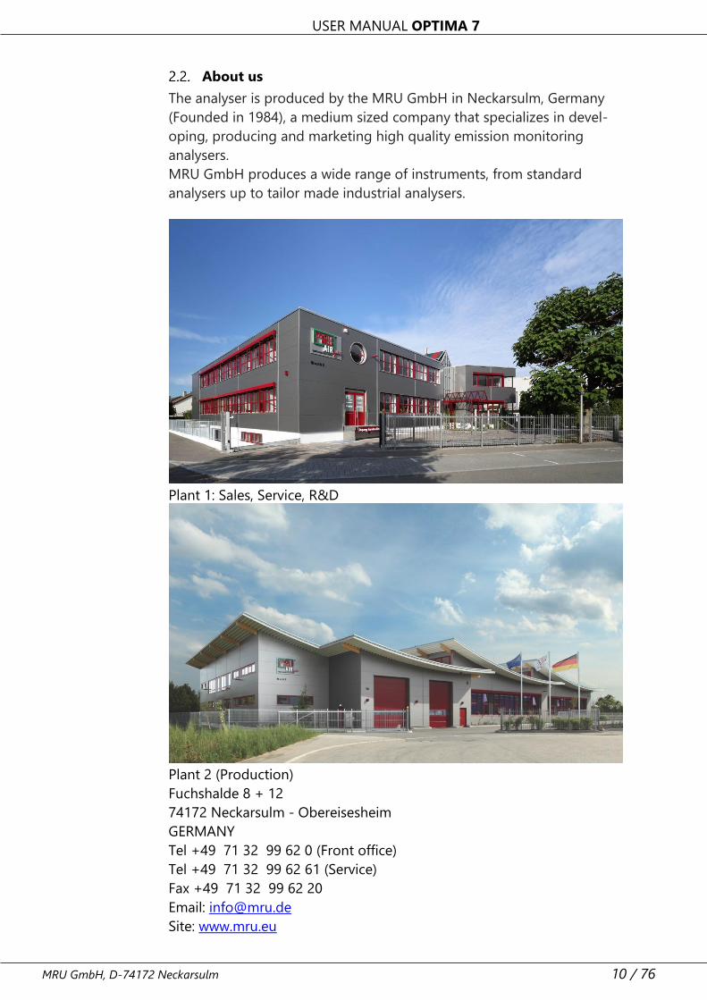
About us
The analyser is produced by the MRU GmbH in Neckarsulm, Germany
(Founded in 1984), a medium sized company that specializes in devel-
oping, producing and marketing high quality emission monitoring
analysers.
MRU GmbH produces a wide range of instruments, from standard
analysers up to tailor made industrial analysers.
Plant 1: Sales, Service, R&D
Plant 2 (Production)
Fuchshalde 8 + 12
74172 Neckarsulm - Obereisesheim
GERMANY
Tel +49 71 32 99 62 0 (Front office)
Tel +49 71 32 99 62 61 (Service)
Fax +49 71 32 99 62 20
Email: [email protected]
Site: www.mru.eu
USER MANUAL OPTIMA 7
11 / 76 MRU GmbH, D-74172 Neckarsulm
Packaging
Save the original carton and packing materials to prevent damage in
transit in case you need to return the unit to the factory.
Return of hazardous materials
Waste Disposal/Returns/Warranty - MRU GmbH is required to accept
the return of hazardous waste such as electro-chemical sensors that
cannot be disposed of locally.
Hazardous waste must be returned to MRU prepaid.
Return of electronic equipment
MRU GmbH is required to accept the return, for proper disposal, of all
analysers delivered after 13th of August 2005. Analysers must be re-
turned to MRU prepaid.
USER MANUAL OPTIMA 7
MRU GmbH, D-74172 Neckarsulm 12 / 76
3 Description
The main task of the analyser is to assist with precision control and ad-
justment measurements of gas, oil and wood fired furnaces.
Available options for this and other analysers can be found on the MRU
Homepage or speak to a member of our sales team.
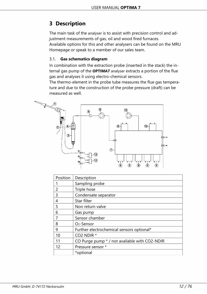
Gas schematics diagram
In combination with the extraction probe (inserted in the stack) the in-
ternal gas pump of the OPTIMA7 analyser extracts a portion of the flue
gas and analyses it using electro-chemical sensors.
The thermo-element in the probe tube measures the flue gas tempera-
ture and due to the construction of the probe pressure (draft) can be
measured as well.
Position Description
1 Sampling probe
2 Triple hose
3 Condensate separator
4 Star filter
5 Non return valve
6 Gas pump
7 Sensor chamber
8 O2-Sensor
9 Further electrochemical sensors optional*
10 CO2 NDIR *
11 CO Purge pump * / not available with CO2-NDIR
12 Pressure sensor *
*optional
USER MANUAL OPTIMA 7
13 / 76 MRU GmbH, D-74172 Neckarsulm
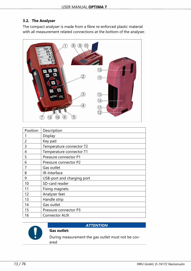
3.2. The Analyser
The compact analyser is made from a fibre re-enforced plastic material
with all measurement related connections at the bottom of the analyser.
Position Description
1 Display
2 Key pad
3 Temperature connector T2
4 Temperature connector T1
5 Pressure connector P1
6 Pressure connector P2
7 Gas outlet
8 IR-Interface
9 USB-port and charging port
10 SD-card reader
11 Fixing magnets
12 Analyzer feet
13 Handle strip
14 Gas outlet
15 Pressure connector P3
16 Connector AUX
ATTENTION
Gas outlet:
During measurement the gas outlet must not be cov-
ered
USER MANUAL OPTIMA 7
MRU GmbH, D-74172 Neckarsulm 14 / 76
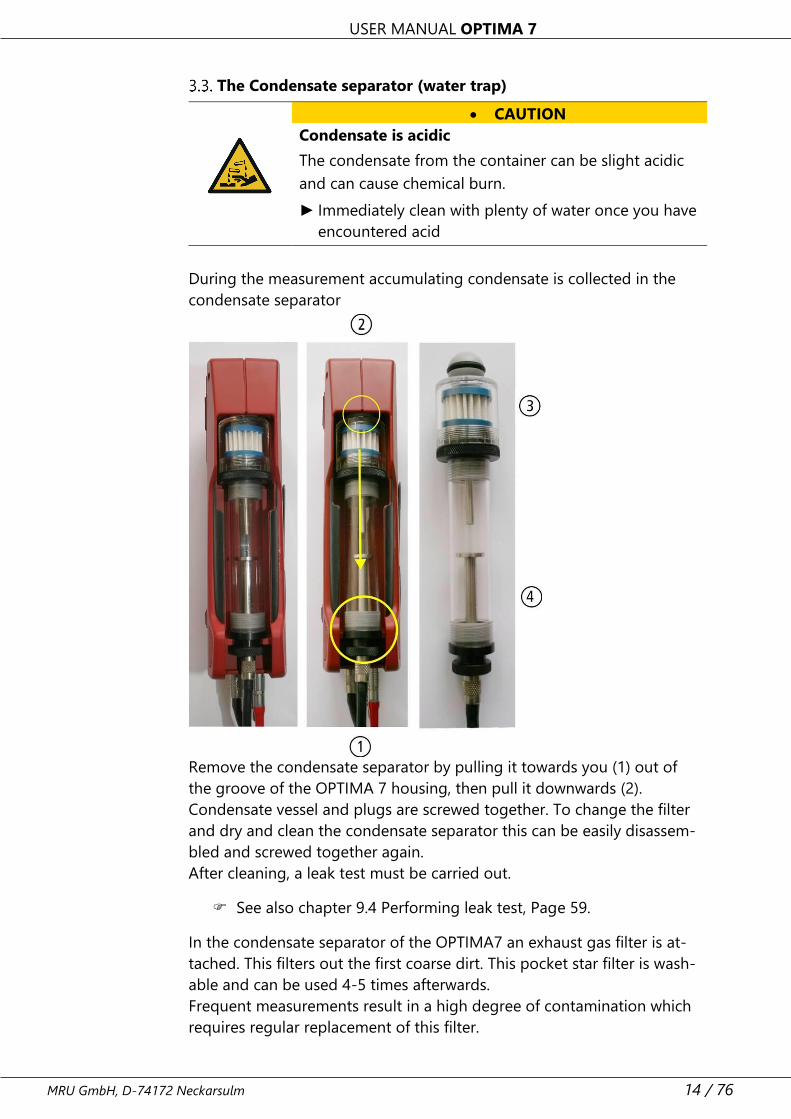
The Condensate separator (water trap)
• CAUTION
Condensate is acidic
The condensate from the container can be slight acidic
and can cause chemical burn.
► Immediately clean with plenty of water once you have
encountered acid
During the measurement accumulating condensate is collected in the
condensate separator
Remove the condensate separator by pulling it towards you (1) out of
the groove of the OPTIMA 7 housing, then pull it downwards (2).
Condensate vessel and plugs are screwed together. To change the filter
and dry and clean the condensate separator this can be easily disassem-
bled and screwed together again.
After cleaning, a leak test must be carried out.
See also chapter 9.4 Performing leak test, Page 59.
In the condensate separator of the OPTIMA7 an exhaust gas filter is at-
tached. This filters out the first coarse dirt. This pocket star filter is wash-
able and can be used 4-5 times afterwards.
Frequent measurements result in a high degree of contamination which
requires regular replacement of this filter.
USER MANUAL OPTIMA 7
15 / 76 MRU GmbH, D-74172 Neckarsulm
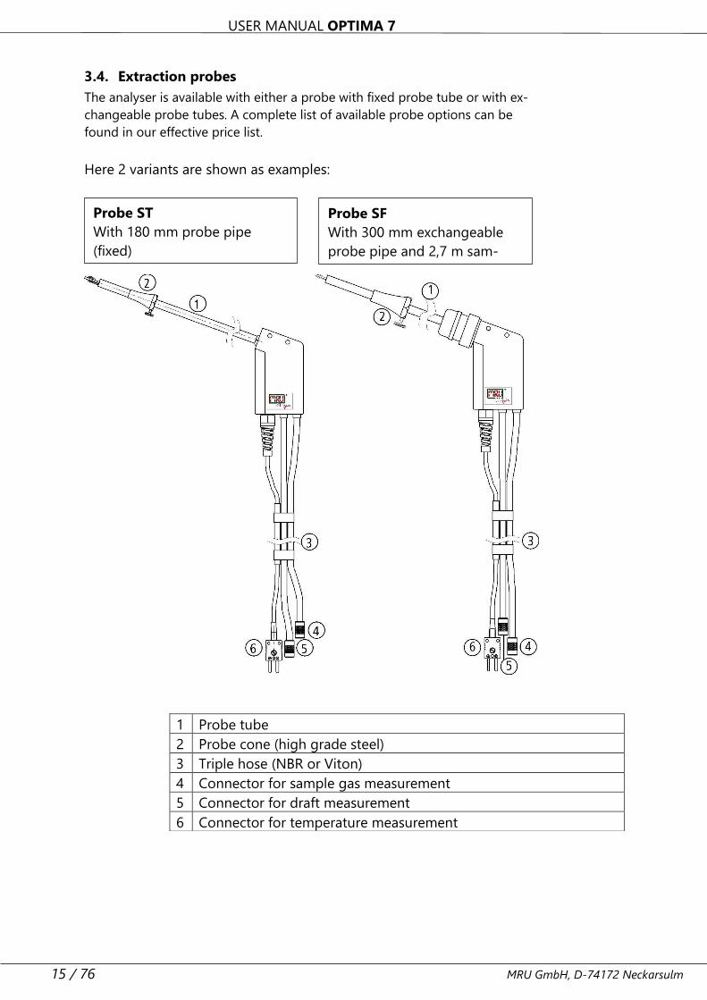
3.4. Extraction probes
The analyser is available with either a probe with fixed probe tube or with ex-
changeable probe tubes. A complete list of available probe options can be
found in our effective price list.
Here 2 variants are shown as examples:
1 Probe tube
2 Probe cone (high grade steel)
3 Triple hose (NBR or Viton)
4 Connector for sample gas measurement
5 Connector for draft measurement
6 Connector for temperature measurement
Probe ST
With 180 mm probe pipe
(fixed)
and 1,5 m sampling line
Probe SF
With 300 mm exchangeable
probe pipe and 2,7 m sam-
pling line
USER MANUAL OPTIMA 7
MRU GmbH, D-74172 Neckarsulm 16 / 76
4 Operating
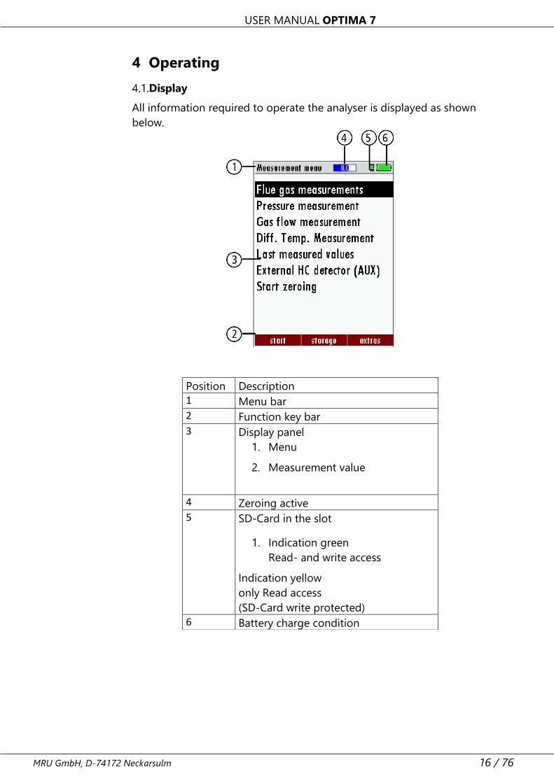
Display
All information required to operate the analyser is displayed as shown
below.
Position Description
1 Menu bar
2 Function key bar
3 Display panel
1. Menu
2. Measurement value
4 Zeroing active
5 SD-Card in the slot
1. Indication green
Read- and write access
Indication yellow
only Read access
(SD-Card write protected)
6 Battery charge condition
USER MANUAL OPTIMA 7
17 / 76 MRU GmbH, D-74172 Neckarsulm
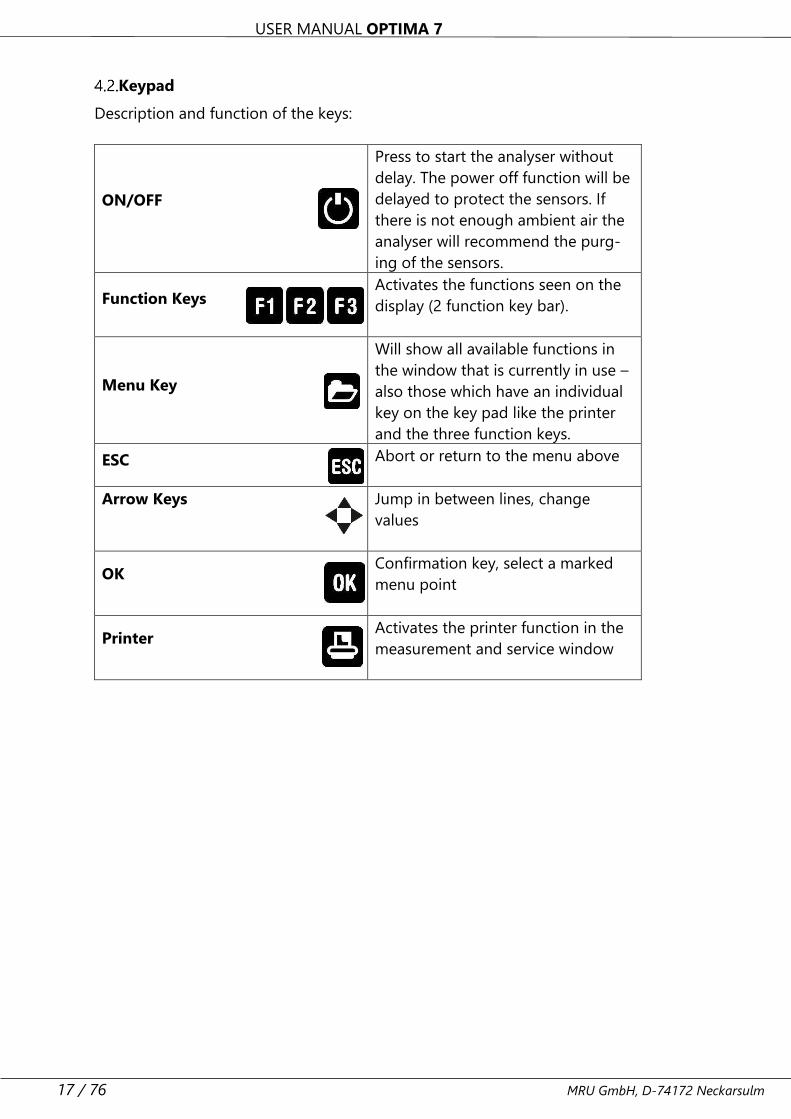
Keypad
Description and function of the keys:
ON/OFF
Press to start the analyser without
delay. The power off function will be
delayed to protect the sensors. If
there is not enough ambient air the
analyser will recommend the purg-
ing of the sensors.
Function Keys Activates the functions seen on the
display (2 function key bar).
Menu Key
Will show all available functions in
the window that is currently in use –
also those which have an individual
key on the key pad like the printer
and the three function keys.
ESC Abort or return to the menu above
Arrow Keys
Jump in between lines, change
values
OK
Confirmation key, select a marked
menu point
Printer
Activates the printer function in the
measurement and service window
USER MANUAL OPTIMA 7
MRU GmbH, D-74172 Neckarsulm 18 / 76
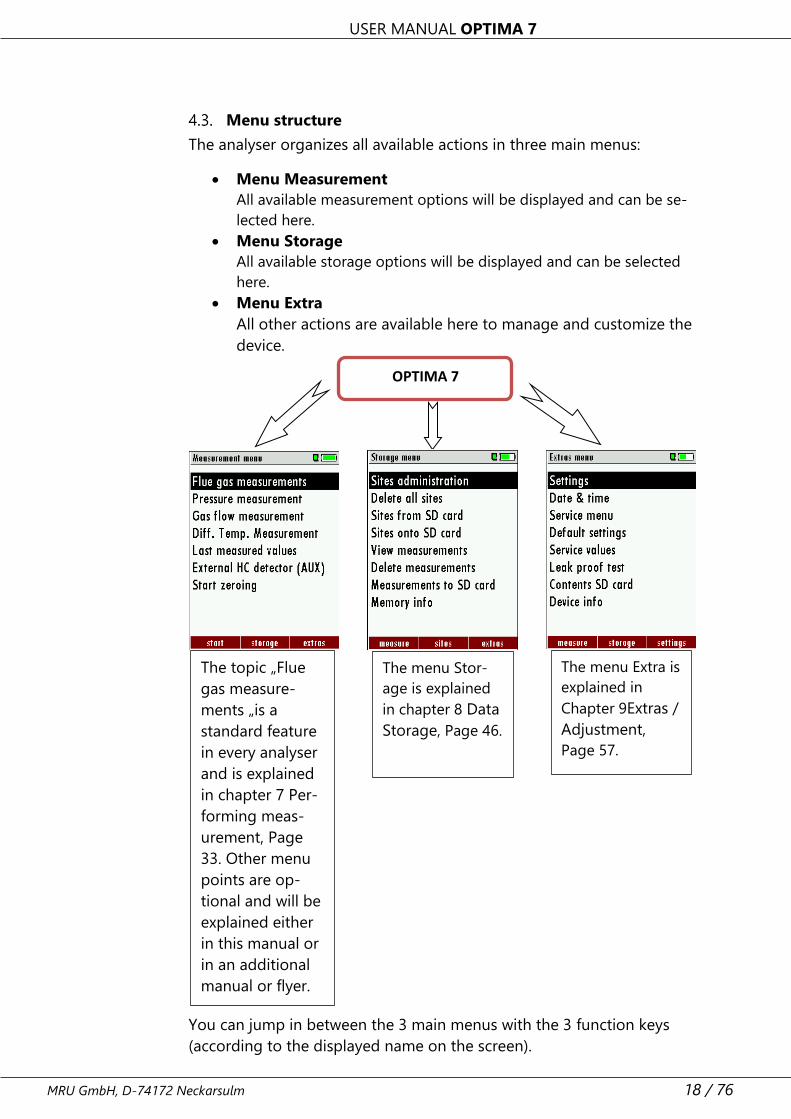
Menu structure
The analyser organizes all available actions in three main menus:
• Menu Measurement
All available measurement options will be displayed and can be se-
lected here.
• Menu Storage
All available storage options will be displayed and can be selected
here.
• Menu Extra
All other actions are available here to manage and customize the
device.
You can jump in between the 3 main menus with the 3 function keys
(according to the displayed name on the screen).
OPTIMA 7
The topic „Flue
gas measure-
ments „is a
standard feature
in every analyser
and is explained
in chapter 7 Per-
forming meas-
urement, Page
33. Other menu
points are op-
tional and will be
explained either
in this manual or
in an additional
manual or flyer.
.
The menu Stor-
age is explained
in chapter 8 Data
Storage, Page 46.
The menu Extra is
explained in
Chapter 9Extras /
Adjustment,
Page 57.
USER MANUAL OPTIMA 7
19 / 76 MRU GmbH, D-74172 Neckarsulm
5 First usage
After the analyser has been inspected and is ready for start-up it can be
switched on and personalized settings can be entered. These settings can
be changed at any time.
5.1. Preparatory steps
► Unpack the analyser.
► Read the User Manual completely.
► The analyser leaves the factory assembled and ready for use.
Nevertheless, check the device for completeness and integrity.
► Charge the battery of the analyser for about 8 hours.
► Check date and time. Modify if needed.
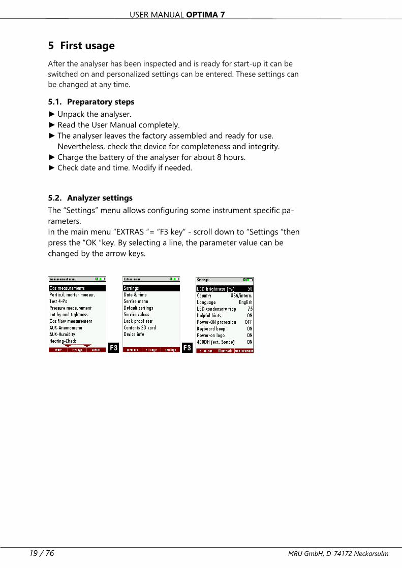
5.2. Analyzer settings
The “Settings” menu allows configuring some instrument specific pa-
rameters.
In the main menu “EXTRAS “= “F3 key” - scroll down to “Settings “then
press the “OK “key. By selecting a line, the parameter value can be
changed by the arrow keys.
USER MANUAL OPTIMA 7
MRU GmbH, D-74172 Neckarsulm 20 / 76
Setting Range Description
LCD brightness
5 – 100 % Display-brightness, depending on
temperature and also on the per-
sonal judgement of the user, at 20°C
a value of ca. 50% is normal
Language option Select device languages
Country option Enables some country specific pa-
rameters like fuel types, calculated
values etc.
LED condensate
trap
0 … 150 Change the brightness of the con-
densate separator LED
Helping hints ON / OFF Helpful hints activated or deac-
tivated (explanation below)
Switch-ON pro-
tection
ON / OFF If activated and if ON key is pressed
(possibly inadvertently), then the
message „3 seconds OK key press
“is displayed
Keyboard beeper ON / OFF Keyboard beeper activated or deac-
tivated
Power-on logo ON / OFF Logo will be show during power-ON
of the analyser
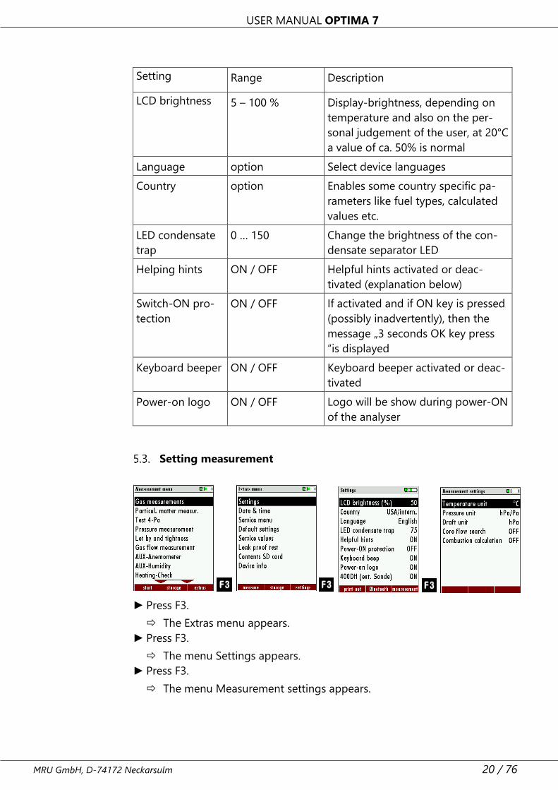
Setting measurement
► Press F3.
The Extras menu appears.
► Press F3.
The menu Settings appears.
► Press F3.
The menu Measurement settings appears.
USER MANUAL OPTIMA 7
21 / 76 MRU GmbH, D-74172 Neckarsulm
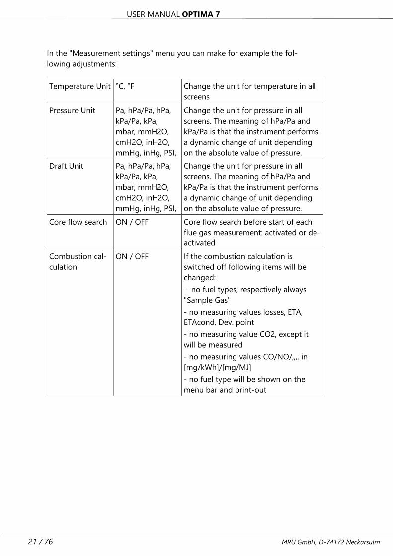
In the "Measurement settings" menu you can make for example the fol-
lowing adjustments:
Temperature Unit °C, °F Change the unit for temperature in all
screens
Pressure Unit Pa, hPa/Pa, hPa,
kPa/Pa, kPa,
mbar, mmH2O,
cmH2O, inH2O,
mmHg, inHg, PSI,
Change the unit for pressure in all
screens. The meaning of hPa/Pa and
kPa/Pa is that the instrument performs
a dynamic change of unit depending
on the absolute value of pressure.
Draft Unit Pa, hPa/Pa, hPa,
kPa/Pa, kPa,
mbar, mmH2O,
cmH2O, inH2O,
mmHg, inHg, PSI,
Change the unit for pressure in all
screens. The meaning of hPa/Pa and
kPa/Pa is that the instrument performs
a dynamic change of unit depending
on the absolute value of pressure.
Core flow search ON / OFF Core flow search before start of each
flue gas measurement: activated or de-
activated
Combustion cal-
culation
ON / OFF If the combustion calculation is
switched off following items will be
changed:
- no fuel types, respectively always
"Sample Gas"
- no measuring values losses, ETA,
ETAcond, Dev. point
- no measuring value CO2, except it
will be measured
- no measuring values CO/NO/,,,. in
[mg/kWh]/[mg/MJ]
- no fuel type will be shown on the
menu bar and print-out
USER MANUAL OPTIMA 7
MRU GmbH, D-74172 Neckarsulm 22 / 76
Explanation for “Helping hints”:
Some helpful hints which are very useful for an inexperienced user but
are not needed by experienced users, can be activated or deactivated.
The following hints will be affected
“Zeroing finished, Sensors are ready. Analyzer ready for measurement.”
“Reminder! Charge batteries at regular intervals!”
“Measurement stopped/started.”
Power-On protection
If activated and if ON key is pressed (possibly inadvertently), then the
message: „Power-On protection is activated! Press key OK for 3 seconds
2“ is displayed.
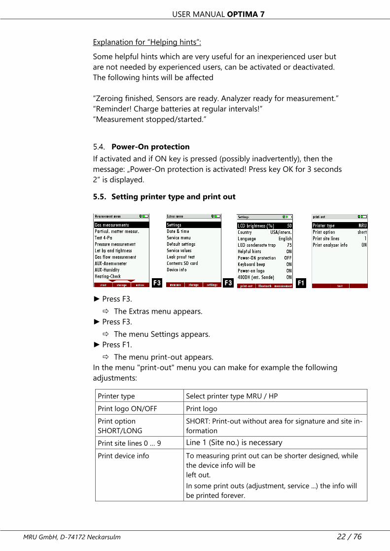
5.5. Setting printer type and print out
► Press F3.
The Extras menu appears.
► Press F3.
The menu Settings appears.
► Press F1.
The menu print-out appears.
In the menu "print-out" menu you can make for example the following
adjustments:
Printer type Select printer type MRU / HP
Print logo ON/OFF Print logo
Print option
SHORT/LONG
SHORT: Print-out without area for signature and site in-
formation
Print site lines 0 … 9 Line 1 (Site no.) is necessary
Print device info To measuring print out can be shorter designed, while
the device info will be
left out.
In some print outs (adjustment, service ...) the info will
be printed forever.
USER MANUAL OPTIMA 7
23 / 76 MRU GmbH, D-74172 Neckarsulm
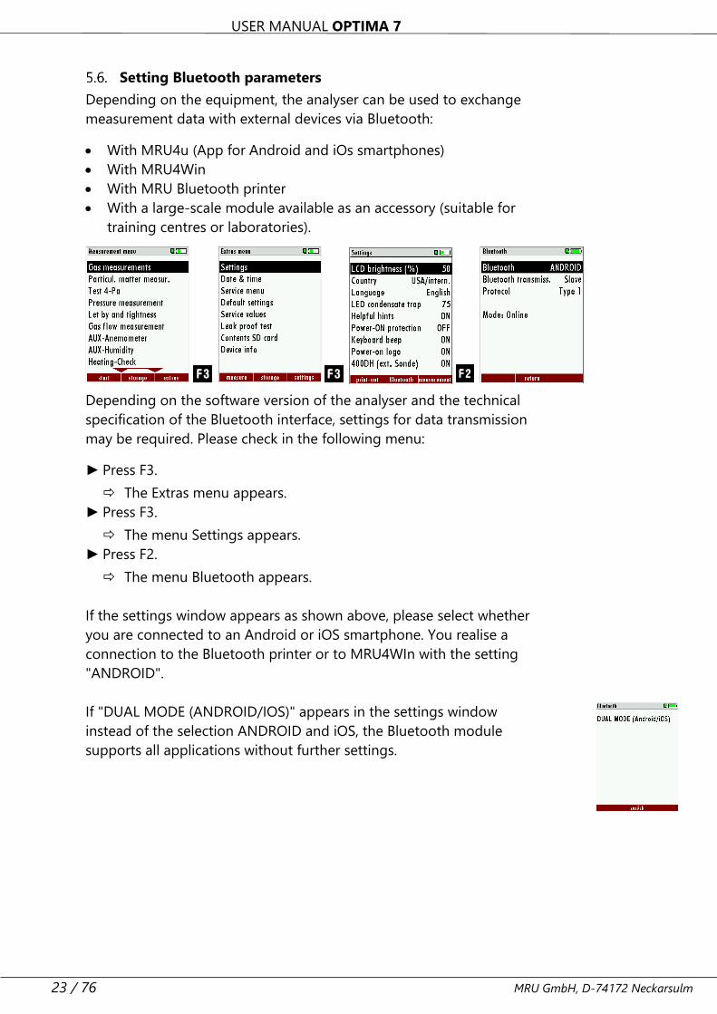
Setting Bluetooth parameters
Depending on the equipment, the analyser can be used to exchange
measurement data with external devices via Bluetooth:
• With MRU4u (App for Android and iOs smartphones)
• With MRU4Win
• With MRU Bluetooth printer
• With a large-scale module available as an accessory (suitable for
training centres or laboratories).
Depending on the software version of the analyser and the technical
specification of the Bluetooth interface, settings for data transmission
may be required. Please check in the following menu:
► Press F3.
The Extras menu appears.
► Press F3.
The menu Settings appears.
► Press F2.
The menu Bluetooth appears.
If the settings window appears as shown above, please select whether
you are connected to an Android or iOS smartphone. You realise a
connection to the Bluetooth printer or to MRU4WIn with the setting
"ANDROID".
If "DUAL MODE (ANDROID/IOS)" appears in the settings window
instead of the selection ANDROID and iOS, the Bluetooth module
supports all applications without further settings.
USER MANUAL OPTIMA 7
MRU GmbH, D-74172 Neckarsulm 24 / 76
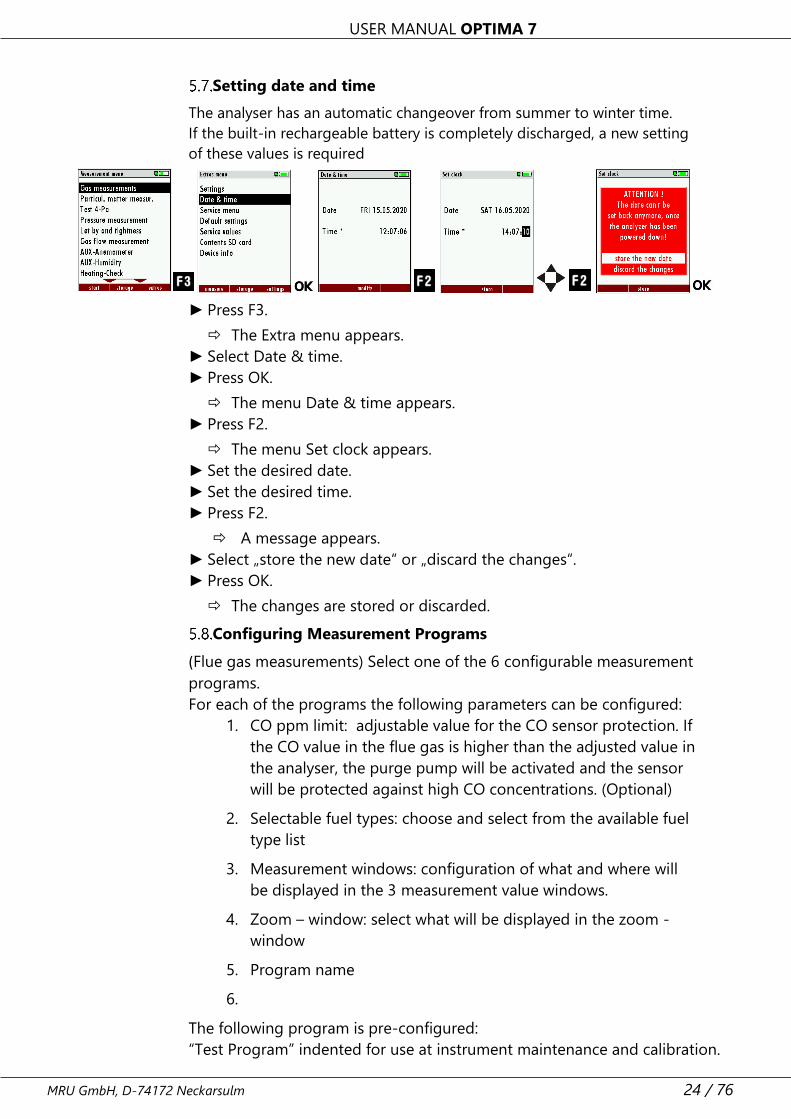
Setting date and time
The analyser has an automatic changeover from summer to winter time.
If the built-in rechargeable battery is completely discharged, a new setting
of these values is required
► Press F3.
The Extra menu appears.
► Select Date & time.
► Press OK.
The menu Date & time appears.
► Press F2.
The menu Set clock appears.
► Set the desired date.
► Set the desired time.
► Press F2.
A message appears.
► Select „store the new date“ or „discard the changes“.
► Press OK.
The changes are stored or discarded.
Configuring Measurement Programs
(Flue gas measurements) Select one of the 6 configurable measurement
programs.
For each of the programs the following parameters can be configured:
1. CO ppm limit: adjustable value for the CO sensor protection. If
the CO value in the flue gas is higher than the adjusted value in
the analyser, the purge pump will be activated and the sensor
will be protected against high CO concentrations. (Optional)
2. Selectable fuel types: choose and select from the available fuel
type list
3. Measurement windows: configuration of what and where will
be displayed in the 3 measurement value windows.
4. Zoom – window: select what will be displayed in the zoom -
window
5. Program name
6.
The following program is pre-configured:
“Test Program” indented for use at instrument maintenance and calibration.
USER MANUAL OPTIMA 7
25 / 76 MRU GmbH, D-74172 Neckarsulm
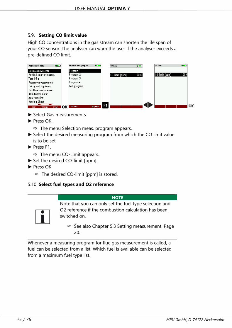
Setting CO limit value
High CO concentrations in the gas stream can shorten the life span of
your CO sensor. The analyser can warn the user if the analyser exceeds a
pre-defined CO limit.
► Select Gas measurements.
► Press OK.
The menu Selection meas. program appears.
► Select the desired measuring program from which the CO limit value
is to be set
► Press F1.
The menu CO-Limit appears.
► Set the desired CO-limit [ppm].
► Press OK
The desired CO-limit [ppm] is stored.
Select fuel types and O2 reference
NOTE
Note that you can only set the fuel type selection and
O2 reference if the combustion calculation has been
switched on.
See also Chapter 5.3 Setting measurement, Page
20.
Whenever a measuring program for flue gas measurement is called, a
fuel can be selected from a list. Which fuel is available can be selected
from a maximum fuel type list.
USER MANUAL OPTIMA 7
MRU GmbH, D-74172 Neckarsulm 26 / 76
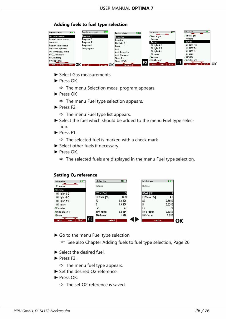
Adding fuels to fuel type selection
► Select Gas measurements.
► Press OK.
The menu Selection meas. program appears.
► Press OK
The menu Fuel type selection appears.
► Press F2.
The menu Fuel type list appears.
► Select the fuel which should be added to the menu Fuel type selec-
tion.
► Press F1.
The selected fuel is marked with a check mark
► Select other fuels if necessary.
► Press OK.
The selected fuels are displayed in the menu Fuel type selection.
Setting O2 reference
► Go to the menu Fuel type selection
See also Chapter Adding fuels to fuel type selection, Page 26
► Select the desired fuel.
► Press F3.
The menu fuel type appears.
► Set the desired O2 reference.
► Press OK.
The set O2 reference is saved.
USER MANUAL OPTIMA 7
27 / 76 MRU GmbH, D-74172 Neckarsulm
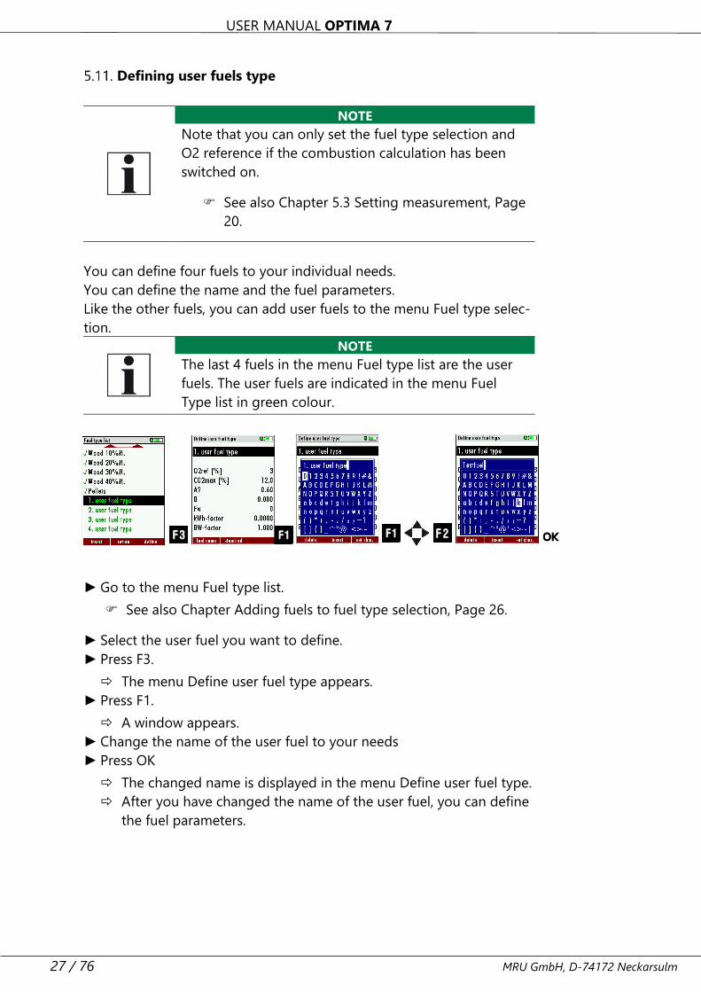
Defining user fuels type
NOTE
Note that you can only set the fuel type selection and
O2 reference if the combustion calculation has been
switched on.
See also Chapter 5.3 Setting measurement, Page
20.
You can define four fuels to your individual needs.
You can define the name and the fuel parameters.
Like the other fuels, you can add user fuels to the menu Fuel type selec-
tion.
NOTE
The last 4 fuels in the menu Fuel type list are the user
fuels. The user fuels are indicated in the menu Fuel
Type list in green colour.
► Go to the menu Fuel type list.
See also Chapter Adding fuels to fuel type selection, Page 26.
► Select the user fuel you want to define.
► Press F3.
The menu Define user fuel type appears.
► Press F1.
A window appears.
► Change the name of the user fuel to your needs
► Press OK
The changed name is displayed in the menu Define user fuel type.
After you have changed the name of the user fuel, you can define
the fuel parameters.
USER MANUAL OPTIMA 7
MRU GmbH, D-74172 Neckarsulm 28 / 76
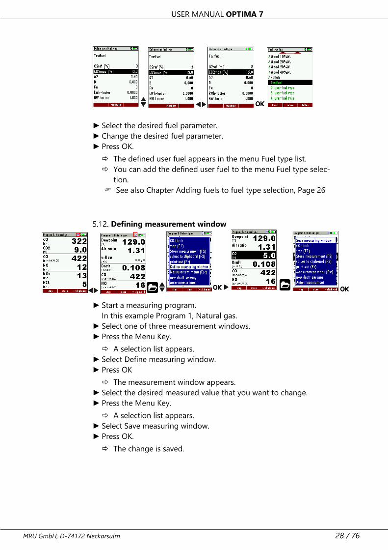
► Select the desired fuel parameter.
► Change the desired fuel parameter.
► Press OK.
The defined user fuel appears in the menu Fuel type list.
You can add the defined user fuel to the menu Fuel type selec-
tion.
See also Chapter Adding fuels to fuel type selection, Page 26
Defining measurement window
► Start a measuring program.
In this example Program 1, Natural gas.
► Select one of three measurement windows.
► Press the Menu Key.
A selection list appears.
► Select Define measuring window.
► Press OK
The measurement window appears.
► Select the desired measured value that you want to change.
► Press the Menu Key.
A selection list appears.
► Select Save measuring window.
► Press OK.
The change is saved.
USER MANUAL OPTIMA 7
29 / 76 MRU GmbH, D-74172 Neckarsulm
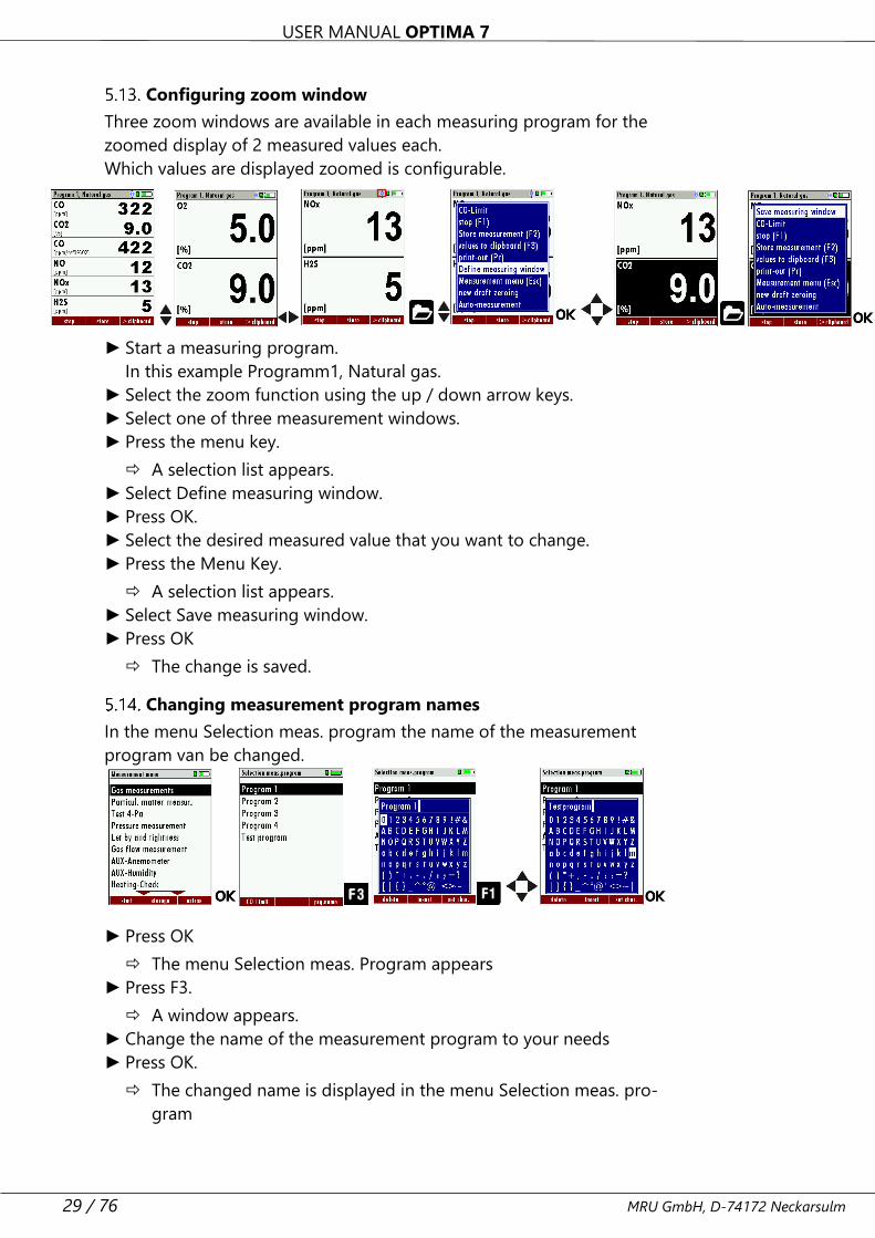
Configuring zoom window
Three zoom windows are available in each measuring program for the
zoomed display of 2 measured values each.
Which values are displayed zoomed is configurable.
► Start a measuring program.
In this example Programm1, Natural gas.
► Select the zoom function using the up / down arrow keys.
► Select one of three measurement windows.
► Press the menu key.
A selection list appears.
► Select Define measuring window.
► Press OK.
► Select the desired measured value that you want to change.
► Press the Menu Key.
A selection list appears.
► Select Save measuring window.
► Press OK
The change is saved.
Changing measurement program names
In the menu Selection meas. program the name of the measurement
program van be changed.
,
► Press OK
The menu Selection meas. Program appears
► Press F3.
A window appears.
► Change the name of the measurement program to your needs
► Press OK.
The changed name is displayed in the menu Selection meas. pro-
gram
USER MANUAL OPTIMA 7
MRU GmbH, D-74172 Neckarsulm 30 / 76
6 Preparing measurement
Ensure power supply
The analyser can be used with:
• with the internal MRU battery (provided)
• with the MRU battery charger (provided)
External equipment may only be connected while the analyser is
switched off!
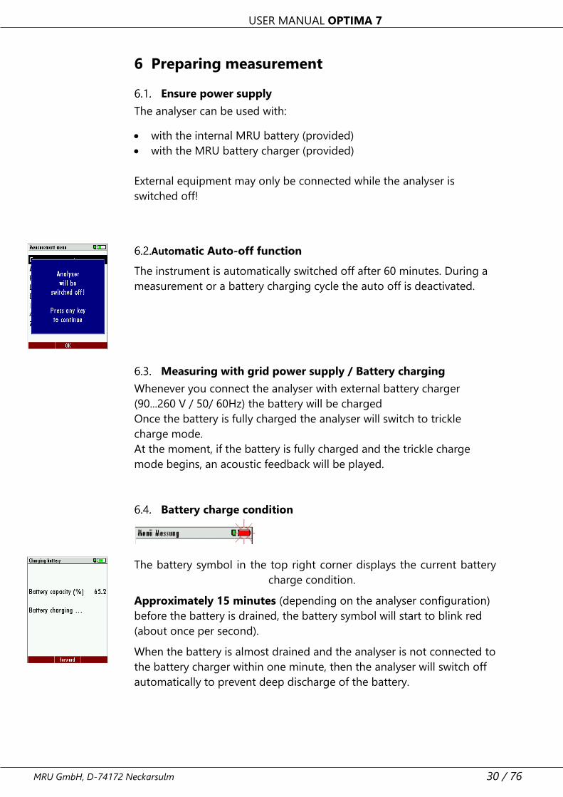
Automatic Auto-off function
The instrument is automatically switched off after 60 minutes. During a
measurement or a battery charging cycle the auto off is deactivated.
Measuring with grid power supply / Battery charging
Whenever you connect the analyser with external battery charger
(90...260 V / 50/ 60Hz) the battery will be charged
Once the battery is fully charged the analyser will switch to trickle
charge mode.
At the moment, if the battery is fully charged and the trickle charge
mode begins, an acoustic feedback will be played.
Battery charge condition
The battery symbol in the top right corner displays the current battery
charge condition.
Approximately 15 minutes (depending on the analyser configuration)
before the battery is drained, the battery symbol will start to blink red
(about once per second).
When the battery is almost drained and the analyser is not connected to
the battery charger within one minute, then the analyser will switch off
automatically to prevent deep discharge of the battery.
USER MANUAL OPTIMA 7
31 / 76 MRU GmbH, D-74172 Neckarsulm
Operating temperature
If the analyser has been stored at low temperatures, it will require some
time to equilibrate to the ambient temperature before being switched
on. If it does not equilibrate, condensation will occur inside the analyser!
If the temperature is out of its operation range you will see the follow-
ing messages on the display: “Analyzer too hot” or “Analyzer too cold”
Once one of these messages appears you will not be able to use the an-
alyser, it will give an acoustic signal until it has reached the specified op-
eration temperature between +5°C and +45°C
See also Chapter 11.1 Technical data, Page 63.
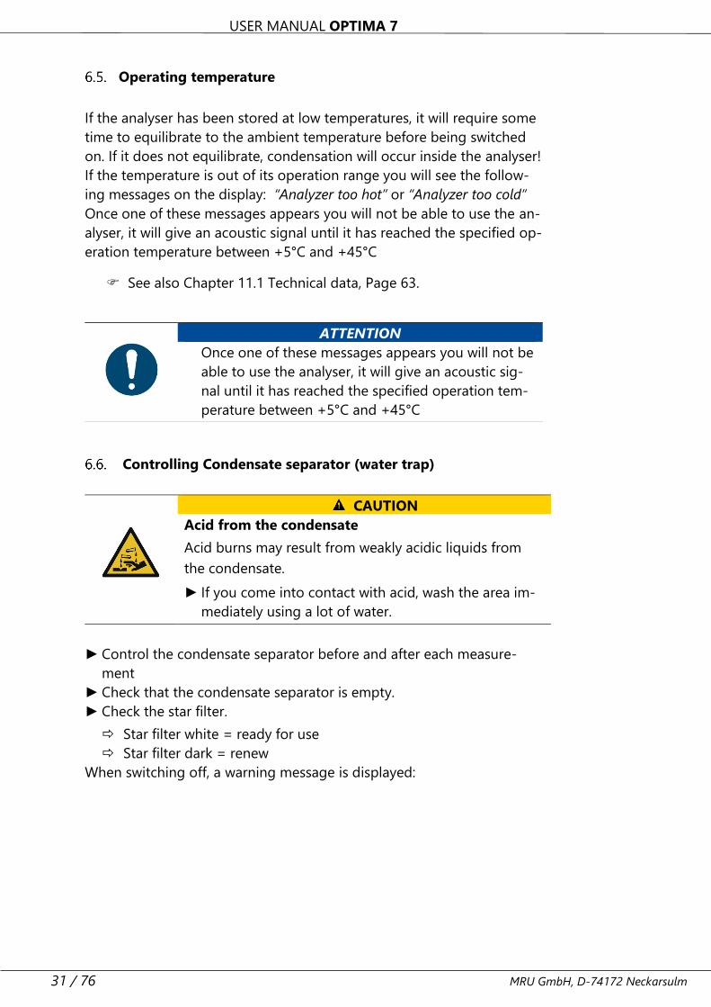
Controlling Condensate separator (water trap)
CAUTION
Acid from the condensate
Acid burns may result from weakly acidic liquids from
the condensate.
► If you come into contact with acid, wash the area im-
mediately using a lot of water.
► Control the condensate separator before and after each measure-
ment
► Check that the condensate separator is empty.
► Check the star filter.
Star filter white = ready for use
Star filter dark = renew
When switching off, a warning message is displayed:
ATTENTION
Once one of these messages appears you will not be
able to use the analyser, it will give an acoustic sig-
nal until it has reached the specified operation tem-
perature between +5°C and +45°C
USER MANUAL OPTIMA 7
MRU GmbH, D-74172 Neckarsulm 32 / 76
Connections and tightness
Check all plug connections for correct fitting.
Check all hoses, hose connections, condensate containers (from the
probe tip to the gas connection on the analyser) for tightness.
The analyser has a built-in automatic test to check the tightness of the
gas paths.
See also Chapter 9.4 Performing leak test, Page 59.
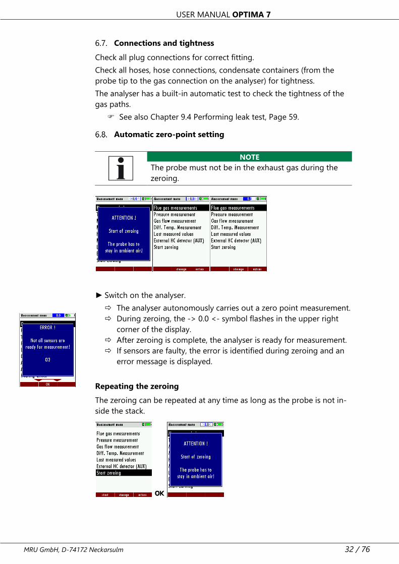
Automatic zero-point setting
NOTE
The probe must not be in the exhaust gas during the
zeroing.
► Switch on the analyser.
The analyser autonomously carries out a zero point measurement.
During zeroing, the -> 0.0 <- symbol flashes in the upper right
corner of the display.
After zeroing is complete, the analyser is ready for measurement.
If sensors are faulty, the error is identified during zeroing and an
error message is displayed.
Repeating the zeroing
The zeroing can be repeated at any time as long as the probe is not in-
side the stack.
USER MANUAL OPTIMA 7
33 / 76 MRU GmbH, D-74172 Neckarsulm
7 Performing measurement
In the basic configuration, each analyser has the complete functionality
you need for gas measurement.
The process of gas measurement is described below.
The description of other optionally available measuring programs can
be found in the appendix or on separate supplementary sheets.
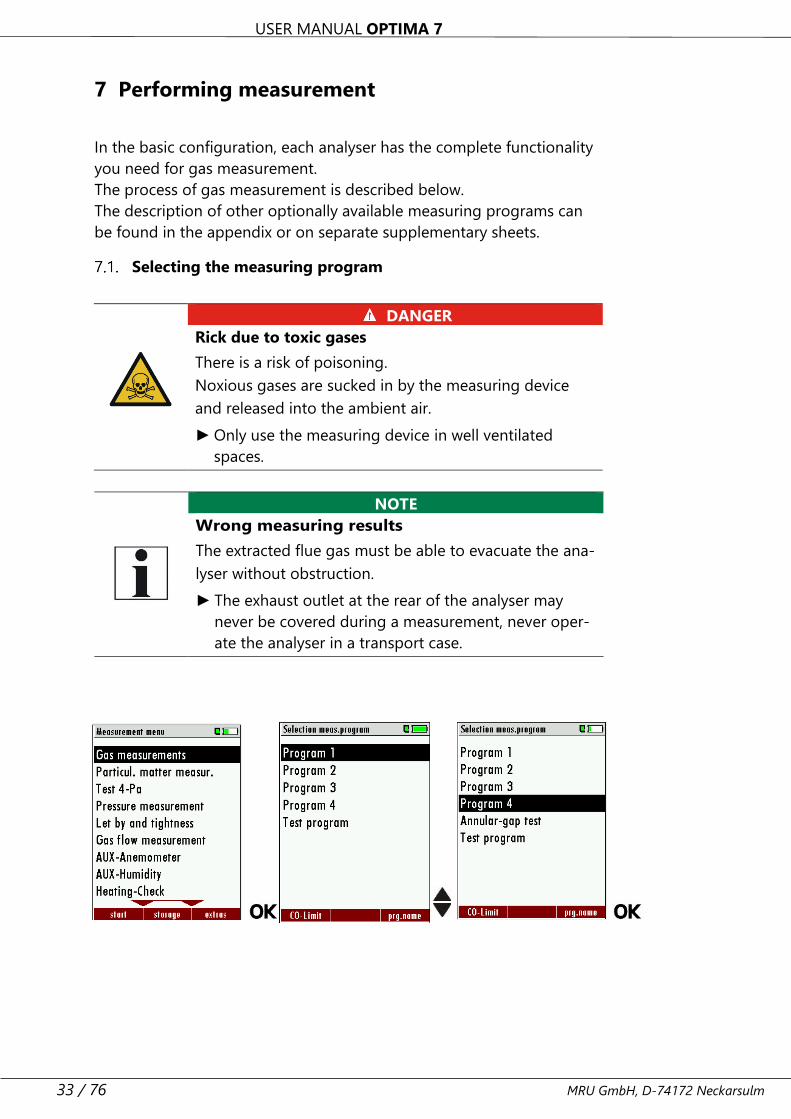
Selecting the measuring program
NOTE
Wrong measuring results
The extracted flue gas must be able to evacuate the ana-
lyser without obstruction.
► The exhaust outlet at the rear of the analyser may
never be covered during a measurement, never oper-
ate the analyser in a transport case.
DANGER
Rick due to toxic gases
There is a risk of poisoning.
Noxious gases are sucked in by the measuring device
and released into the ambient air.
► Only use the measuring device in well ventilated
spaces.
USER MANUAL OPTIMA 7
MRU GmbH, D-74172 Neckarsulm 34 / 76
► Go to the Measurement menu.
► Press OK.
The menu Selection meas. program appears.
► Select the desired measurement program.
► If necessary, change the CO limit.
See also Chapter 5.9 Setting CO limit value, Page 25.
► Change the measuring program name if necessary.
See also Chapter 5.14 Changing measurement program names,
Page 29.
► Press OK.
The menu Fuel type selection appears.
► Select the desired fuel.
► If necessary, add fuels from the fuel type list to the menu Fuel type
selection.
See also Chapter Adding fuels to fuel type selection, Page 26.
► Press OK.
The measurement is started.
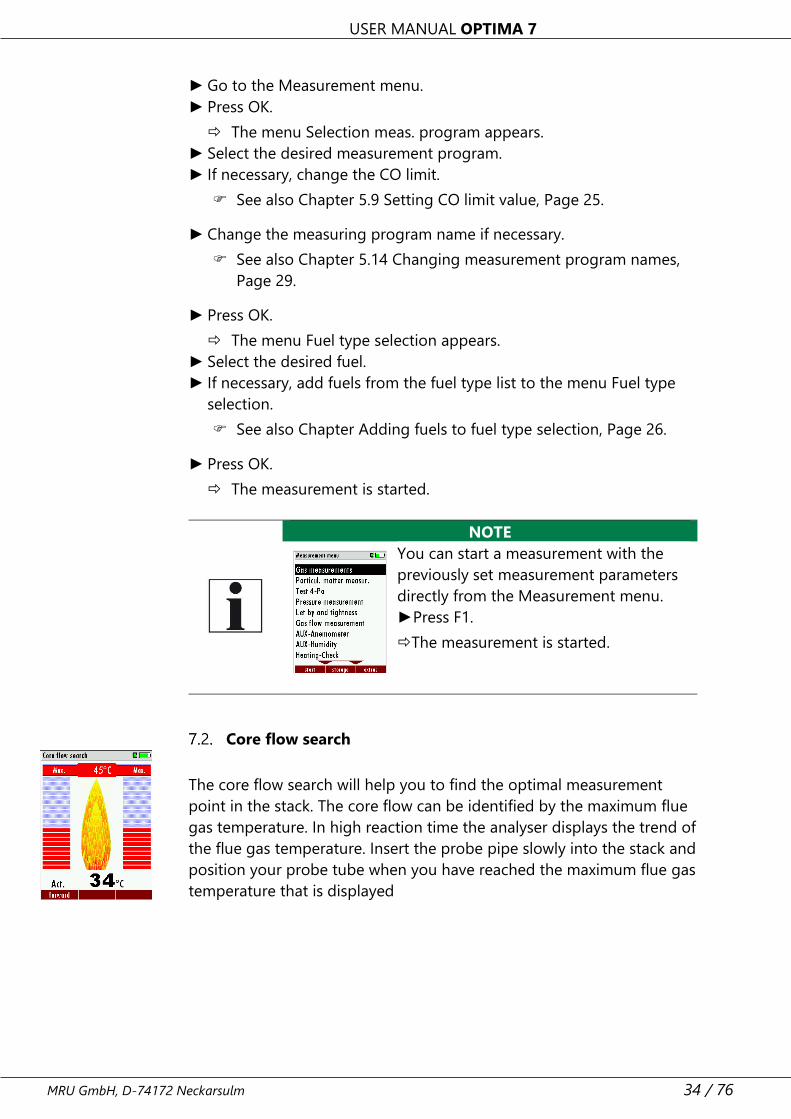
NOTE
You can start a measurement with the
previously set measurement parameters
directly from the Measurement menu.
►Press F1.
The measurement is started.
Core flow search
The core flow search will help you to find the optimal measurement
point in the stack. The core flow can be identified by the maximum flue
gas temperature. In high reaction time the analyser displays the trend of
the flue gas temperature. Insert the probe pipe slowly into the stack and
position your probe tube when you have reached the maximum flue gas
temperature that is displayed
USER MANUAL OPTIMA 7
35 / 76 MRU GmbH, D-74172 Neckarsulm
Before using the core flow search it must be switched-on:
Positioning the probe in the core flow:
Insert the probe pipe slowly into the stack and position your probe pipe
when you have reached the maximum flue gas temperature that is dis-
played (see temperature maximum value on the display – in this case
45°C).
Maximum temperature has been reached when the arrows (left picture)
disappear, max. (Right picture) appears in place of the arrow, and the
beeper signal stops. Moving away from the max. Temperature will result
in the bars moving away from the max. Temperature (1 bar is equivalent
to 1°C). Once the right core flow has been achieved, the probe is fixed
with the probe cone screw.
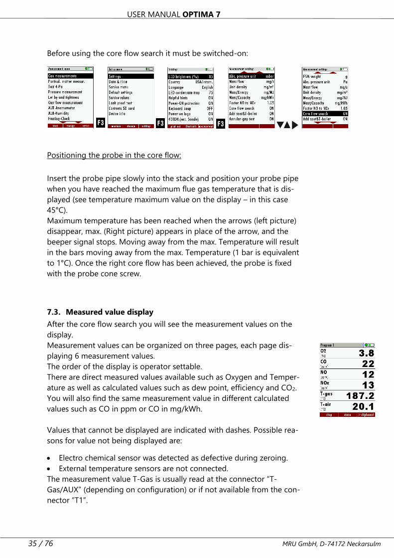
7.3. Measured value display
After the core flow search you will see the measurement values on the
display.
Measurement values can be organized on three pages, each page dis-
playing 6 measurement values.
The order of the display is operator settable.
There are direct measured values available such as Oxygen and Temper-
ature as well as calculated values such as dew point, efficiency and CO2.
You will also find the same measurement value in different calculated
values such as CO in ppm or CO in mg/kWh.
Values that cannot be displayed are indicated with dashes. Possible rea-
sons for value not being displayed are:
• Electro chemical sensor was detected as defective during zeroing.
• External temperature sensors are not connected.
The measurement value T-Gas is usually read at the connector “T-
Gas/AUX” (depending on configuration) or if not available from the con-
nector “T1”.
USER MANUAL OPTIMA 7
MRU GmbH, D-74172 Neckarsulm 36 / 76
There are three measurement windows available, with the arrow keys
left and right moving between them.
Zoom function, each with two values, is activated by moving the arrow
keys up and down. Moving arrow keys left and right pages between the
two zoom windows.
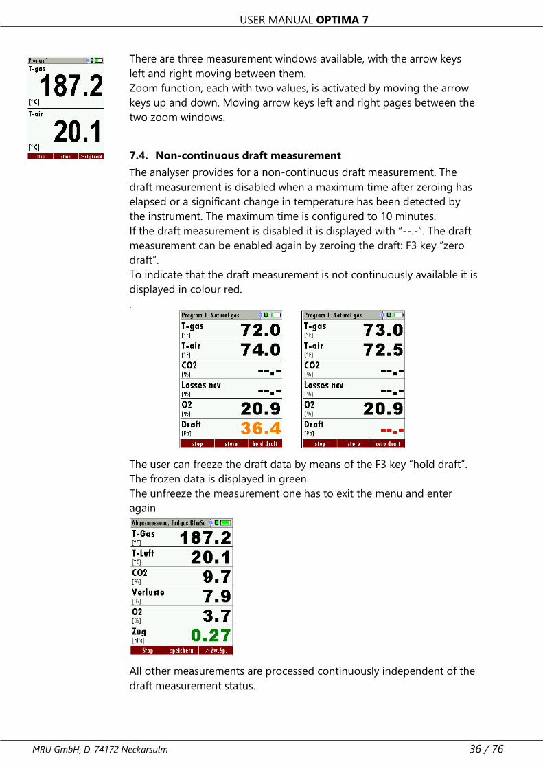
7.4. Non-continuous draft measurement
The analyser provides for a non-continuous draft measurement. The
draft measurement is disabled when a maximum time after zeroing has
elapsed or a significant change in temperature has been detected by
the instrument. The maximum time is configured to 10 minutes.
If the draft measurement is disabled it is displayed with “--.-“. The draft
measurement can be enabled again by zeroing the draft: F3 key “zero
draft”.
To indicate that the draft measurement is not continuously available it is
displayed in colour red.
.
The user can freeze the draft data by means of the F3 key “hold draft”.
The frozen data is displayed in green.
The unfreeze the measurement one has to exit the menu and enter
again
All other measurements are processed continuously independent of the
draft measurement status.
USER MANUAL OPTIMA 7
37 / 76 MRU GmbH, D-74172 Neckarsulm
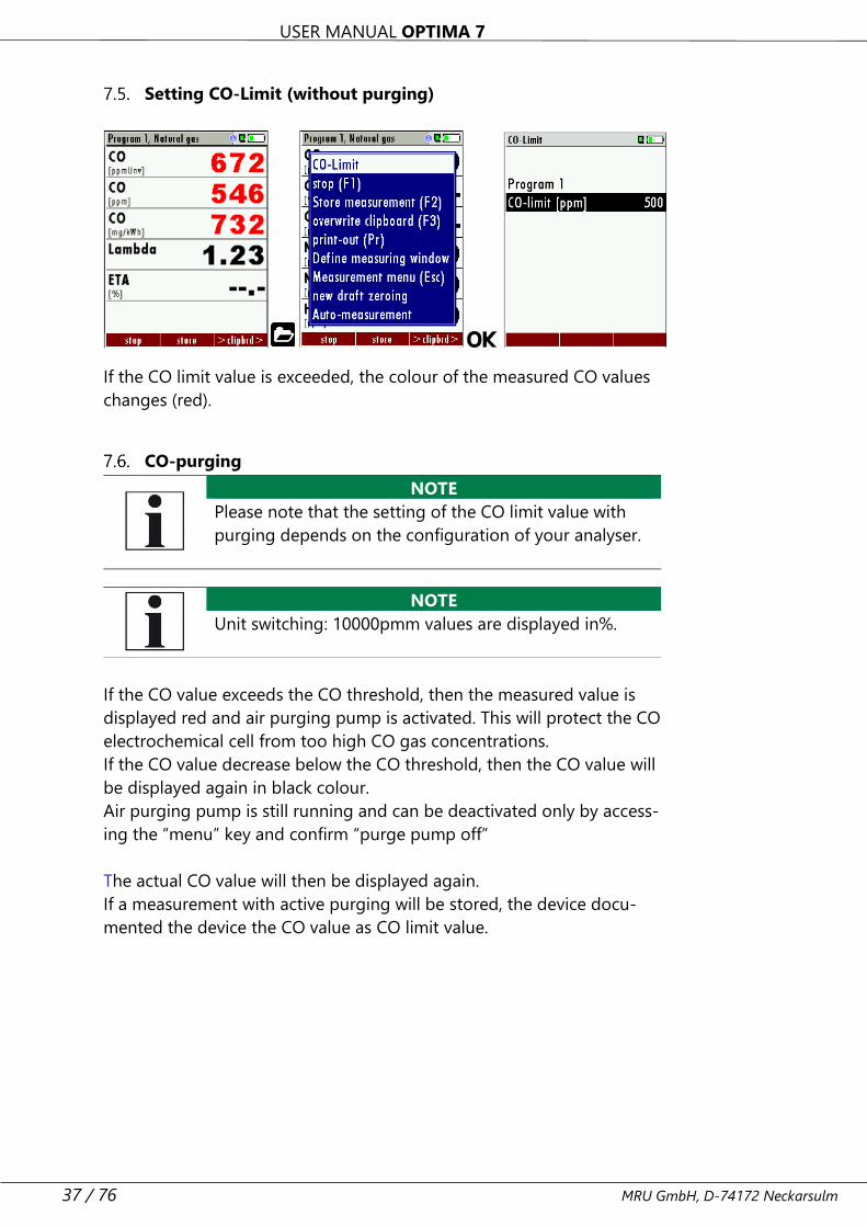
Setting CO-Limit (without purging)
If the CO limit value is exceeded, the colour of the measured CO values
changes (red).
CO-purging
NOTE
Please note that the setting of the CO limit value with
purging depends on the configuration of your analyser.
If the CO value exceeds the CO threshold, then the measured value is
displayed red and air purging pump is activated. This will protect the CO
electrochemical cell from too high CO gas concentrations.
If the CO value decrease below the CO threshold, then the CO value will
be displayed again in black colour.
Air purging pump is still running and can be deactivated only by access-
ing the “menu” key and confirm “purge pump off”
The actual CO value will then be displayed again.
If a measurement with active purging will be stored, the device docu-
mented the device the CO value as CO limit value.
NOTE
Unit switching: 10000pmm values are displayed in%.
USER MANUAL OPTIMA 7
MRU GmbH, D-74172 Neckarsulm 38 / 76
CO/H2 and CO high (optional)
If that exceeds CO the CO threshold, then to CO high, the measured
value is red indicated - also the calculated values - is switched.
The CO value exceeds 10.000 ppm to % is in such a way switched (ex-
ample 1.00%).
If the CO value sinks below the CO threshold, then the red CO value be-
comes again black
Starting from this moment the purge pump can be switched off over
the menu key again.
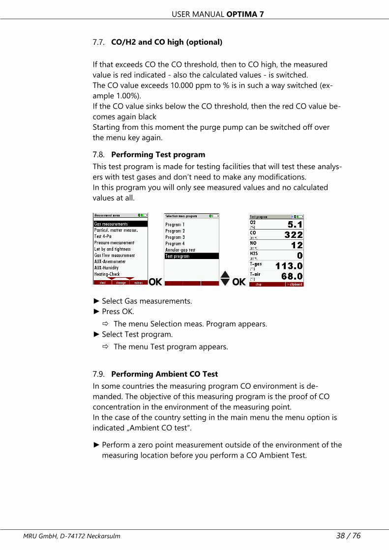
Performing Test program
This test program is made for testing facilities that will test these analys-
ers with test gases and don’t need to make any modifications.
In this program you will only see measured values and no calculated
values at all.
► Select Gas measurements.
► Press OK.
The menu Selection meas. Program appears.
► Select Test program.
The menu Test program appears.
Performing Ambient CO Test
In some countries the measuring program CO environment is de-
manded. The objective of this measuring program is the proof of CO
concentration in the environment of the measuring point.
In the case of the country setting in the main menu the menu option is
indicated „Ambient CO test“.
► Perform a zero point measurement outside of the environment of the
measuring location before you perform a CO Ambient Test.
USER MANUAL OPTIMA 7
39 / 76 MRU GmbH, D-74172 Neckarsulm
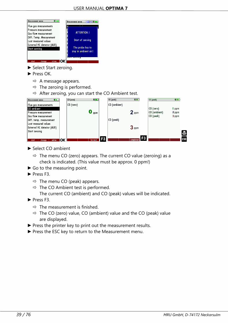
► Select Start zeroing.
► Press OK.
A message appears.
The zeroing is performed.
After zeroing, you can start the CO Ambient test.
► Select CO ambient
The menu CO (zero) appears. The current CO value (zeroing) as a
check is indicated. (This value must be approx. 0 ppm!)
► Go to the measuring point.
► Press F3.
The menu CO (peak) appears.
The CO Ambient test is performed.
The current CO (ambient) and CO (peak) values will be indicated.
► Press F3.
The measurement is finished.
The CO (zero) value, CO (ambient) value and the CO (peak) value
are displayed.
► Press the printer key to print out the measurement results.
► Press the ESC key to return to the Measurement menu.
USER MANUAL OPTIMA 7
MRU GmbH, D-74172 Neckarsulm 40 / 76
Temporary buffer
The analyser gives the possibility to set the momentary values into a
temporary buffer during effecting and continuing the measurement.
► Later on, the values can be brought back from the temporary buffer
to the measuring window in order to print them out or / and to save
them.
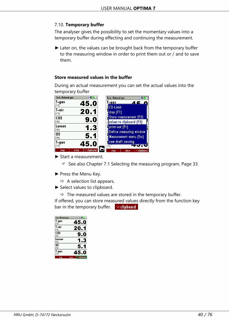
Store measured values in the buffer
During an actual measurement you can set the actual values into the
temporary buffer
► Start a measurement.
See also Chapter 7.1 Selecting the measuring program, Page 33.
► Press the Menu Key.
A selection list appears.
► Select values to clipboard.
The measured values are stored in the temporary buffer.
If offered, you can store measured values directly from the function key
bar in the temporary buffer.
USER MANUAL OPTIMA 7
41 / 76 MRU GmbH, D-74172 Neckarsulm
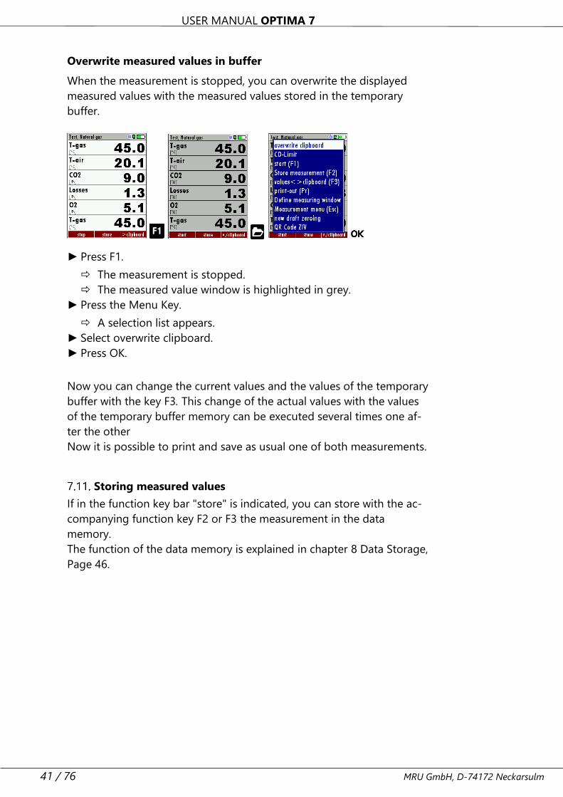
Overwrite measured values in buffer
When the measurement is stopped, you can overwrite the displayed
measured values with the measured values stored in the temporary
buffer.
► Press F1.
The measurement is stopped.
The measured value window is highlighted in grey.
► Press the Menu Key.
A selection list appears.
► Select overwrite clipboard.
► Press OK.
Now you can change the current values and the values of the temporary
buffer with the key F3. This change of the actual values with the values
of the temporary buffer memory can be executed several times one af-
ter the other
Now it is possible to print and save as usual one of both measurements.
Storing measured values
If in the function key bar "store" is indicated, you can store with the ac-
companying function key F2 or F3 the measurement in the data
memory.
The function of the data memory is explained in chapter 8 Data Storage,
Page 46.
USER MANUAL OPTIMA 7
MRU GmbH, D-74172 Neckarsulm 42 / 76
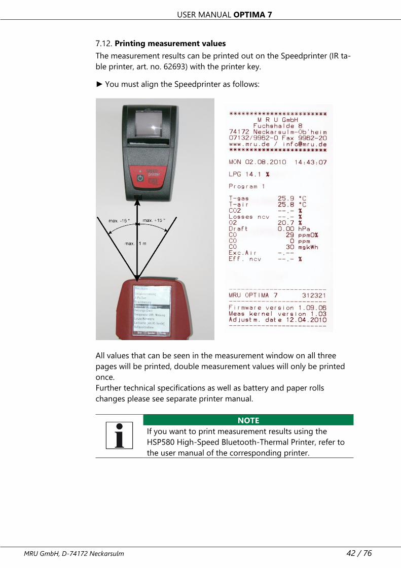
Printing measurement values
The measurement results can be printed out on the Speedprinter (IR ta-
ble printer, art. no. 62693) with the printer key.
► You must align the Speedprinter as follows:
All values that can be seen in the measurement window on all three
pages will be printed, double measurement values will only be printed
once.
Further technical specifications as well as battery and paper rolls
changes please see separate printer manual.
NOTE
If you want to print measurement results using the
HSP580 High-Speed Bluetooth-Thermal Printer, refer to
the user manual of the corresponding printer.
USER MANUAL OPTIMA 7
43 / 76 MRU GmbH, D-74172 Neckarsulm
Terminate measurement
A running measurement can be stopped at any time by pressing the F1
key. The window changes colour and the measured values are frozen.
All measured values available at the time of stopping are available in the
analyser and can still be displayed. By pressing the ESC key, the analyser
returns to Measurement menu.
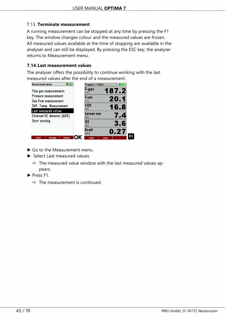
7.14. Last measurement values
The analyser offers the possibility to continue working with the last
measured values after the end of a measurement.
► Go to the Measurement menu.
► Select Last measured values.
The measured value window with the last measured values ap-
pears.
► Press F1.
The measurement is continued.
USER MANUAL OPTIMA 7
MRU GmbH, D-74172 Neckarsulm 44 / 76
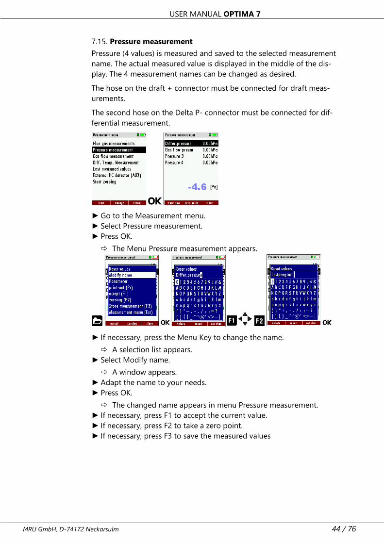
Pressure measurement
Pressure (4 values) is measured and saved to the selected measurement
name. The actual measured value is displayed in the middle of the dis-
play. The 4 measurement names can be changed as desired.
The hose on the draft + connector must be connected for draft meas-
urements.
The second hose on the Delta P- connector must be connected for dif-
ferential measurement.
► Go to the Measurement menu.
► Select Pressure measurement.
► Press OK.
The Menu Pressure measurement appears.
► If necessary, press the Menu Key to change the name.
A selection list appears.
► Select Modify name.
A window appears.
► Adapt the name to your needs.
► Press OK.
The changed name appears in menu Pressure measurement.
► If necessary, press F1 to accept the current value.
► If necessary, press F2 to take a zero point.
► If necessary, press F3 to save the measured values
USER MANUAL OPTIMA 7
45 / 76 MRU GmbH, D-74172 Neckarsulm
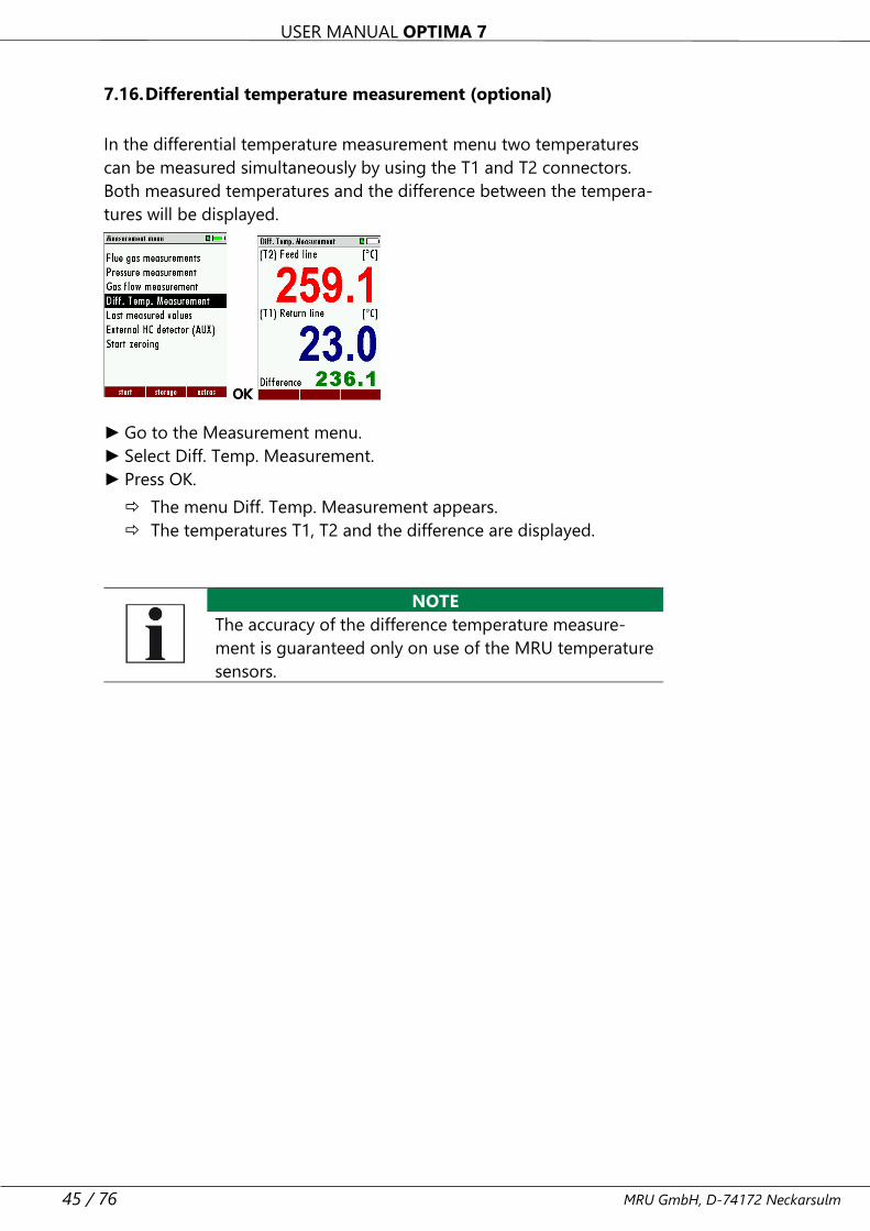
7.16. Differential temperature measurement (optional)
In the differential temperature measurement menu two temperatures
can be measured simultaneously by using the T1 and T2 connectors.
Both measured temperatures and the difference between the tempera-
tures will be displayed.
► Go to the Measurement menu.
► Select Diff. Temp. Measurement.
► Press OK.
The menu Diff. Temp. Measurement appears.
The temperatures T1, T2 and the difference are displayed.
NOTE
The accuracy of the difference temperature measure-
ment is guaranteed only on use of the MRU temperature
sensors.
USER MANUAL OPTIMA 7
MRU GmbH, D-74172 Neckarsulm 46 / 76
8 Data Storage
Organizing data storage
The basis for the data storage of the analyser is saved sets of sites inside
the analyser. Each site has a distinct site number as well as 8 additional
free text lines for names and address.
The analyser can store up to 4,000 different sites.
New sites can be added in the analyser. Modifications can be done us-
ing an external PC program e.g. MRU Win.
NOTE
New sites created in the analyser will NOT be transferred
back to the computer program. When transferring data
from the analyser to the computer only measurement
data will be transferred, identified by the site number
that has been assigned to the measurement, when the
measurement was saved.
Measurements are saved by assigning them to a site. Measurements can
be single flue gas measurements, 4Pa tests, heating checks or other
measuring programs available in the analyser.
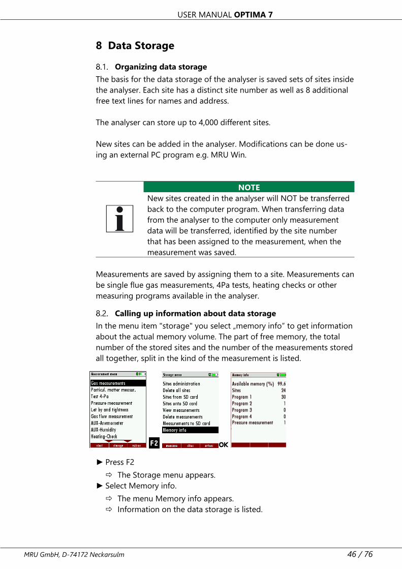
Calling up information about data storage
In the menu item "storage" you select „memory info“ to get information
about the actual memory volume. The part of free memory, the total
number of the stored sites and the number of the measurements stored
all together, split in the kind of the measurement is listed.
► Press F2
The Storage menu appears.
► Select Memory info.
The menu Memory info appears.
Information on the data storage is listed.
USER MANUAL OPTIMA 7
47 / 76 MRU GmbH, D-74172 Neckarsulm
Site administration
In the sub menu Sites administration, you can:
• view all data of the stored sites
• create new sites
• change date of existing sites
• delete sites
NOTE
New sites created in the analyser will NOT be transferred
to a PC program
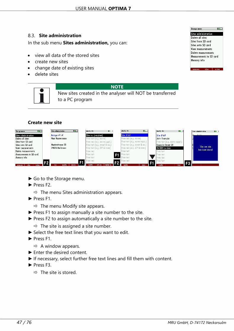
Create new site
► Go to the Storage menu.
► Press F2.
The menu Sites administration appears.
► Press F1.
The menu Modify site appears.
► Press F1 to assign manually a site number to the site.
► Press F2 to assign automatically a site number to the site.
The site is assigned a site number.
► Select the free text lines that you want to edit.
► Press F1.
A window appears.
► Enter the desired content.
► If necessary, select further free text lines and fill them with content.
► Press F3.
The site is stored.
USER MANUAL OPTIMA 7
MRU GmbH, D-74172 Neckarsulm 48 / 76
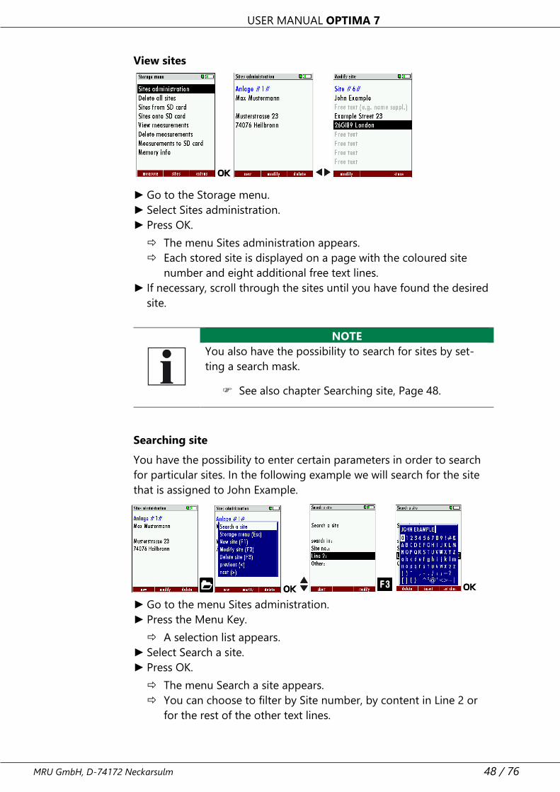
View sites
► Go to the Storage menu.
► Select Sites administration.
► Press OK.
The menu Sites administration appears.
Each stored site is displayed on a page with the coloured site
number and eight additional free text lines.
► If necessary, scroll through the sites until you have found the desired
site.
NOTE
You also have the possibility to search for sites by set-
ting a search mask.
See also chapter Searching site, Page 48.
Searching site
You have the possibility to enter certain parameters in order to search
for particular sites. In the following example we will search for the site
that is assigned to John Example.
► Go to the menu Sites administration.
► Press the Menu Key.
A selection list appears.
► Select Search a site.
► Press OK.
The menu Search a site appears.
You can choose to filter by Site number, by content in Line 2 or
for the rest of the other text lines.

USER MANUAL OPTIMA 7
49 / 76 MRU GmbH, D-74172 Neckarsulm
► Select a line in which you want to search for content.
In this example, the search is performed in line 2.
► Press F3.
A window appears.
► Enter the desired search term.
In this example the search term is John Example.
► Press OK.
The menu Search a site appears.
The search term appears in the selected line.
► Press F2.
The site that is assigned to John Example is displayed. If several sites
were found, the total number is displayed in the header and you can
scroll through these found sites.
Changing sites
► Go to the Storage menu.
► Select Sites administration.
► Press F2.
The menu Sites administration appears.
► Select the site that you want to change.
► Press F2.
A bar appears.
► Select the free text lines that you want to change.
► Press F1.
A window appears.
► Enter the desired changes.
► If necessary, select further free text lines and change the correspond-
ing free text lines.
► Press F3.
The changes are stored.
USER MANUAL OPTIMA 7
MRU GmbH, D-74172 Neckarsulm 50 / 76
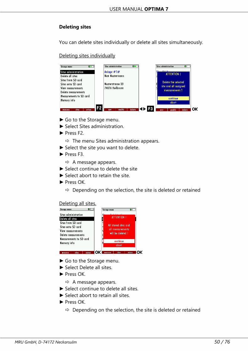
Deleting sites
You can delete sites individually or delete all sites simultaneously.
Deleting sites individually
► Go to the Storage menu.
► Select Sites administration.
► Press F2.
The menu Sites administration appears.
► Select the site you want to delete.
► Press F3.
A message appears.
► Select continue to delete the site
► Select abort to retain the site.
► Press OK.
Depending on the selection, the site is deleted or retained
Deleting all sites.
► Go to the Storage menu.
► Select Delete all sites.
► Press OK.
A message appears.
► Select continue to delete all sites.
► Select abort to retain all sites.
► Press OK.
Depending on the selection, the site is deleted or retained
USER MANUAL OPTIMA 7
51 / 76 MRU GmbH, D-74172 Neckarsulm
Data transfer using SD card
The data exchange format is CSV. A character-separated values (CSV)
file is a simple text format for a database table. Each record in the table
is one line of the text file. Each field value of a record is separated from
the next by a character. Optima 7 uses a semi-colon ‘;’ as value separa-
tor (other implementations use sometimes a comma). Implementations
of CSV can often handle field values with embedded line breaks or sep-
arator characters by using quotation marks or escape sequences. CSV is
a simple file format that is widely supported, so it is often used to move
tabular data between different computer programs, for example Mi-
crosoft Excel™ or Access™, that support the format. Also, other com-
puter programs offer this type of interface because it is widely spread
and easy to use.
The following functions are available from Software Version 1.11 and
higher:
1.Importing sites
2.Exporting sites
3.Exporting combustion tests
4.Exporting differential pressure measurements
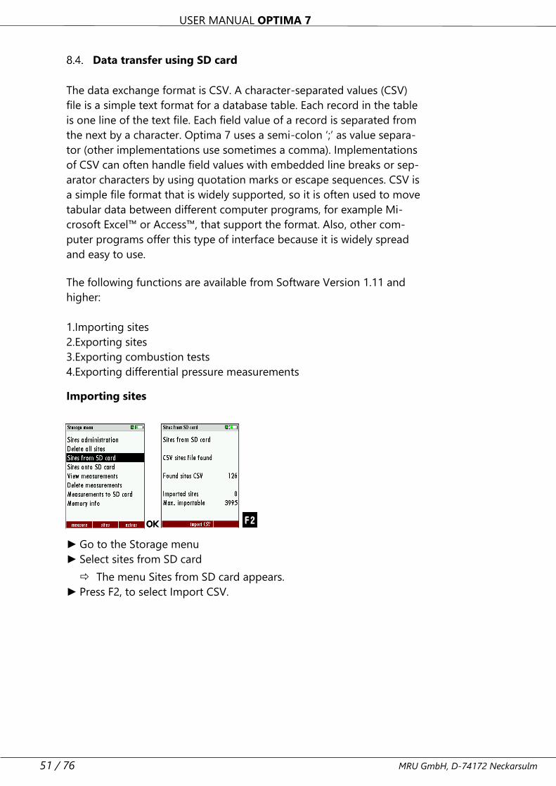
Importing sites
► Go to the Storage menu
► Select sites from SD card
The menu Sites from SD card appears.
► Press F2, to select Import CSV.
USER MANUAL OPTIMA 7
MRU GmbH, D-74172 Neckarsulm 52 / 76
With this function you can Import Sites which have been created on a
computer or another Analyzer.
The File name must have the name “anlagen.csv“(anlagen = German for
sites). The file has no column heading that means that the first line al-
ready has user data. Each line has a minimum of 9 columns (with 8
semi-colons) and the first field in the line will be the site number. All
data will be imported as long a site number is available. Per field a maxi-
mum of 24 characters will be imported, too long words will be cut off.
Example file with 8 valid sites (4 with 9 lines and 4 with less lines):
A1-Z1;A1-Z2;A1-Z3;A1-Z4;A1-Z5;A1-Z6;A1-Z7;A1-Z8;A1-Z9
A2-Z1;A2-Z2;A2-Z3;A2-Z4;A2-Z5;A2-Z6;A2-Z7;A2-Z8;A2-Z9
A3-Z1;A3-Z2;A3-Z3;A3-Z4;A3-Z5;A3-Z6;A3-Z7;A3-Z8;A3-Z9
A4-Z1;A4-Z2;A4-Z3;A4-Z4;A4-Z5;A4-Z6;A4-Z7;A4-Z8;A4-Z9
A5-Z1;A5-Z2;A5-Z3;A5-Z4;;;;;
A6-Z1;A6-Z2;;A6-Z4;;;;;
A7-Z1;;;A7-Z4;;;;;
A8-Z1;;;;;;;;
Example file with 2 invalid sites (1 with not enough fields and 1 with
missing site number):
A1-Z1;A1-Z2
;A1-Z2;A1-Z3;A1-Z4;A1-Z5;A1-Z6;A1-Z7;A1-Z8;A1-Z9
NOTE
While importing data from the SD Card to the analyser
there is no check for double site numbers (Line 1), nei-
ther inside of the file that is imported nor between the
file and the sites already inside the analyser. The analyser
can easily handle double site numbers but you could
face problems with double site numbers when exporting
them again to a computer program (see also Export of
Measurements).
However, the analyser marks the files that have been im-
ported successfully. If you try to import a file with the
same analyser that is already in the analyser you will get a
red information screen.
USER MANUAL OPTIMA 7
53 / 76 MRU GmbH, D-74172 Neckarsulm
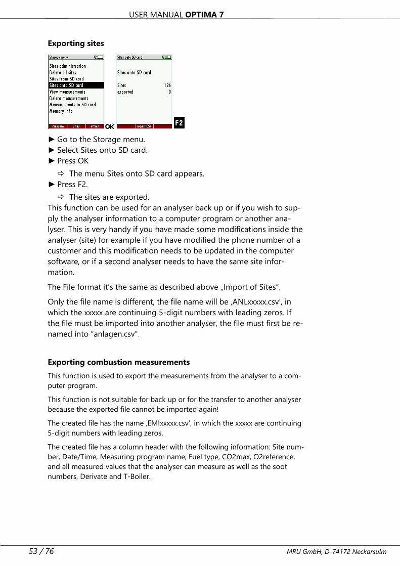
Exporting sites
► Go to the Storage menu.
► Select Sites onto SD card.
► Press OK
The menu Sites onto SD card appears.
► Press F2.
The sites are exported.
This function can be used for an analyser back up or if you wish to sup-
ply the analyser information to a computer program or another ana-
lyser. This is very handy if you have made some modifications inside the
analyser (site) for example if you have modified the phone number of a
customer and this modification needs to be updated in the computer
software, or if a second analyser needs to have the same site infor-
mation.
The File format it’s the same as described above „Import of Sites“.
Only the file name is different, the file name will be ‚ANLxxxxx.csv’, in
which the xxxxx are continuing 5-digit numbers with leading zeros. If
the file must be imported into another analyser, the file must first be re-
named into “anlagen.csv”.
Exporting combustion measurements
This function is used to export the measurements from the analyser to a com-
puter program.
This function is not suitable for back up or for the transfer to another analyser
because the exported file cannot be imported again!
The created file has the name ‚EMIxxxxx.csv’, in which the xxxxx are continuing
5-digit numbers with leading zeros.
The created file has a column header with the following information: Site num-
ber, Date/Time, Measuring program name, Fuel type, CO2max, O2reference,
and all measured values that the analyser can measure as well as the soot
numbers, Derivate and T-Boiler.
USER MANUAL OPTIMA 7
MRU GmbH, D-74172 Neckarsulm 54 / 76
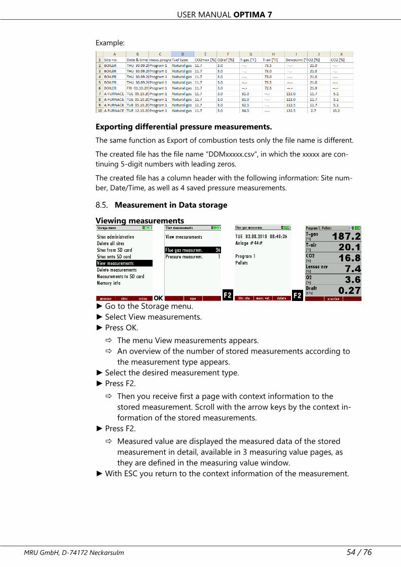
Example:
Exporting differential pressure measurements.
The same function as Export of combustion tests only the file name is different.
The created file has the file name “DDMxxxxx.csv“, in which the xxxxx are con-
tinuing 5-digit numbers with leading zeros.
The created file has a column header with the following information: Site num-
ber, Date/Time, as well as 4 saved pressure measurements.
Measurement in Data storage
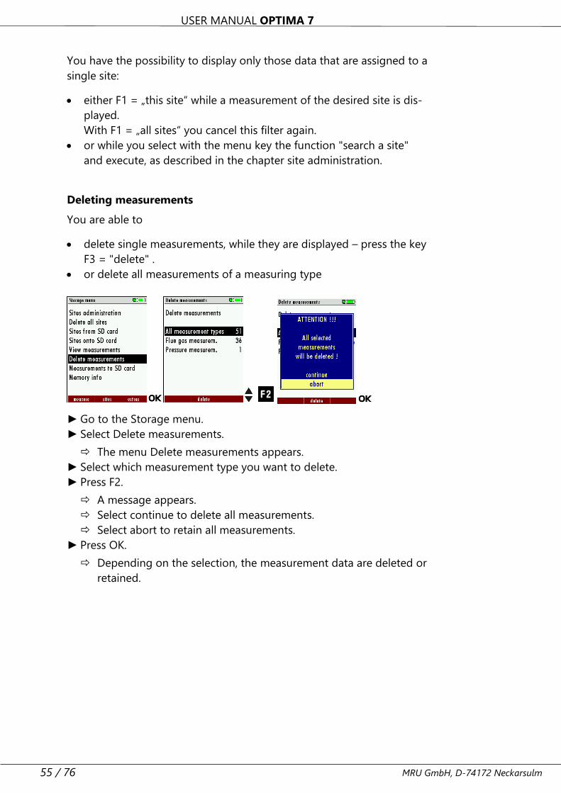
Viewing measurements
► Go to the Storage menu.
► Select View measurements.
► Press OK.
The menu View measurements appears.
An overview of the number of stored measurements according to
the measurement type appears.
► Select the desired measurement type.
► Press F2.
Then you receive first a page with context information to the
stored measurement. Scroll with the arrow keys by the context in-
formation of the stored measurements.
► Press F2.
Measured value are displayed the measured data of the stored
measurement in detail, available in 3 measuring value pages, as
they are defined in the measuring value window.
► With ESC you return to the context information of the measurement.
USER MANUAL OPTIMA 7
55 / 76 MRU GmbH, D-74172 Neckarsulm
You have the possibility to display only those data that are assigned to a
single site:
• either F1 = „this site“ while a measurement of the desired site is dis-
played.
With F1 = „all sites“ you cancel this filter again.
• or while you select with the menu key the function "search a site"
and execute, as described in the chapter site administration.
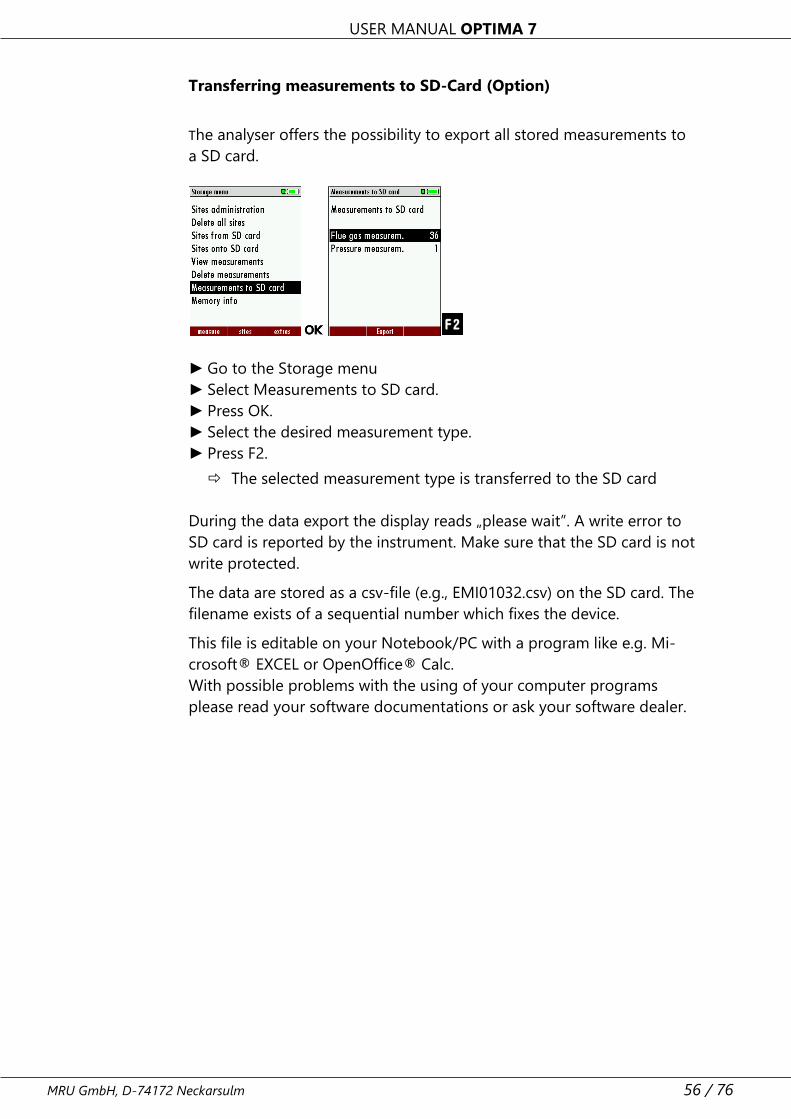
Deleting measurements
You are able to
• delete single measurements, while they are displayed – press the key
F3 = "delete" .
• or delete all measurements of a measuring type
► Go to the Storage menu.
► Select Delete measurements.
The menu Delete measurements appears.
► Select which measurement type you want to delete.
► Press F2.
A message appears.
Select continue to delete all measurements.
Select abort to retain all measurements.
► Press OK.
Depending on the selection, the measurement data are deleted or
retained.
USER MANUAL OPTIMA 7
MRU GmbH, D-74172 Neckarsulm 56 / 76
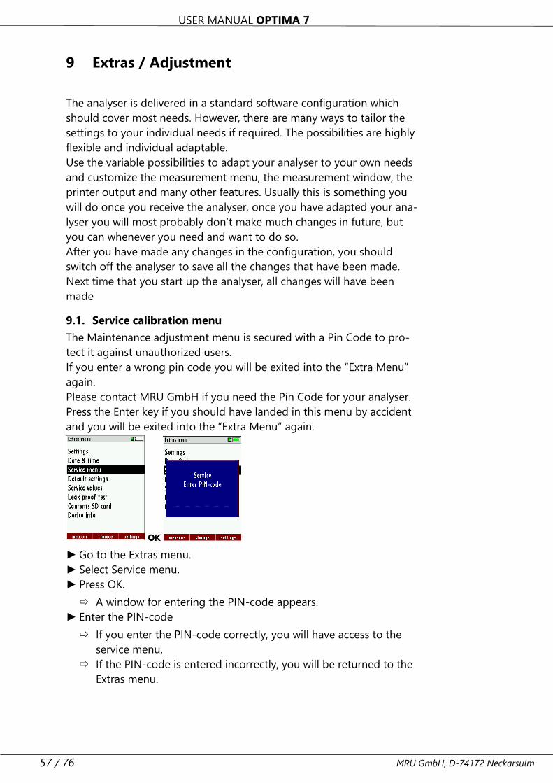
Transferring measurements to SD-Card (Option)
The analyser offers the possibility to export all stored measurements to
a SD card.
► Go to the Storage menu
► Select Measurements to SD card.
► Press OK.
► Select the desired measurement type.
► Press F2.
The selected measurement type is transferred to the SD card
During the data export the display reads „please wait”. A write error to
SD card is reported by the instrument. Make sure that the SD card is not
write protected.
The data are stored as a csv-file (e.g., EMI01032.csv) on the SD card. The
filename exists of a sequential number which fixes the device.
This file is editable on your Notebook/PC with a program like e.g. Mi-
crosoft® EXCEL or OpenOffice® Calc.
With possible problems with the using of your computer programs
please read your software documentations or ask your software dealer.
USER MANUAL OPTIMA 7
57 / 76 MRU GmbH, D-74172 Neckarsulm
9 Extras / Adjustment
The analyser is delivered in a standard software configuration which
should cover most needs. However, there are many ways to tailor the
settings to your individual needs if required. The possibilities are highly
flexible and individual adaptable.
Use the variable possibilities to adapt your analyser to your own needs
and customize the measurement menu, the measurement window, the
printer output and many other features. Usually this is something you
will do once you receive the analyser, once you have adapted your ana-
lyser you will most probably don’t make much changes in future, but
you can whenever you need and want to do so.
After you have made any changes in the configuration, you should
switch off the analyser to save all the changes that have been made.
Next time that you start up the analyser, all changes will have been
made
9.1. Service calibration menu
The Maintenance adjustment menu is secured with a Pin Code to pro-
tect it against unauthorized users.
If you enter a wrong pin code you will be exited into the “Extra Menu”
again.
Please contact MRU GmbH if you need the Pin Code for your analyser.
Press the Enter key if you should have landed in this menu by accident
and you will be exited into the “Extra Menu” again.
► Go to the Extras menu.
► Select Service menu.
► Press OK.
A window for entering the PIN-code appears.
► Enter the PIN-code
If you enter the PIN-code correctly, you will have access to the
service menu.
If the PIN-code is entered incorrectly, you will be returned to the
Extras menu.
USER MANUAL OPTIMA 7
MRU GmbH, D-74172 Neckarsulm 58 / 76
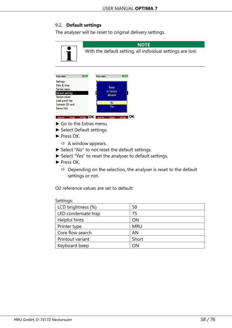
Default settings
The analyser will be reset to original delivery settings.
NOTE
With the default setting, all individual settings are lost.
► Go to the Extras menu.
► Select Default settings.
► Press OK.
A window appears.
► Select "No" to not reset the default settings.
► Select "Yes" to reset the analyser to default settings.
► Press OK.
Depending on the selection, the analyser is reset to the default
settings or not.
O2 reference values are set to default:
Settings:
LCD brightness (%) 50
LED condensate trap 75
Helpful hints ON
Printer type MRU
Core flow search AN
Printout variant Short
Keyboard beep ON
USER MANUAL OPTIMA 7
59 / 76 MRU GmbH, D-74172 Neckarsulm
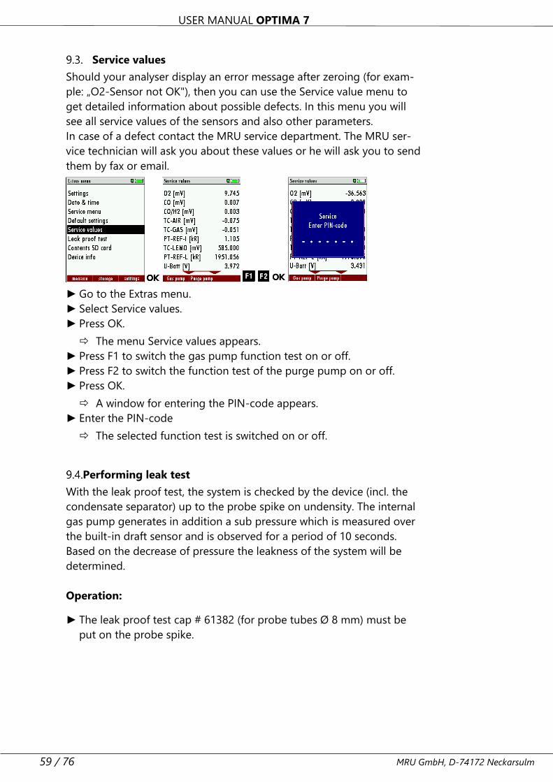
Service values
Should your analyser display an error message after zeroing (for exam-
ple: „O2-Sensor not OK"), then you can use the Service value menu to
get detailed information about possible defects. In this menu you will
see all service values of the sensors and also other parameters.
In case of a defect contact the MRU service department. The MRU ser-
vice technician will ask you about these values or he will ask you to send
them by fax or email.
► Go to the Extras menu.
► Select Service values.
► Press OK.
The menu Service values appears.
► Press F1 to switch the gas pump function test on or off.
► Press F2 to switch the function test of the purge pump on or off.
► Press OK.
A window for entering the PIN-code appears.
► Enter the PIN-code
The selected function test is switched on or off.
Performing leak test
With the leak proof test, the system is checked by the device (incl. the
condensate separator) up to the probe spike on undensity. The internal
gas pump generates in addition a sub pressure which is measured over
the built-in draft sensor and is observed for a period of 10 seconds.
Based on the decrease of pressure the leakness of the system will be
determined.
Operation:
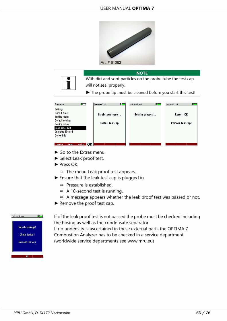
► The leak proof test cap # 61382 (for probe tubes Ø 8 mm) must be
put on the probe spike.
USER MANUAL OPTIMA 7
MRU GmbH, D-74172 Neckarsulm 60 / 76
NOTE
With dirt and soot particles on the probe tube the test cap
will not seal properly.
► The probe tip must be cleaned before you start this test!
► Go to the Extras menu.
► Select Leak proof test.
► Press OK.
The menu Leak proof test appears.
► Ensure that the leak test cap is plugged in.
Pressure is established.
A 10-second test is running.
A message appears whether the leak proof test was passed or not.
► Remove the proof test cap.
If of the leak proof test is not passed the probe must be checked including
the hosing as well as the condensate separator.
If no undensity is ascertained in these external parts the OPTIMA 7
Combustion Analyzer has to be checked in a service department
(worldwide service departments see www.mru.eu)
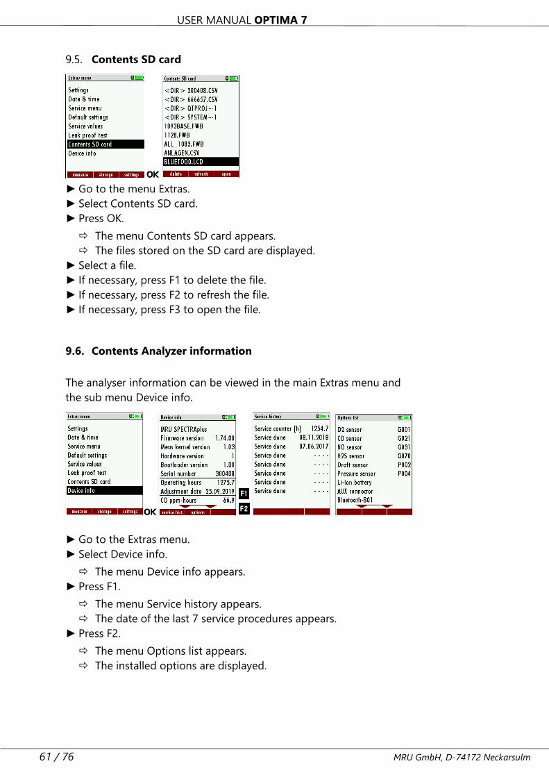
USER MANUAL OPTIMA 7
61 / 76 MRU GmbH, D-74172 Neckarsulm
Contents SD card
► Go to the menu Extras.
► Select Contents SD card.
► Press OK.
The menu Contents SD card appears.
The files stored on the SD card are displayed.
► Select a file.
► If necessary, press F1 to delete the file.
► If necessary, press F2 to refresh the file.
► If necessary, press F3 to open the file.
9.6. Contents Analyzer information
The analyser information can be viewed in the main Extras menu and
the sub menu Device info.
► Go to the Extras menu.
► Select Device info.
The menu Device info appears.
► Press F1.
The menu Service history appears.
The date of the last 7 service procedures appears.
► Press F2.
The menu Options list appears.
The installed options are displayed.

USER MANUAL OPTIMA 7
MRU GmbH, D-74172 Neckarsulm 62 / 76
10 Maintenance and care
The analyser requires very little maintenance to maintain its value over a
long period
• occasionally: cleaning the probe and the probe hose.
• after each measurement: Pull off the gas sampling hose on the ana-
lyser, so that the hose can dry.
• If not used for a longer period of time, charge the battery first.
• Charge the battery approximately every 4 weeks.
Maintenance
An annual inspection and, if necessary, calibration of the sensors by an
MRU service centre (www.mru.eu) is recommended to maintain their
value
NOTE
Please note that correct operation of the analyser is
only ensured if the sensors are adjusted regularly.
► Depending on the intensity of use, the sensors have
to be adjusted / calibrated 1-2 times a year.
Service messages
A message is displayed after 1,000 hours or 11 months.
If the analyser has the optional guarantee extension of 60 months this
will be shown in another window. Confirm these messages with F2= OK.
The next time you switch on, you will be reminded to carry out the an-
nual service.
A complete service at an MRU service centre (MRU service centres can
be found at www.mru.eu) includes the function check and calibration or
cleaning of the following components:
Sensors, pumps, internal / external hose lines, battery, draft, electronics,
time and date, temperature inputs, gas sampling probe, condensate
separator.
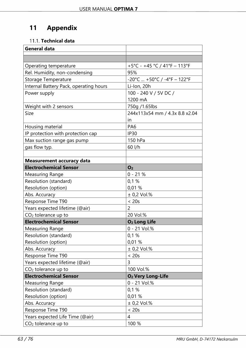
USER MANUAL OPTIMA 7
63 / 76 MRU GmbH, D-74172 Neckarsulm
11 Appendix
Technical data
General data
Operating temperature +5°C - +45 °C / 41°F – 113°F
Rel. Humidity, non-condensing 95%
Storage Temperature -20°C ... +50°C / -4°F – 122°F
Internal Battery Pack, operating hours Li-Ion, 20h
Power supply 100 - 240 V / 5V DC /
1200 mA
Weight with 2 sensors 750g /1.65lbs
Size 244x113x54 mm / 4.3x 8.8 x2.04
in
Housing material PA6
IP protection with protection cap IP30
Max suction range gas pump 150 hPa
gas flow typ. 60 l/h
Measurement accuracy data
Electrochemical Sensor O2
Measuring Range 0 - 21 %
Resolution (standard)
Resolution (option)
0,1 %
0,01 %
Abs. Accuracy ± 0,2 Vol.%
Response Time T90 < 20s
Years expected lifetime (@air) 2
CO2 tolerance up to 20 Vol.%
Electrochemical Sensor O2 Long Life
Measuring Range 0 - 21 Vol.%
Resolution (standard)
Resolution (option)
0,1 %
0,01 %
Abs. Accuracy ± 0,2 Vol.%
Response Time T90 < 20s
Years expected lifetime (@air) 3
CO2 tolerance up to 100 Vol.%
Electrochemical Sensor O2 Very Long-Life
Measuring Range 0 - 21 Vol.%
Resolution (standard)
Resolution (option)
0,1 %
0,01 %
Abs. Accuracy ± 0,2 Vol.%
Response Time T90 < 20s
Years expected Life Time (@air) 4
CO2 tolerance up to 100 %
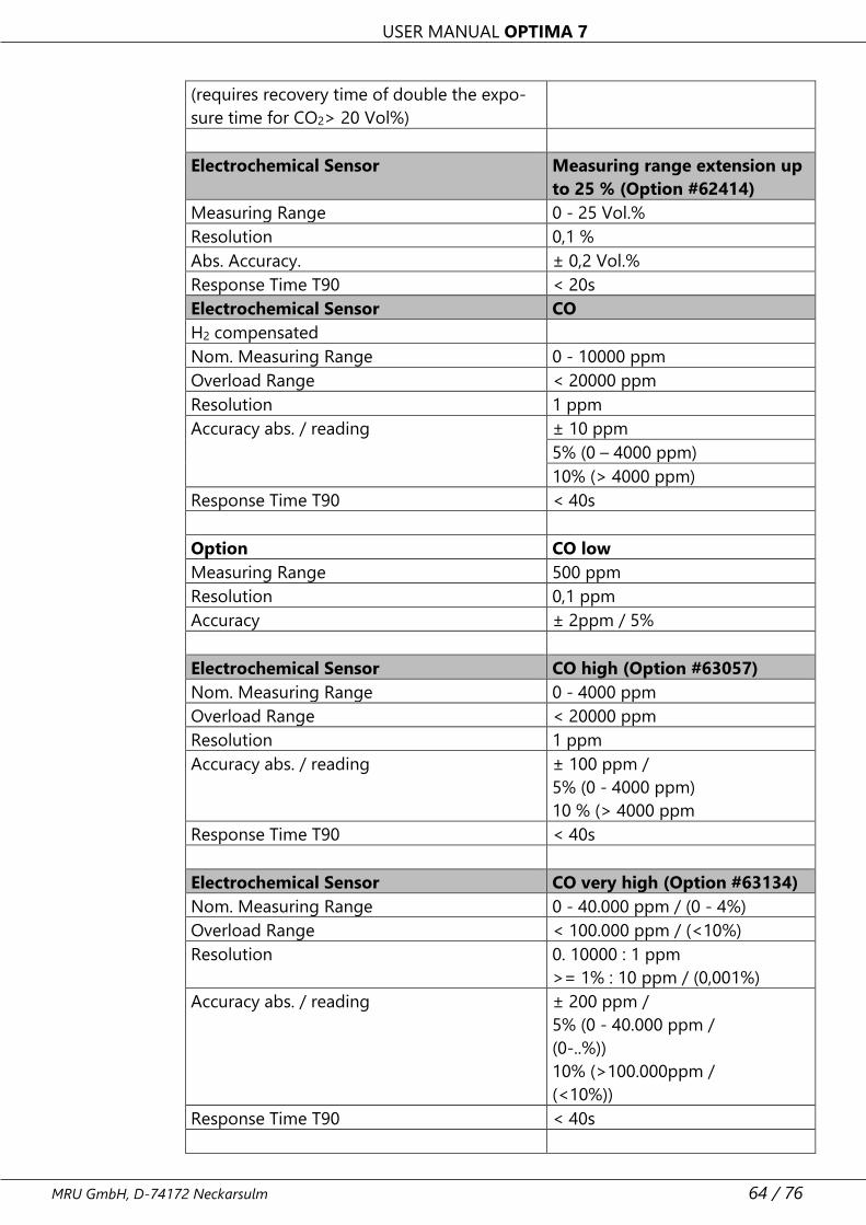
USER MANUAL OPTIMA 7
MRU GmbH, D-74172 Neckarsulm 64 / 76
(requires recovery time of double the expo-
sure time for CO2> 20 Vol%)
Electrochemical Sensor Measuring range extension up
to 25 % (Option #62414)
Measuring Range 0 - 25 Vol.%
Resolution 0,1 %
Abs. Accuracy. ± 0,2 Vol.%
Response Time T90 < 20s
Electrochemical Sensor CO
H2 compensated
Nom. Measuring Range 0 - 10000 ppm
Overload Range < 20000 ppm
Resolution 1 ppm
Accuracy abs. / reading ± 10 ppm
5% (0 – 4000 ppm)
10% (> 4000 ppm)
Response Time T90 < 40s
Option CO low
Measuring Range 500 ppm
Resolution 0,1 ppm
Accuracy ± 2ppm / 5%
Electrochemical Sensor CO high (Option #63057)
Nom. Measuring Range 0 - 4000 ppm
Overload Range < 20000 ppm
Resolution 1 ppm
Accuracy abs. / reading ± 100 ppm /
5% (0 - 4000 ppm)
10 % (> 4000 ppm
Response Time T90 < 40s
Electrochemical Sensor CO very high (Option #63134)
Nom. Measuring Range 0 - 40.000 ppm / (0 - 4%)
Overload Range < 100.000 ppm / (<10%)
Resolution 0. 10000 : 1 ppm
>= 1% : 10 ppm / (0,001%)
Accuracy abs. / reading ± 200 ppm /
5% (0 - 40.000 ppm /
(0-..%))
10% (>100.000ppm /
(<10%))
Response Time T90 < 40s
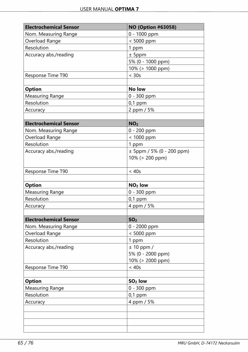
USER MANUAL OPTIMA 7
65 / 76 MRU GmbH, D-74172 Neckarsulm
Electrochemical Sensor NO (Option #63058)
Nom. Measuring Range 0 - 1000 ppm
Overload Range < 5000 ppm
Resolution 1 ppm
Accuracy abs./reading ± 5ppm
5% (0 - 1000 ppm)
10% (> 1000 ppm)
Response Time T90 < 30s
Option No low
Measuring Range 0 - 300 ppm
Resolution 0,1 ppm
Accuracy 2 ppm / 5%
Electrochemical Sensor NO2
Nom. Measuring Range 0 - 200 ppm
Overload Range < 1000 ppm
Resolution 1 ppm
Accuracy abs./reading ± 5ppm / 5% (0 - 200 ppm)
10% (> 200 ppm)
Response Time T90 < 40s
Option NO2 low
Measuring Range 0 - 300 ppm
Resolution 0,1 ppm
Accuracy 4 ppm / 5%
Electrochemical Sensor SO2
Nom. Measuring Range 0 - 2000 ppm
Overload Range < 5000 ppm
Resolution 1 ppm
Accuracy abs./reading ± 10 ppm /
5% (0 - 2000 ppm)
10% (> 2000 ppm)
Response Time T90 < 40s
Option SO2 low
Measuring Range 0 - 300 ppm
Resolution 0,1 ppm
Accuracy 4 ppm / 5%
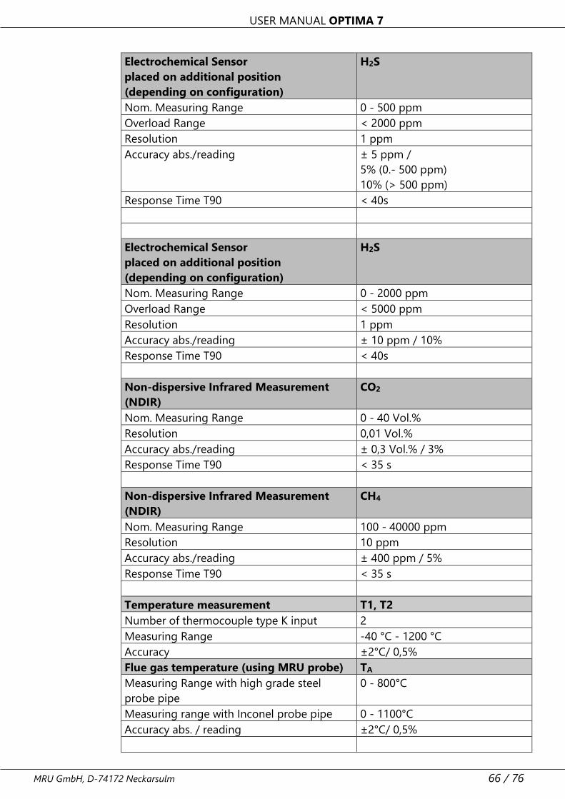
USER MANUAL OPTIMA 7
MRU GmbH, D-74172 Neckarsulm 66 / 76
Electrochemical Sensor
placed on additional position
(depending on configuration)
H2S
Nom. Measuring Range 0 - 500 ppm
Overload Range < 2000 ppm
Resolution 1 ppm
Accuracy abs./reading ± 5 ppm /
5% (0.- 500 ppm)
10% (> 500 ppm)
Response Time T90 < 40s
Electrochemical Sensor
placed on additional position
(depending on configuration)
H2S
Nom. Measuring Range 0 - 2000 ppm
Overload Range < 5000 ppm
Resolution 1 ppm
Accuracy abs./reading ± 10 ppm / 10%
Response Time T90 < 40s
Non-dispersive Infrared Measurement
(NDIR)
CO2
Nom. Measuring Range 0 - 40 Vol.%
Resolution 0,01 Vol.%
Accuracy abs./reading ± 0,3 Vol.% / 3%
Response Time T90 < 35 s
Non-dispersive Infrared Measurement
(NDIR)
CH4
Nom. Measuring Range 100 - 40000 ppm
Resolution 10 ppm
Accuracy abs./reading ± 400 ppm / 5%
Response Time T90 < 35 s
Temperature measurement T1, T2
Number of thermocouple type K input 2
Measuring Range -40 °C - 1200 °C
Accuracy ±2°C/ 0,5%
Flue gas temperature (using MRU probe) TA
Measuring Range with high grade steel
probe pipe
0 - 800°C
Measuring range with Inconel probe pipe 0 - 1100°C
Accuracy abs. / reading ±2°C/ 0,5%
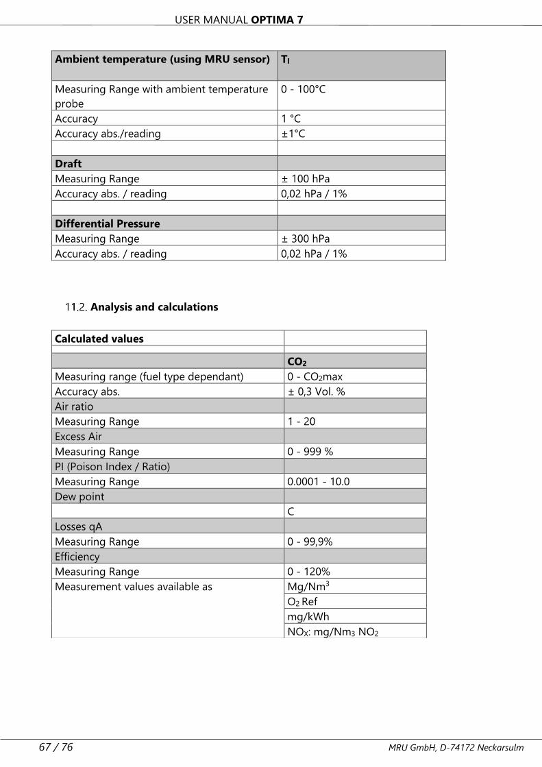
USER MANUAL OPTIMA 7
67 / 76 MRU GmbH, D-74172 Neckarsulm
Ambient temperature (using MRU sensor) Tl
Measuring Range with ambient temperature
probe
0 - 100°C
Accuracy 1 °C
Accuracy abs./reading ±1°C
Draft
Measuring Range ± 100 hPa
Accuracy abs. / reading 0,02 hPa / 1%
Differential Pressure
Measuring Range ± 300 hPa
Accuracy abs. / reading 0,02 hPa / 1%
Analysis and calculations
Calculated values
CO2
Measuring range (fuel type dependant) 0 - CO2max
Accuracy abs. ± 0,3 Vol. %
Air ratio
Measuring Range 1 - 20
Excess Air
Measuring Range 0 - 999 %
PI (Poison Index / Ratio)
Measuring Range 0.0001 - 10.0
Dew point
C
Losses qA
Measuring Range 0 - 99,9%
Efficiency
Measuring Range 0 - 120%
Measurement values available as Mg/Nm3
O2 Ref
mg/kWh
NOX: mg/Nm3 NO2
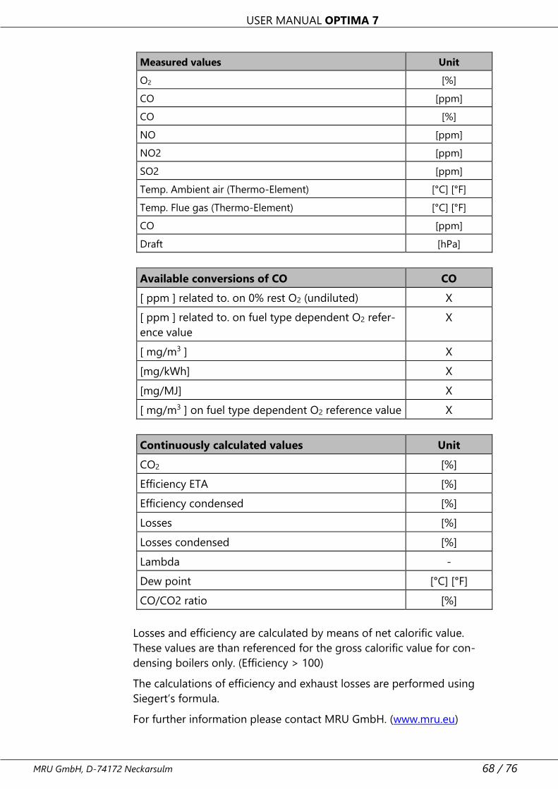
USER MANUAL OPTIMA 7
MRU GmbH, D-74172 Neckarsulm 68 / 76
Measured values Unit
O2 [%]
CO [ppm]
CO [%]
NO [ppm]
NO2 [ppm]
SO2 [ppm]
Temp. Ambient air (Thermo-Element) [°C] [°F]
Temp. Flue gas (Thermo-Element) [°C] [°F]
CO [ppm]
Draft [hPa]
Available conversions of CO CO
[ ppm ] related to. on 0% rest O2 (undiluted) X
[ ppm ] related to. on fuel type dependent O2 refer-
ence value
X
[ mg/m3 ] X
[mg/kWh] X
[mg/MJ] X
[ mg/m3 ] on fuel type dependent O2 reference value X
Continuously calculated values Unit
CO2 [%]
Efficiency ETA [%]
Efficiency condensed [%]
Losses [%]
Losses condensed [%]
Lambda -
Dew point [°C] [°F]
CO/CO2 ratio [%]
Losses and efficiency are calculated by means of net calorific value.
These values are than referenced for the gross calorific value for con-
densing boilers only. (Efficiency > 100)
The calculations of efficiency and exhaust losses are performed using
Siegert’s formula.
For further information please contact MRU GmbH. (www.mru.eu)
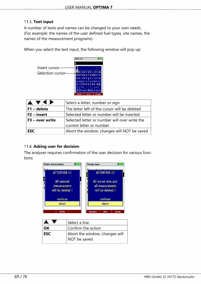
USER MANUAL OPTIMA 7
69 / 76 MRU GmbH, D-74172 Neckarsulm
Text input
A number of texts and names can be changed to your own needs.
(For example: the names of the user defined fuel types, site names, the
names of the measurement programs)
When you select the text input, the following window will pop up:
Asking user for decision
The analyser requires confirmation of the user decision for various func-
tions
, , , Select a letter, number or sign
F1 – delete The letter left of the cursor will be deleted
F2 – insert Selected letter or number will be inserted
F3 – over write Selected letter or number will over write the
current letter or number
ESC Abort the window, changes will NOT be saved
, Select a line
OK Confirm the action
ESC Abort the window, changes will
NOT be saved
Insert cursor
Selection cursor
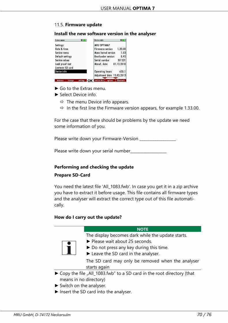
USER MANUAL OPTIMA 7
MRU GmbH, D-74172 Neckarsulm 70 / 76
Firmware update
Install the new software version in the analyser
► Go to the Extras menu.
► Select Device info.
The menu Device info appears.
In the first line the Firmware version appears, for example 1.33.00.
For the case that there should be problems by the update we need
some information of you.
Please write down your Firmware-Version ___________________
Please write down your serial number___________________
Performing and checking the update
Prepare SD-Card
You need the latest file 'All_1083.fwb'. In case you get it in a zip archive
you have to extract it before usage. This file contains all firmware types
and the analyser will extract the correct type out of this file automati-
cally.
How do I carry out the update?
NOTE
The display becomes dark while the update starts.
► Please wait about 25 seconds.
► Do not press any key during this time.
► Leave the SD card in the analyser.
The SD card may only be removed when the analyser
starts again
► Copy the file „All_1083.fwb” to a SD card in the root directory (that
means in no directory)
► Switch on the analyser.
► Insert the SD card into the analyser.
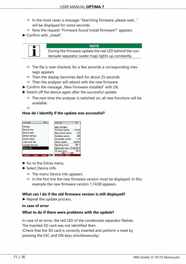
USER MANUAL OPTIMA 7
71 / 76 MRU GmbH, D-74172 Neckarsulm
In the most cases a message “Searching firmware, please wait…”
will be displayed for some seconds.
Now the request "Firmware found Install firmware?" appears.
► Confirm with „install“.
NOTE
During the firmware update the red LED behind the con-
densate separator (water trap) lights up constantly.
The file is now checked, for a few seconds a corresponding mes-
sage appears
Then the display becomes dark for about 25 seconds
Then the analyser will reboot with the new firmware
► Confirm the message „New Firmware installed” with OK.
► Switch off the device again after the successful update.
The next time the analyser is switched on, all new functions will be
available.
How do I identify if the update was successful?
► Go to the Extras menu.
► Select Device info.
The menu Device info appears.
In the first line the new firmware version must be displayed. In this
example the new firmware version 1.74.00 appears.
What can I do if the old firmware version is still displayed?
► Repeat the update process.
In case of error
What to do if there were problems with the update?
In case of an error, the red LED of the condensate separator flashes.
The inserted SD card was not identified then.
(Check that the SD card is correctly inserted and perform a reset by
pressing the ESC and ON keys simultaneously).
USER MANUAL OPTIMA 7
MRU GmbH, D-74172 Neckarsulm 72 / 76
Where can I get help if the update was not successful?
Please contact your responsible sales representative or via email:
11.6. Using the USB Port
This port is used for data transfer from your analyser to your PC / Lap-
top using the MRU Online View (Version 2.XX). The first time you want
to use your analyser for data transfer to your PC or laptop, you have to
“mate” the OPTIMA 7 and your PC / Laptop.
Your PC / Laptop will recognize the OPTIMA 7 as USB- HID (Human In-
terface Device).
Check list:
1. Switch on the OPTIMA 7
2. Connect the USB cable to the OPTIMA 7
3. Connect the USB cable into a free USB port at your PC/Laptop
4. The PC/Laptop must be powered on
5. The above seen information „New hardware found“ will be dis-
played above the USB-Icon of your PC/Laptop
Troubleshooting
Troubleshooting the analyser
1. Effect 2. Error indication 3. Cause 4. Solution
Device cannot be
switched off by
pressing the OFF
key.
LED behind the con-
densate separator is
on and the LCD dis-
play is dark
Device does
not react on
any key.
Press ESC and ON
simultaneously!
EMERGENCY OFF
After this, the date
and time have to
set new.
Inside of the de-
vice is too cold,
device not ready
for operation.
Display indication:
“Device too cold” or
audible sound every
5 sec..
e.g. device
was stored in
a cold place
during winter.
Put the device to a
warm room and
wait
Measuring values
are not correct
Sensors al-
ready get in
touch with the
gas during
calibration.
Vent device with
fresh air and re-
start!
USER MANUAL OPTIMA 7
73 / 76 MRU GmbH, D-74172 Neckarsulm
No measurement
possible
Device cannot
be switched
on or does
not react after
being
switched on.
Battery dis-
charge
Connect the device
to the line power in
order to charge the
battery.
Measurement
without exact
temperature val-
ues.
Temperature indica-
tion:
- - - , - °C
Thermoele-
ment defec-
tive, balancing
network inter-
rupted or not
connected.
Call our after-sales
service.
Remove probe from
the gas duct and
condensate from
the probe tube.
Wrong measuring
values
Measuring range ex-
ceeded:
Value O2 too high
Values CO and CO2
to low
Connection
probe – device
not correct.
Leakage at
probe / tube /
condensate
separator,
pump does
not suck cor-
rectly
Effect tightness
test!
By visual control of
probes, tubes con-
densate separator,
leaking parts could
be found.
Wrong measuring
values
Gas temperature is
too hot or alternates
Probe is not
plugged in
correctly, de-
fective cable
in the probe
line, formation
of condensate
at the probe
tip.
Check probe plug
respectively probe
line regarding dam-
ages (loose connec-
tion), remove con-
densate from the
probe tip.
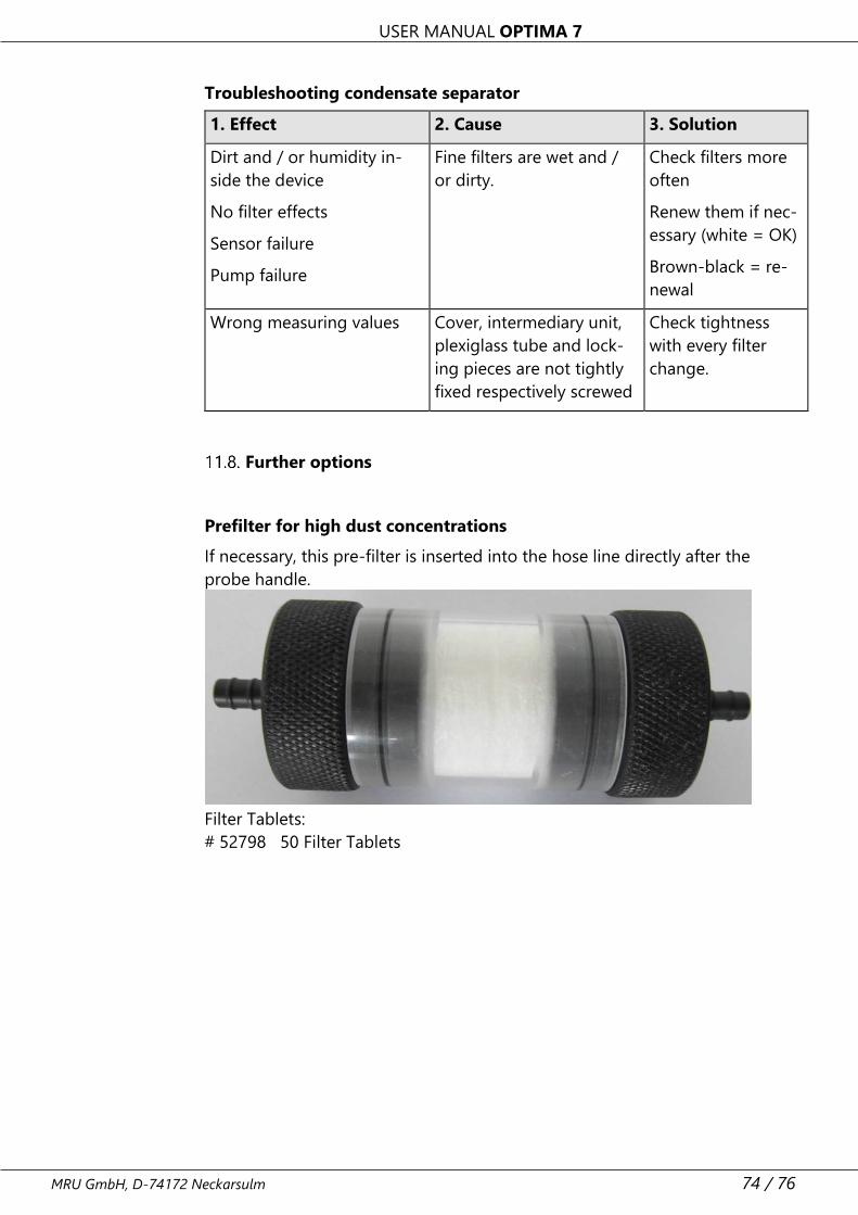
USER MANUAL OPTIMA 7
MRU GmbH, D-74172 Neckarsulm 74 / 76
Troubleshooting condensate separator
1. Effect 2. Cause 3. Solution
Dirt and / or humidity in-
side the device
No filter effects
Sensor failure
Pump failure
Fine filters are wet and /
or dirty.
Check filters more
often
Renew them if nec-
essary (white = OK)
Brown-black = re-
newal
Wrong measuring values Cover, intermediary unit,
plexiglass tube and lock-
ing pieces are not tightly
fixed respectively screwed
Check tightness
with every filter
change.
Further options
Prefilter for high dust concentrations
If necessary, this pre-filter is inserted into the hose line directly after the
probe handle.
Filter Tablets:
# 52798 50 Filter Tablets
USER MANUAL OPTIMA 7
75 / 76 MRU GmbH, D-74172 Neckarsulm
12 Declaration of conformity
USER MANUAL OPTIMA 7
MRU GmbH, D-74172 Neckarsulm 76 / 76