User Manual Interroll Drum motor - Ultimation
112
INSPIRED BY EFFICIENCY User Manual Interroll Drum motor i-Series S-Series S/A-Series D-Series Version 6.0 (07/2017) en Translation of original instruction manual
Transcript of User Manual Interroll Drum motor - Ultimation

INSPIRED BY EFFICIENCY
User Manual
Interroll Drum motori-SeriesS-SeriesS/A-SeriesD-Series
Version 6.0 (07/2017) enTranslation of original instruction manual

Manufacturer
Interroll Trommelmotoren GmbHOpelstr. 3 41836 Hueckelhoven/Baal Germany Phone: +49 2433 44 610
www.interroll.com
Contents
We strive for the information presented to be correct, up to date and complete. We havecarefully worked out the contents of this document. However, we assume no liability forthe information. We expressly deny any liability for damages or consequential damagesthat are connected in any form with the use of this document. We reserve the right tochange the documented products and product information at any time.
Copyright / intellectual property right
Texts, images, graphics and the like as well as their arrangement are protected bycopyright and other protection laws. Reproduction, modification, transfer or publicationof any part or the entire content of the document in any form is prohibited. Thisdocument is intended exclusively for information purposes and for intended use and doesnot authorize replicating the respective products. All signs contained in this document(registered trademarks, such as logos and business designations) are the property ofInterroll Trommelmotoren GmbH or third parties and may not be used, copied ordistributed without prior written consent.
Version 6.0 (07/2017) enTranslation of original instruction manual

Interroll Drum motor series i, S, S/A, D
Version 6.0 (07/2017) enTranslation of original instruction manual
3
Table of ContentsIntroduction............................................................................................................................ 7
Information about the manual .............................................................................................................. 7Contents............................................................................................................................................... 7The instructions are part of the product ..................................................................................... 7
Warning notices in this document........................................................................................................ 7Symbols....................................................................................................................................................... 8
Safety ..................................................................................................................................... 9State of the art.......................................................................................................................................... 9Intended use .............................................................................................................................................. 9Unintended use ......................................................................................................................................... 9Personnel qualification ............................................................................................................................ 10
Operators ........................................................................................................................................... 10Service personnel.............................................................................................................................. 10Electricians........................................................................................................................................... 10
Dangers....................................................................................................................................................... 10Bodily injury ........................................................................................................................................ 10Electricity.............................................................................................................................................. 10Oil.......................................................................................................................................................... 10Rotating parts..................................................................................................................................... 10Hot motor parts ................................................................................................................................. 11Working environment ...................................................................................................................... 11Faults during operation ................................................................................................................... 11Maintenance....................................................................................................................................... 11Accidental motor start ..................................................................................................................... 11
Interfaces to other devices..................................................................................................................... 11
General technical information............................................................................................. 12Product description .................................................................................................................................. 12
Options ................................................................................................................................................ 12Technical data ........................................................................................................................................... 13Product identification............................................................................................................................... 13Thermal protection................................................................................................................................... 14
Standard design: Temperature limiter, automatically switching back................................. 15Optional version: PTC (positive temperature coefficient) ....................................................... 15
Use of 50-Hz motors on 60-Hz supply system................................................................................. 16Effect of using a motor with 50 Hz on a 60-Hz supply system............................................ 16Effect of using a motor with 50-Hz on a 60-Hz supply system with 15/20 % highervoltage ................................................................................................................................................. 17
i-series product information................................................................................................. 18Type plate of i-series drum motor ....................................................................................................... 18Electrical data of i-series ........................................................................................................................ 20
80i 3-phase......................................................................................................................................... 20113i 3-phase ...................................................................................................................................... 21138i 3-phase ...................................................................................................................................... 23

Interroll Drum motor series i, S, S/A, D
Table of Contents
4 Version 6.0 (07/2017) enTranslation of original instruction manual
165i and 217i* 3-phase ................................................................................................................. 25217i 3-phase ...................................................................................................................................... 27
Dimensions of i-series drum motor ...................................................................................................... 29Connection diagrams for the i-series .................................................................................................. 30
Cable connections............................................................................................................................. 30Connections in the terminal box ................................................................................................... 33
S-series product information ............................................................................................... 38Type plate of S-series drum motor ..................................................................................................... 38Electrical data of S-series....................................................................................................................... 40
80S 1-phase ....................................................................................................................................... 4080S 3-phase ....................................................................................................................................... 40113S 1-phase .................................................................................................................................... 41113S 3-phase .................................................................................................................................... 41
Dimensions of S-series drum motor..................................................................................................... 43Connection diagrams for the S-series ................................................................................................ 45
Cable connections............................................................................................................................. 45Connections in the terminal box ................................................................................................... 47
S/A-series product information ........................................................................................... 48Type plate of S/A-series drum motor ................................................................................................. 48Electrical data of S/A-series .................................................................................................................. 49
113S/A 1-phase ................................................................................................................................ 49113S/A 3-phase ................................................................................................................................ 49
Dimensions of S/A-series drum motor ................................................................................................ 50Connection diagrams for the S/A-series ........................................................................................... 51
Cable connections............................................................................................................................. 51Connections in the terminal box .................................................................................................. 53
D-series product information............................................................................................... 54Type plate of D-series drum motor ..................................................................................................... 54Electrical data of D-series ...................................................................................................................... 55Dimensions of D-series drum motor .................................................................................................... 57Connection diagrams for the D-series................................................................................................ 57
Cable connections............................................................................................................................. 58Encoder connection .......................................................................................................................... 58
Options and accessories ...................................................................................................... 60Electromagnetic brake for the i-series ................................................................................................ 60Brake rectifiers for i-series ..................................................................................................................... 62
Brake rectifier connections.............................................................................................................. 62Brake rectifier dimensions ............................................................................................................... 64
Asynchronous drum motors with frequency inverters .................................................................... 66Torque dependent on input frequency........................................................................................ 66Frequency inverter parameters..................................................................................................... 66
Encoder type BMB-6202 & 6205 SKF for the i-series................................................................... 68Technical data .................................................................................................................................... 68Connections ........................................................................................................................................ 69Best connection option..................................................................................................................... 70

Interroll Drum motor series i, S, S/A, D
Table of Contents
Version 6.0 (07/2017) enTranslation of original instruction manual
5
Encoder type RM44-RLS for the i and D-series ............................................................................... 71Technical data .................................................................................................................................... 71Connections ........................................................................................................................................ 72Signal connection .............................................................................................................................. 72
Resolver type RE-15-1-LTN.................................................................................................................... 73Connections ........................................................................................................................................ 73Technical data .................................................................................................................................... 73Impedance........................................................................................................................................... 74
Transport and storage .......................................................................................................... 75Transport..................................................................................................................................................... 75Storage ....................................................................................................................................................... 75
Assembly and installation ................................................................................................... 77Warning notices concerning the installation ..................................................................................... 77Installing the drum motor ....................................................................................................................... 77
Positioning the drum motor............................................................................................................. 77Installing the motor with mounting brackets .............................................................................. 78Installation considering hygienic aspects .................................................................................... 80
Belt assembly ............................................................................................................................................. 80Belt width / tube length................................................................................................................... 80Belt adjustment................................................................................................................................... 80Tensioning the belt ............................................................................................................................ 81
Belt tension ................................................................................................................................................. 82Belt elongation ................................................................................................................................... 82Measuring the belt elongation ...................................................................................................... 83Calculating the belt elongation ..................................................................................................... 83
Drum coating............................................................................................................................................. 84Sprockets .................................................................................................................................................... 84Warning notices concerning the electrical installation ................................................................... 85Electrical connection of the drum motor ............................................................................................ 85
Connecting the drum motor – with a cable............................................................................... 85Connecting the drum motor – with a terminal box ................................................................. 85Single-phase motor .......................................................................................................................... 86External motor protection............................................................................................................... 86Integrated thermal protection ....................................................................................................... 86Frequency inverter ............................................................................................................................ 86Backstop............................................................................................................................................... 87Electromagnetic brake ..................................................................................................................... 87
Initial startup and operation................................................................................................ 89Initial startup .............................................................................................................................................. 89
Checks before the initial startup ................................................................................................... 89Operation................................................................................................................................................... 90
Checks before every startup.......................................................................................................... 90Procedure in case of accident or fault................................................................................................ 90
Maintenance and cleaning.................................................................................................. 91Warning notices concerning maintenance and cleaning............................................................... 91

Interroll Drum motor series i, S, S/A, D
Table of Contents
6 Version 6.0 (07/2017) enTranslation of original instruction manual
Preparation for maintenance and cleaning by hand ..................................................................... 91Maintenance.............................................................................................................................................. 91
Checking the drum motor ............................................................................................................... 91Relubricating the drum motor ........................................................................................................ 91Maintaining drum motors with optional, relubricating IP66 seals ....................................... 91
Oil change at drum motor..................................................................................................................... 92Oil types .............................................................................................................................................. 93Oil quantities for the i-series in liters (standard installation) ................................................. 94Oil quantities for the i-series (vertical installation) ................................................................... 95
Cleaning...................................................................................................................................................... 95Cleaning the drum motor with pressure washer ...................................................................... 95Hygienic cleaning .............................................................................................................................. 96
Troubleshooting..................................................................................................................... 97Troubleshooting......................................................................................................................................... 97
Decommissioning and disposal .......................................................................................... 107Shutdown.................................................................................................................................................... 107Disposal....................................................................................................................................................... 107
Appendix ............................................................................................................................... 108List of abbreviations ................................................................................................................................ 108
Electrical data..................................................................................................................................... 108Connection diagrams....................................................................................................................... 109Color coding....................................................................................................................................... 110
Installation declaration............................................................................................................................ 111

Interroll Drum motor series i, S, S/A, D
Version 6.0 (07/2017) enTranslation of original instruction manual
7
Introduction
Information about the manualThe following drum motor types are described in this instruction manual:
• 80S, 113S• 113S/A• 80i, 113i, 138i, 165i, 217i• 80D, 113D
Contents This instruction manual contains important notes and information about the various operatingphases of the drum motor:
The instruction manual describes the drum motor as it is delivered by Interroll.
In addition to this instruction manual, special contractual agreements and technical documentsapply to special versions.
The instructions are part ofthe product
4 For trouble-free, safe operation and warranty claims, read the instructions first and followthe notices.
4 Keep the instructions close to the drum motor.4 Pass the instructions on to any subsequent operator or owner.4 NOTICE! The manufacturer does not accept any liability for faults or defects due to
non-observance of these instructions.4 If you still have questions after reading the instructions, please contact Interroll customer
service. Contact persons near you can be found on the Internet under www.interroll.com/contact.
Warning notices in this documentThe warning notices refer to risks which may arise while using the drum motor. They areavailable at four danger levels with the following signal words:
Signal word Meaning
DANGER Identifies a danger with high risk that leads to death or serious injury if it isnot avoided.
WARNING Identifies a danger with medium risk that can lead to death or serious injuryif it is not avoided.
CAUTION Identifies a danger with low risk that can lead to minor or medium injury if itis not avoided.
NOTICE Identifies a danger that leads to property damages.

Interroll Drum motor series i, S, S/A, D
Introduction
8 Version 6.0 (07/2017) enTranslation of original instruction manual
Symbols
This symbol marks useful and important information.
Requirement:R This symbol represents a prerequisite to be met prior to assembly and maintenance work.
4 This symbol marks the steps to be carried out.

Interroll Drum motor series i, S, S/A, D
Version 6.0 (07/2017) enTranslation of original instruction manual
9
Safety
State of the artThe conveyor is designed according to the state of the art and is reliable in operation, oncedistributed. However, risks may still arise.
Disregarding the notices in this manual may lead to serious injury.4Carefully read the manual and follow its content.
Intended useThe drum motor is intended for use in industrial environments, supermarkets and airports and isused for transporting general cargo, such as parts, cardboard boxes or boxes, as well astransporting bulk material such as granular material, powder and other fluid materials. The drummotor must be integrated into a conveyor module or conveyor system. Any other use isconsidered inappropriate.
Use of the drum motor is only allowed in the areas described in the product information chapter.
Any modifications that affect the safety of the product are not permitted.
The drum motor may only be operated within the defined operating limits.
Unintended useThe drum motor must not be used for transporting people.
The drum motor is not intended for use under impact or shock loads.
The drum motor is not designed to be used under water. Such a use leads to personal or fatalinjuries from electrocution as well as the penetration of water, resulting in a short circuit or motordamage.
The drum motor may not be used as a drive for cranes or lifting devices or for thecorresponding hoist ropes, cables or chains.
Use of the drum motor for anything other than the intended purpose is subject to approval byInterroll.
Unless otherwise stated in writing and/or specified in a quote, Interroll and its dealers shallassume no liability for product damage or failure which result from failure to observe thesespecification and restrictions (see the chapter "Electrical data" of the respective series).

Interroll Drum motor series i, S, S/A, D
Safety
10 Version 6.0 (07/2017) enTranslation of original instruction manual
Personnel qualificationUnqualified personnel cannot recognize risks and, as a result, is subject to greater dangers.
4 Authorize only qualified personnel with the activities described in these installation andoperating instructions.
4 The operating company must ensure that the personnel follows locally applicable regulationsand rules during their work with regard to safety and dangers.
The following target groups are addressed in these installation and operating instructions:
Operators Operators have been instructed in operating and cleaning the drum motor and follow the safetyguidelines.
Service personnel The service personnel features a technical training or has undergone training by themanufacturer and performs the maintenance and repair tasks.
Electricians Persons working on electrical installations must have the pertinent technical training.
Dangers
The following list informs you about the various types of danger or damage that may occurwhile working with the drum motor.
Bodily injury 4 Maintenance or repair work must only be executed by authorized and qualified persons inaccordance with the applicable regulations.
4 Before turning on the drum motor, ensure that no unauthorized persons are near theconveyor.
Electricity 4 Only perform installation and maintenance work after you have switched off the power.Ensure that the drum motor cannot be turned on accidentally.
Oil 4 Do not ingest the oil. In general, the oil used is relatively non-toxic, but it can still containhazardous substances. Ingestion can lead to nausea, vomiting and/or diarrhea. Generally,medical care is not required, unless large quantities have been ingested. Nevertheless, aphysician should be consulted.
4 Avoid skin and eye contact. Prolonged or repeated skin contact without proper cleaning canclog the pores of the skin and lead to skin problems such as oil acne and folliculitis.
4 Wipe up spilled oil as quickly as possible to avoid slippery surfaces. Ensure that oil does notreach the environment. Properly dispose of dirty rags or cleaning materials to avoid self-ignition and fires.
4 Extinguish oil fires with foam, spraying water or water mist, dry chemical powder or carbondioxide. Do not extinguish with water jet. Wear suitable protective clothing, incl. breathingmask.
4 Observe the corresponding certificates at www.interroll.com.
Rotating parts 4 Do not reach into areas between drum motor and conveyor belts or roller chains.4 Tie long hair together.4 Never wear loose clothing.

Interroll Drum motor series i, S, S/A, D
Safety
Version 6.0 (07/2017) enTranslation of original instruction manual
11
4 Never wear jewelery, such as necklaces or bracelets.
Hot motor parts 4 Do not touch the surface of the drum motor. It can result in burns, even under regularoperating temperature.
4 Install corresponding warnings on the conveyor.
Working environment 4 Do not use the drum motor in explosive atmospheres.4 Remove equipment or material which is not required from the workspace.4 Wear safety shoes.4 Clearly specify and monitor the way materials are placed on the conveyor.
Faults during operation 4 Regularly check the drum motor for visible damage.4 In case of fumes, unusual noise or blocked or damaged materials, stop the drum motor at
once and ensure that the RollerDrive cannot be started accidentally.4 Contact qualified personnel immediately to find the source of the fault.4 During operation, do not step on the drum motor or the conveyor/the system in which it is
installed.
Maintenance 4 Check the product regularly for visible damages, unusual noise and firm seating of fittings,screws and nuts. An additional maintenance is not required.
4 Do not open the drum motor.
Accidental motor start 4 Take care during installation and maintenance work or in the event of a drum motor fault:The drum motor could start up unintentionally.
Interfaces to other devicesHazards may occur while integrating the drum motor into a complete system. These are not partof this manual and have to be analyzed during the design, installation and startup of thecomplete system.
4 After assembling the drum motor in a conveyor module, check the whole system for a newpotential dangerous spot before switching on the conveyor.
4 Additional constructive measures may be required.

Interroll Drum motor series i, S, S/A, D
12 Version 6.0 (07/2017) enTranslation of original instruction manual
General technical information
Product descriptionThe drum motor is a completely enclosed electrical drive roller. It replaces external componentssuch as motors and gears, which require frequent maintenance.
The drum motor can be used in environments with high coarse and fine dust exposure as well asexposed to water jets and spraying water and is resistant to most of the aggressive ambientconditions. In aggressive environments and environments with salt water, only stainless steelmotors should be used. Thanks to protection classification IP66 or IP69k and its stainless steeldesign (upon request), the drum motor is also suitable for use in the food processing industry andpharmaceutical industry as well as for applications with high hygienic demands. The drum motorcan be used without as well as with a drum coating to increase the friction between drum motorand conveyor belt or with profile coating for the drive of form-fit driven belts.
The drum motors of series S, S/A and i are driven by an asynchronous three-phase inductionmotor. It is available in different power stages and for most of the international supply voltages.
The drum motors of the D-series are driven by a synchronous motor and must be connected to asuitable drive control unit. For additional information about the drive control unit, see therespective manual.
The drum motor contains oil as lubricant and coolant which dissipates the heat via the drum andthe conveyor belt.
If an asynchronous drum motor without belt or with a form-fit driven belt is used, a specialdesign is available to ensure cooling.
Options Integrated thermal overload protection: A thermal cut motor protection switch integrated inthe winding head protects against overheating. The switch trips if the motor overheats. However,it has to be connected to a suitable external control device that interrupts the current supply tothe motor in case of overheating (see "Thermal protection", page 14).
Integrated electromagnetic brake: The integrated electromagnetic brake can hold loads. Itacts directly on the rotor shaft of the drum motor and is controlled by a rectifier. The holdingforce of each drum motor with brake has to be calculated first and does not always correspondto the belt pull of the motor. The electromagnetic brake is available for all drum motors of the i-series (see "Electromagnetic brake for the i-series", page 60).
Mechanical backstop: The mechanical backstop attached to the rotor shaft and, for 80i, in thecover, can be used for ascending conveyors. It prevents the belt from running in reverse directionin case of a power failure. The mechanical backstop is available for all drum motors, except113s and the D-series.
Encoder: The signal of the encoder can be used for position determination and for controllingthe speed and rotational direction (see "Options and accessories", page 60).

Interroll Drum motor series i, S, S/A, D
General technical information
Version 6.0 (07/2017) enTranslation of original instruction manual
13
Technical data
Protection class IP65 (S/A-series)IP66 (i and S-series)IP69k (D-series)
Ambient temperature range forstandard applications 1)
+5 °C to +40 °C
Ambient temperature range for low-temperature applications 1)
-25 °C to +15 °C
Ambient temperature range forreduced drum motors 1)
+5 °C to +25 °C
Cycle times max. 3 starts/stops per minute 2)
Ramp times i-series: ≥ 0.5 sS-series: ≥ 1 sD-series: ≤ 0.5 s
Installation altitude above sea level max. 1000 m
1) Depending on the ambient temperature, different types of oil are required (see "Oil types",page 93). For ambient temperatures below +1 °C, Interroll recommends a standstill heater andspecial cables.2) For start/stop applications, the motor shifts have to be designed completely backlash-free. Ifthis requirement is met, higher cycle times with more than 3 starts/stops per minute are possible.Interroll strongly recommends using frequency inverters (FI) with set run-up or run-down rampsor special designs. This is used to reduce the starting torques, e.g. to prevent gear box damage.If you have questions, please contact Interroll.
Product identificationThe information given below is required in order to identify a drum motor. The values for aspecific drum motor can be entered in the last column.
Information Possible value Own value
Type plate of drummotor
Motor typeSpeed in m/sSerial numberTube length in mmNumber of polesPower in kW
Drum diameter (tube diameter)
e.g.112.3 mm drum ends113.3 mm drum center
Cover material e.g. rubber, thickness, profile

Interroll Drum motor series i, S, S/A, D
General technical information
14 Version 6.0 (07/2017) enTranslation of original instruction manual
Thermal protectionUnder normal operating conditions, the thermal circuit breaker integrated in the stator winding isclosed. When the motor limit temperature is reached (overheating), the switch opens at a presettemperature to prevent damage to the motor.
WARNINGThe thermal circuit breaker is automatically reset after the motor has cooled off.
Inadvertent start-up of the motor
4 Connect the thermal circuit breaker in series with a suitable relay or contactor so that thecurrent supply to the motor is safely interrupted when the switch trips.
4 Ensure that the motor can be switched on again after overheating only with a confirmationbutton.
4 After the switch has tripped, wait until the motor has cooled off, and ensure prior to switch-on that there is no danger to persons.

Interroll Drum motor series i, S, S/A, D
General technical information
Version 6.0 (07/2017) enTranslation of original instruction manual
15
Standard design:Temperature limiter,
automatically switchingback
Service life: 10,000 cycles
AC cos φ = 1 2.5 A 250 V AC
cos φ = 0.6 1.6 A 250 V AC
DC 1.6 A 24 V DC
1.25 A 48 V DC
Service life: 2000 cycles
AC cos φ = 1 6.3 A 250 V AC
Reset temperature 40 K ± 15 K
Resistance < 50 mΩ
Contact bounce time < 1 ms
Optional version: PTC(positive temperature
coefficient)
PTC
Maximum operating voltage W 25
Thermal time constant s < 10
Resistance at switching temperature + 15 K Ω 1330 ... 4000
+ 5 K Ω 550 ... 1330
Ω 550
- 5 K Ω 250 ... 550
- 20 K Ω < 250
In particular, if the motor does not have an internal thermal winding protection, a suitableexternal thermal control relay/contactor must be connected upstream.
A thermal winding protection does not replace the overcurrent protection. In addition, everymotor must be connected to a suitable overcurrent protection which is set to the rated motorcurrent.

Interroll Drum motor series i, S, S/A, D
General technical information
16 Version 6.0 (07/2017) enTranslation of original instruction manual
Use of 50-Hz motors on 60-Hz supply systemThis option is not available for the D-series.
Effect of using a motorwith 50 Hz on a 60-Hz
supply system
Rated motor voltage: 230/400 V - 3 ph - 50 Hz System voltage: 230/400 V - 3 ph - 60 Hz
If a 50-Hz motor is connected to a 60-Hz supply system, the frequency increases and, as aresult, the speed by 20 %. Since the torque decreases accordingly, the motor output remainsconstant. The voltage-dependent parameters change in the speed range under field control at60 Hz according to the following table:
System voltage = rated motor voltage
Power P kW 100 %
Rated speed nn 1/min 120 %
Rated torque Mn Nm 83.3 %
Starting torque MA Nm 64 %
Pull-up torque MS Nm 64 %
Pull-out torque MK Nm 64 %
Rated current IN A 95 %
Starting current IA A 80 %
Power factor cos φ 106 %
Efficiency η 99.5 %

Interroll Drum motor series i, S, S/A, D
General technical information
Version 6.0 (07/2017) enTranslation of original instruction manual
17
Effect of using a motorwith 50-Hz on a 60-Hz
supply system with 15/20% higher voltage
Rated motor voltage: 230/400 V - 3 ph - 50 Hz System voltage: 276/480 V - 3 ph - 60 Hz - 2 & 4 poles (motor voltage + 20 %) System voltage: 265/460 V - 3 ph - 60 Hz - 6, 8 & 12 poles (motor voltage + 15 %)
If a 50-Hz motor with a 20% higher voltage is operated on a 60-Hz supply system, frequencyand speed increase by 20 %. But except for minor deviations, the rated motor parametersremain constant (V/f constant).
If the supply voltage is increased by 15 % compared to the motor voltage, the actual motoroutput decreases to 92 % of the original motor output.
In this operating mode, the motor should have an output reserve of at least 20%.
Supply voltage = 1.2 x rated motor voltage (for 2 and 4 number of poles)
Power P kW 100 %
Rated speed nn 1/min 120 %
Rated torque Mn Nm 100 %
Starting torque MA Nm 100 %
Pull-up torque MS Nm 100 %
Pull-out torque MK Nm 100 %
Rated current IN A 102 %
Starting current IA A 100 %
Power factor cos φ 100 %
Efficiency η 98 %

Interroll Drum motor series i, S, S/A, D
18 Version 6.0 (07/2017) enTranslation of original instruction manual
i-series product information
Type plate of i-series drum motorThe information on the type plate of the drum motor is intended for its identification. This is theonly way for the drum motor to be used properly.
For drum motors of the i-series, there are different types of type plates:• Half-circle type plate on the end housing of the drum motor (glued or lasered)• Rectangular type plate on the terminal box (if available)• Rectangular type plates with rounded corners on the individual components with special
information about the product features
IEC 60034
vN: 0,5 (0,6) m/s
SL: 500 mmWeight: 12,35 kg
Ins. Class: F; IP66
Oil: Iso VG 150 FDA 1,25 l
Cust.Ref.: 01234567890123456789012345
138iOrder N°: 0001172181 Pos: 000020
CD: 34
PN: 225 W~ 3 Phases
np: 4 / 2UN: ∆230 V/ Y400 V
(UN: ∆276 V/ Y480 V)
fN: 50 Hz
(fN: 60 Hz)IN: 1,00 A / 0,62 A
(IN: 1,08 A / 0,62 A)nN: 1.355 (1.626) rpm
cos φ: 0,76CR: 10 μF
PN: 225 W~ 3 Phases
np: 4 / 2
PN: 225 W
~ 3 Phases
np: 4 / 2
UN: ∆230 V/ Y400 V; fN: 50 Hz(UN: ∆276 V/ Y480 V; fN: 60 Hz)IN: 1,00 A / 0,62 A
(IN: 1,08 A / 0,62 A)nN: 1.355 (1.626) rpmcos φ: 0,76CR: 10 μF
UN: ∆230 V/ Y400 V; fN: 50 Hz
(UN: ∆276 V/ Y480 V; fN: 60 Hz)
IN: 1,00 A / 0,62 A
(IN: 1,08 A / 0,62 A)
nN: 1.355 (1.626) rpm
cos φ: 0,76
CR: 10 μF
Ø: 138 mm
UL-Type: Q6113
UL-Type: Q6113
IEC 60034CD: 34
CD: 33
vN: 0,5 (0,6) m/s
vN: 0,5 (0,6) m/s
SL: 500 mmWeight: 12,35 kg
Ins. Class: F; IP66Oil: Iso VG 150 FDA 1,25 l
Ø: 138 mm
138i
Interroll Trommelmotoren GmbH - 41836 HückelhovenMade in Germany | www.interroll.com
Amb. Temp.: -20°C to +40°CProd. Week/Year: 41/14/DESer. N°: 12345678Order N°: 0001172181 Pos: 000020Cust. Ref.: 01234567890123456789012345
Interroll Trommelmotoren GmbH - 41836 Hückelhoven
Made in Germany
Ser. N°: 12345678Brake: EM 207 VDC 41/14/DEEncoder: SKF 24 VDC 48 inc
Brake: EM 207 VDC
Brake: EM 207 VDC
Encoder: SKF 24 VDC 48 inc
IEC 60034
SL: 500 mm
Weight: 12,35 kg
Ins. Class: F; IP66
Oil: Iso VG 150 FDA 1,25 l
Ø: 138 mm
138i
Interroll Trommelmotoren GmbH - 41836 Hückelhoven
Made in Germany | www.interroll.com
97863352204360970
Amb. Temp.: -20°C to +40°C
Prod. Week/Year: 41/14/DE
Ser. N°: 12345678
Order N°: 0001172181 Pos: 000020
Cust. Ref.: 012345678901234567890123
Encoder: SKF 24 VDC 48 inc
15
9
8
7
6
5
4
3
2 1 15 17 18 19 20 16
10
11
12 13 14
32302817
21
22
23
24
25
26
27
28
2931 30
3 4
5
2
21
22
23
24
26
2122
23
24
26
27
25
33
27
25
33
14 131 23429311617 2019 101112
6345323028 8
15
18
98
10
18
31
16
29
7
11
6
12
13 14
Type plate for the i-series
1 Direction of travel 18 Type
2 Connection diagram number 19 CE mark
3 Number of phases 20 UL mark
4 Rated power 21 Standard for drum motors
5 Number of poles 22 Max. diameter of tube

Interroll Drum motor series i, S, S/A, D
i-series product information
Version 6.0 (07/2017) enTranslation of original instruction manual
19
6 Rated voltage 23 Roller or tube length
7 Rated frequency 24 Weight
8 (rated voltage) 1) 25 Insulation class and IP rating
9 (rated frequency) 1) 26 Circumferential speed of tube
10 Rated current 27 Oil type
11 (rated current) 1) 28 Serial number
12 Rated speed of rotor 1) 29 Brake data
13 Power factor 30 Date of manufacture (week/year/country)
14 Run capacitor 31 Encoder data
15 Manufacturer / manufacturing location 32 Permissible ambient temperature
16 Customer part number 33 Type of UL standard
17 Part number 34 EAN code
1) The value depends on the voltage used. All values in parentheses refer to the rated voltage inparentheses.

Interroll Drum motor series i, S, S/A, D
i-series product information
20 Version 6.0 (07/2017) enTranslation of original instruction manual
Electrical data of i-seriesAbbreviations see "List of abbreviations", page 108
80i 3-phase
PN nP nN fN UN IN cosφ η JR IS/IN MS/MN
MB/MN
MP/MN
MN RM USH
delta
USH star Cr
kW min-1 Hz W A kgcm2 Nm Ω V DC V DC µF
0.018 8 610 50 230 0.33 0.63 0.22 0.9 1.2 1 1.2 1 0.28 575 60 - 5
0.018 8 732 60 230 0.34 0.63 0.21 0.9 1.2 1.2 1.5 1 0.23 287.5 92 - 12
0.018 8 610 50 400 0.19 0.63 0.22 0.9 1.2 1 1.2 1 0.28 575 - 103 5
0.018 8 732 60 460 0.17 0.63 0.21 0.9 1.2 1.2 1.5 1 0.23 575 - 92 3
0.033 4 1384 50 230 0.3 0.62 0.45 0.4 1.7 2.73 2.74 2.48 0.23 286.5 27 - 4
0.033 4 1384 50 230 0.3 0.62 0.45 0.4 1.7 2.73 2.74 2.48 0.23 286.5 27 - 4
0.033 4 1384 50 400 0.17 0.62 0.45 0.4 1.7 2.73 2.74 2.48 0.23 286.5 - 45 4
0.033 4 1384 50 400 0.17 0.62 0.45 0.4 1.7 2.73 2.74 2.48 0.23 286.5 - 45 4
0.04 4 1384 50 230 0.37 0.68 0.41 0.4 1.9 1.8 2 1.8 0.28 240 30 - 5
0.04 4 1610 60 230 0.36 0.68 0.42 0.4 1.9 3.4 3.32 3 0.24 73.5 27 - 12
0.04 4 1384 50 400 0.21 0.68 0.41 0.4 1.9 1.8 2 1.8 0.28 240 - 51 5
0.04 4 1610 60 460 0.18 0.68 0.42 0.4 1.9 3.4 3.32 3 0.24 267.5 - 49 3
0.058 2 2750 50 230 0.26 0.78 0.71 0.4 2.4 2.15 2.26 1.9 0.201 183.5 19 - -
0.058 2 2750 50 400 0.15 0.78 0.71 0.4 2.4 2.15 2.26 1.9 0.201 183.5 - 32 -
0.058 4 1310 50 230 0.39 0.68 0.54 0.6 2.4 2.31 2.31 2.15 0.423 106.4 14 - -
0.058 4 1310 50 400 0.23 0.68 0.54 0.6 2.4 2.31 2.31 2.15 0.423 106.4 - 25 -
0.07 2 2778 50 230 0.38 0.82 0.56 0.4 2.6 1.9 2 1.9 0.24 190 30 - -
0.07 2 3328 60 230 0.4 0.82 0.53 0.4 2.6 2.6 2.74 2.3 0.2 46 23 - -
0.07 2 2778 50 400 0.22 0.82 0.56 0.4 2.6 1.9 2 1.9 0.24 190 - 51 -
0.07 2 3328 60 460 0.2 0.82 0.53 0.4 2.6 2.6 2.74 2.3 0.2 179.5 - 44 -
0.07 4 1288 50 230 0.48 0.68 0.53 0.6 1.4 1.66 1.75 1.66 0.52 156 25 - 7
0.07 4 1546 60 230 0.5 0.68 0.51 0.6 1.4 2.2 3.1 2.3 0.43 44 22 - 17
0.07 4 1288 50 400 0.28 0.68 0.53 0.6 1.4 1.66 1.75 1.66 0.52 156 - 45 7
0.07 4 1546 60 460 0.26 0.68 0.49 0.6 1.4 2.2 3.1 3 0.43 157.5 - 42 4
0.099 2 2727 50 230 0.45 0.78 0.71 0.6 2.4 2.31 2.31 2.15 0.347 106.4 19 - -
0.099 2 2727 50 400 0.26 0.78 0.71 0.6 2.4 2.31 2.31 2.15 0.347 106.4 - 32 -
0.12 2 2778 50 230 0.59 0.78 0.65 0.6 2.6 2 2.1 2 0.41 89 20 - -
0.12 2 3308 60 230 0.6 0.78 0.65 0.6 2.6 2.8 3 2.6 0.35 22.5 16 - -
0.12 2 2778 50 400 0.34 0.78 0.65 0.6 2.6 2 2.1 2 0.41 89 - 35 -

Interroll Drum motor series i, S, S/A, D
i-series product information
Version 6.0 (07/2017) enTranslation of original instruction manual
21
PN nP nN fN UN IN cosφ η JR IS/IN MS/MN
MB/MN
MP/MN
MN RM USH
delta
USH star Cr
kW min-1 Hz W A kgcm2 Nm Ω V DC V DC µF
0.12 2 3308 60 460 0.32 0.78 0.61 0.6 2.6 2.8 3 2.6 0.35 89 - 33 -
113i 3-phase
PN nP nN fN UN IN cosφ η JR IS/IN MS/MN
MB/MN
MP/MN
MN RM USH
delta
USH star Cr
kW min-1 Hz W A kgcm2 Nm Ω V DC V DC µF
0.035 12 353 50 230 0.71 0.6 0.21 3.3 2.4 1.1 1.46 1.1 0.95 208 44 - 10
0.035 12 353 50 400 0.41 0.6 0.21 3.3 2.4 1.1 1.46 1.1 0.95 208 - 77 10
0.058 12 353 50 230 0.91 0.6 0.26 5.7 1.9 1.07 1.16 0.91 1.569 144 39 - -
0.058 12 353 50 400 0.53 0.6 0.26 5.7 1.9 1.07 1.16 0.91 1.569 144 - 69 -
0.066 8 680 50 230 0.55 0.6 0.5 3.3 2 1.57 1.82 1.74 0.927 190 31 - -
0.066 8 680 50 400 0.32 0.6 0.5 3.3 2 1.57 1.82 1.74 0.927 190 - 55 -
0.07 12 353 50 230 1.07 0.6 0.27 5.7 2 1 1.3 1 1.89 128 41 - 15
0.07 12 415 60 230 1.08 0.6 0.21 5.7 1.92 1.2 1.29 1.1 1.4 128 62 - 11
0.07 12 353 50 400 0.62 0.6 0.27 5.7 2 1 1.3 1 1.89 128 - 71 15
0.07 12 415 60 460 0.62 0.6 0.21 5.7 1.92 1.2 1.29 1.1 1.4 128 - 143 11
0.08 8 680 50 230 0.69 0.6 0.48 3.3 2.2 1.4 1.6 1.4 1.12 164 34 - 10
0.08 8 680 50 400 0.4 0.6 0.48 3.3 2.2 1.4 1.6 1.4 1.12 164 - 59 10
0.083 6 865 50 230 0.66 0.63 0.5 3.3 1.9 1.82 1.74 1.49 0.916 126.4 26 - -
0.083 6 865 50 400 0.38 0.63 0.5 3.3 1.9 1.82 1.74 1.49 0.916 126.4 - 45 -
0.1 6 865 50 230 0.8 0.66 0.47 3.3 2.1 1.8 2 1.8 1.1 111.4 29 - 11
0.1 6 865 50 400 0.46 0.66 0.47 3.3 2.1 1.8 2 1.8 1.1 111.4 - 51 11
0.1 6 1096 60 575 0.37 0.63 0.43 3.3 2.1 2.17 2.13 1.8 0.87 170 - 59 5
0.124 8 678 50 230 0.97 0.62 0.52 5.7 2 2.32 2.18 2.05 1.747 97 29 - -
0.124 8 678 50 400 0.56 0.62 0.52 5.7 2 2.32 2.18 2.05 1.747 97 - 51 -
0.124 4 1360 50 230 0.65 0.7 0.67 2.1 2.9 1.57 1.57 1.32 0.871 86 20 - -
0.124 4 1360 50 400 0.38 0.7 0.67 2.1 2.9 1.57 1.57 1.32 0.871 86 - 34 -
0.149 6 915 50 230 1.02 0.62 0.59 5.7 2.2 2.81 2.64 2.48 1.555 54.8 17 - -
0.149 6 915 50 400 0.59 0.62 0.59 5.7 2.2 2.81 2.64 2.48 1.555 54.8 - 30 -
0.15 8 678 50 230 1.18 0.62 0.51 5.7 2.2 1.35 1.5 1.35 2.11 89 33 - 16
0.15 8 678 50 400 0.68 0.62 0.51 5.7 2.2 1.35 1.5 1.35 2.11 89 - 56 16
0.15 4 1350 50 230 0.94 0.71 0.56 2.1 3.2 1.85 2.15 1.85 1.06 71 24 - 13

Interroll Drum motor series i, S, S/A, D
i-series product information
22 Version 6.0 (07/2017) enTranslation of original instruction manual
PN nP nN fN UN IN cosφ η JR IS/IN MS/MN
MB/MN
MP/MN
MN RM USH
delta
USH star Cr
kW min-1 Hz W A kgcm2 Nm Ω V DC V DC µF
0.15 4 1632 60 575 0.38 0.7 0.57 2.1 3.2 1.9 1.9 1.6 0.88 114 - 45 5
0.15 4 1350 50 400 0.54 0.71 0.56 2.1 3.2 1.85 2.15 1.85 1.06 71 - 41 13
0.18 6 915 50 230 1.39 0.62 0.52 5.7 2.4 2.8 3 2.8 1.88 42.8 18 - 19
0.18 6 1098 60 230 1.36 0.76 0.44 5.7 3.2 3.4 3.2 3 1.57 43.5 34 - 12
0.18 6 915 50 400 0.8 0.62 0.52 5.7 2.4 2.8 3 2.8 1.88 42.8 - 32 19
0.18 6 1098 60 230 1.5 0.68 0.44 5.7 2.4 3.4 3.2 3 1.57 11.08 17 - 52
0.18 6 1098 60 460 0.75 0.68 0.44 5.7 3.2 3.4 3.2 3 1.57 43.5 - 33 13
0.18 6 1098 60 460 0.68 0.76 0.44 5.7 3.2 3.4 3.2 3 1.57 43.5 - 67 12
0.207 2 2850 50 230 1.1 0.71 0.66 1.4 4.2 2.48 2.56 2.31 0.69 36.1 14 - -
0.207 2 2850 50 400 0.64 0.71 0.66 1.4 4.2 2.48 2.56 2.31 0.69 36.1 - 25 -
0.225 4 1308 50 230 1.56 0.71 0.51 2.1 2.7 2 2.3 2 1.64 40.6 22 - 21
0.225 4 1308 50 400 0.9 0.71 0.51 2.1 2.7 2 2.3 2 1.64 40.6 - 39 21
0.225 2 2821 50 230 1.21 0.71 0.65 1.4 4.6 3.5 3.7 3.5 0.76 29.6 13 - -
0.225 2 3360 60 575 0.43 0.77 0.68 1.4 4.6 3 3.09 2.8 0.64 50 - 25 -
0.225 2 2821 50 400 0.7 0.71 0.65 1.4 4.6 3.5 3.7 3.5 0.76 29.6 - 22 -
0.248 4 1329 50 230 1.02 0.79 0.77 3.8 2.9 2.23 2.23 2.07 1.782 49.8 20 - -
0.248 4 1329 50 400 0.59 0.79 0.77 3.8 2.9 2.23 2.23 2.07 1.782 49.8 - 35 -
0.3 4 1376 50 230 1.58 0.79 0.6 3.8 3.2 1.7 1.9 1.7 2.08 41 26 - 22
0.3 4 1652 60 230 1.6 0.78 0.6 3.8 3.2 2.7 2.7 2.55 1.73 40.95 38 - 14
0.3 4 1376 50 400 0.91 0.79 0.6 3.8 3.2 1.7 1.9 1.7 2.08 41 - 44 22
0.3 4 1652 60 230 1.55 0.78 0.62 3.8 3.2 2.7 2.65 2.5 1.73 10.55 19 - 54
0.3 4 1652 60 460 0.8 0.78 0.6 3.8 3.2 2.7 2.7 2.55 1.73 40.95 - 38 14
0.3 4 1652 60 460 0.8 0.78 0.6 3.8 3.2 2.7 2.7 2.55 1.73 40.95 - 77 14
0.3 4 1652 60 575 0.62 0.78 0.62 3.8 3.2 2.7 2.6 2.55 1.73 64 - 46 9
0.306 4 1376 50 230 1.43 0.78 0.68 3.8 2.9 2.23 2.23 2.07 2.124 41.5 23 - -
0.306 4 1376 50 400 0.83 0.78 0.68 3.8 2.9 2.23 2.23 2.07 2.124 41.5 - 40 -
0.306 2 2880 50 230 1.41 0.79 0.68 2.4 4.2 2.48 2.56 2.31 1.015 20.5 11 - -
0.306 2 2880 50 400 0.82 0.79 0.68 2.4 4.2 2.48 2.56 2.31 1.015 20.5 - 20 -
0.37 4 1301 50 230 1.91 0.79 0.62 3.8 3.2 2.4 2.3 2.2 2.72 26.4 20 - 26
0.37 4 1652 60 230 1.76 0.78 0.69 3.8 3.2 2.4 2.3 2.2 2.17 28.3 29 - 15
0.37 4 1301 50 400 1.1 0.79 0.62 3.8 3.2 2.4 2.3 2.2 2.72 26.4 - 34 26
0.37 4 1668 60 460 1.08 0.78 0.55 3.8 3.2 2.4 2.3 2.2 2.12 28.25 - 36 19
0.37 4 1652 60 460 0.87 0.78 0.69 3.8 3.2 2.4 2.3 2.2 2.14 28.25 - 29 15

Interroll Drum motor series i, S, S/A, D
i-series product information
Version 6.0 (07/2017) enTranslation of original instruction manual
23
PN nP nN fN UN IN cosφ η JR IS/IN MS/MN
MB/MN
MP/MN
MN RM USH
delta
USH star Cr
kW min-1 Hz W A kgcm2 Nm Ω V DC V DC µF
0.37 4 1652 60 460 0.88 0.78 0.69 3.8 3.2 2.4 2.3 2.2 2.17 28.3 - 58 15
0.37 4 1668 60 575 0.77 0.78 0.62 3.8 3.2 2.4 2.3 2.2 2.12 45.65 - 41 11
0.37 2 2835 50 230 1.91 0.79 0.62 2.4 6.1 3.65 3.9 3.65 1.25 16.5 12 - -
0.37 2 3402 60 230 1.39 0.79 0.74 2.4 6.1 4.1 4.07 3.55 1.04 16.75 14 - -
0.37 2 2835 50 400 1.1 0.79 0.62 2.4 6.1 3.65 3.9 3.65 1.25 16.5 - 22 -
0.37 2 3402 60 230 1.6 0.79 0.74 2.4 6.1 4.1 4.07 3.55 1.04 4.15 8 - -
0.37 2 3402 60 460 0.8 0.79 0.74 2.4 6.1 4.1 4.07 3.55 1.04 16.75 - 16 -
0.37 2 3402 60 460 0.8 0.79 0.74 2.4 6.1 4.1 4.07 3.55 1.04 16.75 - 32 -
0.37 2 3402 60 575 0.8 0.79 0.59 2.4 6.1 4.1 4.07 3.5 1.04 23.95 - 23 -
0.55 4 1690 60 230 2.73 0.64 0.62 4.9 3.9 2.42 2.45 2.42 3.11 17 15 - 30
0.55 4 1269 50 230 2.65 0.7 0.52 2.1 2.7 1.9 1.8 1.6 2.92 27.7 0 - 37
0.55 4 1380 50 230 3.36 0.68 0.6 4.9 3.5 2 2 2 3.81 16.4 19 - 47
0.55 4 1690 60 460 1.75 0.64 0.62 4.9 3.9 2.42 2.45 2.42 3.11 17 - 29 30
0.55 4 1269 50 400 1.53 0.7 0.52 2.1 2.7 1.9 1.8 1.6 2.92 27.7 - 45 37
0.55 4 1380 50 400 1.95 0.68 0.6 4.9 3.5 2 2 2 3.81 16.4 - 33 47
0.55 2 2679 50 230 2.42 0.8 0.69 1.4 4.6 3 3.1 2.8 1.9 19.5 19 - -
0.55 2 2730 50 230 2.3 0.87 0.74 4.9 4.7 2.5 2.29 2.5 1.92 17 17 - -
0.55 2 2679 50 400 1.4 0.8 0.69 1.4 4.6 3 3.1 2.8 1.9 19.5 - 33 -
0.55 2 2730 50 400 1.23 0.87 0.74 4.9 4.7 2.5 2.29 2.5 1.92 17 - 27 -
138i 3-phase
PN nP nN fN UN IN cosφ η JR IS/IN MS/MN
MB/MN
MP/MN
MN RM USH
delta
USH star Cr
kW min-1 Hz W A kgcm2 Nm Ω V DC V DC µF
0.074 12 415 50 230 0.94 0.4 0.49 9.3 2.7 1.16 1.32 0.99 1.703 110 21 - -
0.074 12 415 50 400 0.55 0.4 0.49 9.3 2.7 1.16 1.32 0.99 1.703 110 - 36 -
0.083 12 498 60 266 1.06 0.4 0.43 9.3 2.88 1.29 1.47 1.1 1.59 92 - 20 11
0.083 12 498 60 460 0.61 0.4 0.43 9.3 2.88 1.29 1.47 1.1 1.59 92 - 34 11
0.09 12 415 50 230 1.14 0.4 0.49 9.3 3 1.15 1.68 1.15 2.07 92 21 - 16
0.09 12 415 50 400 0.66 0.4 0.49 9.3 3 1.15 1.68 1.15 2.07 92 - 36 16
0.149 8 684 50 230 0.94 0.64 0.61 9.3 2.4 1.32 1.4 1.16 2.08 98 29 - -
0.149 8 684 50 400 0.55 0.64 0.61 9.3 2.4 1.32 1.4 1.16 2.08 98 - 52 -

Interroll Drum motor series i, S, S/A, D
i-series product information
24 Version 6.0 (07/2017) enTranslation of original instruction manual
PN nP nN fN UN IN cosφ η JR IS/IN MS/MN
MB/MN
MP/MN
MN RM USH
delta
USH star Cr
kW min-1 Hz W A kgcm2 Nm Ω V DC V DC µF
0.18 8 684 50 230 1.21 0.64 0.58 9.3 2.6 1.1 1.55 1.1 2.51 64 25 - 17
0.18 8 820 60 230 1.2 0.64 0.59 9 2.6 1.6 1.7 1.4 2.1 65 37 - 10
0.18 8 684 50 400 0.7 0.64 0.58 9.3 2.6 1.1 1.55 1.1 2.51 64 - 43 17
0.18 8 820 60 460 0.6 0.64 0.59 9 2.6 1.6 1.7 1.4 2.1 65 - 75 10
0.207 6 920 50 230 1.1 0.68 0.69 9.3 2.7 1.4 1.4 1.24 2.149 47.8 18 - -
0.207 6 920 50 400 0.64 0.68 0.69 9.3 2.7 1.4 1.4 1.24 2.149 47.8 - 31 -
0.25 6 910 50 230 1.3 0.72 0.67 9.3 3 1.35 1.75 1.35 2.62 44 21 - 18
0.25 6 1103 60 230 1.3 0.72 0.67 9 3 1.66 1.82 1.5 2.16 19.5 14 - 11
0.25 6 910 50 400 0.75 0.72 0.67 9.3 3 1.35 1.75 1.35 2.62 44 - 36 18
0.25 6 1103 60 460 0.65 0.72 0.67 9 3 1.66 1.82 1.5 2.16 19.5 - 27 11
0.25 6 1102 60 575 0.52 0.72 0.67 9 3 1.66 1.82 1.5 2.17 55 - 31 7
0.306 4 1350 50 230 1.26 0.79 0.77 5.6 3 1.34 1.49 1.16 2.165 33.1 16 - -
0.306 4 1350 50 400 0.73 0.79 0.77 5.6 3 1.34 1.49 1.16 2.165 33.1 - 29 -
0.37 4 1340 50 230 1.68 0.79 0.7 5.6 3.3 1.55 1.95 1.55 2.64 26.5 18 - 23
0.37 4 1608 60 230 1.7 0.78 0.7 5.6 3.3 1.62 1.8 1.4 2.2 26.5 26 - 15
0.37 4 1340 50 400 0.97 0.79 0.7 5.6 3.3 1.55 1.95 1.55 2.64 26.5 - 30 23
0.37 4 1608 60 460 0.85 0.78 0.7 5.6 3.3 1.62 1.8 1.4 2.2 26.5 - 53 15
0.37 4 1655 60 575 0.65 0.78 0.74 5.6 3.7 1.62 1.8 1.5 2.14 41.5 - 32 9
0.455 2 2826 50 230 2.12 0.72 0.74 3.5 5 2.38 2.56 1.98 1.538 14.1 11 - -
0.455 2 2826 50 400 1.23 0.72 0.74 3.5 5 2.38 2.56 1.98 1.538 14.1 - 19 -
0.55 2 2826 50 230 2.25 0.8 0.76 3.5 5.5 3.2 3.65 3.2 1.86 11.4 10 - -
0.55 2 3321 60 230 2.2 0.81 0.77 3.5 5.5 2.88 3.1 2.4 1.58 95.8 128 - -
0.55 2 2826 50 400 1.3 0.8 0.76 3.5 5.5 3.2 3.65 3.2 1.86 11.4 - 18 -
0.55 2 3321 60 460 1.1 0.81 0.77 3.5 5.5 2.88 3.1 2.4 1.58 95.8 - 256 -
0.55 2 3321 60 575 0.9 0.81 0.76 3.5 6.7 2.88 3.1 2.7 1.58 46 - 50 -
0.62 4 1395 50 230 2.66 0.79 0.73 9.9 3.1 1.07 1.24 1.4 4.244 11.8 12 - -
0.62 4 1395 50 400 1.55 0.79 0.73 9.9 3.1 1.07 1.24 1.4 4.244 11.8 - 22 -
0.75 4 1381 50 230 3.29 0.8 0.71 9.9 3.4 2.1 2.45 2.1 5.19 9.7 13 - 45
0.75 4 1660 60 230 3.3 0.82 0.7 9.9 3.4 1.8 2.1 1.7 4.31 9.45 19 - 29
0.75 4 1381 50 400 1.9 0.8 0.71 9.9 3.4 2.1 2.45 2.1 5.19 9.7 - 22 45
0.75 4 1660 60 460 1.65 0.82 0.7 9.9 3.4 1.8 2.1 1.7 4.31 9.45 - 38 29
0.75 4 1674 60 575 1.3 0.79 0.73 10 3.4 1.3 1.5 1.7 4.28 18.9 - 29 18
0.826 2 2762 50 230 3.13 0.81 0.81 6.2 4.9 1.9 2.07 1.74 2.856 6.8 9 - -

Interroll Drum motor series i, S, S/A, D
i-series product information
Version 6.0 (07/2017) enTranslation of original instruction manual
25
PN nP nN fN UN IN cosφ η JR IS/IN MS/MN
MB/MN
MP/MN
MN RM USH
delta
USH star Cr
kW min-1 Hz W A kgcm2 Nm Ω V DC V DC µF
0.826 2 2762 50 400 1.82 0.81 0.81 6.2 4.9 1.9 2.07 1.74 2.856 6.8 - 15 -
1 2 2775 50 230 4.16 0.8 0.75 6.2 5.4 3.4 3.95 3.4 3.44 5.4 9 - -
1 2 3330 60 230 4.2 0.8 0.75 6.2 5.4 2.8 3.1 2.5 2.87 5.4 14 - -
1 2 2775 50 400 2.4 0.8 0.75 6.2 5.4 3.4 3.95 3.4 3.44 5.4 - 16 -
1 2 3330 60 460 2.1 0.8 0.75 6.2 5.4 2.8 3.1 2.5 2.87 5.4 - 27 -
1 2 3330 60 575 1.68 0.81 0.74 6.2 5.4 2.8 3.1 2.5 2.87 12.6 - 26 -
165i and 217i* 3-phase
PN nP nN fN UN IN cosφ η JR IS/IN MS/MN
MB/MN
MP/MN
MN RM USH
delta
USH star Cr
kW min-1 Hz W A kgcm2 Nm Ω V DC V DC µF
0.37 12 547 60 230 2.8 0.63 0.53 35.1 2 2.1 2.4 1.9 6.46 25 33 - 24
0.37 12 547 60 460 1.4 0.63 0.53 35.1 2 2.1 2.4 1.9 6.46 25 - 66 24
0.62 6 865 50 230 3.3 0.78 0.6 22.6 3.2 1.17 1.2 1.16 6.845 6.2 8 - -
0.62 6 865 50 400 1.91 0.78 0.6 22.6 3.2 1.17 1.2 1.16 6.845 6.2 - 14 -
0.75 8 691 50 230 3.55 0.74 0.71 35.1 7.6 1.3 1.6 1.3 10.37 15.7 21 - 49
0.75 8 691 50 400 2.05 0.74 0.71 35.1 7.6 1.3 1.6 1.3 10.37 15.7 - 36 49
0.75 6 845 50 230 3.64 0.81 0.64 22.6 3.5 1.75 2 1.75 8.48 6.2 9 - 50
0.75 6 1014 60 230 3.7 0.81 0.63 35.1 3.5 1.4 1.45 1.2 7.06 5.5 12 - 32
0.75 6 845 50 400 2.1 0.81 0.64 22.6 3.5 1.75 2 1.75 8.48 6.2 - 16 50
0.75 6 1014 60 460 1.85 0.81 0.63 35.1 3.5 1.4 1.45 1.2 7.06 5.5 - 25 32
0.75 6 1014 60 575 1.35 0.81 0.69 35.1 3.5 1.41 1.45 1.4 7.06 18.1 - 30 19
1.24 4 1393 50 230 4.94 0.8 0.78 19.8 3.5 1.18 1.21 1.07 8.501 6.2 12 - -
1.24 4 1393 50 400 2.86 0.8 0.78 19.8 3.5 1.18 1.21 1.07 8.501 6.2 - 21 -
1.5 4 1393 50 230 6.06 0.87 0.71 19.8 3.8 1.55 2.1 1.55 10.28 5.2 14 - 84
1.5 4 1672 60 230 6.2 0.85 0.72 11.3 4.8 1.43 1.46 1.3 8.57 5.155 20 - 54
1.5 4 1393 50 400 3.5 0.87 0.71 19.8 3.8 1.55 2.1 1.55 10.28 5.2 - 24 84
1.5 4 1672 60 460 3.1 0.85 0.72 11.3 4.8 1.43 1.46 1.3 8.57 5.155 - 41 54
1.5 4 1672 60 575 2.5 0.85 0.68 19.8 4.8 1.43 1.46 1.3 8.2 8 - 26 35
1.818 2 2850 50 230 6.43 0.85 0.83 7.6 4.8 2.07 2.31 1.65 6.092 6.2 17 - -
1.818 2 2850 50 400 3.73 0.85 0.83 7.6 4.8 2.07 2.31 1.65 6.092 6.2 - 29 -
2.2 2 2840 50 230 7.88 0.86 0.81 7.6 5.3 2.6 3.2 2.6 7.4 6.2 21 - -

Interroll Drum motor series i, S, S/A, D
i-series product information
26 Version 6.0 (07/2017) enTranslation of original instruction manual
PN nP nN fN UN IN cosφ η JR IS/IN MS/MN
MB/MN
MP/MN
MN RM USH
delta
USH star Cr
kW min-1 Hz W A kgcm2 Nm Ω V DC V DC µF
2.2 2 3408 60 230 8 0.86 0.8 7.6 3.4 3.2 2 3.2 6.16 2.35 12 - -
2.2 2 2840 50 400 4.55 0.86 0.81 7.6 5.3 2.6 3.2 2.6 7.4 6.2 - 36 -
2.2 2 3408 60 460 4 0.86 0.8 7.6 3.4 3.2 2 3.2 6.16 2.35 - 24 -
2.2 2 3408 60 575 3.2 0.86 0.8 7.6 5.3 3.2 3.4 3.2 6.16 7.8 - 32 -
0.15 12 456 50 230 1.13 0.6 0.56 22.6 5.37 1 1.3 1 3.14 75.5 26 - 16
0.15 12 456 50 400 0.65 0.6 0.56 22.6 5.37 1 1.3 1 3.14 75.5 - 44 16
0.306 12 456 50 230 2.51 0.62 0.49 35.1 1.8 1.74 1.98 1.57 6.409 22.4 17 - -
0.306 12 456 50 400 1.45 0.62 0.49 35.1 1.8 1.74 1.98 1.57 6.409 22.4 - 30 -
0.306 8 840 50 230 1.97 0.62 0.62 22.6 2.9 1.24 1.4 1.16 3.479 28 17 - -
0.306 8 840 50 400 1.15 0.62 0.62 22.6 2.9 1.24 1.4 1.16 3.479 28 - 30 -
0.37 12 456 50 230 2.77 0.63 0.53 35.1 2 1.2 1.5 1.2 7.75 19.39 17 - 38
0.37 12 456 50 400 1.6 0.63 0.53 35.1 2 1.2 1.5 1.2 7.75 19.39 - 29 38
0.37 8 690 50 230 2.42 0.62 0.57 22.6 2.87 1.9 2.35 1.9 5.12 22 17 - 36
0.37 8 828 60 230 2.8 0.62 0.54 22.6 2.8 1.7 1.9 1.6 4.27 18.5 24 - 24
0.37 8 690 50 400 1.5 0.62 0.57 22.6 2.87 1.9 2.35 1.9 5.12 22 - 31 36
0.37 8 828 60 460 1.4 0.62 0.54 22.6 2.8 1.7 1.9 1.6 4.27 18.5 - 48 24
0.37 4 1375 50 230 1.9 0.77 0.66 11.3 3.2 1.6 1.8 1.6 2.7 29.2 21 - -
0.37 4 1375 50 400 1.1 0.77 0.66 11.3 3.2 1.6 1.8 1.6 2.7 29.2 - 37 -
0.455 6 845 50 230 2.04 0.75 0.74 22.6 3.1 1.07 1.07 1.07 5.142 25 19 - -
0.455 6 845 50 400 1.18 0.75 0.74 22.6 3.1 1.07 1.07 1.07 5.142 25 - 33 -
0.55 6 845 50 230 2.77 0.69 0.72 22.6 3.4 1.4 1.65 1.4 6.22 19.5 19 - 38
0.55 6 1060 60 230 2.6 0.8 0.67 22.6 3.4 2.2 2.3 2.1 4.96 19.35 30 - 22
0.55 6 845 50 400 1.6 0.69 0.72 22.6 3.4 1.4 1.65 1.4 6.22 19.5 - 32 38
0.55 6 1060 60 460 1.3 0.8 0.67 22.6 3.4 2.2 2.3 2.1 4.96 19.35 - 60 22
0.62 4 1378 50 230 2.55 0.8 0.76 11.3 3.6 1.26 1.49 1.07 4.297 14.4 15 - -
0.62 4 1378 50 400 1.48 0.8 0.76 11.3 3.6 1.26 1.49 1.07 4.297 14.4 - 26 -
0.75 4 1355 50 230 3.12 0.8 0.75 11.3 3.5 1.53 1.8 1.3 5.29 23.9 30 - 43
0.75 4 1584 60 230 3.1 0.76 0.8 11.3 1.8 1.53 1.4 1.53 4.52 11.95 21 - 27
0.75 4 1355 50 400 1.8 0.8 0.75 11.3 3.5 1.53 1.8 1.3 5.29 23.9 - 52 43
0.75 4 1584 60 460 1.55 0.76 0.8 11.3 1.8 1.53 1.4 1.53 4.52 11.95 - 42 27
0.909 4 1320 50 230 3.92 0.84 0.69 11.3 3.7 1.16 1.24 1.07 6.576 8.3 14 - -
0.909 4 1320 50 400 2.27 0.84 0.69 11.3 3.7 1.16 1.24 1.07 6.576 8.3 - 24 -
0.909 2 2860 50 230 3.3 0.86 0.8 7.3 4.6 2.48 2.64 1.74 3.035 6.2 9 - -

Interroll Drum motor series i, S, S/A, D
i-series product information
Version 6.0 (07/2017) enTranslation of original instruction manual
27
PN nP nN fN UN IN cosφ η JR IS/IN MS/MN
MB/MN
MP/MN
MN RM USH
delta
USH star Cr
kW min-1 Hz W A kgcm2 Nm Ω V DC V DC µF
0.909 2 2860 50 400 1.91 0.86 0.8 7.3 4.6 2.48 2.64 1.74 3.035 6.2 - 15 -
1.1 4 1320 50 230 4.85 0.82 0.69 11.3 3.5 1.5 1.7 1.3 7.96 7.2 14 - 67
1.1 4 1320 50 400 2.8 0.82 0.69 11.3 3.5 1.5 1.7 1.3 7.96 7.2 - 25 67
1.1 2 3414 60 230 4.2 0.86 0.77 6.8 3.42 3.15 2.1 3.15 3.08 2.9 8 - -
1.1 2 2845 50 230 4.16 0.86 0.77 7.6 5.2 3.15 3.42 2.1 3.69 2.9 5 - -
1.1 2 3414 60 460 2.1 0.86 0.77 6.8 3.42 3.15 2.1 3.15 3.08 2.9 - 16 -
1.1 2 2845 50 400 2.4 0.86 0.77 7.6 5.2 3.15 3.42 2.1 3.69 2.9 - 9 -
217i 3-phase
PN nP nN fN UN IN cosφ η JR IS/IN MS/MN
MB/MN
MP/MN
MN RM USH
delta
USH star Cr
kW min-1 Hz W A kgcm2 Nm Ω V DC V DC µF
0.306 8 840 50 230 1.97 0.62 0.62 22.6 2.9 1.24 1.4 1.16 3.479 28 17 - -
0.306 8 840 50 400 1.15 0.62 0.62 22.6 2.9 1.24 1.4 1.16 3.479 28 - 30 -
0.37 8 690 50 230 2.42 0.62 0.57 22.6 2.87 1.9 2.35 1.9 5.12 22 17 - 36
0.37 8 690 50 400 1.5 0.62 0.57 22.6 2.87 1.9 2.35 1.9 5.12 22 - 31 36
0.455 6 845 50 230 2.04 0.75 0.74 22.6 3.1 1.07 1.07 1.07 5.142 25 19 - -
0.455 6 845 50 400 1.18 0.75 0.74 22.6 3.1 1.07 1.07 1.07 5.142 25 - 33 -
0.55 6 845 50 230 2.77 0.69 0.72 22.6 3.4 1.4 1.65 1.4 6.22 19.5 19 - 38
0.55 6 845 50 400 1.6 0.69 0.72 22.6 3.4 1.4 1.65 1.4 6.22 19.5 - 32 38
0.62 4 1378 50 230 2.55 0.8 0.76 11.3 3.6 1.26 1.49 1.07 4.297 14.4 15 - -
0.62 4 1378 50 400 1.48 0.8 0.76 11.3 3.6 1.26 1.49 1.07 4.297 14.4 - 26 -
0.75 4 1355 50 230 3.12 0.8 0.75 11.3 3.5 1.53 1.8 1.3 5.29 23.9 30 - 43
0.75 4 1355 50 400 1.8 0.8 0.75 11.3 3.5 1.53 1.8 1.3 5.29 23.9 - 52 43
0.9 6 925 50 230 3.98 0.81 0.7 86 3.9 1.75 1.95 1.7 9.29 10.8 17 - 55
0.9 6 925 50 400 2.3 0.81 0.7 86 3.9 1.75 1.95 1.7 9.29 10.8 - 30 55
0.909 4 1320 50 230 3.92 0.84 0.69 11.3 3.7 1.16 1.24 1.07 6.576 8.3 14 - -
0.909 4 1320 50 400 2.27 0.84 0.69 11.3 3.7 1.16 1.24 1.07 6.576 8.3 - 24 -
0.909 2 2860 50 230 3.3 0.86 0.8 7.3 4.6 2.48 2.64 1.74 3.035 6.2 9 - -
0.909 2 2860 50 400 1.91 0.86 0.8 7.3 4.6 2.48 2.64 1.74 3.035 6.2 - 15 -
1.1 8 695 50 230 5.54 0.81 0.61 86 4.5 1.8 2.2 1.7 15.12 6.3 14 - 76
1.1 8 695 50 400 3.2 0.81 0.61 86 4.5 1.8 2.2 1.7 15.12 6.3 - 24 76

Interroll Drum motor series i, S, S/A, D
i-series product information
28 Version 6.0 (07/2017) enTranslation of original instruction manual
PN nP nN fN UN IN cosφ η JR IS/IN MS/MN
MB/MN
MP/MN
MN RM USH
delta
USH star Cr
kW min-1 Hz W A kgcm2 Nm Ω V DC V DC µF
1.1 4 1320 50 230 4.85 0.82 0.69 11.3 3.5 1.5 1.7 1.3 7.96 7.2 14 - 67
1.1 4 1320 50 400 2.8 0.82 0.69 11.3 3.5 1.5 1.7 1.3 7.96 7.2 - 25 67
1.1 2 2845 50 230 4.16 0.86 0.77 7.6 5.2 3.15 3.42 2.1 3.69 2.9 5 - -
1.1 2 2845 50 400 2.4 0.86 0.77 7.6 5.2 3.15 3.42 2.1 3.69 2.9 - 9 -
1.5 6 960 50 230 6.93 0.82 0.66 86 4.8 2.1 2.5 1.9 14.92 4.3 12 - 95
1.5 6 960 50 400 4 0.82 0.66 86 4.8 2.1 2.5 1.9 14.92 4.3 - 21 95
1.5 4 1410 50 230 6.41 0.87 0.67 49.6 5.5 2.2 2.5 1.8 10.16 3.6 10 - 88
1.5 4 1410 50 400 3.7 0.87 0.67 49.6 5.5 2.2 2.5 1.8 10.16 3.6 - 17 88
1.5 2 2781 50 230 6.41 0.85 0.69 26 6.4 2.7 3.2 2.4 5.15 4.5 12 - -
1.5 2 2781 50 400 3.7 0.85 0.69 26 6.4 2.7 3.2 2.4 5.15 4.5 - 21 -
2.2 6 934 50 230 9.87 0.8 0.7 86 5 2.1 2.5 1.9 22.49 3.6 14 - 136
2.2 6 934 50 400 5.7 0.8 0.7 86 5 2.1 2.5 1.9 22.49 3.6 - 25 136
2.2 4 1420 50 230 9.01 0.87 0.7 60 5.9 2.4 2.9 2.3 14.8 3.55 14 - 124
2.2 4 1420 50 400 5.2 0.87 0.7 60 5.9 2.4 2.9 2.3 14.8 3.55 - 24 124
2.2 2 2794 50 230 8.83 0.88 0.71 26 6.4 2.6 3.02 2.3 7.52 2.95 11 - -
2.2 2 2794 50 400 5.1 0.88 0.71 26 6.4 2.6 3.02 2.3 7.52 2.95 - 20 -
3 4 1420 50 230 12.12 0.82 0.76 46.9 5 2.4 2.9 2.3 20.18 1.85 9 - 167
3 4 1420 50 400 7 0.82 0.76 46.9 5 2.4 2.9 2.3 20.18 1.85 - 16 167
3 2 2812 50 230 11.52 0.82 0.8 38.1 6.5 2.6 3.4 2.4 10.19 1.55 7 - -
3 2 2812 50 400 6.65 0.82 0.8 38.1 6.5 2.6 3.4 2.4 10.19 1.55 - 13 -

Interroll Drum motor series i, S, S/A, D
i-series product information
Version 6.0 (07/2017) enTranslation of original instruction manual
29
Dimensions of i-series drum motorSome dimensions are listed as "SL+". SL is the abbreviation for "shell length" (tube length). Thisinformation is located on the type plate of the drum motor (see "Type plate of i-series drummotor", page 18).
All the length-dependent dimensions in the catalog and in this manual comply with therequirements of DIN/ISO 2768 (medium quality).
The recommended distance between the mounting brackets (EL) under consideration of themaximum thermal expansion and internal tolerances is EL + 2 mm.
ØB
ØAØ
E
FW
ELC C
D
F
HH
PP
SL
AGL
1/3 1/3 1/3
Dimensions of i-series drum motor
Type Amm
Bmm
Cmm
Dmm
Emm
Fmm
Hmm
Pmm
FWmm
ELmm
AGLmm
80i cambered 81.5 80.5 12.5 17 43 13.5 6 2 SL+7 SL+12 SL+37
80i cylindrical 81 81 12.5 17 43 13.5 6 2 SL+7 SL+12 SL+37
80i cylindrical + key 81.7 81.7 12.5 17 43 13.5 6 2 SL+7 SL+12 SL+37
113i cambered 113.5 112 25 25 83 20 10 1.5 SL+10.6 SL+20 SL+70
113i cylindrical 112 112 25 25 83 20 10 1.5 SL+10.6 SL+20 SL+70
113i cylindrical + key 113 113 25 25 83 20 10 1.5 SL+10.6 SL+20 SL+70
138i cambered 138 136 25 30 100 20 15 1.5 SL+13 SL+30 SL+80
138i cylindrical 136 136 25 30 100 20 15 1.5 SL+13 SL+30 SL+80
138i cylindrical + key 137 137 25 30 100 20 15 1.5 SL+13 SL+30 SL+80
165i cambered 164 162 45 40 130 30 20 1.5 SL+17 SL+40 SL+130
165i cylindrical 162 162 45 40 130 30 20 1.5 SL+17 SL+40 SL+130
165i cylindrical + key 162 162 45 40 130 30 20 1.5 SL+17 SL+40 SL+130
217i cambered 217.5 215.5 45 40 130 30 20 1.5 SL+17 SL+40 SL+130
217i cylindrical 215.5 215.5 45 40 130 30 20 1.5 SL+17 SL+40 SL+130

Interroll Drum motor series i, S, S/A, D
i-series product information
30 Version 6.0 (07/2017) enTranslation of original instruction manual
Connection diagrams for the i-seriesThis instruction manual lists only standard connection diagrams. For other connection types, theconnection diagram is supplied separately with the drum motor.
Abbreviations see "List of abbreviations", page 108
Cable connections30 31
3-phase, 4+2-core cable, winding for 1 voltage, delta or star connection (inside connection)
Delta connection: Low voltage Star connection: High voltage
30B 31B
3-phase, 7+2-core cable, winding for 1 voltage, delta or star connection (switched internally), withbrake
Delta connection: Low voltage Star connection: High voltage

Interroll Drum motor series i, S, S/A, D
i-series product information
Version 6.0 (07/2017) enTranslation of original instruction manual
31
34 34
3-phase, 7+2-core cable, winding for 2 voltages, delta or star connection
Delta connection: Low voltage Star connection: High voltage
3-phase, 7+2-core cable, 2 speeds, delta or double star connection
Delta connection: Low speed Double star connection: High speedThe lines 4, 5 and 6 must be insulated individually.
3-phase, winding for 1 voltage, double star or star connection (inside connection)
Double star connection: Low voltage Star connection: High voltage

Interroll Drum motor series i, S, S/A, D
i-series product information
32 Version 6.0 (07/2017) enTranslation of original instruction manual
3-phase, winding for 1 voltage, double star or star connection, with brake (inside connection)
Double star connection: Low voltage Star connection: High voltage
3-phase, winding for 2 voltages, double star or star connection
Double star connection: Low voltage Star connection: High voltage
39 39
3-phase, 12-core cable, winding for 2 voltages, double star or star connection
Double star connection: Low voltage Star connection: High voltage

Interroll Drum motor series i, S, S/A, D
i-series product information
Version 6.0 (07/2017) enTranslation of original instruction manual
33
Connections in theterminal box
40B 41B
3-phase, winding for 1 voltage, delta or star connection (inside connection), with brake
Delta connection: Low voltage Star connection: High voltageMaximum torque for terminal box cover screws: 1.5 Nm
44 45
3-phase, winding for 2 voltages, delta or star connection
Delta connection: Low voltage Star connection: High voltageMaximum torque for terminal box cover screws: 1.5 Nm

Interroll Drum motor series i, S, S/A, D
i-series product information
34 Version 6.0 (07/2017) enTranslation of original instruction manual
3-phase, 7+2-core cable, 2 speeds, delta or double star connection
Delta connection: Low speed Double star connection: High speedMaximum torque for terminal box cover screws: 1.5 Nm
3-phase, winding for 1 voltage, delta or star or double star connection (inside connection)
Delta or double star connection: Lowvoltage
Star connection: High voltage
Maximum torque for terminal box cover screws: 1.5 Nm

Interroll Drum motor series i, S, S/A, D
i-series product information
Version 6.0 (07/2017) enTranslation of original instruction manual
35
3-phase, winding for 1 voltage, delta or star or double star connection, with brake (inside connection)
Delta or double star connection: Lowvoltage
Star connection: High voltage
Maximum torque for terminal box cover screws: 1.5 Nm
3-phase, winding for 2 voltages, double star or star connection
Double star connection: Low voltage Star connection: High voltageMaximum torque for terminal box cover screws: 1.5 Nm

Interroll Drum motor series i, S, S/A, D
i-series product information
36 Version 6.0 (07/2017) enTranslation of original instruction manual
3-phase, 4+2 and 4-core cable, winding for 1 voltage, delta or star connection
Optional: 2 voltages with 7-2-core cable availableInterroll recommends the use of optocouplers
x
8-core cable, RLS encoder
The connection with resistor and capacitor (RC) can reduce electronic interferences.x = encoder voltage acc. to motor type plate

Interroll Drum motor series i, S, S/A, D
i-series product information
Version 6.0 (07/2017) enTranslation of original instruction manual
37
ϕ
ϕ
ω
Resolver

Interroll Drum motor series i, S, S/A, D
38 Version 6.0 (07/2017) enTranslation of original instruction manual
S-series product information
Type plate of S-series drum motorThe information on the type plate of the drum motor is intended for its identification. This is theonly way for the drum motor to be used properly.
Inte
rroll T
rommelmotoren GmbH 41836 Hückelhoven
UL-Type: Q6113IEC 60034
vN: 0,5 (0,6) m/s
SL: 500 mmWeight: 8,35 kg
Ins. Class: F; IP66
Oil: Iso VG 150 FDA 1,25 l
Cust.Ref.: 01234567890123456789012345Ser. N°: 12345678
113SOrder N°: 0001172181 Pos: 000020
CD: E34
PN: 180 W~ 3 Phases
np: 4UN: ∆230 V/Y400 V
(UN: ∆230 V/Y460 V)fN: 50 Hz
(fN: 60 Hz)IN: 1,00 A / 0,62 A
(IN: 1,08 A / 0,62 A)nN: 1.355 (1.626) rpmcos φ: 0,76
CR: 10 μF
PN: 180 W~ 3 Phases
np: 4
UN: ∆230 V/Y400 V; fN: 50 Hz(UN: ∆230 V/Y460 V; fN: 60 Hz)IN: 1,00 A / 0,62 A(IN: 1,08 A / 0,62 A)nN: 1.355 (1.626) rpmcos φ: 0,76CR: 10 μF
Ø: 113,3 mm
UL-Type: Q6113
IEC 60034CD: E34
vN: 0,5 (0,6) m/s
SL: 500 mmWeight: 8,35 kg
Ins. Class: F; IP66Oil: Iso VG 150 FDA 1,25 l
Ø: 113,3 mm
41/14/DE
113S
Interroll Trommelmotoren GmbH - 41836 HückelhovenMade in Germany | www.interroll.com
Amb. Temp.: -20°C to +40°CProd. Week/Year: 41/14/DESer. N°: 12345678Order N°: 0001172181 Pos: 000020Cust. Ref.: 01234567890123456789012345
9
8
7
6
5
4
3
2
1
10
11
12
13
14
15
16
17 18
17
76
15
30
31
18
16
98
10
11
12
13 14
19
20
21
22
23
24
25
26
27
28
29
30
4319
5
2
23
24
25
26
28
29
27
22
19
Type plate for the S-series
1 Direction of travel 17 Customer part number
2 Connection diagram number 18 Serial number
3 Number of phases 19 Manufacturer / manufacturing location
4 Rated power 20 CE mark
5 Number of poles 21 UL mark
6 Rated voltage 22 Type of UL standard
7 Rated frequency 23 Standard for drum motors
8 (rated voltage) 1) 24 Max. diameter of tube
9 (rated frequency) 1) 25 Roller or tube length

Interroll Drum motor series i, S, S/A, D
S-series product information
Version 6.0 (07/2017) enTranslation of original instruction manual
39
10 Rated current 26 Weight
11 (rated current) 1) 27 Insulation class and IP rating
12 Rated speed of rotor 1) 28 Circumferential speed of tube
13 Power factor 29 Oil type
14 Run capacitor 30 Date of manufacture (week/year/country)
15 Type 31 Permissible ambient temperature
16 Part number
1) The value depends on the voltage used. All values in parentheses refer to the rated voltage inparentheses.

Interroll Drum motor series i, S, S/A, D
S-series product information
40 Version 6.0 (07/2017) enTranslation of original instruction manual
Electrical data of S-seriesAbbreviations see "List of abbreviations", page 108
80S 1-phase
PN nP nN fN UN IN cosφ η JR IS/IN MS/MN
MB/MN
MP/MN
MN RM USH ~ Cr
kW min-1 Hz W A kgcm2 Nm Ω V DC µF
0.025 4 1320 50 230 0.39 1 0.28 1.3 2.19 1.11 1.37 1.11 0.18 150 44 3
0.05 2 2750 50 230 0.54 1 0.4 0.9 3.08 0.94 1.71 0.94 0.17 82 33 3
0.075 2 2750 50 230 0.68 1 0.48 1 3.19 0.74 1.37 0.74 0.26 66 34 4
0.075 2 3300 60 230 0.68 1 0.49 1.3 4.89 1 1.83 1 0.22 38 19 6
0.085 2 2750 50 230 0.73 0.98 0.53 1.3 5.24 0.93 1.6 0.93 0.3 52 28 6
0.085 2 2750 50 230 0.73 0.98 0.53 1.3 5.24 0.93 1.6 0.93 0.3 52 28 6
0.085 2 3300 60 230 0.72 1 0.52 1.3 4.89 1 1.83 1 0.25 38 20 6
0.11 2 2750 50 230 0.94 1 0.51 1.3 1.97 0.73 1.15 0.73 0.38 51 36 8
80S 3-phase
PN nP nN fN UN IN cosφ η JR IS/IN MS/MN
MB/MN
MP/MN
MN RM USH
delta
USH star Cr
kW min-1 Hz W A kgcm2 Nm Ω V DC V DC µF
0.04 4 1320 50 230 0.71 0.65 0.21 1 1.77 1.6 1.6 1.6 0.29 156.5 36 - 10
0.04 4 1320 50 400 0.43 0.65 0.21 1 1.77 1.6 1.6 1.6 0.29 156.5 - 66 10
0.05 2 2750 50 230 0.46 0.57 0.47 1 4.58 3.82 3.82 3.82 0.17 111.3 - - -
0.05 2 3300 60 230 0.45 0.64 0.42 1 5.67 3.29 3.29 3.29 0.14 111.3 - - -
0.05 2 2750 50 400 0.22 0.71 0.45 1 4.35 2.35 2.35 2.35 0.17 171 - 40 -
0.06 4 1320 50 230 0.79 0.65 0.29 1 1.77 1.6 1.6 1.6 0.43 156.5 40 - 11
0.06 4 1584 60 230 0.76 0.65 0.15 1 1.72 1.6 1.6 1.6 0.36 156.5 39 - 13
0.06 4 1320 50 400 0.46 0.65 0.29 1 1.77 1.6 1.6 1.6 0.43 156.5 - 70 11
0.06 4 1584 60 460 0.76 0.65 0.15 1 1.72 1.6 1.6 1.6 0.36 156.5 - 116 13
0.075 2 2820 50 230 0.51 0.69 0.53 1 4.58 2.5 2.5 2.5 0.25 111.3 - - -
0.075 2 3300 60 230 0.49 0.74 0.53 1 5.67 2.19 2.19 2.19 0.22 111.3 - - -
0.075 2 2820 50 400 0.3 0.7 0.51 1 4.46 2.5 2.5 2.5 0.25 113 - 36 -
0.075 2 3300 60 460 0.28 0.7 0.49 1 5.23 2.95 2.95 2.95 0.22 113 - 33 -
0.085 2 2800 50 230 0.53 0.73 0.55 1 4.58 2.24 2.24 2.24 0.29 111.3 - - -
0.085 2 3300 60 230 0.5 0.78 0.56 1 5.67 1.92 1.92 1.92 0.25 111.3 - - -
0.085 2 2800 50 400 0.32 0.74 0.52 1 4.46 2.24 2.24 2.24 0.29 113 - 40 -

Interroll Drum motor series i, S, S/A, D
S-series product information
Version 6.0 (07/2017) enTranslation of original instruction manual
41
PN nP nN fN UN IN cosφ η JR IS/IN MS/MN
MB/MN
MP/MN
MN RM USH
delta
USH star Cr
kW min-1 Hz W A kgcm2 Nm Ω V DC V DC µF
0.085 2 3300 60 460 0.29 0.74 0.51 1 5.23 2.71 2.71 2.71 0.25 113 - 36 -
113S 1-phase
PN nP nN fN UN IN cosφ η JR IS/IN MS/MN
MB/MN
MP/MN
MN RM USH ~ Cr
kW min-1 Hz W A kgcm2 Nm Ω V DC µF
0.06 4 1300 50 230 0.75 0.98 0.36 2.3 2.58 1.29 2.6 1.29 0.44 63.5 35 4
0.06 4 1560 60 230 0.86 0.97 0.32 2.3 2.58 1.29 2.6 1.29 0.37 63.5 40 4
0.08 6 890 50 230 1.35 0.99 0.26 4 1.88 0.7 1.65 0.7 0.86 45.9 46 8
0.09 4 1300 50 230 0.99 0.91 0.43 2.3 2.42 1.24 2.42 1.24 0.66 42.5 29 6
0.09 4 1300 50 230 0.99 0.91 0.43 2.3 2.42 1.24 2.42 1.24 0.66 42.5 29 6
0.09 4 1560 60 230 1.1 0.96 0.37 2.3 2.42 1.24 2.42 1.24 0.55 42.5 34 6
0.09 4 1560 60 230 1.1 0.96 0.37 2.3 2.42 1.24 2.42 1.24 0.55 42.5 34 6
0.11 4 1300 50 230 1.13 0.88 0.48 3.3 2.93 1.06 2.31 1.06 0.81 32.5 24 6
0.11 4 1560 60 115 2.2 0.94 0.46 3.3 3.24 1.08 2.8 1.08 0.67 6.3 10 16
0.11 4 1560 60 115 2.2 0.94 0.46 3.3 3.24 1.08 2.8 1.08 0.67 6.3 10 16
0.11 4 1560 60 230 1.16 0.99 0.41 3.3 2.93 1.06 2.31 1.06 0.67 32.5 28 6
0.15 4 1560 60 115 2.8 0.89 0.52 4 3.57 1.04 2.99 1.04 0.92 4 7 20
113S 3-phase
PN nP nN fN UN IN cosφ η JR IS/IN MS/MN
MB/MN
MP/MN
MN RM USH
delta
USH star Cr
kW min-1 Hz W A kgcm2 Nm Ω V DC V DC µF
0.04 8 720 50 230 0.64 0.58 0.27 3.9 1.53 1.59 1.59 1.49 0.53 187.5 35 - 9
0.04 8 864 60 230 0.55 0.58 0.24 3.9 1.53 1.92 1.92 1.79 0.44 187.5 30 - 6
0.04 8 720 50 400 0.37 0.58 0.27 3.9 1.53 1.59 1.59 1.49 0.53 187.5 - 60 9
0.04 8 864 60 460 0.36 0.58 0.24 3.9 1.53 1.92 1.92 1.79 0.44 187.5 - 59 6
0.11 6 865 50 230 1.05 0.67 0.39 4 2.25 2.24 2.35 2.24 1.21 30 - - 15
0.11 6 865 50 400 0.62 0.62 0.41 4 2.03 3.14 3.35 3.14 1.21 92 - 53 15
0.11 4 1384 50 230 0.8 0.67 0.52 2.3 2.47 2.89 2.92 2.89 0.76 28 - - 11
0.11 4 1384 50 400 0.45 0.72 0.49 2.3 3.33 2.82 2.86 2.82 0.76 83.5 - 41 11
0.11 4 1365 50 230 0.8 0.73 0.47 2.3 3.65 3.38 3.39 3.38 0.77 84 - - 11

Interroll Drum motor series i, S, S/A, D
S-series product information
42 Version 6.0 (07/2017) enTranslation of original instruction manual
PN nP nN fN UN IN cosφ η JR IS/IN MS/MN
MB/MN
MP/MN
MN RM USH
delta
USH star Cr
kW min-1 Hz W A kgcm2 Nm Ω V DC V DC µF
0.11 4 1365 50 400 0.45 0.75 0.47 2.3 3.64 3.41 3.42 3.41 0.77 84 - 43 11
0.11 4 1635 60 230 0.75 0.73 0.5 2.3 2.72 3.18 3.19 3.18 0.64 84 - - 9
0.11 4 1635 60 460 0.43 0.75 0.43 2.3 1.81 4.37 4.4 4.37 0.64 84 - 41 7
0.16 4 1665 60 230 0.87 0.78 0.5 3.9 1.8 2.09 2.09 2.09 0.92 64.1 22 - 9
0.16 4 1384 50 230 0.99 0.76 0.53 3.3 4.28 2.73 2.82 2.73 1.1 24.2 - - 14
0.16 4 1348 50 400 0.57 0.76 0.53 3.3 3.85 3.29 3.39 3.29 1.13 60.5 - 39 14
0.16 4 1350 50 230 0.98 0.76 0.54 3.3 4.02 3.22 3.33 3.22 1.13 59.2 - - 14
0.16 4 1350 50 400 0.57 0.75 0.54 3.3 3.98 3.25 3.35 3.25 1.13 59.2 - 38 14
0.16 4 1665 60 460 0.52 0.78 0.5 3.9 1.8 2.09 2.09 2.09 0.92 64.1 - 39 9
0.16 4 1610 60 230 1 0.76 0.53 3.3 4.28 3.07 2.99 3.07 0.95 59.2 - - 12
0.16 4 1672 60 460 0.55 0.75 0.49 3.3 4.86 4.27 4.15 4.27 0.91 59.2 - 37 10
0.18 4 1383 50 230 0.98 0.76 0.55 5.6 3.71 1.76 2.08 1.76 1.24 47 18 - 15
0.18 4 1384 50 230 1 0.76 0.59 4 4 2.73 2.9 2.73 1.24 15 - - 14
0.18 4 1384 50 400 0.62 0.76 0.55 4 3.71 3.13 3.27 3.13 1.24 47 - 33 15
0.18 4 1383 50 400 0.62 0.76 0.55 5.6 3.71 1.76 2.08 1.76 1.24 47 - 33 15
0.18 4 1355 50 230 1 0.77 0.59 4 4.37 3.54 3.74 3.54 1.27 45.5 - - 14
0.18 4 1355 50 400 0.62 0.76 0.55 4 4.42 3.6 3.79 3.6 1.27 45.5 - 32 15
0.18 4 1665 60 575 0.47 0.73 0.53 4 3.91 3.23 3.15 3.23 1.03 88.5 - 46 6.5
0.18 4 1620 60 230 1.08 0.77 0.54 4 4.59 3.44 3.27 3.44 1.06 45.5 - - 12
0.18 4 1675 60 460 0.62 0.76 0.48 4 5.22 4.76 4.54 4.76 1.03 45.5 - 32 11
0.33 2 2800 50 230 1.74 0.76 0.68 3.3 4.5 3.57 3.57 2.62 1.13 21.5 14 - -
0.33 2 3420 60 230 1.43 0.73 0.68 3.3 4.5 3.2 3.2 3.2 0.92 21.5 11 - -
0.33 2 2800 50 400 0.93 0.76 0.68 3.3 4.5 3.57 3.57 2.62 1.13 21.5 - 23 -
0.33 2 3420 60 460 0.83 0.73 0.68 3.3 4.5 3.2 3.2 3.2 0.92 21.5 - 20 -

Interroll Drum motor series i, S, S/A, D
S-series product information
Version 6.0 (07/2017) enTranslation of original instruction manual
43
Dimensions of S-series drum motorSome dimensions are listed as "SL+". SL is the abbreviation for "shell length" (tube length). Thisinformation is located on the type plate of the drum motor (see "Type plate of S-series drummotor ", page 38). For the drum motors 80S and 113S that were manufactured before 2011, the RL dimensioncorresponds to the FW information used today.
• Drum motor 80S: SL = FW (RL) - 10• Drum motor 113S: SL = FW (RL) - 22
All the length-dependent dimensions in the catalog and in this manual comply with therequirements of DIN/ISO 2768 (medium quality).
The recommended distance between the mounting brackets (EL) under consideration of themaximum thermal expansion and internal tolerances is EL + 2 mm.
F
EL
AGL
ØE
ØA
SL
FW
ØB
D
1/3 1/3 1/3
H
C C
H
Dimensions of S-series drum motor
Type A mm
Bmm
Cmm
Dmm
Emm
Fmm
Hmm
FWmm
ELmm
AGLmm
80S cambered SL 260 to 602 mm
81.5 80 20 35 45 21 8 SL+10 SL+16 SL+56
80S cambered steel, centeruntreated and zinc-platedSL 603 to 952 mm
82.7 81 20 35 45 21 8 SL+10 SL+16 SL+56
80S cambered stainless steel,center untreatedSL 603 to 952 mm
83 80 20 35 45 21 8 SL+10 SL+16 SL+56
80S cylindrical SL 260 to 602 mm
80.5 80.5 20 35 45 21 8 SL+10 SL+16 SL+56

Interroll Drum motor series i, S, S/A, D
S-series product information
44 Version 6.0 (07/2017) enTranslation of original instruction manual
Type A mm
Bmm
Cmm
Dmm
Emm
Fmm
Hmm
FWmm
ELmm
AGLmm
80S cylindrical, steel, outsideuntreatedSL 603 to 952 mm
82.7 82.7 20 35 45 21 8 SL+10 SL+16 SL+56
80S cylindrical, stainless steel,outside untreatedSL 603 to 952 mm
83 83 20 35 45 21 8 SL+10 SL+16 SL+56
113S cambered 113.3 112.4 20 35 45 21 14 SL+22 SL+28 SL+68
113S cylindrical 113.0 113.0 20 35 45 21 14 SL+22 SL+28 SL+68

Interroll Drum motor series i, S, S/A, D
S-series product information
Version 6.0 (07/2017) enTranslation of original instruction manual
45
Connection diagrams for the S-seriesThis instruction manual lists only standard connection diagrams. For other connection types, theconnection diagram is supplied separately with the drum motor.
Abbreviations see "List of abbreviations", page 108
Cable connectionsE12 E12
1-phase, 6-core cable
* A starting capacitor and a matching switching relay can be connected as an option toimprove the starting torque of the single-phase motor.
E10E10
1-phase, 7-core cable
* A starting capacitor and a matching switching relay can be connected as an option toimprove the starting torque of the single-phase motor.
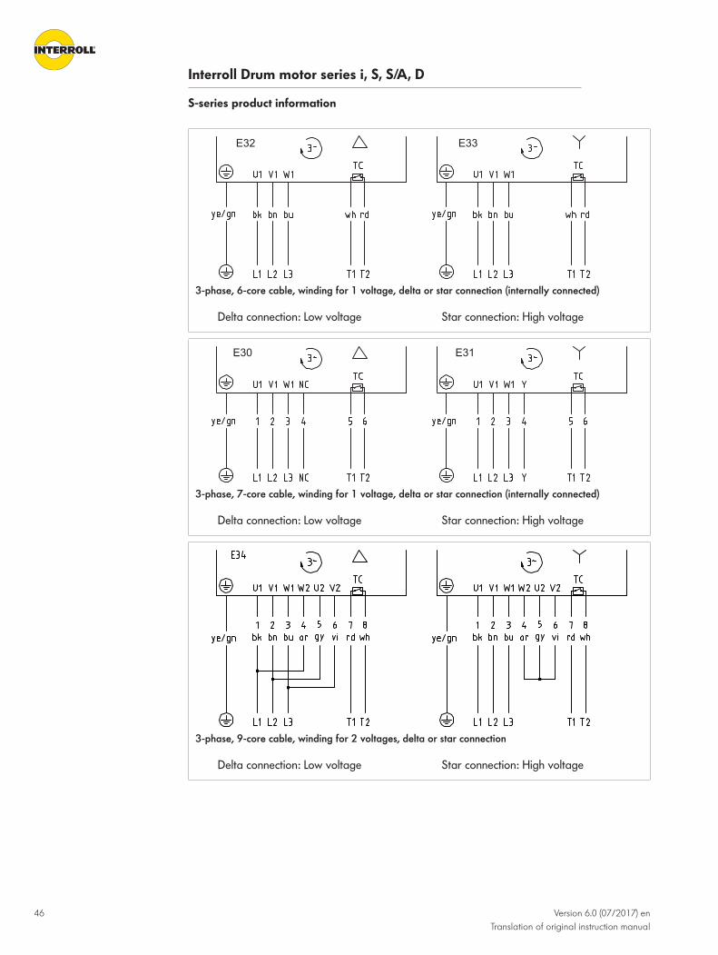
Interroll Drum motor series i, S, S/A, D
S-series product information
46 Version 6.0 (07/2017) enTranslation of original instruction manual
E33E32
3-phase, 6-core cable, winding for 1 voltage, delta or star connection (internally connected)
Delta connection: Low voltage Star connection: High voltage
E31E30
3-phase, 7-core cable, winding for 1 voltage, delta or star connection (internally connected)
Delta connection: Low voltage Star connection: High voltage
3-phase, 9-core cable, winding for 2 voltages, delta or star connection
Delta connection: Low voltage Star connection: High voltage

Interroll Drum motor series i, S, S/A, D
S-series product information
Version 6.0 (07/2017) enTranslation of original instruction manual
47
Connections in theterminal box
E21E20
1-phase, 7-core cable
* A starting capacitor and a matching switching relay can be connected as an option toimprove the starting torque of the single-phase motor.Maximum torque for terminal box cover screws: 1.5 Nm
E45E44
3-phase, 9-core cable, winding for 2 voltages, delta or star connection
Delta connection: Low voltage Star connection: High voltageMaximum torque for terminal box cover screws: 1.5 Nm

Interroll Drum motor series i, S, S/A, D
48 Version 6.0 (07/2017) enTranslation of original instruction manual
S/A-series product information
Type plate of S/A-series drum motorThe information on the type plate of the drum motor is intended for its identification. The typeplate is used to be able to properly use the drum motor.
Inte
rroll T
rommelmotoren GmbH 41836 Hückelhoven
UL-Type: Q6113IEC 60034
vN: 45 (54) m/s
SL: 500 mmWeight: 8,35 kg
Ins. Class: F; IP69k
Oil: Iso VG 150 FDA 1,25 l
Cust.Ref.: 01234567890123456789012345Ser. N°: 12345678
113S/AOrder N°: 0001172181 Pos: 000020
CD: E34
PN: 180 W~ 3 Phases
np: 4 / 2UN: ∆230 V/Y400 V
(UN: ∆230 V/Y460 V)fN: 50 Hz
(fN: 60 Hz)IN: 1,00 A / 0,62 A(IN: 1,08 A / 0,62 A)
nN: 1.355 (1.626) rpmcos φ: 0,76
CR: 10 μF
PN: 180 W~ 3 Phases
np: 4 / 2
UN: ∆230 V/Y400 V; fN: 50 Hz(UN: ∆230 V/Y460 V; fN: 60 Hz)IN: 1,00 A / 0,62 A(IN: 1,08 A / 0,62 A)nN: 1.355 (1.626) rpmcos φ: 0,76CR: 10 μF
Encoder: SKF 24 VDC 48 incBrake EM 207 VDC
Ø: 113,3 mm
UL-Type: Q6113
IEC 60034CD: E34
vN: 45 (54) m/s
SL: 500 mmWeight: 8,35 kg
Ins. Class: F; IP69kOil: Iso VG 150 FDA 1,25 l
Ø: 113,3 mm
Brake: EM 207 VDC 41/14/DE
Encoder: SKF 24 VDC 48 inc
113S/A
Interroll Trommelmotoren GmbH - 41836 HückelhovenMade in Germany | www.interroll.com
Amb. Temp.: -20°C to +40°CProd. Week/Year: 41/14/DESer. N°: 12345678Order N°: 0001172181 Pos: 000020Cust. Ref.: 01234567890123456789012345
9
8
7
6
5
4
3
2
1
10
11
12
13
14 15
16
17
18
19
20
21
22
23
24
25
26
27
28
29
30 3132
17
76
15
30
18
31 33
16
16
98
10
11
12
13 14
43
5
2
23
24
25
26
28
29
27
22
19
Type plate of S/A-series
1 Direction of travel 18 Serial number
2 Connection diagram number 19 Manufacturer / manufacturing location
3 Number of phases 20 CE mark
4 Rated power 21 UL mark
5 Number of poles 22 Type of UL standard
6 Rated voltage 23 Standard for drum motors
7 Rated frequency 24 Max. diameter of tube
8 (rated voltage) 1) 25 Roller or tube length

Interroll Drum motor series i, S, S/A, D
S/A-series product information
Version 6.0 (07/2017) enTranslation of original instruction manual
49
9 (rated frequency) 1) 26 Weight
10 Rated current 27 Insulation class and IP rating
11 (rated current) 1) 28 Circumferential speed of tube
12 Rated speed of rotor 1) 29 Oil type
13 Power factor 30 Brake data
14 Run capacitor 31 Date of manufacture (week/year/country)
15 Type 32 Encoder data
16 Part number 33 Permissible ambient temperature
17 Customer part number
1) The value depends on the voltage used. All values in parentheses refer to the rated voltage inparentheses.
Electrical data of S/A-seriesAbbreviations see "List of abbreviations", page 108
113S/A 1-phase
PN nP nN fN UN IN cosφ η JR IS/IN MS/MN
MB/MN
MP/MN
MN RM Cr
kW min-1 Hz W A kgcm2 Nm Ω µF
0.25 4 1360 60 115 4.34 0.95 0.53 7.2 2.07 1.31 1.31 1.31 1.76 0 40
0.25 4 1360 50 230 2.4 0.97 0.47 7.2 1.25 1.1 1.1 1.1 1.76 12.7 12
113S/A 3-phase
PN nP nN fN UN IN cosφ η JR IS/IN MS/MN
MB/MN
MP/MN
MN RM USH
delta
USH star Cr
kW min-1 Hz W A kgcm2 Nm Ω V DC V DC µF
0.37 4 1400 50 230 2.1 0.71 0.63 7.4 3.9 2.24 2.24 2.24 2.52 21.4 16 - -
0.37 4 1700 60 230 1.7 0.78 0.54 7.4 4.8 2.67 2.67 2.67 2.08 21.4 14 - 19
0.37 4 1360 60 330 1.54 0.66 0.69 7.4 3.9 2.24 2.24 2.24 2.6 34 - 17 11
0.37 4 1400 50 400 1.2 0.71 0.63 7.4 3.9 2.24 2.24 2.24 2.52 21.4 - 27 -
0.37 4 1700 60 460 1.1 0.78 0.54 7.4 4.8 2.67 2.67 2.67 2.08 21.4 - 28 19
0.37 4 1360 60 575 0.82 0.66 0.69 7.4 3.9 2.24 2.24 2.24 2.6 34 - 28 11

Interroll Drum motor series i, S, S/A, D
S/A-series product information
50 Version 6.0 (07/2017) enTranslation of original instruction manual
Dimensions of S/A-series drum motorSome dimensions are listed as "SL+". SL is the abbreviation for "shell length" (tube length). Thisdimension is indicated on the type plate of the drum motor (see "Type plate of S/A-series drummotor", page 48).
All the length-dependent dimensions in the catalog and in this manual comply with therequirements of DIN/ISO 2768 (medium quality).
The recommended distance between the mounting brackets (EL) under consideration of themaximum thermal expansion and internal tolerances is EL + 2 mm.
F
EL
AGL
Ø4
5
ØA
SL
FW
ØB
D
1/3 1/3 1/3
H
C C
11
H
11
Dimensions of 113S/A
Type Amm
Bmm
Cmm
Dmm
Fmm
Hmm
ELmm
AGLmm
113 S/A solid axleversion, cambered
113.3 112.4 25 25 20 14 SL+28 SL+78
113 S/A solid axleversion, cylindrical
113 113 25 25 20 14 SL+28 SL+78
113 S/A shaft-end capversion, cambered
113.3 112.4 20 35 21 14 SL+28 SL+68
113 S/A shaft-end capversion, cylindrical
113 113 20 35 21 14 SL+28 SL+68

Interroll Drum motor series i, S, S/A, D
S/A-series product information
Version 6.0 (07/2017) enTranslation of original instruction manual
51
Connection diagrams for the S/A-seriesThis instruction manual lists only standard connection diagrams. For other connection types, theconnection diagram is supplied separately with the drum motor.
Abbreviations see "List of abbreviations", page 108
Cable connectionsE10E10
1-phase, 7-core cable
* A starting capacitor and a matching switching relay can be connected as an option toimprove the starting torque of the single-phase motor.
E31E30
3-phase, 7-core cable, winding for 1 voltage, delta or star connection (internally connected)
Delta connection: Low voltage Star connection: High voltage

Interroll Drum motor series i, S, S/A, D
S/A-series product information
52 Version 6.0 (07/2017) enTranslation of original instruction manual
E33E32
3-phase, 6-core cable, winding for 1 voltage, delta or star connection (internally connected)
Delta connection: Low voltage Star connection: High voltage
3-phase, 9-core cable, winding for 2 voltages, delta or star connection
Delta connection: Low voltage Star connection: High voltage

Interroll Drum motor series i, S, S/A, D
S/A-series product information
Version 6.0 (07/2017) enTranslation of original instruction manual
53
Connections in theterminal box
E21E20
1-phase, 7-core cable
* A starting capacitor and a matching switching relay can be connected as an option toimprove the starting torque of the single-phase motor.Maximum torque for terminal box cover screws: 1.5 Nm
E45E44
3-phase, 9-core cable, winding for 2 voltages, delta or star connection
Delta connection: Low voltage Star connection: High voltageMaximum torque for terminal box cover screws: 1.5 Nm

Interroll Drum motor series i, S, S/A, D
54 Version 6.0 (07/2017) enTranslation of original instruction manual
D-series product information
Type plate of D-series drum motorThe information on the type plate of the drum motor is intended for its identification. This is theonly way for the drum motor to be used properly.
Inte
rrol
l Tro
mmelmotoren GmbH 41836 Hückelhoven
MA: 27,0 NmIEC 60034
nA: 150 rpmSL: 500 mm
Weight: 14,00 kgWeight: 14,00 kg
Ins. Class: F; IP69k
Oil: Iso VG 150 FDA 0,80 l
Cust.Ref.: 012345678901234567890
Ser. N°: 12345678
80D
Order N°: 0001172181 Pos: 000020
CD: 90PN: 425 Wnp: 8UL: 560 VDC
IN, 10: 1,32AMN, M0: 1,35NmnN: 3000 rpm
kE: 82,62 V/krpmEncoder: SKF 24 VDC 48 Inc
Ø: 81,5 mm
41/14/DE
80D
Interroll Trommelmotoren GmbH - 41836 Hückelhoven
Made in Germany | www.interroll.com
97863352204360970
Amb. Temp.: -20°C to +40°C
Prod. Week/Year: 41/14/DE
PN: 425 W
np: 8
UL: 560 VDC
IN, 10: 1,32 A
MN, M0: 1,35 Nm
nN: 3000 rpm
kE: 82,62 V/krpm
CD: 90
Ser. N°: 12345678
Order N°: 0001172181 Pos: 000020
Cust. Ref.: 012345678901234567890
Encoder: SKF 24 VDC 48 inc
MA: 27,0 Nm
IEC 60034
nA: 150 rpm
SL: 500 mm
Weight: 14,00 kg
Ins. Class: F; IP69k
Oil: Iso VG 150 FDA 0,80 l
Ø: 81,5 mm
14
15
16
17
18
19
20
21
22
23
24
25
17
6234262413 5
8 127 791112
18
19
20
21
22
25
23
15
16
9
8
7
6
5
4
3
2
1
10
11
12
13
14
10
Type plate of D-series
1 Connection diagram number 15 CE mark
2 Rated power 16 UL mark
3 Number of poles 17 Standard for drum motors
4 Intermediate circuit voltage 18 Rated torque of drum motor
5 Rated current 19 Max. diameter of tube
6 Rated torque of rotor 20 Rated speed of tube
7 Rated speed of rotor 21 Roller or tube length
8 Induced motor voltage 22 Weight
9 Encoder data 23 Insulation class and IP rating

Interroll Drum motor series i, S, S/A, D
D-series product information
Version 6.0 (07/2017) enTranslation of original instruction manual
55
10 Type 24 Date of manufacture (week/year/country)
11 Customer part number 25 Oil type
12 Part number 26 Permissible ambient temperature
13 Serial number 27 EAN code
14 Manufacturer / manufacturing location
Electrical data of D-seriesAbbreviations see "List of abbreviations", page 108
Number of poles 8 (4 pole pairs)
Rated speed of rotor 3000 1/min
Rated frequency 200 Hz
Winding connection Star
Thermal protection type TC 130 °C
PN UN IN I0 Imax η JR MN M0 Mmax RM Lsd Lsq ke Te kTN USH
kW V A A A kgcm2 Nm Nm Nm Ω mH mH V/krpm ms Nm/A V
0.08 400 0.26 0.26 0.78 0.83 0.14 0.25 0.25 0.76 62.54 130.7 138.0 72.23 4.41 0.98 36
0.08 230 0.45 0.45 1.34 0.85 0.14 0.25 0.25 0.76 21.62 45.6 53.7 41.57 4.97 0.57 25
0.11 400 0.29 0.29 0.86 0.87 0.28 0.35 0.35 1.05 29.06 81.9 94.1 83.09 6.48 1.22 32
0.11 230 0.48 0.48 1.44 0.86 0.28 0.35 0.35 1.05 10.2 27.8 29.3 47.46 5.75 0.73 19
0.145 230 0.81 0.81 2.43 0.85 0.14 0.46 0.46 1.38 21.6 45.60 53.70 41.57 4.97 0.57 25
0.145 400 0.47 0.47 1.41 0.83 0.14 0.46 0.46 1.38 62.5 130.7 138.0 72.23 4.41 0.98 36
0.18 400 0.56 0.56 1.69 0.86 0.42 0.57 0.57 1.72 17.6 49.8 59 80.80 6.70 1.02 33
0.18 230 0.97 0.97 2.91 0.87 0.42 0.57 0.57 1.72 5.66 16.26 19.42 45.81 6.86 0.59 19
0.298 230 1.30 1.30 3.90 0.86 0.28 0.95 0.95 2.85 10.2 27.80 29.30 47.46 5.75 0.73 19
0.298 400 0.78 0.78 2.34 0.87 0.28 0.95 0.95 2.85 29.1 81.90 94.10 83.09 6.48 1.22 32
0.425 230 2.30 2.30 6.90 0.87 0.42 1.35 1.35 4.05 5.66 16.26 19.42 45.81 6.86 0.59 19
0.425 400 1.32 1.32 3.96 0.86 0.42 1.35 1.35 4.05 17.6 49.80 59.00 80.80 6.70 1.02 33
Number of poles 6 (3 pole pairs)
Rated speed of rotor 4500 1/min
Rated frequency 225 Hz
Winding connection Star
Thermal protection type TC 130 °C

Interroll Drum motor series i, S, S/A, D
D-series product information
56 Version 6.0 (07/2017) enTranslation of original instruction manual
PN UN IN I0 Imax η JR MN M0 Mmax RM Lsd Lsq ke Te kTN USH
kW V A A A kgcm2 Nm Nm Nm Ω mH mH V/krpm ms Nm/A V
0.45 400 1.62 1.62 4.86 0.87 0.42 0.95 0.95 2.86 5.66 16.26 19.42 45.81 6.86 0.59 13.7
0.67 400 1.48 1.48 4.17 0.88 0.72 1.42 1.42 4 4.85 13.2 15.5 65.7 6.39 0.96 10.8
0.7 400 2.52 2.52 6.78 0.87 0.42 1.49 1.49 4 5.66 16.26 19.42 45.81 6.86 0.59 21.4
1.1 400 2.31 2.31 3.97 0.87 0.72 2.33 2.33 4 4.85 13.2 15.5 65.7 6.39 1.01 16.8
Averaged inductance: Lsm = (Lsd + Lsq) / 2

Interroll Drum motor series i, S, S/A, D
D-series product information
Version 6.0 (07/2017) enTranslation of original instruction manual
57
Dimensions of D-series drum motorSome dimensions are listed as "SL+". SL is the abbreviation for "shell length" (tube length). Thisdimension is indicated on the type plate of the drum motor (see "Type plate of D-series drummotor", page 54).
All length-dependent dimensions in the catalog and in this manual comply with the requirementsof DIN/ISO 2768 (medium quality).
The recommended distance between the mounting brackets (EL) while taking into account themaximum thermal expansion and internal tolerances is EL + 2 mm.
6
3.5 3.5
12.512.5
6
1/3 1/3 1/3
25
EL = SL + 12
FW = SL + 7
AGL = SL + 37
SL
ØA
ØB
30
Dimensions of 80D and 113D
Type A mm
B mm
80D cambered 81.5 80.5
80D cylindrical 81.0 81.0
80D cylindrical with key 81.7 81.7
113D cambered 113.5 112.0
113D cylindrical 112.0 112.0
113D cylindrical with key 113.0 113.0
Connection diagrams for the D-seriesThis instruction manual lists only standard connection diagrams. For other connection types, theconnection diagram is supplied separately with the drum motor.
NOTICEDamage of the drum motor from incorrect connection
4 Do not connect drum motors of the D-series directly to the supply system; instead, operatethem via a suitable frequency inverter.

Interroll Drum motor series i, S, S/A, D
D-series product information
58 Version 6.0 (07/2017) enTranslation of original instruction manual
Abbreviations see "List of abbreviations", page 108
Cable connections
3-phase, 4+2-core cable, winding for 1 voltage, star connection
Encoder connection
x
RLS incremental encoder
The connection with resistor and capacitor (RC) can reduce electronic interferences.x = encoder voltage acc. to motor type plate

Interroll Drum motor series i, S, S/A, D
D-series product information
Version 6.0 (07/2017) enTranslation of original instruction manual
59
ϕ
ϕ
ω
LTN resolver
SKS36 Hiperface

Interroll Drum motor series i, S, S/A, D
60 Version 6.0 (07/2017) enTranslation of original instruction manual
Options and accessories
Electromagnetic brake for the i-series
M Rated continuous torque of brake
JBR Brake moment of inertia
UBR Rated voltage
PBR Rated power
IBR Rated current
tpick up Brake response time
tfall delay AC Brake release switching time with AC-based switching
tfall delay DC Brake release switching time with DC-based switching
Motor Brakesize
M JBR PBR UBR IBR tpick up tfall delay AC tfall delay DC
Nm kgcm2 W V DC A ms ms ms
80i 2 0.7 0.04 12 24 0.50 20 80 13
104 0.12
113i 3 1.5 0.08 17 24 0.71 25 120 20
104 0.16
180 0.09
138i 4 2.9 0.23 24 24 1.00 30 200 23
104 0.23
180 0.13
207 0.12
165 /217i*
5 5.95 0.68 33 24 1.38 40 260 46
104 0.32
207 0.16
217i 12 50 104 0.48 60 500 60
207 0.24
217i* see "165i and 217i* 3-phase", page 25

Interroll Drum motor series i, S, S/A, D
Options and accessories
Version 6.0 (07/2017) enTranslation of original instruction manual
61
t pick up t fall
AC-switching (The input voltage at terminals 1 and 2 ofthe brake rectifier is switched.)
Long fall delay
Brake voltage approx. 1 V
Brake is softly applied
DC-switching (The output voltage is switched viaterminals 3 and 4 of the brake rectifier.)The switching contact must be suitable for high-voltagepeaks and contact-breaking sparks resulting from withDC-switching.
Short fall delay
Brake voltage approx. 500 V
Brake is abruptly applied
Electronic rectifier Behavior similar to DC-switching
Overexcitation voltage = 2 x rated operating voltage, tpick up is halved.
Standard 104 V DC, available off-the-shelf
The braking torque at the drum tube corresponds to the gear ratio of the motor times thebraking torque listed in the table above. For safety purposes, 25 % reserve have to be figuredinto the dimensioning of the brake. The brake is not a safety holding brake. Since there aremotor combinations that feature a higher torque than braking torque, it is always recommendedto use the greatest possible gear ratio for the use of a brake.
All brakes are dimensioned for start/stop operation.
The rise and fall delays of the brakes can vary significantly depending on the following factors:• Oil type and viscosity• Oil quantity in the drum motor• Ambient temperature• Internal operating temperature of the motor

Interroll Drum motor series i, S, S/A, D
Options and accessories
62 Version 6.0 (07/2017) enTranslation of original instruction manual
Brake rectifiers for i-series
InputvoltageV AC
BrakevoltageV DC
StartingvoltageV DC
HoldingvoltageV DC
Type Application Referencenumber
115 104 104 52 Fast-switching rectifier Start/stop applications orcontinuous operation
61011343
230 207 207 104 Fast-switching rectifier Start/stop applications orcontinuous operation
61011343
230 104 104 104 One-way half-waverectifier and bridgerectifier
Start/stop applications orcontinuous operation
1001440
230 104 190 52 Phase rectifier Continuous operation 1001442
400 104 180 104 Multi-switch Continuous operation 1003326
460 104 180 104 Multi-switch Continuous operation 1003326
460 207 207 207 One-way half-waverectifier and bridgerectifier
Start/stop applications orcontinuous operation
1001441
The use of a fast-acting or phase rectifier allows saving energy since the holding voltage is lowerthan the rated braking voltage.
Brake rectifier connections Interroll recommends installing a switch between 3 and 4 for a faster release of the brake.
1 2 3 4 5 6
input bridge brake
One-way half-wave rectifier
1 2 3 4 5 6
input bridge brake
Bridge rectifier

Interroll Drum motor series i, S, S/A, D
Options and accessories
Version 6.0 (07/2017) enTranslation of original instruction manual
63
1 2 3 4 5 6
ekarb tupni
Phase rectifier
Maximum switching frequency = 2 cycles/second* Connection 3 & 4 interrupts the DC circuit
and extends the fall delay
input bridge brake justage delay time
1 2 3 4 5 6 7 8
Fast-acting rectifier
Multi-switch rectifier

Interroll Drum motor series i, S, S/A, D
Options and accessories
64 Version 6.0 (07/2017) enTranslation of original instruction manual
Brake rectifier dimensions19
C
E
B
D
A
Half-wave rectifier / bridge rectifier
Reference number Amm
Bmm
Cmm
Dmm
Emm
1001440 34 30 25 3.5 4.5
1001441 64 30 54 4.5 5
1 2 3 4 5 6
54
9
9
30
5
4.5
1 2 3 4 65
48.6
4.5
54
5.6
15
64 17.5
Phase rectifier (reference number 1001442)
Mounting rail 35 mm EN 50022 Mayrpart no. 1802911

Interroll Drum motor series i, S, S/A, D
Options and accessories
Version 6.0 (07/2017) enTranslation of original instruction manual
65
64
48
.6
8 7 6 5 4 3 2 1
15
54
5.6
Ø
8 7 6 5 4 3 2 130
5
4.5
4.5
549
9
17.5
Fast-acting rectifier (reference number 61011343)
Mounting rail 35 mm EN 50022 Mayrpart no. 1802911
ON
1 2 3 4
17.5
54
55.6
9
30
73.6
15
64
69
Ø4.5
54
4.5
Multiple rectifier (reference number 1003326)

Interroll Drum motor series i, S, S/A, D
Options and accessories
66 Version 6.0 (07/2017) enTranslation of original instruction manual
Asynchronous drum motors with frequency inverters
Torque dependent oninput frequency
f / Hz
Operating frequency [Hz] 5 10 15 20 25 30-50 55 60 65 70 75 80
Available motor torque in %
Rated motorfrequency
50 Hz 80 85 90 95 100 100 91 83 77 71
60 Hz 75 80 85 90 95 100 100 100 92 86 80 75
Value 1: Based on a rated motor frequency of 50 Hz (50-Hz motors should be operated only upto 70 Hz in the speed range under field control.)
Value 2: Based on a rated motor frequency of 60 Hz (60-Hz motors should be operated only upto 80 Hz in the speed range under field control.)
The torque dependency depicted in the figure above is expressed as P = T x ω. With a reducedoperating frequency of below 20/24 Hz, the motor torque is reduced by changing heatdissipation conditions. The power loss dissipation is a result of the oil quantity, in contrast tostandard ventilated motors. For frequencies starting at 80 ... 85 / 95 100 Hz, the curve for theoutput torque does not have a hyperbolic shape, but is instead replaced with a quadraticfunction which is the result of the effect of the pull-out torque and the voltage. The output/frequency characteristics of most frequency inverters supplied with 3 x 400 V / 3 x 460 V canbe parameterized to 400 V / 87 Hz in order to connect motors with 230 V / 50 Hz. This maycreate further losses in the motor and lead to its overheating if the motor is dimensioned withinsufficient power reserves.
Frequency inverterparameters
• Clock frequency: A high clock frequency leads to a better utilization factor of the motor.Optimum frequencies are 8 or 16 kHz. Parameters such as smooth running test quality(motor is running smoothly) and noise development are also affected positively by highfrequencies.
• Voltage increase: Interroll motor windings are dimensioned for a rated voltage increaserate of 1 kV/μs. If a frequency inverter generates a steeper voltage increase, motor chokesmust be installed between frequency inverter and motor. But since all drum motors fromInterroll run in an oil bath, the risk of overheating or damage of the motor due to largevoltage increase rates is extremely low. Contact your local Interroll dealer about the need formotor chokes.

Interroll Drum motor series i, S, S/A, D
Options and accessories
Version 6.0 (07/2017) enTranslation of original instruction manual
67
• Voltage: If a frequency inverter with single-phase supply is installed at the drum motor, itmust be ensured that the specified motor is dimensioned for the frequency inverter outputvoltage and is connected accordingly. Single-phase motors cannot be operated on thefrequency inverter.
• Output frequency: Applications with output frequencies in the speed range under fieldcontrol above 70 Hz should be avoided (for asynchronous motors only). High frequenciescan cause noise, vibrations and resonances and reduce the rated output torque of the motor. With 87-HZ technology, asynchronous motors can be operated up to a maximum frequencyof 87 Hz. However, at 87 Hz the motor may not take up more power than specified on thetype plate of the motor. 87-Hz technology requires a motor that has at least 75 % powerreserves in 50-Hz operation. Caution should be exercised when using V/f-regulated inverterswith frequencies below 20 Hz since it could result in overheating or power loss of the motor.For information about required power reserves, see your local Interroll dealer.Synchronous motors can be operated with frequency inverters that are sold by Interrollbetween 7 Hz and 200 Hz.
• Motor output: Not all frequency inverters can operate motors with more than 6 poles and/or output powers below 0.2 KW / 0.27 PS. If in doubt, please contact your local Interrolldealer or the supplier of the frequency inverters.
• Frequency inverter parameters: Frequency inverters are usually delivered with factorysettings. Given these settings, the inverter is generally not immediately ready for operation.The parameters have to be adjusted to the respective motor. For frequency inverters sold byInterroll, startup instructions specifically created for drum motors for the respective frequencyinverters can be supplied upon request.

Interroll Drum motor series i, S, S/A, D
Options and accessories
68 Version 6.0 (07/2017) enTranslation of original instruction manual
Encoder type BMB-6202 & 6205 SKF for the i-seriesManufacturer: SKF
The encoder consists of two components: A standard bearing with built-in magnetic encoder anda corresponding load resistance whose size varies depending on the operating voltage. Theload resistance is not part of the scope of supply. The resolution INC is determined by the size of the bearing and, therefore, by the motor framesize.
The resolution INC in increments per drum revolution is calculated as follows:
INC = p x gear ratio (i)
The gear ratio (i) is listed in the drum motors main catalog and can be requested from Interroll.
p = number of encoder pulses per rotor revolution selected based on the following table:
Encoder type Bearing size Drum motor size Pulses per rotorrevolution (p)
EB-6202-SKF-HTLOC-32-N-0,5
6202 80i ... 138i 1) 32
EB-6205-SKF-HTLOC-48-N-0,5
6205 165i ... 217i 48
1) For 80i, only available with a special shaft diameter of 25 mm.
Technical data Rated operating voltage 4.5 to 24 V DC
Max. rated output current 20 mA
Max. operating current 8 to 10 mA
Pulses per revolution (p) 32/48
High voltage > 3.5 V
Low voltage < 0.1 V

Interroll Drum motor series i, S, S/A, D
Options and accessories
Version 6.0 (07/2017) enTranslation of original instruction manual
69
ConnectionsNOTICEDamage of the encoder from excessive voltages/currents
4 Ensure that the maximum switching current is always less than 20 mA.4 Do not operate the encoder with voltages above 24 V.
Abbreviations see "List of abbreviations", page 108
3-phase, 4+2 and 4-core cable, winding for 1 voltage, delta or star connection
Option: 2 voltages with 7+2-core cable availableInterroll recommends the use of optocouplers (see "Best connection option", page 70).
The signal sequence of A and B depends on the gear stages of the drum motor. For this reason,the rotational direction for drum motors with identical number of poles and output, but differentgear stages. In this case, the signal cables A and B can be swapped with each other.

Interroll Drum motor series i, S, S/A, D
Options and accessories
70 Version 6.0 (07/2017) enTranslation of original instruction manual
Best connection option Best connection option of an encoder with NPN open-collector output to an inputdevice
+V Operating voltage 0 V GroundingRLI Load resistance
Requirement:R RL must be dimensioned for the specified output current range of the encoder.
4 Connect the encoder to an interface, following the illustration above as best as possible.The integrated load resistance RL is generally dimensioned for a load current range of15 mA so that no overload occurs at the encoder output.The signal level of some input devices can be set to NPN or PNP via the hardware or via thesoftware. In this case, NPN is required.
4 If this is not possible, use a signal coupler.The function of a signal coupler is shown in the illustration above. The following can be used:
WAGO Electronics terminal with optocoupler Reference no. 859-758
PHOENIX Input optocoupler Type: DEK-OE-24DC/24DC/100KHz
WEIDMUELLER Optocoupler Waveseries Type: MOS 12-28VDC 100kHz

Interroll Drum motor series i, S, S/A, D
Options and accessories
Version 6.0 (07/2017) enTranslation of original instruction manual
71
Encoder type RM44-RLS for the i and D-seriesOutput: Incremental, RS422A 5 V, push-pull, 24 V
The resolution INC in increments per drum revolution is calculated as follows:
INC = p x i
p = number of encoder pulses per rotor revolution
i = gear ratio of drum motor
Technical data RS422A 5 V Push-pull 24 V
Motor size 80i 1) ... 217iD-series
80i 1) ... 217iD-series
Supply voltage 5 V ± 5 % 8 - 26 V
Power supply 35 mA 50 mA at 24 V
Resolution p (pulses per revolution) 1024, 512 2) 1024, 512 2)
Output signal (RS422A) A/ , B/ , Z/ A/ , B/ , Z/
Max. cable length 50 m 20 m
Accuracy3) ± 0.5° ± 0.5°
Hysteresis 0.18° 0.18°1) For 80i, only available with a special shaft diameter of 25 mm.2) Additional resolutions upon request. Please contact Interroll.3) Worst-case scenario within the operating parameters, including magnet position andtemperature.

Interroll Drum motor series i, S, S/A, D
Options and accessories
72 Version 6.0 (07/2017) enTranslation of original instruction manual
Connections Abbreviations see "List of abbreviations", page 108
x
RLS encoder
The connection with resistor and capacitor (RC) can reduce electronic interferences.x = encoder voltage acc. to motor type plate
The signal sequence of A and and B and depends on the gear stages of the drum motor. Forthis reason, the rotational direction for drum motors with identical number of poles and output,but different gear stages. In this case, the signal cables A and and B and can be swappedwith each other.
Signal connection Encoder Customer electrics
120 Ω
10 nF
Cable impedance = 120 Ω

Interroll Drum motor series i, S, S/A, D
Options and accessories
Version 6.0 (07/2017) enTranslation of original instruction manual
73
Resolver type RE-15-1-LTNA resolver is an inductive, robust feedback system. It is integrated in the drum motor and is usedprimarily in servo systems.
Connections Abbreviations see "List of abbreviations", page 108
ϕ
ϕ
ω
3-phase, 7+6-core cable, winding for 1 voltage, with resolver
Connection Ref+ to Ref- Cos+ to Cos- Sin+ to Sin-
Resistance 40 Ω 102 Ω 102 Ω
Technical data Input frequency 5 kHz 10 kHz
Input voltage 7 Vrms
Input current 58 mA 36 mA
Phase shift (± 3°) 8° -6°
Zero voltage max. 30 mV
Accuracy ± 10', ± 6' upon request
Harmonic max. 1'
Operating temperature -55 °C to +155 °C
Max. permissible speed 20,000 1/min
Rotor weight 25 g
Stator weight 60 g
Rotor moment of inertia 0.02 kgcm²
Hi-Pot housing/winding min. 500 V
Hi-Pot winding/winding min. 250 V
Stator length 16.1 mm

Interroll Drum motor series i, S, S/A, D
Options and accessories
74 Version 6.0 (07/2017) enTranslation of original instruction manual
Impedance Input frequency 5 kHz 10 kHz
Zro in Ω 75j 98 110j 159
Zrs in Ω 70j 85 96j 150
Zso in Ω 180j 230 245j 400
Zss in Ω 170j 200 216j 370
Primary side Secondary side

Interroll Drum motor series i, S, S/A, D
Version 6.0 (07/2017) enTranslation of original instruction manual
75
Transport and storage
Transport
CAUTIONImproper transport poses a risk of injury.
4 Transport-related tasks should only be carried out by qualified and authorized persons.4 For drum motors with a diameter of 136 mm or more, use a crane or hoisting equipment
during the transport. The rated load of the crane or hoisting equipment must be greaterthan the weight of the drum motor. Crane rope/cable and hoisting equipment must besecurely fastened to the shafts of the drum motor during lifting.
4 Do not stack pallets.4 Before the transport, ensure that the drum motor is sufficiently secured.
NOTICERisk of damages to the drum motor due to improper transport
4 Avoid serious impacts during transport.4 Do not lift the drum motor at the cable or terminal box.4 Do not transfer the drum motors between warm and cold environments. This may lead to the
formation of condensation.4 For the transport in shipping containers, ensure that the temperature in the container is not
permanently above 70 °C (158 °F).4 Ensure that motors of the S-series that are intended for vertical mounting are transported in
horizontal position.
4 Check each drum motor visually for damage after transport.4 In the event of damage, take photos of the damaged parts.4 In case of a transport damage, immediately notify the carrier and Interroll to avoid losing
any claims for compensation.
Storage
CAUTIONRisk of injury due to improper storage
4 Do not stack pallets.4 Do not stack more than four cardboard boxes on top of each other.4 Ensure that proper fastening is in place.

Interroll Drum motor series i, S, S/A, D
Transport and storage
76 Version 6.0 (07/2017) enTranslation of original instruction manual
4 Store the drum motor horizontally in a clean, dry and enclosed location at +15 to +30 °C;protect it from moisture and humidity.
4 For storage times exceeding three months, turn the shaft occasionally to prevent damage tothe shaft seals.
4 Inspect each drum motor for damage after storage.

Interroll Drum motor series i, S, S/A, D
Version 6.0 (07/2017) enTranslation of original instruction manual
77
Assembly and installation
Warning notices concerning the installation
CAUTIONRotating parts and inadvertent startup of the motor
Risk of crushing for fingers
4 Do not reach into areas between drum motor and conveyor belts or roller chains.4 Install a protection device (such as a guard plate) to prevent fingers from getting trapped in
the chain belts or roller chains.4 Install an appropriate warning on the conveyor.
NOTICERisk of damage leading to failure or shortened service life of the drum motor
4 Observe the following safety information.
4 Do not drop or mishandle the drum motor to avoid internal damages.4 Prior to the installation, inspect each drum motor for damage after storage.4 Do not hold, carry, or support the drum motor by the wires or terminal boxes extending out
of the mounting shaft to avoid damage to the internal parts and seals.4 Do not twist the motor cable.4 Do not overtension the belt.
Installing the drum motorPositioning the drum
motor4 Ensure that the data on the type plate are correct, and match the ordered and confirmed
product.
A special design must be used for installing the drum motor in non-horizontal applications. Theexact version must be specified at the time of ordering. In case of doubt, contact Interroll.
The drum motor must be mounted horizontally with a clearance of +/- 5° (drum motor 113S: +/- 2°; 113S/A: -5°/+15°), unless specified differently in the order confirmation.

Interroll Drum motor series i, S, S/A, D
Assembly and installation
78 Version 6.0 (07/2017) enTranslation of original instruction manual
-2°-5°
+2°+5°
Position of the drum motor
All drum motors are identified with the serial number on one end of the shaft and some with theletters UP.
NOTICEProperty damages from incorrect mounting position
4 Do not install motors of the i-series in the 180° mounting position (serial number must not beupside down).
4 Ensure that the serial number and/or the UP indicator is located at one of the positionsindicated in the following table.
The models 80S, 113S and the D-series can be installed in any orientation.
Motor type/mounting position 0° -45° -90° 45° 90° 180°
80i - 217i asynchronous motor √ √ √ √ √ ⃠
80S / 113S / 113S/A √ √ √ √ √ √
80D / 113D synchronous motor √ √ √ √ √ √
Installing the motor withmounting brackets
The mounting brackets must be sufficiently robust to withstand the motor torque.
4 Install the brackets at the conveyor or machine frame. Ensure that the drum motor is installedparallel to the idler pulley and at a right angle to the conveyor frame.
4 Insert the shaft ends of the drum motor into the mounting brackets according to the"Mounting position" table (see above).
4 If the shaft must be fastened to the mounting brackets (e.g. with a screw through a cross holein the journal), it should be done only on one side so that the other side can move in axialdirection in case of thermal expansion.
4 Ensure that at least 80% of the drum motor flats are held by the mounting brackets.4 Ensure that the distance between the flats and the bracket is not more than 0.4 mm.4 If the drum motor is used for frequent reversing duty or for start/stop operation: Ensure that
there is no gap between key surfaces and the mounting brackets.

Interroll Drum motor series i, S, S/A, D
Assembly and installation
Version 6.0 (07/2017) enTranslation of original instruction manual
79
The drum motor can also be installed without mounting brackets. In this case, the shaft ends mustbe installed into corresponding recesses in the conveyor frame; these recesses must bereinforced in such a way that they meet the aforementioned requirements.
1.0 mm
Axial clearance
The entire axial clearance of the drum motor should be at least 1 mm (0.5 mm per side) and nomore than 2 mm (1 mm per side).
max. 0,4 mm 0,0 mm
Torsional clearance for standard applications (left) and for applications with frequent reversing dutyor start/stop operation (right)
4 If necessary, install a support plate above the mounting bracket to secure the drum motorshaft.

Interroll Drum motor series i, S, S/A, D
Assembly and installation
80 Version 6.0 (07/2017) enTranslation of original instruction manual
Installation consideringhygienic aspects
4 Ensure that the installation position is open and easily accessible to facilitate cleaning ortesting.
Installation considering hygienic aspects
4 To adhere to the recommendations of the EHEDG, it must be ensured that there is no metal-to-metal contact at the bearing surfaces between motor shaft and conveyor frame, e.g. byinserting a rubber seal between shaft and frame. The material of the seal must meet thespecifications of the USDA/FDA and EG 1935/2004.
Belt assembly
Belt width / tube lengthNOTICERisk of overheating if belt is too small
4 Ensure that the drum motor is operated with a conveyor belt that covers at least 70 % of thedrum tube.
For drum motors with less than 70 % belt contact and drum motors with form-fit driven belts orwithout belt, a motor dimensioned for this purpose is required. This must be specified at the timeof ordering. If in doubt, please contact Interroll.
Belt adjustment Convex tubes center and guide the belt during regular operation. Nevertheless, the belt shouldbe carefully aligned, frequently checked during startup and readjusted depending on the load.
NOTICEAdjustment errors can lead to a shortened service life as well as damages of the beltand the drum motor ball bearings.
4 Adjust the drum motor, belt and idler pulleys according to the instructions in this instructionmanual.
4 Adjust the belt with the synchronous returning rollers and support rollers and/or (if available)with the idler pulleys or snub pulleys.

Interroll Drum motor series i, S, S/A, D
Assembly and installation
Version 6.0 (07/2017) enTranslation of original instruction manual
81
4 Check the diagonal dimensions (between the shafts of the drum motor and the shafts of theend/guide rollers or from belt edge to belt edge).The difference must not be greater than 0.5 %.
The idler pulley should be cylindrical since a camber in the idler pulley could work against thecamber in the drum motor, thereby causing a belt migration.
Diagonal check
The distance between the belt and the gliding plate must not exceed 3 mm.
0-3 mm
Belt position
Tensioning the belt The required belt tension depends on the respective application. The pertinent information islocated in the catalog of the belt manufacturer, or contact Interroll.
NOTICEOvertensioned belts can lead to a shortened service life, wear of bearings or oilleakage.
4 Do not tension the belt beyond the value recommended by the manufacturer or specified inthe product tables of the catalog.
4 Link belts, steel belts, Teflon-coated fiberglass belts and hot-formed PU belts should not betensioned (see the instructions from the belt manufacturer).
4 Adjust the belt tension by tightening or loosening the corresponding screws on both sides ofthe conveyor to ensure that the drum motor is positioned at a right angle to the conveyorframe and parallel to the end roller/idler pulley.
4 Tension the belt only so much that belt and load are being driven.

Interroll Drum motor series i, S, S/A, D
Assembly and installation
82 Version 6.0 (07/2017) enTranslation of original instruction manual
Belt tensionThe following must be observed when calculating the belt tension:
• Length and width of conveyor belt• Belt type• The belt tension required for transporting the load• The belt elongation required for the assembly (depending on the load, the belt elongation
for the assembly should measure between 0.2 and 0.5 % of the belt length)• The required belt tension must not exceed the maximum belt tension (TE) of the drum motor.
The values for the belt tension and elongation are available from the belt manufacturer.
T1
T2
T1+T2 =TE
The required belt tension T1 (top) and T2 (bottom) can be calculated according to thespecifications of DIN 22101 or CEMA. Based on the information from the belt manufacturer, theactual belt tension can be roughly determined by a measurement of the belt elongation duringtensioning.
The maximum permissible belt tension (TE) of a drum motor is listed in the drum motor tables ofthe catalog. Belt type, belt thickness and drum motor diameter must match the information fromthe belt manufacturer. If the diameter of the drum motor is too small, it can lead to damages tothe belt.
If the belt tension is too strong, it can damage the shaft bearings and/or other internalcomponents of the drum motor and shorten the service life of the product.
Belt elongation The belt tension is created by the force of the belt when it is stretched in longitudinal direction.To prevent damages to the drum motor, it is absolutely necessary to measure the belt elongationand to determine the static belt tensioning force. The calculated belt tension must be equal to orlower than the values specified in the drum motor tables of the catalog.
Conveyor belt
Idler
With increasing the distance between idler
and drum motor the belt elongates
Drum motor
Belt elongation

Interroll Drum motor series i, S, S/A, D
Assembly and installation
Version 6.0 (07/2017) enTranslation of original instruction manual
83
Measuring the beltelongation
The belt elongation can very easily be determined using a measuring tape.
4 Mark the untensioned belt at two points in the center where the outer diameter of the drummotor and the idler pulley are the largest due to the camber.
4 Measure the distance between the two markings parallel to the belt edge (Be0). The greaterthe distance between the two markings, the more precise the belt elongation can bemeasured.
4 Tension and align the belt.4 Measure the distance between the markings (Be) again.
The belt elongation increases the distance.
Be [m
m]
BeO
[m
m]
BW BW
Measuring the belt elongation
Calculating the beltelongation
The belt elongation can be calculated in % with the determined measure of the belt elongation.
Be% =
Be .100%
Be0
-100
Formula for calculating the belt elongation in %
Calculating the belt elongation requires the following values:• Belt width in mm (BW)• Static force per mm belt width with 1 % elongation in N/mm (k1 %). (The value is recorded
on the data sheet for the belt or can be obtained from the belt supplier.)
TE[static]
= BW . k1% . Be%
. 2
Formula for calculating the static belt tensioning force in N

Interroll Drum motor series i, S, S/A, D
Assembly and installation
84 Version 6.0 (07/2017) enTranslation of original instruction manual
Drum coatingA drum coating (e.g. rubber coating) that was applied retroactively can cause the drum motor tooverheat. For some drum motors, there may be restrictions concerning the thickness of the drumcoating.
To avoid a thermal overload, the required output should be multiplied with 1.2.
Please contact Interroll concerning the type and maximum thickness of a drum coating if youwant to apply one.
SprocketsTo operate link belts with sprockets requires that a sufficient number of sprockets are attached tothe drum shell in order to support the belt and to correctly transfer the force. Sprockets thatengage with the belt must have a floating fit to prevent them from interfering with the thermalexpansion of the belt. Only one sprocket may be affixed for belt guidance; as an alternative, thebelt may also be guided at the sides.
For a belt guidance with fixed sprocket, the number of sprockets should be odd so that the fixedsprocket can be arranged in the center. At least one sprocket should be used for every 100 mmbelt width. The minimum number of sprockets is 3.
The force is transferred using a key steel welded onto the drum tube. In general, this key steel is50 mm shorter than the tube length (SL).
NOTICEDamage to the belt
4 Do not use a fixed sprocket together with side guides.

Interroll Drum motor series i, S, S/A, D
Assembly and installation
Version 6.0 (07/2017) enTranslation of original instruction manual
85
Warning notices concerning the electrical installation
WARNINGElectrocution due to improper installation
4 All electrical work should only be performed by qualified and authorized persons.4 Disconnect the power supply before installing, removing or rewiring the drum motor.4 Always observe the connection instructions and ensure that the power and control circuits of
the motor are correctly connected.4 Ensure that metal conveyor belt frames are sufficiently grounded.
NOTICEDamage of the drum motor from incorrect power supply
4 Do not connect an AC drum motor to an excessively high DC voltage supply and a DC drummotor to an AC voltage supply – this will lead to irreparable damages.
4 Do not connect drum motors of the D-series directly to the supply system. D-drum motorsmust be operated via suitable frequency inverters or servo drive controllers.
Electrical connection of the drum motorConnecting the drummotor – with a cable
4 Ensure that the motor is connected to the correct supply voltage according to the motor typeplate.
4 Ensure that the drum motor is correctly grounded with the yellow-green cable.4 Connect the drum motor according to the connection diagrams (see "Connection diagrams
for the i-series", page 30 or see "Connection diagrams for the S-series", page 45 or see"Connection diagrams for the S/A-series", page 51 or see "Connection diagrams for the D-series", page 57).
Connecting the drummotor – with a terminal
box
NOTICEDamage to the internal wiring due to changes to the terminal box
4 Do not disassemble, reassemble or modify the terminal box.
4 Remove the cover of the terminal box.4 Ensure that the motor is connected to the correct supply voltage according to the motor type
plate.4 Ensure that the terminal box of the drum motor is correctly grounded.4 Connect the drum motor according to the connection diagrams (see the chapter "Connection
diagrams" of the respective series).4 Replace cover and seals. Tighten the screws of the cover with 1.5 N to ensure that the
terminal box is sealed tight.

Interroll Drum motor series i, S, S/A, D
Assembly and installation
86 Version 6.0 (07/2017) enTranslation of original instruction manual
Single-phase motor If a starting torque of 100% is required, single-phase drum motors,should be connected to astarting capacitor and a run capacitor. An operation without starting capacitor can reduce thestarting torque to 70 % of the rated torque listed in the Interroll catalog.
Connect the starting capacitors according to the connection diagrams (see "Connection diagramsfor the S-series", page 45).
External motor protection The motor must always be installed together with a suitable motor protection, e.g. a motor circuitbreaker or frequency inverter with overcurrent protective function. The protective device must beadjusted to the rated current of the respective motor (see type plate).
Integrated thermalprotection CAUTION
Accidental motor start
Crushing hazard for fingers
4 Connect the integrated thermal circuit breaker to an external control device that interruptsthe current supply to the motor at all poles in case of overheating.
4 After the thermal circuit breaker has tripped, examine and remove the cause for overheatingbefore the current supply is reactivated.
The standard maximum switching current of the thermal circuit breaker is 2.5 A. For otheroptions, please contact Interroll.
For operational safety, the motor must be safeguarded against overload with an external motorprotection, as well as an integrated thermal protection; otherwise, there is no warranty if themotor fails.
Frequency inverter Asynchronous drum motors can be operated with frequency inverters. Frequency inverters fromInterroll are general adjusted to factory setting and have to be parameterized for the respectivedrum motor. For this purpose, Interroll can supply parameterization instructions. In this case,please contact your local Interroll partner.
4 If no frequency inverter from Interroll is used, the frequency inverter must be correctlyparameterized according to the specified motor data. Interroll can provide only very limitedsupport for frequency inverters that are not being sold by Interroll.
4 Resonance frequencies in the power supply line must be prevented since the create voltagespikes in the motor.If the cable is too long, frequency inverters generate resonance frequencies in the linebetween frequency inverter and motor.
4 Use a completely shielded cable to connect the frequency inverter to the motor.4 Install a sine-wave filter or a motor choke if the cable is longer than 10 meter or if a
frequency inverter controls several motors.4 Ensure that the cable shield is connected to a grounded part according to the
electrotechnical guidelines and local EMC recommendations.4 Always observe the installation guidelines of the frequency inverter manufacturer.

Interroll Drum motor series i, S, S/A, D
Assembly and installation
Version 6.0 (07/2017) enTranslation of original instruction manual
87
BackstopNOTICEDamage of the drum motor with backstop due an incorrect connection of the rotationaldirection
4 Connect the drum motor according to the connection diagrams (see the chapter "Connectiondiagrams" of the respective series). An arrow on the housing end cover on the electricalconnection side of the drum motor shows the correct rotational direction.
Electromagnetic brake The drum motor is delivered with an installed electromagnetic brake (if it does not feature a 24-V-DC brake). The rectifier is an accessory part and must be ordered separate from themotor.
4 Connect the rectifier and the brake according to the connection diagrams (see "Connectiondiagrams for the i-series", page 30).
The rectifier has an AC input and a DC output to the brake winding.
DANGERRisk of injuries when used as safety brake
When large loads are being held, the motor can unexpectedly rotate in the opposite direction.As a result, loads may fall down and hit or fatally injure persons.
4 Do not use the electromagnetic brake as safety brake.4 If a safety brake is required, install a suitable additional safety brake system.
NOTICEDamage of the drum motor and the brake if both are operated simultaneously
4 Route the control circuits in such a way that motor and brake do not work against eachother.
4 Consider the response time for applying and releasing the brake (depending on temperatureand oil viscosity, it can amount to 0.4 to 0.6 seconds).
4 Apply the brake only after the current supply to the motor has been switched off.4 Start the motor only after the brake has been released.
NOTICEDamage of the drum motor due to insufficient holding torque of the brake
The holding torque of the brake can be too small for the rated torque of some motors.
4 Ensure that the holding torque of the brake is sufficient. Contact Interroll for the requiredholding torque.

Interroll Drum motor series i, S, S/A, D
Assembly and installation
88 Version 6.0 (07/2017) enTranslation of original instruction manual
The cable should be as short as possible, and the cable cross section should correspond to thenational/international regulations so that the voltage supply at the rectifier does not deviatefrom the rated voltage by more than ±2 %.
If the drum motor with electromagnetic brake is used at an ambient temperature below +5 °C, aspecial oil must be used. In case of doubt, contact Interroll.
The electromagnetic brake is a pure holding brake and should not be used for positioning orbraking the motor. Positioning applications should be implemented with a frequency inverter inconjunction with an encoder integrated in the motor. Braking applications should beimplemented with a frequency inverter.

Interroll Drum motor series i, S, S/A, D
Version 6.0 (07/2017) enTranslation of original instruction manual
89
Initial startup and operation
Initial startupThe drum motor may be put into operation only if it is correctly installed and connected to thepower supply and all rotating parts have been fitted with the corresponding protective devicesand guards.
Checks before theinitial startup
The drum motor is filled with the correct oil quantity at the factory and ready for installation.Prior to the initial startup of the motor, the following steps have to be performed:
4 Ensure that the motor type plate matches the version ordered.4 Ensure that no contact points exist between objects, conveyor belts and rotating or moving
parts.4 Ensure that the drum motor and the conveyor belt can move freely.4 Ensure that the belt features the correct tension according to the recommendations from
Interroll.4 Ensure that all bolts are tightened according to the specifications.4 Ensure that no additional dangerous areas arise due to interfaces to other components.4 Ensure that the drum motor is correctly wired and connected to the voltage supply with the
correct voltage.4 Check all safety devices.4 Ensure that no bystanders are in dangerous areas around the conveyor.4 Ensure that the external motor protection is correctly adjusted to the rated motor current
and a corresponding switching device can switch off the motor voltage at all poles if theintegrated thermal circuit breaker trips.

Interroll Drum motor series i, S, S/A, D
Initial startup and operation
90 Version 6.0 (07/2017) enTranslation of original instruction manual
Operation
CAUTIONRotating parts and accidental starting
Risk of crushing for fingers
4 Do not reach between drum motor and belt.4 Do not remove the protection device.4 Keep fingers, hair and loose clothing away from the drum motor and the belt.4 Keep wristwatches , rings, necklaces, piercings and comparable jewelry away from the drum
motor and the belt.
NOTICEDamage of drum motor in reversing operation
4 Ensure that a time delay is in place between forward and reversing movement. Beforereversing, the motor must come to a complete standstill.
If exact speeds are required, a frequency inverter and/or encoder may have to be used.The specified rated speeds of the motor can deviate by ± 10 %. The belt speed indicated on thetype plate is the calculated speed at the drum diameter under full load, rated voltage and ratedfrequency.
Checks before every startup
4 Check the drum motor for visible damage.4 Ensure that no contact points exist between objects, conveyor belts and rotating or moving
parts.4 Ensure that the drum motor and the conveyor belt can move freely.4 Check all safety devices.4 Ensure that no bystanders are in dangerous areas around the conveyor.4 Clearly specify and monitor the way materials are placed on the conveyor.
Procedure in case of accident or fault4 Stop the drum motor at once and ensure that it cannot be started accidentally.4 In case of an accident: Provide first aid and make an emergency call.4 Inform the responsible person.4 Have the malfunction repaired by qualified persons.4 Start the drum motor only after this has been approved by qualified persons.

Interroll Drum motor series i, S, S/A, D
Version 6.0 (07/2017) enTranslation of original instruction manual
91
Maintenance and cleaning
Warning notices concerning maintenance and cleaning
CAUTIONRisk of injury due to improper handling or accidental motor starts
4 Maintenance work and cleaning must only be performed by qualified and authorizedpersons.
4 Perform maintenance work only after switching off the power. Ensure that the drum motorcannot be turned on accidentally.
4 Set up signs indicating that maintenance work is in progress.
Preparation for maintenance and cleaning by hand4 Switch off the power supply to the drum motor.4 Switch off the main power switch to switch off the drum motor.4 Open terminal box or distribution box and disconnect the cables.4 Attach a sign to the control station that maintenance work is in progress.
MaintenanceGenerally, Interroll drum motors do not have to be maintained and require no special careduring their regular service life. Nevertheless, certain checks have to be performed at regularintervals:
Checking the drum motor 4 Ensure daily that the drum motor can rotate freely.4 Check the drum motor for visible damage every day.4 Ensure daily that the belt is correctly aligned and centered on the drum motor as well as
parallel to the frame of the conveyor. Correct the alignment as necessary.4 Ensure weekly that motor shaft and brackets are firmly fastened to the conveyor frame.4 Ensure weekly that cables, lines and connections are in good condition and securely
fastened.
Relubricating the drum motor
Some drum motors are equipped with grease nipples.
4 In this case, refill the Shell Cassida RLS 2 foodgrade grease after every high-pressurecleaning with hot water.
4 If cleaning is performed using only flowing warm water, relubricate the drum motor onceevery week.
Maintaining drum motorswith optional,
relubricating IP66 seals
4 Lubricate the relubricating IP66 seals regularly with lubricant and/or a foodgrade greaseaccording to operating and ambient conditions.
4 Lubricate the motor more often if it is used under aggressive ambient conditions and inconstant contact with water, salt, dust, etc. or under full load.
Interroll Drum motor series i, S, S/A, D
Maintenance and cleaning
92 Version 6.0 (07/2017) enTranslation of original instruction manual
Oil change at drum motorAn oil change is not required, but it can be performed for special reasons (for i-series only).
WARNINGThe oil can ignite, create slippery surfaces and contain hazardous substances.
Risk of damages to a person's health or the environment
4 Do not ingest the oil. Ingestion can lead to nausea, vomiting and/or diarrhea. Generally,medical care is not required, unless large quantities have been ingested. Nevertheless, aphysician should be consulted.
4 Avoid skin and eye contact. Prolonged or repeated skin contact without proper cleaning canclog the pores of the skin and lead to skin problems such as oil acne and folliculitis.
4 Wipe up spilled oil as quickly as possible to avoid slippery surfaces; ensure that the oil doesnot reach the environment. Properly dispose of dirty rags or cleaning materials to avoid self-ignition and fires.
4 Extinguish oil fires with foam, spraying water or water mist, dry chemical powder or carbondioxide. Do not extinguish with water jet. Wear suitable protective clothing, incl. breathingmask.
NOTICEDamage to the motor from incorrect oil
4 When changing the oil, observe the motor type plate or the list of oil types (see "Oil types",page 93).
4 Do not use oils with additives that could damage the motor insulation or seals.4 Do not use any oil containing graphite or molybdenum disulfide as well as other oils based
on electrically conducting substances.
4 Remove the oil drain plug and remove any metal particles on the magnetic oil drain plug (ifinstalled).
4 Drain the oil from the drum motor and dispose of it according to the recommendations (see"Disposal", page 107).
4 Fill the drum motor with new oil (oil type and quantity according to the following tables).4 Insert the oil drain plug into the drum motor and tighten it.

Interroll Drum motor series i, S, S/A, D
Maintenance and cleaning
Version 6.0 (07/2017) enTranslation of original instruction manual
93
Oil types Drum motor Oil type Ambienttemperature °C
Viscosity Referencenumber
80S Mineral +10 to +40 ISO VG 68 1001783
Foodgrade, synthetic +10 to +40 ISO VG 68 1001777
For low temperatures, foodgrade,synthetic
-25 to +20 ISO VG 15 1001784
113S Mineral 0 to +40 ISO VG 32 1001782
Foodgrade, synthetic 0 to +40 ISO VG 32 1001785
For low temperatures, foodgrade,synthetic
-25 to +20 ISO VG 15 1001784
80i Mineral +10 to +40 ISO VG 100 1001783
For low temperatures, foodgrade,synthetic
-20 to +40 ISO VG 68 1001777
80i withbrake
For low temperatures, foodgrade,synthetic
-10 to +40 ISO VG 68 1001777
113i to 217i Mineral +5 to +40 ISO VG 150 1101314
For low temperatures, foodgrade,synthetic
-25 to +40 ISO VG 150 1001776
113i to 217iwith brake
Mineral +10 to +40 ISO VG 150 1101314
Foodgrade, synthetic +10 to +40 ISO VG 150 1001776
For low temperatures, foodgrade,synthetic
-10 to +15 ISO VG 68 1001777
80D, 113D Foodgrade, synthetic -25 to +40 ISO VG 150 1001776
Foodgrade oils meet the following standards:• FDA• NSF International (categories H1, HT-1 and 3H)• ISO 21469:2006• EN 1672/2 (1997) and EC 389/89 (1989)• Halal-Kosher
The ISO viscosity classes are based on ISO 3498-1979.

Interroll Drum motor series i, S, S/A, D
Maintenance and cleaning
94 Version 6.0 (07/2017) enTranslation of original instruction manual
Oil quantities for the i-series in liters
(standard installation)
SLmm
80i 113i 138i 165i 217i* 217i
SLmin =250 mm
SLmin =300 mm
SLmin =300 mm
SLmin =350 mm
SLmin =400 mm
SLmin =450 mm
SLmin =400 mm
SLmin =500 mm
200 0.12
250 0.14 0.40
300 0.17 0.50 0.40 0.70
350 0.21 0.60 0.40 0.80 0.70
400 0.25 0.60 0.50 1.00 0.80 1.20 3.10
450 0.29 0.70 0.60 1.10 1.00 1.40 1.20 3.30 2.0
500 0.32 0.80 0.70 1.30 1.10 1.60 1.40 3.70 2.1
550 0.36 0.90 0.80 1.40 1.30 1.80 1.60 4.10 2.3
600 0.40 1.00 0.90 1.60 1.40 1.90 1.80 4.50 2.6
650 0.44 1.10 1.00 1.70 1.60 2.10 2.00 4.90 2.9
700 0.48 1.20 1.10 1.90 1.70 2.30 2.10 5.30 3.1
750 0.51 1.30 1.20 2.00 1.90 2.50 2.30 5.70 3.4
800 0.55 1.40 1.30 2.20 2.00 2.70 2.50 6.10 3.6
850 0.59 1.50 1.40 2.30 2.20 2.90 2.70 6.50 3.9
900 0.63 1.60 1.50 2.50 2.30 3.10 2.90 6.90 4.1
950 0.67 1.70 1.60 2.60 2.40 3.30 3.10 7.30 4.4
1000 0.70 1.80 1.70 2.70 2.60 3.50 3.30 7.70 4.7
1050 1.90 1.80 2.90 2.70 3.70 3.50 8.10 4.9
1100 2.00 1.90 3.00 2.90 3.80 3.70 8.50 5.2
1150 2.10 2.00 3.20 3.00 4.00 3.90 8.90 5.4
1200 2.20 2.10 3.30 3.20 4.20 4.00 9.30 5.7
1250 2.30 2.20 3.50 3.30 4.40 4.20 9.70 6.0
1300 2.40 2.30 3.60 3.50 4.60 4.40 10.10 6.2
1350 2.50 2.40 3.80 3.60 4.80 4.60 10.50 6.5
1400 2.60 2.50 3.90 3.80 5.00 4.80 10.90 6.7
1450 2.70 2.60 4.10 3.90 5.20 5.00 11.30 7.0
1500 2.80 2.70 4.20 4.10 5.40 5.20 11.70 7.2
1550 2.90 2.80 4.40 4.20 5.60 5.40 12.10 7.5
1600 3.00 2.90 4.50 4.40 5.70 5.60 12.50 7.8

Interroll Drum motor series i, S, S/A, D
Maintenance and cleaning
Version 6.0 (07/2017) enTranslation of original instruction manual
95
Oil quantities for the i-series (vertical
installation)
Type Liter Electrical connection Version
80i 0.20 Top Special version
113i 0.60 Top Special version
138i 2.00 Top Special version
165i 3.00 Top Special version
217i 5.00 Top Special version
Cleaning
Material deposited on the drum motor or the underside of the belt can lead to slippage of thebelt and to damage to the belt. Material deposited between belt and gliding plate or rollers canalso lead to a decrease of the belt speed and to increased current consumption. Regularcleaning guarantees a high effect on the drive and a correct alignment of the belt.
4 Remove foreign material from the drum shell.4 Do not use sharp-edged tools to clean the drum shell.
Cleaning the drum motorwith pressure washer
Only drum motors made of stainless steel with IP66 or IP69k seal are suitable for cleaning with apressure washer.
NOTICESeal not tight due to excessive pressure
4 Do not hold the nozzle in a position directed onto the shaft seal when cleaning the labyrinthor the seal.
4 Move the nozzle continuously and evenly over the entire drum motor.
Observe the following when using a pressure washer:
4 Ensure that the distance between the high-pressure nozzle and the drum motor is at least30 cm.
4 Observe the maximum pressure from the table below.4 Perform the pressure washing of the drum motor only during running operation; otherwise,
water could enter or the seals could be damaged.
The maximum value for cleaning temperature and pressure depends on the seal type.
Seal type Max.temperature
Max. waterpressure
Comment
NBR IP66 seal 80 °C 50 bar All series for general use
NBR or FPM IP66seal
80 °C 50 bar i-series for wet and foodgrade applications

Interroll Drum motor series i, S, S/A, D
Maintenance and cleaning
96 Version 6.0 (07/2017) enTranslation of original instruction manual
Seal type Max.temperature
Max. waterpressure
Comment
Relubricating NBRIP66 seal
60 °C 50 bar S-series for wet and foodgrade applications4 Relubricate motors of the S-series after
cleaning (see "Relubricating the drummotor", page 91).
PTFE IP69K seal 80 °C 80 bar D-series for wet and foodgradeapplications
Hygienic cleaningNOTICERisk of damages to the drum motor due to improper cleaning
4 Never use an acidic cleaner together with a chlorinated cleaner since the resultingdangerous chlorine gases can damage stainless steel and rubber components.
4 Do not apply any acidic cleaners to aluminum or zinc-plated components.4 Avoid temperatures over 55 °C so that no proteins can be deposited on the surface.
Remove greases at lower temperatures and with suitable cleaners.4 Avoid water pressures over 20 bar so that no aerosols are created.4 Maintain a distance of 30 cm between the nozzle and the surface to be cleaned.4 Do not direct the nozzle directly onto the labyrinth and the seals.
4 Wipe off larger, loose contamination.4 Pre-clean with water (20 bar, 55 °C).4 Direct the nozzle down onto the surface at an angle of 45°.4 For a more thorough cleaning, clean seals, grooves and other recesses with a soft brush.4 In case of heavy contamination, use a soft brush and/or a plastic scraper together with
spraying water.4 Clean for approx. 15 minutes using a cold alkaline or acidic agent.4 Spray off cleaner with water (20 bar, 55 °C).4 Disinfect with cold agents for approx. 10 min.4 Spray off with water (20 bar, 55 °C).4 After cleaning, check surfaces, grooves and recesses for residues.
For scale deposits, we recommend the use of an acidic cleaner 1 to 4 times per month.If a cleaning with chlorine is permissible, we recommend alkaline cleaners and disinfectants. Inthis case, the last disinfecting step can be omitted depending on the degree of contamination.4Observe the corresponding certificates at www.interroll.com.

Interroll Drum motor series i, S, S/A, D
Version 6.0 (07/2017) enTranslation of original instruction manual
97
Troubleshooting
Troubleshooting
Fault Possible cause Remedy
Motor does not start or stopsduring operation
No power supply Check the voltage supply.
Incorrect connection or loose/defective cable connection
Check connection according to connection diagram.Check whether cables are defective or connections are loose.
Motor overheating See the fault "Motor heats up in regular operation".
Motor overload Disconnect main power supply, determine and remove cause ofoverload.
Internal thermal circuit breakertripped / failure
Check whether it is overload or overheating. After cooling off,check continuity of internal thermal protection. See the fault"Motor heats up in regular operation".
External thermal circuitbreaker tripped / failure
Check whether it is overload or overheating. Check continuityand function of external overload protection.Check whether the correct motor current is set in the externaloverload protection.
Motor winding phase error Replace drum motor or contact local Interroll dealer.
Motor winding short circuit(insulation fault)
Replace drum motor or contact local Interroll dealer.
Brake does not apply Check whether the brake works during start-up.During the brake release, one can generally hear the clickingnoise of the brake in the motor. The drum tube must then easilyturn by hand. Depending on the gear ratio, the motors can beturned more easily or harder.Check connections and continuity of the brake winding.If connections and brake winding are OK, check the rectifiers.
Wrong rotation of backstop Immediately switch off the current supply and turn drum byhand to determine whether the backstop is alreadymechanically damaged. Check the correct rotational directionof the connection and change the phase connection ifnecessary so that the drum shell turns in the correct directionor, if possible, reinstall the drum motor so that it turns in theother direction.

Interroll Drum motor series i, S, S/A, D
Troubleshooting
98 Version 6.0 (07/2017) enTranslation of original instruction manual
Fault Possible cause Remedy
Motor does not start or stopsduring operation
Drum shell or conveyor beltblocked
Ensure that belt and drum motor are not being blocked and allrollers and drum shells can turn freely.If the drum motor cannot turn freely, the gear box or thebearing may be blocked. In this case, contact the local Interrolldealer.
Low ambient temperature /high oil viscosity
Check whether the oil viscosity is suitable for the currentambient temperature. If not, fill in new oil with the correctviscosity (only possible for i-series).Install a heater or more powerful drum motor. In this case,contact the local Interroll dealer.
Gear box or bearing blocked Check by hand if the drum shell can be turned freely.If not, replace drum motor or contact local Interroll dealer.
Incorrect assembly Check whether a starting capacitor is required for a single-phase motor.Ensure that the motor is not rubbing against the conveyor beltframe.
Motor is running, drum shelldoes not turn
Transfer loss Contact local Interroll dealer.
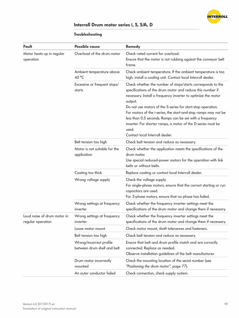
Interroll Drum motor series i, S, S/A, D
Troubleshooting
Version 6.0 (07/2017) enTranslation of original instruction manual
99
Fault Possible cause Remedy
Motor heats up in regularoperation
Overload of the drum motor Check rated current for overload.Ensure that the motor is not rubbing against the conveyor beltframe.
Ambient temperature above40 °C
Check ambient temperature. If the ambient temperature is toohigh, install a cooling unit. Contact local Interroll dealer.
Excessive or frequent stops/starts
Check whether the number of stops/starts corresponds to thespecifications of the drum motor and reduce this number ifnecessary. Install a frequency inverter to optimize the motoroutput.Do not use motors of the S-series for start-stop operation.For motors of the i-series, the start-and-stop ramps may not beless than 0.5 seconds. Ramps can be set with a frequencyinverter. For shorter ramps, a motor of the D-series must beused.Contact local Interroll dealer.
Belt tension too high Check belt tension and reduce as necessary.
Motor is not suitable for theapplication
Check whether the application meets the specifications of thedrum motor.Use special reduced-power motors for the operation with linkbelts or without belts.
Coating too thick Replace coating or contact local Interroll dealer.
Wrong voltage supply Check the voltage supply.For single-phase motors, ensure that the correct starting or runcapacitors are used.For 3-phase motors, ensure that no phase has failed.
Wrong settings at frequencyinverter
Check whether the frequency inverter settings meet thespecifications of the drum motor and change them if necessary.
Loud noise of drum motor inregular operation
Wrong settings at frequencyinverter
Check whether the frequency inverter settings meet thespecifications of the drum motor and change them if necessary.
Loose motor mount Check motor mount, shaft tolerances and fasteners.
Belt tension too high Check belt tension and reduce as necessary.
Wrong/incorrect profilebetween drum shell and belt
Ensure that belt and drum profile match and are correctlyconnected. Replace as needed.Observe installation guidelines of the belt manufacturer.
Drum motor incorrectlymounted
Check the mounting location of the serial number (see"Positioning the drum motor", page 77).
An outer conductor failed Check connection, check supply system.

Interroll Drum motor series i, S, S/A, D
Troubleshooting
100 Version 6.0 (07/2017) enTranslation of original instruction manual
Fault Possible cause Remedy
Drum motor vibrates heavily Wrong settings at frequencyinverter
Check whether the frequency inverter settings meet thespecifications of the drum motor and change them if necessary.
Loose motor mount Check motor mount, shaft tolerances and fasteners.
Drum motor runs unevenly Check whether the specifications of the drum motor contain astatic or dynamic balancing and adjust it. Single-phase motorsnaturally do not run completely even and, for this reason, arelouder and vibrate more than three-phase motors.
Drum motor runs withinterruptions
Drum motor/belt isoccasionally or partiallyblocked
Ensure that belt and drum motor are not being blocked and allrollers and drum shells can turn freely.
Wrong or loose power cableconnection
Check connections.
Gear box is damaged Check by hand if the drum shell can be turned freely.If not, replace drum motor or contact local Interroll dealer.
Wrong or faulty voltagesupply
Check the voltage supply.For single-phase motors: Check capacitors.
Drum motor/belt runs moreslowly than specified
Wrong motor speed ordered/delivered
Check drum motor specifications and tolerances.Replace drum motor or contact local Interroll dealer.
Drum motor/belt isoccasionally or partiallyblocked
Ensure that belt and drum motor are not being blocked and allrollers and drum shells can turn freely.
Wrong settings at frequencyinverter
Check whether the frequency inverter settings meet thespecifications of the drum motor and change them if necessary.
Belt slips See the fault "Belt slips on drum motor".
Drum motor/belt runs moreslowly than specified
Coating slips on the drum shell Check condition of coating and fix coating on drum shell.Replace coating. Sandblast or abrade drum surface toguarantee a good adhesion of the coating.
Use of a 60-Hz motor in a 50-Hz supply system
Check whether motor specifications and tolerances correspondto the supply voltage/frequency.Replace drum motor or contact local Interroll dealer.

Interroll Drum motor series i, S, S/A, D
Troubleshooting
Version 6.0 (07/2017) enTranslation of original instruction manual
101
Fault Possible cause Remedy
Drum motor runs faster thanspecified.
Wrong motor speed ordered/delivered
Check drum motor specifications and tolerances.Replace drum motor or contact local Interroll dealer.
Wrong settings at frequencyinverter
Check whether the frequency inverter settings meet thespecifications of the drum motor and change them if necessary.
Use of a 50-Hz motor in a 60-Hz supply system
Check whether motor specifications and tolerances correspondto the supply voltage/frequency.Replace drum motor or contact local Interroll dealer.
Thickness of rubber coatingincreased the belt speedbeyond the rated speed of themotor
Measure thickness of rubber coating and check whether thisvalue was considered and calculated in the selection of thedrum motor speed.Reduce thickness of rubber coating or install a frequencyinverter or install new drum motor with lower speed.
Motor winding: one phasefailed
Failure/overload of windinginsulation
Check continuity, current and resistance of phase winding.Replace drum motor or contact local Interroll dealer.
Motor winding: two phasesfailed
Power failure at one phasewhich leads to overload at theother two phases / separatingfailure
Check power supply to all phases. Check continuity, currentand resistance of phase winding.Replace drum motor or contact local Interroll dealer.
Motor winding: all threephases failed
Motor overload / wrongcurrent connection
Check whether the correct supply voltage is present.Check continuity, current and resistance of phase winding.Replace drum motor or contact local Interroll dealer.

Interroll Drum motor series i, S, S/A, D
Troubleshooting
102 Version 6.0 (07/2017) enTranslation of original instruction manual
Fault Possible cause Remedy
Belt slips on drum motor Belt blocked Ensure that belt and drum motor are not being blocked and allrollers and drum shells can turn freely.
Friction too low between drummotor and belt
Check condition and tension of the belt.Check condition of drum shell or coating.Check whether oil or grease is between belt and drum motor.
Friction too high between beltand bracket/gliding plate
Check underside of belt and gliding plate for contamination /defective surface coating.Check whether water entered between belt and gliding plateand a suction/draft occurs.
Belt tension too low Check condition of belt and tension or shorten it.
Drum profile too low for linkbelt or wrong
Ensure that belt and drum profile / teeth are correctlyconnected.Ensure that height and tension of belt meets the manufacturerdata.
Oil, lubricant or greasebetween belt and drum shell ofdrum motor
Remove excess oil, grease or lubricant.Ensure correct functioning of cleaning devices.
Diameter of start roller/endroller/transfer roller too lowfor the belt
Check minimum drum diameter for belt. Knife edges/roller withsmall diameter can cause an excessive friction and, therefore, ahigher current demand.
Coating slips on the drum shell Check condition of coating and fix coating on drum shell.Replace coating. Sandblast or abrade drum surface toguarantee a good adhesion of the coating.
Belt skips on drum motor Belt blocked or materialdeposits on the drum shellsPoor or damaged beltconnectionFriction too high between beltand gliding plate
Ensure that belt and drum shell are not being blocked and allrollers and drum shells can turn freely.Check belt connection.Ensure that the motor pulls the belt and does not push it.
Conveyor belt loose ordamaged
Check tension and condition of belt and condition of coating.Check belt tracking and belt adjustment.
Wrong coating/sprocketprofile for link belt
See the fault "Belt slips on drum motor".

Interroll Drum motor series i, S, S/A, D
Troubleshooting
Version 6.0 (07/2017) enTranslation of original instruction manual
103
Fault Possible cause Remedy
Belt not correctly adjusted /belt does not run centered
Material deposits on drummotor/rollers/belt
Ensure that belt and drum shell are not being blocked and allrollers and drum shells can turn freely.Check belt connection.
Material deposits on rollers Check whether material detaches itself and ensure that thecleaning devices function correctly.
Defective or poorly fixed belt Check belt condition and belt connections.
Belt tension higher on one side Ensure that the belt tension is equal on both sides.Check whether continuous connection of belt was done inparallel.
Top/bottom rollers notcorrectly adjusted
Check adjustment of support and returning rollers.
Start roller/end roller/interimroller not correctly adjusted
Check adjustment of drum motor and roller.
Conveyor frame not correctlyadjusted
Ensure that the conveyor frame is rectangular, parallel andstraight over the entire length.
Feeding materials from oneside
Check force or friction at transfer point.
Belt profile not connected withdrum profile
Ensure that belt and drum profile match and are correctlyconnected and adjusted.
Drum camber too low for belt Check belt / drum motor specifications.
Oil exiting at shaft seal Shaft seal worn Check whether negative chemical or aggressive materials/conditions are present.Check operating service life of seals.
Shaft seal damaged Ensure that there are no steel residues, material deposits orother particles at the seals.
Cap bearing damaged / worn Check whether the belt is tensioned or loaded too much.Check whether water or chemicals have entered.
Excess grease in labyrinth seal Check whether oil or grease is exiting. Oil remains fluid andgrease hardens when it cools down.Remove excess grease. If the problem persists, contact localInterroll dealer.Small amount of grease exiting in the S-series is normal andnot a problem.
Oil exiting at the cable/terminal box
Loose cable connection socketDefect at internal cable seal
Ensure that cable connection socket and seals are tight and notstressed by overheating or chemicals.
Loose cable connection socketSeal at terminal box defective
Ensure that cable connection socket and seals at terminal boxare tight and not stressed by overheating or chemicals.

Interroll Drum motor series i, S, S/A, D
Troubleshooting
104 Version 6.0 (07/2017) enTranslation of original instruction manual
Fault Possible cause Remedy
Oil exiting at drum shell/endcap
End cap in drum shell is loose Check whether there are gaps between drum shell and endhousing.Check whether the belt is tensioned too much or impact-loaded.
End cap/drum seal defective Check whether the belt is overheated, tensioned too much orimpact-loaded.
Oil discolorization - silver-metallic particles
Wear of gear teeth orbearings
Check condition of bearings and seals.Check whether an overload is present.
Oil discolorization - whitecolorization
Contamination through wateror other liquid
Check condition and contamination through water/liquid.Change oil (see "Oil change at drum motor", page 92).
Oil discolorization - blackcolorization
Extremely high operatingtemperatureOverloadNo belt installed
Check whether the application / operating conditions meet/meets the specifications of the drum motor.Check whether an overload current or high ambienttemperature is present.
Cable/terminal box defectiveor damaged
Wrong operation by thecustomer or damage duringinstallation
Check type of damage and possible cause.Replace terminal box.
Damage during transport Check type of damage and possible cause.Replace terminal box.
Cap bearing failed Overload Check whether the load of the application meets thespecifications of the drum motor.
Impact load Check whether the load of the application meets thespecifications of the drum motor.
Belt tension too high Check whether the belt is tensioned too much. Reduce belttension as necessary.
Poor lubrication Check oil level and installation of drum motor.With vertical mounting or if the motor is tilted by more than 5°(2° for 113S), check motor specifications of drum motor.
Loading or wrong adjustmentof shaft
Check whether screws have been overtightened and whetherframe or motor mount are incorrectly adjusted.
Shaft seal damaged/worn Check for external contamination.Contact local Interroll dealer.
Loose or fixed seating ofbearing on the shaft
Contact local Interroll dealer.
Gear box failure Overload/impact load orregular wear
Check whether the load of the application meets thespecifications of the drum motor.Check service life.
Rotor bearing worn/failed Poor lubrication Check correct oil type and oil level.

Interroll Drum motor series i, S, S/A, D
Troubleshooting
Version 6.0 (07/2017) enTranslation of original instruction manual
105
Fault Possible cause Remedy
Rotor drive worn or teethbroken off
Excessive or frequent stops/starts, very high startingtorque
Check whether the load of the application meets thespecifications of the drum motor.Check oil, maximum number of stops/starts and permissiblestarting torque.Use frequency inverter with start-and-stop ramps (0.5 s ormore).
Toothed sprocket worn orteeth/bolts broken off
Start-up under overload and/or impact load or blocking
Check whether the application and load meet the specificationsof the drum motor.Check whether a blockage is present.Use frequency inverter with start-and-stop ramps (0.5 s ormore).
Interim gear box and bearingworn/failed
Poor lubrication or worn gearbox or bearing
Check oil level.Check service life and tolerances of journals and drives/shafts.Use frequency inverter with start-and-stop ramps (0.5 s ormore).
Complete or temporary failureof brake and rectifier
Wrong operating voltageapplied
Ensure that the correct rectifier was installed and that thecorrect input voltage (V/ph/Hz) is present.
Wrong connection Never connect the rectifier to the frequency inverter.Ensure that the brake was connected according to connectiondiagram.
Insufficient shielding againstexternal voltage spikes fromcables and external devices
Ensure that all cables between brake, rectifier and voltagesupply are shielded and grounded according to IECrecommendations.
Complete or temporary failureof brake and rectifier
Voltage drop due to cable withexcessive length
Check whether a voltage drop occurs in long cables andensure that the cable cross section meets the IEC specifications.
Excessive stops/starts Ensure that the specifications for brake and rectifier meet therequirements of the application.
Wrong rectifier connected Contact Interroll. We will give you the name of the correctrectifier for the corresponding brake and application.
Voltage overshoot /regeneration with connectionof motor star point rectifier
Conveyor belts with incline can lead to an overload of themotor and cause a regeneration if motor star point voltage isapplied.
Short circuit of brake winding Check continuity of winding and rectifier.
Slow switching of brake andrectifier
Wrong brake / wrong rectifierselected or specified
Ensure that the specifications for brake and rectifier meet therequirements of the application.
Low ambient temperature orexcessive oil viscosity
Ensure that the oil viscosity is suitable for the ambienttemperature. If not, fill in new oil with the correct viscosity.Install a heater or more powerful motor. In this case, contactthe local Interroll dealer.

Interroll Drum motor series i, S, S/A, D
Troubleshooting
106 Version 6.0 (07/2017) enTranslation of original instruction manual
Fault Possible cause Remedy
Encoder (temporarily) notworking
Incorrect connection or loose/defective cable connection
Check connection diagrams and determine whether cables aredefective or connections are loose.
Failure of electronic backfeedsystem
The troubleshooting should be performed only by anelectrician.
Error or failure of encoder The troubleshooting should be performed only by anelectrician.
Error at PC or drive The troubleshooting should be performed only by anelectrician.

Interroll Drum motor series i, S, S/A, D
Version 6.0 (07/2017) enTranslation of original instruction manual
107
Decommissioning and disposal4 When disposing the motor oil, observe the disposal documents of the motor manufacturer.4 The packaging must be recycled to provide environmental relief.
Shutdown
CAUTIONRisk of injury due to incorrect handling
4 Shut-down may only be executed by qualified and authorized persons.4 Only shut down the drum motor after switching off the power. Ensure that the drum motor
cannot be turned on accidentally.
4 Disconnect the motor cable from the power supply and motor control.4 Relax the belt.4 Remove holding plate from the motor mount.4 Remove the drum motor out of the conveyor frame.
DisposalThe operator is responsible for the proper disposal of the drum motor.
4 In doing so, industry-specific and local provisions must be observed for the disposal of thedrum motor and its packaging.

Interroll Drum motor series i, S, S/A, D
108 Version 6.0 (07/2017) enTranslation of original instruction manual
Appendix
List of abbreviations
Electrical data PN in kW Rated output in kilowatt
np Number of poles
nN in 1/min. Rated speed of rotor in revolutions per minute
fN in Hz Rated frequency in Hz
UN in V Rated voltage in volt
IN in A Rated current in ampere
I0 in A Rated open-circuit current in ampere
Imax in A Maximum current in ampere
cos φ Power factor
η Efficiency
JR in kgcm2 Rotor moment of inertia
IS/IN Ratio of startup current to rated current
MS/MN Ratio of starting torque to rated torque
MP/MN Ratio of pull-up torque to rated torque
MB/MN Ratio of pull-out torque to rated torque
MN in Nm Rated torque of rotor in Newton meter
M0 in Nm Stalled torque in Newton meter
Mmax in Nm Maximum torque in Newton meter
RM in Ω Phase resistance in ohm
RA in Ω Phase resistance of auxiliary winding in ohm
Lsd in mH Inductance of d-axles in millihenry
Lsq in mH Inductance of q-axles in millihenry
Lsm in mH Averaged inductance in millihenry
ke in V/krpm Induced motor voltage
Te in ms Electrical time constant in milliseconds
kTN in Nm/A Torque constant in Newton meter per ampere
USH in V Heating voltage in volt
USH delta in V Standstill heating voltage in delta connection in volt
USH star in V Standstill heating voltage in star connection in volt
USH ~ in V Heating voltage for single-phase units in volt
Cr in µF Run capacitor (1~) / Steinmetz capacitor (3~) in microfarad

Interroll Drum motor series i, S, S/A, D
Appendix
Version 6.0 (07/2017) enTranslation of original instruction manual
109
Connection diagrams 1~ Single-phase motor
3~ Three-phase motor
B1 Input of electromagnetic brake
B2 Output of electromagnetic brake
BR Brake (optional)
Cos - Cosine signal 0
Cos + Cosine signal +
Cr Run capacitor
Cs Starting capacitor
FI Frequency inverter
L1 Phase 1
L2 Phase 2
L3 Phase 3
N Neutral conductor
NC Not connected
RC Series circuit of resistor and capacitor
Ref - Reference signal 0
Ref + Reference signal +
Sin - Sine signal 0
Sin + Sine signal +
T1 Input thermistor
T2 Output thermistor
TC Thermal protection
U1 Input winding phase 1
U2 Output winding phase 1
V1 Input winding phase 2
V2 Output winding phase 2
W1 Input winding phase 3
W2 Output winding phase 3
Z1 Input auxiliary winding single-phase motor
Z2 Output auxiliary winding single-phase motor

Interroll Drum motor series i, S, S/A, D
Appendix
110 Version 6.0 (07/2017) enTranslation of original instruction manual
Color coding Color coding of cables in the connection diagrams:
bk: black gn: green pk: pink wh: white
bn: brown gy: gray rd: red ye: yellow
bu: blue or: orange vi/vt: violet ye/gn: yellow/green
( ): alternate color

Interroll Drum motor series i, S, S/A, D
Appendix
Version 6.0 (07/2017) enTranslation of original instruction manual
111
Installation declarationIn accordance with EC Machinery Directive 2006/42/EC, Appendix II 1 B.
The manufacturer:Interroll Trommelmotoren GmbHOpelstr. 3 D - 41836 Hueckelhoven/BaalGermany
hereby declares with sole responsibility that the product range
• Drum motor i-series• Drum motor S-series• Drum motor S/A-series• Drum motor D-series
meets the following requirements in accordance with Appendix I of the above-referenceddirective:1.1.2, 1.1.3, 1.1.5, 1.5.8, 1.5.9, 1.6.4, 1.7.2.
The special technical documents according to Appendix VII Part B were created for the product.Upon justified request, these documents can be transmitted to a sovereign authority via e-mail.
Applied EU Directives:• EMC Directive 2014/30/EU• RoHS Directive 2011/65/EU• Low Voltage Directive 2014/35/EU
Applicable harmonized standards:• EN ISO 12100:2010-03• EN 60034-1:2010/AC: 2010• EN 60034-5:2001/A1:2007• EN 60034-6:1993• EN 60034-11:2004• EN 60034-14:2004• EN 60204-1:2006/AC: 2010
Person authorized to prepare the technical documents: Holger Hoefer, Interroll Trommelmotoren GmbH, Opelstr. 3, D - 41836 Hueckelhoven, Germany
Initial startup of this product is not permitted until the machine or system in which this product isto be installed or of which it is a component complies with the requirements of all relevantdirectives.
Hueckelhoven - May 30, 2016
Dr. Hauke Tiedemann (Managing Director)
(This installation declaration can be obtained at www.interroll.com, if needed.)

For your local contacts please visitinterroll.com/contact
©copyright
Version 6.0 (07/2017) enTranslation of original instruction manual