User Manual Industrial Protocols
101
User Manual Industrial Protocols Modbus/TCP EtherNet/IP PROFINET
Transcript of User Manual Industrial Protocols

User Manual
Industrial Protocols
Modbus/TCPEtherNet/IPPROFINET

Federal Communication Commission Interference Statement
For further certification information, please go to www.advantech.com
Declaration of Conformity
CE
This product has passed the CE test for environmental specifications when shieldedcables are used for external wiring. We recommend the use of shielded cables. Thiskind of cable is available from Advantech. Please contact your local supplier forordering information.
This product has passed the CE test for environmental specifications. Test conditionsfor passing included the equipment being operated within an industrial enclosure. Inorder to protect the product from being damaged by ESD (Electrostatic Discharge)and EMI leakage, we strongly recommend the use of CE-compliant industrial enclo-sure products.
FCC Class A
This equipment has been tested and found to comply with the limits for a Class A dig-ital device, pursuant to part 15 of the FCC Rules. These limits are designed to pro-vide reasonable protection against harmful interference when the equipment isoperated in a commercial environment. This equipment generates, uses, and canradiate radio frequency energy and, if not installed and used in accordance with theinstruction manual, may cause harmful interference to radio communications. Opera-tion of this equipment in a residential area is likely to cause harmful interference inwhich case the user will be required to correct the interference at his own expense.
Part No. XXXXXXXXXX Edition 1
Printed in Taiwan July 2016
Industrial Protocols User Manual i

Read these safety instructions carefully. Keep this user manual for later reference. Disconnect this equipment from any AC outlet before cleaning. Use damp cloth.
Do not use liquid or spray detergents for cleaning. For plug-in equipment, the power outlet socket must be located near the equip-
ment and must be easily accessible. Keep this equipment away from humidity. Put this equipment on a reliable surface during installation. Dropping it or letting
it fall may cause damage. The openings on the enclosure are for air convection. Protect the equipment
from overheating. DO NOT COVER THE OPENINGS. Make sure the voltage of the power source is correct before connecting the
equipment to the power outlet. Position the power cord so that people cannot step on it. Do not place anything
over the power cord. All cautions and warning on the equipment should be noted. If the equipment is not used for a long time, disconnect it from the power source
to avoid damage by transient over voltage. Never pour any liquid into an opening. This may cause fire or electrical shock. Never open the equipment. For safety reasons, the equipment should be
opened only by qualified service personnel. If one of the following situations arises, get the equipment checked by service
personnel:– The power cord or plug is damaged.– Liquid has penetrated into the equipment.– The equipment has been exposed to moisture.– The equipment does not work well, or you cannot get it to work according to
the user manual– The equipment has been dropped and damaged.– The equipment has obvious signs of breakage.
Instructions for installation in a pollution Degree 2 environment or equivalent statement.
PoE requirements:This product was in-door used and not connected to outside plant, so user man-ual shall have the description as below or equivalent: “The equipment is to be connected only to PoE networks without routing to the outside plant.”
Do NOT LEAVE THIS EQUIPMENT IN AN ENVIRONMENT WHERE THE STORAGE TEMPERATURE MAY GO BELOW -40°C(-40°F) OR ABOVE 75°C(167°F) THIS COULD DAMAGE THE EQUIPMENT. THE EQUIPMENT SHOULD BE IN A CONTROLLED ENVIRONMENT.
ii Industrial Protocols User Manual

Product Warranty (5 years)Company Address:
ADVANTECH CO.,LTD. (研華股份有限公司)
1 ALY 20 LN 26 RUEIGUANG RD NEIHU DISTRICT TAIPEI 114 TAIWAN
Advantech warrants to you, the original purchaser, that each of its products will befree from defects in materials and workmanship for five years from the date of pur-chase.
This warranty does not apply to any products which have been repaired or altered bypersons other than repair personnel authorized by Advantech, or which have beensubject to misuse, abuse, accident or improper installation. Advantech assumes noliability under the terms of this warranty as a consequence of such events.
Because of Advantech’s high quality-control standards and rigorous testing, most ofour customers never need to use our repair service. If an Advantech product is defec-tive, it will be repaired or replaced at no charge during the warranty period. For out of-warranty repairs, you will be billed according to the cost of replacement materials,service time and freight. Please consult your dealer for more details.
If you think you have a defective product, follow these steps:
1. Collect all the information about the problem encountered. (For example, CPU speed, Advantech products used, other hardware and software used, etc.) Note anything abnormal and list any on screen messages you get when the problem occurs.
2. Call your dealer and describe the problem. Please have your manual, product, and any helpful information readily available.
3. If your product is diagnosed as defective, obtain an RMA (return merchandize authorization) number from your dealer. This allows us to process your return more quickly.
4. Carefully pack the defective product, a fully-completed Repair and Replacement Order Card and a photocopy proof of purchase date (such as your sales receipt) in a shippable container. A product returned without proof of the purchase date is not eligible for warranty service.
5. Write the RMA number visibly on the outside of the package and ship it prepaid to your dealer.
Industrial Protocols User Manual iii

CopyrightCopyright © 2016 Advantech Inc. All rights reserved. No part of this publication maybe reproduced, adapted, stored in a retrieval system, translated into any language, ortransmitted in any form or by any means without the written permission of the manu-facturer.
Warning! Warnings indicate conditions, which if not observed, can cause personal injury!
Caution! Cautions are included to help you avoid damaging hardware or losing data. e.g.
There is a danger of a new battery exploding if it is incorrectly installed. Do not attempt to recharge, force open, or heat the battery. Replace the battery only with the same or equivalent type recommended by the man-ufacturer. Discard used batteries according to the manufacturer's instructions.
Note! Notes provide optional additional information.
iv Industrial Protocols User Manual

Technical Support and Assistance1. Visit the Advantech web site at www.advantech.com/support where you can find
the latest information about the product.2. Contract your distributor, sales representative, or Advantech's customer service
center for technical support if you need additional assistance. Please have the following information ready before you call:– Product name and serial number– Description of your peripheral attachment– Description of your software (operating system, version, application software,
etc.)– A complete description of the problem– The exact wording of any error messages
About This ManualThis user manual is intended to guide professional installers in installing and config-uring the Serial Device Server. It includes technical specifications, software utilityintroduction, as we as procedures for the use of the software utility to self-managethe devices.
Industrial Protocols User Manual v

Contents
Chapter 1 Modbus/TCP........................................ 11.1 Introduction ............................................................................................... 21.2 Supported Modbus object types ............................................................... 2
1.2.1 Read and write functions .............................................................. 21.3 Masters or Slaves Designation ................................................................. 21.4 Slaves Identification .................................................................................. 31.5 Modbus/TCP Mapping .............................................................................. 3
1.5.1 Modbus/TCP Mapping Table ........................................................ 3
Chapter 2 EtherNet/IP......................................... 292.1 Overview ................................................................................................. 302.2 Supported Hardware............................................................................... 302.3 Requirements.......................................................................................... 30
2.3.1 SCADA Requirements ................................................................ 302.3.2 Hardware .................................................................................... 312.3.3 Operating System....................................................................... 31
2.4 Configuring the Controller Device ........................................................... 312.4.1 Configuring in Logix .................................................................... 31
Figure 2.1 Creating a New Controller ........................................ 32Figure 2.2 Creating a New Ethernet Module ............................. 33Figure 2.3 Selecting a Module Type.......................................... 33Figure 2.4 Module Properties Listing......................................... 34Figure 2.5 Defining the Module Type ........................................ 34Figure 2.6 Creating an Ethernet Module Type .......................... 35Figure 2.7 Modifying Ethernet General Parameters .................. 35Figure 2.8 Modifying Ethernet Module Parameters ................... 36Figure 2.9 Creating a Routine ................................................... 36Figure 2.10Selecting Import Rungs ............................................ 37Figure 2.11Importing a Rung File ............................................... 37Figure 2.12Importing a Rung File ............................................... 38Figure 2.13Importing a Rung File ............................................... 38Figure 2.14Configuring Tag References .................................... 39Figure 2.15Setting Message Configuration Parameters............. 40Figure 2.16Configuring Communication Settings ....................... 40Figure 2.17Selecting the Message Path..................................... 41Figure 2.18Configuring Packet Rate Message........................... 41
2.4.2 Configuring in FactoryTalk® View Machine Edition.................... 42Figure 2.19Opening FactoryTalk® View Studio Applications ..... 42Figure 2.20Creating an Application File ..................................... 42Figure 2.21Opening an Application File ..................................... 43Figure 2.22Importing an Image File............................................ 44Figure 2.23Importing Images...................................................... 44Figure 2.24Importing EKI and HMI Objects................................ 45Figure 2.25Importing GFX Objects............................................. 46Figure 2.26Importing GFX Files ................................................. 46Figure 2.27Importing EKI Param1 into Parameters.................... 47Figure 2.28Importing EKI Param1 into Parameters.................... 47Figure 2.29Locating RSLinx Enterprise List ............................... 48Figure 2.30Creating a New Runtime Configuration.................... 48Figure 2.31Adding a New Runtime Device Shortcut .................. 48Figure 2.32Altering Parameters File........................................... 49Figure 2.33Downloading File to the Device................................ 49
Industrial Protocols User Manual vii

Figure 2.34Opening ME Image Control Panel............................ 50Figure 2.35Identifying Control Panel Menu ................................ 50Figure 2.36Selecting Port Entries ............................................... 51Figure 2.37Configuring Port Settings.......................................... 52Figure 2.38Setting CPU, Port and Alarm Value Limits ............... 52Figure 2.39Setting CPU, Port and Alarm Value Limits ............... 53Figure 2.40Enabling Alarm Options............................................ 53
2.4.4 Configuring in FactoryTalk® View Site Edition ........................... 54Figure 2.41Opening View Site Edition Applications.................... 54Figure 2.42Creating an Application File...................................... 54Figure 2.43Opening an Application File...................................... 55Figure 2.44Importing an Image File............................................ 56Figure 2.45Importing Images...................................................... 56Figure 2.46Importing EKI and HMI Objects ................................ 57Figure 2.47Importing EKI and HMI Objects ................................ 57Figure 2.48Importing GFX Objects ............................................. 58Figure 2.49Importing GFX Files.................................................. 58Figure 2.50Importing EKI Param1 into Parameters.................... 59Figure 2.51Importing EKI Param1 into Parameters.................... 59Figure 2.52Creating a data server .............................................. 60Figure 2.53Locating RSLinx Enterprise List ............................... 60Figure 2.54Creating a New Runtime Configuration .................... 60Figure 2.55Adding a New Runtime Device Shortcut .................. 61Figure 2.56Altering Parameters File ........................................... 61
2.4.5 Configuring in SE Image Control Panel ...................................... 62Figure 2.57Opening SE Image Control Panel ............................ 62Figure 2.58Identifying Control Panel Menu ................................ 63Figure 2.59Port Settings Menu ................................................... 63Figure 2.60Setting CPU, Port and Alarm Value Limits ............... 64Figure 2.61Enabling Alarm Options............................................ 64
2.5 EtherNet/IP CIP Objects ......................................................................... 642.5.1 Identity Objects ........................................................................... 652.5.2 TCP/IP Interface Objects ............................................................ 662.5.3 Ethernet Link Objects.................................................................. 682.5.4 Advantech Networking Objects................................................... 722.5.5 Assembly .................................................................................... 752.5.6 Message Router.......................................................................... 762.5.7 Connection Manager................................................................... 772.5.8 Base Switch ................................................................................ 77
Chapter 3 PROFINET ..........................................753.1 PROFINET .............................................................................................. 76
3.1.1 Introduction ................................................................................. 76Figure 3.1 PROFINET IO........................................................... 76
3.2 Configuring PROFINET........................................................................... 773.2.1 Enable PROFINET I/O................................................................ 77
Figure 3.2 PROFINET Settings ................................................. 773.2.2 PROFINET Cyclic I/O Data......................................................... 78
3.3 TIA Portal V13 Integration....................................................................... 803.3.1 Create a PROFINET I/O project in TIA Portal............................. 80
Figure 3.3 Create new project ................................................... 803.3.2 GSD file installation..................................................................... 80
Figure 3.4 Install GSD File......................................................... 80Figure 3.5 Install GSD File......................................................... 81
3.3.3 Add Devices and configuration ................................................... 81Figure 3.6 Install GSD file.......................................................... 81Figure 3.7 Draw PROFINET-IO System.................................... 82
viii Industrial Protocols User Manual

Figure 3.8 Assign Device Name ................................................ 82Figure 3.9 Assign Device Name ................................................ 83Figure 3.10Add Port Link Status................................................. 83
3.3.4 Save and load the project into the PLC ...................................... 84Figure 3.11Compile Project ........................................................ 84Figure 3.12Download to Device ................................................. 84
3.3.5 Switch Watch tables ................................................................... 85Figure 3.13Download to Device ................................................. 85Figure 3.14Watch Table ............................................................. 85Figure 3.15Monitoring................................................................. 86Figure 3.16Monitoring................................................................. 86
Industrial Protocols User Manual ix

Chapter 1
1 Modbus/TCP
1.1 IntroductionModbus is one of the most widely used serial communication protocol. It allows thetransmission of information over serial lines between the switch and devices. Thebinding supports both TCP and serial slaves.
The binding acts as Modbus TCP client (Modbus master), queering data from Mod-bus TCP server (Modbus slaves).
1.2 Supported Modbus object typesThe binding allows multiple Modbus slave connectivity. The following list includes thesupported Modbus object types:
coils, also known as digital out (DO) (read & write) discrete inputs, also known as digital in (DI) (read) input registers (read) holding registers (read & write)The Modbus binding can be configured to interpret values stored in the 16bit regis-ters, signed or unsigned integers.
1.2.1 Read and write functionsModbus specification has different operations for reading and writing different objecttypes. These types of operations are identified by function code. Some devices sup-port only certain function codes.
For different reading and writing operations, different objects types are availablethrough Modbus. The operations are designated by function codes.
read coils: function code (FC) 1 (Read Coils) write coil: FC 5 (Write Single Coil) read discrete inputs: FC 2 (Read Discrete Inputs) read input registers: FC 4 (Read Input Registers) read holding registers: FC 3 (Read Multiple Holding Registers) write holding register: FC 6 (Write Single Holding Register), OR FC 16 (Write
Multiple Holding Registers)
1.3 Masters or Slaves DesignationModbus devices are classified as either a master or a slave. Initiating all communica-tion with the slave devices is tasked to the master device. While slave devices onlyrespond to a communication request.
Note! In the given example, the address offset 0x1000 (hex) equals Modbus address 34097, while the address offset 0x1100 (hex) equals Modbus address 34353. The information given by the Advantech is shown in hex mode.
Industrial Protocols User Manual 2

1.4 Slaves IdentificationModbus slave devices are assigned a unique ID between 1 and 247. When a requestfrom the master device is initiated, it must include the ID of the intended recipient.Master devices do no have IDs.
1.5 Modbus/TCP MappingThe data map addresses of Advantech switches shown in the following table startfrom Modbus address 30001 for function code 4.
In the given example, the address offset 0x1000 (hex) equals Modbus address34097, while the address offset 0x1100 (hex) equals Modbus address 34353.
The information given by the Advantech is shown in hex mode.
1.5.1 Modbus/TCP Mapping TableThe following listing displays parameters for referencing the different mapping func-tions.
Catalog Name Data Type Interpretation
Address Offset (Hex)
Address 3X
Description
System Info Vendor ID = 0x‘13FE
1 word 16 bits HEX 0x0000 30001 Vendor ID = 0x13FE
Unit ID = 0xFF
1 word 16 bits HEX 0x0001 30002 Unit ID = 0xFF
Product Code
1 word 16 bits HEX 0x0002 30003 Product Code
Vendor Name = "Advantech"
16 words 32 chars ASCII 0x0010 30017 Vendor Name = "Advan-tech"Word 0 Hi byte = 'A'Word 0 Lo byte = 'd'Word 1 Hi byte = 'v'Word 1 Lo byte = 'a'Word 2 Hi byte = 'n'Word 2 Lo byte = 't'Word 3 Hi byte = 'e'Word 3 Lo byte = 'c'Word 4 Hi byte = 'h'Word 4 Lo byte = '\0'
Product Name = "EKI-xxxx"
16 words 32 chars ASCII 0x0020 30033 Product Name = "EKI-xxxx" Word 0 Hi byte = 'E' Word 0 Lo byte = 'K'Word 1 Hi byte = 'I'Word 1 Lo byte = '-'Word 2 Hi byte = 'x'Word 2 Lo byte = 'x'Word 3 Hi byte = 'x'Word 3 Lo byte = 'x'Word 4 Hi byte = '\0'
3 Industrial Protocols User Manual

System Info Firmware Version
2 words 32 bits HEX 0x020A 30523 Firmware VersionWord 0 Hi byte = majorWord 0 Lo byte = minorWord 1 Hi byte = releaseWord 1 Lo byte = build
Ethernet MAC Address
3 words 48 bits HEX 0x020E 30527 Ethernet MAC AddressEx: MAC = 00-19-CB-01-02-03Word 0 Hi byte = 0x00Word 0 Lo byte = 0x19Word 1 Hi byte = 0xCBWord 1 Lo byte = 0x01Word 2 Hi byte = 0x02Word 2 Lo byte = 0x03
Revision Number
16 words 32 chars ASCII 0x0211 30530 Product Name = "YYY.xxxxx"Word 0 Hi byte = 'Y'Word 0 Lo byte = 'Y'Word 1 Hi byte = 'Y'Word 1 Lo byte = '.'Word 2 Hi byte = 'x'Word 2 Lo byte = 'x'Word 3 Hi byte = 'x'Word 3 Lo byte = 'x'Word 4 Hi byte = 'x'Word 4 Hi byte = '\0'
IP Address 2 words 32 bits HEX 0x0400 31025 IP AddressEx: IP = 192.168.1.1Word 0 Hi byte = 0xC0Word 0 Lo byte = 0xA8Word 1 Hi byte = 0x01Word 1 Lo byte = 0x01
Port Info Port Status 1 word 16 bits HEX 0x1000 ~ 0x101F
34097 ~ 34128
Port Status 0x0000: Link down 0x0001: Link up 0xFFFF: No port
Port 1 Sta-tus
1 word 16 bits HEX 0x1000 34097
Port 2 Sta-tus
1 word 16 bits HEX 0x1001 34098
Port 3 Sta-tus
1 word 16 bits HEX 0x1002 34099
Catalog Name Data Type Interpretation
Address Offset (Hex)
Address 3X
Description
Industrial Protocols User Manual 4

Port Info Port 4 Sta-tus
1 word 16 bits HEX 0x1003 34100
Port 5 Sta-tus
1 word 16 bits HEX 0x1004 34101
Port 6 Sta-tus
1 word 16 bits HEX 0x1005 34102
Port 7 Sta-tus
1 word 16 bits HEX 0x1006 34103
Port 8 Sta-tus
1 word 16 bits HEX 0x1007 34104
Port 9 Sta-tus
1 word 16 bits HEX 0x1008 34105
Port 10 Sta-tus
1 word 16 bits HEX 0x1009 34106
Port 11 Sta-tus
1 word 16 bits HEX 0x100A 34107
Port 12 Sta-tus
1 word 16 bits HEX 0x100B 34108
Port 13 Sta-tus
1 word 16 bits HEX 0x100C 34109
Port 14 Sta-tus
1 word 16 bits HEX 0x100D 34110
Port 15 Sta-tus
1 word 16 bits HEX 0x100E 34111
Port 16 Sta-tus
1 word 16 bits HEX 0x100F 34112
Port 17 Sta-tus
1 word 16 bits HEX 0x1010 34113
Port 18 Sta-tus
1 word 16 bits HEX 0x1011 34114
Port 19 Sta-tus
1 word 16 bits HEX 0x1012 34115
Port 20 Sta-tus
1 word 16 bits HEX 0x1013 34116
Port 21 Sta-tus
1 word 16 bits HEX 0x1014 34117
Port 22 Sta-tus
1 word 16 bits HEX 0x1015 34118
Port 23 Sta-tus
1 word 16 bits HEX 0x1016 34119
Port 24 Sta-tus
1 word 16 bits HEX 0x1017 34120
Port 25 Sta-tus
1 word 16 bits HEX 0x1018 34121
Catalog Name Data Type Interpretation
Address Offset (Hex)
Address 3X
Description
5 Industrial Protocols User Manual

Port Info Port 26 Sta-tus
1 word 16 bits HEX 0x1019 34122
Port 27 Sta-tus
1 word 16 bits HEX 0x101A 34123
Port 28 Sta-tus
1 word 16 bits HEX 0x101B 34124
Port 29 Sta-tus
1 word 16 bits HEX 0x101C 34125
Port 30 Sta-tus
1 word 16 bits HEX 0x101D 34126
Port 31 Sta-tus
1 word 16 bits HEX 0x101E 34127
Port 32 Sta-tus
1 word 16 bits HEX 0x101F 34128
Port Speed 1 word 16 bits HEX 0x1100 ~ 0x111F
34353 ~ 34384
Port Speed0x0000: 10M-Half0x0001: 10M-Full0x0002: 100M-Half0x0003: 100M-Full0x0004: 1000M-Half0x0005: 1000M-Full0xFFFF: No port
Port 1 Speed
1 word 16 bits HEX 0x1100 34353
Port 2 Speed
1 word 16 bits HEX 0x1101 34354
Port 3 Speed
1 word 16 bits HEX 0x1102 34355
Port 4 Speed
1 word 16 bits HEX 0x1103 34356
Port 5 Speed
1 word 16 bits HEX 0x1104 34357
Port 6 Speed
1 word 16 bits HEX 0x1105 34358
Port 7 Speed
1 word 16 bits HEX 0x1106 34359
Port 8 Speed
1 word 16 bits HEX 0x1107 34360
Port 9 Speed
1 word 16 bits HEX 0x1108 34361
Port 10 Speed
1 word 16 bits HEX 0x1109 34362
Port 11 Speed
1 word 16 bits HEX 0x110A 34363
Port 12 Speed
1 word 16 bits HEX 0x110B 34364
Catalog Name Data Type Interpretation
Address Offset (Hex)
Address 3X
Description
Industrial Protocols User Manual 6

Port Info Port 13 Speed
1 word 16 bits HEX 0x110C 34365
Port 14 Speed
1 word 16 bits HEX 0x110D 34366
Port 15 Speed
1 word 16 bits HEX 0x110E 34367
Port 16 Speed
1 word 16 bits HEX 0x110F 34368
Port 17 Speed
1 word 16 bits HEX 0x1110 34369
Port 18 Speed
1 word 16 bits HEX 0x1111 34370
Port 19 Speed
1 word 16 bits HEX 0x1112 34371
Port 20 Speed
1 word 16 bits HEX 0x1113 34372
Port 21 Speed
1 word 16 bits HEX 0x1114 34373
Port 22 Speed
1 word 16 bits HEX 0x1115 34374
Port 23 Speed
1 word 16 bits HEX 0x1116 34375
Port 24 Speed
1 word 16 bits HEX 0x1117 34376
Port 25 Speed
1 word 16 bits HEX 0x1118 34377
Port 26 Speed
1 word 16 bits HEX 0x1119 34378
Port 27 Speed
1 word 16 bits HEX 0x111A 34379
Port 28 Speed
1 word 16 bits HEX 0x111B 34380
Port 29 Speed
1 word 16 bits HEX 0x111C 34381
Port 30 Speed
1 word 16 bits HEX 0x111D 34382
Port 31 Speed
1 word 16 bits HEX 0x111E 34383
Port 32 Speed
1 word 16 bits HEX 0x111F 34384
Catalog Name Data Type Interpretation
Address Offset (Hex)
Address 3X
Description
7 Industrial Protocols User Manual

Port Info Flow Con-trol
1 word 16 bits HEX 0x1200 ~ 0x121F
34609 ~ 34640
Flow Control0x0000: Off0x0001: On0xFFFF: No port
Port 1 Flow Control
1 word 16 bits HEX 0x1200 34609
Port 2 Flow Control
1 word 16 bits HEX 0x1201 34610
Port 3 Flow Control
1 word 16 bits HEX 0x1202 34611
Port 4 Flow Control
1 word 16 bits HEX 0x1203 34612
Port 5 Flow Control
1 word 16 bits HEX 0x1204 34613
Port 6 Flow Control
1 word 16 bits HEX 0x1205 34614
Port 7 Flow Control
1 word 16 bits HEX 0x1206 34615
Port 8 Flow Control
1 word 16 bits HEX 0x1207 34616
Port 9 Flow Control
1 word 16 bits HEX 0x1208 34617
Port 10 Flow Control
1 word 16 bits HEX 0x1209 34618
Port 11 Flow Control
1 word 16 bits HEX 0x120A 34619
Port 12 Flow Control
1 word 16 bits HEX 0x120B 34620
Port 13 Flow Control
1 word 16 bits HEX 0x120C 34621
Port 14 Flow Control
1 word 16 bits HEX 0x120D 34622
Port 15 Flow Control
1 word 16 bits HEX 0x120E 34623
Port 16 Flow Control
1 word 16 bits HEX 0x120F 34624
Port 17 Flow Control
1 word 16 bits HEX 0x1210 34625
Port 18 Flow Control
1 word 16 bits HEX 0x1211 34626
Catalog Name Data Type Interpretation
Address Offset (Hex)
Address 3X
Description
Industrial Protocols User Manual 8

Port Info Port 19 Flow Control
1 word 16 bits HEX 0x1212 34627
Port 20 Flow Control
1 word 16 bits HEX 0x1213 34628
Port 21 Flow Control
1 word 16 bits HEX 0x1214 34629
Port 22 Flow Control
1 word 16 bits HEX 0x1215 34630
Port 23 Flow Control
1 word 16 bits HEX 0x1216 34631
Port 24 Flow Control
1 word 16 bits HEX 0x1217 34632
Port 25 Flow Control
1 word 16 bits HEX 0x1218 34633
Port 26 Flow Control
1 word 16 bits HEX 0x1219 34634
Port 27 Flow Control
1 word 16 bits HEX 0x121A 34635
Port 28 Flow Control
1 word 16 bits HEX 0x121B 34636
Port 29 Flow Control
1 word 16 bits HEX 0x121C 34637
Port 30 Flow Control
1 word 16 bits HEX 0x121D 34638
Port 31 Flow Control
1 word 16 bits HEX 0x121E 34639
Port 32 Flow Control
1 word 16 bits HEX 0x121F 34640
Catalog Name Data Type Interpretation
Address Offset (Hex)
Address 3X
Description
9 Industrial Protocols User Manual

Port Info Port Description
20 words 40 chars ASCII 0x1400 ~ 0x166C
35121 ~ 35741
Port DescriptionPort Description = "100RX,RJ45."Word 0 Hi byte = '1'Word 0 Lo byte = '0'Word 1Hi byte = '0'Word 1 Lo byte = ‘R’ Word 2 Hi byte = 'X'Word 2 Lo byte = ‘,’ Word 3 Hi byte = 'R'Word 3 Lo byte = ‘J’ Word 4 Hi byte = ‘4’ Word 4 Lo byte = ‘5’Word 5 Hi byte = ‘.’Word 5 Lo byte = ‘\0’
Port 1 Description
20 words 40 chars ASCII 0x1400 35121
Port 2 Description
20 words 40 chars ASCII 0x1414 35141
Port 3 Description
20 words 40 chars ASCII 0x1428 35161
Port 4 Description
20 words 40 chars ASCII 0x143C 35181
Port 5 Description
20 words 40 chars ASCII 0x1450 35201
Port 6 Description
20 words 40 chars ASCII 0x1464 35221
Port 7 Description
20 words 40 chars ASCII 0x1478 35241
Port 8 Description
20 words 40 chars ASCII 0x148C 35261
Port 9 Description
20 words 40 chars ASCII 0x14A0 35281
Port 10 Description
20 words 40 chars ASCII 0x14B4 35301
Port 11 Description
20 words 40 chars ASCII 0x14C8 35321
Port 12 Description
20 words 40 chars ASCII 0x14DC 35341
Catalog Name Data Type Interpretation
Address Offset (Hex)
Address 3X
Description
Industrial Protocols User Manual 10

Port Info Port 13 Description
20 words 40 chars ASCII 0x14F0 35361
Port 14 Description
20 words 40 chars ASCII 0x1504 35381
Port 15 Description
20 words 40 chars ASCII 0x1518 35401
Port 16 Description
20 words 40 chars ASCII 0x152C 35421
Port 17 Description
20 words 40 chars ASCII 0x1540 35441
Port 18 Description
20 words 40 chars ASCII 0x1554 35461
Port 19 Description
20 words 40 chars ASCII 0x1568 35481
Port 20 Description
20 words 40 chars ASCII 0x157C 35501
Port 21 Description
20 words 40 chars ASCII 0x1590 35521
Port 22 Description
20 words 40 chars ASCII 0x15A4 35541
Port 23 Description
20 words 40 chars ASCII 0x15B8 35561
Port 24 Description
20 words 40 chars ASCII 0x15CC 35581
Port 25 Description
20 words 40 chars ASCII 0x15E0 35601
Port 26 Description
20 words 40 chars ASCII 0x15F4 35621
Port 27 Description
20 words 40 chars ASCII 0x1608 35641
Port 28 Description
20 words 40 chars ASCII 0x161C 35661
Port 29 Description
20 words 40 chars ASCII 0x1630 35681
Port 30 Description
20 words 40 chars ASCII 0x1644 35701
Port 31 Description
20 words 40 chars ASCII 0x1658 35721
Port 32 Description
20 words 40 chars ASCII 0x166C 35741
Catalog Name Data Type Interpretation
Address Offset (Hex)
Address 3X
Description
11 Industrial Protocols User Manual

Port Info Link Up Counter
1 word 16 bits HEX 0x1700 ~ 0x171F
35889 ~ 35920
Link Up CounterEx: port link up counter = 13Received MODBUS response: 0x000D
Port 1 Link Up Counter
1 word 16 bits HEX 0x1700 35889
Port 2 Link Up Counter
1 word 16 bits HEX 0x1701 35890
Port 3 Link Up Counter
1 word 16 bits HEX 0x1702 35891
Port 4 Link Up Counter
1 word 16 bits HEX 0x1703 35892
Port 5 Link Up Counter
1 word 16 bits HEX 0x1704 35893
Port 6 Link Up Counter
1 word 16 bits HEX 0x1705 35894
Port 7 Link Up Counter
1 word 16 bits HEX 0x1706 35895
Port 8 Link Up Counter
1 word 16 bits HEX 0x1707 35896
Port 9 Link Up Counter
1 word 16 bits HEX 0x1708 35897
Port 10 Link Up Counter
1 word 16 bits HEX 0x1709 35898
Port 11 Link Up Counter
1 word 16 bits HEX 0x170A 35899
Port 12 Link Up Counter
1 word 16 bits HEX 0x170B 35900
Port 13 Link Up Counter
1 word 16 bits HEX 0x170C 35901
Port 14 Link Up Counter
1 word 16 bits HEX 0x170D 35902
Port 15 Link Up Counter
1 word 16 bits HEX 0x170E 35903
Port 16 Link Up Counter
1 word 16 bits HEX 0x170F 35904
Port 17 Link Up Counter
1 word 16 bits HEX 0x1710 35905
Port 18 Link Up Counter
1 word 16 bits HEX 0x1711 35906
Catalog Name Data Type Interpretation
Address Offset (Hex)
Address 3X
Description
Industrial Protocols User Manual 12

Port Info Port 19 Link Up Counter
1 word 16 bits HEX 0x1712 35907
Port 20 Link Up Counter
1 word 16 bits HEX 0x1713 35908
Port 21 Link Up Counter
1 word 16 bits HEX 0x1714 35909
Port 22 Link Up Counter
1 word 16 bits HEX 0x1715 35910
Port 23 Link Up Counter
1 word 16 bits HEX 0x1716 35911
Port 24 Link Up Counter
1 word 16 bits HEX 0x1717 35912
Port 25 Link Up Counter
1 word 16 bits HEX 0x1718 35913
Port 26 Link Up Counter
1 word 16 bits HEX 0x1719 35914
Port 27 Link Up Counter
1 word 16 bits HEX 0x171A 35915
Port 28 Link Up Counter
1 word 16 bits HEX 0x171B 35916
Port 29 Link Up Counter
1 word 16 bits HEX 0x171C 35917
Port 30 Link Up Counter
1 word 16 bits HEX 0x171D 35918
Port 31 Link Up Counter
1 word 16 bits HEX 0x171E 35919
Port 32 Link Up Counter
1 word 16 bits HEX 0x171F 35920
PoE Voltage 1 word 16 bits HEX 0x1800 ~ 0x181F
36145 ~ 36176
PoE Voltage (V)Ex: PoE voltage = 5Received MODBUS response: 0x0005
Port 1 PoE Voltage
1 word 16 bits HEX 0x1800 36145
Port 2 PoE Voltage
1 word 16 bits HEX 0x1801 36146
Port 3 PoE Voltage
1 word 16 bits HEX 0x1802 36147
Port 4 PoE Voltage
1 word 16 bits HEX 0x1803 36148
Catalog Name Data Type Interpretation
Address Offset (Hex)
Address 3X
Description
13 Industrial Protocols User Manual

Port Info Port 5 PoE Voltage
1 word 16 bits HEX 0x1804 36149
Port 6 PoE Voltage
1 word 16 bits HEX 0x1805 36150
Port 7 PoE Voltage
1 word 16 bits HEX 0x1806 36151
Port 8 PoE Voltage
1 word 16 bits HEX 0x1807 36152
Port 9 PoE Voltage
1 word 16 bits HEX 0x1808 36153
Port 10 PoE Voltage
1 word 16 bits HEX 0x1809 36154
Port 11 PoE Voltage
1 word 16 bits HEX 0x180A 36155
Port 12 PoE Voltage
1 word 16 bits HEX 0x180B 36156
Port 13 PoE Voltage
1 word 16 bits HEX 0x180C 36157
Port 14 PoE Voltage
1 word 16 bits HEX 0x180D 36158
Port 15 PoE Voltage
1 word 16 bits HEX 0x180E 36159
Port 16 PoE Voltage
1 word 16 bits HEX 0x180F 36160
Port 17 PoE Voltage
1 word 16 bits HEX 0x1810 36161
Port 18 PoE Voltage
1 word 16 bits HEX 0x1811 36162
Port 19 PoE Voltage
1 word 16 bits HEX 0x1812 36163
Port 20 PoE Voltage
1 word 16 bits HEX 0x1813 36164
Port 21 PoE Voltage
1 word 16 bits HEX 0x1814 36165
Port 22 PoE Voltage
1 word 16 bits HEX 0x1815 36166
Port 23 PoE Voltage
1 word 16 bits HEX 0x1816 36167
Port 24 PoE Voltage
1 word 16 bits HEX 0x1817 36168
Catalog Name Data Type Interpretation
Address Offset (Hex)
Address 3X
Description
Industrial Protocols User Manual 14

Port Info Port 25 PoE Voltage
1 word 16 bits HEX 0x1818 36169
Port 26 PoE Voltage
1 word 16 bits HEX 0x1819 36170
Port 27 PoE Voltage
1 word 16 bits HEX 0x181A 36171
Port 28 PoE Voltage
1 word 16 bits HEX 0x181B 36172
Port 29 PoE Voltage
1 word 16 bits HEX 0x181C 36173
Port 30 PoE Voltage
1 word 16 bits HEX 0x181D 36174
Port 31 PoE Voltage
1 word 16 bits HEX 0x181E 36175
Port 32 PoE Voltage
1 word 16 bits HEX 0x181F 36176
PoE Current 1 word 16 bits HEX 0x1820 ~ 0x183F
36177 ~ 36208
PoE Current (mA)Ex: PoE current = 13Received MODBUS response: 0x000D
Port 1 PoE Current
1 word 16 bits HEX 0x1820 36177
Port 2 PoE Current
1 word 16 bits HEX 0x1821 36178
Port 3 PoE Current
1 word 16 bits HEX 0x1822 36179
Port 4 PoE Current
1 word 16 bits HEX 0x1823 36180
Port 5 PoE Current
1 word 16 bits HEX 0x1824 36181
Port 6 PoE Current
1 word 16 bits HEX 0x1825 36182
Port 7 PoE Current
1 word 16 bits HEX 0x1826 36183
Port 8 PoE Current
1 word 16 bits HEX 0x1827 36184
Port 9 PoE Current
1 word 16 bits HEX 0x1828 36185
Port 10 PoE Current
1 word 16 bits HEX 0x1829 36186
Catalog Name Data Type Interpretation
Address Offset (Hex)
Address 3X
Description
15 Industrial Protocols User Manual

Port Info Port 11 PoE Current
1 word 16 bits HEX 0x182A 36187
Port 12 PoE Current
1 word 16 bits HEX 0x182B 36188
Port 13 PoE Current
1 word 16 bits HEX 0x182C 36189
Port 14 PoE Current
1 word 16 bits HEX 0x182D 36190
Port 15 PoE Current
1 word 16 bits HEX 0x182E 36191
Port 16 PoE Current
1 word 16 bits HEX 0x182F 36192
Port 17 PoE Current
1 word 16 bits HEX 0x1830 36193
Port 18 PoE Current
1 word 16 bits HEX 0x1831 36194
Port 19 PoE Current
1 word 16 bits HEX 0x1832 36195
Port 20 PoE Current
1 word 16 bits HEX 0x1833 36196
Port 21 PoE Current
1 word 16 bits HEX 0x1834 36197
Port 22 PoE Current
1 word 16 bits HEX 0x1835 36198
Port 23 PoE Current
1 word 16 bits HEX 0x1836 36199
Port 24 PoE Current
1 word 16 bits HEX 0x1837 36200
Port 25 PoE Current
1 word 16 bits HEX 0x1838 36201
Port 26 PoE Current
1 word 16 bits HEX 0x1839 36202
Port 27 PoE Current
1 word 16 bits HEX 0x183A 36203
Port 28 PoE Current
1 word 16 bits HEX 0x183B 36204
Port 29 PoE Current
1 word 16 bits HEX 0x183C 36205
Port 30 PoE Current
1 word 16 bits HEX 0x183D 36206
Catalog Name Data Type Interpretation
Address Offset (Hex)
Address 3X
Description
Industrial Protocols User Manual 16

Port Info Port 31 PoE Current
1 word 16 bits HEX 0x183E 36207
Port 32 PoE Current
1 word 16 bits HEX 0x183F 36208
PoE Power 1 word 16 bits HEX 0x1840 ~ 0x185F
36209 ~ 36240
PoE Power (W)Ex: PoE power = 10Received MODBUS response: 0x000A
Port 1 PoE Power
1 word 16 bits HEX 0x1840 36209
Port 2 PoE Power
1 word 16 bits HEX 0x1841 36210
Port 3 PoE Power
1 word 16 bits HEX 0x1842 36211
Port 4 PoE Power
1 word 16 bits HEX 0x1843 36212
Port 5 PoE Power
1 word 16 bits HEX 0x1844 36213
Port 6 PoE Power
1 word 16 bits HEX 0x1845 36214
Port 7 PoE Power
1 word 16 bits HEX 0x1846 36215
Port 8 PoE Power
1 word 16 bits HEX 0x1847 36216
Port 9 PoE Power
1 word 16 bits HEX 0x1848 36217
Port 10 PoE Power
1 word 16 bits HEX 0x1849 36218
Port 11 PoE Power
1 word 16 bits HEX 0x184A 36219
Port 12 PoE Power
1 word 16 bits HEX 0x184B 36220
Port 13 PoE Power
1 word 16 bits HEX 0x184C 36221
Port 14 PoE Power
1 word 16 bits HEX 0x184D 36222
Port 15 PoE Power
1 word 16 bits HEX 0x184E 36223
Port 16 PoE Power
1 word 16 bits HEX 0x184F 36224
Catalog Name Data Type Interpretation
Address Offset (Hex)
Address 3X
Description
17 Industrial Protocols User Manual

Port Info Port 17 PoE Power
1 word 16 bits HEX 0x1850 36225
Port 18 PoE Power
1 word 16 bits HEX 0x1851 36226
Port 19 PoE Power
1 word 16 bits HEX 0x1852 36227
Port 20 PoE Power
1 word 16 bits HEX 0x1853 36228
Port 21 PoE Power
1 word 16 bits HEX 0x1854 36229
Port 22 PoE Power
1 word 16 bits HEX 0x1855 36230
Port 23 PoE Power
1 word 16 bits HEX 0x1856 36231
Port 24 PoE Power
1 word 16 bits HEX 0x1857 36232
Port 25 PoE Power
1 word 16 bits HEX 0x1858 36233
Port 26 PoE Power
1 word 16 bits HEX 0x1859 36234
Port 27 PoE Power
1 word 16 bits HEX 0x185A 36235
Port 28 PoE Power
1 word 16 bits HEX 0x185B 36236
Port 29 PoE Power
1 word 16 bits HEX 0x185C 36237
Port 30 PoE Power
1 word 16 bits HEX 0x185D 36238
Port 31 PoE Power
1 word 16 bits HEX 0x185E 36239
Port 32 PoE Power
1 word 16 bits HEX 0x185F 36240
PoE Tem-perature
1 word 16 bits HEX 0x1860 ~ 0x187F
36241 ~ 36272
PoE Temperature (C)Ex: PoE temperature = 32Received MODBUS response: 0x0020
Port 1 PoE Tempera-ture
1 word 16 bits HEX 0x1860 36241
Port 2 PoE Tempera-ture
1 word 16 bits HEX 0x1861 36242
Catalog Name Data Type Interpretation
Address Offset (Hex)
Address 3X
Description
Industrial Protocols User Manual 18

Port Info Port 3 PoE Tempera-ture
1 word 16 bits HEX 0x1862 36243
Port 4 PoE Tempera-ture
1 word 16 bits HEX 0x1863 36244
Port 5 PoE Tempera-ture
1 word 16 bits HEX 0x1864 36245
Port 6 PoE Tempera-ture
1 word 16 bits HEX 0x1865 36246
Port 7 PoE Tempera-ture
1 word 16 bits HEX 0x1866 36247
Port 8 PoE Tempera-ture
1 word 16 bits HEX 0x1867 36248
Port 9 PoE Tempera-ture
1 word 16 bits HEX 0x1868 36249
Port 10 PoE Tempera-ture
1 word 16 bits HEX 0x1869 36250
Port 11 PoE Tempera-ture
1 word 16 bits HEX 0x186A 36251
Port 12 PoE Tempera-ture
1 word 16 bits HEX 0x186B 36252
Port 13 PoE Tempera-ture
1 word 16 bits HEX 0x186C 36253
Port 14 PoE Tempera-ture
1 word 16 bits HEX 0x186D 36254
Port 15 PoE Tempera-ture
1 word 16 bits HEX 0x186E 36255
Port 16 PoE Tempera-ture
1 word 16 bits HEX 0x186F 36256
Port 17 PoE Tempera-ture
1 word 16 bits HEX 0x1870 36257
Port 18 PoE Tempera-ture
1 word 16 bits HEX 0x1871 36258
Port 19 PoE Tempera-ture
1 word 16 bits HEX 0x1872 36259
Port 20 PoE Tempera-
1 word 16 bits HEX 0x1873 36260
Catalog Name Data Type Interpretation
Address Offset (Hex)
Address 3X
Description
19 Industrial Protocols User Manual
ture

Port Info Port 23 PoE Tempera-ture
1 word 16 bits HEX 0x1876 36263
Port 24 PoE Tempera-ture
1 word 16 bits HEX 0x1877 36264
Port 25 PoE Tempera-ture
1 word 16 bits HEX 0x1878 36265
Port 26 PoE Tempera-ture
1 word 16 bits HEX 0x1879 36266
Port 27 PoE Tempera-ture
1 word 16 bits HEX 0x187A 36267
Port 28 PoE Tempera-ture
1 word 16 bits HEX 0x187B 36268
Port 29 PoE Tempera-ture
1 word 16 bits HEX 0x187C 36269
Port 30 PoE Tempera-ture
1 word 16 bits HEX 0x187D 36270
Port 31 PoE Tempera-ture
1 word 16 bits HEX 0x187E 36271
Port 32 PoE Tempera-ture
1 word 16 bits HEX 0x187F 36272
Packet Info Tx Packets Counter
4 words 64 bits HEX 0x2000 ~ 0x207C
38193 ~ 38317
Tx PacketsEx: port 1 Tx Packet Amount = 11223344Received MODBUS response: 0xAB4130 Word 0 = 0x0000Word 1 = 0x0000Word 2 = 0x00ABWord 3 = 0x4130
Port 1 Tx Packets
4 words 64 bits HEX 0x2000 38193
Port 2 Tx Packets
4 words 64 bits HEX 0x2004 38197
Port 3 Tx Packets
4 words 64 bits HEX 0x2008 38201
Port 4 Tx Packets
4 words 64 bits HEX 0x200C 38205
Port 5 Tx Packets
4 words 64 bits HEX 0x2010 38209
Catalog Name Data Type Interpretation
Address Offset (Hex)
Address 3X
Description
Industrial Protocols User Manual 20
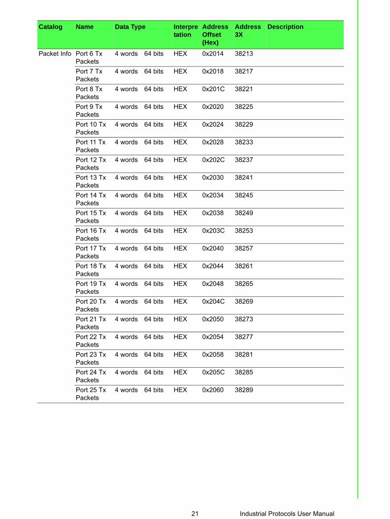
Packet Info Port 6 Tx Packets
4 words 64 bits HEX 0x2014 38213
Port 7 Tx Packets
4 words 64 bits HEX 0x2018 38217
Port 8 Tx Packets
4 words 64 bits HEX 0x201C 38221
Port 9 Tx Packets
4 words 64 bits HEX 0x2020 38225
Port 10 Tx Packets
4 words 64 bits HEX 0x2024 38229
Port 11 Tx Packets
4 words 64 bits HEX 0x2028 38233
Port 12 Tx Packets
4 words 64 bits HEX 0x202C 38237
Port 13 Tx Packets
4 words 64 bits HEX 0x2030 38241
Port 14 Tx Packets
4 words 64 bits HEX 0x2034 38245
Port 15 Tx Packets
4 words 64 bits HEX 0x2038 38249
Port 16 Tx Packets
4 words 64 bits HEX 0x203C 38253
Port 17 Tx Packets
4 words 64 bits HEX 0x2040 38257
Port 18 Tx Packets
4 words 64 bits HEX 0x2044 38261
Port 19 Tx Packets
4 words 64 bits HEX 0x2048 38265
Port 20 Tx Packets
4 words 64 bits HEX 0x204C 38269
Port 21 Tx Packets
4 words 64 bits HEX 0x2050 38273
Port 22 Tx Packets
4 words 64 bits HEX 0x2054 38277
Port 23 Tx Packets
4 words 64 bits HEX 0x2058 38281
Port 24 Tx Packets
4 words 64 bits HEX 0x205C 38285
Port 25 Tx Packets
4 words 64 bits HEX 0x2060 38289
Catalog Name Data Type Interpretation
Address Offset (Hex)
Address 3X
Description
21 Industrial Protocols User Manual

Packet Info Port 26 Tx Packets
4 words 64 bits HEX 0x2064 38293
Port 27 Tx Packets
4 words 64 bits HEX 0x2068 38297
Port 28 Tx Packets
4 words 64 bits HEX 0x206C 38301
Port 29 Tx Packets
4 words 64 bits HEX 0x2070 38305
Port 30 Tx Packets
4 words 64 bits HEX 0x2074 38309
Port 31 Tx Packets
4 words 64 bits HEX 0x2078 38313
Port 32 Tx Packets
4 words 64 bits HEX 0x207C 38317
Rx Packets Counter
4 words 64 bits HEX 0x2100 ~0x217C
38449 ~ 38573
Rx PacketsEx: port 1 Rx Packet Amount = 11223344Received MODBUS response: 0xAB4130 Word 0 = 0x0000Word 1 = 0x0000Word 2 = 0x00ABWord 3 = 0x4130
Port 1 Rx Packets
4 words 64 bits HEX 0x2100 38449
Port 2 Rx Packets
4 words 64 bits HEX 0x2104 38453
Port 3 Rx Packets
4 words 64 bits HEX 0x2108 38457
Port 4 Rx Packets
4 words 64 bits HEX 0x210C 38461
Port 5 Rx Packets
4 words 64 bits HEX 0x2110 38465
Port 6 Rx Packets
4 words 64 bits HEX 0x2114 38469
Port 7 Rx Packets
4 words 64 bits HEX 0x2118 38473
Port 8 Rx Packets
4 words 64 bits HEX 0x211C 38477
Catalog Name Data Type Interpretation
Address Offset (Hex)
Address 3X
Description
Industrial Protocols User Manual 22

Packet Info Port 9 Rx Packets
4 words 64 bits HEX 0x2120 38481
Port 10 Rx Packets
4 words 64 bits HEX 0x2124 38485
Port 11 Rx Packets
4 words 64 bits HEX 0x2128 38489
Port 12 Rx Packets
4 words 64 bits HEX 0x212C 38493
Port 13 Rx Packets
4 words 64 bits HEX 0x2130 38497
Port 14 Rx Packets
4 words 64 bits HEX 0x2134 38501
Port 15 Rx Packets
4 words 64 bits HEX 0x2138 38505
Port 16 Rx Packets
4 words 64 bits HEX 0x213C 38509
Port 17 Rx Packets
4 words 64 bits HEX 0x2140 38513
Port 18 Rx Packets
4 words 64 bits HEX 0x2144 38517
Port 19 Rx Packets
4 words 64 bits HEX 0x2148 38521
Port 20 Rx Packets
4 words 64 bits HEX 0x214C 38525
Port 21 Rx Packets
4 words 64 bits HEX 0x2150 38529
Port 22 Rx Packets
4 words 64 bits HEX 0x2154 38533
Port 23 Rx Packets
4 words 64 bits HEX 0x2158 38537
Port 24 Rx Packets
4 words 64 bits HEX 0x215C 38541
Port 25 Rx Packets
4 words 64 bits HEX 0x2160 38545
Port 26 Rx Packets
4 words 64 bits HEX 0x2164 38549
Port 27 Rx Packets
4 words 64 bits HEX 0x2168 38553
Port 28 Rx Packets
4 words 64 bits HEX 0x216C 38557
Catalog Name Data Type Interpretation
Address Offset (Hex)
Address 3X
Description
23 Industrial Protocols User Manual

Packet Info Port 29 Rx Packets
4 words 64 bits HEX 0x2170 38561
Port 30 Rx Packets
4 words 64 bits HEX 0x2174 38565
Port 31 Rx Packets
4 words 64 bits HEX 0x2178 38569
Port 32 Rx Packets
4 words 64 bits HEX 0x217C 38573
Tx Error Packets Counter
2 words 32 bits HEX 0x2200 ~ 0x223E
38705 ~ 38767
Tx Error PacketsEx: port 1 Tx Packet Amount = 11223344Received MODBUS response: 0xAB4130 Word 0 = 0x00ABWord 1 = 0x4130
Port 1 Tx Error Pack-ets
2 words 32 bits HEX 0x2200 38705
Port 2 Tx Error Pack-ets
2 words 32 bits HEX 0x2202 38707
Port 3 Tx Error Pack-ets
2 words 32 bits HEX 0x2204 38709
Port 4 Tx Error Pack-ets
2 words 32 bits HEX 0x2206 38711
Port 5 Tx Error Pack-ets
2 words 32 bits HEX 0x2208 38713
Port 6 Tx Error Pack-ets
2 words 32 bits HEX 0x220A 38715
Port 7 Tx Error Pack-ets
2 words 32 bits HEX 0x220C 38717
Port 8 Tx Error Pack-ets
2 words 32 bits HEX 0x220E 38719
Port 9 Tx Error Pack-ets
2 words 32 bits HEX 0x2210 38721
Catalog Name Data Type Interpretation
Address Offset (Hex)
Address 3X
Description
Industrial Protocols User Manual 24

Packet Info Port 10 Tx Error Pack-ets
2 words 32 bits HEX 0x2212 38723
Port 11 Tx Error Pack-ets
2 words 32 bits HEX 0x2214 38725
Port 12 Tx Error Pack-ets
2 words 32 bits HEX 0x2216 38727
Port 13 Tx Error Pack-ets
2 words 32 bits HEX 0x2218 38729
Port 14 Tx Error Pack-ets
2 words 32 bits HEX 0x221A 38731
Port 15 Tx Error Pack-ets
2 words 32 bits HEX 0x221C 38733
Port 16 Tx Error Pack-ets
2 words 32 bits HEX 0x221E 38735
Port 17 Tx Error Pack-ets
2 words 32 bits HEX 0x2220 38737
Port 18 Tx Error Pack-ets
2 words 32 bits HEX 0x2222 38739
Port 19 Tx Error Pack-ets
2 words 32 bits HEX 0x2224 38741
Port 20 Tx Error Pack-ets
2 words 32 bits HEX 0x2226 38743
Port 21 Tx Error Pack-ets
2 words 32 bits HEX 0x2228 38745
Port 22 Tx Error Pack-ets
2 words 32 bits HEX 0x222A 38747
Port 23 Tx Error Pack-ets
2 words 32 bits HEX 0x222C 38749
Catalog Name Data Type Interpretation
Address Offset (Hex)
Address 3X
Description
25 Industrial Protocols User Manual

Packet Info Port 24 Tx Error Pack-ets
2 words 32 bits HEX 0x222E 38751
Port 25 Tx Error Pack-ets
2 words 32 bits HEX 0x2230 38753
Port 26 Tx Error Pack-ets
2 words 32 bits HEX 0x2232 38755
Port 27 Tx Error Pack-ets
2 words 32 bits HEX 0x2234 38757
Port 28 Tx Error Pack-ets
2 words 32 bits HEX 0x2236 38759
Port 29 Tx Error Pack-ets
2 words 32 bits HEX 0x2238 38761
Port 30 Tx Error Pack-ets
2 words 32 bits HEX 0x223A 38763
Port 31 Tx Error Pack-ets
2 words 32 bits HEX 0x223C 38765
Port 32 Tx Error Pack-ets
2 words 32 bits HEX 0x223E 38767
Rx Error Packets Counter
2 words 32 bits HEX 0x2300 ~ 0x233E
38961 ~ 39023
Rx Error PacketsEx: port 1 Rx Packet Amount = 11223344Received MODBUS response: 0xAB4130 Word 0 = 0x00ABWord 1 = 0x4130
Port 1 Rx Error Pack-ets
2 words 32 bits HEX 0x2300 38961
Port 2 Rx Error Pack-ets
2 words 32 bits HEX 0x2302 38963
Port 3 Rx Error Pack-ets
2 words 32 bits HEX 0x2304 38965
Catalog Name Data Type Interpretation
Address Offset (Hex)
Address 3X
Description
Industrial Protocols User Manual 26

Packet Info Port 4 Rx Error Pack-ets
2 words 32 bits HEX 0x2306 38967
Port 5 Rx Error Pack-ets
2 words 32 bits HEX 0x2308 38969
Port 6 Rx Error Pack-ets
2 words 32 bits HEX 0x230A 38971
Port 7 Rx Error Pack-ets
2 words 32 bits HEX 0x230C 38973
Port 8 Rx Error Pack-ets
2 words 32 bits HEX 0x230E 38975
Port 9 Rx Error Pack-ets
2 words 32 bits HEX 0x2310 38977
Port 10 Rx Error Pack-ets
2 words 32 bits HEX 0x2312 38979
Port 11 Rx Error Pack-ets
2 words 32 bits HEX 0x2314 38981
Port 12 Rx Error Pack-ets
2 words 32 bits HEX 0x2316 38983
Port 13 Rx Error Pack-ets
2 words 32 bits HEX 0x2318 38985
Port 14 Rx Error Pack-ets
2 words 32 bits HEX 0x231A 38987
Port 15 Rx Error Pack-ets
2 words 32 bits HEX 0x231C 38989
Port 16 Rx Error Pack-ets
2 words 32 bits HEX 0x231E 38991
Port 17 Rx Error Pack-ets
2 words 32 bits HEX 0x2320 38993
Catalog Name Data Type Interpretation
Address Offset (Hex)
Address 3X
Description
27 Industrial Protocols User Manual

Packet Info Port 18 Rx Error Pack-ets
2 words 32 bits HEX 0x2322 38995
Port 19 Rx Error Pack-ets
2 words 32 bits HEX 0x2324 38997
Port 20 Rx Error Pack-ets
2 words 32 bits HEX 0x2326 38999
Port 21 Rx Error Pack-ets
2 words 32 bits HEX 0x2328 39001
Port 22 Rx Error Pack-ets
2 words 32 bits HEX 0x232A 39003
Port 23 Rx Error Pack-ets
2 words 32 bits HEX 0x232C 39005
Port 24 Rx Error Pack-ets
2 words 32 bits HEX 0x232E 39007
Port 25 Rx Error Pack-ets
2 words 32 bits HEX 0x2330 39009
Port 26 Rx Error Pack-ets
2 words 32 bits HEX 0x2332 39011
Port 27 Rx Error Pack-ets
2 words 32 bits HEX 0x2334 39013
Port 28 Rx Error Pack-ets
2 words 32 bits HEX 0x2336 39015
Port 29 Rx Error Pack-ets
2 words 32 bits HEX 0x2338 39017
Port 30 Rx Error Pack-ets
2 words 32 bits HEX 0x233A 39019
Packet Info Port 31 Rx Error Pack-ets
2 words 32 bits HEX 0x233C 39021
Port 32 Rx Error Pack-ets
2 words 32 bits HEX 0x233E 39023
Catalog Name Data Type Interpretation
Address Offset (Hex)
Address 3X
Description
Industrial Protocols User Manual 28

Chapter 2
2 EtherNet/IP
2.1 OverviewEtherNet/IP was introduced in 2001, it is the leading proven industrial automationcommunications technology based on standard Ethernet and Internet technology.Developed and managed by ODVA, EtherNet/IP is open and supported by hundredsof supplier companies.
Advantech EtherNet/IP switches provide Faceplate, Add-on Instruction (AOI), Elec-tronic Data Sheet (EDS), so users can easily integrate with Rockwell systems orother EtherNet/IP systems to monitor and configure switches.
ODVA certificated, Advantech EtherNet/IP switches are quite simply reliable and rug-ged.
2.2 Supported HardwareThe following is a list of devices supported by the AOI program.
2.3 Requirements
2.3.1 SCADA Requirements AB FactoryTalk® View v8.0
Model Version
1756-L61 V19 and higher
1756-L62 V19 and higher
1756-L63 V19 and higher
1756-L64 V19 and higher
1756-L65 V19 and higher
1756-L71 V20 and higher
1756-L72 V19 and higher
1756-L73 V19 and higher
1756-L74 V19 and higher
1756-L75 V19 and higher
1769-L32E V19 and higher
1769-L35E V19 and higher
1769-L30ER V20 and higher
1769-L30ERM V20 and higher
1769-L30ER-NSE V20 and higher
1769-L33ER V20 and higher
1769-L33ERM V20 and higher
1769-L36ERM V20 and higher
1769-L24ER-QB1B V20 and higher
1769-L24ER-QBFC1B V20 and higher
1769-L24ERM-QBFC1B V20 and higher
1769-L16ER-BB1B V20 and higher
1769-L18ER-BB1B V20 and higher
1769-L18ERM-BB1B V20 and higher
Industrial Protocols User Manual 30

2.3.2 Hardware Personal computer with an Intel Pentium 4 processor (2 GHz or faster processor
recommended). Memory (RAM): 1 GB (or more) for 32-bit systems. A minimum of 2 GB required
for 64-bit operating systems Hard disk space: Minimum 1.5 G Human Machine Interface (HMI) requirements:
– Model: AB 2711P-XXXXXX– PanelView Plus 6 (700 or higher)– PanelView Plus 7 (700 or higher)– Version 8.0
2.3.3 Operating SystemThe host computer must be equipped with any of the following operating systems tosupport the AOI program operations.
Windows XP 32/64bit Professional version or higher Window 7 32/64bit Professional version or higher Windows 8 64bit Professional version or higher Windows Server 2012 32/64bit Professional version or higher
2.4 Configuring the Controller DeviceThis section provides a path for configuring and programming the controller device.Once the device is configured, the settings are saved to an AOI file for exporting toPLC devices.
Two possible methods for configuring and programming are available. The followingoutlines the use of the Logix application and FactoryTalk® View ME, the latter of thetwo options.
For further reference, FactoryTalk® View is the application to allow you to generate auser interface. Two possible UI types are available, Machine Edition and Site Edition.The ME UI is intended for HMI devices, while the SE UI is for a personal computer.
2.4.1 Configuring in LogixThe Logix application provides the functionality required to create an AOI file. TheRSLogix5000 v19 or higher is required for this procedure.
1. Prior to getting started, locate the necessary example file(s) from the enclosed CD.
2. Locate the RSLogix5000 application and open it.3. Once in the main menu, navigate to the File main menu and select Open to
open an existing file or New to create a new file. 4. If you selected New, the New Controller window displays. Select the hardware
architecture for your main board type. See the following image for further details.– Click the Vendor drop-down menu to select the hardware vendor.– Click the Type drop-down menu to select the type of hardware.
Note! PLC device is required before you can fully configure the device. The included software and installation guide for the PLC device from the manufacturer are required to fully configure the controller device.
31 Industrial Protocols User Manual

– Click the Revision drop-down menu to select the revisions variable.– Tick the Redundancy Enabled field if required.– In the Name field, enter the name to identify this controller. – In the Description field, enter a brief description to better identify the new
controller, include items such as location, settings type, etc.– Click the Chassis Type drop-down menu to select the chassis type.– Use the Slot numeric entry field to identify the slot number.– In the Create In field, click Browse to select the directory to save the settings.– Click the Security Authority drop-down menu to enable the security author-
ity function.
If security authority is enabled, the Use only the selected Security Authentication and Authorization option is avail-able. Tick the option to set authorization and authentication to the selected security authority as configured in the Security Authority field.
5. Click OK to continue.
Figure 2.1 Creating a New Controller
For 1756 Series users see the following procedures, otherwise continue onto 6:
The following procedure creates an Ethernet module.
Note! If a matching file is already present, a prompt displays. Select Yes to replace the file or No to return to the previous menu.
Industrial Protocols User Manual 32

Under the I/O Configuration root, right-click on the available configuration and select New Module to create an Ethernet controller. See the following figure.
Figure 2.2 Creating a New Ethernet Module
The Select Module Type screen displays. Scroll down to select the following:– 1756-ENBT (1756 10/100 Mbps Ethernet Bridge, Twisted-Pair Media
Click Create to continue and create a new controller listing.
Figure 2.3 Selecting a Module Type
33 Industrial Protocols User Manual

The newly created Module Properties listing displays, see the following figure.
Figure 2.4 Module Properties Listing
This ends the procedures specific to the 1756 series.
Users other than the 1756 series can continue here with the configuration procedure.
6. Select the Ethernet entry and right click on it to open the menu bar.7. Select New Module to define the module type, see the following figure.
Figure 2.5 Defining the Module Type
The Select Module Type window displays.
8. Under the Catalog tab, scroll down to find ETHERNET-MODULE type and select it.
9. Click Close on Create to close the displayed window (optional).
Industrial Protocols User Manual 34

10. Click Create to continue.
Figure 2.6 Creating an Ethernet Module Type
11. Select the General tab to modify the parameters. The Connection and Module Info parameters are fixed and aren’t modifiable.
In the Name field, enter the module name. In the following figure, EKI_Module1 is used.
Under Connection Parameters, enter the values as shown in the following fig-ure. The parameters must match the stated values or the parameters found in the EDS file.
Under Address / Host Name, select IP Address and enter the designated IP address value.If a secondary I/O Configuration is available, make sure to use a different name for example EKI_Module2.
Figure 2.7 Modifying Ethernet General Parameters
12. Select the Connection tab and set the Requested Packet Interval (RPI) field (suggested: 1000.0 ms).
35 Industrial Protocols User Manual

13. Click Ok to continue and return to the main screen.
Figure 2.8 Modifying Ethernet Module Parameters
14. Click Tasks > MainTask > MainProgram to view MainRoutine.15. Right click on MainRoutine submenu and elect Open to display the Rung Rou-
tine window.
Figure 2.9 Creating a Routine
16. Select a Rung Ladder and right click on it to open the Properties menu.
Industrial Protocols User Manual 36

17. Scroll down and select Import Rungs.
Figure 2.10 Selecting Import Rungs
The Import Rungs window displays.
Figure 2.11 Importing a Rung File
37 Industrial Protocols User Manual

Before you can overwrite any of the selected Rung files, select the OverwriteSelected Rungs option.
Figure 2.12 Importing a Rung File
18. Locate the target file and click Import to import the file and continue the pro-cess, see the following figure.
Figure 2.13 Importing a Rung File
The Configure Rung Properties window displays.
Industrial Protocols User Manual 38

To configure a single EKI switch setup, go to “Setting Message Configuration Param-eters” on page 40.
For a multiple EKI switch configuration, see the following:
– Import a second AOI file.– Under TestRoutine (Rungs) > References, locate Tags.– Locate and change all tags marked EKI_Switch1 to EKI_Switch2, see the fol-
lowing figure.– Click OK to complete the process.
Figure 2.14 Configuring Tag References
Users with a single EKI switch, it is not necessary to alter the Tag references. Thedefault values define the single EKI switch.
39 Industrial Protocols User Manual

2.4.1.1 Setting Message Configuration ParametersOnce the AOI is created and displays as seen in the following figure.
19. Locate the property value MSG_IP_Address and click the message configura-tion option (MG_IP1).
Figure 2.15 Setting Message Configuration Parameters
20. The Message Configuration window displays. Locate the Communication tab and click on it.
Figure 2.16 Configuring Communication Settings
The following step is required to set the communication path for the target switch.
21. Locate the Path field and click Browse to open the Message Path Browser.
Industrial Protocols User Manual 40

22. The Message Path Browser window displays. Select the target switch and click OK to continue.
Figure 2.17 Selecting the Message Path
The Packet Rate Message windows displays. In this event if the MG_IP1 MSG set-ting is the only setting to change, other MSG settings do not require further configura-tion.
Figure 2.18 Configuring Packet Rate Message
23. Once the parameter is configured, download the program to the controller and set it to run mode.
41 Industrial Protocols User Manual

2.4.2 Configuring in FactoryTalk® View Machine Edition1. Open FactoryTalk® View Studio editor software (v7.0 or higher).2. The Application Type Selection window displays. Select View Machine Edition,
and click Continue.
Figure 2.19 Opening FactoryTalk® View Studio Applications
The New/Open Machine Edition Application screen displays.
3. Select the New tab to create a new file; see the following:– In the Application name field, enter the name of the file.– In the Description field, type a brief description of the file (optional).– Click the Language drop-down menu and select en-US to designate the lan-
guage tag for the file.– Enter an application name and click Create to create the new application file.
Figure 2.20 Creating an Application File
Industrial Protocols User Manual 42

Or
4. You can open an existing application file, see the following: – Click on the Existing tab to view a list of available files.– Select an option from the list in the open panel.– Click Open to open the existing file.
Figure 2.21 Opening an Application File
5. Once the application file is open, you can add components to the configuration. If the explorer window is not open, locate the main tool bar and click View > Explorer Window to open the menu tree for the application file.
6. Under the Graphics folder, locate Images and right-click to open an options menu.
43 Industrial Protocols User Manual

7. Click Add Components Into Applications.
Figure 2.22 Importing an Image File
8. The Add Components Into Project window displays. Navigate to the location of the source folder located in the included CD or download the required files from the Advantech web site.
9. Select all images in the Images folder (.png and .bmp), and click Open to import them. To view specific supported formats, click the Format drop-down menu and select a specific format to display in the body pane.
Figure 2.23 Importing Images
The images are imported and the main menu displays.
10. From the menu tree, navigate to Graphics > Global Objects.
Industrial Protocols User Manual 44

11. Right-click to open the options menu and select Add Component Into Applica-tion....
Figure 2.24 Importing EKI and HMI Objects
12. The Add Components Into Project window displays. Navigate to the location of the global objects source folder.
13. Select the EKI_Object and HMI_Object files and click Open to import them.To view specific supported formats, click the Format drop-down menu and select a specific format to display in the body pane.
14. From the menu tree, navigate to Graphics > Displays.
45 Industrial Protocols User Manual

15. Right-click to open the options menu and select Add Component Into Applica-tion....
Figure 2.25 Importing GFX Objects
16. The Add Components Into Project window displays. Navigate to the location of the GFX Objects source folder.
17. Select the five files in the GFX folder and click Open to import them.
Figure 2.26 Importing GFX Files
The GFX files are imported and the main menu displays.
Industrial Protocols User Manual 46

18. From the menu tree, navigate to Graphics > Parameters.19. Right-click to open the options menu and select Add Component Into Applica-
tion....
Figure 2.27 Importing EKI Param1 into Parameters
20. The Add Components Into Project window displays. Navigate to the location of the parameter source folder.
21. Select EKI_PARAM1 and click Open to import the files.To view specific supported formats, click the Format drop-down menu and select a specific format to display in the body pane.
Figure 2.28 Importing EKI Param1 into Parameters
22. Click Open to import the files.23. From the menu tree, locate the Communications tab at the bottom of the screen.
47 Industrial Protocols User Manual

24. Navigate to RSLinx Enterprise > Communication Setup and double click to open the options menu.
Figure 2.29 Locating RSLinx Enterprise List
25. Select Create a new configuration to create a new runtime configuration.26. Click OK to continue.
Figure 2.30 Creating a New Runtime Configuration
27. Open RSLinx Enterprise, add a new Device Shortcut. For this example, name the device shortcut CLX and select your PLC controller.
28. Click Apply and Copy from Design to Runtime. 29. Click OK to continue.
Figure 2.31 Adding a New Runtime Device Shortcut
Industrial Protocols User Manual 48

30. In the event that the Device Shortcut is not named CLX in RSLinx Enterprise, then the imported parameters file (EKI_PARAM1), must be modified, see the example and figure as follows:EXAMPLE:– Open the EKI_PARAM1 file.– Change the non-remark line to read as follows:
#1=[CLX]EKI_Switch1– Save and close the parameters file.
Figure 2.32 Altering Parameters File
31. In the Explorer window, navigate to Application > Create Runtime Applica-tion and click on it.
32. Download the previously created parameter file to the device.
Figure 2.33 Downloading File to the Device
33. Start the Runtime application.The runtime application is configured and uploaded to the device effectively program-ming the device through the FactoryTalk® View ME application.
49 Industrial Protocols User Manual

2.4.3 Configuring in ME Image Control Panel1. Open human machine interface PanelView Plus.The following screen displays.
Figure 2.34 Opening ME Image Control Panel
2. Click Switch and enter the Device Information screen.Different device models are represented by their respective images.
On the top right of the screen is a function bar (tool bar), with icons representing spe-cific tasks available in the PanelView Plus main menu.
Figure 2.35 Identifying Control Panel Menu
Function Description
Home page
Configures port status
Industrial Protocols User Manual 50

3. Click the status icon to see the status for a selected port.
To switch between port selections, use the arrow icons ( or ) to select a spe-cific port.
Figure 2.36 Selecting Port Entries
4. Click the tool icon to enter the Port Settings menu.
5. Select the setting to change and use the arrow icons ( or ) to change the settings.
6. Click Enter to apply the new setting changes. If the Enter button is not pressed the changes do not take effect.
Displays port status
Alarm info
Function Description
51 Industrial Protocols User Manual

Figure 2.37 Configuring Port Settings
7. If a setting is grayed out, the setting is cannot be modified.When ports are disabled, the following options are not available: Auto-Nego, PortSpeed, and Port Duplex.
If Auto-Nego is Enabled, Port Speed and Port Duplex cannot be set.
CPU and Port utilization alarm limits are available at the bottom of the screen.
A numeric keypad displays to allow entry of limit values
Figure 2.38 Setting CPU, Port and Alarm Value Limits
8. After entering a value, click the return button to return to the previous win-dow.
Industrial Protocols User Manual 52

9. Click Enter to apply the new setting changes.
Figure 2.39 Setting CPU, Port and Alarm Value Limits
Enabling or disabling additional settings, such as the Alarm function, is also availablethrough the control panel.
10. Click the alarm icon to enter the alarm list.If an image is grayed out, there are no active alarms.
An alarm function is active if the listing is in Red.
11. Click Enable or Disable to change the status of the selected alarm.
Figure 2.40 Enabling Alarm Options
53 Industrial Protocols User Manual

2.4.4 Configuring in FactoryTalk® View Site Edition1. Open FactoryTalk® View Studio editor software (v7.0 or higher).2. The Application Type Selection window displays. Select View Site Edition, and
click Continue.
Figure 2.41 Opening View Site Edition Applications
The New/Open Machine Edition Application screen displays.
3. Select the New tab to create a new file, see the following:– In the Application name field, enter the name of the new application file.– In the Description field, type a brief description of the file (optional).– Click the Language drop-down menu and select en-US to designate the lan-
guage tag for the file.– Enter an application name and click Create to create the new application file.
Figure 2.42 Creating an Application File
Industrial Protocols User Manual 54

Or
4. You can open an existing application file, see the following:– Click on the Existing tab to view a list of available files.– Select an option from the list in the open panel.– Click Open to open the existing file.
Figure 2.43 Opening an Application File
5. Once the application file is open, you can add components to the configuration. If the explorer window is not open, locate the main tool bar and click View > Explorer Window to open the menu tree for the application file.
6. Under the Graphics folder, locate Images and right-click to open an options menu.
55 Industrial Protocols User Manual

7. Click Add Components Into Applications to select it.
Figure 2.44 Importing an Image File
8. The Add Components Into Project window displays. Navigate to the location of the image source folder.
9. Select the images to import and click Open to import the images.To view specific supported formats, click the Format drop-down menu and select a specific format to display in the body pane.
Figure 2.45 Importing Images
The images are imported and the main menu displays.
10. From the menu tree, navigate to Graphics > Global Objects.
Industrial Protocols User Manual 56

11. Right-click to open the options menu and select Add Component Into Applica-tion....
Figure 2.46 Importing EKI and HMI Objects
12. The Add Components Into Project window displays. Navigate to the location of the global objects source folder.
Figure 2.47 Importing EKI and HMI Objects
13. Select the objects to import and click Open to import them.To view specific supported formats, click the Format drop-down menu and select aspecific format to display in the body pane.
14. From the menu tree, navigate to Graphics > Displays.
57 Industrial Protocols User Manual

15. Right-click to open the options menu and select Add Component Into Applica-tion....
Figure 2.48 Importing GFX Objects
16. The Add Components Into Project window displays. Navigate to the location of the GFX Objects source folder.
17. Click Open to import the files in the GFX folder.
Figure 2.49 Importing GFX Files
The object files are imported and the main menu displays.
18. Import EKI Param1 from the PAR folder, into Parameters. From the menu tree, navigate to Graphics > Parameters.
Industrial Protocols User Manual 58

19. Right-click to open the options menu and select Add Component Into Applica-tion....
Figure 2.50 Importing EKI Param1 into Parameters
20. The Add Components Into Project window displays. Navigate to the location of the parameter source folder.
21. Select the parameter files to import and click Open to import the files.To view specific supported formats, click the Format drop-down menu and select aspecific format to display in the body pane.
Figure 2.51 Importing EKI Param1 into Parameters
22. Click Open to import the files.
59 Industrial Protocols User Manual

23. Create a Data Server: Select the project name (EKI_ADVE), and right click to display Add New Server > Rockwell Automation Device Server (RSLinux Enterprise).
Figure 2.52 Creating a data server
24. Navigate to RSLinx Enterprise > Communication Setup and double click to open the options menu.
Figure 2.53 Locating RSLinx Enterprise List
25. Select Create to create a new runtime configuration. 26. Click Finish to continue.
Figure 2.54 Creating a New Runtime Configuration
Industrial Protocols User Manual 60

27. Open RSLinx Enterprise, add a new Device Shortcut. For this example, name the device shortcut CLX and select your PLC controller.
28. Click Apply and Copy from Design to Runtime. 29. Click OK to continue.
Figure 2.55 Adding a New Runtime Device Shortcut
30. In the event that the Device Shortcut is not named CLX in RSLinx Enterprise, then the imported parameters file (EKI_PARAM1) must be modified, see the example and figure as follows:
EXAMPLE:
– Open the EKI_PARAM1 file.– Change the non-remark line to read as follows:
#1=[CLX]EKI_Switch1
– Save and close the parameters file.
Figure 2.56 Altering Parameters File
31. To complete the procedure, create a Client link and turn it on.
61 Industrial Protocols User Manual

2.4.5 Configuring in SE Image Control Panel1. Open man-machine PanelView Plus.The following screen displays.
Figure 2.57 Opening SE Image Control Panel
2. Click the device image to enter the Device Information screen.Different device models are represented by the respective image.
On the top right of the screen is a function bar (tool bar) with icons representing aspecific task available in the PanelView Plus main menu.
Industrial Protocols User Manual 62

Figure 2.58 Identifying Control Panel Menu
3. Click the status icon to see the status for a selected port.
To switch between port selections, use the arrow icons ( or ) to select a spe-cific port.
4. Click the tool icon to enter the Port Settings menu.
Figure 2.59 Port Settings Menu
5. Select the setting to change and use the arrow icons ( or ) to change the settings.
6. Click Enter to apply the new setting changes. If the Enter button is not pressed the changes do not take effect.
If a setting is grayed out, the setting is cannot be modified.
Disabled ports the following options are not available: Auto-Nego, Port Speed, andPort Duplex.
If Auto-Nego is Enabled, Port Speed and Port Duplex cannot be set.
CPU and Port utilization alarm limits are available at the bottom of the screen. After
entering a value, click the return button to return to the previous window.
Function Description
Home page
Configures port status
Displays port status
Alarm info
63 Industrial Protocols User Manual

7. Click Enter to apply the new setting changes.
Figure 2.60 Setting CPU, Port and Alarm Value Limits
Enabling or disabling additional settings, such as the Alarm function, is also availablethrough the control panel.
8. Click the alarm icon to enter the alarm list.If an image is grayed out, there are no active alarms.
An alarm function is active if the listing is in Red.
9. Click Enable or Disable to change the status of the selected alarm.
Figure 2.61 Enabling Alarm Options
2.5 EtherNet/IP CIP ObjectsThe following section identifies supported Common Industrial Protocol (CIP) objects.Advantech’s EKI serial device server line supports the following monitoring objectsfor PLC and SCADA devices:
Identity Objects TCP/IP Interface Objects
Industrial Protocols User Manual 64

Ethernet Link Objects Advantech Networking Objects Assembly Objects Message Router Objects Connection Manager Objects Base Switch Objects
2.5.1 Identity Objects
2.5.1.1 Class Attribute List
2.5.1.2 Instance Attribute Lists
2.5.1.3 Common Service
Attribute ID Access Rule Name Data Type Description
1 Get Revision UINT (16) Object revision
2 Get Max Instance UINT (16) Maximum instance number of the object
3 Get Number of instances
UINT (16) Number of object instances currently created in the class
6 Get Max ID of class attributes
UINT (16) The Maximum class attri-bute ID number which is implemented in the device
7 Get Max ID of instance attri-butes
UINT (16) The Maximum instance attribute ID number which is implemented in the device
Attribute ID Access Rule Name Data Type Description
1 Get VendorID UINT (16) ODVA Vendor ID. Advantech = 148
2 Get DeviceType UINT (16) 43, Generic device
3 Get ProductCode UINT (16) Please reset to Product Code Table
4 Get Revision Struct
Major SINT (8) The structure member, major
Minor SINT (8) The structure member, minor.
5 Get Status DINT (32) Summary status of device
6 Get SerialNumber UDINT (32) Serial number of device, the default is 1234567890
7 Get ProductName Short STRING Human readable identi-fication, Please reset to Product Name Table
Service Code Class Instance Service Name Description
0x01 ● ● Get_Attributes_All Returns multiple attributes in numerical order.
65 Industrial Protocols User Manual
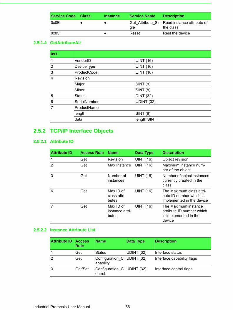
2.5.1.4 GetAttributeAll
2.5.2 TCP/IP Interface Objects
2.5.2.1 Attribute ID
2.5.2.2 Instance Attribute List
0x0E ● ● Get_Attribute_Single
Read instance attribute of the class
0x05 ● Reset Rest the device
Service Code Class Instance Service Name Description
0x1
1 VendorID UINT (16)
2 DeviceType UINT (16)
3 ProductCode UINT (16)
4 Revision
Major SINT (8)
Minor SINT (8)
5 Status DINT (32)
6 SerialNumber UDINT (32)
7 ProductName
length SINT (8)
data length SINT
Attribute ID Access Rule Name Data Type Description
1 Get Revision UINT (16) Object revision
2 Get Max Instance UINT (16) Maximum instance num-ber of the object
3 Get Number of instances
UINT (16) Number of object instances currently created in the class
6 Get Max ID of class attri-butes
UINT (16) The Maximum class attri-bute ID number which is implemented in the device
7 Get Max ID of instance attri-butes
UINT (16) The Maximum instance attribute ID number which is implemented in the device
Attribute ID Access Rule
Name Data Type Description
1 Get Status UDINT (32) Interface status
2 Get Configuration_Capability
UDINT (32) Interface capability flags
3 Get/Set Configuration_Control
UDINT (32) Interface control flags
Industrial Protocols User Manual 66

2.5.2.3 Common Service
2.5.2.4 GetAttributeAll
4 Get Physical Link Object
Struct
Path size UINT (16) Size of Path
Path Padded EPATH Logical segments identifying the physical link object
5 Get Interface Config-uration
Struct
IP Address UDINT (32) The device's IP address
Network Mask UDINT (32) The device's network mask
Gateway Address
UDINT (32) Default gateway address
Name Server UDINT (32) Primary name server
Name Server2 UDINT (32) Secondary name server
Domain Name STRING Default domain name
6 Get Hostname STRING Host name
8 Get TTL value USINT (8) TTL value for EtherNet/IP multi-cast packets
9 Get Mcast Config Struct Multicast address allocation control word
Alloc Control USINT (8) allocation control
Reserved USINT (8) Reserved for future use
Num Mcast UINT (16) Number of IP multicast address to allocation for EIP
Mcast Start Addr UDINT (32) Starting multicast address from which to begin allocation.
13 Set Encapsulation Inactivity of inac-tivity before Timeout
UINT (16) Number of seconds of inactivity before TCP connection is closed
Attribute ID Access Rule
Name Data Type Description
Service Code
Class Instance Service Name Description
0x01 ● ● Get_Attributes_All Returns multiple attributes in numerical order
0x0E ● ● Get_Attribute_Single Read instance attribute of the class
0x10 ● Set_Attribute_Single Write instance attribute of the class
0x1
1 Status UDINT (32)
2 Configuration_Capability UDINT (32)
3 Configuration_Control UDINT (32)
4 Physical Link Object
Path size UINT (16)
Path size path size UINT
67 Industrial Protocols User Manual

2.5.3 Ethernet Link Objects
2.5.3.1 Class Attribute List
2.5.3.2 Instance Attribute List
5 Interface Configuration
IP Address UDINT (32)
Network Mask UDINT (32)
Gateway Address UDINT (32)
Name Server UDINT (32)
Name Server2 UDINT (32)
Domain Name
Length UINT (16)
Data length SINT
6 Hostname
Length UINT (16)
Data length SINT
Reserved 6SINT (48)
8 TTL value USINT (8)
9 Mcast Config
Alloc Control USINT (8)
Reserved USINT (8)
Num Mcast UINT (16)
Mcast Start Addr UDINT (32)
Reserved 37SINT (37)
13 Encapsulation Inactivity of inactiv-ity before Timeout
UINT (16)
0x1
Attribute ID Access Rule Name Data Type Description
1 Get Revision UINT (16) Object revision
2 Get Max Instance UINT (16) Maximum instance number of the object
3 Get Number of instances
UINT (16) Number of object instances currently created in the class
6 Get Max ID of class attributes
UINT (16) The Maximum class attribute ID number which is imple-mented in the device
7 Get Max ID of instance attributes
UINT (16) The Maximum instance attri-bute ID number which is imple-mented in the device
Attribute ID
Access Rule
Name Data Type Description
1 Get Interface Speed UDINT (32) Interface speed currently in use. Speed in Mbps (e.g., 0, 10, 100, 1000, etc.)
2 Get Interface Flags UDINT (32) Interface status flags
3 Get Physical Address ARRAY of 6 USINT (48)
MAC layer address
Industrial Protocols User Manual 68

4 Get Interface Counters Struct
In Octets UDINT (32) Octets received on the inter-face
In Ucast Packets UDINT (32) Unicast packets received on the interface
In NUcast Packets UDINT (32) Non-unicast packets received on the interface
In Discards UDINT (32) Inbound packets received on the interface but discarded
In Errors UDINT (32) Inbound packets that contain errors (does not include In Discards)
In Unknown Protos UDINT (32) Inbound packets with unknown protocol
Out Octets UDINT (32) Octets sent on the interface
Out Ucast Packets UDINT (32) Unicast packets sent on the interface
Out NUcast Packets UDINT (32) Non-unicast packets sent on the interface
Out Discards UDINT (32) Outbound packets received on the interface but discarded
Out Errors UDINT (32) Outbound packets that con-tain errors (does not include In Discards)
Attribute ID
Access Rule
Name Data Type Description
69 Industrial Protocols User Manual

5 Get Media Counters Struct
Alignment Errors UDINT (32) Frames received that are not an integral number of octets in length
FCS Errors UDINT (32) Frames received that do not pass the FCS check
Single Collisions UDINT (32) Successfully transmitted frames which experienced exactly one collision
Multiple_Collisions UDINT (32) Successfully transmitted frames which experienced more than one collision
SQE_Test_Errors UDINT (32) Number of times SQE test error message is generated
Deferred_Transmissions
UDINT (32) Frames for which first trans-mission attempt is delayed because the medium is busy
Late Collisions UDINT (32) Number of times a collision is detected later than 512 bit- times into the transmission of a packet
Excessive_Collisions UDINT (32) Frames for which transmis-sion fails due to excessive collisions
MAC_Transmit_Errors
UDINT (32) Frames for which transmis-sion fails due to an internal MAC sub layer transmit error
Carrier_Sense_Errors
UDINT (32) Times that the carrier sense condition was lost or never asserted when attempting to transmit a frame
Frame_Too_Long UDINT (32) Frames received that exceed the maximum permitted frame size
MAC_Receive_Errors
UDINT (32) Frames for which reception on an interface fails due to an internal MAC sub layer receive error
6 Get/Set Interface Control Struct
Control Bits UINT (16) Interface Control Bits
Forced_Interface_Speed
UINT (16) Speed at which the interface shall be forced to operate. Speed in Mbps (10, 100, 1000, etc.)
10 Get Interface Level STRING Human readable identification
100 Get Interface Utilization UINT (16) Percentage of entire inter-face Rx/Tx bandwidth being used (0-100), rx - 8bits, tx-8bits
101 Get Tx Unicast Packet Rate
UDINT (32) Number of TX unicast pack-ets per second
102 Get Tx Multicast Packet Rate
UDINT (32) Number of TX multicast pack-ets per second
Attribute ID
Access Rule
Name Data Type Description
Industrial Protocols User Manual 70

2.5.3.3 Common Service
2.5.3.4 GetAttributeAll
103 Get Tx Broadcast Packet Rate
UDINT (32) Number of TX broadcast packets per second
104 Get Rx Unicast Packet Rate
UDINT (32) Number of RX unicast pack-ets per second
105 Get Rx Multicast Packet Rate
UDINT (32) Number of RX multicast pack-ets per second
106 Get Rx Broadcast Packet Rate
UDINT (32) Number of RX broadcast packets per second
107 Get/Set Broadcast Storm USINT (8)
108 Get Authentication status USINT (8)
Attribute ID
Access Rule
Name Data Type Description
Service Code
Class Instance Service Name Description
0x01 ● ● Get_Attributes_All Returns multiple attributes in numerical order.
0x0E ● ● Get_Attribute_Single Read instance attribute of the class
0x10 ● Set_Attribute_Single Write instance attribute of the class
0x4C ● Get_and_Clear Get instance attribute of the class and then clear the value
0x1
1 Interface Speed UDINT (32)
2 Interface Flags UDINT (32)
3 Physical Address 6USINT (48)
4 Interface Counters
In Octets UDINT (32)
In Ucast Packets UDINT (32)
In NUcast Packets UDINT (32)
In Discards UDINT (32)
In Errors UDINT (32)
In Unknown Protos UDINT (32)
Out Octets UDINT (32)
Out Ucast Packets UDINT (32)
Out NUcast Packets UDINT (32)
Out Discards UDINT (32)
Out Errors UDINT (32)
71 Industrial Protocols User Manual

2.5.3.5 GetAttributeAll-Vendor1
2.5.4 Advantech Networking Objects
2.5.4.1 Class Attribute List
5 Media Counters
Alignment Errors UDINT (32)
FCS Errors UDINT (32)
Single Collisions UDINT (32)
Multiple_Collisions UDINT (32)
SQE_Test_Errors UDINT (32)
Deferred_Transmissions UDINT (32)
Late Collisions UDINT (32)
Excessive_Collisions UDINT (32)
MAC_Transmit_Errors UDINT (32)
Carrier_Sense_Errors UDINT (32)
Frame_Too_Long UDINT (32)
MAC_Receive_Errors UDINT (32)
6 Interface Control
Control Bits UINT (16)
Forced_Interface_Speed UINT (16)
10 Interface Level
Length UINT (16)
Data length SINT
0x1
(0x32)
100 Interface Utilization USINT (8)
101 Tx Unicast Packet Rate UDINT (32)
102 Tx Multicast Packet Rate UDINT (32)
103 Tx Broadcast Packet Rate UDINT (32)
104 Rx Unicast Packet Rate UDINT (32)
105 Rx Multicast Packet Rate UDINT (32)
106 Rx Broadcast Packet Rate UDINT (32)
107 Broadcast Storm USINT (8)
108 Authentication status USINT (8)
Attribute ID
Access Rule
Name Data Type Description
1 Get Revision UINT (16) Object revision
2 Get Max Instance UINT (16) Maximum instance number of the object
3 Get Number of instances
UINT (16) Number of object instances cur-rently created in the class
6 Get Max ID of class attributes
UINT (16) The Maximum class attribute ID number which is implemented in the device
Industrial Protocols User Manual 72

2.5.4.2 Instance Attribute List
7 Get Max ID of instance attri-butes
UINT (16) The Maximum instance attribute ID number which is implemented in the device
Attribute ID
Access Rule
Name Data Type Description
Attribute ID
Access Rule
Name Data Type Description
1 Get System Uptime UDINT (32) Number of seconds since device was powered up
2 Get FW version Struct
Major1 USINT (8) The structure member, major1
Major2 USINT (8) The structure member, major2
Minor USINT (8) The structure member, minor
Reserved USINT (8)
3 Get System Fault UDINT (32) System fault status
0 bit: CPU utilization alarmvalue 0: no alarmvalue 1: alarm
1 bit: Power supply 1value 0: errorvalue 1: ok
2 bit: Power supply 2value 0: errorvalue 1: ok
[3-31] bit: Reserved
4 Get Port Count USINT (8) Total switch port count
5 Get Port Exist UDINT (32) Switch port exists on device
6 Get/Set Port Enable UDINT (32) Switch port en|dis-able
7 Get Port Link Status UDINT (32) Switch port link status
8 Get CPU Usage USINT (8) Percent of CPU usage (0-100)
9 Get/Set Temperature Upper Limit
UDINT (32) Upper temperature (C) at which to declare an alarm
10 Get/Set Temperature Lower Limit
UDINT (32) Lower temperature (C) at which to declare an alarm
11 Get Temperature in C
UDINT (32) Temperature in degrees C. 0x9999 = Not Supported on device.
12 Get Temperature in F
UDINT (32) Temperature in degrees F. 0x9999 = Not Supported on device.
13 Set MIB Reset USINT (8) Reset MIB counters
14 Get/Set CPU Utilization Alarm Limit
USINT (8) Percent of upper CPU usage at which to declare an alarm, default value is 80
15 Get/Set Port Utilization Alarm Limit
USINT (8) Percent of upper port utilization at which to declare an alarm, default value is 80
16 Get/Set Config Enable USINT (8) Output config data en|dis-able
17 Get MAC address Short STRING Human readable mac address
73 Industrial Protocols User Manual

2.5.4.3 GetAttributeAll
25 Set Reboot USINT (8) Reboot the device
Attribute ID
Access Rule
Name Data Type Description
0x1 "
1 System Uptime UDINT (32)
2 FW version
Major UINT (16)
Minor UINT (16)
3 System Fault UDINT (32)
0 bit: CPU utilization alarmvalue 0: no alarmvalue 1: alarm
1 bit: Power supply 1value 0: errorvalue 1: ok
2 bit: Power supply 2value 0: errorvalue 1: ok
[3-31] bit: Reserved
4 Port Count USINT (8)
5 Port Exist UDINT (32)
6 Port Enable UDINT (32)
7 Port Link Status UDINT (32)
8 CPU Usage USINT (8)
9 Temperature Upper Limit
UDINT (32)
10 Temperature Lower Limit
UDINT (32)
11 Temperature in C UDINT (32)
12 Temperature in F UDINT (32)
14 CPU Utilization Alarm Limit
USINT (8)
15 Port Utilization Alarm Limit
USINT (8)
16 Config Enable USINT (8)
17 MAC address
length USINT (8)
data length USINT
Industrial Protocols User Manual 74

2.5.5 Assembly
2.5.5.1 Class Attribute List
2.5.5.2 Instance Attribute List
2.5.5.3 Common Service
2.5.5.4 I/O Data
Instance number size (bit)
Input 100 256
Output 150 256
Config 151 80
1 Get Revision UINT (16) Object Revision
2 Get Max Instance UINT (16) Maximum instance number of the object
3 Get Number of instances
UINT (16) Number of object instances currently cre-ated in the class
6 Get Max ID of class attri-butes
UINT (16) The Maximum class attribute ID number which is implemented in the device
7 Get Max ID of instance attributes
UINT (16) The Maximum instance attribute ID number which is implemented in the device
3 Get/Set Data Array of BYTE The messaging con-tent
Service Code
Class Instance Service Name Description
0x0E ● ● Get_Attribute_Single Read instance attri-bute of the class
0x10 ● Set_Attribute_Single Write instance attri-bute of the class
Input BitMask Name Bits Description
[0] 0-15 ProductCode 16 bits EKI-5629 = 5629, EKI-5729 = 5729
16-23 CPU usage 8 bits Percent of CPU usage (0-100)
24-31 Reserved
[1] 0-31 Port status 32 bits Switch port link status
[2] 0-31 Port duplex 32 bits Switch port duplex status
[3] 0-31 System uptime 32 bits Number of seconds since device was powered up
[4] 0-31 System fault 32 bits The same result with no.3 attribute of advantech class.
[5] 0-31 Port utilization alarm
32 bits port will be set if port utiliza-tion exceed threshold.
75 Industrial Protocols User Manual

2.5.6 Message Router
2.5.6.1 Class Attribute List
[6] 0-31 Port Auth status 32 bits port authentication status
[7] Reserved
Output
[0] 0-7 Port number 8 bits Which port number want to set
8 Port en |disable
1 bit Port number en | disable, 0 = disable, 1 = enable
9 Port auto-nego en|dis-able
1 bit Port auto-negotiate en | dis-able, 0 = disable, 1 = enable
10 Port duplex 1 bit Port duplex, 0 = half, 1 = full
11-15 5 bits Reserved
16-31 Port speed 16 bits Port speed
[1] 0-7 CPU utilization limit
8 bits Percent of upper CPU usage at which to declare an alarm
8-15 Port utilization limit
8 bits Percent of upper port utili-zation at which to declare an alarm
16-23 Temperature upper limit
8 bits Upper temperature (C) at which to declare an alarm
24-31 Temperature lower limit
8 bits Lower temperature (C) at which to declare an alarm
[2] Reserved
[3] Reserved
[4] Reserved
[5] Reserved
[6] Reserved
[7] Reserved
Input BitMask Name Bits Description
Class Attribute List
1 Get Revision UINT (16) Object revision
2 Get Max Instance UINT (16) Maximum instance number of the object
3 Get Number of instances
UINT (16) Number of object instances currently created in the class
6 Get Max ID of class attributes
UINT (16) The Maximum class attribute ID number which is imple-mented in the device
7 Get Max ID of instance attributes
UINT (16) The Maximum instance attri-bute ID number which is imple-mented in the device
Industrial Protocols User Manual 76

2.5.6.2 Common Service
2.5.7 Connection Manager
2.5.7.1 Class Attribute List
2.5.7.2 Common Service
2.5.8 Base Switch
2.5.8.1 Class Attribute List
Service Code
Class Instance Service Name Description
0x0E ● ● Get_Attribute_Single Read instance attribute of the class
1 Get Revision UINT (16) Object revision
2 Get Max Instance UINT (16) Maximum instance number of the object
3 Get Number of instances
UINT (16) Number of object instances currently created in the class
6 Get Max ID of class attributes
UINT (16) The Maximum class attri-bute ID number which is implemented in the device
7 Get Max ID of instance attri-butes
UINT (16) The Maximum instance attribute ID number which is implemented in the device
Service Code
Class Instance Service Name Description
0x0E ● ● Get_Attribute_Single Read instance attribute of the class
0x10 ● Set_Attribute_Single Write instance attribute of the class
0x4E ● ● Forward_Close close connection
0x54 ● Forward_Open open connection
1 Get Revision UINT (16) Object revision
2 Get Max Instance UINT (16) Maximum instance number of the object
3 Get Number of instances
UINT (16) Number of object instances currently created in the class
6 Get Max ID of class attributes
UINT (16) The Maximum class attri-bute ID number which is implemented in the device
7 Get Max ID of instance attri-butes
UINT (16) The Maximum instance attribute ID number which is implemented in the device
77 Industrial Protocols User Manual

2.5.8.2 Instance Attribute List
2.5.8.3 Common Service
1 Get Device Up Time
UDINT (32) Time since device was pow-ered up
2 Get Total port count UDINT (32) Number of physical ports
3 Get System Firm-ware Version
Short String Human readable representa-tion of System Firmware Ver-sion
4 Get Power Source INT (16) Status of switch power source
5 Get Port Mask Size UINT (16) Number of DWORDs in port array attributes
8 Get Global Port Link Status
Array of DWORD
Ports Link Status
Service Code
Class Instance Service Name Description
0x01 ● Get_Attributes_All Returns multiple attributes in numerical order.
0x0E ● ● Get_Attribute_Single Read instance attribute of the class
Industrial Protocols User Manual 78

Chapter 3
3 PROFINET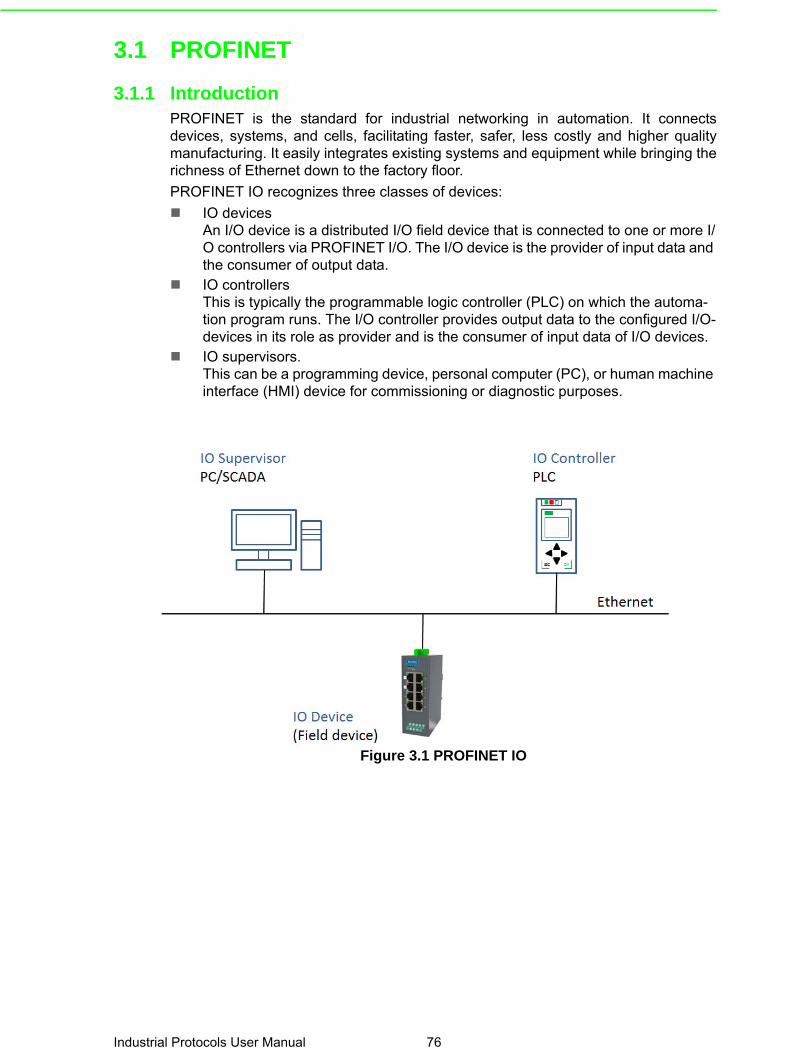
3.1 PROFINET
3.1.1 IntroductionPROFINET is the standard for industrial networking in automation. It connectsdevices, systems, and cells, facilitating faster, safer, less costly and higher qualitymanufacturing. It easily integrates existing systems and equipment while bringing therichness of Ethernet down to the factory floor.
PROFINET IO recognizes three classes of devices:
IO devicesAn I/O device is a distributed I/O field device that is connected to one or more I/O controllers via PROFINET I/O. The I/O device is the provider of input data and the consumer of output data.
IO controllersThis is typically the programmable logic controller (PLC) on which the automa-tion program runs. The I/O controller provides output data to the configured I/O-devices in its role as provider and is the consumer of input data of I/O devices.
IO supervisors.This can be a programming device, personal computer (PC), or human machine interface (HMI) device for commissioning or diagnostic purposes.
Figure 3.1 PROFINET IO
Industrial Protocols User Manual 76

3.2 Configuring PROFINET
3.2.1 Enable PROFINET I/OThe PROFINET function default is enabled in the PROFINET project series.
It can be configure manually in the Web page. To access this page, click Manage-ment > PROFINET > PROFINET Settings.
Figure 3.2 PROFINET Settings
Item Description
State Click Disabled or Enabled to set the PROFINET state.
Apply Click Apply to save the values and update the screen.
77 Industrial Protocols User Manual

3.2.2 PROFINET Cyclic I/O DataThe Advantech PROFINET switch provides PROFINET I/O cyclic data and includesthe following items:
Category Direction Byte(s) Bit Name Description
Port Status Input 0 0 Port1 Connection 0 is not connected, 1 is con-nected
1 Port2 Connection 0 is not connected, 1 is con-nected
2 Port3 Connection 0 is not connected, 1 is con-nected
3 Port4 Connection 0 is not connected, 1 is con-nected
4 Port5 Connection 0 is not connected, 1 is con-nected
5 Port6 Connection 0 is not connected, 1 is con-nected
6 Port7 Connection 0 is not connected, 1 is con-nected
7 Port8 Connection 0 is not connected, 1 is con-nected
1 0 Port9 Connection 0 is not connected, 1 is con-nected
1 Port10 Connection 0 is not connected, 1 is con-nected
2 Port11 Connection 0 is not connected, 1 is con-nected
3 Port12 Connection 0 is not connected, 1 is con-nected
4 Port13 Connection 0 is not connected, 1 is con-nected
5 Port14 Connection 0 is not connected, 1 is con-nected
6 Port15 Connection 0 is not connected, 1 is con-nected
7 Port16 Connection 0 is not connected, 1 is con-nected
Industrial Protocols User Manual 78

2 0 Port17 Connection 0 is not connected, 1 is con-nected
1 Port18 Connection 0 is not connected, 1 is con-nected
2 Reserved
3 Reserved
4 Reserved
5 Reserved
6 Reserved
7 Reserved
3 0 Reserved
1 Reserved
2 Reserved
3 Reserved
4 Reserved
5 Reserved
6 Reserved
7 Reserved
Category Direction Byte(s) Bit Name Description
79 Industrial Protocols User Manual

3.3 TIA Portal V13 IntegrationThe following steps show how to integrate the switch into a PROFINET network:
1. Create a PROFINET I/O project in TIA PortalCreate a PROFINET I/O Ethernet project for deploying environment
2. GSD file installation Import GSD file into the project
3. Add Devices and configuration Search and discover the switch in TIA Portal. Configure PROFINET attributes such as IP address, device name and I/O parameters.
4. Save and load the project into the PLC Load this project and into the PLC
5. Watch tables of the Switch Use TIA Portal to watch switch attributes
3.3.1 Create a PROFINET I/O project in TIA PortalCreate a new project.
Figure 3.3 Create new project
3.3.2 GSD file installationInstall the GSD file via Options.
Figure 3.4 Install GSD File
Now the Ethernet Switch can be found in the Hardware catalog tree under Otherfield devices > PROFINET IO > Network Components > Advantech PROFINETSwitch.
Industrial Protocols User Manual 80

Figure 3.5 Install GSD File
3.3.3 Add Devices and configuration1. Install the GSD file via Options.
Figure 3.6 Install GSD file
81 Industrial Protocols User Manual

2. Draw the PROFINET IO-system between the PLC and the Switch.
Figure 3.7 Draw PROFINET-IO System
3. Assign a device name under the Device view.
Figure 3.8 Assign Device Name
Industrial Protocols User Manual 82

Figure 3.9 Assign Device Name
4. Add Port Link Status to the Module.
Figure 3.10 Add Port Link Status
83 Industrial Protocols User Manual

3.3.4 Save and load the project into the PLCCompile and Download to device.
Figure 3.11 Compile Project
Figure 3.12 Download to Device
Industrial Protocols User Manual 84

3.3.5 Switch Watch tables1. Add a new watch table to Project tree > Devices.
Figure 3.13 Download to Device
2. Drag I/O(Port_Link_Status_1 > Details View) into Watch_table_1.
Figure 3.14 Watch Table
3. Monitor via the Online menu.
85 Industrial Protocols User Manual

Figure 3.15 Monitoring
Figure 3.16 Monitoring
Industrial Protocols User Manual 86

87 Industrial Protocols User Manual

www.advantech.comPlease verify specifications before quoting. This guide is intended for referencepurposes only.All product specifications are subject to change without notice.No part of this publication may be reproduced in any form or by any means,electronic, photocopying, recording or otherwise, without prior written permis-sion of the publisher.All brand and product names are trademarks or registered trademarks of theirrespective companies.© Advantech Co., Ltd. 2007