User Manual - Huawei FusionSolar/media/Solar/attachment/pdf/na/service/download/SUN2000-45...local...
126
SUN2000-45KTL-US-HV-D0 User Manual Issue 04 Date 2018-06-01 HUAWEI TECHNOLOGIES CO., LTD.
Transcript of User Manual - Huawei FusionSolar/media/Solar/attachment/pdf/na/service/download/SUN2000-45...local...

SUN2000-45KTL-US-HV-D0
User Manual
Issue 04
Date 2018-06-01
HUAWEI TECHNOLOGIES CO., LTD.

Issue 04 (2018-06-01) Huawei Proprietary and Confidential
Copyright © Huawei Technologies Co., Ltd.
i
Copyright © Huawei Technologies Co., Ltd. 2018. All rights reserved.
No part of this document may be reproduced or transmitted in any form or by any means without prior
written consent of Huawei Technologies Co., Ltd.
Trademarks and Permissions
and other Huawei trademarks are trademarks of Huawei Technologies Co., Ltd.
All other trademarks and trade names mentioned in this document are the property of their respective
holders.
Notice
The purchased products, services and features are stipulated by the contract made between Huawei and
the customer. All or part of the products, services and features described in this document may not be
within the purchase scope or the usage scope. Unless otherwise specified in the contract, all statements,
information, and recommendations in this document are provided "AS IS" without warranties, guarantees or
representations of any kind, either express or implied.
The information in this document is subject to change without notice. Every effort has been made in the
preparation of this document to ensure accuracy of the contents, but all statements, information, and
recommendations in this document do not constitute a warranty of any kind, express or implied.
Huawei Technologies Co., Ltd.
Address: Huawei Industrial Base
Bantian, Longgang
Shenzhen 518129
People's Republic of China
Website: http://e.huawei.com

SUN2000-45KTL-US-HV-D0
User Manual About This Document
Issue 04 (2018-06-01) Huawei Proprietary and Confidential
Copyright © Huawei Technologies Co., Ltd.
ii
About This Document
Purpose
This document describes the SUN2000-45KTL-US-HV-D0 (SUN2000 for short) in terms of
its installation, electrical connections, commissioning, maintenance, and troubleshooting.
Understand the safety information and get familiar with the SUN2000 functions and features
before installing and operating the SUN2000.
Intended Audience
This document is intended for photovoltaic (PV) power plant personnel and qualified
electrical technicians.
Symbol Conventions
The symbols that may be found in this document are defined as follows.
Symbol Description
Indicates an imminently hazardous situation which, if not
avoided, will result in serious injury or death.
Indicates a potentially hazardous situation which, if not
avoided, could result in serious injury or death.
Indicates a potentially hazardous situation which, if not
avoided, may result in minor or moderate injury.
Indicates a potentially hazardous situation which, if not
avoided, could result in equipment damage, data loss,
performance deterioration, or unanticipated results.
NOTICE is used to address practices not related to personal
injury.
Calls attention to important information, best practices and
tips.
NOTE is used to address information not related to personal
injury, equipment damage, and environment deterioration.

SUN2000-45KTL-US-HV-D0
User Manual About This Document
Issue 04 (2018-06-01) Huawei Proprietary and Confidential
Copyright © Huawei Technologies Co., Ltd.
iii
Change History
Changes between document issues are cumulative. The latest document issue contains all
updates made in previous issues.
Issue 04 (2018-06-01)
Changed Supported Power Grids in 2.1 Introduction to Supported Power Grid Earthing
Systems. Added three power grid earthing systems supported by the SUN2000. Deleted the
description that "The SUN2000 only supports the IT power grid mode" and that "The
SUN2000 is mainly used for medium-voltage power grids. It delivers three-phase, three-wire
output, which is then fed to a medium-voltage power grid through a step-up transformer."
Issue 03 (2018-05-05)
Updated Supported Power Grids in 2.1 Introduction. Added the description that "The
SUN2000 can be configured in common transformer secondary winding scenarios, such as
grounded Y, neutral ungrounded Y, and delta (floating). For any other transformer
configuration, contact Huawei technical support."
Added the description about the metal stamping forming contact in 6.5 Connecting DC Input
Power Cables.
Issue 02 (2017-10-30)
Updated 3 Storage.
Updated 5.1 Crimping the OT Terminal.
Updated 6.3.1 Connecting a Ground Cable to the PE Point (Bonding).
Updated 11 Technical Specifications.
Issue 01 (2017-03-10)
This issue is used for first office application (FOA).

SUN2000-45KTL-US-HV-D0
User Manual Contents
Issue 04 (2018-06-01) Huawei Proprietary and Confidential
Copyright © Huawei Technologies Co., Ltd.
iv
Contents
About This Document .................................................................................................................... ii
1 Safety Precautions ......................................................................................................................... 1
2 Overview ......................................................................................................................................... 4
2.1 Introduction .................................................................................................................................................................. 4
2.2 Appearance ................................................................................................................................................................... 5
2.3 Label Description .......................................................................................................................................................... 9
2.4 Working Principle ....................................................................................................................................................... 14
3 Storage ........................................................................................................................................... 16
4 Installation.................................................................................................................................... 17
4.1 Checking Before Installation ...................................................................................................................................... 17
4.2 Materials ..................................................................................................................................................................... 18
4.3 Determining the Installation Position ......................................................................................................................... 19
4.4 Installing the Mounting Bracket ................................................................................................................................. 23
4.5 Installing the SUN2000 .............................................................................................................................................. 28
5 General Operation ...................................................................................................................... 31
5.1 Crimping the OT Terminal .......................................................................................................................................... 31
5.2 Installing the Tube Fittings ......................................................................................................................................... 33
5.3 Routing Cables Through Waterproof Connectors ....................................................................................................... 36
6 Electrical Connections ................................................................................................................ 38
6.1 Precautions .................................................................................................................................................................. 38
6.2 Opening the Maintenance Compartment Door ........................................................................................................... 38
6.3 Connecting the Ground Cable ..................................................................................................................................... 40
6.3.1 Connecting a Ground Cable to the PE Point (Bonding)........................................................................................... 40
6.3.2 Connecting the Ground Cable to the PV Side Ground Point (GND) ....................................................................... 41
6.4 Connecting AC Output Power Cables ......................................................................................................................... 42
6.4.1 Connection Through a Tube ..................................................................................................................................... 43
6.4.2 Connection Through a Waterproof Connector ......................................................................................................... 45
6.5 Connecting DC Input Power Cables ........................................................................................................................... 49
6.6 Connecting the Communications Cable ...................................................................................................................... 56
6.6.1 Communication Mode Description .......................................................................................................................... 56

SUN2000-45KTL-US-HV-D0
User Manual Contents
Issue 04 (2018-06-01) Huawei Proprietary and Confidential
Copyright © Huawei Technologies Co., Ltd.
v
6.6.2 Connecting the RS485 Communications Cable (to a Terminal Block) .................................................................... 58
6.6.2.1 Connection Through a Tube .................................................................................................................................. 59
6.6.2.2 Connection Through a Waterproof Connector ...................................................................................................... 62
6.6.3 Connecting RS485 Communications Cables (to an RJ45 Network Port) ................................................................ 65
6.6.3.1 Connection Through a Tube .................................................................................................................................. 66
6.6.3.2 Connection Through a Waterproof Connector ...................................................................................................... 68
6.7 Closing the Maintenance Compartment Door ............................................................................................................ 70
7 System Commissioning ............................................................................................................. 72
7.1 Checking Before Power-On ........................................................................................................................................ 72
7.2 DC Input Detection ..................................................................................................................................................... 72
7.3 Powering On the SUN2000 ........................................................................................................................................ 74
7.4 Powering Off the SUN2000 ........................................................................................................................................ 80
8 Man-Machine Interactions ........................................................................................................ 81
8.1 Operations with a USB Flash Drive............................................................................................................................ 81
8.1.1 Exporting Configurations ........................................................................................................................................ 81
8.1.2 Importing Configurations ........................................................................................................................................ 83
8.1.3 Exporting Data ......................................................................................................................................................... 84
8.1.4 Upgrading ................................................................................................................................................................ 85
8.2 Operations with the SUN2000 App ............................................................................................................................ 86
8.2.1 Operations Related to the Advanced User ............................................................................................................... 87
8.2.1.1 Setting Grid Parameters ........................................................................................................................................ 87
8.2.1.2 Setting Protection Parameters ............................................................................................................................... 88
8.2.1.3 Setting Feature Parameters ................................................................................................................................... 88
8.2.2 Operations Related to the Special User.................................................................................................................... 96
8.2.2.1 Setting Grid Parameters ........................................................................................................................................ 96
8.2.2.2 Setting Protection Parameters ............................................................................................................................... 99
8.2.2.3 Setting Feature Parameters ................................................................................................................................. 101
8.2.2.4 Setting Power Adjustment Parameters ................................................................................................................ 104
9 System Maintenance................................................................................................................. 106
9.1 Routine Maintenance ................................................................................................................................................ 106
9.2 Troubleshooting ........................................................................................................................................................ 107
10 Handling the Inverter ............................................................................................................. 115
10.1 Removing the SUN2000 ......................................................................................................................................... 115
10.2 Packing the SUN2000 ............................................................................................................................................. 115
10.3 Disposing of the SUN2000 ..................................................................................................................................... 115
11 Technical Specifications ........................................................................................................ 116
A Acronyms and Abbreviations ................................................................................................ 119
B Contact Information ................................................................................................................. 120

SUN2000-45KTL-US-HV-D0
User Manual 1 Safety Precautions
Issue 04 (2018-06-01) Huawei Proprietary and Confidential
Copyright © Huawei Technologies Co., Ltd.
1
1 Safety Precautions
Before performing operations, read through this manual and follow all the precautions to
prevent accidents. The safety precautions provided in this document do not cover all the
safety precautions. Huawei shall not be liable for any consequence caused by the violation of
the safety operation regulations and design, production, and usage standards.
Disclaimer
Huawei shall not be liable for any consequence caused by any of the following events.
Transportation
The storage conditions do not meet the requirements specified in this document.
Violate the operation instructions and safety precautions in this document for installation,
cable connecting, and maintenance.
Operation in extreme environments which are not covered in this document
Unauthorized modifications to the product or software code
Installation or use in environments which are not specified in related international
standards
Personnel Requirements
Only certified electricians are allowed to install and operate the SUN2000.
Operation personnel should receive professional training.
Operation personnel should read through this document and follow all the precautions.
Operation personnel should be familiar with the safety specifications about the electrical
system.
Operation personnel should understand the composition and working principles of the
grid-tied PV power system and local regulations.

SUN2000-45KTL-US-HV-D0
User Manual 1 Safety Precautions
Issue 04 (2018-06-01) Huawei Proprietary and Confidential
Copyright © Huawei Technologies Co., Ltd.
2
Protect Labels Do not tamper with any warning labels on the inverter enclosure because these labels
contain important information about safe operation.
Do not tamper with the nameplate on the inverter enclosure because it contains important
product information.
Installation Ensure that the inverter is not connected to a power supply and is not powered on before
starting installation.
Ensure that there are no objects within 200 mm (7.87 in.), 300 mm (11.81 in.), 500 mm
(19.69 in.), 600 mm (23.62 in.), and 1000 mm (39.37 in.) of the left, right, top, bottom,
and front of the inverter, respectively. This is to allow sufficient space for installation and
heat dissipation. For ease of installation, ensure that the inverter bottom is at most 730
mm (28.74 in.) above the floor. If you have any questions about the distance, consult the
local technical support engineers.
Ensure that the inverter is installed in a well-ventilated environment.
Ensure that the inverter heat sinks are free from blockage.
Open the maintenance compartment door of the chassis before connecting cables. Do not
perform any operation on other components inside the chassis except connecting the PE
cable, AC power cables and communications cables.
Cable Connections
Before connecting cables, ensure that the inverter is secured in position and not damaged in
any way. Otherwise, electric shocks or fire may occur.
Ensure that all electrical connections comply with local electrical standards.
Obtain approval from the local utility company before using the inverter to generate
electricity in grid-tied mode.
Ensure that the cables used in a grid-tied PV system are properly connected and insulated,
meet all specification requirements.
Operation
High voltages may cause electric shocks result in serious injury, death or serious property
damage from inverter in operation. Strictly comply with the safety precautions in this
document and associated documents when operating the inverter.
Do not touch an energized inverter because the heat sink may be over 60ºC (140°F).
Follow local laws and regulations when operating the equipment.

SUN2000-45KTL-US-HV-D0
User Manual 1 Safety Precautions
Issue 04 (2018-06-01) Huawei Proprietary and Confidential
Copyright © Huawei Technologies Co., Ltd.
3
Maintenance and Replacement
High voltages may cause electric shocks result in serious injury, death or serious property
damage from inverter in operation. Prior to maintenance, power off the inverter and strictly
comply with the safety precautions in this document and associated documents to operate the
inverter.
Maintain the inverter with sufficient knowledge of this document and proper tools and
testing equipment.
Before performing maintenance tasks, power off the inverter and wait at least 5 minutes.
Place temporary warning signs or erect fences to prevent unauthorized access to the
maintenance site.
Rectify any faults that may compromise the inverter security performance before
powering on the inverter again.
Observe ESD precautions during the maintenance.
For personal safety, wear insulation gloves and protective shoes.

SUN2000-45KTL-US-HV-D0
User Manual 2 Overview
Issue 04 (2018-06-01) Huawei Proprietary and Confidential
Copyright © Huawei Technologies Co., Ltd.
4
2 Overview
2.1 Introduction
Function
The SUN2000 is a three-phase grid-tied PV string inverter that converts the DC power
generated by PV strings into AC power and feeds the power into the power grid.
Models
Figure 2-1 describes the model number.
Figure 2-1 Model number description
Network Application
The SUN2000 applies to grid-tied PV systems for commercial rooftops and large plants.
Typically, a grid-tied PV system consists of PV strings, grid-tied inverters, AC power
distribution units, and step-up transformers.
SUN2000-45KTL-US-HV-D0
User Manual 2 Overview
Issue 04 (2018-06-01) Huawei Proprietary and Confidential
Copyright © Huawei Technologies Co., Ltd.
5
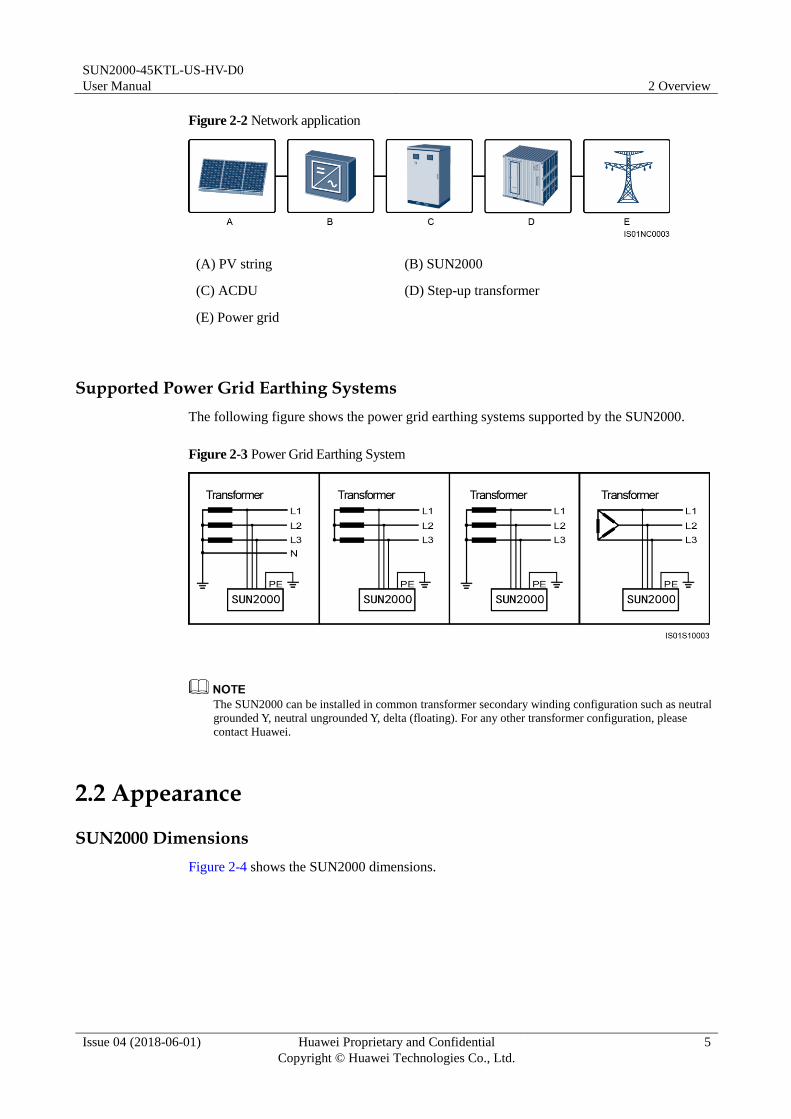
Figure 2-2 Network application
(A) PV string (B) SUN2000
(C) ACDU (D) Step-up transformer
(E) Power grid
Supported Power Grid Earthing Systems
The following figure shows the power grid earthing systems supported by the SUN2000.
Figure 2-3 Power Grid Earthing System
The SUN2000 can be installed in common transformer secondary winding configuration such as neutral
grounded Y, neutral ungrounded Y, delta (floating). For any other transformer configuration, please
contact Huawei.
2.2 Appearance
SUN2000 Dimensions
Figure 2-4 shows the SUN2000 dimensions.

SUN2000-45KTL-US-HV-D0
User Manual 2 Overview
Issue 04 (2018-06-01) Huawei Proprietary and Confidential
Copyright © Huawei Technologies Co., Ltd.
6
Figure 2-4 SUN2000 dimensions
Front view
Figure 2-5 shows the SUN2000 front view.
Figure 2-5 Front view
(1) Maintenance compartment door (2) LED indicators (3) Host panel cover
Table 2-1 describes the LED indicators.

SUN2000-45KTL-US-HV-D0
User Manual 2 Overview
Issue 04 (2018-06-01) Huawei Proprietary and Confidential
Copyright © Huawei Technologies Co., Ltd.
7
Table 2-1 LED indicator description (from left to right)
Indicator Status Meaning
PV connection
indicator
DC input
detection status
Blinking green The DC input is normal.
Blinking red DC input detection is in
progress.
Steady red The DC input is
abnormal.
PV string
connection
status
Steady green At least one PV string is
properly connected, and
the DC input voltage of
the corresponding MPPT
circuit is higher than or
equal to 600 V.
Off The SUN2000
disconnects from all PV
strings, or the DC input
voltage of each MPPT
circuit is less than 600 V.
Grid-tied indicator
Steady green The SUN2000 has
connected to the power
grid.
Off The SUN2000 does not
connect to the power grid.
Communication
indicator
Blinking green The SUN2000 receives
data over RS485 or PLC
communication.
Off The SUN2000 has not
received data over RS485
or PLC communication
for 10 seconds.
Alarm/Maintenanc
e indicator
Alarm status Blinking red at long
intervals (on for 1s
and then off for 4s)
A warning alarm is
generated.
Blinking red at short
intervals (on for 0.5s
and then off for 0.5s)
A minor alarm is
generated.
Steady red A critical alarm is
generated.
Local
maintenance
status
Blinking green at
long intervals (on for
1s and then off for
1s)
Local maintenance is in
progress.
Blinking green at
short intervals (on Local maintenance fails.
SUN2000-45KTL-US-HV-D0
User Manual 2 Overview
Issue 04 (2018-06-01) Huawei Proprietary and Confidential
Copyright © Huawei Technologies Co., Ltd.
8
Indicator Status Meaning
for 0.125s and then
off for 0.125s)
Steady green Local maintenance
succeeds.
If both DC switches are OFF, the PV connection indicator indicates the DC input detection status. If
one or two DC switches are ON, the PV connection indicator indicates the PV string connection
status.
Local maintenance refers to operations performed after a universal serial bus (USB) flash drive,
Bluetooth module, or USB data cable is inserted into the USB port of the SUN2000. For example,
local maintenance includes data import and export using a USB flash drive and connecting to the
SUN2000 app over a Bluetooth module or USB data cable.
If alarming and local maintenance happen concurrently, the alarm/maintenance indicator shows the
local maintenance state first. After the USB flash drive, Bluetooth module, or USB data cable is
removed, the indicator shows the alarm state.
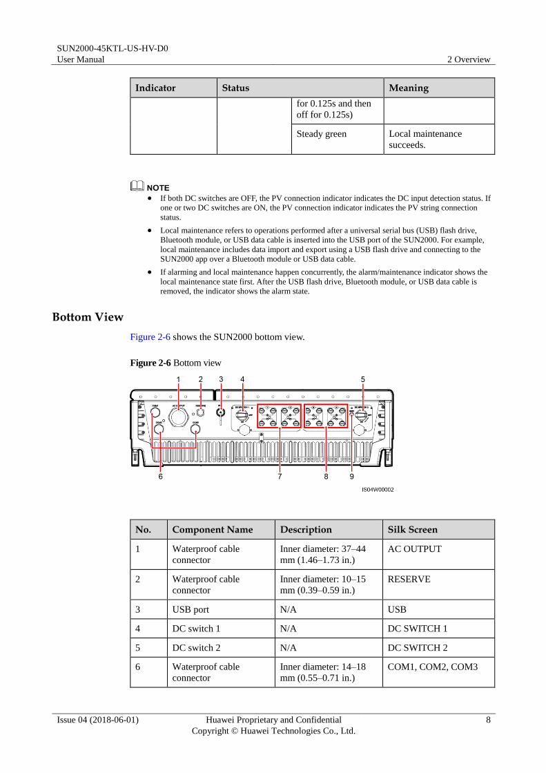
Bottom View
Figure 2-6 shows the SUN2000 bottom view.
Figure 2-6 Bottom view
No. Component Name Description Silk Screen
1 Waterproof cable
connector
Inner diameter: 37–44
mm (1.46–1.73 in.)
AC OUTPUT
2 Waterproof cable
connector
Inner diameter: 10–15
mm (0.39–0.59 in.)
RESERVE
3 USB port N/A USB
4 DC switch 1 N/A DC SWITCH 1
5 DC switch 2 N/A DC SWITCH 2
6 Waterproof cable
connector
Inner diameter: 14–18
mm (0.55–0.71 in.)
COM1, COM2, COM3

SUN2000-45KTL-US-HV-D0
User Manual 2 Overview
Issue 04 (2018-06-01) Huawei Proprietary and Confidential
Copyright © Huawei Technologies Co., Ltd.
9
No. Component Name Description Silk Screen
7 DC input terminal Controlled by DC
SWITCH 1
+/–
8 DC input terminal Controlled by DC
SWITCH 2
+/–
9 PV side ground point N/A GND
Waterproof cable connector is abbreviated as waterproof connector in the following text.
2.3 Label Description
Symbols
Table 2-2 describes the labels on the SUN2000 chassis and their meanings.
SUN2000-45KTL-US-HV-D0
User Manual 2 Overview
Issue 04 (2018-06-01) Huawei Proprietary and Confidential
Copyright © Huawei Technologies Co., Ltd.
10
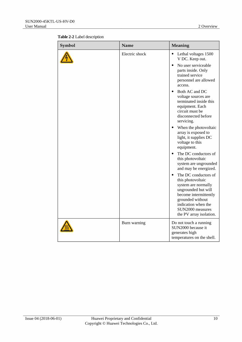
Table 2-2 Label description
Symbol Name Meaning
Electric shock Lethal voltages 1500
V DC. Keep out.
No user serviceable
parts inside. Only
trained service
personnel are allowed
access.
Both AC and DC
voltage sources are
terminated inside this
equipment. Each
circuit must be
disconnected before
servicing.
When the photovoltaic
array is exposed to
light, it supplies DC
voltage to this
equipment.
The DC conductors of
this photovoltaic
system are ungrounded
and may be energized.
The DC conductors of
this photovoltaic
system are normally
ungrounded but will
become intermittently
grounded without
indication when the
SUN2000 measures
the PV array isolation.
Burn warning Do not touch a running
SUN2000 because it
generates high
temperatures on the shell.

SUN2000-45KTL-US-HV-D0
User Manual 2 Overview
Issue 04 (2018-06-01) Huawei Proprietary and Confidential
Copyright © Huawei Technologies Co., Ltd.
11
Symbol Name Meaning
Delay discharge High voltage exists
after the SUN2000 is
powered on. Only
qualified and trained
electrical technicians
are allowed to perform
operations on the
SUN2000.
Residual voltage exists
after the SUN2000 is
powered off. It takes 5
minutes for the
SUN2000 to discharge
to the safe voltage.
Transformerless inverter The SUN2000 output
does not pass through an
isolation transformer.
Grounding Indicates the position for
connecting the protection
ground cable.
Operation warning Do not remove the DC
input connector when the
SUN2000 is running.
DC terminal operation
warninga
High voltage exists after
the SUN2000 is powered
on. To avoid electric
shocks, perform the
following system
power-off operations
before plugging or
unplugging DC input
connectors of the
SUN2000:
1. Send a shutdown
command.
2. Turn off the
downstream AC
switch.
3. Turn off the two DC
switches at the bottom.
SUN2000 serial number
label
Indicates the SUN2000
serial number.

SUN2000-45KTL-US-HV-D0
User Manual 2 Overview
Issue 04 (2018-06-01) Huawei Proprietary and Confidential
Copyright © Huawei Technologies Co., Ltd.
12
Symbol Name Meaning
Weight label The SUN2000 needs to be
carried by more than one
person or using a pallet
truck.
Note a: Fittings delivered with the SUN2000 contain the label of DC terminal operation
warning. You are advised to attach the label at the bottom of the SUN2000 front side, as
shown in Figure 2-7. You can also select an appropriate place for attaching the label based
on site requirements.
Figure 2-7 Place for attaching
Nameplate
The SUN2000 is labeled with a nameplate on the side that contains the model information,
technical specifications, and compliance symbols, as shown in Figure 2-8.
SUN2000-45KTL-US-HV-D0
User Manual 2 Overview
Issue 04 (2018-06-01) Huawei Proprietary and Confidential
Copyright © Huawei Technologies Co., Ltd.
13
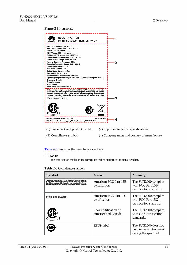
Figure 2-8 Nameplate
(1) Trademark and product model (2) Important technical specifications
(3) Compliance symbols (4) Company name and country of manufacture
Table 2-3 describes the compliance symbols.
The certification marks on the nameplate will be subject to the actual product.
Table 2-3 Compliance symbols
Symbol Name Meaning
American FCC Part 15B
certification
The SUN2000 complies
with FCC Part 15B
certification standards.
American FCC Part 15G
certification
The SUN2000 complies
with FCC Part 15G
certification standards.
CSA certification of
America and Canada
The SUN2000 complies
with CSA certification
standards.
EFUP label The SUN2000 does not
pollute the environment
during the specified
SUN2000-45KTL-US-HV-D0
User Manual 2 Overview
Issue 04 (2018-06-01) Huawei Proprietary and Confidential
Copyright © Huawei Technologies Co., Ltd.
14
Symbol Name Meaning
period.
EU waste electrical and
electronic equipment
(WEEE) label
Do not dispose of the
SUN2000 as household
garbage.
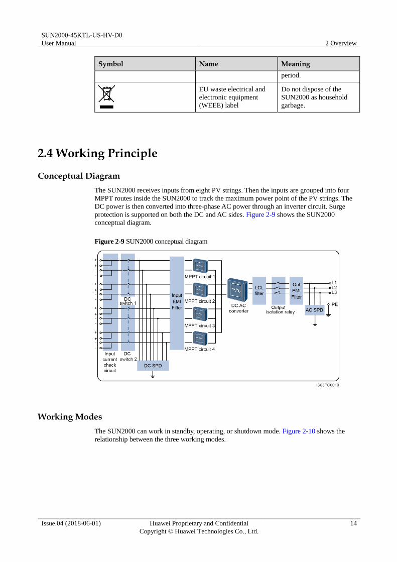
2.4 Working Principle
Conceptual Diagram
The SUN2000 receives inputs from eight PV strings. Then the inputs are grouped into four
MPPT routes inside the SUN2000 to track the maximum power point of the PV strings. The
DC power is then converted into three-phase AC power through an inverter circuit. Surge
protection is supported on both the DC and AC sides. Figure 2-9 shows the SUN2000
conceptual diagram.
Figure 2-9 SUN2000 conceptual diagram
Working Modes
The SUN2000 can work in standby, operating, or shutdown mode. Figure 2-10 shows the
relationship between the three working modes.

SUN2000-45KTL-US-HV-D0
User Manual 2 Overview
Issue 04 (2018-06-01) Huawei Proprietary and Confidential
Copyright © Huawei Technologies Co., Ltd.
15
Figure 2-10 SUN2000 working modes
Table 2-4 describes the three working modes shown in Figure 2-10.
Table 2-4 Working mode description
Working Mode
Description
Standby The SUN2000 enters the standby mode when the external environment does
not meet the requirements for starting the SUN2000. In standby mode:
The SUN2000 continuously performs self-check and enters the operating
mode once the operating requirements are met.
If the SUN2000 enters the shutdown mode after detecting a shutdown
command or a fault after startup.
Operating In operating mode:
The SUN2000 converts DC power from PV strings into AC power and
feeds the power to the power grid.
The SUN2000 tracks the maximum power point to maximize the PV
string output.
The SUN2000 enters the shutdown mode after detecting a fault or a
shutdown command, and enters the standby mode after detecting that the
PV string output power does not meet the requirements for grid-tied
electricity generation.
Shutdown In standby or operating mode, the SUN2000 enters the shutdown mode
after detecting a fault or shutdown command.
In shutdown mode, the SUN2000 enters the standby mode after detecting
a startup command or that a fault is rectified.

SUN2000-45KTL-US-HV-D0
User Manual 3 Storage
Issue 04 (2018-06-01) Huawei Proprietary and Confidential
Copyright © Huawei Technologies Co., Ltd.
16
3 Storage
The following requirements should be met if the SUN2000 is not put into use directly:
Put the SUN2000 in the original package. Keep the desiccant and seal it using the
adhesive tape.
Keep the storage temperature at –40°C (–40°F) to +70°C (+158°F) and the humidity at
5%–95% RH.
The SUN2000 should be stored in a clean and dry place and be protected from dust and
water vapor corrosion.
A maximum of five SUN2000s can be stacked.
Periodic inspections are required during the storage. Replace the packing materials as
necessary.
If the SUN2000 has been long-term stored, inspections and tests should be conducted by
qualified personnel before put into use.
SUN2000-45KTL-US-HV-D0
User Manual 4 Installation
Issue 04 (2018-06-01) Huawei Proprietary and Confidential
Copyright © Huawei Technologies Co., Ltd.
17
4 Installation
4.1 Checking Before Installation
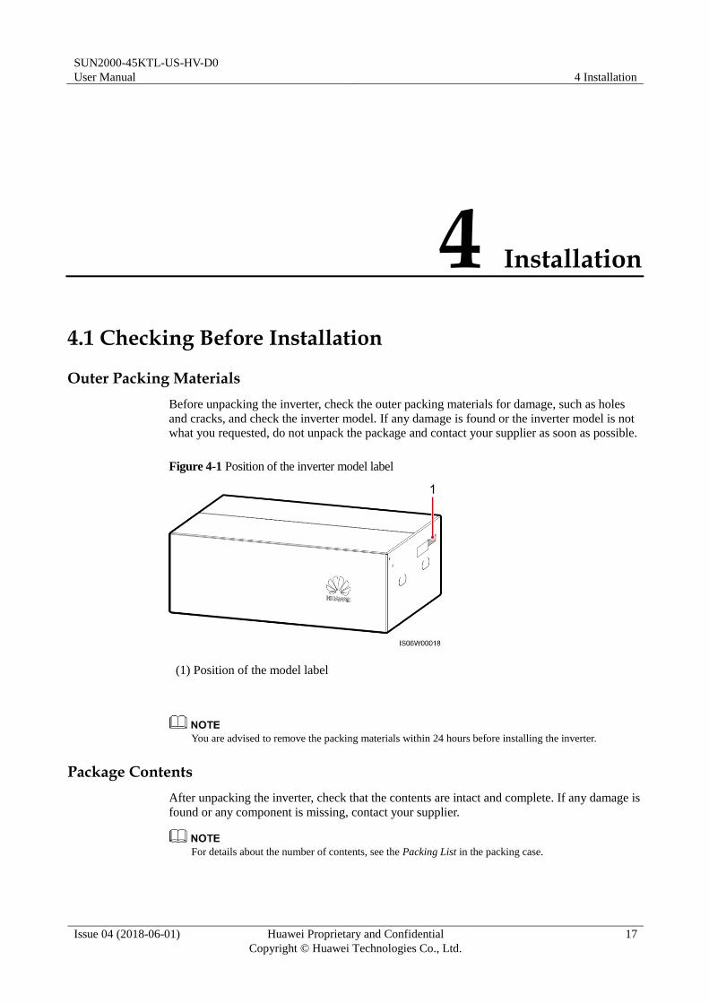
Outer Packing Materials
Before unpacking the inverter, check the outer packing materials for damage, such as holes
and cracks, and check the inverter model. If any damage is found or the inverter model is not
what you requested, do not unpack the package and contact your supplier as soon as possible.
Figure 4-1 Position of the inverter model label
(1) Position of the model label
You are advised to remove the packing materials within 24 hours before installing the inverter.
Package Contents
After unpacking the inverter, check that the contents are intact and complete. If any damage is
found or any component is missing, contact your supplier.
For details about the number of contents, see the Packing List in the packing case.

SUN2000-45KTL-US-HV-D0
User Manual 4 Installation
Issue 04 (2018-06-01) Huawei Proprietary and Confidential
Copyright © Huawei Technologies Co., Ltd.
18
4.2 Materials
Category Materials
Installation
tool
Hammer drill
Drill bit: Φ14 mm (0.55 in.)
and Φ16 mm (0.63 in.)
Socket wrench
Torque wrench
Diagonal pliers
Wire stripper
Flat-head screwdriver
Head: 0.6 mm x 3.5 mm
(0.02 in. x 0.14 in.)
Rubber mallet
Utility knife
Cable cutter
Crimping tool
Model: H4TC0001 or
H4TC0002; manufacturer:
Amphenol
RJ45 crimping tool
Removal wrench
Model: H4TW0001;
manufacturer: AMPHENOL
Vacuum cleaner
Multimeter
DC voltage measurement
range ≥ 1500 V DC
Marker

SUN2000-45KTL-US-HV-D0
User Manual 4 Installation
Issue 04 (2018-06-01) Huawei Proprietary and Confidential
Copyright © Huawei Technologies Co., Ltd.
19
Category Materials
Measuring tape
Bubble or digital level
Hydraulic pliers
Heat shrink tubing
Heat gun
Cable tie
Personal
protective
equipment
(PPE)
Safety gloves
Safety goggles
Anti-dust respirator
Safety shoes
N/A N/A
H4TC0001 is used to crimp metal cold forming contacts, while H4TC0002 is used to crimp metal
stamping forming contacts.
4.3 Determining the Installation Position
Basic Requirements The SUN2000 is protected to Type 4X and can be installed indoors or outdoors.
Do not install the SUN2000 in a place where personnel are easy to come into contact
with its chassis and heat sinks, because these parts are extremely hot during operation.
Do not install the SUN2000 in areas with flammable or explosive materials.
Installation Environment Requirements The SUN2000 must be installed in a well-ventilated environment to ensure good heat
dissipation.

SUN2000-45KTL-US-HV-D0
User Manual 4 Installation
Issue 04 (2018-06-01) Huawei Proprietary and Confidential
Copyright © Huawei Technologies Co., Ltd.
20
When installed under direct sunlight, performance de-rate may be initiated due to
additional temperature rise.
Carrier Requirements The mounting structure where the SUN2000 is installed must be fire-resistant.
Do not install the SUN2000 on flammable building materials.
The SUN2000 weighs 64 kg (141 lb). Ensure that the installation surface is solid enough
to bear the weight load.
In residential areas, do not install the SUN2000 on drywalls or walls made of similar
materials which have a weak sound insulation performance because the noise generated
by the SUN2000 is noticeable.
Installation Angle Requirements Install the SUN2000 vertically or at a maximum back tilted angle of 15 degrees to
facilitate heat dissipation.
Do not install the SUN2000 at forward tilted, excessive back tilted, side tilted, horizontal,
or upside down positions.
Figure 4-2 Installation angle
Installation Space Requirements The SUN2000 dimensions (W x H x D) are 930 mm (36.61 in.) x 600 mm (23.62 in.) x
270 mm (10.63 in.). Reserve enough clearance around the SUN2000 to ensure sufficient
space for installation and heat dissipation.

SUN2000-45KTL-US-HV-D0
User Manual 4 Installation
Issue 04 (2018-06-01) Huawei Proprietary and Confidential
Copyright © Huawei Technologies Co., Ltd.
21
Figure 4-3 Installation space requirements (non-back-to-back installation)
Figure 4-4 Installation space requirements (back-to-back installation)
For ease of installing the SUN2000 on the mounting bracket, connecting cables to the bottom of the
SUN2000, and maintaining the SUN2000 in future, it is recommended that the bottom clearance be
between 600 mm (23.62 in.) and 730 mm (28.74 in.). If you have any questions about the distance,
consult the local technical support engineers.

SUN2000-45KTL-US-HV-D0
User Manual 4 Installation
Issue 04 (2018-06-01) Huawei Proprietary and Confidential
Copyright © Huawei Technologies Co., Ltd.
22
When installing multiple SUN2000s, install them in horizontal mode if sufficient space
is available and install them in triangle mode if no sufficient space is available. Stacked
installation is not recommended.
Figure 4-5 Horizontal installation mode (recommended)
Figure 4-6 Triangle installation mode (recommended)
SUN2000-45KTL-US-HV-D0
User Manual 4 Installation
Issue 04 (2018-06-01) Huawei Proprietary and Confidential
Copyright © Huawei Technologies Co., Ltd.
23
Figure 4-7 Stacked installation mode (not recommended)
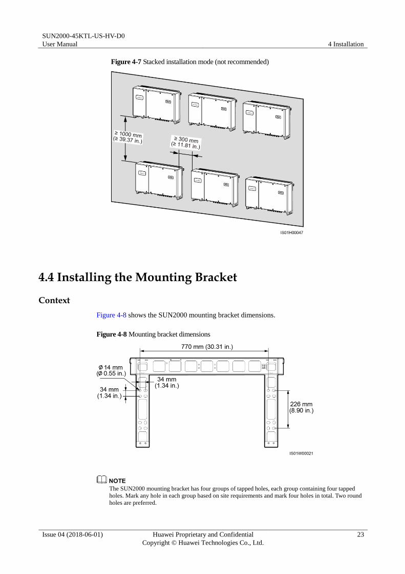
4.4 Installing the Mounting Bracket
Context
Figure 4-8 shows the SUN2000 mounting bracket dimensions.
Figure 4-8 Mounting bracket dimensions
The SUN2000 mounting bracket has four groups of tapped holes, each group containing four tapped
holes. Mark any hole in each group based on site requirements and mark four holes in total. Two round
holes are preferred.

SUN2000-45KTL-US-HV-D0
User Manual 4 Installation
Issue 04 (2018-06-01) Huawei Proprietary and Confidential
Copyright © Huawei Technologies Co., Ltd.
24
Before installing the mounting bracket, remove the security torx wrench from the mounting
bracket and save for later use.
Figure 4-9 Removing a security torx wrench
Wall-mounted Installation
Step 1 Determine the positions for drilling holes using the mounting bracket. Level the positions of
mounting holes using a bubble or digital level, and mark the positions with a marker.
Figure 4-10 Determining hole positions
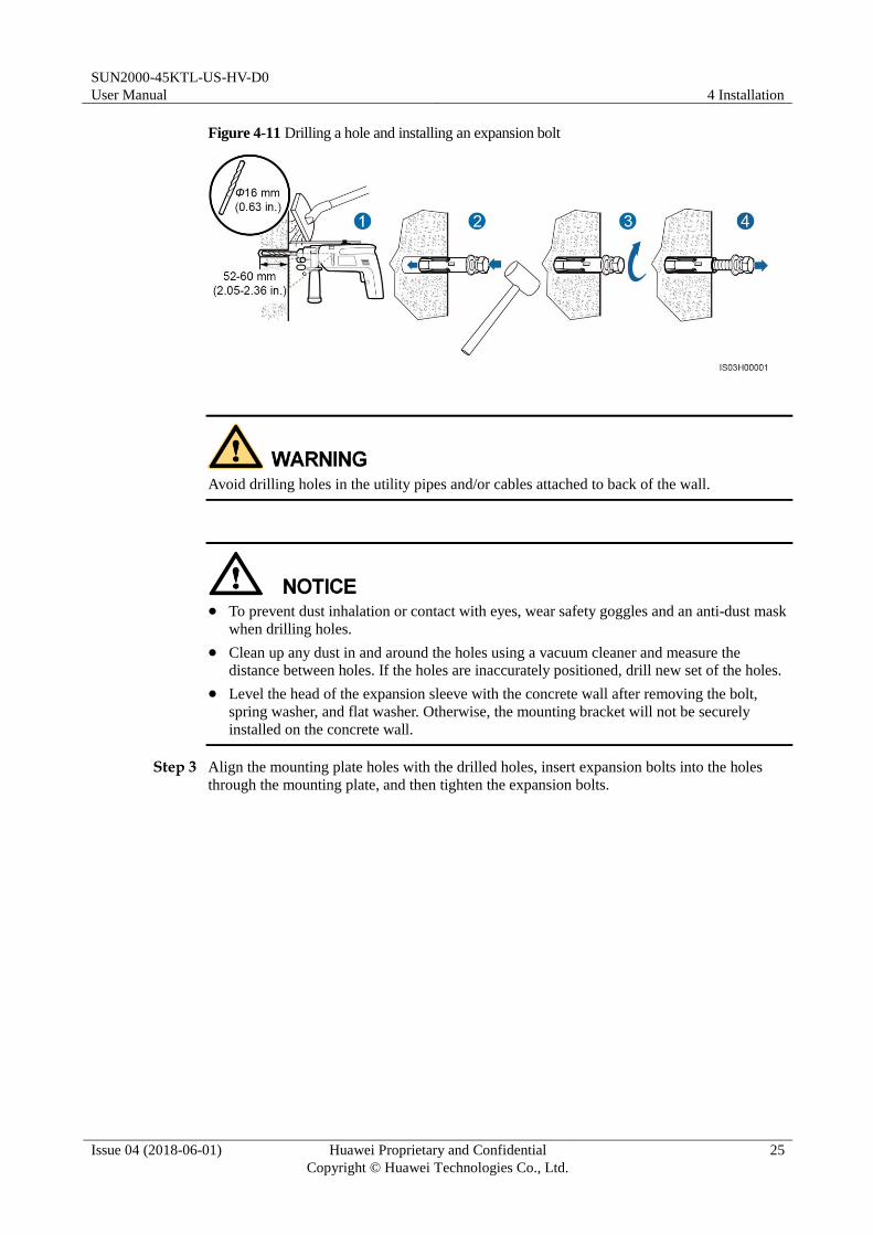
Step 2 Drill holes using a hammer drill and install expansion bolts.
M12x60 expansion bolts are delivered with the SUN2000.
SUN2000-45KTL-US-HV-D0
User Manual 4 Installation
Issue 04 (2018-06-01) Huawei Proprietary and Confidential
Copyright © Huawei Technologies Co., Ltd.
25
Figure 4-11 Drilling a hole and installing an expansion bolt
Avoid drilling holes in the utility pipes and/or cables attached to back of the wall.
To prevent dust inhalation or contact with eyes, wear safety goggles and an anti-dust mask
when drilling holes.
Clean up any dust in and around the holes using a vacuum cleaner and measure the
distance between holes. If the holes are inaccurately positioned, drill new set of the holes.
Level the head of the expansion sleeve with the concrete wall after removing the bolt,
spring washer, and flat washer. Otherwise, the mounting bracket will not be securely
installed on the concrete wall.
Step 3 Align the mounting plate holes with the drilled holes, insert expansion bolts into the holes
through the mounting plate, and then tighten the expansion bolts.

SUN2000-45KTL-US-HV-D0
User Manual 4 Installation
Issue 04 (2018-06-01) Huawei Proprietary and Confidential
Copyright © Huawei Technologies Co., Ltd.
26
Figure 4-12 Securing a mounting bracket
----End
Support-mounted Installation
Step 1 Determine the positions for drilling holes using the mounting bracket. Level the positions of
mounting holes using a bubble or digital level, and mark the positions with a marker.
Figure 4-13 Determining hole positions
Step 2 Drill holes using a hammer drill.
You are advised to apply anti-rust paint on the hole positions for protection.
SUN2000-45KTL-US-HV-D0
User Manual 4 Installation
Issue 04 (2018-06-01) Huawei Proprietary and Confidential
Copyright © Huawei Technologies Co., Ltd.
27
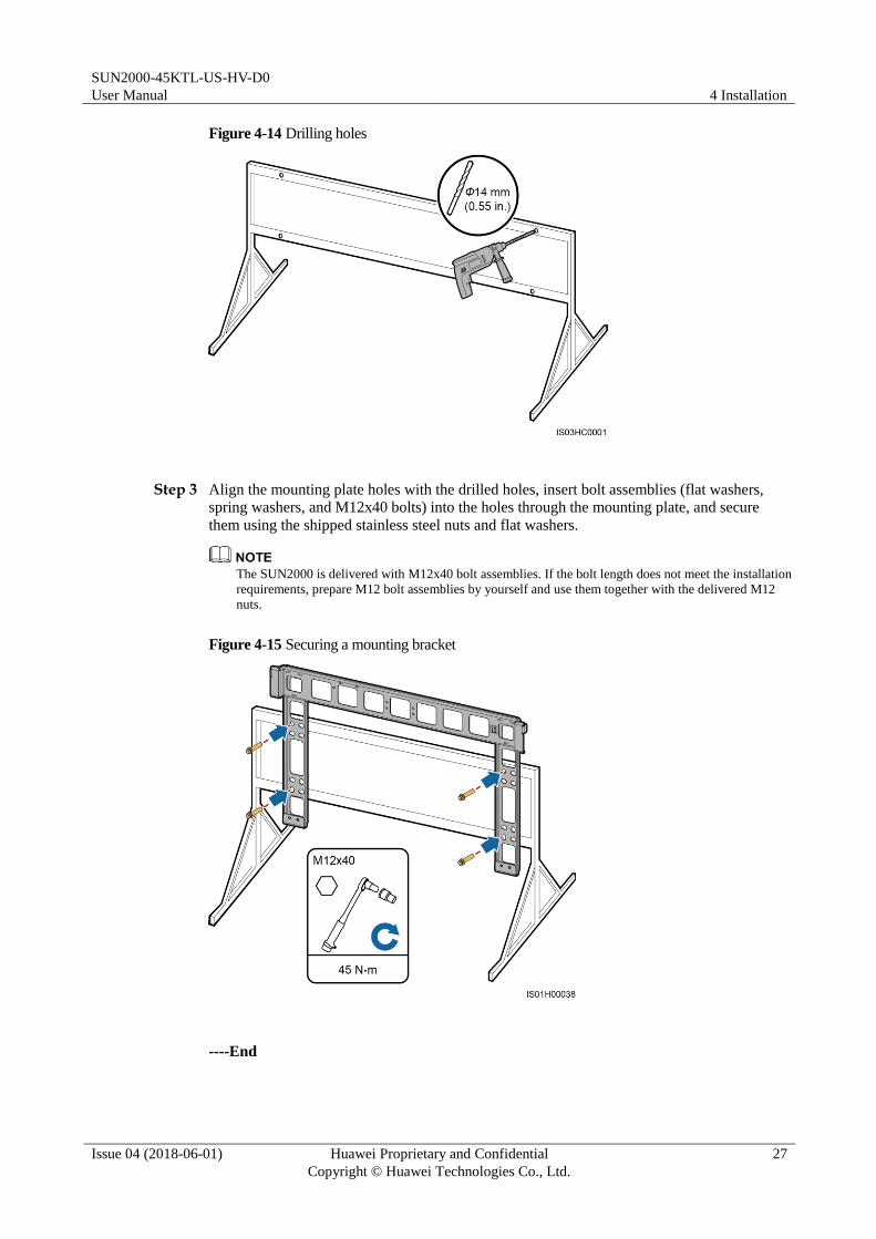
Figure 4-14 Drilling holes
Step 3 Align the mounting plate holes with the drilled holes, insert bolt assemblies (flat washers,
spring washers, and M12x40 bolts) into the holes through the mounting plate, and secure
them using the shipped stainless steel nuts and flat washers.
The SUN2000 is delivered with M12x40 bolt assemblies. If the bolt length does not meet the installation
requirements, prepare M12 bolt assemblies by yourself and use them together with the delivered M12
nuts.
Figure 4-15 Securing a mounting bracket
----End

SUN2000-45KTL-US-HV-D0
User Manual 4 Installation
Issue 04 (2018-06-01) Huawei Proprietary and Confidential
Copyright © Huawei Technologies Co., Ltd.
28
4.5 Installing the SUN2000
Prerequisites
Before installing the SUN2000, take it out from the packing case and move it to the
installation position.
To prevent device damage and personal injury, keep balance when moving the SUN2000
because it is heavy.
Move the SUN2000 by four people with an appropriate transportation tool.
Do not use the wiring terminals at the bottom to support any weight of the SUN2000.
When need to temporally place the SUN2000 on the ground, use foam, paper or other
protection material to prevent damage to its cover.
Procedure
Step 1 If you can mount the SUN2000 onto the mounting bracket directly, go to Step 3 and then Step
5.
Step 2 If you cannot mount the SUN2000 onto the mounting bracket directly, go to Step 3 and then
Step 6.
Step 3 Ensure that minimum of two people lift one SUN2000 and turn it upright. Move the
SUN2000 with handles at the top and bottom.
To prevent device damage and personal injury, keep balance when lifting the SUN2000
because it is heavy.

SUN2000-45KTL-US-HV-D0
User Manual 4 Installation
Issue 04 (2018-06-01) Huawei Proprietary and Confidential
Copyright © Huawei Technologies Co., Ltd.
29
Figure 4-16 Lifting a SUN2000
Step 4 Run a lifting sling through the lifting eyes of the SUN2000.
When lifting the SUN2000, keep balance to prevent the SUN2000 impacting with a wall or
other objects.
Figure 4-17 Lifting a SUN2000

SUN2000-45KTL-US-HV-D0
User Manual 4 Installation
Issue 04 (2018-06-01) Huawei Proprietary and Confidential
Copyright © Huawei Technologies Co., Ltd.
30
The figure is for reference only.
Step 5 Install the SUN2000 on the mounting bracket and align the SUN2000 chassis with the
mounting bracket.
Figure 4-18 Mounting the SUN2000 onto a mounting bracket
Step 6 Tighten the two antitheft screws using a security torx wrench.
Figure 4-19 Tightening antitheft screws
----End
SUN2000-45KTL-US-HV-D0
User Manual 5 General Operation
Issue 04 (2018-06-01) Huawei Proprietary and Confidential
Copyright © Huawei Technologies Co., Ltd.
31
5 General Operation
5.1 Crimping the OT Terminal
Requirements for the OT Terminal If a copper cable is used, use a copper wiring terminal.
If a copper-clad aluminum cable is used, use a copper wiring terminal.
If an aluminum alloy cable is used, use a copper to aluminum adapter terminal or an
aluminum wiring terminal with a copper to aluminum adapter washer.

SUN2000-45KTL-US-HV-D0
User Manual 5 General Operation
Issue 04 (2018-06-01) Huawei Proprietary and Confidential
Copyright © Huawei Technologies Co., Ltd.
32
Directly connecting an aluminum wiring terminal to the AC terminal block will cause
electro-chemical corrosion and weaken the cable connection reliability.
The copper to aluminum adapter terminal or an aluminum wiring terminal with a copper to
aluminum adapter washer must comply with UL486-A and UL486-B.
Do not mix up the aluminum and copper sides of the copper to aluminum adapter washer.
Ensure that the aluminum side of the washer contacts the aluminum wiring terminal, and
the copper side contacts the AC terminal block.
Figure 5-1 Requirements for the OT terminal
Crimping the OT terminal
SUN2000-45KTL-US-HV-D0
User Manual 5 General Operation
Issue 04 (2018-06-01) Huawei Proprietary and Confidential
Copyright © Huawei Technologies Co., Ltd.
33
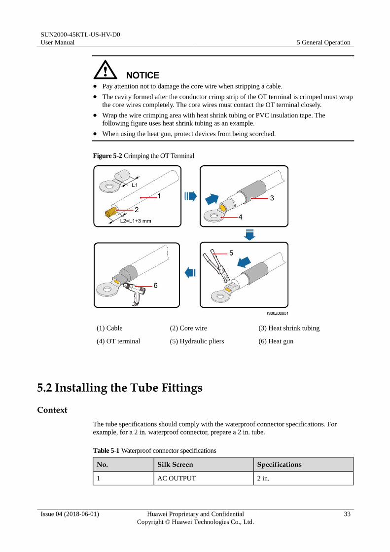
Pay attention not to damage the core wire when stripping a cable.
The cavity formed after the conductor crimp strip of the OT terminal is crimped must wrap
the core wires completely. The core wires must contact the OT terminal closely.
Wrap the wire crimping area with heat shrink tubing or PVC insulation tape. The
following figure uses heat shrink tubing as an example.
When using the heat gun, protect devices from being scorched.
Figure 5-2 Crimping the OT Terminal
(1) Cable (2) Core wire (3) Heat shrink tubing
(4) OT terminal (5) Hydraulic pliers (6) Heat gun
5.2 Installing the Tube Fittings
Context
The tube specifications should comply with the waterproof connector specifications. For
example, for a 2 in. waterproof connector, prepare a 2 in. tube.
Table 5-1 Waterproof connector specifications
No. Silk Screen Specifications
1 AC OUTPUT 2 in.

SUN2000-45KTL-US-HV-D0
User Manual 5 General Operation
Issue 04 (2018-06-01) Huawei Proprietary and Confidential
Copyright © Huawei Technologies Co., Ltd.
34
No. Silk Screen Specifications
2 COM1/COM2/COM3 3/4 in.
3 RESERVE 1/2 in.
Figure 5-3 shows the diameters of the cable holes without waterproof connectors.
Figure 5-3 Cable hole diameters
Figure 5-4 shows a tube.
Figure 5-4 Tube
(1) Nut (2) Fitting (3) Conduit
The tube appearance is for reference only. The actual tube prevails.
Installing the Tube Fitting (Using AC OUTPUT as an Example)
Step 1 Remove the AC filter.

SUN2000-45KTL-US-HV-D0
User Manual 5 General Operation
Issue 04 (2018-06-01) Huawei Proprietary and Confidential
Copyright © Huawei Technologies Co., Ltd.
35
Step 2 Remove the cable gland and cap from the waterproof connector, and then remove the
waterproof connector.
Step 3 Secure the tube fitting to the chassis using the nut delivered with the tube.
Step 4 Install the AC filter in the original position.
Figure 5-5 Installing the tube fitting (using AC OUTPUT as an example)
----End
Installing the Tube Fitting (Using COM/RESERVE as an Example)
Step 1 Remove the cable gland and cap from the waterproof connector, and then remove the
waterproof connector.
Step 2 Secure the tube fitting to the chassis using the nut delivered with the tube.

SUN2000-45KTL-US-HV-D0
User Manual 5 General Operation
Issue 04 (2018-06-01) Huawei Proprietary and Confidential
Copyright © Huawei Technologies Co., Ltd.
36
Figure 5-6 Installing the tube fitting (using COM/RESERVE as an example)
----End
5.3 Routing Cables Through Waterproof Connectors
Context
This section describes how to route an AC power cable through the AC OUTPUT waterproof
connector.
Procedure
Step 1 Route the cable through the waterproof connector.

SUN2000-45KTL-US-HV-D0
User Manual 5 General Operation
Issue 04 (2018-06-01) Huawei Proprietary and Confidential
Copyright © Huawei Technologies Co., Ltd.
37
Figure 5-7 Routing a cable
For ease of connecting the AC output power cable, you are advised to remove the nut assembly from the
AC terminal and set it aside, and then route the cable through the waterproof connector.
----End

SUN2000-45KTL-US-HV-D0
User Manual 6 Electrical Connections
Issue 04 (2018-06-01) Huawei Proprietary and Confidential
Copyright © Huawei Technologies Co., Ltd.
38
6 Electrical Connections
6.1 Precautions
Before connecting cables, ensure that the two DC switches on the SUN2000 are OFF.
Otherwise, the high voltage of the SUN2000 may result in electric shocks.
The equipment damage caused by incorrect cable connections is beyond the warranty
scope.
Only certified electrician can perform electrical terminations.
Wear proper PPE at all time when terminating cables.
The cable colors shown in the electrical connection diagrams provided in this chapter are for reference
only. Select cables in accordance with local cable specifications (green-and-yellow cables are only used
for grounding).
6.2 Opening the Maintenance Compartment Door
Prerequisites

SUN2000-45KTL-US-HV-D0
User Manual 6 Electrical Connections
Issue 04 (2018-06-01) Huawei Proprietary and Confidential
Copyright © Huawei Technologies Co., Ltd.
39
Never open the Host panel cover of the SUN2000.
Before opening the maintenance compartment door, disconnect the AC and DC power
supplies. For processes of disconnecting the power supplies, see 7.4 Powering Off the
SUN2000. After powering off the SUN2000, wait at least 5 minutes and then perform
operations on the SUN2000.
If you need to open the maintenance compartment door on rainy or snowy days, take
protective measures to prevent rain or snow entering the maintenance compartment. If it is
impossible to take protective measures, do not open the maintenance compartment door in
rainy or snowy days.
Do not leave extra hardware in the maintenance compartment.
Procedure
Step 1 Partially loosen the two screws on the maintenance compartment door.
Figure 6-1 Loosening screws
If the screws on the chassis door are lost, obtain spare screws from the fitting bag bound to the inductor
cover at the bottom of the chassis.
Step 2 Open the maintenance compartment and use the support bar to stabilize the door.

SUN2000-45KTL-US-HV-D0
User Manual 6 Electrical Connections
Issue 04 (2018-06-01) Huawei Proprietary and Confidential
Copyright © Huawei Technologies Co., Ltd.
40
Figure 6-2 Stabilizing a door using a support bar
Step 3 Remove the cover and hang it on the hook of the chassis door.
Figure 6-3 Removing a cover
----End
6.3 Connecting the Ground Cable
6.3.1 Connecting a Ground Cable to the PE Point (Bonding)
Prerequisites
The ground cable and OT terminal are available.
Ground cable: 6 AWG or thicker outdoor rated copper wire
OT terminal: M6 and matching the wire gauge of chosen
Context The ground point on the enclosure is preferred to connect to the PE cable for the
SUN2000.

SUN2000-45KTL-US-HV-D0
User Manual 6 Electrical Connections
Issue 04 (2018-06-01) Huawei Proprietary and Confidential
Copyright © Huawei Technologies Co., Ltd.
41
The ground point in the maintenance compartment is mainly used for connecting to the
ground cable included in the multi-core AC power cable. For details, see section 6.4
Connecting AC Output Power Cables.
There are two PE points on the chassis shell, only one need to be utilized.
It is recommended that the ground cable be connected to a nearby PE point. For a system
with multiple SUN2000s connected in parallel, connect the PE points of all SUN2000s to
ensure equipotential connections to ground cables.
Procedure
Step 1 Crimp the OT terminal.
Step 2 Secure the ground cable using the ground screw.
Figure 6-4 Connecting a ground cable
----End
Follow-up Procedure
Recommendation: To enhance the corrosion resistance of a ground terminal, silica gel or paint
might be needed.
6.3.2 Connecting the Ground Cable to the PV Side Ground Point (GND)
Prerequisites
The ground cable and OT terminal are available.
Ground cable: 6 AWG or thicker outdoor rated copper wire
OT terminal: M6 and matching the wire gauge of chosen

SUN2000-45KTL-US-HV-D0
User Manual 6 Electrical Connections
Issue 04 (2018-06-01) Huawei Proprietary and Confidential
Copyright © Huawei Technologies Co., Ltd.
42
Procedure
Step 1 Crimp the OT terminal.
Step 2 Secure the ground cable using the ground screw.
Figure 6-5 Connecting a ground cable
----End
Follow-up Procedure
Recommendation: To enhance the corrosion resistance of a ground terminal, silica gel or paint
might be needed.
6.4 Connecting AC Output Power Cables
A three-phase AC switch must be installed on the AC side of the SUN2000 to ensure that the
SUN2000 can be safely disconnected from the power grid.
Do not connect loads between the SUN2000 and the AC switch.
The SUN2000 is integrated with a comprehensive residual current detection unit to
distinguish fault current from residual current. Upon detecting that the residual current
exceeds the threshold, the SUN2000 immediately disconnects from the power grid.
If an AC switch that can detect residual current is installed outside the SUN2000, the residual current
value that will trigger the switch trip should be greater than 500 mA.

SUN2000-45KTL-US-HV-D0
User Manual 6 Electrical Connections
Issue 04 (2018-06-01) Huawei Proprietary and Confidential
Copyright © Huawei Technologies Co., Ltd.
43
6.4.1 Connection Through a Tube
Prerequisites Use cables that can withstand 90°C (194°F) or 105°C (221°F). The cable that can
withstand 105°C (221°F) is recommended. To facilitate the installation, use flexible
cables.
If you connect a ground cable to the PE point on the chassis, you are advised to use three
(L1, L2, and L3) single-core outdoor copper cables.
If you connect a ground cable to the PE point in the maintenance compartment, you are
advised to use four (L1, L2, L3, and PE) single-core outdoor copper cables.
Table 6-1 describes the cable specifications.
Table 6-1 Cable specifications
Cable Specifications Copper-Core Cable Copper-Clad Aluminum Cable or Aluminum Alloy Cable
Conductor
cross-sectional area
Range 6–2/0 AWG 4–2/0 AWG
Recomm
ended to
use
4 AWG 2 AWG
Cable outer diameter 6.3–12.1 mm (0.25–0.48 in.)
OT terminal: M8 (L1, L2, and L3) and M6 (PE).
Tube: 2-inch tube
Procedure
Step 1 Install the tube fitting. For details, see 5.2 Installing the Tube Fittings.
Step 2 Route the cable through the tube conduit and then fitting.
Step 3 Crimp the OT terminal.
Step 4 Land the AC output power cable in the terminal block, and tighten the nuts with a torque
wrench that has an extension rod.

SUN2000-45KTL-US-HV-D0
User Manual 6 Electrical Connections
Issue 04 (2018-06-01) Huawei Proprietary and Confidential
Copyright © Huawei Technologies Co., Ltd.
44
Ensure that AC terminations provide firm and solid electrical connections. Failing to do so
may cause SUN2000 malfunction and damage to its components, even start thermal events.
Any SUN2000 damaged due to weak termination will result in revocation of product
warranty.
If the AC output power cables are subject to a pulling force because the inverter is not
installed stably, ensure that the last cable that bears the stress is the PE cable.
Figure 6-6 Connecting an AC output power cable (excluding the ground cable)
SUN2000-45KTL-US-HV-D0
User Manual 6 Electrical Connections
Issue 04 (2018-06-01) Huawei Proprietary and Confidential
Copyright © Huawei Technologies Co., Ltd.
45
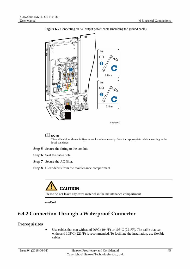
Figure 6-7 Connecting an AC output power cable (including the ground cable)
The cable colors shown in figures are for reference only. Select an appropriate cable according to the
local standards.
Step 5 Secure the fitting to the conduit.
Step 6 Seal the cable hole.
Step 7 Secure the AC filter.
Step 8 Clear debris from the maintenance compartment.
Please do not leave any extra material in the maintenance compartment.
----End
6.4.2 Connection Through a Waterproof Connector
Prerequisites Use cables that can withstand 90°C (194°F) or 105°C (221°F). The cable that can
withstand 105°C (221°F) is recommended. To facilitate the installation, use flexible cables.

SUN2000-45KTL-US-HV-D0
User Manual 6 Electrical Connections
Issue 04 (2018-06-01) Huawei Proprietary and Confidential
Copyright © Huawei Technologies Co., Ltd.
46
If you connect a ground cable to the PE point on the chassis, you are advised to use a
three-core (L1, L2, and L3) outdoor cable.
If you connect a ground cable to the PGND point in the maintenance compartment, you
are advised to use a four-core (L1, L2, and L3) outdoor cable.
Table 6-2 describes the cable specifications.
Table 6-2 Cable specifications
Cable Specifications Copper-Core Cable Copper-Clad Aluminum Cable or Aluminum Alloy Cable
Conductor
cross-sectional area
Range 6–2/0 AWG 4–2/0 AWG
Recomm
ended to
use
4 AWG 2 AWG
Cable outer diameter range
supported by the AC OUTPUT
waterproof connector
37–44 mm (1.46–1.73 in.)
OT terminal: M8 (L1, L2, and L3) and M6 (PE).
Procedure
Step 1 Remove an appropriate length of the jacket and insulation layer from the AC output power
cable using a wire stripper.
Ensure that the jacket is in the maintenance compartment.
Figure 6-8 Three-core cable (excluding the ground cable)
(A) Core wire (B) Insulation layer (C) Jacket

SUN2000-45KTL-US-HV-D0
User Manual 6 Electrical Connections
Issue 04 (2018-06-01) Huawei Proprietary and Confidential
Copyright © Huawei Technologies Co., Ltd.
47
Figure 6-9 Four-core cable (including the ground cable)
Step 2 Crimp the OT terminal.
Step 3 Route the cable through the waterproof connector.
Step 4 Land the AC output power cable in the terminal block, and tighten the nuts with a torque
wrench that has an extension rod.

SUN2000-45KTL-US-HV-D0
User Manual 6 Electrical Connections
Issue 04 (2018-06-01) Huawei Proprietary and Confidential
Copyright © Huawei Technologies Co., Ltd.
48
Ensure that AC terminations provide firm and solid electrical connections. Failing to do so
may cause SUN2000 malfunction and damage to its components, even start thermal events.
Any SUN2000 damaged due to weak termination will result in revocation of product
warranty.
If the AC output power cables are subject to a pulling force because the inverter is not
installed stably, ensure that the last cable that bears the stress is the PE cable.
Figure 6-10 Connecting an AC output power cable (excluding the ground cable)
SUN2000-45KTL-US-HV-D0
User Manual 6 Electrical Connections
Issue 04 (2018-06-01) Huawei Proprietary and Confidential
Copyright © Huawei Technologies Co., Ltd.
49
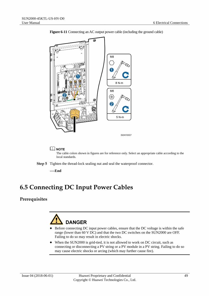
Figure 6-11 Connecting an AC output power cable (including the ground cable)
The cable colors shown in figures are for reference only. Select an appropriate cable according to the
local standards.
Step 5 Tighten the thread-lock sealing nut and seal the waterproof connector.
----End
6.5 Connecting DC Input Power Cables
Prerequisites
Before connecting DC input power cables, ensure that the DC voltage is within the safe
range (lower than 60 V DC) and that the two DC switches on the SUN2000 are OFF.
Failing to do so may result in electric shocks.
When the SUN2000 is grid-tied, it is not allowed to work on DC circuit, such as
connecting or disconnecting a PV string or a PV module in a PV string. Failing to do so
may cause electric shocks or arcing (which may further cause fire).
SUN2000-45KTL-US-HV-D0
User Manual 6 Electrical Connections
Issue 04 (2018-06-01) Huawei Proprietary and Confidential
Copyright © Huawei Technologies Co., Ltd.
50
Ensure that the following conditions are met. Otherwise, the SUN2000 will be damaged, or
even become a fire hazard.
The open-circuit voltage of each PV array is always lower than or equal to 1500 V DC.
The positive and negative terminals of a PV module connect to corresponding positive and
negative DC input terminals of the SUN2000.
Ensure that the PV string is well insulated to ground.
The PV strings connecting to the same MPPT circuit should contain the same number of
identical PV modules.
During the installation of PV strings and SUN2000, the positive or negative terminals of
PV strings may be grounded if power cables are not properly installed or routed. In this
case, an AC or DC short circuit may occur and damage the SUN2000. The caused
equipment damage is beyond the warranty scope.
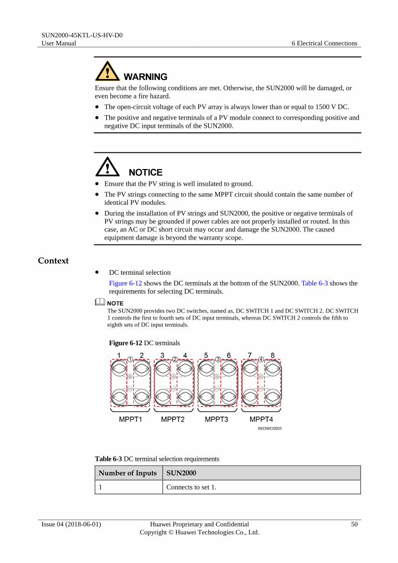
Context DC terminal selection
Figure 6-12 shows the DC terminals at the bottom of the SUN2000. Table 6-3 shows the
requirements for selecting DC terminals.
The SUN2000 provides two DC switches, named as, DC SWITCH 1 and DC SWITCH 2. DC SWITCH
1 controls the first to fourth sets of DC input terminals, whereas DC SWITCH 2 controls the fifth to
eighth sets of DC input terminals.
Figure 6-12 DC terminals
Table 6-3 DC terminal selection requirements
Number of Inputs SUN2000
1 Connects to set 1.
SUN2000-45KTL-US-HV-D0
User Manual 6 Electrical Connections
Issue 04 (2018-06-01) Huawei Proprietary and Confidential
Copyright © Huawei Technologies Co., Ltd.
51
Number of Inputs SUN2000
2 Connects to sets 1 and 5.
3 Connects to sets 1, 3, and 5.
4 Connects to sets 1, 3, 5, and 7.
5 Connects to sets 1, 2, 3, 5, and 7.
6 Connects to sets 1, 2, 3, 5, 6, and 7.
7 Connects to sets 1, 2, 3, 4, 5, 6, and 7.
8 Connects to sets 1, 2, 3, 4, 5, 6, 7, and 8.
DC input power cable specifications
Table 6-4 lists the recommended DC input power cable specifications.
Table 6-4 Recommended DC input power cable specifications
Cable Type Conductor Cross-Sectional Area
Cable Outer Diameter
PV cable that meets the 1500 V
standard
4–6 mm2 (or 12–10 AWG) 4.5–7.8 mm
Cables with high rigidity, such as armored cables, are not recommended, because poor contact
may be caused by the bending of the cables.
Procedure
Step 1 Prepare positive and negative connectors.
Use the Amphenol HH4 DC input terminals provided with the SUN2000. If the terminals are
lost or damaged, purchase the DC input terminals of the same model. Other models of DC
input terminals may be incompatible with the SUN2000, which may cause serious
consequences. The caused equipment damage is beyond the warranty scope.

SUN2000-45KTL-US-HV-D0
User Manual 6 Electrical Connections
Issue 04 (2018-06-01) Huawei Proprietary and Confidential
Copyright © Huawei Technologies Co., Ltd.
52
The metal contacts supplied with the DC connectors are either cold forming contacts or
stamping forming contacts. Choose the crimping tools that fit the metal contact types. Do
not mix up the tools.
Crimp the metal cold forming contacts using crimping tool H4TC0001 (Amphenol).
Crimp the metal stamping forming contacts using crimping tool H4TC0002 (Amphenol,
recommended), PV-CZM-22100 (Staubli), or PV-CZM-19100 (Staubli). When choosing
PV-CZM-22100 or PV-CZM-19100, do not use the locator. Otherwise metal contacts
would be damaged.
Figure 6-13 Crimping tool (H4TC0002)
(1) Locator
Figure 6-14 Preparing positive and negative connectors (using metal cold forming contacts)
(1) Positive metal contact (cold forming) (2) Negative metal contact (cold forming)
(3) Positive connector (4) Negative connector

SUN2000-45KTL-US-HV-D0
User Manual 6 Electrical Connections
Issue 04 (2018-06-01) Huawei Proprietary and Confidential
Copyright © Huawei Technologies Co., Ltd.
53
Figure 6-15 Preparing positive and negative connectors (using metal stamping forming contacts)
(1) Positive metal contact (stamping
forming)
(2) Negative metal contact (stamping
forming)
(3) Positive connector (4) Negative connector
After the positive and negative metal terminals snap into place, pull the DC input power
cables back to ensure that they are connected securely.
Step 2 Tighten the locking nuts on the positive and negative connectors.

SUN2000-45KTL-US-HV-D0
User Manual 6 Electrical Connections
Issue 04 (2018-06-01) Huawei Proprietary and Confidential
Copyright © Huawei Technologies Co., Ltd.
54
Figure 6-16 Locking a nut
Step 3 Use a multimeter to measure the DC voltage between the positive and negative of the PV
string and confirm the string polarity.
The DC voltage measurement range of the multimeter must be at least 1500 V.

SUN2000-45KTL-US-HV-D0
User Manual 6 Electrical Connections
Issue 04 (2018-06-01) Huawei Proprietary and Confidential
Copyright © Huawei Technologies Co., Ltd.
55
Figure 6-17 Measuring voltage
If the voltage is a negative value, the DC input polarity is incorrect. Correct the polarity.
If the voltage is greater than 1500 V, too many PV modules configured to the same string.
Remove some PV modules.
Step 4 Pull out the blue dustproof plugs from the ends of the DC input connectors.
Before performing Step 5, ensure that the two DC switches are OFF.
Step 5 Insert the positive and negative connectors into the corresponding positive and negative DC
input terminals of the SUN2000 until they snap into place.

SUN2000-45KTL-US-HV-D0
User Manual 6 Electrical Connections
Issue 04 (2018-06-01) Huawei Proprietary and Confidential
Copyright © Huawei Technologies Co., Ltd.
56
1. After the positive and negative connectors snap into place, pull test to the DC input cables
is recommended.
2. Only after at least one PV string correctly connects to the MPPT1 circuit, the SUN2000
enables the DC input detection function. Therefore, you are required to connect DC input
power cables to the MPPT1 circuit first.
Figure 6-18 Connecting DC input power cables
If polarity of the DC input power cable is reversed and the DC switch is ON, do not turn off
the DC switch immediately or unplug positive and negative connectors. The device may be
damaged if you do not follow the instruction. The caused equipment damage is beyond the
warranty scope. Wait until the solar irradiance declines and the PV string current reduces to
below 0.5 A, and then turn off the two DC switches and remove the positive and negative
connectors. Correct the string polarity before reconnecting the string to the SUN2000.
----End
6.6 Connecting the Communications Cable
6.6.1 Communication Mode Description
RS485 Communication
The SUN2000 can connect to the SmartLogger over RS485 or to a PC through the
SmartLogger to implement communication. You can use the SUN2000 APP, SmartLogger,

SUN2000-45KTL-US-HV-D0
User Manual 6 Electrical Connections
Issue 04 (2018-06-01) Huawei Proprietary and Confidential
Copyright © Huawei Technologies Co., Ltd.
57
embedded WebUI, or the network management software (such as the NetEco) on the PC to
query information about the SUN2000, such as energy yield, alarms, and running status.
Figure 6-19 shows the communication mode for a single SUN2000.
Figure 6-19 Communication mode for a single SUN2000
Figure 6-20 shows the communication mode for multiple SUN2000s.
If multiple SUN2000s are used, connect all the SUN2000s in daisy chain mode over an
RS485 communications cable.
Figure 6-20 Communication mode for multiple SUN2000s
The RS485 communication distance between the SUN2000 at the end of the daisy chain and the
SmartLogger cannot exceed 1000 meters.
If multiple SUN2000s need to communicate with one another and are connected to a PC over the
SmartLogger2000, a maximum of six daisy chains can be configured.
To ensure the system response speed, it is recommended that the number of devices on each daisy
chain be less than 30.
PLC Communication
The PLC communication board loads communication signals onto power cables for
transmission. For details about how to install the PLC, see the PLC CCO01A User Manual or
SmartLogger2000 User Manual.
The built-in PLC module in the SUN2000 does not need to be connected with cables.

SUN2000-45KTL-US-HV-D0
User Manual 6 Electrical Connections
Issue 04 (2018-06-01) Huawei Proprietary and Confidential
Copyright © Huawei Technologies Co., Ltd.
58
Selecting a Communication Mode
The RS485 and PLC communication modes are mutually exclusive.
If the PLC communication mode is selected, do not connect the RS485 communications
cable. In addition, you need to set PLC communication to Enable.
The PLC communication mode is only applicable to medium-voltage grid connection
scenarios and non-low-voltage public grid connection scenarios (industrial environment).
If the RS485 communication mode is selected, do not connect the PLC CCO module to
the AC power cable. In addition, you are advised to set PLC communication to Disable.
PLC communication is set to Enable by default.
6.6.2 Connecting the RS485 Communications Cable (to a Terminal Block)
Description
The RS485 communications cable can connect to either a terminal block or an RJ45 network
port. Connecting to a terminal block is recommended.
You are advised to use a multi-paired, individually foil shielded cable that complies with
UL2919, CM/CMG (NEC type), or CMH (CSA type) and has a conductor
cross-sectional area of less than or equal to 2.5 mm2 14 AWG and an outer diameter of
14–18 mm (0.55–0.71 in.).
RS485 communications cables can also run through a 3/4 in.tube, which is not provided
with SUN2000 shipping package.
When laying out communications cables, separate them from power cables to avoid strong
signal interference sources.
Terminal Block Pin Definitions
Figure 6-21 shows an RS485 terminal block.

SUN2000-45KTL-US-HV-D0
User Manual 6 Electrical Connections
Issue 04 (2018-06-01) Huawei Proprietary and Confidential
Copyright © Huawei Technologies Co., Ltd.
59
Figure 6-21 Terminal block
Table 6-5 describes pin definitions of the RS485 terminal block.
Table 6-5 Pin definitions of the RS485 terminal block
No. Port Definition Description
1 RS485A IN RS485A, differential signal+
2 RS485A OUT RS485A, differential signal+
3 RS485B IN RS485B, differential signal–
4 RS485B OUT RS485B, differential signal–
6.6.2.1 Connection Through a Tube
Procedure
Step 1 Install the tube fitting. For details, see 5.2 Installing the Tube Fittings.
Step 2 Route the cable through the tube conduit and then fitting.
Step 3 Remove an appropriate length of the jacket and core wire insulation layer from the
communications cable using a wire stripper.

SUN2000-45KTL-US-HV-D0
User Manual 6 Electrical Connections
Issue 04 (2018-06-01) Huawei Proprietary and Confidential
Copyright © Huawei Technologies Co., Ltd.
60
Figure 6-22 Stripping an RS485 communications cable
Step 4 Remove the cable terminal base from the terminal block. Connect the communications cable
to the terminal base.
Figure 6-23 Connecting cables to a terminal base
(1) RS485A IN (2) RS485A OUT
(3) RS485B IN (4) RS485B OUT
Step 5 Install the terminal base on the terminal block, and bond the shield layer to the ground point.
When connecting the shielded cable, crimp the OT terminal if required.

SUN2000-45KTL-US-HV-D0
User Manual 6 Electrical Connections
Issue 04 (2018-06-01) Huawei Proprietary and Confidential
Copyright © Huawei Technologies Co., Ltd.
61
Figure 6-24 Connecting communications cables
Step 6 Bundle communications cables after connecting them.

SUN2000-45KTL-US-HV-D0
User Manual 6 Electrical Connections
Issue 04 (2018-06-01) Huawei Proprietary and Confidential
Copyright © Huawei Technologies Co., Ltd.
62
Figure 6-25 Binding communications cables
Step 7 Secure the fitting to the conduit.
Step 8 Clear debris from the maintenance compartment.
Please do not leave any extra material in the maintenance compartment.
----End
6.6.2.2 Connection Through a Waterproof Connector
Procedure
Step 1 Remove an appropriate length of the jacket and core wire insulation layer from the
communications cable using a wire stripper.

SUN2000-45KTL-US-HV-D0
User Manual 6 Electrical Connections
Issue 04 (2018-06-01) Huawei Proprietary and Confidential
Copyright © Huawei Technologies Co., Ltd.
63
Figure 6-26 Stripping an RS485 communications cable
Step 2 Remove the cable terminal base from the terminal block. Connect the communications cable
to the terminal base.
Figure 6-27 Connecting cables to a terminal base
(1) RS485A IN (2) RS485A OUT
(3) RS485B IN (4) RS485B OUT
Step 3 Route the cable through the waterproof connector.
Step 4 Install the terminal base on the terminal block, and bond the shield layer to the ground point.
When connecting the shielded cable, crimp the OT terminal if required.
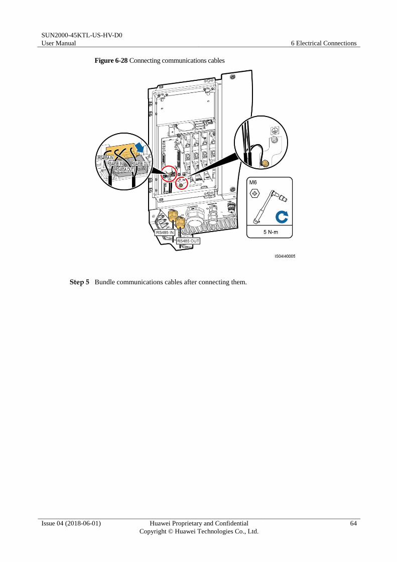
SUN2000-45KTL-US-HV-D0
User Manual 6 Electrical Connections
Issue 04 (2018-06-01) Huawei Proprietary and Confidential
Copyright © Huawei Technologies Co., Ltd.
64
Figure 6-28 Connecting communications cables
Step 5 Bundle communications cables after connecting them.
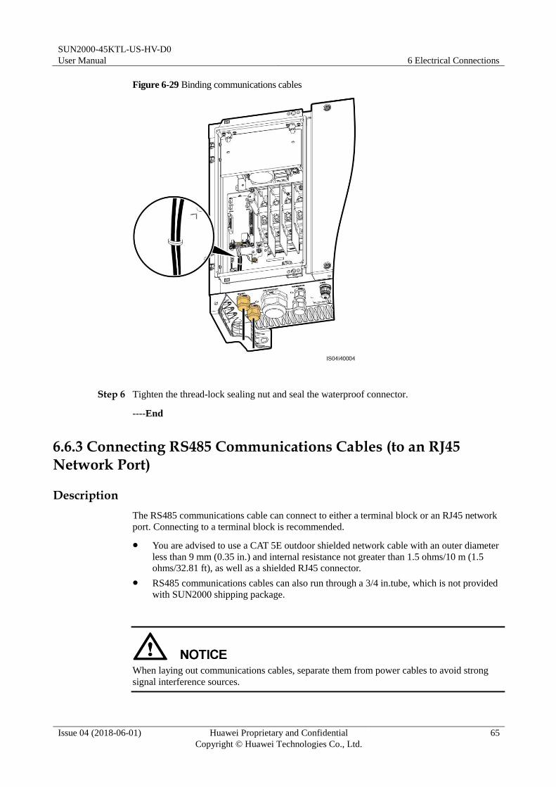
SUN2000-45KTL-US-HV-D0
User Manual 6 Electrical Connections
Issue 04 (2018-06-01) Huawei Proprietary and Confidential
Copyright © Huawei Technologies Co., Ltd.
65
Figure 6-29 Binding communications cables
Step 6 Tighten the thread-lock sealing nut and seal the waterproof connector.
----End
6.6.3 Connecting RS485 Communications Cables (to an RJ45 Network Port)
Description
The RS485 communications cable can connect to either a terminal block or an RJ45 network
port. Connecting to a terminal block is recommended.
You are advised to use a CAT 5E outdoor shielded network cable with an outer diameter
less than 9 mm (0.35 in.) and internal resistance not greater than 1.5 ohms/10 m (1.5
ohms/32.81 ft), as well as a shielded RJ45 connector.
RS485 communications cables can also run through a 3/4 in.tube, which is not provided
with SUN2000 shipping package.
When laying out communications cables, separate them from power cables to avoid strong
signal interference sources.

SUN2000-45KTL-US-HV-D0
User Manual 6 Electrical Connections
Issue 04 (2018-06-01) Huawei Proprietary and Confidential
Copyright © Huawei Technologies Co., Ltd.
66
RJ45 Connector Pin Definitions
Figure 6-30 shows an RJ45 connector.
Figure 6-30 RJ45 connector
Table 6-6 lists the RJ45 connector pin definitions.
Table 6-6 RJ45 connector pin definitions
Pin Color Function
1 White-and-orange RS485A, differential signal+
2 Orange RS485B, differential signal–
3 White-and-green N/A
4 Blue RS485A, differential signal+
5 White-and-blue RS485B, differential signal–
6 Green N/A
7 White-and-brown N/A
8 Brown N/A
6.6.3.1 Connection Through a Tube
Procedure
Step 1 Install the tube fitting. For details, see 5.2 Installing the Tube Fittings.
Step 2 Route the cable through the tube conduit and then fitting.
Step 3 Crimp an RJ45 connector.
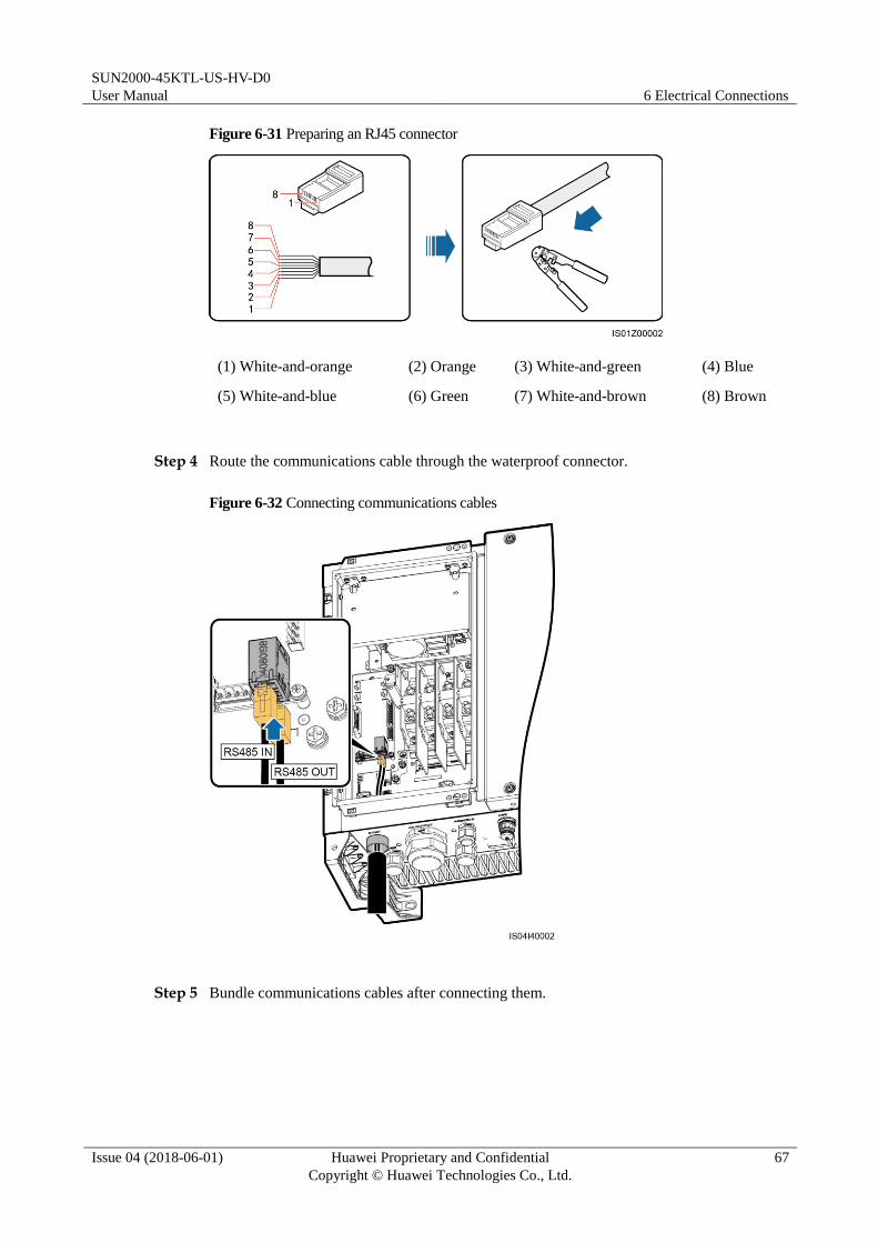
SUN2000-45KTL-US-HV-D0
User Manual 6 Electrical Connections
Issue 04 (2018-06-01) Huawei Proprietary and Confidential
Copyright © Huawei Technologies Co., Ltd.
67
Figure 6-31 Preparing an RJ45 connector
(1) White-and-orange (2) Orange (3) White-and-green (4) Blue
(5) White-and-blue (6) Green (7) White-and-brown (8) Brown
Step 4 Route the communications cable through the waterproof connector.
Figure 6-32 Connecting communications cables
Step 5 Bundle communications cables after connecting them.

SUN2000-45KTL-US-HV-D0
User Manual 6 Electrical Connections
Issue 04 (2018-06-01) Huawei Proprietary and Confidential
Copyright © Huawei Technologies Co., Ltd.
68
Figure 6-33 Binding communications cables
Step 6 Secure the fitting to the conduit.
Step 7 Clear debris from the maintenance compartment.
Please do not leave any extra material in the maintenance compartment.
----End
6.6.3.2 Connection Through a Waterproof Connector
Procedure
Step 1 Crimp an RJ45 connector.
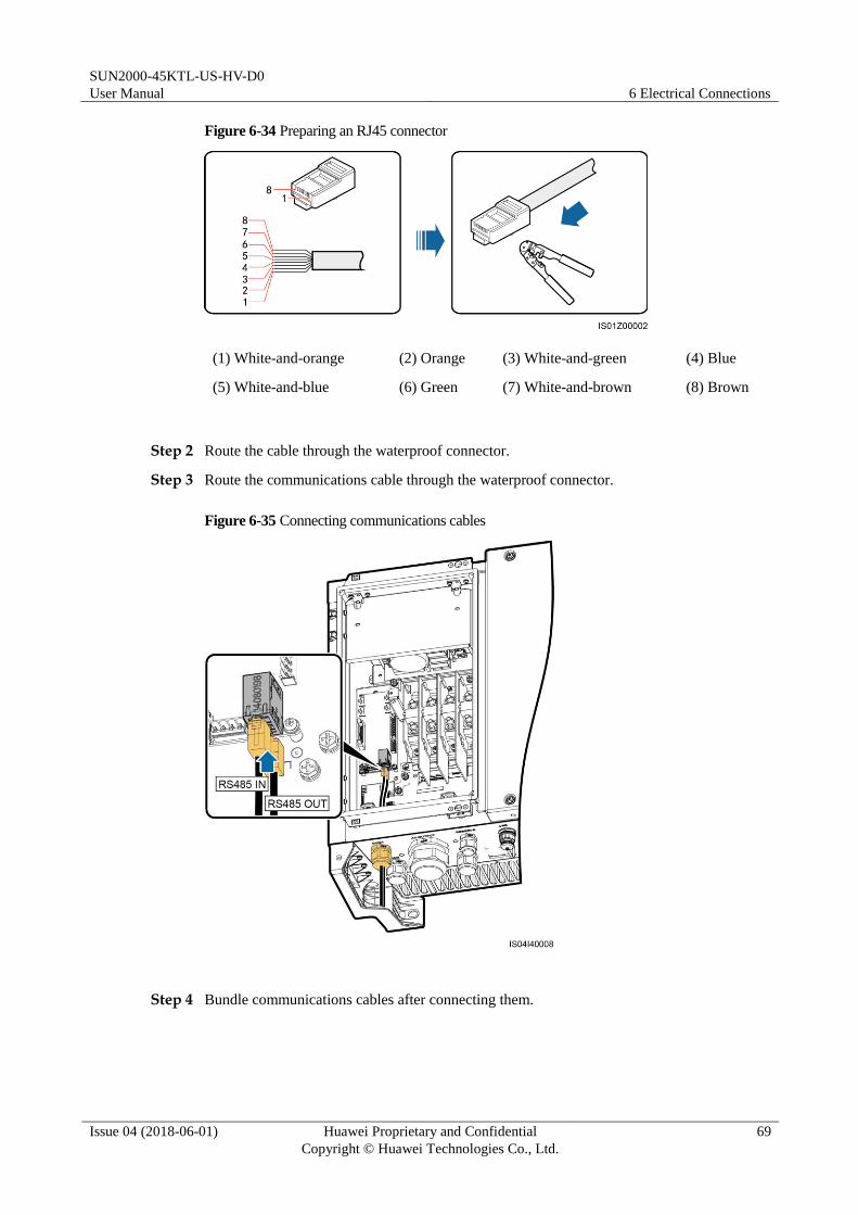
SUN2000-45KTL-US-HV-D0
User Manual 6 Electrical Connections
Issue 04 (2018-06-01) Huawei Proprietary and Confidential
Copyright © Huawei Technologies Co., Ltd.
69
Figure 6-34 Preparing an RJ45 connector
(1) White-and-orange (2) Orange (3) White-and-green (4) Blue
(5) White-and-blue (6) Green (7) White-and-brown (8) Brown
Step 2 Route the cable through the waterproof connector.
Step 3 Route the communications cable through the waterproof connector.
Figure 6-35 Connecting communications cables
Step 4 Bundle communications cables after connecting them.

SUN2000-45KTL-US-HV-D0
User Manual 6 Electrical Connections
Issue 04 (2018-06-01) Huawei Proprietary and Confidential
Copyright © Huawei Technologies Co., Ltd.
70
Figure 6-36 Binding communications cables
Step 5 Tighten the thread-lock sealing nut and seal the waterproof connector.
----End
6.7 Closing the Maintenance Compartment Door
Procedure
Step 1 Install the AC terminal cover.
Figure 6-37 Installing a cover
Step 2 Retrieve the support bar.
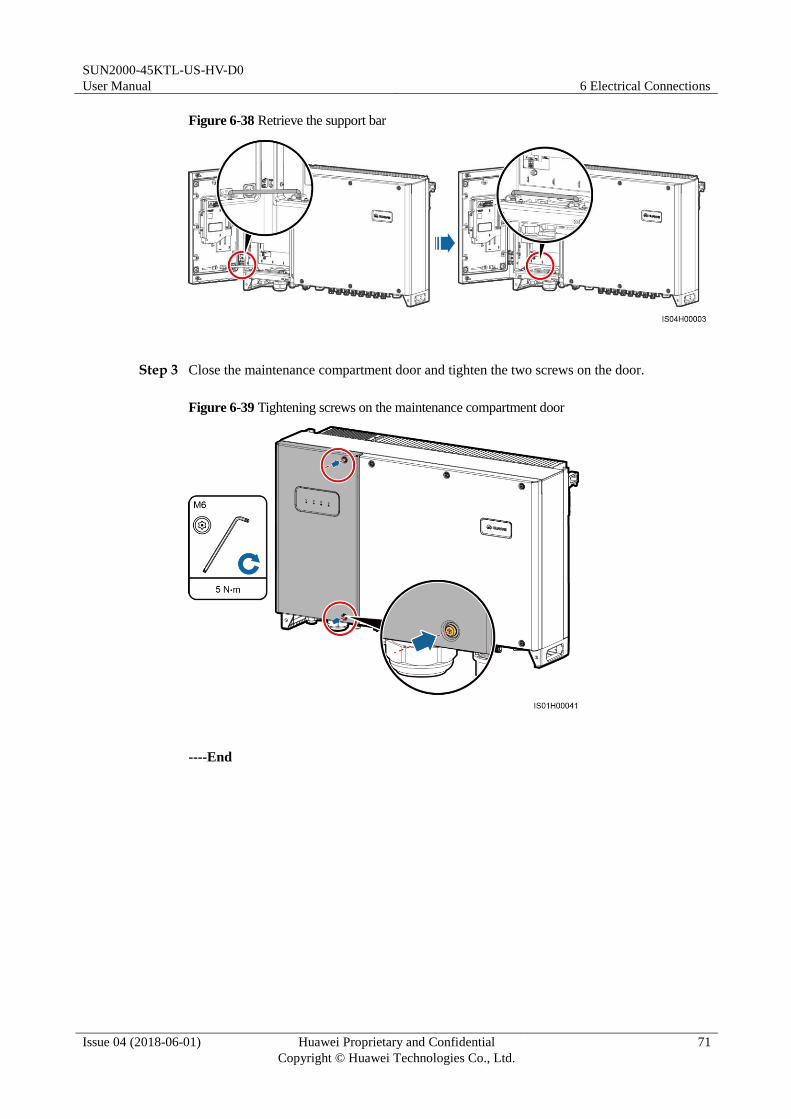
SUN2000-45KTL-US-HV-D0
User Manual 6 Electrical Connections
Issue 04 (2018-06-01) Huawei Proprietary and Confidential
Copyright © Huawei Technologies Co., Ltd.
71
Figure 6-38 Retrieve the support bar
Step 3 Close the maintenance compartment door and tighten the two screws on the door.
Figure 6-39 Tightening screws on the maintenance compartment door
----End

SUN2000-45KTL-US-HV-D0
User Manual 7 System Commissioning
Issue 04 (2018-06-01) Huawei Proprietary and Confidential
Copyright © Huawei Technologies Co., Ltd.
72
7 System Commissioning
7.1 Checking Before Power-On
1. The SUN2000 is installed correctly and securely.
2. Check that the DC switch and downstream AC output switch are OFF.
3. All ground cables are connected securely.
4. All AC output power cables are connected correctly and securely, without open circuits
or short circuits.
5. All DC input power cables are connected correctly and securely, without open circuits or
short circuits.
6. The communications cable is connected correctly and securely.
7. All tube openings and/or used waterproof connectors at the chassis bottom are sealed.
8. The AC terminal cover is installed.
9. The maintenance compartment interior is clean and free from any extra material.
10. The maintenance compartment door is closed and secured with screws.
11. Unused DC input terminals are sealed.
12. Unused USB ports are plugged with waterproof caps.
13. Unused waterproof connectors are covered and the cable glands are tightened.
7.2 DC Input Detection
Function Description
When SUN2000 detects an abnormal DC input voltage from any PV string after DC cables
are connected to the SUN2000, the SUN2000 generates an alarm through the LED indicator
and buzzer. Attention from site personnel is required to check and clear the fault, to avoid
damage to the SUN2000.
The SUN2000 provides four MPPT circuits with eight DC input terminals, as shown in Figure
7-1. After one PV string correctly connects to the MPPT1 circuit, the SUN2000 can start the
DC input detection function. DC input detection can be performed automatically or manually.
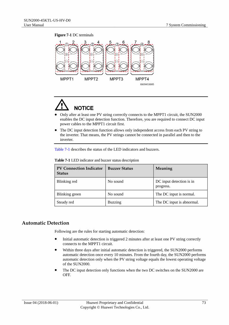
SUN2000-45KTL-US-HV-D0
User Manual 7 System Commissioning
Issue 04 (2018-06-01) Huawei Proprietary and Confidential
Copyright © Huawei Technologies Co., Ltd.
73
Figure 7-1 DC terminals
Only after at least one PV string correctly connects to the MPPT1 circuit, the SUN2000
enables the DC input detection function. Therefore, you are required to connect DC input
power cables to the MPPT1 circuit first.
The DC input detection function allows only independent access from each PV string to
the inverter. That means, the PV strings cannot be connected in parallel and then to the
inverter.
Table 7-1 describes the status of the LED indicators and buzzers.
Table 7-1 LED indicator and buzzer status description
PV Connection Indicator Status
Buzzer Status Meaning
Blinking red No sound DC input detection is in
progress.
Blinking green No sound The DC input is normal.
Steady red Buzzing The DC input is abnormal.
Automatic Detection
Following are the rules for starting automatic detection:
Initial automatic detection is triggered 2 minutes after at least one PV string correctly
connects to the MPPT1 circuit.
Within three days after initial automatic detection is triggered, the SUN2000 performs
automatic detection once every 10 minutes. From the fourth day, the SUN2000 performs
automatic detection only when the PV string voltage equals the lowest operating voltage
of the SUN2000.
The DC input detection only functions when the two DC switches on the SUN2000 are
OFF.
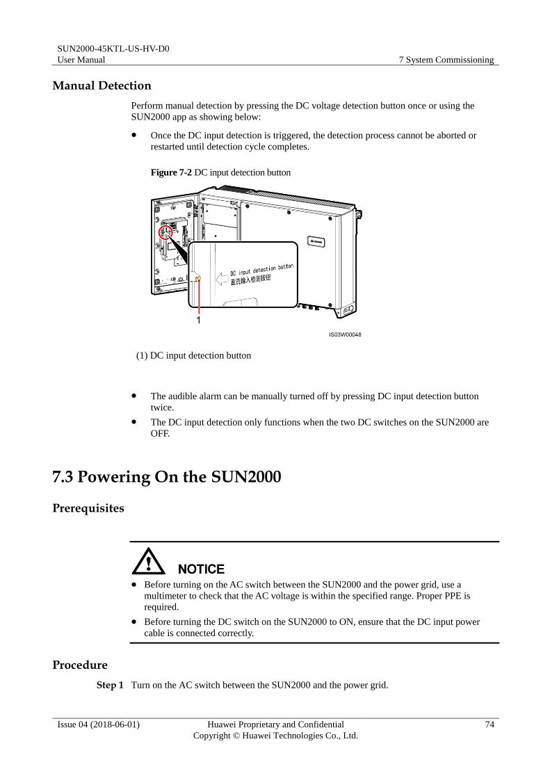
SUN2000-45KTL-US-HV-D0
User Manual 7 System Commissioning
Issue 04 (2018-06-01) Huawei Proprietary and Confidential
Copyright © Huawei Technologies Co., Ltd.
74
Manual Detection
Perform manual detection by pressing the DC voltage detection button once or using the
SUN2000 app as showing below:
Once the DC input detection is triggered, the detection process cannot be aborted or
restarted until detection cycle completes.
Figure 7-2 DC input detection button
(1) DC input detection button
The audible alarm can be manually turned off by pressing DC input detection button
twice.
The DC input detection only functions when the two DC switches on the SUN2000 are
OFF.
7.3 Powering On the SUN2000
Prerequisites
Before turning on the AC switch between the SUN2000 and the power grid, use a
multimeter to check that the AC voltage is within the specified range. Proper PPE is
required.
Before turning the DC switch on the SUN2000 to ON, ensure that the DC input power
cable is connected correctly.
Procedure
Step 1 Turn on the AC switch between the SUN2000 and the power grid.
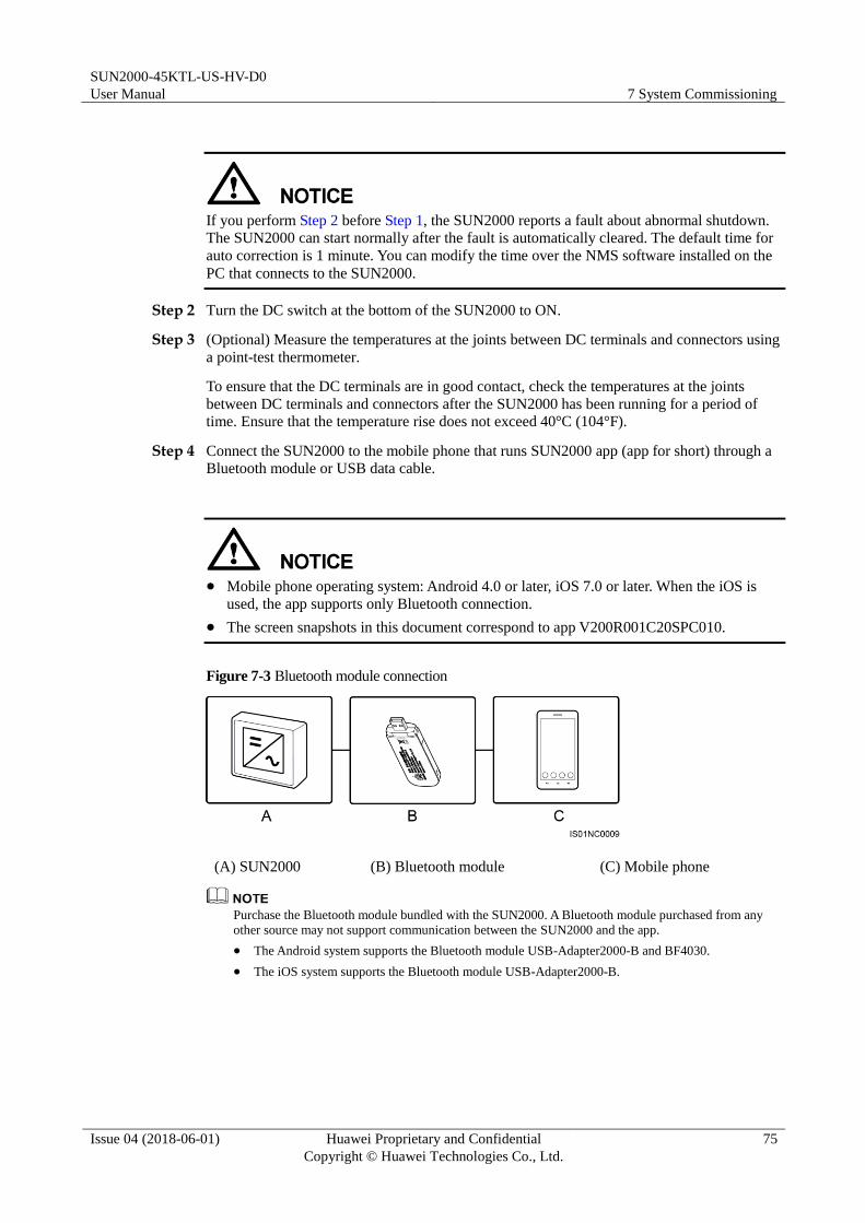
SUN2000-45KTL-US-HV-D0
User Manual 7 System Commissioning
Issue 04 (2018-06-01) Huawei Proprietary and Confidential
Copyright © Huawei Technologies Co., Ltd.
75
If you perform Step 2 before Step 1, the SUN2000 reports a fault about abnormal shutdown.
The SUN2000 can start normally after the fault is automatically cleared. The default time for
auto correction is 1 minute. You can modify the time over the NMS software installed on the
PC that connects to the SUN2000.
Step 2 Turn the DC switch at the bottom of the SUN2000 to ON.
Step 3 (Optional) Measure the temperatures at the joints between DC terminals and connectors using
a point-test thermometer.
To ensure that the DC terminals are in good contact, check the temperatures at the joints
between DC terminals and connectors after the SUN2000 has been running for a period of
time. Ensure that the temperature rise does not exceed 40°C (104°F).
Step 4 Connect the SUN2000 to the mobile phone that runs SUN2000 app (app for short) through a
Bluetooth module or USB data cable.
Mobile phone operating system: Android 4.0 or later, iOS 7.0 or later. When the iOS is
used, the app supports only Bluetooth connection.
The screen snapshots in this document correspond to app V200R001C20SPC010.
Figure 7-3 Bluetooth module connection
(A) SUN2000 (B) Bluetooth module (C) Mobile phone
Purchase the Bluetooth module bundled with the SUN2000. A Bluetooth module purchased from any
other source may not support communication between the SUN2000 and the app.
The Android system supports the Bluetooth module USB-Adapter2000-B and BF4030.
The iOS system supports the Bluetooth module USB-Adapter2000-B.

SUN2000-45KTL-US-HV-D0
User Manual 7 System Commissioning
Issue 04 (2018-06-01) Huawei Proprietary and Confidential
Copyright © Huawei Technologies Co., Ltd.
76
Figure 7-4 Data cable connection
(A) SUN2000 (B) USB data cable (C) Mobile phone
Use the USB data cable delivered with the mobile phone.
The port type of the USB data cable connected to the SUN2000 is USB 2.0.
If the mobile phone provides a USB Type-C port, prepare a USB Type C to USB 2.0 adapter cable.
Figure 7-5 Login screen
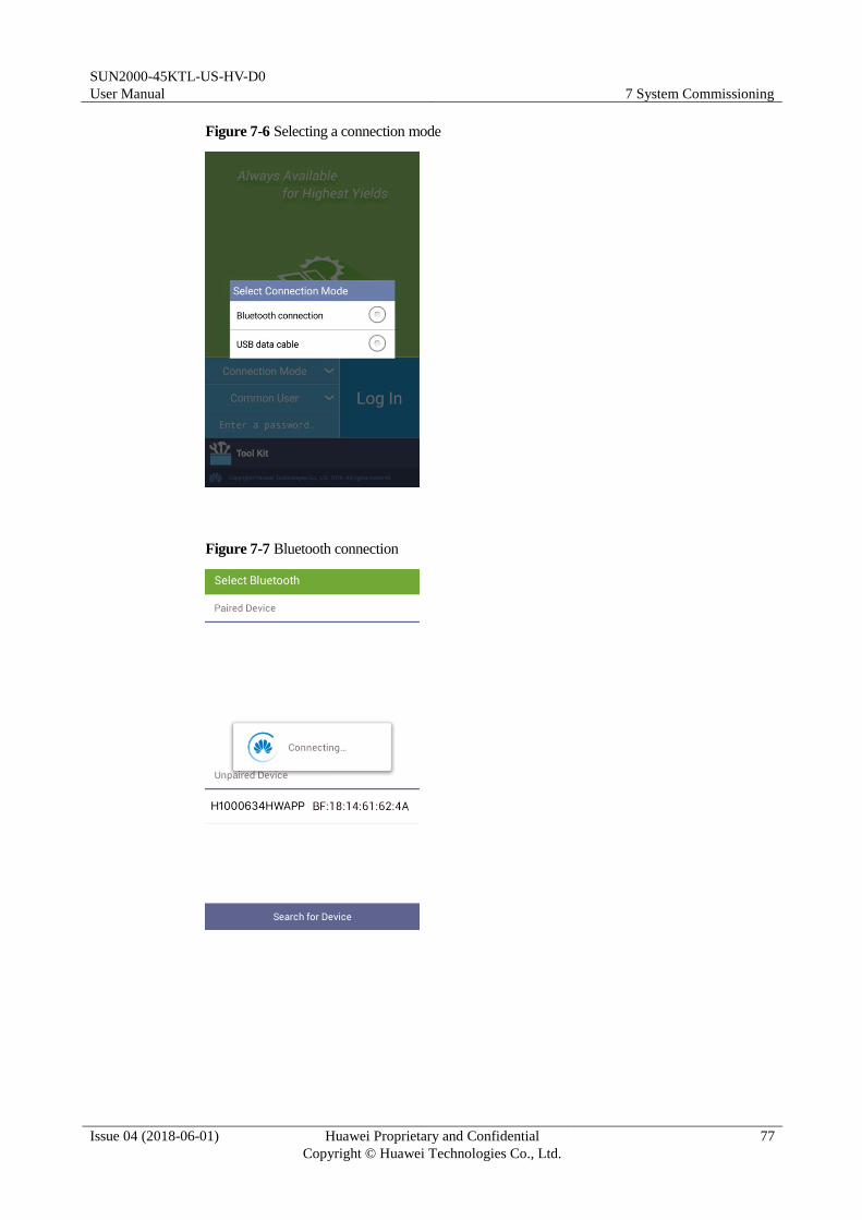
SUN2000-45KTL-US-HV-D0
User Manual 7 System Commissioning
Issue 04 (2018-06-01) Huawei Proprietary and Confidential
Copyright © Huawei Technologies Co., Ltd.
77
Figure 7-6 Selecting a connection mode
Figure 7-7 Bluetooth connection

SUN2000-45KTL-US-HV-D0
User Manual 7 System Commissioning
Issue 04 (2018-06-01) Huawei Proprietary and Confidential
Copyright © Huawei Technologies Co., Ltd.
78
Figure 7-8 Data cable connection
After you select Use by default for this USB accessory, the message will not appear if you reconnect
the app without disconnecting the USB data cable.
Step 5 Tap the user name area to switch between Common User, Advanced User, and Special
User.
Figure 7-9 Switching between users

SUN2000-45KTL-US-HV-D0
User Manual 7 System Commissioning
Issue 04 (2018-06-01) Huawei Proprietary and Confidential
Copyright © Huawei Technologies Co., Ltd.
79
The login password is the same as that for the SUN2000 connected to the app and is used only when
the SUN2000 connects to the app.
The initial passwords for Common User, Advanced User, and Special User are all 00000a. Use the
initial password upon first login. To ensure account security, change the password immediately after
login.
During the login, if five consecutive invalid password entries are made (the interval between two
consecutive entries is less than 2 minutes), the account will be locked for 10 minutes. The password
should consist of six digits.
Step 6 Enter the password and tap Login.
Step 7 After login, the Quick Settings screen or Function Menu screen is displayed.
If you log in to the app after the SUN2000 connects to the app for the first time or factory defaults
are restored, the Quick Settings screen is displayed, on which you can set basic parameters. After
the settings take effect, you can enter the main menu screen and modify the parameters on the
Settings screen. By default, the SUN2000 can be grid-tied and you do not have to set parameters.
You are advised to log in to the Quick Settings screen as an advanced user for parameter settings.
Figure 7-10 Quick Settings (advanced user)
Set the power grid code that applies to the country or region where the PV plant is located and the
SUN2000 model.
Set user parameters based on the current date and time.
Set Baud rate, RS485 protocol, and Address based on site requirements. Baud rate can be set to
4800, 9600, or 19200. RS485 protocol can be set to MODBUS RTU, and Address can be set to any
value in the range of 1 to 247.
When multiple SUN2000s communicate with the SmartLogger over RS485, the RS485 addresses
for all the SUN2000s on each RS485 route must be within the address range set on the SmartLogger
and cannot be duplicate. The baud rates of all the SUN2000s on each RS485 chain must be
consistent with the SmartLogger baud rate.

SUN2000-45KTL-US-HV-D0
User Manual 7 System Commissioning
Issue 04 (2018-06-01) Huawei Proprietary and Confidential
Copyright © Huawei Technologies Co., Ltd.
80
Figure 7-11 Function menu
----End
7.4 Powering Off the SUN2000
Context
If two SUN2000s share the same AC switch on the AC side, power off the two SUN2000s.
After the SUN2000 powers off, the remaining electricity and heat may still cause electric
shocks and body burns. Therefore, put on personal protective equipment (PPE) and begin
servicing the SUN2000 five minutes after the power-off.
Procedure
Step 1 Run a shutdown command on the SUN2000 APP, SmartLogger, or NMS.
For details, see the SUN2000 APP User Manual or SmartLogger2000 User Manual or
iManager NetEco 1000S User Manual.
Step 2 Turn off the AC switch between the SUN2000 and the power grid.
Step 3 Set the two DC switches to OFF.
----End

SUN2000-45KTL-US-HV-D0
User Manual 8 Man-Machine Interactions
Issue 04 (2018-06-01) Huawei Proprietary and Confidential
Copyright © Huawei Technologies Co., Ltd.
81
8 Man-Machine Interactions
8.1 Operations with a USB Flash Drive
USB flash drives of SanDisk, Netac, and Kingston are recommended. Other brands may be
incompatible.
8.1.1 Exporting Configurations
Procedure
Step 1 On the SUN2000 APP, tap Inverter Command Settings to generate a boot script file. For
details, see the SUN2000 APP User Manual.
Step 2 Import the boot script file to a computer.
(Optional) The boot script file can be opened as a .txt file, as shown in Figure 8-1.
Figure 8-1 Boot script file
No. Meaning Remarks
1 User name Advanced user: engineer

SUN2000-45KTL-US-HV-D0
User Manual 8 Man-Machine Interactions
Issue 04 (2018-06-01) Huawei Proprietary and Confidential
Copyright © Huawei Technologies Co., Ltd.
82
No. Meaning Remarks
Special user: admin
2 Ciphertext The ciphertext varies depending on the login password of the
SUN2000 APP.
3 Script validity
period
The script validity period varies depending on the script export
time.
4 Command Different command settings can produce different commands.
Configuration export command: export param.
Configuration import command: import param.
Data export command: export log.
Upgrade command: upgrade.
Step 3 Import the boot script file to the root directory of a USB flash drive.
Step 4 Connect the USB flash drive to the USB port. The system automatically identifies the USB
flash drive and executes all commands specified in the boot script file. View the LED
indicator to determine the operating status.
Verify that the ciphertext in the boot script file matches the login password of the SUN2000
APP. If they do not match and you insert the USB flash drive for five consecutive times, the
user account will be locked for 10 minutes.
Table 8-1 LED indicator description
LED Indicator Status Meaning
Green off There is no operation with
a USB flash drive.
Blinking green at long intervals (on
for 1s and then off for 1s)
There is an operation with
a USB flash drive.
Blinking green at short intervals (on
for 0.125s and then off for 0.125s)
An operation with a USB
flash drive has failed.
Steady green An operation with a USB
flash drive is successful.
Step 5 Insert the USB flash drive into a computer and check the exported data.
When the configuration export is complete, the boot script file and exported file are in the root directory
of the USB flash drive.

SUN2000-45KTL-US-HV-D0
User Manual 8 Man-Machine Interactions
Issue 04 (2018-06-01) Huawei Proprietary and Confidential
Copyright © Huawei Technologies Co., Ltd.
83
----End
8.1.2 Importing Configurations
Prerequisites
A complete configuration file has been exported.
Procedure
Step 1 On the SUN2000 APP, tap Inverter Command Settings to generate a boot script file. For
details, see the SUN2000 APP User Manual.
Step 2 Import the boot script file to a PC.
Step 3 Replace the exported boot script file in the root directory of the USB flash drive with the
imported one.
Replace the boot script file only and keep the exported files.
Step 4 Connect the USB flash drive to the USB port. The system automatically identifies the USB
flash drive and executes all commands specified in the boot script file. View the LED
indicator to determine the operating status.
Verify that the ciphertext in the boot script file matches the login password of the SUN2000
APP. If they do not match and you insert the USB flash drive for five consecutive times, the
user account will be locked for 10 minutes.
Table 8-2 LED indicator description
LED Indicator Status Meaning
Green off There is no operation with
a USB flash drive.
Blinking green at long intervals (on
for 1s and then off for 1s)
There is an operation with
a USB flash drive.
Blinking green at short intervals (on
for 0.125s and then off for 0.125s)
An operation with a USB
flash drive has failed.
Steady green An operation with a USB
flash drive is successful.

SUN2000-45KTL-US-HV-D0
User Manual 8 Man-Machine Interactions
Issue 04 (2018-06-01) Huawei Proprietary and Confidential
Copyright © Huawei Technologies Co., Ltd.
84
----End
8.1.3 Exporting Data
Procedure
Step 1 On the SUN2000 APP, tap Inverter Command Settings to generate a boot script file. For
details, see the SUN2000 APP User Manual.
Step 2 Import the boot script file to the root directory of a USB flash drive.
Step 3 Connect the USB flash drive to the USB port. The system automatically identifies the USB
flash drive and executes all commands specified in the boot script file. View the LED
indicator to determine the operating status.
Verify that the ciphertext in the boot script file matches the login password of the SUN2000
APP. If they do not match and you insert the USB flash drive for five consecutive times, the
user account will be locked for 10 minutes.
Table 8-3 LED indicator description
LED Indicator Status Meaning
Green off There is no operation with
a USB flash drive.
Blinking green at long intervals (on
for 1s and then off for 1s)
There is an operation with
a USB flash drive.
Blinking green at short intervals (on
for 0.125s and then off for 0.125s)
An operation with a USB
flash drive has failed.
Steady green An operation with a USB
flash drive is successful.
Step 4 Insert the USB flash drive into a PC and check the exported data.
After the data is exported, the boot script file and exported file are in the root directory of the USB flash
drive.
----End

SUN2000-45KTL-US-HV-D0
User Manual 8 Man-Machine Interactions
Issue 04 (2018-06-01) Huawei Proprietary and Confidential
Copyright © Huawei Technologies Co., Ltd.
85
8.1.4 Upgrading
Procedure
Step 1 Log in to http://support.huawei.com/carrier/ and browse or search for SUN2000HA on the
Product Support tab page. Download the required upgrade package (for example,
SUN2000HAV100R001C00SPCXXX) from the Software tab page.
Step 2 Decompress the upgrade package.
After obtaining the upgrade package SUN2000HAV100R001C00SPCXXX_package.zip,
decompress the package and copy the extracted files to the root directory of the USB flash
drive. Ensure that the extracted files include:
config.txt
sun_lmt_mgr_cmd.emap (This is a boot script file.)
SUN2000.bin
SUN2000_CPLD.bin
SUN2000_FLT_Release.bin
SUN2000_Master_Release.bin
SUN2000_Slave_Release.bin
vercfg.xml
When the login password of the SUN2000 APP is the initial password (00000a), there is
no need to perform Step 3–Step 5.
When the login password of the SUN2000 APP is not the initial password, perform Step
3–Step 7.
Step 3 On the SUN2000 APP, tap Inverter Command Settings to generate a boot script file. For
details, see the SUN2000 APP User Manual.
Step 4 Import the boot script file to a computer.
Step 5 Replace the boot script file in the upgrade package with the one generated by the SUN2000
APP.
Step 6 Copy the extracted files to the root directory of the USB flash drive.
Step 7 Connect the USB flash drive to the USB port. The system automatically identifies the USB
flash drive and executes all commands specified in the boot script file. View the LED
indicator to determine the operating status.

SUN2000-45KTL-US-HV-D0
User Manual 8 Man-Machine Interactions
Issue 04 (2018-06-01) Huawei Proprietary and Confidential
Copyright © Huawei Technologies Co., Ltd.
86
Verify that the ciphertext in the boot script file matches the login password of the SUN2000
APP. If they do not match and you insert the USB flash drive for five consecutive times, the
user account will be locked for 10 minutes.
Table 8-4 LED indicator description
LED Indicator Status Meaning
Green off There is no operation with
a USB flash drive.
Blinking green at long intervals (on
for 1s and then off for 1s)
There is an operation with
a USB flash drive.
Blinking green at short intervals (on
for 0.125s and then off for 0.125s)
An operation with a USB
flash drive has failed.
Steady green An operation with a USB
flash drive is successful.
Step 8 (Optional) The system automatically restarts when the upgrade is completed. All LED
indicators turn off during the restart. After the restart, the green indicator is blinking at long
intervals (on for 1s and then off for 1s) for 1 minute until it becomes steady on, which
indicates that the upgrade is successful.
The SUN2000 can also be upgraded through the Inverter Upgrade in the SUN2000 APP. For details,
see the SUN2000 APP User Manual.
----End
8.2 Operations with the SUN2000 App

SUN2000-45KTL-US-HV-D0
User Manual 8 Man-Machine Interactions
Issue 04 (2018-06-01) Huawei Proprietary and Confidential
Copyright © Huawei Technologies Co., Ltd.
87
The app software version corresponding to the user interface (UI) snapshots in this section
is SUN2000APP V200R001C20SPC010.
Configurable parameters vary with the grid code.
The parameter names, value ranges, and default values are subject to change. The actual
display prevails.
8.2.1 Operations Related to the Advanced User
Description
If you log in to the app as Advanced User, you can set the grid parameters, protection
parameters, and feature parameters for the SUN2000.
8.2.1.1 Setting Grid Parameters
Procedure
Step 1 Tap Function Menu > Settings > Grid Parameters to access the parameters setting screen.
Figure 8-2 Grid parameters (advanced user)
----End
Parameter List
No. Parameter Description Default Value Value Range
1 Grid code Set this parameter based on the
grid code of the country or
region where the SUN2000 is
used and the SUN2000
application scenario.
IEEE
1547a-MV600
-
2 Isolation Specifies the working mode of
the SUN2000 according to the
grounding status at the DC side
and the connection status to the
grid.
Input
ungrounded, with
TF
Input grounded,
with TF
Input ungrounded,
without TF
Input ungrounded,
with TF

SUN2000-45KTL-US-HV-D0
User Manual 8 Man-Machine Interactions
Issue 04 (2018-06-01) Huawei Proprietary and Confidential
Copyright © Huawei Technologies Co., Ltd.
88
8.2.1.2 Setting Protection Parameters
Procedure
Step 1 Choose Function Menu > Settings > Protection Parameters to access the settings screen.
Figure 8-3 Protection parameter (advanced user)
----End
Parameter List
No. Parameter Description Unit Default Value Value Range
1 Insulation
resistance
protection
To ensure device safety,
the SUN2000 detects the
insulation resistance
between the input side and
the ground when it starts a
self-check. If the detected
value is less than the
preset value, the SUN2000
does not export power to
the power grid.
MΩ 0.05 [0.033, 1.5]
8.2.1.3 Setting Feature Parameters
Procedure
Step 1 Choose Function Menu > Settings > Feature Parameters to access the settings screen.

SUN2000-45KTL-US-HV-D0
User Manual 8 Man-Machine Interactions
Issue 04 (2018-06-01) Huawei Proprietary and Confidential
Copyright © Huawei Technologies Co., Ltd.
89
Figure 8-4 Feature Parameters (advanced user)
----End
Parameter List
No. Parameter Description Unit Default Value
Value Range Remarks
1 MPPT
multi-peak
scanning
When the SUN2000 is
used in scenarios
where PV strings are
obviously shaded,
enable this function.
Then the SUN2000
will perform MPPT
scanning at regular
intervals to locate the
maximum power.
N/A Disable Disable
Enable
The scanning
interval is set by
MPPT multi-peak scanning interval.
2 MPPT
multi-peak
scanning
interval
Specifies the MPPT
multi-peak scanning
interval.
min 15 [5, 30] This parameter is
displayed only when
MPPT multi-peak scanning is set to
Enable.
3 RCD
enhancing
RCD refers to the
residual current of the
SUN2000 to the
ground. To ensure
device security and
personal safety, RCD
should comply with
the standard. If an AC
N/A Disable Disable
Enable
N/A

SUN2000-45KTL-US-HV-D0
User Manual 8 Man-Machine Interactions
Issue 04 (2018-06-01) Huawei Proprietary and Confidential
Copyright © Huawei Technologies Co., Ltd.
90
No. Parameter Description Unit Default Value
Value Range Remarks
switch with a residual
current detection
function is installed
outside the SUN2000,
this function should be
enabled to reduce the
residual current
generated during
SUN2000 running,
thereby preventing the
AC switch from
misoperations.
4 Reactive
power
output at
night
In some specific
application scenarios,
a power grid company
requires that the
SUN2000 can perform
reactive power
compensation at night
to ensure that the
power factor of the
local power grid meets
requirements.
N/A Disable Disable
Enable
This parameter is
configurable only
when Isolation is
set to Input
ungrounded, with a transformer.
5 Power
quality
optimizatio
n mode
If Power quality
optimization mode is
set to Enable, the
inverter output current
harmonics will be
optimized.
N/A Disable Disable
Enable
N/A
6 PV module
type
This parameter is used
to set different types
of PV modules and the
shutdown time of the
concentration PV
modules. If the
concentration PV
modules are shaded,
the power drops
drastically to 0 and the
SUN2000 shuts down.
The energy yield
would be affected
since it takes too long
for the power to
resume and SUN2000
to restart. The
parameter does not
need to be set for
crystalline silicon and
filmy PV modules.
N/A Crystalline
silicon
Crystalline
silicon
Film
CPV 1
CPV 2
If PV module
type is set to
Crystalline silicon or Film,
the SUN2000
automatically
detects the power
of PV modules
when they are
shaded and shuts
down if the
power is too low.
When the
concentration PV
modules are
used:
− If PV module
type is set to
CPV 1, the
inverter can

SUN2000-45KTL-US-HV-D0
User Manual 8 Man-Machine Interactions
Issue 04 (2018-06-01) Huawei Proprietary and Confidential
Copyright © Huawei Technologies Co., Ltd.
91
No. Parameter Description Unit Default Value
Value Range Remarks
quickly
restart in 60
minutes when
the input
power of PV
modules
drops
drastically
due to
shading.
− If PV module
type is set to
CPV 2, the
inverter can
quickly
restart in 10
minutes when
the input
power of PV
modules
drops
drastically
due to
shading.
7 Crystalline
silicon PV
compensati
on mode
This parameter
reduces the DC
voltage of PV modules
to the PE by reducing
the impedance of the
SUN2000 input side to
the PE, thereby
effectively reducing
PID effect of PV
modules.
N/A Output
disabled
Output
disabled
P-type output
N-type output
This parameter is
displayed if PV
module type is set
to Crystalline
silicon. Set this
parameter to P-type
output for P-type
PV modules and
N-type output for
N-type PV modules.
8 Communic
ation
interrupt
shutdown
The standards of
certain countries and
regions require that
the SUN2000 must
shut down after the
communication is
interrupted for a
certain time.
N/A Disable Disable
Enable
If Communication
interrupt shutdown is set to
Enable and the
SUN2000
communication has
been interrupted for
a specified time (set
by Communication
interruption duration), the
SUN2000 will
automatically shut
down.
9 Communic
ation
Specifies the duration
for determining min 30 [1, 120] N/A
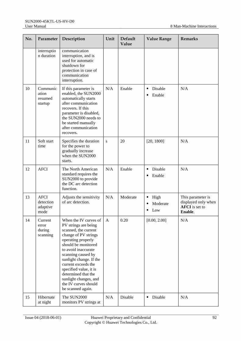
SUN2000-45KTL-US-HV-D0
User Manual 8 Man-Machine Interactions
Issue 04 (2018-06-01) Huawei Proprietary and Confidential
Copyright © Huawei Technologies Co., Ltd.
92
No. Parameter Description Unit Default Value
Value Range Remarks
interruptio
n duration
communication
interruption, and is
used for automatic
shutdown for
protection in case of
communication
interruption.
10 Communic
ation
resumed
startup
If this parameter is
enabled, the SUN2000
automatically starts
after communication
recovers. If this
parameter is disabled,
the SUN2000 needs to
be started manually
after communication
recovers.
N/A Enable Disable
Enable
N/A
11 Soft start
time
Specifies the duration
for the power to
gradually increase
when the SUN2000
starts.
s 20 [20, 1800] N/A
12 AFCI The North American
standard requires the
SUN2000 to provide
the DC arc detection
function.
N/A Enable Disable
Enable
N/A
13 AFCI
detection
adaptive
mode
Adjusts the sensitivity
of arc detection.
N/A Moderate High
Moderate
Low
This parameter is
displayed only when
AFCI is set to
Enable.
14 Current
error
during
scanning
When the IV curves of
PV strings are being
scanned, the current
change of PV strings
operating properly
should be monitored
to avoid inaccurate
scanning caused by
sunlight change. If the
current exceeds the
specified value, it is
determined that the
sunlight changes, and
the IV curves should
be scanned again.
A 0.20 [0.00, 2.00] N/A
15 Hibernate
at night
The SUN2000
monitors PV strings at N/A Disable Disable N/A

SUN2000-45KTL-US-HV-D0
User Manual 8 Man-Machine Interactions
Issue 04 (2018-06-01) Huawei Proprietary and Confidential
Copyright © Huawei Technologies Co., Ltd.
93
No. Parameter Description Unit Default Value
Value Range Remarks
night. If Hibernate at
night is set to Enable,
the monitoring
function of the
SUN2000 will
hibernate at night,
reducing power
consumption.
Enable
16 PLC
communic
ation
For SUN2000 models
that support both
RS485 and PLC
communication, when
RS485 communication
is used, you are
advised to set PLC
communication to
Disable to reduce
power consumption.
N/A Enable Disable
Enable
N/A
17 Upgrade
delay
Upgrade delay is
mainly used in the
upgrade scenarios
where the PV power
supply is disconnected
at night due to no
sunlight or unstable at
dawn or dusk due to
poor sunlight.
N/A Enable Disable
Enable
N/A
18 String
monitor
The SUN2000
monitors PV strings in
real time. If any PV
string is abnormal
(such as the PV string
is shaded or the
energy yield
decreases), the
SUN2000 generates
an alarm to remind
maintenance personnel
to maintain the PV
string in a timely
manner.
N/A Disable Disable
Enable
If PV strings are
easily shaded, you
are advised to set
String monitor to
Disable to prevent
false alarms.
19 String
detection
low power
delay
Specifies the delay
time for generating
abnormal string
alarms when the
SUN2000 detects that
a PV string is working
with low power. This parameter is mainly
min 180 [2, 720]
This parameter is
displayed when
String monitor is
set to Enable.
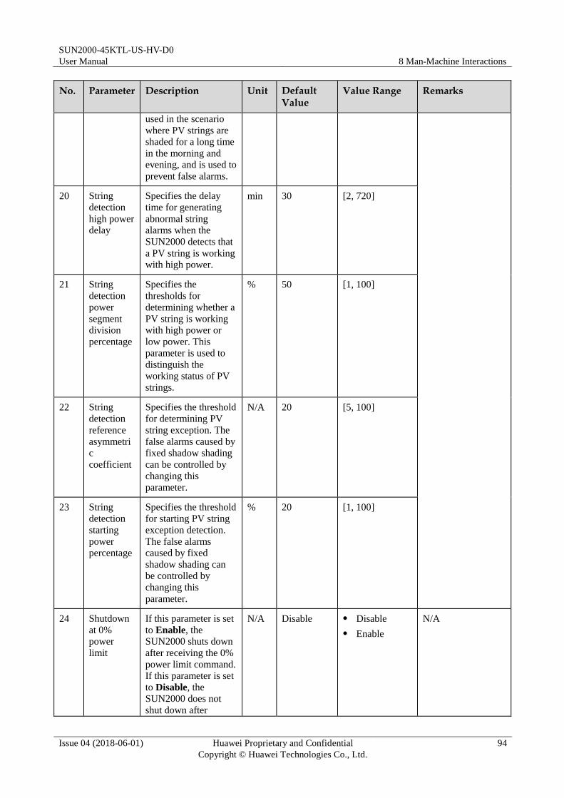
SUN2000-45KTL-US-HV-D0
User Manual 8 Man-Machine Interactions
Issue 04 (2018-06-01) Huawei Proprietary and Confidential
Copyright © Huawei Technologies Co., Ltd.
94
No. Parameter Description Unit Default Value
Value Range Remarks
used in the scenario
where PV strings are
shaded for a long time
in the morning and
evening, and is used to
prevent false alarms.
20 String
detection
high power
delay
Specifies the delay
time for generating
abnormal string
alarms when the
SUN2000 detects that
a PV string is working
with high power.
min 30 [2, 720]
21 String
detection
power
segment
division
percentage
Specifies the
thresholds for
determining whether a
PV string is working
with high power or
low power. This
parameter is used to
distinguish the
working status of PV
strings.
% 50 [1, 100]
22 String
detection
reference
asymmetri
c
coefficient
Specifies the threshold
for determining PV
string exception. The
false alarms caused by
fixed shadow shading
can be controlled by
changing this
parameter.
N/A 20 [5, 100]
23 String
detection
starting
power
percentage
Specifies the threshold
for starting PV string
exception detection.
The false alarms
caused by fixed
shadow shading can
be controlled by
changing this
parameter.
% 20 [1, 100]
24 Shutdown
at 0%
power
limit
If this parameter is set
to Enable, the
SUN2000 shuts down
after receiving the 0%
power limit command.
If this parameter is set
to Disable, the
SUN2000 does not
shut down after
N/A Disable Disable
Enable
N/A

SUN2000-45KTL-US-HV-D0
User Manual 8 Man-Machine Interactions
Issue 04 (2018-06-01) Huawei Proprietary and Confidential
Copyright © Huawei Technologies Co., Ltd.
95
No. Parameter Description Unit Default Value
Value Range Remarks
receiving the 0%
power limit command.
25 Maximum
apparent
power
Specifies the output
upper threshold for the
maximum apparent
power to adapt to the
capacity requirements
for standard and
customized
transformers.
kW Smax_limit [Maximum
active power,
Smax_limit]
If the maximum
active power equals
Smax_limit, this
parameter is not
displayed.
26 Maximum
active
power
Specifies the output
upper threshold for the
maximum active
power to adapt to
various market
requirements.
kW Pmax_limit [0.1,
Pmax_limit]
N/A
27 Tracking
system
controller
Selects a controller
vendor.
N/A N/A N/A N/A
28 Duration
for
determinin
g
short-time
grid
disconnecti
on
The standards of
certain countries and
regions require that
the SUN2000 should
not disconnect from
the power grid if the
power grid
experiences a
short-time failure. The
SUN2000 output
power should be
recovered immediately
after the fault is
rectified.
ms 3000 [500, 20000] N/A
29 Adjust
total
energy
yield
Specifies the initial
energy yield of the
SUN2000. This
parameter is used in
SUN2000 replacement
scenarios. Set the
initial energy yield of
the new SUN2000 to
the total energy yield
of the old SUN2000 to
ensure continuous
statistics of
cumulative energy
yield.
kWh N/A [0.00,
42949600.00]
N/A
30 DC input If DC input detection N/A Enable Disable N/A

SUN2000-45KTL-US-HV-D0
User Manual 8 Man-Machine Interactions
Issue 04 (2018-06-01) Huawei Proprietary and Confidential
Copyright © Huawei Technologies Co., Ltd.
96
No. Parameter Description Unit Default Value
Value Range Remarks
detection is set to Disable, the
SUN2000 does not
perform automatic DC
input detection or
manual DC output
detection.
Enable
31 Commande
d
shutdown
hold after
power
recovery
The standards of
certain countries and
regions require that
the SUN2000 remains
in the commanded
shutdown state after
being powered off by
a command and
experiencing a power
failure and recovery.
N/A The default
value varies
with the
grid code.
The
displayed
value
prevails.
Disable
Enable
N/A
32 Buzzer If this parameter is set
to Enable, the buzzer
buzzes when a DC
input cable connection
error is detected. If
this parameter is set to
Disable, the buzzer
does not buzz when a
DC input cable
connection error is
detected.
N/A Enable Disable
Enable
N/A
8.2.2 Operations Related to the Special User
Description
If you log in to the app as Special User, you can set the grid parameters, protection
parameters, feature parameters, and grid adjustment parameters for the SUN2000.
8.2.2.1 Setting Grid Parameters
Procedure
Step 1 Choose Function Menu > Settings > Grid Parameters to access the settings screen.

SUN2000-45KTL-US-HV-D0
User Manual 8 Man-Machine Interactions
Issue 04 (2018-06-01) Huawei Proprietary and Confidential
Copyright © Huawei Technologies Co., Ltd.
97
Figure 8-5 Grid Parameters (special user)
----End
Parameter List
No. Parameter Description Unit Default Value Value Range
1 Grid code Set this parameter based on
the grid code of the country
or region where the
SUN2000 is used and the
SUN2000 application
scenario.
N/A IEEE
1547a-MV600
N/A
2 Auto start upon
grid recovery
Specifies whether to allow
the SUN2000 to
automatically start after the
power grid recovers.
N/A Enable Disable
Enable
3 Grid
connection
duration after
power grid
recovery
Specifies the waiting time
for SUN2000 restart after
the power grid recovers.
s The default value
is 60 if the
1547a-MV600
grid code is
selected. The
default value is
300 if another
grid code is
selected.
[0, 900]
4 Grid
reconnection
voltage upper limit
The standards of certain
countries and regions require
that the SUN2000 must not export power to the power
V The default value
varies with the
grid code. The
displayed value
[100%Vn, 136%Vn]
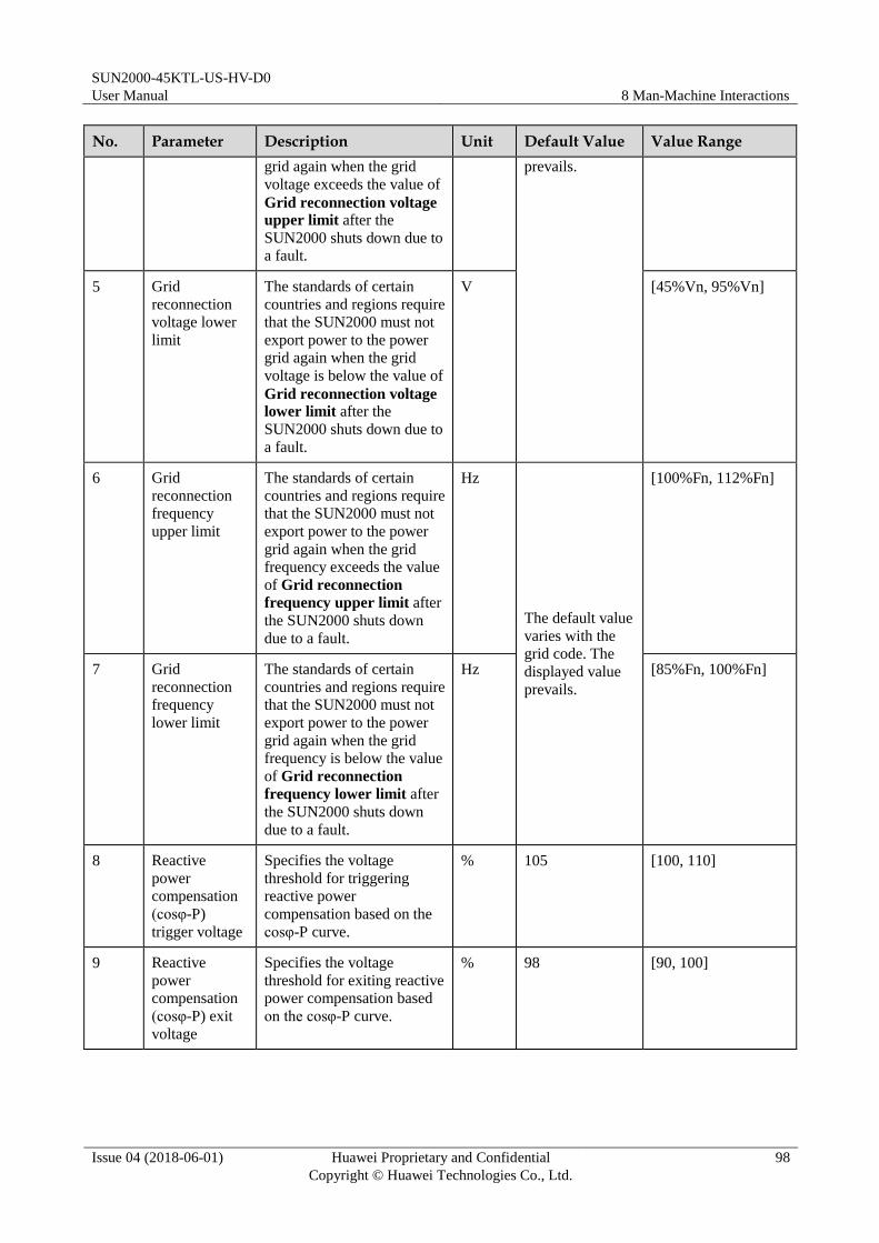
SUN2000-45KTL-US-HV-D0
User Manual 8 Man-Machine Interactions
Issue 04 (2018-06-01) Huawei Proprietary and Confidential
Copyright © Huawei Technologies Co., Ltd.
98
No. Parameter Description Unit Default Value Value Range
grid again when the grid
voltage exceeds the value of
Grid reconnection voltage upper limit after the
SUN2000 shuts down due to
a fault.
prevails.
5 Grid
reconnection
voltage lower
limit
The standards of certain
countries and regions require
that the SUN2000 must not
export power to the power
grid again when the grid
voltage is below the value of
Grid reconnection voltage lower limit after the
SUN2000 shuts down due to
a fault.
V [45%Vn, 95%Vn]
6 Grid
reconnection
frequency
upper limit
The standards of certain
countries and regions require
that the SUN2000 must not
export power to the power
grid again when the grid
frequency exceeds the value
of Grid reconnection
frequency upper limit after
the SUN2000 shuts down
due to a fault.
Hz
The default value
varies with the
grid code. The
displayed value
prevails.
[100%Fn, 112%Fn]
7 Grid
reconnection
frequency
lower limit
The standards of certain
countries and regions require
that the SUN2000 must not
export power to the power
grid again when the grid
frequency is below the value
of Grid reconnection
frequency lower limit after
the SUN2000 shuts down
due to a fault.
Hz [85%Fn, 100%Fn]
8 Reactive
power
compensation
(cosφ-P)
trigger voltage
Specifies the voltage
threshold for triggering
reactive power
compensation based on the
cosφ-P curve.
% 105 [100, 110]
9 Reactive
power
compensation
(cosφ-P) exit
voltage
Specifies the voltage
threshold for exiting reactive
power compensation based
on the cosφ-P curve.
% 98 [90, 100]
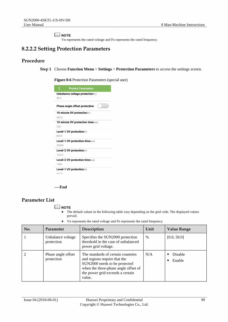
SUN2000-45KTL-US-HV-D0
User Manual 8 Man-Machine Interactions
Issue 04 (2018-06-01) Huawei Proprietary and Confidential
Copyright © Huawei Technologies Co., Ltd.
99
Vn represents the rated voltage and Fn represents the rated frequency.
8.2.2.2 Setting Protection Parameters
Procedure
Step 1 Choose Function Menu > Settings > Protection Parameters to access the settings screen.
Figure 8-6 Protection Parameters (special user)
----End
Parameter List
The default values in the following table vary depending on the grid code. The displayed values
prevail.
Vn represents the rated voltage and Fn represents the rated frequency.
No. Parameter Description Unit Value Range
1 Unbalance voltage
protection
Specifies the SUN2000 protection
threshold in the case of unbalanced
power grid voltage.
% [0.0, 50.0]
2 Phase angle offset
protection
The standards of certain countries
and regions require that the
SUN2000 needs to be protected
when the three-phase angle offset of
the power grid exceeds a certain
value.
N/A Disable
Enable

SUN2000-45KTL-US-HV-D0
User Manual 8 Man-Machine Interactions
Issue 04 (2018-06-01) Huawei Proprietary and Confidential
Copyright © Huawei Technologies Co., Ltd.
100
No. Parameter Description Unit Value Range
3 10 minute OV
protection
Specifies the 10-minute overvoltage
protection threshold.
V [1 x Vn, 1.36 x Vn]
4 10 minute OV
protection time
Specifies the 10-minute overvoltage
protection duration.
ms [50, 720000]
5 Level-1 OV
protection
Specifies the level-1 overvoltage
protection threshold.
V [1 x Vn, 1.36 x Vn]
6 Level-1 OV
protection time
Specifies the level-1 overvoltage
protection duration.
ms [50, 720000]
7 Level-2 OV
protection
Specifies the level-2 overvoltage
protection threshold.
V [1 x Vn, 1.36 x Vn]
8 Level-2 OV
protection time
Specifies the level-2 overvoltage
protection duration.
ms [50, 720000]
9 Level-1 UV
protection
Specifies the level-1 undervoltage
protection threshold.
V [0.15 x Vn, 1 x Vn]
10 Level-1 UV
protection time
Specifies the level-1 undervoltage
protection duration.
ms [50, 720000]
11 Level-2 UV
protection
Specifies the level-2 undervoltage
protection threshold.
V [0.15 x Vn, 1 x Vn]
12 Level-2 UV
protection time
Specifies the level-2 undervoltage
protection duration.
ms [50, 720000]
13 Level-1 OF
protection
Specifies the level-1 overfrequency
protection threshold.
Hz [1 x Fn, 1.15 x Fn]
14 Level-1 OF
protection time
Specifies the level-1 overfrequency
protection duration.
ms [50, 720000]
15 Level-2 OF
protection
Specifies the level-2 overfrequency
protection threshold.
Hz [1 x Fn, 1.15 x Fn]
16 Level-2 OF
protection time
Specifies the level-2 overfrequency
protection duration.
ms [50, 720000]
17 Level-1 UF
protection
Specifies the level-1 underfrequency
protection threshold.
Hz [0.85 x Fn, 1 x Fn]
18 Level-1 UF
protection time
Specifies the level-1 underfrequency
protection duration.
ms [50, 720000]
19 Level-2 UF
protection
Specifies the level-2 underfrequency
protection threshold.
Hz [0.85 x Fn, 1 x Fn]
20 Level-2 UF
protection time
Specifies the level-2 underfrequency
protection duration.
ms [50, 720000]
21 Level-3 OV
protection
Specifies the level-3 overvoltage
protection threshold.
V [1 x Vn, 1.36 x Vn]
22 Level-3 OV Specifies the level-3 overvoltage ms [50, 720000]
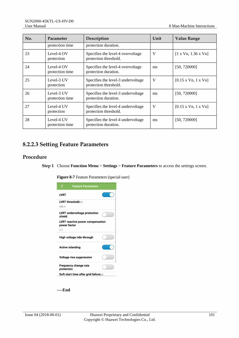
SUN2000-45KTL-US-HV-D0
User Manual 8 Man-Machine Interactions
Issue 04 (2018-06-01) Huawei Proprietary and Confidential
Copyright © Huawei Technologies Co., Ltd.
101
No. Parameter Description Unit Value Range
protection time protection duration.
23 Level-4 OV
protection
Specifies the level-4 overvoltage
protection threshold.
V [1 x Vn, 1.36 x Vn]
24 Level-4 OV
protection time
Specifies the level-4 overvoltage
protection duration.
ms [50, 720000]
25 Level-3 UV
protection
Specifies the level-3 undervoltage
protection threshold.
V [0.15 x Vn, 1 x Vn]
26 Level-3 UV
protection time
Specifies the level-3 undervoltage
protection duration.
ms [50, 720000]
27 Level-4 UV
protection
Specifies the level-4 undervoltage
protection threshold.
V [0.15 x Vn, 1 x Vn]
28 Level-4 UV
protection time
Specifies the level-4 undervoltage
protection duration.
ms [50, 720000]
8.2.2.3 Setting Feature Parameters
Procedure
Step 1 Choose Function Menu > Settings > Feature Parameters to access the settings screen.
Figure 8-7 Feature Parameters (special user)
----End
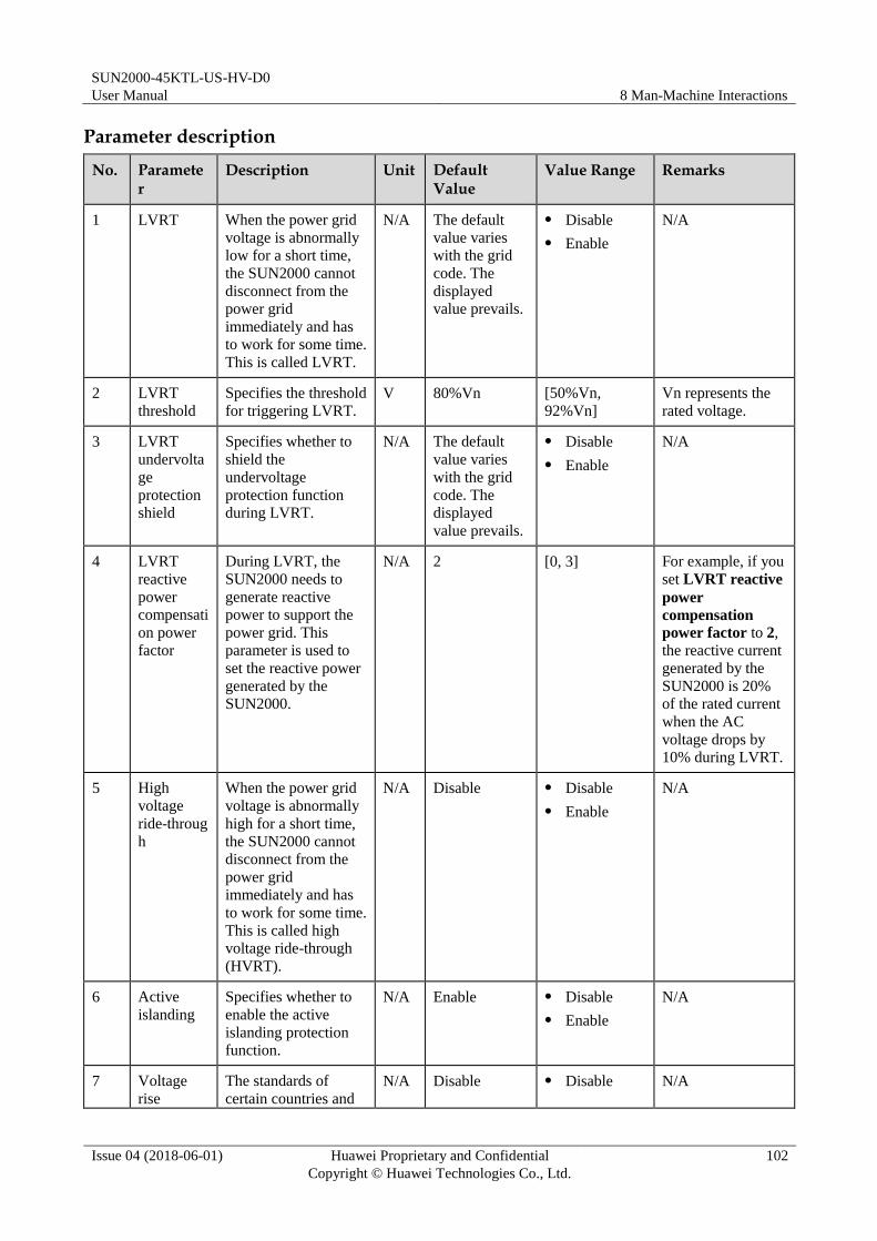
SUN2000-45KTL-US-HV-D0
User Manual 8 Man-Machine Interactions
Issue 04 (2018-06-01) Huawei Proprietary and Confidential
Copyright © Huawei Technologies Co., Ltd.
102
Parameter description
No. Parameter
Description Unit Default Value
Value Range Remarks
1 LVRT When the power grid
voltage is abnormally
low for a short time,
the SUN2000 cannot
disconnect from the
power grid
immediately and has
to work for some time.
This is called LVRT.
N/A The default
value varies
with the grid
code. The
displayed
value prevails.
Disable
Enable
N/A
2 LVRT
threshold
Specifies the threshold
for triggering LVRT.
V 80%Vn [50%Vn,
92%Vn]
Vn represents the
rated voltage.
3 LVRT
undervolta
ge
protection
shield
Specifies whether to
shield the
undervoltage
protection function
during LVRT.
N/A The default
value varies
with the grid
code. The
displayed
value prevails.
Disable
Enable
N/A
4 LVRT
reactive
power
compensati
on power
factor
During LVRT, the
SUN2000 needs to
generate reactive
power to support the
power grid. This
parameter is used to
set the reactive power
generated by the
SUN2000.
N/A 2 [0, 3] For example, if you
set LVRT reactive
power
compensation
power factor to 2,
the reactive current
generated by the
SUN2000 is 20%
of the rated current
when the AC
voltage drops by
10% during LVRT.
5 High
voltage
ride-throug
h
When the power grid
voltage is abnormally
high for a short time,
the SUN2000 cannot
disconnect from the
power grid
immediately and has
to work for some time.
This is called high
voltage ride-through
(HVRT).
N/A Disable Disable
Enable
N/A
6 Active
islanding
Specifies whether to
enable the active
islanding protection
function.
N/A Enable Disable
Enable
N/A
7 Voltage
rise
The standards of
certain countries and N/A Disable Disable N/A
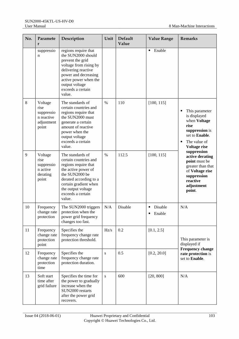
SUN2000-45KTL-US-HV-D0
User Manual 8 Man-Machine Interactions
Issue 04 (2018-06-01) Huawei Proprietary and Confidential
Copyright © Huawei Technologies Co., Ltd.
103
No. Parameter
Description Unit Default Value
Value Range Remarks
suppressio
n
regions require that
the SUN2000 should
prevent the grid
voltage from rising by
delivering reactive
power and decreasing
active power when the
output voltage
exceeds a certain
value.
Enable
8 Voltage
rise
suppressio
n reactive
adjustment
point
The standards of
certain countries and
regions require that
the SUN2000 must
generate a certain
amount of reactive
power when the
output voltage
exceeds a certain
value.
% 110 [100, 115]
This parameter
is displayed
when Voltage
rise suppression is
set to Enable.
The value of
Voltage rise
suppression
active derating point must be
greater than that
of Voltage rise
suppression
reactive
adjustment
point.
9 Voltage
rise
suppressio
n active
derating
point
The standards of
certain countries and
regions require that
the active power of
the SUN2000 be
derated according to a
certain gradient when
the output voltage
exceeds a certain
value.
% 112.5 [100, 115]
10 Frequency
change rate
protection
The SUN2000 triggers
protection when the
power grid frequency
changes too fast.
N/A Disable Disable
Enable
N/A
11 Frequency
change rate
protection
point
Specifies the
frequency change rate
protection threshold.
Hz/s 0.2 [0.1, 2.5]
This parameter is
displayed if
Frequency change
rate protection is
set to Enable.
12 Frequency
change rate
protection
time
Specifies the
frequency change rate
protection duration.
s 0.5 [0.2, 20.0]
13 Soft start
time after
grid failure
Specifies the time for
the power to gradually
increase when the
SUN2000 restarts
after the power grid recovers.
s 600 [20, 800] N/A

SUN2000-45KTL-US-HV-D0
User Manual 8 Man-Machine Interactions
Issue 04 (2018-06-01) Huawei Proprietary and Confidential
Copyright © Huawei Technologies Co., Ltd.
104
8.2.2.4 Setting Power Adjustment Parameters
Procedure
Step 1 Choose Function Menu > Settings > Power Adjustment to access the settings screen.
Figure 8-8 Power Adjustment (special user)
----End
Parameter List
Table 8-5 Parameter description
No. Parameter Description Unit Default Value
Value Range Remarks
1 Fixed
active
power
derating
Adjusts the active
power output of the
SUN2000 to a fixed
value.
kW Pmax_limit [0, Pmax_limit] Pmax represents
the maximum
active power.
2 Active
power
percentage
derating
Adjusts the active
power output of the
SUN2000 to a
percentage.
% 100 [0, 100] If this parameter
is set to 100, the
SUN2000 delivers
power output
based on the
maximum output
power.
3 Power
factor
Adjusts the SUN2000
power factor.
N/A 1.000 (–1.000,
–0.800]U[0.800,
1.000]
N/A

SUN2000-45KTL-US-HV-D0
User Manual 8 Man-Machine Interactions
Issue 04 (2018-06-01) Huawei Proprietary and Confidential
Copyright © Huawei Technologies Co., Ltd.
105
No. Parameter Description Unit Default Value
Value Range Remarks
4 Trigger
frequency
of over
frequency
derating
The standards of
certain countries and
regions require that
the output active
power of the
SUN2000 be derated
when the grid
frequency exceeds a
certain value.
Hz The default
value varies
depending
on the grid
code. The
displayed
value
prevails.
When the
output
frequency is
50 Hz, the
value range is
45.00–55.00
Hz.
When the
output
frequency is
60 Hz, the
value range is
55.00–65.00
Hz.
N/A
5 Quit
frequency
of over
frequency
derating
Specifies the
frequency threshold
for exiting
overfrequency
derating.
Hz N/A
6 Recovery
gradient of
over
frequency
derating
Specifies the power
recovery gradient for
overfrequency
derating.
%/min 10 [5, 20] N/A

SUN2000-45KTL-US-HV-D0
User Manual 9 System Maintenance
Issue 04 (2018-06-01) Huawei Proprietary and Confidential
Copyright © Huawei Technologies Co., Ltd.
106
9 System Maintenance
9.1 Routine Maintenance
To ensure that the SUN2000 can operate properly for a long term, you are advised to perform
routine maintenance on it as described in this chapter.
Before cleaning the system, and maintaining the cable connections and grounding
reliability, power off the system (see 7.4 Powering Off the SUN2000) and ensure that the
two DC switches on the inverter are OFF.
If you need to open the maintenance compartment door in rainy or snowy days, take
protective measures to prevent rain and snow entering the maintenance compartment. If it
is impossible to take protective measures, do not open the maintenance compartment door
in rainy or snowy days.
Table 9-1 Maintenance list
Item Check Method Maintenance Interval
System cleanliness Check the heat sink for foreign matter
or the overall health of the SUN2000.
Annual or every time an
abnormality is detected
System running
status
Check the SUN2000 for damage or
deformation.
Annual
Cable connections Check that cables are securely
connected.
Check that cables are intact, in
particular, the parts touching the
metallic surface are not scratched.
Check that the idle COM, USB, and
AC OUTPUT ports are locked by
waterproof caps.
The first inspection is
half a year after the
initial commissioning.
From then on, perform
the inspection once six
months to a year.
Grounding
reliability
Check whether the ground terminal and
ground cable are securely connected. Annual

SUN2000-45KTL-US-HV-D0
User Manual 9 System Maintenance
Issue 04 (2018-06-01) Huawei Proprietary and Confidential
Copyright © Huawei Technologies Co., Ltd.
107
Item Check Method Maintenance Interval
Sealing Check whether all cable glands are
properly sealed.
Annual
9.2 Troubleshooting
Alarm severities are defined as follows:
Major: The inverter enters the shutdown mode and disconnects from the power grid to
stop generating electricity after a fault occurs.
Minor: Some components are faulty but the inverter can still generate electricity.
Warning: The inverter output power decreases due to external factors.
Table 9-2 Common alarms and troubleshooting measures
Alarm ID Alarm Name
Alarm Severity
Possible Cause Suggestion
103 High DC
Input
Voltage
Major Cause ID = 1
The PV array is not
properly configured.
Excessive PV modules are
connected in series to PV
strings 1 and 2, and
therefore the PV string
open-circuit voltage
exceeds the inverter
maximum operating
voltage.
Cause ID = 2
The PV array is not
properly configured.
Excessive PV modules are
connected in series to PV
strings 3 and 4, and
therefore the PV string
open-circuit voltage
exceeds the inverter
maximum operating
voltage.
Cause ID = 3
The PV array is not
properly configured.
Excessive PV modules are
connected in series to PV
strings 5 and 6, and
therefore the PV string
open-circuit voltage
Cause ID = 1
Reduce the number of PV
modules connected in series to
PV strings 1 and 2 until the
open-circuit voltage is less than
or equal to the maximum inverter
operating voltage. After the PV
array configuration is corrected,
the inverter alarm disappears.
Cause ID = 2
Reduce the number of PV
modules connected in series to
PV strings 3 and 4 until the
open-circuit voltage is less than
or equal to the maximum inverter
operating voltage. After the PV
array configuration is corrected,
the inverter alarm disappears.
Cause ID = 3
Reduce the number of PV
modules connected in series to
PV strings 5 and 6 until the
open-circuit voltage is less than
or equal to the maximum inverter
operating voltage. After the PV
array configuration is corrected,
the inverter alarm disappears.
Cause ID = 4
Reduce the number of PV

SUN2000-45KTL-US-HV-D0
User Manual 9 System Maintenance
Issue 04 (2018-06-01) Huawei Proprietary and Confidential
Copyright © Huawei Technologies Co., Ltd.
108
Alarm ID Alarm Name
Alarm Severity
Possible Cause Suggestion
exceeds the inverter
maximum operating
voltage.
Cause ID = 4
The PV array is not
properly configured.
Excessive PV modules are
connected in series to PV
strings 7 and 8, and
therefore the PV string
open-circuit voltage
exceeds the inverter
maximum operating
voltage.
modules connected in series to
PV strings 7 and 8 until the
open-circuit voltage is less than
or equal to the maximum inverter
operating voltage. After the PV
array configuration is corrected,
the inverter alarm disappears.
106–113 Abnormal
String 1–8
Warning Cause ID = 1
The PV string is shielded
from sunlight for a long
time.
The PV string deteriorates
or is damaged.
1. Check whether the PV string
current is obviously lower than
the currents of other PV strings.
2. If yes, check whether the PV
string is shielded from sunlight.
3. If the PV string is clean and not
shielded from sunlight, check
whether any PV module is faulty.
120–127 String 1–8
Reversed
Cause ID
= 1:
Major
Cause ID
= 2:
Warning
Cause ID = 1
The PV string is reversely
connected.
Cause ID = 2
Only a few PV modules are
connected in series to the
PV string, and therefore the
end voltage is lower than
that of other PV strings.
Cause ID = 1
Check whether the PV string is
reversely connected to the
inverter. If yes, turn off the two
DC switches after the PV string
voltage drops within the safe
voltage range (lower than 60 V
DC), and then correct the PV
string connection.
Cause ID = 2
Check whether the number of PV
modules connected in series to
the inverter is small. If yes,
increase the number.
200 Abnormal
DC Circuit
Major Abnormal external conditions
trigger the protection for the
DC circuit inside the inverter.
The possible causes are as
follows:
Cause ID = 3
The inverter input is
disconnected accidentally,
or the PV string output
power changes sharply
because the PV string is
Cause ID = 3/10/11
1. The inverter detects its external
working conditions in real time.
After the fault is rectified, the
inverter automatically recovers.
2. If the fault persists, contact
Huawei technical support.
Cause ID = 12/15
Turn off the AC output switch and
DC input switch. Then turn on the AC output switch and DC input
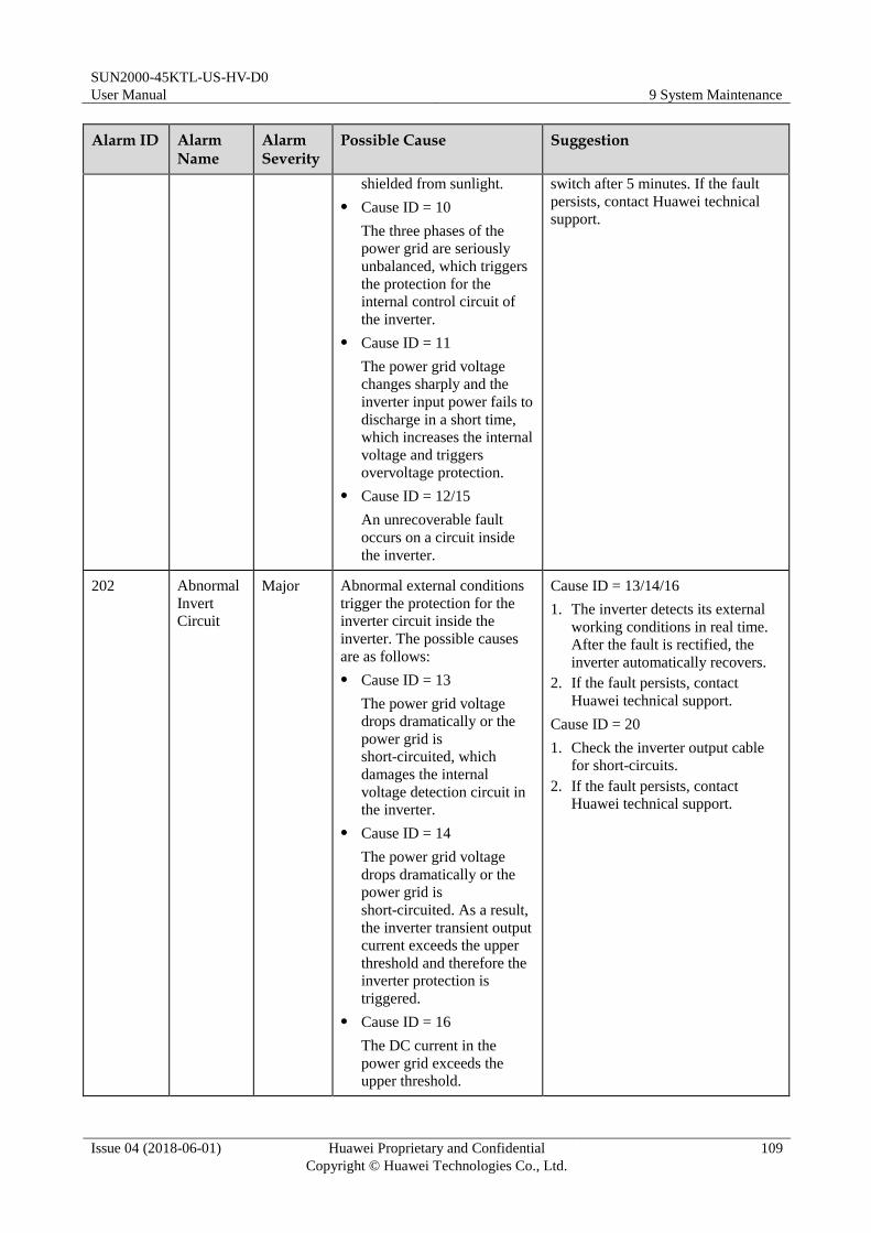
SUN2000-45KTL-US-HV-D0
User Manual 9 System Maintenance
Issue 04 (2018-06-01) Huawei Proprietary and Confidential
Copyright © Huawei Technologies Co., Ltd.
109
Alarm ID Alarm Name
Alarm Severity
Possible Cause Suggestion
shielded from sunlight.
Cause ID = 10
The three phases of the
power grid are seriously
unbalanced, which triggers
the protection for the
internal control circuit of
the inverter.
Cause ID = 11
The power grid voltage
changes sharply and the
inverter input power fails to
discharge in a short time,
which increases the internal
voltage and triggers
overvoltage protection.
Cause ID = 12/15
An unrecoverable fault
occurs on a circuit inside
the inverter.
switch after 5 minutes. If the fault
persists, contact Huawei technical
support.
202 Abnormal
Invert
Circuit
Major Abnormal external conditions
trigger the protection for the
inverter circuit inside the
inverter. The possible causes
are as follows:
Cause ID = 13
The power grid voltage
drops dramatically or the
power grid is
short-circuited, which
damages the internal
voltage detection circuit in
the inverter.
Cause ID = 14
The power grid voltage
drops dramatically or the
power grid is
short-circuited. As a result,
the inverter transient output
current exceeds the upper
threshold and therefore the
inverter protection is
triggered.
Cause ID = 16
The DC current in the
power grid exceeds the
upper threshold.
Cause ID = 13/14/16
1. The inverter detects its external
working conditions in real time.
After the fault is rectified, the
inverter automatically recovers.
2. If the fault persists, contact
Huawei technical support.
Cause ID = 20
1. Check the inverter output cable
for short-circuits.
2. If the fault persists, contact
Huawei technical support.

SUN2000-45KTL-US-HV-D0
User Manual 9 System Maintenance
Issue 04 (2018-06-01) Huawei Proprietary and Confidential
Copyright © Huawei Technologies Co., Ltd.
110
Alarm ID Alarm Name
Alarm Severity
Possible Cause Suggestion
Cause ID = 20
The inverter output is
short-circuited. As a result,
the output current surges to
a value above the upper
limit, and the inverter
protection is triggered.
301 Abnormal
Grid
Voltage
Major The power grid voltage is
beyond the acceptable range.
The possible causes are as
follows:
Cause ID = 4
The power grid voltage is
below the specified lower
threshold.
Cause ID = 16
The power grid voltage
exceeds the specified upper
threshold.
Cause ID = 19
The power grid voltage has
exceeded the specified
upper threshold for 10
minutes.
Cause ID = 26
The power grid voltage
exceeds the specified upper
threshold.
Cause ID = 28
The three phases of the
power grid differ greatly in
voltage.
Cause ID = 29
1. The power grid
experiences an outage.
2. The AC circuit is
disconnected or AC
switch is off.
Cause ID = 31
The impedance of the
output phase wire A to the
PE cable is low or
short-circuited.
Cause ID = 32
The impedance of the
output phase wire B to the
Cause ID = 4
1. If the alarm occurs accidentally,
the power grid may be abnormal
temporarily. The inverter
automatically recovers after
detecting that the power grid
becomes normal.
2. If the alarm occurs frequently,
check whether the power grid
voltage is within the acceptable
range. If no, contact the local
power operator. If yes, log in to
the SUN2000 APP, SmartLogger,
or the NetEco to modify the
power grid overvoltage and
undervoltage protection
thresholds with the consent of the
local power operator.
3. If the fault persists for a long
time, check the connection
between the AC switch and the
output power cable.
Cause ID = 16/19/26
1. Check whether the grid-tied
voltage exceeds the upper
threshold. If yes, contact the local
power operator.
2. If you have confirmed that the
grid-tied voltage exceeds the
upper threshold and obtained the
consent of the local power
operator, modify the overvoltage
and undervoltage protection
thresholds.
3. Check whether the peak power
grid voltage exceeds the upper
threshold.
Cause ID = 28
1. If the exception is caused by an
external fault, the inverter
automatically recovers after the
fault is rectified.

SUN2000-45KTL-US-HV-D0
User Manual 9 System Maintenance
Issue 04 (2018-06-01) Huawei Proprietary and Confidential
Copyright © Huawei Technologies Co., Ltd.
111
Alarm ID Alarm Name
Alarm Severity
Possible Cause Suggestion
PE cable is low or
short-circuited.
Cause ID = 33
The impedance of the
output phase wire C to the
PE cable is low or
short-circuited.
2. If the fault persists and affects the
energy yield of the power station,
contact the local power operator.
Cause ID = 29
1. Check the AC voltage.
2. Check that the AC power cable is
connected and that the AC switch
is ON.
Cause ID = 31
Check the impedance of output
phase wire A to the PE cable, locate
the position with lower impedance,
and resolve the issue.
Cause ID = 32
Check the impedance of output
phase wire B to the PE cable, locate
the position with lower impedance,
and resolve the issue.
Cause ID = 33
Check the impedance of output
phase wire C to the PE cable, locate
the position with lower impedance,
and resolve the issue.
305 Abnormal
Grid
Frequency
Major Cause ID = 2
The actual power grid
frequency is higher than the
standard requirement for
the local power grid.
Cause ID = 4
The actual power grid
frequency is lower than the
standard requirement for
the local power grid.
Cause ID = 5
The actual change rate of
the power grid frequency
does not meet the standard
requirement for the local
power grid.
Cause ID = 2/4
1. If the alarm occurs accidentally,
the power grid may be abnormal
temporarily. The inverter
automatically recovers after
detecting that the power grid
becomes normal.
2. If the alarm occurs frequently,
check whether the power grid
frequency is within the
acceptable range. If no, contact
the local power operator. If yes,
log in to the SUN2000 app,
SmartLogger, or NMS to modify
the power grid overfrequency and
underfrequency protection
thresholds with the consent of the
local power operator.
Cause ID = 5
1. If the alarm occurs accidentally,
the power grid may be abnormal
temporarily. The inverter
automatically recovers after
detecting that the power grid

SUN2000-45KTL-US-HV-D0
User Manual 9 System Maintenance
Issue 04 (2018-06-01) Huawei Proprietary and Confidential
Copyright © Huawei Technologies Co., Ltd.
112
Alarm ID Alarm Name
Alarm Severity
Possible Cause Suggestion
becomes normal.
2. If the alarm occurs frequently,
check whether the power grid
frequency is within the
acceptable range. If no, contact
the local power operator.
313 Low
Insulation
Resistance
Major Cause ID = 1
A short circuit occurs
between the PV string and
the PGND cable.
The PV string is installed in
a moist environment for a
long time.
1. Check the impedance between
the PV string and the PGND
cable. If a short circuit occurs,
rectify the fault.
2. If you are sure that the impedance
is less than the default value in a
cloudy or rainy environment, log
in to the SUN2000 app,
SmartLogger, or NMS and set
Insulation resistance
protection.
318 Abnormal
Residual
Current
Major Cause ID = 1
The insulation resistance
against the PGND cable at the
input side decreases when the
inverter is running, which
causes an excessively high
residual current.
1. If the alarm occurs accidentally,
the external circuit may be
abnormal temporarily. The
inverter automatically recovers
after fault is rectified.
2. If the alarm occurs repeatedly or
persists, check whether the
impedance between the PV string
and the ground is excessively
low.
321 Cabinet
Overtempe
rature
Major Cause ID = 1
The inverter is installed in a
place with poor ventilation.
The ambient temperature
exceeds the upper
threshold.
The internal fan works
abnormally.
1. Check the ventilation and
ambient temperature of the
inverter installation position.
2. If the ventilation is poor or the
ambient temperature exceeds the
upper threshold, improve the
ventilation and heat dissipation.
3. If the ventilation and ambient
temperature both meet
requirements, contact Huawei
technical support.
322 Abnormal
SPI
Communic
ation
Major Cause ID = 1
An unrecoverable fault occurs
on a circuit inside the inverter.
Turn off the AC output switch and
DC input switch. Then turn on the
AC output switch and DC input
switch after 5 minutes. If the fault
persists, contact Huawei technical
support.
326 Abnormal
Grounding
Major Cause ID = 1
The neutral wire or PGND
cable does not connect to
the inverter.
1. Check that the neutral wire or
PGND cable properly connects to
the inverter.
2. If the PV string is grounded,
check whether the inverter output
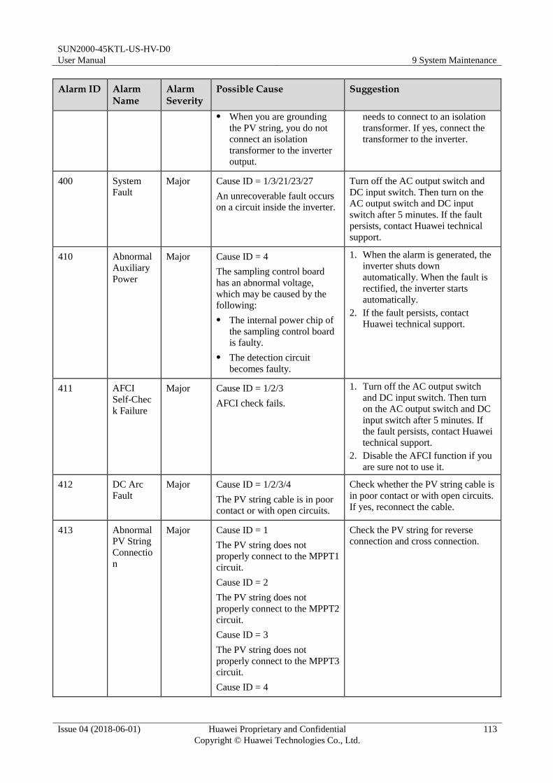
SUN2000-45KTL-US-HV-D0
User Manual 9 System Maintenance
Issue 04 (2018-06-01) Huawei Proprietary and Confidential
Copyright © Huawei Technologies Co., Ltd.
113
Alarm ID Alarm Name
Alarm Severity
Possible Cause Suggestion
When you are grounding
the PV string, you do not
connect an isolation
transformer to the inverter
output.
needs to connect to an isolation
transformer. If yes, connect the
transformer to the inverter.
400 System
Fault
Major Cause ID = 1/3/21/23/27
An unrecoverable fault occurs
on a circuit inside the inverter.
Turn off the AC output switch and
DC input switch. Then turn on the
AC output switch and DC input
switch after 5 minutes. If the fault
persists, contact Huawei technical
support.
410 Abnormal
Auxiliary
Power
Major Cause ID = 4
The sampling control board
has an abnormal voltage,
which may be caused by the
following:
The internal power chip of
the sampling control board
is faulty.
The detection circuit
becomes faulty.
1. When the alarm is generated, the
inverter shuts down
automatically. When the fault is
rectified, the inverter starts
automatically.
2. If the fault persists, contact
Huawei technical support.
411 AFCI
Self-Chec
k Failure
Major Cause ID = 1/2/3
AFCI check fails.
1. Turn off the AC output switch
and DC input switch. Then turn
on the AC output switch and DC
input switch after 5 minutes. If
the fault persists, contact Huawei
technical support.
2. Disable the AFCI function if you
are sure not to use it.
412 DC Arc
Fault
Major Cause ID = 1/2/3/4
The PV string cable is in poor
contact or with open circuits.
Check whether the PV string cable is
in poor contact or with open circuits.
If yes, reconnect the cable.
413 Abnormal
PV String
Connectio
n
Major Cause ID = 1
The PV string does not
properly connect to the MPPT1
circuit.
Cause ID = 2
The PV string does not
properly connect to the MPPT2
circuit.
Cause ID = 3
The PV string does not
properly connect to the MPPT3
circuit.
Cause ID = 4
Check the PV string for reverse
connection and cross connection.
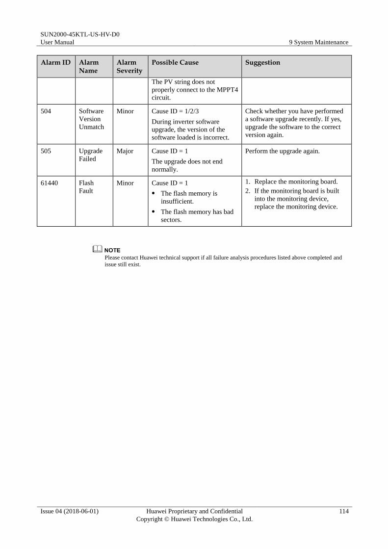
SUN2000-45KTL-US-HV-D0
User Manual 9 System Maintenance
Issue 04 (2018-06-01) Huawei Proprietary and Confidential
Copyright © Huawei Technologies Co., Ltd.
114
Alarm ID Alarm Name
Alarm Severity
Possible Cause Suggestion
The PV string does not
properly connect to the MPPT4
circuit.
504 Software
Version
Unmatch
Minor Cause ID = 1/2/3
During inverter software
upgrade, the version of the
software loaded is incorrect.
Check whether you have performed
a software upgrade recently. If yes,
upgrade the software to the correct
version again.
505 Upgrade
Failed
Major Cause ID = 1
The upgrade does not end
normally.
Perform the upgrade again.
61440 Flash
Fault
Minor Cause ID = 1
The flash memory is
insufficient.
The flash memory has bad
sectors.
1. Replace the monitoring board.
2. If the monitoring board is built
into the monitoring device,
replace the monitoring device.
Please contact Huawei technical support if all failure analysis procedures listed above completed and
issue still exist.

SUN2000-45KTL-US-HV-D0
User Manual 10 Handling the Inverter
Issue 04 (2018-06-01) Huawei Proprietary and Confidential
Copyright © Huawei Technologies Co., Ltd.
115
10 Handling the Inverter
10.1 Removing the SUN2000
Before removing the SUN2000, disconnect both AC and DC connections. After powering off
the SUN2000, wait at least 5 minutes before performing operations on it.
Perform the following operations to remove the SUN2000:
1. Disconnect all cables from the SUN2000, including RS485 communications cables, DC
input power cables, AC output power cables, and PGND cables.
2. Remove the SUN2000 from the mounting bracket.
3. Remove the mounting bracket.
10.2 Packing the SUN2000 If the original packing materials are available, put the SUN2000 inside them and then
seal them by using adhesive tape.
If the original packing materials are not available, put the SUN2000 inside a suitable
cardboard box and seal it properly.
10.3 Disposing of the SUN2000
If the SUN2000 service life expires, dispose of it according to the local disposal rules for
electrical equipment waste.
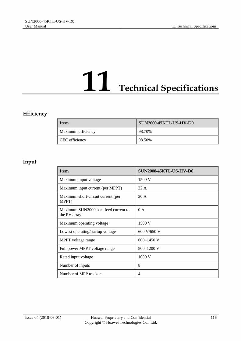
SUN2000-45KTL-US-HV-D0
User Manual 11 Technical Specifications
Issue 04 (2018-06-01) Huawei Proprietary and Confidential
Copyright © Huawei Technologies Co., Ltd.
116
11 Technical Specifications
Efficiency
Item SUN2000-45KTL-US-HV-D0
Maximum efficiency 98.70%
CEC efficiency 98.50%
Input
Item SUN2000-45KTL-US-HV-D0
Maximum input voltage 1500 V
Maximum input current (per MPPT) 22 A
Maximum short-circuit current (per
MPPT)
30 A
Maximum SUN2000 backfeed current to
the PV array 0 A
Maximum operating voltage 1500 V
Lowest operating/startup voltage 600 V/650 V
MPPT voltage range 600–1450 V
Full power MPPT voltage range 800–1200 V
Rated input voltage 1000 V
Number of inputs 8
Number of MPP trackers 4

SUN2000-45KTL-US-HV-D0
User Manual 11 Technical Specifications
Issue 04 (2018-06-01) Huawei Proprietary and Confidential
Copyright © Huawei Technologies Co., Ltd.
117
Output
Item SUN2000-45KTL-US-HV-D0
Rated output power 45,000 W
Maximum apparent power 50,000 VA
Maximum AC output power (cosφ = 1) 50,000 W
Rated output line voltage 600 V AC, 3W+PE
Rated output current 43.3 A
Output frequency 60 Hz
Maximum output current 48 A
Power factor 0.8 leading ... 0.8 lagging
Maximum total harmonic distortion (THD) < 3%
Protection
Item SUN2000-45KTL-US-HV-D0
Input DC switch Supported
Anti-islanding protection Supported
Output overcurrent protection Supported
Input reverse polarity protection Supported
PV string fault detection Supported
DC surge protection Type II
AC surge protection Type II
Insulation resistance detection Supported
Residual current monitoring unit (RCMU) Supported
AFCI Supported (UL 1699B, Type I)
Display and Communication
Item SUN2000-45KTL-US-HV-D0
Display LED indicator, Bluetooth module+app, USB
data cable+app
RS485 Supported
PLC Supported

SUN2000-45KTL-US-HV-D0
User Manual 11 Technical Specifications
Issue 04 (2018-06-01) Huawei Proprietary and Confidential
Copyright © Huawei Technologies Co., Ltd.
118
Common Parameters
Item SUN2000-45KTL-US-HV-D0
Dimensions (W x H x D) 930 mm x 600 mm x 270 mm (36.61 in. x
23.63 in. x 10.63 in.)
Weight About 64 kg (141 lb)
Operating temperature –25°C to +60°C (–13°F to +140°F)
Cooling mode Natural convection
Humidity 0%–100% RH
Input terminal Amphenol Helios H4
Output terminal Waterproof cable connector+OT terminal
Ingress Protection Rating Type 4X
Topology No transformer
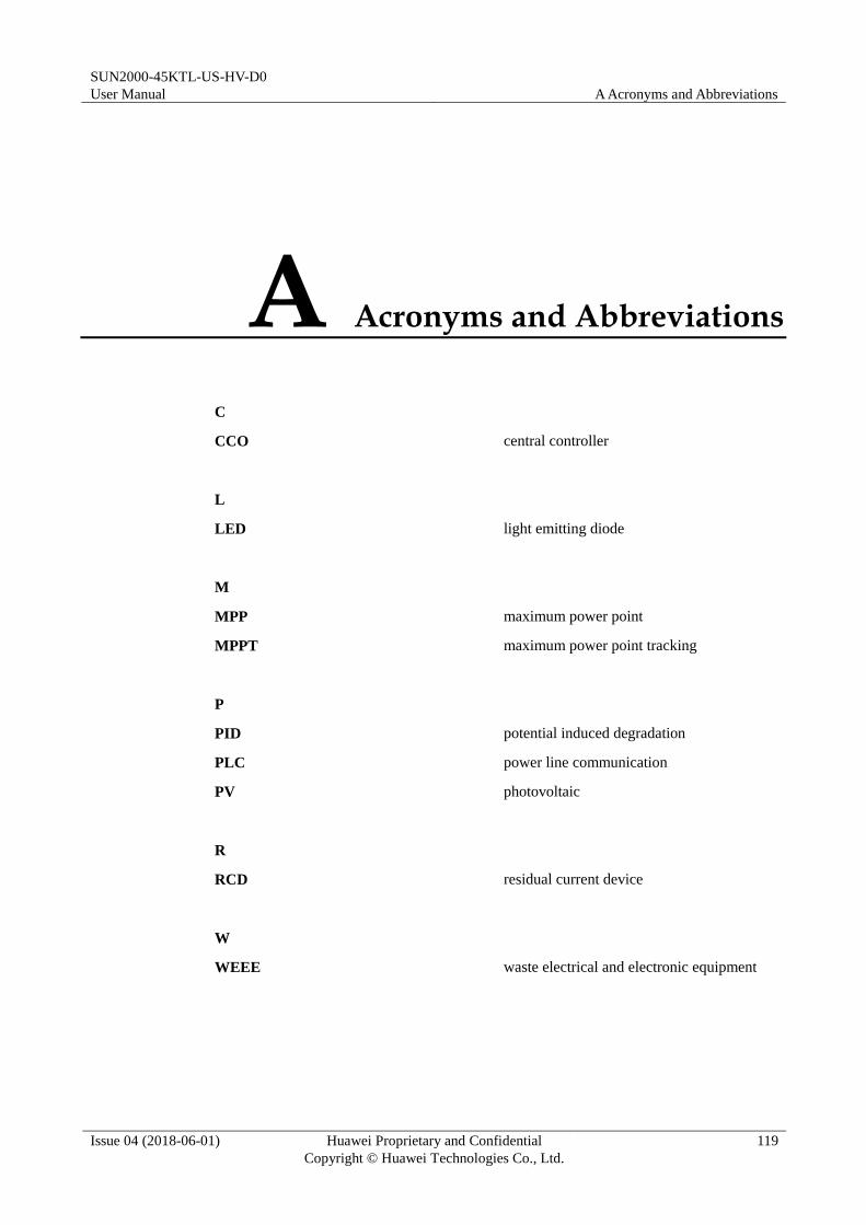
SUN2000-45KTL-US-HV-D0
User Manual A Acronyms and Abbreviations
Issue 04 (2018-06-01) Huawei Proprietary and Confidential
Copyright © Huawei Technologies Co., Ltd.
119
A Acronyms and Abbreviations
C
CCO central controller
L
LED light emitting diode
M
MPP maximum power point
MPPT maximum power point tracking
P
PID potential induced degradation
PLC power line communication
PV photovoltaic
R
RCD residual current device
W
WEEE waste electrical and electronic equipment

SUN2000-45KTL-US-HV-D0
User Manual B Contact Information
Issue 04 (2018-06-01) Huawei Proprietary and Confidential
Copyright © Huawei Technologies Co., Ltd.
120
B Contact Information
If you need to consult any technical problem, dial the Huawei technical assistance center
(TAC) hotline. Please provide the following information to receive better service.
Customer Name
Contact Info
Project Name and Location
Project Scale
Project Grid-connection Time
Fault Occurrence Time
Quantity of Faulty Inverters
Inverter Model
Inverter SN
Inverter Firmware Version
Warranty Info
Problem Description
SmartLogger Model
SmartLogger Firmware Version
SmartLogger Networking Scenarios (Such as Optical Fiber + RS485/PLC Networking)
RMA Shipping Address
HUAWEI TECHNOLOGIES USA INC.
5700 Tennyson Pkwy, Plano, TX 75024
TAC Line: 877-948-2934
Emai: [email protected]