User Manual - Hawk Measurement flow manual v1.00.pdfSoftware Supported Weir / Flume Applications...
28
Sultan Flow Open Channel Flow Measurement AWFR Series User Manual Sultan Sonar Manual Rev 1.0 A Higher Level of Performance www.hawkmeasure.com For more information, please visit >
Transcript of User Manual - Hawk Measurement flow manual v1.00.pdfSoftware Supported Weir / Flume Applications...

Sultan FlowOpen Channel Flow MeasurementAWFR Series
User Manual
Sultan Sonar Manual Rev 1.0
A Higher Level of Performance
www.hawkmeasure.comFor more information, please visit >

2
Table of ContentsSultan Flow
Contents
Overview 3
Principle of Operation 3
Certifications 3
Primary Areas of Application 3
Open Channel Flow Measurement Principles 4
Obstructions in channel cause rise in level 4
Software Supported Weir / Flume Applications 5
Software Supported Exponential Applications 5
Dimensions 6
Remote Transmitter 6
Remote Transducers 6
Flanges 7
Wiring 8
Wiring Terminal Compartment 8
Transducer Cable Extension 8
Wiring 4-20mA Output 9
SOURCING Type Output 9
SINKING Type Output (also 2 wire loop powered) 9
Relay Actions 10
Assembly 11
Cone / Flange Assembly 11
Installation Guide 12
Installation Guide - Remote Transmitter 12
Installation Guide - Remote Transducer 12
Transducer Point of Measurement 13
Other Applications 16
Powering The Unit For The First Time 17
Displayed Information 18
Displayed Diagnostics 18
Quickset Menu 19
Programming Flow Types 21
Exponent 24
Output Adjustment 25
Comms Type 25
Relay Actions 26
Advanced 27

Sultan FlowOverview
3
Principle of Operation
The Sultan Flow measurement system operates by transmitting an ultrasonic signal from its transducer towards the liquid being monitored. The reflected signal or echo is received by the transducer and processed. The time between transmission of the ultrasonic signal and reception of the echo is measured, and using the speed of sound through air, the distance from the transducer to the liquid level is calculated. Flow through the channel or structure is then calculated from the level measurement and the user entered properties of the channel.
The Sultan Flow system uses sophisticated software to locate and track the correct echo without being affected by echoes from fixed objects or changes in the liquid surface. When the liquid level or surface conditions change, the system follows preselected signal tracking parameters. In the event of a total loss of signal, the system adopts signal recovery routines to relocate the correct liquid level.
The system employs automatic gain control to compensate for changes in echo amplitude due to variations in environmental conditions. Continuous current, voltage and relay outputs are provided. These outputs can be programmed for failsafe conditions in the event of a loss of signal or system malfunction.
Certifications
• ATEX, CSA, IEC (Remote Transducer)
• Conforms to British standards for Flow calculations
Primary Areas of Application
• Open Channel Flow
• Water treatment
• Sewage treatment
• Irrigation
• Industrial waste water
• Power waste water
• Environmental monitoring
• Special flow requirements for unusual flow channels
Features
• Capable of monitoring liquid flow under the most difficult conditions• Suits a broad range of flumes, weirs and flow control structures• Real time diagnostic display• Flexible, multi point or calculated scaling of display and outputs
• Programmable totalizer• Programmable pulse per flow output• Programmable failsafe mode• Fast acting temperature compensation• 3G remote setup options and configuration• 4-20mA, HART, Modbus, Goshawk with 32 point flow table (via PC).

Open Channel Flow Measurement PrinciplesSultan Flow
4
Open Channel Flow Measurement Principles
Obstructions in channel cause rise in level
An obstruction in a channel represents a reduction of the cross-section of the channel. Since practical liquids are essentially incompressible, the volume of liquid flowing past an obstruction must equal the volume flowing towards it. It follows that the liquid must divert around the obstruction
If a barrier to flow is installed across the bottom of a channel, the liquid level rises as it flows over it - this leads to the use of the weir in open-channel flow measurement. If the cross-sectional area of a channel is reduced, the liquid level must rise as it flows past - this leads to the flume.
Surface of liquid
Flow
Weir
Rise above weir increases with flow volume
Figure 1.
q =khα
The height of the liquid surface above the Weir is called the Flow Head (h). The head is known to be related to the Volume Flowrate(q), allowing the �owrate to be calculated from measurement of the head. The formula is of me form:
where the exponent α is typically about 1.5and the constant k depends upon the channeland weir dimensions.Di�erent shapes of weir have been devel-opedto provide improved accuracy under di�erent conditions, but the principle is the same forall. These various weirs have di�er-entexponents, but most within the range of 1.3to 1.7.
Flumes, in which the channel width isnar-rowed have become preferred foraccuracy and robustness (eg. self scrubbing).Many �ume pro�les have been developed,each having its advantages and disadvantagesfor a given application.
A similar exponential relationship existsbe-tween head and �owrate in these �umes,and each type has a di�erent exponent,commonly in the range of 1.3 to 1.8.
q = khα
The height of the liquid surface above the Weir is called the Flow Head (h). The head is known to be related to the Volume Flowrate(q), allowing the flowrate to be calculated from measurement of the head. The formula is of me form:
Where the exponent α is typically about 1.5 and the constant k depends upon the channel and weir dimensions.Different shapes of weir have been developed to provide improved accuracy under different conditions, but the principle is the same for all. These various weirs have different exponents, but most within the range of 1.3 to 1.7.
Flumes, in which the channel width is narrowed have become preferred for accuracy and robustness (eg. self scrubbing). Many flume profiles have been developed, each having its advantages and disadvantages for a given application.
A similar exponential relationship exists between head and flowrate in these flumes,and each type has a different exponent,commonly in the range of 1.3 to 1.8.
Software Supported Weir / Flume ApplicationsSultan Flow
5
RectangularSharp-Crested Weir
V-NotchSharp-Crested Weir
Rectangular ConstrictedSharp-Crested Weir
TrapezoidalSharp-Crested Weir
Parshall Flumes Khafagi-Venturi Flumes Palmer-Bowles Flumes
Rectangular Flume Rectangular Weir V-Notch Weir
Software Supported Weir / Flume Applications
The Sultan Flow supports programmable Weir / Flume types where you can input the dimensions of the flume, weir, constriction / throat and the Flow unit will automatically calculate the flow rate based on the inputted dimensions. These include Rectangular Flumes, Rectangular Weirs and V-Notch Weirs.
Software Supported Exponential Applications
Some Flow applications only require an Exponential value to be programmed. You need to select the Expo-nent Flow Type parameter. Typical Exponential Flow designs include Suppressed Rectangular Weir, Cipolletti (Trapezoidal) Weir, Venturi Flume, Parshall Flume, Leopold Lagco Flume, plus other types of exponential device.
Typical Exponential values are shown below.
Application Type Typical Exponent
Suppressed Rectangular Weir 1.50
Cipolletti (Trapezoidal) Weir 1.50
Venturi Flume 1.50
Parshall Flume 1.50-1.60
Leopold Lagco Flume 1.55
DimensionsSultan Flow
6
3 x M16Conduitentries
A
C
B
160mm (6.3”)
SeeFlangeTable
53.5mm (2.1")
305m
m (1
2”)
80m
m
(3.1
”)
75m
m
(2.9
”)
2" BSP or NPT THD
110mm (4.3”)1" BSP/NPT Nipple
B
SeeFlangeTable
A
D
80m
m
(3.1
”)~8
0mm
(3.1
”)
53.5mm (2.1")
3" / 3.5" Type
Remote Transducers
Cone / Transducer Dimensions Table
Sensor FrequencySelected Flange
A B C D
mm in. mm in. mm in. mm in.
5 kHz 10” 236 10.0 455 17.9 840 33.1 750 29.5
10 kHz10” 236 10.0 455 17.9 540 21.3 450 17.7
8” 195 8.0 280 11.1 540 21.3 450 17.7
15 kHz10” 236 10.0 455 17.9 440 17.3 350 13.8
8” 195 8.0 280 11.0 440 17.3 350 13.8
20 / 30(T6)1 kHz 4” 98.5 4.0 280 11.0 390 15.4 300 11.8
30(T4)1 / 40 / 50 kHz 4” 98.5 4.0 280 11.0 350 3.8 260 10.2
14 mm (0.6”)
74 mm (2.9”)
78 mm (3.1”)10
7 m
m (4
.2”)
111.5 mm (4.4”)
4 mm (0.2”)
50 mm (2”)
131.
5 m
m (5
.2”)
7.5
mm
(0.3
”)
192.5 mm (7.6”)
141.
5 m
m (5
.6”)
190
mm
(7.5
”)
182.5 mm (7.2”)
147 mm (5.8”)16
7.5
mm
(6.6
”)
147 mm (5.8”)
30.7
mm
(1.2
”)
158 mm (6.2”)
108
mm
(4.3
”)
190
mm
(7.5
”)
174 mm (6.9”)192.5 mm (7.6”)
182.5 mm (7.2”)
30.0 20.2
33.029.029.033.0
16.2
Remote Transmitter
2" Type
There are 2 versions of 30kHz transducers. AWRT30T6 is a 3" type. AWRT30T4 is a 2" type.

DimensionsSultan Flow
7
Flanges
FLANGE TYPE:A = ANSI FlangeJ = JIS FlangeD = DIN Flange
H
E FG
Note: Other flange sizes available upon request.
STANDARD ANSI/DIN/JIS FLANGE DIMENSIONSFLANGETYPE
E (PCD) F (OD) G (ID) H (Hole)mm in. mm in. mm in. mm in.
FA4 ANSI class 150 190.5 7.5 229 9.0 100 4 19 0.75FD4 DIN100 PN10/16 180 7.1 220 8.7 100 4 18 0.71FJ4 JIS B2220-1984 10kg 175 6.9 210 8.4 100 4 19 0.75
FA8 ANSI class 150 298.5 11.8 343 13.5 200 8 22 0.85FD8 DIN200 PN10 295 11.6 340 13.4 200 8 22 0.85FJ8 JIS B2220-1984 10kg 290 11.4 330 13.0 200 8 19 0.91FA10 ANSI class 150 362 14.3 406 16.0 250 10 25 1.02FD10 DIN250 PN10 350 13.7 395 16.0 250 10 23 0.85FJ10 JIS B2220-1984 10kg 355 14.0 400 15.7 250 10 25 0.99
SIZE
4”
8”
10”
6”FA6 ANSI class 150FD6 DIN150 PN10FJ6 JIS B2220-1984 10kg
241.5 9.5240 9.4240 9.4
279 11.0285 11.2280 11.0
150 6150 6150 6
22 0.8723 0.9123 0.91
No.Holes
888
888
8812
1212
12
Standard ANSI/DN/JIS Flange Dimensions
Size Flange Type E (PCD) F (OD) G (ID) H (Hole) No.
Holesmm in. mm in. mm in. mm in.
4”
FA4 ANSI class 150 190.5 7.5 229 9.0 100 4 19 0.75 8
FD4 DIN100 PN10/16 180 7.1 220 8.7 100 4 18 0.71 8
FJ4 JIS B2220-1984 10kg 175 6.9 210 8.4 100 4 19 0.75 8
6”
FA6 ANSI class 150 241.5 9.5 279 11.0 150 6 22 0.87 8
FD6 DIN150 PN10 240 9.4 285 11.2 150 6 23 0.91 8
FJ6 JIS B2220-1984 10kg 240 9.4 280 11.0 150 6 23 0.91 8
8”
FA8 ANSI class 150 298.5 11.8 343 13.5 200 8 22 0.85 8
FD8 DIN200 PN10 295 11.6 340 13.4 200 8 22 0.85 8
FJ8 JIS B2220-1984 10kg 290 11.4 330 13.0 200 8 19 0.91 12
10”
FA10 ANSI class 150 362 14.3 406 16.0 250 10 25 1.02 12
FD10 DIN200 PN10 350 13.7 395 16.0 250 10 23 0.85 12
FJ10 JIS B2220-1984 10kg 355 14.0 400 15.7 250 10 25 0.99 12

Wiring
8
Sultan Flow
Sourcing 4-20mA from Sultan
Sinking 4-20mA from user device OR
+ – A 1L+– NB
RED
BLAC
K
BLUE
WHI
TE
Test
InIs
TRANSDUCER DC-In AC-In*4-20mA COMMS
RELAY 1
NC
CO
M
NO
RELAY 2
NC
CO
M
NO
RELAY 3
NC
CO
M
NO
RELAY 4
NC
CO
M
NO
RELAY 5
NC
CO
M
NO B
RED
BLAC
K
BLUE
WHI
TE
Test
In
TRANSDUCER
COMMS
+ –
4-20mA
A Shld
Shld
Sinking 4-20mA from user device
1 2 3 4 5 6 7 8 9 10 11 12 13 14 15
16 17 18 19 20 21 22 23 24 25 26 27 28 29 30
1 2 3 4 5 6
7 8 9 10 11 12
*48VDC Sultan version will have these terminals marked
as the 30-48VDC input
Inputs / Outputs may vary. Consult Part Numbering
Wiring Terminal Compartment
The Sultan Remote Transmitter has wiring informa-tion printed inside the flip lid of the unit.
Ensure your power source is deactivated.
Unscrew the lower flip lid to access the wiring terminals.
Pass cables through the cable entry gland before wiring into the terminal block.
To connect a wire, remove the required terminal block with thin nose pliers. Place the wire in firmly screw down the connection. The transducer termi-nals are labeled by colour on the PCB.
If you are connecting HawkLink communications, connect the blue wire to B and the white wire to A. The black wire can be connected to the DC- or GND terminal next to A.
Tighten cable entry gland(s) and cover to ensure sealing is effective.
To Transducer
JUNCTION BOX
Cable Shield
Re-connectCable Shield
to Black
WHITE
BLUE
BLACK
RED
WHITE
BLUEBLACK
RED
SHIELD
SULTANAMPLIFIER
Seperate cable shielding from blackwire at junction box
Transducer Cable Extension
Use long nose pliers to extract terminals

WiringSultan Flow
9
When connecting the 4-20mA output to a user device such as a PLC input, DCS or indicator, use a voltmeter to check the field wires to be used for the 4-20mA signal. If DC voltage around 24V is present, use sinking connection. If no voltage is present, use sourcing connection.
Sultan output is sourcing current and provides voltage to drive a passive load, PLC input, indicator or other user device.
SOURCING Type Output
+
–
NOTE:Isolated current output can be made common with +DC or GND if required.(e.g. RL – connected to GND)
+Is
–RL Max 270Ω
4-20mA
Use shielded
cable
Sultan output is sourcing current and provides voltage to drive a passive load, PLC input, indicator or other user device
4-20
mA
Voltage freeuser device
NOTE: Isolated current output can be made common with +DC or GND if required. (e.g. RL – connected to GND)
SINKING Type Output (also 2 wire loop powered)
Sultan output is sinking current. Voltage to drive current loop must be provided by PLC, indicator, other user device or external DC supply.
User device including
+24VDC source
NOTE: RL Max = 750Ωif user DC Supply 24V
Sultan output is sinking current. Voltage to drive current loop must be provided by PLC, indicator, other user device or external DC supply.
+
–
4-20
mA
Use shielded
cable
+
– NOTE: RL Max = 750Ω if user DC Supply 24V.
Wiring 4-20mA Output

Relay ActionsSultan Flow
10
Relay Actions
• Set Relay Parameters in Output Adjustment menu
• The two relay levels are RlyL1 and RlyL2
• The display will show RlyL1 1, the last 1 indicated the Relay number (eg 1 to 5)
• L1 and L2 distances are measured from the transducer face
Sub-Menu Description Options
RlyL1 1-5Adjust Relay switch point (L1 must be < L2)
Adjustable
RlyL2 1-5Adjust Relay switch point (L2 must be > L1)
Adjustable
HI
OFF
TEST
LOW
EN
DEN
CAL
OFF
DELAYSENSITIVITY
EnergiseEN
DeEnergiseDEN
COMMS DC-IN
AC
GN
D to
met
al c
ase
12-30VDC
+7.
8.
RS 485
5.
B
6.
A
1 2 3 4 5 6 7 8 9 10
+ –4-20mA
AC-IN
A 1L+–
DC-IN4-20mA COMMSTRANSDUCER
NB
RELAY 1
NC COM
NO
RELAY 2
NC COM
NO
RELAY 3
NC COM
NO
RELAY 4
NC COM
NO
RELAY 5
NC COM
NO
Test
inIs
RED
BLAC
K
BLUE
WHI
TE
REMOTE AMPLIFIER
GLADIATOR TERMINAL
NC NOCOM NC NOCOM
NC NOCOM
POWER FAILURE
Stat
e 1
Stat
e 2
Relay ActionFailSafe FS
FailSafe FS
NC NOCOM
Relay Status
LED Status
Remote Amplifier terminal function labels
NC NOCOM
NC NOCOM
NC NOCOMNC NOCOM
NC NOCOMNC NOCOM
NC NOCOM NC NOCOM NC NOCOM NC NOCOM NC NOCOM
system operating normally
OFFpower/system/measurement failure
Below L2 or
RISING LEVEL
L1
L2
between L1 and L2 after passing below L2.
LOW LEVEL or
Above L1 or
FALLING LEVEL
L1
L2
between L1 and L2 after passing above L1.
HIGH LEVEL or

AssemblySultan Flow
11
4
Tighten the locking ring down to the flange to fix the components in place .
2
Screw the flange assembly fully down onto the cone (as far down as it will go until the parts are tightly fastened).
COMPLETE ASSEMBLY
1
Remove red cap (including cardboard).
3
Screw the transducer tightly down onto the flange and cone assembly.
Note! Direction of flange, smallest ring this way up ↑
User mountings should only connect to the larger (lower) isolated mounting flange. No other part of the sensor assembly should touch any other structure or object.
(Appearance above flange may differ for integral and smart units).
Cone / Flange Assembly
Installation GuideSultan Flow
12
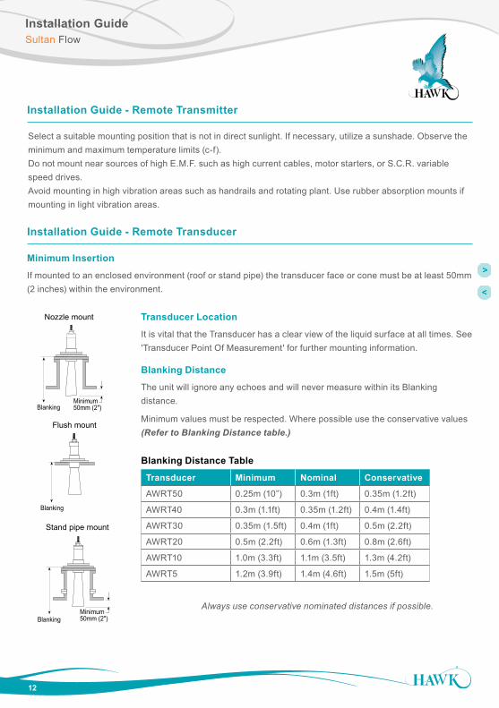
Installation Guide - Remote Transmitter
Select a suitable mounting position that is not in direct sunlight. If necessary, utilize a sunshade. Observe the minimum and maximum temperature limits (c-f).Do not mount near sources of high E.M.F. such as high current cables, motor starters, or S.C.R. variable speed drives. Avoid mounting in high vibration areas such as handrails and rotating plant. Use rubber absorption mounts if mounting in light vibration areas.
Installation Guide - Remote Transducer
Minimum Insertion
If mounted to an enclosed environment (roof or stand pipe) the transducer face or cone must be at least 50mm (2 inches) within the environment.
Nozzle mount
Minimum50mm (2")Blanking
Flush mount
Blanking
Stand pipe mount
Minimum50mm (2")Blanking
Transducer Minimum Nominal Conservative
AWRT50 0.25m (10”) 0.3m (1ft) 0.35m (1.2ft)
AWRT40 0.3m (1.1ft) 0.35m (1.2ft) 0.4m (1.4ft)
AWRT30 0.35m (1.5ft) 0.4m (1ft) 0.5m (2.2ft)
AWRT20 0.5m (2.2ft) 0.6m (1.3ft) 0.8m (2.6ft)
AWRT10 1.0m (3.3ft) 1.1m (3.5ft) 1.3m (4.2ft)
AWRT5 1.2m (3.9ft) 1.4m (4.6ft) 1.5m (5ft)
Always use conservative nominated distances if possible.
Transducer Location
It is vital that the Transducer has a clear view of the liquid surface at all times. See 'Transducer Point Of Measurement' for further mounting information.
Blanking Distance
The unit will ignore any echoes and will never measure within its Blanking distance.
Minimum values must be respected. Where possible use the conservative values (Refer to Blanking Distance table.)
Blanking Distance Table

Transducer Point of MeasurementSultan Flow
13
Suppressed Rectangular,Trapezoidal and V-notch weirs
The head is measured upstream at a minimum distance of 3 times maximum head from the weir plate to ensure the surface of the liquid is not affected by turbulence or draw down.
FLOW (q)
3 x HMAXminimum
FLOW (q)
150mm
Venturi Flume
FLOW (q)
L
Parshall Flume
2/3L
Transducer
Venturi Flumes
The point of measurement should be 150mm upstream from the beginning of the converging section.
Transducer Point Of Measurement
FLOW (q)
3 x HMAXminimum
FLOW (q)
150mm
Venturi Flume
FLOW (q)
L
Parshall Flume
2/3L
Transducer
Parshall Flumes
2/3 the length of the converging section upstream of the throat section.
FLOW (q)
3 x HMAXminimum
FLOW (q)
150mm
Venturi Flume
FLOW (q)
L
Parshall Flume
2/3L
Transducer

Transducer Point of MeasurementSultan Flow
14
100 - 305 4 - 12 25 1.0380 15 32 1.3455 18 38 1.5530 21 44 1.8610 24 51 2.1760 30 64 2.5915 36 76 3.0
1065 42 89 3.51220 48 102 4.01370 54 114 4.51520 60 127 5.01675 66 140 5.51830 72 152 6.0
FLOW
DRWG 4
Transducer mountedminimum blanking distanceabove max. head
Point of measurement Throat
Converging Diverging
Flume Sizemm inches
Point of Measurementmm inches
Transducer Point Of Measurement
Leopald Lagco Flumes
The head is measured at a point upstream of the beginning of the converging section as detailed in the table below (See DRWG 4).

Transducer Point of MeasurementSultan Flow
15
For a Rectangular and U-throated flume, the head is measured at 3 to 4 times the maximum head upstream from the beginning of the converging section, to ensure the surface of the liquid is not effected by turbulence.
Transducerposition
3-4 x hmax
Flow (q)
BS3680 flume
Transducer Point Of Measurement
BS3680 Flumes
BS3680 Weirs
For a Rectangular and V-notch weirs, the head is measured at a point 4 to 5 times the maximum head upstream from the weir plate, to ensure the surface of the liquid is not affected by turbulence or drawdown.
BS3680 Weir
Flow (q)
4-5 x HMAXminimum

Transducer Point of MeasurementSultan Flow
16
Other Applications
Please consult the manufacturer of the device for details of where the point of measurement should be located but ensure that it is chosen such that the surface of the liquid is not effected by turbulence or drawdown.

Powering The Unit For The First Time
17
Installation should only be performed by suitably qualified personnel.
A. Confirm mounting is within recommended specifications.
B. Check the selected unit matches the required application specifications. For Hazardous Locations see appropriate safety instructions available at http://www.hawkmeasure.com
C. Check the wiring is correct and all connections are secure.
D. Apply power to the unit.
When power is applied the unit will start its normal load sequence. The following messages will cycle on the display.
Sultan Flow
Menu Navigation
1
A
B
C
A
B
Low Level
High Level
C
EN URION
1 2
3 4
Navigate up, increase value
2
A
B
C
A
B
Low Level
High Level
C
EN URION
1 2
3 4
Navigate down, decrease value
3
A
B
C
A
B
Low Level
High Level
C
EN URION
1 2
3 4 Proceed, select, save
4
A
B
C
A
B
Low Level
High Level
C
EN URION
1 2
3 4
Go back, return unit to operational mode
Hawk Serial Number Type Software Revision MB Address Tx Serial Tx Model Tx SoftVr

Displayed InformationSultan Flow
18
Displayed Diagnostics
Pressing the arrow buttons cycles through various unit diagnostics on the top line of the display
(Flow Type) Selected Flow Type (example, RecFlume)
(Display Mode) Selected Display Mode (example, Flow)
(Totaliser Value) Totaliser Value since last reset
(Date) Programmed Date
(Time) Programmed Time
Head (Value) Measured height from Low Level
Tx 1 Transducer Number
Normal
Recover
Failed
Unit functioning normally
Unit searching for new echo
Unit in failsafe condition
WinFw Start (near) point of Tracking Window
WinBk End (far) point of Tracking Window
Temp Temperature reading at Transducer
Noise Acoustic or electrical noise interference on Transducer. Low values (1.9%) are normal
Rec Gn Amount of Recover Gain applied
Gain Amount of Gain used at measured distance
E Size Echo size. 0.8V to 2.5V is normal range
Echo Distance reading of unfiltered Echo
Totaliser
Flow
RecFlume 24.4LS
Quickset OutputAd Tx SetupDiagnosticFlow Rate
Quickset MenuSultan Flow
19
Parameter Description Options
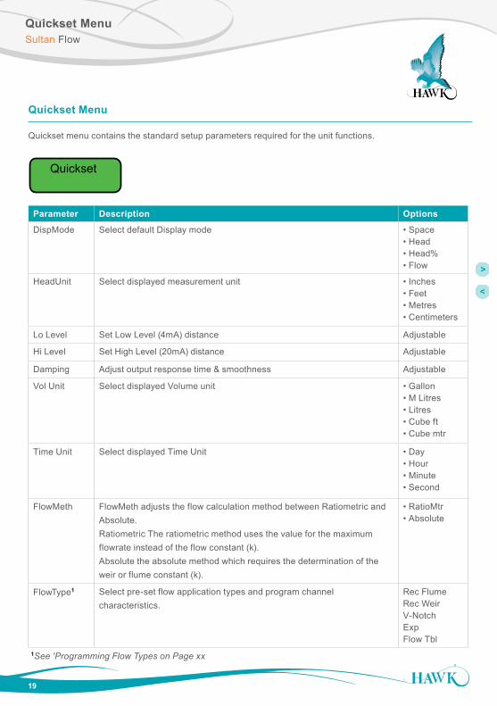
DispMode Select default Display mode • Space• Head• Head%• Flow
HeadUnit Select displayed measurement unit • Inches• Feet• Metres• Centimeters
Lo Level Set Low Level (4mA) distance Adjustable
Hi Level Set High Level (20mA) distance Adjustable
Damping Adjust output response time & smoothness Adjustable
Vol Unit Select displayed Volume unit • Gallon• M Litres• Litres• Cube ft• Cube mtr
Time Unit Select displayed Time Unit • Day• Hour• Minute• Second
FlowMeth FlowMeth adjusts the flow calculation method between Ratiometric and Absolute. Ratiometric The ratiometric method uses the value for the maximum flowrate instead of the flow constant (k). Absolute the absolute method which requires the determination of the weir or flume constant (k).
• RatioMtr• Absolute
FlowType1 Select pre-set flow application types and program channel characteristics.
Rec FlumeRec WeirV-NotchExp Flow Tbl
Quickset Menu
Quickset menu contains the standard setup parameters required for the unit functions.
Totaliser
Flow
RecFlume 24.4LS
Quickset OutputAd Tx Setup
1See 'Programming Flow Types on Page xx
Quickset MenuSultan Flow
20
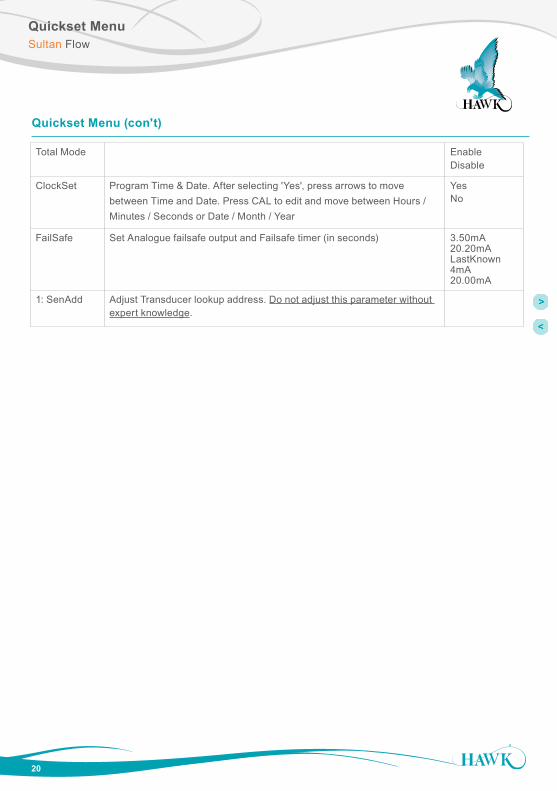
Quickset Menu (con't)
Total Mode Enable Disable
ClockSet Program Time & Date. After selecting 'Yes', press arrows to move between Time and Date. Press CAL to edit and move between Hours / Minutes / Seconds or Date / Month / Year
YesNo
FailSafe Set Analogue failsafe output and Failsafe timer (in seconds) 3.50mA20.20mALastKnown4mA20.00mA
1: SenAdd Adjust Transducer lookup address. Do not adjust this parameter without expert knowledge.

Programming Flow TypesSultan Flow
21
Programming Flow Types
Each selectable Flow Type has various sub parameters depending on the channel shape.
Flow
P
b
B
P
bB
L
B
Angleo
P
Reference Parameter Description
b Throat b Width of flume throat
B AWidth B Width of flume channel
L Throat L Length of flume throat
P Hump P Height of flume hump. If no hump is present, adjust to 0.00
Rough Ks Approximate Constant (k). Consult flume manufacturer specification
Avg Temp Average ambient temperature at transducer (this will over ride the automatic temperature compensation in the transducer
Max Flow Maximum Flow Rate possible. If this value is exceeded the unit will display 'Overflow'
LoCutOff If the application can have a non-flowing liquid level present use LoCutOff to ignore this liquid level. The value is measured from the programmed Low Level up.For example, if a flume has a 20mm high hump then you can program LoCutOff to be 20mm as this 20mm of liquid level will not be flowing
Flumes
Top
Side

Programming Flow TypesSultan Flow
22
Rectangular Weirs
Flow
P
b
B
P
bB
L
B
Angleo
P
Reference Parameter Description
b CWidth b Width of weir
B AWidth B Width of channel
P CHight P Height to Weir crest
Rough Ks Approximate Constant (k). Consult weir manufacturer specification
Max Flow Maximum Flow Rate possible. If this value is exceeded the unit will display 'Overflow'.
LoCutOff If the application can have a non-flowing liquid level present use LoCutOff to ignore this liquid level. The value is measured from the programmed Low Level up.For example, if a flume has a 20mm high hump then you can program LoCutOff to be 20mm as this 20mm of liquid level will not be flowing
Programming Flow TypesSultan Flow
23
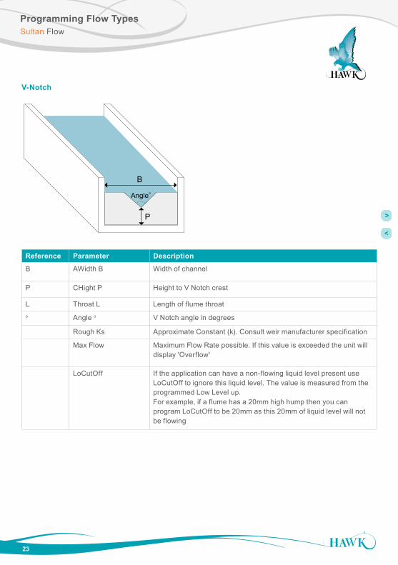
V-Notch
Reference Parameter Description
B AWidth B Width of channel
P CHight P Height to V Notch crest
L Throat L Length of flume throato Angle o V Notch angle in degrees
Rough Ks Approximate Constant (k). Consult weir manufacturer specification
Max Flow Maximum Flow Rate possible. If this value is exceeded the unit will display 'Overflow'
LoCutOff If the application can have a non-flowing liquid level present use LoCutOff to ignore this liquid level. The value is measured from the programmed Low Level up.For example, if a flume has a 20mm high hump then you can program LoCutOff to be 20mm as this 20mm of liquid level will not be flowing
Flow
P
b
B
P
bB
L
B
Angleo
P

ExponentSultan Flow
24
Exp (Exponential) Applications
Some Flow applications only require an Exponential value to be programmed. You need to select the Expo-nent Flow Type parameter. Typical Exponential Flow designs include Suppressed Rectangular Weir, Cipolletti (Trapezoidal) Weir, Venturi Flume, Parshall Flume, Leopold Lagco Flume, plus other types of exponential device. Consult flume manufacturer for information about possible Exponential values.
Application Type Typical Exponent
Suppressed Rectangular Weir 1.50
Cipolletti (Trapezoidal) Weir 1.50
Venturi Flume 1.50
Parshall Flume 1.50-1.60
Leopold Lagco Flume 1.55
Reference Parameter Description
Exponent Exponential Flow calculation based on liquid height
K Factor Flow constant (k). Consult flume manufacturer specification
Max Flow Maximum Flow Rate possible. If this value is exceeded the unit will display 'Overflow'
LoCutOff If the application can have a non-flowing liquid level present use LoCutOff to ignore this liquid level. The value is measured from the programmed Low Level up.For example, if a flume has a 20mm high hump then you can program LoCutOff to be 20mm as this 20mm of liquid level will not be flowing
Typical Exponential values are shown below.
Output AdjustmentSultan Flow
25
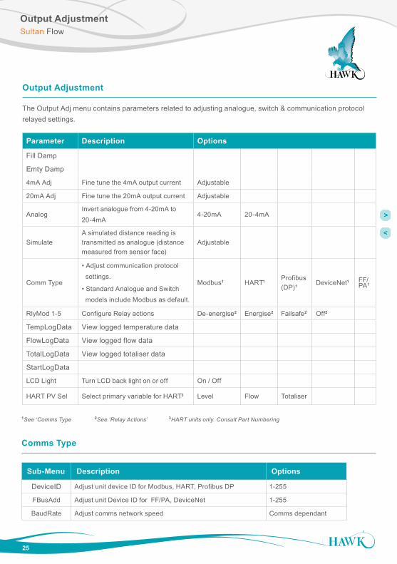
Output Adjustment
The Output Adj menu contains parameters related to adjusting analogue, switch & communication protocol relayed settings.
Parameter Description Options
Fill Damp
Emty Damp
4mA Adj Fine tune the 4mA output current Adjustable
20mA Adj Fine tune the 20mA output current Adjustable
AnalogInvert analogue from 4-20mA to 20-4mA
4-20mA 20-4mA
SimulateA simulated distance reading is transmitted as analogue (distance measured from sensor face)
Adjustable
Comm Type
• Adjust communication protocol settings.
• Standard Analogue and Switch models include Modbus as default.
Modbus1 HART1 Profibus (DP)1 DeviceNet1 FF/
PA1
RlyMod 1-5 Configure Relay actions De-energise2 Energise2 Failsafe2 Off2
TempLogData View logged temperature data
FlowLogData View logged flow data
TotalLogData View logged totaliser data
StartLogData
LCD Light Turn LCD back light on or off On / Off
HART PV Sel Select primary variable for HART3 Level Flow Totaliser
1See ‘Comms Type 2See ‘Relay Actions’ 3HART units only. Consult Part Numbering
Sub-Menu Description Options
DeviceID Adjust unit device ID for Modbus, HART, Profibus DP 1-255
FBusAdd Adjust unit Device ID for FF/PA, DeviceNet 1-255
BaudRate Adjust comms network speed Comms dependant
Comms Type

Relay ActionsSultan Flow
26
Set Relay Parameters in Output Adjustment menu
The two relay levels are RlyL1 and RlyL2
The display will show RlyL1 1, the last 1 indicated the Relay number (eg 1 to 5)
L1 and L2 distances are measured from the transducer face
L1 must be equal to or less than L2.
EnergiseEN
DeEnergiseDEN
NC NOCOM NC NOCOM
NC NOCOM
Stat
e 1
Stat
e 2
Relay ActionFailSafe FS
FailSafe FS
NC NOCOM
Relay Status
LED Status
Remote Amplifier terminal function labels
NC NOCOM
NC NOCOM
NC NOCOMNC NOCOM
NC NOCOMNC NOCOM
system operating normally
OFFpower/system/measurement failure
Below L2 or
RISING LEVEL
L1
L2
between L1 and L2 after passing below L2.
LOW LEVEL or
Above L1 or
FALLING LEVEL
L1
L2
between L1 and L2 after passing above L1.
HIGH LEVEL or
POWER FAILURE
NC NOCOM NC NOCOM NC NOCOM NC NOCOM NC NOCOM
Relay Actions
Sub-Menu Description Options
RlyL1 1-5Adjust Relay switch point (L1 must be < L2)
Adjustable
RlyL2 1-5Adjust Relay switch point (L2 must be > L1)
Adjustable

AdvancedSultan Flow
27
Advanced
The Advanced menu contains parameters for Gain control, manually adjustment of speed of sound, offset and restoring the amplifier and transducer to their default state.
These settings typically do not require adjustment unless there are special circumstances. Do not adjust Advanced settings without expert knowledge or consulting your local representation.
Parameter Description Options
Gain4 Primary sensitivity adjustment. This value is automatically(1) set by the selected Interface range in Quickset. Higher values for lighter densities.
Adjustable
GainStep3 Adjustment of sensitivity for DistStep3 zone. Adjustable
DistStep3 Depth of zone measured from the sensor face for non-variable GainStep3. Adjustable
Threshold Minimum echo size which the unit will accept as a valid echo Adjustable
EmptyDistUnit will not consider any echoes beyond this distance valid. This is automatically calculated by the ‘Low Level’ parameter.
Adjustable
Temp Trim Create manual measurement offset for a specific temperature. Adjustable
Dist Trim Create manual measurement offset for a specific distance. Adjustable
Velocity Adjusts the internal speed of sound calculation. Adjustable
ContactSultan Flow
Hawk Measurement Systems(Head Office)15 - 17 Maurice Court Nunawading VIC 3131, AUSTRALIA
Phone: +61 3 9873 4750Fax: +61 3 9873 [email protected]
Hawk Measurement 96 Glenn StreetLawrence, MA 01843, USA
Phone: +1 888 HAWKLEVEL (1-888-429-5538)Phone: +1 978 304 3000Fax: +1 978 304 [email protected]
DO
C-F
LOW
-MAN
Rev
. 1.0
121
5
All company or product names are registered trademarks or trademarks of their respective owners.
Technical data subject to change without notice.