
User Manual - Hach Flow the mobile SMS option ... Alarms Maximum of 16 channel alarms with...
30
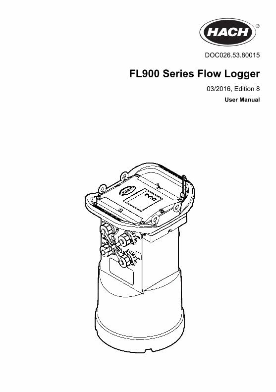
DOC026.53.80015 FL900 Series Flow Logger 03/2016, Edition 8 User Manual
Transcript of User Manual - Hach Flow the mobile SMS option ... Alarms Maximum of 16 channel alarms with...
DOC026.53.80015
FL900 Series Flow Logger03/2016, Edition 8
User Manual

Table of ContentsSpecifications .............................................................................................................. 3
General information .................................................................................................. 4Safety information........................................................................................................ 4
Use of hazard information.................................................................................... 4Precautionary labels ............................................................................................. 5Confined space precautions................................................................................. 5
Certification.................................................................................................................. 5Wireless modem certification....................................................................................... 6Cellular devices........................................................................................................... 6Product overview......................................................................................................... 8Product components ................................................................................................... 9
Apply power to the Logger ................................................................................. 10Install the batteries.....................................................................................................10Attach an external power supply (optional) ................................................................12
System startup .......................................................................................................... 13Install FSDATA Desktop on a computer .................................................................... 13Attach the logger to the computer ..............................................................................13Attach a sensor or external devices to the logger ......................................................13Attach an external module ......................................................................................... 14Attach a sampler ........................................................................................................ 14User interface ........................................................................................................... 15
Program a unit equipped with a modem ........................................................ 15Set up the wireless account ....................................................................................... 15
Install a SIM card (GPRS only) ........................................................................... 17Set up a GPRS modem-based account ............................................................. 18Attach an antenna (wireless option) ................................................................... 18Add the logger to the FSDATA Server ............................................................... 19Configure the logger for remote communication................................................ 20Verify the telemetry (wireless option) ................................................................. 20Verify the telemetry with FSDATA Desktop........................................................ 21Troubleshooting telemetry .................................................................................. 21Use the mobile SMS option................................................................................ 21
Modbus communication ....................................................................................... 21
Basic setup ................................................................................................................. 22Make a basic logger program.................................................................................... 22Calibrate the sensor with the Cal Wizard...................................................................23
Site installation ........................................................................................................ 23Hang from a cable ..................................................................................................... 23Install on a wall bracket ............................................................................................. 24
Maintenance .............................................................................................................. 24Clean the instrument ..................................................................................................24Replace the batteries ................................................................................................. 25Replace the desiccant ............................................................................................... 25
1

Troubleshooting ...................................................................................................... 25Communication failure ............................................................................................... 25
Replacement parts and accessories ............................................................... 26
Table of Contents
2
SpecificationsSpecifications are subject to change without notice.
Specification Details
Dimensions (W x D x H) 25.4 x 22 x 40 cm (10.0 x 8.7 x 16.0 in.)
Enclosure PC/ABS structural foam
Environmental rating NEMA 6P/IP68 (24 hours at 1.8 m (6 ft) submersion)
Weight (model FL900) 4.5 kg (10 lb) with no batteries, 6.3 kg (14 lb) with 2 batteries and 8.2 kg (18 lb)with 4 batteries
Operating temperature –18 to 60 ºC (0 to 140 ºF) at 95% RH
Storage temperature –40 to 60 ºC (–40 to 140 ºF)
Power requirements 8 to 18 VDC from batteries or external power source, 2.5 W max
Battery life Varies with sensor type, logging intervals, telemetry and environment.For a 15 minute logging interval, with no modem, four 6 V lantern batteries atroom temperature:
• Flo-tote 3 sensor 306 days• Area Velocity sensor with AV9000 Analyzer 296 days• Flo-Dar sensor 185 days• Ultrasonic sensor 456 days
Note: For longer deployments use with Long Life Battery, PN 8542900.
Installation category I
Protection class III
Pollution degree 1
Sensor ports 1, 2 or 4 ports
Connectors Stainless steel connectors
Datalog channels 16 maximum
Alarms Maximum of 16 channel alarms with high/high, high, low, low/low options.System alarms include low battery, low RTC battery, low slate memory, slatememory full, sensor time out, sensor ID.
Alarm actions Start the sampler, change the log interval, change the call interval, send an e-mail or a text message (SMS) from logger or server.Note: SMS rates may apply. Not all alarm types may be available with all cellular carriers andservice plans.
Logging intervals 1, 2, 3, 4, 5, 6, 10, 12, 15, 20, 30 or 60 minutes
Primary and secondary intervals for dynamic logging
Data storage Event log: 1000 events maximum in non-volatile flash memory
Sample history: 2000 sample events maximum in non-volatile flash memory
Datalog: 325,000 data points; 1128 days for 3 channels at 15-minute logintervals
PC communication USB
RS232 (Baud rates: 9600, 19200, 38400, 57600, 115200)
Remote communication(optional)
Wireless Modem: CDMA 2000, 1xRTT (US Only); 2G, 3G GPRS (US andCanada)
English 3
Specification Details
Protocols Modbus RTU (RS232)
Mobile-Terminated SMS
Mobile-Originated SMS
Timebase accuracy ±0.002%, synchronized every 24 hours with server software and modem
Supported sensors Flo-Dar, Flo-Dar with SVS, Flo-Tote, Rain Gauge, Ultrasonic, Submerged AreaVelocity1, Sigma 9501
Sampler interface Compatible with Sigma 900 Standard, Sigma 900 Max and Hach SD900 tosupport set point sampling, flow-pacing and sample history logging
Certifications Logger: CE
Optional AC power supply: UL/CSA standards (cETLus)/CE
Modems: FCC, IC, others may be available—contact the manufacturer for moreinformation.
Warranty 1 year
General informationIn no event will the manufacturer be liable for direct, indirect, special, incidental or consequentialdamages resulting from any defect or omission in this manual. The manufacturer reserves the right tomake changes in this manual and the products it describes at any time, without notice or obligation.Revised editions are found on the manufacturer’s website.
Safety informationNOT I CE
The manufacturer is not responsible for any damages due to misapplication or misuse of this product including,without limitation, direct, incidental and consequential damages, and disclaims such damages to the full extentpermitted under applicable law. The user is solely responsible to identify critical application risks and installappropriate mechanisms to protect processes during a possible equipment malfunction.
Please read this entire manual before unpacking, setting up or operating this equipment. Payattention to all danger and caution statements. Failure to do so could result in serious injury to theoperator or damage to the equipment.Make sure that the protection provided by this equipment is not impaired. Do not use or install thisequipment in any manner other than that specified in this manual.
Use of hazard information
D A N G E R Indicates a potentially or imminently hazardous situation which, if not avoided, will result in death or serious injury.
W A R N I N G Indicates a potentially or imminently hazardous situation which, if not avoided, could result in death or seriousinjury.
C A U T I O N Indicates a potentially hazardous situation that may result in minor or moderate injury.
NOT I CE Indicates a situation which, if not avoided, may cause damage to the instrument. Information that requires specialemphasis.
1 This device attaches through an external module.
4 English

Precautionary labelsRead all labels and tags attached to the instrument. Personal injury or damage to the instrumentcould occur if not observed. A symbol on the instrument is referenced in the manual with aprecautionary statement.
This is the safety alert symbol. Obey all safety messages that follow this symbol to avoid potentialinjury. If on the instrument, refer to the instruction manual for operation or safety information.
This symbol indicates that a risk of electrical shock and/or electrocution exists.
This symbol indicates the presence of devices sensitive to Electro-static Discharge (ESD) andindicates that care must be taken to prevent damage with the equipment.
This symbol indicates radio waves.
Electrical equipment marked with this symbol may not be disposed of in European domestic or publicdisposal systems. Return old or end-of-life equipment to the manufacturer for disposal at no charge tothe user.
Confined space precautions
D A N G E R Explosion hazard. Training in pre-entry testing, ventilation, entry procedures, evacuation/rescueprocedures and safety work practices is necessary before entering confined spaces.
The information that follows is supplied to help users understand the dangers and risks that areassociated with entry into confined spaces.On April 15, 1993, OSHA's final ruling on CFR 1910.146, Permit Required Confined Spaces, becamelaw. This standard directly affects more than 250,000 industrial sites in the United States and wascreated to protect the health and safety of workers in confined spaces.Definition of a confined space:A confined space is any location or enclosure that has (or has the immediate potential for) one ormore of the following conditions:
• An atmosphere with an oxygen concentration that is less than 19.5% or more than 23.5% and/or ahydrogen sulfide (H2S) concentration that is more than 10 ppm.
• An atmosphere that can be flammable or explosive due to gases, vapors, mists, dusts or fibers.• Toxic materials which upon contact or inhalation can cause injury, impairment of health or death.
Confined spaces are not designed for human occupancy. Confined spaces have a restricted entryand contain known or potential hazards. Examples of confined spaces include manholes, stacks,pipes, vats, switch vaults and other similar locations.Standard safety procedures must always be obeyed before entry into confined spaces and/orlocations where hazardous gases, vapors, mists, dusts or fibers can be present. Before entry into aconfined space, find and read all procedures that are related to confined space entry.
CertificationCanadian Radio Interference-Causing Equipment Regulation, IECS-003, Class A:
English 5

Supporting test records reside with the manufacturer.This Class A digital apparatus meets all requirements of the Canadian Interference-CausingEquipment Regulations: CAN ICES-3(A)/NMB-3(A).Cet appareil numérique de classe A répond à toutes les exigences de la réglementation canadiennesur les équipements provoquant des interférences.FCC Part 15, Class "A" LimitsSupporting test records reside with the manufacturer. The device complies with Part 15 of the FCCRules. Operation is subject to the following conditions:
1. The equipment may not cause harmful interference.2. The equipment must accept any interference received, including interference that may cause
undesired operation.
Changes or modifications to this equipment not expressly approved by the party responsible forcompliance could void the user's authority to operate the equipment. This equipment has been testedand found to comply with the limits for a Class A digital device, pursuant to Part 15 of the FCC rules.These limits are designed to provide reasonable protection against harmful interference when theequipment is operated in a commercial environment. This equipment generates, uses and canradiate radio frequency energy and, if not installed and used in accordance with the instructionmanual, may cause harmful interference to radio communications. Operation of this equipment in aresidential area is likely to cause harmful interference, in which case the user will be required tocorrect the interference at their expense. The following techniques can be used to reduceinterference problems:
1. Disconnect the equipment from its power source to verify that it is or is not the source of theinterference.
2. If the equipment is connected to the same outlet as the device experiencing interference, connectthe equipment to a different outlet.
3. Move the equipment away from the device receiving the interference.4. Reposition the receiving antenna for the device receiving the interference.5. Try combinations of the above.
Wireless modem certificationThe device complies with Part 15 of the FCC Rules and Industry Canada license-exempt RSSstandard(s). Operation is subject to the following conditions:
1. The equipment may not cause harmful interference.2. The equipment must accept any interference received, including interference that may cause
undesired operation.
Changes or modifications to this wireless communication equipment not expressly approved by theparty responsible for compliance could void the user's authority to operate the equipment. Anychange to the equipment will void the Industry Canada certification and FCC grant. Changes andmodifications include any modifications to the wireless modems and associated antennas, includingantenna cables. Follow the manufacturer recommendations for product installation, configuration andwireless operation.
Cellular devicesNOT I CE
Network and access point security is the responsibility of the customer that uses the wireless instrument. Themanufacturer will not be liable for any indirect, special, incidental or consequential damages caused by a breachin network security.
6 English
W A R N I N G Pacemaker precautions. If electromagnetic interference (EMI) occurs, it can either:
• Stop the stimulating pulses from the pacemaker that control the rhythm of the heart.• Cause the pacemaker to supply the pulses irregularly.• Cause the pacemaker to ignore the rhythm of the heart and supply pulses at a set interval.
Current research shows that cellular devices are not a significant health problem for most pacemakerwearers. However, persons with pacemakers should use precautions to make sure that their devicedoes not cause a problem. Keep the device a minimum of 20 cm (7.9 in.) from the user.
C A U T I O N Electromagnetic radiation hazard. Make sure that the antenna is kept at a minimum distance of 20 cm(7.9 in.) from all personnel in normal use. The antenna cannot be co-located or operated in conjunctionwith any other antenna or transmitters.
C A U T I O N Electromagnetic radiation hazard. In portable applications, do not use the modem within 20 cm (7.9 in.)of the user.
Regulatory RF device approvalsModem MTSMC-EV3-IP-N3 (Equipment Class: PCS Licensed Transmitter, Dual-Band CDMA/GPSmodule):
• FCC: Approved as a Modular Device with a TCB Grant of Authorization. FCC ID: RI7DE910-DUAL• IC: Approved as a Modular Device with Certificat D'Acceptabilite' Technique C-REL ID: 5131A-
DE910Dual
Modem MTSMC-H5-IP (PCS Licensed Transmitter, WWAN module):
• FCC: Approved as a Modular Device with a TCB Grant of Authorization. FCC ID: RI7HE910 • IC: Approved as a Modular Device with Certificat D'Acceptabilite' Technique C-REL ID: 5131A-
HE910
Table 1 Power for Modem CDMA
FCC rule parts Frequency range (MHz) Output (watts)
22H 824.7 to 848.31 0.30
24E 1851.25 to 1908.75 0.274
Cellular Modem MTSMC-EV3-IP-N3 (CDMA)—Important FCC Grant Conditions:The power shown in Table 1 is RF conducted power. The maximum antenna gain is 5.12 dBi for part22H and 6.12 dBi for part 24E. The maximum antenna gain includes the cable loss for compliancewith radiated power limits, RF exposure requirements and the categorical exclusion requirements of2.1091. Install the antenna(s) for this transmitter so there is a minimum distance of 20 cm (7.9 in.)from all persons. Install the antenna(s) for this transmitter so that the antenna does not transmit atthe same time as other antennas or transmitters. Only use this device for OEM integration into hostproducts. Consumer or end-user installation is not permitted. End-users and OEM integrators mustbe supplied with the information that is necessary to satisfy RF exposure compliance.
Table 2 Power for Modem GPRS
FCC rule parts Frequency range (MHz) Output (watts) Emission designator
22H 824.2 to 824.2 1.995 300KGXW
22H 824.2 to 848.8 0.997 300KG7W
22H 826.4 to 846.4 0.446 4M20F9W
English 7
Table 2 Power for Modem GPRS (continued)
FCC rule parts Frequency range (MHz) Output (watts) Emission designator
27 1712.4 to 1752.6 0.226 4M20F9W
24E 1850.2 to 1909.8 0.993 300KGXW
24E 1850.2 to 1909.8 0.380 300KG7W
24E 1852.4 to 1907.6 0.243 4M20F9W
Cellular Modem MTSMC-H5-IP (GPRS):—Important FCC Grant Conditions:The power shown in Table 2 is RF conducted power. The maximum antenna gain is 5.22 dBi for part22H, 3.31 dBi for part 24E and 6.45 dBi for part 27. The maximum antenna gain includes cable lossfor compliance with radiated power limits, RF exposure requirements and the categorical exclusionrequirements of 2.1091. Install the antenna(s) for this transmitter so there is minimum distance of20 cm (7.9 in.) from all persons. Install the antenna(s) for this transmitter so that the antenna doesnot transmit at the same time as other antennas or transmitters that are not in the description of thisFCC ID (identifier), unless in accordance with FCC multi-transmitter product procedures. The finalproduct that operates with this transmitter must include operating instructions and antennainstallation instructions for end users and installers to satisfy RF exposure compliance requirements.Compliance of this device in all final product configurations is the responsibility of the grantee. Thesubmission of a Class II permissive change application that includes the data applicable to RFexposure, spurious emissions, ERP/EIRP and host/module authentication or new application may benecessary for installation of this device into final products. This device contains GSM functions thatare not operational in the U.S. This filing is only applicable for U.S. operations.
Product overviewThe FL900 series flow loggers are used in open-channel flow monitoring studies such as inflow &infiltration (I&I), combined sewer overflow (CSO), capacity and planning and storm water runoffmonitoring.Data is collected from attached sensors and logged for future retrieval. The sensors can be added orchanged in the field. Depending on the model, up to four sensors can be connected. The data can beretrieved directly through a USB or RS232 cable or remotely through a wireless network withFSDATA Desktop and FSDATA server software. The FL900 Series loggers can also connect to anexternal power source, rain gauge or be used to pace a Sigma sampler.The wireless option and the number of available connectors varies with the model of the logger.Refer to Figure 1 and Figure 2.
8 English
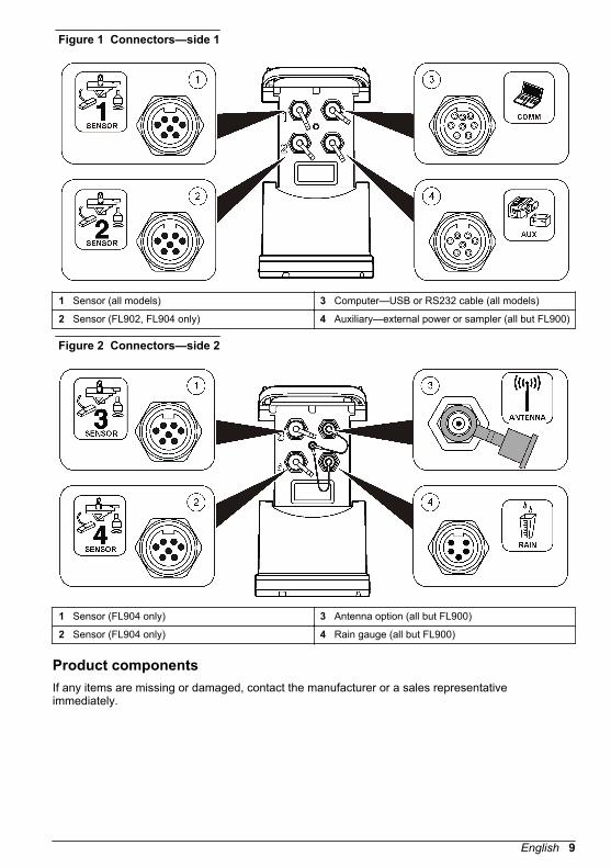
Figure 1 Connectors—side 1
1 Sensor (all models) 3 Computer—USB or RS232 cable (all models)
2 Sensor (FL902, FL904 only) 4 Auxiliary—external power or sampler (all but FL900)
Figure 2 Connectors—side 2
1 Sensor (FL904 only) 3 Antenna option (all but FL900)
2 Sensor (FL904 only) 4 Rain gauge (all but FL900)
Product componentsIf any items are missing or damaged, contact the manufacturer or a sales representativeimmediately.
English 9
Apply power to the Logger
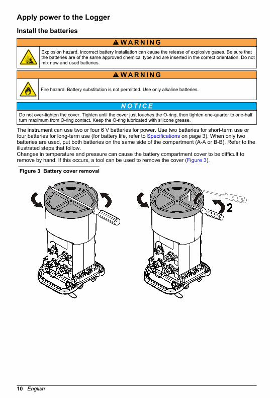
Install the batteriesW A R N I N G
Explosion hazard. Incorrect battery installation can cause the release of explosive gases. Be sure thatthe batteries are of the same approved chemical type and are inserted in the correct orientation. Do notmix new and used batteries.
W A R N I N G
Fire hazard. Battery substitution is not permitted. Use only alkaline batteries.
NOT I CE Do not over-tighten the cover. Tighten until the cover just touches the O-ring, then tighten one-quarter to one-halfturn maximum from O-ring contact. Keep the O-ring lubricated with silicone grease.
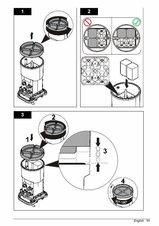
The instrument can use two or four 6 V batteries for power. Use two batteries for short-term use orfour batteries for long-term use (for battery life, refer to Specifications on page 3). When only twobatteries are used, put both batteries on the same side of the compartment (A-A or B-B). Refer to theillustrated steps that follow.Changes in temperature and pressure can cause the battery compartment cover to be difficult toremove by hand. If this occurs, a tool can be used to remove the cover (Figure 3).
Figure 3 Battery cover removal
10 English
1 2
3
English 11
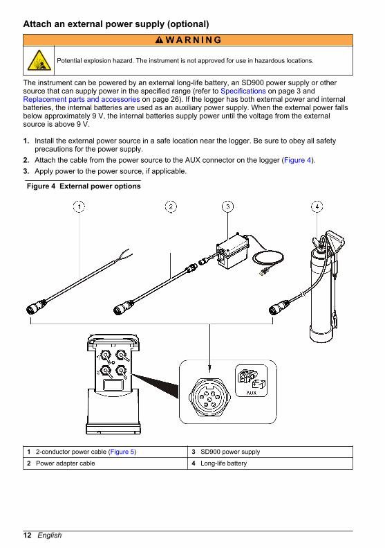
Attach an external power supply (optional)W A R N I N G
Potential explosion hazard. The instrument is not approved for use in hazardous locations.
The instrument can be powered by an external long-life battery, an SD900 power supply or othersource that can supply power in the specified range (refer to Specifications on page 3 and Replacement parts and accessories on page 26). If the logger has both external power and internalbatteries, the internal batteries are used as an auxiliary power supply. When the external power fallsbelow approximately 9 V, the internal batteries supply power until the voltage from the externalsource is above 9 V.
1. Install the external power source in a safe location near the logger. Be sure to obey all safetyprecautions for the power supply.
2. Attach the cable from the power source to the AUX connector on the logger (Figure 4).3. Apply power to the power source, if applicable.
Figure 4 External power options
1 2-conductor power cable (Figure 5) 3 SD900 power supply
2 Power adapter cable 4 Long-life battery
12 English
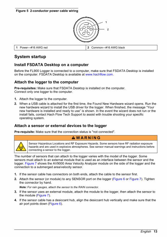
Figure 5 2-conductor power cable wiring
1 Power—#16 AWG red 2 Common—#16 AWG black
System startup
Install FSDATA Desktop on a computerBefore the FL900 Logger is connected to a computer, make sure that FSDATA Desktop is installedon the computer. FSDATA Desktop is available at www.hachflow.com.
Attach the logger to the computerPre-requisites: Make sure that FSDATA Desktop is installed on the computer.Connect only one logger to the computer.
1. Attach the logger to the computer.2. When a USB cable is attached for the first time, the Found New Hardware wizard opens. Run the
new hardware wizard to install the USB driver for the logger. When finished, the message “Yournew hardware is installed and ready to use” is shown. In the event the wizard does not run or theinstall fails, contact Hach Flow Tech Support to assist with trouble shooting your specificoperating system.
Attach a sensor or external devices to the loggerPre-requisite: Make sure that the connection status is "not connected".
W A R N I N G Sensor Hazardous Locations and RF Exposure Hazards. Some sensors have RF radiation exposurehazards and are used in explosive atmospheres. See sensor manual warnings and instructions beforeconnecting a sensor to the logger.
The number of sensors that can attach to the logger varies with the model of the logger. Somesensors must attach to an external module that is used as an interface between the sensor and thelogger. Figure 7 shows the AV9000 Area Velocity Analyzer module on the side of the logger and theconnection to a submerged area/velocity sensor.
1. If the sensor cable has connectors on both ends, attach the cable to the sensor first.2. Attach the sensor (or module) to any SENSOR port on the logger (Figure 6 or Figure 7). Tighten
the connector by hand.Note: For rain gauges, attach the sensor to the RAIN connector.
3. If the sensor uses an external module, attach the module to the logger, then attach the sensor tothe module (Figure 7).
4. If the sensor cable has a desiccant hub, align the desiccant hub vertically and make sure that theair port points down (Figure 6).
English 13
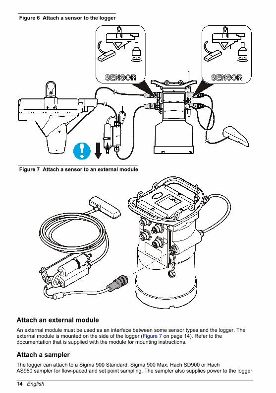
Figure 6 Attach a sensor to the logger
Figure 7 Attach a sensor to an external module
Attach an external moduleAn external module must be used as an interface between some sensor types and the logger. Theexternal module is mounted on the side of the logger (Figure 7 on page 14). Refer to thedocumentation that is supplied with the module for mounting instructions.
Attach a samplerThe logger can attach to a Sigma 900 Standard, Sigma 900 Max, Hach SD900 or HachAS950 sampler for flow-paced and set point sampling. The sampler also supplies power to the logger
14 English

and to attached sensors. Connect the auxiliary cable to the AUX port on the logger and to theauxiliary port on the sampler. To make a sampler program, refer to the documentation that issupplied with the sampler.
User interfaceThe indicators on the user interface show the status of the instrument and the modem. Refer to Figure 8 and Table 3.
Figure 8 User interface
1 Instrument without modem 2 Instrument with modem
Table 3 LED status indicators
Indicator LED color Description
Green Flashes every 3 seconds during normal operation. Flashes every15 seconds during sleep mode.
Red Flashes when an attached sensor does not agree with the loggerprogram, an expected sensor is not found or the sensor operation hasfailed.
Green Stays green during a call to the server.
Red Flashes red if the call to the server failed.
Program a unit equipped with a modemC A U T I O N
Electromagnetic radiation hazard. Make sure that the antenna is kept at a minimum distance of 20 cm(7.9 in.) from all personnel in normal use. The antenna cannot be co-located or operated in conjunctionwith any other antenna or transmitters.
For units without a modem, refer to Basic setup on page 22. For units that come with activatedmodem accounts2, go to Add the logger to the FSDATA Server on page 19.
Set up the wireless accountNote: Adequate cellular coverage from the selected carrier must be verified for each site before a logger with acellular modem is purchased.
2 The units that come with activated modem accounts have patent numbers with GX, .GR, .VX,or .VR as the last digits.
English 15
NOT I CE Network and access point security is the sole responsibility of the customer using the wireless instrument. Themanufacturer will not be liable for any indirect, special, incidental or consequential damages caused by a breachin network security.
When the logger has a modem, data can be sent from the logger to the internet for remote access.The user must first open an account with a mobile (wireless) provider. The instrument is thenregistered to the data-hosting server (FSDATA), and the applicable communication settings areprogrammed into the logger with FSDATA Desktop. If the modem was activated at the factory, go to Add the logger to the FSDATA Server on page 19.Pre-requisite: Make sure that the logger, logger test certificate and antenna are nearby.Mobile (wireless) providers use CDMA or GPRS technology for data transmission.Note: For optimal troubleshooting, install the FSDATA Desktop driver, add the logger to the FSDATA server, andverify telemetry before visiting the deployment site.
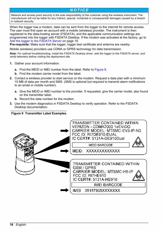
1. Gather your account information.
a. Find the MEID or IMEI number from the label. Refer to Figure 9.b. Find the modem carrier model from the label.
2. Contact a wireless provider to start service on the modem. Request a data plan with a minimum10 MB of data per month and SMS. (SMS is optional but required to transmit alarm notificationsto an email or mobile number).
a. Give the MEID or IMEI number to the provider. If requested, give the carrier model, also foundon the transmitter label.
b. Record the data number for the modem.3. Use the modem diagnostics in FSDATA Desktop to verify operation. Refer to the FSDATA
Desktop documentation.
Figure 9 Transmitter Label Examples
16 English
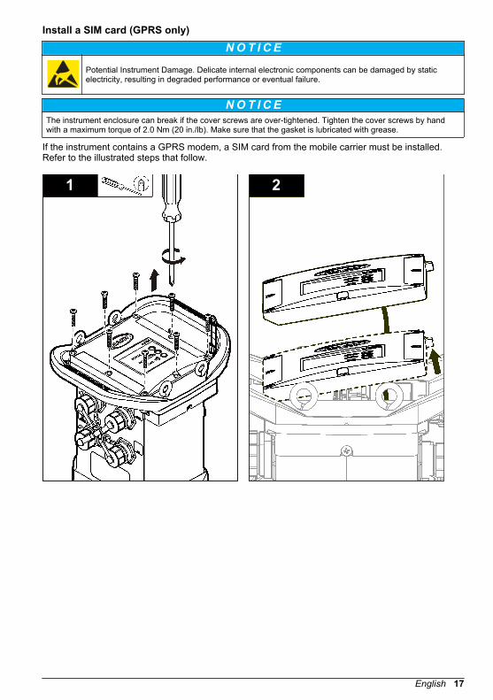
Install a SIM card (GPRS only)
NOT I CE Potential Instrument Damage. Delicate internal electronic components can be damaged by staticelectricity, resulting in degraded performance or eventual failure.
NOT I CE The instrument enclosure can break if the cover screws are over-tightened. Tighten the cover screws by handwith a maximum torque of 2.0 Nm (20 in./lb). Make sure that the gasket is lubricated with grease.
If the instrument contains a GPRS modem, a SIM card from the mobile carrier must be installed.Refer to the illustrated steps that follow.
1 2
English 17
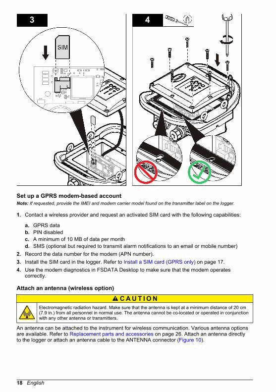
3 4
Set up a GPRS modem-based accountNote: If requested, provide the IMEI and modem carrier model found on the transmitter label on the logger.
1. Contact a wireless provider and request an activated SIM card with the following capabilities:
a. GPRS datab. PIN disabledc. A minimum of 10 MB of data per monthd. SMS (optional but required to transmit alarm notifications to an email or mobile number)
2. Record the data number for the modem (APN number).3. Install the SIM card in the logger. Refer to Install a SIM card (GPRS only) on page 17.4. Use the modem diagnostics in FSDATA Desktop to make sure that the modem operates
correctly.
Attach an antenna (wireless option)
C A U T I O N Electromagnetic radiation hazard. Make sure that the antenna is kept at a minimum distance of 20 cm(7.9 in.) from all personnel in normal use. The antenna cannot be co-located or operated in conjunctionwith any other antenna or transmitters.
An antenna can be attached to the instrument for wireless communication. Various antenna optionsare available. Refer to Replacement parts and accessories on page 26. Attach an antenna directlyto the logger or attach an antenna cable to the ANTENNA connector (Figure 10).
18 English
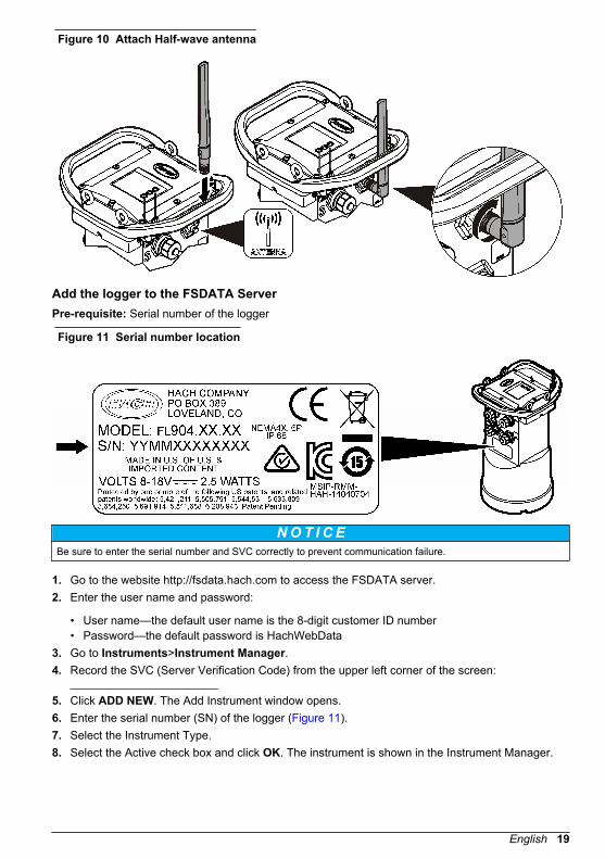
Figure 10 Attach Half-wave antenna
Add the logger to the FSDATA ServerPre-requisite: Serial number of the logger
Figure 11 Serial number location
NOT I CE Be sure to enter the serial number and SVC correctly to prevent communication failure.
1. Go to the website http://fsdata.hach.com to access the FSDATA server.2. Enter the user name and password:
• User name—the default user name is the 8-digit customer ID number• Password—the default password is HachWebData
3. Go to Instruments>Instrument Manager.4. Record the SVC (Server Verification Code) from the upper left corner of the screen:
_______________________5. Click ADD NEW. The Add Instrument window opens.6. Enter the serial number (SN) of the logger (Figure 11).7. Select the Instrument Type.8. Select the Active check box and click OK. The instrument is shown in the Instrument Manager.
English 19
Configure the logger for remote communicationPre-requisites: The logger must be attached to the computer. An account with a network providermust be set up, and the server must be configured.The settings for remote communication must be entered into FSDATA Desktop and then written tothe logger.
1. Start a communication session with the logger:
a. Open FSDATA Desktop.b. Click CONNECT. The Connect to Instrument window opens.c. Click the FL900 button.d. Select the port on the computer where the logger is attached (serial or USB), then click
Connect.Note: If the sensor mismatch message is shown, select "Create new program based on sensorsconnected."
e. Make sure that the connection status shows "connected".2. Go to the Communications tab. Enter the information for the desired site. Select Time Zone.3. Complete the Remote Settings information:
Option Description
CDMA No additional configuration is necessary.
GPRS Select the network provider and the modem frequency. (For US locations,850/1900 MHz. For outside the US, contact the provider for the modemfrequency.) Enter the user name and password, if applicable.
Primary Call Interval The frequency that the logger calls the server, not to exceed the logging interval.
Secondary call interval The frequency that the logger calls the server during an alarm condition.
Server Verification Code The account number that allows a connection to the server.
4. Click WRITE TO LOGGER to save the settings. A message window is shown:
Option Description
Warning: all datawill be lost.Continue?
All data that is stored in the logger is erased when a program is written to the logger.To save the data, select No and download the data to a safe location. Select Yes toerase all data and update the logger with the new program.
Set Logger Clock Synchronize to Computer Clock—the logger uses the date and time settings of thecomputer. Set Logger Clock—the logger uses the date and time settings that are setby the user. If the unit has a modem, the logger automatically uses the date and timesettings of the server.
A pop up screen will show success or failure.5. Go to the General Settings tab. Select data log channels and logging intervals.6. Click Write to Logger to save.
Verify the telemetry (wireless option)The user can manually send a call to the server to make sure that the network communication isgood.
1. Temporarily attach the antenna to the logger to test the antenna and the cell coverage at the sitelocation before installation.
2. Touch the magnet to the call initiation target (Figure 12). The modem LED indicator changes togreen.
3. Look at the modem LED indicator during the call (45 to 90 seconds) and wait for a change:
• LED goes off—the call to the server was successful.
20 English

• LED flashes red—the call to the server failed.
Note: If the connection failed, refer to Troubleshooting on page 25 for more information.
Figure 12 Call the server
1 Call initiation target 2 Magnet
Verify the telemetry with FSDATA Desktop
1. In FSDATA Desktop, select Communications>Modem Diagnostics.2. Make sure the registration status is either home or roaming. If blank or "identify" is shown, the
connection has failed.3. Adjust the antenna for optimum signal strength and quality.4. Click Call Server to make a call to the network.
A pop up screen will indicate success or failure.
Troubleshooting telemetry
• Make sure the SVC is correct.• Make sure the serial number is registered and active on the host server.• Make sure the modem is enabled and the Hach IP address has been correctly entered.• If the problem persists, contact technical support.
Use the mobile SMS optionConfigure the FL900 modem to send or receive SMS messages (optional). Refer to FSDATADesktop documentation for configuration information.
Modbus communicationThe Modbus protocol can be used for communication with this instrument. Attach an externalnetwork device, such as a PLC, to the RS232 interface on the instrument to read data as it is logged.Contact technical support for more information on Modbus communications.Note: Historical data cannot be read with Modbus communication.
English 21

Basic setupThe information in this manual can be used to make a simple program for the logger and to calibratethe sensors. Refer to the FSDATA Desktop documentation for advanced options. Complete thesections in the order that they are shown.
Make a basic logger programA basic program must be written to the logger to specify the channels to be logged.
1. Open a communication session with the logger:
a. Open FSDATA Desktop.b. Click CONNECT. The Connect to Instrument window opens.c. Click the FL900 button.d. Select the port on the computer where the logger is attached (serial or USB), then click
CONNECT.Note: If the sensor mismatch message is shown, select "Create new program based on sensorsconnected."
e. Make sure that the connection status shows "connected".2. Complete the information in the General Settings tab.
Option Description
Site Identification Enter a unique name for the site.
3. Select the channels to be logged in the Select channels to log section:
a. Expand the tree for the Logger channel group. The Power Supply channel is always shown inthis group. Logging the power supply will provide values for the battery level. An alarm couldbe set at a specific level to alert the account manager of a low level, thus prompting a fieldvisit to change the batteries and prevent lost data. If the logger contains a port for a raingauge, the Rain channel is also shown. To include a Logger channel in the datalog, select thecheck box next to the channel name.
b. Expand the tree for each Port[1](Sensor Name) channel group to view the available channelsfor the sensor. If the check box next to Logger or Port[1] is selected, all of the channels in thegroup are automatically selected.
c. To include a Sensor channel in the datalog, select the check box next to the channel name.The log channel count increases each time a channel is selected.Note: For loggers with multiple sensor ports, the port number is added to the channel name. For example,Velocity 3 is the velocity channel name for sensor port 3.
4. To set the logging interval for a channel group:
a. Click on the channel group name, for example Port1 (Flo-Dar). The logging intervals areshown.
22 English
b. Select the interval from the drop-down list. The primary logging interval is used for normaloperation. The secondary logging interval is used during alarm conditions.Note: The logging interval cannot be set for an individual sensor channel.
5. Click WRITE TO LOGGER to save the settings. A message window is shown:
Option Description
Warning: all datawill be lost.Continue?
All data that is stored in the logger is erased when a program is written to the logger.To save the data, select No and download the data to a safe location. Select Yes toerase all data and update the logger with the new program.
Set Logger Clock Synchronize to Computer Clock—the logger uses the date and time settings of thecomputer. Set Logger Clock—the logger uses the date and time settings that are setby the user. If the unit has a modem, the logger automatically uses the date timesettings of the server.
Calibrate the sensor with the Cal WizardPre-requisite: The logger must be connected to the computer and must be online for calibration.The sensor can be configured and calibrated with the calibration wizard.
1. Click the Sensors tab.2. Click on Sensor Port[1] (sensor name).3. Click on the CAL WIZARD button. The Calibration Wizard window opens.4. Select the options on each screen. When the Calibration Complete screen is shown, click
FINISH.5. Click WRITE TO LOGGER to save the settings. A message window is shown:
Option Description
Warning: all datawill be lost,Continue?
All data that is stored in the logger is erased when a program is written to the logger.To save the data, select No and download the data to a safe location. Select Yes toerase all data and update the logger with the new program.
Set Logger Clock Synchronize to Computer Clock—the logger uses the date and time settings of thecomputer. Set Logger Clock—the logger uses the date and time settings that are setby the user. If the unit has a modem, the logger automatically uses the date and timesettings of the server.
The installation is complete. The Status light should flash green if the programming was successful.
Site installationW A R N I N G
Multiple hazards. Only qualified personnel must conduct the tasks described in this section of thedocument.
Hang from a cableNOT I CE
Do not use the handles to hang the logger. The handles are not designed to hold the weight of the logger.
The logger can hang from a cable for installation in an area such as a manhole.
1. Connect a cable to the eye bolts on the top of the logger. Refer to Figure 13.2. Hang the cable from a strong support such as an optional spanner bar.
English 23
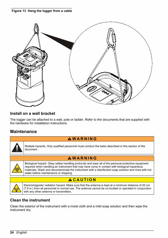
Figure 13 Hang the logger from a cable
Install on a wall bracketThe logger can be attached to a wall, pole or ladder. Refer to the documents that are supplied withthe hardware for installation instructions.
MaintenanceW A R N I N G
Multiple hazards. Only qualified personnel must conduct the tasks described in this section of thedocument.
W A R N I N G Biological hazard. Obey safety handling protocols and wear all of the personal protective equipmentrequired when handling an instrument that may have come in contact with biological hazardousmaterials. Wash and decontaminate the instrument with a disinfectant soap solution and rinse with hotwater before maintenance or shipping.
C A U T I O N Electromagnetic radiation hazard. Make sure that the antenna is kept at a minimum distance of 20 cm(7.9 in.) from all personnel in normal use. The antenna cannot be co-located or operated in conjunctionwith any other antenna or transmitters.
Clean the instrumentClean the exterior of the instrument with a moist cloth and a mild soap solution and then wipe theinstrument dry.
24 English

Replace the batteriesReplace the batteries with the same type and rating. Refer to Install the batteries on page 10 and Specifications on page 3.
Replace the desiccantThe desiccant is located in the battery compartment. To remove the battery cover, refer to Install thebatteries on page 10. The desiccant absorbs moisture from the air and prevents corrosion to theinstrument components. The desiccant beads change color when they become saturated. Replacethe desiccant when the beads change from a yellow to a green color (refer to Figure 14). As a bestpractice, replace the desiccant when the batteries are replaced.
Figure 14 Desiccant replacement
TroubleshootingIf problems occur in the system, try to find whether the problem is with the sensor, the logger or thecable connections.
• Examine all connections to the sensors. Make sure all connections are tight.• Remove and examine the sensor connectors for moisture. Clean and dry if necessary.• Examine the sensors for debris and remove the debris.• Examine the Event Log for problem events.
Communication failureIf a call was sent to the server but the connection failed, complete the following tasks:
• Disconnect and apply power to the instrument.• Adjust the antenna to increase the signal strength.• Log on to the server and make sure that the serial number was entered correctly and that the SVC
used for configuration was recorded correctly.• Make sure that the communication settings were entered correctly in the FL900 driver window.• Connect the logger to the computer and open a communications session. In the FL900 driver
window, click on the Diagnostics tab and then the Modem menu. The Registration Status shouldbe Home.
• If there is no resolution, call technical support.
English 25
Replacement parts and accessoriesNote: Product and Article numbers may vary for some selling regions. Contact the appropriate distributor or refer tothe company website for contact information.
Replacement parts
Description Item no.
Battery compartment cover 8524400
Battery compartment cover, O-ring 8533400
Desiccant cap assembly (battery compartment desiccant) 8754900
Desiccant tube assembly (battery compartment desiccant) 8535200
Desiccant, replacement beads, 680 g (1.5 lb) 8755500
Eyebolts, 1/4–20 x 2.5-in. stainless steel 8535500
Gasket, top cover 8533300
Enclosure screw, #10–14 x 1 in. 8753300
Logger handle 8524200
Lubricant, silicone, 0.25 oz 000298HY
Magnet assembly 8537800
Cap and lanyard for the Sensor, Comm or Aux connectors 8535000
Cap and lanyard for the rain gauge connector 9492500
Power
Description Item no.
Battery, 6 V lantern 11013M
Battery, long-life alkaline 8542900
Long-life alkaline battery pack top cap adapter and cable 8543000
Mounting hardware
Description Item no.
Wall-mount Bracket without ladder hanger 8542700
Wall-mount Bracket, adapter 8543800
Antennas
Description Item no.
Antenna, traffic-rated burial (824–896, 1850–1990 MHz) 8537600
Antenna, half-wave (824–894, 1850–1990 MHz)—US 5228400
Antenna, traffic-rated manhole lid (824–896, 1850–1990 MHz)—US 5255400
Antenna, mini-wing (824–960, 1710–2170 MHz)—US 6241804
26 English


*DOC026.53.80015*
HACH COMPANY World HeadquartersP.O. Box 389, Loveland, CO 80539-0389 U.S.A.Tel. (970) 669-3050(800) 227-4224 (U.S.A. only)Fax (970) 669-2932U.S.A.: [email protected]: [email protected]@hach.comwww.hachflow.com
© Hach Company/Hach Lange GmbH, 2013-2016.All rights reserved. Printed in U.S.A.