User Manual for CMUT Modeling with Agilent Advanced Design System...
14
User Manual for CMUT Modeling with Agilent Advanced Design System (ADS) Electrical and Electronics Engineering Department, Bilkent University, Ankara, Turkey (Hüseyin Kağan Oğuz e-mail: [email protected]. edu.tr, [email protected] ) Contents Introduction ....................................................................................................................................... 2 Advanced Design System (ADS) ...................................................................................................... 2 ADS 2011 Template Workspace .................................................................................................................. 2 Workspace > Library > Cell > View Hierarchy .......................................................................................... 3 Large Signal Model of a Single Circular CMUT Cell.................................................................................. 4 Small Signal Model of a Single Circular CMUT Cell .................................................................................. 4 Circuit Components and Equations ......................................................................................................... 5 Radiation Impedance of a Single CMUT Cell ........................................................................................... 5 Harmonic Balance (HB) Simulation of a Single CMUT Cell ........................................................... 6 Modeling CMUT Arrays ................................................................................................................... 7 Building User‐Compiled Analog Models (ZMATRIX) .................................................................................... 7 Defining Model Parameters .................................................................................................................... 8 Working with Symbols ............................................................................................................................. 8 Compiling the Model ............................................................................................................................. 10 Create CMUT Array Schematic (MACRO) .................................................................................................. 11 Frequency Domain (AC) Simulation .......................................................................................................... 12 Bibliography .................................................................................................................................... 14
Transcript of User Manual for CMUT Modeling with Agilent Advanced Design System...

User Manual for CMUT Modeling with Agilent Advanced Design System (ADS)
Electrical and Electronics Engineering Department, Bilkent University, Ankara, Turkey (Hüseyin Kağan Oğuz e-mail: [email protected]. edu.tr, [email protected])
Contents Introduction ....................................................................................................................................... 2
Advanced Design System (ADS) ...................................................................................................... 2
ADS 2011 Template Workspace .................................................................................................................. 2
Workspace > Library > Cell > View Hierarchy .......................................................................................... 3
Large Signal Model of a Single Circular CMUT Cell .................................................................................. 4
Small Signal Model of a Single Circular CMUT Cell .................................................................................. 4
Circuit Components and Equations ......................................................................................................... 5
Radiation Impedance of a Single CMUT Cell ........................................................................................... 5
Harmonic Balance (HB) Simulation of a Single CMUT Cell ........................................................... 6
Modeling CMUT Arrays ................................................................................................................... 7
Building User‐Compiled Analog Models (ZMATRIX) .................................................................................... 7
Defining Model Parameters .................................................................................................................... 8
Working with Symbols ............................................................................................................................. 8
Compiling the Model ............................................................................................................................. 10
Create CMUT Array Schematic (MACRO) .................................................................................................. 11
Frequency Domain (AC) Simulation .......................................................................................................... 12
Bibliography .................................................................................................................................... 14
Introduction Capacitive micromachined ultrasonic transducers (CMUTs) are usually composed of large arrays of closely packed cells. In this work, we use an equivalent circuit model to analyze CMUT arrays with multiple cells. We study the effects of mutual acoustic interactions through the immersion medium caused by the pressure field generated by each cell acting upon the others. To do this, all the cells in the array are coupled through a radiation impedance matrix at their acoustic terminals. An accurate approximation for the mutual radiation impedance is defined between two circular cells, which can be used in large arrays to reduce computational complexity. Hence, a performance analysis of CMUT arrays can be accurately done with a circuit simulator. By using the proposed model, one can very rapidly obtain the linear frequency and nonlinear transient responses of arrays with an arbitrary number of CMUT cells. The single CMUT model is able to predict the entire behavior of CMUT until the membrane touches the substrate. Many intrinsic properties of the CMUT cell, such as the collapse condition, collapse voltage, the voltage–displacement interrelation and the force equilibrium before and after collapse voltage in the presence of external static force, are obtained as a direct consequence of the model. The work described in this document is implemented by the CMUT Group in Bilkent University. The reader can find all the theoretical information needed to build such a model in (Koymen, et al.) and (Oguz, Atalar ve Koymen).
Advanced Design System (ADS) “Advanced Design System is the world’s leading electronic design automation software for RF, microwave, and high speed digital applications”. We decided to use ADS because of two main reasons:
i. CMUT is a nonlinear device and the Harmonic Balance (HB) simulator in ADS provides an accurate estimate of the steady-state response of nonlinear circuits very quickly.
ii. The employed circuit simulator must be capable of using frequency domain impedance data, which is needed for the radiation impedance matrix.
On the other hand, this circuit simulator can handle arrays with up to about ten thousand CMUT cells reasonably well. To analyze or design an array with much more cells, the model must be solved with a circuit simulator capable of handling very large circuits, which would also satisfy the items listed above (at least the second one).
ADS 2011 Template Workspace In this user manual, I shall demonstrate how to create and simulate CMUT arrays through the ADS workspace that is provided as a template together with this document. ADS uses the workspace, which is a folder/directory, to store and organize your design work. It is a replacement for the ADS Project used in ADS 2009 Update 1 and earlier versions. A workspace contains design data, simulation results, data display files, and other data files.
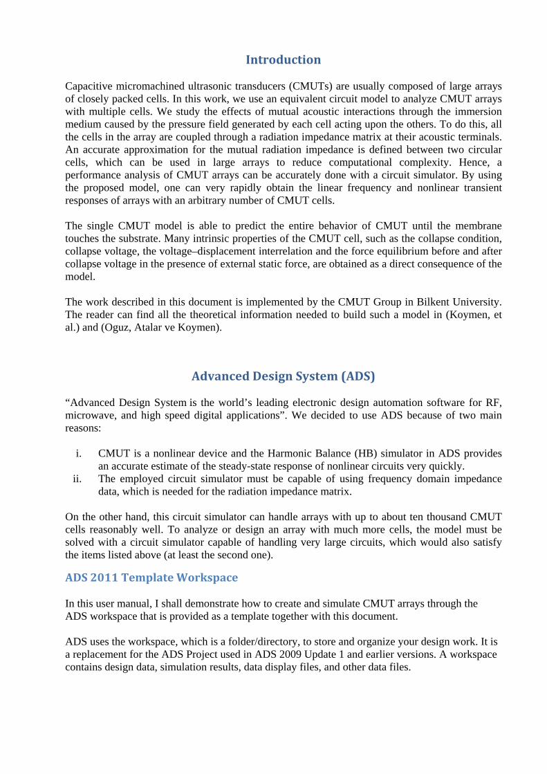
Our workspace contains the following main items:
Large Signal Model of a Single Circular CMUT Cell (cell name: CMUT) Small Signal Model of a Single Circular CMUT Cell (cell name: CMUT_SS) Circuit Components and Equations (cell name: Components_and_Equations) Radiation Impedance of a Single CMUT Cell (cell name: ZRrms)
Workspace > Library > Cell > View Hierarchy
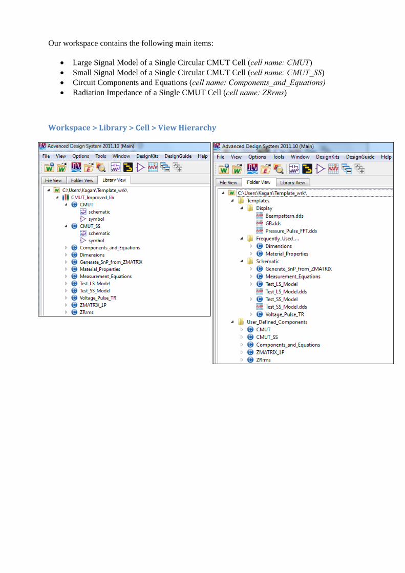
Large Signal Model of a Single Circular CMUT Cell The cell which is named as “CMUT” contains the large signal equivalent circuit of a single CMUT cell. As shown in the figure below, it has a schematic and a symbol (for using it as a subcircuit). It has two ports, which corresponds to the electrical and radiation interface terminals of the CMUT.
Small Signal Model of a Single Circular CMUT Cell The cell which is named as “CMUT_SS” contains the small signal equivalent circuit of a single CMUT cell.

Circuit Components and Equations The cell which is named as “Components_and_Equations” contains all the equations needed for the calculation of the electrical and mechanical components of the equivalent circuits. There are also the physical equations that describe the operation of circular CMUTs.
Radiation Impedance of a Single CMUT Cell The cell which is named as “ZRrms” contains the radiation impedance of clamped circular radiator, which is calculated with reference to rms velocity of the radiator.
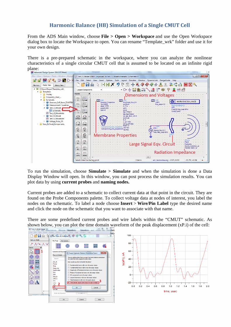
Harmonic Balance (HB) Simulation of a Single CMUT Cell From the ADS Main window, choose File > Open > Workspace and use the Open Workspace dialog box to locate the Workspace to open. You can rename “Template_wrk” folder and use it for your own design. There is a pre-prepared schematic in the workspace, where you can analyze the nonlinear characteristics of a single circular CMUT cell that is assumed to be located on an infinite rigid plane:
To run the simulation, choose Simulate > Simulate and when the simulation is done a Data Display Window will open. In this window, you can post process the simulation results. You can plot data by using current probes and naming nodes. Current probes are added to a schematic to collect current data at that point in the circuit. They are found on the Probe Components palette. To collect voltage data at nodes of interest, you label the nodes on the schematic. To label a node choose Insert > Wire/Pin Label type the desired name and click the node on the schematic that you want to associate with that name. There are some predefined current probes and wire labels within the “CMUT” schematic. As shown below, you can plot the time domain waveform of the peak displacement (xP.i) of the cell:

Modeling CMUT Arrays A CMUT array can be built by combining several of the equivalent circuits developed in (Koymen, et al.), through the appropriate radiation impedance matrix (Z matrix) (Oguz, Atalar ve Koymen). The rest of the document describes how to make this in a systematic way. Sequentially, we must do the following:
i. Define the Z matrix. See, Building User-Compiled Analog Models ii. Use the given macro to obtain the array schematic, where all the cells of the array elements
are connected (coupled) through the Z matrix.
Building User‐Compiled Analog Models (ZMATRIX) The following two paragraphs are taken from ADS Help. For more detailed information you may visit Home >Simulation > Model Creation > User-Defined Models in ADS 2011 Help document. User-defined element models are implemented in ANSI-C code. The user-written code is then compiled and linked with supplied object code to make a dynamically loaded shared library. While the equation and parametric circuit capabilities included in the circuit simulators can be used to effectively alter an element or network response through its parameters, the user-compiled model feature allows you access to state vector voltages that affect the model's response currents and charges. The analysis code for user-compiled models can be written to influence its response depending on its parameters, stimulus controls, analysis type, and pin voltages. The user-defined code can make use of many built-in element models. Creating a model consists of four main steps:
Defining the parameters whose values will be entered from the schematic. See, Defining Model Parameters
Defining the symbol and the number of pins. See, Working with Symbols Writing the C or C++ code itself Compiling. See, Compiling the Model

Defining Model Parameters The parameters listed below must be defined for every ZMATRIX components. They are briefly described here, but shall become clearer with some examples in subsequent sections. num_of_elems # elements in the array
radius membrane radius of the cells
spacing center‐tocenter spacing between the cells
Nrows_elem # row cells in the elements
Ncols_elem # column cells in the elements
xoffs X‐coordinate of the first cell in the element
yoffs Y‐coordinate of the first cell in the element
rotat rotation angle of the element
array_type configuration of the cells in the element
qc density and speed of sound in the medium
approx use approximation or not ?
SnP_param Create S or Z parameter file ? For Transient Sim.
freq_sweep start, stop and # freq. points for the SnP file
Working with Symbols Let us create a 2 by 2 array element. Then we should have a 4 port Z matrix. User Compiled Model (UCM) has symbol view only. Follow the steps below to generate a symbol for a new UCM.
i. From ADS main window, choose File>New> Symbol or click on the tool bar to open New Symbol dialog box.
ii. Specify the Cell name as ZMATRIX_4P. Note : You must name it as ZMATRIX_{#ports}P !
iii. Click OK to open the Symbol view window. iv. Define the symbol.
In this step, we do not need to create a new symbol at each time. Instead, we use the
symbols defined for the built-in SnP components, which take S-parameter data as a file. Therefore, type S4P in the Symbol name and the symbol of this component will appear. However, this component has 5 ports, where the last one is defined as Ref. It is

important to delete this port, since we won’t need it and it will cause problems later on when using the macro.
Note that SnP (n>99) component is not a built-in component. In this case, you must create it before typing its name. From the Main window select Tools > Command Line and type:
generate_snp_component( num_of_cells, "CMUT_Improved_lib")
v. Define model parameters. User Compiled Model parameters can be defined from File > Design Parameters in the
model symbol view window.
As shown in the figure below, you must set the Component Instance Name as ZMATRIX, since it will be recalled in the macro with this name.
As shown in the figure below, Cell Parameters can be copied from the ZMATRIX_1P
user-defined component. This component takes place in the template workspace for this purpose.

vi. Click Save AEL file followed by OK to save the symbol.
Compiling the Model From the symbol view window, choose Tools > User Compiled Model > Open User Compiled Model to open Model Development Kit dialog box. The following figure displays the Model Development Kit:
Follow the steps below:
i. Create new code template ii. Edit model code
A text editor will pop-up,where you will see a template C-code. Browse the file “ZMATRIX_MAIN.c” located at ...\Template_wrk\My_Macros and replace all the template C-code with the one given in this file by copy/paste. Save and exit. iii. Choose the C-compiler iv. Compile
Important Note: To be able to compile the model, you must have Microsoft Visual Studio 2008 or later installed and run ADS as administrator.
Create CMUT Array Schematic (MACRO)
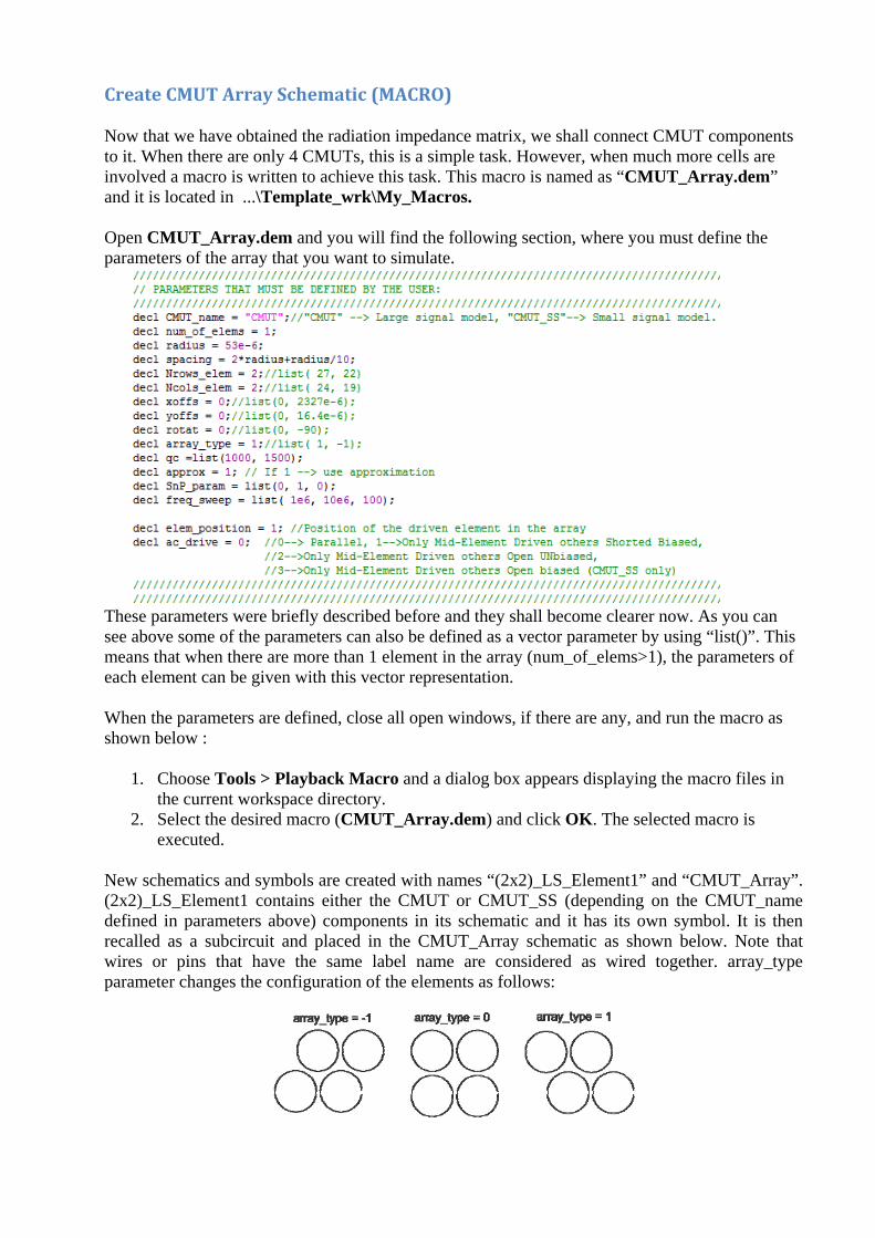
Now that we have obtained the radiation impedance matrix, we shall connect CMUT components to it. When there are only 4 CMUTs, this is a simple task. However, when much more cells are involved a macro is written to achieve this task. This macro is named as “CMUT_Array.dem” and it is located in ...\Template_wrk\My_Macros. Open CMUT_Array.dem and you will find the following section, where you must define the parameters of the array that you want to simulate.
These parameters were briefly described before and they shall become clearer now. As you can see above some of the parameters can also be defined as a vector parameter by using “list()”. This means that when there are more than 1 element in the array (num_of_elems>1), the parameters of each element can be given with this vector representation. When the parameters are defined, close all open windows, if there are any, and run the macro as shown below :
1. Choose Tools > Playback Macro and a dialog box appears displaying the macro files in the current workspace directory.
2. Select the desired macro (CMUT_Array.dem) and click OK. The selected macro is executed.
New schematics and symbols are created with names “(2x2)_LS_Element1” and “CMUT_Array”. (2x2)_LS_Element1 contains either the CMUT or CMUT_SS (depending on the CMUT_name defined in parameters above) components in its schematic and it has its own symbol. It is then recalled as a subcircuit and placed in the CMUT_Array schematic as shown below. Note that wires or pins that have the same label name are considered as wired together. array_type parameter changes the configuration of the elements as follows:

Frequency Domain (AC) Simulation An AC simulation is performed in the frequency domain. You can simulate a single frequency point, or across a frequency span in a linear or logarithmic sweep. Below the 2 by 2 element is biased with 68V DC and driven with 1Vp AC. The electrical conductance is plotted.
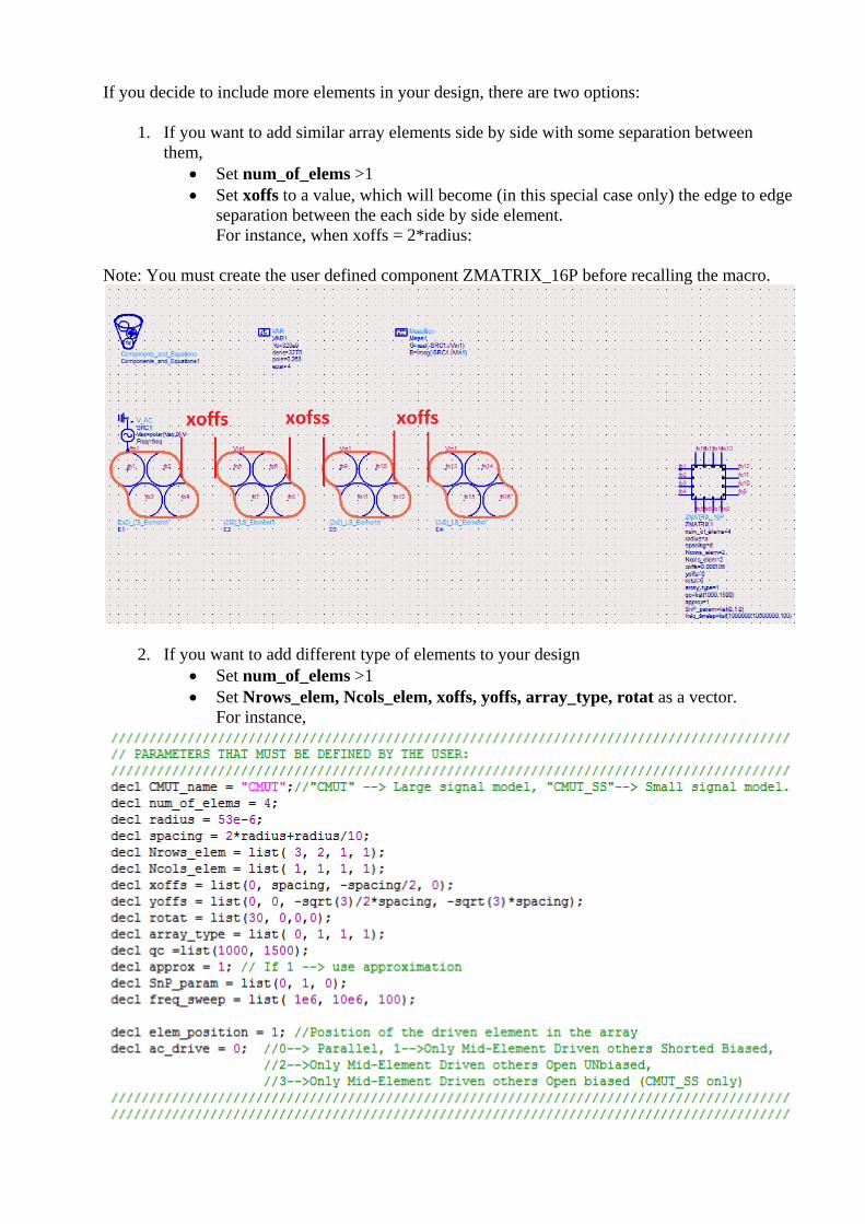
If you decide to include more elements in your design, there are two options:
1. If you want to add similar array elements side by side with some separation between them,
Set num_of_elems >1 Set xoffs to a value, which will become (in this special case only) the edge to edge
separation between the each side by side element. For instance, when xoffs = 2*radius:
Note: You must create the user defined component ZMATRIX_16P before recalling the macro.
2. If you want to add different type of elements to your design Set num_of_elems >1 Set Nrows_elem, Ncols_elem, xoffs, yoffs, array_type, rotat as a vector.
For instance,
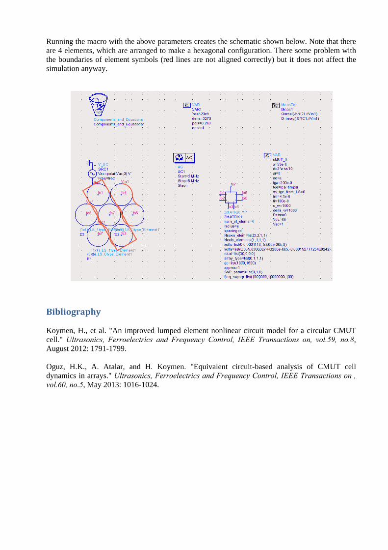
Running the macro with the above parameters creates the schematic shown below. Note that there are 4 elements, which are arranged to make a hexagonal configuration. There some problem with the boundaries of element symbols (red lines are not aligned correctly) but it does not affect the simulation anyway.
Bibliography Koymen, H., et al. "An improved lumped element nonlinear circuit model for a circular CMUT cell." Ultrasonics, Ferroelectrics and Frequency Control, IEEE Transactions on, vol.59, no.8, August 2012: 1791-1799. Oguz, H.K., A. Atalar, and H. Koymen. "Equivalent circuit-based analysis of CMUT cell dynamics in arrays." Ultrasonics, Ferroelectrics and Frequency Control, IEEE Transactions on , vol.60, no.5, May 2013: 1016-1024.