User Manual - Black Box Corporationftp.blackbox.com/manuals/L/LGB5510A_user_rev1.pdf · User Manual...
88
User Manual • Has eight 10-Gigabit twisted-pair ports and two slots for SFP+ modules. • Supports advanced security management and network features. 10-Gigabit Web Smart Switch - 10-Port LGB5510A Order toll-free in the U.S. or for FREE technical support 24/7: Call 877-877-BBOX (outside U.S. call 724-746-5500) www.blackbox.com • [email protected] Contact Information
Transcript of User Manual - Black Box Corporationftp.blackbox.com/manuals/L/LGB5510A_user_rev1.pdf · User Manual...

User Manual
• Has eight 10-Gigabit twisted-pair ports and two slots for SFP+ modules. • Supports advanced security management and network features.
10-Gigabit Web Smart Switch - 10-Port
LGB5510A
Order toll-free in the U.S. or for FREE technical support 24/7: Call 877-877-BBOX (outside U.S. call 724-746-5500)www.blackbox.com • [email protected]
Contact Information

877-877-2269 | blackbox.com
Trademarks Used in this Manual
We‘re here to help! If you have any questions about your application or our products, contact Black Box Tech Support at 877-877-2269
or go to blackbox.com and click on “Talk to Black Box.”You’ll be live with one of our technical experts in less than 60 seconds.
Trademarks Used in this Manual
Black Box and the Double Diamond logo are registered trademarks of BB Technologies, Inc.
Any other trademarks mentioned in this manual are acknowledged to be the property of the trademark owners.

877-877-2269 | blackbox.com 877-877-2269 | blackbox.com
FCC and IC RFI Statements; CE Mark
Federal Communications Commission and Industry Canada Radio Frequency Interference Statements
This equipment generates, uses, and can radiate radio-frequency energy, and if not installed and used properly, that is, in strict accordance with the manufacturer’s instructions, may cause inter ference to radio communication. It has been tested and found to comply with the limits for a Class A computing device in accordance with the specifications in Subpart B of Part 15 of FCC rules, which are designed to provide reasonable protection against such interference when the equipment is operated in a commercial environment. Operation of this equipment in a residential area is likely to cause interference, in which case the user at his own expense will be required to take whatever measures may be necessary to correct the interference.
Changes or modifications not expressly approved by the party responsible for compliance could void the user’s authority to operate the equipment.
This digital apparatus does not exceed the Class A limits for radio noise emis sion from digital apparatus set out in the Radio Interference Regulation of Industry Canada.
Le présent appareil numérique n’émet pas de bruits radioélectriques dépassant les limites applicables aux appareils numériques de la classe A prescrites dans le Règlement sur le brouillage radioélectrique publié par Industrie Canada.
CE Mark
This equipment has been tested and found to comply with the protection requirements of European Emission Standard EN55022/EN61000-3 and the Generic European Immunity Standard EN55024.
Disclaimer:Black Box Network Services shall not be liable for damages of any kind, including, but not limited to, punitive, consequential or cost of cover damages, resulting from any errors in the product information or specifications set forth in this document and Black Box Network Services may revise this document at any time without notice.

877-877-2269 | blackbox.com
NOM Statement
Instrucciones de Seguridad(Normas Oficiales Mexicanas Electrical Safety Statement)1. Todas las instrucciones de seguridad y operación deberán ser leídas antes de que el aparato eléctrico sea operado.
2. Las instrucciones de seguridad y operación deberán ser guardadas para referencia futura.
3. Todas las advertencias en el aparato eléctrico y en sus instrucciones de operación deben ser respetadas.
4. Todas las instrucciones de operación y uso deben ser seguidas.
5. El aparato eléctrico no deberá ser usado cerca del agua—por ejemplo, cerca de la tina de baño, lavabo, sótano mojado o cerca de una alberca, etc.
6. El aparato eléctrico debe ser usado únicamente con carritos o pedestales que sean recomendados por el fabricante.
7. El aparato eléctrico debe ser montado a la pared o al techo sólo como sea recomendado por el fabricante.
8. Servicio—El usuario no debe intentar dar servicio al equipo eléctrico más allá a lo descrito en las instrucciones de operación. Todo otro servicio deberá ser referido a personal de servicio calificado.
9. El aparato eléctrico debe ser situado de tal manera que su posición no interfiera su uso. La colocación del aparato eléctrico sobre una cama, sofá, alfombra o superficie similar puede bloquea la ventilación, no se debe colocar en libreros o gabinetes que impidan el flujo de aire por los orificios de ventilación.
10. El equipo eléctrico deber ser situado fuera del alcance de fuentes de calor como radiadores, registros de calor, estufas u otros aparatos (incluyendo amplificadores) que producen calor.
11. El aparato eléctrico deberá ser connectado a una fuente de poder sólo del tipo descrito en el instructivo de operación, o como se indique en el aparato.
12. Precaución debe ser tomada de tal manera que la tierra fisica y la polarización del equipo no sea eliminada.
13. Los cables de la fuente de poder deben ser guiados de tal manera que no sean pisados ni pellizcados por objetos colocados sobre o contra ellos, poniendo particular atención a los contactos y receptáculos donde salen del aparato.
14. El equipo eléctrico debe ser limpiado únicamente de acuerdo a las recomendaciones del fabricante.
15. En caso de existir, una antena externa deberá ser localizada lejos de las lineas de energia.
16. El cable de corriente deberá ser desconectado del cuando el equipo no sea usado por un largo periodo de tiempo.
17. Cuidado debe ser tomado de tal manera que objectos liquidos no sean derramados sobre la cubierta u orificios de ventilación.
18. Servicio por personal calificado deberá ser provisto cuando: A: El cable de poder o el contacto ha sido dañado; u B: Objectos han caído o líquido ha sido derramado dentro del aparato; o C: El aparato ha sido expuesto a la lluvia; o D: El aparato parece no operar normalmente o muestra un cambio en su desempeño; o E: El aparato ha sido tirado o su cubierta ha sido dañada.

877-877-2269 | blackbox.com
Safety Information
Safety Information
CAUTION: Circuit devices are sensitive to static electricity, which can damage their delicate electronics. Dry weather conditions or walking across a carpeted floor may cause you to acquire a static electrical charge.
To protect your device, always:
• Touch the metal chassis of your computer to ground the static electrical charge before you pick up the circuit device.
• Pick up the device by holding it on the left and right edges only.
• If you are using an outdoor device connected to this device with cable then you need to add an arrester on the cable between the outdoor device and this device.
NOTE: The switch is an indoor device; if it will be used in outdoor environment or connects to an outdoor device, you must use a lightning arrester to protect the switch.
WARNING:
• If you damage the switch by self-demolition, you will be charged a fee to repair the switch.
• Do not place the switch outdoors.
• Before installation, make sure the input power supply complies with switch specifications.
• To reduce the risk of electric shock, disconnect all AC or DC power cords and redundant power service (RPS) cables to completely remove power from the unit.
• Before importing/exporting a configuration, make sure the firmware version is the same.
• After a firmware upgrade, the switch will automatically replace the configuration with the latest firmware version.

877-877-2269 | blackbox.com
Table of Contents
Table of Contents
INTRODUCTION ..........................................................................................................................................................................1
CHAPTER 1: OPERATION OF WEB-BASED MANAGEMENT ........................................................................................................2
CHAPTER 2: SYSTEM CONFIGURATION .....................................................................................................................................3 2-1 System .............................................................................................................................................................................3 2-1.1 Information ...........................................................................................................................................................3 2-1.2 IP ..........................................................................................................................................................................4 2-1.3 NTP .......................................................................................................................................................................9 2-1.4 Time ................................................................................................................................................................... 11 2-1.5 Log ..................................................................................................................................................................... 13 2-2 Ports Configuration .......................................................................................................................................................14 2-2.1 Ports ...................................................................................................................................................................14 2-3 DHCP ............................................................................................................................................................................16 2-3.1 Snooping ............................................................................................................................................................16 2-4 Security ......................................................................................................................................................................... 17 2-4.1 Network ............................................................................................................................................................. 17 2-4.1.1 IP Source Guard ........................................................................................................................................ 17 2-4.1.2 ARP Inspection .........................................................................................................................................19 2-5 Aggregation ..................................................................................................................................................................23 2-5.1 Static ..................................................................................................................................................................23 2-6 MAC Table ....................................................................................................................................................................25 2-7 IGMP Snooping .............................................................................................................................................................27 2-7.1 Basic Configuration .............................................................................................................................................27 2-7.2 VLAN Configuration ...........................................................................................................................................29 2-8 VLANs ...........................................................................................................................................................................31 2-9 Private VLANs................................................................................................................................................................34 2-9.1 VLAN Membership .............................................................................................................................................34 2-9.2 Port Isolation ......................................................................................................................................................35 2-10 QoS .............................................................................................................................................................................36 2-10.1 Port Classification..............................................................................................................................................36 2-10.2 Port Policing .....................................................................................................................................................38 2-10.3 Port Shaper .......................................................................................................................................................39 2-10.4 Port Scheduler .................................................................................................................................................. 41 2-10.5 Port Tag Classification .......................................................................................................................................43 2-10.6 Port Tag Remarking ..........................................................................................................................................45 2-10.7 DSCP Translation ...............................................................................................................................................46 2-10.8 Storm Control ...................................................................................................................................................47 2-10.9 WRED ...............................................................................................................................................................48 2-10.9.1 Basic Configuration .................................................................................................................................48 2-10.9.2 Configuration .........................................................................................................................................49 2-11 Mirror .......................................................................................................................................................................... 51 2-12 Loop Protection ...........................................................................................................................................................53
CHAPTER 3: MONITOR .............................................................................................................................................................55 3-1 System ...........................................................................................................................................................................55 3-1.1 Information .........................................................................................................................................................55 3-1.2 IP Status .............................................................................................................................................................57 3-1.3 Log .....................................................................................................................................................................59

Chapter
877-877-2269 | blackbox.com
3-2 Ports .............................................................................................................................................................................60 3-2.1 Traffic Overview..................................................................................................................................................60 3-2.2 Detailed Statistics ...............................................................................................................................................62 3-3 DHCP ............................................................................................................................................................................65 3-3.1 Snooping Table ...................................................................................................................................................65 3-4 Security .........................................................................................................................................................................66 3-4.1 Network .............................................................................................................................................................66 3-4.1.1 IP Source Guard........................................................................................................................................66 3-4.1.2 ARP Inspection .........................................................................................................................................67 3-5 MAC Table ....................................................................................................................................................................68 3-6 IGMP Snooping ............................................................................................................................................................70 3-6.1 Status .................................................................................................................................................................70 3-6.2 Group Information .............................................................................................................................................72 3-6.3 IPv4 SSM Information ........................................................................................................................................73 3-7 VLANs ........................................................................................................................................................................... 74 3-7.1 VLAN Membership ............................................................................................................................................. 74 3-7.2 VLAN Port ..........................................................................................................................................................75 3-8 Loop Protection ............................................................................................................................................................77
CHAPTER 4: DIAGNOSTICS.......................................................................................................................................................78 4-1 Ping .............................................................................................................................................................................78 4-2 Cable Diagnostics ..........................................................................................................................................................79
CHAPTER 5: MAINTENANCE ....................................................................................................................................................80 5-1 Restart Device ...............................................................................................................................................................80 5-2 Firmware .......................................................................................................................................................................81 5-2.1 Firmware Upgrade ..............................................................................................................................................81 5-3 Configuration ................................................................................................................................................................82 5-3.1 Save startup-config ............................................................................................................................................82

Publication date: Oct, 2015 Revision A2
1
INTRODUCTION
Overview
This user’s manual explains how to install and connect your network system and configure and monitor the LGB5510A through the web via an (RJ-‐45) serial interface and Ethernet ports. Many explanations detailing hardware and software functions are shown as well as examples of the operation for a web-‐based interface.
The LGB5510A switch has the intelligent features you need to improve the availability of your critical
business applications, protect your sensitive information, and optimize your network bandwidth to deliver information and applications more effectively. It provides the ideal combination of affordability and capabilities for entry-‐level networking, including small businesses or enterprises.

Publication date: Oct, 2015 Revision A2
2
Chapter 1 Operation of Web-‐based Management
Initial Configuration
This chapter instructs you how to configure and manage the LGB5510A through the web user interface. With this facility, you can easily access and monitor through any one port of the switch all the status of the switch, including MIBs status, each port activity, port aggregation status, multicast traffic, VLAN and priority status, even illegal access record and so on.
The default values of the LGB5510A are listed in the table below:
IP Address 192.168.1.1
Subnet Mask 255.255.255.0
Default Gateway 192.168.1.254
1. Plug in the power cable 2. Check the IP address of the computer is within the network segment: 192.168.1.xxx
(“xxx” ranges from 1–254). For example, 192.168.1.100. 3. Open the Web browser, and enter 192.168.1.1. The login window appears.
NOTE: When you login to the switch, you must first type the Username of the admin. The Password is blank, so after you type Username, press enter. This takes you to the Web management page. When you login LGB5510A series switch via the Web UI, you can use both ipv4 ipv6 login to manage the switch. To optimize the display effect, we recommend that you use Microsoft IE 6.0 or above, Netscape V7.1 or above or FireFox V1.00 or above and set the resolution to 1024 x 768. The switch supports a neutral web browser interface.

Publication date: Oct, 2015 Revision A2
3
Chapter 2 System Configuration
This chapter describes basic configuration tasks, including entering system Information and managing the switch (for example, Time, Account, IP, Syslog, and SNTP).
2-‐1 System You can identify the system by configuring the contact information, name, and location of the switch.
2-‐1.1 Information
The switch system’s contact information is provided here.
Web interface
To configure System Information configuration in the web interface:
1. Click Configuration, System, and Information. 2. Type in System Contact, System Name, and System Location information in this page. 3. Click Apply.
Figure 2-‐1.1: The System Information Configuration
Parameter description:
System Contact:
The textual identification of the contact person for this managed node, together with information on how to contact this person. The allowed string length is 0 to 128, and the allowed content is the ASCII characters from 32 to 126.
System Name:
An administratively assigned name for this managed node. By convention, this is the node's fully-‐qualified domain name. A domain name is a text string drawn from the alphabet (A-‐Z, a-‐z), digits (0-‐9), and minus sign (-‐). No space characters are permitted as part of a name. The first character must be an alpha character. The first or last character must not be a minus sign. The allowed string length is 0 to 128.
System Location:
The physical location of this node (e.g., telephone closet, 3rd floor). The allowed string length is 0 to 128, and the allowed content is the ASCII characters from 32 to 126.

Publication date: Oct, 2015 Revision A2
4
2-‐1.2 IP
The IPv4 address for the switch can be obtained via DHCP Server for VLAN 1. To manually configure an address, you need to change the switch's default settings to values that are compatible with your network. You may also need to establish a default gateway between the switch and management stations that exist on another network segment.
Configure the switch-‐managed IP information on this page.
Configure IP basic settings, control IP interfaces and IP routes.
The maximum number of interfaces supported is 8 and the maximum number of routes is 32.
Web interface
To configure the IP Configuration in the web interface:
1. Click Configuration, System, IP. 2. Click Add Interface then you can create a new Interface on the switch. 3. Click Add Route, then you can create a new Route on the switch. 4. Click Apply.
Figure2-‐1.2: The IP Configuration
Parameter description:
IP Configuration
DNS Server
This setting controls the DNS name resolution done by the switch. The following modes are supported:
• From any DHCP interfaces The first DNS server offered from a DHCP lease to a DHCP-‐enabled interface will be used.
• No DNS server. No DNS server will be used
• Configured Explicitly provide the IP address of the DNS Server in dotted decimal notation.
• From this DHCP interface Specify from which DHCP-‐enabled interface a provided DNS server should be preferred.
IP Interfaces
Delete
Select this option to delete an existing IP interface.
VLAN
Publication date: Oct, 2015 Revision A2
5
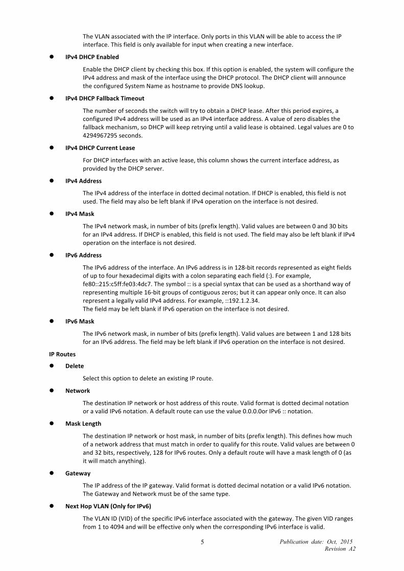
The VLAN associated with the IP interface. Only ports in this VLAN will be able to access the IP interface. This field is only available for input when creating a new interface.
IPv4 DHCP Enabled
Enable the DHCP client by checking this box. If this option is enabled, the system will configure the IPv4 address and mask of the interface using the DHCP protocol. The DHCP client will announce the configured System Name as hostname to provide DNS lookup.
IPv4 DHCP Fallback Timeout
The number of seconds the switch will try to obtain a DHCP lease. After this period expires, a configured IPv4 address will be used as an IPv4 interface address. A value of zero disables the fallback mechanism, so DHCP will keep retrying until a valid lease is obtained. Legal values are 0 to 4294967295 seconds.
IPv4 DHCP Current Lease
For DHCP interfaces with an active lease, this column shows the current interface address, as provided by the DHCP server.
IPv4 Address
The IPv4 address of the interface in dotted decimal notation. If DHCP is enabled, this field is not used. The field may also be left blank if IPv4 operation on the interface is not desired.
IPv4 Mask
The IPv4 network mask, in number of bits (prefix length). Valid values are between 0 and 30 bits for an IPv4 address. If DHCP is enabled, this field is not used. The field may also be left blank if IPv4 operation on the interface is not desired.
IPv6 Address
The IPv6 address of the interface. An IPv6 address is in 128-‐bit records represented as eight fields of up to four hexadecimal digits with a colon separating each field (:). For example, fe80::215:c5ff:fe03:4dc7. The symbol :: is a special syntax that can be used as a shorthand way of representing multiple 16-‐bit groups of contiguous zeros; but it can appear only once. It can also represent a legally valid IPv4 address. For example, ::192.1.2.34. The field may be left blank if IPv6 operation on the interface is not desired.
IPv6 Mask
The IPv6 network mask, in number of bits (prefix length). Valid values are between 1 and 128 bits for an IPv6 address. The field may be left blank if IPv6 operation on the interface is not desired.
IP Routes
Delete
Select this option to delete an existing IP route.
Network
The destination IP network or host address of this route. Valid format is dotted decimal notation or a valid IPv6 notation. A default route can use the value 0.0.0.0or IPv6 :: notation.
Mask Length
The destination IP network or host mask, in number of bits (prefix length). This defines how much of a network address that must match in order to qualify for this route. Valid values are between 0 and 32 bits, respectively, 128 for IPv6 routes. Only a default route will have a mask length of 0 (as it will match anything).
Gateway
The IP address of the IP gateway. Valid format is dotted decimal notation or a valid IPv6 notation. The Gateway and Network must be of the same type.
Next Hop VLAN (Only for IPv6)
The VLAN ID (VID) of the specific IPv6 interface associated with the gateway. The given VID ranges from 1 to 4094 and will be effective only when the corresponding IPv6 interface is valid.
Publication date: Oct, 2015 Revision A2
6
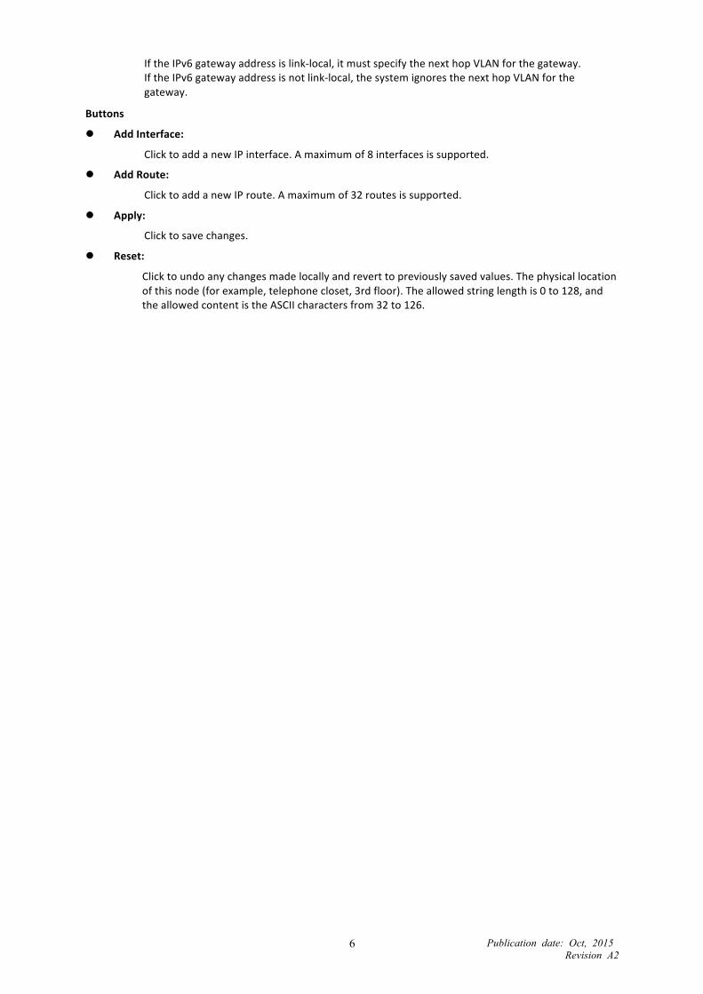
If the IPv6 gateway address is link-‐local, it must specify the next hop VLAN for the gateway. If the IPv6 gateway address is not link-‐local, the system ignores the next hop VLAN for the gateway.
Buttons
Add Interface:
Click to add a new IP interface. A maximum of 8 interfaces is supported.
Add Route:
Click to add a new IP route. A maximum of 32 routes is supported.
Apply:
Click to save changes.
Reset:
Click to undo any changes made locally and revert to previously saved values. The physical location of this node (for example, telephone closet, 3rd floor). The allowed string length is 0 to 128, and the allowed content is the ASCII characters from 32 to 126.

2-‐1.3 NTP
NTP is Network Time Protocol and is used to sync the network time based Greenwich Mean Time (GMT). If you use the NTP mode and select a built-‐in NTP time server or manually specify a user-‐defined NTP server as well as Time Zone, the switch will sync the time shortly after you press <Apply> button. Though it synchronizes the time automatically, NTP does not update the time periodically without user’s processing.
Time Zone is an offset time off GMT. You have to select the time zone first and then perform time sync via NTP because the switch will combine this time zone offset and updated NTP time to match the local time; otherwise, you will not able to get the correct time. The switch supports configurable time zones from –12 to +13 step 1 hour.
Default Time zone: +8 Hrs.
Web interface
To configure SNTP Configuration in the web interface:
1. Click Configuration, System and NTP. 2. Specify the Time manually. 3. Click Apply.
Figure 2-‐1.3: The SNTP Configuration
Parameter description:
Server 1 to 5:
Provide the SNTP IPv4 or IPv6 address of this switch. IPv6 address is in 128-‐bit records represented as eight fields of up to four hexadecimal digits with a colon separating each field (:). For example, “fe80::215:c5ff:fe03:4dc7”. The symbol “::” is a special syntax that can be used as a shorthand way of representing multiple 16-‐bit groups of contiguous zeros; but it can only appear once. It can also represent a legally valid IPv4 address. For example, “::192.1.2.34”.
Buttons

Publication date: Oct, 2015 Revision A2
10
These buttons are displayed on the NTP page:
Apply – Click to save changes.
Reset -‐ Click to undo any changes made locally and revert to previously saved values.

Publication date: Oct, 2015 Revision A2
11
2-‐1.4 Time
The switch provides manual and automatic ways to set the system time via NTP. Manual setting is simple and you just input “Year”, “Month”, “Day”, “Hour” and “Minute” within the valid value range indicated in each item.
Web interface
To configure Time Configuration in the web interface:
1. Click Configuration, System and Time. 2. Specify the Time parameter in manual parameters. 3. Click Apply.
Figure 2-‐1.4: The Time Configuration
Parameter description:
Time Configuration
Clock Source:
There are two modes for configuring the Clock Source. Select "Use Local Settings”: Clock Source from Local Time. Select "Use NTP Server”: Clock Source from NTP Server.
System Date:
Show the current time of the system. The year range is between 2011 and 2037.
Time Zone Configuration
Publication date: Oct, 2015 Revision A2
12
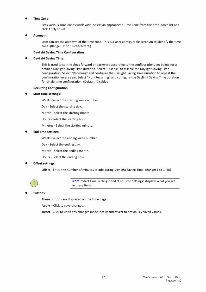
Time Zone:
Lists various Time Zones worldwide. Select an appropriate Time Zone from the drop-‐down list and click Apply to set.
Acronym:
User can set the acronym of the time zone. This is a User configurable acronym to identify the time zone. (Range: Up to 16 characters.)
Daylight Saving Time Configuration
Daylight Saving Time:
This is used to set the clock forward or backward according to the configurations set below for a defined Daylight Saving Time duration. Select “Disable” to disable the Daylight Saving Time configuration. Select “Recurring” and configure the Daylight Saving Time duration to repeat the configuration every year. Select “Non-‐Recurring” and configure the Daylight Saving Time duration for single time configuration. (Default: Disabled).
Recurring Configuration
Start time settings:
Week -‐ Select the starting week number.
Day -‐ Select the starting day.
Month -‐ Select the starting month.
Hours -‐ Select the starting hour.
Minutes -‐ Select the starting minute.
End time settings:
Week -‐ Select the ending week number.
Day -‐ Select the ending day.
Month -‐ Select the ending month.
Hours -‐ Select the ending hour.
Offset settings:
Offset -‐ Enter the number of minutes to add during Daylight Saving Time. (Range: 1 to 1440)
NOTE: “Start Time Settings” and “End Time Settings” displays what you set in these fields.
Buttons
These buttons are displayed on the Time page:
Apply – Click to save changes.
Reset -‐ Click to undo any changes made locally and revert to previously saved values.

Publication date: Oct, 2015 Revision A2
13
2-‐1.5 Log
The log is a standard for logging program messages. It allows separation of the software that generates messages from the system that stores them and the software that reports and analyzes them. You can also use it for general information, analysis and debugging messages. The log is supported by a wide variety of devices and receivers across multiple platforms.
Web Interface
To configure System Log Configuration in the web interface:
1. Click Configuration, System and log. 2. Specify the syslog parameters, including IP Address of Syslog server and Port number. 3. Enable the Syslog. 4. Click Apply.
Figure2-‐1.5: The System Log Configuration
Parameter description:
Server Mode:
Indicate the server mode operation. When the mode operation is enabled, the syslog message will be sent out to the syslog server. The syslog protocol is based on UDP communication and is received on UDP port 514. The syslog server will not send acknowledgments back to the sender since UDP is a connectionless protocol and it does not provide acknowledgments. The syslog packet will always be sent out even if the syslog server does not exist. Possible modes are:
Enabled: Enable server mode operation.
Disabled: Disable server mode operation.
Server Address:
Indicates the IPv4 hosts address of syslog server. If the switch provides a DNS feature, it also can be a host name.
Buttons
These buttons are displayed on the Log page:
Apply – Click to save changes.
Reset -‐ Click to undo any changes made locally and revert to previously saved values.

Publication date: Oct, 2015 Revision A2
14
2-‐2 Ports Configuration The section describes how to configure the switch’s port detail parameters. You can also use Ports configuration to enable or disable the Port of the switch, and/or monitor the port’s content or status.
2-‐2.1 Ports
This page displays current port configurations. Ports can also be configured here.
Web Interface
To configure a Port Configuration in the web interface:
1. Click Configuration, Ports Configuration, and Ports. 2. Specify the Speed Configured, Flow Control, Maximum Frame size, Excessive Collision mode and
Power Control. 3. Click Apply.
Figure 2-‐2.1: The Port Configuration
Parameter description:
Port:
This is the logical port number for this row.
Link:
The current link state is displayed graphically. Green indicates the link is up and red that it is down.
Current Link Speed:
Provides the current link speed of the port.
Configured Link Speed:
Use the menu to select the port’s speed and duplex mode. If you select Auto, the duplex mode and speed will be set by the auto-‐negotiation process. The Switch port’s maximum capability (full duplex and 10 Gbps) will be advertised. Otherwise, your selection will determine the port’s duplex mode and transmission rate. The factory default is Auto.
Maximum Frame Size:
Enter the maximum frame size allowed for the switch port, including FCS.
EEE:

Publication date: Oct, 2015 Revision A2
15
Controls whether EEE is enabled for this switch port.
Buttons
Apply – Click to save changes.
Reset -‐ Click to undo any changes made locally and revert to previously saved values. Upper right icon (Refresh)
Click to refresh the Port link Status manually.
Publication date: Oct, 2015 Revision A2
16
2-‐3 DHCP The section describes how to configure the DHCP Snooping parameters of the switch. DHCP Snooping can prevent attackers from adding their own DHCP servers to the network.
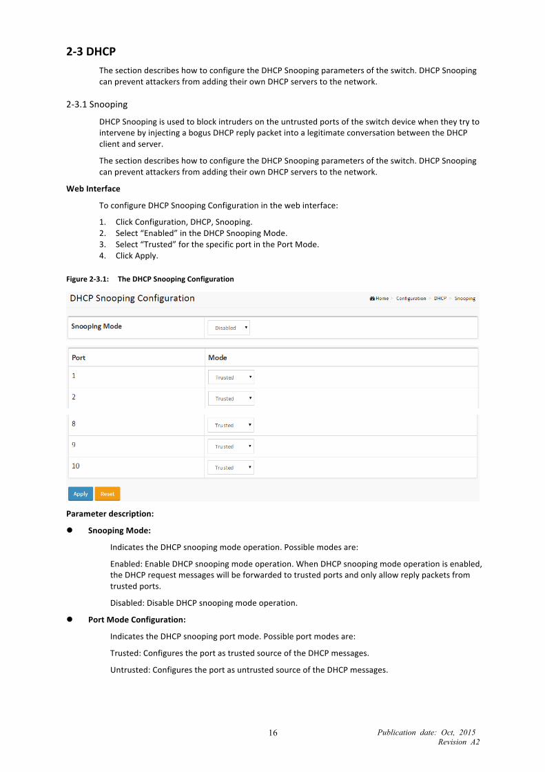
2-‐3.1 Snooping
DHCP Snooping is used to block intruders on the untrusted ports of the switch device when they try to intervene by injecting a bogus DHCP reply packet into a legitimate conversation between the DHCP client and server.
The section describes how to configure the DHCP Snooping parameters of the switch. DHCP Snooping can prevent attackers from adding their own DHCP servers to the network.
Web Interface
To configure DHCP Snooping Configuration in the web interface:
1. Click Configuration, DHCP, Snooping. 2. Select “Enabled” in the DHCP Snooping Mode. 3. Select “Trusted” for the specific port in the Port Mode. 4. Click Apply.
Figure 2-‐3.1: The DHCP Snooping Configuration
Parameter description:
Snooping Mode:
Indicates the DHCP snooping mode operation. Possible modes are:
Enabled: Enable DHCP snooping mode operation. When DHCP snooping mode operation is enabled, the DHCP request messages will be forwarded to trusted ports and only allow reply packets from trusted ports.
Disabled: Disable DHCP snooping mode operation.
Port Mode Configuration:
Indicates the DHCP snooping port mode. Possible port modes are:
Trusted: Configures the port as trusted source of the DHCP messages.
Untrusted: Configures the port as untrusted source of the DHCP messages.

Publication date: Oct, 2015 Revision A2
17
2-‐4 Security This section shows you to configure the Port Security settings of the Switch. You can use the Port Security feature to restrict input to an interface by limiting and identifying MAC addresses.
2-‐4.1 Network 2-‐4.1.1 IP Source Guard
This section describes how to configure the IP Source Guard detail parameters of the switch. You can use the IP Source Guard configure to enable or disable the switch port.
2-‐4.1.1.1 Configuration
This section describes how to configure IP Source Guard setting, including:
• Mode (Enabled and Disabled)
• Maximum Dynamic Clients (0, 1, 2, Unlimited)
Web Interface
To configure an IP Source Guard Configuration in the web interface:
1. Select “Enabled” in the IP Source Guard Configuration Mode. 2. Select “Enabled” for the specific port in the Port Mode Configuration. 3. Select Maximum Dynamic Clients (0, 1, 2, Unlimited) of the specific port in the Port Mode
Configuration. 4. Click Apply.
Figure 2-‐4.1.1.1: The IP Source Guard Configuration
Parameter description:
Port Mode Configuration:
Specify IP Source Guard enabled on specific ports. When both Global Mode and Port Mode on a given port are enabled, IP Source Guard is also enabled on the port.
Max Dynamic Clients:
Specify the maximum number of dynamic clients that can be learned on given port. This value can be 0, 1, 2, or unlimited. If the port mode is enabled and the value of max dynamic client is equal to 0, only IP packets that match the static entries on the specific port are forwarded.

Publication date: Oct, 2015 Revision A2
18
2-‐4.1.1.2 Static Table
The section describes how to configure the switch’s Static IP Source Guard Table. You can configure the Static IP Source Guard Table to manage the entries.
Web Interface
To configure a Static IP Source Guard Table Configuration in the web interface:
1. Click “Add new entry.” 2. Specify the Port, VLAN ID, IP Address, and MAC address in the entry. 3. Click Apply.
Figure 2-‐4.1.1.2: The Static IP Source Guard Table
Parameter description:
Delete:
Check to delete the entry. It will be deleted during the next save.
Port:
The logical port for the settings.
IP Address:
The allowed Source IP address.
MAC address:
The allowed Source MAC address.
Adding new entry:
Click to add a new entry to the Static IP Source Guard table. Specify the Port, VLAN ID, IP address, and IP Mask for the new entry. Click “Save.”
Buttons:
Apply – Click to save changes.
Reset -‐ Click to undo any changes made locally and revert to previously saved values.

Publication date: Oct, 2015 Revision A2
19
2-‐4.1.2 ARP Inspection
The section describes how to configure the ARP Inspection parameters of the switch. You can use the ARP Inspection configure to manage the ARP table.
2-‐4.1.2.1 Configuration
This section describes how to configure ARP Inspection setting including:
• Mode (Enabled and Disabled)
• Port (Enabled and Disabled)
Web Interface
To configure an ARP Inspection Configuration in the web interface:
1. Select “Enabled” in the ARP Inspection Configuration Mode. 2. Select “Enabled” of the specific port in the Port Mode Configuration. 3. Click Apply.
Figure 2-‐4.1.2.1: The ARP Inspection Configuration
Parameter description:
Mode of ARP Inspection Configuration:
Enable the Global ARP Inspection or disable the Global ARP Inspection.
Port Mode Configuration:
Enable ARP Inspection on specific ports. When both Global Mode and Port Mode on a given port are enabled, ARP Inspection is enabled on this port. Possible modes are: Enabled: Enable ARP Inspection operation. Disabled: Disable ARP Inspection operation. If you want to inspect the VLAN configuration, you have to enable the setting of "Check VLAN". The default setting of "Check VLAN" is disabled. When the setting of "Check VLAN" is disabled, the log type of ARP Inspection will refer to the port setting. And the setting of "Check VLAN" is enabled, the log type of ARP Inspection will refer to the VLAN setting. Possible setting of "Check VLAN" are: Enabled: Enable check VLAN operation. Disabled: Disable check VLAN operation. Only the Global Mode and Port Mode on a given port are enabled, and the setting of "Check VLAN" is disabled, the log type of ARP Inspection will refer to the port setting. There are four log types and possible types are: None: Log nothing.

Publication date: Oct, 2015 Revision A2
20
Deny: Log denied entries. Permit: Log permitted entries. ALL: Log all entries.
Buttons:
Apply – Click to save changes.
Reset – Click to undo any changes made locally and revert to previously saved values.

Publication date: Oct, 2015 Revision A2
21
2-‐4.1.2.2 VLAN Mode Configuration
Each page shows up to 4K entries from the VLAN table, default being 20, selected through the “entries per page” input field. When first visited, the web page will show the first 20 entries from the beginning of the VLAN Table. The first displayed will be the one with the lowest VLAN ID found in the VLAN Table.
The “VLAN” input fields allow the user to select the starting point in the VLAN Table. Clicking the button will update the displayed table starting from that or the closest next VLAN Table match. The switch will use the next entry of the currently displayed VLAN entry as a basis for the next lookup. When the end is reached, the warning message is shown in the displayed table. Use the button to start over.
Web Interface
To configure a VLAN Mode Configuration in the web interface:
1. Click “Add new entry.” 2. Specify the VLAN ID, Log Type. 3. Click Apply.
Figure 2-‐4.1.2.2: The VLAN Mode Configuration
Parameter description:
VLAN Mode Configuration
To enable ARP Inspection on VLANs: First, you have to enable the port setting on the Port mode configuration web page. When both Global Mode and Port Mode on a given port are enabled, ARP Inspection is enabled on this port. Second, you can specify which VLAN will be inspected on the VLAN mode configuration web page. The log type also can be configured per VLAN setting. Possible types are: None: Log nothing. Deny: Log denied entries. Permit: Log permitted entries. ALL: Log all entries.
Buttons
Add New Entry: Click to add a new VLAN to the ARP Inspection VLAN table.
Apply: Click to save changes.
Reset: Click to undo any changes made locally and revert to previously saved values.

Publication date: Oct, 2015 Revision A2
22
2-‐4.1.2.3 Static Table
The section describes how to configure the Static ARP Inspection Table switch. You can use the Static ARP Inspection Table configure to manage ARP entries.
Web Interface
To configure a Static ARP Inspection Table Configuration in the web interface:
1. Click “Add new entry.” 2. Specify the Port, VLAN ID, IP Address, and MAC address in the entry. 3. Click Apply.
Figure 2-‐4.1.2.3: The Static ARP Inspection Table
Parameter description:
Delete:
Check to delete the entry. It will be deleted during the next save.
Port:
The logical port for the settings.
VLAN ID:
The VLAN id for the settings.
MAC Address:
Allowed Source MAC address in ARP request packets.
IP Address:
Allowed Source IP address in ARP request packets.
Adding new entry:
Click to add a new entry to the Static ARP Inspection table. Specify the Port, VLAN ID, MAC address, and IP address for the new entry. Click “Save.”

Publication date: Oct, 2015 Revision A2
23
2-‐5 Aggregation Use Aggregation to configure the Link Aggregation settings. You can bundle more than one port with the same speed, full duplex, and the same MAC to be a single logical port, so the logical port aggregates the bandwidth of these ports. This means you can apply your current Ethernet equipment’s bandwidth to build the bandwidth aggregation. For example, if there are three Fast Ethernet ports aggregated in a logical port, then this logical port has bandwidth three times as high as a single Fast Ethernet port.
2-‐5.1 Static
Ports using Static Trunk as their trunk method can choose their unique Static Group ID to form a logical “trunked port.” The benefit of using the Static Trunk method is that a port can immediately become a member of a trunk group without any handshaking with its peer port. This is also a disadvantage because the peer ports of your static trunk group may not know that they should be aggregated together to form a “logical trunked port.” Using Static Trunk on both ends of a link is strongly recommended.
NOTE: Low-‐speed links will stay in “not ready” state when using static trunk to aggregate with high speed links.
Web Interface
To configure the Aggregation Configuration in the web interface:
1. Click Configuration, Aggregation, Static, and then Aggregation Mode Configuration. 2. Enable Aggregation Group ID and Port members. 3. Click “Apply” to save the setting. 4. To cancel the setting, click the reset button. It will revert to previously saved values.
Figure 2-‐5.1: The Aggregation Configuration
Parameter description:
Aggregation Group Configuration
Group ID:
Indicates the group ID for the settings contained in the same row. Group ID "Normal" indicates there is no aggregation. Only one group ID is valid per port.
Port Members:
Each switch port is listed for each group ID. Select a radio button to include a port in an aggregation, or clear the radio button to remove the port from the aggregation. By default, no ports belong to any aggregation group. Only full duplex ports can join an aggregation and ports

Publication date: Oct, 2015 Revision A2
24
must be running at the same speed in each group.
Criteria:
Each switch port is listed for each group ID. Select a radio button to include a port in an aggregation, or clear the radio button to remove the port from the aggregation. By default, no ports belong to any aggregation group. Only full-‐duplex ports can join an aggregation and ports must be running at the same speed in each group.
Scheduler Mode:
Controls whether the aggregation criteria is "src-‐mac", "dst-‐mac ", “src-‐dst-‐mac”, "src-‐ip", "dst-‐ip ", “src-‐dst-‐ip”.
Buttons
Apply – Click to save changes.
Reset-‐ Click to undo any changes made locally and revert to previously saved values.

Publication date: Oct, 2015 Revision A2
25
2-‐6 MAC Table Switching frames is based upon the DMAC address contained in the frame. The switch builds a table that maps MAC addresses to switch ports that know which ports the frames should go to (based upon the DMAC address in the frame). This table contains both static and dynamic entries. The static entries are configured by the network administrator if the administrator wants to do a fixed mapping between the DMAC address and switch ports.
The frames also contain a MAC address (SMAC address), which shows the MAC address of the equipment sending the frame. The SMAC address is used by the switch to automatically update the MAC table with these dynamic MAC addresses. Dynamic entries are removed from the MAC table if no frame with the corresponding SMAC address are seen after a configurable age time
Web Interface
To configure MAC Table Configuration in the web interface:
Aging Configuration
1. Click configuration, MAC Table. 2. Specify the Disable Automatic Aging and Aging Time. 3. Click Apply.
MAC Table Learning
1. Click configuration. 2. Specify the Port Members (Auto, Disable, Secure). 3. Click Apply.
Static MAC Table Configuration
1. Click configuration and Add new Static entry. 2. Specify the VLAN IP and Mac address, Port Members. 3. Click Apply.
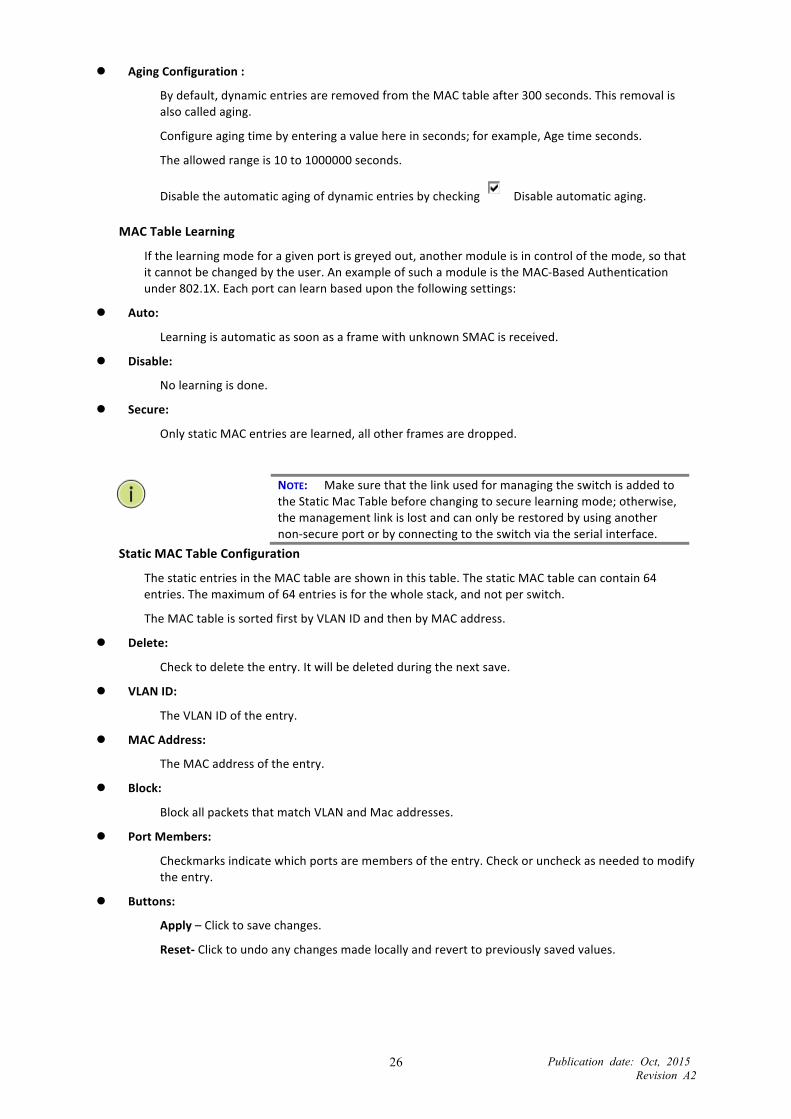
Figure 2-‐6: The MAC Table Configuration
Parameter description:
Publication date: Oct, 2015 Revision A2
26
Aging Configuration :
By default, dynamic entries are removed from the MAC table after 300 seconds. This removal is also called aging.
Configure aging time by entering a value here in seconds; for example, Age time seconds.
The allowed range is 10 to 1000000 seconds.
Disable the automatic aging of dynamic entries by checking Disable automatic aging.
MAC Table Learning
If the learning mode for a given port is greyed out, another module is in control of the mode, so that it cannot be changed by the user. An example of such a module is the MAC-‐Based Authentication under 802.1X. Each port can learn based upon the following settings:
Auto:
Learning is automatic as soon as a frame with unknown SMAC is received.
Disable:
No learning is done.
Secure:
Only static MAC entries are learned, all other frames are dropped.
NOTE: Make sure that the link used for managing the switch is added to the Static Mac Table before changing to secure learning mode; otherwise, the management link is lost and can only be restored by using another non-‐secure port or by connecting to the switch via the serial interface.
Static MAC Table Configuration
The static entries in the MAC table are shown in this table. The static MAC table can contain 64 entries. The maximum of 64 entries is for the whole stack, and not per switch.
The MAC table is sorted first by VLAN ID and then by MAC address.
Delete:
Check to delete the entry. It will be deleted during the next save.
VLAN ID:
The VLAN ID of the entry.
MAC Address:
The MAC address of the entry.
Block:
Block all packets that match VLAN and Mac addresses.
Port Members:
Checkmarks indicate which ports are members of the entry. Check or uncheck as needed to modify the entry.
Buttons:
Apply – Click to save changes.
Reset-‐ Click to undo any changes made locally and revert to previously saved values.

Publication date: Oct, 2015 Revision A2
27
2-‐7 IGMP Snooping Use this function to establish the multicast groups that forward the multicast packets to the member ports. The does not waste bandwidth when IP multicast packets are running over the network. This is because a switch that does not support IGMP or IGMP Snooping cannot tell a multicast packet from a broadcast packet, so it can only treat them all as broadcast packets. Without IGMP Snooping, multicast packets are forwarded in the same way as broadcast packets.
A switch that supports IGMP Snooping with query, report and leave, a type of packet exchanged between IP Multicast Router/Switch and IP Multicast Host, can update the information of the Multicast table when a member (port) joins or leaves an IP Multicast Destination Address. With this function, once a switch receives an IP multicast packet, it will forward the packet to the members who joined a specified IP multicast group before.
Packets will be discarded by IGMP Snooping if the user transmits multicast packets to the multicast group that was not built up in advance. IGMP mode enables the switch to issue IGMP for IGMP proxy or snooping on the switch that connects to a router closer to the root of the tree. This interface is the upstream interface. The router on the upstream interface should be running IGMP.
2-‐7.1 Basic Configuration
The section describes how to set the basic IGMP snooping on the switch that connects to a router closer to the root of the tree. This interface is the upstream interface. The router on the upstream interface should be running IGMP
Web Interface
To configure the IGMP Snooping Configuration in the web interface:
1. Click Configuration, IPMC, IGMP Snooping, Basic Configuration. 2. Enable or disable Global configuration. 3. Select the port that will be the Router Port or enable/ disable the Fast Leave function. 4. Scroll to set the Throttling parameter. 5. Click “Apply” to save the setting. 6. To cancel the setting, click the Reset button. It will revert to previously saved values.
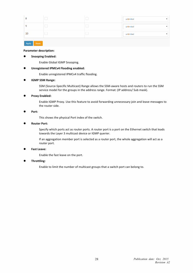
Figure 2-‐7.1: The IGMP Snooping Configuration
Publication date: Oct, 2015 Revision A2
28
Parameter description:
Snooping Enabled:
Enable Global IGMP Snooping.
Unregistered IPMCv4 Flooding enabled:
Enable unregistered IPMCv4 traffic flooding.
IGMP SSM Range:
SSM (Source-‐Specific Multicast) Range allows the SSM-‐aware hosts and routers to run the SSM service model for the groups in the address range. Format: (IP address/ Sub mask).
Proxy Enabled:
Enable IGMP Proxy. Use this feature to avoid forwarding unnecessary join and leave messages to the router side.
Port:
This shows the physical Port index of the switch.
Router Port:
Specify which ports act as router ports. A router port is a port on the Ethernet switch that leads towards the Layer 3 multicast device or IGMP querier.
If an aggregation member port is selected as a router port, the whole aggregation will act as a router port.
Fast Leave:
Enable the fast leave on the port.
Throttling:
Enable to limit the number of multicast groups that a switch port can belong to.

Publication date: Oct, 2015 Revision A2
29
2-‐7.2 VLAN Configuration
The section describes the VLAN configuration setting process integrated with IGMP Snooping function. Each setting page shows up to 99 entries from the VLAN table (the default is 20) selected through the “entries per page” input field. When first visited, the web page will show the first 20 entries from the beginning of the VLAN Table. The first displayed will be the one with the lowest VLAN ID found in the VLAN Table. The “VLAN” input fields allow the user to select the starting point in the VLAN Table. Clicking the button will update the displayed table starting from that or the next closest VLAN Table match.
Web Interface
To configure the IGMP Snooping VLAN Configuration in the web interface:
1. Click Configuration, IPMC, IGMP Snooping, VLAN Configuration. 2. Select enable or disable Snooping, IGMP Querier. Specify the parameters in the blank field. 3. Click “Refresh” to update the data or click << or >> to display previous entry or next entry. 4. Click “Save” to save the setting. 5. To cancel the setting, click the “Reset” button. It will revert to previously saved values.
Figure 2-‐7.2: The IGMP Snooping VLAN Configuration
Parameter description:
Delete:
Check to delete the entry. The designated entry will be deleted during the next save.
VLAN ID:
This displays the VLAN ID of the entry.
IGMP Snooping Enabled:
Enable the per-‐VLAN IGMP Snooping. Only up to 32 VLANs can be selected.
IGMP Querier:
Enable to join IGMP Querier election in the VLAN. Disable to act as an IGMP Non-‐Querier.
Compatibility:
Compatibility is maintained by hosts and routers taking appropriate actions depending on the versions of IGMP operating on hosts and routers within a network. The allowed selection is IGMP-‐Auto, Forced IGMPv1, Forced IGMPv2, Forced IGMPv3, and the default compatibility value is IGMP-‐Auto.
Rv:
Robustness Variable. The Robustness Variable allows tuning for the expected packet loss on a network. The allowed range is 1 to 255; the default robustness variable value is 2.

Publication date: Oct, 2015 Revision A2
30
QI:
Query Interval. The Query Interval is the interval between General Queries sent by the Querier. The allowed range is 1 to 31744 seconds; the default query interval is 125 seconds.
QRI:
Query Response Interval. The Max Response Time used to calculate the Max Resp Code inserted into the periodic General Queries. The allowed range is 0 to 31744 in tenths of seconds; the default query response interval is 100 in tenths of seconds (10 seconds).
LLQI (LMQI for IGMP):
Last Member Query Interval. The Last Member Query Time is the time value represented by the Last Member Query Interval, multiplied by the Last Member Query Count. The allowed range is 0 to 31744 in tenths of seconds; the default last member query interval is 10 in tenths of seconds (1 second).
URI:
Unsolicited Report Interval. The Unsolicited Report Interval is the time between repetitions of a host‘s initial report of membership in a group. The allowed range is 0 to 31744 seconds; the default unsolicited report interval is 1 second.
Buttons:
Apply – Click to save changes.
Reset – Click to undo any changes made locally and revert to previously saved values.
Publication date: Oct, 2015 Revision A2
31
2-‐8 VLANs Assign a specific VLAN for management. The management VLAN is used to establish an IP connection to the switch from a workstation connected to a port in the VLAN. This connection supports a VSM, SNMP, and Telnet session. By default, the active management VLAN is VLAN 1, but you can designate any VLAN as the management VLAN using the Management VLAN window. Only one management VLAN can be active at a time.
When you specify a new management VLAN, your HTTP connection to the old management VLAN is lost. For this reason, you should have a connection between your management station and a port in the new management VLAN or connect to the new management VLAN through a multi-‐VLAN route.
Web Interface
To configure VLAN Configuration in the web interface:
1. Click Configuration VLANS. 2. Specify Existing VLANs, Ether type for Custom S-‐ports. 3. Click Apply.
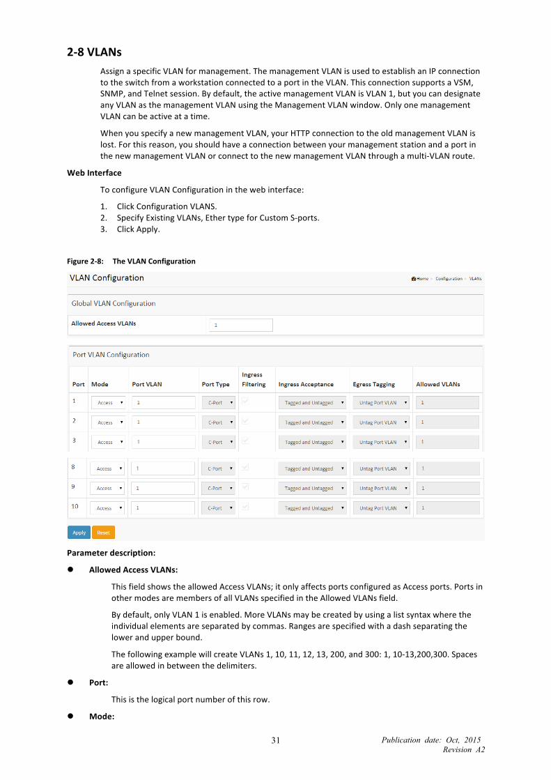
Figure 2-‐8: The VLAN Configuration
Parameter description:
Allowed Access VLANs:
This field shows the allowed Access VLANs; it only affects ports configured as Access ports. Ports in other modes are members of all VLANs specified in the Allowed VLANs field.
By default, only VLAN 1 is enabled. More VLANs may be created by using a list syntax where the individual elements are separated by commas. Ranges are specified with a dash separating the lower and upper bound.
The following example will create VLANs 1, 10, 11, 12, 13, 200, and 300: 1, 10-‐13,200,300. Spaces are allowed in between the delimiters.
Port:
This is the logical port number of this row.
Mode:

Publication date: Oct, 2015 Revision A2
32
The port mode (default is Access) determines the fundamental behavior of the port in question. A port can be in one of three modes as described below (access, trunk, or hybrid). When a particular mode is selected, the remaining fields in that row will be either grayed out or changeable depending on the mode in question. Grayed out fields show the value that the port will get when the mode is applied. Access: Access ports are normally used to connect to end stations. Dynamic features like Voice VLAN may add the port to more VLANs behind the scenes. Access ports have the following characteristics:
Member of exactly one VLAN, the Port VLAN (a.k.a. Access VLAN), which by default is 1.
Accepts untagged frames and C-‐tagged frames.
Discards all frames that are not classified to the Access VLAN.
On egress all frames are transmitted untagged.
Trunk: Trunk ports can carry traffic on multiple VLANs simultaneously, and are normally used to connect to other switches. Trunk ports have the following characteristics:
By default, a trunk port is member of all existing VLANs. This may be limited by the use of Allowed VLANs.
Unless VLAN Trunking is enabled on the port, frames classified to a VLAN that the port is not a member of will be discarded.
By default, all frames but frames classified to the Port VLAN (a.k.a. Native VLAN) get tagged on egress. Frames classified to the Port VLAN do not get C-‐tagged on egress.
Egress tagging can be changed to tag all frames, in which case only tagged frames are accepted on ingress.
VLAN trunking may be enabled. Hybrid: Hybrid ports resemble trunk ports in many ways, but add additional port configuration features. In addition to the characteristics described for trunk ports, hybrid ports have these abilities:
Can be configured to be VLAN tag unaware, C-‐tag aware, S-‐tag aware, or S-‐custom-‐tag aware.
Ingress filtering can be controlled.
Ingress acceptance of frames and configuration of egress tagging can be configured independently.
Port VLAN:
Determines the port’s VLAN ID (a.k.a. PVID). Allowed VLANs range from 1 through 4095; the default is 1. On ingress, frames are classified to the Port VLAN if the port is configured as VLAN unaware, the frame is untagged, or VLAN awareness is enabled on the port, but the frame is priority tagged (VLAN ID = 0). On egress, frames classified to the Port VLAN do not get tagged if Egress Tagging configuration is set to untag Port VLAN. The Port VLAN is called an “Access VLAN” for ports in Access mode and “Native VLAN” for ports in Trunk or Hybrid mode.
Port Type:
Ports in hybrid mode allow for changing the port type, that is, whether a frame's VLAN tag is used to classify the frame on ingress to a particular VLAN, and if so, which TPID it reacts on. On egress, the Port Type determines the TPID of the tag if a tag is required. Unaware: On ingress, all frames, whether carrying a VLAN tag or not, get classified to the Port VLAN, and possible tags are not removed on egress. C-‐Port: On ingress, frames with a VLAN tag with TPID = 0x8100 get classified to the VLAN ID embedded in the tag. If a frame is untagged or priority tagged, the frame gets classified to the Port VLAN. If frames must be tagged on egress, they will be tagged with a C-‐tag. S-‐Port: On ingress, frames with a VLAN tag with TPID = 0x8100 or 0x88A8 get classified to the VLAN ID embedded in the tag. If a frame is untagged or priority tagged, the frame gets classified to the Port VLAN. If frames must be tagged on egress, they will be tagged with an S-‐tag. S-‐Custom-‐Port:

Publication date: Oct, 2015 Revision A2
33
On ingress, frames with a VLAN tag with a TPID = 0x8100 or equal to the Ethertype configured for Custom-‐S ports get classified to the VLAN ID embedded in the tag. If a frame is untagged or priority tagged, the frame gets classified to the Port VLAN. If frames must be tagged on egress, they will be tagged with the custom S-‐tag.
Ingress Filtering:
Hybrid ports allow for changing ingress filtering. Access and Trunk ports always have ingress filtering enabled. If ingress filtering is enabled (checkbox is checked), frames classified to a VLAN that the port is not a member of get discarded. If ingress filtering is disabled, frames classified to a VLAN that the port is not a member of are accepted and forwarded to the switch engine. However, the port will never transmit frames classified to VLANs that it is not a member of.
VLAN Trunking:
Trunk and Hybrid ports allow for enabling VLAN trunking. When VLAN trunking is enabled, frames classified to unknown VLANs are accepted on the port whether ingress filtering is enabled or not. This is useful in scenarios where a cloud of intermediary switches must bridge VLANs that haven't been created. By configuring the ports that connect the cloud of switches as trunking ports, they can seamlessly carry those VLANs from one end to the other.
Ingress Acceptance:
Hybrid ports allow for changing the type of frames that are accepted on ingress. Tagged and Untagged: Both tagged and untagged frames are accepted. Tagged Only: Only tagged frames are accepted on ingress. Untagged frames are discarded. Untagged Only: Only untagged frames are accepted on ingress. Tagged frames are discarded.
Egress Tagging:
Ports in Trunk and Hybrid mode may control the tagging of frames on egress. Untag Port VLAN Frames classified to the Port VLAN are transmitted untagged. Other frames are transmitted with the relevant tag. Tag All All frames, whether classified to the Port VLAN or not, are transmitted with a tag. Untag All All frames, whether classified to the Port VLAN or not, are transmitted without a tag. This option is only available for ports in Hybrid mode.
Allowed VLANs:
Ports in Trunk and Hybrid mode may control which VLANs they are allowed to become members of. Access ports can only be member of one VLAN, the Access VLAN. The field’s syntax is identical to the syntax used in the Existing VLANs field. By default, a port may become a member of all possible VLANs, and is therefore set to 1–4095. The field may be left empty, which means that the port will not be member of any of the existing VLANs, but if it is configured for VLAN Trunking, it will still be able to carry all unknown VLANs.

Publication date: Oct, 2015 Revision A2
34
2-‐9 Private VLANs In a private VLAN, communication between ports in that private VLAN is not permitted. A VLAN can be configured as a private VLAN.
2-‐9.1 VLAN Membership
The VLAN membership configuration for the selected stack switch unit can be monitored and modified here. Up to 4096 VLANs are supported. This page allows for adding and deleting VLANs as well as adding and deleting port members of each VLAN.
Web Interface
To configure Private VLAN Membership Configuration in the web interface:
1. Click VLAN membership Configuration. 2. Specify Management VLAN ID. (Range is 0–4094.) 3. Click Apply.
Figure 2-‐9.1: The Private VLAN Membership Configuration
Parameter description:
Delete:
To delete a private VLAN entry, check this box. The entry will be deleted during the next save.
PVLAN ID:
Indicates the ID of this particular private VLAN.
Port Members:
A row of check boxes for each port is displayed for each VLAN ID. To include a port in a VLAN, check the box. To remove or exclude the port from the VLAN, make sure the box is unchecked. By default, no ports are members, and all boxes are unchecked.
Add:
Click to add a new VLAN ID. An empty row is added to the table, and the VLAN can be configured as needed. Legal values for a VLAN ID are 1 through 4095.
The VLAN is enabled on the selected stack switch unit when you click on “Save.” The VLAN is thereafter present on the other stack switch units, but with no port members. The check box is grayed out when VLAN is displayed on other stacked switches, but users can add member ports to it.
A VLAN without any port members on any stack unit will be deleted when you click “Save.”
Use the button to undo the addition of new VLANs.
Buttons:
Apply – Click to save changes.
Reset-‐ Click to undo any changes made locally and revert to previously saved values.

Publication date: Oct, 2015 Revision A2
35
2-‐9.2 Port Isolation
Port Isolation provides for an apparatus and method to isolate ports on layer 2 switches on the same VLAN to restrict traffic flow. The apparatus comprises a switch with mulitple ports, each port configured as a protected port or a non-‐protected port. An address table memory stores an address table that has a destination address and port number pair. A forwarding map generator generates a forwarding map that responds to a data packet’s destination address. The method for isolating ports on a layer 2 switch comprises configuring each of the ports on the layer 2 switch as a protected port or a non-‐protected port. A destination address on a data packet is matched with a physical address on the layer 2 switch and a forwarding map is generated for the data packet based upon the destination address on the data packet. The data packet is then sent to the multiple ports according to the forwarding map generated based upon whether the ingress port was configured as a protected or non-‐protected port.
Use this page to enable or disable port isolation on ports in a Private VLAN. A port member of a VLAN can be isolated to other isolated ports on the same VLAN and Private VLAN.
Web Interface
To configure Port Isolation Configuration in the web interface:
1. Click Private VLAN, Port Isolation. 2. Select the port for which you want to enable Port Isolation. 3. Click Apply.
Figure 2-‐9.2: The Port Isolation Configuration
Parameter description:
Port Members:
A check box is provided for each port of a private VLAN. When checked, port isolation is enabled on that port. When unchecked, port isolation is disabled on that port. By default, port isolation is disabled on all ports.
Buttons:
Apply – Click to save changes.
Reset – Click to undo any changes made locally and revert to previously saved values.

Publication date: Oct, 2015 Revision A2
36
2-‐10 QoS The switch supports four QoS queues per port with strict or weighted fair queuing scheduling. It supports QoS Control Lists (QCL) for advanced programmable QoS classification, based on IEEE 802.1p, Ethertype, VID, IPv4/IPv6 DSCP and UDP/TCP ports and ranges.
The switch is flexible in classifying incoming frames to a QoS class. The QoS classification looks for information up to Layer 4, including IPv4 and IPv6 DSCP, IPv4 TCP/UDP port numbers, and user priority of tagged frames. This QoS classification mechanism is implemented in a QoS control list (QCL). The QoS class assigned to a frame is used throughout the device for providing queuing, scheduling, and congestion control guarantees to the frame according to what was configured for that specific QoS class.
The switch supports advanced memory control mechanisms that provide excellent performance of all QoS classes under any traffic scenario, including jumbo frame. A super priority queue with dedicated memory and strict highest priority in the arbitration. The ingress super priority queue allows traffic recognized as CPU traffic to be received and queued for transmission to the CPU, even when all the QoS class queues are congested.
2-‐10.1 Port Classification
The section allows you to configure the basic QoS Ingress Classification settings for all switch ports. The settings relate to the currently selected stack unit, as reflected by the page header.
Web Interface
To configure the QoS Ingress Port Classification parameters in the web interface:
1. Click Configuration, QoS, Port Classification. 2. Scroll to select QoS class, DP Level, PCP and DEI parameters. 3. Click “Save” to save to save the setting. 4. To cancel the setting, click the Reset button. It will revert to previously saved values.
Figure 2-‐10.1: The QoS Ingress Port Classification
Parameter description:
Port:
The port number for which the configuration below applies.
PCP:
Controls the default PCP value.
All frames are classified to a PCP value.

Publication date: Oct, 2015 Revision A2
37
If the port is VLAN aware and the frame is tagged, then the frame is classified to the PCP value in the tag. Otherwise, the frame is classified to the default PCP value.
DSCP Based:
Click to Enable DSCP Based QoS Ingress Port Classification.
Buttons:
Apply – Click to save changes.
Reset – Click to undo any changes made locally and revert to previously saved values.
Publication date: Oct, 2015 Revision A2
38
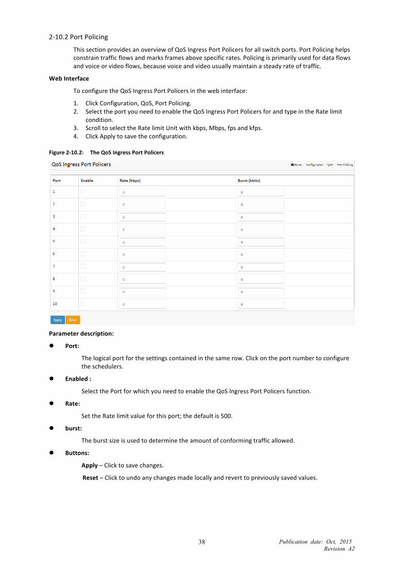
2-‐10.2 Port Policing
This section provides an overview of QoS Ingress Port Policers for all switch ports. Port Policing helps constrain traffic flows and marks frames above specific rates. Policing is primarily used for data flows and voice or video flows, because voice and video usually maintain a steady rate of traffic.
Web Interface
To configure the QoS Ingress Port Policers in the web interface:
1. Click Configuration, QoS, Port Policing. 2. Select the port you need to enable the QoS Ingress Port Policers for and type in the Rate limit
condition. 3. Scroll to select the Rate limit Unit with kbps, Mbps, fps and kfps. 4. Click Apply to save the configuration.
Figure 2-‐10.2: The QoS Ingress Port Policers
Parameter description:
Port:
The logical port for the settings contained in the same row. Click on the port number to configure the schedulers.
Enabled :
Select the Port for which you need to enable the QoS Ingress Port Policers function.
Rate:
Set the Rate limit value for this port; the default is 500.
burst:
The burst size is used to determine the amount of conforming traffic allowed.
Buttons:
Apply – Click to save changes.
Reset – Click to undo any changes made locally and revert to previously saved values.

Publication date: Oct, 2015 Revision A2
39
2-‐10.3 Port Shaper
This section provides an overview of QoS Egress Port Shaping for all switch ports. Users can get detailed information for the ports that belong to the currently selected unit, as reflected by the page header.
Web Interface
To display the QoS Egress Port Shaper in the web interface:
1. Click Configuration, QoS, Port Shaper. 2. Display the QoS Egress Port Shapers.
Figure 2-‐10.3: The QoS Egress Port Shaper
Parameter description:
Port:
The logical port for the settings contained in the same row. Click on the port number in order to configure the schedulers.
Queue Shaper Enable:
Controls whether the queue shaper is enabled for this queue on this switch port.
Queue Shaper Rate:
Controls the rate for the queue shaper. The default value is 500. This value is restricted to 100–1000000 when the “Unit” is “kbps,” and it is restricted to 1–13200 when the ”Unit” is “Mbps.”
Queue Shaper Unit:
Controls the unit of measure for the queue shaper rate as “kbps” or “Mbps.” The default value is “kbps.”
Port Shaper Enable:
Controls whether the port shaper is enabled for this switch port.
Port Shaper Rate:

Publication date: Oct, 2015 Revision A2
40
Controls the rate for the port shaper. The default value is 500. This value is restricted to 100–1000000 when the ”Unit” is “kbps,” and it is restricted to 1–13200 when the “Unit” is “Mbps.”
Port Shaper burst:
The burst size is used to determine the amount of conforming traffic allowed.
Buttons:
Apply – Click to save changes.
Reset – Click to undo any changes made locally and revert to previously saved values.

Publication date: Oct, 2015 Revision A2
41
2-‐10.4 Port Scheduler
This section provides an overview of QoS Egress Port Shapers for all switch ports. Users can get detailed information for the ports that belong to the currently selected stack unit, as reflected by the page header.
Web Interface
To display the QoS Egress Port Scheduler in the web interface:
1. Click Configuration, QoS, Port Scheduler. 2. Display the QoS Egress Port Scheduler.
Figure 2-‐10.4: The QoS Egress Port Scheduler
Parameter description:
Port:
The logical port for the settings contained in the same row. Click on the port number to configure the shapers.
Shapers (Qn):
Shows “disabled” or actual queue shaper rate—for example, “800 Mbps.”
Scheduler Mode:
Controls whether the scheduler mode is “Strict Priority,” “WRR,” or “DWRR” on this switch port.
Queue Shaper Enable:
Controls whether the queue shaper is enabled for this queue on this switch port.
Queue Shaper Unit:
Controls the unit of measure for the port shaper rate as “kbps” or “Mbps.”
Queue Scheduler Weight:
Controls the weight for this queue. The default value is “17.” This value is restricted to 1–100. This parameter is only shown if “Scheduler Mode” is set to “Weighted.”
Buttons:
Apply – Click to save changes.

Publication date: Oct, 2015 Revision A2
42
Reset – Click to undo any changes made locally and revert to previously saved values.

Publication date: Oct, 2015 Revision A2
43
2-‐10.5 Port Tag Classification
The section allows you to configure the basic QoS Ingress Classification settings for all switch ports. The settings relate to the currently selected stack unit, as reflected by the page header.
Web Interface
To configure the QoS Ingress Port Classification parameters in the web interface:
1. Click Configuration, QoS, Port Classification. 2. Scroll to select QoS class, DP Level, PCP and DEI parameters. 3. Click “Save” to save the setting. 4. To cancel the setting, click the Reset button. It will revert to previously saved values.
Figure 2-‐10.5: The QoS Ingress Port Tag Classification
Parameter description:
Port:
The Port column shows the list of ports for which you can configure DSCP ingress and egress settings.
PCP:
Controls the default PCP value.
All frames are classified to a PCP value.
If the port is VLAN aware and the frame is tagged, then the frame is classified to the PCP value in the tag. Otherwise, the frame is classified to the default PCP value.
DEI :
Controls the default DEI value.
All frames are classified to a DEI value.
If the port is VLAN aware and the frame is tagged, then the frame is classified to the DEI value in the tag. Otherwise, the frame is classified to the default DEI value.
QoS Class:
Available QoS Class values range from 0 to 7. QoS Class (0–7) can be mapped to followed parameters.
DPL:
Actual Drop Precedence Level.

Publication date: Oct, 2015 Revision A2
44
Buttons:
Apply – Click to save changes.
Reset – Click to undo any changes made locally and revert to previously saved values.
Auto-‐refresh:
Select the auto-‐refresh iconm, then the device will refresh the information automatically.
Upper right icon (Refresh):
Click to refresh the QoS Port DSCP information manually.

Publication date: Oct, 2015 Revision A2
45
2-‐10.6 Port Tag Remarking
This section explains how to get an overview of QoS Egress Port Tag Remarking for all switch ports. Otherwise, the ports belong to the currently selected stack unit, as reflected by the page header.
Web Interface
To display the QoS Egress Port Tag Remarking in the web interface:
1. Click Configuration, QoS, Port Tag Remarking.
Figure 2-‐10.6: The QoS Egress Port Tag Remarking
Parameter description:
PCP/DEI Configuration:
Controls the default PCP and DEI values used when the mode is set to Default.
(QoS class, DP level) to (PCP, DEI) Mapping:
Controls the mapping of the classified (QoS class, DP level) to (PCP, DEI) values when the mode is set to Mapped.
Buttons:
Apply – Click to save changes.
Reset – Click to undo any changes made locally and revert to previously saved values.
Cancel – Click to cancel the changes.
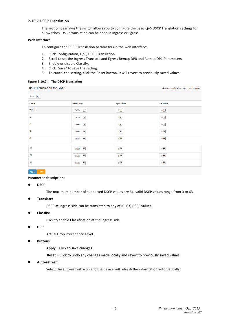
Publication date: Oct, 2015 Revision A2
46
2-‐10.7 DSCP Translation
The section describes the switch allows you to configure the basic QoS DSCP Translation settings for all switches. DSCP translation can be done in Ingress or Egress.
Web Interface
To configure the DSCP Translation parameters in the web interface:
1. Click Configuration, QoS, DSCP Translation. 2. Scroll to set the Ingress Translate and Egress Remap DP0 and Remap DP1 Parameters. 3. Enable or disable Classify. 4. Click “Save” to save the setting. 5. To cancel the setting, click the Reset button. It will revert to previously saved values.
Figure 2-‐10.7: The DSCP Translation
Parameter description:
DSCP:
The maximum number of supported DSCP values are 64; valid DSCP values range from 0 to 63.
Translate:
DSCP at Ingress side can be translated to any of (0–63) DSCP values.
Classify:
Click to enable Classification at the Ingress side.
DPL:
Actual Drop Precedence Level.
Buttons:
Apply – Click to save changes.
Reset – Click to undo any changes made locally and revert to previously saved values.
Auto-‐refresh:
Select the auto-‐refresh icon and the device will refresh the information automatically.

Publication date: Oct, 2015 Revision A2
47
2-‐10.8 Storm Control
The section allows the user to configure the Storm control for the switch. There is a unicast storm rate control, multicast storm rate control, and a broadcast storm rate control. These only affect flooded frames, i.e. frames with a (VLAN ID, DMAC) pair not present on the MAC table. The configuration indicates the permitted packet rate for unicast, multicast, or broadcast traffic across the switch.
Web Interface
To configure the Storm Control Configuration parameters in the web interface:
1. Click Configuration, QoS, Storm Control Configuration. 2. Select the frame type to enable storm control. 3. Scroll to set the Rate Parameters. 4. Click “Save” to save the setting. 5. To cancel the setting, click the Reset button. It will revert to previously saved values.
Figure 2-‐10.8: The Storm Configuration
Parameter description: Frame Type:
The settings in a particular row apply to the frame type listed here: Unicast, Multicast, or Broadcast.
Enable:
Enable or disable the storm control status for the given frame type.
Rate:
The rate unit is packets per second (pps). Valid values are: 1, 2, 4, 8, 16, 32, 64, 128, 256, 512, 1K, 2K, 4K, 8K, 16K, 32K, 64K, 128K, 256K, 512K or 1024K, 2048K, 4096K, 8192K, 16384K, or 32768K.
The 1k pps is actually 1002.1 pps.
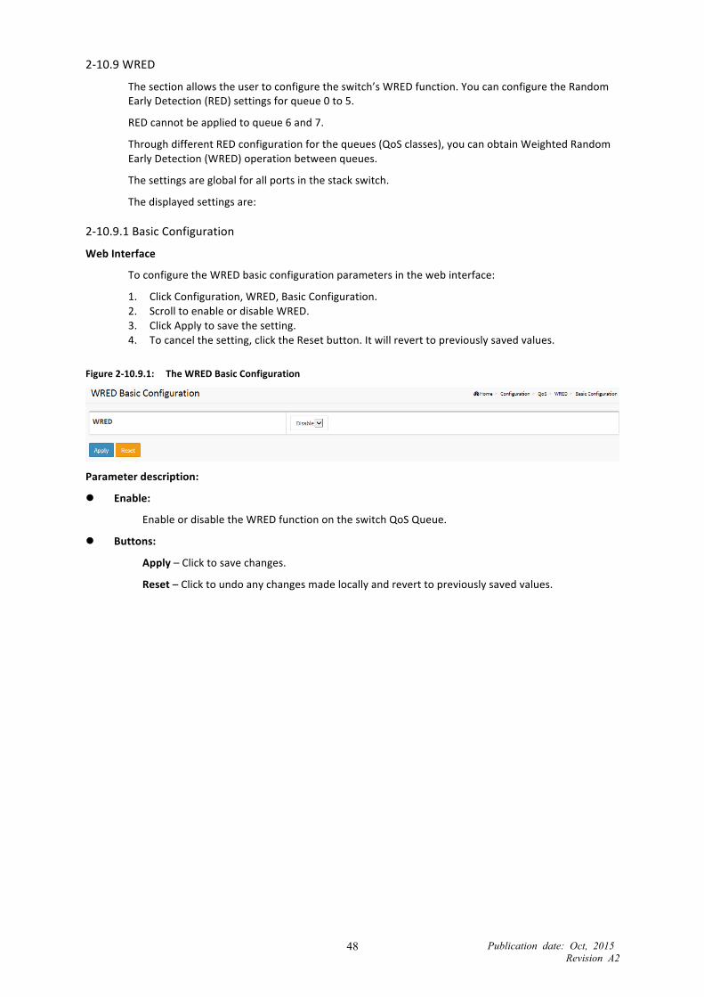
Publication date: Oct, 2015 Revision A2
48
2-‐10.9 WRED
The section allows the user to configure the switch’s WRED function. You can configure the Random Early Detection (RED) settings for queue 0 to 5.
RED cannot be applied to queue 6 and 7.
Through different RED configuration for the queues (QoS classes), you can obtain Weighted Random Early Detection (WRED) operation between queues.
The settings are global for all ports in the stack switch.
The displayed settings are:
2-‐10.9.1 Basic Configuration
Web Interface
To configure the WRED basic configuration parameters in the web interface:
1. Click Configuration, WRED, Basic Configuration. 2. Scroll to enable or disable WRED. 3. Click Apply to save the setting. 4. To cancel the setting, click the Reset button. It will revert to previously saved values.
Figure 2-‐10.9.1: The WRED Basic Configuration
Parameter description:
Enable:
Enable or disable the WRED function on the switch QoS Queue.
Buttons:
Apply – Click to save changes.
Reset – Click to undo any changes made locally and revert to previously saved values.
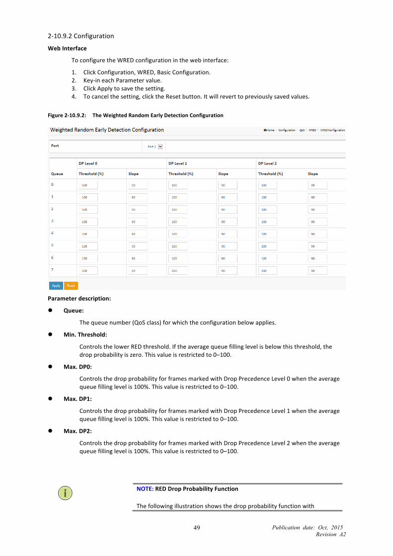
Publication date: Oct, 2015 Revision A2
49
2-‐10.9.2 Configuration
Web Interface
To configure the WRED configuration in the web interface:
1. Click Configuration, WRED, Basic Configuration. 2. Key-‐in each Parameter value. 3. Click Apply to save the setting. 4. To cancel the setting, click the Reset button. It will revert to previously saved values.
Figure 2-‐10.9.2: The Weighted Random Early Detection Configuration
Parameter description:
Queue:
The queue number (QoS class) for which the configuration below applies.
Min. Threshold:
Controls the lower RED threshold. If the average queue filling level is below this threshold, the drop probability is zero. This value is restricted to 0–100.
Max. DP0:
Controls the drop probability for frames marked with Drop Precedence Level 0 when the average queue filling level is 100%. This value is restricted to 0–100.
Max. DP1:
Controls the drop probability for frames marked with Drop Precedence Level 1 when the average queue filling level is 100%. This value is restricted to 0–100.
Max. DP2:
Controls the drop probability for frames marked with Drop Precedence Level 2 when the average queue filling level is 100%. This value is restricted to 0–100.
NOTE: RED Drop Probability Function
The following illustration shows the drop probability function with

Publication date: Oct, 2015 Revision A2
50
associated parameters.
Max. DP 1–3 is the drop probability when the average queue filling level is 100%. Frames marked with Drop Precedence Level 0 are never dropped. Min. Threshold is the average queue filling level where the queues randomly start dropping frames. The drop probability for frames marked with Drop Precedence Level n increases linearly from zero (at Min. Threshold average queue filling level) to Max. DP n (at 100% average queue filling level).
Buttons:
Apply – Click to save changes.
Reset – Click to undo any changes made locally and revert to previously saved values.

Publication date: Oct, 2015 Revision A2
51
2-‐11 Mirror You can mirror traffic from any source port to a target port for real-‐time analysis. You can then attach a logic analyzer or RMON probe to the target port and study the traffic crossing the source port in a completely unobtrusive manner.
Use Mirror Configuration to monitor the traffic of the network. For example, we assume that Port A and Port B are Monitoring Port and Monitored Port respectively, so, the traffic received by Port B will be copied to Port A for monitoring.
Web Interface
To configure the Mirror Configuration in the web interface:
1. Click Configuration, Mirroring. 2. Scroll to select the Port to mirror on which port. 3. Click “Save” to save the setting. 4. To cancel the setting, click the Reset button. It will revert to previously saved values.
Figure 2-‐11: The Mirror Configuration
Parameter description:
Port to mirror on:
Port to mirror is also known as the mirror port. Frames from ports that have either source (rx) or destination (tx) mirroring enabled are mirrored on this port. Disabled disables mirroring.
Mirror Port Configuration
The following table is used for Rx and Tx enabling.
Port:
The logical port for the settings contained in the same row.
Mode:
Select mirror mode.
Rx only Frames received on this port are mirrored on the mirror port. Frames transmitted are not mirrored.
Tx only Frames transmitted on this port are mirrored on the mirror port. Frames received are not mirrored.

Publication date: Oct, 2015 Revision A2
52
Disabled Neither frames transmitted nor frames received are mirrored.
Enabled Frames received and frames transmitted are mirrored on the mirror port.
NOTE: For a given port, a frame is only transmitted once. It is not possible to mirror Tx frames on the mirror port. Because of this, the mode for the selected mirror port is limited to Disabled or Rx only.
Buttons:
Apply – Click to save changes.
Reset – Click to undo any changes made locally and revert to previously saved values.

Publication date: Oct, 2015 Revision A2
53
2-‐12 Loop Protection Loop Protection is used to detect the presence of traffic. When a switch receives a packet’s (looping detection frame) MAC address that is the same as its own, Loop Protection occurs. The port will be locked when it receives the looping Protection frames.
Web Interface
To configure the Loop Protection Configuration parameters in the web interface:
1. Click Configuration, Loop Protection. 2. Enable or disable the port loop Protection. 3. Click apply to save the setting. 4. To cancel the setting, click the Reset button. It will revert to previously saved values.
Figure2-‐12: The Loop Protection Configuration
Parameter description:
General Settings:
Enable Loop Protection:
Controls whether loop protections is enabled (as a whole).
Transmission Time:
The interval between each loop protection PDU sent on each port. Valid values are 1 to 10 seconds.
Shutdown Time:
The period (in seconds) for which a port will be kept disabled if a loop is detected (and the port action shuts down the port). Valid values are 0 to 604800 seconds (7 days). A value of zero will keep a port disabled (until the next device restart).

Publication date: Oct, 2015 Revision A2
54
Port Configuration:
Port:
The switch port number of the port.
Enable:
Controls whether loop protection is enabled on this switch port.
Action:
Configures the action performed when a loop is detected on a port. Valid values are Shutdown Port, Shutdown Port and Log, or Log Only.
TX Mode:
Controls whether the port is actively generating loop protection PDUs, or whether it is just passively looking for looped PDUs.
Buttons:
Apply – Click to apply changes.
Reset – Click to undo any changes made locally and revert to previously saved values.
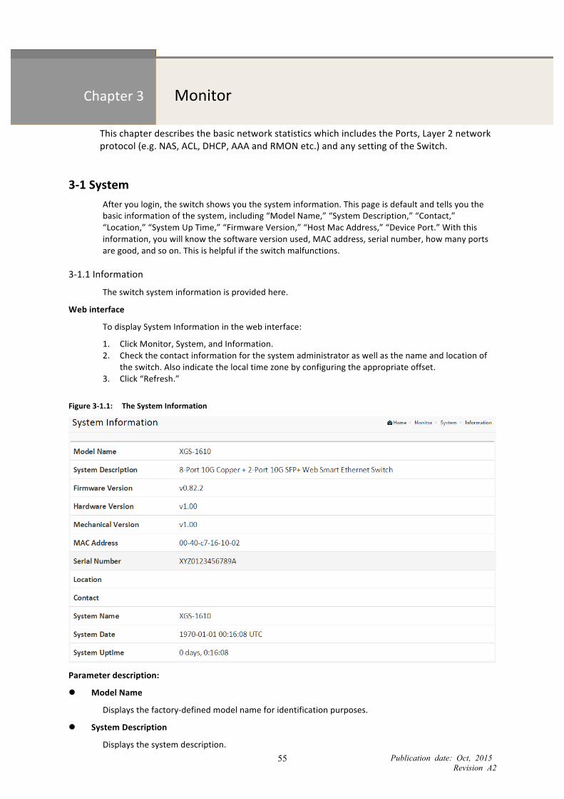
Publication date: Oct, 2015 Revision A2
55
Chapter 3 Monitor
This chapter describes the basic network statistics which includes the Ports, Layer 2 network protocol (e.g. NAS, ACL, DHCP, AAA and RMON etc.) and any setting of the Switch.
3-‐1 System After you login, the switch shows you the system information. This page is default and tells you the basic information of the system, including “Model Name,” “System Description,” “Contact,” “Location,” “System Up Time,” “Firmware Version,” “Host Mac Address,” “Device Port.” With this information, you will know the software version used, MAC address, serial number, how many ports are good, and so on. This is helpful if the switch malfunctions.
3-‐1.1 Information
The switch system information is provided here.
Web interface
To display System Information in the web interface:
1. Click Monitor, System, and Information. 2. Check the contact information for the system administrator as well as the name and location of
the switch. Also indicate the local time zone by configuring the appropriate offset. 3. Click “Refresh.”
Figure 3-‐1.1: The System Information
Parameter description:
Model Name
Displays the factory-‐defined model name for identification purposes.
System Description
Displays the system description.

Publication date: Oct, 2015 Revision A2
56
Firmware Version The software version of this switch.
Hardware Version The hardware version of this switch.
Mechanical Version The mechanical version of this switch.
MAC Address
The MAC Address of this switch.
Series Number
The serial number of this switch.
Location
The system location configured in Configuration | System | Information | System Location.
Contact
The system contact configured in Configuration | System | Information | System Contact.
System Name
Displays the user-‐defined system name configured in System | System Information | Configuration | System Name.
System Date
The current (GMT) system time and date. The system time is obtained through the Timing server running on the switch, if any.
System Uptime
The period of time the device has been operating.

Publication date: Oct, 2015 Revision A2
57
3-‐1.2 IP Status
This page displays the status of the IP protocol layer. The status is defined by the IP interfaces, the IP routes, and the neighbor cache (ARP cache).
Web Interface
To display the IP Status in the web interface:
1. Click Monitor, System, and IP Status. 2. Display the IP address information.
Figure 3-‐ 1.2: The IP Status
Parameter description:
IP Interfaces
Interface
Show the name of the interface.
Type
Show the address type of the entry. This may be LINK or IPv4.
Address
Show the current address of the interface (of the given type).
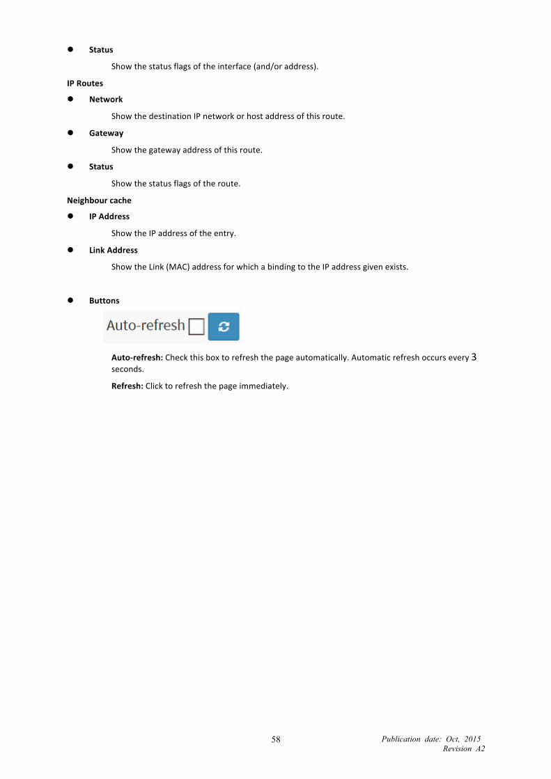
Publication date: Oct, 2015 Revision A2
58
Status
Show the status flags of the interface (and/or address).
IP Routes
Network
Show the destination IP network or host address of this route.
Gateway
Show the gateway address of this route.
Status
Show the status flags of the route.
Neighbour cache
IP Address
Show the IP address of the entry.
Link Address
Show the Link (MAC) address for which a binding to the IP address given exists.
Buttons
Auto-‐refresh: Check this box to refresh the page automatically. Automatic refresh occurs every 3 seconds.
Refresh: Click to refresh the page immediately.

Publication date: Oct, 2015 Revision A2
59
3-‐1.3 Log
This section describes the switch’s system log information display.
Web Interface
To display the log configuration in the web interface:
1. Click Monitor, System, and Log. 2. Display the log information.
Figure 3-‐ 1.3: The System Log Information
Parameter description:
Auto-‐refresh
Click the auto-‐refresh icon, then the device will refresh the log automatically.
Level
Level of the system log entry. The following level types are supported:
Information: Information level of the system log.
Warning: Warning level of the system log.
Error: Error level of the system log. All: All levels.
ID
ID (>= 1) of the system log entry.
Time
It will display the log record by device time. The time of the system log entry.
Message
It will display the log detail message. The message of the system log entry.
Buttons
Auto-‐refresh: Check this box to refresh the page automatically. Automatic refresh occurs every 3 seconds.
Refresh: Updates the system log entries, starting from the current entry ID.
Clear: Clears the selected log entries.

Publication date: Oct, 2015 Revision A2
60
3-‐2 Ports The section describes how to configure the switch’s Port detail parameters. You can also use Port configure to enable or disable the switch Port or monitor the port‘s content.
3-‐2.1 Traffic Overview
The section describes the Port statistics information and provides an overview of general traffic statistics for all switch ports.
Web Interface
To display the Port Statistics Overview in the web interface:
1. Click Monitor, Port, Traffic Overview. 2. If you want to auto-‐refresh, then you need to select “Auto-‐refresh.” 3. Click “Refresh” to refresh the port statistics, or click “Clear” to clear all information.
Figure 3-‐2.1: The Port Statistics Overview
Parameter description:
Port:
The logical port for the settings contained in the same row.
Packets:
The number of received and transmitted packets per port.
Bytes:
The number of received and transmitted bytes per port.
Errors:
The number of frames received in error and the number of incomplete transmissions per port.
Drops:
The number of frames discarded because of ingress or egress congestion.
Buttons
Auto-‐refresh: Check this box to refresh the page automatically. Automatic refresh occurs every 3 seconds.
Refresh: Click to refresh the page.

Publication date: Oct, 2015 Revision A2
61
Clear: Clears the counters for all ports.

Publication date: Oct, 2015 Revision A2
62
3-‐2.2 Detailed Statistics
The section describes how to provide detailed traffic statistics for a specific switch port. Use the port select box to select which switch port details to display.
The displayed counters are the totals for receive and transmit, the size counters for receive and transmit, and the error counters for receive and transmit.
Web Interface
To display per Port detailed Port Statistics Overview in the web interface:
1. Click Monitor, Ports, then Detailed Port Statistics. 2. Scroll the Port Index to select the port you want to show the detailed Port statistics overview for. 3. To auto-‐refresh the information, select “Auto-‐refresh.” 4. Click “Refresh” to refresh the port’s detailed statistics or click “Clear” to clear all information.
Figure 3-‐2.2: The Detailed Port Statistics

Publication date: Oct, 2015 Revision A2
63
Parameter description:
Auto-‐refresh:
Select auto-‐refresh to refresh the Port Statistics information automatically.
Upper left scroll bar:
Scroll to the port that you want to display the Port statistics for with “Port-‐0,” “Port-‐1.”
Receive Total and Transmit Total Rx and Tx Packets:
The number of received and transmitted (good and bad) packets.
Rx and Tx Octets:
The number of received and transmitted (good and bad) bytes. Includes FCS, but excludes framing bits.
Rx and Tx Unicast:
The number of received and transmitted (good and bad) unicast packets.
Rx and Tx Multicast:
The number of received and transmitted (good and bad) multicast packets.
Rx and Tx Broadcast:
The number of received and transmitted (good and bad) broadcast packets.
Rx and Tx Pause:
A count of the MAC Control frames received or transmitted on this port that have an opcode indicating a PAUSE operation.
Receive and Transmit Size Counters The number of received and transmitted (good and bad) packets split into categories based on their respective frame sizes.
Receive and Transmit Queue Counters The number of received and transmitted packets per input and output queue.
Receive Error Counters Rx Drops:
The number of frames dropped because of lack of receive buffers or egress congestion.
Rx CRC/Alignment:
The number of frames received with CRC or alignment errors.
Rx Undersize:
The number of short 1 frames received with valid CRC.
Rx Oversize:
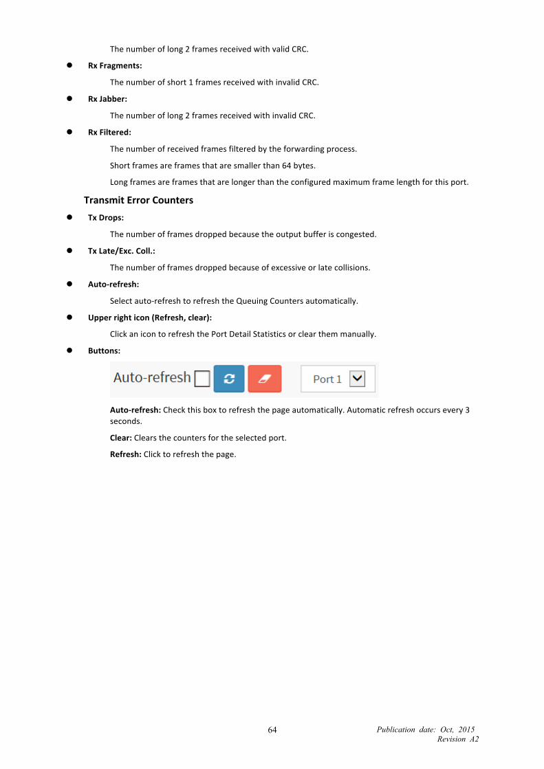
Publication date: Oct, 2015 Revision A2
64
The number of long 2 frames received with valid CRC.
Rx Fragments:
The number of short 1 frames received with invalid CRC.
Rx Jabber:
The number of long 2 frames received with invalid CRC.
Rx Filtered:
The number of received frames filtered by the forwarding process.
Short frames are frames that are smaller than 64 bytes.
Long frames are frames that are longer than the configured maximum frame length for this port.
Transmit Error Counters Tx Drops:
The number of frames dropped because the output buffer is congested.
Tx Late/Exc. Coll.:
The number of frames dropped because of excessive or late collisions.
Auto-‐refresh:
Select auto-‐refresh to refresh the Queuing Counters automatically.
Upper right icon (Refresh, clear):
Click an icon to refresh the Port Detail Statistics or clear them manually.
Buttons:
Auto-‐refresh: Check this box to refresh the page automatically. Automatic refresh occurs every 3 seconds.
Clear: Clears the counters for the selected port.
Refresh: Click to refresh the page.

Publication date: Oct, 2015 Revision A2
65
3-‐3 DHCP
3-‐3.1 Snooping Table
This page displays the dynamic IP assigned information after DHCP Snooping mode is disabled. All DHCP clients that obtained the dynamic IP address from the DHCP server will be listed in this table, except for local VLAN interface IP addresses. Entries in the Dynamic DHCP snooping Table are shown on this page.
Web Interface
To monitor a Dynamic DHCP Snooping Table in the web interface:
1. Click Monitor, DHCP, and Snooping table.
Figure 3-‐3.1: The Dynamic DHCP Snooping Table
Parameter description:
MAC Address:
User MAC address of the entry.
VLAN ID:
VLAN-‐ID in which the DHCP traffic is permitted.
Port:
Switch Port Number for which the entries are displayed.
IP Address:
User IP address of the entry.
IP Subnet Mask:
User IP subnet mask of the entry.
DHCP Server:
DHCP Server address of the entry.

Publication date: Oct, 2015 Revision A2
66
3-‐4 Security
3-‐4.1 Network 3-‐4.1.1 IP Source Guard
Entries in the Dynamic IP Source Guard Table are shown on this page. The Dynamic IP Source Guard Table is sorted first by port, then by VLAN ID, then by IP address, and then by MAC address.
Web Interface
To display a Dynamic IP Source Guard Table in the web interface:
1. Click Monitor, Network, IP Source Guard. 2. Check “Auto-‐refresh.” 3. Click “Refresh” to refresh the port’s detailed statistics. 4. Specify the Start from port, VLAN ID, IP Address, and entries per page.
Figure 3-‐4.1.1: The Dynamic IP Source Guard Table
Parameter description:
Port:
Switch Port Number for which the entries are displayed.
IP Address:
User IP address of the entry.
MAC Address:
Source MAC address.
Buttons:
Auto-‐refresh: Check this box to refresh the page automatically. Automatic refresh occurs every 3 seconds.
Refresh: Click to refresh the page.

Publication date: Oct, 2015 Revision A2
67
3-‐4.1.2 ARP Inspection
The section describes how to configure the Dynamic ARP Inspection Table parameters of the switch. The Dynamic ARP Inspection Table contains up to 1024 entries, and is sorted first by port, then by VLAN ID, then by MAC address, and then by IP address.
Web Interface
To configure a Dynamic ARP Inspection Table Configuration in the web interface:
1. Click Monitor, Network, ARP Inspection. 2. Check “Auto-‐refresh.” 3. Click “Refresh” to refresh the port’s detailed statistics. 4. Specify Start from port, VLAN ID, MAC Address, IP Address, and entries per page.
Figure 3-‐4.1.2: The Dynamic ARP Inspection Table
Parameter description:
Port:
Switch Port Number for which the entries are displayed.
VLAN ID:
VLAN-‐ID in which the ARP traffic is permitted.
MAC Address:
User MAC address of the entry.
IP Address:
User IP address of the entry.
Buttons:
Auto-‐refresh: Check this box to refresh the page automatically. Automatic refresh occurs every 3 seconds.
Refresh: Click to refresh the page.
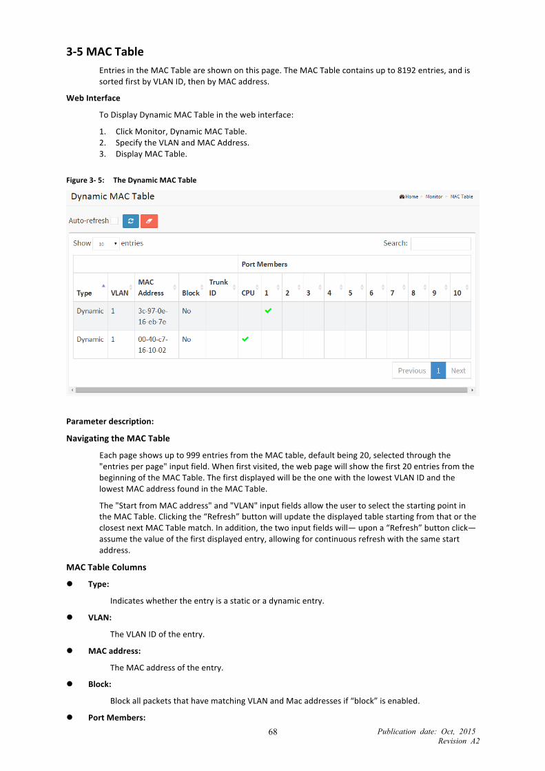
Publication date: Oct, 2015 Revision A2
68
3-‐5 MAC Table Entries in the MAC Table are shown on this page. The MAC Table contains up to 8192 entries, and is sorted first by VLAN ID, then by MAC address.
Web Interface
To Display Dynamic MAC Table in the web interface:
1. Click Monitor, Dynamic MAC Table. 2. Specify the VLAN and MAC Address. 3. Display MAC Table.
Figure 3-‐ 5: The Dynamic MAC Table
Parameter description:
Navigating the MAC Table
Each page shows up to 999 entries from the MAC table, default being 20, selected through the "entries per page" input field. When first visited, the web page will show the first 20 entries from the beginning of the MAC Table. The first displayed will be the one with the lowest VLAN ID and the lowest MAC address found in the MAC Table.
The "Start from MAC address" and "VLAN" input fields allow the user to select the starting point in the MAC Table. Clicking the “Refresh” button will update the displayed table starting from that or the closest next MAC Table match. In addition, the two input fields will— upon a “Refresh” button click— assume the value of the first displayed entry, allowing for continuous refresh with the same start address.
MAC Table Columns
Type:
Indicates whether the entry is a static or a dynamic entry.
VLAN:
The VLAN ID of the entry.
MAC address:
The MAC address of the entry.
Block:
Block all packets that have matching VLAN and Mac addresses if “block” is enabled.
Port Members:

Publication date: Oct, 2015 Revision A2
69
The ports that are members of the entry.
Buttons:
Auto-‐refresh: Check this box to refresh the page automatically. Automatic refresh occurs every 3 seconds.
Clear: Clears the counters for the selected port.
Refresh: Click to refresh the page.
NOTE: 00-‐40-‐C7-‐73-‐01-‐29 : your switch MAC address (for IPv4) 33-‐33-‐00-‐00-‐00-‐01 : Destination MAC (for IPv6 Router Advertisement) (reference IPv6 RA.JPG) 33-‐33-‐00-‐00-‐00-‐02 : Destination MAC (for IPv6 Router Solicitation) (reference IPv6 RS.JPG) 33-‐33-‐FF-‐73-‐01-‐29 : Destination MAC (for IPv6 Neighbor Solicitation) (reference IPv6 DAD.JPG) 33-‐33-‐FF-‐A8-‐01-‐01: your switch MAC address (for IPv6 global IP) FF-‐FF-‐FF-‐FF-‐FF-‐FF: for Broadcast.

Publication date: Oct, 2015 Revision A2
70
3-‐6 IGMP Snooping
3-‐6.1 Status
After you complete the IGMP Snooping configuration, let the switch display the IGMP Snooping Status. The section explains how to let the switch display the IGMP Snooping detail status.
Web Interface
To display the IGMP Snooping status in the web interface:
1. Click Monitor, IGMP Snooping, Status. 2. To auto-‐refresh the information, enable “Auto-‐refresh.” 3. Click “Refresh” to refresh the IGMP Snooping Status. 4. Click “Clear “to clear the IGMP Snooping Status.
Figure 3-‐6.1: The IGMP Snooping Status
Parameter description:
VLAN ID:
The VLAN ID of the entry.
Querier Version:
The currently working Querier Version.
Host Version:
The currently working Host Version.
Querier Status:
Shows the Querier status is "ACTIVE" or "IDLE.”
"DISABLE" denotes that the specific interface is administratively disabled.
Queries Transmitted:
The number of Transmitted Queries.
Queries Received:

Publication date: Oct, 2015 Revision A2
71
The number of Received Queries.
V1 Reports Received:
The number of Received V1 Reports.
V2 Reports Received:
The number of Received V2 Reports.
V3 Reports Received:
The number of Received V3 Reports.
V2 Leaves Received:
The number of Received V2 Leaves.
Router Port:
Display which ports act as router ports. A router port is a port on the Ethernet switch that leads towards the Layer 3 multicast device or IGMP querier. Static denotes that the specific port is configured to be a router port. Dynamic denotes that the specific port is learned to be a router port. Both denotes the specific port is configured or learned to be a router port.
Port:
Switch port number.
Status:
Indicate whether the specific port is a router port or not.
Buttons:
Auto-‐refresh: Check this box to refresh the page automatically. Automatic refresh occurs every 3 seconds.
Clear: Clears the counters for the selected port.
Refresh: Click to refresh the page.

Publication date: Oct, 2015 Revision A2
72
3-‐6.2 Group Information
After you set the IGMP Snooping function, the switch will display the IGMP Snooping Group Information. Entries in the IGMP Group Table are shown on this page. The IGMP Group Table is sorted first by VLAN ID, and then by group. The switch will use the last entry of the currently displayed table as a basis for the next lookup. When the end is reached, the text "No more entries" is shown in the displayed table. Use the button to start over.
Web Interface
To display the IGMP Snooping Group Information in the web interface:
1. Click Monitor, IGMP Snooping, Group Information. 2. To auto-‐refresh the information, select “Auto-‐refresh.” 3. Click “Refresh” to refresh an entry of the IGMP Snooping Groups Information. 4. Click “<<” or “>> “ to move to the previous or next entry.
Figure 3-‐6.2: The IGMP Snooping Groups Information
Parameter description:
IGMP Group Table Columns
VLAN ID:
VLAN ID of the group.
Groups:
Group address of the group displayed.
Port Members:
Ports under this group.

Publication date: Oct, 2015 Revision A2
73
3-‐6.3 IPv4 SSM Information
Entries in the IGMP SFM Information Table are shown on this page. The IGMP SFM (Source-‐Filtered Multicast) Information Table also contains the SSM (Source-‐Specific Multicast) information. This table is sorted first by VLAN ID, then by group, and then by Port. Different source addresses that belong to the same group are treated as a single entry.
Web Interface
To display the IGMP SFM Information in the web interface:
1. Click Monitor, IGMP Snooping, IPv4 SSM Information. 2. To auto-‐refresh the information, enable “Auto-‐refresh.” 3. Click “Refresh” to refresh an entry of the IPv4 SFM Information. 4. Click “<<” or “>> “to move to the previous or next entry.
Figure 3-‐6.3: The IGMP SFM Information
Parameter description:
IGMP SFM Information Table Columns
VLAN ID:
VLAN ID of the group.
Group:
Group address of the group displayed.
Port:
Switch port number.
Mode:
Indicates the filtering mode maintained per (VLAN ID, port number, Group Address) basis. It can be either Include or Exclude.
Source Address:
IP Address of the source. Currently, the system limits the total number of IP source addresses for filtering to be 128.
Type:
Indicates the Type. It can be either Allow or Deny.

Publication date: Oct, 2015 Revision A2
74
3-‐7 VLANs
3-‐7.1 VLAN Membership
This page provides an overview of membership status of VLAN users.
The ports belong to the currently selected stack unit, as reflected by the page header.
Web Interface
To configure VLAN membership configuration in the web interface:
1. Click Monitor, VLANs, VLAN membership. 2. Scroll to choose which VLANs you want to show. 3. Click Refresh to update the state.
Figure 3-‐7.1: The VLAN Membership Status
Parameter description:
VLAN ID
VLAN ID for which the Port members are displayed.
Port Members
A row of check boxes for each port is displayed for each VLAN ID.
If a port is included in a VLAN, an image will be displayed.
Untagged Port Members
A row of check boxes for each port is displayed for each VLAN ID.
If a port is an untagged port in a VLAN, an image will be displayed.
Buttons
Auto-‐refresh: Check this box to refresh the page automatically. Automatic refresh occurs every 3 seconds.
Refresh: Click to refresh the page.

Publication date: Oct, 2015 Revision A2
75
3-‐7.2 VLAN Port
The function Port Status gathers the information of all VLAN status and reports it by the order of Static, NAS, MVRP, MVP, Voice, VLAN, MSTP, GVRP, Combined.
Web Interface
To Display VLAN Port Status in the web interface:
1. Click Monitor, VLAN Port Status. 2. Display Port Status information.
Figure 3-‐7.2: The VLAN Port Status
Parameter description:
Port:
The logical port for the settings contained in the same row.
Port Type:
Shows the Port Type. Port type can be Unaware, C-‐port, S-‐port, Custom S-‐port.
If Port Type is Unaware, all frames are classified as the Port VLAN ID and tags are not removed. C-‐port is Customer Port. S-‐port is Service port. Custom S-‐port is S-‐port with Custom TPID.
Ingress Filtering :
Shows the ingress filtering on a port. This parameter affects VLAN ingress processing. If ingress filtering is enabled and the ingress port is not a member of the classified VLAN, the frame is discarded.
Frame Type:
Shows whether the port accepts all frames or only tagged frames. This parameter affects VLAN ingress processing. If the port only accepts tagged frames, untagged frames received on that port are discarded.
Port VLAN ID:
Shows the Port VLAN ID (PVID) that a given user wants the port to have.
The field is empty if not overridden by the selected user.
Tx Tag:
Shows egress filtering frame status whether tagged or untagged.
UVID:
Shows UVID (untagged VLAN ID). The port’s UVID determines the packet’s behavior on the egress side.
Conflicts:

Publication date: Oct, 2015 Revision A2
76
Shows whether Conflicts exist or not. When a Volatile VLAN User requests to set VLAN membership or VLAN port configuration, the following conflicts can occur:
• Functional Conflicts between features.
• Conflicts because of hardware limitation.
• Direct conflict between user modules.
Buttons
Auto-‐refresh: Check this box to refresh the page automatically. Automatic refresh occurs every 3 seconds.
Refresh: Click to refresh the page.

Publication date: Oct, 2015 Revision A2
77
3-‐8 Loop Protection This page displays the loop protection status for the switch ports.
Web Interface
To configure the Loop Protection Status parameters in the web interface:
1. Click Configuration, Loop Protection, Status. 2. Select Auto-‐refresh or click to refresh the Loop protection Port status manually.
Figure 3-‐8: The Loop Protection Status
Parameter description:
Port:
The switch port number of the logical port.
Action:
The currently configured port action.
Transmit:
The currently configured port transmit mode.
Loops:
The number of loops detected on this port.
Status:
The current loop protection status of the port.
Loop:
Whether a loop is currently detected on the port.
Time of Last Loop:
The time of the last loop event detected.
Auto-‐refresh:
Select the auto-‐refresh icon, then the device will refresh the information automatically.
Upper right icon (Refresh):
You can click this icon to refresh the Loop Protection information manually.
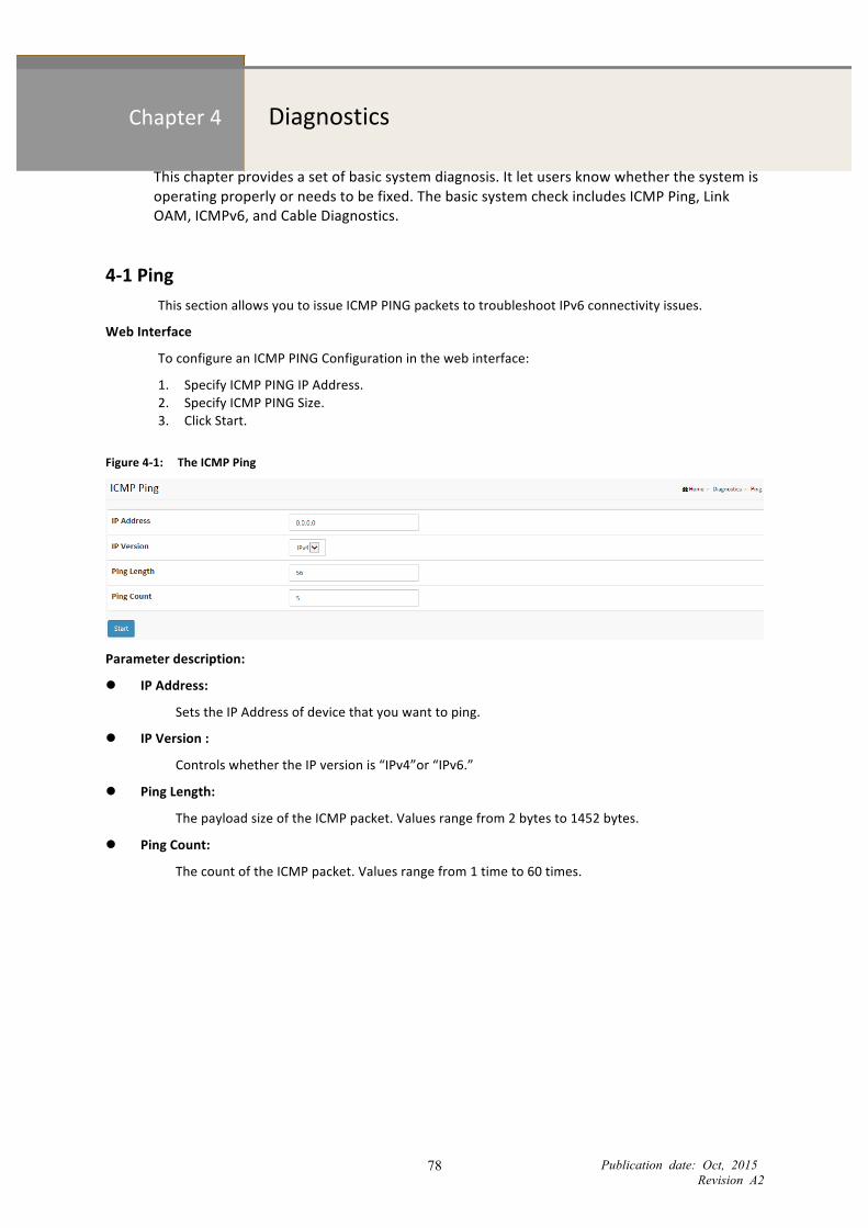
Publication date: Oct, 2015 Revision A2
78
Chapter 4 Diagnostics
This chapter provides a set of basic system diagnosis. It let users know whether the system is operating properly or needs to be fixed. The basic system check includes ICMP Ping, Link OAM, ICMPv6, and Cable Diagnostics.
4-‐1 Ping This section allows you to issue ICMP PING packets to troubleshoot IPv6 connectivity issues.
Web Interface
To configure an ICMP PING Configuration in the web interface:
1. Specify ICMP PING IP Address. 2. Specify ICMP PING Size. 3. Click Start.
Figure 4-‐1: The ICMP Ping
Parameter description:
IP Address:
Sets the IP Address of device that you want to ping.
IP Version :
Controls whether the IP version is “IPv4”or “IPv6.”
Ping Length:
The payload size of the ICMP packet. Values range from 2 bytes to 1452 bytes.
Ping Count:
The count of the ICMP packet. Values range from 1 time to 60 times.

Publication date: Oct, 2015 Revision A2
79
4-‐2 Cable Diagnostics This section is used for running the Cable Diagnostics. Press to run the diagnostics. This will take approximately 5 seconds. If all ports are selected, this can take approximately 15 seconds. When completed, the page refreshes automatically, and you can view the cable diagnostics results in the cable status table.
NOTE: This is only accurate for cables 7–140 meters long. 10 and 100 Mbps ports will be linked down while running. Cable Diagnostics running on a 10 or 100 Mbps management port will cause the switch to stop responding until is complete.
Web Interface
To configure Cable Diagnostics in the web interface:
1. Specify the Port you want to check. 2. Click Start.
Figure 4-‐2: The Cable Diagnostics
Parameter description:
Port:
The port where you are requesting Cable Diagnostics.
Cable Status:
Port: Port number.
Pair: The status of the cable pair.
Length: The length (in meters) of the cable pair.

Publication date: Oct, 2015 Revision A2
80
Chapter 5 Maintenance
This chapter describes the switch Maintenance configuration tasks that enhance the performance of the local network, including Restart Device, Firmware upgrade, and Save/Restore.
5-‐1 Restart Device This section describes how to restart the switch for maintenance. Any configuration files or scripts that you saved in the switch should still be available afterwards.
Web Interface
To configure a Restart Device in the web interface:
1. Click Restart Device. 2. Click Yes.
Figure 5-‐1: Restart Device
Parameter description:
Restart Device:
You can restart the switch on this page. After restart, the switch will boot normally.
Buttons:
Yes – Click “Yes” and the device will restart.
No – Click to undo any restart.

Publication date: Oct, 2015 Revision A2
81
5-‐2 Firmware This section describes how to upgrade Firmware. The Switch can be enhanced with more value-‐added functions by installing firmware upgrades.
5-‐2.1 Firmware Upgrade
This page facilitates an update of the firmware controlling the switch.
Web Interface
To configure a Soft Upgrade in the web interface:
1. Click “Choose File” to select Maintenance/Software in your device. 2. Click Download.
Figure 5-‐2.1 The Software Upload
Parameter description:
Browse :
Click the “Choose File” button to search the Firmware URL and filename.
NOTE: This page facilitates an update of the firmware controlling the switch. Uploading software will update all managed switches to the location of a software image. After the software image is uploaded, a page announces that the firmware update is initiated. After about a minute, the firmware is updated and all managed switches restart.
WARNING: While the firmware is being updated, Web access appears to be defunct. The front LED flashes Green/Off with a frequency of 10 Hz while the firmware update is in progress. Do not restart or power off the device at this time or the switch may fail to function afterwards.

Publication date: Oct, 2015 Revision A2
82
5-‐3 Configuration The switch stores its configuration in a number of text files in CLI format. The files are either virtual (RAM-‐based) or stored in flash on the switch.
5-‐3.1 Save startup-‐config
This copies running-‐config to startup-‐config, ensuring that the currently active configuration will be used at the next reboot.
Web Interface
To save the running configuration in the web interface:
1. Click Browser to select Maintenance/Configuration in your device. 2. Click Apply Startup-‐Config Select.
Figure 5-‐3.1: The Save Running Configuration to startup-‐config
Parameter description:
Buttons:
Save Configuration: Click to save the configuration, the running configuration will be written to flash memory for system boot up to load this startup configuration file.

877-877-2269 | blackbox.com
About Black BoxBlack Box provides an extensive range of networking and infrastructure products. You’ll find everything from cabinets and racks and power and surge protection products to media converters and Ethernet switches all supported by free, live 24/7 Tech support available in 60 seconds or less.
© Copyright 2016. Black Box Corporation. All rights reserved. Black Box® and the Double Diamond logo are registered trademarks of BB Technologies, Inc. Any third-party trademarks appearing in this manual are acknowledged to be the property of their respective owners.
Black Box Tech Support: FREE! Live. 24/7.
Tech support the way it should be.
Great tech support is just 60 seconds away at 877-877-2269 or blackbox.com.
LGB5510A_user_rev1