USER MANUAL - AVL DiTEST · User Manual I Warning and Safety Notices This device manual contains...
66
USER MANUAL AVL DITEST DSS DIAGNOSTIC SYSTEM SOFTWARE Ident number: AT7683E Revision: 02 Issue: 11 / 2016 Program version: From version 2.4.123.0 Data may change without notice. All data valid at the time of print FUTURE SOLUTIONS FOR TODAY
Transcript of USER MANUAL - AVL DiTEST · User Manual I Warning and Safety Notices This device manual contains...

USER MANUAL
AVL DITEST DSS DIAGNOSTIC SYSTEM SOFTWARE
Ident number: AT7683E
Revision: 02
Issue: 11 / 2016
Program version: From version 2.4.123.0
Data may change without notice. All data valid at the time of print
FUTURE SOLUTIONS FOR TODAY
AVL DiTEST GmbH Alte Poststrasse 156 A-8020 Graz / AUSTRIA Tel: +43 316 787-0 Fax: +43 316 787-1460 [email protected] www.avlditest.com
Copyright © 2016 AVL DiTEST GMBH, all rights reserved.
The content of this publication may not be reproduced in any way or forwarded to third parties, either in part or in full, without the prior written consent of AVL DiTEST. This publication was created with due care such that AVL DiTEST is not liable for any remaining errors or omissions or for any damages arising therefrom.

AVL DiTEST DSS Warning and Safety Notices
User Manual I
Warning and Safety Notices This device manual contains important warning and safety notices that must be observed by the user.
The product is intended only for the highly specific use described in the user manual. The most important prerequisites and safety measures for the use and operation of the product are also described to ensure faultless operation.
No warranty can be given and no liability is assumed for applications beyond the described use, irrespective of observance of the necessary prerequisites and safety measures.
The product may only be used and operated by personnel who, based on their qualifications, are capable of adhering to the necessary safety measures during use and operation. Only accessories and consumables supplied by AVL DiTEST or approved by AVL DiTEST may be used. The measurement results obtained from the product in question depend not only on correct functioning of the product, but also on a series of general conditions. The results delivered by the product must therefore be evaluated by a specialist (e.g. plausibility check) before further measures are taken on the basis of a delivered measurement.
Settings and maintenance work on open devices while still live may only be performed by trained specialists who are aware of the associated danger.
The product may only be repaired in the factory of origin or by specialists specifically trained to perform such repair.
When using the product, it must be ensured by a specialist that the test object or test system is not brought into any operational state that could result in damage to goods or endangerment of people.
Warning and Safety Notices AVL DiTEST DSS
II User Manual
AVL DiTEST DSS Summarized Safety Notices
User Manual III
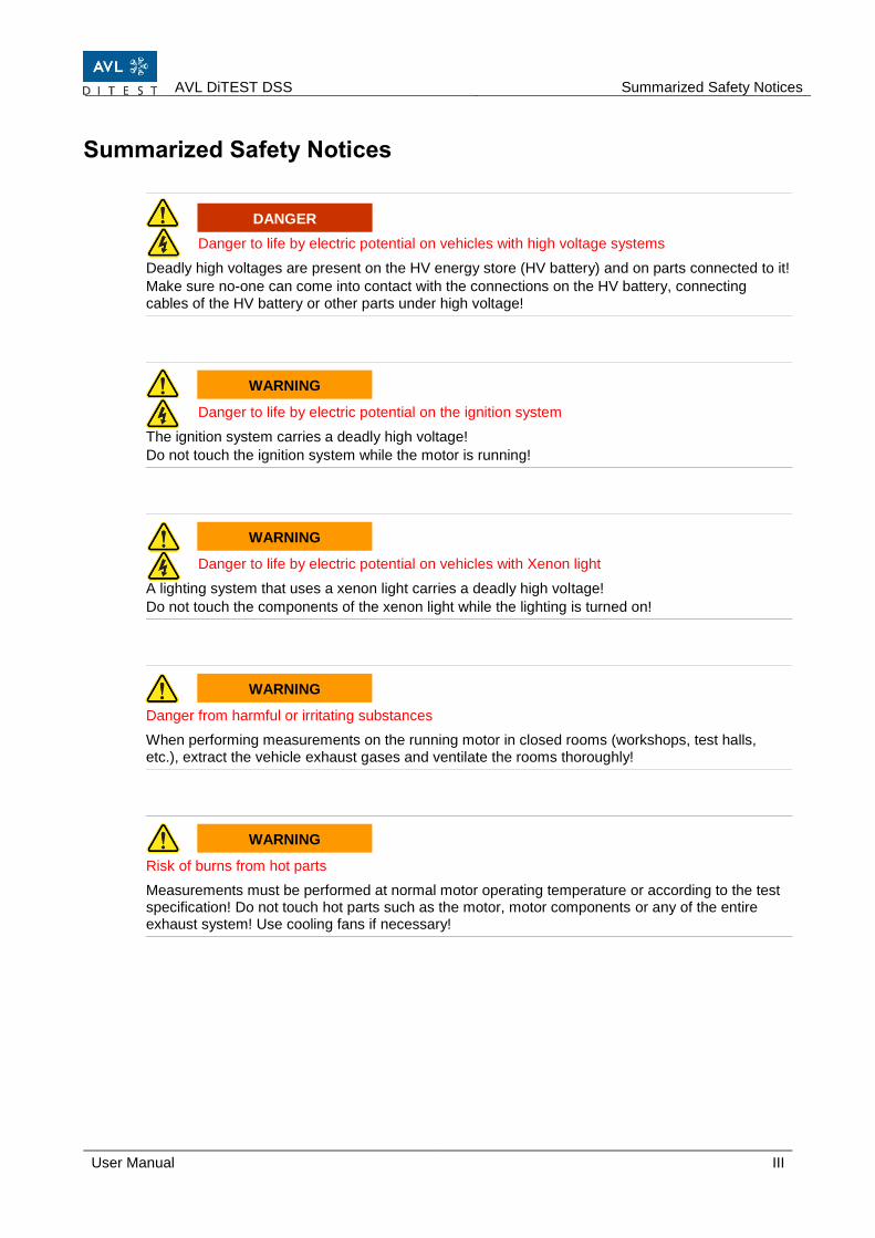
Summarized Safety Notices
Danger to life by electric potential on vehicles with high voltage systems
Deadly high voltages are present on the HV energy store (HV battery) and on parts connected to it!
Make sure no-one can come into contact with the connections on the HV battery, connecting cables of the HV battery or other parts under high voltage!
Danger to life by electric potential on the ignition system
The ignition system carries a deadly high voltage!
Do not touch the ignition system while the motor is running!
Danger to life by electric potential on vehicles with Xenon light
A lighting system that uses a xenon light carries a deadly high voltage!
Do not touch the components of the xenon light while the lighting is turned on!
Danger from harmful or irritating substances
When performing measurements on the running motor in closed rooms (workshops, test halls, etc.), extract the vehicle exhaust gases and ventilate the rooms thoroughly!
Risk of burns from hot parts
Measurements must be performed at normal motor operating temperature or according to the test specification! Do not touch hot parts such as the motor, motor components or any of the entire exhaust system! Use cooling fans if necessary!
WARNING
WARNING
WARNING
DANGER
WARNING
Summarized Safety Notices AVL DiTEST DSS
IV User Manual
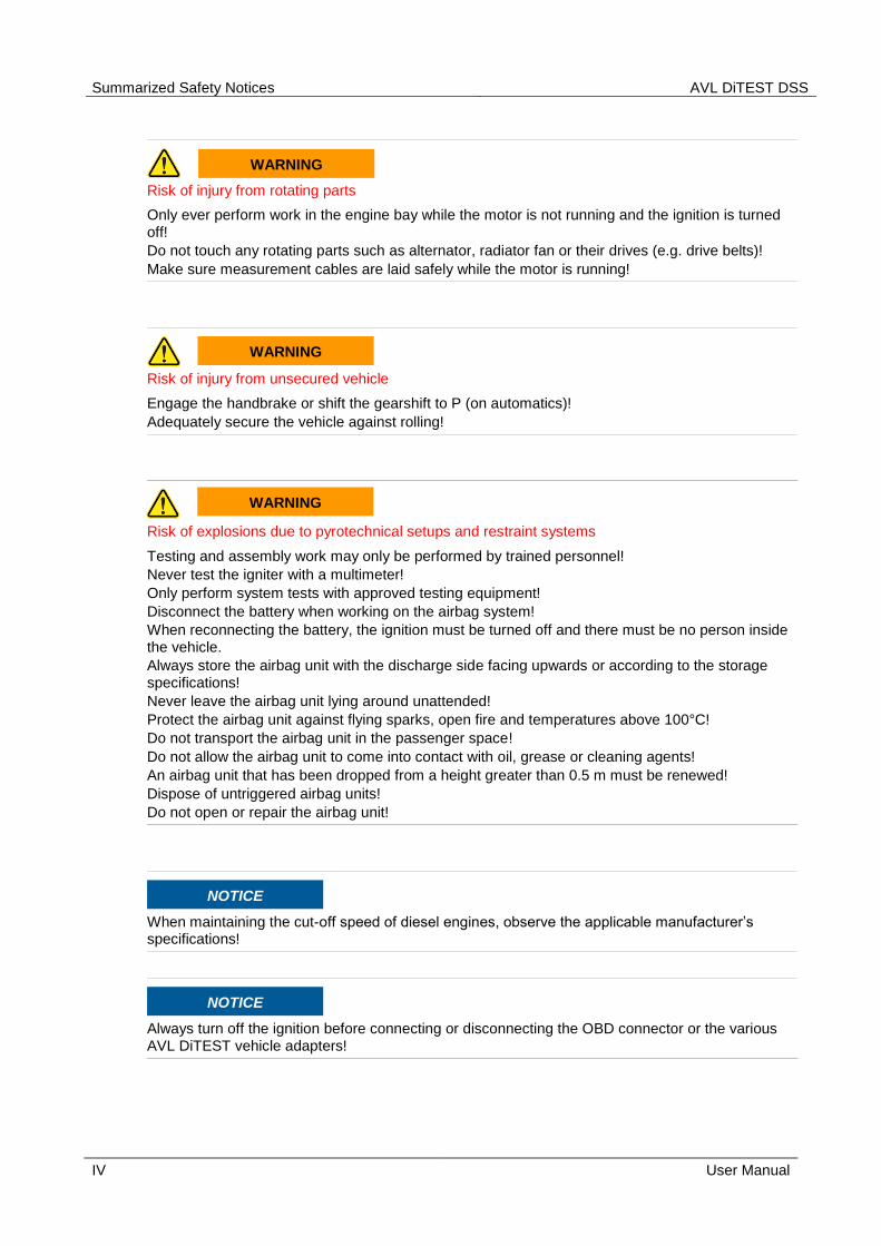
Risk of injury from rotating parts
Only ever perform work in the engine bay while the motor is not running and the ignition is turned off!
Do not touch any rotating parts such as alternator, radiator fan or their drives (e.g. drive belts)!
Make sure measurement cables are laid safely while the motor is running!
Risk of injury from unsecured vehicle
Engage the handbrake or shift the gearshift to P (on automatics)!
Adequately secure the vehicle against rolling!
Risk of explosions due to pyrotechnical setups and restraint systems
Testing and assembly work may only be performed by trained personnel!
Never test the igniter with a multimeter!
Only perform system tests with approved testing equipment!
Disconnect the battery when working on the airbag system!
When reconnecting the battery, the ignition must be turned off and there must be no person inside the vehicle.
Always store the airbag unit with the discharge side facing upwards or according to the storage specifications!
Never leave the airbag unit lying around unattended!
Protect the airbag unit against flying sparks, open fire and temperatures above 100°C!
Do not transport the airbag unit in the passenger space!
Do not allow the airbag unit to come into contact with oil, grease or cleaning agents!
An airbag unit that has been dropped from a height greater than 0.5 m must be renewed!
Dispose of untriggered airbag units!
Do not open or repair the airbag unit!
When maintaining the cut-off speed of diesel engines, observe the applicable manufacturer’s specifications!
Always turn off the ignition before connecting or disconnecting the OBD connector or the various AVL DiTEST vehicle adapters!
WARNING
NOTICE
WARNING
WARNING
NOTICE

AVL DiTEST DSS Contents
User Manual V
Contents
WARNING AND SAFETY NOTICES .............................................................. I
SUMMARIZED SAFETY NOTICES .............................................................. III
1 GENERAL ......................................................................................... 1-1 1.1 Operation .............................................................................................................................. 1-2
1.1.1 DSS Application Window ......................................................................................... 1-2 1.1.2 User Prompts ........................................................................................................... 1-3 1.1.3 Help .......................................................................................................................... 1-4 1.1.4 Infobox ...................................................................................................................... 1-4 1.1.5 Switching on ............................................................................................................. 1-4 1.1.6 Quitting and switching off the application ................................................................. 1-4
2 PREPARING FOR MEASUREMENT ................................................ 2-1 2.1 Leak Test .............................................................................................................................. 2-1 2.2 HC Residue Test ................................................................................................................... 2-1 2.3 Warm-Up Phase.................................................................................................................... 2-2 2.4 Stability Test .......................................................................................................................... 2-2
3 DIAGNOSTIC SYSTEM SOFTWARE (DSS) ..................................... 3-1 3.1 DSS Manager ........................................................................................................................ 3-1
3.1.1 File ............................................................................................................................ 3-2 3.1.1.1 Close all applications ................................................................................... 3-2 3.1.1.2 Stop devices ................................................................................................ 3-2 3.1.1.3 Quit .............................................................................................................. 3-2
3.1.2 Tools ......................................................................................................................... 3-3 3.1.2.1 Settings ........................................................................................................ 3-3
3.1.2.1.1 Language ................................................................................ 3-3 3.1.2.1.2 Asanetwork ............................................................................. 3-4 3.1.2.1.3 AVL DiGate 480 ...................................................................... 3-5 3.1.2.1.4 Workshop ................................................................................ 3-5 3.1.2.1.5 Logging ................................................................................... 3-6 3.1.2.1.6 Automatic Execution ............................................................... 3-6 3.1.2.1.7 Application window ................................................................. 3-6 3.1.2.1.8 Data Recording ....................................................................... 3-6 3.1.2.1.9 Device connections ................................................................. 3-7 3.1.2.1.10 Bluetooth ................................................................................. 3-7 3.1.2.1.11 AVL OBD ................................................................................ 3-7 3.1.2.1.12 BMW Key Reader ................................................................... 3-8 3.1.2.1.13 AVL HV Safety ........................................................................ 3-9 3.1.2.1.14 AVL AUX ................................................................................. 3-9 3.1.2.1.15 AVL SMOKE ......................................................................... 3-10 3.1.2.1.17 AVL GAS ............................................................................... 3-11 3.1.2.1.18 Applications ........................................................................... 3-12 3.1.2.1.19 HV Safety .............................................................................. 3-12 3.1.2.1.20 Manufacturer Options ........................................................... 3-12
3.1.2.2 Log File ...................................................................................................... 3-13 3.1.2.2.1 Show Log File ....................................................................... 3-13 3.1.2.2.2 Dateien exporting .................................................................. 3-13
Contents AVL DiTEST DSS
VI User Manual
3.1.2.3 System-Update .......................................................................................... 3-14
3.1.2.3.1 License .................................................................................. 3-14 3.1.2.3.2 Vehicle Data.......................................................................... 3-15 3.1.2.3.3 Device ................................................................................... 3-16 3.1.2.3.4 Device connections ............................................................... 3-17
3.1.2.4 Backup ....................................................................................................... 3-18 3.1.2.5 Restore ...................................................................................................... 3-18
3.1.3 Customer Management .......................................................................................... 3-19 3.1.3.1 General ...................................................................................................... 3-19 3.1.3.2 Customer Area .......................................................................................... 3-19 3.1.3.3 Vehicle Area .............................................................................................. 3-20 3.1.3.4 Customer/Vehicle Assignment .................................................................. 3-20
3.1.4 AU .......................................................................................................................... 3-21 3.1.4.1 File ............................................................................................................. 3-21 3.1.4.2 Extras ........................................................................................................ 3-21
3.1.4.2.1 Filter test ............................................................................... 3-22 3.1.4.2.2 Diesel Values Display Program ............................................ 3-22 3.1.4.2.3 Gas Values Display Program ................................................ 3-23
3.1.5 Diagnostic ............................................................................................................... 3-24 3.1.5.1 Exhaust Analysis ....................................................................................... 3-24
3.1.5.1.1 Continuous Gas Measurement ............................................. 3-24 3.1.5.1.2 Continuous Opacity Measurement ....................................... 3-26 3.1.5.1.3 Continuous Gas & Opacity Measurement ............................ 3-27 3.1.5.1.4 Timing ................................................................................... 3-27 3.1.5.1.5 File ........................................................................................ 3-28 3.1.5.1.6 Extras .................................................................................... 3-28
3.1.5.2 EOBD ........................................................................................................ 3-29 3.1.5.2.1 Overview of EOBD Modes .................................................... 3-29 3.1.5.2.2 Establishing a Connection .................................................... 3-30 3.1.5.2.3 Mode 1 Actual Values ........................................................... 3-30 3.1.5.2.4 Mode 2 Freeze Frame .......................................................... 3-30 3.1.5.2.5 Mode 3 Read Error Memory ................................................. 3-30 3.1.5.2.6 Mode 4 Delete Error Memory ............................................... 3-31 3.1.5.2.7 Mode 5 Lambda Probe Values ............................................. 3-31 3.1.5.2.8 Mode 6 Sporadic Test Values ............................................... 3-31 3.1.5.2.9 Mode 7 Sporadic Error Memory ............................................ 3-31 3.1.5.2.10 Mode 8 Actuator Test ........................................................... 3-31 3.1.5.2.11 Mode 9 Vehicle Information .................................................. 3-31
3.1.5.3 ECU Diagnosis .......................................................................................... 3-32 3.1.5.4 Measurement & testing ............................................................................. 3-32 3.1.5.5 HV Safety .................................................................................................. 3-32
3.1.6 Jobs ........................................................................................................................ 3-33 3.1.6.1 Asanetwork ................................................................................................ 3-33
3.1.6.1.1 Taking On Jobs from asanetwork ......................................... 3-33 3.1.6.1.2 Send Results to asanetwork ................................................. 3-34
3.1.7 Results Management ............................................................................................. 3-35 3.1.7.1 File ............................................................................................................. 3-36 3.1.7.2 Extras ........................................................................................................ 3-36
3.1.8 Service/ Maintenance ............................................................................................. 3-37 3.1.8.1 Calibration Programs ................................................................................. 3-37 3.1.8.2 Service Screen AVL SMOKE .................................................................... 3-38 3.1.8.3 Service Screen AVL GAS .......................................................................... 3-39 3.1.8.4 Service Screen AVL AUX .......................................................................... 3-41 3.1.8.5 Service Screen AVL OBD ......................................................................... 3-42 3.1.8.6 Service Screen AVL HV Safety ................................................................. 3-43 3.1.8.7 System Info................................................................................................ 3-44 3.1.8.8 License Information ................................................................................... 3-45
AVL DiTEST DSS Inhaltsverzeichnis
User Manual VII
4 MAINTENANCE ................................................................................ 4-1 4.1 Maintenance Plan AVL GAS ................................................................................................. 4-1 4.2 Maintenance Plan AVL SMOKE ........................................................................................... 4-1 4.3 Maintenance AVL AUX ......................................................................................................... 4-1 4.4 Maintenance AVL SCOPE .................................................................................................... 4-1 4.5 Maintenance AVL HV Safety ................................................................................................ 4-1 4.6 Software update .................................................................................................................... 4-1
5 INDEX ............................................................................................... 5-1

Contents AVL DiTEST DSS
VIII User Manual

AVL DiTEST DSS General
User Manual 1-1
1 General AVL DiTEST DSS (DSS: Diagnostic System Software) is the pioneering new software for the latest AVL DiTEST MDS stations (MDS: Modular Diagnostic Station).
Features:
Compatible with the following MS Windows operating systems:
- Windows® XP Prof. (32-bit)
- Windows® 7 (32-bit)
- Windows® 8
Flexible and sustainable thanks to a modular concept
- Existing AVL modules can be easily integrated
- Communication with PC via Bluetooth or USB
Multiple functions:
- Completely scalable screen
- Simple customer and vehicle management (vehicle selected once only for all applications)
- Independent, country-specific software (examples:"AU Germany", "§57a" Austria, "MOT UK","OM“ Switzerland") for performing official emissions tests.
- Simple, rapid exhaust emissions analysis without running through the complete emissions test
- Results logs for all applications easily exported in standard PDF format
- Detailed service screens for all hardware modules; rapid and effective self-diagnostics for the hardware modules; software application system information
Automatic system updates Vehicle data, device firmware updates and license updates
Vehicle databases rapidly loaded
User-friendly software
- User "guided" through the emissions test
- Easy-to-follow graphical and text-based help screens
Multiple applications can be run in parallel
Internet software updates available:
An incremental software update concept only downloads those program components which need a software update
Twin operation
Application screen assignment retained upon restart
Wide range of network connection options:
- Easily connect to the company network as NW client
- Connection to AUplus QM System
- asanetwork-compatible

General AVL DiTEST DSS
1-2 User Manual
1.1 Operation
AVL DiTEST DSS is operated using a conventional computer mouse and keyboard.
1.1.1 DSS Application Window
Fig. 1-1 (example: continuous gas measurement with module AVL Digas 480)
(1) Taskbar:
File for closing applications, stopping devices and exiting AVL DiTEST DSS. ( Cap. 3.1.1)
Tools for a range of settings, displaying/exporting log files, updating the system (license, vehicle data and devices) and backing up/restoring the system. ( Cap. 3.1.2 “ Extras”)
Note: The functions available under "File" and "Tools" depend on the selected application. Only the functions relevant to the selected application will be displayed.
(2) Vehicle information:
This is where you can inspect the vehicle identification data. ( Cap. 1.1.4 “Infobox”)
(3) Application:
This is where the current operating mode is displayed. ( Cap. 3 “Diagnostic system Software (DSS)”
(4) Operating bar:
Displays the available function buttons.
(2)
(4)
(3)
(1)

AVL DiTEST DSS General
User Manual 1-3
1.1.2 User Prompts
User prompts are displayed optically by symbols on the screen.
Slow, continuous
speed increase by
slow, continuous pushing on the gas pedal.
Waiting for recognition of the deviation.
Slow, continuous
speed decrease by
slow, continuous removal of pressure from the gas pedal.
Deviation recognized.
Maintain speed.
Deviation not recognized.
Accelerate as fast as possible until
cut-off speed is reached.
Waiting for recognition of the cut-off.
Decelerate as fast as possible.
Cut-off recognized.
Control loop check:
Apply disturbance value.
Cut-off not recognized.
Control loop check:
Remove disturbance value..

General AVL DiTEST DSS
1-4 User Manual
1.1.3 Help
Help text appears when you click on or on .
Durch Klicken auf erscheinen zusätzliche Informationen.
1.1.4 Infobox
A window (Infobox) with vehicle data can be displayed at the top of the screen.
Opens the Infobox
Closes the Infobox
1.1.5 Switching on
Double-click on or click StartAll programsAVL DITESTAVL DSS.
1.1.6 Quitting and switching off the application
Click on or exit AVL DiTEST DSS by clicking FileQuit.
Do not disconnect your PC until you have correctly exited AVL DiTEST DSS and WINDOWS!
Click StartShutdownShutdown.
NOTICE
AVL DiTEST DSS Preparing for Measurement
User Manual 2-1
2 Preparing for Measurement All measurement preparation steps described are started automatically by the device.
2.1 Leak Test
The AVL exhaust gas tester demands a leak test once a day!
When prompted, close off the probe and press F8 Next. The leak test will be performed and the exhaust instrument tested for leaks.
Once the leak test is complete, unblock the exhaust probe again and the program will continue where it left off.
2.2 HC Residue Test
Before every exhaust measurement, an HC residue test must be performed on the AVL exhaust gas tester. This serves to measure the HC value in the measurement system and the ambient air, and lasts for 80 seconds.
Remove the exhaust probe from the exhaust pipe.
F8 Next starts the HC residue test.
The measured HC value must be below 20 ppm. If this is the case, then the measurement will continue automatically (sometimes even before the 80 seconds are up).
If the HC value is above 20 ppm, then check whether the exhaust probe is in the exhaust stream; note that high quantities of fuel residue can also exist in the ambient air. In this case, change the testing location or ventilate the room.
Wait until the HC residue test is complete.
Once the HC residue test is complete, you have the options:
F5 Repeat to repeat the HC residue test, if errors occurred.
F8 Next to continue the process.
Preparing for Measurement AVL DiTEST DSS
2-2 User Manual
2.3 Warm-Up Phase
After switching on, the AVL exhaust gas tester requires a warm-up time of up to one minute.
(Older modules up to 15 minutes).
You must wait out this warm-up phase in order to obtain stable measurement values.
2.4 Stability Test
Before each measurement, the AVL exhaust gas tester runs through a stability test. The exhaust probe must not be in the exhaust stream during this test.
This test runs automatically and takes about 20 seconds.
AVL DiTEST DSS Diagnostic System Software (DSS)
User Manual 3-1
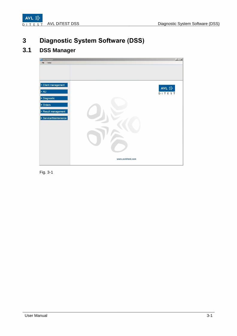
3 Diagnostic System Software (DSS)
3.1 DSS Manager
Fig. 3-1

Preparing for Measurement AVL DiTEST DSS
3-2 User Manual
3.1.1 File
3.1.1.1 Close all applications
FileClose all applications will close all applications with the exception of the DSS Manager.
3.1.1.2 Stop devices
Applications which use devices (AVL AUX, AVL GAS …) or device drivers will be closed. Always click FileStop devices before disconnecting devices from a USB interface. After inserting the USB plug, click F8 next.
Never disconnect/connect devices from/to a USB port without clicking FileStop devices (and afterwards pressing F8 next). The PC might no longer respond. If this happens, restart the PC.
3.1.1.3 Quit
AVL DiTEST DSS is exited via FileQuit or by clicking .
NOTICE

AVL DiTEST DSS Diagnostic System Software (DSS)
User Manual 3-3
3.1.2 Tools
3.1.2.1 Settings
Fig. 3-2
3.1.2.1.1 Language
Click on ExtrasSettingsLanguage.
Here, you can select the desired language.
OK Quits the “Language” function. The application window appears.
Cancel Quits the “Language” function without saving changes.
Apply Applies the entered values.
Help Shows help text.
The buttons OK, Cancel, Apply and Help always have the same function under “Tools” and will not be discussed any further below!
Information
Preparing for Measurement AVL DiTEST DSS
3-4 User Manual
3.1.2.1.2 Asanetwork
Click on ExtrasSettingsasanetwork.
Service Location DLOC
The asanetwork location is entered during installation under “Service Location DLOC”.
Only ever change this entry if necessary, for example, if several stations are operated in the network.
Additional services
Target Data Service:
Enable the Set value service if your asanetwork provides a choice of nominal data.
Advanced vehicle type data:
Enable Extended vehicle data information if your asanetwork provides an extended choice of vehicle type data such as date of first registration, fuel type and engine code.
Unsent result protocols of exhaust emission tests If you select Enable deleting of obsolete results, then obsolete results will be deleted automatically.
If Delete with user confirmation is selected, then results will only be deleted upon confirmation.
With Delete after (in days), you can define how many days unsent AU results logs will be kept on the local system before being automatically deleted.
Sent AU event logs
Save sent AU event logs:
Check this box if you wish for sent AU results logs to remain saved after sending.
Days to save:
Set here the number of days a sent results log should be kept before it is automatically deleted. This option is only available if “Save sent AU results logs” has been selected.
Order view
By selecting Standard or Extended, you can select the view (i.e. display of additional data in the form of additional columns) of jobs over the workshop network.
Show completed jobs
If Show completed orders is enabled, then the completed jobs will be displayed under “Orders”, “asanetwork” and “Select orders”.
AVL DiTEST DSS Diagnostic System Software (DSS)
User Manual 3-5
3.1.2.1.3 AVL DiGate 480
Click on ExtrasSettingsAVL DiGate 480.
Directory for backup classified according to year and month
If this option is enabled, then the network drive on which the results shall be saved (in XML and PDF format) can be selected by clicking on .
The connection to the network drive can be tested with Test.
Directory for transmission to external applications
If this option is enabled, then the network drive on which the results shall be saved for forwarding to external applications (in XML format) can be selected by clicking on .
The connection to the network drive can be tested with Test.
3.1.2.1.4 Workshop
a) Address
Click on ExtrasSettingsAddress and enter your details in the labeled fields.
b) Personnel
Click on ExtrasSettingsPersonnel.
Clicking New opens an input window into which you can enter the name of a new tester. Return to “Tester” with OK. Clicking Delete deletes the blue-highlighted tester name. Clicking Edit opens an input window in which you can edit the blue-highlighted tester name. Return to “Tester” with OK. Clicking Current Operator selects the blue-highlighted tester name (or clicking the desired tester name). Clicking Responsible Operator selects the blue-highlighted tester name (or clicking the desired tester name). c) Report
Clicking Add opens a window in which you can select your logo. Click Open to confirm the choice of logo.
Logos can be inserted in BMP, JPG and GIF format.
You can delete the selected logo by clicking Remove.
With Show workshop address on reports, you can define whether the workshop address shall appear on the log or not.
With Show vehicle data on reports, you can define whether the vehicle data shall appear on the log or not.
These settings do not affect the logs of official measurements (AUs).
Preparing for Measurement AVL DiTEST DSS
3-6 User Manual
3.1.2.1.5 Logging
Click on ExtrasSettingsLogging.
All of the user‘s interactions can be recorded and saved for servicing purposes by enabling Logging.
You can drag the slider to set the size of log file that will trigger a warning upon exporting.
Clicking opens a window with which you can specify the location for saving the log file.
3.1.2.1.6 Automatic Execution
Click on ExtrasSettingsAutomatic execution.
Executing functions automatically:
Check the box next to those functions you wish to start automatically.
3.1.2.1.7 Application window
Click ToolsSettingsApplication window. You can set the size and position of the application window by clicking on "Save window position and size".
You can set the application window to appear in the taskbar minimized by clicking "Start window in minimized mode".
3.1.2.1.8 Data Recording
Click on ExtrasSettingsData records.
In the “Sampling rate” field, select the desired sampling rate in milliseconds.
You can choose the directory in which to save the data recordings by clicking on .
Also observe Chapter 3.1.5.1.1 “Continuous Gas Measurement”, Chapter. 3.1.5.1.2 „Continuous Turbidity Measurement “and Chapter 3.1.5.1.3 “Continuous Gas & Turbidity Measurement “.
AVL DiTEST DSS Diagnostic System Software (DSS)
User Manual 3-7
3.1.2.1.9 Device connections
Click ToolsSettingsDevice connections.
If "Open automatically upon start-up" has been disabled, the "Device connections" dialog box will not appear when you start AVL DiTEST DSS( Cap. 3.1.2.1.9 „Device connections“).
3.1.2.1.10 Bluetooth
Click on ExtrasSettingsBluetooth.
Here, you can select the Bluetooth stack (Bluetooth driver) to use.
„Autodetect" is the default setting.
3.1.2.1.11 AVL OBD
The standard AVL DiTEST MDS with AVL DiOBD comes with a Bluetooth connection. A USB cable can alternatively be supplied for the PC connection.
Click on ExtrasSettingsOBD.
Scantool
Here you can select which scan tool and what connection type to be used.
COM port settings
If you deactivate the function COM-Port Auto detection, you can change the COM port for the AVL OBD manually.
You can select the COM port to be used by clicking on the list field.
Logging
By clicking on Scantool communication (continuous), you can set the scan tool communication to be logged continuously. As a rule, this option should be disabled, since it can lead to an enormous volume of data.
Information

Preparing for Measurement AVL DiTEST DSS
3-8 User Manual
Bluetoothverbindung
Ist „Bluetooth“ aktiviert, so können Sie Sie durch Klicken auf manuell nach dem Bluetooth-Gerät suchen.
Opening the search dialog box automatically launches the search for Bluetooth devices in the device group.
Fig. 3-3 Example AVL DiTEST DiOBD 880
If the Bluetooth device used is found, then click on it and then click OK.
3.1.2.1.12 BMW Key Reader
Click ToolsSettingsBMW KeyReader.
Path to BMW KeyReader file
Path to the BMW KeyReader file which is to be imported. This file is generated by the BMW KeyReader software as soon as a key is found. The export settings must match the corresponding import settings.
You can test the connection to the selected path by using Test.
Automatically delete file will automatically delete the BMW KeyReader file after import. This point should usually be disabled.
URL of the "SAM" web service
Enter the URL of the SAM web service for key data interpretation. This is usually http://localhost:8080/soap/servlet/soaprouter.
You can test the connection to the SAM web service using Test.
Timeout
Enter the period of time in seconds after which an unsuccessful connection attempt will be cancelled.

AVL DiTEST DSS Diagnostic System Software (DSS)
User Manual 3-9
3.1.2.1.13 AVL HV Safety
AVL HV Safety is connected to the PC with a USB cable.
Click Tools Settings AVL HV Safety.
Select USB.
If "Serial" is enabled, you can select the COM port used from the list box.
3.1.2.1.14 AVL AUX
Stationary MDS stations:
Standard AVL AUX – PC communication is via USB cable.
Mobile MDS stations:
Standard AVL AUX – PC communication is via Bluetooth.
Click on ExtrasSettingsAVL AUX.
You can click to select the interface to be used by the AVL AUX.
If "Bluetooth" is enabled, you can search manually for the Bluetooth device by clicking .
Opening the search dialog box automatically launches the search for Bluetooth devices in the device group.
Fig. 3-4
If the Bluetooth device used is found, click on it and then on OK.
If "Serial" is enabled, you can select the COM port used from the list box.
Information
Information
AVL AUX
Preparing for Measurement AVL DiTEST DSS
3-10 User Manual
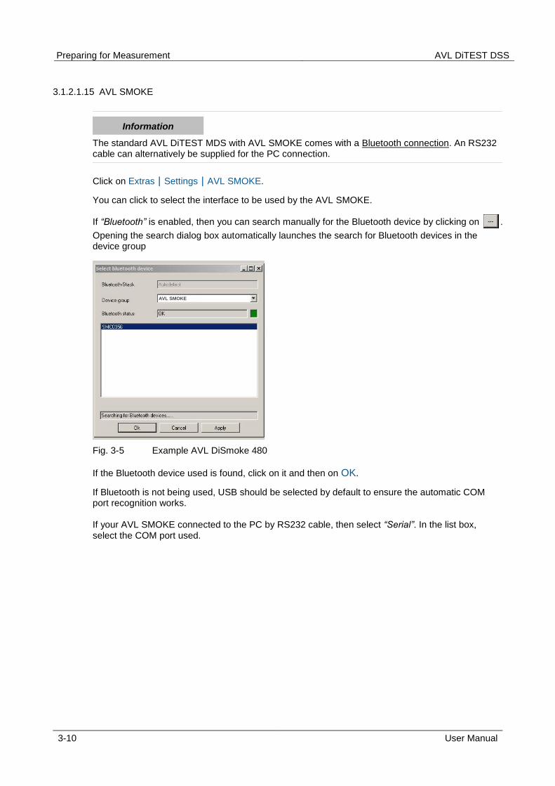
3.1.2.1.15 AVL SMOKE
The standard AVL DiTEST MDS with AVL SMOKE comes with a Bluetooth connection. An RS232 cable can alternatively be supplied for the PC connection.
Click on ExtrasSettingsAVL SMOKE.
You can click to select the interface to be used by the AVL SMOKE.
If “Bluetooth” is enabled, then you can search manually for the Bluetooth device by clicking on .
Opening the search dialog box automatically launches the search for Bluetooth devices in the device group
Fig. 3-5 Example AVL DiSmoke 480
If the Bluetooth device used is found, click on it and then on OK.
If Bluetooth is not being used, USB should be selected by default to ensure the automatic COM port recognition works.
If your AVL SMOKE connected to the PC by RS232 cable, then select “Serial”. In the list box, select the COM port used.
Information
AVL SMOKE

AVL DiTEST DSS Diagnostic System Software (DSS)
User Manual 3-11
3.1.2.1.17 AVL GAS
Stationary MDS stations:
Standard AVL GAS – PC communication is via USB cable.
Mobile MDS stations:
Standard AVL GAS – PC communication is via Bluetooth.
Click on ExtrasSettingsAVL GAS.
You can click to select the interface to be used by the AVL GAS.
If "Bluetooth" is enabled, you can search manually for the Bluetooth device by clicking .
Opening the search dialog box automatically launches the search for Bluetooth devices in the device group.
Fig. 3-6
If the Bluetooth device used is found, click on it and then on OK.
If "Serial" is enabled, you can select the COM port used from the list box.
Information
AVL GAS
Preparing for Measurement AVL DiTEST DSS
3-12 User Manual
3.1.2.1.18 Applications
This is where you will find the settings for country-specific emissions tests ("AU Deutschland" - "German emissions test").
3.1.2.1.19 HV Safety
Click Tools Settings ApplicationsHV Safety.
Results
Enabling "Save automatically" will automatically save the measurement results.
Automatic feedback
Enabling "On" activates a feedback signal during measurement.
Tester
If "Use tester" is enabled, the name of this tester will be needed when you start measuring with the AVL HV Safety. Click on "Password input" to enter the tester name and set a password.
Vehicle identification
If "Use vehicle identification" is enabled, the vehicle identification data will be included in the test report.
Activation of specific measurements
Here you can activate measurements "insulation monitor review", "SAE J 1766 Measurement" and activate "overall measurement".
3.1.2.1.20 Manufacturer Options
Click on ExtrasSettingsManufacturer options.
In this password-protected area, you can make further specific settings.
AVL DiTEST DSS Diagnostic System Software (DSS)
User Manual 3-13
3.1.2.2 Log File
Also refer to Chapter 3.1.2.1.5 “Logging” with regard to this.
3.1.2.2.1 Show Log File
Click on ExtrasLogging fileDisplay.
A window appears showing the log file.
3.1.2.2.2 Dateien exporting
Click on ExtrasLogging fileExport.
The entire log or individual log files can be exported.
a) Export all log files
F8 Next The entire log will be compressed.
F5 Directory A window opens in which you can select the saving location. Continue with OK.
F8 Next Creates a zip archive of the entire log.
F8 Confirm Exports the entire log; back to main window.
b) Export individual log files
F5 Selection Shows the log files.
F2 Choose Selects all log files.
F3 Discard Discards the selected log files.
Selects a log file.
F8 Next The anticipated file size is shown.
F8 Next Compresses the log files.
F5 Directory A window opens in which you can select the saving location. Continue with OK.
F8 Next Creates a zip archive of the entire log.
F8 Confirm Exports the entire log; back to main window.

Preparing for Measurement AVL DiTEST DSS
3-14 User Manual
3.1.2.3 System-Update
Here you can update the licenses, vehicle data and device firmware of your AVL DiTEST MDS stations.
3.1.2.3.1 License
Die Lizenz kann sich auf einer CD befinden oder Sie erhalten die Lizenz per Email in Form einer Lizenzdatei (*.lic).
1. Insert the CD with the license in the DVD drive or copy the license to a USB flash drive and insert the flash drive into a free USB port.
2. Click on ExtrasSystem UpdateLicense.
3. The dialog "License Update" appears On the left side you will see the existing licenses. Show by clicking on one of the licenses and the content of the dongle are displayed details of the dongle and the selected license in the right part of the screen.
4. Click on F2 File. A window opens in which you can select the license. Confirm the selection by clicking Open.
The license can now be updated over the Internet. Click on F3 Internet. If the Internet connection exists, the license file will be downloaded automatically. Click Write to dongle to transfer the license to the dongle.
5. You can print the screen with F4 Print.
6. With F5 Skip, you can prevent the license update.
7. You can see all licenses in the area on the left. In the area on the right, you can see a detailed view of the license that has been highlighted in blue on the left. Click on the appropriate license and then click F8 Next. The license will be transferred to the dongle.
8. Complete the license update by clicking F8 confirm.
AVL DiTEST DSS Diagnostic System Software (DSS)
User Manual 3-15
3.1.2.3.2 Vehicle Data
The vehicle data are located on a CD in the form of a self-extracting file (*.exe).
Installing vehicle data:
1. Quit AVL DiTEST DSS if it has been started.
2. Insert the CD with the Sfx installation package in the DVD drive. If a window does not open automatically, double-click on the autostart.exe file.
3. Click Vehicle data update for DSS V2.2.
4. Click on the vehicle data package which you wish to install, e.g. [08/2010].
5. An installation program will start. Follow the instructions and confirm all messages by clicking F8 next.
6. The available license and vehicle data will be copied to the AVL DITEST DSS system directory to enable direct access to this data during the update. Quit the installation program by clicking .
Updating vehicle data:
1. Start AVL DiTEST DSS by double-clicking AVL DiTEST DSS.
2. If the update does not start automatically with the dialog "License update" (see step 3), click ToolsSystem updateVehicle data.
3. This opens the "License update" dialog. You can update the license. You can prevent the license update with F5 Skip. (See "License" for details.)
4. The vehicle data currently installed will be displayed. Continue with F8 Next.
5. Select the source of vehicle data. Click Locally installed versions and F8 Next.
6. Check the box next to the vehicle data to be updated and click F8 Next.
7. A summary of the system update will be shown. You can print the system update with F4 Print.
8. Complete the system update by clicking F8 Confirm.

Preparing for Measurement AVL DiTEST DSS
3-16 User Manual
3.1.2.3.3 Device
Device firmware is automatically updated after an AVL DiTEST DSS software update. Please follow the AVL DSS Brief Instructions, AVL DiTEST identification number AT7260ML, for AVL DiTEST DSS software installation and updates. These can be found in the DVD sleeve.
If the device data are in the form of a self-extracting file (*.exe) on a data carrier (CD, USB flash drive, etc.):
Installing device data:
1. Quit AVL DiTEST DSS if it has been started.
2. Insert the CD with the device data in the DVD drive or copy the device data to a USB flash drive and insert the flash drive into a free USB port.
3. Start Windows Explorer. Search for and double-click on device update file(s).
4. The available device data will be copied to the AVL DITEST DSS system directory to enable direct access to this data during the update.
5. Quit Windows Explorer.
Updating vehicle data:
1. Start AVL DiTEST DSS by double-clicking on AVL DiTEST DSS.
2. If the update does not start automatically with the dialog "License update" (see step 3), click ToolsSystem updateDevice data.
3. This opens the "License update" dialog. You can update the license. You can prevent a license update with F5 Skip. (See "License" for details.) Click F8 Next.
4. Connect all devices and switch the devices on. Wait until all devices are available and then confirm with F8 Next.
The devices must be connected to the power supply during the firmware update!
5. The necessary firmware updates will be determined and automatically installed.
6. A summary of the system update will be shown. You can print the system update with F4 Print.
7. Complete the system update by clicking F8 Confirm.
NOTICE

AVL DiTEST DSS Diagnostic System Software (DSS)
User Manual 3-17
3.1.2.3.4 Device connections
You can select the type of connection (Bluetooth or USB) for the individual devices (AVL SMOKE, AVL GAS, AVL AUX and AVL OBD) with ToolsUpdate systemDevice connections.
MDS stations come with the correct connection types already configured.
Bluetooth devices
If more than one Bluetooth device is found, click on the Bluetooth device used by your MDS station.
Devices (AVL OBD)
You can select the OBD module used in the list box.
Automatically identify COM port (AVL OBD)
If this item is enabled, the system will automatically look for the COM port used. "Automatically identify COM port" should be enabled if the connection type "USB" has been selected.
COM port (AVL OBD)
If "Automatically identify COM port" is disabled, you can select the COM port used from the "COM port" list box.
Bluetooth stack
This is where you can select the Bluetooth stack (Bluetooth driver) used. The default setting is "Autodetect".
Connection okay.
Devices have previously been connected to the software; however, the most recently connected devices cannot currently be accessed.
The device cannot be accessed.
F2 Bluetooth "Bluetooth connection" is selected for all devices.
F3 USB "USB connection" is selected for all devices.
Display information on the connection status if an intact connection could not be established.
NOTICE

Preparing for Measurement AVL DiTEST DSS
3-18 User Manual
3.1.2.4 Backup
This backs up the data on your system.
Click on ExtrasBackup.
Select the data to be backed up from:
Settings
Results / Customer data / Vehicle data
All
F8 Next The data backup commences.
F5 Directory A window opens in which you can select the saving location. Continue with Open.
F8 Next The location and the backup data will be displayed.
F8 Next This data will be backed up.
F8 Next Continue to the AVL DiTEST DSS window.
3.1.2.5 Restore
This backed-up data can be restored.
Click on ExtrasRestore.
F5 Directory A window opens.
Select the file to be recovered and click Open. The restored file is displayed. Go to F8 Next.
Select the data that you want to restore and click Next F8. The data and the source of the data for restoration are displayed. Go to F8 Next. Files will be restored. With F8 Next continue to the main window.
AVL DiTEST DSS Diagnostic System Software (DSS)
User Manual 3-19
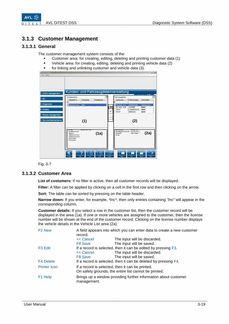
3.1.3 Customer Management
3.1.3.1 General
The customer management system consists of the: Customer area: for creating, editing, deleting and printing customer data (1)
Vehicle area: for creating, editing, deleting and printing vehicle data (2)
for linking and unlinking customer and vehicle data (3).
Fig. 3-7
3.1.3.2 Customer Area
List of costumers: If no filter is active, then all customer records will be displayed.
Filter: A filter can be applied by clicking on a cell in the first row and then clicking on the arrow.
Sort: The table can be sorted by pressing on the table header.
Narrow down: If you enter, for example, *Inc*, then only entries containing “Inc” will appear in the corresponding column.
Customer details: If you select a row in the customer list, then the customer record will be displayed in the area (1a). If one or more vehicles are assigned to the customer, then the license number will be shown at the end of the customer record. Clicking on the license number displays the vehicle details in the Vehicle List area (2a).
F2 New A field appears into which you can enter data to create a new customer record. << Cancel The input will be discarded. F8 Save The input will be saved.
F3 Edit If a record is selected, then it can be edited by pressing F3. << Cancel The input will be discarded. F8 Save The input will be saved.
F4 Delete If a record is selected, then it can be deleted by pressing F4.
Printer icon If a record is selected, then it can be printed. On safety grounds, the entire list cannot be printed.
F1 Help Brings up a window providing further information about customer management.
(1)
(2)
(3)
(1a)
(2a)
Preparing for Measurement AVL DiTEST DSS
3-20 User Manual
3.1.3.3 Vehicle Area
List of vehicles: If no filter is active, then all vehicle records (vehicle list) will be displayed.
Sort: The table can be sorted by pressing on the table header.
Narrow down: If you enter, for example, *1234*, then only entries containing “1234” will appear in the corresponding column.
Vehicle details: If you select a row in the vehicle list, then the vehicle record will be displayed in the area (2a). If the vehicle is assigned to a customer, then the customer’s name will be shown at the end of the detailed information. Clicking on the customer’s name displays the customer record in the area (1a).
F5 New A field appears into which you can enter data to create a new vehicle record. F2 Type select can be used to identify the vehicle in a licensed vehicle database (HSN, TSN, manufacturer, model, engine code…).
<< Cancel The input will be discarded. F8 Save The input will be saved.
F6 Edit If a record is selected, then it can be edited by pressing F6. << Cancel The input will be discarded. F8 Save The input will be saved.
F7 Delete If a record is selected, then it can be deleted by pressing F7.
Printer icon If a record is selected, then it can be printed.
On safety grounds, the entire list cannot be printed. F1 Help Brings up a window providing further information about customer
management.
3.1.3.4 Customer/Vehicle Assignment
One or more vehicles can be assigned to a customer.
If a customer and a vehicle are selected, then the records will be linked (customer data assigned the vehicle data). This unlinks records.
F1 Help Brings up a window providing further information about customer management.

AVL DiTEST DSS Diagnostic System Software (DSS)
User Manual 3-21
3.1.4 AU
AVL DiTEST DSS includes country-specific software (examples: “AU Germany”, “§57a” Austria, “MOT UK”) for performing an official emissions test. To start the installed application, click on OMOM start.
The respective application is certified and runs according to the legal requirements. (Example: Guideline for Germany). All AU applications include the starting points for filter test (see Chapter 3.1.4.2.1), Diesel values display program (see Chapter 3.1.4.2.2 and Gas values display program (see Chapter 3.1.4.2.3).
3.1.4.1 File
Please refer to Section 3.1.1 "File". Only "Quit" will appear here.
3.1.4.2 Extras
Please refer to 3.1.2 “Extras". Only the functions relevant to the "AU" will appear here.
Preparing for Measurement AVL DiTEST DSS
3-22 User Manual
3.1.4.2.1 Filter test
Start the filter test by clicking AU Filter test.
For further details on the filter test: see Device Manual AVL DiSmoke 480 BT, Section 3.7 "System Check with Filter".
3.1.4.2.2 Diesel Values Display Program
This function is required for calibration of AVL DiSmoke 480.
Click on AU Diesel Values Display Program. A window appears showing:
Silicon serial number and firmware version/checksum of the measurement module
Driver version/checksum and display version/checksum
Actual turbidity values
Maximum absorption value
Actual absorption value
Logbook:
Read Logbook A window appears showing the logbook entries.
Close the “Read Logbook” function by clicking OK
Closes the window with the logbook entries.
Measuring turbidity and absorption:
F8 Next Starts the measurement display.
F6 Reset Resets the maximum absorption value.
F8 Next Ends the diesel values display program.
Information
AVL DiTEST DSS Diagnostic System Software (DSS)
User Manual 3-23
3.1.4.2.3 Gas Values Display Program
This function is required for calibration of AVL Gas 1000.
Click on AU Gas Values Display Program.
A window appears showing:
Silicon serial number and firmware version/checksum of the measurement module
Driver version/checksum and display version/checksum
Values for CO, CO2, O2 and HC
Logbook:
Read Logbook A window appears showing the logbook entries.
Close the “Read Logbook” function by clicking OK.
Closes the window with the logbook entries.
Measuring the gases:
F8 Next Starts the measurement display.
F8 Next Ends the gas values display program.
Information

Preparing for Measurement AVL DiTEST DSS
3-24 User Manual
3.1.5 Diagnostic
Fig. 3-8
3.1.5.1 Exhaust Analysis
3.1.5.1.1 Continuous Gas Measurement
In this operating mode, the concentrations of the gases CO, CO2, HC and O2 can be measured
without running through the AU procedure.
Speed and engine temperature can also be measured.
Engine settings can be made under direct observation of noxious emission values.
Click on DiagnosticEmission analysisGas.
The measurements will be shown.
The following settings are related to AVL AUX. When using the AVL 480 DiLink note the settings in the Cape. 3.1.5.1.4.
F2 Sensor Select the sensor for the engine temperature measurement. Manual input Enter the engine temperature. Temperature sensor --- EOBD Press F5 Connect to establish a connection to the OBD module.
F8 Confirm Back to the measurement display.
F3 Sensor Select the sensor for speed measurement. DiSpeed Select "Internal/external". For "internal", select "Car/truck", "4-stroke motorcycle“ or "2-stroke motorcycle". EOBD Press F5 Connect to connect to the OBD module. F8 Confirm Back to the measurement display.

AVL DiTEST DSS Diagnostic System Software (DSS)
User Manual 3-25
F4 Timing ---
F5 Fuel type Select the fuel type. F8 Confirm Back to the measurement display.
F6 Freeze "Freezes" the measurement display. F6 Continue Continues the continuous measurement.
F7 Record Continuously records the measurements and writes them to a text file.
Please also refer to 3.1.2.1.8 "Data Recording". F7 Quit Quits continuous measurement recording.
F8 Log Creates a results log.
F3 Identification "Vehicle identification" will appear. F8 Next Quits vehicle identification.
F4 Print Prints the results log.
F5 Edit This is where you can edit the results log (display workshop and vehicle data: yes/no).
F5 Apply Quits results log editing.
F6 Save Saves the results log in the internal database (see also Results management).
F8 Next Back to continuous gas measurement.
<< Cancel Quits continuous gas measurement.
Preparing for Measurement AVL DiTEST DSS
3-26 User Manual
3.1.5.1.2 Continuous Opacity Measurement
In this operating mode, you can measure turbidity without running through the AU procedure.
Speed and oil temperature can also be measured.
Engine settings can be made under direct observation of noxious emission values.
Click on Diagnostic Emission analysisOpacity.
The measurements will be shown.
The following settings are related to AVL AUX. When using the AVL 480 DiLink note the settings in the Cape. 3.1.5.1.4.
F2 Sensor Select the sensor for the engine temperature measurement. Manual input Enter the engine temperature. Temperature sensor --- EOBD Press F5 Connect to establish a connection to the OBD module.
F8 Confirm Back to the measurement display.
F3 Sensor Select the sensor for speed measurement. DiSpeed Select "Internal/external". For "internal", select "Car/truck", "4-stroke motorcycle" or "2-stroke motorcycle". EOBD Press F5 Connect to establish a connection with the OBD module
F8 Confirm Back to the measurement display.
F4 Timing ---
F6 Freeze "Freezes" the measurement display. F6 Continue Back to continuous measurement.
F7 Record Continuously records the measurements and writes them to a text file.
Please also refer to 3.1.2.1.8 "Data Recording". F7 Quit Quits continuous measurement recording.
F8 Log Saves the results log.
F3 Identification "Vehicle identification" will appear. F8 Next Quits vehicle identification.
F4 Print Prints the results log.
F5 Edit This is where you can edit the results log (display workshop and vehicle data yes/no).
F5 Apply Quits results log editing.
F6 Save Saves the results log in the internal database (see also Results management).
F8 Next Back to continuous turbidity measurement.
<< Cancel Quits continuous turbidity measurement.
AVL DiTEST DSS Diagnostic System Software (DSS)
User Manual 3-27
3.1.5.1.3 Continuous Gas & Opacity Measurement
This combines the operating modes “Continuous Gas Measurement” and “Continuous Turbidity Measurement”. Click on Diagnostic Emission analysisGas & Opacity. Refer to Chapter 3.1.5.1.1 „Continuous Gas Measurement“ and chapter 3.1.5.1.2 „ Continuous Turbidity Measurement “.
3.1.5.1.4 Timing
Timing measurements can be performed only with the AVL 480 DiLink hardware module!
Otto engine: Displays speed, ignition timing, dwell angle and oil temperature. Diesel engine: Displays speed, diesel timing and oil temperature.
Click DiagnosticsExhaust emissions analysisTiming.
Select your engine (Otto engine/diesel engine) and click F8 Next. The measurements will be shown.
F2 Sensor Select the sensor for the engine temperature measurement. Manual input Enter the engine temperature. Temperature sensor --- EOBD Press F5 Connect to establish a connection to the OBD module.
F8 Confirm Back to the measurement display.
F4 Timing ---
F6 Freeze "Freezes" the measurement display. F6 Continue Back to continuous measurement.
F7 Record Continuously records the measurements and writes them to a text file. F7 Quit Quits continuous measurement recording.
F8 Log Saves the results log.
F3 Identification "Vehicle identification" will appear. F8 Next Quits vehicle identification.
F4 Print Prints the results log.
F5 Edit This is where you can edit the results log (display workshop and vehicle data yes/no).
F5 Apply Quits results log editing.
F6 Save Saves the results log in the internal database (see also 3.1.7 "Results management").
F8 Next Back to continuous turbidity measurement.
<< Cancel Quits continuous turbidity measurement.
Information
Preparing for Measurement AVL DiTEST DSS
3-28 User Manual
3.1.5.1.5 File
Please refer to 3.1.1 „"File". Only the functions relevant to the "Exhaust emissions analysis" will appear here.
3.1.5.1.6 Extras
Please refer to 3.1.2 "Extras". Only the functions relevant to the "Exhaust emissions analysis" will appear here.
AVL DiTEST DSS Diagnostic System Software (DSS)
User Manual 3-29
3.1.5.2 EOBD
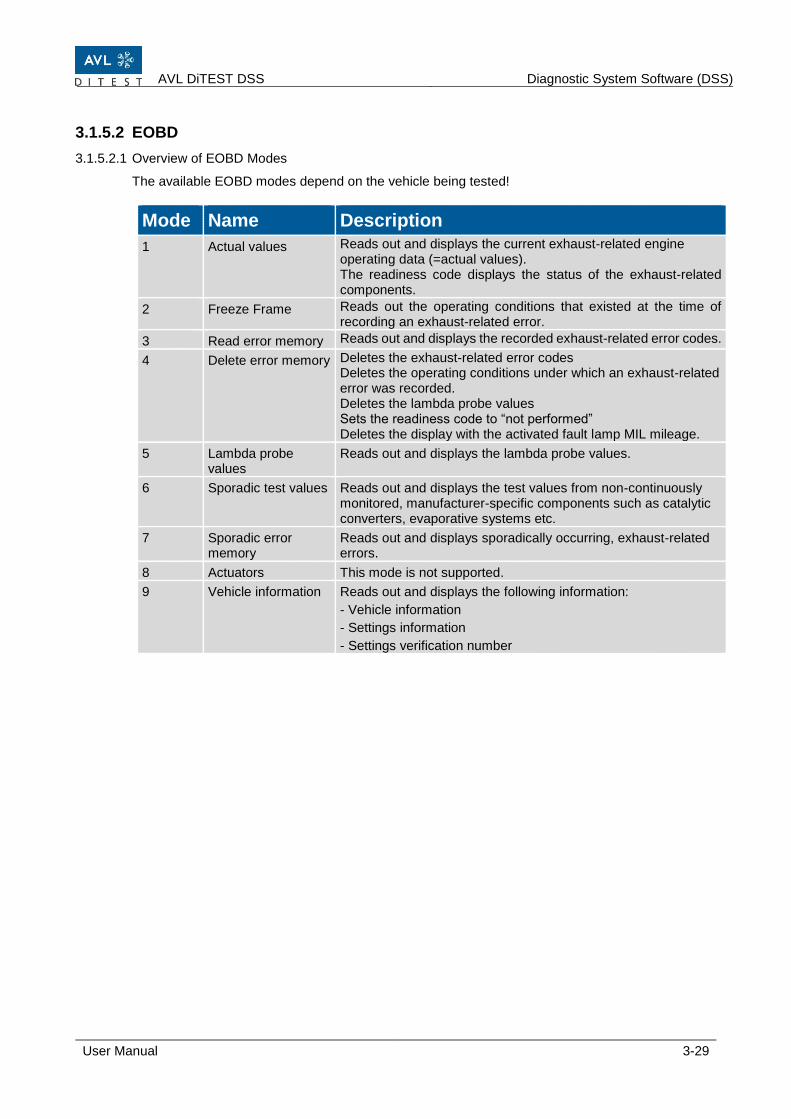
3.1.5.2.1 Overview of EOBD Modes
The available EOBD modes depend on the vehicle being tested!
Mode Name Description
1 Actual values Reads out and displays the current exhaust-related engine operating data (=actual values). The readiness code displays the status of the exhaust-related components.
2 Freeze Frame Reads out the operating conditions that existed at the time of recording an exhaust-related error.
3 Read error memory Reads out and displays the recorded exhaust-related error codes.
4 Delete error memory Deletes the exhaust-related error codes Deletes the operating conditions under which an exhaust-related error was recorded. Deletes the lambda probe values Sets the readiness code to “not performed” Deletes the display with the activated fault lamp MIL mileage.
5 Lambda probe values
Reads out and displays the lambda probe values.
6 Sporadic test values Reads out and displays the test values from non-continuously monitored, manufacturer-specific components such as catalytic converters, evaporative systems etc.
7 Sporadic error memory
Reads out and displays sporadically occurring, exhaust-related errors.
8 Actuators This mode is not supported.
9 Vehicle information Reads out and displays the following information:
- Vehicle information
- Settings information
- Settings verification number

Preparing for Measurement AVL DiTEST DSS
3-30 User Manual
3.1.5.2.2 Establishing a Connection
For these test procedures, the vehicle must be connected to the AVL OBD and the vehicle ignition must be turned on.
3.1.5.2.3 Mode 1 Actual Values
Click on DiagnosticEOBDMode 1.
A connection with the vehicle will be established and the data will be read out.
All possible diagnostic data will be displayed; select the data you are interested in.
F8 Next Accepts your selection.
The selected values are presented.
F4 Print Measured values will be printed.
F7 Back Returns to the parameter selection.
F8 Next Exit Mode 1.
3.1.5.2.4 Mode 2 Freeze Frame
Click on DiagnosticEOBDMode 2.
A connection with the vehicle will be established and the data will be read out.
All possible freeze frame data will be displayed; select the data you are interested in.
F2 Select Selects all data.
F3 Discard Discards data selection.
F8 Next Accepts your selection.
The selected freeze frame data are presented.
F4 Print Prints the selected freeze frame data.
F7 Back Returns to the parameter selection.
F8 Weiter Exit Mode 2.
3.1.5.2.5 Mode 3 Read Error Memory
Click on DiagnosticEOBDMode 3.
A connection with the vehicle will be established and all emission-related error codes will be read out.
F4 Print Error codes will be printed.
F8 Next Exit Mode 3.

AVL DiTEST DSS Diagnostic System Software (DSS)
User Manual 3-31
3.1.5.2.6 Mode 4 Delete Error Memory
Click on DiagnosticEOBDMode 4.
A connection with the vehicle will be established and all emission-related error codes will be read out.
F4 Print Deleted errors will be printed.
F5 New Clears the fault memory.
F8 Next Exit Mode 4.
3.1.5.2.7 Mode 5 Lambda Probe Values
Click on DiagnosticEOBDMode 5.
A connection with the vehicle will be established and the test results of the lambda probe monitoring will be read out.
F4 Print Values of lambda sensores will be printed.
F8 Next Exit Mode 5.
3.1.5.2.8 Mode 6 Sporadic Test Values
Click on DiagnosticEOBDMode 6.
A connection with the vehicle will be established and all test results of non-continuously monitored systems will be read out.
F4 Print Sporadic test data will be printed.
F8 Next Exit Mode 6.
3.1.5.2.9 Mode 7 Sporadic Error Memory
Click on DiagnosticEOBDMode 7.
Click on EOBDMode 7.
A connection with the vehicle will be established and all test results of non-continuously monitored systems will be read out.
F4 Print Sporadic errors will be printed.
F8 Next Exit Mode 7.
3.1.5.2.10 Mode 8 Actuator Test
This mode is not supported.
3.1.5.2.11 Mode 9 Vehicle Information
Click on DiagnosticEOBDMode 9.
A connection with the vehicle will be established and all vehicle information will be read out.
F8 Next Exit Mode 9.
Preparing for Measurement AVL DiTEST DSS
3-32 User Manual
3.1.5.3 ECU Diagnosis
Click DiagnosticsECU diagnosis.
If installed, AVL DiTEST XDS 1000 will start.
Please see the AVL DiTEST XDS 1000 User Manual.
3.1.5.4 Measurement & testing
Click DiagnosticsMeasurement & testing.
The "Measurement & testing" application will start.
Please see the AVL SCOPE User Manual.
3.1.5.5 HV Safety
Click DiagnosticsHV Safety.
The "HV Safety" application will start.
Please see the AVL SAFETY User Manual.

AVL DiTEST DSS Diagnostic System Software (DSS)
User Manual 3-33
3.1.6 Jobs
In the Jobs area you will find the job services available on your device (asanetwork).
3.1.6.1 Asanetwork
To be able to operate AVL DiTEST DSS in a network, you need:
AWN-compatible commercial software.
An active network manager.
The corresponding network installation (cabling, connection sockets, wireless LAN).
With asanetwork functionality enabled, all AU measurements performed without asanetwork job will be stored under “Send results”.
For more options, see Chapter 3.1.2.1.2 „asanetwork“.
Observe the documentation of:
Your asanetwork program
Your commercial software
3.1.6.1.1 Taking On Jobs from asanetwork
Click on OrdersasanetworkSelect order.
Select the desired job by clicking on it.
Display only AU jobs:
If this item is enabled, then only AU jobs will be displayed.
F4 Refresh Refreshes the display of jobs.
Refreshing the display in the main application window of AU jobs may take a few seconds, depending on the network speed.
F5 Release If there are problems with the asanetwork, jobs can “hang”. That is, they are marked as if being processed by the AVL DiTEST DSS (when this is not the case). Such jobs can be released by pressing F5.
F8 Next Accepts the selected Job.
After performing the AU, the AVL DiTEST DSS automatically sends the AU results log back to the asanetwork.
Information
Information

Preparing for Measurement AVL DiTEST DSS
3-34 User Manual
3.1.6.1.2 Send Results to asanetwork
All AU results can be sent to asanetwork.
Click on OrdersasanetworkSend results.
A list may appear containing obsolete results. You can either delete these obsolete results with F5 Yes or keep them with F8 No.
All unsent jobs will be displayed; select the job in question.
Individual jobs can be selected by checking a box.
F2 Choose Selects all jobs.
F3 Discard Discards the selected jobs.
F5 Delete Deletes the selected jobs.
F6 Send Sends the selected jobs to asanetwork.
F8 Next Closes the function “Send Results to asanetwork”.
AVL DiTEST DSS Diagnostic System Software (DSS)
User Manual 3-35
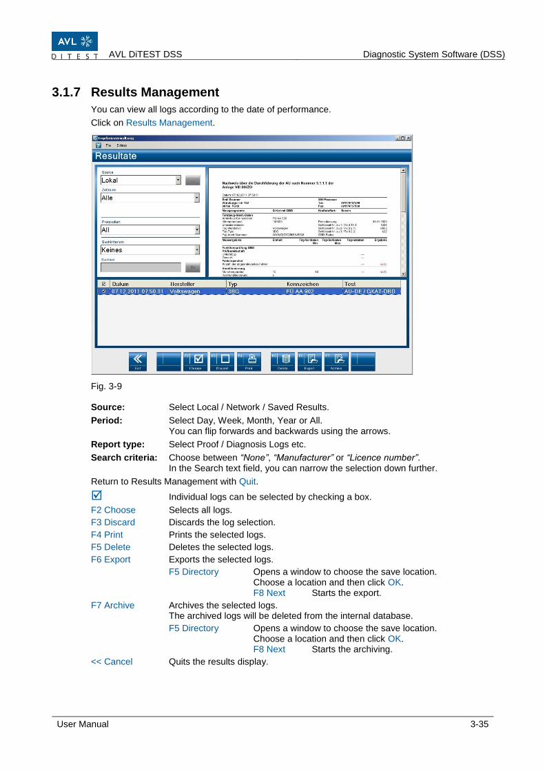
3.1.7 Results Management
You can view all logs according to the date of performance.
Click on Results Management. Fig. 3-9 Source: Select Local / Network / Saved Results.
Period: Select Day, Week, Month, Year or All. You can flip forwards and backwards using the arrows.
Report type: Select Proof / Diagnosis Logs etc.
Search criteria: Choose between “None”, “Manufacturer” or “Licence number”. In the Search text field, you can narrow the selection down further.
Return to Results Management with Quit.
Individual logs can be selected by checking a box.
F2 Choose Selects all logs.
F3 Discard Discards the log selection.
F4 Print Prints the selected logs.
F5 Delete Deletes the selected logs.
F6 Export Exports the selected logs.
F5 Directory Opens a window to choose the save location. Choose a location and then click OK. F8 Next Starts the export.
F7 Archive Archives the selected logs. The archived logs will be deleted from the internal database.
F5 Directory Opens a window to choose the save location. Choose a location and then click OK. F8 Next Starts the archiving.
<< Cancel Quits the results display.

Preparing for Measurement AVL DiTEST DSS
3-36 User Manual
3.1.7.1 File
Please refer to Cap. 3.1.1„File“. Only the functions relevant to "Results management" will appear.
3.1.7.2 Extras
Please refer to 3.1.2 "Extras". Only the functions relevant to "Results management" will appear.
AVL DiTEST DSS Diagnostic System Software (DSS)
User Manual 3-37
3.1.8 Service/ Maintenance
This chapter gives tips for an initial on-site diagnosis of the AVL DiTEST DSS station. Preparation for calibration and linearity testing can be performed by the end customer as well as by the qualified service company.
AVL SMOKE:
Service screen (parameters for self-diagnostics)
AVL GAS:
Service screen (parameters for self-diagnostics)
AVL AUX:
Service screen (parameters for self-diagnostics)
AVL OBD:
Service screen (parameters for self-diagnostics)
AVL HV Safety:
Service screen (parameters for self-diagnostics)
Please refer to the relevant device manual for further information on the AVL DiTEST MDS hardware components.
System info:
Parameters for self-diagnosis, with and without connected devices
License information:
Display the licenses present on the dongle
3.1.8.1 Calibration Programs
Please refer to the chapter 3.1.4 „AU“.
Information

Preparing for Measurement AVL DiTEST DSS
3-38 User Manual
3.1.8.2 Service Screen AVL SMOKE
The service screen AVL SMOKE shows: ■ Device identification
■ Measurements
■ Status
■ Information on the turbidity measurement chamber
Click on Service/MaintenanceAVL SMOKEService Screen.
The message “Initializing the diesel measurement chamber” appears shortly.
A service screen with parameters for self-diagnostics is shown.
Fig. 3-10 Example Servicescreen AVL DiSmoke 480
(1) This field displays the connection and device status as well as various version numbers
and serial numbers.
(2) Here you can perform various functional checks
Valve position: Calibration, measurement
Lamp status: lamp A and B ON, lamps OFF, lamp A ON, and lamp B ON
Fan status: Automatic, ON
Heater status: Automatic, ON
Linearity test: The linearity error is measured and then shown. Description of automatic procedure: 1. A lamp is measured. 2. Lamp B is measured. 3. A plus lamp bulb B is measured. 4. Comparison of point 3 with the sum of point 1 and point 2.
Initialization: AVL SMOKE will be re-initialized.
(3) This field displays the device-internal measurements. F4 Report Displays a log. This can also be subsequently printed out.
(1)
(2)
(3)
AVL DiTEST DSS Diagnostic System Software (DSS)
User Manual 3-39
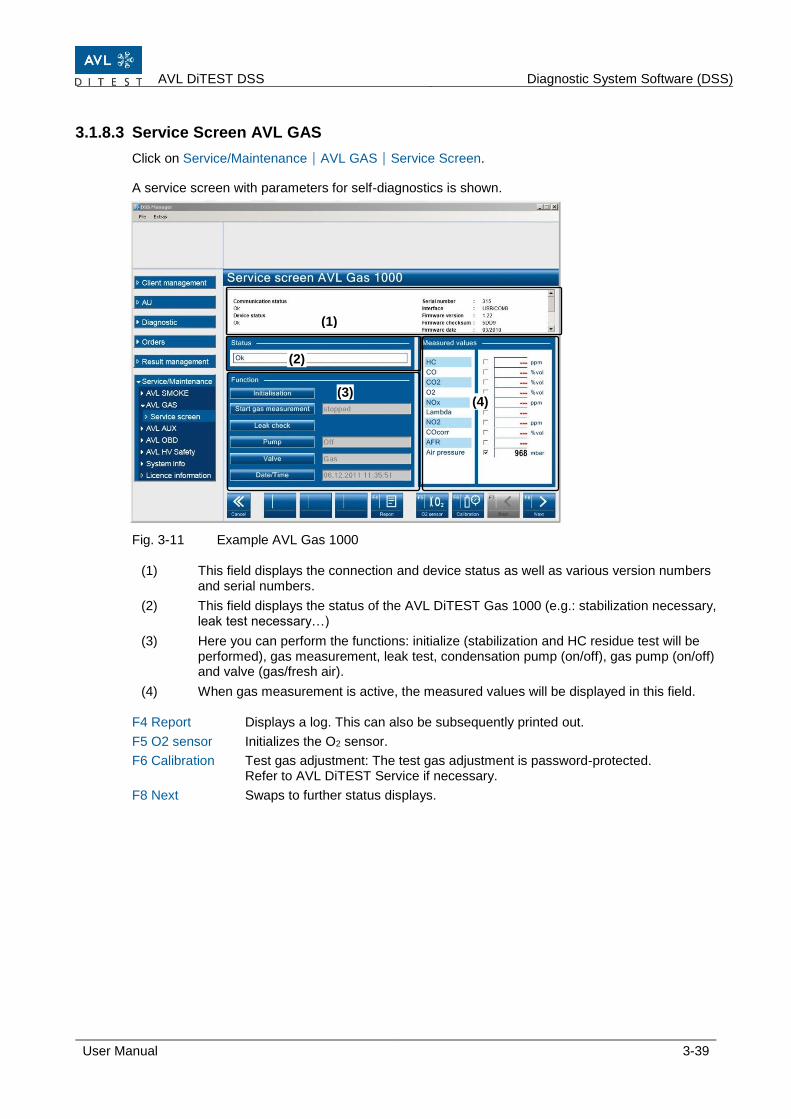
3.1.8.3 Service Screen AVL GAS
Click on Service/MaintenanceAVL GASService Screen.
A service screen with parameters for self-diagnostics is shown.
Fig. 3-11 Example AVL Gas 1000
(1) This field displays the connection and device status as well as various version numbers and serial numbers.
(2) This field displays the status of the AVL DiTEST Gas 1000 (e.g.: stabilization necessary, leak test necessary…)
(3) Here you can perform the functions: initialize (stabilization and HC residue test will be performed), gas measurement, leak test, condensation pump (on/off), gas pump (on/off) and valve (gas/fresh air).
(4) When gas measurement is active, the measured values will be displayed in this field. F4 Report Displays a log. This can also be subsequently printed out.
F5 O2 sensor Initializes the O2 sensor.
F6 Calibration Test gas adjustment: The test gas adjustment is password-protected. Refer to AVL DiTEST Service if necessary.
F8 Next Swaps to further status displays.
(1)
(2)
(3) (4)
Preparing for Measurement AVL DiTEST DSS
3-40 User Manual
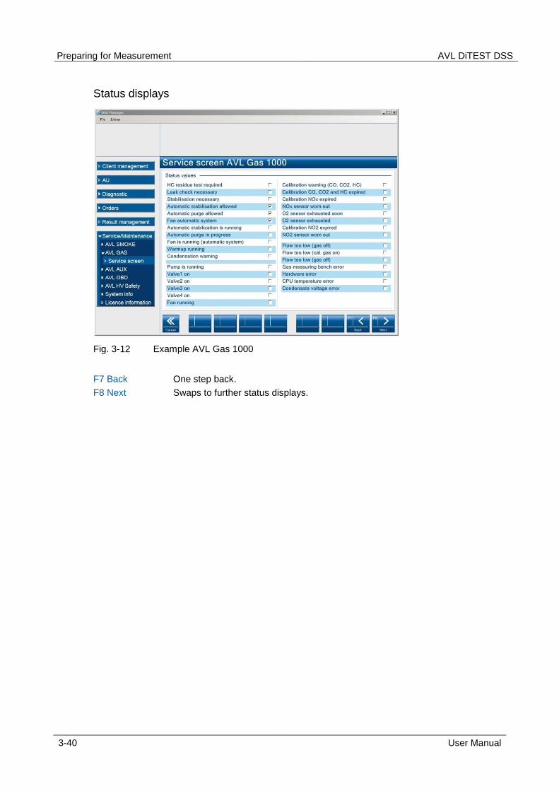
Status displays
Fig. 3-12 Example AVL Gas 1000
F7 Back One step back.
F8 Next Swaps to further status displays.

AVL DiTEST DSS Diagnostic System Software (DSS)
User Manual 3-41
3.1.8.4 Service Screen AVL AUX
The AVL AUX service screen displays:
Connection and device status
Measurements
Speed measurement configuration
Click on Service/MaintenanceAVL AUXService Screen.
Fig. 3-13 Example AVL AUX 1000
(1) This field displays the connection and device status and various version numbers and
serial numbers.
(2) This field displays the speed and oil temperature.
(3) Switch between DiSpeed "Internal/External". DiSpeed "internal" selection: „truck", "car", "2/4-stroke motorcycle".
F4 Report Shows a print preview of the service screen.
(1)
(2)
(3)
Preparing for Measurement AVL DiTEST DSS
3-42 User Manual
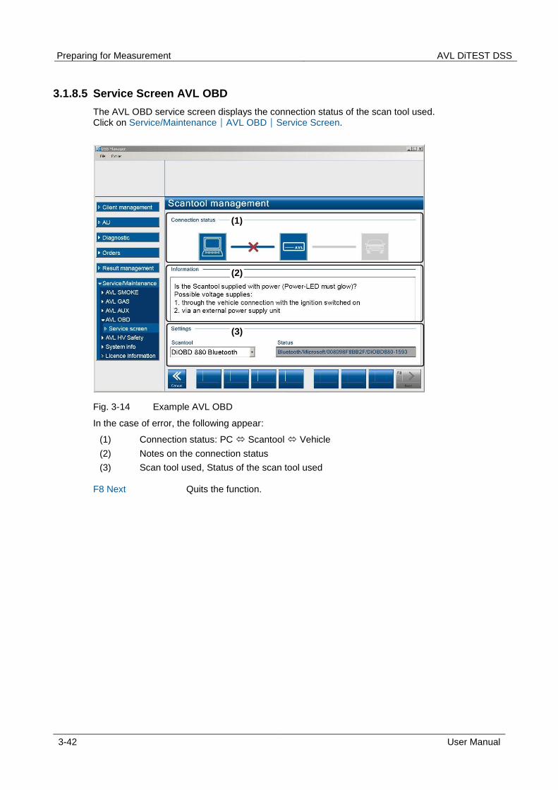
3.1.8.5 Service Screen AVL OBD
The AVL OBD service screen displays the connection status of the scan tool used. Click on Service/MaintenanceAVL OBDService Screen.
Fig. 3-14 Example AVL OBD
In the case of error, the following appear:
(1) Connection status: PC Scantool Vehicle
(2) Notes on the connection status
(3) Scan tool used, Status of the scan tool used F8 Next Quits the function.
(1)
(2)
(3)

AVL DiTEST DSS Diagnostic System Software (DSS)
User Manual 3-43
3.1.8.6 Service Screen AVL HV Safety
The AVL HV Safety service screen displays:
Communication status
Device status
Firmware version
Firmware checksum
Boot loader version
Serial number
COM port used
Click on Service/MaintenanceAVL HV SafetyService screen.
Abb. 3-15 Example AVL DiTEST HV Safety 1000
F4 Log Displays a print preview of the service screen.
F5 Self-test Launches an AVL HV Safety self-test.

Preparing for Measurement AVL DiTEST DSS
3-44 User Manual
3.1.8.7 System Info
This shows: ■ Product information
- Installed programs
- Program versions
- Program versions of the connected components
■ Settings
- Input values that have been entered under “Tools”, “Settings”.
Click on Service/MaintenanceSystem Infowith devices or without devices.
The AVL DiTEST DSS system information will be displayed.
Fig. 3-16 Example
F4 Print Prints a log of the system information.
F8 Next Quits this function.

AVL DiTEST DSS Diagnostic System Software (DSS)
User Manual 3-45
3.1.8.8 License Information
The license information present on the dongle is displayed.
Click on Service/MaintenanceLicense information.
The license information present on the dongle will be displayed.
Fig. 3-17 Example
F4 Print Prints a log of the license information.
F8 Next Quits this function.

Preparing for Measurement AVL DiTEST DSS
3-46 User Manual

AVL DiTEST CDS Maintenance
User Manual 4-1
4 Maintenance
4.1 Maintenance Plan AVL GAS Refer to user manual AVL DiTEST Gas 1000, Chapter 5.1 Maintenance Plan or the user manual AVL DiTEST DiGas 480, chap. 5.1 Maintenance Schedule.
4.2 Maintenance Plan AVL SMOKE Refer to user manual AVL DiSmoke 480 BT, Chapter 3.1 Maintenance Plan.
4.3 Maintenance AVL AUX Make sure that the housing, the sockets and the Bluetooth aerial are neither damaged nor dirty.
4.4 Maintenance AVL SCOPE Make sure that the housing, the USB cable and the BNC sockets are neither damaged nor dirty.
4.5 Maintenance AVL HV Safety
Make sure that the housing, the USB cable and the measurement cables/measurement adapters are neither damaged nor dirty.
4.6 Software update Please refer to AVL DSS Installation and Updates, AVL ID no. AT7260ML. This can be found in the DVD sleeve

Maintenance AVL DiTEST CDS
4-2 User Manual

AVL DiTEST CDS Index
User Manual 5-1
5 Index
A Applications ....................................................... 3-12 Asanetwork ................................................. 3-4, 3-33 AU...................................................................... 3-21 Automatic Execution............................................ 3-6 AVL AUX ............................................................. 3-9 AVL DiGate 480 .................................................. 3-5 AVL GAS ........................................................... 3-11 AVL HV Safety .................................................... 3-9 AVL OBD ............................................................. 3-7 AVL SMOKE ...................................................... 3-10
B Backup .............................................................. 3-18 Bluetooth ............................................................. 3-7 BMW Key Reader ................................................ 3-8
C Calibration Programs......................................... 3-37 Close all applications........................................... 3-2 Continuous Gas & Opacity Measurement ......... 3-27 Continuous Gas Measurement ......................... 3-24 Continuous Opacity Measurement .................... 3-26 Customer Area .................................................. 3-19 Customer Management ..................................... 3-19 Customer/Vehicle Assignment .......................... 3-20
D Data Recording ................................................... 3-6 Dateien exporting .............................................. 3-13 Device ............................................................... 3-16 Device connections .................................... 3-7, 3-17 Diagnostic .......................................................... 3-24 Diagnostic System Software (DSS) .................... 3-1 Diesel Values Display Program ......................... 3-22 DSS Application Window .................................... 1-2 DSS Manager ...................................................... 3-1
E ECU Diagnose ................................................... 3-32 EOBD ................................................................ 3-29 Exhaust Analysis ............................................... 3-24
F File ....................................................................... 3-2 Filtertest ............................................................. 3-22
G Gas Values Display Program ............................ 3-23 General ....................................................... 1-1, 3-19
H HC Residue Test ................................................. 2-1 Help ..................................................................... 1-4 HV Safety ................................................. 3-12, 3-32
I Infobox ................................................................. 1-4
J Jobs ................................................................... 3-33
L Language ............................................................. 3-3 Leak Test ............................................................. 2-1 License .............................................................. 3-14 License Information ........................................... 3-45 Log File .............................................................. 3-13 Logging ................................................................ 3-6
M Maintenance ........................................................ 4-1 Maintenance AVL AUX ........................................ 4-1 Maintenance AVL HV Safety ............................... 4-1 Maintenance AVL SCOPE .................................. 4-1 Maintenance Plan AVL GAS ............................... 4-1 Maintenance Plan AVL SMOKE .......................... 4-1 Manufacturer Options ........................................ 3-12 Measurement & testing ..................................... 3-32 Mode 1 Actual Values ....................................... 3-30 Mode 2 Freeze Frame ....................................... 3-30 Mode 3 Read Error Memory .............................. 3-30 Mode 4 Delete Error Memory ............................ 3-31 Mode 5 Lambda Probe Values .......................... 3-31 Mode 6 Sporadic Test Values ........................... 3-31 Mode 7 Sporadic Error Memory ........................ 3-31 Mode 9 Vehicle Information ............................... 3-31
O Operation ............................................................. 1-2
P Preparing for Measurement ................................. 2-1
Q Quit ...................................................................... 3-2 Quitting and switching off the application ............ 1-4
Index AVL DiTEST CDS
5-2 User Manual
R Restore .............................................................. 3-18 Results Management ........................................ 3-35
S Send Results to asanetwork ............................. 3-34 Service Screen AVL AUX .................................. 3-41 Service Screen AVL GAS ................................. 3-39 Service Screen AVL HV Safety ......................... 3-43 Service Screen AVL OBD ................................. 3-42 Service Screen AVL SMOKE ............................ 3-38 Service/ Maintenance ........................................ 3-37 Settings ............................................................... 3-3 Show Log File .................................................... 3-13 Softwareupdate ................................................... 4-1 Stability Test ........................................................ 2-2 Stop devices ........................................................ 3-2 Summarized Safety Notices ................................... III Switching on ........................................................ 1-4 System Info ....................................................... 3-44 System-Update .................................................. 3-14
T Taking On Jobs from asanetwork ...................... 3-33 Timing ................................................................ 3-27 Tools .................................................................... 3-3
U User Prompts ....................................................... 1-3
V Vehicle Area ...................................................... 3-20 Vehicle Data ...................................................... 3-15
W Warm-Up Phase .................................................. 2-2 Warn- und Sicherheitshinweise ............................... I Workshop ............................................................ 3-5