User Manual ASMB-815 Series - Advantechadvdownload.advantech.com/productfile/Downloadfile4/1-1...iii...
118
User Manual ASMB-815 Series LGA 3647-P0 Intel Xeon® Server Board with 6 DDR4, 5 PCIe x8 or 2 PCIe x16 and 1 PCIe x8, 8 SATA3, 6 USB3.0, Dual 10GbE, IPMI
Transcript of User Manual ASMB-815 Series - Advantechadvdownload.advantech.com/productfile/Downloadfile4/1-1...iii...
User Manual
ASMB-815 Series
LGA 3647-P0 Intel Xeon® Server Board with 6 DDR4, 5 PCIe x8 or 2 PCIe x16 and 1 PCIe x8, 8 SATA3, 6 USB3.0, Dual 10GbE, IPMI

CopyrightThe documentation and the software included with this product are copyrighted 2017by Advantech Co., Ltd. All rights are reserved. Advantech Co., Ltd. reserves the rightto make improvements in the products described in this manual at any time withoutnotice. No part of this manual may be reproduced, copied, translated or transmittedin any form or by any means without the prior written permission of Advantech Co.,Ltd. Information provided in this manual is intended to be accurate and reliable. How-ever, Advantech Co., Ltd. assumes no responsibility for its use, nor for any infringe-ments of the rights of third parties, which may result from its use.
AcknowledgementsIntel and Pentium are trademarks of Intel® Corporation.
Microsoft Windows and MS-DOS are registered trademarks of Microsoft® Corp.
All other product names or trademarks are properties of their respective owners.
Product Warranty (2 years)Advantech warrants to you, the original purchaser, that each of its products will befree from defects in materials and workmanship for two years from the date of pur-chase.
This warranty does not apply to any products which have been repaired or altered bypersons other than repair personnel authorized by Advantech, or which have beensubject to misuse, abuse, accident or improper installation. Advantech assumes noliability under the terms of this warranty as a consequence of such events.
Because of Advantech’s high quality-control standards and rigorous testing, most ofour customers never need to use our repair service. If an Advantech product is defec-tive, it will be repaired or replaced at no charge during the warranty period. For out-of-warranty repairs, you will be billed according to the cost of replacement materials,service time and freight. Please consult your dealer for more details.
If you think you have a defective product, follow these steps:
1. Collect all the information about the problem encountered. (For example, CPU speed, Advantech products used, other hardware and software used, etc.) Note anything abnormal and list any on screen messages you get when the problem occurs.
2. Call your dealer and describe the problem. Please have your manual, product, and any helpful information readily available.
3. If your product is diagnosed as defective, obtain an RMA (return merchandise authorization) number from your dealer. This allows us to process your return more quickly.
4. Carefully pack the defective product, a fully-completed Repair and Replacement Order Card and a photocopy proof of purchase date (such as your sales receipt) in a shippable container. A product returned without proof of the purchase date is not eligible for warranty service.
5. Write the RMA number visibly on the outside of the package and ship it prepaid to your dealer.
Part No. 2001815I00 Edition 1
Printed in Taiwan November 2017
ASMB-815 User Manual ii

A Message to the Customer
Advantech Customer Services
Each and every Advantech product is built to the most exacting specifications toensure reliable performance in the harsh and demanding conditions typical of indus-trial environments. Whether your new Advantech equipment is destined for the labo-ratory or the factory floor, you can be assured that your product will provide thereliability and ease of operation for which the name Advantech has come to beknown. Your satisfaction is our primary concern. Here is a guide to Advantech’s cus-tomer services. To ensure you get the full benefit of our services, please follow theinstructions below carefully.
Technical Support
We want you to get the maximum performance from your products. So if you run intotechnical difficulties, we are here to help. For the most frequently asked questions,you can easily find answers in your product documentation. These answers arenormally a lot more detailed than the ones we can give over the phone.
So please consult this manual first. If you still cannot find the answer, gather all theinformation or questions that apply to your problem, and with the product close athand, call your dealer. Our dealers are well trained and ready to give you the supportyou need to get the most from your Advantech products. In fact, most problemsreported are minor and are easily solved over the phone.
In addition, free technical support is available from Advantech engineers everybusiness day. We are always ready to give advice on application requirements orspecific information on the installation and operation of any of our products.
Declaration of Conformity
FCC Class B
Note: This equipment has been tested and found to comply with the limits for a ClassB digital device, pursuant to part 15 of the FCC Rules. These limits are designed toprovide reasonable protection against harmful interference in a residential installa-tion. This equipment generates, uses and can radiate radio frequency energy and, ifnot installed and used in accordance with the instructions, may cause harmful inter-ference to radio communications. However, there is no guarantee that interferencewill not occur in a particular installation. If this equipment does cause harmful interfer-ence to radio or television reception, which can be determined by turning the equip-ment off and on, the user is encouraged to try to correct the interference by one ormore of the following measures:
Reorient or relocate the receiving antenna. Increase the separation between the equipment and receiver. Connect the equipment into an outlet on a circuit different from that to which the
receiver is connected. Consult the dealer or an experienced radio/TV technician for help.
iii ASMB-815 User Manual
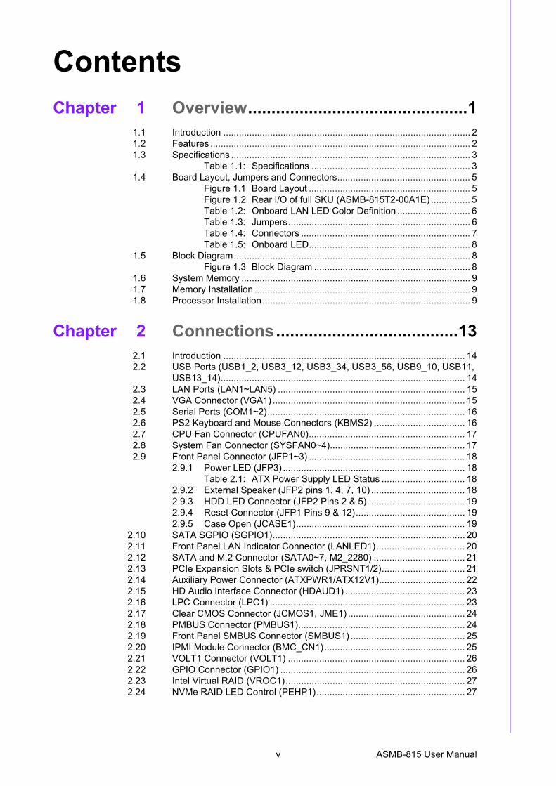
Initial InspectionBefore installing motherboard, please make sure that the following materials havebeen shipped:
1 x ASMB-815 ATX motherboard 1 x ASMB-815 Startup Manual 1 x Driver CD 2 x Serial ATA HDD data cables 1 x I/O port bracket 1 x CPU power cable (8P) 2 x SATA power cable 1 x Warranty card
If any of these items are missing or damaged, contact distributor or sales representa-tive immediately. We have carefully inspected the ASMB-815 mechanically and elec-trically before shipment. It should be free of marks and scratches and in perfectworking order upon receipt. When unpacking the ASMB-815, check it for signs ofshipping damage. (For example, damaged box, scratches, dents, etc.) If it is dam-aged or it fails to meet the specifications, notify our service department or local salesrepresentative immediately. Also notify the carrier. Retain the shipping carton andpacking material for inspection by the carrier. After inspection, we will make arrange-ments to repair or replace the unit.
Order Information
Part Number Chipset HDD Expansion Slot IPMI 10GbE LAN
ASMB-815-00A1E C6218*SATA3+1*M.2
5 PCIe x8 or 2 PCIe x16 and 1 PCIe x8+ 1 PCIe x4 + 1 PCIe x1 (Gen 3.0)
No No
ASMB-815I-00A1E C6218*SATA3+1*M.2
5 PCIe x8 or 2 PCIe x16 and 1 PCIe x8+ 1 PCIe x4 + 1 PCIe x1 (Gen 3.0)
Yes No
ASMB-815T2-00A1E C6228*SATA3+1*M.2
5 PCIe x8 or 2 PCIe x16 and 1 PCIe x8+ 1 PCIe x4 + 1 PCIe x1 (Gen 3.0)
Yes Yes
ASMB-815 User Manual iv
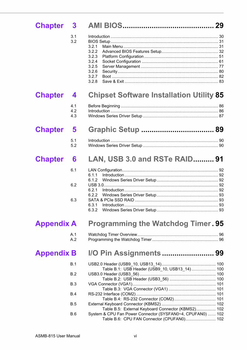
Contents
Chapter 1 Overview...............................................11.1 Introduction ............................................................................................... 21.2 Features .................................................................................................... 21.3 Specifications ............................................................................................ 3
Table 1.1: Specifications ............................................................. 31.4 Board Layout, Jumpers and Connectors................................................... 5
Figure 1.1 Board Layout .............................................................. 5Figure 1.2 Rear I/O of full SKU (ASMB-815T2-00A1E) ............... 5Table 1.2: Onboard LAN LED Color Definition ............................ 6Table 1.3: Jumpers...................................................................... 6Table 1.4: Connectors ................................................................. 7Table 1.5: Onboard LED.............................................................. 8
1.5 Block Diagram........................................................................................... 8Figure 1.3 Block Diagram ............................................................ 8
1.6 System Memory ........................................................................................ 91.7 Memory Installation ................................................................................... 91.8 Processor Installation................................................................................ 9
Chapter 2 Connections.......................................132.1 Introduction ............................................................................................. 142.2 USB Ports (USB1_2, USB3_12, USB3_34, USB3_56, USB9_10, USB11,
USB13_14).............................................................................................. 142.3 LAN Ports (LAN1~LAN5) ........................................................................ 152.4 VGA Connector (VGA1) .......................................................................... 152.5 Serial Ports (COM1~2)............................................................................ 162.6 PS2 Keyboard and Mouse Connectors (KBMS2) ................................... 162.7 CPU Fan Connector (CPUFAN0)............................................................ 172.8 System Fan Connector (SYSFAN0~4).................................................... 172.9 Front Panel Connector (JFP1~3) ............................................................ 18
2.9.1 Power LED (JFP3) ...................................................................... 18Table 2.1: ATX Power Supply LED Status ................................ 18
2.9.2 External Speaker (JFP2 pins 1, 4, 7, 10) .................................... 182.9.3 HDD LED Connector (JFP2 Pins 2 & 5) ..................................... 192.9.4 Reset Connector (JFP1 Pins 9 & 12).......................................... 192.9.5 Case Open (JCASE1)................................................................. 19
2.10 SATA SGPIO (SGPIO1).......................................................................... 202.11 Front Panel LAN Indicator Connector (LANLED1).................................. 202.12 SATA and M.2 Connector (SATA0~7, M2_2280) ................................... 212.13 PCIe Expansion Slots & PCIe switch (JPRSNT1/2)................................ 212.14 Auxiliary Power Connector (ATXPWR1/ATX12V1)................................. 222.15 HD Audio Interface Connector (HDAUD1) .............................................. 232.16 LPC Connector (LPC1) ........................................................................... 232.17 Clear CMOS Connector (JCMOS1, JME1) ............................................. 242.18 PMBUS Connector (PMBUS1)................................................................ 242.19 Front Panel SMBUS Connector (SMBUS1) ............................................ 252.20 IPMI Module Connector (BMC_CN1)...................................................... 252.21 VOLT1 Connector (VOLT1) .................................................................... 262.22 GPIO Connector (GPIO1) ....................................................................... 262.23 Intel Virtual RAID (VROC1)..................................................................... 272.24 NVMe RAID LED Control (PEHP1)......................................................... 27
v ASMB-815 User Manual
Chapter 3 AMI BIOS............................................ 293.1 Introduction ............................................................................................. 303.2 BIOS Setup ............................................................................................. 31
3.2.1 Main Menu.................................................................................. 313.2.2 Advanced BIOS Features Setup................................................. 323.2.3 Platform Configuration ................................................................ 513.2.4 Socket Configuration .................................................................. 613.2.5 Server Management ................................................................... 773.2.6 Security....................................................................................... 803.2.7 Boot ............................................................................................ 823.2.8 Save & Exit ................................................................................. 83
Chapter 4 Chipset Software Installation Utility 854.1 Before Beginning .................................................................................... 864.2 Introduction ............................................................................................. 864.3 Windows Series Driver Setup ................................................................. 87
Chapter 5 Graphic Setup ................................... 895.1 Introduction ............................................................................................. 905.2 Windows Series Driver Setup ................................................................. 90
Chapter 6 LAN, USB 3.0 and RSTe RAID.......... 916.1 LAN Configuration................................................................................... 92
6.1.1 Introduction ................................................................................. 926.1.2 Windows Series Driver Setup ..................................................... 92
6.2 USB 3.0................................................................................................... 926.2.1 Introduction ................................................................................. 926.2.2 Windows Series Driver Setup ..................................................... 93
6.3 SATA & PCIe SSD RAID ........................................................................ 936.3.1 Introduction ................................................................................. 936.3.2 Windows Series Driver Setup ..................................................... 93
Appendix A Programming the Watchdog Timer . 95A.1 Watchdog Timer Overview...................................................................... 96A.2 Programming the Watchdog Timer ......................................................... 96
Appendix B I/O Pin Assignments ......................... 99B.1 USB2.0 Header (USB9_10, USB13_14)............................................... 100
Table B.1: USB Header (USB9_10, USB13_14) ..................... 100B.2 USB3.0 Header (USB3_56) .................................................................. 100
Table B.2: USB Header (USB3_56) ........................................ 100B.3 VGA Connector (VGA1)........................................................................ 101
Table B.3: VGA Connector (VGA1) ......................................... 101B.4 RS-232 Interface (COM2) ..................................................................... 101
Table B.4: RS-232 Connector (COM2).................................... 101B.5 External Keyboard Connector (KBMS2) ............................................... 102
Table B.5: External Keyboard Connector (KBMS2)................. 102B.6 System & CPU Fan Power Connector (SYSFAN0~4, CPUFAN0) ....... 102
Table B.6: CPU FAN Connector (CPUFAN0).......................... 102
ASMB-815 User Manual vi
Table B.7: SYS FAN Connector (SYSFAN0~4)....................... 102B.7 Power LED (JFP3) ................................................................................ 103
Table B.8: Power LED Connector (JFP3) ................................ 103B.8 External Speaker Connector (JFP2) ..................................................... 103
Table B.9: External Speaker Connector (JFP2)....................... 103B.9 Reset Connector (JFP1) ....................................................................... 103
Table B.10:Reset Connector (JFP1)......................................... 103B.10 HDD LED Connector (JFP2) ................................................................. 104
Table B.11:HDD LED Connector (JFP2) .................................. 104B.11 ATX Soft Power Switch (JFP1) ............................................................. 104
Table B.12:ATX Soft Power Switch (JFP1)............................... 104B.12 SMBus Connector (SMBUS1)............................................................... 104
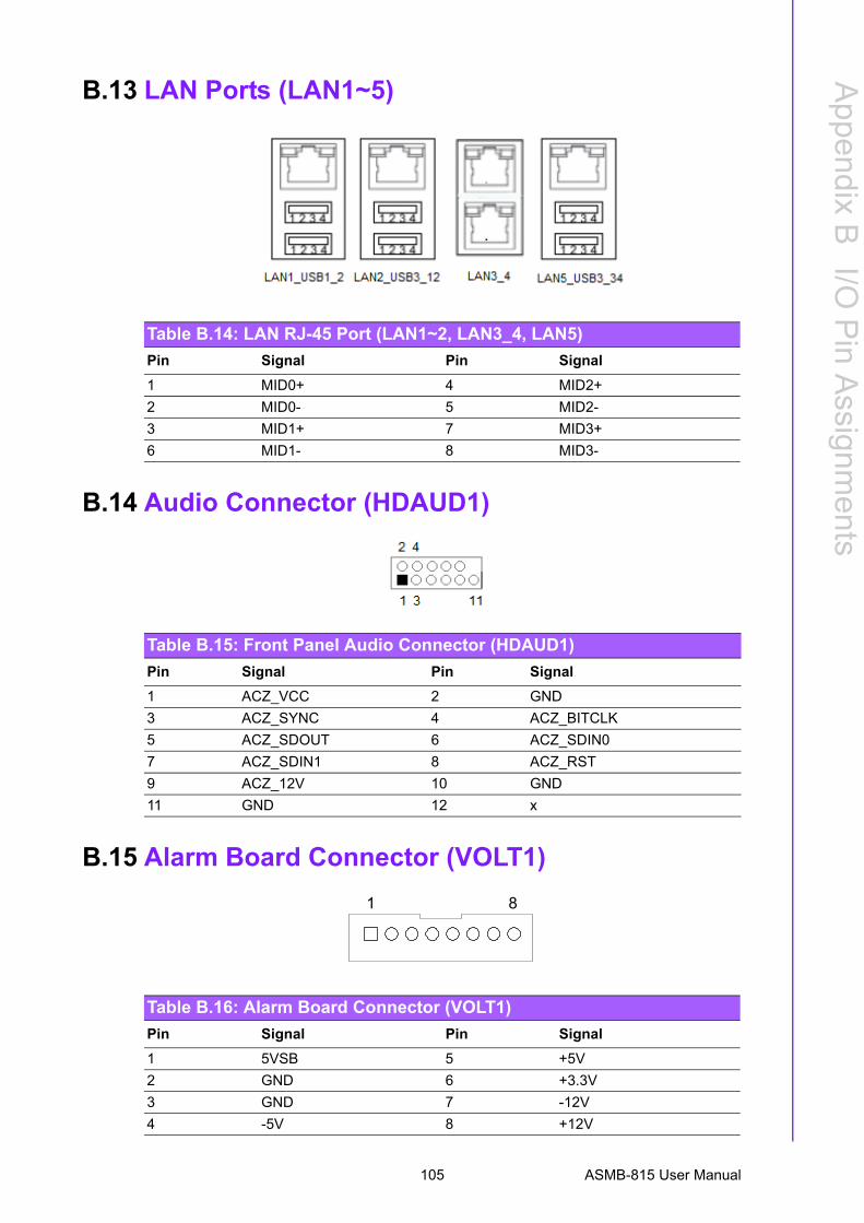
Table B.13:Front panel SMBus Connector (SMBUS1) ............. 104B.13 LAN Ports (LAN1~5) ............................................................................. 105
Table B.14:LAN RJ-45 Port (LAN1~2, LAN3_4, LAN5)............ 105B.14 Audio Connector (HDAUD1) ................................................................. 105
Table B.15:Front Panel Audio Connector (HDAUD1) ............... 105B.15 Alarm Board Connector (VOLT1).......................................................... 105
Table B.16:Alarm Board Connector (VOLT1) ........................... 105B.16 Case Open Connector (JCASE1) ......................................................... 106
Table B.17:Case Open Connector (JFP1) ................................ 106B.17 Front Panel LAN LED Connector (LANLED1)....................................... 106
Table B.18:LAN LED Connector (LANLED1)............................ 106B.18 SATA SGPIO Connector (SGPIO1) ..................................................... 106
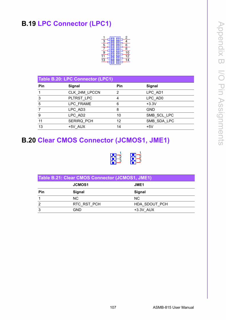
Table B.19:SATA SGPIO Connector (SGPIO1) ....................... 106B.19 LPC Connector (LPC1) ......................................................................... 107
Table B.20:LPC Connector (LPC1)........................................... 107B.20 Clear CMOS Connector (JCMOS1, JME1) ........................................... 107
Table B.21:Clear CMOS Connector (JCMOS1, JME1) ............ 107B.21 PMBUS Connector (PMBUS1).............................................................. 108
Table B.22:PMBUS Connector (PMBUS1) ............................... 108B.22 GPIO Connector (GPIO1) ..................................................................... 108
Table B.23:GPIO Connector (GPIO1)....................................... 108
vii ASMB-815 User Manual

ASMB-815 User Manual viii

Chapter 1
1 Overview
1.1 IntroductionThe ASMB-815 serverboard is the most advanced Intel Xeon Processor scalablefamily series board for server-grade IPC applications that require high-performancecomputing power & multi-expansion slots. This serverboard supports Intel Xeon Scal-able series processor and DDR4 ECC-REG 2133/2400/2666 MHz memory up to 192GB.
ASMB-815 provides five PCIe x8 or two PCIe x16 and 1 PCIe x8, one PCIe x4 andone PCIe x1 in Gen3.0 high speed. In addition, the full ASMB-815 SKU has dualGigabit and dual 10GbE Ethernet LAN ports that eliminate network bottlenecks.(ASMB-815 I & T2 SKUs only)
A fifth RJ-45 LAN connector (LAN5) is dedicated for IPMI function that allows remotecontrol management. One RJ-45 LAN jack (LAN 4) from 10GbE port can also beused as IPMI LAN. High reliability and outstanding performance makes ASMB-815the ideal platform for industrial server/networking applications.
By using the Intel C621/C622 chipset, the ASMB-815 offers a variety of features suchas 6 x USB3.0 and 7 x USB 2.0 connectivity, 8 x onboard SATA III, and 1 x M.2 (SATAand PCIe) interface. It supports software RAID 0, 1, 10 and 5 (Windows only*), andwith the latest Intel RSTe (Rapid Storage Technology Enterprise) it provides a com-pelling RAID solution for NVMe SSDs via Intel VROC (Virtual RAID on CPU) HW key.
These powerful I/O capabilities ensure even more reliable data storage capabilitiesand high-speed I/O peripheral connectivity.
1.2 FeaturesGeneral
Intel Xeon Processor Scalable Family support: ASMB-815 is equipped with single CPU socket to support Intel Xeon Platinum/Gold/Silver/Bronze series up to 28-core processors.
High performance I/O capability: 2 x 10GbE + 2 x GbE LAN, 2 PCIe x16 slot (x8 or x16 link) +3 PCIe x8 slot (x8 link) +1 PCIe x4 (x4 link) + 1 PCIe x1 (x1 link), 8 x SATA and 1 x M.2 connector, 6 x USB 3.0 and 7 x USB 2.0 (incl. 1 x Type-A) ports.
Standard ATX form factor with industrial features: ASMB-815 provides industrial features like long product life cycle, reliable operation under wide tem-perature range, watchdog timer, etc.
IPMI 2.0 support: ASMB-815 (T2 and I SKUs) equipped with ASPEED 2500 BMC chip supports IPMI 2.0 (Intelligent Platform Management Interface 2.0) via dedicated LAN port.
KVM over IP: KVM over IP function allows BIOS level remote control of ASMB-815 (T2 and I SKUs) through your own computer.
Note! 1. IPMI module will be included in ASMB-815I and ASMB-815T2 SKUs. Only ASMB-815T2 SKU can support 10GbE LAN ports.
2. Please refer to Order Information at the front for chipset, IPMI, and LAN support on individual product SKU.
3. Please refer to the release note of each Linux OS for Intel's C621/C622 chipset SATA RAID function support.
ASMB-815 User Manual 2
Chapter 1
Overview
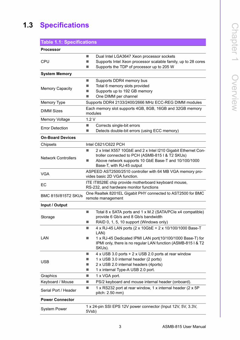
1.3 Specifications
Table 1.1: Specifications
Processor
CPU Dual Intel LGA3647 Xeon processor sockets Supports Intel Xeon processor scalable family, up to 28 cores Supports the TDP of processor up to 205 W
System Memory
Memory Capacity
Supports DDR4 memory bus Total 6 memory slots provided Supports up to 192 GB memory One DIMM per channel
Memory Type Supports DDR4 2133/2400/2666 MHz ECC-REG DIMM modules
DIMM SizesEach memory slot supports 4GB, 8GB, 16GB and 32GB memory modules
Memory Voltage 1.2 V
Error Detection Corrects single-bit errors Detects double-bit errors (using ECC memory)
On-Board Devices
Chipsets Intel C621/C622 PCH
Network Controllers
2 x Intel X557 10GbE and 2 x Intel I210 Gigabit Ethernet Con-troller connected to PCH (ASMB-815 I & T2 SKUs)
Above network supports 10 GbE Base-T and 10/100/1000 Base-T, with RJ-45 output
VGAASPEED AST2500/2510 controller with 64 MB VGA memory pro-vides basic 2D VGA function.
EC ITE IT8528E chip provide motherboard keyboard mouse, RS-232, and hardware monitor functions
BMC 815I/815T2 SKUsOne Realtek 8201EL Gigabit PHY connected to AST2500 for BMC remote management
Input / Output
Storage Total 8 x SATA ports and 1 x M.2 (SATA/PCIe x4 compatible)
provide 6 Gb/s and 8 Gb/s bandwidth RAID 0, 1, 5, 10 support (Windows only)
LAN
4 x RJ-45 LAN ports (2 x 10GbE + 2 x 10/100/1000 Base-T LAN)
1 x RJ-45 Dedicated IPMI LAN port(10/100/1000 Base-T) for IPMI only, there is no regular LAN function (ASMB-815 I & T2 SKUs).
USB
4 x USB 3.0 ports + 2 x USB 2.0 ports at rear window 1 x USB 3.0 internal header (2 ports) 2 x USB 2.0 internal headers (4ports) 1 x internal Type-A USB 2.0 port.
Graphics 1 x VGA port.
Keyboard / Mouse PS/2 keyboard and mouse internal header (onboard).
Serial Port / Header 1 x RS232 port at rear window, 1 x internal header (2 x 5P
pitch: 2.50 mm)
Power Connector
System Power1 x 24-pin SSI EPS 12V power connector (Input 12V, 5V, 3.3V, 5Vsb)
3 ASMB-815 User Manual
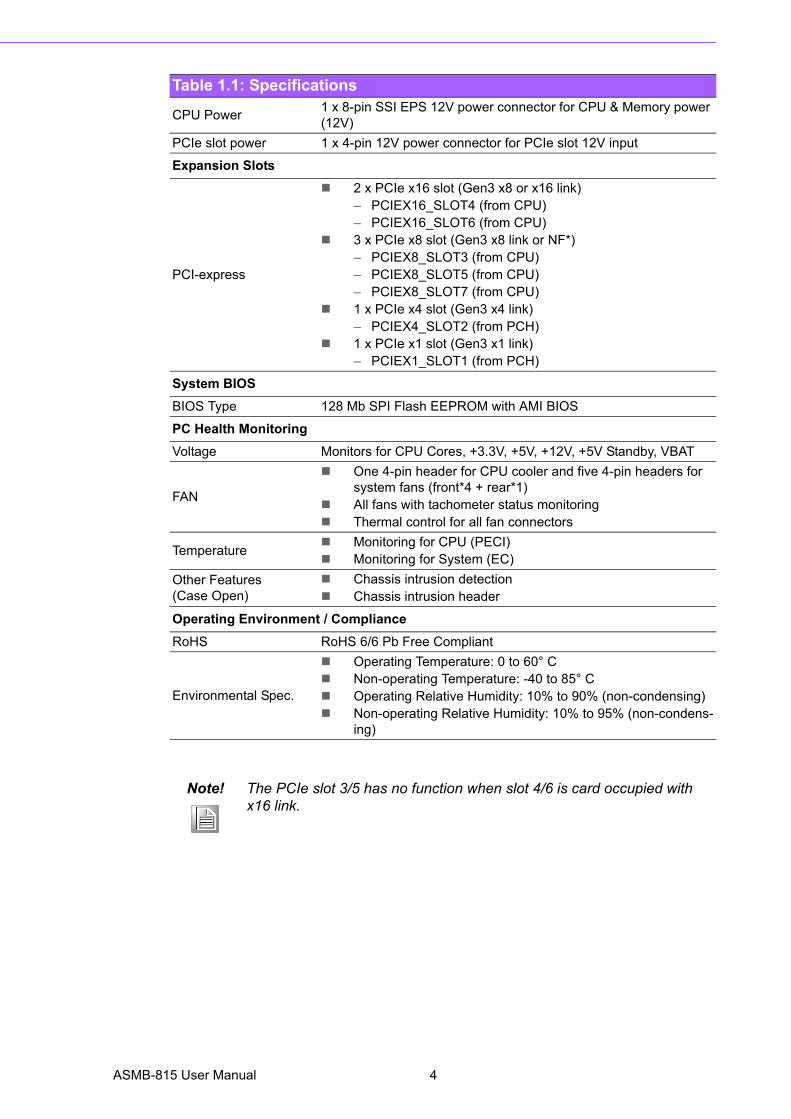
CPU Power1 x 8-pin SSI EPS 12V power connector for CPU & Memory power (12V)
PCIe slot power 1 x 4-pin 12V power connector for PCIe slot 12V input
Expansion Slots
PCI-express
2 x PCIe x16 slot (Gen3 x8 or x16 link)– PCIEX16_SLOT4 (from CPU)– PCIEX16_SLOT6 (from CPU)
3 x PCIe x8 slot (Gen3 x8 link or NF*) – PCIEX8_SLOT3 (from CPU)– PCIEX8_SLOT5 (from CPU)– PCIEX8_SLOT7 (from CPU)
1 x PCIe x4 slot (Gen3 x4 link)– PCIEX4_SLOT2 (from PCH)
1 x PCIe x1 slot (Gen3 x1 link)– PCIEX1_SLOT1 (from PCH)
System BIOS
BIOS Type 128 Mb SPI Flash EEPROM with AMI BIOS
PC Health Monitoring
Voltage Monitors for CPU Cores, +3.3V, +5V, +12V, +5V Standby, VBAT
FAN
One 4-pin header for CPU cooler and five 4-pin headers for system fans (front*4 + rear*1)
All fans with tachometer status monitoring Thermal control for all fan connectors
Temperature Monitoring for CPU (PECI) Monitoring for System (EC)
Other Features(Case Open)
Chassis intrusion detection Chassis intrusion header
Operating Environment / Compliance
RoHS RoHS 6/6 Pb Free Compliant
Environmental Spec.
Operating Temperature: 0 to 60° C Non-operating Temperature: -40 to 85° C Operating Relative Humidity: 10% to 90% (non-condensing) Non-operating Relative Humidity: 10% to 95% (non-condens-
ing)
Note! The PCIe slot 3/5 has no function when slot 4/6 is card occupied with x16 link.
Table 1.1: Specifications
ASMB-815 User Manual 4
Chapter 1
Overview
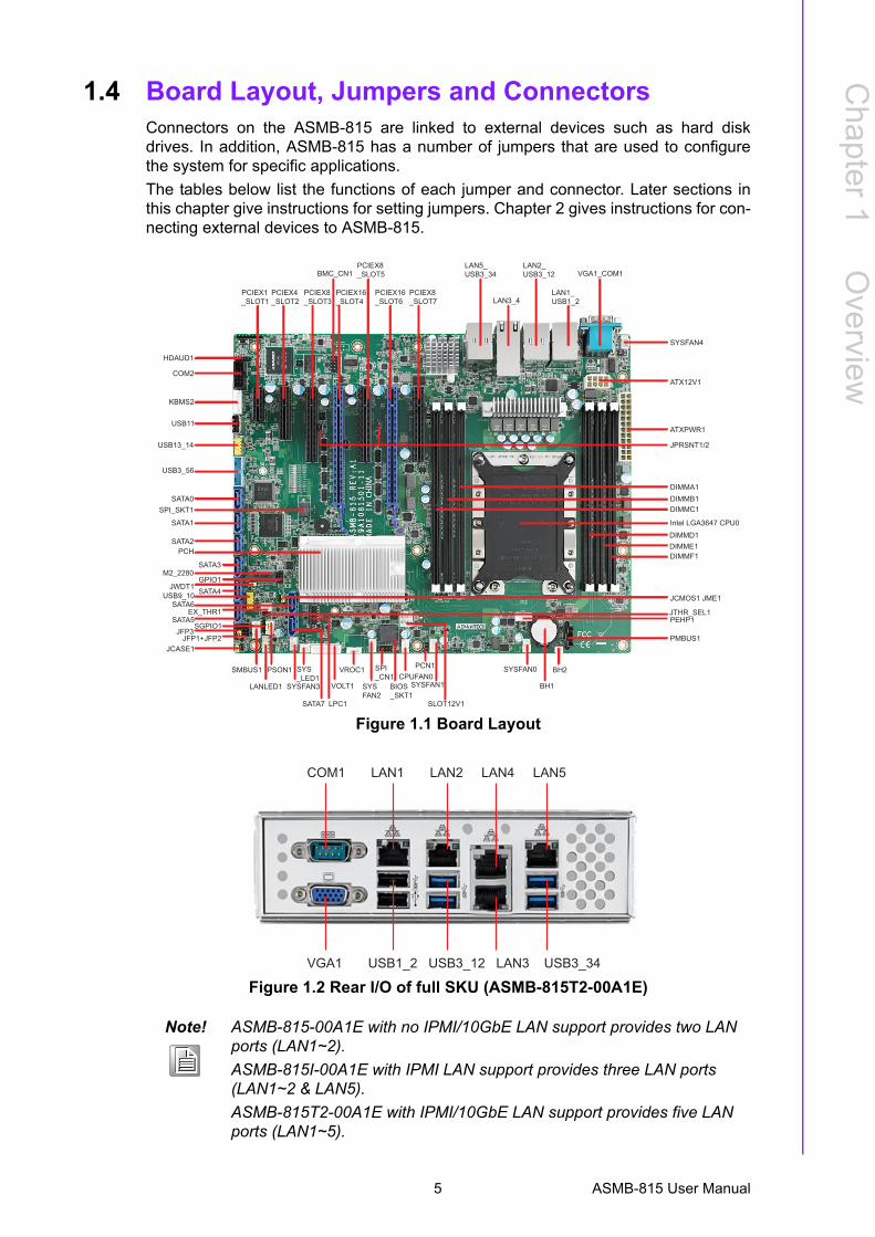
1.4 Board Layout, Jumpers and ConnectorsConnectors on the ASMB-815 are linked to external devices such as hard diskdrives. In addition, ASMB-815 has a number of jumpers that are used to configurethe system for specific applications.
The tables below list the functions of each jumper and connector. Later sections inthis chapter give instructions for setting jumpers. Chapter 2 gives instructions for con-necting external devices to ASMB-815.
Figure 1.1 Board Layout
Figure 1.2 Rear I/O of full SKU (ASMB-815T2-00A1E)
Note! ASMB-815-00A1E with no IPMI/10GbE LAN support provides two LAN ports (LAN1~2).
ASMB-815I-00A1E with IPMI LAN support provides three LAN ports (LAN1~2 & LAN5).
ASMB-815T2-00A1E with IPMI/10GbE LAN support provides five LAN ports (LAN1~5).
HDAUD1
COM2
KBMS2
USB11
USB13_14
USB3_56
SATA0
SATA1
SATA2PCH
SPI_SKT1
SATA3M2_2280
GPIO1JWDT1
SATA4USB9_10
EX_THR1SATA6
SATA7
SATA5
JCMOS1 JME1
SGPIO1JFP3
JFP1+JFP2JCASE1
SMBUS1
LANLED1
PSON1
SYSFAN3
SYS_LED1
LPC1
JTHR_SEL1
VOLT1
VROC1
SYSFAN2
SPI_CN1
BIOS_SKT1
CPUFAN0
SLOT12V1
SYSFAN1
SYSFAN0
PMBUS1
BH1
BH2
DIMMA1DIMMB1DIMMC1
DIMMF1DIMME1DIMMD1
Intel LGA3647 CPU0
ATX12V1
ATXPWR1
SYSFAN4
PCIEX1_SLOT1
PCIEX4_SLOT2
PCIEX8_SLOT3
BMC_CN1
PCIEX16_SLOT4
PCIEX8_SLOT5
PCIEX16_SLOT6
PCIEX8_SLOT7
LAN5_USB3_34
LAN3_4
LAN2_USB3_12
LAN1_USB1_2
VGA1_COM1
JPRSNT1/2
PCN1
PEHP1
COM1 LAN1 LAN2 LAN4 LAN5
VGA1 USB1_2 USB3_12 LAN3 USB3_34
5 ASMB-815 User Manual
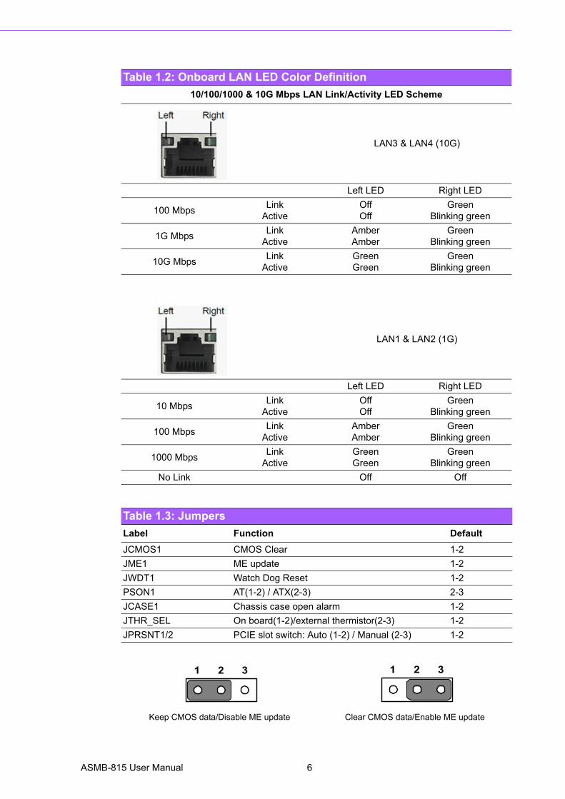
Table 1.2: Onboard LAN LED Color Definition
10/100/1000 & 10G Mbps LAN Link/Activity LED Scheme
LAN3 & LAN4 (10G)
Left LED Right LED
100 MbpsLink
ActiveOff Off
GreenBlinking green
1G MbpsLink
ActiveAmberAmber
GreenBlinking green
10G MbpsLink
ActiveGreenGreen
GreenBlinking green
LAN1 & LAN2 (1G)
Left LED Right LED
10 MbpsLink
ActiveOff Off
GreenBlinking green
100 MbpsLink
ActiveAmberAmber
GreenBlinking green
1000 MbpsLink
ActiveGreenGreen
GreenBlinking green
No Link Off Off
Table 1.3: Jumpers
Label Function Default
JCMOS1 CMOS Clear 1-2
JME1 ME update 1-2
JWDT1 Watch Dog Reset 1-2
PSON1 AT(1-2) / ATX(2-3) 2-3
JCASE1 Chassis case open alarm 1-2
JTHR_SEL On board(1-2)/external thermistor(2-3) 1-2
JPRSNT1/2 PCIE slot switch: Auto (1-2) / Manual (2-3) 1-2
Keep CMOS data/Disable ME update Clear CMOS data/Enable ME update
1 2 3 1 2 3
ASMB-815 User Manual 6
Chapter 1
Overview
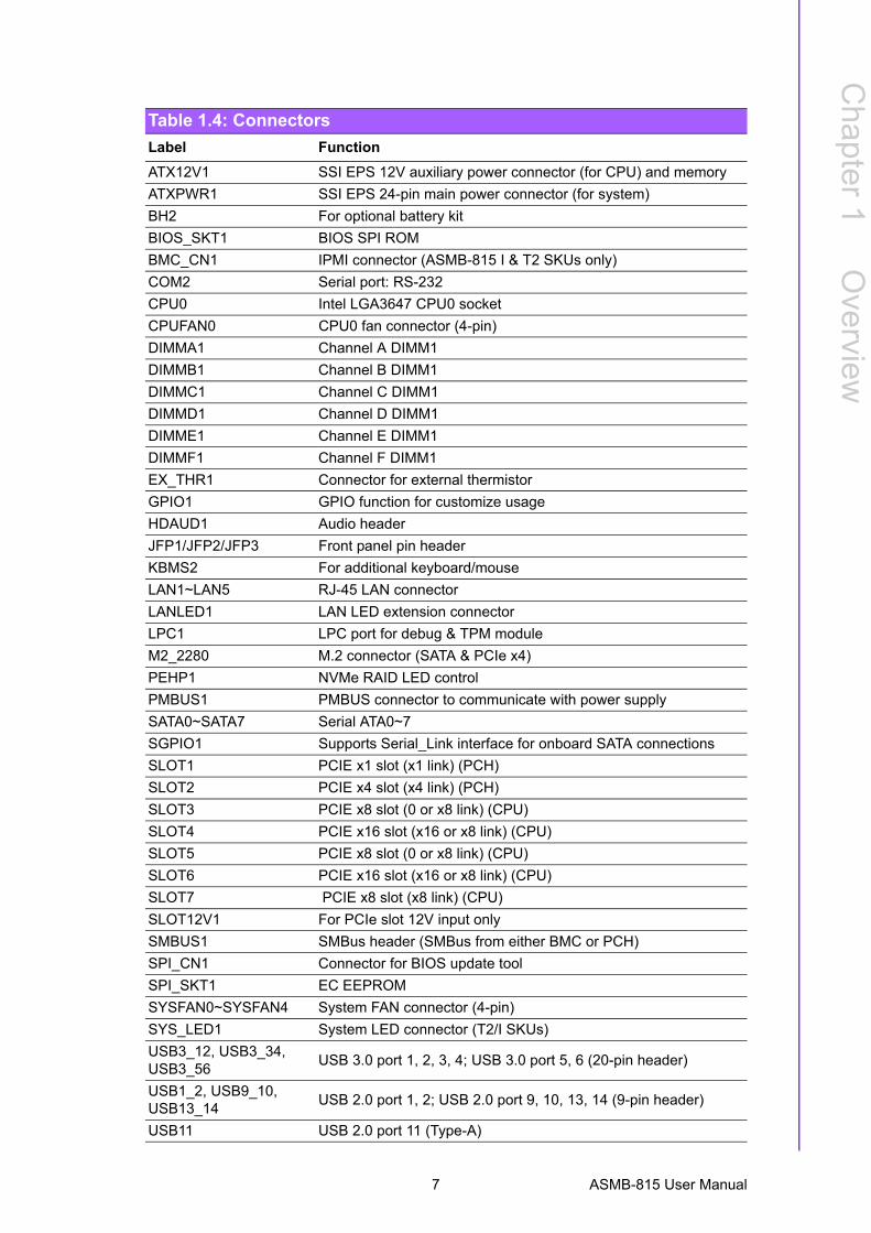
Table 1.4: Connectors
Label Function
ATX12V1 SSI EPS 12V auxiliary power connector (for CPU) and memory
ATXPWR1 SSI EPS 24-pin main power connector (for system)
BH2 For optional battery kit
BIOS_SKT1 BIOS SPI ROM
BMC_CN1 IPMI connector (ASMB-815 I & T2 SKUs only)
COM2 Serial port: RS-232
CPU0 Intel LGA3647 CPU0 socket
CPUFAN0 CPU0 fan connector (4-pin)
DIMMA1 Channel A DIMM1
DIMMB1 Channel B DIMM1
DIMMC1 Channel C DIMM1
DIMMD1 Channel D DIMM1
DIMME1 Channel E DIMM1
DIMMF1 Channel F DIMM1
EX_THR1 Connector for external thermistor
GPIO1 GPIO function for customize usage
HDAUD1 Audio header
JFP1/JFP2/JFP3 Front panel pin header
KBMS2 For additional keyboard/mouse
LAN1~LAN5 RJ-45 LAN connector
LANLED1 LAN LED extension connector
LPC1 LPC port for debug & TPM module
M2_2280 M.2 connector (SATA & PCIe x4)
PEHP1 NVMe RAID LED control
PMBUS1 PMBUS connector to communicate with power supply
SATA0~SATA7 Serial ATA0~7
SGPIO1 Supports Serial_Link interface for onboard SATA connections
SLOT1 PCIE x1 slot (x1 link) (PCH)
SLOT2 PCIE x4 slot (x4 link) (PCH)
SLOT3 PCIE x8 slot (0 or x8 link) (CPU)
SLOT4 PCIE x16 slot (x16 or x8 link) (CPU)
SLOT5 PCIE x8 slot (0 or x8 link) (CPU)
SLOT6 PCIE x16 slot (x16 or x8 link) (CPU)
SLOT7 PCIE x8 slot (x8 link) (CPU)
SLOT12V1 For PCIe slot 12V input only
SMBUS1 SMBus header (SMBus from either BMC or PCH)
SPI_CN1 Connector for BIOS update tool
SPI_SKT1 EC EEPROM
SYSFAN0~SYSFAN4 System FAN connector (4-pin)
SYS_LED1 System LED connector (T2/I SKUs)
USB3_12, USB3_34, USB3_56
USB 3.0 port 1, 2, 3, 4; USB 3.0 port 5, 6 (20-pin header)
USB1_2, USB9_10, USB13_14
USB 2.0 port 1, 2; USB 2.0 port 9, 10, 13, 14 (9-pin header)
USB11 USB 2.0 port 11 (Type-A)
7 ASMB-815 User Manual

1.5 Block Diagram
Figure 1.3 Block Diagram
VGA1_COM1 VGA+COM connector
VOLT1 Voltage display
VROC1 Intel Virtual RAID (VROC) key
Table 1.5: Onboard LED
LED Description LED Definition
5V_LED1 Power on LEDOff: Power off
On (Green): System is On
5VSB_LED1 Standby LEDOff: No input AC Power
On (Green): System is ON, in sleep mode, or in soft-off mode
LED3BMC heartbeat LED(ASMB-815 T2 and I SKUs)
Blinking (Green):Controller is working normally
Table 1.4: Connectors
Intel LGA 3647-P0Xeon® Scalable
Processors(CPU0)
Channel 3ECC DDR4 2133/2400/2666
ECC DDR4 2133/2400/2666
ECC DDR4 2133/2400/2666
PCIe x4 Slot
ECC DDR4 2133/2400/2666
ECC DDR4 2133/2400/2666
ECC DDR4 2133/2400/2666
Channel 4
Channel 5
PCIe Gen3 x4
sSATA6Gb/s
DM
I Gen
3 x4
PCIE
UP
Gen
3 x8
Channel 0
Channel 1
Channel 2
PCIe Gen3 x8
PCIe Gen3 x16
PCIe Gen3 x8
Intel C621/C622 PCH
KR x110GbE
LAN3/4: X557
PCIe Gen1 x1 GbE LAN1: I210
MDI RJ4510/100/1G/10G
MDI RJ4510/100/1G/10G
MDI RJ4510/100/1G
MDI RJ4510/100/1G
PCIe Gen1 x1 GbE LAN2: I210
LAN5: Realtek 8201EL MDI RJ45
10/100/1G
NC-
SI
USB 2.0
PCIe Gen2 x1BMC
AST2500 SPI SPI Flash 32MB
DDR4 DRAM
RGB VGA Conn.
SPI B
US
LPC Conn.
6 x FAN Conn.EC
IT8528E
SPIBIOS 2 x RS-232 Header/Conn.
8 bit GPIO Pin Header
PS/2 KB, MS
256M-bit
LPC
BUS
LPC BUS
SW
PCIe Gen3 x16
PCIEX4_Slot 2
8 x SATA3
1 x M.2 2280
USB 2.07 x USB2.0(2 Rear / 4 on board / 1 type A)
SATA6Gb/s
6x USB3.0(4 Rear / 2 on board)
USB 3.0
HD Conn. HD Audio
PCIe Gen3 x48Gb/s
PCIe Gen3 x8
PCIe x8 Slot
PCIe x16 Slot
PCIEX8_SLOT7
PCIEX16_SLOT4
PCIe x8 SlotPCIEX8_SLOT3
PCIe x16 SlotPCIEX16_SLOT6
PCIe Gen3 x1 PCIe x1 SlotPCIEX1_Slot 1
PCIe x8 SlotPCIEX8_SLOT5SW
NC-SI
ASMB-815 User Manual 8
Chapter 1
Overview
1.6 System MemoryASMB-815 has six 288-pin memory slots for DDR4 2133/2400/2666 MHz memorymodules with maximum capacity of 192 GB (Maximum 32 GB for each DIMM).ASMB-815 supports registered DIMMs memory module.
1.7 Memory Installation
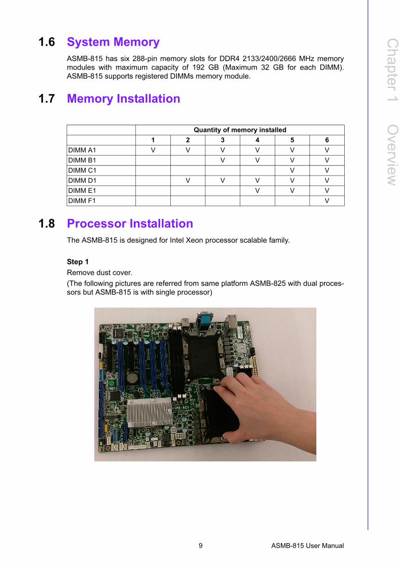
1.8 Processor InstallationThe ASMB-815 is designed for Intel Xeon processor scalable family.
Step 1
Remove dust cover.
(The following pictures are referred from same platform ASMB-825 with dual proces-sors but ASMB-815 is with single processor)
Quantity of memory installed
1 2 3 4 5 6
DIMM A1 V V V V V V
DIMM B1 V V V V
DIMM C1 V V
DIMM D1 V V V V V
DIMM E1 V V V
DIMM F1 V
9 ASMB-815 User Manual
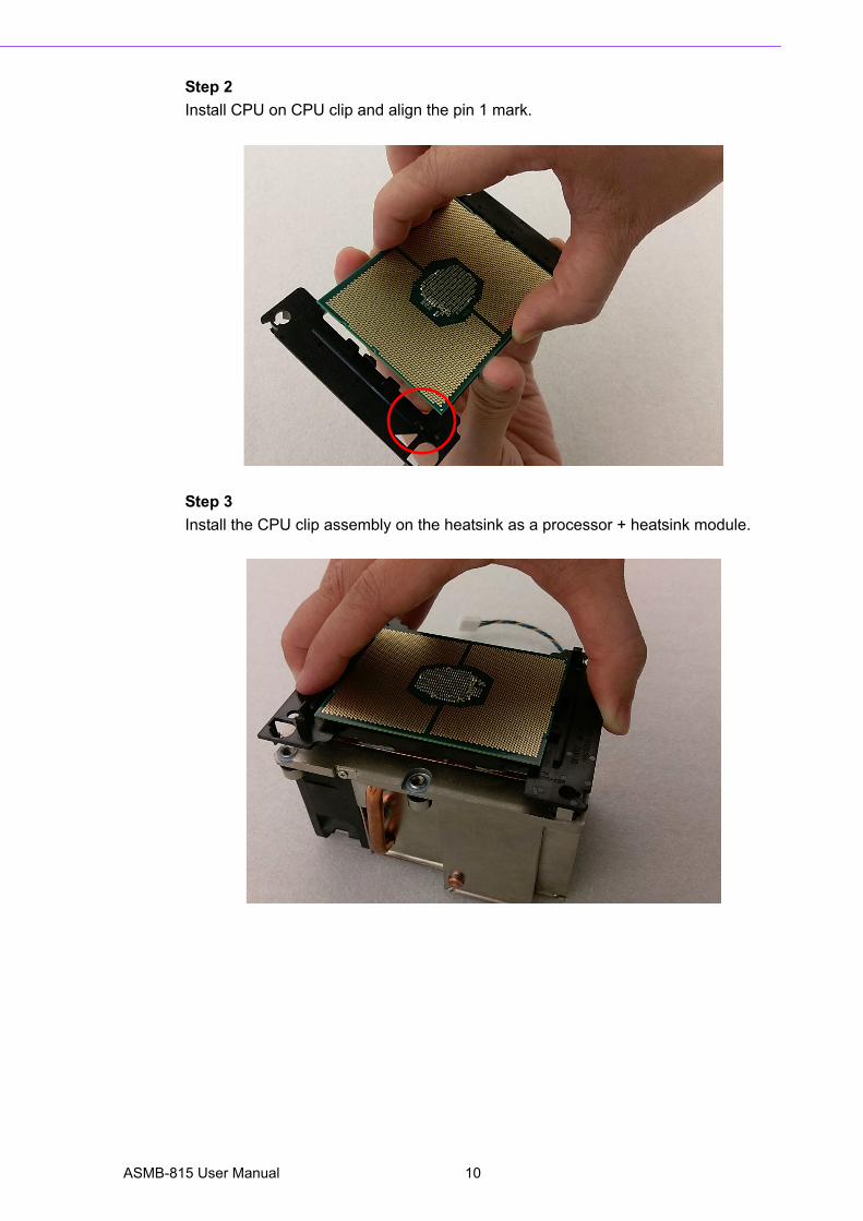
Step 2
Install CPU on CPU clip and align the pin 1 mark.
Step 3
Install the CPU clip assembly on the heatsink as a processor + heatsink module.
ASMB-815 User Manual 10
Chapter 1
Overview
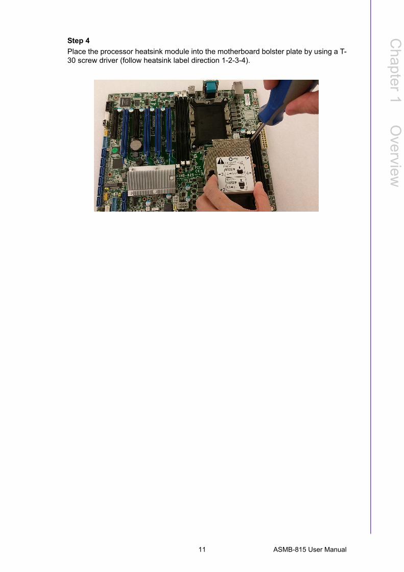
Step 4
Place the processor heatsink module into the motherboard bolster plate by using a T-30 screw driver (follow heatsink label direction 1-2-3-4).
11 ASMB-815 User Manual

ASMB-815 User Manual 12

Chapter 2
2 Connections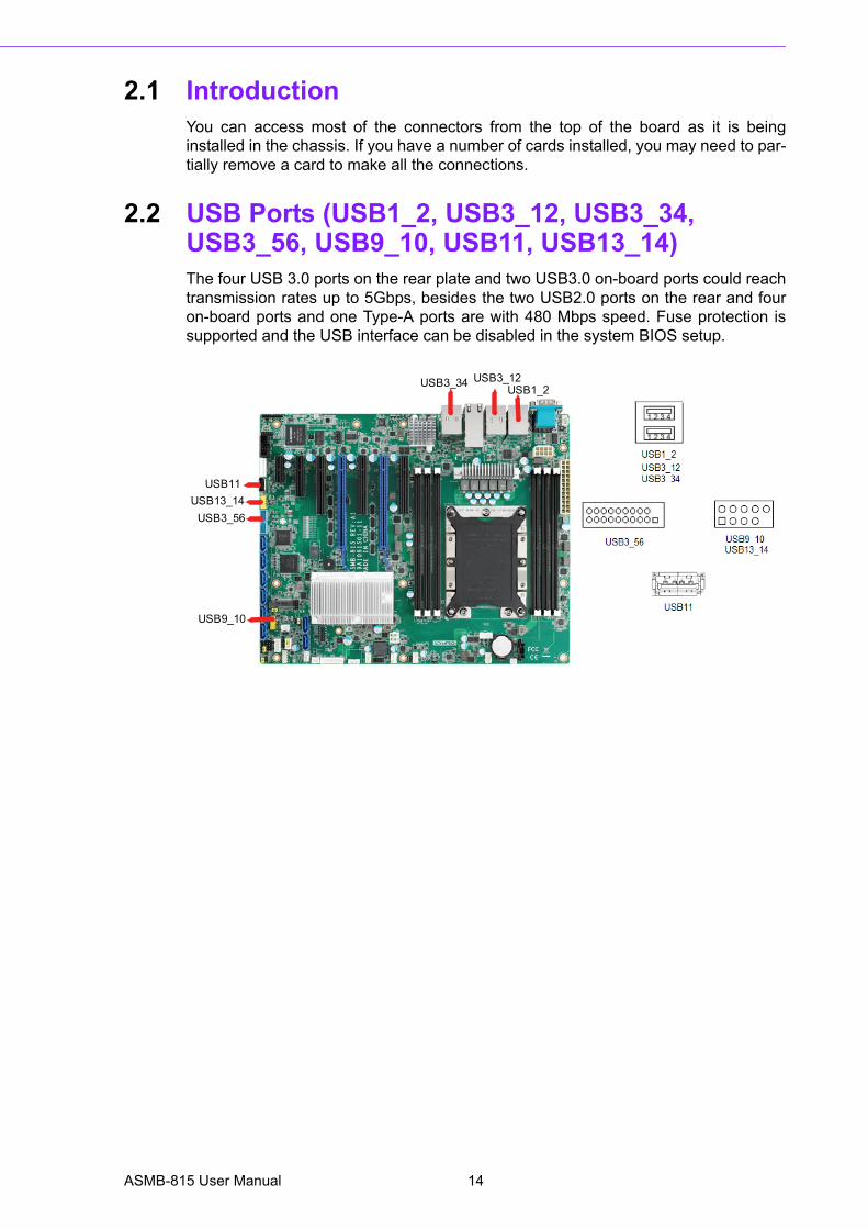
2.1 IntroductionYou can access most of the connectors from the top of the board as it is beinginstalled in the chassis. If you have a number of cards installed, you may need to par-tially remove a card to make all the connections.
2.2 USB Ports (USB1_2, USB3_12, USB3_34, USB3_56, USB9_10, USB11, USB13_14)The four USB 3.0 ports on the rear plate and two USB3.0 on-board ports could reachtransmission rates up to 5Gbps, besides the two USB2.0 ports on the rear and fouron-board ports and one Type-A ports are with 480 Mbps speed. Fuse protection issupported and the USB interface can be disabled in the system BIOS setup.
USB1_2USB3_12USB3_34
USB13_14USB3_56
USB9_10
USB11
ASMB-815 User Manual 14
Chapter 2
Connections
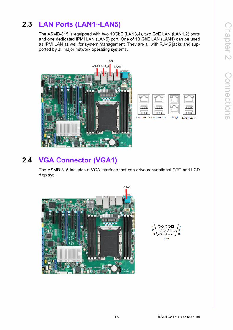
2.3 LAN Ports (LAN1~LAN5)The ASMB-815 is equipped with two 10GbE (LAN3,4), two GbE LAN (LAN1,2) portsand one dedicated IPMI LAN (LAN5) port. One of 10 GbE LAN (LAN4) can be usedas IPMI LAN as well for system management. They are all with RJ-45 jacks and sup-ported by all major network operating systems.
2.4 VGA Connector (VGA1)The ASMB-815 includes a VGA interface that can drive conventional CRT and LCDdisplays.
LAN1
LAN2
LAN5 LAN3_4
VGA1
15 ASMB-815 User Manual
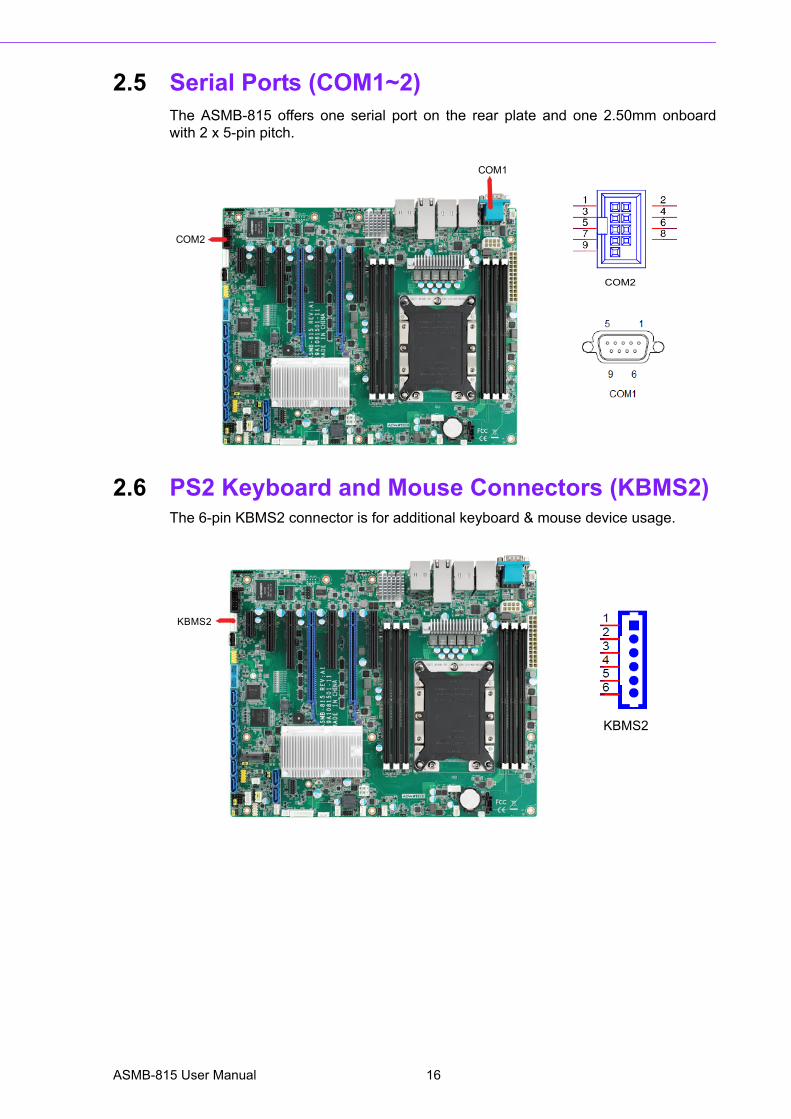
2.5 Serial Ports (COM1~2)The ASMB-815 offers one serial port on the rear plate and one 2.50mm onboardwith 2 x 5-pin pitch.
2.6 PS2 Keyboard and Mouse Connectors (KBMS2)The 6-pin KBMS2 connector is for additional keyboard & mouse device usage.
COM1
COM2
COM2
KBMS2
KBMS2
ASMB-815 User Manual 16
Chapter 2
Connections
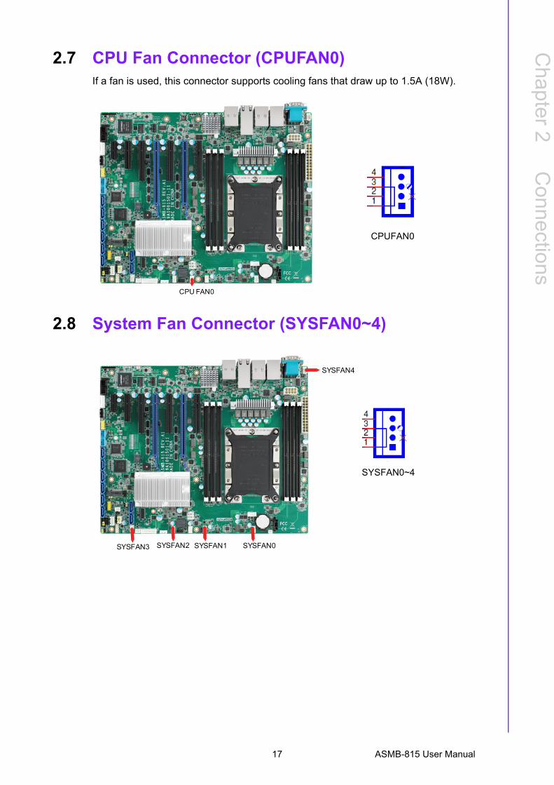
2.7 CPU Fan Connector (CPUFAN0)If a fan is used, this connector supports cooling fans that draw up to 1.5A (18W).
2.8 System Fan Connector (SYSFAN0~4)
CPU FAN0
CPUFAN0
SYSFAN1SYSFAN3
SYSFAN4
SYSFAN2 SYSFAN0
SYSFAN0~4
17 ASMB-815 User Manual
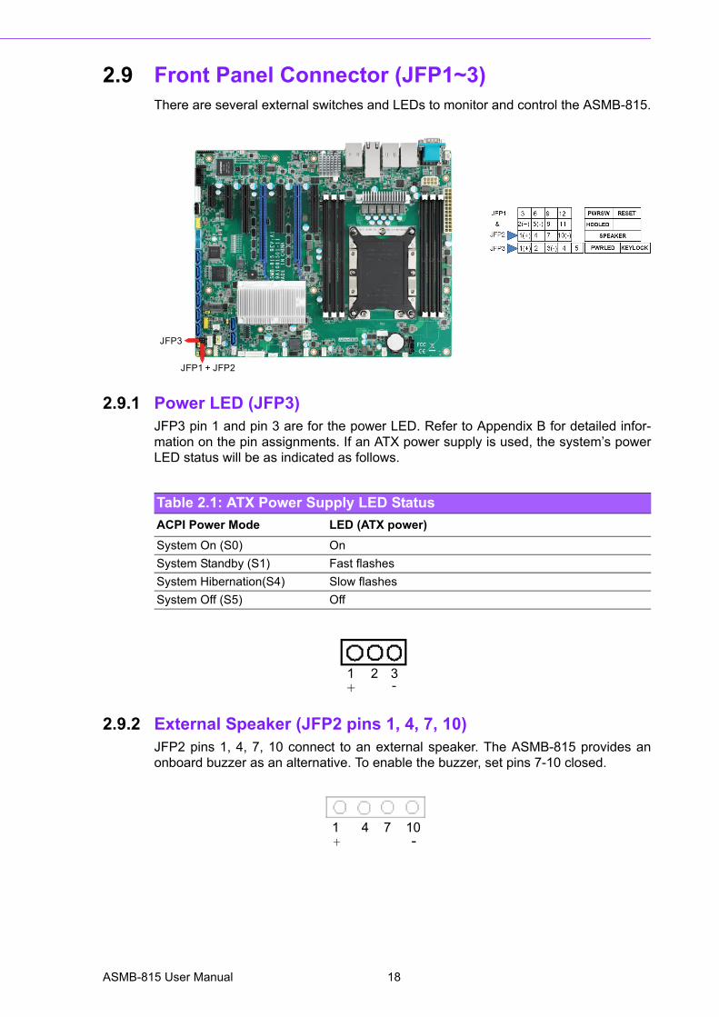
2.9 Front Panel Connector (JFP1~3)There are several external switches and LEDs to monitor and control the ASMB-815.
2.9.1 Power LED (JFP3)JFP3 pin 1 and pin 3 are for the power LED. Refer to Appendix B for detailed infor-mation on the pin assignments. If an ATX power supply is used, the system’s powerLED status will be as indicated as follows.
2.9.2 External Speaker (JFP2 pins 1, 4, 7, 10)JFP2 pins 1, 4, 7, 10 connect to an external speaker. The ASMB-815 provides anonboard buzzer as an alternative. To enable the buzzer, set pins 7-10 closed.
JFP3
JFP1 + JFP2
Table 2.1: ATX Power Supply LED Status
ACPI Power Mode LED (ATX power)
System On (S0) On
System Standby (S1) Fast flashes
System Hibernation(S4) Slow flashes
System Off (S5) Off
1 2 3+ -
1 4 7 10+ -
ASMB-815 User Manual 18
Chapter 2
Connections
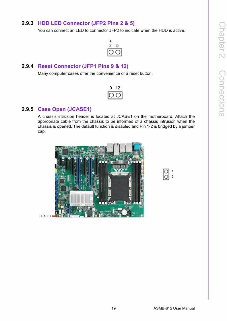
2.9.3 HDD LED Connector (JFP2 Pins 2 & 5)You can connect an LED to connector JFP2 to indicate when the HDD is active.
2.9.4 Reset Connector (JFP1 Pins 9 & 12)Many computer cases offer the convenience of a reset button.
2.9.5 Case Open (JCASE1)A chassis intrusion header is located at JCASE1 on the motherboard. Attach theappropriate cable from the chassis to be informed of a chassis intrusion when thechassis is opened. The default function is disabled and Pin 1-2 is bridged by a jumpercap.
2 5 +
9 12
1
2
JCASE1
19 ASMB-815 User Manual
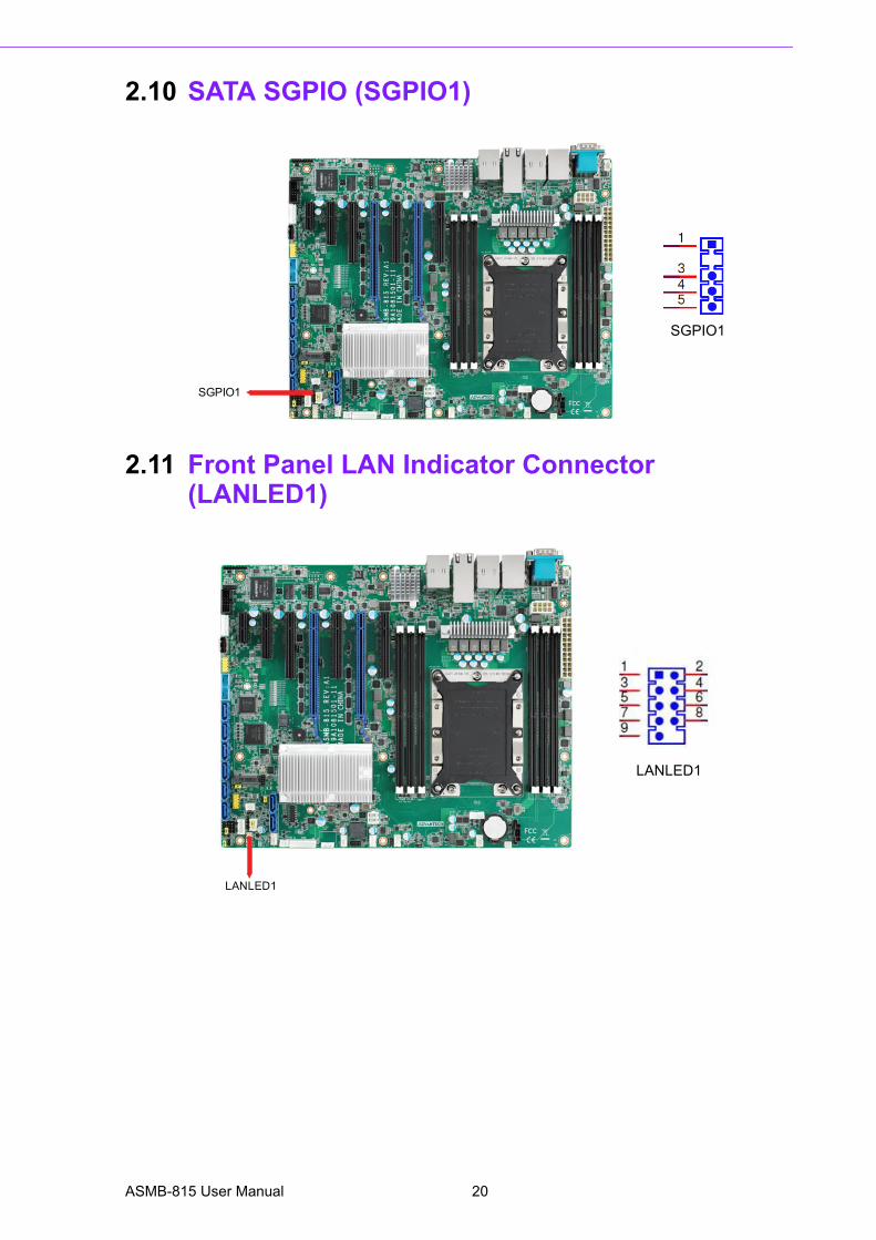
2.10 SATA SGPIO (SGPIO1)
2.11 Front Panel LAN Indicator Connector (LANLED1)
SGPIO1
SGPIO1
LANLED1
LANLED1
ASMB-815 User Manual 20
Chapter 2
Connections
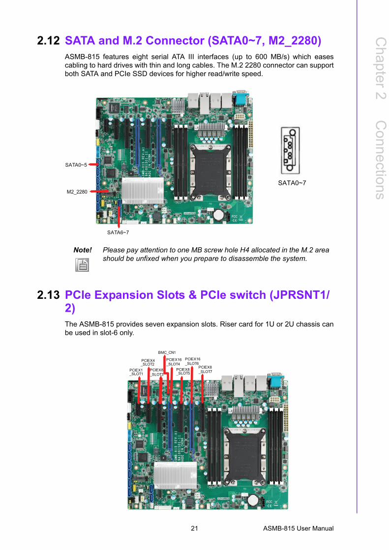
2.12 SATA and M.2 Connector (SATA0~7, M2_2280)ASMB-815 features eight serial ATA III interfaces (up to 600 MB/s) which easescabling to hard drives with thin and long cables. The M.2 2280 connector can supportboth SATA and PCIe SSD devices for higher read/write speed.
2.13 PCIe Expansion Slots & PCIe switch (JPRSNT1/2)The ASMB-815 provides seven expansion slots. Riser card for 1U or 2U chassis canbe used in slot-6 only.
Note! Please pay attention to one MB screw hole H4 allocated in the M.2 area should be unfixed when you prepare to disassemble the system.
SATA0~5
M2_2280
SATA6~7
SATA0~7
PCIEX4_SLOT2
PCIEX16_SLOT4
PCIEX16_SLOT6
PCIEX1_SLOT1
BMC_CN1
PCIEX8_SLOT3
PCIEX8_SLOT5
PCIEX8_SLOT7
21 ASMB-815 User Manual

Slot 7 has dedicated PCIe x8 link. Slot 3/4 is sharing one x16 link from CPU0, andslot 5/6 is sharing another x16 link from CPU0.
There are JPRSNT1 or JPRSNT2 jumper to switch PCIe slot 3/4 or slot 5/6 to two x8links manually. Normally this jumper is 1-2 closed as default for auto detect. Somecards on slot 3 or slot 5 can't be recognized until JPRSNT jumper is forced to 2-3closed.
2.14 Auxiliary Power Connector (ATXPWR1/ATX12V1)
Slot Length Link PCI-E Generation PCIe link from
SLOT1 PCI-E x1 PCI-E x1 3 PCH
SLOT2 PCI-E x4 PCI-E x4 3 PCH
SLOT3 PCI-E x8 PCI-E x8 3 CPU
SLOT4 PCI-E x16 PCI-E x16 3 CPU
SLOT5 PCI-E x8 PCI-E x8 3 CPU
SLOT6 PCI-E x16 PCI-E x16 3 CPU
SLOT7 PCI-E x8 PCI-E x8 3 CPU
Part Number Description Remarks
Riser Card
ASMB-RF388-21A1E ASMB-RF388 (2U riser card)2*PCI-E x8 or 1*PCI-E x8 + 2*PCI-E x4
ASMB-RF348-21A1E ASMB-RF348 (2U riser card)2*PCI-E x4 + 1*PCI-E x8
ASMB-RF3X8-21A1E ASMB-RF3X8 (2U riser card) 1*PCI-Ex4 + 2*PCI-X
AIMB-RF10F-01A1E AIMB-RF10F (1U riser card) 1*PCI-E x16
Note! 1. Please use a power supply which is of SSI type; minimum output should be at least 500 W.
2. ATXPWR1 & ATX12V1 sockets should be all connected with power supply, otherwise ASMB-815 will not boot up normally.
ATXPWR1
ATX12V1
ASMB-815 User Manual 22

Chapter 2
Connections
2.15 HD Audio Interface Connector (HDAUD1)ASMB-815 has one audio connector for Advantech's audio board (P/N: PCA-AUDIO-HDB1E) installation.
2.16 LPC Connector (LPC1)ASMB-815 has one LPC connector that can be used for Advantech's TPM Module(P/N: PCA-TPM-00A1E, PCA-TPM-00B1E) for security management.
HDAUD1
HDAUD1
LPC1
LPC1
23 ASMB-815 User Manual

2.17 Clear CMOS Connector (JCMOS1, JME1)Setting jumper from pin 1-2 to pin 2-3, then back to pin 1-2 to reset CMOS data.
2.18 PMBUS Connector (PMBUS1)
JCMOS1JME1
JME1 JCMOS1
PMBUS1
PMBUS1
ASMB-815 User Manual 24
Chapter 2
Connections
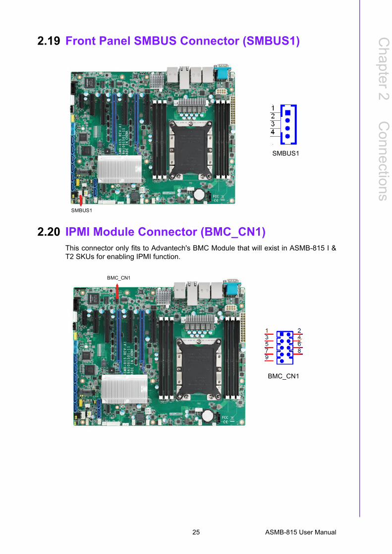
2.19 Front Panel SMBUS Connector (SMBUS1)
2.20 IPMI Module Connector (BMC_CN1)This connector only fits to Advantech's BMC Module that will exist in ASMB-815 I &T2 SKUs for enabling IPMI function.
SMBUS1
SMBUS1
BMC_CN1
BMC_CN1
25 ASMB-815 User Manual
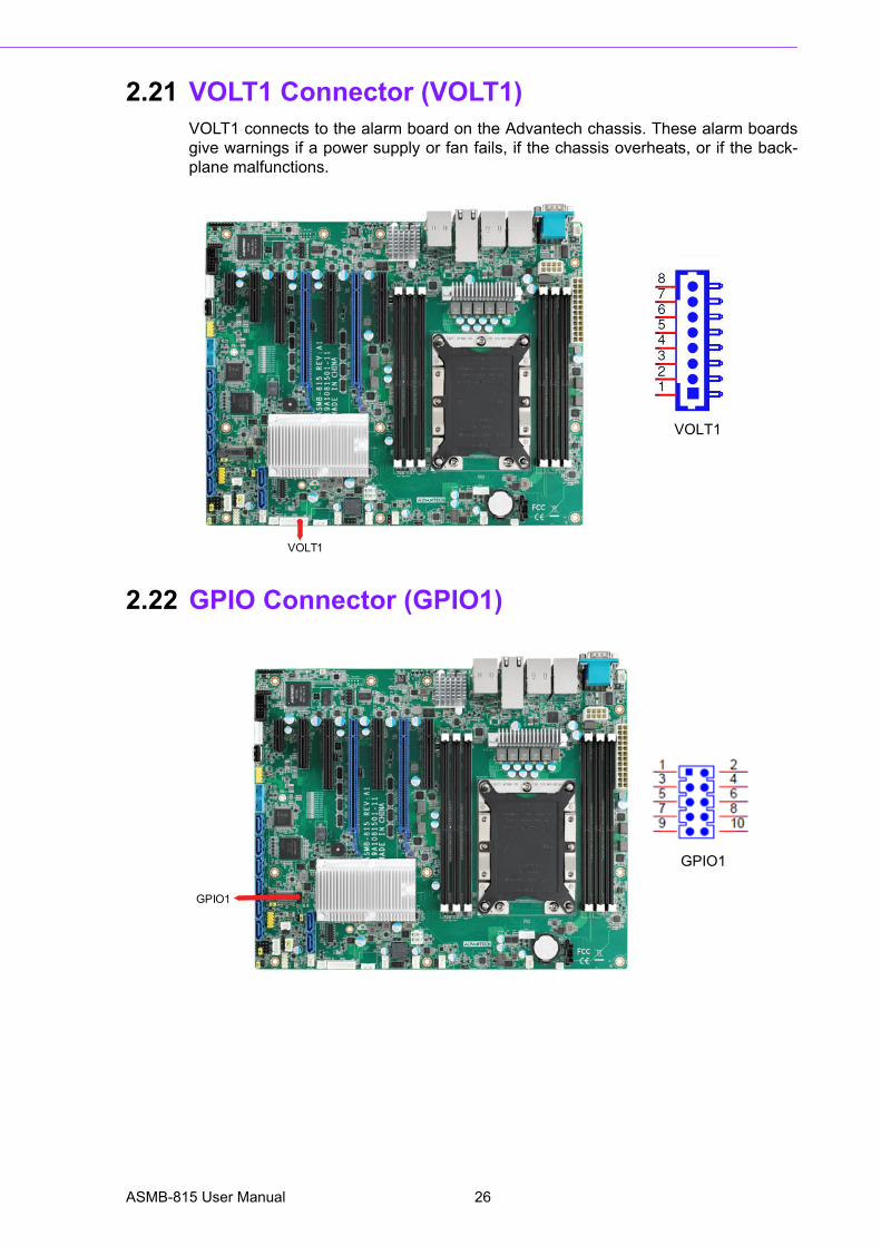
2.21 VOLT1 Connector (VOLT1)VOLT1 connects to the alarm board on the Advantech chassis. These alarm boardsgive warnings if a power supply or fan fails, if the chassis overheats, or if the back-plane malfunctions.
2.22 GPIO Connector (GPIO1)
VOLT1
VOLT1
GPIO1
GPIO1
ASMB-815 User Manual 26
Chapter 2
Connections
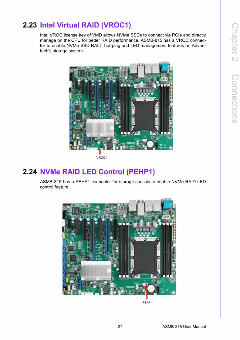
2.23 Intel Virtual RAID (VROC1)Intel VROC license key of VMD allows NVMe SSDs to connect via PCIe and directlymanage on the CPU for better RAID performance. ASMB-815 has a VROC connec-tor to enable NVMe SSD RAID, hot-plug and LED management features on Advan-tech's storage system.
2.24 NVMe RAID LED Control (PEHP1)ASMB-815 has a PEHP1 connector for storage chassis to enable NVMe RAID LEDcontrol feature.
VROC1
PEHP1
27 ASMB-815 User Manual

ASMB-815 User Manual 28

Chapter 3
3 AMI BIOS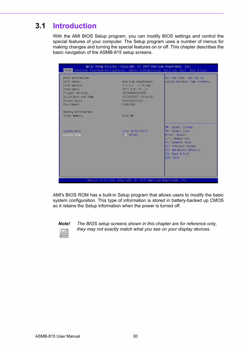
3.1 IntroductionWith the AMI BIOS Setup program, you can modify BIOS settings and control thespecial features of your computer. The Setup program uses a number of menus formaking changes and turning the special features on or off. This chapter describes thebasic navigation of the ASMB-815 setup screens.
AMI's BIOS ROM has a built-in Setup program that allows users to modify the basicsystem configuration. This type of information is stored in battery-backed up CMOSso it retains the Setup information when the power is turned off.
Note! The BIOS setup screens shown in this chapter are for reference only, they may not exactly match what you see on your display devices.
ASMB-815 User Manual 30
Chapter 3
AM
I BIO
S
3.2 BIOS Setup
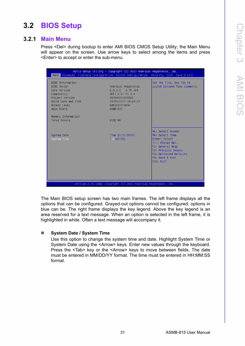
3.2.1 Main MenuPress <Del> during bootup to enter AMI BIOS CMOS Setup Utility; the Main Menuwill appear on the screen. Use arrow keys to select among the items and press<Enter> to accept or enter the sub-menu.
The Main BIOS setup screen has two main frames. The left frame displays all theoptions that can be configured. Grayed-out options cannot be configured; options inblue can be. The right frame displays the key legend. Above the key legend is anarea reserved for a text message. When an option is selected in the left frame, it ishighlighted in white. Often a text message will accompany it.
System Date / System TimeUse this option to change the system time and date. Highlight System Time orSystem Date using the <Arrow> keys. Enter new values through the keyboard.Press the <Tab> key or the <Arrow> keys to move between fields. The datemust be entered in MM/DD/YY format. The time must be entered in HH:MM:SSformat.
31 ASMB-815 User Manual
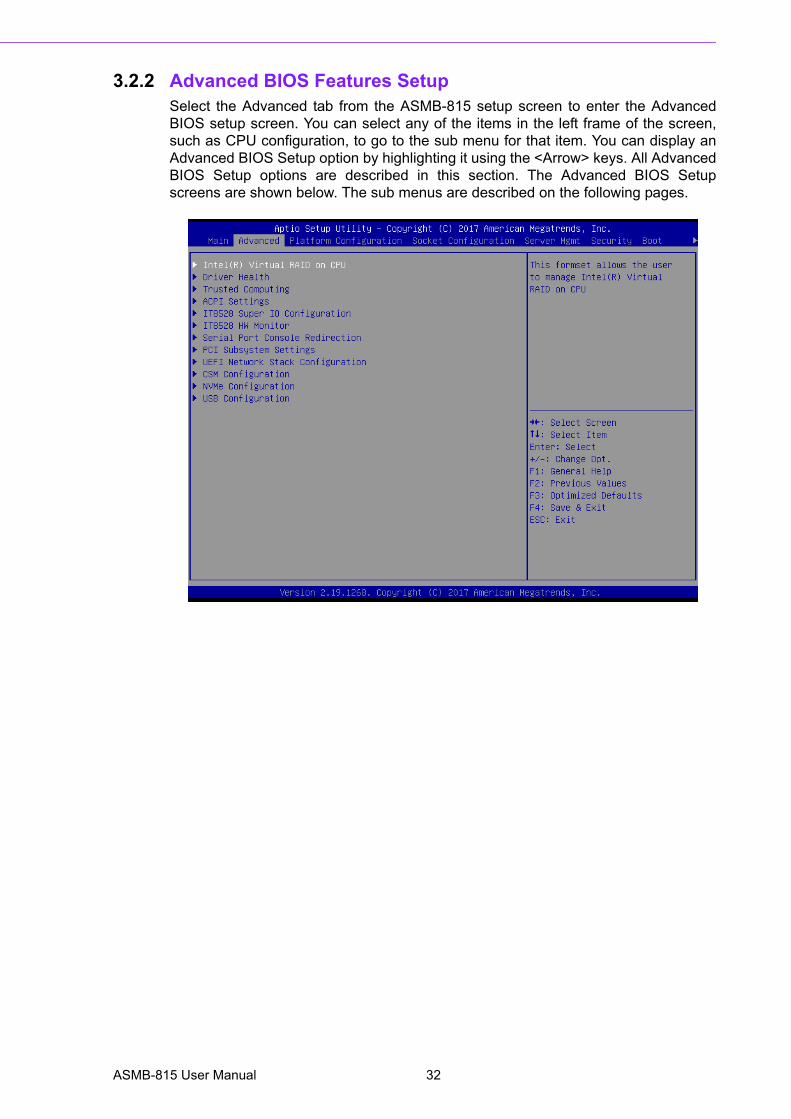
3.2.2 Advanced BIOS Features SetupSelect the Advanced tab from the ASMB-815 setup screen to enter the AdvancedBIOS setup screen. You can select any of the items in the left frame of the screen,such as CPU configuration, to go to the sub menu for that item. You can display anAdvanced BIOS Setup option by highlighting it using the <Arrow> keys. All AdvancedBIOS Setup options are described in this section. The Advanced BIOS Setupscreens are shown below. The sub menus are described on the following pages.
ASMB-815 User Manual 32
Chapter 3
AM
I BIO
S
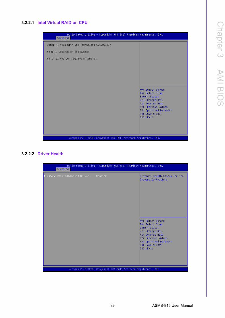
3.2.2.1 Intel Virtual RAID on CPU
3.2.2.2 Driver Health
33 ASMB-815 User Manual
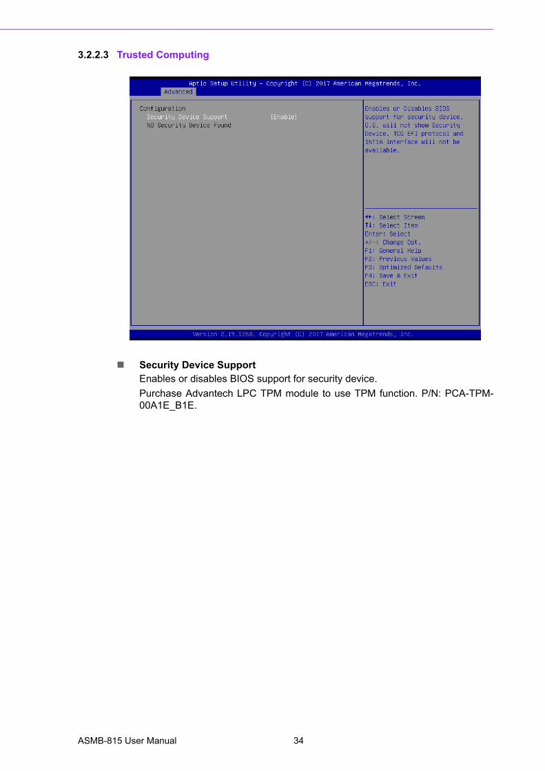
3.2.2.3 Trusted Computing
Security Device SupportEnables or disables BIOS support for security device.
Purchase Advantech LPC TPM module to use TPM function. P/N: PCA-TPM-00A1E_B1E.
ASMB-815 User Manual 34
Chapter 3
AM
I BIO
S
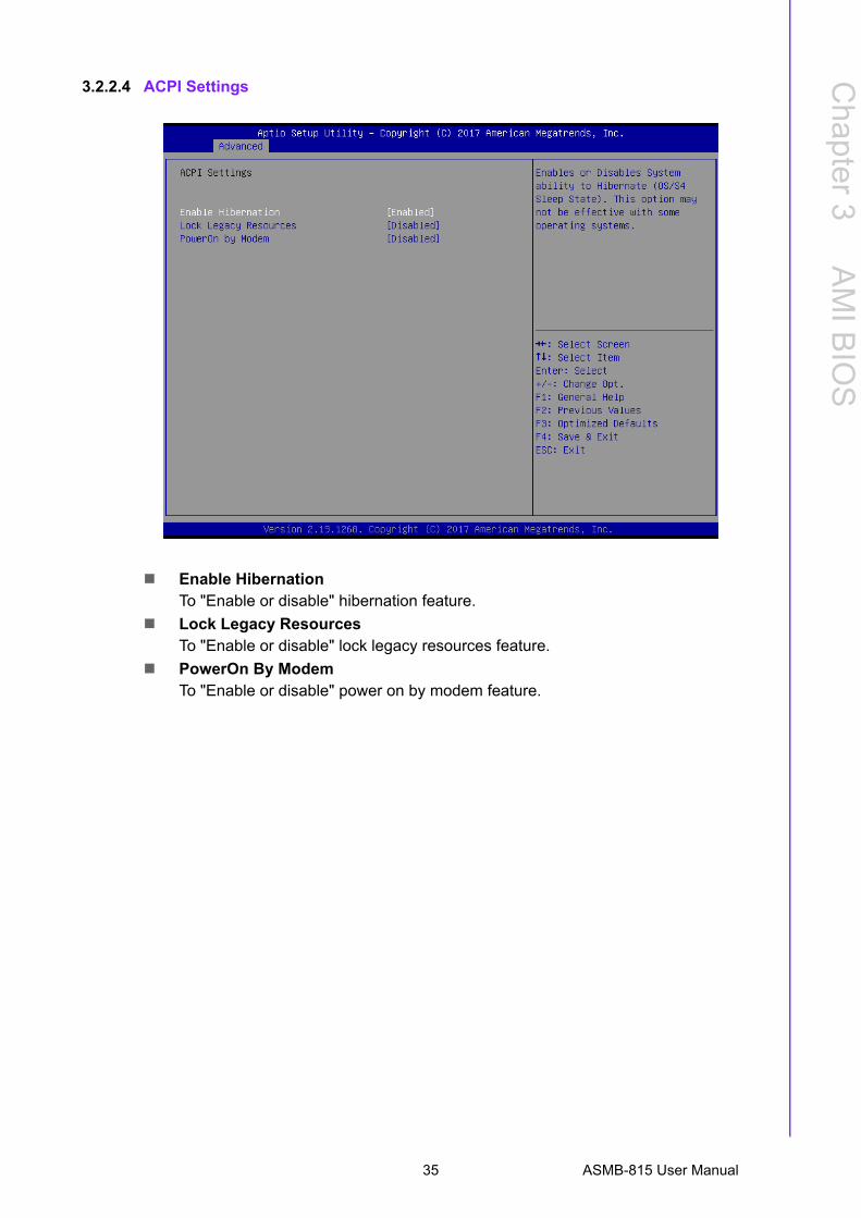
3.2.2.4 ACPI Settings
Enable HibernationTo "Enable or disable" hibernation feature.
Lock Legacy ResourcesTo "Enable or disable" lock legacy resources feature.
PowerOn By ModemTo "Enable or disable" power on by modem feature.
35 ASMB-815 User Manual
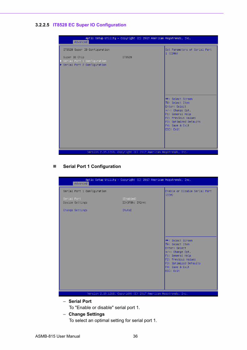
3.2.2.5 IT8528 EC Super IO Configuration
Serial Port 1 Configuration
– Serial PortTo "Enable or disable" serial port 1.
– Change SettingsTo select an optimal setting for serial port 1.
ASMB-815 User Manual 36
Chapter 3
AM
I BIO
S
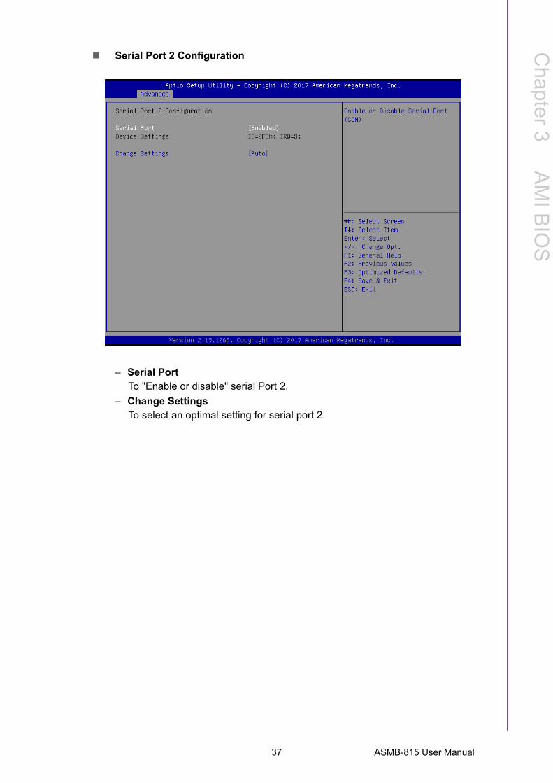
Serial Port 2 Configuration
– Serial PortTo "Enable or disable" serial Port 2.
– Change SettingsTo select an optimal setting for serial port 2.
37 ASMB-815 User Manual
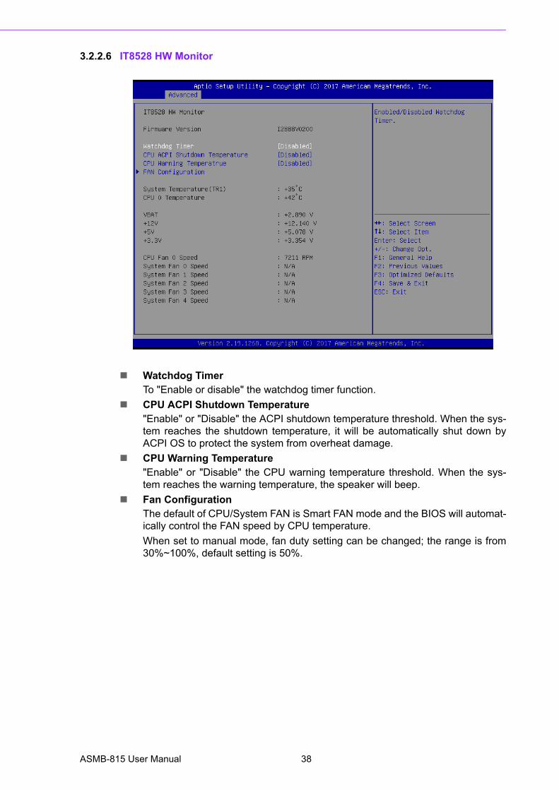
3.2.2.6 IT8528 HW Monitor
Watchdog TimerTo "Enable or disable" the watchdog timer function.
CPU ACPI Shutdown Temperature"Enable" or "Disable" the ACPI shutdown temperature threshold. When the sys-tem reaches the shutdown temperature, it will be automatically shut down byACPI OS to protect the system from overheat damage.
CPU Warning Temperature"Enable" or "Disable" the CPU warning temperature threshold. When the sys-tem reaches the warning temperature, the speaker will beep.
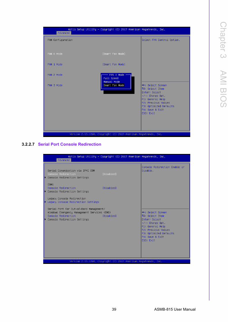
Fan ConfigurationThe default of CPU/System FAN is Smart FAN mode and the BIOS will automat-ically control the FAN speed by CPU temperature.
When set to manual mode, fan duty setting can be changed; the range is from30%~100%, default setting is 50%.
ASMB-815 User Manual 38
Chapter 3
AM
I BIO
S
3.2.2.7 Serial Port Console Redirection
39 ASMB-815 User Manual
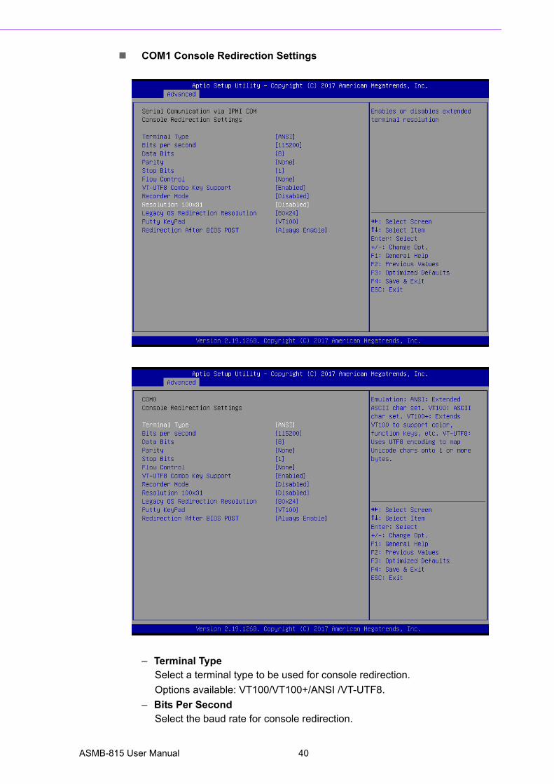
COM1 Console Redirection Settings
– Terminal TypeSelect a terminal type to be used for console redirection.
Options available: VT100/VT100+/ANSI /VT-UTF8.
– Bits Per SecondSelect the baud rate for console redirection.
ASMB-815 User Manual 40
Chapter 3
AM
I BIO
S
Options available: 9600/19200/57600/115200.
– Data Bits– Parity
A parity bit can be sent with the data bits to detect some transmission errors.
Even: parity bit is 0 if the number of 1's in the data bits is even.
Odd: parity bit is 0 if number of 1's the data bits is odd.
Mark: parity bit is always 1. Space: Parity bit is always 0.
Mark and Space Parity do not allow for error detection.
Options available: None/Even/Odd/Mark/Space.
– Stop BitsStop bits indicate the end of a serial data packet. (A start bit indicates thebeginning). The standard setting is 1 stop bit. Communication with slowdevices may require more than 1 stop bit.
Options available: 1/2.
– Flow ControlFlow control can prevent data loss from buffer overflow. When sending data,if the receiving buffers are full, a 'stop' signal can be sent to stop the dataflow. Once the buffers are empty, a 'start' signal can be sent to re-start theflow. Hardware flow control uses two wires to send start/stop signals.
Options available: None/Hardware RTS/CTS.
– VT-UTF8 Combo Key SupportEnable VT-UTF8 combination key support for ANSI/VT100 terminals
– Recorder ModeWhen this mode enabled, only text will be send. This is to capture Terminaldata.
Options available: Enabled/Disabled.
– Resolution 100x31Enables or disables extended terminal resolution.
– Legacy OS Redirection ResolutionOn Legacy OS, the number of rows and columns support redirection.
Options available: 80x24/80X25.
– Putty KeypadSelect function key and keypad on putty.
– Redirection After BIOS PostWhen Bootloader is selected, then Legacy Console Redirection is disabledbefore booting to legacy OS. When Always Enable is selected, then LegacyConsole Redirection is enabled for legacy OS. Default setting for this optionis set to Always Enable.
41 ASMB-815 User Manual
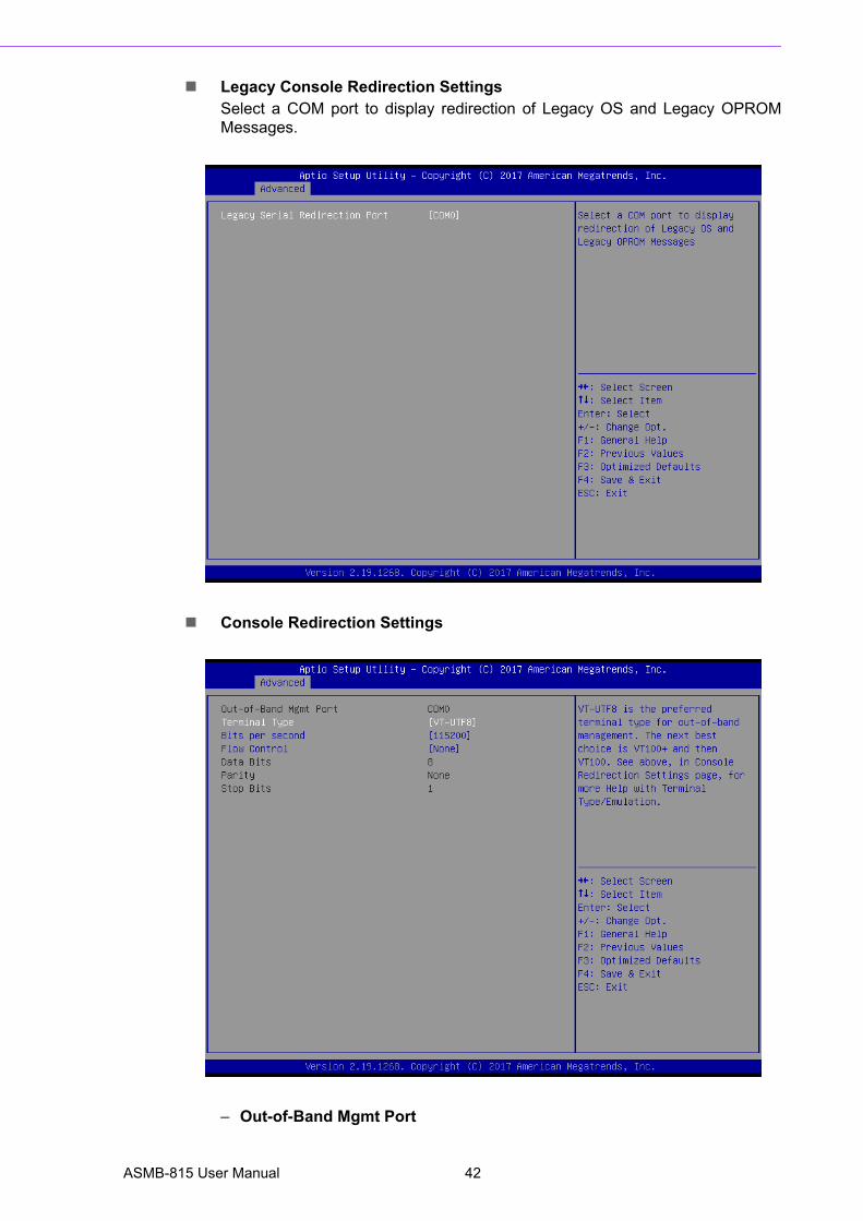
Legacy Console Redirection SettingsSelect a COM port to display redirection of Legacy OS and Legacy OPROMMessages.
Console Redirection Settings
– Out-of-Band Mgmt Port
ASMB-815 User Manual 42
Chapter 3
AM
I BIO
S
To select the com port user would like to set for having console redirectionfeature.
– Terminal TypeSet as "VT100", "VT100+", "VT-UTF8", or "ANSI". "VT-UTF8" is the defaultsetting.
– Bits Per SecondTo select serial port transmission. Speed must be matched on the other side.It can be set as "9600", "19200", "57600", or "115200". "115200" is thedefault setting.
– Flow ControlFlow control can prevent data loss from buffer overflow. It can be set as"None",
"Hardware RTS/CTS", or "Software Xon/Xoff". "None" is the default setting.
– Data Bits– Parity – Stop Bits
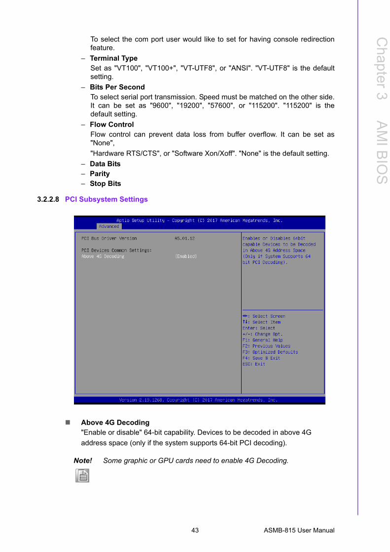
3.2.2.8 PCI Subsystem Settings
Above 4G Decoding"Enable or disable" 64-bit capability. Devices to be decoded in above 4G
address space (only if the system supports 64-bit PCI decoding).
Note! Some graphic or GPU cards need to enable 4G Decoding.
43 ASMB-815 User Manual
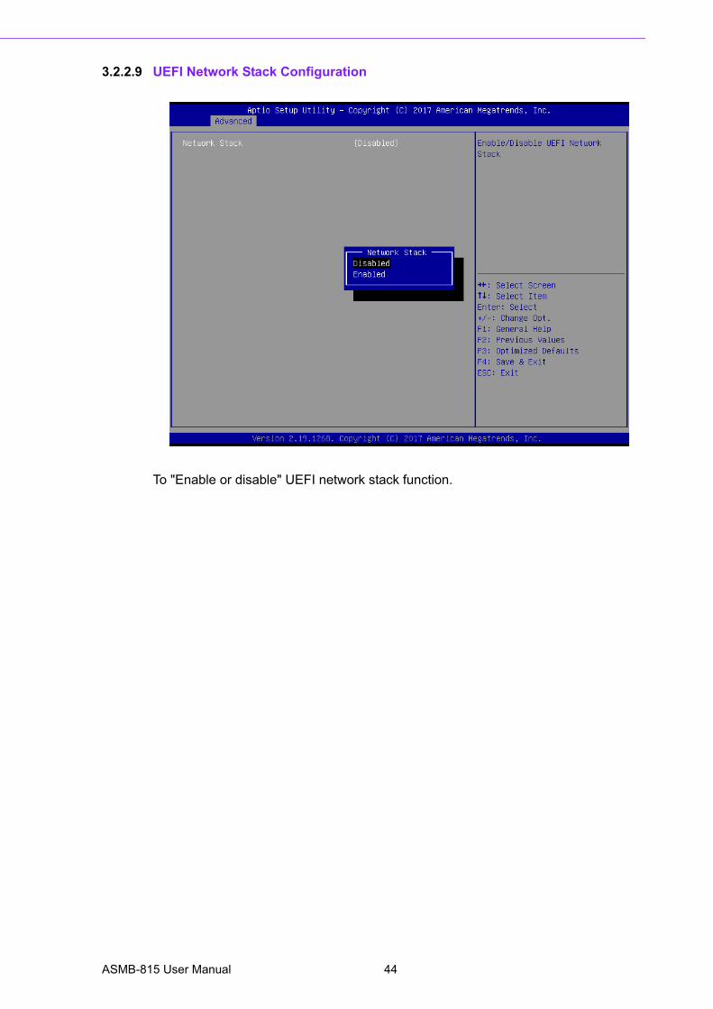
3.2.2.9 UEFI Network Stack Configuration
To "Enable or disable" UEFI network stack function.
ASMB-815 User Manual 44
Chapter 3
AM
I BIO
S
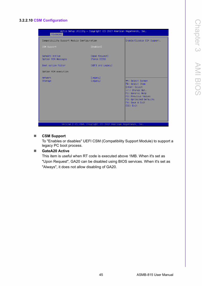
3.2.2.10 CSM Configuration
CSM SupportTo "Enables or disables" UEFI CSM (Compatibility Support Module) to support alegacy PC boot process.
GateA20 ActiveThis item is useful when RT code is executed above 1MB. When it's set as
"Upon Request", GA20 can be disabled using BIOS services. When it's set as
"Always", it does not allow disabling of GA20.
45 ASMB-815 User Manual
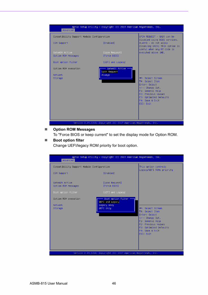
Option ROM MessagesTo "Force BIOS or keep current" to set the display mode for Option ROM.
Boot option filterChange UEFI/legacy ROM priority for boot option.
ASMB-815 User Manual 46
Chapter 3
AM
I BIO
S
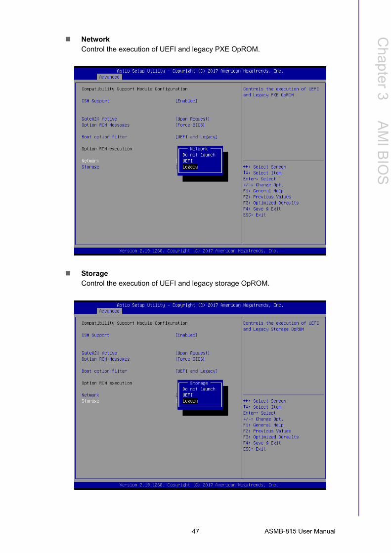
NetworkControl the execution of UEFI and legacy PXE OpROM.
StorageControl the execution of UEFI and legacy storage OpROM.
47 ASMB-815 User Manual
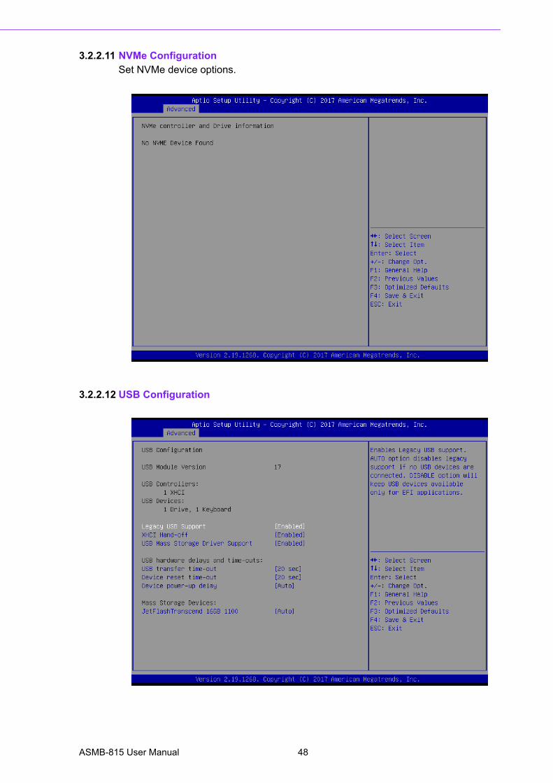
3.2.2.11 NVMe ConfigurationSet NVMe device options.
3.2.2.12 USB Configuration
ASMB-815 User Manual 48
Chapter 3
AM
I BIO
S
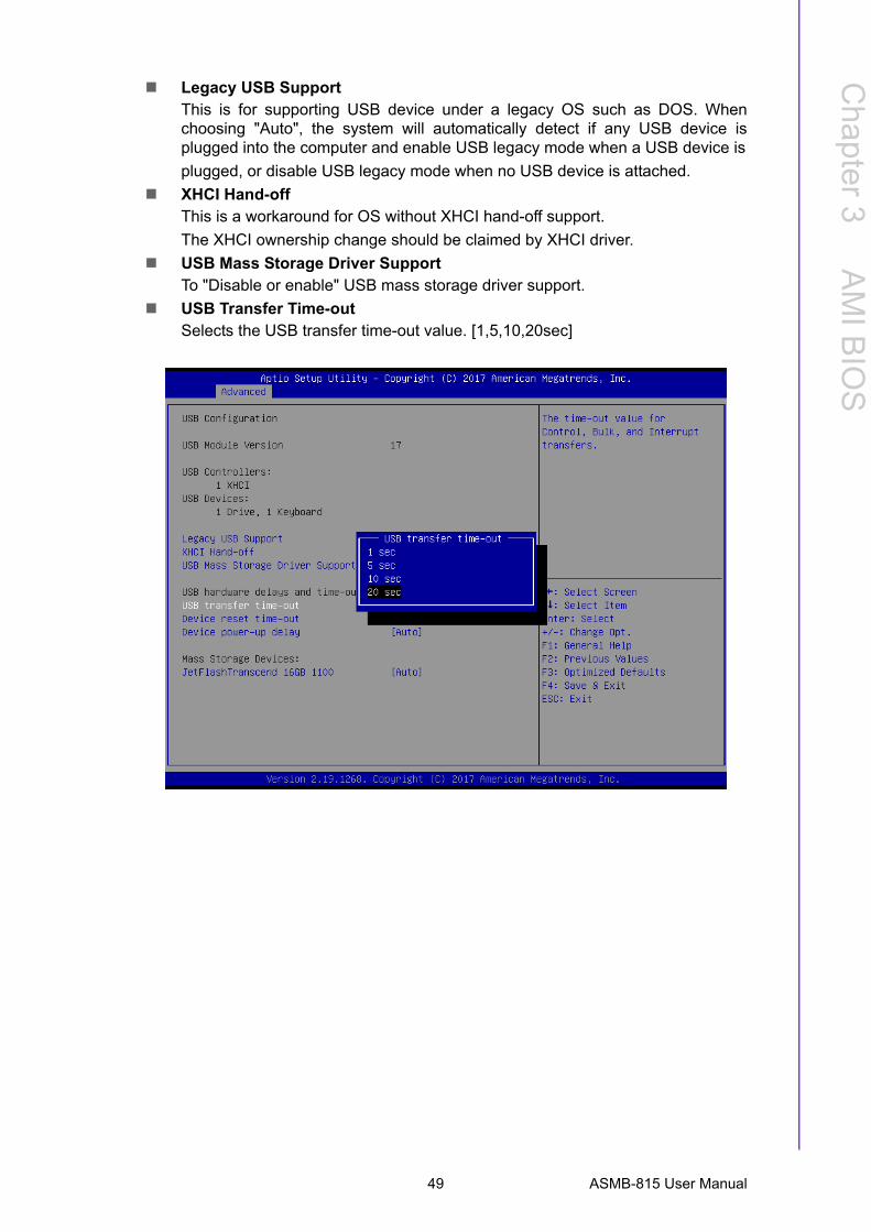
Legacy USB SupportThis is for supporting USB device under a legacy OS such as DOS. Whenchoosing "Auto", the system will automatically detect if any USB device isplugged into the computer and enable USB legacy mode when a USB device is
plugged, or disable USB legacy mode when no USB device is attached.
XHCI Hand-offThis is a workaround for OS without XHCI hand-off support.
The XHCI ownership change should be claimed by XHCI driver.
USB Mass Storage Driver SupportTo "Disable or enable" USB mass storage driver support.
USB Transfer Time-outSelects the USB transfer time-out value. [1,5,10,20sec]
49 ASMB-815 User Manual
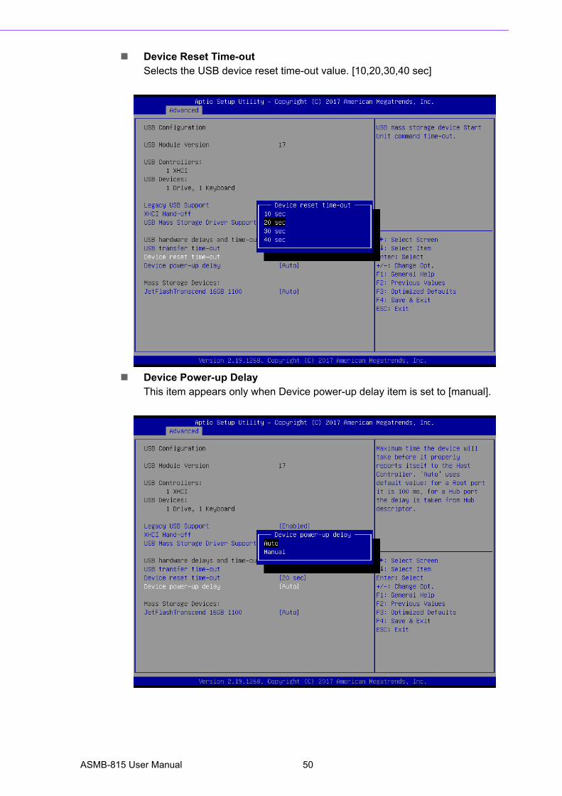
Device Reset Time-outSelects the USB device reset time-out value. [10,20,30,40 sec]
Device Power-up DelayThis item appears only when Device power-up delay item is set to [manual].
ASMB-815 User Manual 50
Chapter 3
AM
I BIO
S
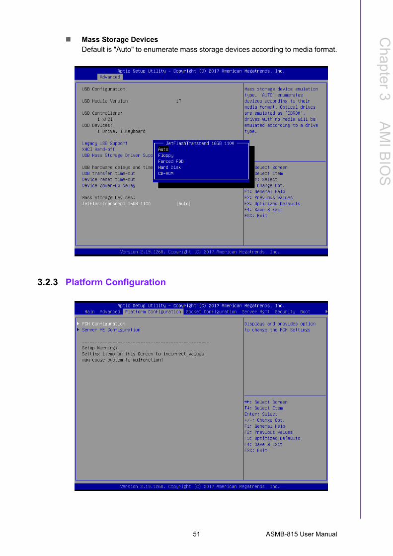
Mass Storage DevicesDefault is "Auto" to enumerate mass storage devices according to media format.
3.2.3 Platform Configuration
51 ASMB-815 User Manual
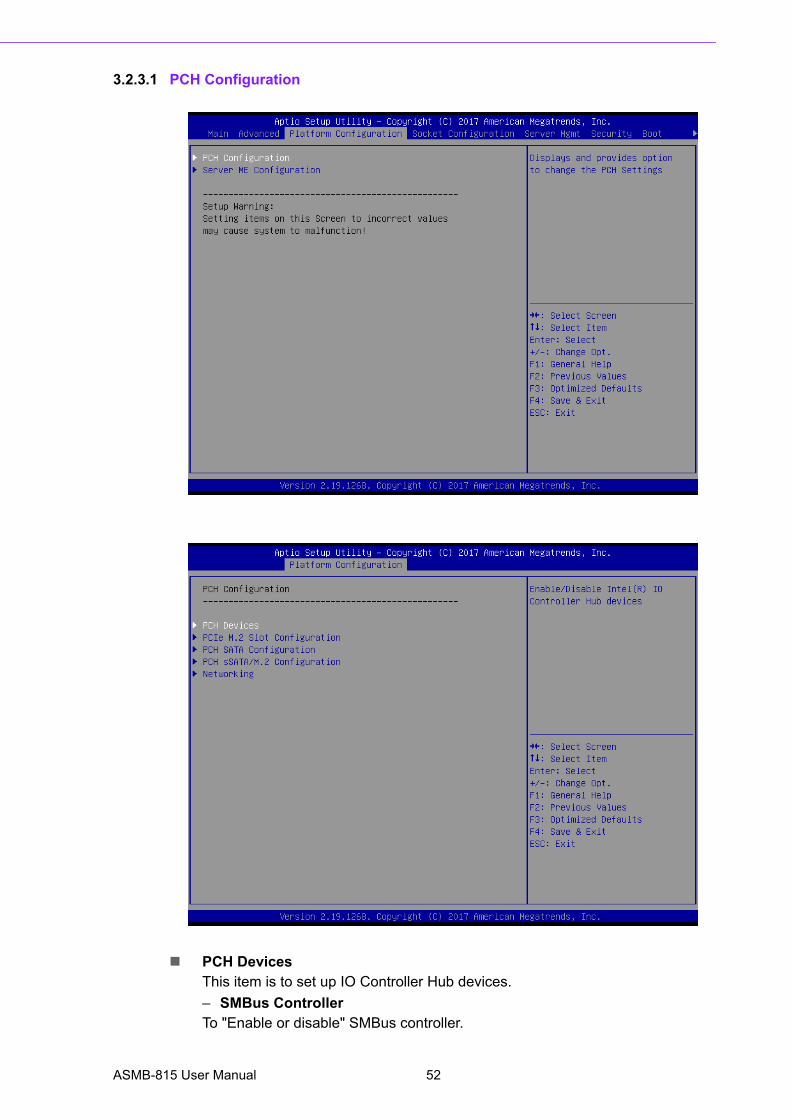
3.2.3.1 PCH Configuration
PCH DevicesThis item is to set up IO Controller Hub devices.
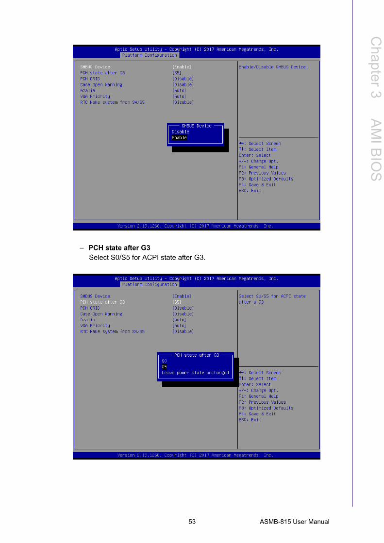
– SMBus ControllerTo "Enable or disable" SMBus controller.
ASMB-815 User Manual 52
Chapter 3
AM
I BIO
S
– PCH state after G3Select S0/S5 for ACPI state after G3.
53 ASMB-815 User Manual
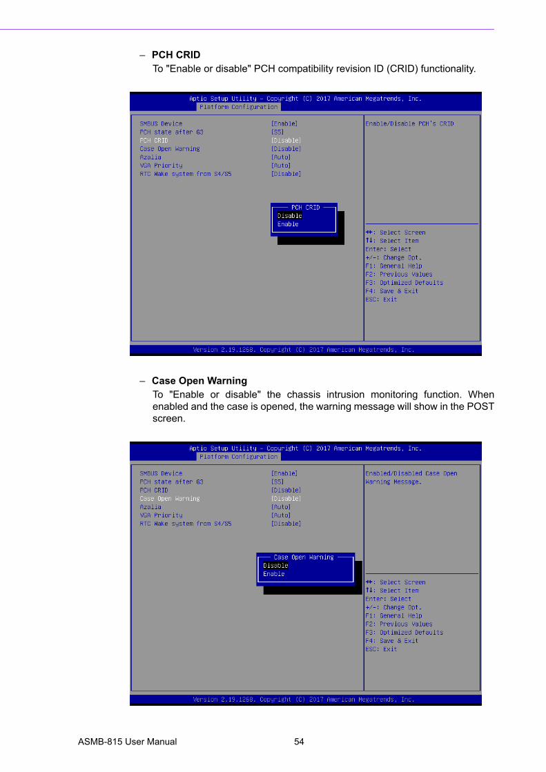
– PCH CRIDTo "Enable or disable" PCH compatibility revision ID (CRID) functionality.
– Case Open WarningTo "Enable or disable" the chassis intrusion monitoring function. Whenenabled and the case is opened, the warning message will show in the POSTscreen.
ASMB-815 User Manual 54
Chapter 3
AM
I BIO
S
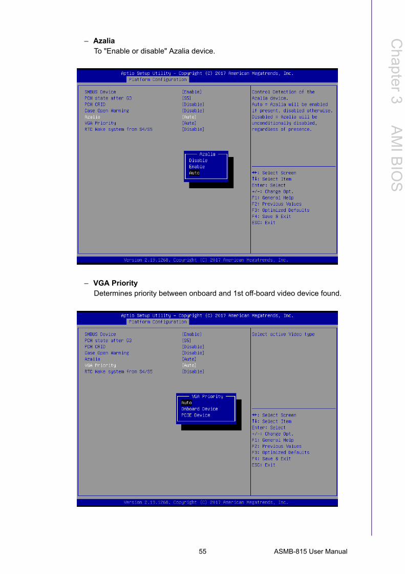
– AzaliaTo "Enable or disable" Azalia device.
– VGA PriorityDetermines priority between onboard and 1st off-board video device found.
55 ASMB-815 User Manual
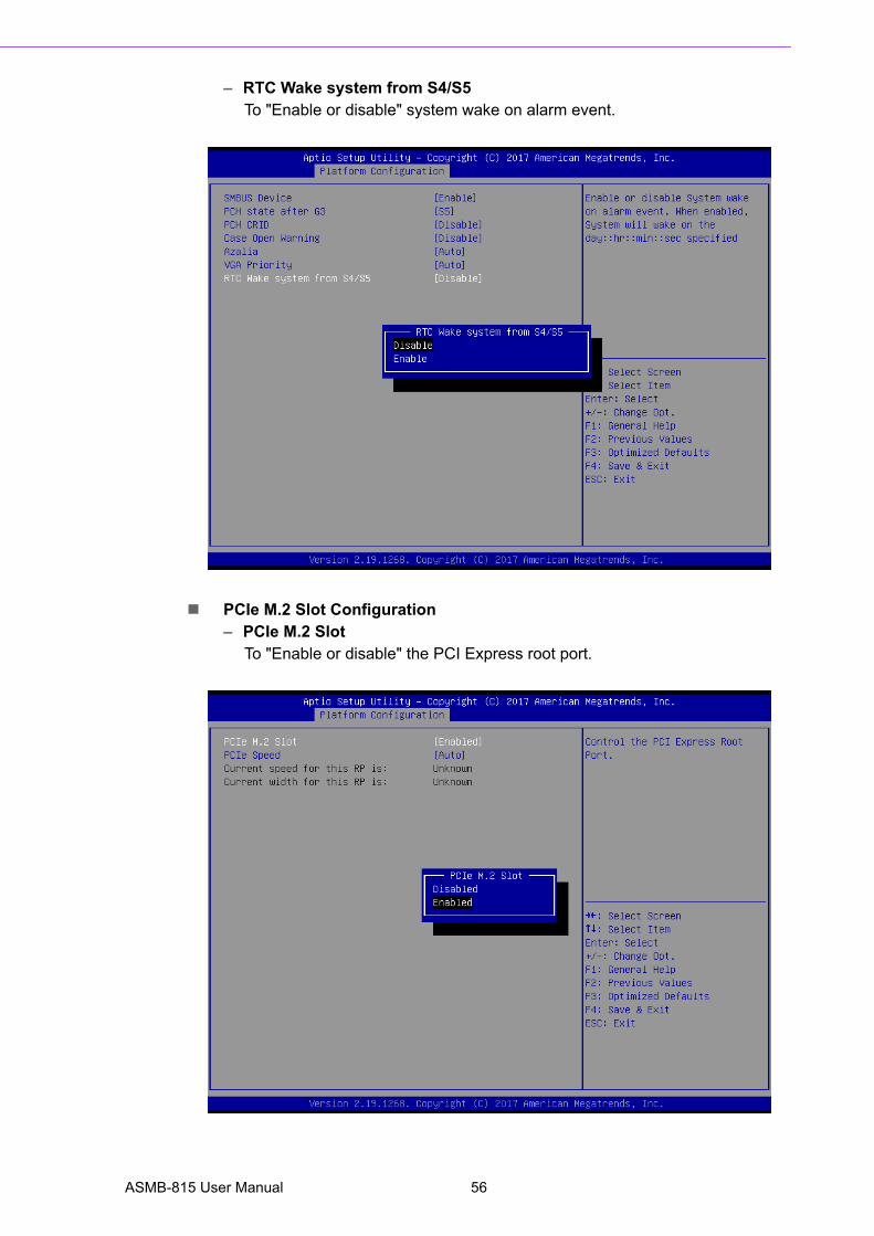
– RTC Wake system from S4/S5To "Enable or disable" system wake on alarm event.
PCIe M.2 Slot Configuration– PCIe M.2 Slot
To "Enable or disable" the PCI Express root port.
ASMB-815 User Manual 56
Chapter 3
AM
I BIO
S
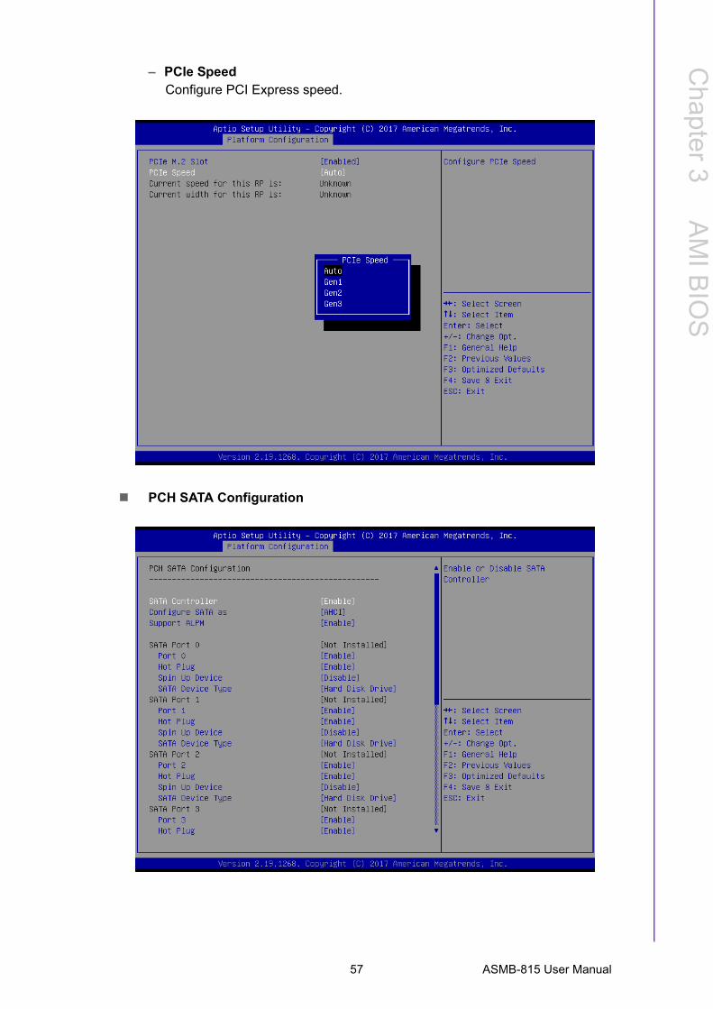
– PCIe SpeedConfigure PCI Express speed.
PCH SATA Configuration
57 ASMB-815 User Manual
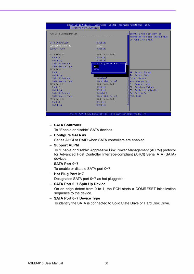
– SATA ControllerTo "Enable or disable" SATA devices.
– Configure SATA asSet as AHCI or RAID when SATA controllers are enabled.
– Support ALPMTo "Enable or disable" Aggressive Link Power Management (ALPM) protocolfor Advanced Host Controller Interface-compliant (AHCI) Serial ATA (SATA)devices.
– SATA Port 0~7To enable or disable SATA port 0~7.
– Hot Plug Port 0~7Designates SATA port 0~7 as hot pluggable.
– SATA Port 0~7 Spin Up DeviceOn an edge detect from 0 to 1, the PCH starts a COMRESET initializationsequence to the device.
– SATA Port 0~7 Device TypeTo identify the SATA is connected to Solid State Drive or Hard Disk Drive.
ASMB-815 User Manual 58
Chapter 3
AM
I BIO
S
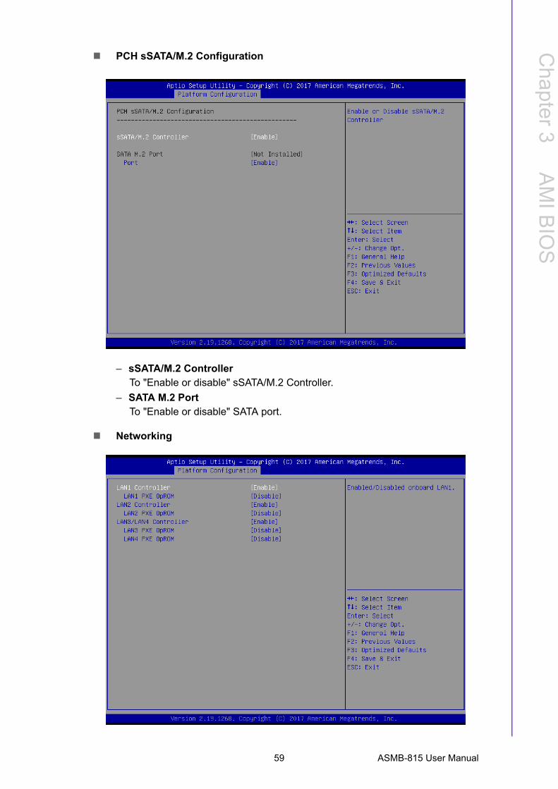
PCH sSATA/M.2 Configuration
– sSATA/M.2 ControllerTo "Enable or disable" sSATA/M.2 Controller.
– SATA M.2 PortTo "Enable or disable" SATA port.
Networking
59 ASMB-815 User Manual
– LAN1 ControllerTo "Enable or disable" Intel I210 Controller support.
– LAN1 PXE OpROMTo "Enable or disable" Boot option for Intel I210 controller.
– LAN2 ControllerTo "Enable or disable" Intel I210 Controller support.
– LAN2 PXE OpROMTo "Enable or disable" Boot option for Intel I210 controller.
– LAN3/LAN4 ControllerTo "Enable or disable" Intel X557 controller support.
– LAN3 PXE OpROMTo "Enable or disable" boot option for Intel X557 controller.
– LAN4 PXE OpROMTo "Enable or disable" boot option for Intel X557 controller.
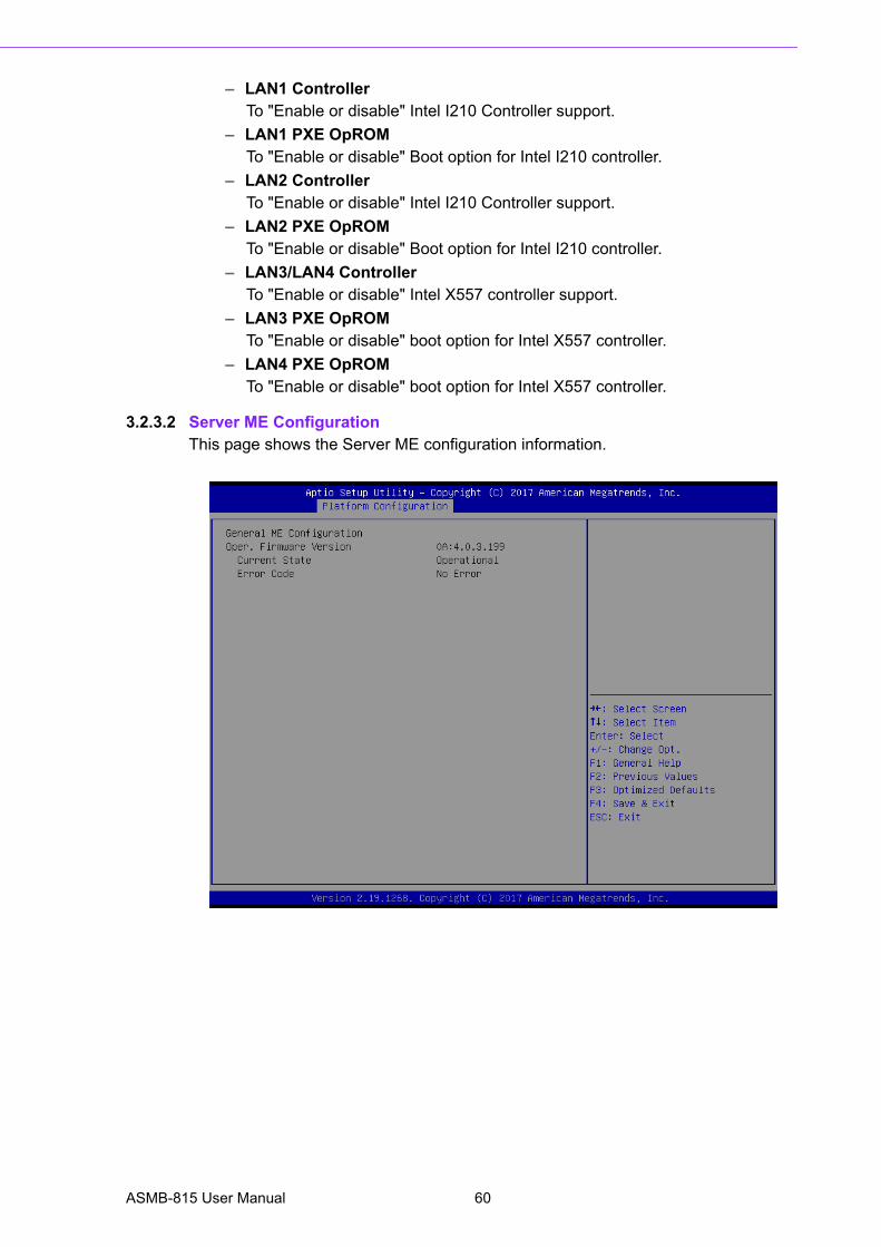
3.2.3.2 Server ME ConfigurationThis page shows the Server ME configuration information.
ASMB-815 User Manual 60
Chapter 3
AM
I BIO
S
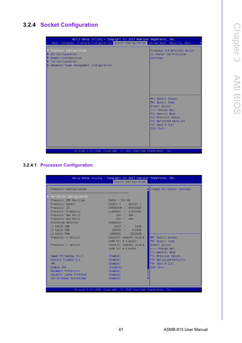
3.2.4 Socket Configuration
3.2.4.1 Processor Configuration
61 ASMB-815 User Manual
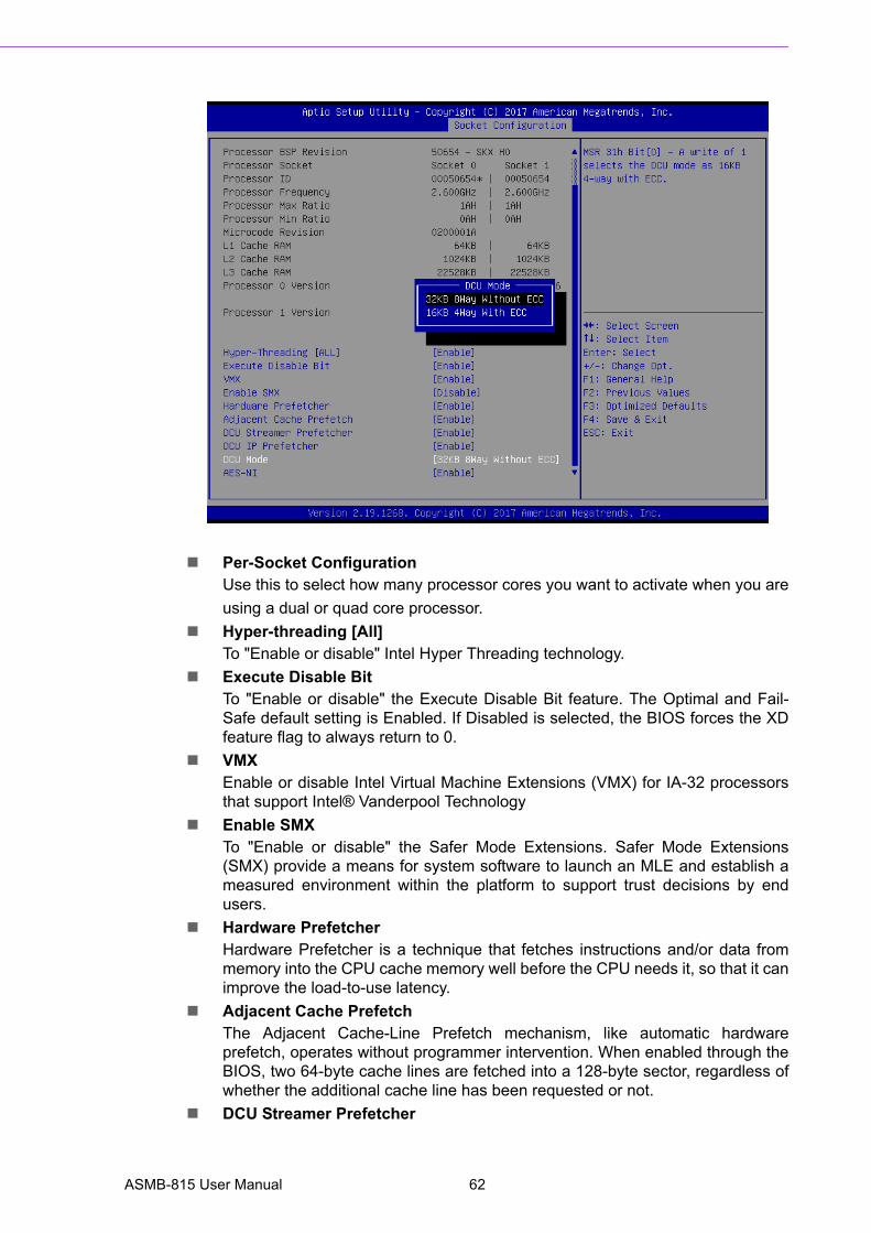
Per-Socket ConfigurationUse this to select how many processor cores you want to activate when you are
using a dual or quad core processor.
Hyper-threading [All]To "Enable or disable" Intel Hyper Threading technology.
Execute Disable BitTo "Enable or disable" the Execute Disable Bit feature. The Optimal and Fail-Safe default setting is Enabled. If Disabled is selected, the BIOS forces the XDfeature flag to always return to 0.
VMXEnable or disable Intel Virtual Machine Extensions (VMX) for IA-32 processorsthat support Intel® Vanderpool Technology
Enable SMXTo "Enable or disable" the Safer Mode Extensions. Safer Mode Extensions(SMX) provide a means for system software to launch an MLE and establish ameasured environment within the platform to support trust decisions by endusers.
Hardware PrefetcherHardware Prefetcher is a technique that fetches instructions and/or data frommemory into the CPU cache memory well before the CPU needs it, so that it canimprove the load-to-use latency.
Adjacent Cache PrefetchThe Adjacent Cache-Line Prefetch mechanism, like automatic hardwareprefetch, operates without programmer intervention. When enabled through theBIOS, two 64-byte cache lines are fetched into a 128-byte sector, regardless ofwhether the additional cache line has been requested or not.
DCU Streamer Prefetcher
ASMB-815 User Manual 62
Chapter 3
AM
I BIO
S
Enable prefetch of next L1 data line based upon multiple loads in same cacheline.
DCU IP PrefetcherEnable prefetch of next L1 line based upon sequential load history.
DCU ModeChange the data cache unit mode.
AES-NIThis item is to enable or disable CPU advanced encryption standard instruc-tions.
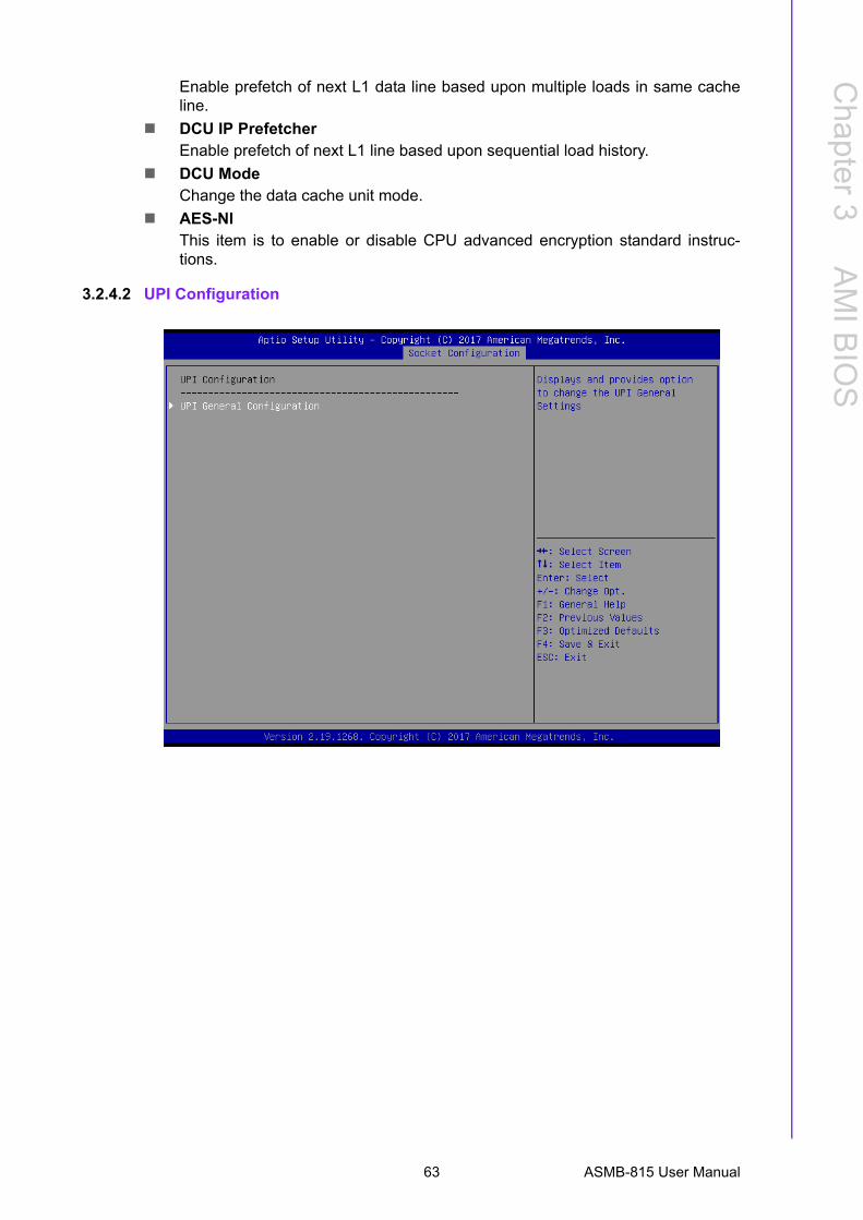
3.2.4.2 UPI Configuration
63 ASMB-815 User Manual
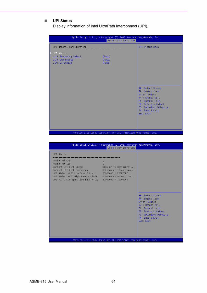
UPI StatusDisplay information of Intel UltraPath Interconnect (UPI).
ASMB-815 User Manual 64
Chapter 3
AM
I BIO
S
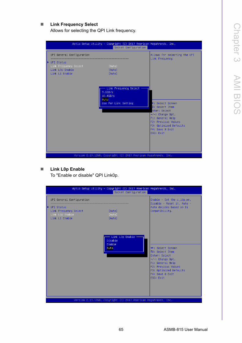
Link Frequency SelectAllows for selecting the QPI Link frequency.
Link L0p EnableTo "Enable or disable" QPI Link0p.
65 ASMB-815 User Manual
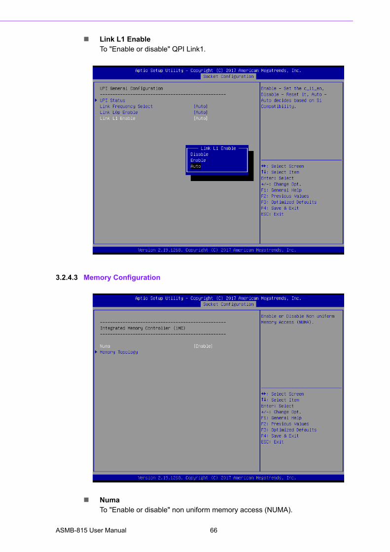
Link L1 EnableTo "Enable or disable" QPI Link1.
3.2.4.3 Memory Configuration
NumaTo "Enable or disable" non uniform memory access (NUMA).
ASMB-815 User Manual 66
Chapter 3
AM
I BIO
S
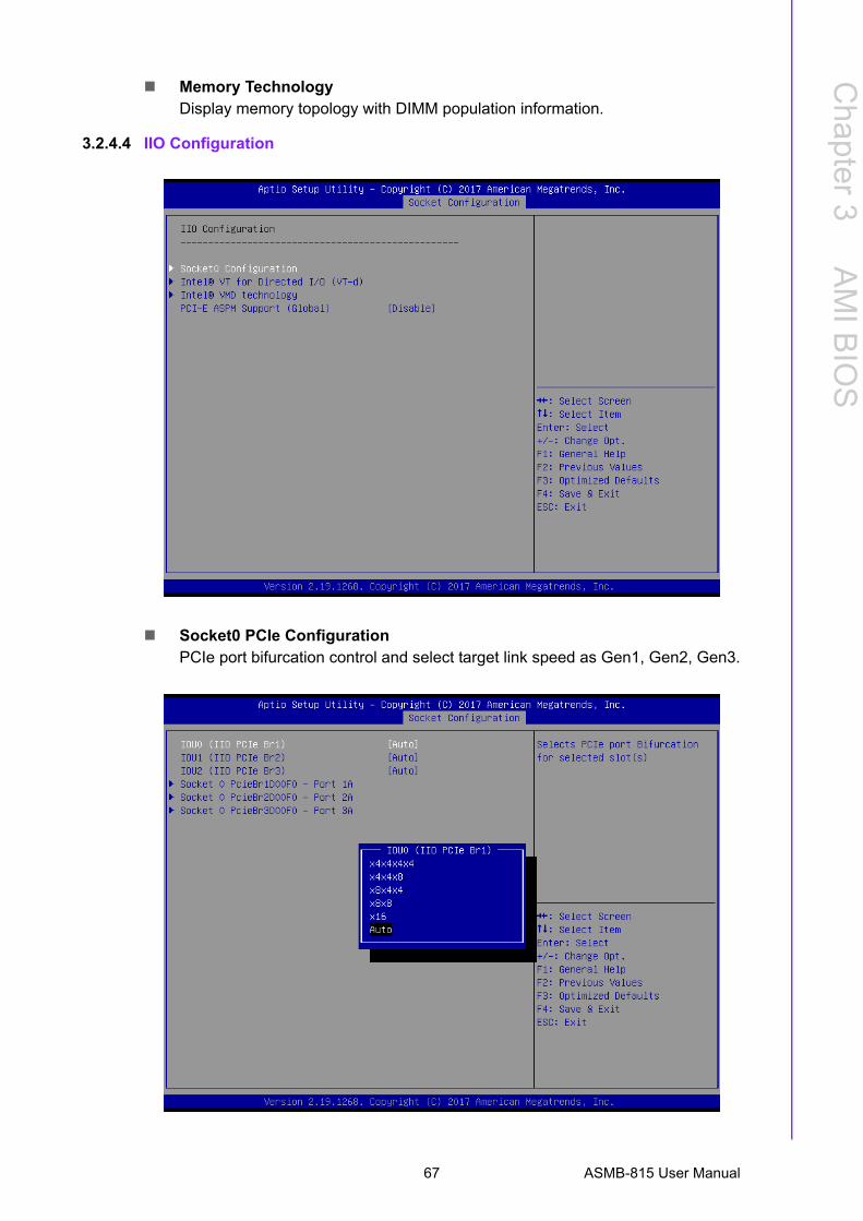
Memory TechnologyDisplay memory topology with DIMM population information.
3.2.4.4 IIO Configuration
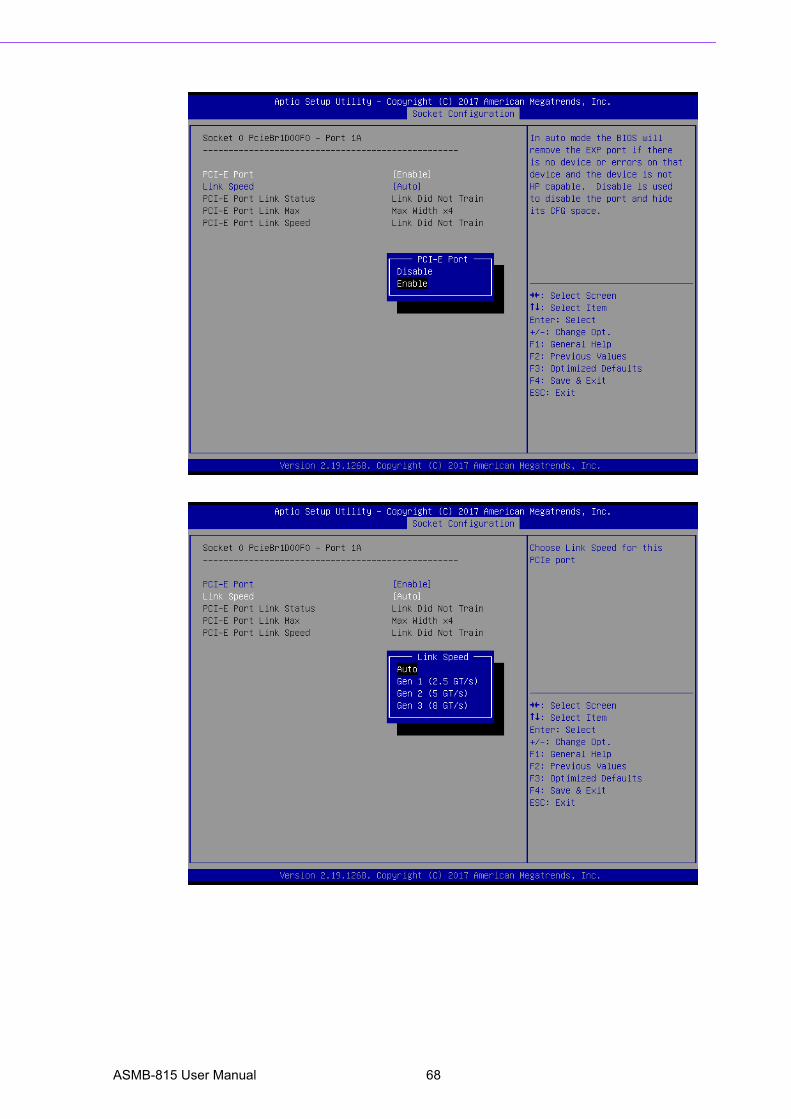
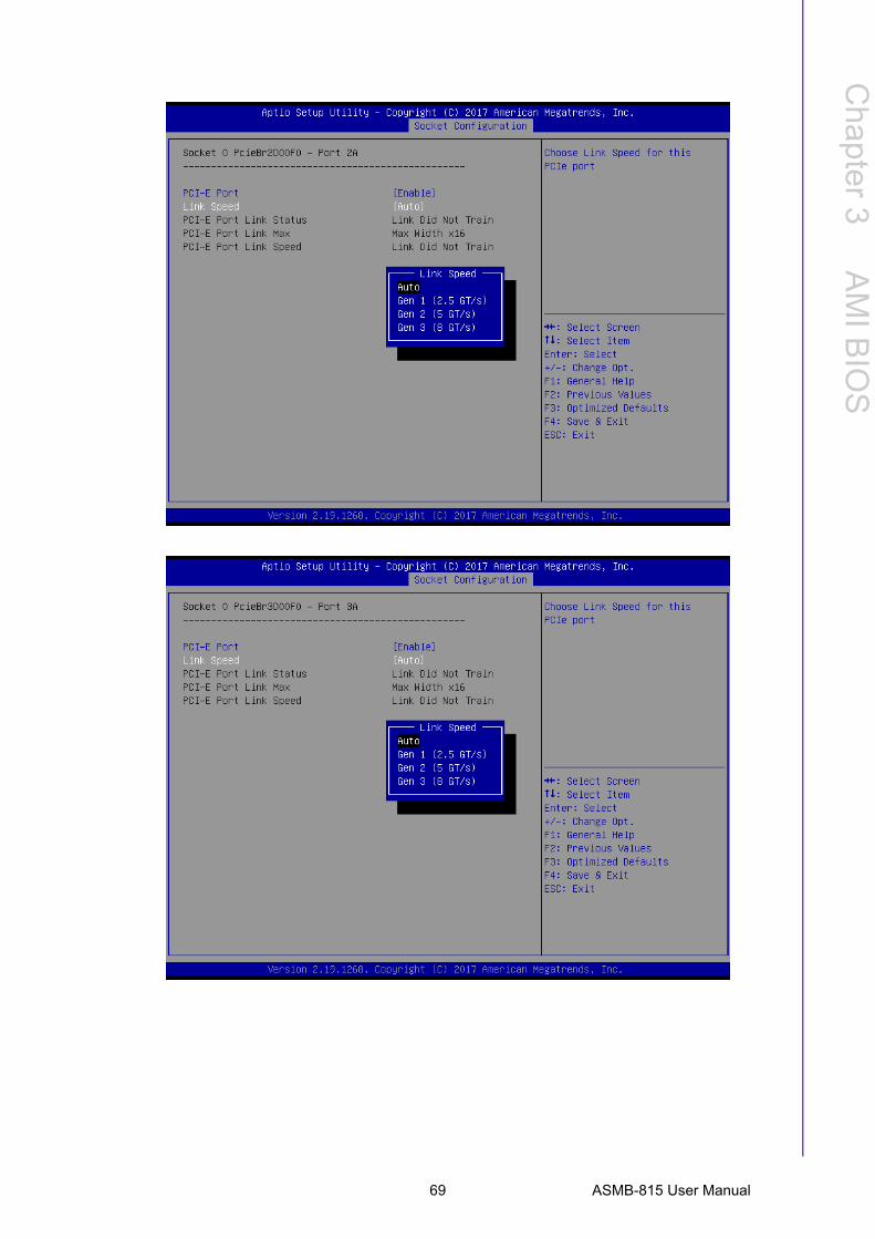
Socket0 PCIe ConfigurationPCIe port bifurcation control and select target link speed as Gen1, Gen2, Gen3.
67 ASMB-815 User Manual
ASMB-815 User Manual 68
Chapter 3
AM
I BIO
S
69 ASMB-815 User Manual
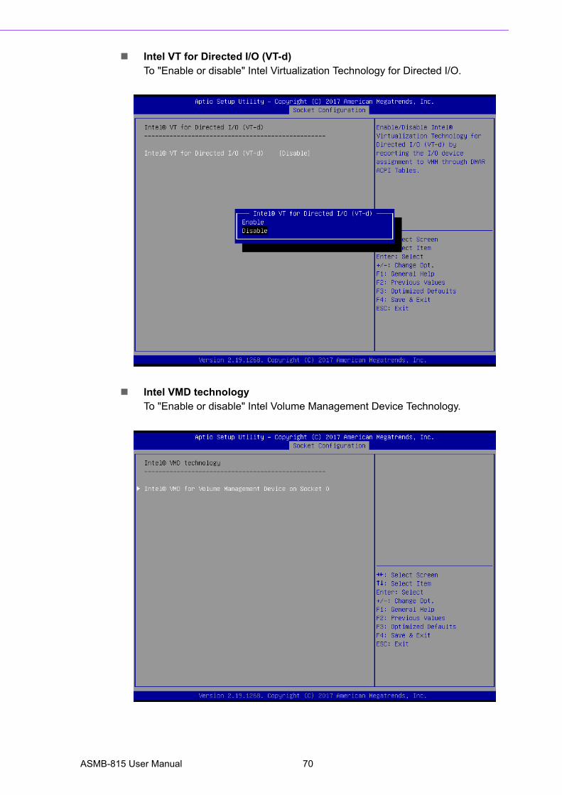
Intel VT for Directed I/O (VT-d)To "Enable or disable" Intel Virtualization Technology for Directed I/O.
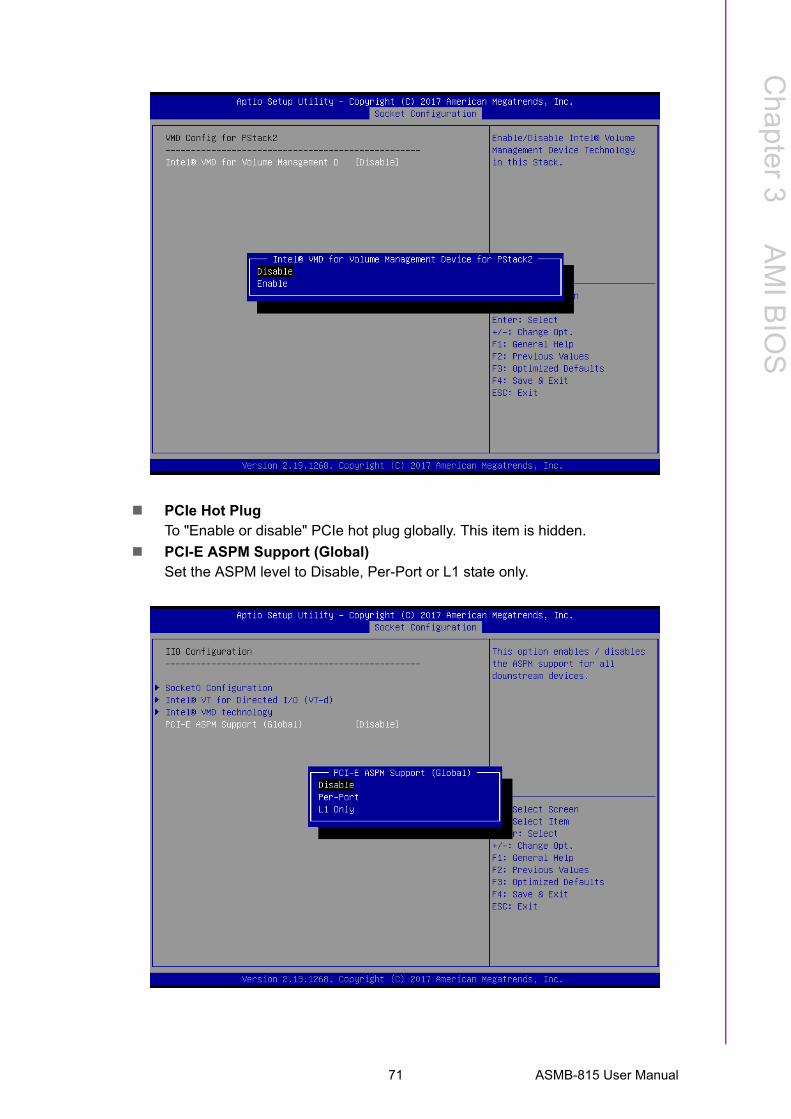
Intel VMD technologyTo "Enable or disable" Intel Volume Management Device Technology.
ASMB-815 User Manual 70
Chapter 3
AM
I BIO
S
PCIe Hot PlugTo "Enable or disable" PCIe hot plug globally. This item is hidden.
PCI-E ASPM Support (Global)Set the ASPM level to Disable, Per-Port or L1 state only.
71 ASMB-815 User Manual
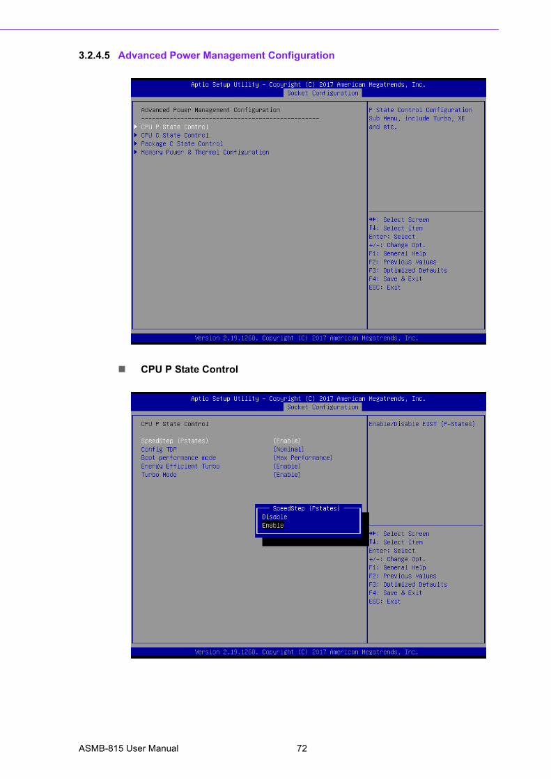
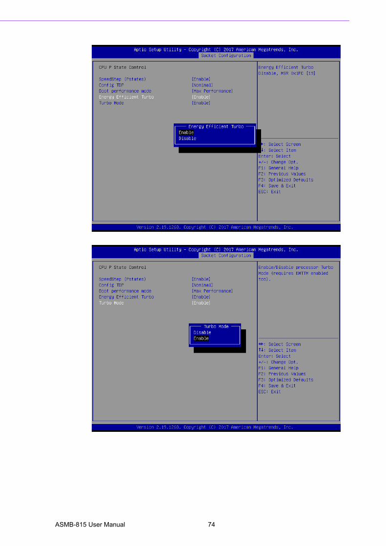
3.2.4.5 Advanced Power Management Configuration
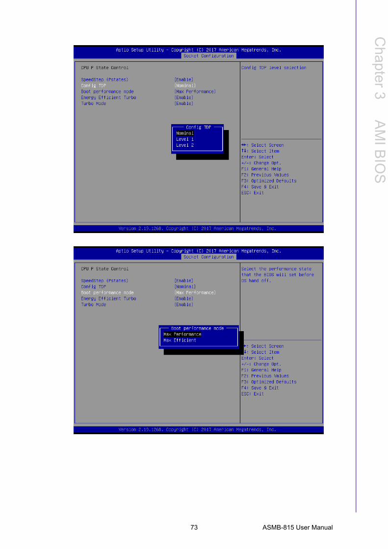
CPU P State Control
ASMB-815 User Manual 72
Chapter 3
AM
I BIO
S
73 ASMB-815 User Manual
ASMB-815 User Manual 74
Chapter 3
AM
I BIO
S
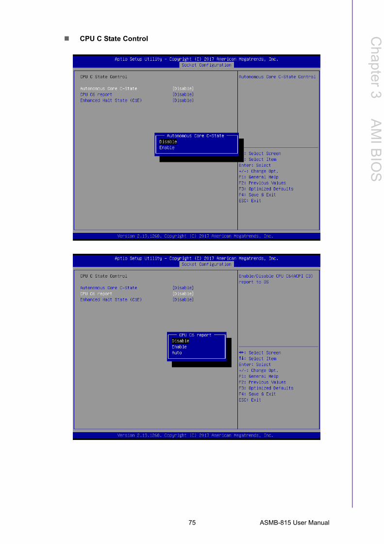
CPU C State Control
75 ASMB-815 User Manual
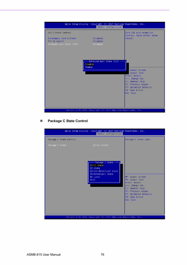
Package C State Control
ASMB-815 User Manual 76
Chapter 3
AM
I BIO
S
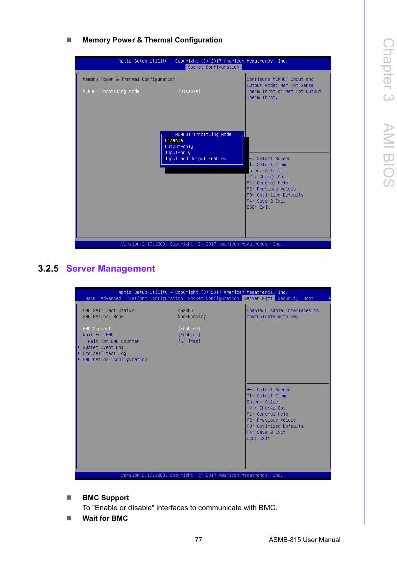
Memory Power & Thermal Configuration
3.2.5 Server Management
BMC SupportTo "Enable or disable" interfaces to communicate with BMC.
Wait for BMC
77 ASMB-815 User Manual
If enabled, motherboard will wait 30 ~ 60 seconds until BMC module boots up
completely. After that, the normal BIOS post screen will be displayed.
If disabled, motherboard will not wait for BMC module's response.
Wait for BMC counterInitialize host to BMC interfaces.
The MB beeps per 5 seconds to check it.
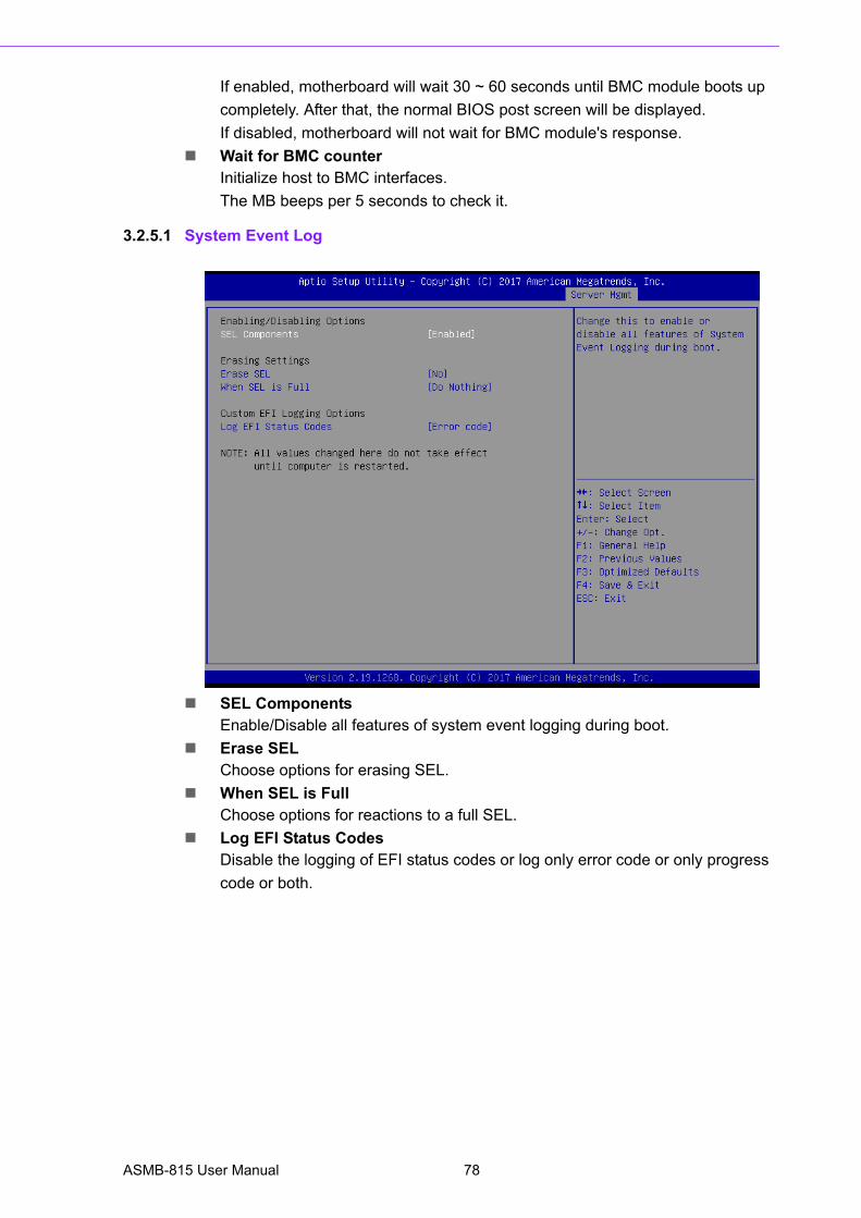
3.2.5.1 System Event Log
SEL ComponentsEnable/Disable all features of system event logging during boot.
Erase SELChoose options for erasing SEL.
When SEL is FullChoose options for reactions to a full SEL.
Log EFI Status CodesDisable the logging of EFI status codes or log only error code or only progress
code or both.
ASMB-815 User Manual 78
Chapter 3
AM
I BIO
S
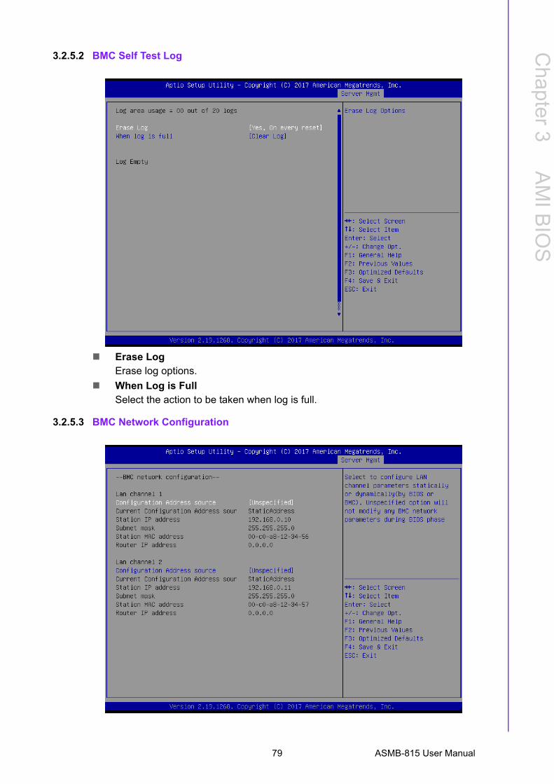
3.2.5.2 BMC Self Test Log
Erase LogErase log options.
When Log is FullSelect the action to be taken when log is full.
3.2.5.3 BMC Network Configuration
79 ASMB-815 User Manual
Configuration Address SourceSelect to configure LAN channel parameters statically or dynamically (by BMC).
Unspecified option will not modify any BMC network parameters during BIOS
phase.
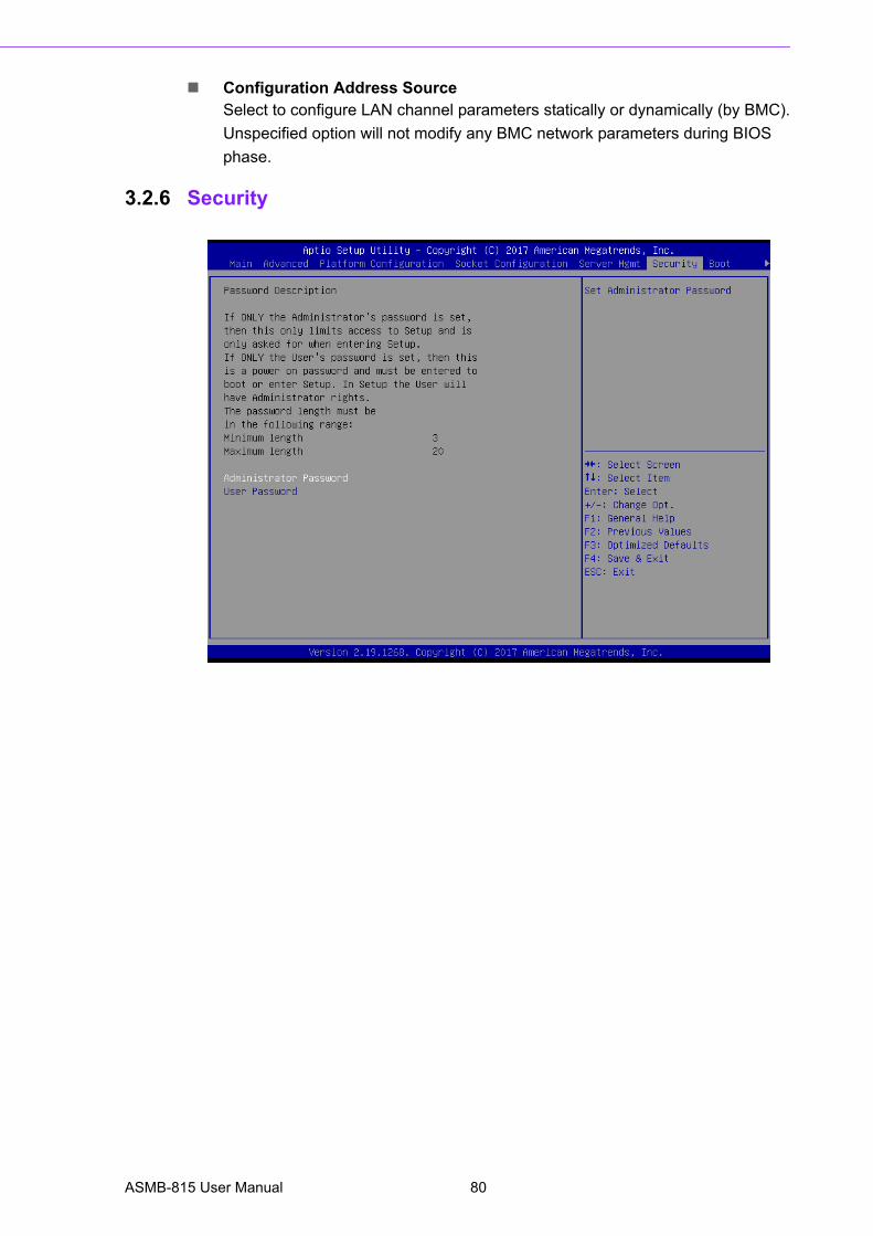
3.2.6 Security
ASMB-815 User Manual 80
Chapter 3
AM
I BIO
S
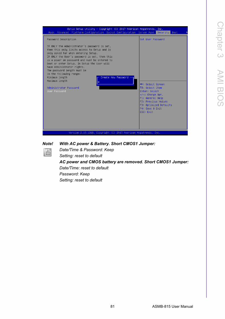
Note! With AC power & Battery. Short CMOS1 Jumper:
Date/Time & Password: Keep
Setting: reset to default
AC power and CMOS battery are removed. Short CMOS1 Jumper:
Date/Time: reset to default
Password: Keep
Setting: reset to default
81 ASMB-815 User Manual
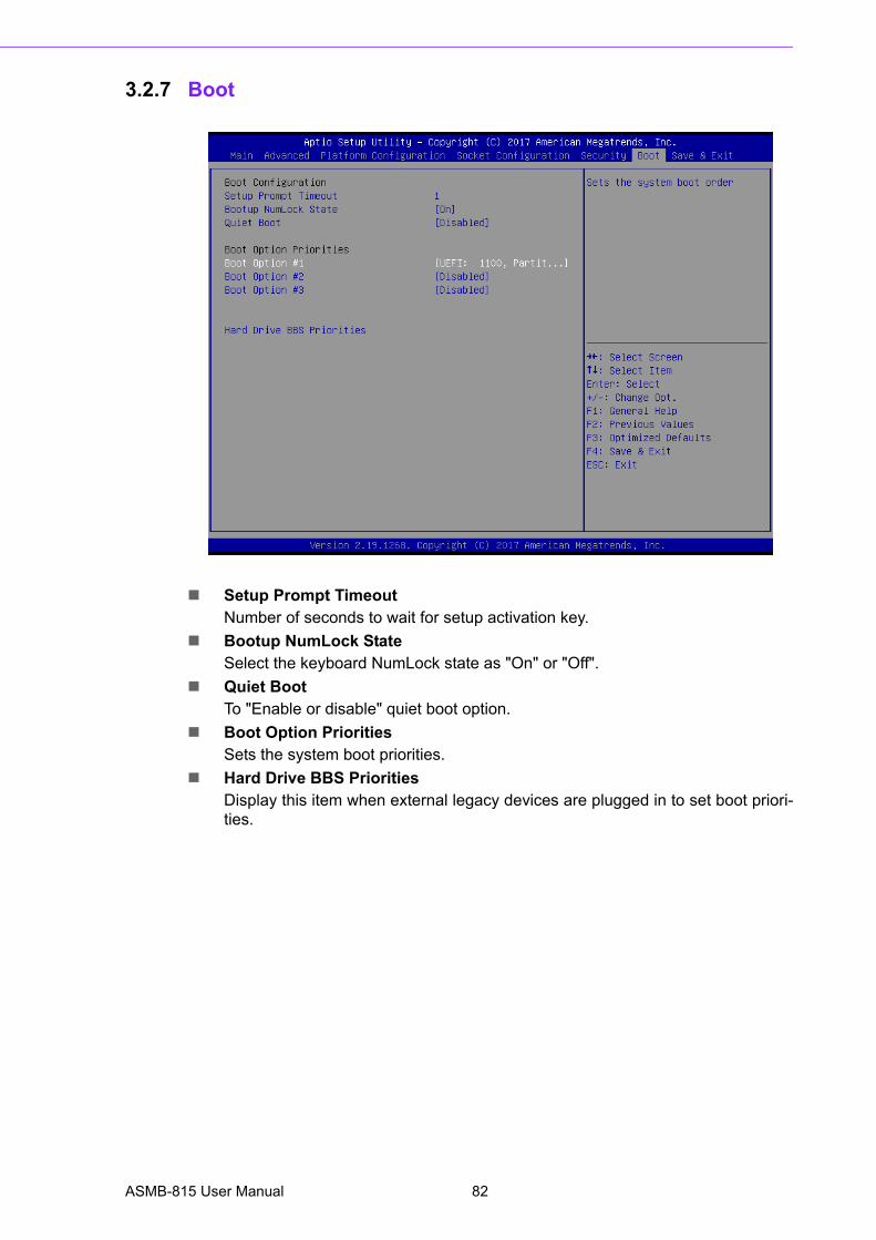
3.2.7 Boot
Setup Prompt TimeoutNumber of seconds to wait for setup activation key.
Bootup NumLock StateSelect the keyboard NumLock state as "On" or "Off".
Quiet BootTo "Enable or disable" quiet boot option.
Boot Option PrioritiesSets the system boot priorities.
Hard Drive BBS PrioritiesDisplay this item when external legacy devices are plugged in to set boot priori-ties.
ASMB-815 User Manual 82
Chapter 3
AM
I BIO
S
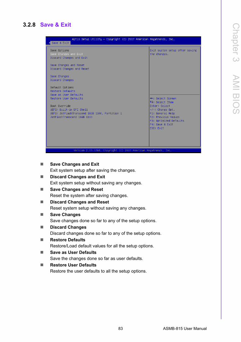
3.2.8 Save & Exit
Save Changes and ExitExit system setup after saving the changes.
Discard Changes and ExitExit system setup without saving any changes.
Save Changes and ResetReset the system after saving changes.
Discard Changes and ResetReset system setup without saving any changes.
Save ChangesSave changes done so far to any of the setup options.
Discard ChangesDiscard changes done so far to any of the setup options.
Restore DefaultsRestore/Load default values for all the setup options.
Save as User DefaultsSave the changes done so far as user defaults.
Restore User DefaultsRestore the user defaults to all the setup options.
83 ASMB-815 User Manual

ASMB-815 User Manual 84
Chapter 4
4 Chipset Software Installation Utility
4.1 Before BeginningTo facilitate the installation of the enhanced display drivers and utility software, readthe instructions in this chapter carefully. The drivers for the ASMB-815 are located onthe software installation CD.
Before beginning, it is important to note that most display drivers need to have therelevant software application already installed on the system prior to installing theenhanced display drivers. In addition, many of the installation procedures assumethat you are familiar with both the relevant software applications and operating sys-tem commands. Review the relevant operating system commands and the pertinentsections of your application software’s user manual before performing the installa-tion.
4.2 IntroductionThe Intel Chipset Software Installation (CSI) utility installs the Windows INF files thatoutline to the operating system how the chipset components will be configured. Thisis needed for the proper functioning of the following features:
Core PCI PnP services Serial ATA interface support USB 1.1/2.0/3.0 support Identification of Intel chipset components in the Device Manager
Note! The files on the software installation CD are compressed. Do not attempt to install the drivers by copying the files manually. You must use the supplied SETUP program to install the drivers.
Note! The chipset driver is used for the following versions of Windows, and it has to be installed before installing all the other drivers:
Windows Server 2016 Standard
Windows Server 2012 R2 Standard
Windows 10 Ultimate
x64
x64
x64
Note! It is necessary to update all the latest Microsoft hot fix files when using this OS.
ASMB-815 User Manual 86
Chapter 4
ChipsetS
oftware
Installation Utility
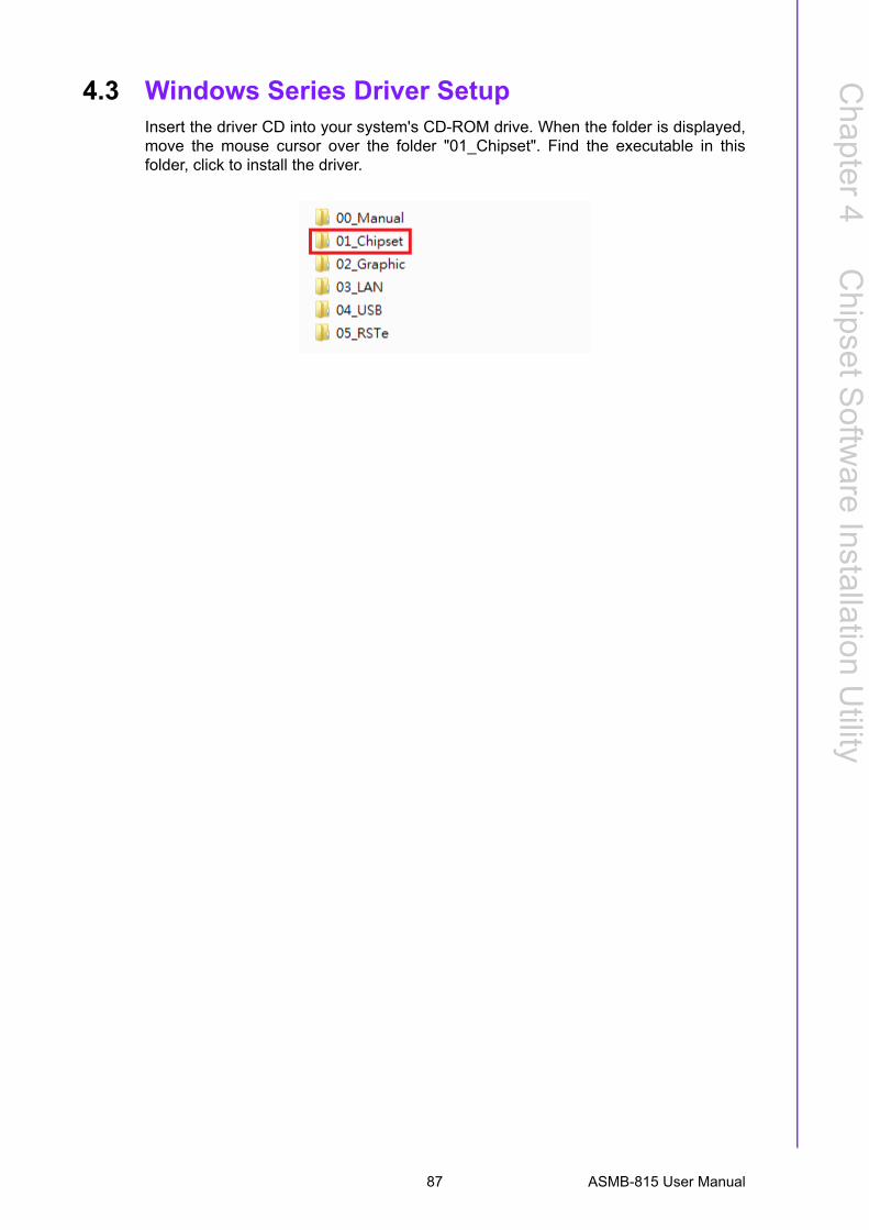
4.3 Windows Series Driver SetupInsert the driver CD into your system's CD-ROM drive. When the folder is displayed,move the mouse cursor over the folder "01_Chipset". Find the executable in thisfolder, click to install the driver.
87 ASMB-815 User Manual

ASMB-815 User Manual 88

Chapter 5
5 Graphic Setup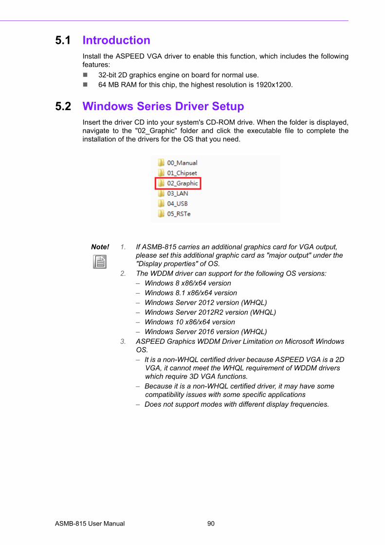
5.1 IntroductionInstall the ASPEED VGA driver to enable this function, which includes the followingfeatures:
32-bit 2D graphics engine on board for normal use. 64 MB RAM for this chip, the highest resolution is 1920x1200.
5.2 Windows Series Driver SetupInsert the driver CD into your system's CD-ROM drive. When the folder is displayed,navigate to the "02_Graphic" folder and click the executable file to complete theinstallation of the drivers for the OS that you need.
Note! 1. If ASMB-815 carries an additional graphics card for VGA output, please set this additional graphic card as "major output" under the "Display properties" of OS.
2. The WDDM driver can support for the following OS versions:– Windows 8 x86/x64 version– Windows 8.1 x86/x64 version– Windows Server 2012 version (WHQL)– Windows Server 2012R2 version (WHQL)– Windows 10 x86/x64 version– Windows Server 2016 version (WHQL)
3. ASPEED Graphics WDDM Driver Limitation on Microsoft Windows OS.– It is a non-WHQL certified driver because ASPEED VGA is a 2D
VGA, it cannot meet the WHQL requirement of WDDM drivers which require 3D VGA functions.
– Because it is a non-WHQL certified driver, it may have some compatibility issues with some specific applications
– Does not support modes with different display frequencies.
ASMB-815 User Manual 90
Chapter 6
6 LAN, USB 3.0 and RSTe RAID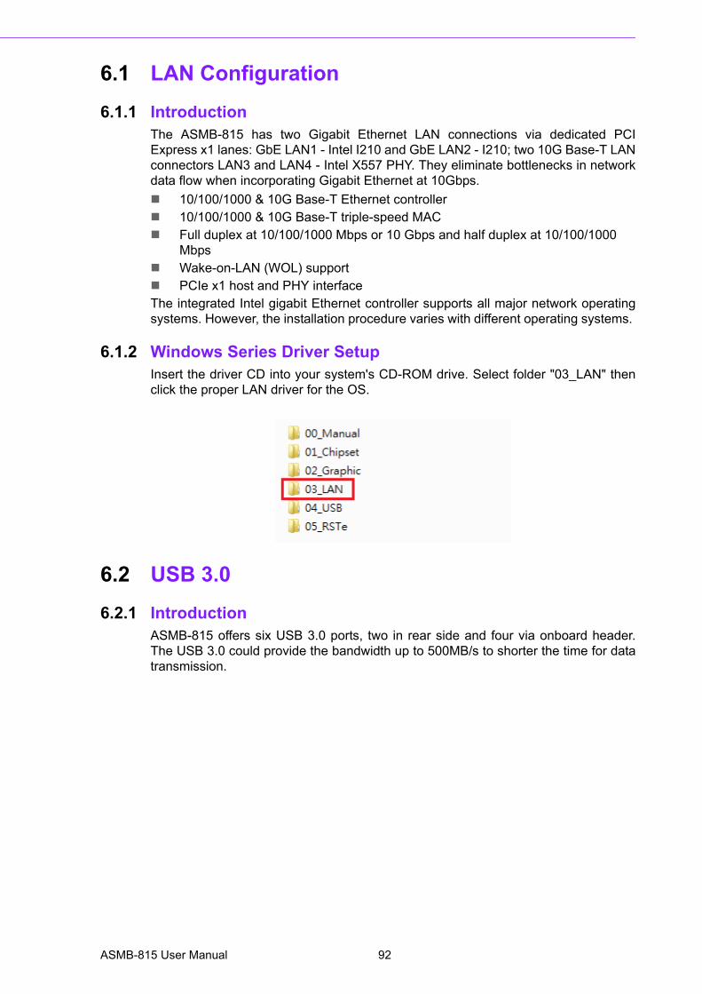
6.1 LAN Configuration
6.1.1 IntroductionThe ASMB-815 has two Gigabit Ethernet LAN connections via dedicated PCIExpress x1 lanes: GbE LAN1 - Intel I210 and GbE LAN2 - I210; two 10G Base-T LANconnectors LAN3 and LAN4 - Intel X557 PHY. They eliminate bottlenecks in networkdata flow when incorporating Gigabit Ethernet at 10Gbps.
10/100/1000 & 10G Base-T Ethernet controller 10/100/1000 & 10G Base-T triple-speed MAC Full duplex at 10/100/1000 Mbps or 10 Gbps and half duplex at 10/100/1000
Mbps Wake-on-LAN (WOL) support PCIe x1 host and PHY interfaceThe integrated Intel gigabit Ethernet controller supports all major network operatingsystems. However, the installation procedure varies with different operating systems.
6.1.2 Windows Series Driver SetupInsert the driver CD into your system's CD-ROM drive. Select folder "03_LAN" thenclick the proper LAN driver for the OS.
6.2 USB 3.0
6.2.1 IntroductionASMB-815 offers six USB 3.0 ports, two in rear side and four via onboard header.The USB 3.0 could provide the bandwidth up to 500MB/s to shorter the time for datatransmission.
ASMB-815 User Manual 92

Chapter 6
LAN
, US
B3.0
andR
ST
eR
AID
6.2.2 Windows Series Driver SetupInsert the driver CD into your system's CD-ROM drive. Select folder "04_USB" thenclick the Setup.exe file for the installation.
6.3 SATA & PCIe SSD RAID
6.3.1 IntroductionIntel C621/C622 PCH chip offers SATA & PCIe SSD RAID under Windows operatingsystem.
6.3.2 Windows Series Driver SetupInsert the driver CD into your system's CD-ROM drive. Select folder "05_RSTe" then
click to install the proper driver for the OS.
Note! 1.Please visit the Intel download center for "Intel Rapid Storage Tech-nology enterprise for Microsoft Windows Operating System Software User's Guide" file download,
2.For the hotfix file download, please visit Microsoft website.
93 ASMB-815 User Manual

ASMB-815 User Manual 94

Appendix A
A Programming the Watchdog Timer
The ASMB-815’s watchdog timer can be used to monitor system software operationand take corrective action if the software fails to function within the programmedperiod. This section describes the operation of the watchdog timer and how to pro-gram it.
A.1 Watchdog Timer OverviewThe watchdog timer is built in to the EC controller IT8528E. It provides the followingfunctions for user programming:
Can be enabled and disabled by user’s program Timer can be set from 1 to 255 seconds Generates an interrupt or reset signal if the software fails to reset the timer
before time-out
A.2 Programming the Watchdog TimerThe I/O port address of the watchdog timer is as below:
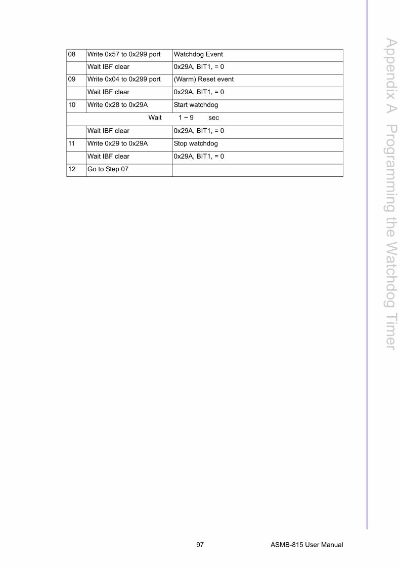
Here is an example to step by step program the Watchdog Timer.
Address Description
0x57 Event - Warm Reset: 0x04
0x5E Warm Reset Timer (High BYTE)Based 100ms
0x5F Warm Reset Timer (Low BYTE)
Step Action Description
00 Read 0x299 port Clear I/O port
Wait IBF clear 0x29A, BIT1, = 0
01 Write 0x89 to 0x29A
Wait IBF clear 0x29A, BIT1, = 0
02 Write 0x5E to 0x299 port
Wait IBF clear 0x29A, BIT1, = 0
03 Write 0x00 to 0x299 port Set 10 sec (high byte)
Wait IBF clear 0x29A, BIT1, = 0
04 Write 0x89 to 0x29A
Wait IBF clear 0x29A, BIT1, = 0
05 Write 0x5F to 0x299 port
Wait IBF clear 0x29A, BIT1, = 0
06 Write 0x64 to 0x299 port Set 10 sec (low byte)
Wait IBF clear 0x29A, BIT1, = 0
07 Write 0x89 to 0x29A
Wait IBF clear 0x29A, BIT1, = 0
ASMB-815 User Manual 96
Appendix A
Program
ming
theW
atchdogT
imer
08 Write 0x57 to 0x299 port Watchdog Event
Wait IBF clear 0x29A, BIT1, = 0
09 Write 0x04 to 0x299 port (Warm) Reset event
Wait IBF clear 0x29A, BIT1, = 0
10 Write 0x28 to 0x29A Start watchdog
Wait 1 ~ 9 sec
Wait IBF clear 0x29A, BIT1, = 0
11 Write 0x29 to 0x29A Stop watchdog
Wait IBF clear 0x29A, BIT1, = 0
12 Go to Step 07
97 ASMB-815 User Manual

ASMB-815 User Manual 98

Appendix B
B I/O Pin Assignments
B.1 USB2.0 Header (USB9_10, USB13_14)
B.2 USB3.0 Header (USB3_56)
Table B.1: USB Header (USB9_10, USB13_14)
Pin Signal Pin Signal
1 USB_VCC5 2 USB_VCC5
3 USB_D- 4 USB_D-
5 USB_D+ 6 USB_D+
7 GND 8 GND
10 NC
1
2 10
Table B.2: USB Header (USB3_56)
Pin Signal Pin Signal
1 +5 V 2 STDA_SSRX-
3 STDA_SSRX+ 4 GND
5 STDA_SSRX-TX- 6 STDA_SSRX+TX+
7 GND 8 D-
9 D+ 10 NC (reserved for OC pin)
11 D+ 12 D-
13 GND 14 STDA_SSRX+TX+
15 STDA_SSRX-TX- 16 GND
17 STDA_SSRX+ 18 STDA_SSRX-
19 +5 V 20
2 110
11 19
ASMB-815 User Manual 100
Appendix B
I/O P
inA
ssignments
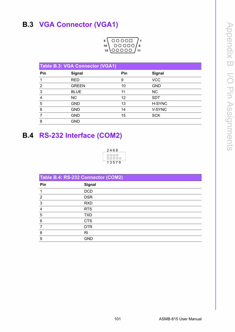
B.3 VGA Connector (VGA1)
B.4 RS-232 Interface (COM2)
Table B.3: VGA Connector (VGA1)
Pin Signal Pin Signal
1 RED 9 VCC
2 GREEN 10 GND
3 BLUE 11 NC
4 NC 12 SDT
5 GND 13 H-SYNC
6 GND 14 V-SYNC
7 GND 15 SCK
8 GND
5
15
1
11
10 6
Table B.4: RS-232 Connector (COM2)
Pin Signal
1 DCD
2 DSR
3 RXD
4 RTS
5 TXD
6 CTS
7 DTR
8 RI
9 GND
1 3 5 7 9
2 4 6 8
101 ASMB-815 User Manual
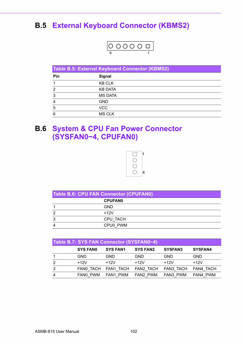
B.5 External Keyboard Connector (KBMS2)
B.6 System & CPU Fan Power Connector (SYSFAN0~4, CPUFAN0)
Table B.5: External Keyboard Connector (KBMS2)
Pin Signal
1 KB CLK
2 KB DATA
3 MS DATA
4 GND
5 VCC
6 MS CLK
6 1
Table B.6: CPU FAN Connector (CPUFAN0)CPUFAN0
1 GND
2 +12V
3 CPU_TACH
4 CPU0_PWM
Table B.7: SYS FAN Connector (SYSFAN0~4)
SYS FAN0 SYS FAN1 SYS FAN2 SYSFAN3 SYSFAN4
1 GND GND GND GND GND
2 +12V +12V +12V +12V +12V
3 FAN0_TACH FAN1_TACH FAN2_TACH FAN3_TACH FAN4_TACH
4 FAN0_PWM FAN1_PWM FAN2_PWM FAN3_PWM FAN4_PWM
1
4
ASMB-815 User Manual 102
Appendix B
I/O P
inA
ssignments
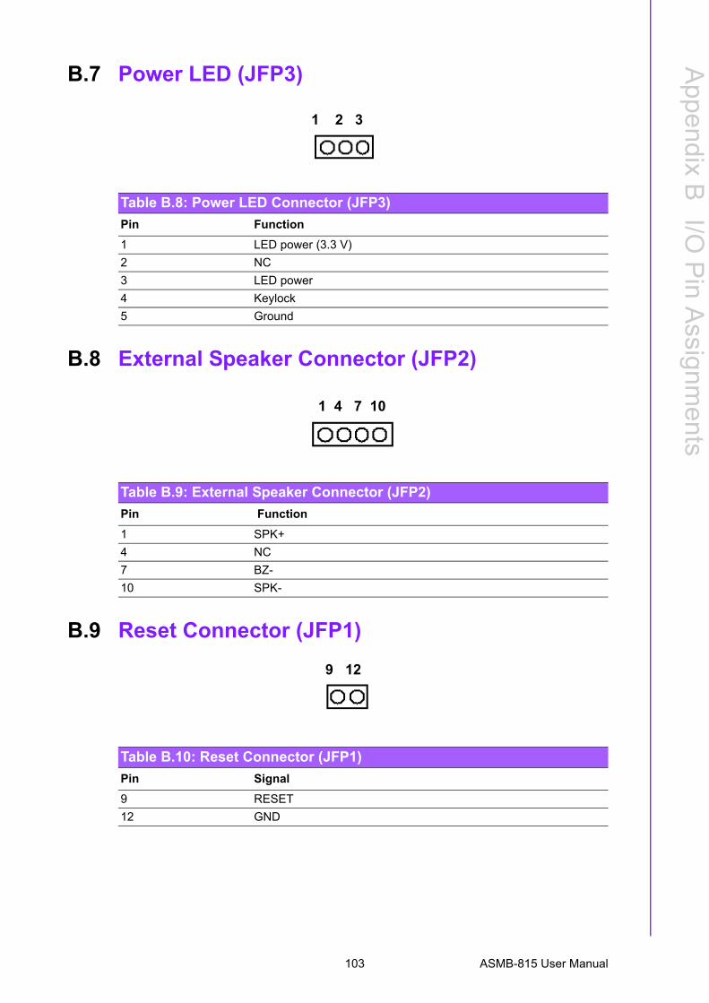
B.7 Power LED (JFP3)
B.8 External Speaker Connector (JFP2)
B.9 Reset Connector (JFP1)
Table B.8: Power LED Connector (JFP3)
Pin Function
1 LED power (3.3 V)
2 NC
3 LED power
4 Keylock
5 Ground
1 2 3
Table B.9: External Speaker Connector (JFP2)
Pin Function
1 SPK+
4 NC
7 BZ-
10 SPK-
1 4 7 10
Table B.10: Reset Connector (JFP1)
Pin Signal
9 RESET
12 GND
9 12
103 ASMB-815 User Manual
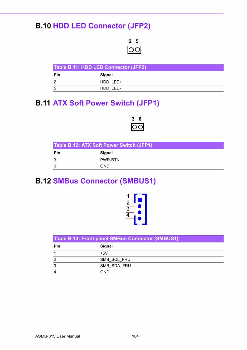
B.10 HDD LED Connector (JFP2)
B.11 ATX Soft Power Switch (JFP1)
B.12 SMBus Connector (SMBUS1)
Table B.11: HDD LED Connector (JFP2)
Pin Signal
2 HDD_LED+
5 HDD_LED-
2 5
Table B.12: ATX Soft Power Switch (JFP1)
Pin Signal
3 PWR-BTN
6 GND
3 6
Table B.13: Front panel SMBus Connector (SMBUS1)
Pin Signal
1 +5V
2 SMB_SCL_FRU
3 SMB_SDA_FRU
4 GND
ASMB-815 User Manual 104
Appendix B
I/O P
inA
ssignments
B.13 LAN Ports (LAN1~5)
B.14 Audio Connector (HDAUD1)
B.15 Alarm Board Connector (VOLT1)
Table B.14: LAN RJ-45 Port (LAN1~2, LAN3_4, LAN5)
Pin Signal Pin Signal
1 MID0+ 4 MID2+
2 MID0- 5 MID2-
3 MID1+ 7 MID3+
6 MID1- 8 MID3-
Table B.15: Front Panel Audio Connector (HDAUD1)
Pin Signal Pin Signal
1 ACZ_VCC 2 GND
3 ACZ_SYNC 4 ACZ_BITCLK
5 ACZ_SDOUT 6 ACZ_SDIN0
7 ACZ_SDIN1 8 ACZ_RST
9 ACZ_12V 10 GND
11 GND 12 x
Table B.16: Alarm Board Connector (VOLT1)
Pin Signal Pin Signal
1 5VSB 5 +5V
2 GND 6 +3.3V
3 GND 7 -12V
4 -5V 8 +12V
1 8
105 ASMB-815 User Manual
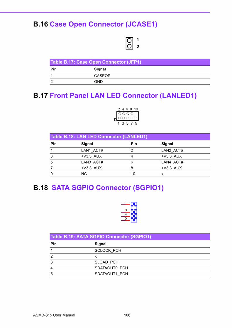
B.16 Case Open Connector (JCASE1)
B.17 Front Panel LAN LED Connector (LANLED1)
B.18 SATA SGPIO Connector (SGPIO1)
Table B.17: Case Open Connector (JFP1)
Pin Signal
1 CASEOP
2 GND
1
2
Table B.18: LAN LED Connector (LANLED1)
Pin Signal Pin Signal
1 LAN1_ACT# 2 LAN2_ACT#
3 +V3.3_AUX 4 +V3.3_AUX
5 LAN3_ACT# 6 LAN4_ACT#
7 +V3.3_AUX 8 +V3.3_AUX
9 NC 10 x
Table B.19: SATA SGPIO Connector (SGPIO1)
Pin Signal
1 SCLOCK_PCH
2 x
3 SLOAD_PCH
4 SDATAOUT0_PCH
5 SDATAOUT1_PCH
ASMB-815 User Manual 106
Appendix B
I/O P
inA
ssignments
B.19 LPC Connector (LPC1)
B.20 Clear CMOS Connector (JCMOS1, JME1)
Table B.20: LPC Connector (LPC1)
Pin Signal Pin Signal
1 CLK_24M_LPCCN 2 LPC_AD1
3 PLTRST_LPC 4 LPC_AD0
5 LPC_FRAME 6 +3.3V
7 LPC_AD3 8 GND
9 LPC_AD2 10 SMB_SCL_LPC
11 SERIRQ_PCH 12 SMB_SDA_LPC
13 +5V_AUX 14 +5V
Table B.21: Clear CMOS Connector (JCMOS1, JME1)
JCMOS1 JME1
Pin Signal Signal
1 NC NC
2 RTC_RST_PCH HDA_SDOUT_PCH
3 GND +3.3V_AUX
107 ASMB-815 User Manual
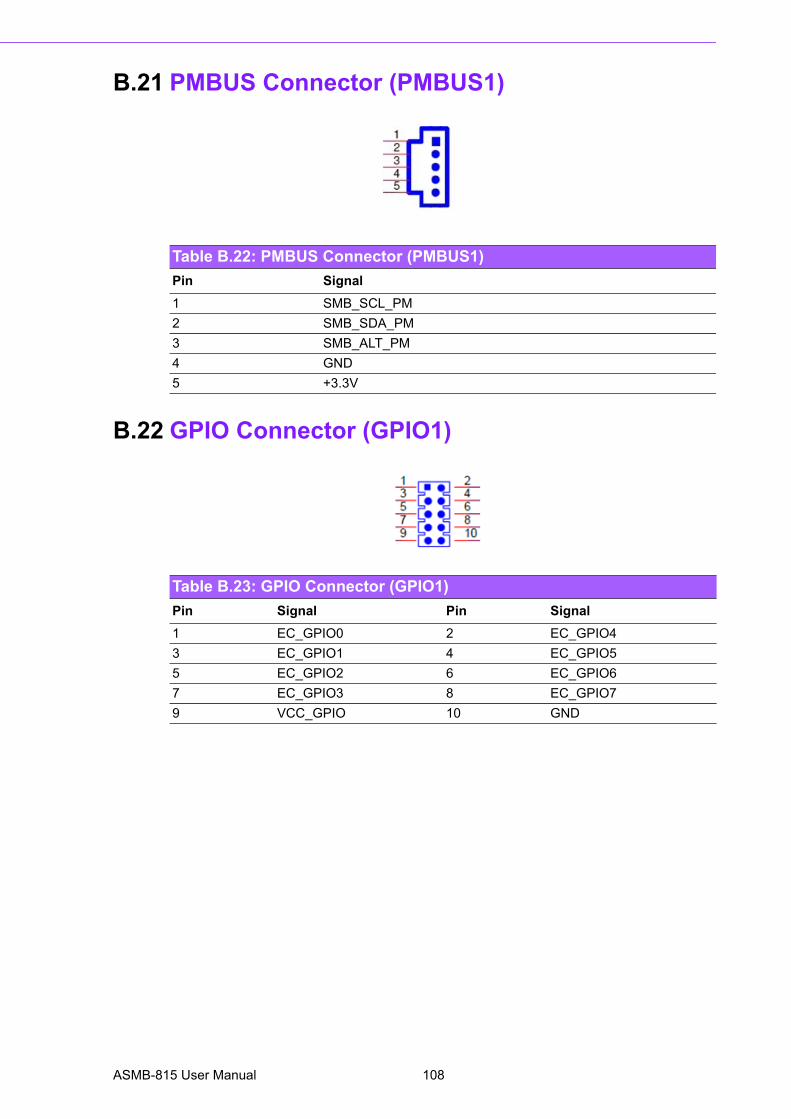
B.21 PMBUS Connector (PMBUS1)
B.22 GPIO Connector (GPIO1)
Table B.22: PMBUS Connector (PMBUS1)
Pin Signal
1 SMB_SCL_PM
2 SMB_SDA_PM
3 SMB_ALT_PM
4 GND
5 +3.3V
Table B.23: GPIO Connector (GPIO1)
Pin Signal Pin Signal
1 EC_GPIO0 2 EC_GPIO4
3 EC_GPIO1 4 EC_GPIO5
5 EC_GPIO2 6 EC_GPIO6
7 EC_GPIO3 8 EC_GPIO7
9 VCC_GPIO 10 GND
ASMB-815 User Manual 108

Appendix B
I/O P
inA
ssignments
109 ASMB-815 User Manual

www.advantech.comPlease verify specifications before quoting. This guide is intended for referencepurposes only.All product specifications are subject to change without notice.No part of this publication may be reproduced in any form or by any means,electronic, photocopying, recording or otherwise, without prior written permis-sion of the publisher.All brand and product names are trademarks or registered trademarks of theirrespective companies.© Advantech Co., Ltd. 2017