User Manual ADAM 4000 Series - Advantechadvdownload.advantech.com/productfile/Downloadfile2/1...v...
390
User Manual ADAM 4000 Series Data Acquisition Modules
Transcript of User Manual ADAM 4000 Series - Advantechadvdownload.advantech.com/productfile/Downloadfile2/1...v...

User Manual
ADAM 4000 Series
Data Acquisition Modules

CopyrightThe documentation and the software included with this product are copyrighted 2013by Advantech Co., Ltd. All rights are reserved. Advantech Co., Ltd. reserves the rightto make improvements in the products described in this manual at any time withoutnotice. No part of this manual may be reproduced, copied, translated or transmittedin any form or by any means without the prior written permission of Advantech Co.,Ltd. Information provided in this manual is intended to be accurate and reliable. How-ever, Advantech Co., Ltd. assumes no responsibility for its use, nor for any infringe-ments of the rights of third parties, which may result from its use.
AcknowledgementsADAM is a trademark of Advantech Co., Ltd.
IBM and PC are trademarks of International Business Machines Corporation.
All other product names or trademarks are properties of their respective owners.
Product Warranty (2 years)Advantech warrants to you, the original purchaser, that each of its products will befree from defects in materials and workmanship for two years from the date of pur-chase.
This warranty does not apply to any products which have been repaired or altered bypersons other than repair personnel authorized by Advantech, or which have beensubject to misuse, abuse, accident or improper installation. Advantech assumes noliability under the terms of this warranty as a consequence of such events.
Because of Advantech’s high quality-control standards and rigorous testing, most ofour customers never need to use our repair service. If an Advantech product is defec-tive, it will be repaired or replaced at no charge during the warranty period. For out-of-warranty repairs, you will be billed according to the cost of replacement materials,service time and freight. Please consult your dealer for more details.
If you think you have a defective product, follow these steps:
1. Collect all the information about the problem encountered. (For example, CPU speed, Advantech products used, other hardware and software used, etc.) Note anything abnormal and list any onscreen messages you get when the problem occurs.
2. Call your dealer and describe the problem. Please have your manual, product, and any helpful information readily available.
3. If your product is diagnosed as defective, obtain an RMA (return merchandize authorization) number from your dealer. This allows us to process your return more quickly.
4. Carefully pack the defective product, a fully-completed Repair and Replacement Order Card and a photocopy proof of purchase date (such as your sales receipt) in a shippable container. A product returned without proof of the purchase date is not eligible for warranty service.
5. Write the RMA number visibly on the outside of the package and ship it prepaid to your dealer.
Part No. XXXXXXXXXX Edition 1
Printed in Taiwan November 2015
ADAM-4000 Series User Manual ii

Declaration of Conformity
CE
The ADAM-4000 series developed by Advantech Co., Ltd. has passed the CE test forenvironmental specifications when operated within an industrial enclosure (ADAM-4950-ENC). Therefore, in order to protect the ADAM modules from being damagedby ESD (Electric Static Discharge), we strongly recommend that the use of CE-com-pliant industrial enclosure products when using any ADAM module.
Technical Support and Assistance1. Visit the Advantech web site at www.advantech.com/support where you can find
the latest information about the product.2. Contact your distributor, sales representative, or Advantech's customer service
center for technical support if you need additional assistance. Please have the following information ready before you call:– Product name and serial number– Description of your peripheral attachments– Description of your software (operating system, version, application software,
etc.)– A complete description of the problem– The exact wording of any error messages
iii ADAM-4000 Series User Manual

ADAM-4000 Series User Manual iv

Contents
Chapter 1 Introduction..........................................11.1 Overview ................................................................................................... 21.2 Applications............................................................................................... 3
Chapter 2 Installation Guideline ..........................52.1 System Requirements to Set up an ADAM Network................................. 6
Figure 2.1 Power Supply Connections ........................................ 72.2 Basic Configuration and Hook-up ............................................................. 9
Figure 2.2 Basic Hook-up of ADAM Module to Host Switches .... 92.3 Baud Rate and Checksum ...................................................................... 11
Figure 2.3 Grounding the INIT* Terminal................................... 12Figure 2.4 Set INIT switch to “Init” ............................................. 12
2.4 Multiple Module Hookup.......................................................................... 13Figure 2.5 Multi-module Connection.......................................... 13
2.5 Programming Example............................................................................ 14
Chapter 3 I/O Modules ........................................213.1 The Common Specification of ADAM-4000 I/O Series ........................... 223.2 ADAM-4011/4011D Thermocouple Input Modules ................................. 22
3.2.1 ADAM-4011D Thermocouple Input Module ................................ 25Figure 3.1 ADAM-4011 Thermocouple Input Module ................ 25
3.2.2 ADAM-4011D Thermocouple Input Module ................................ 26Figure 3.2 ADAM-4011D Thermocouple Input Module with LED
Display...................................................................... 263.2.3 Application Wiring ....................................................................... 27
Figure 3.3 ADAM-4011/4011D Thermocouple Input Wiring Dia-gram ......................................................................... 27
Figure 3.4 ADAM-4011/4011D Millivolt and Volt Input Wiring Dia-gram ......................................................................... 27
Figure 3.5 ADAM-4011/4011D Process Current Input Wiring Dia-gram ......................................................................... 27
Figure 3.6 ADAM-4011/4011D Digital Output Wiring Diagram Used with SSR (HI-LO alarm) .................................. 28
Figure 3.7 ADAM-4011/4011D Digital Input Wiring Diagram Used with TTL.................................................................... 28
Figure 3.8 ADAM-4011/4011D Digital Input Wiring Diagram Used with Dry contact ........................................................ 28
3.3 ADAM-4012 Analog Input Module........................................................... 293.3.1 ADAM-4012 Analog Input Module .............................................. 30
Figure 3.9 ADAM-4012 Analog Input Module ............................ 303.3.2 Application Wiring ....................................................................... 31
Figure 3.10ADAM-4012 Millivolt and Volt Input Wiring Diagram 31Figure 3.11ADAM-4012 Process Current Input Wiring Diagram 31Figure 3.12ADAM-4012 Digital Output Wiring Diagram Used with
SSR (HI-LO alarm) ................................................... 31Figure 3.13ADAM-4012 Digital Input Wiring Diagram Used with
TTL ........................................................................... 32Figure 3.14ADAM-4012 Digital Input Wiring Diagram Used with
Dry contact ............................................................... 323.4 ADAM-4013 RTD Module ....................................................................... 33
Figure 3.15ADAM-4013 RTD Input Module................................ 33
v ADAM-4000 Series User Manual

3.4.1 Application Wiring ....................................................................... 34Figure 3.16ADAM-4013 RTD Inputs Wiring Diagram................. 34
3.5 ADAM-4015 6-channel RTD Input Module ............................................. 35Figure 3.17ADAM-4015 6-channel RTD Input Module............... 35
3.5.1 Application Wiring ....................................................................... 36Figure 3.18ADAM-4015 RTD Input Module Wiring Diagram...... 36
3.5.2 Technical specification of ADAM-4015 ....................................... 37Table 3.1: Technical Specification of ADAM-4015 .................... 37
3.6 ADAM-4015T 6-channel Thermistor Input Module ................................. 38Figure 3.19ADAM-4015T 6-channel Thermistor Input Module... 38
3.6.1 Application Wiring ....................................................................... 38Figure 3.20ADAM-4015T Thermistor Input Module Wiring Diagram
383.6.2 Technical Specification of ADAM-4015T .................................... 39
Table 3.2: Technical Specification of ADAM-4015T.................. 393.7 ADAM-4016 Analog Input/Output Module............................................... 40
Figure 3.21ADAM-4016 Analog Input/Output Module ................ 413.7.1 Application Wiring ....................................................................... 42
Figure 3.22ADAM-4016 Strain Gauge Voltage Input Wiring Dia-gram ......................................................................... 42
Figure 3.23ADAM-4016 Strain Gauge Current Input Wiring Dia-gram ......................................................................... 42
Figure 3.24ADAM-4016 Digital Output Wiring Diagram Used with SSR .......................................................................... 42
3.8 ADAM-4017/4017+/4018/4018M/4018+ 8-channel Analog Input Modules.433.8.1 ADAM-4017/4018 8-channel Analog Input Module .................... 433.8.2 ADAM-4018M 8-channel Analog Input Data logger.................... 433.8.3 ADAM-4017+ 8-channel Differential Analog Input Module ......... 433.8.4 ADAM-4018+ 8-channel Thermocouple Input Module ............... 443.8.5 ADAM-4017 8-channel Analog Input Module ............................. 44
Figure 3.25ADAM-4017 8-channel Analog Input Module ........... 443.8.6 ADAM-4017+ 8-channel Differential Analog Input Module ......... 45
Figure 3.26ADAM-4017+ 8-ch. differential analog input module 45Table 3.3: Technical Specification of ADAM-4017+.................. 46
3.8.7 ADAM-4018 8-channel Analog Input Module ............................. 46Figure 3.27ADAM-4018 8-channel Thermocouple Input Module 46
3.8.8 ADAM-4018M 8-channel Analog Input Data logger.................... 47Figure 3.28ADAM-4018M 8-channel Analog Input Data Logger 47
3.8.9 ADAM-4018+ 8-channel Thermocouple Input Module ............... 48Figure 3.29ADAM-4018+ 8-ch. thermocouple input module ...... 48Table 3.4: Technical specification of ADAM-4018+................... 49
3.8.10 Application Wiring ....................................................................... 49Figure 3.30Current Input Wiring Diagram of ADAM-4017 .......... 49Figure 3.31ADAM-4017 Differential Input Wiring Diagram (Ch0 ~
Ch5).......................................................................... 49Figure 3.32ADAM-4017 Single-ended Input Wiring Diagram (Ch6
and Ch7)................................................................... 50Figure 3.33ADAM-4017+ Voltage and Current Input Wiring Dia-
gram ......................................................................... 50Figure 3.34ADAM-4018+ Thermocouple Input Wiring Diagram. 51
3.9 ADAM-4019+ 8-channel Universal Analog Input Module........................ 51Figure 3.35ADAM-4019+ 8-channel Universal Analog Input...... 51
3.9.1 Application Wiring ....................................................................... 52Figure 3.36ADAM-4019+ Universal Analog Input Wiring Diagram.
523.9.2 Technical Specification of ADAM-4019+ .................................... 53
Table 3.5: Technical Specification of ADAM-4019+.................. 533.10 ADAM-4021 Analog Output Module........................................................ 53
Figure 3.37ADAM -4021 Analog Output Module ........................ 54
ADAM-4000 Series User Manual vi

3.10.1 Application Wiring ....................................................................... 55Figure 3.38ADAM-4021 Analog Output Wiring Diagram ............ 55
3.11 ADAM-4024 4-channel Analog Output Module ....................................... 55Figure 3.39ADAM-4024 4-channel Analog Output Module ........ 55
3.11.1 Technical specification of ADAM-4024 ....................................... 563.11.2 Application Wiring ....................................................................... 56
Figure 3.40ADAM-4024 Pin Define and Wiring Diagram............ 573.12 ADAM-4050 Digital I/O Module ............................................................... 57
Figure 3.41ADAM-4050 Digital I/O Module ................................ 583.12.1 Application Wiring ....................................................................... 59
Figure 3.42ADAM-4050 TTL Input Wiring Diagram.................... 59Figure 3.43ADAM-4050 Contact Closure Input Wiring Diagram 59Figure 3.44ADAM-4050 Digital Output Wiring Diagram Used with
SSR .......................................................................... 593.13 ADAM-4051 16-channel Isolated Digital Input Module ........................... 60
Figure 3.45ADAM-4051 16-channel Isolated Digital Input Module.60
3.13.1 Application Wiring ....................................................................... 61Figure 3.46ADAM-4051 Dry Contact Wiring Diagram ................ 61Figure 3.47ADAM-4051 Wet Contact Wiring Diagram ............... 61
3.14 ADAM-4052 Isolated Digital Input Module .............................................. 62Figure 3.48ADAM-4052 Isolated Digital Input Module................ 62
3.14.1 Application Wiring ....................................................................... 63Figure 3.49ADAM-4052 Isolation Digital Input Wiring Ground ... 63
3.15 ADAM-4053 16-channel Digital Input Module ......................................... 63Figure 3.50ADAM-4053 16-channel Digital Input Module .......... 63
3.15.1 Application Wiring ....................................................................... 65Figure 3.51ADAM-4053 Wet Contact Input Wiring Diagram ...... 65Figure 3.52ADAM-4053 Contact Closure Input Wiring Diagram 65
3.16 ADAM-4055 16-channel Isolated Digital I/O Module............................... 66Figure 3.53ADAM-4055 16-channel Digital I/O Module.............. 66
3.16.1 Application Wiring: ...................................................................... 67Figure 3.54ADAM-4055 Digital Output Wiring Diagram ............. 67Figure 3.55ADAM-4055 Digital Input Dry Contact Wiring Diagram
67Figure 3.56ADAM-4055 Digital Input Dry Contact Diagram (Inter-
nal)............................................................................ 68Figure 3.57ADAM-4055 Digital Input Wet Contact Wiring Diagram
68Figure 3.58ADAM-4055 Digital Input Wet Contact Diagram (Inter-
nal)............................................................................ 69Figure 3.59ADAM-4055 Default Jumper Setting for the Digital Input
Wiring ....................................................................... 69Figure 3.60ADAM-4055 Default Jumper Setting for the Digital Input
Wiring ....................................................................... 703.17 ADAM-4056S 12-channel Sink Type Isolated Digital Output Module ..... 71
Figure 3.61ADAM-4056S 12-channel Sink Type Isolated Digital Output Module .......................................................... 71
3.17.1 Technical Specification of ADAM-4056S .................................... 713.17.2 Application Wiring ....................................................................... 72
Figure 3.62ADAM-4056S Digital Output Wiring Diagram ........... 723.18 ADAM-4056SO 12-channel Source Type Isolated Digital Output Module ..
72Figure 3.63ADAM-4056SO 12-channel Source Type Isolated Digi-
tal Output Module ..................................................... 733.18.1 Technical Specification of ADAM-4056SO ................................. 733.18.2 Application Wiring ....................................................................... 74
Figure 3.64ADAM-4056SO Digital Output Wiring Diagram ........ 743.19 ADAM-4060/4068 Relay Output Module................................................. 74
3.19.1 ADAM-4060 4-channel Relay Output Module............................. 75
vii ADAM-4000 Series User Manual

Figure 3.65ADAM-4060 4-channel Relay Output Module .......... 753.19.2 ADAM-4068 8-channel Relay Output Module............................. 76
Figure 3.66ADAM-4068 8-channel Relay Output Module .......... 763.19.3 Application Wiring ....................................................................... 77
Figure 3.67ADAM-4060 Form A Relay Output Wiring Diagram . 77Figure 3.68ADAM-4060 Form C Relay Output Wiring Diagram . 77Figure 3.69ADAM-4068 Form C Relay Output Wiring Diagram . 77Figure 3.70ADAM-4068 Form A relay output Wiring Diagram ... 78
3.20 ADAM-4069 8-channel Relay Output Module......................................... 78Figure 3.71ADAM-4069 Relay Output Module ........................... 78
3.20.1 Specification ............................................................................... 793.20.2 Wiring.......................................................................................... 79
Figure 3.72ADAM-4069 Form C Relay Output........................... 79Figure 3.73ADAM-4069 Form A Relay Output ........................... 79
3.21 ADAM-4080/4080D Counter/Frequency Input Modules ......................... 803.21.1 ADAM-4080 Counter/Frequency Input Modules......................... 81
Figure 3.74ADAM-4080 Counter/Frequency Input Module ........ 813.21.2 ADAM-4080D Counter/Frequency Input Modules with LED Display
82Figure 3.75ADAM-4080D Counter/Frequency Input Module with
LED Display.............................................................. 823.21.3 Application Wiring ....................................................................... 83
Figure 3.76ADAM-4080/4080D Non-isolated Input .................... 83Figure 3.77ADAM-4080/4080D Photo-isolated Input ................. 83
Chapter 4 Command Set.................................... 854.1 Introduction ............................................................................................. 864.2 Syntax ..................................................................................................... 864.3 I/O Module Commands Search Table..................................................... 87
Table 4.1: ADAM-4011 Command Table .................................. 87Table 4.2: ADAM-4011D Command Table................................ 88Table 4.3: ADAM-4012 Command Table .................................. 89Table 4.4: ADAM-4013 Command Table .................................. 90Table 4.5: ADAM-4015/ADAM-4015T Command Table ........... 90Table 4.6: ADAM-4016 Command Table .................................. 91Table 4.7: ADAM-4017 Command Table .................................. 93Table 4.8: ADAM-4017+ Command Table ................................ 93Table 4.9: ADAM-4017+ Input range and external calibrating input
source for each input type ........................................ 94Table 4.10:ADAM-4018 Command Table .................................. 95Table 4.11:ADAM-4018+ Command Table ................................ 96Table 4.12:ADAM-4018+ Input range and external calibrating input
source for each input type ........................................ 97Table 4.13:ADAM-4018M Command Table ............................... 97Table 4.14:ADAM-4019+ Command Table ................................ 99Table 4.15:ADAM-4021 Command Table ................................ 100Table 4.16:ADAM-4024 Command Table ................................ 101Table 4.17:ADAM-4050 Command Table ................................ 102Table 4.18:ADAM-4051 Command Table ................................ 103Table 4.19:ADAM-4052 Command Table ................................ 104Table 4.20:ADAM-4053 Command Table ................................ 104Table 4.21:ADAM-4055 Command Table ................................ 105Table 4.22:ADAM-4056S Command Table.............................. 106Table 4.23:ADAM-4056SO Command Table ........................... 107Table 4.24:ADAM-4060/4068 Command Table ....................... 108Table 4.25:ADAM-4069 Command Table ................................ 109Table 4.26:ADAM-4080 Command Table ................................ 109Table 4.27:ADAM-4080D Command Table.............................. 111
ADAM-4000 Series User Manual viii

Chapter 5 Analog Input Module Command Set ...............................................................115
5.1 Analog Input Common Command Set .................................................. 1165.1.1 %AANNTTCCFF....................................................................... 117
Figure 5.1 Data format for FF (8-bit parameter) ...................... 118Table 5.1: Input Range Codes (Type Codes).......................... 119Table 5.2: ADAM-4015/4015T command codes against Input
ranges table............................................................ 120Table 5.3: Baud Rate Codes ................................................... 121
5.1.2 $AA2 ......................................................................................... 1215.1.3 $AAF......................................................................................... 1225.1.4 $AAM ........................................................................................ 1235.1.5 #AA ........................................................................................... 1245.1.6 #AAN......................................................................................... 1265.1.7 $AA5VV .................................................................................... 1275.1.8 $AA6 ......................................................................................... 1285.1.9 $AA0 ......................................................................................... 1295.1.10 $AA1 ......................................................................................... 1305.1.11 #** ............................................................................................. 1315.1.12 $AA4 ......................................................................................... 1315.1.13 $AAB......................................................................................... 1335.1.14 $AA3 ......................................................................................... 1345.1.15 $AA9SNNNN ............................................................................ 1355.1.16 $AA0Ci...................................................................................... 1365.1.17 $AA1Ci...................................................................................... 1375.1.18 $AA7CiRrr................................................................................. 1385.1.19 $AA8Ci...................................................................................... 1395.1.20 $AAXnnnn................................................................................. 1405.1.21 $AAY......................................................................................... 1415.1.22 $AAS0....................................................................................... 1425.1.23 $AAS1....................................................................................... 142
5.2 Analog Input Data Logger Command Set ............................................. 1435.2.1 @AACCCSDMTTTT................................................................. 1435.2.2 @AAD....................................................................................... 1455.2.3 @AAD....................................................................................... 1465.2.4 @AASO .................................................................................... 1475.2.5 @AAT ....................................................................................... 1485.2.6 @AAL ....................................................................................... 1495.2.7 @AAN....................................................................................... 1505.2.8 @AARNNNN............................................................................. 1515.2.9 @AAACSDHHHHTEIIII............................................................. 1525.2.10 @AABC .................................................................................... 153
5.3 Digital I/O, Alarm and Event Command Set.......................................... 1545.3.1 @AADI...................................................................................... 1555.3.2 @AADO .................................................................................... 1575.3.3 @AAEAT .................................................................................. 1585.3.4 @AAHI...................................................................................... 1595.3.5 @AALO..................................................................................... 1605.3.6 @AADA .................................................................................... 1615.3.7 @AACA .................................................................................... 1625.3.8 @AARH .................................................................................... 1635.3.9 @AARL..................................................................................... 1645.3.10 @AARE .................................................................................... 1655.3.11 @AACE .................................................................................... 166
5.4 Excitation Voltage Output Command Set.............................................. 1665.4.1 $AA6 ......................................................................................... 1675.4.2 $AA7 ......................................................................................... 1685.4.3 $AAS......................................................................................... 169
ix ADAM-4000 Series User Manual

5.4.4 $AAE......................................................................................... 1705.4.5 $AAA......................................................................................... 1715.4.6 $AAB......................................................................................... 172
Chapter 6 Analog Output Module Command Set.......................................................... 173
6.1 Analog Output Module Command for ADAM-4021............................... 1746.1.1 %AANNTTCCFF....................................................................... 175
Figure 6.1 Data format for FF (8-bit parameter) ...................... 175Table 6.1: Baud Rate Codes ................................................... 176Table 6.2: Output Range Codes (Type Codes)....................... 176
6.1.2 #AA........................................................................................... 1776.1.3 $AA4......................................................................................... 1786.1.4 $AA3......................................................................................... 1796.1.5 $AA0......................................................................................... 1806.1.6 $AA2......................................................................................... 1816.1.7 $AA6......................................................................................... 1826.1.8 $AA8......................................................................................... 1836.1.9 $AA5......................................................................................... 1846.1.10 $AAF......................................................................................... 1856.1.11 $AAM........................................................................................ 186
6.2 Analog Output Module Command for ADAM-4024............................... 187Table 6.3: ADAM-4024 Command Review: ............................ 187
Chapter 7 Digital I/O, Relay ouput and Counter/Frequency Command Set............... 191
7.1 Digital I/O and Relay Output Module Command................................... 1927.1.1 %AANNTTCCFF....................................................................... 194
Figure 7.1 Data format for FF (8-bit parameter) ...................... 194Table 7.1: Baud Rate Codes ................................................... 195
7.1.2 $AA6......................................................................................... 1967.1.3 #AABB ...................................................................................... 1987.1.4 #** ............................................................................................. 2007.1.5 $AA4......................................................................................... 2007.1.6 $AA2......................................................................................... 202
Table 7.2: Baud Rate Codes ................................................... 203Figure 7.2 Data format for FF (8-bit parameter) ...................... 203
7.1.7 $AA5......................................................................................... 2047.1.8 $AAF......................................................................................... 2057.1.9 $AAM........................................................................................ 2067.1.10 $AAX0TTTTDD......................................................................... 2077.1.11 $AAX1....................................................................................... 2087.1.12 $AAX2....................................................................................... 2097.1.13 $AAE0....................................................................................... 2097.1.14 $AAP......................................................................................... 2107.1.15 AAS........................................................................................... 2117.1.16 $AAXnnnn................................................................................. 2127.1.17 $AAY......................................................................................... 213
7.2 Counter/Frequency Module Command................................................. 2147.2.1 Configuration, Counter Input and Display Command Set......... 214
Figure 7.3 Data format for FF (8-bit parameter) ...................... 215Table 7.3: Baud Rate Codes ................................................... 216
7.2.2 Counter Setup Command Set................................................... 2257.2.3 Digital Filter and Programmable Threshold Command Set ...... 2347.2.4 Digital Output and Alarm Command Set................................... 245
ADAM-4000 Series User Manual x

Chapter 8 Calibration........................................2638.1 Analog Input Module Calibration ........................................................... 264
Figure 8.1 Applying Calibration Voltage .................................. 264Figure 8.2 Zero Calibration ...................................................... 265Figure 8.3 Span Calibration ..................................................... 265Figure 8.4 Cold Junction Calibration........................................ 266
8.2 Analog Input Resistance Calibration ..................................................... 266Figure 8.5 Applying calibration resistance ............................... 267Table 8.1: Calibration Resistance............................................ 268
8.3 Analog Input Thermistor module Calibration......................................... 2688.4 Analog Output Calibration ..................................................................... 275
Figure 8.6 Setup for Analog Output Calibration....................... 275Figure 8.7 Setup for Voltage Output Calibration...................... 276Figure 8.8 Zero Calibration ...................................................... 276Figure 8.9 Span Calibration ..................................................... 277
Appendix A Technical Specifications.................279A.1 ADAM-4011 Thermocouple Input Module............................................. 280
Table A.1: ADAM-4011 Specifications..................................... 280Table A.2: ADAM-4011 Range Accuracy for Thermocouple ... 280Figure A.1 ADAM-4011 Function Diagram............................... 281
A.2 ADAM-4011D Thermocouple Input Module with LED Display .............. 282Table A.3: ADAM-4011D Specifications .................................. 282Table A.4: ADAM-4011D Range Accuracy for Thermocouple. 283Figure A.2 ADAM-4011D Function Diagram............................ 284
A.3 ADAM-4012 Analog Input Module......................................................... 285Table A.5: ADAM-4012 Specifications..................................... 285Figure A.3 ADAM-4012 Function Diagram............................... 286
A.4 ADAM-4013 RTD Input Module ............................................................ 287Table A.6: ADAM-4013 Specifications..................................... 287Figure A.4 ADAM-4013 Function Diagram............................... 288
A.5 ADAM-4016 Analog Input/Output Module............................................. 289Table A.7: ADAM-4016 Specifications..................................... 289Figure A.5 ADAM-4016 Function Diagram............................... 290
A.6 ADAM-4017/4017+ 8-channel Analog Input Module............................. 291Table A.8: ADAM-4017/4017+ Specifications.......................... 291Figure A.6 ADAM-4017/4017+ Function Diagram.................... 292
A.7 ADAM-4018/4018+ 8-channel Analog Input Module............................. 293Table A.9: ADAM-4018/4018+ Specifications.......................... 293Table A.10:ADAM-4018/4018+ Range Accuracy for Thermocouple
294Figure A.7 ADAM-4018/4018+ Function Diagram.................... 295
A.8 ADAM-4018M 8-channel Analog Input Data Logger............................. 296Table A.11:ADAM-4018M Specifications.................................. 296Table A.12:ADAM-4018M Range Accuracy for Thermocouple 297Figure A.8 ADAM-4018M Function Diagram............................ 298
A.9 ADAM-4019+ 8-channel Universal Analog Input Module...................... 299Table A.13:ADAM-4019+ Specifications................................... 299Figure A.9 ADAM-4019+ Function Diagram............................. 300
A.10 ADAM-4021/4024 Analog Output Module............................................. 301Table A.14:ADAM-4021/4024 Specifications............................ 301Figure A.10ADAM-4021 Function Diagram .............................. 302Figure A.11ADAM-4024 Function Diagram .............................. 303
A.11 ADAM-4050 Digital I/O Module ............................................................. 304Table A.15:ADAM-4050 Specifications..................................... 304Figure A.12ADAM-4050 Function Diagram .............................. 304
A.12 ADAM-4051/4052 Isolated Digital Input Module ................................... 305
xi ADAM-4000 Series User Manual

Table A.16:ADAM-4051/4502 Specifications............................ 305Figure A.13ADAM-4051/4052 Function Diagram ..................... 306
A.13 ADAM-4053 16-channel Digital Input Module....................................... 307Table A.17:ADAM-4053 Specifications..................................... 307Figure A.14ADAM-4053 Function Diagram .............................. 308
A.14 ADAM-4055 Isolated Digital Input/Output Module ................................ 309Table A.18:ADAM-4055 Isolated Digital Input/Output Module.. 309Figure A.15ADAM-4055 Function Diagram .............................. 310
A.15 ADAM-4056S 12-channel Sink Type Isolated Digital Output Module ... 311Table A.19:ADAM-4056S Specifications .................................. 311Figure A.16ADAM-4056S Function Diagram............................ 312
A.16 ADAM-4056SO 12-channel Source Type Isolated Digital Output Module..313
Table A.20:ADAM-4056SO Specifications ............................... 313Figure A.17ADAM-4056SO Function Diagram......................... 314
A.17 ADAM-4060 Relay Output Module........................................................ 315Table A.21:ADAM-4060 Specifications..................................... 315Figure A.18ADAM-4060 Function Diagram .............................. 316
A.18 ADAM-4068/4069 8-channel Relay Output Module.............................. 317Table A.22:ADAM-4068/4069 Specifications............................ 317Figure A.19ADAM-4068/4069 Function Diagram ..................... 317
A.19 ADAM-4080 Counter/Frequency Input Module..................................... 318Table A.23:ADAM-4080 Specifications..................................... 318Figure A.20ADAM-4080 Function Diagram .............................. 319
A.20 ADAM-4080D Counter/Frequency Input Module with LED Display ...... 320Table A.24:ADAM-4080D Specifications .................................. 320Figure A.21ADAM-4080D Function Diagram............................ 321
Appendix B Data Formats and I/O Ranges........ 323B.1 Analog Input Formats............................................................................ 324
B.1.1 Engineering Units ..................................................................... 324B.1.2 Percent of FSR ......................................................................... 325B.1.3 Twos complement hexadecimal ............................................... 326B.1.4 Ohms ........................................................................................ 327
B.2 Analog Input Ranges ............................................................................ 328B.3 Analog Output Formats......................................................................... 332
B.3.1 Engineering Units ..................................................................... 332B.3.2 Percent of Span ........................................................................ 332B.3.3 Hexadecimal ............................................................................. 332
B.4 Analog Output Ranges.......................................................................... 333
Appendix C Technical Diagrams ........................ 335C.1 ADAM Dimensions................................................................................ 336
Figure C.1 ADAM Modules Dimensions................................... 336C.2 Installation............................................................................................. 337
C.2.1 DIN-Rail Mounting .................................................................... 337Figure C.2 DIN-Rail Adapter .................................................... 337Figure C.3 DIN-Rail Mounting .................................................. 338
C.2.2 Panel Mounting......................................................................... 339Figure C.4 Panel Mounting Bracket Dimensions ..................... 339Figure C.5 Panel Mounting ...................................................... 339
C.2.3 Piggyback Stack ....................................................................... 340Figure C.6 Piggyback Stack..................................................... 340
Appendix D Utility Software................................ 341
ADAM-4000 Series User Manual xii

D.1 ADAM-4000 Utility Software.................................................................. 342Figure D.1 Search screen ........................................................ 342Figure D.2 Configuration Screen.............................................. 343Figure D.3 Terminal Function................................................... 344Figure D.4 Terminal Function................................................... 345
D.2 The Procedure for ADAM-4000 Series Installation Guide..................... 346
Appendix E RS-485 Network ...............................349E.1 RS-485 Network.................................................................................... 350E.2 Basic Network Layout ........................................................................... 350
Figure E.1 Daisychaining ......................................................... 351Figure E.2 Star Structure ......................................................... 351Figure E.3 Random Structure .................................................. 351
E.3 Line Termination ................................................................................... 352Figure E.4 Signal Distortion ..................................................... 352Figure E.5 Termination resistor locations................................. 352
E.4 RS-485 Data Flow Control .................................................................... 353Figure E.6 RS-485 data flow control with RTS......................... 353
Appendix F How to Use the Checksum Feature355F.1 Checksum Enable/Disable .................................................................... 356
Table F.1: Printable ASCII Characters .................................... 357
Appendix G ADAM-4000 I/O Modbus Mapping Table .................................................359
G.1 ADAM-4000 I/O Modbus Mapping Table .............................................. 360
Appendix H Changing Configuration to Modbus Protocol ............................................373
H.1 Changing Configuration to Modbus Protocol ........................................ 374
xiii ADAM-4000 Series User Manual

ADAM-4000 Series User Manual xiv

Chapter 1
1 Introduction
1.1 OverviewThe ADAM Series is a set of intelligent sensor-to-computer interface modules con-taining built-in microprocessor. They are remotely controlled through a simple set ofcommands issued in ASCII format and transmitted in RS-485 protocol. They providesignal conditioning, isolation, ranging, A/D and D/A conversion, data comparison,and digital communication functions. Some modules provide digital I/O lines for con-trolling relays and TTL devices.
Software Configuration and Calibration
By merely issuing a command from the host computer, you can change an analoginput module to accept several ranges of voltage input, thermocouple input or RTDinput. All of the module’s configuration parameters including I/O address, communi-cation speed, HI and LO alarm, calibration parameters settings may be set remotely.Remote configuration can be done by using either the provided menu-based soft-ware or the command set’s configuration and calibration commands.
By storing configuration and calibration parameters in a nonvolatile EEPROM, mod-ules are able to retain these parameters in case of power failure.
Watchdog Timer
A watchdog timer supervisory function will automatically reset the ADAM modules inthe event of system failure. Maintenance is thus simplified.
Power Requirements
Although the modules are designed for standard industrial unregulated 24 VDC powersupply, they accept any power unit that supplies power within the range of +10 to +30VDC. The power supply ripple must be limited to 5 V peak-to-peak, and the immediateripple voltage should be maintained between +10 and +30 VDC.
Connectivity and Programming
ADAM modules can connect to and communicate with all computers and terminals.They use RS-485 transmission standards, and communicate with ASCII format com-mands. The command set for every module type consists of approximately ten differ-ent commands.
The command set for input modules is larger because it incorporates alarm functions.All communications to and from the module are performed in ASCII, which meansthat ADAM modules can be virtually programmed in any high-level language.
RS-485 Network
The RS-485 network provides lower-noise sensor readings, as modules can beplaced much closer to the source. Up to 256 ADAM modules may be connected to anRS-485 multi-drop network by using the ADAM RS-485 repeater which extends themaximum communication distance up to 4,000 ft. The host computer is connected tothe RS-485 network with one of its COM ports through the ADAM-452x module (RS-232 to RS-422/485 converter).
To boost the network’s throughput, ADAM RS-485 repeater uses a logical RTS signalto manage the repeater’s direction. The only two wires that are needed for the RS-485 network, DATA+ and DATA-, are inexpensive shielded twisted pair.
ADAM-4000 Series User Manual 2

Chapter 1
Introduction
Panel/DIN Rail mounting
ADAM modules can be mounted on any panels, brackets, or DIN rails. They can alsobe stacked together.
The RS-485 network, together with screw-terminal plug connectors, allows for sys-tem expansion, reconfiguration, and repair without disturbing field wiring.
Protection against the environment
Since all the configurations are controlled by software, the protection provided by thepackaging is very important. The plastic outer shell enhances resistance against cor-rosive materials, moisture and vibrations. ADAM modules’ low power requirementshelp them to operate in temperatures from 0 to 70 ?, and in humidity from 0 to 95%(non-condensing). They are compactly built using automated SMT technology.Therefore, they can be implemented in water-tight and explosion-proof industrialenclosures.
1.2 Applications Remote data acquisition Process monitoring Industrial process control Energy management Supervisory control Security systems Laboratory automation Building automation Product testing Direct digital control
3 ADAM-4000 Series User Manual

ADAM-4000 Series User Manual 4

Chapter 2
2 Installation Guideline
This chapter provides guidelines to what is needed to set up and install an ADAMnetwork. A quick hookup scheme is provided that lets you configure modules beforethey are installed in a network. To help you connect ADAM modules with sensorinputs, several wiring examples are provided. At last, you will find a programmingexample using the ADAM command set at the end of this chapter.
Be sure to plan the layout and configuration of your network carefully before youstart. Guidelines regarding layout are given in Appendix E: RS-485 Network.
2.1 System Requirements to Set up an ADAM NetworkThe following list gives an overview of what is needed to setup,
install and configure an ADAM environment.
ADAM modules A host computer, such as an IBM PC/AT compatible, that can output ASCII char-
acters with a RS-232C or RS-485 port. Power supply for the ADAM modules (+10 to +30 VDC ) ADAM Series Utility software ADAM Isolated RS-232/RS-485 Converter (optional) RS-232/RS-485 ADAM Repeater (optional)
Host computer
Any computer or terminal that can output in ASCII format over either RS-232 or RS-485 can be connected as the host computer. When only RS-232 is available, anADAM RS-232/RS-485 Converter is required to transform the host signals to the cor-rect RS-485 protocol. The converter also provides opto-isolation and transformer-based isolation to protect your equipment.
Power supply
For the ease of use in industrial environments, the ADAM modules are designed toaccept industry standard +24 VDC, unregulated power.
Operation is guaranteed when using any power supply between +10 and +30 VDC.Power ripples must be limited to 5 V peak to peak while the voltage in all cases mustbe maintained between +10 and +30 VDC. All power supply specifications are refer-enced at module connector. When modules are powered remotely, the effects of DCvoltage drops must be considered.
All modules use on-board switching regulators to sustain good efficiency over the 10to 30 V input range; therefore, we can assume that the actual drawn current isinversely proportional to the DC voltage.
The following example shows how to calculate the required current that a power sup-ply should provide.
Assume that a +24 VDC is used for five ADAM-4011 Analog Input Modules, and thedistance between modules and power supply is not significant enough to cause a DCvoltage drop. One ADAM-4011 module consumes a maximum of 1.2 Watts (W). Thetotal required power will equal to 5 x 1.2=6 W. A power supply of +24 VDC shouldtherefore be able to supply a minimal current of 6 / 24=0.25 Amps.
Small systems may be powered by using wall-mounted modular power supplies.Also, when modules operate in long communication lines (>500 feet), it is often morereliable to obtain power locally through modular power supplies. These inexpensiveunits can be easily obtained from any electronic retail stores.
ADAM-4000 Series User Manual 6

Chapter 2
InstallationG
uideline
The power cables should be selected according to the length of the power lines andthe number of modules connected. When implementing a network with long cables,the use of thicker wire is more suitable due to the limitation of DC voltage drop. Fur-thermore, long wires can also cause interference with communication wires.
Figure 2.1 Power Supply Connections
We advise the following standard colors (as indicated on the modules) for eachpower line:
+Vs (R) Red
GND (B) Black
Communication Wiring
We recommend the use of shielded-twisted-pair cable in the ADAM network forreducing interference purpose, but the cable has to comply with the EIA RS-485standard. Furthermore, only one set of twistedpair cable is required for transmittingData. We advise the following standard colors (as indicated on the modules) for eachthe communication line:
DATA+ (Y) Yellow
DATA- (G) Green
ADAM Utility Software
A menu-driven utility program is provided for ADAM module configuration, monitoringand, calibration. It also includes a terminal emulation program that lets you communi-cate through the ADAM command set. (See Appendix D, Utility Software and onlinehelp)
Note! User can refer our help file to see more details for explanation of Utility operation.
7 ADAM-4000 Series User Manual

ADAM Communication Speed
In ADAM series, the baud rate can be configured from 1200 bps to 38.4 Kbps. How-ever, the baud rate of all modules in an RS-485 network must be the same.
ADAM Isolated RS-232/RS485 Converter (optional): ADAM-452x
When the host computer or terminal only has a RS-232 port, an ADAM Isolated RS-232/RS-485 Converter is required. Since this module is not addressable by the host,the baud rate must be reset using a switch inside the module. The factory default set-ting is 9600 baud.
ADAM Repeater (optional): ADAM-451x
When communication lines exceed 4000 ft (1200 meter) or more than 32 ADAMmodules are connected, a repeater should be implemented. In a network, up to eightRepeater modules can be connected allowing connection up to 255 ADAM modules.As with the Converter module, the Repeater module is not addressable by the hostand the baud rate must be reset by changing the switch inside the module. The fac-tory default setting is 9600 baud.
ADAM-4000 Series User Manual 8

Chapter 2
InstallationG
uideline
2.2 Basic Configuration and Hook-upBefore placing a module in an existing network, the module should be configured.Though all modules are initially configured at the factory, it is recommended to checkif the baud rate is set correctly beforehand.
Default Factory Settings
Baud rate: 9600 Bit/sec.
Address: 01 (hexadecimal)
The basic hook-up for module configuration is shown below.
Figure 2.2 Basic Hook-up of ADAM Module to Host Switches
9 ADAM-4000 Series User Manual

The following items are required to configure a module: an ADAM converter module,a personal computer with RS-232 port (baud rate set to 9600) and the ADAM utilitysoftware.
Configuration with the ADAM Utility Software
The easiest way to configure the ADAM module is by using the ADAM utility soft-ware. It is a user friendly structured menu program that will guide you through everystep of the configuration. (See Appendix D, Utility Software)
Changing the protocol from ADAM ASCII to Modbus
Some ADAM-4000 modules support both ADAM ASCII and Modbus protocols, andthe factory default setting of these modules is ADAM ASCII protocol. If you would liketo configure the modules to Modbus protocol, please refer to Appendix H whichdescribes how to change the protocol in ADAM utility.
Configuration with the ADAM command set
ADAM modules can also be configured by issuing direct commands through a termi-nal emulation program that is part of the ADAM utility software. The following exam-ple will guide you through the setup of an analog input module. Assume an ADAM-4011 Analog Input module still has its default settings (baud rate 9600 and address01h), and you are being requested to send its default settings before any reconfigura-tion is made.
Example:
Make sure that the module is properly connected and turn on all the connecteddevices. Then, start the terminal emulation program, and type in the following com-mand:
$012(cr)
The command above requests the module with address 01 to send its configurationstatus
!01050600
Module at address 01 responds that it is configured for an input range of +/-2.5 V,baud rate of 9600, integration time of 50 ms (60 Hz).
The code also shows engineering units and no checksum checking or generation.
To change the configuration setting of the analog input module, the following com-mand is issued:
%01070F0600(cr)
% = change configuration
01 = target module at address 00 to:
07 = change address to 07 hexadecimal
0F = set input range to Type K thermocouple
06 = set baud rate to 9600
00 = set integration time to 50 ms (60 Hz)
disable checksum
Note! An analog input module requires a maximum of 7 seconds to perform auto calibration and ranging after reboot or start up.
During this time span, the module can not be addressed to perform any other actions.
ADAM-4000 Series User Manual 10

Chapter 2
InstallationG
uideline
set data format to engineering units
(Please refer to Chapter 4, a full description of Command set syntax for an analoginput module)
When the module received the configuration command, it will respond with its newaddress as shown below:
!07(cr)
Before giving more commands to the module, please wait for 7 seconds to let thenew configuration settings to take effect.
2.3 Baud Rate and ChecksumADAM modules contain EEPROMs to store configuration information and calibrationconstants. The EEPROM replaces the conventional array of switches and pots thatare originally used for specifying baud rate, input and output range… etc.
Since there is no visual indication of a module’s configuration status, it is impossibleto know the baud rate, address and other settings just by looking at it. It might not bepossible to establish communications with a module whose baud rate and addressare unknown. To overcome this problem, most modules have an input terminallabeled INIT*. Booting the module while connecting the INIT* terminal with the mod-ule’s GND terminal forces the configuration into a known state called the INIT* state.Besides, some newer modules have INIT switch which you can set “Init” or “Normal”(See Figure 2.4). If you set the switch to “Init”, then it becomes INIT* state.
INIT* state defaults:
Baud rate: 9600
Address: 00h
Checksum: disabled
Forcing the module in INIT* state does not change any parameters in the module’sEEPROM. When the module is in the INIT* state with its INIT* and GND terminalsshorted, all configuration settings can be changed, and the module will respond to allother commands normally.
Changing Baud rate and Checksum
Baud rate and checksum settings have several things in common:
They should be the same for all modules and host computer. Their settings can only be changed by putting a module in the INIT* state. Changed settings can only take effect after a module is rebooted
Note! All reconfiguration except for changing baud rate and checksum values can be done dynamically, and the modules are not required to reset. However, all the connected devices are required to reset by turning power off and on after the baud rate or checksum values are changed. The baud rate or checksum values should be the same for all the con-nected devices after the reconfiguration. See the next page for a strat-egy in changing baud rate and checksum of the network.
11 ADAM-4000 Series User Manual

To alter baud rate or checksum settings, you must perform the following steps:
Power on all components except the ADAM Module. • Power the ADAM module on while shorting the INIT* and GND terminals (See
Figure 2.3) or set the INIT switch to “Init” (See Figure 2-4)
Figure 2.3 Grounding the INIT* Terminal
Figure 2.4 Set INIT switch to “Init”
Configure the checksum status and/or the baud rate. Switch the power OFF to the ADAM Module. Remove the grounding of the INIT* terminal and turn on the module, or set the
INIT switch to “Normal”. Check the settings (If the baud rate has changed, the settings on the host com-
puter should be changed accordingly).
ADAM-4000 Series User Manual 12

Chapter 2
InstallationG
uideline
2.4 Multiple Module HookupThe Figure below is an example of how ADAM modules are connected in a multiplemodule network:
Figure 2.5 Multi-module Connection
13 ADAM-4000 Series User Manual

2.5 Programming ExampleThe following example is a simple program written in Visual Basic 6.0 that demon-strates how to get temperature reading which is stored in the address of 01H fromADAM-4011 module.
1. Using ADAM Utility to check the settings as the following below:“Address = 01H”, “Baud rate = 9600” and “Checksum = Disabled”.
ADAM-4000 Series User Manual 14
Chapter 2
InstallationG
uideline
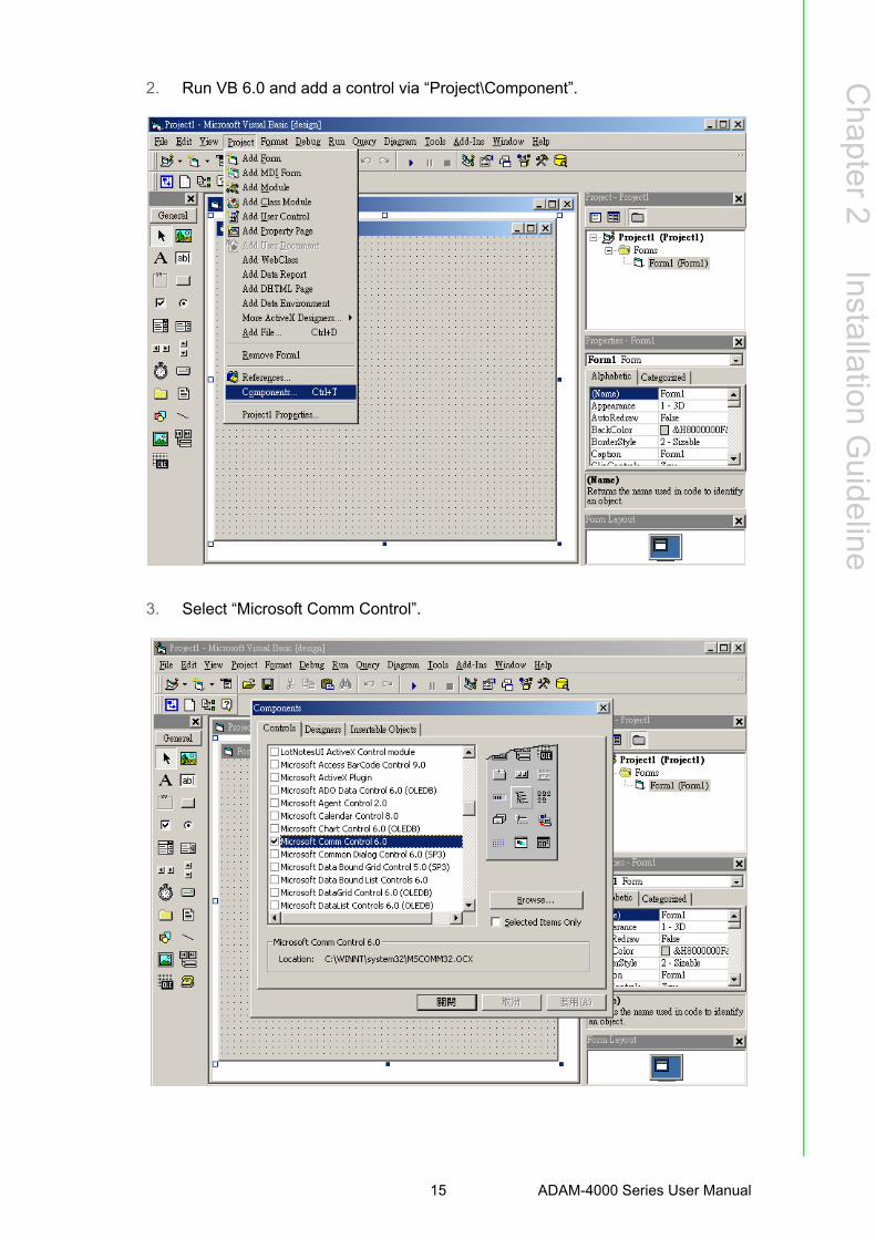
2. Run VB 6.0 and add a control via “Project\Component”.
3. Select “Microsoft Comm Control”.
15 ADAM-4000 Series User Manual

4. Add the Comm Control on the form.
5. Add three Command Buttons on the form as shown below.
ADAM-4000 Series User Manual 16

Chapter 2
InstallationG
uideline
6. Add one Label and one Text on the form as shown below.
7. Click OPEN Button and type in the following codes. The source codes are listed at the end of this section.
17 ADAM-4000 Series User Manual

8. Click SEND Button and type in the following codes. The source codes are listed at the end of this section.
9. Click CLOSE Button and type in the following codes. The source codes are listed at the end of this section.
ADAM-4000 Series User Manual 18

Chapter 2
InstallationG
uideline
10. Run the Project → Click OPEN to open COM1 → Click SEND to send the Get Temperature Reading Command. Now, you will find the reading the same as the displayed format shown below.
Program Source Codes:
OPEN Command Button:Private Sub Command1_Click()
' Buffer to hold input string
Dim Instring As String
' Use COM1.
MSComm1.CommPort = 1
' 9600 baud, no parity, 8 data, and 1 stop bit.
MSComm1.Settings = "9600,N,8,1"
' Tell the control to read entire buffer when Input ' is used.
MSComm1.InputLen = 0
' Open the port.
MSComm1.PortOpen = True
End Sub
19 ADAM-4000 Series User Manual

SEND Command Button:Private Sub Command2_Click()
' Send Get AI command to ADAM-4011 Module at address 01H.
MSComm1.Output = "#01" & Chr$(13)
' Wait for data to come back to the serial port.
Do
DoEvents
Buffer$ = Buffer$ & MSComm1.Input
Loop Until InStr(Buffer$, vbCr)
' Read the response till the carriage return character.
Text1.Text = Buffer$
' Display the reading.
End Sub
CLOSE Command ButtonPrivate Sub Command3_Click()
' Close the serial port.
MSComm1.PortOpen = False
End Sub
ADAM-4000 Series User Manual 20

Chapter 3
3 I/O Modules
3.1 The Common Specification of ADAM-4000 I/O SeriesCommunication:
RS-485 (2-wire) to host Speeds: 1200, 2400, 4800, 9600, 19200, 38400, 57600, 115200 bps (ADAM-
4080, ADAM-4080D only support up to 38400 bps) Max. communication distance: 4000 feet (1.2 km) Power and communication LED indicator ASCII command/response protocol Communication error checking with checksum Asynchronous data format: 1 start bit, 8 data bits, 1 stop bit, no parity (N, 8, 1) Up to 256 multidrop modules per serial port Online module insertion and removal Transient suppression on RS-485 communication lines
Power Requirement:
Unregulated +10 ~ +30 VDC Protected against power reversal
Mechanical:
Case: ABS+PC with captive mounting hardware Plug-in screw: Stripped length: 6.5 mm
Terminal block: #14 ~22 or #14~28 AWG
Environment
EMI: Meets FCC Class A or CE Operating Temperature: -10 ~ 70° C (14 ~ 158° F) Storage Temperature: -25 ~ 85° C (-13 ~ 185° F) Humidity: 5 ~ 95%, non-condensing
3.2 ADAM-4011/4011D Thermocouple Input ModulesThe ADAM-4011/4011D Thermocouple Input Modules use a microprocessor-con-trolled integrating A/D converter to convert sensor voltage, current or thermocouplesignal into digital data. The digital data is then translated into either two’s comple-ment hexadecimal format or percentage of full-scale range (FSR) according to themodule’s configuration. When prompted by the host computer, the data is sentthrough a standard RS-485 interface.
The ADAM-4011/4011D Thermocouple Input Modules offer signal conditioning, A/Dconversion, ranging, and RS-485 digital communication functions. They protect yourequipment from power surges at the ground terminal by providing opto-isolation ofthe A/D input and transformer based isolation up to 3000 VDC. (ADAM-4011 hastransformer-based isolation up to 500 VDC)
ADAM-4000 Series User Manual 22

Chapter 3
I/O M
odules
Open Thermocouple Detection and Input Surge Protection (ADAM-4011D only)
The ADAM-4011D provides an open thermocouple detection function. Users can usea simple command to detect whether the thermocouple is opened or closed. Themodule also provides surge protection on its input channel. Internal high-speed tran-sient suppressor on its input channel protects the module from dangerous spikes and
voltages.
Front Panel LED Indicator (ADAM-4011D only)
The 4½ digits LED display on the back of the ADAM-4011D lets you monitor the pro-cess readings right at their source. The module displays readings in a wide variety offormats as well as high-low alarm messages. The ADAM-4011D offers flexibility, easyinstallation, and direct availability of process data. For critical process monitoring, this
module is the ideal choice.
Digital Input/Output
The ADAM-4011/4011D Thermocouple Input Modules also contain two digital outputsand one digital input. Outputs are open-collector transistor switches that may be con-trolled by the host computer. They can control solid-state relays, which may be usedto control heaters, pumps, and other electrical powered equipment. The digital inputsmay be read by the host computer and used to sense the state of a remote digital sig-nal.
Event counting
The event counter is connected to the Digital Input channel and can be used to keeptrack of the total amount of external low-speed pulses. Its accumulated maximalcount is 65535. The count will maintain at 65535 even if the actual number of eventsexceeds 65535. The counter can be read or reset to zero by the host computer.
Since the Event counter’s data are not stored in EEPROM, the event counter iscleared and set to zero after every reset or start up of the analog input module.
Alarm signaling
Analog input modules include High and Low alarm functions. High and Low alarmlimits may be downloaded into the module’s EEPROM by the host computer.
The alarm functions can be enabled or disabled remotely. When the alarm function isenabled, both Digital Output channels are used to indicate the High and Low alarmstate. Digital Output channel 1 (DO1) equals to High alarm state, and Digital Outputchannel 0 (DO0) equals to Low alarm state. The High and Low alarm states can beread at any time by the host computer.
Every A/D conversion will be followed by a comparison with the High and Low limit.When the input value exceeds one of these limits, the High or Low alarm state is setto ON.
There are two alarm mode options, Momentary and Latching. If the alarm is in Latch-ing mode, the alarm will stay on even if the input value returns within the limits. Analarm in Latching mode can be turned OFF by giving a Clear Alarm command fromthe host computer. A Latching alarm is cleared by the module when the oppositealarm is set. When
the module receives a value that is lower than the Low alarm limit, it will clear theHigh alarm and turn the Low alarm ON.
When the alarm is in Momentary mode, the alarm will be turned OFF as soon as theinput value returns within the limits.
23 ADAM-4000 Series User Manual

The arrangement of coupling High and Low alarm states with Digital Output lines maybe utilized to build ON/OFF controllers that
can operate without the involvement of host computer.
Function Description for the ADAM-4011 Thermocouple Input Module
To provide a better understanding of the ADAM module functions, the following is adescription of the module ADAM-4011 with the most extensive set of functions.
All analog input data first flow through the PGA (programmable gain amplifier). Theamplifier can vary its gain from 1 to 128. The PGA then automatically adjusts the sig-nal to a range from -2.5 V to +2.5 V.
This ensures an optimal input voltage and resolution for the A/D converter.
The A/D conversion is supervised by the microprocessor that holds the calibrationsoftware. Two kinds of calibrations, Auto Zero and Auto Span calibrations, take placeautomatically in startup or reset. Normal calibration is used to adjust the signalaccording to calibration parameters defined by the user.
The digital 10 Hz filter provides a steady state output by using the ∆ unction.
Before the data enter the microprocessor, they pass through an optical isolationdevice which prevents the chance of circuit damaging caused by power surges fromthe ground terminal.
The microprocessor has six basic functions:
- Linearization of T/C (Thermocouple)
- Communication software and command set
- Calibration software
- Alarm monitoring
- Event counting
- Management of the EEPROM device that holds the system parameters
- Data transformation
After data have been transformed to the right data format, they are being passed onto the RS-485 output port.
If an input value exceeds the High alarm setting or falls below the Low alarm setting,a flag is set in one of the Digital Output channels.
Finally, the on-board switching regulator accepts voltage between +10 and +30 VDC,and it has an isolation value of 500 VDC to protect your equipment from damagescaused by power surges.
ADAM-4000 Series User Manual 24

Chapter 3
I/O M
odules
3.2.1 ADAM-4011D Thermocouple Input Module
Figure 3.1 ADAM-4011 Thermocouple Input Module
Accepts:
- J, K, T, E, R, S and B thermocouples
- Millivolt inputs: ±15 mV, ±50 mV, ±100 mV and ±500 mV
- Volt inputs: ±1 V and ±2.5 V
- Current input: ±20 mA (Requires a 125 resistor)
Two digital output channels and one digital input channel are provided.
Depending on the module’s configuration setting, it can forward the data to the hostcomputer in one of the following formats:
- Engineering units (°C, mV, V, or mA)
- Percent of full-scale range (FSR)
- Two’s complement hexadecimal
25 ADAM-4000 Series User Manual

3.2.2 ADAM-4011D Thermocouple Input Module
Figure 3.2 ADAM-4011D Thermocouple Input Module with LED Display
Accepts:
- J, K, T, E, R, S and B thermocouples
- Millivolt inputs: ±15 mV, ±50 mV, ±100 mV and ±500 mV
- Volt inputs: ±1 V and ±2.5 V
- Current input: ±20 mA (Requires a 125 resistor)
Two digital output channels and one digital input channel are provided.
Depending on the module’s configuration setting, it can forward the data to the hostcomputer in one of the following formats:
- Engineering units (oC, mV, V, or mA)
- Percent of full-scale range (FSR)
- Two’s complement hexadecimal
ADAM-4000 Series User Manual 26

Chapter 3
I/O M
odules
3.2.3 Application Wiring
Figure 3.3 ADAM-4011/4011D Thermocouple Input Wiring Diagram
Figure 3.4 ADAM-4011/4011D Millivolt and Volt Input Wiring Diagram
Figure 3.5 ADAM-4011/4011D Process Current Input Wiring Diagram
27 ADAM-4000 Series User Manual

Figure 3.6 ADAM-4011/4011D Digital Output Wiring Diagram Used with SSR (HI-LO alarm)
Figure 3.7 ADAM-4011/4011D Digital Input Wiring Diagram Used with TTL
Figure 3.8 ADAM-4011/4011D Digital Input Wiring Diagram Used with Dry contact
ADAM-4000 Series User Manual 28

Chapter 3
I/O M
odules
3.3 ADAM-4012 Analog Input ModuleThe ADAM-4012 Analog Input Modules use a microprocessorcontrolled integratingA/D converter to convert sensor voltage or current signals into digital data. The digitaldata are then translated into either two’s complement hexadecimal format or percent-age of full-scale range (FSR) according to the module’s configuration. Whenprompted by the host computer, the data are sent through a standard RS-485 inter-face.
The ADAM-4012 Analog Input Modules offer signal conditioning, A/D conversion,ranging, and RS-485 digital communication functions. They protect your equipmentfrom power surges at the ground terminal by providing opto-isolation of the A/D inputand up to 3000 VDC transformer based isolation.
Digital Inputs/Outputs
The ADAM-4012 also contains two digital outputs and one digital input. Outputs areopen-collector transistor switches that may be controlled by the host computer. Theycan control solid-state relays, which can be applied to heaters, pumps, and otherelectrical powered equipment. The digital inputs may be read by the host computerand used to sense the state of a remote digital signal.
Event counting
The event counter is connected to the Digital Input channel and can be used to keeptrack of the total amount of external low-speed pulses.
Its accumulated maximal count is 65535. The number 65535 is held even if the actualnumber of events exceeds 65535. The counter can be read or reset to zero by thehost computer.
Since the Event counter’s data are not stored in EEPROM, the event counter iscleared and set to zero after every reset or start up of the analog input module.
Alarm signaling
Analog input modules include High and Low alarm functions. High and Low alarmlimits may be downloaded into the module’s EEPROM by the host computer.
The alarm functions can be enabled or disabled remotely. When the alarm function isenabled, both Digital Output channels are used to indicate the High and Low alarmstates. Digital Output channel 1 (DO1) equals to High alarm state, and Digital Outputchannel 0 (DO0) equals to Low alarm state. The High and Low alarm states can beread at any time by the host computer.
Every A/D conversion will be followed by a comparison with the High and Low limit.When the input value exceeds one of these limits, the High or Low alarm state is setto ON.
There are two alarm mode options, Momentary and Latching.
If the alarm is in Latching mode, the alarm will stay on even when the input valuereturns within the limits. It can also be turned OFF by issuing a Clear Alarm com-mand from the host computer. A Latching alarm is cleared by the module when theopposite alarm is set.
When the module receives a value that is lower than the Low alarm limit, it will clearthe High alarm and turn the Low alarm ON.
When the alarm is in Momentary mode, the alarm will be turned OFF as soon as theinput value returns within the limits.
29 ADAM-4000 Series User Manual

The arrangement of coupling High and Low alarm states with Digital Output lines maybe utilized to build ON/OFF controllers that can operate without involving the hostcomputer.
3.3.1 ADAM-4012 Analog Input Module
Figure 3.9 ADAM-4012 Analog Input Module
Accepts:
- Millivolt inputs ± 150 mV and ±500 mV
- Volt inputs: ±1 V, ±5 V and ±10 V
- Current input: ±20 mA (requires a 125 resistor)
Two digital output channels and one digital input channel are provided.
Depending on the module's configuration setting, it can forward the data to the hostcomputer in one of the following formats:
- Engineering units (mV, V, or mA)
- Percent of full-scale range (FSR)
- Two’s complement hexadecimal
ADAM-4000 Series User Manual 30

Chapter 3
I/O M
odules
3.3.2 Application Wiring
Figure 3.10 ADAM-4012 Millivolt and Volt Input Wiring Diagram
Figure 3.11 ADAM-4012 Process Current Input Wiring Diagram
Figure 3.12 ADAM-4012 Digital Output Wiring Diagram Used with SSR (HI-LO alarm)
31 ADAM-4000 Series User Manual

Figure 3.13 ADAM-4012 Digital Input Wiring Diagram Used with TTL
Figure 3.14 ADAM-4012 Digital Input Wiring Diagram Used with Dry contact
ADAM-4000 Series User Manual 32

Chapter 3
I/O M
odules
3.4 ADAM-4013 RTD ModuleThe ADAM-4013 RTD Input Module supports one Pt or Ni RTD input channel for tem-perature measurement. This module can accept RTD sensors with two, three, or fourwires. The module offers signal conditioning, A/D conversion, ranging, and RS-485digital communication functions. It protects your equipment from power surges at theground terminal by providing opto-isolation of the A/D input and up to 3000 VDCtransformer based isolation.
Figure 3.15 ADAM-4013 RTD Input Module
Accepts:
- Input from platinum and nickel RTDs
Depending on the module’s configuration setting, it can forward the data to the hostcomputer in one of the following formats:
- Engineering units (°C)
- Percent of full-scale range (FSR)
- Two’s complement hexadecimal
33 ADAM-4000 Series User Manual
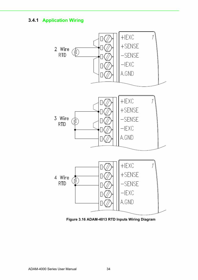
3.4.1 Application Wiring
Figure 3.16 ADAM-4013 RTD Inputs Wiring Diagram
ADAM-4000 Series User Manual 34

Chapter 3
I/O M
odules
3.5 ADAM-4015 6-channel RTD Input ModuleA RTD module is popularly used for temperature measurement. Unlike the traditionaldesign, the ADAM-4015 RTD Input Module provides six RTD input channels for dif-ferent types of RTD signal like as Pt, Ni, Balco. It is an effective solution in industrial& building automation. Normally, broken external wire will lead to an inaccurate cur-rent value; however, the ADAM-4015 provides a broken wire detecting function.Therefore, users can easily fix the broken wire problems. This module can acceptRTD sensors that have two or three wires. After the V2.04 of ADAM-4015, ADAM-4015 can support the “BA1 -200~600°C”.
Please be noted that the pin 26 is defined as GND and it’s reserved.
Figure 3.17 ADAM-4015 6-channel RTD Input Module
35 ADAM-4000 Series User Manual

3.5.1 Application Wiring
Figure 3.18 ADAM-4015 RTD Input Module Wiring Diagram
ADAM-4000 Series User Manual 36

Chapter 3
I/O M
odules
3.5.2 Technical specification of ADAM-4015
Table 3.1: Technical Specification of ADAM-4015Channel Number 6 differential
Support Protocol ADAM ASCII and MODBUS/RTU
Input Type Pt100, Pt1000, BALCO500, Ni
Input Connections 2 or 3 wires
Wire Burnout Detection Yes
Input Type and Temper-ature Range
Pt100: -50 to 150° C 0 to 100° C 0 to 200° C 0 to 400° C -200 to 200° C Pt1000: -40 to 160° C Balco500: -30 to 120° C Ni 50 RTD: -80 to 100° C Ni 508 RTD: 0 to 100° C
Isolation Voltage 3000 VDC
Sampling Rate 10 sample/second (total)
Input Impedance 10 MΩ
Resolution 16-bit
Accuracy ±0.1% or better
CMR@50/60Hz 120 dB
NMR@50/60Hz 100 dB
Span Drift ± 25 ppm/°C
Zero Drift ± 3 μV/°C
Watchdog Timer System (1.6 second) and Communication
Power Input +10~+30 VDC (non-regulated)
Power Consumption 1.2 W @ 24VDC
37 ADAM-4000 Series User Manual

3.6 ADAM-4015T 6-channel Thermistor Input ModuleA Thermistor Module is popularly used for temperature measurement. Unlike the tra-ditional design, the ADAM-4015T provides six thermistor input channels for thermis-tor signal. It is an effective solution in industrial & building automation. Normally,broken external wires will lead to an inaccurate current value. The ADAM-4015T pro-vides a broken wire detecting function, so users can easily fix the problems.
Figure 3.19 ADAM-4015T 6-channel Thermistor Input Module
3.6.1 Application Wiring
Figure 3.20 ADAM-4015T Thermistor Input Module Wiring Diagram
ADAM-4000 Series User Manual 38

Chapter 3
I/O M
odules
3.6.2 Technical Specification of ADAM-4015T
Table 3.2: Technical Specification of ADAM-4015TChannel Number 6 differential
Support Protocol ADAM ASCII and MODBUS/RTU
Input Type Thermistor
Input Connections 2 or 3 wires
Wire Burnout Detection Yes
Input Type and Temperature Range
Thermistor 3k 0~100? (9.796K ohm ~ 203.8 ohm) Thermistor 10k 0~100?(29.49K ohm ~ 816.8 ohm)
Isolation Voltage 3000 VDC
Sampling Rate 10 sample/second (total)
Input Impedance 10 MΩ
Resolution 16-bit
Accuracy ±0.1% or better
CMR@50/60Hz 120 dB
NMR@50/60Hz 100 dB
Span Drift ± 25 ppm/°C
Zero Drift ± 3 μV/°C
Watchdog Timer System (1.6 second) and Communication
Power Input +10~+30 VDC (non-regulated)
Power Consumption 1.2 W @ 24VDC
39 ADAM-4000 Series User Manual

3.7 ADAM-4016 Analog Input/Output ModuleA strain gauge input module uses a microprocessor-controlled integrating A/D con-verter to convert sensor voltage or current signals into digital data for load cell andstress measurement. The digital data are then translated into either, two’s comple-ment hexadecimal format or percentage of full-scale range (FSR) according to themodule’s configuration. When prompted by the host computer, the data are sentthrough a standard RS-485 interface.
The strain gauge input module offers signal conditioning, A/D conversion, ranging,and RS-485 digital communication functions.
They protect your equipment from power surges at the ground terminal by providingopto-isolation of the A/D input and up to 3000 VDC transformer based isolation.
Excitation Voltage Output
A strain gauge input module can supply single channel voltage output for excitation.The module receives digital input from the host computer, and the format of the datais engineering units. It then uses its microprocessor-controlled D/A converter to con-vert the digital data into output signals.
Strain gauge input modules protect your equipment from power surges at the groundterminal by providing opto-isolation of the D/A output and up to 3000 VDC trans-former-based isolation.
Digital Outputs
A strain gauge input module also contains four digital outputs. Outputs are open-col-lector transistor switches that may be controlled by the host computer. They can con-trol solid-state relays which can be applied to heaters, pumps, and other electricalcontrolled equipments.
Alarm signaling
Strain Gauge input modules include High and Low alarm functions. High and Lowalarm limits may be downloaded into the module’s EEPROM by the host computer.
The alarm functions can be enabled or disabled remotely. When the alarm function isenabled, both Digital Output channels are used to indicate the High and Low alarmstates. Digital Output channel 1 (DO1) equals to High alarm state and Digital Outputchannel 0 (DO0) equals to Low alarm state. The High and Low alarm state can beread at any time by the host computer.
Every A/D conversion will be followed by a comparison with the High and Low limits.When the input value exceeds one of these limits, the High or Low alarm state is setto ON.
There are two alarm mode options, Momentary and Latching. If the alarm is in Latch-ing mode, the alarm will stay on even when the input value returns within limits. Analarm in Latching mode can be turned OFF by issuing a Clear Alarm command fromthe host computer. A Latching alarm is cleared by the module when the oppositealarm is set.
When the module receives a value that is lower than the Low alarm limit, it will clearthe High alarm and turn the Low alarm ON.
When the alarm is in Momentary mode, the alarm will be turned OFF as soon as theinput value returns to within limits.
The arrangement of coupling High and Low alarm states with Digital Output lines maybe utilized to build ON/OFF controllers that can operate without the host computerinvolvement.
ADAM-4000 Series User Manual 40

Chapter 3
I/O M
odules
Figure 3.21 ADAM-4016 Analog Input/Output Module
Accepts:
- Millivolt inputs: ±15 mV, ±50 mV, ±100 mV, ±500 mV
- Current input: ±20 mA
Excitation voltage output: 0 ~ 10 V
Four digital output channels are provided.
Depending on the module’s configuration setting, it can forward the data to the hostcomputer in one of the following formats:
- Engineering units (mV or mA)
- Percent of full-scale range (FSR)
- Two’s complement hexadecimal
41 ADAM-4000 Series User Manual

3.7.1 Application Wiring
Figure 3.22 ADAM-4016 Strain Gauge Voltage Input Wiring Diagram
Figure 3.23 ADAM-4016 Strain Gauge Current Input Wiring Diagram
Figure 3.24 ADAM-4016 Digital Output Wiring Diagram Used with SSR
ADAM-4000 Series User Manual 42

Chapter 3
I/O M
odules
3.8 ADAM-4017/4017+/4018/4018M/4018+ 8-channel Analog Input Modules
3.8.1 ADAM-4017/4018 8-channel Analog Input ModuleThe ADAM-4017/4018 is a 16-bit, 8-channel analog input module that provides pro-grammable input ranges on all channels. This module is an extremely cost-effectivesolution for industrial measurement and monitoring applications. Its opto-isolatedinputs provide 3000 VDC of isolation between the analog input and the module, andprotect the module and peripherals from damaging due to high input-line voltages.
The ADAM-4017/4018 offers signal conditioning, A/D conversion, ranging and RS-485 digital communication functions. The module protects your equipment frompower surges at the ground terminal by providing opto-isolation of A/D input and upto 3000 VDC transformer based isolation.
The ADAM-4017/4018 uses a 16-bit microprocessor-controlled sigma-delta A/D con-verter to convert sensor voltage or current into digital data. The digital data are thentranslated into engineering units.
When prompted by the host computer, the module sends the data to the host througha standard RS-485 interface.
3.8.2 ADAM-4018M 8-channel Analog Input Data loggerThe ADAM-4018M is a 16-bit, 8-channel analog input data logger featuring program-mable input ranges on all channels. This reliable and easy to use analog input loggercan store up to 38,000 measurements for a maximum duration of 20 years.
The ADAM-4018M can accept various analog inputs such as thermocouple, mV, Vand mA. It also offers three configurable logging modes, standard log, event log, andmixed log. Optically isolated inputs provide 3000 VDC of isolation between the mod-ule and the analog input, and protect the module and peripherals from damaging dueto high voltages on the input lines.
The ADAM-4018M is an extremely cost-effective solution for industrial measurementand monitoring applications.
3.8.3 ADAM-4017+ 8-channel Differential Analog Input ModuleHere comes a solution to the demand for more analog input channels.
Similar to its counterpart, the ADAM-4017+ enables eight differential channels withmultiple input ranges. This multi-channel/multi-range structure allows channels withdifferent input ranges at the same time.
For example, channel 1 can have the range ± 5V meanwhile the others are ± 10Vand ± 20 mA.
Instead of leaving two single-ended channels in ADAM-4017 module due to the limitnumber of pins, ADAM-4017+ uses a switch to switch AGND and INIT* to Vin6- andVin7- respectively to allow 8- channel input. Moreover, the ADAM-4017+ has beenexpanded to accept 4 ~ 20 mA, so the user can employ it in various applications
43 ADAM-4000 Series User Manual
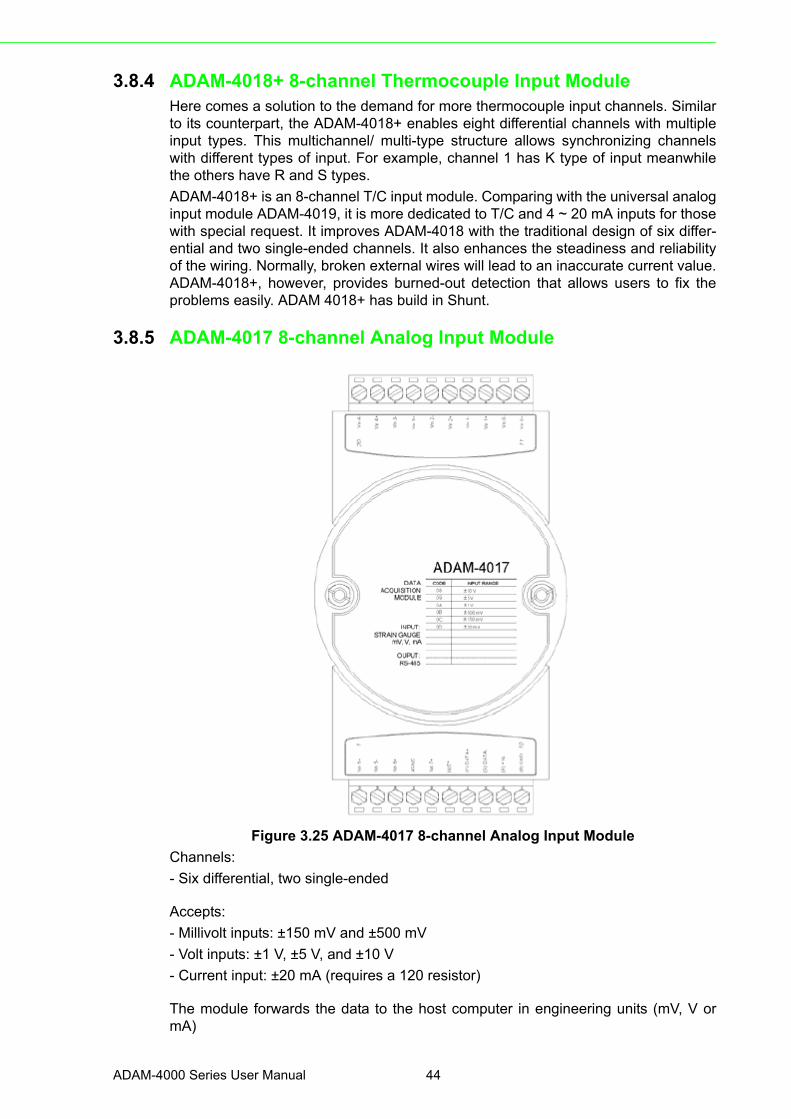
3.8.4 ADAM-4018+ 8-channel Thermocouple Input ModuleHere comes a solution to the demand for more thermocouple input channels. Similarto its counterpart, the ADAM-4018+ enables eight differential channels with multipleinput types. This multichannel/ multi-type structure allows synchronizing channelswith different types of input. For example, channel 1 has K type of input meanwhilethe others have R and S types.
ADAM-4018+ is an 8-channel T/C input module. Comparing with the universal analoginput module ADAM-4019, it is more dedicated to T/C and 4 ~ 20 mA inputs for thosewith special request. It improves ADAM-4018 with the traditional design of six differ-ential and two single-ended channels. It also enhances the steadiness and reliabilityof the wiring. Normally, broken external wires will lead to an inaccurate current value.ADAM-4018+, however, provides burned-out detection that allows users to fix theproblems easily. ADAM 4018+ has build in Shunt.
3.8.5 ADAM-4017 8-channel Analog Input Module
Figure 3.25 ADAM-4017 8-channel Analog Input Module
Channels:
- Six differential, two single-ended
Accepts:
- Millivolt inputs: ±150 mV and ±500 mV
- Volt inputs: ±1 V, ±5 V, and ±10 V
- Current input: ±20 mA (requires a 120 resistor)
The module forwards the data to the host computer in engineering units (mV, V ormA)
ADAM-4000 Series User Manual 44

Chapter 3
I/O M
odules
3.8.6 ADAM-4017+ 8-channel Differential Analog Input Module
Figure 3.26 ADAM-4017+ 8-ch. differential analog input module
Jumper setting (ADAM-4017+)
1. JP0~JP7
2. JP12 can Enable/Disable Watchdog Timer Function. The default setting is closed, i.e., Watchdog Timer Function Enabled. Please always keep JP12 closed and enable/disable the watchdog timer function in ADAM-utility.
45 ADAM-4000 Series User Manual

3.8.6.1 Technical Specification of ADAM-4017+
3.8.7 ADAM-4018 8-channel Analog Input Module
Figure 3.27 ADAM-4018 8-channel Thermocouple Input Module
Channels:
- Six differential, two single-ended
Accepts:
Table 3.3: Technical Specification of ADAM-4017+Channel 8
Input Type mV, V, mA
Input Range ±150 mV, ±500 mV, ±1 V, ±5 V, ±10 V, ±20 mA, 4 ~ 20 mA Current Input doesn’t need an external resistor
Isolation Voltage 3000 VDC
Fault and Over-voltage protection With stands over-voltage up to ±35 V
Sampling Rate 10 sample/sec (total)
Input Impedance Voltage: 20 MΩ, Current: 120Ω
Accuracy ±0.1% or better
Power Consumption 1.2 W @ 24VDC
I/O Connector Type 10 pin plug-in terminal
Span drift Current Input: ±30 ppm/oC
Voltage Input: ±25 ppm/oC
ADAM-4000 Series User Manual 46
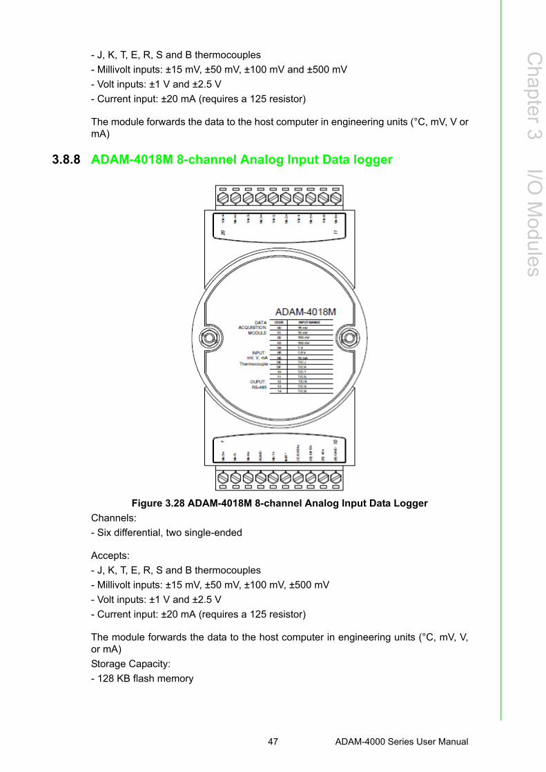
Chapter 3
I/O M
odules
- J, K, T, E, R, S and B thermocouples
- Millivolt inputs: ±15 mV, ±50 mV, ±100 mV and ±500 mV
- Volt inputs: ±1 V and ±2.5 V
- Current input: ±20 mA (requires a 125 resistor)
The module forwards the data to the host computer in engineering units (°C, mV, V ormA)
3.8.8 ADAM-4018M 8-channel Analog Input Data logger
Figure 3.28 ADAM-4018M 8-channel Analog Input Data Logger
Channels:
- Six differential, two single-ended
Accepts:
- J, K, T, E, R, S and B thermocouples
- Millivolt inputs: ±15 mV, ±50 mV, ±100 mV, ±500 mV
- Volt inputs: ±1 V and ±2.5 V
- Current input: ±20 mA (requires a 125 resistor)
The module forwards the data to the host computer in engineering units (°C, mV, V,or mA)
Storage Capacity:
- 128 KB flash memory
47 ADAM-4000 Series User Manual

3.8.9 ADAM-4018+ 8-channel Thermocouple Input Module
Figure 3.29 ADAM-4018+ 8-ch. thermocouple input module
ADAM-4000 Series User Manual 48

Chapter 3
I/O M
odules
3.8.9.1 Technical specification of ADAM-4018+
3.8.10 Application Wiring
Figure 3.30 Current Input Wiring Diagram of ADAM-4017
Figure 3.31 ADAM-4017 Differential Input Wiring Diagram (Ch0 ~ Ch5)
Table 3.4: Technical specification of ADAM-4018+Channel 8
Input Type T hermocouple
Input range and T/C type
±20 mA, 4~20 mA J 0 ~ 760° C K 0 ~ 1370° C T -100 ~ 400° C E 0 ~ 1000° C R 500 ~ 1750° C S 500 ~ 1750° C B 500 ~ 1800° C
Isolation Voltage 3000 VDC
Fault and over-voltage protection
Withstands over voltage up to ±35 V
Sampling Rate 10 sample/sec (total)
Input Impedance Voltage: 20 MΩ, Current: 120Ω
Accuracy ±0.1% or better
Power Consumption 0.8 W @ 24VDC
I/O Connector Type 10 pin plug-in terminal
49 ADAM-4000 Series User Manual

Figure 3.32 ADAM-4017 Single-ended Input Wiring Diagram (Ch6 and Ch7)
Figure 3.33 ADAM-4017+ Voltage and Current Input Wiring Diagram
ADAM-4000 Series User Manual 50
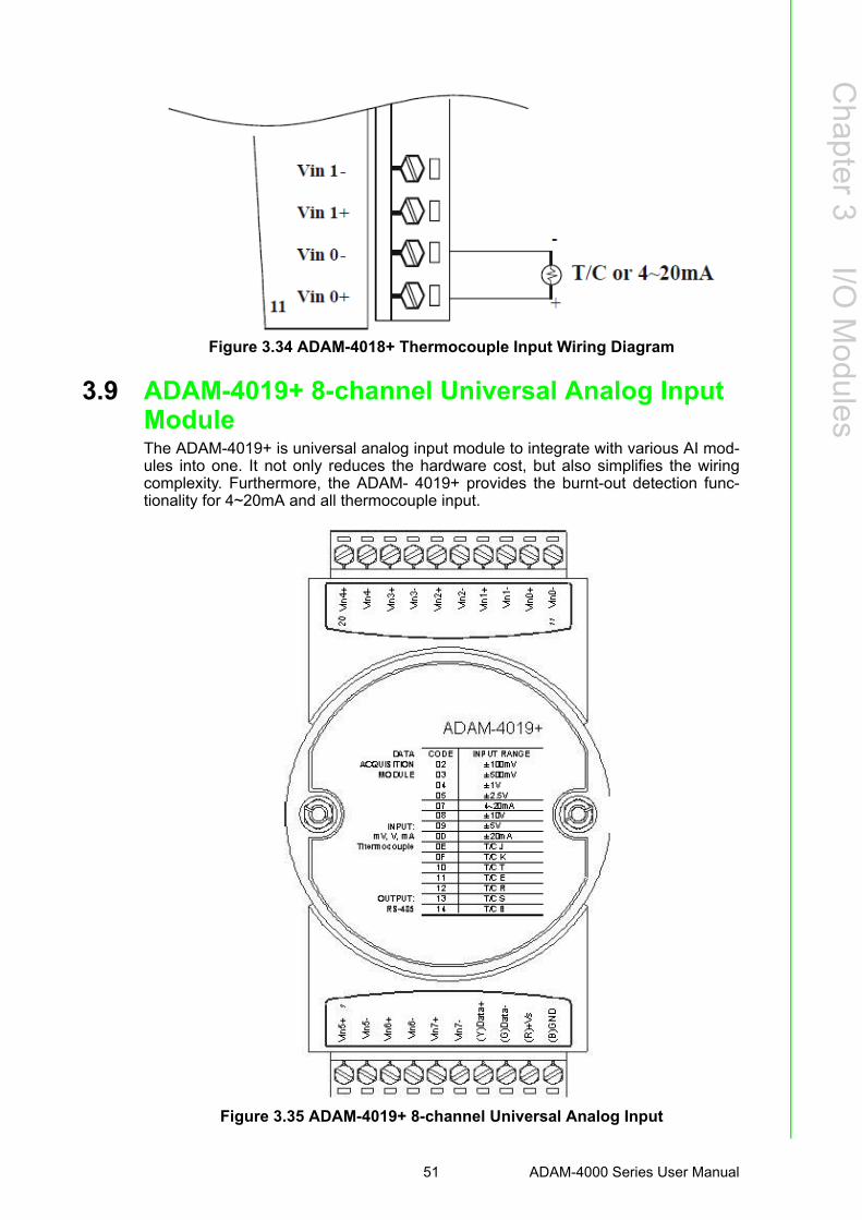
Chapter 3
I/O M
odules
Figure 3.34 ADAM-4018+ Thermocouple Input Wiring Diagram
3.9 ADAM-4019+ 8-channel Universal Analog Input ModuleThe ADAM-4019+ is universal analog input module to integrate with various AI mod-ules into one. It not only reduces the hardware cost, but also simplifies the wiringcomplexity. Furthermore, the ADAM- 4019+ provides the burnt-out detection func-tionality for 4~20mA and all thermocouple input.
Figure 3.35 ADAM-4019+ 8-channel Universal Analog Input
51 ADAM-4000 Series User Manual

The jumper setting of ADAM-4019+ for input type selection:
*It is built the 120Ω resister inside under current input mode.
3.9.1 Application Wiring
Figure 3.36 ADAM-4019+ Universal Analog Input Wiring Diagram
ADAM-4000 Series User Manual 52

Chapter 3
I/O M
odules
3.9.2 Technical Specification of ADAM-4019+
3.10 ADAM-4021 Analog Output ModuleAnalog output module receives its digital input through an RS-485 interface from thehost computer. The format of the data is either two’s complement hexadecimal formator percentage of full-scale range (FSR), depending on the module’s configuration. Itthen uses its microprocessor-controlled D/A converter to convert the digital data into
output signals.
You will get a true read-back of the analog output signal from the unit’s ADC, whichmonitors the output independently. You can also specify slew rates and start up cur-rents through the configuration software. The Analog Output Module can supply sin-gle-channel analog output in a range of voltages or currents.
Furthermore, it will protect your equipment from power surges at the ground terminalby providing opto-isolation of the D/A output and up to 3000 VDC transformer basedisolation.
Slew Rate
The slew rate is defined as the discrepancy between the present number of milliamps(or Volts) per second and the required output currents (or voltages). An ADAM analogoutput module may be configured for a specific slew rate.
Table 3.5: Technical Specification of ADAM-4019+Channel 8
Resolution 16 bits
Input Type V, mV, mA, T/C
Input type and tempera-ture range
V: ±1 V , ±2.5 V, ±5 V , ±10 V mV: ±100 mV , ±500 mV mA: ±20 mA (with 120 Ω resister) 4~20mA (with 120 Ω resister)Thermocouple: J 0 to 760 °C K 0 to 1370 °C T -100 to 400 °C E 0 to 1000 °C R 500 to 1750 °C S 500 to 1750 °C B 500 to 1800 °C
Isolation Voltage 3000 VDC
Sampling Rate 10 samples/sec (total)
Input Impedance Voltage: 20 MΩ, Current: 120Ω
Accuracy ±0.1% or better
Power Consumption 1.0W @ 24VDC
I/O Connector Type 10 pin plug-in terminal
Burn-out Detection 4~20mA and all thermocouple input
53 ADAM-4000 Series User Manual

Figure 3.37 ADAM -4021 Analog Output Module
Depending on its configuration settings the module accepts the following formatsfrom the host computer:
- Engineering units
- Percent of full-scale range (FSR)
- Two’s complement hexadecimal format,
Output types:
- Voltage: 0 ~ 10 V
(Slew rate: 0.0625 to 64 V/sec)
- Currents: 0 ~ 20 mA, or 4 ~ 20 mA.
(Slew rate: 0.125 to 128 mA/sec)
ADAM-4000 Series User Manual 54

Chapter 3
I/O M
odules
3.10.1 Application Wiring
Figure 3.38 ADAM-4021 Analog Output Wiring Diagram
3.11 ADAM-4024 4-channel Analog Output ModuleADAM-4024 is a 4-channel analog output module with mixed type I/O. Under somecircumstances, it is, however, a demand for multiple analog outputs to fulfill particularapplications without many duplicate modules. ADAM-4024 is designed to achievethis purpose by integrating four A/O channels and four isolated D/I channels into onlyone module. The four digital input channels function as an interlock for emergencylatch output.
ADAM-4024 inherited from ADAM-4021, but provide multi-range AO support, allowsits four A/O channels working at the same time with different and more output ranges.For example, it can have 4~20 mA and ±10 V at its output. To ensure the operation ofmachines and facilities, ADAM-4024 has the functionality of slew rate control. Outputslope is programmable through ramping/clamping the slew rate. Unlike traditionalmechanism, ADAM-4024 permits users to substitute its default value at the start up.Users can easily set up and configure the module to be more adaptive.
Figure 3.39 ADAM-4024 4-channel Analog Output Module
55 ADAM-4000 Series User Manual

3.11.1 Technical specification of ADAM-4024 Resolution: 12-bit Output Type: mA, V (Differential) Output Range: 0~20 mA, 4~20 mA, and ±10V Isolation Voltage: 3000 VDC
Output Impedance: 0.5 Ω Accuracy:
– ±0.1% of FSR for current output– ±0.2% of FSR for voltage output
Zero Drift:– Voltage output: ±30 μV/°C– Current output: ±0.2 μA/°C
Span Temperature Coefficient: ±25 ppm/°C Output Slope Rate:
– 0.125 ~ 128 mA/sec.– 0.0625 ~ 64 V/sec.
Current Load Resistor:Max. 500Ω Voltage Load Resistor:Min. 1K Ω Built-in Watchdog Timer Isolation Digital Input
– Channel: 4– Level 0: +1V max– Level 1: +10~30 VDC
3.11.2 Application Wiring
ADAM-4000 Series User Manual 56

Chapter 3
I/O M
odules
Figure 3.40 ADAM-4024 Pin Define and Wiring Diagram
3.12 ADAM-4050 Digital I/O ModuleThe ADAM-4050 features seven digital input and eight digital output channels. Theoutputs are open-collector transistor switches that you can control from the host com-puter. You can also use the switches to control solid-state relays, which can beapplied to equipments such as heaters and pumps. The host computer can use themodule's digital inputs to determine the states of limit, safety switches, and remotedigital signals.
57 ADAM-4000 Series User Manual

Figure 3.41 ADAM-4050 Digital I/O Module
Channels:
- 7 input channels
- 8 output channels
Digital Input:
- Logic level 0: +1 V max.
- Logic level 1: +3.5 ~ 30 V
Digital Output:
- Open collector to 30 V, 30 mA max. load
ADAM-4000 Series User Manual 58

Chapter 3
I/O M
odules
3.12.1 Application Wiring
Figure 3.42 ADAM-4050 TTL Input Wiring Diagram
Figure 3.43 ADAM-4050 Contact Closure Input Wiring Diagram
Figure 3.44 ADAM-4050 Digital Output Wiring Diagram Used with SSR
59 ADAM-4000 Series User Manual

3.13 ADAM-4051 16-channel Isolated Digital Input ModuleThe ADAM-4051 is a 16 channel Digital Input Module. It is built with 2500VDC opticalisolation, and it is suitable for critical applications. The main difference from othermodules is that ADAM-4051 accepts 10 ~ 50V input voltage to fit various digital sig-nals like 12 V, 24 V, and 48 V. Moreover, users can read the current status from theLED indicators on the front panel.
Figure 3.45 ADAM-4051 16-channel Isolated Digital Input Module
Channel: 16 Optical Isolation: 2500 VDC Opto-isolator response time: 25 μs Over-voltage Protect: 70 VDC ESD (Electro Static Discharge): 2000 VDC LED Indicator: On: Active; Off: Non-active Input Voltage:
– Dry Contact Logic level 1: close to GND, Logic level 0: open– Wet Contact Logic level 1: 10 ~ 50 V, Logic level 0: 3 V
Power consumption: 1W @ 24 VDC I/O Connector Type: 13 pin plug-in terminal*2
ADAM-4000 Series User Manual 60
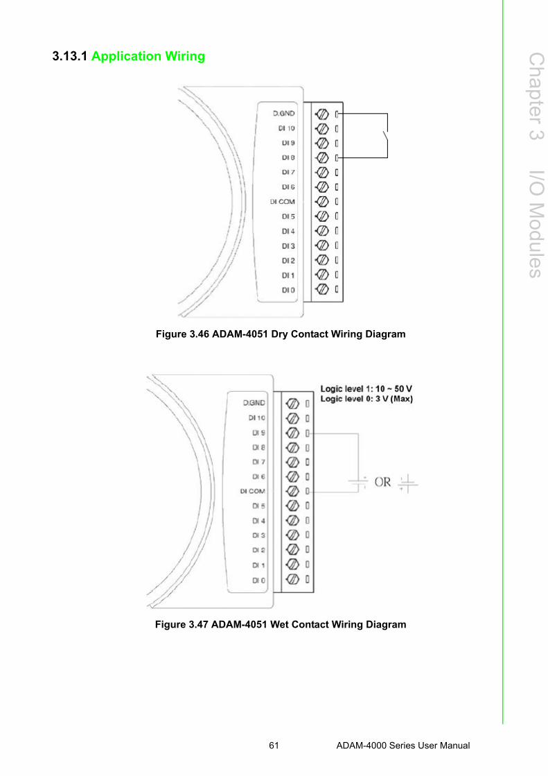
Chapter 3
I/O M
odules
3.13.1 Application Wiring
Figure 3.46 ADAM-4051 Dry Contact Wiring Diagram
Figure 3.47 ADAM-4051 Wet Contact Wiring Diagram
61 ADAM-4000 Series User Manual

3.14 ADAM-4052 Isolated Digital Input ModuleThe ADAM-4052 provides eight digital input channels. Among these eight channels,six of them are fully independent isolated channels and the other two are isolatedchannels with a common ground. They all have 5000 VRMS isolation to preventpower surges from the input lines
Figure 3.48 ADAM-4052 Isolated Digital Input Module
Channels: 8
- 6 differential channels (fully independent isolated channels)
- 2 single-ended channels (isolated channels with common ground)
Digital Input:
- Logic level 0: +1 V max.
- Logic level 1: +3 ~ 30 V
ADAM-4000 Series User Manual 62

Chapter 3
I/O M
odules
3.14.1 Application Wiring
Figure 3.49 ADAM-4052 Isolation Digital Input Wiring Ground
3.15 ADAM-4053 16-channel Digital Input ModuleThe ADAM-4053 provides 16 digital input channels for dry contact or wet contact sig-nals. For dry contact, the effective distance from DI to contact point is up to 500 m.
Figure 3.50 ADAM-4053 16-channel Digital Input Module
63 ADAM-4000 Series User Manual
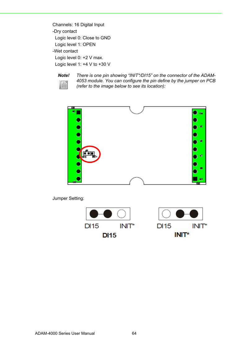
Channels: 16 Digital Input
-Dry contact
Logic level 0: Close to GND
Logic level 1: OPEN
-Wet contact
Logic level 0: +2 V max.
Logic level 1: +4 V to +30 V
Jumper Setting:
Note! There is one pin showing “INIT*/DI15” on the connector of the ADAM-4053 module. You can configure the pin define by the jumper on PCB (refer to the image below to see its location):
ADAM-4000 Series User Manual 64

Chapter 3
I/O M
odules
3.15.1 Application Wiring
Figure 3.51 ADAM-4053 Wet Contact Input Wiring Diagram
Figure 3.52 ADAM-4053 Contact Closure Input Wiring Diagram
65 ADAM-4000 Series User Manual

3.16 ADAM-4055 16-channel Isolated Digital I/O ModuleThe ADAM-4055 offers 8 channel isolated digital input and 8 channel isolated digitaloutput for critical applications. The inputs accept 10~50 V voltage, and the outputscan supply 5~40 VDC at the open collector. The ADAM-4055 is user friendly withbuilt LED indicator for status reading.
Notice: We had updated the digital input dry/wet contact option by using jumperselection. The default setting is to support these two DI contacts both at the sametime. However, a customer can also choose his or her needs by supporting only one.Please refer to the following wiring illustration figure 3-53 for more details.
Figure 3.53 ADAM-4055 16-channel Digital I/O Module
ADAM-4000 Series User Manual 66

Chapter 3
I/O M
odules
3.16.1 Application Wiring:
Figure 3.54 ADAM-4055 Digital Output Wiring Diagram
Figure 3.55 ADAM-4055 Digital Input Dry Contact Wiring Diagram
67 ADAM-4000 Series User Manual

Figure 3.56 ADAM-4055 Digital Input Dry Contact Diagram (Internal)
Figure 3.57 ADAM-4055 Digital Input Wet Contact Wiring Diagram
ADAM-4000 Series User Manual 68

Chapter 3
I/O M
odules
Figure 3.58 ADAM-4055 Digital Input Wet Contact Diagram (Internal)
Figure 3.59 ADAM-4055 Default Jumper Setting for the Digital Input Wiring
(Support dry and wet contact digital input at the same time)
69 ADAM-4000 Series User Manual

Figure 3.60 ADAM-4055 Default Jumper Setting for the Digital Input Wiring
ADAM-4000 Series User Manual 70

Chapter 3
I/O M
odules
3.17 ADAM-4056S 12-channel Sink Type Isolated Digital Output ModuleADAM-4056S is a 12-channel sink type isolated digital output module. The isolatedchannels are designed for digital output for critical applications. Open collector out-puts can provide from +5 to +40 VDC, and both ADAM ASCII and Modbus/RTU pro-tocols are supported. LED indicators are used for status reading.
Figure 3.61 ADAM-4056S 12-channel Sink Type Isolated Digital Output Module
3.17.1 Technical Specification of ADAM-4056S Number of Output Channel: 12 Digital Output:
Open Collector from +5 ~ +40V, 200mA max. load (Sink) LED Indicator: On: Active, Off: Non-active Power Consumption: 1 W @ 24VDC
Optical isolation: 5000 VDC
Supports Modbus/RTU protocol I/O Connector Type: 10 pin plug-in terminal*2 Support Safety Value:
Force the DO channels to safety status when communication is in time-out and over pre-defined period.
71 ADAM-4000 Series User Manual

3.17.2 Application Wiring
Figure 3.62 ADAM-4056S Digital Output Wiring Diagram
3.18 ADAM-4056SO 12-channel Source Type Isolated Digital Output ModuleADAM-4056SO is a 12-channel source type isolated digital output module. The 12isolated digital output channels are designed for critical applications. The digital out-put signals are sent in the range of 10 ~ 35 VDC with maximum 1A per channel, andboth ADAM ASCII and Modbus/RTU protocols are supported. The LED indicatorsprovide status reading of the module.
ADAM-4000 Series User Manual 72
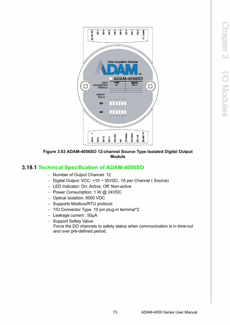
Chapter 3
I/O M
odules
Figure 3.63 ADAM-4056SO 12-channel Source Type Isolated Digital Output Module
3.18.1 Technical Specification of ADAM-4056SO– Number of Output Channel: 12– Digital Output: VCC: +10 ~ 35VDC, 1A per Channel ( Source)– LED Indicator: On: Active, Off: Non-active– Power Consumption: 1 W @ 24VDC– Optical isolation: 5000 VDC– Supports Modbus/RTU protocol– ?/O Connector Type: 10 pin plug-in terminal*2– Leakage current : 50μA– Support Safety Value:
Force the DO channels to safety status when communication is in time-out and over pre-defined period.
73 ADAM-4000 Series User Manual

3.18.2 Application Wiring
Figure 3.64 ADAM-4056SO Digital Output Wiring Diagram
3.19 ADAM-4060/4068 Relay Output ModuleThe ADAM Relay Output Module is a low-cost alternative to SSR modules. TheADAM-4060 Relay Output Module provides four relay channels; two of them areForm A, and two are Form C. The ADAM- 4068 Relay Output Module provides eightchannels. Four of the channels are Form A, and four are Form C. These two modulesare excellent for ON/OFF control or low-power switching applications and they areable to support the safety value setting.
ADAM-4000 Series User Manual 74

Chapter 3
I/O M
odules
3.19.1 ADAM-4060 4-channel Relay Output Module
Figure 3.65 ADAM-4060 4-channel Relay Output Module
Contact rating for Form A and Form C: (Resistive)
AC 0.6 A @ 125 V
0.3 A @ 250 V
DC 2 A @ 30 V
0.6 A @ 110 V
75 ADAM-4000 Series User Manual

3.19.2 ADAM-4068 8-channel Relay Output Module
Figure 3.66 ADAM-4068 8-channel Relay Output Module
Contact Rating for Form A and Form C: (Resistive)
AC 0.5 A @120 V
0.25 A @240 V
DC 1 A @ 30 V
0.3 A @ 110 V
Note! This electric current is under the load of resistance. If you try to use the load of inductance, the electric current would be less the above-men-tioned value.
ADAM-4000 Series User Manual 76

Chapter 3
I/O M
odules
3.19.3 Application WiringThe following diagrams are examples of how to connect Form A and Form C relayoutput applications to your ADAM modules.
Figure 3.67 ADAM-4060 Form A Relay Output Wiring Diagram
Figure 3.68 ADAM-4060 Form C Relay Output Wiring Diagram
Figure 3.69 ADAM-4068 Form C Relay Output Wiring Diagram
77 ADAM-4000 Series User Manual

Figure 3.70 ADAM-4068 Form A relay output Wiring Diagram
3.20 ADAM-4069 8-channel Relay Output ModuleThe ADAM-4069 Relay Output Module provides eight channels; four are Form A andthe rest are Form C. This module is excellent for ON/OFF control or low-powerswitching applications.
Figure 3.71 ADAM-4069 Relay Output Module
ADAM-4000 Series User Manual 78

Chapter 3
I/O M
odules
3.20.1 Specification Number of Relay Output Channel: 8 Digital Output: (Source)
– 4 Form A, 4 Form C– AC 5A@250V– DC 5A@30V– ON/OFF : 5ms/ 5.6ms
Power Consumption: 2.2 W Supports Modbus/RTU protocol I/O Connector Type: 13-pin plug-terminal * 2 Support Safety Value: Force the DO channels to safety status when communi-
cation is in time-out and over pre-defined period.
3.20.2 Wiring
Figure 3.72 ADAM-4069 Form C Relay Output
Figure 3.73 ADAM-4069 Form A Relay Output
79 ADAM-4000 Series User Manual

3.21 ADAM-4080/4080D Counter/Frequency Input ModulesADAM-4080/4080D Counter/frequency input module has two 32- bit counter inputchannels (counter 0 and counter 1) with built-in programmable timer for frequencymeasurement. These cost-effective modules let you monitor counter/frequency dataas measurements are taken.
Front Panel LED Indicator (ADAM-4080D only)
The 5-digit LED display of the ADAM-4080D lets you monitor its counter data right atthe source. The module's LED display shows counter values as well as high-lowalarm messages when the counter exceeds its programmed limits (direct display).
Another option is to display the data sent by the host computer. The module firstsends counter data to the host computer for conversion or calculation. The host com-puter then sends the data back to the ADAM- 4080D and displays on the module'sLED display (remote display).
Signal Input Mode
The ADAM-4080/4080D provides separate terminals for photo isolated input andnon-isolated input to simplify the wiring. Optoisolated input provides 2500 VRMS iso-lation to protect your equipment from power surges at the ground terminal. After youmake the physical connections, program the module to identify which of its two inputterminals should be activated (isolated or non-isolated terminals).
Programmable Digital Filter
The ADAM-4080/4080D module includes a unique programmable digital filter toreject noise from the input lines. You can specify separate time constant like mini-mum signal width at high level and minimum signal width at low level. This providesstable output readings.
Programmable Threshold
When the ADAM-4080/4080D is programmed for non-isolated input, you can set ahigh and low trigger level. Like the programmable digital filter, the programmablethreshold rejects noise from the input lines and provides a stable input readings
External Control (Gate mode)
Aside from the GND and counter terminal, each channel has a gate terminal to con-nect to an external gate signal. The gate signal (high or low) can trigger the counterfrom start or stop counting. The gate mode can be among these three options, low,high or disabled (low means that counting starts when the gate signal is low. It stopsonce the gate signal becomes high)
Programmable Alarm Output
The ADAM-4080 module provides a configurable alarm for each counter. The ADAM-4080D provides high and low alarm functions for counter 0. When the counterreaches an alarm limit, it will trigger the built-in digital output of machine ON/OFFcontrol. The alarm limits may be downloaded into the module's EEPROM by the hostcomputer. The initial count value of ADAM-4080 module's counter can be configuredin any values.
ADAM-4000 Series User Manual 80

Chapter 3
I/O M
odules
The alarm functions can be enabled or disabled remotely. When the alarm functionsare enabled, digital output channels are used to indicate the alarm states. For ADAM-4080, digital output channel 0 equals to the alarm state of counter 0, and digital out-put channel 1 equals to the alarm state of counter 1. For ADAM-4080D, digital outputchannel 0 equals to the low alarm state of counter 0, and digital output channel 1equals to the high alarm state of counter 0.
Every A/D conversion will be followed by a comparison of alarm limits. If the inputvalue exceeds one of these limits, the corresponding alarm state is set to ON.
There are two alarm mode options, momentary and latching, for ADAM-4080D. If thealarm is in latching mode, the alarm will stay on even when the input value returnswithin the limits. An alarm in latching mode can be turned off by issuing a Clear Alarmcommand from the host computer. A latching alarm is cleared by the module whenthe opposite alarm is set. For example, the alarm is in latching mode and the highalarm is then turned ON. When the module receives a value that is lower than the lowalarm limit, it will clear the high alarm and turn the low alarm ON.
When the alarm is in Momentary mode, the alarm will be turned OFF as soon as theinput value returns within the limits. The arrangement of coupling high and low alarmstates with digital output lines may be utilized to build ON/OFF controllers that can
operate without the host computer involvement.
3.21.1 ADAM-4080 Counter/Frequency Input Modules
Figure 3.74 ADAM-4080 Counter/Frequency Input Module
81 ADAM-4000 Series User Manual

Channels: 2 independent 32-bit counters (counter 0 and counter 1)
Input frequency: 50 kHz max.
Input mode: Isolated or non-isolated
Isolation input level:
- Logic level 0: +1 V max
- Logic level 1: +3.5 V to +30 V
- Input Impedance: 1.2 kΩ
Non-isolation input level (programmable threshold):
- Logic level 0: 0 to +5V (default = 0.8 V)
- Logic level 1: 0 to +5V (default = 2.4 V)
- Input Impedance: 50 MΩ
3.21.2 ADAM-4080D Counter/Frequency Input Modules with LED Display
Figure 3.75 ADAM-4080D Counter/Frequency Input Module with LED Display
Channels: 2 independent 32-bit counters (counter 0 and counter 1)
Input frequency: 50 kHz max.
Input mode: Isolated or non-isolated
Isolation input level:
- Logic level 0: +1 V max
- Logic level 1: +3.5 V to +30 V
- Input Impedance: 1.2 kΩ
ADAM-4000 Series User Manual 82

Chapter 3
I/O M
odules
Non-isolation input level (programmable threshold):
- Logic level 0: 0 to +5V (default = 0.8 V)
- Logic level 1: 0 to +5V (default = 2.4 V)
- Input Impedance: 50 MΩ
3.21.3 Application Wiring
Figure 3.76 ADAM-4080/4080D Non-isolated Input
Figure 3.77 ADAM-4080/4080D Photo-isolated Input
83 ADAM-4000 Series User Manual

ADAM-4000 Series User Manual 84

Chapter 4
4 Command Set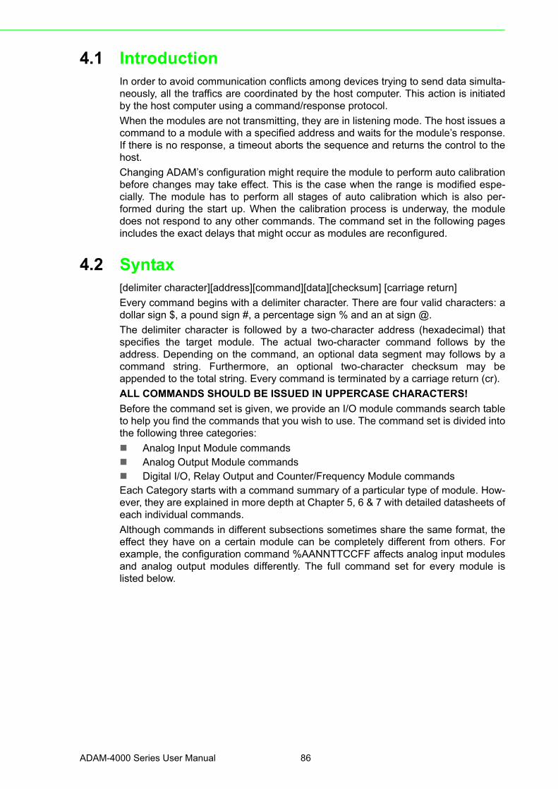
4.1 IntroductionIn order to avoid communication conflicts among devices trying to send data simulta-neously, all the traffics are coordinated by the host computer. This action is initiatedby the host computer using a command/response protocol.
When the modules are not transmitting, they are in listening mode. The host issues acommand to a module with a specified address and waits for the module’s response.If there is no response, a timeout aborts the sequence and returns the control to thehost.
Changing ADAM’s configuration might require the module to perform auto calibrationbefore changes may take effect. This is the case when the range is modified espe-cially. The module has to perform all stages of auto calibration which is also per-formed during the start up. When the calibration process is underway, the moduledoes not respond to any other commands. The command set in the following pagesincludes the exact delays that might occur as modules are reconfigured.
4.2 Syntax[delimiter character][address][command][data][checksum] [carriage return]
Every command begins with a delimiter character. There are four valid characters: adollar sign $, a pound sign #, a percentage sign % and an at sign @.
The delimiter character is followed by a two-character address (hexadecimal) thatspecifies the target module. The actual two-character command follows by theaddress. Depending on the command, an optional data segment may follows by acommand string. Furthermore, an optional two-character checksum may beappended to the total string. Every command is terminated by a carriage return (cr).
ALL COMMANDS SHOULD BE ISSUED IN UPPERCASE CHARACTERS!
Before the command set is given, we provide an I/O module commands search tableto help you find the commands that you wish to use. The command set is divided intothe following three categories:
Analog Input Module commands Analog Output Module commands Digital I/O, Relay Output and Counter/Frequency Module commandsEach Category starts with a command summary of a particular type of module. How-ever, they are explained in more depth at Chapter 5, 6 & 7 with detailed datasheets ofeach individual commands.
Although commands in different subsections sometimes share the same format, theeffect they have on a certain module can be completely different from others. Forexample, the configuration command %AANNTTCCFF affects analog input modulesand analog output modules differently. The full command set for every module islisted below.
ADAM-4000 Series User Manual 86

Chapter 4
Com
mand
Set
4.3 I/O Module Commands Search Table
Table 4.1: ADAM-4011 Command Table
Command Syntax Command Name Command Description Page No.
%AANNTTCCFF Configuration
Sets the address, input range, baud rate, data format, checksum status, and/or integration time for a specified analog input module
5-4
$AA2 Configuration Status Returns the configuration parameters for the specified analog input module
5-10
$AAF Read Firmware Ver-sion
Return the firmware version code from the specified analog input module
5-12
$AAM Read Module Name Return the module name from the specified analog input module
5-13
#AA Analog Data In Returns the input value from a speci-fied analog input module in the cur-rently configured data format
5-14
$AA0 Span Calibration Calibrates an analog input module to correct for gain errors
5-19
$AA1 Offset Calibration Calibrates an analog input module to correct for offset errors
5-20
#** Synchronized Sam-pling
Orders all analog input modules to sample their input values and store them in special registers
5-21
$AA4 Read Synchronized Data
Returns the value that was stored in the specified module's register after the #** command
5-22
$AA3 CJC Status Returns the value of the CJC sensor for a specified analog input module
5-25
$AA9SNNNN CJC Offset Calibra-tion
Calibrates the CJC sensor for offset errors
5-26
@AADI Read Digital I/O and Alarm Status
The addressed module returns the state of its digital input channel, its two digital output channels and the status of its alarm
5-50
@AADO(data) Set Digital Output Set the values of the module's two dig-ital outputs (ON or OFF)
5-52
@AAEAT Enable Alarm Enables the alarm in either Momentary or Latching mode
5-54
@AAHI(data) Set High Alarm Downloads the High alarm limit value 5-56
@AALO(data) Set Low Alarm Downloads the Low alarm limit value 5-57
@AADA Disable Alarm Disables all alarm functions 5-58
@AACA Clear Latch Alarm The latch alarm is reset 5-59
@AARH Read High Alarm The addressed analog input module is asked to return its high alarm value
5-60
@AARL Read Low Alarm The addressed analog input module is asked to return its low alarm value
5-61
@AARE Read Event Counter The addressed module is asked to return its event counter value
5-62
@AACE Clear Event Counter The event counter is set to 0 5-63
87 ADAM-4000 Series User Manual

Table 4.2: ADAM-4011D Command Table
Command Syntax Command Name Command Description Page No.
%AANNTTCCFF Configuration
Sets the address, input range, baud rate, data format, checksum status, and/or integration time for a specified analog input module
5-4
$AA2 Configuration Status Returns the configuration parameters for the specified analog input module
5-10
$AAF Read Firmware Version
Return the firmware version code from the specified analog input module
5-12
$AAM Read Module Name Return the module name from the specified analog input module
5-13
#AA Analog Data In Returns the input value from a speci-fied analog input module in the cur-rently configured data format
5-14
$AA0 Span Calibration Calibrates an analog input module to correct for gain errors
5-19
$AA1 Offset Calibration Calibrates an analog input module to correct for offset errors
5-20
#** Synchronized Sampling
Orders all analog input modules to sample their input values and store them in special registers
5-21
$AA4 Read Synchronized Data
Returns the value that was stored in the specified module's register after the #** command
5-22
$AA3 CJC Status Returns the value of the CJC sensor for a specified analog input module
5-25
$AA9SNNNN CJC Offset Calibra-tion
Calibrates the CJC sensor for offset errors
5-26
@AADI Read Digital I/O and Alarm Status
The addressed module returns the state of its digital input channel, its two digital output channels and the status of its alarm
5-50
@AADO(data) Set Digital Output Set the values of the module's two dig-ital outputs (ON or OFF)
5-52
@AAEAT Enable Alarm Enables the alarm in either Momentary or Latching mode
5-54
@AAHI(data) Set High Alarm Downloads the High alarm limit value 5-56
@AALO(data) Set Low Alarm Downloads the Low alarm limit value 5-57
@AADA Disable Alarm Disables all alarm functions 5-58
@AACA Clear Latch Alarm The latch alarm is reset 5-59
@AARH Read High Alarm The addressed analog input module is asked to return its high alarm value
5-60
@AARL Read Low Alarm The addressed analog input module is asked to return its low alarm value
5-61
@AARE Read Event Counter The addressed module is asked to return its event counter value
5-62
@AACE Clear Event Counter The event counter is set to 0 5-63
ADAM-4000 Series User Manual 88

Chapter 4
Com
mand
Set
Table 4.3: ADAM-4012 Command Table
Command Syntax Command Name Command Description Page No.
%AANNTTCCFF Configuration
Sets the address, input range, baud rate, data format, checksum status, and/or integration time for a specified analog input module
5-4
#AA Analog Data In Returns the input value from a speci-fied analog input module in the cur-rently configured data format
5-14
$AA0 Span Calibration Calibrates an analog input module to correct for gain errors
5-19
$AA1 Offset Calibration Calibrates an analog input module to correct for offset errors
5-20
#** Synchronized Sampling
Orders all analog input modules to sample their input values and store them in special registers
5-21
$AA4 Read Synchronized Data
Returns the value that was stored in the specified module's register after the #** command
5-22
$AA2 Configuration Status Returns the configuration parame-ters for the specified analog input module
5-10
$AAFRead Firmware Version
Return the firmware version code from the specified analog input mod-ule
5-12
$AAM Read Module Name Return the module name from the specified analog input module
5-13
@AADI Read Digital I/O and Alarm Status
The addressed module returns the state of its digital input channel, its two digital output channels and the status of its alarm
5-50
@AADO(data) Set Digital Output Set the values of the module's two digital outputs (ON or OFF)
5-52
@AAEAT Enable Alarm Enables the alarm in either Momen-tary or Latching mode
5-54
@AAHI(data) Set High Alarm Downloads the High alarm limit value 5-56
@AALO(data) Set Low Alarm Downloads the Low alarm limit value 5-57
@AADA Disable Alarm Disables all alarm functions 5-58
@AACA Clear Latch Alarm The latch alarm is reset 5-59
@AARH Read High Alarm The addressed analog input module is asked to return its high alarm value
5-60
@AARL Read Low Alarm The addressed analog input module is asked to return its low alarm value
5-61
@AARE Read Event Counter The addressed module is asked to return its event counter value
5-62
@AACE Clear Event Counter The event counter is set to 0 5-63
89 ADAM-4000 Series User Manual

Table 4.4: ADAM-4013 Command Table
Command Syntax Command Name Command Description Page No.
%AANNTTCCFF Configuration
Sets the address, input range, baud rate, data format, checksum status, and/or integration time for a specified analog input module
5-4
#AA Analog Data In Returns the input value from a speci-fied analog input module in the cur-rently configured data format
5-14
$AA0 Span Calibration Calibrates an analog input module to correct for gain errors
5-19
$AA1 Offset Calibration Calibrates an analog input module to correct for offset errors
5-20
#** Synchronized Sampling
Orders all analog input modules to sample their input values and store them in special registers
5-21
$AA4 Read Synchronized Data
Returns the value that was stored in the specified module's register after the #** command
5-22
$AA2 Configuration Status Returns the configuration parameters for the specified analog input module
5-10
$AAFRead Firmware Version
Return the firmware version code from the specified analog input mod-ule
5-12
$AAM Read Module Name Return the module name from the specified analog input module
5-13
Table 4.5: ADAM-4015/ADAM-4015T Command Table
Command Syntax Command Name Command Description Page No.
%AANNTTCCFF Configuration
Sets the address, input range, baud rate, data format, checksum status, and/or integration time for a specified analog input module
5-4
$AA2 Configuration Status Returns the configuration parame-ters for the specified analog input module
5-10
$AAFRead Firmware Version
Return the firmware version code from the specified analog input mod-ule
5-12
$AAM Read Module Name Return the module name from the specified analog input module
5-13
#AA Analog Data In Returns the input value from a speci-fied analog input module in the cur-rently configured data format
5-14
#AANRead Analog Input from Channel N
Returns the input value from a speci-fied channel of analog input module in the currently configured data for-mat
5-16
$AA5VVEnable/Disable Channels for Multi-plexing
Enable or disable the individual chan-nels in an analog module
5-17
ADAM-4000 Series User Manual 90

Chapter 4
Com
mand
Set
$AA6 Read Channel StatusGet the enable/disable status of all channels in an analog module
5-18
$AA0 Span Calibration Calibrates an analog input module to correct for gain errors
5-19
$AA1 Offset Calibration Calibrates an analog input module to correct for offset errors
5-20
#** Synchronized Sampling
Orders all analog input modules to sample their input values and store them in special registers
5-21
$AA4 Read Synchronized Data
Returns the value that was stored in the specified module's register after the #** command
5-22
$AAB Channel DiagnoseDiagnose channel status in over range, under range, and wire opening
5-24
$AA0CiSingle Channel Span Calibration
Calibrates a specified channel to cor-rect for gain errors
5-27
$AA1CiSingle Channel Offset Calibration
Calibrates a specified channel to cor-rect for offset errors
5-28
$AA7CiRrrSingle Channel Range Configuration
Configure the input type and range of the specified channel in an analog input module
5-29
$AA8CiRead Single Chan-nel Range Configura-tion
Get the input type and range of the specified channel in an analog input module
5-30
$AAXnnnnWatchdog TimerSetting
Set communication WDT cycle time from 0000 ~ 9999 (unit: 0.1 second. if value is 0000, the communication WDT function will be disable)
5-31
$AAYRead Watchdog Timer Setting
Read the cycle time setting of com-munication WDT
5-32
$AAS0 Internal Calibration Internal self-calibration for offset and gain errors
5-33
$AAS0Reload default cali-brating parameter
Reload factory default calibrating parameter to overwrite current cali-brating parameter
5-34
Table 4.6: ADAM-4016 Command Table
Command Syntax Command Name Command Description Page No.
%AANNTTCCFF Configuration
Sets the address, input range, baud rate, data format, checksum status, and/or integration time for a specified analog input module
5-4
$AA2 Configuration Status Returns the configuration parame-ters for the specified analog input module
5-10
$AAFRead Firmware Version
Return the firmware version code from the specified analog input mod-ule
5-12
$AAM Read Module Name Return the module name from the specified analog input module
5-13
Table 4.5: ADAM-4015/ADAM-4015T Command Table
91 ADAM-4000 Series User Manual

#AA Read Analog Input Return the input value from the speci-fied analog input module in the cur-rently configured data format
5-14
$AA0 Span Calibration Calibrates an analog input module to correct for gain errors
5-19
$AA1 Offset Calibration Calibrates an analog input module to correct for offset errors
5-20
#** Synchronized Sampling
Orders all analog input modules to sample their input values and store them in special registers
5-21
$AA4 Read Synchronized Data
Returns the value that was stored in the specified module's register after the #** command
5-22
$AA6Get Excitation Voltage Output Value
Returns either last value sent to spec-ified module by $AA7 command, orstart-up output voltage
5-65
$AA7Excitation VoltageOutput
Direct output excitation voltage datato a specified module
5-66
$AASStart-up Voltage Out-put Configuration
Stores a default value in a specified module. The output value will take effect upon startup
5-67
$AAE Trim CalibrationTrims specified module a number of units up or down
5-69
$AAA Zero Calibration Tells the module to store parametersfor zero calibration
5-70
$AAB Span CalibrationTells the module to store parameters for span calibration
5-71
@AADI Read Digital I/O and Alarm Status
The addressed module returns the state of its digital input channel, its two digital output channels and the status of its alarm
5-50
@AADO(data) Set Digital Output Set the values of the module's two digital outputs (ON or OFF)
5-52
@AAEAT Enable Alarm Enables the alarm in either Momen-tary or Latching mode
5-54
@AAHI(data) Set High Alarm Downloads the High alarm limit value 5-56
@AALO(data) Set Low Alarm Downloads the Low alarm limit value 5-57
@AADA Disable Alarm Disables all alarm functions 5-58
@AACA Clear Latch Alarm The latch alarm is reset 5-59
@AARH Read High Alarm The addressed analog input module is asked to return its high alarm value
5-60
@AARL Read Low Alarm The addressed analog input module is asked to return its low alarm value
5-61
Table 4.6: ADAM-4016 Command Table
ADAM-4000 Series User Manual 92
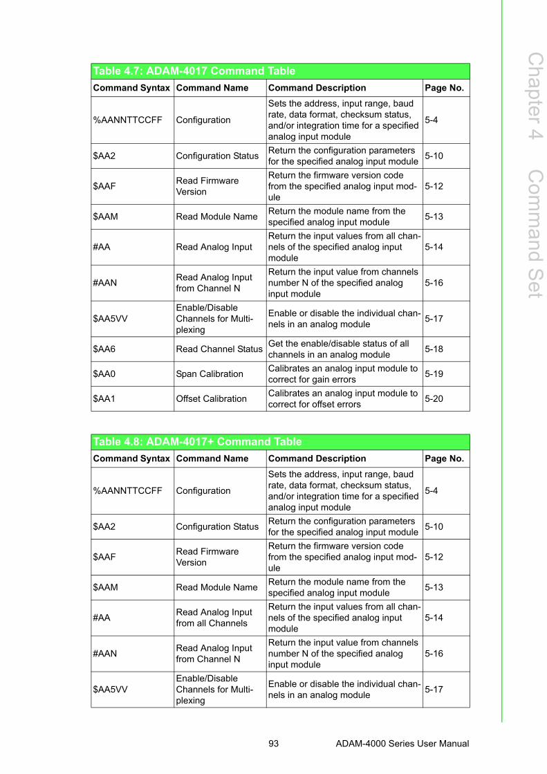
Chapter 4
Com
mand
Set
Table 4.7: ADAM-4017 Command Table
Command Syntax Command Name Command Description Page No.
%AANNTTCCFF Configuration
Sets the address, input range, baud rate, data format, checksum status, and/or integration time for a specified analog input module
5-4
$AA2 Configuration StatusReturn the configuration parameters for the specified analog input module
5-10
$AAFRead FirmwareVersion
Return the firmware version code from the specified analog input mod-ule
5-12
$AAM Read Module NameReturn the module name from the specified analog input module
5-13
#AA Read Analog Input Return the input values from all chan-nels of the specified analog input module
5-14
#AANRead Analog Input from Channel N
Return the input value from channels number N of the specified analog input module
5-16
$AA5VVEnable/Disable Channels for Multi-plexing
Enable or disable the individual chan-nels in an analog module
5-17
$AA6 Read Channel StatusGet the enable/disable status of all channels in an analog module
5-18
$AA0 Span Calibration Calibrates an analog input module to correct for gain errors
5-19
$AA1 Offset Calibration Calibrates an analog input module to correct for offset errors
5-20
Table 4.8: ADAM-4017+ Command Table
Command Syntax Command Name Command Description Page No.
%AANNTTCCFF Configuration
Sets the address, input range, baud rate, data format, checksum status, and/or integration time for a specified analog input module
5-4
$AA2 Configuration StatusReturn the configuration parameters for the specified analog input module
5-10
$AAFRead FirmwareVersion
Return the firmware version code from the specified analog input mod-ule
5-12
$AAM Read Module NameReturn the module name from the specified analog input module
5-13
#AA Read Analog Input from all Channels
Return the input values from all chan-nels of the specified analog input module
5-14
#AANRead Analog Input from Channel N
Return the input value from channels number N of the specified analog input module
5-16
$AA5VVEnable/Disable Channels for Multi-plexing
Enable or disable the individual chan-nels in an analog module
5-17
93 ADAM-4000 Series User Manual

$AA6 Read Channel StatusGet the enable/disable status of all channels in an analog module
5-18
$AA0CiSingle Channel Span Calibration
Calibrates a specified channel to cor-rect for gain errors
5-27
$AA1CiSingle Channel Offset Calibration
Calibrates a specified channel to cor-rect for offset errors
5-28
$AA7CiRrrSingle Channel Range Configuration
Configure the input type and range of the specified channel in an analog input module
5-29
$AA8CiRead Single Chan-nel Range Configura-tion
Get the input type and range of the specified channel in an analog input module
5-30
$AAXnnnnWatchdog TimerSetting
Set communication WDT cycle time from 0000 ~ 9999 (unit: 0.1 second. if value is 0000, the communication WDT function will be disable)
5-31
$AAYRead Watchdog Timer Setting
Read the cycle time setting of com-munication WDT
5-32
Table 4.9: ADAM-4017+ Input range and external calibrating input source for each input type
Range bcode(Hex)
Input Range Max. Signal Min Signal Displayed Resolution
07 4~20 mA +20.000 +4.000 1 uA
08 +/-10 V +10.000 -10.000 1mV
09 +/-5 V +5.0000 -5.0000 100.00uV
0a +/-1 V +1.0000 -1.0000 100.00uV
0b +/-500 mV +500.00 -500.00 10uV
0c +/-150 mV +150.00 -150.00 10uV
0d +/-20 mA +20.000 -20.000 1uA
Table 4.8: ADAM-4017+ Command Table
ADAM-4000 Series User Manual 94

Chapter 4
Com
mand
Set
Table 4.10: ADAM-4018 Command Table
Command Syntax Command Name Command Description Page No.
%AANNTTCCFF Configuration
Sets the address, input range, baud rate, data format, checksum status, and/or integration time for a specified analog input module
5-4
$AA2 Configuration StatusReturn the configuration parameters for the specified analog input module
5-10
$AAFRead FirmwareVersion
Return the firmware version code from the specified analog input mod-ule
5-12
$AAM Read Module NameReturn the module name from the specified analog input module
5-13
#AA Read Analog Input from all Channels
Return the input values from all chan-nels of the specified analog input module
5-14
#AANRead Analog Input from Channel N
Return the input value from channels number N of the specified analog input module
5-16
$AA5VVEnable/Disable Channels for Multi-plexing
Enable or disable the individual chan-nels in an analog module
5-17
$AA6 Read Channel StatusGet the enable/disable status of all channels in an analog module
5-18
$AA0 Span Calibration Calibrates an analog input module to correct for gain errors
5-19
$AA1 Offset Calibration Calibrates an analog input module to correct for offset errors
5-20
$AA3 CJC StatusReturns the value of the CJC sensor for a specified analog input module
5-25
$AA9SNNNNCJC Offset Calibration
Calibrates the CJC sensor for offset errors
5-26
95 ADAM-4000 Series User Manual

Table 4.11: ADAM-4018+ Command Table
Command Syntax Command Name Command Description Page No.
%AANNTTCCFF Configuration
Sets the address, input range, baud rate, data format, checksum status, and/or integration time for a specified analog input module
5-4
$AA2 Configuration StatusReturn the configuration parameters for the specified analog input module
5-10
$AAFRead FirmwareVersion
Return the firmware version code from the specified analog input mod-ule
5-12
$AAM Read Module NameReturn the module name from the specified analog input module
5-13
#AA Read Analog Input from all Channels
Return the input values from all chan-nels of the specified analog input module
5-14
#AANRead Analog Input from Channel N
Return the input value from channels number N of the specified analog input module
5-16
$AA5VVEnable/Disable Channels for Multi-plexing
Enable or disable the individual chan-nels in an analog module
5-17
$AA6 Read Channel StatusGet the enable/disable status of all channels in an analog module
5-18
$AAB Get Operating Status
Get the channel operating status When bit value is 0, it means this channel is in normal operating, when bit value is 1, it means this channel is opening wire
5-24
$AA3 CJC StatusReturns the value of the CJC sensor for a specified analog input module
5-25
$AA9SNNNNCJC Offset Calibration
Calibrates the CJC sensor for offset errors
5-26
$AA0CiSingle Channel Span Calibration
Calibrates a specified channel to cor-rect for gain errors
5-27
$AA1CiSingle Channel Offset Calibration
Calibrates a specified channel to cor-rect for offset errors
5-28
$AA7CiRrrSingle Channel Range Configuration
Configure the input type and range of the specified channel in an analog input module
5-29
$AA8CiRead Single Chan-nel Range Configura-tion
Get the input type and range of the specified channel in an analog input module
5-30
$AAXnnnnWatchdog TimerSetting
Set communication WDT cycle time from 0000 ~ 9999 (unit: 0.1 second. if value is 0000, the communication WDT function will be disable)
5-31
$AAYRead Watchdog Timer Setting
Read the cycle time setting of com-munication WDT
5-32
ADAM-4000 Series User Manual 96
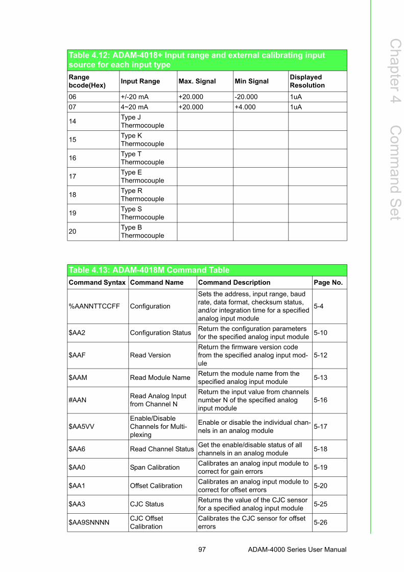
Chapter 4
Com
mand
Set
Table 4.12: ADAM-4018+ Input range and external calibrating input source for each input type
Range bcode(Hex)
Input Range Max. Signal Min Signal Displayed Resolution
06 +/-20 mA +20.000 -20.000 1uA
07 4~20 mA +20.000 +4.000 1uA
14Type JThermocouple
15Type KThermocouple
16Type TThermocouple
17Type EThermocouple
18Type RThermocouple
19Type SThermocouple
20Type BThermocouple
Table 4.13: ADAM-4018M Command Table
Command Syntax Command Name Command Description Page No.
%AANNTTCCFF Configuration
Sets the address, input range, baud rate, data format, checksum status, and/or integration time for a specified analog input module
5-4
$AA2 Configuration StatusReturn the configuration parameters for the specified analog input module
5-10
$AAF Read VersionReturn the firmware version code from the specified analog input mod-ule
5-12
$AAM Read Module NameReturn the module name from the specified analog input module
5-13
#AANRead Analog Input from Channel N
Return the input value from channels number N of the specified analog input module
5-16
$AA5VVEnable/Disable Channels for Multi-plexing
Enable or disable the individual chan-nels in an analog module
5-17
$AA6 Read Channel StatusGet the enable/disable status of all channels in an analog module
5-18
$AA0 Span Calibration Calibrates an analog input module to correct for gain errors
5-19
$AA1 Offset Calibration Calibrates an analog input module to correct for offset errors
5-20
$AA3 CJC StatusReturns the value of the CJC sensor for a specified analog input module
5-25
$AA9SNNNNCJC Offset Calibration
Calibrates the CJC sensor for offset errors
5-26
97 ADAM-4000 Series User Manual

$AAB Get Operating Status
Get the channel operating status When bit value is 0, it means this channel is in normal operating, when bit value is 1, it means this channel is opening wire
5-24
$AA3 CJC StatusReturns the value of the CJC sensor for a specified analog input module
5-25
$AA9SNNNNCJC Offset Calibration
Calibrates the CJC sensor for offset errors
5-26
@AACCCSDM-TTTT
Set MemoryConfiguration
Set the channel storage status, standalone mode, data logger mode, storage type and sampling interval for the specified analog input data log-ger.
5-37
@AADRead Memory Configuration
Return the configuration parameters for the specified analog input data logger.
5-39
@AASOSet Memory Operation Mode
Start/stop the recording function of the memory module.
5-40
@AATRead Memory Operation Mode
Read the recording status of the memory module.
5-41
@AAL Event Record CountRead the number of stored eventrecords in the memory module.
5-42
@AANStandard Record Count
Read the number of stored standard records in the memory module.
5-43
@AARNNNN Read Record ContentRead the contents of the specifiedrecord.
5-44
@AAACSDHHHH-TEIIII
Set Alarm LimitSet the high/low alarm settings forthe specified channel.
5-46
@AABC Read Alarm LimitRead the high/low alarm settingsfor the specified channel.
5-48
Table 4.13: ADAM-4018M Command Table
ADAM-4000 Series User Manual 98

Chapter 4
Com
mand
Set
Table 4.14: ADAM-4019+ Command Table
Command Syntax Command Name Command Description Page No.
%AANNTTCCFF Configuration
Sets the address, input range, baud rate, data format, checksum status, and/or integration time for a specified analog input module
5-4
$AA2 Configuration StatusReturn the configuration parameters for the specified analog input module
5-10
$AAFRead FirmwareVersion
Return the firmware version code from the specified analog input mod-ule
5-12
$AAM Read Module NameReturn the module name from the specified analog input module
5-13
#AA Read Analog Input from all Channels
Return the input values from all chan-nels of the specified analog input module
5-14
#AANRead Analog Input from Channel N
Return the input value from channels number N of the specified analog input module
5-16
$AA5VVEnable/Disable Channels for Multi-plexing
Enable or disable the individual chan-nels in an analog module
5-17
$AA6 Read Channel StatusGet the enable/disable status of all channels in an analog module
5-18
$AAB Get Operating Status
Get the channel operating status When bit value is 0, it means this channel is in normal operating, when bit value is 1, it means this channel is opening wire
5-24
$AA3 CJC StatusReturns the value of the CJC sensor for a specified analog input module
5-25
$AA9SNNNNCJC Offset Calibration
Calibrates the CJC sensor for offset errors
5-26
$AA0CiSingle Channel Span Calibration
Calibrates a specified channel to cor-rect for gain errors
5-27
$AA1CiSingle Channel Offset Calibration
Calibrates a specified channel to cor-rect for offset errors
5-28
$AA7CiRrrSingle Channel Range Configuration
Configure the input type and range of the specified channel in an analog input module
5-29
$AA8CiRead Single Chan-nel Range Configura-tion
Get the input type and range of the specified channel in an analog input module
5-30
$AAXnnnnSet Communication WDT
Set communication WDT cycle time from 0000 ~ 9999 (unit: 0.1 second. if value is 0000, the communication WDT function will be disable)
5-31
$AAYGet Communication WDT setting
Read the cycle time setting of com-munication WDT
5-32
99 ADAM-4000 Series User Manual

Table 4.15: ADAM-4021 Command Table
Command Syntax Command Name Command Description Page No.
%AANNTTCCFF ConfigurationSet the address, output range, baud rate, data format, slew rate and/or checksum status
6-3
#AA(data) Analog Data OutDirects output data to a specified module
6-6
$AA4Start-up output cur-rent/voltage configu-ration
Stores a default output value in a specified module. The output value will take effect upon startup.
6-8
$AA3(number of counts)
Trim CalibrationTrims specified module a number of units up/down
6-9
$AA0 4 mA CalibrationTells the module to store parameters for 4 mA Calibration
6-11
$AA1 20 mA CalibrationTells the module to store parameters for 20 mA Calibration
6-12
$AA2 Configuration StatusReads configuration of specified module
6-13
$AA6 Last Value ReadbackReturns either last value sent to spec-ified module by #AA command, or start-up output current/voltage
6-14
$AA8 Current ReadbackReturns measured value of the cur-rent/voltage flowing through current loop
6-15
$AA5 Reset StatusChecks if module has been reset since the last $AA5 command
6-16
$AAFRead Firmware Ver-sion
Return the firmware version code from the specified analog output module
6-17
$AAM Read Module NameReturn the module name from the specified analog output module
6-18
ADAM-4000 Series User Manual 100
Chapter 4
Com
mand
Set
Table 4.16: ADAM-4024 Command Table
Command Syntax Command Name Command Description Page No.
%AANNTTCCFF ConfigurationSet the address, output range, baud rate, data format, slew rate and/or checksum status
6-19
#AACn(data) Analog Data OutDirects output data to a specified module
6-20
#AASCn(data) Set Startup Data Set data As CHn StartUp Data 6-20
#AAECn(data) Set Emergency StopSet data As CHn Emergency Stop Data
6-20
#** N/A Synchrous Sample IDI 6-20
$AA0Cn 4 mA CalibrationTells the module to store parameters for 4 mA Calibration
6-20
$AA1Cn 20 mA CalibrationTells the module to store parameters for 20 mA Calibration
6-20
$AA2 Configuration Status Read back Module status 6-20
$AA3Cn(number of counts)
Trim CalibrationTrims specified module a number of units up/down
6-20
$AA4Start-up output cur-rent/voltage configu-ration
Stores a default output value in a specified module. The output value will take effect upon startup.
6-20
$AA5 Reset StatusRead Back Reset Times After Last $AA5 CMD And Clear This ounter
6-20
$AA6Cn Last Value ReadbackReturns either last value sent to spec-ified module by #AA command, or start-up output current/voltage
6-20
$AA7CnRxx Set Output Type Set CHn Output Type 6-20
$AA8Cn Current ReadbackReturns measured value of the cur-rent/voltage flowing through current loop
6-21
$AAFRead Firmware Version
Return the firmware version code from the specified analog output module
6-21
$AAM Read Module NameReturn the module name from the specified analog output module
6-21
$AAACnZ EMS Flag settingEnable/Disable (Z=1/0)CHn EMS Flag
6-21
$AABCn Read EMS Flag Read CHn EMS Flag 6-21
$AADCn Read startup data Read Back CHn StartUp Data 6-21
$AAECnRead emergency Stop
Read Back CHn Emergency Stop Data
6-21
$AAG Reset Current TrimReset Current Trim Data Variable To 0
6-21
$AAH Read Current Trim Read Current Trim Data Variable 6-21
$AAI Read IDI Read IDI 6-21
$AANCnRead 4mA Calibra-tion Parameter
Read Back CHn 4mA Calibration Parameter
6-21
$AAOCnRead 20mA Calibra-tion Parameter
Read Back CHn 20mA Calibration Parameter
6-21
101 ADAM-4000 Series User Manual

$AAPCnClear 4mA Calibra-tion Parameter
Clear CHn 4mA Calibration Parameter/EEPROM
6-21
$AAQCnClear 20mA Calibra-tion Parameter
Clear CHn 20mA CalibrationParameter/EEPROM
6-21
$AAX0nnnnWatchdog Timer Setting
Set communication W DT cycle time from 0000 ~ 9999 (unit: 0.1 second. if value is 0000, the communication W DT function will be disable)
6-21
$AAX1Read WatchdogTimer Setting
Read the cycle time setting of com-munication W DT
6-21
#** N/A Synchrous Sample IDI 6-20
$AA0Cn 4 mA CalibrationTells the module to store parameters for 4 mA Calibration
6-20
Table 4.17: ADAM-4050 Command Table
Command Syntax Command Name Command Description Page No.
%AANNTTCCFF ConfigurationSets address, baud rate, and/or checksum status, to a digital I/O mod-ule
7-4
$AA6 Digital Data InReturns the values of the digital I/O channels of the addressed module
7-6
#AABB(data) Digital Data OutWrites specified values to either a single channel or all channels simul-taneously
7-8
#**SynchronizedSampling
Orders all digital I/O modules tosample their input values and store them in a special register
7-11
$AA4Read Synchronized Data
Return the value of a specified digital I/O module that was stored after an #** command was issued
7-12
$AA2 Configuration StatusReturns the configuration parame-ters of a specified digital I/O module
7-14
$AA5 Reset StatusIndicates whether a specified digital I/O module was reset after the last time the $AA5 command was issued
7-16
$AAFRead FirmwareVersion
Return the firmware version code from the specified digital I/O module
7-18
$AAM Read Module NameReturn the module name from the specified Digital I/O module
7-19
Table 4.16: ADAM-4024 Command Table
ADAM-4000 Series User Manual 102

Chapter 4
Com
mand
Set
Table 4.18: ADAM-4051 Command Table
Command Syntax Command Name Command Description Page No.
%AANNTTCCFF ConfigurationSets the address, baud rate, and/or checksum status to a digital I/O module
7-4
#**Synchronized Sampling
Orders all digital I/O modules tosample their input values and store them in special registers
7-11
$AA2 Configuration StatusReturns the configuration parame-ters of a specified digital I/O module
7-14
$AA4Read Synchronized Data
Returns the value of a specified digital I/O module that was stored in the specified register after an #** command was issued
7-12
$AA5 Reset StatusIndicates whether a specified digitalI/O module was reset after the last time that $AA5 command was issued
7-16
$AA6 Digital Data InReturns the values of the digital I/Ochannel in the addressed module
7-6
$AAFRead Firmware Version
Return the firmware version codefrom the specified digital I/O module
7-18
$AAM Read Module NameReturn the module name from thespecified digital I/O module
7-19
103 ADAM-4000 Series User Manual
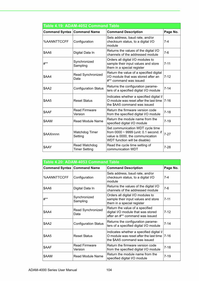
Table 4.19: ADAM-4052 Command Table
Command Syntax Command Name Command Description Page No.
%AANNTTCCFF ConfigurationSets address, baud rate, and/orchecksum status, to a digital I/Omodule
7-4
$AA6 Digital Data InReturns the values of the digital I/Ochannels of the addressed module
7-6
#**SynchronizedSampling
Orders all digital I/O modules to sample their input values and store them in a special register
7-11
$AA4Read SynchronizedData
Return the value of a specified digital I/O module that was stored after an #** command was issued
7-12
$AA2 Configuration StatusReturns the configuration parame-ters of a specified digital I/O module
7-14
$AA5 Reset StatusIndicates whether a specified digital I/O module was reset after the last time the $AA5 command was issued
7-16
$AAFRead FirmwareVersion
Return the firmware version code from the specified digital I/O module
7-18
$AAM Read Module NameReturn the module name from the specified digital I/O module
7-19
$AAXnnnnWatchdog TimerSetting
Set communication WDT cycle timefrom 0000 ~ 9999 (unit: 0.1 second. if value is 0000, the communication WDT function will be disable)
7-27
$AAYRead WatchdogTimer Setting
Read the cycle time setting of communication WDT
7-28
Table 4.20: ADAM-4053 Command Table
Command Syntax Command Name Command Description Page No.
%AANNTTCCFF ConfigurationSets address, baud rate, and/orchecksum status, to a digital I/Omodule
7-4
$AA6 Digital Data InReturns the values of the digital I/Ochannels of the addressed module
7-6
#**Synchronized Sampling
Orders all digital I/O modules tosample their input values and store them in a special register
7-11
$AA4Read SynchronizedData
Return the value of a specifieddigital I/O module that was stored after an #** command was issued
7-12
$AA2 Configuration StatusReturns the configuration parame-ters of a specified digital I/O module
7-14
$AA5 Reset StatusIndicates whether a specified digital I/O module was reset after the last time the $AA5 command was issued
7-16
$AAFRead Firmware Version
Return the firmware version code from the specified digital I/O module
7-18
$AAM Read Module NameReturn the module name from the specified digital I/O module
7-19
ADAM-4000 Series User Manual 104

Chapter 4
Com
mand
Set
Table 4.21: ADAM-4055 Command Table
Command Syntax Command Name Command Description Page No.
%AANNTTCCFF ConfigurationSets the address, baud rate, and/orchecksum status to a digital I/Omodule
7-4
#AABB(data) Digital Data OutWrites specified values to either a single channel or all channels simul-taneously
7-8
#**SynchronizedSampling
Orders all digital I/O modules to sample their input values and store them in special registers
7-11
$AA2 Configuration StatusReturns the configuration parametersof a specified digital I/O module
7-14
$AA4Read SynchronizedData
Returns the value of a specified digi-tal I/O module that was stored in the specified register after an #** com-mand was issued
7-12
$AA5 Reset StatusIndicates whether a specified digitalI/O module was reset after the last time that $AA5 command was issued
7-16
$AA6 Digital Data InReturns the values of the digital I/Ochannel in the addressed module
7-6
$AAFRead Firmware Version
Return the firmware version code from the specified digital I/O module
7-18
$AAM Read Module NameReturn the module name from thespecified digital I/O module
7-19
$AAX0TTTTDD Write Safety ValueForce the DO channels to safety sta-tus when communication is time-out and over pre-defined period.
7-21
$AAX1 Read Safety ValueRead the time-out setting and pre-defined safety status of DO channels.
7-22
$AAX2 Read Safety Flag
Requests the Safty Flag of the addressed digital I/O module to see whether the safety value has been executed since Write Safety Value command was set.
7-23
105 ADAM-4000 Series User Manual

Table 4.22: ADAM-4056S Command Table
Command Syntax Command Name Command Description Page No.
%AANNTTCCFF ConfigurationSets the address, baud rate, and/orchecksum status to a digital I/Omodule
7-4
#AABB(data) Digital Data OutWrites specified values to either asingle channel or all channels simul-taneously
7-8
$AA2 Configuration StatusReturns the configuration parame-ters of a specified digital I/O module
7-14
$AA5 Reset StatusIndicates whether a specified digitalI/O module was reset after the last time that $AA5 command was issued
7-16
$AA6 Digital Data InReturns the values of the digital I/Ochannel in the addressed module
7-6
$AAFRead FirmwareVersion
Return the firmware version codefrom the specified digital I/O module
7-18
$AAM Read Module NameReturn the module name from the specified digital I/O module
7-19
$AAX0TTTTDD Write Safety ValueForce the DO channels to safetystatus when communication is time-out and over pre-defined period.
7-21
$AAX1 Read Safety ValueRead the time-out setting andpre-defined safety status of DOchannels.
7-22
$AAX2 Read Safety Flag
Requests the Safty Flag of theaddressed digital I/O module to see whether the safety value has been executed since Write Safety Value command was set.
7-23
$AAXnnnnWatchdog TimerSetting
Set communication WDT cycle timefrom 0000 ~ 9999 (unit: 0.1 second. if value is 0000, the communication WDT function will be disable)
7-27
$AAYRead WatchdogTimer Setting
Read the cycle time setting ofcommunication WDT
7-28
ADAM-4000 Series User Manual 106

Chapter 4
Com
mand
Set
Table 4.23: ADAM-4056SO Command Table
Command Syntax Command Name Command Description Page No.
%AANNTTCCFF ConfigurationSets the address, baud rate, and/or checksum status to a digital I/O module
7-4
#AABB(data) Digital Data OutWrites specified values to either asingle channel or all channels simul-taneously
7-8
$AA2 Configuration StatusReturns the configuration parame-ters of a specified digital I/O module
7-14
$AA5 Reset StatusIndicates whether a specified digital I/O module was reset after the last time that $AA5 command was issued
7-16
$AA6 Digital Data InReturns the values of the digital I/O channel in the addressed module
7-6
$AAFRead FirmwareVersion
Return the firmware version code from the specified digital I/O module
7-18
$AAM Read Module NameReturn the module name from the specified digital I/O module
7-19
$AAX0TTTTDD Write Safety ValueForce the DO channels to safety status when communication is time-out and over pre-defined period.
7-21
$AAX1 Read Safety ValueRead the time-out setting and pre-defined safety status of DO channels.
7-22
$AAX2 Read Safety Flag
Requests the Safety Flag of the addressed digital I/O module to see whether the safety value has been executed since Write Safety Value command was set.
7-23
$AAE0Read and Clear OverCurrent Status Flag
Read the Over Current Status Flag and Clear the Flag simultaneously
7-24
$AAXnnnnWatchdog TimerSetting
Set communication WDT cycle time from 0000 ~ 9999 (unit: 0.1 second. if value is 0000, the communication WDT function will be disable)
7-27
$AAYRead WatchdogTimer Setting
Read the cycle time setting ofcommunication WDT
7-28
107 ADAM-4000 Series User Manual

Table 4.24: ADAM-4060/4068 Command Table
Command Syntax Command Name Command Description Page No.
%AANNTTCCFF ConfigurationSets address, baud rate, and/orchecksum status, to a digital I/Omodule
7-4
$AA6 Digital Data InReturns the values of the digital I/O channels of the addressed module
7-6
#AABB(data) Digital Data OutWrites specified values to either asingle channel or all channels simul-taneously
7-8
#**Synchronized Sampling
Orders all digital I/O modules to sam-ple their input values and store them in a special register
7-11
$AA4Read Synchronized Data
Return the value of a specified digital I/O module that was stored after an #** command was issued
7-12
$AA2 Configuration StatusReturns the configuration parame-ters of a specified digital I/O module
7-14
$AA5 Reset StatusIndicates whether a specified digital I/O module was reset after the last time the $AA5 command was issued
7-16
$AAFRead Firmware Version
Return the firmware version code from the specified digital I/O module
7-18
$AAM Read Module NameReturn the module name from the specified digital I/O module
7-19
$AAX0TTTTDD Write Safety ValueForce the DO channels to safety sta-tus when communication is time-out and over pre-defined period.
7-21
$AAX1 Read Safety ValueRead the time-out setting and pre-defined safety status of DO channels.
7-22
$AAX2 Read Safety Flag
Requests the Safety Flag of the addressed digital I/O module to see whether the safety value has been executed since Write Safety Value command was set.
7-23
ADAM-4000 Series User Manual 108

Chapter 4
Com
mand
Set
Table 4.25: ADAM-4069 Command Table
Command Syntax Command Name Command Description Page No.
%AANNTTCCFF ConfigurationSets address, baud rate, and/or checksum status, to a digital I/O mod-ule
7-4
$AA6 Digital Data InReturns the values of the digital I/O channels of the addressed module
7-6
#AABB(data) Digital Data OutWrites specified values to either a single channel or all channels simul-taneously
7-8
$AA2 Configuration StatusReturns the configuration parame-ters of a specified digital I/O module
7-14
$AA5 Reset StatusIndicates whether a specified digital I/O module was reset after the last time the $AA5 command was issued
7-16
$AAFRead FirmwareVersion
Return the firmware version code from the specified digital I/O module
7-18
$AAM Read Module NameReturn the module name from the specified digital I/O module
7-19
$AAX0TTTTDD Write Safety ValueForce the DO channels to safety status when communication is time-out and over pre-defined period.
7-21
$AAX1 Read Safety ValueRead the time-out setting and pre-defined safety status of DO channels.
7-22
$AAPRead low power status
The command requests the module at address AA to return the low power status of module
7-25
$AAS Set low power statusThe command requests the module at address AA to set and return the low power mode of module
7-26
Table 4.26: ADAM-4080 Command Table
Command Syntax Command Name Command Description Page No.
%AANNTTCCFF Configuration
Sets the address, input mode, baud rate, checksum status and/or fre-quency gate time for a specified counter/ frequency module
7-28
109 ADAM-4000 Series User Manual

$AA2 Configuration StatusReturns configuration parametersfrom the specified counter/frequency module
7-30
$AAFRead FirmwareVersion
Return firmware version code fromthe specified counter/frequency mod-ule
7-31
$AAM Read Module NameReturn the module name from the specified counter/frequency module
7-32
$AABSSet Input SignalMode
Sets the input signal mode of the specified counter/frequency module to either non-isolated or photo-iso-lated input signals
7-33
$AABRead Input SignalMode
Read the input signal mode of thespecified counter/frequency module.
7-34
#AANRead Counter orFrequency Value
Returns the value of counter 0 or counter 1 from a specified counter/ frequency module in hex format
7-35
$AAAG Set Gate ModeRequests the specified counter/frequency module to set its gate mode to either high, low or disabled
7-40
$AAA Read Gate ModeRequests the specified counter/frequency module to return the status of its gate mode
7-41
$AA3N(data)Set MaximumCounter Value
Sets the maximum value of counter 0 or counter 1 for the specified counter/frequency module
7-42
$AA3NRead MaximumCounter Value
Reads the maximum value of counter 0 or counter 1 of the specified counter/frequency module
7-43
$AA5NS Start/Stop CounterThe command orders the specified counter/frequency module to start or stop counting
7-44
$AA5NRead CounterStart/Stop Status
The addressed counter frequency module returns its status indicating whether counting is enabled or dis-abled
7-45
$AA6N Clear CounterThe command clears the counter 0 or counter 1 of the specified counter module
7-46
$AA7N Read Overflow FlagThe addressed module returns the status of the overflow flag of counter 0 or counter 1
7-47
$AA4SEnable/DisableDigital Filter
Enables or disables the digital filter of the addressed counter/frequency module
7-49
$AA4 Read Filter StatusThe addressed counter frequencymodule returns the status of its digital filter
7-50
$AA0H(data)Set Minimum Input Signal Width at High Level
Sets the minimum input signal width at high level for a specified counter/frequency module
7-51
Table 4.26: ADAM-4080 Command Table
ADAM-4000 Series User Manual 110

Chapter 4
Com
mand
Set
No.
$AA0HRead Minimum Input Signal Width at High Level
Reads the minimum input signal width setting at high level for a speci-fied counter/frequency module
7-52
$AA0L(data)Set Minimum Input Signal Width at Low Level
Sets the minimum input signal width at low level for a specified counter/frequency module
7-53
$AA0LRead Minimum Input Signal Width at Low Level
Reads minimum input signal width setting at low level for a specified counter/frequency module
7-54
$AA1H(data)Set Non-isolated High Trigger Level
Sets the high trigger level of non-iso-lated input signals for a specified counter/frequency module
7-55
$AA1HRead Non-isolated High Trigger Level
Requests the addressed counterfrequency module to return the high trigger level for non-
7-56
$AA1L(data)Set Non-isolated Low Trigger Level
isolated input signals 7-57
$AA1LRead Non-isolated Low Trigger Level
Sets the low trigger level of non-iso-lated input signals for a specified counter/frequency module
7-58
@AAPN(data)Set Initial CountValue of Counter N
Sets the initial count value of the module for counter 0 or counter 1
7-61
@AAGNRead Initial CountValue of Counter N
Reads the initial count value ofcounter 0 or counter 1
7-62
@AAEANEnable Alarm ofCounter N
Enable alarm for the specifiedcounter 0 or counter 1
7-63
@AADANDisable Alarm ofCounter N
Disable alarm for the specifiedcounter 0 or counter 1
7-64
@AAPA(data)Set Alarm Limit Valueof Counter 0
Download the alarm limit value forcounter 0 of the specified module
7-65
@AASA(data)Set Alarm Limit Valueof Counter 1
Download the alarm limit value forcounter 1 of the specified module
7-65
@AARPRead Alarm LimitValue of Counter 0
Ask the module to return the alarmlimit value of counter 0
7-66
@AARARead Alarm LimitValue of Counter 1
Ask the module to return the alarm limit value of counter 1
7-66
@AADO (data)Set Digital OutputValues
Set the values of the module's twodigital outputs (ON or OFF)
7-67
@AADIRead Digital Outputand Alarm Status
Ask the module to return thestatus state of its two digital outputs and the status of its alarm.
7-68
Table 4.27: ADAM-4080D Command Table
Command Syntax Command Name Command Description Page No.
Table 4.26: ADAM-4080 Command Table
111 ADAM-4000 Series User Manual

%AANNTTCCFF Configuration
Sets the address, input mode, baud rate, checksum status and/or fre-quency gate time for a specified counter/ frequency module
7-28
$AA2 Configuration StatusReturns configuration parametersfrom the specified counter/frequency module
7-30
$AAFRead FirmwareVersion
Return firmware version code from the specified counter/frequency mod-ule
7-31
$AAM Read Module NameReturn the module name from the specified counter/frequency module
7-32
$AABSSet Input SignalMode
Sets the input signal mode of the specified counter/frequency module to either non-isolated or photo-iso-lated input signals
7-33
$AABRead Input SignalMode
Read the input signal mode of thespecified counter/frequency module.
7-34
#AANRead Counter orFrequency Value
Returns the value of counter 0 orcounter 1 from a specified counter/frequency module in hex format
7-35
$AA8VSelect LED DataOrigin
Select whether LED will display data from the counter/frequency module directly or from the host computer
7-36
$AA8Read LED DataOrigin
Returns the status of the LED Dataorigin. Origin is either direct from module or from host computer
7-37
$AA9(data) Send Data to LED
The host computer sends data to the addressed module to display on its LED. This command is valid only after selecting to display host computer data ($AA8V)
7-38
$AAAG Set Gate ModeRequests the specified counter/ fre-quency module to set its gate mode to either high, low or disabled
7-40
$AAA Read Gate ModeRequests the specified counter/ frequency module to return the status of its gate mode
7-41
$AA3N(data)Set MaximumCounter Value
Sets the maximum value of counter0 or counter 1 for the specified coun-ter/frequency module
7-42
$AA3NRead MaximumCounter Value
Reads the maximum value of counter 0 or counter 1 of the specified coun-ter/ frequency module
7-43
$AA5NS Start/Stop CounterThe command orders the specifiedcounter/frequency module to start or stop counting
7-44
$AA5NRead CounterStart/Stop Status
The addressed counter frequencymodule returns its status indicating whether counting is enabled or dis-abled
7-45
$AA6N Clear CounterThe command clears the counter 0or counter 1 of the specified counter module
7-46
Table 4.27: ADAM-4080D Command Table
ADAM-4000 Series User Manual 112

Chapter 4
Com
mand
Set
$AA7N Read Overflow FlagThe addressed module returns thestatus of the overflow flag of counter 0 or counter 1
7-47
$AA4SEnable/DisableDigital Filter
Enables or disables the digitalfilter of the addressed counter/fre-quency module
7-49
$AA4 Read Filter StatusThe addressed counter frequencymodule returns the status of its digital filter
7-50
$AA0H(data)Set Minimum InputSignal Width at HighLevel
Sets the minimum input signal width at high level for a specified counter/frequency module
7-51
$AA0HRead Minimum Input Signal Width at High Level
Reads the minimum input signal width setting at high level for a speci-fied counter/frequency module
7-52
$AA0L(data)Set Minimum InputSignal Width at LowLevel
Sets the minimum input signal width at low level for a specified counter/frequency module
7-53
$AA0LRead Minimum InputSignal Width at LowLevel
Reads minimum input signal width setting at low level for a specified counter/frequency module
7-54
$AA1H(data)Set Non-isolatedHigh Trigger Level
Sets the high trigger level of non-iso-lated input signals for a specified counter/frequency module
7-55
$AA1HRead Non-isolatedHigh Trigger Level
Requests the addressed counterfrequency module to return the high trigger level for non-isolated input sig-nals
7-56
$AA1L(data)Set Non-isolated LowTrigger Level
Sets the low trigger level of non-iso-lated input signals for a specified counter/frequency module
7-57
$AA1LRead Non-isolatedLow Trigger Level
Sets the low trigger level of non-iso-lated input signals for a specified counter/frequency module
7-58
@AAEAT Enable AlarmEnable the alarm in either momentary or latching mode
7-69
@AADA Disable Alarm Disable all alarm functions 7-70
@AACA Clear Latch Alarm The latch alarm is reset 7-71
@AAPA(data)Set Low-AlarmCount Value ofCounter 0
Downloads the low-alarm count value for counter 0 of the specified counter/frequency module
7-72
@AASA(data)Set High-AlarmCount Value ofCounter 0
Downloads the high-alarm count value for counter 0 of the specified counter/frequency module
7-73
@AARPRead Low-AlarmCount Value ofCounter 0
Ask the addressed module to return its low-alarm count value for counter 0
7-74
@AARARead High-AlarmCount Value ofCounter 0
Ask the addressed module to return its high-alarm count value for counter 0
7-75
@AADO(data)Set Digital OutputValues
Set the values of the module's twodigital outputs(ON or OFF)
7-67
Table 4.27: ADAM-4080D Command Table
113 ADAM-4000 Series User Manual

@AADIRead Digital Outputand Alarm Status
Ask the module to return the statusstate of its two digital outputs and the status of its alarm.
7-68
Table 4.27: ADAM-4080D Command Table
ADAM-4000 Series User Manual 114

Chapter 5
5 Analog Input Module Command Set
5.1 Analog Input Common Command Set
Command Syntax Description I/O Module
%AANNTTCCFF Sets the address, input range,baud rate, data format, checksum status, and/or integration time for a specified analog input module
4011, 4011D, 4012, 4013, 4015,4015T, 4016, 4017, 4017+, 4018,4018+, 4018M, 4019+
$AA2 Returns the configuration parame-ters for the specified analog input module
4011, 4011D, 4012, 4013, 4015,4015T, 4016, 4017, 4017+, 4018,4018+, 4018M, 4019+
$AAF Returns the firmware versioncode from the specified analog input module
4011, 4011D, 4012, 4013, 4015,4015T, 4016, 4017, 4017+, 4018,4018+, 4018M, 4019+
$AAM Returns the module name from the specified analog input module
4011, 4011D, 4012, 4013, 4015,4015T, 4016, 4017, 4017+, 4018,4018+, 4018M, 4019+
#AA Returns the input value from aspecified analog input moudule in the currently configured data for-mat
4011, 4011D, 4012, 4013, 4015,4015T, 4016, 4017, 4017+, 4018,4018+, 4019+
#AAN Returns the input value fromchannel number n of the specified analog input module
4015, 4015T, 4017, 4017+, 4018,4018+, 4018M, 4019+
$AA5VV Enables/disables multiplexingsimultaneously for separate chan-nels of the specified input module
4015, 4015T, 4017, 4017+, 4018,4018+, 4018M, 4019+
$AA6 Ask the specified input module to return the status of all eight chan-nels
4015, 4015T, 4017, 4017+, 4018+,4018, 4018M, 4019+
$AA0 Calibrate the analog input module to correct for gain errors
4011, 4011D, 4012, 4013, 4016,4017, 4018, 4018M
$AA1 Calibrate the analog input module to correct for offset errors.
4011, 4011D, 4012, 4013, 4016,4017, 4018, 4018M
#** Orders all analog input modules to sample their input values and store them in special registers
4011, 4011D, 4012, 4013, 4015,4015T, 4016
$AA4 Returns the value that was stored in the specified module's register after the #** command
4011, 4011D, 4012, 4013, 4015,4015T, 4016
$AAB Ask the module to respond whether the wiring is open or closed
4011D, 4015, 4015T, 4018+,4019+
$AA3 Returns the value of the CJC sen-sor for a specified analog input module
4011, 4011D, 4018, 4018+,4018M, 4019+
$AA9 Calibrates the CJC sensor for offset errors
4011, 4011D, 4018, 4018+, 4018M4019+
$AA0Ci Calibrates a specified channel to correct for gain errors
4015, 4015T, 4017+, 4018+, 4019+
$AA1Ci Calibrates a specified channel to correct for offset errors
4015, 4015T, 4017+, 4018+, 4019+
ADAM-4000 Series User Manual 116

Chapter 5
Analog
InputModule
Com
mand
Set
4011, 4011D, 4012, 4013, 4015, 4015T, 4016, 4017, 4017+, 4018, 4018+, 4018M, 4019+
5.1.1 %AANNTTCCFFName Configuration command
Description Sets address, input range, baud rate, data format, checksum status,and/or integration time for an analog input module.
Syntax %AANNTTCCFF(cr)
% is a delimiter character.
AA (range 00-FF) represents the 2-character hexadecimal
address of the analog input module you want to configure.
NN represents the new hexadecimal address of the analog
input module. Range is from 00h to FFh.
TT represents the type (input range) code. (Note: 4015 and
4019 must be 00)
(Refer to Table 5-1 on Page 5-6)
CC represents the baud rate code.
(Refer to Table 5-2 on Page 5-8)
FF is a hexadecimal number that equals the 8-bit parameter
representing the data format, checksum status and
integration time. The layout of the 8-bit parameter is shown
in Figure 5-1. Bits 2 through 5 are not used and are set to 0.
(cr) is the terminating character, carriage return (0Dh)
$AA7CiRrr Configure the input type andrange of the specified channel in an analog input module
4015, 4015T, 4017+, 4018+, 4019+
$AA8Ci Get the input type and range of the specified channel in an analog input module
4015, 4015T, 4017+, 4018+, 4019+
$AAXnnnn Communication Watchdog TimerSetting
4015, 4015T, 4017+, 4018+,4019+
$AAY Read Communication WatchdogTimer Setting
4015, 4015T, 4017+, 4018+, 4019+
$AAS0 Internal self-calibration for offsetand gain errors
4015, 4015T
$AAS1 Reload factory default calibrating parameter to overwrite current cal-ibrating parameter
4015, 4015T
117 ADAM-4000 Series User Manual

Figure 5.1 Data format for FF (8-bit parameter)
Response !AA(cr) if the command is valid.
?AA(cr) if an invalid parameter was entered or if the INIT*
terminal was not grounded when attempting to change baud
rate or checksum settings.
There is no response if the module detects a syntax error or
communication error or if the specified address does not exist.
! delimiter character indicates a valid command was received.
? delimiter character indicates the command was invalid
AA (range 00-FF) represents the 2-character hexadecimal
address of an analog input module.
(cr) is the terminating character, carriage return (0Dh)
Example command:%2324050600(cr)
response: !24(cr)
The ADAM-4011 module with address 23h is configured to
a new address of 24h, an input range ±2.5 V, baud rate
9600, integration time 50 ms (60 Hz), engineering units
data format and no checksum checking or generation.
The response indicates that the command was received.
Wait 7 seconds to let the new configuration settings take
effect before issuing a new command to the module.
Caution! Only ADAM-4011, ADAM-4011D, ADAM-4012, ADAM-4013, ADAM-4016 and ADAM-4018+ support “% of FSR” and “two’s complement of hexadecimal” Data Format.
Caution! An analog input module requires a maximum of 7 seconds to perform auto calibration and ranging after it is reconfigured.
During this time span, the module cannot be addressed to perform any other actions.
Caution! All configuration parameters can be changed dynamically, except checksum and baud rate parameters. They can only be altered when the INIT* terminal is grounded. (Refer to Baud rate and Checksum con-figuration in Chapter 2, for the correct procedure)
7 6 5 4 3 2 1 0
Checksum status0: Disabled1: Enabled
Integration time0: 50 ms (Operation under 60 Hz power)1: 60 ms (Operation under 50 Hz power)
not used 00: Engineering units01: % of FSR10: two's complement of hexadecimal11: Ohms (for 4013 and 4015)
Data Format
ADAM-4000 Series User Manual 118
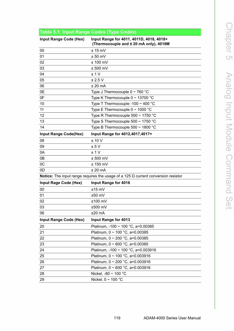
Chapter 5
Analog
InputModule
Com
mand
Set
Table 5.1: Input Range Codes (Type Codes)
Input Range Code (Hex) Input Range for 4011, 4011D, 4018, 4018+ (Thermocouple and ± 20 mA only), 4018M
00 ± 15 mV
01 ± 50 mV
02 ± 100 mV
03 ± 500 mV
04 ± 1 V
05 ± 2.5 V
06 ± 20 mA
0E Type J Thermocouple 0 ~ 760 °C
0F Type K Thermocouple 0 ~ 13700 °C
10 Type T Thermocouple -100 ~ 400 °C
11 Type E Thermocouple 0 ~ 1000 °C
12 Type R Thermocouple 500 ~ 1750 °C
13 Type S Thermocouple 500 ~ 1750 °C
14 Type B Thermocouple 500 ~ 1800 °C
Input Range Code(Hex) Input Range for 4012,4017,4017+
08 ± 10 V
09 ± 5 V
0A ± 1 V
0B ± 500 mV
0C ± 150 mV
0D ± 20 mA
Notice: The input range requires the usage of a 125 Ω current conversion resistor
Input Rage Code (Hex) Input Range for 4016
00 ±15 mV
01 ±50 mV
02 ±100 mV
03 ±500 mV
06 ±20 mA
Input Range Code (Hex) Input Range for 4013
20 Platinum, -100 ~ 100 °C, a=0.00385
21 Platinum, 0 ~ 100 °C, a=0.00385
22 Platinum, 0 ~ 200 °C, a=0.00385
23 Platinum, 0 ~ 600 °C, a=0.00385
24 Platinum, -100 ~ 100 °C, a=0.003916
25 Platinum, 0 ~ 100 °C, a=0.003916
26 Platinum, 0 ~ 200 °C, a=0.003916
27 Platinum, 0 ~ 600 °C, a=0.003916
28 Nickel, -80 ~ 100 °C
29 Nickel, 0 ~ 100 °C
119 ADAM-4000 Series User Manual

Table 5.2: ADAM-4015/4015T command codes against Input ranges table
Command Code (Hex) Input Type Input Range
20 Platinum 100 (IEC) -50 ~ 150 °C
21 Platinum 100 (IEC) 0 ~ 100 °C
22 Platinum 100 (IEC) 0 ~ 200 °C
23 Platinum 100 (IEC) 0 ~ 400 °C
24 Platinum 100 (IEC) -200 ~ 200 °C
25 Platinum 100 (JIS) -50 ~ 150 °C
26 Platinum 100 (JIS) 0 ~ 100 °C
27 Platinum 100 (JIS) 0 ~ 200 °C
28 Platinum 100 (JIS) 0 ~ 400 °C
29 Platinum 100 (JIS) -200 ~ 200 °C
2A Platinum 1000 -40 ~ 160 °C
2B BALCO 500 -30 ~ 120 °C
2C Ni 604 -80 ~ 100 °C
2D Ni 604 0 ~ 100 °C
30 Thermistor 3K 0 ~ 100 °C
31 Thermistor 10K 0 ~ 100 °C
33 Ni 508 -50 ~ 200 °C
IEC RTD 100O, α = 0.00385JIS RTD 100O, α = 0.00391
Input Range Code (Hex) Input Range for 4019+
02 ± 100 mV
03 ± 500 mV
04 ± 1 V
05 ± 2.5 V
07 +4~20mA
08 ± 10 V
09 ± 5 V
0D ± 20 mA
0E Type J Thermocouple 0 ~ 760 °C
0F Type K Thermocouple 0 ~1370 °C
10 Type T Thermocouple -100 ~ 400 °C
11 Type E Thermocouple 0 ~ 1000 °C
12 Type R Thermocouple 500 ~ 1750 °C
13 Type S Thermocouple 500 ~ 1750 °C
14 Type B Thermocouple 500 ~ 1800 °C
ADAM-4000 Series User Manual 120

Chapter 5
Analog
InputModule
Com
mand
Set
4011, 4011D, 4012, 4013, 4015, 4015T, 4016, 4017, 4017+, 4018, 4018+, 4018M, 4019+
5.1.2 $AA2Name Configuration Status command
Description The command requests the return of the configuration data
from the analog input module at address AA.
Syntax $AA2(cr)
$ is a delimiter character.
AA (range 00-FF) represents the 2-character hexadecimal
address of the analog input module that you want to interrogate.
2 is the Configuration Status command.
(cr) is the terminating character, carriage return (0Dh).
Response !AATTCCFF(cr) if the command is valid.
?AA(cr) if an invalid operation was entered.
There is no response if the module detects a syntax error or
communication error or if the specified address does not exist.
! delimiter character indicates a valid command was received.
? delimiter character indicates the command was invalid.
AA (range 00-FF) represents the 2-character hexadecimal
address of an analog input module.
TT represents the type code. Type code determines the input range.
CC represents the baud rate code.
FF is a hexadecimal number that equals the 8-bit parameter
that represents the data format, checksum status and
integration time. The layout of the 8-bit parameter is shown
in figure 4-1. Bits 2 to 5 are not used, and are set to 0.
(cr) is the terminating character, carriage return (0Dh).
(Please refer to %AANNTTCCFF configuration command
to see TT, CC and FF parameter definition)
Table 5.3: Baud Rate Codes
Baud Rate Code (Hex) Baud Rate
03 1200 bps
04 2400 bps
05 4800 bps
06 9600 bps
07 19.2 kbps
08 38.4 kbps
121 ADAM-4000 Series User Manual

Example command: $452(cr)
response: !45050600(cr)
The command asks the analog input module at address 45h
to send its configuration data.
The analog input module at address 45h responds with an
input range of 2.5 volts, a baud rate of 9600 bps, an
integration time of 50 ms (60 Hz), engineering units are the
currently configured data format, and no checksum
function or checksum generation.
4011, 4011D, 4012, 4013, 4015, 4015T, 4016, 4017, 4017+, 4018, 4018+, 4018M, 4019+
5.1.3 $AAFName Read Firmware Version command
Description The command requests the analog input module at address
AA to return the version code of its firmware.
Syntax $AAF (cr)
$ is a delimiter character.
AA (range 00-FF) represents the 2-character hexadecimal
address of the analog input module that you want to interrogate.
F is the Read Firmware Version command.
(cr) is the terminating character, carriage return (ODh).
Response !AA(Version)(cr) if the command is valid.
There is no response if the module detects a syntax error or
communication error, or if the specified address does not exist.
! is a delimiter character indicating a valid command was received.
AA (range 00-FF) represents the 2-character hexadecimal
address of an analog input module.
(Version) is the version code of the module’s firmware at address AA.
(cr) is the terminating character, carriage return (ODh).
ADAM-4000 Series User Manual 122

Chapter 5
Analog
InputModule
Com
mand
Set
4011, 4011D, 4012, 4013, 4015, 4015T, 4016, 4017, 4017+, 4018, 4018+, 4018M, 4019+
5.1.4 $AAMName Read Module Name command
Description The command requests the analog input module at address
AA to return its name.
Syntax $AAM (cr)
$ is a delimiter character.
AA (range 00-FF) represents the 2-character hexadecimal
address of the analog input module that you want to interrogate.
M is the Read Module Name command.
(cr) is the terminating character, carriage return (ODh).
Response !AA(Module Name)(cr) if the command is valid.
There is no response if the module detects a syntax error or
communication error, or if the specified address does not exist.
! is a delimiter character indicating a valid command was received.
AA (range 00-FF) represents the 2-character hexadecimal
address of an analog input module.
(Module Name) is the name of the module at address AA.
(cr) is the terminating character, carriage return (ODh).
123 ADAM-4000 Series User Manual

4011, 4011D, 4012, 4013, 4015, 4015T, 4016, 4017, 4017+, 4018, 4018+, 4018M, 4019+
5.1.5 #AAName Analog Data In command
Description The command will return the input value from a specified
(AA) module in the currently configured data format.
Syntax #AA(cr)
# is a delimiter character.
AA (range 00-FF) represents the 2-character hexadecimal
address of an analog input module.
(cr) is the terminating character, carriage return (0Dh).
Response >(data)(cr)
There is no response if the module detects a syntax error or
communication error or if the specified address does not exist.
> is a delimiter character.
(data) is the input value in the configured data format of
the interrogated module.
(For data formats, see Appendix B).
(cr) is the terminating character, carriage return (0Dh).
Example command: #21(cr)
response: >+7.2111+7.2567+7.3125+7.1000
+7.4712+7.2555+7.1234+7.5678 (cr)
The command interrogates the analog input module at
address 21h for its input values of all channels.
The analog input module responds with channels from 0 to
7 with +7.2111 volts, +7.2567 volts, +7.3125 volts,
+7.1000 volts, +7.4712 volts, +7.2555 volts, +7.1234 volts
and +7.5678 volts.
Example command: #DE(cr)
response: >FF5D(cr)
The analog input module at address DEh has an input value
of FF5D. (The configured data format of the analog input
module is two’s complement)
Two’s complement % of Span Engineering units
under 0000 -0000 -0000
over FFFF +9999 +9999
ADAM-4000 Series User Manual 124

Chapter 5
Analog
InputModule
Com
mand
Set
In the next example the target module is configured for an input range of T/C type J(Input range: 0 ~ 760 ?) and for a data format in engineering units. The module mea-sures an input value of 820 °C.
Example command: #D1(cr)
response: >+9999(cr)
By returning a high value, +9999, the module at address
D1h indicates that the measured input value exceeds the
configured range.
Caution! When modules measure Thermocouple or RTD input values that are outside their configured range they will send data that implies input out of bounds. The next table shows the values that the modules will return, depending on the configured data format and if the input value falls under or exceeds the configured range.
Only when modules are configured for Thermocouple or RTD, “input out of bounds” warning will occur. When analog input modules measure voltage or current that falls outside the configured range, they will return the actual measured input!
125 ADAM-4000 Series User Manual

4015, 4015T, 4017, 4017+, 4018,4018+, 4018M, 4019+
5.1.6 #AANName Read Analog Input from Channel N command
Description The command will return the input value from one of the
eight channels of a specified (AA) module in the currently
configured data format.
Syntax #AAN(cr)
# is a delimiter character.
AA (range 00-FF) represents the 2-character hexadecimal
address of the analog input module.
N identifies the channel you want to read. The value can
range from 0 to 7 for 4017, 4018, 4018M, 4019. (The range
of 4015 is from 0 to 5)
(cr) is the terminating character, carriage return (0Dh).
Response >(data)(cr)
There is no response if the module detects a syntax error or
communication error or if the specified address does not exist.
> is a delimiter character.
(data) is the input value of the channel number N. Data
consists of a + or - sign followed by five decimal digits
with a fixed decimal point.
(cr) is the terminating character, carriage return (0Dh).
Example command: #120(cr)
response: >+1.4567(cr)
The command requests the analog input module at address
12h to return the input value of channel 0.
The analog input module responds that the input value of
channel 0 is equal to +1.4567 volts.
ADAM-4000 Series User Manual 126

Chapter 5
Analog
InputModule
Com
mand
Set
4015, 4015T, 4017, 4017+, 4018,4018+, 4018M, 4019+
5.1.7 $AA5VVName Enable/disable Channels for Multiplexing command
Description Enables/disables multiplexing simultaneously for separate
channels of a specified input module.
Syntax $AA5VV(cr)
$ is a delimiter character.
AA (range 00-FF) represents the 2-character hexadecimal
address of analog input module.
5 is the Enable/disable Channels command.
VV are two hexadecimal values. The values are interpreted
by the module as two binary words (4-bit). The first word
represents the status of channel 4~7, and the second word
represents the status of channel 0~3. Value 0 means the
channel is disabled, value 1 means the channel is enabled.
(cr) is the terminating character, carriage return (0Dh).
Response !AA(cr) if the command is valid.
?AA(cr) if an invalid operation was entered.
There is no response if the module detects a syntax error or
communication error or if the specified address does not exist.
! delimiter character indicates a valid command was received.
? delimiter character indicates the command was invalid.
AA (range 00-FF) represents the 2-character hexadecimal
address of an analog input module.
(cr) is the terminating character, carriage return (0Dh).
Example command: $00581(cr)
response: !00(cr)
Hexadecimal 8 equals binary 1000, which enables channel
7 and disables channels 4, 5, and 6.
Hexadecimal 1 equals binary 0001, which enables channel
0 and disables channel 1, 2, and 3.
127 ADAM-4000 Series User Manual

4015, 4015T, 4017, 4017+, 4018,4018+, 4018M, 4019+
5.1.8 $AA6Name Read Channel Status command
Description Asks a specified input module to return the status of all channels.
Syntax $AA6(cr)
AA (range 00-FF) represents the 2-character hexadecimal
address of analog input module of which the channel status
you want to send. The channel status defines whether a
channel is enabled or disabled.
6 is the Read Channel Status command.
(cr) is the terminating character, carriage return (0Dh).
Response !AAVV(cr) if the command is valid.
?AA(cr) if an invalid operation was entered.
There is no response if the module detects a syntax error or
communication error or if the specified address does not exist.
! delimiter character indicates a valid command was received.
? delimiter character indicates the command was invalid.
AA (range 00-FF) represents the 2-character hexadecimal
address of an analog input module.
VV are two hexadecimal values. The values are interpreted
by the module as two binary words (4-bit). The first word
represents the status of channel 4-7, and the second word
represents the status of channel 0-3. Value 0 means the
channel is disabled, value 1 means the channel is enabled.
(cr) is the terminating character, carriage return (0Dh).
Example command: $026(cr)
response: !02FF(cr)
The command asks the analog input module at address 02
to send the status of it input channels. The analog input
module at address 02 responds that all its multiplex
channels are enabled (FF equals 1111 and 1111).
ADAM-4000 Series User Manual 128
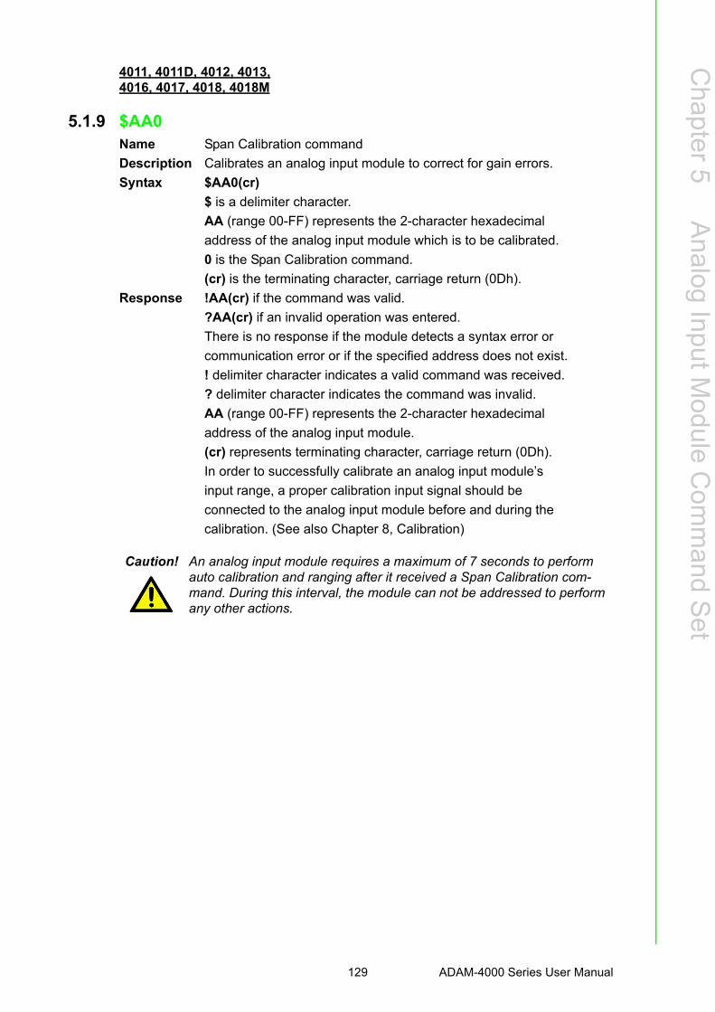
Chapter 5
Analog
InputModule
Com
mand
Set
4011, 4011D, 4012, 4013,4016, 4017, 4018, 4018M
5.1.9 $AA0Name Span Calibration command
Description Calibrates an analog input module to correct for gain errors.
Syntax $AA0(cr)
$ is a delimiter character.
AA (range 00-FF) represents the 2-character hexadecimal
address of the analog input module which is to be calibrated.
0 is the Span Calibration command.
(cr) is the terminating character, carriage return (0Dh).
Response !AA(cr) if the command was valid.
?AA(cr) if an invalid operation was entered.
There is no response if the module detects a syntax error or
communication error or if the specified address does not exist.
! delimiter character indicates a valid command was received.
? delimiter character indicates the command was invalid.
AA (range 00-FF) represents the 2-character hexadecimal
address of the analog input module.
(cr) represents terminating character, carriage return (0Dh).
In order to successfully calibrate an analog input module’s
input range, a proper calibration input signal should be
connected to the analog input module before and during the
calibration. (See also Chapter 8, Calibration)
Caution! An analog input module requires a maximum of 7 seconds to perform auto calibration and ranging after it received a Span Calibration com-mand. During this interval, the module can not be addressed to perform any other actions.
129 ADAM-4000 Series User Manual

4011, 4011D, 4012, 4013,4016, 4017, 4018, 4018M
5.1.10 $AA1Name Offset Calibration command
Description Calibrates an analog input module to correct for offset errors.
Syntax $AA1(cr)
$ is a delimiter character.
AA (range 00-FF) represents the 2-character hexadecimal
address of the analog input module you want to calibrate.
1 is the Offset Calibration command.
(cr) is the terminating character, carriage return (0Dh).
Response !AA(cr) if the command is valid.
?AA(cr) if an invalid operation was entered.
There is no response if the module detects a syntax error or
communication error or if the specified address does not exist.
! delimiter character indicates a valid command was received.
? delimiter character indicates the command was invalid.
AA (range 00-FF) represents the 2-character hexadecimal
address of the analog input module.
(cr) represents terminating character, carriage return (0Dh).
In order to successfully calibrate an analog input module’s
input range, a proper calibration input signal should be
connected to the analog input module before and during the
calibration. (See also Chapter 8, Calibration)
Caution! An analog input module requires a maximum of 7 seconds to perform auto calibration and ranging after it received an Offset Calibration com-mand. During this interval, the module can not be addressed to perform any other actions.
ADAM-4000 Series User Manual 130

Chapter 5
Analog
InputModule
Com
mand
Set
4011, 4011D, 4012, 4013,4015, 4015T, 4016
5.1.11 #**Name Synchronized Sampling mand com
Description Orders all analog input modules to sample their input
values and store the values in special registers.
Syntax #**
# is a delimiter character.
** is the Synchronized Sampling command.
The terminating character, in the form of a carriage return
(0Dh), is not required.
Response The analog input modules will send no response after
executing the synchronized sampling command. In order to
retrieve the data, a separate Read Synchronized Data
command has to be issued for every analog input module.
The pound sign (#) followed by two asterisks (**) does not
represent an optional value, but is the actual command string.
4011, 4011D, 4012, 4013,4015, 4015T, 4016
5.1.12 $AA4Name Read Synchronized Data command
Description Returns the input value that was stored in the addressed
module’s register, after a Synchronized Sampling command
#** was issued.
Syntax $AA4(cr)
$ is a delimiter character.
AA (range 00-FF) represents the 2-character hexadecimal
address of the analog input module from which data is to be sent.
4 is the Read Synchronized Data command.
(cr) is the terminating character, carriage return (0Dh).
Response !AA(status)(data)(cr) if the command was valid.
?AA(cr) if an invalid operation was entered.
There is no response if the module detects a syntax error or
communication error or if the specified address does not exist.
! delimiter character indicates a valid command was received.
AA (range 00-FF) represents the 2-character hexadecimal
address of the analog input module that is responding.
(status) will tell you if the data (data) from the last
Synchronized Sampling command (#**) has already been
sent. If status = 1, then the data has been sent for the first
time since a Synchronized Sampling command was issued.
If status = 0, then the data has been sent at least once before.
131 ADAM-4000 Series User Manual

(data) a value stored in a special register of the interrogated
module in the configured data format. It has been sampled
by the module after a Synchronized Sampling command.
(For possible data formats, see Appendix B, Data Formats
and I/O Ranges)
(cr) represents terminating character, carriage return (0Dh).
Example command: $074(cr)
response: >071+5.8222(cr)
The command asks the analog input module at address 07h
to send its analog input data.
The analog input module responds with status = 1, which
means that this is the first time that the data has been sent
and that the data = +5.8222 Volts.
(Configured data format of the analog input module in this
case is engineering units.)
command: $074(cr)
response: >070+5.8222(cr)
The command asks the analog input module at address 07h
to send its analog input data.
The analog input module responds with status = 0, which
means that it has sent the same data at least once before,
and data = +5.8222 Volts. This could indicate that a
previous Synchronized Sampling command was not received!
(Configured data format of the analog input module in this
case is engineering units.)
ADAM-4000 Series User Manual 132

Chapter 5
Analog
InputModule
Com
mand
Set
4011D, 4015, 4015T, 4018+, 4019+
5.1.13 $AABName Channel Diagnose command
Description Diagnose channel status in over range, under range, and
wire opening.
Syntax $AAB(cr)
$ is a delimiter character.
AA (range 00-FF) represents the 2-character hexadecimal
address of the analog input module to be detected.
B is the Channel Diagnose command.
(cr) is the terminating character, carriage return (0Dh).
Response ADAM-4011D:
!AA0(cr) if the module detects a close thermocouple.
!AA1(cr) if the module detects an open thermocouple.
?AA(cr) if an invalid command was issued.
ADAM-4015/4015T/4018+/4019+:
!AANN(cr) if the command is valid when it applied with.
?AA(cr) if an invalid command was issued.
There is no response if the module detects a syntax error or
communication error of if the specified address does not exist.
! delimiter character indicates a valid command was received.
? delimiter character indicates the command was invalid.
AA (range 00-FF) represents the 2-character hexadecimal
address of the analog input module.
NN (range 00-FF) is a hexadecimal number that equals the
8-bit parameter, representing the status of analog input
channels. Bit value 0 means normal status; and bit value 1
means channel over range, under range, or open wiring.
(cr) is the terminating character, carriage return (0Dh)
133 ADAM-4000 Series User Manual

4011, 4011D, 4018, 4018+, 4018M, 4019+
5.1.14 $AA3Name CJC Status command
Description Instructs the addressed analog input module to read its CJC
(Cold Junction Compensation) sensors and return the acquired data.
Syntax $AA3(cr)
$ is a delimiter character.
AA (range 00-FF) represents the 2-character hexadecimal
address of the analog input module which contains the CJC
Status you wish to retrieve.
3 is the CJC Status command.
(cr) is the terminating character, carriage return (0Dh).
Response >data(cr) if the command is valid.
?AA(cr) if an invalid command was issued.
There is no response if the module detects a syntax error or
communication error or if the specified address does not exist.
! delimiter character indicates a valid command was received.
? delimiter character indicates the command was invalid
AA (range 00-FF) represents the 2-character hexadecimal
address of an analog input module.
(data) is the value that is retrieved by the module by
reading its CJC sensor. The data format, in degrees Celsius,
consists an “+” or “-” sign followed by five decimal digits
and a fixed decimal point. The resolution of the data is 0.1 ° C.
(cr) is the terminating character, carriage return (0Dh).
Example command: $093(cr)
response: >+0036.8(cr)
The command requests the analog input module at address
09h to read its CJC sensor and return the data. The analog
input module at address 09h responds with: 36.8 °C.
ADAM-4000 Series User Manual 134

Chapter 5
Analog
InputModule
Com
mand
Set
4011, 4011D, 4018, 4018+, 4018M, 4019+
5.1.15 $AA9SNNNNName CJC Offset Calibration command
Description Calibrates an analog input module to adjust for offset errors
of its CJC (Cold Junction Compensation) sensors.
Syntax $AA9SNNNN(number of counts)(cr)
$ is a delimiter character.
AA (range 00-FF) represents the 2-character hexadecimal
address of the analog input module which contains the CJC
status you wish to retrieve.
9 is the CJC Status command.
S sign, + or -, indicates whether to increase or decrease the
CJC offset value.
NNNN (number of counts) is a four character hexadecimal
“count” value. Each count equals approximately 0.009 ?.
The value can range from 0000 to FFFF.
(cr) is the terminating character, carriage return (0Dh).
Response !AA(cr) if the command is valid.
?AA(cr) if an invalid command was issued.
There is no response if the module detects a syntax error or
communication error or if the specified address does not exist.
! delimiter character indicates a valid command was received.
? delimiter character indicates the command was invalid.
AA (range 00-FF) represents the 2-character hexadecimal
address of an analog input module.
(cr) is the terminating character, carriage return (0Dh).
Example command: $079+0042(cr)
response: !07(cr)
The command increases the CJC offset value of the analog
input module at address 07h with 66 counts (42 hex) which
equals about 0.6 °C.
Caution! An analog input module requires a maximum of 2 seconds to perform auto calibration and ranging after it received a CJC Calibration com-mand. During this interval, the module can not be addressed to perform any other actions.
135 ADAM-4000 Series User Manual

4015, 4015T, 4017+, 4018+, 4019+
5.1.16 $AA0CiName Single Channel Span Calibration command
Description The command calibrates a specified channel to correct for
gain errors.
Syntax $AA0Ci(cr)
$ is a delimiter character.
AA (range 00-FF) represents the 2-character hexadecimal
address of the analog input module which is to be calibrated.
0 is the Single Channel Span Calibration command.
Ci represents the specified input channel you want to calibrate.
(cr) is the terminating character, carriage return (0Dh).
Response !AA(cr) if the command was valid.
?AA(cr) if an invalid operation was entered.
There is no response if the module detects a syntax error or
communication error or if the specified address does not exist.
! delimiter character indicates a valid command was received.
? delimiter character indicates the command was invalid.
AA (range 00-FF) represents the 2-character hexadecimal
address of the analog input module.
(cr) represents terminating character, carriage return (0Dh).
In order to successfully calibrate an analog input module’s
input range, a proper calibration input signal should be
connected to the analog input module before and during the
calibration. (See also Chapter 8, Calibration)
Caution! An analog input module requires a maximum of 7 seconds to perform auto calibration and ranging after it received a Span Calibration com-mand. During this interval, the module can not be addressed to perform any other actions.
ADAM-4000 Series User Manual 136
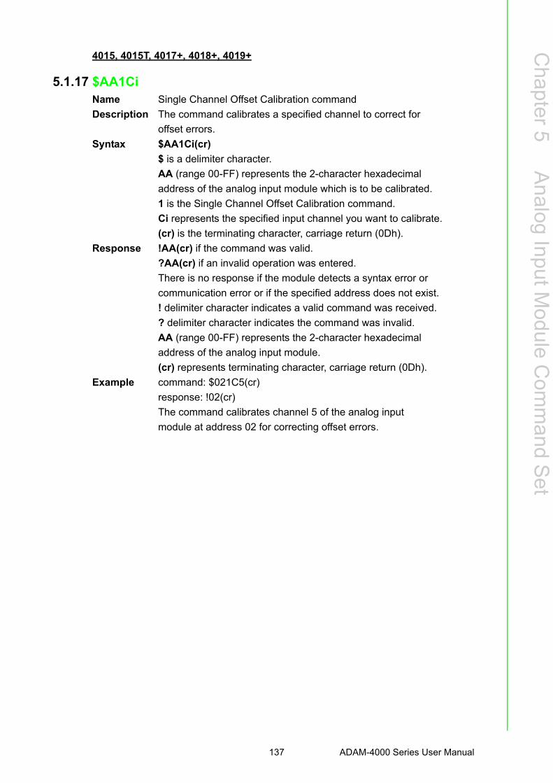
Chapter 5
Analog
InputModule
Com
mand
Set
4015, 4015T, 4017+, 4018+, 4019+
5.1.17 $AA1CiName Single Channel Offset Calibration command
Description The command calibrates a specified channel to correct for
offset errors.
Syntax $AA1Ci(cr)
$ is a delimiter character.
AA (range 00-FF) represents the 2-character hexadecimal
address of the analog input module which is to be calibrated.
1 is the Single Channel Offset Calibration command.
Ci represents the specified input channel you want to calibrate.
(cr) is the terminating character, carriage return (0Dh).
Response !AA(cr) if the command was valid.
?AA(cr) if an invalid operation was entered.
There is no response if the module detects a syntax error or
communication error or if the specified address does not exist.
! delimiter character indicates a valid command was received.
? delimiter character indicates the command was invalid.
AA (range 00-FF) represents the 2-character hexadecimal
address of the analog input module.
(cr) represents terminating character, carriage return (0Dh).
Example command: $021C5(cr)
response: !02(cr)
The command calibrates channel 5 of the analog input
module at address 02 for correcting offset errors.
137 ADAM-4000 Series User Manual

4015, 4015T, 4017+, 4018+, 4019+
5.1.18 $AA7CiRrrName Single Channel Range Configuration command
Description This command configures the input type and range of the
specified channel in an analog input module.
Syntax $AA7CiRrr(cr)
$ is a delimiter character.
AA (range 00-FF) represents the 2-character hexadecimal
address of the analog input module which is to be configured.
7 is the Single Channel Range Configuration command.
Ci represents the specified input channel you want to configure.
Rrr represents the type and range you want to set. (Refer to
Table 5.1 on Page 5-6 to check range codes)
(cr) is the terminating character, carriage return (0Dh).
Response !AA(cr) if the command was valid.
?AA(cr) if an invalid operation was entered.
There is no response if the module detects a syntax error or
communication error or if the specified address does not exist.
! delimiter character indicates a valid command was received.
? delimiter character indicates the command was invalid.
AA (range 00-FF) represents the 2-character hexadecimal
address of the analog input module.
(cr) represents terminating character, carriage return (0Dh).
Example command: $027C5R21(cr)
response: !02(cr)
The command configures the range of channel 5 in the
analog input module at address 02 as Pt100(IEC) 0 ~ 100 °C
ADAM-4000 Series User Manual 138

Chapter 5
Analog
InputModule
Com
mand
Set
4015, 4015T, 4017+, 4018+, 4019+
5.1.19 $AA8CiName Read Single Channel Range Configuration command
Description This command read the input type and range configuration
of the specified channel in an analog input module.
Syntax $AA8Ci(cr)
$ is a delimiter character.
AA (range 00-FF) represents the 2-character hexadecimal
address of the analog input module which is to be read.
8 is the Read Single Channel Range Configuration command.
Ci represents the specified input channel you want to read.
(cr) is the terminating character, carriage return (0Dh).
Response !AACiRrr(cr) if the command was valid.
?AA(cr) if an invalid operation was entered.
There is no response if the module detects a syntax error or
communication error or if the specified address does not exist.
! delimiter character indicates a valid command was received.
? delimiter character indicates the command was invalid.
AA (range 00-FF) represents the 2-character hexadecimal
address of the analog input module.
Ci represents the specified input channel you read.
Rrr represents the type and range setting in the specified channel.
(Refer to Table 5-1 on Page 5-6 to check range codes)
(cr) represents terminating character, carriage return (0Dh).
Example command: $028C5(cr)
response: !02C5R21(cr)
The command read the range of channel 5 in the analog
input module at address 02. The response “R21” means
Pt100 (IEC) 0 ~ 100 °C.
139 ADAM-4000 Series User Manual

4015, 4015T, 4017+, 4018+, 4019+
5.1.20 $AAXnnnnName Watchdog Timer Setting command
Description This command set the communication watchdog timer
(WDT) cycle time.
Syntax $AAXnnnn(cr)
$ is a delimiter character.
AA (range 00-FF) represents the 2-character hexadecimal
address of the analog input module which is to be read.
X is the Watchdog Timer Setting command.
nnnn (range 0000~9999) represents the specified value of
communication cycle you want to set. (Unit: 0.1 second)
(cr) is the terminating character, carriage return (0Dh).
Response !AA(cr) if the command was valid.
?AA(cr) if an invalid operation was entered.
There is no response if the module detects a syntax error or
communication error or if the specified address does not exist.
! delimiter character indicates a valid command was received.
? delimiter character indicates the command was invalid.
AA (range 00-FF) represents the 2-character hexadecimal
address of the analog input module.
(cr) represents terminating character, carriage return (0Dh).
Example command: $02X1234(cr)
response: !02(cr)
The command set the WDT cycle as 1234 in the input
module at address 02.
Caution! If the value of “nnnn” is 0000, the communication WDT function will be disabled.
ADAM-4000 Series User Manual 140

Chapter 5
Analog
InputModule
Com
mand
Set
4015, 4015T, 4017+, 4018+, 4019+
5.1.21 $AAYName Read Communication Watchdog Timer Cycle Setting command
Description This command read the setting of communication watchdog
timer (WDT) cycle time.
Syntax $AAY(cr)
$ is a delimiter character.
AA (range 00-FF) represents the 2-character hexadecimal
address of the analog input module which is to be read.
Y is the Reading Communication WDT Cycle Setting command.
(cr) is the terminating character, carriage return (0Dh).
Response !AAnnnn(cr) if the command was valid.
?AA(cr) if an invalid operation was entered.
There is no response if the module detects a syntax error or
communication error or if the specified address does not exist.
! delimiter character indicates a valid command was received.
? delimiter character indicates the command was invalid.
AA (range 00-FF) represents the 2-character hexadecimal
address of the analog input module.
nnnn (range 0000~9999) represent the specified value of
communication cycle you read. (Unit: 0.1 second)
(cr) represents terminating character, carriage return (0Dh).
Example command: $02Y(cr)
response: !020030(cr)
The command read the WDT cycle as 0030 in the input
module at address 02.
141 ADAM-4000 Series User Manual

4015, 4015T
5.1.22 $AAS0Name Internal Calibration command
Description This command executes internal self-calibration for offset
and gain errors.
Syntax $AAS0(cr)
$ is a delimiter character.
AA (range 00-FF) represents the 2-character hexadecimal
address of the analog input module which is to be calibrated.
S0 is the Internal Calibration command.
(cr) is the terminating character, carriage return (0Dh).
Response !AA(cr) if the command was valid.
?AA(cr) if an invalid operation was entered.
There is no response if the module detects a syntax error or
communication error or if the specified address does not exist.
! delimiter character indicates a valid command was received.
? delimiter character indicates the command was invalid.
AA (range 00-FF) represents the 2-character hexadecimal
address of the analog input module.
(cr) represents terminating character, carriage return (0Dh).
4015, 4015T
5.1.23 $AAS1Name Reload Default Calibrating Parameter command
Description Reload factory default calibrating parameter to overwrite
current calibrating parameter.
Syntax $AAS1(cr)
$ is a delimiter character.
AA (range 00-FF) represents the 2-character hexadecimal
address of the analog input module which is to be reloaded.
S1 is the Reload Calibrating Parameter command.
(cr) is the terminating character, carriage return (0Dh).
Response !AA(cr) if the command was valid.
?AA(cr) if an invalid operation was entered.
There is no response if the module detects a syntax error or
communication error or if the specified address does not exist.
! delimiter character indicates a valid command was received.
? delimiter character indicates the command was invalid.
AA (range 00-FF) represents the 2-character hexadecimal
address of the analog input module.
(cr) represents terminating character, carriage return (0Dh).
ADAM-4000 Series User Manual 142

Chapter 5
Analog
InputModule
Com
mand
Set
5.2 Analog Input Data Logger Command Set
4018M
5.2.1 @AACCCSDMTTTTName Set Memory Configuration command
Description Sets the channel storage status, standalone mode, data
logger mode storage type and sampling interval for the
specified analog input data logger.
Syntax @AACCCSDMTTTT(cr)
@ is a delimiter character.
AA (range 00-FF) represents the 2-character hexadecimal
address of an analog input data logger.
C is the Set Memory Configuration command.
CC (range 00-FF) represents the data storage status of each
channel. The ADAM-4018M has 8 channels, bit 0
representing channel 0, and bit 7 representing channel 7. A
mask bit value of ‘1’ enables data storage in the specified
channel, while a mask bit value of ‘0’ disables data storage.
Command Syntax Command Name Description I/O Module
@AACCCSDMTT TT Set MemoryConfiguration
Set the channel storage status, standalone mode, data logger mode, storage type and sampling interval for the specified analog input data logger.
4018M
@AAD Read MemoryConfiguration
Return the configuration parame-ters for the specified analog input data logger.
4018M
@AASO Set MemoryOperation Mode
Start/stop the recording functionof the memory module.
4018M
@AAT Read MemoryOperation Mode
Read the recording status of thememory module.
4018M
@AAL Event RecordCount
Read the number of stored event records in the memory module.
4018M
@AAN Standard RecordCount
Read the number of storedstandard records in the memory module.
4018M
@AARNNNN Read RecordContent
Read the contents of the specified record.
4018M
@AAACSDHHHH TEIIII
Set Alarm Limit Set the high/low alarm settings for the specified channel.
4018M
@AABC Read Alarm Limit Read the high/low alarm settings for the specified channel.
4018M
143 ADAM-4000 Series User Manual

S represents the standalone mode. In order for the
ADAM-4018M to operate in the field, you must power on
the memory module by setting this value to ‘1.’ Otherwise,
the data will not be recorded.
D represents the data logging mode. ‘0’ enables Standard
Mode, where all eight channels record the normal data
according to the sampling interval. ‘1’ enables Event Mode,
where all eight channels record the data if its value is over
the High Alarm limit or under the Low Alarm limit. ‘2’
enables Mixed Mode, where channels 0 ~ 3 act as the
standard logger and the channels 4 ~ 7 act as the event logger.
M represents the storage type. "0" represents writing to the
end of memory. "1" represents circular memory mode.
TTTT (range 2-65535) represents the sampling interval in seconds.
(cr) is the terminating character, carriage return (0Dh).
Response !AA(cr) if the configuration is successful.
?AA(cr) if the configuration fails.
! and ? are delimiter characters.
AA (range 00-FF) represents the 2-character hexadecimal
address of an analog input module.
(cr) represents terminating character, carriage return (0Dh).
Example command: @0DCFF111012C(cr)
response: !0D(cr)
The ADAM-4018M module at address 0D is configured as such:
All eight data storage channels enabled
Standalone mode enabled
Event logger selected
Circular memory mode
Sampling interval 300 seconds
The response indicates the command is successful.
Channel 7 Channel 0
Bit 7 Bit 6 Bit 5 Bit 4 Bit 3 Bit 2 Bit 1 Bit 0
ADAM-4000 Series User Manual 144

Chapter 5
Analog
InputModule
Com
mand
Set
4018M
5.2.2 @AADName Read Memory Configuration command
Description The command requests the configuration data from the
analog input data logger at address AA.
Syntax @AAD (cr)
@ is a delimiter character.
AA (range 00-FF) represents the 2-character hexadecimal
address of an analog input data logger.
D is the Read Memory Configuration command.
(cr) is the terminating character, carriage return (0Dh).
Response !AACCSDMTTTT(cr) if the command is valid.
! is a delimiter character indicating a valid command was received.
AA (range 00-FF) represents the 2-character hexadecimal
address of an analog input data logger.
CC (range 00-FF) represents the data storage status of each
channel. The ADAM-4018M has 8 channels, bit 0
representing channel 0, and bit 7 representing channel 7. A
mask bit value of ‘1’ enables data storage in the specified
channel, while a mask bit value of ‘0’ disables data storage.
S represents the standalone mode. In order for the
ADAM-4018M to operate in the field, you must power on
the memory module by setting this value to ‘1.’ Otherwise,
the data will not be recorded.
D represents the data logging mode. ‘0’ enables Standard
Mode, where all eight channels record the normal data
according to the sampling interval. ‘1’ enables Event Mode,
where all eight channels record the data if its value is over
the High Alarm limit or under the Low Alarm limit. ‘2’
enables Mixed Mode, where channels 0 ~ 3 act as the
standard logger and the channels 4 ~ 7 act as the event logger.
M represents the storage type. "0" represents writing to the
end of memory. "1" represents circular memory mode.
TTTT (range 2-65535) represents the sampling interval in seconds.
(cr) is the terminating character, carriage return (0Dh).
145 ADAM-4000 Series User Manual

4018M
5.2.3 @AADName Read Memory Configuration command
Description The command requests the configuration data from the
analog input data logger at address AA.
Syntax @AAD (cr)
@ is a delimiter character.
AA (range 00-FF) represents the 2-character hexadecimal
address of an analog input data logger.
D is the Read Memory Configuration command.
(cr) is the terminating character, carriage return (0Dh).
Response !AACCSDMTTTT(cr) if the command is valid.
! is a delimiter character indicating a valid command was received.
AA (range 00-FF) represents the 2-character hexadecimal
address of an analog input data logger.
CC (range 00-FF) represents the data storage status of each
channel. The ADAM-4018M has 8 channels, bit 0
representing channel 0, and bit 7 representing channel 7. A
mask bit value of ‘1’ enables data storage in the specified
channel, while a mask bit value of ‘0’ disables data storage.
S represents the standalone mode. In order for the
ADAM-4018M to operate in the field, you must power on
the memory module by setting this value to ‘1.’ Otherwise,
the data will not be recorded.
D represents the data logging mode. ‘0’ enables Standard
Mode, where all eight channels record the normal data
according to the sampling interval. ‘1’ enables Event Mode,
where all eight channels record the data if its value is over
the High Alarm limit or under the Low Alarm limit. ‘2’
enables Mixed Mode, where channels 0 ~ 3 act as the
standard logger and the channels 4 ~ 7 act as the event logger.
M represents the storage type. "0" represents writing to the
end of memory. "1" represents circular memory mode.
TTTT (range 2-65535) represents the sampling interval in seconds.
(cr) is the terminating character, carriage return (0Dh).
ADAM-4000 Series User Manual 146

Chapter 5
Analog
InputModule
Com
mand
Set
4018M
5.2.4 @AASOName Set Memory Operation Mode command
Description Sets the operation mode of the analog input data logger at
address AA to Start or Stop.
Syntax @AASO(cr)
@ is a delimiter character.
AA (range 00-FF) represents the 2-character hexadecimal
address of an analog input data logger.
S is the Set Memory Operation Mode command.
O represents the operation mode:
‘1’: enables the recording of data.
‘0’: disables the recording of data.
(cr) is the terminating character, carriage return (0Dh).
Response !AA(cr) if the command is valid.
?AA(cr) if an invalid parameter was entered. There is no
response if the module detects a syntax error or
communication error or if the specified address does not exist.
! is a delimiter character indicating a valid command was received.
? is a delimiter character indicating the command was invalid.
AA (range 00-FF) represents the 2-character hexadecimal
address of an analog input data logger.
(cr) is the terminating character, carriage return (0Dh).
Example command: @03S1(cr)
response: !03(cr)
The command enables the analog input data logger at
address 03 to record data.
The response indicates that the command was received.
147 ADAM-4000 Series User Manual

4018M
5.2.5 @AATName Read Memory Operation Mode command
Description Request the memory operation status of the analog input
data logger at address AA.
Syntax @AAT (cr)
@ is a delimiter character.
AA (range 00-FF) represents the 2-character hexadecimal
address of an analog input data logger.
T is the Read Memory Operation Mode command.
(cr) is the terminating character, carriage return (0Dh).
Response !AAO(cr) if the command is valid.
! is a delimiter character indicating a valid command was received.
AA (range 00-FF) represents the 2-character hexadecimal
address of an analog input module.
O represents the operation mode:
‘1’: enables the recording of data.
‘0’: disables the recording of data.
(cr) is the terminating character, carriage return (0Dh).
Example command: @F3T(cr)
response: !F31(cr)
The command requests the memory operation status of the
analog input data logger at address F3.
The response indicates that data recording is enabled.
ADAM-4000 Series User Manual 148

Chapter 5
Analog
InputModule
Com
mand
Set
4018M
5.2.6 @AALName Event Record Count command
Description Request the number of event records stored in the analog
input data logger at address AA.
Syntax @AAL (cr)
@ is a delimiter character.
AA (range 00-FF) represents the 2-character hexadecimal
address of an analog input data logger.
L is the Event Record Count command.
(cr) is the terminating character, carriage return (0Dh).
Response !AAHHHH(cr) if the command is valid.
! is a delimiter character indicating a valid command was received.
AA (range 00-FF) represents the 2-character hexadecimal
address of an analog input module.
HHHH represents the 4-character hexadecimal number of
event records stored in the analog input data logger at address AA.
(cr) is the terminating character, carriage return (0Dh).
Example command: @F3L(cr)
response: !F30096(cr)
The command requests the number of event records stored
in the analog input data logger at address F3.
The module currently has 150 event records.
149 ADAM-4000 Series User Manual

4018M
5.2.7 @AANName Standard Record Count command
Description Request the number of standard records stored in the analog
input data logger at address AA.
Syntax @AAN (cr)
@ is a delimiter character
AA (range 00-FF) represents the 2-character hexadecimal
address of an analog input data logger.
N is the Standard Record Count command.
(cr) is the terminating character, carriage return (0Dh).
Response !AAHHHH(cr) if the command is valid.
! is a delimiter character indicating a valid command was received.
AA (range 00-FF) represents the 2-character hexadecimal
address of an analog input module.
HHHH represents the 4-character hexadecimal number of
data records stored in the analog input data logger at address AA.
(cr) is the terminating character, carriage return (0Dh).
Example command: @A3N(cr)
response: !A30320(cr)
The command requests the number of data records stored in
the analog input data logger at address A3.
The module currently has 800 data records.
ADAM-4000 Series User Manual 150
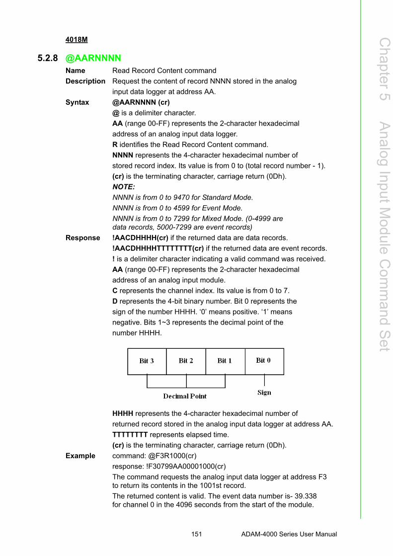
Chapter 5
Analog
InputModule
Com
mand
Set
4018M
5.2.8 @AARNNNNName Read Record Content command
Description Request the content of record NNNN stored in the analog
input data logger at address AA.
Syntax @AARNNNN (cr)
@ is a delimiter character.
AA (range 00-FF) represents the 2-character hexadecimal
address of an analog input data logger.
R identifies the Read Record Content command.
NNNN represents the 4-character hexadecimal number of
stored record index. Its value is from 0 to (total record number - 1).
(cr) is the terminating character, carriage return (0Dh).
NOTE:
NNNN is from 0 to 9470 for Standard Mode.
NNNN is from 0 to 4599 for Event Mode.
NNNN is from 0 to 7299 for Mixed Mode. (0-4999 aredata records, 5000-7299 are event records)
Response !AACDHHHH(cr) if the returned data are data records.
!AACDHHHHTTTTTTTT(cr) if the returned data are event records.
! is a delimiter character indicating a valid command was received.
AA (range 00-FF) represents the 2-character hexadecimal
address of an analog input module.
C represents the channel index. Its value is from 0 to 7.
D represents the 4-bit binary number. Bit 0 represents the
sign of the number HHHH. ‘0’ means positive. ‘1’ means
negative. Bits 1~3 represents the decimal point of the
number HHHH.
HHHH represents the 4-character hexadecimal number of
returned record stored in the analog input data logger at address AA.
TTTTTTTT represents elapsed time.
(cr) is the terminating character, carriage return (0Dh).
Example command: @F3R1000(cr)
response: !F30799AA00001000(cr)
The command requests the analog input data logger at address F3to return its contents in the 1001st record.
The returned content is valid. The event data number is- 39.338 for channel 0 in the 4096 seconds from the start of the module.
151 ADAM-4000 Series User Manual

4018M
5.2.9 @AAACSDHHHHTEIIIIName Set Alarm Limit command
Description Set high/low alarm limits for the channel C in the analog
input data logger at address AA.
Syntax @AAACSDHHHHTEIIII(cr)
@ is a delimiter character
AA (range 00-FF) represents the 2-character hexadecimal
address of an analog input data logger.
A is the Set Alarm Limit command.
C represents the channel index. Its value is from 0 to 7.
S represents the sign of the high alarm limit.
‘+’ is for positive, and ‘-’ is for negative.
D represents the decimal point of the high alarm limit. Its
value is from 0 to 5.
HHHH represents the 4-character hexadecimal number of
high alarm limit.
T represents the sign of the low alarm limit.
‘+’ is for positive, and ‘-’ is for negative.
E represents the decimal point of the low alarm limit. Its
value is from 0 to 5.
IIII represents the 4-character hexadecimal number of low alarm limit.
(cr) is the terminating character, carriage return (0Dh).
Response !AA(cr) if the command is valid.
?AA(cr) if an invalid parameter was entered. There is no
response if the module detects a syntax error or
communication error or if the specified address does not exist.
! is a delimiter character indicating a valid command was received.
? is a delimiter character indicating the command was invalid.
AA (range 00-FF) represents the 2-character hexadecimal
address of an analog input data logger.
(cr) is the terminating character, carriage return (0Dh).
Example command: @EFA0+20400+20100(cr)
response: !EF(cr)
The command sets channel 0 of the analog input data
logger at address EF as such:
high alarm limit = 10.24
low alarm limit = 2.56
The response indicates the command was received.
ADAM-4000 Series User Manual 152

Chapter 5
Analog
InputModule
Com
mand
Set
4018M
5.2.10 @AABCName Read Alarm Limit command
Description Request the alarm limits for the specified channel in the
analog input data logger at address AA.
Syntax @AABC(cr)
@ is a delimiter character.
AA (range 00-FF) represents the 2-character hexadecimal
address of an analog input data logger.
B is the Read Alarm Limit command.
C represents the channel index. Its value is from 0 to 7.
(cr) is the terminating character, carriage return (0Dh).
Response !AASDHHHHTEIIII
! is a delimiter character indicating a valid command was received.
AA (range 00-FF) represents the 2-character hexadecimal
address of an analog input data logger.
S represents the sign of the high alarm limit.
‘+’ is for positive, and ‘-’ is for negative.
D represents the decimal point of the high alarm limit. Its
value is from 0 to 5.
HHHH represents the 4-character hexadecimal number of
high alarm limit.
T represents the sign of the low alarm limit.
‘+’ is for positive, and ‘-’ is for negative.
E represents the decimal point of the low alarm limit. Its
value is from 0 to 5.
IIII represents the 4-character hexadecimal number of low alarm limit.
(cr) is the terminating character, carriage return (0Dh).
153 ADAM-4000 Series User Manual

5.3 Digital I/O, Alarm and Event Command Set
Command Syntax Command Name Description I/O Module
@AADI Read Digital I/O andAlarm Status
The addressed module returns the state of its digital input and digital output channels and the status of its alarm
4011, 4011D,4012, 4016
@AADO(data) Set Digital OutputValues
Set the values of themodule's digital outputs (ONor OFF)
4011, 4011D,4012, 4016
@AAEAT Enable Alarm Enables the alarm in eitherMomentary or Latching mode
4011, 4011D,4012, 4016
@AAHI(data) Set High Alarm Value Downloads the High alarm limit value
4011, 4011D,4012, 4016
@AALO(data) Set Low Alarm Value Downloads the Low alarmlimit value
4011, 4011D,4012, 4016
@AADA Disable Alarm Disables all alarm functions 4011, 4011D,4012, 4016
@AACA Clear Latch Alarm Resets the module's Latchalarm to zero
4011, 4011D,4012, 4016
@AARH Read High AlarmValue
Ask the addressed module toreturn its high alarm value
4011, 4011D,4012, 4016
@AARL Read Low AlarmValue
Ask the addressed module to return its low alarm value
4011, 4011D,4012, 4016
@AARE Read Event Counter Ask the addressed module toreturn its event counter value
4011, 4011D,4012
@AACE Clear Event Counter Reset the module's event counter to zero
4011, 4011D,4012
ADAM-4000 Series User Manual 154
Chapter 5
Analog
InputModule
Com
mand
Set
4011, 4011D, 4012, 4016
5.3.1 @AADIName Read Digital I/O and Alarm State
Description The addressed analog input module is instructed to return
the value of its digital input and output channels and the
state of its alarm (Momentary or Latching).
Syntax @AADI(cr)
@ is a delimiter character.
AA (range 00-FF) represents the 2-character hexadecimal
address of an analog input module.
DI is the Read Digital I/O and Alarm Status command.
(cr) represents terminating character, carriage return (0Dh).
Response ADAM-4011/4011D/4012:
!AASOOII(cr) if the command was valid
ADAM-4016:
!AASOO00(cr) if the command was valid
There is no response if the module detects a syntax error or
communication error or if the specified address does not exist.
! delimiter character indicates a valid command was received.
AA represents the 2-character hexadecimal address of the
responding analog input module.
S hexadecimal number that represents the alarm state (0h =
disabled, 1h = MOMENTARY mode enabled, 2h =
LATCH mode enabled).
OO
For ADAM-4011/4011D/4012: it is a hexadecimal number
representing the Digital Output port’s channel 0 and 1
status (00h = D/O channels 0 and 1 are both OFF, 01h =
channel 0 is ON, channel 1 is OFF, 02h = channel 0 is OFF,
channel 1 is ON, 03h = channel 0 and 1 are both ON).
For ADAM-4016: it is a hexadecimal number representing
the status of the four digital output channels. The
corresponding table is show in the following table:
155 ADAM-4000 Series User Manual

II is a hexadecimal number representing the Digital input
port’s channel status (00h = D/I channel is Low, 01h =
channel is High).
(cr) represents terminating character, carriage return (0Dh).
Example command: @15DI(cr)
response: !510001(cr)
The analog input module at address 15h is instructed to
return digital I/O data and alarm status.
The module responds that both digital output channels are
OFF, digital input is HIGH, and alarm state is Momentary.
Status Code DO0 001 002 003
OO OFF OFF OFF OFF
O1 OFF OFF OFF ON
O2 OFF OFF ON OFF
O3 OFF OFF ON ON
O4 OFF ON OFF OFF
O5 OFF ON OFF ON
O6 OFF ON ON OFF
O7 OFF ON ON ON
O8 ON OFF OFF OFF
O9 ON OFF OFF ON
OA ON OFF ON OFF
OB ON OFF ON ON
OC ON ON OFF OFF
OD ON ON OFF ON
OE ON ON ON OFF
OF ON ON ON ON
ADAM-4000 Series User Manual 156

Chapter 5
Analog
InputModule
Com
mand
Set
4011, 4011D, 4012, 4016
5.3.2 @AADOName Set Digital Output command
Description Sets the values of the module’s digital outputs (ON or OFF).
Syntax @AADO(data)(cr)
@ is a delimiter character.
AA (range 00-FF) represents the 2-character hexadecimal
address of an analog input module.
DO is the Set Digital Output command.
(data) is the two-character parameter that sets the state for
the digital output bits of the module, as shown below:
For ADAM-4011/4011D/4012:
00 all D/O bits are OFF
01 DO0 is ON, DO1 is OFF
02 DO0 is OFF, DO1 is ON
03 all bits are ON
For ADAM-4016:
00 DO0 and DO1 are OFF
01 DO0 is ON, DO1 is OFF
02 DO0 is OFF, DO1 is ON
03 DO0 and DO1 are ON
10 DO2 and DO3 are OFF
11 DO2 is ON, DO3 is OFF
12 DO2 is OFF, DO3 is ON
13 DO2 and DO3 are ON
(cr) represents terminating character, carriage return (0Dh).
Response !AA(cr) if the command was valid.
?AA(cr) if an invalid parameter was entered.
There is no response if the module detects a syntax error or
communication error or if the specified address does not exist
! delimiter character indicates a valid command was received.
? delimiter character indicates the command was invalid.
AA represents the 2-character hexadecimal address of the
responding analog input module.
(cr) represents terminating character, carriage return (0Dh).
Example command: @05DO01(cr)
response: !05(cr)
The analog input module at address 05h is instructed to set
digital output channel 1 to ON and digital output channel 2
to OFF. The module confirms the settings.
157 ADAM-4000 Series User Manual

4011, 4011D, 4012, 4016
5.3.3 @AAEATName Enable Alarm command
Description The addressed analog input module is instructed to enable
its alarm in either Latching or Momentary mode.
Syntax @AAEAT(cr)
@ is a delimiter character.
AA (range 00-FF) represents the 2-character hexadecimal
address of an analog input module.
EA is the Enable Alarm command.
T indicates alarm type and can have the value M =
Momentary alarm state, or L = Latching alarm state.
(cr) represents terminating character, carriage return (0Dh).
Response !AA(cr) if the command was valid.
There is no response if the module detects a syntax error or
communication error or if the specified address does not exist.
! delimiter character indicates a valid command was received.
AA represents the 2-character hexadecimal address of the
responding analog input module.
(cr) represents terminating character, carriage return (0Dh).
Example command: @03EAL(cr)
response: !03(cr)
The analog input module at address 03h is instructed to
enable its alarm in Latching mode.
The module confirms that the command has been received.
Caution! An analog input module requires a maximum of 2 seconds after it received an Enable Alarm command to let the settings take effect . Dur-ing this interval, the module can not be addressed to perform any other actions.
ADAM-4000 Series User Manual 158

Chapter 5
Analog
InputModule
Com
mand
Set
4011, 4011D, 4012, 4016
5.3.4 @AAHIName Set High Alarm Limit command
Description Downloads high alarm limit value into the addressed module.
Syntax @AAHI(data)(cr)
@ is a delimiter character.
AA (range 00-FF) represents the 2-character hexadecimal
address of an analog input module.
HI is the Set High Limit command.
(data) represents the value of the desired high limit setting.
The format is always engineering units.
(cr) represents terminating character, carriage return (0Dh).
Response !AA(cr) if the command was valid.
There is no response if the module detects a syntax error or
communication error or if the specified address does not exist.
! delimiter character indicates a valid command was received.
AA represents the 2-character hexadecimal address of the
responding analog input module.
(cr) represents terminating character, carriage return (0Dh).
Example command: @04HI+080.00(cr)
response: !04(cr)
Presume the analog input module at address 04h is
configured to accept T-type thermocouple input. The
command will set the High alarm limit to 80?.
The module responds that the command has been received.
Caution! An analog input module requires a maximum of 2 seconds after it received an Set High Alarm command to let the settings take effect . During this interval, the module can not be addressed to perform any other actions.
159 ADAM-4000 Series User Manual

4011, 4011D, 4012, 4016
5.3.5 @AALOName Set Low Alarm Limit command
Description Downloads Low alarm limit value into the addressed module.
Syntax @AALO(data)(cr)
@ is a delimiter character.
AA (range 00-FF) represents the 2-character hexadecimal
address of an analog input module.
LO is the Set Low Limit command.
(data) represents the value of the desired low limit setting.
The format is always engineering units.
(cr) represents terminating character, carriage return (0Dh).
Response !AA(cr) if the command was valid.
There is no response if the module detects a syntax error or
communication error or if the specified address does not exist.
! delimiter character indicates a valid command was received.
AA represents the 2-character hexadecimal address of the
responding analog input module.
(cr) represents terminating character, carriage return (0Dh).
Example command: @04LO-020.00(cr)
response: !04(cr)
Presume the analog input module at address 04h is
configured to accept T-type thermocouple input. The
command will set the Low alarm limit to -20 °C.
The module responds that the command has been received.
Caution! An analog input module requires a maximum of 2 seconds after it received an Set Low Alarm command to let the settings take effect. During this interval, the module can not be addressed to perform any other actions.
ADAM-4000 Series User Manual 160

Chapter 5
Analog
InputModule
Com
mand
Set
4011, 4011D, 4012, 4016
5.3.6 @AADAName Disable Alarm command
Description Disables all alarm functions of the addressed analog input module.
Syntax @AADA(cr)
@ is a delimiter character.
AA (range 00-FF) represents the 2-character hexadecimal
address of an analog input module.
DA is the Disable Alarm command.
(cr) represents terminating character, carriage return (0Dh).
Response !AA(cr) if the command was valid.
There is no response if the module detects a syntax error or
communication error or if the specified address does not exist.
! delimiter character indicates a valid command was received.
AA represents the 2-character hexadecimal address of the
responding analog input module.
(cr) represents terminating character, carriage return (0Dh).
Example command: @07DA (cr)
response: !07(cr)
The analog input module at address 07h is instructed to
disable all alarm functions.
The module confirms it alarm functions have been disabled.
Caution! An analog input module requires a maximum of 2 seconds after it received an Disable Alarm command to let the settings take effect. Dur-ing this interval, the module can not be addressed to perform any other actions.
161 ADAM-4000 Series User Manual

4011, 4011D, 4012, 4016
5.3.7 @AACAName Clear Latch Alarm command
Description Both alarm states (High and Low) of the addressed analog
input module are set to OFF, no alarm.
Syntax @AACA(cr)
@ is a delimiter character.
AA (range 00-FF) represents the 2-character hexadecimal
address of an analog input module.
CA is the Clear Latch Alarm command.
(cr) represents terminating character, carriage return (0Dh).
Response !AA(cr) if the command was valid.
There is no response if the module detects a syntax error or
communication error or if the specified address does not exist.
! delimiter character indicates a valid command was received.
AA represents the 2-character hexadecimal address of the
responding analog input module.
(cr) represents terminating character, carriage return (0Dh).
Example command: @05CA(cr)
response: !05(cr)
The analog input module at address 05h is instructed to set
both alarm states (High and Low) to OFF.
The module confirms it has done so accordingly.
ADAM-4000 Series User Manual 162

Chapter 5
Analog
InputModule
Com
mand
Set
4011, 4011D, 4012, 4016
5.3.8 @AARHName Read High Alarm Limit command
Description The addressed module is asked to return its High alarm limit value.
Syntax @AARH(cr)
@ is a delimiter character.
AA (range 00-FF) represents the 2-character hexadecimal
address of an analog input module.
RH is the Read High Alarm Limit command.
(cr) represents terminating character, carriage return (0Dh).
Response !AA(data)(cr) if the command was valid.
There is no response if the module detects a syntax error or
communication error or if the specified address does not exist.
! delimiter character indicates a valid command was received.
AA represents the 2-character hexadecimal address of the
responding analog input module.
(data) is the value of the High alarm limit in engineering units.
(cr) represents terminating character, carriage return (0Dh).
Example command: @07RH(cr)
response: !07+2.0500(cr)
Presume the analog input module at address 07h is
configured to accept 5 V input. The command instructs the
module to return it High alarm limit value. The module
responds its High alarm limit value is 2.0500 V.
163 ADAM-4000 Series User Manual

4011, 4011D, 4012, 4016
5.3.9 @AARLName Read Low Alarm Limit command
Description The addressed module is asked to return its Low alarm limit value.
Syntax @AARL(cr)
@ is a delimiter character.
AA (range 00-FF) represents the 2-character hexadecimal
address of an analog input module.
RL is the Read Low Alarm Limit command.
(cr) represents terminating character, carriage return (0Dh).
Response !AA(data)(cr) if the command was valid.
There is no response if the module detects a syntax error or
communication error or if the specified address does not exist.
! delimiter character indicates a valid command was received.
AA represents the 2-character hexadecimal address of the
responding analog input module.
(data) is the value of the Low alarm limit in engineering units.
(cr) represents terminating character, carriage return (0Dh).
Example command: @05RL(cr)
response: !05-0.3750(cr)
Presume the analog input module at address 05h is
configured to accept 1 V input. The command instructs the
module to return it Low alarm limit value. The module
responds its Low alarm limit value is -0.3750 V.
ADAM-4000 Series User Manual 164

Chapter 5
Analog
InputModule
Com
mand
Set
4011, 4011D, 4012
5.3.10 @AAREName Read Event Counter command
Description The addressed module is instructed to return its event counter value.
Syntax @AARE(cr)
@ is a delimiter character.
AA (range 00-FF) represents the 2-character hexadecimal
address of an analog input module.
RE is the Reads Event Counter command.
(cr) represents terminating character, carriage return (0Dh).
Response !AA(data)(cr) if the command was valid.
There is no response if the module detects a syntax error or
communication error or if the specified address does not exist.
! delimiter character indicates a valid command was received.
AA represents the 2-character hexadecimal address of the
responding analog input module.
(data) represents the stored value, from ‘00000’ to ‘65535’
(The max value that can be held by the counter register is
65535). The number 65535 is held when the actual total
counts exceed this number.
(cr) represents terminating character, carriage return (0Dh).
Example command: @08RE(cr)
response: !0832011(cr)
The command instructs the module at address 08h to return
its counter value. The module responds that its counter
value equals 32011.
165 ADAM-4000 Series User Manual

4011, 4011D, 4012
5.3.11 @AACEName Clear Event Counter command
Description The addressed module is instructed to reset its event counter to zero.
Syntax @AACE(cr)
@ is a delimiter character.
AA (range 00-FF) represents the 2-character hexadecimal
address of an analog input module.
CE is the Clear Event Counter command.
(cr) represents terminating character, carriage return (0Dh).
Response !AA(cr) if the command was valid.
There is no response if the module detects a syntax error or
communication error or if the specified address does not exist.
! delimiter character indicates a valid command was received.
AA represents the 2-character hexadecimal address of the
responding analog input module.
(cr) represents terminating character, carriage return (0Dh).
Example command: @09CE(cr)
response: !09(cr)
The command instructs the module at address 09h to set its
event counter to zero. The module responds that its counter
has been reset.
5.4 Excitation Voltage Output Command Set
Command Syntax Command Name Description I/O module
$AA6 Get Excitation VoltageOutput Value
Returns either last value sent to specified module by $AA7 command, or start-up output voltage.
4016
$AA7 Excitation VoltageOutput
Direct output excitationvoltage data to a specified module
4016
$AAS Start-up Voltage OutputConfiguration
Stores a default value in aspecified module. The output value will take effect upon startup.
4016
$AAE Trim Calibration Trims specified module anumber of units up/down
4016
$AAA Zero Calibration Tells the module to storeparameters for zero calibration
4016
$AAB Span Calibration Tells the module to storeparameters for span calibration
4016
ADAM-4000 Series User Manual 166

Chapter 5
Analog
InputModule
Com
mand
Set
4016
5.4.1 $AA6Name Get Excitation Voltage Output Value command
Description The addressed strain gauge input module is instructed to
return the latest output value it received from Excitation
Voltage Output command. If the module hasn’t received an
Excitation Voltage Output command since startup, it will
return its Start-up Output value.
Syntax $AA6(cr)
$ is a delimiter character.
AA (range 00-FF) represents the 2-character hexadecimal
address of the strain gauge input module.
6 is the Get Excitation Voltage Output command.
(cr) is the terminating character, carriage return (0Dh)
Response !AA(data)(cr) if the command is valid.
?AA(cr) if an invalid command was issued.
There is no response if the module detects a syntax error or
communication error or if the specified address does not exist.
! delimiter character indicates a valid command was received.
? delimiter character indicates the command was invalid.
AA (range 00-FF) represents the 2-character hexadecimal
address of the strain gauge input module.
(data) is the value that is returned by analog output channel.
The format of the data is in engineering unit.
(cr) is the terminating character, carriage return (0Dh)
Example command: $0A6(cr)
response: !0A+03.000(cr)
The command tells the strain gauge input module at address
0Ah to return the last excitation voltage output value it
received from an Excitation Voltage Output command. The
strain gauge input module returns the value +03.000V.
167 ADAM-4000 Series User Manual

4016
5.4.2 $AA7Name Excitation Voltage Output command
Description Send a value to the analog output channel of the addressed
strain gauge input module. Upon receipt, the analog output
channel will output this value.
Syntax $AA7(data)(cr)
$ is a delimiter character.
AA (range 00-FF) represents the 2-character hexadecimal
address of the strain gauge input module.
7 is the Excitation Voltage Output command.
(data) is the value that has to be output through the analog
output channel. The data format is engineering unit and the
range is between 0 ~ 10 V.
(cr) is the terminating character, carriage return (0Dh)
Response !AA(cr) if the command is valid.
?AA(cr) if a value was sent that is out of range.
There is no response if the module detects a syntax error or
communication error or if the specified address does not exist.
! delimiter character indicates a valid command was received.
? delimiter character indicates the command was invalid.
AA (range 00-FF) represents the 2-character hexadecimal
address of the strain gauge input module.
(cr) is the terminating character, carriage return (0Dh)
Example command: $337+05.000(cr)
response: !33(cr)
The command sends the value +05.000V to the analog
output channel of the strain gauge input module at address
33h. The module responds that the command is valid. Its
output data format is in engineering unit, the value is +05.000V.
ADAM-4000 Series User Manual 168

Chapter 5
Analog
InputModule
Com
mand
Set
4016
5.4.3 $AASName Start-up Voltage Output Configuration command
Description Stores the present analog output value of the strain gauge
input module with address AA in the module’s non-volatile
register. The output value will take effect upon start-up or
after a brownout.
Syntax $AAS(cr)
$ is a delimiter character.
AA (range 00-FF) represents the 2-character hexadecimal
address of the strain gauge input module whose analog
output is to be set.
S is the Start-up Voltage Output Configuration command.
(cr) is the terminating character, carriage return (0Dh).
Response !AA(cr) if the command is valid.
?AA(cr) if an invalid command was issued.
There is no response if the module detects a syntax error or
communication error or if the specified address does not exist.
! delimiter character indicates a valid command was received.
? delimiter character indicates the command was invalid.
AA (range 00-FF) represents the 2-character hexadecimal
address of the strain gauge input module.
(cr) is the terminating character, carriage return (0Dh).
Example command: $0AS(cr)
response: !0A(cr)
Presume the present output value of the output channel of
the strain gauge input module with address 0A is +05.000V.
The command tells the module store the present output
value, in its non-volatile memory. When the module is
powered up or reset, its default output value will be
+05.000V. The response of the strain gauge input module
indicates that the command has been received.
Note! A strain gauge input module requires a maximum of 6 milliseconds after it received a Startup Voltage Output Configuration command to let the settings take effect. During this interval, the module can not be addressed to perform any other actions.
169 ADAM-4000 Series User Manual

4016
5.4.4 $AAEName Trim Calibration command
Description Trims the output voltage of the strain gauge input module a
specified number of units up or down.
Syntax $AAE(number of counts)(cr)
$ is a delimiter character.
AA (range 00-FF) represents the 2-character hexadecimal
address of the strain gauge input module to be calibrated.
E is the Trim Calibration command.
(number of counts) is the 2-character two’s complement
hexadecimal value that represents the number of counts by
which to increase or decrease the output voltage. Each
count equals approximately 1mV. Values range from 00 to
7F and from 80 to FF, where 00 represents 0 counts, 7F
represents 127 counts, 80 represents -128 counts and FF
represents -1 counts. Negative values decrease and positive
values increase the output voltage according to the number of counts.
(cr) is the terminating character, carriage return (0Dh).
Response !AA(cr) if the command is valid.
There is no response if the module detects a syntax error or
communication error or if the specified address does not exist.
! delimiter character indicates a valid command was received.
AA (range 00-FF) represents the 2-character hexadecimal
address of the strain gauge input module.
(cr) is the terminating character, carriage return (0Dh).
Example command: $07E14(cr)
response: !07
The command tells the analog output of the strain gauge
input module at address 07h to increase its output value by
20 (14h) counts which is approximately 20 mV. The strain
gauge input module confirms the increase. In order to
perform this trim calibration, a voltmeter should be
connected to the module’s output. (See also the zero
calibration command and span calibration command of the
strain gauge input module and Chapter 8, Calibration, for a
detailed description.)
ADAM-4000 Series User Manual 170

Chapter 5
Analog
InputModule
Com
mand
Set
4016
5.4.5 $AAAName Zero Calibration command
Description Stores the voltage output value of the addressed strain
gauge input module as zero voltage reference.
Syntax $AAA(cr)
$ is a delimiter character.
AA (range 00-FF) represents the 2-character hexadecimal
address of the strain gauge input module whose output
channel is to be calibrated.
A is the Zero Calibration command.
(cr) is the terminating character, carriage return (0Dh)
Response !AA(cr) if the command is valid.
?AA(cr) if an invalid command was issued.
There is no response if the module detects a syntax error or
communication error or if the specified address does not exist.
! delimiter character indicates a valid command was received.
? delimiter character indicates the command was invalid.
AA (range 00-FF) represents the 2-character hexadecimal
address of the strain gauge input module.
(cr) is the terminating character, carriage return (0Dh).
Before issuing the Zero Calibration command, the analog
output should be trimmed to the correct value with the
Trim Calibration command. A voltmeter should be
connected to the module’s output channel. (See also the
strain gauge input module’s Trim Calibration command
and Chapter 8, Calibration, for a detailed description.)
171 ADAM-4000 Series User Manual

4016
5.4.6 $AABName Span Calibration command
Description Stores the voltage output value of the addressed strain
gauge input module as 10V reference.
Syntax $AAB(cr)
$ is a delimiter character.
AA (range 00-FF) represents the 2-character hexadecimal
address of the strain gauge input module whose output
channel is to be calibrated.
B is the Span Calibration command.
(cr) is the terminating character, carriage return (0Dh).
Response !AA(cr) if the command is valid.
?AA(cr) if an invalid command was issued.
There is no response if the module detects a syntax error or
communication error or if the specified address does not exist.
! delimiter character indicates a valid command was received.
? delimiter character indicates the command was invalid.
AA (range 00-FF) represents the 2-character hexadecimal
address of the strain gauge input module.
(cr) is the terminating character, carriage return (0Dh).
Before issuing the Span Calibration command, the analog
output should be trimmed to the correct value with the
Trim Calibration command. A voltmeter should be
connected to the module’s output channel. (See also the
strain gauge input module’s Trim Calibration command
and Chapter 8, Calibration, for a detailed description.)
ADAM-4000 Series User Manual 172

Chapter 6
6 Analog Output Module Command Set
6.1 Analog Output Module Command for ADAM-4021
Command Syntax Command Name Description I/O Module
%AANNTTCCFF Configuration Sets the address, output range,baud rate, data format, slew rate and/or checksum status
4021
#AA(data) Analog Data Out Directs output data to aspecified module
4021
$AA4 Start-Up OutputCurrent or VoltageConfiguration
Stores a default output value ina specified module. The output value will take effect upon startup
4021
$AA3(number of counts)
Trim Calibration Trims specified module anumber of units up/down
4021
$AA0 4 mA Calibration Tells the module to store parame-ters for 4mA Calibration
4021
$AA1 20 mA Calibration Tells the module to storeparameters for 20 mA Calibration
4021
$AA2 ConfigurationStatus
Reads the configuration ofspecified module
4021
$AA6 Last ValueReadback
Returns either last value sent tospecified module by #AA com-mand, or start-up output current/voltage
4021
$AA8 Current Readback Returns measured value of thecurrent/voltage flowing through current loop
4021
$AA5 Reset Status Checks if module has beenreset since the last $AA5 com-mand
4021
$AAF Read FirmwareVersion
Returns the firmware version code from the specified analog output module
4021
$AAM Read ModelName
Return the module name fromspecified analog output module
4021
ADAM-4000 Series User Manual 174

Chapter 6
Analog
OutputM
oduleC
omm
andS
et
4021
6.1.1 %AANNTTCCFFName Configuration command
Description Sets address, input range, baud rate, data format, checksum
status, and/or integration time for an analog output module.
Syntax %AANNTTCCFF(cr)
% is a delimiter character.
AA (range 00-FF) represents the 2-character hexadecimal
address that is to be configured.
NN represents the new hexadecimal address of the analog
output module. Range is from 00h to FFh.
TT represents the type codes (output range codes).
(See Table 6-2 on next page)
CC represents the baud rate codes.
(See Table 6-1 on next page)
FF is a hexadecimal number that equals to 8-bit parameter
representing the status of data format, slew rate, and
checksum. The layout of the 8-bit parameter is shown in Figure 6.1.
Bit 7 is not used and must be set to 0.
(cr) is the terminating character, carriage return (0Dh).
Figure 6.1 Data format for FF (8-bit parameter)
Note! Only ADAM-4021 supports “% of FSR” and “two’s complement of hexadecimal” Data Format.
175 ADAM-4000 Series User Manual

Response !AA(cr) if the command is valid.
?AA(cr) if an invalid parameter was entered or the INIT*
terminal was not grounded when changing baud rate or
checksum settings was attempted.
There is no response if the module detects a syntax or
communication error, or even if the specified address does not exist.
! delimiter character indicates that a valid command is received.
? delimiter character indicates that the command is invalid.
AA (range 00-FF) represents the 2-character hexadecimal
address of an analog output module.
(cr) is the terminating character, carriage return (0Dh).
Example command: %310A310610(cr)
response: !24(cr)
The analog input module is configured from addresses 31h
to a new address 0Ah, output range 4 to 20 mA, baud rate
9600, engineering units data format, a slew rate of 1.0
mA/sec and no checksum checking.
The response indicates that the command has been received.
Table 6.1: Baud Rate Codes
Baud Rate Code (Hex) Baud Rate
03 1200 bps
04 2400 bps
05 4800 bps
06 9600 bps
07 19.2 Kbps
08 38.4 Kbps
Table 6.2: Output Range Codes (Type Codes)Output Range Code (Hex) Output Range for ADAM-4021
30 0 to 20 mA
31 4 to 20 mA
32 0 to 10 V
Caution! An analog output module requires a maximum of 20 milliseconds to per-form auto calibration and ranging after it is reconfigured. During this time span, the module can not be addressed to perform any other actions.
Caution! All configuration parameters can be changed dynamically, except the checksum and baud rate parameters. They can only be altered when the INIT* terminal is grounded. (Refer to Baud rate and Checksum in Chapter 2).
ADAM-4000 Series User Manual 176

Chapter 6
Analog
OutputM
oduleC
omm
andS
et
4021
6.1.2 #AAName Analog Data Out command
Description Send a value to the address of analog output module. Then,
the analog output module will output this value.
Syntax #AA(data)(cr)
# is a delimiter character.
AA (range 00-FF) represents the 2-character hexadecimal
address of an analog output module.
(data) is the value that has to be outputted through the
analog output module. The Range and value depend on the
module’s configured data format. The possible formats are
engineering units or % of FSR or hexadecimal. (Please
refer to Appendix B, Data Formats and I/O Ranges.)
(cr) is the terminating character, carriage return (0Dh).
Response >(cr) if the command was valid.
?AA(cr) if the sent value was out of range. Note that when
the analog output module receives such a value, it will try
to use a value which is close to the one received and within
the module’s configured range.
There is no response if the module detects a syntax or
communication error, or even if the specified address does not exist.
> is a delimiter character.
? delimiter character indicates that the command is invalid.
AA (range 00-FF) represents the 2-character hexadecimal
address of an analog output module.
(cr) is the terminating character, carriage return (0Dh).
Example command: #3315.000(cr)
response: >(cr)
The command sends the value 15 mA, which is converted
to engineering units, to the address 33h of the analog output
module. The analog output module responds with an output
value of 15 mA which represents a valid command.
command: #0A+030.00(cr)
response: >(cr)
The module is configured for an output range of 4 to 20 mA
and a percent of span data format. The command sends the
value 8.8 mA (4 mA + 0.30 x 16 mA = 8.8 mA) which is
30% of the span to the address 0Ah of analog output
module. The analog output module responds with an output
value of 8.8 mA which represents a valid command.
command: #1B7FF(cr)
response: >(cr)
177 ADAM-4000 Series User Manual

The command sends the hexadecimal value 7FF to the
analog output module at address 1Bh. The module is
configured to a 0 to 20 mA output range and a hexadecimal
data format. It will output with a value of 10 mA
((7FFH/FFFH) x 20 mA = 10 mA).
4021
6.1.3 $AA4Name Start-up Voltage/Current Output Configuration command
Description Stores the present output value of an analog output module
at address AA in the module’s non-volatile register. The
output value will take effect at start-up or after a brownout.
Syntax $AA4(cr)
$ is a delimiter character.
AA (range 00-FF) represents the 2-character hexadecimal
address of the analog output module whose output current is to be set.
4 is the Start-up Output Current Configuration command.
(cr) is the terminating character, carriage return (0Dh).
Response !AA(cr) if the command is valid.
?AA(cr) if an invalid command was issued.
There is no response if the module detects a syntax or
communication error, or even if the specified address does not exist.
! delimiter character indicates that a valid command was received.
? delimiter character indicates that the command was invalid.
AA (range 00-FF) represents the 2-character hexadecimal
address of the analog output module.
(cr) is the terminating character, carriage return (0Dh).
Example command: $0A4(cr)
response: !0A(cr)
Presume the present output value of the analog output
module at address 0A is 9.4 mA. The command tells the
analog output module to store the present output value into
non-volatile memory. When the module is at start-up or
reset, its default output value will be 9.4mA. The response
of the analog output module indicates that the command
has been received.
Caution! An analog output module requires a maximum of 6 milli-seconds after it received a Startup Voltage/Current Output Configuration command to let the settings take effect . During this interval, the module can not be addressed to perform any other actions.
ADAM-4000 Series User Manual 178
Chapter 6
Analog
OutputM
oduleC
omm
andS
et
4021
6.1.4 $AA3Name Trim Calibration command
Description Trim the address of analog output module for a specific
number of units up or down.
Syntax $AA3(number of counts)(cr)
$ is a delimiter character.
AA (range 00-FF) represents the 2-character hexadecimal
address which is to be calibrated.
3 is the Trim Calibration Command.
(number of counts) is the 2-character two’s complement
hexadecimal value that represents the number of counts
increasing or decreasing the output current. Each count
equals to approximately 1.5 ?A. Values range from 00 to
5F and A1 to FF (hexadecimal). The 00 represents 0 counts,
5F represents +95 counts, A1 represents -95 counts and FF
represents -1 count. Negative values decrease the output
current according to the number of counts. On the other
hand, the positive values do the opposite.
(cr) is the terminating character, carriage return (0Dh).
Response !AA(cr) if the command is valid.
There is no response if the module detects a syntax or
communication error, or even if the specified address does not exist.
! delimiter character indicates that a valid command was received
AA (range 00-FF) represents the 2-character hexadecimal
address of the analog output module.
(cr) is the terminating character, carriage return (0Dh).
Example command: $07314(cr)
response: !07(cr)
The command tells the analog output module at address
07h to increase its output value by 20 (14h) counts which
are approximately 30 µA.
The analog output module confirms the increase.
In order to perform this trim calibration, a millimeter or a
resistor and voltmeter should be connected to the module’s
output. (Please see the 4 mA Calibration command and 20
mA Calibration command of the analog output module’s
command set. Please also refer to Chapter 8, Calibration
for a detailed description.)
179 ADAM-4000 Series User Manual

4021
6.1.5 $AA0Name 4 mA Calibration command
Description Stores the current output value 4 mA for reference in the
specified address in analog output module.
Syntax $AA0(cr)
$ is a delimiter character.
AA (range 00-FF) represents the 2-character hexadecimal
address whose data are to be sent.
0 is the 4 mA Calibration command.
(cr) is the terminating character, carriage return (0Dh).
Response !AA(cr) if the command was valid.
?AA(cr) if an invalid command was issued.
There is no response if the module detects a syntax or
communication error, or even if the specified address does not exist.
! delimiter character indicates that a valid command was received.
? delimiter character indicates that the command was invalid.
AA (range 00-FF) represents the responding 2-character
hexadecimal address of the analog output module.
(cr) is the terminating character, carriage return (0Dh).
Before issuing the 4 mA Calibration command, the analog
output module should be trimmed to the correct value with
the Trim Calibration command. A millimeter or a resistor
and voltmeter should be connected to the module’s output.
(Please refer to the analog output module’s Trim
Calibration command and Chapter 8, Calibration, for a
detailed description.)
ADAM-4000 Series User Manual 180
Chapter 6
Analog
OutputM
oduleC
omm
andS
et
4021
6.1.6 $AA2Name Read Configuration Status command
Description Instruct the analog output module to return its configuration data.
Syntax $AA2(cr)
$ is a delimiter character.
AA (range 00-FF) represents the 2-character hexadecimal
address for status reading.
2 is the Read Configuration Status command.
(cr) is the terminating character, carriage return (0Dh).
Response !AATTCCFF(cr) if the command is valid.
?AA(cr) if an invalid command was issued.
There is no response if the module detects a syntax or
communication error, or even if the specified address does not exist.
! delimiter character indicates that a valid command was received.
? delimiter character indicates that the command was invalid.
AA (range 00-FF) represents the 2-character hexadecimal
address of an analog output module.
TT represents the type of code, which determines the output range.
CC represents the baud rate code.
FF is a hexadecimal number that equals to 8-bit parameter
representing the data format, slew rate, and checksum status.
(cr) is the terminating character, carriage return (0Dh)
Please refer to %AANNTTCCFF Configuration command
(Page 6-3 and 6-4) for TT, CC and FF parameter definition.
Example command: $452(cr)
response: !45300614(cr)
The command asks the analog output module at address
45h to send its configuration data.
The analog output module at address 45h responds with
output range 0 to 20 mA, baud rate 9600, engineering units
as the currently configured data format, slew rate 2 mA per
second, and no checksum checking.
181 ADAM-4000 Series User Manual

4021
6.1.7 $AA6Name Last Value Readback command
Description The analog output module is instructed to return the latest
output value that it has received from the Analog Data Out
command. If the module hasn’t received any Analog Data
Out commands since startup, it will return to its Start-up Output value.
Syntax $AA6(cr)
$ is a delimiter character.
AA (range 00-FF) represents the 2-character hexadecimal
address whose value you want to return.
6 is the Last Value Readback command.
(cr) is the terminating character, carriage return (0Dh).
Response !AA(data)(cr) if the command was valid.
?AA(cr) if an invalid command was issued.
There is no response if the module detects a syntax or
communication error, or even if the specified address does not exist.
! delimiter character indicates that a valid command was received.
? delimiter character indicates that the command was invalid.
AA (range 00-FF) represents the 2-character hexadecimal
address of the analog output module.
(data) is the value that is returned by the analog output
module. The format of the data depends on the module’s
configured data format.
(cr) is the terminating character, carriage return (0Dh).
Example command: $0A6(cr)
response: !0A03.000(cr)
The command requests the analog output module at address
0Ah to return the last output value that it has received from
an Analog Out command.
The analog output module returns the value 3.000 mA.
ADAM-4000 Series User Manual 182

Chapter 6
Analog
OutputM
oduleC
omm
andS
et
4021
6.1.8 $AA8Name Current Readback command
Description The addressed analog output module is instructed to
measure the current flowing through its current/voltage
loop and return the measured data in the module’s
configured data format. The value returned may be a rough
estimate of the real value.
Syntax $AA8(cr)
$ is a delimiter character.
AA (range 00-FF) represents the 2-character hexadecimal
address of the analog output module that you want to
retrieve the data from. The data are current/voltage loop.
8 is the Current feedback command.
(cr) is the terminating character, carriage return (0Dh).
Response !AA(data)(cr) if the command was valid.
?AA(cr) if an invalid command was issued.
There is no response if the module detects a syntax or
communication error, or even if the specified address does not exist.
! delimiter character indicates that a valid command was received.
? delimiter character indicates that the command was invalid.
AA (range 00-FF) represents the 2-character hexadecimal
address of the analog output module.
(data) is the value returned by the analog output module.
(cr) is the terminating character, carriage return (0Dh).
Example command: $0A8(cr)
response: !0A18.773(cr)
The command tells the analog output module at address
0Ah to measure its current loop and return the measured value.
The analog output module returns the value 18.773 mA.
183 ADAM-4000 Series User Manual

4021
6.1.9 $AA5Name Reset Status command
Description Checks the Reset Status of the analog output module to see
whether it has been reset since the last Reset Status
command was issued.
Syntax $AA5(cr)
$ is a delimiter character.
AA (range 00-FF) represents the 2-character hexadecimal
address of the analog output module who’s Reset Status is
to be returned.
5 is the Reset Status command.
(cr) is the terminating character, carriage return (0Dh).
Response !AAS(cr) if the command was valid.
?AA(cr) if an invalid command was issued.
There is no response if the module detects a syntax or
communication error, or even if the specified address does not exist.
! delimiter character indicates that a valid command was received.
? delimiter character indicates that the command was valid.
AA (range 00-FF) represents the 2-character hexadecimal
address of the analog output module.
S represents the Status bit which is returned by the analog
output module. If S=1, the module is in reset mode since a
Reset Status command had been issued already. If S=0, the
module has not been reset since the last Reset Status
command was not issued.
(cr) is the terminating character, carriage return (0Dh).
Example command: $395(cr)
response: !391(cr)
The analog output module at address 39h was reset or
powered up after the last execution of the Reset Status
command. When the command is executed once more, the
analog output module will reply with !390(cr)
ADAM-4000 Series User Manual 184

Chapter 6
Analog
OutputM
oduleC
omm
andS
et
4021
6.1.10 $AAFName Read Firmware Version command
Description The command requests the analog output module at address
AA to return the version code of its firmware.
Syntax $AAF (cr)
$ is a delimiter character.
AA (range 00-FF) represents the 2-character hexadecimal
address that you want to access.
F is the Read Firmware Version command.
(cr) is the terminating character, carriage return (ODh).
Response !AA(Version)(cr) if the command is valid.
There is no response if the module detects a syntax or
communication error, or if the specified address does not exist.
! is a delimiter character indicating that a valid command
was received.
AA (range 00-FF) represents the 2-character hexadecimal
address of an analog output module.
(Version) is the version code of the module’s firmware at
address AA.
(cr) is the terminating character, carriage return (ODh).
185 ADAM-4000 Series User Manual

4021
6.1.11 $AAMName Read Module Name
Description The command requests the analog output module at address
AA to return its name
Syntax $AAM (cr)
$ is a delimiter character.
AA (range 00-FF) represents the 2-character hexadecimal
address that you want to access.
M is the Read Module Name command.
(cr) is the terminating character, carriage return (ODh)
Response !AA(Module Name)(cr) if the command is valid.
There is no response if the module detects a syntax or
communication error, or even if the specified address does not exist.
! is a delimiter character indicating that a valid command
was received.
AA (range 00-FF) represents the 2-character hexadecimal
address of an analog output module.
(Module Name) is the name of the module at address AA.
For example, 4021
(cr) is the terminating character, carriage return (ODh).
ADAM-4000 Series User Manual 186

Chapter 6
Analog
OutputM
oduleC
omm
andS
et
6.2 Analog Output Module Command for ADAM-4024
Table 6.3: ADAM-4024 Command Review:
Command Set Function Response Examplep p
%AANNTTCCFF
Module Configuration : Set Address, Baud Rate, Check Sum AA : Current Module Address NN : New Module Address TT : Not Used For ADAM-4024
(Must Be 00) CC : Baud Rate Index
03 1200 bps04 2400 bps05 4800 bps06 9600 bps07 19200 bps 08 38400 bps 09 57600 bps 0A 115200 bps
FF : Control the parameter listed below Bit 7: Reserved Bit 6: Check Sum: 0-Disable 1-Enable Bit 5 – 2 : Slew Rate (see table below) Bit 1 – 0 : Reserved Slew Rate:
Voltage Current 00 immediately immediately 01 0.0625 V/sec 0.125 mA/sec 02 0.125 V/sec 0.25 mA/sec 03 0.25 V/sec 0.5 mA/sec 04 0.5 V/sec 1.0 mA/sec 05 1.0 V/sec 2.0 mA/sec 06 2.0 V/sec 4.0 mA/sec 07 4.0 V/sec 8.0 mA/sec 08 8.0 V/sec 16.0 mA/sec 09 16.0 V/sec 32.0 mA/sec 0A 32.0 V/sec 64.0 mA/sec 0B 64.0 V/sec 128.0 mA/sec
!AA %0203000600
#AACn(data) Direct Output CHn Data !AACn (data)
#02C2+07.456 #02C1-03.454 #02C0+11.234
#AASCn(data) Set data As CHn Start Up Data !AASCn (data)
#02SC2+07.456 #02SC1-03.454 #02SC0+11.234
187 ADAM-4000 Series User Manual

Table 6.3: ADAM-4024 Command Review:
#AAECn(data) Set data As CHn Emergency Stop Data !AAECn (data) #02EC2 +07.456 #02EC1 -03.454 #02EC0 +11.234
#** Synchronous Sample IDI No Response #**
$AA0Cn Set Current Trim Data As CHn 4m A Calibration Parameter/EEPROM
!AA $020C2
$AA1Cn Set Current Trim Data As CHn 20m A Calibration Parameter/EPROM
!AA $021C2
$AA2 Read Back Module Status !AATTCCFF $022 $AA3Cn(m) Set Trim Data For CHn
m :0 ~ 127 And If Negative Then Add 0x80 (m =xx ) Ex.m=89 -9 m=09 +9
!AA $02308
$AA4 Read Back The IDI Input By Synchronous Command (#**)
!AAx $024
$AA5 Checks the Reset Status of the analog output module to see whether it has been reset since the last Reset Status command was issued.
!AAS $025
$AA6Cn Read Back CHn Last Output Value !AA(data) $026C2 $AA7CnRxx Set CHn Output Type
AA: Current Module Address Cn: Channel C: Prefix Command String n = 0,1,2,3 Rxx: Output Type (Range) R: Prefix Command String xx = 32 -10 V ~ +10 V xx = 30 0 ~ 20 mA xx = 31 4 ~ 20 mA
!AA $027C2R32
ADAM-4000 Series User Manual 188

Chapter 6
Analog
OutputM
oduleC
omm
andS
et
Table 6.3: ADAM-4024 Command Review:p p
$AA8Cn Read Back CHn Output Range !AACnxx $027C2 $AAACnZ Enable/Disable (Z=1/0) CHn EMS Flag !AA $02AC21
$02AC20
$AABCn Read CHn EMS Flag !AACn1 !AACn0
$02BC2
$AADCn Read Back CHn StartUp Data !AA(data) $02DC2 $AAECn Read Back CHn Emergency Stop Data !AA(data) $02EC2 $AAF Read Firmware Version !AAAx.xx $02F $AAG Reset Current Trim Data Variable To 0 !AA $02G $AAH Read Current Trim Data Variable !AAxx (xx=m) $02H $AAI Read IDI !AAx $02I $AAM Read Module Name !AA4024 $02M $AANCn Read Back CHn 4mA Calibration
Parameter !AAxx $02NC2
$AAOCn Read Back CHn 20mA Calibration Parameter
!AAxx $02OC2
$AAPCn Clear CHn 4mA Calibration Parameter / EEPROM
!AA $02PC2
$AAQCn Clear CHn 20mA Calibration Parameter / EEPROM
!AA $02QC2
$AAX0nnnn This command set the communication watchdog timer (WDT) cycle time. AA: (range 00-FF) 2-character hexadecimal address of the analog input module which is to be read. X0: the setting WDT command. Nnnn: (range 0000~9999) the specified value of communication cycle you want to set. (Unit: 0.1 second)
!AA $02X01234
$AAX1 Read Communication Watchdog Timer Cycle Setting. AA: (range 00-FF) 2-character hexadecimal address of the analog input module which is to be read. X1: the reading WDT cycle command.
!AA $02X1
189 ADAM-4000 Series User Manual

ADAM-4000 Series User Manual 190

Chapter 7
7 Digital I/O, Relay ouput and Counter/Frequency Command Set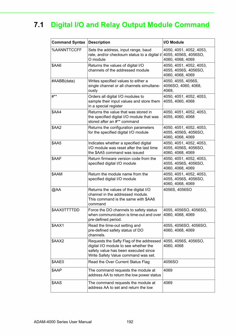
7.1 Digital I/O and Relay Output Module Command
Command Syntax Description I/O Module
%AANNTTCCFF Sets the address, input range, baudrate, and/or checksum status to a digital I/O module
4050, 4051, 4052, 4053,4055, 4056S, 4056SO,4060, 4068, 4069
$AA6 Returns the values of digital I/Ochannels of the addressed module
4050, 4051, 4052, 4053,4055, 4056S, 4056SO,4060, 4068, 4069
#AABB(data) Writes specified values to either asingle channel or all channels simultane-ously
4050, 4055, 4056S,4056SO, 4060, 4068,4069,
#** Orders all digital I/O modules tosample their input values and store them in a special register
4050, 4051, 4052, 4053,4055, 4060, 4068
$AA4 Returns the value that was stored inthe specified digital I/O module that was stored after an #** command
4050, 4051, 4052, 4053,4055, 4060, 4068
$AA2 Returns the configuration parametersfor the specified digital I/O module
4050, 4051, 4052, 4053,4055, 4056S, 4056SO,4060, 4068, 4069
$AA5 Indicates whether a specified digitalI/O module was reset after the last time the $AA5 command was issued
4050, 4051, 4052, 4053,4055, 4056S, 4056SO,4060, 4068, 4069
$AAF Return firmware version code from thespecified digital I/O module
4050, 4051, 4052, 4053,4055, 4056S, 4056SO,4060, 4068, 4069
$AAM Return the module name from thespecified digital I/O module
4050, 4051, 4052, 4053,4055, 4056S, 4056SO,4060, 4068, 4069
@AA Returns the values of the digital I/Ochannel in the addressed module.This command is the same with $AA6 command
4056S, 4056SO
$AAX0TTTTDD Force the DO channels to safety status when communication is time-out and over pre-defined period.
4055, 4056SO, 4056SO,4060, 4068, 4069
$AAX1 Read the time-out setting andpre-defined safety status of DOchannels.
4055, 4056SO, 4056SO,4060, 4068, 4069
$AAX2 Requests the Safty Flag of the addressed digital I/O module to see whether the safety value has been executed since Write Safety Value command was set.
4055, 4056S, 4056SO,4060, 4068
$AAE0 Read the Over Current Status Flag 4056SO
$AAP The command requests the module ataddress AA to return the low power status
4069
$AAS The command requests the module ataddress AA to set and return the low
4069
ADAM-4000 Series User Manual 192

Chapter 7
Digital I/O
,Relay
ouputandC
ounter/Frequency
Com
mand S
et
193 ADAM-4000 Series User Manual

4050, 4051, 4052, 4053, 4055,
4056S, 4056SO, 4060, 4068, 4069
7.1.1 %AANNTTCCFFName Configuration command
Description Configure address, baud rate and/or checksum status of the
digital I/O module.
Syntax %AANNTTCCFF(cr)
% is a delimiter character.
AA (range 00-FF) represents the 2-character hexadecimal
address which is to be configured.
NN represents the new hexadecimal address ranging from
00h to FFh of the digital I/O module.
TT represents the type of code that is always set to 40 for a
digital I/O module.
CC represents the baud rate code.
(Refer to Table 7-1 on next page)
FF is a hexadecimal number that equals to a 8-bit
parameter that represents the checksum and protocol status.
Bits 3 through 5 and bit 0, 1, 7 are not used and are being
set to 0. (Refer to Figure 7-1 below)
Bit 6 is the selection of checksum and bit 2 is the selection
of protocol. (0: advantech; 1: modbus). (Modbus protocol
is supported by ADAM-4052, 4051, 4055, 4056S, 4056SO,
4068 only)
(cr) is the terminating character, carriage return (0Dh).
Figure 7.1 Data format for FF (8-bit parameter)
ADAM-4000 Series User Manual 194

Chapter 7
Digital I/O
,Relay
ouputandC
ounter/Frequency
Com
mand S
et
Response !AA (cr) if the command is valid.
?AA(cr) if an invalid parameter was entered or the INIT*
terminal was not grounded when changing baud rate or
checksum settings were attempted.
There is no response if the module detects a syntax or
communication error, or even if the specified address does not exist.
! is a delimiter character which indicates a received valid command.
? is a delimiter character which indicates an invalid command.
AA (range 00-FF) represents the 2-character hexadecimal
address of a digital I/O module.
(cr) is the terminating character, carriage return (0Dh).
Example command: %2324400600(cr)
response: !24(cr)
The command tries to configure module by changing
address 23h to address 24h, assigning baud rate 9600,
setting no checksum checking and supporting Advantech protocol.
The response indicates that the configuration was successful.
Table 7.1: Baud Rate Codes
Baud Rate Code (Hex) Baud Rate
03 1200 bps
04 2400 bps
05 4800 bps
06 9600 bps
07 19.2 kbps
08 38.4 kbps
09 57.6 kbps
0A 115.2 kbps
Note! All configuration parameters can be changed dynamically, except checksum and baud rate parameters. They can only be altered when the INIT* terminal is grounded. (Please Refer to Baud rate and Check-sum, in Chapter 2 for the correct procedure.)
195 ADAM-4000 Series User Manual

4050, 4051, 4052, 4053, 4055,
4056S, 4056SO, 4060, 4068, 4069
7.1.2 $AA6Name Digital Data In command
Description This command requests the specified (AA) module to
return the status of its digital input channels and feedback
value from its digital output channels.
Syntax $AA6(cr)
$ is a delimiter character.
AA (range 00-FF) represents the 2-character hexadecimal
address of the module.
6 is the Digital Data In command.
(cr) is the terminating character, carriage return (0Dh).
Response !(dataOutput)(dataInput)00(cr)
if the command was valid. (ADAM-4050)
!(dataInput)00(cr)
if the command was valid. (ADAM-4051)
!(dataInput)0000(cr)
if the command was valid. (ADAM-4052)
!(dataInput)(dataInput) 00 (cr)
if the command was valid. (ADAM-4053)
!(dataOutput)(dataInput)00(cr)
if the command was valid. (ADAM-4055)
!(dataOutput)00(cr)
if the command was valid. (ADAM-4056S/4056SO)
!(dataOutput)0000(cr)
if the command was valid. (ADAM-4060/4068)
?AA(cr) if an invalid command has been issued.
There is no response if the module detects a syntax or
communication error, or even if the specified address does not exist.
! delimiter character indicates that a valid command was received.
? delimiter character indicates that the command was invalid.
AA (range 00-FF) represents the responding 2-character
hexadecimal address of the module.
(dataOutput) two-character hexadecimal value which is either
the feedback of a digital output channel or a relay. For
ADAM-4056S and ADAM-4056SO, it is four-character
hexadecimal for representing 12 channel digital output.
(dataInput) two-character hexadecimal value representing the
input values of the digital I/O module.
(cr) is the terminating character, carriage return (0Dh).
Example command: $336(cr)
response: !112200(cr)
This example is for ADAM-4050. The first two characters,
ADAM-4000 Series User Manual 196

Chapter 7
Digital I/O
,Relay
ouputandC
ounter/Frequency
Com
mand S
et
11h (00010001), of the response indicates that digital
output channels 0 and 4 are ON and channels 1, 2, 3, 5, 6, 7
are OFF. The second two characters of the response, 22h
(00100010), indicates that digital input channels 1 and 5 are
HIGH and channels 0, 2, 3, 4, 6, 7 are LOW.
command: $036(cr)
response: !BEDE00(cr)
This example is for ADAM-4053. The first two characters,
BEh (10111110), of the response indicates that digital input
channels 8 and 14 are LOW and channels 9, 10, 11, 12, 13
and 15 are HIGH. The second two characters, DEh
(11011110), of the response indicates that digital input
channels 0 and 5 are LOW and channels 1, 2, 3, 4, 6, 7 are HIGH.
command: $056(cr)
response: !017A00(cr)
This example is for ADAM-4056S or ADAM-4056SO. The
first character of the response is always 0. The next three
characters, 17A (000101111010), are the status of 12
channel digital outputs. The detail status is as below.
Digital value 0 0 0 1 0 1 1 1 1 0 1 0
ADAM-4056S/4056SOChannel no. 11 10 9 8 7 6 5 4 3 2 1 0
197 ADAM-4000 Series User Manual

4050, 4055, 4056S,
4056SO, 4060, 4068, 4069
7.1.3 #AABBName Digital Data Out command
Description The command either sets a single digital output channel or
sets all digital output channels simultaneously.
Syntax #AABB(data)(cr)
# is a delimiter character.
AA (range 00-FF) represents the 2-character hexadecimal
address of the output value.
BB is used to indicate whether all channels will be set or a
single channel will be set. In the last case, BB will also
indicate which channel it is. Writing data (a byte) to all
channels should make both characters to be zero (BB=00).
Writing data (a bit) to a single channel, however, will make
the first character 1and the second character ranging from 0
to B. The second character indicates the channel number.
(data) is the hexadecimal representation of the digital output
value(s). Two characters are for ADAM-4050, ADAM-4055,
ADAM-4060 and ADAM-4068. Four characters are for
ADAM-4056S and 4056SO.
ADAM-4050, 4055, 4060 and 4068:
When writing to a single channel (bit), the first character is
always 0. The value of the second character will be either 0 or 1.
When writing to all channels (byte), both characters are
significant (range 00h-FFh). The digital equivalent of these
two hexadecimal characters represents the value of the channels.
The amount of channels on ADAM-4050, ADAM-4055,
ADAM-4060 and ADAM-4068 differ. The value 7A
representation for 8 channeled ADAM-4050, ADAM-4055
and ADAM-4068 would be the following:
Since the ADAM-4060 only has four output channels, all the
relevant values lie between 00h and 0Fh. The value 0Ah for
the ADAM-4060 would represent the following:
ADAM-4056S and 4056SO:
When writing to a single channel (bit), the first three
characters are always 0. The value of the last character is
either 0 or 1.
Digital Value: 0 1 1 1 1 0 1 0
ADAM-4050/4055/4068 channel no. 7 6 5 4 3 2 1 0
Digital Value: 0 0 0 0 1 0 1 0
ADAM-4060 channel no. - - - - 3 2 1 0
ADAM-4000 Series User Manual 198

Chapter 7
Digital I/O
,Relay
ouputandC
ounter/Frequency
Com
mand S
et
When writing to all channels (byte), the first character zero
is irrelevant, but the rest are significant (range 000h-FFFh).
The digital equivalent of last three hexadecimal characters
represents the value of channels.
For example: 017A
First character is always 0
2nd~4th character means the the channel values 17A.
(cr) is the terminating character, carriage return (0Dh).
Response >(cr) if the command was valid.
?AA(cr) if an invalid command has been issued.
There is no response if the module detects a syntax or
communication error, or even if the specified address does not exist.
> is a delimiter character which indicates a valid command.
? is a delimiter character which indicates an invalid command.
AA (range 00-FF) represents the responding 2-character
hexadecimal address of the module.
(cr) is the terminating character, carriage return (0Dh).
Examples command: #140005(cr)
response: >(cr)
An output byte with value 05h (00000101) is sent to the
digital I/O module at address 14h (Either ADAM-4050 or
ADAM-4060). Its channel 0 and 2 will be set to ON.
Other channels are set to OFF.
command: #151201(cr)
response: >(cr)
An output bit with value 1 is sent to channel 2 at address
15h of a digital I/O module (Either ADAM-4050 or
ADAM-4060).
Channel 2 of the digital I/O module is set to ON.
command: #1400017A(cr)
response: >(cr)
An output byte with value 017Ah (0000000101111010) is
sent to the digital I/O module at address 14h (Either
ADAM-4056S or ADAM-4056SO). Its channel 1, 3, 4, 5, 6,
and 8 will be set to ON. Other channels are set to OFF.
command: #15120001(cr)
response: >(cr)
An output bit with value 1 is sent to channel 2 of a digital
I/O module at address 15h (Either ADAM-4056S or
ADAM-4056SO). Channel two of the digital I/O module is set to ON.
Digital value 0 0 0 1 0 1 1 1 1 0 1 0
Adam-4056S/4056SO channel no. 11 10 9 8 7 6 5 4 3 2 1 0
199 ADAM-4000 Series User Manual

4050, 4051, 4052, 4053,
4055, 4060, 4068
7.1.4 #**Name Synchronized Sampling command
Description Orders all (analog or digital) input modules to sample their
input values and store them into a special register.
Syntax #**
# is a delimiter character.
** is the Synchronized Sampling command.
The terminating character, in the form of a carriage
return (0Dh), is not required.
Response The digital I/O modules will not respond to the
Synchronized Sampling command. In order to retrieve the
data, you must execute a Read Synchronized Data
command for every module separately.
4050, 4051, 4052, 4053,
4055, 4060, 4068
7.1.5 $AA4Name Read Synchronized Data command
Description The addressed digital I/O module is instructed to return the
value that was stored in its register by a Synchronized
Sampling command.
Syntax $AA4(cr)
$ is a delimiter character.
AA (range 00-FF) represents the 2-character hexadecimal
address of returning data.
4 is the Read Synchronized Data command.
(cr) is the terminating character, carriage return (0Dh).
Response !(status)(dataOutput)(dataInput)00(cr)
if the command was valid. (ADAM-4050)
!(status)(dataInput)00(cr)
if the command was valid. (ADAM-4051)
!(status)(dataInput)0000(cr)
if the command was valid. (ADAM-4052)
!(status)(dataInput)(dataInput)00(cr)
if the command was valid. (ADAM-4053)
!(status)(dataOutput)0000(cr)
if the command was valid. (ADAM-4060/4068)
?AA(cr) if an invalid command has been issued.
There is no response if the module detects a syntax or
communication error, or even if the specified address does not exist.
ADAM-4000 Series User Manual 200

Chapter 7
Digital I/O
,Relay
ouputandC
ounter/Frequency
Com
mand S
et
! is a delimiter character which indicates a valid command.
? is a delimiter character which indicates an invalid command.
AA (range 00-FF) represents the responding 2-character
hexadecimal address of the digital I/O module.
(status) will tell you if the data (data) from the last
Synchronized Sampling command (#**) have already been
sent. If (status=1), data have only been sent for the first
time after a Synchronized Sampling command was issued.
If (status=0), then the data have been sent at least once
since no Synchronized Sampling command was issued.
(dataOutput) two-character hexadecimal value which is
either the feedback of a digital output channel or a relay.
(dataInput) two-character hexadecimal value representing
the input values of the digital I/O module.
(cr) is the terminating character, carriage return (0Dh).
Example command: $064(cr)
response: !1055100(cr)
The command asks the ADAM-4050 digital I/O module at
address 06h to send its digital input data that was gathered
during the last Synchronized Sampling command. The
module returns the value 1055100 with status equals to 1
which also represents that data have not been sent before.
From inspection, the value has dataOutput = 05h
(00000101), ON for digital output channels 0 and 2 and
OFF for channels 1, 3, 4, 5, 6, 7. It also has dataInput = 51h
(01010001) which represents HIGH for digital input
channels 0, 4, 6 and LOW for channels 1, 2, 3, 4, 5.
The digital I/O module responds with data = 055100 and
status = 1. These mean that the data has been sent for the first time.
command: $064(cr)
response: !0055100(cr)
The command asks the digital I/O module at address 06h to
send its digital input data.
The digital I/O module responds with data = 055100 and
status = 0, which means that it has sent the same data at
least once before. This may also indicates that a previous
Synchronized Sampling command was not received!
201 ADAM-4000 Series User Manual

4050, 4051, 4052, 4053, 4055,
4056S, 4056SO, 4060, 4068, 4069
7.1.6 $AA2Name Configuration Status command
Description Returns the configuration parameters of the digital I/O module.
Syntax $AA2(cr)
$ is a delimiter character.
AA (range 00-FF) represents the 2-character hexadecimal
address that you will access to.
2 is Configuration Status command.
(cr) is the terminating character, carriage return (0Dh).
This command requests the return of the configuration data
from the digital I/O module at address AA.
Response !AATTCCFF(cr) if the command is valid.
?AA(cr) if an invalid command has been issued.
There is no response if the module detects a syntax or
communication error, or even if the specified address does not exist.
! is a delimiter character which indicates a valid command.
? is a delimiter character which indicates an invalid command.
AA (range 00-FF) represents the 2-character hexadecimal
address of the module.
TT represents the type of code, which is always 40.
CC represents the baud rate codes.
(Refer to Table 7-2 on next page).
The hexadecimal number FF which is converted to a 8-bit
parameter represents the checksum and protocol status .
Bits 3 through 5 and bit 0, 1, 7 are not used, so they are
set to 0. (Refer to Figure 7-2 on next page)
Bit 6 is the selection of checksum and bit 2 is the selection
of protocol (0: advantech, 1: modbus).
(Modbus protocol is supported by ADAM-4051, 4055,
4056S, 4056SO, 4068 only)
(cr) is the terminating character, carriage return (ODh).
Example command: $452 (cr)
response: !45400600 (cr)
The command asks the digital I/O module at address 45h to
send its configuration data.
The digital I/O module at address 45h responds with baud
rate 9600, no checksum function and module supports for
Advantech protocol.
ADAM-4000 Series User Manual 202

Chapter 7
Digital I/O
,Relay
ouputandC
ounter/Frequency
Com
mand S
et
Figure 7.2 Data format for FF (8-bit parameter)
Table 7.2: Baud Rate Codes
Baud Rate Code (Hex) Baud Rate
03 1200 bps
04 2400 bps
05 4800 bps
06 9600 bps
07 19.2 kbps
08 38.4 kbps
09 57.6 kbps
0A 115.2 kbps
203 ADAM-4000 Series User Manual
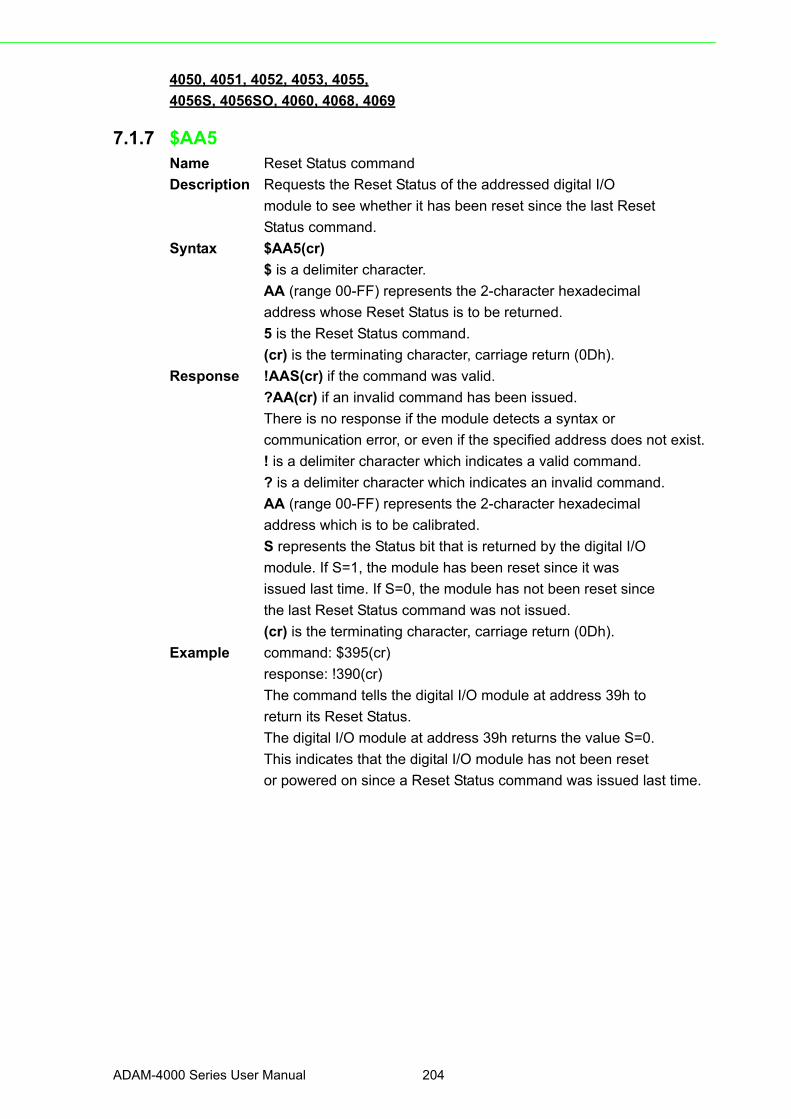
4050, 4051, 4052, 4053, 4055,
4056S, 4056SO, 4060, 4068, 4069
7.1.7 $AA5Name Reset Status command
Description Requests the Reset Status of the addressed digital I/O
module to see whether it has been reset since the last Reset
Status command.
Syntax $AA5(cr)
$ is a delimiter character.
AA (range 00-FF) represents the 2-character hexadecimal
address whose Reset Status is to be returned.
5 is the Reset Status command.
(cr) is the terminating character, carriage return (0Dh).
Response !AAS(cr) if the command was valid.
?AA(cr) if an invalid command has been issued.
There is no response if the module detects a syntax or
communication error, or even if the specified address does not exist.
! is a delimiter character which indicates a valid command.
? is a delimiter character which indicates an invalid command.
AA (range 00-FF) represents the 2-character hexadecimal
address which is to be calibrated.
S represents the Status bit that is returned by the digital I/O
module. If S=1, the module has been reset since it was
issued last time. If S=0, the module has not been reset since
the last Reset Status command was not issued.
(cr) is the terminating character, carriage return (0Dh).
Example command: $395(cr)
response: !390(cr)
The command tells the digital I/O module at address 39h to
return its Reset Status.
The digital I/O module at address 39h returns the value S=0.
This indicates that the digital I/O module has not been reset
or powered on since a Reset Status command was issued last time.
ADAM-4000 Series User Manual 204

Chapter 7
Digital I/O
,Relay
ouputandC
ounter/Frequency
Com
mand S
et
4050, 4051, 4052, 4053, 4055,
4056S, 4056SO, 4060, 4068, 4069
7.1.8 $AAFName Read Firmware Version command
Description The command requests the digital I/O module at address
AA to return the version code of its firmware
Syntax $AAF (cr)
$ is a delimiter character.
AA (range 00-FF) represents the 2-character hexadecimal
address that you will access to.
F is the Read Firmware Version command.
(cr) is the terminating character, carriage return (ODh).
Response !AA(Version)(cr) if the command is valid.
There is no response if the module detects a syntax or
communication error, or even if the specified address does not exist.
! is a delimiter character which indicates a valid command.
AA (range 00-FF) represents the 2-character hexadecimal address
of the module.
(Version) is the version code of the module’s firmware at address AA.
(cr) is the terminating character, carriage return (ODh).
205 ADAM-4000 Series User Manual

4050, 4051, 4052, 4053, 4055,
4056S, 4056SO, 4060, 4068, 4069
7.1.9 $AAMName Read Module Name command
Description The command requests the digital I/O module at address
AA to return its name
Syntax $AAM (cr)
$ is a delimiter character.
AA (range 00-FF) represents the 2-character hexadecimal
address that you will access to.
M is the Read Module Name command.
(cr) is the terminating character, carriage return (ODh).
Response !AA(Module Name)(cr) if the command is valid.
There is no response if the module detects a syntax or
communication error, even or if the specified address does not exist.
! is a delimiter character which indicates a valid command.
AA (range 00-FF) represents the 2-character hexadecimal
address of the module.
(Module Name) is the name of the module at address AA.
For example, 4052
(cr) is the terminating character, carriage return (ODh).
ADAM-4000 Series User Manual 206

Chapter 7
Digital I/O
,Relay
ouputandC
ounter/Frequency
Com
mand S
et
4055, 4056S, 4056SO,
4060, 4068, 4069
7.1.10 $AAX0TTTTDDName Write Safety Value command
Description Force the DO channels to safety status when communication
is in time-out and over pre-defined period.
Syntax $AAX0TTTTDD(cr)
$ is a delimiter character.
AA (range 00-FF) represents the 2-character hexadecimal
address that you will access to.
X0 is the Write Safety Value command.
TTTT is the time divided by 100ms and shown in hexadecimal number
DD is the two-hexadecimal character representing the
desired input safety value. The first character D is always 0,
and the others are the channels values.
For Example, 017A
First character is always 0
The meaning of 17A is as follows:
17A means that the status of channel 1, 3, 4, 5, 6, 8 is ON;
and the rest are OFF.
(cr) is the terminating character, carriage return (0Dh).
Response >(cr) if the command was valid.
?AA(cr) if an invalid command has been issued.
There is no response if the module detects a syntax or
communication error, or even if the specified address does not exist.
> is a delimiter character which indicates a valid command.
? is a delimiter character which indicates an invalid command.
AA (range 00-FF) represents the responding 2-character
hexadecimal address of the module.
(cr) is the terminating character, carriage return (0Dh).
Digital value 0 0 0 1 0 1 1 1 1 0 1 0
Adam-4056SO channel no. 11 10 9 8 7 6 5 4 3 2 1 0
207 ADAM-4000 Series User Manual

4055, 4056S, 4056SO,
4060, 4068, 4069
7.1.11 $AAX1Name Read Safety Value command
Description Read the time-out setting and pre-defined safety status of DO
channels.
Syntax $AAX1(cr)
$ is a delimiter character.
AA (range 00-FF) represents the 2-character hexadecimal
address that you will access to.
X1 is the Read Safety Value command.
(cr) is the terminatng character, carriage return (0Dh).
Response ! TTTTDDDD(cr) if the command is valid.
?AA(cr) if an invalid command has been issued.
! is a delimiter character which indicates a valid command.
? is a delimiter character which indicates an invalid command.
TTTT is the time, 100 ms per number.
DDDD is the four-hexadecimal character representing the
desired input safety value. The first character D is always 0,
and the others are the channels values.
For Example, 017A
First character is always 0
The meaning of 17A is as follows:
17A means channels 1, 3,4,5, 6, 8 are ON, and the rest are OFF.
(cr) is the terminating character, carriage return (ODh).
Digital value 0 0 0 1 0 1 1 1 1 0 1 0
Adam-4056SO channel no. 11 10 9 8 7 6 5 4 3 2 1 0
ADAM-4000 Series User Manual 208
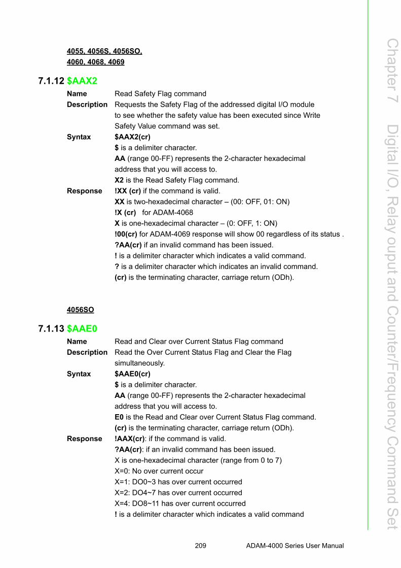
Chapter 7
Digital I/O
,Relay
ouputandC
ounter/Frequency
Com
mand S
et
4055, 4056S, 4056SO,
4060, 4068, 4069
7.1.12 $AAX2Name Read Safety Flag command
Description Requests the Safety Flag of the addressed digital I/O module
to see whether the safety value has been executed since Write
Safety Value command was set.
Syntax $AAX2(cr)
$ is a delimiter character.
AA (range 00-FF) represents the 2-character hexadecimal
address that you will access to.
X2 is the Read Safety Flag command.
Response !XX (cr) if the command is valid.
XX is two-hexadecimal character – (00: OFF, 01: ON)
!X (cr) for ADAM-4068
X is one-hexadecimal character – (0: OFF, 1: ON)
!00(cr) for ADAM-4069 response will show 00 regardless of its status .
?AA(cr) if an invalid command has been issued.
! is a delimiter character which indicates a valid command.
? is a delimiter character which indicates an invalid command.
(cr) is the terminating character, carriage return (ODh).
4056SO
7.1.13 $AAE0Name Read and Clear over Current Status Flag command
Description Read the Over Current Status Flag and Clear the Flag
simultaneously.
Syntax $AAE0(cr)
$ is a delimiter character.
AA (range 00-FF) represents the 2-character hexadecimal
address that you will access to.
E0 is the Read and Clear over Current Status Flag command.
(cr) is the terminating character, carriage return (ODh).
Response !AAX(cr): if the command is valid.
?AA(cr): if an invalid command has been issued.
X is one-hexadecimal character (range from 0 to 7)
X=0: No over current occur
X=1: DO0~3 has over current occurred
X=2: DO4~7 has over current occurred
X=4: DO8~11 has over current occurred
! is a delimiter character which indicates a valid command
209 ADAM-4000 Series User Manual

? is a delimiter character which indicates an invalid command
(cr) is the terminating character, carriage return (ODh).
4069
7.1.14 $AAPName Read the Low Power Status of Module command
Description The command requests the module at address AA to return
the low power status of module
Syntax $AAP(cr)
$ is a delimiter character.
AA (range 00-FF) represents the 2-character hexadecimal
address that you will access to.
P is the Read the Low Power Status of Module command.
(cr) is the terminating character, carriage return (ODh).
Response !AAS(cr) if the command was valid.
?AA(cr) if an invalid command has been issued.
There is no response if the module detects a syntax or
communication error, or even if the specified address does not exist.
! is a delimiter character which indicates a valid command
? is a delimiter character which indicates an invalid command
AA (range 00-FF) represents the calibrated 2-character
hexadecimal address of the module.
S represents the Status bit from the low power status. When
the logic equals to 1, it represents low power. When it equals
to zero, it means normal.
(cr) is the terminating character, carriage return (0Dh).
ADAM-4000 Series User Manual 210

Chapter 7
Digital I/O
,Relay
ouputandC
ounter/Frequency
Com
mand S
et
4069
7.1.15 AASName Change and Read the Low Power Mode of Module command
Description The command requests the module at address AA to change
and return the status of low power mode of module
Syntax $AAS(cr)
$ is a delimiter character.
AA (range 00-FF) represents the 2-character hexadecimal
address that you will access to.
S is the Change and Read the Low Power Mode of Module command
(cr) is the terminating character, carriage return (ODh).
Response !AAX(cr) if the command was valid.
?AA(cr) if an invalid command has been issued.
There is no response if the module detects a syntax or
communication error, or even if the specified address does not exist.
! is a delimiter character which indicates a valid command
? is a delimiter character which indicates an invalid command
AA (range 00-FF) represents the calibrated 2-character
hexadecimal address of the module.
X represents the Status bit from the low power status. When
the logic is 1, it represents low power. However, if the logic
is 0, it is normal
(cr) is the terminating character, carriage return (0Dh).
211 ADAM-4000 Series User Manual
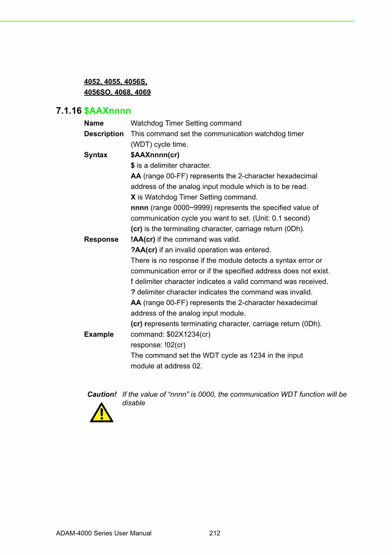
4052, 4055, 4056S,
4056SO, 4068, 4069
7.1.16 $AAXnnnnName Watchdog Timer Setting command
Description This command set the communication watchdog timer
(WDT) cycle time.
Syntax $AAXnnnn(cr)
$ is a delimiter character.
AA (range 00-FF) represents the 2-character hexadecimal
address of the analog input module which is to be read.
X is Watchdog Timer Setting command.
nnnn (range 0000~9999) represents the specified value of
communication cycle you want to set. (Unit: 0.1 second)
(cr) is the terminating character, carriage return (0Dh).
Response !AA(cr) if the command was valid.
?AA(cr) if an invalid operation was entered.
There is no response if the module detects a syntax error or
communication error or if the specified address does not exist.
! delimiter character indicates a valid command was received.
? delimiter character indicates the command was invalid.
AA (range 00-FF) represents the 2-character hexadecimal
address of the analog input module.
(cr) represents terminating character, carriage return (0Dh).
Example command: $02X1234(cr)
response: !02(cr)
The command set the WDT cycle as 1234 in the input
module at address 02.
Caution! If the value of “nnnn” is 0000, the communication WDT function will be disable
ADAM-4000 Series User Manual 212
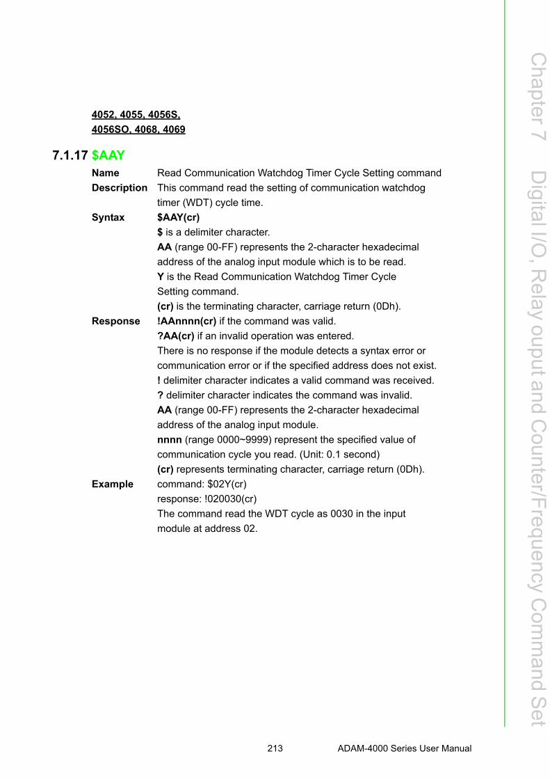
Chapter 7
Digital I/O
,Relay
ouputandC
ounter/Frequency
Com
mand S
et
4052, 4055, 4056S,
4056SO, 4068, 4069
7.1.17 $AAYName Read Communication Watchdog Timer Cycle Setting command
Description This command read the setting of communication watchdog
timer (WDT) cycle time.
Syntax $AAY(cr)
$ is a delimiter character.
AA (range 00-FF) represents the 2-character hexadecimal
address of the analog input module which is to be read.
Y is the Read Communication Watchdog Timer Cycle
Setting command.
(cr) is the terminating character, carriage return (0Dh).
Response !AAnnnn(cr) if the command was valid.
?AA(cr) if an invalid operation was entered.
There is no response if the module detects a syntax error or
communication error or if the specified address does not exist.
! delimiter character indicates a valid command was received.
? delimiter character indicates the command was invalid.
AA (range 00-FF) represents the 2-character hexadecimal
address of the analog input module.
nnnn (range 0000~9999) represent the specified value of
communication cycle you read. (Unit: 0.1 second)
(cr) represents terminating character, carriage return (0Dh).
Example command: $02Y(cr)
response: !020030(cr)
The command read the WDT cycle as 0030 in the input
module at address 02.
213 ADAM-4000 Series User Manual
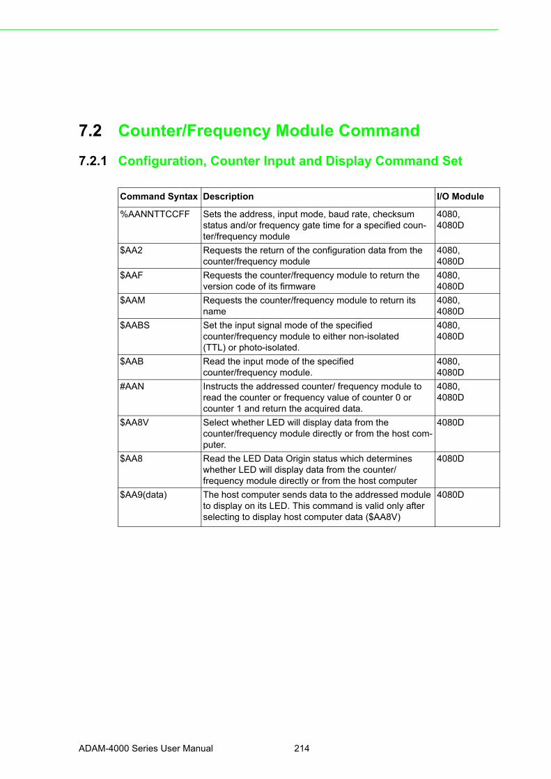
7.2 Counter/Frequency Module Command
7.2.1 Configuration, Counter Input and Display Command Set
Command Syntax Description I/O Module
%AANNTTCCFF Sets the address, input mode, baud rate, checksumstatus and/or frequency gate time for a specified coun-ter/frequency module
4080,4080D
$AA2 Requests the return of the configuration data from thecounter/frequency module
4080,4080D
$AAF Requests the counter/frequency module to return theversion code of its firmware
4080,4080D
$AAM Requests the counter/frequency module to return its name
4080,4080D
$AABS Set the input signal mode of the specifiedcounter/frequency module to either non-isolated(TTL) or photo-isolated.
4080,4080D
$AAB Read the input mode of the specifiedcounter/frequency module.
4080,4080D
#AAN Instructs the addressed counter/ frequency module toread the counter or frequency value of counter 0 or counter 1 and return the acquired data.
4080,4080D
$AA8V Select whether LED will display data from thecounter/frequency module directly or from the host com-puter.
4080D
$AA8 Read the LED Data Origin status which determineswhether LED will display data from the counter/frequency module directly or from the host computer
4080D
$AA9(data) The host computer sends data to the addressed module to display on its LED. This command is valid only after selecting to display host computer data ($AA8V)
4080D
ADAM-4000 Series User Manual 214

Chapter 7
Digital I/O
,Relay
ouputandC
ounter/Frequency
Com
mand S
et
4080, 4080D
7.2.1.1 %AANNTTCCFFName Configuration command
Description Sets the address, input mode, baud rate, checksum status
and frequency gate time for a specified counter/frequency module
Syntax %AANNTTCCFF (cr)
% is a delimiter character.
AA (range 00-FF) represents the 2-character hexadecimal
address that you will access to.
NN represents the new hexadecimal address of the
counter/frequency module. Range is from 00h to FFh.
TT represents the input mode.
50h : counter input mode
51h : frequency measurement mode
CC represents the baud rate code.
(Refer to Table 7-3 on next page).
Hexadecimal value FF which is converted to an 8-bit
parameter represents the checksum status and frequency
gate time. The layout of the 8-bit parameter is shown in
Figure 7-3 below.
Bits 0, 1, 3, 4, 5 and 7 are not used and are set to 0.
(cr) is the terminating character, carriage return (0Dh).
Figure 7.3 Data format for FF (8-bit parameter)
Response AA(cr) if the command is valid.
?AA(cr) if an invalid parameter was entered or the INIT*
215 ADAM-4000 Series User Manual

terminal was not grounded when changing baud rate or
checksum setting were attempted.
There is no response if the module detects a syntax or
communication error, or even if the specified address does not exist.
! is a delimiter character which indicates a valid command.
? is a delimiter character which indicates an invalid command.
AA (range 00-FF) represents the 2-character hexadecimal
address of the module.
(cr) is the terminating character, carriage return (0Dh).
Example command: %0120510600(cr)
response: !20(cr)
The ADAM 4080D module is configured by changing
address 01 to a new address 20, choosing frequency
measurement module, assigning 9600 to baud rate, setting
frequency gate time 0.1 second and no checksum checking
or generation.
The response indicates that the command was received.
Wait seven seconds to let the new configuration settings
take effect before you issue a new command to the module.
Table 7.3: Baud Rate Codes
Baud Rate Code (Hex) Baud Rate
03 1200 bps
04 2400 bps
05 4800 bps
06 9600 bps
07 19.2 kbps
08 38.4 kbps
Caution! You can change all configuration parameters dynamically except check-sum and baud rate parameters. They can only be altered when the INIT* terminal is grounded.
ADAM-4000 Series User Manual 216

Chapter 7
Digital I/O
,Relay
ouputandC
ounter/Frequency
Com
mand S
et
4080, 4080D
7.2.1.2 $AA2Name Configuration Status command
Description The command requests the return of the configuration data
from the counter/frequency module at address AA.
Syntax $AA2(cr)
$ is a delimiter character.
AA (range 00-FF) represents the 2-character hexadecimal
address that you will access to.
2 is the Configuration Status command.
(cr) is the terminating character, carriage return (0Dh).
Response !AATTCCFF (cr) if the command is valid.
?AA(cr) if an invalid operation was entered
There is no response if the module detects a syntax or
communication error, or even if the specified address does
not exist.
! is a delimiter character which indicates a valid command.
? is a delimiter character which indicates an invalid command.
AA (range 00-FF) represents the 2-character hexadecimal
that you will access to.
TT (50h or 51h) represents the type of code. 50h means
using module as a counter. 51h means using module as a
frequency measurement module.
CC represents the baud rate code.
Hexadecimal value FF which also equals to an 8-bit
parameter represents the checksum status and frequency
gate time. The layout of the 8-bit parameter is shown in
figure 4-5. The bits are not used and are set to 0.
(cr) is the terminating character, carriage return (0Dh)
(Also see the %AANNTTCCFF configuration command)
217 ADAM-4000 Series User Manual

4080, 4080D
7.2.1.3 $AAFName Read Version command
Description The command requests the analog input module at address
AA to return the version code of its firmware.
Syntax $AAF (cr)
$ is a delimiter character.
AA (range 00-FF) represents the 2-character hexadecimal
address that you will access to.
F is the Read Version command.
(cr) is the terminating character, carriage return (0Dh).
Response !AA(Version)(cr) if the command is valid.
There is no response if the module detects a syntax or
communication error, or even if the specified address does not exist.
! is a delimiter character which indicates a valid command.
AA (range 00-FF) represents the 2-character hexadecimal
address of the module.
(Version) is the version code of the module's firmware at address AA.
(cr) is the terminating character, carriage return (0Dh).
4080, 4080D
7.2.1.4 $AAMName Read Module Name command
Description The command requests the counter/frequency module at
address AA to return its name
Syntax $AAM (cr)
$ is a delimiter character.
AA (range 00-FF) represents the 2-character hexadecimal
address that you will access to.
M is the Read Module Name command.
(cr) is the terminating character, carriage return (0Dh).
Response !AA(Module Name)(cr) if the command is valid.
There is no response if the module detects a syntax or
communication error, or even if the specified address does not exist.
! is a delimiter character which indicates a valid command.
AA (range 00-FF) represents the 2-character hexadecimal
address of the module.
(Module Name) is the name of the module at address AA.
ADAM-4000 Series User Manual 218
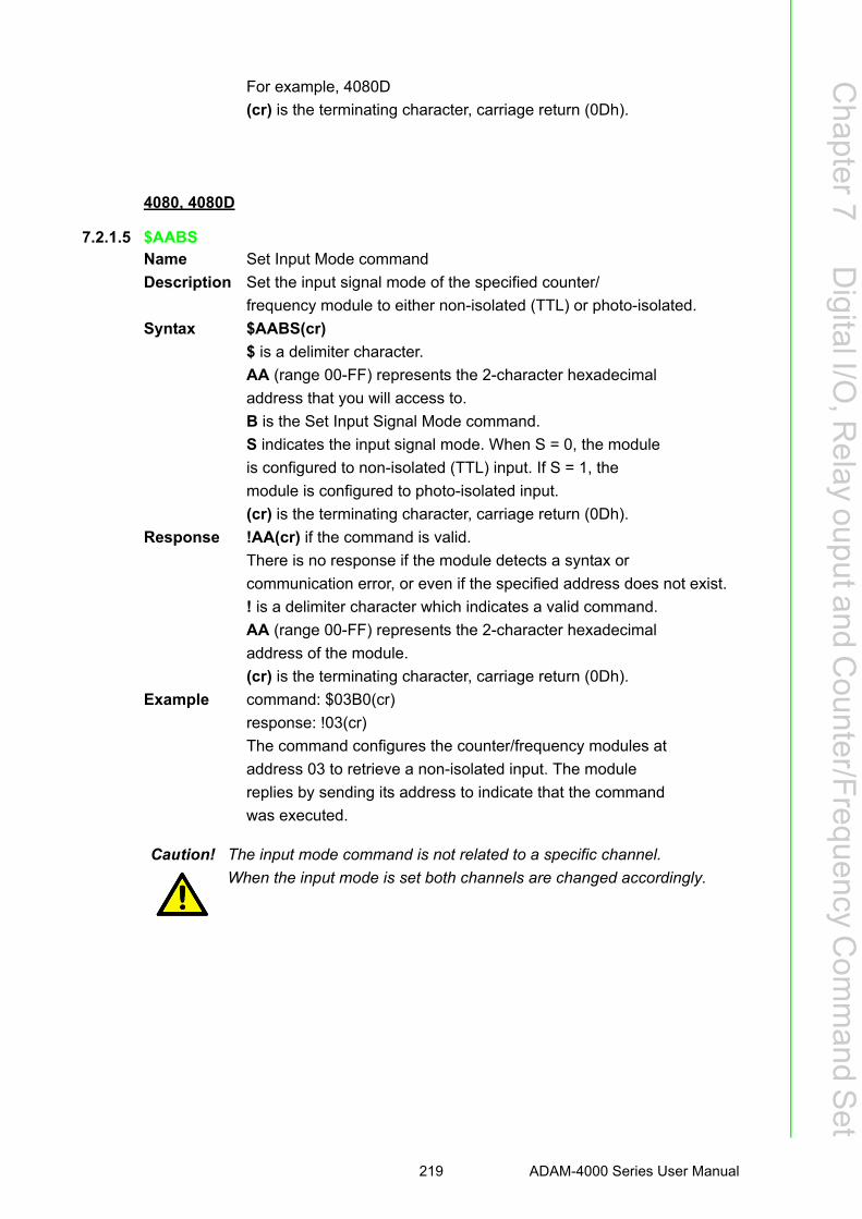
Chapter 7
Digital I/O
,Relay
ouputandC
ounter/Frequency
Com
mand S
et
For example, 4080D
(cr) is the terminating character, carriage return (0Dh).
4080, 4080D
7.2.1.5 $AABSName Set Input Mode command
Description Set the input signal mode of the specified counter/
frequency module to either non-isolated (TTL) or photo-isolated.
Syntax $AABS(cr)
$ is a delimiter character.
AA (range 00-FF) represents the 2-character hexadecimal
address that you will access to.
B is the Set Input Signal Mode command.
S indicates the input signal mode. When S = 0, the module
is configured to non-isolated (TTL) input. If S = 1, the
module is configured to photo-isolated input.
(cr) is the terminating character, carriage return (0Dh).
Response !AA(cr) if the command is valid.
There is no response if the module detects a syntax or
communication error, or even if the specified address does not exist.
! is a delimiter character which indicates a valid command.
AA (range 00-FF) represents the 2-character hexadecimal
address of the module.
(cr) is the terminating character, carriage return (0Dh).
Example command: $03B0(cr)
response: !03(cr)
The command configures the counter/frequency modules at
address 03 to retrieve a non-isolated input. The module
replies by sending its address to indicate that the command
was executed.
Caution! The input mode command is not related to a specific channel.
When the input mode is set both channels are changed accordingly.
219 ADAM-4000 Series User Manual
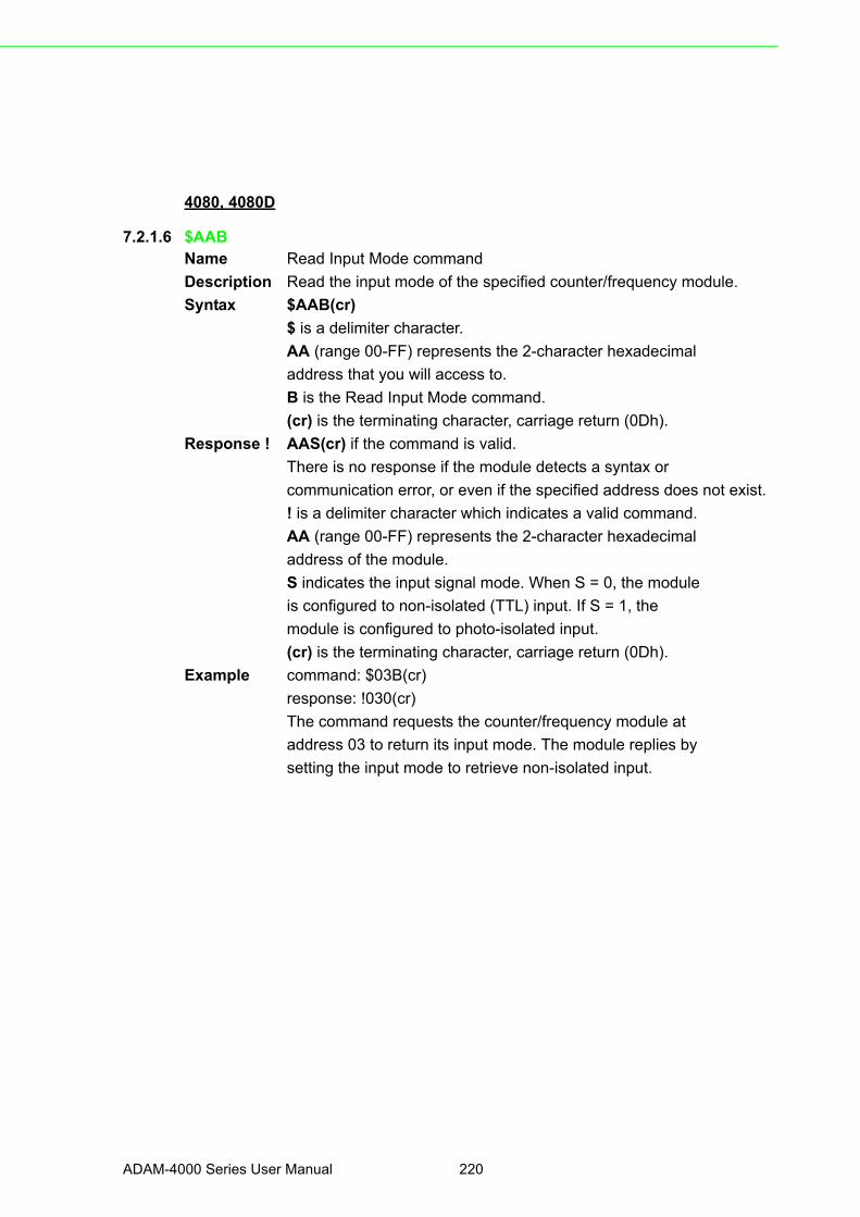
4080, 4080D
7.2.1.6 $AABName Read Input Mode command
Description Read the input mode of the specified counter/frequency module.
Syntax $AAB(cr)
$ is a delimiter character.
AA (range 00-FF) represents the 2-character hexadecimal
address that you will access to.
B is the Read Input Mode command.
(cr) is the terminating character, carriage return (0Dh).
Response ! AAS(cr) if the command is valid.
There is no response if the module detects a syntax or
communication error, or even if the specified address does not exist.
! is a delimiter character which indicates a valid command.
AA (range 00-FF) represents the 2-character hexadecimal
address of the module.
S indicates the input signal mode. When S = 0, the module
is configured to non-isolated (TTL) input. If S = 1, the
module is configured to photo-isolated input.
(cr) is the terminating character, carriage return (0Dh).
Example command: $03B(cr)
response: !030(cr)
The command requests the counter/frequency module at
address 03 to return its input mode. The module replies by
setting the input mode to retrieve non-isolated input.
ADAM-4000 Series User Manual 220

Chapter 7
Digital I/O
,Relay
ouputandC
ounter/Frequency
Com
mand S
et
4080, 4080D
7.2.1.7 $AANName Counter or Frequency Value command
Description Instructs the addressed counter/frequency module at
address AA to read the counter or frequency value of
counter 0 or counter 1 and return the acquired data.
Syntax #AAN(cr)
# is a delimiter character.
AA (range 00-FF) represents the 2-character hexadecimal
address that you will access to.
N represents the counter number.
N=0 represents counter 0
N=1 represents counter 1
(cr) is the terminating character, carriage return (0Dh).
Response >data(cr) if the command is valid.
?AA(cr) if an invalid operation was entered.
There is no response if the module detects a syntax or
communication error, or even if the specified address does not exist.
? is a delimiter character which indicates an invalid command.
AA (range 00-FF) represents the 2-character hexadecimal
address of the module.
(data) is the value that is retrieved by the module from
reading counter 0 or counter 1. The data format consists of
eight hexadecimal characters.
(cr) is the terminating character, carriage return (0Dh).
Example command: #120(cr)
response: >000002FE(cr)
The command requests the counter/frequency module at
address 12 to read the counter 0 and return the data. The
counter/frequency module at address 12 responds with
value 000002FE (hexadecimal) of counter 0 which is also
equivalent to 766 (decimal).
221 ADAM-4000 Series User Manual

4080D
7.2.1.8 $AA8VName Select LED Data Origin command
Description Select whether LED will display data from either the host
computer or the counter/frequency module directly.
Syntax $AA8V(cr)
$ is a delimiter character.
AA (range 00-FF) represents the 2-character hexadecimal
address that you will access to.
8 is the Select LED Data Origin command.
V indicates the origin of the data which is to be displayed
on the LED:
V=0 sets the LED data origin to the module's counter 0
V=1 sets the LED data origin to the module's counter 1
V=2 sets the LED data origin to the host computer
(cr) is the terminating character, carriage return (0Dh)
Response !AA(cr) if the command is valid.
?AA(cr) if an invalid operation was entered.
There is no response if the module detects a syntax or
communication error, or even if the specified address does not exist.
! is a delimiter character which indicates a valid command.
? is a delimiter character which indicates an invalid command.
AA (range 00-FF) represents the 2-character hexadecimal
address of the module.
(cr) is the terminating character, carriage return (0Dh).
Example command: $0182(cr)
response: !01(cr)
The command sets the counter/frequency modules at
address 01 to display data sent by the host computer. After
this command has been issued, the host computer can use
command $AA9(data) to send the data to the module.
ADAM-4000 Series User Manual 222

Chapter 7
Digital I/O
,Relay
ouputandC
ounter/Frequency
Com
mand S
et
4080D
7.2.1.9 $AA8Name Read LED Data Origin command
Description Read the LED Data Origin status which determines whether
LED will display data from either the host computer or the
counter/frequency module directly.
Syntax $AA8(cr)
$ is a delimiter character.
AA (range 00-FF) represents the 2-character hexadecimal
address that you will access to.
8 is the Read LED Data Origin command.
(cr) is the terminating character, carriage return (0Dh)
Response !AAV(cr) if the command is valid.
?AA(cr) if an invalid operation was entered.
There is no response if the module detects a syntax or
communication error, or even if the specified address does not exist.
! is a delimiter character which indicates a valid command.
? is a delimiter character which indicates an invalid command.
AA (range 00-FF) represents the 2-character hexadecimal
address of the module.
V indicates the origin of the data to be displayed on the LED:
V=0 sets the LED data origin to the module's counter 0
V=1 sets the LED data origin to the module's counter 1
V=2 sets the LED data origin to the host computer
(cr) is the terminating character, carriage return (0Dh).
Example command: $018(cr)
response: !011(cr)
The command requests the counter/frequency module at
address 01 to return its LED Data Origin status. The
module replies that it currently displays data from counter 1.
223 ADAM-4000 Series User Manual

4080D
7.2.1.10 $AA9(data)Name Send Data to LED command
Description The host computer sends data to the addressed module to
display on its LED.
Syntax $AA9(data)(cr)
$ is a delimiter character.
AA (range 00-FF) represents the 2-character hexadecimal
address that you will access to.
9 is the Send LED Data command.
(data) is a floating point numeral consisting of five digits,
and there can be a decimal point. Its maximum value is 99999.
(cr) is the terminating character, carriage return (0Dh)
Response !AA(cr) if the command is valid.
?AA(cr) if an invalid operation was entered.
There is no response if the module detects a syntax or
communication error, or even if the specified address does not exist.
! is a delimiter character which indicates a valid command.
? is a delimiter character which indicates an invalid command.
AA (range 00-FF) represents the 2-character hexadecimal
address of a counter/frequency module.
(cr) is the terminating character, carriage return (0Dh).
Example command: $0198999.9(cr)
response: !01(cr)
The command requests the host computer to send 8999.9 to
the counter/frequency module at address 01 for LED
display. This command is only valid after the command
$0182 has been issued.
ADAM-4000 Series User Manual 224

Chapter 7
Digital I/O
,Relay
ouputandC
ounter/Frequency
Com
mand S
et
7.2.2 Counter Setup Command Set
CommandSyntax
Command Name Description I/O Module
$AAAG Set Gate Mode Requests the specified counter/frequency module to set its gate mode to either high, low or disabled
4080, 4080D
$AAA Read Gate Mode Requests the specified counter/frequency module to return the sta-tus of its gate mode
4080, 4080D
$AA3N(data) Set MaximumCounter Value
Sets the maximum value ofcounter 0 or counter 1 for the speci-fied counter/frequency module
4080, 4080D
$AA3N Read MaximumCounter Value
Reads the maximum value ofcounter 0 or counter 1 of the speci-fied counte/ frequency module
4080, 4080D
$AA5NS Start/Stop Counter The command orders the specifiedcounter/frequency module to start or stop counting
4080, 4080D
$AA5N Read CounterStart/Stop Status
The addressed counter frequencymodule returns its status indicating whether counting is enabled or dia-bled
4080, 4080D
$AA6N Clear Counter The command clears the counter 0or counter 1 of the specified counter module
4080, 4080D
$AA7N Read Overflow Flag The addressed module returns thestatus of the overflow flag of counter 0 or counter 1
4080, 4080D
225 ADAM-4000 Series User Manual

4080, 4080D
7.2.2.1 $AAAGName Set Gate Mode command
Description Request the specified counter/frequency module to set its
gate to one of the three states, high, low or disabled.
Syntax $AAAG(cr)
$ is a delimiter character.
AA (range 00-FF) represents the 2-character hexadecimal
address that you will access to.
A is the Gate Mode command.
G determines the gate mode:
G = 0 the gate is low
G = 1 the gate is high
G = 2 the gate is disabled
(cr) is the terminating character, carriage return (0Dh).
Response !AA(cr) if the command is valid.
There is no response if the module detects a syntax or
communication error, or even if the specified address does not exist.
! is a delimiter character which indicates a valid command.
AA (range 00-FF) represents the 2-character hexadecimal
address of the module.
(cr) is the terminating character, carriage return (0Dh).
Example command: $01A1(cr)
response: !01(cr)
The command requests the counter/frequency module at
address 01 to set its gate high. The module will reply with
an address indicating that it has executed the command.
ADAM-4000 Series User Manual 226

Chapter 7
Digital I/O
,Relay
ouputandC
ounter/Frequency
Com
mand S
et
4080, 4080D
7.2.2.2 $AAAName Read Gate Mode command
Description Request the specified counter/frequency module to return
its gate status.
Syntax $AAA(cr)
$ is a delimiter character.
AA (range 00-FF) represents the 2-character hexadecimal
address that you will access to.
A is the Read Gate Mode command.
(cr) is the terminating character, carriage return (0Dh).
Response !AAG(cr) if the command is valid.
There is no response if the module detects a syntax or
communication error, or even if the specified address does not exist.
! is a delimiter character which indicates a valid command.
AA (range 00-FF) represents the 2-character hexadecimal
address of the module.
G determines the gate mode.
G = 0 the gate is low
G = 1 the gate is high
G = 2 the gate is disabled.
(cr) is the terminating character, carriage return (0Dh).
Example command: $01A(cr)
response: !011(cr)
The command requests the counter/frequency module to
return its gate status. The module at address 01 replies with
gate setting high.
227 ADAM-4000 Series User Manual

4080, 4080D
7.2.2.3 $AA3N(data)Name Set Maximum Counter Value command
Description Set the maximum value for either counter 0 or counter 1 of
a specified counter/frequency module.
Syntax $AA3N(data)(cr)
$ is a delimiter character.
AA (range 00-FF) represents the 2-character hexadecimal
address that you will access to.
3 is the Set Maximum Counter Value command.
N determines the counter for which the maximum counter
value is to be set.
N = 0 represents counter 0
N = 1 represents counter 1
(data) is the maximum count value which consists of eight
hexadecimal digits. The module will accumulate the input
counts until it reaches the maximum value. When the count
exceeds the maximum counter value, the counter will stop
counting. The programmer should use the command
$AA6N to reset the counter to 1.
(cr) is the terminating character, carriage return (0Dh).
Response !AA(cr) if the command is valid.
?AA(cr) if an invalid operation was entered.
There is no response if the module detects a syntax or
communication error, or even if the specified address does not exist.
! is a delimiter character which indicates a valid command.
? is a delimiter character which indicates an invalid
command.
AA (range 00-FF) represents the 2-character hexadecimal
address of the module.
(cr) is the terminating character, carriage return (0Dh).
Example command: $24300000ffff(cr)
response: !24(cr)
The command requests the counter/frequency module at
address 24 to set the maximum value for counter 0 to 65535
(0x0000ffff). The module will reply that it has executed the command.
ADAM-4000 Series User Manual 228
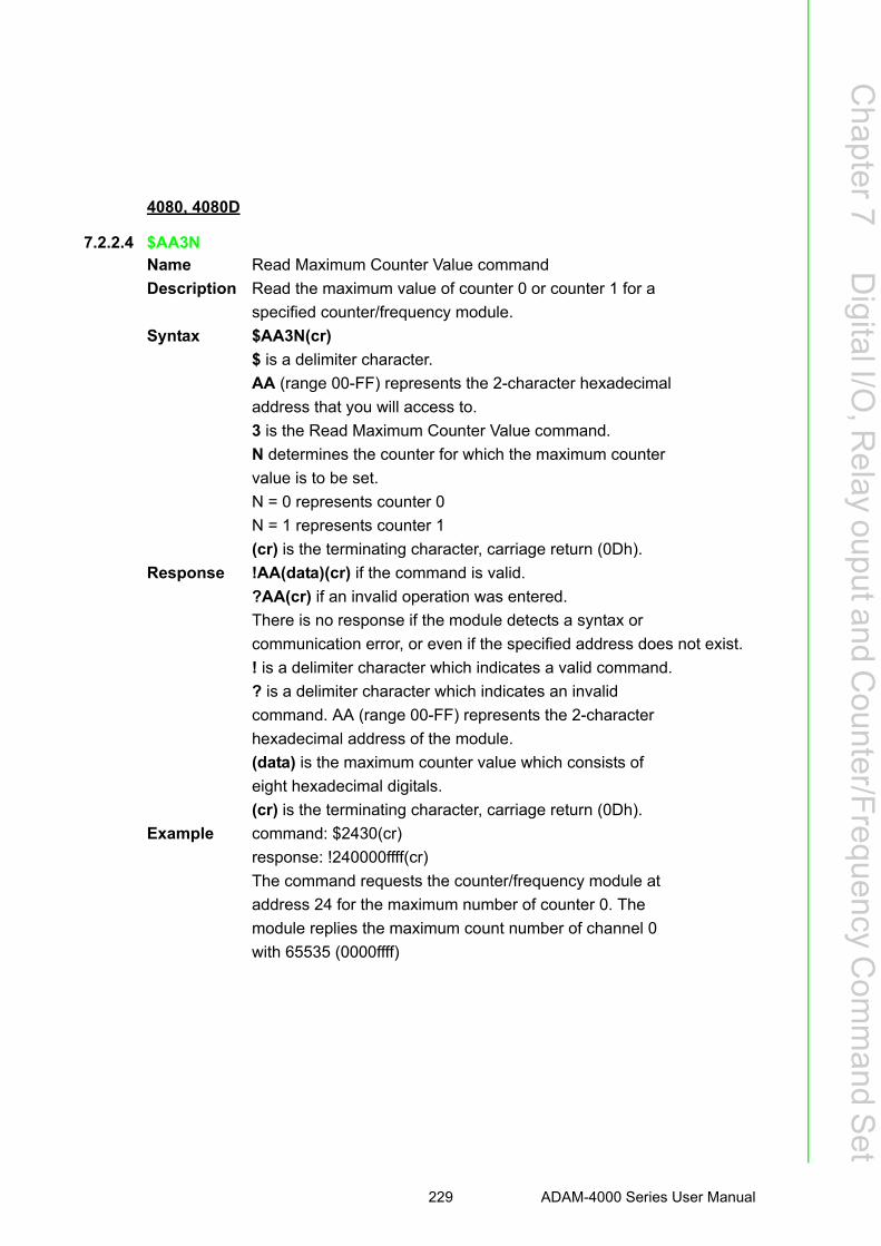
Chapter 7
Digital I/O
,Relay
ouputandC
ounter/Frequency
Com
mand S
et
4080, 4080D
7.2.2.4 $AA3NName Read Maximum Counter Value command
Description Read the maximum value of counter 0 or counter 1 for a
specified counter/frequency module.
Syntax $AA3N(cr)
$ is a delimiter character.
AA (range 00-FF) represents the 2-character hexadecimal
address that you will access to.
3 is the Read Maximum Counter Value command.
N determines the counter for which the maximum counter
value is to be set.
N = 0 represents counter 0
N = 1 represents counter 1
(cr) is the terminating character, carriage return (0Dh).
Response !AA(data)(cr) if the command is valid.
?AA(cr) if an invalid operation was entered.
There is no response if the module detects a syntax or
communication error, or even if the specified address does not exist.
! is a delimiter character which indicates a valid command.
? is a delimiter character which indicates an invalid
command. AA (range 00-FF) represents the 2-character
hexadecimal address of the module.
(data) is the maximum counter value which consists of
eight hexadecimal digitals.
(cr) is the terminating character, carriage return (0Dh).
Example command: $2430(cr)
response: !240000ffff(cr)
The command requests the counter/frequency module at
address 24 for the maximum number of counter 0. The
module replies the maximum count number of channel 0
with 65535 (0000ffff)
229 ADAM-4000 Series User Manual

4080, 4080D
7.2.2.5 $AA5NSName Start/Stop Counter command
Description Request the counter/frequency module to start or stop the
counting for either counter 0 or counter 1.
Syntax $AA5NS(cr)
$ is a delimiter character.
AA (range 00-FF) represents the 2-character hexadecimal
address that you will access to.
5 is the Start/Stop Counter command.
N determines the counter that should be either enabled or
disabled.
N = 0 represents counter 0
N = 1 represents counter 1
S represents the counter status.
S = 0 stops counting
S = 1 starts counting
(cr) is the terminating character, carriage return (0Dh).
Response !AA(cr) if the command is valid. There is no response if
the module detects a syntax or communication error, or
even if the specified address does not exist.
! is a delimiter character which indicates a valid command.
AA (range 00-FF) represents the 2-character hexadecimal
address of a counter input module.
(cr) is the terminating character, carriage return (0Dh).
Example command: $06501(cr)
response: !06(cr)
The command requests the counter 0 of counter/frequency
module at address 06 to start. The addressed module replies
with its address indicating that the command has been
executed. Counter 0 has started.
ADAM-4000 Series User Manual 230

Chapter 7
Digital I/O
,Relay
ouputandC
ounter/Frequency
Com
mand S
et
4080, 4080D
7.2.2.6 $AA5NName Read Counter Start/Stop Status command
Description Requests the addressed counter/frequency module to
indicate whether counter 0 or counter 1 is active.
Syntax $AA5N(cr)
$ is a delimiter character.
AA (range 00-FF) represents the 2-character hexadecimal
address that you will access to.
5 is the Read Counter Start/Stop Status command.
N determines the counter for which the status should be returned.
N = 0 represents counter 0
N = 1 represents counter 1
(cr) is the terminating character, carriage return (0Dh).
Response !AAS(cr) if the command is valid.
There is no response if the module detects a syntax or
communication error, or even if the specified address does
not exist.
! is a delimiter character which indicates a valid command.
AA (range 00-FF) represents the 2-character hexadecimal
address of the module.
S represents the counter status.
S = 1 indicates the status is counting
S = 0 indicates the status is not counting
(cr) is the terminating character, carriage return (0Dh).
Example command: $0650(cr)
response: !061(cr)
The command requests the counter/frequency module at
address 06 to return the status of counter 0. The module
replies that the counter 0 is in the counting process.
231 ADAM-4000 Series User Manual

4080, 4080D
7.2.2.7 $AA6NName Clear Counter command
Description Clears the counter 0 or counter 1 of the specified
counter/frequency module.
Syntax $AA6N(cr)
$ is a delimiter character.
AA (range 00-FF) represents the 2-character hexadecimal
address that you will access to.
6 is the Clear Counter command.
N determines the counter which should be cleared.
N = 0 represents counter 0
N = 1 represents counter 1
(cr) is the terminating character, carriage return (0Dh).
Response !AA(cr) if the command is valid.
There is no response if the module detects a syntax or
communication error, or even if the specified address does not exist.
! is a delimiter character which indicates a valid command.
AA (range 00-FF) represents the 2-character hexadecimal
address of the module.
(cr) is the terminating character, carriage return (0Dh).
Example command: $1361(cr)
response: !13(cr)
The command requests the counter/frequency module at
address 13 to clear counter 1. The module replies with its
address indicating that the counter has been cleared.
ADAM-4000 Series User Manual 232

Chapter 7
Digital I/O
,Relay
ouputandC
ounter/Frequency
Com
mand S
et
4080, 4080D
7.2.2.8 $AA7NName Read/Clear Overflow Flag command
Description The command requests the module to return the status of
the overflow flag for either counter 0 or counter 1. Then
clear the flag afterwards.
Syntax $AA7N(cr)
$ is a delimiter character.
AA (range 00-FF) represents the 2-character hexadecimal
address that you will access to.
7 is the Read/Clear Overflow Flag command.
N determines the channel whose overflow flag status
should be read and cleared. When N = 0, it represents
counter 0. On the other hand, N = 1 represents counter 1
(cr) is the terminating character, carriage return (0Dh).
Response !AAV(cr) if the command is valid.
?AA(cr) if an invalid operation was entered.
There is no response if the module detects a syntax or
communication error, or even if the specified address does not exist.
! is a delimiter character which indicates a valid command.
? is a delimiter character which indicates an invalid command .
AA (range 00-FF) represents the 2-character hexadecimal
address of the module.
V represents the status of the Nth channel's overflow flag.
V = 1 means that the overflow flag has been set because the
counting has exceeded the maximum count.
V = 0 means that the overflow flag has not been set.
(cr) is the terminating character, carriage return (0Dh).
Example command: $1371(cr)
response: !131(cr)
The command requests the counter/frequency module at
address 13 to return the status of the overflow flag for
counter 1 and to reset it. The module replies with the
overflow flag for counter 1indicating overflow. Then it is being reset.
233 ADAM-4000 Series User Manual
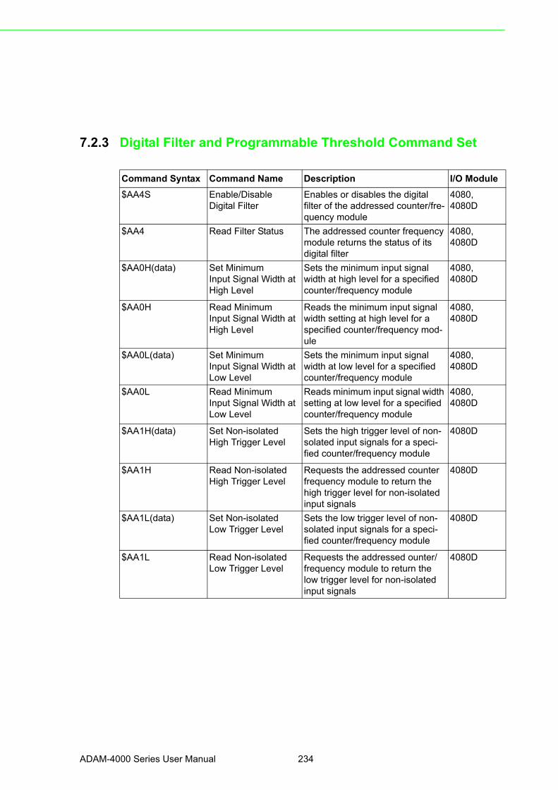
7.2.3 Digital Filter and Programmable Threshold Command Set
Command Syntax Command Name Description I/O Module
$AA4S Enable/DisableDigital Filter
Enables or disables the digitalfilter of the addressed counter/fre-quency module
4080,4080D
$AA4 Read Filter Status The addressed counter frequency module returns the status of its digital filter
4080,4080D
$AA0H(data) Set MinimumInput Signal Width at High Level
Sets the minimum input signal width at high level for a specified counter/frequency module
4080,4080D
$AA0H Read MinimumInput Signal Width at High Level
Reads the minimum input signalwidth setting at high level for a specified counter/frequency mod-ule
4080,4080D
$AA0L(data) Set MinimumInput Signal Width at Low Level
Sets the minimum input signalwidth at low level for a specified counter/frequency module
4080,4080D
$AA0L Read MinimumInput Signal Width at Low Level
Reads minimum input signal width setting at low level for a specified counter/frequency module
4080,4080D
$AA1H(data) Set Non-isolatedHigh Trigger Level
Sets the high trigger level of non-solated input signals for a speci-fied counter/frequency module
4080D
$AA1H Read Non-isolatedHigh Trigger Level
Requests the addressed counter frequency module to return the high trigger level for non-isolated input signals
4080D
$AA1L(data) Set Non-isolatedLow Trigger Level
Sets the low trigger level of non-solated input signals for a speci-fied counter/frequency module
4080D
$AA1L Read Non-isolatedLow Trigger Level
Requests the addressed ounter/frequency module to return the low trigger level for non-isolated input signals
4080D
ADAM-4000 Series User Manual 234
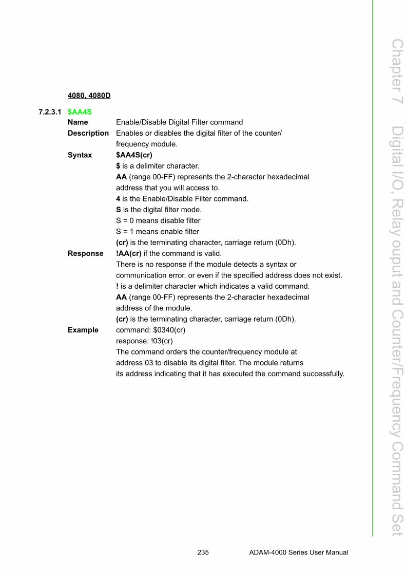
Chapter 7
Digital I/O
,Relay
ouputandC
ounter/Frequency
Com
mand S
et
4080, 4080D
7.2.3.1 $AA4SName Enable/Disable Digital Filter command
Description Enables or disables the digital filter of the counter/
frequency module.
Syntax $AA4S(cr)
$ is a delimiter character.
AA (range 00-FF) represents the 2-character hexadecimal
address that you will access to.
4 is the Enable/Disable Filter command.
S is the digital filter mode.
S = 0 means disable filter
S = 1 means enable filter
(cr) is the terminating character, carriage return (0Dh).
Response !AA(cr) if the command is valid.
There is no response if the module detects a syntax or
communication error, or even if the specified address does not exist.
! is a delimiter character which indicates a valid command.
AA (range 00-FF) represents the 2-character hexadecimal
address of the module.
(cr) is the terminating character, carriage return (0Dh).
Example command: $0340(cr)
response: !03(cr)
The command orders the counter/frequency module at
address 03 to disable its digital filter. The module returns
its address indicating that it has executed the command successfully.
235 ADAM-4000 Series User Manual

4080, 4080D
7.2.3.2 $AA4Name Read Filter Status command
Description Read the digital filter status of the addressed counter/
frequency module.
Syntax $AA4(cr)
$ is a delimiter character.
AA (range 00-FF) represents the 2-character hexadecimal
address that you will access to.
4 is the Read Filter Status command.
(cr) is the terminating character, carriage return (0Dh).
Response !AAS(cr) if the command is valid.
There is no response if the module detects a syntax or
communication error, or even if the specified address does not exist.
! is a delimiter character which indicates an invalid command.
AA (range 00-FF) represents the 2-character hexadecimal
address of the module.
S is the digital filter mode.
S = 0 means filter is disabled
S = 1 means filter is enabled
(cr) is the terminating character, carriage return (0Dh).
Example command: $034(cr)
response: !030(cr)
The command requests the counter/frequency module at
address 03 to return whether its digital filter is ON or not.
The module returns its address which indicates that its
digital filter is disabled.
ADAM-4000 Series User Manual 236

Chapter 7
Digital I/O
,Relay
ouputandC
ounter/Frequency
Com
mand S
et
4080, 4080D
7.2.3.3 $AA0H(data)Name Set Minimum Input Signal Width at High Level command
Description Set the minimum input signal width at high level for a
specified counter/frequency module to filter the noise.
Syntax $AA0H(data)(cr)
$ is a delimiter character.
AA (range 00-FF) represents the 2-character hexadecimal
address that you will access to.
0H is the Set Minimum Input Signal Width at High Level
command.
(data) is the minimum width at high level. The unit is in
μsec (microseconds) and its resolution is 1 μsec. The
format is a five digit integer that can range from 2 μsec to
65535 μsec. Out of range values will cause errors.
(cr) is the terminating character, carriage return (0Dh).
Response !AA(cr) if the command is valid. The addressed module
stores the value and will recognize the input signal “high”
only after the input signal continues “high” and for longer
than the specified value.
?AA(cr) if an invalid operation was entered.
There is no response if the module detects a syntax or
communication error, or even if the specified address does not exist.
! is a delimiter character which indicates a valid command.
? is a delimiter character which indicates an invalid command.
AA (range 00-FF) represents the 2-character hexadecimal
address of the module.
(cr) is the terminating character, carriage return (0Dh).
Example command: $130H00020(cr)
response: !13(cr)
The command requests the counter/frequency module at
address 13 to set the minimum input width at high level to
20 ?sec. The module stores the value and will identify an
input signal to be "high” only if the signal continues to be
“high” longer than 20 ?sec. This function can be used as a
digital filter.
237 ADAM-4000 Series User Manual

4080, 4080D
7.2.3.4 $AA0HName Read Minimum Input Signal Width at High Level command
Description Read the minimum input signal width at high level for a
specified counter/frequency module.
Syntax $AA0H(cr)
$ is a delimiter character.
AA (range 00-FF) represents the 2-character hexadecimal
address that you will access to.
0H is the Read Minimum Input Signal Width at High Level command.
(cr) is the terminating character, carriage return (0Dh).
Response !AA(data)(cr) if the command is valid.
?AA(cr) if an invalid operation was entered.
There is no response if the module detects a syntax or
communication error, or even if the specified address does not exist.
! is a delimiter character which indicates a valid command.
? is a delimiter character which indicates an invalid command.
AA (range 00-FF) represents the 2-character hexadecimal
address of the module.
(data) is the minimum width at high level. The unit is in
μsec (microseconds) and its resolution is 1 μsec. The
format is a five digit integer that ranges from 2 μsec to
65535 μsec.
(cr) is the terminating character, carriage return (0Dh).
Example command: $130H(cr)
response: !1300020(cr)
The command requests the counter/frequency module at
address 13 to read its minimum input signal width at high
level. The module replies that its minimum input signal
width at high level is 20 μsec.
ADAM-4000 Series User Manual 238

Chapter 7
Digital I/O
,Relay
ouputandC
ounter/Frequency
Com
mand S
et
4080, 4080D
7.2.3.5 $AA0L(data)Name Set Minimum Input Signal Width at Low Level command
Description Set the minimum input signal width at low level for a
specified counter/frequency module to filter noise.
Syntax $AA0L(data)(cr)
$ is a delimiter character.
AA (range 00-FF) represents the 2-character hexadecimal
address that you will access to.
0L is the Set Minimum Input Signal Width at Low Level command.
(data) is the minimum width at low level. The unit is in
μsec (microseconds) and its resolution is 1 μsec. The
format is a five digit integer that can range from 2 μsec to
65535 μsec. Out of range values will cause errors.
(cr) is the terminating character, carriage return (0Dh).
Response !AA(cr) if the command is valid. The addressed module
stores the value and will identify the input signal “low”
only if the input signal continues to be “low” longer than
the specified time.
?AA(cr) if an invalid operation was entered.
There is no response if the module detects a syntax or
communication error, or even if the specified address does not exist.
! is a delimiter character which indicates a valid command.
? is a delimiter character which indicates an invalid command.
AA (range 00-FF) represents the 2-character hexadecimal
address of the module.
(cr) is the terminating character, carriage return (0Dh).
Example command: $050L00084(cr)
response: !05(cr)
The command requests the counter/frequency module at
address 05 to set the minimum input width at low level to
84 ?sec. The module stores the value and will identify an
input signal to be "low” only if the signal continues to be
“low” longer than 84 μsec. This function can be used as digital filter.
239 ADAM-4000 Series User Manual

4080, 4080D
7.2.3.6 $AA0LName Read Minimum Input Signal Width at Low Level command
Description Read the minimum input signal width at low level for a
specified counter/frequency module to filter noise.
Syntax $AA0L(cr)
$ is a delimiter character.
AA (range 00-FF) represents the 2-character hexadecimal
address that you will access to.
0L is the Read Minimum Input Signal Width at Low Level
command.
(cr) is the terminating character, carriage return (0Dh).
Response !AA(data)(cr) if the command is valid.
?AA(cr) if an invalid operation was entered.
There is no response if the module detects a syntax or
communication error, or even if the specified address does not exist.
! is a delimiter character which indicates a valid command.
? is a delimiter character which indicates an invalid command.
AA (range 00-FF) represents the 2-character hexadecimal
address of the module.
(data) is the minimum width at low level. The unit is in
μsec (microsecond) and its resolution is 1 μsec. The format
is a five digit integer that ranges from 2 μsec to 65535 μsec.
(cr) is the terminating character, carriage return (0Dh).
Example command: $050L(cr)
response: !0500084(cr)
The command requests the counter/frequency module at
address 05 to read its minimum input signal width at low
level. The module replies that its minimum input signal
width at low level is 84 μsec.
ADAM-4000 Series User Manual 240

Chapter 7
Digital I/O
,Relay
ouputandC
ounter/Frequency
Com
mand S
et
4080D
7.2.3.7 $AA1H(data)Name Set Non-isolated High Trigger Level command
Description Set the high trigger level for non-isolated input signals for a
specified counter/frequency module.
Syntax $AA1H(data)(cr)
$ is a delimiter character.
AA (range 00-FF) represents the 2-character hexadecimal
address that you will access to.
1H is the Set Non-isolated High Trigger Level command.
(data) is the high trigger level for non-isolated input
The unit and resolution are both 0.1 V (voltage). The
format is a two digit integer that range from 1 to 50 (i.e. 0.1
to 5 V). This high trigger level must at all times be higher
than the low trigger level which is set by the $AA1L(data)
command. When the high trigger level is out of range or
lower than the low trigger level, an error will occur.
(cr) is the terminating character, carriage return (0Dh).
Response !AA(cr) if the command is valid. The addressed module
stores the value and will recognize input signal as “high”
only when they exceed the high trigger level
?AA(cr) if an invalid operation was entered.
There is no response if the module detects a syntax or
communication error, or even if the specified address does
not exist.
! is a delimiter character which indicates a valid command.
? is a delimiter character which indicates an invalid
command.
AA (range 00-FF) represents the 2-character hexadecimal
address of the module.
(cr) is the terminating character, carriage return (0Dh).
Example command: $131H30(cr)
response: !13(cr)
The command requests the counter/frequency module at
address 13 to set its non-isolated high trigger level to 3 V.
The module stores the value and will identify the input
signals to be “high” only after the signals exceed 3 V. This
function can be used as a level filter.
241 ADAM-4000 Series User Manual

4080, 4080D
7.2.3.8 $AA1HName Read Non-isolated High Trigger Level command
Description Read the high trigger level for non-isolated input signals of
a specified counter/frequency module.
Syntax $AA1H(cr)
$ is a delimiter character.
AA (range 00-FF) represents the 2-character hexadecimal
address that you will access to.
1H is the Read Non-isolated High Trigger Level command.
(cr) is the terminating character, carriage return (0Dh).
Response !AA(data)(cr) if the command is valid.
?AA(cr) if an invalid operation was entered.
There is no response if the module detects a syntax or
communication error, or even if the specified address does not exist.
! is a delimiter character which indicates a valid command.
? is a delimiter character which indicates an invalid command.
AA (range 00-FF) represents the 2-character hexadecimal
address of the module.
(data) is the high trigger level of non-isolated input signals
The unit and resolution are both 0.1 V (voltage). The
format is a two digit integer that range from 1 to 50 (i.e. 0.1
V to 5 V).
(cr) is the terminating character, carriage return (0Dh).
Example command: $131H(cr)
response: !1330(cr)
The command requests the counter/frequency module at
address 13 to read its non-isolated high trigger level. The
module replies that the high trigger level is 3 V.
ADAM-4000 Series User Manual 242
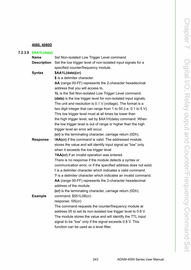
Chapter 7
Digital I/O
,Relay
ouputandC
ounter/Frequency
Com
mand S
et
4080, 4080D
7.2.3.9 $AA1L(data)Name Set Non-isolated Low Trigger Level command
Description Set the low trigger level of non-isolated input signals for a
specified counter/frequency module.
Syntax $AA1L(data)(cr)
$ is a delimiter character.
AA (range 00-FF) represents the 2-character hexadecimal
address that you will access to.
1L is the Set Non-isolated Low Trigger Level command.
(data) is the low trigger level for non-isolated input signals.
The unit and resolution is 0.1 V (voltage). The format is a
two digit integer that can range from 1 to 50 (i.e. 0.1 to 5 V).
This low trigger level must at all times be lower than
the high trigger level, set by $AA1H(data) command. When
the low trigger level is out of range or higher than the high
trigger level an error will occur.
(cr) is the terminating character, carriage return (0Dh).
Response !AA(cr) if the command is valid. The addressed module
stores the value and will identify input signal as “low” only
when it exceeds the low trigger level
?AA(cr) if an invalid operation was entered.
There is no response if the module detects a syntax or
communication error, or if the specified address does not exist.
! is a delimiter character which indicates a valid command.
? is a delimiter character which indicates an invalid command.
AA (range 00-FF) represents the 2-character hexadecimal
address of the module.
(cr) is the terminating character, carriage return (0Dh).
Example command: $051L08(cr)
response: !05(cr)
The command requests the counter/frequency module at
address 05 to set its non-isolated low trigger level to 0.8 V.
The module stores the value and will identify the TTL input
signal to be “low” only if the signal exceeds 0.8 V. This
function can be used as a level filter.
243 ADAM-4000 Series User Manual

4080, 4080D
7.2.3.10 $AA1LName Read Non-isolated Low Trigger Level command
Description Read the low trigger level for non-isolated input signals of
a specified counter/frequency module.
Syntax $AA1L(cr)
$ is a delimiter character.
AA (range 00-FF) represents the 2-character hexadecimal
address that you will access to.
1L is the Read Non-isolated Low Trigger Level command.
(cr) is the terminating character, carriage return (0Dh).
Response !AA(data)(cr) if the command is valid.
?AA(cr) if an invalid operation was entered.
There is no response if the module detects a syntax or
communication error, or even if the specified address does not exist.
! is a delimiter character which indicates a valid command.
? is a delimiter character which indicates an invalid command.
AA (range 00-FF) represents the 2-character hexadecimal
address of the module.
(data) is the low trigger level of non-isolated input signal.
The unit and resolution is 0.1 V (voltage). The format is a
two digit integer that can range from 1 to 50 (i.e. 0.1 V to 5 V).
(cr) is the terminating character, carriage return (0Dh).
Example command: $051L(cr)
response: !0508(cr)
The command requests the counter/frequency module at
address 05 to read its non-isolated input signal low trigger
level. The module replies that its low trigger level is 0.8 V.
ADAM-4000 Series User Manual 244

Chapter 7
Digital I/O
,Relay
ouputandC
ounter/Frequency
Com
mand S
et
7.2.4 Digital Output and Alarm Command Set
Command Syntax Command Name Description I/O Module
@AAPN(data) Set Initial Count Valueof Counter N
Sets the initial count value ofthe module for counter 0 or counter 1
4080
@AAGN Read Initial CountValue of Counter N
Read the initial count value ofcounter 0 or counter 1
4080
@AAEAN Enable Alarm ofCounter N
Enable alarm for the specifiedcounter 0 or counter 1
4080
@AADAN Disable Alarm ofCounter N
Disable alarm for the specifiedcounter 0 or counter 1
4080
@AAPA(data) Set Alarm Limit Valueof Counter 0
Download the alarm limit valuefor counter 0 of the specified module
4080
@AASA(data) Set Alarm Limit Value of Counter 1
Download the alarm limit value for counter 1 of the specified module
4080
@AARP Read Alarm LimitValue of Counter 0
Ask the module to return thealarm limit value of counter 0
4080
@AARA Read Alarm LimitValue of Counter 1
Ask the module to return thealarm limit value of counter 1
4080
@AADO(data) Set Digital OutputValues
Set the values of the module'stwo digital outputs (ON or OFF)
4080,4080D
@AADI Read Digital Outputand Alarm Status
Ask the addressed module toreturn the state of its two digital output channels and the status of its alarm
4080,4080D
@AAEAT Enable Alarm ofCounter 0
Enable the alarm of counter 0 ineither momentary or latching
4080D
@AADA Disable Alarm of Disable all alarm functions of 4080D
@AACA Clear Latch Alarm Both alarm states of the counter 4080D
@AAPA(data) Set Low-AlarmCount Value of
Downloads the low-alarm countvalue for counter 0 of the speci-
4080D
@AASA(data) Set High-AlarmCount Value of
Downloads the high-alarm countvalue for counter 0 of the speci-
4080D
@AARP Read Low-AlarmCount Value of
Ask the module to return thelow-alarm count value for coun-
4080D
@AARA Read High-alarmCount Value for
Requests the addressed countermodule to return its high-alarm
4080D
245 ADAM-4000 Series User Manual

4080
7.2.4.1 @AAPN(data)Name Set Initial Count Value of Counter 0 or 1 command
Description Set the initial count value for counter 0 or 1 of the specified
counter module at address AA.
Syntax @AAPN(data)(cr)
@ is a delimiter character.
AA (range 00-FF) represents the 2-character hexadecimal
address of the module.
PN is the Set Initial Count Value of Counter 0 or 1
command.
N = 0 represents counter 0
N = 1 represents counter 1
(data) is the initial count value which must consist of eight
hexadecimal digits.
(cr) is the terminating character, carriage return (0Dh).
Response !AA(cr) if the command is valid.
There is no response if the module detects a syntax or
communication error, or even if the specified address does not exist.
! is a delimiter character which indicates a valid command.
AA (range 00-FF) represents the 2-character hexadecimal
address of the module.
(cr) is the terminating character, carriage return (0Dh).
Example command: @12P0000000FF(cr)
response: !12(cr)
The command sets the initial count value 000000FF for
counter 0 of the counter module at address 12. The
module replies that the command has been received.
ADAM-4000 Series User Manual 246

Chapter 7
Digital I/O
,Relay
ouputandC
ounter/Frequency
Com
mand S
et
4080
7.2.4.2 @AAGNName Read Initial Count Value of Counter 0 or 1 command
Description Read the initial count value of counter 0 or 1 of the
specified counter module at address AA.
Syntax @AAGN(data)(cr)
@ is a delimiter character.
AA (range 00-FF) represents the 2-character hexadecimal
address of the module.
GN is the Read Initial Count Value for Counter 0 or 1 command.
N = 0 represents counter 0
N = 1 represents counter 1
(cr) is the terminating character, carriage return (0Dh).
Response !AA(data)(cr) if the command is valid.
There is no response if the module detects a syntax or
communication error, or even if the specified address does not exist.
! is a delimiter character which indicates a valid command.
AA (range 00-FF) represents the 2-character hexadecimal
address of the module.
(data) is the initial count value which must consist of eight
hexadecimal digits.
(cr) is the terminating character, carriage return (0Dh).
Example command: @12G0(cr)
response: !12000000FF(cr)
The command instructs the module at address 12h to return
the initial value of counter 0. The module replies that
initial count value of counter 0 is 000000FF.
247 ADAM-4000 Series User Manual

4080
7.2.4.3 @AAEANName Enable Alarm command
Description Enable Alarm for the specified counter.
Syntax @AAEAN (cr)
@ is a delimiter character.
AA (range 00-FF) represents the 2-character hexadecimal
address of the module.
EAN is the Enable Alarm command.
N = 0 Represents counter 0
N = 1 Represents counter 1
(cr) is the terminating character, carriage return (0Dh).
Response !AA(cr) if the command is valid.
There is no response if the module detects a syntax or
communication error, or even if the specified address does not exist.
! is a delimiter character which indicates a valid command.
AA (range 00-FF) represents the 2-character hexadecimal
address of the module.
(cr) is the terminating character, carriage return (0Dh).
Example command: @12EA0(cr)
response: !12(cr)
The command sets the Alarm Status as ‘Enable’ for counter
0 of the counter module at address 12h. It means that the
digital output will be triggered while the count value of the
counter 0 reaches the alarm limit value. The module
replies that the command has been received.
ADAM-4000 Series User Manual 248

Chapter 7
Digital I/O
,Relay
ouputandC
ounter/Frequency
Com
mand S
et
4080
7.2.4.4 @AADANName Disable Alarm command
Description Disable Alarm for the specified counter.
Syntax @AADAN (cr)
@ is a delimiter character.
AA (range 00-FF) represents the 2-character hexadecimal
address of the module.
DAN is the Disable Alarm Mode command.
N = 0 Represents counter 0
N = 1 Represents counter 1
(cr) is the terminating character, carriage return (0Dh).
Response !AA(cr) if the command is valid.
There is no response if the module detects a syntax or
communication error, or even if the specified address does not exist.
! is a delimiter character which indicates a valid command.
AA (range 00-FF) represents the 2-character hexadecimal
address of a counter module.
(cr) is the terminating character, carriage return (0Dh).
Example command: @12DA0(cr)
response: !12(cr)
The counter module at address 12h is instructed to disable
the alarm functions for counter 0. The module confirms
that its alarm functions have been disabled.
249 ADAM-4000 Series User Manual

4080
7.2.4.5 @AAPA(data)@AASA(data)Name Set Alarm Limit Value of Counter 0 or 1 command
Description Set the Alarm limit value of counter 0 or 1 of the specified
counter module at address AA.
Syntax @AAPA(data)(cr)
@AASA(data)(cr)
@ is a delimiter character.
AA (range 00-FF) represents the 2-character hexadecimal
address of the module.
PA represents the Set Alarm Limit value for counter 0 command.
SA represents the Set Alarm Limit Value for counter 1 command.
(data) is the alarm limit value which must consist of eight
hexadecimal digits.
(cr) is the terminating character, carriage return (0Dh).
Response !AA(cr) if the command is valid.
There is no response if the module detects a syntax or
communication error, or even if the specified address does not exist.
! is a delimiter character which indicates a valid command.
AA (range 00-FF) represents the 2-character hexadecimal
address of the module.
(cr) is the terminating character, carriage return (0Dh).
Example command: @$12PA0000FFFF(cr)
response: !12(cr)
The command sets the alarm limit value 0000FFFF for
counter 0 of the counter module at address 12h. The
module replies that the command has been received.
ADAM-4000 Series User Manual 250

Chapter 7
Digital I/O
,Relay
ouputandC
ounter/Frequency
Com
mand S
et
4080
7.2.4.6 @AARP@AARAName Read Alarm Limit Value of Counter 0 or 1 command
Description Read the alarm limit value of counter 0 or 1 of the specified
counter module at address AA.
Syntax @AARP(data)(cr)
@AARA(data)(cr)
@ is a delimiter character.
AA (range 00-FF) represents the 2-character hexadecimal
address of the module.
RP represents the Read Alarm Limit Value for counter 0
command.
RA represents the Read Alarm Limit Value for counter 1
command.
(cr) is the terminating character, carriage return (0Dh).
Response !AA(data)(cr) if the command is valid.
There is no response if the module detects a syntax or
communication error, or even if the specified address does not exist.
! is a delimiter character which indicates a valid command.
AA (range 00-FF) represents the 2-character hexadecimal
address of the module.
(data) is the alarm limit value which must consist of eight
hexadecimal digits.
(cr) is the terminating character, carriage return (0Dh).
Example command: @12RP(cr)
response: !120000FFFF(cr)
The command instructs the module at address 12h to return
the alarm limit value of counter 0. The module replies
that the alarm limit value of counter 0 is 0000FFFF.
251 ADAM-4000 Series User Manual

4080, 4080D
7.2.4.7 @AADOName Set Digital Output command
Description Set the values of the module’s two digital outputs (ON or OFF).
Syntax @AADO(data)(cr)
@ is a delimiter character.
AA (range 00-FF) represents the 2-character hexadecimal
address of the module.
DO is the Set Digital Output command.
(data) is the two-character parameter that sets the state for
the two digital output bits of the module, as shown below:
00 all D/O bits are OFF
01 bit 0 is ON, bit 1 is OFF
02 bit 0 is OFF, bit 1 is ON
03 all bits are ON
(cr) represents terminating character, carriage return (0Dh).
Response !AA(cr) if the command was valid
?AA(cr) if an invalid parameter was entered
There is no response if the module detects a syntax or
communication error, or even if the specified address does not exists.
! is a delimiter character which indicates a valid command.
? is a delimiter character which indicates an invalid command.
AA represents the 2-character hexadecimal address of the module.
(cr) represents terminating character, carriage return (0Dh).
Example command: @05DO01(cr)
response: !05(cr)
The counter module at address 05h is instructed to set
digital output channel 1 to ON and digital output channel 2
to OFF. The module confirms the settings.
ADAM-4000 Series User Manual 252

Chapter 7
Digital I/O
,Relay
ouputandC
ounter/Frequency
Com
mand S
et
4080, 4080D
7.2.4.8 @AADIName Read Digital Output and Alarm State command
Description The addressed counter module is instructed to return the
value of its two digital output channels and the state of its alarm.
Syntax @AADI(cr)
@ is a delimiter character.
AA (range 00-FF) represents the 2-character hexadecimal
address of the module.
DI is the Read Digital Output and Alarm Status command.
(cr) represents terminating character, carriage return (0Dh).
Response !AASOO00(cr) if the command was valid
There is no response if the module detects a syntax error or
communication error or if the specified address does not exists.
! is a delimiter character which indicates a valid command.
AA represents the 2-character hexadecimal address of the module.
S (for ADAM-4080) is a hexadecimal number that
represents the disable or enable status of alarm mode:
0h: Counter 0 alarm is disabled, counter 1 alarm is disabled
1h: Counter 0 alarm is enabled, counter 1 alarm is disabled
2h: Counter 0 alarm is disabled, counter 1 alarm is enabled
3h: Counter 0 alarm is enabled, counter 1 alarm is enabled
S (for ADAM-4080D) is a hexadecimal number that
represents the alarm state of counter 0:
0h: Alarm of counter 0 is disabled
1h: Alarm of counter 0 is in MOMENTARY mode
2h: Alarm of counter 0 is in LATCH mode
OO is a hexadecimal number representing the Digital
Output port's channel 0 and 1 status
(00h = D/0 channels 0 and 1 are both OFF, 01h = channel 0
is ON, channel 1 is OFF, 02h = channel 0 is OFF, channel 1
is ON, 03h = channel 0 and 1 are both ON).
(cr) represents the terminating character, carriage return (0Dh).
Example command: @15DI(cr)
response: !1510000(cr)
The counter module at address 15h is instructed to return digital
output data and alarm status. The module responds that both digital
output channels are OFF and alarm state is MOMENTARY.
command: @05DI(cr)
253 ADAM-4000 Series User Manual
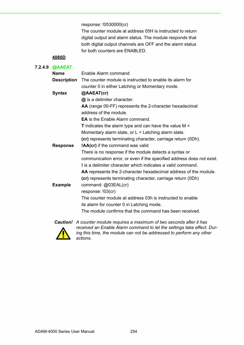
response: !0530000(cr)
The counter module at address 05H is instructed to return
digital output and alarm status. The module responds that
both digital output channels are OFF and the alarm status
for both counters are ENABLED.
4080D
7.2.4.9 @AAEATName Enable Alarm command
Description The counter module is instructed to enable its alarm for
counter 0 in either Latching or Momentary mode.
Syntax @AAEAT(cr)
@ is a delimiter character.
AA (range 00-FF) represents the 2-character hexadecimal
address of the module.
EA is the Enable Alarm command.
T indicates the alarm type and can have the value M =
Momentary alarm state, or L = Latching alarm state.
(cr) represents terminating character, carriage return (0Dh).
Response !AA(cr) if the command was valid
There is no response if the module detects a syntax or
communication error, or even if the specified address does not exist.
! is a delimiter character which indicates a valid command.
AA represents the 2-character hexadecimal address of the module.
(cr) represents terminating character, carriage return (0Dh)
Example command: @03EAL(cr)
response: !03(cr)
The counter module at address 03h is instructed to enable
its alarm for counter 0 in Latching mode.
The module confirms that the command has been received.
Caution! A counter module requires a maximum of two seconds after it has received an Enable Alarm command to let the settings take effect. Dur-ing this time, the module can not be addressed to perform any other actions.
ADAM-4000 Series User Manual 254

Chapter 7
Digital I/O
,Relay
ouputandC
ounter/Frequency
Com
mand S
et
4080D
7.2.4.10 @AADAName Disable Alarm command
Description Disable all alarm functions for counter 0 of the addressed
counter module.
Syntax @AADA(cr)
@ is a delimiter character.
AA (range 00-FF) represents the 2-character hexadecimal
address of the module.
DA is the Disable Alarm command.
(cr) represents terminating character, carriage return (0Dh).
Response !AA(cr) if the command was valid.
There is no response if the module detects a syntax or
communication error, or even if the specified address does not exist.
! is a delimiter character which indicates a valid command.
AA represents the 2-character hexadecimal address of the module.
(cr) represents terminating character, carriage return (0Dh).
Example command: @07DA(cr)
response: !07(cr)
The counter module at address 07h is instructed to disable
all alarm functions for channel 0. The module confirms by
disabling the alarm functions.
Caution! A counter module requires a maximum of two seconds after it
has received a Disable Alarm command before the settings take
effect. During this interval, the module cannot be addressed to
perform any other actions.
255 ADAM-4000 Series User Manual

4080D
7.2.4.11 @AACAName Clear Latch Alarm command
Description Both alarm states (High and Low) of the addressed counter
module are set to OFF, no alarm.
Syntax @AACA(cr)
@ is a delimiter character.
AA (range 00-FF) represents the 2-character hexadecimal
address of the module.
CA is the Clear Latch Alarm command.
(cr) represents terminating character, carriage return (0Dh).
Response !AA(cr) if the command was valid.
There is no response if the module detects a syntax or
communication error, or even if the specified address does not exist.
! is a delimiter character which indicates a valid command.
AA represents the 2-character hexadecimal address of the module.
(cr) represents terminating character, carriage return (0Dh).
Example command: @05CA(cr)
response: !05(cr)
The counter module at address 05h is instructed to set
both alarm states (High and Low) to OFF. The module
confirms that it has done so.
ADAM-4000 Series User Manual 256

Chapter 7
Digital I/O
,Relay
ouputandC
ounter/Frequency
Com
mand S
et
4080D
7.2.4.12 @AAPA(data)Name Set Low-alarm Count Value for Counter 0 command
Description Set the low-alarm count value for counter 0 of the specified
counter module.
Syntax @AAPA(data)(cr)
@ is a delimiter character.
AA (range 00-FF) represents the 2-character hexadecimal
address of the module.
PA is the Set Low-alarm Count Value for Counter 0 command.
(data) is the low-alarm count value which must consist of
eight hexadecimal digits. This value should be lower than
the high alarm value.
(cr) is the terminating character, carriage return (0Dh).
Response !AA(cr) if the command is valid.
There is no response if the module detects a syntax or
communication error, or even if the specified address does not exist.
! is a delimiter character which indicates a valid command
AA (range 00-FF) represents the 2-character hexadecimal
address of the module.
(cr) is the terminating character, carriage return (0Dh).
Example command: @12PA0000FFFF(cr)
response: !12(cr)
The command sets the low-alarm count number
0000FFFF(hex) for channel 0 of the counter modules at
address 12. The addressed module replies that the
command has been received.
257 ADAM-4000 Series User Manual

4080D
7.2.4.13 @AASA(data)Name Set Hi-alarm Count Value of Counter 0 command
Description Set the high-alarm count value for counter 0 of the
specified counter module.
Syntax @AASA(data)(cr)
@ is a delimiter character.
AA (range 00-FF) represents the 2-character hexadecimal
address of the module.
SA is the Set High-alarm Count Value of Counter 0 command.
(data) is the high-alarm count value which must consist of
eight hexadecimal digits. This value should be higher than
the low-alarm count value.
(cr) is the terminating character, carriage return (0Dh).
Response !AA(cr) if the command is valid.
There is no response if the module detects a syntax or
communication error, or even if the specified address does not exist.
! is a delimiter character which indicates a valid command.
AA (range 00-FF) represents the 2-character hexadecimal
address of the module.
(cr) is the terminating character, carriage return (0Dh).
Example command: @12SAF0000000(cr)
response: !12(cr)
The command sets the low-alarm count number
F0000000(hex) for channel 0 of the counter modules at
address 12. The addressed module replies that the
command has been received.
ADAM-4000 Series User Manual 258

Chapter 7
Digital I/O
,Relay
ouputandC
ounter/Frequency
Com
mand S
et
4080D
7.2.4.14 @AARPName Read Low-alarm Count Value of Counter 0 command
Description Read the low-alarm value of counter 0 of the specified
counter module.
Syntax @AARP(cr)
@ is a delimiter character.
AA (range 00-FF) represents the 2-character hexadecimal
address of the module.
RP is the Read Low-alarm Count Value of Counter 0
command.
(cr) is the terminating character, carriage return (0Dh).
Response !AA(data)(cr) if the command is valid.
There is no response if the module detects a syntax or
communication error, or even if the specified address does not exist.
! is a delimiter character indicating a valid command
AA (range 00-FF) represents the 2-character hexadecimal
address of the module.
(data) is the low-alarm count value which consists of eight
hexadecimal digits.
(cr) is the terminating character, carriage return (0Dh).
Example command: @12RP(cr)
response: !120000FFFF(cr)
The command instructs the module at address 12 to return
its low-alarm count value. The module replies that counter
0's low-alarm count value is 0000FFFF(hex).
259 ADAM-4000 Series User Manual
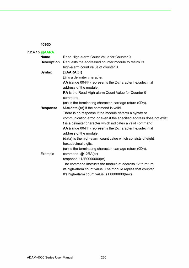
4080D
7.2.4.15 @AARAName Read High-alarm Count Value for Counter 0
Description Requests the addressed counter module to return its
high-alarm count value of counter 0.
Syntax @AARA(cr)
@ is a delimiter character.
AA (range 00-FF) represents the 2-character hexadecimal
address of the module.
RA is the Read High-alarm Count Value for Counter 0
command.
(cr) is the terminating character, carriage return (0Dh).
Response !AA(data)(cr) if the command is valid.
There is no response if the module detects a syntax or
communication error, or even if the specified address does not exist.
! is a delimiter character which indicates a valid command
AA (range 00-FF) represents the 2-character hexadecimal
address of the module.
(data) is the high-alarm count value which consists of eight
hexadecimal digits.
(cr) is the terminating character, carriage return (0Dh).
Example command: @12RA(cr)
response: !12F0000000(cr)
The command instructs the module at address 12 to return
its high-alarm count value. The module replies that counter
0's high-alarm count value is F0000000(hex).
ADAM-4000 Series User Manual 260

Chapter 7
Digital I/O
,Relay
ouputandC
ounter/Frequency
Com
mand S
et
261 ADAM-4000 Series User Manual

ADAM-4000 Series User Manual 262

Chapter 8
8 Calibration
Analog input/output modules are calibrated when you receive them. However, cali-bration is sometimes required. No screwdriver is necessary because calibration isdone in software. Calibration parameters are stored in the ADAM module’s onboardEEPROM.
The ADAM modules come with utility software that supports the calibration of analoginput and analog output. Aside from the calibration that is carried out through soft-ware, the modules incorporate automatic Zero Calibration and automatic Span Cali-bration at boot-up or reset.
8.1 Analog Input Module CalibrationModels: ADAM-4011, 4011D, 4012, 4016, 4017, 4017+, 4018, 4018+, 4018M,4019+
1. Set modules as initial mode before applying power to the module and let it warm up for about 30 minutes
2. Assure that the module is correctly installed and is properly configured for the input range that you want to calibrate. You can do this by using the ADAM utility software. (Please refer to Appendix D, Utility Software.)
3. Use a precise voltage source to calibrate the module through +IN and -IN termi-nals for ADAM-4011, 4011D and 4012. However, for ADAM-4016, the calibrat-ing voltage should be applied to terminals Vin+ and Vin- (or Iin+ and Iin-). At last, Vin0+ and Vin0- are used for calibration in ADAM-4017, 4017+, 4018, 4018+, 4018M, 4019 and 4019+ models.
Figure 8.1 Applying Calibration Voltage
ADAM-4000 Series User Manual 264

Chapter 8
Calibration
4. Execute the Offset Calibration command. This is also done through the ADAM utility software. (Please see “Offset Calibration” option in the Calibration sub-menu of the ADAM utility software).
Figure 8.2 Zero Calibration
5. Execute the Span Calibration command. This can be done through the ADAM utility software. (Please see “Span Calibration” option in the Calibration sub-menu of the ADAM utility software).
Figure 8.3 Span Calibration
265 ADAM-4000 Series User Manual
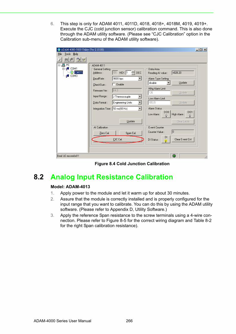
6. This step is only for ADAM 4011, 4011D, 4018, 4018+, 4018M, 4019, 4019+. Execute the CJC (cold junction sensor) calibration command. This is also done through the ADAM utility software. (Please see “CJC Calibration” option in the Calibration sub-menu of the ADAM utility software).
Figure 8.4 Cold Junction Calibration
8.2 Analog Input Resistance CalibrationModel: ADAM-4013
1. Apply power to the module and let it warm up for about 30 minutes.2. Assure that the module is correctly installed and is properly configured for the
input range that you want to calibrate. You can do this by using the ADAM utility software. (Please refer to Appendix D, Utility Software.)
3. Apply the reference Span resistance to the screw terminals using a 4-wire con-nection. Please refer to Figure 8-5 for the correct wiring diagram and Table 8-2 for the right Span calibration resistance).
ADAM-4000 Series User Manual 266

Chapter 8
Calibration
Figure 8.5 Applying calibration resistance
Use a precision resistance decade box or discrete resistors with values:
10 W, 15 W, 60 W, 140 W, 200 W and 440 W.
4. Apply the reference Offset resistance to the terminals of the module. (Please refer to Figure 8.5 for the correct wiring diagram and Table 8.2 for the right Off-set calibration resistance.)
5. Issue an Offset Calibration command to the module. This can be done by using the Calibrate option in the ADAM utility software (Please see Appendix D, Utility Software)
6. Issue a Span Calibration command to the module. This can be done through the Calibrate option in the ADAM utility software (Please see Appendix D, Utility Software)
267 ADAM-4000 Series User Manual

8.3 Analog Input Thermistor module CalibrationModel: ADAM-4015T
If you select the range “Thermistor 3K 0~100C”, please follow the calibration steps asbelow.
1. Short the INIT* pin to GND and then power up ADAM-4015T. Run ADAM-4000-5000 Utility and search for the module.
Table 8.1: Calibration Resistance
Module Input Range Code (Hex)
Input RangeSpan CalibrationResistance
Offset CalibrationResistance
4013 2
0Pt, -100~100 °Ca = 0.00385
140 Ω 60 Ω
21Pt, 0~100 °Ca = 0.00385
140 Ω 60 Ω
22Pt, 0~200 °Ca = 0.00385
200 Ω 60 Ω
23Pt, 0~600 °Ca = 0.00385
440 Ω 60 Ω
24Pt, -100~100 °Ca = 0.003916
140 Ω 60 Ω
25Pt, 0~100 °Ca = 0.003916
140 Ω 60 Ω
26Pt, 0~200 °Ca = 0.003916
200 Ω 60 Ω
27Pt, 0~200 °Ca = 0.003916
440 Ω 60 Ω
28 Ni, -80~100 °C 200 Ω 60 Ω
29 Ni, 0~100 °C 200 Ω 60 Ω
ADAM-4000 Series User Manual 268

Chapter 8
Calibration
2. Click on “Lead Wire Effect Compensation”.
3. Set the resistance to “0” and click on “Save”
269 ADAM-4000 Series User Manual

4. Click on “Zero Cal.”
5. Apply 200.0 ohms resistor with 0.01% accuracy to CH0 and then click on “Save”.
ADAM-4000 Series User Manual 270

Chapter 8
Calibration
6. Click on “Span Cal.”
7. Apply 10K ohms resistor with 0.01% accuracy to CH0 and then click on “Save”
8. Finished!
271 ADAM-4000 Series User Manual

If you select the range “Thermistor 10K 0~100C”, please follow the calibration stepsas below.
1. Change the input range to “Thermistor 10K 0~100C” and click on “Update”
2. Click on “Lead Wire Effect Compensation”.
ADAM-4000 Series User Manual 272
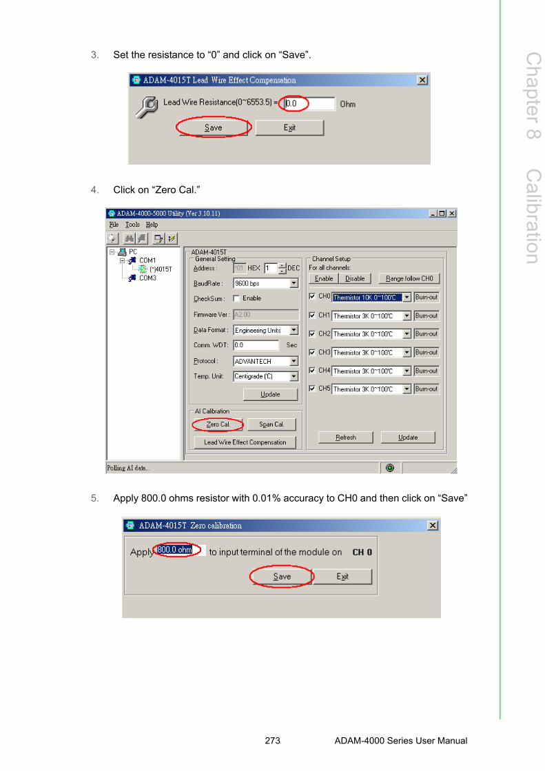
Chapter 8
Calibration
3. Set the resistance to “0” and click on “Save”.
4. Click on “Zero Cal.”
5. Apply 800.0 ohms resistor with 0.01% accuracy to CH0 and then click on “Save”
273 ADAM-4000 Series User Manual

6. Click on “Span Cal.”
7. Apply 30K ohms resistor with 0.01% accuracy to CH0 and then click on “Save”
8. Finished!
ADAM-4000 Series User Manual 274
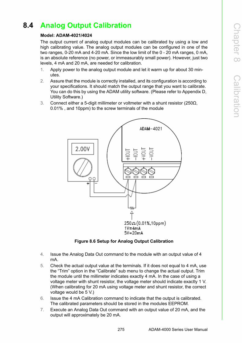
Chapter 8
Calibration
8.4 Analog Output CalibrationModel: ADAM-4021/4024
The output current of analog output modules can be calibrated by using a low andhigh calibrating value. The analog output modules can be configured in one of thetwo ranges, 0-20 mA and 4-20 mA. Since the low limit of the 0 - 20 mA ranges, 0 mA,is an absolute reference (no power, or immeasurably small power). However, just twolevels, 4 mA and 20 mA, are needed for calibration.
1. Apply power to the analog output module and let it warm up for about 30 min-utes.
2. Assure that the module is correctly installed, and its configuration is according to your specifications. It should match the output range that you want to calibrate. You can do this by using the ADAM utility software. (Please refer to Appendix D, Utility Software.)
3. Connect either a 5-digit millimeter or voltmeter with a shunt resistor (250Ω, 0.01% , and 10ppm) to the screw terminals of the module
Figure 8.6 Setup for Analog Output Calibration
4. Issue the Analog Data Out command to the module with an output value of 4 mA.
5. Check the actual output value at the terminals. If it does not equal to 4 mA, use the “Trim” option in the “Calibrate” sub menu to change the actual output. Trim the module until the millimeter indicates exactly 4 mA. In the case of using a voltage meter with shunt resistor, the voltage meter should indicate exactly 1 V. (When calibrating for 20 mA using voltage meter and shunt resistor, the correct voltage would be 5 V.)
6. Issue the 4 mA Calibration command to indicate that the output is calibrated. The calibrated parameters should be stored in the modules EEPROM.
7. Execute an Analog Data Out command with an output value of 20 mA, and the output will approximately be 20 mA.
275 ADAM-4000 Series User Manual

8. Continue executing the Trim Calibration command until the output current is equal to exactly 20 mA.
9. Execute the 20 mA Calibration command until the present output is exactly 20 mA. The analog output module will store its calibrated parameters in EEPROM.
Module: ADAM-4016
1. Apply power to the strain gauge input module and let it warm up for about 30 minutes.
2. Assure that the module is correctly installed. Then, connect a voltmeter to the screw terminals of the module.
Figure 8.7 Setup for Voltage Output Calibration
3. Execute the Zero Calibration command. This is done through the ADAM utility software. (Please see "A/O 0V Calibration" option in the Calibration sub-menu of the ADAM utility software.)
Figure 8.8 Zero Calibration
ADAM-4000 Series User Manual 276

Chapter 8
Calibration
4. Execute the Span Calibration command. This can be done through the ADAM utility software. (Please see "A/O 10 V Calibration" option in the Calibration sub-menu of the ADAM utility software.)
Figure 8.9 Span Calibration
5. Check the actual output value at the terminals. If this does not equal 0 V or 10 V, use the Trim Calibration command to change the output value. This is done through the ADAM utility software. (Use the arrow key to adjust the output value after executing the "A/O 0V Calibration" or "A/O 10 V Calibration". Right and Up keys mean increasing, and Left and Down keys mean decreasing).
277 ADAM-4000 Series User Manual

ADAM-4000 Series User Manual 278

Appendix A
A Technical Specifications
A.1 ADAM-4011 Thermocouple Input Module
Table A.1: ADAM-4011 SpecificationsT/C channel number 1
Input rangeJ, K, T, E, R, S and B Thermocouple±15 mV, ±50 mV, ±100 mV, ±500mV, ±1 V, ±2.5 V and ±20mA
Outputspeed (in bps)Maximum distance
RS-485 (2-Wire)1200, 2400, 4800, 9600, 19.2K, 38.4K, 57.6K, 115.2K4000 ft. (1200 m.)
Accuracy ±0.05% or better
Zero drift ±6μV/°C
Span drift ±25 ppm/°C
Isolation-rated voltage 3000 VDC
CMR @ 50/60 Hz 150 dB
NMR @ 50/60 Hz 100 dB
Resolution 16-bit
Sampling rate 10 samples/second
Input impedance Voltage: 2 MΩ, Current: 125 Ω
Digital outputSink currentPower dissipation
2 channels open collector to 30 V30 mA maximum load300 mW
Digital inputLogic level 0Logic level 1Pull up current
1 channel+1 V maximum+3.5 to +30 V0.5 mA
Event counterMax. input frequencyMin. pulse width
50 Hz1 msec
Support protocol ADAM ASCII
Watchdog timer 1.6 second (System)
Power supply +10 to +30 VDC (non-regulated)
Power consumption 1.4 W @ 24 VDC
Burn-out detection Yes
Table A.2: ADAM-4011 Range Accuracy for Thermocouple
Range Code (Hex) Input Range Typical Accuracy Maximum Error Units
0EJ thermocouple0 to760 °C
±0.5 ±0.75 °C
0FK thermocouple0 to 1370 °C
±0.5 ±0.75 °C
10T thermocouple-100 to 400 °C
±0.5 ±0.75 °C
11E thermocouple0 to 1000 °C
±0.5 ±0.75 °C
12R thermocouple500 to 1750 °C
±0.6 ±1.5 °C
13S thermocouple500 to 1750 °C
±0.6 ±1.5 °C
14B thermocouple500 to 1800 °C
±1.2 ±2.0 °C
ADAM-4000 Series User Manual 280
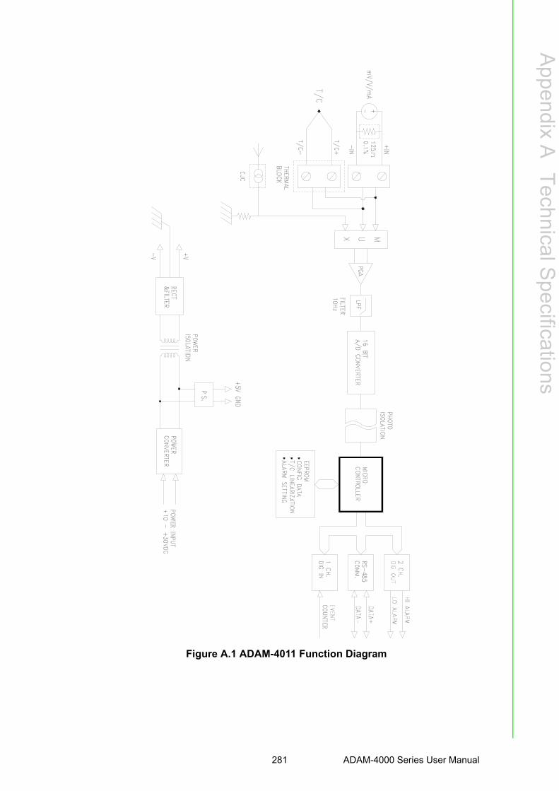
Appendix A
TechnicalS
pecifications
Figure A.1 ADAM-4011 Function Diagram
281 ADAM-4000 Series User Manual

A.2 ADAM-4011D Thermocouple Input Module with LED Display
Table A.3: ADAM-4011D SpecificationsT/C channel number 1
Input rangeJ, K, T, E, R, S and B Thermocouple±15 mV, ±50 mV, ±100 mV, ±500mV,±1 V, ±2.5 V and ±20mA
Outputspeed (in bps)Maximum distance
RS-485 (2-Wire)1200, 2400, 4800, 9600, 19.2K, 38.4K, 57.6K, 115.2K4000 ft. (1200 m.)
Accuracy ±0.05% or better
Zero drift ±6 μV/°C
Span drift ±25 ppm/°C
Isolation-rated voltage 3000 VDC
CMR @ 50/60 Hz 150 dB
NMR @ 50/60 Hz 100 dB
Resolution 16-bit
Sampling rate 10 samples/second
Input impedance Voltage: 2 MΩ, Current: 125 Ω
LED indicator 5 digit readout
Digital outputSink currentPower dissipation
2 channels open collector to 30 V30 mA maximum load300 mW
Digital inputLogic level 0Logic level 1Pull up current
1 channel+1 V maximum+3.5 to +30 V0.5 mA
Event counterMax. input frequencyMin. pulse width
50 Hz1 msec
Support protocol ADAM ASCII
Watchdog timer 1.6 second (System)
Power supply +10 to +30 VDC (non-regulated)
Power consumption 1.4 W @ 24 VDC
Burn-out detection Yes
ADAM-4000 Series User Manual 282

Appendix A
TechnicalS
pecifications
Table A.4: ADAM-4011D Range Accuracy for Thermocouple
Range Code (Hex) Input Range Typical Accuracy Maximum Error Units
0EJ thermocouple0 to760 °C
±0.5 ±0.75 °C
0FK thermocouple0 to 1370 °C
±0.5 ±0.75 °C
10T thermocouple-100 to 400 °C
±0.5 ±0.75 °C
11E thermocouple0 to 1000 °C
±0.5 ±0.75 °C
12R thermocouple500 to 1750 °C
±0.6 ±1.5 °C
13S thermocouple500 to 1750 °C
±0.6 ±1.5 °C
14B thermocouple500 to 1800 °C
±1.2 ±2.0 °C
283 ADAM-4000 Series User Manual

Figure A.2 ADAM-4011D Function Diagram
ADAM-4000 Series User Manual 284

Appendix A
TechnicalS
pecifications
A.3 ADAM-4012 Analog Input Module
Table A.5: ADAM-4012 SpecificationsAI channel number 1
Input range±150 mV, ±500mV, ±1 V, ±5 V,±10 V and ±20mA
Outputspeed (in bps)Maximum distance
RS-485 (2-wire)1200, 2400, 4800, 9600, 19.2K, 38.4K, 57.6K, 115.2K4000 ft. (1200 m.)
Accuracy ±0.05% or better
Zero drift ±6 μV/°C
Span drift ±25 ppm/°C
Isolation-rated voltage 3000 VDC
CMR @ 50/60 Hz 150 dB
NMR @ 50/60 Hz 100 dB
Resolution 16-bit
Sampling rate 10 samples/second
Input impedance Voltage: 20 MΩ, Current: 125 Ω
Digital output Sink current Power dissipation
2 channels open collector to 30 V30 mA maximum load300 mW
Digital inputLogic level 0Logic level 1Pull up current
1 channel+1 V maximum+3.5 to +30 V0.5 mA
Event counterMax. input frequencyMin. pulse width
50 Hz1 msec
Support protocol ADAM ASCII
Watchdog timer 1.6 second (System)
Power supply +10 to +30 VDC (non-regulated)
Power consumption 1.2 W @ 24 VDC
285 ADAM-4000 Series User Manual
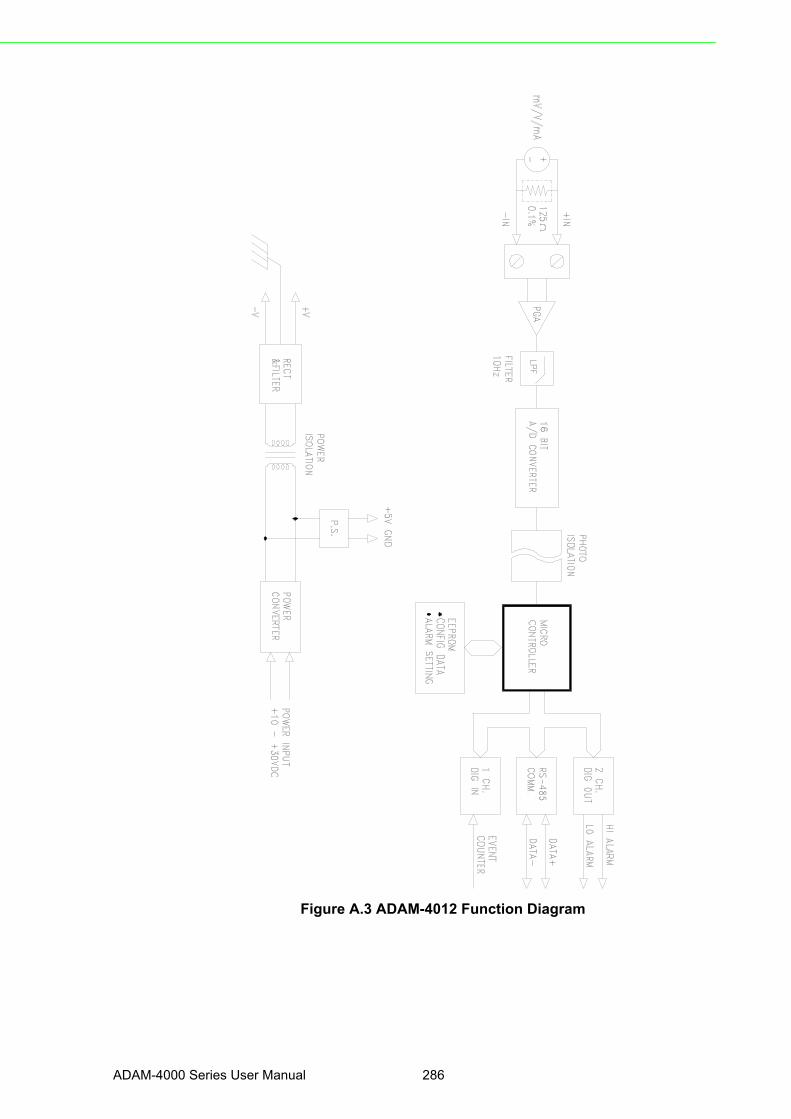
Figure A.3 ADAM-4012 Function Diagram
ADAM-4000 Series User Manual 286

Appendix A
TechnicalS
pecifications
A.4 ADAM-4013 RTD Input Module
Table A.6: ADAM-4013 SpecificationsRTD channel number 1
Input type Pt or Ni RTD
Outputspeed (in bps)Maximum distance
RS-485 (2-Wire)1200, 2400, 4800, 9600, 19.2K, 38.4K, 57.6K, 115.2K4000 ft. (1200 m.)
Accuracy ±0.1% or better
Zero drift ±3μV/°C
Span drift ±25 ppm/°C
Input connections 2, 3 or 4 wires
Isolation-rated voltage 3000 VDC
CMR @ 50/60 Hz 150 dB
NMR @ 50/60 Hz 100 dB
Sampling rate 10 samples/second
Input impedance 2 MΩ
Support protocol ADAM ASCII
Watchdog timer 1.6 second (System)
Power supply +10 to +30 VDC (non-regulated)
Power consumption 0.7 W @ 24 VDC
287 ADAM-4000 Series User Manual

Figure A.4 ADAM-4013 Function Diagram
ADAM-4000 Series User Manual 288

Appendix A
TechnicalS
pecifications
A.5 ADAM-4016 Analog Input/Output Module
Table A.7: ADAM-4016 SpecificationsAI channel number 1
AI range ±15 mV, ±50 mV, ±100 mV, ±500 mV and ±20 mA
OutputSpeed (bps)Maximum distance
RS-485 (2-wire)1200, 2400, 4800, 9600, 19.2K, 38.4K, 57.6K, 115.2K4000 ft. (1200 m)
Input impedance Voltage: 2 MΩ, Current: 125 Ω
AI isolation voltage 3000 VDC
AI resolution 16-bit
AI sampling rate 10 samples/second
AI accuracy ±0.05% or better
AI zero drift ±6 μV /?
AI span drift ±25 ppm/?
AI CMR @ 50/60 Hz 150 dB
AI NMR @ 50/60 Hz 100 dB
AO channel number 1
AO range 0~10 V
AO drive current 30 mA
AO isolation voltage 3000 VDC
AO accuracy 0.05% of FSR
AO drift ± 50 ppm/°C
Digital outputSink currentPower dissipation
4 channels open collector to 30 V30 mA maximum load300 mW
Support protocol ADAM ASCII
Watchdog timer 1.6 second (System)
Power requirements +10 to +30 VDC (non-regulated)
Power consumption 2.2 W @ 24 VDC
289 ADAM-4000 Series User Manual

Figure A.5 ADAM-4016 Function Diagram
ADAM-4000 Series User Manual 290

Appendix A
TechnicalS
pecifications
A.6 ADAM-4017/4017+ 8-channel Analog Input Module
Table A.8: ADAM-4017/4017+ Specifications
AI channel numberADAM-4017: 6 differential and 2 single-endedADAM-4017+: 8 differential
Input type mV, V and mA
Input range
ADAM-4017:±150 mV, ±500 mV, ±1 V, ±5 V, ±10 V and ±20 mAADAM-4017+:±150 mV, ±500 mV, ±1 V, ±5 V, ±10 V, ±20 mA and 4~20 mA
Outputspeed (bps)Maximum distance
RS-485 (2-wire)1200, 2400, 4800, 9600, 19.2K, 38.4K, 57.6K, 115.2K4000 ft. (1200 m)
Isolation voltage 3000 VDC
Resolution 16-bit
Sampling rate 10 samples/second (total)
Bandwidth 13.1 Hz
Accuracy ±0.1% or better
Zero drift ±6 μV/°C
Span drift ±25 ppm/°C
CMR @ 50/60 Hz 120 dB
NMR @ 50/60 Hz 100 dB
Input impedance Voltage: 20 MΩ, Current: 120 Ω
Support protocolADAM ASCII (ADAM-4017 & 4107+)MODBUS/RTU (ADAM-4017+ only)
Watchdog timerADAM-4017: System (1.6 second)ADAM-4017+: System (1.6 second) and communication
Power requirements +10 to +30 VDC (non-regulated)
Power consumption 1.2 W @ 24 VDC
291 ADAM-4000 Series User Manual

Figure A.6 ADAM-4017/4017+ Function Diagram
The use of a 125 ohm external resistor is when only 4017 needs one. The resistor iscontained internally for the ADAM- 4017+ and doesn’t need to be include externally.
ADAM-4000 Series User Manual 292

Appendix A
TechnicalS
pecifications
A.7 ADAM-4018/4018+ 8-channel Analog Input Module
Table A.9: ADAM-4018/4018+ Specifications
AI channel numberADAM-4018: 6 differential and 2 single-endedADAM-4018+: 8 differential
Input type Thermocouple with mV, V, or mA
Input range
J, K, T, E, R, S and B ThermocoupleADAM-4018:±15 mV, ±50 mV, ±100 mV, ±500 mV, ±1 V, ±2.5 V and ±20 mAADAM-4018+:±20 mA and 4~20 mA
Outputspeed (bps)Maximum distance
RS-485 (2-wire)1200, 2400, 4800, 9600, 19.2K, 38.4K, 57.6K, 115.2K4000 ft. (1200 m)
Isolation voltage 3000 VDC
Resolution 16-bit
Sampling rate 10 samples/second (total)
Bandwidth 13.1 Hz
Accuracy ±0.1% or better
Zero drift ±6 μV/°C
Span drift ±25 ppm/°C
CMR @ 50/60 Hz 120 dB
NMR @ 50/60 Hz 100 dB
Input impedance Voltage: 20 MΩ, Current: 120 Ω
Support protocolADAM ASCII (ADAM-4018 & 4108+)MODBUS/RTU (ADAM-4018+ only)
Watchdog timerADAM-4018: System (1.6 second)ADAM-4018+: System (1.6 second) and communication
Power requirements +10 to +30 VDC (non-regulated)
Power consumption 0.8 W @ 24 VDC
Burn-out detection All T/C input (ADAM-4018+ only)
293 ADAM-4000 Series User Manual

Table A.10: ADAM-4018/4018+ Range Accuracy for Thermocouple
Range Code (Hex) Input Range Typical Accuracy Maximum Error Units
0EJ thermocouple0 to760 °C
±1.0 ±1.5 °C
0FK thermocouple0 to 1370 °C
±1.0 ±1.5 °C
10T thermocouple-100 to 400 °C
±1.0 ±1.5 °C
11E thermocouple0 to 1000 °C
±1.0 ±1.5 °C
12R thermocouple500 to 1750 °C
±1.2 ±2.5 °C
13S thermocouple500 to 1750 °C
±1.2 ±2.5 °C
14B thermocouple500 to 1800 °C
±2.0 ±3.0 °C
Note! Because the CJC sensor of ADAM-4018 is located in the side of chan-nel 0 to 4, the measurement will have the difference ± 1 °C between channel 0 ~ 4 and channel 5 ~ 7.
ADAM-4000 Series User Manual 294

Appendix A
TechnicalS
pecifications
Figure A.7 ADAM-4018/4018+ Function Diagram
295 ADAM-4000 Series User Manual

A.8 ADAM-4018M 8-channel Analog Input Data Logger
Table A.11: ADAM-4018M SpecificationsAI channel number 6 differential and 2 single-ended
Input type mV, V and mA
Input rangeJ, K, T, E, R, S and B Thermocouple±15 mV, ±50 mV, ±100 mV, ±500 mV, and ±20 mA
Outputspeed (bps)Maximum distance
RS-485 (2-wire)1200, 2400, 4800, 9600, 19.2K, 38.4K, 57.6K, 115.2K4000 ft. (1200 m)
Isolation voltage 500 VDC
Resolution 16-bit
Sampling rate 10 samples/sec(total)
Bandwidth 13.1 Hz
Accuracy ±0.1% or better
Zero drift ±6 μV/°C
Span drift ±25 ppm/°C
CMR @ 50/60 Hz 120 dB
NMR @ 50/60 Hz 100 dB
Input impedance Voltage: 20 MΩ, Current: 120 Ω
Storage capacityStandard log Event log Mixed log
128 KB Flash memory38,000 samples (total)16,300 samples (total)16,300 data samples and 9,300 event samples (total)
Storage type Write to end of memory, or circular memory
Logging mode Standard log, Event log or Mixed log
Sampling interval 2 second to 18 hours
Measurement duration 330 minutes to 20 years
Support protocol ADAM ASCII
Watchdog timer 1.6 second (System)
Power requirements +10 to +30 VDC (non-regulated)
Power consumption 1.8 W @ 24 VDC
ADAM-4000 Series User Manual 296

Appendix A
TechnicalS
pecifications
Table A.12: ADAM-4018M Range Accuracy for Thermocouple
Range Code (Hex) Input Range Typical Accuracy Maximum Error Units
0EJ thermocouple0 to760 °C
±1.0 ±1.5 °C
0FK thermocouple0 to 1370 °C
±1.0 ±1.5 °C
10T thermocouple-100 to 400 °C
±1.0 ±1.5 °C
11E thermocouple0 to 1000 °C
±1.0 ±1.5 °C
12R thermocouple500 to 1750 °C
±1.2 ±2.5 °C
13S thermocouple500 to 1750 °C
±1.2 ±2.5 °C
14B thermocouple500 to 1800 °C
±2.0 ±3.0 °C
Note! Because the CJC sensor of ADAM-4018M is located in the side of chan-nel 0 to 4, the measurement will have the difference ± 1 °C between channel 0 ~ 4 and channel 5 ~ 7.
297 ADAM-4000 Series User Manual

Figure A.8 ADAM-4018M Function Diagram
ADAM-4000 Series User Manual 298

Appendix A
TechnicalS
pecifications
A.9 ADAM-4019+ 8-channel Universal Analog Input Module
Table A.13: ADAM-4019+ SpecificationsAI channel number 8
Input type V, mV, mA and T/C
Input range
V: ±1 V , ±2.5 V, ±5 V , ±10 VmV: ±100 mV , ±500 mVmA: ±20 mA (with120 Ω resister)4~20 mA(with 120 Ω resister) Thermocouple:J 0 to 760 °CK 0 to 1370 °CT -100 to 400 °CE 0 to 1400 °CR 500 to 1750 °CS 500 to 1750 °CB 500 to 1800 °C
Isolation voltage 3000 VDC
Resolution 16-bit
Sampling rate 10 samples/sec (total)
Input impedance 20 MΩ
Accuracy ±0.1% or better
Zero drift ±6 μV/°C
CMR @ 50/60 Hz 120 dB
NMR @ 50/60 Hz 100 dB
Span drift ±25 ppm/°C
Support protocol ADAM ASCII and MODBUS/RTU
Watchdog timer System (1.6 second) and communication
Power requirements +10 to +30 VDC (non-regulated)
Power consumption 1.0 W @ 24 VDC
Burn-out detection +4~20mA and all Thermocouple input
299 ADAM-4000 Series User Manual

Figure A.9 ADAM-4019+ Function Diagram
ADAM-4000 Series User Manual 300

Appendix A
TechnicalS
pecifications
A.10 ADAM-4021/4024 Analog Output Module
Table A.14: ADAM-4021/4024 SpecificationsInputspeed (bps)Maximum distance
RS-485 (2-wire)1200, 2400, 4800, 9600, 19.2K, 38.4K, 57.6K, 115.2K4000 ft. (1200 m)
AO channel numberADAM-4021: 1ADAM-4024: 4
Output type mA, V
Output range 0~20 mA, 4~20 mA and ±10 V
Accuracy
ADAM-4021:±0.1% of FSR for current output±0.2% of FSR for voltage outputADAM-4024:±0.1% of FSR for current output±0.1% of FSR for voltage output
Resolution 12-bit
Readback accuracy ±0.1% of FSR (ADAM-4021 only)
Zero drift voltage output current output
±30 μV/°C±0.2 μA/°C
Span temperature coefficient ±25 ppm/°C
Isolation rated voltage 3000 VDC
Programmable outputslope
0.125 to 128 mA/second0.0625 to 64 V/second
Current load resistor 0 to 500 Ω (source)
Bandwidth 100 samples/second
Output impedance 0.5 Ω
Support protocolADAM-4021: ADAM ASCIIADAM-4024: ADAM ASCII and MODBUS/RTU
Watchdog timerADAM-4021: System (1.6 second)ADAM-4024: System (1.6 second) and communication
Power supply +10 to +30 VDC (non-regulated)
Power consumptionADAM-4021: 1.4 W @ 24 VDC
ADAM-4024: 3.0 W @ 24 VDC
301 ADAM-4000 Series User Manual

Figure A.10 ADAM-4021 Function Diagram
ADAM-4000 Series User Manual 302

Appendix A
TechnicalS
pecifications
Figure A.11 ADAM-4024 Function Diagram
303 ADAM-4000 Series User Manual

A.11 ADAM-4050 Digital I/O Module
Figure A.12 ADAM-4050 Function Diagram
Table A.15: ADAM-4050 Specifications
DI/O channel number 7 digital inputs8 digital outputs
Input/Outputspeed (bps)Maximum distance
RS-485 (2-wire)1200, 2400, 4800, 9600, 19.2K, 38.4K, 57.6K, 115.2K4000 ft. (1200 m)
Digital output Sink-current Power dissipation
Open collector to 30 V30 mA maximum300 mW
Digital input levelLogic level 0Logic level 1Pull-up current
+1 V maximum+3.5 to +30 V0.5 mA, 10K resistor to +5 V
Support protocol ADAM ASCII
Watchdog timer 1.6 second (System)
Power supply +10 to +30 VDC (non-regulated)
Power consumption 0.4 W @ 24 VDC
ADAM-4000 Series User Manual 304

Appendix A
TechnicalS
pecifications
A.12 ADAM-4051/4052 Isolated Digital Input Module
Table A.16: ADAM-4051/4502 Specifications
DI/O channel numberADAM-4501: 16 digital inputsADAM-4052: 8 digital inputs (6 fully independent isolated channels, and 2 isolated channels with common ground)
Input/Output speed (bps)
Maximum distance
RS-485 (2-wire)1200, 2400, 4800, 9600, 19.2K, 38.4K, 57.6K, 115.2K4000 ft. (1200 m)
Digital input levelADAM-4051: Dry Contact: Logic level 0: Logic level 1: Wet Contact: Logic level 0: Logic level 1: ADAM-4052: Logic level 0: Logic level 1:
Close to GND Open
+3V maximum+10 to 50V
+1V maximum+3 to 30V
Input resistanceADAM-4051: 5.2 kΩADAM-4052: 3 kΩ
Isolation voltageADAM-4051: 2500 VDC
ADAM-4052: 5000 VRMS
Over-voltage protect 70 VDC (ADAM-4051 only)
Support protocol
ADAM-4051:ADAM ASCII and MODBUS/RTUADAM-4052:ADAM ASCII
Watchdog timerADAM-4051: System (1.6 second) and communicationADAM-4052: System (1.6 second)
Power supply +10 to +30 VDC (non-regulated)
Power consumptionADAM-4051: 1.0 W @ 24 VDC
ADAM-4052: 0.4 W @ 24 VDC
305 ADAM-4000 Series User Manual

Figure A.13 ADAM-4051/4052 Function Diagram
ADAM-4000 Series User Manual 306

Appendix A
TechnicalS
pecifications
A.13 ADAM-4053 16-channel Digital Input Module
Table A.17: ADAM-4053 SpecificationsDI/O channel number 16 digital inputs
Input/Outputspeed (bps)Maximum distance
RS-485 (2-wire)1200, 2400, 4800, 9600, 19.2K, 38.4K, 57.6K, 115.2K4000 ft. (1200 m)
Digital input levelDry Contact: logic level 0:logic level 1: Wet Contact:logic level 0: logic level 1:
Close to GND Open
+2V maximum+4 to +30 V
Effective distance(Dry contact only)
500 m maximum
Support protocol ADAM ASCII
Watchdog timer 1.6 second (System)
Power supply +10 to +30 VDC (non-regulated)
Power consumption 1.0 W @ 24 VDC
307 ADAM-4000 Series User Manual

Figure A.14 ADAM-4053 Function Diagram
ADAM-4000 Series User Manual 308
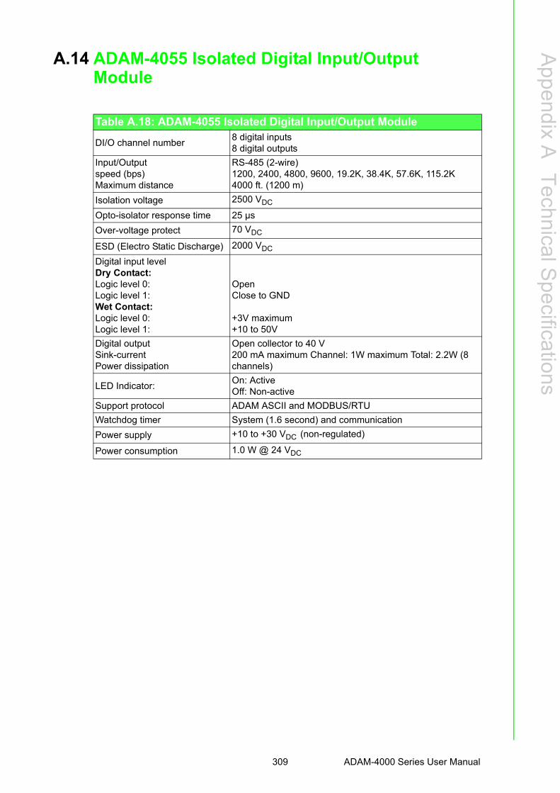
Appendix A
TechnicalS
pecifications
A.14 ADAM-4055 Isolated Digital Input/Output Module
Table A.18: ADAM-4055 Isolated Digital Input/Output Module
DI/O channel number8 digital inputs8 digital outputs
Input/Outputspeed (bps)Maximum distance
RS-485 (2-wire)1200, 2400, 4800, 9600, 19.2K, 38.4K, 57.6K, 115.2K4000 ft. (1200 m)
Isolation voltage 2500 VDC
Opto-isolator response time 25 µs
Over-voltage protect 70 VDC
ESD (Electro Static Discharge) 2000 VDC
Digital input levelDry Contact: Logic level 0: Logic level 1:Wet Contact: Logic level 0: Logic level 1:
OpenClose to GND
+3V maximum+10 to 50V
Digital outputSink-currentPower dissipation
Open collector to 40 V200 mA maximum Channel: 1W maximum Total: 2.2W (8 channels)
LED Indicator:On: ActiveOff: Non-active
Support protocol ADAM ASCII and MODBUS/RTU
Watchdog timer System (1.6 second) and communication
Power supply +10 to +30 VDC (non-regulated)
Power consumption 1.0 W @ 24 VDC
309 ADAM-4000 Series User Manual

Figure A.15 ADAM-4055 Function Diagram
ADAM-4000 Series User Manual 310

Appendix A
TechnicalS
pecifications
A.15 ADAM-4056S 12-channel Sink Type Isolated Digital Output Module
Table A.19: ADAM-4056S SpecificationsDO channel number 12 digital outputs (sink type)
Input/Outputspeed (bps)Maximum distance
RS-485 (2-wire)1200, 2400, 4800, 9600, 19.2K, 38.4K, 57.6K, 115.2K4000 ft. (1200 m)
Digital outputPower dissipation
Open Collector to +40V200 mA maximum Channel: 1W maximum Total: 2.2W (8 channels)
Isolation voltage 5000 VDC
Support protocol ADAM ASCII and MODBUS/RTU
LED IndicatorOn: ActiveOff: Non-active
Watchdog timer System (1.6 second) and communication
Power supply +10 to +30 VDC (non-regulated)
Power consumption 1.0 W @ 24 VDC
311 ADAM-4000 Series User Manual

Figure A.16 ADAM-4056S Function Diagram
ADAM-4000 Series User Manual 312

Appendix A
TechnicalS
pecifications
A.16 ADAM-4056SO 12-channel Source Type Isolated Digital Output Module
Table A.20: ADAM-4056SO SpecificationsDO channel number 12 digital outputs (source type)
Input/Outputspeed (bps)Maximum distance
RS-485 (2-wire)1200, 2400, 4800, 9600, 19.2K, 38.4K, 57.6K, 115.2K4000 ft. (1200 m)
Digital outputVCC: +10~ +35V1A (per Channel)
Isolation voltage 5000 VDC
Support protocol ADAM ASCII and MODBUS/RTU
LED IndicatorOn: ActiveOff: Non-active
Watchdog timer System (1.6 second) and communication
Power supply +10 to +30 VDC (non-regulated)
Power consumption 1.0 W @ 24 VDC
313 ADAM-4000 Series User Manual

Figure A.17 ADAM-4056SO Function Diagram
ADAM-4000 Series User Manual 314

Appendix A
TechnicalS
pecifications
A.17 ADAM-4060 Relay Output Module
Table A.21: ADAM-4060 Specifications
DO channel number4 channel relay(2 form A, 2 form C)
Inputspeed (bps)
Maximum distance
RS-485 (2-wire)1200, 2400, 4800, 9600, 19.2K, 38.4K, 57.6K, 115.2K4000 ft. (1200 m)
Contact rating(Resistive)
AC: 0.6 A @ 125 V 0.3 A @ 250 V DC: 2 A @ 30 V 0.6 A @ 110 V
Breakdown voltage 500 VAC (50/60 Hz)
Relay on time (typical) 3 ms
Relay off time (typical) 2 ms
Total switching time 10 ms
Insulation resistance 1 GΩ minimum at 500 VDC
Support protocol ADAM ASCII
Watchdog timer 1.6 second (System)
Power supply +10 to +30 VDC (non-regulated)
Power consumption 0.8 W @ 24 VDC
315 ADAM-4000 Series User Manual
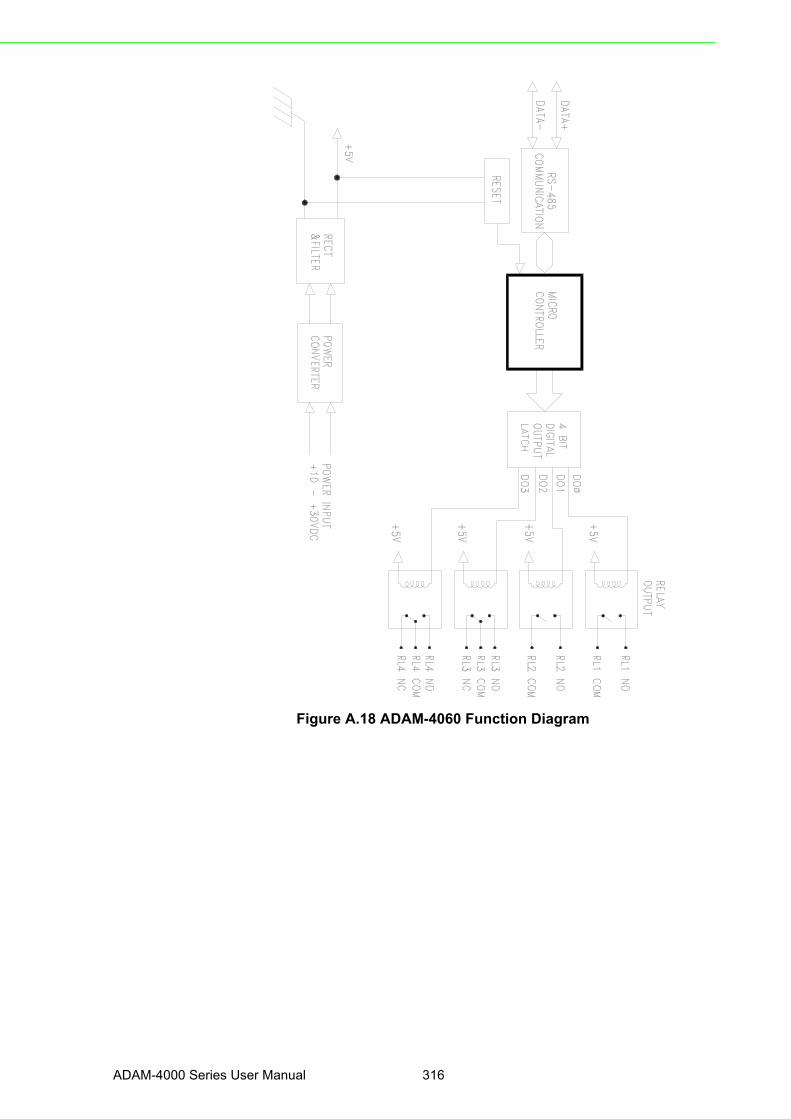
Figure A.18 ADAM-4060 Function Diagram
ADAM-4000 Series User Manual 316

Appendix A
TechnicalS
pecifications
A.18 ADAM-4068/4069 8-channel Relay Output Module
Figure A.19 ADAM-4068/4069 Function Diagram
Table A.22: ADAM-4068/4069 Specifications
DO channel number8 channel relay(4 form A, 4 form C)
Contact rating(Resistive)
ADAM-4068:AC: 0.6A @ 125V 0.3A @ 250V DC: 2A @ 30V 0.6 @ 110V ADAM-4069: AC: 5A @ 240V DC: 5A @ 30V
Breakdown voltageADAM-4068: 500 VAC (50/60 Hz)ADAM-4069: 1000 VAC (50/60 Hz)
Insulation resistance 1 GΩ minimum at 500 VDC
Relay on time (typical)ADAM-4068: 3 msADAM-4069: 5 ms
Relay off time (typical)ADAM-4068: 4 msADAM-4069: 5.6 ms
Support protocol ADAM ASCII and MODBUS/RTU
Watchdog timer System (1.6 second) and communication
Power supply +10 to +30 VDC (non-regulated)
Power consumptionADAM-4068: 0.6 W @ 24 VDC
ADAM-4069: 2.2 W @ 24 VDC
317 ADAM-4000 Series User Manual

A.19 ADAM-4080 Counter/Frequency Input Module
Table A.23: ADAM-4080 SpecificationsInput channel number 2 independent 32-bit counters
Input frequency 50 kHz maximum
Input mode Isolated or non-isolated
Isolation input levelLogic level 0Logical level 1
+1 V maximum+3.5 V to +30 V
Isolation voltage 2500 VRMS
Non-isolation input levelLogic Ievel 0Logic level 1
Programmable threshold0 to +5 V (default = 0.8 V)0 to +5 V (default = 2.4 V)
Input pulse width >10 μsec
Maximum count 4,294,967,295 (32 bits)
Programmable digital noise filter 2 μsec to 65 msec
Alarming Alarm comparators on each counter
Preset type Absolute or relative
Frequency measurement RangeProgrammable built-in gate time
5 Hz to 50 KHz1.0/0.1 sec
Digital output channelsSink currentPower dissipation
2 channels open collector to 30 V30 mA max. load300 mW
Support protocol ADAM ASCII
Watchdog timer 1.6 second (System)
Power requirements +10 to +30 VDC (non-regulated)
Power consumption 2.0 W@ 24 VDC
ADAM-4000 Series User Manual 318

Appendix A
TechnicalS
pecifications
Figure A.20 ADAM-4080 Function Diagram
319 ADAM-4000 Series User Manual
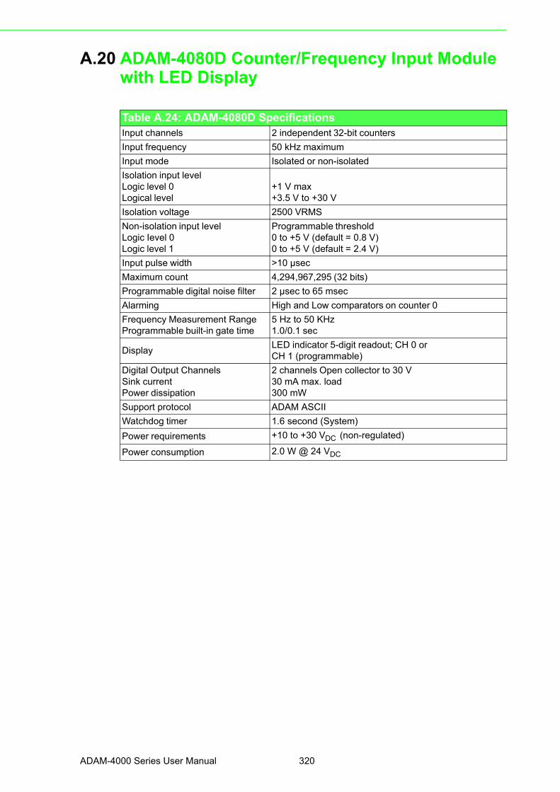
A.20 ADAM-4080D Counter/Frequency Input Module with LED Display
Table A.24: ADAM-4080D SpecificationsInput channels 2 independent 32-bit counters
Input frequency 50 kHz maximum
Input mode Isolated or non-isolated
Isolation input levelLogic level 0Logical level
+1 V max+3.5 V to +30 V
Isolation voltage 2500 VRMS
Non-isolation input levelLogic Ievel 0Logic level 1
Programmable threshold0 to +5 V (default = 0.8 V)0 to +5 V (default = 2.4 V)
Input pulse width >10 μsec
Maximum count 4,294,967,295 (32 bits)
Programmable digital noise filter 2 μsec to 65 msec
Alarming High and Low comparators on counter 0
Frequency Measurement RangeProgrammable built-in gate time
5 Hz to 50 KHz1.0/0.1 sec
DisplayLED indicator 5-digit readout; CH 0 orCH 1 (programmable)
Digital Output ChannelsSink currentPower dissipation
2 channels Open collector to 30 V30 mA max. load300 mW
Support protocol ADAM ASCII
Watchdog timer 1.6 second (System)
Power requirements +10 to +30 VDC (non-regulated)
Power consumption 2.0 W @ 24 VDC
ADAM-4000 Series User Manual 320

Appendix A
TechnicalS
pecifications
Figure A.21 ADAM-4080D Function Diagram
321 ADAM-4000 Series User Manual

ADAM-4000 Series User Manual 322

Appendix B
B Data Formats and I/O Ranges
B.1 Analog Input FormatsThe ADAM analog input modules can be configured to transmit data to the host inone of the following data formats:
Engineering Units Percent of FSR Twos complement hexadecimal Ohms
B.1.1 Engineering UnitsData can be represented in engineering units by assigning bits 0 and 1 of the dataformat/checksum/integration time parameter with value 00.
This format presents data in standard units such as degrees, volts, millivolts and mil-liamps. When the value in engineering format is converted to computer language, it ispresented in seven characters. These characters may include sign and decimals.However, the number of characters can not exceed seven.
Data is grouped into a plus (+) or minus (-) sign, followed by five decimal digits and adecimal point. The input range which is employed determines the resolution or thenumber of decimal places used as illustrated in the following examples:
Example 1
The input value is -2.65 and the corresponding analog input module is configured fora range of ±5 V. The response to the Analog Data In command is: -2.6500 (cr)
Example 2
The input value is 305.5°C, and the analog input module is configured for a type Jthermocouple whose range is (0°C to 760°C). The response to the Analog Data Incommand is: +305.50 (cr)
Example 3
The input value is +5.653 V. The analog input module is configured for a ±5 V range.When the engineering unit format is used, the ADAM Series analog input modulesare configured so that they automatically provide an over-range capability. Theresponse to the Analog Data In command in this case is: +5.6530 (cr)
ADAM-4000 Series User Manual 324

Appendix B
Data F
ormats
andI/O
Ranges
B.1.2 Percent of FSRThis mode is used by setting bits 0 and 1 of the data format/checksum /integrationtime parameter to 01. The format used in Percent of FSR consists of a plus (+) orminus (-) sign followed by five decimal digits including a decimal point. The maximumpossible resolution is 0.01% with the decimal point fixed.
Data are given as the ratio of the input signal to the full-scale range.
Example 1
The input value is +2.0 V. The input module is configured for a range of ±5 V. Theresponse to the Analog Data In command is as follows: +040.00 (cr)
The full calibrated voltage range ranges from -100% to 100% as voltage input rangesare always bipolar. A ±5 V input would range from -5 V (-100%) to 5 V (100%).
In this example the input is represented by +40% of the full-scale range which equalsto (+(40/100) x 5 V = +2.0 V) the actual input value.
Example 2
The input value is 652.5o C, and a type E thermocouple (0°C to 1000°C) is config-ured in the analog input module. The response to the Analog Data In command is:+065.25 (cr)
The result shows that the value of the input (652.5°C) is 65.25% of the full-scalerange (1000°C).
Thermocouple input ranges are always assumed to be bipolar with zero being thepoint of symmetry. This holds true regardless of the specified range of operation. Forexample, when we use a type J thermocouple (0°C to 760°C), 760°C corresponds to+100% and 0°C corresponds to 0%. Even if 0°C lies outside of the specified opera-tion range for the thermocouple, zero will remain as the point of symmetry. Forinstance, a type B thermocouple is specified for operation from +500°C to +1800°C.In this case +1800°C corresponds to + 100% and 500°C corresponds to +27.77%.
The percentage is related to the full span of the configured range. For instance, anickel RTD is specified for -80°C to +100°C. Then, the lower value of -80°C equals to0% of span and the upper value of +100°C equals to 100% of span.
In the FSR mode, an over-range feature is automatically invoked by the ADAM ana-log input modules if the value exceeds the uppermost value of the input range. Forinstance, an analog module which is configured for a ±5 V range has one of the val-ues reading + 5.5V. The resulting value would then be 110%.
The readings must fall within the input range for accuracy assurance. Although theyare typically linear readings, anything which falls between ±100% and ±115% limitsmay not be accurate. Furthermore, readings beyond these limits are neither accuratenor linear.
325 ADAM-4000 Series User Manual

B.1.3 Twos complement hexadecimalTwos Complement Hexadecimal format presents the data in ASCII hexadecimal formproviding a rapid communication, high resolution and easy conversion to computer-compatible integer format.
In order to indicate twos complement hexadecimal, bits 0 and 1 of the data format/checksum/integration time parameter must be set to 10. This format displays data inthe form of a 4-character hexadecimal string.
This string represents a 16-bit twos complement binary value. Positive full scale isdenoted as 7FFF (+32,767) while negative full scale is represented by the value 8000(-32,768). The resolution is digit one at the least significant bit (LSB) of 16 bits.
Example
The input value is -1.234 V. An analog input module is configured for a ±5 V range.The value returned is: E069 (cr)
This value is equivalent to the signed integer -8087.
Input ranges with voltage and milliamp values are used with the full calibrated voltagerange from 8000 to 7FFF. For instance, an ADAM-4011 module is given a ±5 V inputrange. In this case, -5 V is represented as 8000h and +5 V is denoted as 7FFFh.
When thermocouple input ranges are used, an input range which is bipolar and sym-metric at zero is assumed. The following table provides several examples.
The given span of the specified range is used to determine the RTD input ranges fortwos complement hexadecimal values. For an example, if the nickel RTD is specifiedfor the range -80°C to +100°C, the corresponding values in hexadecimal notationwould be 8000h to 7FFFh.
Thermocouple Type Temperature Range (Degrees) Temperature Range (Hex)
J 0° C to 760° C 0000h - 7FFFh
T -100° C to 400° C E000h - 7FFFh
R 500° C to 1750° C 2492h - 7FFFh
ADAM-4000 Series User Manual 326

Appendix B
Data F
ormats
andI/O
Ranges
B.1.4 OhmsTo indicate ohms, set bits 0 and 1 of the data format/checksum/integration timeparameter to 11.
The ohms format allows you to read the value of the RTD resistance in ohms. It con-sists of a “+” or “-” sign followed by five decimal digits and a decimal point. The reso-lution (position of the decimal point) of Platinum-Nickel RTDs is 10 m Ω. (two decimalplaces).
For example, a 100 Ω platinum RTD specified for -100°C to +100°C has +100°C cor-responding to +138.50 Ω and -100o C corresponding to +060.60 Ω.
The measurable resistance values are as given below:
The format is Type, Bottom Tem. (ohm) ~ Top Temp. (ohm)
BA1 -200(7.95) ~ 600(145.85)
PT-100 (0.385) -50(80.31) ~ +150(157.31)
PT-100 (0.392) -50(79.96) ~ +150(158.29)
PT-100 (0.385) 0(100.00) ~ +100(138.50)
PT-100 (0.392) 0(100.00) ~ +100(139.16)
PT-100 (0.385) 0(100.00) ~ +200(175.84)
PT-100 (0.392) 0(100.00) ~ +200(177.13)
PT-100 (0.385) 0(100.00) ~ +400(247.04)
PT-100 (0.392) 0(100.00) ~ +400(249.56)
PT-100 (0.385) -200(18.49) ~ +200(175.84)
PT-100 (0.392) -200(18.49) ~ +200(177.13)
PT-1000 -40(842.7) ~ +160(1610.4)
Balco-500 -30(397.05) ~ +120(723.44)
Ni604-518 -80(410.73) ~ +100(917.33)
Ni604-518 0(604) ~ +100(917.33)
Ni508A 0(507) ~ 100(772)
Ni508B -50(400.14) ~ 200(1099.89)
327 ADAM-4000 Series User Manual

B.2 Analog Input Ranges
Range Code(hex)
Input RangeDescription
Data Formats +F.S. Zero -F.S.DisplayedResolution
00 ± 15 mV
EngineeringUnits
+15.000 ±00.000 -15.000 1 µv
% of FSR +100.00 ±000.00 -100.00 0.01%
TwosComplement
7FFF 0000 8000 1 LSB*
01 ± 50 mV
EngineeringUnits
+50.000 ±00.000 -50.000 1 µv
% of FSR +100.00 ±000.00 -100.00 0.01%
TwosComplement
7FFF 0000 8000 1 LSB*
02 ± 100 mV
EngineeringUnits
+100.00 ±000.00 -100.00 10 µv
% of FSR +100.00 ±000.00 -100.00 0.01%
TwosComplement
7FFF 0000 8000 1 LSB*
03 ± 500 mV
EngineeringUnits
+500.00 ±000.00 -500.00 10 µv
% of FSR +100.00 ±000.00 -100.00 0.01%
TwosComplement
7FFF 0000 8000 1 LSB*
04 ± 1 V
EngineeringUnits
+100.00 ±0.0000 -1.0000 100.00 µv
% of FSR +100.00 ±000.00 -100.00 0.01%
TwosComplement
7FFF 0000 8000 1 LSB*
05 ± 2.5 V
EngineeringUnits
+2.5000 ±0.0000 -2.5000 100.00 µv
% of FSR +100.00 ±000.00 -100.00 0.01%
TwosComplement
7FFF 0000 8000 1 LSB*
06 ± 20 mV
EngineeringUnits
+20.000 ±00.000 -20.000 1 µv
% of FSR +100.00 ±000.00 -100.00 0.01%
TwosComplement
7FFF 0000 8000 1 LSB*
07 ± 4~20mA
EngineeringUnits
+20.000 ±00.000 -20.000 1 µA
% of FSR +100.00 ±000.00 -100.00 0.01%
TwosComplement
7FFF 0000 8000 1 LSB*
08 ± 10 mV
EngineeringUnits
+10.000 ±00.000 -10.000 Resolution
% of FSR +100.00 ±000.00 -100.00 1 µv
TwosComplement
7FFF 0000 8000 0.01%
ADAM-4000 Series User Manual 328

Appendix B
Data F
ormats
andI/O
Ranges
Range Code(hex)
Input RangeDescription
Data Formats +F.S. Zero -F.S.DisplayedResolution
09 ± 5 V
EngineeringUnits
+5.0000 ±0.0000 -5.0000 1 LSB*
% of FSR +100.00 ±000.00 -100.00 100.00 µv
TwosComplement
7FFF 0000 8000 0.01%
0A ± 1 V
EngineeringUnits
+1.0000 ±0.0000 -1.000 1 LSB*
% of FSR +100.00 ±000.00 -100.00 100.00 µv
TwosComplement
7FFF 0000 8000 0.01%
0B ± 500 mV
EngineeringUnits
+500.00 ±000.00 -500.00 1 LSB*
% of FSR +100.00 ±000.00 -100.00 10 µv
TwosComplement
7FFF 0000 8000 0.01%
0C ± 150 mV
EngineeringUnits
+150.00 ±000.00 -150.00 1 LSB*
% of FSR +100.00 ±000.00 -100.00 10 µv
TwosComplement
7FFF 0000 8000 0.01%
0D ± 20 mV
EngineeringUnits
+20.000 ±00.000 -20.000 1 LSB*
% of FSR +100.00 ±000.00 -100.00 1 µv
TwosComplement
7FFF 0000 8000 0.01%
329 ADAM-4000 Series User Manual

Range Code(hex)
Input RangeDescription
Data FormatsMaximumSpecifiedSignal
MinimumSpeciatedSignal
DisplayedResolution
0EType J Thermocouple0°C to 760°C
EngineeringUnits
+760.000 +000.00 0.01°C
% of FSR +100.00 +000.00 0.01%
TwosComplement
7FFF 0000 1 LSB*
0FType K Thermocouple0°C to 1370°C
EngineeringUnits
+1370.0 +0000.0 0.1°C
% of FSR +100.00 +000.00 0.01%
TwosComplement
7FFF 0000 1 LSB*
10Type T Thermocouple-100°C to 400°C
EngineeringUnits
+400.00 -100.00 0.01°C
% of FSR +100.00 -0.25.00 0.01%
TwosComplement
7FFF E000 1 LSB*
11Type E Thermocouple0°C to 1000°C
EngineeringUnits
+1000.0 +0000.0 0.1°C
% of FSR +100.00 +000.00 0.01%
TwosComplement
7FFF 0000 1 LSB*
12Type R Thermocouple500°C to 1750°C
EngineeringUnits
+1750.0 +0500.0 0.1°C
% of FSR +100.00 +028.57 0.01%
TwosComplement
7FFF 2492 1 LSB*
13Type S Thermocouple500°C to 1750°C
EngineeringUnits
+1750.0 +0500.0 0.1°C
% of FSR +100.00 +028.57 0.01%
TwosComplement
7FFF 2492 1 LSB*
14Type B Thermocouple500°C to 1800°C
EngineeringUnits
+1800.0 +0500.0 0.1°C
% of FSR +100.00 +027.77 0.01%
TwosComplement
7FFF 2381 1 LSB*
20100.00 Ω Platinum RTD α = .00385-100°C to 100°C
EngineeringUnits
+100.00 -100.000 0.1°C
% of FSR +100.00 +000.00 0.01%
TwosComplement
7FFF 8000 1 LSB*
Ohms +138.50 +060.60 10 mΩ
21100.00 Ω Platinum RTD α = .003850°C to 100°C
EngineeringUnits
+100.000 +000.00 0.1°C
% of FSR +100.00 +000.00 0.01%
TwosComplement
7FFF 0000 1 LSB*
Ohms +138.50 +100.00 10 mΩ
ADAM-4000 Series User Manual 330

Appendix B
Data F
ormats
andI/O
Ranges
Range Code(hex)
Input RangeDescription
Data FormatsMaximumSpecifiedSignal
MinimumSpecifiedSignal
DisplayedResolution
22
100.00 ΩPlatinum RTDα = .003850°C to 200°C
EngineeringUnits
+200.00 +000.00 0.01°C
% of FSR +100.00 +000.00 0.01%
TwosComplement
7FFF 0000 1 LSB*
Ohms +175.84 +100.00 10 mΩ
23100.00 Ω Platinum RTD α = .003850°C to 600°C
EngineeringUnits
+600.00 +000.00 0.01°C
% of FSR +100.00 +000.00 0.01%
TwosComplement
7FFF 0000 1 LSB*
Ohms +313.59 +100.00 10 mΩ
24100.00 Ω Platinum RTD α = .00392-100°C to 100°C
EngineeringUnits
+00.00 -100.00 0.01°C
% of FSR +100.00 +000.00 0.01%
TwosComplement
7FFF 8000 1 LSB*
Ohms +139.16 +060.60 10 mΩ
25100.00 Ω Platinum RTD α = .003920°C to 100°C
EngineeringUnits
+100.00 +000.00 0.01°C
% of FSR +100.00 +000.00 0.01%
TwosComplement
7FFF 0000 1 LSB*
Ohms +139.16 +100.00 10 mΩ
26100.00 Ω Platinum RTD α = .003920°C to 200°C
EngineeringUnits
+200.00 +000.00 0.01°C
% of FSR +100.00 +000.00 0.01%
TwosComplement
7FFF 0000 1 LSB*
Ohms +177.13 +100.00 10 mΩ
27100.00 Ω Platinum RTD α = .003920°C to 600°C
EngineeringUnits
+600.00 +000.00 0.01°C
% of FSR +100.00 +000.00 0.01%
TwosComplement
7FFF 0000 1 LSB*
Ohms +317.28 +100.00 10 mΩ
28120 ΩNickel RTD-80°C to 100°C
EngineeringUnit
+100.000 -80.00 0.01°C
% of FSR +100.00 +000.00 0.01%
TwosComplement
7FFF 8000 1 LSB*
Ohms +200.64 +066.60 10 mΩ
29
100.00 ΩNickel RTDα = .003920°C to 100°C
EngineeringUnit
+100.000 +000.00 0.01°C
% of FSR +100.00 +000.00 0.01%
TwosComplement
7FFF 0000 1 LSB*
Ohms +200.64 +120.00 10 mΩ
331 ADAM-4000 Series User Manual

B.3 Analog Output FormatsYou can configure ADAM analog output modules to receive data from the host in oneof the following data formats:
Engineering Units Percent of FSR Twos complement hexadecimalData for ADAM modules can be used in any one of the following data formats:
B.3.1 Engineering UnitsThis format is chosen by setting bits 0 and 1 of the data format/slew rate/checksumparameter to 00.
Data are presented in natural units such as milliamps. When the value in engineeringformat is converted to computer language, it is presented in six characters. Thesecharacters are ordered as two decimal digits, a decimal point, and then three decimaldigits. As a result, the resolution is 5 μA.
For example, an analog output module (address 01h) is configured for a 0 to 20 mArange. If the output value is + 4.762 mA, the format of the Analog Data Out commandwould be #0104.762(cr).
B.3.2 Percent of SpanThe Percent of Span format is employed by setting bits 0 and 1 of the data format/slew rate/checksum parameter to 01.
This format consists of a “+” or “-” sign, three decimal digits, a decimal point and twodecimal digits. Data are presented as the value sent by the output signal relative tothe span of the output (percent of span).
The maximum resolution is 0.2% of the span (5 μA for the 0 to 20 mA output range);therefore, the desired output value is 10 mA. The format of the Analog Data Out com-mand is as follows:
#01+050.00 (cr). It indicates that the output is at 50% of the span, and the decimalpoint is fixed.
B.3.3 HexadecimalThis format is selected by setting bits 0 and 1 of the data format/slew rate/checksumparameter to 10.
ASCII’s condensed hexadecimal representation of data provides high resolution. Theformat consists of a 3-character hexadecimal string representing a 12-bit binaryvalue. The resolution for the 0 to 20mA output range equals to .025% of the span,which is also equivalent to 5μA. The corresponding value for 000 is 0mA; likewise,the value FFF corresponds to 20mA.
Note! * Resolution is one LSB of 16 bits
ADAM-4000 Series User Manual 332

Appendix B
Data F
ormats
andI/O
Ranges
B.4 Analog Output Ranges
Range Code(hex)
Input RangeDescription
Data FormatsMaximumSpecifiedSignal
MinimumSpeciatedSignal
OutputResolution
30 0 to 20 mA
EngineeringUnits
20.000 00.000 5 µA
% of FSR +100.00 +000.00 5 µA
HexadecimalBinary
FFF 000 5 µA
31 4 to 20 mA
EngineeringUnits
20.000 04.000 5 µA
% of FSR +100.00 +000.00 5 µA
HexadecimalBinary
FFF 000 5 µA
32 0 to 10 V
EngineeringUnits
20.000 00.000 2.442 mA
% of FSR +100.00 +000.00 2.442 mA
HexadecimalBinary
FFF 000 2.442 mA
333 ADAM-4000 Series User Manual

ADAM-4000 Series User Manual 334

Appendix C
C Technical Diagrams
C.1 ADAM Dimensions
Figure C.1 ADAM Modules Dimensions
ADAM-4000 Series User Manual 336

Appendix C
TechnicalD
iagrams
C.2 Installation
C.2.1 DIN-Rail Mounting
Figure C.2 DIN-Rail Adapter
337 ADAM-4000 Series User Manual

Figure C.3 DIN-Rail Mounting
ADAM-4000 Series User Manual 338
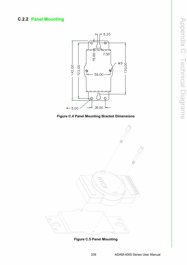
Appendix C
TechnicalD
iagrams
C.2.2 Panel Mounting
Figure C.4 Panel Mounting Bracket Dimensions
Figure C.5 Panel Mounting
339 ADAM-4000 Series User Manual

C.2.3 Piggyback Stack
Figure C.6 Piggyback Stack
ADAM-4000 Series User Manual 340

Appendix D
D Utility Software
D.1 ADAM-4000 Utility SoftwareTogether with the ADAM modules you will find a utility disk
containing utility software with the following capabilities:
Module configuration Module calibration Data Input and Output Alarm settings Autoscan of connected modules Terminal emulationThe following text will give you a brief instruction how to use the program.
Search the installed modules
The main screen consists of a menu bar at the top side of the screen and a statusfield which displays information about the connected modules. When the modulesare connected well, you have to start the program and search the modules by clickingthe search icon as below. Please do check the COM port and related settings arecorrect.
Figure D.1 Search screen
Caution! When changing configuration, calibration or alarm parameters, you should always make sure that a window appears notifying you that the target module has confirmed the changes.
An asterix sign “*” before the modules address indicates that the module is in the INIT* state.
ADAM-4000 Series User Manual 342

Appendix D
Utility S
oftware
Configuration
Click the searched module, which you would like to configure. You will find Setuppage and related settings. An example is shown in Figure D.2 for an ADAM-4011module.
Figure D.2 Configuration Screen
Here there are three major areas, General Setting, Data Area and AI Calibration. Youmay change the settings by selecting the preferred items and then clicking Updatebutton.
The Checksum and Baud rate options need special attention since they can only bechanged when an ADAM module is in the INIT* state. To place a module in INITstate, its INIT terminal should be connected to its GND terminal (see Baud rate andChecksum in Chapter 2). When the ADAM module is not in INIT mode, an error mes-sage will appear.
After you have made all necessary changes to the module configuration, the utilitywill display the process data automatically.
Calibration
Please note only analog input and output modules can be calibrated. For example,ADAM-4011 module has Zero, Span and CJC Calibration items. To learn what stepsshould be taken to calibrate both input and output modules, please refer to Chapter 8Calibration.
343 ADAM-4000 Series User Manual

Terminal Function
When you would like to send and receive commands on the RS-485 line directly, youcan use this Terminal function in this utility.
Figure D.3 Terminal Function
You can type the ADAM ASCII command in the text box and click Send button fortesting the commands which are listed in Chapter 4 Command Set.
ADAM-4000 Series User Manual 344
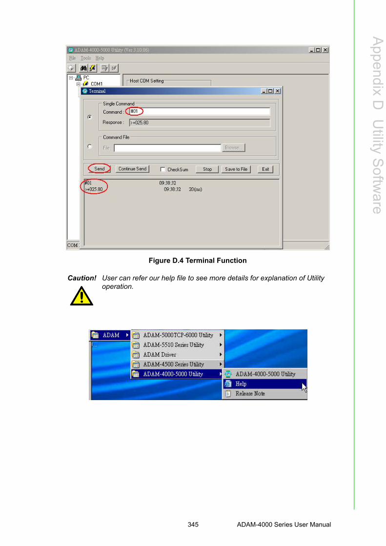
Appendix D
Utility S
oftware
Figure D.4 Terminal Function
Caution! User can refer our help file to see more details for explanation of Utility operation.
345 ADAM-4000 Series User Manual

D.2 The Procedure for ADAM-4000 Series Installation GuideWhen user first time gets ADAM-4000 modules, he can refer following procedure toconfigure and operate. Especially note that new ADAM-4000 modules will havedefault factory settings with Address setting 1, and data format 9600, N, 8, 1. Rede-fine the address to avoid ID conflict if two or more new modules are used in the samenetwork.
Standard Installation Procedures
1. Prepare the install environment
Host computer Isolated RS-232/RS-485 Converter ADAM module2. Install ADAM-4000-5000 utility in host computer
3.Wiring for ADAM-4000 module
Power supply & Communication Wiring
Move hardware switch to Initial mode (For some older Adam models, use an exter-nal wire to connect the INIT* terminal to the GND terminal. Booting the modulewhile connecting the INIT* terminal with the module’s GND terminal forces the config-uration into a known state called the INIT* state.)
INIT* state defaults:
Baud rate: 9600
Address: 00h
Checksum: disabled
Forcing the module in INIT* state does not change any parameters in the module’sEEPROM. When the module is in the INIT* state with its INIT* and GND terminalsshorted, all configuration settings can be changed, and the module will respond to allother commands normally.
Caution! Init Mode
When the switch is set to the initial mode, the module will operate with its factory settings. (Address 0 with data format 9600, N, 8, 1).
Normal Mode
When the switch is set to the normal mode, the module will operate with user-defined settings. A power reset will not alter these settings.
ADAM-4000 Series User Manual 346
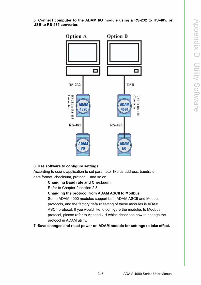
Appendix D
Utility S
oftware
5. Connect computer to the ADAM I/O module using a RS-232 to RS-485, orUSB to RS-485 converter.
6. Use software to configure settings
According to user’s application to set parameter like as address, baudrate,
data format, checksum, protocol…and so on.
Changing Baud rate and Checksum
Refer to Chapter 2 section 2.3.
Changing the protocol from ADAM ASCII to Modbus
Some ADAM-4000 modules support both ADAM ASCII and Modbus
protocols, and the factory default setting of these modules is ADAM
ASCII protocol. If you would like to configure the modules to Modbus
protocol, please refer to Appendix H which describes how to change the
protocol in ADAM utility.
7. Save changes and reset power on ADAM module for settings to take effect.
347 ADAM-4000 Series User Manual

ADAM-4000 Series User Manual 348

Appendix E
E RS-485 Network
E.1 RS-485 NetworkEIA RS-485 is industry’s most widely used bidirectional, balanced transmission linestandard. It is specifically developed for industrial multi-drop systems that should beable to transmit and receive data at high rates or over long distances.
The specifications of the EIA RS-485 protocol are as follows:
Max line length per segment: 1200 meters (4000 feet) Throughput of 10 Mbaud and beyond Differential transmission (balanced lines) with high resistance against noise Maximum 32 nodes per segment Bi-directional master-slave communication over a single set of twisted pair
cables Parallel connected nodes, true multi-dropADAM modules are fully isolated and use just a single set of twisted pair wires tosend and receive! Since the nodes are connected in parallel they can be freely dis-connected from the host without affecting the functioning of the remaining nodes. Inindustry shielded twisted pair is preferable due to the high noise ratio of the environ-ment.
When nodes communicate through the network, no sending conflicts can occur sincea simple command/response sequence is used. There is always one initiator (with noaddress) and many slaves (with address). In this case the master is a personal com-puter that is connected with its serial, RS-232, port to an ADAM RS-232/RS-485 con-verter. The slaves are the ADAM I/O modules. When modules are not transmittingdata, they are in listen mode. The host computer initiates a command/responsesequence with one of the modules. Commands normally contain the address of themodule the host wants to communicate with. The module with the matching addresscarries out the command and sends its response to the host.
E.2 Basic Network LayoutMulti-drop RS-485 implies that there are two main wires in an segment. The con-nected modules tap from these two lines with so called drop cables. Thus all connec-tions are parallel and connecting or disconnecting of a node doesn’t affect thenetwork as a whole. Since ADAM modules use the RS-485 standard, and use anASCII-based commands set, they can connect and communicate with all ASCIIbased
computers and terminals. The basic layouts that can be used for an RS-485 networkare:
Daisychain
The last module of a segment is a repeater. It is directly connected to the main-wiresthereby ending the first segment and starting the next segment. Up to 32 address-able modules can be diasychained. This limitation is a physical one. When usingmore modules per segment the IC driver current rapidly decreases, causing commu-nication errors. Totally the network can hold up to 256 addressable modules. The lim-itation for this number is the two number hexadecimal address codes that know 256combinations. The ADAM converter, ADAM repeaters and the host computer are nonaddressable units and therefore are not included in these numbers.
ADAM-4000 Series User Manual 350

Appendix E
RS
-485N
etwork
Figure E.1 Daisychaining
Star Layout
In this scheme the repeaters are connected to drop-down cables from the main wiresof the first segment. A tree structure is the result. This scheme is not recommendedwhen using long lines since it will cause a serious amount of signal distortion due to asignal reflection in a several line endings.
Figure E.2 Star Structure
Random
This is a combination of daisychain and hierarchical structure
Figure E.3 Random Structure
351 ADAM-4000 Series User Manual

E.3 Line TerminationEach discontinuity in impedance causes reflections and distortion. When an imped-ance discontinuity occurs in the transmission line the immediate effect is signalreflection. This will lead to signal distortion. Specially at line ends this mismatchcauses problems. To eliminate this discontinuity terminate the line with a resistor.
Figure E.4 Signal Distortion
The value of the resistor should be a close as possible to the characteristic imped-ance of the line. Although receiver devices add some resistance to the whole of thetransmission line, normally it is sufficient to the resistor impedance should equal thecharacteristic impedance of the line.
Example:
Each input of the receivers has a nominal input impedance of 18 kW feeding into adiode transistor- resistor biasing network that is equivalent to an 18 kΩ input resistortied to a common mode voltage of 2.4 V. It is this configuration which provides thelarge common range of the receiver required for RS-485 systems! (See Figure E.5below)
Figure E.5 Termination resistor locations
ADAM-4000 Series User Manual 352

Appendix E
RS
-485N
etwork
Because each input is biased to 2.4 V, the nominal common mode voltage of bal-anced RS-485 systems, the 18 kΩ on the input can be taken as being in seriesacross the input of each individual receiver.
If thirty of these receivers are put closely together at the end of the transmission line,they will tend to react as thirty 36kΩ resistors in parallel with the termination resistor.The overall effective resistance will need to be close to the characteristics of the line.
The effective parallel receiver resistance RP will therefore be equal to:
RP = 36 x 103/30 = 1200 W
While the termination receptor RT will equal:
RT = RO / [1 - RO/RP]
Thus for a line with a characteristic impedance of 100 Ω resistor, the terminationresistor RT should be:
RT = 100/[1 - 100/1200] = 110 Ω
Since this value lies within 10% of the line characteristic impedance.
Thus as already stated above the line termination resistor RT will normally equal thecharacteristic impedance ZO.
The star connection causes a multitude of these discontinuities since there are sev-eral transmission lines and is therefore not recommend.
E.4 RS-485 Data Flow ControlThe RS-485 standard uses a single pair of wires to send and receive data. This linesharing requires some method to control the direction of the data flow. RTS (RequestTo Sent) and CTS (Clear To Sent) are the most commonly used method.
Figure E.6 RS-485 data flow control with RTS
Intelligent RS-485 Control
ADAM-4510 and ADAM-4520 are both equipped with an I/O circuit which can auto-matically sense the direction of the data flow. No handshaking with the host (likeRTS, Request to Send) is necessary to receive data and forward it in the correctdirection. You can use any software written for half-duplex RS-232 with an ADAMnetwork without modification. The RS-485 control is completely transparent to theuser.
Caution! The recommended wiring method that causes a minimum amount of reflection is daisy chaining where all receivers tap from one transmis-sion line and needs to be terminated only twice.
353 ADAM-4000 Series User Manual

ADAM-4000 Series User Manual 354

Appendix F
F How to Use the Checksum Feature
A checksum helps you detect communication errors between the host and module.This feature adds two extra checksum characters to the command or responsestring; therefore, it reduces the throughput.
F.1 Checksum Enable/DisableIn order to enable configuration of a module’s checksum feature, its INIT* terminalshould be shorted to its GND terminal. Then, the module should be rebooted. Thechecksum feature is enabled by setting bit 6 of the data format/checksum parameterto 1. On the other hand, the checksum is disabled by setting the parameter to 0.Whenever the checksum feature is used, all the connected devices including the hostcomputer should be in enable mode.
The checksum is represented by a 2-character ASCII hexadecimal format and istransmitted just prior to the carriage return. The checksum equals to the result afterperforming modulus-256 (100h) of all the ASCII values’ sum preceding the check-sum. If the checksum is missing or incorrect, the module will not respond.
Example 1
The following example is an Analog Data In command and response when thechecksum is enabled:
Command: #0588(CR)
Response: +3.56719D(CR)
The input value of the module at address 05h is +3.5671 V. (The data format is inengineering units.) The command checksum (88h) is the sum of the ASCII values forthe following characters: #, 0, and 5. The response checksum (9Dh) is the sum of theASCII values for the following characters: “>”, “+”, “3”, “.”, “5”, “6”, “7”, and “1”.
Example 2
This example explains how to calculate the checksum value of a Read High alarmlimit command string:
Case 1. (If the Checksum feature is disabled)
Command: $07RH(cr)
Response: !07+2.0500(cr) when the command is valid.
Case 2. (If the Checksum feature is enabled)
Command: $07RH25(cr)
Response: !07+2.0500D8(cr)
where:
25 represents the checksum of this command, and
D8 represents the checksum of the response.
The checksum of the command string is derived as shown below:
25h = (24h+ 30h + 37h + 52h + 48h) MOD 100h
The hexadecimal ASCII codes for $, 0, 7, R, H are 24h, 30h, 37h, 52h and 48hrespectively. The sum of these ASCII codes is 125h, and the result equals to 25hafter modulus-256(100h) execution.
ADAM-4000 Series User Manual 356

Appendix F
How
toU
sethe
Checksum
Feature
Table F.1: Printable ASCII Characters
HEX ASCII HEX ASCII HEX ASCII HEX ASCII
21 ! 40 @ 5F _ 7E ~
22 "" 41 A 60 '
23 # 42 B 61 a
24 $ 43 C 62 b
25 % 44 D 63 c
26 & 45 E 64 d
27 ' 46 F 65 e
28 ( 47 G 66 f
29 ) 48 H 67 g
2A * 49 I 68 h
2B + 4A J 69 i
2C , 4B K 6A j
2D - 4C L 6B k
2E . 4D M 6C l
2F / 4E N 6D m
30 0 4F O 6E n
31 1 50 P 6F o
32 2 51 Q 70 p
33 3 52 R 71 q
34 4 53 S 72 r
35 5 54 T 73 s
36 6 55 U 74 t
37 7 56 V 75 u
38 8 57 W 76 v
39 9 58 X 77 w
3A : 59 Y 78 x
3B ; 5A Z 79 y
3C < 5B [ 7A z
3D = 5C \ 7B
3E > 5D ] 7C |
3F ? 5E ^ 7D
357 ADAM-4000 Series User Manual

ADAM-4000 Series User Manual 358

Appendix G
GADAM-4000 I/O Modbus Mapping Table
G.1 ADAM-4000 I/O Modbus Mapping TableThe model list of ADAM-4000 I/O series support Modbus protocol
1. ADAM-4015 6-channel RTD Input Module and ADAM-4015T 6-channel Therm-istor Input Module
Model Description
1ADAM-4015 6-channel RTD Input Module
ADAM-4015T 6-channel Thermistor Input Module
2 ADAM-4017+ 8-channel Analog Input Module
3 ADAM-4018+ 8-channel Thermocouple Input Module
4 ADAM-4019+ 8-Channels Universal Analog Input Module
5 ADAM-4024 4-channel Analog Output Module
6 ADAM-4051 16-channel Isolated Digital Input with LED Module
7 ADAM-4055 16-channel Isolated Digital I/O with LED Module
8 ADAM-4056S 12 channel Sink-type Isolated Digital Output Module
9 ADAM-4056SO 12 channel Source-type Isolated Digital Output Module
10 ADAM-4068 8 Relay Output Module
11 ADAM-4069 8 Power Relay Output Module
ADDR 0X Channel Item Attribute Memo
00201 0 Burn-out Signal R 1:Burn-out
00202 1 Burn-out Signal R
00203 2 Burn-out Signal R
00204 3 Burn-out Signal R
00205 4 Burn-out Signal R
00206 5 Burn-out Signal R
00207 6 Burn-out Signal R
00208 7 Burn-out Signal R
ADAM-4000 Series User Manual 360

Appendix G
AD
AM
-4000I/O
Modbus
Mapping
Table
ADDR 4X Channel Item Attribute Memo
40001 0 Current Value R
40002 1 Current Value R
40003 2 Current Value R
40004 3 Current Value R
40005 4 Current Value R
40006 5 Current Value R
40007 6 Current Value R
40008 7 Current Value R
40201 0 Type Code R/W 0x00 0x0e
40202 1 Type Code R/W
40203 2 Type Code R/W
40204 3 Type Code R/W
40205 4 Type Code R/W
40206 5 Type Code R/W
40207 6 Type Code R/W
40208 7 Type Code R/W
40211 Module Name 1 R 0x40 0x18
40212 Module Name 2 R 0x50 0x00
40213 Version 1 R 0xa2 0x00
40214 Version 2 R 0x00 0x00
40221 Channel Enable R/W 0x00 0xff
361 ADAM-4000 Series User Manual

2. ADAM-4018+ 8-channel Thermocouple Input Module
ADDR 0X Channel Item Attribute Memo
00201 0 Burn-out Signal R 1:Burn-out
00202 1 Burn-out Signal R
00203 2 Burn-out Signal R
00204 3 Burn-out Signal R
00205 4 Burn-out Signal R
00206 5 Burn-out Signal R
00207 6 Burn-out Signal R
00208 7 Burn-out Signal R
ADDR 4X Channel Item Attribute Memo
40001 0 Current Value R
40002 1 Current Value R
40003 2 Current Value R
40004 3 Current Value R
40005 4 Current Value R
40006 5 Current Value R
40007 6 Current Value R
40008 7 Current Value R
40201 0 Type Code R/W 0x00 0x0e
40202 1 Type Code R/W
40203 2 Type Code R/W
40204 3 Type Code R/W
40205 4 Type Code R/W
40206 5 Type Code R/W
40207 6 Type Code R/W
40208 7 Type Code R/W
40211 Module Name 1 R 0x40 0x18
40212 Module Name 2 R 0x50 0x00
40213 Version 1 R 0xa2 0x00
40214 Version 2 R 0x00 0x00
40221 Channel Enable R/W 0x00 0xff
ADAM-4000 Series User Manual 362

Appendix G
AD
AM
-4000I/O
Modbus
Mapping
Table
3. ADAM-4017+ 8-channel Analog Input Module
ADDR 4X Channel Item Attribute Memo
40001 0 Current Value R
40002 1 Current Value R
40003 2 Current Value R
40004 3 Current Value R
40005 4 Current Value R
40006 5 Current Value R
40007 6 Current Value R
40008 7 Current Value R
40201 0 Type Code R/W
40202 1 Type Code R/W
40203 2 Type Code R/W
40204 3 Type Code R/W
40205 4 Type Code R/W
40206 5 Type Code R/W
40207 6 Type Code R/W
40208 7 Type Code R/W
40211 Module Name 1 R 0x40 0x17
40212 Module Name 2 R 0x50 0x00
40213 Version 1 R 0xa2 0x00
40214 Version 2 R 0x00 0x00
40221 Channel Enable R/W 0x00 0xff
363 ADAM-4000 Series User Manual

4. ADAM-4019+ 8-Channels Universal Analog Input Module
ADDR 0X Channel Item Attribute Memo
00201 0 Burn-out Signal R
0: Non1:Burn-out
00202 1 Burn-out Signal R
00203 2 Burn-out Signal R
00204 3 Burn-out Signal R
00205 4 Burn-out Signal R
00206 5 Burn-out Signal R
00207 6 Burn-out Signal R
00208 7 Burn-out Signal R
ADDR 4X Channel Item Attribute Memo
40001 0 Current Value R
40002 1 Current Value R
40003 2 Current Value R
40004 3 Current Value R
40005 4 Current Value R
40006 5 Current Value R
40007 6 Current Value R
40008 7 Current Value R
40201 0 Type Code R/W
40202 1 Type Code R/W
40203 2 Type Code R/W
40204 3 Type Code R/W
40205 4 Type Code R/W
40206 5 Type Code R/W
40207 6 Type Code R/W
40208 7 Type Code R/W
40211 Module Name 1 R 0x40 0x19
40212 Module Name 2 R 0x42 0x00
40213 Version 1 R 0xa1 0x00
40214 Version 2 R 0x00 0x00
40221 Channel Enable R/W 0x00 0xff
ADAM-4000 Series User Manual 364

Appendix G
AD
AM
-4000I/O
Modbus
Mapping
Table
5. ADAM-4024 4-channel Analog Output Module
ADDR 0X Channel Item Attribute Memo
00001 0 Emergency DI Input Flag R
00002 1 Burn-out Signal R
00003 2 Burn-out Signal R
00004 3 Burn-out Signal R
ADDR 4X Channel Item Attribute Memo
40001 0 Current Output Value R/W
40002 1 Current Output Value R/W
40003 2 Current Output Value R/W
40004 3 Current Output Value R/W
40201 0 Type Code R/W
40202 1 Type Code R/W
40203 2 Type Code R/W
40204 3 Type Code R/W
40211 Module Name 1 R 0x40 0x24
40212 Module Name 2 R 0x00 0x00
40213 Version 1 R 0xa2 0x00
40214 Version 2 R 0x00 0x00
40215 Comm Safety Enable R Enable:0x00 0x01
40216 Comm Safety Flag R Occur:0x00 0x01
40221 Channel Enable R/W 0x00 0xff
365 ADAM-4000 Series User Manual

6. ADAM-4051 16-channel Isolated Digital Input with LED Module
ADDR 0X Channel Item Attribute Memo
00001 0 DI Input Signal R
00002 1 DI Input Signal R
00003 2 DI Input Signal R
00004 3 DI Input Signal R
00005 4 DI Input Signal R
00006 5 DI Input Signal R
00007 6 DI Input Signal R
00008 7 DI Input Signal R
00009 8 DI Input Signal R
00010 9 DI Input Signal R
00011 10 DI Input Signal R
00012 11 DI Input Signal R
00013 12 DI Input Signal R
00014 13 DI Input Signal R
00015 14 DI Input Signal R
00016 15 DI Input Signal R
ADDR 4X Channel Item Attribute Memo
40211 Module Name 1 R 0x40 0x55
40212 Module Name 2 R 0x00 0x00
40213 Version 1 R 0xa2 0x00
40214 Version 2 R 0x00 0x00
ADAM-4000 Series User Manual 366

Appendix G
AD
AM
-4000I/O
Modbus
Mapping
Table
7. ADAM-4055 16-channel Isolated Digital I/O with LED Module
ADDR 0X Channel Item Attribute Memo
00001 0 DI Input Signal R
00002 1 DI Input Signal R
00003 2 DI Input Signal R
00004 3 DI Input Signal R
00005 4 DI Input Signal R
00006 5 DI Input Signal R
00007 6 DI Input Signal R
00008 7 DI Input Signal R
00017 0 DO Output Value R/W
00018 1 DO Output Value R/W
00019 2 DO Output Value R/W
00020 3 DO Output Value R/W
00021 4 DO Output Value R/W
00022 5 DO Output Value R/W
00023 6 DO Output Value R/W
00024 7 DO Output Value R/W
ADDR 4X Channel Item Attribute Memo
40211 Module Name 1 R 0x40 0x55
40212 Module Name 2 R 0x00 0x00
40213 Version 1 R 0xa2 0x00
40214 Version 2 R 0x00 0x00
40215 Comm Safety Enable REnable:0x000x01
40216 Comm Safety Flag ROccur:0x00 0x01
367 ADAM-4000 Series User Manual

8. ADAM-4056S 12 channel Sink-type Isolated Digital Output Module
ADDR 0X Channel Item Attribute Memo
00017 0 Digital Output Value R/W
00018 1 Digital Output Value R/W
00019 2 Digital Output Value R/W
00020 3 Digital Output Value R/W
00021 4 Digital Output Value R/W
00022 5 Digital Output Value R/W
00023 6 Digital Output Value R/W
00024 7 Digital Output Value R/W
00025 8 Digital Output Value R/W
00026 9 Digital Output Value R/W
00027 10 Digital Output Value R/W
00028 11 Digital Output Value R/W
ADDR 4X Channel Item Attribute Memo
40211 Module Name 1 R 0x40 0x56
40212 Module Name 2 R 0x53 0x00
40213 Version 1 R 0xA1 0x00
40214 Version 2 R 0x00 0x00
40215 Comm Safety Enable R Enable:0x00 0x01
40216 Comm Safety Flag R Occur:0x00 0x01
ADAM-4000 Series User Manual 368

Appendix G
AD
AM
-4000I/O
Modbus
Mapping
Table
9. ADAM-4056SO 12 channel Source-type Isolated Digital Output Module
ADDR 0X Channel Item Attribute Memo
00017 0 Digital Output Value R/W
00018 1 Digital Output Value R/W
00019 2 Digital Output Value R/W
00020 3 Digital Output Value R/W
00021 4 Digital Output Value R/W
00022 5 Digital Output Value R/W
00023 6 Digital Output Value R/W
00024 7 Digital Output Value R/W
00025 8 Digital Output Value R/W
00026 9 Digital Output Value R/W
00027 10 Digital Output Value R/W
00028 11 Digital Output Value R/W
00029 Over Current CH0-3 Over Current Flag R/W
00030 Over Current CH4-7 Over Current Flag R/W
00031 Over Current CH8-11 Over Current Flag R/W
ADDR 4X Channel Item Attribute Memo
40211 Module Name 1 R 0x40 0x56
40212 Module Name 2 R 0x53 0x4F
40213 Version 1 R 0xA1 0x00
40214 Version 2 R 0x00 0x00
40215 Comm Safety Enable R Enable:0x00 0x01
40216 Comm Safety Flag R Occur:0x00 0x01
369 ADAM-4000 Series User Manual

10. ADAM-4068 8 Relay Output Module
ADDR 0X Channel Item Attribute Memo
00017 0 Relay Output Value R/W
00018 1 Relay Output Value R/W
00019 2 Relay Output Value R/W
00020 3 Relay Output Value R/W
00021 4 Relay Output Value R/W
00022 5 Relay Output Value R/W
00023 6 Relay Output Value R/W
00024 7 Relay Output Value R/W
ADDR 4X Channel Item Attribute Memo
40211 Module Name 1 R 0x40 0x68
40212 Module Name 2 R 0x00 0x00
40213 Version 1 R 0xa2 0x00
40214 Version 2 R 0x00 0x00
40215 Comm Safety Enable R Enable:0x00 0x01
40216 Comm Safety Flag R Occur:0x00 0x01
ADAM-4000 Series User Manual 370

Appendix G
AD
AM
-4000I/O
Modbus
Mapping
Table
11. ADAM-4069 8 Power Relay Output Module
ADDR 0X Channel Item Attribute Memo
00017 0 Relay Output Value R/W
00018 1 Relay Output Value R/W
00019 2 Relay Output Value R/W
00020 3 Relay Output Value R/W
00021 4 Relay Output Value R/W
00022 5 Relay Output Value R/W
00023 6 Relay Output Value R/W
00024 7 Relay Output Value R/W
ADDR 4X Channel Item Attribute Memo
40211 Module Name 1 R 0x40 0x69
40212 Module Name 2 R 0x00 0x00
40213 Version 1 R 0xa1 0x01
40214 Version 2 R 0x00 0x00
40215 Comm Safety Enable R Enable:0x00 0x01
40216 Comm Safety Flag R Occur:0x00 0x01
371 ADAM-4000 Series User Manual

ADAM-4000 Series User Manual 372

Appendix H
H Changing Configuration to Modbus Protocol
H.1 Changing Configuration to Modbus ProtocolThe ADAM-4000 Modbus version modules may come from the factory set for whichADAM ASCII protocol are set as the default protocol.
If the module is connected to a Modbus network, the Modbus network may not recog-nize the module. This may be caused by the incorrect settings. ADAM-4000 moduleshould be set-up for Modbus protocol instead of ADAM ASCII protocol.
Please follow the steps as below for configuring an ADAM-4000 module to Modbusprotocol.
1. Configure the ADAM-4000 Module with the ADAM-4000 utility (latest ADAM-4000 utility can be found at www.advantech.com service & support.)
2. Initialize the ADAM-4000 on a RS-485 network (the preferred method is one module at a time on the RS-485 network).
3. With the module powered off, turn the switch in the “Init” position. (For some older Adam models, use an external wire to connect the INIT* terminal to the GND terminal)
4. Power up the module5. Wait 10 seconds for the module to initialize.6. Using the ADAM-4000 utility, search (scan) for the module to change the proto-
col. (Initial COM settings: 9600 baud, N-8-1)7. The utility will identify the module from the search function.8. The ADAM-4000 utility will now permit the serial data protocol to be changed to
the Modbus protocol.9. The address and COM port settings can also be changed at this time.10. To access the module, click on the module icon in the utility.11. Update the settings by pressing the “Update” button.12. Power off the module.13. Turn the switch back to NORMAL* position. (For the older Adam models,
remove the wire between the INIT* and GND terminals)14. The module is now ready to be placed in the Modbus network.
ADAM-4000 Series User Manual 374

Appendix H
Changing
Configuration
toM
odbusP
rotocol
375 ADAM-4000 Series User Manual

www.advantech.comPlease verify specifications before quoting. This guide is intended for referencepurposes only.All product specifications are subject to change without notice.No part of this publication may be reproduced in any form or by any means,electronic, photocopying, recording or otherwise, without prior written permis-sion of the publisher.All brand and product names are trademarks or registered trademarks of theirrespective companies.© Advantech Co., Ltd. 2014