Fig. 1 Fig. 2 Fig. 3 Fig. 4 Fig. 5 Fig. 6 Fig. 7 Fig. 8 Fig. 9.

1
Power Factor Controller
Power Factor Controller
USERMANUAL

2
Power Factor Controller
SECTION 1 GENERAL INFORMATION .....................................................101.1 Symbols .................................................................................................................101.2 General Warnings ...............................................................................................101.3 Receipt Control and Contents of the Delivery ........................................111.4 RAPIDUS Reactive Power Control Relay .....................................................111.5 RAPIDUS Front Panel ........................................................................................13
SECTION 2 INSTALLATION .......................................................................172.1 Preparation for Installation .............................................................................172.2 Placing on the panel ..........................................................................................172.3 Wiring Diagrams ................................................................................................202.4 Dimensions ...........................................................................................................20
SECTION 3 MENUS ....................................................................................223.1 “First Power-on” Settings .................................................................................223.1.1 Dil / Lang. / Язык Setting .................................................................................223.1.2 Date .........................................................................................................................233.1.3 Time ........................................................................................................................243.1.4 Current Transformer Ratio (CTR) ...................................................................243.1.5 Voltage Transformer Ratio (VTR) ...................................................................263.1.6 Step number ........................................................................................................263.1.7 Restart.....................................................................................................................273.2 Startup Screen .....................................................................................................273.2.1 Settings .................................................................................................................283.2.1.1 Quick setup Menu ..............................................................................................293.2.1.1.1 Language Setting ...............................................................................................293.2.1.1.2 Date Menu ............................................................................................................293.2.1.1.3 Time Menu ............................................................................................................293.2.1.1.4 CTR ...........................................................................................................................293.2.1.1.5 VTR ...........................................................................................................................293.2.1.1.6 Step number ........................................................................................................293.2.1.2 Setup Menu ..........................................................................................................303.2.1.2.1 Network Menu .....................................................................................................313.2.1.2.1.1 CTR Setting ...........................................................................................................313.2.1.2.1.2 VTR Setting ...........................................................................................................323.2.1.2.1.3 Demand period setting ....................................................................................323.2.1.2.2 Step Menu .............................................................................................................333.2.1.2.2.1 Ent. Power Menu .................................................................................................333.2.1.2.2.2 Ent. Type Menu ....................................................................................................333.2.1.2.2.3 Predefined Menu ................................................................................................343.2.1.2.2.3.1 Structure Menu ...................................................................................................353.2.1.2.2.3.2 Power Menu .........................................................................................................353.2.1.2.2.3.3 Number Menu .....................................................................................................353.2.1.2.2.4 Other Menu ..........................................................................................................363.2.1.2.3 Compensation Menu ........................................................................................36
TABLE OF CONTENTS
3
Power Factor Controller
3.2.1.2.3.1 Steps Menu ...........................................................................................................363.2.1.2.3.2 Program Menu .....................................................................................................373.2.1.2.3.2.1 Rapidus Program ................................................................................................383.2.1.2.3.2.2 Ascending Sequential program ...................................................................383.2.1.2.3.2.3 Descending Sequential Mode .......................................................................403.2.1.2.3.2.4 Linear Mode ..........................................................................................................423.2.1.2.3.2.5 Circular Mode .......................................................................................................443.2.1.2.3.2.6 Manual program .................................................................................................463.2.1.2.3.3 Target 1 Inductive Menu ..................................................................................473.2.1.2.3.4 Target 1 Capacitive Menu ................................................................................473.2.1.2.3.5 Target 2 Inductive Menu ..................................................................................473.2.1.2.3.6 Target 2 Capacitive Menu ................................................................................483.2.1.2.3.7 Activation Time Menu .......................................................................................483.2.1.2.3.8 Deactivation Time Menu ..................................................................................483.2.1.2.3.9 Shift Angle Menu ................................................................................................483.2.1.2.3.10 Averaging Time ..................................................................................................493.2.1.2.3.11 Fixed Steps Menu ...............................................................................................493.2.1.2.4 Learn Menu ...........................................................................................................493.2.1.2.4.1 Learn Conn. Menu ..............................................................................................503.2.1.2.4.1.1 Learn at start ......................................................................................................503.2.1.2.4.1.2 Step number ........................................................................................................513.2.1.2.4.1.3 Retry Timer ............................................................................................................513.2.1.2.4.1.4 Retry Number ......................................................................................................523.2.1.2.4.2 Aux. Input Menu .................................................................................................523.2.1.2.4.3 Off mode ................................................................................................................533.2.1.2.4.4 Night/Day Mode .................................................................................................533.2.1.2.4.5 Generator Mode ..................................................................................................533.2.1.2.5 Device Menu ........................................................................................................533.2.1.2.5.1 Language Setting ...............................................................................................543.2.1.2.5.2 Contrast Setting ..................................................................................................543.2.1.2.5.3 Pass. Protection .................................................................................................543.2.1.2.5.4 New Password Setting ......................................................................................553.2.1.2.5.5 Display On Setting .............................................................................................553.2.1.2.5.6 Display On Time Setting ..................................................................................553.2.1.2.6 Energy Menu ........................................................................................................563.2.1.2.6.1 Start of day setting .............................................................................................563.2.1.2.6.2 Start of month setting ......................................................................................563.2.1.2.6.3 kWh Setting ..........................................................................................................563.2.1.2.6.4 kWh E. Setting ......................................................................................................563.2.1.2.6.5 kVArh I. Setting ....................................................................................................573.2.1.2.6.6 kVArh C. Setting ..................................................................................................573.2.1.2.7 Communication Menu......................................................................................573.2.1.2.7.1 Baud Rate Menu ..................................................................................................573.2.1.2.7.2 Slave Id Menu .......................................................................................................573.2.1.2.8 Alarm Menu ..........................................................................................................583.2.1.2.8.1 Energy Alarm Menu ...........................................................................................58
4
Power Factor Controller
3.2.1.2.8.2 V(L-N) Alarm Menu .............................................................................................593.2.1.2.8.3 V(L-L) Alarm Menu ..............................................................................................613.2.1.2.8.4 Current Alarm Menu ..........................................................................................613.2.1.2.8.5 P Alarm Menu ......................................................................................................613.2.1.2.8.6 Q Alarm Menu ......................................................................................................613.2.1.2.8.7 S Alarm Menu .......................................................................................................613.2.1.2.8.8 CosØ Alarm Menu ..............................................................................................613.2.1.2.8.9 PF Alarm Menu ....................................................................................................613.2.1.2.8.10 Step Alarm Menu ................................................................................................613.2.1.2.8.11 IN Alarm Menu .....................................................................................................623.2.1.2.8.12 F Alarm Menu .......................................................................................................623.2.1.2.8.13 V Harmonics Alarm Menu ................................................................................623.2.1.2.8.14 I Harmonics Alarm Menu .................................................................................633.2.1.2.8.15 Temperature Alarm Menu ...............................................................................633.2.1.2.9 Clear Menu ............................................................................................................643.2.1.3 Date/Time Menu .................................................................................................663.2.1.4 System Info Menu ...............................................................................................663.2.1.5 Password Menu ...................................................................................................673.2.1.6 Restart Menu ........................................................................................................673.2.1.7 Default Settings ..................................................................................................683.2.2 Measure Menu .....................................................................................................683.2.2.1 Instantaneous Menu .........................................................................................693.2.2.2 Energy Menu ........................................................................................................693.2.2.2.1 Imp. Active Menu (Imported Active Energy Menu) ...............................703.2.2.2.2 Exp. Active Menu (Exported Active Energy Menu) .................................723.2.2.2.3 Ind. Reactive Menu (Inductive Reactive Energy Menu) ........................723.2.2.2.4 Cap. Reactive Menu (Capacitive Reactive Energy Menu) .....................723.2.2.3 Demand Menu ....................................................................................................723.2.2.3.1 Current Menu .......................................................................................................733.2.2.3.1.1 Act. Power Menu .................................................................................................743.2.2.3.1.2 Rea. Power Menu ................................................................................................743.2.2.3.1.3 App. Power Menu ...............................................................................................743.2.2.4 Phasor diagram Menu.......................................................................................743.2.2.5 Harmonics Menu ................................................................................................753.2.2.5.1 Table Menu ...........................................................................................................753.2.2.5.2 Graphic Menu ......................................................................................................763.2.3 Comp. (Compensation) Menu ........................................................................763.2.3.1 Switch Count Menu ...........................................................................................773.2.3.2 Conn. Time Menu ...............................................................................................773.2.3.3 DCM (Dynamic Capacitor Monitoring) .......................................................773.2.3.4 Learn Conn. Menu ..............................................................................................783.2.3.5 Learned Conn. Menu .........................................................................................783.2.3.6 Learn Steps Menu ...............................................................................................793.2.4 Alarms Menu .......................................................................................................793.2.4.1 Phase1 Menu ........................................................................................................803.2.4.2 Phase2 Menu ........................................................................................................81

5
Power Factor Controller
3.2.4.3 Phase3 Menu ........................................................................................................813.2.4.4 Step Menu .............................................................................................................813.2.4.5 Other Menu ..........................................................................................................813.2.5 Analysis Menu .....................................................................................................823.2.5.1 Minimum Menu ..................................................................................................833.2.5.1.1 Hourly Menu.........................................................................................................833.2.5.1.1.1 Phase1 Menu ......................................................................................................833.2.5.1.1.2 Phase2 Menu ........................................................................................................833.2.5.1.1.3 Phase3 Menu ........................................................................................................833.2.5.1.1.4 Other ......................................................................................................................843.2.5.1.2 Daily Menu ............................................................................................................843.2.5.1.3 Monthly Menu .....................................................................................................843.2.5.2 Maximum Menu ..................................................................................................843.2.5.3 Average Menu .....................................................................................................843.2.5.4 Energy Menu ........................................................................................................843.2.5.4.1 Hourly Menu.........................................................................................................853.2.5.4.2 Daily Menu ............................................................................................................853.2.5.4.3 Monthly Menu .....................................................................................................85
SECTION 4 FACTORY PRESETS ................................................................87
SECTION 5 TECHNICAL SPECIFICATIONS ..............................................93

6
Power Factor Controller
FIGURES
Fig. 1-1 RAPIDUS 231R-E .................................................................................................13Fig. 1-2 RAPIDUS 232R-E ..................................................................................................14Fig. 1-3 RAPIDUS with 24 RELAYS ................................................................................15Fig. 1-4 Step Information Screen for RAPIDUS 232R-E ........................................15Fig. 2-1 Placing RAPIDUS on the Panel .......................................................................17Fig. 2-2 Securing RAPIDUS .............................................................................................18Fig. 2-3 Loosening of the Terminal Screws ................................................................18Fig. 2-4 Inserting Cable into the Terminal Block .....................................................19Fig. 2-5 Fixing the Cable to the Terminal Block .......................................................19Fig. 2-6 RAPIDUS Connection Diagram ......................................................................20Fig. 2-7 Dimensions ...........................................................................................................20Fig. 3-1 First Operation Settings ...................................................................................22Fig. 3-2 Dil / Lang./ Язык Setting ..................................................................................22Fig. 3-3 Date Setting ..........................................................................................................23Fig. 3-4 Date Setting Example .......................................................................................23Fig. 3-5 Current Transformer Ratio ...............................................................................24Fig. 3-6 Entering a Value in Virtual Keyboard ...........................................................25Fig. 3-7 Voltage Transformer Ratio ...............................................................................26Fig. 3-8 Step Structure ......................................................................................................26Fig. 3-9 Restart.....................................................................................................................27Fig. 3-10 Startup Screen when the Connections Are Being Learned .................27Fig. 3-11 Startup Screen after the Connections Are Learned ...............................28Fig. 3-12 Settings Menu ......................................................................................................28Fig. 3-13 Quick Setup Menu ..............................................................................................29Fig. 3-14 RAPIDUS Prompt for saving ............................................................................30Fig. 3-15 Network Menu .....................................................................................................31Fig. 3-16 Current Transformer Ratio Setting ...............................................................31Fig. 3-17 Voltage Transformer Ratio Setting ...............................................................32Fig. 3-18 Demand Period Setting ....................................................................................32Fig. 3-19 Step Menu .............................................................................................................33Fig. 3-20 Ent. Power Menu .................................................................................................33Fig. 3-21 Ent. Type Menu ....................................................................................................34Fig. 3-22 Predefined Menu ................................................................................................34Fig. 3-23 Other Menu ..........................................................................................................36Fig. 3-24 Compensation Menu ........................................................................................36Fig. 3-25 Compensation Menu ........................................................................................37Fig. 3-26 RAPIDUS Mode Compensation Steps .........................................................38Fig. 3-27 RAPIDUS Asc. Sequential Mode ....................................................................39Fig. 3-28 RAPIDUS Des. Sequential Mode ....................................................................41Fig. 3-29 RAPIDUS Linear Mode ......................................................................................43

7
Power Factor Controller
Fig. 3-30 RAPIDUS Circular Mode ....................................................................................45Fig. 3-31 Manual Mode Menu ..........................................................................................46Fig. 3-32 RAPIDUS with 24 RELAYS ................................................................................46Fig. 3-33 Step Information Screen for RAPIDUS 232R-E .........................................47Fig. 3-34 Averaging Time Menu .......................................................................................49Fig. 3-35 Fixed Steps Menu ...............................................................................................49Fig. 3-36 Connection Setup ..............................................................................................50Fig. 3-37 Learning Connections at the Startup ..........................................................51Fig. 3-38 Waiting Time After Unsuccessful Connection Learning .......................51Fig. 3-39 Retry Timer ............................................................................................................52Fig. 3-40 Retry Number ......................................................................................................52Fig. 3-41 Aux. Input ..............................................................................................................52Fig. 3-42 Device Menu ........................................................................................................53Fig. 3-43 Contrast Setting ..................................................................................................54Fig. 3-44 Pass. Protection ...................................................................................................54Fig. 3-45 New Password Entry ..........................................................................................55Fig. 3-46 Display On Time Setting ...................................................................................55Fig. 3-47 Energy Menu ........................................................................................................56Fig. 3-48 Baud Rate Setting ...............................................................................................57Fig. 3-49 Slave Id Setting ....................................................................................................57Fig. 3-50 Alarm Menu ..........................................................................................................58Fig. 3-51 Energy Menu ........................................................................................................58Fig. 3-52 V(L-N) Alarm Menu .............................................................................................59Fig. 3-53 Alarm Relay Setting ...........................................................................................59Fig. 3-54 Alarm Time Setting ............................................................................................60Fig. 3-55 Hysteresis Setting ...............................................................................................60Fig. 3-56 Alarm Example ....................................................................................................60Fig. 3-57 V Harmonics Alarm Menu ................................................................................62Fig. 3-58 THDV High Limit Setting ..................................................................................62Fig. 3-59 V3-V21 Harmonics High Limit Setting ........................................................63Fig. 3-60 No Alarm Time Condition ................................................................................63Fig. 3-61 Invalid Limit ..........................................................................................................64Fig. 3-62 Clear Menu ............................................................................................................64Fig. 3-63 Before Clearing ....................................................................................................65Fig. 3-64 After Clearing .......................................................................................................65Fig. 3-65 Initial Value Entered After Clearing ..............................................................65Fig. 3-66 Date/Time Menu .................................................................................................66Fig. 3-67 System Info ...........................................................................................................66Fig. 3-68 Password ................................................................................................................67Fig. 3-69 RAPIDUS Restart .................................................................................................67Fig. 3-70 Default Settings ..................................................................................................68Fig. 3-71 Measure Menu .....................................................................................................68

8
Power Factor Controller
Fig. 3-72 Instantaneous Menu .........................................................................................69Fig. 3-73 Imp. Active Energy Page ..................................................................................70Fig. 3-74 Hour Start Example ............................................................................................70Fig. 3-75 Day Start Example ..............................................................................................71Fig. 3-76 Month Start Example ........................................................................................71Fig. 3-77 Demand Menu .....................................................................................................72Fig. 3-78 Demand Example ...............................................................................................73Fig. 3-79 Current Menu .......................................................................................................73Fig. 3-80 Phasor Diagram Menu ......................................................................................75Fig. 3-81 Harmonics Table Menu .....................................................................................75Fig. 3-82 Graphic Menu ......................................................................................................76Fig. 3-83 Comp. Menu .........................................................................................................76Fig. 3-84 Switch Count ........................................................................................................77Fig. 3-85 Conn. Time ...........................................................................................................77Fig. 3-86 Learn Conn. ...........................................................................................................78Fig. 3-87 Learned Conn.......................................................................................................78Fig. 3-88 Learn Steps ...........................................................................................................79Fig. 3-89 Alarms Menu ........................................................................................................80Fig. 3-90 Phase1 Menu ........................................................................................................80Fig. 3-91 Step Menu .............................................................................................................81Fig. 3-92 Other Menu ..........................................................................................................81Fig. 3-93 Analysis Menu ......................................................................................................82Fig. 3-94 Minimum Menu ..................................................................................................83Fig. 3-95 Hourly Menu.........................................................................................................83Fig. 3-96 Energy Menu ........................................................................................................84

9
Power Factor Controller
Power Factor Controller
SECTION 1GENERAL
INFORMATION
10
Power Factor Controller
SECTION 1 GENERAL INFORMATION
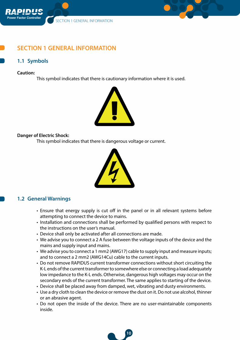
1.1 Symbols
Caution:This symbol indicates that there is cautionary information where it is used.
Danger of Electric Shock:This symbol indicates that there is dangerous voltage or current.
1.2 General Warnings
• Ensure that energy supply is cut off in the panel or in all relevant systems before attempting to connect the device to mains.
• Installation and connections shall be performed by qualified persons with respect to the instructions on the user’s manual.
• Device shall only be activated after all connections are made.• We advise you to connect a 2 A fuse between the voltage inputs of the device and the
mains and supply input and mains.• We advise you to connect a 1 mm2 (AWG17) cable to supply input and measure inputs;
and to connect a 2 mm2 (AWG14Cu) cable to the current inputs. • Do not remove RAPIDUS current transformer connections without short circuiting the
K-L ends of the current transformer to somewhere else or connecting a load adequately low impedance to the K-L ends. Otherwise, dangerous high voltages may occur on the secondary ends of the current transformer. The same applies to starting of the device.
• Device shall be placed away from damped, wet, vibrating and dusty environments.• Use a dry cloth to clean the device or remove the dust on it. Do not use alcohol, thinner
or an abrasive agent. • Do not open the inside of the device. There are no user-maintainable components
inside.
SECTION 1 GENERAL INFORMATION
11
Power Factor Controller
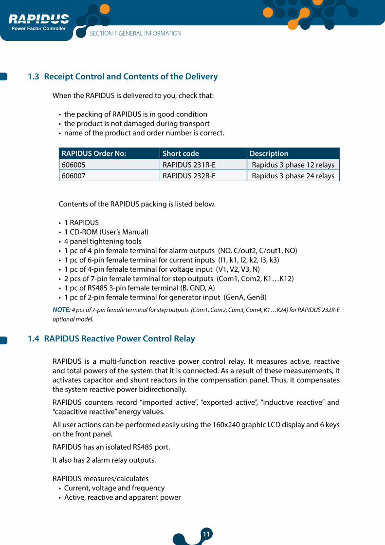
1.3 Receipt Control and Contents of the Delivery
When the RAPIDUS is delivered to you, check that:
• the packing of RAPIDUS is in good condition• the product is not damaged during transport• name of the product and order number is correct.
RAPIDUS Order No: Short code Description606005 RAPIDUS 231R-E Rapidus 3 phase 12 relays606007 RAPIDUS 232R-E Rapidus 3 phase 24 relays
Contents of the RAPIDUS packing is listed below.
• 1 RAPIDUS• 1 CD-ROM (User’s Manual)• 4 panel tightening tools• 1 pc of 4-pin female terminal for alarm outputs (NO, C/out2, C/out1, NO)• 1 pc of 6-pin female terminal for current inputs (I1, k1, I2, k2, I3, k3)• 1 pc of 4-pin female terminal for voltage input (V1, V2, V3, N)• 2 pcs of 7-pin female terminal for step outputs (Com1, Com2, K1…K12)• 1 pc of RS485 3-pin female terminal (B, GND, A)• 1 pc of 2-pin female terminal for generator input (GenA, GenB)
NOTE: 4 pcs of 7-pin female terminal for step outputs (Com1, Com2, Com3, Com4, K1…K24) for RAPIDUS 232R-E optional model.
1.4 RAPIDUS Reactive Power Control Relay
RAPIDUS is a multi-function reactive power control relay. It measures active, reactive and total powers of the system that it is connected. As a result of these measurements, it activates capacitor and shunt reactors in the compensation panel. Thus, it compensates the system reactive power bidirectionally.
RAPIDUS counters record “imported active”, “exported active”, “inductive reactive” and “capacitive reactive” energy values.
All user actions can be performed easily using the 160x240 graphic LCD display and 6 keys on the front panel.
RAPIDUS has an isolated RS485 port.
It also has 2 alarm relay outputs.
RAPIDUS measures/calculates • Current, voltage and frequency• Active, reactive and apparent power
SECTION 1 GENERAL INFORMATION
12
Power Factor Controller
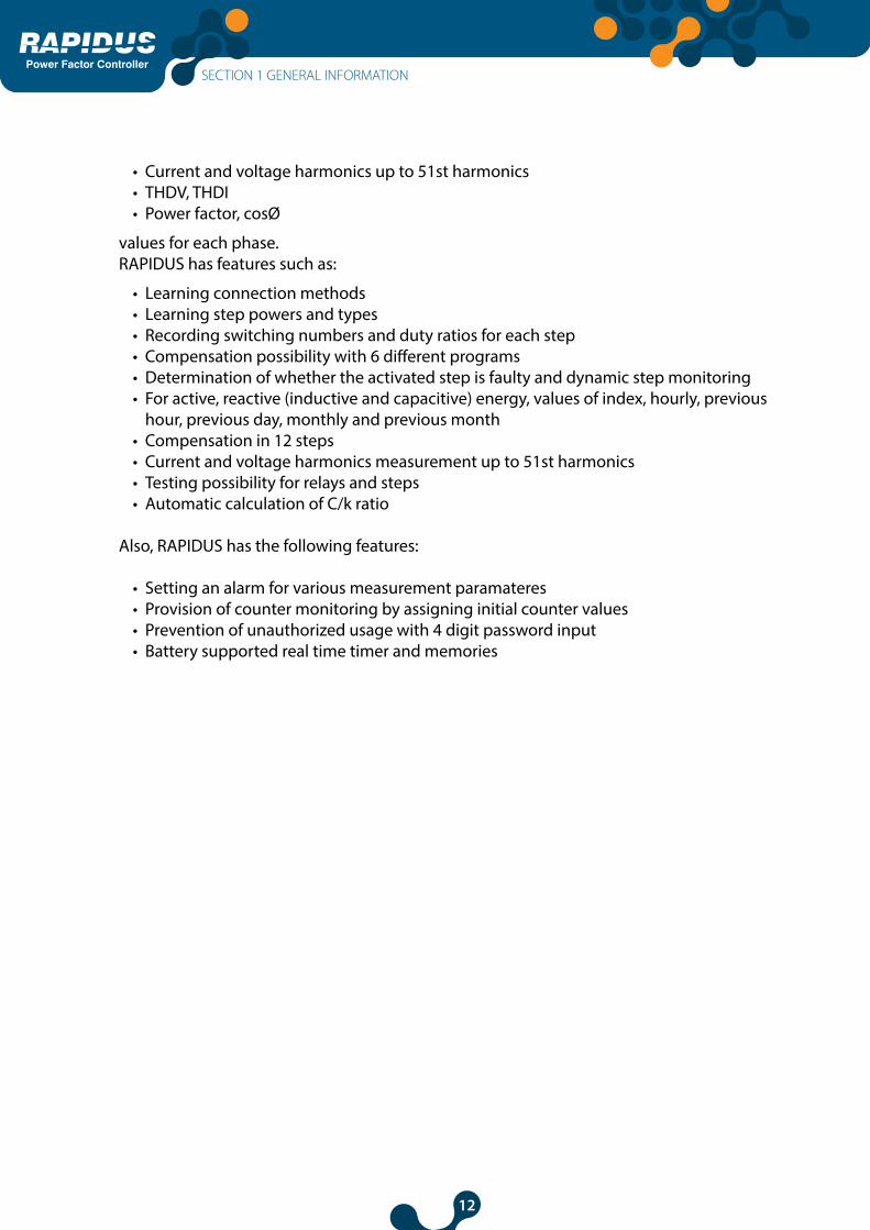
• Current and voltage harmonics up to 51st harmonics• THDV, THDI• Power factor, cosØ
values for each phase.RAPIDUS has features such as:
• Learning connection methods • Learning step powers and types• Recording switching numbers and duty ratios for each step• Compensation possibility with 6 different programs• Determination of whether the activated step is faulty and dynamic step monitoring• For active, reactive (inductive and capacitive) energy, values of index, hourly, previous
hour, previous day, monthly and previous month • Compensation in 12 steps• Current and voltage harmonics measurement up to 51st harmonics• Testing possibility for relays and steps• Automatic calculation of C/k ratio
Also, RAPIDUS has the following features:
• Setting an alarm for various measurement paramateres• Provision of counter monitoring by assigning initial counter values• Prevention of unauthorized usage with 4 digit password input• Battery supported real time timer and memories
SECTION 1 GENERAL INFORMATION

13
Power Factor Controller
1.5 RAPIDUS Front Panel
1
23
456
7
8
18
1617
9 10 11 12 13 14 15
110.0c
1 7 : 2 2V1 2 3
I
1 2
210.0c
310.0c
410.0c
510.0c
610.0c
710.0c
810.0c
910.0c
1010.0c
1110.0c
1210.0c
Settings Measure Comp. Alarms Analysis
P 1326.4 W I 8.9 A
V 257.1 V
1.000 S 1326.4 VA
Q 4.2 VAr
Fig. 1-1 RAPIDUS 231R-E
1- Menus
2- Total Active Power
3- Total Reactive Power
4- Total Apparent Power
5- Number of steps
6- Step power
7- Step type
8- Presence/absence of currents and voltages for voltages
9- Selected compensation mode
10- Alarm status symbol (displayed when an alarm occurred in the system)
11- Temperature alarm status symbol (displayed when an alarm occurred in the system)
12- Alarm relay symbol (This symbol is displayed if 1st and/or 2nd alarm relay is assigned to an alarm and an alarm is present in the system. “1” indicates 1st alarm relay, and “2” indicates 2nd alarm relay on the symbol)
13- Indicates that DCM is active
14- RS485 communication symbol
15- System clock
16- System Cos Ø value
17- Average VLL(line to line) voltages
18- Total Current of Three Phases
SECTION 1 GENERAL INFORMATION

14
Power Factor Controller
1
23
45
6
15
1314
7 8 9 10 11 12
1 7 : 2 2V1 2 3
I
1 2
Settings Measure Comp. Alarms Analysis
P 1326.4 W I 8.9 A
V 257.1 V
1.000 S 1326.4 VA
Q 4.2 VAr
1 2 3 4 5 6
7 8 9 10 11 12
1 2 3 4 5 6
7 8 9 10 11 12
Fig. 1-2 RAPIDUS 232R-E
1- Menus
2- Total Active Power
3- Total Reactive Power
4- Total Apparent Power
5- Number of steps
6- Presence/absence of currents and voltages for voltages
7- Selected compensation mode
8- Alarm status symbol (displayed when an alarm occurred in the system)
9- Temperature alarm status symbol (displayed when an alarm occurred in the system)
10- Alarm relay symbol (This symbol is displayed if 1st and/or 2nd alarm relay is assigned to an alarm and an alarm is present in the system. “1” indicates 1st alarm relay, and “2” indicates 2nd alarm relay on the symbol)
11- RS485 communication symbol
12- System clock
13- System Cos Ø value
14- Average VLL(line to line) voltages
15- Total Current of Three Phases
SECTION 1 GENERAL INFORMATION
15
Power Factor Controller
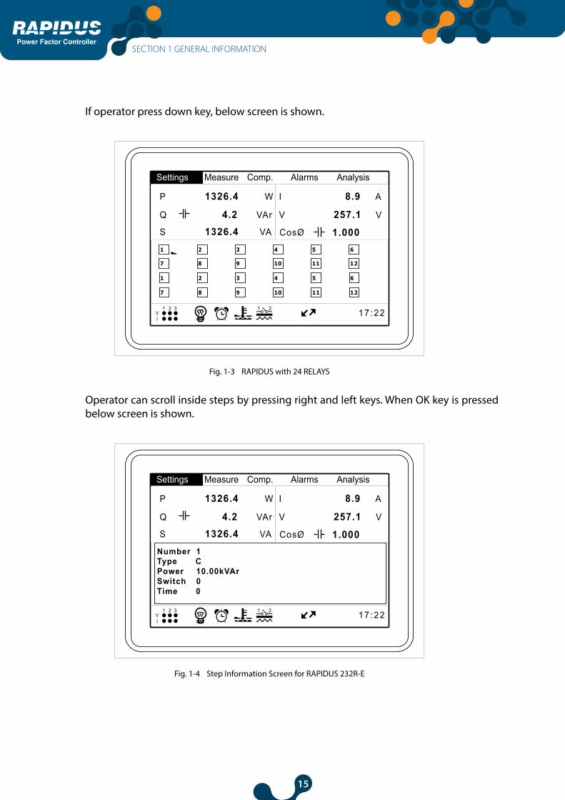
If operator press down key, below screen is shown.
1 7 : 2 2V1 2 3
I
1 2
Settings Measure Comp. Alarms Analysis
P 1326.4 W I 8.9 A
V 257.1 V
1.000 S 1326.4 VA
Q 4.2 VAr
1 2 3 4 5 6
7 8 9 10 11 12
1 2 3 4 5 6
7 8 9 10 11 12
Fig. 1-3 RAPIDUS with 24 RELAYS
Operator can scroll inside steps by pressing right and left keys. When OK key is pressed below screen is shown.
1 7 : 2 2V1 2 3
I
1 2
Settings Measure Comp. Alarms Analysis
P 1326.4 W I 8.9 A
V 257.1 V
1.000 S 1326.4 VA
Q 4.2 VAr
Number 1Type CPower 10.00kVArSwitch 0Time 0
Fig. 1-4 Step Information Screen for RAPIDUS 232R-E
SECTION 1 GENERAL INFORMATION

16
Power Factor Controller
SECTION 2INSTALLATION
Power Factor Controller

17
Power Factor Controller
SECTION 2 INSTALLATION
This section contains information on the installation, cable connections and connection methods of RAPIDUS.
2.1 Preparation for Installation
RAPIDUS that you have purchased may not include all hardware options specified in the installation manual. This is not issue for the electrical installation.
Installation and connections of RAPIDUS shall be performed by qualified persons with respect to the instructions on the user’s manual.
Do not operate the device before making the connections correctly.
2.2 Placing on the panel
RAPIDUS is placed vertically on the empty compartment on the panel.
Fig. 2-1 Placing RAPIDUS on the Panel
After placing RAPIDUS on the panel tightening tool is installed and then secured by tightening its screw.
SECTION 2 INSTALLATION

18
Power Factor Controller
Fig. 2-2 Securing RAPIDUS
RAPIDUS has female terminals with 2.5mm2 and 1.5mm2 screws. Female terminal is removed on its housing on RAPIDUS (removed from the fixed male terminal). Screws on the female terminal are loosened.
Fig. 2-3 Loosening of the Terminal Screws
Make sure that the power is cut off before connecting voltage and current ends to RAPIDUS.
SECTION 2 INSTALLATION

19
Power Factor Controller
Do not remove RAPIDUS current transformer connections without short circuiting the K-L ends of the current transformer to somewhere else. Otherwise, dangerous high voltages may occur on the secondary ends of the current transformer. The same applies to starting of the device.
Cable is placed in the relevant connection hole.
Fig. 2-4 Inserting Cable into the Terminal Block
After the cable is placed, the screws are tightened and the cable is fixed.
Fig. 2-5 Fixing the Cable to the Terminal Block
Terminal is placed on its housing on RAPIDUS.
Consider this warning if RAPIDUS is used with current transformers. Correct operating threshold values of transformers vary as per the type and size of the current transformers used. Please check that the measured current value is higher than the current threshold specified in the user’s manual of current transformer.”
SECTION 2 INSTALLATION

20
Power Factor Controller
2.3 Wiring Diagrams
Aux. Relay Step Outputs 1…6 Step Outputs 7…12 Current Inputs Voltage Inputs
Gen InputRS485
D+
NO
2
NO
1
C22A 2A 2A 2A 2A
L1
L2
L3
N
6A 6A
C1 K1 K7 K8 K9 K10
K11
K12
I3 I2k3 k2 I2 k1 V1 V2 V3 NK2 K3 K4 K5 K6 Com1
Com2
D-
GN
D
Fig. 2-6 RAPIDUS Connection Diagram
2.4 Dimensions
Dimensions are in millimeters.
144
144
7.0
58.0
137
Fig. 2-7 Dimensions
SECTION 2 INSTALLATION

21
Power Factor Controller
SECTION 3MENUS
Power Factor Controller

22
Power Factor Controller
SECTION 3 MENUS
3.1 “First Power-on” Settings
The following page is displayed when RAPIDUS is energized for the “first time” after it is released from the factory
Açılış Ayarları / Startup Settings / настройки Dil / Language EnglishDate 30 August 2013Time 21:24:13CTR 1VTR 1.0Step number 1Start
Fig. 3-1 First Operation Settings
3.1.1 Dil / Lang. / Язык Setting
“Türkçe”, “English” and “Pусский” language options are displayed when you press OK while this tab is selected. User shall select the desired option with up and down arrows and press “OK”. If the language is selected as English, the language settings for all other tabs shall also be English.
Açılış Ayarları / Startup Settings / настройки Dil / Language TürkçeDate 30 August2013Time 21:24:13CTR 1VTR 1.0Step number 1Start
TürkçeEnglishPусский
Fig. 3-2 Dil / Lang./ Язык Setting
SECTION 3 MENUS

23
Power Factor Controller
3.1.2 Date
Date setting of RAPIDUS is performed here. Press OK when this option selected. Highlight day, month or year digits with the right and left arrow keys. Date setting is performed with up and down keys. Date setting is completed by pressing OK.
Açılış Ayarları / Startup Settings / настройки Dil / Language EnglishDate 30 August 2013Time 21:24:13CTR 1VTR 1.0Step number 1Start
Fig. 3-3 Date Setting
Example: To select “August 30th, 2013”:
Date 29 July 20121
Date 30 July 20122
Date 30 July 20123
Date 30 August 20124
Date 30 August 20125
Tarih 30 August 20137
Date 30 August 20136
Fig. 3-4 Date Setting Example
SECTION 3 MENUS

24
Power Factor Controller
3.1.3 Time
Time setting of RAPIDUS is performed here. It is set as described on 3.1.2 Date menu.
3.1.4 Current Transformer Ratio (CTR)
This is the settings tab for entering the current transformer ratio. Current transformer ratio may be selected between 1 and 5000. RAPIDUS Virtual Keyboard shall be displayed when you press OK when this option selected.
Açılış Ayarları / Startup Settings / настройки Dil / Language EnglishDate 30 August2013Time 21:24:13CTR 1VTR 1.0Step number 1Start
1
Low limit1High limit5000
1 2 3 4
5 6 7 8
9 0 . -
ok clr
Fig. 3-5 Current Transformer Ratio
Use arrow keys to navigate between the digits and OK key to enter the selected digit as
a value. If you enter an incorrect number, select box and press OK. Thus, the incorrect number entered shall be deleted.
Current transformer ratio shall be entered correctly to ensure that RAPIDUS performs a correct compensation.
SECTION 3 MENUS

25
Power Factor Controller
Example:
1 2 3 4
1 2
5 6Açılış Ayarları / Startup Settings / настройки Dil / Language EnglishDate 30 August 2013Time 21:24:13CTR 20VTR 1.0Step number 1Start
1
Low limit1High limit5000
1 2 3 4
5 6 7 8
9 0 . -
ok clr
1
Low limit1High limit5000
1 2 3 4
5 6 7 8
9 0 . -
ok clr
20
Low limit1High limit5000
1 2 3 4
5 6 7 8
9 0 . -
ok clr
20
Low limit1High limit5000
1 2 3 4
5 6 7 8
9 0 . -
ok clr
2
Low limit1High limit5000
1 2 3 4
5 6 7 8
9 0 . -
ok clr
2
Low limit1High limit5000
1 2 3 4
5 6 7 8
9 0 . -
ok clr
Fig. 3-6 Entering a Value in Virtual Keyboard
SECTION 3 MENUS
26
Power Factor Controller
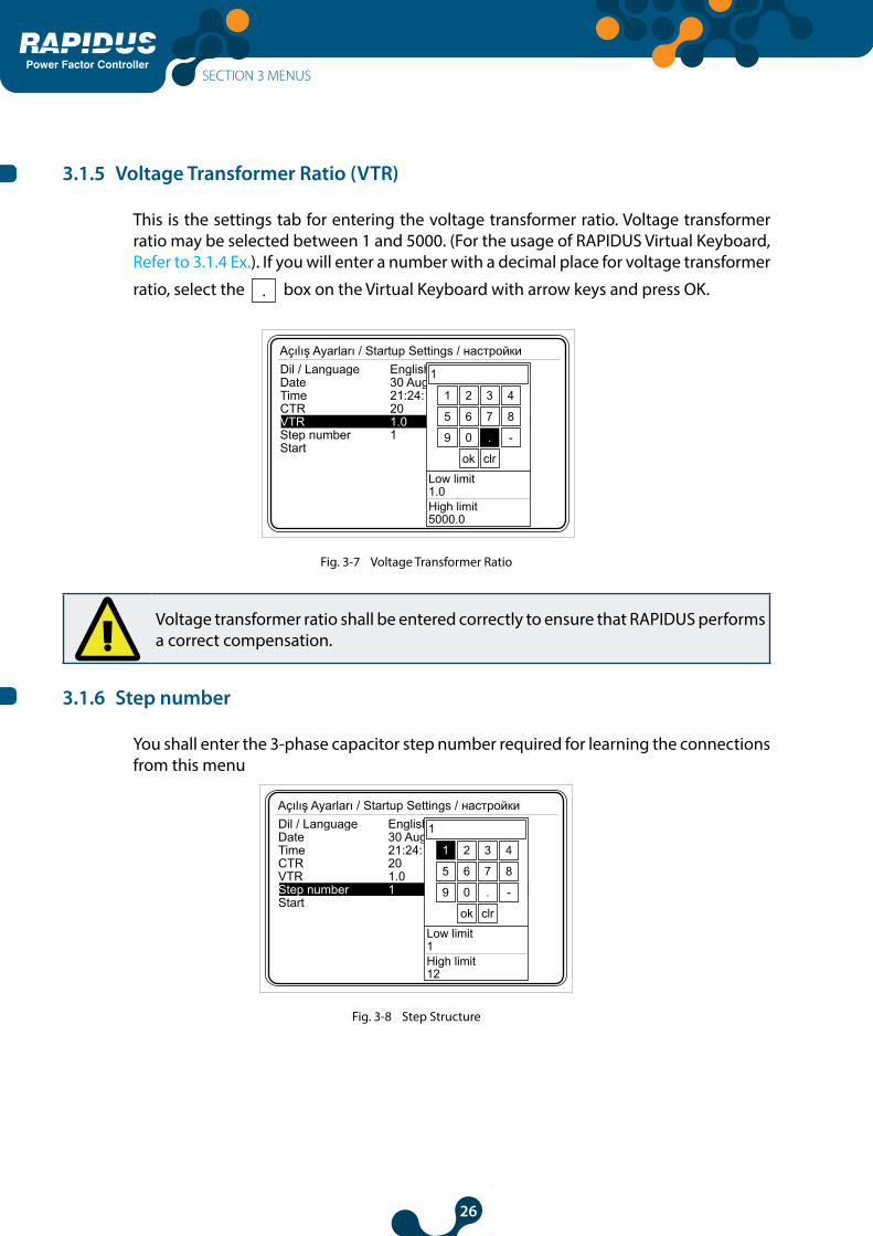
3.1.5 Voltage Transformer Ratio (VTR)
This is the settings tab for entering the voltage transformer ratio. Voltage transformer ratio may be selected between 1 and 5000. (For the usage of RAPIDUS Virtual Keyboard, Refer to 3.1.4 Ex.). If you will enter a number with a decimal place for voltage transformer
ratio, select the box on the Virtual Keyboard with arrow keys and press OK.
Açılış Ayarları / Startup Settings / настройки Dil / Language EnglishDate 30 August 2013Time 21:24:13CTR 20VTR 1.0Step number 1Start
1
Low limit1.0High limit5000.0
1 2 3 4
5 6 7 8
9 0 . -
ok clr
Fig. 3-7 Voltage Transformer Ratio
Voltage transformer ratio shall be entered correctly to ensure that RAPIDUS performs a correct compensation.
3.1.6 Step number
You shall enter the 3-phase capacitor step number required for learning the connections from this menu
Açılış Ayarları / Startup Settings / настройки Dil / Language EnglishDate 30 August 2013Time 21:24:13CTR 20VTR 1.0Step number 1Start
1
Low limit1High limit12
1 2 3 4
5 6 7 8
9 0 . -
ok clr
Fig. 3-8 Step Structure
SECTION 3 MENUS
27
Power Factor Controller
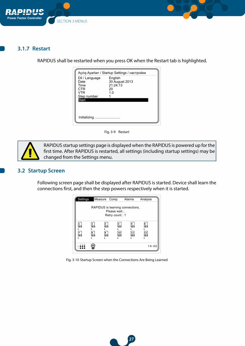
3.1.7 Restart
RAPIDUS shall be restarted when you press OK when the Restart tab is highlighted.
Açılış Ayarları / Startup Settings / настройки Dil / Language EnglishDate 30 August 2013Time 21:24:13CTR 20VTR 1.0Step number 1Start
Initializing ..........................
Fig. 3-9 Restart
RAPIDUS startup settings page is displayed when the RAPIDUS is powered up for the first time. After RAPIDUS is restarted, all settings (including startup settings) may be changed from the Settings menu.
3.2 Startup Screen
Following screen page shall be displayed after RAPIDUS is started. Device shall learn the connections first, and then the step powers respectively when it is started.
Qind/P 0 %
Qcap/P0 5c
0 %
CosØ1
CosØ2
CosØ3 1.0001.0001.000
110.0c
1 4 : 4 0V1 2 3
I
1 2
210.0c
310.0c
410.0c
510.0c
610.0c
710.0c
810.0c
910.0c
1010.0c
1110.0c
1210.0c
Settings Measure Comp. Alarms Analysis
RAPIDUS is learning connections.Please wait...
Retry count : 1
Fig. 3-10 Startup Screen when the Connections Are Being Learned
SECTION 3 MENUS

28
Power Factor Controller
110.0c
1 4 : 4 0V1 2 3
I
1 2
210.0c
310.0c
410.0c
510.0c
610.0c
710.0c
810.0c
910.0c
1010.0c
1110.0c
1210.0c
Settings Measure Comp. Alarms Analysis
P 1326.4 W I 8.9 A
V 257.1 V
1.000 S 1326.4 VA
Q 4.2 VAr
Fig. 3-11 Startup Screen after the Connections Are Learned
Multi selection menus are displayed on the upper part of the screen.
Upper left corner is used for displaying cosØ values of each phase.
Upper right corner displays capacitive and inductive ratios.
Status of the phases and compensation mode are displayed on the lower left corner, and system clock is displayed on the lower right corner.
User may navigate on the menus on the upper side of the screen using left and right arrow keys, and access the contents of the menus by pressing OK.
3.2.1 Settings
RAPIDUS settings are made from this menu. If you press OK when the settings tab is highlighted, sub-menus shall be displayed as shown in Fig. 3-12. Sub-menus below are available under the settings tab.
• Quick setup• Setup• Date/Time• System info• Password• Restart• Default Settings
110.0c
1 4 : 4 0V1 2 3
I
1 2
210.0c
310.0c
410.0c
510.0c
610.0c
710.0c
810.0c
910.0c
1010.0c
1110.0c
1210.0c
Settings Measure Comp. Alarms Analysis
P 1326.4 W I 8.9 A
V 257.1 V
1.000 S 1326.4 VA
Q 4.2 VAr
Quick setup
Date / TimeSetup
System infoPasswordRestartDefault settings
Fig. 3-12 Settings Menu
SECTION 3 MENUS
29
Power Factor Controller
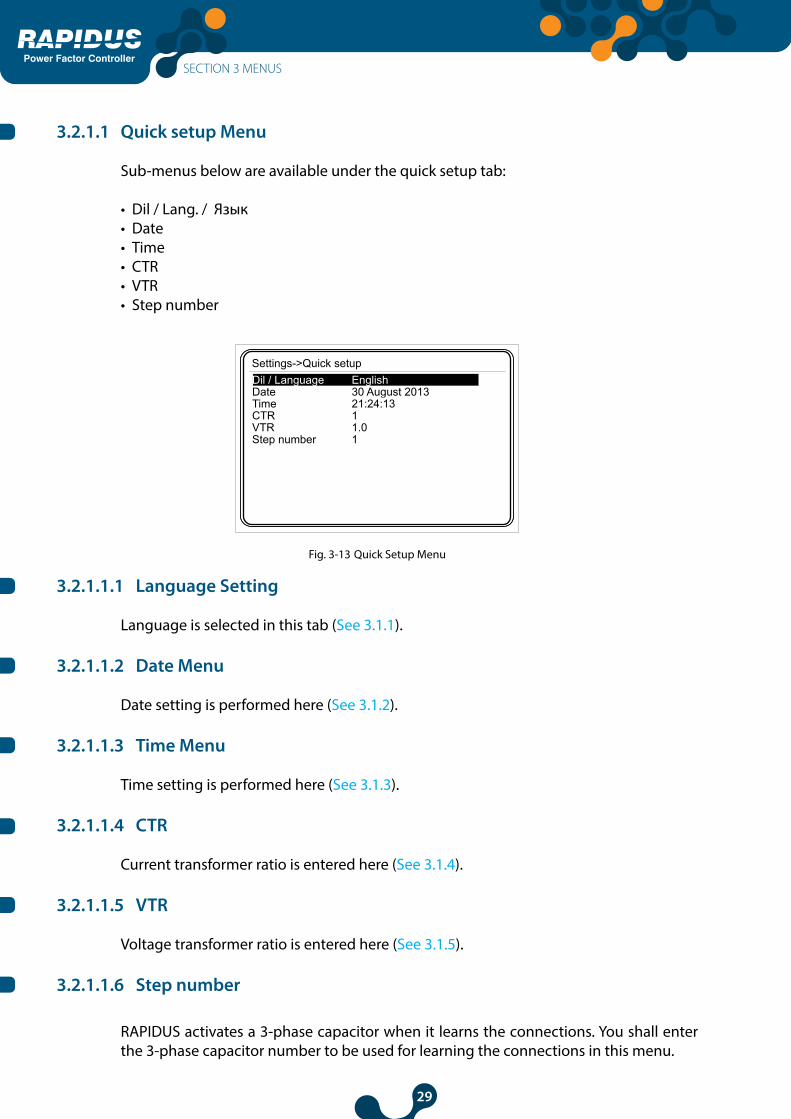
3.2.1.1 Quick setup Menu
Sub-menus below are available under the quick setup tab:
• Dil / Lang. / Язык• Date • Time• CTR• VTR• Step number
Settings->Quick setupDil / Language EnglishDate 30 August 2013Time 21:24:13CTR 1VTR 1.0Step number 1
Fig. 3-13 Quick Setup Menu
3.2.1.1.1 Language Setting
Language is selected in this tab (See 3.1.1).
3.2.1.1.2 Date Menu
Date setting is performed here (See 3.1.2).
3.2.1.1.3 Time Menu
Time setting is performed here (See 3.1.3).
3.2.1.1.4 CTR
Current transformer ratio is entered here (See 3.1.4).
3.2.1.1.5 VTR
Voltage transformer ratio is entered here (See 3.1.5).
3.2.1.1.6 Step number
RAPIDUS activates a 3-phase capacitor when it learns the connections. You shall enter the 3-phase capacitor number to be used for learning the connections in this menu.
SECTION 3 MENUS

30
Power Factor Controller
In order to store the new settings in the nonvolatile memory, you shall return back to the “Startup Screen” from the tab where the changes are made using X key. Press OK when “Settings changed. Save?” message is displayed on the Screen. Thus, the changes are saved and stored in the nonvolatile memory. The changes shall not be saved and stored in the nonvolatile memory if X key is pressed.
Settings changed.Save?
OKX
Fig. 3-14 RAPIDUS Prompt for saving
Changes shall be saved on the nonvolatile memory if you press OK when “Settings changed. Save?” message is displayed on the Screen. The changes shall not be saved and stored in the nonvolatile memory if X key is pressed.
3.2.1.2 Setup Menu
Sub-menus below are available under the setup tab:
• Network• Step• Compensation• Learning• Aux. input• Device• Energy• Communication• Alarm• Clear
User may navigate inside the menu using up and down arrow keys, and access the contents of the menus (sub-menus under the setup menu) by pressing OK.
SECTION 3 MENUS
31
Power Factor Controller
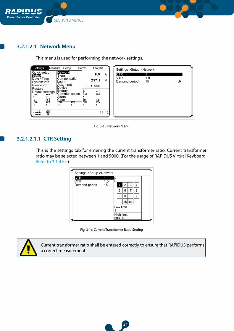
3.2.1.2.1 Network Menu
This menu is used for performing the network settings.
110.0c
1 4 : 4 0V1 2 3
I
1 2
210.0c
310.0c
410.0c
510.0c
610.0c
710.0c
810.0c
910.0c
1010.0c
1110.0c
1210.0c
Settings Measure Comp. Alarms Analysis Settings->Setup->NetworkCTR 1VTR 1.0Demand period 15 dk
P 1326.4 W I 8.9 A
V 257.1 V
1.000 S 1326.4 VA
Q 4.2 VAr
Quick setup
Date / TimeSetup
System infoPasswordRestartDefault settings
ClearAlarmCommunicationEnergyDeviceAux. inputLearnCompensationStepsNetwork
Fig. 3-15 Network Menu
3.2.1.2.1.1 CTR Setting
This is the settings tab for entering the current transformer ratio. Current transformer ratio may be selected between 1 and 5000. (For the usage of RAPIDUS Virtual Keyboard, Refer to 3.1.4 Ex.)
Settings->Setup->NetworkCTR 1VTR 1.0Demand period 15 dk
1
Low limit1High limit5000.0
1 2 3 4
5 6 7 8
9 0 . -
ok clr
Fig. 3-16 Current Transformer Ratio Setting
Current transformer ratio shall be entered correctly to ensure that RAPIDUS performs a correct measurement.
SECTION 3 MENUS

32
Power Factor Controller
3.2.1.2.1.2 VTR Setting
This is the settings tab for entering the voltage transformer ratio. Voltage transformer ratio may be selected between 1.0 and 5000.0. (For the usage of RAPIDUS Virtual Keyboard, Refer to 3.1.4 Ex.). If you will enter a number with a decimal place for voltage transformer
ratio, select the box on the Virtual Keyboard with arrow keys and press OK.
Voltage transformer ratio shall be entered correctly to ensure that RAPIDUS performs a correct measurement.
Settings->Setup->NetworkCTR 1VTR 1.0Demand period 15 dk
1.0
Low limit1.0High limit5000.0
1 2 3 4
5 6 7 8
9 0 . -
ok clr
Fig. 3-17 Voltage Transformer Ratio Setting
3.2.1.2.1.3 Demand period setting
This is the settings tab for entering the demand period. Demand period may be selected between 1 and 60 minutes. (For the usage of RAPIDUS Virtual Keyboard, Refer to 3.1.4 Ex.)
Settings->Setup->NetworkCTR 1VTR 1.0Demand period 15 dk
15
Low limit1High limit60
1 2 3 4
5 6 7 8
9 0 . -
ok clr
Fig. 3-18 Demand Period Setting
SECTION 3 MENUS

33
Power Factor Controller
3.2.1.2.2 Step Menu
This menu includes the sub-menus below:
• Ent. power• Ent. type• Predefined• Other
110.0c
1 4 : 4 0V1 2 3
I
1 2
210.0c
310.0c
410.0c
510.0c
610.0c
710.0c
810.0c
910.0c
1010.0c
1110.0c
1210.0c
Settings Measure Comp. Alarms Analysis
P 1326.4 W I 8.9 A
V 257.1 V
1.000 S 1326.4 VA
Q 4.2 VAr
Quick setup
Date / TimeSetup
System infoPasswordRestartDefault settings
Ent. power
PredefinedEnt. type
Other
ClearAlarmCommunicationEnergyDeviceAux. inputLearnCompensationStepsNetwork
NOTE: There are two Ent. Power sub menus for RAPIDUS 232R-E. Operator can assign 1st, 2nd, … and 12th step powers in “Ent. Power 1” Submenu. Operator can assign 13th, 14th, …and 24th step powers in “Ent. Power 1” Submenu.
Fig. 3-19 Step Menu
3.2.1.2.2.1 Ent. Power Menu
Step powers learned by RAPIDUS are indicated in this menu. Also, user may enter/change all step powers manually using this menu.
Settings->Setup->Steps->Ent. powerStep 1 10.00Step 2 10.00Step 3 10.00Step4 10.00Step 5 10.00Step 6 10.00Step 7 10.00Step 8 10.00Step 9 10.00Step 10 10.00Step 11 10.00Step 12 10.00
10.00
Low limit0.00High limit1000.00
1 2 3 4
5 6 7 8
9 0 . -
ok clr
Fig. 3-20 Ent. Power Menu
3.2.1.2.2.2 Ent. Type Menu
Step types learned by RAPIDUS are indicated or user may set the step powers in this menu.
“C” is for 3-phase capacitor, “C1” is for single-phase capacitor connected to R phase, “C2” is for single-phase capacitor connected to S phase,
SECTION 3 MENUS

34
Power Factor Controller
“C3” is for single-phase capacitor connected to TR phase, “L” is for 3-phase shunt reactor, “L1” is for single-phase shunt reactor connected to R phase, “L2” is for single-phase shunt reactor connected to S phase, “L3” is for single-phase shunt reactor connected to T phase,“C1-2” is for two-phase capacitor connected to R and S phases, “C2-3” is for two-phase capacitor connected to S and T phases,“C3-1” is for two-phase capacitor connected to R and T phases,
You shall check whether RAPIDUS has learned step types correctly from this menu. If RAPIDUS has not learned step types correctly, perform one of the following. - RAPIDUS is commanded to learn the steps again (See 3.2.3.6 Learn Steps Menu) - Step types are corrected manually. (See Fig. 3-21)
Settings->Setup->Steps->Ent. typeStep 1 CStep 2 CStep 3 CStep 4 CStep 5 CStep 6 CStep 7 CStep 8 CStep 9 CStep 10 CStep 11 CStep 12 C
CLC1C2C3L1L2L3C1-2C2-3C3-1L1-2
NOTE: There are two “Ent. Type” submenus for RAPIDUS 232R-E. Operator can assign 1st, 2nd, … and 12th step powers in “Ent. Type 1” Submenu. Operator can assign 13th, 14th, …and 24th step powers in “Ent. Type 1” Submenu.
Fig. 3-21 Ent. Type Menu
3.2.1.2.2.3 Predefined Menu
Step settings may be performed as per a predefined structure. Relevant settings are performed on the following three sub-menus specified below for predefined menu.
Settings->Setup->Steps->PredefinedStructure 1 - 1 - 1 - 1Power 10.00Count 12
1 - 1 - 1 - 11 - 1 - 2 - 21 - 2 - 2 - 41 - 2 - 3 - 31 - 2 - 4 - 41 - 1 - 2 - 41 - 2 - 3 - 41 - 2 - 4 - 81 - 1 - 2 - 3
Fig. 3-22 Predefined Menu
SECTION 3 MENUS

35
Power Factor Controller
3.2.1.2.2.3.1 Structure Menu
Following options are available on the step structure
• 1.1.1.1.1.1.1.....• 1.1.2.2.2.2.2..... • 1.2.2.4.4.4.4.....• 1.2.3.3.3.3.3.....• 1.2.4.4.4.4.4..... • 1.1.2.4.4.4.4..... • 1.2.3.4.4.4.4.....• 1.2.4.8.8.8.8..... • 1.1.2.3.3.3.3.....
3.2.1.2.2.3.2 Power Menu
Power of the first step is entered in kVAr. RAPIDUS calculates the step powers after the first step as per the selected template selected in the structure menu.
3.2.1.2.2.3.3 Number Menu
Number of steps in the template selected in structure is set in this menu.
Example:
Assume that 1.2.4.8 is selected as the structure, and 10 kVAR is entered as the power (RAPIDUS takes this value as the 1st step power), and 8 is entered as the number. Then, step powers shall be as follows:
1st step: 10 kVAR2nd step: 20 kVAR3rd step: 40 kVAR4th step: 80 kVAR5th step: 80 kVAR6th step: 80 kVAR7th step: 80 kVAR8th step: 80 kVAR
SECTION 3 MENUS
36
Power Factor Controller
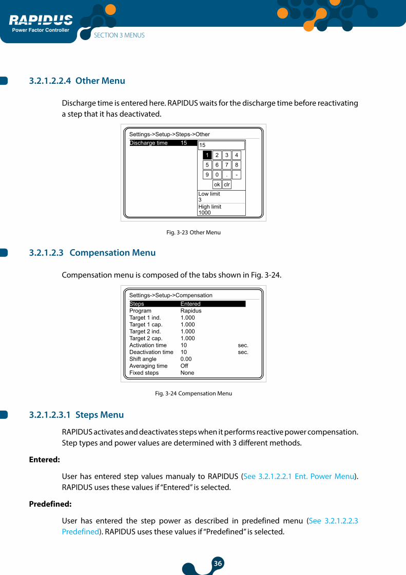
3.2.1.2.2.4 Other Menu
Discharge time is entered here. RAPIDUS waits for the discharge time before reactivating a step that it has deactivated.
Settings->Setup->Steps->OtherDischarge time 15 15
Low limit3High limit1000
1 2 3 4
5 6 7 8
9 0 . -
ok clr
Fig. 3-23 Other Menu
3.2.1.2.3 Compensation Menu
Compensation menu is composed of the tabs shown in Fig. 3-24.
Settings->Setup->CompensationSteps EnteredProgram RapidusTarget 1 ind. 1.000Target 1 cap. 1.000Target 2 ind. 1.000Target 2 cap. 1.000Activation time 10 sec.Deactivation time 10 sec.Shift angle 0.00Averaging time OffFixed steps None
Fig. 3-24 Compensation Menu
3.2.1.2.3.1 Steps Menu
RAPIDUS activates and deactivates steps when it performs reactive power compensation. Step types and power values are determined with 3 different methods.
Entered:
User has entered step values manualy to RAPIDUS (See 3.2.1.2.2.1 Ent. Power Menu). RAPIDUS uses these values if “Entered” is selected.
Predefined:
User has entered the step power as described in predefined menu (See 3.2.1.2.2.3 Predefined). RAPIDUS uses these values if “Predefined” is selected.
SECTION 3 MENUS
37
Power Factor Controller
DCM (Dynamic Capacitor Monitoring):
RAPIDUS follows the step values dynamically. DCM algorithm runs on the background continuously.
When user selects “DCM” option on the “Steps” tab, RAPIDUS uses the step values that it dynamically monitors and updates for compensation.
NOT: DCM(Dynamic Capacitor Monitoring) feature isn’t avaliable in for RAPIDUS 232R-E optional model.
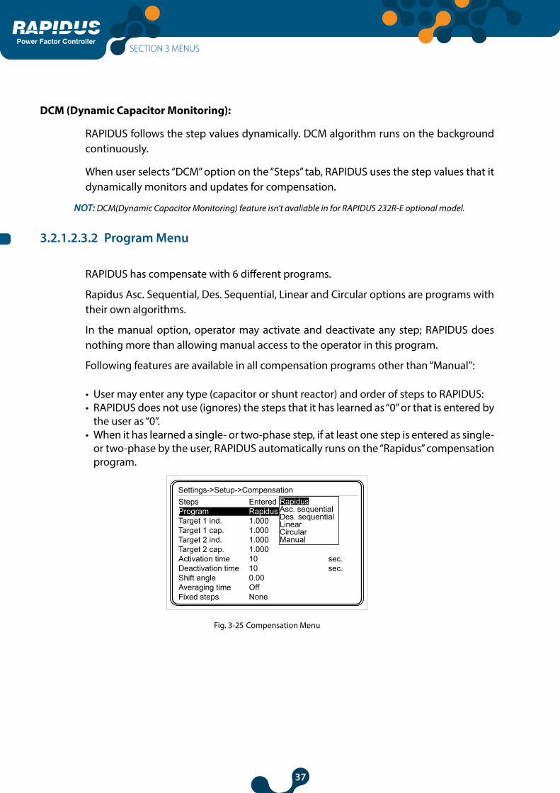
3.2.1.2.3.2 Program Menu
RAPIDUS has compensate with 6 different programs.
Rapidus Asc. Sequential, Des. Sequential, Linear and Circular options are programs with their own algorithms.
In the manual option, operator may activate and deactivate any step; RAPIDUS does nothing more than allowing manual access to the operator in this program.
Following features are available in all compensation programs other than “Manual”:
• User may enter any type (capacitor or shunt reactor) and order of steps to RAPIDUS:• RAPIDUS does not use (ignores) the steps that it has learned as “0” or that is entered by
the user as “0”.• When it has learned a single- or two-phase step, if at least one step is entered as single-
or two-phase by the user, RAPIDUS automatically runs on the “Rapidus” compensation program.
Settings->Setup->CompensationSteps EnteredProgram RapidusTarget 1 ind. 1.000Target 1 cap. 1.000Target 2 ind. 1.000Target 2 cap. 1.000Activation time 10 sec.Deactivation time 10 sec.Shift angle 0.00Averaging time OffFixed steps None
RapidusAsc. sequentialDes. sequentialLinearCircularManual
Fig. 3-25 Compensation Menu
SECTION 3 MENUS

38
Power Factor Controller
3.2.1.2.3.2.1 Rapidus Program
“Rapidus” option is the only compensation program that allows single- or two-phase capacitors and/or single- or two-phase shunt reactor (other than “Manual”)
The compensation program selected in the default settings (factory settings) of RAPIDUS is the “Rapidus” option. It activates the step combination closest to the measured demand.
B C C C C
A
C
Demand
CosPhi = 0.950 (Target inductive)
CosPhi = 0.900 (Target capacitive)
CosPhi = 1.000
Fig. 3-26 RAPIDUS Mode Compensation Steps
On the diagram above:
A: Reactive power interval corresponding to the measured CosØ values.
B: Limit value decided for compensation by RAPIDUS (calculated as per automatic C/K ratio).
C: Reactive power value to be compensated.
When the system is in interval A, RAPIDUS does not compensate. When the system is in this interval, activation and deactivation counters of RAPIDUS are not active.
RAPIDUS starts to activate a step after an “activation time” (See 3.2.1.2.3.7 Activation time) when the system reactive power requirement reaches over B point.
Similarly, RAPIDUS starts to deactivate a step after a “deactivation time” (See 3.2.1.2.3.8 Deactivation time) when the system reactive power requirement is decreased under B point.
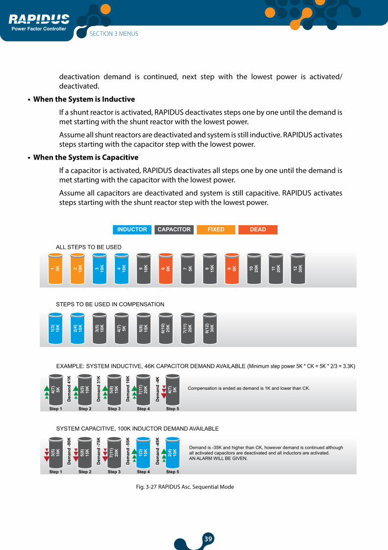
3.2.1.2.3.2.2 Ascending Sequential program
All steps (capacitor or reactor) shall have 3 phases in ascending sequential program.
Step activation and deactivation operations are performed by starting from the step with the lowest power (ascending sequential). When activation/deactivation is required, only one step is activated/deactivated. Then reactive power is calculated again. If activation/
SECTION 3 MENUS
39
Power Factor Controller
deactivation demand is continued, next step with the lowest power is activated/deactivated.
• When the System is Inductive
If a shunt reactor is activated, RAPIDUS deactivates steps one by one until the demand is met starting with the shunt reactor with the lowest power.
Assume all shunt reactors are deactivated and system is still inductive. RAPIDUS activates steps starting with the capacitor step with the lowest power.
• When the System is Capacitive
If a capacitor is activated, RAPIDUS deactivates all steps one by one until the demand is met starting with the capacitor with the lowest power.
Assume all capacitors are deactivated and system is still capacitive. RAPIDUS activates steps starting with the shunt reactor step with the lowest power.
ALL STEPS TO BE USED
STEPS TO BE USED IN COMPENSATION
EXAMPLE: SYSTEM INDUCTIVE, 46K CAPACITOR DEMAND AVAILABLE (Minimum step power 5K * CK = 5K * 2/3 = 3.3K)
SYSTEM CAPACITIVE, 100K INDUCTOR DEMAND AVAILABLE
Compensation is ended as demand is 1K and lower than CK.
Demand is -35K and higher than CK, however demand is continued although all activated capacitors are deactivated and all inductors are activated. AN ALARM WILL BE GIVEN.
INDUCTOR CAPACITOR FIXED DEAD
1 5K4(
7) 5K
Dem
and
41K
Step 1 Step 2 Step 3 Step 4 Step 5
Dem
and
31K
Dem
and
16K
Dem
and
-4K
3(5)
10K
5(8)
15K
7(11
)20
K
4(7) 5K
6(10
)25
K
7(11
)20
K
8(12
)30
K
2 10K 3 10K 4 10K 5 10K
1(3)
10K
2(4)
10K
3(5)
10K
4(7) 5K 5(8)
15K
6 0K 7 5K 8 15K 9 0K 10 25K
11 20K
12 30K
3(5)
10K
Dem
and
-90K
Step 1 Step 2 Step 3 Step 4 Step 5
Dem
and
-75K
Dem
and
-55K
Dem
and
-45K
5(8)
15K
7(11
)20
K
1(3)
10K
2(4)
10K
Fig. 3-27 RAPIDUS Asc. Sequential Mode
SECTION 3 MENUS

40
Power Factor Controller
3.2.1.2.3.2.3 Descending Sequential Mode
All steps (capacitor or reactor) shall have 3 phases in descending sequential program.
RAPIDUS performs activation/deactivation operation starting with the step closest to the demand. When activation/deactivation is required, only one step is activated/deactivated. Then reactive power is calculated again. If activation/deactivation demand is continued, next step closest to the demand is activated/deactivated.
• If the System is Inductive:
If a shunt reactor is activated, steps are deactivated one by one until the demand is met starting with the shunt reactor closest to the demand.
If system is still inductive although all shunt reactors are deactivated, and there are capacitor steps that are not active, steps are activated one by one until the demand is met starting with the capacitor step closest to the demand.
• If the System is Capacitive:
If a capacitor is activated, steps are deactivated one by one until the demand is met starting with the capacitor closest to the demand.
If system is still capacitive although all capacitors are deactivated, and there are shunt reactor steps that are not active, steps are activated one by one until the demand is met starting with the shunt reactor step closest to the demand.
SECTION 3 MENUS

41
Power Factor Controller
ALL STEPS TO BE USED
STEPS TO BE USED IN COMPENSATION
Example: Demand 46K (inductive) (Minimum step power 5K * CK = 5K * 2/3 = 3.3K)
Demand 100K (Capacitive)
Compensation is ended as demand is 1K and lower than CK.
Demand is -35K and higher than CK, however demand is continued although all activated capacitors are deactivated and all inductors are activated. AN ALARM WILL BE GIVEN.
INDUCTOR CAPACITOR FIXED DEAD
1 5K8(
12)
30K
Dem
and
16K
Step 1 Step 2 Step 3
Dem
and
6K
Dem
and
1K
3(5)
10K
5(8)
15K
6(10
)25
K
7(11
)20
K
8(12
)30
K
2 10K 3 10K 4 10K 5 10K
1(3)
10K
2(4)
10K
3(5)
10K
4(7) 5K 5(8)
15K
6 0K 7 5K 8 15K 9 0K 10 25K
11 20K
12 30K
8(12
)30
K
Dem
and
-70K
Step 1 Step 2 Step 3 Step 4 Step 5
Dem
and
-60K
Dem
and
-55K
Dem
and
-45K
3(5)
10K
5(8)
15K
1(3)
10K
2(4)
10K
Fig. 3-28 RAPIDUS Des. Sequential Mode
SECTION 3 MENUS

42
Power Factor Controller
3.2.1.2.3.2.4 Linear Mode
All steps (capacitor or reactor) shall have 3 phases in linear program.
Linear program is used in panels with the step structure 1.1.1.1.
The step activated first is deactivated last in linear program.
• If the System is Inductive:
If there are shunt reactors activated, the number of shunt reactors that will the demand shall be deactivated. If the system is still inductive although all shunt reactors are deactivated, the number of capacitors required shall be activated.
• If the System is Capacitive:
If there are capacitors activated, the number of capacitors that will the demand shall be deactivated. If the system is still capacitive although all capacitors are deactivated, the number of shunt reactors required shall be activated.
SECTION 3 MENUS

43
Power Factor Controller
ALL STEPS TO BE USED
STEPS TO BE USED IN COMPENSATION
Example: SYSTEM INDUCTIVE, 46K CAPACITOR DEMAND AVAILABLE (Minimum step power 10K * CK = 10K * 2/3 = 6.7K)
SYSTEM CAPACITIVE, 20K INDUCTOR DEMAND AVAILABLE
Compensation is ended as demand is -4K and lower than CK.
Compensation is ended as demand is 0K and lower than CK.
INDUCTOR CAPACITOR FIXED DEAD
1 10K
3(5)
10K
Step 1
4(7)
10K
5(8)
10K
6(10
)10
K
7(11
)10
K
6(10
)10
K
7(11
)10
K
8(12
)10
K
2 10K 3 10K 4 10K 5 10K
1(3)
10K
2(4)
10K
3(5)
10K
4(7)
10K
5(8)
10K
6 0K 7 10K 8 10K 9 0K 10 10K
11 10K
12 10K
7(11
)10
K
Step 1
6(10
)10
K
SYSTEM CAPACITIVE, 40K INDUCTOR DEMAND AVAILABLE
Compensation is ended as demand is 0K and lower than CK.
5(8)
10K
Step 1
4(7)
10K
3(5)
10K
1(3)
10K
SYSTEM CAPACITIVE, 20K INDUCTOR DEMAND AVAILABLE
Compensation Demand is continued as demand is -10K and higher than CK. However, there are no inductors to activate nor capacitors to deactivate. AN ALARM WILL BE GIVEN.
5(8)
10K
Step 1
Fig. 3-29 RAPIDUS Linear Mode
SECTION 3 MENUS

44
Power Factor Controller
3.2.1.2.3.2.5 Circular Mode
All steps (capacitor or reactor) shall have 3 phases in circular program.
Circular program is used in panels with the step structure 1.1.1.1.
The step activated first is deactivated first in circular program.
• If the system is inductive:
If there are shunt reactors activated, the number of shunt reactors that will the demand shall be deactivated. If the system is still inductive although all shunt reactors are deactivated, the number of capacitors required shall be activated.
• If the system is capacitive:
If there are capacitors activated, the number of capacitors that will the demand shall be deactivated. If the demand is resumed although all capacitors are deactivated, the number of shunt reactors required shall be activated.
SECTION 3 MENUS

45
Power Factor Controller
ALL STEPS TO BE USED
STEPS TO BE USED IN COMPENSATION
Example: SYSTEM INDUCTIVE, 46K CAPACITOR DEMAND AVAILABLE (Minimum step power 10K * CK = 10K * 2/3 = 6.7K)
SYSTEM CAPACITIVE, 30K INDUCTOR DEMAND AVAILABLE
Compensation is ended as demand is -4K and lower than CK.
Compensation is ended as demand is 0K and lower than CK.
INDUCTOR CAPACITOR FIXED DEAD
1 10K
3(5)
10K
Step 1
4(7)
10K
5(8)
10K
6(10
)10
K
7(11
)10
K
6(10
)10
K
7(11
)10
K
8(12
)10
K
2 10K 3 10K 4 10K 5 10K
1(3)
10K
2(4)
10K
3(5)
10K
4(7)
10K
5(8)
10K
6 0K 7 10K 8 10K 9 0K 10 10K
11 10K
12 10K
3(5)
10K
Step 1
4(7)
10K
5(8)
10K
SYSTEM INDUCTIVE, 20K CAPACITOR DEMAND AVAILABLE
Compensation is ended as demand is 0K and lower than CK.
8(12
)10
K
Step 1
3(5)
10K
SYSTEM CAPACITIVE, 60K INDUCTOR DEMAND AVAILABLE
Compensation is ended as demand is 0K and lower than CK.
6(10
)10
K
Step 1
7(11
)10
K
8(12
)10
K
3(5)
10K
1(3)
10K
2(4)
10K
SYSTEM INDUCTIVE, 90K CAPACITOR DEMAND AVAILABLE
Demand is -10K, however, there are no inductors to activate nor capacitors to deactivate although the demand is continued. AN ALARM WILL BE GIVEN.
1(3)
10K
Step 1
2(4)
10K
4(7)
10K
5(8)
10K
6(10
)10
K
7(11
)10
K
8(12
)10
K
3(5)
10K
Fig. 3-30 RAPIDUS Circular Mode
SECTION 3 MENUS
46
Power Factor Controller
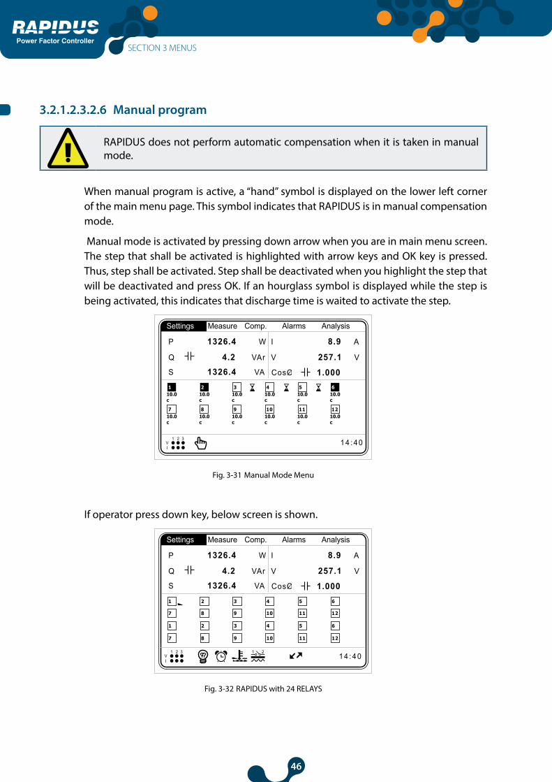
3.2.1.2.3.2.6 Manual program
RAPIDUS does not perform automatic compensation when it is taken in manual mode.
When manual program is active, a “hand” symbol is displayed on the lower left corner of the main menu page. This symbol indicates that RAPIDUS is in manual compensation mode.
Manual mode is activated by pressing down arrow when you are in main menu screen. The step that shall be activated is highlighted with arrow keys and OK key is pressed. Thus, step shall be activated. Step shall be deactivated when you highlight the step that will be deactivated and press OK. If an hourglass symbol is displayed while the step is being activated, this indicates that discharge time is waited to activate the step.
10.0c
1 4 : 4 0V1 2 3
I
1 2
10.0c
10.0c
10.0c
10.0c
10.0c
710.0c
810.0c
910.0c
1010.0c
1110.0c
1210.0c
Settings Measure Comp. Alarms Analysis
1 2 3 4 5 6
P 1326.4 W I 8.9 A
V 257.1 V
1.000 S 1326.4 VA
Q 4.2 VAr
Fig. 3-31 Manual Mode Menu
If operator press down key, below screen is shown.
1 4 : 4 0
Settings Measure Comp. Alarms Analysis
P 1326.4 W I 8.9 A
V 257.1 V
1.000 S 1326.4 VA
Q 4.2 VAr
V1 2 3
I
1 2
1 2 3 4 5 6
7 8 9 10 11 12
1 2 3 4 5 6
7 8 9 10 11 12
Fig. 3-32 RAPIDUS with 24 RELAYS
SECTION 3 MENUS
47
Power Factor Controller
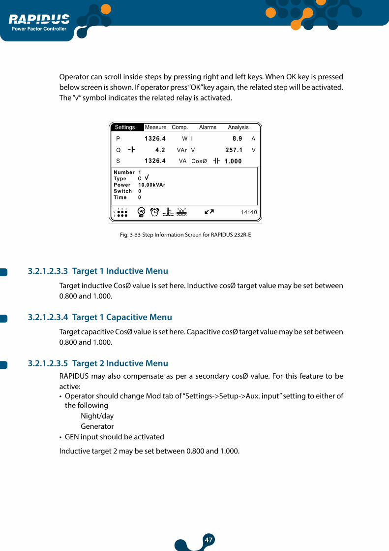
Operator can scroll inside steps by pressing right and left keys. When OK key is pressed below screen is shown. If operator press “OK”key again, the related step will be activated. The “ ” symbol indicates the related relay is activated.
1 4 : 4 0
Settings Measure Comp. Alarms Analysis
P 1326.4 W I 8.9 A
V 257.1 V
1.000 S 1326.4 VA
Q 4.2 VAr
V1 2 3
I
1 2
Number 1Type CPower 10.00kVArSwitch 0Time 0
Fig. 3-33 Step Information Screen for RAPIDUS 232R-E
3.2.1.2.3.3 Target 1 Inductive Menu
Target inductive CosØ value is set here. Inductive cosØ target value may be set between 0.800 and 1.000.
3.2.1.2.3.4 Target 1 Capacitive Menu
Target capacitive CosØ value is set here. Capacitive cosØ target value may be set between 0.800 and 1.000.
3.2.1.2.3.5 Target 2 Inductive MenuRAPIDUS may also compensate as per a secondary cosØ value. For this feature to be active:• Operator should change Mod tab of “Settings->Setup->Aux. input” setting to either of
the following Night/day Generator • GEN input should be activated
Inductive target 2 may be set between 0.800 and 1.000.

48
Power Factor Controller
3.2.1.2.3.6 Target 2 Capacitive Menu
RAPIDUS may also compensate as per a secondary cosØ value. For this feature to be active:• Operator should change Mod tab of “Settings->Setup->Aux. input” setting to either of
the following Night/day Generator • GEN input should be activated
Capacitive target 2 may be set between 0.800 and 1.000.
3.2.1.2.3.7 Activation Time Menu
RAPIDUS waits for the “activation time” before activating a step. Activation time may be selected between 1 and 600 seconds.
3.2.1.2.3.8 Deactivation Time Menu
RAPIDUS waits for the “deactivation time” before deactivating a step. Deactivation time may be selected between 1 and 600 seconds.
3.2.1.2.3.9 Shift Angle Menu
By entering the shift angle, changes in reactive power (transformer losses) that occur before the RAPIDUS measurement point are compensated.
Shift angle is set from -45° to 45°. RAPIDUS adds the reactive power that is calculates with the shift angle to the reactive power that it calculates by measuring the system voltage and current. Then it calculates the cosØ value and compensates.
Index values vary as per shift angle.
Example 1:
Assume that the CosØ value indicated by RAPIDUS is 1.000.
When the user enters 20° as the shift angle, RAPIDUS shall calculate CosØ value as 0.940 inductive.
When the user enters -30° as the shift angle, RAPIDUS shall calculate CosØ value as 0.866 capacitive.
SECTION 3 MENUS
49
Power Factor Controller
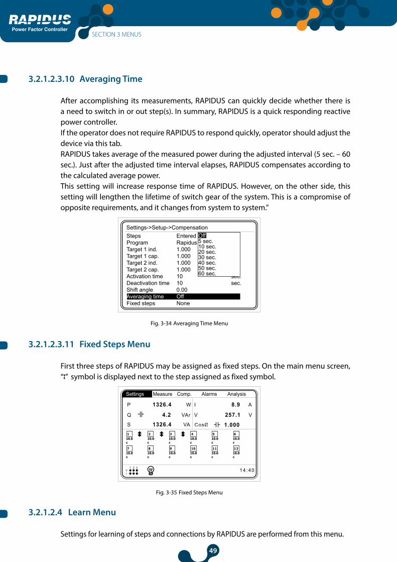
3.2.1.2.3.10 Averaging Time
After accomplishing its measurements, RAPIDUS can quickly decide whether there is a need to switch in or out step(s). In summary, RAPIDUS is a quick responding reactive power controller. If the operator does not require RAPIDUS to respond quickly, operator should adjust the device via this tab.RAPIDUS takes average of the measured power during the adjusted interval (5 sec. – 60 sec.). Just after the adjusted time interval elapses, RAPIDUS compensates according to the calculated average power. This setting will increase response time of RAPIDUS. However, on the other side, this setting will lengthen the lifetime of switch gear of the system. This is a compromise of opposite requirements, and it changes from system to system.”
Settings->Setup->CompensationSteps EnteredProgram RapidusTarget 1 ind. 1.000Target 1 cap. 1.000Target 2 ind. 1.000Target 2 cap. 1.000Activation time 10 sec.Deactivation time 10 sec.Shift angle 0.00Averaging time OffFixed steps None
Off5 sec.10 sec.20 sec.30 sec.40 sec.50 sec.60 sec.
Fig. 3-34 Averaging Time Menu
3.2.1.2.3.11 Fixed Steps Menu
First three steps of RAPIDUS may be assigned as fixed steps. On the main menu screen, “ ” symbol is displayed next to the step assigned as fixed symbol.
110.0c
1 4 : 4 0V1 2 3
I
1 2
210.0c
310.0c
410.0c
510.0c
610.0c
710.0c
810.0c
910.0c
1010.0c
1110.0c
1210.0c
Settings Measure Comp. Alarms Analysis
P 1326.4 W I 8.9 A
V 257.1 V
1.000 S 1326.4 VA
Q 4.2 VAr
Fig. 3-35 Fixed Steps Menu
3.2.1.2.4 Learn Menu
Settings for learning of steps and connections by RAPIDUS are performed from this menu.
SECTION 3 MENUS

50
Power Factor Controller
3.2.1.2.4.1 Learn Conn. Menu
Settings for learning of current and voltage connections by RAPIDUS are performed here.
3.2.1.2.4.1.1 Learn at start
On => RAPIDUS learns connections automatically when it is turned on or restarted.Off => RAPIDUS does not learn connections automatically when it is turned on or restarted.
Settings->Setup->Learn->Learn conn.Learn at start OffStep number 1Retry timer 5Retry count 3
OffOn
Fig. 3-36 Connection Setup
If the connections shall not be learned at start up, we advise them to be learned manually. This procedure is performed at “Compensation->Learn conn.” menu. (See 3.2.3.4 Learn Conn. Menu)
Factory setting for connections is V1, V2, V3, I1, I2 and I3. RAPIDUS shall take a measurement with this combination in the initial start.
Current threshold values for transformers vary according to type and size of the current transformers used. Please check that the measured current value is higher than the threshold specified in the technical specifications of current transformer. Otherwise Rapidus learn algorithm may not be completed or may be completed even if the connections are incorrect.
In cases where electrical system is unbalanced and/or there are sudden load changes, “learn algoritm” can be completed in an erroneous result. In such a situation, active powers measured by Rapidus will also be positive (checking active powers will not help).Therefore, it is important that operator should also physically check connections.
SECTION 3 MENUS
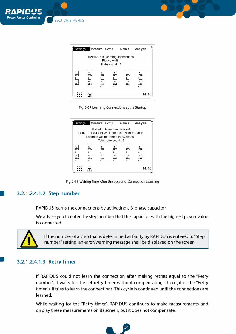
51
Power Factor Controller
Qind/P 0 %
Qcap/P0 5c
0 %
CosØ1
CosØ2
CosØ3 1.0001.0001.000
110.0c
1 4 : 4 0V1 2 3
I
1 2
210.0c
310.0c
410.0c
510.0c
610.0c
710.0c
810.0c
910.0c
1010.0c
1110.0c
1210.0c
Settings Measure Comp. Alarms Analysis
RAPIDUS is learning connections.Please wait...
Retry count : 1
Fig. 3-37 Learning Connections at the Startup
Qind/P 0 %
Qcap/P0 5c
0 %
CosØ1
CosØ2
CosØ3 1.0001.0001.000
110.0c
1 4 : 4 0V1 2 3
I
1 2
210.0c
310.0c
410.0c
510.0c
610.0c
710.0c
810.0c
910.0c
1010.0c
1110.0c
1210.0c
Settings Measure Comp. Alarms Analysis
Failed to learn connections!COMPENSATION WILL NOT BE PERFORMED!
Learning will be retried in 289 secs...Total retry count : 3
Fig. 3-38 Waiting Time After Unsuccessful Connection Learning
3.2.1.2.4.1.2 Step number
RAPIDUS learns the connections by activating a 3-phase capacitor.
We advise you to enter the step number that the capacitor with the highest power value is connected.
If the number of a step that is determined as faulty by RAPIDUS is entered to “Step number” setting, an error/warning message shall be displayed on the screen.
3.2.1.2.4.1.3 Retry Timer
If RAPIDUS could not learn the connection after making retries equal to the “Retry number”, it waits for the set retry timer without compensating. Then (after the “Retry timer”), it tries to learn the connections. This cycle is continued until the connections are learned.
While waiting for the “Retry timer”, RAPIDUS continues to make measurements and display these measurements on its screen, but it does not compensate.
SECTION 3 MENUS

52
Power Factor Controller
If user does not want to wait during the retry timer, he/she can manually command from “Comp.->Learn conn.”.
Settings->Setup->Learn->Learn conn.Learn at start OnStep number 1Retry timer 5Retry count 3
5
Low limit5High limit60
1 2 3 4
5 6 7 8
9 0 . -
ok clr
Fig. 3-39 Retry Timer
3.2.1.2.4.1.4 Retry Number
When it cannot learn the connection at startup, RAPIDUS it tries to learn the connections for times equal to the “Retry Number”.
Settings->Setup->Learn->Learn conn.Learn at start OnStep number 1Retry timer 5Retry count 3
3
Low limit1High limit20
1 2 3 4
5 6 7 8
9 0 . -
ok clr
Fig. 3-40 Retry Number
3.2.1.2.4.2 Aux. Input Menu
Aux. input menu is used to ensure that, RAPIDUS compensates as per the secondary target cosØ.
Settings->Setup->Aux. inputMod Off Off
Night/DayGenerator
Fig. 3-41 Aux. Input
SECTION 3 MENUS
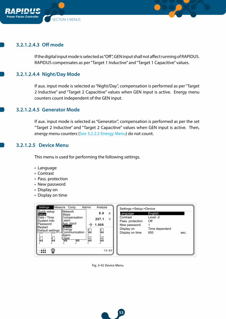
53
Power Factor Controller
3.2.1.2.4.3 Off mode
If the digital input mode is selected as “Off”, GEN input shall not affect running of RAPIDUS. RAPIDUS compensates as per “Target 1 Inductive” and “Target 1 Capacitive” values.
3.2.1.2.4.4 Night/Day Mode
If aux. input mode is selected as “Night/Day”, compensation is performed as per “Target 2 Inductive” and “Target 2 Capacitive” values when GEN input is active. Energy menu counters count independent of the GEN input.
3.2.1.2.4.5 Generator Mode
If aux. input mode is selected as “Generator”, compensation is performed as per the set “Target 2 Inductive” and “Target 2 Capacitive” values when GEN input is active. Then, energy menu counters (See 3.2.2.2 Energy Menu) do not count.
3.2.1.2.5 Device Menu
This menu is used for performing the following settings.
• Language • Contrast • Pass. protection• New password• Display on • Display on time
110.0c
1 4 : 4 0V1 2 3
I
1 2
210.0c
310.0c
410.0c
510.0c
610.0c
710.0c
810.0c
910.0c
1010.0c
1110.0c
1210.0c
Settings Measure Comp. Alarms Analysis Settings->Setup->DeviceLanguage EnglishContrast Level -3Pass. protection OffNew password 1Display on Time dependentDisplay on time 600 sec.
P 1326.4 W I 8.9 A
V 257.1 V
1.000 S 1326.4 VA
Q 4.2 VAr
Quick setup
Date / TimeSetup
System infoPasswordRestartDefault settings
ClearAlarmCommunicationEnergyDeviceAux. inputLearnCompensationStepsNetwork
Fig. 3-42 Device Menu
SECTION 3 MENUS

54
Power Factor Controller
3.2.1.2.5.1 Language Setting
• Türkçe• English• Pусский
User shall select the desired setting with up and down arrows and press “OK”.
3.2.1.2.5.2 Contrast Setting
This menu is used for performing the contrast setting. Level setting steps are displayed when you press OK when this option selected. User shall select the desired contrast level with up and down arrows and press “OK”. RAPIDUS screen gets darker when you go up to level 4. RAPIDUS screen gets lighter when you go down to level -4.
Settings->Setup->DeviceLanguage EnglishContrast Level -3Pass. protection OffNew password 1Display on Time dependentDisplay on time 600 sec.
Level -4Level -3Level -2Level -1Level 0Level 1Level 2Level 3Level 4
Fig. 3-43 Contrast Setting
3.2.1.2.5.3 Pass. Protection
If password protection is selected as “On”, you shall enter a password in order to enter the setting menus each time RAPIDUS is restarted again.
If password protection is selected as “Off”, you do not need to enter a password in order to enter the setting menus each time RAPIDUS is restarted again.
Settings->Setup->DeviceLanguage EnglishContrast Level -3Pass. protection OnNew password 1Display on Time dependentDisplay on time 600 sec.
OffOn
Fig. 3-44 Pass. Protection
SECTION 3 MENUS

55
Power Factor Controller
3.2.1.2.5.4 New Password Setting
Factory set password of RAPIDUS is “1”. New password may be selected between 1 and 9999. (For the usage of RAPIDUS Virtual Keyboard, Refer to 3.1.4 Ex.)
Settings->Setup->DeviceLanguage EnglishContrast Level -3Pass. protection OnNew password 1Display on Time dependentDisplay on time 600 sec.
1
Low limit1High limit9999
1 2 3 4
5 6 7 8
9 0 . -
ok clr
Fig. 3-45 New Password Entry
3.2.1.2.5.5 Display On Setting
• Continuous • Time dependent
When continuous is selected, the backlight of RAPIDUS display does not turn off. When time dependent is selected, screen backlight is turned on for “display on time”.
3.2.1.2.5.6 Display On Time Setting
This tab is used for setting the on time for the backlight of RAPIDUS display. It may be selected between 10 and 600 seconds. (For the usage of RAPIDUS Virtual Keyboard, Refer to 3.1.4 Ex.)
Ayarlar->Kurulum->CihazLanguage EnglishContrast Level -3Pass. protection OnNew password 1Display on Time dependentDisplay on time 600 sec.
600
Low limit10High limit600
1 2 3 4
5 6 7 8
9 0 . -
ok clr
Fig. 3-46 Display On Time Setting
SECTION 3 MENUS

56
Power Factor Controller
3.2.1.2.6 Energy Menu
This menu is used for entering the initial energy values. The settings in this menu are used for synchronization of system electricity counter and RAPIDUS counters. User shall select the desired energy value with up and down arrows and press “OK”.
Settings->Setup->EnergyStart of day 0Start of month 1kWh 0.0 kWhkWh E. 0.0 kWhkVArh I. 0.0 kVArhkVArh C. 0.0 kVArh
Fig. 3-47 Energy Menu
3.2.1.2.6.1 Start of day setting
This is the settings tab for entering the time for start of the day. Start of the day time may be selected between 0 and 23. (For the usage of RAPIDUS Virtual Keyboard, Refer to 3.1.4 Ex.)
3.2.1.2.6.2 Start of month setting
This is the settings tab for entering the day for start of the month. Start of month day may be selected between 1 and 28. (For the usage of RAPIDUS Virtual Keyboard, Refer to 3.1.4 Ex.)
--------------------------------
The settings listed below between 3.2.1.2.6.3 and 3.2.1.2.6.6 are used for synchronization of system electricity counter and RAPIDUS counter. Each of them may be set between 0.0 and 20000000000.0. (For the usage of RAPIDUS Virtual Keyboard, Refer to 3.1.4 Ex.).
3.2.1.2.6.3 kWh Setting
This tab is used for entering the “initial” value for imported active energy.
3.2.1.2.6.4 kWh E. Setting
This tab is used for entering the “initial” value for exported active energy.
SECTION 3 MENUS

57
Power Factor Controller
3.2.1.2.6.5 kVArh I. Setting
This tab is used for entering the “initial” value for inductive reactive energy.
3.2.1.2.6.6 kVArh C. Setting
This tab is used for entering the “initial” value for capacitive reactive energy.
3.2.1.2.7 Communication Menu
RAPIDUS includes Modbus RTU communication protocol. Settings related with Modbus protocol are made in this menu.
3.2.1.2.7.1 Baud Rate Menu
User shall select the desired value with up and down arrows and press “OK”. RAPIDUS communicates with speeds of 2400, 4800, 9600, 19200, 38400 and 57600 bits/second.
Settings->Setup->CommunicationBaud rate 38400Slave Id 2400
48009600192003840057600
Fig. 3-48 Baud Rate Setting
3.2.1.2.7.2 Slave Id Menu
This is the settings tab for entering the slave id number. (For the usage of RAPIDUS Virtual Keyboard, Refer to 3.1.4 Ex.).
Slave Id 1
Fig. 3-49 Slave Id Setting
Maximum 247 devices may communicate over the same RS485 line. Therefore, slave id may be selected between 1 and -247.
SECTION 3 MENUS
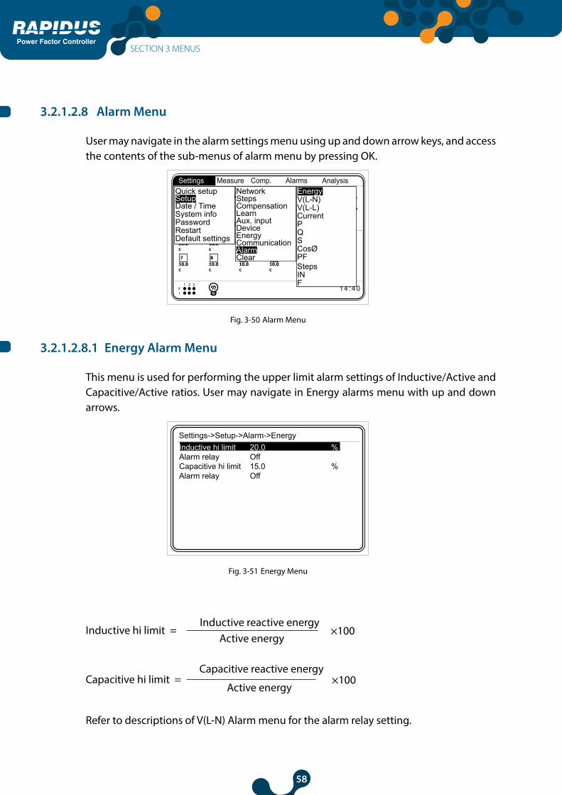
58
Power Factor Controller
3.2.1.2.8 Alarm Menu
User may navigate in the alarm settings menu using up and down arrow keys, and access the contents of the sub-menus of alarm menu by pressing OK.
110.0c
1 4 : 4 0V1 2 3
I
1 2
210.0c
310.0c
410.0c
510.0c
610.0c
710.0c
810.0c
910.0c
1010.0c
1110.0c
1210.0c
Settings Measure Comp. Alarms Analysis
P 1326.4 W I 8.9 A
V 257.1 V
1.000 S 1326.4 VA
Q 4.2 VAr
Quick setup
Date / TimeSetup
System infoPasswordRestartDefault settings
EnergyV(L-N)V(L-L)CurrentPQSCosØPFStepsINF
ClearAlarmCommunicationEnergyDeviceAux. inputLearnCompensationStepsNetwork
Fig. 3-50 Alarm Menu
3.2.1.2.8.1 Energy Alarm Menu
This menu is used for performing the upper limit alarm settings of Inductive/Active and Capacitive/Active ratios. User may navigate in Energy alarms menu with up and down arrows.
Settings->Setup->Alarm->EnergyInductive hi limit 20.0 %Alarm relay OffCapacitive hi limit 15.0 %Alarm relay Off
Fig. 3-51 Energy Menu
Inductive hi limit = Inductive reactive energy
×100Active energy
Capacitive hi limit = Capacitive reactive energy
×100Active energy
Refer to descriptions of V(L-N) Alarm menu for the alarm relay setting.
SECTION 3 MENUS
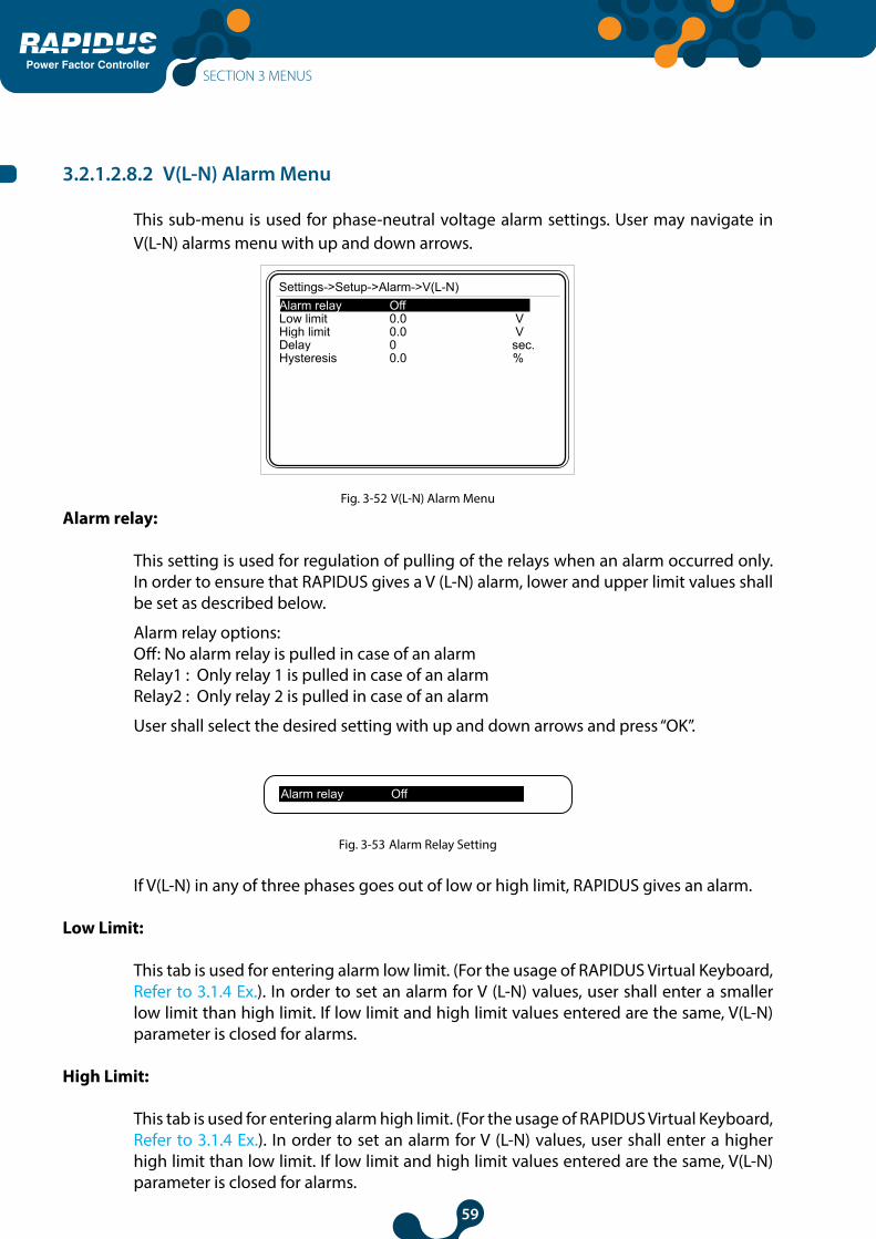
59
Power Factor Controller
3.2.1.2.8.2 V(L-N) Alarm Menu
This sub-menu is used for phase-neutral voltage alarm settings. User may navigate in V(L-N) alarms menu with up and down arrows.
Settings->Setup->Alarm->V(L-N)Alarm relay OffLow limit 0.0 VHigh limit 0.0 VDelay 0 sec.Hysteresis 0.0 %
Fig. 3-52 V(L-N) Alarm Menu
Alarm relay:
This setting is used for regulation of pulling of the relays when an alarm occurred only. In order to ensure that RAPIDUS gives a V (L-N) alarm, lower and upper limit values shall be set as described below.
Alarm relay options:Off: No alarm relay is pulled in case of an alarmRelay1 : Only relay 1 is pulled in case of an alarmRelay2 : Only relay 2 is pulled in case of an alarm
User shall select the desired setting with up and down arrows and press “OK”.
Alarm relay Off
Fig. 3-53 Alarm Relay Setting
If V(L-N) in any of three phases goes out of low or high limit, RAPIDUS gives an alarm.
Low Limit:
This tab is used for entering alarm low limit. (For the usage of RAPIDUS Virtual Keyboard, Refer to 3.1.4 Ex.). In order to set an alarm for V (L-N) values, user shall enter a smaller low limit than high limit. If low limit and high limit values entered are the same, V(L-N) parameter is closed for alarms.
High Limit:
This tab is used for entering alarm high limit. (For the usage of RAPIDUS Virtual Keyboard, Refer to 3.1.4 Ex.). In order to set an alarm for V (L-N) values, user shall enter a higher high limit than low limit. If low limit and high limit values entered are the same, V(L-N) parameter is closed for alarms.
SECTION 3 MENUS

60
Power Factor Controller
Delay:
RAPIDUS waits for the delay time before giving an alarm when the related alarm parameter exceeds “Low limit” or “High limit” value. Also, RAPIDUS waits for the delay time again before cancelling an alarm condition when the related alarm parameter returns back in the limits. It may be selected between 0 and 600 seconds. (For the usage of RAPIDUS Virtual Keyboard, Refer to 3.1.4 Ex.).
Delay 0 sec.
Fig. 3-54 Alarm Time Setting
Hysteresis setting:
This is the tolerance value entered in %. Refer to the example below and Fig. 3-55 for the usage method. It may be selected between 0.0 and 20.0. (For the usage of RAPIDUS Virtual Keyboard, Refer to 3.1.4 Ex.)
Hysteresis 0.0 %
Fig. 3-55 Hysteresis Setting
Example: For the figure below (delay setting is zero):
An alarm occurs in point A Alarm is cancelled in point B An alarm occurs in point C Alarm is cancelled in point D
Time
Waveform
D
C
B
A
Amplitude
Hi limit valueHysteresis %
Low limit valueHysteresis %
Fig. 3-56 Alarm Example
SECTION 3 MENUS
61
Power Factor Controller
3.2.1.2.8.3 V(L-L) Alarm Menu
This sub-menu is used for phase-phase voltage alarm settings. Settings are the same for the settings for Alarm->V(L-N) menu. (V(L-L) low and high limit values: 0.0 2600000.0).
3.2.1.2.8.4 Current Alarm Menu
This sub-menu is used for current alarm settings. Settings are the same for the settings for Alarm->V(L-N) menu. (Current low and high limit values: 0.0 30000.0)
3.2.1.2.8.5 P Alarm Menu
This sub-menu is used for active power alarm settings. Settings are the same for the settings for Alarm->V(L-N) menu. (P low and high limit values: -10000000000.0 10000000000.0)
3.2.1.2.8.6 Q Alarm Menu
This sub-menu is used for reactive power alarm settings. Settings are the same for the settings for Alarm->V(L-N) menu. (Q low and high limit values: -10000000000.010000000000.0)
3.2.1.2.8.7 S Alarm Menu
This sub-menu is used for apparent power settings. Settings are the same for the settings for Alarm->V(L-N) menu. (S low and high limit values: 0.0 10000000000.0)
3.2.1.2.8.8 CosØ Alarm Menu
This sub-menu is used for CosØ alarm settings. Settings are the same for the settings for Alarm->V(L-N) menu. (CosØ low and high limit values: 0.000 1.000).
3.2.1.2.8.9 PF Alarm Menu
This sub-menu is used for power factor alarm settings. Settings are the same for the settings for Alarm->V(L-N) menu. (PF low and high limit values: 0.000 1.000)
3.2.1.2.8.10 Step Alarm Menu
This sub-menu is used for step alarm settings. RAPIDUS gives an alarm when any of the steps used in compensation gets lower than the value calculated with the “low limit” setting (alarm limit).
Alarm limit = initial value x Low limit 100
(Step low limit values: 20.0 100.0)
SECTION 3 MENUS

62
Power Factor Controller
3.2.1.2.8.11 IN Alarm Menu
This sub-menu is used for neutral current alarm settings. Settings are the same for the settings for Alarm->V(L-N) menu. (IN high limit values: 0.000 30000.000)
3.2.1.2.8.12 F Alarm Menu
This sub-menu is used for frequency alarm settings. Settings are the same for the settings for Alarm->V(L-N) menu. (Frequency low and high limit values: 35.0 70.0)
3.2.1.2.8.13 V Harmonics Alarm Menu
This sub-menu is used for harmonics alarm settings. User shall select the desired tab with up and down arrows and press “OK”.
Settings->Setup->Alarm->Harmonics VAlarm relay OffTHDV hi limit 0.0 %V3 hi limit 0.0 %V5 hi limit 0.0 %V7 hi limit 0.0 %V9 hi limit 0.0 %V11 hi limit 0.0 %V13 hi limit 0.0 %V15 hi limit 0.0 %V17 hi limit 0.0 %V19 hi limit 0.0 %V21 hi limit 0.0 %
OffRelay1Relay2
Fig. 3-57 V Harmonics Alarm Menu
Alarm relay:
Refer to 3.2.1.1.8.1 V(L-N) - Alarm relay.
THDV High Limit:
This is used for entering high limit value of total harmonic distortion in the voltage. In order to set a THDV alarm, user shall enter a number higher than zero as THDV high limit. If zero is entered as the high limit value, THDV parameter is turned off for alarms.
It may be selected between 0.0 and 100.0. (For the usage of RAPIDUS Virtual Keyboard, Refer to 3.1.4 Ex.).
THDV hi limit 20.0 %
Fig. 3-58 THDV High Limit Setting
SECTION 3 MENUS

63
Power Factor Controller
V3 --- V21 high limit:
This is used for entering high limit value of “3rd”, “5th” … “21st” harmonic distortion in the voltage. In order to set a V3, V5 – V21 harmonic alarm, user shall enter a number higher than zero as high limit. If zero is entered as the high limit value, V3, V5 – V21 parameters are turned off for alarms.
It may be selected between 0.0 and 100.0. (For the usage of RAPIDUS Virtual Keyboard, Refer to 3.1.4 Ex.)
V3 hi limit 20.0 %
V21 hi limit 20.0 %
Fig. 3-59 V3-V21 Harmonics High Limit Setting
Delay:
Refer to 3.2.1.1.8.1 V(L-N) – Delay.
3.2.1.2.8.14 I Harmonics Alarm Menu
Settings for the “I harmonics” alarms are the same for the settings for “V harmonics”.
3.2.1.2.8.15 Temperature Alarm Menu
This sub-menu is used for temperature alarm settings. Settings are the same for the settings for Alarm->V(L-N) menu. (Temperature low and high limit values: It may be selected between -20.0 and 55.0).
If low limit and high limit values entered are the same, RAPIDUS does not give an alarm.
Settings->Setup->Alarm->CurrentAlarm relay Relay1Low limit 0.0 A
Hysteresis 0.0 %
High limit 0.0 ADelay 0.0 sec.
Fig. 3-60 No Alarm Time Condition
SECTION 3 MENUS

64
Power Factor Controller
If low limit entered is higher than the high limit, “Invalid limits! Please check” message is displayed on RAPIDUS screen.
Invalid limits!Please check.
OKX
Settings->Setup->Alarm->CurrentAlarm relay Relay1Low limit 0.0 A
Hysteresis 0.0 %
High limit 0.0 ADelay 0.0 sec.
Fig. 3-61 Invalid Limit
3.2.1.2.9 Clear Menu
Sub menus are displayed when you press OK when the Clear option selected. User shall select the tab to be cleared with up and down arrows and press “OK”. Relevant clearing operation is performed if you press OK when “Are you sure?” message is displayed on the screen; and it returns back without clearing when you press X.
Energy and demand values are cleared. Learned connections are returned back to factory presets.
All tab performs all of the three operations above.
110.0c
1 4 : 4 0V1 2 3
I
1 2
210.0c
310.0c
410.0c
510.0c
610.0c
710.0c
810.0c
910.0c
1010.0c
1110.0c
1210.0c
Settings Measure Comp. Alarms Analysis
Are you sure?
OKX
P 1326.4 W I 8.9 A
V 257.1 V
1.000 S 1326.4 VA
Q 4.2 VAr
Quick setup
Date / TimeSetup
System infoPasswordRestartDefault settings
ClearAlarmCommunicationEnergyDeviceAux. inputLearnCompensationStepsNetwork Energy
DemandLearnAll
Fig. 3-62 Clear Menu
Assume that for a RAPIDUS used for some time, “Measure->Energy->Imp. Active” sub menu is like the one in Fig. 3-63.
SECTION 3 MENUS

65
Power Factor Controller
Measure->Energy->Imp. activeIndex 267500.1 kWhCurr. hour 0.5 kWhPrev. hour 0.6 kWhCurr. day 21.3 kWhPrev. day 22.6 kWhCurr. month 598.4 kWhPrev. month 439.5 kWh
Fig. 3-63 Before Clearing
After the clearing operation is completed, “Measure->Energy->Imp. Active” sub menu shall be like the one in Fig. 3-64.
Measure->Energy->Imp. activeIndex 0.0 kWhCurr. hour 0.0 kWhPrev. hour 0.0 kWhCurr. day 0.0 kWhPrev. day 0.0 kWhCurr. month 0.0 kWhPrev. month 0.0 kWh
Fig. 3-64 After Clearing
After the clearing operation, a number different than zero may be seen for index parameters. This number is the initial value entered by the user for the relevant index parameter.
For example, assume that initial value for “Setup->Energy->T1 kWh” is entered as 7500 kWh. Then, after the clearing operation is completed, “Counters->Rate 1->Imp. Active->Index” value shall be 7500 kWh. (See Fig. 3-65)
Measure->Energy->Imp. activeIndex 7500.0 kWhCurr. hour 0.0 kWhPrev. hour 0.0 kWhCurr. day 0.0 kWhPrev. day 0.0 kWhCurr. month 0.0 kWhPrev. month 0.0 kWh
Fig. 3-65 Initial Value Entered After Clearing
SECTION 3 MENUS

66
Power Factor Controller
3.2.1.3 Date/Time Menu
Date/Time is set in this menu. (For RAPIDUS Date/Time Setting, Refer to 3.1.4 Ex.).
110.0c
1 4 : 4 0V1 2 3
I
1 2
210.0c
310.0c
410.0c
510.0c
610.0c
710.0c
810.0c
910.0c
1010.0c
1110.0c
1210.0c
Settings Measure Comp. Alarms AnalysisQuick setup
Date / TimeSetup
System infoPasswordRestartDefault settings
Settings->Date / TimeTime 14 : 40 : 00Date 30 August 2013
P 1326.4 W I 8.9 A
V 257.1 V
1.000 S 1326.4 VA
Q 4.2 VAr
Fig. 3-66 Date/Time Menu
3.2.1.4 System Info Menu
No setting is performed in this menu, it is just for informational purposes.
KLEMSANRAPIDUS - Power Factor Controller
Model 606000Serial number 2359339Language EnglishFirmware version 1.00PCB version 1_1-2Build date 16 February 2013Temperature 16.5 °CBattery voltage 3.00 V
Fig. 3-67 System Info
Temperature and battery voltage values may be read via RS485.
SECTION 3 MENUS

67
Power Factor Controller
3.2.1.5 Password Menu
If no password is entered, only Date/Time, System Info and Password tabs shall be active under settings menu. You shall enter a password in order to activate the other tabs.
“Login success” shall be displayed if the password entered is correct; and “Password mismatch” message shall be displayed if it is incorrect. (For the usage of RAPIDUS Virtual Keyboard, Refer to 3.1.4 Ex.).
Login required! Login success. Password mismatch.
OKX X
110.0c
1 4 : 4 0V1 2 3
I
1 2
210.0c
310.0c
410.0c
510.0c
610.0c
710.0c
810.0c
910.0c
1010.0c
1110.0c
1210.0c
Settings Measure Comp. Alarms Analysis
P 1326.4 W I 8.9 A
V 257.1 V
1.000 S 1326.4 VA
Q 4.2 VAr
Quick setup
Date / TimeSetup
System infoPasswordRestartDefault settings
Fig. 3-68 Password
3.2.1.6 Restart Menu
This is used for restarting RAPIDUS. “Are you sure?” message shall be displayed if you press OK when the Restart tab is highlighted. RAPIDUS is restarted by pressing OK again.
110.0c
1 4 : 4 0V1 2 3
I
1 2
210.0c
310.0c
410.0c
510.0c
610.0c
710.0c
810.0c
910.0c
1010.0c
1110.0c
1210.0c
Settings Measure Comp. Alarms Analysis
CosØ1
CosØ2
CosØ3Are you sure?
OKX
P 1326.4 W I 8.9 A
V 257.1 V
1.000 S 1326.4 VA
Q 4.2 VAr
Quick setup
Date / TimeQuick setup
System infoPasswordRestartDefault settings
Fig. 3-69 RAPIDUS Restart
SECTION 3 MENUS
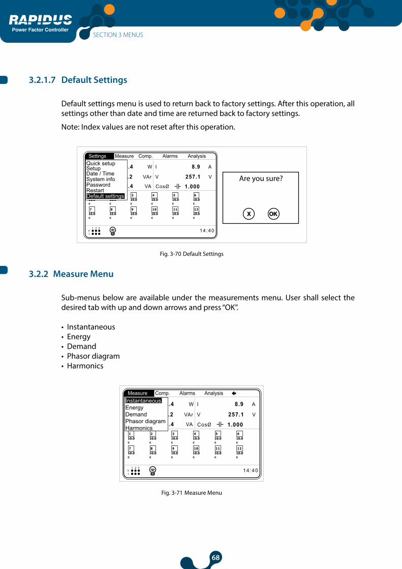
68
Power Factor Controller
3.2.1.7 Default Settings
Default settings menu is used to return back to factory settings. After this operation, all settings other than date and time are returned back to factory settings.
Note: Index values are not reset after this operation.
110.0c
1 4 : 4 0V1 2 3
I
1 2
210.0c
310.0c
410.0c
510.0c
610.0c
710.0c
810.0c
910.0c
1010.0c
1110.0c
1210.0c
Settings Measure Comp. Alarms Analysis
Are you sure?
OKX
P 1326.4 W I 8.9 A
V 257.1 V
1.000 S 1326.4 VA
Q 4.2 VAr
Quick setup
Date / TimeSetup
System infoPasswordRestartDefault settings
Fig. 3-70 Default Settings
3.2.2 Measure Menu
Sub-menus below are available under the measurements menu. User shall select the desired tab with up and down arrows and press “OK”.
• Instantaneous• Energy• Demand• Phasor diagram • Harmonics
110.0c
1 4 : 4 0V1 2 3
I
1 2
210.0c
310.0c
410.0c
510.0c
610.0c
710.0c
810.0c
910.0c
1010.0c
1110.0c
1210.0c
Measure Comp. Alarms Analysis
P 1326.4 W I 8.9 A
V 257.1 V
1.000 S 1326.4 VA
Q 4.2 VAr
InstantaneousEnergyDemandPhasor diagramHarmonics
Fig. 3-71 Measure Menu
SECTION 3 MENUS

69
Power Factor Controller
3.2.2.1 Instantaneous Menu
Instantaneous measurement values are available in this menu. Page in fig. 3-72 shall be displayed when OK is pressed while Measure menu, Instantaneous tab is highlighted. Instantaneous measurement parameters listed below are monitored using the right and left arrow keys.
Measure->Instantaneous->V L-N
V1 220.0 V
V2 220.0 V
V3 220.0 V
Vo 220.0 V
Powers V L-N V L-L
Fig. 3-72 Instantaneous Menu
• Phase voltage (L-N) values and average voltage (L-N) value• Phase voltage (L-L) values and average voltage (L-L) value • Phase currents total current (I) value• Neutral current (IN)• CosØ values of phases and CosØ value of the system• Power factor (PF) values of phases and total power factor (PF) • Active power (P) values of phases and total active power (P) value • Reactive power (Q) values of phases and total reactive power (Q) value • Apparent power (S) values of phases and total apparent power (S) value • Frequency (F) values of phases• THDV values of phases and total THDV value • THDI values of phases and total THDI value
3.2.2.2 Energy Menu
This menu includes
• Imported active• Exported active • Inductive reactive• Capacitive reactive
energy values.
When an energy meter reaches the value “50000000.0 Mega”, it will start to count from “0.0”.
SECTION 3 MENUS

70
Power Factor Controller
3.2.2.2.1 Imp. Active Menu (Imported Active Energy Menu)
Imported active energy values are displayed.
Measure->Energy->Imp. activeIndex 0.0 kWhCurr. hour 0.0 kWhPrev. hour 0.0 kWhCurr. day 0.0 kWhPrev. day 0.0 kWhCurr. month 0.0 kWhPrev. month 0.0 kWh
Fig. 3-73 Imp. Active Energy Page
Index
is the imported active energy value from the time when the energy values are cleared to this moment.
Curr. hour
is the imported active energy value from the start of the hour to this moment.
Prev. hour
is the active energy value imported during the previous hour.
Previous hour
Start of previous hour
13:00
Start of current hour
14:00 14:26
Current hour
Current time(RAPIDUS observation time –
reading time)
Fig. 3-74 Hour Start Example
SECTION 3 MENUS

71
Power Factor Controller
Curr. day
is the imported active energy value from the starting hour of the day to this moment.
Prev. day
is the active energy value imported during the previous day.
Previous day
*Starting hour of the day: 8
June 18th
08:00June 19th
08:00Juneth
16:47
Current day
Current time (RAPIDUS observation
time – reading time)
Fig. 3-75 Day Start Example
Curr. month
is the imported active energy value from the starting day of the month to this moment.
Prev. month
is the active energy value imported during the previous month.
Previous month
*Starting hour of the day: 7*Starting day of the month: 3
April 3rd 07:00
May 3rd 07:00
May 17th
17:47
Current month
Current time (RAPIDUS observation
time – reading time)
Fig. 3-76 Month Start Example
Settings for “start of day” and “start of month” parameters which are important for the usage of energy menu page are performed on “Settings->Setup->Energy” menu.
SECTION 3 MENUS
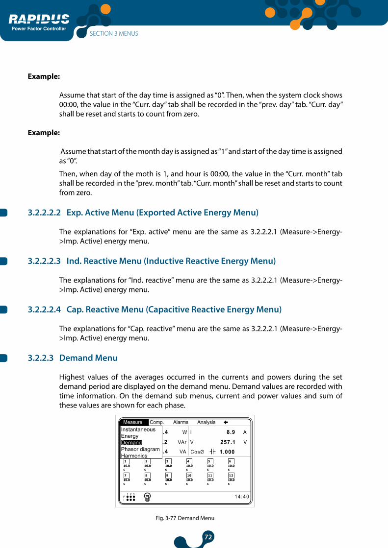
72
Power Factor Controller
Example:
Assume that start of the day time is assigned as “0”. Then, when the system clock shows 00:00, the value in the “Curr. day” tab shall be recorded in the “prev. day” tab. “Curr. day” shall be reset and starts to count from zero.
Example:
Assume that start of the month day is assigned as “1” and start of the day time is assigned as “0”.
Then, when day of the moth is 1, and hour is 00:00, the value in the “Curr. month” tab shall be recorded in the “prev. month” tab. “Curr. month” shall be reset and starts to count from zero.
3.2.2.2.2 Exp. Active Menu (Exported Active Energy Menu)
The explanations for “Exp. active” menu are the same as 3.2.2.2.1 (Measure->Energy->Imp. Active) energy menu.
3.2.2.2.3 Ind. Reactive Menu (Inductive Reactive Energy Menu)
The explanations for “Ind. reactive” menu are the same as 3.2.2.2.1 (Measure->Energy->Imp. Active) energy menu.
3.2.2.2.4 Cap. Reactive Menu (Capacitive Reactive Energy Menu)
The explanations for “Cap. reactive” menu are the same as 3.2.2.2.1 (Measure->Energy->Imp. Active) energy menu.
3.2.2.3 Demand Menu
Highest values of the averages occurred in the currents and powers during the set demand period are displayed on the demand menu. Demand values are recorded with time information. On the demand sub menus, current and power values and sum of these values are shown for each phase.
110.0c
1 4 : 4 0V1 2 3
I
1 2
210.0c
310.0c
410.0c
510.0c
610.0c
710.0c
810.0c
910.0c
1010.0c
1110.0c
1210.0c
Measure Comp. Alarms Analysis
P 1326.4 W I 8.9 A
V 257.1 V
1.000 S 1326.4 VA
Q 4.2 VAr
InstantaneousEnergyDemandPhasor diagramHarmonics
Fig. 3-77 Demand Menu
SECTION 3 MENUS

73
Power Factor Controller
Example:
Current signal averages and demand value for 15 minutes demand period are shown in the following graphic.
Time (minutes)
Waveform
Amplitude (A)
average value=3A
demand period=15 minutes
average value=3A
average value=5A average value=4A
average value=5A average value=4A
15 minutes 15 minutes 15 minutes
Fig. 3-78 Demand Example
3.2.2.3.1 Current Menu
Demand values for each phase current and the demand value for the sum of the phase currents are shown. Bottom tab of the demand values indicate the date and time they have occurred.
Measure->Demand->CurrentPhase1 5.0 A 02:44:59 - 10/10/12Phase2 5.1 A 13:29:59 - 11/10/12Phase3 4.9 A 14:29:59 - 09/10/12Total 15.6 A 09:14:59 - 12/10/12
110.0c
1 4 : 4 0V1 2 3
I
1 2
210.0c
310.0c
410.0c
510.0c
610.0c
710.0c
810.0c
910.0c
1010.0c
1110.0c
1210.0c
Measure Comp. Alarms Analysis
P 1326.4 W I 8.9 A
V 257.1 V
1.000 S 1326.4 VA
Q 4.2 VAr
InstantaneousEnergyDemandPhasor diagramHarmonics
CurrentAct. powerRea. powerApp. power
Fig. 3-79 Current Menu
Example:
Assume that the demand period is entered as 15 minutes and current value demand value and time are read as Phase1 5.0 A 02:44:59 - 10/10/13. Then, the description for the value read is as follows:
SECTION 3 MENUS
74
Power Factor Controller
On October 10th, 2013, at 02:29:59 and 02:44:59 period, demand value for 1st phase is 5.0 A.
Example:
Demand periods when the demand period is set as 15 minutes when system clock is 15:07:00 are shown below:
05:07:00 - 15:14:59 = 1st demand period15:14:59 - 15:29:59 = 2nd demand period15:29:59 - 15:44:59 = 3rd demand period15:44:59 - 15:59:59 = 4th demand period15:59:59 - 16:14:59 = 5th demand period . . .
3.2.2.3.1.1 Act. Power Menu
Demand values in the active power sub menu are as described in “Measure->Demand->Current” sub menu.
3.2.2.3.1.2 Rea. Power Menu
Demand values in the reactive power sub menu are as described in “Measure->Demand->Current” sub menu.
3.2.2.3.1.3 App. Power Menu
Demand values in the apparent power sub menu are as described in “Measure->Demand->Current” sub menu.
3.2.2.4 Phasor diagram Menu
Following information are listed on the right side of the diagram on phasor diagram menu screen.
• voltage values for phases• current values for phases • Angle values between V1-V2, V2-V3 and V3-V1• Angle values between V1-I1, V2-I2 and V3-I31 On the phasor diagram, current lines are displayed as gray and voltage lines are displayed as black.
In order to follow the currents and voltages pertaining to the same phase more easily in phasor diagram, circles with the same size are added to the ends of the lines pertaining to the same phase.
SECTION 3 MENUS

75
Power Factor Controller
110.0c
1 4 : 4 0V1 2 3
I
1 2
210.0c
310.0c
410.0c
510.0c
610.0c
710.0c
810.0c
910.0c
1010.0c
1110.0c
1210.0c
Measure Comp. Alarms Analysis Measure->Phasor diagram
V1 150.0 VV2 150.0 VV3 150.9 VI1 3.0 AI2 3.0 AI3 3.0 AV1-V2 120.0V2-V3 120.0V3-V1 120.0V1-I1 30.1V2-I2 30.0V3-I3 30.1
P 1326.4 W I 8.9 A
V 257.1 V
1.000 S 1326.4 VA
Q 4.2 VAr
InstantaneousEnergyDemandPhasor diagramHarmonics
Fig. 3-80 Phasor Diagram Menu
3.2.2.5 Harmonics Menu
RAPIDUS measures/calculates current and voltage harmonics up to 51st level. Current and voltage harmonics are displayed both in tabular and graphic form.
3.2.2.5.1 Table Menu
Current and voltage harmonics pertaining to each phase are displayed in tabular form in this menu (See Fig. 3-81). User may navigate between tables by pressing right and left arrows. There are 6 table pages. V1, V2, V3, I1, I2, I3.
1-56-1011-1516-2021-2526-3031-3536-4041-4546-50
99.010.005.700.000.000.000.000.000.000.00
10.002.100.000.000.000.000.000.000.000.00
21.020.000.750.000.000.000.000.000.000.00
30.003.300.000.000.000.000.000.000.000.00
40.050.000.000.000.000.000.000.000.000.00
5
I3 % V1 % V2 %
Measure->Harmonics->V1 %
Fig. 3-81 Harmonics Table Menu
SECTION 3 MENUS

76
Power Factor Controller
3.2.2.5.2 Graphic Menu
Current and voltage harmonics pertaining to each phase are displayed in graphic form in this menu (See Fig. 3-82). User may navigate between current-voltage graphics by pressing right and left arrows. There are 6 graphic pages: V1, V2, V3, I1, I2, I3.
Measure->Harmonics->V1 %20 %
15 %
10 %
5 %
1 11 21 31 41 51
I3 % V1 % V2 %
Fig. 3-82 Graphic Menu
3.2.3 Comp. (Compensation) Menu
Sub menus shown in Fig. 3-83 are available.
110.0c
1 4 : 4 0V1 2 3
I
1 2
210.0c
310.0c
410.0c
510.0c
610.0c
710.0c
810.0c
910.0c
1010.0c
1110.0c
1210.0c
Comp. Alarms Analysis
P 1326.4 W I 8.9 A
V 257.1 V
1.000 S 1326.4 VA
Q 4.2 VAr
Switch countConn. timeDCMLearn conn.Learned conn.Learn steps
Fig. 3-83 Comp. Menu
SECTION 3 MENUS

77
Power Factor Controller
3.2.3.1 Switch Count Menu
This menu displays how many times RAPIDUS activated each step.
In order to clear/change switching counts, highlight the desired step and press OK. Switch count is set between 0 and 10000. (For the usage of RAPIDUS Virtual Keyboard, Refer to 3.1.4 Ex.).
Comp.->Switch countStep 1 0Step 2 0Step 3 0Step 4 0Step 5 0Step 6 0Step 7 0Step 8 0Step 9 0Step 10 0Step 11 0Step 12 0
NOTE: There are two “Switch Count” submenus for RAPIDUS 232R-E. Operator can assign 1st, 2nd, … and 12th step powers in “Switch Count 1” Submenu. Operator can assign 13th, 14th, …and 24th step powers in “Switch Count 2” Submenu.
Fig. 3-84 Switch Count
3.2.3.2 Conn. Time Menu
Connection times of the steps are displayed.
In order to clear/change connection times, highlight the desired step and press OK. Conn. time is set between 0 and 1000000. (For the usage of RAPIDUS Virtual Keyboard, Refer to 3.1.4 Ex.).
Comp.->Conn. timeStep 1 0 minStep 2 0 minStep 3 0 minStep 4 0 minStep 5 0 minStep 6 0 minStep 7 0 minStep 8 0 minStep 9 0 minStep 10 0 minStep 11 0 minStep 12 0 min
NOTE: There are two “Conn. Time” submenus for RAPIDUS 232R-E. Operator can assign 1st, 2nd, … and 12th step powers in “Conn. Time 1” Submenu. Operator can assign 13th, 14th, …and 24th step powers in “Conn. Time 2” Submenu.
Fig. 3-85 Conn. Time
3.2.3.3 DCM (Dynamic Capacitor Monitoring)
Step values learned by dynamic monitoring can be followed from this menu. These are observed after a certain amount of time due to the effects and nature of DCM algorithm.
There is no compensation program with a prerequisite for DCM. DCM shall estimate step powers in each compensation program.
SECTION 3 MENUS

78
Power Factor Controller
First estimation results require at least 128x8 compensation switching. Estimation values shall be updated at every 128 compensation switching after that. Previous estimation power is the entered or learned step power values.
NOTE: DCM(Dynamic Capacitor Monitoring) feature isn’t avaliable in RAPIDUS 232R-E optional model.
3.2.3.4 Learn Conn. Menu
Connections of current and voltage measurement inputs are learned.
RAPIDUS learns the connections by activating a 3-phase capacitor. Relevant capacitor is determined with the “Step number” tab on the ‘Quick Setup’ or ‘Settings->Setup->Learn->Learn Conn.’ menu.
110.0c
1 4 : 4 0V1 2 3
I
1 2
210.0c
310.0c
410.0c
510.0c
610.0c
710.0c
810.0c
910.0c
1010.0c
1110.0c
1210.0c
Comp. Alarms Analysis
P 1326.4 W I 8.9 A
V 257.1 V
1.000 S 1326.4 VA
Q 4.2 VAr
Switch countConn. timeDCMLearn conn.Learned conn.Learn steps
Fig. 3-86 Learn Conn.
On the “Step number” setting, the step number that the capacitor with the highest power value is connected shall be entered.
3.2.3.5 Learned Conn. Menu
Connections learned by RAPIDUS are displayed.
Comp..->Learned conn.
Learn success.
Network Voltage term. Current term.
Phase 1 V 1 I 1
Phase 2 V 2 I 2
Phase 3 V 3 I 3
Fig. 3-87 Learned Conn.
SECTION 3 MENUS
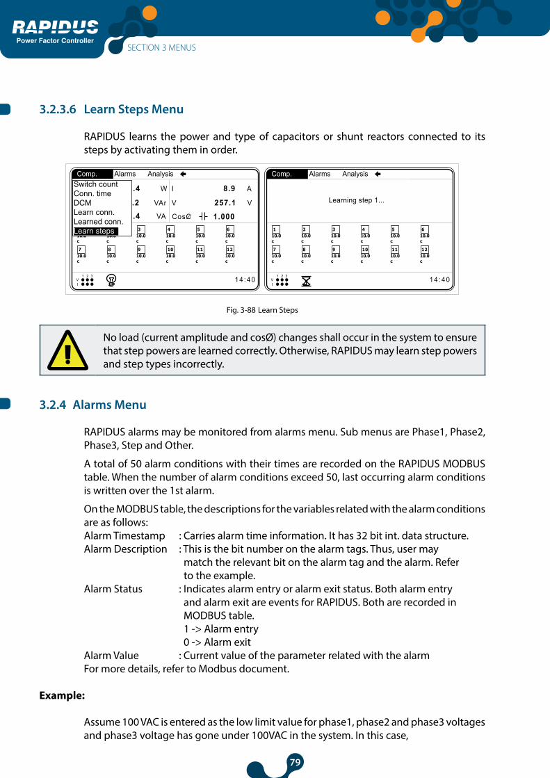
79
Power Factor Controller
3.2.3.6 Learn Steps Menu
RAPIDUS learns the power and type of capacitors or shunt reactors connected to its steps by activating them in order.
Qind/P 0 %
Qcap/P0 5c
0 %
CosØ1
CosØ2
CosØ3 1.0001.0001.000
110.0c
1 4 : 4 0V1 2 3
I
1 2
210.0c
310.0c
410.0c
510.0c
610.0c
710.0c
810.0c
910.0c
1010.0c
1110.0c
1210.0c
Learning step 1...
Comp. Alarms Analysis
110.0c
1 4 : 4 0V1 2 3
I
1 2
210.0c
310.0c
410.0c
510.0c
610.0c
710.0c
810.0c
910.0c
1010.0c
1110.0c
1210.0c
Comp. Alarms Analysis
P 1326.4 W I 8.9 A
V 257.1 V
1.000 S 1326.4 VA
Q 4.2 VAr
Switch countConn. timeDCMLearn conn.Learned conn.Learn steps
Fig. 3-88 Learn Steps
No load (current amplitude and cosØ) changes shall occur in the system to ensure that step powers are learned correctly. Otherwise, RAPIDUS may learn step powers and step types incorrectly.
3.2.4 Alarms Menu
RAPIDUS alarms may be monitored from alarms menu. Sub menus are Phase1, Phase2, Phase3, Step and Other.
A total of 50 alarm conditions with their times are recorded on the RAPIDUS MODBUS table. When the number of alarm conditions exceed 50, last occurring alarm conditions is written over the 1st alarm.
On the MODBUS table, the descriptions for the variables related with the alarm conditions are as follows:Alarm Timestamp : Carries alarm time information. It has 32 bit int. data structure.Alarm Description : This is the bit number on the alarm tags. Thus, user may match the relevant bit on the alarm tag and the alarm. Refer to the example.Alarm Status : Indicates alarm entry or alarm exit status. Both alarm entry and alarm exit are events for RAPIDUS. Both are recorded in MODBUS table. 1 -> Alarm entry 0 -> Alarm exitAlarm Value : Current value of the parameter related with the alarmFor more details, refer to Modbus document.
Example:
Assume 100 VAC is entered as the low limit value for phase1, phase2 and phase3 voltages and phase3 voltage has gone under 100VAC in the system. In this case,
SECTION 3 MENUS

80
Power Factor Controller
Alarm Description is the index number of the relevant alarm bit in the alarm tags. Thus, for the condition above, “alarm description value” shall be 3.
Briefly, you can use the number under this heading as an index in the alarm tags to reach the description of alarm. Moreover, user matches the alarm and alarm tag.
110.0c
1 4 : 4 0V1 2 3
I
1 2
210.0c
310.0c
410.0c
510.0c
610.0c
710.0c
810.0c
910.0c
1010.0c
1110.0c
1210.0c
Alarms Analysis
P 1326.4 W I 8.9 A
V 257.1 V
1.000 S 1326.4 VA
Q 4.2 VAr
Phase1Phase2Phase3StepsOther
Fig. 3-89 Alarms Menu
3.2.4.1 Phase1 Menu
Statuses of alarms pertaining to 1st phase are shown in Phase1 menu.“Normal” NO Alarm “Alarm” Alarm AVAILABLE
Alarms->Phase 1V AlarmI NormalP NormalQ NormalS NormalCosØ NormalPF NormalV harmonics NormalTHDV NormalI harmonics NormalTHDI NormalF Normal
Fig. 3-90 Phase1 Menu
Following alarm statuses are monitored in Phase1 menu.• V (phase-neutral voltage)• I (current)• P (active power)• Q (reactive power)• S (apparent power)• CosØ• PF (power factor)• V harmonics (up to 21st voltage harmonics)• THDV voltage (total harmonics distortion in the voltage)
SECTION 3 MENUS
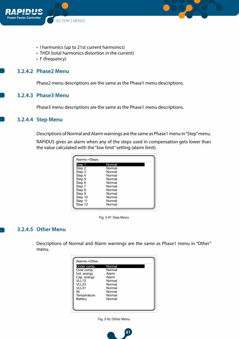
81
Power Factor Controller
• I harmonics (up to 21st current harmonics)• THDI (total harmonics distortion in the current) • F (frequency)
3.2.4.2 Phase2 Menu
Phase2 menu descriptions are the same as the Phase1 menu descriptions.
3.2.4.3 Phase3 Menu
Phase3 menu descriptions are the same as the Phase1 menu descriptions.
3.2.4.4 Step Menu
Descriptions of Normal and Alarm warnings are the same as Phase1 menu in “Step” menu.
RAPIDUS gives an alarm when any of the steps used in compensation gets lower than the value calculated with the “low limit” setting (alarm limit).
Alarms->StepsStep 1 NormalStep 2 NormalStep 3 NormalStep 4 NormalStep 5 NormalStep 6 NormalStep 7 NormalStep 8 NormalStep 9 NormalStep 10 NormalStep 11 NormalStep 12 Normal
Fig. 3-91 Step Menu
3.2.4.5 Other Menu
Descriptions of Normal and Alarm warnings are the same as Phase1 menu in “Other” menu.
Alarms->OtherUnder comp. NormalOver comp. NormalInd. energy AlarmCap. energy AlarmVLL12 NormalVLL23 NormalVLL31 NormalIN NormalTemperature NormalBattery Normal
Fig. 3-92 Other Menu
SECTION 3 MENUS
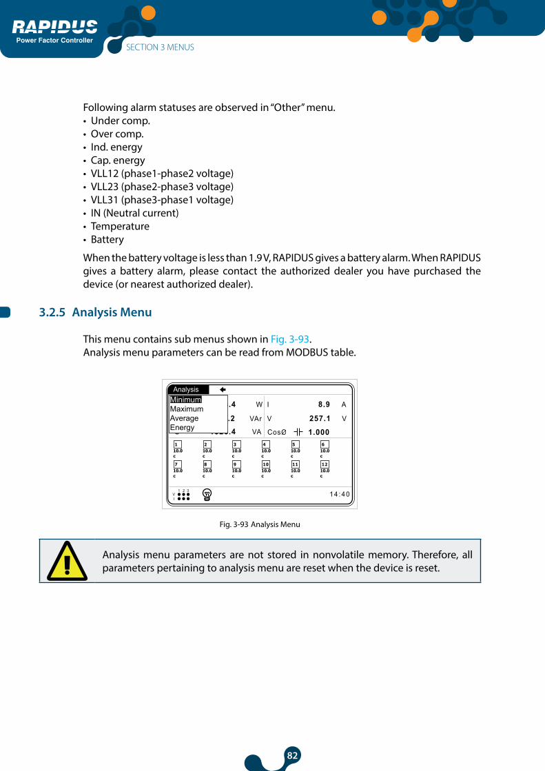
82
Power Factor Controller
Following alarm statuses are observed in “Other” menu.• Under comp.• Over comp.• Ind. energy• Cap. energy • VLL12 (phase1-phase2 voltage)• VLL23 (phase2-phase3 voltage)• VLL31 (phase3-phase1 voltage)• IN (Neutral current)• Temperature• Battery
When the battery voltage is less than 1.9 V, RAPIDUS gives a battery alarm. When RAPIDUS gives a battery alarm, please contact the authorized dealer you have purchased the device (or nearest authorized dealer).
3.2.5 Analysis Menu
This menu contains sub menus shown in Fig. 3-93. Analysis menu parameters can be read from MODBUS table.
110.0c
1 4 : 4 0V1 2 3
I
1 2
210.0c
310.0c
410.0c
510.0c
610.0c
710.0c
810.0c
910.0c
1010.0c
1110.0c
1210.0c
Analysis
P 1326.4 W I 8.9 A
V 257.1 V
1.000 S 1326.4 VA
Q 4.2 VAr
MinimumMaximumAverageEnergy
Fig. 3-93 Analysis Menu
Analysis menu parameters are not stored in nonvolatile memory. Therefore, all parameters pertaining to analysis menu are reset when the device is reset.
SECTION 3 MENUS

83
Power Factor Controller
3.2.5.1 Minimum Menu
This menu includes hourly, daily and monthly minimum values.
110.0c
1 4 : 4 0V1 2 3
I
1 2
210.0c
310.0c
410.0c
510.0c
610.0c
710.0c
810.0c
910.0c
1010.0c
1110.0c
1210.0c
Analysis
P 1326.4 W I 8.9 A
V 257.1 V
1.000 S 1326.4 VA
Q 4.2 VAr
MinimumMaximumAverageEnergy
HourlyDailyMonthly
Fig. 3-94 Minimum Menu
3.2.5.1.1 Hourly Menu
This menu includes minimum ‘instantaneous’ values measured from the start of the hour to current time.
110.0c
1 4 : 4 0V1 2 3
I
1 2
210.0c
310.0c
410.0c
510.0c
610.0c
710.0c
810.0c
910.0c
1010.0c
1110.0c
1210.0c
Analysis
P 1326.4 W I 8.9 A
V 257.1 V
1.000 S 1326.4 VA
Q 4.2 VAr
MinimumMaximumAverageEnergy
HourlyDailyMonthly
Phase1Phase2Phase3Other
Fig. 3-95 Hourly Menu
3.2.5.1.1.1 Phase1 Menu
Voltage (V), current (I), active power (P), reactive power (Q), apparent power (S), cosØ, power factor (PF) and frequency (F) values are displayed.
3.2.5.1.1.2 Phase2 Menu
Voltage (V), current (I), active power (P), reactive power (Q), apparent power (S), cosØ, power factor (PF) and frequency (F) values are displayed.
3.2.5.1.1.3 Phase3 Menu
Voltage (V), current (I), active power (P), reactive power (Q), apparent power (S), cosØ, power factor (PF) and frequency (F) values are displayed.
SECTION 3 MENUS

84
Power Factor Controller
3.2.5.1.1.4 Other
VLL12 (phase1-phase2 voltage), VLL23 (phase2-phase3 voltage), VLL31 (phase3-phase1 voltage)
3.2.5.1.2 Daily Menu
This menu includes minimum “instantaneous” values measured from the starting hour of the day (Refer to 3.2.1.2.6.1) to current time. Descriptions of sub menus are the same as the hourly menu.
3.2.5.1.3 Monthly Menu
This menu includes minimum “instantaneous” values measured from the starting day of the month (Refer to 3.2.1.2.6.2) and starting hour of the day (Refer to 3.2.1.2.6.1) to current time. Descriptions of sub menus are the same as the hourly menu.
3.2.5.2 Maximum Menu
Sub menus and descriptions of the sub menus of the “Maximum” menu are the same as “Minimum” menu. Values measured in “Maximum” menu are also “instantaneous” maximum values.
3.2.5.3 Average Menu
Sub menus and descriptions of the sub menus of the “Average” menu are the same as “Maximum” menu. “Average” menu displays the “average” values taken in hourly, daily and monthly periods.
3.2.5.4 Energy Menu
This menu includes hourly, daily and monthly counter values.
110.0c
1 4 : 4 0V1 2 3
I
1 2
210.0c
310.0c
410.0c
510.0c
610.0c
710.0c
810.0c
910.0c
1010.0c
1110.0c
1210.0c
Analysis
P 1326.4 W I 8.9 A
V 257.1 V
1.000 S 1326.4 VA
Q 4.2 VAr
MinimumMaximumAverageEnergy
HourlyDailyMonthly
Fig. 3-96 Energy Menu
SECTION 3 MENUS

85
Power Factor Controller
3.2.5.4.1 Hourly Menu
This menu includes counter values measured from the start of the hour to current time.
kWh (imp. active), kWh E. (exp. active), kVArh I (inductive reactive), kVArh C. (capacitive reactive) counter values are displayed.
3.2.5.4.2 Daily Menu
This menu includes counter values measured from the starting hour of the day (Refer to3.2.1.2.6.1) to current time.
kWh (imp. active), kWh E. (exp. active), kVArh I (inductive reactive), kVArh C. (capacitive reactive) counter values are displayed.
3.2.5.4.3 Monthly Menu
This menu includes counter values measured from the starting day of the month (Refer to. 3.2.1.2.6.2) and starting hour of the day (Refer to 3.2.1.2.6.1) to current time.
kWh (imp. active), kWh E. (exp. active), kVArh I (inductive reactive), kVArh C. (capacitive reactive) counter values are displayed.
SECTION 3 MENUS

86
Power Factor ControllerSECTION 4 MODBUS PROTOCOL
SECTION 4FACTORYPRESETS
Power Factor Controller

87
Power Factor Controller
SECTION 4 FACTORY PRESETS
Factory Presets Unit Setting Values
Network Settings
CTR 1 - 1 5000
VTR 1 - 1.0 5000.0
Demand Period 15 min 1 60
Step Settings
Ent. Power 10 kVAr 0.00 1000.00
Ent. Type C -
C, C1, C2, C3,L, L1, L2, L3
Predefined Structure 1-1-1-1 -
1-1-1-1,1-1-2-2, 1-2-2-4, 1-2-3-3, 1-2-4-4, 1-1-2-4, 1-2-3-4, 1-2-4-8, 1-1-2-3
Predefined Power 10 kVar 0.00 1000.00
Number of Predefined Steps 12 - 1 12 / 1 24
Discharge Time 15 s 3 1000
Compensation Settings
Steps Entered - Entered, Predefined
Program Rapidus -
Rapidus, Ascending Sequential, Descending Sequential, Linear, Circular, Manual
Target 1 Ind. 1.000 - 0.800 1.000
Target 1 Cap. 1.000 - 0.800 1.000
Target 2 Ind. 1.000 - 0.800 1.000
Target 2 Cap. 1.000 - 0.800 1.000
Activation Time 10 s 1 500
Deactivation Time 10 s 1 500
Shift Angle 0.00 º -45.00 º 45.00 º
SECTION 4 FACTORY PRESETS
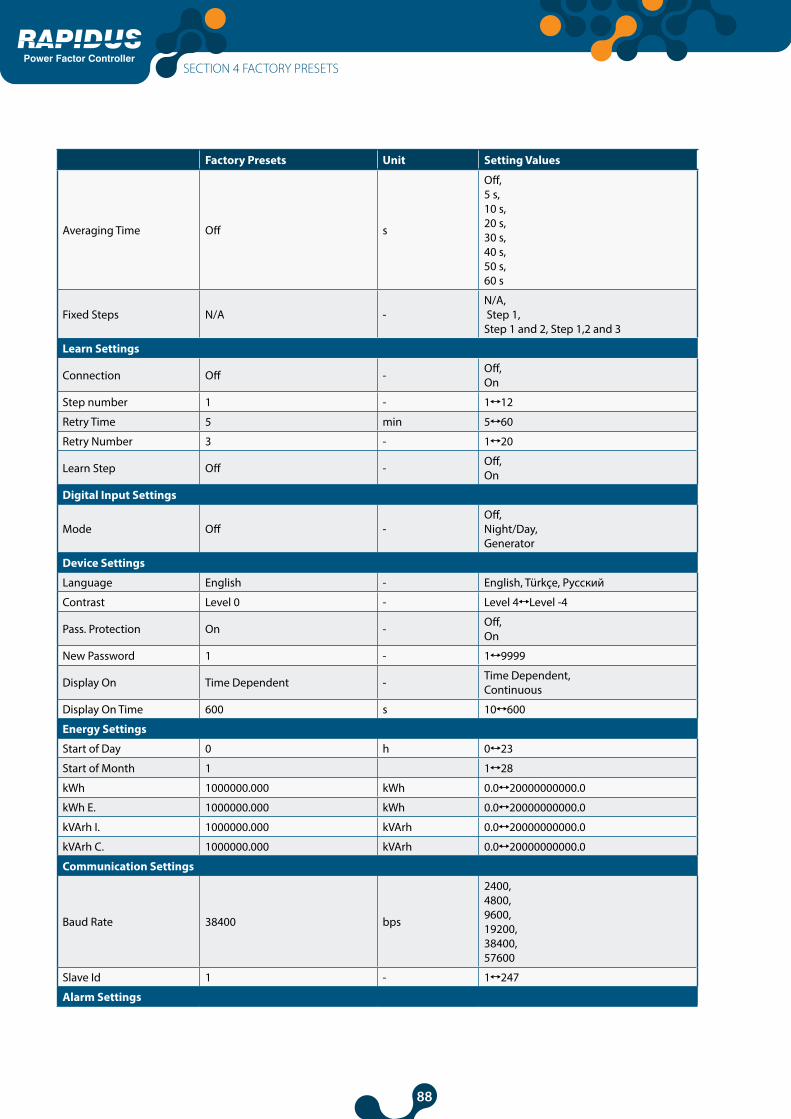
88
Power Factor Controller
Factory Presets Unit Setting Values
Averaging Time Off s
Off,5 s,10 s,20 s,30 s,40 s,50 s,60 s
Fixed Steps N/A -N/A, Step 1, Step 1 and 2, Step 1,2 and 3
Learn Settings
Connection Off - Off,On
Step number 1 - 1 12
Retry Time 5 min 5 60
Retry Number 3 - 1 20
Learn Step Off - Off,On
Digital Input Settings
Mode Off -Off,Night/Day,Generator
Device Settings
Language English - English, Türkçe, Pусский
Contrast Level 0 - Level 4 Level -4
Pass. Protection On - Off,On
New Password 1 - 1 9999
Display On Time Dependent - Time Dependent,Continuous
Display On Time 600 s 10 600
Energy Settings
Start of Day 0 h 0 23
Start of Month 1 1 28
kWh 1000000.000 kWh 0.0 20000000000.0
kWh E. 1000000.000 kWh 0.0 20000000000.0
kVArh I. 1000000.000 kVArh 0.0 20000000000.0
kVArh C. 1000000.000 kVArh 0.0 20000000000.0
Communication Settings
Baud Rate 38400 bps
2400,4800,9600,19200,38400,57600
Slave Id 1 - 1 247
Alarm Settings
SECTION 4 FACTORY PRESETS

89
Power Factor Controller
Factory Presets Unit Setting Values
Energy
Inductive Hi Limit 20.0 % 0.0 40.0
Alarm Relay Off -Off,Relay1,Relay2
Capacitive Hi Limit 15.0 % 0.0 40.0
Alarm Relay Off -Off,Relay1,Relay2
V (L-N)
Alarm Relay Off -Off,Relay1,Relay2
Low Limit 0.0 V 0.0 1500000
High Limit 0.0 V 0.0 1500000
Delay 0 s 0 600
Hysteresis 0.0 % 0.0 20
V (L-L)
Alarm Relay Off -Off,Relay1,Relay2
Low Limit 0.0 V 0.0 2600000
High Limit 0.0 V 0.0 2600000
Delay 0 s 0 600
Hysteresis 0.0 % 0.0 20
Current, IN
Alarm Relay Off -Off,Relay1,Relay2
Low Limit 0.0 A 0.0 30000.0
High Limit 0.0 A 0.0 30000.0
Delay 0 s 0 600
Hysteresis 0.0 % 0.0 20
P
Alarm Relay Off -Off,Relay1,Relay2
Low Limit 0.0 W -1000000000.0 10000000000.0
High Limit 0.0 W -1000000000.0 10000000000.0
Delay 0 s 0 600
Hysteresis 0.0 % 0.0 20
Q
Alarm Relay Off -Off,Relay1,Relay2
Low Limit 0.0 VAr -1000000000.0 10000000000.0
High Limit 0.0 VAr -1000000000.0 10000000000.0
Delay 0 s 0 600
Hysteresis 0.0 % 0.0 20
SECTION 4 FACTORY PRESETS

90
Power Factor Controller
Factory Presets Unit Setting Values
S
Alarm Relay Off -Off,Relay1,Relay2
Low Limit 0.0 VA 0.0 10000000000.0
High Limit 0.0 VA 0.0 10000000000.0
Delay 0 s 0 600
Hysteresis 0.0 % 0.0 20
CosØ, PF
Alarm Relay Off -Off,Relay1,Relay2
Low Limit 0.000 - 0.000 1.000
High Limit 0.000 - 0.000 1.000
Delay 0 s 0 600
Hysteresis 0.0 % 0.0 20
Step
Low Limit 20.0 - 20.0 100.0
F
Alarm Relay Off -Off,Relay1,Relay2
Low Limit 50.0 Hz 45.0 65.0
High Limit 50.0 Hz 45.0 65.0
Delay 0 s 0 600
Hysteresis 0.0 % 0.0 20
Harmonics V
Alarm Relay Off -Off,Relay1,Relay2
THDV Hi Limit 0.0 % 0.0 100.0
V3 Hi Limit 0.0 % 0.0 100.0
V5 Hi Limit 0.0 % 0.0 100.0
V7 Hi Limit 0.0 % 0.0 100.0
V9 Hi Limit 0.0 % 0.0 100.0
V11 Hi Limit 0.0 % 0.0 100.0
V13 Hi Limit 0.0 % 0.0 100.0
V15 Hi Limit 0.0 % 0.0 100.0
V17 Hi Limit 0.0 % 0.0 100.0
V19 Hi Limit 0.0 % 0.0 100.0
V21 Hi Limit 0.0 % 0.0 100.0
Harmonics I
Alarm Relay Off -Off,Relay1,Relay2
THDI Hi Limit 0.0 % 0.0 100.0
I3 Hi Limit 0.0 % 0.0 100.0
SECTION 4 FACTORY PRESETS
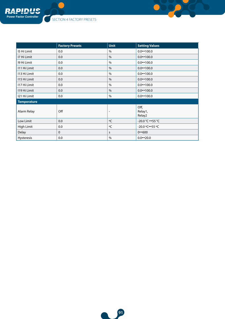
91
Power Factor Controller
Factory Presets Unit Setting Values
I5 Hi Limit 0.0 % 0.0 100.0
I7 Hi Limit 0.0 % 0.0 100.0
I9 Hi Limit 0.0 % 0.0 100.0
I11 Hi Limit 0.0 % 0.0 100.0
I13 Hi Limit 0.0 % 0.0 100.0
I15 Hi Limit 0.0 % 0.0 100.0
I17 Hi Limit 0.0 % 0.0 100.0
I19 Hi Limit 0.0 % 0.0 100.0
I21 Hi Limit 0.0 % 0.0 100.0
Temperature
Alarm Relay Off -Off,Relay1,Relay2
Low Limit 0.0 ºC -20.0 °C 55 °C
High Limit 0.0 ºC -20.0 ºC 55 ºC
Delay 0 s 0 600
Hysteresis 0.0 % 0.0 20.0
SECTION 4 FACTORY PRESETS

92
Power Factor Controller
SECTION 5TECHNICAL
SPECIFICATIONS
Power Factor Controller

93
Power Factor Controller
SECTION 5 TECHNICAL SPECIFICATIONS
Supply Voltage .........................................95 .. 272 VAC RMS Frequency ...................................45..65 Hz
Measurement Inputs Voltage .........................................85..300 V RMS (L-N) Current .........................................0.01..6 A RMS Frequency ...................................45..65 Hz Night/Day Input ........................85..265VAC RMS
Measurement Accuracy
Relay Outputs for Compensation12/24 pcs., Max. switching voltage ....................... : 250 VACMax. switchig current........................... : 1.5 A (all relays active) 5.0 A (only one relay is activated) Alarm Relay Outputs:2 pcs,Max. switching current ........................ : 4AMax. switching voltage ....................... : 250 VACMax. switching power .......................... : 1250 VA
SECTION 5 TECHNICAL SPECIFICATIONS
FunctionSymbol Function
Function Performance
Class According to IEC 61557-12
Measuring Range Other Complementary Characteristics
P Total active power 0,2 10 % Ib ≤ I ≤ Imax 0,5 Ind to 0,8 Cap -
QV Total reactive power 1 5 % Ib ≤ I ≤ Imax 0,25 Ind to 0,25 Cap -
SA Total apparent power 0,2 10 % Ib ≤ I ≤ Imax 0,5 Ind to 0,8 Cap -
EA Total active energy 0,2 0 to 49999999999 IEC 62053-22 Class 0.2S
ErV Total reactive energy 2 0 to 49999999999 IEC 62053-23 Class 2
f Frequency 0,05 45 – 65 Hz -
I Phase current 0,2 20 % Ib ≤ I ≤ Imax -
INc Neutral current (calculated) 0,2 20 % Ib ≤ I ≤ Imax -
U Voltage 0,2 Umin ≤ U ≤ Umax -
PFA Power factor 0,5 0,5 Ind to 0,8 Cap -
THDV Total harmonic distortion voltage 1 0 % to 20 % -
THDI Total harmonic distortion current 1 0 % to 100 % -

94
Power Factor Controller
Number of Steps Can be selected between 1-12/1-24.
Target CosØ Interval 0.800-1.000 (ind.-cap.) can be selected with 0.001 steps.
CTR Can be set 1..5000.
VTR Can be set 1..5000.
Demand Period Can be set 1 to 60 minutes.
User Interface Keypad ......................................... : 6 keys with ESD protection LCD ................................................ : Self-illuminated 160 x 240 graphicCommunication Isolated RS485 Port.................. :1 Channel, ESD and over current/voltage protected, programmable, 2400bps to 57600 bps baud rate. 2000VRMS isolation.
Operating Temperature -20°C..+55°C
Storage Temperature -30°C..+80°C
Relative Humidity Maximum 95% No Condensation
Dimensions W144 x H144 x D78
Protection class IP40
Power Consumption <10VA
SECTION 5 TECHNICAL SPECIFICATIONS

95
Power Factor Controller
www.klemsan.com.tr