USER INSTRUCTION MANUAL LANYARDS WITH INTEGRAL ...
16
© Copyright 2009, DB Industries, Inc. WARNING: This product is part of a personal restraint, work positioning, suspension, or rescue system. These instructions must be provided to the user and rescuer (see section 8 Terminology). The user must read and understand these instructions or have them explained to them before using this equipment. The user must read and follow the manufacturer’s instructions for each component or part of the complete system. Manufacturer’s instructions must be followed for proper use and maintenance of this product. Alterations or misuse of this product or failure to follow instructions may result in serious injury or death. IMPORTANT: If you have any questions on the use, care, application, or suitability for use of this equipment, contact DBI-SALA. IMPORTANT: Before using this equipment record the product identification information (found on the I.D. label) in the inspection and maintenance log in section 10.0 of this manual. USER INSTRUCTION MANUAL LANYARDS WITH INTEGRAL ENERGY ABSORBERS AND ENERGY ABSORBER COMPONENTS USED IN PERSONAL FALL ARREST SYSTEMS (ANSI Z359.1) Figure 1 - EZ STOP ® Lanyards Instructions for the following series products: EZ Stop Lanyards ShockWave Lanyards EZ Stop Retrax Lanyards (See back pages for specific model numbers.) EZ Stop II Web Lanyards EZ Stop II Shockwave Lanyards EZ Stop II Cable Lanyards EZ Stop II Tie-back Lanyards EZ Stop III Web Lanyards EZ Stop III Energy Absorber Component EZ Stop Retrax Retracting Lanyard Shockwave 2 Lanyard DESCRIPTIONS EZ STOP® II WEB LANYARDS 1-in. (2.5 cm) web, 9503175 hook each end. 1-in. (2.5 cm) web, 9503175 hook one end, 2007153 hook other end. 1-in. (2.5 cm) web, 9503175 hook one end, 1200049 wire pipe clamp other end. 1-in. (2.5 cm) web, 9503175 hook one end, 2000108 carabiner other end. 1-in. (2.5 cm) web, web loop one end, 2007153 hook other end. 1-in. (2.5 cm) web, web loop one end, 9503175 hook other end. 1-in. (2.5 cm) web, adjustable, 9503175 hook each end. 1-in. (2.5 cm) web, 100% tie-off, 9503175 hook center, 2007153 hook leg ends. 1-in. (2.5 cm) web, 100% tie-off, 9503175 hook center and leg ends. 1-in. (2.5 cm) web, 100% tie-off, 9503175 hook center, 2000108 carabiner leg ends. 1-in. (2.5 cm) web, 100% tie-off, web loop center, 2007153 hook leg ends. 1-in. (2.5 cm) web, 100% tie-off, web loop center, 9503175 hook leg ends. This manual is intended to meet the Manufacturer’s Instructions as required by ANSI Z359.1, and should be used as part of an employee training program as required by OSHA. Form: 5902143 Rev: K
-
Upload
nguyenthuan -
Category
Documents
-
view
228 -
download
8
Transcript of USER INSTRUCTION MANUAL LANYARDS WITH INTEGRAL ...
© Copyright 2009, DB Industries, Inc.
WARNING: This product is part of a personal restraint, work positioning, suspension, or rescue system. These instructions must be provided to the user and rescuer (see section 8 Terminology). The user must read and understand these instructions or have them explained to them before using this equipment. The user must read and follow the manufacturer’s instructions for each component or part of the complete system. Manufacturer’s instructions must be followed for proper use and maintenance of this product. Alterations or misuse of this product or failure to follow instructions may result in serious injury or death.
IMPORTANT: If you have any questions on the use, care, application, or suitability for use of this equipment, contact DBI-SALA.
IMPORTANT: Before using this equipment record the product identifi cation information (found on the I.D. label) in the inspection and maintenance log in section 10.0 of this manual.
USER INSTRUCTION MANUALLANYARDS WITH INTEGRAL ENERGY ABSORBERS AND ENERGY ABSORBER COMPONENTS USED IN PERSONAL FALL ARREST SYSTEMS (ANSI Z359.1)
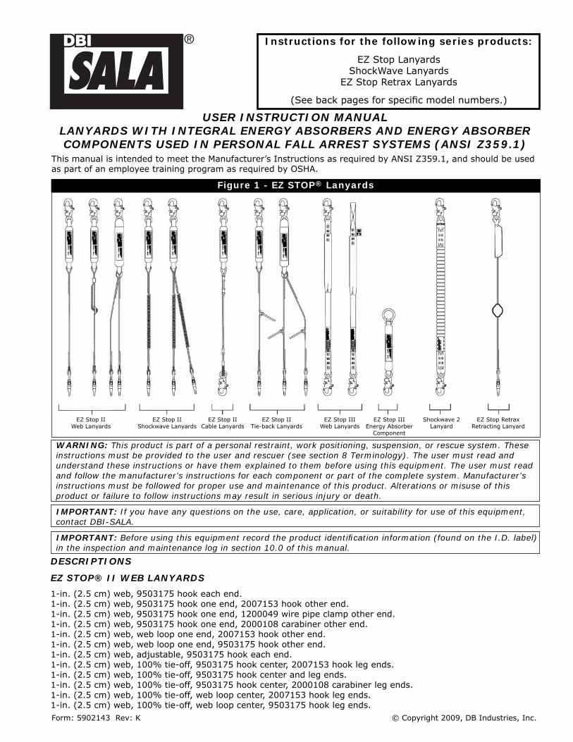
Figure 1 - EZ STOP® Lanyards
Instructions for the following series products:
EZ Stop LanyardsShockWave Lanyards
EZ Stop Retrax Lanyards
(See back pages for specifi c model numbers.)
EZ Stop IIWeb Lanyards
EZ Stop IIShockwave Lanyards
EZ Stop IICable Lanyards
EZ Stop IITie-back Lanyards
EZ Stop IIIWeb Lanyards
EZ Stop IIIEnergy Absorber
Component
EZ Stop RetraxRetracting Lanyard
Shockwave 2Lanyard
DESCRIPTIONS
EZ STOP® II WEB LANYARDS
1-in. (2.5 cm) web, 9503175 hook each end.1-in. (2.5 cm) web, 9503175 hook one end, 2007153 hook other end. 1-in. (2.5 cm) web, 9503175 hook one end, 1200049 wire pipe clamp other end.1-in. (2.5 cm) web, 9503175 hook one end, 2000108 carabiner other end.1-in. (2.5 cm) web, web loop one end, 2007153 hook other end.1-in. (2.5 cm) web, web loop one end, 9503175 hook other end.1-in. (2.5 cm) web, adjustable, 9503175 hook each end.1-in. (2.5 cm) web, 100% tie-off, 9503175 hook center, 2007153 hook leg ends.1-in. (2.5 cm) web, 100% tie-off, 9503175 hook center and leg ends.1-in. (2.5 cm) web, 100% tie-off, 9503175 hook center, 2000108 carabiner leg ends.1-in. (2.5 cm) web, 100% tie-off, web loop center, 2007153 hook leg ends.1-in. (2.5 cm) web, 100% tie-off, web loop center, 9503175 hook leg ends.
This manual is intended to meet the Manufacturer’s Instructions as required by ANSI Z359.1, and should be used as part of an employee training program as required by OSHA.
Form: 5902143 Rev: K
2
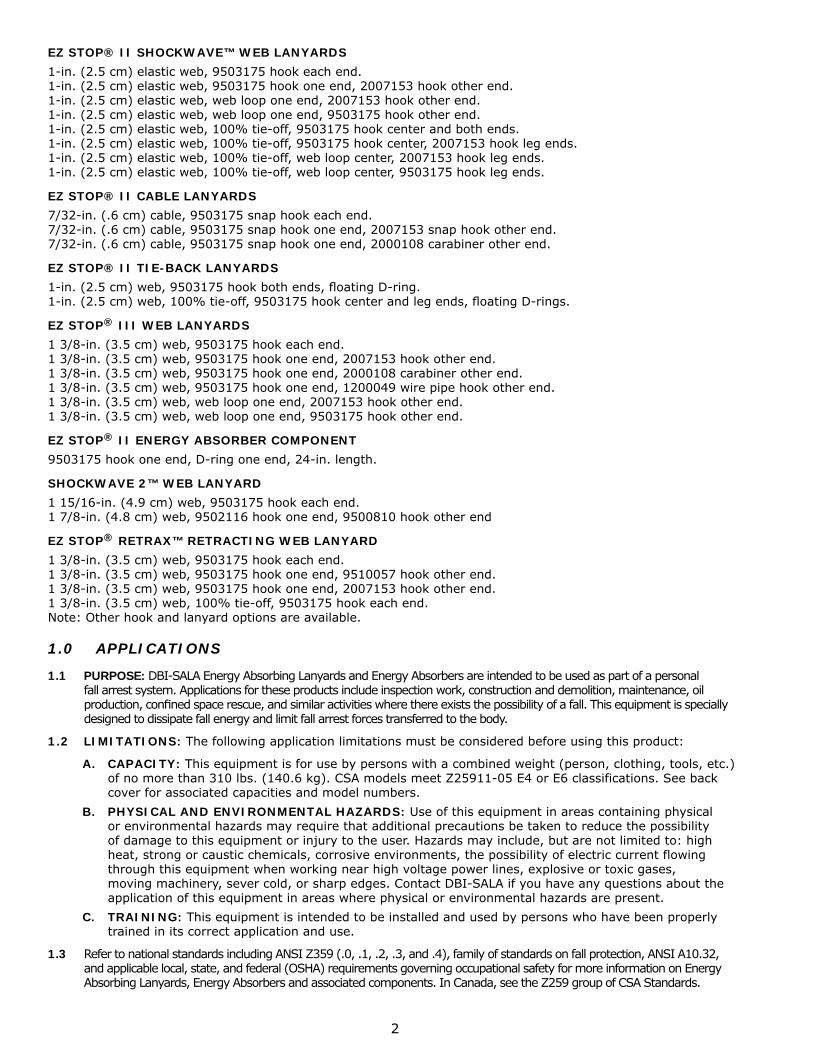
EZ STOP® II SHOCKWAVE™ WEB LANYARDS
1-in. (2.5 cm) elastic web, 9503175 hook each end.1-in. (2.5 cm) elastic web, 9503175 hook one end, 2007153 hook other end.1-in. (2.5 cm) elastic web, web loop one end, 2007153 hook other end.1-in. (2.5 cm) elastic web, web loop one end, 9503175 hook other end.1-in. (2.5 cm) elastic web, 100% tie-off, 9503175 hook center and both ends.1-in. (2.5 cm) elastic web, 100% tie-off, 9503175 hook center, 2007153 hook leg ends.1-in. (2.5 cm) elastic web, 100% tie-off, web loop center, 2007153 hook leg ends.1-in. (2.5 cm) elastic web, 100% tie-off, web loop center, 9503175 hook leg ends.
EZ STOP® II CABLE LANYARDS
7/32-in. (.6 cm) cable, 9503175 snap hook each end.7/32-in. (.6 cm) cable, 9503175 snap hook one end, 2007153 snap hook other end.7/32-in. (.6 cm) cable, 9503175 snap hook one end, 2000108 carabiner other end.
EZ STOP® II TIE-BACK LANYARDS
1-in. (2.5 cm) web, 9503175 hook both ends, fl oating D-ring.1-in. (2.5 cm) web, 100% tie-off, 9503175 hook center and leg ends, fl oating D-rings.
EZ STOP® III WEB LANYARDS
1 3/8-in. (3.5 cm) web, 9503175 hook each end.1 3/8-in. (3.5 cm) web, 9503175 hook one end, 2007153 hook other end.1 3/8-in. (3.5 cm) web, 9503175 hook one end, 2000108 carabiner other end.1 3/8-in. (3.5 cm) web, 9503175 hook one end, 1200049 wire pipe hook other end.1 3/8-in. (3.5 cm) web, web loop one end, 2007153 hook other end.1 3/8-in. (3.5 cm) web, web loop one end, 9503175 hook other end.
EZ STOP® II ENERGY ABSORBER COMPONENT
9503175 hook one end, D-ring one end, 24-in. length.
SHOCKWAVE 2™ WEB LANYARD
1 15/16-in. (4.9 cm) web, 9503175 hook each end.1 7/8-in. (4.8 cm) web, 9502116 hook one end, 9500810 hook other end
EZ STOP® RETRAX™ RETRACTING WEB LANYARD
1 3/8-in. (3.5 cm) web, 9503175 hook each end.1 3/8-in. (3.5 cm) web, 9503175 hook one end, 9510057 hook other end.1 3/8-in. (3.5 cm) web, 9503175 hook one end, 2007153 hook other end.1 3/8-in. (3.5 cm) web, 100% tie-off, 9503175 hook each end.Note: Other hook and lanyard options are available.
1.0 APPLICATIONS
1.1 PURPOSE: DBI-SALA Energy Absorbing Lanyards and Energy Absorbers are intended to be used as part of a personal fall arrest system. Applications for these products include inspection work, construction and demolition, maintenance, oil production, confi ned space rescue, and similar activities where there exists the possibility of a fall. This equipment is specially designed to dissipate fall energy and limit fall arrest forces transferred to the body.
1.2 LIMITATIONS: The following application limitations must be considered before using this product:
A. CAPACITY: This equipment is for use by persons with a combined weight (person, clothing, tools, etc.) of no more than 310 lbs. (140.6 kg). CSA models meet Z25911-05 E4 or E6 classifications. See back cover for associated capacities and model numbers.
B. PHYSICAL AND ENVIRONMENTAL HAZARDS: Use of this equipment in areas containing physical or environmental hazards may require that additional precautions be taken to reduce the possibility of damage to this equipment or injury to the user. Hazards may include, but are not limited to: high heat, strong or caustic chemicals, corrosive environments, the possibility of electric current flowing through this equipment when working near high voltage power lines, explosive or toxic gases, moving machinery, sever cold, or sharp edges. Contact DBI-SALA if you have any questions about the application of this equipment in areas where physical or environmental hazards are present.
C. TRAINING: This equipment is intended to be installed and used by persons who have been properly trained in its correct application and use.
1.3 Refer to national standards including ANSI Z359 (.0, .1, .2, .3, and .4), family of standards on fall protection, ANSI A10.32, and applicable local, state, and federal (OSHA) requirements governing occupational safety for more information on Energy Absorbing Lanyards, Energy Absorbers and associated components. In Canada, see the Z259 group of CSA Standards.
3
2.0 SYSTEM REQUIREMENTS
2.1 COMPATIBILITY OF CONNECTORS: DBI-SALA equipment is designed for use with DBI-SALA approved components and subsystems only. Substitutions or replacements made with non-approved components or subsystems may jeopardize compatibility of equipment and may effect the safety and reliability of the complete system.
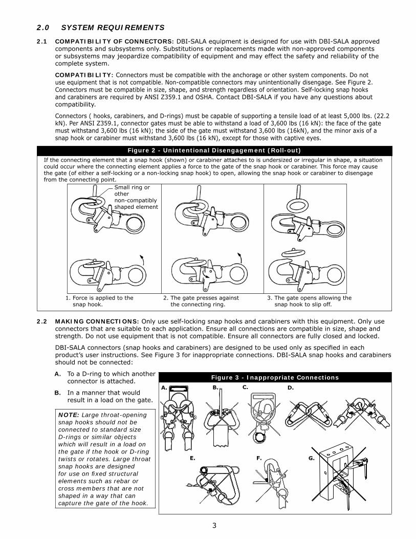
COMPATIBILITY: Connectors must be compatible with the anchorage or other system components. Do not use equipment that is not compatible. Non-compatible connectors may unintentionally disengage. See Figure 2. Connectors must be compatible in size, shape, and strength regardless of orientation. Self-locking snap hooks and carabiners are required by ANSI Z359.1 and OSHA. Contact DBI-SALA if you have any questions about compatibility.
Connectors ( hooks, carabiners, and D-rings) must be capable of supporting a tensile load of at least 5,000 lbs. (22.2 kN). Per ANSI Z359.1, connector gates must be able to withstand a load of 3,600 lbs (16 kN): the face of the gate must withstand 3,600 lbs (16 kN); the side of the gate must withstand 3,600 lbs (16kN), and the minor axis of a snap hook or carabiner must withstand 3,600 lbs (16 kN), except for those with captive eyes.
If the connecting element that a snap hook (shown) or carabiner attaches to is undersized or irregular in shape, a situation could occur where the connecting element applies a force to the gate of the snap hook or carabiner. This force may cause the gate (of either a self-locking or a non-locking snap hook) to open, allowing the snap hook or carabiner to disengage from the connecting point.
1. Force is applied to the snap hook.
2. The gate presses against the connecting ring.
3. The gate opens allowing the snap hook to slip off.
Figure 2 - Unintentional Disengagement (Roll-out)
Small ring or othernon-compatibly shaped element
2.2 MAKING CONNECTIONS: Only use self-locking snap hooks and carabiners with this equipment. Only use connectors that are suitable to each application. Ensure all connections are compatible in size, shape and strength. Do not use equipment that is not compatible. Ensure all connectors are fully closed and locked.
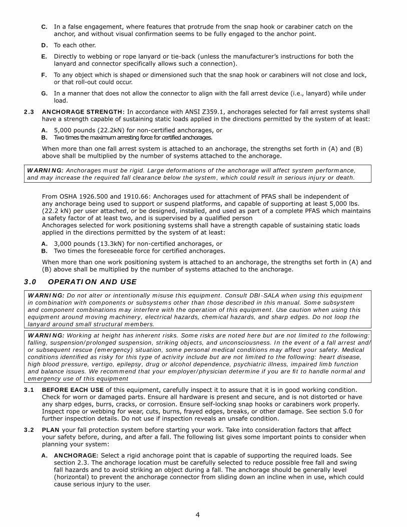
DBI-SALA connectors (snap hooks and carabiners) are designed to be used only as specifi ed in each product’s user instructions. See Figure 3 for inappropriate connections. DBI-SALA snap hooks and carabiners should not be connected:
A. To a D-ring to which another connector is attached.
B. In a manner that would result in a load on the gate.
NOTE: Large throat-opening snap hooks should not be connected to standard size D-rings or similar objects which will result in a load on the gate if the hook or D-ring twists or rotates. Large throat snap hooks are designed for use on fi xed structural elements such as rebar or cross members that are not shaped in a way that can capture the gate of the hook.
Figure 3 - Inappropriate Connections
4
C. In a false engagement, where features that protrude from the snap hook or carabiner catch on the anchor, and without visual confirmation seems to be fully engaged to the anchor point.
D. To each other.
E. Directly to webbing or rope lanyard or tie-back (unless the manufacturer’s instructions for both the lanyard and connector specifically allows such a connection).
F. To any object which is shaped or dimensioned such that the snap hook or carabiners will not close and lock, or that roll-out could occur.
G. In a manner that does not allow the connector to align with the fall arrest device (i.e., lanyard) while under load.
2.3 ANCHORAGE STRENGTH: In accordance with ANSI Z359.1, anchorages selected for fall arrest systems shall have a strength capable of sustaining static loads applied in the directions permitted by the system of at least:
A. 5,000 pounds (22.2kN) for non-certified anchorages, orB. Two times the maximum arresting force for certified anchorages.
When more than one fall arrest system is attached to an anchorage, the strengths set forth in (A) and (B) above shall be multiplied by the number of systems attached to the anchorage.
WARNING: Anchorages must be rigid. Large deformations of the anchorage will affect system performance, and may increase the required fall clearance below the system, which could result in serious injury or death.
From OSHA 1926.500 and 1910.66: Anchorages used for attachment of PFAS shall be independent of any anchorage being used to support or suspend platforms, and capable of supporting at least 5,000 lbs. (22.2 kN) per user attached, or be designed, installed, and used as part of a complete PFAS which maintains a safety factor of at least two, and is supervised by a qualifi ed person Anchorages selected for work positioning systems shall have a strength capable of sustaining static loads applied in the directions permitted by the system of at least:
A. 3,000 pounds (13.3kN) for non-certified anchorages, orB. Two times the foreseeable force for certified anchorages.
When more than one work positioning system is attached to an anchorage, the strengths set forth in (A) and (B) above shall be multiplied by the number of systems attached to the anchorage.
3.0 OPERATION AND USE
WARNING: Do not alter or intentionally misuse this equipment. Consult DBI-SALA when using this equipment in combination with components or subsystems other than those described in this manual. Some subsystem and component combinations may interfere with the operation of this equipment. Use caution when using this equipment around moving machinery, electrical hazards, chemical hazards, and sharp edges. Do not loop the lanyard around small structural members.
WARNING: Working at height has inherent risks. Some risks are noted here but are not limited to the following: falling, suspension/prolonged suspension, striking objects, and unconsciousness. In the event of a fall arrest and/or subsequent rescue (emergency) situation, some personal medical conditions may affect your safety. Medical conditions identifi ed as risky for this type of activity include but are not limited to the following: heart disease, high blood pressure, vertigo, epilepsy, drug or alcohol dependence, psychiatric illness, impaired limb function and balance issues. We recommend that your employer/physician determine if you are fi t to handle normal and emergency use of this equipment
3.1 BEFORE EACH USE of this equipment, carefully inspect it to assure that it is in good working condition. Check for worn or damaged parts. Ensure all hardware is present and secure, and is not distorted or have any sharp edges, burrs, cracks, or corrosion. Ensure self-locking snap hooks or carabiners work properly. Inspect rope or webbing for wear, cuts, burns, frayed edges, breaks, or other damage. See section 5.0 for further inspection details. Do not use if inspection reveals an unsafe condition.
3.2 PLAN your fall protection system before starting your work. Take into consideration factors that affect your safety before, during, and after a fall. The following list gives some important points to consider when planning your system:
A. ANCHORAGE: Select a rigid anchorage point that is capable of supporting the required loads. See section 2.3. The anchorage location must be carefully selected to reduce possible free fall and swing fall hazards and to avoid striking an object during a fall. The anchorage should be generally level (horizontal) to prevent the anchorage connector from sliding down an incline when in use, which could cause serious injury to the user.
5
B. FREE FALL: Personal fall arrest systems must be rigged such that the potential free fall is never greater than 6 ft. (1.8 m). Avoid working above your anchorage level to avoid an increased free fall distance.
IMPORTANT: Some energy absorbing lanyards, such as EZ Stop® Retrax™ and the Shockwave lanyards, make use of retracting devices designed to shorten their free length. These devices do not decrease free fall distance
C. FALL ARREST FORCES: The assembled fall arrest system must keep fall arrest forces below 1,800 lbs. (8.0 kN) when used with a full body harness.
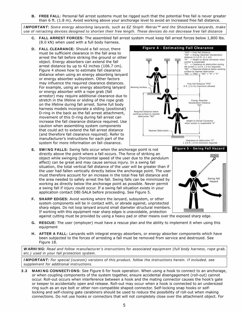
D. FALL CLEARANCE: Should a fall occur, there must be sufficient clearance in the fall area to arrest the fall before striking the ground or other object. Energy absorbers can extend the fall arrest distance by up to 42 inches (106.7 cm). Figure 4 shows how to estimate fall clearance distance when using an energy absorbing lanyard or energy absorber subsystem. Other factors may influence the required clearance distances. For example, using an energy absorbing lanyard or energy absorber with a rope grab (fall arrestor) may require additional clearance due to stretch in the lifeline or sliding of the rope grab on the lifeline during fall arrest. Some full body harness models incorporate a sliding (positional) D-ring in the back as the fall arrest attachment, movement of this D-ring during fall arrest can increase the fall clearance distance required. Use caution when assembling system components that could act to extend the fall arrest distance (and therefore fall clearance required). Refer to manufacturer’s instructions for each part of the system for more information on fall clearance.
E. SWING FALLS: Swing falls occur when the anchorage point is not directly above the point where a fall occurs. The force of striking an object while swinging (horizontal speed of the user due to the pendulum affect) can be great and may cause serious injury. In a swing fall situation, the total vertical fall distance of the user will be greater than if the user had fallen vertically directly below the anchorage point. The user must therefore account for an increase in the total free fall distance and the area needed to safely arrest the fall. Swing falls can be minimized by working as directly below the anchorage point as possible. Never permit a swing fall if injury could occur. If a swing fall situation exists in your application contact DBI-SALA before proceeding. See Figure 5.
F. SHARP EDGES: Avoid working where the lanyard, subsystem, or other system components will be in contact with, or abrade against, unprotected sharp edges. Do not loop lanyard around small diameter structural members. If working with this equipment near sharp edges is unavoidable, protection against cutting must be provided by using a heavy pad or other means over the exposed sharp edge.
G. RESCUE: The user (employer) must have a rescue plan and the ability to implement it when using this equipment
H. AFTER A FALL: Lanyards with integral energy absorbers, or energy absorber components which have been subjected to the forces of arresting a fall must be removed from service and destroyed. See Figure 18.
WARNING: Read and follow manufacturer’s instructions for associated equipment (full body harness, rope grab, etc.) used in your fall protection system.
IMPORTANT: For special (custom) versions of this product, follow the instructions herein. If included, see supplement for additional instructions.
3.3 MAKING CONNECTIONS: See Figure 6 for hook operation. When using a hook to connect to an anchorage, or when coupling components of the system together, ensure accidental disengagement (roll-out) cannot occur. Roll-out occurs when interference between a hook and the mating connector causes the hook’s gate or keeper to accidentally open and release. Roll-out may occur when a hook is connected to an undersized ring such as an eye bolt or other non-compatible shaped connector. Self-locking snap hooks or self-locking and self-closing gate carabiners should be used to reduce the possibility of roll-out when making connections. Do not use hooks or connectors that will not completely close over the attachment object. For
Figure 4 - Estimating Fall Clearance
Working Surface
Required Distance below working surface to nearest
obstruction “RD”
Nearest Obstruction
Free Fall Distance “FFD” 6 ft. (1.6 m) maximum allowed
Energy Absorber Deceleration Distance
“DD”
Height to Dorsal Connector when worker is suspended “H”
Clearance to obstruction “C” 1 1/2 ft. (.5 m) minimum required
“FFD” = Free Fall Distance“DD” = Energy Absorber Deceleration distance (3 1/2 ft. [1.1 m])“H” = Height to dorsal connector when worker is suspended“C” = Clearance to obstruction during fall arrest (1 1/2 ft. [.5 m] required)“RD” = Required distance below working surface to nearest obstruction“RD” = “FFD” + “DD” + “H” + “C”
Figure 5 - Swing Fall Hazard
Swing Fall Hazard
6
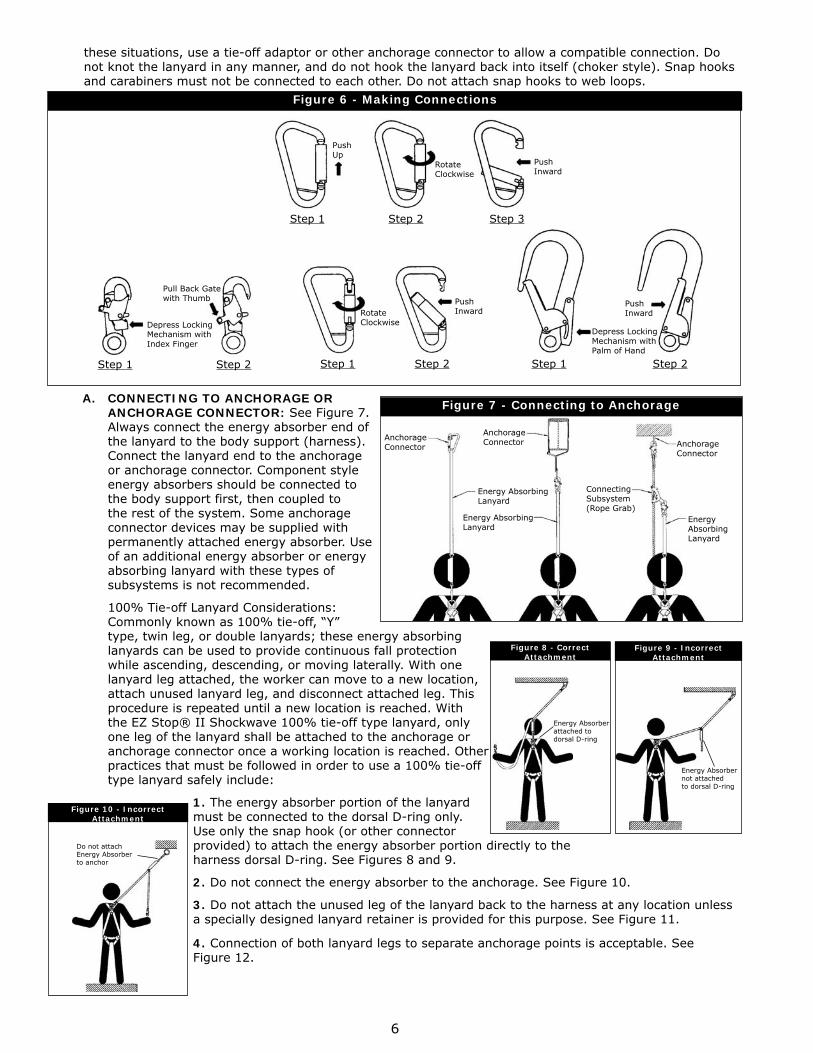
A. CONNECTING TO ANCHORAGE OR ANCHORAGE CONNECTOR: See Figure 7. Always connect the energy absorber end of the lanyard to the body support (harness). Connect the lanyard end to the anchorage or anchorage connector. Component style energy absorbers should be connected to the body support first, then coupled to the rest of the system. Some anchorage connector devices may be supplied with permanently attached energy absorber. Use of an additional energy absorber or energy absorbing lanyard with these types of subsystems is not recommended.
100% Tie-off Lanyard Considerations: Commonly known as 100% tie-off, “Y” type, twin leg, or double lanyards; these energy absorbing lanyards can be used to provide continuous fall protection while ascending, descending, or moving laterally. With one lanyard leg attached, the worker can move to a new location, attach unused lanyard leg, and disconnect attached leg. This procedure is repeated until a new location is reached. With the EZ Stop® II Shockwave 100% tie-off type lanyard, only one leg of the lanyard shall be attached to the anchorage or anchorage connector once a working location is reached. Other practices that must be followed in order to use a 100% tie-off type lanyard safely include:
1. The energy absorber portion of the lanyard must be connected to the dorsal D-ring only. Use only the snap hook (or other connector provided) to attach the energy absorber portion directly to the harness dorsal D-ring. See Figures 8 and 9.
2. Do not connect the energy absorber to the anchorage. See Figure 10.
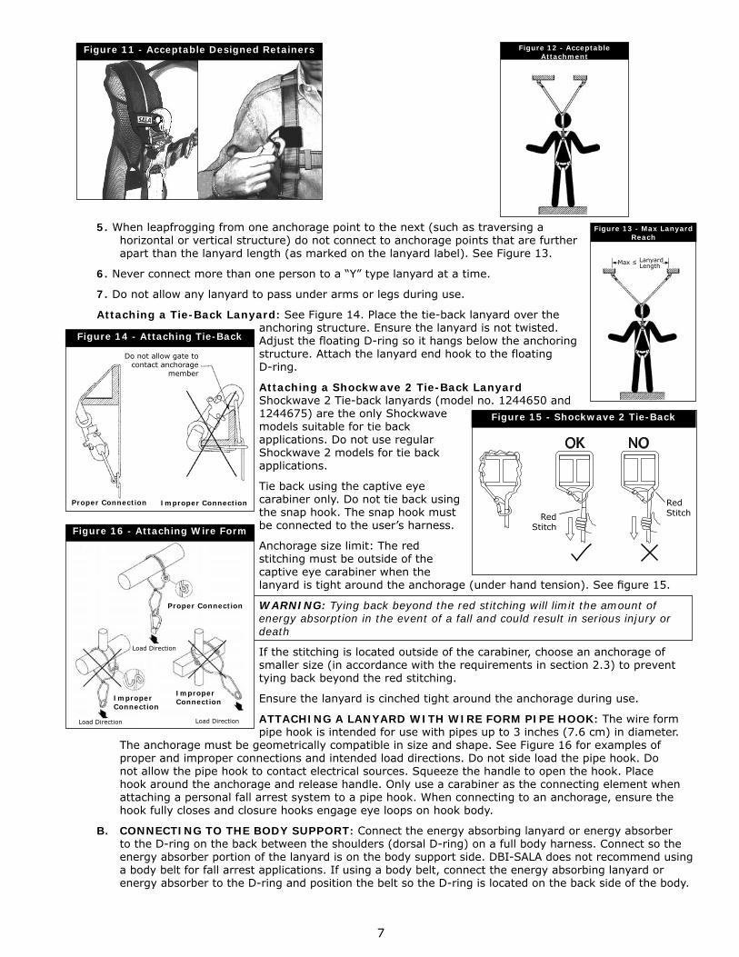
3. Do not attach the unused leg of the lanyard back to the harness at any location unless a specially designed lanyard retainer is provided for this purpose. See Figure 11.
4. Connection of both lanyard legs to separate anchorage points is acceptable. See Figure 12.
these situations, use a tie-off adaptor or other anchorage connector to allow a compatible connection. Do not knot the lanyard in any manner, and do not hook the lanyard back into itself (choker style). Snap hooks and carabiners must not be connected to each other. Do not attach snap hooks to web loops.
Figure 10 - Incorrect Attachment
Do not attachEnergy Absorberto anchor
Figure 6 - Making Connections
Push Up
Rotate Clockwise
PushInward
Step 1 Step 2 Step 3
Step 1 Step 2 Step 1 Step 2 Step 1 Step 2
Pull Back Gate with Thumb
Depress Locking Mechanism with Index Finger
Rotate Clockwise
PushInward
PushInward
Depress Locking Mechanism with Palm of Hand
Figure 7 - Connecting to Anchorage
Anchorage Connector
Anchorage Connector Anchorage
Connector
Energy Absorbing Lanyard
Energy Absorbing Lanyard
Energy Absorbing Lanyard
ConnectingSubsystem(Rope Grab)
Figure 8 - Correct Attachment
Figure 9 - Incorrect Attachment
Energy Absorbernot attachedto dorsal D-ring
Energy Absorberattached to dorsal D-ring
7
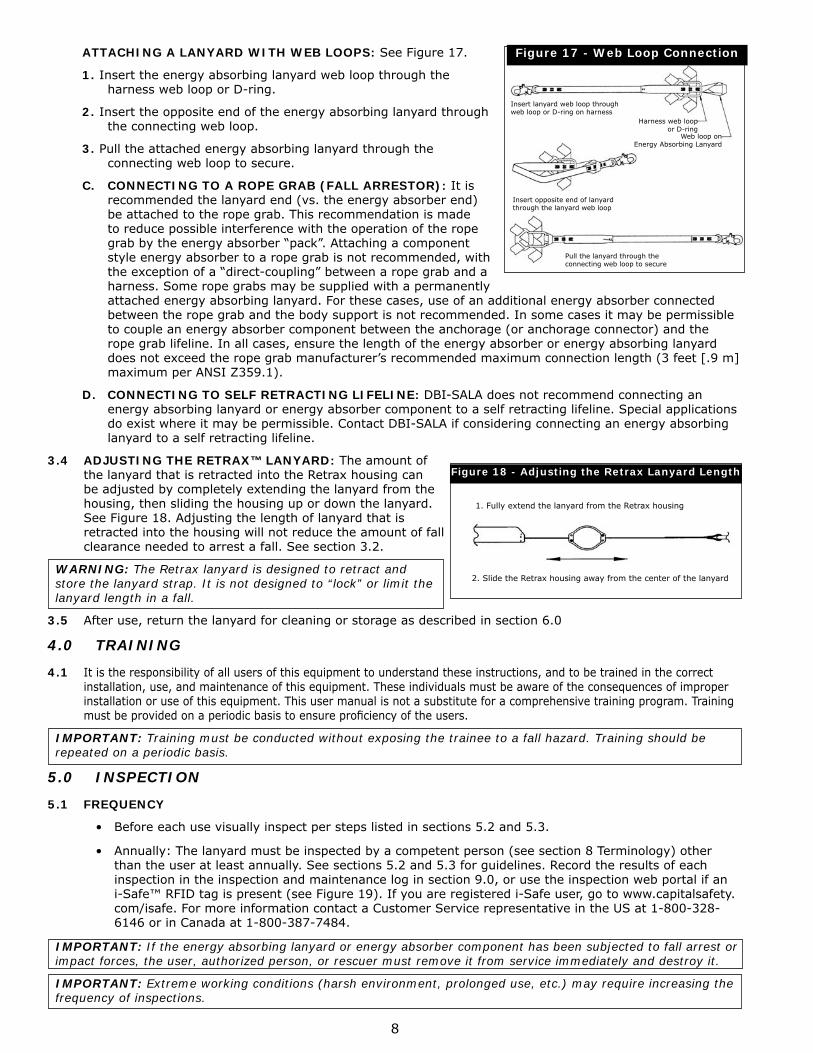
5. When leapfrogging from one anchorage point to the next (such as traversing a horizontal or vertical structure) do not connect to anchorage points that are further apart than the lanyard length (as marked on the lanyard label). See Figure 13.
6. Never connect more than one person to a “Y” type lanyard at a time.
7. Do not allow any lanyard to pass under arms or legs during use.
Attaching a Tie-Back Lanyard: See Figure 14. Place the tie-back lanyard over the anchoring structure. Ensure the lanyard is not twisted. Adjust the floating D-ring so it hangs below the anchoring structure. Attach the lanyard end hook to the floating D-ring.
Attaching a Shockwave 2 Tie-Back Lanyard Shockwave 2 Tie-back lanyards (model no. 1244650 and 1244675) are the only Shockwave models suitable for tie back applications. Do not use regular Shockwave 2 models for tie back applications.
Tie back using the captive eye carabiner only. Do not tie back using the snap hook. The snap hook must be connected to the user’s harness.
Anchorage size limit: The red stitching must be outside of the captive eye carabiner when the lanyard is tight around the anchorage (under hand tension). See fi gure 15.
WARNING: Tying back beyond the red stitching will limit the amount of energy absorption in the event of a fall and could result in serious injury or death
If the stitching is located outside of the carabiner, choose an anchorage of smaller size (in accordance with the requirements in section 2.3) to prevent tying back beyond the red stitching.
Ensure the lanyard is cinched tight around the anchorage during use.
ATTACHING A LANYARD WITH WIRE FORM PIPE HOOK: The wire form pipe hook is intended for use with pipes up to 3 inches (7.6 cm) in diameter.
The anchorage must be geometrically compatible in size and shape. See Figure 16 for examples of proper and improper connections and intended load directions. Do not side load the pipe hook. Do not allow the pipe hook to contact electrical sources. Squeeze the handle to open the hook. Place hook around the anchorage and release handle. Only use a carabiner as the connecting element when attaching a personal fall arrest system to a pipe hook. When connecting to an anchorage, ensure the hook fully closes and closure hooks engage eye loops on hook body.
B. CONNECTING TO THE BODY SUPPORT: Connect the energy absorbing lanyard or energy absorber to the D-ring on the back between the shoulders (dorsal D-ring) on a full body harness. Connect so the energy absorber portion of the lanyard is on the body support side. DBI-SALA does not recommend using a body belt for fall arrest applications. If using a body belt, connect the energy absorbing lanyard or energy absorber to the D-ring and position the belt so the D-ring is located on the back side of the body.
Figure 12 - Acceptable Attachment
Figure 11 - Acceptable Designed Retainers
Figure 13 - Max Lanyard Reach
Max ≤ Lanyard
Length
Figure 14 - Attaching Tie-Back
Do not allow gate to contact anchorage
member
Proper Connection Improper Connection
Figure 16 - Attaching Wire Form
Proper Connection
Improper Connection
Improper Connection
Load Direction Load Direction
Load Direction
OK NO
Figure 15 - Shockwave 2 Tie-Back
Red Stitch
Red Stitch
8
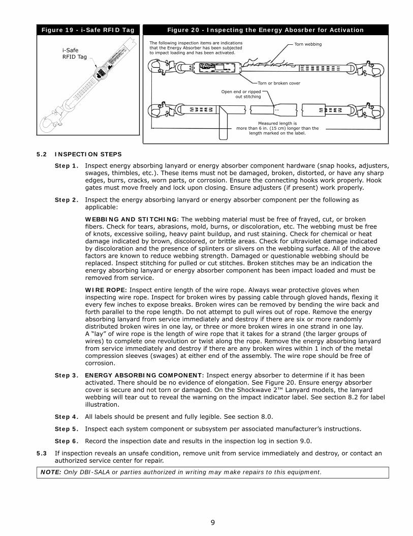
ATTACHING A LANYARD WITH WEB LOOPS: See Figure 17.
1. Insert the energy absorbing lanyard web loop through the harness web loop or D-ring.
2. Insert the opposite end of the energy absorbing lanyard through the connecting web loop.
3. Pull the attached energy absorbing lanyard through the connecting web loop to secure.
C. CONNECTING TO A ROPE GRAB (FALL ARRESTOR): It is recommended the lanyard end (vs. the energy absorber end) be attached to the rope grab. This recommendation is made to reduce possible interference with the operation of the rope grab by the energy absorber “pack”. Attaching a component style energy absorber to a rope grab is not recommended, with the exception of a “direct-coupling” between a rope grab and a harness. Some rope grabs may be supplied with a permanently attached energy absorbing lanyard. For these cases, use of an additional energy absorber connected between the rope grab and the body support is not recommended. In some cases it may be permissible to couple an energy absorber component between the anchorage (or anchorage connector) and the rope grab lifeline. In all cases, ensure the length of the energy absorber or energy absorbing lanyard does not exceed the rope grab manufacturer’s recommended maximum connection length (3 feet [.9 m] maximum per ANSI Z359.1).
D. CONNECTING TO SELF RETRACTING LIFELINE: DBI-SALA does not recommend connecting an energy absorbing lanyard or energy absorber component to a self retracting lifeline. Special applications do exist where it may be permissible. Contact DBI-SALA if considering connecting an energy absorbing lanyard to a self retracting lifeline.
3.4 ADJUSTING THE RETRAX™ LANYARD: The amount of the lanyard that is retracted into the Retrax housing can be adjusted by completely extending the lanyard from the housing, then sliding the housing up or down the lanyard. See Figure 18. Adjusting the length of lanyard that is retracted into the housing will not reduce the amount of fall clearance needed to arrest a fall. See section 3.2.
WARNING: The Retrax lanyard is designed to retract and store the lanyard strap. It is not designed to “lock” or limit the lanyard length in a fall.
3.5 After use, return the lanyard for cleaning or storage as described in section 6.0
4.0 TRAINING
4.1 It is the responsibility of all users of this equipment to understand these instructions, and to be trained in the correct installation, use, and maintenance of this equipment. These individuals must be aware of the consequences of improper installation or use of this equipment. This user manual is not a substitute for a comprehensive training program. Training must be provided on a periodic basis to ensure profi ciency of the users.
IMPORTANT: Training must be conducted without exposing the trainee to a fall hazard. Training should be repeated on a periodic basis.
5.0 INSPECTION
5.1 FREQUENCY
• Before each use visually inspect per steps listed in sections 5.2 and 5.3.
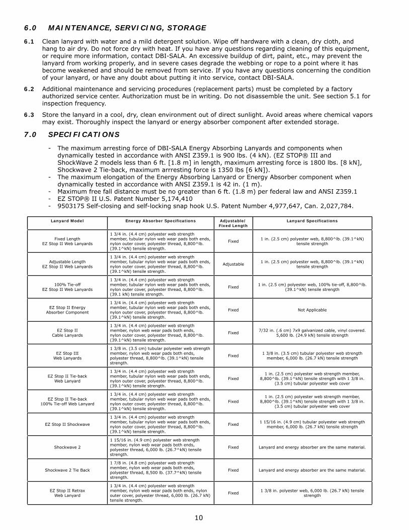
• Annually: The lanyard must be inspected by a competent person (see section 8 Terminology) other than the user at least annually. See sections 5.2 and 5.3 for guidelines. Record the results of each inspection in the inspection and maintenance log in section 9.0, or use the inspection web portal if an i-Safe™ RFID tag is present (see Figure 19). If you are registered i-Safe user, go to www.capitalsafety.com/isafe. For more information contact a Customer Service representative in the US at 1-800-328-6146 or in Canada at 1-800-387-7484.
IMPORTANT: If the energy absorbing lanyard or energy absorber component has been subjected to fall arrest or impact forces, the user, authorized person, or rescuer must remove it from service immediately and destroy it.
IMPORTANT: Extreme working conditions (harsh environment, prolonged use, etc.) may require increasing the frequency of inspections.
Figure 17 - Web Loop Connection
Insert lanyard web loop through web loop or D-ring on harness
Insert opposite end of lanyard through the lanyard web loop
Pull the lanyard through the connecting web loop to secure
Harness web loop or D-ring
Web loop on Energy Absorbing Lanyard
Figure 18 - Adjusting the Retrax Lanyard Length
1. Fully extend the lanyard from the Retrax housing
2. Slide the Retrax housing away from the center of the lanyard
9
Figure 19 - i-Safe RFID Tag
i-SafeRFID Tag
Figure 20 - Inspecting the Energy Abosrber for Activation
The following inspection items are indicationsthat the Energy Absorber has been subjected to impact loading and has been activated.
Measured length is more than 6 in. (15 cm) longer than the
length marked on the label.
Torn webbing
Torn or broken cover
Open end or ripped out stitching
5.2 INSPECTION STEPS
Step 1. Inspect energy absorbing lanyard or energy absorber component hardware (snap hooks, adjusters, swages, thimbles, etc.). These items must not be damaged, broken, distorted, or have any sharp edges, burrs, cracks, worn parts, or corrosion. Ensure the connecting hooks work properly. Hook gates must move freely and lock upon closing. Ensure adjusters (if present) work properly.
Step 2. Inspect the energy absorbing lanyard or energy absorber component per the following as applicable:
WEBBING AND STITCHING: The webbing material must be free of frayed, cut, or broken fi bers. Check for tears, abrasions, mold, burns, or discoloration, etc. The webbing must be free of knots, excessive soiling, heavy paint buildup, and rust staining. Check for chemical or heat damage indicated by brown, discolored, or brittle areas. Check for ultraviolet damage indicated by discoloration and the presence of splinters or slivers on the webbing surface. All of the above factors are known to reduce webbing strength. Damaged or questionable webbing should be replaced. Inspect stitching for pulled or cut stitches. Broken stitches may be an indication the energy absorbing lanyard or energy absorber component has been impact loaded and must be removed from service.
WIRE ROPE: Inspect entire length of the wire rope. Always wear protective gloves when inspecting wire rope. Inspect for broken wires by passing cable through gloved hands, fl exing it every few inches to expose breaks. Broken wires can be removed by bending the wire back and forth parallel to the rope length. Do not attempt to pull wires out of rope. Remove the energy absorbing lanyard from service immediately and destroy if there are six or more randomly distributed broken wires in one lay, or three or more broken wires in one strand in one lay. A “lay” of wire rope is the length of wire rope that it takes for a strand (the larger groups of wires) to complete one revolution or twist along the rope. Remove the energy absorbing lanyard from service immediately and destroy if there are any broken wires within 1 inch of the metal compression sleeves (swages) at either end of the assembly. The wire rope should be free of corrosion.
Step 3. ENERGY ABSORBING COMPONENT: Inspect energy absorber to determine if it has been activated. There should be no evidence of elongation. See Figure 20. Ensure energy absorber cover is secure and not torn or damaged. On the Shockwave 2™ Lanyard models, the lanyard webbing will tear out to reveal the warning on the impact indicator label. See section 8.2 for label illustration.
Step 4. All labels should be present and fully legible. See section 8.0.
Step 5. Inspect each system component or subsystem per associated manufacturer’s instructions.
Step 6. Record the inspection date and results in the inspection log in section 9.0.
5.3 If inspection reveals an unsafe condition, remove unit from service immediately and destroy, or contact an authorized service center for repair.
NOTE: Only DBI-SALA or parties authorized in writing may make repairs to this equipment.
10
6.0 MAINTENANCE, SERVICING, STORAGE
6.1 Clean lanyard with water and a mild detergent solution. Wipe off hardware with a clean, dry cloth, and hang to air dry. Do not force dry with heat. If you have any questions regarding cleaning of this equipment, or require more information, contact DBI-SALA. An excessive buildup of dirt, paint, etc., may prevent the lanyard from working properly, and in severe cases degrade the webbing or rope to a point where it has become weakened and should be removed from service. If you have any questions concerning the condition of your lanyard, or have any doubt about putting it into service, contact DBI-SALA.
6.2 Additional maintenance and servicing procedures (replacement parts) must be completed by a factory authorized service center. Authorization must be in writing. Do not disassemble the unit. See section 5.1 for inspection frequency.
6.3 Store the lanyard in a cool, dry, clean environment out of direct sunlight. Avoid areas where chemical vapors may exist. Thoroughly inspect the lanyard or energy absorber component after extended storage.
7.0 SPECIFICATIONS
- The maximum arresting force of DBI-SALA Energy Absorbing Lanyards and components when dynamically tested in accordance with ANSI Z359.1 is 900 lbs. (4 kN). (EZ STOP® III and ShockWave 2 models less than 6 ft. [1.8 m] in length, maximum arresting force is 1800 lbs. [8 kN], Shockwave 2 Tie-back, maximum arrresting force is 1350 lbs [6 kN]).
- The maximum elongation of the Energy Absorbing Lanyard or Energy Absorber component when dynamically tested in accordance with ANSI Z359.1 is 42 in. (1 m).
- Maximum free fall distance must be no greater than 6 ft. (1.8 m) per federal law and ANSI Z359.1- EZ STOP® II U.S. Patent Number 5,174,410- 9503175 Self-closing and self-locking snap hook U.S. Patent Number 4,977,647, Can. 2,027,784.
Lanyard Model Energy Absorber Specifications Adjustable/Fixed Length
Lanyard Specifications
Fixed LengthEZ Stop II Web Lanyards
1 3/4 in. (4.4 cm) polyester web strength member, tubular nylon web wear pads both ends, nylon outer cover, polyester thread, 8,800^lb. (39.1^kN) tensile strength.
Fixed 1 in. (2.5 cm) polyester web, 8,800^lb. (39.1^kN) tensile strength
Adjustable LengthEZ Stop II Web Lanyards
1 3/4 in. (4.4 cm) polyester web strength member, tubular nylon web wear pads both ends, nylon outer cover, polyester thread, 8,800^lb. (39.1^kN) tensile strength.
Adjustable 1 in. (2.5 cm) polyester web, 8,800^lb. (39.1^kN) tensile strength
100% Tie-offEZ Stop II Web Lanyards
1 3/4 in. (4.4 cm) polyester web strength member, tubular nylon web wear pads both ends, nylon outer cover, polyester thread, 8,800^lb. (39.1 kN) tensile strength.
Fixed 1 in. (2.5 cm) polyester web, 100% tie-off, 8,800^lb. (39.1^kN) tensile strength
EZ Stop II EnergyAbsorber Component
1 3/4 in. (4.4 cm) polyester web strength member, tubular nylon web wear pads both ends, nylon outer cover, polyester thread, 8,800^lb. (39.1^kN) tensile strength.
Fixed Not Applicable
EZ Stop IICable Lanyards
1 3/4 in. (4.4 cm) polyester web strength member, nylon web wear pads both ends, nylon outer cover, polyester thread, 8,800^lb. (39.1^kN) tensile strength.
Fixed 7/32 in. (.6 cm) 7x9 galvanized cable, vinyl covered.5,600 lb. (24.9 kN) tensile strength
EZ Stop IIIWeb Lanyards
1 3/8 in. (3.5 cm) tubular polyester web strength member, nylon web wear pads both ends, polyester thread, 8,800^lb. (39.1^kN) tensile strength.
Fixed 1 3/8 in. (3.5 cm) tubular polyester web strength member, 6,000 lb. (26.7 kN) tensile strength
EZ Stop II Tie-backWeb Lanyard
1 3/4 in. (4.4 cm) polyester web strength member, tubular nylon web wear pads both ends, nylon outer cover, polyester thread, 8,800^lb. (39.1^kN) tensile strength.
Fixed1 in. (2.5 cm) polyester web strength member,
8,800^lb. (39.1^kN) tensile strength with 1 3/8 in. (3.5 cm) tubular polyester web cover
EZ Stop II Tie-back100% Tie-off Web Lanyard
1 3/4 in. (4.4 cm) polyester web strength member, tubular nylon web wear pads both ends, nylon outer cover, polyester thread, 8,800^lb. (39.1^kN) tensile strength.
Fixed1 in. (2.5 cm) polyester web strength member,
8,800^lb. (39.1^kN) tensile strength with 1 3/8 in. (3.5 cm) tubular polyester web cover
EZ Stop II Shockwave
1 3/4 in. (4.4 cm) polyester web strength member, tubular nylon web wear pads both ends, nylon outer cover, polyester thread, 8,800^lb. (39.1^kN) tensile strength.
Fixed 1 15/16 in. (4.9 cm) tubular polyester web strength member, 6,000 lb. (26.7 kN) tensile strength
Shockwave 2
1 15/16 in. (4.9 cm) polyester web strength member, nylon web wear pads both ends, polyester thread, 6,000 lb. (26.7^kN) tensile strength.
Fixed Lanyard and energy absorber are the same material.
Shockwave 2 Tie Back
1 7/8 in. (4.8 cm) polyester web strength member, nylon web wear pads both ends, polyester thread, 8,500 lb. (37.7^kN) tensile strength.
Fixed Lanyard and energy absorber are the same material.
EZ Stop II RetraxWeb Lanyard
1 3/4 in. (4.4 cm) polyester web strength member, nylon web wear pads both ends, nylon outer cover, polyester thread, 6,000 lb. (26.7 kN) tensile strength.
Fixed 1 3/8 in. polyester web, 6,000 lb. (26.7 kN) tensile strength
11
8.0 TERMINOLOGY
Authorized Person: A person assigned by the employer to perform duties at a location where the person will be exposed to a fall hazard (otherwise refered to as “user” for the purpose of these instructions).
Rescuer: Person or persons other than the rescue subject acting to perform an assisted rescue by operation of a rescue system.
Certified Anchorage: An anchorage for fall arrest, positioning, restraint, or rescue systems that a qualified person certifies to be capable of supporting the potential fall forces that could be encountered during a fall or that meet the criteria for a certified anchorage prescribed in this standard.
Qualified Person: A person with a recognized degree or professional certificate and with extensive knowledge, training, and experience in the fall protection and rescue field who is capable of designing, analyzing, evaluating and specifying fall protection and rescue systems to the extent required by this standard.
COMPETENT PERSON: One who is capable of identifying existing and predictable hazards in the surroundings or working conditions which are unsanitary, hazardous, or dangerous to employees, and who has authorization to take prompt corrective measures to eliminate them.
9.0 LABELING
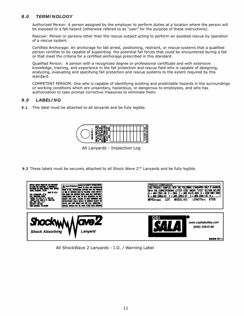
9.1 This label must be attached to all lanyards and be fully legible.
All ShockWave 2 Lanyards - I.D. / Warning Label
All Lanyards - Inspection Log
9.2 These labels must be securely attached to all Shock Wave 2™ Lanyards and be fully legible.
12
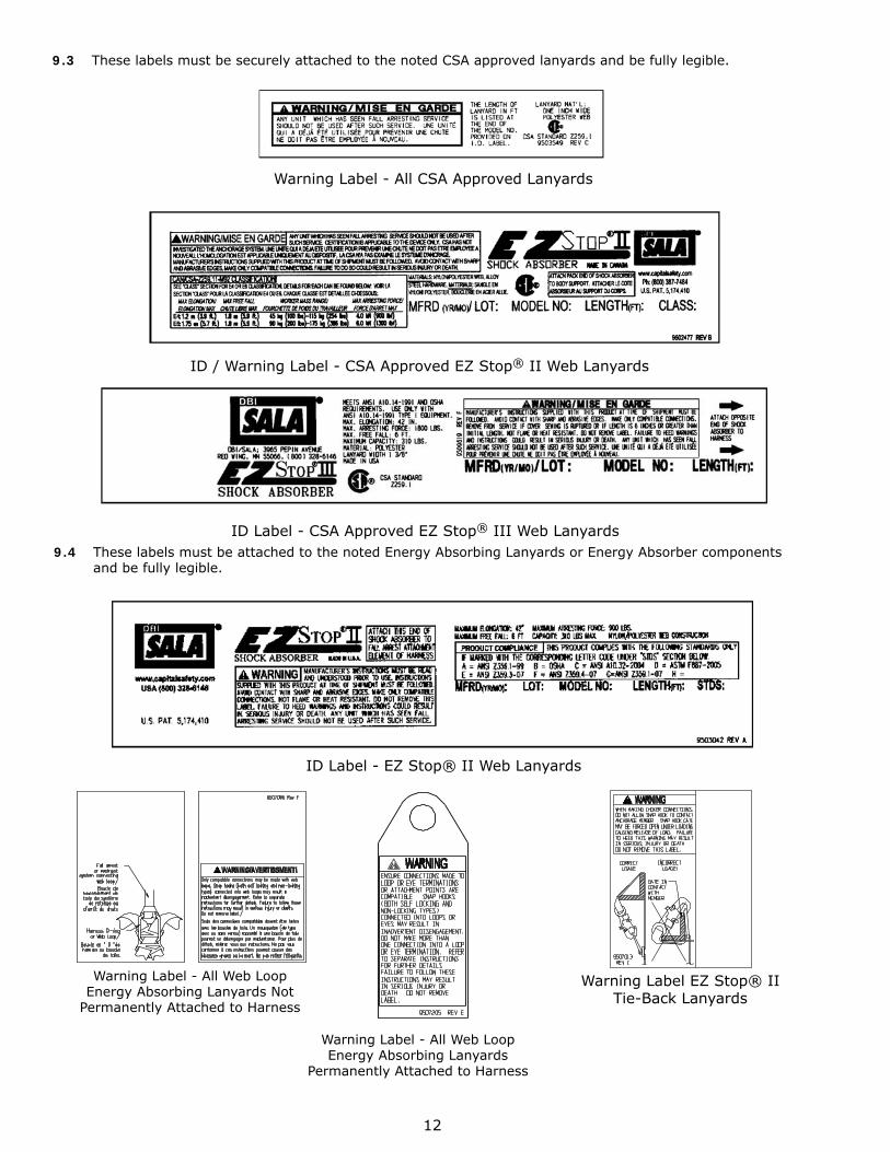
ID Label - EZ Stop® II Web Lanyards
Warning Label EZ Stop® II Tie-Back Lanyards
Warning Label - All Web Loop Energy Absorbing Lanyards Not
Permanently Attached to Harness
Warning Label - All Web Loop Energy Absorbing Lanyards
Permanently Attached to Harness
Warning Label - All CSA Approved Lanyards
ID / Warning Label - CSA Approved EZ Stop® II Web Lanyards
ID Label - CSA Approved EZ Stop® III Web Lanyards
9.3 These labels must be securely attached to the noted CSA approved lanyards and be fully legible.
9.4 These labels must be attached to the noted Energy Absorbing Lanyards or Energy Absorber components and be fully legible.
13
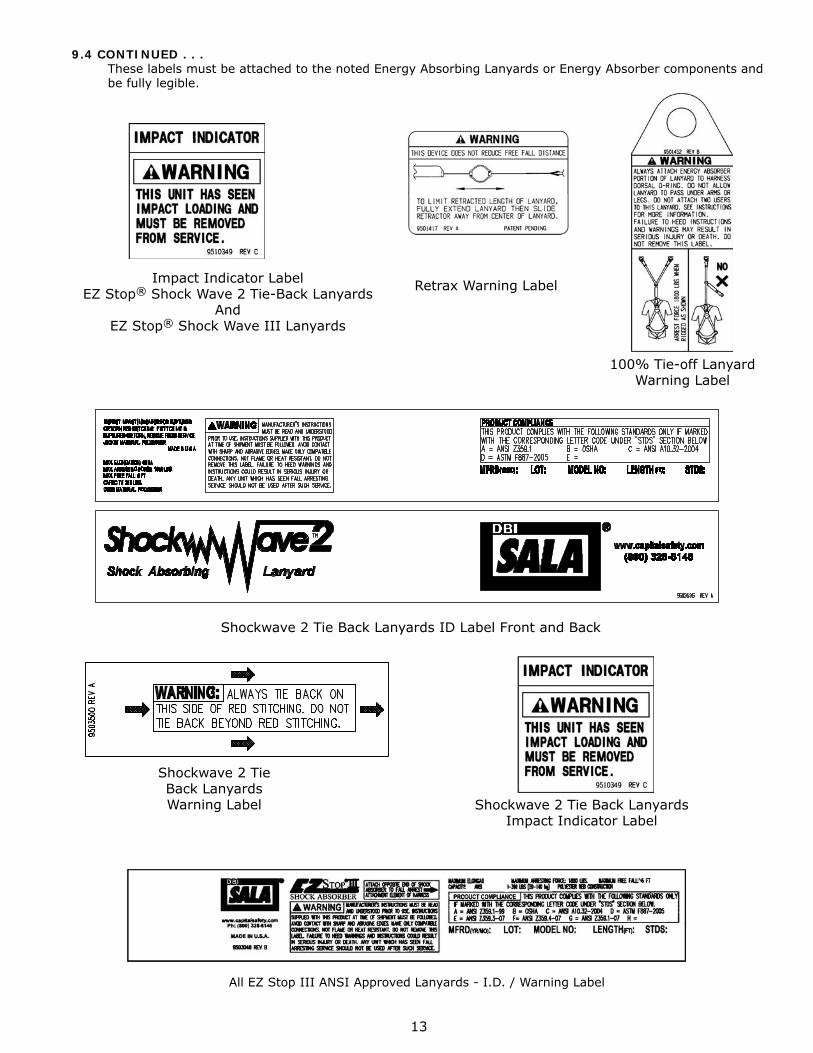
Retrax Warning Label
100% Tie-off Lanyard Warning Label
Impact Indicator Label EZ Stop® Shock Wave 2 Tie-Back Lanyards
And EZ Stop® Shock Wave III Lanyards
Shockwave 2 Tie Back Lanyards ID Label Front and Back
Shockwave 2 Tie Back Lanyards Warning Label Shockwave 2 Tie Back Lanyards
Impact Indicator Label
All EZ Stop III ANSI Approved Lanyards - I.D. / Warning Label
9.4 CONTINUED . . . These labels must be attached to the noted Energy Absorbing Lanyards or Energy Absorber components and be fully legible.
14
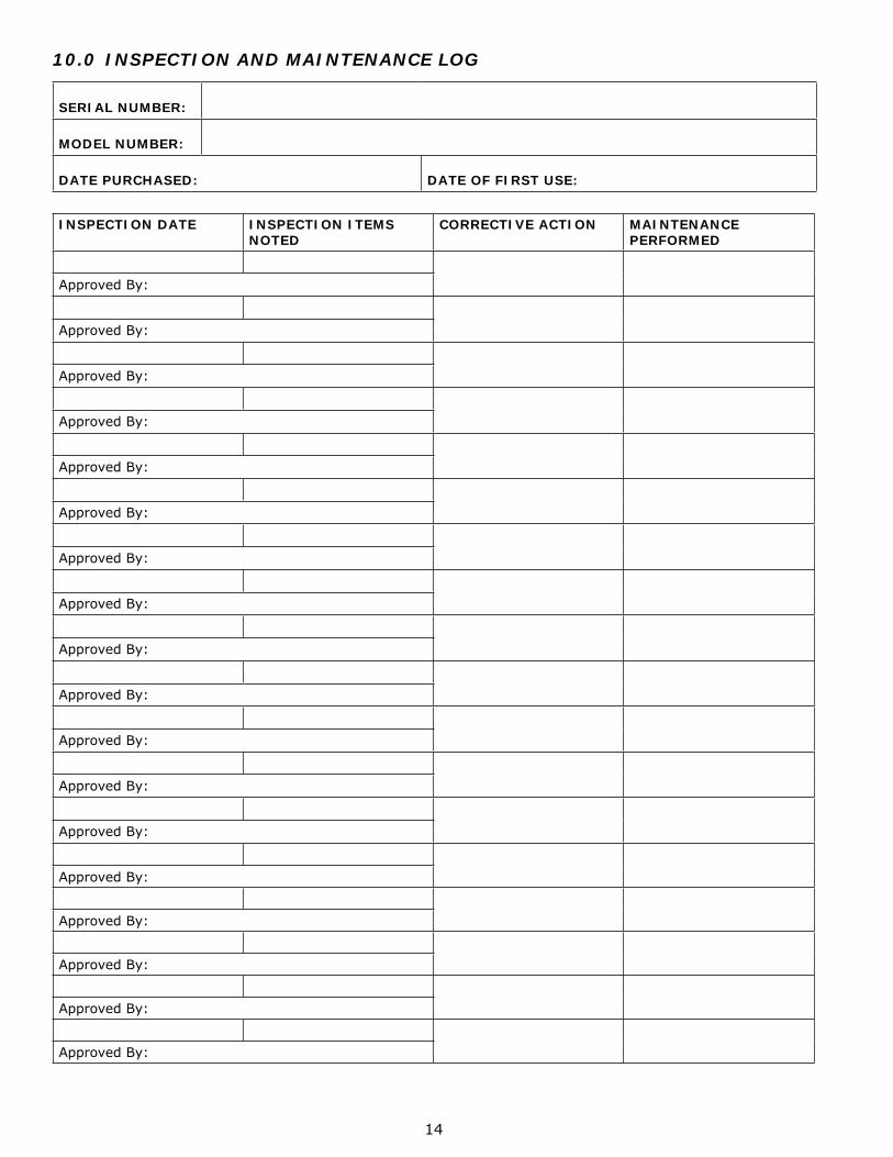
10.0 INSPECTION AND MAINTENANCE LOG
SERIAL NUMBER:
MODEL NUMBER:
DATE PURCHASED: DATE OF FIRST USE:
INSPECTION DATE INSPECTION ITEMS NOTED
CORRECTIVE ACTION MAINTENANCE PERFORMED
Approved By:
Approved By:
Approved By:
Approved By:
Approved By:
Approved By:
Approved By:
Approved By:
Approved By:
Approved By:
Approved By:
Approved By:
Approved By:
Approved By:
Approved By:
Approved By:
Approved By:
Approved By:
15
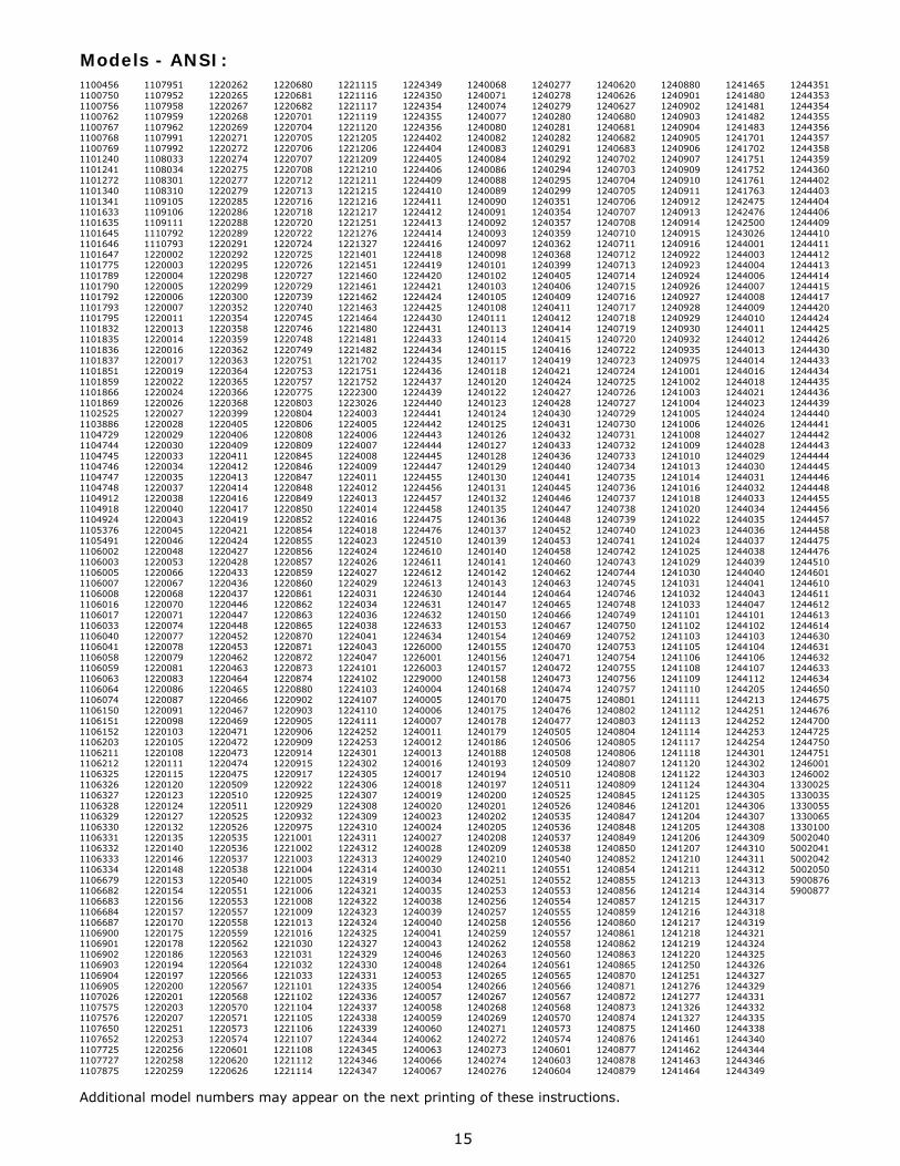
Models - ANSI:1100456110075011007561100762110076711007681100769110124011012411101272110134011013411101633110163511016451101646110164711017751101789110179011017921101793110179511018321101835110183611018371101851110185911018661101869110252511038861104729110474411047451104746110474711047481104912110491811049241105376110549111060021106003110600511060071106008110601611060171106033110604011060411106058110605911060631106064110607411061501106151110615211062031106211110621211063251106326110632711063281106329110633011063311106332110633311063341106679110668211066831106684110668711069001106901110690211069031106904110690511070261107575110757611076501107652110772511077271107875
1107951110795211079581107959110796211079911107992110803311080341108301110831011091051109106110911111107921110793122000212200031220004122000512200061220007122001112200131220014122001612200171220019122002212200241220026122002712200281220029122003012200331220034122003512200371220038122004012200431220045122004612200481220053122006612200671220068122007012200711220074122007712200781220079122008112200831220086122008712200911220098122010312201051220108122011112201151220120122012312201241220127122013212201351220140122014612201481220153122015412201561220157122017012201751220178122018612201941220197122020012202011220203122020712202511220253122025612202581220259
1220262122026512202671220268122026912202711220272122027412202751220277122027912202851220286122028812202891220291122029212202951220298122029912203001220352122035412203581220359122036212203631220364122036512203661220368122039912204051220406122040912204111220412122041312204141220416122041712204191220421122042412204271220428122043312204361220437122044612204471220448122045212204531220462122046312204641220465122046612204671220469122047112204721220473122047412204751220509122051012205111220525122052612205351220536122053712205381220540122055112205531220557122055812205591220562122056312205641220566122056712205681220570122057112205731220574122060112206201220626
1220680122068112206821220701122070412207051220706122070712207081220712122071312207161220718122072012207221220724122072512207261220727122072912207391220740122074512207461220748122074912207511220753122075712207751220803122080412208061220808122080912208451220846122084712208481220849122085012208521220854122085512208561220857122085912208601220861122086212208631220865122087012208711220872122087312208741220880122090212209031220905122090612209091220914122091512209171220922122092512209291220932122097512210011221002122100312210041221005122100612210081221009122101312210161221030122103112210321221033122110112211021221104122110512211061221107122110812211121221114
1221115122111612211171221119122112012212051221206122120912212101221211122121512212161221217122125112212761221327122140112214511221460122146112214621221463122146412214801221481122148212217021221751122175212223001223026122400312240051224006122400712240081224009122401112240121224013122401412240161224018122402312240241224026122402712240291224031122403412240361224038122404112240431224047122410112241021224103122410712241101224111122425212242531224301122430212243051224306122430712243081224309122431012243111224312122431312243141224319122432112243221224323122432412243251224327122432912243301224331122433512243361224337122433812243391224344122434512243461224347
1224349122435012243541224355122435612244021224404122440512244061224409122441012244111224412122441312244141224416122441812244191224420122442112244241224425122443012244311224433122443412244351224436122443712244391224440122444112244421224443122444412244451224447122445512244561224457122445812244751224476122451012246101224611122461212246131224630122463112246321224633122463412260001226001122600312290001240004124000512400061240007124001112400121240013124001612400171240018124001912400201240023124002412400271240028124002912400301240034124003512400381240039124004012400411240043124004612400481240053124005412400571240058124005912400601240062124006312400661240067
1240068124007112400741240077124008012400821240083124008412400861240088124008912400901240091124009212400931240097124009812401011240102124010312401051240108124011112401131240114124011512401171240118124012012401221240123124012412401251240126124012712401281240129124013012401311240132124013512401361240137124013912401401240141124014212401431240144124014712401501240153124015412401551240156124015712401581240168124017012401751240178124017912401861240188124019312401941240197124020012402011240202124020512402081240209124021012402111240251124025312402561240257124025812402591240262124026312402641240265124026612402671240268124026912402711240272124027312402741240276
1240277124027812402791240280124028112402821240291124029212402941240295124029912403511240354124035712403591240362124036812403991240405124040612404091240411124041212404141240415124041612404191240421124042412404271240428124043012404311240432124043312404361240440124044112404451240446124044712404481240452124045312404581240460124046212404631240464124046512404661240467124046912404701240471124047212404731240474124047512404761240477124050512405061240508124050912405101240511124052512405261240535124053612405371240538124054012405511240552124055312405541240555124055612405571240558124056012405611240565124056612405671240568124057012405731240574124060112406031240604
1240620124062612406271240680124068112406821240683124070212407031240704124070512407061240707124070812407101240711124071212407131240714124071512407161240717124071812407191240720124072212407231240724124072512407261240727124072912407301240731124073212407331240734124073512407361240737124073812407391240740124074112407421240743124074412407451240746124074812407491240750124075212407531240754124075512407561240757124080112408021240803124080412408051240806124080712408081240809124084512408461240847124084812408491240850124085212408541240855124085612408571240859124086012408611240862124086312408651240870124087112408721240873124087412408751240876124087712408781240879
1240880124090112409021240903124090412409051240906124090712409091240910124091112409121240913124091412409151240916124092212409231240924124092612409271240928124092912409301240932124093512409751241001124100212410031241004124100512410061241008124100912410101241013124101412410161241018124102012410221241023124102412410251241029124103012410311241032124103312411011241102124110312411051241106124110812411091241110124111112411121241113124111412411171241118124112012411221241124124112512412011241204124120512412061241207124121012412111241213124121412412151241216124121712412181241219124122012412501241251124127612412771241326124132712414601241461124146212414631241464
1241465124148012414811241482124148312417011241702124175112417521241761124176312424751242476124250012430261244001124400312440041244006124400712440081244009124401012440111244012124401312440141244016124401812440211244023124402412440261244027124402812440291244030124403112440321244033124403412440351244036124403712440381244039124404012440411244043124404712441011244102124410312441041244106124410712441121244205124421312442511244252124425312442541244301124430212443031244304124430512443061244307124430812443091244310124431112443121244313124431412443171244318124431912443211244324124432512443261244327124432912443311244332124433512443381244340124434412443461244349
12443511244353124435412443551244356124435712443581244359124436012444021244403124440412444061244409124441012444111244412124441312444141244415124441712444201244424124442512444261244430124443312444341244435124443612444391244440124444112444421244443124444412444451244446124444812444551244456124445712444581244475124447612445101244601124461012446111244612124461312446141244630124463112446321244633124463412446501244675124467612447001244725124475012447511246001124600213300251330035133005513300651330100500204050020415002042500205059008765900877
Additional model numbers may appear on the next printing of these instructions.
CSG USA3833 Sala WayRed Wing, MN 55066-5005Toll Free: 800.328.6146Phone: 651.388.8282Fax: [email protected]
CSG Canada Ltd.260 Export BoulevardMississauga, Ontario L5S 1Y9CanadaToll Free: 800.387.7484Phone: 905.795.9333Fax: [email protected]
CSG Northern Europe Ltd.7 Christleton Court • Stuart Rd.Manor Park • RuncornCheshire WA7 1ST • UKPhone: +44 (0) 1928 571324Fax: +44 (0) 1928 [email protected]
CSG EMEA (France)Le Broc Center Z.I. 1ère Avenue-5600 MBP 15 • 06511 Carros CedexPhone: +33 (0)4 97 10 00 10Fax: +33 (0)4 93 08 79 [email protected]
CSG Asia Pte Ltd.No. 6, Tuas Avenue 18Singapore 638892Phone: +65 6558 7758Fax: +65 6558 [email protected]
CSG (Aust) Pty Ltd.20 Fariola Street • SliverwaterSydney, NSW 2128AustraliaPhone: +61 (2) 9748 0335Fax: +61 (2) 9748 [email protected]
www.capitalsafety.com
A Capital Safety Company
Certificate No. FM 39709
I S O9 0 0 1
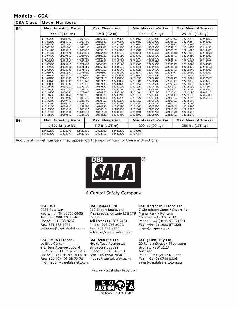
Models - CSA:CSA Class Model Numbers
E4: Max. Arresting Force Max. Elongation Min. Mass of Worker Max. Mass of Worker
900 lbf (4.0 kN) 3.9 ft (1.2 m) 100 lbs (45 kg) 254 lbs (115 kg)
1100320C1100321C1100322C1100323C1100447C1100448C1100449C1100450C1100890C1100891C1100892C1100893C1100894C1100980C1100981C1100982C1100983C1101166C1101167C1101168C1101169C1101170C1101535C1101536C1101537C1101538C1101540C1101851C
1101859C1101871C1102319C1102320C1102321C1102967C1102968C1102969C1102970C1102971C1103266C1103268C1103269C1103387C1103388C1103389C1103390C1103391C1103392C1105855C1106015C1106040C1106041C1106042C1106053C1106054C1106060C1106061C
1106062C1106075C1106203C1106684C1106685C1106689C1106690C1106698C1106699C1107160C1107161C1107162C1107163C1107164C1107165C1107837C1107838C1107839C1107840C1107961C1108028C1108355C1108356C1108357C1108358C1108359C1108528C1108529C
1108530C1108534C1108539C1108540C1108541C1108542C1108603C1108678C1108679C1108680C1108684C1108685C1108686C1108710C1108711C1108712C1108713C1108714C1108715C1109025C1109037C1109038C1109045C1109057C1109058C1109061C1109141C1109432C
1109433C1109434C1109435C1109436C1109437C1110310C1110311C1110312C1110313C1110612C1110613C1110614C1110619C1110705C1110706C1220006C1220007C1220012C1220016C1220017C1220024C1220028C1220030C1220035C1220038C1220040C1220042C1220043C
1220046C1220048C1220054C1220058C1220068C1220071C1220074C1220079C1220080C1220086C1220091C1220092C1220093C1220098C1220105C1220108C1220115C1220132C1220139C1220180C1220181C1220182C1220195C1220204C1220206C1220256C1220259C1220269C
1220296C1220297C1220299C1220300C1220301C1220359C1220362C1220364C1220369C1220406C1220409C1220450C1220451C1220455C1220459C1220461C1220466C1220468C1220526C1220527C1220535C1220536C1220539C1220540C1220553C1220558C1220572C1220601C
1220680C1220681C1220850C1220851C1220852C1220853C1220857C1220858C1220861C1220863C1220864C1220866C1220870C1220871C1220873C1220880C1220906C1220937C1220938C1220939C1220940C1221001C1221006C1221028C1221034C1221104C1221106C1221206C
1221425C12214261221426C1221460C1221461C1221480C1221481C1221484C1221801C1221802C1221803C1221804C1221805C1221806C1221807C1221808C1221809C1221810C1221811C1221812C1221813C1221814C1221815C1221816C1221851C1221852C1221853C1221854C
1224006C1224306C1224341C1224343C1224348C1224405C1224406C1224409C1224427C1224428C1224431C1224438C1240210C1240211C1240256C1240325C1240477C12405591244610C1244611C1244630C1244631C
E6: Max. Arresting Force Max. Elongation Min. Mass of Worker Max. Mass of Worker
1,300 lbf (6.0 kN) 5.7 ft (1.75 m) 200 lbs (90 kg) 386 lbs (175 kg)
1242225C1242226C
1242227C1242228C
1242229C1242230C
1242250C1242275C
1242325C1242326C
1242350C1242375C
Additional model numbers may appear on the next printing of these instructions.