User Guide - Welcome to General Photonics · The PSW-002 is compact and can be mounted on a PCB...
18
PSW-002 Fiber Optic Polarization Switch User Guide Version: 1.0 Date: May 30, 2014
Transcript of User Guide - Welcome to General Photonics · The PSW-002 is compact and can be mounted on a PCB...

PSW-002
Fiber Optic Polarization Switch
User Guide Version: 1.0 Date: May 30, 2014

GP-UM-PSW-002-10 Page 2 of 18
PSW-002 User Guide
General Photonics, Incorporated is located in Chino California.
For more information visit the company's website at:
www.generalphotonics.com
or call 909-590-5473

PSW-002 User Guide
SAFETY CONSIDERATIONS
The following safety precautions must be observed during operation of this product.
Failure to comply with these precautions or with specific warnings elsewhere in this manual
violates safety standards of design, manufacture, and intended use of the product. General
Photonics assumes no liability for customers’ failure to comply with these requirements.
Before operation, the user should inspect the product and review the manual carefully.
Use only in a safe work environment in terms of temperature, humidity, electrical power and risk
of fire or shock. The product is designed for indoor use. Avoid exposure to liquids or water
condensation. Provide adequate ventilation for cooling.
Operate the product on a stable surface. Avoid excess vibration.
Standard laser safety procedures should be followed during operation.
Never look into the light source fiber connector when the light source is turned on. THE OUTPUT LIGHT FROM A HIGH POWER LASER IS HARMFUL TO HUMAN EYES. Follow industry standard procedures when operating a high power laser source.
GP-UM-PSW-002-10 Page 3 of 18

PSW-002 User Guide
GP-UM-PSW-002-10 Page 4 of 18

PSW-002 User Guide
Section 1.0 Overview............................................................... 7
1.1 Principle of Operation......................................................... 7
Section 2.0 Features................................................................ 9
2.1 Optical Features ................................................................. 9 2.2 Electrical Features.............................................................. 9 2.3 Switch Timing................................................................... 11 2.4 Dimensions and Mounting Holes....................................... 12
Section 3.0 Operation Instructions ........................................ 13
3.1 Unpacking ........................................................................ 13 3.2 Operation ......................................................................... 13
Section 4.0 Specifications..................................................... 14
Optical...........................................................................14 Electrical .......................................................................14 Physical and Environmental ..........................................14
WARRANTY................................................................................. 15
Appendices................................................................................. 16
Appendix 1.0 Driver Board (Optional) .................................... 16 Driver Board Specifications ...........................................16 Board Diagram ..............................................................17 Setup.............................................................................18 Power Supply/Control Signal Guidelines.......................18
GP-UM-PSW-002-10 Page 5 of 18

PSW-002 User Guide
GP-UM-PSW-002-10 Page 6 of 18

PSW-002 User Guide
Section 1.0 Overview
The PSW-002 is a miniature polarization switch that rotates the input polarization state by
a fixed angle, either 45° or 90°. It is available with either single mode (SM) fiber or polarization
maintaining (PM) fiber pigtails. The switching of the polarization state is achieved using an
external control current supply. The PSW-002 is compact and can be mounted on a PCB
Applications include polarization diversified detectors and sensors, polarization multiplexing,
polarization modulation, polarization metrology, polarization mode dispersion (PMD) monitoring,
coherent optical communications, and other polarization related applications.
Figure 1 PSW-002 polarization switch
1.1 Principle of Operation
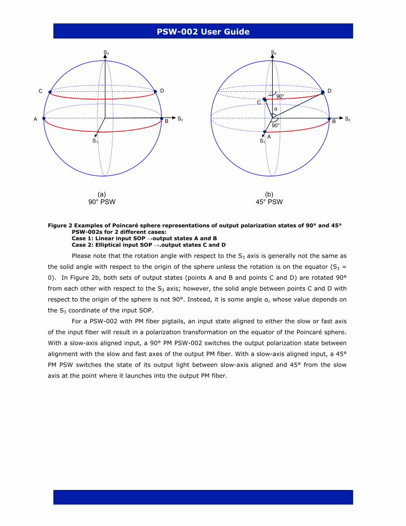
The PSW-002 performs polarization state transformations on a signal traveling in optical
fiber. Using Poincaré sphere representation, the PSW-002 transforms the input polarization state
along the equi-ellipticity contours that are represented by latitude lines. The 90° and 45° PSW-
002 devices rotate the polarization state by a half (1/2) circle or quarter circle (1/4 circle),
respectively, along the latitude line on which the input polarization state falls. Figure 2a shows the
two output SOPs of a 90° PSW resulting from different input polarization states. In the first case,
the input SOP is linear (on the equator); the two output SOPs will be 180° apart on the circle
defined by the equator (points A and B in the diagram). In the second case, the input SOP is
elliptical; the two output SOPs (points C and D) will be 180° apart on a smaller circle
corresponding to the latitude line on which the input SOP falls. If the input polarization state is
circular (north or south poles of the sphere), the latitude circle collapses to a point, so the output
SOP will still be circular.
Figure 2b shows a similar example for a 45° PSW-002. In this case, points A and B and
points C and D are 90° from each other on their respective circles.
GP-UM-PSW-002-10 Page 7 of 18
PSW-002 User Guide
Figure 2 Examples of Poincaré sphere representations of output polarization states of 90° and 45° PSW-002s for 2 different cases: Case 1: Linear input SOP →output states A and B Case 2: Elliptical input SOP →.output states C and D
Please note that the rotation angle with respect to the S3 axis is generally not the same as
the solid angle with respect to the origin of the sphere unless the rotation is on the equator (S3 =
0). In Figure 2b, both sets of output states (points A and B and points C and D) are rotated 90°
from each other with respect to the S3 axis; however, the solid angle between points C and D with
respect to the origin of the sphere is not 90°. Instead, it is some angle α, whose value depends on
the S3 coordinate of the input SOP.
For a PSW-002 with PM fiber pigtails, an input state aligned to either the slow or fast axis
of the input fiber will result in a polarization transformation on the equator of the Poincaré sphere.
With a slow-axis aligned input, a 90° PM PSW-002 switches the output polarization state between
alignment with the slow and fast axes of the output PM fiber. With a slow-axis aligned input, a 45°
PM PSW switches the state of its output light between slow-axis aligned and 45° from the slow
axis at the point where it launches into the output PM fiber.
S1
S2
S3
A
B
C
D90°
90°
α
S1
S2
S3
DC
A B
(a) (b) 90° PSW 45° PSW
GP-UM-PSW-002-10 Page 8 of 18
PSW-002 User Guide
Section 2.0 Features
2.1 Optical Features
output
input
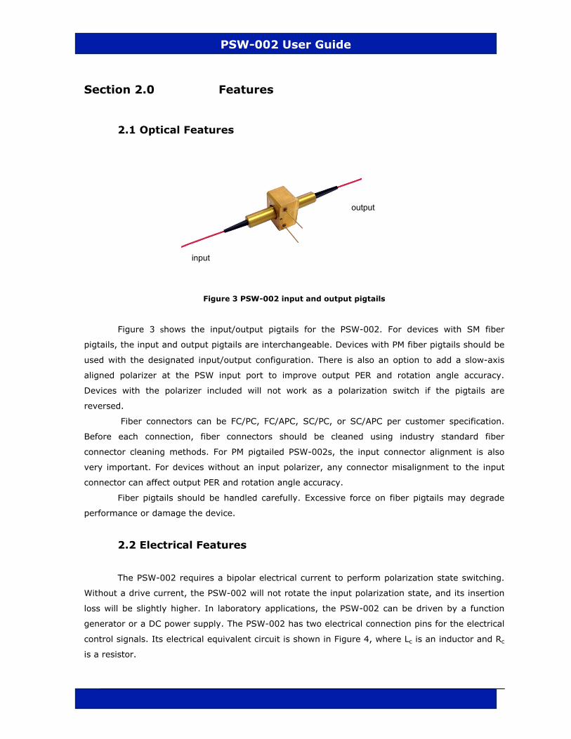
Figure 3 PSW-002 input and output pigtails
Figure 3 shows the input/output pigtails for the PSW-002. For devices with SM fiber
pigtails, the input and output pigtails are interchangeable. Devices with PM fiber pigtails should be
used with the designated input/output configuration. There is also an option to add a slow-axis
aligned polarizer at the PSW input port to improve output PER and rotation angle accuracy.
Devices with the polarizer included will not work as a polarization switch if the pigtails are
reversed.
Fiber connectors can be FC/PC, FC/APC, SC/PC, or SC/APC per customer specification.
Before each connection, fiber connectors should be cleaned using industry standard fiber
connector cleaning methods. For PM pigtailed PSW-002s, the input connector alignment is also
very important. For devices without an input polarizer, any connector misalignment to the input
connector can affect output PER and rotation angle accuracy.
Fiber pigtails should be handled carefully. Excessive force on fiber pigtails may degrade
performance or damage the device.
2.2 Electrical Features
The PSW-002 requires a bipolar electrical current to perform polarization state switching.
Without a drive current, the PSW-002 will not rotate the input polarization state, and its insertion
loss will be slightly higher. In laboratory applications, the PSW-002 can be driven by a function
generator or a DC power supply. The PSW-002 has two electrical connection pins for the electrical
control signals. Its electrical equivalent circuit is shown in Figure 4, where Lc is an inductor and Rc
is a resistor.
GP-UM-PSW-002-10 Page 9 of 18

PSW-002 User Guide
Figure 4 PSW-002 equivalent electrical circuit
Voltage/Current Guidelines:
The PSW-002 requires a certain level of current and voltage to switch from one output
state to another (switching voltage/current), but once it has switched, it can maintain its state
with a lower voltage/current (latching voltage/current).
Voltage Current
Switching 2-3 V <130 mA
Latching 1.5-2V <80 mA
A typical drive signal might look like:
V VS VL
Figure 5 Drive signal diagram VS = switching voltage VL = latching voltage TS = time switching voltage is applied
Lowering the control voltage to the latching voltage to maintain the current output state
improves the stability of the output state because it reduces device heating, which can affect the
rotation angle. It is generally recommended to use a drive signal pattern like the one shown in
Figure 5, especially if the PSW-002 is to remain in one state or the other for relatively long periods
of time.
0 −VL −VS
T
TS >100µs
GP-UM-PSW-002-10 Page 10 of 18

PSW-002 User Guide
2.3 Switch Timing
A typical switching response is shown in Figure 6, where the upper trace is the
synchronization output waveform from a function generator, and the lower trace is the PSW-002
output power after a polarizer. A function generator with output voltage set at ±2V is used as the
PSW-002 driver. The time scale (horizontal axis) is 50 µs/division.
As shown in Figure 6, when a step function waveform voltage is applied to the PSW-002,
there is an initial delay of ~75 µs. The rise time (10%-90%) of the switch is also on the order of a
few 10s of µs. The total switching time is ~100µs.
Figure 6 Switching speed of PSW-002 under a −2 to +2V voltage step
GP-UM-PSW-002-10 Page 11 of 18

PSW-002 User Guide
2.4 Dimensions and Mounting Holes
The PSW-002 has one mounting hole on its bottom surface, between the electrical pins.
Package dimensions and electrical pin and mounting hole locations are given below.
Electrical pins are 0.5mm in diameter.
Figure 7 Dimensions and mounting hole information All dimensions given in inches.
GP-UM-PSW-002-10 Page 12 of 18
PSW-002 User Guide
Section 3.0 Operation Instructions
3.1 Unpacking
Inspect PSW-002 for any physical damage due to shipping and transportation. Contact
carrier if any damage is found. Check the packing list to see if any parts or accessories are
missing.
Packing List
Item # Description
1 PSW-002
2 User Guide
3 Electrical cable (only for devices with driver board)
3.2 Operation
1. Make optical connections. For PM PSWs, do not reverse input and output connectors.
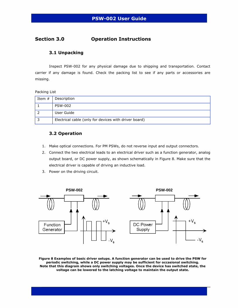
2. Connect the two electrical leads to an electrical driver such as a function generator, analog
output board, or DC power supply, as shown schematically in Figure 8. Make sure that the
electrical driver is capable of driving an inductive load.
3. Power on the driving circuit.
PSW-002 PSW-002
Figure 8 Examples of basic driver setups. A function generator can be used to drive the PSW for periodic switching, while a DC power supply may be sufficient for occasional switching.
Note that this diagram shows only switching voltages. Once the device has switched state, the voltage can be lowered to the latching voltage to maintain the output state.
GP-UM-PSW-002-10 Page 13 of 18

PSW-002 User Guide
Section 4.0 Specifications
Optical
Operating Wavelength 1550 ±30nm or 1310±30nm
Polarization Rotation (at λc, 23° C)
45 ± 0.5° or 90 ± 0.5°
Polarization Rotation (all wavelengths, all temps)
45 ± 5° or 90 ± 5°
Rotation Angle Temperature Dependence
−0.1 degree/°C for 45° version −0.2 degree/°C for 90° version
Switching Time 100 μs typical
Insertion Loss <0.5 dB
Return Loss >55 dB
Extinction Ratio1 > 18 dB for PM model
Optical Power Handling 300 mW
Note: Values referenced without connectors. 1. Both output states of 90° PM PSW with input polarizer at 23°C.
Electrical
Switching Current <130 mA
Switching Voltage 2~3 V
Latching Current ~ 80 mA
Latching Voltage 1.5~2 V
Physical and Environmental
Fiber Type PM Panda, SMF-28 or compatible
Operating temperature 0 °C to 50 °C
Storage temperature −40 °C to 85 °C
Dimensions 1.57”(L) x 0.69” (W) x 0.53” (H)
Weight 30g typical (including connectors)
GP-UM-PSW-002-10 Page 14 of 18

PSW-002 User Guide
WARRANTY
All of General Photonics’ products have been inspected and found to comply with our
quality assurance standards before shipping. If any damage occurs during shipment, please
contact the carrier and inform us or your distributor as soon as possible.
Do not attempt repair of any General Photonics product. Repair of defective products must
be performed by factory trained engineers.
General Photonics warrants that this product will be free from defects in materials or
workmanship for a period of one year from the date of shipment. A product found to be defective
during the warranty period will be repaired or replaced, at no charge, at General Photonics’ option.
If a problem is found, please contact General Photonics for assistance and instructions for
any necessary returns.
General Photonics Customer Service T: 909-590-5473 Email: [email protected]
Hwww.generalphotonics.com
The above warranty specifically excludes products that have been repaired or modified by
non-manufacturer-authorized personnel, as well as damage caused by misuse, abuse, improper
storage or handling, or acts of nature. This warranty is in lieu of all other warranties, expressed or
implied. General Photonics will not be liable for any indirect or consequential damages or losses
resulting from the use of its products.
GP-UM-PSW-002-10 Page 15 of 18

PSW-002 User Guide
Appendices
Appendix 1.0 Driver Board (Optional)
General Photonics offers an optional driver board to simplify use of the PSW-002. The
board generates the recommended switching/latching voltages (see Figure 5), allowing the user to
control the output state using simple TTL levels.
Note that the control signal for the board is TTL levels, not pulses.
TTL high: output state A
TTL low: output state B
Input output
Figure 9 PSW-002 on driver board
Driver Board Specifications
Electrical connector IDC 6-pin connector (2x3 pins), cable provided
Power supply +8~+15VDC/0.2A
Control signal TTL logic level 0-5V
Maximum switching rate 1 kHz (1ms per state)
LED indicators Drive logic high (red) and low (green)
Dimensions 1.50” (L) x 1.50” (W) x 0.5”(H)
Mounting holes 4x ∅2mm
GP-UM-PSW-002-10 Page 16 of 18

GP-UM-PSW-002-10 Page 17 of 18
PSW-002 User Guide
Board Diagram
Figure 10 PSW driver board
The PSW driver board has 4 mounting holes located at the corners of the board, as shown
above.
A 6-pin electrical connector is used to connect the power supply and control signal. A
connection cable is provided. The connector pinout and corresponding connection cable color code
are as follows:
Table 1 PSW driver board cable pinout
Pin # Symbol Wire Color Function Description
1 GND Brown Board ground
2 GND Red Board ground
3 PS Orange Polarization switching
Logic signal, TTL compatible Low = polarization state A High = polarization state B
4 PWR Yellow Power input 8~15VDC/200mA
5 GND Green Board ground
6 GND Board ground
The connection cable is shown below.
Figure 11 PSW driver board electrical cable
PSW pins
5 3 1 6 4 2
Dimensions in inches

PSW-002 User Guide
Setup
1. Connect optical input and output to PSW-002.
2. Connect electrical cable to board.
3. Make sure power supply voltage and current are set at appropriate levels (8 to
15VDC/200 mA).
4. Connect control signal.
5. Power on power supply.
Power Supply/Control Signal Guidelines
Power Supply
The PSW-002 driver board will accept a power supply voltage anywhere between 8 and
15V, but it is generally better to use a lower voltage if possible (i.e. closer to 8V).
Control Signal
Voltage ranges:
TTL Level Nominal Range
High 5V 3-5V
Low 0V 0-1V
Current requirement: <1µA
Maximum switching rate: 1kHz (1 ms per output state)