USER GUIDE - ColDesisupport.coldesi.com/Portals/8/Viper2 User Guide 1.02.pdf · DTG Viper2 User...
108
DTG-V2UG Rev1.0 28/01/2014 USER GUIDE
Transcript of USER GUIDE - ColDesisupport.coldesi.com/Portals/8/Viper2 User Guide 1.02.pdf · DTG Viper2 User...

DTG-V2UG Rev1.0
28/01/2014
USER GUIDE

DTG Viper2 User Guide


Chapter DTG Viper2 User Guide
i
Important Notices
1. For Users in Europe
IMPORTANT:
This is a Class A product approved for industrial environments. In some environments this product may cause radio interference in which case you may be required to take measures to re-locate this product.
2. For Users in the United States
This equipment has been tested and found to comply with the limits for a Class A digital device, pursuant to Part 15 of the FCC Rules. These limits are designed to provide reasonable protection against harmful interference when the equipment is operated in a commercial environment.
This equipment generates, uses, and can radiate radio frequency energy and, if not installed and used in accordance with the instruction manual, may cause harmful interference to radio communications. Operation of this equipment in a residential area is likely to cause harmful interference in which case the user will be required to correct the interference at his own expense.
3. Trademarks Mentioned in this Manual
(1) DTG and Viper2 are registered trademarks or product names of IMPRESSION TECHNOLOGY.
(2) EPSON® and EPSON STYLUS® are registered trademarks of Seiko Epson Corporation.
(3) Microsoft®, Windows®, and Windows Vista® are registered trademarks of Microsoft
Corporation.
(4) Apple® and Macintosh® are registered trademarks of Apple Inc.
(5) Intel® is a registered trademark of Intel Corporation.
(6) PowerPC® is a registered trademark of International Business Machines Corporation.
(7) Adobe®, Photoshop®, Elements®, Lightroom® and Adobe® RGB are registered trademarks of
Adobe Systems Incorporated.
G e n e r a l N o t i c e : O t h e r p r o d u c t n a m e s u s e d h e r e i n a r e f o r i d e n t i f i c a t i o n p u r p o s e s o n l y a n d m a y b e t r a d e m a r k s o f t h e i r r e s p e c t i v e o w n e r s . I m p r e s s i o n T e c h n o l o g y d i s c l a i m s a n y a n d a l l r i g h t s i n t h o s e m a r k s .
4. In this manual, safety instructions are preceded by the symbol . Always read and follow the instructions before performing the required procedures
5. Impression Technology is not responsible for any breakdown of machines due to infection of
computer virus or computer hacking.

DTG Viper2 User Guide Chapter
ii
IMPORTANT:
1. No part of this product or publication may be stored, reproduced, copied, or transmitted in any form or by any means without the express permission of IMPRESSION TECHNOLOGY.
2. The product and the contents of this publication may be changed at any time without prior notification.
3. IMPRESSION TECHNOLOGY has made the best efforts to keep this publication free from error, but if you find any uncertainties or misprints, please call us or the dealer from where you bought this equipment.
4. IMPRESSION TECHNOLOGY shall not be liable for any damages or troubles resulting from the use or mis-use of this equipment or this manual either directly or indi rectly.

Chapter DTG Viper2 User Guide
iii
Warranty Limitations
IMPRESSION TECHNOLOGY warrants part repair or replacement as a sole measure only if a failure is found in the system or in the materials and workmanship of the product the seller produced.
However, if the cause of failure is uncertain or cannot be conclusively proved to be directly related to defect in workmanship any part repair or replacement shall be solely at the discretion of Impression Technology.
The warranty shall not apply to any direct or indirect loss, or compensation for the loss due to the product that has been subject to misuse, neglect, or improper alternation whether directly or indirectly.
ALL INFORMATION CONTAINED IN THIS DOCUMENT IS PROVIDED AS IS WITHOUT WARRANTY OF ANY KIND. THE CREATOR OF THIS DOCUMENT , HEREINAFTER REFERRED TO AS THE 'WRITER' HEREBY DISCLAIMS ALL WARRANTIES, EXPRESSED, IMPLIED OR OTHERWISE, INCLUDING WARRANTIES OF MERCHANTABILITY, FITNESS FOR A PARTICULAR PURPOSE, AND NON-INFRINGEMENT OF INTELLECTUAL PROPERTY RIGHTS. THE WRITER DOES NOT ASSUME OR AUTHORIZE ANY OTHER PERSON TO ASSUME FOR IT ANY OTHER LIABILITY IN CONNECTION WITH THIS DOCUMENT CONTENT. IN NO EVENT SHALL THE WRITER BE LIABLE TO THE READER OF THE CONTENT OF THIS DOCUMENT, OR ANY SUBSEQUENT USER, INCLUDING THE ULTIMATE END-USER, IN CONTRACT, TORT, WARRANTY, STRICT LIABILITY, OR OTHERWISE FOR ANY SPECIAL, INDIRECT, INCIDENTAL OR CONSEQUENTIAL DAMAGES, INCLUDING BUT NOT LIMITED TO, THE COST OF LABOR, REQUALIFICATION, DELAY, LOSS OF PROFITS OR GOODWILL, EVEN IF THE WRITER IS ADVISED OF THE POSSIBILITY OF SUCH DAMAGES. BY LOOKING AT THE CONTENT OF THIS DOCUMENT THE READER AGREES THAT THEY HAVE READ AND AGREE TO THE ABOVE CONDITIONS ENTIRELY.
DTG Viper2 User Guide Chapter
iv
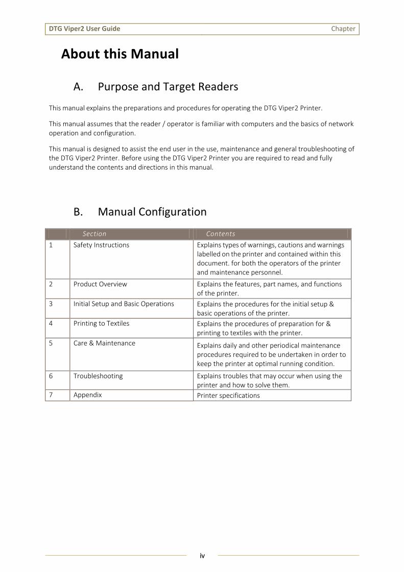
About this Manual
A. Purpose and Target Readers
This manual explains the preparations and procedures for operating the DTG Viper2 Printer.
This manual assumes that the reader / operator is familiar with computers and the basics of network operation and configuration.
This manual is designed to assist the end user in the use, maintenance and general troubleshooting of the DTG Viper2 Printer. Before using the DTG Viper2 Printer you are required to read and fully understand the contents and directions in this manual.
B. Manual Configuration
Section Contents
1 Safety Instructions Explains types of warnings, cautions and warnings labelled on the printer and contained within this document. for both the operators of the printer and maintenance personnel.
2 Product Overview Explains the features, part names, and functions of the printer.
3 Initial Setup and Basic Operations Explains the procedures for the initial setup & basic operations of the printer.
4 Printing to Textiles Explains the procedures of preparation for & printing to textiles with the printer.
5 Care & Maintenance Explains daily and other periodical maintenance procedures required to be undertaken in order to keep the printer at optimal running condition.
6 Troubleshooting Explains troubles that may occur when using the printer and how to solve them.
7 Appendix Printer specifications

Chapter DTG Viper2 User Guide
v
C. Manual Notation
The following symbols are used in this manual for easier understanding of the information.
Symbol Meaning
Meaning
Must be followed carefully to avoid death or serious bodily injury or catastrophic damage to your equipment.
Must be observed to avoid slight or moderate bodily injury or damage to your equipment.
Contains important information and useful tips on the operation of the product
Indicates useful tips for operating or understanding the equipment or getting the best performance from your equipment.
Indicates reference pages in this manual
Follow all warning instructions and symbols marked on this product. These additional cautionary symbols may also be used throughout this manual and represent the following:
Symbol Meaning
Meaning / examples
Pay attention when handling the machine, follow instructions carefully for safe use of the machine:
Static Sensitive
Caution Flammable Explodable Electric Shock
Heated Surface
Moving Object
Pinched Fingers
The symbol indicates actions that are prohibited. Follow these instructions carefully to avoid actions that may put a person or persons in immediate danger:
Prohibited No fire / flame
Do not touch
Keep away from wet
areas
Do not dissassemble
Do not allow to get wet
Do not touch with wet hands
This symbol indicates actions or activities that must be performed. Follow these instructions carefully to carry out these essential tasks:
Instructions Unplug Ground / Earth
NOTE
TIP
WARNING
CAUTION

DTG Viper2 User Guide Chapter
vi
D. Document Change History
This version of the document replaces and obsoletes all previous versions. The following table describes the most recent changes:
Revision Date summary of changes
February 2014
June 2015
Initial Release
US Rev. 1

Chapter DTG Viper2 User Guide
1
TABLE of CONTENTS
1. Safety Instructions ............................................................ 5
1.1 Introduction ............................................................................................. 6
1.2 Warnings, Cautions and Notes ................................................................. 6
1.3 Electrical Safety ........................................................................................ 7
1.4 Machine Handling Safety Instructions ...................................................... 9
1.5 Consumables Handling Safety Instructions............................................. 13
1.6 Warning Label Types and Meanings ....................................................... 14
1.6.1 Handling the Warning Labels ........................................................................... 14
1.6.2 Locations of Warning Labels ............................................................................. 15
2. Product Overview ............................................................17
2.1 Introduction ........................................................................................... 18
2.2 Features ................................................................................................. 18
2.2.1 High Resolution Image Quality ......................................................................... 18
2.2.2 Ink Supply System ............................................................................................ 18
2.2.3 Operation Efficiency Improvement .................................................................. 18
2.2.4 Operability Improvement .................................................................................. 18
2.3 Part Names and Functions ...................................................................... 19
2.3.1 Front Section .................................................................................................... 20
2.3.2 Rear Section ..................................................................................................... 22
2.3.3 Operation Panel ............................................................................................... 23
2.3.4 Ink System ........................................................................................................ 27
3. Initial Setup & Basic Operations ........................................28

DTG Viper2 User Guide Chapter
2
3.1 Introduction ........................................................................................... 29
3.2 Before you Get Started ........................................................................... 29
3.2.1 Commit to Maintenance .................................................................................. 29
3.2.2 Get to Know your VIPER2 ................................................................................. 29
3.3 Choosing a Place for the Printer ............................................................. 32
3.3.1 Installation Environment Requirements ........................................................... 32
3.3.2 Required Space ................................................................................................ 33
3.4 Minimum Computer Requirements ........................................................ 34
3.5 Basic Operations ..................................................................................... 35
3.5.1 Switching the Printer ON .................................................................................. 35
3.5.2 Starting the Printer .......................................................................................... 36
3.5.3 Switching the Printer OFF................................................................................. 37
3.5.4 Connecting the Printer to the PC...................................................................... 38
3.5.5 Operation Panel Operation .............................................................................. 40
3.5.6 Performing a Head Clean from the Operation Panel ........................................ 45
3.6 Initial Setup ............................................................................................ 47
3.6.1 Removal of Shipping Tape ................................................................................ 47
3.6.2 Initial Ink Fill Process ........................................................................................ 48
3.6.3 Preparing & Loading Media for Printing ........................................................... 51
3.6.4 Checking Media Height .................................................................................... 53
3.6.5 Load and Eject Operations ............................................................................... 54
3.6.6 Performing a Nozzle Check Test Print .............................................................. 56
3.6.7 Examining a Nozzle Check Test Print ................................................................ 57
3.6.8 Print Head Alignment ....................................................................................... 59
3.6.9 Printer Drivers & Network Setup ...................................................................... 62

Chapter DTG Viper2 User Guide
3
4. Printing to Textiles ...........................................................66
4.1 Introduction ........................................................................................... 67
4.2 Prepare Your Image ................................................................................ 67
4.3 Garment Preparation & Finishing ........................................................... 70
4.4 Load Garment to Platen / Platen to Printer ............................................ 70
4.4.1 Put the garment onto the Platen...................................................................... 70
4.4.2 Adjust Printing Bed Height / Move Platen to Print Ready Position ................... 71
4.5 Print Your Image ..................................................................................... 71
4.6 Post-Printing ........................................................................................... 71
4.7 Cancelling a Print Job ............................................................................. 72
4.7.1 Introduction ..................................................................................................... 72
4.7.2 Cancelling the Print Job .................................................................................... 72
4.7.3 Re-starting the Printer after Cancelling a Print Job .......................................... 72
5. General Care & Maintenance ............................................74
5.1 Introduction ........................................................................................... 75
5.2 Execute a Print Head Clean at the end of production ............................. 75
5.3 Cartridges should be agitated daily. For best results gently shake each cartridge for 20 seconds. ................................................................................. 75
5.4 Run the Nozzle Check test print each day before starting production ... 75
5.5 Maintaining the Ink System .................................................................... 75
5.5.1 Accessing the Capping Station ......................................................................... 75
5.5.2 Cleaning the Wiper and Head Cap .................................................................... 77
5.5.3 Manual Print Head Guards Clean ..................................................................... 78
5.5.4 Parking the Print Head ..................................................................................... 79

DTG Viper2 User Guide Chapter
4
5.5.5 Flushing the Waste Pipes / Tubes ..................................................................... 80
5.5.6 Emptying the Waste Ink Container ...................................................................... 81
5.5.7 Emptying the Dripper Tray ............................................................................... 82
5.6 Maintaining the Carriage Movement Mechanism .................................. 83
5.6.1 Clean the CR Encoder Strip ............................................................................... 83
5.6.2 Cleaning the Carriage Guide Shaft .................................................................... 85
5.6.3 Clean the CR Drive Belt, Roller and Pulley ........................................................ 86
5.7 General Care ........................................................................................... 87
5.7.1 Environment .................................................................................................... 87
5.7.2 Clean your DTG Viper2™ .................................................................................. 87
5.7.3 Avoid White Ink Separation .............................................................................. 87
5.7.4 Empty & Wash White Ink Container ..................... Error! Bookmark not defined.
5.7.5 Pre-Treat garments away from the printer ...................................................... 88
5.7.6 Keep the Printer Busy....................................................................................... 88
5.8 Flushing the Printer ................................................................................ 89
5.8.1 Flush Ink System .............................................................................................. 89
5.9 Preparing the Printer for Transportation / Storage ................................ 90
6. Troubleshooting ...............................................................91
6.1 Introduction ........................................................................................... 92
6.2 Troubleshooting with Error Messages .................................................... 92
6.2.1 Operation Status .............................................................................................. 93
6.2.2 Errors with Message ......................................................................................... 97

DTG Viper2 User Guide
5
1. Safety Instructions

DTG Viper2 User Guide
6
1.1 Introduction
This chapter explains the meaning of safety terms for personnel who install, operate, or maintain this equipment, important safety instructions, and the warning labels attached to the equipment.
Make sure to follow all instructions and warnings on the equipment and in this manual when installing, operating, or maintaining the equipment.
1.2 Warnings, Cautions and Notes
Safety terms in this manual and the contents of warning labels attached to the printer are categorized into the following three types depending on the degree of risk (or the scale of accident).
Read the following explanations carefully, and follow the instructions in this manual.
Symbol Meaning
Must be followed carefully to avoid death or serious bodily injury or catastrophic damage to your equipment.
Must be observed to avoid slight or moderate bodily injury or damage to your equipment.
Contains important information and useful tips on the operation of the product
WARNING
CAUTION
NOTE
WARNING

DTG Viper2 User Guide
7
1.3 Electrical Safety
This Product must be operated by the power source as indicated on the product’s data plate. Consult your local power company to check if your power source meets the requirements.
Connect this product to a protective ground circuit. This product is supplied with a plug that has a protective earth pin. The plug fits only into a grounded electrical outlet. This is a safety feature. If the plug doesn’t fit to the outlet, contact an electrician to replace the outlet to avoid risk of electric shock. Never use a grounded adaptor plug to connect the product to the electrical outlet that has no ground connection terminal.
Plug the power cord directly into a grounded electrical outlet. To prevent overheating and fire, do not use an extension cord, a multi-plug adaptor or a multiple connector. Consult your local electrician to check if an outlet is grounded.
Connect this product to a branch circuit or an outlet that has larger capacity than the rated ampere and voltage of this product. Refer to the data plate on the rear panel of this product for it’s rated ampere and voltage.
Never touch the power cord with wet hands. It may cause electric shock.
Keep the plug connection free of dust and other contaminants. Dust, damp and other contaminants may cause a minute electrical current in a connector, which may in turn generate heat and possible cause a fire accident.
To avoid the risk of electric shock and fire accident, only use the power cord supplied with this product.
Do not damage or modify the power cord. Damage or tampering may generate head and eventually cause electric shock or a fire accident.
If the power cord is damaged or insulated wires are exposed, replace the power cord. Do not use a damaged or un-insulated cord to avoid the risk of electric shock and a fire accident.
Do not operate the printer if it has been contaminated by foreign substances or liquid spills as doing so may result in electrical shock or fire. Immediately turn off the power switch, disconnect the power plug from the electric socket, and contact your authorized DTG Dealer.
Do not insert or drop metal or objects which are easily combustible through the openings such as the ventilation hole of your printer. Doing so may result in electrical shock or fire.
Do not place the printer in humid and/or dusty areas. Doing so may result in electrical shock or fire.
Replace the fuse (located in fuse socket, near on/off switch at rear of printer) only with a 4Ampere “slow blow” fuse (4A, 250VAC/ 120VAC, 5mm x 20mm, Type T)
WARNING
DTG Viper2 User Guide
8
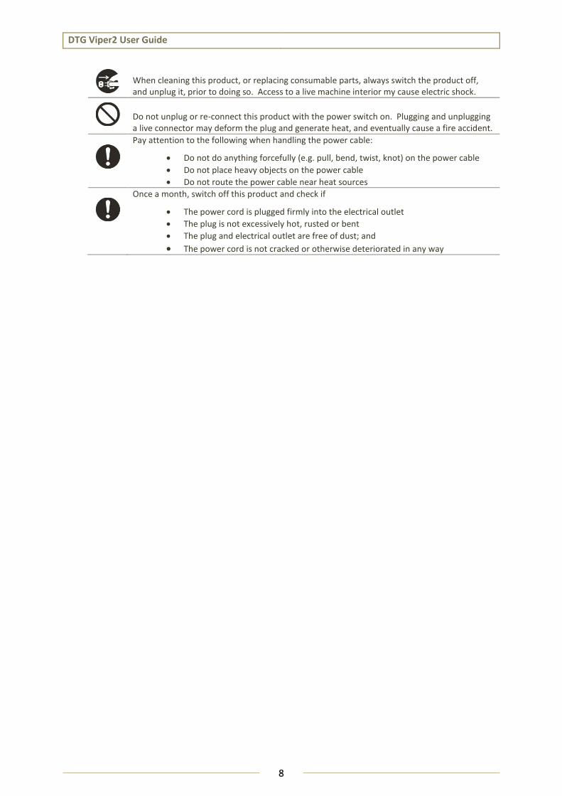
When cleaning this product, or replacing consumable parts, always switch the product off, and unplug it, prior to doing so. Access to a live machine interior my cause electric shock.
Do not unplug or re-connect this product with the power switch on. Plugging and unplugging a live connector may deform the plug and generate heat, and eventually cause a fire accident.
Pay attention to the following when handling the power cable:
Do not do anything forcefully (e.g. pull, bend, twist, knot) on the power cable
Do not place heavy objects on the power cable
Do not route the power cable near heat sources
Once a month, switch off this product and check if
The power cord is plugged firmly into the electrical outlet
The plug is not excessively hot, rusted or bent
The plug and electrical outlet are free of dust; and
The power cord is not cracked or otherwise deteriorated in any way
DTG Viper2 User Guide
9
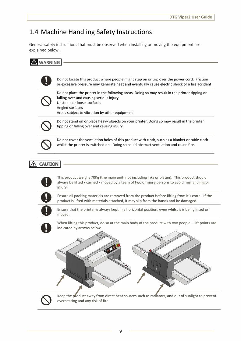
1.4 Machine Handling Safety Instructions
General safety instructions that must be observed when installing or moving the equipment are explained below.
Do not locate this product where people might step on or trip over the power cord. Friction or excessive pressure may generate heat and eventually cause electric shock or a fire accident
Do not place the printer in the following areas. Doing so may result in the printer tipping or falling over and causing serious injury. Unstable or loose surfaces Angled surfaces Areas subject to vibration by other equipment
Do not stand on or place heavy objects on your printer. Doing so may result in the printer tipping or falling over and causing injury.
Do not cover the ventilation holes of this product with cloth, such as a blanket or table cloth whilst the printer is switched on. Doing so could obstruct ventilation and cause fire.
This product weighs 70Kg (the main unit, not including inks or platen). This product should always be lifted / carried / moved by a team of two or more persons to avoid mishandling or injury
Ensure all packing materials are removed from the product before lifting from it’s crate. If the product is lifted with materials attached, it may slip from the hands and be damaged.
Ensure that the printer is always kept in a horizontal position, even whilst it is being lifted or moved.
When lifting this product, do so at the main body of the product with two people – lift points are indicated by arrows below.
Keep the product away from direct heat sources such as radiators, and out of sunlight to prevent overheating and any risk of fire.
WARNING
DTG Viper2 User Guide
10
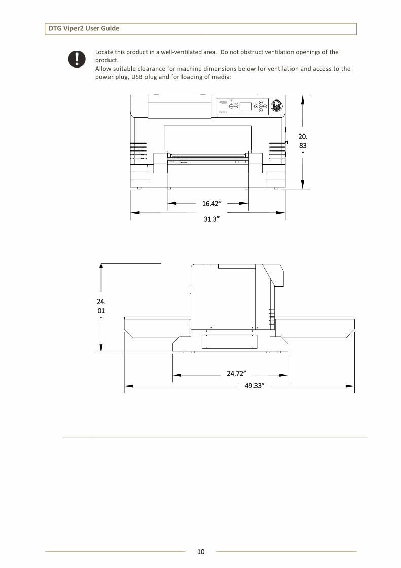
Locate this product in a well-ventilated area. Do not obstruct ventilation openings of the product. Allow suitable clearance for machine dimensions below for ventilation and access to the power plug, USB plug and for loading of media:
16.42”
31.3”
24.72”
49.33”
24.01”
20.83”
DTG Viper2 User Guide
11
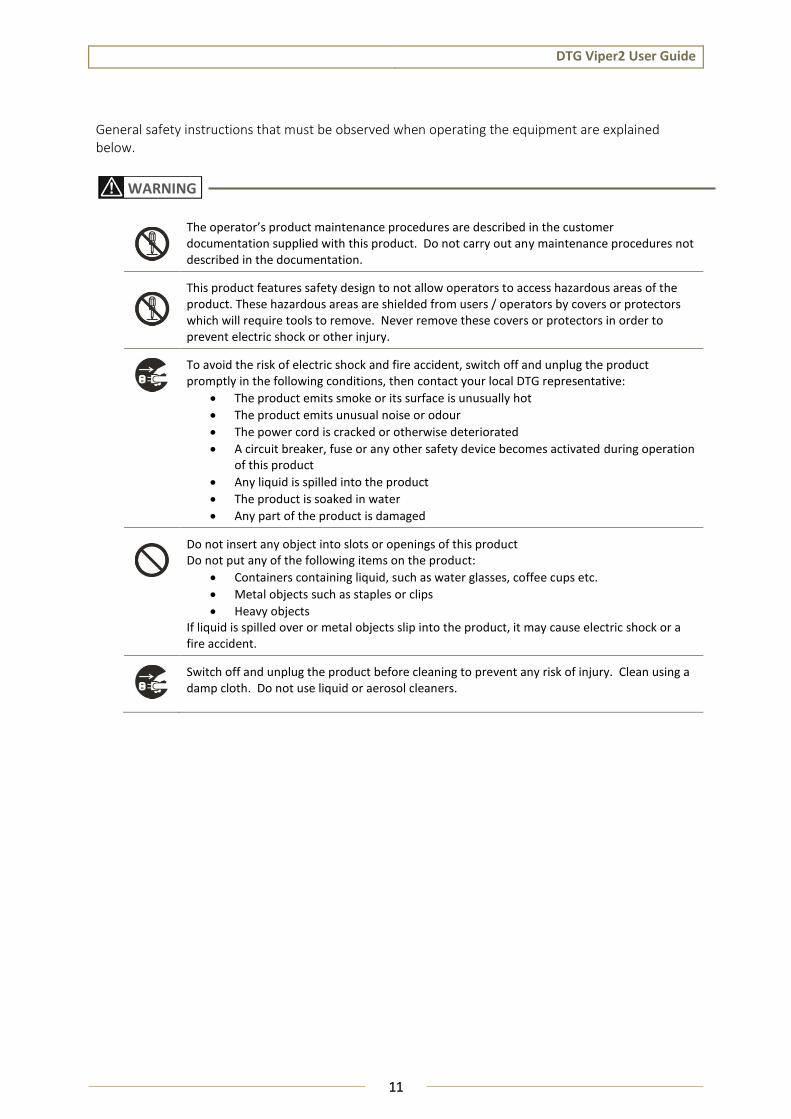
General safety instructions that must be observed when operating the equipment are explained below.
The operator’s product maintenance procedures are described in the customer documentation supplied with this product. Do not carry out any maintenance procedures not described in the documentation.
This product features safety design to not allow operators to access hazardous areas of the product. These hazardous areas are shielded from users / operators by covers or protectors which will require tools to remove. Never remove these covers or protectors in order to prevent electric shock or other injury.
To avoid the risk of electric shock and fire accident, switch off and unplug the product promptly in the following conditions, then contact your local DTG representative:
The product emits smoke or its surface is unusually hot
The product emits unusual noise or odour
The power cord is cracked or otherwise deteriorated
A circuit breaker, fuse or any other safety device becomes activated during operation of this product
Any liquid is spilled into the product
The product is soaked in water
Any part of the product is damaged
Do not insert any object into slots or openings of this product Do not put any of the following items on the product:
Containers containing liquid, such as water glasses, coffee cups etc.
Metal objects such as staples or clips
Heavy objects If liquid is spilled over or metal objects slip into the product, it may cause electric shock or a fire accident.
Switch off and unplug the product before cleaning to prevent any risk of injury. Clean using a damp cloth. Do not use liquid or aerosol cleaners.
WARNING

DTG Viper2 User Guide
12
Always follow all warning instructions marked on or supplied with this product. To avoid the risk of burn injuries and electric shock, never touch areas marked with “High Temperature” or High Voltage marks.
Ensure that the room in which the product is being operated is well ventilated, especially during extended operation or mass printing. The office air environment may be affected with odours (such as ozone) in a poorly ventilated room. Provide adequate ventilation to ensure a comfortable and safe operating environment.
Do not use strong solvents such as thinners, benzene or alcohol on the printer. These products may damage the paint on the printer.
Ensure loose clothing and hair is kept clear of moving parts when the product is in operation to prevent possible risk of injury.
Always operate this product in an environment meeting the following specifications to avoid damage to the product:
Temperature: 18 to 30˚C (64 to 86˚F)
Humidity: 20 to 80% RH*
Operate this product in an environment meeting the following specifications to minimize print quality issues:
Temperature: 18 to 25˚C (64 to 77˚F)
Humidity: 40 to 60% RH*
If the product is left in a low temperature environment, and then the room is rapidly warmed, dew condensation may form inside the product and cause irregularities in printing. Allow sufficient time for such condensation to evaporate in the warmer environment before operating the product.
* Without condensation
Be careful to ensure that fingers are not caught in the opening when lifting and closing the top cover of the printer.
If you need to operate the printer with the cover removed for maintenance or repair, be careful not to get injured by any moving parts.
Assembling and disssembling of the printer are possible only for the parts for which disassembling procedures are shown in this manual. Do not dissassemble any frame parts or parts that disassembling procedures are not shown in this manual. Doing so may cause trouble that connot be resetored, as the printer is orriginally assembled in the factory with a high accuracy.
Ensure sufficient space around the printer when performing maintenance work.
Maintenance must be done by two or more persons for the following work:
When disassembling or reassembling the product.
When packing the printer for transportation

DTG Viper2 User Guide
13
1.5 Consumables Handling Safety Instructions
Handle all inks, pre-treatments and cleaning solutions in accordance with the relevant MSDS (Material Safety Data Sheet).
Store all consumables in accordance with the instructions given on their packaging or container or provided by your DTG Dealer (5 - 30 °C, 41 - 86 °F).
Keep inks, pre-treatments and cleaning solutions out of the reach of children. If toner is accidentally swallowed, spit it out, rinse mouth thoroughly with water, drink plenty of water and consult a physician immediately.
When re-filling inks, be careful not to spill the ink. In the case of any ink spills, avoid inhalation and avoid contact with clothes, skin, eyes and mouth.
If ink, pre-treatment or cleaning solution spills onto your skin or clothing, wash it off with soap and water. Seek medical treatment if irritation occurs.
If you get ink, pre-treatment or cleaning solution in your eyes, rinse cautiously with water for several minutes. Remove contact lenses, if present and easy to do. Continue rinsing. If eye irritation persists, get medical attention.
If you inhale ink, pre-treatment or cleaning solution, move to fresh air, and rinse your mouth with water.
If you swallow ink, pre-treatment or cleaning solution, treat symptomatically. Get medical attention. Call a poison centre or doctor if exposed or you feel unwell.
There is ink in the tubes throughout the printer. Be careful that the ink is not spilled from any tube outlet onto the printer or items close to the printer.
WARNING

DTG Viper2 User Guide
14
1.6 Warning Label Types and Meanings
The handling, attachment locations, and types of warning labels are explained below.
Warning labels are attached to areas where care should be taken. Read and understand the positions and contents thoroughly before maintenance operation.
1.6.1 Handling the Warning Labels
Make sure to note the following when handling the warning labels.
1. Make sure that all warning labels can be recognized. If text or illustrations cannot be seen clearly, clean or replace the label.
2. When cleaning warning labels, use a cloth with water or neutral detergent. Do not use any solvent or gasoline products.
3. If a warning label is damaged, lost, or cannot be recognized, replace the label.
TABLE 1-1 WARNING LABEL TYPE
Ref Warning Label Warning Label Type
A
Using this area as a lift point will cause damage to the printer.
B
Do not touch anything in this area unless instructed.
C
Dangerous voltages present in this area.
D
Fingers may be trapped and ripped off in this area.
NOTE

DTG Viper2 User Guide
15
1.6.2 Locations of Warning Labels
The locations of warning labels are shown below.
Ref Warning Label Type
A Using this area as a lift point will cause damage to the printer.
B Do not touch anything in this area unless instructed.
C Dangerous voltages present in this area.
D Fingers may be trapped and ripped off in this area.
A
A C

DTG Viper2 User Guide
16

DTG Viper2 User Guide
17
2. Product Overview
DTG Viper2 User Guide
18
2.1 Introduction
This chapter explains the features, part names, and functions of the printer.
2.2 Features
The features of the printer are explained below.
2.2.1 High Resolution Image Quality This model uses the drop on-demand piezo head with a high performance coated nozzle plate.
The ability to eject >40pl droplet size enables excellent white ink delivery.
2.2.2 Ink Supply System This model uses a microprocessor controlled pressurized ink supply system.
2.2.3 Operation Efficiency Improvement With the DTG VIPER 2 you can load garments that will auto register for perfect white and color prints time and again. The DTG Viper2 is also flexible in that finished garments can either be returned to the front of the machine (if you are operating in a tight area) or can be ejected to the rear of the printer for faster loading, unloading and all around production throughput.
2.2.4 Operability Improvement Print jobs can be sent to the printer whether the platen is loaded or un-loaded. An easily accessible LED indicator button allows the user to select single or double layer print modes, ensuring that prints are auto-reloaded when required, and ejected when the job is complete.
DTG Viper2 User Guide
19
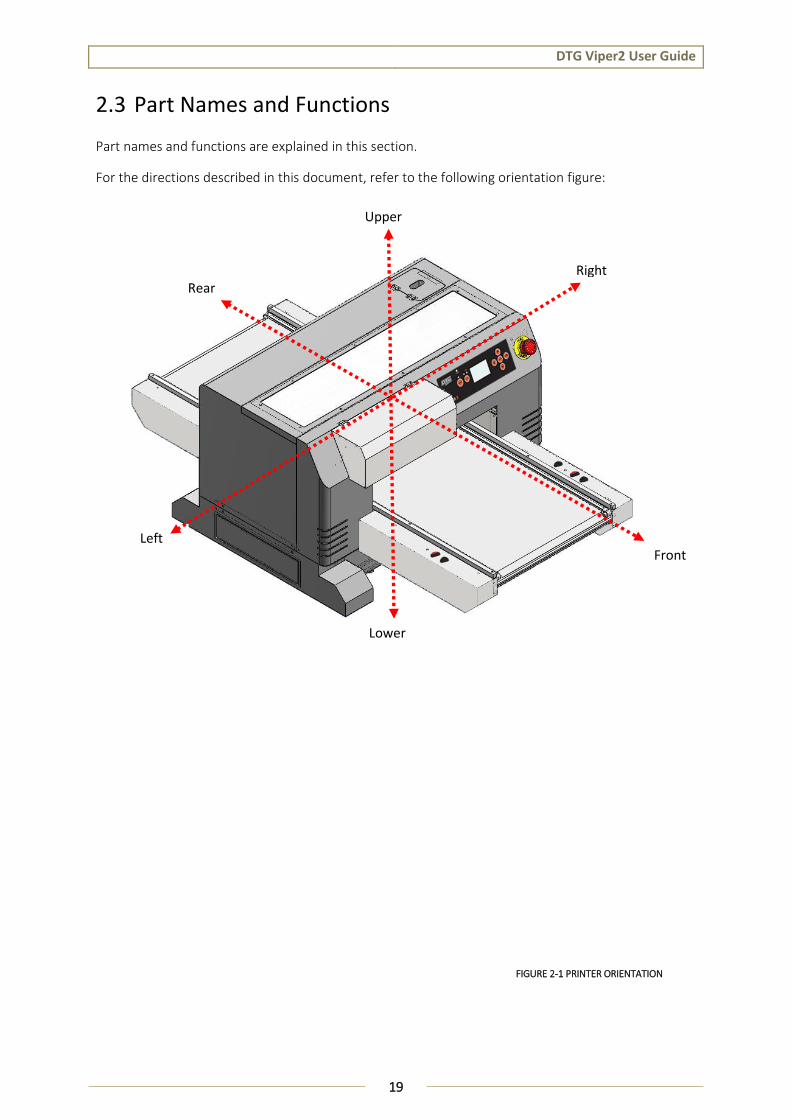
2.3 Part Names and Functions
Part names and functions are explained in this section.
For the directions described in this document, refer to the following orientation figure:
Left
Rear
Upper
Right
Front
Lower
FIGURE 2-1 PRINTER ORIENTATION
DTG Viper2 User Guide
20
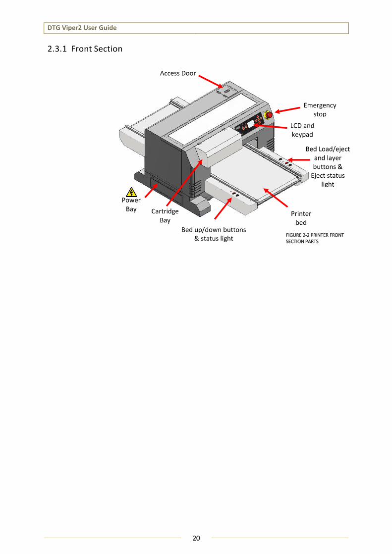
2.3.1 Front Section
FIGURE 2-2 PRINTER FRONT SECTION PARTS
Bed Load/eject and layer buttons &
Eject status light
Emergency stop
LCD and keypad
Bed up/down buttons & status light
Printer bed
Cartridge Bay
Access Door
Power Bay
DTG Viper2 User Guide
21
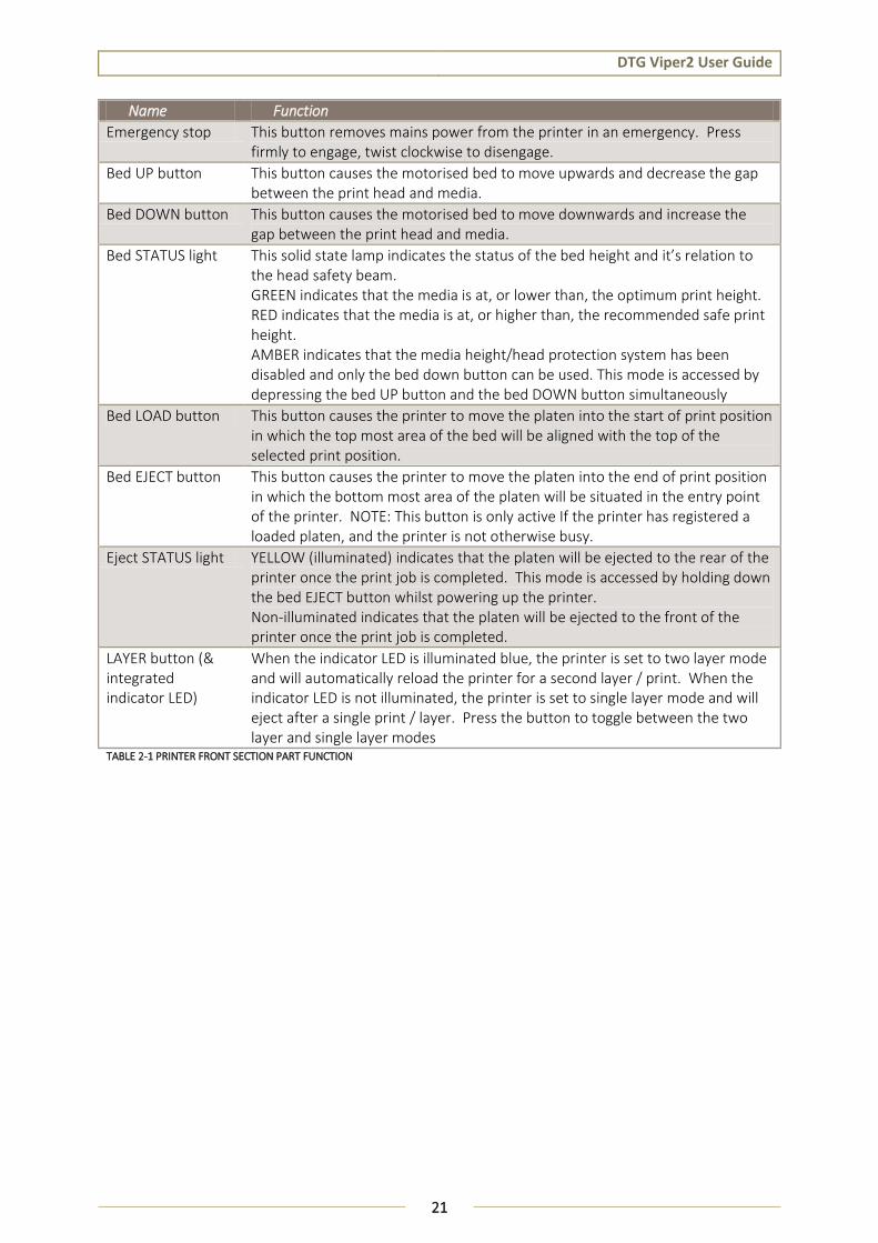
Name Function
Emergency stop This button removes mains power from the printer in an emergency. Press firmly to engage, twist clockwise to disengage.
Bed UP button This button causes the motorised bed to move upwards and decrease the gap between the print head and media.
Bed DOWN button This button causes the motorised bed to move downwards and increase the gap between the print head and media.
Bed STATUS light This solid state lamp indicates the status of the bed height and it’s relation to the head safety beam. GREEN indicates that the media is at, or lower than, the optimum print height. RED indicates that the media is at, or higher than, the recommended safe print height. AMBER indicates that the media height/head protection system has been disabled and only the bed down button can be used. This mode is accessed by depressing the bed UP button and the bed DOWN button simultaneously
Bed LOAD button This button causes the printer to move the platen into the start of print position in which the top most area of the bed will be aligned with the top of the selected print position.
Bed EJECT button This button causes the printer to move the platen into the end of print position in which the bottom most area of the platen will be situated in the entry point of the printer. NOTE: This button is only active If the printer has registered a loaded platen, and the printer is not otherwise busy.
Eject STATUS light YELLOW (illuminated) indicates that the platen will be ejected to the rear of the printer once the print job is completed. This mode is accessed by holding down the bed EJECT button whilst powering up the printer. Non-illuminated indicates that the platen will be ejected to the front of the printer once the print job is completed.
LAYER button (& integrated indicator LED)
When the indicator LED is illuminated blue, the printer is set to two layer mode and will automatically reload the printer for a second layer / print. When the indicator LED is not illuminated, the printer is set to single layer mode and will eject after a single print / layer. Press the button to toggle between the two layer and single layer modes
TABLE 2-1 PRINTER FRONT SECTION PART FUNCTION
DTG Viper2 User Guide
22
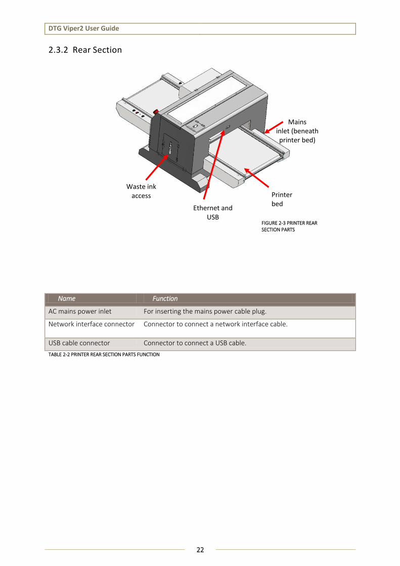
2.3.2 Rear Section
Name Function
AC mains power inlet For inserting the mains power cable plug.
Network interface connector Connector to connect a network interface cable.
USB cable connector Connector to connect a USB cable.
TABLE 2-2 PRINTER REAR SECTION PARTS FUNCTION
FIGURE 2-3 PRINTER REAR SECTION PARTS
Mains inlet (beneath printer bed)
Ethernet and USB
Waste ink access Printer
bed
DTG Viper2 User Guide
23
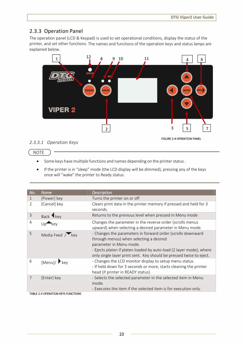
2.3.3 Operation Panel The operation panel (LCD & Keypad) is used to set operational conditions, display the status of the printer, and set other functions. The names and functions of the operation keys and status lamps are explained below.
2.3.3.1 Operation Keys
Some keys have multiple functions and names depending on the printer status .
If the printer is in “sleep” mode (the LCD display will be dimmed), pressing any of the keys once will “wake” the printer to Ready status.
No. Name Description
1 [Power] key Turns the printer on or off
2 [Cancel] key Clears print data in the printer memory if pressed and held for 3 seconds.
3 Back key Returns to the previous level when pressed in Menu mode
4 Up key Changes the parameter in the reverse order (scrolls menus upward) when selecting a desired parameter in Menu mode.
5 Media Feed / key - Changes the parameters in forward order (scrolls downward through menus) when selecting a desired parameter in Menu mode. - Ejects platen if platen loaded by auto-load (2 layer mode), where only single layer print sent. Key should be pressed twice to eject.
6 [Menu]/ key - Changes the LCD monitor display to setup menu status. - If held down for 3 seconds or more, starts cleaning the printer head (if printer in READY status).
7 [Enter] key - Selects the selected parameter in the selected item in Menu mode. - Executes the item if the selected item is for execution only.
TABLE 2-3 OPERATION KEYS FUNCTIONS
1
7
2
5
6
4
FIGURE 2-4 OPERATION PANEL
3
NOTE
8
9
10
11
12

DTG Viper2 User Guide
24
2.3.3.2 LCD Display and Status Lights
No.
Name Color Status Function
8 Power Light Green On The printer is in the ready status. Blinking The printer is printing
The printer is cleaning the print head The printer is drying ink on the printed media
Off The printer is switched off. 9 Paper Status
Light Orange On The printer is waiting for media load
Blinking Media load has failed 10 Ink Status Light Orange On The Maintenance tank is reading full
One or more ink cartridges is not seated correctly
Blinking The Maintenance tank is reading as nearly full 11 LCD display - - This monitor displays the operation status and error
messages of the printer. 12 Printer Status
Light Green Slow
Illuminate /Fade
The printer is in “sleep” mode
On The printer is in Ready status
Blue Blinking The printer is printing The printer is cleaning the print head
On
Red Blinking The Maintenance tank is reading as nearly full
On The Maintenance tank is reading full One or more ink cartridges is not seated correctly
TABLE 2-4 LCD MONITOR & STATUS LAMPS
When a service call error occurs, all the lights are flashing
2.3.3.3 Combination of keys
This section describes the functions available when several buttons are pressed at the same time.
Buttons Function
1. [Power] key 2. [Cancel] key
If the printer is turned on while you are pressing and holding the [Cancel] key, the printer enters Maintenance mode.
NOTE
DTG Viper2 User Guide
25
2.3.3.4 Messages
This section describes the meaning of messages displayed on the LCD panel.
The messages are status messages. For error messages, see
Message Description
READY The printer is ready to print data.
PRINTING The printer is processing data.
PLEASE WAIT Wait until READY appears.
CHARGING INK The printer is charging the ink delivery system.
RESETTING The printer is being reset.
CLEANING The printer is cleaning the ink system.
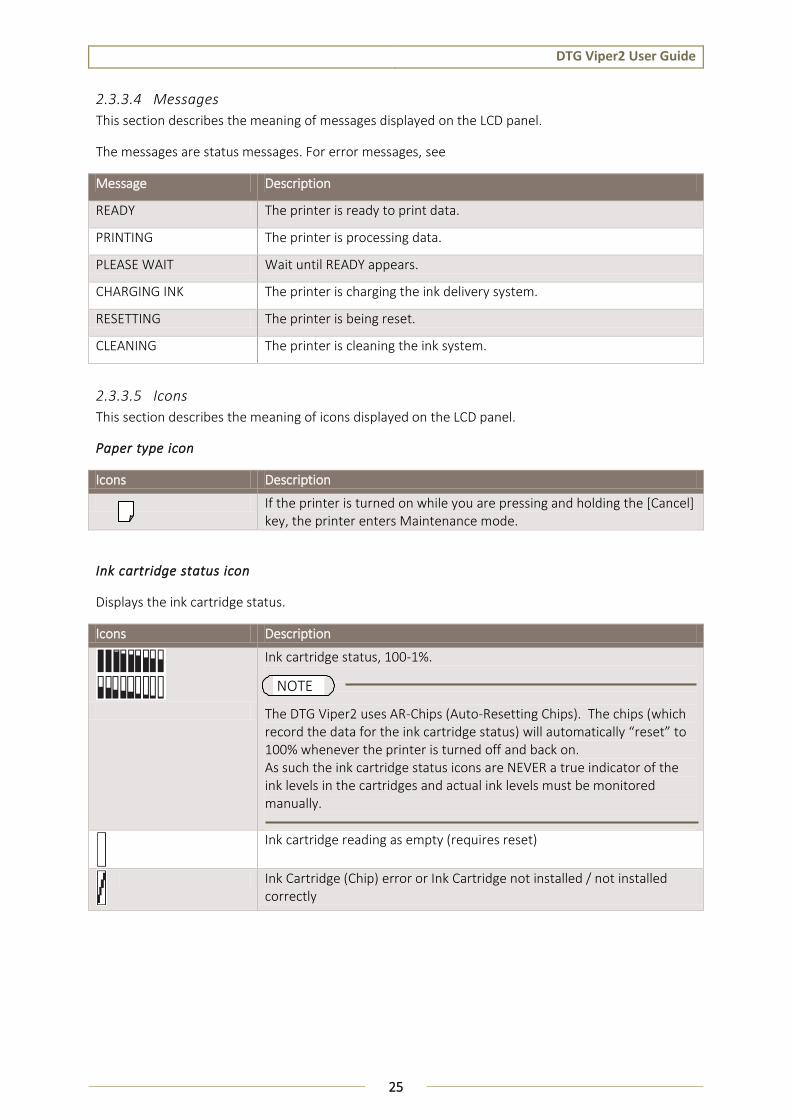
2.3.3.5 Icons
This section describes the meaning of icons displayed on the LCD panel.
Paper type icon
Icons Description
If the printer is turned on while you are pressing and holding the [Cancel] key, the printer enters Maintenance mode.
Ink cartridge status icon
Displays the ink cartridge status.
Icons Description
Ink cartridge status, 100-1%.
The DTG Viper2 uses AR-Chips (Auto-Resetting Chips). The chips (which record the data for the ink cartridge status) will automatically “reset” to 100% whenever the printer is turned off and back on. As such the ink cartridge status icons are NEVER a true indicator of the ink levels in the cartridges and actual ink levels must be monitored manually.
Ink cartridge reading as empty (requires reset)
Ink Cartridge (Chip) error or Ink Cartridge not installed / not installed correctly
NOTE

DTG Viper2 User Guide
26
Remaining maintenance cartridge icon
Displays the free capacity of the maintenance cartridge.
Icons Description
Free capacity of the maintenance cartridge status, 100-1%.
The DTG Viper2 has a “maintenance” cartridge which, in a standard wide format printer, would collect waste ink. In the Viper2, waste ink is instead diverted to a waste ink tank which can and should be emptied on a regular basis. As the Maintenance Cartridge status is reset to 100% when the printer is turned off and then on again, the icon is NEVER a true indicator of the waste ink level in the waste ink tank and the actual waste ink level must be monitored manually.
Maintenance cartridge reading as full (requires reset)
Maintenance Cartridge (Chip) error or Maintenance Cartridge not installed / not installed correctly
NOTE
DTG Viper2 User Guide
27
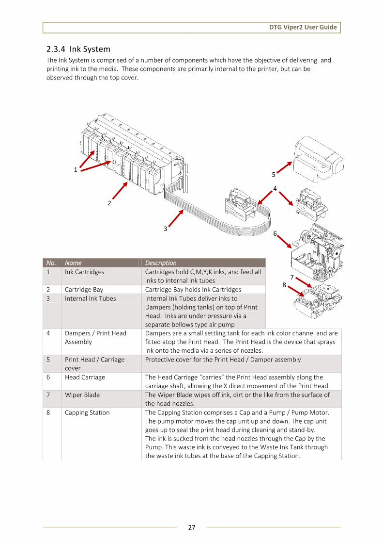
2.3.4 Ink System The Ink System is comprised of a number of components which have the objective of delivering and printing ink to the media. These components are primarily internal to the printer, but can be observed through the top cover.
No. Name Description
1 Ink Cartridges Cartridges hold C,M,Y,K inks, and feed all inks to internal ink tubes
2 Cartridge Bay Cartridge Bay holds Ink Cartridges
3 Internal Ink Tubes Internal Ink Tubes deliver inks to Dampers (holding tanks) on top of Print Head. Inks are under pressure via a separate bellows type air pump
4 Dampers / Print Head Assembly
Dampers are a small settling tank for each ink color channel and are fitted atop the Print Head. The Print Head is the device that sprays ink onto the media via a series of nozzles.
5 Print Head / Carriage cover
Protective cover for the Print Head / Damper assembly
6 Head Carriage The Head Carriage “carries” the Print Head assembly along the carriage shaft, allowing the X direct movement of the Print Head.
7 Wiper Blade The Wiper Blade wipes off ink, dirt or the like from the surface of the head nozzles.
8 Capping Station The Capping Station comprises a Cap and a Pump / Pump Motor. The pump motor moves the cap unit up and down. The cap unit goes up to seal the print head during cleaning and stand-by. The ink is sucked from the head nozzles through the Cap by the Pump. This waste ink is conveyed to the Waste Ink Tank through the waste ink tubes at the base of the Capping Station.
1
2
3
4
5
6
7
8

DTG Viper2 User Guide
28
3. Initial Setup & Basic Operations

DTG Viper2 User Guide
29
3.1 Introduction
This chapter provides information on the initial setup and basic operation of the Viper2 Printer.
It is highly recommended that the initial setup of the printer be performed by a DTG trained & authorized technician. Damage caused by incorrect setup will not be warrantied.
Initial setup should be undertaken in the following order:
1. Position the printer 3.3 "Choosing a Place for the Printer" p.32 2. Remove packaging materials 3.6.1 "Removal of Shipping Tape" p.47
3. Load color ink cartridges (before power is applied to the printer)
4. Load white ink cartridges (before power is applied to the printer)
5. Load media for printing 3.6.3 "Preparing & Loading Media for Printing" p.51
3.2 Before you Get Started
3.2.1 Commit to Maintenance Your DTG VIPER2™ represents a significant investment, not only of your money but also of your commitment to your new business opportunity with the DTG VIPER2™.
Whilst the mechanics of the printing unit of the VIPER2 are similar to that of a normal inkjet printer, printing on fabric is not the same as printing on paper. Fabric generates much more dust, printing on fabrics requires a much greater volume of ink, and the white ink pre-treatment can become airborne during spraying and can ingress into the VIPER2. Each of these factors individually can cause problems with your DTG VIPER2™, and in combination can be critical to the ongoing operation of the VIPER2. All is not lost, however! A few minutes of your time each day spent undertaking some basic maintenance tasks on the VIPER2 will ensure its continued optimal performance. Please refer to the sections within this User’s Guide on Preventative Maintenance for further information.
3.2.2 Get to Know your VIPER2
Starting a new business or adding to your existing product line with the DTG VIPER2™ is a very exciting, and potentially very profitable time. Don’t get too carried away though and start accepting orders before you even have your printer. Allow plenty of time to become familiar with your VIPER2 and to learn not only the basics, but also the variables that can impact on your finished product. These variables include image types, fabric types, your operating environment, garment preparation, and curing of the garment. Thoroughly read this manual, ask questions of your DTG Technician or Distributor, talk to other users (see various internet forums). Be prepared to ruin a few shirts. Be realistic about deadlines when accepting orders and allow yourself sufficient time (and perhaps a couple of extra garments) to complete the order.

DTG Viper2 User Guide
30
FIGURE 3-2 PRINTER FRONT SECTION PARTS
FIGURE 3-1 PRINTER ORIENTATION
Left
Rear
Upper
Right
Front
Lower
Bed Load/eject and layer buttons & Eject status light
Emergency stop
LCD and keypad
Bed up/down buttons & status light
Printer bed
Cartridge Bay
Maintenance Tank Access Door
Power Bay

DTG Viper2 User Guide
31
FIGURE 3-3 PRINTER REAR SECTION PARTS
Mains inlet (beneath printer bed)
Ethernet and USB
Waste ink access Printer
bed

DTG Viper2 User Guide
32
3.3 Choosing a Place for the Printer
3.3.1 Installation Environment Requirements Choose a place for printer installation following the requirements of the table below.
Installation space 1.5m2 or more, 1.3m or more is required for the length
Floor loading capability Up to 3000Pa (450kgf/m2) or more
Electrical specifications
Voltage AC 100 V - 120 V ± 10% or AC 200 V - 240 V ± 10% (NOT auto-switching)
Frequency 50/60Hz ± 1Hz
Capacity Up to 4A or more
Environmental conditions Temperature Humidity
Operation environment 18º C (64F) to 30ºC (86F) 20% to 80%, with no condensation
Printing accuracy range 18ºC (64F) to 25ºC (77F) 40% to 60%, with no condensation
Rate of change 2ºC per hour or less 5% per hour or less TABLE 3-1 INSTALLATION ENVIRONMENT REQUIREMENTS
Do not place the printer in a location under the following conditions. Doing so may cause the product to fall over, become damaged, or cause serious injury:
Unstable or shaky surfaces.
Slippery, slanted or angled surfaces.
Locations that are subject to vibration from other products.
Do not stand, or lean, on the printer or place any objects on it. Doing so may cause it to fall over, become damaged, or cause injury.
Do not cover any ventilation holes or slots of the printer with anything at all. Doing so could prevent the printer from ventilating and cause fire.
Keep the printer away from damp, humid or dusty areas. Failure to do so may result in electrical shock or fire.
WARNING
DTG Viper2 User Guide
33
Avoid the following temperature and humidity conditions. Otherwise, printed images may appear differently from what you expect and machine operation may be erratic or incorrect.
Places where sudden changes in temperature or humidity are expected, even if the condition is within the range specified within this document.
Places where direct sunlight or excessive lighting conditions are expected
Places where air conditioners blow directly.
Impression Technology strongly recommends that the printer should be installed where air conditioning airflow, humidity and temperature can be adjusted easily.
3.3.2 Required Space Install the printer on a flat surface that meets the following conditions:
The load bearing surface will fully support the full weight of the printer (and/or stand) plus 100%.
The load bearing surface has an angular difference from level by no more than 2 degrees.
The load bearing surface is textured and firm enough to be considered a non-slip, hard surface.
The load bearing surface will fully support lateral forces in all directions in excess of 220lbs.
For printer options
NOTE
NOTE

DTG Viper2 User Guide
34
3.4 Minimum Computer Requirements
Ensure that your computer has the minimum specifications as recommended here to ensure optimum performance of your printer and the RIP:
Specification Minimum requirement
Processor PC based on Quad Core (3.0 GHZ) technology or higher processor, such as the Intel i5.
Operating System
Microsoft® Windows® 7 or later.
Hard Disk 200 GB free hard disk space.
RAM 4GB DDR2 (plus OS requirements)
Monitor SVGA or better with resolution of 1024x768 or better.
Software Commercial Graphics Software such as CorelDraw, Adobe Photoshop or Adobe Illustrator**
Internet High speed Internet connection for technical
USB Dual USB 2.0
**Please note that your design software may require higher specifications than what is listed above. You should choose to follow the higher requirements to ensure a smoother operation.

DTG Viper2 User Guide
35
3.5 Basic Operations
Some basic printer operations are described here as they are referred to in the Initial Setup instructions.
3.5.1 Switching the Printer ON
1. Ensure that the emergency stop is engaged by pressing hard on the red cap.
2. Plug the supplied mains cord into the socket at the rear of the printer, and switch the power switch at printer socket to the “ON” position.
3. Failure to remove the shipping tape before powering up the printer may result in catastrophic damage to the printer drive mechanism.
4. Plug the other end of the power cord into the wall socket and turn ON.
5. Rotate the red cap of the emergency stop to allow the printer to receive power.
After a few seconds, a two tone beep will be heard from the printer.
Be sure to use the power cable supplied with the printer. If incorrect power cables are
used, electric shock or fire may result
Do not use a power cable that is damaged. To do so could result in electric shock or
fire.
Pay attention to the following when handling the power cable:
Do not do anything forcefully (e.g. pull, bend, twist) on the power cable
Do not place heavy objects on the power cable
Do not route the power cable near heat sources
WARNING

DTG Viper2 User Guide
36
3.5.2 Starting the Printer 1. Press the Power button on the operation panel.
After a few seconds, a two-tone beep will be heard from the printer.
2. The printer will begin initializing, this process will take approximately 60 seconds, after which the LCD on the operation panel will display “READY”
The printer is likely to perform a short head cleaning operation shortly after turning on.
Do not attempt to operate the printer until READY is displayed on the LCD screen.
NOTE

DTG Viper2 User Guide
37
3.5.3 Switching the Printer OFF. 1. Press the Power button on the operation panel. After about 20 seconds or so a beep will be
heard from the printer, and the Operation panel display will be blank.
At this point, the printer unit been switched of, but power is still being supplied to the conveyor unit and other components.
2. Ensure that the emergency stop is engaged by pressing hard on the red cap.
3. Turn the power switch at the rear of the printer to the off position.
4. Unplug the power cord from the rear of the printer.
During normal non-operational periods such as overnight and during weekends it is recommended that the printer is NOT switched off
Do not attempt to operate the printer during the shutdown process.
NOTE

DTG Viper2 User Guide
38
3.5.4 Connecting the Printer to the PC The DTG VIPER2 has both Ethernet and USB interface ports for connection to the PC. You will require either a USB or Ethernet interface cable for connecting to the PC, depending upon your objectives.
3.5.4.1 Connecting Ethernet (network) interface cable
Refer to Section 3.6.9.2 "Setting up the Printer on a Network" p.62 for instructions on configuring the network setup of the DTG Viper2
The Network interface supports the following environments:
OS Protocol
Windows 8 TCP/IP(Using LPR, Standard TCP/IP Port)
Windows 7
Windows Vista®
1. Turn off both your PC and the printer 3.5.3 "Switching the Printer OFF." p.37
2. Insert the network interface cable connector into the network interface connector port located at the rear of the printer:
3. Connect the other network interface connector to your PC.
No. Part name
1 USB interface connector port
2 Network interface connector port
TIP Refer to the Operation Manual of your PC for connection to your PC
NOTE
1
2
NOTE

DTG Viper2 User Guide
39
3.5.4.2 Connecting USB interface cable
Install the printer driver Section 3.6.9.1 "Printer Driver" p.Error! Bookmark not defined. before connecting the USB cable
1. Insert the USB cable into the USB connector on the back of the printer.
2. Connect the other USB cable connector to your PC.
Refer to the Operation Manual of your PC for connection to your PC
USB connection supports Windows 98 and higher
USB connection supports Windows 98 and higher
This printer supports USB 2.0. If the connection is made under the following conditions, the speed may decrease to the level measured in USB1.1
o When the USB connection is used in Windows 98
o When your PC does not support USB 2.0
o When a USB hub of not USB 2.0 type is used
When using the printer with USB connection, install the printer driver onto your PC using the printer driver provided with the printer
No. Part name
1 USB interface connector port
2 Network interface connector port
NOTE
1
2
NOTE
DTG Viper2 User Guide
40
3.5.5 Operation Panel Operation This section gives an overview of the Viper2 Operation Panel modes and the Viper2 default settings.
Most settings that can be made via the Viper2 Operation Panel are overwritten or ignored by the RIP software used to print from the Viper2. It is possible, however, that if these settings are not set at the correct value, the printer will not behave correctly. 3.5.5.5 “Menu Structure” page 43 Take care not to alter the default settings of the printer. If it is necessary to enter the Menu for any reason follow the instructions below carefully and ensure that settings are maintained as described in
3.5.5.5 “Menu Structure” page 43
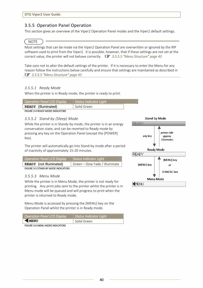
3.5.5.1 Ready Mode
When the printer is in Ready mode, the printer is ready to print.
Operation Panel LCD Display Status Indicator Light
READY (Illuminated) Solid Green FIGURE 3-4 READY MODE INDICATORS
3.5.5.2 Stand-by (Sleep) Mode
While the printer is in Standy-by mode, the printer is in an energy conservation state, and can be reverted to Ready mode by pressing any key on the Operation Panel (except the [POWER] key).
The printer will automatically go into Stand-by mode after a period of inactivity of approximately 15-20 minutes.
Operation Panel LCD Display Status Indicator Light
READY (not Illuminated) Green – Slow Fade / Illuminate FIGURE 3-5 STAND-BY MODE INDICATORS
3.5.5.3 Menu Mode
While the printer is in Menu Mode, the printer is not ready for printing. Any print jobs sent to the printer whilst the printer is in Menu mode will be queued and will progress to print when the printer is returned to Ready mode.
Menu Mode is accessed by pressing the [MENU] key on the Operation Panel whilst the printer is in Ready mode.
Operation Panel LCD Display Status Indicator Light MENU Solid Green FIGURE 3-6 MENU MODE INDICATORS
NOTE

DTG Viper2 User Guide
41
3.5.5.4 Menu Setup Procedure
This section describes how to enter Menu mode and make settings with the keys on the Operation Panel.
1. Check that the operation panel is in Ready mode. (reference Section 3.5.5.1 Ready Mode, page 40)
Press the [CANCEL] key whenever you want to exit Menu mode and return to the READY status.
Press the Back key to return to the previous step.
2. Press the [Menu] key on the operation panel.
" MENU " and the menu list will be displayed on the LCD screen.
3. To select a menu, press the Up key or the Media Feed / key to scroll the Menu list.
4. To Set the selected menu, press the [Menu]/ key
NOTE

DTG Viper2 User Guide
42
The first item of the selected menu will appear on the LCD panel
5. To select the desired item from the menu, press the Up key or the Media Feed / key to
scroll the options.
6. Press, the [Menu]/ key at the selected item to enter or set that item.
The list of parameters for that menu item will display on the LCD screen.
7. To Select a parameter from the displayed list, press the Up key or the Media Feed / key
to scroll the options.
8. Once the selected parameter is highlighted on the LCD screen, press the [Enter] key to store
the selected parameter. If the parameter is for execution only, press the [Enter] key to
execute the function for the item.
After execution, the printer exits Menu mode and returns to the READY status.
9. Press the [Cancel] key to exit Menu mode and return to the READY status.
DTG Viper2 User Guide
43
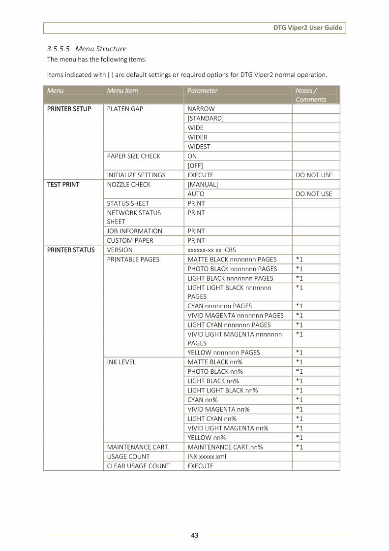
3.5.5.5 Menu Structure
The menu has the following items:
Items indicated with [ ] are default settings or required options for DTG Viper2 normal operation.
Menu Menu Item Parameter Notes / Comments
PRINTER SETUP PLATEN GAP NARROW
[STANDARD]
WIDE
WIDER
WIDEST
PAPER SIZE CHECK ON
[OFF]
INITIALIZE SETTINGS EXECUTE DO NOT USE
TEST PRINT NOZZLE CHECK [MANUAL]
AUTO DO NOT USE
STATUS SHEET PRINT
NETWORK STATUS SHEET
JOB INFORMATION PRINT
CUSTOM PAPER PRINT
PRINTER STATUS VERSION xxxxxx-xx xx ICBS
PRINTABLE PAGES MATTE BLACK nnnnnnn PAGES *1
PHOTO BLACK nnnnnnn PAGES *1
LIGHT BLACK nnnnnnn PAGES *1
LIGHT LIGHT BLACK nnnnnnn PAGES
*1
CYAN nnnnnnn PAGES *1
VIVID MAGENTA nnnnnnn PAGES *1
LIGHT CYAN nnnnnnn PAGES *1
VIVID LIGHT MAGENTA nnnnnnn PAGES
*1
YELLOW nnnnnnn PAGES *1
INK LEVEL MATTE BLACK nn% *1
PHOTO BLACK nn% *1
LIGHT BLACK nn% *1
LIGHT LIGHT BLACK nn% *1
CYAN nn% *1
VIVID MAGENTA nn% *1
LIGHT CYAN nn% *1
VIVID LIGHT MAGENTA nn% *1
YELLOW nn% *1
MAINTENANCE CART. MAINTENANCE CART.nn% *1
USAGE COUNT INK xxxxx.xml
CLEAR USAGE COUNT EXECUTE

DTG Viper2 User Guide
44
Menu Menu Item Parameter Notes / Comments
PRINTER STATUS JOB HISTORY NO.0 ~ NO. 9
TOTAL PRINTS nnnnnn PAGES
CUSTOM PAPER PAPER NUMBER [STANDARD]
PAPER NO. 1~10 DO NOT USE
PAPER TYPE MATTE THICK *2
MATTE THIN
PHOTO PAPER
FINE ART PAPER
REMOTE PANEL PAPER
PLATEN GAP NARROW *2
STANDARD
WIDE
WIDER
THICKNESS PATTERN PRINT *2
THICKNESS NUMBER 1~5 *2
PAPER FEED ADJUST A -.70% ~ 0.70% *2
PAPER FEED ADJUST B -.70% ~ 0.70% *2
DRYING TIME 0.0 SEC ~ 10.0 SEC *2
MAINTENANCE BLACK INK CHANGE EXECUTE
POWER CLEANING EXECUTE
CLOCK SETTING MM/DD/YY HH:MM
CONTRAST ADJUSTMENT -20 ~ [0] ~ +20
HEAD ALIGNMENT AUTO PREM. GLOSSY/LUSTER > PRINT DO NOT USE
PQ INK JET PAPER > PRINT DO NOT USE
ENHANCED MATTE PAPER > PRINT DO NOT USE
MANUAL 0.1 ~ [0.5] MM > PRINT
NETWORK SETUP [DISABLE]
ENABLE
IP ADDRESS SETTING AUTO *3
[PANEL]
PING
IP, SM, DG SETTING IP ADDRESS 000.000.000.000 ~ 192.168.192.168 ~ 255.255.255.255
*3
SUBNET MASK 000.000.000.000 ~ 255.255.255.000 ~ 255.255.255.255
DEFAULT GATEWAY 000.000.000.000 ~ 255.255.255.000
APPLE TALK ON *3 / DO NOT USE
OFF

DTG Viper2 User Guide
45
Menu Menu Item Parameter Notes / Comments
NETWORK SETUP MS NETWORK ON *3
OFF
BONJOUR ON *3 / DO NOT USE
OFF
INIT NETWORK SETTING EXECUTE *3 TABLE 3-2 MENU STRUCTURE
*1 – Information displayed for these parameters will not be accurate due to auto-resetting ink counts- refer Section 2.3.3.5 Icons, page 25
*2 – Menu items will not display unless Menu item other than “Standard” is set
*3 – Menu items will not display unless Menu item “Enable” is set
3.5.6 Performing a Head Clean from the Operation Panel A Head Clean is a process which sucks a little ink through the print head and also wipes the face of the print head, the process is usually executed in order to clear any blocked nozzles in the print head.
Do not attempt to perform a Head Clean unless inks have been loaded to the printer.
1. Ensure the printer is in Print Ready mode
2. Press and hold the [MENU] key for approximately 3 seconds.
The operation panel will display CLEANING / PLEASE WAIT and the cleaning
process will begin
After 2 ½ to 3 ½ minutes or so the clean operation will complete and the Operation Panel will return to Ready mode.

DTG Viper2 User Guide
46
Head cleaning will consume some ink during operation, this is normal with all printers.
TIP Executing a 2nd Head Cleaning from the operation panel within one print of the 1st Head Cleaning will trigger a longer (and stronger) clean.
NOTE
DTG Viper2 User Guide
47
3.6 Initial Setup
Once your printer has been removed from the crate and positioned as per Section 3.3 “ Choosing a Place for the Printer” p.32 , use the following directions to prepare the printer for printing.
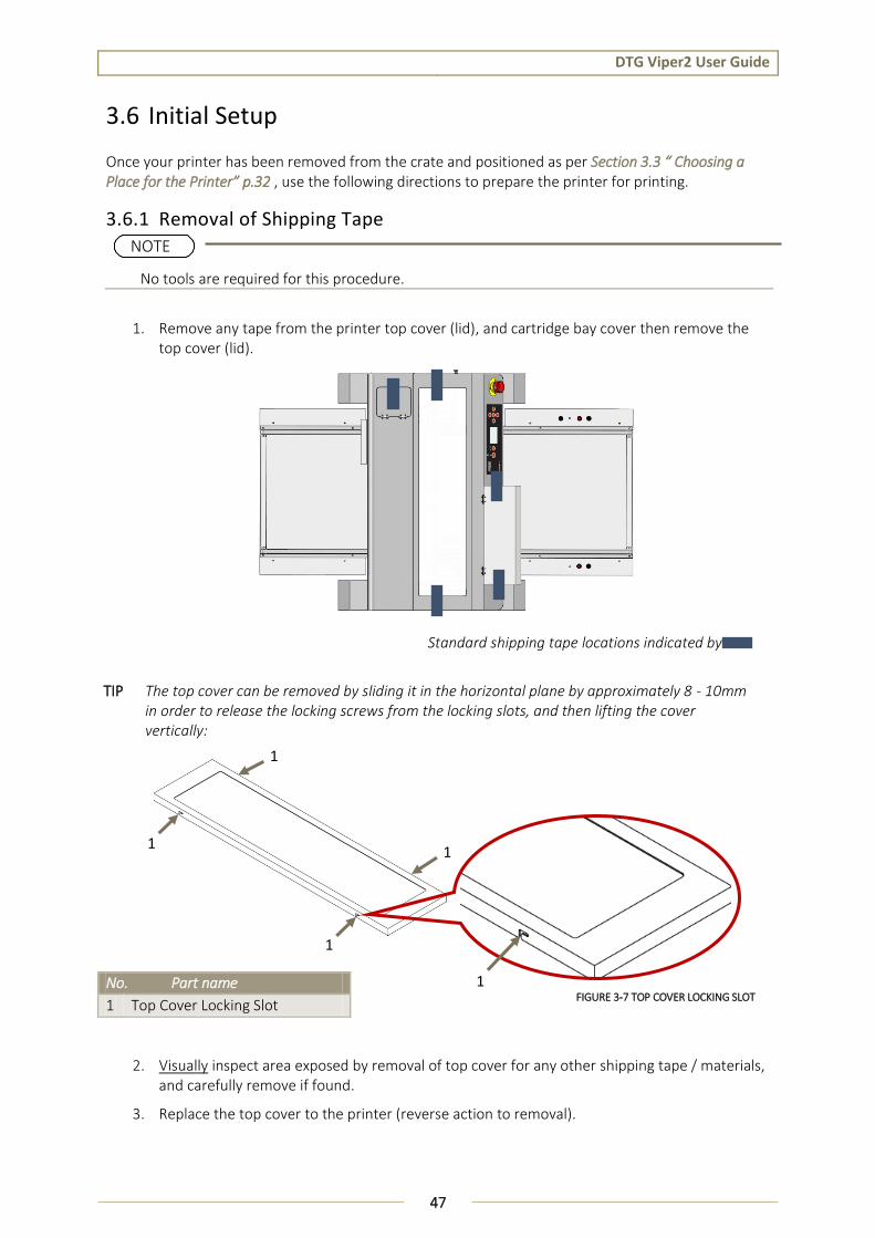
3.6.1 Removal of Shipping Tape
No tools are required for this procedure.
1. Remove any tape from the printer top cover (lid), and cartridge bay cover then remove the top cover (lid).
Standard shipping tape locations indicated by
TIP The top cover can be removed by sliding it in the horizontal plane by approximately 8 - 10mm in order to release the locking screws from the locking slots, and then lifting the cover vertically:
2. Visually inspect area exposed by removal of top cover for any other shipping tape / materials, and carefully remove if found.
3. Replace the top cover to the printer (reverse action to removal).
No. Part name
1 Top Cover Locking Slot
NOTE
1
1
1
1
1 FIGURE 3-7 TOP COVER LOCKING SLOT

DTG Viper2 User Guide
48
4. Visually inspect remainder of printer for any other shipping tape / materials, and carefully remove if found.
5.
Failure to remove all shipping tape before powering up the printer may result in catastrophic damage to the printer drive mechanism.
3.6.2 Initial Ink Fill Process 6.
Observe all recommended ink handling procedures as prescribed in the relevant MSDS for inks.
Do not power on the printer until instructed to do so.
3.6.2.1 Introduction
The Viper2 has ink cartridges that are used to supply ink to the printer.
The Viper2 Ink Cartridges are pressurized by a bellows type air pump. There is constant pressure on the cartridges. Pressure is only released:
When the Cartridge Bay Cover is opened (a magnetic read switch signals to release the pressure)
When the printer is powered down from the Operation Panel
NOTE

DTG Viper2 User Guide
49
The labels on the end of the ink cartridge correspond to the sticker on the underside of the cartridge bay door when open. It is important that you verify that these match up before doing an initial fill or when replacing cartridges.
NOTE
FIGURE 3-8 CARTRIDGE ORDER
This label shows the position of the cartridges. Please make sure that the labels on the cartridge are matched to the label on the machine.

DTG Viper2 User Guide
50
3.6.2.2 Drawing Ink from Ink Cartridges to Printing Head
1. Navigate to the Maintenance Menu on the Operation Panel, select and execute a Power Cleaning. This will begin to charge the ink through from the cartridges to the printer head:
The progress of the ink charge can be observed through the top cover of the printer. The ink should be able to be seen through the translucent (white) tubes that are located behind the Operation Panel area within the printer:
The Power Cleaning will take several minutes to complete, after which you may note that the (internal) ink tubes are not completely filled.
Repeat the Power Clean if necessary – it should not require more than 3 or 4 Power Cleanings to completely charge the ink to the print head.
2. Perform a head clean in accordance with the instructions in Section 3.5.6 Performing a Head Clean from the Operation Panel, page 45 and then follow the instructions in Section Error! Reference source not found. page 56 regarding the loading of media and doing nozzle test prints.
FIGURE 3-10 INTERNAL INK TUBE SECTION
FIGURE 3-9 POWER CLEAN MENU

DTG Viper2 User Guide
51
3.6.3 Preparing & Loading Media for Printing 1. Ensure that all 4 platen tops are level in the horizontal plane and in relation to each other.
Any adjustments to the levels should be made to the platen tops whilst the platen is loaded on the printer bed so that the levels are relevant to the printing area of the printer.
2. Place the platen on a firm, level surface.
3. If you are using paper for test printing purposes gently smooth the paper onto the platen with your hands to ensure that it is flat.
A level platen is critical to achieving good print results. Handle the platen with care at all times as dropping the platen may cause damage rendering it unusable.
TIP If you are using paper for test printing purposes lightly spray the platen surface with spray tack adhesive.
Be sure not to use the spray within 15 feet of the printer as air-borne adhesive may make its way into the printer and cause damage to the print head or other working parts.
DTG Viper2 User Guide
52
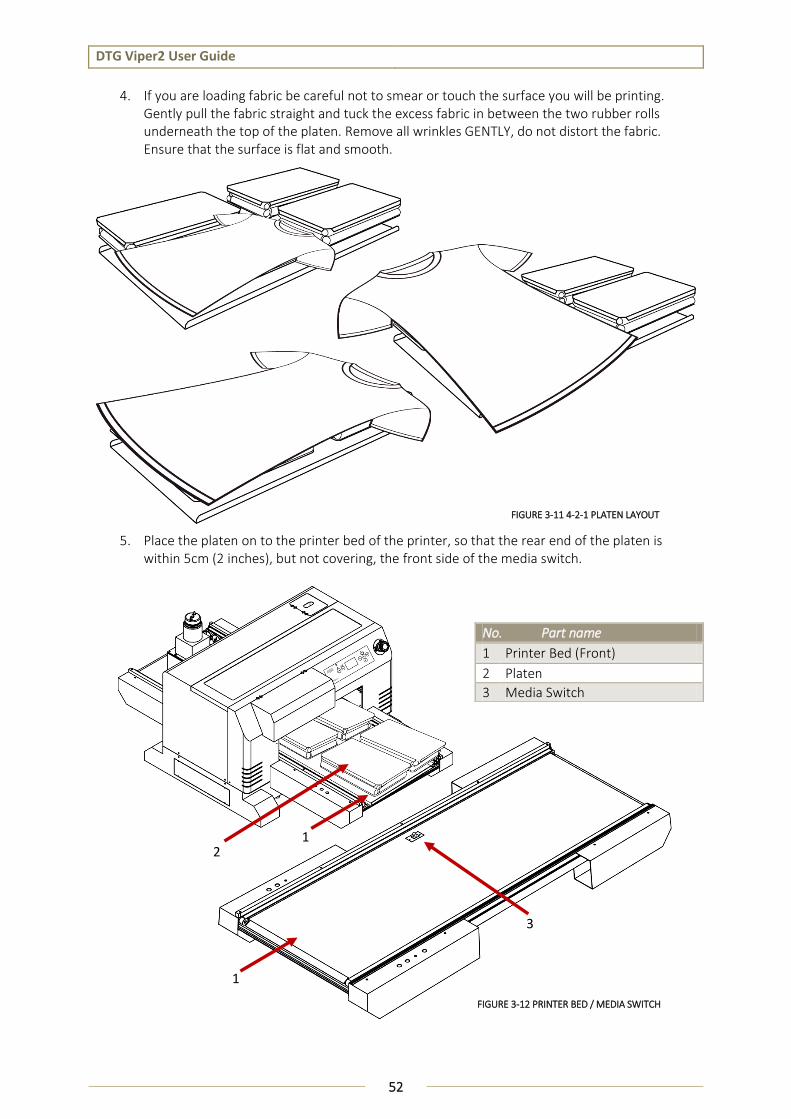
4. If you are loading fabric be careful not to smear or touch the surface you will be printing. Gently pull the fabric straight and tuck the excess fabric in between the two rubber rolls underneath the top of the platen. Remove all wrinkles GENTLY, do not distort the fabric. Ensure that the surface is flat and smooth.
5. Place the platen on to the printer bed of the printer, so that the rear end of the platen is within 5cm (2 inches), but not covering, the front side of the media switch.
No. Part name
1 Printer Bed (Front)
2 Platen
3 Media Switch
FIGURE 3-12 PRINTER BED / MEDIA SWITCH
FIGURE 3-11 4-2-1 PLATEN LAYOUT
1 2
3
1

DTG Viper2 User Guide
53
3.6.4 Checking Media Height
1. Place the platen to the Printer Bed as described in Section 3.6.3 Preparing & Loading Media for Printing, p.51. If the platen is too high the platen LED will turn red and the platen will lower its self. If the platen LED is amber the printer is in platen gap lock mode, press both the UP and DOWN buttons together to turn the lock mode off. The platen LED should go green to indicate all is well and the optimum print head gap is now set.
2. To set the correct height press and hold the UP button, the platen will begin to rise until the internal safety beam detects that the platen height is correct. The platen LED will go red and the platen will stop moving, release the UP button and the LED will turn green indicating that the platen height is now set. The Bed Up and Down buttons are located at the left front side of the Printer Bed.
3. Press the LOAD button, the platen will move into the printer. If there are any high-spots in the media detected by the safety beam as the platen tray moves into the printer, the printer bed will automatically drop until the high spot no longer crosses the safety beam. The Bed Load and Eject buttons are located at the right-front side of the Printer Bed
4. If the Printer Bed drops significantly during the loading process, press the EJECT button to return the platen to the front of the printer, if necessary move the platen again to a firm, level surface to re-check and adjust the level of the media to be printed , and if required, to re-check & adjust the platen levels.
The Printer has an interactive protection system that monitors the height of the media on the printer bed by means of a safety beam that continually watches the gap between the print head and the media. This is to help prevent damage to the print head caused by collision with the media or platen. The safety system can be disabled by pressing and holding both the UP and DOWN keys until the media status light turns yellow. In this condition the automatic safety system will be disabled and only the DOWN button will be operational.
The platen LED has three different colors during operation. GREEN which indicates that the platen should not be high enough to a collision between print head and media. AMBER indicates that the automatic head protection system is OFF and there is a possibility of catastrophic collision damage to the print head. When the indicator is RED the platen bed will begin lowering itself to try and protect the print head from possible collision damage
High spots in the media during loading will cause the printer bed to drop, thereby increasing the gap between the print head (which jets the ink onto the media) and the media. If this gap is too great, print results will be negatively impacted. It is therefore critical that the media printing surface is as smooth and flat as possible when placed on to the printer.
NOTE
NOTE
NOTE

DTG Viper2 User Guide
54
3.6.5 Load and Eject Operations The Viper2 has advanced functionality that allows automatic re-load for 2 layer prints (e.g. where printing white ink layer and then second layer color ink to media) and /or eject to the rear of the printer. This section describes that functionality and offers some simple tests that can be undertaken to observe and therefore better understand the load / eject features & functionality of the DTG Viper2 printer.
3.6.5.1 Basic Bed Load / Eject Functions
1. Place platen on printer bed as described in Section 3.6.3 Preparing & Loading Media for Printing, p. 51.
2. Ensure that the platen has not been positioned over the media switch.
3. Press the LOAD button – platen will load such that the front edge of the platen is positioned approximately 20mm to the rear of the media switch. This is the Print Ready position
4. Press the EJECT button – platen will eject to the front
5.
6. Test the warning function by placing the platen at the front of the printer such that the rear edge of the platen is forward of the media switch by 8.25” or more.
7. Press load – printer will move the platen a short distance and then sound a warning alarm.
8. Press load again to load the platen
9. Press eject to return the platen to the front.
3.6.5.2 Single Layer Print Mode
The Layer Count Button (located on right front arm of Printer Bed, above the Load / Eject buttons) is used to select or de-select the automatic reload for second layer print. The blue indicator LED within the button illuminates when the auto-reload function is selected, and is not illuminated when single layer print is selected.
If Single Layer print mode is selected (blue led not illuminated), the printer will automatically eject the platen / media after each print layer.
If the Single Layer print mode is selected, but a two layer print job is sent to the printer, the printer will issue a beep when the first layer has completed and ejected. At this point, the printer is ready to be re-loaded manually (press the LOAD button).
3.6.5.3 Two Layer Print Mode
When Two Layer print mode is selected (blue led illuminated), the printer will automatically re-load the media to the Print Ready position after printing the first
It is advisable to leave the head safety system operational at all times to assist in protecting the print head. Print heads DO NOT CARRY ANY WARRANTY what so ever.
if platen is placed on bed too far to the front of the machine (where rear edge of platen is approximately 8.25”++ from media switch, front edge of platen overhangs front of printer bed by approximately 4.0”++), it will sound an alarm when it tries to load. This is a protective warning, designed to prevent the printer from loading a platen that is already in the loaded position (in which case the platen would fall from the rear of the bed).
NOTE
NOTE
DTG Viper2 User Guide
55
layer of a print job, in preparation for the second layer print. The print job will be ejected after two layers have printed.
1.
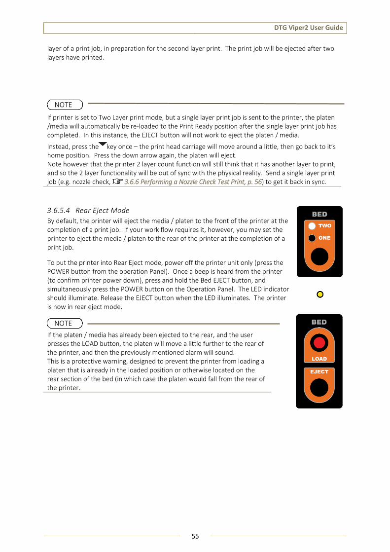
3.6.5.4 Rear Eject Mode
By default, the printer will eject the media / platen to the front of the printer at the completion of a print job. If your work flow requires it, however, you may set the printer to eject the media / platen to the rear of the printer at the completion of a print job.
To put the printer into Rear Eject mode, power off the printer unit only (press the POWER button from the operation Panel). Once a beep is heard from the printer (to confirm printer power down), press and hold the Bed EJECT button, and simultaneously press the POWER button on the Operation Panel. The LED indicator should illuminate. Release the EJECT button when the LED illuminates. The printer is now in rear eject mode.
If the platen / media has already been ejected to the rear, and the user presses the LOAD button, the platen will move a little further to the rear of the printer, and then the previously mentioned alarm will sound. This is a protective warning, designed to prevent the printer from loading a platen that is already in the loaded position or otherwise located on the rear section of the bed (in which case the platen would fall from the rear of the printer.
If printer is set to Two Layer print mode, but a single layer print job is sent to the printer, the platen /media will automatically be re-loaded to the Print Ready position after the single layer print job has completed. In this instance, the EJECT button will not work to eject the platen / media.
Instead, press the key once – the print head carriage will move around a little, then go back to it’s home position. Press the down arrow again, the platen will eject. Note however that the printer 2 layer count function will still think that it has another layer to print, and so the 2 layer functionality will be out of sync with the physical reality. Send a single layer print job (e.g. nozzle check, 3.6.6 Performing a Nozzle Check Test Print, p. 56) to get it back in sync.
NOTE
NOTE
DTG Viper2 User Guide
56
3.6.6 Performing a Nozzle Check Test Print At the heart of the DTG Viper2 is latest high performance piezoelectric print head technology. The print head contains a series of nozzles that are used to spray drops of ink on to the media. (Ink tubes carry the ink from the bottle / cartridges to dampers, or holding chambers which sit on top of the print head. These dampers then deliver the ink to the print head).
The Printer has the ability to print a nozzle test print which will indicate the integrity of the nozzle orifices. Blocked nozzles will cause the printer to produce poor quality output.
1. Load a sheet of clean paper for printing in accordance with Section 3.6.3 "Preparing & Loading Media for Printing" p.51.
2. Ensure the Media Height has been set correctly 3.6.4 Checking Media Height p. 53
3. Follow the menu selection shown below to access the nozzle test print utility.
4. The print job (nozzle test print) will be executed by the printer:
If the platen with paper media has already been loaded, the print job will begin to print.
If the platen with paper media has not already been loaded, the printer will emit a beep and PAPER ERROR will display on the LCD screen:
Press the bed LOAD button to have the printer load the media / platen to the Print Ready position, and the print job should start immediately.
TIP The summary of the key presses above to execute the Nozzle Check test print is: [Menu ], ,
[Menu ], [Menu ], [Menu ] [Enter].
Do Not choose the AUTO option for the Nozzle Check. This will result in an error.
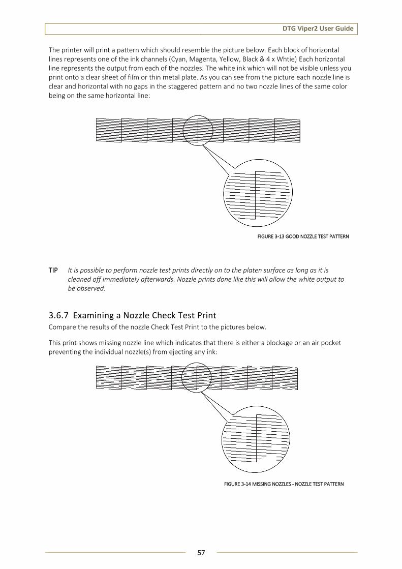
DTG Viper2 User Guide
57
The printer will print a pattern which should resemble the picture below. Each block of horizontal lines represents one of the ink channels (Cyan, Magenta, Yellow, Black & 4 x Whtie) Each horizontal line represents the output from each of the nozzles. The white ink which will not be visible unless you print onto a clear sheet of film or thin metal plate. As you can see from the picture each nozzle line is clear and horizontal with no gaps in the staggered pattern and no two nozzle lines of the same color being on the same horizontal line:
3.6.7 Examining a Nozzle Check Test Print Compare the results of the nozzle Check Test Print to the pictures below.
This print shows missing nozzle line which indicates that there is either a blockage or an air pocket preventing the individual nozzle(s) from ejecting any ink:
TIP It is possible to perform nozzle test prints directly on to the platen surface as long as it is cleaned off immediately afterwards. Nozzle prints done like this will allow the white output to be observed.
FIGURE 3-13 GOOD NOZZLE TEST PATTERN
FIGURE 3-14 MISSING NOZZLES - NOZZLE TEST PATTERN
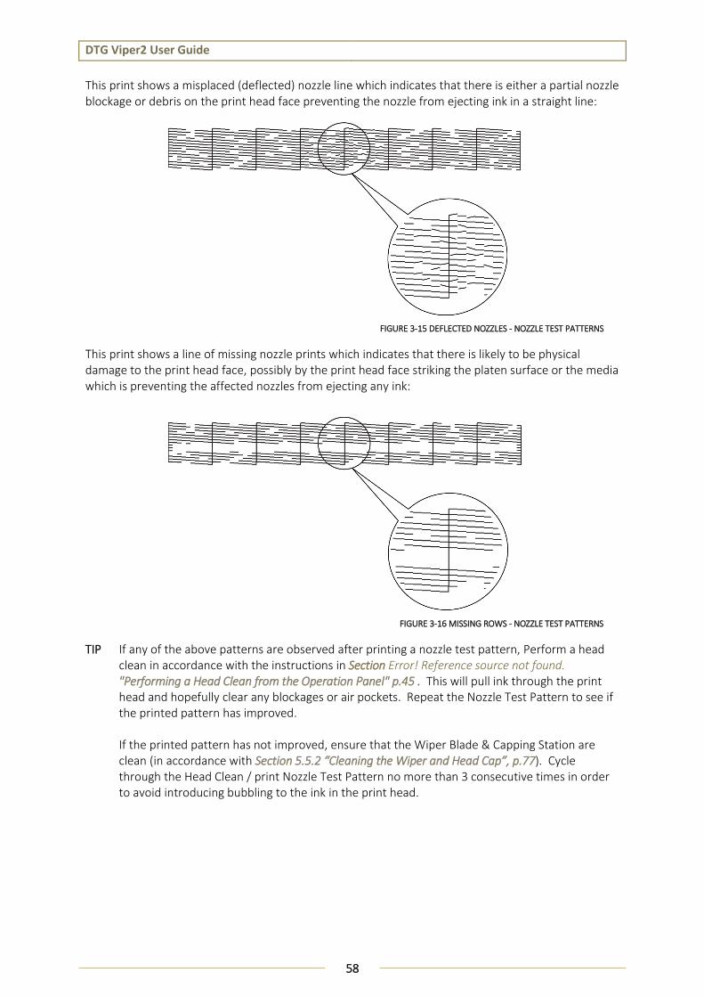
DTG Viper2 User Guide
58
This print shows a misplaced (deflected) nozzle line which indicates that there is either a partial nozzle blockage or debris on the print head face preventing the nozzle from ejecting ink in a straight line:
This print shows a line of missing nozzle prints which indicates that there is likely to be physical damage to the print head face, possibly by the print head face striking the platen surface or the media which is preventing the affected nozzles from ejecting any ink:
TIP If any of the above patterns are observed after printing a nozzle test pattern, Perform a head clean in accordance with the instructions in Section Error! Reference source not found. "Performing a Head Clean from the Operation Panel" p.45 . This will pull ink through the print head and hopefully clear any blockages or air pockets. Repeat the Nozzle Test Pattern to see if the printed pattern has improved. If the printed pattern has not improved, ensure that the Wiper Blade & Capping Station are clean (in accordance with Section 5.5.2 “Cleaning the Wiper and Head Cap”, p.77). Cycle through the Head Clean / print Nozzle Test Pattern no more than 3 consecutive times in order to avoid introducing bubbling to the ink in the print head.
FIGURE 3-15 DEFLECTED NOZZLES - NOZZLE TEST PATTERNS
FIGURE 3-16 MISSING ROWS - NOZZLE TEST PATTERNS
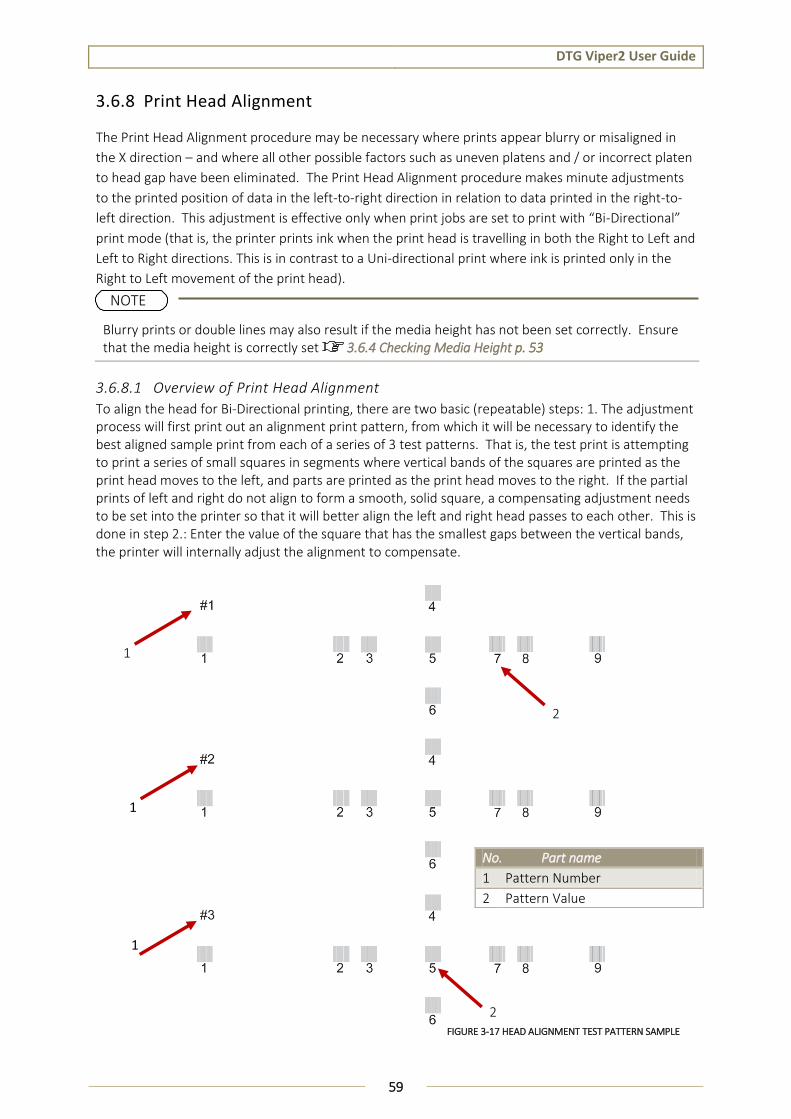
DTG Viper2 User Guide
59
3.6.8 Print Head Alignment
The Print Head Alignment procedure may be necessary where prints appear blurry or misaligned in
the X direction – and where all other possible factors such as uneven platens and / or incorrect platen
to head gap have been eliminated. The Print Head Alignment procedure makes minute adjustments
to the printed position of data in the left-to-right direction in relation to data printed in the right-to-
left direction. This adjustment is effective only when print jobs are set to print with “Bi-Directional”
print mode (that is, the printer prints ink when the print head is travelling in both the Right to Left and
Left to Right directions. This is in contrast to a Uni-directional print where ink is printed only in the
Right to Left movement of the print head).
Blurry prints or double lines may also result if the media height has not been set correctly. Ensure that the media height is correctly set 3.6.4 Checking Media Height p. 53
3.6.8.1 Overview of Print Head Alignment
To align the head for Bi-Directional printing, there are two basic (repeatable) steps: 1. The adjustment process will first print out an alignment print pattern, from which it will be necessary to identify the best aligned sample print from each of a series of 3 test patterns. That is, the test print is attempting to print a series of small squares in segments where vertical bands of the squares are printed as the print head moves to the left, and parts are printed as the print head moves to the right. If the partial prints of left and right do not align to form a smooth, solid square, a compensating adjustment needs to be set into the printer so that it will better align the left and right head passes to each other. This is done in step 2.: Enter the value of the square that has the smallest gaps between the vertical bands, the printer will internally adjust the alignment to compensate.
No. Part name
1 Pattern Number
2 Pattern Value
NOTE
FIGURE 3-17 HEAD ALIGNMENT TEST PATTERN SAMPLE
1
1
1
2
2

DTG Viper2 User Guide
60
3.6.8.2 Performing the Head Alignment Check Print
1. Load a sheet of clean paper for printing in accordance with Section 3.6.3 "Preparing & Loading Media for Printing" p.51.
2. Ensure the Media Height has been set correctly 3.6.4 Checking Media Height p. 53
Ensure that the media height is correctly set 3.6.4 Checking Media Height p. 53, and that the media & platen and true and level. These check points are critical for obtaining a good Head Alignment.
3. Follow the menu selection shown below to access the Head Alignment utility.
5. The print job (Head Alignment print) will be executed by the printer:
If the platen with paper media has already been loaded, the print job will begin to print.
If the platen with paper media has not already been loaded, the printer will emit a beep and PAPER ERROR will display on the LCD screen:
Press the bed LOAD button to have the printer load the media / platen to the Print Ready position, and the print job should start immediately.
TIP The summary of the key presses above to execute the Head Alignment print is: [Menu ], , ,
, , [Menu ], [Menu ], [Menu ] [Enter].
Do Not choose the AUTO option for the Head Alignment. This will result in an error.
NOTE
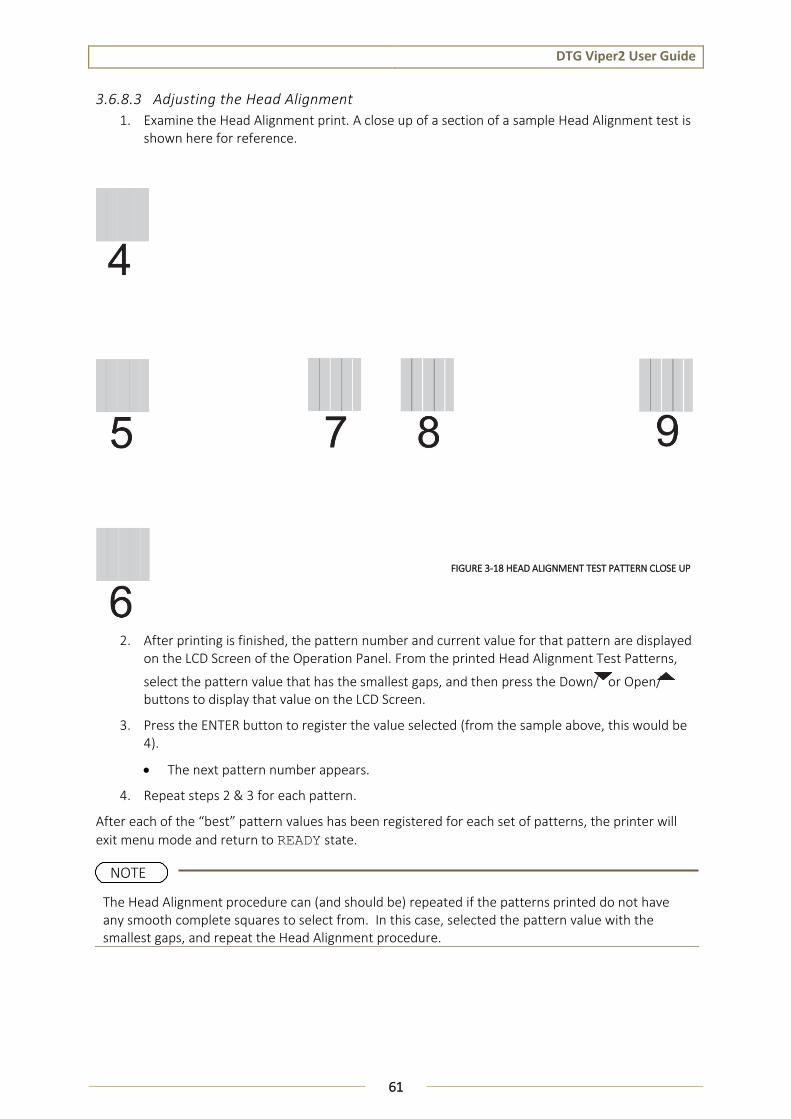
DTG Viper2 User Guide
61
3.6.8.3 Adjusting the Head Alignment
1. Examine the Head Alignment print. A close up of a section of a sample Head Alignment test is shown here for reference.
2. After printing is finished, the pattern number and current value for that pattern are displayed on the LCD Screen of the Operation Panel. From the printed Head Alignment Test Patterns,
select the pattern value that has the smallest gaps, and then press the Down/ or Open/ buttons to display that value on the LCD Screen.
3. Press the ENTER button to register the value selected (from the sample above, this would be 4).
The next pattern number appears.
4. Repeat steps 2 & 3 for each pattern.
After each of the “best” pattern values has been registered for each set of patterns, the printer will
exit menu mode and return to READY state.
The Head Alignment procedure can (and should be) repeated if the patterns printed do not have any smooth complete squares to select from. In this case, selected the pattern value with the smallest gaps, and repeat the Head Alignment procedure.
FIGURE 3-18 HEAD ALIGNMENT TEST PATTERN CLOSE UP
NOTE

DTG Viper2 User Guide
62
3.6.9 Printer Drivers & Network Setup 3.6.9.1 Printer Driver
A printer driver is a piece of software that converts the data to be printed to the form specific to a
printer, and it is usually supplied with a new printing device.
In the case of the DTG Viper2, you will have been supplied with a RIP software which also converts the
data from an image that you wish to print into a form that the printer will understand. In most cases
you will not have need to use the native driver for the printer as the RIP will handle the printing
process.
There may, however, be occasions where you have need to by-pass the RIP software for test printing
purposes. In these instances, you will require the printer driver. The DTG Viper2 uses the same
printer driver as that for the Epson Stylus Pro 3880 printer.
It is assumed that the user will have the basic knowledge required to install a printer driver, details are not provided here. If necessary, contact your Administrator for assistance with printer driver installation.
3.6.9.2 Setting up the Printer on a Network
CONNECTING TO THE NETWORK
Connect the DTG Viper2 to the network as described in Section 3.5.4.1 Connecting Ethernet (network) interface cable, p.38.
You must use a Category 5 shielded twisted-pair cable to connect the network interface to prevent malfunction. You can use both 10Base-T and 100Base-TX networks. We recommend using the highest speed available for the Viper2 with light network traffic.
CONFIGURING THE NETWORK INTERFACE
1. Make sure that the printer is turned on and the LCD displays READY . 3.5.1 Switching the Printer ON, p. 35 and 3.5.2 Starting the Printer p. 36.
2. Press the MENU button on the Operation Panel to enter the menu system.
3. Press to highlight NETWORK SETUP, then press to display the Network Setup Menu.
4. Press then to highlight ENABLE.
5. Press ENTER. An asterisk (*) appears next to ENABLE to show that it’s selected.
6. Press to go back, then press to highlight IP ADDRESS SETTING.
7. Press , then press or to choose one of the following IP configuration settings:
If you don’t know which setting to use, see your network administrator for help configuring the printer’s IP settings.
NOTE
NOTE
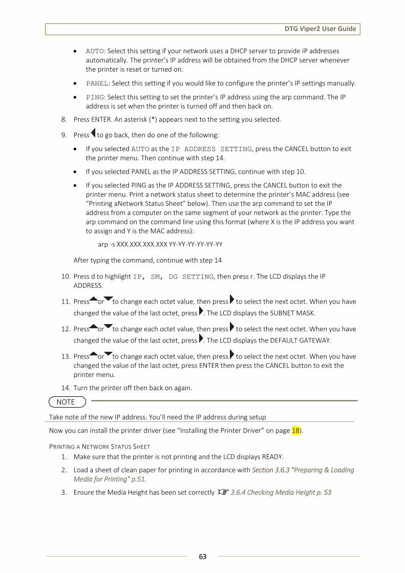
DTG Viper2 User Guide
63
AUTO: Select this setting if your network uses a DHCP server to provide IP addresses automatically. The printer’s IP address will be obtained from the DHCP server whenever the printer is reset or turned on.
PANEL: Select this setting if you would like to configure the printer’s IP settings manually.
PING: Select this setting to set the printer’s IP address using the arp command. The IP address is set when the printer is turned off and then back on.
8. Press ENTER. An asterisk (*) appears next to the setting you selected.
9. Press to go back, then do one of the following:
If you selected AUTO as the IP ADDRESS SETTING, press the CANCEL button to exit the printer menu. Then continue with step 14.
If you selected PANEL as the IP ADDRESS SETTING, continue with step 10.
If you selected PING as the IP ADDRESS SETTING, press the CANCEL button to exit the printer menu. Print a network status sheet to determine the printer’s MAC address (see “Printing aNetwork Status Sheet” below). Then use the arp command to set the IP address from a computer on the same segment of your network as the printer. Type the arp command on the command line using this format (where X is the IP address you want to assign and Y is the MAC address):
arp -s XXX.XXX.XXX.XXX YY-YY-YY-YY-YY-YY
After typing the command, continue with step 14
10. Press d to highlight IP, SM, DG SETTING, then press r. The LCD displays the IP ADDRESS.
11. Press or to change each octet value, then press to select the next octet. When you have
changed the value of the last octet, press . The LCD displays the SUBNET MASK.
12. Press or to change each octet value, then press to select the next octet. When you have
changed the value of the last octet, press . The LCD displays the DEFAULT GATEWAY.
13. Press or to change each octet value, then press to select the next octet. When you have changed the value of the last octet, press ENTER then press the CANCEL button to exit the printer menu.
14. Turn the printer off then back on again.
Now you can install the printer driver (see “Installing the Printer Driver” on page 18).
PRINTING A NETWORK STATUS SHEET
1. Make sure that the printer is not printing and the LCD displays READY.
2. Load a sheet of clean paper for printing in accordance with Section 3.6.3 "Preparing & Loading Media for Printing" p.51.
3. Ensure the Media Height has been set correctly 3.6.4 Checking Media Height p. 53
Take note of the new IP address. You’ll need the IP address during setup
NOTE
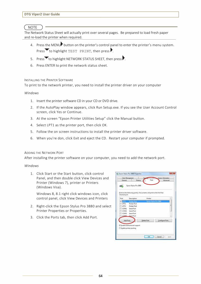
DTG Viper2 User Guide
64
4. Press the MENU button on the printer’s control panel to enter the printer’s menu system.
Press to highlight TEST PRINT, then press .
5. Press to highlight NETWORK STATUS SHEET, then press .
6. Press ENTER to print the network status sheet.
INSTALLING THE PRINTER SOFTWARE
To print to the network printer, you need to install the printer driver on your computer
Windows
1. Insert the printer software CD in your CD or DVD drive.
2. If the AutoPlay window appears, click Run Setup.exe. If you see the User Account Control screen, click Yes or Continue.
3. At the screen “Epson Printer Utilities Setup” click the Manual button.
4. Select LPT1 as the printer port, then click OK.
5. Follow the on screen instructions to install the printer driver software.
6. When you’re don, click Exit and eject the CD. Restart your computer if prompted.
ADDING THE NETWORK PORT
After installing the printer software on your computer, you need to add the network port.
Windows
1. Click Start or the Start button, click control Panel, and then double click View Devices and Printer (Windows 7), printer or Printers (Windows Visa).
Windows 8, 8.1 right click windows icon, click control panel, click View Devices and Printers
2. Right-click the Epson Stylus Pro 3880 and select Printer Properties or Properties.
3. Click the Ports tab, then click Add Port.
The Network Status Sheet will actually print over several pages. Be prepared to load fresh paper and re-load the printer when required.
NOTE

DTG Viper2 User Guide
65
4. Select Standard TCP/IP Port, then click the New Port button.
5. When the printer port wizard opens, click Next.
6. Enter the printer’s IP address (as previously noted during the Network Interface Configuration above), in the Printer Name or IP Address text box. Then click Next.
7. On the next screen, click Finish.
You can now use the printer on your Network.

DTG Viper2 User Guide
66
4. Printing to Textiles
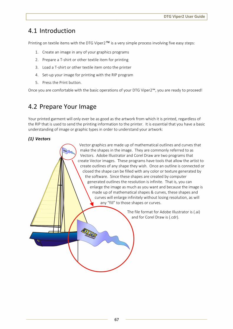
DTG Viper2 User Guide
67
4.1 Introduction
Printing on textile items with the DTG Viper2™ is a very simple process involving five easy steps:
1. Create an image in any of your graphics programs
2. Prepare a T-shirt or other textile item for printing
3. Load a T-shirt or other textile item onto the printer
4. Set-up your image for printing with the RIP program
5. Press the Print button.
Once you are comfortable with the basic operations of your DTG Viper2™, you are ready to proceed!
4.2 Prepare Your Image
Your printed garment will only ever be as good as the artwork from which it is printed, regardless of the RIP that is used to send the printing information to the printer. It is essential that you have a basic understanding of image or graphic types in order to understand your artwork:
(1) Vectors
Vector graphics are made up of mathematical outlines and curves that make the shapes in the image. They are commonly referred to as Vectors. Adobe Illustrator and Corel Draw are two programs that
create Vector images. These programs have tools that allow the artist to create outlines of any shape they wish. Once an outline is connected or
closed the shape can be filled with any color or texture generated by the software. Since these shapes are created by computer
generated outlines the resolution is infinite. That is, you can enlarge the image as much as you want and because the image is
made up of mathematical shapes & curves, these shapes and curves will enlarge infinitely without losing resolution, as will
any “fill” to those shapes or curves.
The file format for Adobe Illustrator is (.ai) and for Corel Draw is (.cdr).
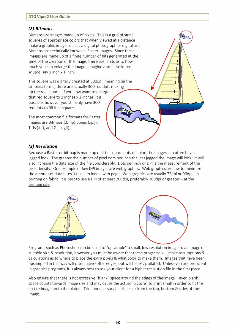
DTG Viper2 User Guide
68
(2) Bitmaps
Bitmaps are images made up of pixels. This is a grid of small squares of appropriate colors that when viewed at a distance make a graphic image such as a digital photograph or digital art. Bitmaps are technically known as Raster Images. Since these images are made up of a finite number of bits generated at the time of the creation of the image, there are limits as to how much you can enlarge the image. Imagine a small solid red square, say 1 inch x 1 inch.
This square was digitally created at 300dpi, meaning (in the simplest terms) there are actually 300 red dots making up the red square. If you now want to enlarge that red square to 2 inches x 2 inches, it is possible, however you still only have 300 red dots to fill that square.
The most common file formats for Raster Images are Bitmaps (.bmp), Jpegs (.jpg), Tiffs (.tif), and Gifs (.gif).
(3) Resolution
Because a Raster or bitmap is made up of little square dots of color, the images can often have a jagged look. The greater the number of pixel dots per inch the less jagged the image will look. It will also increase the data size of the file considerably. Dots per inch or DPI is the measurement of the pixel density. One example of low DPI images are web graphics. Web graphics are low to minimize the amount of data bites it takes to load a web page. Web graphics are usually 72dpi or 96dpi. In printing on fabric, it is best to use a DPI of at least 200dpi, preferably 300dpi or greater – at the printing size.
Programs such as Photoshop can be used to “upsample” a small, low resolution image to an image of suitable size & resolution, however you must be aware that these programs will make assumptions & calculations as to where to place the extra pixels & what color to make them. Images that have been upsampled in this way will often have softer edges, but will be less pixilated. Unless you are proficient in graphics programs, it is always best to ask your client for a higher resolution file in the first place.
Also ensure that there is not excessive “blank” space around the edges of the image – even blank space counts towards image size and may cause the actual “picture” to print small in order to fit the en tire image on to the platen. Trim unnecessary blank space from the top, bottom & sides of the image.

DTG Viper2 User Guide
69
(4) Image Sharpness & Saturation
Images printed to fabric often tend to be softer & darker than what the image appears on screen. You may need to adjust images to give them a color boost using a saturation adjustment in the graphics program, and/or sharpen the image using suitable sharpening tools within the graphics program.
(5) Transparent Backgrounds
As we have already discussed, regular bitmap images are made up of colored pixels; this includes the background (even a plain white background!). In a digital photograph, the rectangle is filled entirely with color. Graphic images are not usually just a rectangle. They are shapes and text. The background area is usually filled with white pixels. To print on a media other than white, it is almost impossible to match the digital color with the color of the media.
In programs such as Photoshop, the file data includes transparent pixels as a background color of choice. If the file is set to have a transparent background, then a removed or erased pixel will be virtually removed. Transparent backgrounds are often represented by a grey and white checker board pattern.
The standard printer driver was designed to print on a white surface using color ink. Inherently, it ignores white pixels in an image when printing, and only prints the color pixels.
The RIP supplied by your authorized DTG Distributor, however, is designed to print all non-transparent pixels, and particularly, to print white pixels with white ink.
It will separate the image into a white ink “underbase” layer (made up of all pixels in the image) and a color layer with very little additional effort on your part.
4-1 WHITE PIXELS IN BACKGROUND VS. TRANSPARENT BACKGROUND
DTG Viper2 User Guide
70
4.3 Garment Preparation & Finishing
Garment preparation for printing with the DTG Viper2 will vary dependent upon the type of fabric, the color of the fabric, and the image type to be printed. It will also vary dependent upon the ink set and pre-treatment options being used with the DTG Viper2.
In general though, preparation & finishing will involve the following steps:
Step Details
Pre-treatment Pre-treatments are generally applied to the garments to be printed to provide better ink adhesion and stability. In most cases they are applied by way of HVLP sprayer.
Curing of Pre-treatment
Pre-treatments usually require a curing or at least a drying process. In some cases, the pre-treatment is cured under a heat press, which has the added benefit of flattening the fibres of the fabric, providing a very smooth surface for the ink to adhere to.
Post-Print Curing Once printed, the inks will need to be cured to finish the bonding process of the ink with the pre-treatment to the fabric
4.4 Load Garment to Platen / Platen to Printer
4.4.1 Put the garment onto the Platen Your authorized DTG Distributor will have supplied at least one platen on which to place garments / other media for printing. Please follow the directions provided by the supplier of your DTG Viper2TM
for the proper securing of the garment to the platen.
Flatten / smooth out the printing surface. Ensure that any excess garment is tucked out of the way.
We recommend following the application instructions provided with the inks and pre-treatments delivered for your DTG Viper2. In all cases, however, those instructions are general guidelines for the application & finishing of pre-treatments and inks. Due to potential differences in the fabric or garment as well as potential differences in fusing equipment, these general guidelines may not be sufficient or applicable in all cases. Each customer should carry out on-site tests to identify the optimal fusing conditions for their preferred fabrics and equipment set-up.
Lint is one of the biggest enemies of the DTG Viper2™. By shaking your garment (away from the printer) prior to use, you can remove some of the excess lint from the garment. Pressing the garment can also help to contain excess lint.
NOTE
NOTE
DTG Viper2 User Guide
71
4.4.2 Adjust Printing Bed Height / Move Platen to Print Ready Position 3.6.3 Preparing & Loading Media for Printing, page 51
3.6.4 Checking Media Height, page 53
4.5 Print Your Image
Refer to the manual for your RIP for detailed information on sending print information to the DTG M2TM.
Checking PRINT QUALITY Print quality is an extremely important component of the printing process. You can check the print quality by printing a Nozzle Check 3.6.6 “Performing a Nozzle Check Test Print”, p.56
Be aware that you will need to do a Head Cleaning:
if any streaking appears in the print
if small drops of ink get on the garment during a printing cycle
if the unit has been sitting for a few days
if the print head brushes the pre-treated garment
4.6 Post-Printing
After DTG Viper2™ has finished printing, the Printing Bed will automatically eject the platen to the front of the printer (or to the rear of the printer if you have selected this eject function on your DTG Viper2).
Remove the GARMENT
Carefully remove the garment from the Platen, so as not to smudge the wet ink.
HEAT CURE Your Finished Print The final step is to heat cure your finished prints to completely set the ink. Follow the instructions provided for your inks & pre-treatments. Equipment temperature settings should be calibrated using a thermocouple or infra-red thermometer.
WASHING Garments Garments printed with the DTG M2™ can be laundered as normal, with a few restrictions. It is a good idea to give your customer the following washing instructions:
TIP 3.5.6. Performing a Head Clean from the Operation Panel, p. 45 Severe head clogging may require you to do more than one head cleaning, or alternatively, to execute a Power Cleaning .
3.6.2.2. Drawing Ink from Ink Cartridges to Printing Head, p. 50
TIP Turn the garment inside out before washing and drying, use cold water only and a medium dryer temperature

DTG Viper2 User Guide
72
4.7 Cancelling a Print Job
4.7.1 Introduction On rare occasions you may find you cannot get your printer to print. Check the following to rectify the problem:
Is the printer in the ready state when you send the print command?
Is there a message on the Operation Panel LCD Display or an indicator light on the
OperationPanel
Is there a problem with the file you are printing from?
4.7.2 Cancelling the Print Job It may be best to cancel the print job and start again. As with any inkjet printer, it is sometimes difficult to stop a print job with the DTG Viper2™ once you have set it in motion.
1. Firstly, press the Emergency Stop button on the front of the printer – this will immediately cut power to the printer & stop the print job.
2. Open the Top Cover of the printer and ensure that the Print Head Carriage is homed to the Capping Station, if necessary, gently slide the Carriage Assembly to the right until it is positioned over the Capping Station and then Lock the Print Head to the Capping Station (refer Section
3. Cancel / clear the print job from the RIP and / or the Windows Print Queue.
4.7.3 Re-starting the Printer after Cancelling a Print Job Re-start the printer by following the steps shown at 3.5.1 Switching the Printer ON, page 35 and 3.5.2 Starting the Printer, p. 36.
Do not allow the Carriage assembly to remain out of the capping station for longer than two or three minutes. Failure to do so will result in possible blockage of print nozzles due to ink drying. This may result in irreversible damage to the print head requiring print head replacement.

DTG Viper2 User Guide
73

DTG Viper2 User Guide
74
5. General Care & Maintenance
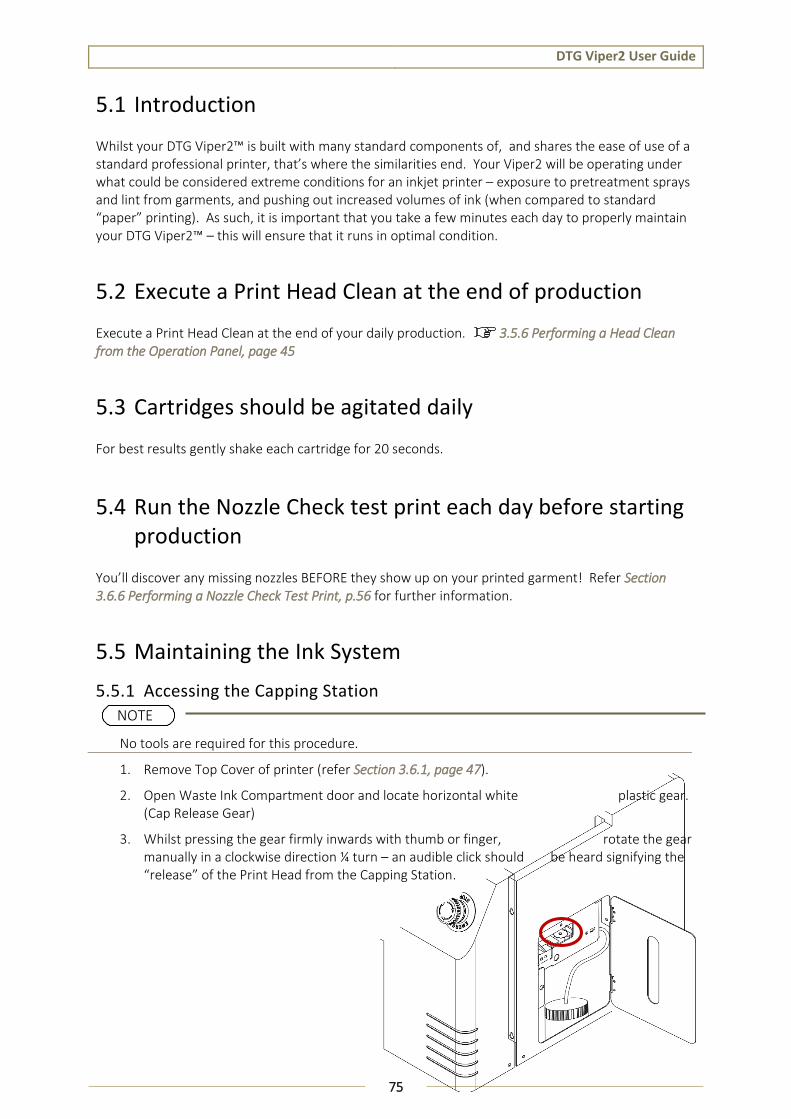
DTG Viper2 User Guide
75
5.1 Introduction
Whilst your DTG Viper2™ is built with many standard components of, and shares the ease of use of a standard professional printer, that’s where the similarities end. Your Viper2 will be operating under what could be considered extreme conditions for an inkjet printer – exposure to pretreatment sprays and lint from garments, and pushing out increased volumes of ink (when compared to standard “paper” printing). As such, it is important that you take a few minutes each day to properly maintain your DTG Viper2™ – this will ensure that it runs in optimal condition.
5.2 Execute a Print Head Clean at the end of production
Execute a Print Head Clean at the end of your daily production. 3.5.6 Performing a Head Clean from the Operation Panel, page 45
5.3 Cartridges should be agitated daily
For best results gently shake each cartridge for 20 seconds.
5.4 Run the Nozzle Check test print each day before starting production
You’ll discover any missing nozzles BEFORE they show up on your printed garment! Refer Section 3.6.6 Performing a Nozzle Check Test Print, p.56 for further information.
5.5 Maintaining the Ink System
5.5.1 Accessing the Capping Station
1. Remove Top Cover of printer (refer Section 3.6.1, page 47).
2. Open Waste Ink Compartment door and locate horizontal white plastic gear. (Cap Release Gear)
3. Whilst pressing the gear firmly inwards with thumb or finger, rotate the gear manually in a clockwise direction ¼ turn – an audible click should be heard signifying the “release” of the Print Head from the Capping Station.
No tools are required for this procedure.
NOTE
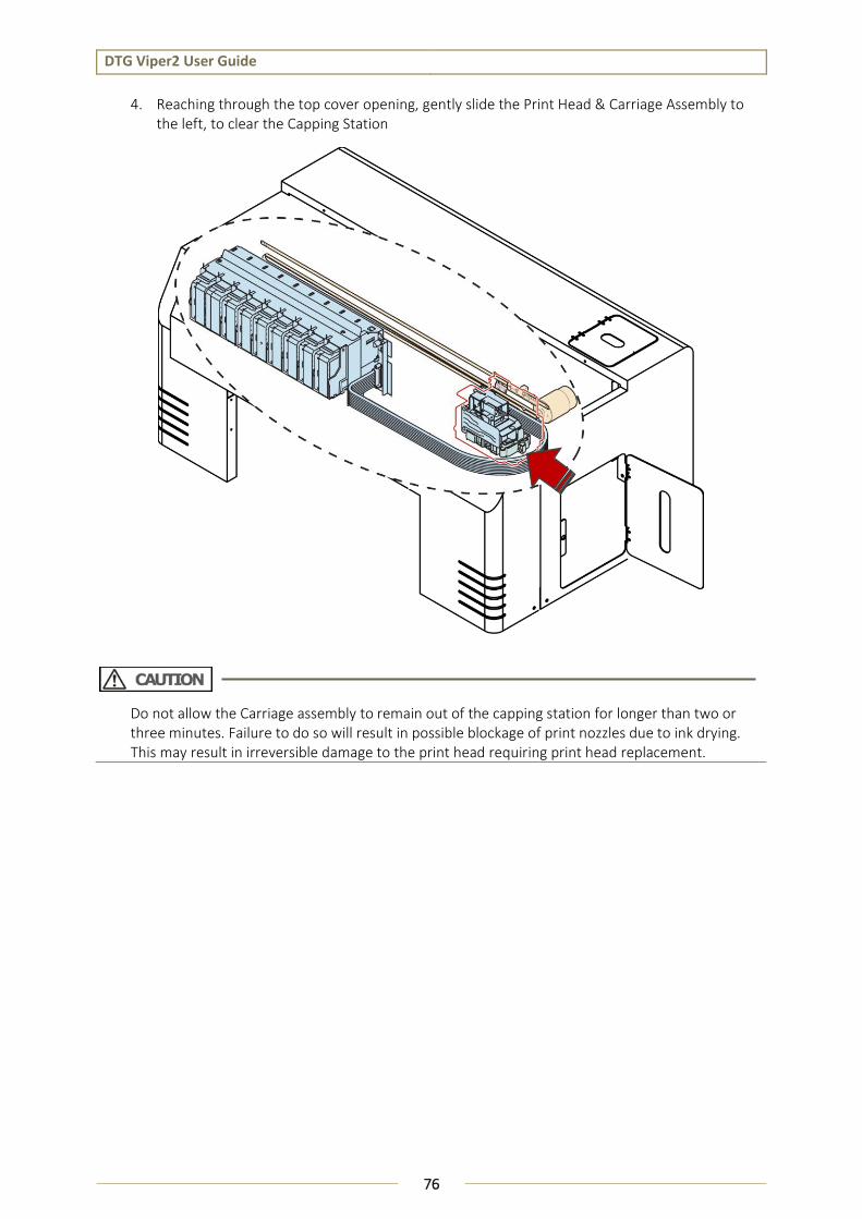
DTG Viper2 User Guide
76
4. Reaching through the top cover opening, gently slide the Print Head & Carriage Assembly to the left, to clear the Capping Station
Do not allow the Carriage assembly to remain out of the capping station for longer than two or three minutes. Failure to do so will result in possible blockage of print nozzles due to ink drying. This may result in irreversible damage to the print head requiring print head replacement.

DTG Viper2 User Guide
77
1
2
3
4
5.5.2 Cleaning the Wiper and Head Cap
1. Access the capping station. 5.5.1 Accessing the Capping Station, page 75
2. If necessary, press and turn the Cap Release Gear a further ¼ clockwise turn to move the Wiper Blade further toward the front of the printer for easier access.
3. Clean the wiper and slider carefully with a swab and cleaning fluid.
4. Clean the gutter with a swab and cleaning fluid.
5. Clean the head cap lip with a swab and cleaning fluid.
6. Return the Print Head to the Capping Station & “re-lock” the capping station to the Print Head by pressing & turning the Cap Release Gear in the anti-clockwise direction for the same number of turns as was used to release it.
No tools are required for this procedure. The wiper, gutter, slider and head cap must be cleaned on a daily basis. Use protective gloves to avoid stained fingers. Use recommended cleaning fluid ONLY. Stubborn or dried ink can be removed carefully with tweezers or a toothpick.
Do not allow the Carriage assembly to remain out of the capping station for longer than two or three minutes. Failure to do so will result in possible blockage of print nozzles due to ink drying. This may result in irreversible damage to the print head requiring print head replacement.
No. Name
1 Wiper Blade Slider
2 Wiper Blade
3 Wiper Blade Gutter
4 Head Cap Lip
NOTE

DTG Viper2 User Guide
78
5.5.3 Manual Print Head Guards Clean
1. Remove any platens from the printer.
2. Release the carriage assembly (see accessing the capping station).
3. Move the carriage to the centre of the printer.
4. Clean the leading and trailing edges of the underside of the carriage with a swab and cleaning solution.
5. Carefully clean the metal guards at either side of the print head with a swab and cleaning solution.
No tools are required for this procedure. The head surrounds must be cleaned on a daily basis. Use protective gloves to avoid stained fingers. Use recommended cleaning fluid ONLY. Stubborn or dried ink can be removed carefully with plastic tweezers or a toothpick.
Do not allow the Carriage assembly to remain out of the capping station for longer than two or three minutes. Failure to do so will result in possible blockage of print nozzles due to ink drying. This may result in irreversible damage to the print head requiring print head replacement.
Take care to NOT wipe the face of the print head, or to damage the face of the print head with sharp implements. Either action can result in damage to the print nozzles which is irreversible and will require print head replacement.
NOTE

DTG Viper2 User Guide
79
5.5.4 Parking the Print Head
1. Place a sponge from the cleaning kit onto the platen. Ensure that the platen height is at least .8” below height usually required for printing.
2. Pour enough cleaning fluid onto the sponge until it becomes saturated.
3. Place a piece of the white microfiber cloth (from the cleaning kit) over the top of the sponge.
4. Unlock the carriage and slide it towards the left.
5. Align the print head face to the cloth covered sponge.
6. Carefully raise the platen bed by pressing the bed UP button until the print head face is pressed lightly against the saturated sponge. The sponge must be compressed to NO LESS than two thirds of its original height.
This process allows the operator to park the print head in such a way that remedial work may be carried out in the capping station or upper carriage assembly without damaging the print head due to ink drying in the nozzles. No tools are required for this procedure. Use protective gloves to avoid stained fingers. Use recommended cleaning fluid ONLY. Absorbent paper towels and the sponge & microfiber cloth (from maintenance kit) will be required for this process.
Do not allow the sponge to press too hard against the print head as this will cause catastrophic damage to the print head, carriage assembly and platen drive system. The sponge must be compressed to NO LESS than two thirds of its original height.
NOTE

DTG Viper2 User Guide
80
FIGURE 5-1 WASTE INK COMPARTMENT
5.5.5 Flushing the Waste Pipes / Tubes During the Head Cleaning process your DTG Viper2™ forces ink through the print head by way of
suction through the Capping Station. This ink collected from this process passes through Waste Tubes
from the Capping Station and into a holding bottle called the Waste Ink Container.
The Waste Pipes / Tubes have a narrow internal diameter and so ink may dry and build up within the tubes and eventually cause a blockage if the tubes are not regularly flushed through with Cleaning Solution.
1. Access the capping station. 5.5.1 Accessing the Capping Station, page 75
2. Drip a small amount of Cleaning Solution into the Cap of the Capping Station until the Cap appears full.
3. Press and rotate the Cap Release Gear to manually activate the Capping Station Pump and draw the fluid down through the capping station (and eventually through the Waste Tubes / Pipes).
4. Repeat Steps 2 & 3 several times until the fluid draining through the Waste Tubes (observable through the Waste Compartment Door) appears clear.
A blunt tip syringe and some cleaning solution are required for this procedure.
Use protective gloves to avoid stained fingers.
No. Name
1 Waste Ink Container
2 Waste Pipe/Tube
3 Waste Ink Compartment Door
Do not allow the Carriage assembly to remain out of the capping station for longer than two or three minutes. Failure to do so will result in possible blockage of print nozzles due to ink drying. This may result in irreversible damage to the print head requiring print head replacement.
NOTE
1
2
3
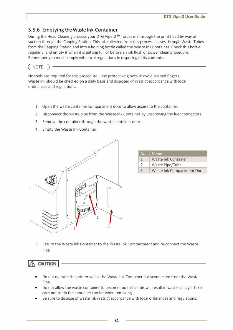
DTG Viper2 User Guide
81
5.5.6 Emptying the Waste Ink Container During the Head Cleaning process your DTG Viper2™ forces ink through the print head by way of suction through the Capping Station. This ink collected from this process passes through Waste Tubes from the Capping Station and into a holding bottle called the Waste Ink Container. Check this bottle regularly, and empty it when it is getting full or before an ink flush or power clean procedure. Remember you must comply with local regulations in disposing of its contents.
1. Open the waste container compartment door to allow access to the container.
2. Disconnect the waste pipe from the Waste Ink Container by unscrewing the luer connectors.
3. Remove the container through the waste container door.
4. Empty the Waste Ink Container.
5. Return the Waste Ink Container to the Waste Ink Compartment and re-connect the Waste
Pipe
No tools are required for this procedure. Use protective gloves to avoid stained fingers. Waste ink should be checked on a daily basis and disposed of in strict accordance with local ordinances and regulations.
No. Name
1 Waste Ink Container
2 Waste Pipe/Tube
3 Waste Ink Compartment Door
Do not operate the printer whilst the Waste Ink Container is disconnected from the Waste Pipe.
Do not allow the waste container to become too full as this will result in waste spillage. Take care not to tip the container too far when removing.
Be sure to dispose of waste ink in strict accordance with local ordinances and regulations.
NOTE
1
2
3

DTG Viper2 User Guide
82
5.5.7 Emptying the Dripper Tray During the Head Cleaning process, the Print Head travels across the Wiper Blade. The Wiper Blade wipes excess ink from the face of the Print Head. This excess ink then travels down the wiper blade, flows along the Wiper Blade Gutter and then through a drip point into the Dripper Tray.
1. Open the waste container compartment door to allow access to the Dripper Tray (located above the waste container).
2. Unscrew the thumb screw securing the Dripper Tray and carefully remove the Dripper Tray through the Waste Ink Compartment Door.
3. Empty and wash the Dripper Tray.
4. Return the Dripper Tray to it’s location within the Waste Ink Compartment, and re-secure it with the thumb screw.
No tools are required for this procedure. Use protective gloves to avoid stained fingers. The Dripper Tray should be checked on a daily basis and it’s contents disposed of in strict accordance with local ordinances and regulations.
NOTE

DTG Viper2 User Guide
83
5.6 Maintaining the Carriage Movement Mechanism
5.6.1 Clean the CR Encoder Strip
The Encoder Strip is the thin plastic strip that runs behind the Print Head for the length of the carriage area. It looks to be clear or at least slightly grey in color, but is in fact clear with hundreds of fine vertical marks on it. There is a sensor that sits at the rear right side of the Print Head carriage which “reads” these vertical marks so that the Print Head knows exactly where to spray the ink. You can understand that if this strip gets dirty, the sensor will be unable to read these marks properly and your printer is likely to get “confused”. Lint from your garments, ink overspray, and even airborne pre-treatment spray can all contribute to a grime build-up on the Encoder Strip, and it is important that you clean this strip at least weekly, even daily if you have a high daily production volume:
No tools are required for this procedure. Use protective gloves to avoid stained fingers. Use recommended cleaning fluid ONLY. The microfiber cloth (from maintenance kit) will be required for this process.
No. Name
1 CR Encoder Strip
2 CR (Carriage) Belt
3 CR (Carriage) Motor
4 CR (Carriage) Guide Shaft
5 CR Encoder Sensor
NOTE
1
2
3
4
5
FIGURE 5-2 WASTE DRIPPER TRAY

DTG Viper2 User Guide
84
1. Using a microfibre cloth (as supplied in the maintenance kit of the printer), moistened with distilled or purified water, or approved Cleaning Solution, GENTLY rub both faces of the encoder strip.
If the cloth or applicator gets dirty, discard it and use a clean one.
Before cleaning the CR encoder strip, ensure the printer is switched off .
When performing the following steps, be careful not to touch the CR Encoder Strip with bare hands or get it soiled with ink. Also be extremely careful not to scratch it by, for example, hitting it against frames. Any dirt or scratches on the CR Encoder Strip may cause a malfunction of the CR Encoder Sensor.
Do not pull the CR encoder strip by force; CR encoder strip guide can be easily broken.
Pay attention not to damage or break the CR encoder strip.
Do not rub with excessive force as you may remove the markings from the CR Encoder Strip.
NOTE
FIGURE 5-3 CLEANING THE CR ENCODER STRIP

DTG Viper2 User Guide
85
2
1
2. Release the Print Head Carriage (refer 5.5.1 Accessing the Capping Station at page 75) and gently slide the Print Head Carriage from it’s home position. This will give you easier access to the other end of the encoder strip.
Allow the encoder strip to dry thoroughly before using the printer again.
5.6.2 Cleaning the Carriage Guide Shaft The Head Carriage Unit (which holds the Print Head) moves left and right along the carriage guide shaft. If the Carriage Guide Shaft becomes dirty or too dry, movement of the Print Head Carriage will be impeded.
1. Inspect the Print Head Guide Shaft regularly and remove any dust and grime build up with a soft dry cloth.
2. Every few weeks, place a drop of special grease on each guide rail to keep the Print Head Carriage moving freely. Too much grease will collect dust and grime, please use sparingly.
Do not allow the Carriage assembly to remain out of the capping station for longer than two or three minutes. Failure to do so will result in possible blockage of print nozzles due to ink drying. This may result in irreversible damage to the print head requiring print head replacement.
No. Name
1 CR Encoder Strip
2 CR (Carriage) Belt
3 CR (Carriage) Motor
4 CR (Carriage) Guide Shaft
5 CR Encoder Sensor

DTG Viper2 User Guide
86
1 2
3
4
5
5.6.3 Clean the CR Drive Belt, Roller and Pulley The CR Drive Belt, Pulley & Roller can collect a build-up of pre-treatment, dust & lint in their “teeth”. An excessive build up can cause the Print Head to “skip” during printing.
The Drive Belt & Gear are driven by the CR Motor, and in turn drive the Print Head itself left & right during the printing process. These components are located along the top of the CR Guide, the CR Belt Pulley is directly behind the Carriage Assembly (when in home position), the CR Drive Belt runs the length of the Carriage area, and the Roller is located on the far left side of the printer.
Use a small brush or mini-vacuum cleaner to clean the teeth of the Drive Belt and the Drive Gear. You may also need to use a small sharp object and/or a small pair of tweezers to remove stubborn build up (take care not to scratch or damage the Drive Belt or Gear in doing this).
The Roller should also be cleaned. This should be done monthly, or more frequently if your DTG Viper2™ produces high volumes of output.
No. Name
1 Head Carriage
2 CR (Carriage) Belt
3 CR (Carriage) Motor & Pulley
4 CR (Carriage) Roller
5 CR Encoder Sensor
Take care not to touch the encoder strip during the cleaning process as it can be easily damaged, and attempt to “capture” any debris removed from the Drive Belt so that it does not contaminate other working components of the printer.

DTG Viper2 User Guide
87
5.7 General Care
5.7.1 Environment It is important to maintain consistent environmental conditions so that your DTG Viper2™ can run at it’s best. Inkjet printers like humidity levels of 40 – 70%. They do not like extremes in temperature, so it is best to operate your DTG Viper2™ in an air conditioned environment – but not such that fans are blowing directly across the printer (and therefore the print head which may dry the ink in the print head itself). As the ink needs to be stored no less than 5° Celcius (41°F) and no more than 30° Celcius (86°F), this is also the recommended operating & storage temperature range for your DTG M2™. 3.3.1 Installation Environment Requirements, p. 32
Dust is also an enemy of the DTG Viper2™ (and in fact any ink-jet printer). The working environment should be relatively dust free.
5.7.2 Clean your DTG Viper2™ Lint, dust and pre-treatment overspray can build up and interfere with not only the “internal” workings of the printer, but also the operation of the printer bed. Turn the printer off and clean all accessible surfaces of the printer with mild cleaner and a soft cloth (do not spray the cleaner directly onto the printer, rather onto the cloth) to remove dust & grime build up.
Ensure that any ink spills on or around the ink bottles in particular are cleaned immediately. If spilled ink dries on the ink bottles, specifically near the threads of the bottles or the lids, then that dried ink can potentially flake & transfer into the ink within the ink bottles. Those flakes of ink can make their way through the ink tubing and block the dampers and/or the print head.
5.7.3 Avoid White Ink Separation White Ink is a water based titanium dioxide solution. The titanium dioxide is ground into a fine powder and mixed with other binders to allow it to dry and adhere to the pre-treated fabric. Titanium dioxide is what gives the ink its bright white properties, and this brightness gives the colored ink layer a vibrant and rich color.
White Ink Properties & Maintenance
Direct to Garment printers have been plagued with ink clogging issues and general instability since white ink was released in late 2005 to the market. There have been significant improvements in the general stability of white ink in that time, however due to the chemical properties of white ink it still requires more maintenance than the color inks. Titanium dioxide is a mineral and does not dissolve in liquids. This means that the titanium dioxide will, over a period of time, settle to the bottom of the container (being the ink bottles, ink tubes and / or dampers). Once complete, separation of the titanium dioxide from the binders and other components in the ink cannot be reversed! It is therefore critical that any stock white ink be gently agitated or swirled daily, or at minimum every 2-3 days to maximize the shelf life of the white ink. The white ink cartridges need to be removed and agitated daily before using the Viper 2. If this is not done white can appear semitransparent when printed and the end result will not be successful.
DTG Viper2 User Guide
88
5.7.4 Pre-Treat garments away from the printer The pre-treatment for printing of white ink is very sticky, and airborne particles of the spray can very easily find their way into, and clog up the moving parts of your DTG Viper2.
For this reason, it is important that you spray the white ink pre-treatment to your garments in a separate room, or at the very least, make up a “spray booth” to contain the spray so that it does not contaminate the printer. The spray station should be at least 5 meters (15 feet) away from the DTG Viper2™, with forced extraction of the pre-treat vapors.
5.7.5 Keep the Printer Busy As described previously, white ink, by its very nature, is prone to sedimentation. The ink held within the internal ink tubes, dampers and even the Print Head can be susceptible to separation and sedimentation. The best way to avoid this, and to therefore reduce the risk of Print Head blockages, is to use the printer to print jobs that include white ink. This moves the ink through the tubes, dampers and print head, keeping it fresh.
Even if you do not have “paid” jobs to print, ensure that a white ink print job is executed at least every 2-3 days. Use this as an opportunity to test new designs or new fabrics etc., or perhaps to print give-away products to help promote your business
DTG Viper2 User Guide
89
5.8 Flushing the Printer
If the printer is to be unused for a long period of time (3-4 weeks or more) and / or you are unable to maintain the printer within the recommended operation environmental conditions (temperature & humidity – ref. section 3.3.1 “Installation Environment Requirements”, page 32) even for a shorter period of time, then it is recommended to flush all inks from the printer to help prevent Print Head blockages.
5.8.1 Flush Ink System The following steps describe the process of clearing ink from the ink system, including the internal ink tubes, dampers, print head, and capping station.
1. Replace CMYK and White cartridges with flushing cartridges.
2. Empty Waste Ink Container ( 5.5.6 “Emptying the Waste Ink Container”, p. 81)
3. Execute Power Cleaning from the Operation Panel ( 3.6.2.2 “Drawing Ink from Ink Cartridges to Printing Head”, p. 50). This will start to draw the cleaning solution from the WIMS System / CMYK cartridges through the internal ink lines, dampers, print head & capping station to the Waste Ink container.
4. Repeat the Power Cleaning as necessary until the fluid passing through the waste ink tubes into the Waste Ink Container is relatively clear.
Monitor the level of Cleaning Solution in the Flushing Cartridges, and replace as necessary.
Monitor the on-screen display indicator of maintenance cartridge capacity, reset Maintenance Cartridge as necessary 2.3.3.5 “AR-Chips”, page26
Monitor the level of waste fluid in the Waste Ink Container and empty as necessary ( 5.5.6 “Emptying the Waste Ink Container”, p. 81).

DTG Viper2 User Guide
90
5.9 Preparing the Printer for Transportation / Storage
In addition to Flushing the Printer (see above, Section 5.8, “Flushing the Printer”)in preparation for long periods of disuse or for transportation, the following should be observed to ensure that the printer is prepared appropriately:
1. After performing the Flushing procedure, clean the Wiper and Head Cap (page 77), and clean the Print Head Guards (page 78). Ensure that the Print Head is re-locked correctly to the capping station after the cleaning procedures are completed.
2. Empty the Waste Ink Container (p. 81) and the Dripper Tray (page 82).
3. Lower the Printer Bed to its lowest possible position (using the Bed Down button).
4. For transportation, use low-tack tape to secure the Waste Compartment Door, Maintenance Tank Compartment door, Cartridge Bay Cover, and Top Cover.

DTG Viper2 User Guide
91
6. Troubleshooting
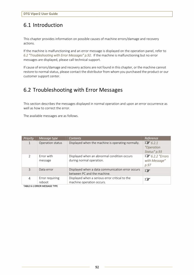
DTG Viper2 User Guide
92
6.1 Introduction
This chapter provides information on possible causes of machine errors/damage and recovery actions.
If the machine is malfunctioning and an error message is displayed on the operation panel, refer to 6.2 "Troubleshooting with Error Messages" p.92. If the machine is malfunctioning but no error messages are displayed, please call technical support.
If cause of errors/damage and recovery actions are not found in this chapter, or the machine cannot restore to normal status, please contact the distributor from whom you purchased the product or our customer support center.
6.2 Troubleshooting with Error Messages
This section describes the messages displayed in normal operation and upon an error occurrence as well as how to correct the error.
The available messages are as follows.
Priority Message type Contents Reference
1 Operation status Displayed when the machine is operating normally. 6.2.1 "Operation Status" p.93
2 Error with message
Displayed when an abnormal condition occurs during normal operation.
6.2.2 "Errors with Message" p.97
3 Data error Displayed when a data communication error occurs between PC and the machine.
4 Error requiring reboot
Displayed when a serious error critical to the machine operation occurs.
TABLE 6-1 ERROR MESSAGE TYPE

DTG Viper2 User Guide
93
6.2.1 Operation Status
This section describes the message contents, check items, and recovery actions for normal operation.
TABLE 6-2 EVENTS AND CHECK ITEMS FOR OPERATION STATUS MESSAGES
No. Message Event/ Symptom
Check item Action Reference
1 READY No error, printer is ready to print data
2 PRINTING The printer is processing data
1. If printer does not respond within a reasonable period of time (and no actual print job is printing), turn printer off and then back on again.
2. contact your authorized DTG Dealer or technician
3.5.3 “Switching the Printer OFF.”, p.37
3.5.1 "Switching the Printer ON" p.35
3 PLEASE WAIT Printer is busy.
1. If printer does not respond within a reasonable period of time, turn printer off and then back on again.
2. contact your authorized DTG Dealer or technician
3.5.3 “Switching the Printer OFF.”, p.37
3.5.1 "Switching the Printer ON" p.35
4 CHARGING INK Printer is charging the ink delivery system
1. If printer does not respond within a reasonable period of time, turn printer off and then back on again.
2. contact your authorized DTG Dealer or technician
3.5.3 “Switching the Printer OFF.”, p.37
3.5.1 "Switching the Printer ON" p.35
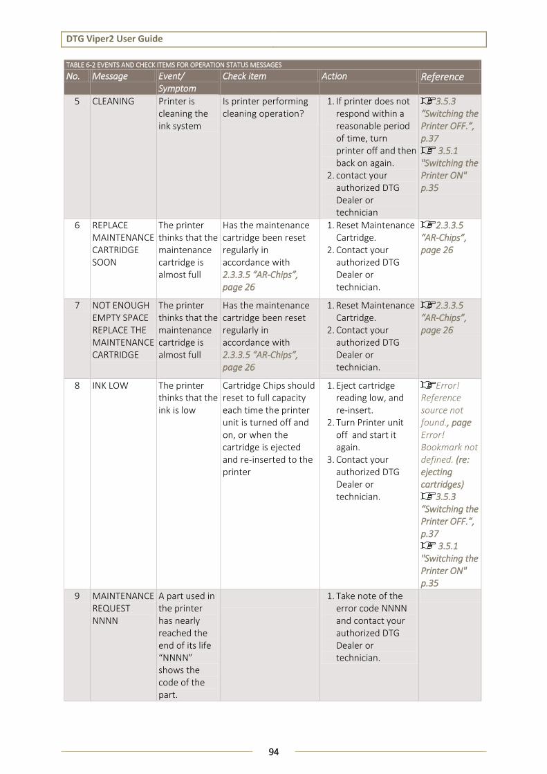
DTG Viper2 User Guide
94
TABLE 6-2 EVENTS AND CHECK ITEMS FOR OPERATION STATUS MESSAGES
No. Message Event/ Symptom
Check item Action Reference
5 CLEANING Printer is cleaning the ink system
Is printer performing cleaning operation?
1. If printer does not respond within a reasonable period of time, turn printer off and then back on again.
2. contact your authorized DTG Dealer or technician
3.5.3 “Switching the Printer OFF.”, p.37
3.5.1 "Switching the Printer ON" p.35
6 REPLACE MAINTENANCE CARTRIDGE SOON
The printer thinks that the maintenance cartridge is almost full
Has the maintenance cartridge been reset regularly in accordance with 2.3.3.5 “AR-Chips”, page 26
1. Reset Maintenance Cartridge.
2. Contact your authorized DTG Dealer or technician.
2.3.3.5 “AR-Chips”, page 26
7 NOT ENOUGH EMPTY SPACE REPLACE THE MAINTENANCE CARTRIDGE
The printer thinks that the maintenance cartridge is almost full
Has the maintenance cartridge been reset regularly in accordance with 2.3.3.5 “AR-Chips”, page 26
1. Reset Maintenance Cartridge.
2. Contact your authorized DTG Dealer or technician.
2.3.3.5 “AR-Chips”, page 26
8 INK LOW The printer thinks that the ink is low
Cartridge Chips should reset to full capacity each time the printer unit is turned off and on, or when the cartridge is ejected and re-inserted to the printer
1. Eject cartridge reading low, and re-insert.
2. Turn Printer unit off and start it again.
3. Contact your authorized DTG Dealer or technician.
Error! Reference source not found., page Error! Bookmark not defined. (re: ejecting cartridges)
3.5.3 “Switching the Printer OFF.”, p.37
3.5.1 "Switching the Printer ON" p.35
9 MAINTENANCE REQUEST NNNN
A part used in the printer has nearly reached the end of its life “NNNN” shows the code of the part.
1. Take note of the error code NNNN and contact your authorized DTG Dealer or technician.
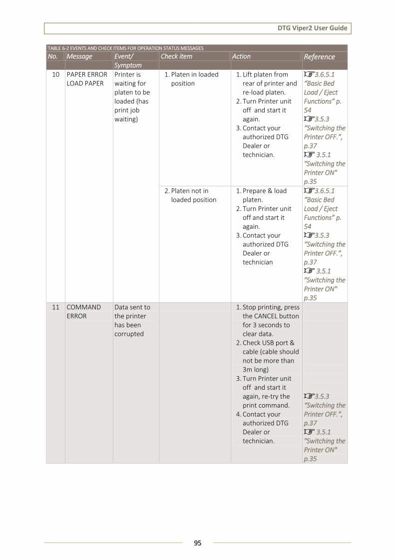
DTG Viper2 User Guide
95
TABLE 6-2 EVENTS AND CHECK ITEMS FOR OPERATION STATUS MESSAGES
No. Message Event/ Symptom
Check item Action Reference
10 PAPER ERROR LOAD PAPER
Printer is waiting for platen to be loaded (has print job waiting)
1. Platen in loaded position
1. Lift platen from rear of printer and re-load platen.
2. Turn Printer unit off and start it again.
3. Contact your authorized DTG Dealer or technician.
3.6.5.1 “Basic Bed Load / Eject Functions” p. 54
3.5.3 “Switching the Printer OFF.”, p.37
3.5.1 "Switching the Printer ON" p.35
2. Platen not in loaded position
1. Prepare & load platen.
2. Turn Printer unit off and start it again.
3. Contact your authorized DTG Dealer or technician
3.6.5.1 “Basic Bed Load / Eject Functions” p. 54
3.5.3 “Switching the Printer OFF.”, p.37
3.5.1 "Switching the Printer ON" p.35
11 COMMAND ERROR
Data sent to the printer has been corrupted
1. Stop printing, press the CANCEL button for 3 seconds to clear data.
2. Check USB port & cable (cable should not be more than 3m long)
3. Turn Printer unit off and start it again, re-try the print command.
4. Contact your authorized DTG Dealer or technician.
3.5.3 “Switching the Printer OFF.”, p.37
3.5.1 "Switching the Printer ON" p.35

DTG Viper2 User Guide
96
TABLE 6-2 EVENTS AND CHECK ITEMS FOR OPERATION STATUS MESSAGES
No. Message Event/ Symptom
Check item Action Reference
12 INK CARTRIDGE ERROR REPLACE INK CARTRIDGE
The Printer thinks that the Ink Cartridge is empty (out of ink)
Cartridge Chips should reset to full capacity each time the printer unit is turned off and on
1. Turn Printer unit off and start it again.
2. Contact your authorized DTG Dealer or technician.
3.5.3 “Switching the Printer OFF.”, p.37
3.5.1 "Switching the Printer ON" p.35
19 MAINTENANCE CART. REPLACE MAINTENANCE CARTRIDGE
Printer is registering the Maintenance cartridge as “full”
1. Turn Printer unit off and start it again.
2. Contact your authorized DTG Dealer or technician.

DTG Viper2 User Guide
97
6.2.2 Errors with Message
This section describes the contents of errors with messages as well as the check items and recovery actions. These messages are displayed when an abnormal condition occurs while the machine is running.
Upon an occurrence of an error with message, the machine stops its operation at the same time.
In some instances, the error may be cancelled by removing the error causes. After that, the machine will restart its operation.
TABLE 6-3 SYMPTOMS AND CHECK ITEMS FOR ERRORS WITH MESSAGE
No. Message Event/ Symptom
Check item Action Reference
1 Media detection error
- 6. Turn machine OFF. Disconnect mains power, wait 5 minutes. Turn it ON again and check if the same message appears.
If the message appears: Contact your authorized DTG Distributor or Technician for further assistance
0 " Switching the Printer OFF." p.37
3.5.1 "Switching the Printer ON" p.35
2 Media skew error
Media skew error is displayed
1. Wrong settings in panel control.
Check settings . Error! Reference source not found. "Error! Reference source not found." p.Error! Bookmark not defined.
7. Turn machine OFF. Disconnect mains power, wait 5 minutes.
Turn it ON again and check if the same message appears.
If the message appears: Contact your authorized DTG Distributor or Technician for further assistance
0 " Switching the Printer OFF." p.37
3.5.1 "Switching the Printer ON" p.35

DTG Viper2 User Guide
98
TABLE 6-3 SYMPTOMS AND CHECK ITEMS FOR ERRORS WITH MESSAGE
No. Message Event/ Symptom
Check item Action Reference
3 Warning: Waste fluid box full
Automatic Waste fluid reset failed.
8. Turn machine OFF. Disconnect mains power, wait 5 minutes. Turn it ON again and check if the same message appears.
If the message appears: Contact your authorized DTG Distributor or Technician for further assistance
0 " Switching the Printer OFF." p.37
3.5.1 "Switching the Printer ON" p.35
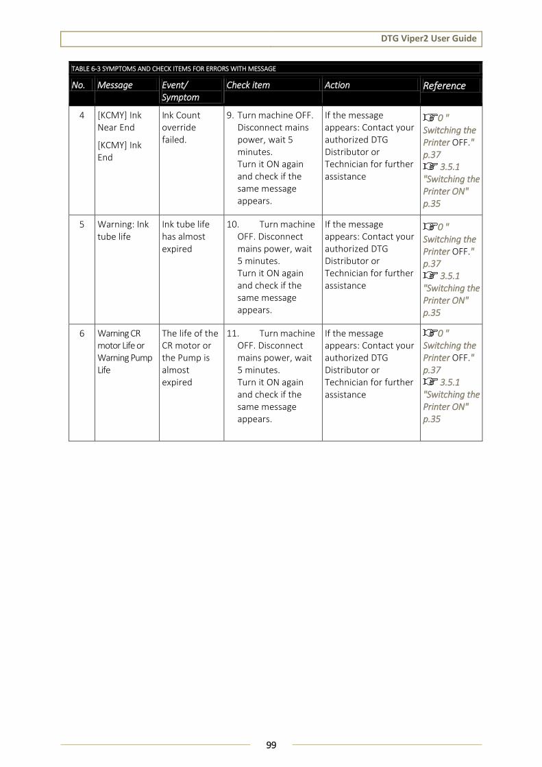
DTG Viper2 User Guide
99
TABLE 6-3 SYMPTOMS AND CHECK ITEMS FOR ERRORS WITH MESSAGE
No. Message Event/ Symptom
Check item Action Reference
4 [KCMY] Ink Near End
[KCMY] Ink End
Ink Count override failed.
9. Turn machine OFF. Disconnect mains power, wait 5 minutes. Turn it ON again and check if the same message appears.
If the message appears: Contact your authorized DTG Distributor or Technician for further assistance
0 " Switching the Printer OFF." p.37
3.5.1 "Switching the Printer ON" p.35
5 Warning: Ink tube life
Ink tube life has almost expired
10. Turn machine OFF. Disconnect mains power, wait 5 minutes. Turn it ON again and check if the same message appears.
If the message appears: Contact your authorized DTG Distributor or Technician for further assistance
0 " Switching the Printer OFF." p.37
3.5.1 "Switching the Printer ON" p.35
6 Warning CR motor Life or Warning Pump Life
The life of the CR motor or the Pump is almost expired
11. Turn machine OFF. Disconnect mains power, wait 5 minutes. Turn it ON again and check if the same message appears.
If the message appears: Contact your authorized DTG Distributor or Technician for further assistance
0 " Switching the Printer OFF." p.37
3.5.1 "Switching the Printer ON" p.35