User guide - Eurotherm by Schneider Electric · 6100A/6180A 100 and 180 mm paperless graphic...
420
6100A/6180A 100 and 180 mm paperless graphic recorders User guide E UR O T H E R M
Transcript of User guide - Eurotherm by Schneider Electric · 6100A/6180A 100 and 180 mm paperless graphic...

6100
A/6
180A
100 a
nd 1
80 m
m paper
less
gra
phi
c re
cord
ers
User guide
EUROTHERM


All rights are strictly reserved. No part of this document may be reproduced, stored in a retrieval system ortransmitted in any form, by any means, without the prior, written permission of the copyright owner.
Eurotherm Limited reserves the right to alter the specification of its products from time to time withoutprior notice. Although every effort has been made to ensure the accuracy of the information contained inthis manual, it is not warranted or represented by Eurotherm Limited to be a complete or up-to-date de-scription of the product.
© 2007 Eurotherm Limited
EUROTHERM
Declaration of Conformity
Manufacturer's name: Eurotherm Limited
Manufacturer's address: Faraday Close, Worthing, West Sussex,BN13 3PL, United Kingdom
Product type: Paperless graphic recorder
Models: 6100A Status level A1 and above6180A Status level A1 and above
Safety specification: BS EN61010-1: 2001-02
EMC emissions specification: BS EN61326 2002-02
EMC immunity specification: BS EN61326 2002-02
Eurotherm Limited hereby declares that the above products conform to the safetyand EMC specifications listed. Eurotherm Limited further declares that the above prod-ucts comply with the EMC Directive 89 / 336 / EEC amended by 93 / 68 / EEC, and alsowith the Low Voltage Directive 73 / 23 / EEC.
Signed: Dated:
Signed for and on behalf of Eurotherm LimitedWilliam Davis
(General Manager)IA249986U670 Issue 1 Dec 05 (CN21129)

EUROTHERM

100/180 MM PAPERLESS GRAPHIC RECORDER: USER GUIDE
User GuidePage i
HA028910Issue 4 Aug 07
Cont...
PAPERLESS GRAPHIC RECORDER
USER GUIDE
LIST OF SECTIONSSection Page1 INTRODUCTION................................................................................... 22 INSTALLATION ...................................................................................... 23 PROCESS VARIABLE DISPLAY ................................................................. 144 SETTING UP THE RECORDER ................................................................. 515 FILE ..................................................................................................... 2216 BRIDGE ................................................................................................ 2257 SCREEN BUILDER .................................................................................. 2348 MODBUS TCP SLAVE COMMS ............................................................... 2629 ANALOGUE OUTPUTS .......................................................................... 31410 EVENT INPUTS ................................................................................... 31611 TRANSMITTER POWER SUPPLY ............................................................ 31712 ASCII PRINTER .................................................................................... 32013 PORTABLE CASE OPTIONS .................................................................. 330ANNEX A: SPECIFICATION ....................................................................... 341ANNEX B: REFERENCE ............................................................................ 351ANNEX C: WEB SERVER DETAILS .............................................................. 381INDEX ..................................................................................................... 385
EFFECTIVITYThis manual refers to recorders fitted with software version 4.2 To determine the software version fitted to the re-corder, the 'About' screen in the System menu may be accessed as described in section 4.6.11.

100/180 MM PAPERLESS GRAPHIC RECORDER: USER GUIDE
HA028910Issue 4 Aug 07
User GuidePage ii
Cont...
PAPERLESS GRAPHICS RECORDER USER GUIDE
LIST OF CONTENTSSection PageSafety Notes ....................................................................................................... 1SYMBOLS USED ON THE RECORDER LABELLING .................................................. 11 INTRODUCTION ................................................................................. 21.1 UNPACKING THE RECORDER ....................................................................... 22 INSTALLATION ................................................................................... 22.1 MECHANICAL INSTALLATION ...................................................................... 22.2 ELECTRICAL INSTALLATION .......................................................................... 5
2.2.1 Signal wiring ..................................................................................................... 5CONNECTOR WIRING DETAILS ........................................................................ 5
2.2.2 Supply voltage wiring .......................................................................................... 9LINE SUPPLY ..................................................................................................... 9LOW VOLTAGE SUPPLY OPTION........................................................................ 9
2.3 ACCESS FLAP .............................................................................................. 102.3.1 Stylus ................................................................................................................ 112.3.2 Card slot ........................................................................................................... 11
LED INDICATORS .............................................................................................. 112.3.3 USB Front Port .................................................................................................... 11
2.4 LOCKABLE FLAP OPTION ............................................................................. 122.4.1 Flap lock operation ............................................................................................. 12
ARCHIVE INACTIVE .......................................................................................... 12ARCHIVE ACTIVE .............................................................................................. 13
3 PROCESS VARIABLE DISPLAY .............................................................. 14TRUNCATION OF NUMERIC VALUES ................................................................. 14CURRENT TRACE ALARM ICONS ....................................................................... 15
3.1 STATUS BAR ................................................................................................ 153.1.1 Current access level ............................................................................................ 153.1.2 Page name ........................................................................................................ 153.1.3 Alarm indication ................................................................................................ 16
INSTRUMENT ALARM ....................................................................................... 16CHANNEL ALARM ............................................................................................ 18CHANGE BATTERY ........................................................................................... 18DISK ICON ...................................................................................................... 18FTP ICON ........................................................................................................ 18CONFIGURATION LOCKED INDICATOR ............................................................ 18TRIAL MODE INDICATOR .................................................................................. 18
3.1.4 Summary menu .................................................................................................. 19INSTRUMENT ALARM SUMMARY ...................................................................... 19ACK ALL ALARMS ............................................................................................. 19ALARM SUMMARY PAGE .................................................................................. 20ALARM ACKNOWLEDGEMENT ......................................................................... 21BATCH SUMMARY ............................................................................................ 22MESSAGE LOG ................................................................................................ 24REMOVE MEDIA ............................................................................................... 27
3.2 NAVIGATION Keys ...................................................................................... 283.2.1 Key functions ..................................................................................................... 28
ROOT MENU KEYS ........................................................................................... 28ALARM SUMMARY ........................................................................................... 30MESSAGE LOG ................................................................................................ 30
3.3 FIRST SWITCH-ON ....................................................................................... 313.3.1 Access to Configuration ...................................................................................... 32
TEXT STRING ENTRY ......................................................................................... 333.4 DISPLAY MODES .......................................................................................... 35
3.4.1 Vertical Trend display ......................................................................................... 35TIME CHANGE RECORDS ................................................................................. 36TREND HISTORY ............................................................................................... 36

100/180 MM PAPERLESS GRAPHIC RECORDER: USER GUIDE
User GuidePage iii
HA028910Issue 4 Aug 07
Cont...
LIST OF CONTENTS (Cont.)Section Page
3.4.2 Horizontal Trend display ..................................................................................... 383.4.3 Circular Trend .................................................................................................... 40
TREND MODES ................................................................................................ 40NORMAL VIEW ................................................................................................ 41NORMAL VIEW FEATURES ................................................................................ 42FULL SCREEN DISPLAY ....................................................................................... 42FULL SCREEN FEATURES .................................................................................... 42TIMESTAMPS .................................................................................................... 43OTHER NOTES ................................................................................................. 43
3.4.4 Vertical bargraph ................................................................................................ 44FACEPLATES ABOVE THE BARS .......................................................................... 44FACEPLATES AT RIGHT-HAND EDGE ................................................................... 44
3.4.5 Horizontal bargraph ........................................................................................... 463.4.6 Numeric ............................................................................................................ 48
3.5 OPERATOR NOTES ...................................................................................... 504 SETTING UP THE RECORDER ............................................................... 514.1 ARCHIVE ..................................................................................................... 52
4.1.1 Local Archive ..................................................................................................... 52BRING ARCHIVE UP TO DATE ............................................................................ 53ARCHIVE ALL .................................................................................................... 53ARCHIVING WITH THE LOCKABLE FLAP OPTION ............................................... 53
4.1.2 Remote archiving (FTP transfer) ............................................................................ 544.2 SAVE / RESTORE ......................................................................................... 55
4.2.1 Save ................................................................................................................. 56SAVE AS .......................................................................................................... 56
4.2.2 Restore .............................................................................................................. 564.2.3 New ................................................................................................................. 564.2.4 Text ................................................................................................................... 564.2.5 Import screen ..................................................................................................... 564.2.6 Export screen ..................................................................................................... 574.2.7 Import User Linearisation ..................................................................................... 574.2.8 Export User Linearisation ..................................................................................... 574.2.9 Import printer driver ............................................................................................ 57
4.3 CONFIG KEY ............................................................................................... 584.3.1 Instrument configuration ...................................................................................... 63
INSTRUMENT NAME ........................................................................................ 63NORMAL/SAVER DISPLAY ................................................................................. 63SAVE AFTER ..................................................................................................... 63MODBUS ADDRESS .......................................................................................... 63MODBUS SECURITY DISABLED .......................................................................... 63COMMS CHANNEL TIMEOUT ........................................................................... 63PRESET HOUR .................................................................................................. 64PRESET MINUTE ................................................................................................ 64DISABLE WARNING DIALOGS ........................................................................... 64SHOW OPERATOR NOTES LIST ......................................................................... 64
4.3.2 Group configuration ........................................................................................... 65GROUP NUMBER ............................................................................................. 66TREND UNITS ................................................................................................... 66DESCRIPTOR .................................................................................................... 66TREND TYPE ..................................................................................................... 66A/B SWITCHING ............................................................................................. 67TREND SPEED/TREND INTERVAL ........................................................................ 67CIRCULAR SETTINGS ........................................................................................ 67CIRCULAR SPEED .............................................................................................. 67CIRCULAR CHART FULL ..................................................................................... 67START AT .......................................................................................................... 67GRID TYPE ........................................................................................................ 68RECORDING ENABLE ....................................................................................... 68RECORDING SPEED/RECORDING INTERVAL ...................................................... 69TREND HISTORY DURATION.............................................................................. 69ARCHIVE TO MEDIA ENABLE/ARCHIVE VIA FTP ENABLE .................................... 69

100/180 MM PAPERLESS GRAPHIC RECORDER: USER GUIDE
HA028910Issue 4 Aug 07
User GuidePage iv
Cont...
LIST OF CONTENTS (Cont.)Section Page
4.3.2 Group configuration (Cont.)ALARM MESSAGE ............................................................................................ 69ACK MESSAGE ................................................................................................ 69POINT TYPE/SELECTION................................................................................... 70
4.3.3 Channel/Alarm configuration .............................................................................. 71CHANNEL NUMBER ......................................................................................... 72VALUE .............................................................................................................. 72INPUT TYPE ...................................................................................................... 72LIN TYPE .......................................................................................................... 72INPUT LOW ..................................................................................................... 72INPUT HIGH ..................................................................................................... 72SHUNT ............................................................................................................ 73RANGE LOW ................................................................................................... 73RANGE HIGH................................................................................................... 73RANGE UNITS .................................................................................................. 73SCALED ........................................................................................................... 73OFFSET ............................................................................................................ 73SCALE TYPE...................................................................................................... 74FILTER ............................................................................................................... 76BREAK RESPONSE ............................................................................................ 76COLD JUNCTION COMPENSATION (CJC) ......................................................... 76DESCRIPTOR .................................................................................................... 76A/B SWITCHING ............................................................................................. 76SPANNED ........................................................................................................ 77ZONE .............................................................................................................. 77PV FORMAT...................................................................................................... 77MAXIMUM DECIMAL DIGITS ............................................................................. 77COLOUR .......................................................................................................... 77ALARM NUMBER .............................................................................................. 77ENABLE ........................................................................................................... 78TYPE ................................................................................................................ 78SETPOINT SOURCE .......................................................................................... 78PARAMETERS .................................................................................................... 79HYSTERESIS EXAMPLE ....................................................................................... 79RATE-OF CHANGE ALARM EXAMPLE ................................................................. 79JOB NUMBER ................................................................................................... 81CATEGORY ...................................................................................................... 81WHILE/ON ...................................................................................................... 81ALARM MESSAGES .......................................................................................... 81
4.3.4 Views Configuration ........................................................................................... 82HOME TIMEOUT .............................................................................................. 82HOME GROUP ................................................................................................. 82SCOPE ............................................................................................................. 82GROUP ............................................................................................................ 83DISPLAY ENABLE ............................................................................................... 83HOME PAGE .................................................................................................... 83DISPLAY MODE ENABLING ............................................................................... 83USER SCREENS 1 to N ...................................................................................... 84

100/180 MM PAPERLESS GRAPHIC RECORDER: USER GUIDE
User GuidePage v
HA028910Issue 4 Aug 07
Cont...
LIST OF CONTENTS (Cont.)Section Page
4.3.5 Archive configuration ......................................................................................... 85COMPRESSION ................................................................................................ 86FLASH SIZE ...................................................................................................... 86SHORTEST TREND HISTORY / DURATION .......................................................... 86CSV CHECK BOXES, DATE/TIME FORMAT ......................................................... 86SHOW ............................................................................................................ 86MEDIA ............................................................................................................. 86ARCHIVE TO MEDIA ......................................................................................... 86MEDIA FILE FORMAT/FTP FILE FORMAT .............................................................. 87ON MEDIA FULL ............................................................................................... 87MEDIA SIZE ...................................................................................................... 87REMOVABLE MEDIA CAPACITY .......................................................................... 87MEDIA FULL EVENT LIMIT .................................................................................. 87ARCHIVE TO REMOTE....................................................................................... 87REMOTE PATH .................................................................................................. 87PRIMARY REMOTE HOST ................................................................................... 88PRIMARY LOGIN NAME/PASSWORD ................................................................ 88SECONDARY REMOTE HOST/LOGIN/PASSWORD ............................................ 88CSV FILES......................................................................................................... 88
4.3.6 Event configuration ............................................................................................. 90EVENT NUMBER ............................................................................................... 90SOURCE TYPES ................................................................................................ 90SOURCE 1 SENSE ............................................................................................ 91OPERATOR ....................................................................................................... 92SOURCE 2 SENSE ............................................................................................ 92DESCRIPTOR .................................................................................................... 92JOB NUMBER ................................................................................................... 92CATEGORY ...................................................................................................... 92WHILE/ON ...................................................................................................... 92EVENT EXAMPLE ............................................................................................... 92
4.3.7 Event Buttons ...................................................................................................... 934.3.8 Messages .......................................................................................................... 94
MESSAGE ENTRY ............................................................................................. 94CONFIGURABLE PARAMETERS .......................................................................... 94EXAMPLE.......................................................................................................... 96
4.3.9 User Linearisation Tables ..................................................................................... 97CONFIGURATION PARAMETERS ....................................................................... 97
4.3.10 Batch recording option ..................................................................................... 99AUDITOR MESSAGES ....................................................................................... 99BATCH SUMMARY ............................................................................................ 99CONFIGURATION ............................................................................................ 100OPERATOR INITIATION ..................................................................................... 102NON OPERATOR INITIATION ............................................................................ 105EVENT SOURCES ............................................................................................. 105
4.3.11 Maths .............................................................................................................. 106CONFIGURATION ............................................................................................ 106MODBUS ADDRESSING .................................................................................... 132
4.3.12 Totalisers ......................................................................................................... 135INTRODUCTION............................................................................................... 135CONFIGURATION ............................................................................................ 135
4.3.13 Counters .......................................................................................................... 140INTRODUCTION............................................................................................... 140CONFIGURATION ............................................................................................ 140COUNTER MODBUS ADDRESSING ................................................................... 141
4.3.14 Timers .............................................................................................................. 144INTRODUCTION............................................................................................... 144CONFIGURATION ............................................................................................ 144SELF-START EXAMPLE ......................................................................................... 145

100/180 MM PAPERLESS GRAPHIC RECORDER: USER GUIDE
HA028910Issue 4 Aug 07
User GuidePage vi
Cont...
LIST OF CONTENTS (Cont.)Section Page
4.3.15 Connections ..................................................................................................... 146INTRODUCTION............................................................................................... 146INSTALLATION .................................................................................................. 146TERMINATION AND BIASSING (Not EIA232) ..................................................... 146CONFIGURATION ............................................................................................ 147CONFIGURATION PARAMETERS ....................................................................... 148MESSAGING INFORMATION ............................................................................ 149MODBUS ADDRESS .......................................................................................... 149
4.3.16 Master comms .................................................................................................. 150INTRODUCTION............................................................................................... 150MASTER COMMS CONFIGURATION MENU ...................................................... 151DETECT THIS SLAVE .......................................................................................... 152DETECT ALL SLAVES .......................................................................................... 153SHARE SOCKET ................................................................................................ 155MASTER COMMS CHANNEL CONFIGURATION ................................................ 156STATUS BITS ..................................................................................................... 162MASTER COMMS CHANNEL CONFIGURATION EXAMPLE .................................. 164MASTER CHANNEL 1 SETUP ............................................................................. 165MASTER CHANNEL 2 SETUP ............................................................................. 166MASTER OUTPUT 1 SETUP ................................................................................ 167SLAVE INPUT CHANNEL 1 SETUP ...................................................................... 167MASTER COMMS DIAGNOSTICS ...................................................................... 168
4.3.17 Output channels ............................................................................................... 169MASTER COMMS ............................................................................................. 169ANALOGUE OUTPUTS (RETRANSMISSION) ....................................................... 170
4.3.18 Demand Writes ................................................................................................ 171DEMAND WRITE CONFIGURATION .................................................................. 171WRITING TO A SPECIFIC REGISTER ................................................................... 173
4.3.19 E-mails ............................................................................................................ 175E-MAIL CONFIGURATION ................................................................................. 175CONFIGURABLE PARAMETERS .......................................................................... 176E-MAIL DETAILS ................................................................................................. 177OPERATION ..................................................................................................... 178
4.3.20 Reports configuration ........................................................................................ 179REPORT ............................................................................................................ 179DESCRIPTOR .................................................................................................... 179NUMBER OF FIELDS .......................................................................................... 179FIELD N TYPE .................................................................................................... 179STYLE ............................................................................................................... 180POINT ............................................................................................................. 180LINE FEED ........................................................................................................ 180
4.3.21 Options ........................................................................................................... 181TRIAL MODE..................................................................................................... 182VIRTUAL CHANNELS ......................................................................................... 182SIMULATION OPTION....................................................................................... 183

100/180 MM PAPERLESS GRAPHIC RECORDER: USER GUIDE
User GuidePage vii
HA028910Issue 4 Aug 07
Cont...
4.4 SECURITY .................................................................................................... 1844.4.1 Access levels ...................................................................................................... 185
SETTING PERMISSIONS .................................................................................... 185ACCESS WHEN: .............................................................................................. 186NEW PASSWORD/RETYPE PASSWORD ............................................................. 186CONNECT FROM REMOTE ............................................................................... 186REMOTE USER NAME/REMOTE PASSWORD ..................................................... 186LOGIN DISABLED ............................................................................................. 186EDIT OWN PASSWORD .................................................................................... 186CHANGE ALARM SETPOINTS ............................................................................ 186ACKNOWLEDGE ALARMS ................................................................................ 187EDIT MATHS CONSTANT .................................................................................. 187RESET MATHS ................................................................................................... 187PRESET TOTALISERS .......................................................................................... 187PRESET COUNTERS .......................................................................................... 187START/RESET TIMERS ........................................................................................ 187SET CLOCK ...................................................................................................... 187ADJUST I/O ..................................................................................................... 187ARCHIVING CONTROL ..................................................................................... 187SAVE/RESTORE ................................................................................................ 187PASTE/DELETE FILES .......................................................................................... 187FULL CONFIGURATION ..................................................................................... 187FULL SECURITY ................................................................................................. 187BATCH CONTROL ............................................................................................ 187CAN SIGN....................................................................................................... 188CAN AUTHORIZE ............................................................................................. 188PERFORM UPGRADES ....................................................................................... 188EVENT PERMISSION 1 ...................................................................................... 188EVENT PERMISSION 2 TO 5.............................................................................. 188EDIT OUTPUT CHANNEL DEFAULT ...................................................................... 188ACTION DEMAND WRITES ............................................................................... 188FORCE CHANGE OF PASSWORD ..................................................................... 189ENTER BATCH DATA ......................................................................................... 189ALLOW WEB SERVER ........................................................................................ 189
4.4.2 Management (option) ......................................................................................... 190CHANGES NOT RECORDED ............................................................................. 190CONFIGURABLE PARAMETERS .......................................................................... 191
4.4.3 Add user ........................................................................................................... 195NEW USER ID .................................................................................................. 195NEW FULL USER NAME .................................................................................... 195NEW PASSWORD/RETYPE PASSWORD ............................................................. 195BASED ON ...................................................................................................... 195
4.4.4 Remove user ...................................................................................................... 1954.5 NETWORK KEY ........................................................................................... 196
4.5.1 Address ............................................................................................................. 196INSTRUMENT NUMBER/MAC ADDRESS ............................................................ 196IP ADDRESS LOOKUP ........................................................................................ 196BOOTP TIMEOUT.............................................................................................. 196IP ADDRESS...................................................................................................... 196SUBNET MASK ................................................................................................. 197DEFAULT GATEWAY .......................................................................................... 197SNTP SERVER ENABLE....................................................................................... 197SNTP CLIENT ENABLE ....................................................................................... 197SNTP SERVER ................................................................................................... 197EUROPRP SERVER ENABLE ................................................................................. 197
4.5.2 Name ............................................................................................................... 198LOCAL HOST ................................................................................................... 198DOMAIN ......................................................................................................... 198DOMAIN NAME SERVICE (DNS) ....................................................................... 198PRIMARY/SECONDARY DNS SERVER ................................................................ 198
LIST OF CONTENTS (Cont.)Section Page

100/180 MM PAPERLESS GRAPHIC RECORDER: USER GUIDE
HA028910Issue 4 Aug 07
User GuidePage viii
Cont...
LIST OF CONTENTS (Cont.)Section Page4.6 SYSTEM ...................................................................................................... 199
4.6.1 Clock ................................................................................................................ 2014.6.2 Locale ............................................................................................................... 201
LONG DATE FORMAT ....................................................................................... 2014.6.3 Upgrade ............................................................................................................ 2024.6.4 Input adjust ........................................................................................................ 203
ADJUST PROCEDURE ........................................................................................ 2044.6.5 Output Adjust ..................................................................................................... 2054.6.6 Master Comms Diagnostics ................................................................................. 2054.6.7 Ethernet Diagnostics ........................................................................................... 2054.6.8 Copy ................................................................................................................. 206
CONFIGURABLE PARAMETERS .......................................................................... 206COPY RULES .................................................................................................... 207
4.6.9 Job search ......................................................................................................... 208SEARCH RESULTS .............................................................................................. 208
4.6.10 Customise ........................................................................................................ 209FONT SIZE EXAMPLES....................................................................................... 210
4.6.11 About .............................................................................................................. 211INSTRUMENT VARIANT ..................................................................................... 211CONFIG REVISION .......................................................................................... 211LAST UPDATED ................................................................................................. 211AT VERSION..................................................................................................... 211CREATED ON ................................................................................................... 211SECURITY REVISION ......................................................................................... 212SUPPORT FILE ................................................................................................... 212
4.7 JOBS .......................................................................................................... 2134.7.1 No Action .......................................................................................................... 2134.7.2 Drive relay category ........................................................................................... 2134.7.3 Totaliser category ............................................................................................... 2134.7.4 Message category .............................................................................................. 2144.7.5 Maths category .................................................................................................. 2144.7.6 Clock category ................................................................................................... 2154.7.7 Counter category ............................................................................................... 2154.7.8 Timer category ................................................................................................... 2164.7.9 Batch category ................................................................................................... 2164.7.10 Recording category .......................................................................................... 2174.7.11 Trend category ................................................................................................. 2184.7.12 Output category ............................................................................................... 2194.7.13 Demand Writes category .................................................................................. 2194.7.14 Alarm category ................................................................................................ 2204.7.15 Archive category .............................................................................................. 2204.7.16 Email category ................................................................................................. 2214.7.17 Report category ............................................................................................... 221
SEND REPORT TO ............................................................................................. 221GROUP ............................................................................................................ 221REPORT ............................................................................................................ 221
5 FILE ................................................................................................... 2225.1 FILER OPTION MENU KEYS .......................................................................... 2225.2 THE HIDE KEY ............................................................................................. 2225.3 FILE STRUCTURE .......................................................................................... 224

100/180 MM PAPERLESS GRAPHIC RECORDER: USER GUIDE
User GuidePage ix
HA028910Issue 4 Aug 07
Cont...
LIST OF CONTENTS (Cont.)Section Page
6 BRIDGE (REMOTE VIEWER) ................................................................. 2256.1 INTRODUCTION.......................................................................................... 225
6.1.1 Minimum PC requirements ................................................................................... 226SUPPORTED PDA CONFIGURATION .................................................................. 226
6.2 CONNECTION DETAILS ............................................................................... 2276.2.1 Direct PC connection .......................................................................................... 2276.2.2 PC To remote recorder ........................................................................................ 2276.2.3 Networked systems ............................................................................................. 227
6.3 SOFTWARE INSTALLATION ........................................................................... 2286.4 RECORDER CONFIGURATION ...................................................................... 228
6.4.1 Network ............................................................................................................ 2286.4.2 Options ............................................................................................................. 2286.4.3 Access ............................................................................................................... 229
6.5 RUNNING THE PROGRAM........................................................................... 230CHANNEL ALARM SOUND ............................................................................... 231
6.6 OPERATION ................................................................................................ 2326.6.1 Display Modes ................................................................................................... 2326.6.2 Alarm acknowledgement ..................................................................................... 2326.6.3 Status line .......................................................................................................... 2326.6.4 Error messages ................................................................................................... 233
NETWORK CONNECTION HAS TIMED OUT ..................................................... 233UNABLE TO CONNECT TO HOST ... ................................................................. 233UNABLE TO RESOLVE HOSTNAME .................................................................... 233FAILED TO AUTHENTICATE THE USER NAME ... .................................................. 233MAXIMUM NUMBER OF BRIDGE SESSIONS ALREADY RUNNING ON ... ............ 233THERE APPEARS TO BE NO FREE DISK SPACE ON ... ......................................... 233YOU ARE ALREADY RUNNING A FULL BRIDGE SESSION ... ................................ 233YOU ARE AUTHENTICATING FULL BRIDGE ... ..................................................... 233
7 SCREEN BUILDER................................................................................ 2347.1 INTRODUCTION.......................................................................................... 234
7.1.1 Display Access ................................................................................................... 2357.1.2 Importing/Exporting screens ................................................................................ 235
IMPORTING SCREENS ...................................................................................... 236EXPORTING SCREENS ...................................................................................... 236
7.2 DISPLAY CREATION ..................................................................................... 2367.2.1 Before starting ................................................................................................... 2367.2.2 Screen components ............................................................................................ 2377.2.3 The properties page ........................................................................................... 238
KEY DESCRIPTIONS (UPPER KEYS) ..................................................................... 238KEY DESCRIPTIONS (LOWER KEYS) ................................................................... 239OPTIONS PAGE ITEMS ...................................................................................... 240
7.2.4 Screen creation example ..................................................................................... 241PROCEDURE ..................................................................................................... 241
7.3 PARAMETER DEFINITIONS ............................................................................ 2457.3.1 Basic parameters ................................................................................................ 2457.3.2 Advanced parameters ......................................................................................... 247

100/180 MM PAPERLESS GRAPHIC RECORDER: USER GUIDE
HA028910Issue 4 Aug 07
User GuidePage x
Cont...
LIST OF CONTENTS (Cont.)Section Page7.4 COMPONENT DEFINITIONS ........................................................................ 253
7.4.1 Group Vertical/Horizontal Trend .......................................................................... 2537.4.2 Group vertical bargraph ..................................................................................... 2537.4.3 Group horizontal bargraph ................................................................................. 2537.4.4 Group numeric display ....................................................................................... 2547.4.5 Channel vertical/horizontal bargraph .................................................................. 2547.4.6 Channel Numeric ............................................................................................... 2547.4.7 Channel data ..................................................................................................... 2547.4.8 Dialogue Action ................................................................................................. 2547.4.9 Navigation Action .............................................................................................. 2547.4.10 Operator button ............................................................................................... 2557.4.11 Event Button ..................................................................................................... 2557.4.12 Image ............................................................................................................. 2557.4.13 Text ................................................................................................................. 2567.4.14 Round rectangle ............................................................................................... 2567.4.15 Rectangle ........................................................................................................ 2567.4.16 Polyline - series of points ................................................................................... 2577.4.17 Polygon - closed area ....................................................................................... 2587.4.18 Oval ............................................................................................................... 2597.4.19 Line .................................................................................................................. 259
EXAMPLE.......................................................................................................... 2597.4.20 Arc ................................................................................................................. 260
EXAMPLE.......................................................................................................... 2607.5 MEASURING UNIT COMPARISONS .............................................................. 261
7.5.1 XGA screen ....................................................................................................... 2617.5.2 QVGA screen .................................................................................................... 261
7.6 ERROR CODES ............................................................................................ 2618 MODBUS TCP SLAVE COMMS ............................................................. 2628.1 INSTALLATION............................................................................................. 2628.2 INTRODUCTION.......................................................................................... 262
8.2.1 Function Codes .................................................................................................. 262DIAGNOSTIC CODES ....................................................................................... 262EXCEPTION CODES .......................................................................................... 263
8.2.2 Data types ......................................................................................................... 263DATA ENCODING ............................................................................................ 263
8.2.3 Invalid multiple register writes .............................................................................. 2638.2.4 Security ............................................................................................................. 263
TO SEND A LOGIN REQUEST............................................................................ 2668.2.5 Text messages .................................................................................................... 268
LONG MESSAGES............................................................................................ 2688.3 ADDRESS MAP ............................................................................................ 2708.4 ADDRESS ALLOCATION ............................................................................... 272
8.4.1 Instrument data .................................................................................................. 2728.4.2 Channel configuration data ................................................................................. 273
CHANNEL 1 .................................................................................................... 273CHANNEL 2 .................................................................................................... 274CHANNEL 3 .................................................................................................... 275CHANNEL 4 .................................................................................................... 276CHANNEL 5 .................................................................................................... 277CHANNEL 6 .................................................................................................... 278CHANNEL 7 .................................................................................................... 279CHANNEL 8 .................................................................................................... 280CHANNEL 9 .................................................................................................... 281CHANNEL 10 .................................................................................................. 282CHANNEL 11 .................................................................................................. 283CHANNEL 12 .................................................................................................. 284

100/180 MM PAPERLESS GRAPHIC RECORDER: USER GUIDE
User GuidePage xi
HA028910Issue 4 Aug 07
Cont...
LIST OF CONTENTS (Cont.)Section Page
8.4.3 Channel Run-Time data ....................................................................................... 285CHANNEL 1 .................................................................................................... 285CHANNEL 2 .................................................................................................... 285CHANNEL 3 .................................................................................................... 286CHANNEL 4 .................................................................................................... 286CHANNEL 5 .................................................................................................... 287CHANNEL 6 .................................................................................................... 287CHANNEL 7 .................................................................................................... 288CHANNEL 8 .................................................................................................... 288CHANNEL 9 .................................................................................................... 289CHANNEL 10 .................................................................................................. 289CHANNEL 11 .................................................................................................. 290CHANNEL 12 .................................................................................................. 290
8.4.4 Group data ....................................................................................................... 291GROUP 1 ......................................................................................................... 291GROUP 2 ......................................................................................................... 292GROUP 3 ......................................................................................................... 293GROUP 4 ......................................................................................................... 294GROUP 5 ......................................................................................................... 295GROUP 6 ......................................................................................................... 296
8.4.5 Feature identification table (FIT) ........................................................................... 2978.4.6 Indirection tables ................................................................................................ 2978.4.7 IEEE 32-bit channel configuration data ................................................................. 300
CHANNEL 1 .................................................................................................... 300CHANNEL 2 .................................................................................................... 300CHANNEL 3 .................................................................................................... 300CHANNEL 4 .................................................................................................... 301CHANNEL 5 .................................................................................................... 301CHANNEL 6 .................................................................................................... 301CHANNEL 7 .................................................................................................... 302CHANNEL 8 .................................................................................................... 302CHANNEL 9 .................................................................................................... 302CHANNEL 10 .................................................................................................. 303CHANNEL 11 .................................................................................................. 303CHANNEL 12 .................................................................................................. 303
8.4.8 IEEE Area Channel run-time data ......................................................................... 304CHANNEL 1 .................................................................................................... 304CHANNEL 2 .................................................................................................... 304CHANNEL 3 .................................................................................................... 305CHANNEL 4 .................................................................................................... 305CHANNEL 5 .................................................................................................... 306CHANNEL 6 .................................................................................................... 306CHANNEL 7 .................................................................................................... 307CHANNEL 8 .................................................................................................... 307CHANNEL 9 .................................................................................................... 308CHANNEL 10 .................................................................................................. 308CHANNEL 11 .................................................................................................. 309CHANNEL 12 .................................................................................................. 309
8.4.9 Permanent ID table ............................................................................................. 3108.5 DATA TRANSMISSION ................................................................................. 310
FUNCTION CODES AND EXCEPTION CODES ................................................... 310TEXT STRINGS .................................................................................................. 310
8.5.1 Function code 03 ............................................................................................... 311REQUEST ......................................................................................................... 311RESPONSE ....................................................................................................... 311EXCEPTION RESPONSES................................................................................... 311
8.5.2 Function code 04 ............................................................................................... 3128.5.3 Function code 06 ............................................................................................... 312
REQUEST ......................................................................................................... 312RESPONSE ....................................................................................................... 312EXCEPTION RESPONSES................................................................................... 312
Cont...

100/180 MM PAPERLESS GRAPHIC RECORDER: USER GUIDE
HA028910Issue 4 Aug 07
User GuidePage xii
Cont...
8.5.4 Function code 08 ............................................................................................... 3128.5.5 Function code 16 (Hex 10) ................................................................................. 313
REQUEST ......................................................................................................... 313RESPONSE ....................................................................................................... 313EXCEPTION RESPONSES................................................................................... 313
9 ANALOGUE OUTPUT OPTION ............................................................ 3149.1 SIGNAL WIRING ......................................................................................... 3149.2 SPECIFICATION ........................................................................................... 3149.3 CONFIGURATION ....................................................................................... 3149.4 OUTPUT ADJUST .......................................................................................... 314
9.4.1 Adjustment procedure ......................................................................................... 3149.4.2 Adjustment removal ............................................................................................ 314
10 EVENT INPUT OPTION ..................................................................... 31610.1 INTRODUCTION........................................................................................ 31610.2 SIGNAL WIRING ....................................................................................... 31610.3 SPECIFICATION ......................................................................................... 31611 TRANSMITTER POWER SUPPLY ......................................................... 31711.1 INTRODUCTION........................................................................................ 31711.2 FUSING .................................................................................................... 317
11.2.1 Fuse Rating ...................................................................................................... 31711.2.2 Access to the user connections/fuse ................................................................... 31711.2.3 User wiring ...................................................................................................... 319
12 ASCII PRINTER OUTPUT OPTION ...................................................... 32012.1 INTRODUCTION........................................................................................ 32012.2 WIRING.................................................................................................... 320
12.2.1 Serial communications ports .............................................................................. 32012.2.2 DC connection ................................................................................................. 320
12.3 Configuration ............................................................................................ 32112.3.1 Connections ..................................................................................................... 321
PORT ............................................................................................................... 321LINK ERROR COUNT ........................................................................................ 321PROTOCOL ...................................................................................................... 322BAUD RATE ...................................................................................................... 322STOP BITS ........................................................................................................ 322PARITY ............................................................................................................. 322PRINTER TYPE ................................................................................................... 322PRINTER NAME ................................................................................................ 322PRINTER STATUS ............................................................................................... 322PRINTER TEST ................................................................................................... 322PRINT MESSAGES FROM .................................................................................. 322MESSAGES TO PRINT ....................................................................................... 322
12.3.2 Reports configuration ........................................................................................ 323REPORT ............................................................................................................ 323DESCRIPTOR .................................................................................................... 323NUMBER OF FIELDS .......................................................................................... 323FIELD N TYPE .................................................................................................... 323STYLE ............................................................................................................... 324POINT ............................................................................................................. 324LINE FEED ........................................................................................................ 324
12.4 IMPORTING PRINTER DRIVERS .................................................................... 32512.5 REPORT EXAMPLE ...................................................................................... 326
12.5.1 Group Configuration ........................................................................................ 326GROUP NUMBER 1 .......................................................................................... 326
LIST OF CONTENTS (Cont.)Section Page

100/180 MM PAPERLESS GRAPHIC RECORDER: USER GUIDE
User GuidePage xiii
HA028910Issue 4 Aug 07
Cont...
12.5.2 Channel configuration ...................................................................................... 326CHANNEL 1 .................................................................................................... 326CHANNEL 2 .................................................................................................... 326CHANNEL 3 .................................................................................................... 326CHANNEL 4 .................................................................................................... 326
12.5.3 Event Configuration .......................................................................................... 327EVENT NUMBER 1 ............................................................................................ 327
12.5.4 Report Configuration ........................................................................................ 32712.5.5 Serial Communications Configuration ................................................................. 328
12.6 TSP600 SWITCH SETTINGS........................................................................ 32913 PORTABLE CASE OPTIONS................................................................. 33013.1 BASIC OPTION ......................................................................................... 331
13.1.1 Introduction ..................................................................................................... 33113.1.2 Wiring ............................................................................................................ 331
SUPPLY VOLTAGE .............................................................................................. 331SIGNAL WIRING .............................................................................................. 331INTERNAL WIRING ........................................................................................... 331
13.2 TRANSMITTER POWER SUPPLY (TRS) OPTION .............................................. 33313.2.1 Internal wiring .................................................................................................. 333
13.3 HTM2010 QUARTERLY TEST KIT .................................................................. 33513.3.1 Introduction ..................................................................................................... 33513.3.2 Wiring ............................................................................................................ 335
SUPPLY VOLTAGE .............................................................................................. 335SIGNAL WIRING .............................................................................................. 335INTERNAL WIRING ........................................................................................... 336
13.3.3 Specification .................................................................................................... 33613.4 THERMOCOUPLE OPTION ......................................................................... 337
13.4.1 Introduction ..................................................................................................... 33713.4.2 Wiring ............................................................................................................ 337
SUPPLY VOLTAGE .............................................................................................. 337SIGNAL WIRING .............................................................................................. 337THERMOCOUPLE WIRING ................................................................................ 338
13.4.3 Specification .................................................................................................... 33913.5 LOW SUPPLY VOLTAGE OPTION................................................................. 340Annex A: SPECIFICATION...................................................................... 341TECHNICAL SPECIFICATION (Recorder) ................................................................ 342TECHNICAL SPECIFICATION (Universal input board) .............................................. 345WORST CASE ERROR CALCULATION................................................................... 347
Input error: ................................................................................................................... 347Range error: ................................................................................................................ 347Temperature error: ........................................................................................................ 347Linearisation error: ........................................................................................................ 347Cold junction compensation (CJC) error: ......................................................................... 347Maximum error ............................................................................................................ 347
PREVIOUS INSTRUMENTS ................................................................................... 348TECHNICAL SPECIFICATION (Relay output board) ................................................. 349TECHNICAL SPECIFICATION (Event input board) ................................................... 350TECHNICAL SPECIFICATION (Analogue output board) ........................................... 350TECHNICAL SPECIFICATION (ASCII Printer) .......................................................... 350
LIST OF CONTENTS (Cont.)Section Page

100/180 MM PAPERLESS GRAPHIC RECORDER: USER GUIDE
HA028910Issue 4 Aug 07
User GuidePage xiv
Cont...
Annex B: REFERENCE ............................................................................ 351B1 DIAGNOSTICS DISPLAY ................................................................................ 351B1.1 Main diagnostic display .............................................................................. 351B1.2 SPECIAL MODES........................................................................................ 352B1.3 DISPLAY TEST ............................................................................................. 352B1.4 TOUCH CALIBRATION ............................................................................... 352
B1.4.1 Touch screen calibrate ...................................................................................... 353B1.4.2 Touch screen verify ........................................................................................... 353B1.4.3 Main menu ...................................................................................................... 353
B1.5 SYSTEM SUMMARY ................................................................................... 354B1.6 DIAG SUMMARY ....................................................................................... 354
B1.6.1 MAC Address .................................................................................................. 354B1.6.2 Software version number ................................................................................... 354B1.6.3 Serial 1/Serial 2 .............................................................................................. 355B1.6.4 Battery ............................................................................................................ 355B1.6.5 Lockable .......................................................................................................... 355B1.6.6 Option boards ................................................................................................. 355
RELAY OUTPUT BOARDS ................................................................................... 355EVENT INPUTS ................................................................................................. 355
B1.6.7 Input boards .................................................................................................... 355B1.6.8 Main menu ...................................................................................................... 356
B1.7 QUIT ......................................................................................................... 356B2 PREVENTIVE MAINTENANCE ........................................................................ 356B2.1 TOUCH SCREEN CLEANING ...................................................................... 356B2.2 MAINTENANCE SCHEDULE ....................................................................... 357
B2.2.1 Battery replacement procedure ................................................................ 357B2.3 FLAP RELEASE ............................................................................................ 359B3 OPTION ENABLING...................................................................................... 360B4 COLOUR SELECTION .................................................................................... 360B5 TCP PORT NUMBERS ..................................................................................... 363B6 ASCII CHARACTERS FOR SERIAL COMMS ...................................................... 364B7 TIME ZONE INFORMATION .......................................................................... 365B8 HISTORY MAINTENANCE OPTION ................................................................ 366B8.1 KEYCODE EXTRACTION ............................................................................. 366B8.2 ERASING HISTORY .................................................................................... 366B9 MENU STRUCTURE ....................................................................................... 367Annex C: WEB SERVER DETAILS ............................................................. 381C1 INTRODUCTION .......................................................................................... 381C1.1 INTERNET LINKS ....................................................................................... 381C1.2 ACCESS TABS ........................................................................................... 381
C1.2.1 Instrument ........................................................................................................ 381INSTRUMENT ALARMS...................................................................................... 381GLOBAL CHANNEL ALARM ............................................................................... 381
C1.2.2 Trends ............................................................................................................. 382HORIZONTAL TREND ........................................................................................ 382VERTICAL TREND .............................................................................................. 383NUMERIC DISPLAY ............................................................................................ 383
C1.2.3 Message Logs .................................................................................................. 383C1.2.4 History ............................................................................................................ 384C1.2.5 About ............................................................................................................. 384
Index .................................................................................................... 385
LIST OF CONTENTS (Cont.)Section Page

100/180MM PAPERLESS GRAPHIC RECORDER: USER GUIDE
HA028910Issue 4 Aug 07
User GuidePage 1
SAFETY NOTES
WARNINGAny interruption of the protective conductor inside or outside the apparatus, or disconnection of the protectiveearth terminal is likely to make the apparatus dangerous under some fault conditions. Intentional interruptionis prohibited.
Note: in order to comply with the requirements of safety standard BS EN61010, the recorder shall have oneof the following as a disconnecting device, fitted within easy reach of the operator, and labelled as the discon-necting device.
a. A switch or circuit breaker which complies with the requirements of IEC947-1 and IEC947-3b. A separable coupler which can be disconnected without the use of a toolc. A separable plug, without a locking device, to mate with a socket outlet in the building.
1. Before any other connection is made, the protective earth terminal shall be connected to a protective conductor.The mains (supply voltage) wiring must be terminated within the connector in such a way that, should it slip inthe cable clamp, the Earth wire would be the last wire to become disconnected.
2. In the case of portable equipment, the protective earth terminal must remain connected (even if the recorder isisolated from the mains supply), if any of the I/O circuits are connected to hazardous voltages*.
3. The mains supply fuse within the power supply is not replaceable. If it is suspected that the fuse is faulty, themanufacturer's local service centre should be contacted for advice.
4. Whenever it is likely that protection has been impaired, the unit shall be made inoperative, and secured againstaccidental operation. The manufacturer's nearest service centre should be contacted for advice.
5. Any adjustment, maintenance and repair of the opened apparatus under voltage, should be avoided as far as possi-ble and, if inevitable, shall be carried out only by a skilled person who is aware of the hazard involved.
6. Where conductive pollution (e.g. condensation, carbon dust) is likely, adequate air conditioning/filtering/sealingetc. must be installed in the recorder enclosure.
7. Signal and supply voltage wiring should be kept separate from one another. Where this is impractical, shieldedcables should be used for the signal wiring.
8. If the equipment is used in a manner not specified by the manufacturer, the protection provided by the equipmentmight be impaired.
* A full definition of 'Hazardous' voltages appears under 'Hazardous live' in BS EN61010. Briefly, under normal op-erating conditions, hazardous voltages are defined as being > 30V RMS (42.2V peak) or > 60V dc.
SYMBOLS USED ON THE RECORDER LABELLINGOne or more of the symbols below may appear as a part of the recorder labelling.
! Refer to the manual for instructions
Protective earth
This recorder for ac supply only
This recorder for dc supply only
This recorder for either ac or dc supply
Risk of electric shock
100/180MM PAPERLESS GRAPHIC RECORDER: USER GUIDE
User GuidePage 2
HA028910Issue 4 Aug 07
USER GUIDE1 INTRODUCTION
This document describes the installation, operation and configuration of a paperless graphic recorder. The recordercomes in two versions, which differ in physical size, and in the number of I/O channels and options available, but oth-erwise are identical (i.e. the operation and configuration procedures are the same for both).
The standard recorder comes equipped for FTP transfer and is also fitted with 'Bridge' (Remote viewing) software.
1.1 UNPACKING THE RECORDER
The recorder is despatched in a special pack, designed to give adequate protection during transit. Should the outer boxshow signs of damage, it should be opened immediately, and the recorder examined. If there is evidence of damage,the instrument should not be operated and the local representative contacted for instructions. After the recorder hasbeen removed from its packing, the packing should be examined to ensure that all accessories and documentation havebeen removed. The packing should then be stored against future transport requirements.
2 INSTALLATION
2.1 MECHANICAL INSTALLATION
Figures 2.1a and 2.1b give installation details for the small and large frame cases respectively.
Note: It is recommended that the rear face of the panel be centre-punched at suitable positions to locate the tipsof the case clamps. Otherwise, particularly on smooth surfaces, the clamps can 'wander' as they are tightened,leading to inefficient clamping and possible damage to the recorder mounting slots.
The unit is inserted through the panel aperture from the front of the panel. With the weight of the recorder supported, apanel clamp is inserted into each of the mounting slots (one each on the left- and right-hand sides). The jacking screwsare then tightened sufficiently to clamp the recorder into position. EXCESS FORCE SHOULD NOT BE USED INTIGHTENING THESE SCREWS.

100/180MM PAPERLESS GRAPHIC RECORDER: USER GUIDE
HA028910Issue 4 Aug 07
User GuidePage 3
2 INSTALLATION (Cont.)
Figure 2.1a Mechanical installation details - small frame unit
a˚ b˚
Ver
tica
l
Maximum installed angle
a˚ = b˚ = 45 degrees max
Panel cutout138mm x 138mm (+1 - 0)
or5.44 x 5.44 inches
(+0.04 - 0.00)
y
x = 15 mm (0.6 inch)y = 10 mm (0.4 in)
Minimum recommended inter-unit spacingSide clamps Top/bottom clamps
x = 10 mm (0.4 in)y = 15 mm (0.6 inch)
x
Front view
144 mm
Access Flap
144
mm
Side elevation(RHS)
View on underside
137
mm
Panel clamping
211.5 mm
Standard terminal cover: 246.5 mm
Long terminal cover: 288 (closed); 415mm (open)
24.75mm
35 m
m
102
mm
106.
9 m
m
137
mm
Panel thickness = 3 to 25 mm. Optimum thicknessdepends on panel material
Safety Earth

100/180MM PAPERLESS GRAPHIC RECORDER: USER GUIDE
User GuidePage 4
HA028910Issue 4 Aug 07
2 INSTALLATION (Cont.)
Ver
tica
l
MAXIMUM INSTALLED ANGLE
a˚ = b˚ = 45 degrees max
a b
Side elevation
View on underside
Panel cutout281mm x 281mm (+1 - 0)
or11.07 x 11.07 inches
(+0.04 - 0.00)
x
y
292 mm
292
mmFront view
Access Flap
211 mm
260.90 mm
28.34mm
279
mm
216
mm
279
mm
Panel mounting technique
x = 25 mm (1 inch)y = 12.5 mm (0.5 in)
Minimum recommended inter-unit spacingSide clamps Top/bottom clamps
x = 12.5 mm (0.5 in)y = 25 mm (1 inch)
Panel thickness range = 6 to 25 mm.Optimum thickness depends on panel material
Safety Earth
Figure 2.1b Mechanical installation details -large frame unit

100/180MM PAPERLESS GRAPHIC RECORDER: USER GUIDE
HA028910Issue 4 Aug 07
User GuidePage 5
2.2 ELECTRICAL INSTALLATION
2.2.1 Signal wiring
Figures 2.2.1a and 2.2.1b show connector locations for the small and large-frame recorders respectively. The figuresare not to the same scale.
Figure 2.2.1c shows details of universal input board wiring and figure 2.2.1d gives the pinouts for option boards.
CONNECTOR WIRING DETAILSMaximum wire size = 4.13mm2 (11 AWG)Minimum wire size = 0.081mm2 (28 AWG)Design torque = 0.35Nm.
EthernetRJ45
Safety Earth(M4)
Serial comms (option)
USB Ports (option)
USB 1 USB 2
Port 1 Port 2
L NE
Mains (supply)connection
Input channels 1 to 6
Option slot 1 Option slot 2
Option slot 3 Option slot 4
L NE
Mains (supply)connection
Input channels 1 to 6
Option slot 1 Option slot 2
Option slot 3 Option slot 4
Input channels 7 to 12
Serial comms (option)
USB Ports (option)
USB 1 USB 2
Port 1 Port 2 EthernetRJ45
Safety Earth(M4)
L NE
Mains (supply)connection
Input channels 1 to 6
Option slot 1 Option slot 2
Input channels 7 to 12
Input channels 13 to 18
Serial comms (option)
USB Ports (option)
USB 1 USB 2
Port 1 Port 2 EthernetRJ45
Safety Earth(M4)
Figure 2.2.1a Connector locations - small frame units

100/180MM PAPERLESS GRAPHIC RECORDER: USER GUIDE
User GuidePage 6
HA028910Issue 4 Aug 07
2.2.1 SIGNAL WIRING (Cont.)
Input channels 1 to 7
Input channels 1 to 6
Input channels 7 to 12
Input channels 1 to 7
Input channels 13 to 18
Input channels 19 to 24
Input channels 1 to 7
Input channels 25 to 30
Input channels 31 to 36
Input channels 1 to 7
Input channels 37 to 42
Input channels 43 to 48
Option board 3 Option board 4
Option board 1 Option board 2
Not used Option board 9
Option board 7 Option board 8
Option board 5 Option board 6
Serial comms (option)
L NE
Mains (supply)connection
USB Ports (option)
EthernetRJ45
USB1 USB2Port 1 Port 2
Safety Earth(M4)
Figure 2.2.1b Connector locations - large frame units

100/180MM PAPERLESS GRAPHIC RECORDER: USER GUIDE
HA028910Issue 4 Aug 07
User GuidePage 7
2.2.1 SIGNAL WIRING (Cont.)
com
nc
no
V+ V- I
Digital input (contact closure)(Not channels 1, 7, 13 etc)
Minimum contact = 60m sec
V+ V- I
Potentiometer
Potentiometer
V+ V- I
2-wire resistancethermometer
RTD
V+ V- I
3-wire resistancethermometer
RTD
Not active (2 to 30 V)
Active (0.8 to -30 V)
Digital inputs (voltage levels)(Not channels 1, 7, 13 etc)
V+ V- I-30V < Vin < +0.8V = active
+2V < Vin < 30V = not active+0.8 < Vin < 2V = not defined
Vin
User 0V
V+ V- I
+ - + -
Shuntassembly
V+ V- I
+ -
V+ V- I
Attenuatorassembly
-200 to + 200 V dc-20 to + 20 V dcThermocouples
dc millivoltsDC milliamps
1 2 3 4 5 6 7 8 9 10 11 12 13 14 15 16 17 18 19 20 21 22
V+ V- I V+ V- I V+ V- ICold
junction V+ V- I V+ V- I V+ V- I
Input board pinouts
Channels1, 7, 13, 19, 25,
31, 37, 43
Channels2, 8, 14, 20, 26,
32, 38, 44
Channels3, 9, 15, 21, 27,
33, 39, 45
Channels4, 10, 16, 22, 28,
34, 40, 46
Channels5, 11, 17, 23, 29,
35, 41, 47
Channels6, 12, 18, 24, 30,
36, 42, 48
Figure 2.2.1c Analogue Input board wiring

100/180MM PAPERLESS GRAPHIC RECORDER: USER GUIDE
User GuidePage 8
HA028910Issue 4 Aug 07
2.2.1 SIGNAL WIRING (Cont.)
1 2 3 4 5 6 7 8 9 10 11 12 13 14 15 16 17 18 19 20 21 22
Relay 1nc c no
Relay 2nc c no
Relay 3nc c no
Relay 1nc c no
Relay 2nc c no
Relay 3nc c no
c
nc
noContacts shown in
power off/alarm state
Three changeover relays
1 2 3 4 5 6 7 8 9 10 11 12 13 14 15 16 17 18 19 20 21 22
Rly 1c c
Rly 2nc c
Rly 3nc c ncnc
Rly 4 c
nc
Contacts shown inpower off/alarm state
Four normally closed relays
Rly 1c c
Rly 2nc c
Rly 3nc c ncnc
Rly 4
1 2 3 4 5 6 7 8 9 10 11 12 13 14 15 16 17 18 19 20 21 22
Rly 1c c
Rly 2no c
Rly 3no c nono
Rly 4
Four normally open relays
Rly 1c c
Rly 2no c
Rly 3no c nono
Rly 4 c
noContacts shown in
power off/alarm state
Relay outputsMax number of boards = 4 for small frame or 9 for large frame
1 2 3 4 5 6 7 8 9 10 11 12 13 14 15 16 17 18 19 20 21 22
1 2 3 4 5 6 C 1 2 3 4 5 6 C
Event inputs (max 4 option boards)
Event input Number
C1 2 3 4 5 6
+2 to +30 V
+0.8 to -30 V
User 0V
Input 6 shown;inputs 1 to 5 identical
Event input Number
C1 2 3 4 5 6
Voltage inputsContact closure inputs
Voltageoutputs
+ -
V+ – I+
+-
Currentoutputs
V+ – I+1 2 3 4 5 6 7 8 9 10 11 12 13 14 15 16 17 18 19 20 21 22
V+ – I+ V+ – I+ V+ – I+ V+ – I+
Channel1
Channel2
Channel1
Channel2
Analogue outputs (max 4 option boards)
Behaviour undefined for+0.8 < Vin < +2 V
Figure 2.2.1d Option wiring sheet 1

100/180MM PAPERLESS GRAPHIC RECORDER: USER GUIDE
HA028910Issue 4 Aug 07
User GuidePage 9
2.2.1 SIGNAL WIRING (Cont.)
EIA485 (5-wire)
Pin123456789
SignalRxANCNCNCSignal groundRxBTxATxB5V via 1500Ω
EIA232C
Pin123456789
SignalNCRxTxDTRSignal groundNCNCNC5V via 1500Ω
EIA485 (3-wire)
Pin123456789
SignalLink to pin 7NCNCNCSignal groundLink to pin 8TxA/RxATxB/RxB5V via 1500Ω
1
6
5
9
View on solder-bucket faceof user socket
+V or acEarth
0V or ac
Figure 2.2.1d (Cont.) Option wiring sheet 2 (Serial communications)
2.2.2 Supply voltage wiring
WARNINGDC supply voltages must never be applied to recorders fitted with isolated transmitter power supplies.
Note: The minimum recommended wire size is 20AWG equivalent to 16/0.2 (0.5mm2).
LINE SUPPLYThe supply voltage to the recorder is terminated using an IEC socket which is connected to the mating plug at the rearof the recorder. The recorder is suitable for use with all ac voltages between 85 and 265 V RMS (47 to 63 Hz), andrequires 50 W max. power. For recorders without transmitter power supplies, supply voltages between 110V dc and370V dc are also suitable.
LOW VOLTAGE SUPPLY OPTIONNot suitable for recorders fitted with the isolated transmitter power supply option.The low voltage supply option is terminated at a three-pin connector (plug mounted on recorder - socket on supplycable) as shown in figure 2.2.2. The option allows the use of ac or dc supplies with the following characteristics:
AC: 20 to 42V RMS (45 to 400 Hz)DC: 20 to 54V (See warning above)Power: 50 W max.
Figure 2.2.2 Low voltage supply pinout (view on fixed connector face)

100/180MM PAPERLESS GRAPHIC RECORDER: USER GUIDE
User GuidePage 10
HA028910Issue 4 Aug 07
2.3 ACCESS FLAP
Note: See also section 2.4 if the lockable flap option is fitted. Lockable flaps are identified by meansof a padlock symbol printed towards the right hand end of the flap label.
Figure 2.3 Access flap detail
The access flap is located immediately below the recorder screen. To open the flap, insert one or more fingers underthe flap handle, and pull it outwards and down (figure 2.3). A lockable version of the flap is available - see section 2.4for details. Located behind the flap are (from left to right):1. a stylus (press to eject)2. a slot for a Compact Flash or Secure Digital (SD) card3. a USB port (usbfront).
a) Insert finger(s) and pull forward and down (small frame)
c) Insert finger(s) and pull forward and down (large frame)
USBFrontStylus storage
SD orCompact Flash
card
Door lock (option)
b) behind flap details (small frame)
Stylusstorage
SD orCompact
Flash cardUSBFront
Door lock
(option)
d) behind flap details (large frame)

100/180MM PAPERLESS GRAPHIC RECORDER: USER GUIDE
HA028910Issue 4 Aug 07
User GuidePage 11
2.3.1 Stylus
A stylus suitable for use on the touch screen is located in a storage area to the left of the Compact Flash/SD Card slot.
2.3.2 Card slot
The slot for the Compact Flash or SD card is located centrally behind the flap. If an SD card is already fitted, it isremoved by pressing on the card, to unlatch it, then pulling the card out of the slot. If a Compact Flash card is alreadyfitted, it is removed by a double operation of the eject button. See details in figures 2.3.2a and 2.3.2b, below
CautionRemoval of the memory device whilst archiving is in progress causes irreparable damage to the filing structureon the device, rendering it unusable. For this reason, archiving should be suspended (section 4.1) (wait for thegreen section of the disk icon (section 3.1.3) to go ‘white’) before the device is removed. It is strongly recom-mended that the 'Remove Media' facility described in section 3.1.4 (Summary menu) be used to ensure that it issafe to remove the memory device. For recorders fitted with a lockable flap, see also section 2.4.
SD card(Push in - Push out)
Eject button(Press twice)
CompactFlash card
Power/watchdogLED (green)
Card activityLED (yellow)
USBFrontPower LED (yellow)
Card slot
Figure 2.3.2a SD card details Figure 2.3.2b Compact Flash card details
LED INDICATORSThree LED indicators are located above the card slot as shown in figure 2.3.2c, below.
Figure 2.3.2c indicating LEDs (SD card - Compact Flash card similar)
2.3.3 USB Front Port
A type-A USB socket is located to the right of the Compact Flash/SD Card slot. This port can be used to connect amouse, a keyboard, a barcode scanner, a 'memory stick' or a floppy disk drive. If more than one such device is requiredat a time, two further, rear panel USB ports (USB 1 and USB 2) are available as an option. Maximum current per USBdevice = 500 mA.
Note: It is the responsibility of the user to establish the electromagnetic susceptibility of any USB peripheralconnected to the recorder. Refer to the USB port specification in Annex A for details.

100/180MM PAPERLESS GRAPHIC RECORDER: USER GUIDE
User GuidePage 12
HA028910Issue 4 Aug 07
2.4 LOCKABLE FLAP OPTION
This option allows the access flap below the display screen to be locked against unauthorized access to the CompactFlash/SD card. It also provides some protection (in the form of a warning message) against the inadvertent removal ofsuch a card whilst archive data is being written to it. Removal of the memory device whilst it is being written to willnot only corrupt the current archive, but might also damage the memory device irreparably, rendering it unusable. Seealso section 3.1.4.
Notes:1. Control of the flap lock is available only to users with ‘Archiving Control’ permission enabled.2. Control of the flap lock is not possible via Bridge software.3. The description below applies only to Archive data.
2.4.1 Flap lock operation
ARCHIVE INACTIVE
1. Touch the root menu or alarm status area at the top of the screen.2. Touch the ‘Unlock Flap’ key (figure 2.4.1a).3. Archiving is suspended, the internal solenoid releases the catch, to allow the flap to be opened, and a pop-up mes-
sage appears ‘OK to remove archive media’ (figure 2.4.1b).4. After approximately five seconds, the solenoid returns the catch to the locked position. The flap can be returned to
the closed position whether or not the flap lock is engaged. It is up to the user to ensure that the flap is properlyclosed and locked.
OK to remove archive media
Ok
Archive Media
Touch Root menu key or Alarm area(e.g. channel alarm symbol)
Home Operator
File
Goto View Goto Group
Root Menu
Unlock Flap
Ack all Alarms
Alarm Summary
Batch Summary
Message Log
Unlock Flap
Instrument Alarm Summary
Summary
Figure 2.4.1a Unlock Flap key locations
Figure 2.4.1b ‘OK to remove archive media’ message

100/180MM PAPERLESS GRAPHIC RECORDER: USER GUIDE
HA028910Issue 4 Aug 07
User GuidePage 13
2.4.1 FLAP LOCK OPERATION (Cont.)
ARCHIVE ACTIVE
1. Touch the root menu key or alarm status area at the top of the screen.2. Touch the ‘Unlock Flap’ key (figure 2.4.1a).3. The flap unlocks for 5 seconds in the normal way (to allow access to the stylus and the usbfront port), but a warn-
ing message appears on the screen (figure 2.4.1c).a) If the ‘Cancel’ key is operated, the message disappears. Subsequently, if this is a Demand Archive the ‘De-
mand archive finished’ message appears when the archive is complete. Archiving is not suspended, so operatethe ‘Suspend Archiving’ key before removing the memory device. This ensures that no attempt will be madeby the recorder to write to the device until ‘Resume Archiving’ is operated.
b) If the ‘Cancel’ key is not operated (the warning message remains on the screen), then when the archive is com-plete, archiving is automatically suspended and the flap unlocks again for five seconds, allowing the memorydevice to be removed. The message on the screen changes to ‘OK to remove archive media’ (figure 2.4.1b),although, for demand archives this is masked by the ‘Demand archive finished’ message.
Will advise when OK to remove...
Cancel
DO NOT REMOVE Archive Media!
Figure 2.4.1c ‘Do Not Remove Archive Media’ message
4. Archiving automatically resumes:a. 15 seconds (max.) after a memory device is inserted.b. after 10 minutes if no new memory device is inserted (i.e. the flap was opened for a reason other than to re-
place the memory device).
Note A System message is generated each time the flap is unlocked.

100/180MM PAPERLESS GRAPHIC RECORDER: USER GUIDE
User GuidePage 14
HA028910Issue 4 Aug 07
3 PROCESS VARIABLE DISPLAY
The operator interface consists of a touch-sensitive screen, showing either process variable values in one of a numberof formats, or, showing configuration or operational details for use in setting up the recorder. This section (3) describesthe process variable displays. Section 4 describes the Configuration displays.
Figure 3, below, depicts a typical trend display for a large-frame unit and gives details of the various areas of the dis-play page. The small frame display is similar, but the navigation keys are printed on a strip below the chart area insteadof being drawn on the screen.
Notes:1. Dialogue boxes, message boxes etc. cause Process Variable displays to 'freeze' for as long as the box is on
display. Root and Option menus (amongst others) time-out (i.e. are removed from the display) after ap-proximately one minute. Messages, however, are displayed until the operator takes action to remove them.It should be noted, especially, that several message boxes may be active at one time, but only the oldestone is visible, until it is removed to reveal the 'next oldest' message, and so on.
2. Many of the screen components can be customised as to colour/size etc. as described in section 4.6.10(Customise).
TRUNCATION OF NUMERIC VALUESIf the amount of space on the display page is insufficient to display the full width of the process variable or scale value,then the displayed value is rounded down and the number of decimal places reduced. If the width is still too restricted,the value is displayed in 'scientific' format, or if this is still too wide, the final visible character of the integer part of thevalue is replaced by a '?' (as depicted in figure 3.4.4b)
Channel 1
0.00
73.98V
100.0020.00 60.00 80.0040.00Channel value
99%
Group nameNo Batch in Progress
11:52:0428/01/04
11:49:2428/05/05
11:46:4428/05/05
28/05/05 11:47:51 Alarms(s) on 3(1)
28/05/05 11:51:33 Alarms(s) off 3(1)
Instrument alarmChannel alarm
Change battery alarm
Time and date
Scale (Current) trace(Diamond icon)
Other traces(Pen icon)
Channel scale
Time/date stamp
Off channel(s)
Logged out
Current access level oruser name
Status bar
Page Name and batch status(if option fitted)
FTP activity indicator
Current trace alarmicons
Channel 3 alarm 1 on time and date
Channel 3 alarm 1 off time and date
An animated bar appearsover the date, when therecorder is busy.Though normally paleblue, the bar is gold-coloured when therecorder configuration isbeing updated remotelyvia Bridge software.
Alarm threshold marker(absolute high)
Configuration locked indicator
Navigation keys
Disk icon(% free space)
Channel descriptor
11:48:0428/05/05
11:50:4428/05/05
11:45:2428/05/05
Figure 3 Trend display definitions (large frame unit)
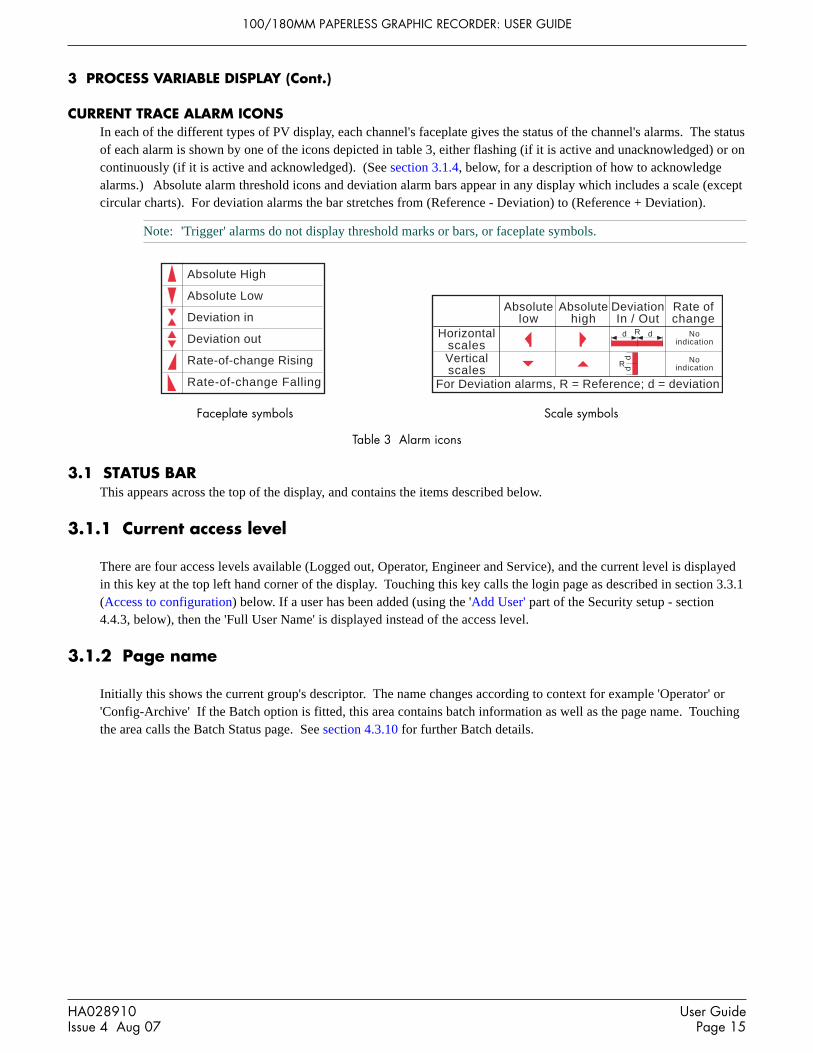
100/180MM PAPERLESS GRAPHIC RECORDER: USER GUIDE
HA028910Issue 4 Aug 07
User GuidePage 15
3 PROCESS VARIABLE DISPLAY (Cont.)
CURRENT TRACE ALARM ICONSIn each of the different types of PV display, each channel's faceplate gives the status of the channel's alarms. The statusof each alarm is shown by one of the icons depicted in table 3, either flashing (if it is active and unacknowledged) or oncontinuously (if it is active and acknowledged). (See section 3.1.4, below, for a description of how to acknowledgealarms.) Absolute alarm threshold icons and deviation alarm bars appear in any display which includes a scale (exceptcircular charts). For deviation alarms the bar stretches from (Reference - Deviation) to (Reference + Deviation).
Note: 'Trigger' alarms do not display threshold marks or bars, or faceplate symbols.
Table 3 Alarm icons
3.1 STATUS BARThis appears across the top of the display, and contains the items described below.
3.1.1 Current access level
There are four access levels available (Logged out, Operator, Engineer and Service), and the current level is displayedin this key at the top left hand corner of the display. Touching this key calls the login page as described in section 3.3.1(Access to configuration) below. If a user has been added (using the 'Add User' part of the Security setup - section4.4.3, below), then the 'Full User Name' is displayed instead of the access level.
3.1.2 Page name
Initially this shows the current group's descriptor. The name changes according to context for example 'Operator' or'Config-Archive' If the Batch option is fitted, this area contains batch information as well as the page name. Touchingthe area calls the Batch Status page. See section 4.3.10 for further Batch details.
Faceplate symbols Scale symbols
Absolute High
Absolute Low
Deviation in
Deviation out
Rate-of-change Rising
Rate-of-change Falling
Absolutelow
Absolutehigh
DeviationIn / Out
HorizontalscalesVerticalscales
Rate ofchange
Noindication
Noindication
Rd d
ddR
For Deviation alarms, R = Reference; d = deviation

100/180MM PAPERLESS GRAPHIC RECORDER: USER GUIDE
User GuidePage 16
HA028910Issue 4 Aug 07
3.1.3 Alarm indication
This area of the display can contain a number of status icons: Instrument alarm, Channel alarm, Battery change, Diskstatus, FTP in progress, Configuration locked, and so on. Pressing this area of the screen calls the 'Summary menu' -(section 3.1.4) allowing the user to view active instrument alarms, to acknowledge all channel alarms, to display theAlarm Summary or Message Log page. Media removal strategy is also controlled from this pop-up. If the access flap'Lock' option is fitted, see also section 2.4.
For channel alarm symbols refer to 'Current Trace Alarm Icons', above.
INSTRUMENT ALARMThis indicator appears, flashing, if any of the following errors are active. The instrument alarm summary page, de-scribed in Section 3.1.4, allows the user to view such instrument alarms as are active.
Archive failed -(message) Message explains archive failure.
Battery-backed RAM cleared This message appears if the battery has failed, and the unit has been switched off.
Clock failure Internal clock was corrupt at power up, or the time has never been set. Can becaused by battery failure, in which case the battery icon will also be visible. Theerror is cleared by setting the time and date. Server time forced to 00:00 1/1/1900.
Channel error Indicates a hardware failure in the channel circuit or in the internal CJ temperaturemeasurement
Channel failure Indicates a hardware failure in the input channel circuit (see note).
DHCP Server failure For instruments with IP address lookup set to ‘Get from DHCP Server’, this alarmoccurs if the recorder cannot obtain an IP address from the server. See section 4.5for details.
FTP Archiving file lost Archive failed. A file which has not been archived, has been detected.
FTP Archiving too slow Remote archive is too infrequent. The recorder effectively switches to 'Automatic'(section 4.3.5) to ensure that data is not lost.
FTP Primary Server Failure This error is set if the recorder fails, after two attempts, to establish communica-tions with the primary server as defined in Archive Configuration (section 4.3.5).After the second attempt has failed, the Secondary server is tried.
FTP Secondary Server Failure This error is set if the recorder fails, after two attempts, to establish communica-tions with the secondary server as defined in Archive Configuration (section 4.3.5).See also 'FTP Primary Server Failure, above.
Insufficient non-volatile memory... There is insufficient memory available for the configuration. Can be caused by useof Rolling Average maths functions.
Internal flash: \application\ required repairError found in the internal file system at power-up, and corrected.
Internal flash: \history\ required repair Error found in the internal file system at power-up, and corrected.
Internal flash: \screens\ required repair Error found in the internal file system at power-up, and corrected.
Internal flash: \user\ required repair Error found in the internal file system at power-up, and corrected.
Internal flash: \user\ is full Appears if the User partition is full. To clear, either user screens must be simplifiedor files must be deleted from \User\, or both.
Maths Channel failure Appears if, for example, the divisor of a divide function is zero.
Media Archiving file lost Archive failed. A file which has not been archived, has been detected.
Media Archiving too slow Archive is too infrequent. The recorder effectively switches to 'Automatic' (section4.3.5) to ensure that data is not lost.
Network boot failure The recorder is unable to establish connection with the BootP or DHCP server. Thismight be caused by, for example, cable failure, network hardware failure, etc.
Output channel failure Indicates a hardware failure in the output channel circuit (see note).
Note: Unlike other instrument alarms, Channel Failure and Output channel failure are not self clearing. Oncethe cause of the failure is rectified, the recorder must be power cycled in order to clear the alarm.
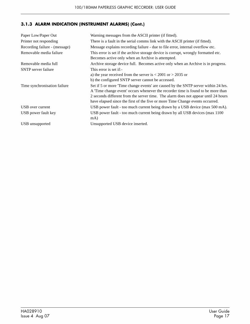
100/180MM PAPERLESS GRAPHIC RECORDER: USER GUIDE
HA028910Issue 4 Aug 07
User GuidePage 17
3.1.3 ALARM INDICATION (INSTRUMENT ALARMS) (Cont.)
Paper Low/Paper Out Warning messages from the ASCII printer (if fitted).
Printer not responding There is a fault in the serial comms link with the ASCII printer (if fitted).
Recording failure - (message) Message explains recording failure - due to file error, internal overflow etc.
Removable media failure This error is set if the archive storage device is corrupt, wrongly formatted etc.Becomes active only when an Archive is attempted.
Removable media full Archive storage device full. Becomes active only when an Archive is in progress.
SNTP server failure This error is set if:-a) the year received from the server is < 2001 or > 2035 orb) the configured SNTP server cannot be accessed.
Time synchronisation failure Set if 5 or more 'Time change events' are caused by the SNTP server within 24 hrs.A 'Time change event' occurs whenever the recorder time is found to be more than2 seconds different from the server time. The alarm does not appear until 24 hourshave elapsed since the first of the five or more Time Change events occurred.
USB over current USB power fault - too much current being drawn by a USB device (max 500 mA).
USB power fault key USB power fault - too much current being drawn by all USB devices (max 1100mA)
USB unsupported Unsupported USB device inserted.

100/180MM PAPERLESS GRAPHIC RECORDER: USER GUIDE
User GuidePage 18
HA028910Issue 4 Aug 07
3.1.3 ALARM INDICATION (Cont.)
CHANNEL ALARMThis red 'bell' indicator appears if any channel is in alarm. The symbol is illuminated continuously if all alarms areacknowledged or flashes if any active alarm is unacknowledged. Refer to 'ALARM ACKNOWLEDGEMENT' below,for details of how to acknowledge alarms.
CHANGE BATTERYThis flashing indicator first appears when the battery voltage (checked every 15 minutes) indicates that the battery isapproaching the end of its useful life. The indicator continues to flash until the battery is replaced (B2.2 in Annex B).The indicator does not appear if the battery is not fitted.
DISK ICONThis shows the free space available on whatever mass storage medium is fitted (if any), and selected for Archive desti-nation (note 1). The disk icon appears soon after the device is inserted (but see note 2). During archiving, the colour ofthe central area of the disk changes to green (see note 3). No other disk activity (e.g. save/restore configuration) isindicated.
Figure 3.1.3 Archive activity indication
Notes1. The icon appears only when a memory device is present, AND when that memory device has been se-
lected in the 'Archive to media' selection in archive configuration (section 4.3.5). For example: if amemory stick is inserted in ‘usbfront’, but Archive to Media is set to 'mediacard', then the disk icon ap-pears only if a suitable card is present in the 'mediacard' slot.
2. When a disk is inserted into a USB floppy disk drive which is connected to the recorder, the disk iconappears only after the disk has been accessed, (either by reading from it or writing to it), or after the filesystem has been opened by touching the ‘file’ key. (This note does not apply for disks which have beeninserted before the disk drive is plugged in.)
3. The central area goes green whenever local archiving is taking place - not only when archiving is takingplace to the memory device selected in Archive configuration.
FTP ICONThe FTP icon appears to the right of the disc icon position whenever transfer activity is taking place.
CONFIGURATION LOCKED INDICATORThis symbol appears only when Bridge software is being used, in the following situations:1. Whilst units are 'synchronising' configuration changes2. Whilst configuration is taking place. If the reconfiguration is taking place at the host pc (Bridge 'Full' only), then
the symbol appears at the target instrument, and vice-versa.
TRIAL MODE INDICATORThis symbol is displayed whilst the recorder Trial Mode (section 4.3.21) is enabled.
This area of the icon colouredgreen during any archive activity
(not necessarily to the deviceselected in Archive configuration).
99%

100/180MM PAPERLESS GRAPHIC RECORDER: USER GUIDE
HA028910Issue 4 Aug 07
User GuidePage 19
3.1.4 Summary menu
This pop-up display appears if the Alarm Indication area at the top of the display is touched. Figure 3.1.4 shows thedisplay.
Touch Alarm area(e.g. channel alarm symbol)
Ack all Alarms
Alarm Summary
Batch Summary
Message Log
Remove Media
Instrument Alarm Summary
Summary
Instrument Alarm Summary
Ok
Maths Channel FailurePrinter Error
Ack all Alarms
Yes No
Confirm acknowledge of alarms?
Note: For recorders fitted with the LockableFlap option, 'Remove Media' is replaced by'Unlock Flap' - see section 2.4, above
Figure 3.1.4a Summary pop-up menu
INSTRUMENT ALARM SUMMARY
Figure 3.1.4b Typical Instrument alarm summary display
This contains a list of the currently active instrument alarms. For a list of possible alarms and their definitions, seesection 3.1.3, above.
ACK ALL ALARMS
Figure 3.1.4c Ack all Alarms display
'Yes' confirms all active, unconfirmed alarms.This page can also be displayed by touching an alarm in the alarm summary page, described below.

100/180MM PAPERLESS GRAPHIC RECORDER: USER GUIDE
User GuidePage 20
HA028910Issue 4 Aug 07
3.1.4 SUMMARY MENU (Cont.)
ALARM SUMMARY PAGEAs shown in figure 3.1.4d, below, the alarm summary page contains the following information for the current group:1. Alarm identifier. This appears as a point ID, followed by the relevant alarm number in parentheses. For example,
Alarm 1 on maths channel 6 would appear as: D6 (1). Maths channels are prefixed by 'D'. Totalisers are prefixedby 'T' and Counters are prefixed by 'C'. Input channels are not prefixed.
2 Alarm threshold for absolute alarms only3 The current process value for the point4 An alarm symbol (see Table 3). Alarm symbols flash until acknowledged.
Notes:1. Alarms are always listed in Point/Alarm order with input channels first, followed by derived channels,
totalisers and counters, if these options are fitted.2 When the alarm source returns to its non-alarm state: Unlatched alarms are removed from the list whether
or not they have been acknowledged; latched alarms remain displayed until acknowledged. See section4.3.3 for a description of alarm types and actions.
3. There are no time or history components associated with the Alarm Summary. If Alarm messages havebeen enabled in the relevant group's configuration (section 4.3.2), then alarm initiation/acknowledgementtimes and dates can be found from the trend and trend history displays, described in section 3.4 or in Mes-sage log described later in this section.
4. If an alarm is active on a channel which is not included in any group, then although the channel alarmsymbol will flash, the alarm will not appear in any of the alarm summary pages.
Ack all Alarms
Alarm Summary
Batch Summary
Message Log
Unlock Flap
Instrument Alarm Summary
Summary
Goto Group
Group 1Group 2
Group 5
Group 4
Group 6
Group 3
Touch Alarm area(e.g. channel alarm symbol)
Alarm Summary: Group 5
1(1) Water temp 1a 60.0000 C 68.52772 (1) Water temp 1b 30.0000 C 23.45312 (2) Water temp 1b 10.0000 C 23.45313 (1) 0il pressure 250.000 PSI 260.34254(1) Transfer 15.3678
Channel no.(alarm no.)
Channeldescriptor Alarm type
symbolCurrent process
value
Touch alarm to call 'Acknowledge'
dialogue box. Alarm setpoint (Absolute alarms only)
Ack Alarm
Yes No
Confirm acknowledge of alarm?
Figure 3.1.4d Alarm Summary display

100/180MM PAPERLESS GRAPHIC RECORDER: USER GUIDE
HA028910Issue 4 Aug 07
User GuidePage 21
3.1.4 SUMMARY MENU (Cont.)
ALARM ACKNOWLEDGEMENTAlarms can be acknowledged individually, on a group basis, or globally (all alarms).
INDIVIDUAL ALARMSIndividual alarms are acknowledged from the alarm summary page by touching the relevant item (highlights yellow),then touching 'Yes' in the resulting pop-up confirmation box. Figure 3.1.3a, above, attempts to show this process.
GROUP ALARMSAlarms can be acknowledged on a group basis by calling the alarm summary page for the relevant group, then pressingthe Options key (section 3.2), the 'Ack Group Alarms' key and finally, 'Yes' in the resulting pop-up confirmation box.Figure 3.1.4e below, attempts to show this process.
Alarm Summary: Group 1
1(1) Water temp 1a 60.0000 C 68.52772 (1) Water temp 1b 30.0000 C 23.45312 (2) Water temp 1b 10.0000 C 23.45313 (1) 0il pressure 250.000 PSI 260.34254(1) Transfer 15.3678
Yes No
Confirm acknowledge of alarms?
Batch
Note
Ack Group Alarms
Option Menu
Ack Group Alarms
Figure 3.1.4e Group Alarm acknowledgement
ALL ALARMSTo acknowledge all active alarms, touch (e.g.) the channel alarm icon at the top of the screen. From the resulting 'Sum-mary’ menu, select 'Ack all Alarms', then finally, touch 'Yes' in the resulting pop-up confirmation box.
Note: The options menu is context sensitive, and may, therefore, not appear as illustrated above.

100/180MM PAPERLESS GRAPHIC RECORDER: USER GUIDE
User GuidePage 22
HA028910Issue 4 Aug 07
Ack all Alarms
Alarm Summary
Batch Summary
Message Log
Unlock Flap
Instrument Alarm Summary
Summary
Touch Alarm area(e.g. channel alarm symbol)
Batch Summary - Group Mode
Group namesBatch start
time and dateElapsed
timeBatch Field 1
textBatch Field 1
values
ColourMix1 25/04/06 09:12:18 00:02:41 Batch Number: 060425C1ColourMix2 25/04/06 08:45:13 00:29:46 Batch Number: 060425M1ColourMix3 25/04/06 08:50:07 00:24:40 Batch Number: 060425Y1ColourMix4 25/04/06 09:03:53 00:11:06 Batch Number: 060425K1Mix1 00:00:00 00:00:00 Mixed batch:Mix2 24/04/06 23:11:48 09:57:49 Mixed batch: 060424R..Group 7 00:00:00 00:00:00 Batch field 1Group 8 00:00:00 00:00:00 Batch field 1Group 9 00:00:00 00:00:00 Batch field 1Group 10 00:00:00 00:00:00 Batch field 1Group 11 00:00:00 00:00:00 Batch field 1Add Inputs 00:00:00 00:00:00 Batch field 1
Batch runningindicator
Click to highlight
Full Details
Batch Control
Sort (ON)
Highlight (OFF)
Exit
Mix2
3.1.4 SUMMARY MENU (Cont.)
BATCH SUMMARYIf the Batch option is fitted (section 4.3.10) a ‘Batch Summary’ key appears in the Summary menu.
Note: The following description shows the situation where batch ‘Scope’ is configured as ‘Group’. Thedescription is similar when ‘Scope’ = ‘Instrument’ except that there is only one line (Instrument), instead of oneline per group.
As shown in figure 3.1.4f, below, the Batch Summary page contains the following batch information:1. Group names in group number order (if Scope = Group) or Instrument Name if scope = ‘Instrument’2. Batch active indicator (green spot)3. Initiation time and date4. Elapsed time for the batch4. Batch Field 1 and its ‘value’.
Figure 3.1.4f Batch Summary page (Group mode - sort OFF; highlighting ON))
Touching anywhere on a group row calls a pop-up menu as shown above. The functions of this menu are as follows:

100/180MM PAPERLESS GRAPHIC RECORDER: USER GUIDE
HA028910Issue 4 Aug 07
User GuidePage 23
3.1.4 SUMMARY MENU (Cont.)
BATCH SUMMARY (Cont.)
FULL DETAILSTouching this key calls the Batch Details page showing the group name, batch status and batch field details.
BATCH CONTROLThis calls a page similar to the Full Details page, but including a ‘NEW’ key to allow the operator to start a new batch.If the batch is configured as ‘Start/Stop’ a ‘Stop’ key is also included allowing the user to stop the batch.
SORTIf Sort is Off (default), the groups appear in Group number order with Group 1 at the top and group 12 at the bottom.The key legend is ‘Sort (ON)’.
If Sort is On, those groups with batches running appear (in group number order) at the top of the list, followed by anyremaining groups (also in group number order). The key legend is ‘Sort (OFF)’.
HIGHLIGHTIf Highlight is Off (default), then all groups’ text appears in white. The key legend is ‘Highlight (ON)’.
If Highlight is On then the text associated with groups which have batches running appears in green. Remaininggroups’ text is in white. The key legend is ‘Highlight (OFF)’.
EXITCloses the pop-up menu. (It closes itself after approximately 50 seconds.)

100/180MM PAPERLESS GRAPHIC RECORDER: USER GUIDE
User GuidePage 24
HA028910Issue 4 Aug 07
3.1.4 SUMMARY MENU (Cont.)
MESSAGE LOG
Note: Message log can also be selected using the Root menu/Goto View/Message log key. This goes immedi-ately to the first Message Log page for the current group to the screen (i.e. the 'Goto Group' menu does notappear).
If there are more messages than can be displayed in the height of the screen, a scroll bar appears to allow 'hidden' mes-sages to be displayed.
Messages are retrieved from the history files in batches of 100 messages. If there are more than 100 messages, 'Earliermessages..' appears after the hundredth message. Touching 'Earlier messages..' calls the option menu, and touching'Earlier messages..' in this menu, calls the next batch of 100, and so on. If applicable, operating 'Later messages..' /'Later messages..' calls the previously displayed 100 messages.
As can be seen from figure 3.1.4g the list of messages can be 'filtered' both by type and by time. For example, settingthe message type to 'Alarm' and the period filter to 'Last Day' excludes all messages except alarm messages which haveoccurred within the previous 24 hours. (For clarity, the figure shows both filters open. In fact, only one can be open ata time)
Ack all Alarms
Alarm Summary
Batch Summary
Message Log
Unlock Flap
Instrument Alarm Summary
Summary
Group 5Batch number:050405A12
09:06:2205/04/05Engineer
Message Log: Group name
All Messages All History
05/04/05 09:06:18 Alarm(s) on 1(1)
05/04/05 09:06:18 Operator's name: Andrew
05/04/05 09:06:18 Customer: FishesRus
05/04/05 09:06:18 Batch number:020205A12
05/04/05 09:06:18 Config Revision:682759 Security Revision 746261
05/04/05 09:06:18 Batch start (Engineer)
05/04/05 08:50:30 Configuration revision 682,759 was 682,758
05/04/05 08:50:28 Batch) Name files by batch true was false
05/04/05 08:50:28 Batch) On start log 3 was 1
05/04/05 08:50:28 Batch) Field 3 Operator's name: was Batch field 3
05/04/05 08:50:28 Batch) Field 2 Customer: was Batch field 2
05/04/05 08:50:28 Batch) Field 1 Batch number: was Batch field 1
05/04/05 08:50:28 Batch) Batch fields 3 was 1
05/04/05 08:50:50 Config,Signed:Engineer, Authorized:Engineer,New batch fields
04/04/05 16:42:11 Alarm(s) off 2(1)
04/04/05 16:32:50 Alarm(s) off 1(1)
04/04/05 16:31:05 Batch stop (Engineer)
04/04/05 16:31:05 Stop Batch,Signed:Engineer,Authorized:Engineer,Belt Failure
04/04/05 16:29:33 Alarm(s) Ackd 1(1) 2(1)
04/04/05 16:28:05 Ack all alarms,Signed:Engineer,Authorized:Engineer,Belt Failure
04/04/05 16:27:13 Alarm(s) on1(1)
04/04/05 16:27:13 Alarm(s) on2(1)
04/04/05 14:06:22 Config Revision:682759 Security Revision 746261
04/04/05 14:06:22 Batch start (Engineer)
System
Alarms
Power Up
General
Batches
Logins
Signings
Audit Trail
Reports
All Messages
Last Hour
Last Day
Last 3 Days
Last Week
Last Month
All History
Goto Group
Group 1Group 2
Group 5
Group 4
Group 6
Group 3
Touch Alarm area(e.g. channel alarm symbol)
Figure 3.1.4g Message log page showing message-type picklist

100/180MM PAPERLESS GRAPHIC RECORDER: USER GUIDE
HA028910Issue 4 Aug 07
User GuidePage 25
3.1.4 SUMMARY MENU (Cont.)
MESSAGE LOG (Cont.)
MESSAGE TYPE FILTERAll Messages All messages are displayedSystem Only System messages and instrument alarms are listedAlarms Only alarm on/off and acknowledgement messages appear.Power Up Displays power up messages only including Config Revision and Security revision are included. See 'About'
(section 4.6.11) for more details.General Displays e-mails, messages sent via Modbus, operator notes/custom messages etc. if they do not have to be
'signed' (Auditor option 21CFR11 only - see section 4.4 for more details). If the notes etc. are signed, theyappear in the 'Signings' message type list.
Batches Displays only batch messages (including Config and Security Revisions if either Auditor option is enabled).Logins Lists only changes in login.Signings This list contains only notes, messages etc. that have been signed (and authorized). This category is used only
when 'Require Signing' (and 'Require Authorization') is (are) enabled in the Security/Management menu- seesection 4.4 for more details.
Audit trail This list contains Configuration change messages only. This category is used only when 'Audit Trail' is ena-bled - see section 4.4 for more details.
Reports For each report, this contains all the Report's fields (set up in 'Reports' configuration) on separate lines. LineFeed fields are ignored (i.e. they do not appear).
PERIOD FILTERThis picklist allows the user to select one of the following to define the period of time that the message list is to encom-pass:All History, Last Month (28 days), Last Week, Last 3 Days, Last Day or Last Hour.

100/180MM PAPERLESS GRAPHIC RECORDER: USER GUIDE
User GuidePage 26
HA028910Issue 4 Aug 07
3.1.4 SUMMARY MENU (Cont.)
MESSAGE LOG (Cont.)
OPTION MENUTouching a message (highlights yellow) calls the Option Menu* as shown in figure 3.1.4h, below.
05/04/05 09:06:18 Alarm(s) on 1(1)
05/04/05 09:06:18 Operator's name: Andrew
05/04/05 09:06:18 Customer: FishesRus
05/04/05 09:06:18 Batch number:020205A12
05/04/05 09:06:18 Config Revision:682759 Security Revision 746261
05/04/05 09:06:18 Batch start (Engineer)
05/04/05 08:50:30 Configuration revision 682,759 was 682,758
05/04/05 08:50:28 Batch) Name files by batch true was false
05/04/05 08:50:28 Batch) On start log 3 was 1
05/04/05 08:50:28 Batch) Field 3 Operator's name: was Batch field 3
05/04/05 08:50:28 Batch) Field 2 Customer: was Batch field 2
05/04/05 08:50:28 Batch) Field 1 Batch number: was Batch field 1
05/04/05 08:50:28 Batch) Batch fields 3 was 1
05/04/05 08:50:50 Config,Signed:Engineer, Authorized:Engineer,New batch fields
04/04/05 16:42:11 Alarm(s) off 2(1)
04/04/05 16:32:50 Alarm(s) off 1(1)
04/04/05 16:31:05 Batch stop (Engineer)
04/04/05 16:31:05 Stop Batch,Signed:Engineer,Authorized:Engineer,Belt Failure
04/04/05 16:29:33 Alarm(s) Ackd 1(1) 2(1)
04/04/05 16:28:05 Ack all alarms,Signed:Engineer,Authorized:Engineer,Belt Failure
04/04/05 16:27:13 Alarm(s) on1(1)
04/04/05 16:27:13 Alarm(s) on2(1)
04/04/05 14:06:22 Config Revision:682759 Security Revision 746261
04/04/05 14:06:22 Batch start (Engineer)
Engineer
Message Log: Group name
All Messages All History
To call Option Menu, touch message(highlights yellow) or Option key
Group nameBatch number:050405A12
09:06:2205/04/05
Option Menu
Batch
Note
Enter History
Full Details
Refresh
Figure 3.1.4h Message Log options menu
Batch See section 4.3.10.Note See section 3.5.Enter history Operating the Enter History key causes the recorder to display that page of history which
includes the highlighted message. See section 3.4.1 for details of trend history. When in Trendhistory mode, operating the Message Log key calls that message log page which contains thosemessages which are nearest the trend history cursor time.
Full details If the highlighted message is wider than the display, the whole message can be displayed byoperating the 'Full Details' key.
Refresh/Earlier messages../Later messages.. 'Refresh' places (at the top of the screen), any messages, which have occurred since the MessageLog page was last entered, or since the last 'Refresh'. If earlier or later messages have beenselected, then 'Refresh' is replaced by 'Earlier messages..' or 'Later messages..' as appropriate,and operating the key calls the next or previously displayed group of 100 messages to thedisplay respectively.
* The option menu can also be called by touching the option key. In this case:a. Enter History calls the current Trend History display, as described in section 3.4.1, andb. Because no message is highlighted, the 'Full Details' key is not enabled,
Notes:1 Selecting 'Enter History' whilst either 'Earlier Messages' or 'Later Messages' is highlighted calls the current
History page.2 If the Option Menu has 'timed out' leaving a message highlighted, and the option key is operated, then this
is equivalent to reselecting the message.

100/180MM PAPERLESS GRAPHIC RECORDER: USER GUIDE
HA028910Issue 4 Aug 07
User GuidePage 27
3.1.4 SUMMARY MENU (Cont.)
REMOVE MEDIA
Note: See section 2.4 if the 'Lockable Door Flap' option is fitted.
This key is provided to help ensure that any local memory storage device is removed only when it is 'safe' to do so.
Touching the key results in either an 'OK to remove archive media', or a 'DO NOT REMOVE Archive Media! message,as appropriate. See figure 3.1.4i
CautionRemoval of memory devices such as SD cards or Compact Flash cards whilst archiving is taking place can leadto permanent, irreparable damage to the device, rendering it unusable.
OK to remove archive media
Ok
Will advise when OK to remove...
Cancel
Archive Media DO NOT REMOVE Archive Media!
Figure 3.1.4i Remove archive media messages

100/180MM PAPERLESS GRAPHIC RECORDER: USER GUIDE
User GuidePage 28
HA028910Issue 4 Aug 07
3.2 NAVIGATION KEYS
Above the lower edge of the display screen are six keys (as shown below, for the small frame unit) which allow theuser to perform various context-related tasks such as to change the display mode (section 3.4), to access the recorderconfiguration, to archive data, to select groups etc. In addition to this, left and right arrow keys or open/close folderkeys appear when relevant.
Page up Page down Lef t Right Opt ion Root
Closefo lder
Openfolder
Leftcursor
Rightcursor
Figure 3.2 Navigation keys
3.2.1 Key functions
Page up Used, as appropriate, to recall the previous (higher level) display page, to call the previous display modeand to scroll through previous text entries.Where relevant, the function of this key is mimicked by the 'Close folder' key.
Page down Used, where appropriate, to call a further (lower level) display page, to call the next display mode and toscroll through previous text entries.Where relevant, the function of this key is mimicked by the 'Open folder' key.
Left arrow Used a) to select the previous group, b) to navigate backwards through a text string when editing or c) toselect the previous channel whilst in configuration. Where relevant, the function of this key is mimickedby the 'Left cursor' key.
Right arrow Used a) to select the next group, b) to navigate forwards through a text string when editing or c) to selectthe next channel whilst in configuration. Where relevant, the function of this key is mimicked by the'Right cursor' key.
Option Calls a pop-up Options menu allowing the user to carry out functions such as entering/quitting history,turning channel cycling on and off etc. according to context.
Root Calls the 'Root Menu' as described below. To quit the Root menu, touch the root key again.
ROOT MENU KEYSHome Causes a return to the 'Home' page from any page in the recorder. As delivered, the 'Home' page is the
Group 1, vertical trend display as depicted in figure 3, but this can be edited (in Config/Views) to be any ofthe other available groups' display modes - Horizontal trend, Vertical bargraph etc.
Operator Causes the top level Operator page to appear. The appearance of this display is dictated by the securitylevel that the recorder is set to, and by the access level of the user. As despatched from the factory, therecorder is in 'logged out' mode and the Operator page contains only 'Archive', 'Security' and 'System' keys.Further details appear in 'Access to configuration' below.
File Allows the file system in that area of Flash memory that is accessible to the user, and the file system on anybulk storage device fitted, to be viewed. See section 5 for details.
Remove Media This key is provided to help ensure that any local memory storage device is removed only when it is 'safe'to do so. Touching the key results in either an 'OK to remove archive media', or a 'DO NOT REMOVEArchive Media! message, as appropriate. For more details see section 3.1.4.
Unlock Flap Replaces 'Remove Media' (above) for recorders fitted with the lockable flap option (section 2.4).
Go to View Allows the user to select the display mode for the current group, as shown in figure 3.2.1a. Display modesnot enabled for this group in Config/Views configuration page (section 4.3.4) do not appear. As an alter-native, display modes can be scrolled-through using the up and down arrow navigation keys.Goto View also offers an alternative means of entry to the Alarm Summary page described in section 3.1.4,and also allows entry to the current group's Message Log pages, described below.

100/180MM PAPERLESS GRAPHIC RECORDER: USER GUIDE
HA028910Issue 4 Aug 07
User GuidePage 29
3.2.1 KEY FUNCTIONS (Cont.)
ROOT MENU KEYS (Cont.)
Goto Group Allows a group to be selected for display. Groups which are not 'display enabled' in the Config/Viewspage (section 4.3.4) are greyed. An alarm icon appears (as shown for groups 1 and 4, in figure 3.2.1b, be-low) for any group containing one or more points in alarm. The icon flashes if any of the group's alarmshave not been acknowledged.
Notes:1. If there is insufficient space on the display screen for all the enabled groups or views, 'More...' keys ap-
pear, as necessary, to allow further items to be displayed for selection.2. In normal operating (e.g. trend) displays, the right arrow key can be used to scroll through groups in as-
cending group number order. The left arrow key can be used to scroll through groups in descending groupnumber order.
Home Operator
File
Goto View Goto Group
Message Log
Horizontal Trend
Vertical Bargraph
Alarm Summary
Vertical Trend
Circular Trend
Numeric Page
User Screen 2
Horizontal Bargraph
User Screen 1
User Screen 3 More...
A display mode appears only if it is enabled for thecurrent group.
User screen keys appear only if a User Screensoption is fitted and the relevant screen is enabledfor the current group.
See Views configuration (section 4.3.4) for enable/disable details.
Root Menu
Goto View: Group 1
Remove Media
Figure 3.2.1a Root menu with Goto View sub menu
Home Operator
File
Goto View Goto Group
Group 1Group 2
Group 3Group 4
Group 5 Group 6Groups which are not displayenabled in 'Views' configuration(section 4.3.4) are 'greyed'.
Root Menu
Goto Group
Remove Media
Figure 3.2.1b Root menu with Goto Group sub menu

100/180MM PAPERLESS GRAPHIC RECORDER: USER GUIDE
User GuidePage 30
HA028910Issue 4 Aug 07
3.2.1 KEY FUNCTIONS (Cont.)
ALARM SUMMARYThe Root menu/Goto View/Alarm summary key calls the Alarm summary page for the current group to the screen.Alternatively, Alarm summary can be selected from the Alarm, Message and Media menu, but in this case, the usermust select an alarm summary group from a pop-up (Goto Group) menu. See section 3.1.4 for more details of the alarmsummary page.
MESSAGE LOG The Root menu/Goto View/Message log key calls the Message Log page for the current group to the screen. Alterna-tively, Message Log can be selected from the Alarm, Message and Media menu, but in this case, the user must select a'Group' for the Message Log display from a pop-up (Goto Group) menu.
See section 3.1.4 for full details of the message log.

100/180MM PAPERLESS GRAPHIC RECORDER: USER GUIDE
HA028910Issue 4 Aug 07
User GuidePage 31
3.3 FIRST SWITCH-ON
When power is applied the recorder initialises, and once this process is complete, the home page is displayed. It isunlikely that this will contain any useful information because the input channels will not, as yet, have been configuredto suit the type of input signals being applied to them, as described in section 4.
Notes:1 There is no on/off switch associated with the recorder.2 Date, time and the message 'Power Up' are printed on the chart each time power is applied to the recorder,
followed by a similar message giving 'Config Revision' and 'Security Revision'.3 A red line is drawn across the width of the chart at power up
The recorder has four security levels as follows:Logged out Initially, no access to recorder configuration is possible. Only Archive, Login/security and the System
'About' functions can be accessed - via the root menu. Limited or full access can be permitted from'Engineer' level.
Operator* No access to recorder configuration is possible until access permissions have been set up. Section 4.4.1describes how limited or full access can be permitted by an operator with 'Engineer' level access.
Engineer* Accessed initially, by entering '100' as the password (section 3.3.1, below). Full access to all recorderfunctions is available. Section 4.4.1 describes how the Engineer level password can be edited and anOperator password can be entered if required. The section also describes how access permission tosome or all of the recorder functions can be granted, or not, to individual user names and default securitylevels (except 'Service').
Service Full access to all recorder functions and to areas of recorder memory for diagnostic purposes. For useonly by Service Engineers.
*Note: For units with the Auditor 21CFR11 Option enabled, the default Engineer and Operator passwords areboth '100'.

100/180MM PAPERLESS GRAPHIC RECORDER: USER GUIDE
User GuidePage 32
HA028910Issue 4 Aug 07
3.3.1 Access to Configuration
1 As shown in figure 3.3.1a, once the recorder has initialised, touch the current access level key2 Touch the 'Logged out' field and then touch 'Engineer' from the resulting picklist.3 Touch the blank Password area to call the keyboard display (see figure 3.3.1b).4 Touch <Numeric><1><0><0><OK> to enter the password '100'. The screen reverts to the 'Home' page.5 Operation of the Root key followed by a touch on the Operator key calls the top level page allowing access to the
Archive, Save/Restore, Config, Security, Network and System areas described in section 4 below.
Touch Currentaccess level key Group name 11:52:59
05/04/05
11:52:0405/04/05
11:49:2405/04/05
11:46:4405/04/05
Logged out
Login
Select the required access level and enter the password ifrequired.
Close
User Logged out
Operator
Engineer
Service
Logged out
Touch 'logged out'area...
...then touch accesslevel required.
Touch the password window when it appears, and enter the password.The Engineer level password is '100' when the unit is despatched fromthe factory. Passwords can be edited in 'Security' as described in sec-tion 4.4.1.
The screen reverts to the home page, with the new access level dis-played in the 'Current access level' key
0.0000 1.0000
Channel 1 0.0237V
0.2000 0.4000 0.6000 0.8000
1
2
3
Figure 3.3.1a Access to configuration
Notes:1. For units which have the Auditor 21CFR11 Option enabled, the default Operator password is '100'. Other-
wise no password is required for default Operator level access. In either case the Operator access levelpassword can be edited in 'Security' configuration. (Section 4.4.1.)
2. The login screen, above, can also be called by operating the Root menu, then 'Operator' then 'Security',then 'Login'. In such a case, the screen reverts to the 'Operator' page rather than returning to the homepage once login has been achieved.
3. Figure 3.3.1a shows 'Login by user list' which is the default method. If either Auditor option and/or theSecurity management option is enabled, an alternative procedure is possible where each user has to enter aname and associated password - i.e. there is no list of users/access levels to choose from. See section 4.4.2(Management) for details.

100/180MM PAPERLESS GRAPHIC RECORDER: USER GUIDE
HA028910Issue 4 Aug 07
User GuidePage 33
3.3.1 ACCESS TO CONFIGURATION (Cont.)
TEXT STRING ENTRY
The keyboard which appears when the password area is touched is the same as that which appears when any non-nu-meric text string entry is required (e.g. channel descriptor). Figures 3.3.1b and 3.3.1c below are an attempt, within thelimitations of the illustrating process, to depict the available keyboards and thus the available character set. Actualentry of the text string is by touching the relevant keys.
When editing existing text strings, the existing text string appears highlighted, and will be replaced in its entirety by thefirst character entered. To avoid this, the left arrow key* can be touched to 'unhighlight' it. The down and up arrowkeys can be used to scroll through previously entered text strings.
Immediately below the keyboard are six keys with the functions listed below. When active, the background colourchanges to yellow for as long as the key is active.
Shift* Once the shift key has been pressed, the next-entered letter appears as a capital; subsequent letters are inlower case.
Caps* When pressed, all subsequent letters appear as capital letters until the Caps key is operated againBSpc This backspace key deletes character to the left of the cursor.Ovr If selected, the next-entered character replaces (overwrites) the existing character to the right of the cursor
position. If not selected, the next-entered character in inserted into the existing text string at the cursor posi-tion.
Ok Used to save the new text string and to return to the page from which the keyboard was called.Cancel Causes a return to the page from which the keyboard was called without saving the new string.
*Notes1. The character on each display key is always a capital letter, whether or not the actual character being
entered is in capitals or lower case.2. The cursor keys mimic the function of the left and right arrow Navigation keys.3. As an alternative, text may be entered using a suitable keyboard connected via the USB port behind the
access flap or (if the relevant option is fitted) one of the USB ports at the rear of the instrument (section2.2.1).
Figure 3.3.1b Alphabet 1 keyboard
SymbolsNumericAlphabet 2
**
Alphabet
Shift Caps BSpc Ovr Ok Cancel
Shift key Backspace
Text string(all * for password)
Q W E R T Y U I O P
A S D F G H J K L ˚
Z X C V B N M \ .
Cursor keys
Tabs showactive keyboard
(tab positions varyaccording to context)
Caps Lock Overprint(shown active)

100/180MM PAPERLESS GRAPHIC RECORDER: USER GUIDE
User GuidePage 34
HA028910Issue 4 Aug 07
3.3.1 ACCESS TO CONFIGURATION (Cont.)
TEXT STRING ENTRY (Cont.)
Figure 3.3.1c Alternative keyboards
SymbolsNumeric
Text String
Alphabet
Shift Caps BSpc Ok Cancel
Alphabet 2
Ovr
SymbolsNumeric
Text String
Alphabet
Shift Caps BSpc Ok Cancel
Alphabet 2
Ovr
Numeric
Text String
Alphabet
Shift Caps BSpc Ok Cancel
Alphabet 2
Ovr
Symbols
Ä Å Á À Æ Ç É Èa Ë
Ê Í Ì Ï Ó Ò ÔÎ Ö º
Ü Ú Ù Û Ñÿ β Γ δα
τ φ ΩΣθ µ πηε
! " £ $ ^ & * ( )
- _ + = [ ] : ;
@ ' ~ # > , . ? /
| ' 3 ± ¿ ¡ ¥ ¢
<
÷
%
2
7 8 9
4 5 6
1 2 3
0 . ,– E
The 'E' key is used toenter exponents

100/180MM PAPERLESS GRAPHIC RECORDER: USER GUIDE
HA028910Issue 4 Aug 07
User GuidePage 35
3.4 DISPLAY MODES
The display modes described below allow the currently displayed group's process values (channels, totalisers etc.-known collectively as points) to be displayed as vertical, horizontal or circular 'chart' traces, as vertical or horizontalbargraphs or as numeric values. The various display modes are cycled-through using the up/down arrow keys, or a spe-cific mode (or view) can be selected from the Root Menu 'Goto View' key. Groups can be scrolled through using theleft/right arrow keys. The Home key returns the user to the Home page (defined in Configuration/Views - section4.3.4) from anywhere in the Operator or Configuration pages in the recorder. When dispatched, the Home page isGroup 1, vertical trend display. See also the Screen builder description in section 7.
3.4.1 Vertical Trend display
This display (figure 3.4.1b) shows each point in the display group as though it were being traced on a white chart. It ispossible to change the appearance of the chart in the System key ‘Customise’ area of configuration (section 4.6.10). Itis recommended that some thought be given to ensuring good contrast between trace colours and background colour.
One of the channels is said to be the 'current' or 'scale' channel. This channel is identified by its diamond shaped penicon and by its descriptor, digital value and scale being displayed on a 'faceplate' across the full width of the screen,above the chart. Faceplates for all the group channels can be displayed, by using the Faceplates On/Off key in the op-tion menu. If selected On, faceplates (showing colour, descriptor, digital value and units) for all the group's channelsappear either above the current channel's faceplate or, if there are too many to fit across the screen, at the right handedge of the screen. When necessary, a slider bar appears to allow further (hidden) faceplates to be viewed.
Each channel in the display group becomes the 'current' channel, in turn, for approximately 10 seconds – i.e. the chan-nels are cycled-through, starting with the lowest numbered channel. Once the final channel in the group has been dis-played for 10 seconds, the lowest numbered channel is returned to and the sequence repeats. This scrolling process canbe enabled or disabled using the Channel Cycling On (Off) key in the Option menu.
To select a particular channel to be the current channel, the relevant pen icon can be touched. To cycle through thechannels manually, the faceplate area is touched repeatedly until the required channel is reached.
If a channel is included in the display group but its status is 'not good' for some reason, then its pen icon is hollow.
See section 4.3.10 for 'Batch'details
See section 3.5 for 'Operator Notes'details
OptionKey
Option Menu
Enter History
Channel Cycling Off
Faceplates On/Off
Batch
Note
Figure 3.4.1a Option Menu (Typical)

100/180MM PAPERLESS GRAPHIC RECORDER: USER GUIDE
User GuidePage 36
HA028910Issue 4 Aug 07
3.4.1 VERTICAL TREND DISPLAY (Cont.)
TIME CHANGE RECORDSFor vertical trend mode only, a line is drawn across the width of the chart whenever a time discontinuity in the recordoccurs. These lines are volatile in real-time i.e. they disappear if the display mode is changed, or if a configuration pageis called etc.Red line A red line is drawn on the trend history chart at power up.Blue line A blue line indicates that recording has been disabled/enabled in Group Configuration (section 4.3.2), or
by a recording job (section 4.7.10). Blue lines are not drawn when the Simulation Option is active.Green line A green line appears if there has been a time change as a result of a clock job (section 4.7.6), an SNTP
synchronisation or by the operator physically changing the recorder time.
Note: Changes from standard time to daylight saving time and back again are not 'green lined' in this way
TREND HISTORYTrend history, allows the user to view the history of the display group. The maximum amount that can be revieweddepends on a number of factors, including how many points are configured, how rapidly the traces are changing and soon. At a recording rate of 20 mm/hour (see group configuration - section 4.3.2), with all channels configured, a mini-mum of 30 day's worth of traces is available for viewing, provided that the group contents are not re-configured duringthis period (in which case, the history starts at the end of the re-configuration). The amount of trace visible on thescreen depends on the recording rate, the higher the rate, the less trace is visible at any one time.
Notes:1. Trend history mode is not available for groups with 'Recording Enable' disabled (Group configuration -
section 4.3.2).2. Channel cycling is inhibited in trend history mode. To increment the current channel, touch the faceplate.3. Group faceplates are not displayed in trend history mode.4. Operation of the Root/Goto View/Message Log key (section 3.2.1), when in history mode, displays a mes-
sage log page containing messages which occurred at or near the selected cursor time.5. With A/B switching selected, traces are displayed with the 'A' or 'B' span/zone, colour settings etc. obtain-
ing at the cursor time. See sections 4.3.2, 4.3.3 and 4.7, for more details of A/B switching.
To enter trend history mode, the option key can be used (as shown in figure 3.4.1b), or the trace area of the screen canbe continuously touched until the screen blanks prior to re-drawing. A 'Preparing History, please wait' message appearswhilst the re-drawing calculation is taking place. Although tracing stops whilst trace history mode is active, no data islost. Process Variable values are saved in the recorder memory. Alarms are still scanned-for and any associated actiontaken.
The trend history display is similar to the real-time trend display, with the addition of a slider control and up and downkeys for selecting that part of trend history which is to be displayed. The controls are used as follows:1 Touching the up/down key causes the trace history to move an incremental amount.2 Holding the up/down key continuously, causes continuous movement.3 Touching the bar above or below the slider causes a page-height shift. The Page up and Page down keys can also
be used to provide this function4 Touching and dragging the slider, whilst observing the time/date display, allows the user to select the section of
history exactly.
On first entry to trend history mode, the channel value and the time and date shown in the faceplate are those at the topedge of the chart. Touching the screen causes a cursor to appear at point of screen contact. This cursor can be touchedand dragged up and down the screen to provide a reference point on the current trace. The displayed value date andtime refer to the cursor intersection with the current channel. To return to real-time trending, the Option key is operated,followed by 'Exit History'.
When back in real-time trending, the Horizontal Trend display can be called using the down arrow key. Alternatively,any one of the enabled display modes (section 4.3.4) can be selected using the Root Menu, 'Goto View' key.

100/180MM PAPERLESS GRAPHIC RECORDER: USER GUIDE
HA028910Issue 4 Aug 07
User GuidePage 37
VERTICAL TREND DISPLAY (Cont.)
O p t i o n M e n u
E n t e r H i s t o r y
Channel Cycling Off
Facep la tes On /Of f
B a t c h
N o t e
Option Menu
Batch
Note
Exit History
Message Log
Channel 1
400.00
686.84 ˚C
640.00
G r o u p n a m e 11:53:090 4 / 0 5 / 0 4
11:52:040 5 / 0 4 / 0 5
11:49:240 5 / 0 4 / 0 5
14:46:440 5 / 0 4 / 0 5
05/04/05 18:28:22 Alarms(s) on 3(1)
05/04/05 18:33:04 Alarms(s) off 3(1)
Cursor
Real time/dateTrend History mode
Press bar tomove onepageful
Pageforwards in time(show newer data)
Pagebackwards in time(Show older data)
E n g i n e e r
G r o u p n a m e 11:52:590 5 / 0 4 / 0 5
11:52:040 5 / 0 4 / 0 5
11:49:240 5 / 0 4 / 0 5
11:46:440 5 / 0 4 / 0 5
05/04/05 11:47:51 Alarms(s) on 3(1)
05/04/05 11:51:33 Alarms(s) off 3(1)
Home
Trend display modeE n g i n e e r
Preparing History, please wait
0 4 / 0 5 / 0 4 1 1 : 4 9 : 5 4 Cursor time/date(Touch faceplate toincrement channel.)
800.00720.005 6 0 . 0 04 8 0 . 0 0
Faceplate for currentchannel.Touch and release face-plate to increment channel
(or touch pen to selectchannel).
If Channel Cycle On:Current channel incre-ments every 10 seconds.
Pressarrow keys
to moveminimumamount
Value at cursortime/date
Channel 1
400.00 800.00
700.87
720.00640.00480.00 560.00
Channel 1700.87˚C
Channel 2487.39˚C
Channel 3235.68˚C
Channel 4378.99˚C
Channel 50.49V
Channel 60.85V
Group faceplates (appear only ifFaceplates selected On fromoption menu). If there are toomany faceplates to fit across thescreen, they appear down theright edge instead.
Figure 3.4.1b Trend display mode and trend history mode

100/180MM PAPERLESS GRAPHIC RECORDER: USER GUIDE
User GuidePage 38
HA028910Issue 4 Aug 07
3.4 DISPLAY MODES (Cont.)
3.4.2 Horizontal Trend display
Entered from the Vertical Trend display by means of the down arrow key, or selected via the Root Menu 'Goto View'key, this display mode (figure 3.4.2a) is similar to the Vertical Trend display described in section 3.4.1 above, exceptthat the traces are produced horizontally rather than vertically.
Figure 3.4.2a Horizontal Trend Display
One of the channels is defined as being the 'current' or 'scale' channel and this is identified on the chart by its pen iconbeing diamond shaped rather than triangular as for non-current channels. If a channel is included in the display group,but its status is 'not good' for some reason, then its pen icon is hollow. Each channel in the display group becomes the'current' channel, in turn, for approximately 10 seconds – i.e. the channels are cycled-through, starting with the lowestnumbered channel. Once the final channel in the group has been displayed for 10 seconds, the lowest numbered chan-nel is returned to and the sequence repeats. This scrolling process can be stopped using the Channel Cycling key in theOption menu.
There are two faceplates associated with this display mode, one above the 'chart', showing the current channel's de-scriptor and its digital value; the other - to the right of the 'chart' - showing a bargraph representation of the currentchannel's value, together with a scale showing the low and high range values for the channel. Touching either of thesefaceplates causes the current channel number to increment. To select a particular channel to be the current channel, therelevant pen icon can be touched. In either case, the bargraph and the background colour of the channel descriptor takethe colour of the new current channel.
There is no horizontal trend history function. Touching the trace for a few seconds, or using the Option key then 'EnterHistory' calls the Vertical trend history page described in section 3.4.1, above.
Time and date are printed on the 'chart' immediately to the right of grid lines, and it is to these grid lines that the printedtime and date relate.
G r o u p n a m e 14:21:300 6 / 0 4 / 0 5Engineer
Channel 1 7 0 0 . 8 7 ˚C
400
800
14:16:2006/04/05
14:13:4006/04/05
14:11:0006/04/05
Bargraph
Current pen icon
Time(at adjacent gridline)
Faceplates for currentchannel.Touch either faceplate toincrement channel(or touch pen to selectchannel).
06/04/05 12:02:20 Alarm(s) off 2 (1)
If this arrow head is displayed,then touching the message bardisplays previous messages
Latest messageMessage bar
Non-currentpen icon
Alarm mark(Abs High)

100/180MM PAPERLESS GRAPHIC RECORDER: USER GUIDE
HA028910Issue 4 Aug 07
User GuidePage 39
3.4.2 HORIZONTAL TREND MODE (Cont.)
Below the 'chart' is a message bar, containing the latest message. If there is more than one message, an arrow head iconappears near the right-hand end of the message bar. If this arrow head appears, then touching the message bar calls apop-up box (figure 3.4.2b) which displays the latest messages. If there are more messages than can be displayed in thebox, a slider control appears, which can be used to access previous messages, up to a total of 60 messages. Furthermessages, cause the oldest messages to be discarded to keep the total to 60.
Note: At power-up, only those messages which occurred within the 'time width' of the page are displayed
G r o u p n a m e 14:21:300 6 / 0 4 / 0 5
E n g i n e e r
Channel 1 7 0 0 . 8 7 ˚C
400
800
14:16:2006/04/05
14:13:4006/04/05
14:11:0006/04/05
06/04/05 12:02:20 Alarm(s) off 2 (1)
View Messages06/04/05 12:02:20 Batch Number 050406-306/04/05 11:11:41 Config Revision:218 SecurityRevision:306/04/05 11:11:34 Batch start (Engineer)06/04/05 11:09:34 Alarm(s) on 1 (1)06/04/05 11:09:26 Alarm(s) off 1 (2)06/04/05 11:07:41 Alarm(s) on 1 (2)06/04/05 11:07:34 Alarm(s) off 1 (1)06/04/05 11:05:34 Alarm(s) on 1 (1)06/04/05 11:05:26 Alarm(s) off 1 (2)06/04/05 11:03:41 Alarm(s) on 1 (2)06/04/05 11:03:34 Alarm(s) off 1 (1)06/04/05 11:01:34 Alarm(s) on 1 (1)06/04/05 11:01:26 Alarm(s) off 1 (2)06/04/05 10:59:41 Alarm(s) on 1 (2)06/04/05 10:59:34 Alarm(s) off 1 (1)06/04/05 10:57:34 Batch Number 050406-206/04/05 10:55:41 Config Revision:218 SecurityRevision:306/04/05 10:55:34 Batch start (Engineer))
Ok
Figure 3.4.2b Horizontal Trend mode message dialogue box
The circular trend mode can be called by using the down arrow key. Alternatively, any one of the enabled displaymodes (section 4.3.4) can be selected using the Root Menu, 'Goto View' key.

100/180MM PAPERLESS GRAPHIC RECORDER: USER GUIDE
User GuidePage 40
HA028910Issue 4 Aug 07
3.4.3 Circular Trend
This allows up to 12 points to be traced as though on a circular chart. More than 12 points can be included in thegroup, but only the first 12 traces and their associated faceplates are included in the real-time display. Entering TrendHistory mode (by using the Options button or by continuously touching the screen for a few seconds), allows all thepoints to be reviewed, but only in vertical trend history mode, described in section 3.4.1, above.
For large frame recorders, two alternative views called 'Full Screen' and 'Normal View' are available and are toggledbetween by means of a push-button key near the top left corner of the screen. In each case, faceplates can be displayed,or not, as required, using the Option key 'Faceplates On/Off' selection. The diameter of the chart is independent offaceplate on/off selection. When quitting History, Normal view is always returned to. Small frame recorders use only‘full screen’ view, (except when viewed via Bridge software when the small frame recorder behaves in the same way asthe large frame recorder).
Notes Alarm icons (section 3) do not appear on circular trend scales.
TREND MODES
The way in which traces are laid down on the chart depends on the action to be taken when the chart is 'full', as set upin group configuration - section 4.3.2. The user can select 'Rotate' or 'New Chart'.
ROTATE In the following description, the word 'segment' is used interchangeably with 'Major chart division'. The number ofMajor chart divisions is a function of the selected chart speed, as described in Group Configuration (section 4.3.2).
With 'Rotate' selected, the traces start one major chart division anti-clockwise from the top of the chart and trace clock-wise until they reach the top of the chart ('12 o'clock'). At this point, the chart, complete with time stamps and traces,rotates one major chart division anticlockwise, and the tracing process continues. When the chart is 'full', the oldestsegment-full of tracing is removed, leaving an empty segment to be traced-on when the chart rotates.
Figures 3.4.3b and 3.4.3c, below show Circular trending in 'Rotate' mode.
NEW CHART With 'New Chart' selected, tracing starts at top of the chart (12 o'clock) and continue to trace clockwise round the chart,back up to the vertical. When the chart is full, it is cleared, new timestamps are displayed, and tracing restarts from thetop of the chart.
The start time of the tracing can be set as a part ('Start at') of group configuration, the choices available depending onthe time per revolution setting. The start time is placed at top centre of the chart, and 'backfilled', clockwise, round tothe current time.
Figure 3.4.3a, below, shows New Chart mode.
Note: The use of '12 o'clock' above is intended to be illustrative and only to explain angles in terms of a normalanalogue clock face. It does not mean that this position must actually be noon or midnight in real time.

100/180MM PAPERLESS GRAPHIC RECORDER: USER GUIDE
HA028910Issue 4 Aug 07
User GuidePage 41
3.4.3 CIRCULAR TREND (Cont.)
06/04/05 10:00
10:05
10:10
10:15
10:20
10:25
10:30
10:35
10:40
10:45
10:50
10:55
Group name 11:05:3306/04/05Logged out
Full ScreenFurnace 1 Temp 13
1500.0000 0.0000 0.0000 1500.000
06/04/05 10:10
14/08/02 10:15
06/04/05 2 10:20
06/04/05 10:25
06/04/05 10:30
06/04/05 10:35
06/04/05 10:40
06/04/05 10:45
06/04/05 10:50
06/04/05 10:55
06/04/05 11:00
06/04/05 11:05
06/04/05 11:07:52 Engineer,Restarted 11:07
Furnace 1 Te..
1125.0956˚C
Furnace 1 Te..
1113.9806˚C
Furnace 1 Te..
1200.9456˚C
Flow 1
1365.21l/hr
Flow 2
1299.65l/hr
Flow 3
989.54l/hr
Chart zero
Chart Full scale
Scale for left halfof chart
1 hr/rev
Chart Speed
Scale for righthalf of chart
897.3476˚C
Figure 3.4.3a Circular trend - New chart mode
NORMAL VIEW
Normal view is available only for large frame recorders (also small frame recorders when viewed via Bridge software).As shown in figure 3.4.6b, below, this provides a view of the chart, together with scale, chart speed, message bar andnavigation keys. The figure shows a view with faceplates selected on.
Figure 3.4.3b Circular Trend normal view (with faceplates)

100/180MM PAPERLESS GRAPHIC RECORDER: USER GUIDE
User GuidePage 42
HA028910Issue 4 Aug 07
3.4.3 CIRCULAR TREND (Cont.)
NORMAL VIEW FEATURES
Scales Two scales are provided, one for the left hand side of the chart, the other for the right hand side.Channel scaling is a part of channel configuration, as described in section 4.3.3, below. Thescales apply only to values along the horizontal line through the centre of the chart. Values forother angles (times) can be most easily found from the trace history, selected from the Optionkey, or by touching anywhere in the chart or in the green background area for a few seconds.
Chart speed This displays the currently selected speed of revolution of the chart. This speed is set up as apart of Group configuration (section 4.3.2)
Faceplates Up to 12 faceplates can be displayed, giving point values and alarm indication.Message Bar The message bar at the bottom of the screen displays the latest message. If an up arrow appears
at the right hand end of the bar, there is more than one message. Touching the message bar callsa 'View Messages' window, detailing previous messages. See the description in section 3.4.2 formore details.
FULL SCREEN DISPLAY As shown in figure 3.4.3c, below, this maximizes the chart diameter, leaving only the chart, chart speed and faceplates(if selected on) on display. The figure shows a view with faceplates selected off. For the large frame recorder,faceplate on/off selection can be made only from one of the other display modes, as the navigation keys are not visiblein this display mode.
Group name 11:05:3306/04/05Logged out
Normal View06/04/05 10:10
06/04/05 10:15
06/04/05 10:20
06/04/05 10:25
06/04/05 10:30
06/04/05 10:35
06/04/05 10:40
06/04/05 10:45
06/04/05 10:50
06/04/05 10:55
06/04/05 11:00
06/04/05 11:05
1 hr/rev
Figure 3.4.3c Circular Trend full screen view (with faceplates selected off)
FULL SCREEN FEATURES
Faceplates As described above for Normal View features

100/180MM PAPERLESS GRAPHIC RECORDER: USER GUIDE
HA028910Issue 4 Aug 07
User GuidePage 43
3.4.3 CIRCULAR TREND (Cont.)
TIMESTAMPS Time and/or date are displayed at every major chart division. The following rules apply:
1. For chart durations of a week or more, only the date is displayed2. For chart durations of less than a week, both time and date appear, with the following exception:
In 'New Chart' mode (unless the chart 'bridges' midnight), the date appears only at top centre of the chart. All otherchart divisions are identified by time only.
OTHER NOTES
1. Adaptive recording results in two traces per trend, as in other trend display modes.2. For successful circular trend display, 'Circular Settings' must be enabled for the relevant group (section 4.3.2), and
'Circular Trend' must be enabled for the group, in Views configuration (section 4.3.4). If Circular Trend is enabled,but Circular Settings is disabled, then, although the circular chart will appear, it is unlikely that it will contain anytrends.
3. The circular chart speed is unaffected by A/B switching of Trend Speed/Interval (section 4.3.2).4. Circular trends backfill only to the previous power up.

100/180MM PAPERLESS GRAPHIC RECORDER: USER GUIDE
User GuidePage 44
HA028910Issue 4 Aug 07
3.4 DISPLAY MODES (Cont.)
3.4.4 Vertical bargraph
Entered from Circular Trend mode by means of the down arrow key, or selected from the Root Menu 'Goto View' key,this display mode shows the Process Variable (PV) values as vertical bars with faceplates containing digital values andalarm data. There are two versions, one with faceplates above the bars (1 to 6 channels - figure 3.4.4a); the other (withfaceplates at the right hand edge of the display - figure 3.4.4b) is used where there are more than six channels.
Note: The description above refers to the 180 mm version of the recorder. For the 100 mm version, thefaceplates appear above the bars for one or two points, but to the right of the bars for three or more points.
Operation of the option key calls the Option menu display for this display page, allowing faceplates to be selected on oroff. This feature is available for vertical trend, circular trend and vertical bargraph displays only.
To call the horizontal bargraph display mode, use the down arrow key. Alternatively, any one of the enabled displaymodes (section 4.3.4) can be selected using the Root Menu, 'Goto View' key.
Trend history mode is not available from this display mode.
FACEPLATES ABOVE THE BARSSee figure 3.4.4a.
As the number of channels in the display group increases, the bars and their faceplates get narrower,
FACEPLATES AT RIGHT-HAND EDGESee figure 3.4.4b.
As the number of PVs increases, the bars get narrower. As the bars get narrower, so the scale values become truncatedas shown in figure 3.4.4b. The bars have a set minimum width, and if the total number of points in the group cannot bedisplayed within the width of the screen, a horizontal scroll bar appears, allowing 'hidden' bars to be viewed. Similarly,the faceplates reduce in height to a minimum readable height. If there are more point faceplates than can be accommo-dated within the height of the screen, a vertical scroll bar appears, allowing hidden faceplates to be displayed as re-quired.

100/180MM PAPERLESS GRAPHIC RECORDER: USER GUIDE
HA028910Issue 4 Aug 07
User GuidePage 45
3.4.4 VERTICAL BARGRAPH (Cont.)
Group name 11:48:5606/04/05
Logged out
400.00
800.00
Channel 1700.87˚C
400.00
800.00
Channel 2487.39˚C
Channel 3235.68˚C
0.00
400.00
Channel 4378.99˚C
0.00
1.00
Channel 50.49V
0.00
400.00
80?
40?
80?
40?
40?
0.0
40?
0.0
1.0
0.0
1.0
0.0
80?
40?
80?
40?
40?
0.0
40?
0.0
1.0
0.0
1.0
0.0
500
0
500
0
500
0
500
0
500
0
500
0
100
0
100
0
100
0
100
0
100
0
100
0
Group name 11:49:3706/04/05Logged out
487.39˚C
235.68˚C
378.99˚C
0.49V
Channel 60.85V
Channel 7689.43˚C
Channel 8483.72˚C
Channel 9255.81˚C
Channel 10375.01˚C
Channel 110.53V
Channel 120.79V
Channel 13235V
235V
700.87˚C
Channel 2
Channel 3
Channel 4
Channel 5
Channel 1
Channel 14
Figure 3.4.4a Vertical bargraph display (1 to 6 channels)
Figure 3.4.4b Vertical bargraph display (more than 6 channels)

100/180MM PAPERLESS GRAPHIC RECORDER: USER GUIDE
User GuidePage 46
HA028910Issue 4 Aug 07
3.4 DISPLAY MODES (Cont.)
3.4.5 Horizontal bargraph
Entered from Vertical bargraph by means of the down arrow key, or selected using the Root Menu 'Goto View' key, thisdisplay mode shows the Process Variable (PV) values as horizontal bars with digital values and alarm data displayed, asshown in figures 3.4.5a and 3.4.5b.
Notes:1. For large frame recorders, single column format is used when there are up to 12 channels in the display
group; double column for more than 12 channels. For small frame recorders, only the single column modeis employed, with a scroll bar when necessary.
2. For large frame recorders, up to 26 points can be displayed simultaneously; for small frame recorders themaximum is 5 points. In either case, if more points are enabled than can be displayed within the height ofthe screen, a vertical scroll bar appears allowing currently hidden channels to be accessed.
Trend history mode is not available from this display mode.
To call numeric display mode, use the down arrow key. Alternatively, any one of the enabled display modes (section4.3.4) can be selected using the Root Menu, 'Goto View' key.
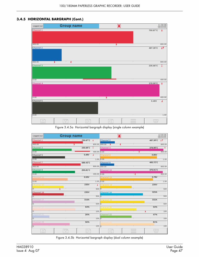
100/180MM PAPERLESS GRAPHIC RECORDER: USER GUIDE
HA028910Issue 4 Aug 07
User GuidePage 47
3.4.5 HORIZONTAL BARGRAPH (Cont.)
Group name 12:00:0906/04/05
Logged out
Channel 1
400.00 800.00
700.87˚CChannel 2
400.00 800.00
Channel 3 700.87˚CChannel 4
0.00 400.00
Channel 5
0.00 1.00
700.87˚CChannel 6
Channel 7
400.00 800.00
700.87˚CChannel 8
400.00 800.00
Channel 9
0.00 400.00
700.87˚CChannel 10
0.00 400.00
Channel 11
0.00 1.00
700.87˚CChannel 12
0.00 1.00
Channel 13
0 500
700.87˚CChannel 14
0 500
Channel 15
0 500
700.87˚CChannel 16
0 500
Channel 17
0 500
700.87˚CChannel 18
0 500
Channel 19
0 100
700.87˚CChannel 20
0 100
Channel 21
0 100
700.87˚CChannel 22
0 100
Channel 23
0 100
700.87˚CChannel 24
0 100
700.87˚C
235.68˚C
0.49V
689.43˚C
255.81˚C
0.53V
235V
235V
316A
64%
26%
56%
487.39˚C
378.99˚C
0.85V
483.72˚C
375.01˚C
0.79V
235V
320A
332A
54%
47%
81%
0.00 1.00
0.00 400.00
Group name 11:58:0806/04/05
Channel 1
400.00 800.00
700.87˚C
Channel 2
400.00 800.00
487.39˚C
Channel 3
0.00 400.00
235.68˚C
Channel 4
0.00 400.00
378.99˚C
Channel 5
0.00 1.00
0.49V
Logged out
Figure 3.4.5a Horizontal bargraph display (single column example)
Figure 3.4.5b Horizontal bargraph display (dual column example)

100/180MM PAPERLESS GRAPHIC RECORDER: USER GUIDE
User GuidePage 48
HA028910Issue 4 Aug 07
3.4 DISPLAY MODES (Cont.)
3.4.6 Numeric
Entered from Horizontal bargraph mode by means of the down arrow key, or selected using the Root Menu 'Goto View'key, this display mode shows the Process Variable (PV) values as digital values. The format (which is automaticallyselected) is based on the number of channels in the display group. Figures 3.4.6a, 3.4.6b and 3.4.6c, show typical(large frame) examples of the one, two and three column versions of this display mode respectively. Within each ver-sion, the process variable display areas expand or contract to fill the screen.
Trend history mode is not available from this display mode.
A further operation of the down arrow key returns to Vertical Trend Display mode described in section 3.4.1 above, orif user screens are fitted and enabled, to the first user screen (section 7). Alternatively, any one of the enabled displaymodes (section 4.3.4) can be selected using the Root Menu, 'Goto View' key.
Figure 3.4.6a Numeric display mode (1 to 5 channels example)
Note: Figures 3.4.6a, b and c apply to the large frame instrument. For the small frame instrument, the singlecolumn display (figure 3.4.6a) is used for groups with up to four points enabled, and the two column display(figure 3.4.6b) is used, with scroll bar if necessary, for groups with more than four points. The small framerecorder does not employ a three-column mode (figure 3.4.6c).
Group nameChannel 1
˚C
11:54:5006/04/05Logged out
Channel 2
˚C
Channel 4
Channel 5
487.39
˚C235.68
˚C378.99
V0.49
700.87
Channel 3

100/180MM PAPERLESS GRAPHIC RECORDER: USER GUIDE
HA028910Issue 4 Aug 07
User GuidePage 49
3.4.6 NUMERIC DISPLAY MODES (Cont.)
Group name 12:02:2706/04/05
Channel 1
Channel 3
Channel 5
Channel 2
Channel 4
Channel 6
˚C ˚C
˚C ˚C
V V
487.39
378.99
0.85
235.68
0.49
Logged out
700.87
Group nameChannel 1
700.87˚C
Channel 2
487.39˚C
Channel 3
235.68˚C
12:04:1306/04/05Logged out
Channel 4
378.99˚C
Channel 5
0.49V
Channel 6
0.85V
Channel 7
689.43˚C
Channel 8
483.72˚C 255.81˚C
Channel 10
375.01˚C
Channel 11
0.53V
Channel 12
0.79V
Channel 13
235V
Channel 14
235V
Channel 15
235V
Channel 16
320A
Channel 17
316A
Channel 18
331A
Channel 19
64%
Channel 9
Figure 3.4.6b Numeric display mode example (6 channels)
Figure 3.4.6c Numeric display mode example (19 channels)

100/180MM PAPERLESS GRAPHIC RECORDER: USER GUIDE
User GuidePage 50
HA028910Issue 4 Aug 07
3.5 OPERATOR NOTES
Note: Operator notes should not be confused with similar messages, (described in section 4.3.8), which appearas a result of job action.
It is possible for the user to enter a note, of up to 120 characters, at any time, from any display page (not from configu-ration pages). Each note is associated with the current display group and becomes a part of that group's history. Thenotes appear on vertical and horizontal trend displays only, although they can be entered in any display mode.The note appears on the chart and in the Message Log, preceded by the date, time and current full user name, as shownin the first example below. If 'Audit Trail' is enabled, the note contains audit trail information, as shown in the secondexample below. See section 4.4.2 for details of the Auditor options.
Date and time MessageFull user name
06/04/06 13:51:11 Frederick Bloggs, New Spray nozzles fitted to Line A, Tube 1.
Date and time MessageAudit trail information (if enabled)
06/04/06 13:51:11 Note, Signed:Engineer,Authorized:Engineer,New Spray nozzles fitted to Line A, Tube 1.
To enter a message:1. Press the Option key, then the 'Note' key2. If necessary enter Signature and Authorization passwords (Auditor 21CFR11 option only - see section 4.4.2).3. Touch the note area of the resulting pop-up display (see note below).4. Enter the required text of up to 120 characters (spaces are also counted as characters). Press Ok when finished.5. View the note and
a. press the Ok button to enter the note ORb. re-touch the text area to edit the note ORc. press the Cancel key to quit note entry.
Note
Operator Note
OptionKey
Option Menu
Batch
Note
Faceplates On/Off
Enter History
Channel Cycling Off00:0A:8D:00:20:A0
AM Shift started
AM Shift finished
PM Shift started
PM Shift finished
Operator Notes list.Appears if note area is touched contin-uously for 2 seconds (approx).List entries are made in InstrumentConfiguration (section 4.3.1)
Figure 3.5 Access to Note entry page
Note: Touching the note area continuously for two seconds or more, causes a list of pre-defined messages toappear. Touching one of these messages selects it as the operator note, which can then be edited in the normalway (if required) before the OK key is operated. There are a maximum of 13 pre-defined messages, 12 ofwhich are user editable in the Configuration/instrument menu (section 4.3.1), the 13th being the non-editableMAC address of the recorder.

100/180MM PAPERLESS GRAPHIC RECORDER: USER GUIDE
HA028910Issue 4 Aug 07
User GuidePage 51
4 SETTING UP THE RECORDER
As described in the 'Access to Configuration' (section 3.3.1) above, the setting-up of the recorder is divided into thefollowing areas:Archive Section 4.1 - Allows manual archiving of data to a memory device or to a remote host (FTP transfer).Save/restore Section 4.2 - Allows new configurations to be created and saved, and saved configurations to be 're-
stored'. Save/Restore also allows the importing and exporting of User Linearisation Tables and, if therelevant options are fitted, User Screens and Printer Drivers.
Config Section 4.3 - This is the major channel/alarm option etc. area of configuration.Security Section 4.4 - Allows passwords to be entered and edited and allows the Engineer-level password holder
to enable/disable areas of configuration to Operator-level password holders. New users can be added,with their own user names, passwords and access level permissions.
Network Section 4.5 - This area sets up the IP address/host names etc. used in FTP transfer, Bridge and SNTPapplications.
System Section 4.6 - Allowsa) Time and date to be set (Clock).b) Language, date/time format, time zone, and daylight saving start and finish dates to be set (Locale).c) Software upgrades to be carried out (Upgrade).d) Input channels to be adjusted for errors in transducer inputs (Input Adjust).e) Output channels (if fitted) to be adjusted (Output Adjust - see section 9.4).f) A Master Comms Diagnostics page to be displayed (if Master Comms option fitted and enabled).g) A Network diagnostics page to be displayed (Ethernet diagnostics).h) Configuration items (e.g. input channels) to be copied, to speed up configuration (Copy).i) Search criteria to be entered to allow the user to locate trigger sources for a specific job (Job
search).j) The appearance of the display screens to be customised (Customise).k) Details of the hardware and software associated with the recorder to be displayed (About).
Note: In all the following descriptions, if a change is made to a menu item, then the item text changes to red,until it is 'applied'

100/180MM PAPERLESS GRAPHIC RECORDER: USER GUIDE
User GuidePage 52
HA028910Issue 4 Aug 07
4.1 ARCHIVE
Notes:1. The archiving functions described below can also be initiated by job action - see section 4.7.15.2. Archiving is carried out on a group by group basis, with a message being sent to each group when its ar-
chive is finished. When all the groups have been archived, a pop-up appears to inform the user that ar-chiving is complete. Because of the sequential nature of this process, the time given in this pop-up isdifferent from the times which appear in the messages generated for the individual groups.
3. For floppy disk drives (connected via a USB port), it is not recommended that archiving be enabled formore than one group (see 'Group' configuration - section 4.3.2)
4.1.1 Local Archive
CautionRemoval of the memory device whilst archiving is in progress causes irreparable damage to the filing structureon the device, rendering it unusable. For this reason, archiving should be suspended before the device is re-moved. It is strongly recommended that the 'Remove Media' facility described in section 3.1.4 (Summarymenu) be used to ensure that it is safe to remove the memory device. For recorders fitted with a lockable flap,see also section 2.4.
Figure 4.1.1 Local archive configuration
Local archive allows the user to initiate data transfer to the device defined in the 'Media' picklist for all groups with'Archive to Media' enabled (Group configuration - section 4.3.2). Archiving is initiated by touching the relevant ar-chive period key (e.g. Last Day'). The memory device can be selected as 'mediacard' (the integral Compact Flash or SDcard), or a USB port can be selected if, for example, a memory stick is to be the destination device. USBfront is lo-cated behind the flap below the screen. If the option is fitted, USB 1 and USB 2 ports are located at the recorder rearpanel.
Archiving starts as soon as the selection is made, and cannot be stopped until completed, unless the Cancel Archive keyis operated, in which case the archive will be stopped after a confirmatory message has been responded to. The Cancelkey is active only if 'Archiving Control' is enabled in Security/Access (section 4.4) for the current login.
Archive SystemSave/Restore Config Security Network
Section 4.1.2
Last Archive
Archive Last Hour
Bytes
Bytes
Archive Last Day
Archive Last 7 Days
Archive Last 31 Days
Archive All
Suspend Archiving
Cancel Archive
Bring Archive Up To Date
Archive Transfer
Media Size
Free Space
Inactive
31954944
28786688
13/09/2005 11:02:42
Media mediacard Select Media card or USB port
Media Full 08/09/2006 00:34:57
Local
Remote

100/180MM PAPERLESS GRAPHIC RECORDER: USER GUIDE
HA028910Issue 4 Aug 07
User GuidePage 53
4.1.1 LOCAL ARCHIVE (Cont.)
BRING ARCHIVE UP TO DATEThis causes the recorder to archive all history files created since the last manual or automatic (section 4.3.5) archive.
ARCHIVE ALLThis causes the recorder to archive all its history files.
If the memory device becomes full before archiving is complete, archiving pauses and a pop-up request appears, askingfor a replacement. If this request is not responded to within 10 minutes of its appearance, archiving is aborted.
Unattended archiving can be paused by the user (e.g. to change media without losing data) by operating the 'SuspendArchiving' / 'Resume Archiving' button. Any archiving in progress is allowed to complete before the 'Suspend Archiv-ing' request takes effect. Transfer activity is indicated in the 'Archive transfer' window.
Below the selection buttons are a number of status windows relating to the selected memory device. 'Media Full' is anestimate, based on the current configuration, of when the memory device will become full. The meanings of the 'MediaSize' and 'Free Space' values are self evident.
If automatic archiving is active (section 4.3.5), then automatic and manual archives will operate on a first come-firstserved basis. Some files will be saved twice in such a circumstance, the later archive's files overwriting any earlierarchive's files which have the same name.
ARCHIVING WITH THE LOCKABLE FLAP OPTION
For recorders fitted with the lockable flap (section 2.4) it should be noted that when the flap is opened, archiving isautomatically suspended. It is therefore necessary to press on the ‘Resume Archiving’ key before any attempt is madeto carry out a demand archive.
Before removing the memory device, archiving should be suspended again, using the ‘Suspend Archive’ key. Thisensures that the memory device can be safely removed.
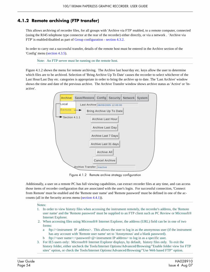
100/180MM PAPERLESS GRAPHIC RECORDER: USER GUIDE
User GuidePage 54
HA028910Issue 4 Aug 07
4.1.2 Remote archiving (FTP transfer)
This allows archiving of recorder files, for all groups with 'Archive via FTP' enabled, to a remote computer, connected(using the RJ45 telephone type connector at the rear of the recorder) either directly, or via a network . 'Archive viaFTP' is enabled/disabled as part of Group configuration - section 4.3.2.
In order to carry out a successful transfer, details of the remote host must be entered in the Archive section of the'Config' menu (section 4.3.5).
Note: An FTP server must be running on the remote host.
Figure 4.1.2 shows the menu for remote archiving. The Archive last hour/day etc. keys allow the user to determinewhich files are to be archived. Selection of 'Bring Archive Up To Date' causes the recorder to select whichever of theLast Hour/Last Day etc. categories is appropriate in order to bring the archive up to date. The 'Last Archive' windowshows the time and date of the previous archive. The Archive Transfer window shows archive status as 'Active' or 'In-active'.
Archive SystemSave/Restore Config Security Network
Section 4.1.1
Last Archive
Archive Last Hour
Archive Transfer
Archive Last Day
Archive Last 7 Days
Archive Last 31 days
Archive All
Cancel Archive
Bring Archive Up To Date
08/09/2005 12:00:00
Inactive
Local
Remote
Figure 4.1.2 Remote archive strategy configuration
Additionally, a user on a remote PC has full viewing capabilities, can extract recorder files at any time, and can accessthose items of recorder configuration that are associated with the user's login. For successful connection, 'Connectfrom Remote' must be enabled and the 'Remote user name' and 'Remote password' must be defined in one of the ac-counts (all in the Security access menu (section 4.4.1)).
Notes:1. In order to view history files when accessing the instrument remotely, the recorder's address, the 'Remote
user name' and the 'Remote password' must be supplied to an FTP client such as PC Review or Microsoft®Internet Explorer.
2. When accessing files using Microsoft® Internet Explorer, the address (URL) field can be in one of twoforms:a ftp://<instrument IP address>. This allows the user to log in as the anonymous user (if the instrument
has any account with 'Remote user name' set to 'Anonymous' and a blank password).b ftp://<user name>:<password>@<instrument IP address> to log in as a specific user.
3. For IE5 users only: Microsoft® Internet Explorer displays, by default, history files only. To exit thehistory folder, either uncheck the Tools/Internet Options/Advanced/Browsing/"Enable folder view for FTPsites" option, or check the Tools/Internet Options/Advanced/Browsing/"Use Web based FTP" option.

100/180MM PAPERLESS GRAPHIC RECORDER: USER GUIDE
HA028910Issue 4 Aug 07
User GuidePage 55
4.2 SAVE / RESTORE
As shown in figure 4.2a, touching the 'Save/Restore' key calls the picklist: Save, Restore, New, Text, Import/ExportScreen, Import/Export User Linearisation, Import Printer Driver. Import/Export Screen choices appear only if the Userscreens option is fitted.
Save
Restore
New
Text
File Name
Network Data
Screen Data
Security Data
Configuration Data
Restore
New/Default
Network Data
Screen Data
Security Data
Configuration Data
File Name
Save As Text
Archive SystemSave/Restore Config Security Network
Import Screen
Export Screen
See 'Screen Builder'description (section 7).
Import User Linearisation
Export User Linearisation
User Linearisation
File Name
Import
1) UserLin1
userlin
Export
Import Printer Driver
See 'ASCII Printer Out-put option' description
(section 12)
File Name
Save
Save as
config
config
6100A
Figure 4.2a Save/Restore menu
Where a file name is required, then, if the displayed file name is suitable, operation of the 'Save', 'Restore', 'Import' or'Export' key will initiate the action. If, instead, a file name has to be entered, this is carried out as follows:
Touching the filename window causes a pop-up menu to appear, giving a list of 'Volumes' in the Flash memory or onthe memory device (if inserted). Figure 4.2b shows an imaginary Volume contents list, displayed by touching the name'user', then operating the down arrow or 'open folder' key. (See section 5, below for more details). Once the correctfolder is open, either select an existing file, or enter a new filename, by touching the FileName window and enteringthe name using the pop-up keyboard(s) as described in section 3.3.1 above. Operation of the Save/Restore key initiatesthe action.
Hide\user\
TypeName
cal\config\
lib\
FolderFolder
Folder
Save CancelFileName Filter1b
sdb\ Folder
user\ Folder
Date
03/04/05 12:35:0801/04/05 10:27:13
05/03/05 10:23:14
11/02/05 14:01:0806/04/05 15:41:30
Filter1a Config 05/03/05 10:22:23
Bytes
4445
Figure 4.2b Typical volume contents page

100/180MM PAPERLESS GRAPHIC RECORDER: USER GUIDE
User GuidePage 56
HA028910Issue 4 Aug 07
4.2.1 Save
Touching this item allows the current configuration to be saved in the recorder's memory. Files saved in this way arenot in a 'readable' format and are used only for archive /security purposes or for transfer to another, similar, recorder.
SAVE AS This selection box allows a configuration to be saved, if required, in a format suitable for importing into previous re-corder models. The default is always the current instrument.
4.2.2 Restore
Touching this item allows the user to select or type-in a previously saved configuration file name, which will then beused as the current configuration. Touching the 'Restore' key completes the operation. Check boxes allow one or moreof Configuration Data, Security data (note 3), Network data and Screen data to be chosen for the restore function.
Notes:1 Screen data restores faceplate status for vertical trend and vertical bargraph modes, and user screen infor-
mation (if the option is fitted).2. If archiving is in progress when a 'Restore' is requested, the Restore operation will be delayed until the
archive is complete (maybe several minutes). If required, the 'Cancel Archive' key (section 4.1 above) canbe used to speed up the Restore process, at the cost of losing the archive data.
3. If 'Centralised Security' is active (part of Security/Management configuration - section 4.4.2) 'SecurityData' is not selectable (either for 'Restore' or for 'New' (below)).
4.2.3 New
Touching this item causes the factory entered default configuration to be loaded for use, or for editing. Operation of theNew/Default key completes the operation. Tick boxes allow one or more of Configuration Data, Security data (note 3above) and Network data to be chosen for the restore default function; only those items which are ticked are replacedby default values.
For recorders with the User Screens option (section 7), a further tick box is displayed - 'Screen Data'
4.2.4 Text
This is identical to the 'Save' function described above, but the configuration is saved in ASCII format, and can betransferred to a computer and read, printed etc. as required. It is not possible, using this means, to modify the configu-ration and then re-load it.
4.2.5 Import screen
This field appears only if the User Screens option (section 7) is fitted, and allows a previously exported User Screenfile to be imported.

100/180MM PAPERLESS GRAPHIC RECORDER: USER GUIDE
HA028910Issue 4 Aug 07
User GuidePage 57
4.2.6 Export screen
This field appears only if the User Screens option (section 7) is fitted, and allows a User Screen to be exported to aremovable memory device or to the internal Flash memory. The exported screen can subsequently be imported eitherinto this recorder or into a different recorder.
4.2.7 Import User Linearisation
User LinearisationFile Name
Import
1) UserLin1
userlin
The Import Linearisation feature allows linearisation tables to be imported either from the Compact Flash/SD card,USB device or if Bridge 'Full' software is fitted, directly from the host PC.
Touching the User Linearisation field allows the user to select which of 'UserLin1' to 'UserLin4' is to contain the im-ported file.
Touching the File Name field, calls a popup menu similar to that shown in figure 4.2b. This allows the user to select thetable to be imported.
The file must be comma separated ASCII as follows:n,X1,Y1X2.Y2X3,Y3 . .Xn,Ynwhere 'n' is the total number of XY pairs in the table, and or each pair, X is the input value, and Y is the linearised valuecorresponding to X. See section 4.3.9 for full details.
Note: Imported linearisation tables will not become effective until after the next configuration 'Apply' opera-tion.
4.2.8 Export User Linearisation
Similar to 'Import user Linearisation', above, the Export Linearisation feature allows linearisation tables created in therecorder to be exported either via the Compact Flash/SD card or if Bridge 'Full' software is fitted, directly to the hostPC. See section 4.3.9 for full details.
4.2.9 Import printer driver
Similar to 'Import user Linearisation', above, this allows driver (.uhi) files for new printer types to be imported eithervia the Compact Flash/SD card, or USB memory stick, or if the Bridge 'Full' option is fitted, directly from the host PC.See section 12 for further details.
Note: Imported printer drivers do not become effective until after the next configuration 'Apply' operation.

100/180MM PAPERLESS GRAPHIC RECORDER: USER GUIDE
User GuidePage 58
HA028910Issue 4 Aug 07
4.3 CONFIG KEY
Touching this key calls the top level configuration pick list:
Instrument,Groups,Channels,Views,Archive,Events,Event Buttons,
Messages,User Linearisations,Batch,Maths,Totalisers,Counters,Timers,
Connections,Master Comms,Output Channels,Demand Writes,Emails,Reports.
Notes:1. Figure 4.3b gives an overview of the configuration menus.2. If an option is not fitted, it does not appear in the above list.
When making changes to the configuration the name of each changed parameter is displayed in red (instead of the nor-mal black) until the 'Apply/Discard' key has been operated. For example, in channel configuration, if a thermocouplewere to be changed from Type J to Type K, 'Lin Type' would appear in red, until the Apply key is operated.
Should an attempt be made to leave configuration with unsaved changes, a warning message appears, allowing the userto apply the changes, to discard the changes or to return to configuration (Cancel).
Config
Apply Discard Cancel
Data Has Been Modified

100/180MM PAPERLESS GRAPHIC RECORDER: USER GUIDE
HA028910Issue 4 Aug 07
User GuidePage 59
4.3 CONFIG KEY (Cont.)
Ap
ply
Dis
card
Ala
rm M
ess
ag
e
Re
cord
ing
Sp
ee
dR
eco
rdin
g I
nte
rva
l
Arc
hiv
e t
o M
ed
ia E
na
ble
Arc
hiv
e v
ia F
TP
En
ab
le
Tre
nd
His
tory
Du
rati
on
Re
cord
ing
En
ab
le
Ack
Me
ssa
ge
Tu
rbin
eT
em
pA
Tu
rbin
eT
em
pB
Etc
.11,2
00
mm
/hr
s
List
of a
ll av
aila
ble
poin
ts(in
put c
hann
els,
mat
hsch
anne
ls, t
otal
iser
s et
c.).
25
.96
Da
ys
Tre
nd
Un
its
De
scri
pto
r
Tre
nd
Sp
ee
dT
ren
d I
nte
rva
l
Gro
up
Nu
mb
er
Tre
nd
Typ
e
mm
/hr
11,2
00
mm
/hr
s
Gro
up
1
1)
Gro
up
1
Ad
ap
tive
Cir
cula
r S
ett
ing
s
Gri
d T
ype
Fro
m P
oin
t
fro
mC
ha
nn
el 3
A/B
Sw
itch
ing
Po
int
Typ
eC
ha
nn
el
Se
lect
ion
1-3
,7,9
,11
-20
En
ab
le
Dis
ab
le
%
%
Min
ute
s
s
= D
isa
ble
d
0 0
Inst
rum
en
t N
am
eIn
stru
me
nt
No
rma
l Dis
pla
y1
00
Sa
ver
Dis
pla
y5
0S
ave
Aft
er
30
Mo
db
us
Ad
dre
ss1
Mo
db
us
Se
curi
ty D
isa
ble
dC
om
ms
Ch
an
ne
l Tim
eo
ut
0P
rese
t H
ou
r1
2P
rese
t M
inu
te0
Dis
ab
le W
arn
ing
Dia
log
sS
ho
w O
pe
rato
r N
ote
s L
ist
Ap
ply
Dis
card
On
Me
dia
Fu
ll
Me
dia
Siz
e3
0.4
74
60
94
Mb
Ov
erw
rite
Me
dia
Fu
ll e
ven
t lim
it
Re
mo
vab
le M
ed
ia C
ap
aci
ty3
3.1
8D
ays
10
0%
Arc
hiv
e t
o M
ed
ia
Co
mp
ress
ion
No
rma
l
Fla
sh S
ize
99
.25
Mb
Sh
ort
est
Tre
nd
His
tory
Gro
up
1
Sh
ow
Lo
ca
l s
ett
ing
s
Du
rati
on
26
.95
Da
ys
No
ne
Me
dia
file
fo
rma
tB
ina
ry
Me
dia
me
dia
ca
rd
Ap
ply
Dis
card
Job
Nu
mb
er
1
Ca
t eg
ory
No
Act
ion
Max
Dec
imal
Dig
its4
Co
lou
rA
larm
Nu
mb
er
1
En
ab
leO
f f
26
PV
Fo
rma
tN
um
eri
c
Va
lue
5.0
00
2
Inp
ut
Typ
eT
he
rmo
cou
ple
Lin
Typ
eT
ype
K
Ra
ng
e L
ow
0C
Ra
ng
e H
igh
10
0C
Ra
ng
e U
nit
sC
Sca
led
Off
set
0V
Filt
er
No
ne
Bre
ak
Re
spo
nse
No
ne
Col
d Ju
nctio
n T
ype
Off
De
scri
pto
rT
urb
ine
Te
mp
A
Sp
an
ne
d
Ch
an
ne
l N
um
be
r1
) T
urb
ine
Te
mp
A
07
/04
/05
08
:46
:45
Sca
le T
ype
No
ne
A/B
Sw
itch
ing
Zo
ne
Lo
w0
%
Zo
ne
Hig
h%
10
0
Gro
up
s(S
ect
ion
4.3
.2)
Vie
ws
(Se
ctio
n 4
.3.4
)
Ho
me
Tim
e-o
ut
Ho
me
Gro
up
Sco
pe
Gro
up
Dis
pla
y E
na
ble
Ho
me
Pa
ge
Ve
rtic
al
Tre
nd
Ho
rizo
nta
l T
ren
d
Ve
rtic
al
Ba
rgra
ph
Ho
rizo
nta
l B
arg
rap
hN
um
eri
c P
ag
eU
ser
Scr
ee
n 1
Use
r S
cre
en
2U
ser
Scr
ee
n 3
Use
r S
cre
en
4
1)
Gro
up
1
0 Gro
up
1)
Gro
up
1
Cir
cula
r T
ren
d
Min
ute
s
Cir
cula
r T
ren
d
Use
r S
cre
en
5
Ap
ply
Dis
card
Lo
cal
Arc
hiv
e(S
ect
ion
4.3
.5)
Re
mo
te
Arc
hiv
e t
o R
em
ote
No
ne
Re
mo
te p
ath
Sh
ow
Re
mo
te s
ett
ing
s
0.0
.0.0
Pri
ma
ry r
em
ote
ho
st
Pri
ma
ry lo
gin
na
me
an
on
ym
ou
s
Pri
ma
ry p
ass
wo
rd* *
* **
Re
typ
e p
ass
wo
rd* *
* **
0.0
.0.0
Se
con
da
ry r
em
ote
ho
stS
eco
nd
ary
log
in n
am
ea
no
ny
mo
us
Se
con
da
ry p
ass
wo
rd**
***
Re
t yp
e p
ass
wo
rd**
***
/ re
co
rde
r /G
rou
p1
Co
mp
ress
ion
No
rma
l
Fla
sh S
ize
99
.25
Mb
Sh
ort
est
Tre
nd
His
tory
Gro
up
1
Du
rati
on
10
8.0
6D
ays
Ftp
File
fo
rma
tB
ina
ry
Ap
ply
Dis
card
Inst
rum
en
t(S
ect
ion
4.3
.1)
Se
e s
he
ets
2 t
o 4
for
furt
he
r it
em
s
Arc
hiv
eS
yste
mS
ave
/Re
sto
reC
on
fig
Se
curi
tyN
etw
ork
Ch
an
ne
ls(S
ect
ion
4.3
.3)
Ap
ply
Dis
card
Eve
nt
Nu
mb
er
1)
Eve
nt
1
So
urc
e 1
De
scri
pto
rE
ven
t 1
Job
Nu
mb
er
1
Ca
teg
ory
No
Act
ion
Ala
rm o
n G
rou
p
On
Gro
up
1)
Gro
up
1
So
urc
e 2
Po
int
Ala
rm
On
Ma
th 1
2
Ala
rm2
So
urc
e 1
Se
nse
Op
era
tor
So
urc
e 2
Se
nse
So
urc
e 1
An
d
No
t S
ou
rce
2
Inst
rum
en
t
Gro
up
s
Ch
an
ne
ls
Vie
ws
Arc
hiv
e
Eve
nts
Bri
dg
e U
ser
Scr
ee
ns
0
Eve
nts
(Se
ctio
n 4
.3.6
)
Ap
ply
Dis
card
Figu
re 4
.3b
Con
figur
atio
n m
enu
over
view
she
et 1

100/180MM PAPERLESS GRAPHIC RECORDER: USER GUIDE
User GuidePage 60
HA028910Issue 4 Aug 07
4.3 CONFIG KEY (Cont.)
Ena
ble
Bat
ch m
ode
Bat
ch F
ield
sF
ield
1
On
star
t log
4
On
stop
log
On
new
cle
ar14
Nam
e fil
es b
y ba
tch
Sta
rt/S
top
4 Bat
ch N
umbe
r:
Ap
ply
Dis
card
Gro
up
Sco
peG
roup
1) G
roup
1
Bat
ch fi
eld
1U
se C
ount
er
Cou
nter
Cou
nter
1
Fie
ld 2
Cus
tom
er N
ame:
Fie
ld 3
Ope
rato
r N
ame:
Fie
ld 4
Sup
ervi
sor:
Sho
w B
atch
Ent
ry L
ist
Me
ssa
ge
Nu
mb
er
Me
ssa
ge
Re
pla
ce
1
wit
h
Re
pla
ce
2
wit
h
Re
pla
ce
3
wit
h3
so
urc
eR
ep
lace
4
w
ith
4
sou
rce
Re
pla
ce
5
wit
hR
ep
lace
6
w
ith
1)
Th
e v
alu
e o
f
Th
e v
alu
e o
f 1
=
2
&
3
=
4
,
5
So
urc
e D
esc
rip
tor
So
urc
e V
alu
e
To
tal is
er
1
Sp
eci
fied
De
scri
pto
r
To
tal is
er
1
Sp
eci
fied
Va
lue
Co
nfig
Re
visi
on
Bla
nk
Ap
ply
Dis
card
Me
ssa
ge
s (S
ect
ion
4.3
.8)
Bu
tto
n N
um
be
r
De
scri
pto
rT
ype
Te
xtL
atc
he
d T
ext
Re
qu
ire
Sig
nin
g
Re
qu
ire
Au
tho
risa
tio
n
Ap
ply
Dis
card
1)
Bu
tto
n 1
Bu
tto
n 1
La
tch
ed
Off
Te
xt
On
Te
xt
Use
r L
ine
ari
satio
n
De
scri
pto
r
Fo
rma
t
Nu
mb
er
of
Po
ints X1
Y1
X2
3)
Use
rLin
3
Nu
me
ric
2 0 0 1
Y2
1Use
rLin
3
Ap
ply
Dis
card
Use
r L
ine
ari
satio
ns
(Se
ctio
n 4
.3.9
)
Arc
hiv
eS
yste
mS
ave
/Re
sto
reC
on
fig
Se
curi
tyN
etw
ork
Eve
nt
Bu
tto
ns
(Se
ctio
n 4
.3.7
)
App
lyD
isca
rd
Fu
nct
ion
fVa
lue
Fva
lue
of
Ste
riliz
ing
Te
mp
12
1.1
Lo
w c
ut
off
De
scri
pto
rF
o 1
Sca
le L
ow
0M
ins
Sca
le T
ype
No
ne
Zo
ne
low
0
Zo
ne
hig
h
Max
Dec
imal
Dig
its2
Co
lou
rA
larm
Nu
mb
er
1
En
ab
leO
ff
Job
Nu
mb
er
1
Ca
t eg
ory
No
Act
ion
26Ch
an
ne
l 1
75
%
10
0%
Ma
ths
Nu
mb
er
1)
Fo
1
Va
lue
32
.65 R
eset
now
Min
s
PV
Fo
rma
tN
um
eri
c
Te
mp
era
ture
in
terv
al
10
Un
its
Min
s
Sca
le h
igh
60
A/B
Sw
itch
ing
Min
s
Ap
ply
Dis
card
To
tal is
er
Nu
mb
er
En
ab
le
Ala
rm N
um
be
rE
na
ble
Job
Nu
mb
er
Ca
teg
ory
Va
lue
To
tal o
fL
ow
cu
t o
ffH
igh
cu
t o
ffU
nit
sP
rese
t
Pre
set n
ow
12
34
56
ch u
nits
ch u
nits
Un
its (
tota
l ise
r)
Pe
rio
d s
cale
rU
nit
sca
ler
De
scri
pto
r
Un
its (
tota
lise
r)
Sca
le L
ow
Sca
le H
igh
Un
its (
tota
lise
r)
Un
its (
tota
lise
r)
Zo
ne
Lo
wZ
on
e H
igh
% %
Max
Dec
imal
Dig
itsC
olo
ur
Sca
le T
ype
No
ne
PV
fo
rma
t
A/B
Sw
itch
ing
1)
To
tal is
er
1
1 Off
1 No
Act
ion
Ch
an
ne
l 1
0 99
99
99
Un
its
0 1 1 To
talis
er
1
0 1 1 10
0
4 0Nu
me
ric
Eve
nt
Bu
tto
ns
Me
ssa
ge
s
Use
r L
ine
ari
satio
ns
Ba
tch
Ma
ths
To
tal is
ers
Ba
tch
(o
ptio
n)
Se
ctio
n 4
.3.1
0M
ath
s (o
ptio
n)
Se
ctio
n 4
.3.1
1
To
tal is
er
(op
tion
)S
ect
ion
4.3
.12
Figu
re 4
.3b
Con
figur
atio
n m
enu
over
view
she
et 2

100/180MM PAPERLESS GRAPHIC RECORDER: USER GUIDE
HA028910Issue 4 Aug 07
User GuidePage 61
4.3 CONFIG KEY (Cont.)A
rch
ive
Sys
tem
Sa
ve/R
est
ore
Co
nfi
gS
ecu
rity
Ne
two
rk
Tim
er
nu
mb
er
1)
Tim
er
1
En
ab
leR
em
ain
ing S
tart
now
00
:00
:00
De
scri
pto
rT
ime
r 1
Se
lf s
tart
Da
teM
on
th
Re
pe
at
in0
0:0
0:0
0
Res
et n
ow
An
y
An
y
Ap
ply
Dis
card
Se
con
dD
ura
tio
n
Job
Nu
mb
er
Min
ute
Re
pe
at
aft
er
1
Ca
teg
ory
No
Act
ion
Ho
ur
Mid
nig
ht
An
y
An
y
60
Se
con
ds
0S
eco
nd
s
The
se fi
elds
app
ear
only
if 'S
elf s
tart
' is
enab
led.
The
se b
utto
ns a
ppea
ron
ly a
fter
'App
ly' h
asbe
en o
pera
ted
Ap
ply
Dis
card
Co
un
ter
nu
mb
er
En
ab
le
Ala
rm N
um
be
rE
na
ble
Job
Nu
mb
er
Ca
teg
ory
Va
lue
Un
its
Pre
set
Pre
set n
ow
Un
its
De
scri
pto
r
Un
its
Sca
le L
ow
Sca
le H
igh
Un
its
Un
its
Zo
ne
Lo
wZ
on
e H
igh
% %
Co
lou
r
Sca
le T
ype
No
ne
A/B
S
wit
chin
g
1)
Co
un
ter
1
1 Off
1 No
Act
ion
OF
F
Un
its
0 Co
un
ter
1
0 1 0 10
0
0
Pro
toco
l
Lin
k E
rro
r C
ou
nt
Re
set
Err
or
Co
un
t
On
line
Co
nn
ect
ion
Po
rt
Ba
ud
Ra
te
Sto
p B
its
Pa
rity
Pri
nte
r T
ype
Pri
nte
r N
am
e
Pri
nte
r S
tatu
s
Sys
tem
Ala
rms
Po
we
r U
p
Pri
nte
r T
est
Prin
t Mes
sage
s F
rom
Me
ssa
ge
s T
o P
rin
t
Ge
ne
ral
Ba
tch
es
Lo
gin
s
Ap
ply
Dis
card
Sig
nin
gs
Au
dit
Tra
il
AS
CII
Pri
nte
r
0 EIA
23
2
Se
ria
l 1
96
00
1 Eve
n
Sta
r T
SP
60
0
Sta
r T
SP
60
0(1
)
No
t R
esp
on
din
g
1)
Gro
up
1
AS
CII
Prin
ter
Ap
ply
Dis
card
25
0
Ba
ud
Ra
te
Pa
rity
Da
ta B
its
Tim
eo
ut
Fir
st S
tart
Ch
ar
Se
con
d S
tart
Ch
ar
Fir
st E
nd
Ch
ar
Se
con
d E
nd
Ch
ar
Gro
up
1
Gro
up
2
Gro
up
3
Gro
up
4
Gro
up
5
Gro
up
6
19
20
0
1 No
ne
8m
s
0 13
Lin
k E
rro
r C
ou
nt
0 0 10
Re
set
Err
or
Co
un
t
Pro
toco
lA
SC
II (
inp
ut)
Po
rtS
eri
al 1
Co
nn
ect
ion
EIA
23
2
Sto
p B
its
AS
CII
Inpu
t
Ap
ply
Dis
card
Ba
ud
Ra
te
Sto
p B
its
Pa
rity
Tim
eo
ut
ms
En
ab
le e
rro
r co
de
BE
na
ble
Ta
lk T
hro
ug
h
Pro
toco
l
Lin
k E
rro
r C
ou
nt
Re
set
Err
or
Co
un
t
Co
nn
ect
ion
Po
rt
19
20
0
1 No
ne
10
00
Mo
db
us
Ma
ste
r
0 EIA
23
2
Se
ria
l 1
Mod
bus
Mas
ter
Ap
ply
Dis
card
Ba
ud
Ra
te
Sto
p B
its
Pa
rity
Pro
toco
l
Lin
k E
rro
r C
ou
nt
Re
set
Err
or
Co
un
t
Co
nn
ect
ion
Po
rt
19
20
0
1 No
ne
Mo
db
us
Sla
ve
0 EIA
23
2
Se
ria
l 1Mod
bus
Sla
ve
Det
ect T
his
Sla
ve
Hig
h P
riorit
y in
terv
alM
ediu
m p
riorit
y in
terv
alLo
w p
riorit
y in
terv
alS
tore
dia
gnos
tics
Sla
veE
nabl
eO
nlin
eD
escr
ipto
rN
etw
ork
IP A
ddre
ssM
odbu
s ad
dres
s
Pro
file
Tim
eout
Ret
ryM
ax B
lock
Siz
eS
hare
Soc
ket
Logi
n R
equi
red
Use
rnam
eP
assw
ord
0.12
51 2 1)
Rem
ote_
1
Rem
ote_
1
149.
121.
30.0
Eth
erne
t
1 Thi
rd P
arty
250
3 124
ms
Reg
iste
r
Sec
onds
Sec
onds
Sec
onds
Use
rnam
e**
****
**
Det
ect A
ll S
lave
sD
isca
rdA
pply
Co
un
ters
Tim
ers
Co
nn
ect
ion
s
Ma
ste
r C
om
ms
Co
un
ters
(o
ptio
n)
Se
ctio
n 4
.3.1
3
Tim
ers
Se
ctio
n 4
.3.1
4
Connections (option)Section 4.3.15
Ma
ste
r C
om
ms
(op
tion
)S
ect
ion
4.3
.16
Figu
re 4
.3b
Con
figur
atio
n m
enu
over
view
she
et 3

100/180MM PAPERLESS GRAPHIC RECORDER: USER GUIDE
User GuidePage 62
HA028910Issue 4 Aug 07
4.3 CONFIG KEY (Cont.)
Figu
re 4
.3b
Con
figur
atio
n m
enu
over
view
she
et 4
Ena
ble
Dem
and
Typ
e
Sta
tus
Ap
ply
Dis
card
Writ
e nu
mbe
r
Dem
and
Writ
e
Sla
ve
Par
amet
er
Poi
nt T
ype
Poi
nt N
umbe
r
Des
crip
tor
Sou
rce
Def
ault
Allo
w C
onst
ant E
dits
Dis
able
Ret
ries
Sen
d O
n P
ower
Up
On
Err
or W
rite
Def
ault
Mas
ter
Com
ms
1) W
rite
1
OK
1) F
urn
1 R
ecor
der
Ala
rm s
etpo
int 2
Cha
nnel
1 Writ
e 1
Cha
nnel
1
0
Re
po
rt
De
scri
pto
rN
um
be
r o
f F
ield
s
Fie
ld 1
Typ
e
Sty
le
1)
Re
po
rt 1
1 Da
te &
Tim
e
No
rma
l
Re
po
rt 1
Ap
ply
Dis
card
Re
po
rts
(Se
ctio
n 4
.3.2
0)
De
ma
nd
Wri
tes
(Se
ctio
n 4
.3.1
8)
(cu
rre
ntly
1)
(cu
rre
ntly
0)
Ap
ply
Dis
card
Au
toco
nfig
ure
Tria
l Mod
eD
isab
led
Tria
l Tim
e R
emai
ning
30 d
ay(s
)
Fitt
ed c
hann
els
18
Virt
ual c
hann
els
36
Mat
hs18
Tot
alis
ers
12
Cou
nter
s6
Gro
ups
12
Bat
chE
nabl
ed
Sec
urity
Man
ager
Dis
able
d
Aud
itor
21C
FR
11
Scr
een
Bui
lder
Ful
l
Brid
ge L
evel
Ful
l
Mas
ter
Com
ms
Dev
ices
16
Rel
ay B
oard
s2
Rel
ays
on B
oard
13
Rel
ays
on B
oard
24
Eve
nt In
put B
oard
s1
Ana
logu
e O
utpu
t Boa
rds
1
Se
e s
he
ets
1 t
o 3
fo
rp
revi
ou
s C
on
fig
ite
ms
Co
nfig
\Op
tion
s(S
ect
ion
4.3
.21
)
Mai
l Ser
ver
Por
t Num
ber
Sen
der
Err
ors
To
Ret
ry T
ime
Rec
ipie
nt L
ist
Des
crip
tor
Rcp
t1
Rcp
t2
Rcp
t3
Rcp
t4
Rcp
t5
Rcp
t6
Rcp
t7
Rcp
t8
Rcp
t9
Rcp
t10
Em
ail N
umbe
r
Des
crip
tor
Pro
toco
l
Sub
ject
Tex
t
Incl
ude
Mes
sage
Mes
sage
mai
l ser
ver
nam
e
25 IP A
ddre
ss o
f rec
orde
r
e-m
ail a
ddre
ss to
whi
ch e
-mai
l fai
lure
mes
sage
s to
be
sent
60S
econ
ds
1) L
ist1
List
1
e-m
ail a
ddre
ss o
f 1st
Rec
ipie
nt o
n th
is li
st
e-m
ail a
ddre
ss o
f 2nd
Rec
ipie
nt o
n th
is li
st
etc.
1) E
mai
l1
Em
ail1
SM
TP
(E
mai
l)
Col
d st
ore
alar
m
Col
d st
ore
tem
p. s
enso
r 1
too
hot.
Inst
rum
ent n
ame,
Inst
rum
ent n
umbe
r, c
han
1Ala
rm1
3)
1,
2,
3,
4
Sel
ect L
ist N
umbe
r
App
lyD
isca
rd
Ou
tpu
t ch
an
ne
ls
De
ma
nd
Wri
tes
Em
ails
Re
po
rts
Op
tio
ns
Arc
hiv
eS
yste
mS
ave
/Re
sto
reC
on
fig
Se
curi
tyN
etw
ork
Em
ail
(Se
ctio
n 4
.3.1
9)
Out
put C
hann
el N
umbe
rE
nabl
eO
utpu
t Typ
eS
lave
Par
amet
erS
calin
gS
cale
Low
Sca
le H
igh
Poi
nt T
ype
Poi
nt N
umbe
rP
roce
ss V
alue
Des
crip
tor
Sou
rce
Def
ault
On
Err
or W
rite
Def
ault
1) O
utpu
t 1
Dis
card
App
lyMas
ter
Com
ms
1) F
urn
Rec
orde
r 2
Com
ms
Cha
nnel
Cha
nnel
Med
ium
Prio
rity
1) C
hann
el 4
Hig
h/Lo
w0 10
0
01 Out
put 1
Ou
tpu
t ch
an
ne
ls(S
ect
ion
4.3
.17
)

100/180MM PAPERLESS GRAPHIC RECORDER: USER GUIDE
HA028910Issue 4 Aug 07
User GuidePage 63
4.3.1 Instrument configuration
Figure 4.3.1 Instrument Configuration menu
INSTRUMENT NAMEAllows the entry of an alphanumeric name for the recorder, up to 20 characters long. See section 3.3.1 for text entrytechniques.
NORMAL/SAVER DISPLAYAllows normal and 'saver' display brightnesses to be defined. Defaults are Normal = 100%; Saver = 50%
SAVE AFTERThe number of minutes (between 1 and 99 inclusive), which are to elapse after a screen operation, before the screenbrightness changes from 'normal' to 'saver'. Default is 30 minutes.
MODBUS ADDRESSAllows a Modbus address between 1 and 247 to be set up, for use when the instrument is acting as a Modbus slave.
MODBUS SECURITY DISABLEDWhen using MODBUS, it is possible, by 'checking' this field to allow a host computer to access the recorder without itsfirst having to supply a valid User name and Password. This box must be checked if this unit is acting as a Modbusslave in order for the unit to be detected. Once communications have been established, Modbus security can be ena-bled, providing that the Slave's Remote user name and password have been entered at the Master. See also section8.2.4.
COMMS CHANNEL TIMEOUTAllows a number of seconds (between 1 and 999) to be entered. If none of the channels set to 'Comms' is communi-cated with, within this period, an event source (Comms channel timeout) is set, and remains set until the next communi-cation. An entry of 0 disables the time out.
%
%
Minutes
s
= Disabled
0
0
Instrument Name InstrumentNormal Display 100
Saver Display 50Save After 30
Modbus Address 1Modbus Security DisabledComms Channel Timeout 0
Preset Hour 12Preset Minute 0
Disable Warning DialogsShow Operator Notes List
00:0A:8D:00:20:A0MAC Address
Operator Note 1
Operator Note 12
Apply Discard
These fields appear
only if 'Show Operator
Notes List' is enabled
AM Shift started

100/180MM PAPERLESS GRAPHIC RECORDER: USER GUIDE
User GuidePage 64
HA028910Issue 4 Aug 07
4.3.1 INSTRUMENT CONFIGURATION (Cont.)
PRESET HOUREnter an hours number between 0 and 23 for use with Clock Job - Preset clock.
PRESET MINUTEEnter a minutes number between 0 and 59 for use with Clock Job - Preset clock.
Note: See section 4.7 for a description of recorder jobs, and section 4.5.1 for further details of time synchroni-sation.
DISABLE WARNING DIALOGSChecking this box prevents instrument alarm messages from appearing on the screen.
SHOW OPERATOR NOTES LISTEnabling this field produces a list of 13 entries which can be used in Operator Notes. The first entry is the MAC ad-dress of the recorder and is not editable. The remaining 12 entries (of up to 60 characters each) are freely editable.
Any one of these predefined notes can be selected (as described in section 3.5) by touching the Operator Note areacontinuously for two seconds, then touching the required note from the picklist which appears. Once selected thepredefined note can be edited before use, like a normal Operator Note. Such editing does not affect the original noteentered here in Instrument Configuration.

100/180MM PAPERLESS GRAPHIC RECORDER: USER GUIDE
HA028910Issue 4 Aug 07
User GuidePage 65
4.3.2 Group configuration
Note: Groups 1 to 6 is a standard recorder feature. The supply of groups seven to twelve is an optional extra.
Group configuration allows the user to define the following:a Group trend speed/intervalb Group recording speed/intervalc Group descriptord Group contente Circular Trend speed and chart-full operationf Chart grid divisions
The production of alarm messages and the saving of group data to Flash memory, to removable memory device and/orto remote computer (FTP transfer) can also be enabled / disabled from this menu.
Grid Type Linear
Grid Divisions - Minor
Grid Divisions - Major 5
1
Apply Discard
Alarm Message
Recording SpeedRecording Interval
Archive to Media EnableArchive via FTP Enable
Trend History Duration
Recording Enable
Ack Message
TurbineTempATurbineTempB
= Enabled
Etc.
1
1,200 mm/hr
s
List of all available points(input channels, mathschannels, totalisers etc.).
314.36 DaysEditable only if'Recording Enable'is enabled.
Trend UnitsDescriptor
Trend SpeedTrend Interval
Group Number
Trend Type
Selectmm/hr or in/hr
mm/hr
1
1,200 mm/hr
s
Group 1
1) Group 1 Select Group
Adaptive
Select None, Linear, Logor 'From Point'
Circular Speed 1 week
Circular Chart Full New Chart
Start At Monday
Appear only if 'Circular Set-tings' enabled.
Circular Settings
Grid Type From Point
from Channel 3
A/B Switching
SelectNormal or Adaptive
Not editable if 'Circularsettings' enabled
Point Type Totaliser
Selection 1-3,5,7,9
Enable
Disable
Grid Type Log
Grid Decades 5
Figure 4.3.2a Group configuration menu

100/180MM PAPERLESS GRAPHIC RECORDER: USER GUIDE
User GuidePage 66
HA028910Issue 4 Aug 07
4.3.2 GROUP CONFIGURATION (Cont.)
GROUP NUMBERAllows a particular group to be selected for configuration.
TREND UNITSAllows mm/hr or inches per hour to be selected for the 'chart' speed. Automatically converts the trend speed field be-low.
DESCRIPTORAllows the group name to be edited. See section 3.3.1 for text entry techniques.
TREND TYPEThis allows the selection of Adaptive Recording for vertical and horizontal trend modes. The purpose of adaptive re-cording is to ensure that rapid, short duration spikes (for example), are represented on the 'chart' even at low trendspeeds. This allows the user to extend the total amount of history stored in the recorder (by using slow trend speeds)without losing transient data.
The adaptive recording method works by measuring the input signal at the normal 125 msec period, and saving themaximum and minimum values, continuously, over the period of trend update. When the trend is updated, both maxi-mum and minimum values are traced on the chart - i.e. two traces are produced for each channel in the group.
The faceplates and pen positions are still updated every second, as normal.
Notes:1 During the period between updates, the maximum and minimum values are shown on the trend as a hori-
zontal line just beneath the pen, where the ends of the line represent the minimum and maximum values sofar. This line is removed at trend update time.
2. Adaptive recording takes twice as much memory as normal recording, so to maintain the total amount ofhistory stored, the trend speed must be reduced to 50% of that which would be used for non-adaptive re-cording.
3. In Trend History mode, both minimum and maximum values for the cursor position are shown on thefaceplate. See section 3.4.1 for a description of trend history.
Figure 4.3.2b shows the difference between normal and adaptive recording, at slow trend rates. Note that rapid changesin signal, (such as those shown in the circled area of the 'actual signal') are largely filtered out by Normal Tracing, butis displayed by the Adaptive Trace. Figure 4.3.2b is for illustrative purposes only, as traces such as these could neverappear on the chart together.
Adaptive trace
Actual input signal
Normal trace
Max/Minbar
Figure 4.3.2b Adaptive recording compared with Normal tracing

100/180MM PAPERLESS GRAPHIC RECORDER: USER GUIDE
HA028910Issue 4 Aug 07
User GuidePage 67
4.3.2 GROUP CONFIGURATION (Cont.)
A/B SWITCHING If enabled, this function allows alternative values for Trend speed/interval and Recording speed/interval to be entered.'A' values are used during normal operation. 'B' values are switched-to by job action, as described in section 4.7.
TREND SPEED/TREND INTERVALAllows the 'chart' speed to be selected either as mm or in per hour, or as an interval. Entering a value in one field auto-matically converts the value in the other field. A trend interval of N seconds is equivalent to 1200/N mm/hr chartspeed; a chart speed of P mm/hr is equivalent to a trend interval of 1200/P seconds.
If A/B switching is enabled, a second Trend Speed /Interval value can be entered. Trend Speed/Interval 'A' is usedduring normal operation. Trend Speed/Interval 'B' is switched to by job action, as described in section 4.7.
Note: Trend speed/interval are not editable fields if 'Circular Settings' is enabled.
CIRCULAR SETTINGS When checked, this checkbox causes the Circular Speed/Chart Full/Start At fields, described below, to appear. Whenchecked, the Trend Speed and Trend Interval fields described above are disabled (i.e. they are no longer editable).
Notes: If Circular Settings is not enabled, here in Group configuration, but Circular Trend is enabled for thegroup in Views configuration (section 4.3.4), then, although the circular chart will appear, it is unlikely that thechart will contain any trends.
CIRCULAR SPEED This field allows the chart speed to be selected from a pick list, as detailed in table 4.3.2, below. The table also showsthe number of major and minor chart divisions.
CIRCULAR CHART FULL This allows 'New Chart' or 'Rotate' to be selected from a picklist. See section 3.4.3 for details. Table 4.3.2 shows themajor and minor chart divisions for each chart speed.
START AT This item, (which appears only if 'New Chart' has been selected in 'Circular Chart Full', above) allows the user to selecta start time and/or date for the new chart. The exception is for a chart speed of 1 hr/rev, which always starts on thehour.
Chart spd.(1 rev per)
1 hour2 hours4 hours6 hours8 hours
12 hours16 hours
1 day2 days1 week2 weeks4 weeks30 days
Chart divs
Major Minor
121212128
128
121277430
2222222224470
New Chart Start at
On the hour
Day of week at00:00:00
Day of week at00:00:00
00 to 23 at00:00 hrs
Start at choices Examples/comments
4 hours/rev.; Start at 12.This chart will start at 1200 hrs and re-start at
1600, 2000, 2400, 0400, 0800 hrs etc.
2 days/rev.; Start Monday.Chart starts Mon. 00:00:00 and restarts Weds, Fri etc,
At each power-on, the system resets to the first weekof the period, with the most recent 'Start at' day of the
week at the top of the chart.
Table 4.3.2 Circular chart speed details

100/180MM PAPERLESS GRAPHIC RECORDER: USER GUIDE
User GuidePage 68
HA028910Issue 4 Aug 07
4.3.2 GROUP CONFIGURATION (Cont.)
GRID TYPE Grid type allows the chart grid type to be defined for the group being configured. This is not necessarily related tochannel scale (section 4.3.3), unless 'From point' is selected, when the grid matches the scale of the selected point.
NONE No chart grid is traced.
LINEAR The chart grid is linear, with the major and minor divisions defined by the fields Grid Divisions - Major and Minor,which appear if 'Linear' is selected as grid type.Figure 4.3.2c, below, defines major and minor divisions.
LOG The chart grid is logarithmic, with the number of decades being selected in the 'Grid Decades' field which appears if'Log' is selected as Grid Type. Figure 4.3.2c gives an example.
Note: For the small frame recorder, the minor divisions within each decade are shown only for groups with‘Number of decades’ ≤ 5.
FROM POINTThis allows the chart grid to be aligned with the scale of a particular 'point', selected in the 'from' field which appears if'From Point' is selected as 'Grid Type'
Figure 4.3.2c Typical chart grid definitions
RECORDING ENABLEThis tick box allows the logging of this group's data to the flash memory to be enabled/disabled. When disabled:a The recording speed/interval fields are not editable, and Trend History duration is set to zero.b Display trends are present on the chart, but are not preserved when changing 'Views'.c It is not possible to enter trace history if 'Recording Enable' is not selected.
Notes1 A blue line is drawn across the chart, when recording is re-enabled to indicate a time change in the trace.2 If a 'Recording enable' job (section 4.7.10) is set to act on a particular group, then the group will be re-
corded only whilst the job is active, and only if Recording is enabled for the group.
Five major divisions
Two minor divisions
Nine major divisions
Three minor divisions
Three decades
Linear scale
Linear scale
Log scale

100/180MM PAPERLESS GRAPHIC RECORDER: USER GUIDE
HA028910Issue 4 Aug 07
User GuidePage 69
4.3.2 GROUP CONFIGURATION (Cont.)
RECORDING SPEED/RECORDING INTERVALIf recording is enabled, these fields are as for trend speed/interval but define the rate at which data is saved to Flashmemory. This value also affects how much trace history appears per screen height in trend history mode (section3.4.1). If recording is not enabled, these fields are 'greyed' and not editable.
If A/B switching is enabled, a second Recording Speed /Interval value can be entered. Recording Speed/Interval 'A' isused during normal operation. Recording Speed/Interval 'B' is switched to by job action, as described in section 4.7.
Note: With large numbers of points configured in one or more groups, the total amount of data generated periteration may exceed the amount that can be written to the internal FLASH memory in the time available. Sucha situation may also arise if many messages are being generated. The recorder responds by reducing therecording speed, and a message ‘Recording failed - internal overflow. Slowing re-cording interval of fastest group(s)’ appears, to draw the user’s attention to the situation.
TREND HISTORY DURATIONGives an estimated time to fill the group's trend history area of the Flash memory. The calculation is based on the ar-chive rate, the compression ratio, the flash size and on the exact nature of the data. (Rapidly changing values use morespace than static/slowly changing values.) If A/B switching is enabled the calculation is based on Recording Speed/Interval 'A'.
Changing the contents of one group may affect the Trend History Duration of other groups. This happens because therecorder attempts to store, as nearly as possible, the same amount of history for all groups, regardless of how manypoints there are in the groups.
For 'empty' groups, or if Recording is not enabled for a group, the Trend History Duration is displayed as '0' Days.
ARCHIVE TO MEDIA ENABLE/ARCHIVE VIA FTP ENABLEIf recording is enabled, these tick boxes allow the archiving of this group's data to removable mass storage media and/or to a remote host (FTP) to be enabled or disabled. If recording is disabled, these fields cannot be edited.
Note: When recording to floppy disk drives (via a USB port), it is recommended that only one group be set upwith 'Archive to media' enabled. This is because history files are typically 400kB in size and this limits thenumber of files which can be saved to a 1.4MB floppy disk, to three. If more than one group is set up toarchive, and if 'Overwrite' strategy is selected, then it is likely that all the data for one or more of the groupswill be lost. No warning is given.
ALARM MESSAGEThis box allows the printing of alarm on and off messages on the 'chart' to be enabled or disabled as required. Alarmmessages appear on the trend display and in PC Review in the form HH:MM:SS Alarm ON n/m and HH:MM:SS AlarmOFF n/m, where 'n' is the relevant channel number and 'm' is the alarm number (1 or 2).
ACK MESSAGEThis tick box allows the printing of alarm acknowledgement messages on the 'chart' to be enabled or disabled as re-quired. Acknowledge messages appear on the trend display and in PC Review in the form HH:MM:SS.
ALARM ACKNOWLEDGEAlarms are acknowledged as described in section 3.1.4.

100/180MM PAPERLESS GRAPHIC RECORDER: USER GUIDE
User GuidePage 70
HA028910Issue 4 Aug 07
4.3.2 GROUP CONFIGURATION (Cont.)
POINT TYPE/SELECTION
The 'Point Type' box, together with the 'Selection' box immediately below, offers a quick way of editing the contents ofa group, as follows:
1. Select the type of point (Channel, Maths, Totaliser or Counter) to be edited from the Point Type drop down menu.2. Enter the numbers of all the points of the selected type to be added or deleted, in the 'Selection' box. See notes
below for further details.3. Click on 'Enable' to add the selected points to the group contents, or on 'Disable' to remove them.4. Repeat for other point types, as required.
Notes:1. The status of all points not included in the selection box, remains unchanged.2. Point numbers are entered individually, or as one or more ranges, separated by commas (if applicable).
For example, an entry of '1-3,6,9-11' would cause points 1, 2, 3, 6, 9, 10 and 11 to be added or removedfrom the group contents. Only numeric characters, commas and hyphens (minus signs) are accepted. Ifany other character (including space(s)) is included in the list, the edit will fail, with a message 'InvalidSelection' appearing when the 'Enable' or 'Disable' key is operated..
3. Ranges must be complete: '1-' is not acceptable.4. Each group may contain any or all points, but for vertical and horizontal trend modes, only the first 36 are
displayed, and for circular trend mode, only the first twelve are traced..5. If a point number is entered which is greater than the number of that point type fitted, then the selection is
ignored. For example, if totalisers 1-60 are selected for deletion, and only 12 are enabled, then the rangewill be accepted, and totalisers 1 to 12 deleted from the group's contents.
Alternatively, a group's contents can be edited using the tick-boxes, to include the ticked items in, or to exclude non-ticked items from, the group, as required.

100/180MM PAPERLESS GRAPHIC RECORDER: USER GUIDE
HA028910Issue 4 Aug 07
User GuidePage 71
4.3.3 Channel/Alarm configuration
Figure 4.3.3a below, shows a typical configuration menu for an input channel. (For maths channels see section 4.3.11.)The actual fields that appear depend on what input type is selected, what linearisation type is selected, and so on.
Apply Discard
Select Linearisation type(e.g.Type K)
Select: Off, Internal, External, Remote.
Select channel number
V
1
0
˚C
100
0
Type K
Thermocouple
6.6893
1) Channel 1
0
Linear
10
1
NoneFilter
None
Internal
Channel 1
0Span Low
1Span High
0Zone Low
100Zone High
NumericPv Format
4Max Decimal Digits
0Colour
1Alarm Number
UnlatchedEnable
Absolute HighType
0Threshold
0Hysteresis
0Dwell
1Job Number
Drive RelayCategory
1Relay Board
1Relay Number
Activewhile
Channel Number
Value
Input Type
Lin Type
Range Low
Range High
Range Units
Scaled
Scale Low
Scale High
Units
Offset
Scale Type
Scale Divisions - Major
Scale Divisions - Minor
Break Response
Cold Junction Type
Descriptor
Spanned
14/09/05 15:10:53
˚C
˚C
V
V
V
Off, T/C, mV,V, mA, RTD, Ohms,Digital, Comms or Test
Select: Celsius, Fahrenheit, Kelvins or Rankine
Select: None, Linear or Log(Log available only if 'Scaled' is ticked.)
Select: None, High or Low
Select: None,2, 4, 8, 16, 32, 64,128 or 256 seconds
Select Alarm number
V
V
%
%
V
V
s
These fields vary accordingto the selected job category
These fields appear only if'Spanned' is selected.
These fields vary according toAlarm Type selection
These fields appear only if'Scaled' is selected.
These fields vary with the type of scale selected
A/B Switching
Select Job number
These fields vary according toInput Type selection
Allows Span A high/low, Span B high/low, Zone A high/low,Zone B high/low and Colour A/B values to be entered for useby Trend jobs.
Select Numeric or Scientific
ConstantSetpoint Source
Figure 4.3.3a Channel/alarm configuration menu (typical)
Notes1. Numeric values (e.g. 'input low') can be up to 10 characters including decimal point2. Refer to section 3.3.1 for numeric and text entry techniques.

100/180MM PAPERLESS GRAPHIC RECORDER: USER GUIDE
User GuidePage 72
HA028910Issue 4 Aug 07
4.3.3 CHANNEL/ALARM CONFIGURATION (Cont.)
Example: A type J thermocouple is used to measure a temperature range of 100 to 200 degrees Celsius. This thermo-couple output is transmitted to the recorder by a 4 to 20 mA transmitter, for display as an efficiency value between 0and 100%. In such a case, the following values would be set up:
Input type = milliampInput low = 4.0
Input high = 20.0Shunt = 250 Ohms
Lin Type = Type JRange Low = 100Range High = 200Range Units = ˚C
Scaled =Scale low = 0.0Scale high = 100Scale units = %
Note: The following description shows all possible fields. The recorder itself edits the list and shows onlythose fields appropriate to the setup so far. For example, the 'Shunt' field appears only for mA input type.
CHANNEL NUMBERThe current channel and its descriptor are displayed. Touching the window area allows another channel to be selectedfor configuration. Alternatively, the right and left arrow keys at the bottom of the screen can be used to increment anddecrement, respectively, the channel number.
VALUEShows the current value of the channel, together with either 'Unadjusted' or the date and time of channel adjustment(section 4.6.4).
INPUT TYPESelect thermocouple, millivolt, Volt, milliamp, RTD, Ohms, Digital (not channel 1, 7 etc.), Slave Comms, Test or Mas-ter Comms as input type. Slave Comms must be selected if the channel is to be written-to via Modbus. Master Commsmust be selected if this channel is to read from another instrument. See section 4.3.16 for details of Master Comms.
LIN TYPEThe following linearisation tables are available as standard:
Linear, square root, x3/2, x5/2, UserLin1, UserLin2, UserLin3, UserLin4 (see section 4.3.9 for user linearisations)Thermocouple types B, C, D, E, G2, J, K, L, N, R, S, T, U, NiMo/NiCo, Platinel, Ni/NiMo, Pt20%Rh/Pt40%RhResistance thermometer (RTD) types Cu10, Pt
100, Pt
100A, JPT
100, Pt
1000, Ni
100, Ni
120, Cu
53.
For input ranges, accuracies etc. associated with the above thermocouple/RTD tables, see Annex A.
INPUT LOWEnter the lowest value to be applied to the input terminals (e.g. 4.00).
INPUT HIGHEnter the highest value to be applied across the input terminals (e.g. 20.00).

100/180MM PAPERLESS GRAPHIC RECORDER: USER GUIDE
HA028910Issue 4 Aug 07
User GuidePage 73
4.3.3 CHANNEL/ALARM CONFIGURATION (Cont.)
SHUNTAllows a shunt resistor value to be entered for input type = mA. Commonly used values are 100 ohms and 250 ohms.Note that shunt resistors are connected to the input connector. The recorder cannot detect whether a shunt is fitted, or ifone is, what value it has. Therefore it is the responsibility of the user to ensure that the ohmic value of any shunt fittedmatches the shunt value entered in this field.
RANGE LOWEnter the lowest value of the required linearisation range (e.g. 100)
RANGE HIGHEnter the highest value of the required linearisation range (e.g. 200)
RANGE UNITSSelectable from degrees Celsius, degrees Fahrenheit, Kelvin or Rankine.
SCALEDThis box allows the user to select low and high values and units for a scale. This box must be ticked if logarithmicscales are to be used.
SCALE LOWEnter the scale value to correspond with input range low (e.g. 0).
SCALE HIGHEnter the scale value to correspond with input range high (e.g. 100).
SCALE UNITSEnter up to five characters of unit descriptor (e.g.%).
Note:User linearisation tables units,To set user linearisation table units to temperature units (˚C for example), the Range Units selection box can beused.To enter custom units, 'Scaled' must be selected. Scale low must be set to Range Low; Scale high must be setto Range High. The required Units string is entered in the Scale units text entry box.
OFFSETAllows a fixed value to be added to or subtracted from the process variable. Recorder accuracy figures no longer applyif an offset is included.

100/180MM PAPERLESS GRAPHIC RECORDER: USER GUIDE
User GuidePage 74
HA028910Issue 4 Aug 07
4.3.3 CHANNEL/ALARM CONFIGURATION (Cont.)
SCALE TYPE This field allows 'None', 'Linear' or 'Log' to be selected as scale type. For linear scales, the number of major/minorscale divisions can be selected. This does not affect the 'chart' grid divisions, which is set up as a part of Group con-figuration (section 4.3.2). Figures 4.3.3b1 and 4.3.3b2 show various examples.
NONEChannels with Scale Type selected to 'None', appear with no scale information in any display mode.
LINEAR Channels with Scale Type = Linear, appear with scale information in all display modes (except numeric). The numberof major and minor divisions can be selected from subsequent fields. Examples are shown in figure 4.3.3b1.
SCALE DIVISIONS - MAJORAppears for Linear Scale types only. Setting major divisions to 1, means that the scale consists only of 'zero' and fullscale. Setting Major divisions to 2, means that the scale has divisions at zero, 50% and full scale, and so on. Intermedi-ate scale values appear at major divisions if there is sufficient space. Default = 10 for large frame recorders or 5 forsmall frame units.
SCALE DIVISIONS - MINORAppears for Linear Scale types only. With minor divisions set to 1 (default), the scale major divisions are not dividedi.e. no minor division tick marks appear . Setting Minor divisions to 2, means that each major scale division is dividedinto two, and so on. See figure 4.3.3b1 for an example showing five minor divisions.
LOG For some input type selections, this appears only if 'Scaled' is ticked.Channels with Scale Type = Log, appear with logarithmic scales. These scales have major divisions at each decadeboundary, and (space permitting), minor divisions for mantissa values 2 to 9. Examples are shown in figure 4.3.3b1.Because of the nature of logarithms, neither negative values nor the value 0 can be used as scale 'zero'. Linear inputsare traced as exponental curves (figure 4.3.3b2).
LOG/LINEARFor some input type selections, this appears only if 'Scaled' is ticked.Channels with Scale Type = Log/Linear, appear with logarithmic scales. These scales have major divisions at eachdecade boundary, and (space permitting), minor divisions for mantissa values 2 to 9. Examples are shown in figure4.3.3b1. Because of the nature of logarithms, neither negative values nor the value 0 can be used as scale 'zero'. Linearinputs are traced as straight lines (figure 4.3.3b2).

100/180MM PAPERLESS GRAPHIC RECORDER: USER GUIDE
HA028910Issue 4 Aug 07
User GuidePage 75
4.3.3 CHANNEL/ALARM CONFIGURATION (Cont.)
10:49:1825/05/06
10:47:5825/05/06
10:46:3825/05/06
10:45:1825/05/06
0.0000
Channel 4710.0000 20.0000 30.0000 40.0000 50.0000 60.0000 70.0000 80.0000 90.0000 100.0000
41.6667V
4 minute triangleLinear Scale - Linear Grid
11:57:2125/05/06
11:56:0025/05/06
11:54:4025/05/06
11:53:2025/05/06
1.0000Channel 47
10.0000100.0000
41.4250V
4 minute triangleLog Scale - Log Grid
12:13:2125/05/06
12:12:0025/05/06
12:09:2025/05/06
12:10:4025/05/06
1.0000Channel 47
10.0000100.0000
6.4158V
10:44:1825/05/06
10:42:5825/05/06
10:41:3825/05/06
10:40:1825/05/06
0.0000
Channel 4710.0000 20.0000 30.0000 40.0000 50.0000 60.0000 70.0000 80.0000 90.0000 100.0000
41.6667V
4 minute triangleLinear Scale - Log Grid
4 minute triangleLog/Linear Scale - Log Grid
4 minute triangleLog/Linear Scale - Log Grid
1000.000.00
Channel 2 388.33V
5 minordivisions
Scale = Linear: Major divisions = 10; Minor divisions = 1(Standard for 180mm recorders )
Scale = Linear: Major divisions = 10; Minor divisions = 5Intermediate scale values displayed only if room permits.
1.00E61.00E0
Channel 2 388.33V
Scale = Log
Number format = Scientific (1.00 x100 to 1.00 x10⁶)
1.00E51.00E41.00E31.00E21.00E1
1000000.001.00
Channel 2 388.33V
Scale = Log
Number format = Numeric (1.00 to 1,000,000.00)
100000.0010000.001000.00100.0010.00
200.00 300.00 400.00 500.00 600.00 700.00 800.00 900.00 1000.00100.000.00
Channel 2 388.33V
Figure 4.3.3b1 Scale type examples (large frame)
Figure 4.3.3b2 Trace examples for different scale types (large frame)
Note: Grid type is selected in Group configuration. Grid (and chart text) colour is defined in ‘Trend Fore-ground’ in System/Customisation configuration

100/180MM PAPERLESS GRAPHIC RECORDER: USER GUIDE
User GuidePage 76
HA028910Issue 4 Aug 07
4.3.3 CHANNEL/ALARM CONFIGURATION (Cont.)
FILTERFor 'noisy' slowly changing signals, damping can be used to filter noise sothat the underlying trend can be seen more clearly. None, 2, 4, 8, 16, 32,64, 128 or 256 seconds can be selected.
It is not recommended that damping be used on quickly changing signals.
BREAK RESPONSEFor thermocouples and other low level inputs (i.e. input voltages less than 150 mV), the recorder can be made to re-spond in one of the following ways, if a break in the input circuit is detected.None trace drifts with the input wiring acting as an aerial.High trace placed at full scale.Low trace placed at scale 'zero'.
COLD JUNCTION COMPENSATION (CJC)For input type = thermocouple, None, Internal, External or Remote can be selected for cold junction compensation.
INTERNALInternal CJC is by means of an RTD connected across pins 11 and 12 of the input board connector.
EXTERNALIf the cold junction is maintained (by the user) at a known, fixed tempera-ture, 'external' should be selected. An extra numeric entry box appears toallow the user to enter the temperature at which the cold junction is main-tained.
REMOTE'Remote' is selected if the cold junction temperature is to bemeasured by an external device connected to the instrument. Anextra picklist appears which allows the user to select any input ormaths channel to act as the cold junction temperature source chan-nel. The temperature units displayed here, are those of the channelbeing configured, not those of the CJ source channel. The CJ source channel must be configured appropriately for theexternal device, and must provide a value which is consistent with the configured channel's units.
DESCRIPTORAllows a text string of up to 30 characters (including spaces) to be entered for the channel descriptor (e.g. 'Turbine 2tempA').
A/B SWITCHING If enabled, this function allows alternative Span, Zone and Trace Colour values to be entered. 'A' values are used dur-ing normal operation. 'B' values are switched to by job action, as described in section 4.7.
Break ResponseCold Junction Type
Remote CJ Temp fromDescriptor
NoneRemoteChannel 3 ˚CChannel 1
Break ResponseCold Junction Type
External CJ TempDescriptor
NoneExternal0Channel 1
Input
95%
3 xDamping
Recorderresponse
Effect of damping on stepchange in input signal
Figure 4.3.3c Channel filter

100/180MM PAPERLESS GRAPHIC RECORDER: USER GUIDE
HA028910Issue 4 Aug 07
User GuidePage 77
4.3.3 CHANNEL/ALARM CONFIGURATION (Cont.)
SPANNED This box, when selected, allows span low and high values to be entered. For example, in an input range of 0 to 600 degC, it may be that the temperature range between 500 and 600 degrees is of most interest. In such a case, setting spanlow to 500 and span high to 600 will cause the recorder to display only that part of the input range, and this will fill thezone width which is selected next, effectively magnifying the area of interest.
If A/B switching is enabled, a second set of span low and span high values can be entered. 'A' values are used duringnormal operation. 'B' values are switched to by job action, as described in section 4.7.
ZONE This allows the portion of the chart which the channel occupies to be defined in terms of percent, where the left edge ofthe chart is 0% and the right hand edge is 100%. For example, setting a low value of 50 and a high value of 100 causesthe channel trace to be confined to the right hand half of the chart.
If A/B switching is enabled, a second set of zone low and zone high values can be entered. 'A' values are used duringnormal operation. 'B' values are switched to by job action, as described in section 4.7.
PV FORMAT This allows the PV value, alarm setpoints, hysteresis values etc. to be displayed as normal numeric values (Numeric) orin 'Scientific' format (Scientific). When 'Scientific' is selected, values are displayed and entered as a decimal numberbetween 1 and 10† (the mantissa), followed by a multiplier (the exponent). E.G. to enter a value of 1244.5678, thevalue entered would be 1.2445678E3, where 3 represents the number of places that the decimal point has been shiftedto the left in order to convert the value to a number between 1 and 10†. To enter a value of 0.0004196, the entry wouldbe 4.196E-4.
† Notes1. Strictly this is a number less than 10, as 10 would be 1.0E1.2. There must be at least one number after the decimal point.
MAXIMUM DECIMAL DIGITS This defines the number of decimal places in the process value. Settable between zero and nine. Leading and trailingzeros are not displayed. Values too long for the available displaying width are truncated as described in section 3.
COLOUR Allows the trace colour to be selected from a colour chart. Each of the 56 available colours is displayed with a number,and it is this number which is entered. The background colour to the selection box changes to the selected colour.
If A/B switching is enabled, a second colour selection can be entered. Colour 'A' is used during normal operation. Col-our 'B' is switched to by job action, as described in section 4.7.
ALARM NUMBERAllows an alarm to be selected for configuration.

100/180MM PAPERLESS GRAPHIC RECORDER: USER GUIDE
User GuidePage 78
HA028910Issue 4 Aug 07
4.3.3 CHANNEL/ALARM CONFIGURATION (Cont.)
ENABLEAllows the alarm to be defined as Off, Unlatched, Latched or Trigger.
Off Alarm is disabled and the remainder of the alarm configuration is hidden.Unlatched Unlatched alarms become active when the trigger source becomes active and remain active until the source
returns to a non-active state.The indicator is on (flashing before acknowledgment - steady after acknowledgement) until the alarmclears.Alarm messages are printed if enabled in group configuration.
Latched Latched alarms become active when the trigger source becomes active and remain active until the alarm isacknowledged AND the trigger source has returned to a non-active state.The indicator is on (flashing before acknowledgment - steady after acknowledgement) until the alarm hasbeen acknowledged AND the trigger source has returned to a non-active state.Alarm messages are printed if enabled in group configuration.Continuous jobs remain active only whilst the alarm trigger source is active. I.E. the job finishes when thealarm clears, whether acknowledged or not.
Trigger When triggered all associated jobs are initiated, and continuous jobs remain active until the alarm clears.There is no alarm indication, and no messages are printed.
TYPEThis field appears only when the alarm Enable is not selected Off. Each alarm can be defined as absolute high, abso-lute low, deviation-in, deviation-out, rate-of-change rise or rate-of-change fall.
Absolute High As shown in figure 4.3.3d, an absolute high alarm becomes active when the channel value exceeds thethreshold value. The alarm remains active until the channel value falls below (Threshold minus hyster-esis). If a dwell value is defined, the alarm does not become effective until this dwell time has been ex-ceeded.
Absolute Low As shown in figure 4.3.3d, an absolute low alarm becomes active when the channel value falls below thethreshold value. The alarm remains active until the channel value exceeds (Threshold + hysteresis). If adwell value is defined, the alarm does not become effective until this dwell time has been exceeded.
Deviation in As shown in figure 4.3.3e, a deviation-in alarm becomes active whenever the channel value enters theband: Reference ± Deviation. It remains active until the channel value leaves the band: Reference ± (De-viation+ Hysteresis). If a dwell value is defined, the alarm does not become effective until this dwell timehas been exceeded.
Deviation out As shown in figure 4.3.3e, a deviation-out alarm is active whenever the channel value leaves the bandReference ± Deviation. It remains active until the channel value enters the band: Reference ± (Deviation- Hysteresis). If a dwell value is defined, the alarm does not become effective until this dwell time has beenexceeded.
Rate of change As shown in figure 4.3.3f, rate of change alarms become active whenever the signal value changes by morethan a specified amount within a specified period. If a dwell value is defined, the alarm does not becomeeffective until this dwell time has been exceeded. An averaging period can be set to remove the effects ofsudden, but short-lived changes, such as noise spikes on the signal.
Note: Alarm icons appear at the display, as described in section 3.
SETPOINT SOURCEAllows the user to choose either a fixed, user-defined value (constant) or the value of another point (input channel,maths channel, totaliser etc.) to be chosen as the trigger point. In the latter it is possible, for example, to trigger analarm, when one channel’s value rises above, falls below etc. the value of a second channel.

100/180MM PAPERLESS GRAPHIC RECORDER: USER GUIDE
HA028910Issue 4 Aug 07
User GuidePage 79
4.3.3 CHANNEL/ALARM CONFIGURATION (Cont.)
PARAMETERSFigures 4.3.3d, e and f illustrate the following terms for the different alarm types.
Threshold For Absolute alarms, this defines the value (in engineering units) at which an alarm is triggered. The alarmalso returns to its non-active state at this value (unless a hysteresis value has been set). If a dwell value isset, the alarm does not become active until this dwell time has elapsed.
Hysteresis Defines a 'deadband' (in engineering units) to eliminate spurious triggering if the signal value is hoveringaround the trigger point. The deadband lies:Below Absolute High thresholdsAbove Absolute Low thresholdsOutside the deviation band for Deviation-in alarmsInside the deviation band for Deviation-out alarms.
Dwell Allows a dwell period to be entered in seconds. The alarm does not take effect until this period has ex-pired. If an alarm clears before the dwell period has expired, the alarm is ignored.
Reference For Deviation alarms, this is the central value of the deviation band.
Deviation For Deviation alarms, this value defines the width of the deviation band, each side of the reference value.I.E. the total width of the deviation band is 2 x Deviation value.
Amount For Rate-of-change alarms, this value defines the minimum amount by which the signal value would haveto change, within the 'Change Time' period (below), in order for the alarm to become active.
Change Time For Rate-of-change alarms, this selects the time period (Per second, Per minute, Per hour) within which thechange in signal value must exceed the Amount value (entered in the preceding field) in order for the alarmto become active. See Rate-of-Change example below for more details.
Average time For rate-of-change alarms, this allows an average period to be entered for signal smoothing.
HYSTERESIS EXAMPLEThreshold = 100 units; Hysteresis = 5 units
With the above settings, an absolute high alarm would become active if its input were to rise above 100 and wouldremain active until its value fell to below 95 units. An absolute low alarm would become active if its input fell below100 units, and would remain active until its input rose above 105 units. Deviation alarms behave in a similar manner.
RATE-OF CHANGE ALARM EXAMPLERate-of-change alarms allow the user to enter an 'amount' (say 3 degrees) and a time period (say 1 minute) , and if theprocess value changes by the specified amount or more, within the specified time period (more than 3 degrees in aminute in this example), then the alarm becomes active.
The recorder uses its iteration rate of 125 msec (1/8th second) as the time base for it calculations. For our example, 3degrees per minute equates to 3/60 degrees per second or 3/(60 x 8) = 0.00625 degrees per iteration. If a change greaterthan this is detected, then the alarm becomes active.
In order to reduce sensitivity, an averaging period can be configured. This means that an average of all the 1/8th sec-ond samples is taken over the specified period, and the alarm becomes active only if the average value exceeds thespecified rate of change.
Configuring a dwell time can also reduce 'jitter' because, if during the specified dwell time, any one sample is non ac-tive, then the elapsed dwell time is reset to zero. The alarm becomes active only after the dwell time has elapsed i.e.only if the rate of change has been exceeded for every software cycle throughout the specified dwell time.

100/180MM PAPERLESS GRAPHIC RECORDER: USER GUIDE
User GuidePage 80
HA028910Issue 4 Aug 07
4.3.3 CHANNEL/ALARM CONFIGURATION (Cont.)
Threshold
Hysteresis
Hysteresis: noDwell: 0 secs
= alarm activeD is in seconds up to 999999.Hysteresis is in engineering units
Hysteresis: noDwell: D secs
Hysteresis: yesDwell: 0 Secs
Hysteresis: yesDwell: D Secs
Input signal
Absolute low alarm definitionsAbsolute high alarm definitions
D
Threshold
Hysteresis
Hysteresis: noDwell: 0 secs
= alarm activeD is in seconds up to 999999.Hysteresis is in engineering units
Hysteresis: noDwell: D secs
Hysteresis: yesDwell: 0 Secs
Hysteresis: yesDwell: D Secs
Input signal
symbol symbol
D D D D D
DD
D D D D D D
DD
Am
ount
'Change Time' units(seconds, minutes or hours)
Rate-of-change alarm definitions
Rise symbol Fall symbol
Presenttime
A rate-of-change alarm is active if the channel value changes by more than 1 amount unit in less than 1 timeunit. Dwell delays the alarm-on time. Averaging removes the effects of spurious 'spikes'.
Rate-of-change rise active
Rate-of-change fall active
ReferenceDeviation
Hysteresis: noDwell: 0 secs
= alarm activeD is in seconds up to 999999.Hysteresis is in engineering units
Hysteresis: noDwell: D secs
Hysteresis: yesDwell: 0 Secs
Hysteresis: yesDwell: D Secs
Input signal
Deviation-in alarm definitions
Hysteresis
Deviation-out alarm definitionssymbolsymbol
Reference
Hysteresis
Hysteresis: noDwell: 0 secs
= alarm activeD is in seconds up to 999999.Hysteresis is in engineering units
Hysteresis: noDwell: D secs
Hysteresis: yesDwell: 0 Secs
Hysteresis: yesDwell: D Secs
Input signal
D
Deviation
Deviation
Hysteresis
DeviationHysteresis
D D D
D D D D
DD D D
D D D D
Figure 4.3.3d Absolute alarm definitions
Figure 4.3.3e Deviation alarm definitions
Figure 4.3.3f Rate-of-change alarm definitions

100/180MM PAPERLESS GRAPHIC RECORDER: USER GUIDE
HA028910Issue 4 Aug 07
User GuidePage 81
4.3.3 CHANNEL/ALARM CONFIGURATION (Cont.)
JOB NUMBERSelect the required job number.
CATEGORYSelect the required job to be carried out when the channel is in alarm (e.g. Drive relay) See section 4.7 for a descrip-tion of job categories.
WHILE/ONAllows the action of the alarm job to be chosen asa. while active, while inactive or while unacknowledged for continuous jobs (e.g. drive relay), or,b. on going active, on going inactive or on acknowledgement for 'one-shot' jobs (e.g. increment counter).
Figure 4.3.3g, below, shows the various actions graphically. For 'While unacknowledged' and 'on acknowledgement'settings, two cases are shown, one where the alarm goes inactive before acknowledgement; the other where the alarm isacknowledged whilst the alarm is still active. The coloured (shaded) areas show the duration for which continuous jobsrun; the down arrows show trigger points for 'one-shot' jobs. See section 3.1.4 for details on how to acknowledgealarms.
Alarm triggerActive
Inactive
While active
While inactive
While unacknowledged(latching alarm)
While unacknowledged(non-latching alarm)
While unacknowledged(non-latching alarm)
Job goes inactive even ifalarm not yet acknowledged
While unacknowledged(latching alarm)
Job goes inactive even ifalarm still active
Alarm triggerActive
Inactive
On going active
On going inactive
On acknowledgement (latching alarm)
Acknowledge
On acknowledgement(non-latching alarm)
On acknowledgement(non-latching alarm)
Job triggers even if alarmnot yet acknowledged
On acknowledgement(latching alarm)
Job triggers even ifalarm still active
Acknowledge
Acknowledge
Acknowledge
Figure 4.3.3g Graphical representation of job actions
ALARM MESSAGESAlarm on/off and alarm acknowledge message printing on the chart can be enabled/disabled as a part of 'Group con-figuration' described below. See section 3.1.4 for details on how to acknowledge alarms.

100/180MM PAPERLESS GRAPHIC RECORDER: USER GUIDE
User GuidePage 82
HA028910Issue 4 Aug 07
4.3.4 Views Configuration
This part of the recorder's configuration allows groups to be set up (either individually, or globally) to include the vari-ous display modes described in section 3.4, above, and user screens (if fitted). When enabled, a display mode is addedto the Group's 'Goto View' menu and to the up/down arrow scroll list.
Home Group and Home Page picklists allow a group and display mode to be defined for display when the Home key ispressed in the Root menu.
Select Homedisplay mode forinstrument or forselected group
= Enabled
Home Time-outHome Group
ScopeGroup
Display EnableHome Page
Vertical TrendHorizontal Trend
Vertical BargraphHorizontal Bargraph
Numeric PageUser Screen 1
User Screen 2User Screen 3User Screen 4
1) Group 1
Apply Discard
0
Group
1) Group 1
Circular Trend
Select group forHome display
Select group fordisplay mode enable
These fields appearonly if Scope = 'Group'
Select Instrument or Group
Minutes
Circular Trend
User Screen 23User Screen 24
Bridge User Screens
User screens appear only if the Screen Build-er option (Section 7) is fitted.Bridge user screens are accessible only froma remote PC which has Bridge softwareinstalled and running.
0
Figure 4.3.4a Views Configuration menu
HOME TIMEOUTThe recorder returns to the specified home page after the timeout value of minutes has elapsed since the last touch onthe display. Timeout action is inhibited if a configuration is incomplete (there are changes which have not been 'Ap-plied'), or if a system-generated message (e.g. 'Clock Failure') is on display. User displays (e.g. Root menu) are timed-out after approximately 50 seconds.
A value of zero disables the time-out function. Valid entries are between 1 and 99 minutes.
HOME GROUPThis picklist allows a particular group to be selected for display when the root menu 'Home' key is pressed.
SCOPEThe remaining items of Views configuration can be selected to act globally (Instrument) or to act on individual groups(Group). When 'Instrument' is selected, enabled display modes appear in all groups' up/down arrow scroll lists and areactive in the Root Menu 'Goto View' menu (figure 4.3.4b). When 'Group' is selected, each group can be set up withindividual display mode lists. For the particular group on display, the up and down arrow keys can be used to scrollthrough the enabled display modes, or a particular mode can be selected using the 'Goto View' menu.

100/180MM PAPERLESS GRAPHIC RECORDER: USER GUIDE
HA028910Issue 4 Aug 07
User GuidePage 83
4.3.4 VIEWS CONFIGURATION (Cont.)
GROUPThis field appears only if 'Scope' is set to 'Group', and allows each group to be selected for display configuration. Forother items of Group configuration, see Section 4.3.2.
DISPLAY ENABLEThis field appears only if 'Scope' is set to 'Group', and allows the selected group to be enabled or disabled for display.When enabled, the group can be displayed either by using the 'Root menu/Goto screens/Group N' selection (figure4.3.4b) or can be scrolled-to using the right/left arrow keys. When disabled, the group is 'greyed' in the 'Root menu/Goto screens/Group N' selection and is skipped when using the right/left arrow keys. It is not possible to disable theHome group.
HOME PAGEAllows a particular display mode to be selected as the default display, either for all groups (Scope = instrument) or on agroup-by-group basis (Scope = group).
DISPLAY MODE ENABLINGA series of tick boxes allow the various display modes to be added to (or removed from) the up/down arrow scroll listand to be activated/deactivated in the Root menu 'Goto View' menu, either for all groups (Scope = instrument) or on agroup-by-group basis (Scope = group). It is not possible to disable the selected Home page mode.
Note: If Circular Trend view is enabled here in Views configuration, but the 'Circular settings' checkbox is notenabled in Group configuration (section 4.3.2), then, although the circular chart will appear, it will not containany trends.

100/180MM PAPERLESS GRAPHIC RECORDER: USER GUIDE
User GuidePage 84
HA028910Issue 4 Aug 07
4.3.4 VIEWS CONFIGURATION (Cont.)
USER SCREENS 1 to NThis field appears only for recorders with the Screen Builder option (fully described in section 7). Up to 24 userscreens can be included in the up/down arrow scroll list and to be active in the Root menu 'Goto View' menu (figure4.3.4b).
In addition to the 24 screens accessible from the recorder display, up to 100 extra screens, which can be accessed onlyby using Bridge 'Full' software, can be specified. The number selected should be kept to the minimum necessary, inorder to reduce the number of 'Goto View' 'More...' displays. Once created a Bridge screen can be copied to one or morerecorder screens 1 to 24 if required, making it accessible from the recorder.
Root Menu
Goto GroupGoto View: Group 1
Home Operator
File
Goto View Goto Group
Message Log
Horizontal Trend
Vertical Bargraph
Alarm Summary
Vertical Trend
Circular Trend
Numeric Page
User Screen 2
Horizontal Bargraph
User Screen 1
User Screen 3 More...
Group 1Group 2
Group 3Group 4
Group 5 Group 6
Remove Media
Figure 4.3.4b Goto View and Goto Group submenus

100/180MM PAPERLESS GRAPHIC RECORDER: USER GUIDE
HA028910Issue 4 Aug 07
User GuidePage 85
4.3.5 Archive configuration
Notes:1. For the sake of brevity, the phrase 'memory device' is used for whatever mass-storage medium is fitted to
the recorder (integral or via a USB port).2. CSV format files are not as secure as Packed Binary format files.
This allows an archive strategy to be set up for saving data to a local memory device or to a remote PC. The local strat-egy includes archive period, memory device full operation, compression factor and an estimate of the maximum-time-to-next-archive to avoid data being overwritten in memory (Duration).
The recorder uses a dedicated area of its Flash memory as an archive data buffer, which means that data is written tothe memory device or remote PC only when required, rather than continuously.
In order to carry out a successful remote archive, details of the remote host must be entered both in this Archive sectionof the 'Config' menu, and in Network configuration (section 4.5). Further, the current access level must have 'Connectfrom remote' enabled in the Security/Access menu (section 4.4.1).
Apply Discard
On Media Full
Media Size 30.4746094 Mb
Overwri te
Media Full event limit
Select: Overwrite or Stop
Removable Media Capacity 3 3 . 1 8 Days
100 %
Archive to Media
Compression
Automatic Select archive frequency
Normal
Flash Size 9 9 . 2 5 Mb
Shortest Trend History G r o u p 1
Select: Normal or High
Show Local sett ings Select Local or Remote settings
Duration 1 0 8 . 6 Days
Media file format Binary
Media mediacard Select Media card or USB port
Select Binary and/or CSV
Archiving Hourly Appears only for 'Automatic'
Archive to Remote None Select archive interval
Remote path
Show Remote settings
0.0.0.0Primary remote host
Primary login name a n o n y m o u s
Primary password * * * * *
Retype password * * * * *
0.0.0.0Secondary remote hostSecondary login name a n o n y m o u s
Secondary password * * * * *
Retype password * * * * *
/ r e c o r d e r / G r o u p 1
Compression Normal
Flash Size 9 9 . 2 5 Mb
Shortest Trend History G r o u p 1
Select: Normal or High
Duration 1 0 8 . 0 6 Days
Ftp File format Binary Select Binary and/or CSV
Apply Discard
Figure 4.3.5a Archive configuration menu (Local settings)
Figure 4.3.5b Archive configuration menu (Remote settings)

100/180MM PAPERLESS GRAPHIC RECORDER: USER GUIDE
User GuidePage 86
HA028910Issue 4 Aug 07
4.3.5 ARCHIVE CONFIGURATION (Cont.)
COMPRESSIONSelect Normal or High compression. 'Normal' compresses the data but still provides an exact copy. 'High' compressesmore, but channel values are saved only to 1 part in 108 resolution. This field does not appear if 'CSV' is selected asfile format (see below).
FLASH SIZEAllows the size of the internal flash memory to be viewed by the user.
SHORTEST TREND HISTORY / DURATIONThis shows which group has the shortest amount of Flash memory allocated to its history record. Providing the archiveperiod is less than the value displayed in the Duration window, no data will be lost from any group. If the archive pe-riod is greater than this value, then some of the data in one or more groups will have been overwritten and thereforelost.
If there is more than one group with the same Shortest Trend History Duration, the group with the lowest number isdisplayed. (E.G. If groups two and four both have the same duration, 'Group 2' will appear in this window.)
Note: Trend history duration depends on many factors, as described in Group Configuration (section 4.3.2)above.
CSV CHECK BOXES, DATE/TIME FORMATThese appear only if the 'Media File Format' or 'FTP file format' are set to either 'CSV' or 'Binary and CSV'. Refer to'CSV Files' at the end of this subsection (4.3.5).
SHOWThis allows the fields which are to appear below 'Show' to be applicable to the local memory device (Local Settings), orto the setting up of a remote host path for archiving purposes (Remote settings). The following descriptions contain allthe fields which may appear in either menu.
MEDIAFor 'Local' setting onlyFor standard recorders, this allows 'mediacard or 'usbfront'' to be selected as the local archive destination. If the USBoption is fitted, the two rear USB ports (usb1 and usb2) also appear in the pick list. USB ports may support both floppydisk drives and 'memory sticks'.
ARCHIVE TO MEDIAFor 'Local' setting only:None Archive must be initiated by the operator (section 4.1)Hourly Archive occurs on the hour every hourDaily Archive occurs at 00:00* hrs each dayWeekly Archive occurs at 00:00* hrs every MondayMonthly Archive occurs at 00:00* hrs on the 1st of each monthAutomatic The recorder selects the least frequent archive period (Hourly, Daily, Weekly, Monthly), which is guaran-
teed not to lose data as a result of either the internal Flash, or the local memory device, running out ofspace (calculated assuming that the memory device is initially 'empty'). When Automatic is selected, afurther, non-editable menu item appears, showing which of the archive frequencies has been selected.
*Note: Archive times are not adjusted for Daylight Saving hour changes. Thus if the archive is set to 'daily','weekly' or ' monthly' then, during 'Summer Time', the archive will occur an hour late (i.e. at 01:00 hrs. insteadof midnight).
If the recorder has been powereddown prior to archive time, thearchive takes place the next time theunit is powered up.

100/180MM PAPERLESS GRAPHIC RECORDER: USER GUIDE
HA028910Issue 4 Aug 07
User GuidePage 87
4.3.5 ARCHIVE CONFIGURATION (Cont.)
MEDIA FILE FORMAT/FTP FILE FORMATAllows 'Binary' (.uhh) files, 'CSV' (.csv) files or 'Binary and CSV' to be chosen for FTP transfer. For further details ofCVS archiving, see description at the end of this subsection (4.3.5).
ON MEDIA FULLFor 'Local' setting only:Overwrite Oldest data is replaced with latest data when storage medium is full.Stop Archiving stops when the storage medium is full.
Note: When in 'Overwrite' mode, the recorder will overwrite only those files which it has itself created. Thus,if a storage medium is inserted which contains history files from another recorder, these cannot be overwritten.The file names are of the form UUU....UUUIIIIIIFFGGSSSSSS, where IIIIII represent the lowestthree bytes of MAC address of the recorder which created the file (see section 4.5.1). It is not possible for theuser to delete files created by another instrument (i.e. one with a different MAC address).
MEDIA SIZEFor 'Local' setting only, this displays the capacity of the memory device.
REMOVABLE MEDIA CAPACITYFor 'Local' setting only, this gives an estimated time to fill the archive medium, based on the archive rate, the compres-sion ratio, the storage medium size and on the exact nature of the data. (Rapidly changing values use more space thanstatic/slowly changing values.) When archiving to Floppy disks (via USB port), this field remains empty until after thefirst archive has taken place.
MEDIA FULL EVENT LIMIT For 'Local' setting only, this allows the user to specify a percentage-full value for the storage medium, at which theevent source 'Archive media % full' is triggered. The event remains active until the storage medium is replaced, or hasdata removed from it to make more room available.
ARCHIVE TO REMOTEFor 'Remote' setting only:
None Archive to host is initiated by the operator (section 4.1.2)Hourly Archive to host occurs on the hour every hourDaily Archive to host occurs at 00:00* hrs each dayWeekly Archive to host occurs at 00:00* hrs every MondayMonthly Archive to host occurs at 00:00* hrs on the 1st of each monthAutomatic The recorder selects the slowest out of ‘Hourly’, Daily, Weekly or Monthly, which is guaranteed not to
lose data (depends on the size of the Trend History Buffer).
*Note: Archive times are not adjusted for Daylight Saving hour changes. Thus if the archive is set to 'daily','weekly' or ' monthly' then, during 'Summer Time', the archive will occur an hour late (i.e. at 01:00 hrs. insteadof midnight).
REMOTE PATHFor Remote setting only, this specifies the route to a folder or directory on the remote host, set up as a part of that host’sFTP configuration. The path name may be up to 103 characters in length.

100/180MM PAPERLESS GRAPHIC RECORDER: USER GUIDE
User GuidePage 88
HA028910Issue 4 Aug 07
4.3.5 ARCHIVE CONFIGURATION (Cont.)
PRIMARY REMOTE HOSTFor 'Remote' setting only:If a Domain Name Server (DNS) is specified in the Network key ‘Name’ page (fig 4.5.2), then the Primary RemoteHost is the server name. If DNS is not selected, then the Primary Remote Host is the IP address of the remote host, setup in the host’s Control Panel\Network.
PRIMARY LOGIN NAME/PASSWORDFor 'Remote' setting only:Login name and password of the remote host account assigned either by the Network administrator, or in the Guestaccount of the remote host’s FTP Server or User Manager configuration. The password, which must be of betweeneight and 20 characters, must be entered twice to ensure integrity.
SECONDARY REMOTE HOST/LOGIN/PASSWORDFor 'Remote' setting only:As for primary versions, but for a secondary host. The secondary route is used only if the primary route fails.
CSV FILESThis allows archive files to be transferred in comma-separated-values (CSV) format, to a memory device or, via FTP, toa remote host computer.
Apply Discard
On Media Full
Media Size Mb
Media Full event limit
Disk Archive Capacity Days
%
Archive to Media
Compression
Flash Size Mb
Shortest Trend History
Binary format only
Show
Duration Days
Media file format
CSV include ValuesCSV include Messages
CSV include Header detailsCSV include Column headings
CSV Date/Time formatCSV use Tab delimiter
30.4746094
Overwrite
3 3 . 1 8
100
None
Normal
9 9 . 2 5
G r o u p 1
Local settings
Binary and CSV
Text
1 0 8 . 8 6
Figure 4.3.5c CSV archive menu items
MEDIA FILE FORMATFor Local Settings only, this allows 'Binary', 'CSV' or both to be selected for file type when archiving. 'Binary' is theproprietary format used by the instrument and it requires other software (e.g. Review Software) to interpret the data,before it can be presented in spreadsheets, shown as if on a chart etc. Binary files have the extension '.uhh'.
CSV format is a standard open-file format for numeric data. A simple ASCII-based format, it is readable by a widerange of PC applications as well as being suitable for direct import into many commercial databases. CSV files havethe extension '.csv'.
Note: CSV is ASCII based, and cannot interpret Unicode characters. Some characters available to the user willtherefore be displayed incorrectly in CSV files.

100/180MM PAPERLESS GRAPHIC RECORDER: USER GUIDE
HA028910Issue 4 Aug 07
User GuidePage 89
4.3.5 ARCHIVE CONFIGURATION (Cont.)
MEDIA FILE FORMAT (Cont.)
If 'CSV' or 'Binary and CSV' is selected, a number of extra check boxes appear. Figure 4.3.5c above, shows a typicalmenu page. Figure 4.3.5d below, shows the effects of enabling the CSV check boxes, with the exception of 'CSV useTab delimiter' the use of which is as follows:
CSV USE TAB DELIMITERDespite its name, CSV does not always use commas as separators.
For example, in some countries, the decimal point is represented by a full stop (period), whilst in other areas, a commais used. In order to avoid confusion between the comma as a decimal point and the comma as a separator, a differentseparator is used, usually the semicolon.
The instrument automatically chooses a separator suitable for use with the 'Locale' selected in System Configuration(section 4.6.2). 'CSV Use Tab delimiter' allows the user to override this choice, and force the instrument to use tabs asseparators. This can be particularly useful when moving the data from one locale to another.
CSV DATE/TIME FORMATAllows 'Text' or Spreadsheet numeric to be selected. Text causes a time/date to appear in the spreadsheet. Spreadsheetnumeric displays the number of days since December 30th 1899. The decimal part of the value represents the latest 6hours, so DDD---DDD.25 represents 0600 hrs, DDD---DDD.5 represents noon etc. Numeric format is more easilyinterpretable by some spreadsheets than Text format is.
Tank1 Temp1Tank1 Temp2Tank1 Temp3Tank2 Temp1Tank2 Temp2Tank2 Temp3
Group Name
Difference
Tank Temps
Date/Time
Mac AddressName=
Tank1 Temp1Tank1 Temp1Tank1 Temp1Tank2 Temp1Tank2 Temp2Tank2 Temp3
Distil temp Timezone=Country=Software Version
Language=Serial Number
A B C D E F G H I J K L M N O
23456789
10111213141516171819202122232425262728293031323334
00:AB:8D:80:26:C0Instrument1 9921
en4.0GB
GMT
09.39.0-C -C Deg C Deg C Deg C Deg C
23.49 23.74 24.01 31.2334 29.7693 30.098309.44.0 23.53 23.70 23.88 30.6458 29.0673 29.908309.49.0 23.57 23.68 23.91 30.0945 28.8936 29.908309.54.0 23.50 23.69 23.99 31.1437 29.4387 30.0235
A1 = Instrument
ReadyTank Temps~8026C026000002A9
Click/drag separatorto edit field width
Low=Low=Low=Low=Low=Low=
000000
Low= -20
High=High=High=High=High=High=
404040404040
High= +20
-C-CDeg CDeg CDeg CDeg CDeg C
DifferenceDeg C
6.616.135.916.47
Include columnheadings
Include values
Include headerdetails
09.54.0 08/04/05 14:09:54 Alarm offEnd of Archive
Right click, then:Format cells...Select 'Time' as number categorySelect time/date 'Type' as required
Include messages
Figure 4.3.5d CSV data example
FTP FILE FORMATThe above description for 'Media file format' also applies to 'Remote' setting.

100/180MM PAPERLESS GRAPHIC RECORDER: USER GUIDE
User GuidePage 90
HA028910Issue 4 Aug 07
4.3.6 Event configuration
A number of internal and external (Event input option) triggers are available for use in initiating Events which will thenrun job lists. Events can have up to two sources each, but can themselves be used as sources allowing a large number ofinputs to be used. Input sources can be logically combined, and can be inverted if required.
Apply Discard
Select 1 to 96Event Number 1) Event 1
Event 1
1
No Action
Alarm on Group
1) Group 1
Point Alarm
Math 12
2
Source 1
And
Not Source 2
Source 1
DescriptorSelect job numberJob Number
Category Select Job Category
Select source 1
On Group
Source 2 Select source 2
On
Alarm
Source 1 Sense
Operator
Source 2 Sense
Make sub-sub selection (if any)
Select logic combination: Only, AND,OR, NAND, NOR, XOR.
Select source inversion or not
Select source inversion or not
Make source 1 sub selection (if any)
Make source 2 sub selection (if any)
Figure 4.3.6 Event configuration menu layout (typical)
EVENT NUMBERAllows the required event (1 to 96) to be selected for configuration.
SOURCE TYPES
Note: Event sources associated with options appear only if those options are fitted.
Off The event is disabledGlobal alarm The event is active whilst any one or more alarms is active.Global Unack'd alarm The event is active as long as there is an unacknowledged alarm present.Comms channel timeout The event is set if no communication has been made with 'Comms' channels within the
Comms channel timeout period set in Instrument configuration (section 4.3.1). The sourceis reset when the next communication occurs.
Timer active The event is triggered when a specified timer (section 4.3.14) becomes active.Batch Running* The event is triggered when a batch is started and remains active until the batch stops. If
Scope = 'Group' in Batch configuration (section 4.3.10) then a group can be specified. IfScope = 'Instrument', the group select field does not appear. If the Batch option is notfitted, 'Batch running' does not appear in the picklist.
Batch Start* The event is triggered, fleetingly, when a batch is started If Scope = 'Group' in Batch con-figuration (section 4.3.10) then a group can be specified. If Scope = 'Instrument', thegroup select field does not appear. If the Batch option is not fitted, 'Batch running' doesnot appear in the picklist.
Event Allows another event to be specified as a source.Point alarm Triggered by the specified alarm on the specified point.Unack'd point alarm Triggered by the specified alarm on the specified point. Remains active until the alarm is
acknowledged (section 3.1.4).Alarm on Group Triggered if any alarm in the specified group becomes active.
(Continued)* Batch stop also available - see below.

100/180MM PAPERLESS GRAPHIC RECORDER: USER GUIDE
HA028910Issue 4 Aug 07
User GuidePage 91
4.3.6 EVENT CONFIGURATION (Cont.)
EVENT SOURCES (Cont.)Unack'd Alarm on Group Triggered if any alarm in the specified group becomes active. The event remains
active until the alarm is acknowledged.Instrument alarm This source triggers an event if any of the following becomes active:
Any, Input channel failure, Removable media failure, Removable media full, Noremovable media fitted, FTP primary server failure, FTP secondary server failure,Maths channel failure, Clock failure, Unrecognised PCCard, Recording failure -overflow, Network not found, SNTP server failure, Time synchronisation failure,Battery backed RAM cleared. See section 3.1.3 for Instrument alarm details.The event remains active until the instrument alarm clears.
Power up A transient event is triggered at power up.Maths channel partial failure For recorders fitted with Maths channels (section 4.3.11), this event is set if, say,
one of the inputs to a group averaging function becomes invalid. In such a case,the average will be calculated on the remaining input values, but the result may notbe as accurate as expected. Loss of one input can also be important in functionssuch as Fvalue, where several sensors may be distributed within the load and theiroutputs used in a group minimum calculation for input into the Fvalue equation.
Battery Low This event is set when the battery is reaching the end of its useful life. The eventremains active until the battery is replaced (see Annex B for details).
Archive media % full Triggered when the archive medium has reached the % fullness defined in Archiveconfiguration (section 4.3.5).
Invalid Password Entry Transient event at the point of an invalid password entry attemptUser Login Account Disabled Transient event at the point when an account is disabled because the number of
password re-tries has been exceeded (Section 4.4.2). Available only if the Auditor21CFR11 option is fitted.
User Logged In This event becomes active whenever a user with the specified Event Permissionlogs in. The event remains active until all local and remote users, with the speci-fied permission, have logged out. See also section 4.4.1 (Access levels).
Event Button Allows the operation of an event button (if Screen Builder option fitted - section 7)to be used as an event source. See section 4.3.7 for Event Button details.
Master Comms Slave Failure If the Master Comms option is fitted, this event source allows either a communica-tions failure with a specifiable remote device, or communications failure with 'Any'connected remote device to be used as an event source. See section 4.3.16 for moredetails.
Event input board If one or more Event Input option boards are fitted, this allows a contact closure ornegative going voltage signal to be used as an event source. The required input isdefined by specifying a Board number and an Input number. Refer to Section 10for more details. The menu item does not appear if Event input boards are not fit-ted.
Email Failure Triggered if an attempt to send an e-mail (section 4.3.19) is unsuccessful.Batch Stop The event is triggered, fleetingly, when a batch is stopped. If Scope = 'Group' in
Batch configuration (section 4.3.10) then a group can be specified. If Scope ='Instrument', the group select field does not appear. If the Batch option is not fitted,'Batch Stop' does not appear in the picklist.
SOURCE 1 SENSE Allows source 1 to be used in its normal sense (Select 'Source 1') or inverted (Select 'Not Source 1').
Example: Source 1 is alarm 1 on channel 3With Source 1 Sense = Source 1, the event is active whenever channel 3 alarm 1 is active.With Source 1 Sense = Not Source 1, the event is active whenever the alarm is not active.
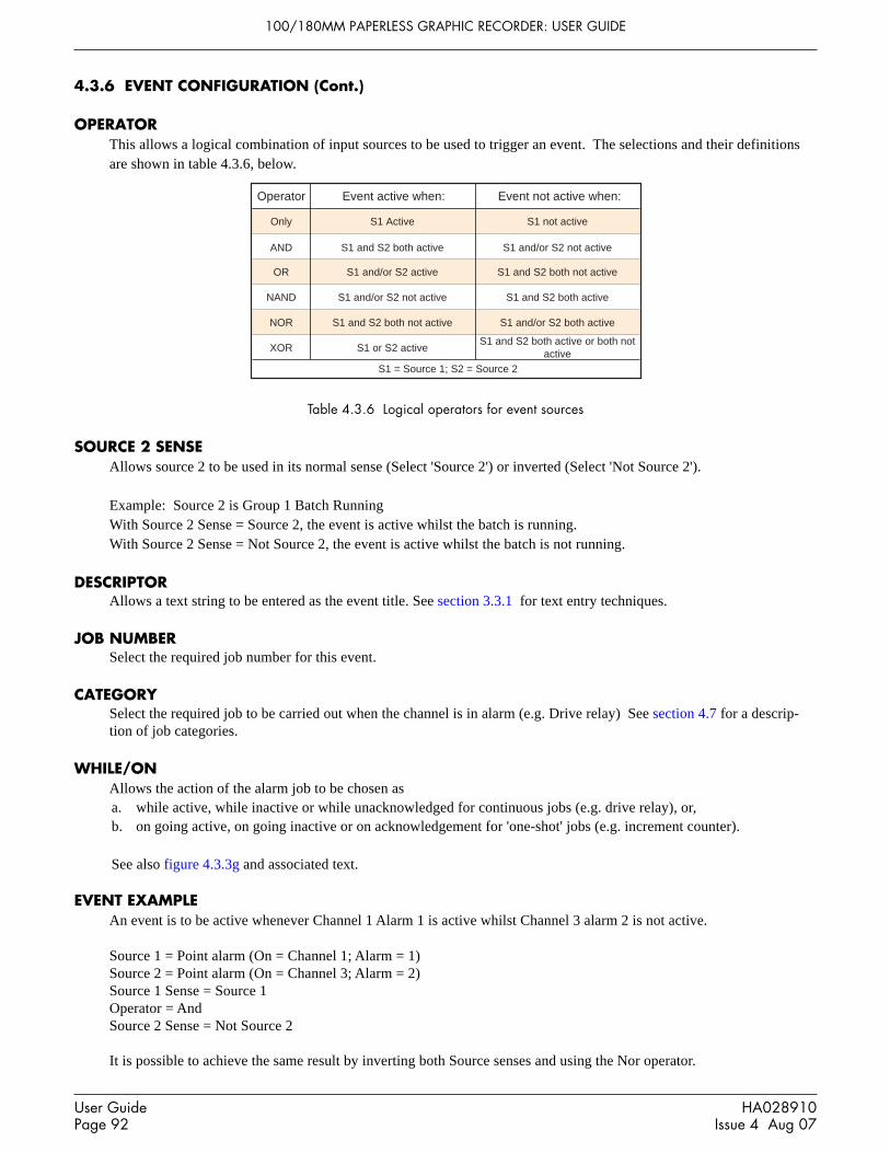
100/180MM PAPERLESS GRAPHIC RECORDER: USER GUIDE
User GuidePage 92
HA028910Issue 4 Aug 07
4.3.6 EVENT CONFIGURATION (Cont.)
OPERATOR This allows a logical combination of input sources to be used to trigger an event. The selections and their definitionsare shown in table 4.3.6, below.
Operator Event active when: Event not active when:
Only S1 Active S1 not active
AND S1 and S2 both active S1 and/or S2 not active
OR S1 and/or S2 active S1 and S2 both not active
NAND S1 and/or S2 not active S1 and S2 both active
NOR S1 and S2 both not active S1 and/or S2 both active
XOR S1 or S2 activeS1 and S2 both active or both not
activeS1 = Source 1; S2 = Source 2
Table 4.3.6 Logical operators for event sources
SOURCE 2 SENSE Allows source 2 to be used in its normal sense (Select 'Source 2') or inverted (Select 'Not Source 2').
Example: Source 2 is Group 1 Batch RunningWith Source 2 Sense = Source 2, the event is active whilst the batch is running.With Source 2 Sense = Not Source 2, the event is active whilst the batch is not running.
DESCRIPTORAllows a text string to be entered as the event title. See section 3.3.1 for text entry techniques.
JOB NUMBERSelect the required job number for this event.
CATEGORYSelect the required job to be carried out when the channel is in alarm (e.g. Drive relay) See section 4.7 for a descrip-tion of job categories.
WHILE/ONAllows the action of the alarm job to be chosen asa. while active, while inactive or while unacknowledged for continuous jobs (e.g. drive relay), or,b. on going active, on going inactive or on acknowledgement for 'one-shot' jobs (e.g. increment counter).
See also figure 4.3.3g and associated text.
EVENT EXAMPLEAn event is to be active whenever Channel 1 Alarm 1 is active whilst Channel 3 alarm 2 is not active.
Source 1 = Point alarm (On = Channel 1; Alarm = 1)Source 2 = Point alarm (On = Channel 3; Alarm = 2)Source 1 Sense = Source 1Operator = AndSource 2 Sense = Not Source 2
It is possible to achieve the same result by inverting both Source senses and using the Nor operator.
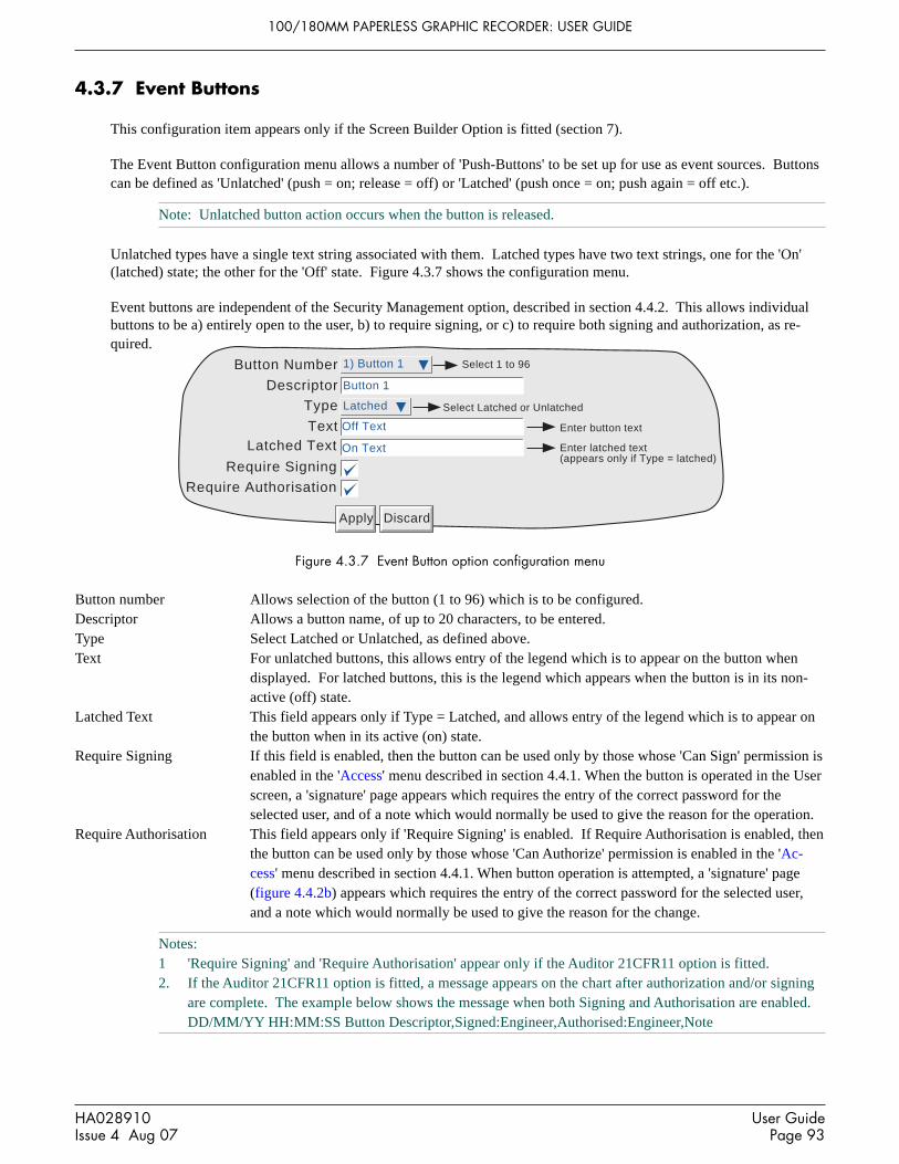
100/180MM PAPERLESS GRAPHIC RECORDER: USER GUIDE
HA028910Issue 4 Aug 07
User GuidePage 93
4.3.7 Event Buttons
This configuration item appears only if the Screen Builder Option is fitted (section 7).
The Event Button configuration menu allows a number of 'Push-Buttons' to be set up for use as event sources. Buttonscan be defined as 'Unlatched' (push = on; release = off) or 'Latched' (push once = on; push again = off etc.).
Note: Unlatched button action occurs when the button is released.
Unlatched types have a single text string associated with them. Latched types have two text strings, one for the 'On'(latched) state; the other for the 'Off' state. Figure 4.3.7 shows the configuration menu.
Event buttons are independent of the Security Management option, described in section 4.4.2. This allows individualbuttons to be a) entirely open to the user, b) to require signing, or c) to require both signing and authorization, as re-quired.
Button Number
DescriptorType
TextLatched Text
Require Signing
Require Authorisation
Apply Discard
Select Latched or Unlatched
Select 1 to 96
Enter button text
Enter latched text(appears only if Type = latched)
1) Button 1
Button 1
Latched
Off Text
On Text
Figure 4.3.7 Event Button option configuration menu
Button number Allows selection of the button (1 to 96) which is to be configured.Descriptor Allows a button name, of up to 20 characters, to be entered.Type Select Latched or Unlatched, as defined above.Text For unlatched buttons, this allows entry of the legend which is to appear on the button when
displayed. For latched buttons, this is the legend which appears when the button is in its non-active (off) state.
Latched Text This field appears only if Type = Latched, and allows entry of the legend which is to appear onthe button when in its active (on) state.
Require Signing If this field is enabled, then the button can be used only by those whose 'Can Sign' permission isenabled in the 'Access' menu described in section 4.4.1. When the button is operated in the Userscreen, a 'signature' page appears which requires the entry of the correct password for theselected user, and of a note which would normally be used to give the reason for the operation.
Require Authorisation This field appears only if 'Require Signing' is enabled. If Require Authorisation is enabled, thenthe button can be used only by those whose 'Can Authorize' permission is enabled in the 'Ac-cess' menu described in section 4.4.1. When button operation is attempted, a 'signature' page(figure 4.4.2b) appears which requires the entry of the correct password for the selected user,and a note which would normally be used to give the reason for the change.
Notes:1 'Require Signing' and 'Require Authorisation' appear only if the Auditor 21CFR11 option is fitted.2. If the Auditor 21CFR11 option is fitted, a message appears on the chart after authorization and/or signing
are complete. The example below shows the message when both Signing and Authorisation are enabled.DD/MM/YY HH:MM:SS Button Descriptor,Signed:Engineer,Authorised:Engineer,Note

100/180MM PAPERLESS GRAPHIC RECORDER: USER GUIDE
User GuidePage 94
HA028910Issue 4 Aug 07
4.3.8 Messages
This feature allows messages to be sent, by job action (section 4.7), to the display, to a specified group or to all groups.Messages can also be included in e-mails (section 4.3.19). The messages are of the form: Date, Time, Message. Themessage can be just text (up to 80 characters), or it can include up to nine embedded items which are typed into themessage as 1 to 9. The embedded values represented by 1 to 9 are selected from picklists.
If a Group-destination message contains more characters than can be displayed on the screen (depends on recordermodel), the right-hand part of the message is invisible to the user. The message appears in full in the message log (sec-tion 3.1.4) and when Review Software is used. Display-destination messages are always fully visible.
MESSAGE ENTRYThe message configuration page is shown below in figure 4.3.8 The page is accessed from the Root menu/Operator/Config menu.
Message Number
Message
Replace 1 with
Replace 2 with
Replace 3 with3 source
Replace 4 with4 source
Replace 5 with
Select embedding source
Replace 6 with
Select point whosedescriptor, value etc. isto be inserted
Select message to be con-figured
Apply Discard
1) The value of
The value of 1 = 2 & 3 = 4, 5
Source Descriptor
Source Value
Totaliser 1
Specified Descriptor
Totaliser 1
Specified Value
Config Revision
Blank
Absolute Enable, Type (high or low), Threshold, Status
Deviation Enable, Type (in or out), Reference, Deviation, Status
Rate of change Enable, Type (rise or fall), Amount, Change time, Status
Alarm Type Embedded details
Figure 4.3.8 Message entry configuration page.
CONFIGURABLE PARAMETERSMessage Number Select the required message from the picklist.Message Enter the message by using the pop-up keyboards (section 3.3.1)Replace n with A picklist allowing the user to select data to be embedded in the message:
Source Descriptor: The descriptor of the source which triggers the job message.Source Value: The instantaneous value of the source at trigger time.Source Alarm Data: Details (see table 4.3.8) of the source alarm at message trigger time.
Table 4.3.8 Alarm details versus alarm type
Note: If any of 'Source Descriptor', 'Source Value' or 'Source Alarm Data' are embedded in a message which istriggered by a job which cannot be associated with a specific source (e.g. event, timer), then the embeddedvalue will be: ?????.
(Continued)

100/180MM PAPERLESS GRAPHIC RECORDER: USER GUIDE
HA028910Issue 4 Aug 07
User GuidePage 95
4.3.8 MESSAGES (Cont.)
Replace n with (Cont.)
Specified Descriptor, Specified Value, Specified Alarm data: Produces a further field ‘n source’,described below.Batch Status: Causes the status ('Active' or 'Inactive') of the current batch to be embedded. See Section4.3.10 for details of the Batch option.Batch Field data: Allows a selected batch field to be included in the message. If a batch is not runningat the time the message is triggered, the Batch field data is replaced by '?????'. See Section 4.3.10 fordetails of the Batch option.
Note: Group number must be entered if the batch is configured for Group mode.
Instrument Name: Allows the Instrument Name (as entered in Configuration/Instrument - section4.3.1) to be included in the message.Instrument Number: Causes the instrument number (Network/Address - Section 4.5.1) to be embed-ded.Config Revision: Embeds the Config File Version number (System/About - section 4.6.11) in themessage
n source This field appears only if the previous field (Replace n with) is selected as ‘Specified Descriptor’,‘Specified Value’ or 'Specified alarm data'. The associated picklist(s) allow a specific point, and aspecific alarm (if appropriate) to be selected. It is thus possible to configure, say alarm 1 on channel 2,to produce a message giving the descriptor and/or value of, say, totaliser 1.
Notes:1. n = 1 to 92. The example below is intended to clarify message entry techniques.

100/180MM PAPERLESS GRAPHIC RECORDER: USER GUIDE
User GuidePage 96
HA028910Issue 4 Aug 07
4.3.8 MESSAGES (Cont.)
EXAMPLE
To configure Message 2 to read “The value of Chan two = (Value channel 2) & Tot one = (Value totaliser 1)”
Before configuring the message:In channel configuration:
Set channel 2 descriptor to: Chan twoSet Channel 2 alarm job to:
Category: MessageSend message(s) to: All Groups
First message: 2) Message 2Last Message: 2) Message 2
On: ActiveIn Totaliser configuration:
Set Totaliser 1 descriptor to: Tot one
In Messages configuration:1. Select Message 2.2. Access the Symbols keyboard (section 3.3.1) and enter, without spaces, =&=
3. Access the Numeric keyboard and insert 1, 2, 3, 4 within the braces to give: 1=2&3=4
4. Access the Alphabet keyboard, and insert text and spaces: The value of 1 = 2 & 3 = 45. Set ‘Replace 1’ to “Source Descriptor’6. Set ‘Replace 2’ to ‘Source Value’7. Set ‘Replace 3’ to ‘Specified Descriptor’8. Set ‘3 source’ to Tot one9. Set ‘Replace 4’ to ‘Specified Value’10. Set ‘4 source’ to ‘Tot one’
The result of this is that, should the channel 2 alarm go active, the following message would be sent to all groups, ap-pear on the ‘chart’ and become part of all groups’ histories:
18/10/01 11:19:58 The value of Chan two = 6.0˚C & Tot one = 3383.8073 Units
Note: On some models, the message may be wider than the screen. If necessary, the message can be shortened(e.g. use 'Ch2' instead of 'Chan two'), or it can be viewed in full, either in Message log, (section 3.1.4) or byusing Review Software, if available.

100/180MM PAPERLESS GRAPHIC RECORDER: USER GUIDE
HA028910Issue 4 Aug 07
User GuidePage 97
4.3.9 User Linearisation Tables
The Channel configuration item 'Lin Type' includes four linearisation tables called, initially, UserLin1 to UserLin4.This User Linearisation part of the instrument configuration allows the user to enter a linearisation look-up table ofbetween two and 66 pairs of points.
The pairs of points are entered as X1Y1, X2Y2... ...XnYn,where 'n' is the specified number of points.X1 to Xn represent the inputs to the function.Y1 to Yn represent the corresponding outputs from the function.
Notes:1. Each Y value must be unique - i.e. there cannot be more than one X value with the same Y value assigned
to it.2. Each X value (other than the first) must be greater than the previous one.3. Each Y value (other than the first) must be greater than the previous one.4. To specify units other than temperature units, the channel 'scaled' facility must be used. The scale low/
high values should be set to be the same as the range low/high values, and the required units entered
The import/export Linearisation tables feature described in 'Save/Restore' (section 4.2) offers an alternative way ofentering linearisation tables.
Figure 4.3.9a shows the default configuration page. Figure 4.3.9b shows a simple table for relating water depth to wa-ter volume for a cylindrical tank with a conical bottom.
User Linearisation
Descriptor
Format
Number of Points
X1
Y1
X2
3) UserLin3
Numeric
2
0
0
1
1
UserLin3
Apply Discard
Y2
Select Numericor Scientific
Figure 4.3.9a User linearisation configuration page
CONFIGURATION PARAMETERSUser Linearisation Allows one of the four user linearisation tables to be selected for configuration.Descriptor Allows the user to enter a name of up to 20 characters (including spaces) for the table.Format This allows the point pair values to be entered as normal numeric values (Numeric) or in
'Scientific' format (Scientific). When 'Scientific' is selected, values are displayed and entered asa decimal number between 1 and 10† (the mantissa), followed by a multiplier (the exponent).E.G. to enter a value of 1244.5678, the value entered would be 1.2445678E3, where 3 repre-sents the number of places that the decimal point has been shifted to the left in order to convertthe value to a number between 1 and 10†. To enter a value of 0.0004196, the entry would be4.196E-4. Figure 4.3.9b, below, gives further examples.
† Notes1. Strictly this is a number less than 10, as 10 would be 1.0E1.2. There must be at least one number after the decimal point.

100/180MM PAPERLESS GRAPHIC RECORDER: USER GUIDE
User GuidePage 98
HA028910Issue 4 Aug 07
4.3.9 USER LINEARISATION TABLES (Cont.)
CONFIGURATION PARAMETERS (Cont.)
Number of points This is used to enter the total number of point pairs in the table. The following XY fieldsincrease in number up to the entered value. (A scroll bar appears if there are more points thancan be displayed in the available screen height.)
X1 to XN The input values to the table, where N is the 'Number of Points' entered above.Y1 to YN The resulting, corresponding output values from the look-up table.
Figure 4.3.9b Sample User Linearisation table.
6.5
me
tre
s
3 metres
2 metres
10
20
30
40
50
60
Vo
lum
e (
cub
ic m
etr
es)
0
1 2 3 4 5 6 7 8 9
Depth (metres)
0
1 0 0.0 0.0E0 0.0E02 0.5 0.074 0.5E0 7.4E-23 1 0.589 1.0E0 5.89E-14 1.5 1.988 1.5E0 1.988E05 2 4.712 2.0E0 4.712E06 3 11.771 3.0E0 1.1771E17 4 18.840 4.0E0 1.8840E18 5 25.908 5.0E0 2.5908E19 6 32.977 6.0E0 3.2977E110 7 40.045 7.0E0 4.0045E111 8 47.114 8.0E0 4.7114E112 8.5 50.648 8.5E0 5.0648E1
Numeric ScientificPointpair X Y X Y
X
Y

100/180MM PAPERLESS GRAPHIC RECORDER: USER GUIDE
HA028910Issue 4 Aug 07
User GuidePage 99
4.3.10 Batch recording option
Batch records form a part of recording history and are included in the normal archiving process to a removable SD orCompact Flash card or to a remote PC (sections 4.1 and 4.3.5). Batches can be initiated directly by the operator (ifaccess permission is granted), automatically whenever a specified counter changes value, by job or remotely viaMODBUS/TCP.
Batches can be defined as start/stop, or continuous and can incorporate all channels, or just those associated with aspecified Group. For start/stop batches, the batch record starts when the batch is started, and continues until it isstopped. For continuous batches, the batch record starts when the batch is started and continues until the next batch isstarted, or until batch recording is disabled.
When using 'PC review' software the 'Go to Batch' feature can be used to select a particular batch record.
If ' Name files by Batch' is enabled a separate history file is created for each batch.
For each batch start, a start message is printed:
DD/MM/YY HH:MM:SS Batch start (User Full Name)
Where DD/MM/YY is the date, HH:MM:SS is the time, and User Full name is either the current user name, the secu-rity level (e.g. Engineer) or ‘Automatic’ if the batch has been initiated by job, or ‘Modbus’ if triggered remotely. Asimilar message is printed at Batch Stop. (There are no stop messages associated with continuous batch selection).
In addition to the above start/stop messages, up to six lines of text can, if required, be printed on the ‘chart’ at the startof a batch and, if required, at the end of a batch. The messages are in two parts, which for the sake of this document,are called ‘Headings’ and ‘Values’ The Headings are entered in Fields 1 to 6 in Batch Configuration. The Values asso-ciated with these headings are entered by the operator at initiation.
AUDITOR MESSAGES
If either Auditor option is fitted a Config/Security Revision message appears immediately after the Batch Start mes-sage:
DD/MM/YY HH:MM:SS Config Revision:NNNNNN Security Revision:SSSSSS
DD/MM/YY HH:MM:SS Batch start (User Full Name)
BATCH SUMMARYA Batch Summary page can be displayed from the Summary menu described in section 3.1.4, above.

100/180MM PAPERLESS GRAPHIC RECORDER: USER GUIDE
User GuidePage 100
HA028910Issue 4 Aug 07
4.3.10 BATCH OPTION (Cont.)
CONFIGURATION
Enable
Batch mode
Batch Fields
Field 1
On start log 4
On stop log
On new clear
1
1
Name files by batch
Start/Stop
4
Batch Number:
Apply Discard
Field 2 Customer Name:
Field 3 Operator Name:
Field 4 Supervisor:
Group
Scope Group
1) Group 1
SelectInstrumentor Group
SelectStart/Stopor Continuous
Batch field 1 Use Counter
Counter Counter 1
SelectCounter or Text
Select Counter(Appears only if 'UseCounter' selected)
Show Batch Entry List00:0A:8D:00:20:A0MAC Address
Predefined Entry 1
Predefined Entry 12
These fields appear
only if 'Show Batch
Entry List' is enabled
FishesRus
Figure 4.3.10a Batch configuration menu
As depicted in figure 4.3.10a, the following configuration entries can be made:
SCOPEAllows the user to define all configured channels (instrument) or just those in a particular group, for batch control. If'Group' is selected, a further picklist appears allowing a specific group to be selected.
SHOW BATCH ENTRY LISTEnabling this field produces a list of 13 entries which can be used as field entries when starting or storing a batch (asdescribed in ‘Operator initiation’, below). The first entry is the MAC address of the recorder and is not editable. Theremaining 12 entries (of up to 60 characters each) are freely editable. This is a different list from that entered (for Op-erator notes) in Instrument configuration (section 4.3.1).
ENABLEAllows the batch function to be switched on or off.
BATCH MODEAllows batch mode to be selected as Continuous or Start/Stop.

100/180MM PAPERLESS GRAPHIC RECORDER: USER GUIDE
HA028910Issue 4 Aug 07
User GuidePage 101
4.3.10 BATCH CONFIGURATION (Cont.)
BATCH FIELDSAllows the number of messages to be printed at batch start/stop to be selected between one and six.
FIELD 1This field is the first of up to six which can be used as headings for batch information. Headings can be up to 20 char-acters long (including spaces). In the example shown in Figure 4.3.10a, Heading 1 (Field 1) has the entry ‘BatchNumber:’. When initiating the batch, the operator has to enter a value to be associated with this heading (see below),unless 'Use Counter' is selected in the following 'Batch Number' field.
BATCH NUMBERThis allows the Value entered for Field 1's heading to be selected as 'Use Text' or 'Use Counter'.USE TEXT. When Text is selected, the value for field 1 is entered by the operator on initiation of the batch.USE COUNTER. When Counter is selected, a further field appears ('counter') allowing a specific counter to be selectedfrom a picklist. The selected counter initiates a new batch whenever it changes value, and the counter value is appendedto the text associated with Field 1. See section 4.3.13 for details of counters.
Note: Start batch is initiated on any change in counter value - not just increment.
FIELDS 2 TO 6Fields 2 to 6 are also used as headings for batch information. Values for these headings must be entered by the operatorprior to Batch initiation. See also ‘On new clear’, below. Headings can be up to 20 characters long (including spaces).
ON START LOGThis defines how many of the selected Fields are to be printed at batch start. An entry of ‘1’ means that only Field 1will be printed. An entry of ‘2’ means that Fields 1 and 2 will be used, and so on. An entry of 0 means that only the‘Batch Start’ message will be printed. It is not possible to print only, say, Field 3. If Field 3 is required, it must bepreceded by Fields 1 and 2.
ON STOP LOGAs for On start log, above, but for batch stop. This item appears only if Start/Stop is selected as batch mode.
ON NEW CLEARFor 'Use Text' Batches only, this allows the user to clear none or more of the batch entries at each batch start. In theexample above, if the user enters a batch number of say 050825.001, with Customer Name: FishesRus, Operator name:Marvin, Supervisor: Fred, then setting ‘On New Clear’ to ‘1’, causes the batch number to be cleared, and to have to bere-entered, each time a new batch is started.
In a similar way, setting ‘On New Clear’ to ‘2’ means that the batch number value and the Customer Name: value to becleared. A new batch cannot be started without new values first being entered.

100/180MM PAPERLESS GRAPHIC RECORDER: USER GUIDE
User GuidePage 102
HA028910Issue 4 Aug 07
4.3.10 BATCH CONFIGURATION (Cont.)
NAME FILES BY BATCHAs an aid to identification, if ‘Name Files by Batch’ is selected, the Batch Name, as entered by the operator, is insertedinto the history file name.
For example, if a batch name of 060511.001 is amongst the items archived to disk, then this file will appear in the form:
Group Name~060511.001~YYYYMMDD_HHHHHHHHHHHHHHHH,
Where YYYYMMDD is the date (e.g.20060511 = 11th May 2006) and HH----HH is a 16 digit hex code* used by therecorder and by review software to identify the file. If name files by batch is not selected, the Batch name is not in-cluded, and the file will appear as:
Group Name~YYYYMMDD_HHHHHHHHHHHHHHHH,
*The HHH--HHH code contains the following information:
H H H H H H H H H H H H H H H H
Lowest 3 bytes of theinstrument MAC address
History file formatversion identifier
Group numberGroup 1 = 00, Group 2 = 01 etc.
Sequential number (May skip one if thereis a configuration change)
6 2 2 6
OPERATOR INITIATIONThis section describes how the operator initiates a new batch. Batches can be initiated from any of the trend, bargraphor numeric display modes, but the start/stop and other messages appear only on the Vertical Trend screen in the trendhistory display and in Message Log. Batch information and status are retained whilst power is off.
Option Menu
Batch
Enter History
Channel Cycling Off
Faceplates On/Off
Note
Group 1Group
New Close
No batch in progressStatus
'Group' data appears only ifScope = Group (Section 1.2)
To initiate a batch, either1, Operate the Option key, then press ‘Batch’ in the Option Menu*
which appears, or2. Touch the coloured message area at the top of the screen. The
batch Status page appears - in this example - with no batch run-ning.
3. Press ‘New’. A new display page appears (figure 4.3.10b),showing all the headings entered in Field 1 to Field 6 duringconfiguration. If the Batch Fields entry is less than 6, then onlythe selected number appear (in our example, 4).
*Notes:1. The option menu is context sensitive, so its appearance may differ from the example shown.2. Batches can also be started and stopped from the Batch Summary page as described in section 3.1.4.

100/180MM PAPERLESS GRAPHIC RECORDER: USER GUIDE
HA028910Issue 4 Aug 07
User GuidePage 103
4.3.10 BATCH CONFIGURATION (Cont.)
OPERATOR INITIATION (Cont.)
‘Values’ can now be entered for these headings by entering strings of up to 60 characters (including spaces).
This may be done done by touching the empty field and using the resulting pop-up keyboard to type-in the entry, or bytouching the field continuously for two seconds or more and then selecting one of the predefined Batch Entry messagespreviously entered in the configuration page. In the latter case, the predefined mesage may be edited in the normal waybefore being Applied. Such editing has no effect on the original message.
Once the entries are complete, operation of the Start button initiates batch recording. Operation of the Store buttonsaves the configuration for later initiation by job, by counter or via MODBUS/TCP.
The Values entry page is replaced by the batch status page (figure 4.3.10c), this time showing details of the batch inprogress. This page allows the batch to be stopped or a new one triggered.
Note: Text may also be entered using a suitable keyboard connected via the USB port behind the access flap or(if the relevant option is fitted) one of the USB ports at the rear of the instrument (section 2.2).
Batch Number:
Customer Name:
Operator name:
Supervisor:
Batch - Furnace1 Temps
Start CloseStore
060509.015
FishesRus
Marvin
00:0A:8D:00:20:A0
FishesRus
Marvin
Arthur
Tricia
Jason
Manky Clothes Ltd.
Rat's Nest Hair Co.
Batch Entry list.Appears if batch entry area is touchedcontinuously for 2 seconds (approx).List entries are made in Batch Config-uration.
These keys not shown whilst the BatchEntry list displayed
Figure 4.3.10b Batch values entry page

100/180MM PAPERLESS GRAPHIC RECORDER: USER GUIDE
User GuidePage 104
HA028910Issue 4 Aug 07
4.3.10 BATCH INITIATION (Cont.)
Batch - Group 1
Stop CloseNew
Batch in progressStatus
Batch Number: 050822.001Customer Name: FishesRusOperator Name: MarvinSupervisor: Fred
Channel 1
400.00 800.00
700.87
Group 1Batch Number 050822.001
12:14:1722/08/05
12:13:4622/08/05
12:11:0622/08/05
12:08:2622/08/05
Engineer
720.00640.00
22/08/05 12:14:31 Alarm(s) on 3(1)22/08/05 12:14:31 Supervisor: Fred22/08/05 12:14:31 Operator Name: Marvin22/08/05 12:14:31 Customer name: FishesRus22/08/05 12:14:31 Batch number: 050822.00122/08/05 12:14:31 Config Revision:48 Security Revision 122/08/05 12:14:31 Batch start (Automatic)
Operator entries
Batch start message
480.00 560.00
Touching this area calls thebatch status page
Date and time automatically printed
Batch trigger source
Figure 4.3.10c Status page (Batch running)
BATCH MESSAGE DISPLAY
The messages are displayed on the Graph Trend display as shown in figure 4.3.10d, below. This figure uses the exam-ple given in the previous sections, and uses only four messages. Further messages would appear above message 4. Thefigure also shows that time and date are added to the messages, and that the currently running batch number is given inthe Group name area. Touching this area calls the Batch status page. In this job-triggered batch, the alarm triggeringthe job also appears (as shown).
Figure 4.3.10d Typical Batch start messages

100/180MM PAPERLESS GRAPHIC RECORDER: USER GUIDE
HA028910Issue 4 Aug 07
User GuidePage 105
4.3.10 BATCH INITIATION (Cont.)
NON OPERATOR INITIATION
Batch start/stop can be initiated by job, by counter or via MODBUS/TCP
JOB INITIATION As described in section 4.7.9, a job can be set up to initiate a batch whenever the job source becomes active. If 'Scope'is set to 'Group' a specific group can be selected (default = Group 1) and the job will act only on the batch associatedwith this group. Batch ‘Start’ jobs automatically start the batch using the entries made duing the ‘Store’ function, de-scribed above. ‘Display Batch Dialog’ jobs allow the user to enter the field values manually, before the job starts.
COUNTER INITIATIONIf Batch Number is selected as 'Use Counter', then a new batch will automatically be started whenever the selectedcounter changes value (increment, decrement or preset). The new value of the counter is used as the value associatedwith Field 1.
For the other fields to have values printed on the chart, these must have been entered as described above for Operatorinitiation, then the 'Store' button touched.
The 'On new clear' setting is ignored, the stored values being used each new batch.
Batch start messages are of the form:
DD/MM/YY HH:MM:SS Batch start (Automatic)
Batch recording cannot be stopped by Counter action.
MODBUS INITIATIONIn order to initiate batch recording via MODBUS/TCP, a Batch Start flag has to be set (value = 0001). For Scope =Group, the flag for the specified group must be set. For Scope = Instrument any group's Batch Start flag may be used.
The address of the flag for group 1 is decimal 42364; the address for group N is 42364 + 629(N-1)
For further details of the Modbus TCP option see section 8.
If Batch mode = Start/Stop, batches can also be stopped via MODBUS. The address for group 1 is 42365; the addressfor group N is 42364 + 629(N-1). Again the value must be set to 0001.
Modbus start messages are of the form:
DD/MM/YY HH:MM:SS Batch start (Modbus)
Stop messages are similar.
EVENT SOURCES
As described in section 4.3.6 , ‘Batch Start’, ‘Batch Running’ and ‘Batch Stop’ can be selected as event sources. If'Scope' = 'Group' in Configuration (described above), then the user can select which group's batch is to be used as theevent source.

100/180MM PAPERLESS GRAPHIC RECORDER: USER GUIDE
User GuidePage 106
HA028910Issue 4 Aug 07
4.3.11 Maths
CONFIGURATION
This feature allows a range of mathematical functions to be performed. Figure 4.3.11a shows a typical configurationpage - the selected maths function determines which configuration fields actually appear.
Apply Discard
Select Required maths functionFunction fValue
Fvalue ofSterilizing Temp 121.1
Low cut off
Descriptor Fo 1
Scale Low 0 Mins
Select Source input
Scale Type None Select None, Linear or Log
Zone low 0
Zone high
Max Decimal Digits 2
ColourAlarm Number 1
Enable Off
Job Number 1
Category No Action Select job category
Select: Off, Unlatched,Latched orTrigger
Select Job number
26
Channel 1
75
%
100 %
Maths Number 1) Fo 1Select mathschannel number
Value Current value32.65
Reset now
Mins
Reset button appears onlyfor resettable functions
PV Format Numeric
Select Alarm number
Temperature interval 10
Units Mins
Scale high 60
Select Numeric, Elapsed Time,Scientific, Time or Date
A/B Switching
Mins
Figure 4.3.11a Maths configuration menu (typical - varies from function to function)
Maths number
Allows the user to select the required maths channel for configuration. The maximum number of maths channels isselected in the Virtual channels section of the Configuration/Options display, described in section 4.3.21.
Value
This field shows the current value of the selected maths channel. If the channel has not yet been configured, the valuereads 'Off'.
Reset Now
This button appears only after a resettable function has been selected. Operation of the button sets the maths value tozero.

100/180MM PAPERLESS GRAPHIC RECORDER: USER GUIDE
HA028910Issue 4 Aug 07
User GuidePage 107
4.3.11 MATHS CONFIGURATION (Cont.)
Function
This picklist allows the relevant maths function to be selected. In the following description, the word 'channel' is usedas an umbrella term for input channels, maths channels, totalisers etc.
Off Allows the function to be disabled. Once 'Apply' has been actioned, all configuration for thisMaths number is lost.
Constant Allows a maths channel to be set to a constant value.Add Allows any channel or a constant value to be added to any other.Subtract Allows any channel or a constant value to be subtracted from any other.Multiply Allows any channel or a constant value to be multiplied by any other.Divide Allows any channel or a constant value to be divided by any other. Should the value of the
divisor pass through zero, 'Maths Channel N error' and 'Maths Channel Failure' messagesappear.
Group average* The instantaneous value of all the channels in the source group added together and divided bythe number of channels in the group. For example, in a group of four channels whose instanta-neous values are 4, 8, 2 and 6, the group average is (4 + 8 + 2 + 6) / 4 = 5. The relevant sourcegroup is selected by picklist. Should a channel return a non-valid value, it is excluded from thecalculation, and the result of the function is the average of the remaining channels.
Group minimum* The lowest value of any of the channels in the source group. For example, in a group of fourchannels whose instantaneous values are 4, 8, 2 and 6, the group minimum is 2. The requiredsource group is selected by picklist. Should a channel return a non-valid value, it is excludedfrom the calculation, and the result of the function is the minimum of the remaining channels.
Group maximum* The highest value of any of the channels in the source group. For example, in a group of fourchannels whose instantaneous values are 4, 8, 2 and 6, the group maximum is 8. The requiredsource group is selected by picklist. Should a channel return a non-valid value, it is excludedfrom the calculation, and the result of the function is the maximum of the remaining channels.
*Note: If a maths channel with a Group function is contained within its own source group, then it willact on itself as well as on the other group contents, thus changing the calculation.
For example, if Group 1 were to contain channel 1, channel 2 and maths channel 1, where mathschannel 1 had the function 'Group Maximum' for Group 1, then the Group Maximum would become alatching function, showing the highest value ever reached by channel 1, channel 2 or maths channel 1since the group was configured. In order to trace the instantaneous highest value, channel 1 and channel2 would have to be contained in e.g. Group 1, and the group maximum channel contained in, say, Group2, but with a source of 'Group 1'.
Slave Comms Allows a process value for the maths channel to be communicated over the Modbus linkStopwatch This causes the value of the maths channel to increment in milliseconds. The value can be
displayed in milliseconds (PV format = numeric), or in HH:MM:SS (PV format = elapsed time).The value can be held, using a ‘Disable’ job or set to zero either using a ‘reset’ job or by theoperation of the ‘Reset now’ button in the maths configuration page. See section 4.7 for adescription of jobs.The function value is retained during power off.
Note: The scale low and high values are displayed in numeric format for both numeric and elapsed timedisplay formats

100/180MM PAPERLESS GRAPHIC RECORDER: USER GUIDE
User GuidePage 108
HA028910Issue 4 Aug 07
4.3.11 FUNCTION (Cont.)
Copy Copies the value of a selected point to the maths channel being configured. Allows extra alarmsto be set up for the copied point.
Polynomial Provides a polynomial curve fit for the specified point, using up to 8 orders,
Fvalue This function calculates ‘equivalent time at sterilizing temperature’ for temperatures above andbelow the sterilizing temperature. FO (dry) and FH (steam) sterilizing calculations can becarried out, by entering the correct constant. The value can be held, using a ‘Disable’ job or setto zero (prior to the next run) using a ‘reset’ job. See section 4.7 for a description of jobs. Thefunction value is retained during power off.
Switch Allows two channels (‘A’ and ‘B’) to be selected as alternative sources for the selected mathschannel to copy. The maths channel copies source ‘A’, unless a ‘Switch to B’ job is active onthe maths channel. See section 4.7 for Job descriptions.
Linear Mass Flow This function calculates mass flow from linear-type transducer outputs.
Root Mass Flow This function calculates mass flow from square root-type transducer outputs.
Rolling Average This takes the average value of a single channel over a specified number of readings taken at aspecified interval. The function value is retained during power off.
MKT Mean Kinetic Temperature. A single calculation to simulate non-isothermal effects of variationsin storage temperature.
10 to the power Output = 10 raised to the power of the selected input value.
Group Latched Minimum Outputs the minimum value reached by any of the points in a selected source group since lastreset. The function ignores points that are not producing valid PV. A disable job stops thefunction reading its input. A reset job sets the function to the current minimum value within thegroup. Note that for proper operation, the maths function must be in a group which is not thesource group. If this is not the case, it will always see itself as the lowest valued point in thegroup, and Reset operations will have no useful effect.
Group Latched Maximum As for Group Latched Minimum, above, but outputs the maximum value of the source group.Sample and Hold This function is initiated by a trigger job. At trigger time, the selected point value is sampled,
and its value at trigger time is output continuously by this function. On reset, the PV becomes'No data'.
Square Root Outputs the square root of the value of the selected point.
High Select Allows two points to be selected as inputs. The output of the function is the value of that inputpoint which currently has the higher value.
Low Select Allows two points to be selected as inputs. The output of the function is the value of that inputpoint which currently has the lower value.
Saturated Steam Mass FlowCalculates mass flow in kg/s for saturated steam, using either the steam temperature (Celsius) orpressure (MPa) as appropriate to the process.
Saturated Steam Heat FlowCalculates the energy flow in kJ/s for saturated steam, using either the steam temperature(Celsius) or pressure (MPa) as appropriate to the process.
Saturated Steam Heat ConsumedCalculates the heat consumed in kJ/s for saturated steam, using the inlet steam temperature(Celsius) or pressure (MPa) (as appropriate to the process), and the return (condensate) tempera-ture.
Group MKT Calculates Mean Kinetic Temperature of a specified group of channels

100/180MM PAPERLESS GRAPHIC RECORDER: USER GUIDE
HA028910Issue 4 Aug 07
User GuidePage 109
4.3.11 FUNCTION (Cont.)
Log Base 10 Takes log10 of selected input. (For example: Input = 2 gives maths function value = 0.3010)
Log Base e Takes loge of selected input. (For example: Input = 2 gives maths function value = 0.6931)
e to the power Takes natural antilog of input. (For example: Input = 0.6931 gives maths function value = 2)
Modulus This function copies the magnitude of the input value, without the sign. For example, themodulus of value +100 = +100; the modulus of -100 = +100.
Channel Maximum Maths function value is the minimum value the input point has reached since last reset. Whenreset, the value is reset to the current input value.
Channel Minimum Maths function value is the minimum value the input point has reached since last reset. Whenreset, the value is reset to the current input value.
Channel Average Takes the average value of the selected channel over a specified time period. The time periodmust be a multiple of 125 msecs. For example, a period of 0.2 seconds would be rejected, but aperiod of 0.25 seconds would be accepted.
Master comms Allows a maths channel to read point values from other instruments on the Modbus link.
Rate of change Produces a value for the speed at which a signal changes over a specified period.
O2 Correction This function carries out O2 correction of gas measurements for use in Continuous EmissionsMonitoring applications.
Relative Humidity This uses wet and dry bulb temperatures and atmospheric pressure inputs to produce a percent-age Relative Humidity reading.
Zirconia probe Allows oxygen concentration and oxygen potential to be determined by solving the Nernstoxygen equation.
Timestamp When triggered by an event or alarm job, this causes the current number of milliseconds since00:00 hrs on 1st January 1970 to appear as the function value. If the selected PV format is dateor time, the result is displayed as date or time, respectively.
Config Revision Number* Allows the Configuration Revision number to be used as the input to a maths channel. Whenthis maths channel is included in a group, the user can determine the Configuration Revisionnumber obtaining at any time in the history record.
Security Revision Number* Allows the Security Revision number to be used as the input to a maths channel. When thismaths channel is included in a group, the user can determine the Security Revision numberobtaining at any time in the history record.
*Note: See ‘About’ in section 4.6 for a description of the Configuration and Security Revisionnumbers.
Scale Low / Scale High
The 'zero' and full scale values for the maths function, as displayed.
If A/B switching is enabled, a second set of scale low and scale high values can be entered. 'A' values are used duringnormal operation. 'B' values are switched to by job action, as described in section 4.7.

100/180MM PAPERLESS GRAPHIC RECORDER: USER GUIDE
User GuidePage 110
HA028910Issue 4 Aug 07
4.3.11 FUNCTION (Cont.)
PV FORMAT
Numeric Provides a decimal value for the maths channel.Elapsed time Shows the maths channel value in HH:MM:SS (hours minutes, seconds) format. Normally used only for
time functions. For other functions, elapsed time counts in milliseconds e.g. a PV of 10000 would bedisplayed as 00:00:10; a PV of 60000 would be displayed as 00:01:00
Scientific Values are displayed and entered as a decimal number between 1.0 and 10† (the mantissa), followed bya multiplier (the exponent). E.G. to enter a value of 1244.5678, the value entered would be1.2445678E3, where 3 represents the number of places that the decimal point must be shifted to the leftin order to convert the value to a number between 1 and 10†. To enter a value of 0.0004196, the entrywould be 4.196E-4.
Time/date For timestamp functions, displays the timestamp as time or date as selected, instead of a number ofmilliseconds, as would be displayed in numeric format.
† Notes1. Strictly this is a number less than 10, as 10 would be 1.0E1.2. There must be at least one number after the decimal point.
REMAINING CONFIGURATION ITEMS
The remaining configuration items are identical with the relevant items in Input Channel configuration (section 4.3.3).
FUNCTION DETAILS
POLYNOMIAL FIT
A polynomial curve fit of up to eight orders:A0 + A1(X) + A2(X2) + A3(X3) + A4(X4) + A5(X5) + A6(X6) + A7(X7) + A8(X8) where X is the value of the sourcechannel and A0 to A8 are constants. Figure 4.11.3b shows the configuration items for a third order fit with channel 2used as the source (X), and A0 = 1, A1 = 2, A2 = 3 and A3 = 4.
Function Polynomial
OrdersPolynomial of
A0Math 1
0
1
3
1
Maths Number 1) Math 1
Value OFF
Channel 2
A1 2
A2 3
A3 4
Units
Figure 4.11.3b Polynomial configuration fields (3rd order)
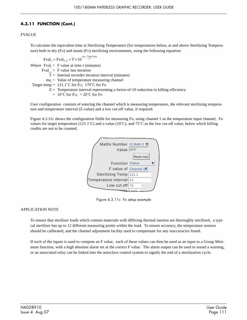
100/180MM PAPERLESS GRAPHIC RECORDER: USER GUIDE
HA028910Issue 4 Aug 07
User GuidePage 111
4.3.11 FUNCTION (Cont.)
FVALUE
To calculate the equivalent time at Sterilizing Temperature (for temperatures below, at and above Sterilizing Tempera-ture) both in dry (FH) and steam (FO) sterilizing environments, using the following equation:
Fval Fval T 10t t 1
mat Target temp
= + ×−
−Z
Where Fvalt= F value at time t (minutes)
Fvalt-1
= F value last iterationT = Internal recorder iteration interval (minutes)
mat= Value of temperature measuring channel
Target temp = 121.1˚C for FO; 170˚C for FHZ = Temperature interval representing a factor-of-10 reduction in killing efficiency
= 10˚C for FO; = 20˚C for FH
User configuration consists of entering the channel which is measuring temperature, the relevant sterilizing tempera-ture and temperature interval (Z-value) and a low cut-off value, if required.
Figure 4.3.11c shows the configuration fields for measuring Fo, using channel 1 as the temperature input channel, Fovalues for target temperature (121.1˚C) and z-value (10˚C), and 75˚C as the low cut-off value, below which killingcredits are not to be counted.
Function fValue
F value ofSterilizing Temp 121.1
Temperature intervalLow cut off
Channel 1
75
Maths Number 2) Math 2
Value OFF
Reset now
10
Figure 4.3.11c Fo setup example
APPLICATION NOTE
To ensure that sterilizer loads which contain materials with differing thermal inertias are thoroughly sterilized, a typi-cal sterilizer has up to 12 different measuring points within the load. To ensure accuracy, the temperature sensorsshould be calibrated, and the channel adjustment facility used to compensate for any inaccuracies found.
If each of the inputs is used to compute an F value, each of these values can then be used as an input to a Group Mini-mum function, with a high absolute alarm set at the correct F value. The alarm output can be used to sound a warning,or an associated relay can be linked into the autoclave control system to signify the end of a sterilization cycle.

100/180MM PAPERLESS GRAPHIC RECORDER: USER GUIDE
User GuidePage 112
HA028910Issue 4 Aug 07
4.3.11 FUNCTION (Cont.)
LINEAR MASS FLOW
Note: The overall accuracy of a flow measurement installation depends on a number of factors outside thecontrol of the recorder manufacturer. For this reason, the recorder manufacturer takes no responsibility for theaccuracy of the results obtained using the mass flow equations implemented in the maths pack.
The equations solved is:
where, QMt = Mass flow (in kg/sec), at time ‘t’
K = Scaling factor (see below)Rg = Specific gas constant in J/kg-K (see below)Z = Compressibility factor (see below)
Flowt = Measured value from the flow meter at time ‘t’
AbsPt = Absolute pressure of the fluid at time ‘t’ in kPa(A)
Temp = Temperature of the fluid in Kelvins
SCALING FACTORThis is determined from an assumed value of Qm at a known Flow, AbsP and Temp. The value is chosen to give anoutput within the range low scale to high scale.
SPECIFIC GAS CONSTANTThe specific gas constant for any gas is available from published tables. For convenience, the value for a number ofcommon gases is given in table 4.3.11a, below.
QMt = ×××K
Rg ZFlow AbsP
Tempt t
AirAmmoniaCarbon dioxideCarbon monoxideEthyleneHydrogenMethaneNitrogenOxygenPropaneSteam
287.1488.2188.9296.8296.4
4116.0518.4296.8259.8188.5461.4
RG(J/kg-K)
Gas
Table 4.3.11a Common gas constants

100/180MM PAPERLESS GRAPHIC RECORDER: USER GUIDE
HA028910Issue 4 Aug 07
User GuidePage 113
4.3.11 FUNCTION (Cont.)
LINEAR MASS FLOW (Cont.)
COMPRESSIBILITY FACTOR (Z-FACTOR)
Compressibility factor is a density-related measure of how far a particular gas deviates from a ‘perfect’ gas under anyset of temperature and pressure conditions, and is give by the equation:
ZP
T= × 1
ρwhere: Z = Compressibility factor
P = Absolute pressure of the gas in kPa(A)T = Absolute temperature of the gas (Kelvins)ρ = gas density at pressure P and temperature T (from published tables)
CONFIGURABLE PARAMETERS
Figure 4.3.11d shows the relevant part of the configuration menu for a maths channel with ‘Linear Mass Flow’ functionselected.
Function Linear Mass Flow
FlowTemperature
Absolute Pressure
Scale o/p0Ma0Gas Constant
0ZUnits
Channel 1
0
Units
Maths Number 1) Math 1Value 123.4567
Channel 2Channel 3
Units
Apply Discard
J/kg-K
Figure 4.3.11d Linear mass flow menu
Flow Allows the input channel measuring the flowmeter output to be enteredTemperature Allows the input channel measuring the fluid temperature (Kelvins) to be enteredAbsolute Pressure Allows the input channel measuring the absolute gas pressure (kPa(A)) to be enteredScale o/p Full scale output from the flowmeter in flowmeter units (S)Ma Full scale input range set for ‘Flow’ channel in flowmeter units (ma
max)
Gas Constant the relevant gas constant in J/kg-KZ The compressibility factor described above.

100/180MM PAPERLESS GRAPHIC RECORDER: USER GUIDE
User GuidePage 114
HA028910Issue 4 Aug 07
4.3.11 FUNCTION (Cont.)
ROOT MASS FLOW
Note: The overall accuracy of a flow measurement installation depends on a number of factors outsidethe control of the recorder manufacturer. For this reason, the recorder manufacturer takes no responsi-bility for the accuracy of the results obtained using the mass flow equations implemented in the mathspack.
The equation solved is:
where, QMt = Mass flow (in kg/sec), at time ‘t’
K = Scaling factor (see below)Rg = Specific gas constant in J/kg-K (see below)Z = Compressibility factor (see below)
DeltaPt = Measured value across the orifice plate at time ‘t’
AbsPt = Absolute pressure of the fluid at the up-stream tapping at time ‘t’ in kPa(A)
Temp = Temperature of the fluid at the up-stream tapping in Kelvins
SCALING FACTORThis is determined from an assumed value of Qm at a known DeltaP, AbsP and Temp. The value is chosen to give anoutput within the range low scale to high scale.
SPECIFIC GAS CONSTANTThe specific gas constant for any gas is available from published tables. For convenience, the value for a number ofcommon gases is given in table 4.3.11a, above.
COMPRESSIBILITY FACTOR (Z-FACTOR)Compressibility factor is a density-related measure of how far a particular gas deviates from a ‘perfect’ gas under anyset of temperature and pressure conditions, and is give by the equation:
ZP
T= × 1
ρwhere: Z = Compressibility factor
P = Absolute pressure of the gas in kPa(A)T = Absolute temperature of the gas (Kelvins)ρ = gas density at pressure P and temperature T (from published tables)
QMt = ×××K
Rg ZDeltaP AbsP
Tempt t
2

100/180MM PAPERLESS GRAPHIC RECORDER: USER GUIDE
HA028910Issue 4 Aug 07
User GuidePage 115
4.3.11 FUNCTION (Cont.)
ROOT MASS FLOW (Cont.)
CONFIGURABLE PARAMETERSFigure 4.3.11e shows the relevant part of the configuration menu for a maths channel with ‘Root Mass Flow’ functionselected.
FunctionDelta PressureTemperature
Absolute PressureScale o/p
MaGas Constant
ZUnits
Maths NumberValue Units
J/kg-K
Apply Discard
Root Mass Flow
00
00
Channel 1
Units
1) Math 1123.4567
Channel 2Channel 3
Figure 4.3.11e Root mass flow menu
Delta Pressure Allows the input channel measuring the differential pressure output from the orifice plate to be enteredTemperature Allows the input channel measuring the fluid temperature (Kelvins) at the upstream tapping to be enteredAbsolute Pressure Allows the input channel measuring the absolute gas pressure (kPa(A)) to be enteredScale o/p Full scale output from the flowmeter in flowmeter units (S)Ma Full scale input range set for ‘Flow’ channel in flowmeter units (ma
max)
Gas Constant The relevant gas constant in J/kg-KZ The compressibility factor described above.

100/180MM PAPERLESS GRAPHIC RECORDER: USER GUIDE
User GuidePage 116
HA028910Issue 4 Aug 07
4.3.11 FUNCTION (Cont.)
ROLLING AVERAGE
This calculates the average value of the last R samples of a channel, taken at N second intervals, where R and N can bedefined by the user. At initiation, up to the time of the first sample reading, the displayed value is the average of thechannel sampled every iteration (i.e. at 8 Hz.).
The number of readings over which the average can be taken is limited by the amount of free RAM instantaneouslyavailable, and is thus dependent on the overall configuration of the recorder. An instrument alarm is generated if thereis insufficient free RAM available - see section 3.1.3 for details.
Function Rolling Average
Average ofNumber of samples 10
Sample Interval
Channel 1
Maths Number 4) Math 4
Value OFF
Reset now
60 s
T = kln
- HR
e
- HRT1max
e
- HRT1min
+ ... + e
- HRTNmax
+ e
- HRTNmin
2N
∆
∆ ∆ ∆ ∆+
Figure 4.3.11f Rolling average menu
MEAN KINETIC TEMPERATURE (MKT)
MKT is defined as 'the isothermal temperature that corresponds to the kinetic effects of time-temperature distribution'.The recorder calculates MKT, using the equation below:
where: Tk = The required mean kinetic temperature in Kelvins
∆H = The heat of activationR = The universal gas constant
T1max
= The highest temperature reached during the first measurement period (in Kelvins)T
1min = The lowest temperature reached during the first measurement period (in Kelvins)
TNmax
= The highest temperature reached during the Nth measurement period (in Kelvins)T
Nmin = The lowest temperature reached during the Nth measurement period (in Kelvins)
N = The total number of measurement periods
As described in 'Configurable items, below, this is simplified for the recorder user , to four entries viz: The number ofthe channel measuring temperature, the number of samples to be used, the time between the samples and the relevant'Heat of Activation'.
Note: The input temperature must be in Kelvins. This can be achieved either by setting the relevant channel'sunits to Kelvins, or by using a further maths channel to convert the measuring units to Kelvins.(K = ˚C + 273.15 or K = 0.555(˚F -32) + 273.15).

100/180MM PAPERLESS GRAPHIC RECORDER: USER GUIDE
HA028910Issue 4 Aug 07
User GuidePage 117
4.3.11 FUNCTION (Cont.)
MEAN KINETIC TEMPERATURE (Cont.)
CONFIGURABLE ITEMS
Figure 4.3.11g shows the configurable items for the MKT function.
Function MKT
Mean Kinetic Temperature ofNumber of samples
Sample interval 604800Heat of Activation 83.144
Units Units
Math 2
52
Maths Number 1) Math 1Value 0.0000 Units
kJ/mole
s
Apply Discard
Figure 4.3.11g MKT function parameters
Mean Kinetic Temperature ofSelect the source from which MKT is to be derived. This may be an input channel, scaled inKelvins, or it can be a maths channel used to convert a different temperature scale into Kelvins(see 'Note' on previous page).
Number of Samples Enter the number of samples over which the MKT is to be measured.Sample interval Enter the time period, in seconds, between samples. At each sample interval, the maximum and
minimum temperatures reached by the input source, since the last sample, are entered into theequation.
Heat of Activation The default value is an average value based on many common organic reactions. Allows theuser to enter an alternative value, if known.
EXAMPLE 1: To Produce a 4-weekly value of MKT, taking samples every day.Number of samples = 28Sample interval = No. of seconds in a day = 24 x 60 x 60 = 86,400
EXAMPLE 2: To produce an annual value of MKT, taking samples every week.Number of sample = 52Sample interval = No. of seconds in a week = 7 x 24 x 60 x 60 = 604,800
Notes1 This function produces a 'rolling' result. I.E. when the final (Nth) sample has been taken, the next sample
(N + 1)th replaces Sample 1, the (N + 2th) sample replaces Sample 2, and so on.2 During the first sample, the current minimum and maximum values of temperature are entered into the
equation at the recorder iteration rate (i.e. 8Hz).3. The number of readings over which the value can be taken is limited by the amount of free RAM instanta-
neously available, and is thus dependent on the overall configuration of the recorder. An instrument alarmis generated if there is insufficient free RAM available - see section 3.1.3 for details.

100/180MM PAPERLESS GRAPHIC RECORDER: USER GUIDE
User GuidePage 118
HA028910Issue 4 Aug 07
4.3.11 FUNCTION (Cont.)
SATURATED STEAM MASS FLOW
Note: The overall accuracy of a flow measurement installation depends on a number of factors outsidethe control of the recorder manufacturer. For this reason, the recorder manufacturer takes no responsi-bility for the accuracy of the results obtained using the mass flow equations implemented in the mathspack.
The equations solved is:
where, QMt = Mass flow (in kg/sec), at time ‘t’ (Note 1)
Flowt = Measured flow in m3/sec. at time 't' (Note 1)
VLT
= Volume of liquid per kg of steam (m3/kg) at temperature T ˚C∆V
T = V
VT - V
LT, where V
VT is the volume of vapour per kg of steam at temperature T ˚C
d = Dryness factor between 0 (no vapour) and 100 (no liquid)
VLT
and ∆VT are available from published tables (note 2), but the recorder user need only enter 'values' for measured
flow and either the temperature or the pressure of the steam. These 'values' can be constants, input channels or mathschannels. Figure 4.3.11h and accompanying parameter descriptions give full details.
QM = Flow
V + V tt
LT Td
100∆ ( )
FunctionFlowUse
Temperature
DrynessUnits
Maths NumberValue Units
Apply Discard
%
Saturated Steam Mass Flow
Channel 1
0Units
1) Math 1123.4567
Temperature
Channel 2
Figure 4.3.11h Typical Saturated Steam Mass Flow configuration page
PARAMETERSFlow Select 'Constant' or the number of the channel supplying the measured flow rate. If 'Constant' selected, a
further 'box' allows the value for the constant to be entered.
Use Allows the user to select Temperature (˚C) or Pressure (MPa) for the calculation.
Temperature Appears only if Use = Temperature. Select 'Constant' or the number of the channel supplying the steamtemperature. If 'Constant' is selected, a further 'box' allows a value for the constant to be entered.
Pressure Appears only if Use = Pressure. Select 'Constant' or the number of the channel supplying the steam pres-sure. If 'Constant' is selected, a further 'box' allows a value for the constant to be entered.Table 4.3.11b, below, gives multipliers for converting some common pressure units to MPa. More detailsmay be found at websites http://www.ex.ac.uk/trol/scol/ccpress.htm and http://www.onlineconversion.com/pressure.htm, amongst others.
Dryness Enter a value between 0 and 100 to represent the dryness of the steam. 0 = no vapour; 100 = no liquid.
Notes:1 The units of kg/sec and m3/sec are used above for simplicity. In fact any time unit can be used. For exam-
ple if the measured flow is in m3/hour, then the Mass flow will be in kg/hour.2. ASME Steam tables 1999, from IAPWF IF97.

100/180MM PAPERLESS GRAPHIC RECORDER: USER GUIDE
HA028910Issue 4 Aug 07
User GuidePage 119
4.3.11 FUNCTION (Cont.)
SATURATED STEAM MASS FLOW (Cont.)
PRESSURE UNITS CONVERSION
There is a wide range of pressure measuring units in use throughout the world. The following table gives a multiplica-tion factor for converting some common units to MPa (MegaPascals), to four significant figures. Further conversionfactors can be found at the websites given on the previous page. (Where the conversion is to Pascals, not toMegaPascals, the factors given have to be divided by 1,000,000.)
Pressure units Multiplier forMPa
Atmospheres 0.1013Bar 0.1
kg/cm2 0.09 807kNewton/m2 0.001kPa 0.001mBar 0.0001
Lb/ft2 0.00 004 788Lb/in2 (PSI) 0.006 895Mercury (inches of) 0.003 386Mercury (mm of) 0.0 001 333
Newtons/cm2 0.01
Newtons/m2 0.000 001Pascals 0.000 001
Tonnes/m2 0.009 807
Tons(UK)/ft2 0.1 073
Tons(US)/ft2 0.09 576Water (feet of) 0.002 989
Water (inches of) 0.0 002 491
Water (mm of) 0.000 009 807
Pressure units Multiplier forMPa
FunctionMultiply
by
Constant ValueUnits
Maths NumberValue Units
Apply Discard
DescriptorScale low
Scale high
MPa
MPa
Multiply
Channel 3
0.006895MPa
2) Steam Pressure
0.0348
Constant
Steam Pressure0
1
Table 4.3.11b Pressure unit conversion
The table above shows multiplying factors to convert common pressure units to MPa. This conversion is carried out asfollows:
Example: A pressure transducer, connected to input channel 3 gives an output in the range 10 to 100 PSI. The input toa steam equation in maths channel 1 requires the pressure units to be MPa. To convert, set up a further maths channel(e.g. No. 2) as shown below, then use maths channel 2 as the source channel for the pressure input to the steam equa-tion. The suggested scale low/high values are based on the resulting pressure range in MPa - i.e 0.06895 to 0.6895.
Figure 4.3.11i PSI to MPa conversion example

100/180MM PAPERLESS GRAPHIC RECORDER: USER GUIDE
User GuidePage 120
HA028910Issue 4 Aug 07
4.3.11 FUNCTION (Cont.)
SATURATED STEAM HEAT FLOW
Note: The overall accuracy of a flow measurement installation depends on a number of factors outsidethe control of the recorder manufacturer. For this reason, the recorder manufacturer takes no responsi-bility for the accuracy of the results obtained using the mass flow equations implemented in the mathspack.
The equations solved is:
where, QEt = Heat energy flow (in kJ/sec), at time ‘t’ (Note 1)
Flowt = Measured flow in m3/sec (Note 1)
VLT
= Volume of liquid per kg of steam (m3/kg) at temperature T ˚C∆V
T = V
VT - V
LT, where V
VT is the volume of vapour per kg of steam at temperature T ˚C
d = Dryness factor between 0 (no vapour) and 100 (no liquid)h
LT = Enthalpy of the liquid in kJ/kg at temperature T ˚C
∆hT = h
VT - h
LT, where h
VT is the enthalpy of vapour in kJ/kg vapour at temperature T ˚C
VLT
and ∆VT; h
LT and ∆h
T are available from published tables (note 2), but the recorder user needs only to enter 'values'
for measured flow and either the temperature or the pressure of the steam. These 'values' can be constants, input chan-nels or maths channels. Figure 4.3.11j and accompanying parameter descriptions give full details.
FunctionFlowUse
Pressure
DrynessUnits
Maths NumberValue Units
Apply Discard
%
Saturated Steam Heat Flow
Channel 1
10Units
2) Math 2987.6543
Pressure
Channel 2
QE = Flow
V + V h + ht
t
LT Td
100L T T
d100∆
∆( )
( )( )
Figure 4.3.11j Typical Saturated Steam Heat Flow configuration page
PARAMETERSFlow Select 'Constant' or the number of the channel supplying the measured flow rate. If 'Constant' selected, a
further 'box' allows the value for the constant to be entered.
Use Allows the user to select Temperature (˚C) or Pressure (MPa) for the calculation.
Temperature Appears only if Use = Temperature. Select 'Constant' or the number of the channel supplying the steamtemperature. If 'Constant' is selected, a further 'box' allows a value for the constant to be entered.
Pressure (note 3) Appears only if Use = Pressure. Select 'Constant' or the number of the channel supplying the steam pres-sure. If 'Constant' is selected, a further 'box' allows a value for the constant to be entered.
Dryness Enter a value between 0 and 100 to represent the dryness of the steam. 0 = no vapour; 100 = no liquid.
Notes:1 The units of kg/sec and m3/sec are used above for simplicity. In fact any time unit can be used. For exam-
ple if the measured flow is in m3/hour, then the Mass flow will be in kg/hour.2. ASME Steam tables 1999, from IAPWF IF97.3. See 'Saturated Steam Mass Flow' above for details of pressure unit conversion

100/180MM PAPERLESS GRAPHIC RECORDER: USER GUIDE
HA028910Issue 4 Aug 07
User GuidePage 121
4.3.11 FUNCTION (Cont.)
SATURATED STEAM HEAT CONSUMED
Note: The following assumptions are made with regard to this implementation:1. The condensate return is 100% wet saturated water. No flash steam component is included.2. The same mass leaves the system as enters it.
Note: The overall accuracy of a flow measurement installation depends on a number of factors outside thecontrol of the recorder manufacturer. For this reason, the recorder manufacturer takes no responsibility for theaccuracy of the results obtained using the mass flow equations implemented in the maths pack.
The equations solved is:
where, QEt = Heat energy consumed (in kJ/sec), at time ‘t’ (Note 1)
Flowt = Measured flow in m3/sec (Note 1)
VLT1
= Volume of liquid per kg of steam (m3/kg) at temperature T1 ˚C∆V
T1 = V
VT1 - V
LT1, where V
VT1 is the volume of vapour per kg of steam at temperature T1 ˚C
d = Dryness factor between 0 (no vapour) and 100 (no liquid)h
LT1 = Enthalpy of the liquid in kJ/kg at temperature T1 ˚C
∆hT1
= hVT1
- hLT1
, where hVT1
is the enthalpy of vapour in kJ/kg vapour at temperature T1 ˚Ch
LT2 = Enthalpy of the condensate liquid in kJ/kg at temperature T2 ˚C
VLT1
and ∆VT1
; hLT1
, ∆hLT2
and ∆hT1
are available from published tables (note 2), but the recorder user needs only toenter 'values' for measured flow, either the temperature or the pressure of the steam and the temperature of the conden-sate. These 'values' can be constants, input channels or maths channels. Figure 4.3.11l and accompanying parameterdescriptions give full details.
Figure 4.3.11k is a simplified sketch of a typical installation, showing where flow rate, pressure and temperature read-ings are taken.
QE = Flow
V + V h + h - ht
t
LT1 T1d
100L T1 T1
d100 LT2∆
∆( )
( )( )
Inlet pressureor temperature
Inletflow
Steam supply
Condensate
SteamTrap
HeatexchangerProcess 2
SteamTrap
HeatexchangerProcess 1
Condensatetemperature
Figure 4.3.11k Measurement transducer - typical locations
Notes:1 The units of kg/sec and m3/sec are used above for simplicity. In fact any time unit can be used. For exam-
ple if the measured flow is in m3/hour, then the Mass flow will be in kg/hour.2. ASME Steam tables 1999, from IAPWF IF97.

100/180MM PAPERLESS GRAPHIC RECORDER: USER GUIDE
User GuidePage 122
HA028910Issue 4 Aug 07
4.3.11 FUNCTION (Cont.)
SATURATED STEAM HEAT CONSUMED (Cont.)
Function Saturated Steam Heat Consumed
Inlet FlowUse
Inlet Pressure
Inlet DrynessReturn Temperature
Channel 1
23.8
Maths Number 2) Math 2Value 987.6543
Pressure
Channel 2
Units
Apply Discard
%
Units Units
Channel 3
Function Group MKT
SourceNumber of samples
Sample interval 0.125Heat of Activation 83.144
Units Units
1) Group 1
3
Maths Number 1) Math 1Value 0.0000 Units
kJ/mole
s
Apply Discard
Figure 4.3.11l Typical Saturated Steam Heat Flow configuration page
PARAMETERSInlet Flow Select 'Constant' or the number of the channel supplying the measured flow rate. If 'Constant' se-
lected, a further 'box' allows the value for the constant to be entered.
Use Allows the user to select Temperature (˚C) or Pressure (MPa) for the calculation.
Inlet Temperature Appears only if Use = Temperature. Select 'Constant' or the number of the channel supplying thesteam temperature. If 'Constant' is selected, a further 'box' allows a value for the constant to be en-tered.
Inlet Pressure Appears only if Use = Pressure. Select 'Constant' or the number of the channel supplying the steampressure. If 'Constant' is selected, a further 'box' allows a value for the constant to be entered.
Inlet Dryness Enter a value between 0 and 100 to represent the dryness of the steam. 0 = no vapour; 100 = noliquid.
Return Temperature Select 'Constant' or the number of the channel supplying the condensate temperature If 'Constant' isselected, a further 'box' allows a value for the constant to be entered.
*Note: See Saturated Steam Mass Flow, above, for details of pressure unit conversion
GROUP MKT
Similar in operation to MKT, described above, except that the MKT is derived from a specified group of points ratherthan a single point.
For each sample period, the maximum and minimum values reached by any point(s) within the specified group aresaved, and used as inputs to the Equation.
Figure 4.3.11m Group MKT configuration page

100/180MM PAPERLESS GRAPHIC RECORDER: USER GUIDE
HA028910Issue 4 Aug 07
User GuidePage 123
4.3.11 FUNCTION (Cont.)
RATE-OF-CHANGE
The equation solved is:
dPV
dt
In In
PRt t p =
−×−
Where:dPV/dt = Rate of change of PV with time
Int = Input value ‘this time’
Int - P
= Input value ‘last time’ (i.e. ‘this time’ - P)P = Sample period (i.e. ‘this time’ - ‘last time’) in seconds. Only periods that are a multiple of
0.125 seconds are accepted.*R = Scaling factor. Generally, R is the number of seconds in the required ‘per unit time’ value. For
example: if R = 1, the rate is ‘per second’; if R = 60, the rate is ‘per minute’; if R = 3600, therate is ‘per hour’.
*Note: For channels being read over Modbus, the ‘priority intervals’ set in the Modbus Master configurationmenu (section 4.3.16) may cause the readings to be inaccurate or to be continuously zero. For this reason, aminimum sample period of 1 second is recommended.
FunctionRate of change of
Sample periodRate Scalar
Units
Maths NumberValue Units
s
Apply Discard
Reset now
Rate of change
0.125
Units
1) Channel 1
0.125
1) Math 10.0000
Figure 4.3.11n Rate of change configuration menu

100/180MM PAPERLESS GRAPHIC RECORDER: USER GUIDE
User GuidePage 124
HA028910Issue 4 Aug 07
4.3.11 FUNCTION (Cont.)
OXYGEN (O2) CORRECTION
This function carries out O2 correction of gas measurements for use in Continuous Emissions Monitoring applications.
The equation calculated is:
CorrectionSpecified O
Measured OMeasured Gas
= −
−×20 9
20 92
2
. %
. %
where,Specified O
2 = specified oxygen entered as a constant 5-digit value (prescribed for the particular process).
Measured O2 = measured oxygen,
, entered as a channel number (gas analyser input) (See application note, be-
low).Measured Gas = the measured gas, entered as a channel number (gas analyser input).
APPLICATION NOTE
Some Authorities allow Oxygen correction to be made ONLY if the Measured Oxygen value is above a limit specifiedby such Authorities.
For the oxygen correction function to conform with this requirement it is necessary to 'Filter' the Measured Oxygenvalue using a High Select function, with 'Measured Oxygen' and the Specified Limit constant as its inputs. The outputfrom this function (derived channel number) is then used as the 'Measured oxygen' value.
FunctionMeasured O2
Specified O2Units
Maths NumberValue Units
%
Apply Discard
Measured Gas
O2 Correction
Units
Channel 1
0
1) Math 10.0000
Channel 2
Figure 4.3.11p Oxygen correction configuration menu

100/180MM PAPERLESS GRAPHIC RECORDER: USER GUIDE
HA028910Issue 4 Aug 07
User GuidePage 125
4.3.11 FUNCTION (Cont.)
RELATIVE HUMIDITY
This determines the percentage relative humidity from wet and dry temperature and atmospheric pressure inputs.
Standard temperature and pressure at sea level are defined as 1.01325 Bar, and 15˚C. Pressure varies with height asindicated in table 4.3.11c. The standard psychrometric constant is 0.000666 (6.66 x 10⁻⁴).
The equation solved is:
RHA wA w A w A w A w A p AbsP d w
A dA d A d A d A d A= + + + + + − × −
+ + + + +0 1
22
33
44
55
0 12
23
34
45
5
( )
Where:RH = Percentage relative humidityA
0 = 6.17204663 x 10⁻³
A1 = 4.28096024 x 10⁻⁴
A2 = 1.53342964 x 10⁻⁵
A3 = 2.40833685 x 10⁻⁷
A4 = 3.04249240 x 10⁻⁹
A5 = 2.65867713 x 10⁻¹¹
p = Psychrometric constant (0.000666)AbsP = Pressure in Bar (absolute not gauge)
d = Dry bulb temperature in degrees Celsiusw = Wet bulb temperature in degrees Celsius
FunctionWet bulb temperatureDry bulb temperature
Pressure
Psychrometric Constant
Maths NumberValue Units
Units
Apply Discard
Relative Humidity
6.66E-4
Channel 1
1) Math 10.0000
Channel 2Channel 3
Units
Geometric height(metres)
Pressure(Bar)
1.043651.01325
0.9835760.9546120.9263460.8987620.8455960.795014
-2500
250500750
100015002000
Table 4.3.11 cHeight versus atmospheric pressure
Figure 4.3.11q Relative humidity configuration menu

100/180MM PAPERLESS GRAPHIC RECORDER: USER GUIDE
User GuidePage 126
HA028910Issue 4 Aug 07
4.3.11 FUNCTION (Cont.)
ZIRCONIA PROBE
A zirconia (oxygen) probe consists of two platinum electrodes bonded to a pellet or cylinder of zirconia. At elevatedtemperatures, such a probe develops an emf across it which is proportional to probe temperature and to the log of thedifference in oxygen partial pressure between its two ends.
OXYGEN CONCENTRATIONIn order to measure oxygen concentrations, one end of the probe is inserted into the atmosphere to be measured, whilstthe other is subjected to a reference atmosphere. For most applications, air provides a suitable reference (referenceinput = 20.95 for air).
The temperature of the probe is normally measured using a type K or type R thermocouple. The temperature effect onthe thermocouple is such, that for successful operation the probe temperature must be greater than 973K (700˚C).
The equation solved by the maths function is:
P
PE
T
21
100 0496
=×.
where:P2 = Partial pressure of oxygen in the sampled gas (%)P1 = partial pressure of oxygen in the reference atmosphere (%) (20.95% for air)E = Electromotive force (emf) across the probe in mVT = Probe temperature in Kelvins
Figure 4.3.11r shows the configuration menu. Figure 4.3.11s shows oxygen concentration versus probe emf for varioustemperatures.
FunctionProbe temperature
Probe emfReference Partial Pressure
Maths NumberValue Units
Units
Apply Discard
Zirconia Probe
Channel 1
1) Math 10.0000
Channel 2
Units20.95
Figure 4.3.11r Zirconia probe function configuration menu
To obtain a useful result, it is necessary to scale correctly.
The channel which is measuring the probe output would normally need to be set to: Input Type = mV; Input low = 0;input high = 100..
A typical temperature-measuring channel might be set up as:Input Type = Thermocouple; Lin type = Type K; Range low = 273; Range high = 1800, Range units = K.The maths channel scaling would typically be configured as:Units = %; Scale Low = 0; Scale High = 5 (for boiler flues) or 10 (for kilns).

100/180MM PAPERLESS GRAPHIC RECORDER: USER GUIDE
HA028910Issue 4 Aug 07
User GuidePage 127
4.3.11 FUNCTION (Cont.)
ZIRCONIA PROBE (Cont.)
2001801601401201008060402000.01
0.1
1
10
100 1
8
6
4
2
1
8
6
4
2
1
8
6
4
2
1
8
6
4
2
1
Probe EMF (mV)
Per
cent
Oxy
gen
1500˚C1400˚C1300˚C1200˚C1100˚C
900˚C800˚C700˚C600˚C
400˚C
300˚C
500˚C
1000˚C
Figure 4.3.11s Probe emf versus temperature
100/180MM PAPERLESS GRAPHIC RECORDER: USER GUIDE
User GuidePage 128
HA028910Issue 4 Aug 07
4.3.11 FUNCTION (Cont.)
ZIRCONIA PROBE (Cont.)
OXYGEN POTENTIAL
The oxygen potential of an atmosphere is a measurement of its ability to oxidise or reduce. For any element, a value ofoxygen potential (free energy of formation) is known. Above this value, the material will oxidise, below it, no oxidisa-tion will occur. Figure 4.3.11t, below, is a free energy diagram for a number of oxidising processes.
Oxygen potential is given by the equation
Op T Op = × × ′0 00457. log
Where: Op = Required oxygen potential (in kilocalories)T = Probe temperature (in Kelvins)
Op’ = Partial pressure of oxygen in the reference atmosphere (in atmospheres)
It can be shown that, because the oxygen potential of air is essentially constant over the range 870 to 1450 kelvins, thezirconia probe output is proportional to the oxygen potential of an atmosphere, according to:
E = (10.84 × T) + 40 mV (in the range 870 to 1450 K)
Thus, it is possible to measure oxygen potential directly from a zirconia probe, using a standard input channel of theinstrument, scaled in units of oxygen potential. A typical configuration might be:Input Type = mV; Input low = 40; Input high = 1124; Scale low = -100; Scale high = 0; Units kCal. Such a configura-tion would be suitable over the temperature range 873 to 1473 K (600 to 1200 ˚C).

100/180MM PAPERLESS GRAPHIC RECORDER: USER GUIDE
HA028910Issue 4 Aug 07
User GuidePage 129
4.3.11 FUNCTION (Cont.)
ZIRCONIA PROBE (Cont.)
100
200
300
400
500
600
700
800
900
1000
1100
1200
1300
1400
1500
1600
1700
1800
1900
2000
2100
2200
2300
2400
2500
2600
2700
2800
2900
2Cu + O2 → 2CuO
Air
4Fe 3O4 + O 2
→ 6Fe 2O3
M
M
Mm
2Ni + O2 → 2NiO
T
T
2Co + O2 → 2CoO
b
M
Mm
Sn + O 2 → SnO 2
2Fe + O2 → 2FeO
C + O2 → CO2
2CO + O2 → 2CO2
2H2 + O2 → 2H2O
T TM
m
M
M
M
M
M
M
M
T
T
t
T
m
mt
-50
-100
-150
-200
-250
0 500 1000 1500 2000
B
Degrees Celsius
Oxy
gen
pote
ntia
l (ki
loca
lorie
s)
mill
iVol
ts
2Zn + O 2 → 2ZnO
2C + O2 → 2CO
4Cr + 3O2 → 2Cr2O3
2Mn + O2 → 2MnO
4V + 3O2 → 2V2O3
Si + O2 → SiO2
Ti + O2 → TiO2
T
4Al + 3O 2 → 2Al 2O
3
Zr + O2 → ZrO2
2Mg + O 2 → 2MgO
2Be + O2 → 2BeO
Th + O2 → ThO2
4Cu + O2 → 2Cu2O
6FeO + O2 → 2Fe3O4
S2 + 2O2 → 2SO2
4Ta + 5O2 → 2Ta2O5
Change of state Element Oxide
Melting pointBoiling pointSublimation pointTransition point
MBST
mbst
Note:Colours serve no purpose. in the figure above, other than to simplify interpretation.
Figure 4.3.11t Free energy diagram

100/180MM PAPERLESS GRAPHIC RECORDER: USER GUIDE
User GuidePage 130
HA028910Issue 4 Aug 07
4.3.11 FUNCTION (Cont.)
GROUP MINIMUM
The following description assumes a group name of ‘Furnace 1’, which contains four channels with descriptors ‘Temp1’, ‘Temp 2’, ‘Temp 3’ and ‘Temp 4’
The output of the Group Minimum function is the current lowest value of any of the points in the source group. Therequired source group is selected by picklist. Should a point return a non-valid value, it is excluded from the calcula-tion, and the result of the function is the minimum of the remaining points.
DESCRIPTORSAs a part of the Group Minimum function configuration, it is possible to select one of two types of descriptor: ‘UserDefined’ and ‘Minimum Channel’. Figure 4.3.11u, below shows the relevant area of the configuration page.
Maths Number
Value
Function
Source
Units
Descriptor type
Descriptor
Maths Number
Value
Function
Source
Units
Descriptor type
DescriptorUser entereddescriptor
Descriptor of channelwith lowest current value
1) Furnace 1 min temp
Value
Group Minimum
1) Furnace 1
Furnace 1 min temp
User defined descriptor
1) Group 1 minimum
234.67
Group Minimum
1) Furnace 1
Minimum Channel Descriptor
Temp 1
Figure 4.3.11u Group minimum configuration page
User Defined Descriptor.This allows a descriptor to be entered in the normal way. For example ‘Furnace 1 min temp’. This descriptor is copiedto the Maths Number field at the top of the display page.
Minimum Channel DescriptorThis selection causes the descriptor of the point with the instantaneous current lowest value in the group, to become the(non-editable) maths channel descriptor. For example if the four channels in the group (Temp 1 to Temp 4) have theinstantaneous values 800, 950, 790 and 873 respectively, then the Descriptor will be ‘Temp 3’ . Should Temp 3 riseabove 800, whilst all the others remain static, then the Descriptor would become ‘Temp 1’.
The ‘Maths Number’ field which normally copies the maths channel descriptor, contains instead the text: ‘N) Group Nminimum’, where ‘Group N’ is the default name of the source group.
A typical application of the ‘Minimum channel descriptor’ would be to include the descriptor in a message sent to thechart on a regular basis by a Timer function. Section 4.3.8 describes the entry of the messages, and section 4.3.14 de-scribes the setting up of timers.
(Continued)

100/180MM PAPERLESS GRAPHIC RECORDER: USER GUIDE
HA028910Issue 4 Aug 07
User GuidePage 131
4.3.11 FUNCTION (Cont.)
GROUP MINIMUM (Cont.)
A typical message entry would be:Message: Lowest temperature is 1 at chan 2
Replace 1 with: Specified Value1 source: Group 1 minimum
Replace 2 with: Specified Descriptor2 source: Group 1 Minimum
resulting in a message such as:22/08/05 14:22:06 Lowest temperature is 790.00 Units at chan Temp 3.where ‘Units’ is the text entered in the Group Minimum maths channel configuration, not that for the input channel,although typically, they would be the same.
Note: The Group configuration checkboxes for maths channels with ’Minimum Channel Descriptor’ selected,are ‘greyed’ thus preventing such channels from being used as inputs to their own source group. See section4.3.2 for Group configuration details.

100/180MM PAPERLESS GRAPHIC RECORDER: USER GUIDE
User GuidePage 132
HA028910Issue 4 Aug 07
MODBUS ADDRESSING
For units fitted with the Modbus TCP comms option, the following table gives hex addresses for maths channel 1Generally: Maths channel N parameter address = maths channel 1 parameter address + 162 (N-1) (decimal).For full details of the Modbus TCP implementation, see section 8.
MATHS CHANNEL CONFIGURATION DATA
CHANNEL 1
Ch1 Span high Upper span value (display full scale) Scaled Read only 2FF1 (12273) 1
Ch1 Span low Lower span value (display ‘zero’) Scaled Read only 2FF2 (12274) 1Ch1 Zone high Zone high value (two decimal places) Scaled Read only 2FF3 (12275) 1Ch1 Zone low Zone low value (two decimal places) Scaled Read only 2FF4 (12276) 1Ch1 PV type Input type Enum Read only 2FF5 (12277) 1
1 = Analogue input 3 = Totaliser2 = Maths 4 = Counter
Ch1 Decimal places Number of decimal places (0 to 9) Uint16 Read only 2FF6 (12278) 1(used by all scaled parameters except where stated)
Ch1 Colour Channel colour (0 to 55) (See Annex B for RGB definitions) Enum Read only 2FF7 (12279) 1Ch1 Units Units string (up to five characters) String_5 Read only 2FF8 (12280) 3Spare 2FFB (12283) 2Ch1 Open string Open Digital Input string (up to eight characters) String_8 Read only 2FFD (12285) 4Spare 3001 (12289) 4Ch1 Close string Closed Digital Input string (up to eight characters) String_8 Read only 3005 (12293) 4Spare 3009 (12297) 4Ch1 Descriptor Channel descriptor (up to 20 characters) String_20 Read only 300D (12301) 10Spare 3017 (12311) 10Ch1 No of alarms Number of alarms on this channel Uint16 Read only 3021 (12321) 1Ch1 PV format Enum Read only 3022 (12322) 1
0 = Numeric1 = Digital strings
Spare 3023 (12323) 60Ch1 Alarm 1 enable Alarm 1 enable Enum Read only 305F (12383) 1
0 = Off 2 = Latched1 = Unlatched 3 = Trigger
Ch1 Alarm 1 type Alarm 1 type Enum Read only 3060 (12384) 10 = Absolute low 1 = Absolute high2 = Deviation in 3 = Deviation out4 = Rate of change rise 5 = Rate of change fall
Ch1 Alarm 1 setpoint Trigger setpoint (see note) Scaled Read/Write 3061 (12385) 1Spare 3062 (12386) 10Ch1 Alarm 2 enable Alarm 2 enable (As alarm 1 enable above) Enum Read only 306C (12396) 1Ch1 Alarm 2 type Alarm 2 type (As alarm 1 type above) Enum Read only 306D (12397) 1Ch1 Alarm 2 setpoint Trigger setpoint (see note) Scaled Read/Write 306E (12398) 1Spare 306F (12399) 10Ch1 Alarm 3 enable Alarm 3 enable (As alarm 1 enable above) Enum Read only 3079 (12409) 1Ch1 Alarm 3 type Alarm 3 type (As alarm 1 type above) Enum Read only 307A (12410) 1Ch1 Alarm 3 setpoint Trigger setpoint (see note) Scaled Read/Write 307B (12411) 1Spare 307C (12412) 10Ch1 Alarm 4 enable Alarm 4 enable (As alarm 1 enable above) Enum Read only 3086 (12422) 1Ch1 Alarm 4 type Alarm 4 type (As alarm 1 type above) Enum Read only 3087 (12423) 1Ch1 Alarm 4 setpoint Trigger setpoint (see note) Scaled Read/Write 3088 (12424) 1Spare 3089 (12425) 10
Parameter Description Type Access Start Addr. Register Name Hex (Dec) Length
Note: A/B Switching:B values are not accessible via modbus forthis software version. Span, Zone, Colouretc. are therefore all setting A
4.3.11 MATHS OPTION (Cont.)
Note: If an alarm’s Setpoint Source (section 4.3.3) is set to anything other than ‘Constant’ the value returnedwill be the previously configured constant value.

100/180MM PAPERLESS GRAPHIC RECORDER: USER GUIDE
HA028910Issue 4 Aug 07
User GuidePage 133
4.3.11 MATHS OPTION (Cont.)
MATHS CHANNEL RUN-TIME DATA
This table show addresses for maths channel 1 run-time data.Generally: channel N address = channel 1 address + 3(N-1) (decimal)
CHANNEL 1
Ch1 value Current process value (PV) Scaled Read/Write A2BA (41658) 1
Ch1 status Channel status Enum Read only A2BB (41659) 10 = Good PV 5 = Ranging error1 = Channel off 6 = Overflow2 = Over range 7 = Bad PV3 = Under range 8 = No data4 = Hardware error
Ch1 Alarms Alarm information Uint16 - A2BC (41660) 1
Bit 0: 0 = Alarm 1 inactive; 1 = Alarm 1 active Read onlyBit 1: 0 = No alarm 1 Ack. required; 1 = Ack. required Read onlyBit 2: 1 = Acknowledge alarm 1 Read/WriteBit 3: SpareBit 4: 0 = Alarm 2 inactive; 1 = Alarm 2 active Read onlyBit 5: 0 = No Alarm 2 Ack. required; 1 = Ack. required Read onlyBit 6: 1 = Acknowledge alarm 2 Read/WriteBit 7: SpareBit 8: 0 = Alarm 3 inactive; 1 = Alarm 3 active Read onlyBit 9: 0 = No alarm 3 Ack. required; 1 = Ack. required Read onlyBit 10: 1 = Acknowledge alarm 3 Read/WriteBit 11: SpareBit 12: 0 = Alarm 4 inactive; 1 = Alarm 4 active Read onlyBit 13: 0 = No Alarm 4 Ack. required; 1 = Ack. required Read onlyBit 14: 1 = Acknowledge alarm 4 Read/WriteBit 15: Spare
IEEE 32-BIT CHANNEL CONFIGURATION DATA
The following table shows addresses for the specified 32-bit floating-point values, for Maths channel 1. Generally,Parameter address for channel N = Parameter address for channel 1 + 36(N-1) (decimal).
CHANNEL 1
Ch1 span high Upper span value (Display full scale) Float Read only DF73 (57203) 2
Ch1 span low Lower span value (display ‘zero’) Float Read only DF75 (57205) 2
Ch1 Zone high Zone upper value (% of ‘chart’ width) Float Read only DF77 (57207) 2
Ch1 Zone low Zone lower value (% of ‘chart’ width) Float Read only DF79 (57209) 2
Ch1 Alarm 1 setpoint Trigger setpoint for alarm 1 (see note) Float Read/Write DF7B (57211) 2
Ch1 Alarm 2 setpoint Trigger setpoint for alarm 2 (see note) Float Read/Write DF7D (57213) 2
Ch 1 Alarm 3 setpoint Trigger setpoint for alarm 3 (see note) Float Read/Write DF7F (57215) 2
Ch 1 Alarm 4 setpoint Trigger setpoint for alarm 4 (see note) Float Read/Write DF81 (57217) 2
Spare DF83 (57219) 20
Parameter Description Type Access Start Addr. Register Name Hex (Dec) Length
Parameter Description Type Access Start Addr. Register Name Hex (Dec) Length
Note: If an alarm’s Setpoint Source (section 4.3.3) is set to anything other than ‘Constant’ the value returnedwill be the previously configured constant value.

100/180MM PAPERLESS GRAPHIC RECORDER: USER GUIDE
User GuidePage 134
HA028910Issue 4 Aug 07
4.3.11 MATHS OPTION (Cont.)
IEEE Area Maths Channel run-time data
The following table gives addresses for the specified 32-bit floating-point values, for maths channel 1. Generally,Parameter address for channel N = Parameter address for channel 1 + 4(N-1) (decimal).
CHANNEL 1
Channel 1 value Current process value (PV) Float Read/Write F9EF (63983) 2
Channel 1 status Channel status Enum Read only F9F1 (63985) 10 = Good PV 5 = Ranging error1 = Channel off 6 = Overflow2 = Over range 7 = Bad PV3 = Under range 8 = No data4 = Hardware error
Channel 1 Alarms Alarm information Uint16 - F9F2 (63986) 1
Bit 0: 0 = Alarm 1 inactive; 1 = Alarm 1 active Read onlyBit 1: 0 = No alarm 1 Ack. required; 1 = Ack. required Read onlyBit 2: 1 = Acknowledge alarm 1 Read/WriteBit 3: SpareBit 4: 0 = Alarm 2 inactive; 1 = Alarm 2 active Read onlyBit 5: 0 = No Alarm 2 Ack. required; 1 = Ack. required Read onlyBit 6: 1 = Acknowledge alarm 2 Read/WriteBit 7: SpareBit 8: 0 = Alarm 3 inactive; 1 = Alarm 3 active Read onlyBit 9: 0 = No alarm 3 Ack. required; 1 = Ack. required Read onlyBit 10: 1 = Acknowledge alarm 3 Read/WriteBit 11: SpareBit 12: 0 = Alarm 4 inactive; 1 = Alarm 4 active Read onlyBit 13: 0 = No Alarm 4 Ack. required; 1 = Ack. required Read onlyBit 14: 1 = Acknowledge alarm 4 Read/WriteBit 15: Spare
Parameter Description Type Access Start Addr. Register Name Hex (Dec) Length

100/180MM PAPERLESS GRAPHIC RECORDER: USER GUIDE
HA028910Issue 4 Aug 07
User GuidePage 135
4.3.12 Totalisers
INTRODUCTION
Each totaliser allows the user to maintain a running total of any input channel, or of any maths channel. Using themaths functions, it is possible to totalise combinations of input channels, so the value of two channels added together, orthe difference between two channels could be totalised if required. The totaliser equation is :
where tott = totaliser value this sample*
tott-1
= totaliser value last sample*ma
t = value of totalised channel this sample*
PSF = Period Scaling Factor (See Period scaler description below)USF = Units Scaling Factor (See Unit scaler description below)
*Note: Time between samples = Recording interval set in Group configuration.See ‘Update information’ in Annex A for details.
CONFIGURATION
Figure 4.3,12, below, shows a typical (enabled) totaliser configuration page
Totaliser Number Allows any of the available totalisers to be selected from the picklist, for configuration.Enable Allows the user to enable/disable the totaliser.Value Shows the (dynamic) current value of the selected totaliser.Total of Allows an input channel or a maths channel to be selected as the source to be totalised.Low Cutoff The value of the source channel (in engineering units) below which it is not to be totalised.High Cutoff The value of the source channel (in engineering units) above which it is not to be totalised.Units The totalised units (e.g. m3)Preset Allows the entry of a 10-character positive, or nine-character negative value from which the
totaliser is to start counting.Direction of counting is defined by the sign of the Unit scaler viz: + = increment; - = decrement.
Preset now Operation of this key initiates the totaliser preset.
tot = tot +ma
PSF USF t t -1
t
×

100/180MM PAPERLESS GRAPHIC RECORDER: USER GUIDE
User GuidePage 136
HA028910Issue 4 Aug 07
4.3.12 TOTALISER CONFIGURATION (Cont.)
Apply Discard
Totaliser Number Select totalisernumber
Enable
Select Alarm numberAlarm NumberEnable
Job NumberCategory
Select: Off,Unlatched,Latched,Trigger
Select Job category
ValueTotal of
Low cut offHigh cut off
UnitsPreset
Preset now
123456
Select channel etc. to be totalised
ch units
ch units
Units of channelbeing totalised
Units (totaliser)
Period scalerUnit scalerDescriptor
Units (totaliser)
Scale LowScale High
Units (totaliser)
Units (totaliser)
Zone LowZone High
%
%
Max Decimal DigitsColour
Scale Type Select None, Linear or LogNone
PV format Select Numeric or Scientific
A/B Switching
Select Job number
1) Totaliser 1
1
Off
1
No Action
Channel 1
0
999999
Units
0
1
1
Totaliser 1
0
1
1
100
4
0
Numeric
Figure 4.3.12 Totaliser configuration menu
Period Scaler The totaliser equation works in seconds. If the totalised channel units are other than ‘persecond’ a period scaler other than the default (1) must be entered. For example, if the inputchannel is in litres per hour, then the period scaler would have to be the number of seconds inan hour (3600).
Unit Scaler If, for example, the input channel is in litres per hour, the totalised value will be in litres, unlessthe unit scaler is set to a value other than 1. If it is more convenient, the totalised value can bein thousands of litres by setting the unit scaler to 1000. Setting the unit scaler negative causesthe totaliser to decrement rather than increment.
Scale Low/High The 'zero' and full scale values for the totaliser, as traced on the screen.
If A/B switching is enabled, a second set of scale low and scale high values can be entered. 'A'values are used during normal operation. 'B' values are switched to by job action, as describedin section 4.7.
The remaining configuration items are identical with the relevant items in Input Channel configuration (section 4.3.3),except that Log/Linear scale type is not available. For job information, see section 4.7.

100/180MM PAPERLESS GRAPHIC RECORDER: USER GUIDE
HA028910Issue 4 Aug 07
User GuidePage 137
4.3.12 (Cont.) TOTALISER MODBUS ADDRESSING
For units fitted with the Modbus TCP comms option, the following table gives addresses for totaliser 1 configurationdataGenerally: Totaliser N parameter address = totaliser 1 parameter address + 162 (N-1) (decimal).For full details of the Modbus TCP implementation, see section 8.
TOTALISER CONFIGURATION DATA
TOTALISER 1
Span high Upper span value (display full scale) Scaled Read only 6F39 (28473) 1Span low Lower span value (display ‘zero’) Scaled Read only 6F3A (28474) 1Zone high Zone high value (two decimal places) Scaled Read only 6F3B (28475) 1Zone low Zone low value (two decimal places) Scaled Read only 6F3C (28476) 1PV type Input type Enum Read only 6F3D (28477) 1
1 = Analogue input 3 = Totaliser2 = Maths 4 = Counter
Decimal places Number of decimal places (0 to 9) Uint16 Read only 6F3E (28478) 1(used by all scaled parameters except where stated)
Colour Channel colour (0 to 55) (See Annex B for RGB definitions) Enum Read only 6F3F (28479) 1Units Units string (up to five characters) String_5 Read only 6F40 (28480) 3Spare 6F43 (28483) 2Open string Open Digital Input string (up to eight characters) String_8 Read only 6F45 (28485) 4Spare 6F49 (28489) 4Close string Closed Digital Input string (up to eight characters) String_8 Read only 6F4D (28493) 4Spare 6F51 (28497) 4Descriptor Channel descriptor (up to 20 characters) String_20 Read only 6F55 (28501) 10Spare 6F5F (28511) 10No of alarms Number of alarms on this channel Uint16 Read only 6F69 (28521) 1PV format Enum Read only 6F6A (28522) 1
0 = Numeric1 = Digital strings
Spare 6F6B (28523) 60Alarm 1 enable Alarm 1 enable Enum Read only 6FA7 (28583) 1
0 = Off 2 = Latched1 = Unlatched 3 = Trigger
Alarm 1 type Alarm 1 type Enum Read only 6FA8 (28584) 10 = Absolute low 1 = Absolute high2 = Deviation in 3 = Deviation out4 = Rate of change rise 5 = Rate of change fall
Alarm 1 setpoint Trigger setpoint (see note) Scaled Read/Write 6FA9 (28585) 1Spare 6FAA (28586) 10Alarm 2 enable Alarm 2 enable (As alarm 1 enable above) Enum Read only 6FB4 (28596) 1Alarm 2 type Alarm 2 type (As alarm 1 type above) Enum Read only 6FB5 (28597) 1Alarm 2 setpoint Trigger setpoint (see note) Scaled Read/Write 6FB6 (28598) 1Spare 6FB7 (28599) 10Alarm 3 enable Alarm 3 enable (As alarm 1 enable above) Enum Read only 6FC1 (28609) 1Alarm 3 type Alarm 3 type (As alarm 1 type above) Enum Read only 6FC2 (28610) 1Alarm 3 setpoint Trigger setpoint (see note) Scaled Read/Write 6FC3 (28611) 1Spare 6FC4 (28612) 10Alarm 4 enable Alarm 4 enable (As alarm 1 enable above) Enum Read only 6FCE (28622) 1Alarm 4 type Alarm 4 type (As alarm 1 type above) Enum Read only 6FCF (28623) 1Alarm 4 setpoint Trigger setpoint (see note) Scaled Read/Write 6FD0 (28624) 1Spare 6FD1 (28625) 10
Parameter Description Type Access Start Addr. Register Name Hex (Dec) Length
Note: A/B Switching:B values are not accessible via modbus forthis software version. Span, Zone, Colouretc. are therefore all setting A
Note: If an alarm’s Setpoint Source (section 4.3.3) is set to anything other than ‘Constant’ the value returnedwill be the previously configured constant value.

100/180MM PAPERLESS GRAPHIC RECORDER: USER GUIDE
User GuidePage 138
HA028910Issue 4 Aug 07
4.3.12 (Cont.) TOTALISER MODBUS ADDRESSING
RUN-TIME DATA
This table shows addresses for totaliser 1.Generally: totaliser N address = totaliser 1 address + 3(N-1) (decimal)
TOTALISER 1
Value Current process value (PV) Scaled Read/Write A3E6 (41958) 1
Status Channel status Enum Read only A3E7 (41959) 10 = Good PV 5 = Ranging error1 = Channel off 6 = Overflow2 = Over range 7 = Bad PV3 = Under range 8 = No data4 = Hardware error
Alarms Alarm information Uint16 - A3E8 (41960) 1
Bit 0: 0 = Alarm 1 inactive; 1 = Alarm 1 active Read onlyBit 1: 0 = No alarm 1 Ack. required; 1 = Ack. required Read onlyBit 2: 1 = Acknowledge alarm 1 Read/WriteBit 3: SpareBit 4: 0 = Alarm 2 inactive; 1 = Alarm 2 active Read onlyBit 5: 0 = No Alarm 2 Ack. required; 1 = Ack. required Read onlyBit 6: 1 = Acknowledge alarm 2 Read/WriteBit 7: SpareBit 8: 0 = Alarm 3 inactive; 1 = Alarm 3 active Read onlyBit 9: 0 = No alarm 3 Ack. required; 1 = Ack. required Read onlyBit 10: 1 = Acknowledge alarm 3 Read/WriteBit 11: SpareBit 12: 0 = Alarm 4 inactive; 1 = Alarm 4 active Read onlyBit 13: 0 = No Alarm 4 Ack. required; 1 = Ack. required Read onlyBit 14: 1 = Acknowledge alarm 4 Read/WriteBit 15: Spare
IEEE 32-BIT CONFIGURATION DATA
The following table gives addresses for the specified 32-bit floating-point values, for Totaliser 1. Generally, Parameteraddress for totaliser N = Parameter address for totaliser 1 + 36(N-1) (decimal).
TOTALISER 1
Span high Upper span value (Display full scale) Float Read only ED83 (60803) 2
Span low Lower span value (display ‘zero’) Float Read only ED85 (60805) 2
Zone high Zone upper value (% of ‘chart’ width) Float Read only ED87 (60807) 2
Zone low Zone lower value (% of ‘chart’ width) Float Read only ED89 (60809) 2
Alarm 1 setpoint Trigger setpoint for alarm 1 (see note) Float Read/Write ED8B (60811) 2
Alarm 2 setpoint Trigger setpoint for alarm 2 (see note) Float Read/Write ED8D (60813) 2
Alarm 3 setpoint Trigger setpoint for alarm 3 (see note) Float Read/Write ED8F (60815) 2
Alarm 4 setpoint Trigger setpoint for alarm 4 (see note) Float Read/Write ED91 (60817) 2
Spare ED93 (60819) 20
Parameter Description Type Access Start Addr. Register Name Hex (Dec) Length
Parameter Description Type Access Start Addr. Register Name Hex (Dec) Length
Note: If an alarm’s Setpoint Source (section 4.3.3) is set to anything other than ‘Constant’ the value returnedwill be the previously configured constant value.

100/180MM PAPERLESS GRAPHIC RECORDER: USER GUIDE
HA028910Issue 4 Aug 07
User GuidePage 139
4.3.12 (Cont.) TOTALISER MODBUS ADDRESSING
IEEE AREA TOTALISER RUN-TIME DATA
The following table gives addresses for the specified 32-bit floating-point values, for totaliser 1. Generally, Parameteraddress for totaliser N = Parameter address for totaliser 1 + 4(N-1) (decimal).
TOTALISER 1
Totaliser 1 value Current process value (PV) Float Read/Write FB7F (64383) 2
Totaliser 1 status Channel status Enum Read only FB81 (64385) 10 = Good PV 5 = Ranging error1 = Channel off 6 = Overflow2 = Over range 7 = Bad PV3 = Under range 8 = No data4 = Hardware error
Totaliser 1 Alarms Alarm information Uint16 - FB82 (64386) 1
Bit 0: 0 = Alarm 1 inactive; 1 = Alarm 1 active Read onlyBit 1: 0 = No alarm 1 Ack. required; 1 = Ack. required Read onlyBit 2: 1 = Acknowledge alarm 1 Read/WriteBit 3: SpareBit 4: 0 = Alarm 2 inactive; 1 = Alarm 2 active Read onlyBit 5: 0 = No Alarm 2 Ack. required; 1 = Ack. required Read onlyBit 6: 1 = Acknowledge alarm 2 Read/WriteBit 7: SpareBit 8: 0 = Alarm 3 inactive; 1 = Alarm 3 active Read onlyBit 9: 0 = No alarm 3 Ack. required; 1 = Ack. required Read onlyBit 10: 1 = Acknowledge alarm 3 Read/WriteBit 11: SpareBit 12: 0 = Alarm 4 inactive; 1 = Alarm 4 active Read onlyBit 13: 0 = No Alarm 4 Ack. required; 1 = Ack. required Read onlyBit 14: 1 = Acknowledge alarm 4 Read/WriteBit 15: Spare
Parameter Description Type Access Start Addr. Register Name Hex (Dec) Length

100/180MM PAPERLESS GRAPHIC RECORDER: USER GUIDE
User GuidePage 140
HA028910Issue 4 Aug 07
4.3.13 Counters
INTRODUCTION
The virtual channels option introduces a user-configurable number of counters, which can be preset, disabled,incremented or decremented by Job action. If access is permitted, the user can preset the counter to a selected value, asand when required, from the configuration page. See section 4.7 for Job details and section 4.3.21 for a description ofvirtual channels. If the Batch option is fitted (section 4.3.10), then batches can be started when a specified counterchanges value, and if this is done, the batch number is the value of the specified counter.
CONFIGURATION
Figure 4.3.13 shows a typical (enabled) counter configuration page. The page is accessed from the Root menu/Opera-tor/Config menu.
Apply Discard
Counter number Select counternumber
Enable
Select Alarm numberAlarm NumberEnable
Job NumberCategory
Select: Off,Unlatched,Latched,Trigger
Select Job category
Value
UnitsPreset
Preset now
Units
Descriptor
Units
Scale LowScale High
Units
Units
Zone LowZone High
%
%
Colour
Scale Type Select None or LinearNone
A/B Switching
Select Job number
1) Counter 1
1
Off
1
No Action
OFF
Units
0
Counter 1
0
1
0
100
0
Figure 4.3.13 Typical Counter configuration menu
CONFIGURABLE PARAMETERS
Counter number Allows any of the available counters to be selected for configurationEnable Allows the user to start/stop counting by enabling/disabling the counter.Value Shows the current dynamic value of the counterUnits Allows a text string of up to 5 characters to be entered as a units descriptionPreset Allows a counter value to be entered for manual or job action preset.Scale low/high The values to appear at the scale end points. If A/B switching is enabled, a second set of scale
low and scale high values can be entered. 'A' values are used during normal operation. 'B'values are switched to by job action, as described in section 4.7.
The remaining configuration items are as described for input channels in section 4.3.3, except that Log/Linear scalesare not available.
Note: An absolute high alarm (for example) with a threshold of 10, will not be triggered until the valueexceeds 10 (i.e. counter value = 11). In order to trip the alarm at 10, a threshold lower than 10 must beentered (e.g. threshold = 9.5). A similar situation exists for absolute low and deviation alarms.

100/180MM PAPERLESS GRAPHIC RECORDER: USER GUIDE
HA028910Issue 4 Aug 07
User GuidePage 141
4.3.13 COUNTERS (Cont.)
COUNTER MODBUS ADDRESSING
For units fitted with the Modbus TCP comms option, the table below gives addresses for counter 1 configuration data.Generally: Counter N parameter address = counter 1 parameter address + 162 (N-1) (decimal).For full details of the Modbus implementation, see section 8.
COUNTER CONFIGURATION DATA
COUNTER 1
Span high Upper span value (display full scale) Scaled Read only 8EDD (36573) 1Span low Lower span value (display ‘zero’) Scaled Read only 8EDE (36574) 1Zone high Zone high value (two decimal places) Scaled Read only 8EDF (36575) 1Zone low Zone low value (two decimal places) Scaled Read only 8EE0 (36576) 1PV type Input type Enum Read only 8EE1 (36577) 1
1 = Analogue input 3 = Totaliser2 = Maths 4 = Counter
Decimal places Number of decimal places (0 to 9) Uint16 Read only 8EE2 (36578) 1(used by all scaled parameters except where stated)
Colour Channel colour (0 to 55) (See Annex B for RGB definitions) Enum Read only 8EE3 (36579) 1Units Units string (up to five characters) String_5 Read only 8EE4 (36580) 3Spare 8EE7 (36583) 2Open string Open Digital Input string (up to eight characters) String_8 Read only 8EE9 (36585) 4Spare 8EED (36589) 4Close string Closed Digital Input string (up to eight characters) String_8 Read only 8EF1(36593) 4Spare 8EF5 (36597) 4Descriptor Channel descriptor (up to 20 characters) String_20 Read only 8EF9 (36601) 10Spare 8F03 (36611) 10No of alarms Number of alarms on this channel Uint16 Read only 8F0D (36621) 1PV format Enum Read only 8F0E (36622) 1
0 = Numeric1 = Digital strings
Spare 8F0F (36623) 60Alarm 1 enable Alarm 1 enable Enum Read only 8F4B (36683) 1
0 = Off 2 = Latched1 = Unlatched 3 = Trigger
Alarm 1 type Alarm 1 type Enum Read only 8F4C (36684) 10 = Absolute low 1 = Absolute high2 = Deviation in 3 = Deviation out4 = Rate of change rise 5 = Rate of change fall
Alarm 1 setpoint Trigger setpoint (see note) Scaled Read/Write 8F4D (36685) 1Spare 8F4E (36686) 10Alarm 2 enable Alarm 2 enable (As alarm 1 enable above) Enum Read only 8F58 (36696) 1Alarm 2 type Alarm 2 type (As alarm 1 type above) Enum Read only 8F59 (36697) 1Alarm 2 setpoint Trigger setpoint (see note) Scaled Read/Write 8F5A (36698) 1Spare 8F5B (36699) 10Alarm 3 enable Alarm 3 enable (As alarm 1 enable above) Enum Read only 8F65 (36709) 1Alarm 3 type Alarm 3 type (As alarm 1 type above) Enum Read only 8F66 (36710) 1Alarm 3 setpoint Trigger setpoint (see note) Scaled Read/Write 8F67 (36711) 1Spare 8F68 (36712) 10Alarm 4 enable Alarm 4 enable (As alarm 1 enable above) Enum Read only 8F72 (36722) 1Alarm 4 type Alarm 4 type (As alarm 1 type above) Enum Read only 8F73 (36723) 1Alarm 4 setpoint Trigger setpoint (see note) Scaled Read/Write 8F74 (36724) 1Spare 8F75 (36725) 10
Parameter Description Type Access Start Addr. Register Name Hex (Dec) Length
Note: A/B Switching:B values are not accessible via modbus forthis software version. Span, Zone, Colouretc. are therefore all setting A
Note: If an alarm’s Setpoint Source (section 4.3.3) is set to anything other than ‘Constant’ the value returnedwill be the previously configured constant value.

100/180MM PAPERLESS GRAPHIC RECORDER: USER GUIDE
User GuidePage 142
HA028910Issue 4 Aug 07
4.3.13 COUNTERS (Cont.)
RUN-TIME DATA
This table shows addresses for counter 1.Generally: Counter N address = counter 1 address + 3(N-1) (decimal)
COUNTER 1
Value Current process value (PV) Scaled Read/Write A47C (42108) 1
Status Channel status Enum Read only A47D (42109) 10 = Good PV 5 = Ranging error1 = Channel off 6 = Overflow2 = Over range 7 = Bad PV3 = Under range 8 = No data4 = Hardware error
Alarms Alarm information Uint16 - A47E (42110) 1
Bit 0: 0 = Alarm 1 inactive; 1 = Alarm 1 active Read onlyBit 1: 0 = No alarm 1 Ack. required; 1 = Ack. required Read onlyBit 2: 1 = Acknowledge alarm 1 Read/WriteBit 3: SpareBit 4: 0 = Alarm 2 inactive; 1 = Alarm 2 active Read onlyBit 5: 0 = No Alarm 2 Ack. required; 1 = Ack. required Read onlyBit 6: 1 = Acknowledge alarm 2 Read/WriteBit 7: SpareBit 8: 0 = Alarm 3 inactive; 1 = Alarm 3 active Read onlyBit 9: 0 = No alarm 3 Ack. required; 1 = Ack. required Read onlyBit 10: 1 = Acknowledge alarm 3 Read/WriteBit 11: SpareBit 12: 0 = Alarm 4 inactive; 1 = Alarm 4 active Read onlyBit 13: 0 = No Alarm 4 Ack. required; 1 = Ack. required Read onlyBit 14: 1 = Acknowledge alarm 4 Read/WriteBit 15: Spare
IEEE 32-BIT CONFIGURATION DATA
The following table gives addresses for the specified 32-bit floating-point values, for Counter 1. Generally, Parameteraddress for counter N = Parameter address for counter 1 + 36(N-1) (decimal).
COUNTER 1
Span high Upper span value (Display full scale) Float Read only F48B (62603) 2
Span low Lower span value (display ‘zero’) Float Read only F48D (62605) 2
Zone high Zone upper value (% of ‘chart’ width) Float Read only F48F (62607) 2
Zone low Zone lower value (% of ‘chart’ width) Float Read only F491 (62609) 2
Alarm 1 setpoint Trigger setpoint for alarm 1 (see note) Float Read/Write F493 (62611) 2
Alarm 2 setpoint Trigger setpoint for alarm 2 (see note) Float Read/Write F495 (62613) 2
Alarm 3 setpoint Trigger setpoint for alarm 3 (see note) Float Read/Write F497 (62615) 2
Alarm 4 setpoint Trigger setpoint for alarm 4 (see note) Float Read/Write F499 (62617) 2
Spare F49B (62619) 20
Parameter Description Type Access Start Addr. Register Name Hex (Dec) Length
Parameter Description Type Access Start Addr. Register Name Hex (Dec) Length
Note: If an alarm’s Setpoint Source (section 4.3.3) is set to anything other than ‘Constant’ the value returnedwill be the previously configured constant value.

100/180MM PAPERLESS GRAPHIC RECORDER: USER GUIDE
HA028910Issue 4 Aug 07
User GuidePage 143
4.3.13 COUNTERS (Cont.)
IEEE AREA COUNTER RUN-TIME DATA
The following table gives addresses for the specified 32-bit floating-point values, for counter 1. Generally, Parameteraddress for counter N = Parameter address for counter 1 + 4(N-1) (decimal).
COUNTER 1
Counter 1 value Current process value (PV) Float Read/Write FC47 (64583) 2
Counter 1 status Channel status Enum Read only FC49 (64585) 10 = Good PV 5 = Ranging error1 = Channel off 6 = Overflow2 = Over range 7 = Bad PV3 = Under range 8 = No data4 = Hardware error
Counter 1 Alarms Alarm information Uint16 - FC4A (64586) 1
Bit 0: 0 = Alarm 1 inactive; 1 = Alarm 1 active Read onlyBit 1: 0 = No alarm 1 Ack. required; 1 = Ack. required Read onlyBit 2: 1 = Acknowledge alarm 1 Read/WriteBit 3: SpareBit 4: 0 = Alarm 2 inactive; 1 = Alarm 2 active Read onlyBit 5: 0 = No Alarm 2 Ack. required; 1 = Ack. required Read onlyBit 6: 1 = Acknowledge alarm 2 Read/WriteBit 7: SpareBit 8: 0 = Alarm 3 inactive; 1 = Alarm 3 active Read onlyBit 9: 0 = No alarm 3 Ack. required; 1 = Ack. required Read onlyBit 10: 1 = Acknowledge alarm 3 Read/WriteBit 11: SpareBit 12: 0 = Alarm 4 inactive; 1 = Alarm 4 active Read onlyBit 13: 0 = No Alarm 4 Ack. required; 1 = Ack. required Read onlyBit 14: 1 = Acknowledge alarm 4 Read/WriteBit 15: Spare
Parameter Description Type Access Start Addr. Register Name Hex (Dec) Length

100/180MM PAPERLESS GRAPHIC RECORDER: USER GUIDE
User GuidePage 144
HA028910Issue 4 Aug 07
4.3.14 Timers
INTRODUCTION
This feature supplies 12 count-down timers which can be used for general timing purposes. The timers can be eitherone-shot or repeating, and can be initiated in the following ways:
1. directly by the operator from the configuration page (if access permission is granted),2. by job action (see section 4.7),3. at a predefined time/date,4. every ‘time period’, where the ‘time period’ can be configured to be anything from 1 second to 1 year. For exam-
ple, setting seconds to ‘30’ and leaving all other fields ‘Any’, the timer will start every minute on the half minute.Setting seconds to ‘30’ and minutes to ‘0’ will cause the timer to start at 30 seconds past each hour.
Note: Times are not adjusted for Daylight Saving changes. Thus if the timer is set to trigger on a daily, weekly,etc, basis, then, during 'Summer Time', the trigger will occur an hour late (i.e. at 01:00 hrs. instead of at mid-night).
The full range of jobs is available as described in section 4.7. 'Timer Active' is defined as an internal event trigger (sec-tion 4.3.6).
CONFIGURATION
Figure 4.3.14 shows a typical timer configuration display. The page is accessed from the Root menu/Operator/Configmenu.
Timer number Select timer
EnableRemaining
Start now
DescriptorSelf start
DateMonth
Repeat in
Reset now
Apply Discard
SecondDuration
Job Number
Minute
Repeat after
Category
Select Job numberSelect Jobcategory
Hour
Seconds
Seconds
These fields appearonly if 'Self start' isenabled.
1) Timer 1
00:00:00
Timer 1
00:00:00
Any
Any
1
No Action
Midnight
Any
Any
60
0
Figure 4.3.14 Typical timer configuration page

100/180MM PAPERLESS GRAPHIC RECORDER: USER GUIDE
HA028910Issue 4 Aug 07
User GuidePage 145
4.3.14 TIMERS (Cont.)
Configurable parameters
Timer number Allows a specific timer to be selected for configurationEnable Allows the user to enable/disable the selected timerRemaining This is a dynamic display showing the time remaining in hours:minutes:seconds format.Repeat in For repeat timers, shows the time remaining before the repeat is initiated. Display is 00:00:00
whilst timer is counting down.Reset now Allows a running timer to be reset to 00:00:00.Start now Allows the operator to initiate the timer.Descriptor Allows a descriptor to be entered for the timer.Self Start If enabled, this causes date and time selection fields to appear as shown in figure 4.3.14 above.
Date: allows a day number to be selected from a picklist of 1 to N and ‘Any’, where N is themaximum number of days in the selected month.
Month: allows a month number to be entered from a picklist of 1 to 12 and ‘Any’.Hour: allows an hour number to be selected from a picklist of 1 to 23, ‘Midnight’ and ‘Any’.Minute: allows a minutes number to be entered from a picklist of 0 to 59 and ‘Any’.Seconds: allows a seconds value to be entered from a picklist of 0 to 59 and ‘Any’.
Duration Allows the user to enter a count-down time period in seconds.Repeat after Allows the user to enter a repeat rate. It should be noted that the repeat value includes the
duration time. For example, to time down from 50 seconds, every minute, a ‘Duration’ value of50 seconds should be entered, with a ‘Repeat after’ value of 60 seconds (not 10 seconds).
Note: If Month = ‘Any’, and Day = 31, then the timer will not be triggered in February, April, June,September or November. Similarly, if Day = 30, the timer will not be triggered in February, and so on.
Job configuration is as described in section 4.7.
SELF-START EXAMPLETo preset Totaliser number 1 to zero, daily, at midnight:
In totaliser configuration, enter 0 as the Preset value for Totaliser 1.
In timer configuration, select:1. Timer number Timer 12. Enable enabled3 Self start enabled4 Date Any5. Month Any6. Hour Midnight7. Minute 08. Second 09. Duration 0.12510. Repeat after 011. Job number 112. Job category Totaliser13. Action Preset14. Totaliser Totaliser 115. On Active

100/180MM PAPERLESS GRAPHIC RECORDER: USER GUIDE
User GuidePage 146
HA028910Issue 4 Aug 07
4.3.15 Connections
INTRODUCTION
ASCII (INPUT)
Note: See Section 12 for details of the ASCII Printer Output option.
This mode allows the recorder to receive simple ASCII messages from, for example, barcode readers, ProgrammableLogic Controllers (PLCs), Global Positioning Systems (GPSs) (NMEA-0183 protocol) etc. Messages are sent to asmany groups as are set up to receive them, and become a part of these groups’ histories, and appear on vertical andhorizontal trend displays in the following format:
MODBUS RTUThis allows the recorder’s serial communications ‘port’ to be used as Modbus master or Modbus slave. When acting asa master, the unit can communicate with up to 16 slaves. Use of the Serial port is complementary to the use of Ethernetconnections.
Note: When configuring a unit as a Modbus slave, it is recommended that the Instrument and Point Configura-tions give easily identifiable instrument and point names (descriptors).
INSTALLATION
If the option is fitted, two 9-way D-type connectors (plugs) are fitted at the rear of the recorder, as shown in section 2.2.
TERMINATION AND BIASSING (Not EIA232)
If the communications line is left open-ended, the end of the cable acts as a reflector, returning what can appear to be‘true’ data signals back down the line. A receiver cannot distinguish between ‘true’ and reflected data, with the resultthat the ‘true’ data is corrupted.
In order to avoid this, a termination resistor is fitted across the line at the final instrument. If the value of this resistoris equal to the characteristic impedance of the cable (e.g. 120 Ohms), then the line appears to be of infinite length andno reflections occur. Such a value however, does not always give the best signal-to-noise ratio, so a compromisevalue (e.g. 220 Ohms) is normally selected to give the optimum performance in reducing unwanted reflections and inimproving the signal-to-noise ratio. The recorder communications port is terminated as shown in figure 4.3.15a, below,for a single point-to-point application.
Date and time MessageSource
23/08/05 10:25:06 (Serial), Message of up to 85 characters
RxB
Recorder
Transmit linesfrom sender
TxB
TxARxA
0 Volts
5 Volts
100kΩ
100kΩ
Receiverdevice220Ω
Figure 4.3.15a Recorder termination (single-drop EIA485 application)

100/180MM PAPERLESS GRAPHIC RECORDER: USER GUIDE
HA028910Issue 4 Aug 07
User GuidePage 147
4.3.15 CONNECTIONS (Cont.)
CONFIGURATION
The default (ASCII) Serial comms configuration menu is as shown in figure 4.3.15b below. Figures 4.3.15c and4.3.15d show the alternative menus for Modbus slave and Modbus master selections, respectively. If the ASCII PrinterOutput option is fitted, a fourth Protocol choice (ASCII Printer) appears - see section 12 for details.
Note: The serial communications hardware is limited to one start bit.
Apply Discard
250
Baud Rate
Stop Bits
Parity
Data Bits
TimeoutFirst Start Char
Second Start CharFirst End Char
Second End Char
Group 1
Group 2
Group 3
Group 4
Group 5
Group 6
19200
1
None
8ms
0
13
Select required Baud rate.
Select 1 or 2
Select None, Odd or Even
Select 7 or 8
Enter required Timeout value
Enter decimal ASCII value between 0and 127. (0 = no character.)See User Guide, (section B6) for list.
Select Group(s) to receive messages( = Receive)
Link Error Count 0
0
10
Reset Error Count
Protocol ASCII (input)
Port Serial 1 Select port
Connection EIA232
Apply Discard
Baud Rate
Stop Bits
Parity
19200
1
Select required Baud rate.
Select 1 or 2
Select None, Odd or EvenNone
Modbus SlaveProtocol
Link Error Count 0
Reset Error Count
Connection EIA232
Port Serial 1 Select port
Apply Discard
Baud Rate
Stop Bits
Parity
Select required Baud rate.
Select 1 or 2
Select None, Odd or Even
Timeout msEnable error code B
Enable Talk Through
Protocol
Link Error Count
Reset Error Count
Connection
Port Select port
19200
1
None
1000
Modbus Master
0
EIA232
Serial 1
Figure 4.3.15b Serial Communications configuration menu (ASCII input)
Figure 4.3.15cSerial Communications configuration menu (Modbus slave)
Figure 4.3.15dSerial Communications configuration menu (Modbus master)

100/180MM PAPERLESS GRAPHIC RECORDER: USER GUIDE
User GuidePage 148
HA028910Issue 4 Aug 07
4.3.15 CONNECTIONS (Cont.)
CONFIGURATION PARAMETERS
SERIAL PORTAllows the user to select the port to be used for serial communications.
LINK ERROR COUNTA Link error count is provided for every slave. The count is incremented every time there is a framing error, a parityerror or a Cyclic redundancy check (CRC) error. The ‘Reset Error Count’ key is used to reset the count to zero.
PROTOCOLFor the Serial communications board option, ASCII (input), Modbus Slave, Modbus Master or ASCII Printer protocolsare available.
CONNECTIONAllows EIA232 or EIA485 to be selected as transmission standard.
BAUD RATEAllows a Baud rate to be chosen from a picklist of: 300, 600, 1200, 4800, 9600, 19200, 38400. This value must be thesame for all devices in the serial link.
STOP BITSSelectable as 1 or 2. This value must be the same for all devices in the serial link.
PARITYAllows Parity to be chosen from a pick list of: None, Odd, Even. This value must be the same for all devices in theserial link.
DATA BITSFor ASCII (input) protocol only, selectable as 7 or 8. This value must be the same for all devices in the serial link.
TIMEOUTFor ASCII (input) protocol, this allows a timeout value to be entered of between 50 and 3000 msec inclusive. A valueof 0 = no timeout. See also ‘Messaging Information’ below.
For Modbus Master protocol, this allows a timeout to be entered of between 100 and 9,999 msec (inclusive), An errorcode B is generated (if so configured - see ‘Enable Error Code B’ below). If the master has not received a reply to arequest within the timeout period. For slaves configured with their own timeout periods, these will override the entryhere.
MESSAGE START/END CHARACTERSFor ASCII (input) protocol only, the message can be prefixed by 0, 1 or 2 specific characters and can be suffixed by 0,1 or 2 specific characters. The First and Second Start and End characters are entered as decimal ASCII codes between0 and 127 as required. 0 = no character, 10 = Line Feed; 13 = Carriage Return. See Annex B for a list of ASCII codes.If only one start or end character is required, the first character must be entered, and the second character be entered aszero.
GROUP SELECTIONFor ASCII input protocol, this allows groups to be deselected/selected for receipt of the messages. A checked boxindicates that the associated group will receive the messages.

100/180MM PAPERLESS GRAPHIC RECORDER: USER GUIDE
HA028910Issue 4 Aug 07
User GuidePage 149
4.3.15 CONFIGURATION PARAMETERS (Cont.)
ENABLE ERROR CODE B For Modbus Master only.If enabled, this causes an error code B to be generated in the event of a timeout or a Cyclic Redundancy Check (CRC)error.
ENABLE TALK THROUGHFor Modbus Master only.If disabled, this prevents ‘external’ (Ethernet) masters from accessing the slaves connected to this instrument. (I.E.only this instrument can act as a master to its slaves.)
MESSAGING INFORMATION
Characters are read into a buffer, until the end of message characters are received, or until the time-since-last-characterexceeds the entered Timeout value. Date, Time and ‘(Serial)’ are then prefixed to the message, which is then sent to theselected groups. The date and time relate to when the first buffered character was received. If Start-of-message charac-ters are configured, characters will be read into the buffer only after these characters have been received.
The buffer holds up to 120 characters plus date/time etc. and start/end-of-message characters . Further characters arediscarded until End-of-message is received, or timeout occurs.
Message characters below Hex 20 (decimal 32) will be replaced by question marks (?).
Message characters above Hex 7F (decimal 127) will be treated as Unicode.
MESSAGING RULES
1 If no start-of-message characters are configured, but a timeout value other than 0 has been entered, the new mes-sage will start after the timeout period has elapsed.
2 If no end-of-message characters are configured, but a timeout value other than 0 has been entered, the new mes-sage will end after the timeout period has elapsed.
3 If start-of-message characters are configured, and a timeout value other than 0 has been entered, all charactersprior to the Start-of-message characters are ignored.
4 If start-of-message characters are configured but neither end characters nor timeout have been configured, then thisis an invalid configuration.Should this configuration be a requirement, if the same characters are entered as end-of-message characters in-stead, then each message will be sent to the groups when the next message is received.
5 If no start or end-of-message characters are entered and no timeout value is entered, all received characters arediscarded
6 If a received message is deemed to be corrupt, it is discarded and the software will await a further message.
7 Start and End-of-message characters are removed before the messages are sent to the groups.
MODBUS ADDRESSWhen acting as a slave, the recorder will respond both to the address set in Instrument Configuration (section 4.3.1) andto address 255 (used by some network scanning software).

100/180MM PAPERLESS GRAPHIC RECORDER: USER GUIDE
User GuidePage 150
HA028910Issue 4 Aug 07
4.3.16 Master comms
INTRODUCTION
This option allows the unit to be used as a Modbus Master unit, as well as a Modbus Slave. The instrument can com-municate using the Ethernet (RJ45) connection, or by means of one of the serial communications ports (if fitted - seesection 4.3.15 for details) or both simultaneously.
Master Configuration consists of entering a Modbus Address, and, for Ethernet connection, an IP address or DNS pathname for each of the available remote devices which are to be used as slaves. The configuration also allows three dif-ferent priority intervals to be entered, and read/write parameters can be configured to be accessed at one of these threerates.
The unit comes complete with a number of ‘Profiles’ for known instruments. This allows it to ‘recognise’ an instru-ment as a slave type, and simplifies the read/write process for ‘known’ instruments, by presenting commonly used Pa-rameters by name. Other parameters can be accessed by entering the relevant register’s address. The unit will alsocommunicate with ‘third party’ instruments, but in such a case, the user has to define the required read/write registeraddresses derived from data supplied by the manufacturer of the instrument.
Once the remote unit has been recognised by the master, the master and slave units can be configured to carry out thefollowing:
1. By setting a master input channel to: Type = ‘Master Comms’, selected parameters can be read by the master froma selected slave. This master channel can then be included in display groups, can have alarm setpoints, run jobsetc., independently of the original channel. In a similar way, maths functions can be read by setting a master Mathschannel to: Function = ‘Master Comms’.
2. The ‘Demand Write’ feature can write values to a selected parameter in a selected slave, as a one-shot update.Demand Writes can be initiated by operator action, or they can be initiated by job action or (if the User Screensoption is fitted), by Operator Key action.
3. For slaves whose input and/or maths channels can be set to ‘Slave Comms’ or ‘Serial Comms’ etc., the master’s‘Output channels’ feature can copy master input or maths channels to a selected slave, as a continuous process.
Notes1. If reading from or writing to more than one instrument, it is recommended that some thought be given to
instrument and point descriptors, as confusion can easily arise. This is particularly true if Bridge is con-nected to a master which has several slaves attached.
2. If ‘Link error’ occurs whilst connected to a Modbus slave, the slave’s delay parameter (if any) should beenabled. If no such parameter is available, the slave’s manufacturer should be contacted for advice.
An example configuration is given later in this section showing how to set up a master unit to read inputs from twoslaves, and to re-write one of these channels to a third slave.

100/180MM PAPERLESS GRAPHIC RECORDER: USER GUIDE
HA028910Issue 4 Aug 07
User GuidePage 151
4.3.16 MASTER COMMS (Cont.)
MASTER COMMS CONFIGURATION MENU
A typical master comms configuration page is shown in figure 4.3.16a, below.
Note: For the sake of completeness, the figure below shows all possible fields, even though some are actuallymutually exclusive (e.g. ‘Login Required’ does not appear for ‘Profile = Third party’).
Detect This Slave
High Priority intervalMedium priority interval
Low priority intervalStore diagnostics
SlaveEnableOnline
DescriptorNetwork
IP AddressModbus address
ProfileTimeout
RetryMax Block Size
Share SocketLogin Required
UsernamePassword
0.12512
1) Remote_1
Remote_1
149.121.30.0
Ethernet
1
Third Party2503124
ms
Register
SecondsSecondsSeconds
Detect All SlavesDiscardApply
Select 'Ethernet' or Serial port
Username********
Appears only if Profile slave type supports login security
IP Address field appearsonly if 'Ethernet' selectedas Network type.
Appear only if 'Login Required'is selected
Figure 4.3.16a Master Comms configuration menu.
CONFIGURABLE PARAMETERS
Priority intervals This allows three levels of update rate to be entered. These rates are used in point configura-tion, to define how often a value is read. In order to optimise the performance of the serial link,it is recommended that the slowest rate consistent with requirements be selected. The interval isentered in multiples of 1/8th second (0.125 seconds).In some cases, two update rates can be defined. For example, when reading a Process Value(PV) channel from a slave, it is possible to set the reading frequency of the PV to the highestrate available, but other, less frequently changing, values (scale low/high for example) can beread at a slower rate.
Store Diagnostics If enabled, diagnostics information is kept in non-volatile memory, and is thus retained duringpower cycling.
Slave A picklist of slaves, initially called ‘Remote Device N’. When the device is detected, this namechanges to the detected Instrument’s Descriptor (if any) or a default tag. The slave name can beedited in the ‘Descriptor’ entry field below.

100/180MM PAPERLESS GRAPHIC RECORDER: USER GUIDE
User GuidePage 152
HA028910Issue 4 Aug 07
4.3.16 MASTER COMMS (Cont.)
CONFIGURABLE PARAMETERS (Cont.)
Enable If this window is not selected, none of the following fields appears, and the Remote Devicecannot be accessed.
Online If enabled, normal communications with the slave are carried out. When disabled, the connec-tion with the slave is terminated.
Descriptor Allows a new name for the slave device to be entered. (This name is used only within the master- it does not overwrite the Instrument Descriptor in the slave itself).
Network Select Ethernet or a Serial port. All the slaves on the link must have the same communicationsparameter values (e.g. Baud Rate) as are set for the master. See Section 4.3.15 for SerialCommunications Configuration details.
Note: Serial ports appear in the selection list only if ‘Protocol’ has been set to ‘ModbusMaster’ in the Serial Comms Configuration (section 4.3.15).
IP Address This field appears only if Network = Ethernet. This must match the IP address or DNS name ofthe slave. For this unit, this information is to be found in Network/Address and Network/Namerespectively. For other instruments, refer to the documentation supplied with those instruments.
Modbus Address For Ethernet links, Modbus addresses are associated with the IP address. This means that, forany IP address, the range of Modbus addresses used for slaves can (if required) be the same asthe range used by a unit with a different IP address.For Serial communications, each unit (including the master) must have a unique Modbusaddress.For the unit described by this manual, the Modbus address is accessed in ‘Instrument’ configu-ration (section 4.3.1). For other instrument the documentation supplied with those instrumentsshould be referred to.
Profile A pick list of supported instrument types. Third party is used as a default, and for non-listedinstrument types. This field is updated automatically if the slave is Detected.
Timeout Allows a timeout period to be set for the read/write process. See ‘Retry’ below, and ‘DisableRetries’ in section 4.3.15.
Retry Allows entry of the number of times the master attempts to get a response from the slave, beforeaborting. If not successful, an error message appears.
Max Block size Always 124 for supported instruments, this field is editable for ‘Third party’ instruments. Themaximum block length supported by a particular instrument is found from that instrument’sdocumentation.
Share Socket This item appears only for slaves with Network = Ethernet.When enabled, allows a reduction in the number of links between a master and multiple slaves.See ‘Share Socket’, below for more details. Generally, it is recommended that this item is left atthe default for the particular slave being configured.
Login Required Some slaves require a user name and password to be entered before access can be gained. Theuser name and password set here in the master Comms configuration must match those of theslave.For this type of instrument, the user name is the ‘Remote user name’ and the password is the‘Remote password’ set up in the Security/Access configuration (section 4.4.1). Password isnecessary only when Modbus security disabled is not selected in ‘Instrument’ configuration(section 4.3.1). For other types of instrument, refer to the documentation supplied with thatinstrument.
Username/Password See Login Required, immediately above
DETECT THIS SLAVEThis button causes the master to search for the slave set up on this configuration page. If the search is successful, theRemote Device name changes to the instrument name or default tag.

100/180MM PAPERLESS GRAPHIC RECORDER: USER GUIDE
HA028910Issue 4 Aug 07
User GuidePage 153
4.3.16 MASTER COMMS (Cont.)
DETECT ALL SLAVES
Timeout
From Node
For
Modbus Address
To
500
149.121.130.200
50
1
2
Node(s)
Abort Start Discard Apply Re-Scan
Network Ethernet
Overwrite existing slaves
Figure 4.3.16b Detect all slaves set-up menu
The ‘Detect All Slaves’ key is used to detect any slaves connected to the system, within certain search parameters.
Operation of the button calls a display page (figure 4.3.16b) which allows the entry of a start IP address, a range of IPaddresses, and a range of Modbus addresses. In the above example, the search is carried out for all devices withModbus addresses in the range 1 to 2 inclusive, associated with instruments which have IP addresses between149.121.130.200 and 149.121.130.249 inclusive.
PARAMETERS AND KEYS
Network Allows the user to select a network to search over.Overwrite existing slaves The Auto Detect results page (see below) lists all the instruments found within the search
parameters, along with a ‘tick box’ for each one. Each instrument whose tick box is enabled isassigned to the ‘Remote Device’ list in the Master Comms configuration page. If ‘Overwriteexisting slaves’ is enabled, then newly found instruments will temporarily over write instru-ments previously configured there. The list becomes permanent when the Modbus configurationpage ‘Apply’ key is operated, but any of the slaves can be edited, if required, prior to this.
Timeout The search for a slave is aborted if it does not respond within this time, and the search moves onto the next slave.
From Node The start address for the searchFor (nodes) The number of contiguous addresses to be searched starting with the ‘From Node’ address.Modbus Address The lowest Modbus address for the search. The search will seek all slaves whose Modbus
Address lies between the value entered here, and the value entered in the ‘To’ field, below,inclusive.
To The highest Modbus address to be included in the search.Abort This key allows the user to quit the searchStart Once the search information has been entered, operation of the Start key causes the unit to
search for any instruments which respond to the search criteria.Discard Returns to the Modbus configuration page, without saving.Apply Saves the details of the detected slaves to the Modbus configuration page. The changes to the
configuration page are temporaryRe-scan Allows the user to repeat the scan, with the same or edited search criteria.

100/180MM PAPERLESS GRAPHIC RECORDER: USER GUIDE
User GuidePage 154
HA028910Issue 4 Aug 07
4.3.16 MASTER COMMS (Cont.)
AUTO DETECT PAGE
The ‘Autodetect’ page displays the progress of the search. Once the search is complete, the results are displayed asshown in figure 4.3.16c, below. For example, the top two lines show that devices with Modbus addresses 1 and 2 weredetected at IP address 149.121.130.211.
For instrument types similar to those described in this manual, the Instrument Descriptor is displayed in the list. Forother instruments, if the type is recognised, then the instrument type ID (e.g. model number) appears. As can be seenfrom the figure, the instrument descriptors for the first two detected instruments have been edited (section 4.3.2); thesecond two have the default descriptor (Instrument), and the final one is a model 2747.
Note: The model number ‘2747’ is used for illustrative purposes only. If such an instrument type exists, itshould not be assumed from the above that it will be recognised by the auto detect system.
Auto Detect
Please select required slave devices
Furnace temps 1 at 149.121.130.211/1
Furnace Temps 2 at 149.121.130.211/2
Instrument at 149.121.130.232/1
Instrument at 149.121.130.236/1
2747 at 149.121.130.237/1
Abort Start Discard Apply Re-Scan
If 'Overwrite existing slaves' is not enabled, AND thenumber of detected slaves is greater than the numberof free slots, then this text reads 'Please select amaximum of N slave devices', where N is the differ-ence between the number of slaves detected and thenumber of free slots.If the user selects more than N devices, only the firstN selected devices are used.
Figure 4.3.16c Auto detect results page
As can be seen from the figure above, each instrument has a tick box associated with it. The user enables those instru-ments which are to be included in the Slave List, by touching the relevant boxes. Operation of ‘Apply’ then causes theselected instruments to be incorporated into the Slave list in the Modbus Master configuration page.
If ‘Overwrite existing slaves’ is enabled, existing slaves are overwritten starting with slave 1 in the list.
If ‘Overwrite existing slaves’ is not enabled, then new slaves selected from the Auto detect page will be inserted intothe free slots in the slave list.
Note: A ‘free slot’ is either an empty slot, or a slot containing a slave which has not yet been enabled.

100/180MM PAPERLESS GRAPHIC RECORDER: USER GUIDE
HA028910Issue 4 Aug 07
User GuidePage 155
4.3.16 MASTER COMMS (Cont.)
SHARE SOCKETThis advanced configuration feature is used to improve communications performance, to take advantage of the higherspeed of Ethernet links compared with ‘Serial’ links. It is recommended that the default value (enabled or disabledaccording to type) be left as despatched from the factory, unless there is good reason to change it.
A socket is the name given to a logical connection between two Ethernet nodes. The establishment and maintenance ofsockets is controlled by the recorder, and the user has no control other than to enable or disable the ‘Share sockets’facility. The share socket feature is available only for slaves configured as Ethernet devices (i.e. Network = Ethernet).
The upper illustration in figure 4.3.16d, shows master 1 communicating with slaves 1 to n via an Ethernet-to-Serialconverter, called a Modbus Gateway. In such a case, it is more efficient to allow all the slaves to communicate overone link between master 1 and master 2, than to establish individual links between master 1 and each of the slaves. Inthis example, ‘Share sockets’ should be enabled.
The lower illustration show a similar situation, except that master 2 is not just a gateway, but is a measuring device inits own right. In such a case, Socket 1 is used for high speed communications between master 1 and master 2, andSocket 2 is used to link master 1 to the slaves individually. In this case ‘Share Sockets’ should be disabled for master 2,and enabled for all other devices.
Slave 1IP:123.123.1.2
Modbus Address 1
Slave 2IP:123.123.1.2
Modbus Address 2
Slave 3IP:123.123.1.2
Modbus Address 3
Slave n-1IP:123.123.1.2
Modbus Addr. n-1
Slave nIP:123.123.1.2
Modbus Address n
Master 1Ethernet
IP address:123.123.1.2
Modbus address: 10
Master 2(TCP-Gateway)
Serial link (RS485)
Notes:1. The IP address '123.123.1.2' is for demonstration purposes only2. Modbus address can be any number between 1 and 247, but must be
unique per IP address.3. Modbus addresses need not be consecutive
Master 1
Socket 1
IP address:123.123.1.2
Modbus address: 10
Master 2(Instrument)
Serial link (RS485)
Socket 2
Socket 1 Communicates with IP address123. 123.1.2, Modbus address 10.
Socket 2 communicates with IP Address123.123.1.2, Modbus addresses 1 to n
Ethernet
Socket 1
Socket 1 communicates with IP Address123.123.1.2, Modbus addresses 1 to n
Slave 1IP:123.123.1.2
Modbus Address 1
Slave 2IP:123.123.1.2
Modbus Address 2
Slave 3IP:123.123.1.2
Modbus Address 3
Slave n-1IP:123.123.1.2
Modbus Addr. n-1
Slave nIP:123.123.1.2
Modbus Address n
Figure 4.3.16d Share socket examples

100/180MM PAPERLESS GRAPHIC RECORDER: USER GUIDE
User GuidePage 156
HA028910Issue 4 Aug 07
4.3.16 MASTER COMMS (Cont.)
MASTER COMMS CHANNEL CONFIGURATION
This display page, shown below, is called from the Operator/Config/Channels as described in section 4.3.3. A similarpage appears in the Operator/Config/Maths configuration described in section 4.3.11. The actual picklists which ap-pear, depend entirely on the type or model of instrument being read from. It is assumed that the user knows which pa-rameters are to be accessed.
The following sections describea. a typical input channel configuration page with ‘Master Comms’ selected as Input Type, and a recorder or data
acquisition unit as slave.b. a typical input channel configuration page with ‘Master Comms’ selected as Input Type for a slave controller.c. the situation where ‘User Defined’ has been selected as Parameter. In such a case, the user must determine the
required register number from the documentation supplied with the slave.
Note: For completeness, figures 4.3.16e, 4.3.16f and 4,3,16g show all possible configuration fields. The fieldsthat actually appear are slave-model, and parameter dependent.
RECORDER/DATA ACQUISITION UNIT CONFIGURABLE PARAMETERS
Channel NumberValue
Input TypeSlave
DigitalParameter
Point TypePoint Number
Process ValuePV FormatSpan LowSpan HighZone LowZone High
Max Decimal DigitsColour
UnitsDescriptor
Alarm NumberEnable
Medium Priority
Unadjusted
1
Numeric01010040
UnitsRead 1
1
TriggerDiscardApply
1) Read 1-0.4670Master Comms1) Furn 1 Recorder
Process Value
Channel
UnitsUnits
%%
Select required slave
Select required slave parameter type
Select iteration rate forparameter update
Copies descriptor entry
Scaling None
Select Required Slave parameter point
Appears only for some slave types
Figure 4.3.16e Channel configuration page - Typical Recorder

100/180MM PAPERLESS GRAPHIC RECORDER: USER GUIDE
HA028910Issue 4 Aug 07
User GuidePage 157
4.3.16 MASTER COMMS (Cont.)
RECORDER/DAQ CONFIGURABLE PARAMETERS (Cont.)
TYPICAL RECORDER PARAMETERS
The following parameters may be accessible from a recorder or data acquisition unit, depending on model number.Figure 4.3.16e, above, refers
Notes:1. Items such as Scale, Zone and descriptor may be editable (white background) or not (grey background),
depending on model.2 This description includes only those items which are unique to input channels with Input Type = Master
Comms. For other items please see section 4.3.3.
Channel Number Allows the user to select the number of the channel to be configured. As soon as Modbus masteris selected as input type, the display changes from ‘Channel 1’ (for example) to ‘Read 1’. Thislegend stays as ‘Read 1’ ‘until a descriptor is entered (below), which immediately overwrites it.
Slave Allows the user to select (from a picklist), the slave from which data is to be retrieved. Thepicklist contains all the Remote Devices configured as slaves in the Master Comms Configura-tion described above.
Digital Allows data to be read into a digital input.Parameter Allows the user to select Alarm setpoints, Process Value, Batch status (model dependent) or
‘User defined’ to be selected. ‘User defined’ allows a (decimal) register address to be enteredScaling For some slaves, scale zero (scale low) is returned as value 0 and full scale (scale high) as value
65,535 (Hex FFFF) with intermediate values having proportionate values. For example thevalue 15, would be represented as 32,767 (7FFF) for a channel scale 0 to 30, as would a valueof 50 for a channel scaled 0 to 100, and a value of 45 for a channel scaled 30 to 60. In order toconvert this reading to an understandable value, a scaling factor must be entered. If the low andhigh scale entries match the slave channel’s scale, the master reading will be the same as theslave’s reading.Selecting ‘High/Low’ allows Scale low and Scale high values to be entered for the selectedparameter. If ‘None’ is selected, the process value is displayed as a proportion of 64k.
Point type This item appears for Alarm setpoints and Process Value parameters only. Point type allows therelevant point type (i.e. input channel, maths channel, totaliser etc.) in the slave to be selected.
Point number This item appears for Alarm setpoints and Process Value parameters only. Point number allowsthe relevant point number in the slave to be selected.
Group Number This item appears for Parameter = ‘Batch Status’ only. Group number allows that group, thestatus of which is to be read, to be defined.
Process Value Allows one of three rates to be set for reading the Process Value. The three rates (Low, Mediumand High) have the values set in the Master Comms configuration.
Span Where the input value is scaled (see above), this ‘Span’ setting sets the Zero and Full Scalevalues for the channel. This is different from the situation obtaining in input channels, wherespan and scale have different meanings.
Remaining items are as described in Channel Configuration in section 4.3.3.

100/180MM PAPERLESS GRAPHIC RECORDER: USER GUIDE
User GuidePage 158
HA028910Issue 4 Aug 07
4.3.16 MASTER COMMS (Cont.)
CONTROLLER PARAMETERS
The following parameters may be accessible from a controller, depending on type.
Note: Figure 4.3.16f is a typical page and may show more or fewer items than appear on the actual screen for aparticular controller
Medium Priority
Unadjusted
Select Required slave
1
Numeric01010040UnitsRead 1
1
Trigger
1) Read 1-0.4670Master Comms1) Furn 1 Control
Working Setpoint Select Required slaveparameterSelect required loop
Select iteration rate forparameter update
UnitsUnits
%%
Reflects descriptor entryChannel NumberValue
Input TypeSlaveDigital
ParameterLoop Number
Process ValuePV FormatSpan LowSpan HighZone LowZone High
Max Decimal DigitsColour
UnitsDescriptor
Alarm NumberEnable
DiscardApply
Figure 4.3.16f Typical Controller parameter page

100/180MM PAPERLESS GRAPHIC RECORDER: USER GUIDE
HA028910Issue 4 Aug 07
User GuidePage 159
4.3.16 MASTER COMMS (Cont.)
TYPICAL CONTROLLER PARAMETERS
Channel Number Allows the user to select the number of the channel to be configured. As soon as ModbusMaster is selected as input type, this changes from ‘Channel 1’ (for example) to ‘Read 1’. Oncecommunication with the slave is established, this will change to the descriptor of the remotechannel (unless the controller type does not support this item, in which case a suitable descriptorcan be entered later in the configuration).
Slave Allows the user to select (from a picklist), the slave from which data is to be retrieved. Thepicklist contains all the Remote Devices configured as slaves in the Master Comms Configura-tion described above.
Digital Allows data to be read into a digital input.Parameter Allows the user to select a specific parameter (table 4.3.16a shows a typical set) or ‘User
defined’ to be selected. ‘User defined’ allows a (decimal) register address to be entered (see‘User defined’, below).
Loop number Allows the user to enter a Loop Number for the parameter read.Process Value Allows one of three rates to be set for reading the Process Value. The three rates (Low, Medium
and High) have the values set in the Master Comms configuration.Span This ‘Span’ setting allows the Zero and Full Scale values for the parameter to be entered.Zone etc. The remaining items are as described in Channel Configuration in section 4.3.3.
Alarm statusAuto/ManualProcess valueRead alarm active statusRead alarm unacknowledged statusWorking output powerWorking setpoint
Table 4.3.16a Typical Controller read parameters

100/180MM PAPERLESS GRAPHIC RECORDER: USER GUIDE
User GuidePage 160
HA028910Issue 4 Aug 07
4.3.16 MASTER COMMS (Cont.)
USER DEFINED REGISTERS
As previously mentioned, ‘User Defined’ can be selected for all slaves and for some slave types it is the only way ofaccessing some or all parameters.
The number of the register holding the required parameter is to be found in the user documentation supplied with theslave. For instance, if the unit to which this manual refers, were to be a slave, then the list of registers is to be found insection 8. For example, for this instrument, to determine what type of alarm, alarm 1 on channel 2 is, register 396would be used, and the expected value would be 0 for Absolute low, 1 for absolute high, 2 for Deviation in, 3 for De-viation out, 4 for Rate-of-change high or 5 for Rate-of-Change low.
Channel NumberValue
Input TypeSlaveDigital
ParameterFunction Code
RegisterData Type
ScalingDecimal PlacesProcess Value
PV FormatSpan LowSpan HighZone LowZone High
Decimal digits
UInteger (16 Bit)
Unadjusted
Select required slave
Decimal Places
010100
1) Read 10.0400Master Comms1) Furn1 Recorder2
User Defined Select required slave parameter
Select iteration rate forcontinuous parameters
UnitsUnits
%%
Read holding registers (3)
2Medium PriorityNumeric
Select 'None' or 'Decimal Places'
Select Data Type
Select Function Code
Enter No. of decimal point shifts
396 Enter required register number (decimal)
Reflects descriptor, once theApply key has been operated.
4DiscardApply
Figure 4.3.16g Configuration page for user defined parameters

100/180MM PAPERLESS GRAPHIC RECORDER: USER GUIDE
HA028910Issue 4 Aug 07
User GuidePage 161
4.3.16 MASTER COMMS (Cont.)
CONFIGURABLE PARAMETERSThis section defines those parameters which are unique to user defined registers.
Value Shows the value returned from the selected register, as modified by the scaling factor (if any).Function Code Allows Modbus function code 03 or 04 to be selected. In some implementations, the functions of the
two codes are identical. In others, the codes have different functions. See the documentation suppliedwith the slave for a list of supported Modbus codes. For this instrument see section 8.2.1.
Register A decimal number representing the required parameter’s location in the slave’s Modbus Register map.This information must be determined from the documentation supplied with the slave. For this instru-ment, section 8.4 contains listings for a number of instrument, groups, and input channels. For detailsof maths, totalisers etc., refer to the relevant option description.
Data Type Select a suitable data type for the selected parameter (again from the slave documentation). For thisinstrument, a list of relevant data types is given in section 8.4.
Scaling Whether Scaling appears or not is Model and Parameter dependent. If scaling is required, the choicemay be ‘Decimal Places, or High/Low, again according to Model.
‘Decimal Places’ allows a dividing factor to be entered. An entry of 1, divides the returned value by10. An entry of 2, divides by 100 etc. for successful implementation, there must be a sufficientnumber of decimal places defined in the ‘Max Decimal Digits’ configuration field for the value to bedisplayed with the required precision. ‘None’ leaves the returned value unchanged.
For some slaves, scale zero (scale low) is returned as value 0 and full scale (scale high) as value 65,535(Hex FFFF) with intermediate values having proportionate values. For example the value 15, wouldbe represented as 32,767 (7FFF) for a channel scale 0 to 30, as would a value of 50 for a channelscaled 0 to 100, and a value of 45 for a channel scaled 30 to 60. In order to convert this reading to anunderstandable value, a scaling factor must be entered. If the low and high scale entries match theslave channel’s scale, the master reading will be the same as the slave’s reading.Selecting ‘High/Low’ allows Scale low and Scale high values to be entered for the selected parameter.If ‘None’ is selected, the process value is displayed as a proportion of 65,535.

100/180MM PAPERLESS GRAPHIC RECORDER: USER GUIDE
User GuidePage 162
HA028910Issue 4 Aug 07
4.3.16 MASTER COMMS (Cont.)
READING DIGITAL VALUES
Digital values can either be the open/closed status of a discrete input, or it can be a status string showing, for exampleInstrument Status, if ‘User Defined’ is selected as Parameter Type,
OPEN/CLOSED STRINGSThe text strings for the open and closed statuses of a digital input channel can be read by ‘Enabling’ the Digitalcheckbox for the relevant slave and Channel number. The strings returned will be those entered in the slave channel’sconfiguration.
The default values are representations of an open switch (for Open) and a closed switch (for Closed). Figure 4.3.16hshows these two states.
Open String
Closed String
0 Not used Always zero 11 Not used Always zero 22 Not used Always zero 43 Card/Disk. 0 = Inserted 1 = Missing 84 Card/Disk 0 = Not full 1 = Full 165 Not used Always zero 326 Not used Always zero 647 Channel status. 0 = No failures 1 = Channel failure 128
Bit Item being tested Status Value
Figure 4.3.16h Default Open/Closed depictions
STATUS BITSThis allows the user to view the value of a bit in a status word such as Instrument Status, Channels in Group etc. Therelevant Register is accessed by entering its decimal number into the Register field which appears when ‘User Defined’is selected as Parameter.
ExampleFigure 4.3.16i, below shows a master channel configuration page which causes a message* to be sent to all groups ifthe memory device inserted in a slave recorder is full. Open / closed strings are also entered as Disk OK and DiskFullrespectively, so that if this channel is included in a group, then whichever of these legends is appropriate will be dis-played in the channel faceplate.
* Note: The message string is entered as a part of Message Configuration as described in section 4.3.8.
From the recorder’s documentation, Instrument Status is held at register number 22. As can be seen from table 4.3.16b,disk full status is reported by bit 4.
Table 4.3.16b Instrument status (Register 22)

100/180MM PAPERLESS GRAPHIC RECORDER: USER GUIDE
HA028910Issue 4 Aug 07
User GuidePage 163
4.3.16 MASTER COMMS (Cont.)
READING DIGITAL VALUES EXAMPLE (Cont.)
Figure 4.3.16i Example configuration page
Channel NumberValue
Input TypeSlave
DigitalParameter
RegisterData Type
Bit PositionProcess Value
Zone LowZone High
ColourOpen String
DescriptorAlarm Number
751000Card in
1
Trigger
DiscardApply
1) Card in?Card inMaster Comms
1) Recorder
User Defined
22
%%
Function Code Read input reg (4)
Bit (from register)
Medium Priority3
Card in?Closed String Card out
Digital
Card out
Dwell 0 sJob Number 1
Enable
Type
Active when
Category MessageSend Message(s) to All Groups
First Message 1) Card missingLast Message
On Active
1) Card missing

100/180MM PAPERLESS GRAPHIC RECORDER: USER GUIDE
User GuidePage 164
HA028910Issue 4 Aug 07
4.3.16 MASTER COMMS (Cont.)
MASTER COMMS CHANNEL CONFIGURATION EXAMPLE
This example describes a recorder (Furn1 Master) acting as a master to two other recorders (Furn1 Record and Furn2Record) and a controller (Furn1 Control). This example shows only the configuration pages necessary to set up themaster input/output channels and the slave Comms channel. It is assumed that:
a. the master comms configuration has been completed with Remote devices 1, 2 and 3 set up as Furn1 Control,Furn1 Record and Furn2 control, respectively.
b. all recorders are of the type described in this manual. Other types of slave may need more inputs, or different in-puts to be entered.
EXAMPLE (see figure 4.3.16j)
to:Read Loop1 PV from Controller 1 to Channel 1 of Recorder 1 (the master)Read Channel 1 from Recorder 2 to Channel 2 of the masterWrite Channel 2 of the Master to Channel 1 of Recorder 3.
Controller 1(Slave 1)
Furn1 Control
Furn1 PV1
Recorder 3(Slave 3)
Furn2 Record
Channel 1
Recorder 2(Slave 2)
Furn1 Record
Furn1 Temp1
Recorder 1(Master)
Furn1Master
Channel 1
Channel 2Channel 2
Figure 4.3.16j Required setup

100/180MM PAPERLESS GRAPHIC RECORDER: USER GUIDE
HA028910Issue 4 Aug 07
User GuidePage 165
4.3.16 MASTER COMMS (Cont.)
MASTER CHANNEL 1 SETUP
Master channel 1 setup, to read the Loop1 PV from ‘Furn1 Control’ into channel 1, is shown in figure 4.3.16k, below.Note that, for this example that a Span High of 100 and Descriptor ‘Furn1 PV1’ have been entered. The span zero andspan high values should match those of the PV being read.
Medium Priority
Unadjusted
1
Numeric
Low Priority
0100010040UnitsFurn1 PV1
1
Trigger
1) Furn1 PV133.2453Master Comms1) Furn1 Control
Process Value
UnitsUnits
%%
Channel NumberValue
Input TypeSlaveDigital
ParameterLoop Number
Process ValuePV FormatSpan LowSpan HighZone LowZone High
Max Decimal DigitsColour
UnitsDescriptor
Configuration DataAlarm Number
EnableDiscardApply
Figure 4.3.16k Master Channel 1 setup example

100/180MM PAPERLESS GRAPHIC RECORDER: USER GUIDE
User GuidePage 166
HA028910Issue 4 Aug 07
4.3.16 MASTER COMMS (Cont.)
MASTER CHANNEL 2 SETUP
Master channel 2 setup, to read the Channel 1 PV from ‘Furn1 record into channel 2’, is shown in figure 4.3.16l, below.
Channel NumberValue
Input TypeSlave
DigitalParameter
Point TypePoint Number
Process ValuePV FormatSpan LowSpan HighZone LowZone High
Max Decimal DigitsColour
UnitsDescriptor
Configuration DataAlarm Number
Enable
Medium Priority
Unadjusted
1
Numeric
Low Priority
01000010041
UnitsFurn1 Temp 1
1
TriggerDiscardApply
2) Furn1 Temp1658.3654Master Comms2) Furn1 Record
Process Value
Channel
UnitsUnits
%%
Figure 4.3.16l Master Channel 2 setup example

100/180MM PAPERLESS GRAPHIC RECORDER: USER GUIDE
HA028910Issue 4 Aug 07
User GuidePage 167
4.3.16 MASTER COMMS (Cont.)
MASTER OUTPUT 1 SETUP
This shows the setup required in order to output the master’s channel 2 (Furn1 Temp1) to Furn2 Record channel 1. TheDescriptor Furn1 Temp1 has been entered as the Output Name. This happens to be the same as the channel descriptor,but could be any required text string.
Output Channel NumberEnable
Output TypeSlave
ParameterPoint Type
Point NumberProcess Value
DescriptorSourceDefault
On Error Write Default
1) Furn1 Temp 1
DiscardApply
Master Comms3) Furn2 RecordComms Channel
Channel
Medium Priority
2) Furn1 Temp1
0
1
Furn1 PV1
Channel NumberValue
Input Type
Scale LowScale High
Unadjusted
01000
1) Furn1 Temp1658.3654Slave Comms
Deg CDeg C
Units Deg C
Scale Type Linear
Scale Divisions - MajorScale Divisions Minor
101
Descriptor Furn1 Temp 1A/B Switching
DiscardApply
Figure 4.3.16m Master Output 1 setup example
SLAVE INPUT CHANNEL 1 SETUP
Figure 4.3.16n shows how to set up a slave channel to read an input from a master. Note that the scaling of this channelmust match the scaling of the source channel.
Figure 4.3.16n Slave channel setup

100/180MM PAPERLESS GRAPHIC RECORDER: USER GUIDE
User GuidePage 168
HA028910Issue 4 Aug 07
4.3.16 MASTER COMMS (Cont.)
MASTER COMMS DIAGNOSTICS
Master Comms Diagnostics appears as an additional item on the System Menu. For details of the other items see sec-tion 4.6.
Most items are self-evident.
The Total requests and Bad requests totals both exclude retries. The numbers in parentheses are exception code num-bers as described in table 8.2.1b.
The Initiate Comms Test is a loop-back test that sends a message to the selected slave and waits for it to be returned. Ifthe test is successful, the ‘Successful Comms Test’ is incremented. If not successful, one (or more) of the error boxvalues is incremented.
Figure 4.3.16p shows a typical page.
Slave 1) Furn recorder 1
Reset Diagnostics
Initiate Comms Test
Archive SystemSave/Restore Config Security Network
Clock
Locale
Upgrade
Input Adjust
Output Adjust
Actual High Priority
Modbus Address
Slave Status
Seconds
Actual Medium Priority
Actual Low Priority
Seconds
Seconds
2
1
0.125
1
Online
Last Transaction Status OK
Total Requests 1308
Bad requests 10
Good requests 1298
Illegal function codes (01) 0
Illegal addresses (02) 0
Illegal Values (03) 0
No Gateway path (10) 0
Gateway Target Fail (11) 0
Timed out requests 10
Retried requests 4
Serial Link Error Count 0
Successful Comms Tests 1
Slave Failures (04) 0
Master Rejects 0
Master Comms Diagnostics
Ethernet diagnosticcs
Figure 4.3.16p Master Comms diagnostic page

100/180MM PAPERLESS GRAPHIC RECORDER: USER GUIDE
HA028910Issue 4 Aug 07
User GuidePage 169
4.3.17 Output channels
'Output Channels' appears as a configuration item only if either or both of the Master Comms or Analogue outputs op-tions is fitted.
MASTER COMMSFor Master Comms, this feature allows a Master Unit to write one (or more) of its points to one (or more) slaves’ chan-nels. Figure 4.3.17a shows a typical configuration page.
Output Channel NumberEnable
Output TypeSlave
ParameterScaling
Scale LowScale HighPoint Type
Point NumberProcess Value
DescriptorSourceDefault
On Error Write Default
1) Output 1
DiscardApply
Master Comms1) Furn Recorder 2
Comms Channel
Channel
Medium Priority
1) Channel 4
High/Low0100
0
1
Output 1
Scaling items appear onlyfor some slave types
Select destination point
Select iteration rate
Select source point
Select 'Off'', 'MasterComms', 'mA' or 'V'
Figure 4.3.17a Typical output channel configuration page
CONFIGURABLE PARAMETERS
Output Channel Number Allows the user to select the Output to be configured.Enable Allows the output channel to be enabled or disabled.Output Type Select Master CommsSlave Select the slave to be written-to.Parameter Select required parameter from picklist (varies according to slave type/model)Scaling If this field appears (depends on slave type), the Low and High scaling should match that of the
slave Channel being written to.Point Type Allows a point type to be chosen from a picklist. (Picklist items vary according to slave type/
model)Point Number For recorders, allows a point number to be entered. This point must be configured as ‘Comms’
or ‘Slave Comms’ etc. (depending on slave type or model) at the slave.Loop Number For Controllers, allows a loop number to be selected from a picklist.Process Value Allows the selection of High, Medium or Low priority interval, as defined in the Master Comms
configuration page in section 4.3.16.Descriptor Allows a descriptor of up to 20 characters to be entered for the output channel name.Source This allows the user to select the source point to be written to the slave destination point.Default This is the value written, if the source is in ‘Error’, and the ‘On error Write Default’ item
(below) has been enabled.On Error Write Default If this item is enabled, the default value is written instead of the selected Source, if the Source is
in ‘Error’.

100/180MM PAPERLESS GRAPHIC RECORDER: USER GUIDE
User GuidePage 170
HA028910Issue 4 Aug 07
4.3.17 OUTPUT CHANNELS (Cont.)
ANALOGUE OUTPUTS (RETRANSMISSION)For Analogue outputs, this feature allows the user to direct any recorder point to a pair of rear panel terminals (figure2.2.1d), either as a voltage signal or as a current signal, as required. Figure 4.3.17 shows a typical configuration page.See section 9 for Output Adjust details.
Output Channel NumberEnable
Output TypeDescriptor
Range LowRange High
OffsetSource span low
Source span highData Source
On Error
1) Output 1
DiscardApply
V
Drive OffChannel 1
00
Output 1
Select source point
Select 'Off', 'MasterComms', 'mA' or 'V'.
010
10
Select 'Drive Off', 'DriveHigh' or 'Drive Low'.
Figure 4.3.17b Typical analogue output configuration page
CONFIGURABLE PARAMETERS
Output Channel Number Allows the user to select the Output to be configured.Enable Allows the output channel to be enabled or disabled.Output Type Select V or mADescriptor Allows a descriptor of up to 20 characters to be entered for the output channel name.Range Low The output which is to appear at the terminals when the source signal is at 'Source span low'.Range High The output which is to appear at the terminals when the source signal is at 'Source span high'.Offset Allows a fixed value to be entered to the value of the source signal before conversion to the
output range.Source span low Allows the value of the source signal which is to result in 'Range Low' appearing at the output
terminals to be set.Source span high Allows the value of the source signal which is to result in 'Range High' appearing at the output
terminals to be set.Data Source This allows the user to select a point, or a constant to act as the source. If 'Constant' is selected,
a further field (not shown in figure 4.3.17b) appears allowing the constant value to be entered.On Error Drive Off: the output signal is switched off (0 Volts or 0 mA).
Drive High: the output signal is set to Range High + 15%.Drive Low: the output signal is set to Range Low - 15%.

100/180MM PAPERLESS GRAPHIC RECORDER: USER GUIDE
HA028910Issue 4 Aug 07
User GuidePage 171
4.3.18 Demand Writes
DEMAND WRITE CONFIGURATION
Demand writes allow slave values to be written from the master by operator action (from the configuration page), byjob action, or (if the Screen Builder option is fitted - section 7) by operation of a suitably configured Operator key.Figure 4.3.18a shows a typical configuration page. Modbus codes 6 and 16 can be selected for this purpose - see sec-tion 8.2.1 for code definitions.
Figure 4.3.18a shows a typical configuration page for writing to a recorder. Figure 4.3.18b shows the Edit Constantpage. Figure 4.3.18c shows a configuration page for the case where the destination is defined as a register location.
WRITING TO A KNOWN DEVICE
Figure 4.3.18a shows the configuration page for writing a value from the master unit to a ‘known’ slave unit.
Enable
Demand Type
Status
Master Comms
Apply Discard
Write number 1) Write_1 Select the Write num-ber to be configured
Select 'MasterComms' or 'Off'
OK
Demand Write
Slave 1) Furn 1 Recorder Select destinationslave
Parameter Alarm setpoint 2 Select parameterto be written-to
Point Type Channel Select destination
Point Number 1Descriptor Write 1
Source Constant
Enter default valueDefault 0
Allow Constant Edits
Disable Retries
Send On Power Up
On Error Write Default
Allows user to edit the constant priorto write (if Source = 'constant')If enabled, the default value is written, shouldthe selected source be in an 'Error' state.
If enabled, the write is attempted only once.
Write is triggered when the unit powers up.
Figure 4.3.18a Typical Demand write configuration page

100/180MM PAPERLESS GRAPHIC RECORDER: USER GUIDE
User GuidePage 172
HA028910Issue 4 Aug 07
4.3.18 DEMAND WRITES (Cont.)
CONFIGURABLE ITEMSWrite number Allows the user to select the Demand Write number to be configuredEnable Allows the user to enable/disable the write.Demand Type Select ‘Master Comms’ or ‘Off’Status Shows the status of the transaction. The meaning of most status strings are self-evident, the
remaining ones have the following definitions:OK: Transaction was carried out and a satisfactory response has been receivedIdle: Appears only before the first Write following a power cycle, or if the Write has not
previously been configured.Pending: Appears if the Write is waiting to happen, or a response is being waited for. Can
appear, for example, if the Write is queued.Timeout: Appears if the slave fails to respond within the timeout set in the Master Comms
configuration page.Transaction Disabled:
Appears, for example, if the Write has been disabled, but a job is still trying totrigger it.
Slave Allows the user to select the Slave to be written-to, from a picklist containing all the configureddevices in the Master Comms configuration page.
Parameter Select parameter to be written to (picklist varies according to slave type/model)Point type/Loop Number/Group Number
Allows a point, loop or group number to be entered for the selected parameter.Descriptor Allows a descriptor to be entered for the Write.Source Allows the source of the Write to be chosen, from a picklist containing ‘Constant’ plus all points
in the recorder.Default Allows a value to be entered for use as a default to be written to the destination point. Appears
if ‘Source’ = ‘Constant’, or for any other source, if the ‘On Error Write Default’ checkbox (seebelow) is enabled.
Allow Constant edits If this is enabled, the user may change the default value before it is sent. Applies only to user-triggered writes. See ‘Demand Write Button’, below.
On Error Write Default Appears for all sources other than ‘Constant’. If this function is enabled, then the default valueis written, instead of the source value, should the source be in an Error state. When enabled, the‘Default’ entry box appears, if it was previously hidden.
Disable Retries If enabled, this function causes the recorder to attempt the Write only once, instead of retryingaccording to the number of retries set in the Master Comms Configuration Page.
Send On Power Up If enabled, this causes the default value to be Written at Power-Up.
DEMAND WRITE BUTTONWhen operated, this pushbutton causes the Write to be initiated. If the source is ‘Constant’ and the ‘Allow ConstantEdits’ item is enabled, an ‘Edit’ page appears (figure 4.3.18b) allowing the user to change the constant value from itsdefault value, before the Write is carried out. Otherwise, the Write is carried out without any further action being re-quired.
Write 1OK
0
Write now
Close
StatusConstant
Figure 4.3.18b Constant Edit page

100/180MM PAPERLESS GRAPHIC RECORDER: USER GUIDE
HA028910Issue 4 Aug 07
User GuidePage 173
4.3.18 DEMAND WRITES (Cont.)
WRITING TO A SPECIFIC REGISTER
When ‘User Defined’ is selected , or if the slave device is ‘Unknown’, then a register can be defined which can be writ-ten-to directly. The register addresses must be found from the documentation supplied with the slave device.
Enable
Demand Type
Status
Master Comms
Apply Discard
Write number 1) Write 1 Select the Write tobe configured
Select 'MasterComms' or 'Off'
Idle
Demand Write
Slave 1) Furn 1 Recorder Select destinationslave
Parameter User Defined
Function CodeRegister 248
Data Type
Source Constant
Enter default valueDefault 0
Allow Constant Edits
Disable Retries
Send On Power Up
Allows user to edit the constant priorto write (if Source = 'constant')
If enabled, the write is attempted only once.
Write is triggered when the unit powers up.
Descriptor Write 1
Preset Multiple reg (16)
Float (32 Bit)
Figure 4.3.18c Demand Writes to specific register
CONFIGURABLE PARAMETERSThis contains details of parameters unique to Demand Writes to specific registers. Other parameters are as describedabove.
Function Code Allows the Modbus function code 6 or 16 to be selected. See the documentation supplied with theslave for a list of supported Modbus codes (for this instrument see section 8.2.1). Demand writes of asingle 8 or 16-bit register can use either code, but code 6 is more efficient. Writing two or moreregisters requires the use of code 16.
Register A decimal number representing the required parameter’s location in the slave’s Modbus Register map.This information must be determined from the documentation supplied with the slave. For this instru-ment, section 8.4 contains listings for a number of instrument, groups, and input channels. For detailsof maths, totalisers etc., refer to the relevant option description.
Data Type Select a suitable data type for the selected parameter (again from the slave documentation). For thisinstrument, a list of relevant data types is given in section 8.4.

100/180MM PAPERLESS GRAPHIC RECORDER: USER GUIDE
User GuidePage 174
HA028910Issue 4 Aug 07
4.3.18 DEMAND WRITES (Cont.)
WRITING TO A SPECIFIC REGISTER (Cont.)
CONFIGURABLE PARAMETERS (Cont.)
Scaling Whether Scaling appears or not is Model and Parameter dependent. If scaling is required, the choicemay be ‘Decimal Places, or High/Low, again according to Model.
‘Decimal Places’ allows a dividing factor to be entered. An entry of 1, divides the returned value by10. An entry of 2, divides by 100 etc. for successful implementation, there must be a sufficientnumber of decimal places defined in the ‘Max Decimal Digits’ configuration field for the value to bedisplayed with the required precision.. ‘None’ leaves the returned value unchanged. ‘None’ leaves thereturned value unchanged.
For some slaves, scale zero (scale low) is returned as value 0 and full scale (scale high) as value 65,535(Hex FFFF) with intermediate values having proportionate values. For example the value 15, wouldbe represented as 32,767 (7FFF) for a channel scale 0 to 30, as would a value of 50 for a channelscaled 0 to 100, and a value of 45 for a channel scaled 30 to 60. In order to convert this reading to anunderstandable value, a scaling factor must be entered. If the low and high scale entries match theslave channel’s scale, the master reading will be the same as the slave’s reading.Selecting ‘High/Low’ allows Scale low and Scale high values to be entered for the selected parameter.If ‘None’ is selected, the process value is displayed as a proportion of 65,535.
DEMAND WRITES WITH AUDIT TRAIL
Normal Audit Trail messages include both the new value and the previous value, for example
09/08/05 11:27:58 1) Temp1 Alarm Number 1 Enable Latched was Off
With Demand Writes, the recorder has no way of determining what the value, of the parameter being written to, wasprior to the Write. For this reason no ‘was’ value is included in the message. A typical Demand Write audit trail mes-sage would be:
09/08/05 11:35:10 Write_1 wrote 255.75
Please see section 4.4.2 for more details of Audit Trail.

100/180MM PAPERLESS GRAPHIC RECORDER: USER GUIDE
HA028910Issue 4 Aug 07
User GuidePage 175
4.3.19 E-mails
E-mails can be sent by the instrument to one or more recipients. The user can enter 10 recipient e-mail addresses ineach of five mailing lists, giving a maximum of 50 addresses, 10 of which can be sent to at any one time. A Recipientcan appear in as many lists as required.
Up to 24 e-mails can be configured, but which of these e-mails is sent, is defined during Job or Event Button configura-tion. Any function capable of triggering a job, can cause any of the available e-mails to be sent.
As well as a ‘Subject’, and the body text, each e-mail can include one of the messages set up in ‘Message Configura-tion’, and can thus include embedded values, alarm status, batch status etc., as described in section 4.3.8.
E-MAIL CONFIGURATION
The figure below shows the e-mail configuration page (using fictitious names for email server/address information).
Mail Server
Port Number
Sender
Errors To
Retry Time
Recipient List
Descriptor
Rcpt1
Rcpt2
Rcpt3
Rcpt4
Rcpt5
Rcpt6
Rcpt7
Rcpt8
Rcpt9
Rcpt10
Email Number
Descriptor
Protocol
Subject
Text
Include Message
Message
Seconds
Select List Number
Select SMTP,SMS (Subject Only) orSMS (Body only)
Select Message Number
Apply Discard
mail server name
25
IP Address of Recorder
e-mail address to which e-mail failure messages to be sent
60
1) List1
List1
e-mail address of 1st Recipient on this list
e-mail address of 2nd Recipient on this list
Cold store alarm
Cold store temp. sensor 1 too hot. Instrument name,Instrument number, chan 1Alarm1
SMTP (Email)
etc.
3) 1,2,3,4
Email1
1) Email1
Figure 4.3.19a E-mail configuration (SMTP Protocol)

100/180MM PAPERLESS GRAPHIC RECORDER: USER GUIDE
User GuidePage 176
HA028910Issue 4 Aug 07
4.3.19 EMAILS (Cont.)
CONFIGURABLE PARAMETERS
This subsection contains details of the parameters that appear in the E-mail configuration page (figure 4.3.19a above).Figure 4.3.19b (below) may also be referred-to for further explanation.
Mail Server Enter the name (note 1) of the mail server or IP address here. This is the destination to which e-mails are sent, for subsequent delivery.
Port Number This is the port number used for SMTP by the servers. Most servers use port 25 for this func-tion, and this value should be changed from the default only by experienced personnel.
Sender For DNS operation, this is a combination of the Local Host and Domain entries set up in the‘Network/Name’ area of configuration described in section 4.5 .If Fixed I.P. Address is selected, the I.P. Address appears instead.The unit accesses the ‘Sender’ information automatically, and it cannot be edited here. The‘Sender’ is placed in the ‘From:’ part of the e-mail header.
Errors To An e-mail address to which any error messages can be sent for display etc. The instrumentitself cannot receive e-mails and so is unable to display (for example ‘undeliverable’) messagesitself. An entry in this field must be made. The same address may be used for any number ofinstruments.
Retry time The product tries repeatedly (until successful) to dispatch the e-mail until the ‘Retry time’ hasexpired. If the e-mail has not been sent within this period, it is deleted, and a ‘General’ messageis generated.
Recipient List Allows a list to be chosen for entry of recipient e-mail addressesDescriptor Allows a name to be entered for the selected list.Rcpt1 to Rcpt10 These fields allow 10 recipients’ e-mail addresses to be entered for the selected list. The first
valid address appears in the ‘To:’ part of the e-mail header; subsequent valid addresses appear inthe ‘Cc:’ part of the e-mail header (note 2).
Email Number Allows an e-mail to be selected for configuration.Descriptor Allows a descriptor to be entered for the e-mail. This appears in the list of e-mails when setting
up a job, and also in the message log.Protocol Choose one of ‘SMPT (Email)’, ‘SMS (Subject Only)’ and ‘SMS (Body Only)’. 'Operation'
(below) gives some details of the application of the SMS protocol in this instrument.SMPT (Email).
Selecting this protocol allows both a Subject and Body text to be entered.SMS (Subject Only).
Selecting this protocol allows a subject to be entered, but the entry field for the body text isnot presented for use. Any text previously entered here, whilst another protocol was se-lected, is lost.
SMS (Body Only)Selecting this protocol allows Body text to be entered, but the Subject field is not displayed.Any text previously entered as a Subject, whilst another protocol was selected, is lost.
Subject Allows the entry of up to 100 characters to appear in the ‘Subject:’ part of the e-mail header.The field does not appear if ‘SMS Body Only’ is selected as the Protocol.
Text Allows the entry of up to 240 characters to appear as the body of the e-mail. The field does notappear if ‘SMS Subject Only’ is selected as the Protocol. Also referred to as ‘Body Text’.
Include message If this checkbox in enabled, one of the messages in the ‘Message Configuration’ area can beselected to appear below the body text in the e-mail.
Notes:1. Domain Name Service (DNS) must be enabled in the recorder network configuration (section 4.5.2) if a
mail server name is to be used.2. A ‘general’ message is generated if there are any invalid recipients in any list (who would not receive e-
mails). Such messages may be viewed in ‘Message Log’ (section 3.1.4).

100/180MM PAPERLESS GRAPHIC RECORDER: USER GUIDE
HA028910Issue 4 Aug 07
User GuidePage 177
4.3.19 EMAILS (Cont.)
E-MAIL DETAILS
Figure 4.3.19b depicts an e-mail using fictitious entries.
Message(if 'Include message' checked)
'Text' entry(body text)
First valid recipient address
Further valid recipientsHeader
Body
Instrument's Local Host address(or IP address, if fixed)
'Subject' entry
Figure 4.3.19b E-mail appearance
The figure above shows that the e-mail is in two distinct parts, the header (grey area) and the body (white area).
THE HEADER AREA
The header contains details of the sender, the recipient(s), the subject and the time and date.
Note: The time and date may be local to the generating instrument, or local to the recipient, depending on therecipient’s mail host configuration
The header is important in the prevention of ‘spamming’. The instrument adheres to the RFC2822 standard with re-spect to e-mail headers. Some servers are stricter than others, and it is not guaranteed that an e-mail generated by theinstrument will not be interpreted as a spam message by the receiving server.
From:This contains either the ‘Local Host’ name (as defined in Network/Name Setup) and mailserver address, or the IP ad-dress if a fixed IP address is selected in Network/Address settings. See section 4.5 for details of the Network key.
To:The first valid recipient address in the selected list.
CC:The remaining valid addresses in the recipient list
Subject:Contains the subject text entered during configuration. Empty if ‘SMS Body’ selected as Protocol

100/180MM PAPERLESS GRAPHIC RECORDER: USER GUIDE
User GuidePage 178
HA028910Issue 4 Aug 07
4.3.19 EMAILS (Cont.)
THE BODY AREA
This contains the body text, along with any appended messages. In the example above the message has the embeddedvalues of Instrument name, Instrument number, channel 1 alarm 1 status, as implied by the body text.
OPERATION
1. E-mails are generated either by job or by operation of an Event Button from a User screen (if the Screen builderoption is fitted).
2. Every time the sending of an e-mail is requested, a ‘General’ note is generated and appears in the message log forall groups. The format is: Date, Time Sent <e-mail descriptor> to List N, where <e-mail descriptor> represents thedescriptor entered in the configuration page for the e-mail, and ‘List N’ is the recipient list to whom the e-mail wassent.
3. Access to e-mails is restricted to users with ‘Full Configuration’ permission.4. Signing/Authorizing restrictions can be applied only to e-mails generated by Event button operation, as part of the
Event button’s configuration (section 4.3.7).5. The instrument implements the Simple Message Transfer Protocol (SMTP), incorporating Multipurpose Internet
Mail extensions.6. The instrument does not implement the Short Message Service (SMS) protocol, though it is able to send SMS mes-
sages to a mobile phone via an appropriate server or gateway. As some servers/gateways use the ‘subject’ as theSMS message, and others use the body text, these alternatives are provided for in the Protocol pick list in the Con-figuration page described above.
7. A new event source ‘Email fail’ can be used to trigger a job list should an e-mail send failure occur.

100/180MM PAPERLESS GRAPHIC RECORDER: USER GUIDE
HA028910Issue 4 Aug 07
User GuidePage 179
4.3.20 Reports configuration
This allows the user to configure up to 10 ‘reports’ for output to the chart or for printing by an ASCII printer (option) asa result of job action. Figure 4.3.20a shows a typical configuration page, accessed from the CONFIG button ‘Reports’item.
Number of Fields
Report
Descriptor
Field 1 Type
Style
Field 2 Type
Text
Style
Field 3 Type
Point
Style
Field 4 Type
Style
Field 5 Type
Style
Field 6 Type
Line Feed
Apply Discard
Bold
Process Value
Channel 1
Emphasised
Batch Field 1
1) Message
Normal
Line Feed
1
1) Report 1
Date & Time
Normal
Text
Report 1
6
Banner
Figure 4.3.20a Reports ConfigurationREPORT
Allows the user to select the required report number for configuration.
DESCRIPTORA name for the Report can be entered here.
NUMBER OF FIELDSSelect 0 to 10 for the number of items to be included in the report.
FIELD N TYPEN = 1 to the number of fields selected in the previous item.
Date & Time Causes the time and date of report generation to be included in the reportText Allows the user to enter a text message of up to 60 characters.Process value Allows a specified point’s process value (including descriptor and units) to be included in the
reportBatch Field 1 Batch field 1 can be included in the report. See section 4.3.10 for Batch details.Message A message can be selected for inclusion in the report. See section 4.3.8 for details of message
configuration.Line Feed Allows one or more blank lines to be left. This can be useful at the end of a report.

100/180MM PAPERLESS GRAPHIC RECORDER: USER GUIDE
User GuidePage 180
HA028910Issue 4 Aug 07
4.3.20 REPORTS CONFIGURATION (Cont.)
Note: The Style, Point and Line feed settings described below apply only to printed outputs and have no effectwhen presented on the 'chart' or in the message log.
STYLE
See figure 4.3.20b for examples of ‘Normal’, ‘Bold’, ‘Emphasised’ and ‘Banner’ print styles. For all styles, if the textis too long to fit on one line it ‘wraps round’ as shown (for normal style) in the figure.
Figure 4.3.20b Printer text style examples
POINTAllows a point to be chosen when ‘Process value’ has been selected as Field Type. The point is selected from a pick-list containing all the input channels, derived channels, totalisers etc. in the instrument.
LINE FEEDAppears only when ‘Line Feed’ has been chosen as Field Type. Allows the user to enter the required number of blanklines (up to 10) which are to be inserted. Line feeds appear only on printed outputs - not on the 'chart' or in the messagelog.
Note: See section 12 for printer configuration details

100/180MM PAPERLESS GRAPHIC RECORDER: USER GUIDE
HA028910Issue 4 Aug 07
User GuidePage 181
4.3.21 Options
Trial Mode Disabled
Trial Time Remaining 30 day(s)
Fitted channels 18
Virtual channels 36
Maths 12
Totalisers 12
Counters 7
Groups 12
Batch Enabled
Security Manager Disabled
Auditor 21CFR11
Screen Builder Full
Bridge Level Full
Master Comms Devices 32
Simulation Enabled
Relay Boards 2
Relays on Board 1 3
Relays on Board 2 4
Event Input Boards 1
Analogue Output Boards 1
(currently 1)
(currently 0)
(currently 0)
Apply Discard Autoconfigure
Figure 4.3.21 Options menu layout
Touching this key calls a display showing the current recorder hardware/software setup, for example the number ofinput channels fitted, the number of output relay boards fitted, and how many relays are fitted per card. Subsequently,should further options be fitted (relay board two and Analogue output board 1 in the above example), this page showsthe difference between the hardware actually fitted and the hardware the recorder software is configured for (currently...). Whenever there is a difference, the 'Autoconfigure' key can be pressed to alert the recorder to the fact that extraoptions have been added (or taken away).
If no changes have occurred since last switch-on, then the '(currently ...)' fields and the 'Autoconfigure' key do not ap-pear.

100/180MM PAPERLESS GRAPHIC RECORDER: USER GUIDE
User GuidePage 182
HA028910Issue 4 Aug 07
4.3.21 OPTIONS (Cont.)
TRIAL MODEEnabling 'Trial Mode' allows the user to enable, temporarily, the various software options that are available. Once theuser has made the required choices, the 'Set Trial Options' key at the bottom of the screen, must be operated, followedby an 'Autoconfigure' procedure.
Initially, the trial mode is set to expire 30 days after enabling (whether the recorder is powered or not). Any change inconfiguration results in a pop-up message stating how much of the 30 days period remains. Once Trial mode is disa-bled by the user, the remaining Trial Time Remaining’ value is retained until Trial Mode is re-enabled.
Notes:1. Trial mode enables/disables all options or features (except ‘Simulation’ and ‘History Maintenance’) which
are not fitted or enabled in the recorder. The number and distribution of virtual channels reverts to thatconfigured before Trial mode was invoked.
2. When disabling Trial mode, all configuration for the trial features is lost. Should the user decide to pur-chase a trial feature, then it is recommended that the trial configuration be saved (see section 4.2) so that itmay be restored once the purchased trial feature is fitted and enabled (keycodes cannot be entered in TrialMode).
3. Trial mode can be enabled only by users with ‘Perform upgrades’ permission (section 4.4.1).
VIRTUAL CHANNELSVirtual channels are Maths channels, Totalisers and Counters. The total number of virtual channels is as specified attime of order. The user can select whatever combination of maths channels, totalisers and counters is required, so longas the total does not exceed the number of virtual channels available. If it does, a warning is given when the 'Apply'button is operated, and the edit is ignored.

100/180MM PAPERLESS GRAPHIC RECORDER: USER GUIDE
HA028910Issue 4 Aug 07
User GuidePage 183
4.3.21 OPTIONS (Cont.)
SIMULATION OPTIONThis option consists of a number of additional jobs, as described below. This option is not enabled in ‘Trial mode’.
TREND FREEZEWhen this ‘Trend’ category job (section 4.7.11) is initiated, the displays are held at their values at the time of initiation.When the recorder is ‘unfrozen’ the displays switch to their current values, and the clock will re-start from where itstopped. No blue line is drawn across the trace to indicate time discontinuity (Time change records - section 3.4.1).
Note: If ‘SNTP client enable’ is enabled (Network Address area - section 4.5), then the recorder time issynchronised at power-up only. I.E. the normal checks of recorder time compared with server time are notcarried out with the Simulator option enabled.If ‘SNTP server enable’ is enabled, then the recorder will supply recorder time.
CLEARThis ‘Trend’ category job (section 4.7.11) clears the display. Used in conjunction with ‘Erase all History (below), this isknown, in some applications, as Recall Mode.
ERASE ALL HISTORYThis ‘Recording’ category job (section 4.7.10) erases all the history files in the recorder. Used in conjunction with‘Clear’ (above), this is known, in some applications, as Recall Mode.
Note: If the 21CFR11 option is enabled, Erase All History jobs can be triggered, but are ignored, leaving therecording history unaffected.
SCREEN SAVERThis ‘Trend’ category job (section 4.7.11) switches the display brightness to the value set up in ‘Saver Display’ (Instru-ment Configuration - section 4.3.1) for the duration of the job. The job overrides the ‘Save after’ time value also set upin Instrument Configuration.

100/180MM PAPERLESS GRAPHIC RECORDER: USER GUIDE
User GuidePage 184
HA028910Issue 4 Aug 07
4.4 SECURITY
Touching this key allows the operator to select 'Login' (described in section 3.3.1), 'Management', 'Access' or 'Add/Remove User' for configuration. Selecting 'Access' displays the current user level. Touching this area allows the userto select 'Logged out', 'Operator', 'Engineer' or any of the added users. The user may also go directly to logged outmode by operating the 'Logout' key.
Figure 4.4 Security configuration menus
User User Full Name
Apply Discard
Remove
Engineer
**
**
Apply Discard
Engineer
Select the required access level and enter thepassword if required
Logout
User
Add UserSection 4.4.3)
Remove User(Section 4.4.4)
Login
Access
Management
Add User
Remove User
Access (Section 4.4.1)
Archive SystemSave/Restore Config Security Network
Login(Section 3.3.1)
Management option (Section 4.4.2)
29Password expires in Days
Record Logins
with unapplied changes
Minimum Password Length
Enable Audit TrailRequire Authorization
Apply Discard
Login Timeout
Password RetriesPasswords Expire
Require Signing
1
3 times
30 Days3
MinutesIgnore timeout
Password Change on ExpiryCentralised Security
Login By User List
New User ID
New PasswordRetype Password
Based On Operator
Apply Discard
Add
New Full User name
Access whenNew Password
Retype PasswordConnect from remote
Login DisabledEdit Own Password
Change Alarm SetpointsAcknowledge AlarmsEdit Maths Constant
Reset mathsPreset TotalisersPreset Counters
Start/reset TimersSet ClockAdjust I/O
Archiving ControlSave/Restore
Paste/Delete FilesFull Configuration
Full SecurityBatch Control
Can SignCan Authorize
Perform UpgradesEvent Permission 1Event Permission 2Event Permission 3Event Permission 4Event Permission 5
Edit Output Channel DefaultAction Demand Writes
Force Change Of PasswordEnter Batch DataAllow web server

100/180MM PAPERLESS GRAPHIC RECORDER: USER GUIDE
HA028910Issue 4 Aug 07
User GuidePage 185
4.4.1 Access levels
There are essentially three levels of security associated with the recorder viz: Engineer, Operator and Logged out. (Thefourth level - Service - is available only to service engineers). When logged-in at engineer level, the user can set ac-cess permissions for other levels, and can enter or edit passwords for Operator and Engineer levels. The default pass-word for Engineer level access is '100'. The default password for 'Operator' level access is 'blank' (i.e. no password isrequired), unless the Auditor 21CFR11 option is fitted in which case the default is also 100.
Note: To allow free access to the recorder configuration, the password can be set to 'blank'. This allowssubsequent access without a password having to be entered (not for recorders with either Auditor option fitted).
Users with Full Security permission can Add (and Delete) users (sections 4.4.3, 4.4.4) and assign them individual pass-words and access permissions.
SETTING PERMISSIONS
Once logged in at Engineer level, operate the Securitykey and select Access. A page similar to that shown infigure 4.4.1 appears, allowing the permissions to be setfor the various access levels and for individual users.The list of parameters is the same for all access levelsexcept for 'Logged out', for which the password pa-rameters and 'login disabled' items do not appear.
Note: If the Security management option is fitted,and 'Centralised Security' is enabled in theSecurity/Management system (section 4.4.2),permissions are 'Read Only' (i.e., not editable) atthe recorder.In such a case permissions can be changed only byusing the Security Management software.
Frederick BloggsAccess whenNew Password
Retype PasswordConnect from remote
Login Disabled
Change Alarm SetpointsEdit own Password
Remote user name Fred
Remote password
**
**
Retype remote password
Remote user fieldsappear only if 'Connect
from remote' is enabled
Password functions donot appear for 'Logged-out' level of access.
Password functions donot appear for 'Logged-out' level of access.
Edit Maths Constant
Set Clock
Archiving ControlSave/Restore
Paste/Delete FilesFull Configuration
Full Security
= Enabled
Apply Discard
Batch Control
Preset Counters
Action Demand Writesappears only if the MasterComms option is fitted.
These fields appear onlyif the relevant options are
fitted
Adjust I/O
Reset Maths
Preset Totalisers
Start/Reset Timers
Acknowledge Alarms
Can SignCan Authorize
Event Permission 1Event Permission 2Event Permission 3Event Permission 4Event Permission 5
Edit Output Channel DefaultAction Demand Writes
Force Change of Password
These fields appear onlyif the Auditor 21CFR11
option is enabled.Perform Upgrades
Enter Batch DataAllow web server
Figure 4.4.1 Access permissions menu

100/180MM PAPERLESS GRAPHIC RECORDER: USER GUIDE
User GuidePage 186
HA028910Issue 4 Aug 07
4.4.1 ACCESS LEVELS (Cont.)
ACCESS WHEN:Allows an access level or an individual user name to be selected from a pick list.
NEW PASSWORD/RETYPE PASSWORDFor all levels except Logged Out, these fields allow a new password to be entered for the selected access level or User.The password must also be entered in the 'Re-type Password' field. If the two differ, a warning message (Passwords didnot match) appears when the APPLY key is operated, and password entry must be repeated. If the password does notcomply with the minimum length requirements in Security Management (if fitted) (section 4.4.2), a warning message(Invalid Password) appears when the 'Apply' key is operated, and password entry must be repeated.
CONNECT FROM REMOTEEnabling this field, causes two further entry boxes: 'Remote user name' and 'Remote password' to appear. These itemsare used in establishing connection between a host computer and the recorder. To make use of the Web server facility(Annex C), ‘Allow web server’ (below) must also be enabled.
REMOTE USER NAME/REMOTE PASSWORDThese two entry boxes allow user name and password to be entered for use by the remote host operator. The remoteuser will be able to access the recorder configuration according to the other access permissions enabled in this page.The password must be entered twice to ensure integrity.
To allow unrestricted view-only to the host, 'Logged out' permission level should be selected and then a user name of‘anonymous’ entered, and the password field left blank.
Notes:1. Remote login will be refused if the user account is disabled for any reason.2. For maximum security, it is recommended that the remote password and the 'local' password are non-iden-
tical.3. Attempts to establish a Bridge connection will fail if the relevant Remote User Name contains characters
with ASCII codes greater than 127 (such as é, è, a., ü etc.). Section B6 (Annex B) shows codes 0 to 127.
LOGIN DISABLEDFor all levels except Logged Out, This allows any one or more of the access levels to be removed from the 'Accesswhen' picklist.
Note: This feature should be used with discretion, or the situation might arise in which the recorder cannot belogged onto, either at a particular access level or at all. It is recommended that at least one user with Engineer-level access is retained with login enabled, or it may become necessary to return the recorder to the manufac-turer, or to arrange for a service visit.
Auditor option notes:1. If the Auditor 21CFR11 option is fitted, and the number of Password Retries is exceeded then the relevant
login is disabled. A user with Engineer level access can re-enable the login.2. If the Auditor 21CFR11 option is fitted, and the Password Expire time has been exceeded, all logins are
disabled. In order to reconfigure the recorder, it is necessary to use the Service password - please contactthe recorder supplier or the nearest service centre for advice.
EDIT OWN PASSWORDAllows each user, with this permission enabled, to edit his/her password.
CHANGE ALARM SETPOINTSAllows each user with this permission enabled, to edit alarm parameters under Configuration/Channel

100/180MM PAPERLESS GRAPHIC RECORDER: USER GUIDE
HA028910Issue 4 Aug 07
User GuidePage 187
4.4.1 ACCESS LEVELS (Cont.)
ACKNOWLEDGE ALARMSAllows each user with this permssion enabled to acknowledge alarms (section 3.1.4)
EDIT MATHS CONSTANTFor recorders fitted with the Maths option only. If one or more maths channels are configured with function 'Constant',then with this permission set, the user may edit the constant value(s).
RESET MATHSAllows the user to reset applicable maths functions. See section 4.3.11 for further details of maths functions.
PRESET TOTALISERSAllows the user to preset totaliser values (if the option is fitted). See section 4.3.12 for further details of totalisers.
PRESET COUNTERSAllows the user to preset counter values (if the option is fitted). See section 4.3.13 for further details of Counters.
START/RESET TIMERSAllows the user to start and reset the timer value. See section 4.3.14 for further details of timers.
SET CLOCKAllows each user with this permission enabled, to set the recorder time and date functions under System/Clock
ADJUST I/O Allows the user to adjust recorder inputs and outputs as described in section 4.6.4, and section 9 below
ARCHIVING CONTROLAllows each user with this permission enabled full access to archive control. For units fitted with the lockable flapoption, the flap may be unlocked only by users who have this Archiving Control permission enabled.
SAVE/RESTOREAllows each user with this permission enabled, full access to saving and restoring functions as described in section 4.2,above. Without this permission, the SAVE/RESTORE key does not appear.
PASTE/DELETE FILESAllows each user with this permission enabled, to Paste and Delete files as described in section 5.
FULL CONFIGURATIONAllows each user with this permission enabled, full access the recorder configuration.
FULL SECURITYAllows each user with this permission enabled, full access to all recorder security functions.
BATCH CONTROLThis field appears only if the Batch Option (section 4.3.10) is fitted. Allows the user to enter batch data and to start,stop and create new batches. If this access permission is set, ‘Enter Batch Data’ below, is automatically enabled andcannot be disabled.

100/180MM PAPERLESS GRAPHIC RECORDER: USER GUIDE
User GuidePage 188
HA028910Issue 4 Aug 07
4.4.1 ACCESS LEVELS (Cont.)
CAN SIGNThis appears only if the Auditor 21CFR11 option is fitted. If the field is enabled it allows the user to change the con-figuration of the recorder (according to the other permissions set for the login), providing the security managementsystem 'Require Authorization' is not enabled. If it is, changes can be made only if the correct password for a user with'Can Authorize' permission is entered. See section 4.4.2 for details
CAN AUTHORIZEThis appears only if the Auditor 21CFR11 option is fitted. If the field is enabled it allows the user to change the con-figuration of the recorder according to the permissions set for the login. See section 4.4.2 for details of the Auditoroptions.
PERFORM UPGRADES 'Upgrade' appears in the system menu only for access levels in which this box is ticked. Section 4.6.3 contains furtherdetails. Trial mode (section 4.3.21) can be enabled/disabled only by users with Perform Upgrades permission.
EVENT PERMISSION 1If this is enabled, then this login will trigger an event source which remains active for as long as the login is active. Seesection 4.3.6 (Event Sources: User Logged In) for further details.
EVENT PERMISSION 2 TO 5As for Event permission 1, above.
EDIT OUTPUT CHANNEL DEFAULTAppears only if the Master Comms and/or Analogue output option is fitted.
When enabled, this allows a user with this login to edit the default value of any output channel. Normally the defaultsare used only when the source channel is 'In Error'.
ACTION DEMAND WRITESAppears only if the Master Comms option is fitted. See section 4.3.16 and section 4.3.18 for further details.
When enabled, this allows a user with this login to write values manually over master comms either directly, by jobaction or (if the option is fitted), by using the User Screens 'Operator' key. Where Demand Writes are initiated by Jobaction, the job will be carried out whether or not this login has permission to action Demand Writes.
Note:When Audit trail is enabled, only the newly written value appears in the audit trail messages. This is be-cause the instrument has no way of determining what the value of the parameter was before the write oc-curred.The messages are of the form:
23/08/05 10:14:30 Auto Mode wrote 19.3723/08/05 10:14:29 Demand write Auto Mode, Signed Engineer, No Auth. Reqd., Note
where 'Auto Mode' is the descriptor associated with the demand write, and '19.37' is the value written.

100/180MM PAPERLESS GRAPHIC RECORDER: USER GUIDE
HA028910Issue 4 Aug 07
User GuidePage 189
4.4.1 ACCESS LEVELS (Cont.)
FORCE CHANGE OF PASSWORDWhen this checkbox is enabled for a user, it means that that user will have to change password at his/her next login. Atnext log in, a pop-up dialogue box requests that a new password be entered. If a new password is not entered, login isdenied.
Entering the new password clears the checkbox, so this is a 'one-shot' operation, until the checkbox is enabled again bya user with 'Engineer' level access.
Change PasswordNew Password
Retype Password
Apply Logout
ENTER BATCH DATAIf ‘Batch Control’ is enabled, then this field is automatically enabled, and is ‘greyed out’ so that it cannot be edited.
If ‘Batch Control’ is not enabled, then enabling this item allows the user to enter batch data, but not to start, stop orcreate new batches.
ALLOW WEB SERVERAny user with this permission and ‘Connect from remote’ permission will be able to view the recorder from a remotePC, using the Remote user name and Remote password described above.
Note: See Annex C for details of the Web server facility.

100/180MM PAPERLESS GRAPHIC RECORDER: USER GUIDE
User GuidePage 190
HA028910Issue 4 Aug 07
4.4.2 Management (option)
This menu selection appears only if the Audit Trail option, 21CFR11 option and/or Security Management option isfitted. Which configuration fields appear depends on the option(s) fitted. Figure 4.4.2a, below, shows the configurationmenus for the various combinations.
The 21CFR11 option allows the recorder to be set up so that all changes to configuration (with the exceptions listedbelow) are added to the history files and also allows certain constraints to be placed on the recorder passwords. Oncethese items of configuration are set up, they apply to all groups. Figure 4.4.2a, below, shows the configuration menu.
Record Logins
with unapplied changes
Minimum Password Length
Enable Audit TrailRequire Authorization
Apply Discard
Login Timeout
Password AttemptsPasswords Expire
Require Signing
1
3 times
30
3
Ignore timeout
Days
MinutesThis field appearsonly if Login
timeout is non-zero
Password Change on ExpiryCentralised Security
This field appears only if 'Require Signing' is enabled
Login By User List
This item appears only if the Securiy Managementoption is fitted. If enabled, all other security fields canbe edited only via Security Management software.
This item appears only if one or more of SecurityManagement, Audit trail or 21CFR11 options isfitted.
Centralised Security
Apply Discard
Login By user List
Record Logins
Centralised SecurityEnable Audit Trail
This item appears only if theSecurity Management optionis fitted.
Login By user List
Apply Discard
21CFR11 + Security Manager
Audit Trail + Security Manager Security Manager only
Figure 4.4.2a Management menu structure
CHANGES NOT RECORDED
Changes to configuration made via MODBUS/TCP are not recorded. It is up to the user to write the identity, time/date, reason for change etc. as text messages, which when sent via MODBUS/TCP, become part of the relevant historyfile.

100/180MM PAPERLESS GRAPHIC RECORDER: USER GUIDE
HA028910Issue 4 Aug 07
User GuidePage 191
4.4.2 MANAGEMENT (Cont.)
CONFIGURABLE PARAMETERS
Notes:1. Unless otherwise indicated, the following parameters appear only if the Auditor 21CFR11 option is fitted.2. If Centralised Security is enabled, none of the other parameters in this menu can be edited at the recorder.
Changes can be made only using Security Management software.
Record logins For either Auditor option, if this field is enabled, then each time a new login occurs a messageappears, giving the date, time and login name. E.G.23/08/05 15:32:20 Login by Frederick BloggsLogouts are recorded in a similar way - e.g.23/08/05 15:49:43 Logout by Frederick BloggsIf the login or logout is via a 'Bridge' session (section 6), the IP address of that viewer appears inthe login/logout message - e.g.23/08/05 15:58:03 Login by (149.121.130.126)Engineer
Login Timout When set to zero, the login remains valid until changed. For any other value, the user is loggedout after the number of minutes entered here has elapsed since the last time the screen wastouched.
with unapplied changes This field does not appear if the Login Timeout has been set to zero. For non-zero time-outvalues, this allows the user to choose whethera any unapplied changes are lost when the Login Timeout period has elapsed, orb the login timeout is ignored if there are any unapplied configuration changes.
Password Attempts This allows the user to limit to three, the number of attempt that can be made to enter a pass-word. The choices are '3 times' and 'unlimited'. When set to 3 times, the user login is disabledafter three incorrect attempts to enter the password have been made. A 'System Message'appears on the screen and is also sent to the 'chart':23/08/05 13:20:42 User Frederick Bloggs, login disabled, invalid password
In order to re-enable the login, a user with Engineer access level must deselect 'Login Disa-bled' in the 'Access' menu described in section 4.4.1, above.
Passwords expire This field allows the user to set an expiry period of up to 999 days which applies to all pass-words. The number of days remaining to expiry is shown in the login page. If set to zero, thenthe expiry period does not apply.
Note: All required passwords MUST be changed within this number of days or all logins will be disabled Inthis situation, the configuration of the recorder will be available only to those with Service Level access and inmost cases, a call will have to be made to the recorder supplier or service agency. (But see 'Password Changeon Expiry', below)
Minimum Password Length This allows a minimum length of password to be entered (default = 0; minimum = 3). If anattempt is made to enter a new password with fewer characters than the minimum, a warningmessage appears on the screen (Invalid Password Length) and the new password is ignored.
Require Signing If this field is enabled, then changes to the recorder operation, configuration (or any other itemincluded in the history file) can be made only by those users whose 'Can Sign' permission isenabled in the 'Access' menu described in section 4.4.1 above. When 'Apply' is attempted, a'signature' page appears which requires the entry of the correct password for the selected user,and of a note which would normally be used to give the reason for the change.

100/180MM PAPERLESS GRAPHIC RECORDER: USER GUIDE
User GuidePage 192
HA028910Issue 4 Aug 07
4.4.2 MANAGEMENT (Cont.)
CONFIGURABLE PARAMETERS (Cont.)
Require Authorization This field appears only if 'Require Signing' is enabled. If Require Authorization is enabled, thenchanges to the recorder operation, configuration (or any other item included in the history file)can be made only by those users whose 'Can Authorize' permission is enabled in the 'Access'menu described in section 4.4.1 above. When 'Apply' is attempted, a 'signature' page (figure4.4.2b) appears which requires the entry of the correct password for the selected user, and a notewhich would normally be used to give the reason for the change.
Note: If neither 'Require Signing' nor 'Require Authorization' is enabled, then any user can make changes tothe recorder operation, configuration etc. and the 'signature' page does not appear.
Operator Note
Signed Frederick Bloggs
Authorised Engineer
PasswordAppears only if 'Requires Authorising' enabled
***
******
Appears only if 'Requires Signing' enabled
Ok Cancel
Note cannot be empty.
Ok
Password
Config
Pop-up appears only if 'Ok' isoperated without an operatornote having been entered.
Figure 4.4.2b Signature page
Enable Audit trail For either Auditor option, if this field is enabled, then all changes to configuration are displayedon the 'chart' and become part of the history file for each enabled group. The following is anexample of how these changes would appear on the screen for an imaginary set up for channel8. 'New T/C type chan 8' is the note entered in the Signature page, and 'Kiln8 temp' is thechannel descriptor.
03/08/05 11:53:01 Configuration Revision 486,144 was 486,143
03/08/05 11:52:57 Kiln8 temp Alarm Number 1, Job Number 1 Drive Relay 1 on board 7 while
Unacknowledged was No action
03/08/05 11:52:57 Kiln8 temp Alarm Number 1 Threshold 530.0 ˚C was 500
03/08/05 11:52:57 Kiln8 temp Alarm Number 1 Type Absolute Low was Absolute High
03/08/05 11:52:57 Kiln8 temp Cold Junction Type Internal was External
03/08/05 11:52:57 Kiln8 temp Scale High 1000.0˚C was 900.0
03/08/05 11:52:57 Kiln8 temp Scale Low 450.0˚C was 300.0
03/08/05 11:52:57 Kiln8 temp Lin Type Type K was Type J
03/08/05 11:52:57 Config,Signed:Engineer,Authorized:Engineer,New T/C type chan 8
(Please see notes below)

100/180MM PAPERLESS GRAPHIC RECORDER: USER GUIDE
HA028910Issue 4 Aug 07
User GuidePage 193
4.4.2 MANAGEMENT (Cont.)
CONFIGURABLE PARAMETERS (Cont.)
Notes:1. The Configuration Revision (and for changes in the Security menus - the Security Revision) are
incremented every time the recorder configuration (security configuration) is changed. The current valuescan be viewed in the System/About menu (section 4.6.11).
2. All configuration and security changes must be made either at the recorder operator interface, or from ahost pc using Bridge 'Full' software. Use of the configuration editor is not permitted if traceability is to bemaintained.
3. If fitted, Event buttons (section 4.3.7) are not included in the Require Signing/Require Authorization re-gime described above. Instead, each individual button can be configured to require signing or to requireboth signing and authorization.
4. If a large number of configuration changes are made with Audit trail enabled, then the number of messagesproduced may result in the total amount of data generated exceeding the amount that can be written to theinternal FLASH memory in the time available, particularly if there are a large number of points config-ured. The recorder responds by reducing the recording speed, and a message ‘Recording failed -internal overflow. Slowing recording interval of fastest group(s)’ ap-pears, to draw the user’s attention to the situation.
Password Change on ExpiryIf this check box is enabled, then the first time a user tries to login, after his or her password hasexpired, a dialogue box appears asking the user to enter a new password. Only when this newpassword has been entered and confirmed, will the user be able to access the recorder configura-tion.Security Management Option. The new password is not written to the Security Manager untilthe next 'deploy', after which the expiry period configured for the user (within Security Manage-ment), is restored. The interim expiry period is set to 24 hours, and the 'deploy' must be carriedout within this period, or password expiry will recur.
Change PasswordNew Password
Retype Password
Apply Logout
Centralised Security This checkbox occurs only if the Security Management option is fitted.If this checkbox is enabled, none of the other parameters in the Management menu can be editedat the recorder (i.e. they become 'Read Only'). Changes can be made only by means of SecurityManagement software. At the recorder, the following menu items also become 'read only', or donot appear as menu items or are not selectable, even if the checkbox appears:Access level permissions (section 4.1.1) (Read Only)Add User/ Remove User (section 4.4.3) (Do not appear as menu items)Restore configuration/Security data (section 4.2.2) (Not selectable)New configuration/Security data (section 4.2.3) (Not selectable)
The Security Revision (previously Security Version) is initially set to -1 when CentralisedSecurity is enabled. It will remain at this value until a successful download has been performedvia Security Manager Software. The Security Revision will then take the downloaded value(e.g. 139). Any local security revision changes (e.g. max. number of logins exceeded) cause thevalue to have a 'local change count', starting at 001 appended to it (e.g. 139.001, 139.002 and soon). The local change count is reset to 000 (and no longer displayed) when the next downloadoccurs (e.g. 140). Downloads can occur automatically when the Security Manager detects that alocal change has occurred, or manually, as and when required.

100/180MM PAPERLESS GRAPHIC RECORDER: USER GUIDE
User GuidePage 194
HA028910Issue 4 Aug 07
4.4.2 MANAGEMENT (Cont.)
CONFIGURABLE PARAMETERS (Cont.)
Login by User List This checkbox appears if either of the Auditor options and/or the Security management option isfitted.When enabled, the normal login window appears, with a pull down list of users. Once a userhas been selected the correct password for that user must be entered in order to log in.When disabled, the user must enter a user name and associated password in order to log in.
Type in your user ID and a password ifrequired
User ID
Logout
Select the required access level and enter thepassword if required
User ID Logged out
Logged out
Operator
Engineer
Service
'Login By User List' enabled 'Login By User List' not enabled

100/180MM PAPERLESS GRAPHIC RECORDER: USER GUIDE
HA028910Issue 4 Aug 07
User GuidePage 195
4.4.3 Add user
Figure 4.4.3 shows that the selecting of 'Add User' from the SECURITY picklist allows new user IDs to be entered,together with passwords, and a chosen set of access permissions, which can subsequently be edited under Security/Access. The ADD key and the APPLY key must both be used to write the change to the recorder data base. The usermust have Full Security access in order to add a new user. If either Auditor option is fitted, the new user's access per-mission list is printed on the chart.
NEW USER IDThis field allows a User ID of up to 20 characters to be entered for a new user. This ID is used when logging in usingID/password entry technique (that is, when 'Login by user list' is disabled, as described in section 4.4.2 above).
NEW FULL USER NAMEThis field allows a User name of up to 25 characters to be entered. This name appears in the 'current access level'pushbutton at the top left corner of the display screen, in operator notes and so on.
NEW PASSWORD/RETYPE PASSWORDThese fields allow a password to be entered and confirmed. If the password does not comply with the minimum lengthrequirements in Security Management (if fitted) (section 4.4.2), a warning message (Invalid Password) appears whenthe 'Apply' key is operated, and password entry must be repeated.
BASED ONThis picklist allows another user or access level to be used as a permissions template, to simplify the configuration ifseveral operators are to have identical permissions.
New User ID
New PasswordRetype Password
Based On Operator
Apply Discard
Add
New Full User name
User Steven Eric Andrew Bass
Apply Discard
Remove
Figure 4.4.3 Add User display page
4.4.4 Remove user
Selecting 'Remove User' from the SECURITY picklist allows users to be removed from the user list. The 'Remove' keyand the 'Apply' key must both be used to write the change to the recorder data base. Figure 4.4.4 depicts the displaypage. The User Full Name appears in this page.
Figure 4.4.4 Remove User display page

100/180MM PAPERLESS GRAPHIC RECORDER: USER GUIDE
User GuidePage 196
HA028910Issue 4 Aug 07
4.5 NETWORK KEY
Note: This manual does not describe network setup in detail, as each network is different. In most cases, thehelp of the network administrator or supervisor will be required, for example, in the allocation of valid ad-dresses and passwords.
Touching the Network key calls a selection box to the display, allowing ‘Address’ or ‘Name’ to be selected for configu-ration.
4.5.1 Address
Figure 4.5.1 shows the address menu fields.
Archive Save/Restore Config Security Network System
MAC address
IP address lookup
IP address
Subnet mask 255.255.255.0
Default gateway 0.0.0.0
192.168.111.222
Instrument number 240
08:00:48:80:00:F0
Get from BootP Server
Apply Discard
Fig 4.5.2
BootP timeout 28 s
SNTP server enable
SNTP server 149.121.128.179
SNTP client enable
Select 'specify an IP address','Get from BootP Server' or'Get from DHCP Server'
Appears only for 'Get from BootP Server'
Address
Name
EuroPRP server enable
Figure 4.5.1 Network addressing
INSTRUMENT NUMBER/MAC ADDRESSUnique numbers set up during manufacture to identify the recorder to a remote host, or to the recorder manufacturer/distributor, in case of query.
IP ADDRESS LOOKUPThis field allows an address to be entered for the recorder. This can be done either by manually entering an address (IPaddress field - below), or a network service BootP or DHCP can be used to assign an IP address to the recorder.
BOOTP TIMEOUTThis 28 second period is the maximum time the recorder will wait, at power-up, for a response from the BootP server.If no response is received within this time, the IP address, Subnet mask and Default gateway are all set to, or remain at0.0.0.0
IP ADDRESSAllows manual entry of the recorder’s internet protocol (IP) address only if ‘Specify an IP address’ is selected in the ‘IPaddress lookup’ picklist above.
Notes:1. DHCP attempts to connect to the network continuously, until successful. Only when successful will the
network settings be updated and appear at the address page. This can take up to 13 seconds after powerup.
2. It takes 2 to 3 minutes for a DHCP failure to be reported, so an instrument alarm would not be generatedfor 2 to 3 minutes after power up, should the connection fail to be established.
100/180MM PAPERLESS GRAPHIC RECORDER: USER GUIDE
HA028910Issue 4 Aug 07
User GuidePage 197
4.5.1 NETWORK ADDRESS (Cont.)
SUBNET MASKThis field is editable only if ‘Specify an IP address’ is selected in the ‘IP address lookup’ picklist above. The subnetmask is the network address plus the bits in the host address reserved for sub-network identification. By convention,all the network address bits are set to 1. The subnet mask is used to identify the subnet to which an IP address belongsby performing a bitwise AND on the mask and the IP address.
DEFAULT GATEWAYTo deliver traffic from one subnet to another, devices called ‘routers’ or ‘gateways’ are placed between segments. Thedefault gateway address informs each network device where to send data if the target station does not reside on thesame subnet as the source.
SNTP SERVER ENABLEThis tick box allows the recorder to act as an SNTP time server.
SNTP CLIENT ENABLEThis tickbox allows time synchronisation from a Simple Network Time Protocol (SNTP) server to be enabled and disa-bled. When enabled, the instrument time is updated every 15 minutes.
SNTP SERVERIf 'Obtain from BootP server' or 'Obtain from DHCP server' is selected as the IP address look-up (see above), then thisaddress appears automatically. Otherwise this area allows an IP address to be entered for the SNTP server.
Notes:1 SNTP is a protocol that allows clients on a TCP/IP network to set their times to that of a server - port
number 123. The recorder can act both as a client and as a server; when acting as a server, the resolutionis 1 msec.
2. SNTP time is based on elapsed seconds since 00:00 hrs on 1st January 1900. The time is not affected bytime zones or daylight saving adjustments.
3. If the instrument time differs from the SNTP time by less than 2 seconds, the instrument time is updatedgradually (1 msec 8 times a second) to prevent time change events being recorded. If the difference isgreater than 2 seconds, this is defined as a 'time change event', the results of which are that the recordertime is immediately updated, and a green line is drawn across the chart (vertical trend/history only) toindicate the time change.
4. If more than 5 time change events occur within 24 hours, a 'Time Synchronisation failure' instrumentalarm is set 24 hours after the first event. Once synchronisation is re-established, the alarm self-clearswithin 24 hours.
5. An 'SNTP server failure' instrument alarm is flagged if the configured server cannot be accessed, or if theyear received from the server is less than 2001 or more than 2035.
6. When the instrument is acting as a server and a "Clock Failure' instrument alarm is active, the server timeis set to 1/1/1900 which is ignored by clients.
7. Servers such as Microsoft 'TimeServ' cannot be used with this series of instruments because they are notSNTP servers.
8. If the Simulation option is enabled and ‘SNTP client enable’ is enabled, then the recorder synchronisesonly on power up. If ‘SNTP server enable’ is enabled, the server output will follow the recorder time.
EUROPRP SERVER ENABLEEnabling this item causes the instruent to ‘declare itself’ (i.e. to become visible to a network scanning tool running on aPC), thus allowing the pc user to identify all such instruments on a network.

100/180MM PAPERLESS GRAPHIC RECORDER: USER GUIDE
User GuidePage 198
HA028910Issue 4 Aug 07
4.5.2 Name
Figure 4.5.2 shows the ‘Name’ fields
Address
Name
Archive Save/Restore Config Security Network System
Domain Name Service
Primary DNS Server
Secondary DNS Server
Local Host Andy136-4
149.121.164.11
149.121.165.14
Apply Discard
Domain FishesRus.co.uk
Figure 4.5.2 network name fields
LOCAL HOSTEnglish language name for the recorder. Non-editable - assigned to the IP Address
DOMAINThe name of the Group or area of networked units which contains the recorder. Non editable.
DOMAIN NAME SERVICE (DNS)Enables the mapping of host names to IP addresses and vice-versa.
PRIMARY/SECONDARY DNS SERVERIP addresses supplied by IT department or the Domain manager or Supervisor.
Notes:1. Any one or more of the above items may be overwritten if ‘IP address lookup’ is set to ‘Obtain from BootP
Server’ or 'Obtain from DHCP server' as described under ‘Address’ above.2. If Domain Name Server is enabled, but either no DNS server is connected to the network or neither the
DNS Primary nor secondary server can be ‘found’, it can take up to four minutes for the system totimeout. During this period, the recorder’s user interface (touchscreen) will not respond.

100/180MM PAPERLESS GRAPHIC RECORDER: USER GUIDE
HA028910Issue 4 Aug 07
User GuidePage 199
4.6 SYSTEM
Fir
st C
ha
nn
el
1 6 5.0
00
1
5.0
00
1
5.0
00
1
5.0
00
1
5.0
00
1
4.9
98
La
st C
ha
nn
el
Ad
just
Ch
an
ne
ls
1)
Ch
an
ne
l 1
2)
Ch
an
ne
l 23
) C
ha
nn
el 3
4)
Ch
an
ne
l 4
Re
mo
ve A
dju
st
Se
lect
Ch
an
ne
ls
6)
Ch
an
ne
l 56
) C
ha
nn
el 6
12/0
4/05
12:
11:5
512
/04/
05 1
2:11
:55
12/0
4/05
12:
11:5
512
/04/
05 1
2:11
:55
12/0
4/05
12:
11:5
5U
na
dju
ste
d
Inp
ut
ad
just
Se
ctio
n 4
.6.4
La
ng
ua
ge
Co
un
try
Tim
e Z
on
e
Use
Su
mm
ert
ime
(D
ST
)S
tart
at
on
th
e inE
nd
at
on
th
e inLo
cale
Se
ctio
n 4
.6.2 S
ectio
n 4.
6.3
Up
gra
de
Clo
ck
Cu
rre
nt
da
teC
urr
en
t ti
me
DD/MM/YYYY
HH:MM:SS
Ap
ply
Dis
card
Arc
hive
Sa
ve/R
est
ore
Co
nfi
gS
ecu
rity
Ne
two
rkS
yste
mS
ect
ion
4.6
.1
Se
e S
ect
ion
4.3
.16
Se
e f
igu
re 4
.6b
fo
r fu
rth
er
ite
ms
Ho
st
Pin
g S
tatu
sH
ost
Re
ach
ab
le
Pin
g N
ow
Lo
cal M
od
bu
s C
lien
t 1
Lo
cal M
od
bu
s C
lien
t 2
Re
mo
te M
od
bu
s C
lien
t 1
Re
mo
te M
od
bu
s C
lien
t 2
Re
mo
te M
od
bu
s C
lien
t 3
Re
mo
t e M
od
bu
s C
lien
t 4
Eth
ern
et
Dia
gn
ost
ics
Se
ctio
n 4
.6.7
Se
e S
ect
ion
9
En
glis
h
Un
ited
Kin
gd
om
GM
T
01
:00
:00
La
st
Su
nd
ay
Ma
rch
01
:00
:00
La
st
Su
nd
ay
Oct
ob
er
14
9.1
21
.13
1.7
8
Off
line
Off
line
Off
line
Off
line
Off
line
Of f
line
Inst
rum
en
t N
um
be
rK
ey
Co
de
82
03
WC
8N
-9F
5E
-1D
41
Ap
ply
Dis
card
Ke
y C
od
e F
ile
Sou
rce
File
s F
rom
Re
mo
te F
TP
Site
Up
gra
de
Add n
ew o
pti
ons
Up
gra
de
soft
ware
Clo
ck
Lo
cale
Up
gra
de
Inp
ut
Ad
just
Ou
tpu
t A
dju
st
Ma
ste
r C
om
ms
Dia
gn
ost
ics
Eth
ern
et
Dia
gn
ost
ics
Lo
ng
Da
te F
orm
at
Ap
ply
Dis
card
Figu
re 4
.6a
Sys
tem
con
figur
atio
n m
enu
layo
ut (s
heet
1)

100/180MM PAPERLESS GRAPHIC RECORDER: USER GUIDE
User GuidePage 200
HA028910Issue 4 Aug 07
4.6 SYSTEM (Cont.)
Figu
re 4
.6b
Sys
tem
con
figur
atio
n m
enu
layo
ut (s
heet
2)
Inst
rum
en
t V
ari
an
t:
Co
nfig
Re
visi
on
:
La
st U
pd
ate
d:
At
Ve
rsio
n:
Cre
ate
d O
n:
Se
curi
ty R
evi
sio
n:
Pro
du
ct S
oft
wa
re V
ers
ion
:
His
tory
File
Ve
rsio
n:
Bo
otR
om
Ve
rsio
n:
Bo
ard
Ve
rsio
n
His
tory
:
SR
AM
:
DR
AM
:
61
00
A
31
09
08
25
Ma
y 2
00
7 1
0:4
4:3
2
4.2
61
00
A
17
80
08
Co
mp
risi
ng
4.2
1.1
0
1.3
2 Fitt
ed
Me
mo
ry
99
.25
MB
25
6kB
64
MB
Su
pp
ort
File
Ab
ou
tS
ect
ion
4.6
.11
Co
py
No
w
Ch
an
ne
l
1)
Fu
rna
ce T
em
p 1
2)
Ch
an
ne
l 2
5)
Ch
an
ne
l 5
So
urc
e T
ype
Co
py
Fro
m
Co
py
To –
Incl
ud
e a
larm
da
ta
Incl
ud
e jo
b d
ata
Co
py
Se
ctio
n 4
.6.8
Arc
hive
Sa
ve/R
est
ore
Co
nfi
gS
ecu
rity
Ne
two
rkS
yste
m
Co
py
Job
Se
arc
h
Cu
sto
mis
e
Ab
ou
t
Se
e f
igu
re 4
.6a
fo
r o
the
r ite
ms
Se
arc
h N
ow
All
Se
ctio
ns
To
tal is
er
Pre
set
Se
ctio
n
Job
Ca
teg
ory
Job
Act
ion
Job
Se
arc
hS
ectio
n 4.
6.9
De
skto
pD
ata
En
try
Ba
ckg
rou
nd
Se
lect
ion
Fix
ed
Te
xtA
ctiv
e T
ext
Dis
ab
led
Te
xtT
itle
Ba
r B
ack
gro
un
dT
ren
d F
ore
gro
un
dT
ren
d B
ack
gro
un
dH
isto
ry F
ore
gro
un
dH
isto
ry B
ack
gro
un
d
54
55
27
47
6 49
41
48
55
52
48
Fo
nt
set
Au
to
Def
ault
Ap
ply
Dis
card
Cu
sto
mis
eS
ectio
n 4.
6.10

100/180MM PAPERLESS GRAPHIC RECORDER: USER GUIDE
HA028910Issue 4 Aug 07
User GuidePage 201
4.6 SYSTEM (Cont.)
Touching the System key calls the pick list: Clock, Locale, Upgrade, Input adjust, Master Comms Diagnostics (if op-tion fitted), Ethernet diagnostics, Copy, Job search, About.
Figures 4.6a and 4.6b above, give an overview of the System Menus.
4.6.1 ClockSelecting 'clock' causes the recorder's date and time to be displayed. To edit the date, touch the current date area, to callthe keyboard and enter the new numbers. The date is edited in a similar way. The settings apply as soon as the 'Applysettings' button is touched. See also SNTP details in section 4.5.1.
4.6.2 LocaleThis allows the setting of the following items:Language Choose the required language from the picklistCountry Displays a pick list of countries associated with the selected languageTime zone* Select required time zone from picklist.Use Summertime (DST)*
Select box if daylight saving is to be used, If 'Use Summertime (DST)' is selected, the times anddates for the start and end of summertime can be entered using picklists - see figure 4.6a.
Notes1 Date format DD/MM/YY or MM/DD/YY is defined by the language and country selected. Time format
(e.g. 12/24 hr. clock) is defined by the country selected.2. When using Bridge software, the host PC's locale information and the recorder locale information should
match, or the displayed time will not be correct.
*Note: For more information, see B7 Annex B and/or http://www.timeanddate.com
LONG DATE FORMATTable 4.6.2 shows some examples of the Standard and Long Format date layouts which are available according to Lan-guage and Country selections.
Argentina 01/05/06 01/05/2006Australia 1/05/06 1/05/2006Bolivia 01-05-06 01-05-2006Canada (Eng) 01/05/06 1-May-06Canada (Fra) 06-05-01 06-05-01France 01/05/06 1 mai 06Germany 01.05.06 01.05.2006Holland 1-5-06 1-mei-06Italy 01/05/06 1-Mag-06Portugal 01-05-2006 1/Mai/06South Africa 06/05/01 2006/05/01Spain 1/05/06 01-may-06Switzerland (Fra) 01.05.06 1 mai 06Switzerland (Ger) 01.05.06 01.05.2006Switzerland (Ita) 01.05.06 1-mag-06United Kingdom 01/05/06 01-May-06United States 5/1/06 01-May-06Uruguay 01/05/06 01/05/2006
Country(Language) Standard Long Format
Date display
Table 4.6.2 Date format examples

100/180MM PAPERLESS GRAPHIC RECORDER: USER GUIDE
User GuidePage 202
HA028910Issue 4 Aug 07
4.6.3 Upgrade
This allows1. New options to be enabled (by the entering of a 'Key Code') and/or2. The recorder operating software to be upgraded by reading a file from Compact Flash, SD card or other local or
remote source.
Host Address/Name
Ok Cancel
FTP Username
FTP Password
Source Path name to upgrade file
Instrument NumberKey Code
8203
WC8N-9F5E-1D41
Apply Discard
Key Code File
Source Files From Remote FTP Site
Upgrade
Add new options
Upgradesoftware
Hide\UsbFront\RELEASE
TypeName
Open CancelFileName
Date Bytes
upgrade_module uhx 09/08/05 11:41:58
upgrade_module
Figure 4.6.3a Upgrade menu
Instrument Number This number must be quoted when ordering upgrades. It is unique to the instrument and is notuser editable.
Key Code If the relevant key code is known, it can be entered manually using this fieldKey Code File If Key Code File is selected, the first line of the file must be the Key Code. To select the file for
reading, the Key Code File field is touched, to display the file list - if necessary, refer to section5, below, for more details.
Source Files From Allows the user to select 'Remote FTP site' or 'Local Media'.Upgrade Initiates upgrade once the upgrade source has been defined (see figures below).
Figure 4.6.3b Remote upgrade details Figure 4.6.3c Local upgrade details
CautionPower to the recorder must be maintained during the upgrade process or the recorder might not power up. Ifsuch a situation arises, the manufacturer’s local service centre should be contacted for advice.
Notes:1. Recording is suspended and the user interface (touchscreen) is disabled whilst the upgrade is in progress.
During the subsequent, automatic power cycle, any alarm relays will go into their alarm states until therecorder has re-initialised.
2. When upgrading from another instrument, using 'Remote Upgrade', the I.P. address (or network name) ofthe source instrument should be typed into the Host Address/Name field, and 'mediacard' (or usbfront etc.as appropriate) should be entered in the 'Source' field.
3. If 'Audit trail' is enabled (see 'Management' - section 4.4.2), then system messages are generated, contain-ing date, time, source and status details of the upgrade.
4. 'Upgrade' appears in the System menu only for access levels which have 'Perform Upgrades' enabled inSecurity/Access configuration (section 4.4.1).
5. 'Signing/Authorizing' apply to upgrades, if the relevant boxes are ticked in Security/Management configu-ration. See 'Management' - section 4.4.2 for further details.

100/180MM PAPERLESS GRAPHIC RECORDER: USER GUIDE
HA028910Issue 4 Aug 07
User GuidePage 203
4.6.4 Input adjust
Notes1. Input adjust cannot be applied to input channels with input type of 'Digital', 'Test' or 'comms'.2. Input adjustments can be carried out only by users with 'Adjust I/O' permission (see section 4.4.1).3. The instrument must be powered for a sufficient time (e.g. 30 mins) for it to reach thermal equilibrium
before an input adjust is performed.
This facility allows the user to compensate for tolerance errors etc. The technique used is to select those channels towhich adjust is to be applied, then for each channel to:a apply a known low level signal (at or close to the low input range value) to the relevant input. When the recorder
reading is steady, press 'Apply'.b. apply a known high level signal (at, or close to, the high input range value) to the relevant input. When the re-
corder reading is steady, press 'Apply'.
Figure 4.6.4a shows the initial display which appears when 'Input adjust' is first selected from the SYSTEM menu.Channels 1 to 6 are selected by default.
1) Channel 1
2) Channel 23) Channel 3
4) Channel 45) Channel 56) Channel 6
Channels to be included
First Channel 1 Select first channel for adjust
Last Channel 6 Select final channel for adjust
Adjust Channels Initiate adjust-ment procedure
1) Channel 1
2) Channel 23) Channel 3
4) Channel 4
Remove Adjust
Select Channels
Remove previ-ous adjustments
6) Channel 6
23/05/07 12:11:5523/05/07 12:11:5523/05/07 12:11:5523/05/07 12:11:55Unadjusted
Add/Removeindividualchannels fromadjustment list
5.0001
5.0001
5.0001
5.0001
4.998
Figure 4.6.4a Input adjust status page
First channel Allows the user to select the lowest channel number of all the channels to be adjusted.Last channel Allows the user to select the highest channel number of all the channels to be adjusted.Select Channels Presents a list of all the channels from the First channel to the Last channel inclusive, each of
which can be removed from the adjustment list by 'unticking' its check box. The channelsdisplayed in the status page reflect this selection.
Adjust channels Initiates the adjustment procedure to all the channels from the First channel to the Last channelinclusive, unless the effectivity is modified using the Select Channels key.
Remove Adjust Returns the selected channels to factory calibration1) Channel 1 etc. A list of channels required to be susceptible to the adjustment procedure, together with their
current values and their adjustment status (i.e. Unadjusted or, the time/date of the previousadjustment (if any)).

100/180MM PAPERLESS GRAPHIC RECORDER: USER GUIDE
User GuidePage 204
HA028910Issue 4 Aug 07
4.6.4 INPUT ADJUST (Cont.)
ADJUST PROCEDUREOperation of the Adjust Channels key calls the low-end adjust page, as shown in figure 4.6.4b.
Specify the sensor low point and connect thecor respond ing input .
2) Channel 23) Channel 3
4) Channel 4 -0.0002
6) Channel 6
-0.0002
-0.0001
-0.0026
0.0000
1) Channel 1
Archive SystemSave/Restore Config Security Network
Low Point 0
When the values below have settled selectApply.
UnadjustedUnadjustedUnadjustedUnadjustedUnadjusted
Apply Discard
Specify the sensor high point and connect thecor respond ing input .
2) Channel 23) Channel 3
4) Channel 4 4.994
6) Channel 6
5.0010
4.9972
4.9993
5.011
1) Channel 1
Archive SystemSave/Restore Config Security Network
High Point 5
When the values below have settled selectApply.
UnadjustedUnadjustedUnadjustedUnadjustedUnadjusted
Apply Discard
Figure 4.6.4b Typical low-end input adjust page
Low Point Usually 0, but a different value can be entered here, if required.
Apply the Low point value to the relevant input channels, and wait some minutes for the recorder readings to becomestable. When the readings are stable, press the Apply key, to call the High-end page depicted in figure 4.6.4c, below.
Figure 4.6.4c Typical high-end input adjust page
High Point Default value displayed, but a different value can be entered here, if required.
Apply the High point value to the relevant input channels, and wait some minutes for the recorder readings to becomestable. When the readings are stable, press the Apply key, to return to the status page.
Note: Adjusting a channel invalidates the accuracy values given in the specification in Annex A for thatchannel.

100/180MM PAPERLESS GRAPHIC RECORDER: USER GUIDE
HA028910Issue 4 Aug 07
User GuidePage 205
4.6.5 Output Adjust
Applies only to units with Analogue output option boards fitted. See section 9 for details.
4.6.6 Master Comms Diagnostics
This menu item is concerned only with Master comms diagnostics, and is fully described in Section 4.3.16.
4.6.7 Ethernet Diagnostics
This screen (figure 4.6.7) allows the user to test the status of the connection with a host computer, and if Modbuscomms is enabled, the connections with local and remote Modbus slaves. The page is available to any access levelwith 'Full Configuration' enabled in Security/Access configuration (section 4.4.1).
Host
Ping Status
149.121.131.78
Host Reachable
Ping Now
Local Modbus Client 1
Local Modbus Client 2
Remote Modbus Client 1
Remote Modbus Client 2
Remote Modbus Client 3
Remote Modbus Client 4
127.0.0.1
Offline
149.121.130.242
Offline
Offline
192.168.189.89
WaitingIn ProgressHost ReachablePing (Error in value)Request Timed OutHost UnreachableUnknown error
The default status displayed on power up.Displayed whilst waiting for a response from the hostA device was found at the specified address.Host refused to allow socket connection on the defined Ping Port.Unable to reach a host at the specified network address.Unable to reach a host at the specified network address.An unknown internal error has occurred.
Displayed Status Interpretation
Figure 4.6.7 Ethernet Diagnostics display
Host Allows the IP address, or DNS Name of the host to be 'Pinged'.Ping Status Indicates the latest status returned - see table 4.6.7, below for details.Ping Now Operating this button causes an Internet Control Message Protocol (ICMP) command to be sent
to the host. If the host receives the message, it returns a message to the sender within a fewseconds.
Local Modbus Client Appears only if the 'Master Comms' option is enabled. Indicates that the local Modbus Masteris connected.
Remote Modbus Client Appears only if the 'Master Comms' option is enabled. Displays the IP address of connectedModbus TCP/IP clients. Otherwise 'Offline' is displayed.
Table 4.6.7 Ping Status

100/180MM PAPERLESS GRAPHIC RECORDER: USER GUIDE
User GuidePage 206
HA028910Issue 4 Aug 07
4.6.8 Copy
This facility allows the user to copy a point or group configuration from one point, group etc. to one or more others.The user may choose whether or not to include alarm and (if applicable) job data when copying point configurations.Descriptors and colour selections are not copied.
Figure 4.6.8 shows a typical configuration page for copying the configuration of channel 1 (Furnace Temp1) to chan-nels 2 to 5 inclusive.
CopyingFrom: 1) Furnace Temp 1
To: 2) Channel 2– 5) Channel 5
OK Cancel
Copy Now
Source Type
Copy From
Copy To
–
Include alarm data
Include job data
Channel
1) Furnace Temp 1
2) Channel 2
5) Channel 5
Figure 4.6.8 Copy configuration page (typical)
When 'Copy Now' is operated, a confirmatory dialogue box opens, to allow the user to check the source and destinationentries.
CONFIGURABLE PARAMETERSSource Type Picklist allows selection of Group, Channel, Event, Message, Maths Channel, Totaliser, Coun-
ter, Timer, Output or Demand Write, as the type of source to be copied.Copy From Allows the user to select a specific point, group etc. to be copiedCopy To Allows the first destination point to be selected, for the source to be copied to.– Allows the final destination point to be selected for the source to be copied to.Include alarm data This field appears only for source types which support alarms. If this box is 'selected', then
alarm data is included in the copy process.Include job data This field appears only for source types which support jobs. If this box is 'selected', then jobs
data is included in the copy. For source types that support both alarms and jobs, it is not possibleto include job data, without including alarm data as well.

100/180MM PAPERLESS GRAPHIC RECORDER: USER GUIDE
HA028910Issue 4 Aug 07
User GuidePage 207
4.6.8 COPY (Cont.)
Once the copy is complete, the user should enter the configuration area of the items that have been copied, and edit/apply the changes etc.
COPY RULES1. The first channel on any input card may not be a digital input type.2. If a destination channel was a digital input, AND the source channel is an analogue input AND 'include alarm data'
is not selected, the destination channel alarm settings will be set as:Enable = Off; Type = Absolute high; Threshold = 0.0; Dwell = 0.0.
3. If a destination channel was an analogue input, AND the source channel is a digital input AND 'include alarm data'is not selected, the destination channel alarm settings will be set as:Enable = Off; Type = Digital; Threshold = Closed; Dwell = 0.0.
4. Descriptors and Colours are never copied.

100/180MM PAPERLESS GRAPHIC RECORDER: USER GUIDE
User GuidePage 208
HA028910Issue 4 Aug 07
4.6.9 Job search
With multiple job sources, it can sometimes be difficult to discover what the trigger for a particular job is, particularlyif the recorder has been configured by more than one operator. The 'Job Search' facility allows the user to define a jobtype, and the recorder then produces a list of relevant triggers. Figure 4.6.9 shows a typical search page, which willproduce a list of all triggers for Preset Totaliser jobs.
Search ResultsChannels (1) , Alarm (1), Job (3)
Channels (3) , Alarm (3), Job (1)
Channels (6) , Alarm (4), Job (1)
Maths (1), Alarm (2), Job (3)
Ok
Search Now
All Sections
Totaliser
Preset
Section
Job Category
Job Action
Figure 4.6.9a Job search
Section Allows the user to select a point type for the search. For example, selecting 'Maths', causes thesearch to be restricted to Maths channels. 'All Sections' causes all enabled point types to beincluded in the search.
Job Category Allows a job category (e.g. 'Totaliser') to be selected for the search.Job Action This depends on the job category. For example, for 'Totalisers', 'Preset', 'Disable', Preset Group'
or 'Disable Group' to be selected. Section 4.7 gives details of all job types and their associatedactions.
Search Now Operation of this button initiates the search, after confirmation.
SEARCH RESULTSThe search results in one of two displays, one 'No Match was found' if no jobs are found which match the search crite-ria, or a list of triggers is produced. A typical example is given in figure 4.6.9b.
Figure 4.6.9b Search results (typical)

100/180MM PAPERLESS GRAPHIC RECORDER: USER GUIDE
HA028910Issue 4 Aug 07
User GuidePage 209
4.6.10 Customise
‘Customise’ allows:1. the background and foreground colours for various screen items to be selected2. the size of the text font to be varied.
Figure 4.6.10a shows the display page with the settings used for most of the screen drawings in this manual.
DesktopData Entry Background
SelectionFixed Text
Active TextDisabled Text
Title Bar BackgroundTrend ForegroundTrend Background
History ForegroundHistory Background
545527476494148555248
Font set Auto
Default
Apply Discard
Figure 4.6.10a Customise menu
Desktop This defines the background colour for the display screens, including keytops.Data Entry Background This is the background colour for drop-down menus and text entry areas.Selection The colour that keytops and menu items adopt when selected.Fixed Text This defines the colour of all fixed text items including key top text, menu text, scale data, title
bar legends etc.Active Text The colour of all non-fixed text, such as selectable menu items.Disabled Text This allows the user to choose a colour for the text associated with disabled items. For exam-
ple: key top legends on the Goto Group menu, for groups that are not display enabled.Title Bar background The colour of the title bar block at the top of the display screen. Note that the text colour for the
title block is that defined in 'Fixed Text', above.Trend Foreground The colour of the grid lines, timestamps and messages on the real-time trend display.Trend Background The colour of the 'chart' in the real-time trend display.History Foreground The colour of the grid lines, timestamps and messages on the trend history display.History Background The colour of the 'chart' in the trend history display.Font set Allows the user to select a size for the display font. This also affects the size of the 'containing
item' i.e. push button keys etc. also change size. See 'FONT SIZE EXAMPLES', below.Default Allows the user to return to the factory default settings.

100/180MM PAPERLESS GRAPHIC RECORDER: USER GUIDE
User GuidePage 210
HA028910Issue 4 Aug 07
4.6.10 CUSTOMISE (Cont.)
FONT SIZE EXAMPLESThe following figures give examples, drawn to the same scale, for all of the different font sizes available, except 'Auto'which picks a font size considered appropriate for the size of screen.
Archive Save/Restore Config Security Network System
Archive Save/Restore Config Security Network System
Archive Save/Restore Config Security Network System
Archive Save/Restore Config Security Network System
Very small
Small
Large
Very Large
Figure 4.6.10b Font sizes

100/180MM PAPERLESS GRAPHIC RECORDER: USER GUIDE
HA028910Issue 4 Aug 07
User GuidePage 211
4.6.11 About
Selecting 'About' from the System key menu gives details of the version numbers of different aspects of the recorder,and details of the amount of memory fitted. Figure 4.6.11 shows a typical 'About' display page.
Instrument Variant:
Config Revision:
Last Updated:
At Version:
Created On:
Security Revision:
Bridge Version:
Product Software Version:
History File Version:
BootRom Version:
Board Version
History:
SRAM:
DRAM:
DRAM:
6100A
310908
25 May 2007 12:42:41
4.2
6100A
178008
Comprising
4.2
4.2
1.10
1.3
2
Fitted Memory
96MB
256kB
64MB
32MBSupport File
Appears only whenviewing via
Bridge software
Figure 4.6.11 About display (typical).
INSTRUMENT VARIANTDisplays the instrument type.
CONFIG REVISIONWhenever a change to the Configuration of the recorder is applied the 'Config Revision' is incremented. For these pur-poses, Configuration is defined as including all items within the menu structures of the Config and Network keys, andincludes User Screens. It does not include those items associated with the Security key. Config Revision is printed onthe 'chart' at power up, and if either Auditor option or if the Batch option is fitted, Config Revision is included in themessages associated with these options.
Notes:1. Config Revision can be used as an input to one or more maths channels. If such a maths channel is in-
cluded in one or more groups, the revision number can be determined for any time/date, when Trend His-tory mode is invoked for the group(s) in question. See section 4.3.11 for maths function details.
2. Config Revision can be embedded in one or more messages, as described in section 4.3.8.
LAST UPDATEDThe time and date at which the configuration was last edited.
AT VERSIONThe version number at the time of the last configuration update.
CREATED ONShows the type of instrument that the configuration was created on. Normally, this will be the same as 'InstrumentVariant', and will be different only if the configuration has been downloaded from a different instrument model.

100/180MM PAPERLESS GRAPHIC RECORDER: USER GUIDE
User GuidePage 212
HA028910Issue 4 Aug 07
4.6.11 ABOUT (Cont.)
SECURITY REVISIONWhenever a change is made to an item within the Security menus, the Security revision is incremented. Security Revi-sion is printed on the 'chart' at power up, and if either of the Auditor options or if the Batch option is fitted, SecurityRevision is included in the messages associated with these options. See notes 1 and 2, below.
Notes:1 Security Revision can be used as an input to one or more maths channels. If such a maths channel is in-
cluded in one or more groups, the revision number can be determined for any time/date, when Trend His-tory mode is invoked for the group(s) in question. See section 4.3.11 for maths option details.
2. If 'Centralised Security' is enabled, the Security Revision is in a different format (e.g. 15.001) see section4.4.2.
SUPPORT FILE If the unit is not performing as it should (e.g. it resets itself unexpectedly), the Support File key allows the user to save'critical system files' into a single file (SupportInfo.uhq*), for despatch to the manufacturer for analysis. This file maybe saved to the instrument's Compact Flash or SD card or, using Bridge 'Full' software, to a remote PC. For securityreasons, this file cannot be viewed by anyone other than the manufacturer or his agents.
Once the save operation is complete, a 'Support' message appears on the screen giving details of where to send the file.More information is held in the file 'SupportInfo.txt' which is also saved to the disk. This file can be opened, and theinformation within it read, by inserting the disk into a PC, clicking on the floppy disk icon (A drive) in 'My Computer'and then double clicking on the file icon when it appears.
* 'SupportInfo' is the default name. This name may be edited by the user before saving to disk or pc. The .uhq suffix isautomatically appended to the new name.

100/180MM PAPERLESS GRAPHIC RECORDER: USER GUIDE
HA028910Issue 4 Aug 07
User GuidePage 213
4.7 JOBS
A number of sources (e.g. channel, event, totaliser) can be set up to trigger one or more jobs. The following descriptionincludes all possible job categories, but which jobs are available on any particular recorder depends on the options fit-ted to that recorder. Many job categories require the relevant access level permission to be set, as described in section4.4.1, above.
The type of action (continuous or 'single-shot'), available for selection, depends on the type of trigger source. Continu-ous actions are selected from: While active, While inactive or While unacknowledged. The available single-shot ac-tions are: On becoming active, On becoming inactive, On acknowledgement.
4.7.1 No Action
This means that no job action is configured for the trigger source.
4.7.2 Drive relay category
Allows a specific relay to be set up to change state whilst the trigger source is active, inactive or whilst it remains unac-knowledged. Relays are normally energised i.e. 'common' (c) is shorted to 'normally open' (no). When in alarm, therelay is de-energised i.e. 'common' (c) is shorted to 'normally closed' (nc). Thus, if power is removed from the recorder,all relays automatically 'fail safe' to their alarm conditions. See section 2.2.1 for details of relay output board connectorlocation(s) and pinout.
Job Number
Relay BoardCategory
Relay NumberWhile
1
Drive Relay
Active
Select Relay
Select 'Active', 'Inactive'or 'Unacknowledged'
1
1
Job Number
ActionCategory
GroupOn
1) Group 1
1
Totaliser
Preset Group
Acknowledgement
Select 'Preset', 'Disable','Preset Group' or 'Disable Group'
Select Required Group
Select 'Active', 'Inactive'or 'Acknowledgement'
Figure 4.7.2 Relay job menu layout
4.7.3 Totaliser category
If the Totaliser option is fitted (section 4.3.12), the following jobs become available:Preset Loads the selected totaliser with the value set up in 'Preset' in the totaliser's configuration menu.Preset Group Loads all the totalisers in the specified group with their 'Preset' values.Disable Stops the specified totaliser accumulating.Disable Group Stops all totalisers in the specified group.
Note: If more than one job is set up to disable a particular totaliser, then any of these jobs going active willdisable the totaliser.
Figure 4.7.3 Totaliser job menu layout (group action)

100/180MM PAPERLESS GRAPHIC RECORDER: USER GUIDE
User GuidePage 214
HA028910Issue 4 Aug 07
4.7.4 Message category
One or more messages (section 4.3.8) can be directed to the display, to 'All groups' or to a 'Specified Group'. The mes-sages must be contiguous - e.g. messages 2, 3 and 4 may be sent, but messages 1, 3 and 4 cannot be sent, without mes-sage 2 as well.
Job Number
ActionCategory
MathOn
Math 1
1
Math
Reset
Active
Select 'Reset', 'Disable''Switch to B' or 'Trigger'
Select Required Maths channel
Select 'Active', 'Inactive',or 'Acknowledgement'
Select 'Display', 'All Groups', or 'Specified Group'
Job Number
Send Message(s) toCategory
First MessageLast Message
Group Select Required Group(only if 'Specified Group' previously selected)
Select range of messages to be output.
On Select 'Active', 'Inactive' or 'Acknowledgement'
1) Message 1
1
Message
Specified Group
1) Group 1
1) Message 1
Active
Figure 4.7.4 Message job menu layout
4.7.5 Maths category
If Maths channels (section 4.3.11) are enabled, the following jobs become available to applicable functions:
Reset Sets the selected maths channel value to zero.Disable Stops historical functions such as Fvalue, Stopwatch and Rolling Average from accumulating further values.
When the function is subsequently re-enabled, the function re-starts from its pre-disabled value. 'Disable'has no effect on other functions.
Switch to B Causes the relevant maths channel to copy source B instead of its normal source A - see section 4.3.11 forfurther details. This function is not related to the 'A/B Switching' maths function.
Trigger Used to initiate a 'Sample and hold' function - see section 4.3.11 for further details.
Figure 4.7.5 Maths job menu layout

100/180MM PAPERLESS GRAPHIC RECORDER: USER GUIDE
HA028910Issue 4 Aug 07
User GuidePage 215
4.7.6 Clock category
This job causes the System Clock to be Preset to the value entered in Instrument Configuration (Preset Hour, PresetMinute) (Section 4.3.1). This job can be used to synchronise a number of recorders as follows:a. For each recorder, set up one input channel as
Input Type........... DigitalClosed String ...... Synch (for example)Enable ................. TriggerActive when........ SynchJob 1 category .... ClockJob 1 action......... PresetJob 1 On ............. Active
b. For each recorder, set the same preset hour and minute in Instrument Configuration.c. For each recorder provide a simultaneous pulse or contact closure to the digital input previously set up.The recorders will all be automatically set to the preset time on receipt of the input.
An alternative way of synchronising recorders is via an SNTP time server as described in section 4.5.1.
Job Number
ActionCategory
On Active
1
Clock
PresetSelect 'Active', 'Inactive' or'Acknowledgement'
Select 'Preset', 'Disable', 'Increment','Decrement','Preset group', 'Disable Group'.
Job Number
ActionCategory
GroupOn
1) Group 1
1
Counter
Preset Group
Acknowledgement
Select Required Group
Select 'Active', 'Inactive'or 'Acknowledgement'
Figure 4.7.6 Clock job menu layout
Notes1 Whenever a time change occurs, a green line is drawn across the chart in vertical trend mode.2 The clock presets to the 'Preset Hour' value set in Config/Instrument menu. If, however, 'Use Summertime
(DST)' is enabled in System/Locale configuration, then an hour is added whilst daylight saving time is inoperation.
4.7.7 Counter category
If Counters (section 4.3.13) are enabled, the following jobs become available:Preset counter Loads the selected counter with the preset value set in the configuration for that counter.Disable counter Stops the selected counter.Increment Adds 1 to the selected counter's value.Decrement Subtracts 1 from the selected counter's value.Preset group Loads all the counters in the specified group with their 'Preset' values.Disable group Stops all counters in the specified group.
Figure 4.7.7 Counter job menu layout (group action)

100/180MM PAPERLESS GRAPHIC RECORDER: USER GUIDE
User GuidePage 216
HA028910Issue 4 Aug 07
4.7.8 Timer category
The following jobs are available:1. Reset timer - sets the timer to zero2. Start timer - causes the timer to start.3. Disable timer - stops the timer.
Figure 4.7.8 Timer job menu layout
4.7.9 Batch category
If the Batch option (section 4.3.10) is fitted, a previously 'Stored' batch can be started by job action or by a Batch Startcommand sent via MODBUS/TCP (section 8). If a batch is already running, it will be restarted. In Batch configura-tion, if Scope = Group, then a specific group can be selected for the batch job to act on; if Scope = Instrument, theGroup selection field does not appear.
Figure 4.7.9 Batch job menu layout
Job Number
ActionCategory
TimerOn
Timer 1
1
Timer
Reset
Active
Select 'Reset', 'Start' or 'Disable'
Select Required Timer
Select 'Active', 'Inactive' or 'Acknowledgement'
Job Number
ActionCategory
GroupOn
1) Group 1
1
Batch
Start
Active
Select 'Start' or 'Stop'
Select Required Group(only if Scope = Group in Batch Configuration)
Select 'Active', 'Inactive'or 'Acknowledgement'

100/180MM PAPERLESS GRAPHIC RECORDER: USER GUIDE
HA028910Issue 4 Aug 07
User GuidePage 217
4.7.10 Recording category
The following ‘Recording jobs’ are available:Enable This enables recording to the group's history file, ‘while active’, ‘while inactive’ or ‘while unac-
knowledged’. This allows, for example, recording to be enabled (job 2) only whilst a Trend Freezejob (job 1) is inactive (i.e recording is disabled for the duration of a Trend Freeze job). Trend freezeis described in section 4.7.11, below.
Speed/Interval B Recording speed/interval B is selected for use, for the duration of the job. See 'Group configurationfor A/B switching details.
Erase all History All recorder history is erased (only if Simulation option - section 4.3.21 - is enabled), but see alsonote four.
Notes:1 The group in question will be recorded only if Recording Enable selected in group Configuration (section
4.3.2) and the job is active.2. If Audit Trail (section 4.4.2) is enabled, then in order to preserve the audit trail, messages will be saved in
the group's history files even when recording is not enabled by job.3. A blue line is drawn across the 'chart' whenever a recording job is used to disable/enable recording.4. If the 21CFR11 option is enabled, ‘Erase All History’ jobs can be triggered, but are ignored, leaving the
recording history unaffected.
Figure 4.7.10 Recording job menu layout
Job Number
RecordingCategory
GroupWhile
1) Group 1
1
Recording
Enable
Active
Select required action
Select required Group if appropriate
Select 'Active', 'Inactive' or 'Unacknowledged'

100/180MM PAPERLESS GRAPHIC RECORDER: USER GUIDE
User GuidePage 218
HA028910Issue 4 Aug 07
Job Number
ActionCategory
GroupWhile
1) Group 1
1
Trend
Speed/Interval B
Active
Select required action
Select Required Group or Point (according to action)
Select 'Active', 'Inactive' or 'Unacknowledged'
4.7.11 Trend category
Trend jobs allow the following actions to occur:Span B Switches the point being configured to span B and zone B, for as long as the job is active.Span B Group Switches all the points in the selected group to their individual spans and zones B, for as long as
the job is active.Colour B Switches the point being configured to colour B, for as long as the job is active.Colour B Group Switches all the points in the selected group to their individual colours B, for as long as the job is
active.Speed/Interval B Switches Trend Speed/Interval for the selected group to Speed/Interval B, for as long as the job is
active.
Note: If a 'B' value has not been set, the default 'A' value will be used instead
If the Simulation option (section 4.3.21) is enabled the following additional Trend jobs become available:Freeze Freezes process variables and trend displays, stops the recorder clock and stops data further writ-
ing of history files (but see note). When the job deactivates, process values/trends are updated totheir current values, the clock restarts from its frozen value and writing to history files is resumed.No blue line is drawn across the chart.
Clear Clears the trend displays from the screen.Saver Display Sets the recorder display brightness to the value set up in ‘Saver display’ in Instrument configura-
tion (section 4.3.1) . Overrides the ‘Save after’ value.
Figure 4.7.11 Trend job menu layout
Note: in order to ensure that no further data is written to the recorder’s history files, recording must be disabledby setting a second, ‘Recording’, job to be initiated by the same trigger as initiates the Freeze job. This Re-cording job should be set to ‘Enable’, ‘while Inactive’. Recording jobs are described in section 4.7.10, above.

100/180MM PAPERLESS GRAPHIC RECORDER: USER GUIDE
HA028910Issue 4 Aug 07
User GuidePage 219
4.7.12 Output category
Applies only to recorders with Modbus master option fitted. As described in section 4.3.16, when Modbus Master isenabled, a number of 'Output channels' become available for configuration. This feature allows any specified recorderpoint to be copied to a destination instrument's input channel, if this is set to Input Type = Slave comms.
An output job allows a specific output channel write to be disabled when the recorder is acting as a modbus master.
Job Number
ActionCategory
OutputOn
1
Output
Disable Write
Active
1) Output 1
Select 'Active', 'Inactive' or 'Acknowledgement'
Select required output
Job Number
ActionCategory
AcyclicOn
1
Demand writes
Write
Active
1) Write 1 Select Required Write numberSelect 'Active', 'Inactive' or 'Acknowledgement'
Figure 4.7.12 Output Job menu layout
4.7.13 Demand Writes category
Applies only to recorders with Modbus master option fitted.
Demand Writes jobs allow the user to set up the recorder so that, when the job is triggered, it initiates the selected De-mand Write. The write action is performed to the remote device as defined in Demand Write Configuration describedin section 4.3.18.
Figure 4.7.13 Demand write jobs menu layout

100/180MM PAPERLESS GRAPHIC RECORDER: USER GUIDE
User GuidePage 220
HA028910Issue 4 Aug 07
4.7.14 Alarm category
This allows the user to set up a job to acknowledge or disable point alarms as follows:Acknowledge All Alarms Acknowledges all alarmsAcknowledge Alarms on Group Acknowledges all alarms in the specified groupAcknowledge Alarms on Point Acknowledges all alarms associated with the specified pointAcknowledge Alarm Acknowledges specific alarmDisable All Alarms Disables all alarmsDisable Alarms on Group Disables all alarms in the specified groupDisable Alarms on Point Disables all alarms associated with the specified pointDisable Alarm Disables a specific alarm
Further selection boxes allow a group or point, respectively, to be defined.
Figure 4.7.14 Alarm job menu layout
4.7.15 Archive category
Archive jobs allow a job to be used to trigger an archive to the instrument's mass storage medium or to a host computerusing FTP transfer. The following jobs are available:Archive Last Hour, Last Day, Last 7 Days or Last 31 days to FTPBring FTP archive up to dateCancel Archive to FTPArchive Last Hour, Last Day, Last 7 Days or Last 31 days to Local deviceBring Media Archive up to dateSuspend Archive to MediaCancel Archive to Media
These jobs copy the archiving functions available from the 'Archive' key described in section 4.1 of this document. For'FTP' items see 'Remote archiving'; for 'Media' see 'Local Archive'.
Figure 4.7.15 Archive jobs menu layout
Job Number
ActionCategory
GroupOn
1) Group1
1
Alarm
Acknowledge Alarms on Group
Acknowledgement
Select required Acknowledgeor Disable function
Select Required Group (or point)
Select 'Active', 'Inactive' or 'Acknowledgement'
Job Number
ActionCategory
On
1
Archive
Bring Media Archive Up to Date
Acknowledgement
Select required Archive function
Select 'Active', 'Inactive' or 'Acknowledgement'

100/180MM PAPERLESS GRAPHIC RECORDER: USER GUIDE
HA028910Issue 4 Aug 07
User GuidePage 221
4.7.16 Email category
Allows the user to send a specified e-mail to the recipients set up in e-mail configuration (see section 4.3.19). A systemmessage is generated, and displayed in all recording groups whenever an e-mail is sent.
4.7.17 Report category
Report
Group
3) Furnace 3
2) Current temps
Active
Category
Send Report to
Group
Report
On
Select 'Group' or printer (if fitted)
If destination = 'Group',select destination group.
Select the report to be sent
Select 'Active', Inactive or'Acknowledgement'.
Figure 4.7.17 Report category job menu
SEND REPORT TOAllows the user to select 'Group' or an ASCII printer (if fitted - requires Serial Comms. option) as the report destina-tion. If 'Group' is selected (as in the figure above), a further field appears allowing the user to specify the group towhich the report is to be sent (Group 3 in the figure above). If a printer is selected, the report is sent to the printer.
GROUPThis field appears only if 'Group' has been selected as the report destination, and allows the destination group to bedefined. If a group descriptor has been entered ('Furnace 3' in the figure above), then this descriptor appears in the field.
REPORTThis defines which of the reports is to be sent when the job is triggered. If a Report descriptor has been entered, thenthis appears in the field ('Current temps' in the figure above).

100/180MM PAPERLESS GRAPHIC RECORDER: USER GUIDE
User GuidePage 222
HA028910Issue 4 Aug 07
5 FILE
Figure 5, below, gives an overview of the File Menus. The area is entered by touching the 'File' key of the root menu,and can be used to display the contents of directories stored both in the user area of flash memory and on any bulk stor-age device inserted or connected.
The first display page shows the 'volume' or 'device' names associated with the various areas of memory available tothe user. If one of these volume names is selected (touched), and the 'open-folder' key* operated, the contents of theselected volume is displayed. This would typically consist of a list of folders. Similarly, if a folder name is selectedand the 'open folder' key* is touched, the contents of the folder is displayed and so on.
To return to higher levels, the 'close-folder' key* is used.
The path name of the current window is shown at the top of the window.
*Note: The open-folder and close-folder key functions are the same as the down arrow and up arrow keyfunctions respectively.
5.1 FILER OPTION MENU KEYS
These keys appear in a pop-up menu when the option key is pressed. This menu appears only when an actual file hasbeen selected (i.e. it does not appear if a directory (folder) or volume is selected.) Cut and paste functions are availableonly to users with the relevant access permissions (section 4.4).
Cut Removes a file from the list, ready for 'pasting' to another destination.Copy Copies a file from the list, ready for 'pasting' to another destination.Delete Removes a file from the memory.New Allows a new directory (folder) to be createdPaste Places a 'cut' or 'copy' file into the new destination.Refresh Refreshes the display.
A key's legend is hidden* if at any time its function is not applicable.
* i.e. displayed in the colour selected for 'Disabled Text' in the System key ’Customise’ menu.
5.2 THE HIDE KEY
The Hide key at the top right corner of the display screen is used to hide (show) Type, Date and Bytes information,allowing the full filename text string to appear.

100/180MM PAPERLESS GRAPHIC RECORDER: USER GUIDE
HA028910Issue 4 Aug 07
User GuidePage 223
5 FILE (Cont.)
Name Type Date Bytes
002088260000.. Folder 28/09/05 15:39:18
002088260000.. Folder 12/09/05 11:40:54
002088260000.. Folder 07/09/05 09:26:32
Engineer 13:36:0906/10/05
Hide
No batch In Progress
\mediacard\history\group1\
Select folder
Engineer 13:35:4906/10/05
Hide
No batch In Progress
\mediacard\
Name Type Date Bytes
history\ Folder 07/09/05 09:25:46
Engineer 13:35:2906/10/05
Hide
No batch In Progress
\
Name Type Size (Bytes) Free (Bytes)
\mediacard\ Remov.. 125894656 124715008
\user\ Flash 1390592 1361920
Engineer 13:35:5906/10/05
Hide
No batch In Progress
\mediacard\history
Name Type Date Bytes
group1\ Folder 12/09/05 11:40:56
Select volume
Select folder
OpenFolder
RootKey
Home Operator
File Remove Media
Goto View Goto Group
Root Menu
Filer Options
New Delete
Cut Copy
Paste Refresh
Engineer 13:36:4906/10/05No Batch In Progress
\mediacard\history\group1\000
Select folder
Name Type Date Bytes
Group-1-20050.. History 28/09/05 15:39:10
Hide
1
3931
Group-1-20050.. History 20/09/05 17:17:30 351401
Group-1-20050.. History 12/09/05 11:40:50 1555
2
3
5
4
6
8
7
Select file
9
OperateOptions key
10
Note:The down arrow navigation keycan be used as an alternativeto the 'Open Folder' key.
Figure 5 File system overview

100/180MM PAPERLESS GRAPHIC RECORDER: USER GUIDE
User GuidePage 224
HA028910Issue 4 Aug 07
5.3 FILE STRUCTURE
The file structure on the archive medium, is as depicted below in figure 5.3 for a six-group instrument. Eachsubdirectory contains a maximum of 32 files, there being sufficient subdirectories created, to contain all the group'shistory files.
The subfolder names are the numerical part of the first history file that they contain.For example if the first file name is Furnace1 Temp~20051012 80155F2601000120.uhh, then the subdirectory namewill be 20051012 80155F2601000120.If there are more than 32 files, the next subdirectory name is 20051012 80155F2601000140 (assuming the file namesare contiguous).
SD orFlash card
history\
group 4 group 3group 6 group 5 group 2 group 1
First 32group 1history
files
sub-directory 1
sub-directory n
sub-directory 2
Second 32group 1history
files
Remaininggroup 1history
files(max = 32)
Only group 1 structureshown, for clarity.
Each group containssubdirectories, eachcontaining up to 32 files.
Figure 5.3 File structure (archive)
100/180MM PAPERLESS GRAPHIC RECORDER: USER GUIDE
HA028910Issue 4 Jun 07
User GuidePage 225
6 BRIDGE (REMOTE VIEWER)
6.1 INTRODUCTION
This feature comes in two levels, called 'Full' (option) and 'Lite' (supplied as standard).
The 'Full' option allows full operation and configuration of the recorder, simultaneously, from up to ten PCs which meetor exceed the minimum requirements listed below. When a change is being made to the configuration of the recorderby one Bridge user ('client'), the message: Feature Locked Another client (IP ADDRESS) has locked this feature. Wait for lock to be released and try againappears on the screen of any other user who attempts to change the configuration. When changes are complete, themessage: Feature changed Synchronising dataappears on the screens of all clients (except that of the one making the change).
Bridge 'Lite' allows the user to view recorder standard screens, dynamically, on-line, from up to 10 PCs which meet orexceed the minimum requirements listed below.
The software is supplied on a CD ROM, which also includes PC Review, PC Configuration and Acrobat reader soft-ware and various manuals relevant to the recorder.
The Bridge software is suitable for any physical hardware configurations, some common examples being:1. A single PC connected directly to a recorder.2. Multiple PCs connected via a network to one or more recorders. (Each recorder can be accessed, simultaneously,
by a maximum of 10 PCs, but one PC can look at only ‘N’ recorders where ‘N’ depends on how much memory isavailable at the PC. For example, a minimum specification computer (section 6.1.1) running Windows NT can‘look at' up to three recorders simultaneously.
3. A single PC connected via a telephone line to a remote recorder.
This manual does not describe network setup in detail, as each network is different. In most cases, the help of the net-work administrator or supervisor will be required, for example, in the allocation of valid addresses and passwords.
Notes:1 When logging in via ‘Bridge’, only users with 'Connect from Remote' enabled appear in the user list. See
section 4.4.1 for details.2 Full Bridge requires some small amount of space on the PC disk. The message 'There appears to be no
free disk space on the client. Create some space and run again.' appears if there is insufficient space.3. If an attempt is made to establish more than one Full Bridge connection between a PC and an instrument,
the message “You are already running a Full Bridge session with this instrument. The new session willrun as Bridge Lite.” appears.
4. If an attempt is made to establish a Full Bridge connection using the 'anonymous' user name, the follow-ing message appears:'You are authenticating Full Bridge using the "anonymous" user name. This provides guest read only ac-cess. To establish Full Bridge connection you must use a different user name. Please change and tryagain.'
5. The maximum number of Bridge sessions that can be run simultaneously on one recorder is 10.

100/180MM PAPERLESS GRAPHIC RECORDER: USER GUIDE
HA028910Issue 4 Jun 07
User GuidePage 226
6.1.1 Minimum PC requirements
1. P90 running Windows NT/2000/XP Home/XP Pro/Server 2003.2. 32MB RAM3. 50MB free hard disk space4. Graphics drive capable of displaying > 256 colours (recommended)5. Sound card required for audible alarms feature (section 6.5)
SUPPORTED PDA CONFIGURATION
PDA not supported this issue of software

100/180MM PAPERLESS GRAPHIC RECORDER: USER GUIDE
HA028910Issue 4 Jun 07
User GuidePage 227
6.2 CONNECTION DETAILS
The connection to the recorder is terminated at the RJ45 connector located as shown in figures 2.2.1a, 2.2.1b). Theother end of the cable may be terminated, for example, at a hub, a dial-up router or a PC, and it is up to the user to ob-tain a suitable cable (normally available from a computer supplier or electronic component distributor.)
Note: For direct connection between a PC and the recorder, a crossover cable is required. For all otherconnections, a 'straight-through' connection is required.
6.2.1 Direct PC connection
The RJ45 connector at the rear of the recorder is connected via a crossover cable to the PC network card connector.
6.2.2 PC To remote recorder
As shown in figure 6.2.2, one or more recorders' Ethernet connector can be connected to a Dial Up Router, plugged intoa telephone socket The PC must similarly be connected to a telephone socket via a modem (shown externally in thefigure, but often built-in with modern computers.)
The dial-up router (available from computer suppliers etc.) has an associated telephone number, and can also have asecurity password system. Both the telephone number and any password(s) must be known to the PC user before anyattempt at communication is made.
The PC can be set up to dial the number automatically, or the number may be dialled manually. Reference should bemade to the computer documentation or help pages if necessary.
Once communication has been established, the software can be run.
Figure 6.2.2 Remote connection example
6.2.3 Networked systems
For PCs and recorders connected into an internal network, it is necessary only to obtain an IP address (or name) and therequired passwords in order to establish connections between the PC(s) and the recorder(s).
For PCs remote from a networked system which is permanently connected to the internet, it is necessary to obtain anIP address (or name) and the required passwords in order to establish connections between the PC and the recorder(s).In many cases it is also necessary that the internal network and 'firewall' (if such exists) be configured to allow access.
For PCs remote from a networked system which is not connected to the internet, a system similar to that shown in fig-ure 6.2.2 is needed.
Recorder Dial-uprouter
'phonesocket
Hostcomputer Modem
'phonesocket
Recorder

100/180MM PAPERLESS GRAPHIC RECORDER: USER GUIDE
HA028910Issue 4 Jun 07
User GuidePage 228
6.3 SOFTWARE INSTALLATION
Please refer to the CD box insert for details of software installation.
6.4 RECORDER CONFIGURATION
The recorder configuration is in three areas: Network, Options and Access,
6.4.1 Network
The Network key fields are fully described in Section 4.5.
6.4.2 Options
In order to make the ‘Full’ option accessible, it must first be correctly entered in the Options Menu.
If the Bridge level displayed does not match the ‘currently’ value (if displayed), operation of the ‘Autoconfigure’ keywill add the option to the database.
If all options are correctly entered, the ‘Currently’ fields and the Autoconfigure key do not appear.
Figure 6.4.2 Options menu
Trial Mode Disabled
Trial Time Remaining 30 day(s)
Fitted channels 0
Virtual channels 36
Maths 12
Totalisers 12
Counters 7
Groups 12
Batch Enabled
Security Manager Disabled
Auditor 21CFR11
Screen Builder Full
Bridge Level Full
Master Comms Devices 32
Simulation Enabled (currently disabled)
Apply Discard Autoconfigure
(currently Lite)
Check that the Bridgelevel is correct.If not press Autoconfigure.

100/180MM PAPERLESS GRAPHIC RECORDER: USER GUIDE
HA028910Issue 4 Jun 07
User GuidePage 229
6.4.3 Access
Each of the access levels and user IDs can have ‘Connect from Remote’ access enabled. When this box is checked,password entry fields appear as shown in figure 6.4.3. Initially, the Remote User Name is the same as the login nameor access level. Enter the required User name and password, then re-type the password to ensure it was entered cor-rectly. This name and password are required when establishing connection with the host computer.
Notes:1. If the Auditor 21CFR11 option is fitted, the minimum password length is that set in the Security/Manage-
ment menu described in section 4.4.2. For all recorders, the maximum password length is 20 characters.2. For maximum security, it is recommended that the remote password and the local password be non-identi-
cal.
Figure 6.4.3 Remote user access fields
FredAccess whenNew Password
Retype PasswordConnect from remote
Login Disabled
Change Alarm SetpointsEdit own Password
Remote user name Fred
Remote password
**
**
Retype remote password

100/180MM PAPERLESS GRAPHIC RECORDER: USER GUIDE
HA028910Issue 4 Jun 07
User GuidePage 230
6.5 RUNNING THE PROGRAM
Initiate the program using the START button in the normal way.
Once the program starts, a Host name and User name will be requested as depicted in figure 6.5a.
Enter the Local host name (e.g. Andy136-4) found in the recorder Network/Name area, followed by a dot (full stop,period) followed by the domain name (e.g. FishesRus.co.uk) (also in the Network/Name area). These examples wouldresult in an entry of Andy136-4.FishesRus.co.uk
Notes1 If frequent use is to be made of this option, it is recommended that a ‘short-cut’ be created, and placed on
the computer desktop. To create a new Bridge link: right click on the desktop, left click ‘New’ in the popup menu which appears, then left click on the Bridge icon. When naming Bridge files, the extension .uhvmust be used.
2 If there is no DNS server associated with the system, the IP address (found in the recorder Network/Ad-dress area) should be used instead.
3. The PC locale setting (e.g. Daylight Saving Time) must match that set in the recorder (System/Locale) orthe displayed time will be incorrect.
4. If an attempt is made to start the program whilst another user is configuring the recorder, a 'FeatureLocked' message appears: 'Another client (instrument) has locked this feature. Retrying until successful'appears. As soon as the other client 'Saves' the new recorder configuration, this message disappears andthe program continues its startup.
Enter the user name as entered in the recorder’s Security/Access/Remote user name field (section 6.4.3).
If password entry is not required, disable the tick box (goes blank), then press ‘Start’ to start running the program
If a password entry is required, ensure that the password required tick box is enabled (tick visible). Press ‘Start’, thenenter the password (as entered in the Security/Access/Remote User Name/Remote password field), followed by car-riage return to start running the program.
Clicking ‘Start as Lite’, allows the user to select the ‘View only’ version of Bridge. This has the advantage of fasteroperation.
Figure 6.5a Profile (uhv file)
Figure 6.5b Bridge icon (approximation)
Filename.uhv
START
Password required
User name
Host name 149.121.130.232
Engineer
Start as Lite Channel Alarm Sound
Car AlarmNonePolice Siren
Bridge Configuration

100/180MM PAPERLESS GRAPHIC RECORDER: USER GUIDE
HA028910Issue 4 Jun 07
User GuidePage 231
6.5 RUNNING THE PROGRAM (Cont.)
CHANNEL ALARM SOUNDIf the host PC is fitted with a sound card (enabled), bridge can cause sounds to be played on point alarm (not systemalarms). The sound is selected on a connection-by-connection basis via the profile (uhv) file (see figure6.5a). Thisallows each user to choose a sound (including none) suited to the local environment.
The sound runs for as long as any point alarm is active and unacknowledged.
Bridge software supplies a range of sounds as listed below. In addition, eight-bit, mono, µLaw-format .AU sound filescan be imported to "<install location>\Series6000\startup\sounds". Once a sound has been imported, create or edit theprofile (UHV) file. The new file should appear in the list. Select it and start.
The default sounds are:1. Buzzer2. Car Alarm3. None4. Police Siren5. Siren, Fast6. Siren, Slow7. Something wrong8. Train bell

100/180MM PAPERLESS GRAPHIC RECORDER: USER GUIDE
HA028910Issue 4 Jun 07
User GuidePage 232
6.6 OPERATION
6.6.1 Display Modes
When the program starts, the Home page, as set up in Configuration\Views (section 4.3.4) is displayed on the computerscreen. By click-dragging on the bottom right hand corner of the display, the page size can be edited as required. It isthus possible for the computer to log on to, say four, different recorders and to display their values simultaneously indifferent parts of the screen.
The up/down arrow keys allow the enabled display modes to be cycled through and the root menu 'Goto View' menuallows a specific display mode to be chosen for the current group. The Home display page can be returned-to at anytime, by operating the Root Menu key followed by the Home key.
Note: Any changes to the recorder’s group configuration are reflected immediately at the Host PC’sscreen.
6.6.2 Alarm acknowledgement
The alarm acknowledgement/read messages function are as described in section 3.1.4.
6.6.3 Status line
The status line at the top of the screen reflects the status of the instrument to which the recorder is connected - e.g. sys-tem messages, global alarm, FTP, clock etc.

100/180MM PAPERLESS GRAPHIC RECORDER: USER GUIDE
HA028910Issue 4 Jun 07
User GuidePage 233
6.6.4 Error messages
A number of error conditions may occur to prevent Bridge from ‘viewing’ the recorder. Such conditions result in theappearance of one of the pop-up messages listed below:
NETWORK CONNECTION HAS TIMED OUT This message appears when no connection can be established between the host pc and the instrument. This might becaused by, for example, cable failure, the instrument’s not being powered, network hardware failure etc.
UNABLE TO CONNECT TO HOST ...Similar to the timeout message above, but with the additional cause: incorrect host address.
UNABLE TO RESOLVE HOSTNAMECaused by an incorrect host address, or network failure.
FAILED TO AUTHENTICATE THE USER NAME ... Caused by incorrect user name or password.
MAXIMUM NUMBER OF BRIDGE SESSIONS ALREADY RUNNING ON ... An attempt is being made to establish more than the maximum number of Bridge sessions to the specified instrument.
THERE APPEARS TO BE NO FREE DISK SPACE ON ... Appears if there is insufficient space on the PC hard disk.
YOU ARE ALREADY RUNNING A FULL BRIDGE SESSION ... Appears if the pc is already connected to the recorder and running a Full Bridge session.
YOU ARE AUTHENTICATING FULL BRIDGE ... Only Bridge 'Lite' is accessible to users using 'Anonymous'.
100/180MM PAPERLESS GRAPHIC RECORDER: USER GUIDE
HA028910Issue 4 Jun 07
User GuidePage 234
7 SCREEN BUILDER
7.1 INTRODUCTION
This option allows the user to create screen layouts using recorder data, simple drawing tools, text and/or importedimage files.
24 user screens are editable directly from the operator interface. A further 100 extra screens (25 to 124) which can becreated/edited etc. only via Bridge software are also available. Once created, such screens can be copied or moved toone or more of screens 1 to 24, thus becoming accessible at the instrument’s operator interface.
Each enabled user screen appears as a selection key in the ‘Goto View’ menu. It is therefore recommended that thenumber of ‘Bridge Screens’ is set to the number actually needed, in order to reduce the number of ‘More...’ operations.
Notes:1. User screens are not supported from a PDA.2. As a result of the way in which the screen is refreshed, unexpected results may be obtained if any compo-
nent is superimposed upon an active component, such as a bargraph or trend display.3. The hash (#) key may not be used in text strings.

100/180MM PAPERLESS GRAPHIC RECORDER: USER GUIDE
HA028910Issue 4 Jun 07
User GuidePage 235
7.1.1 Display Access
As shown in figure 7.1.1, the user screens can be included in the display modes, described in section 3.4, and a Userscreen can be selected as the 'Home page'.
Note: Circular Trend option displays are not supported in User screens with this release of software.
Figure 7.1 .1 Views configuration menu
7.1.2 Importing/Exporting screens
The Save/Restore screen (figure 7.1.2) includes the categories 'Import screen' and ‘Export screen’.
Figure 7.1.2 Save/Restore menu (Import screen)
Save
Restore
New
Text
Archive SystemSave/Restore Config Security Network
Import Screen
Export Screen File Name
User Screen
Import
See section 4.2 fordescriptions of other
Save/Restore functions.
Import User Linearisation
Export User Linearisation
User Screen 1
screen
Import Printer Driver
Select Homedisplay mode forinstrument or forselected group
= Enabled
Home Time-outHome Group
ScopeGroup
Display EnableHome Page
Vertical TrendHorizontal Trend
Vertical BargraphHorizontal Bargraph
Numeric PageUser Screen 1
User Screen 2User Screen 3User Screen 4
1) Group 1
Apply Discard
0
Group
1) Group 1
Circular Trend
Select group forHome display
Select group fordisplay mode enable
These fields appearonly if Scope = 'Group'
Select Instrument or Group
Minutes
Circular Trend
User Screen 23User Screen 24
Bridge User Screens
Bridge User Screens are accessible only froma remote PC which has Bridge softwareinstalled and running.
0

100/180MM PAPERLESS GRAPHIC RECORDER: USER GUIDE
HA028910Issue 4 Jun 07
User GuidePage 236
7.1.2 IMPORTING/EXPORTING SCREENS (Cont.)
IMPORTING SCREENSTouching the filename area, allows a previously created user screen to be selected either from the Flash memory orfrom disk to be imported. The User Screen picklist allows the user to define which User screen is to be 'replaced' bythe imported file.
EXPORTING SCREENSAllows user screens to be exported to Flash memory, or disk, The operator can assign a suitable filename before ex-porting.
7.2 DISPLAY CREATION
The following description is an attempt to show how to create a simple screen layout. The technique used is to definean object, then to specify its size, and where its top left corner is to be located on the screen.
The option offers two levels of sophistication - basic and advanced. The basic system defines size, position, fill colouretc. for components (section 7.3.1). Advanced parameters allow a more sophisticated fine-tuning of the appearance ofthe components
Note: X is horizontal, increasing rightwards. Y is vertical, increasing downwards. (Top left corner is 0,0)
As implied in figure 7.2.3a, screen component position and dimensions can be specified as percentage, absolute pixelsor relative pixels. Percentage is ‘percentage of screen size'. Absolute pixels allow position and/or dimensions to bedefined as an absolute number of pixels. Relative pixels are the same as absolute pixels, except that if the display isrescaled on, say, a pc screen, the absolute pixel object will remain unchanged, whereas the relative pixel object willscale appropriately. Similarly, for transfer from an XGA screen recorder to a 1/4VGA recorder or vice-versa.
7.2.1 Before starting
Before starting to lay the screen out:1. The user must have ‘full configuration’ access permission.2. One or more user screens must be enabled in Views Configuration (section 7.1.2)3. A layout plan is produced, with all the required screen’s components listed with their top left corner co-ordinates,
their widths and heights, and where appropriate background and foreground colours.
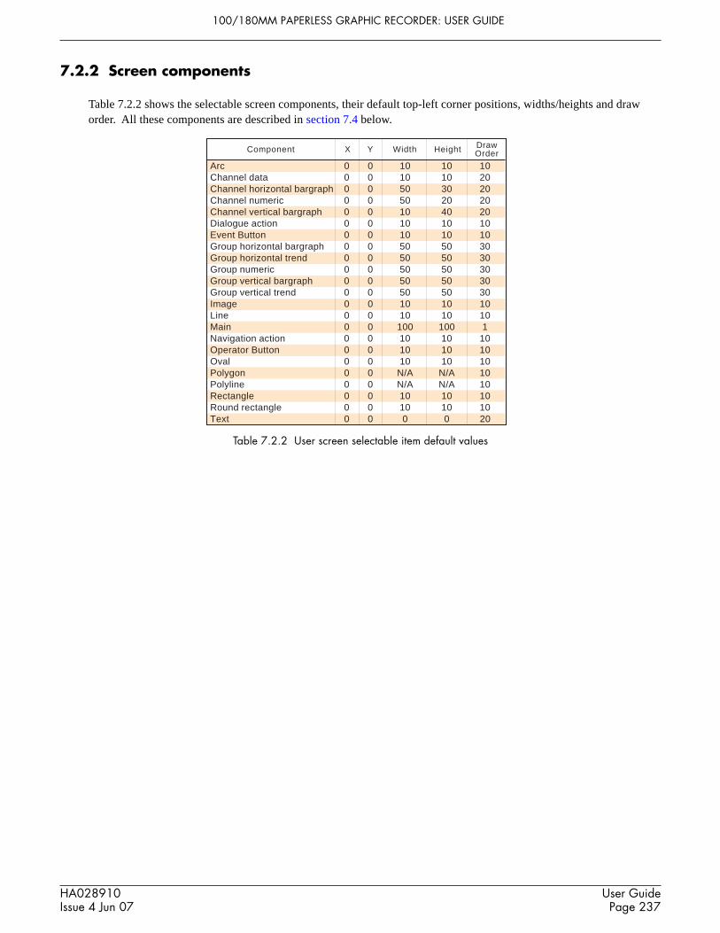
100/180MM PAPERLESS GRAPHIC RECORDER: USER GUIDE
HA028910Issue 4 Jun 07
User GuidePage 237
7.2.2 Screen components
Table 7.2.2 shows the selectable screen components, their default top-left corner positions, widths/heights and draworder. All these components are described in section 7.4 below.
Table 7.2.2 User screen selectable item default values
Arc 0 0 10 10 10Channel data 0 0 10 10 20Channel horizontal bargraph 0 0 50 30 20Channel numeric 0 0 50 20 20Channel vertical bargraph 0 0 10 40 20Dialogue action 0 0 10 10 10Event Button 0 0 10 10 10Group horizontal bargraph 0 0 50 50 30Group horizontal trend 0 0 50 50 30Group numeric 0 0 50 50 30Group vertical bargraph 0 0 50 50 30Group vertical trend 0 0 50 50 30Image 0 0 10 10 10Line 0 0 10 10 10Main 0 0 100 100 1Navigation action 0 0 10 10 10Operator Button 0 0 10 10 10Oval 0 0 10 10 10Polygon 0 0 N/A N/A 10Polyline 0 0 N/A N/A 10Rectangle 0 0 10 10 10Round rectangle 0 0 10 10 10Text 0 0 0 0 20
Component DrawOrderX Y Width Height

100/180MM PAPERLESS GRAPHIC RECORDER: USER GUIDE
HA028910Issue 4 Jun 07
User GuidePage 238
7.2.3 The properties page
1. Ensure that one or more user screens is enabled in views Configuration (section 7.1.1). If necessary, call the requiredUser screen to the display using the Root menu 'Goto View' menu.
2. Press the Option key to call the Option Menu.3. Press ‘Edit Screen’ to call the ‘Component Property Editor’ page to the display. This display contains the basic prop-
erties of the ‘Main’ (background) screen onto which the required components are to be overlaid.
Note: This may take some seconds, according to the complexity of the configuration
4. A further press of the Option key calls the user screen Options display page.5 Use the Option key again to return to the Component Properties display
Figure 7.2.3a Component properties and User screen options pages
KEY DESCRIPTIONS (UPPER KEYS)Add Calls the Component selection listDel Deletes (after confirmation) the component in the Identifier field (except the Main pane which cannot be de-
leted).Copy Used to copy the current component to the pasteboard. ‘Greyed’ for ‘Main’ as this cannot be Copied.Paste Used to ‘paste’ the copied component to the screen. The copied item is placed 1% to the right of, and 1% be-
low, the source component. ‘Greyed’ until a component Copy action has taken place.
Note
Batch
Option Menu
Edit Screen
Component Property Editor - Screen 1
Identifier
Last Error
Page Title
X Position
Y Position
Width
Height
Draw Order
Component Type Main
Dimension picklist.Select %, absolute pixels,or relative pixels.
Component properties(Fields vary according tocomponent type)
Background Colour
Goto Canvas Save Close More. . .
Add Del Copy Paste
Component Add/Delete etc.keys
Component picklist field
Usr Screen Options
Edit level
Component info on screen
Quick entry to edit
Basic
Use Last Properties
Positioning Grid
Positioning Tip
main_1.1
main_1.1
-1
100
100
0
0 %
%
%
%
-1

100/180MM PAPERLESS GRAPHIC RECORDER: USER GUIDE
HA028910Issue 4 Jun 07
User GuidePage 239
7.2.3 THE PROPERTIES PAGE (Cont.)
KEY DESCRIPTIONS (LOWER KEYS)Which keys appear at the bottom of the properties page depends on whether the user screen is being viewed at the re-corder’s user interface, or via Bridge software. Figure 7.2.3b show the recorder key arrangement; figure 7.2.3c theBridge keys. The key descriptions below are in alphabetical order, rather than in left-right appearance order.
Figure 7.2.3b Recorder key arrangement
Goto Canvas Save Close More... Revert Discard New More... Copy Screen Move Screen More...
Goto Canvas Save Close More...Revert DiscardDeploy
New More...Copy Screen Move ScreenDispose Import Export
Figure 7.2.3c Key arrangement via Bridge
Close Causes the screen to quit edit mode. If there are unsaved changes the user is asked for confirmation.Copy Screen Copies the contents of the current screen to another specified screen, leaving the current screen un-
changed. If the destination screen is already in use, confirmation is required before the screen isoverwritten.
Discard Causes all changes made since the last ‘Save’ to be ‘undone’Dispose This key appears only for users accessing user pages using Bridge software. When operated, it deletes the
local version of the screen, so that the display reverts to the deployed version.Deploy This key appears only for users accessing user pages using Bridge software. It causes the screen to be
saved to the PC database, and sent to the recorder.Export This key appears only for users accessing user pages using Bridge software. Calls a browser screen,
allowing the user to select a path name to which to Export the current screen.Goto Canvas The Component Property Editor page disappears, and the screen is shown with the current component
highlighted. Click and Drag techniques on the highlight ‘handles’ allow the component to be re-sized andits aspect ratio to be edited. Clicking and dragging within the highlighted area allows the component tobe moved to any position on the screen.Selecting a component and touching the option key ‘Goto Editor’ key returns the user to the ComponentProperty Editor with the selected component as the current component. (Using the Goto editor keywithout first highlighting a component re-opens the Component Property Editor with ‘Main’ as thecurrent component.)When editing via Bridge, double clicking on a component returns to the Component Property Editor withthat component as the current component.
Import This key appears only for users accessing user pages using Bridge software. Calls a browser screen,allowing the user to select a User Screen for import.
More... Calls next keyset.Move Screen Moves the contents of the current screen to another specified screen, leaving the current screen empty. If
the destination screen is already in use, confirmation is required before the screen is overwritten.New Allows the creation of a new (blank) screen. Current screen components are deleted (after confirmation)
leaving a blank screen. Items can be retrieved using the Revert key (above) prior to the next ‘Save’,‘Deploy’ or ‘Goto canvas’.
Revert Causes all changes made since the last ‘Goto canvas’ operation to be ‘undone’.Save Causes the current screen to be saved to flash or, for Bridge operation, to the PC database.

100/180MM PAPERLESS GRAPHIC RECORDER: USER GUIDE
HA028910Issue 4 Jun 07
User GuidePage 240
7.2.3 THE PROPERTIES PAGE (Cont.)
OPTIONS PAGE ITEMS
Edit levelAllows Basic or Advanced edit level to be selected for further use.
Component info on screenEnabling this box causes a component description to appear at the top left corner of each component. This descrip-tion is in the form: Identifier(X,Y)+[∂X,∂Y], where X and Y defines the top left corner position in pixels, and ∂Xand ∂Y are the width and height of the component in pixels. The identifier is the component name as appears in theIdentifier field of the Component Property Editor page.
Quick entry to editIf selected, this function allows direct entry from the user screen being edited to the Component Property editorpage, without the options menu first appearing offering the choice of ‘Batch’ or ‘Edit Screen’.
If Quick entry is selected, the option menu does not appear when the option key is touched. The Batch status pagecan be called by touching the ‘Page Name’ area at the top of the screen, as an alternative to the option menu.Quick entry has no effect on screens other than user screens.
Use Last propertiesIf selected, then all the common attributes (e.g. position, size, colours etc.) of the most recently edited object areapplied to the next component to be added.
Positioning GridCauses a grid to appear on the ‘Goto canvas’ screen to help in component layout
Positioning tipIf enabled, then hovering over the highlighted item in a ‘goto Canvas’ screen causes the coordinates of the top leftcorner of the component to appear, in whatever units (%, pixels etc.) are selected for the component. The firstnumber gives the ‘X’ (left-right) co-ordinate; the second gives the ‘Y’ (up-down) position.Clicking the left mouse key within a component causes the coordinates of the top left corner of the component toappear, in whatever units (%, pixels etc.) are selected for the component.Clicking the left mouse key outside a component, shows the co-ordinates of the mouse cursor tip. To see these co-ordinates within a component, the mouse must be click-dragged from outside the component.

100/180MM PAPERLESS GRAPHIC RECORDER: USER GUIDE
HA028910Issue 4 Jun 07
User GuidePage 241
7.2.4 Screen creation example
To produce a new display screen with channels one to four inclusive each displayed as an independent bar graph acrossthe width of the screen, with Group 1 vertical trend display below. To achieve the above, the following items will berequired:
1. Bar1: Horizontal bargraph with X = 0, Y = 0, Width = 100, Height = 10, channel = Channel 12. Bar2: Horizontal bargraph with X = 0, Y = 12, Width = 100, Height = 10, channel = Channel 23. Bar3: Horizontal bargraph with X = 0, Y = 24, Width = 100, Height = 10, channel = Channel 34. Bar4: Horizontal bargraph with X = 0, Y = 36, Width = 100, Height = 10, channel = Channel 45. Group 1: Vertical trend group with X = 25, Y = 48, Width = 50, Height = 50. Group name to appear above display.
PROCEDURE
1. Operate the ‘Add’ key to call the Component se-lection list.
2. Touch Channel Horizontal Bargraph to highlightit, then press ‘Add’.
3. Repeat step 2 three times then
4. Touch ‘Group Vertical Trend’, then ‘Add’, then‘Close’
5. The Component property editor page reappearswith the default values for the most recently addedcomponent displayed.
6. Touch the Identifier field, then enter the name‘Group 1’ ‘Ok’ using the pop-up keyboard whichappears.
7. In Group Number, select: 1) Group 1
8. Title bar is selected on (yes), as required
9 Enter the X (25%) and Y (48%) co-ordinates,using the same technique as was used for theIdentifier field in step 6. The default dimensions(50 x 50%) are as required.
10 The Draw order is as required.
11. Press ‘Save’
Component Property Editor - Screen 1
gr_vtrend_6.1
Identifier gr_vtrend_6.1
Last Error
X Position
Y Position
Width
Height
Background Colour
Component Type Group Vertical Trend (gr_vtrend)
-1
50
50
0
0 %
%
%
%
Group Number 0) Current display group
Show Title Bar Yes
Draw Order 30
Add Del Copy Paste
Goto Canvas Save Close More. . .
Identifier
Last Error
X Position
Group Number
Show Title Bar
Component Property Editor - Screen 1
Y Position
Width
Height
Background Colour
Component Type Group Vertical Trend (gr_vtrend)
Draw order
Add Del Copy Paste gr_vtrend_6.1
Group 1
-1
50
50
0
0 %
%
%
%
1) Group 1
Yes
30
Goto Canvas Save Close More. . .
List of component typesGroup Vertical Trend (gr_vtrend)
Group Horizontal Trend (gr_htrend)
Channel Numeric (ch_num)
Group Numeric (gr_num)
Channel Vertical Bargraph (ch_ver_bar)
Group Horizontal Bargraph (gr_hor_bar)
Channel Data (ch_data)
Navigation Action
Operator Button
Group Vertical Bargraph (gr_ver_bar)
Dialog Action
CloseAdd
Channel Horizontal Bargraph (ch_hor_bar)

100/180MM PAPERLESS GRAPHIC RECORDER: USER GUIDE
HA028910Issue 4 Jun 07
User GuidePage 242
Figure 7.2.3d Complete user screen
7.2.4 SCREEN CREATION EXAMPLE (Cont.)
12 Touch the component picklist field, and highlightthe topmost ch_hor_bar... field.
13. In the Identifier field, enter the name ‘Bar 1’ usingthe pop-up keyboard. (To enter numbers, touch the'Numeric' tab under the keyboard, then touch therequired number.)
14. The channel number is as required
15. Touch the width field and enter a value of 100.
16. Touch the height field and enter ‘10’
17. Press 'Save'
18. Touch the component picklist field and select an-other bargraph.
19. In a similar way to that described for Bar 1a) enter the identifier ‘Bar 2’b) select Channel 2 from the picklistc) enter a Y value of 12d) enter width = 100%; height = 10%.
20. Similarly configure Bar 3 and Bar 4, using theappropriate Y values (24 and 36) and Channelselection (3 and 4).
21 Finally, press 'Save', then ‘Close’, to reveal thedisplay page.
ch_hor_bar_2.2
Identifier Bar 1
Last Error
X Position 0 %
Y Position
Width
Height
Foreground Colour
Component Type
-1
10
100
0 %
%
%
Channel Horizontal Bargraph (ch_hor_bar)
Channel 1) Channel 1
Background Colour -1
Draw Order 20
Add Del Copy Paste
Component Property Editor - Screen 1
Goto Canvas Save Close More. . .
Identifier
Component Property Editor - Screen 1
Last Error
X Position
Y Position
Width
Height
Background Colour
Component Type Channel Horizontal Bargraph (ch_hor_bar)
Channel
Forground ColourDraw Order
Add Del Copy Paste ch_hor_bar_4.2
Bar 2
0 %
-1
10
100
12 %
%
%
2) Channel 2
-1-1
Goto Canvas Save Close More. . .
Group 1 . User Screen 1Batch Number:060711.015
14:01:2411/07/06Engineer
1.00000.0000
0.4187 ˚CChannel 1
1.00000.0000
0.3316 ˚CChannel 2
1.00000.0000
0.1427 ˚CChannel 3
1.00000.0000
0.6293 ˚CChannel 4
13:59:0211/07/06
0.0000 0.2000 0.4000 0.6000 0.8000 1.0000
Channel 1 0.4187˚C
Group 1

100/180MM PAPERLESS GRAPHIC RECORDER: USER GUIDE
HA028910Issue 4 Jun 07
User GuidePage 243
7.2.4 SCREEN CREATION PROCEDURE (Cont.)
In order to provide a degree of contrast, the background colour of the ‘Main’ page can be changed to a darker colour asshown for colour 22 in figure 7.2.3e, below. Figure 7.2.3f on the next page, shows the relevant component propertypages.
Figure 7.2.3e User screen example with coloured background
Group 1 . User Screen 1Batch Number:060711.015
14:01:2511/07/06Engineer
1.00000.0000
0.4187 ˚CChannel 1
1.00000.0000
0.3316 ˚CChannel 2
1.00000.0000
0.1427 ˚CChannel 3
1.00000.0000
0.6293 ˚CChannel 4
13:59:0211/07/06
0.0000 0.2000 0.4000 0.6000 0.8000 1.0000
Channel 1 0.4187˚C
Group 1

100/180MM PAPERLESS GRAPHIC RECORDER: USER GUIDE
HA028910Issue 4 Jun 07
User GuidePage 244
7.2.4 SCREEN CREATION PROCEDURE (Cont.)
Figure 7.2.3f background colour selection pages
0
8
16
24
32
40
48
1
9
17
25
33
41
49
2
10
18
26
34
42
50
3
11
19
27
35
43
51
4
12
20
28
36
44
52
5
13
21
29
37
45
53
6
14
22
30
38
46
54
7
15
23
31
39
47
55
Shift Caps BSpc Ovr Ok Cancel
Colour list
22
main_1.2
Identifier main_1.2
Component Property Editor - Screen 1
Last Error
Page Title
X Position
Y Position
Width
Height
Background Colour
Component Type Main
-1
100
100
0
0 %
%
%
%
Touch backgroundcolour fieldDraw Order 1
Add Del Copy Paste
Goto Canvas Save Close More. . .

100/180MM PAPERLESS GRAPHIC RECORDER: USER GUIDE
HA028910Issue 4 Jun 07
User GuidePage 245
7.3 PARAMETER DEFINITIONSThe following parameters are associated with the components listed in table 7.2.2, above. The list is divided into basicand advanced.
7.3.1 Basic parameters
Notes:1 Not all components have all the following parameters associated with them. The component definitions in
section 7.4 define each component’s parameters.2 The generic term ‘solid objects’ as used in this description includes rectangles, lines, arcs, rounded rectan-
gles, ovals, polygons and polylines. Lines and arcs do not have a background colour as they cannot befilled.
3. Default parameter units are in ‘percentage of screen width/height’. The picklist next to each dimensionfield allows pixels to be used instead.
Parameter Description
Table 7.3.1 Basic level parameters (sheet 1 of 2)
Arc Angle For Arcs only, the number of degrees of arc drawn anti-clockwise (counter-clockwise) from the StartAngle. Negative angles draw clockwise.See figure2.4.20a for definitions.
Arc Height For Rounded Rectangles only, this is double the vertical distance from the corner of the (unrounded)rectangle at which the curve is to start. To draw ‘circular’ corners, this value must be 3/2 times the ArcWidth. The Arc height value must be less than half the Rectangle height. Percent units are relative tothe rectangle height, not the screen height.
Arc Width For Rounded Rectangles only, this is double the horizontal distance from the corner of the (unrounded)rectangle at which the curve is to start. To draw ‘circular’ corners, this value must be 2/3 the ArcHeight. The Arc width value must be less than half the Rectangle width. Percent units are relative tothe rectangle width, not the screen width.
Background colour The fill colour of solid objects; the background colour for the main page, trend charts, text messagesetc. For Bargraphs, the colour ‘behind’ the bar.
Button Text For operator buttons, Dialogue Action and Navigation Action. Allows button text to be entered. Eventbutton text is defined in Event Button Configuration, described in section 4.3.7.
Channel Allows a channel to be selected for bargraph, numeric, value etc. display.Draw edge If set to ‘Yes’, this causes the outline shape of a solid object to be drawn in the foreground colour. If
set to ‘No’, the object’s outline is not drawn.Draw Order Allows a layer scheme to be introduced. Items with higher draw order values are overlaid on compo-
nents with lower draw order values. The Draw Order feature is included specifically to allow a dy-namic element (such as a bargraph) to be placed ‘on top of’ a background, static image. A dynamicelement is always drawn on top all other elements at update time. When one or more dynamic ele-ments are placed on top of one another, the results are unpredictable.
Edit Parameter For operator buttons, allows the user to select the parameter type (e.g Channel N Alarm 1) to be editedwhen the button is operated. The parameter number (N) is entered in the ‘N value’ field.
Event Button For Event buttons, this allows the user to assign an Event button to the User Screen Button to bedisplayed.
Feature For ‘Channel data’ only, allows the type of data to be displayed (e.g. Current value), to be selectedfrom a pick-list.
Fill Area If set to ‘Yes’, this causes a solid object to be filled with the background colour. If set to ‘No’, theinside of the object is transparent. If ‘draw edge’ is also set to ‘No’, the object is invisible.
Foreground Colour The line colour of solid objects. The bar colour of bargraphs (default = normal point colour). Thecolour of Text and of numeric values. Where applicable, this overrides channel colour.

100/180MM PAPERLESS GRAPHIC RECORDER: USER GUIDE
HA028910Issue 4 Jun 07
User GuidePage 246
7.3.1 BASIC PARAMETERS (Cont.)
Parameter Description
Table 7.3.1 Basic level parameters (sheet 2 of 2)
Group number Allows a group to be selected for group trend, bargraph and numeric displays, and for Dialogue actionbuttons. Select specific group, or '0' to follow current display group.
Height Height of a component, measured downwards from the component’s ‘Y position’. Negative valuesmeasure upwards.
Identifier Component name. Initially as in the Add Component list, but editable by the user.Image File Allows a file name to be entered when importing GIF or JPG images.Last error A text message describing the last error to occur for this component. The component must be re-edited
in order to clear the problem.N Value See ‘Edit parameter’ above.Page Title Allows a name for the current user screen to be entered in ‘Main’. This name appears at the top of the
screen, and in the Screen number picklist for navigation action buttons.Screen Number For navigation action buttons, allows a screen to be selected. When the button is operated, the instru-
ment will switch to the selected display screen.Show Title Bar When set to ‘Yes’, group displays (e.g. Group Vertical Trend) display a title bar across the top of the
component, giving the selected group’s descriptor. Selecting ‘Show Title Bar’ to ‘No’, removes thetitle bar from the display
Start Angle For Arcs only, defines a start point for ‘Arc Angle’ above. See figure2.4.20a for definitions.Text Allows a text string to be entered for display at the screen. The hash (#) key may not be used in text
messages.Width The width of a component measured rightwards from the component’s “X position’. Negative values
measure leftwards.X points Defines the X co-ordinates for polylines and polygons. Must match the number of Y-points for correct
interpretationX position Distance between the left edge of the screen and the left edge of the component.Y points Defines the Y co-ordinates for polylines and polygons. Must match the number of X-points for correct
interpretationY position Distance between the top edge of the screen and the top edge of the component.

100/180MM PAPERLESS GRAPHIC RECORDER: USER GUIDE
HA028910Issue 4 Jun 07
User GuidePage 247
7.3.2 Advanced parameters
The selection of the Advanced properties set, is carried out from the Properties Options page as described in section7.2.3, above. Advanced properties are in addition to the basic properties described above, not a replacement for them.
Parameter Pick list content Description
3D effect Enable/Disable For Channel numeric display only, adds an embossed boxed surround tothe display. Applies only if ‘Custom’ selected as Faceplate style.
Alarm marks colour None Allows a colour to be selected for alarm marks on trend scales. Default iscolour 0 (red).
Bargraph style Single Line... For horizontal bargraphs only. 'Plain' produces a bargraph with descriptorto the left of the bar, digital value to the right of the bar, and alarm indica-tion to the right of the decimal value. 'With units' adds units after thedigital value. '3D' adds an embossed boxed surround. 'Scale' adds a scalebelow the bar, with end-point values and tick points. Scale style (describedbelow) may be used to modify the appearance of the scale.
Faceplate below bar Produces coloured bar above channel descriptor, digital value and alarmindication. No scale is printed
Just bar Produces a colour bar with no textual information, or just the low and highscale values, according to component.
Bar and scale Produces a colour bar with a scale, but no digital value or alarm indicationDefault Produces a colour bar with scale, with descriptor, digital value and alarm
indication above.Default Vertical Bargraph Produces a colour bar with a scaleSystem Vertical Bargraph Produces a colour bar with a scaleHorizontal Bargraph Produces a colour bar with scale, with descriptor, digital value and alarm
indication above.
Best Fit Font Enabled/Disabled For Channel numeric only. Applies only if ‘Custom’ selected as Faceplatestyle. If enabled, the display fonts for descriptor, value and units areselected by the instrument to suit the screen scale. The fonts will thus varyin size according to the size of the Channel Numeric display. Overriddenby any settings for Value Font, Descriptor Font or Units Font other than‘Default’.
Channel cycle time 10 For group trend displays, allows a time period, in seconds, to be enteredfor channel scroll rate. 0 = no scroll.
Colour Alarms None Used only when Colour style = ‘Channel alarms’. A semicolon-separatedlist of (Colour channel) alarms, used to change the colour of the compo-nent being configured according to alarm status. Colours are defined in‘Colour Backgrounds’ and ‘Colour Foregrounds’, described below.
Colour Backgrounds None Used only if Colour style = ‘Channel Alarms’ or ‘Channel thresholds’. Asemicolon-separated list of background colours for the component beingconfigured. The number of colours entered must match the number ofalarms or threshold values as appropriate. Overrides any entry in ‘Back-ground Colour’. Colours are entered by touching each required selectionin turn. The semicolon separators are entered automatically, in front ofeach selection (apart from the first).
Colour channel All channels Allows a channel to be defined to be used in percentile or quartile filling oras a source of channel thresholds or channel alarms, as selected in ‘Colourstyle’, below.
Table 7.3.2 Advanced edit level parameters (sheet 1 of 6)

100/180MM PAPERLESS GRAPHIC RECORDER: USER GUIDE
HA028910Issue 4 Jun 07
User GuidePage 248
Colour foregrounds None Used only if Colour style = ‘Channel Alarms’ or ‘Channel thresholds’. Asemicolon-separated list of foreground colours for the component beingconfigured. The number of colours entered must match the number ofalarms or threshold values as appropriate. Overrides any entry in ‘Fore-ground Colour’. Colours are entered by touching each required selectionin turn. The semicolon separators are entered automatically, in front ofeach selection (apart from the first).
Colour style Channel thresholds Allows a number of semicolon-separated values to be entered, to act ascolour change triggers for the component being configured. The values arethose of the source channel selected in ‘Colour Channel’ described above.The number of threshold values entered must match the number of colourvalues entered in Colour Foregrounds and Colour Backgrounds.
Channel Alarms Allows a number of semicolon-separated values (1 to 4) to be entered, toact as colour change triggers for the component being configured. Thesevalues represent alarms 1 to 4 of the source channel selected in ‘ColourChannel’ described above. The number of alarms entered must match thenumber of colour values entered in Colour Foregrounds and ColourBackgrounds. Point is displayed in the colour of the latest active alarm. Forexample: Alarms configured 1,2. Foreground colours configured 3;0(amber and red). When alarm 1 goes active, the component goes amber.When alarm 2 goes active the component goes red. When alarm twoclears, component reverts to Amber and so on.
Background quartile Background colour represents the value of the colour channel. Colour 0appears for values below 25%, colour 1 for values between 25 and 50 %,colour 3 for values between 50 and 75% and colour 4 for values above 75%. Foreground colour is default (-1).
Foreground quartile As background quartile but for the foreground colour. Background colouris default (-1).
Background decimal Background colour represents the value of the colour channel. Colour 0appears for values below 10%, colour 1 for values between 10 and 20 %,colour 2 for values between 20 and 30% and so on up to colour 9. Fore-ground colour is default (-1).
Foreground decimal As background decimal but for the foreground colour. Background colouris default (-1).
Colour Thresholds None Used only when Colour style = ‘Channel thresholds’. A semicolon-separated list of (Colour channel) values, used to change the colour of thecomponent being configured according to the process value of the pointselected in ‘Colour Channel’ described above. The number of thresholdvalues entered must match the number of colours defined in ‘ColourBackgrounds’ and ‘Colour Foregrounds’, described above.
Decimal places Default Number of decimal places in Channel data display.
Descriptor Font Default For Channel Numeric displays only, if Faceplate Style is set to ‘Custom’,then Descriptor Font allows the Channel Descriptor font to be selectedfrom a picklist.
Display Alarms Enable/Disable For Channel Numeric displays only, if Faceplate Style is set to ‘Custom’,this selection determines whether or not alarm symbols are displayed in thetop right hand corner of the display.
7.3.2 ADVANCED PARAMETERS (Cont.)
Parameter Pick list content Description
Table 7.3.2 Advanced edit level parameters (sheet 2 of 6)

100/180MM PAPERLESS GRAPHIC RECORDER: USER GUIDE
HA028910Issue 4 Jun 07
User GuidePage 249
Display Bargraph None If selected, a vertical bargraph is drawn at the right hand edge of Horizon-tal Trend displays.
Display Descriptor Enable/Disable For Channel Numeric displays only, if Faceplate Style is set to ‘Custom’,this selection determines whether or not the channel descriptor appears atthe top of the display.
Display messages Enable/Disable If selected, displays a message bar for Horizontal Trend displays.
Display Pens Enable/Disable If selected, pen representations appear at the top or right edge of a trendchart.
Display Units Enable/Disable For Channel Numeric displays only, if Faceplate Style is set to ‘Custom’,this selection determines whether or not the channel’s units appear at theright edge of the display.
Faceplate Style Default Produces a channel display with the descriptor and alarm indicators on thetop line and with the digital value, and units on the bottom line.
Just value Shows only the channel valueNo alarms As default, but without alarm displayValue and Units Produces a larger digital display of the channel value, with units.Single line Faceplate As default, but all on a single line.Custom The ‘Display Descriptor’, ‘Display units’ and ‘Display Alarms’ checkbox
settings, and the font selections for Value, Units and Descriptor becomeactive only if ‘Custom’ is selected as Faceplate style.
Faceplates Location Dynamic, N, S, E, W (Not available for group horizontal bargraph displays.) Allows the positionof the faceplates to be ‘dynamic’ (appears at best position for the numberof channels), or to be located above (North), below (South), to the right(East) or to the left (West) of the bargraphs. Also allows faceplates to beturned off altogether. For group trend displays, these faceplates are inaddition to the current-channel faceplate, which always appears above the'chart' across the full width of the display, unless turned off using Horizon-tal Faceplate disable.
Font style List of fonts Picklist holds a number of sizes, plain, bold and underlined bold.
Grid Line colour Default Allows a colour to be selected for trend chart gridlines
Horizontal Alignment Left/centred/right Allows text to be justified relative to its width setting
Horizontal Faceplate Enable/Disable For vertical trend displays, allows the current-channel faceplate to beselected on or off.
Horizontal Grid total Default Number of vertical divisions of a trend chart. If left at default uses thevalue entered in Group Configuration (section 4.3.2). Any other settingoverrides Group Configuration entry.
Horizontal Minor Divs Default Allows the user to enter a number of minor grid divisions. If left at defaultuses the value entered in Group Configuration (section 4.3.2). Any othersetting overrides Group Configuration entry
7.3.2 ADVANCED PARAMETERS (Cont.)
Parameter Pick list content Description
Table 7.3.2 Advanced edit level parameters (sheet 3 of 6)

100/180MM PAPERLESS GRAPHIC RECORDER: USER GUIDE
HA028910Issue 4 Jun 07
User GuidePage 250
Line thickness 1 Allows a pixel value to be entered for the line thickness of some compo-nents. It should be noted that the nature of the screen and of the drawingmethod means that curved lines of multi-pixel thickness can suffer fromMoiré fringe, or interference effects.
Message Colour Default Allows a colour to be selected for messages on a trend chart
Minimum Height Default For individual channels within a group horizontal bargraph display
Minimum Width Default For individual channels within a group vertical bargraph display
Minor grid line colour Default Allows a colour to be selected for trend chart minor gridlines
Nominal height None 653 (503) = height of large frame (small frame) display area in pixels
Nominal width None 1024 (934) = width of large frame (small frame) display area in pixels
Notes None Allows a note to be entered for the users convenience.
Number of Columns None Lays out group displays (other than trend) in the specified number ofcolumns.
Number of Rows None Lays out group displays in the specified number of rows.
Numeric width None Number of characters in channel data display including decimal point.
On visibility change Paint Background Repaint the area of the component, including any text, in its backgroundcolour. If no background colour has been defined, the default (silver/grey)colour is used.
Paint All Repaints the component area in the screen background colour thus render-ing the component invisible.
PV Error Colour BackgroundDefault Allows a colour to be selected for background use when the relevant PV is
in an error state. Overrides other selections.
PV Error Colour ForegroundDefault Allows a colour to be selected for foreground use when the relevant PV is
in an error state. Overrides other selections
Reversed colour None Allows text to be displayed in the background colour against a backgroundof foreground colour.
Scale Digits None For Horizontal trend displays. Allows the chart area to be maximised, byreducing the width of the vertical bar to the right of the chart. Scales willbe presented in scientific format, or in ‘N.?’, ‘N?’ format etc. depending onthe number of digits specified. The number of digits is in addition to thedecimal point.
Scale Divisions - Major None For channel bargraphs, allows the number of major scale divisions to bespecified for the channel. Overwrites the Scale Divisions-Major setting inthe Channel’s configuration.
7.3.2 ADVANCED PARAMETERS (Cont.)
Parameter Pick list content Description
Table 7.3.2 Advanced edit level parameters (sheet 4 of 6)

100/180MM PAPERLESS GRAPHIC RECORDER: USER GUIDE
HA028910Issue 4 Jun 07
User GuidePage 251
Scale Divisions - Minor None For channel bargraphs, allows the number of minor scale divisions to bespecified for the channel. Overwrites the Scale Divisions-Minor setting inthe Channel’s configuration.
Scale style Scale on bar.--- See the figure below for clarification. For vertical bargraphs only.No Text Produces scale tick marks, but without valuesDecimal scale For bargraphs, produces scale with 9 divisions (0, 10, 20, 30, 40, 50, 60,
70, 80, 90, 100% of scale width). Zero and full scale values printed. ForHorizontal bargraphs, each scale division has 4 minor divisions (0, 20, 40,60, 80, 100 % of major division).
Default Uses scale information from each point's scale configurationHorizontal Bargraph As default for horizontal bargraphsHorizontal Faceplate Produces faceplate display with scale end points, descriptor, digital value
and alarm indicatorVertical bargraph As default for vertical bargraphs.
Table 7.3.2 Advanced edit level parameters (sheet 5 of 6)
7.3.2 ADVANCED PARAMETERS (Cont.)
Parameter Pick list content Description
Show Alarm Marks Yes/No Allows channel scale alarm marks to be displayed (yes) or not (no). AlarmMarks Colour, described above, allows the user to select a colour for thealarm marks.
Time Marker colour Default Allows a colour to be selected for time/date printing on a trend chart
Time Marker interval Default Number of horizontal grid lines between successive time markers.
Trend Padding Default For group trend only. Normal trends are 1 pixel wide. Setting a paddingvalue of N, adds N pixels on each side of the central pixel. For example, apadding value of 2 would produce traces 5 pixels wide. Applies to allchannels in the group.
Units Font List of fonts For Channel Numeric displays only, if Faceplate Style is set to ‘Custom’,then Units Font allows the Channel Units font to be selected from apicklist.
Update when Value changes Action is taken when the value associated with the component changesAlways The component is redrawn, continuously, at the display update rate.
Vertical alignment Centred/bottom/top Allows text to be positioned relative to its height setting
Value Font List of fonts For Channel Numeric displays only, if Faceplate Style is set to ‘Custom’,then Value Font allows the Channel Value font to be selected from apicklist.
400.00
440.00
480.00
520.00
560.00
600.00
640.00
680.00
720.00
760.00
800.00
Scale on barValue 10
Scale on barValue 12
400.00433.00467.00
533.00567.00600.00633.00
700.00733.00767.00800.00
667.00
500.00
0
10
20
30
40
50
60
70
80
90
100
Scale on bar Percent
0
10
20
30
40
50
60
70
80
90
100
0
10
20
30
40
50
60
70
80
90
100
RightLeft Centre
400.00
800.00
Decimal scale
400.00
800.00
VerticalBargraph
The examples below are alternatives - only one style can be chosen for each group bargraph display.

100/180MM PAPERLESS GRAPHIC RECORDER: USER GUIDE
HA028910Issue 4 Jun 07
User GuidePage 252
Vertical Grid Total Default Number of vertical divisions for trend chart. If left at default uses the valueentered in Group Configuration (section 4.3.2). Any other setting overridesGroup Configuration entry
Vertical Minor Divs Default Allows the user to enter a number of minor grid divisions. If left atdefault, the value entered in Group Configuration (section 4.3.2) is used.Any other setting overrides Group Configuration entry
Visible Alarm Default For ‘When Visible’ (below) is selected as ‘In alarm or error’ or ‘not inalarm or error’. ‘Visible Alarm’ allows an alarm number to be entered, foruse in determining whether a component be visibile or invisible.
Visible Channel All points For use ‘When Visible’ (below) is selected as ‘Channel Value’, ‘In alarm orerror’ or ‘not in alarm or error’. ‘Visible Channel’ allows a point numberto be selected from a pick list. See also Visible Operator, and VisibleValue, below.
Visible Operator List of operators For ‘When Visible’ (below) is selected as ‘Channel Value’. ‘VisibleOperator’ allows a comparison operator to be selected from a picklist. Thepicklist contains the following items:Greater than, Less than, Greater than or equal to, Less than or equal to,Equal to, Not equal to. The comparison is made between the instantaneousvalue of the point selected in ‘Visible Channel’ and the value entered in‘Visible Value’ (below). For example, when using the ‘Greater than’operator, the component is visible whenever the Visible Channel’s value isgreater than the Visible Value.
Visible Value Default For ‘When Visible’ (below) is selected as ‘Channel Value’. ‘Visible Value’allows a value to be entered to be used in the ‘Visible Operator’ compari-son described above.
When visible Always Component is always visibleNever Component is never visibleChannel value Component is visible or not, depending on the relationship between the
current value of a selected channel and a specified constant value. See‘Visible channel’, above, for details.
In alarm or error Component is visible if a specified alarm on a specified point is active, orif the point is in an ‘Error’ state. See ‘Visible Alarm’, above, for details.
Not in alarm or error Component is visible if a specified alarm on a specified point is not active,or the point is not in an ‘Error’ state. See ‘Visible Alarm’, above, fordetails.
7.3.2 ADVANCED PARAMETERS (Cont.)
Parameter Pick list content Description
Table 7.3.2 Advanced edit level parameters (sheet 6 of 6)

100/180MM PAPERLESS GRAPHIC RECORDER: USER GUIDE
HA028910Issue 4 Jun 07
User GuidePage 253
7.4 COMPONENT DEFINITIONS
This section defines all the available components listed in table 7.2.2 in terms of their parameters. The componentsoccur in the order in which they appear in the list.
7.4.1 Group Vertical/Horizontal Trend
This produces a display which mimics a recorder chart, for a selected group. All the functions (e.g. trend history) de-scribed in, sections 3.4.1 and 3.4.2. The following unique parameters (fully described in table 7.3.2) are available forconfiguration:
Background colour Allows the ‘chart’ to be drawn in the selected colour.Message Colour The colour of messages printed on the ‘Chart’.Time Marker Colour The colour of time/date printed on the ‘Chart’.Grid Line Colour The colour of the ‘Chart’ grid lines.Faceplates location Allows 'group' faceplates to be enabled/disabled, and when enabled allows the position of the
faceplates to be defined. These 'group' faceplates are additional to the current-channelfaceplate which always appears above the chart, unless it has been disabled under 'Horizontalfaceplate' (below).
Time Marker Interval Selects the number of horizontal chart lines between successive time markersVertical Grid Total Total number of vertical chart divisions.Horizontal Grid Total Total number of horizontal chart divisions.Trend Padding Sets thickness of traces.Channel cycle time Allows a number to be entered for the scrolling period between channels. 0 = Channel hold.Display Messages Allows message printing to be enabled/disabled.Display Bargraph For Horizontal trending only, allows the vertical bargraph display to be switched on andoff.Display Pens Allows the pen icons at the edge of the chart to be switched on and off.Horizontal Faceplate Allows the current-channel faceplate to be switched on and off.
7.4.2 Group vertical bargraph
Produces a vertical bargraph for a selected group in a format defined by ‘Bargraph Style’ and ‘Scale style’ described intable 7.3.2. The number of rows of bars can also be defined by the user, according to the overall size of the display,number of channels etc. The default value of zero means that the recorder will display what it ‘believes’ to be the mostergonomic number of rows.
The recorder attempts to fit as many channel bars as possible into the width of the display. The default minimum widthof a column is 6 mm. If there are more channels than can be fitted into the display, a scroll bar device appears at thebottom edge to allow ‘hidden’ bars to be accessed.
The recorder attempts to fit as many faceplates as possible into the height of the display. If there are more faceplatesthan can be fitted into the display, a scroll bar device appears to allow ‘hidden’ faceplates to be accessed.
7.4.3 Group horizontal bargraph
Produces a group horizontal bargraph, for a selected group, in a format defined by ‘Bargraph Style’ and ‘Scale style’described in table 7.3.2. The number of columns can also be defined by the user, according to the overall size of thedisplay, minimum width, number of channels etc.
The recorder attempts to fit as many channels as possible into the height of the display, according to the specified mini-mum height (default = 12mm). If there are more channels than can be fitted into the display, a scroll bar appears at theright edge to allow ‘hidden’ channels to be accessed.

100/180MM PAPERLESS GRAPHIC RECORDER: USER GUIDE
HA028910Issue 4 Jun 07
User GuidePage 254
7.4.4 Group numeric display
This produces a display of a selected group's numeric values, in one of a number of formats, as described in ‘FaceplateStyle’ in table 7.3.2 above. The number of columns can also be defined by the user, according to the overall size of thedisplay, number of channels etc. The default value of zero means that the recorder will display what it ‘believes’ to bethe most ergonomic number of columns.
The recorder attempts to fit as many channels as possible into the height of the display, according to the specified mini-mum height (default = 12mm.). If there are more channels than can be fitted into the display, a scroll bar appears at theright edge to allow ‘hidden’ channels to be accessed.
7.4.5 Channel vertical/horizontal bargraph
For a specified channel, this produces a dynamic horizontal or vertical bargraph display of channel value, in a formatdefined by ‘Bargraph Style’ and ‘Scale style’ described in table 7.3.2
7.4.6 Channel Numeric
For a specified channel, allows the channel faceplate to be displayed in one of a number of formats, as described in‘Faceplate Style’ in table 7.3.2 above.
7.4.7 Channel data
For a specified channel, allows one of : Current value, Descriptor, Units, Span low or Span high to be selected for dis-play.
7.4.8 Dialogue Action
This displays a pushbutton which can have one of three actions assigned to it:1. Call the Login page.2. Call the Batch Status page3. Call the Operator Note dialogue box.For Batch and Operator Note use, a Group number can be selected.
7.4.9 Navigation Action
This displays a pushbutton, the purpose of which is to call a different display screen. A Group and a screen can both bespecified, so this button provides a shortcut version of the ‘Goto group’ and ‘Goto View’ keys of the root menu.

100/180MM PAPERLESS GRAPHIC RECORDER: USER GUIDE
HA028910Issue 4 Jun 07
User GuidePage 255
7.4.10 Operator button
This displays a user pushbutton. The legend on the pushbutton, and the task it is to carry out, are defined in the buttonconfiguration. If the text is too long for the width of the button, the text is truncated (e.g. Reset Ave...). Possible tasksare as follows (assuming that the relevant options are fitted):
1 Edit the threshold (setpoint) setting for alarms 1 to 4 for point N2 Reset Maths channel N3 Edit Maths constant N4 Preset Totaliser N5 Preset Counter N6 Start/Stop Timer N7 Initiate Demand Write N8 Set output channel N to default values.
In all the above, N represents any number between 1 and the maximum number available for the relevant type of point.(Point is an umbrella term for input channel, a maths channel, a totaliser, etc.)
When the button is operated a ‘confirmation’ page appears allowing, for example, the value of a constant to be editedbefore operating the ‘Apply’ button.
Notes:1 If the point being accessed is not suitably configured, the ‘confirmation’ page is blank. For example, if the
Operator button is configured to change, say, the threshold (SP) of Alarm 2 on Channel 6, and eitherChannel 6 is Configured ‘Off’, or alarm 2 is ‘Off’, then the Confirmation page will not have aconfigurable area allowing the user to enter the required new value.
2. Any signing or authorizing that normally applies to the item being edited, also applies when changes arebeing made by means of the Operator button.
7.4.11 Event Button
This displays a pushbutton, to be used as a source for an event. The button name, its action (latching or unlatching),and whether or not the operation of the button needs signing or authorizing are set up in Event Button configuration,described in section 4.3.7. The actions taken when the button is operated are set up in Event configuration, described insection 4.3.6. Signing and Authorizing are as described in section 4.4.2 (Management).
Figure 7.4.11 Typical Event Button
7.4.12 Image
This allows a GIF (Gif87a format only) or JPG image file to be loaded from (e.g.) an SD or Flash card. Once this hasbeen done, bargraphs, text messages etc. can be superimposed on the image.
Notes:1 Only user screens 1 to 6, may have images embedded in them, and the size of each image may not exceed
250kB (see also note 3). Does not apply to Bridge-only screens (25 to 124).2. It is recommended that ‘abs_pxl’ be selected as width and height units, before an image is loaded. The use
of any other units significantly increases the time taken for the loading process to complete.3. For user screens 1 to 6, the physical size of the image may not exceed 1024 pixels wide or 768 high. Any
attempt to load am image larger than this results in a ‘User Screen Image Error’ message asking that theimage size be reduced. The size constraint does not apply to Bridge-only screens (25 to 124).
Reset Average
Ack Alarms
Figure 7.4.10T ypical operator button

100/180MM PAPERLESS GRAPHIC RECORDER: USER GUIDE
HA028910Issue 4 Jun 07
User GuidePage 256
7.4.13 Text
If width and height are left with the default values of zero, the text will start at the specified start point and fit in thespace between there and the right edge of the screen, in a single line (left justified (ranged) as a default). If the textstring is too long, it is truncated. The text appears in the specified foreground colour, superimposed on a 'box' ofbackground colour which is the same width of the text string.
If width and height are defined, then the text will fill the defined width and any remaining text is truncated. The textappears in the foreground colour (default black), over a field of background colour (default grey).
Advanced properties allow the text to be set to range left, range right or be centred, at the top, bottom or centre of thefield, and for the foreground and background colours to be swapped.
7.4.14 Round rectangle
Similar to a rectangle described in section 7.4.15, but offers the user the opportunity to draw rectangles with curvedcorners. The horizontal and vertical curve angles are specified separately, and the aspect ratio of the screen should betaken into account when working in percentage units.
Note: The rounded rectangle will draw incorrectly if either of the arc height/width settings are greater thanhalf the rectangle height/width settings.
Figure 7.4.14 Round rectangle definitions
7.4.15 Rectangle
This draws a rectangle on the display page. If the height and width of the rectangle are defined in the default ‘percent-age units’, then entering equal values for height and width will result in a rectangle with the same aspect ratio as that ofthe screen, not a square as might be expected. Because the screen height is approximately 2/3 the width, the rectangleheight should be 3/2 the rectangle width to produce a square. (The actual height/width ratio is 535/800 = 0.669 forlarge frame units or 214/320 = 0.669 for small frame units).
Using pixels as the measuring units obviates this problem as pixels are square.
Y Position
X Position
Width
1/2 Arc width
1/2 Archeight
Height

100/180MM PAPERLESS GRAPHIC RECORDER: USER GUIDE
HA028910Issue 4 Jun 07
User GuidePage 257
7.4.16 Polyline - series of points
Similar to closed polygons, described in section 7.4.17 below, but the first and last points are not automatically joined,and the drawn item cannot be filled and the line width cannot be specified - it is always one pixel.
Note: When working in percentage units, it should be remembered that vertical percentage units are only 2/3the size of horizontal percentage units - this affecting the appearance of the drawn item.
Example: To draw an (old fashioned) electronic resistor icon (Units = Absolute pixels)
X position = 400, Y position = 236,Foreground colour = 0X points = 0,10,15,25,35,45,55,65,75,85,90,100Y points = 0,0,-10,10,-10,10,-10,10,-10,10,0,0
Press 'Apply', then 'Close' to produce a red ‘sawtooth’ outline, as depicted in figure 7.4.16 below.
Figure 7.4.16 Polyline example
Group 1 • User Screen 1Batch Number:060711.015
14:20:5011/07/06Engineer
Point1X=0; y=0
Point 12X=100; y=0

100/180MM PAPERLESS GRAPHIC RECORDER: USER GUIDE
HA028910Issue 4 Jun 07
User GuidePage 258
7.4.17 Polygon - closed area
This allows a number of pairs of points to be entered, which, if valid, will then be joined by straight lines. The first andlast points are automatically joined, by the recorder. The shape, drawn in the specified foreground colour, with thespecified line width, can be filled with the specified background colour.
Note: When working in percentage units, it should be remembered that vertical percentage units are only 2/3the size of horizontal percentage units - this affecting the appearance of the drawn item
Example: To draw a left pointing solid arrow, positioned with its point at the centre of the screen.
Access the component page as described in section 7.2.3, select ‘polygon - closed area’ and press Ok. In the propertiespage, carry out the following configuration (units = %):
X position = 50, Y position = 50,Background colour = 22, Foreground colour = 30Draw edge = Yes, Fill area = YesX points = 0,10,10,30,30,10,10Y points = 0, -15, -5, -5, 5, 5, 15
Press Apply, then Close to produce a dark green arrow, with pale green outline, as depicted in figure 7.4.17 below.
Figure 7.4.17 Polygon example
14:22:1511/07/06
Point 1X= 0; y= 0
Point 2X=10; y=-15
Point 3X=10; y=-5 Point 4
X=30; y=-5
Point 5X=30; y= 5Point 6
X=10; y= 5
Point 7X=10; y= 15
Group 1 • User Screen 1Batch Number:060711.015
Engineer

100/180MM PAPERLESS GRAPHIC RECORDER: USER GUIDE
HA028910Issue 4 Jun 07
User GuidePage 259
7.4.18 Oval
Similar to an arc (section 7.4.20) with an arc angle of 360 degrees, but arcs cannot be filled,
If the height and width of the oval are defined in the default ‘percentage units’, then entering equal values for heightand width will result in an oval with the same aspect ratio as that of the screen, not a circle as might be expected. Be-cause the screen height is approximately 2/3 the width, the oval height should be 3/2 its width to produce a circle.(The actual height/width ratio = 0.669).
7.4.19 Line
This causes a straight line of user-definable thickness to be drawn between the points (X position; Y position) and (Xposition + width; Y position + height)
Notes:1 Y increases downwards; X increases rightwards2 Height = 2/3 width if measuring in percent
X position;Y position
Height
Width
X position + width;Y position + height
Figure 7.4.19a Line definitionsEXAMPLE
To draw an approximation to a St.Andrew’s cross (saltire):
Access the component property editor page as described in section 7.2.3:Select Advanced Edit level, then in the component property editor page1. touch the ‘Add’ key at the top of the screen. In the ‘List of Component types’ page, press ‘Line’, ‘Add’, ‘Line’,
‘Add’, then ‘Close’2. In ‘main_1.2’ - set background colour to 64. In ‘line_2.3’ Set Width to 100, Height to 100. Set Foreground colour to 55 and Line thickness to 355. In ‘line_3.4’ - Set X position to 100, Width to -100, Height to 100. Set Foreground colour to 55 and Line thickness
to 356. Press 'Save', then 'Close'.
Note: because of the thickness of the lines takes the corners beyond the display area, an error message mayappear in the ‘Last error’ field for the lines : position maybe out of bounds. This should not prevent the screenbeing drawn correctly.
Figure 7.4.19b Example

100/180MM PAPERLESS GRAPHIC RECORDER: USER GUIDE
HA028910Issue 4 Jun 07
User GuidePage 260
7.4.20 Arc
This causes a curved line of user-definable thickness to be drawn anti-clockwise between start angle and (start angle +arc angle). The origin (‘centre’) of the arc is (X position + 1/2 Width) ; (Y position + 1/2 Height). Arcs cannot befilled.
Notes:1 Angle increases anticlockwise2 Height = 2/3 width if measuring in percent3 Arcs cannot be filled - the shading in the figure is included for clarity only
Figure 7.4.20a Arc dimension definitions
EXAMPLEAn arc definition of:X position = 50%, Y position = 50%, Width = 50%, Height = 50%, Start angle = 0; Arc angle 270 would produce thecurve depicted in figure 7.4.20b, below.
Figure 7.4.20b Sample arc
X/Y Position
1/2 Width
1/2 HeightArc Start point
Arc end point
= Start angle= Arc angle
14:24:3111/07/06
Width
Height
X position;y position
Start of arc
End of arc
Group 1 • User Screen 1Batch Number:060711.015
Engineer

100/180MM PAPERLESS GRAPHIC RECORDER: USER GUIDE
HA028910Issue 4 Jun 07
User GuidePage 261
7.5 MEASURING UNIT COMPARISONS
Note: All the following figures are approximate.
7.5.1 XGA screen
The physical display screen area available for user screens is approximately 245 mm across and 164 mm high. Thisarea can be divided into a 100 x 100 array for percentage measurement or into a pixel array, 1024 across by 700 verti-cally.
Thus, horizontally,10 mm = 4% = 42 pixels
or 1% = 2.45 mm = 10.24 pixelsor 10 pixels = 2.45 mm
and Vertically,10 mm = 6% = 43 pixels
or 1% = 1.64 mm = 7 pixelsor 10 pixels = 2.3 mm
Centre of screen is given by X = 50%; Y = 50% or by X = 512 pixels; Y = 350 pixels
7.5.2 QVGA screen
The physical display screen area available for user screens is approximately 100 mm across and 72 mm high. This areacan be divided into a 100 x 100 array for percentage measurement or into a pixel array, 320 across by 210 vertically.
Thus, horizontally,10 mm = 10% = 32 pixels
or 1% = 1 mm = 3.2 pixelsor 10 pixels = 3.2 mm
and Vertically,10 mm = 13% = 29 pixels
or 1% = .72 mm = 2.4 pixelsor 10 pixels = 3.4 mm
Centre of screen is given by X = 50%; Y = 50% or by X = 160 pixels; Y = 105 pixels
7.6 ERROR CODES
Error codes 1 to F may appear at the top left corner of the screen. The following codes are currently implemented, andif more than one occurs at the same time, the code numbers are added. For example, Error code 6 would mean thatcodes 4 and 2 had both occurred.
1 Component error e.g. image does not exist.2 Error loading the Property.uhr file4 Error loading the Style.uhr file8 Error loading the usrscrn.uhu file

100/180MM PAPERLESS GRAPHIC RECORDER: USER GUIDE
HA028910Issue 4 Jun 07
User GuidePage 262
8 MODBUS TCP SLAVE COMMS
8.1 INSTALLATION
The installation of the Modbus link consists of connecting a standard Ethernet cable between the RJ45 connector at therear of the recorder either:
1. Directly to a host computer, using a crossover cable2. To a host computer via a network, using a ‘straight through’ cable.
8.2 INTRODUCTION
MODBUS TCP allows one or more recorders to act as ‘slave’ devices to one or more host computers connected via theRJ45 connector at the rear of the recorder. Each recorder must have a unique Internet Protocol (IP) address, set up asdescribed in Section 4.5.
MODBUS TCP (Transmission Control Protocol) is a variant of the MODBUS family of communications protocolsintended for supervision and control of automated equipment specifically covering the use of MODBUS messaging inan intranet or internet environment, using TCP/IP protocols. Much of the MODBUS detail in this manual is derivedfrom the document openmbus.doc, available at http://www.modbus.org/default.htm The above mentioned documentalso includes implementation guidelines for users.
Note: The Modbus protocol allows a maximum of 255 data bytes to be read from or written to in one transac-tion. For this reason, the maximum number of standard (16 bit) registers that can be accessed in one transac-tion is 255/2 = 127 and the maximum number of IEEE (32-bit) registers is 127/2 = 63.
8.2.1 Function Codes
MODBUS function codes 3, 4, 6, 8 and 16, defined in table 8.2.1a below, are supported and are fully described in sec-tion 8.5, below.
Table 8.2.1a MODBUS Function code definition
DIAGNOSTIC CODESFunction code 08, subfunction 00 (Return query data) echoes the query (Loop back).
Reads the binary contents of holding registers.In this implementation, code 03 is identical with code 04.
Read holding registers
Read input registers
Pre-set single register
Diagnostics
Pre-set multiple Registers
Reads the binary contents of input registers. In thisimplementation, code 04 is identical with code 03.
Writes a single value to a single register.
Obtains communications diagnostics information
Writes values to multiple holding registers
03
04
06
08
16
Code MODBUS definition Description

100/180MM PAPERLESS GRAPHIC RECORDER: USER GUIDE
HA028910Issue 4 Jun 07
User GuidePage 263
An invalid function code was receivedIllegal Function01
Illegal Data Value
Slave Device Failure
Gateway path unavailable
Gateway target devicefailed to respond
An invalid data value was received
An unrecoverable error occurred in the recorder
Gateway misconfigured or overloaded.
Device not present on the network
03
04
0A
0B
CodeMODBUS definition Description (see Modbus specification for full details)
An invalid data address was receivedIllegal Data Address02
HexDec
01
02
03
04
10
11
Illegal Sub Function An invalid sub function was received.0909
8.2.1 FUNCTION CODES (Cont.)
EXCEPTION CODESMODBUS TCP provides reserved codes used for exceptions. These codes provide error information relating to failedrequests. Exceptions are signalled by hex 80 being added to the function code of the request, followed by one of thecodes listed in table 8.2.1b, below.
Table 8.2.1b Exception codes
8.2.2 Data types
The following data types are supported:1 2’s complement signed 16-bit analogue values with implied decimal point. The decimal point position must be
configured in both the recorder and the host computer.2 2’s complement, 16, 32 and 64 bit signed integers.3 16-bit unsigned integer values.4 32 bit IEEE Floating point values.5 Strings of limited size, can be transferred across Modbus TCP in ASCII format using a single non-multiplexed set
of consecutive registers.
DATA ENCODINGMODBUS uses what is called a ‘Big endian’ representation for addresses and data items. This means that when anumerical quantity larger than a single byte is transmitted, the most significant byte is sent first. For example a 32-bithex value of 12345678 would be transmitted as 12, followed by 34, followed by 56 and finally 78.
8.2.3 Invalid multiple register writes
When a recorder receives a multi-register write request, it is possible that one or more requests will be rejected. Undersuch a circumstance, the recorder will accept all valid write requests and ignore any invalid writes. No error response isproduced.
8.2.4 Security
The recorder has a local file in which are stored all users’ login information, as set up in Security/Access configuration(section 4.4) it must then supply the correct Username and Password. Should a host fail to login after three attempts,the recorder will terminate the connection.
This MODBUS security function can be enabled/disabled in the Operator/Config/Instrument menu (section 4.3.1).
Note: Modbus Security must be disabled in order for Modbus communications to be established. Once theMaster is communicating with the Slave, Modbus security can be re-enabled, providing that the master has thecorrect remote user name and password data for the relevant slave. If this information is missing, all read/writerequests will be ignored by the slave.

100/180MM PAPERLESS GRAPHIC RECORDER: USER GUIDE
HA028910Issue 4 Jun 07
User GuidePage 264
(Continued)
8.2.4 SECURITY (Cont.)
The following C++ code is intended for use in creating a suitable 16-bit encrypted register using an IP address andpassword:
/*---------------------------------------------------------------------------FUNCTION : MB_Driver::encrypt
DESCRIPTION : Create an encrypted value from a password stringARGUMENTS : pswd : Pointer to password from network file
eKey : Pointer to eKey, usually I.P. address (must be 4 bytes)RETURN : result : A 16 bit value representing the encryption result
NOTES : None---------------------------------------------------------------------------*/Ushort MB_Driver::encrypt(cchar *pswd, cchar *ipAddr) Uchar key1; Uchar key2; Ushort dataLen; Uchar ibyte; Ushort byteResult = 0; Uchar *encryptedData = NULL; Uchar eKeys[4]; Ulong ipAddress;
/* Convert ip address to an unsigned long value so that we can manipulate each of the 4 bytes, to be used as our private keys */ ipAddress = inet_addr(ipAddr);
// Now split the bytes up by copying the IP address into a byte array memcpy(eKeys, &ipAddress, sizeof(Ulong));
// From the 4 bytes of the IP address create two exclusive keys key1 = eKeys[0] ^ eKeys[3]; key2 = eKeys[1] ^ eKeys[2];
// Calculate the length of the string to be encrypted dataLen = strlen(pswd);
// Create some memory to store the new encrypted password encryptedData = (Uchar*) malloc(sizeof(Uchar)*dataLen);
/* Copy the unencrypted password into a byte array, so we can use the character code as each byte value */ memcpy(encryptedData, pswd, dataLen);
/* Perform EXOR comparison between keys and raw data. Perform the operation on each byte using alternate key values starting at byte 1 with key 1 */ for(ibyte=0; ibyte < dataLen;) // EXOR with the key1 encryptedData[ibyte++] ^= key1;

100/180MM PAPERLESS GRAPHIC RECORDER: USER GUIDE
HA028910Issue 4 Jun 07
User GuidePage 265
8.2.4 SECURITY (Cont.)
// Compare the next byte with key2 if(ibyte < dataLen) encryptedData[ibyte++] ^= key2;
/* Now EXOR each byte to the next byte until no more are available if all goes well the last byte in the array should never change */ for(ibyte=0; ibyte < (dataLen-1); ibyte++) encryptedData[ibyte] = (encryptedData[ibyte] ^ encryptedData[ibyte+1]);
// Now add all the bytes together to get a 16 bit value result for(ibyte=0; ibyte < dataLen; ibyte++) byteResult += encryptedData[ibyte];
// Return the encrypted string as a 16 bit value return(byteResult);
Notes:1. If login is accepted, a standard response is sent to the master2 If three invalid logins are sent, by the master, then an ‘illegal address’ exception code (2) is sent to the
master.

100/180MM PAPERLESS GRAPHIC RECORDER: USER GUIDE
HA028910Issue 4 Jun 07
User GuidePage 266
Byte 0
Transactionidentifier
Transactionidentifier
Protocolidentifier
Protocolidentifier
Byte 1 Byte 2 Byte 3 Byte 4
Number ofbytes fol-
lowing (hex)
Byte 5
Always 00
Byte 6
Recorderidentifier
Byte 7
MODBUSfunction
code (hex)
00 00 00 00 00 13 00
Byte 8 Byte 9 Byte 10 Byte 11
Byte 12 Byte 13 Byte 14 Byte 15 Byte 16 Byte 17 Byte 18 Byte 19 Byte 20 Byte 21 Byte 22 Byte 23
10 CC
Startaddress
high
Startaddress low
No. of regis-ters high
No. of reg-isters low
Byte count
30
ASCIIE (Hex)
45
Null PasswordHighByte
0C
00 06
ASCIIn (Hex)
6E
ASCIIg (Hex)
67
ASCIIi (Hex)
69
ASCIIn (Hex)
6E
ASCIIe (Hex)
65
ASCIIe (Hex)
65
ASCIIr (Hex)
72 00 HH
User name (as configured in instrument. Must be followed by null character (Hex 00)
Byte 24
Null
00
PasswordLowByte
HH HH
Null character inserted only, ifotherwise, the Byte count inByte 12 would be Odd.
Byte 6
Slaveidentifier
MODBUSfunction
code (hex)
00
Byte 0 Byte 1 Byte 2 Byte 3 Byte 4 Byte 5
10 CC
Startaddress
high
Startaddress low
No. of regis-ters high
No. of reg-isters low
30 00 06
Byte 7 Byte 8 Byte 9 Byte 10 Byte 11
Byte 12 Byte 13 Byte 14 Byte 15 Byte 16 Byte 17 Byte 18 Byte 19 Byte 20
Byte count(excluding
CRC)
ASCIIE (Hex)
450C
ASCIIn (Hex)
6E
ASCIIg (Hex)
67
ASCIIi (Hex)
69
ASCIIn (Hex)
6E
Null PasswordHighByte
ASCIIe (Hex)
65
ASCIIe (Hex)
65
ASCIIr (Hex)
72 00 HH
Null
00
PasswordLowByte
HH HH
Null character inserted only ifwithout it, the Byte count inByte 6 would be Odd.
CRC lowByte
HH HH
CRC highByte
8.2.4 SECURITY (Cont.)
TO SEND A LOGIN REQUEST
RequestFigure 8.2.4a shows data transmission sequence for sending a login request using the Ethernet network connection.Figure 8.2.4b is the same message for use with serial communications
Figure 8.2.4a Login request via Ethernet (Modbus TCP)
Figure 8.2.4b Login Request using a serial transmission line.
Notes:1 The high and low password bytes are entered using the result of the encryption program above. If the pass-
word is blank, both High and Low Bytes must be 00 (null).2 For successful login, the ‘Connect from remote’ item must be enabled (ref. ‘Access levels in section
4.4.1).

100/180MM PAPERLESS GRAPHIC RECORDER: USER GUIDE
HA028910Issue 4 Jun 07
User GuidePage 267
Byte 0
Transactionidentifier
Transactionidentifier
Protocolidentifier
Protocolidentifier
Byte 1 Byte 2 Byte 3 Byte 4
Number ofbytes fol-
lowing (hex)
Byte 5
Always 00
Byte 6
Recorderidentifier
Byte 7
MODBUSfunction
code (hex)
00 00 00 00 00 06 00
Byte 8
StartAddress
high
Byte 9 Byte 10 Byte 11
10
StartAddress
low
No. of regis-ters high
No. of regis-ters low
CC 30 00 05
Byte 0
Transactionidentifier
Transactionidentifier
Protocolidentifier
Protocolidentifier
Byte 1 Byte 2 Byte 3 Byte 4
Number ofbytes fol-
lowing (hex)
Byte 5
Always 00
Byte 6
Recorderidentifier
Byte 7
MODBUSfunction
code+ MSBset (hex)
00 00 00 00 00 04 00
Byte 8
Exceptioncode
90 02
8.2.4 SECURITY (Cont.)
TO SEND A LOGIN REQUEST (Cont.)
ResponseFigures 8.2.4c and 8.2.4d show response messages for successful and non-successful login attempts.
Figure 8.2.4c Response to a successful login attempt
Figure 8.2.4d Response after an unsuccessful login attempt
Note: MSB = Most Significant Bit

100/180MM PAPERLESS GRAPHIC RECORDER: USER GUIDE
HA028910Issue 4 Jun 07
User GuidePage 268
0 4 / 0 4 / 0 2 1 6 : 3 1 : 0 5 B a t c h s t o p p e d b e c a u s e o f b e l t f a i l u r e
19 20 21 22 23 25 26 27 28 29 30 31 33 34 35 36 37 38 39 41 42 44 45 46 47 49 50 51 52 53 54 551 2 3 4 5 6 7 8 10 11 12 13 14 15 16 179 18 24 32 40 43 48 56 57 58 59 60
42 61 74 63 68 73 74 6F 70 70 65 64 62 65 63 61 75 73 65 6F 66 62 65 6C 74 66 61 69 6C 75 72 6530 34 2F 30 34 2F 30 32 31 36 3A 33 31 3A 30 3520 20 20 20 20 20 20 20 42 54 30 31
B T 10
19 20 21 22 23 25 26 27 28 29 30 31 33 34 35 36 37 38 39 41 42 44 45 46 47 49 50 51 52 53 54 551 2 3 4 5 6 7 8 10 11 12 13 14 15 16 179 18 24 32 40 43 48 56 57 58 59 60
20 00 00 00 00 00 00 00 00 00 00 00 00 00 00 00 00 00 00 00 00 00 00 00 00 00 00 00 00 00 00 00 00 00 00 00 00 00 00 00 00 00 00 00 00 00 00 00 00 00 00 00 00 00 00 00 00 00 00 00
Message
Extensionmessage
(Space + 59 nullcharacters)
Space = hex 20; Null = 00
0 4 / 0 4 / 0 2 1 6 : 3 1 : 0 5 B a t c h s t o p p e d b e c a u s e o f b e l t f a i l u r e
19 20 21 22 23 25 26 27 28 29 30 31 33 34 35 36 37 38 39 41 42 44 45 46 47 49 50 51 52 53 54 551 2 3 4 5 6 7 8 10 11 12 13 14 15 16 179 18 24 32 40 43 48 56 57 58 59 60
42 61 74 63 68 73 74 6F 70 70 65 64 62 65 63 61 75 73 65 6F 66 62 65 6C 74 66 61 69 6C 75 72 6530 34 2F 30 34 2F 30 32 31 36 3A 33 31 3A 30 3520 20 20 20 20 20 20 00 00 00 00 00
Character no.
English message
ASCII (Hex)
8.2.5 Text messages
In order to increase efficiency, it is possible to set the system to transmit screen messages (e.g. alarm on/off) only whena new message occurs. This is done by continuously polling the ‘Text Length’ parameter (in group data - section 8.4.4)to see if its value is non-zero. (This parameter contains the character count of the latest message to occur since the lastpoll.)
If ‘text length’ is non-zero, the host must access the parameter ‘Read Text’ (also in group data) to read the message, andit must also reset the ‘Text Length’ parameter to zero. This causes the recorder to look for any further messages in thequeue, and if there are, it will load the latest message into the area accessed by ‘Read Data’, and then set ‘Text Length’to the length of the new message. If the host fails to set Text Length to zero after reading a message, no new messageswill be read.
If ‘Text Length’ is zero, no new messages have been generated since the last poll.
LONG MESSAGES All messages are terminated with a null character.
Messages of up to 60 characters (including the time and date and the terminating ‘null’) can be read by the master de-vice in a single transaction.
If the message contains more than 60 characters, one or more continuation messages of up to 60 characters each areplaced in ‘Read Text’, as soon as the previous message has been confirmed as ‘read’. The master can continue to readall these messages, until it detects a ‘null’ character. Intelligent masters can then re-assemble the characters into a sin-gle message. Non-intelligent masters can treat the continuation messages as separate messages sent at the same time asthe first message.
Notes:1. If any of the messages is of less than 60 characters, the unused part of message is filled with ‘null’ charac-
ters (example 1). Thus, by reading character 60, the master can determine either that this is the last mes-sage (character 60 = ‘null’), or that there is at least one message to follow (character 60 is not ‘null’).
2. Continuation messages cannot contain only null characters. For this reason, if the message itself (i.e. ex-cluding final ‘null’ characters) is exactly 60 characters long (or a multiple of 60 characters long) then thefinal extension message contains a space, followed by 59 ‘nulls’ (Example 2).
3. Time and date appear only in the main message, not the continuation message(s).
Example 1Message of less than 60 characters
Example 2Message of exactly 60 characters

100/180MM PAPERLESS GRAPHIC RECORDER: USER GUIDE
HA028910Issue 4 Jun 07
User GuidePage 269
0 4 / 0 4 / 0 2 1 6 : 3 1 : 0 5 B a t c h s t o p p e d b e c a u s e o f b e l t f a i l u r e
19 20 21 22 23 25 26 27 28 29 30 31 33 34 35 36 37 38 39 41 42 44 45 46 47 49 50 51 52 53 54 551 2 3 4 5 6 7 8 10 11 12 13 14 15 16 179 18 24 32 40 43 48 56 57 58 59 60
42 61 74 63 68 73 74 6F 70 70 65 64 62 65 63 61 75 73 65 6F 66 62 65 6C 74 66 61 69 6C 75 72 6530 34 2F 30 34 2F 30 32 31 36 3A 33 31 3A 30 3520 20 20 20 20 20 20 20 6F 6E 20 6C
o n l
19 20 21 22 23 25 26 27 28 29 30 31 33 34 35 36 37 38 39 41 42 44 45 46 47 49 50 51 52 53 54 551 2 3 4 5 6 7 8 10 11 12 13 14 15 16 179 18 24 32 40 43 48 56 57 58 59 60
69 6E 65 20 33 20 73 65 63 74 69 6F 6E 20 31 37 00 00 00 00 00 00 00 00 00 00 00 00 00 00 00 00 00 00 00 00 00 00 00 00 00 00 00 00 00 00 00 00 00 00 00 00 00 00 00 00 00 00 00 00
Message
Extensionmessage
Space = hex 20; Null = 00
i n e 3 s e c t i o n 1 7
8.2.5 TEXT MESSAGES (Cont.)
Example 3Message of more than 60 but less than 120 characters

100/180MM PAPERLESS GRAPHIC RECORDER: USER GUIDE
HA028910Issue 4 Jun 07
User GuidePage 270
Addresses FC47 to FCBE: CountersAddresses FB7F to FC46: Totalisers
Addresses F9EF to FB7E: Maths
Addresses F8C3 to F9EE:Input channels
Addresses F48B to F8C2: Counters
Addresses ED83 to F48A: Totalisers
Addresses DF73 to ED82: Maths
Addresses D4E7 to DF72:Input channels
32-bitconfig.
data
Addresses A47C to A4D5: Counters
Addresses A3E6 to A47B: Totalisers
Addresses A2BA to A3E5: Maths
Addresses A1D9 to A2B9:Input channels
1 6
Addresses FFF0 to FFF4: Permanent ID table
Addresses FFF5 to FFFF: Not used
Addresses FCBF to FFEF: Spare
Addresses D4E7 to F8C2: Point configuration data
IEEE Region (32-bit data access area)
Addresses D0E6 to D4E6: R/W Indirection tableAddresses CCE5 to D0E5: R/O Indirection table
Addresses CC26 to CCE4: Feature ID table
Addresses A4D6 to CC25:
Group data
Addresses A1D9 to A4D5: Point run-time data
Addresses 007B to A1D8: Point configuration data
Input channels = points 1 to 75Math channels = points 76 to 175
Totalisers = points 176 to 225Counters = points 226 to 255
Addresses 0001 to 007A: Instrument data
Address 0000: Not used00000001007A007B
A1D8A1D9A4D5A4D6
CC25CC26CCE4CCE5D0E5D0E6D4E6D4E7
FCBEFCBF
FFEFFFF0FFF4FFF5
FFFF
Addresses F8C3 to FCBE: Run-time dataIEEE Region (32-bit data access area)F8C3
F8C2
32-bitrun-time
data
Pointrun-time
data
Pointconfig.
data
Addresses 8EDD to A1D8: Counters
Addresses 6F39 to 8EDC: Totalisers
Addresses 2FF1 to 6F38: Maths
Addresses 007B to 2FF0:Input channels
8.3 ADDRESS MAP
Figure 8.3 shows the range of addresses allocated to various recorder functions. Each of these functions is described indetail in later sections.
Figure 8.3 Address map representation
Notes:1 All addresses in hexadecimal2 Areas represent relative sizes, but are not to scale

100/180MM PAPERLESS GRAPHIC RECORDER: USER GUIDE
HA028910Issue 4 Jun 07
User GuidePage 271
123456789
10111213141516
1 2 4 8 16 32 64 128
256
512
1024
2048
4096
8192
1638
4
3276
8Value ifbit set
Bit number
Reg
iste
r N
umbe
r
1 2 3 4 5 6 7 8 9 10 11 12 13 14 15 16
17 18 19 20 21 22 23 24 25 26 27 28 29 30 31 32
33 34 35 36 37 38 39 40 41 42 43 44 45 46 47 48
49 50 51 52 53 54 55 56 57 58 59 60 61 62 63 64
65 66 67 68 69 70 71 72 73 74 75 M1 M2 M3 M4 M5
M6 M7 M8 M9 M10 M11 M12 M13 M14 M15 M16 M17 M18 M19 M20 M21
M22 M23 M24 M25 M26 M27 M28 M29 M30 M31 M32 M33 M34 M35 M36 M37
M38 M39 M40 M41 M42 M43 M44 M45 M46 M47 M48 M49 M50 M51 M52 M53
M54 M55 M56 M57 M58 M59 M60 M61 M62 M63 M64 M65 M66 M67 M68 M69
M70 M71 M72 M73 M74 M75 M76 M77 M78 M79 M80 M81 M82 M83 M84 M85
M86 M87 M88 M89 M90 M91 M92 M93 M94 M95 M96 M97 M98 M99 M100 T1
T2 T3 T4 T5 T6 T7 T8 T9 T10 T11 T12 T13 T14 T15 T16 T17
T18 T19 T20 T21 T22 T23 T24 T25 T26 T27 T28 T29 T30 T31 T32 T33
T34 T35 T36 T37 T38 T39 T40 T41 T42 T43 T44 T45 T46 T47 T48 T49
T50 C1 C2 C3 C4 C5 C6 C7 C8 C9 C10 C11 C12 C13 C14 C15
C16 C17 C18 C19 C20 C21 C22 C23 C24 C25 C26 C27 C28 C29 C30
0 1 2 3 4 5 6 7 8 9 10 11 12 13 14 15
8.3 ADDRESS MAP (Cont.)
The contents of each group can be determined by reading the relevant register number, as shown in section 8.4.4, be-low. The table below is a decoder for the results.
For example, if a group has channels 1 to 6, maths channel 1 and totaliser three fitted, the results would be:Register 1 = 63 (32 + 16 + 8 + 4 + 2 + 1) (channels 1 to 6)Register 5 = 2048 (maths channel 1)Register 12 = 2 (Totaliser 1)All other register values = 0
Table 8.3 ‘Channels in group’ interpretation

100/180MM PAPERLESS GRAPHIC RECORDER: USER GUIDE
HA028910Issue 4 Jun 07
User GuidePage 272
* CNOMO = Comité de normalisation des moyens de production.
8.4 ADDRESS ALLOCATION
This section consists of a number of tables showing how the address space within the memory map is allocated. Forfull details of configuration parameters, refer to section 4. For convenience, the word ‘channel’ is used as an umbrellaterm for measuring points in general (i.e. input channels, maths channels, totalisers etc.).
The following ‘types’ are used in the tables.
1 Uint16 16 bit unsigned integer.2 Uint32 32 bit unsigned integer.3 Uint64 64 bit unsigned integer.4 Scaled Double precision floating point value scaled to represent single precision 16-bit integer between
– 32,767 and + 32,767.5 Boolean Represented as a single 16 bit integer.6 Enum Enumeration value - represented by a single 16 bit character.7 16, 32 and 64-bit 2’s complement signed integers.
Note: When reading a Process Variable (PV) values, as ‘scaled’ integers the position of the decimal point is setby the ‘Max. Decimal Digits’ parameter in the relevant Channel’s Configuration. Only if the resulting valuecan be represented within 16 bit resolution (±32767), will the value be transmitted accurately. For example, avalue of 12.3456 needs more than 16-bit resolution, and the transmitted value would be the maximum value of32767 (over range). Reducing the number of decimal places to three, for example (12.345) allows the value tobe encoded as a 16-bit value which can be transmitted accurately.
8.4.1 Instrument data
Parameter Description Type Access Start Addr. Register Name Hex (Dec) Length
Instrument type Instrument type number Uint16 Read only 0001 (1) 1
Instrument descriptor Instrument descriptor (up to 20 characters) String_20 Read only 0002 (2) 10
Reserved Not used 000C (12) 10
Instrument status Uint16 Read only 0016 (22) 1
Bit 0: Not used (value always 0) Read onlyBit 1: Not used (value always 0) Read onlyBit 2: Not used (value always 0) Read onlyBit 3: 0 = SD/Flash card inserted, 1 = Missing Read onlyBit 4: 0 = SD/Flash card not full, 1 = Full Read onlyBit 5: Not used (value always 0) Read onlyBit 6 Not used (value always 0) Read onlyBit 7 Not used (value always 0) Read onlyBit 8: Not used (value always 0) Read onlyBit 9: 0 = No channel failures, 1 = channel failure Read onlyBits 10 to 15: Not used (value always 0) Read only
Config counter Counts configuration changes. Powers up at zero, Uint16 Read only 0017 (23) 1and is reset to zero at brown-out
Time Current instrument time (UTC format) Double Read only 0018 (24) 4
Date Current instrument date Double Read only 001C (28) 4
Global alarm acknowledge A value of 1 acknowledges all alarms. Other values: no effect Uint16 Write only 0020 (32) 1
Spare Not used 0021 (33) 74
Product version Product version. Returns value HHHH (CNOMO*) Uint 16 Read only 006B (107) 1
(HHHH = version number in hex. E.G. 0401 = version 4.01)
Serial number Returns ‘Instrument Number’ (see Section 4.5) in decimal. Uint32 Read only 006C (108) 2
Not used 006E (110) 11
Company ID Company ID. Returns value hex 0500 (CNOMO*) Uint 16 Read only 0079 (121) 1
Product ID Product ID. Returns model number in hex (CNOMO*) Uint 16 Read only 007A (122) 1

100/180MM PAPERLESS GRAPHIC RECORDER: USER GUIDE
HA028910Issue 4 Jun 07
User GuidePage 273
8.4.2 Channel configuration data
The following tables give hex addresses for channels 1 to 12, inclusive.Generally: channel N parameter address = channel 1 parameter address + 162 (N-1) (decimal).
CHANNEL 1Parameter Description Type Access Start Addr. Register Name Hex (Dec) Length
Notes1. For maths, totalisers and counters, see the relevant option description.2. If an alarm’s Setpoint Source (section 4.3.3) is set to anything other than ‘Constant’ the value returned will
be the previously configured constant value.
Note: A/B Switching:B values are not accessible via modbus forthis software version. Span, Zone, Colouretc. are therefore all setting A
Ch1 Span high Upper span value (display full scale) Scaled Read only 007B (123) 1
Ch1 Span low Lower span value (display ‘zero’) Scaled Read only 007C (124) 1
Ch1 Zone high Zone high value (two decimal places) Scaled Read only 007D (125) 1
Ch1 Zone low Zone low value (two decimal places) Scaled Read only 007E (126) 1
Ch1 PV type Input type Enum Read only 007F (127) 11 = Analogue input 3 = Totaliser2 = Maths 4 = Counter
Ch1 Decimal places Number of decimal places (0 to 9) Uint16 Read only 0080 (128) 1(used by all scaled parameters except where stated)
Ch1 Colour Channel colour (0 to 55) (See Annex B for RGB definitions) Enum Read only 0081 (129) 1
Ch1 Units Units string (up to five characters) String_5 Read only 0082 (130) 3
Spare 0085 (133) 2
Ch1 Open string Open Digital Input string (up to eight characters) String_8 Read only 0087 (135) 4
Spare 008B (139) 4
Ch1 Close string Closed Digital Input string (up to eight characters) String_8 Read only 008F (143) 4
Spare 0093 (147) 4
Ch1 Descriptor Channel descriptor (up to 20 characters) String_20 Read only 0097 (151) 10
Spare 00A1 (161) 10
Ch1 No of alarms Number of alarms on this channel Uint16 Read only 00AB (171) 1
Ch1 PV format Enum Read only 00AC (172) 10 = Numeric1 = Digital strings
Spare 00AD (173) 60
Ch1 Alarm 1 enable Alarm 1 enable Enum Read only 00E9 (233) 10 = Off 2 = Latched1 = Unlatched 3 = Trigger
Ch1 Alarm 1 type Alarm 1 type Enum Read only 00EA (234) 10 = Absolute low 1 = Absolute high2 = Deviation in 3 = Deviation out4 = Rate of change rise 5 = Rate of change fall
Ch1 Alarm 1 setpoint Trigger setpoint (Note 2) Scaled Read/Write 00EB (235) 1
Spare 00EC (236) 10
Ch1 Alarm 2 enable Alarm 2 enable (As alarm 1 enable above) Enum Read only 00F6 (246) 1Ch1 Alarm 2 type Alarm 2 type (As alarm 1 type above) Enum Read only 00F7 (247) 1Ch1 Alarm 2 setpoint Trigger setpoint (Note 2) Scaled Read/Write 00F8 (248) 1
Spare 00F9 (249) 10
Ch1 Alarm 3 enable Alarm 3 enable (As alarm 1 enable above) Enum Read only 0103 (259) 1Ch1 Alarm 3 type Alarm 3 type (As alarm 1 type above) Enum Read only 0104 (260) 1Ch1 Alarm 3 setpoint Trigger setpoint (Note 2) Scaled Read/Write 0105 (261) 1
Spare 0106 (262) 10
Ch1 Alarm 4 enable Alarm 4 enable (As alarm 1 enable above) Enum Read only 0110 (272) 1Ch1 Alarm 4 type Alarm 4 type (As alarm 1 type above) Enum Read only 0111 (273) 1Ch1 Alarm 4 setpoint Trigger setpoint (Note 2) Scaled Read/Write 0112 (274) 1
Spare 0113 (275) 10
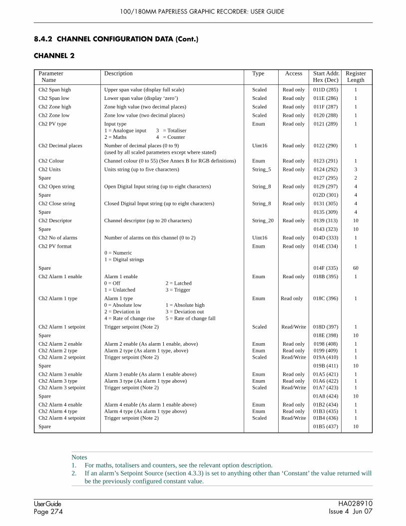
100/180MM PAPERLESS GRAPHIC RECORDER: USER GUIDE
HA028910Issue 4 Jun 07
User GuidePage 274
Parameter Description Type Access Start Addr. Register Name Hex (Dec) Length
8.4.2 CHANNEL CONFIGURATION DATA (Cont.)
CHANNEL 2
Ch2 Span high Upper span value (display full scale) Scaled Read only 011D (285) 1
Ch2 Span low Lower span value (display ‘zero’) Scaled Read only 011E (286) 1
Ch2 Zone high Zone high value (two decimal places) Scaled Read only 011F (287) 1
Ch2 Zone low Zone low value (two decimal places) Scaled Read only 0120 (288) 1
Ch2 PV type Input type Enum Read only 0121 (289) 11 = Analogue input 3 = Totaliser2 = Maths 4 = Counter
Ch2 Decimal places Number of decimal places (0 to 9) Uint16 Read only 0122 (290) 1(used by all scaled parameters except where stated)
Ch2 Colour Channel colour (0 to 55) (See Annex B for RGB definitions) Enum Read only 0123 (291) 1
Ch2 Units Units string (up to five characters) String_5 Read only 0124 (292) 3
Spare 0127 (295) 2
Ch2 Open string Open Digital Input string (up to eight characters) String_8 Read only 0129 (297) 4
Spare 012D (301) 4
Ch2 Close string Closed Digital Input string (up to eight characters) String_8 Read only 0131 (305) 4
Spare 0135 (309) 4
Ch2 Descriptor Channel descriptor (up to 20 characters) String_20 Read only 0139 (313) 10
Spare 0143 (323) 10
Ch2 No of alarms Number of alarms on this channel (0 to 2) Uint16 Read only 014D (333) 1
Ch2 PV format Enum Read only 014E (334) 10 = Numeric1 = Digital strings
Spare 014F (335) 60
Ch2 Alarm 1 enable Alarm 1 enable Enum Read only 018B (395) 10 = Off 2 = Latched1 = Unlatched 3 = Trigger
Ch2 Alarm 1 type Alarm 1 type Enum Read only 018C (396) 10 = Absolute low 1 = Absolute high2 = Deviation in 3 = Deviation out4 = Rate of change rise 5 = Rate of change fall
Ch2 Alarm 1 setpoint Trigger setpoint (Note 2) Scaled Read/Write 018D (397) 1
Spare 018E (398) 10
Ch2 Alarm 2 enable Alarm 2 enable (As alarm 1 enable, above) Enum Read only 0198 (408) 1Ch2 Alarm 2 type Alarm 2 type (As alarm 1 type, above) Enum Read only 0199 (409) 1Ch2 Alarm 2 setpoint Trigger setpoint (Note 2) Scaled Read/Write 019A (410) 1
Spare 019B (411) 10
Ch2 Alarm 3 enable Alarm 3 enable (As alarm 1 enable above) Enum Read only 01A5 (421) 1Ch2 Alarm 3 type Alarm 3 type (As alarm 1 type above) Enum Read only 01A6 (422) 1Ch2 Alarm 3 setpoint Trigger setpoint (Note 2) Scaled Read/Write 01A7 (423) 1
Spare 01A8 (424) 10
Ch2 Alarm 4 enable Alarm 4 enable (As alarm 1 enable above) Enum Read only 01B2 (434) 1Ch2 Alarm 4 type Alarm 4 type (As alarm 1 type above) Enum Read only 01B3 (435) 1Ch2 Alarm 4 setpoint Trigger setpoint (Note 2) Scaled Read/Write 01B4 (436) 1
Spare 01B5 (437) 10
Notes1. For maths, totalisers and counters, see the relevant option description.2. If an alarm’s Setpoint Source (section 4.3.3) is set to anything other than ‘Constant’ the value returned will
be the previously configured constant value.

100/180MM PAPERLESS GRAPHIC RECORDER: USER GUIDE
HA028910Issue 4 Jun 07
User GuidePage 275
Parameter Description Type Access Start Addr. Register Name Hex (Dec) Length
8.4.2 CHANNEL CONFIGURATION DATA (Cont.)
CHANNEL 3
Ch3 Span high Upper span value (display full scale) Scaled Read only 01BF (447) 1
Ch3 Span low Lower span value (display ‘zero’) Scaled Read only 01C0 (448) 1
Ch3 Zone high Zone high value (two decimal places) Scaled Read only 01C1 (449) 1
Ch3 Zone low Zone low value (two decimal places) Scaled Read only 01C2 (450) 1
Ch3 PV type Input type Enum Read only 01C3 (451) 11 = Analogue input 3 = Totaliser2 = Maths 4 = Counter
Ch3 Decimal places Number of decimal places (0 to 9) Uint16 Read only 01C4 (452) 1(used by all scaled parameters except where stated)
Ch3 Colour Channel colour (0 to 55) (See Annex B for RGB definitions) Enum Read only 01C5 (453) 1
Ch3 Units Units string (up to five characters) String_5 Read only 01C6 (454) 3
Spare 01C9 (457) 2
Ch3 Open string Open Digital Input string (up to eight characters) String_8 Read only 01CB (459) 4
Spare 01CF (463) 4
Ch3 Close string Closed Digital Input string (up to eight characters) String_8 Read only 01D3 (467) 4
Spare 01D7 (471) 4
Ch3 Descriptor Channel descriptor (up to 20 characters) String_20 Read only 01DB (475) 10
Spare 01E5 (485) 10
Ch3 No of alarms Number of alarms on this channel (0 to 2) Uint16 Read only 01EF (495) 1
Ch3 PV format Enum Read only 01F0 (496) 10 = Numeric1 = Digital strings
Spare 01F1 (497) 60
Ch3 Alarm 1 enable Alarm 1 enable Enum Read only 022D (557) 10 = Off 2 = Latched1 = Unlatched 3 = Trigger
Ch3 Alarm 1 type Alarm 1 type Enum Read only 022E (558) 10 = Absolute low 1 = Absolute high2 = Deviation in 3 = Deviation out4 = Rate of change rise 5 = Rate of change fall
Ch3 Alarm 1 setpoint Trigger setpoint (Note 2) Scaled Read/Write 022F (559) 1
Spare 0230 (560) 10
Ch3 Alarm 2 enable Alarm 2 enable (As alarm 1 enable, above) Enum Read only 023A (570) 1Ch3 Alarm 2 type Alarm 2 type (As alarm 1 type, above) Enum Read only 023B (571) 1Ch3 Alarm 2 setpoint Trigger setpoint (Note 2) Scaled Read/Write 023C (572) 1
Spare 023D (573) 10
Ch3 Alarm 3 enable Alarm 3 enable (As alarm 1 enable above) Enum Read only 0247 (583) 1Ch3 Alarm 3 type Alarm 3 type (As alarm 1 type above) Enum Read only 0248 (584) 1Ch3 Alarm 3 setpoint Trigger setpoint (Note 2) Scaled Read/Write 0249 (585) 1
Spare 024A (586) 10
Ch3 Alarm 4 enable Alarm 4 enable (As alarm 1 enable above) Enum Read only 0254 (596) 1Ch3 Alarm 4 type Alarm 4 type (As alarm 1 type above) Enum Read only 0255 (597) 1Ch3 Alarm 4 setpoint Trigger setpoint (Note 2) Scaled Read/Write 0256 (598) 1
Spare 0257 (599) 10
Notes1. For maths, totalisers and counters, see the relevant option description.2. If an alarm’s Setpoint Source (section 4.3.3) is set to anything other than ‘Constant’ the value returned will
be the previously configured constant value.

100/180MM PAPERLESS GRAPHIC RECORDER: USER GUIDE
HA028910Issue 4 Jun 07
User GuidePage 276
Parameter Description Type Access Start Addr. Register Name Hex (Dec) Length
8.4.2 CHANNEL CONFIGURATION DATA (Cont.)
CHANNEL 4
Ch4 Span high Upper span value (display full scale) Scaled Read only 0261 (609) 1
Ch4 Span low Lower span value (display ‘zero’) Scaled Read only 0262 (610) 1
Ch4 Zone high Zone high value (two decimal places) Scaled Read only 0263 (611) 1
Ch4 Zone low Zone low value (two decimal places) Scaled Read only 0264 (612) 1
Ch4 PV type Input type Enum Read only 0265 (613) 11 = Analogue input 3 = Totaliser2 = Maths 4 = Counter
Ch4 Decimal places Number of decimal places (0 to 9) Uint16 Read only 0266 (614) 1(used by all scaled parameters except where stated)
Ch4 Colour Channel colour (0 to 55) (See Annex B for RGB definitions) Enum Read only 0267 (615) 1
Ch4 Units Units string (up to five characters) String_5 Read only 0268 (616) 3
Spare 026B (619) 2
Ch4 Open string Open Digital Input string (up to eight characters) String_8 Read only 026D (621) 4
Spare 0271 (625) 4
Ch4 Close string Closed Digital Input string (up to eight characters) String_8 Read only 0275 (629) 4
Spare 0279 (633) 4
Ch4 Descriptor Channel descriptor (up to 20 characters) String_20 Read only 027D (637) 10
Spare 0287 (647) 10
Ch4 No of alarms Number of alarms on this channel (0 to 2) Uint16 Read only 0291 (657) 1
Ch4 PV format Enum Read only 0292 (658) 10 = Numeric1 = Digital strings
Spare 0293 (659) 60
Ch4 Alarm 1 enable Alarm 1 enable Enum Read only 02CF (719) 10 = Off 2 = Latched1 = Unlatched 3 = Trigger
Ch4 Alarm 1 type Alarm 1 type Enum Read only 02DO (720) 10 = Absolute low 1 = Absolute high2 = Deviation in 3 = Deviation out4 = Rate of change rise 5 = Rate of change fall
Ch4 Alarm 1 setpoint Trigger setpoint (Note 2) Scaled Read/Write 02D1 (721) 1
Spare 02D2 (722) 10
Ch4 Alarm 2 enable Alarm 2 enable (As alarm 1 enable, above) Enum Read only 02DC (732) 1Ch4 Alarm 2 type Alarm 2 type (As alarm 1 type, above) Enum Read only 02DD (733) 1Ch4 Alarm 2 setpoint Trigger setpoint (Note 2) Scaled Read/Write 02DE (734) 1
Spare 02DF (735) 10
Ch4 Alarm 3 enable Alarm 3 enable (As alarm 1 enable above) Enum Read only 02E9 (745) 1Ch4 Alarm 3 type Alarm 3 type (As alarm 1 type above) Enum Read only 02EA (746) 1Ch4 Alarm 3 setpoint Trigger setpoint (Note 2) Scaled Read/Write 02EB (747) 1
Spare 02EC (748) 10
Ch4 Alarm 4 enable Alarm 4 enable (As alarm 1 enable above) Enum Read only 02F6 (758) 1Ch4 Alarm 4 type Alarm 4 type (As alarm 1 type above) Enum Read only 02F7 (759) 1Ch4 Alarm 4 setpoint Trigger setpoint (Note 2) Scaled Read/Write 02F8 (760) 1
Spare 02F9 (761) 10
Notes1. For maths, totalisers and counters, see the relevant option description.2. If an alarm’s Setpoint Source (section 4.3.3) is set to anything other than ‘Constant’ the value returned will
be the previously configured constant value.

100/180MM PAPERLESS GRAPHIC RECORDER: USER GUIDE
HA028910Issue 4 Jun 07
User GuidePage 277
Parameter Description Type Access Start Addr. Register Name Hex (Dec) Length
Notes1. For maths, totalisers and counters, see the relevant option description.2. If an alarm’s Setpoint Source (section 4.3.3) is set to anything other than ‘Constant’ the value returned will
be the previously configured constant value.
8.4.2 CHANNEL CONFIGURATION DATA (Cont.)
CHANNEL 5
Ch5 Span high Upper span value (display full scale) Scaled Read only 0303 (771) 1
Ch5 Span low Lower span value (display ‘zero’) Scaled Read only 0304 (772) 1
Ch5 Zone high Zone high value (two decimal places) Scaled Read only 0305 (773) 1
Ch5 Zone low Zone low value (two decimal places) Scaled Read only 0306 (774) 1
Ch5 PV type Input type Enum Read only 0307 (775) 11 = Analogue input 3 = Totaliser2 = Maths 4 = Counter
Ch5 Decimal places Number of decimal places (0 to 9) Uint16 Read only 0308 (776) 1(used by all scaled parameters except where stated)
Ch5 Colour Channel colour (0 to 55) (See Annex B for RGB definitions) Enum Read only 0309 (777) 1
Ch5 Units Units string (up to five characters) String_5 Read only 030A (778) 3
Spare 030D (781) 2
Ch5 Open string Open Digital Input string (up to eight characters) String_8 Read only 030F (783) 4
Spare 0313 (787) 4
Ch5 Close string Closed Digital Input string (up to eight characters) String_8 Read only 0317 (791) 4
Spare 031B (795) 4
Ch5 Descriptor Channel descriptor (up to 20 characters) String_20 Read only 031F (799) 10
Spare 0329 (809) 10
Ch5 No of alarms Number of alarms on this channel (0 to 2) Uint16 Read only 0333 (819) 1
Ch5 PV format Enum Read only 0334 (820) 10 = Numeric1 = Digital strings
Spare 0335 (821) 60
Ch5 Alarm 1 enable Alarm 1 enable Enum Read only 0371 (881) 10 = Off 2 = Latched1 = Unlatched 3 = Trigger
Ch5 Alarm 1 type Alarm 1 type Enum Read only 0372 (882) 10 = Absolute low 1 = Absolute high2 = Deviation in 3 = Deviation out4 = Rate of change rise 5 = Rate of change fall
Ch5 Alarm 1 setpoint Trigger setpoint (Note 2) Scaled Read/Write 0373 (883) 1
Spare 0374 (884) 10
Ch5 Alarm 2 enable Alarm 2 enable (As alarm 1 enable, above) Enum Read only 037E (894) 1Ch5 Alarm 2 type Alarm 2 type (As alarm 1 type, above) Enum Read only 037F (895) 1Ch5 Alarm 2 setpoint Trigger setpoint (Note 2) Scaled Read/Write 0380 (896) 1
Spare 0381 (897) 10
Ch5 Alarm 3 enable Alarm 3 enable (As alarm 1 enable above) Enum Read only 02E9 (907) 1Ch5 Alarm 3 type Alarm 3 type (As alarm 1 type above) Enum Read only 02EA (908) 1Ch5 Alarm 3 setpoint Trigger setpoint (Note 2) Scaled Read/Write 02EB (909) 1
Spare 02EC (910) 10
Ch5 Alarm 4 enable Alarm 4 enable (As alarm 1 enable above) Enum Read only 02F6 (920) 1Ch5 Alarm 4 type Alarm 4 type (As alarm 1 type above) Enum Read only 02F7 (921) 1Ch5 Alarm 4 setpoint Trigger setpoint (Note 2) Scaled Read/Write 02F8 (922) 1
Spare 02F9 (923) 10

100/180MM PAPERLESS GRAPHIC RECORDER: USER GUIDE
HA028910Issue 4 Jun 07
User GuidePage 278
Parameter Description Type Access Start Addr. Register Name Hex (Dec) Length
8.4.2 CHANNEL CONFIGURATION DATA (Cont.)
CHANNEL 6
Ch6 Span high Upper span value (display full scale) Scaled Read only 03A5 (933) 1
Ch6 Span low Lower span value (display ‘zero’) Scaled Read only 03A6 (934) 1
Ch6 Zone high Zone high value (two decimal places) Scaled Read only 03A7 (935) 1
Ch6 Zone low Zone low value (two decimal places) Scaled Read only 03A8 (936) 1
Ch6 PV type Input type Enum Read only 03A9 (937) 11 = Analogue input 3 = Totaliser2 = Maths 4 = Counter
Ch6 Decimal places Number of decimal places (0 to 9) Uint16 Read only 03AA (938) 1(used by all scaled parameters except where stated)
Ch6 Colour Channel colour (0 to 55) (See Annex B for RGB definitions) Enum Read only 03AB (939) 1
Ch6 Units Units string (up to five characters) String_5 Read only 03AC (940) 3
Spare 03AF (943) 2
Ch6 Open string Open Digital Input string (up to eight characters) String_8 Read only 03B1 (945) 4
Spare 03B5 (949) 4
Ch6 Close string Closed Digital Input string (up to eight characters) String_8 Read only 03B9 (953) 4
Spare 03BD (957) 4
Ch6 Descriptor Channel descriptor (up to 20 characters) String_20 Read only 03C1 (961) 10
Spare 03CB (971) 10
Ch6 No of alarms Number of alarms on this channel (0 to 2) Uint16 Read only 03D5 (981) 1
Ch6 PV format Enum Read only 03D6 (982) 10 = Numeric1 = Digital strings
Spare 03D7 (983) 60
Ch6 Alarm 1 enable Alarm 1 enable Enum Read only 0413 (1043) 10 = Off 2 = Latched1 = Unlatched 3 = Trigger
Ch6 Alarm 1 type Alarm 1 type Enum Read only 0414 (1044) 10 = Absolute low 1 = Absolute high2 = Deviation in 3 = Deviation out4 = Rate of change rise 5 = Rate of change fall
Ch6 Alarm 1 setpoint Trigger setpoint (Note 2) Scaled Read/Write 0415 (1045) 1
Spare 0416 (1046) 10
Ch6 Alarm 2 enable Alarm 2 enable (As alarm 1 enable, above) Enum Read only 0420 (1056) 1Ch6 Alarm 2 type Alarm 2 type (As alarm 1 type, above) Enum Read only 0421 (1057) 1Ch6 Alarm 2 setpoint Trigger setpoint (Note 2) Scaled Read/Write 0422 (1058) 1
Spare 0423 (1059) 10
Ch6 Alarm 3 enable Alarm 3 enable (As alarm 1 enable above) Enum Read only 042D (1069) 1Ch6 Alarm 3 type Alarm 3 type (As alarm 1 type above) Enum Read only 042E (1070) 1Ch6 Alarm 3 setpoint Trigger setpoint (Note 2) Scaled Read/Write 042F (1071) 1
Spare 0430 (1072) 10
Ch6 Alarm 4 enable Alarm 4 enable (As alarm 1 enable above) Enum Read only 043A (1082) 1Ch6 Alarm 4 type Alarm 4 type (As alarm 1 type above) Enum Read only 043B (1083) 1Ch6 Alarm 4 setpoint Trigger setpoint (Note 2) Scaled Read/Write 043C (1084) 1
Spare 043D (1085) 10
Notes1. For maths, totalisers and counters, see the relevant option description.2. If an alarm’s Setpoint Source (section 4.3.3) is set to anything other than ‘Constant’ the value returned will
be the previously configured constant value.

100/180MM PAPERLESS GRAPHIC RECORDER: USER GUIDE
HA028910Issue 4 Jun 07
User GuidePage 279
Parameter Description Type Access Start Addr. Register Name Hex (Dec) Length
8.4.2 CHANNEL CONFIGURATION DATA (Cont.)
CHANNEL 7
Ch7 Span high Upper span value (display full scale) Scaled Read only 0447 (1095) 1
Ch7 Span low Lower span value (display ‘zero’) Scaled Read only 0448 (1096) 1
Ch7 Zone high Zone high value (two decimal places) Scaled Read only 0449 (1097) 1
Ch7 Zone low Zone low value (two decimal places) Scaled Read only 044A (1098) 1
Ch7 PV type Input type Enum Read only 044B (1099) 11 = Analogue input 3 = Totaliser2 = Maths 4 = Counter
Ch7 Decimal places Number of decimal places (0 to 9) Uint16 Read only 044C (1100) 1(used by all scaled parameters except where stated)
Ch7 Colour Channel colour (0 to 55) (See Annex B for RGB definitions) Enum Read only 044D (1101) 1
Ch7 Units Units string (up to five characters) String_5 Read only 044E (1102) 3
Spare 0451 (1105) 2
Ch7 Open string Open Digital Input string (up to eight characters) String_8 Read only 0453 (1107) 4
Spare 0457 (1111) 4
Ch7 Close string Closed Digital Input string (up to eight characters) String_8 Read only 045B (1115) 4
Spare 045F (1119) 4
Ch7 Descriptor Channel descriptor (up to 20 characters) String_20 Read only 0463 (1123) 10
Spare 046D (1133) 10
Ch7 No of alarms Number of alarms on this channel (0 to 2) Uint16 Read only 0477 (1143) 1
Ch7 PV format Enum Read only 0478 (1144) 10 = Numeric1 = Digital strings
Spare 0479 (1145) 60
Ch7 Alarm 1 enable Alarm 1 enable Enum Read only 04B5 (1205) 10 = Off 2 = Latched1 = Unlatched 3 = Trigger
Ch7 Alarm 1 type Alarm 1 type Enum Read only 04B6 (1206) 10 = Absolute low 1 = Absolute high2 = Deviation in 3 = Deviation out4 = Rate of change rise 5 = Rate of change fall
Ch7 Alarm 1 setpoint Trigger setpoint (Note 2) Scaled Read/Write 04B7 (1207) 1
Spare 04B8 (1208) 10
Ch7 Alarm 2 enable Alarm 2 enable (As alarm 1 enable, above) Enum Read only 04C2 (1218) 1Ch7 Alarm 2 type Alarm 2 type (As alarm 1 type, above) Enum Read only 04C3 (1219) 1Ch7 Alarm 2 setpoint Trigger setpoint (Note 2) Scaled Read/Write 04C4 (1220) 1
Spare 04C5 (1221) 10
Ch7 Alarm 3 enable Alarm 3 enable (As alarm 1 enable above) Enum Read only 04CF (1231) 1Ch7 Alarm 3 type Alarm 3 type (As alarm 1 type above) Enum Read only 04D0 (1232) 1Ch7 Alarm 3 setpoint Trigger setpoint (Note 2) Scaled Read/Write 04D1 (1233) 1
Spare 04D2 (1234) 10
Ch7 Alarm 4 enable Alarm 4 enable (As alarm 1 enable above) Enum Read only 04DC (1244) 1Ch7 Alarm 4 type Alarm 4 type (As alarm 1 type above) Enum Read only 04DD (1245) 1Ch7 Alarm 4 setpoint Trigger setpoint (Note 2) Scaled Read/Write 04DE (1246) 1
Spare 04DF (1247) 10
Notes1. For maths, totalisers and counters, see the relevant option description.2. If an alarm’s Setpoint Source (section 4.3.3) is set to anything other than ‘Constant’ the value returned will
be the previously configured constant value.

100/180MM PAPERLESS GRAPHIC RECORDER: USER GUIDE
HA028910Issue 4 Jun 07
User GuidePage 280
Parameter Description Type Access Start Addr. Register Name Hex (Dec) Length
8.4.2 CHANNEL CONFIGURATION DATA (Cont.)
CHANNEL 8
Ch8 Span high Upper span value (display full scale) Scaled Read only 04E9 (1257) 1
Ch8 Span low Lower span value (display ‘zero’) Scaled Read only 04EA (1258) 1
Ch8 Zone high Zone high value (two decimal places) Scaled Read only 04EB (1259) 1
Ch8 Zone low Zone low value (two decimal places) Scaled Read only 04EC (1260) 1
Ch8 PV type Input type Enum Read only 04ED (1261) 11 = Analogue input 3 = Totaliser2 = Maths 4 = Counter
Ch8 Decimal places Number of decimal places (0 to 9) Uint16 Read only 04EE (1262) 1(used by all scaled parameters except where stated)
Ch8 Colour Channel colour (0 to 55) (See Annex B for RGB definitions) Enum Read only 04EF (1263) 1
Ch8 Units Units string (up to five characters) String_5 Read only 04F0 (1264) 3
Spare 04F3 (1267) 2
Ch8 Open string Open Digital Input string (up to eight characters) String_8 Read only 04F5 (1269) 4
Spare 04F9 (1273) 4
Ch8 Close string Closed Digital Input string (up to eight characters) String_8 Read only 04FD (1277) 4
Spare 0501 (1281) 4
Ch8 Descriptor Channel descriptor (up to 20 characters) String_20 Read only 0505 (1285) 10
Spare 050F (1295) 10
Ch8 No of alarms Number of alarms on this channel (0 to 2) Uint16 Read only 0519 (1305) 1
Ch8 PV format Enum Read only 051A (1306) 10 = Numeric1 = Digital strings
Spare 051B (1307) 60
Ch8 Alarm 1 enable Alarm 1 enable Enum Read only 0557 (1367) 10 = Off 2 = Latched1 = Unlatched 3 = Trigger
Ch8 Alarm 1 type Alarm 1 type Enum Read only 0558 (1368) 10 = Absolute low 1 = Absolute high2 = Deviation in 3 = Deviation out4 = Rate of change rise 5 = Rate of change fall
Ch8 Alarm 1 setpoint Trigger setpoint (Note 2) Scaled Read/Write 0559 (1369) 1
Spare 055A (1370) 10
Ch8 Alarm 2 enable Alarm 2 enable (As alarm 1 enable, above) Enum Read only 0564 (1380) 1Ch8 Alarm 2 type Alarm 2 type (As alarm 1 type, above) Enum Read only 0565 (1381) 1Ch8 Alarm 2 setpoint Trigger setpoint (Note 2) Scaled Read/Write 0566 (1382) 1
Spare 0567 (1383) 10
Ch8 Alarm 3 enable Alarm 3 enable (As alarm 1 enable above) Enum Read only 0571(1393) 1Ch8 Alarm 3 type Alarm 3 type (As alarm 1 type above) Enum Read only 0572 (1394) 1Ch8 Alarm 3 setpoint Trigger setpoint (Note 2) Scaled Read/Write 0573 (1395) 1
Spare 0574 (1396) 10
Ch8 Alarm 4 enable Alarm 4 enable (As alarm 1 enable above) Enum Read only 057E (1406) 1Ch8 Alarm 4 type Alarm 4 type (As alarm 1 type above) Enum Read only 057F (1407) 1Ch8 Alarm 4 setpoint Trigger setpoint (Note 2) Scaled Read/Write 0580 (1408) 1
Spare 0581 (1409) 10
Notes1. For maths, totalisers and counters, see the relevant option description.2. If an alarm’s Setpoint Source (section 4.3.3) is set to anything other than ‘Constant’ the value returned will
be the previously configured constant value.

100/180MM PAPERLESS GRAPHIC RECORDER: USER GUIDE
HA028910Issue 4 Jun 07
User GuidePage 281
Parameter Description Type Access Start Addr. Register Name Hex (Dec) Length
8.4.2 CHANNEL CONFIGURATION DATA (Cont.)
CHANNEL 9
Ch9 Span high Upper span value (display full scale) Scaled Read only 058B (1419) 1
Ch9 Span low Lower span value (display ‘zero’) Scaled Read only 058C (1420) 1
Ch9 Zone high Zone high value (two decimal places) Scaled Read only 058D (1421) 1
Ch9 Zone low Zone low value (two decimal places) Scaled Read only 058E (1422) 1
Ch9 PV type Input type Enum Read only 058F (1423) 11 = Analogue input 3 = Totaliser2 = Maths 4 = Counter
Ch9 Decimal places Number of decimal places (0 to 9) Uint16 Read only 0590 (1424) 1(used by all scaled parameters except where stated)
Ch9 Colour Channel colour (0 to 55) (See Annex B for RGB definitions) Enum Read only 0591 (1425) 1
Ch9 Units Units string (up to five characters) String_5 Read only 0592 (1426) 3
Spare 0595 (1429) 2
Ch9 Open string Open Digital Input string (up to eight characters) String_8 Read only 0597 (1431) 4
Spare 059B (1435) 4
Ch9 Close string Closed Digital Input string (up to eight characters) String_8 Read only 059F (1439) 4
Spare 05A3 (1443) 4
Ch9 Descriptor Channel descriptor (up to 20 characters) String_20 Read only 05A7 (1447) 10
Spare 05B1 (1457) 10
Ch9 No of alarms Number of alarms on this channel (0 to 2) Uint16 Read only 05BB (1467) 1
Ch9 PV format Enum Read only 05BC (1468) 10 = Numeric1 = Digital strings
Spare 05BD (1469) 60
Ch9 Alarm 1 enable Alarm 1 enable Enum Read only 05F9 (1529) 10 = Off 2 = Latched1 = Unlatched 3 = Trigger
Ch9 Alarm 1 type Alarm 1 type Enum Read only 05FA (1530) 10 = Absolute low 1 = Absolute high2 = Deviation in 3 = Deviation out4 = Rate of change rise 5 = Rate of change fall
Ch9 Alarm 1 setpoint Trigger setpoint (Note 2) Scaled Read/Write 05FB (1531) 1
Spare 05FC (1532) 10
Ch9 Alarm 2 enable Alarm 2 enable (As alarm 1 enable, above) Enum Read only 0606 (1542) 1Ch9 Alarm 2 type Alarm 2 type (As alarm 1 type, above) Enum Read only 0607 (1543) 1Ch9 Alarm 2 setpoint Trigger setpoint (Note 2) Scaled Read/Write 0608 (1544) 1
Spare 0609 (1545) 10
Ch9 Alarm 3 enable Alarm 3 enable (As alarm 1 enable above) Enum Read only 0613(1555) 1Ch9 Alarm 3 type Alarm 3 type (As alarm 1 type above) Enum Read only 0614 (1556) 1Ch9 Alarm 3 setpoint Trigger setpoint (Note 2) Scaled Read/Write 0615 (1557) 1
Spare 0616 (1558) 10
Ch9 Alarm 4 enable Alarm 4 enable (As alarm 1 enable above) Enum Read only 0620 (1568) 1Ch9 Alarm 4 type Alarm 4 type (As alarm 1 type above) Enum Read only 0621 (1569) 1Ch9 Alarm 4 setpoint Trigger setpoint (Note 2) Scaled Read/Write 0622 (1570) 1
Spare 0623 (1571) 10
Notes1. For maths, totalisers and counters, see the relevant option description.2. If an alarm’s Setpoint Source (section 4.3.3) is set to anything other than ‘Constant’ the value returned will
be the previously configured constant value.

100/180MM PAPERLESS GRAPHIC RECORDER: USER GUIDE
HA028910Issue 4 Jun 07
User GuidePage 282
Parameter Description Type Access Start Addr. Register Name Hex (Dec) Length
8.4.2 CHANNEL CONFIGURATION DATA (Cont.)
CHANNEL 10
Ch10 Span high Upper span value (display full scale) Scaled Read only 062D (1581) 1
Ch10 Span low Lower span value (display ‘zero’) Scaled Read only 062E (1582) 1
Ch10 Zone high Zone high value (two decimal places) Scaled Read only 062F (1583) 1
Ch10 Zone low Zone low value (two decimal places) Scaled Read only 0630 (1584) 1
Ch10 PV type Input type Enum Read only 0631 (1585) 11 = Analogue input 3 = Totaliser2 = Maths 4 = Counter
Ch10 Decimal places Number of decimal places (0 to 9) Uint16 Read only 0632 (1586) 1(used by all scaled parameters except where stated)
Ch10 Colour Channel colour (0 to 55) (See Annex B for RGB definitions) Enum Read only 0633 (1587) 1
Ch10 Units Units string (up to five characters) String_5 Read only 0634 (1588) 3
Spare 0637 (1591) 2
Ch10 Open string Open Digital Input string (up to eight characters) String_8 Read only 0639 (1593) 4
Spare 063D (1597) 4
Ch10 Close string Closed Digital Input string (up to eight characters) String_8 Read only 0641 (1601) 4
Spare 0645 (1605) 4
Ch10 Descriptor Channel descriptor (up to 20 characters) String_20 Read only 0649 (1609) 10
Spare 0653 (1619) 10
Ch10 No of alarms Number of alarms on this channel (0 to 2) Uint16 Read only 065D (1629) 1
Ch10 PV format Enum Read only 065E (1630) 10 = Numeric1 = Digital strings
Spare 065F (1631) 60
Ch10 Alarm 1 enable Alarm 1 enable Enum Read only 069B (1691) 10 = Off 2 = Latched1 = Unlatched 3 = Trigger
Ch10 Alarm 1 type Alarm 1 type Enum Read only 069C (1692) 10 = Absolute low 1 = Absolute high2 = Deviation in 3 = Deviation out4 = Rate of change rise 5 = Rate of change fall
Ch10 Alarm 1 setpoint Trigger setpoint (Note 2) Scaled Read/Write 069D (1693) 1
Spare 069E (1694) 10
Ch10 Alarm 2 enable Alarm 2 enable (As alarm 1 enable, above) Enum Read only 06A8 (1704) 1Ch10 Alarm 2 type Alarm 2 type (As alarm 1 type, above) Enum Read only 06A9 (1705) 1Ch10 Alarm 2 setpoint Trigger setpoint (Note 2) Scaled Read/Write 06AA (1706) 1
Spare 06AB (1707) 10
Ch10 Alarm 3 enable Alarm 3 enable (As alarm 1 enable above) Enum Read only 06B5(1717) 1Ch10 Alarm 3 type Alarm 3 type (As alarm 1 type above) Enum Read only 06B6(1718) 1Ch10 Alarm 3 setpoint Trigger setpoint (Note 2) Scaled Read/Write 06B7 (1719) 1
Spare 06B8 (1720) 10
Ch10 Alarm 4 enable Alarm 4 enable (As alarm 1 enable above) Enum Read only 06C2 (1730) 1Ch10 Alarm 4 type Alarm 4 type (As alarm 1 type above) Enum Read only 06C3 (1731) 1Ch10 Alarm 4 setpoint Trigger setpoint (Note 2) Scaled Read/Write 06C4 (1732) 1
Spare 06C5 (1733) 10
Notes1. For maths, totalisers and counters, see the relevant option description.2. If an alarm’s Setpoint Source (section 4.3.3) is set to anything other than ‘Constant’ the value returned will
be the previously configured constant value.

100/180MM PAPERLESS GRAPHIC RECORDER: USER GUIDE
HA028910Issue 4 Jun 07
User GuidePage 283
Parameter Description Type Access Start Addr. Register Name Hex (Dec) Length
8.4.2 CHANNEL CONFIGURATION DATA (Cont.)
CHANNEL 11
Ch11 Span high Upper span value (display full scale) Scaled Read only 06CF (1743) 1
Ch11 Span low Lower span value (display ‘zero’) Scaled Read only 06D0 (1744) 1
Ch11 Zone high Zone high value (two decimal places) Scaled Read only 06D1 (1745) 1
Ch11 Zone low Zone low value (two decimal places) Scaled Read only 06D2 (1746) 1
Ch11 PV type Input type Enum Read only 06D3 (1747) 11 = Analogue input 3 = Totaliser2 = Maths 4 = Counter
Ch11 Decimal places Number of decimal places (0 to 9) Uint16 Read only 06D4 (1748) 1(used by all scaled parameters except where stated)
Ch11 Colour Channel colour (0 to 55) (See Annex B for RGB definitions) Enum Read only 06D5 (1749) 1
Ch11 Units Units string (up to five characters) String_5 Read only 06D6 (1750) 3
Spare 06D9 (1753) 2
Ch11 Open string Open Digital Input string (up to eight characters) String_8 Read only 06DB (1755) 4
Spare 06DF (1759) 4
Ch11 Close string Closed Digital Input string (up to eight characters) String_8 Read only 06E3 (1763) 4
Spare 06E7 (1767) 4
Ch11 Descriptor Channel descriptor (up to 20 characters) String_20 Read only 06EB (1771) 10
Spare 06F5 (1781) 10
Ch11 No of alarms Number of alarms on this channel (0 to 2) Uint16 Read only 06FF (1791) 1
Ch11 PV format Enum Read only 0700 (1792) 10 = Numeric1 = Digital strings
Spare 0701 (1793) 60
Ch11 Alarm 1 enable Alarm 1 enable Enum Read only 073D (1853) 10 = Off 2 = Latched1 = Unlatched 3 = Trigger
Ch11 Alarm 1 type Alarm 1 type Enum Read only 073E (1854) 10 = Absolute low 1 = Absolute high2 = Deviation in 3 = Deviation out4 = Rate of change rise 5 = Rate of change fall
Ch11 Alarm 1 setpoint Trigger setpoint (Note 2) Scaled Read/Write 073F (1855) 1
Spare 0740 (1856) 10
Ch11 Alarm 2 enable Alarm 2 enable (As alarm 1 enable, above) Enum Read only 074A (1866) 1Ch11 Alarm 2 type Alarm 2 type (As alarm 1 type, above) Enum Read only 074B (1867) 1Ch11 Alarm 2 setpoint Trigger setpoint (Note 2) Scaled Read/Write 074C (1868) 1
Spare 074D (1869) 10
Ch11 Alarm 3 enable Alarm 3 enable (As alarm 1 enable above) Enum Read only 0757(1879) 1Ch11 Alarm 3 type Alarm 3 type (As alarm 1 type above) Enum Read only 0758 (1880) 1Ch11 Alarm 3 setpoint Trigger setpoint (Note 2) Scaled Read/Write 0759 (1881) 1
Spare 075A (1882) 10
Ch11 Alarm 4 enable Alarm 4 enable (As alarm 1 enable above) Enum Read only 0764 (1892) 1Ch11 Alarm 4 type Alarm 4 type (As alarm 1 type above) Enum Read only 0765 (1893) 1Ch11 Alarm 4 setpoint Trigger setpoint (Note 2) Scaled Read/Write 0766 (1894) 1
Spare 0767 (1895) 10
Notes1. For maths, totalisers and counters, see the relevant option description.2. If an alarm’s Setpoint Source (section 4.3.3) is set to anything other than ‘Constant’ the value returned will
be the previously configured constant value.

100/180MM PAPERLESS GRAPHIC RECORDER: USER GUIDE
HA028910Issue 4 Jun 07
User GuidePage 284
Parameter Description Type Access Start Addr. Register Name Hex (Dec) Length
8.4.2 CHANNEL CONFIGURATION DATA (Cont.)
CHANNEL 12
Ch12 Span high Upper span value (display full scale) Scaled Read only 0771 (1905) 1
Ch12 Span low Lower span value (display ‘zero’) Scaled Read only 0772 (1906) 1
Ch12 Zone high Zone high value (two decimal places) Scaled Read only 0773 (1907) 1
Ch12 Zone low Zone low value (two decimal places) Scaled Read only 0774 (1908) 1
Ch12 PV type Input type Enum Read only 0775 (1909) 11 = Analogue input 3 = Totaliser2 = Maths 4 = Counter
Ch12 Decimal places Number of decimal places (0 to 9) Uint16 Read only 0776 (1910) 1(used by all scaled parameters except where stated)
Ch12 Colour Channel colour (0 to 55) (See Annex B for RGB definitions) Enum Read only 0777 (1911) 1
Ch12 Units Units string (up to five characters) String_5 Read only 0778 (1912) 3
Spare 077B (1915) 2
Ch12 Open string Open Digital Input string (up to eight characters) String_8 Read only 077D (1917) 4
Spare 0781 (1921) 4
Ch12 Close string Closed Digital Input string (up to eight characters) String_8 Read only 0785 (1925) 4
Spare 0789 (1929) 4
Ch12 Descriptor Channel descriptor (up to 20 characters) String_20 Read only 078D (1933) 10
Spare 0797 (1943) 10
Ch12 No of alarms Number of alarms on this channel (0 to 2) Uint16 Read only 07A1 (1953) 1
Ch12 PV format Enum Read only 07A2 (1954) 10 = Numeric1 = Digital strings
Spare 07A3 (1955) 60
Ch12 Alarm 1 enable Alarm 1 enable Enum Read only 07DF (2015) 10 = Off 2 = Latched1 = Unlatched 3 = Trigger
Ch12 Alarm 1 type Alarm 1 type Enum Read only 07E0 (2016) 10 = Absolute low 1 = Absolute high2 = Deviation in 3 = Deviation out4 = Rate of change rise 5 = Rate of change fall
Ch12 Alarm 1 setpoint Trigger setpoint (Note 2) Scaled Read/Write 07E1 (2017) 1
Spare 07E2 (2018) 10
Ch12 Alarm 2 enable Alarm 2 enable (As alarm 1 enable, above) Enum Read only 07EC (2028) 1Ch12 Alarm 2 type Alarm 2 type (As alarm 1 type, above) Enum Read only 07ED (2029) 1Ch12 Alarm 2 setpoint Trigger setpoint (Note 2) Scaled Read/Write 07EE (2030) 1
Spare 07EF (2031) 10
Ch12 Alarm 3 enable Alarm 3 enable (As alarm 1 enable above) Enum Read only 07F9 (2041) 1Ch12 Alarm 3 type Alarm 3 type (As alarm 1 type above) Enum Read only 07FA (2042) 1Ch12 Alarm 3 setpoint Trigger setpoint (Note 2) Scaled Read/Write 07FB (2043) 1
Spare 07FC (2044) 10
Ch12 Alarm 4 enable Alarm 4 enable (As alarm 1 enable above) Enum Read only 0806 (2054) 1Ch12 Alarm 4 type Alarm 4 type (As alarm 1 type above) Enum Read only 0807 (2055) 1Ch12 Alarm 4 setpoint Trigger setpoint (Note 2) Scaled Read/Write 0808 (2056) 1
Spare 0809 (2057) 10
Notes1. For maths, totalisers and counters, see the relevant option description.2. If an alarm’s Setpoint Source (section 4.3.3) is set to anything other than ‘Constant’ the value returned will
be the previously configured constant value.

100/180MM PAPERLESS GRAPHIC RECORDER: USER GUIDE
HA028910Issue 4 Jun 07
User GuidePage 285
Note: PV access is Read/Write for any point configured with ‘Slave Comms’ as its Type or Function. Other-wise PV access is Read only.
Parameter Description Type Access Start Addr. Register Name Hex (Dec) Length
8.4.3 Channel Run-Time data
These tables show addresses for channel input values for channels 1 to 12 inclusive.Generally: channel N address = channel 1 address + 3(N-1) (decimal)
CHANNEL 1
Ch1 value Current process value (PV) Scaled See note 1 A1D9 (41433) 1Ch1 status Channel status Enum Read only A1DA (41434) 1
0 = Good PV 5 = Ranging error1 = Channel off 6 = Overflow2 = Over range 7 = Bad PV3 = Under range 8 = No data4 = Hardware error
Ch1 Alarms Alarm information Uint16 - A1DB (41435) 1Bit 0: 0 = Alarm 1 inactive; 1 = Alarm 1 active Read onlyBit 1: 0 = No alarm 1 Ack. required; 1 = Ack. required Read onlyBit 2: 1 = Acknowledge alarm 1 Read/WriteBit 3: SpareBit 4: 0 = Alarm 2 inactive; 1 = Alarm 2 active Read onlyBit 5: 0 = No Alarm 2 Ack. required; 1 = Ack. required Read onlyBit 6: 1 = Acknowledge alarm 2 Read/WriteBit 7: SpareBit 8: 0 = Alarm 3 inactive; 1 = Alarm 3 active Read onlyBit 9: 0 = No alarm 3 Ack. required; 1 = Ack. required Read onlyBit 10: 1 = Acknowledge alarm 3 Read/WriteBit 11: SpareBit 12: 0 = Alarm 4 inactive; 1 = Alarm 4 active Read onlyBit 13: 0 = No Alarm 4 Ack. required; 1 = Ack. required Read onlyBit 14: 1 = Acknowledge alarm 4 Read/WriteBit 15: Spare
CHANNEL 2
Ch2 value Current process value (PV) Scaled See note 1 A1DC (41436) 1Ch2 status Channel status Enum Read only A1DD (41437) 1
0 = Good PV 5 = Ranging error1 = Channel off 6 = Overflow2 = Over range 7 = Bad PV3 = Under range 8 = No data4 = Hardware error
Ch2 Alarms Alarm information Uint16 - A1DE (41438) 1Bit 0: 0 = Alarm 1 inactive; 1 = Alarm 1 active Read onlyBit 1: 0 = No alarm 1 Ack. required; 1 = Ack. required Read onlyBit 2: 1 = Acknowledge alarm 1 Read/WriteBit 3: SpareBit 4: 0 = Alarm 2 inactive; 1 = Alarm 2 active Read onlyBit 5: 0 = No Alarm 2 Ack. required; 1 = Ack. required Read onlyBit 6: 1 = Acknowledge alarm 2 Read/WriteBit 7: SpareBit 8: 0 = Alarm 3 inactive; 1 = Alarm 3 active Read onlyBit 9: 0 = No alarm 3 Ack. required; 1 = Ack. required Read onlyBit 10: 1 = Acknowledge alarm 3 Read/WriteBit 11: SpareBit 12: 0 = Alarm 4 inactive; 1 = Alarm 4 active Read onlyBit 13: 0 = No Alarm 4 Ack. required; 1 = Ack. required Read onlyBit 14: 1 = Acknowledge alarm 4 Read/WriteBit 15: Spare
Parameter Description Type Access Start Addr. Register Name Hex (Dec) Length

100/180MM PAPERLESS GRAPHIC RECORDER: USER GUIDE
HA028910Issue 4 Jun 07
User GuidePage 286
Parameter Description Type Access Start Addr. Register Name Hex (Dec) Length
Parameter Description Type Access Start Addr. Register Name Hex (Dec) Length
Note: PV access is Read/Write for any point configured with ‘Slave Comms’ as its Type or Function. Other-wise PV access is Read only.
8.4.3 CHANNEL RUN TIME DATA (Cont.)
CHANNEL 3
Ch3 value Current process value (PV) Scaled See note 1 A1DF (41439) 1
Ch3 status Channel status Enum Read only A1E0 (41440) 10 = Good PV 5 = Ranging error1 = Channel off 6 = Overflow2 = Over range 7 = Bad PV3 = Under range 8 = No data4 = Hardware error
Ch3 Alarms Alarm information Uint16 - A1E1 (41441) 1
Bit 0: 0 = Alarm 1 inactive; 1 = Alarm 1 active Read onlyBit 1: 0 = No alarm 1 Ack. required; 1 = Ack. required Read onlyBit 2: 1 = Acknowledge alarm 1 Read/WriteBit 3: SpareBit 4: 0 = Alarm 2 inactive; 1 = Alarm 2 active Read onlyBit 5: 0 = No Alarm 2 Ack. required; 1 = Ack. required Read onlyBit 6: 1 = Acknowledge alarm 2 Read/WriteBit 7: SpareBit 8: 0 = Alarm 3 inactive; 1 = Alarm 3 active Read onlyBit 9: 0 = No alarm 3 Ack. required; 1 = Ack. required Read onlyBit 10: 1 = Acknowledge alarm 3 Read/WriteBit 11: SpareBit 12: 0 = Alarm 4 inactive; 1 = Alarm 4 active Read onlyBit 13: 0 = No Alarm 4 Ack. required; 1 = Ack. required Read onlyBit 14: 1 = Acknowledge alarm 4 Read/WriteBit 15: Spare
CHANNEL 4
Ch4 value Current process value (PV) Scaled See note 1 A1E2 (41442) 1
Ch4 status Channel status Enum Read only A1E3 (41443) 10 = Good PV 5 = Ranging error1 = Channel off 6 = Overflow2 = Over range 7 = Bad PV3 = Under range 8 = No data4 = Hardware error
Ch4 Alarms Alarm information Uint16 - A1E4 (41444) 1
Bit 0: 0 = Alarm 1 inactive; 1 = Alarm 1 active Read onlyBit 1: 0 = No alarm 1 Ack. required; 1 = Ack. required Read onlyBit 2: 1 = Acknowledge alarm 1 Read/WriteBit 3: SpareBit 4: 0 = Alarm 2 inactive; 1 = Alarm 2 active Read onlyBit 5: 0 = No Alarm 2 Ack. required; 1 = Ack. required Read onlyBit 6: 1 = Acknowledge alarm 2 Read/WriteBit 7: SpareBit 8: 0 = Alarm 3 inactive; 1 = Alarm 3 active Read onlyBit 9: 0 = No alarm 3 Ack. required; 1 = Ack. required Read onlyBit 10: 1 = Acknowledge alarm 3 Read/WriteBit 11: SpareBit 12: 0 = Alarm 4 inactive; 1 = Alarm 4 active Read onlyBit 13: 0 = No Alarm 4 Ack. required; 1 = Ack. required Read onlyBit 14: 1 = Acknowledge alarm 4 Read/WriteBit 15: Spare

100/180MM PAPERLESS GRAPHIC RECORDER: USER GUIDE
HA028910Issue 4 Jun 07
User GuidePage 287
Note: PV access is Read/Write for any point configured with ‘Slave Comms’ as its Type or Function. Other-wise PV access is Read only.
8.4.3 CHANNEL RUN TIME DATA (Cont.)
CHANNEL 5
Ch5 value Current process value (PV) Scaled See note 1 A1E5 (41445) 1
Ch5 status Channel status Enum Read only A1E6 (41446) 10 = Good PV 5 = Ranging error1 = Channel off 6 = Overflow2 = Over range 7 = Bad PV3 = Under range 8 = No data4 = Hardware error
Ch5 Alarms Alarm information Uint16 - A1E7 (41447) 1
Bit 0: 0 = Alarm 1 inactive; 1 = Alarm 1 active Read onlyBit 1: 0 = No alarm 1 Ack. required; 1 = Ack. required Read onlyBit 2: 1 = Acknowledge alarm 1 Read/WriteBit 3: SpareBit 4: 0 = Alarm 2 inactive; 1 = Alarm 2 active Read onlyBit 5: 0 = No Alarm 2 Ack. required; 1 = Ack. required Read onlyBit 6: 1 = Acknowledge alarm 2 Read/WriteBit 7: SpareBit 8: 0 = Alarm 3 inactive; 1 = Alarm 3 active Read onlyBit 9: 0 = No alarm 3 Ack. required; 1 = Ack. required Read onlyBit 10: 1 = Acknowledge alarm 3 Read/WriteBit 11: SpareBit 12: 0 = Alarm 4 inactive; 1 = Alarm 4 active Read onlyBit 13: 0 = No Alarm 4 Ack. required; 1 = Ack. required Read onlyBit 14: 1 = Acknowledge alarm 4 Read/WriteBit 15: Spare
CHANNEL 6
Ch6 value Current process value (PV) Scaled See note 1 A1E8 (41448) 1
Ch6 status Channel status Enum Read only A1E9 (41449) 10 = Good PV 5 = Ranging error1 = Channel off 6 = Overflow2 = Over range 7 = Bad PV3 = Under range 8 = No data4 = Hardware error
Ch6 Alarms Alarm information Uint16 - A1EA (41450) 1
Bit 0: 0 = Alarm 1 inactive; 1 = Alarm 1 active Read onlyBit 1: 0 = No alarm 1 Ack. required; 1 = Ack. required Read onlyBit 2: 1 = Acknowledge alarm 1 Read/WriteBit 3: SpareBit 4: 0 = Alarm 2 inactive; 1 = Alarm 2 active Read onlyBit 5: 0 = No Alarm 2 Ack. required; 1 = Ack. required Read onlyBit 6: 1 = Acknowledge alarm 2 Read/WriteBit 7: SpareBit 8: 0 = Alarm 3 inactive; 1 = Alarm 3 active Read onlyBit 9: 0 = No alarm 3 Ack. required; 1 = Ack. required Read onlyBit 10: 1 = Acknowledge alarm 3 Read/WriteBit 11: SpareBit 12: 0 = Alarm 4 inactive; 1 = Alarm 4 active Read onlyBit 13: 0 = No Alarm 4 Ack. required; 1 = Ack. required Read onlyBit 14: 1 = Acknowledge alarm 4 Read/WriteBit 15: Spare
Parameter Description Type Access Start Addr. Register Name Hex (Dec) Length
Parameter Description Type Access Start Addr. Register Name Hex (Dec) Length

100/180MM PAPERLESS GRAPHIC RECORDER: USER GUIDE
HA028910Issue 4 Jun 07
User GuidePage 288
Parameter Description Type Access Start Addr. Register Name Hex (Dec) Length
Parameter Description Type Access Start Addr. Register Name Hex (Dec) Length
Note: PV access is Read/Write for any point configured with ‘Slave Comms’ as its Type or Function. Other-wise PV access is Read only.
8.4.3 CHANNEL RUN TIME DATA (Cont.)
CHANNEL 7
Ch7 value Current process value (PV) Scaled See note 1 A1EB (41451) 1
Ch7 status Channel status Enum Read only A1EC (41452) 10 = Good PV 5 = Ranging error1 = Channel off 6 = Overflow2 = Over range 7 = Bad PV3 = Under range 8 = No data4 = Hardware error
Ch7 Alarms Alarm information Uint16 - A1ED (41453) 1
Bit 0: 0 = Alarm 1 inactive; 1 = Alarm 1 active Read onlyBit 1: 0 = No alarm 1 Ack. required; 1 = Ack. required Read onlyBit 2: 1 = Acknowledge alarm 1 Read/WriteBit 3: SpareBit 4: 0 = Alarm 2 inactive; 1 = Alarm 2 active Read onlyBit 5: 0 = No Alarm 2 Ack. required; 1 = Ack. required Read onlyBit 6: 1 = Acknowledge alarm 2 Read/WriteBit 7: SpareBit 8: 0 = Alarm 3 inactive; 1 = Alarm 3 active Read onlyBit 9: 0 = No alarm 3 Ack. required; 1 = Ack. required Read onlyBit 10: 1 = Acknowledge alarm 3 Read/WriteBit 11: SpareBit 12: 0 = Alarm 4 inactive; 1 = Alarm 4 active Read onlyBit 13: 0 = No Alarm 4 Ack. required; 1 = Ack. required Read onlyBit 14: 1 = Acknowledge alarm 4 Read/WriteBit 15: Spare
CHANNEL 8
Ch8 value Current process value (PV) Scaled See note 1 A1EE (41454) 1
Ch8 status Channel status Enum Read only A1EF (41455) 10 = Good PV 5 = Ranging error1 = Channel off 6 = Overflow2 = Over range 7 = Bad PV3 = Under range 8 = No data4 = Hardware error
Ch8 Alarms Alarm information Uint16 - A1F0 (41456) 1
Bit 0: 0 = Alarm 1 inactive; 1 = Alarm 1 active Read onlyBit 1: 0 = No alarm 1 Ack. required; 1 = Ack. required Read onlyBit 2: 1 = Acknowledge alarm 1 Read/WriteBit 3: SpareBit 4: 0 = Alarm 2 inactive; 1 = Alarm 2 active Read onlyBit 5: 0 = No Alarm 2 Ack. required; 1 = Ack. required Read onlyBit 6: 1 = Acknowledge alarm 2 Read/WriteBit 7: SpareBit 8: 0 = Alarm 3 inactive; 1 = Alarm 3 active Read onlyBit 9: 0 = No alarm 3 Ack. required; 1 = Ack. required Read onlyBit 10: 1 = Acknowledge alarm 3 Read/WriteBit 11: SpareBit 12: 0 = Alarm 4 inactive; 1 = Alarm 4 active Read onlyBit 13: 0 = No Alarm 4 Ack. required; 1 = Ack. required Read onlyBit 14: 1 = Acknowledge alarm 4 Read/WriteBit 15: Spare

100/180MM PAPERLESS GRAPHIC RECORDER: USER GUIDE
HA028910Issue 4 Jun 07
User GuidePage 289
Note: PV access is Read/Write for any point configured with ‘Slave Comms’ as its Type or Function. Other-wise PV access is Read only.
8.4.3 CHANNEL RUN TIME DATA (Cont.)
CHANNEL 9
Ch9 value Current process value (PV) Scaled See note 1 A1F1 (41457) 1
Ch9 status Channel status Enum Read only A1F2 (41458) 10 = Good PV 5 = Ranging error1 = Channel off 6 = Overflow2 = Over range 7 = Bad PV3 = Under range 8 = No data4 = Hardware error
Ch9 Alarms Alarm information Uint16 - A1F3 (41459) 1
Bit 0: 0 = Alarm 1 inactive; 1 = Alarm 1 active Read onlyBit 1: 0 = No alarm 1 Ack. required; 1 = Ack. required Read onlyBit 2: 1 = Acknowledge alarm 1 Read/WriteBit 3: SpareBit 4: 0 = Alarm 2 inactive; 1 = Alarm 2 active Read onlyBit 5: 0 = No Alarm 2 Ack. required; 1 = Ack. required Read onlyBit 6: 1 = Acknowledge alarm 2 Read/WriteBit 7: SpareBit 8: 0 = Alarm 3 inactive; 1 = Alarm 3 active Read onlyBit 9: 0 = No alarm 3 Ack. required; 1 = Ack. required Read onlyBit 10: 1 = Acknowledge alarm 3 Read/WriteBit 11: SpareBit 12: 0 = Alarm 4 inactive; 1 = Alarm 4 active Read onlyBit 13: 0 = No Alarm 4 Ack. required; 1 = Ack. required Read onlyBit 14: 1 = Acknowledge alarm 4 Read/WriteBit 15: Spare
CHANNEL 10
Ch10 value Current process value (PV) Scaled See note 1 A1F4 (41460) 1
Ch10 status Channel status Enum Read only A1F5 (41461) 10 = Good PV 5 = Ranging error1 = Channel off 6 = Overflow2 = Over range 7 = Bad PV3 = Under range 8 = No data4 = Hardware error
Ch10 Alarms Alarm information Uint16 - A1F6 (41462) 1
Bit 0: 0 = Alarm 1 inactive; 1 = Alarm 1 active Read onlyBit 1: 0 = No alarm 1 Ack. required; 1 = Ack. required Read onlyBit 2: 1 = Acknowledge alarm 1 Read/WriteBit 3: SpareBit 4: 0 = Alarm 2 inactive; 1 = Alarm 2 active Read onlyBit 5: 0 = No Alarm 2 Ack. required; 1 = Ack. required Read onlyBit 6: 1 = Acknowledge alarm 2 Read/WriteBit 7: SpareBit 8: 0 = Alarm 3 inactive; 1 = Alarm 3 active Read onlyBit 9: 0 = No alarm 3 Ack. required; 1 = Ack. required Read onlyBit 10: 1 = Acknowledge alarm 3 Read/WriteBit 11: SpareBit 12: 0 = Alarm 4 inactive; 1 = Alarm 4 active Read onlyBit 13: 0 = No Alarm 4 Ack. required; 1 = Ack. required Read onlyBit 14: 1 = Acknowledge alarm 4 Read/WriteBit 15: Spare
Parameter Description Type Access Start Addr. Register Name Hex (Dec) Length
Parameter Description Type Access Start Addr. Register Name Hex (Dec) Length

100/180MM PAPERLESS GRAPHIC RECORDER: USER GUIDE
HA028910Issue 4 Jun 07
User GuidePage 290
Parameter Description Type Access Start Addr. Register Name Hex (Dec) Length
Parameter Description Type Access Start Addr. Register Name Hex (Dec) Length
Note: PV access is Read/Write for any point configured with ‘Slave Comms’ as its Type or Function. Other-wise PV access is Read only.
8.4.3 CHANNEL RUN TIME DATA (Cont.)
CHANNEL 11
Ch11 value Current process value (PV) Scaled See note 1 A1F7 (41463) 1
Ch11 status Channel status Enum Read only A1F8 (41464) 10 = Good PV 5 = Ranging error1 = Channel off 6 = Overflow2 = Over range 7 = Bad PV3 = Under range 8 = No data4 = Hardware error
Ch11 Alarms Alarm information Uint16 - A1F9 (41465) 1
Bit 0: 0 = Alarm 1 inactive; 1 = Alarm 1 active Read onlyBit 1: 0 = No alarm 1 Ack. required; 1 = Ack. required Read onlyBit 2: 1 = Acknowledge alarm 1 Read/WriteBit 3: SpareBit 4: 0 = Alarm 2 inactive; 1 = Alarm 2 active Read onlyBit 5: 0 = No Alarm 2 Ack. required; 1 = Ack. required Read onlyBit 6: 1 = Acknowledge alarm 2 Read/WriteBit 7: SpareBit 8: 0 = Alarm 3 inactive; 1 = Alarm 3 active Read onlyBit 9: 0 = No alarm 3 Ack. required; 1 = Ack. required Read onlyBit 10: 1 = Acknowledge alarm 3 Read/WriteBit 11: SpareBit 12: 0 = Alarm 4 inactive; 1 = Alarm 4 active Read onlyBit 13: 0 = No Alarm 4 Ack. required; 1 = Ack. required Read onlyBit 14: 1 = Acknowledge alarm 4 Read/WriteBit 15: Spare
CHANNEL 12
Ch12 value Current process value (PV) Scaled See note 1 A1FA (41466) 1
Ch12 status Channel status Enum Read only A1FB (41467) 10 = Good PV 5 = Ranging error1 = Channel off 6 = Overflow2 = Over range 7 = Bad PV3 = Under range 8 = No data4 = Hardware error
Ch12 Alarms Alarm information Uint16 - A1FC (41468) 1
Bit 0: 0 = Alarm 1 inactive; 1 = Alarm 1 active Read onlyBit 1: 0 = No alarm 1 Ack. required; 1 = Ack. required Read onlyBit 2: 1 = Acknowledge alarm 1 Read/WriteBit 3: SpareBit 4: 0 = Alarm 2 inactive; 1 = Alarm 2 active Read onlyBit 5: 0 = No Alarm 2 Ack. required; 1 = Ack. required Read onlyBit 6: 1 = Acknowledge alarm 2 Read/WriteBit 7: SpareBit 8: 0 = Alarm 3 inactive; 1 = Alarm 3 active Read onlyBit 9: 0 = No alarm 3 Ack. required; 1 = Ack. required Read onlyBit 10: 1 = Acknowledge alarm 3 Read/WriteBit 11: SpareBit 12: 0 = Alarm 4 inactive; 1 = Alarm 4 active Read onlyBit 13: 0 = No Alarm 4 Ack. required; 1 = Ack. required Read onlyBit 14: 1 = Acknowledge alarm 4 Read/WriteBit 15: Spare

100/180MM PAPERLESS GRAPHIC RECORDER: USER GUIDE
HA028910Issue 4 Jun 07
User GuidePage 291
Parameter Description Type Access Start Addr. Register Name Hex (Dec) Length
See table 8.3 forpoint types
8.4.4 Group data
Generally: Parameter address for group N = Parameter address for group 1 + 629(N-1) (decimal)
GROUP 1
Grp1 Trend type Trend enhancements Enum Read only A4D6 (42198) 10 = Interpolation enabled1 = Adaptive recording enabled
Grp1 Trend rate Trend update rate in milliseconds Uint32 Read only A4D7 (42199) 2
Grp1 Archive rate Archive (to flash) rate in milliseconds Uint 32 Read only A4D9 (42201) 2
Grp1 Descriptor Group descriptor (20 characters max.) String_20 Read only A4DB (42203) 10
Spare A4E5 (42213) 10
Grp1 Channels in group 16 Registers holding the group contents, as follows: (16)Register 1 Uint16 Read only A4EF (42223) 1Bit 0: 0 = Point 1 not in group; 1 = Point 1 is in groupBit 1: 0 = Point 2 not in group; 1 = Point 2 is in groupBit 2: 0 = Point 3 not in group; 1 = Point 3 is in group Etc.Bit 15: 0 = Point 16 not in group; 1 = Point 16 is in group
Register 2 - as register 1, but for points 17 to 32 Uint16 Read only A4F0 (42224) 1Register 3 - as register 1, but for points 33 to 48 Uint16 Read only A4F1 (42225) 1Register 4 - as register 1, but for points 49 to 64 Uint16 Read only A4F2 (42226) 1Register 5 - as register 1, but for points 65 to 80 Uint16 Read only A4F3 (42227) 1Register 6 - as register 1, but for points 81 to 96 Uint16 Read only A4F4 (42228) 1Register 7 - as register 1, but for points 97 to 112 Uint16 Read only A4F5 (42229) 1Register 8 - as register 1, but for points 113 to 128 Uint16 Read only A4F6 (42230) 1Register 9 - as register 1, but for points 129 to 144 Uint16 Read only A4F7 (42231) 1Register 10 - as register 1, but for points 145 to 160 Uint16 Read only A4F8 (42232) 1Register 11 - as register 1, but for points 161 to 176 Uint16 Read only A4F9 (42233) 1Register 12 - as register 1, but for points 177 to 192 Uint16 Read only A4FA (42234) 1Register 13 - as register 1, but for points 193 to 208 Uint16 Read only A4FB (42235) 1Register 14 - as register 1, but for points 209 to 224 Uint16 Read only A4FC (42236) 1Register 15 - as register 1, but for points 225 to 240 Uint16 Read only A4FD (42237) 1Register 16 - as register 1, but for points 241 to 256 Uint16 Read only A4FE (42238) 1
Grp1 Text length Identifies the length of a text message to be read Uint16 Read/Write A4FF (42239) 1
Grp1 Text time stamp Time stamp of the text message to be read (UTC format) Double Read only A500 (42240) 4
Grp1 Read text Read text string from instrument display String_60 Read only A504 (42244) 30
Reserved A522 (42274) 30
Grp1 Write text Write a text string to instrument display String_60 Write only A540 (42304) 30
Reserved A55E (42334) 30
Grp1 Batch start Boolean Flag. Value 0001 starts new batch Boolean Write only A57C (42364) 1
Grp1 Batch stop Boolean Flag. Value 0001 stops current batch Boolean Write only A57D (42365) 1
Grp1 Batch running Batch status flag: 1 = Running; 0 = Not running Boolean Read only A57E (42366) 1
Grp1 Text field 1 Batch field 1 text string (max. 60 characters) String_60 Read/Write A57F (42367) 30
Reserved A59D (42397) 30
Grp1 Text field 2 Batch field 2 text string (max. 60 characters) String_60 Read/Write A5BB (42427) 30
Reserved A5D9 (42457) 30
Grp1 Text field 3 Batch field 3 text string (max. 60 characters) String_60 Read/Write A5F7 (42487) 30
Reserved A615 (42517) 30
Grp1 Text field 4 Batch field 4 text string (max. 60 characters) String_60 Read/Write A633 (42547) 30
Reserved A651 (42577) 30
Grp1 Text field 5 Batch field 5 text string (max. 60 characters) String_60 Read/Write A66F (42607) 30
Reserved A68D (42637) 30
Grp1 Text field 6 Batch field 6 text string (max. 60 characters) String_60 Read/Write A6AB (42667) 30
Reserved A6C9 (42697) 30
Spare A6E7 (42727) 100

100/180MM PAPERLESS GRAPHIC RECORDER: USER GUIDE
HA028910Issue 4 Jun 07
User GuidePage 292
Parameter Description Type Access Start Addr. Register Name Hex (Dec) Length
See table 8.3 forpoint types
8.4.4 GROUP DATA (Cont.)
GROUP 2
Grp2 Trend type Trend enhancements Enum Read only A74B (42827) 10 = Interpolation enabled1 = Adaptive recording enabled
Grp2 Trend rate Trend update rate in milliseconds Uint32 Read only A74C (42828) 2
Grp2 Archive rate Archive (to flash) rate in milliseconds Uint 32 Read only A74E (42830) 2
Grp2 Descriptor Group descriptor (20 characters max.) String_20 Read only A750 (42832) 10
Spare A75A (42842) 10
Grp2 Channels in group 16 Registers holding the group contents, as follows: (16)Register 1 Uint16 Read only A764 (42852) 1Bit 0: 0 = Point 1 not in group; 1 = Point 1 is in groupBit 1: 0 = Point 2 not in group; 1 = Point 2 is in groupBit 2: 0 = Point 3 not in group; 1 = Point 3 is in group Etc.Bit 15: 0 = Point 16 not in group; 1 = Point 16 is in group
Register 2 - as register 1, but for points 17 to 32 Uint16 Read only A765 (42853) 1Register 3 - as register 1, but for points 33 to 48 Uint16 Read only A766 (42854) 1Register 4 - as register 1, but for points 49 to 64 Uint16 Read only A767 (42855) 1Register 5 - as register 1, but for points 65 to 80 Uint16 Read only A768 (42856) 1Register 6 - as register 1, but for points 81 to 96 Uint16 Read only A769 (42857) 1Register 7 - as register 1, but for points 97 to 112 Uint16 Read only A76A(42858) 1Register 8 - as register 1, but for points 113 to 128 Uint16 Read only A76B (42859) 1Register 9 - as register 1, but for points 129 to 144 Uint16 Read only A76C (42860) 1Register 10 - as register 1, but for points 145 to 160 Uint16 Read only A76D (42861) 1Register 11 - as register 1, but for points 161 to 176 Uint16 Read only A76E (42862) 1Register 12 - as register 1, but for points 177 to 192 Uint16 Read only A76F (42863) 1Register 13 - as register 1, but for points 193 to 208 Uint16 Read only A770 (42864) 1Register 14 - as register 1, but for points 209 to 224 Uint16 Read only A771 (42865) 1Register 15 - as register 1, but for points 225 to 240 Uint16 Read only A772 (42866) 1Register 16 - as register 1, but for points 241 to 256 Uint16 Read only A773 (42867) 1
Grp2 Text length Identifies the length of a text message to be read Uint16 Read/Write A774 (42868) 1
Grp2 Text time stamp Time stamp of the text message to be read (UTC format) Double Read only A775 (42869) 4
Grp2 Read text Read text string from instrument display String_60 Read only A779 (42873) 30
Reserved A797 (42903) 30
Grp2 Write text Write a text string to instrument display String_60 Write only A7B5 (42933) 30
Reserved A7D3 (42963) 30
Grp2 Batch start Boolean Flag. Value 0001 starts new batch Boolean Write only A7F1 (42993) 1
Grp2 Batch stop Boolean Flag. Value 0001 stops current batch Boolean Write only A7F2 (42994) 1
Grp2 Batch running Batch status flag: 1 = Running; 0 = Not running Boolean Read only A7F3 (42995) 1
Grp2 Text field 1 Batch field 1 text string (max. 60 characters) String_60 Read/Write A7F4 (42996) 30
Reserved A812 (43026) 30
Grp2 Text field 2 Batch field 2 text string (max. 60 characters) String_60 Read/Write A830 (43056) 30
Reserved A84E (43086) 30
Grp2 Text field 3 Batch field 3 text string (max. 60 characters) String_60 Read/Write A86C (43116) 30
Reserved A88A (43146) 30
Grp2 Text field 4 Batch field 4 text string (max. 60 characters) String_60 Read/Write A8A8 (43176) 30
Reserved A8C6 (43206) 30
Grp2 Text field 5 Batch field 5 text string (max. 60 characters) String_60 Read/Write A8E4 (43236) 30
Reserved A902 (43266) 30
Grp2 Text field 6 Batch field 6 text string (max. 60 characters) String_60 Read/Write A920 (43296) 30
Reserved A93E (43326) 30
Spare A95C (43356) 100

100/180MM PAPERLESS GRAPHIC RECORDER: USER GUIDE
HA028910Issue 4 Jun 07
User GuidePage 293
Parameter Description Type Access Start Addr. Register Name Hex (Dec) Length
See table 8.3 forpoint types
8.4.4 GROUP DATA (Cont.)
GROUP 3
Grp3 Trend type Trend enhancements Enum Read only A9C0 (43456) 10 = Interpolation enabled1 = Adaptive recording enabled
Grp3 Trend rate Trend update rate in milliseconds Uint32 Read only A9C1 (43457) 2
Grp3 Archive rate Archive (to flash) rate in milliseconds Uint 32 Read only A9C3 (43459) 2
Grp3 Descriptor Group descriptor (20 characters max.) String_20 Read only A9C5 (43461) 10
Spare A9CF (43471) 10
Grp3 Channels in group 16 Registers holding the group contents, as follows: (16)Register 1 Uint16 Read only A9D9 (43481) 1Bit 0: 0 = Point 1 not in group; 1 = Point 1 is in groupBit 1: 0 = Point 2 not in group; 1 = Point 2 is in groupBit 2: 0 = Point 3 not in group; 1 = Point 3 is in group Etc.Bit 15: 0 = Point 16 not in group; 1 = Point 16 is in group
Register 2 - as register 1, but for points 17 to 32 Uint16 Read only A9DA (42482) 1Register 3 - as register 1, but for points 33 to 48 Uint16 Read only A9DB (42483) 1Register 4 - as register 1, but for points 49 to 64 Uint16 Read only A9DC (42484) 1Register 5 - as register 1, but for points 65 to 80 Uint16 Read only A9DD (42485) 1Register 6 - as register 1, but for points 81 to 96 Uint16 Read only A9DE (42486) 1Register 7 - as register 1, but for points 97 to 112 Uint16 Read only A9DF (42487) 1Register 8 - as register 1, but for points 113 to 128 Uint16 Read only A9E0 (42488) 1Register 9 - as register 1, but for points 129 to 144 Uint16 Read only A9E1 (42489) 1Register 10 - as register 1, but for points 145 to 160 Uint16 Read only A9E2 (42490) 1Register 11 - as register 1, but for points 161 to 176 Uint16 Read only A9E3 (42491) 1Register 12 - as register 1, but for points 177 to 192 Uint16 Read only A9E4 (42492) 1Register 13 - as register 1, but for points 193 to 208 Uint16 Read only A9E5 (42493) 1Register 14 - as register 1, but for points 209 to 224 Uint16 Read only A9E6 (42494) 1Register 15 - as register 1, but for points 225 to 240 Uint16 Read only A9E7 (42495) 1Register 16 - as register 1, but for points 241 to 256 Uint16 Read only A9E8 (43496) 1
Grp3 Text length Identifies the length of a text message to be read Uint16 Read/Write A9E9 (43497) 1
Grp3 Text time stamp Time stamp of the text message to be read (UTC format) Double Read only A9EA (43498) 4
Grp3 Read text Read text string from instrument display String_60 Read only A9EE (43502) 30
Reserved AA0C (43532 30
Grp3 Write text Write a text string to instrument display String_120 Write only AA2A (43562) 60
Reserved AA48 (43592) 30
Grp3 Batch start Boolean Flag. Value 0001 starts new batch Boolean Write only AA66 (43622) 1
Grp3 Batch stop Boolean Flag. Value 0001 stops current batch Boolean Write only AA67 (43623) 1
Grp3 Batch running Batch status flag: 1 = Running; 0 = Not running Boolean Read only AA68 (43624) 1
Grp3 Text field 1 Batch field 1 text string (max. 60 characters) String_60 Read/Write AA69 (43625) 30
Reserved AA87 (43655) 30
Grp3 Text field 2 Batch field 2 text string (max. 60 characters) String_60 Read/Write AAA5 (43685) 30
Reserved AAC3 (43715) 30
Grp3 Text field 3 Batch field 3 text string (max. 60 characters) String_60 Read/Write AAE1 (43745) 30
Reserved AAFF (43775) 30
Grp3 Text field 4 Batch field 4 text string (max. 60 characters) String_60 Read/Write AB1D (43805) 30
Reserved AB3B (43835) 30
Grp3 Text field 5 Batch field 5 text string (max. 60 characters) String_60 Read/Write AB59 (43865) 30
Reserved AB77 (43895) 30
Grp3 Text field 6 Batch field 6 text string (max. 60 characters) String_60 Read/Write AB95 (43925) 30
Reserved ABB3 (43955) 30
Spare ABD1 (43985) 100

100/180MM PAPERLESS GRAPHIC RECORDER: USER GUIDE
HA028910Issue 4 Jun 07
User GuidePage 294
Parameter Description Type Access Start Addr. Register Name Hex (Dec) Length
See table 8.3 forpoint types
8.4.4 GROUP DATA (Cont.)
GROUP 4
Grp4 Trend type Trend enhancements Enum Read only AC35 (44085) 10 = Interpolation enabled1 = Adaptive recording enabled
Grp4 Trend rate Trend update rate in milliseconds Uint32 Read only AC36 (44086) 2
Grp4 Archive rate Archive (to flash) rate in milliseconds Uint 32 Read only AC38 (44088) 2
Grp4 Descriptor Group descriptor (20 characters max.) String_20 Read only AC3A (44090) 10
Spare AC44 (44100) 10
Grp4 Channels in group 16 Registers holding the group contents, as follows: (16)Register 1 Uint16 Read only AC4E (44110) 1Bit 0: 0 = Point 1 not in group; 1 = Point 1 is in groupBit 1: 0 = Point 2 not in group; 1 = Point 2 is in groupBit 2: 0 = Point 3 not in group; 1 = Point 3 is in group Etc.Bit 15: 0 = Point 16 not in group; 1 = Point 16 is in group
Register 2 - as register 1, but for points 17 to 32 Uint16 Read only AC4F (44111) 1Register 3 - as register 1, but for points 33 to 48 Uint16 Read only AC50 (44112) 1Register 4 - as register 1, but for points 49 to 64 Uint16 Read only AC51 (44113) 1Register 5 - as register 1, but for points 65 to 80 Uint16 Read only AC52 (44114) 1Register 6 - as register 1, but for points 81 to 96 Uint16 Read only AC53 (44115) 1Register 7 - as register 1, but for points 97 to 112 Uint16 Read only AC54 (44116) 1Register 8 - as register 1, but for points 113 to 128 Uint16 Read only AC55 (44117) 1Register 9 - as register 1, but for points 129 to 144 Uint16 Read only AC56 (44118) 1Register 10 - as register 1, but for points 145 to 160 Uint16 Read only AC57 (44119) 1Register 11 - as register 1, but for points 161 to 176 Uint16 Read only AC58 (44120) 1Register 12 - as register 1, but for points 177 to 192 Uint16 Read only AC59 (44121) 1Register 13 - as register 1, but for points 193 to 208 Uint16 Read only AC5A (44122) 1Register 14 - as register 1, but for points 209 to 224 Uint16 Read only AC5B (44123) 1Register 15 - as register 1, but for points 225 to 240 Uint16 Read only AC5C (44124) 1Register 16 - as register 1, but for points 241 to 256 Uint16 Read only AC5D (44125) 1
Grp4 Text length Identifies the length of a text message to be read Uint16 Read/Write AC5E (44126) 1
Grp4 Text time stamp Time stamp of the text message to be read (UTC format) Double Read only AC5F (44127) 4
Grp4 Read text Read text string from instrument display String_60 Read only AC63 (44131) 30
Reserved AC81 (44161) 30
Grp4 Write text Write a text string to instrument display String_60 Write only AC9F (44191) 30
Reserved ACBD (44221) 30
Grp4 Batch start Boolean Flag. Value 0001 starts new batch Boolean Write only ACDB (44251) 1
Grp4 Batch stop Boolean Flag. Value 0001 stops current batch Boolean Write only ACDC (44252) 1
Grp4 Batch running Batch status flag: 1 = Running; 0 = Not running Boolean Read only ACDD (44253) 1
Grp4 Text field 1 Batch field 1 text string (max. 60 characters) String_60 Read/Write ACDE (44254) 30
Reserved ACFC (44284) 30
Grp4 Text field 2 Batch field 2 text string (max. 60 characters) String_60 Read/Write AD1A (44314) 30
Reserved AD38 (44344) 30
Grp4 Text field 3 Batch field 3 text string (max. 60 characters) String_60 Read/Write AD56 (44374) 30
Reserved AD74 (44404) 30
Grp4 Text field 4 Batch field 4 text string (max. 60 characters) String_60 Read/Write AD92 (44434) 30
Reserved ADB0 (44464) 30
Grp4 Text field 5 Batch field 5 text string (max. 60 characters) String_60 Read/Write ADCE (44494) 30
Reserved ADEC (44524) 30
Grp4 Text field 6 Batch field 6 text string (max. 60 characters) String_60 Read/Write AE0A (44554) 30
Reserved AE28 (44584) 30
Spare AE46 (44614) 100

100/180MM PAPERLESS GRAPHIC RECORDER: USER GUIDE
HA028910Issue 4 Jun 07
User GuidePage 295
Parameter Description Type Access Start Addr. Register Name Hex (Dec) Length
See table 8.3 forpoint types
8.4.4 GROUP DATA (Cont.)
GROUP 5
Grp5 Trend type Trend enhancements Enum Read only AEAA (44714) 10 = Interpolation enabled1 = Adaptive recording enabled
Grp5 Trend rate Trend update rate in milliseconds Uint32 Read only AEAB (44715) 2
Grp5 Archive rate Archive (to flash) rate in milliseconds Uint 32 Read only AEAD (44717) 2
Grp5 Descriptor Group descriptor (20 characters max.) String_20 Read only AEAF (44719) 10
Spare AEB9 (44729) 10
Grp5 Channels in group 16 Registers holding the group contents, as follows: (16)Register 1 Uint16 Read only AEC3 (44739) 1Bit 0: 0 = Point 1 not in group; 1 = Point 1 is in groupBit 1: 0 = Point 2 not in group; 1 = Point 2 is in groupBit 2: 0 = Point 3 not in group; 1 = Point 3 is in group Etc.Bit 15: 0 = Point 16 not in group; 1 = Point 16 is in group
Register 2 - as register 1, but for points 17 to 32 Uint16 Read only AEC4 (44740) 1Register 3 - as register 1, but for points 33 to 48 Uint16 Read only AEC5 (44741) 1Register 4 - as register 1, but for points 49 to 64 Uint16 Read only AEC6 (44742) 1Register 5 - as register 1, but for points 65 to 80 Uint16 Read only AEC7 (44743) 1Register 6 - as register 1, but for points 81 to 96 Uint16 Read only AEC8 (44744) 1Register 7 - as register 1, but for points 97 to 112 Uint16 Read only AEC9 (44745) 1Register 8 - as register 1, but for points 113 to 128 Uint16 Read only AECA (44746) 1Register 9 - as register 1, but for points 129 to 144 Uint16 Read only AECB (44747) 1Register 10 - as register 1, but for points 145 to 160 Uint16 Read only AECC (44748) 1Register 11 - as register 1, but for points 161 to 176 Uint16 Read only AECD (44749) 1Register 12 - as register 1, but for points 177 to 192 Uint16 Read only AECE (44750) 1Register 13 - as register 1, but for points 193 to 208 Uint16 Read only AECF (44751) 1Register 14 - as register 1, but for points 209 to 224 Uint16 Read only AED0 (44752) 1Register 15 - as register 1, but for points 225 to 240 Uint16 Read only AED1 (42253) 1Register 16 - as register 1, but for points 241 to 256 Uint16 Read only AED2 (44754) 1
Grp5 Text length Identifies the length of a text message to be read Uint16 Read/Write AED3 (44755) 1
Grp5 Text time stamp Time stamp of the text message to be read (UTC format) Double Read only AED4 (44756) 4
Grp5 Read text Read text string from instrument display String_60 Read only AED8 (44760) 30
Reserved AEF6 (44790) 30
Grp5 Write text Write a text string to instrument display String_60 Write only AF14 (44820) 30
Reserved AF32 (44850) 30
Grp5 Batch start Boolean Flag. Value 0001 starts new batch Boolean Write only AF50 (44880) 1
Grp5 Batch stop Boolean Flag. Value 0001 stops current batch Boolean Write only AF51 (44881) 1
Grp5 Batch running Batch status flag: 1 = Running; 0 = Not running Boolean Read only AF52 (44882) 1
Grp5 Text field 1 Batch field 1 text string (max. 60 characters) String_60 Read/Write AF53 (44883) 30
Reserved AF71 (44913) 30
Grp5 Text field 2 Batch field 2 text string (max. 60 characters) String_60 Read/Write AF8F (44943) 30
Reserved AFAD (44973) 30
Grp5 Text field 3 Batch field 3 text string (max. 60 characters) String_60 Read/Write AFCB (45003) 30
Reserved AFE9 (45033) 30
Grp5 Text field 4 Batch field 4 text string (max. 60 characters) String_60 Read/Write B007 (45063) 30
Reserved B025 (45093) 30
Grp5 Text field 5 Batch field 5 text string (max. 60 characters) String_60 Read/Write B043 (45123) 30
Reserved B061 (45153) 30
Grp5 Text field 6 Batch field 6 text string (max. 60 characters) String_60 Read/Write B08F (45183) 30
Reserved B09D (45213) 30
Spare B0BB (45243) 100

100/180MM PAPERLESS GRAPHIC RECORDER: USER GUIDE
HA028910Issue 4 Jun 07
User GuidePage 296
Parameter Description Type Access Start Addr. Register Name Hex (Dec) Length
See table 8.3 forpoint types
8.4.4 GROUP DATA (Cont.)
GROUP 6
Grp6 Trend type Trend enhancements Enum Read only B11F (45343) 10 = Interpolation enabled1 = Adaptive recording enabled
Grp6 Trend rate Trend update rate in milliseconds Uint32 Read only B120 (45344) 2
Grp6 Archive rate Archive (to flash) rate in milliseconds Uint 32 Read only B122 (45346) 2
Grp6 Descriptor Group descriptor (20 characters max.) String_20 Read only B124 (45348) 10
Spare B12E (45358) 10
Grp6 Channels in group 16 Registers holding the group contents, as follows: (16)Register 1 Uint16 Read only B138 (45368) 1Bit 0: 0 = Point 1 not in group; 1 = Point 1 is in groupBit 1: 0 = Point 2 not in group; 1 = Point 2 is in groupBit 2: 0 = Point 3 not in group; 1 = Point 3 is in group Etc.Bit 15: 0 = Point 16 not in group; 1 = Point 16 is in group
Register 2 - as register 1, but for points 17 to 32 Uint16 Read only B139 (45369) 1Register 3 - as register 1, but for points 33 to 48 Uint16 Read only B13A (45370) 1Register 4 - as register 1, but for points 49 to 64 Uint16 Read only B13B (45371) 1Register 5 - as register 1, but for points 65 to 80 Uint16 Read only B13C (45372) 1Register 6 - as register 1, but for points 81 to 96 Uint16 Read only B13D (45373) 1Register 7 - as register 1, but for points 97 to 112 Uint16 Read only B13E (45374) 1Register 8 - as register 1, but for points 113 to 128 Uint16 Read only B13F (45375) 1Register 9 - as register 1, but for points 129 to 144 Uint16 Read only B140 (45376) 1Register 10 - as register 1, but for points 145 to 160 Uint16 Read only B141 (45377) 1Register 11 - as register 1, but for points 161 to 176 Uint16 Read only B142 (45378) 1Register 12 - as register 1, but for points 177 to 192 Uint16 Read only B143 (45379) 1Register 13 - as register 1, but for points 193 to 208 Uint16 Read only B144 (45380) 1Register 14 - as register 1, but for points 209 to 224 Uint16 Read only B145 (45381) 1Register 15 - as register 1, but for points 225 to 240 Uint16 Read only B146 (45382) 1Register 16 - as register 1, but for points 241 to 256 Uint16 Read only B147 (45383) 1
Grp6 Text length Identifies the length of a text message to be read Uint16 Read/Write B148 (45384) 1
Grp6 Text time stamp Time stamp of the text message to be read (UTC format) Double Read only B149 (45385) 4
Grp6 Read text Read text string from instrument display String_60 Read only B14D (45389) 30
Reserved B16B (45419) 30
Grp6 Write text Write a text string to instrument display String_60 Write only B189 (45449) 30
Reserved B1A7 (45479) 30
Grp6 Batch start Boolean Flag. Value 0001 starts new batch Boolean Write only B1C5 (45509) 1
Grp6 Batch stop Boolean Flag. Value 0001 stops current batch Boolean Write only B1C6 (45510) 1
Grp6 Batch running Batch status flag: 1 = Running; 0 = Not running Boolean Read only B1C7 (45511) 1
Grp6 Text field 1 Batch field 1 text string (max. 60 characters) String_60 Read/Write B1C8 (45512) 30
Reserved B1E6 (45542) 30
Grp6 Text field 2 Batch field 2 text string (max. 60 characters) String_60 Read/Write B204 (45572) 30
Reserved B222 (45602) 30
Grp6 Text field 3 Batch field 3 text string (max. 60 characters) String_60 Read/Write B240 (45632) 30
Reserved B25E (45662) 30
Grp6 Text field 4 Batch field 4 text string (max. 60 characters) String_60 Read/Write B27C (45692) 30
Reserved B29A (45722) 30
Grp6 Text field 5 Batch field 5 text string (max. 60 characters) String_60 Read/Write B2B8 (45752) 30
Reserved B2D6 (45782) 30
Grp6 Text field 6 Batch field 6 text string (max. 60 characters) String_60 Read/Write B2F4 (45812) 30
Reserved B312 (45842) 30
Spare B330 (45872) 100

100/180MM PAPERLESS GRAPHIC RECORDER: USER GUIDE
HA028910Issue 4 Jun 07
User GuidePage 297
Parameter Description Value Access Start Addr. Register Name Hex (Dec) Length
8.4.5 Feature identification table (FIT)
This table allows the host to identify which features are available at the recorder.
Number of features Number of supported features 3 Read only CC26 (52262) 1
Feature 1 Indirection Table 1 Read only CC27 (52263) 1Read only indirection table start address (R/O vector) CD89 Read only CC28 (52264) 1Read/Write indirection table start address (R/W vector) D18A Read only CC29 (52265) 1Spare CC2A (52266) 1
Feature 2 Function codes supported (FC I.D.) 4 Read only CC2B (52267) 1
Bit map of supported MODBUS function codes 32940 Read only CC2C (52268) 1Bit 0: 0 = code 1 not supported; 1 = code 1 supportedBit 1: 0 = code 2 not supported; 1 = code 2 supportedBit 2: 0 = code 3 not supported; 1 = code 3 supportedBit 3: 0 = code 4 not supported; 1 = code 4 supported
Etc.Bit 15: 0 = code 16 not supported; 1 = code 16 supportedReserved CC2D (52269) 1Reserved CC2E (52270) 1
Feature 3 Security ID (MODBUS login security feature) 9 Read only CC2F (52271) 1User name Write only CC30 (52272) 40Password Write only CC58 (52312) 40Reserved CC80 (52352) 1
Feature N 100 Spare addresses for further features CC81 (52353) 100
8.4.6 Indirection tables
The standard MODBUS protocol allows block register reads and writes. This is efficient only if data is groupedcontiguously, or nearly so. Indirection tables are a means by which widely spaced register addresses can (in effect) begrouped, offering the host the ability to access a block of user defined data in one single read/write request.
Two configurable tables are available, one for read only parameters, the other for read/write. Each table is in twohalves - the lower address half contains the addresses of the registers to be accessed; the higher address half containsthe values which have been read or which are to be written.
Notes:1. For Ethernet connections, indirection table entries are lost at power off, as the result of a brown-out or if
the connection with the host is broken.2. Parameters in IEEE format can be accessed by configuring two successive entries in the table. Parameters
which occupy more than one register can be loaded into the indirection area by using function code 16(pre-set multiple registers) and the parameter’s base address (i.e. the parameter’s 1st register).
3. Separate indirection table entries are held for each host - the recorder automatically switches each host toits own indirection table without user intervention.
4. Indirection table addresses (CCE5 to D4E7) cannot be entered in the indirection tables. Any attempt to doso will be ignored.

100/180MM PAPERLESS GRAPHIC RECORDER: USER GUIDE
HA028910Issue 4 Jun 07
User GuidePage 298
Read onlyindirection
area
Read onlydata area
Read/Writeindirection
area
Read/Writedata area
CCE5CCE6
CEE6
CEE5
D0E5D0E6D0E7
D2E7D2E6
D4E6
No. of R/W entries
No. of Read Only entries
Re
ad
on
ly a
rea
Re
ad
/ W
rite
are
a
8.4.6 INDIRECTION TABLES (CONT.)
Table 8.4.6a shows the overall arrangement of the indirection table area. Figures 8.4.6b and 8.4.6c show simpleexamples of Read only and Read/Write addressing for tables with 6 entries.
Table 8.4.6a Indirection table areas

100/180MM PAPERLESS GRAPHIC RECORDER: USER GUIDE
HA028910Issue 4 Jun 07
User GuidePage 299
CCE5 0006
CCE6
CCE7
CCE8
CCE9
CCEA
0001
A4D7
A4D9F8C3
F8C4
A1DB
Instrument type number
Group 1 trend rate
Group 1 archive rate
Channel 1 PV (bits 0 to 15)
Channel 1 PV (bits 16 to 31)
Channel 1 Alarm statusCCEB
Number of Read only entries
CEE6 Instrument type
Trend rateCEE7
Archive rateCEE8
PV chan 1CEE9
PV chan 1CEEA
Alarms chan 1CEEB
Enter required dataaddresses here
Read values from here(address + hex 200)
32-bit IEEEchannel
D0E6 0006
D0E7
D0E8
D0E9
D0EA
D0EB
00EB
018D
022F02D1
0373
0415
Chan 1 Alarm 1 setpoint
Chan 2 Alarm 1 setpoint
Chan 3 Alarm 1 setpoint
Chan 4 Alarm 1 setpoint
Chan 5 Alarm 1 setpoint
Chan 6 Alarm 1 setpointD0EC
Number of Read/Write entries
D2E7 Ch1 Alarm1 Sp
Ch2 Alarm1 SpD2E8
Ch3 Alarm1 SpD2E9
Ch4 Alarm1 SpD2EA
Ch5 Alarm1 SpD2EB
Ch6 Alarm1 SpD2EC
Enter required dataaddresses here
Write values to, or readvalues from this area(address + hex 200)
8.4.6 INDIRECTION TABLES (CONT.)
Table 8.4.6b Read only indirection example
Table 8.4.6c Read/Write indirection example
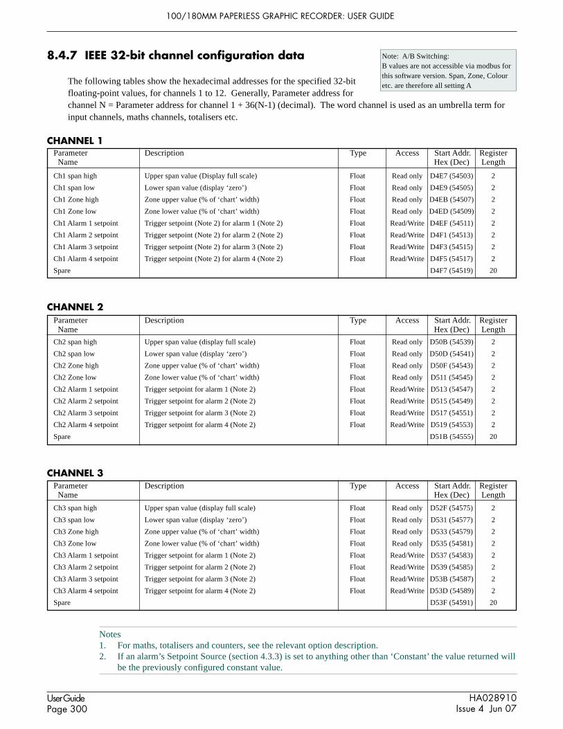
100/180MM PAPERLESS GRAPHIC RECORDER: USER GUIDE
HA028910Issue 4 Jun 07
User GuidePage 300
Parameter Description Type Access Start Addr. Register Name Hex (Dec) Length
Parameter Description Type Access Start Addr. Register Name Hex (Dec) Length
Parameter Description Type Access Start Addr. Register Name Hex (Dec) Length
8.4.7 IEEE 32-bit channel configuration data
The following tables show the hexadecimal addresses for the specified 32-bitfloating-point values, for channels 1 to 12. Generally, Parameter address forchannel N = Parameter address for channel 1 + 36(N-1) (decimal). The word channel is used as an umbrella term forinput channels, maths channels, totalisers etc.
CHANNEL 1
Ch1 span high Upper span value (Display full scale) Float Read only D4E7 (54503) 2
Ch1 span low Lower span value (display ‘zero’) Float Read only D4E9 (54505) 2
Ch1 Zone high Zone upper value (% of ‘chart’ width) Float Read only D4EB (54507) 2
Ch1 Zone low Zone lower value (% of ‘chart’ width) Float Read only D4ED (54509) 2
Ch1 Alarm 1 setpoint Trigger setpoint (Note 2) for alarm 1 (Note 2) Float Read/Write D4EF (54511) 2
Ch1 Alarm 2 setpoint Trigger setpoint (Note 2) for alarm 2 (Note 2) Float Read/Write D4F1 (54513) 2
Ch1 Alarm 3 setpoint Trigger setpoint (Note 2) for alarm 3 (Note 2) Float Read/Write D4F3 (54515) 2
Ch1 Alarm 4 setpoint Trigger setpoint (Note 2) for alarm 4 (Note 2) Float Read/Write D4F5 (54517) 2
Spare D4F7 (54519) 20
CHANNEL 2
Ch2 span high Upper span value (display full scale) Float Read only D50B (54539) 2
Ch2 span low Lower span value (display ‘zero’) Float Read only D50D (54541) 2
Ch2 Zone high Zone upper value (% of ‘chart’ width) Float Read only D50F (54543) 2
Ch2 Zone low Zone lower value (% of ‘chart’ width) Float Read only D511 (54545) 2
Ch2 Alarm 1 setpoint Trigger setpoint for alarm 1 (Note 2) Float Read/Write D513 (54547) 2
Ch2 Alarm 2 setpoint Trigger setpoint for alarm 2 (Note 2) Float Read/Write D515 (54549) 2
Ch2 Alarm 3 setpoint Trigger setpoint for alarm 3 (Note 2) Float Read/Write D517 (54551) 2
Ch2 Alarm 4 setpoint Trigger setpoint for alarm 4 (Note 2) Float Read/Write D519 (54553) 2
Spare D51B (54555) 20
CHANNEL 3
Ch3 span high Upper span value (display full scale) Float Read only D52F (54575) 2
Ch3 span low Lower span value (display ‘zero’) Float Read only D531 (54577) 2
Ch3 Zone high Zone upper value (% of ‘chart’ width) Float Read only D533 (54579) 2
Ch3 Zone low Zone lower value (% of ‘chart’ width) Float Read only D535 (54581) 2
Ch3 Alarm 1 setpoint Trigger setpoint for alarm 1 (Note 2) Float Read/Write D537 (54583) 2
Ch3 Alarm 2 setpoint Trigger setpoint for alarm 2 (Note 2) Float Read/Write D539 (54585) 2
Ch3 Alarm 3 setpoint Trigger setpoint for alarm 3 (Note 2) Float Read/Write D53B (54587) 2
Ch3 Alarm 4 setpoint Trigger setpoint for alarm 4 (Note 2) Float Read/Write D53D (54589) 2
Spare D53F (54591) 20
Note: A/B Switching:B values are not accessible via modbus forthis software version. Span, Zone, Colouretc. are therefore all setting A
Notes1. For maths, totalisers and counters, see the relevant option description.2. If an alarm’s Setpoint Source (section 4.3.3) is set to anything other than ‘Constant’ the value returned will
be the previously configured constant value.

100/180MM PAPERLESS GRAPHIC RECORDER: USER GUIDE
HA028910Issue 4 Jun 07
User GuidePage 301
Parameter Description Type Access Start Addr. Register Name Hex (Dec) Length
Parameter Description Type Access Start Addr. Register Name Hex (Dec) Length
Parameter Description Type Access Start Addr. Register Name Hex (Dec) Length
8.4.7 IEEE 32-BIT CHANNEL CONFIGURATION DATA (Cont.)
CHANNEL 4
Ch4 span high Upper span value (display full scale) Float Read only D553 (54611) 2
Ch4 span low Lower span value (display ‘zero’) Float Read only D555 (54613) 2
Ch4 Zone high Zone upper value (% of ‘chart’ width) Float Read only D557 (54615) 2
Ch4 Zone low Zone lower value (% of ‘chart’ width) Float Read only D559 (54617) 2
Ch4 Alarm 1 setpoint Trigger setpoint for alarm 1 (Note 2) Float Read/Write D55B (54619) 2
Ch4 Alarm 2 setpoint Trigger setpoint for alarm 2 (Note 2) Float Read/Write D55D (54621) 2
Ch4 Alarm 3 setpoint Trigger setpoint for alarm 3 (Note 2) Float Read/Write D55F (54623) 2
Ch4 Alarm 4 setpoint Trigger setpoint for alarm 4 (Note 2) Float Read/Write D561 (54625) 2
Spare D563 (54627) 20
CHANNEL 5
Ch5 span high Upper span value (display full scale) Float Read only D577 (54647) 2
Ch5 span low Lower span value (display ‘zero’) Float Read only D569 (54649) 2
Ch5 Zone high Zone upper value (% of ‘chart’ width) Float Read only D57B (54651) 2
Ch5 Zone low Zone lower value (% of ‘chart’ width) Float Read only D57D (54653) 2
Ch5 Alarm 1 setpoint Trigger setpoint for alarm 1 (Note 2) Float Read/Write D57F (54655) 2
Ch5 Alarm 2 setpoint Trigger setpoint for alarm 2 (Note 2) Float Read/Write D581 (54657) 2
Ch5 Alarm 3 setpoint Trigger setpoint for alarm 3 (Note 2) Float Read/Write D583 (54659) 2
Ch5 Alarm 4 setpoint Trigger setpoint for alarm 4 (Note 2) Float Read/Write D585 (54661) 2
Spare D587 (54663) 20
CHANNEL 6
Ch6 span high Upper span value (display full scale) Float Read only D59B (54683) 2
Ch6 span low Lower span value (display ‘zero’) Float Read only D59D (54685) 2
Ch6 Zone high Zone upper value (% of ‘chart’ width) Float Read only D59F (54687) 2
Ch6 Zone low Zone lower value (% of ‘chart’ width) Float Read only D5A1 (54689) 2
Ch6 Alarm 1 setpoint Trigger setpoint for alarm 1 (Note 2) Float Read/Write D5A3 (54691) 2
Ch6 Alarm 2 setpoint Trigger setpoint for alarm 2 (Note 2) Float Read/Write D5A5 (54693) 2
Ch6 Alarm 3 setpoint Trigger setpoint for alarm 3 (Note 2) Float Read/Write D5A7 (54695) 2
Ch6 Alarm 4 setpoint Trigger setpoint for alarm 4 (Note 2) Float Read/Write D5A9 (54697) 2
Spare D5AB (54699) 20
Notes1. For maths, totalisers and counters, see the relevant option description.2. If an alarm’s Setpoint Source (section 4.3.3) is set to anything other than ‘Constant’ the value returned will
be the previously configured constant value.
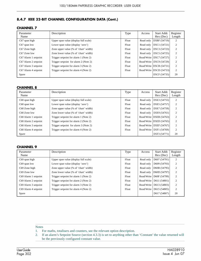
100/180MM PAPERLESS GRAPHIC RECORDER: USER GUIDE
HA028910Issue 4 Jun 07
User GuidePage 302
Parameter Description Type Access Start Addr. Register Name Hex (Dec) Length
Parameter Description Type Access Start Addr. Register Name Hex (Dec) Length
Parameter Description Type Access Start Addr. Register Name Hex (Dec) Length
8.4.7 IEEE 32-BIT CHANNEL CONFIGURATION DATA (Cont.)
CHANNEL 7
Ch7 span high Upper span value (display full scale) Float Read only D5BF (54719) 2
Ch7 span low Lower span value (display ‘zero’) Float Read only D5C1 (54721) 2
Ch7 Zone high Zone upper value (% of ‘chart’ width) Float Read only D5C3 (54723) 2
Ch7 Zone low Zone lower value (% of ‘chart’ width) Float Read only D5C5 (54725) 2
Ch7 Alarm 1 setpoint Trigger setpoint for alarm 1 (Note 2) Float Read/Write D5C7 (54727) 2
Ch7 Alarm 2 setpoint Trigger setpoint for alarm 2 (Note 2) Float Read/Write D5C9 (54729) 2
Ch7 Alarm 3 setpoint Trigger setpoint for alarm 3 (Note 2) Float Read/Write D5CB (54731) 2
Ch7 Alarm 4 setpoint Trigger setpoint for alarm 4 (Note 2) Float Read/Write D5CD (54733) 2
Spare D5CF (54735) 20
CHANNEL 8
Ch8 span high Upper span value (display full scale) Float Read only D5E3 (54755) 2
Ch8 span low Lower span value (display ‘zero’) Float Read only D5E5 (54757) 2
Ch8 Zone high Zone upper value (% of ‘chart’ width) Float Read only D5E7 (54759) 2
Ch8 Zone low Zone lower value (% of ‘chart’ width) Float Read only D5E9 (54761) 2
Ch8 Alarm 1 setpoint Trigger setpoint for alarm 1 (Note 2) Float Read/Write D5EB (54763) 2
Ch8 Alarm 2 setpoint Trigger setpoint for alarm 2 (Note 2) Float Read/Write D5ED (54765) 2
Ch8 Alarm 3 setpoint Trigger setpoint for alarm 3 (Note 2) Float Read/Write D5EF (54767) 2
Ch8 Alarm 4 setpoint Trigger setpoint for alarm 4 (Note 2) Float Read/Write D5F1 (54769) 2
Spare D5F3 (54771) 20
CHANNEL 9
Ch9 span high Upper span value (display full scale) Float Read only D607 (54791) 2
Ch9 span low Lower span value (display ‘zero’) Float Read only D609 (54793) 2
Ch9 Zone high Zone upper value (% of ‘chart’ width) Float Read only D60B (54795) 2
Ch9 Zone low Zone lower value (% of ‘chart’ width) Float Read only D60D (54797) 2
Ch9 Alarm 1 setpoint Trigger setpoint for alarm 1 (Note 2) Float Read/Write D60F (54799) 2
Ch9 Alarm 2 setpoint Trigger setpoint for alarm 2 (Note 2) Float Read/Write D611 (54801) 2
Ch9 Alarm 3 setpoint Trigger setpoint for alarm 3 (Note 2) Float Read/Write D613 (54803) 2
Ch9 Alarm 4 setpoint Trigger setpoint for alarm 4 (Note 2) Float Read/Write D615 (54805) 2
Spare D617 (54807) 20
Notes1. For maths, totalisers and counters, see the relevant option description.2. If an alarm’s Setpoint Source (section 4.3.3) is set to anything other than ‘Constant’ the value returned will
be the previously configured constant value.

100/180MM PAPERLESS GRAPHIC RECORDER: USER GUIDE
HA028910Issue 4 Jun 07
User GuidePage 303
Parameter Description Type Access Start Addr. Register Name Hex (Dec) Length
Parameter Description Type Access Start Addr. Register Name Hex (Dec) Length
Parameter Description Type Access Start Addr. Register Name Hex (Dec) Length
8.4.7 IEEE 32-BIT CHANNEL CONFIGURATION DATA (Cont.)
CHANNEL 10
Ch10 span high Upper span value (display full scale) Float Read only D62B (54827) 2
Ch10 span low Lower span value (display ‘zero’) Float Read only D62D (54829) 2
Ch10 Zone high Zone upper value (% of ‘chart’ width) Float Read only D62F (54831) 2
Ch10 Zone low Zone lower value (% of ‘chart’ width) Float Read only D631 (54833) 2
Ch10 Alarm 1 setpoint Trigger setpoint for alarm 1 (Note 2) Float Read/Write D633 (54835) 2
Ch10 Alarm 2 setpoint Trigger setpoint for alarm 2 (Note 2) Float Read/Write D635 (54837) 2
Ch10 Alarm 3 setpoint Trigger setpoint for alarm 3 (Note 2) Float Read/Write D637 (54839) 2
Ch10 Alarm 4 setpoint Trigger setpoint for alarm 4 (Note 2) Float Read/Write D639 (54841) 2
Spare D63B (54843) 20
CHANNEL 11
Ch11 span high Upper span value (display full scale) Float Read only D64F (54863) 2
Ch11 span low Lower span value (display ‘zero’) Float Read only D651 (54865) 2
Ch11 Zone high Zone upper value (% of ‘chart’ width) Float Read only D653 (54867) 2
Ch11 Zone low Zone lower value (% of ‘chart’ width) Float Read only D655 (54869) 2
Ch11 Alarm 1 setpoint Trigger setpoint for alarm 1 (Note 2) Float Read/Write D657 (54871) 2
Ch11 Alarm 2 setpoint Trigger setpoint for alarm 2 (Note 2) Float Read/Write D659 (54873) 2
Ch11 Alarm 3 setpoint Trigger setpoint for alarm 3 (Note 2) Float Read/Write D65B (54875) 2
Ch11 Alarm 4 setpoint Trigger setpoint for alarm 4 (Note 2) Float Read/Write D65D (54877) 2
Spare D65F (54879) 20
CHANNEL 12
Ch12 span high Upper span value (display full scale) Float Read only D673 (54899) 2
Ch12 span low Lower span value (display ‘zero’) Float Read only D675 (54901) 2
Ch12 Zone high Zone upper value (% of ‘chart’ width) Float Read only D677 (54903) 2
Ch12 Zone low Zone lower value (% of ‘chart’ width) Float Read only D679 (54905) 2
Ch12 Alarm 1 setpoint Trigger setpoint for alarm 1 (Note 2) Float Read/Write D67B (54907) 2
Ch12 Alarm 2 setpoint Trigger setpoint for alarm 2 (Note 2) Float Read/Write D67D (54909) 2
Ch12 Alarm 3 setpoint Trigger setpoint for alarm 3 (Note 2) Float Read/Write D67F (54911) 2
Ch12 Alarm 4 setpoint Trigger setpoint for alarm 4 (Note 2) Float Read/Write D681 (54913) 2
Spare D683 (54915) 20
Notes1. For maths, totalisers and counters, see the relevant option description.2. If an alarm’s Setpoint Source (section 4.3.3) is set to anything other than ‘Constant’ the value returned will
be the previously configured constant value.

100/180MM PAPERLESS GRAPHIC RECORDER: USER GUIDE
HA028910Issue 4 Jun 07
User GuidePage 304
Note: PV access is Read/Write for any point configured with ‘Slave Comms’ as its Type or Function. Other-wise PV access is Read only.
Parameter Description Type Access Start Addr. Register Name Hex (Dec) Length
Parameter Description Type Access Start Addr. Register Name Hex (Dec) Length
8.4.8 IEEE Area Channel run-time data
The following tables show the hexadecimal addresses for the specified 32-bit floating-point values, for channels 1 to 12.Generally, Parameter address for channel N = Parameter address for channel 1 + 4(N-1) (decimal).
CHANNEL 1
Channel 1 value Current process value (PV) Float See note 1 F8C3 (63683) 2Channel 1 status Channel status Enum Read only F8C5 (63685) 1
0 = Good PV 5 = Ranging error1 = Channel off 6 = Overflow2 = Over range 7 = Bad PV3 = Under range 8 = No data4 = Hardware error
Channel 1 Alarms Alarm information Uint16 - F8C6 (63686) 1Bit 0: 0 = Alarm 1 inactive; 1 = Alarm 1 active Read onlyBit 1: 0 = No alarm 1 Ack. required; 1 = Ack. required Read onlyBit 2: 1 = Acknowledge alarm 1 Read/WriteBit 3: SpareBit 4: 0 = Alarm 2 inactive; 1 = Alarm 2 active Read onlyBit 5: 0 = No Alarm 2 Ack. required; 1 = Ack. required Read onlyBit 6: 1 = Acknowledge alarm 2 Read/WriteBit 7: SpareBit 8: 0 = Alarm 3 inactive; 1 = Alarm 3 active Read onlyBit 9: 0 = No alarm 3 Ack. required; 1 = Ack. required Read onlyBit 10: 1 = Acknowledge alarm 3 Read/WriteBit 11: SpareBit 12: 0 = Alarm 4 inactive; 1 = Alarm 4 active Read onlyBit 13: 0 = No Alarm 4 Ack. required; 1 = Ack. required Read onlyBit 14: 1 = Acknowledge alarm 4 Read/WriteBit 15: Spare
CHANNEL 2
Channel 2 value Current process value (PV) Float See note 1 F8C7 (63687) 2Channel 2 status Channel status Enum Read only F8C9 (63689) 1
0 = Good PV 5 = Ranging error1 = Channel off 6 = Overflow2 = Over range 7 = Bad PV3 = Under range 8 = No data4 = Hardware error
Channel 2 alarms Alarm information Uint16 - F8CA (63690) 1Bit 0: 0 = Alarm 1 inactive; 1 = Alarm 1 active Read onlyBit 1: 0 = No alarm 1 Ack. required; 1 = Ack. required Read onlyBit 2: 1 = Acknowledge alarm 1 Read/WriteBit 3: SpareBit 4: 0 = Alarm 2 inactive; 1 = Alarm 2 active Read onlyBit 5: 0 = No Alarm 2 Ack. required; 1 = Ack. required Read onlyBit 6: 1 = Acknowledge alarm 2 Read/WriteBit 7: SpareBit 8: 0 = Alarm 3 inactive; 1 = Alarm 3 active Read onlyBit 9: 0 = No alarm 3 Ack. required; 1 = Ack. required Read onlyBit 10: 1 = Acknowledge alarm 3 Read/WriteBit 11: SpareBit 12: 0 = Alarm 4 inactive; 1 = Alarm 4 active Read onlyBit 13: 0 = No Alarm 4 Ack. required; 1 = Ack. required Read onlyBit 14: 1 = Acknowledge alarm 4 Read/WriteBit 15: Spare

100/180MM PAPERLESS GRAPHIC RECORDER: USER GUIDE
HA028910Issue 4 Jun 07
User GuidePage 305
Parameter Description Type Access Start Addr. Register Name Hex (Dec) Length
Parameter Description Type Access Start Addr. Register Name Hex (Dec) Length
Note: PV access is Read/Write for any point configured with ‘Slave Comms’ as its Type or Function. Other-wise PV access is Read only.
8.4.8 IEEE AREA CHANNEL RUN-TIME DATA (Cont.)
CHANNEL 3
Channel 3 value Current process value (PV) Float See note 1 F8CB (63691) 2
Channel 3 status Channel status Enum Read only F8CD (63693) 10 = Good PV 5 = Ranging error1 = Channel off 6 = Overflow2 = Over range 7 = Bad PV3 = Under range 8 = No data4 = Hardware error
Channel 3 Alarms Alarm information Uint16 - F8CE (63694) 1
Bit 0: 0 = Alarm 1 inactive; 1 = Alarm 1 active Read onlyBit 1: 0 = No alarm 1 Ack. required; 1 = Ack. required Read onlyBit 2: 1 = Acknowledge alarm 1 Read/WriteBit 3: SpareBit 4: 0 = Alarm 2 inactive; 1 = Alarm 2 active Read onlyBit 5: 0 = No Alarm 2 Ack. required; 1 = Ack. required Read onlyBit 6: 1 = Acknowledge alarm 2 Read/WriteBit 7: SpareBit 8: 0 = Alarm 3 inactive; 1 = Alarm 3 active Read onlyBit 9: 0 = No alarm 3 Ack. required; 1 = Ack. required Read onlyBit 10: 1 = Acknowledge alarm 3 Read/WriteBit 11: SpareBit 12: 0 = Alarm 4 inactive; 1 = Alarm 4 active Read onlyBit 13: 0 = No Alarm 4 Ack. required; 1 = Ack. required Read onlyBit 14: 1 = Acknowledge alarm 4 Read/WriteBit 15: Spare
CHANNEL 4
Channel 4 value Current process value (PV) Float See note 1 F8CF (63695) 2
Channel 4 status Channel status Enum Read only F8D1 (63697) 10 = Good PV 5 = Ranging error1 = Channel off 6 = Overflow2 = Over range 7 = Bad PV3 = Under range 8 = No data4 = Hardware error
Channel 4 alarms Alarm information Uint16 - F8D2 (63698) 1
Bit 0: 0 = Alarm 1 inactive; 1 = Alarm 1 active Read onlyBit 1: 0 = No alarm 1 Ack. required; 1 = Ack. required Read onlyBit 2: 1 = Acknowledge alarm 1 Read/WriteBit 3: SpareBit 4: 0 = Alarm 2 inactive; 1 = Alarm 2 active Read onlyBit 5: 0 = No Alarm 2 Ack. required; 1 = Ack. required Read onlyBit 6: 1 = Acknowledge alarm 2 Read/WriteBit 7: SpareBit 8: 0 = Alarm 3 inactive; 1 = Alarm 3 active Read onlyBit 9: 0 = No alarm 3 Ack. required; 1 = Ack. required Read onlyBit 10: 1 = Acknowledge alarm 3 Read/WriteBit 11: SpareBit 12: 0 = Alarm 4 inactive; 1 = Alarm 4 active Read onlyBit 13: 0 = No Alarm 4 Ack. required; 1 = Ack. required Read onlyBit 14: 1 = Acknowledge alarm 4 Read/WriteBit 15: Spare

100/180MM PAPERLESS GRAPHIC RECORDER: USER GUIDE
HA028910Issue 4 Jun 07
User GuidePage 306
Parameter Description Type Access Start Addr. Register Name Hex (Dec) Length
Parameter Description Type Access Start Addr. Register Name Hex (Dec) Length
Note: PV access is Read/Write for any point configured with ‘Slave Comms’ as its Type or Function. Other-wise PV access is Read only.
8.4.8 IEEE AREA CHANNEL RUN-TIME DATA (Cont.)
CHANNEL 5
Channel 5 value Current process value (PV) Float See note 1 F8D3 (63699) 2
Channel 5 status Channel status Enum Read only F8D5 (63701) 10 = Good PV 5 = Ranging error1 = Channel off 6 = Overflow2 = Over range 7 = Bad PV3 = Under range 8 = No data4 = Hardware error
Channel 5 Alarms Alarm information Uint16 - F8D6 (63702) 1
Bit 0: 0 = Alarm 1 inactive; 1 = Alarm 1 active Read onlyBit 1: 0 = No alarm 1 Ack. required; 1 = Ack. required Read onlyBit 2: 1 = Acknowledge alarm 1 Read/WriteBit 3: SpareBit 4: 0 = Alarm 2 inactive; 1 = Alarm 2 active Read onlyBit 5: 0 = No Alarm 2 Ack. required; 1 = Ack. required Read onlyBit 6: 1 = Acknowledge alarm 2 Read/WriteBit 7: SpareBit 8: 0 = Alarm 3 inactive; 1 = Alarm 3 active Read onlyBit 9: 0 = No alarm 3 Ack. required; 1 = Ack. required Read onlyBit 10: 1 = Acknowledge alarm 3 Read/WriteBit 11: SpareBit 12: 0 = Alarm 4 inactive; 1 = Alarm 4 active Read onlyBit 13: 0 = No Alarm 4 Ack. required; 1 = Ack. required Read onlyBit 14: 1 = Acknowledge alarm 4 Read/WriteBit 15: Spare
CHANNEL 6
Channel 6 value Current process value (PV) Float See note 1 F8D7 (63703) 2
Channel 6 status Channel status Enum Read only F8D9 (63705) 10 = Good PV 5 = Ranging error1 = Channel off 6 = Overflow2 = Over range 7 = Bad PV3 = Under range 8 = No data4 = Hardware error
Channel 6 alarms Alarm information Uint16 - F8DA (63706) 1
Bit 0: 0 = Alarm 1 inactive; 1 = Alarm 1 active Read onlyBit 1: 0 = No alarm 1 Ack. required; 1 = Ack. required Read onlyBit 2: 1 = Acknowledge alarm 1 Read/WriteBit 3: SpareBit 4: 0 = Alarm 2 inactive; 1 = Alarm 2 active Read onlyBit 5: 0 = No Alarm 2 Ack. required; 1 = Ack. required Read onlyBit 6: 1 = Acknowledge alarm 2 Read/WriteBit 7: SpareBit 8: 0 = Alarm 3 inactive; 1 = Alarm 3 active Read onlyBit 9: 0 = No alarm 3 Ack. required; 1 = Ack. required Read onlyBit 10: 1 = Acknowledge alarm 3 Read/WriteBit 11: SpareBit 12: 0 = Alarm 4 inactive; 1 = Alarm 4 active Read onlyBit 13: 0 = No Alarm 4 Ack. required; 1 = Ack. required Read onlyBit 14: 1 = Acknowledge alarm 4 Read/WriteBit 15: Spare

100/180MM PAPERLESS GRAPHIC RECORDER: USER GUIDE
HA028910Issue 4 Jun 07
User GuidePage 307
Parameter Description Type Access Start Addr. Register Name Hex (Dec) Length
Parameter Description Type Access Start Addr. Register Name Hex (Dec) Length
Note: PV access is Read/Write for any point configured with ‘Slave Comms’ as its Type or Function. Other-wise PV access is Read only.
8.4.8 IEEE AREA CHANNEL RUN-TIME DATA (Cont.)
CHANNEL 7
Channel 7 value Current process value (PV) Float See note 1 F8DB (63707) 2
Channel 7 status Channel status Enum Read only F8DD (63709) 10 = Good PV 5 = Ranging error1 = Channel off 6 = Overflow2 = Over range 7 = Bad PV3 = Under range 8 = No data4 = Hardware error
Channel 7 Alarms Alarm information Uint16 - F8DE (63710) 1
Bit 0: 0 = Alarm 1 inactive; 1 = Alarm 1 active Read onlyBit 1: 0 = No alarm 1 Ack. required; 1 = Ack. required Read onlyBit 2: 1 = Acknowledge alarm 1 Read/WriteBit 3: SpareBit 4: 0 = Alarm 2 inactive; 1 = Alarm 2 active Read onlyBit 5: 0 = No Alarm 2 Ack. required; 1 = Ack. required Read onlyBit 6: 1 = Acknowledge alarm 2 Read/WriteBit 7: SpareBit 8: 0 = Alarm 3 inactive; 1 = Alarm 3 active Read onlyBit 9: 0 = No alarm 3 Ack. required; 1 = Ack. required Read onlyBit 10: 1 = Acknowledge alarm 3 Read/WriteBit 11: SpareBit 12: 0 = Alarm 4 inactive; 1 = Alarm 4 active Read onlyBit 13: 0 = No Alarm 4 Ack. required; 1 = Ack. required Read onlyBit 14: 1 = Acknowledge alarm 4 Read/WriteBit 15: Spare
CHANNEL 8
Channel 8 value Current process value (PV) Float See note 1 F8DF (63711) 2
Channel 8 status Channel status Enum Read only F8E1 (63713) 10 = Good PV 5 = Ranging error1 = Channel off 6 = Overflow2 = Over range 7 = Bad PV3 = Under range 8 = No data4 = Hardware error
Channel 8 alarms Alarm information Uint16 - F8E2 (63714) 1
Bit 0: 0 = Alarm 1 inactive; 1 = Alarm 1 active Read onlyBit 1: 0 = No alarm 1 Ack. required; 1 = Ack. required Read onlyBit 2: 1 = Acknowledge alarm 1 Read/WriteBit 3: SpareBit 4: 0 = Alarm 2 inactive; 1 = Alarm 2 active Read onlyBit 5: 0 = No Alarm 2 Ack. required; 1 = Ack. required Read onlyBit 6: 1 = Acknowledge alarm 2 Read/WriteBit 7: SpareBit 8: 0 = Alarm 3 inactive; 1 = Alarm 3 active Read onlyBit 9: 0 = No alarm 3 Ack. required; 1 = Ack. required Read onlyBit 10: 1 = Acknowledge alarm 3 Read/WriteBit 11: SpareBit 12: 0 = Alarm 4 inactive; 1 = Alarm 4 active Read onlyBit 13: 0 = No Alarm 4 Ack. required; 1 = Ack. required Read onlyBit 14: 1 = Acknowledge alarm 4 Read/WriteBit 15: Spare

100/180MM PAPERLESS GRAPHIC RECORDER: USER GUIDE
HA028910Issue 4 Jun 07
User GuidePage 308
Parameter Description Type Access Start Addr. Register Name Hex (Dec) Length
Parameter Description Type Access Start Addr. Register Name Hex (Dec) Length
Note: PV access is Read/Write for any point configured with ‘Slave Comms’ as its Type or Function. Other-wise PV access is Read only.
8.4.8 IEEE AREA CHANNEL RUN-TIME DATA (Cont.)
CHANNEL 9
Channel 9 value Current process value (PV) Float See note 1 F8E3 (63715) 2
Channel 9 status Channel status Enum Read only F8E5 (63717) 10 = Good PV 5 = Ranging error1 = Channel off 6 = Overflow2 = Over range 7 = Bad PV3 = Under range 8 = No data4 = Hardware error
Channel 9 Alarms Alarm information Uint16 - F8E6 (63718) 1
Bit 0: 0 = Alarm 1 inactive; 1 = Alarm 1 active Read onlyBit 1: 0 = No alarm 1 Ack. required; 1 = Ack. required Read onlyBit 2: 1 = Acknowledge alarm 1 Read/WriteBit 3: SpareBit 4: 0 = Alarm 2 inactive; 1 = Alarm 2 active Read onlyBit 5: 0 = No Alarm 2 Ack. required; 1 = Ack. required Read onlyBit 6: 1 = Acknowledge alarm 2 Read/WriteBit 7: SpareBit 8: 0 = Alarm 3 inactive; 1 = Alarm 3 active Read onlyBit 9: 0 = No alarm 3 Ack. required; 1 = Ack. required Read onlyBit 10: 1 = Acknowledge alarm 3 Read/WriteBit 11: SpareBit 12: 0 = Alarm 4 inactive; 1 = Alarm 4 active Read onlyBit 13: 0 = No Alarm 4 Ack. required; 1 = Ack. required Read onlyBit 14: 1 = Acknowledge alarm 4 Read/WriteBit 15: Spare
CHANNEL 10
Channel 10 value Current process value (PV) Float See note 1 F8E7 (63719) 2
Channel 10 status Channel status Enum Read only F8E9 (63721) 10 = Good PV 5 = Ranging error1 = Channel off 6 = Overflow2 = Over range 7 = Bad PV3 = Under range 8 = No data4 = Hardware error
Channel 10 alarms Alarm information Uint16 - F8EA (63722) 1
Bit 0: 0 = Alarm 1 inactive; 1 = Alarm 1 active Read onlyBit 1: 0 = No alarm 1 Ack. required; 1 = Ack. required Read onlyBit 2: 1 = Acknowledge alarm 1 Read/WriteBit 3: SpareBit 4: 0 = Alarm 2 inactive; 1 = Alarm 2 active Read onlyBit 5: 0 = No Alarm 2 Ack. required; 1 = Ack. required Read onlyBit 6: 1 = Acknowledge alarm 2 Read/WriteBit 7: SpareBit 8: 0 = Alarm 3 inactive; 1 = Alarm 3 active Read onlyBit 9: 0 = No alarm 3 Ack. required; 1 = Ack. required Read onlyBit 10: 1 = Acknowledge alarm 3 Read/WriteBit 11: SpareBit 12: 0 = Alarm 4 inactive; 1 = Alarm 4 active Read onlyBit 13: 0 = No Alarm 4 Ack. required; 1 = Ack. required Read onlyBit 14: 1 = Acknowledge alarm 4 Read/WriteBit 15: Spare
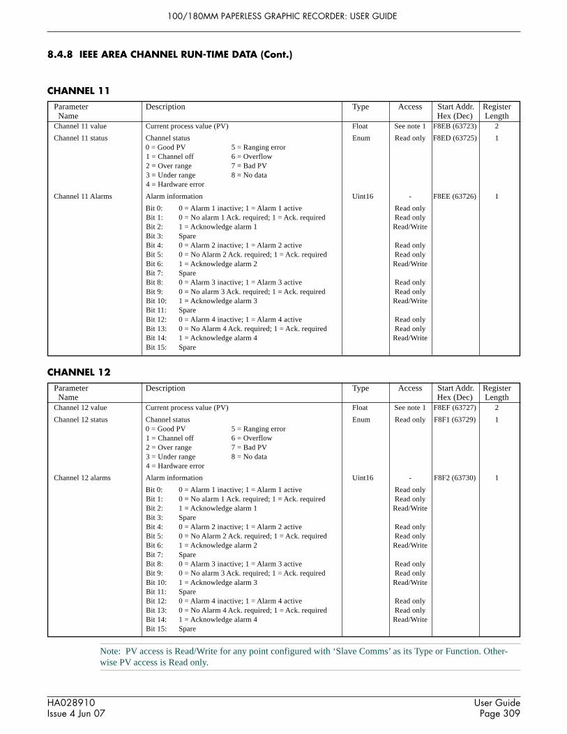
100/180MM PAPERLESS GRAPHIC RECORDER: USER GUIDE
HA028910Issue 4 Jun 07
User GuidePage 309
Parameter Description Type Access Start Addr. Register Name Hex (Dec) Length
Parameter Description Type Access Start Addr. Register Name Hex (Dec) Length
Note: PV access is Read/Write for any point configured with ‘Slave Comms’ as its Type or Function. Other-wise PV access is Read only.
8.4.8 IEEE AREA CHANNEL RUN-TIME DATA (Cont.)
CHANNEL 11
Channel 11 value Current process value (PV) Float See note 1 F8EB (63723) 2
Channel 11 status Channel status Enum Read only F8ED (63725) 10 = Good PV 5 = Ranging error1 = Channel off 6 = Overflow2 = Over range 7 = Bad PV3 = Under range 8 = No data4 = Hardware error
Channel 11 Alarms Alarm information Uint16 - F8EE (63726) 1
Bit 0: 0 = Alarm 1 inactive; 1 = Alarm 1 active Read onlyBit 1: 0 = No alarm 1 Ack. required; 1 = Ack. required Read onlyBit 2: 1 = Acknowledge alarm 1 Read/WriteBit 3: SpareBit 4: 0 = Alarm 2 inactive; 1 = Alarm 2 active Read onlyBit 5: 0 = No Alarm 2 Ack. required; 1 = Ack. required Read onlyBit 6: 1 = Acknowledge alarm 2 Read/WriteBit 7: SpareBit 8: 0 = Alarm 3 inactive; 1 = Alarm 3 active Read onlyBit 9: 0 = No alarm 3 Ack. required; 1 = Ack. required Read onlyBit 10: 1 = Acknowledge alarm 3 Read/WriteBit 11: SpareBit 12: 0 = Alarm 4 inactive; 1 = Alarm 4 active Read onlyBit 13: 0 = No Alarm 4 Ack. required; 1 = Ack. required Read onlyBit 14: 1 = Acknowledge alarm 4 Read/WriteBit 15: Spare
CHANNEL 12
Channel 12 value Current process value (PV) Float See note 1 F8EF (63727) 2
Channel 12 status Channel status Enum Read only F8F1 (63729) 10 = Good PV 5 = Ranging error1 = Channel off 6 = Overflow2 = Over range 7 = Bad PV3 = Under range 8 = No data4 = Hardware error
Channel 12 alarms Alarm information Uint16 - F8F2 (63730) 1
Bit 0: 0 = Alarm 1 inactive; 1 = Alarm 1 active Read onlyBit 1: 0 = No alarm 1 Ack. required; 1 = Ack. required Read onlyBit 2: 1 = Acknowledge alarm 1 Read/WriteBit 3: SpareBit 4: 0 = Alarm 2 inactive; 1 = Alarm 2 active Read onlyBit 5: 0 = No Alarm 2 Ack. required; 1 = Ack. required Read onlyBit 6: 1 = Acknowledge alarm 2 Read/WriteBit 7: SpareBit 8: 0 = Alarm 3 inactive; 1 = Alarm 3 active Read onlyBit 9: 0 = No alarm 3 Ack. required; 1 = Ack. required Read onlyBit 10: 1 = Acknowledge alarm 3 Read/WriteBit 11: SpareBit 12: 0 = Alarm 4 inactive; 1 = Alarm 4 active Read onlyBit 13: 0 = No Alarm 4 Ack. required; 1 = Ack. required Read onlyBit 14: 1 = Acknowledge alarm 4 Read/WriteBit 15: Spare

100/180MM PAPERLESS GRAPHIC RECORDER: USER GUIDE
HA028910Issue 4 Jun 07
User GuidePage 310
FFF0 0500
FFF1
FFF2
FFF3
FFF4
6100 or 6180
0001
CC26HHHH
Product ID
Version ID
FIT start address
Checksum
Company ID
Byte 0
Transactionidentifier
(usually 00)
Transactionidentifier
(usually 00)
Protocolidentifier
(00)
Protocolidentifier
(00)
Byte 1 Byte 2 Byte 3 Byte 4
Number ofbytes fol-
lowing
Byte 5
Always 00
Byte 6
Recorderidentifier
Byte 7
MODBUSfunction
code (hex)
Bytes 8 onwards
Data(Depends on
function code)
8.4.9 Permanent ID table
This table contains information relating to the recorder, and also gives the start address of the feature identification table(FIT).
Table 8.4.9 Permanent ID table
8.5 DATA TRANSMISSION
Each message (request or response) is packaged in the (MODBUS) frame shown below. The messages consist of a 7byte prefix, followed by the function code (in hex), followed by the relevant data bytes, the number and content ofwhich depend on the function code, as described in subsequent sections.
Figure 8.5 MODBUS package
Notes:1 The transaction identifier has no active function - the recorder just copies the bytes from the request
message to the response message.2 The recorder identifier has no active function - the recorder just copies the byte from the request message
to the response message.3. The protocol identifier bytes are always zero.
FUNCTION CODES AND EXCEPTION CODESRefer to section 8.2.1 for lists of function codes and exception codes supported.
TEXT STRINGSWhen sending text strings, such as Batch fields, the final character must be followed by one or two ‘Null’ characters.The number of bytes in the text string (including the null) must be even, even if this means adding two nulls at the endof the message instead of one.
For example, the text string: “Batch Number’ should be sent as Ba tc hSpace Nu mb er NullNull, or Ba tc hSpace Nu mb er SpaceNullwhere each pair of characters occupies on 16-bit word. Similarly, the text string ‘Batch Number:’ would be sent as Ba tc hSpace Nu mb er :null,but only one Null character is required to provide an even number of bytes.

100/180MM PAPERLESS GRAPHIC RECORDER: USER GUIDE
HA028910Issue 4 Jun 07
User GuidePage 311
Byte 0
Transactionidentifier
Transactionidentifier
Protocolidentifier
Protocolidentifier
Byte 1 Byte 2 Byte 3 Byte 4
Number ofbytes fol-
lowing
Byte 5
Always 00
Byte 6
Recorderidentifier
Byte 7
MODBUSfunction
code (hex)
00 00 00 00 00 06 00 03
Byte 8 Byte 9
Registerstart
addresshigh byte
Byte 10
Word counthigh byte
Byte 11
Registerstart
addresslow byte
Word countlow byte
03 1F 00 0A
Byte 0
Transactionidentifier
Transactionidentifier
Protocolidentifier
Protocolidentifier
Byte 1 Byte 2 Byte 3 Byte 4
Number ofbytes fol-
lowing (hex)
Byte 5
Always 00
Byte 6
Recorderidentifier
Byte 7
MODBUSfunction
code (hex)
00 00 00 00 00 17 00 03
Byte 8
Byte count(No of reg-isters x 2)
(Hex)
14
Byte 9 Byte 10 Byte 11
ASCIIC (Hex)
43 68 61
ASCIIh (Hex)
ASCIIa (Hex)
Byte 12 Byte 13 Byte 14 Byte 15 Byte 16 Byte 17 Byte 18 Byte 19
6E 6E 65 6C 20 35 20 44
Byte 20
65
ASCIIn (Hex)
ASCIIn (Hex)
ASCIIe (Hex)
ASCIIl (Hex)
ASCIIspace (Hex)
ASCII5 (Hex)
ASCIIspace (Hex)
ASCIID (Hex)
ASCIIe (Hex)
Byte 24 Byte 25 Byte 26 Byte 27 Byte 28
Byte 21 Byte 22 Byte 23
73 63 72
ASCIIs (Hex)
ASCIIc (Hex)
ASCIIr (Hex)
69 70 74 6F 72
ASCIIi (Hex)
ASCIIp (Hex)
ASCIIt (Hex)
ASCIIo (Hex)
ASCIIr (Hex)
8.5.1 Function code 03
REQUESTThe bytes after the 7-byte prefix described above are:Function code (03) (1 byte)Register start address (2 bytes)Word count (Total number of registers) (1 to 125 decimal; 1 to 7D hex) (2 bytes)
Thus to read Channel 5 descriptor (start address 031F - 10 registers altogether) the following request (as described infigure 8.5.1a) would be transmitted:0000000000060003031F000A
Figure 8.5.1a Function code 03 request example
RESPONSEAs a response to a request, the recorder returns a similar message, but the function code (03) is followed by:
Byte count (= 2 x the number of register values requested) in hex (1 byte)Value of register at start address (2 bytes)Value of register at start address + 1 (2 bytes)etc.etc.Value of final register (2 bytes)
Thus as a response to the above request for channel 5 descriptor, the following message (as expanded in figure 8.5.1b)would be returned to the host (assuming channel descriptor to be: Channel 5 Descriptor):0000000000170003144368616E6E656C20352044657363726970746F72
Figure 8.5.1b Function code 03 response example
EXCEPTION RESPONSESByte 0 = Function code 83 (hex) (i.e. Hex (80 + function code))Byte 1 = Exception code 01 (Illegal function) or 02 (Invalid data address)

100/180MM PAPERLESS GRAPHIC RECORDER: USER GUIDE
HA028910Issue 4 Jun 07
User GuidePage 312
Byte 0
Transactionidentifier
Transactionidentifier
Protocolidentifier
Protocolidentifier
Byte 1 Byte 2 Byte 3 Byte 4
Number ofbytes fol-
lowing
Byte 5
Always 00
Byte 6
RecorderID
Byte 7
MODBUSfunction
code (hex)
00 00 00 00 00 06 01 06
Byte 8 Byte 9
Registerstart
addresshigh byte
Byte 10
Valuehigh byte
(hex)
Byte 11
Registerstart
addresslow byte
Valuelow byte
(hex)
02 2F 00 50
Byte 0
Transactionidentifier
Transactionidentifier
Protocolidentifier
Protocolidentifier
Byte 1 Byte 2 Byte 3 Byte 4
Number ofbytes fol-
lowing
Byte 5
Always 00
Byte 6
Recorderidentifier
Byte 7
MODBUSfunction
code (hex)
00 00 00 00 00 06 00 08
Byte 8 Byte 9
Subfunctioncode
high byte
Byte 10
Query datahigh byte
(ASCII 'P')(Hex)
Byte 11
Subfunctioncode
low byte
Query datalow byte
(ASCII 'Q')(Hex)
00 00 50 51
8.5.2 Function code 04
This is identical with function code 03, except that 04 must be used as the function code and the exception responseFunction code is 84 (hex) not 83.
8.5.3 Function code 06
REQUESTThis is used to write a value to a single register. The bytes after the 7-byte prefix described in section 8.5, above are:Function code (06) (1 byte)Register address (2 bytes)Value to be written (2 bytes)
Thus to write a value of 80 degrees as Alarm 1 setpoint for channel 3 (register address 022F), the following request (asdetailed in figure 8.5.3) would be transmitted to the recorder:0000000000060006022F0050
Figure 8.5.3 Function code 06 request/response example
RESPONSEAs a response to a request, the recorder returns a message identical with the request message.
EXCEPTION RESPONSESByte 0 = Function code 86 (hex) (i.e. Hex (80 + function code))Byte 1 = Exception code 01 (Illegal function) or 02 (Invalid data address)
8.5.4 Function code 08
This is used to initiate a loop-back test. The bytes after the 7-byte prefix described in section 8.5, above are:
Function code (08) (1 byte)Subfunction code (00 00) (2 bytes)Query data (loopback value) (HH HH) (2 bytes)
Thus to initiate a loopback test (using, as an example, ‘P’ ’Q’ as the query data), the following request (as detailed infigure 8.5.4) is transmitted to the recorder:000000000006000800005051The response to the receipt of such a message should be to ‘echo’ the request back to the host.
Figure 8.5.4 Function code 08 (loopback test) example

100/180MM PAPERLESS GRAPHIC RECORDER: USER GUIDE
HA028910Issue 4 Jun 07
User GuidePage 313
Byte 0
Transactionidentifier
Transactionidentifier
Protocolidentifier
Protocolidentifier
Byte 1 Byte 2 Byte 3 Byte 4 Byte 5
Always 00
Byte 6
Recorderidentifier
Byte 7
00 00 00 00 00 15 00 10
Byte 8
Baseaddress
High byte
A5
Byte 9 Byte 10 Byte 11
Baseaddress
Low byte
7F 00 07
Word countHigh byte
Byte 12
0E
Byte countWord countLow byte
Number ofbytes to fol-low (hex)
MODBUSfunction
code (hex)
Byte 13 Byte 14 Byte 15 Byte 16 Byte 17 Byte 18 Byte 19
42 61 74 63 68 20 4E
Byte 20
75
ASCIIB (Hex)
ASCIIa (Hex)
ASCIIt (Hex)
ASCIIc (Hex)
ASCIIh (Hex)
ASCIIspace (Hex)
ASCIIN (Hex)
ASCIIu (Hex)
Byte 21 Byte 22 Byte 23
6D 62 65
ASCIIm (Hex)
ASCIIb (Hex)
ASCIIe (Hex)
Byte 24
72
ASCIIr (Hex)
Byte 25
00
ASCIINull
Byte 26
00
ASCIINull
Byte 0
Transactionidentifier
Transactionidentifier
Protocolidentifier
Protocolidentifier
Byte 1 Byte 2 Byte 3 Byte 4
Number ofbytes fol-
lowing (hex)
Byte 5
Always 00
Byte 6
RecorderID
Byte 7
MODBUSfunction
code (hex)
00 00 00 00 00 06 00 10
Byte 8
Baseaddress
High byte
A5
Byte 9 Byte 10 Byte 11
Baseaddress
Low byte
7F 00 07
Word countHigh byte
Word countLow byte
8.5.5 Function code 16 (Hex 10)
REQUESTThis is used to write values to multiple registers. The bytes after the 7-byte prefix described in section 8.5, above are:Function code (10) (1 byte)Register Start address (2 bytes)Word count (Total number of registers to be written) (1 to 100 decimal; 1 to 64 hex) (2 bytes)Byte count (B) ( 2 x word count) (1 byte)Values to be written (2B bytes).
Thus to write ”Batch Number” as batch field 1 for group 1 (start address A57F), the following message (expanded infigure 8.5.5a) would be transmitted to the recorder:0000000000150010A57F00070E4261746368204E756D6265720000
Figure 8.5.5a Function code 16 request example
RESPONSEThe response message (detailed in figure 8.5.5b) after the 7-byte prefix described in section 8.5, above is:
Function code 10 (1 byte)Start address (2 bytes)Word count (2 bytes)
Thus, the response to the above batch field request would be:0000000000060010A57F0007
Figure 8.5.5b Function code 16 response example
EXCEPTION RESPONSESByte 0 = Function code 90 (hex) (i.e. Hex (80 + function code))Byte 1 = Exception code 01 (Illegal function) or 02 (Invalid data address)
Note: Function code 16 can be used to write multiple registers into the indirection table area, for example, bywriting the base register address of a 32-bit channel value (e.g. channel 3 - start address: F994) into locationD18B.

100/180MM PAPERLESS GRAPHIC RECORDER: USER GUIDE
HA028910Issue 4 Jun 07
User GuidePage 314
9 ANALOGUE OUTPUT OPTION
Up to four analogue output boards can be fitted, each of which supplies two outputs. This allows any of the recorderpoints to be output as a voltage or current signal, as configured. Any part of the source point’s span can be mapped tothe output range, and the outputs can be adjusted (as described below) to compensate for errors in the monitoring sys-tem.
9.1 SIGNAL WIRING
Figure 2.2.1d shows the output wiring for analogue output boards.
9.2 SPECIFICATION
See Annex A for the analogue output board specification.
9.3 CONFIGURATION
See section 4.3.17 (output channel configuration) for details.
9.4 OUTPUT ADJUST
Notes1. Output adjust is relevant only to output channels configured as ‘V’ or ‘mA’, not to those configured as
Master Comms.2. Output channels can be adjusted only by users with ‘Adjust I/O’ access permission (section 4.4.1)
9.4.1 Adjustment procedure
This procedure is carried out as follows:1. Select ‘Output Adjust’ in the System menu.2. Select the required channel.3. Enter a low value for the recorder to output.4. Observe what value the monitoring equipment is reading for this output5. Enter this monitored value.6. Repeat for a high value.
Note: 10% and 90% of output range are commonly used as low and high values respectively.
Figure 9.4.1 below, shows typical adjust pages.
9.4.2 Adjustment removal
Adjustments can be removed at any time, as follows:1. Select ‘Output Adjust’ in the System menu.2. Select the required channel.3. Operate the ‘Remove Adjust’ key4. Select ‘Yes’ from the resulting confirmation dialogue.

100/180MM PAPERLESS GRAPHIC RECORDER: USER GUIDE
HA028910Issue 4 Jun 07
User GuidePage 315
9.4 OUTPUT ADJUST (Cont.)
Figure 9.4.1 Typical output adjust pages
Specify the low output and then the low reading
Low Output
Low Reading
4
4.018
When the values have been entered selectApply
1) 10.690 13/10/05 15:22:54
Apply Discard
Channel
Adjust Channel
Remove Adjust
4
1)
2)
3)
4)
5)
6)
10.690
20.960
3.563
0.000
9.365
8.896
13/10/05 15:22:54
13/10/05 16:03:09
Unadjusted
Unadjusted
Unadjusted
12/10/05 14:29:26
Specify the high output and then the highreading
High Output
High Reading
9
8.917
When the values have been entered selectApply to complete the adjustment procedure.
Apply Discard
Archive SystemSave/Restore Config Security Network
Clock
Locale
Upgrade
Input Adjust
Output adjust

100/180MM PAPERLESS GRAPHIC RECORDER: USER GUIDE
HA028910Issue 4 Jun 07
User GuidePage 316
10 EVENT INPUT OPTION
10.1 INTRODUCTION
Each Event input option board offers six isolated input circuits. Inputs can be either switch closures or voltage levels.
Section 4.3.6 (Event configuration) describes the use of events and how they can be combined to perform logic func-tions, if required. Job lists can be triggered by any event, either internal or as a result of external events wired to anevent input board.
If this option is fitted, ‘Event input board’ appears as a event source, and the user must then specify a board number andassociated input number as required.
Figure 10.1 Event input selection
10.2 SIGNAL WIRING
See figure 2.2.1d
10.3 SPECIFICATION
See Annex A
Event Number 1) Event 1
Source 1 Event Input Board
Board 1
Source 1 Sense Source 1
Operator
Select Event Input board
Input 5
And
Select Input on associated board
Apply Discard

100/180MM PAPERLESS GRAPHIC RECORDER: USER GUIDE
HA028910Issue 4 Jun 07
User GuidePage 317
11 TRANSMITTER POWER SUPPLY
11.1 INTRODUCTION
WARNING!Transmitter power supplies must not be used with dc supply voltages.
Notes:1. Transmitter power supplies are not suitable for use with dc or low-voltage ac supplies.2 The transmitter power supply is available only with 100 mm. recorders.
This option consists of a circuit board, terminal block and suitable wiring inside a long terminal cover at the rear of a100mm recorder. The board supplies three mutually isolated dc supplies (nominal 25 Volts) each of which is intendedto power a single 0 to 20 mA or 4 to 20 mA current loop.
11.2 FUSING
11.2.1 Fuse Rating
The circuit board is protected by a 20 mm anti-surge (type T) fuse, the value of which depends on the supply voltage asshown in table 11.2.1, below.
Access to the output wiring and to the fuse is achieved by isolating the recorder from mains power and opening theterminal cover (after removing its securing screws). The process is fully described below.
Table 11.2.1 Transmitter power supply fuse details
11.2.2 Access to the user connections/fuse
1 Isolate the recorder from the supply voltage.2 At the rear of the recorder remove the terminal cover securing screws (figure 11.2.2a), taking care to retain them
for use in re-assembly.
Supply voltage Fuse rating Part Number115V ac 100 mA CH050012230V ac 63mA CH050630
Figure 11.2.2a Retaining screw locations
Cover securing screws

100/180MM PAPERLESS GRAPHIC RECORDER: USER GUIDE
HA028910Issue 4 Jun 07
User GuidePage 318
11.2.2 ACCESS TO THE USER CONNECTIONS/FUSE (Cont.)
3 Open the cover (figure 11.2.2b) to reveal the circuit board, user connections etc. (figure 11.2.2c)
Figure 11.2.2b Opening the rear cover
4 The fuse is located as shown in figure 11.2.2c. User wiring to the terminal block (figures 11.2.3a/b) can be carriedout now, or the terminal cover can be removed for convenience, as described in steps 5 onwards below.
Figure 11.2.2c Fuse and User terminal block locations
To remove the terminal cover:5. Unplug the IEC connector from the rear of the recorder connector panel and remove the cable tie securing the loom
to the chassis.6. Close the terminal cover, and lift it off.
Note: Four apertures in each side of the terminal cover allow the user to actuate the clips which secure the i/oconnectors to the rear panel of the recorder. This allows the i/o connectors to be removed if, for example, therecorder is to be removed from the panel for any reason. The positions of these apertures are shown in figure11.2.2b (right-hand side shown; left-hand side similar).
RecorderBody
Swing rear coverdown for access
Connectorclip access
Power cordto recorder
Fuse
User terminalblock

100/180MM PAPERLESS GRAPHIC RECORDER: USER GUIDE
HA028910Issue 4 Jun 07
User GuidePage 319
11.2.3 User wiring
Figure 11.2.3a shows the terminal block pinout, and figure 11.2.3b shows typical applications wiring.
Figure 11.2.3a Terminal block wiring
Figure 11.2.3b Applications wiring
O/P 1+ –
O/P 2+ –
O/P 3+ –
User terminal block
Bla
ck
Bla
ck
Bla
ck
Red
Red
Red
– +
Transmitter
+- Other transmitters
V+ V-Channel input
– + – +
Only one channelshown, for clarity.
Long terminal cover
Recorder rearterminal panel
User terminal block
I
R
Transmitter Power SupplyPCB
0 mA4 mA
20 mA
0 V0.4 V2.0 V
0 V1.0 V5.0V
100Ω 250Ω
Voltages generated byvarious currents forR = 100Ω and R =250Ω
R (minimum spec) = 1.4W, ± 1%. 100Ω or 250Ω as required (see table)

100/180MM PAPERLESS GRAPHIC RECORDER: USER GUIDE
HA028910Issue 4 Jun 07
User GuidePage 320
Serial Port 1 Serial Port 2
EIA232C
Pin123456789
SignalNCRxTxDTRSignal groundNCNCNC5V via 1500Ω
1
6
5
9
View on solder-bucket faceof user socket
+24V
0V 2
31
NC
Pin Function1 +24V±10%2 0V3 Not connected
Shell Chassis ground
Figure 12.2.1a Serial port locations (small frame)
12 ASCII PRINTER OUTPUT OPTION
12.1 INTRODUCTION
If the Serial Communications option is fitted, this allows the printing of messages, as and when they occur, or the print-ing of configurable reports as a result of job action. The recorder is set up to drive a number of recommended printers.As more printers become available, printer drivers can be imported as described in section 12.4, below. For printerspecification, refer to the documentation supplied with the printer.
12.2 WIRING
12.2.1 Serial communications ports
The printer is connected to one of the Serial communications ports, configured for EIA232 standard, using the Rx, Txand common signal lines. Printer Tx must be connected to recorder Rx. Printer Rx must be connected to recorder Tx.Figure 12.2.1 shows the location of, and user connections for, the recorder ports. See also section 2.2.
Figure 12.2.1b Serial port pinout
12.2.2 DC connection
Figure 12.2.2 DC connector pinout(solder side of user connector)

100/180MM PAPERLESS GRAPHIC RECORDER: USER GUIDE
HA028910Issue 4 Jun 07
User GuidePage 321
Connection
Baud Rate
Stop Bits
Parity
Printer Type
Printer Name
Printer Status
SystemAlarms
Power Up
Select required Baud rate.
Select 1 or 2
Link Error Count
Reset Error Count
Select printer type
Printer Test
Print Messages From
Messages To Print
GeneralBatches
Logins
Apply Discard
Port
Online
Protocol
EIA232
9600
1
Even
Star TSP600
0
Star TSP600(0)
Not Responding
1) Group 1
Serial 1
ASCII Printer
12.3 CONFIGURATION
Configuration takes place in two areas viz: ‘Connections’ and ‘Reports’ (section 12.3.2).
12.3.1 Connections
Figure 12.3.1a shows the default configuration page for ASCII printer protocol. See section 4.3.15 for other protocols.
Figure 12.3.1a Serial communications configuration menu
PORTThis allows serial port 1 or serial port 2 to be selected for printer configuration. Separate, independently configurableprinters can be connected to the two ports, or, if only one printer is to be connected, any of the other available protocolscan be selected for the non-printer port.
LINK ERROR COUNTThe counter is incremented every time there is a framing error, a parity error or a Cyclic redundancy check (CRC) errorwhilst communicating with the printer. The ‘Reset Error Count’ key is used to reset the count to zero.
Note: For instruments fitted with two printers, the count relates to the currently selected printer.
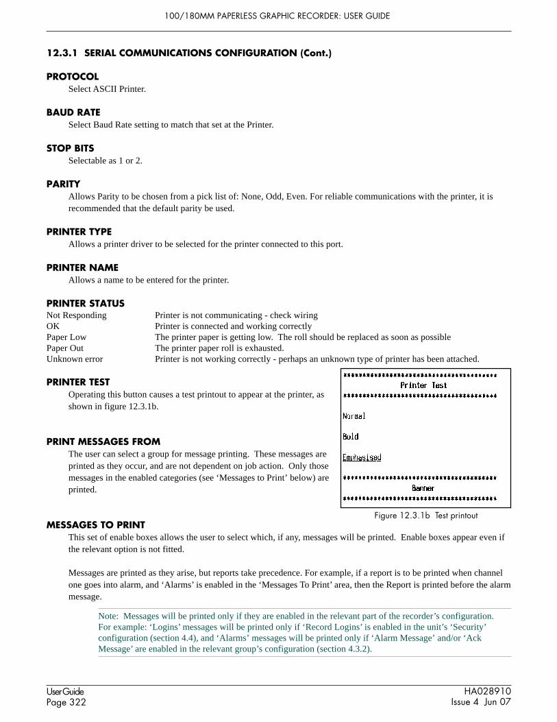
100/180MM PAPERLESS GRAPHIC RECORDER: USER GUIDE
HA028910Issue 4 Jun 07
User GuidePage 322
Figure 12.3.1b Test printout
12.3.1 SERIAL COMMUNICATIONS CONFIGURATION (Cont.)
PROTOCOLSelect ASCII Printer.
BAUD RATESelect Baud Rate setting to match that set at the Printer.
STOP BITSSelectable as 1 or 2.
PARITYAllows Parity to be chosen from a pick list of: None, Odd, Even. For reliable communications with the printer, it isrecommended that the default parity be used.
PRINTER TYPEAllows a printer driver to be selected for the printer connected to this port.
PRINTER NAMEAllows a name to be entered for the printer.
PRINTER STATUSNot Responding Printer is not communicating - check wiringOK Printer is connected and working correctlyPaper Low The printer paper is getting low. The roll should be replaced as soon as possiblePaper Out The printer paper roll is exhausted.Unknown error Printer is not working correctly - perhaps an unknown type of printer has been attached.
PRINTER TESTOperating this button causes a test printout to appear at the printer, asshown in figure 12.3.1b.
PRINT MESSAGES FROMThe user can select a group for message printing. These messages areprinted as they occur, and are not dependent on job action. Only thosemessages in the enabled categories (see ‘Messages to Print’ below) areprinted.
MESSAGES TO PRINTThis set of enable boxes allows the user to select which, if any, messages will be printed. Enable boxes appear even ifthe relevant option is not fitted.
Messages are printed as they arise, but reports take precedence. For example, if a report is to be printed when channelone goes into alarm, and ‘Alarms’ is enabled in the ‘Messages To Print’ area, then the Report is printed before the alarmmessage.
Note: Messages will be printed only if they are enabled in the relevant part of the recorder’s configuration.For example: ‘Logins’ messages will be printed only if ‘Record Logins’ is enabled in the unit’s ‘Security’configuration (section 4.4), and ‘Alarms’ messages will be printed only if ‘Alarm Message’ and/or ‘AckMessage’ are enabled in the relevant group’s configuration (section 4.3.2).

100/180MM PAPERLESS GRAPHIC RECORDER: USER GUIDE
HA028910Issue 4 Jun 07
User GuidePage 323
Number of Fields
Report
Descriptor
Field 1 Type
Style
Field 2 Type
Text
Style
Field 3 Type
Point
Style
Field 4 Type
Style
Field 5 Type
Style
Field 6 Type
Line Feed
Apply Discard
Bold
Process Value
Channel 1
Emphasised
Batch Field 1
1) Message
Normal
Line Feed
1
1) Report 1
Date & Time
Normal
Text
Report 1
6
Banner
Figure 12.3.2a Reports ConfigurationREPORT
Allows the user to select the required report number for configuration.
DESCRIPTORA name for the Report can be entered here.
NUMBER OF FIELDSSelect 0 to 10 for the number of items to be included in the report.
FIELD N TYPEN = 1 to the number of fields selected in the previous item.
Date & Time Causes the time and date of report generation to be included in the reportText Allows the user to enter a text message of up to 60 characters.Process value Allows a specified point’s process value (including descriptor and units) to be included in the
reportBatch Field 1 Batch field 1 can be included in the report. See section 4.3.10 for Batch details.Message A message can be selected for inclusion in the report. See section 4.3.8 for details of message
configuration.Line Feed Allows one or more blank lines to be left. This can be useful at the end of a report.
12.3.2 Reports configuration
This allows the user to configure up to 10 ‘reports’ for printing by the ASCII printer as a result of job action. Figure12.3.2a shows a typical configuration page, accessed from the CONFIG button ‘Reports’ item.

100/180MM PAPERLESS GRAPHIC RECORDER: USER GUIDE
HA028910Issue 4 Jun 07
User GuidePage 324
12.3.2 REPORTS CONFIGURATION (Cont.)
STYLESee figure 12.3.2b for examples of ‘Normal’, ‘Bold’, ‘Emphasised’ and ‘Banner’ print styles. For all styles, if the textis too long to fit on one line it ‘wraps round’ as shown (for normal style) in figure 12.3.2b, below.
Figure 12.3.2b Text style examples
POINTAllows a point to be chosen when ‘Process value’ has been selected as Field Type. The point is selected from a pick-list containing all the input channels, derived channels, totalisers etc. in the instrument.
LINE FEEDAppears only when ‘Line Feed’ has been chosen as Field Type. Allows the user to enter the required number of blanklines (up to 10) which are to be inserted.

100/180MM PAPERLESS GRAPHIC RECORDER: USER GUIDE
HA028910Issue 4 Jun 07
User GuidePage 325
File Name
Import
Printer_Driver.uhi
Save
Restore
New
Text
Archive SystemSave/Restore Config Security Network
Import Screen
Export Screen
Import User Linearisation
Export User Linearisation
Import Printer Driver
Save CancelFileName Pr inter_Dr iver .uh i
Hide
TypeName Date Bytes
\user \
ca l \conf ig \
l ib \
FolderFolder
Folder
sdb\ Folder
user \ Folder
03/06/04 12:35:0801/05/04 10:27:13
05/07/04 10:23:14
11/05/04 14:01:0805/06/04 17:30:29
Fi l ter1a Conf ig 05/07/04 10:22:23 4445
Pr inter_Dr iver .uh i Folder 05/06/04 17:30:29
12.4 IMPORTING PRINTER DRIVERS
The importing of new printer drivers is carried out from the SAVE/RESTORE button menu, fully described in section4.2. Before a printer driver can be ‘imported’, it must be available from the recorder’s Flash memory, from an SD orFlash card, from a USB memory stick or, for Bridge users, from the host PC. Printer driver files have the suffix .uhi.
Figure 12.4 depicts the process for a recorder.
When using a PC as the operator interface, the detailed appearance of the Host PC browse window depends on the Win-dows version in use.
Figure 12.4 Importing a printer driver

100/180MM PAPERLESS GRAPHIC RECORDER: USER GUIDE
HA028910Issue 4 Jun 07
User GuidePage 326
12.5 REPORT EXAMPLE
This example shows how to configure a report to be printed if any of channel 1 to channel 4 go into alarm. It is as-sumed that the Serial comms link with the printer has been successfully established.
The report is to include the process values of channels 1 to 4 and the time and date.
Note: The example assumes that the channels being configured are in their factory default state. Configurationitems not mentioned in the example (e.g. Scale Low) should be left at their default values.
12.5.1 Group Configuration
Refer to section 4.3.2, as necessary.
GROUP NUMBER 1
Descriptor = Colour mix.Alarm message = DisableDeselect all points except Channels 1 to 4.
12.5.2 Channel configuration
Refer to section 4.3.3 as necessary
CHANNEL 1Input Type = TestScale High =100Units = %Descriptor = Red
Alarm 1Enable = UnlatchedType = Absolute lowThreshold = 10
CHANNEL 2As channel 1, exceptDescriptor = Blue
CHANNEL 3As channel 1, exceptDescriptor = Green
CHANNEL 4As channel 1, exceptWaveform = Sine 4 minutesDescriptor = Orange

100/180MM PAPERLESS GRAPHIC RECORDER: USER GUIDE
HA028910Issue 4 Jun 07
User GuidePage 327
12.5.3 Event Configuration
Refer to section 4.3.6 as necessary
EVENT NUMBER 1Source 1 = Unack’d Alarm on GroupDescriptor = Paint low
Job number 1Category = ReportSend Report to = Select required printerReport = 1) report 1On = Active
12.5.4 Report ConfigurationDescriptor = Paint LowNumber of fields = 8Field 1 Type = Text
Text = ‘Paint Low Warning’Style = Banner
Field 2 Type = Line FeedLine Feed = 2
Field 3 Type = Date & TimeStyle = Normal
Field 4 Type = Process ValuePoint = RedStyle = Normal
Field 5 Type = Process ValuePoint = BlueStyle = Normal
Field 6 Type = Process ValuePoint = GreenStyle = Normal
Field 7 Type = Process ValuePoint = OrangeStyle = Normal
Field 8 Type = Line feedLine Feed = 5

100/180MM PAPERLESS GRAPHIC RECORDER: USER GUIDE
HA028910Issue 4 Jun 07
User GuidePage 328
12.5.5 Serial Communications Configuration
Enable ‘Alarms’ in the ‘Messages To Print’ area.
Press ‘Apply’.
A sample Printout is shown in figure 12.5.5, in which it can be seen that it was the Orange channel which triggered thewarning.
Note: In the example above the event trigger is ‘Unacknowledged alarm’. This means that once the firstchannel alarm becomes active and the relevant report printed, then no further reports will be initiated until thealarm is acknowledged, no matter how many other channel alarms go active. If, however, an unlatched alarmbecomes inactive, this is the equivalent of its being acknowledged as far as report printing is concerned. Forlatched alarms, each alarm must be acknowledged before further reports can be triggered.
Figure 12.5.5 Example printout

100/180MM PAPERLESS GRAPHIC RECORDER: USER GUIDE
HA028910Issue 4 Jun 07
User GuidePage 329
DSW1 DSW2
DSW1 DSW2
DSW3
12.6 TSP600 SWITCH SETTINGS
This section applies only to the Star TSP600 Printer.
The DIP switches are revealed by removing the access panel located on the underside of the printer. The two switchesappear as shown in figure 12.6a, and their elements should be configured as shown in figure 12.6b. See SW1/SW2details in the TSP600 ‘User’s guide’ for details.
Figure 12.6c SW3 location Figure 12.6d SW3 settings
Figure 12.6a DIP switch access Figure 12.6b DIP switch element configuration
The illustrated switch settings (segments 4, 5 and 6 ‘Off’; all other segments ‘On’) give the following parameter val-ues: Baud Rate = 9600, Data bits = 8, Parity = Even, Handshake = Xon/Xoff.
Settings other than these may result in no communications or unreliable communications with the printer. See theTSP600 ‘User’s guide’ for more details of SW3.

100/180MM PAPERLESS GRAPHIC RECORDER: USER GUIDE
HA028910Issue 4 Jun 07
User GuidePage 330
13 PORTABLE CASE OPTIONS
Note: Portable case options are available only for the small frame recorder.
The various options described below come provided in a rugged carrying case as depicted in figure 13, below,
It is possible that input/output circuits can carry high voltages, and this might prove dangerous if the safety earth con-nection to the recorder is not in place (e.g. the plug is pulled out) at any time whilst such hazardous voltages arepresent. Therefore, the following warning must be complied with:
WARNINGFor portable case instruments only:All I/O connections must be Low Voltage (i.e. maximum 33V ac RMS, 46.7V ac peak, 70V dc) unless theintegrity of the instrument safety earth is maintained for as long as the I/O is connected to the recorder.
Figure 13 Portable case dimensions
190 mm
Top view
384.8 mm
190mm
40.5 mm
153mm
15 mm240 mm
300 mm
38 mm
174 mm
View on right-hand side
430 mm

100/180MM PAPERLESS GRAPHIC RECORDER: USER GUIDE
HA028910Issue 4 Jun 07
User GuidePage 331
13.1 BASIC OPTION
13.1.1 Introduction
The basic portable case option provides 6 or 12 input channels with up to four option boards, or 18 input channels andup to two option boards.
13.1.2 Wiring
Figure 13.1.2a, below, gives alternative back panel connector layouts for the 12-input and 18-input recorder options.
Figure 13.1.2a Back panel connector details.
SUPPLY VOLTAGE
CautionBefore powering the recorder, check that the supply voltage, to be applied, lies within the range specifiedon the serial number label at the rear of the recorder.
As shown in Figure 13.1.2a, above, the line supply is terminated using an IEC connector at the rear of the case. Asocket is required to mate with the plug fitted at the recorder. Minimum recommended conductor size is 16/0.2(0.5mm2) (20AWG).
SIGNAL WIRING
Input and typical options pinouts are as shown in figure 13.1.2a, above. For full I/O wiring details, refer to Section 2.2.
INTERNAL WIRING
Figure 13.1.2b, below, shows details of the wiring between the portable case rear panel and the recorder rear panel.
1 221
22
1 22
Option board 1 Option board 2
Option board 3 Option board 4
IV+
V– IV
+V– IV
+V–
Ch1 Ch2 Ch3 Ch4 Ch5 Ch6IV
+V– IV
+V– IV
+V–
1 22IV
+V– IV
+V– IV
+V– IV
+V– IV
+V– IV
+V–
Ch7 Ch8 Ch9 Ch11 Ch12Ch10
Serial comms (option)
USB Ports (option)
Ethernet RJ45
L NE
Mains (supply)connection
1 221
1 22
Option board 1 Option board 2
IV+
V– IV
+V– IV
+V–
Ch1 Ch2 Ch3 Ch4 Ch5 Ch6IV
+V– IV
+V– IV
+V–
1 22IV
+V– IV
+V– IV
+V– IV
+V– IV
+V– IV
+V–
Ch7 Ch8 Ch9 Ch11 Ch12Ch10
Serial comms (option)
USB Ports (option)
Ethernet RJ45
L NE
Mains (supply)connection
1 22IV
+V– IV
+V– IV
+V– IV
+V– IV
+V– IV
+V–
Ch13 Ch17 Ch18Ch16Ch14 Ch15

100/180MM PAPERLESS GRAPHIC RECORDER: USER GUIDE
HA028910Issue 4 Jun 07
User GuidePage 332
13.1.2 WIRING (Cont.)
Figure 13.1.2b Basic option internal wiring
1
2
3
4
56
7
89
10
12
13
1415
16
1718
19
20
21
22
Bottom connector
1
2
3
4
56
7
8
910
12
13
14
1516
17
18
19
20
21
22
Top connectorOption board 2
Power supply unitBrown
Blue
Green/Yellow
L
N
E
Line supply(100 to 240V)
(50/60 Hz)
EarthChassis ground(Safety earth)
1
2
3
4
56
7
8
910
11
12
13
14
1516
17
18
19
20
21
22
Option board 1
Option board 4
1
2
3
4
56
7
8
910
11
12
13
14
1516
17
18
19
20
21
22
Option board 31
2
3
4
56
7
89
10
11
12
13
14
1516
17
18
19
20
21
22
Input board 2
1
2
3
4
56
7
8
910
11
12
13
14
1516
17
18
19
20
21
22
Input board 1
CJsensor
Recorder back panel
Portable case
L
N
E
V+
V-
I
V+V-
I
V+
V-I
V+
V-
I
V+V-
I
V+
V-I
CJsensor
V+
V-
I
V+V-
I
V+
V-I
V+
V-
I
V+V-
I
V+
V-I
1
2
3
4
56
7
89
10
11
12
13
14
1516
17
18
19
20
21
22
V+
V-
I
V+V-
I
V+
V-I
V+
V-
I
V+V-
I
V+
V-I
1
2
3
4
56
7
8
910
11
12
13
14
1516
17
18
19
20
21
22
V+
V-
I
V+V-
I
V+
V-I
V+
V-
I
V+V-
I
V+
V-I
Ethernetconnector
Note: For 18 input channels, Option boards 3/4are replaced with input board 3, includingassociated CJ sensor
Note: For the sake of clarity, the SerialCommunications and USB option wiringare not shown.

100/180MM PAPERLESS GRAPHIC RECORDER: USER GUIDE
HA028910Issue 4 Jun 07
User GuidePage 333
13.2 TRANSMITTER POWER SUPPLY (TRS) OPTION
This option is identical with the 6/12 channel basic option described in section 13.1, above except that one of the optionslots is used for TRS output. The TRS pinout is given in figure 13.2, below.
Note: Only one transmitter power supply can be fitted in the portable case, and may be terminated only atoption slot 2 OR option slot 4 (if available).
Figure 13.2 TRS pinout
13.2.1 Internal wiring
Figure 13.2.1 shows wiring details between the recorder and the back panel connectors.
1 2 3 4 5 6 7 8 9 10 11 12 13 14 15 16 17 18 19 20 21 22
+V 0V+V 0V+V0V
Pinout for TRS(must use option slot 2 OR 4)

100/180MM PAPERLESS GRAPHIC RECORDER: USER GUIDE
HA028910Issue 4 Jun 07
User GuidePage 334
13.2 TRS OPTION (Cont.)
Figure 13.2.1 Typical internal wiring
Bottom connector
Top connector
V+
V-
I
V+V-
I
V+
V-I
V+
V-
I
V+V-
I
V+
V-I
Option board 2
Power supply unitBrown
Blue
Green/Yellow
L
N
E
Line supply(100 to 240V)
(50/60 Hz)
EarthChassis ground(Safety earth)
CJsensor
1
2
3
4
56
7
8
910
11
12
13
14
1516
17
18
19
20
21
22
Option board 1
Input board 2
Input board 1
CJsensor
Recorder back panel
Portable case
L
N
E
0V24V
0V24V
0V24V
1
2
3
4
56
7
8
910
12
13
14
1516
17
18
19
20
21
22
1
2
3
4
56
7
8
910
12
13
14
1516
17
18
19
20
21
22
1
2
3
4
56
7
8
910
11
12
13
14
1516
17
18
19
20
21
22
1
2
3
4
56
7
8
910
11
12
13
14
1516
17
18
19
20
21
22
Terminalblock
TRS
V+
V-
I
V+V-
I
V+
V-I
V+
V-
I
V+V-
I
V+
V-I
V+
V-
I
V+V-
I
V+
V-I
V+
V-
I
V+V-
I
V+
V-I
V+
V-
I
V+V-
I
V+
V-I
V+
V-
I
V+V-
I
V+
V-I
Option board 31
2
3
4
56
7
8
910
11
12
13
14
1516
17
18
19
20
21
22
1
2
3
4
56
7
8
910
11
12
13
14
1516
17
18
19
20
21
22
1
2
3
4
56
7
8
910
11
12
13
14
1516
17
18
19
20
21
22
Ethernetconnector
Note: For the sake of clarity, the SerialCommunications and USB option wiringare not shown.
Note: For 6 or 12 input channel recorders thetransmitter power supply may use either optionboard 2 connector or (as shown) the option board 4connector.For 18 input channel instruments, the transmitterpower supply must use option board 2 connector,because option board 3 and 4 slots (and associatedconnector) are occupied by input board 3 and itscold junction sensor.

100/180MM PAPERLESS GRAPHIC RECORDER: USER GUIDE
HA028910Issue 4 Jun 07
User GuidePage 335
13.3 HTM2010 QUARTERLY TEST KIT
13.3.1 Introduction
This option is supplied as a six-channel, 100 mm recorder in a rugged portable case, configured for five type-T thermo-couples and one pressure transducer. The option comes complete with pressure transducer, insertion tubes and mini-ature plugs for type T thermocouples. As supplied, the recorder is for use with small, unwrapped utensil sterilisers.The default configuration for the thermocouples is: Function = Type T, Input range = 0 to 150˚C, and for the transducer:Input range = -1 to + 3 bar.
13.3.2 Wiring
SUPPLY VOLTAGE
CautionBefore powering the recorder, check that the supply voltage, to be applied, lies within the range specifiedon the serial number label at the rear of the recorder.
As shown in Figure 13.3.2a, below, the line supply is terminated using an IEC connector at the rear of the case. Asocket is required to mate with the plug fitted at the recorder. Minimum recommended conductor size is 16/0.2(0.5mm2) (20AWG).
SIGNAL WIRINGSignal wiring consists of wiring the thermocouples to the relevant plugs and plugging them and the (pre-wired) pres-sure transducer in. Figure 13.3.2a shows the arrangement of the sockets at the rear of a six-channel recorder (12 chan-nel similar), and of an 18-channel recorder. Figure 13.3.2b shows the wiring of the thermocouple plugs.
Figure 13.3.2 a Connector locations
Figure 13.3.2b Thermocouple plug wiring (cover removed for clarity)
Con1 Con2 Con3 Con4 Con5 Con6
Serial comms (option)
USB Ports (option)
Ethernet RJ45
L NE
Mains (supply)connection
Con1 Con2 Con3 Con4 Con5 Con6
Con
7
Con
8
Con
9
Con
10
Con
11
Con
12
Serial comms (option)
USB Ports (option)
Ethernet RJ45
L NE
Con
13
Con
14
Con
15
Con
16
Con
17
Con
18
Mains (supply)connection
BrownWhiteBrown
+ wire
— wire
BS1843:1952(Superseded)
BS4937:1993IEC584-3:1989
(Current)WhiteBlueBlue
+—
Sheath
T/C type T colours

100/180MM PAPERLESS GRAPHIC RECORDER: USER GUIDE
HA028910Issue 4 Jun 07
User GuidePage 336
Brown
Blue
BrownBlue
Green/Yellow
Red
Black
Red
Black
Red
Black
O/P 3
O/P 2
O/P 1
+
+
+
N
L
Transmitter PSU
123456789
10
131415161718
1920
2122
InputBoard
L
NE
Line supply(100 to 240V)
(50/60 Hz)
Recorder back panel
PSU
CJsensor
V+V--
+
-+
-+
-+
V+V-
V+V-
V+V-Con 1
Con 2
Con 3
Con 6 Shunt
Wiring from thermocoupleconnectors to input terminalsis in thermocouple wire
Chassis ground(safety earth)
Earth
-+
Con 4
-+
Con 5V+V-
V+V-
1112
LN
E
TerminalBlock
Ethernetconnector
13.3.2 WIRING (Cont.)
INTERNAL WIRINGFigure 13.3.2c shows the internal wiring between the portable case connectors and the recorder rear panel for a 6 inputoption..
Figure 13.3.2c Internal wiring details
13.3.3 Specification
Information additional to the general specification in Annex A.
Pressure transducerInput range -1 to 3 Bar G
Output range 4 to 20 mA
Supply voltage range 12 to 32V dc
Non linearity/hysteresis ≤0.25% span
Long term stability 0.1% in 12 months
Safety isolationDC to 65 Hz: BS EN61010 (Installation category II; Pollution degree 2
Channel to channel: 33V ac RMS, 46.7V ac peak, or 70V dc to earth
Channel to ground 33V ac RMS, 46.7V ac peak, or 70V dc to earth
Note: For the sake of clarity, the SerialCommunications and USB option wiringare not shown.
Note: For the sake of clarity, only oneinput board shown. Two and three inputboard wiring similar.
If fitted, input board 2 channels 1 to 6 arewired to connectors 7 to 12 respectively;input board 3 channels 1 to 6 wired toconnectors 13 to 18 respectively.

100/180MM PAPERLESS GRAPHIC RECORDER: USER GUIDE
HA028910Issue 4 Jun 07
User GuidePage 337
13.4 THERMOCOUPLE OPTION
13.4.1 Introduction
This option allows the connection of up to 12 type J, K or T thermocouples together with up to two option boards, or upto 18 thermocouples with no option boards. Transmitter power supply is not available with this option.
The type of thermocouple (the same for all channels) must be specified at time of order. Each thermocouple input chan-nel will be configured at the factory for the specified type of thermocouple and will be set to a range of 0 to 100 de-grees Celsius.
Thermocouple-style connectors with copper terminals can also be fitted, for use with non-thermocouple inputs. Forsuch channels the recorder is pre-configured as: Function = Linear, Input range = 0 to 1 Volt.
13.4.2 Wiring
SUPPLY VOLTAGE
CautionBefore powering the recorder, check that the supply voltage, to be applied, lies within the range specifiedon the serial number label at the rear of the recorder.
As shown in Figure 13.4.2a, below, the line supply is terminated using an IEC connector at the rear of the case. Asocket is required to mate with the plug fitted at the recorder. Minimum recommended conductor size is 16/0.2(0.5mm2) (20AWG).
SIGNAL WIRINGSignal wiring consists of connecting the transducer wires into the correct type of plug, and inserting the plugs into therelevant socket at the rear of the recorder.
Figure 13.4.2a shows the arrangement of the connectors at the rear panel for 12 and 18 channel versions. Figure13.4.2b shows thermocouple wiring details, and Figure 13.4.2c shows the wiring between the portable case rear paneland the recorder for a 12 thermocouple option.
Figure 13.4.2a Rear panel connector locations (typical)
Con1 Con2 Con3 Con4 Con5 Con6
1 22
Option board 1 Option board 2
Con7 Con8 Con9 Con10 Con11 Con12
Serial comms (option)
USB Ports (option)
Ethernet RJ45
L NE
Mains (supply)connection
Con1 Con2 Con3 Con4 Con5 Con6
Con
7
Con
8
Con
9
Con
10
Con
11
Con
12
Serial comms (option)
USB Ports (option)
Ethernet RJ45
L NE
Con
13
Con
14
Con
15
Con
16
Con
17
Con
18
Mains (supply)connection

100/180MM PAPERLESS GRAPHIC RECORDER: USER GUIDE
HA028910Issue 4 Jun 07
User GuidePage 338
13.4.2 WIRING (Cont.)
THERMOCOUPLE WIRING
Figure 13.4.2b Thermocouple wiring details.
Black
White
Black
BS1843:1952(Superseded)
BS4937:1993IEC584-3:1989
(Current)Yellow
Blue
Black
+
—
Sheath
T/C type J colours
Green
White
Green
Brown
Blue
Red
Brown
White
Brown
White
Blue
Blue
+ wire
— wire
T/C type K colours
BS1843:1952(Superseded)
BS4937:1993IEC584-3:1989
(Current)
T/C type T colours
BS1843:1952(Superseded)
BS4937:1993IEC584-3:1989
(Current)

100/180MM PAPERLESS GRAPHIC RECORDER: USER GUIDE
HA028910Issue 4 Jun 07
User GuidePage 339
13.4.2 WIRING (Cont.)
Figure 13.4.2c Internal wiring
13.4.3 Specification
Information additional to the general specification in Annex A.
Safety isolationDC to 65 Hz: BS EN61010 (Installation category II; Pollution degree 2
Channel to channel: 33V ac RMS, 46.7V ac peak, or 70V dc to earth
Channel to ground 33V ac RMS, 46.7V ac peak, or 70V dc to earth
Optionsconnector
Input board 2
1
2
3
4
56
7
8
910
11
12
13
14
1516
17
18
19
20
21
22
Input board 1
V+
V-
I
V+V-
I
V+
V-I
V+
V-
I
V+V-
I
V+
V-I
1
2
3
4
56
7
8
910
11
12
13
14
1516
17
18
19
20
21
22
V+
V-
I
V+V-
I
V+
V-I
V+
V-
I
V+V-
I
V+
V-I
CON 7
CON 8
CON 9
CON 10
CON 11
CON 12
CJsensor
+-
+-
+-
+-
+-
+-
CON 1
CON 2
CON 3
CON 4
CON 5
CON 6
CJsensor
Option board 2
Power supply unitBrown
Blue
Green/Yellow
L
N
E
Line supply(100 to 240V)
(50/60 Hz)
EarthChassis ground(Safety earth)
1
2
3
4
56
7
8
910
11
12
13
14
1516
17
18
19
20
21
22
Option board 1
Recorder back panelPortable case
L
N
E
1
2
3
4
56
7
89
10
11
12
13
14
1516
17
18
19
20
21
22
Ethernetconnector
+-
+-
+-
+-
+-
+-
Note: For the sake of clarity, the SerialCommunications and USB option wiringare not shown.
Note: Two input board (12 t/c) wiring shown.One input board version (6t/c) similar but inputboard two and associated wiring and connec-tors are not fitted.Three input board (18 t/c) similar, but withoption boards 1 and 2 being replaced by thethird i/p board and the 22-way connector beingreplaced by thermocouple connectors CON 13to CON18. Input board 3 channels 1 to 6 arewired to CON 13 to CON 18 respectively.

100/180MM PAPERLESS GRAPHIC RECORDER: USER GUIDE
HA028910Issue 4 Jun 07
User GuidePage 340
13.5 LOW SUPPLY VOLTAGE OPTION
Some of the portable case options described in this manual can be ordered for use with 24V (nom.) supply voltages. Insuch cases, the supply voltage part of the wiring diagrams is replaced with that shown in figure 13.5a unless otherwisestated. The low voltage supply is terminated by a three pin plug, as shown in figure 13.5b.
Note: The polarity of the dc supply is not critical, but the recorder operates more efficiently with the polarityshown below
Figure 13.5a Internal wiring for low voltage options
Figure 13.5b Low supply voltage connector details
Blue
Brown
Green/YellowEarth
ChassisGround
Earth
3
2
1
DC+
0VRecorder power
supply
20 to 54V dc,or 20 to 42V ac
(45 to 400 Hz RMS)
1 221
22
1 22
1 22
0V24V Earth
Supply connector:20 to 52Vdc or20 to 42V(RMS)

100/180 MM PAPERLESS GRAPHIC RECORDER: USER GUIDE
User GuidePage 341
HA028910Issue 4 Aug 07
ANNEX A: SPECIFICATION
INSTALLATION CATEGORY AND POLLUTION DEGREE
This product has been designed to conform to BS EN61010 installation category II and pollution degree 2. These aredefined as follows:
Installation category IIThe rated impulse voltage for equipment on nominal 230V ac mains is 2500V.
Pollution degree 2Normally, only non-conductive pollution occurs. Occasionally, however, a temporary conductivity caused by conden-sation shall be expected.

100/180 MM PAPERLESS GRAPHIC RECORDER: USER GUIDE
HA028910Issue 4 Aug 07
User GuidePage 342
TECHNICAL SPECIFICATION (Recorder) Board types (I/O)
Universal input boardRelay output boards (3 change-over, 4 normally closed or 4 normally open relays per board)6 - event input boardSerial communications board2 - channel analogue output (retransmission) board
Standard featuresBridge ‘Lite’Configuration CopyCSV Archive file formatE-mailFile transfer protocol (FTP)6 GroupsJob searchLog scalesMODBUS TCPMessagesTimersUSB port behind access flap (not stainless-steel case option)Web server
OptionsSoftware: ASCII Printer output (supplied as a part of the Serial Communications option)
Audit trail21CFR11AuditBatch RecordingBridge ‘Full’ versionEvent Buttons (supplied as a part of the Screen Builder option)Master CommsMaths/Totalisers/CountersMultiple groups (six additional groups)Screen Builder (User screens)Security ManagerSimulation
Hardware: Transmitter power supply - isolated (100 mm recorders only)Low supply voltageAccess flap lockStainless steel case (no access flap) (check availability)Further two USB ports at rear of recorderSerial Communications
Environmental PerformanceTemperature limits Operation: 0 to 50˚C.
Storage: - 20 to +60˚CHumidity limits Operation: 5% to 80% RH non - condensing
Storage: 5% to 90% RH non - condensingAltitude (maximum) <2000 metresProtection Standard bezel/display: IP66 for a recorder mounted in a panel.
Standard sleeve: IP20Portable case option: IP21
Stainless-steel case: IP66 for a recorder mounted in a panel.Shock BS EN61010Vibration (10 Hz to 150Hz) 2g peak

100/180 MM PAPERLESS GRAPHIC RECORDER: USER GUIDE
User GuidePage 343
HA028910Issue 4 Aug 07
TECHNICAL SPECIFICATION (RECORDER) (Cont.)
PhysicalPanel mounting DIN 43700Bezel size Small frame: 144mm x 144mm
Large frame: 292mm x 292mmPanel cutout Small frame: 138mm x 138mm (-0.0 + 1.0) mm
Large frame; 281mm x 281mm (-0.0 + 1.0) mmDepth behind bezel Small frame: 246.5 mm (211.5 mm without terminal cover, 284 with long terminal cover)
Large frame: 260.90 mm (211 mm without terminal cover)Weight Small frame: 3 kg. max. (5 kg. max. if fitted in portable case)
Large frame: 7 kg. max.Mounting angle ±45 ˚ from vertical
Electromagnetic compatibility (EMC)Emissions and immunity: BS EN61326
Electrical safetyBS EN61010. Installation category II, Pollution degree 2
Power requirementsSupply voltage Standard: 85 to 265 volts; 47 to 63 Hz or 110 to 370V dc (dc supply not to be used if isolated transmitter power supply fitted)
Low voltage option: 20 to 42V RMS; 45 to 400 Hz, or 20 to 54V dc (option not to be used if isolated transmitter power supply fitted)
Power (max.) All options: 50 W
Inrush current Standard: 36A
Low voltage option: 36A
Namur compliant option: 5.5A at 25˚C
Fuse type None
Interrupt protection Standard: Holdup >200msec. at 240V ac, with full load.
Low voltage option: Holdup 20msec at 20Vdc or RMS, with full load.
Back-up batteryType Poly-carbonmonofluoride/lithium (BR2330). Part Number PA261095. See also section B2.2.
Support time A fully-charged, new battery supports the Real-Time Clock for a minimum of 1 year with the recorder unpowered
Replacement period 3-years
Stored data Time; date; values for totalisers, counters and timers; batch data; values for those maths functions with history, such as
Fvalue, Rolling average, Stopwatch etc.
Clock (RTC) dataTemperature stability 0 to 50˚C: ± 20 ppm
Ageing ±5 ppm per year
Touch screenColour TFT LCD with cold-cathode backlighting, fitted with resistive, analogue, touch panel
Screen specification Small frame: 1/4 VGA Resolution = 320 x 240 pixels
Large frame: XGA Resolution= 1024 x 768 pixels
Update information Input/relay output sample rate: 8 Hz.
Display update: 8 Hz,
Archive sample value: Latest value at archive time
Trended/displayed value: Latest value at display update time
Note: For portable case dimensions - see section 13.

100/180 MM PAPERLESS GRAPHIC RECORDER: USER GUIDE
HA028910Issue 4 Aug 07
User GuidePage 344
TECHNICAL SPECIFICATION (RECORDER) (Cont.)
Ethernet CommunicationsType 10/100 base T (IEEE802.3)
Protocols TCP/IP, FTP, DHCP, BootP, SNTP, Modbus, SMTP, ICMP.
Cable Type: CAT5
Maximum length: 100 metres
Termination: RJ45
RJ45 LED indicators Green: Indicates a 100MB link
Yellow: Indicates Ethernet activity
Internal green LED Indicates a 10MB link
Serial communications optionNumber of ports Two, at rear of instrument
Protocol ASCII input, ASCII printer, Modbus master, Modbus slave.
Transmission standards EIA232 and/or EIA485, software selectable per port. EIA485 can be connected as 3-wire or 5-wire as required.
Isolation (dc to 65Hz BS EN61010) Installation category II; Pollution degree 2.
Terminals to ground: 50 V RMS or dc (basic insulation)
Transmitter power supply (Isolated) (Small frame recorders only)Number of outputs Three
Output voltage 25V nominal
Max. current 20mA per output
Isolation (dc to 65Hz BS EN61010) Installation category II; Pollution degree 2.
Channel to channel: 100V RMS or dc (double insulation)
Channel to ground: 100V RMS or dc (basic insulation).
Fuse (20mm Type T)
Supply voltage = 110/120Vac: 100 mA
Supply voltage = 220/240Vac: 63 mA
USB portsNumber of ports 1 at front of recorder (standard*); 2 further ports (optional - at rear of instrument)
(*No front USB port with Stainless steel case option)
Standard USB1.1
Transmission speeds 12Mbits/sec (full speed devices) or 1.5Mbits/sec (low speed devices)
Maximum current per port 500mA
Peripherals supported Floppy disk drive, Keyboard, Bar code reader, Mouse, Memory stick.
Note: The recorder meets the industrial EMC requirements of BS EN61326. Typically, USB peripherals aretested to domestic information technology standards (BS EN55022) with category C performance. Some USBperipherals, designed for use in domestic or office environments, can be susceptible to ‘lock up’ in environ-ments containing high electromagnetic field strengths. In order to recover from such ‘lock up’ situations, theperipheral must be disconnected and then reconnected. Recorder operation is not affected.
Other items
Virus susceptibility The 6000 series VxWorks operating system is immune to viruses targeted at Windows based operating systems. As at
December 2005, there are no known viruses that target VxWorks.
Calibration coefficients Input: The Read-only input coefficients are stored in EEPROM on the input board.
Instrument: Instrument configuration is held in FLASH memory and has no effect on calibration coefficients.

100/180 MM PAPERLESS GRAPHIC RECORDER: USER GUIDE
User GuidePage 345
HA028910Issue 4 Aug 07
TECHNICAL SPECIFICATION (Universal input board)
General*Termination Edge connector/terminal block
Max. number of inputs Small frame: 18 (three 6-input boards)
Large frame: 48 (eight 6-input boards)
Input ranges ±38mV; ±150mV; ±1Volt; ± 20 Volts
Input types Dc volts, dc millivolts, dc milliamps, (with external shunt), thermocouple, 2/3 wire resistance temperature detector (RTD),
Ohms, Contact closure (not channels 1, 7, 13,19, 25, 31, 37, 43) (Minimum contact closure = 60msec.)
Input type mix Freely configurable
Sample rate See 'Update information' above
Noise rejection (48 to 62Hz)
Common mode: >140dB (Channel to channel and channel to ground)
Series mode: >60dB
Maximum common mode voltage 250Volts continuous
Maximum series mode voltage 45mV at lowest range; 23.74 Volts peak at highest range
Isolation (dc to 65Hz; BS EN61010) Installation category II; Pollution degree 2
300V RMS or dc channel to channel (double insulation), channel to common electronics (double insulation) and channel
to ground (basic insulation)
Dielectric strength Channel to ground: 1500Vac for 1 minute.
Channel to channel: 2500Vac for 1 minute
Insulation resistance >10MΩ at 500V dc
Input impedance 20V range: 65.3kΩ
Other ranges: >10MΩ
Overvoltage protection 50V peak (150V with attenuator)
Open circuit detection (applies only to ± 38mV and ± 150mV ranges).
Detection current: ± 57nA max
Recognition time: 500mSec
Minimum break resistance: 10MΩ
Long term drift (typical) Better than 0.03% of reading or 30µV (whichever is greater) over a three month period.
DC input rangesShunt Externally mounted resistor modules
Additional error due to shunt 0.1% of input
Performance See table
Note: The table above applies to recorders with status level E7 or above (June 2007). For instrumentsprior to this, see the table in ‘Previous instruments’ later in Annex A.
*WARNINGFor portable case instruments only:
All I/O connections must be Low Voltage (maximum 33V ac RMS, 46.7V ac peak or 70Vdc) unless theintegrity of the instrument safety earth is maintained for as long as the I/O is connected to the recorder.
For small frame recorders only:
For 6 input recorders, up to four option boards may be fitted.
For 12 input recorders up to four option boards may be fitted
For 18 channel recorders up to two option boards may be fitted.
Low High Typical error Maximum error Worst case temperatureRange Range (Instrument at 20 deg C) (Instrument at 20 deg C) performance-38 mV 38 mV 1.4 µV 0.013% input + 0.031% range 0.030% input + 0.052% range 25ppm of input per deg C
-150 mV 150 mV 5.5 µV 0.013% input + 0.028% range 0.029% input + 0.039% range 25ppm of input per deg C-1 V 1 V 37 µV 0.013% input + 0.024% range 0.029% input + 0.029% range 25ppm of input per deg C
-20 V 20 V 720 µV 0.075% input + 0.027% range 0.393% input + 0.033% range 388ppm of input per deg C
Resolution

100/180 MM PAPERLESS GRAPHIC RECORDER: USER GUIDE
HA028910Issue 4 Aug 07
User GuidePage 346
TECHNICAL SPECIFICATION (Universal input board) (Cont.)
Resistance inputsTemperature scale ITS90
Types, ranges and accuracies See tables (values exclude influence of lead resistance)
Influence of lead resistance Error: Negligible
Mismatch: 1Ω/Ω
Maximum source current 250µA
0.14˚C0.07˚C
0 to 400˚C = 1.7˚CMax.linearisation error
0.12˚C0.08˚C0.03˚C0.07˚C0.02˚C0.04˚C
0.04˚C0.04˚C0.02˚C0.08˚C0.06˚C0.02˚C
400 to 1820˚C = 0.03˚C
0.02˚C0.04˚C
Ni/NiMo
Pt20%Rh/Pt40%Rh
T/C type
B
C
D
E
G2
J
K
R
S
T
U
NiMo/NiCo
Platinel
L
N
0 to + 1406
0 to + 1888
0 to + 1820
0 to + 2300
0 to + 2495
-270 to + 10000 to + 2315
-210 to + 1200-270 to + 1372
-50 to + 1768
-50 to + 1768
-270 to + 400
-200 to + 600
-50 to + 1410
0 to + 1370
-200 to + 900
-270 to + 1300
Overall range (˚C)
Ipsen
ASTM E1751-95
IEC584.1
Standard
Hoskins
Hoskins
IEC584.1
Hoskins
IEC584.1
IEC584.1
IEC584.1
IEC584.1
IEC584.1
DIN43710:1985
ASTM E1751-95
Engelhard
DIN43710:1985 (To IPTS68)
IEC584.1
RTD typeCu10
JPT100Ni100
Ni120
Overall range (˚C) Standard0.02˚C
0.01˚C
0.01˚C
0.01˚C
0.01˚C
0.09˚C0.01˚C
Pt100
Pt100APt1000
-20 to + 400
-220 to + 630
-60 to + 250
-50 to + 170-200 to + 850
-200 to + 600-200 to + 850
General Electric Co.
JIS C1604:1989
DIN43760:1987
DIN43760:1987
IEC751
Eurotherm Recorders SAIEC751
Max. linearisation error
Cu53 < 0.01˚C-70 to + 200 RC21-4-1966
Note: The table above applies to recorders with status level E7 or above (June 2007). For instrumentsprior to this, see the table in ‘Previous instruments’ later in Annex A.
LowRange
0Ω0Ω0Ω
HighRange
150Ω600Ω5kΩ
Resolu-tion
5mΩ22mΩ
148mΩ
Typical error(Instrument at 20 deg. C)
0.027% input + 0.034% range 30ppm of input per deg C
30ppm of input per deg C30ppm of input per deg C
0.027% input + 0.035% range0.030% input + 0.034% range
Worst case temperatureperformance
Maximum error(Instrument at 20 deg. C)
0.037% input + 0.077% range
0.037% input + 0.057% range0.040% input + 0.041% range
Thermocouple dataTemperature scale ITS90
Bias current 0.05nA
Cold junction compensation types Off, internal, external, remote
Remote CJC source: Any input or maths channel.
Internal CJC error 1˚C max with instrument at 25˚C
Internal CJC rejection ratio 50:1 minimum
Upscale/downscale drive Types: 'High'. 'low' or 'none' selectable for each thermocouple channel.
Additional error: Typically 0.01˚C - depends on wiring. (Detect current = 57nA.)
Types, ranges and accuracies See table

100/180 MM PAPERLESS GRAPHIC RECORDER: USER GUIDE
User GuidePage 347
HA028910Issue 4 Aug 07
WORST CASE ERROR CALCULATION
Assuming type T thermocouple at 350˚C, ambient temp = 40˚C, CJC = internal.Total error = input error + range error + temperature error +linearisation error + cold junction error.
Input error:From thermocouple tables, a type T thermocouple generates a voltage of 17.819mV at 350 ˚C. From the dc perform-ance table above, the maximum error is 0.030% input = 0.03 x 17.819/100 = 5.346µV
Range error:The 38mV range is used as the type t thermocouple is defined to cover the range -270˚C (-6.258mV) to +400˚C(20.872mV). From the dc performance table, the maximum range error is 0.052% range, and the range is 38 + 38 = 76mV. Thus the maximum range error is 0.052 x 76/100 = 39.52µV.
Temperature error:The dc performance table above is specifed at 20˚C, but the ambient in this example is 40˚C. From the dc performancetable, the worst case temperature performance is 25ppm/˚C, so our error is 25 x (40-20) x 17.819 x 10-6 = 8.910µV.
Linearisation error:From the thermocouple table, the maximum linearisation error for a type t thermocouple is 0.02 ˚C
Cold junction compensation (CJC) error:The internal CJC error is 1˚C maximum with the instrument at 25˚C. The CJC rejection ratio is 50:1, so a further errorof (40-25)/50 = 0.30 ˚C may occur, giving a total maximum CJC error of 1.3˚C.
Maximum errorFrom the above, the total error adds up as follows:Input error: 5.346µVRange error: 39.520µVTemperature error: 8.910µVLinearisation error: 0.02˚CCJC error: 1.30 ˚CTotal error: 53.776µV + 1.32˚C
From thermocouple tables, a change of 1˚C is equivalent to a change of 60µV, so a change of 53.776µV is equivalent toa change of 0.896˚C.
Thus the total worst case error for this example is (0.896 + 1.32) = 2.216˚C

100/180 MM PAPERLESS GRAPHIC RECORDER: USER GUIDE
HA028910Issue 4 Aug 07
User GuidePage 348
PREVIOUS INSTRUMENTS
This section contains dc performance and resistance input data for instruments with status levels prior to D6 (June2007).
DC input rangesShunt Externally mounted resistor modules
Additional error due to shunt 0.1% of input
Performance See table
Low High Typical error Maximum error Worst case temperatureRange Range (Instrument at 20 deg C) (Instrument at 20 deg C) performance-38 mV 38 mV 1.4 µV 0.035% input + 0.031% range 0.085% input + 0.052% range 80ppm of input per deg C
-150 mV 150 mV 5.5 µV 0.035% input + 0.028% range 0.084% input + 0.039% range 80ppm of input per deg C-1 V 1 V 37 µV 0.035% input + 0.024% range 0.084% input + 0.029% range 80ppm of input per deg C
-20 V 20 V 720 µV 0.097% input + 0.027% range 0.448% input + 0.033% range 443ppm of input per deg C
Resolution
Note: The table above applies to recorders with status level prior to E7 (June 2007). For instrumentswith a status level of E7 or above, see the equivalent table earlier in Annex A.
*WARNINGFor portable case instruments only:
All I/O connections must be Low Voltage (maximum 33V ac RMS, 46.7V ac peak or 70Vdc) unless theintegrity of the instrument safety earth is maintained for as long as the I/O is connected to the recorder.
Resistance inputsTemperature scale ITS90
Types, ranges and accuracies See tables (values exclude influence of lead resistance)
Influence of lead resistance Error: Negligible
Mismatch: 1Ω/Ω
Maximum source current 250µA
LowRange
0Ω0Ω0Ω
HighRange
150Ω600Ω6kΩ
Resolu-tion
5mΩ22mΩ
148mΩ
Typical error(Instrument at 20 deg. C)
0.027% input + 0.034% range 35ppm of input per deg C
35ppm of input per deg C35ppm of input per deg C
0.027% input + 0.035% range0.030% input + 0.028% range
Worst case temperatureperformance
Maximum error(Instrument at 20 deg. C)
0.042% input + 0.110% range
0.042% input + 0.053% range0.045% input + 0.035% range
Note: The table above applies to recorders with status level prior to E7 (June 2007). For instrumentswith a status level of E7 or above, see the equivalent table earlier in Annex A.
RTD typeCu10
JPT100Ni100
Ni120
Overall range (˚C) Standard0.02˚C
0.01˚C
0.01˚C
0.01˚C
0.01˚C
0.09˚C0.01˚C
Pt100
Pt100APt1000
-20 to + 400
-220 to + 630
-60 to + 250
-50 to + 170-200 to + 850
-200 to + 600-200 to + 850
General Electric Co.
JIS C1604:1989
DIN43760:1987
DIN43760:1987
IEC751
Eurotherm Recorders SAIEC751
Max. linearisation error
Cu53 < 0.01˚C-70 to + 200 RC21-4-1966

100/180 MM PAPERLESS GRAPHIC RECORDER: USER GUIDE
User GuidePage 349
HA028910Issue 4 Aug 07
TECHNICAL SPECIFICATION (Relay output board)
GeneralMaximum number of relay boards
Small-frame unit Four
Large-frame unit Nine
Number of relays per board
Changeover relays: Three
Normally open relays: Four
Normally closed relays: Four
Estimated mechanical life 30,000,000 operations
Update rate See 'Update rates' in 'Recorder specification' above
AC load ratingsDerating
The figures given below are for resistive loads. For reactive or inductive loads, de-rate in accordance with graph 1, in which
F1 = Actually measured results on representative samples
F2 = Typical values (according to experience)
Contact life = Resistive contact life x reduction factor.
Maximum switching power 500VA
Maximum contact voltage 250V providing this does not cause the maximum switching power (above) to be exceeded
Maximum contact current 2 Amps providing this does not cause the maximum switching power (above) to be exceeded
DC load ratingsMaximum switching power See graph 2 for operating volt/Amp envelope
Maximum contact voltage/current See graph 2 for examples.
Safety isolationIsolation (dc to 65 Hz; BS EN61010) Installation category II; Pollution degree 2
Relay to relay: 300V RMS or dc (double insulation)
Relay to ground: 300V RMS or dc (basic insulation)
F1
F2
1 0.8 0.6 0.4 0.20.3
0.4
0.5
0.6
0.7
0.80.9
1F
Red
uctio
n F
acto
r F
Power factor (cos φ)
Graph 1 Derating curves for ac loads Graph 2 DC load switching curves
10
20
304050
100
200
300
0.1 0.2 0.5 5 20
Max. DC load breaking capacity
1 2
inductive load(L/R = 20msec)
resistive load
DC
Vol
tage
(V
olts
)
DC current (Amps)

100/180 MM PAPERLESS GRAPHIC RECORDER: USER GUIDE
HA028910Issue 4 Aug 07
User GuidePage 350
TECHNICAL SPECIFICATION (Event input board)
GeneralMaximum number of event input boards Four
Number of inputs per board Six
Type of input Contact closure (active closed) or voltage level (active low)
Recognition levels (input to ‘C’ terminal) (R = contact resistance)
Active: -30V to + 0.8V or switch contacts closed (R < 35kΩ).
Undefined: + 0.8V to + 2.0V (35 kΩ < R < 200kΩ)
Inactive: + 2V to +30V or switch contacts open (R > 200kΩ).
Maximum frequency 8 Hz
Minimum closure or pulse width 62.5 msec
Current sink for voltage inputs 10mA max
IsolationEvent input to ground: 100V RMS or dc (basic insulation)
Event input to Event input: 0V
TECHNICAL SPECIFICATION (Analogue output board)
GeneralMax number of analogue o/p boards Four
Number of outputs per board Two
Output ranges Voltage: 0 to 10V (source 5mA max.)
Current: 0 to 20 mA
Update rate See 'Update rates' in 'Recorder specification' above
Step response 250msec (10% to 90%)
Linearity 0.024% of hardware range
Performance See table
Safety isolationIsolation (dc to 65 Hz; BS EN61010) Installation category II; Pollution degree 2
Output channel-to output channel: 300V RMS or dc (double insulation)
Output channel to ground: 300V RMS or dc (basic insulation)
TECHNICAL SPECIFICATION (ASCII Printer)
See the documentation supplied with the printer
0 to 10 V
0 to 20 mA
0.1% of range
0.1% of range
±0.12mV +0.022% of reading per deg. C
± 1µA + 0.03% of reading per deg. C
Range Accuracy Temperature drift
Performance in instrument at 20 deg. C

100/180 MM PAPERLESS GRAPHIC RECORDER: USER GUIDE
User GuidePage 351
HA028910Issue 4 Aug 07
ANNEX B: REFERENCE
B1 DIAGNOSTICS DISPLAY
B1.1 MAIN DIAGNOSTIC DISPLAY
At power-up, continuously hold a finger in contact with the screen until the main diagnostic display appears as shownin figure B1.1
Special Modes Display Test
Touch Calibration System Summary
Diag Summary Quit
Figure B1.1b Top-level diagnostic display

100/180 MM PAPERLESS GRAPHIC RECORDER: USER GUIDE
HA028910Issue 4 Aug 07
User GuidePage 352
B1.2 SPECIAL MODES
For factory use only, selecting 'Special Modes' allows the enabling and disabling of the Sales Demo mode of operation.
An 'S' symbol is displayed at the top of the screen whilst the recorder is in sales demo mode.
B1.3 DISPLAY TEST
Selecting this option, allows the user to check the display by flooding the screen with single colours. Repeatedlytouching the screen, scrolls through the following colour sequence: Black, White, Red, Green, Blue, Cyan, Magenta,Yellow. A further operation of the touch screen returns the main diagnostic screen.
B1.4 TOUCH CALIBRATION
Touching this key calls a selection screen as shown below:
Figure B1.4 Touch screen selections
Touch Screen Calibrate
Touch Screen Verify
Main Menu

100/180 MM PAPERLESS GRAPHIC RECORDER: USER GUIDE
User GuidePage 353
HA028910Issue 4 Aug 07
B1.4.1 Touch screen calibrate
This key initiates the display calibration (offset correction) procedure. This procedure ensures that the display screenimage is positioned correctly compared with the touch screen (so that 'what you touch is what you get'). The procedure,is necessary only rarely, if at all, and is included here only for the sake of completeness.
1. Operate the 'Touch Screen Calibrate' key to call the first calibration screen, as depicted in figure B1.4.12. Using the stylus, touch the intersection of the upper set of crosshairs, as requested by the display and keep touch-
ing it until the next target appears.3. Continue the process, according to the directions appearing on the screen. Once all the 'targets' have been ac-
cepted, the recorder returns to the diagnostic display.
Figure B1.4.1 Initial calibration display
B1.4.2 Touch screen verify
This allows the user to check the accuracy of the touch screen without having to carry out the calibration proceduredescribed above.
Touching the screen with the stylus produces a crosshair at the position the recorder believes the screen to have beentouched. It is up to the user to decide if the response is good enough for recorder operation. After a few seconds ofnon-operation, the recorder returns to the top level touch screen display (figure 1.4).
B1.4.3 Main menu
Touching this returns the user to the top level diagnostics screen (Figure B1.1)
Touch top left target

100/180 MM PAPERLESS GRAPHIC RECORDER: USER GUIDE
HA028910Issue 4 Aug 07
User GuidePage 354
B1.5 SYSTEM SUMMARYThis key calls a system summary display, as shown for a typical small-frame recorder, in figure B1.5.
Figure B1.5 System summary display
B1.6 DIAG SUMMARY
Note: The diagnostic display does not include details of the Transmitter Power Supply option (if fitted).
Main Menu
SYSTEM SUMMARY
Variant: 6100ASoftware: 4.0
DRAM: 67108864SRAM: 32768
FLASH: 134217728MAC address: 000A8D002026
Date: 02/08/05Time: 16:41:58
3_RELAY_1 4_RELAY_2
Main Menu
4_RELAY_3
AI_6
AI_6
BATTERY LOCKAB...
00 00 00
Serial 2
N.N
Serial 1
MAC address
Option boards
Input boards
Software version
EVENT_IP_3
Figure B1.6 Diag Summary (small frame recorder - large frame similar)
B1.6.1 MAC AddressEach instrument is allocated a unique hex address as a part of the manufacturing process. The display at the top left ofthe display screen shows the final 6 characters of this address. The full address can be found in the System Summarydisplay, described above, or in the Network\Name display described in section 4.5.1.
B1.6.2 Software version numberThis shows the version number of the software fitted to the recorder.

100/180 MM PAPERLESS GRAPHIC RECORDER: USER GUIDE
User GuidePage 355
HA028910Issue 4 Aug 07
B1.6.3 Serial 1/Serial 2
Touching one of these keys performs a loopback test on the relevant Serial port. In orderfor the test to be successful, a 9-way D-type socket, wired as in figure B1.6.3, must befitted to the relevant serial port at the rear of the recorder. If wired as shown, the socket issuitable for testing with both EIA232 and EIA485 communications standards. The testwill result in the legend 'S1(2) Passed' or 'S1(2) Failed' replacing 'Serial 1' or 'Serial 2' onthe appropriate key. If the Serial Comms option is not fitted, pressing either key returns a'Failed' message.
Figure B1.6.6 Relay board test displayEVENT INPUTS
If event input boards are fitted, touching the option board key calls a display showing input status (1 = active; 0 = notactive). Changes in input status can be displayed by operating the 'Update' key.
B1.6.7 Input boards
This shows how many input boards are fitted.
Main Menu
RELAY TESTS
1 (Energised) 2 (De-Energised)
3 (De-Energised) 4 (De-Energised)
Exercise relays bytouching keys.
Relay 4 greyed-outfor 3-relay boards.
Return to previousmenu level
Figure B1.6.3Loop back test wiring
B1.6.4 Battery
This area, normally green, flashes red/white when the battery needs to be replaced (section B2). Battery status ischecked once every 15 minutes.
B1.6.5 Lockable
The lockable flap display is green if the lockable flap is fitted, or flashes red/white if the option is not fitted.
B1.6.6 Option boards
This shows which option boards are fitted where as viewed from the rear of the recorder.
RELAY OUTPUT BOARDSIf relay output boards are fitted, the associated relays can be tested, by touching the Option board key, then touching therelevant relay key to energise/de-energise the relay. Figure B1.6.6 shows a typical display.
69
2 3
7 8
15
9-way D-type socket(solder bucket side)
Short pin 1 to pin 7; pin 2 to pin 3;and pin 6 to pin 8

100/180 MM PAPERLESS GRAPHIC RECORDER: USER GUIDE
HA028910Issue 4 Aug 07
User GuidePage 356
B1.6.8 Main menu
To return to the main diagnostics display, touch the 'Main Menu' key.
B1.7 QUITAllows the user to quit diagnostics (after confirmation). The recorder restarts in normal operating mode.
B2 PREVENTIVE MAINTENANCE
B2.1 TOUCH SCREEN CLEANING
CAUTION
The touch-sensitive screen used in this product is designed for use by hand or by the stylus supplied only. Theuse of sharp or pointed implements such as pens, keys and fingernails to operate the instrument must beavoided, or irreparable damage will be done to the surface material. When cleaning the touch-screen, a moistcloth should be used, if necessary with a minimal amount of mild soap solution.
ALCOHOLS SUCH AS ISOPROPYL ALCOHOL MUST NEVER BE USED ON THE SCREEN.

100/180 MM PAPERLESS GRAPHIC RECORDER: USER GUIDE
User GuidePage 357
HA028910Issue 4 Aug 07
A
A
AA
B
CSmall Frame
Large Frame
Note: Drawings are not to the same scale.
B2.2 MAINTENANCE SCHEDULE
Battery replacement - Every three years
B2.2.1 Battery replacement procedure
WARNING
In order to eliminate the risk of user contact with hazardous voltages, the recorder must be isolated from linepower before its top cover is removed.
The battery is of poly-carbonmonofluoride/lithium construction and should be disposed of according to local regula-tions covering this type of battery.
Note: All battery backed RAM data is lost during battery change (see Annex A for details of stored data)..
1. Isolate the recorder from supply power and remove the recorder from the panel (if fitted)2. Remove the recorder cover by removing the Four Torx headed screws (A) and the Pozidriv-headed screw B, and
then lifting the cover up and out, under the gasket (C).
A
A
AA
B

100/180 MM PAPERLESS GRAPHIC RECORDER: USER GUIDE
HA028910Issue 4 Aug 07
User GuidePage 358
B2.2.1 BATTERY REPLACEMENT (Cont.)
3. With the cover removed, the battery board is accessible, allowing the exhausted battery to be slid out of its holderand the replacement battery to be inserted (+ up).
Disconnect connector for access to battery
Small Frame
Large Frame
Battery type BR2330Part Number PA261095
Note: drawings are not to the same scale.

100/180 MM PAPERLESS GRAPHIC RECORDER: USER GUIDE
User GuidePage 359
HA028910Issue 4 Aug 07
B2.3 FLAP RELEASE
For recorders fitted with the lockable flap option (section 2.4), it is possible to unlatch the flap from inside the recorderas follows:
1. Remove the recorder cover as described in section 2.2.1, above.2. Press down on the solenoid actuator to release the flap.
Fig 2.3a Flap release - small frame units Fig 2.3b Flap release - large frame units
Note: drawings are not to the same scale.

100/180 MM PAPERLESS GRAPHIC RECORDER: USER GUIDE
HA028910Issue 4 Aug 07
User GuidePage 360
B3 OPTION ENABLING
See 'Upgrade' in section 4.6.3.
B4 COLOUR SELECTION
The following table, gives RGB values and decimal and hex numbers for the available channel colours. Normally, thistable is necessary only when communicating over the Modbus link.
Note: Colour representation varies from screen to screen. For this reason, it is unlikely that the colour on a PCwill match those on these pages or those on the recorder display.

100/180 MM PAPERLESS GRAPHIC RECORDER: USER GUIDE
User GuidePage 361
HA028910Issue 4 Aug 07
B4 COLOUR SELECTION (Cont.)
Table B4, sheet 1: Colour definitions 0 to 27
Colour Red Green Blue Decimal Hex
Red 255 0 0 0 00
Blue 0 0 255 1 01
Green 0 255 0 2 02
Honey 255 191 0 3 03
Violet 170 321 153 4 04
Russet 170 95 0 5 05
Dark Blue 0 0 102 6 06
Jade 0 95 0 7 07
Magenta 255 0 102 8 08
Dusky Rose 255 95 51 9 09
Yellow 255 255 255 10 0A
Powder Blue 85 63 255 11 0B
Dark Red 170 0 0 12 0C
Avocado 0 233 102 13 0D
Indigo 85 0 102 14 0E
Dark Brown 85 63 0 15 0F
Ægean 0 63 51 16 10
Cyan 0 255 255 17 11
Aubergine 85 0 51 18 12
Dark Orange 255 63 0 19 13
Pale Yellow 255 255 51 20 14
Hyacinth 170 0 51 21 15
Dark Green 0 63 0 22 16
Sugar Pink 255 31 204 23 17
Bluebell 85 31 255 24 18
Orange 255 95 0 25 19
Pink 255 159 255 26 1A
Buttermilk 255 255 102 27 1B

100/180 MM PAPERLESS GRAPHIC RECORDER: USER GUIDE
HA028910Issue 4 Aug 07
User GuidePage 362
B4 COLOUR SELECTION (Cont.)
Table B4, sheet 2: Colour definitions 28 to 55
Colour Red Green Blue Decimal Hex
Terracotta 170 63 0 28 1C
Blue Babe 85 95 255 29 1D
Lime 0 223 0 30 1E
Blue Jive 85 31 204 31 1F
Cucumber 0 255 153 32 20
EuroGreen 67 107 103 33 21
Wheatgerm 255 223 51 34 22
Sea Blue 85 159 255 35 23
Ginger 255 159 0 36 24
Aqua Pool 0 63 255 37 25
Pale Red 255 63 51 38 26
Pale Blue 85 127 255 39 27
Lilac 170 0 255 40 28
Sky Blue 85 191 255 41 29
Wild Moss 0 127 0 42 2A
Turquoise 0 127 153 43 2B
Pale Green 85 255 153 44 2C
Coffee 170 127 0 45 2D
Wicker 255 255 191 46 2E
Black 0 0 0 47 2F
Dark Dark Grey 48 48 48 48 30
Dark Grey 64 64 64 49 31
Grey 128 128 128 50 32
Light Light Dark Grey 154 154 154 51 33
Light Dark Grey 172 172 172 52 34
Light Grey 192 192 192 53 35
Light Light Grey 212 212 212 54 36
White 255 255 255 55 37

100/180 MM PAPERLESS GRAPHIC RECORDER: USER GUIDE
User GuidePage 363
HA028910Issue 4 Aug 07
B5 TCP PORT NUMBERS
The following TCP ports are made use of by the recorder. (This information would be needed by anyone involved insetting up 'firewalls', which may be used selectively to block incoming or outgoing access to specific ports.)
PORT Usage
20 File Transfer Protocol - data
21 File Transfer Protocol - control
25 E-mail; SMTP
80 Web access
123 SNTP server
502 Modbus/TCPIP communications
1264 Bridge communications - general
50010 Bridge communications - trend review

100/180 MM PAPERLESS GRAPHIC RECORDER: USER GUIDE
HA028910Issue 4 Aug 07
User GuidePage 364
B6 ASCII CHARACTERS FOR SERIAL COMMS
This section contains details of the ASCII characters that may be used with the Serial Comms option. All the ASCIIcharacters listed can be used as Start or End-of-message characters, but only characters with decimal codes 32 to 127can be used in messages, as decimal codes 0 to 31 are replaced by Question marks in messages.
Character Decimal Hex Character Decimal Hex Character Decimal Hex Character Decimal Hex
NUL 0 00SOH 1 01STX 2 02ETX 3 03EOT 4 04ENQ 5 05ACK 6 06BEL 7 07BS 8 08HT 9 09LF 10 0AVT 11 0BFF 12 0CCR 13 0DSO 14 0ESI 15 0FDLE 16 10DC1 17 11DC2 18 12DC3 19 13DC4 20 14NAK 21 15SYN 22 16ETB 23 17CAN 24 18EM 25 19SUB 26 1AESC 27 1BFS 28 1CGS 29 1DRS 30 1EUS 31 1F
Space 32 20! 33 21" 34 22# 35 23$ 36 24% 37 25& 38 26’ 39 27( 40 28) 41 29* 42 2A+ 43 2B, 44 2C- 45 2D. 46 2E/ 47 2F0 48 301 49 312 50 323 51 334 52 345 53 356 54 367 55 378 56 389 57 39: 58 3A; 59 3B< 60 3C= 61 3D> 62 3E? 63 3F
@ 64 40A 65 41B 66 42C 67 43D 68 44E 69 45F 70 46G 71 47H 72 48I 73 49J 74 4AK 75 4BL 76 4CM 77 4DN 78 4EO 79 4FP 80 50Q 81 51R 82 52S 83 53T 84 54U 85 55V 86 56W 87 57X 88 58Y 89 59Z 90 5A[ 91 5B\ 92 5C] 93 5D^ 94 5E_ 95 5F
‘ 96 60a 97 61b 98 62c 99 63d 100 64e 101 65f 102 66g 103 67h 104 68i 105 69j 106 6Ak 107 6Bl 108 6Cm 109 6Dn 110 6Eo 111 6Fp 112 70q 113 71r 114 72s 115 73t 116 74u 117 75v 118 76w 119 77x 120 78y 121 79z 122 7A 123 7B| 124 7C 125 7D~ 126 7ENot printed 127 7F
Notes:1 All the above characters can be used as Start or End-of-message characters (entered in decimal)2 If characters 0 to 31 ( 00 to 1F) are used as message characters, they will be replaced by question marks on
the screen.

100/180 MM PAPERLESS GRAPHIC RECORDER: USER GUIDE
User GuidePage 365
HA028910Issue 4 Aug 07
B7 TIME ZONE INFORMATION
This section gives an explanation of the time zone abbreviations listed in the System/Locale/Time Zone pick list. Thelist starts at GMT, travelling Eastwards round the world.
Abbre- Full title Time at Hours ofviation noon GMT difference
GMT Greenwich mean time ..............................12:00 0UTC Co-ordinated Universal time ................... 12.00 0ECT Central European time ............................. 13:00 +1EET Eastern European time............................. 13:00 +1ART Arabic standard time ...............................14:00 +2EAT Eastern African time ................................15:00 +3MET Middle East time......................................15:30 +3.5NET Near East time ......................................... 16:00 +4PLT Pakistan Lahore time ...............................17:00 +5IST India standard time .................................. 17:30 +5.5BST Bangladesh standard time ........................18:00 +6VST Vietnam standard time ............................. 19:00 +7CTT China Taiwan time ................................... 20:00 +8JST Japan standard time ................................. 21:00 +9ACT Australia Central time ............................. 21:30 +9.5AET Australia Eastern time ............................. 22:00 +10SST Solomon standard time ............................ 23:00 +11NST New Zealand standard time ..................... 24:00 +12
MIT Midway Islands time ...............................01:00 -11HST Hawaii standard time ...............................02:00 -10AST Alaska standard time ...............................03:00 -9PST Pacific standard time ...............................04:00 -8PNT Phoenix standard time ............................. 05:00 -7MST Mountain standard time ........................... 05:00 -7CST Central standard time...............................06:00 -6EST Eastern standard time ..............................07:00 -5IET Indiana Eastern standard time ................. 07:00 -5PRT Puerto Rico and US Virgin Islands time .08:00 -4CNT Canada Newfoundland time ....................08:30 -3.5AGT Argentina standard time ..........................09:00 -3BET Brazil Eastern time .................................. 09:00 -3CAT Central African time ................................ 11:00 -1

100/180 MM PAPERLESS GRAPHIC RECORDER: USER GUIDE
HA028910Issue 4 Aug 07
User GuidePage 366
B8 HISTORY MAINTENANCE OPTION
This option, which must be specified at time of order, is intended for use by hire companies etc. who have a require-ment to remove all customer data from recorders which are not fitted with the 'Simulator' option (which includes an'Erase all history' job). See section 4.3.21 for a description of the Simulator option. The History maintenance option isnot enabled in Trial Mode' (section 4.3.21).
The erase history procedure consists of entering a special keycode into the System\Upgrade\Key Code area (section4.6.3) and operating the 'Apply' button.
CAUTIONThe option should be used with discretion, as once the history has been erased, it can never be regained.
B8.1 KEYCODE EXTRACTION
Notes:1. This operation can be carried out only from the recorder's operator interface. It is not possible to extract
the keycode or to erase history from a remote pc.2. To be able to carry out the procedure below, users must have 'Paste/Delete Files' permission enabled in the
'Security' menu (section 4.4.1).3. The keycode displayed in the System/Upgrade menu returns to its previous value after a history erase op-
eration.
1. Recorders fitted with this option come complete with a file called 'HMT.TXT in the 'user/'area of the filing system, accessed as described in section 5.
2. Highlight this file, and copy it using the Filer Options menu 'Copy' key.3. With a memory device (e.g. SD card, Memory stick etc.) inserted, use the Filer Options
menu 'Paste' key to save the file into the removable media area.4. Move the storage device from the recorder to a pc, and open the file in an appropriate
program (e.g. 'Notebook') to reveal a key code.5. This keycode can be kept in a secure area for re-use in subsequent erase operations for
this recorder.
B8.2 ERASING HISTORY
1. Enter the key code into the recorder's System\Upgrade\Key Code area and operate the 'Apply' button.2. Operate the 'Ok' button in the dialogue box (figure B8.2). This initiates the erasure of the recorder's history files,
after which the recorder restarts.
Filer Options
New Delete
Cut Copy
Paste Refresh
Figure B8.1Filer option menu
Figure B8.2 Confirmation dialogue box
Note: This operation erases only the recorder's history files; the recorder's configuration remains unchanged.The Save/Restore 'New' selection (section 4.2), with all tickboxes ticked must be used to reset the configurationto default values (if required).
!!!HISTORY ERASE!!!WARNING:ALL HISTORY DATA WILL BE PERMANENTLY ERASED(The instrument will restart after erasing history)Are you ceratin you wish to proceed?
Ok Cancel

100/180 MM PAPERLESS GRAPHIC RECORDER: USER GUIDE
User GuidePage 367
HA028910Issue 4 Aug 07
G r o u p n a m e 11 :52 :0405/10/05
11 :49 :2405 /10 /05
11 :46 :4405 /10 /05
05/10/05 11:47:39 A larms(s) on 3(1)
05/10/05 11:51:18 A larms(s) o f f 3 (1)
Eng ineer
Channel 1
4 0 0 . 0 0 8 0 0 . 0 0
700.87
7 2 0 . 0 06 4 0 . 0 04 8 0 . 0 0 5 6 0 . 0 0
Channel 1700.87˚C
Channel 2487.39˚C
Channel 3235.68˚C
Channel 4378.99˚C
Channel 50.49V
Channel 60.85V
G r o u p n a m e 14 :21 :3005/10/05
Eng ineer
Channel 1 7 0 0 . 8 7 ˚ C
400
800
14:16 :2005 /10 /05
14 :13 :4005 /10 /05
14 :11 :0005 /10 /05
05/10/05 12:02:20 Alarm(s) off 2 (1)
Home Operator
File
Goto View Goto Group
1
3
5
New Delete
Cut Copy
Paste Refresh
Filer Options
6
Section 5
Section 4G r o u p n a m e 18:10 :39
0 5 / 1 0 / 0 5Eng ineer
Archive SystemSave/Restore Config Security Network
Save/RestoreA r c h i v e C o n f i g Secu r i t y Network System
G r o u p n a m eChannel 1
˚ C
18 :08 :2005 /10 /05
Logged ou t
Channel 2
˚C
Channel 4
Channel 5
487.39
˚C235.68
˚C378.99
V0.49
7 0 0 . 8 7
Channel 3
Typical displays -see section 3.4 for full details.See also section 7 if a ScreenBuilder option is fitted.
Instead of using the Root menu:1 the Up and Down arrow keys can be
used to scroll through display modes;2 the left and right arrows can be used
to scroll through groups
Channel1400 .00
686 .84 ˚C
640 .00
G r o u p n a m e 11:52:510 5 / 1 0 / 0 5
11:52:040 5 / 1 0 / 0 5
11:49:240 5 / 1 0 / 0 5
14:46:440 5 / 1 0 / 0 5
05/10/05 11:51:18 Alarms(s) of f 3(1)
Trend Historymode
Engineer
G r o u p n a m e 11:52:0405/10/05
11:49:2405/10/05
11:46:440 5 / / 0 5
05/10/05 11:47:39 Alarms(s) on 3(1)
05/10/05 11:51:18 Alarms(s) of f 3(1)
Engineer
Channel 1
400 .00 800 .00
700.87
720 .00640 .00480 .00 560 .00
Channel 1700.87˚C
Channel 2487.39˚C
Channel 3235.68˚C
Channel 4378.99˚C
Channel 50.49V
Channel 60.85V
Trend displaymode
Preparing History, please wait
0 5 / 1 0 / 0 5 1 1 : 4 9 : 5 0
800 .00720 .005 6 0 . 0 04 8 0 . 0 0
E n t e r H i s t o r y
Channel Cycling Off
Facep la tes On/Of f
B a t c h
N o t e
O p t i o n M e n u
A l a r m S u m m a r y
1(1) Water temp 1a 60.0000 C 68 .52772 (1) Water temp 1b 30.0000 C 23 .45312 (2) Water temp 1b 10.0000 C 23 .45313 (1) 0i l pressure 250.000 PSI 260 .34254(1) Transfer 15 .3678
G r o u p n a m eE n g i n e e r 11 :17 :5105/10/05
N o t e
Go to selected
display mode
SelectedHome page
Group nameB a t c h n u m b e r : 0 2 0 2 0 5 A 1 2
09:06 :2205/10 /05
Logged out
05/10/05 09:06:18 Alarm(s) on 1(1)
05/10/05 09:06:18 Operator 's name: Andrew
05/10/05 09:06:18 Customer: F ishesRus
05/10/05 09:06:18 Batch number :020205A12
05/10/05 09:06:18 Conf ig Vers ion:682759 Secur i ty Vers ion 746261
05/10/05 09:06:18 Batch s tar t (Engineer)
05/10/05 08:50:30 Conf igurat ion vers ion 682,759 was 682,758
05/10/05 08:50:28 Batch) Name f i les by batch t rue was fa lse
05/10/05 08:50:28 Batch) On s tar t log 3 was 1
05/10/05 08:50:28 Batch) F ie ld 3 Operator 's name: was Batch f ie ld 3
05/10/05 08:50:28 Batch) F ie ld 2 Customer : was Batch f ie ld 2
05/10/05 08:50:28 Batch) F ie ld 1 Batch number : was Batch f ie ld 1
05/10/05 08:50:28 Batch) Batch f ie lds 3 was 1
05/10/05 08:50:50 Conf ig ,S igned:Engineer , Author ized:Engineer ,New batch f ie lds
04/10/05 16:42:11 Alarm(s) o f f 2(1)
04/10/05 16:32:50 Alarm(s) o f f 1(1)
04/10/05 16:31:05 Batch s top (Engineer)
04/10/05 16:31:05 Stop Batch,S igned:Engineer ,Author ized:Engineer ,Bel t Fa i lu re
04/10/05 16:29:33 Alarm(s) Ackd 1(1) 2(1)
04/10/05 16:31:05 Ack a l l a larms,Signed:Engineer ,Author ized:Engineer ,Be l t Fa i lu re
04/10/05 16:27:13 Alarm(s) on1(1)
04/10/05 16:27:13 Alarm(s) on2(1)
04/10/05 14:06:22 Conf ig Vers ion:682759 Secur i ty Vers ion 746261
04/10/05 14:06:22 Batch s tar t (Engineer)
Message Log: Group name
All Messages All History
G r o u p n a m e 11 :05 :330 5 / 1 0 / 0 5Logged ou t
Full ScreenFurnace 1 Temp 13
1500.0000 0.0000 0 . 0 0 0 0 1 5 0 0 . 0 0 0
0 5 / 1 0 / 0 5 1 0 : 1 0
0 5 / 1 0 / 0 5 1 0 : 1 5
0 5 / 1 0 / 0 5 1 0 : 2 0
0 5 / 1 0 / 0 5 1 0 : 2 5
0 5 / 1 0 / 0 5 1 0 : 3 0
0 5 / 1 0 / 0 5 1 0 : 3 5
0 5 / 1 0 / 0 5 1 0 : 4 0
05/10/05 10:45
05 /10 /0510 :50
0 5 / 1 0 / 0 5 10 :55
105/10/0511:00
0 5 / 1 0 / 0 5 1 1 : 0 5
0 5 / 1 0 / 0 5 1 1 : 0 7 : 5 2 E n g i n e e r , R e s t a r t e d 1 1 : 0 7
Furnace 1T e . .
1 1 2 5 . 0 9 5 6 ˚ C
Furnace 1T e . .
1 1 1 3 . 9 8 0 6 ˚ C
Furnace 1T e . .
1 2 0 0 . 9 4 5 6 ˚ C
F l o w 1
1 3 6 5 . 2 1 l / h r
F l o w 2
1 2 9 9 . 6 5 l / h r
F l o w 3
9 8 9 . 5 4 l / h r
1 hr/rev
Vertical Trend
Circular Trend
Horizontal Bargraph
User Screen 1
User Screen 3
Message Log
Horizontal Trend
Vertical Bargraph
Numeric Page
User Screen 2
More...
Alarm Summary
G r o u p n a m e 18 :09 :470 5 / 1 0 / 0 5Logged out
C h a n n e l 1
4 0 0 . 0 0 8 0 0 . 0 0
7 0 0 . 8 7 ˚ C
Channel 2
400.00 800.00
487.39˚C
Channel 3
0.00 400.00
235.68˚C
Channel 4
0.00 400.00
378.99˚C
Channel 5
0.00 1.00
0.49V
G r o u p n a m e 10 :43 :500 5 / 1 0 / 0 5
Logged out
4 0 0 . 0 0
8 0 0 . 0 0
C h a n n e l 17 0 0 . 8 7 ˚ C
400.00
800.00
Channel 2487.39˚C
Channel 3235.68˚C
0.00
400.00
Channel 4378.99˚C
0.00
1.00
Channel 50.49V
0.00
400.00
05/10/05 14:47:39 Alarms(s) on 3(1)
B a t c h
Exit History
Message Log
\
N a m e
\ P c a r d \ R e m o v a b l e
17:06 :410 5 / 1 0 / 0 5
H i d e
2
Engineer
\ u s e r \
N a m e T y p e D a t e B y t e s
\ u s e r \ c a l \
N a m e T y p e D a t e B y t e s
4
Engineer
Eng ineer
17 :07 :3905/10/05
H i d e
17 :08 :0805/10/05
H i d e
\ u s e r \
s d b \u s e r \ 0 4 / 1 0 / 0 5 0 8 : 5 7 : 0 3
0 1 / 1 0 / 0 5 1 0 : 1 4 : 5 6l i b \ 2 9 / 0 9 / 0 5 1 4 : 2 5 : 1 3c a l \ 0 1 / 0 9 / 0 5 1 0 : 1 3 : 4 8
T y p eF l a s h
T o u c h S c r e e n u h a 0 3 / 1 0 / 0 5 1 0 : 1 3 : 4 8
FigureB9b
FigureB9c
FiguresB9d to B9i
FigureB9j
FigureB9k
FigureB9l/B9m
Option Menu
Root Menu
Goto View: Group 1
Goto Group
Group 1Group 2
Group 3Group 4
Group 5 Group 6
Unlock Flap
Vertical trendHorizontal trend
Vertical bargraphHorizontal bargraph
Numeric page
Message LogAlarm summary
B9 MENU STRUCTURE
Figure B9a Root key menu structure

100/180 MM PAPERLESS GRAPHIC RECORDER: USER GUIDE
HA028910Issue 4 Aug 07
User GuidePage 368
Last Archive
Archive Last Hour
Archive Last Day
Archive Last 7 Days
Archive Last 31 Days
Archive All
Suspend Archiving
Cancel Archive
Bring Archive Up To Date
23/08/05 11:32:18
Media mediacard Select Media card, orUSB port
Archive SystemSave/Restore Config Security Network
Local
Last Archive
Archive Last Hour
Archive Transfer
Archive Last Day
Archive Last 7 Days
Archive Last 31 days
Archive All
Cancel Archive
Bring Archive Up To Date
23/08/2005 10:10:46
Inactive
Archive(section 4.1)
Remote
Local
Remote
FigureB9c
FiguresB9d to
B9i
FigureB9j
FigureB9k
FigureB9l/m
Bytes
Bytes
Archive Transfer
Media Size
Free Space
Inactive
31954944
28786688
Media Full 08/09/2006 00:34:57
B9 MENU STRUCTURE (Cont.)
Figure B9b Archive key menu structure

100/180 MM PAPERLESS GRAPHIC RECORDER: USER GUIDE
User GuidePage 369
HA028910Issue 4 Aug 07
\user \
ca l \conf ig \
l ib \
FolderFolder
Folder
FileName Fi l ter1b
sdb\ Folder
user \ Folder
14/04/05 12:35:0814/04/05 10:27:13
14/04/05 10:23:14
14/04/05 14:01:0814/04/05 17:30:29
Fi l ter1a Conf ig 14/04/05 10:22:23 4445
Save Cancel
Hide
TypeName Date Bytes
File Name1User Screen
screen
Export
New
New/Default
Network Data
Screens Data
Security Data
Configuration Data
File Name
Import
Printer
File Name1) UserLin1User linearisation
userlin
Export
File Name
Save As Text
File Name
Import
1User Screen
screen
Save
Restore
Text
Import Screen
Export screen
File Name
Network Data
Screens Data
Security Data
Configuration Data
Restore
File Name
Save
Save as
File Name1) UserLin1User linearisation
userlin
Import
Import User Linearisation
Export UserLinearisation
6100
Save/Restore(section 4.2)
Archive SystemSave/Restore Config Security Network
Save
Restore
New
Text
Import Screen
Export Screen
Import User Linearisation
Export User Linearsation
Import Printer Driver
Appear only if ScreenBuilder option enabled
FigureB9b
FiguresB9d to
B9i
FigureB9j
FigureB9k
FigureB9l/m
Import Printer Driver
B9 MENU STRUCTURE (Cont.)
Figure B9c Save/Restore menu structure

100/180 MM PAPERLESS GRAPHIC RECORDER: USER GUIDE
HA028910Issue 4 Aug 07
User GuidePage 370
Apply Discard
Alarm Message
Recording SpeedRecording Interval
Archive to Media EnableArchive via FTP Enable
Trend History Duration
Recording Enable
Ack Message
TurbineTempATurbineTempB
Etc.
1
1,200 mm/hr
s
List of all available points(input channels, mathschannels, totalisers etc.).
5.29 Days
Trend UnitsDescriptor
Trend SpeedTrend Interval
Group Number
Trend Type
mm/hr
5
240 mm/hr
s
Group 1
1) Group 1
Adaptive
Circular Speed 1 week
Circular Chart Full New Chart
Start At Monday
Circular Settings
Grid Type From Point
from Channel 3
A/B Switching
Point Type Totaliser
Selection 1-3,5,7,9
Enable
Disable
Groups (Section 4.3.2)
%
%
Minutes
s
= Disabled
0
Instrument10050301
012
Apply Discard
Instrument NameNormal Display
Saver DisplaySave After
Modbus AddressModbus Security DisabledComms Channel Timeout 0
Preset HourPreset Minute
Disable Warning DialogsShow Operator Notes List
Instrument (Section 4.3.1)
Home Time-outHome Group
ScopeGroup
Display EnableHome Page
Vertical TrendHorizontal Trend
Vertical BargraphHorizontal Bargraph
Numeric PageUser Screen 1
User Screen 2User Screen 3User Screen 4
1) Group 1
Apply Discard
0
Group
1) Group 1
Circular Trend
Minutes
Circular Trend
User Screen 23User Screen 24
Bridge User Screens 0
Views(Section 4.3.4)
Channels (Section 4.3.3)
Job Number 1
Category No Action
Value 50.002
Input Type Thermocouple
Lin Type Type K
Range Low 0 C
Range High 100 C
Range Units C
ScaledScale Low 0 %
Scale High 100 %
Units %
Offset 0 %
Filter None
Break Response None
Cold Junction Type Internal
Descriptor TurbineTempA
Spanned ASpan Low A 50 %
Span High A 100 %
Zone Low A 0 %
Zone High A 100 %
Max Decimal Digits 4
Colour A
Alarm Number 1
Enable Unlatched
0
Channel Number 1) TurbineTempA
22/08/05 11:04:56
Type Absolute Low
ThresholdHysteresis
Dwell
75 %
10 %
1 s
Scale TypeScale Divisions - Major 10
1Scale Divisions - Minor
Linear
PV Format Numeric
A/B Switching
Spanned BZone Low B 0 %
Zone High B 100 %
Archive SystemSave/Restore Config Security Network
Instrument
Groups
Channels
Views
Archive
Events
Event Buttons
Messages
User Linearisations
Batch
Maths
Totalisers
Counters
Timers
Connections
Master Comms
Output Channels
Demand Writes
Emails
Reports
Options
FigureB9b
FigureB9c
Fig B9j FigureB9k
FigureB9l/m
Figure B9e
Figure B9f
Figure B9h
Figure B9i
Figure B9g
Colour A 26
Apply Discard
Setpoint Source Constant
B9 MENU STRUCTURE (Cont.)
Figure B9d Config menu structure (sheet 1)

100/180 MM PAPERLESS GRAPHIC RECORDER: USER GUIDE
User GuidePage 371
HA028910Issue 4 Aug 07
Archive to Remote
Remote path
Show
Primary remote host
Primary login name
Primary password
Retype password
Secondary remote hostSecondary login name
Secondary password
Retype password
Compression
Flash Size Mb
Shortest Trend HistoryDuration Days
Ftp File format
Apply Discard
None
Remote settings
0.0.0.0
a n o n y m o u s
* * * * *
* * * * *
0.0.0.0
a n o n y m o u s
* * * * *
* * * * *
/ h i s t o r y
Normal
9 6 . 2 5
G r o u p 1
1 0 . 8 6
Binary
Apply Discard
On Media Full
Media Size Mb
Media Full event limit
Removable Media Capacity Days
%
Archive to Media
Compression
Flash Size Mb
Shortest Trend History
Show
Duration Days
Media file format
CSV include ValuesCSV include Messages
CSV include Header detailsCSV include Column headings
CSV Date/Time formatCSV use Tab delimiter
These fields appear onlyif Media File Format is'CSV' or 'Binary and CSV'
Media
30.4746094
Overwrite
3 3 . 1 8
100
None
Normal
9 6 . 2 5
G r o u p 1
Local settings
1 0 . 8 6
Binary and CSV
Spreadsheet numeric
mediacard
Messages(Section 4.3.8)
Blank
Message Number
Message
Replace 1 with
Replace 2 with
Replace 3 with3 source
Replace 4 with4 source
Replace 5 withReplace 6 with
1) The value of
The value of 1 = 2 & 3 = 4, 5
Source Descriptor
Source Value
Totaliser 1
Specified Descriptor
Totaliser 1
Specified Value
Config Revision
Blank
Apply DiscardReplace 7 with
Button Number
DescriptorType
TextLatched Text
Require Signing
Require Authorisation
Apply Discard
1) Button 1
Button 1
Latched
Off Text
On Text
Event Buttons (Section 4.3.7)
User Linearisation
Descriptor
Format
Number of Points
X1
Y1
X2
Apply Discard
Y2
3) UserLin3
Numeric
2
0
0
1
1
UserLin3
Apply Discard
Event NumberSource 1
Descriptor
Job NumberCategory
On Group
Source 2
On
Alarm
Source 1 Sense
Operator
Source 2 Sense
Events(Section 4.3.6)
User Linearisations(Section 4.3.9)
Archive(Section 4.3.5)
Remote
Local
Archive SystemSave/Restore Config Security Network
Instrument
Groups
Channels
Views
Archive
Events
Event Buttons
Messages
User Linearisations
Batch
Maths
Totalisers
Counters
Timers
Connections
Master Comms
Output Channels
Demand Writes
Emails
Reports
Options
FigureB9b
FigureB9c
Fig B9j FigureB9k
FigureB9l/m
Figure B9f
Figure B9h
Figure B9i
Figure B9g
Figure B9d
1) Event 1
Event 1
1
No Action
Alarm on Group
1) Group 1
Point Alarm
Math 12
2
Source 1
And
Not Source 2
Archive(Section 4.3.5)
Local
B9 MENU STRUCTURE (Cont.)
Figure B9e Config menu structure (sheet 2)

100/180 MM PAPERLESS GRAPHIC RECORDER: USER GUIDE
HA028910Issue 4 Aug 07
User GuidePage 372
Timer numberEnable
Remaining
Start now
DescriptorSelf start
DateMonth
Repeat in
Reset now
Apply Discard
SecondDuration
Job Number
Minute
Repeat after
Category
Hour
Seconds
Seconds
These fields appearonly if 'Self start' isenabled.
Any
Any
Any
Any
Any
1) Timer 1
00:00:00
Timer 1
00:00:00
1
No Action
60
0
Apply Discard
Totaliser Number Select totalisernumber
Enable
Select Alarm numberAlarm NumberEnable
Job NumberCategory
Select: Off,Unlatched,Latched,TriggerSelect Job number
Select Job category
ValueTotal of
Low cut offHigh cut off
UnitsPreset
Preset now
Select channel etc. to be totalised
ch units
ch units
Units of channelbeing totalised
Units (totaliser)
Period scalerUnit scalerDescriptor
Units (totaliser)
Scale LowScale High
Units (totaliser)
Units (totaliser)
Zone LowZone High
%
%
Max Decimal DigitsColour
Scale Type Select None, Linear or Log (if logscales option fitted)
PV format Select Numeric or Scientific
A/B Switching
1) Totaliser 1
1
Off
1
No Action
Channel 1
123456
0
999999
Units
0
1
1
Totaliser 1
0
1
1
100
4
0
None
Numeric
Enable
Apply Discard
Group
Scope
Batch(Section 4.3.10)
Apply Discard
FunctionFvalue of
Sterilizing Temp
Low cut off
Descriptor
Scale Low Mins
Scale TypeZone low
Zone high
Max Decimal DigitsColour
Alarm NumberEnable
Job NumberCategory
%
%
Maths NumberValue 32.65
Reset now
Mins
Reset button appears onlyfor resettable functions
PV Format
Temperature interval
Units
Scale high
A/B Switching
fValue
121.1
Fo 1
0
None
0
2
1
Off
1
No Action
26
Channel 1
75
100
1) Fo 1
Numeric
10
Mins
60
Maths(Section 4.3.11)
Totalisers (Section 4.3.12)
Apply Discard
Counter numberEnable
Select Alarm numberAlarm NumberEnable
Job NumberCategory
Select: Off,Unlatched,Latched,TriggerSelect Job number
Select Job category
Value
UnitsPreset
Preset now
Units
Descriptor
Units
Scale LowScale High
Units
Units
Zone LowZone High
%
%
Colour
Scale Type
A/B Switching
Select None orLinear
1) Counter 1
1
Off
1
No Action
OFF
Units
0
Counter 1
0
1
0
100
0
None
Counters (Section 4.3.13)
Archive SystemSave/Restore Config Security Network
Instrument
Groups
Channels
Views
Archive
Events
Event Buttons
Messages
User Linearisations
Batch
Maths
Totalisers
Counters
Timers
Connections
Master Comms
Output Channels
Demand Writes
Emails
Reports
Options
FigureB9b
FigureB9c
Fig B9j FigureB9k
FigureB9l/m
Figure B9e
Figure B9d
Figure B9h
Figure B9i
Figure B9g
Timers (Section 4.3.14)
Show Batch Entry List
Group
1) Group1
Start/Stop
4
Batch Number
Use Counter
Counter 1
Customer Name:
Operator Name:
Supervisor:
4
1
1
Batch mode
Field 1
Batch field 1
Batch fields
Counter
Field 2
Field 3
Field 4
On start log
On stop log
On new clear
Name files by batch
B9 MENU STRUCTURE (Cont.)
Figure B9f Config menu structure (sheet 3)

100/180 MM PAPERLESS GRAPHIC RECORDER: USER GUIDE
User GuidePage 373
HA028910Issue 4 Aug 07
Archive SystemSave/Restore Config Security Network
FigureB9b
FigureB9c
Fig B9j FigureB9k
FigureB9l/m
Protocol
Link Error Count
Reset Error Count
Online
Connection
Port Select port
Baud Rate Select required Baud rate.
Stop Bits
Parity
Printer Type
Printer Name
Printer Status
SystemAlarms
Power Up
Select 1 or 2
Select None, Odd or Even
Select printer type
Printer Test
Print Messages From
Messages To Print
General= Print these messages
BatchesLogins
Apply Discard
SigningsAudit Trail
Apply Discard
250
Baud Rate
Stop Bits
Parity
Data Bits
TimeoutFirst Start Char
Second Start CharFirst End Char
Second End Char
Group 1
Group 2
Group 3
Group 4
Group 5
Group 6
19200
1
None
8ms
0
13
Link Error Count 0
0
10
Reset Error Count
ASCII input(Section 4.3.15)
Protocol ASCII (input)
Apply Discard
Baud Rate
Stop Bits
Parity
Select required Baud rate.
Select 1 or 2
Select None, Odd or Even
Timeout msEnable error code B
Enable Talk Through
Protocol
Link Error Count
Reset Error Count
Connection
Port Select port
19200
1
None
1000
Modbus Master
0
EIA232
Serial 1
Modbus Master (Section 4.3.15)
Apply Discard
Baud Rate
Stop Bits
Parity
Select required Baud rate.
Select 1 or 2
Select None, Odd or Even
Protocol
Link Error Count
Reset Error Count
Connection
Port Select port
19200
1
None
Modbus Slave
0
EIA232
Serial 1
Modbus Slave (Section 4.3.15)
ASCII Printer(Section 12)
Port Serial 1 Select port
Connection EIA232ASCII Printer
0
EIA232
Serial 1
9600
1
Even
Star TSP600
Star TSP600(0)
Not Responding
1) Group 1
Instrument
Groups
Channels
Views
Archive
Events
Event Buttons
Messages
User Linearisations
Batch
Maths
Totalisers
Counters
Timers
Connections
Master Comms
Output Channels
Demand Writes
Emails
Reports
Options
Figure B9e
Figure B9f
Figure B9h
Figure B9d
Figure B9i
B9 MENU STRUCTURE (Cont.)
Figure B9g Config menu structure (sheet 4)

100/180 MM PAPERLESS GRAPHIC RECORDER: USER GUIDE
HA028910Issue 4 Aug 07
User GuidePage 374
Detect This Slave
High Priority intervalMedium priority interval
Low priority intervalStore diagnostics
SlaveEnableOnline
DescriptorNetwork
IP AddressModbus address
ProfileTimeout
RetryMax Block Size
Share SocketLogin Required
UsernamePassword
0.12512
1) Remote Device 1
Remote Device 1
149.121.30.0
Ethernet
1
Third Party2503124
ms
Register
SecondsSecondsSeconds
Username********
Detect All SlavesDiscardApply
Output Channel NumberEnable
Output TypeSlave
ParameterScaling
Scale LowScale HighPoint Type
Point NumberProcess Value
DescriptorSourceDefault
On Error Write Default
Detect All SlavesDiscardApply
Scaling items appear onlyfor some slave types
Output channels(Section 4.3.17)
Enable
Demand Type
Status
Apply Discard
Write number
Demand Write
Slave
Parameter
Point TypePoint Number
DescriptorSourceDefault
Allow Constant Edits
Disable Retries
Send On Power Up
On Error Write Default
Master Comms
1) Write 1
OK
1) Furn 1 Recorder
Alarm setpoint 2
Channel
1Write 1
Channel 1
0
Demand Writes(Section 4.3.18)
Master Comms(Section 4.3.16)
1) Output 1
Master Comms1) Furn Recorder 2
Comms Channel
Channel
Medium Priority
1) Channel 4
High/Low0100
0
1
Output 1
Archive SystemSave/Restore Config Security Network
Instrument
Groups
Channels
Views
Archive
Events
Event Buttons
Messages
User Linearisations
Batch
Maths
Totalisers
Counters
Timers
Connections
Master Comms
Output Channels
Demand Writes
Emails
Reports
Options
FigureB9b
FigureB9c
Fig B9j FigureB9k
FigureB9l/m
Figure B9e
Figure B9f
Figure B9i
Figure B9g
Figure B9d
Output Channel NumberEnable
Output TypeDescriptor
Range LowRange High
OffsetSource span low
Source span highData Source
On Error
1) Output 1
DiscardApply
V
Drive OffChannel 1
00
Output 1
010
10
Analogue o/p
Master Com
ms
B9 MENU STRUCTURE (Cont.)
Figure B9h Config menu structure (sheet 5)

100/180 MM PAPERLESS GRAPHIC RECORDER: USER GUIDE
User GuidePage 375
HA028910Issue 4 Aug 07
Trial Mode Disabled
Trial Time Remaining 30 day(s)
Fitted channels 18
Virtual channels 36
Maths 12
Totalisers 12
Counters 7
Groups 12
Batch Enabled
Security Manager Disabled
Auditor 21CFR11
Screen Builder Full
Bridge Level Full
Master Comms Devices 32
Simulation Enabled
Relay Boards 2
Relays on Board 1 3
Relays on Board 2 4
Event Input Boards 1
Analogue Output Boards 1
(currently 1)
(currently 0)
(currently 0)
Apply Discard Autoconfigure
Number of Fields
Report
Descriptor
Field 1 Type
Style
Field 2 Type
Text
Style
Field 3 Type
Point
Style
Field 4 Type
Style
Field 5 Type
Style
Field 6 Type
Line Feed
Apply Discard
Bold
Process Value
Channel 1
Emphasised
Batch Field 1
1) Message
Normal
Line Feed
1
1) Report 1
Date & Time
Normal
Text
Report 1
6
Banner
Reports(Section 4.3.20)
Seconds
Apply Discard
Mail Server
Port Number
Sender
Errors To
Retry Time
Recipient List
Descriptor
Rcpt1
Rcpt2
Rcpt3
Rcpt4
Rcpt5
Rcpt6
Rcpt7
Rcpt8
Rcpt9
Rcpt10
Email Number
Descriptor
Protocol
Subject
Text
Include Message
Message
25
Recorder IP address
60
1) List1
List1
1) Email1
Email1
SMTP (Email)
1) Message 1
E-mail(Section 4.3.19)
Options(Section 4.3.21)
Archive SystemSave/Restore Config Security Network
Instrument
Groups
Channels
Views
Archive
Events
Event Buttons
Messages
User Linearisations
Batch
Maths
Totalisers
Counters
Timers
Connections
Master Comms
Output Channels
Demand Writes
Emails
Reports
Options
FigureB9b
FigureB9c
Fig B9j FigureB9k
FigureB9l/m
Figure B9e
Figure B9f
Figure B9h
Figure B9g
Figure B9d
B9 MENU STRUCTURE (Cont.)
Figure B9i Config menu structure (sheet 6)

100/180 MM PAPERLESS GRAPHIC RECORDER: USER GUIDE
HA028910Issue 4 Aug 07
User GuidePage 376
Frederick BloggsAccess whenNew Password
Retype PasswordConnect from remote
Login Disabled
Change Alarm SetpointsEdit own Password
Remote user name Fred
Remote password
**
**
Retype remote password
Edit Maths Constant
Set Clock
Archiving ControlSave/Restore
Paste/Delete FilesFull Configuration
Full Security
Apply Discard
Batch Control
Preset Counters
Adjust I/O
Reset Maths
Preset Totalisers
Start/Reset Timers
Acknowledge Alarms
Can SignCan Authorize
Event Permission 1Event Permission 2Event Permission 3Event Permission 4Event Permission 5
Edit Output Channel DefaultAction Demand Writes
Force Change of Password
Perform Upgrades
Enter Batch DataAllow web server
Access (section 4.4.1)
New User ID
New PasswordRetype Password
Based On Operator
Apply Discard
Add
New Full User name
User User Full Name
Apply Discard
Remove
Record Logins
with unapplied changes
Minimum Password Length
Enable Audit TrailRequire Authorization
Apply Discard
Login Timeout
Password AttemptsPasswords Expire
Require Signing
Days
Minutes
Password Change on ExpiryCentralised Security
Login By User List
Management (section 4.4.2)
Add user(section 4.4.3)
Security(section 4.4)
Archive SystemSave/Restore Config Security Network
FigureB9b
Figs B9dto B9i
FigureB9k EngineerUser
To change access level, a password may berequired, (according to configuration).Engineer password is 100 when dispatched, butcan be edited from Engineer level in 'Access'.
Service is for use by service engineers only.
Operator default password is blank (i.e. nonerequired) unless Auditor pack option is fitted, inwhich case it is also 100.
Select the required access level and enter thepassword if required
Logout
30 DaysPassword expires inLogin (section 3.3.1)
Remove user(section 4.4.4)
Login
Access
Management
Add User
Remove User
FigureB9l/m
FigureB9c
1
3 times
30
3
Ignore timeout
B9 MENU STRUCTURE (Cont.)
Figure B9j Security key menu structure

100/180 MM PAPERLESS GRAPHIC RECORDER: USER GUIDE
User GuidePage 377
HA028910Issue 4 Aug 07
Address
Domain Name Service
Primary DNS Server
Secondary DNS Server
Local Host
Domain
Name
Apply Discard
Address
Name
MAC address
IP address lookup
IP address
Subnet mask 255.255.255.0
Default gateway 0.0.0.0
192.168.111.222
Instrument number 240
08:00:48:80:00:F0
Obtain from a BootP Server
BootP timeout 28 s
SNTP client enable
SNTP server 149.121.128.179
Apply Discard
FigureB9b
Archive SystemSave/Restore Config Security Network
FiguresB9d
to B9i
FigureB9j
Network (Section 4.5)
FigureB9l/m
SNTP server enable
Figure B9c
Andy136-4
149.121.164.11
149.121.165.14
FishesRus.co.uk
Note: 'Name' appears only when'IP address lookup' is set to'Get from BootP server' or to'Get from DHCP Server'
EuroPRP server enable
B9 MENU STRUCTURE (Cont.)
Figure B9k Network key menu structure

100/180 MM PAPERLESS GRAPHIC RECORDER: USER GUIDE
HA028910Issue 4 Aug 07
User GuidePage 378
Slave 1) Furn recorder 1
Reset Diagnostics
Initiate Comms Test
Actual High Priority
Modbus Address
Slave Status
Seconds
Actual Medium Priority
Actual Low Priority
Seconds
Seconds
2
1
Master Rejects
0
0.125
Slave Failures (04)
1
1Successful Comms Tests
Online
0
Last Transaction Status OK
Serial Link Error Count
4
Total Requests
Retried requests
1308
10
Bad requests
Timed out requests
10
0
Good requests
Gateway Target Fail (11)
1298
0
Illegal function codes (01)
No Gateway path (10)
0
0
Illegal addresses (02)
Illegal Values (03)
0
0
Current date
Apply Discard
Current time
DD/MM/YYYYHH:MM:SS
Instrument NumberKey Code
8203WC8N-9F5E-1D41
Apply Discard
Key Code File
Source Files From Remote FTP Site
Upgrade
Input Adjust(section 4.6.4)
Locale (section 4.6.2)Language English
Apply Discard
Select language
Country United Kingdom Pick list:Appropriate tothe selectedLanguage
Time Zone GMT Selecttimezone
Use Summertime (DST)Start at 12:00:00 PM
on the
in
Last
Sunday
March Pick lists allowSummertimeperiod to bedefinedEnd at 12:00:00 PM
on the
in
Last
Sunday
October
Clock (section 4.6.1)
System(Section 4.6)
1) Channel 1
2) Channel 23) Channel 3
4) Channel 45) Channel 56) Channel 6
Channels to be Included
First Channel 1 Select first channel for adjust
Last Channel 6 Select final channel for adjust
Adjust Channels Initiate adjust-ment procedure
1) Channel 1
2) Channel 23) Channel 3
4) Channel 4 5.0001
5.0001
5.0001
5.0001
4.998
Remove Adjust
Select Channels
Remove previ-ous adjustments
6) Channel 6
18/04/05 11:58:3818/04/05 11:58:3818/04/05 11:58:3818/04/05 11:58:38Unadjusted
Upgrade (section 4.6.3)
FigureB9b
Archive SystemSave/Restore Config Security Network
Figure B9c FiguresB9d to
B9i
FigureB9j
FigureB9k
Host
Ping Status
149.121.131.78
Host Reachable
Ping Now
Local Modbus Client 1
Local Modbus Client 2
Remote Modbus Client 1
Remote Modbus Client 2
Remote Modbus Client 3
Remote Modbus Client 4
127.0.0.1
Offline
149.121.130.242
Offline
Offline
192.168.189.89
Ethernet diagnostics(section 4.6.7)
.
Master comms disagnostics(section 4.3.16)
Specify the low output and then the low reading
Low Output
Low Reading
4
4.018
When the values have been entered selectApply
1) 10.690 13/10/05 15:22:54
Apply Discard
Channel
Adjust Channel
Remove Adjust
4
1)
2)
3)
4)
5)
6)
10.690
20.960
3.563
0.000
9.365
8.896
13/10/05 15:22:54
13/10/05 16:03:09
Unadjusted
Unadjusted
Unadjusted
12/10/05 14:29:26
Specify the high output and then the highreading
High Output
High Reading
9
8.917
When the values have been entered selectApply to complete the adjustment procedure.
Apply Discard
Output adjust(section 9)
Clock
Locale
Upgrade
Input Adjust
Output adjust
Master Comms Diagnostics
Ethernet Diagnostics
Copy
Job Search
Customise
About
FigureB9m
Long Date format
B9 MENU STRUCTURE (Cont.)
Figure B9l System key menu structure (sheet 1)

100/180 MM PAPERLESS GRAPHIC RECORDER: USER GUIDE
User GuidePage 379
HA028910Issue 4 Aug 07
DesktopData Entry Background
SelectionFixed Text
Active TextDisabled Text
Title Bar BackgroundTrend ForegroundTrend Background
History ForegroundHistory Background
545527476494148555248
Font set Auto
Default
Apply Discard
Customise(section 4.6.10)
Instrument Variant:
Config Revision:
Last Updated:
At Version:
Created On:
Security Revision:
Bridge Version:
Product Software Version:
History File Version:
BootRom Version:
Board Version
History:
SRAM:
DRAM:
DRAM:
6100A
310908
25 May 2007 12:42:21
4.2
6100A
178008
Comprising
4.2
4.2
1.10
1.3
2
Fitted Memory
32.00MB
256kB
64MB
32MBSupport File
About(section 4.6.11)
System(Section 4.6)
Copy Now
Source Type
Copy From
Copy To
–
Include alarm data
Include job data
Channel
1) Furnace Temp 1
2) Channel 2
5) Channel 5
Copy(section 4.6.8)Figure
B9b
Archive SystemSave/Restore Config Security Network
Figure B9c FiguresB9d to
B9i
FigureB9j
FigureB9k
Job Search(section 4.6.9)
FigureB9l
Search Now
All Sections
Totaliser
Preset
Section
Job Category
Job Action
.
Clock
Locale
Upgrade
Input Adjust
Output adjust
Master Comms Diagnostics
Ethernet Diagnostics
Copy
Job Search
Customise
About
B9 MENU STRUCTURE (Cont.)
Figure B9m System key menu structure (sheet 2)

100/180 MM PAPERLESS GRAPHIC RECORDER: USER GUIDE
HA028910Issue 4 Aug 07
User GuidePage 380
This page is deliberately left blank

100/180 MM PAPERLESS GRAPHIC RECORDER: USER GUIDE
User GuidePage 381
HA028910Issue 4 Aug 07
ANNEX C: WEB SERVER DETAILS
C1 INTRODUCTION
This feature allows a user limited Read Only access to the recorder from a remote PC, by:1. Opening a standard internet browser2. Typing-in the IP address of the recorder in the form: http://xxx.xxx.xxx.xxx, or the 'Local host' name http://Local
host. IP address and Local host are described in section 4.5 of this manual.3. Entering the correct Remote user name and Remote password (as set up in the Security/Access menu described in
section 4.4.1).If all the entries are correct, the Web Server home page appears, the top part of which is shown in figure C1, below.
Note: The 'Remote user' must have 'Allow web server' permission enabled (section 4.4.1) and must havesufficient network access to the product.
Figure C1 Home page
As can be seen there are two sets of 'controls' viz the internet links and the instrument access tabs.
C1.1 INTERNET LINKS
These three links take the user to various areas of the manufacturer's web site.
C1.2 ACCESS TABS
Most of the information displayed in the pages described below is updated every 20 seconds. The exception is theTrend page refresh rate which can be edited (as shown in gigure C1.2.2a) by typing in the new value, and then eitherclicking on 'Set' or using the computer <Enter> key. Because of the processing time required, it is not recommendedthat a value of less than 5 seconds be entered.
C1.2.1 Instrument
This opens the instrument page, a typical example of which is shown in figure C1.2.1 below.
Home Instrument Trends Message Logs About
ε EUROTHERM
History
Eurotherm Home Page Recorder Downloads Document Library Search
12/04/06 14:53:09
Web Server
Instrument AboutHistoryMessage LogsTrendsHome
Instrument - Status at 12/04/06 14:53:24
Instrument Alarms :
Global Channel Alarm:
SNTP Server Failure
Healthy
Figure C1.2.1 Instrument displayINSTRUMENT ALARMS
Either 'Healthy' (green background) or a list of any active instrument alarm(s) (red background).
GLOBAL CHANNEL ALARMEither 'Healthy' (green background) if there are no point alarms, or 'Active' (red background) if there is one or moreactive point alarm.

100/180 MM PAPERLESS GRAPHIC RECORDER: USER GUIDE
HA028910Issue 4 Aug 07
User GuidePage 382
Trends
Instrument Message Logs About
ε EUROTHERM
History
Trends
12/04/06 14:53:09
Web Server
Home Trends
Group 1 2 3 4 5 6 7 8 9 10 11 12
Span Low
0.0000
0.0000
Process Value
61.6667˚C
41.1667˚C
Span High
100.0000
100.0000
Descriptor
Stack 1
Stack2North
Furnace Temps 1
Show me the last minutes of data20
Span High
Span Low
Select required group byclicking on required number
Descriptor of selected group
Select horizontal scale here...Select horizontal scale here...
Set
...Confirm horizontal scale here
Time and date of mostrecent sample update
Earliest sample
Latest sample
Return to modeselection page
C1.2.2 Trends
Clicking on the 'Trends' tab displays a screen allowing the user to select a refresh rate and one of Horizontal trend, Ver-tical Trend or Numeric as the display format. Both the horizontal and vertical trend modes include the numeric displaytable.
Figure C1.2.2a Trend mode selection
HORIZONTAL TRENDFigure C1.2.2b shows a horizontal trend display for an imaginary group (Furnace Temps 1) with two channels (Stack 1and Stack2North)
Figure C1.2.2b Horizontal trend example
As shown in the figure, the group process values appear as though being traced on a chart which is rolling from right toleft (i.e the oldest sample is at the left edge of the chart, and the latest sample is at the right edge of the chart). Thepoint Descriptors, Span high and Span low values and process values (at the time and date at the top left of the screen)appear in a table below the chart.
The amount of time across the width of the chart (the 'horizontal scale') can be edited from its default of 20 minutes bytyping a new value in the box at bottom left of the page, and confirming either by clicking on the 'Set' button at bottomright or by using the pc's <Enter> key.
To return to the Trend Mode selection page, Click on the 'Trends' link at top left.
Trend Refresh Rate Seconds
Home Instrument Trends M
Horizontal Trend Vertical Trend Numeric Display
Please select a trend page for viewing
30
Edit refresh rate(then click on 'Set')
Select viewing mode byclicking on required heading

100/180 MM PAPERLESS GRAPHIC RECORDER: USER GUIDE
User GuidePage 383
HA028910Issue 4 Aug 07
C1.2.2 TRENDS (Cont.)
VERTICAL TRENDThis viewing mode is identical in operation to the Horizontal Trend mode described above, except that the 'chart' isvertical, with the most recent sample at the top, and the oldest at the bottom. The 'Vertical scale' (i.e the amount oftrend history displayed within the height of the chart) is edited as described for 'Horizontal scale' in the HorizontalTrend description above.
To return to the Trend Mode selection page, Click on the 'Trends' link at top left.
NUMERIC DISPLAYThis viewing mode contains only a table of point descriptors, spans high and low, and process values. The table isidentical in layout to that shown below the 'chart' in figure C1.2.2b, above.
To return to the Trend Mode selection page, Click on the 'Trends' link at top left.
C1.2.3 Message Logs
Figure C1.2.3 shows an imaginary message log with a number of alarm messages, for a group called Furnace Temps 1.
Show me the last minutes of data20 Set
Instrument AboutHistoryHome Trends Message Logs
Group 1 2 3 4 5 6 7 8 9 10 11 12
Furnace Temps 1
All Messages19/04/06 11:21:26 CO2 OK
19/04/06 11:21:26 SO2 OK
19/04/06 11:21:26 CO OK
19/04/06 11:21:26 Alarm(s) off1(1)
19/04/06 11:21:26 Alarm(s) off2(1)
19/04/06 11:11:13 CO2 over limit
19/04/06 11:11:13 SO2 over limit
19/04/06 11:11:13 CO over limit
19/04/06 11:11:13 Alarm(s) on1(1)
19/04/06 11:11:13 Alarm(s) on2(1) Enter history time here... ...Confirm time here
Select required group byclicking on required number
Selected group's descriptor
Figure C1.2.3 Message log
The required group is selected by clicking on the relevant number at the top of the page. The length of time that the listcovers, can be edited from its default of 20 minutes by typing a new value in the box at bottom left of the page, andconfirming by clicking on the 'Set' button at bottom right or using the <Enter> key on the pc. If there are more mes-sages than can be accommodated in the window height, a scroll bar appear at the left edge of the window to allow hid-den messages to be revealed.

100/180 MM PAPERLESS GRAPHIC RECORDER: USER GUIDE
HA028910Issue 4 Aug 07
User GuidePage 384
C1.2.4 History
This produces a list of all the .uhh files held in the instrument archive. The files can be saved to a user-specified loca-tion, for use in Review or Quickchart applications. Figure C1.2.4 shows part of a typical page.
History
Download All Data Files
Note: This data is in archived (TAR) format, and cannot be opened directly by Review without first having been unzipped.
Size Last Modified
391 Kb 01/05/06 16:20:10
391 Kb01/05/06 20:20:10
Home Instrument Trends Message Logs About
File NameGroup-1~20060501 00204B26000001C4.uhh
Group-1~20060501 00204B26000001C5.uhh
Click here to select all files for sav-ing to a user specified location
Click on individual files to save to auser specified location
C1.2.4 History file display
C1.2.5 About
Clicking on this tab displays a subset of the information which appears in the recorder's 'About' screen, described insection 4.6.11. The items which appear are:Instrument variantSerial numberProduct software versionBoot ROM versionBoard versionSRAM and DRAM sizes.

100/180 MM PAPERLESS GRAPHIC RECORDER: USER GUIDE
User GuidePage 385
HA028910Issue 4 Aug 07
INDEX
Symbols.uhq file ............................................................................ 212????? in message .......................................................94, 95n source ........................................................................... 9410 to the power maths function ....................................... 1083D effect ........................................................................... 247
AA/B Switching ...............................................................67, 76About ........................................................................ 211, 379Absolute high/low .............................................................. 78AC supply voltage range ..................................................... 9Access
Configuration menu ..................................................... 376Flap ................................................................................ 10
Lock option ................................................................ 12Levels ........................................................................... 185To configuration ............................................................. 32when ............................................................................ 186
Ack all Alarms .................................................................... 19ACK Message .................................................................... 69Acknowledge
Alarm job ...................................................................... 220Alarms ............................................................................ 21
Group job ................................................................. 220Permission ............................................................... 187Point job ................................................................... 220
All Alarms job ............................................................... 220Action Demand Writes permission .................................. 188Adaptive recording ............................................................. 66Add
Key ...................................................................... 238, 239Maths function ............................................................. 107
Add User .......................................................................... 195Configuration menu ..................................................... 376
AddressAllocation (MODBUS) .................................................. 272IP .................................................................................. 196MAC .................................................................... 196, 354Map (MODBUS) ........................................................... 270
AdjustInputs ........................................................................... 203Outputs ........................................................................ 314
Permission ............................................................... 314Advanced
Edit level ...................................................................... 240Parameters .................................................................. 247
AlarmAcknowledgement ......................................................... 21
Message enable/disable ............................................ 69Permission ............................................................... 187
Configuration ................................................................. 77Indication ....................................................................... 16Jobs ............................................................................. 220Marks ............................................................................. 15
Colour ...................................................................... 247
Message enable/disable ................................................ 69Messages ....................................................................... 81On Group (Event source) .............................................. 90Sounds ......................................................................... 231Summary page .............................................................. 20Type .........................................................................77, 78
Illustrations ................................................................. 80Allow
Constant edits .............................................................. 172Web server ................................................................... 189
Always .............................................................................. 251Amount (R of C alarms) ..................................................... 79Analogue outputs .................................................... 170, 314
Specification ................................................................ 350Wiring ............................................................................... 8
AND ................................................................................... 92Apply key ................................................................ 238, 239Arc
Angle ............................................................................ 245Definition ...................................................................... 260Height ........................................................................... 245Width ............................................................................ 245
ArchiveAll ................................................................................... 53Archive failed instrument alarm ..................................... 16Archive media % full ...................................................... 91Configuration ........................................................ 85 to 88
Menu ........................................................................ 371Control permission ....................................................... 187File formats ..............................................................88, 89Jobs ............................................................................. 220Key ................................................................................. 52
Menu ........................................................................ 368Manual initiation ............................................................. 52
To host ....................................................................... 54Period selection (local) .................................................. 86Suspend ......................................................................... 53To local memory device ................................................. 69To Remote ..................................................................... 87via FTP........................................................................... 69
ASCII ................................................................................ 146Codes ........................................................................... 364Printer .......................................................................... 320
Configuration menu ................................................. 373Specification ............................................................ 350
At Version ......................................................................... 211Audible warnings ............................................................. 231Audit
Pack option .................................................................. 190Trail ..................................................................... 174, 192
Auto-detect page ............................................................. 154Autoconfigure ................................................................... 181Average time ...................................................................... 79
Alarm (Cont)

100/180 MM PAPERLESS GRAPHIC RECORDER: USER GUIDE
HA028910Issue 4 Aug 07
User GuidePage 386
BBackground colour .................................................. 209, 245Bargraph
Channel ........................................................................ 254Displays ...................................................................44, 46Group
Horizontal ................................................................. 253Vertical ..................................................................... 253
Style ............................................................................. 247Based on .......................................................................... 195Basic edit level ................................................................. 240Basic/Advanced selection ............................................... 240Batch ....................................................................... 99 to 224
As event source ........................................................... 105Batch Running Event Source ........................................ 90Batch Start event source ............................................... 90Batch Stop event source ............................................... 91Configuration ............................................................... 100Configuration menu ..................................................... 372Control access permission .......................................... 187Counter initiation .......................................................... 105Enter batch data permission ........................................ 189Field 1 ................................................................. 179, 323Job initiation ................................................................. 105Jobs ............................................................................. 216Message display .......................................................... 104Modbus initiation .......................................................... 105Non-operator initiation ................................................. 105Operation ..................................................................... 102Operator initiation ........................................................ 102Start ............................................................................. 216Summary page .............................................................. 22
BatteryBacked RAM cleared ..................................................... 16Backed RAM data ........................................................ 343Diagnostics .................................................................. 355Icon ................................................................................ 18Low (Event source) ........................................................ 91Replacement ................................................................ 357Specification ................................................................ 343
Baud RateSerial comms ............................................................... 148Serial coms .................................................................. 322Serial printer ................................................................ 329
Best Fit Font .................................................................... 247Blue line across the chart .................................................. 36BootP timeout .................................................................. 196Break response.................................................................. 76Bridge
Alarm acknowledgement ............................................. 232Configuration
Access menu ........................................................... 229Options menu .......................................................... 228
Connection details ....................................................... 227Minimum PC requirements .......................................... 226Operation ..................................................................... 232Running the program ................................................... 230Software installation .................................................... 228Start as Lite .................................................................. 230
Brightness control .............................................................. 63Bring archive up to date .................................................... 53BSpc .................................................................................. 33Button Text ....................................................................... 245
CCable
Signal, Max/min sizes ..................................................... 5Supply voltage (min. size) ............................................... 9
Can Authorize .................................................................. 188Can Sign .......................................................................... 188Caps ................................................................................... 33Centralised security ......................................................... 193Change
Alarm setpoint permission ........................................... 186Battery
Indicator ..................................................................... 18Procedure ................................................................ 357
Constant value ............................................................. 187Change time (R of C alarms) ............................................. 79Channel
Alarm indicator ............................................................... 18Alarm sound ................................................................. 231Bargraph ...................................................................... 254Colour ............................................................................ 77Configuration ............................................... 71 to 88, 370
32-bit data (MODBUS) ................................. 300 to 303MODBUS ...................................................... 273 to 284
Copy ............................................................................. 206Cycle time .................................................................... 247Cycling on/off ................................................................. 35Damping ......................................................................... 76Data ............................................................................. 254Descriptor ...................................................................... 76Failure ............................................................................ 16Instrument alarms .......................................................... 16Max/Min/Average ......................................................... 109Numeric ........................................................................ 254Run-time data
32-bit (MODBUS)................................. 134, 304 to 309Run-time data (MODBUS) ................................ 285 to 290User screen parameter ................................................ 245Virtual ........................................................................... 182
Character setKeyboards ...................................................................... 33Serial comms ............................................................... 364
ChartGrid type/divisions ......................................................... 68Speed (Circular) ............................................................ 67
Circular ChartChart Full operation ....................................................... 67Settings .......................................................................... 67Speed ............................................................................. 67Start At ........................................................................... 67Trend .............................................................................. 40
CJC .................................................................................... 76Cleaning ........................................................................... 356Clear ....................................................................... 183, 218Clock
Accuracy ...................................................................... 343Clock failure instrument alarm ....................................... 16Preset
Hours and minutes selection ..................................... 64Job ........................................................................... 215
Setting .......................................................................... 201

100/180 MM PAPERLESS GRAPHIC RECORDER: USER GUIDE
User GuidePage 387
HA028910Issue 4 Aug 07
Close ................................................................................ 239Cold junction compensation .............................................. 76Colour
Alarms .......................................................................... 247Background .................................................................. 209Backgrounds ................................................................ 247Channel .................................. 77, 247. See also Annex BColour B select job ...................................................... 218Foreground .................................................................. 209Style ............................................................................. 248
Colours and Fonts ........................................................... 209Configuration menu ..................................................... 379
CommunicationsChannel timeout ............................................................ 90Diagnostics .................................................................. 205Modbus master ................................................. 150 to 224Printer settings ............................................................. 329Serial ............................................................................ 146Timeout .......................................................................... 63
Compact flash location ....................................................... 11Component
Definitions .................................................................... 253Info on screen .............................................................. 240
Compressibility factor .............................................. 113, 114Config Revision .................................................. 31, 99, 211Config. data update rate ......................................... 157, 159Configuration ............................................................ 58 to 88
A/B Switching ...........................................................67, 76Access ........................................................................... 32Alarm .............................................................................. 77
Amount ....................................................................... 79Average time .............................................................. 79Change time .............................................................. 79Deviation value .......................................................... 79Dwell period ............................................................... 79Hysteresis .................................................................. 79Reference value ........................................................ 79Threshold ................................................................... 79Type ........................................................................... 78
Analogue outputs ......................................................... 170Archive .................................................................. 85 to 88ASCII printer ................................................................ 321Audit pack .................................................................... 190Batch ............................................................................ 100Break response.............................................................. 76Channel ................................................................. 71 to 88Cold junction compensation .......................................... 76Counters ...................................................................... 140Country ........................................................................ 201Date format .................................................................. 201Decimal point ................................................................. 77Demand writes ............................................................. 171Display brightness settings ............................................ 63E-mails ......................................................................... 175Event ................................................................... 90 to 224
Buttons ............................................................ 93 to 224Filter ............................................................................... 76Group ............................................................................. 65Input low/high ................................................................. 72Instrument ...................................................................... 63Language ..................................................................... 201Linearisation range ........................................................ 73
Linearisation type .......................................................... 72Locked indicator ............................................................ 18Management ................................................................ 190Master comms ............................................................. 151Maths channels ............................................................ 106Menu ................................................................. 370 to 375Messages ............................................................ 94 to 224Network ........................................................................ 196Offset ............................................................................. 73Options ......................................................................... 181Output channels
Analogue outputs ..................................................... 170Modbus Master ........................................................ 169
Printer comms parameters .......................................... 328Reports ............................................................... 179, 323Scale .............................................................................. 73Security ........................................................................ 184Serial Communications ................................................ 147Shunt value .................................................................... 73Span ............................................................................... 77Summertime ................................................................ 201Time and date .............................................................. 201Time zone .................................................................... 201Timers .......................................................................... 144Totaliser ....................................................................... 135Trace Colour .................................................................. 77User linearisation tables ..................................... 97 to 224Views .................................................................... 82 to 88Zone ............................................................................... 77
Connect from Remote ..................................................... 186Connections .......................................................... 146 to 224Connector locations .................................................... 5 to 88Contents of group .............................................................. 70Continuous batch selection ............................................. 100Controller parameters ...................................................... 159Copy
Configuration menu ..................................................... 379Facility .......................................................................... 206Key ............................................................................... 222Maths function ............................................................. 108Screen.......................................................................... 239
Counter ............................................................................ 140Configuration data
32-bit data (MODBUS) ................................. 142 to 224Configuration data (Modbus) ............................ 141 to 224Configuration menu ..................................................... 372Copy ............................................................................. 206Jobs ............................................................................. 215Modbus addressing ..................................................... 141Run-time data
32-bit (MODBUS)..................................................... 143Run-time data (MODBUS) ................................ 142 to 224
Country, Selection of ...................................................... 201Created On ....................................................................... 211Creating a user screen .................................................... 236CSV
Date/Time format ........................................................... 89Use Tab delimiter ........................................................... 89
Currently ... ...................................................................... 181Cursor keys ........................................................................ 28Customise ........................................................................ 209
Configuration menu ..................................................... 379
Configuration (Cont.)C (Cont.)

100/180 MM PAPERLESS GRAPHIC RECORDER: USER GUIDE
HA028910Issue 4 Aug 07
User GuidePage 388
Cut key ............................................................................. 222Cutoff (High/Low) ............................................................. 135Cycle channels on/off ........................................................ 35
DDamping ............................................................................. 76Data
Bits (serial comms) ...................................................... 148Bits (serial printer) ....................................................... 329Compression ratio ......................................................... 86Encoding (MODBUS) .................................................. 263Source .......................................................................... 170Transmission (MODBUS) ............................................ 310Type ............................................................161, 173, 263
DateFormat .......................................................................... 201Setting .......................................................................... 201
Date and time ......................................................... 179, 323Configuration menu ..................................................... 378
Daylight saving setup ...................................................... 201DC supply
Printer wiring ................................................................ 320Voltage range ................................................................... 9
DecimalPlaces .......................................................................... 248Point position ................................................................. 77Scale ............................................................................ 251
Decrement counter job .................................................... 215Default
Demand Write .............................................................. 172Default Gateway .............................................................. 197Delete key .......................................................222, 238, 239Demand
Type ............................................................................. 172Write ............................................................................. 171
Button ....................................................................... 172Configuration menu ................................................. 374Copy ......................................................................... 206Jobs ......................................................................... 219Permission ............................................................... 188With Audit Trail selected .......................................... 174
Deploy .............................................................................. 239Descriptor
Channel .......................................................................... 76E-mail ........................................................................... 176Event .............................................................................. 92Font .............................................................................. 248Group .......................................................................15, 66Group minimum ........................................................... 130Instrument ...................................................................... 63Modbus slave ............................................................... 152Recipient list ................................................................ 176Report ................................................................. 179, 323
Detect this slave/all slaves .............................................. 152Deviation alarms ................................................................ 78DHCP Server failure .......................................................... 16Diag Summary ................................................................. 354
DiagnosticsComms......................................................................... 205Display ......................................................................... 351Ethernet ....................................................................... 205
Dialogue action ................................................................ 254Digital ...................................................................... 157, 159Disable
Alarms on Group job .................................................... 220Alarms on Point job ..................................................... 220Alarn job ....................................................................... 220All Alarms job ............................................................... 220Counter ........................................................................ 215Login ............................................................................ 186Maths channel ............................................................. 214Retries .......................................................................... 172Timer ............................................................................ 216Totaliser ....................................................................... 213Warning Dialogs ............................................................ 64
Discard ............................................................................. 239Key ...................................................................... 238, 239
DiskIcon ................................................................................ 18Size ................................................................................ 87
DisplayAlarms .......................................................................... 248Bargraph ...................................................................... 249Batch Dialogue ............................................................ 105Brightness ...................................................................... 63Calibration .................................................................... 352Colour
Configuration menu ................................................. 379Descriptor .................................................................... 249Messages ..................................................................... 249Mode ..................................................................... 35 to 88
Enable/disable ........................................................... 82Home selection .......................................................... 82Horizontal Bars .......................................................... 46Horizontal Trend ........................................................ 38Numeric ...................................................................... 48Select ......................................................................... 28Vertical bars ............................................................... 44Vertical Trend ............................................................. 35
Pens ............................................................................. 249Test .............................................................................. 352Units ............................................................................. 249Update rate .................................................................. 343Values (truncation of) ..................................................... 14
Dispose ............................................................................ 239Divide ............................................................................... 107DNS ................................................................................. 198Do Not Remove Archive Media ......................................... 13Domain ............................................................................. 198
Name Service .............................................................. 198Draw
Edge ............................................................................. 245Order ............................................................................ 245
Drive Relay Job ............................................................... 213Dwell .................................................................................. 79
D (Cont.)C (Cont.)
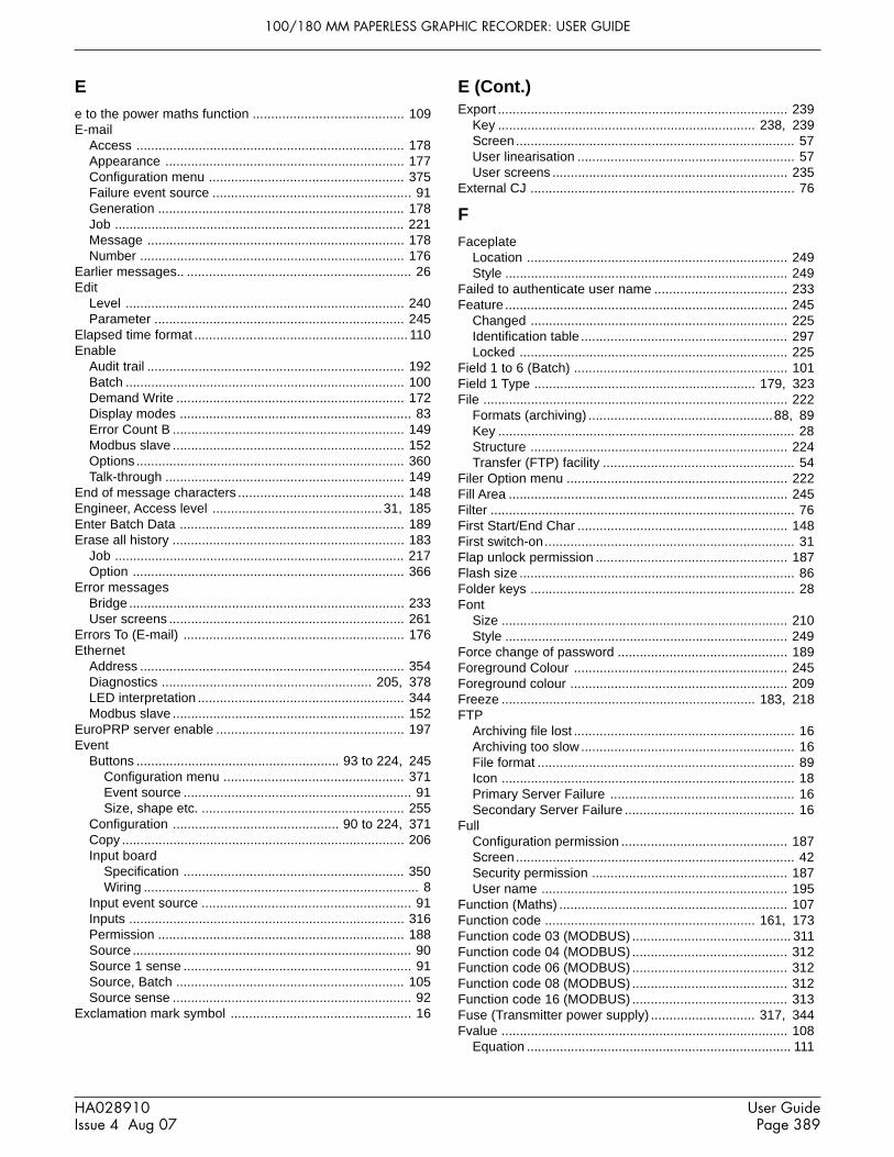
100/180 MM PAPERLESS GRAPHIC RECORDER: USER GUIDE
User GuidePage 389
HA028910Issue 4 Aug 07
Ee to the power maths function ......................................... 109E-mail
Access ......................................................................... 178Appearance ................................................................. 177Configuration menu ..................................................... 375Failure event source ...................................................... 91Generation ................................................................... 178Job ............................................................................... 221Message ...................................................................... 178Number ........................................................................ 176
Earlier messages.. ............................................................. 26Edit
Level ............................................................................ 240Parameter .................................................................... 245
Elapsed time format .......................................................... 110Enable
Audit trail ...................................................................... 192Batch ............................................................................ 100Demand Write .............................................................. 172Display modes ............................................................... 83Error Count B ............................................................... 149Modbus slave ............................................................... 152Options ......................................................................... 360Talk-through ................................................................. 149
End of message characters ............................................. 148Engineer, Access level ..............................................31, 185Enter Batch Data ............................................................. 189Erase all history ............................................................... 183
Job ............................................................................... 217Option .......................................................................... 366
Error messagesBridge ........................................................................... 233User screens ................................................................ 261
Errors To (E-mail) ............................................................ 176Ethernet
Address ........................................................................ 354Diagnostics ......................................................... 205, 378LED interpretation ........................................................ 344Modbus slave ............................................................... 152
EuroPRP server enable ................................................... 197Event
Buttons ....................................................... 93 to 224, 245Configuration menu ................................................. 371Event source .............................................................. 91Size, shape etc. ....................................................... 255
Configuration ............................................. 90 to 224, 371Copy ............................................................................. 206Input board
Specification ............................................................ 350Wiring ........................................................................... 8
Input event source ......................................................... 91Inputs ........................................................................... 316Permission ................................................................... 188Source ............................................................................ 90Source 1 sense .............................................................. 91Source, Batch .............................................................. 105Source sense ................................................................. 92
Exclamation mark symbol ................................................. 16
Export ............................................................................... 239Key ...................................................................... 238, 239Screen............................................................................ 57User linearisation ........................................................... 57User screens ................................................................ 235
External CJ ........................................................................ 76
FFaceplate
Location ....................................................................... 249Style ............................................................................. 249
Failed to authenticate user name .................................... 233Feature ............................................................................. 245
Changed ...................................................................... 225Identification table ........................................................ 297Locked ......................................................................... 225
Field 1 to 6 (Batch) .......................................................... 101Field 1 Type ............................................................ 179, 323File ................................................................................... 222
Formats (archiving) ..................................................88, 89Key ................................................................................. 28Structure ...................................................................... 224Transfer (FTP) facility .................................................... 54
Filer Option menu ............................................................ 222Fill Area ............................................................................ 245Filter ................................................................................... 76First Start/End Char ......................................................... 148First switch-on.................................................................... 31Flap unlock permission .................................................... 187Flash size ........................................................................... 86Folder keys ........................................................................ 28Font
Size .............................................................................. 210Style ............................................................................. 249
Force change of password .............................................. 189Foreground Colour .......................................................... 245Foreground colour ........................................................... 209Freeze ..................................................................... 183, 218FTP
Archiving file lost ............................................................ 16Archiving too slow .......................................................... 16File format ...................................................................... 89Icon ................................................................................ 18Primary Server Failure .................................................. 16Secondary Server Failure .............................................. 16
FullConfiguration permission ............................................. 187Screen............................................................................ 42Security permission ..................................................... 187User name ................................................................... 195
Function (Maths) .............................................................. 107Function code ......................................................... 161, 173Function code 03 (MODBUS) ........................................... 311Function code 04 (MODBUS) .......................................... 312Function code 06 (MODBUS) .......................................... 312Function code 08 (MODBUS) .......................................... 312Function code 16 (MODBUS) .......................................... 313Fuse (Transmitter power supply) ............................ 317, 344Fvalue .............................................................................. 108
Equation ........................................................................ 111
E (Cont.)

100/180 MM PAPERLESS GRAPHIC RECORDER: USER GUIDE
HA028910Issue 4 Aug 07
User GuidePage 390
GGas constant ............................................................ 112, 114Global Alarm Event Source ............................................... 90Global channel alarm....................................................... 381Global Unack'd Alarm Event Source ................................. 90Goto
Canvas ......................................................................... 239Group key ...................................................................... 28View key ......................................................................... 28
Green line across the chart ............................................... 36Grid
Line colourMajor ........................................................................ 249Minor ........................................................................ 250
Type/Divisions ................................................................ 68Group
Average ........................................................................ 107Configuration ................................................................. 65Configuration menu ..................................................... 370Copy ............................................................................. 206Data (MODBUS) .......................................................... 291Display enable ............................................................... 83Display modes ............................................................... 83Enable/disable ............................................................... 68Home ............................................................................. 82Horizontal Bargraph ..................................................... 253Latched maximum ....................................................... 108Latched minimum ........................................................ 108Maximum ..................................................................... 107Minimum ...................................................................... 107Name .......................................................................15, 66Number ............................................................... 157, 246Numeric display ........................................................... 254Report destination ....................................................... 221Select ............................................................................. 28Selection for comms messages .................................. 148Trend ............................................................................ 253Vertical bargraph ......................................................... 253
HHandshake ....................................................................... 329Hardware version ............................................................. 211Height ............................................................................... 246High Priority interval ........................................................ 151High Select ...................................................................... 108History .............................................................................. 384
Amount of ................................................................36, 69Maximum history ............................................................ 36
HomeGroup ............................................................................. 82Key ................................................................................. 28Page (Display mode) ..................................................... 83Timeout .......................................................................... 82
HorizontalAlignment ..................................................................... 249Bargraph ...................................................................... 251Bargraph enable ............................................................ 83Faceplate ............................................................ 249, 251Grid total ...................................................................... 249Minor Divisions ............................................................ 249Trend enable .................................................................. 83Trend mode ...................................................38, 253, 382
HTM2010 Quarterly Test kit ............................................. 335Hysteresis .......................................................................... 79
IIdentifier ........................................................................... 246Image ............................................................................... 255
File ............................................................................... 246Import ............................................................................... 239
An image ...................................................................... 255Key ...................................................................... 238, 239Printer driver ................................................................ 325Screen....................................................................56, 235User linearisation ........................................................... 57
Include message ............................................................. 176Increment counter job ...................................................... 215Indirection tables (MODBUS) .......................................... 297Input
Adjust ........................................................................... 203Configuration menu ................................................. 378
Board specification ...................................................... 345Configuration ................................................................. 72Low/high ........................................................................ 72Type selection ................................................................ 72Wiring ............................................................................... 7
InstallationCategory ...................................................................... 341Electrical ................................................................. 5 to 88Mechanical .............................................................. 2 to 88
InstrumentAlarm
Definition .................................................................... 16Event source .............................................................. 91Indicator ..................................................................... 16Summary.................................................................... 19
Alarms .......................................................................... 381Configuration ................................................................. 63Configuration menu ..................................................... 370Data (MODBUS) .......................................................... 272Name ............................................................................. 63Number ........................................................................ 196Variant ........................................................................... 211
Insufficient non-volatile memory... ..................................... 16Internal flash: \application\required repair ......................... 16Internal flash: \user\ is full ................................................. 16Internal flash: \user\ required repair .................................. 16Internal flash:\screens ....................................................... 16Interval (recording) ............................................................ 69Interval B .......................................................................... 218Invalid multiple register writes ......................................... 263Invalid Password Entry ...................................................... 91Invalid Selection ................................................................ 70IP Address........................................................................ 196
Look-up ........................................................................ 196Manual entry ................................................................ 196Modbus slave ............................................................... 152
H (Cont.)

100/180 MM PAPERLESS GRAPHIC RECORDER: USER GUIDE
User GuidePage 391
HA028910Issue 4 Aug 07
JJobs ................................................................................. 213
Alarm ............................................................................ 220Archive ......................................................................... 220Batch ............................................................................ 216Clock ............................................................................ 215Counter ........................................................................ 215Demand writes ............................................................. 219Disable totaliser ........................................................... 136Drive relay .................................................................... 213E-mail ........................................................................... 221Event .............................................................................. 92Input channel ................................................................. 81Maths ........................................................................... 214Message ...................................................................... 214Output .......................................................................... 219Preset totaliser ............................................................. 136Recording .................................................................... 217Report .......................................................................... 221Search .......................................................................... 208
Configuration menu ................................................. 379Totaliser ....................................................................... 213Trend ............................................................................ 218
KKeycode ........................................................................... 202
LLabelling symbols ................................................................ 1Language selection ......................................................... 201Last error ......................................................................... 246Last Updated .................................................................... 211Latched .............................................................................. 78Later messages.. ............................................................... 26Left key .............................................................................. 28Line .................................................................................. 259
Across the chart ............................................................. 36Feed ...................................................179, 180, 323, 324Thickness ..................................................................... 250
LinearChart grid ....................................................................... 68Scales ............................................................................ 74
LinearisationFunction ......................................................................... 72
User entered ................................................... 97 to 224Link error count ....................................................... 148, 321Local Host ........................................................................ 198Local Modbus client ......................................................... 205Locale
Configuration menu ..................................................... 378Lockable flap option ........................................................... 12Log
Chart grid ....................................................................... 68Maths functions ........................................................... 109Scale .............................................................................. 74
Log/LinearScale .............................................................................. 74
Logged out ......................................................................... 31Login .................................................................32, 194, 376
Disable ......................................................................... 186Timeout ........................................................................ 191
Login Required (Modbus slave) ...................................... 152
Logout key ....................................................................... 184Long messages ............................................................... 268Loop number ........................................................... 159, 172Low
Priority interval ............................................................. 151Select ........................................................................... 108
MMAC Address .......................................................... 196, 354Mail Server ....................................................................... 176Maintenance .................................................................... 356
Schedule ...................................................................... 357Major circular chart divisions ............................................. 67Management .................................................................... 190
Configuration menu ..................................................... 376Manual archive
Local .............................................................................. 52To host computer ........................................................... 54
Mass flowLinear ................................................................... 108, 112Saturated Steam ........................................................... 118Square root .......................................................... 108, 114
Master Comms ..................................................... 150 to 224Configuration menu ..................................................... 374Diagnostics .................................................................. 168Example configuration ................................................. 164Slave Failure Event source ........................................... 91
MathsConfiguration menu ..................................................... 372
Maths channelChannel data (Modbus) .................................... 132 to 224Configuration ............................................................... 106
32-bit data (MODBUS) ................................. 133 to 224Copy ............................................................................. 206Failure ............................................................................ 16Function selection ........................................................ 107Jobs ............................................................................. 214Modbus addressing .......................................... 132 to 224Partial Failure ................................................................ 91Run-time data (MODBUS) ................................ 133 to 224
MaximumBlock size ..................................................................... 152Number of Bridge ... .................................................... 233Number of data bytes .................................................. 262
Mean kinetic temperature ................................................. 116Measuring units ............................................................... 261Media ................................................................................. 86
Archiving file lost ............................................................ 16Archiving too slow .......................................................... 16File format ................................................................88, 89Full ................................................................................. 53
Event limit .................................................................. 87Removal ......................................................................... 12Size ................................................................................ 87
Medium Priority interval ................................................... 151Memory device location ...................................................... 11Memory size .............................................................. 86, 211Menu structure
Archive key .................................................................. 368Config menu ..................................................... 370 to 375Network key menu ....................................................... 377Root menu ................................................................... 367
L (Cont.)

100/180 MM PAPERLESS GRAPHIC RECORDER: USER GUIDE
HA028910Issue 4 Aug 07
User GuidePage 392
Save/Restore key ........................................................ 369Security key menu ....................................................... 376System key .................................................................. 378
Messages....................................................... 94 to 224, 323Alarm .............................................................................. 81Auditor , Batch ............................................................... 99Batch, Initiation ............................................................ 102Colour .......................................................................... 250Configuration menu ..................................................... 371Copying ........................................................................ 206Enable/disable ............................................................... 69Entry ............................................................................... 94
Example ..................................................................... 96Inclusion in reports ...................................................... 179Jobs ............................................................................. 214Log .................................................................. 24, 30, 383Operator entered ........................................................... 50Power up ........................................................................ 31Serial Comms .............................................................. 146To print ......................................................................... 322
Min-Max recording ............................................................. 66Minimum
Channel Descriptor ...................................................... 130Height ........................................................................... 250Password length .......................................................... 191PC requirements .......................................................... 226Width ............................................................................ 250
Missing pixels test ........................................................... 352MKT maths function ................................................. 108, 116
Group .................................................................. 108, 122Modbus
Address ........................................................................ 152Address 255 ................................................................. 149Address setting .............................................................. 63Master/Slave
Configuration menus ............................................... 373Maximum number of data bytes .................................. 262RTU .............................................................................. 146Security ........................................................................ 263Security disable ............................................................. 63Slave
Enable ...................................................................... 152Online ....................................................................... 152Selection .................................................................. 151
Status ........................................................................... 205Wiring ........................................................................... 262
Modulus maths function .................................................. 109Mouse lock-up ................................................................. 344Move Screen .................................................................... 239Multiply maths function .................................................... 107
NN Value ............................................................................ 246Name Files by Batch ....................................................... 102NAND ................................................................................. 92Navigation action ............................................................. 254Network
AddressConfiguration menu ................................................. 377
Boot failure ..................................................................... 16Configuration ............................................................... 196
Connection has timed out ............................................ 233Ethernet/Serial selection ............................................. 152Key menu ..................................................................... 377Name ........................................................................... 198Scanning tool ............................................................... 197Specification ................................................................ 344
New .................................................................................. 239Chart ........................................................................40, 67Configuration ................................................................. 56Full User Name ............................................................ 195Key ............................................................................... 222Password ..................................................................... 186User ID ......................................................................... 195User Screen key ................................................. 238, 239
No action .......................................................................... 213No chart grid ...................................................................... 68No Text ............................................................................. 251Nominal height/width ....................................................... 250NONE ................................................................................. 92NOR ................................................................................... 92Normal View ...................................................................... 41Notes ................................................................................ 250Number
Of Batch Messages ..................................................... 101Of columns ................................................................... 250Of Fields ............................................................. 179, 323Of rows......................................................................... 250
NumericDisplay ...................................................................77, 383Display mode enable ..................................................... 83Width ............................................................................ 250
OO2 Correction ......................................................... 109, 124Offset ................................................................................. 73
Correction (touch screen) ............................................ 352Ok ...................................................................................... 33OK to remove archive media ............................................. 12On
Becoming active/inactive etc. ...................................... 213Error Write Default ....................................................... 172Media full ....................................................................... 87New clear ..................................................................... 101Start/Stop Log .............................................................. 101Visibility change ........................................................... 250
Online (Modbus slave) ..................................................... 152Open/Closed strings ........................................................ 162Operator
Access level ...........................................................31, 185Button ........................................................................... 255Event logic ..................................................................... 92Key ................................................................................. 28Notes (Messages) ......................................................... 50
OptionDisplay ................................................................ 181, 375Key ................................................................................. 28
OR ...................................................................................... 92Output
Adjust .................................................................. 205, 314Channel
Analogue outputs ..................................................... 170
Network (Cont.)Menu structure (Cont.)

100/180 MM PAPERLESS GRAPHIC RECORDER: USER GUIDE
User GuidePage 393
HA028910Issue 4 Aug 07
Configuration menu ................................................. 374Default editing .......................................................... 188Master Comms ........................................................ 169
Copy ............................................................................. 206Jobs ............................................................................. 219
Oval .................................................................................. 259Ovr ..................................................................................... 33Oxygen
Correction ........................................................... 109, 124Potential .............................................................. 126, 128
PPage Title ......................................................................... 246Page up/down keys ........................................................... 28Paint
All ................................................................................. 250Background .................................................................. 250
Paper Low message .......................................................... 17Paper Out message ........................................................... 17Parameter .......................................................157, 159, 172Parity
Serial comms ...................................................... 148, 322Serial printer ................................................................ 329
Password ......................................................................... 185Change on expiry ........................................................ 193Editing .......................................................................... 184Expiry ........................................................................... 191Force change of ........................................................... 189
Paste key ......................................................................... 222Paste/delete file permission ............................................ 187Period scaler .................................................................... 136Ping .................................................................................. 205Pixels (Absolute/relative) ................................................. 236Point ........................................................................ 180, 324
Alarm .............................................................................. 90Number ........................................................................ 157Type ..............................................................70, 157, 172
Pollution degree ............................................................... 341Polygon ............................................................................ 258Polyline ............................................................................ 257Polynomial ............................................................... 108, 110Port .................................................................................. 176Portable case
Basic option ................................................................. 331Basic option with TRS ................................................. 333Dimensions .................................................................. 330HTM2010 Test kit ......................................................... 335Low supply voltage ...................................................... 340Thermocouple option ................................................... 337
PositioningGrid .............................................................................. 240Tip ................................................................................ 240
Power requirements ........................................................ 343Power Up
Event source .................................................................. 91Message ........................................................................ 31
PresetClock Job ..................................................................... 215Counter ............................................................... 140, 215
Permission ............................................................... 187
Totaliser ....................................................................... 135Job ........................................................................... 213Permission ............................................................... 187
Pressure unit conversion .................................................. 119Preventive maintenance .................................................. 356Primary
DNS Server .................................................................. 198Login Name ................................................................... 88Remote Host .................................................................. 88
Print Messages From ...................................................... 322Printed keys ....................................................................... 28Printer
Driver, importing new ................................................... 325Name ........................................................................... 322Not responding .............................................................. 17Status ........................................................................... 322Supply Wiring ............................................................... 320Switch settings ............................................................. 329Test .............................................................................. 322Type ............................................................................. 322
Process value ......................................................... 179, 323Update rate ......................................................... 157, 159
Profile (Modbus slave) ..................................................... 152Properties page (User screens) ...................................... 238Protocol ...........................................................148, 176, 322PV Format .................................................................. 77, 110
QQuestion marks in message .............................................. 94Quick entry to user screen edit ....................................... 240
RRange Low/High .............................................................. 170Range Low/High/Units ....................................................... 73Rate-of-change
Alarms ............................................................................ 78Maths function .................................................... 109, 123
Rcpt1 to Rcpt10 ............................................................... 176Reading
Digital values ............................................................... 162User defined registers ................................................. 160
Recall ............................................................................... 183Recipient List ................................................................... 176Record logins ................................................................... 191Recorder
Configuration. See Section 4.3Dimensions .................................................................. 3, 4Electrical installation ........................................................ 5Panel installation .................................................... 2, 3, 4Specification ................................................................ 342Synchronisation (SNTP) .............................................. 197Unpacking ........................................................................ 2Wiring ...................................................................... 5 to 88
RecordingEnable ............................................................................ 36Enable/Disable ............................................................. 217Enable/disable ............................................................... 68Failed instrument alarm ................................................. 17Interval ........................................................................... 69
Preset (Cont.)Output channel (Cont.)

100/180 MM PAPERLESS GRAPHIC RECORDER: USER GUIDE
HA028910Issue 4 Aug 07
User GuidePage 394
Jobs ............................................................................. 217Speed ............................................................................. 69Speed B job ................................................................. 217
Recording failed - internal overflow .......................... 69, 193Rectangle ......................................................................... 256Red line across the chart ................................................... 36Reference value ................................................................ 79Refresh key ...................................................................... 222Register ............................................................................ 173Relative Humidity .................................................... 109, 125Relay
Board specification ...................................................... 349Drive relay job .............................................................. 213Wiring ............................................................................... 8
RemoteCold Junction Compensation ........................................ 76Path ................................................................................ 87User name/password ................................................... 186Viewer
Network menu .......................................................... 196Removable Media Capacity .............................................. 87Removable media full ........................................................ 17Removable media instrument alarms ................................ 17Remove Media ................................................................... 27Remove User ................................................................... 195
Configuration menu ..................................................... 376Replace n with ................................................................. 94Reports ................................................................... 179, 323
Configuration ...................................................... 179, 323Menu ........................................................................ 375
Example ....................................................................... 326Jobs ............................................................................. 221
Require Authorization/Signing ...................................93, 191Reset
Maths channel ............................................................. 214Permission ............................................................... 187
TimerJob ........................................................................... 216Permission ............................................................... 187
Restore .............................................................................. 56Retransmission outputs ................................................... 170Retry (Modbus slave) ...................................................... 152Retry Time ....................................................................... 176Reversed colour .............................................................. 250Revert .............................................................................. 239Revision Numbers ............................................................ 211Right key ............................................................................ 28Rolling Average ........................................................ 108, 116Root key menu...........................................................28, 367Rotate ................................................................................ 67
Chart .............................................................................. 40Round Rectangle ............................................................. 256RTD
Specifications ............................................................... 346Type selection ................................................................ 72
S'S' symbol ......................................................................... 352Safety notes ......................................................................... 1Sales Demo Enable/Disable ............................................ 352Sample and hold .............................................................. 108Sample rates .................................................................... 343Saturated Steam
Heat Consumed ........................................................... 121Heat Flow ..................................................................... 120Mass flow ...................................................................... 118
Save ...........................................................................56, 239Save as .............................................................................. 56Save/Restore ..................................................................... 55
Key menu ..................................................................... 369Permission ................................................................... 187
Saver Display ................................................................... 218Scale
Divisions (Major/Minor) ..........................................74, 250Style ............................................................................. 251Type ............................................................................... 74
Scaled tick box .................................................................. 73Scaling ............................................................157, 161, 173Scientific display ................................................................ 77Scope ............................................................................... 100
Display modes ............................................................... 82Screen
Builder option .................................................... 234 to 261Calibration .................................................................... 352Importing/Exporting ....................................................... 57Number ........................................................................ 246Saver ......................................................................63, 183Size .............................................................................. 261
SD card location ................................................................. 11Second Start/End Char .................................................... 148Secondary
DNS Server .................................................................. 198Login .............................................................................. 88Password ....................................................................... 88Remote Host .................................................................. 88
SecurityConfiguration ............................................................... 184Key
Menu ........................................................................ 376Levels ........................................................................... 185Modbus ........................................................................ 263Revision ................................................. 31, 99, 193, 212
SelectDisplay mode ................................................................. 28Group ............................................................................. 28
Selection ............................................................................ 70Send on power up ........................................................... 172Send Report to ................................................................. 221Sender ............................................................................. 176Serial (Modbus slave) ...................................................... 152Serial 1/Serial 2 ............................................................... 355Serial communications .................................................... 146
Configuration menus ................................................... 373Message information ................................................... 149Specification ................................................................ 344Wiring ............................................................................... 9
Recording (Cont.)

100/180 MM PAPERLESS GRAPHIC RECORDER: USER GUIDE
User GuidePage 395
HA028910Issue 4 Aug 07
Serial Port ............................................................... 148, 321Service level access .......................................................... 31Set clock permission ........................................................ 187Setting the time and date ................................................ 201Share socket ........................................................... 152, 155Shift .................................................................................... 33Shortest trend history ........................................................ 86Show
Batch Entry list ............................................................. 100Disk settings .................................................................. 86Operator Notes list ......................................................... 64Title Bar ........................................................................ 246
Shunt value entry ............................................................... 73Signal wiring ............................................................... 5 to 88Simulation ........................................................................ 183Slave ...............................................................157, 159, 172
Comms Maths function ................................................ 107Selection ...................................................................... 151
Slowing recording interval .........................................69, 193SMPT (Email) .................................................................. 176SMS ................................................................................. 178
(Body Only) .................................................................. 176(Subject Only) .............................................................. 176
SMTP ............................................................................... 178SNTP ............................................................................... 197
Client enable ................................................................ 197Instrument alarm ............................................................ 17Server enable .............................................................. 197
Socket, share ................................................................... 155Software version ............................................................... 211Source .............................................................................. 172
Descriptor/value ............................................................. 94Span high/low .............................................................. 170Types ............................................................................. 90
Source 1 sense .................................................................. 91Source 2 sense .................................................................. 92Span ........................................................................ 157, 159
B ................................................................................... 218Group ....................................................................... 218Select job ................................................................. 218
Configuration ................................................................. 77Special modes ................................................................. 352Specific gas constant ............................................... 112, 114Specification
Analogue output board ................................................ 350ASCII Printer ................................................................ 350Back-up battery ........................................................... 343Battery .......................................................................... 343Event input board ........................................................ 350Event inputs ................................................................. 316Input board ................................................................... 345Pressure transducer .................................................... 336Recorder, general ........................................................ 342RTC .............................................................................. 343Serial comms board ..................................................... 344Transmitter Power Supply ........................................... 344USB ports .................................................................... 344
Specified descriptor/value ................................................. 94Speed
of recording .................................................................... 69Speed/interval B job .................................................... 218
Square root (maths function) ........................................... 108Start
Angle ............................................................................ 246as Lite .......................................................................... 230Start/End characters .................................................... 148Start/Stop batch selection ........................................... 100Timer
Job ........................................................................... 216Permission ............................................................... 187
StatusBar ................................................................................. 15Comms......................................................................... 172
Stop bits .................................................................. 148, 322Stopwatch ........................................................................ 107Store diagnostics ............................................................. 151Style ........................................................................ 180, 324Stylus location .................................................................... 11Subject ............................................................................. 176Subnet Mask .................................................................... 197Subtract ............................................................................ 107Summary
Menu .............................................................................. 19Page
Alarm.......................................................................... 20Batch .......................................................................... 22
Summertime setup .......................................................... 201Supply voltage ..................................................................... 9Support file ....................................................................... 212Suspend Archiving ............................................................. 53Switch .............................................................................. 108
Printer, settings ............................................................ 329Symbols used on labels ...................................................... 1Synchronisation by SNTP ............................................... 197System key menu ............................................................ 378
T'T' symbol ........................................................................... 18Tag, Channel ...................................................................... 76Termination and biassing ................................................. 146Text ........................................................176, 179, 246, 323
Messages (Modbus) .................................................... 268Save and Restore .......................................................... 56Size ..................................................................... 209, 379String entry .................................................................... 33User screens ................................................................ 256
There appears to be no free disk space... ............. 225, 233Thermocouple
Type selection ................................................................ 72Types and ranges ........................................................ 346Types J, K and T colours ............................................. 338
Threshold ........................................................................... 79Time
Change annotation ........................................................ 36Format .......................................................................... 201Marker
Colour ...................................................................... 251Interval ..................................................................... 251
Permission to set ......................................................... 187
S (Cont.) S (Cont.)

100/180 MM PAPERLESS GRAPHIC RECORDER: USER GUIDE
HA028910Issue 4 Aug 07
User GuidePage 396
Setting .......................................................................... 201Synch. instrument alarm ................................................ 17Synchronisation (SNTP) .............................................. 197Synchronisation failure .................................................. 17To fill storage device ...................................................... 87Zone selection ............................................................. 201
Time and date Configuration menu ................................. 378Timeout .............................................................................. 82
Comms......................................................................... 148Comms channel ............................................................. 63Modbus slave ............................................................... 152
TimerConfiguration menu ..................................................... 372Copy ............................................................................. 206Description ................................................................... 144Disable job ................................................................... 216Jobs ............................................................................. 216Reset job ...................................................................... 216Start job ....................................................................... 216Start/Reset Permission ................................................ 187Timer Active Event Source ............................................ 90
Timestamp, circular charts ................................................ 43Timestamp maths function .............................................. 109Totaliser
Configuration32-bit data (MODBUS) ............................................ 138
Configuration data (Modbus) ....................................... 137Configuration menu ..................................................... 372Copy ............................................................................. 206Equation ....................................................................... 135Jobs ............................................................................. 213Option .......................................................................... 135Run-time data
32-bit (MODBUS)..................................................... 139Run-time data (MODBUS) ........................................... 138
Touch screenCalibration .................................................................... 352Precautions .................................................................. 356
Transmitter Power Supply ............................................... 317Trend
Circular ........................................................................... 40Colour ............................................................................ 77Freeze .......................................................................... 183History, maximum ......................................................... 69History (shortest) ........................................................... 86History display .........................................................36, 69Horizontal ..................................................................... 382Interval/Speed/Units ...................................................... 66Jobs ............................................................................. 218Padding ........................................................................ 251Speed/interval ................................................................ 67Thickness ..................................................................... 251Trend speed/interval B job .......................................... 218Type ............................................................................... 66Vertical ......................................................................... 383
Trial Mode ........................................................................ 182Indicator ......................................................................... 18
Trigger ................................................................................ 78Truncation of display values .............................................. 14
UUnable to connect to host ................................................ 233Unable to resolve hostname............................................ 233Unack'd
Alarm on group .............................................................. 91Point alarm ..................................................................... 90
Units ................................................................................. 236Conversion (Pressure) .................................................. 119Font .............................................................................. 251Scaler ........................................................................... 136
Unlatched ........................................................................... 78Unlock flap permission .................................................... 187Update when .................................................................... 251Upgrade ........................................................................... 202
Configuration menu ..................................................... 378USB
Front port location ........................................................... 11Lock-up ........................................................................ 344Over current ................................................................... 17Power fault key .............................................................. 17Specification ................................................................ 344Unsupported .................................................................. 17
UseCounter batch number ................................................. 101Last properties ............................................................. 240Text batch number ....................................................... 101
UserAdding and removing ................................................... 195Defined......................................................................... 160Defined descriptor ....................................................... 130Linearisation table
Configuration .................................................. 97 to 224Configuration menu ................................................. 371Importing/Exporting ................................................... 57Units selection .....................................................73, 97
Logged in Event Source ................................................ 91Login account disabled .................................................. 91Name (full) ................................................................... 195Password ..................................................................... 195
User Screen Image Error ................................................ 255User screens ......................................................... 234 to 261
Advanced parameters ................................................. 247Basic parameters ......................................................... 245Basic/Advanced selection ........................................... 240Component info on screens ........................................ 240Component list ............................................................. 237Creation ....................................................................... 236Importing/Exporting ..................................................... 235Key descriptions ................................................. 238, 239Number of ...................................................................... 84Properties page ........................................................... 238Quick entry ................................................................... 240
T
Time (Cont.)
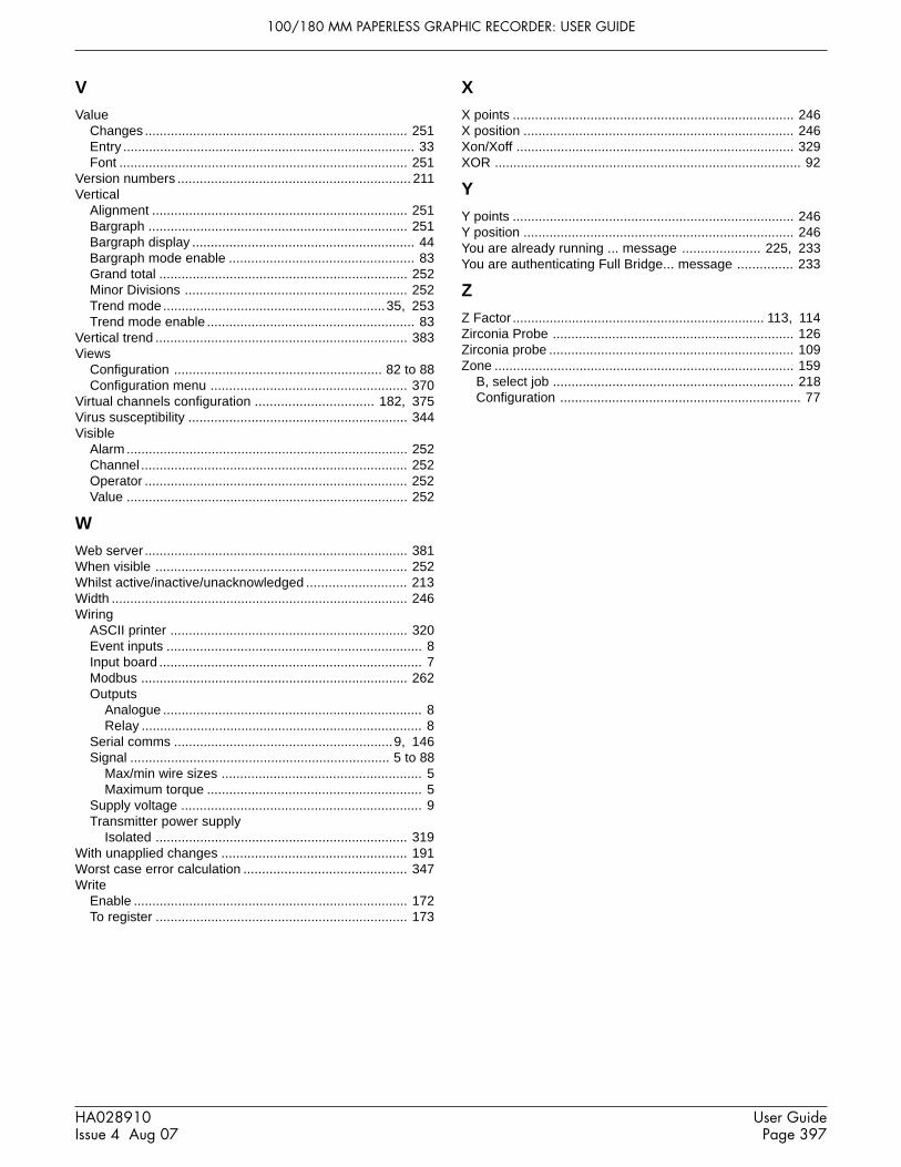
100/180 MM PAPERLESS GRAPHIC RECORDER: USER GUIDE
User GuidePage 397
HA028910Issue 4 Aug 07
VValue
Changes ....................................................................... 251Entry ............................................................................... 33Font .............................................................................. 251
Version numbers ............................................................... 211Vertical
Alignment ..................................................................... 251Bargraph ...................................................................... 251Bargraph display ............................................................ 44Bargraph mode enable .................................................. 83Grand total ................................................................... 252Minor Divisions ............................................................ 252Trend mode ............................................................35, 253Trend mode enable ........................................................ 83
Vertical trend .................................................................... 383Views
Configuration ........................................................ 82 to 88Configuration menu ..................................................... 370
Virtual channels configuration ................................ 182, 375Virus susceptibility ........................................................... 344Visible
Alarm ............................................................................ 252Channel ........................................................................ 252Operator ....................................................................... 252Value ............................................................................ 252
WWeb server ....................................................................... 381When visible .................................................................... 252Whilst active/inactive/unacknowledged ........................... 213Width ................................................................................ 246Wiring
ASCII printer ................................................................ 320Event inputs ..................................................................... 8Input board ....................................................................... 7Modbus ........................................................................ 262Outputs
Analogue ...................................................................... 8Relay ............................................................................ 8
Serial comms ...........................................................9, 146Signal ...................................................................... 5 to 88
Max/min wire sizes ...................................................... 5Maximum torque .......................................................... 5
Supply voltage ................................................................. 9Transmitter power supply
Isolated .................................................................... 319With unapplied changes .................................................. 191Worst case error calculation ............................................ 347Write
Enable .......................................................................... 172To register .................................................................... 173
XX points ............................................................................ 246X position ......................................................................... 246Xon/Xoff ........................................................................... 329XOR ................................................................................... 92
YY points ............................................................................ 246Y position ......................................................................... 246You are already running ... message ..................... 225, 233You are authenticating Full Bridge... message ............... 233
ZZ Factor .................................................................... 113, 114Zirconia Probe ................................................................. 126Zirconia probe .................................................................. 109Zone ................................................................................. 159
B, select job ................................................................. 218Configuration ................................................................. 77

100/180 MM PAPERLESS GRAPHIC RECORDER: USER GUIDE
HA028910Issue 4 Aug 07
User GuidePage 398
This page is deliberately left blank

Inter-Company sales and service locations
Specification subject to change without notice. ©Eurotherm Limited.
AUSTRALIA SydneyEurotherm Pty. Ltd.Telephone (+61 2) 9838 0099Fax (+61 2) 9838 9288E-mail [email protected]
AUSTRIA ViennaEurotherm GmbHTelephone (+43 1) 7987601Fax (+43 1) 7987605E-mail [email protected]
BELGIUM & LUXEMBURG MohaEurotherm S.A/N.V.Telephone (+32) 85 274080Fax (+32 ) 85 274081E-mail [email protected]
BRAZIL Campinas-SPEurotherm Ltda.Telephone (+5519) 3707 5333Fax (+5519) 3707 5345E-mail [email protected]
DENMARK CopenhagenEurotherm Danmark ASTelephone (+45 70) 234670Fax (+45 70) 234660E-mail [email protected]
FINLAND AboEurotherm FinlandTelephone (+358) 22506030Fax (+358) 22503201E-mail [email protected]
FRANCE LyonEurotherm Automation SATelephone (+33 478) 664500Fax (+33 478) 352490E-mail [email protected]
GERMANY LimburgEurotherm Deutschland GmbHTelephone (+49 6431) 2980Fax (+49 6431) 298119E-mail [email protected]
EUROTHERM LIMITEDFaraday Close, Durrington, Worthing, West Sussex, BN13 3PLTelephone: +44 (0)1903 268500 Facsimile: +44 (0)1903 265982
e-mail: [email protected]: http://www.eurotherm.co.uk
HA028910/4 (CN23473)
EUROTHERM
HONG KONG & CHINAEurotherm Limited North PointTelephone (+85 2) 28733826Fax (+85 2) 28700148E-mail [email protected]
Guangzhou OfficeTelephone (+86 20) 8755 5099Fax (+86 20) 8755 5831E-mail [email protected]
Beijing OfficeTelephone (+86 10) 6567 8506Fax (+86 10) 6567 8509E-mail [email protected]
Shanghai OfficeTelephone (+86 21) 6145 1188Fax (+86 21) 6145 1187E-mail [email protected]
INDIA ChennaiEurotherm India LimitedTelephone (+9144) 2496 1129Fax (+9144) 2496 1831E-mail [email protected]
IRELAND DublinEurotherm Ireland LimitedTelephone (+353 1) 4691800Fax (+353 1) 4691300E-mail [email protected]
ITALY ComoEurotherm S.r.lTelephone (+39 31) 975111Fax (+39 31) 977512E-mail [email protected]
KOREA SeoulEurotherm Korea LimitedTelephone (+82 31) 2738507Fax (+82 31) 2738508E-mail [email protected]
NETHERLANDS Alphen a/d RijnEurotherm B.V.Telephone (+31 172) 411752Fax (+31 172) 417260E-mail [email protected]
NORWAY OsloEurotherm A/STelephone (+47 67) 592170Fax (+47 67) 118301E-mail [email protected]
POLAND KatowiceInvensys Eurotherm Sp z o.oTelephone (+48 32) 218 5100Fax (+48 32) 217 7171E-mail [email protected]
SPAIN MadridEurotherm España SATelephone (+34 91) 661 6001Fax (+34 91) 661 9093E-mail [email protected]
SWEDEN MalmoEurotherm ABTelephone (+46 40) 384500Fax (+46 40) 384545E-mail [email protected]
SWITZERLAND WollerauEurotherm Produkte (Schweiz) AGTelephone (+41 44) 787 1040Fax (+41 44) 787 1044E-mail [email protected]
UNITED KINGDOM WorthingEurotherm LimitedTelephone (+44 1903) 268500Fax (+44 1903) 265982E-mail [email protected] www.eurotherm.co.uk
U.S.A Leesburg VAEurotherm Inc.Telephone (+1 703) 443 0000Fax (+1 703) 669 1300E-mail [email protected] www.eurotherm.com
ED52


![e Model 6100E 100 mm paperless graphic recorders1].pdf · Model 6100E 100 mm paperless graphic recorders User guide e EUROTHERM ... 6100A Status level A1 and above 6180A Status level](https://static.fdocuments.in/doc/165x107/5aeacbce7f8b9a585f8cc774/e-model-6100e-100-mm-paperless-graphic-1pdfmodel-6100e-100-mm-paperless-graphic.jpg)