User Guide Enhanced Network Time Appliance Model ENTA …€¦ · the equipment is not compromised....
44
1 MANUAL P/N 900000124 REV B User Guide Enhanced Network Time Appliance Model ENTA-R P/N 001-XXXX (0226/0286) Revision B August 2011 Brandywine Communications 1153 Warner Ave. Tustin, CA 92780 (714) 755 1050 (714) 755 0175 http://www.brandywinecomm.com
-
Upload
vuongduong -
Category
Documents
-
view
215 -
download
0
Transcript of User Guide Enhanced Network Time Appliance Model ENTA …€¦ · the equipment is not compromised....
1 MANUAL P/N 900000124 REV B
User Guide
Enhanced Network Time Appliance
Model ENTA-R
P/N 001-XXXX (0226/0286)
Revision B
August 2011
Brandywine Communications
1153 Warner Ave. Tustin, CA 92780 (714) 755 1050 (714) 755 0175
http://www.brandywinecomm.com

2 MANUAL P/N 900000124 REV B
Revision History
REVISION DATE COMMENTS A July 2011 Initial Release B August 2011 Added new FPGA load procedure.
3 MANUAL P/N 900000124 REV B
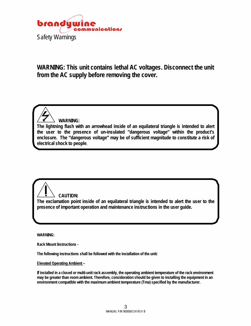
Safety Warnings WARNING: This unit contains lethal AC voltages. Disconnect the unit from the AC supply before removing the cover.
WARNING: The lightning flash with an arrowhead inside of an equilateral triangle is intended to alert the user to the presence of un-insulated “dangerous voltage” within the product’s enclosure. The “dangerous voltage” may be of sufficient magnitude to constitute a risk of electrical shock to people.
CAUTION: The exclamation point inside of an equilateral triangle is intended to alert the user to the presence of important operation and maintenance instructions in the user guide.
WARNING: Rack Mount Instructions - The following instructions shall be followed with the installation of the unit: Elevated Operating Ambient – If installed in a closed or multi-unit rack assembly, the operating ambient temperature of the rack environment may be greater than room ambient. Therefore, consideration should be given to installing the equipment in an environment compatible with the maximum ambient temperature (Tma) specified by the manufacturer.

4 MANUAL P/N 900000124 REV B
Reduced Air Flow – Installation of the equipment in a rack should be such that the amount of air flow required for safe operation of the equipment is not compromised. Mechanical Loading – Mounting of the equipment in the rack should be such that a hazardous condition is not achieved due to uneven mechanical loading. Circuit Overloading – Consideration should be given to the connection of the equipment to the supply circuit and the effect that overloading of the circuits might have on over-current protection and supply wiring. Reliable Earthing – Reliable earthing of rack-mounted equipment should be maintained. Particular attention should be given to supply connections other than direct connections to the J1 Connector

5 MANUAL P/N 900000124 REV B
Table of Contents
1 Specifications .......................................................................................................................... 7 1.1 GPS Receiver .................................................................................................................. 7
1.1.1 Receiver Type .......................................................................................................... 7 1.2 Internal Oscillator ............................................................................................................. 7
1.2.1 Oscillator Type ......................................................................................................... 7 1.3 Inputs ............................................................................................................................... 7
1.3.1 Antenna .................................................................................................................... 7 1.3.2 1 PPS ....................................................................................................................... 7 1.3.3 IRIG-B ...................................................................................................................... 7
1.4 Outputs ............................................................................................................................ 8 1.4.1 Reference Frequency Output ................................................................................... 8 1.4.2 Time Code - IRIG B + IRIG E ................................................................................ 8 1.4.3 Serial Time Code RS 232/ RS 422 (Not Used) ........................................................ 8 1.4.4 Pulse Rates .............................................................................................................. 8
1.5 Network Ports ................................................................................................................... 8 1.6 Status Indicators .............................................................................................................. 8 1.7 Time Display .................................................................................................................... 8 1.8 EnvironmENTA-Rl ............................................................................................................ 8 1.9 Mechanical ....................................................................................................................... 9 1.10 Rear Panel Connections .................................................................................................10
2 General Description ................................................................................................................12 3 Unpacking and Installation .....................................................................................................13
3.1 Unpacking .......................................................................................................................13 3.2 Installation .......................................................................................................................13 3.3 Connections ....................................................................................................................13
3.3.1 Power ......................................................................................................................13 3.3.2 GPS Connections ....................................................................................................13 3.3.3 RF Loss (Talk about cable lengths and input impedances) .....................................13 3.3.4 Network Connection ................................................................................................14 3.3.5 Other Connections ..................................................................................................14
4 Getting Started .......................................................................................................................15 4.1 Powering Up the ENTA-R ...............................................................................................15 4.2 Setting the Network Address ...........................................................................................15
4.2.1 IPSetup.exe .............................................................................................................16 4.2.2 Web Browser ...........................................................................................................17
Latest Version of Java Software .................................................................................................18 5 Configuration ..........................................................................................................................19
5.1 Web Browser Configuration ............................................................................................19 5.1.1 About .......................................................................................................................19 5.1.2 Status ......................................................................................................................20 5.1.3 Configuration ...........................................................................................................22 5.1.4 Help .........................................................................................................................32
6 Uploading Firmware ...............................................................................................................33 7 Uploading FPGA ....................................................................................................................36

6 MANUAL P/N 900000124 REV B
7.1 FPGA Update ..................................................................................................................36 7.2 FPGA Upload ..................................................................................................................39
8 Maintenance and Troubleshooting .........................................................................................41 9 Drawings ................................................................................................................................43

7 MANUAL P/N 900000124 REV B
1 Specifications 1.1 GPS Receiver 1.1.1 Receiver Type Architecture 12 parallel channels
• Dynamics Velocity 1000 knots everywhere
> 1000 knots at altitudes < 60000 ft. Acceleration 4 g Jerk 5 m/s3
• Acquisition Time Hot (with the current almanac, position, time, and
ephemeris) < 20 s typical
Warm (with the current almanac, position, and time) < 50 s typical Cold < 300 s typical
• Positioning Accuracy Fix mode < 25 m SEP Site Survey mode < 5 m SEP typical after position average
• Datum WGS-84 1.2 Internal Oscillator 1.2.1 Oscillator Type GPS disciplined High Precision OCXO Aging (typical) < 5x10⁻¹⁰per month when free running Temperature coefficient ± 2x10⁻⁹ ;-20°C to +50°C Design lifetime > 20 years 1.3 Inputs 1.3.1 Antenna Type Active patch antenna Connector BNC Pre-amp power 5 VDC @ 80 mA via center conductor 1.3.2 1 PPS Signal used 1 PPS Connector BNC Level 2.0 V min & 5.0 V max (TTL compatible) Impedance 50Ω Minimum pulse width 5 microseconds On time Rising edge 1.3.3 IRIG-B Signal used IRIG B122 and B123 per IRIG 215.98
2 – 5 Vpp Connector BNC

8 MANUAL P/N 900000124 REV B
1.4 Outputs 1.4.1 Reference Frequency Output Frequency 10 MHz Connector BNC Output level TTL INTO 50Ω 1.4.2 Time Code - IRIG B + IRIG E Code format IEEE 1344 Ext. IRIG B modulated
DC Level Shift IRIG E DC Level Shift
Modulation ratio 3:1 nominal Amplitude 3 Vpp into 600 ohm (modulated)
TTL into 50 ohm (DC Level Shift) DC offset voltage < 0.05 V
Connector BNC 1.4.3 Serial Time Code RS 232/ RS 422 (Not Used) 1.4.4 Pulse Rates
• 1 PPS Amplitude 0-5 V logic compatible
VOH > 2.4 V & VOL < 0.55 V Output impedance 50 ohm
Connector BNC Pulse width 10 microseconds On time Rising edge Phase relationship to 10 MHz When synchronized there are always 107 10
MHz cycles between each 1 PPS rising edge 1.5 Network Ports Number of ports 2 Port type Ethernet 10/100BaseT Protocols supported NTP (RFC 1305), Telnet (RFC 854) Connector RJ-45 1.6 Status Indicators
• LEDS Power (Green) Indicates power is available
1.7 Time Display DOY;HH:MM:SS – UTC or Local time
1.8 EnvironmENTA-Rl • Temperature
Unit Operating -20°C to +50°C Antenna Operating -40 to +85°C All units Storage -55 to +85°C
• Humidity Unit Up to 95% RH non-condensing Antenna Not limited
• Altitude Unit Operating 20, 000 ft Transport 40, 000 ft
• Power (Dual redundant PSU; Hot swappable) Range 85-264 VAC 50/60 Hz Power 40W Nom. Connector IEC 320 with integrated switch and fuse Fuse 1A 5x20mm slo-blo

9 MANUAL P/N 900000124 REV B
• EMC
MIL-STD_461E RE101 RE102 CE102
1.9 Mechanical Size (unit) 17” x 1.72” x 9” excluding the connectors and
handles. Front panel width 19”. Weight 5 lbs. nominal
MANUAL P/N 900000124 REV B
10
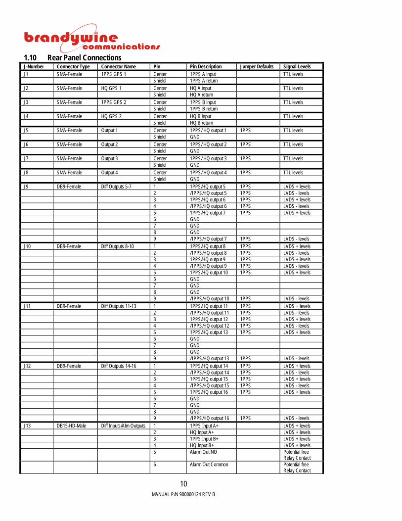
1.10 Rear Panel Connections J-Number Connector Type Connector Name Pin Pin Description Jumper Defaults Signal Levels J1 SMA-Female 1PPS GPS 1 Center 1PPS A input TTL levels Shield 1PPS A return J2 SMA-Female HQ GPS 1 Center HQ A input TTL levels Shield HQ A return J3 SMA-Female 1PPS GPS 2 Center 1PPS B input TTL levels Shield 1PPS B return J4 SMA-Female HQ GPS 2 Center HQ B input TTL levels Shield HQ B return J5 SMA-Female Output 1 Center 1PPS/ HQ output 1 1PPS TTL levels Shield GND J6 SMA-Female Output 2 Center 1PPS/ HQ output 2 1PPS TTL levels Shield GND J7 SMA-Female Output 3 Center 1PPS/ HQ output 3 1PPS TTL levels Shield GND J8 SMA-Female Output 4 Center 1PPS/ HQ output 4 1PPS TTL levels Shield GND J9 DB9-Female Diff Outputs 5-7 1 1PPS/HQ output 5 1PPS LVDS + levels 2 /1PPS/HQ output 5 1PPS LVDS - levels 3 1PPS/HQ output 6 1PPS LVDS + levels 4 /1PPS/HQ output 6 1PPS LVDS - levels 5 1PPS/HQ output 7 1PPS LVDS + levels 6 GND 7 GND 8 GND 9 /1PPS/HQ output 7 1PPS LVDS - levels J10 DB9-Female Diff Outputs 8-10 1 1PPS/HQ output 8 1PPS LVDS + levels 2 /1PPS/HQ output 8 1PPS LVDS - levels 3 1PPS/HQ output 9 1PPS LVDS + levels 4 /1PPS/HQ output 9 1PPS LVDS - levels 5 1PPS/HQ output 10 1PPS LVDS + levels 6 GND 7 GND 8 GND 9 /1PPS/HQ output 10 1PPS LVDS - levels J11 DB9-Female Diff Outputs 11-13 1 1PPS/HQ output 11 1PPS LVDS + levels 2 /1PPS/HQ output 11 1PPS LVDS - levels 3 1PPS/HQ output 12 1PPS LVDS + levels 4 /1PPS/HQ output 12 1PPS LVDS - levels 5 1PPS/HQ output 13 1PPS LVDS + levels 6 GND 7 GND 8 GND 9 /1PPS/HQ output 13 1PPS LVDS - levels J12 DB9-Female Diff Outputs 14-16 1 1PPS/HQ output 14 1PPS LVDS + levels 2 /1PPS/HQ output 14 1PPS LVDS - levels 3 1PPS/HQ output 15 1PPS LVDS + levels 4 /1PPS/HQ output 15 1PPS LVDS - levels 5 1PPS/HQ output 16 1PPS LVDS + levels 6 GND 7 GND 8 GND 9 /1PPS/HQ output 16 1PPS LVDS - levels J13 DB15-HD-Male Diff Inputs/Alm Outputs 1 1PPS Input A+ LVDS + levels 2 HQ Input A+ LVDS + levels 3 1PPS Input B+ LVDS + levels 4 HQ Input B+ LVDS + levels 5 Alarm Out NO Potential free
Relay Contact 6 Alarm Out Common Potential free
Relay Contact
MANUAL P/N 900000124 REV B
11
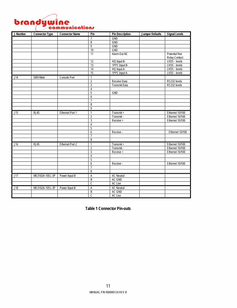
J-Number Connector Type Connector Name Pin Pin Description Jumper Defaults Signal Levels 7 GND 8 GND 9 GND 10 GND 11 Alarm Out NC Potential free
Relay Contact 12 HQ Input B- LVDS - levels 13 1PPS Input B- LVDS - levels 14 HQ Input A- LVDS - levels 15 1PPS Input A- LVDS - levels J14 DB9-Male Console Port 1 2 Receive Data RS232 levels 3 Transmit Data RS232 levels 4 5 GND 6 7 8 9 J15 RJ45 Ethernet Port 1 1 Transmit + Ethernet 10/100 2 Transmit - Ethernet 10/100 3 Receive + Ethernet 10/100 4 5 6 Receive - Ethernet 10/100 7 8 J16 RJ45 Ethernet Port 2 1 Transmit + Ethernet 10/100 2 Transmit - Ethernet 10/100 3 Receive + Ethernet 10/100 4 5 6 Receive - Ethernet 10/100 7 8 J17 MS3102A-10SL-3P Power Input B A AC Neutral B AC GND C AC Live J18 MS3102A-10SL-3P Power Input B A AC Neutral B AC GND C AC Live
Table 1 Connector Pin-outs

MANUAL P/N 900000124 REV B
12
2 General Description
Figure 1 ENTA-R Block Diagram
The main PCB assembly uses a microprocessor module and an FPGA to do input signal decoding, clock disciplining, frequency division, delay generation, output signal encoding, fault detection and display control. The processor further handles all dual-port ethernet communications and memory management. A fifth overtone 5.014MHz OCXO (ovenized crystal oscillator) is used as the timing oscillator. An accurate 10MHz frequency is synthesized by a DDS, and used as the control frequency. The control frequency is divided down to 1PPS and compared to the 1PPS input signal from the GPS. The phase error between these 2 signals drive the DDS control, which keeps the control system locked to the GPS. The GPS in the ENTA-R is the equivalent of 1PPS and HQ.
MANUAL P/N 900000124 REV B
13
3 Unpacking and Installation 3.1 Unpacking
Carefully remove the ENTA-R from the shipping carton. The following items are included in the shipment:
• 1 ENTA-R • 2 power cords (optional) • 1 user guide
3.2 Installation
Install the ENTA-R in its mounting rack location and secure with four rack mounting screws 3.3 Connections 3.3.1 Power
Insert both the provided power cords into the rear of the power entry module and connect the power cord to an AC power outlet.
3.3.2 GPS Connections
Connect the GPS signals, HQ and 1PPS to the GPS 1 inputs, J1 and J2 on the rear panel of the ENTA-R. Contact Brandywine Communications for more details on suitable cables. Connect the second set of GPS signals to J3 and J4 respectively. The ENTA-R will automatically select the GPS input signals that exhibit the best TFOM (Time Figure Of Merit).
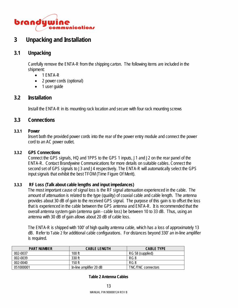
3.3.3 RF Loss (Talk about cable lengths and input impedances) The most important cause of signal loss is the RF signal attenuation experienced in the cable. The amount of attenuation is related to the type (quality) of coaxial cable and cable length. The antenna provides about 30 dB of gain to the received GPS signal. The purpose of this gain is to offset the loss that is experienced in the cable between the GPS antenna and ENTA-R. It is recommended that the overall antenna system gain (antenna gain - cable loss) be between 10 to 33 dB. Thus, using an antenna with 30 dB of gain allows about 20 dB of cable loss. The ENTA-R is shipped with 100’ of high quality antenna cable, which has a loss of approximately 13 dB. Refer to Table 2 for additional cable configurations. For distances beyond 330’ an in-line amplifier is required. PART NUMBER CABLE LENGTH CABLE TYPE
002-0037 100 ft RG 58 (supplied) 002-0039 330 ft RG 8 002-0040 150 ft RG 8 051000001 In-line amplifier 20 dB TNC/TNC connectors
Table 2 Antenna Cables

MANUAL P/N 900000124 REV B
14
3.3.4 Network Connection Connect one end of the network cable to the RJ-45 10/100 BaseT Network port (J15 PORT 1/J16 PORT 2) and connect the other end of the network cable to your network. The ENTA-R configuration process is described in Section 4 and Section 5 . 3.3.5 Other Connections Connect the output signals as required. For additional help connecting the output signals please refer to Section 1.10.
MANUAL P/N 900000124 REV B
15
4 Getting Started 4.1 Powering Up the ENTA-R Once all connections to the ENTA-R have been made, apply power to the unit by setting the On/Off switches to the on position. The On/Off switches are located on the rear panel power entry module. The POWER LED‘s on the front panel should be illuminated green within 2 seconds. The POWER LED indicates that the ENTA-R has power. Once the GPS has locked to the input GPS signals time will be displayed on the front panel in the format: DDD: HH:MM: SS. 4.2 Setting the Network Address The ENTA-R is shipped with DHCP (Dynamic Host Configuration Protocol) enabled.
To set the network address, the user may use either IPSetup.exe or a web browser. The two processes are described below.
MANUAL P/N 900000124 REV B
16
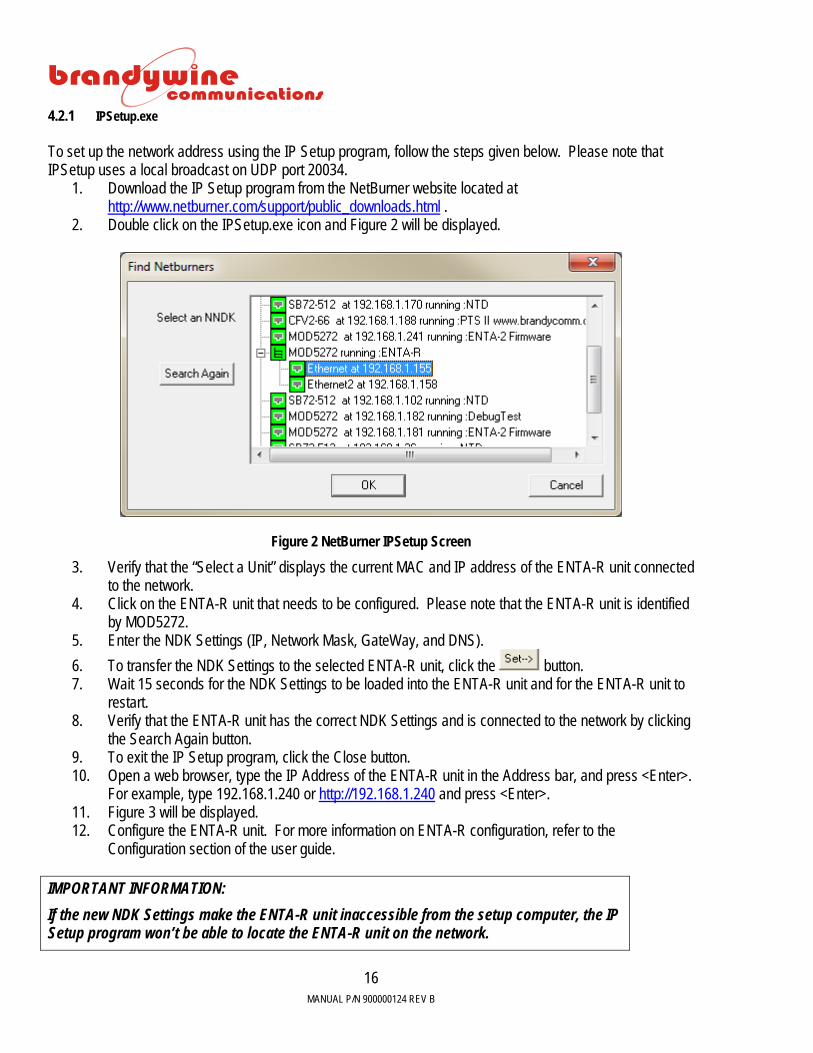
4.2.1 IPSetup.exe To set up the network address using the IP Setup program, follow the steps given below. Please note that IPSetup uses a local broadcast on UDP port 20034.
1. Download the IP Setup program from the NetBurner website located at http://www.netburner.com/support/public_downloads.html .
2. Double click on the IPSetup.exe icon and Figure 2 will be displayed.
Figure 2 NetBurner IPSetup Screen
3. Verify that the “Select a Unit” displays the current MAC and IP address of the ENTA-R unit connected to the network.
4. Click on the ENTA-R unit that needs to be configured. Please note that the ENTA-R unit is identified by MOD5272.
5. Enter the NDK Settings (IP, Network Mask, GateWay, and DNS). 6. To transfer the NDK Settings to the selected ENTA-R unit, click the button. 7. Wait 15 seconds for the NDK Settings to be loaded into the ENTA-R unit and for the ENTA-R unit to
restart. 8. Verify that the ENTA-R unit has the correct NDK Settings and is connected to the network by clicking
the Search Again button. 9. To exit the IP Setup program, click the Close button. 10. Open a web browser, type the IP Address of the ENTA-R unit in the Address bar, and press <Enter>.
For example, type 192.168.1.240 or http://192.168.1.240 and press <Enter>. 11. Figure 3 will be displayed. 12. Configure the ENTA-R unit. For more information on ENTA-R configuration, refer to the
Configuration section of the user guide.
IMPORTANT INFORMATION: If the new NDK Settings make the ENTA-R unit inaccessible from the setup computer, the IP Setup program won’t be able to locate the ENTA-R unit on the network.

MANUAL P/N 900000124 REV B
17
4.2.2 Web Browser To set up the network address using the web browser, follow the steps given below.
1. Connect one end of an Ethernet cable to the ENTA-R Network Port. 2. Connect the other end of the Ethernet cable to your network. 3. Open a web browser, type the IP Address of the ENTA-R unit in the Address bar, and press <Enter>.
For example, type 192.168.1.240 or http://192.168.1.240 and press <Enter>. 4. Figure 3 will be displayed. 5. Configure the ENTA-R unit.
Figure 3 ENTA-R System Screen

MANUAL P/N 900000124 REV B
18
Latest Version of Java Software To properly control and monitor the ENTA-R via a web browser based interface, Java software must be installed on your computer. To obtain the Java software, follow the steps given below.
1. Go to http://www.sun.com/ . 2. Click on the Downloads link. 3. Click on the Java Download link. 4. Download Java. 5. Complete the installation process.
MANUAL P/N 900000124 REV B
19
5 Configuration The ENTA-R configuration may be completed in one of two ways.
• Via the web browser (recommended) • Via SNMP
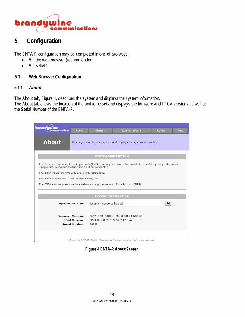
5.1 Web Browser Configuration 5.1.1 About The About tab, Figure 4, describes the system and displays the system information. The About tab allows the location of the unit to be set and displays the firmware and FPGA versions as well as the Serial Number of the ENTA-R.
Figure 4 ENTA-R About Screen
MANUAL P/N 900000124 REV B
20
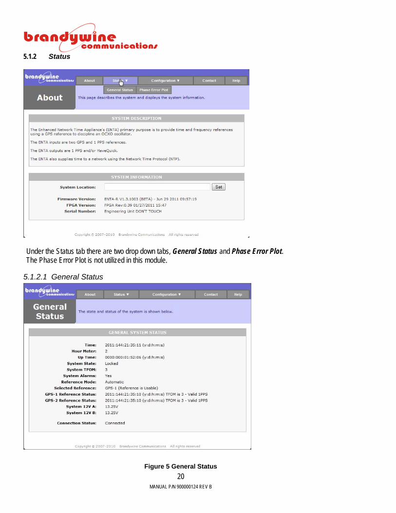
5.1.2 Status
Under the Status tab there are two drop down tabs, General Status and Phase Error Plot. The Phase Error Plot is not utilized in this module.
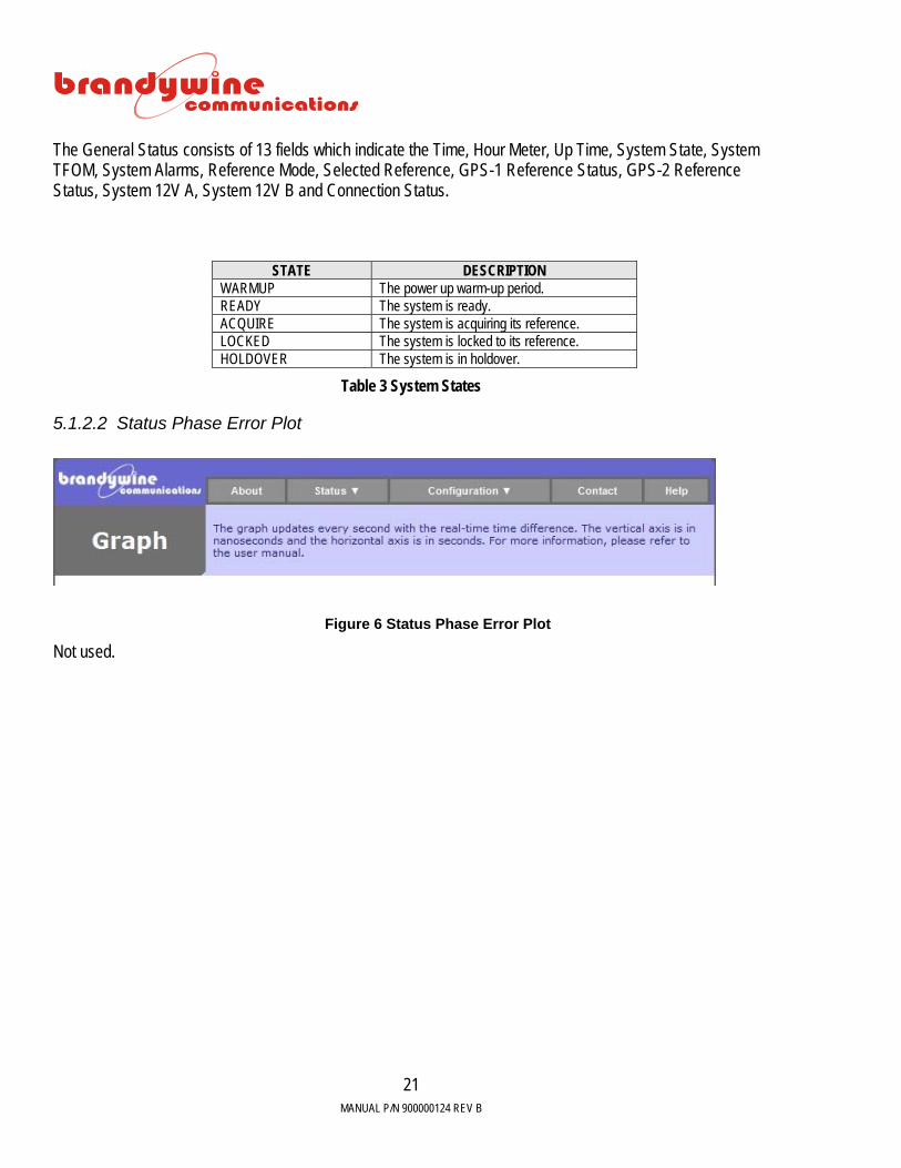
5.1.2.1 General Status
Figure 5 General Status
MANUAL P/N 900000124 REV B
21
The General Status consists of 13 fields which indicate the Time, Hour Meter, Up Time, System State, System TFOM, System Alarms, Reference Mode, Selected Reference, GPS-1 Reference Status, GPS-2 Reference Status, System 12V A, System 12V B and Connection Status.
STATE DESCRIPTION WARMUP The power up warm-up period. READY The system is ready. ACQUIRE The system is acquiring its reference. LOCKED The system is locked to its reference. HOLDOVER The system is in holdover.
Table 3 System States
5.1.2.2 Status Phase Error Plot
Figure 6 Status Phase Error Plot
Not used.
MANUAL P/N 900000124 REV B
22
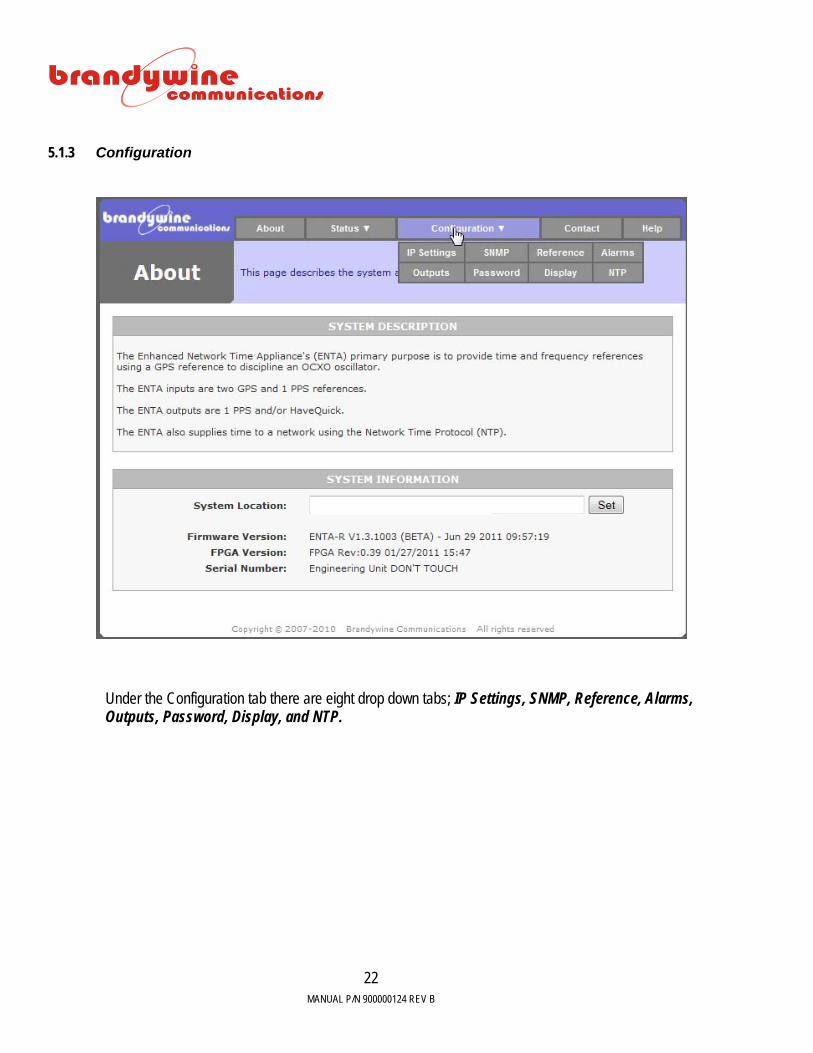
5.1.3 Configuration
Under the Configuration tab there are eight drop down tabs; IP Settings, SNMP, Reference, Alarms, Outputs, Password, Display, and NTP.

MANUAL P/N 900000124 REV B
23
5.1.3.1 IP Settings
The IP Settings tab consists of 8 fields which include IP Address, Subnet Mask, Gateway, DHCP Enabled, IP Address, Subnet Mask, DHCP enabled with a Submit button and a Reset button.
Figure 7 IP Settings

MANUAL P/N 900000124 REV B
24
5.1.3.2 SNMP The SNMP tab consists of 4 fields Read Community, Write Community, Trap IP Address and Download MIB file with 2 buttons; Submit and Reset.
Figure 8 SNMP
MANUAL P/N 900000124 REV B
25
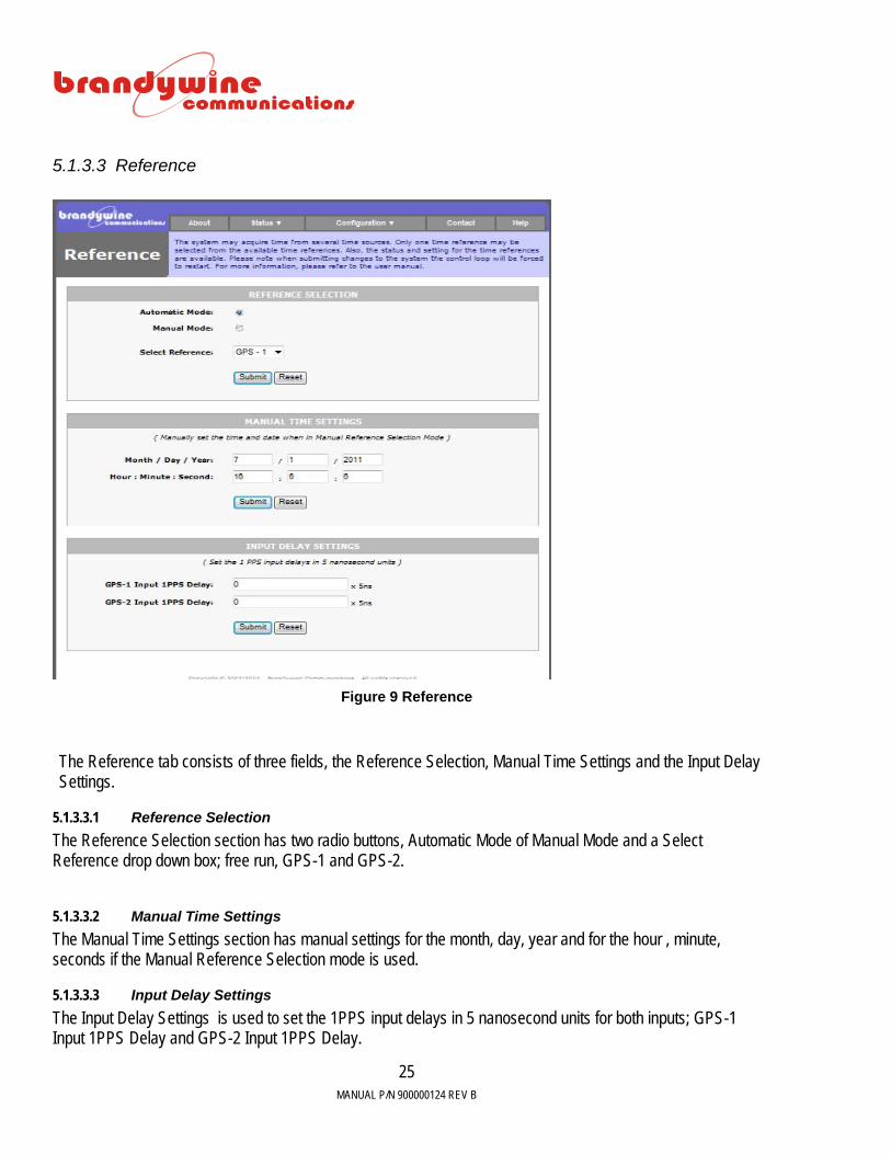
5.1.3.3 Reference
Figure 9 Reference
The Reference tab consists of three fields, the Reference Selection, Manual Time Settings and the Input Delay Settings.
5.1.3.3.1 Reference Selection The Reference Selection section has two radio buttons, Automatic Mode of Manual Mode and a Select Reference drop down box; free run, GPS-1 and GPS-2.
5.1.3.3.2 Manual Time Settings The Manual Time Settings section has manual settings for the month, day, year and for the hour , minute, seconds if the Manual Reference Selection mode is used.
5.1.3.3.3 Input Delay Settings The Input Delay Settings is used to set the 1PPS input delays in 5 nanosecond units for both inputs; GPS-1 Input 1PPS Delay and GPS-2 Input 1PPS Delay.

MANUAL P/N 900000124 REV B
26
5.1.3.4 Alarms
.
Figure 10 Alarms
The Alarm tab indicates all the Alarm States as shown in Figure 10 Alarms.
MANUAL P/N 900000124 REV B
27
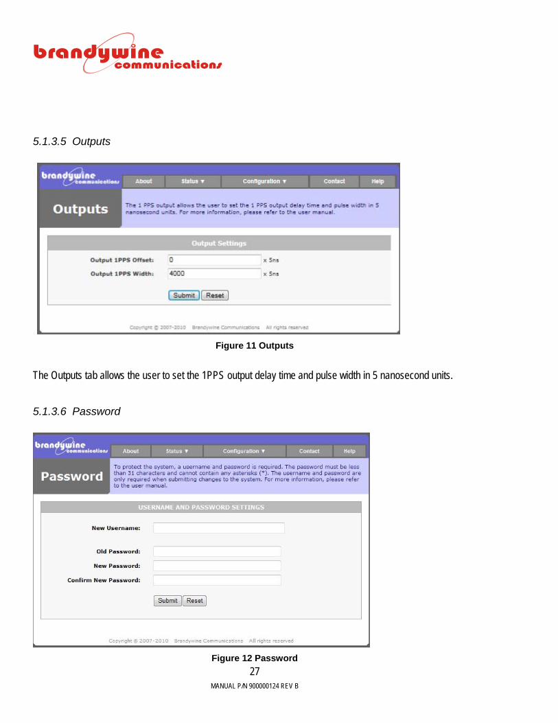
5.1.3.5 Outputs
Figure 11 Outputs
The Outputs tab allows the user to set the 1PPS output delay time and pulse width in 5 nanosecond units.
5.1.3.6 Password
Figure 12 Password

MANUAL P/N 900000124 REV B
28
The Password tab allows the user to change the user name and password for the system. To save all modifications made to the Password screen, click the Submit button. To undo all modifications made to the Password screen, click the Reset button. IMPORTANT INFORMATION:The default user name and password for the system are both BRANDYWINE. The user must always enter a user name and password when submitting changes to the system. The Password consists of four fields, the New User Name, Old Password, New Password, and Confirm New Password. The new password must be less than 31 characters and cannot contain any asterisks. Moreover, the user name and password are case sensitive.
5.1.3.7 Display
Figure 13
The Brightness box is available to adjust the brightness of the display. The least bright is equal to 0 and the most bright is equal to 15. The Time Zone combo box allows the user to enter the Standard Time offset from the Universal Time. The Time Zone combo box allows the user to select either hour or minute. The Time Zone Table lists all time zones and their Standard Time offsets from the Universal Time.

MANUAL P/N 900000124 REV B
29
Time Zone Table
TIME ZONE STANDARD TIME OFFSET FROM UNIVERSAL TIME
Eniwetok (Marshall Islands) -12 Samoa (Polynesian Islands) -11 Hawaii -10 Alaska -9 Pacific Time -8 Mountain Time -7 Central Time -6 Eastern Time -5 Atlantic Time -4 Brazilia (Brazil) -3 Mid-Atlantic -2 Azores (Azores Islands) -1 Rome (Italy) 1 Israel 2 Moscow (Russia) 3 Baku (Azerbaijan) 4 New Delhi (India) 5 Dhakar (Jordan) 6 Bangkok (Thailand) 7 Hong Kong 8 Tokyo (Japan) 9 Sydney (Australia) 10 Magadan (Russia) 11 Wellington (New Zealand) 12
5.1.3.7.1 Daylight Savings Time The Daylight Savings Time consists of three fields and a check box, the Daylight Savings Time Offset (DSTO), Daylight Savings Time Start, and Daylight Savings Time End. The DSTO is a number that is added to or subtracted from the time zone setting. The DSTO entered by the user may be either in hours or minutes. The Daylight Savings Time Start allows the user to add the DSTO to the time the daylight saving should start. The user must enter the daylight saving start time, the occurrence of the specific day, the day of the week, and the month that the daylight saving should start. For example, Pacific Standard Time adds an hour at 02:00 on the second Sunday of March. The Daylight Savings Time End allows the user to subtract the DSTO from the time the daylight saving should stop. The user must enter the daylight saving stop time, the occurrence of the specific day, the day of the week, and the month that the daylight saving should stop. For example, Pacific Standard Time subtracts an hour at 02:00 on the first Sunday of November.

MANUAL P/N 900000124 REV B
30
Please note that the daylight saving start time and daylight saving stop time must be in 24 hour format. For example, if daylight saving start time and daylight saving stop time are at 1:00 pm, the user must enter 13:00. The Enable DST check box must be checked to enable Daylight Savings Time adjustments.
5.1.3.8 NTP
Figure 14 NTP
Figure 14 is displayed when the NTP sub-tab is selected. The NTP sub-tab consists of three sections, the Automatic mode radio button, the Manual mode radio button and the Select Leap Indicator Mode . To save all modifications made to the NTP Server screen, click the Submit button. The Select Leap Indicator has four drop down selections No Warning, Last minute has 61 seconds, last minute has 59 seconds and Alarm Condition. The Manual Mode Settings consist of one combo box, the Select Leap Indicator. This allows the user to manually set the leap indicator setting used. The table below describes the supported leap indicator settings used.
DESCRIPTION No warning Last minute has 61 seconds Last minute has 59 seconds Alarm condition (clock not synchronized)
Table 4 Leap Indicator Settings

MANUAL P/N 900000124 REV B
31
If the leap indicator setting is set to no warning, the ENTA-R automatically warns of an impending leap second only if the internal GPS receiver is used as the synchronizing source.
5.1.3.9 Contact
The Contact tab provides the Brandywine Communications address and contact phone, fax and email numbers.

MANUAL P/N 900000124 REV B
32
5.1.4 Help The Help tab provides the user with help while using difficult areas in the system. Help links are located throughout the entire system so the user has access to the Help screen whenever the user encounters a problem. Once the user clicks on the Help link the user will be automatically redirected to the Help screen. Various topics are discussed in the Help screen.
Figure 15 Help
MANUAL P/N 900000124 REV B
33
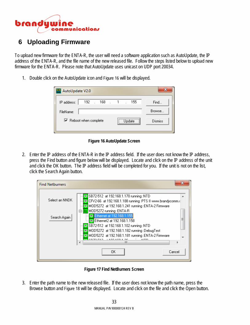
6 Uploading Firmware To upload new firmware for the ENTA-R, the user will need a software application such as AutoUpdate, the IP address of the ENTA-R, and the file name of the new released file. Follow the steps listed below to upload new firmware for the ENTA-R. Please note that AutoUpdate uses unicast on UDP port 20034.
1. Double click on the AutoUpdate icon and Figure 16 will be displayed.
Figure 16 AutoUpdate Screen
2. Enter the IP address of the ENTA-R in the IP address field. If the user does not know the IP address,
press the Find button and figure below will be displayed. Locate and click on the IP address of the unit and click the OK button. The IP address field will be completed for you. If the unit is not on the list, click the Search Again button.
Figure 17 Find NetBurners Screen
3. Enter the path name to the new released file. If the user does not know the path name, press the
Browse button and Figure 18 will be displayed. Locate and click on the file and click the Open button.

MANUAL P/N 900000124 REV B
34
The file will be in the form ‘925000062A ENTA-R2v1.00Build 1129_APP.s19’ . The File Name field will be completed for you.
Figure 18 Open Screen
4. Now, click on the Reboot when complete check box. 5. To close the application, click the Dismiss button. 6. To upload the new firmware, click the Update button and Figure 19 will be displayed for a few seconds.
Figure 19 Programming Screen
7. After above figure automatically closes, Figure 20 will be displayed. Click the OK button and now the
uploading firmware process is completed.

MANUAL P/N 900000124 REV B
35
Figure 20 AutoUpdate Complete Screen

MANUAL P/N 900000124 REV B
36
7 Uploading FPGA To upload the FPGA for the ENTA-R, the user will need a software application called FPGA Update provided by Brandywine. Follow the steps listed below to upload new FPGA for the ENTA-R. 7.1 FPGA Update
When installing the FPGAUpdate Application this is the initial Welcome screen. Click the “Next” button.

MANUAL P/N 900000124 REV B
37
The FPGA Update application will then request the folder to install the application to. Keep the existing folder or browse for a new folder on the user’s compluter. Click “Next”.
Confirm by clicking “Next” to start the installation.

MANUAL P/N 900000124 REV B
38
FPGAUpdate will be installed.
FPGAUpdate is installed. Click “Close” to exit.
MANUAL P/N 900000124 REV B
39
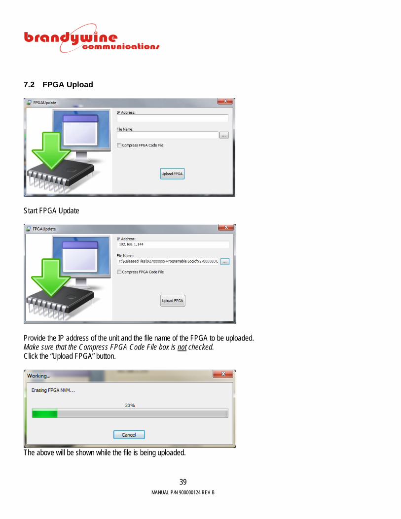
7.2 FPGA Upload
Start FPGA Update
Provide the IP address of the unit and the file name of the FPGA to be uploaded. Make sure that the Compress FPGA Code File box is not checked. Click the “Upload FPGA” button.
The above will be shown while the file is being uploaded.

MANUAL P/N 900000124 REV B
40
The Unit Version and the Previous FPGA Version will be shown in the above box. The new FPGA version will take effect once the unit has restarted. Click the “Yes” button to restart the unit now or the “No” button to restart later.

MANUAL P/N 900000124 REV B
41
8 Maintenance and Troubleshooting There is no required preventive maintenance for the ENTA-R. To troubleshoot the problems, refer to Table 5.
SYMPTOM POTENTIAL CAUSE CORRECTIVE ACTION Power LED does not illuminate
1. There is no power. 2. There is a blown fuse. 3. There is a ENTA-R power supply
failure.
1. Verify that the AC power is available. 2. Replace the fuse. 3. Return unit to the factory.
Display colons continue flashing
1. ENTA-R is performing a cold start. 2. Antenna is in bad location.
3. The antenna is bad. 4. There is an excessive cable loss. 5. There is excessive EMI interference
with the antenna. 6. The oscillator is not synchronized.
7. There is an oscillator failure.
1. Wait for 15 minutes. 2. The antenna should see > 50% of the
sky. Use the GPS screen to verify which satellites (if any) are being tracked.
3. Replace the antenna. 4. Replace the cable with a lower loss
cable. 5. Check for nearby interfering radiators
and move the GPS antenna. 6. Allow the system to warm up for 10
minutes. 7. Return unit to the factory.
Fault LED is illuminated
1. There is an internal failure.
1. Check the alarm screen to verify cause of the fault.
2. Recycle the power.
No signal outputs
1. There is an internal failure.
1. Return unit to the factory.
Table 5: Troubleshooting ENTA-R Problems

MANUAL P/N 900000124 REV B
42
This page left intentionally blank

MANUAL P/N 900000124 REV B
43
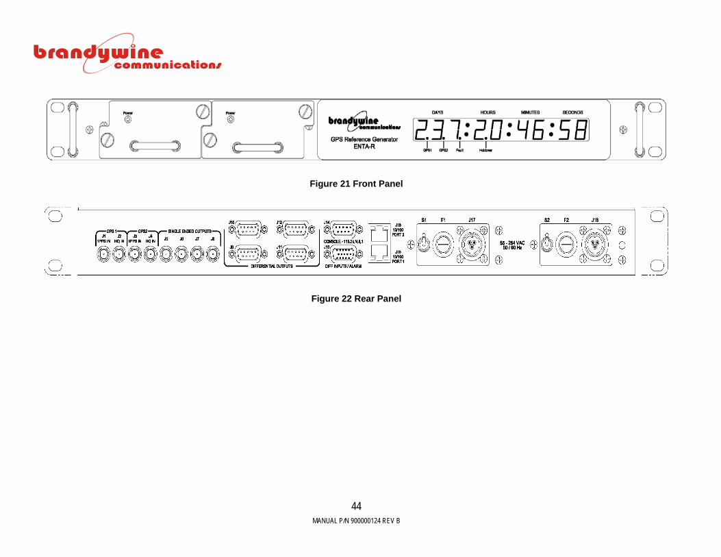
9 Drawings
FIGURE DESCRIPTION 21 ENTA-R Front Panel 22 ENTA-R Rear Panel
Table 21 ENTA-R Drawings
MANUAL P/N 900000124 REV B
44
Figure 21 Front Panel
Figure 22 Rear Panel


![Enta Mag 1 Vii[1]](https://static.fdocuments.in/doc/165x107/544b88fbb1af9f7a7d8b46c4/enta-mag-1-vii1.jpg)