
User Guide - DF II Series · LTCM-100 Direct Connect TT Tester NC002582 DF II Series Low Capacity...
84
Part No. NC003194 July 2017 DF II Series Digital Force Gauges for DFS II, DFS II-R, DFS II-R-ND and DFE II Models User Manual
Transcript of User Guide - DF II Series · LTCM-100 Direct Connect TT Tester NC002582 DF II Series Low Capacity...

DF II Series User Manual 1
Part No. NC003194July 2017
DF II SeriesDigital Force Gauges
for DFS II, DFS II-R, DFS II-R-ND and DFE II Models
User Manual

2 DF II Series User Manual
WARRANTYThis instrument is warranted against defects in workmanship, material and design for one (1) year from date of delivery to the extent that AMETEK® will, at its sole option, repair or replace the instrument or any part thereof which is defective, provided, however, that this warranty shall not apply to instruments subjected to tampering or, abuse, or exposed to highly corrosive conditions.
THIS WARRANTY IS IN LIEU OF ALL OTHER WARRANTIES WHETHER EXPRESS OR IMPLIED AND AMETEK® HEREBY DISCLAIMS ALL OTHER WARRANTIES, INCLUDING, WITHOUT LIMITATION, ANY WARRANTY OF FITNESS FOR A PARTICULAR PURPOSE OR MERCHANTABILITY. AMETEK® SHALL NOT BE LIABLE FOR ANY INCIDENTAL OR CONSEQUENTIAL DAMAGES, INCLUDING, BUT NOT LIMITED TO, ANY ANTICIPATED OR LOST PROFITS.
This warranty is voidable if the purchaser fails to follow any and all instructions, warnings or cautions in the instrument’s Instruction Manual.
If a manufacturing defect is found, AMETEK® will replace or repair the instrument or replace any defec-tive part thereof without charge; however, AMETEK®’s obligation hereunder does not include the cost of transportation, which must be borne by the customer. AMETEK® assumes no responsibility for damage in transit, and any claims for such damage should be presented to the carrier by the purchaser.
TRADEMARKSAMETEK® is a registered trademarks of AMETEK®, Inc.Chatillon® is a registered trademark of AMETEK®, Inc.Other trademarks are the property of their respective owners.
SUPPORTAMETEK® Measurement & Calibration Technologies8600 Somerset DriveLargo, FL 33773United States of America
Tel: +1 800 527 9999 (toll free within continental U.S.A.)Tel: +1 727 538 6000Fax: +1 727 539 6882Email: [email protected]: www.ametektest.com
DF II Series User Manual 3
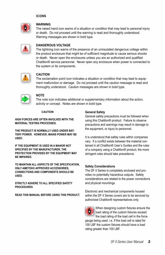
ICONS
WARNINGThe raised hand icon warns of a situation or condition that may lead to personal injury or death. Do not proceed until the warning is read and thoroughly understood. Warning messages are shown in bold type.
DANGEROUS VOLTAGEThe lightning icon warns of the presence of an uninsulated dangerous voltage within theproductenclosurethatmightbeofsufficientmagnitudetocauseseriousshocksordeath.NeveropentheenclosuresunlessyouareanauthorizedandqualifiedChatillon® service personnel. Never open any enclosure when power is connected to the system or its components.
CAUTIONThe exclamation point icon indicates a situation or condition that may lead to equip-ment malfunction or damage. Do not proceed until the caution message is read and thoroughly understood. Caution messages are shown in bold type.
NOTEThe note icon indicates additional or supplementary information about the action, activity or concept. Notes are shown in bold type.
CAUTION
HIGH FORCES ARE OFTEN INVOLVED WITH THE MATERIAL TESTING PROCESSES.
THE PRODUCT IS NORMALLY USED UNDER BAT-TERY POWER. HOWEVER, MAINS POWER MAY BE USED.
IF THE EQUIPMENT IS USED IN A MANOR NOT SPECIFIED BY THE MANUFACTURER, THE PROTECTION PROVIDED BY THE EQUIPMENT MAY BE IMPAIRED.
TO MAINTAIN ALL ASPECTS OF THE SPECIFICATION, ONLY AMETEK® APPROVED ACCESSORIES, CONNECTIONS AND COMPONENTS SHOULD BE USED.
STRICTLY ADHERE TO ALL SPECIFIED SAFETY PROCEDURES
READ THIS MANUAL BEFORE USING THIS PRODUCT.
General SafetyGeneral safety precautions must be followed when using this Chatillon® product. Failure to observe precautions and warnings may result in damage to the equipment, or injury to personnel.
It is understood that safety rules within companies vary.Ifaconflictexistsbetweenthematerialcon-tained in all Chatillon® User’s Guides and the rules of a company using a Chatillon® product, the more stringent rules should take precedence.
Safety ConsiderationsThe DF II Series is completely enclosed and pro-vides no potentially hazardous outputs. Safety considerations are related to the power connections and physical mountings.
Electronic and mechanical components housed within the DF II Series covers are to be serviced by authorized Chatillon® representatives only.
Whendesigningcustomfixturesensuretheloadratingofthecustomfixturesexceedthe load rating of the load cell in the force
gauge being used. i.e. If the load cell is rated for 100LBFthecustomfixturesshouldhavealoadrating greater than 100 LBF.

4 DF II Series User Manual
Getting started .............................................. 6Test stand adapters ...................................... 8Poweringgaugeon/off .................................. 9Charging your gauge .................................... 9Keypad operation ........................................ 10Display layout .............................................. 11Display options ............................................ 11Changing display options ............................ 12Display up or down option ........................... 12Display backlight option ............................... 12Display hide option ...................................... 13Auto dimming............................................... 13Display peaks .............................................. 13Languages ................................................... 13Changing mode ........................................... 14Zero and taring mode .................................. 14Changing units............................................. 15Units lock ..................................................... 15Load bar graph ............................................ 16Sensor overload protection.......................... 16Sensor overload display .............................. 16Password protection .................................... 16Operating your gauge .................................. 17Handheld operation ..................................... 17Test stand operation .................................... 17Affixingadapters&fixtures .......................... 17Saving results .............................................. 18Clear saved data ......................................... 18Viewing results ............................................ 19Viewing active result .................................... 19Veiwing pass-fail results .............................. 20Graphing of results ...................................... 21Transmit results ........................................... 22Transmit displayed result ............................. 22Transmit format ........................................... 23Clear result from memory ............................ 25Using pass-fail limits .................................... 26Activating pass-fail limits ............................. 28Select pass-fail method ............................... 28Selecting increments ................................... 29Selecting high range limit ............................ 29Selecting low range limit .............................. 30Select nominal value method ...................... 30Select nominal value ................................... 31Select bandwidth ......................................... 31Using load limits .......................................... 32Load limit buzzer ......................................... 32Activating transmit limits .............................. 33Selecting increments ................................... 34Selecting high limit setpoint ......................... 34
Selecting low limit setpoint .......................... 35Viewing load limit result ............................... 35Using auto shutdown ................................... 36Selecting time period ................................... 36Activating auto shutdown............................. 36About gauge communications ..................... 37USB Communication Set-up........................ 37Setup - Communications ............................. 37Selecting limits............................................. 38Selecting baud rate...................................... 38Pinouts......................................................... 39Using hyperterminal commands .................. 40Changing gauge polarity.............................. 41Setup - Polarity ............................................ 41Connecting a printer .................................... 42Communication cables ................................ 42Connecting a serial printer........................... 43Connecting a mitutoyo printer...................... 43Using remote sensors.................................. 44SLC loadcell sensors ................................... 44STS torque sensors ..................................... 44Specifying the correct sensor ...................... 45Understanding full scale capacity ................ 45Accuracyerroreffects .................................. 45Powering your gauge................................... 46Connecting a sensor.................................... 46Power up with STS sensor .......................... 46Improper sensor connection ........................ 46About SLC sensors...................................... 47Inserting the SLC sensor ............................. 47Handling the SLC sensor............................. 48Mounting SLC sensor to tester .................... 49Using software ............................................. 50Using load averaging ................................... 51Load average force-based........................... 51Load average time-based ............................ 51Load average setup ..................................... 52Load average - select type .......................... 52Selecting increments ................................... 52Selecting preload limit ................................. 53Selecting time limit....................................... 53Preforming a force-based load average test 54Preforming a time-based load average test 55Test annuciators .......................................... 55Using break detection .................................. 56Sharp break ................................................. 57Percentage break ........................................ 57Break detection setup .................................. 58Break detect - select type ............................ 58Selecting increments ................................... 58
TABLE OF CONTENTS
DF II Series User Manual 5
TABLE OF CONTENTS
Selecting break point ................................... 59Selecting % drop value ................................ 60Performing a sharp break test ..................... 61Performing a percentage break test ............ 62Viewing your break test result ..................... 63Transmitting your break test result .............. 63Saving your break test result ....................... 65Applying statistics to your break test result . 66View%difference ........................................ 67Usingfilters .................................................. 68Displayfilter ................................................. 68Peakfilter..................................................... 68Filter setup ................................................... 68Displayfiltersetup ....................................... 69Peakfiltersetup ........................................... 69Using contact closure .................................. 70Contact closure operation............................ 71Contact closure mode.................................. 71Contact closure pass-fail ............................. 71Contact closure setup .................................. 72Contactclosure-on/off ............................... 73Contact closure - open type......................... 73Contact closure - close type ........................ 73Specifications .............................................. 74Features and functions ................................ 74Dimensions .................................................. 75
6 DF II Series User Manual
CAUTION: The load cell sensor used in your DF II Series gauge is temperature sensitive. The gauge should be turned On and allowed to acclimate to ambient temperature before normal use and before being calibrated.
A 5 minute “warm-up” period is recommended.
1.0 GETTING STARTED
The Chatillon® DF II Series digital force gauges are battery powered precision instruments used to mea-sure axial tensile or compressive forces.
The following models represent the DF II Series force gauges:
n DFE II Series (With Outputs)n DFS II Series (Integral Loadcell)n DFS II-R Series (Dedicated Remote Loadcell)n DFS II-R-ND Series (Interchangeable Sensor) - SLC Series (Loadcell Sensor) - STS Series (Torque Sensor)
NOTE: The functions and features described in this user’s guide may not be available on all DF II models.

DF II Series User Manual 7
Please read this operating manual thoroughly before attempting to operate your gauge.
The tables below identify the standard accessories that were supplied with your DF II Series digital force gauge.
DFE II Series DFS II Series DFS II-R Series
DFS II-R-ND Series
NOTE: 1 Accessories are capacity dependent. Accessories used with capacities below 110 lbf (500N) will generally have a #10-32 thread. Accessories for higher capacities generally have a 5/16-18 thread.2 Accessories are capacity dependent. Accessories used with low torque capacity (3-50 in-lb) will receive 1/4 and 3/8 Hex Drive. Larger capacities receive 3/8 and 1/2 Drives.
Carrying Case SPK-DF-118Flat Adapter1 SPK-FMG-011A SPK-FMG-011BHook1 SPK-FMG-012A SPK-FMG-012B SPK-FMG-012CChisel Point1 SPK-FMG-008A SPK-FMG-008BPoint1 SPK-FMG-009A SPK-FMG-009BNotch Adapter1 SPK-FMG-010A SPK-FMG-010BExtension Rod1 SPK-FMG-013A SPK-FMG-013BCharger SPK-DF2-UNIVRS232 Cable SPK-DF-RS232Calibration Certificate
Carrying Case SPK-DF-118Flat Adapter1 SPK-FMG-011A SPK-FMG-011BHook1 SPK-FMG-012A SPK-FMG-012B SPK-FMG-012CChisel Point1 SPK-FMG-008A SPK-FMG-008BPoint1 SPK-FMG-009A SPK-FMG-009BNotch Adapter1 SPK-FMG-010A SPK-FMG-010BExtension Rod1 SPK-FMG-013A SPK-FMG-013BCharger SPK-DF2-UNIVRS232 Cable SPK-DF-RS232Calibration Certificate
Carrying Case SPK-DF-118Flat Adapter1 SPK-FMG-011A SPK-FMG-011BHook1 SPK-FMG-012A SPK-FMG-012B SPK-FMG-012CCharger SPK-DF2-UNIVRS232 Cable SPK-DF-RS232Calibration Certificate
Carrying Case SPK-DF-118Charger SPK-DF2-UNIVRS232 Cable SPK-DF-RS232Calibration Certificate
DF II Series Standard Accessories by Model
SLC Series
Carrying Case SPK-DF-118Flat Adapter1 SPK-FMG-011A SPK-FMG-011BHook1 SPK-FMG-012A SPK-FMG-012B SPK-FMG-012CMale Adapter NC000296Calibration Certificate
STS Series
Carrying Case SPK-DF-118Hex Blade SPK-DTG-040Hex Drive 1/4 SPK-DTG-0372
Hex Drive 3/8 SPK-DTG-0382
Hex Drive 1/2 SPK-DTG-039Calibration Certificate
8 DF II Series User Manual
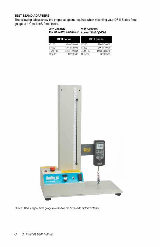
TEST STAND ADAPTERSThe following tables show the proper adapters required when mounting your DF II Series force gauge to a Chatillon® force tester.
MT150 SPK-MT-0001MT500 SPK-MT-0001LTCM-100 Direct ConnectTT Tester NC002582
DF II Series
MT150 SPK-MT-0004MT500 SPK-MT-0004LTCM-100 Direct ConnectTT Tester NC002582
DF II Series
Low Capacity 110 lbf (500N) and below
High Capacity Above 110 lbf (500N)
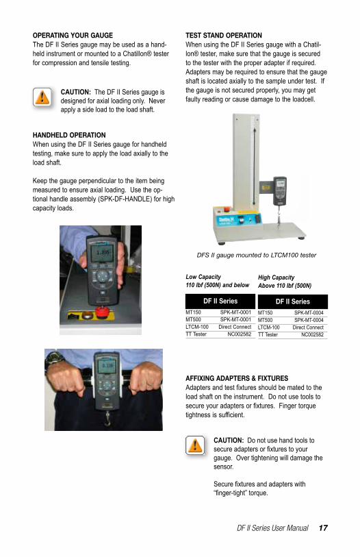
Shown: DFS II digital force gauge mounted on the LTCM-100 motorized tester.
DF II Series User Manual 9
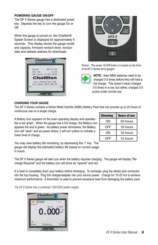
POWERING GAUGE ON/OFFThe DF II Series gauge has a dedicated power key. Depress the key to turn the gauge On or Off.
When the gauge is turned on, the Chatillon® Splash Screen is displayed for approximately 5 seconds. This display shows the gauge model andcapacity,firmwarerevisionlevel,revisiondate and website address for downloads.
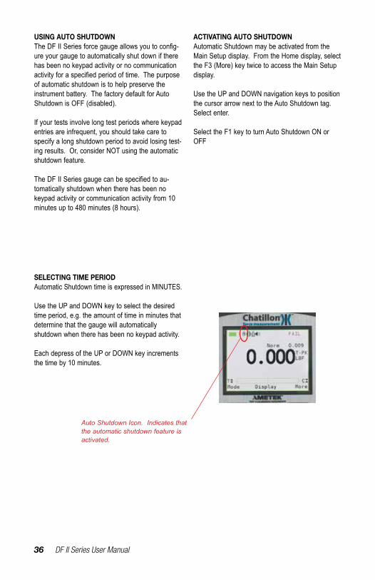
Shown: The power On/Off button is located on the front of all DF II Series force gauges.
CHARGING YOUR GAUGEThe DF II Series contains a Nickle Metal Hydride (NiMh) Battery Pack that can provide up to 20 hours of continuous use on a single charge.
A Battery icon appears on the main operating display and operates like a bar graph. When the gauge has a full charge, the Battery icon appears full and is green. As battery power diminishes, the Battery icon will “open” and as power drains, it will turn yellow to indicate a lower level of charge.
You may view battery life remaining, by depressing the “i” key. The gauge will display the estimated battery life based on current usage in hours.
The DF II Series gauge will alert you when the battery requires charging. The gauge will display “Re-charge Required” and the battery icon will show as “opened” and red.
It is best to completely drain your battery before reharging. To recharge, plug the stereo jack connector into the top housing. Plug the charger/adapter into your source power. Charge for 15-20 hrs to achieve maximum performance. A thermistor is used to prevent excessive heat from damaging the battery pack.
The DF II Series has a universal 120/230V power supply.
NOTE: New NiMh batteries need to be charged 3-5 times before they will hold a full charge. This doesn’t mean charged
3-5 times in a row, but rather, charged 3-5 cycles under normal use.
Dimming Hours of use
ON 20 hours
OFF 16 hours
ON 16 hours
OFF 12 hours

10 DF II Series User Manual
KEYPAD OPERATIONThe DF II Series gauge has nine (9) keys and a navigation pod.
Function KeysThere are three (3) function keys located immediately below the gauge display. These keys are mapped to the display prompt above it. Key functions change based on the gauge’s current status or operating mode. If no prompt appears above the key, the key is inactive.
Navigation PodThe navigation pod is primarily used during setup. This circular pod contains four (4) directional arrows that correspond to certain gauge functions. The UP and RIGHT arrows are used to increment numbers or to navigate in an upward direction or to the right. The DOWN and LEFT arrows are used to decrement numbers or to navigate in a downward direction or to the left.
UNITS KeyA dedicated UNITS key is used to change the units of measure.
ZERO KeyA dedicated ZERO key is used to zero a measured result or to tare the weight of attachments and fixturespriortomeasuringaload.
HOME KeyA dedicated HOME key is used to return you to the main operating display.
ENTER KeyA dedicated ENTER key is used to enable a selection or to accept a result.
Power KeyA dedicated POWER key is used to turn gauge power ON or OFF.
INFO KeyThe INFO key provides you with “information” about your DF II Series force gauge. It is also used to review SAVED information that is stored in the gauge memory.
Depress the “i” key to access the following information:n Gauge Capacity x Resolutionn Firmware Revision and Revision Daten Overload Historyn Battery Lifen Saved Results and Graph of Results
Units
Home
Zero
Enter
i
l

DF II Series User Manual 11
DISPLAY LAYOUTThe DF II Series digital force gauge features a TFT-LCD full-color display with backlight.
DISPLAY OPTIONSThe DF II Series gauge features the following dis-play options designed to enhance operation and performance.
n Display Up or Downn Display Backlightn Hide Result
Display Up DownThis function operates in normal operating mode only. It allows you to display information rightside up or upside down using the navigation pod.
Display BacklightThis function operates in either normal operating mode or setup mode. It allows you to adjust the display backlight lighter or darker depending on your lighting conditions.
Hide ResultThis function operates in normal operating mode only. It allows you to “hide” your results during a test. The “hide” function is useful for blind study applications. Selecting the right or left arrow on the navigation pod toggles the displayed result on/off.
To access and change display options, select the HOME key to place the gauge in normal operation. Select the F2 DISPLAY key.
Display Up or Down
Display Backlight
Hide Result
Display Options Menu
NOTE: The brighter the setting on the backlight, the shorter battery life.
Battery Status Auto Shutdown ON Measured Result
Mode
Units
12 DF II Series User Manual
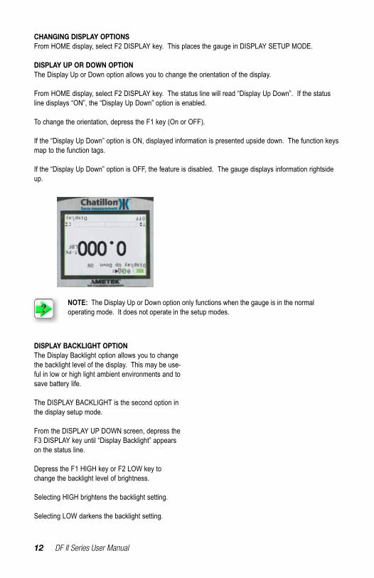
CHANGING DISPLAY OPTIONSFrom HOME display, select F2 DISPLAY key. This places the gauge in DISPLAY SETUP MODE.
DISPLAY UP OR DOWN OPTIONThe Display Up or Down option allows you to change the orientation of the display.
From HOME display, select F2 DISPLAY key. The status line will read “Display Up Down”. If the status line displays “ON”, the “Display Up Down” option is enabled.
To change the orientation, depress the F1 key (On or OFF).
If the “Display Up Down” option is ON, displayed information is presented upside down. The function keys map to the function tags.
If the “Display Up Down” option is OFF, the feature is disabled. The gauge displays information rightside up.
NOTE: The Display Up or Down option only functions when the gauge is in the normal operating mode. It does not operate in the setup modes.
DISPLAY BACKLIGHT OPTIONThe Display Backlight option allows you to change the backlight level of the display. This may be use-ful in low or high light ambient environments and to save battery life.
The DISPLAY BACKLIGHT is the second option in the display setup mode.
From the DISPLAY UP DOWN screen, depress the F3 DISPLAY key until “Display Backlight” appears on the status line.
Depress the F1 HIGH key or F2 LOW key to change the backlight level of brightness.
Selecting HIGH brightens the backlight setting.
Selecting LOW darkens the backlight setting.

DF II Series User Manual 13
DISPLAY HIDE OPTIONThe Display HIDE option allows you to hide your measured result during testing. This feature is useful when performing blind studies.
From the DISPLAY BACKLIGHT screen, depress the F3 DISPLAY key until “Hide Result” appears on the status line.
Depress the F1 (NO or Yes) key to enable the Hide Result option.
Selecting YES allows you to use the navigation pod to hide your measured result.
Use the LEFT arrow to “Hide” your force value.
Use the RIGHT arrow to “Unhide” your force value.
Selecting NO disables the Hide Result option.
AUTO DIMMINGThe Auto dimming function is preset from the fac-tory to maximize battery life. The DF II Series of gauges is set such that the LCD Backlight will au-tomatically dim if there is no use of the unit within 30 seconds. The user can disable this setting and also manually brighten the display.To change the setting:-Press F3 (More) four times. Scroll down to Auto Dimming and press Enter.-PresstheF1(Off)keytodisable.- To enable, follow the same instructions as above with the F1 (On) key used to enable the function.
WARNING: Disabling Auto Dimming will result in a reduction in battery life.
DISPLAY PEAKSThe Display Peaks function is preset from the fac-tory to show the peak values. The user can disable this setting.
To change the setting:-Press F3 (More) four times. Scroll down to Display Peaks and press Enter.-PresstheF1(Off)keytodisable.- To enable, follow the same instructions as above with the F1 (On) key used to enable the function.
LANGUAGESThe DF II Series of gauges contains the program-ming to allow for the unit to display in English, French, German, Spanish, Portuguese, and Chi-nese. To change the language displayed on the unit:
-PresstheF3(More)keyfivetimes.- The Select Language function is the only function on this screen. Press Enter.- Use the Navigation Pod Up/Down arrows to change the language selection. Once the desired language is displayed on the unit, press Enter to select that language.
CAUTION: If the language has been changed on the unit inadvertently, the user should press the Home key, the F3 keyfivetimes,andthenEnter.Theuser
can then use the Up/Down arrows to select a read-able language.

14 DF II Series User Manual
CHANGING MODEYou may change the DF II Series gauge operating mode by selecting the F1 (Mode) key. From the HOME display, select F1 (Mode) for the following operating modes:
Normal ModeWhen the gauge is in normal mode (NORM), the display will indicate the tensile or compressive load that is applied to the loadcell.
Peak Tension ModeWhen the gauge is in Peak Tension mode (T-PK), the gauge will display the maximum tensile load that was measured by the loadcell sensor.
Peak Compression ModeWhen the gauge is in Peak Compression mode (C-PK), the gauge will display the maximum com-pressive load that was measured by the loadcell sensor.
Normal Mode (Norm)
Tension Peak (T-PK)
Compression Peak (C-PK)
ZERO AND TARING GAUGEThe DF II Series gauge has a dedicated ZERO key for zeroing the measured result or for taring out the weightofaccessories,gripsorfixturesattachedtoyour gauge. Your gauge is capable of taring up to 10%ofitsspecifiedcapacity.
To zero a result or tare, depress the ZERO key.
To zero or CLEAR stored values in memory, please see Stored Values section.
ZeroUnits
Home
Zero
Enter
i
NOTE: The DF II Series force gauge allows you to save results to memory for the purposes of calculating statistics. Therefore, you cannot change mode if you have results saved in memory. You must clear results from the instrument’s memory before you are allowed to change the mode.
Load Averaging (Lav)
Tension Break (%Tbk)
Compression Break (%Cbk)NOTE: Load averaging, Tension break and Compression break are explained later in the manual.
DF II Series User Manual 15
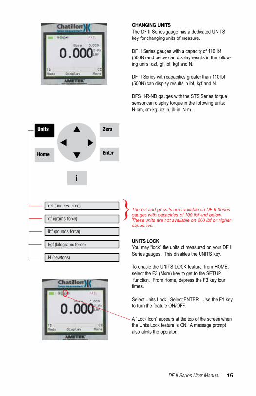
CHANGING UNITSThe DF II Series gauge has a dedicated UNITS key for changing units of measure.
DF II Series gauges with a capacity of 110 lbf (500N) and below can display results in the follow-ing units: ozf, gf, lbf, kgf and N.
DF II Series with capacities greater than 110 lbf (500N) can display results in lbf, kgf and N.
DFS II-R-ND gauges with the STS Series torque sensor can display torque in the following units: N-cm, cm-kg, oz-in, lb-in, N-m.
ozf (ounces force)
gf (grams force)
lbf (pounds force)
kgf (kilograms force)
N (newtons)
Units
Home
Zero
Enter
i
}The ozf and gf units are available on DF II Series gauges with capacities of 100 lbf and below. These units are not available on 200 lbf or higher capacities.
UNITS LOCKYou may “lock” the units of measured on your DF II Series gauges. This disables the UNITS key.
To enable the UNITS LOCK feature, from HOME, select the F3 (More) key to get to the SETUP function. From Home, depress the F3 key four times.
Select Units Lock. Select ENTER. Use the F1 key to turn the feature ON/OFF.
A “Lock Icon” appears at the top of the screen when the Units Lock feature is ON. A message prompt also alerts the operator.
16 DF II Series User Manual
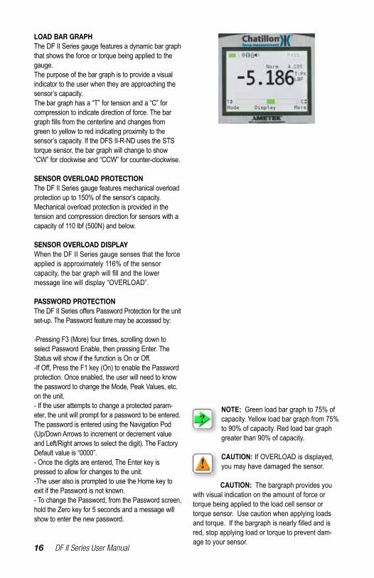
LOAD BAR GRAPHThe DF II Series gauge features a dynamic bar graph that shows the force or torque being applied to the gauge.The purpose of the bar graph is to provide a visual indicator to the user when they are approaching the sensor’s capacity.The bar graph has a “T” for tension and a “C” for compression to indicate direction of force. The bar graphfillsfromthecenterlineandchangesfromgreen to yellow to red indicating proximity to the sensor’s capacity. If the DFS II-R-ND uses the STS torque sensor, the bar graph will change to show “CW” for clockwise and “CCW” for counter-clockwise.
SENSOR OVERLOAD PROTECTIONThe DF II Series gauge features mechanical overload protection up to 150% of the sensor’s capacity.Mechanical overload protection is provided in the tension and compression direction for sensors with a capacity of 110 lbf (500N) and below.
SENSOR OVERLOAD DISPLAYWhen the DF II Series gauge senses that the force applied is approximately 116% of the sensor capacity,thebargraphwillfillandthelower message line will display “OVERLOAD”.
PASSWORD PROTECTIONTheDFIISeriesoffersPasswordProtectionfortheunitset-up. The Password feature may be accessed by:
-Pressing F3 (More) four times, scrolling down to select Password Enable, then pressing Enter. The StatuswillshowifthefunctionisOnorOff.-IfOff,PresstheF1key(On)toenablethePasswordprotection. Once enabled, the user will need to know the password to change the Mode, Peak Values, etc. on the unit.- If the user attempts to change a protected param-eter, the unit will prompt for a password to be entered. The password is entered using the Navigation Pod (Up/Down Arrows to increment or decrement value and Left/Right arrows to select the digit). The Factory Default value is “0000”.- Once the digits are entered, The Enter key is pressed to allow for changes to the unit.-The user also is prompted to use the Home key to exit if the Password is not known.- To change the Password, from the Password screen, hold the Zero key for 5 seconds and a message will show to enter the new password.
NOTE: Green load bar graph to 75% of capacity. Yellow load bar graph from 75% to 90% of capacity. Red load bar graph greater than 90% of capacity.
CAUTION: If OVERLOAD is displayed, you may have damaged the sensor.
CAUTION: The bargraph provides you with visual indication on the amount of force or torque being applied to the load cell sensor or torque sensor. Use caution when applying loads andtorque.Ifthebargraphisnearlyfilledandisred, stop applying load or torque to prevent dam-age to your sensor.
DF II Series User Manual 17
OPERATING YOUR GAUGEThe DF II Series gauge may be used as a hand-held instrument or mounted to a Chatillon® tester for compression and tensile testing.
HANDHELD OPERATIONWhen using the DF II Series gauge for handheld testing, make sure to apply the load axially to the load shaft.
Keep the gauge perpendicular to the item being measured to ensure axial loading. Use the op-tional handle assembly (SPK-DF-HANDLE) for high capacity loads.
TEST STAND OPERATIONWhen using the DF II Series gauge with a Chatil-lon® tester, make sure that the gauge is secured to the tester with the proper adapter if required. Adapters may be required to ensure that the gauge shaft is located axially to the sample under test. If the gauge is not secured properly, you may get faulty reading or cause damage to the loadcell.
AFFIXING ADAPTERS & FIXTURESAdaptersandtestfixturesshouldbematedtotheload shaft on the instrument. Do not use tools to secureyouradaptersorfixtures.Fingertorquetightnessissufficient.
MT150 SPK-MT-0001MT500 SPK-MT-0001LTCM-100 Direct ConnectTT Tester NC002582
DF II Series
MT150 SPK-MT-0004MT500 SPK-MT-0004LTCM-100 Direct ConnectTT Tester NC002582
DF II Series
Low Capacity 110 lbf (500N) and below
High Capacity Above 110 lbf (500N)
CAUTION: The DF II Series gauge is designed for axial loading only. Never apply a side load to the load shaft.
CAUTION: Do not use hand tools to secureadaptersorfixturestoyourgauge. Over tightening will damage the sensor.
Securefixturesandadapterswith “finger-tight”torque.
DFS II gauge mounted to LTCM100 tester
18 DF II Series User Manual
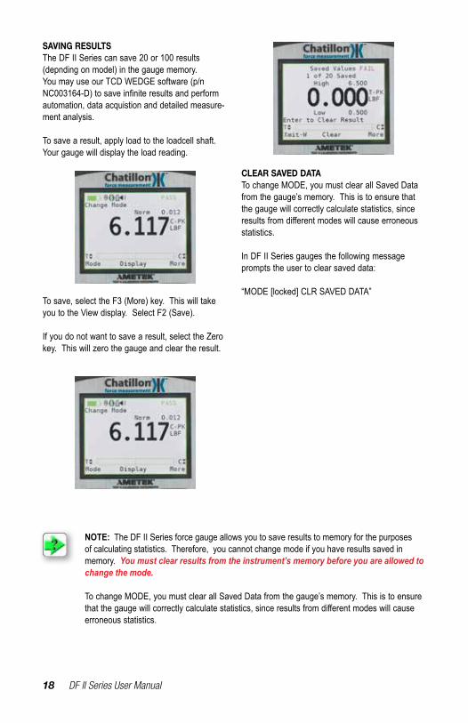
SAVING RESULTSThe DF II Series can save 20 or 100 results (depnding on model) in the gauge memory. You may use our TCD WEDGE software (p/n NC003164-D)tosaveinfiniteresultsandperformautomation, data acquistion and detailed measure-ment analysis.
To save a result, apply load to the loadcell shaft. Your gauge will display the load reading.
To save, select the F3 (More) key. This will take you to the View display. Select F2 (Save).
If you do not want to save a result, select the Zero key. This will zero the gauge and clear the result.
CLEAR SAVED DATATo change MODE, you must clear all Saved Data from the gauge’s memory. This is to ensure that the gauge will correctly calculate statistics, since resultsfromdifferentmodeswillcauseerroneousstatistics.
In DF II Series gauges the following message prompts the user to clear saved data:
“MODE [locked] CLR SAVED DATA”
NOTE: The DF II Series force gauge allows you to save results to memory for the purposes of calculating statistics. Therefore, you cannot change mode if you have results saved in memory. You must clear results from the instrument’s memory before you are allowed to change the mode.
To change MODE, you must clear all Saved Data from the gauge’s memory. This is to ensure thatthegaugewillcorrectlycalculatestatistics,sinceresultsfromdifferentmodeswillcauseerroneous statistics.
DF II Series User Manual 19
VIEWING RESULTSThe DF II Series displays results in the following formats:
n Active Measured Resultn Saved Measured Result(s)n Pass - Fail Resultn Load Limt Resultn Load Average Resultn Break Detect Result (DFS II Series only)
VIEWING ACTIVE RESULTThe DF II Series gauge will display the result in Normal, Tension Peak (T-PK) or Compression Peak (C-PK) modes.
The DF II Series gauge will display the measured result, mode, units of measure, active options and battery life.
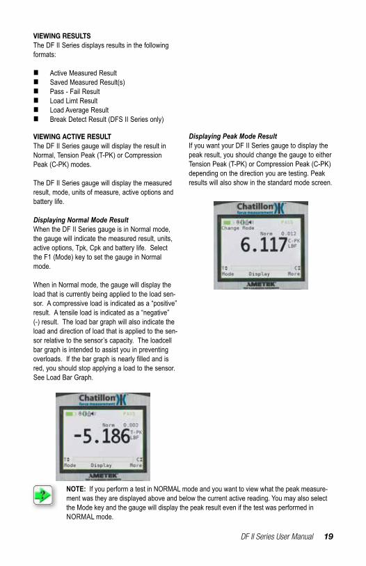
Displaying Normal Mode ResultWhen the DF II Series gauge is in Normal mode, the gauge will indicate the measured result, units, active options, Tpk, Cpk and battery life. Select the F1 (Mode) key to set the gauge in Normal mode.
When in Normal mode, the gauge will display the load that is currently being applied to the load sen-sor. A compressive load is indicated as a “positive” result. A tensile load is indicated as a “negative” (-) result. The load bar graph will also indicate the load and direction of load that is applied to the sen-sor relative to the sensor’s capacity. The loadcell bar graph is intended to assist you in preventing overloads.Ifthebargraphisnearlyfilledandisred, you should stop applying a load to the sensor. See Load Bar Graph.
Displaying Peak Mode ResultIf you want your DF II Series gauge to display the peak result, you should change the gauge to either Tension Peak (T-PK) or Compression Peak (C-PK) depending on the direction you are testing. Peak results will also show in the standard mode screen.
NOTE: If you perform a test in NORMAL mode and you want to view what the peak measure-ment was they are displayed above and below the current active reading. You may also select the Mode key and the gauge will display the peak result even if the test was performed in NORMAL mode.

20 DF II Series User Manual
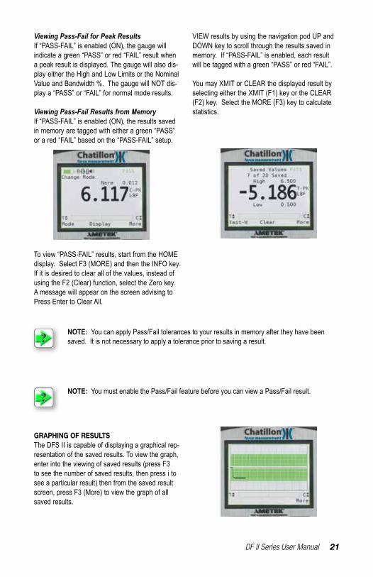
VIEWING PASS-FAIL RESULTSPass-Fail results are viewed from the View display. To access the View display from the Home display, select the F3 (More) key.
Saved results are displayed with their reference number (1 of 100, 2 of 100, etc.) and indication of green “Pass”orred“Fail”basedonyourspecifications.Themeasuredvalue,unitsandmodearedisplayedwith a green “Pass” or red “Fail” tag. Use the navigation pod UP and DOWN arrow to view the remaining saved results from memory.
When “PASS-FAIL” is enabled (ON), the gauge will display a green “PASS” or red “FAIL” two ways:
1. If the gauge MODE is either T-PK or C-PK;
2. If measured results are SAVED into memory.
Viewing Saved ResultThe DFE II will save up to 20 and the DFS II will save up to 100 measured results in its internal memory provided you elect to “SAVE” a result.
To view a “Saved Result”, from the Home display, select F3 (More) to access the View display. Se-lect the “INFO” key (i).
Saved results are displayed with their reference number (1 of 100, 2 of 100, etc.). The measured value, units and mode are displayed. Use the navigation pod UP and DOWN arrow to view the remaining saved results from memory.
A graphical representation of the results can also be viewed by selecting F3 (More) key while view-ing a result. To exit the graph and return to viewing results, select F3 (More)
DF II Series User Manual 21
To view “PASS-FAIL” results, start from the HOME display. Select F3 (MORE) and then the INFO key.If it is desired to clear all of the values, instead of using the F2 (Clear) function, select the Zero key. A message will appear on the screen advising to Press Enter to Clear All.
VIEW results by using the navigation pod UP and DOWN key to scroll through the results saved in memory. If “PASS-FAIL” is enabled, each result will be tagged with a green “PASS” or red “FAIL”.
You may XMIT or CLEAR the displayed result by selecting either the XMIT (F1) key or the CLEAR (F2) key. Select the MORE (F3) key to calculate statistics.
Viewing Pass-Fail for Peak ResultsIf “PASS-FAIL” is enabled (ON), the gauge will indicate a green “PASS” or red “FAIL” result when a peak result is displayed. The gauge will also dis-play either the High and Low Limits or the Nominal Value and Bandwidth %. The gauge will NOT dis-play a “PASS” or “FAIL” for normal mode results.
Viewing Pass-Fail Results from MemoryIf “PASS-FAIL” is enabled (ON), the results saved in memory are tagged with either a green “PASS” or a red “FAIL” based on the “PASS-FAIL” setup.
NOTE: You can apply Pass/Fail tolerances to your results in memory after they have been saved. It is not necessary to apply a tolerance prior to saving a result.
NOTE: You must enable the Pass/Fail feature before you can view a Pass/Fail result.
GRAPHING OF RESULTSThe DFS II is capable of displaying a graphical rep-resentation of the saved results. To view the graph, enter into the viewing of saved results (press F3 to see the number of saved results, then press i to see a particular result) then from the saved result screen, press F3 (More) to view the graph of all saved results.
22 DF II Series User Manual
TRANSMIT RESULTSThe DF II Series can transmit data using its RS232, Mitutoyo, USB, or Analog output. The gauge will transmit data to whatever device is con-nected to the gauge through the selected output port.
Data transmit is used to send information to another device, e.g. personal computer or to print information to a serial or Mitutoyo printer.
To transmit information, the gauge must be in the View display.
You have two options when transmitting:
n Transmit Displayed Resultn Transmit ALL Results from Memory
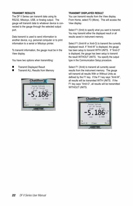
TRANSMIT DISPLAYED RESULTYou can transmit results from the View display. From Home, select F3 (More). This will access the View display.
Select F1 (Xmit) to specify what you want to transmit. You may transmit either the displayed result or all results saved in instrument memory.
Select F1 (Xmit-W or Xmit-O) to transmit the currently displayed result. If “Xmit-W” is displayed, the gauge has been setup to transmit WITH UNITS. If “Xmit-O” is displayed, the gauge has been setup to transmit the result WITHOUT UNITS. You specify the output type in the Communication Setup procedure.
Select F1 (Xmit) to transmit all currently saved results from the instrument memory. The gauge will transmit all results With or Without Units as definedbytheF1key.IftheF1keysays“Xmit-W”,all results will be transmited WITH UNITS. If the F1 key says “Xmit-O”, all results will be transmitted WITHOUT UNITS.
DF II Series User Manual 23
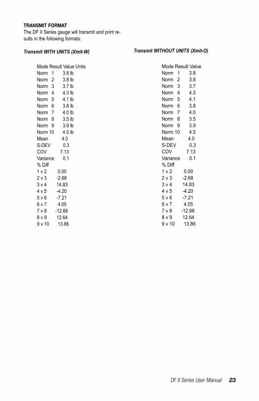
TRANSMIT FORMATThe DF II Series gauge will transmit and print re-sults in the following formats:
Transmit WITH UNITS (Xmit-W) Transmit WITHOUT UNITS (Xmit-O)
Mode Result Value Norm 1 3.8 Norm 2 3.8Norm 3 3.7Norm 4 4.3Norm 5 4.1Norm 6 3.8Norm 7 4.0Norm 8 3.5Norm 9 3.9Norm 10 4.5Mean 4.0S-DEV 0.3COV 7.13Variance 0.1%Diff1 v 2 0.002 v 3 -2.683 v 4 14.834 v 5 -4.205 v 6 -7.216 v 7 4.057 v 8 -12.668 v 9 12.649 v 10 13.86
Mode Result Value Units Norm 1 3.8 lb Norm 2 3.8 lbNorm 3 3.7 lbNorm 4 4.3 lbNorm 5 4.1 lbNorm 6 3.8 lbNorm 7 4.0 lbNorm 8 3.5 lbNorm 9 3.9 lbNorm 10 4.5 lbMean 4.0S-DEV 0.3COV 7.13Variance 0.1%Diff1 v 2 0.002 v 3 -2.683 v 4 14.834 v 5 -4.205 v 6 -7.216 v 7 4.057 v 8 -12.668 v 9 12.649 v 10 13.86
24 DF II Series User Manual
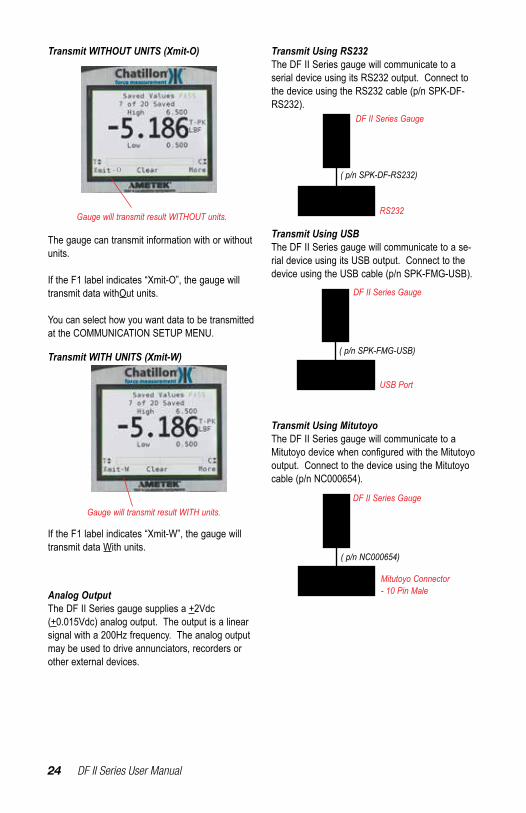
Transmit Using RS232The DF II Series gauge will communicate to a serial device using its RS232 output. Connect to the device using the RS232 cable (p/n SPK-DF-RS232).
Transmit Using MitutoyoThe DF II Series gauge will communicate to a MitutoyodevicewhenconfiguredwiththeMitutoyooutput. Connect to the device using the Mitutoyo cable (p/n NC000654).
( p/n SPK-FMG-USB)
DF II Series Gauge
USB Port
( p/n NC000654)
DF II Series Gauge
Mitutoyo Connector- 10 Pin Male
The gauge can transmit information with or without units.
If the F1 label indicates “Xmit-O”, the gauge will transmit data withOut units.
You can select how you want data to be transmitted at the COMMUNICATION SETUP MENU.
If the F1 label indicates “Xmit-W”, the gauge will transmit data With units.
Gauge will transmit result WITHOUT units.
Gauge will transmit result WITH units.
Transmit WITH UNITS (Xmit-W)
Transmit WITHOUT UNITS (Xmit-O)
Analog OutputThe DF II Series gauge supplies a +2Vdc (+0.015Vdc) analog output. The output is a linear signal with a 200Hz frequency. The analog output may be used to drive annunciators, recorders or other external devices.
Transmit Using USBThe DF II Series gauge will communicate to a se-rial device using its USB output. Connect to the device using the USB cable (p/n SPK-FMG-USB).
( p/n SPK-DF-RS232)
DF II Series Gauge
RS232
- O
DF II Series User Manual 25
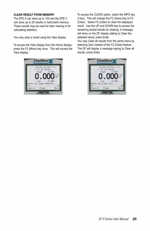
CLEAR RESULT FROM MEMORYThe DFS II can store up to 100 and the DFE II can store up to 20 results in instrument memory. These results may be used for later viewing or for calculating statistics.
You may clear a result using the View display.
To access the View display from the Home display, press the F3 (More) key once. This will access the View display.
To access the CLEAR option, select the INFO key (i key). This will change the F2 (Save) key to F2 (Clear). Select F2 (Clear) to clear the displayed result. Use the UP and DOWN key to access the remaining stored results for clearing. A message will show on the DF display stating to Clear the selected result, press Enter.You may Clear all results from the same menu by selecting Zero instead of the F2 (Clear) feature. The DF will display a message saying to Clear all results, press Enter.
26 DF II Series User Manual
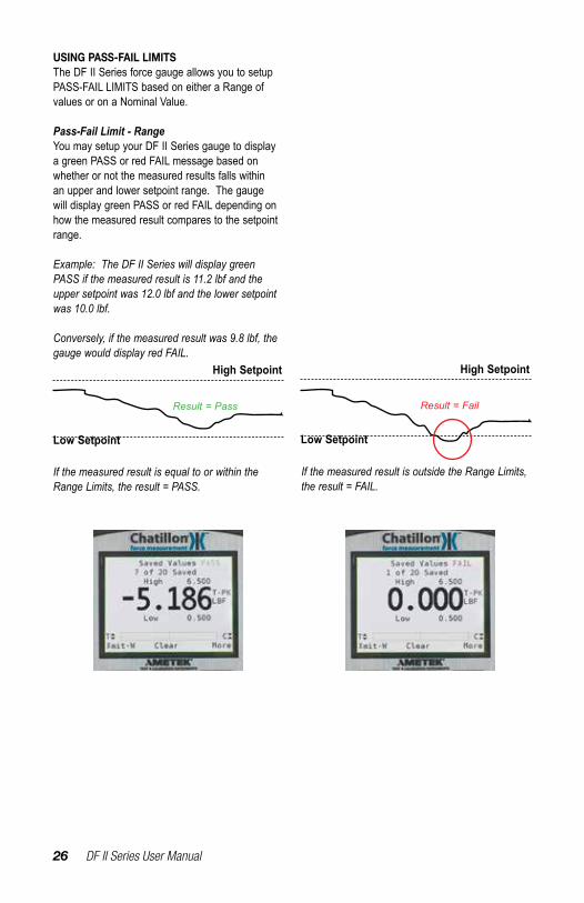
USING PASS-FAIL LIMITSThe DF II Series force gauge allows you to setup PASS-FAIL LIMITS based on either a Range of values or on a Nominal Value.
Pass-Fail Limit - RangeYou may setup your DF II Series gauge to display a green PASS or red FAIL message based on whether or not the measured results falls within an upper and lower setpoint range. The gauge will display green PASS or red FAIL depending on how the measured result compares to the setpoint range.
Example: The DF II Series will display green PASS if the measured result is 11.2 lbf and the upper setpoint was 12.0 lbf and the lower setpoint was 10.0 lbf.
Conversely, if the measured result was 9.8 lbf, the gauge would display red FAIL.
If the measured result is equal to or within the Range Limits, the result = PASS.
If the measured result is outside the Range Limits, the result = FAIL.
Low Setpoint
High Setpoint
Result = Fail
Low Setpoint
High Setpoint
Result = Pass
DF II Series User Manual 27
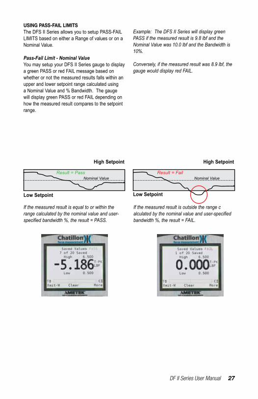
USING PASS-FAIL LIMITSThe DFS II Series allows you to setup PASS-FAIL LIMITS based on either a Range of values or on a Nominal Value.
Pass-Fail Limit - Nominal ValueYou may setup your DFS II Series gauge to display a green PASS or red FAIL message based on whether or not the measured results falls within an upper and lower setpoint range calculated using a Nominal Value and % Bandwidth. The gauge will display green PASS or red FAIL depending on how the measured result compares to the setpoint range.
If the measured result is equal to or within the range calculated by the nominal value and user-specified bandwidth %, the result = PASS.
If the measured result is outside the range c alculated by the nominal value and user-specified bandwidth %, the result = FAIL.
Nominal Value Nominal Value
High Setpoint High Setpoint
Low Setpoint Low Setpoint
Result = FailResult = Pass
Example: The DFS II Series will display green PASS if the measured result is 9.8 lbf and the Nominal Value was 10.0 lbf and the Bandwidth is 10%.
Conversely, if the measured result was 8.9 lbf, the gauge would display red FAIL.
28 DF II Series User Manual
SELECT PASS - FAIL METHODThere are two Pass-Fail Methods available to choose from:
n Rangen Nominal Value
Use the navigation pod UP and DOWN key to position the cursor arrow next to the method you want to base your Pass-Fail result on. Select ENTER.
ACTIVATING PASS-FAIL LIMITSYou have the option of enabling or disabling Pass-Fail Limits. The factory default is Pass-Fail Limits OFF.
To enable Pass-Fail Limits, from the Home display, select F3 (More) twice. This will take you to the Main Setup Menu display.
Use the navigation UP or DOWN key to position the cursor arrow next to the PASS - FAIL option. Select enter.
The Pass-Fail activation display allows you to “turn ON” or “turn OFF” the Pass-Fail feature. Select F1 to turn ON or OFF. Select enter.
SELECT RANGE METHODUse the navigation pod UP and DOWN key to position the cursor arrow next to the RANGE method. Select ENTER.
DF II Series User Manual 29
SELECTING INCREMENTSIncrements are associated with the numeric values displayed by the gauge during setup. You select the increment you want to use to adjust your setup values. Increments are provided in values corresponding to the gauge capacity and units of measure. Increment values available are:
n 0.001n 0.01n 0.1n 1.0n 10.0n 100.0
Selecting an increment of 10.0 will adjust the setup numeric value by “tens”. Selecting the increment 0.1 will adjust the setup numeric value by “tenths”.
You select increments using the RIGHT and LEFT arrow keys on the navigation pod. Selecting the RIGHT arrow increases the increment value. Selecting the LEFT arrow decreases the increment value.
SELECTING HIGH RANGE LIMITUse the F1 key to select the HIGH RANGE Pass-Fail Limit. The cursor arrow will automatically be placed next to the HIGH Limit tag indicating that you are about to adjust this value.
Use the UP and DOWN navigation key to increase or decrease the High Pass-Fail Limit VALUE. The value will increase by the increment selected upon each key press.
Do NOT select ENTER until you have adjusted both the High and Low Pass-Fail Limits to your desired setpoints.
30 DF II Series User Manual
SELECTING LOW RANGE LIMITUse the F1 key to select the LOW RANGE Pass-Fail Limit. The cursor arrow will automatically be placed next to the LOW Limit tag indicating that you are about to adjust this value.
Use the UP and DOWN navigation key to increase or decrease the Low Pass-Fail Limit VALUE. The value will increase by the increment selected upon each key press.
Select enter when you have adjusted both the High and Low Pass-Fail Limits to your desired setpoints.
SELECT NOMINAL VALUE METHODUse the navigation pod UP and DOWN key to posi-tion the cursor arrow next to the NOMINAL VALUE method. Select ENTER.
TheNominalValuemethodusesaspecifiedset-point value and bandwidth to calculate the High and Low setpoints. The DF gauge will automatically calculate and display the High and Low Limits. You only need to specify the Nominal Value and the % Bandwidth.
DF II Series User Manual 31
SELECT NOMINAL VALUEUse the F1 key to specify the Nominal Value or the Bandwidth. When Pass-Fail is ON, the gauge will start at the Nominal Value position.
Use the UP and DOWN navigation key to increase or decrease the Nominal Value. The value will increase by the increment selected upon each key press. Note that the gauge will automatically calculate the High and Low Limits based on the Nominal Value entered and the Bandwidth value.
SELECT BANDWIDTHUse the F1 key to specify the Bandwidth. the Bandwidth is expressed as a percentage of the Nominal Value. The maximum allowable band-width is 50%.
Use the UP and DOWN navigation key to increase or decrease the Bandwidth. The value will increase by the increment selected upon each key press. Note that the gauge will automatically calculate the High and Low Limits based on the Bandwidth en-tered and the Nominal value.
Selectenterwhenyouaresatisfiedwithyour calculated limits based on your Nominal Value and Bandwidth.
SELECTING INCREMENTSIncrements are associated with the numeric values displayed by the gauge during setup. You select the increment you want to use to adjust your setup values. Increments are provided in values corresponding to the gauge capacity and units of measure. Increment values available are:
n 0.001n 0.01n 0.1n 1.0n 10.0n 100.0
Selecting an increment of 10.0 will adjust the setup numeric value by “tens”. Selecting the increment 0.1 will adjust the setup numeric value by “tenths”.
You select increments using the RIGHT and LEFT arrow keys on the navigation pod. Selecting the RIGHT arrow increases the increment value. Selecting the LEFT arrow decreases the increment value.
32 DF II Series User Manual
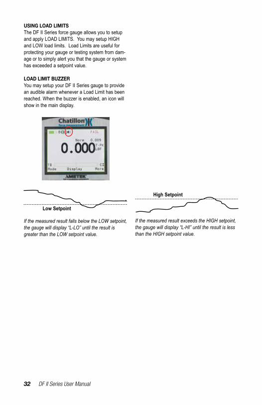
If the measured result falls below the LOW setpoint, the gauge will display “L-LO” until the result is greater than the LOW setpoint value.
If the measured result exceeds the HIGH setpoint, the gauge will display “L-HI” until the result is less than the HIGH setpoint value.
USING LOAD LIMITSThe DF II Series force gauge allows you to setup and apply LOAD LIMITS. You may setup HIGH and LOW load limits. Load Limits are useful for protecting your gauge or testing system from dam-age or to simply alert you that the gauge or system has exceeded a setpoint value.
LOAD LIMIT BUZZERYou may setup your DF II Series gauge to provide an audible alarm whenever a Load Limit has been reached. When the buzzer is enabled, an icon will show in the main display.
Low Setpoint
High Setpoint
DF II Series User Manual 33
ACTIVATING TRANSMIT LIMITSYou have the option of enabling or disabling Trans-mit Limits. The factory default is Transmit Limits OFF.
To enable Transmit Limits, from the Home display, select F3 (More) twice. This will take you to the Main Setup Menu display.Use the navigation UP or DOWN key to position the cursor arrow next to the COMMUNICATIONS option. Select enter.
The XMIT LIMITS option is used to activate the Transmit Limits feature. Use the RIGHT arrow to activate the Transmit Limits (ON). Use the LEFT arrow to deactive the Transmit Limits (OFF).
When Transmit Limits are ON, the DF II Series gauge will transmit a continuous data string to the attached TCD Series tester through the RS232 port.
When a High Limit is reached, the DF II Series gauge will send a continuous string of “$$$$$” to the tester. The tester will read this string and stop the crosshead from traveling.
When a Low Limit is reached, the DF II Series gauge will send a continuous string of “‘‘‘‘‘‘‘‘” to the tester. The tester will read this string and stop the crosshead from traveling.
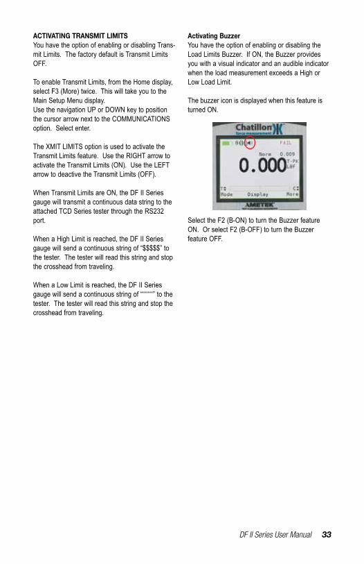
Activating BuzzerYou have the option of enabling or disabling the Load Limits Buzzer. If ON, the Buzzer provides you with a visual indicator and an audible indicator when the load measurement exceeds a High or Low Load Limit.
The buzzer icon is displayed when this feature is turned ON.
Select the F2 (B-ON) to turn the Buzzer feature ON. Or select F2 (B-OFF) to turn the Buzzer feature OFF.
34 DF II Series User Manual
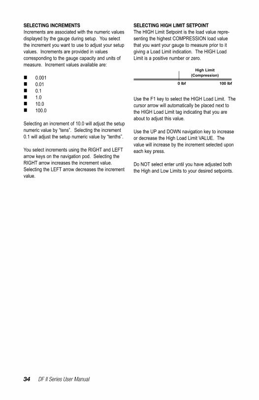
SELECTING HIGH LIMIT SETPOINTThe HIGH Limit Setpoint is the load value repre-senting the highest COMPRESSION load value that you want your gauge to measure prior to it giving a Load Limit indication. The HIGH Load Limit is a positive number or zero.
Use the F1 key to select the HIGH Load Limit. The cursor arrow will automatically be placed next to the HIGH Load Limit tag indicating that you are about to adjust this value.
Use the UP and DOWN navigation key to increase or decrease the High Load Limit VALUE. The value will increase by the increment selected upon each key press.
Do NOT select enter until you have adjusted both the High and Low Limits to your desired setpoints.
0 lbf 100 lbf
High Limit(Compression)
SELECTING INCREMENTSIncrements are associated with the numeric values displayed by the gauge during setup. You select the increment you want to use to adjust your setup values. Increments are provided in values corresponding to the gauge capacity and units of measure. Increment values available are:
n 0.001n 0.01n 0.1n 1.0n 10.0n 100.0
Selecting an increment of 10.0 will adjust the setup numeric value by “tens”. Selecting the increment 0.1 will adjust the setup numeric value by “tenths”.
You select increments using the RIGHT and LEFT arrow keys on the navigation pod. Selecting the RIGHT arrow increases the increment value. Selecting the LEFT arrow decreases the increment value.
DF II Series User Manual 35
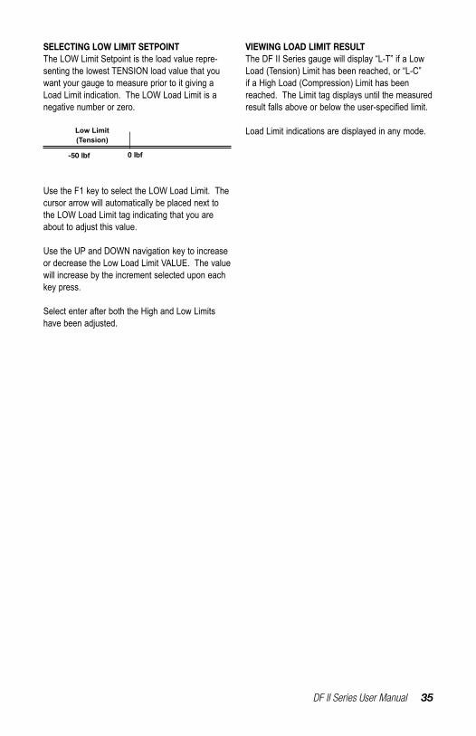
SELECTING LOW LIMIT SETPOINTThe LOW Limit Setpoint is the load value repre-senting the lowest TENSION load value that you want your gauge to measure prior to it giving a Load Limit indication. The LOW Load Limit is a negative number or zero.
0 lbf-50 lbf
Low Limit(Tension)
Use the F1 key to select the LOW Load Limit. The cursor arrow will automatically be placed next to the LOW Load Limit tag indicating that you are about to adjust this value.
Use the UP and DOWN navigation key to increase or decrease the Low Load Limit VALUE. The value will increase by the increment selected upon each key press.
Select enter after both the High and Low Limits have been adjusted.
VIEWING LOAD LIMIT RESULTThe DF II Series gauge will display “L-T” if a Low Load (Tension) Limit has been reached, or “L-C” if a High Load (Compression) Limit has been reached. The Limit tag displays until the measured resultfallsaboveorbelowtheuser-specifiedlimit.
Load Limit indications are displayed in any mode.
36 DF II Series User Manual
USING AUTO SHUTDOWNTheDFIISeriesforcegaugeallowsyoutoconfig-ure your gauge to automatically shut down if there has been no keypad activity or no communication activityforaspecifiedperiodoftime.Thepurposeof automatic shutdown is to help preserve the instrument battery. The factory default for Auto Shutdown is OFF (disabled).
If your tests involve long test periods where keypad entries are infrequent, you should take care to specify a long shutdown period to avoid losing test-ing results. Or, consider NOT using the automatic shutdown feature.
TheDFIISeriesgaugecanbespecifiedtoau-tomatically shutdown when there has been no keypad activity or communication activity from 10 minutes up to 480 minutes (8 hours).
ACTIVATING AUTO SHUTDOWNAutomatic Shutdown may be activated from the Main Setup display. From the Home display, select the F3 (More) key twice to access the Main Setup display.
Use the UP and DOWN navigation keys to position the cursor arrow next to the Auto Shutdown tag. Select enter.
Select the F1 key to turn Auto Shutdown ON or OFF
Auto Shutdown Icon. Indicates that the automatic shutdown feature is activated.
SELECTING TIME PERIODAutomatic Shutdown time is expressed in MINUTES.
Use the UP and DOWN key to select the desired time period, e.g. the amount of time in minutes that determine that the gauge will automatically shutdown when there has been no keypad activity.
Each depress of the UP or DOWN key increments the time by 10 minutes.

DF II Series User Manual 37
If Mitutoyo communications are enabled, all other communication features and outputs are disabled. If communications are not working, verify that Mitutoyo is not enabled.
ABOUT GAUGE COMMUNICATIONSThe DF II Series force gauges allow you to com-municate to external devices using either RS232, Mitutoyo, USB, or analog outputs.
Communication may be via the 12-pin output using the following Chatillon® cables:
n RS232 (Cable p/n SPK-DF-RS232)n Mitutoyo (Cable p/n NC000654)
The +2Vdc analog output is always available via pins 11 and 12.
Communications via the USB output is through the USB port.
n USB (Cable p/n SPK-FMG-USB)
USB COMMUNICATION SET-UPIf the computer does not recognize the DF2 force gauge as a USB device please run the execut-able file contained on the user manual CD named “DF2_Drivers.exe”. These drivers will allow the computer to properly communicate with the Cha-tillon DF2 force gauge via the USB port. To verify the USB connection is set up properly between the computer and the Chatillon DF2 force gauge go “Control Panel”, “Hardware and Sound”,“Device Manager”, “Ports (COM & LPT)”. You can ensure the USB connection is set up properly and what COM port the computer assigned to it.
Note: When using RS232 or USB communication please ensure that the Mitutoyo communication is set to the “OFF” setting (disabled). If the Mitutoyo communication is set to “ON” (enabled), the Cha-tillon DF2 force gauge disables all other RS232 or USB communications.
SETUP - COMMUNICATIONSCommunications may be setup from the Main Set-up display. From the Home display, select the F3 (More) key twice to access the Main Setup display.
Use the UP and DOWN navigation keys to position the cursor arrow next to the Communications tag. Select enter.
You may then set the Xmit Units, Xmit Limits, Baud.
Use the F2 (More) function to move to the next screen and select the communication method. The default factory setting is RS232. Use the UP and DOWN navigation keys or the F1 (Change) to change selections to USB Port.
Use the F2 (More) function to move to the screen to select a protocol for the DF II Series.
The DF II Series has a standard AMETEK® proto-col and an Alternate protocol loaded for use of the ASCII commands. Use the UP and DOWN naviga-tion keys or the F1 (Change) to change selection.
38 DF II Series User Manual
SELECTING LIMITS (RS232 AND USB)The DF II Series allows you to transmit an ASCII signal when a Load Limit has been met. This sig-nal is used to stop crosshead movement on a TCD Series tester.
A HIGH LIMIT sends the following ASCII string:$$$$$$$$$$
A LOW LIMIT sends the following ASCII string:’’’’’’’’’’’’’’’
To enable XMIT LIMITS, position the arrow next to the XMIT LIMITS tag. Select the RIGHT arrow on the navigation key to enable this feature (ON). Select the LEFT arrow on the navigation key to dis-able this feature (OFF). Select ENTER.
SELECTING BAUD RATE (RS232)The DF II Series allows you to select the required baud rate when in RS232 mode.
Position the arrow next to the BAUD tag. Use the UP and DOWN arrow to specify any of the follow-ing baud rates:
n 4800n 9600n 19200n 28800n 38400n 57600n 115200
Select ENTER to enable.

DF II Series User Manual 39
PINOUTS
The DF II Series is supplied with a 12-pin female connector to provide RS232, Mitutoyo and analog outputs. Thepinoutoftheconnectorisshownabove.Pinassignmentsaredefinedinthetablebelow.
1 TXD O RS-232 Transmitted Data 2 RXD I RS-232 Received Data 3 GND O Ground Digital Ground 4 O Clock Mitutoyo Clock 5 O Ready Mitutoyo Ready 6 I Request Mitutoyo Request 7 O Data Mitutoyo Data 8 I Detect Sense Contact Closure 9 O Setpoint Setpoint Output Signal 10 - Ground Digital Ground 11 - Analog GND Analog Ground 12 O Analog SIG Analog Output
PIN SYMBOL I/O PURPOSE DESCRIPTION
9
8
7
65
4
3
21
10
12 11
40 DF II Series User Manual
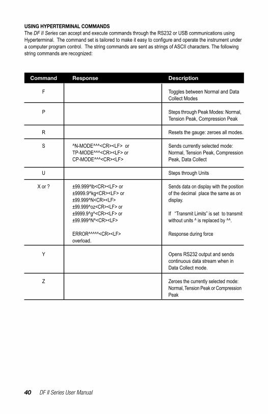
USING HYPERTERMINAL COMMANDS The DF II Series can accept and execute commands through the RS232 or USB communications using Hyperterminal.Thecommandsetistailoredtomakeiteasytoconfigureandoperatetheinstrumentundera computer program control. The string commands are sent as strings of ASCII characters. The following string commands are recognized:
Command Response Description F Toggles between Normal and Data Collect Modes P Steps through Peak Modes: Normal, Tension Peak, Compression Peak R Resets the gauge: zeroes all modes. S ^N-MODE^^^<CR><LF> or Sends currently selected mode: TP-MODE^^^<CR><LF> or Normal, Tension Peak, Compression CP-MODE^^^<CR><LF> Peak, Data Collect U Steps through Units X or ? ±99.999^lb<CR><LF> or Sends data on display with the position ±9999.9^kg<CR><LF> or of the decimal place the same as on ±99.999^N<CR><LF> display. ±99.999^oz<CR><LF> or ±9999.9^g^<CR><LF> or If “Transmit Limits” is set to transmit ±99.999^N^<CR><LF> without units ^ is replaced by ^^. ERROR^^^^^<CR><LF> Response during force overload. Y Opens RS232 output and sends continuous data stream when in Data Collect mode.
Z Zeroes the currently selected mode: Normal, Tension Peak or Compression Peak

DF II Series User Manual 41
CHANGING GAUGE POLARITY The DF II Series will normally display TENSION measurements as a NEGATIVE number, while displaying COMPRESSION measurements as a POSITIVE number.
However, you may change the gauge so that it displays tensile results as POSITIVE number and compression results as a NEGATIVE.
SETUP - POLARITYPolarity may be setup from the Main Setup display. From the Home display, select the F3 (More) key twice to access the Main Setup display.
Use the UP and DOWN navigation keys to position the cursor arrow next to the Communications tag. Select enter.
The F1 key indicates the current polarify for the gauge results:C +ve means the compression result with display as a POSITIVE number (ve = voltage excitation). This is the gauge default setting
T +ve means the tension result will display as a POSITIVE number.
To change the polarity, depress the F1 key. Select ENTER.

42 DF II Series User Manual
CONNECTING A PRINTERThe DF II Series force gauge can transmit infor-mation to a serial data printer or Mitutoyo printer. Printing is performed from the View display using the TRANSMIT function.
From the Home display, select F3 (More) to access the View Display.
Select F1 (Xmit) to access the Transmit display. From this display, you have the options of transmit-ting the current displayed result, or transmitting all results saved in the instrument memory. Selecting the Xmit keys will send data through the gauge’s output,intheconfiguredformat,totheexternaldevice.
See Communications for the output setup options.
COMMUNICATION CABLESThe DF II Series gauges are supplied standard with an RS232 serial data cable (p/n SPK-DF-RS232). You may also use the outputs on these gauges to communicate with Mitutoyo devices.A USB cable is also available.
Serial Device SPK-DF-RS232 Mitutoyo Device NC000654
Connect to Cable
SPK-DF-RS232
DF II Series User Manual 43
CONNECTING A SERIAL PRINTER Connect the DF II Series gauge to the serial printer using the gauge output connector and the serial cable provided with the gauge (p/n SPK-DF-RS232). The serial data cable has a Hirose connector for the gauge and a D-Type 9-Pin male connector for the printer.
Configurethegaugeoutputs(SeeUsingOutputs)and match the baud rate in the gauge to the baud rate for the printer.
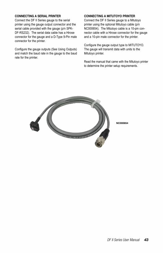
CONNECTING A MITUTOYO PRINTER Connect the DF II Series gauge to a Mitutoyo printer using the optional Mitutoyo cable (p/n NC000654). The Mitutoyo cable is a 10-pin con-nector cable with a Hirose connector for the gauge and a 10-pin male connector for the printer.
ConfigurethegaugeoutputtypetoMITUTOYO.The gauge will transmit data with units to the Mitutoyo printer.
Read the manual that came with the Mitutoyo printer to determine the printer setup requirements.
NC000654

44 DF II Series User Manual
USING REMOTE SENSORSThe DFS II-R-ND Series digital force gauge can be usedwithtwodifferenttypesofsensors:
n SLC Loadcell Sensorsn STS Torque Sensors
SLC LOADCELL SENSORSThe SLC Series loadcell sensors have been designed to work exclusively with the DFS-R-ND and DFS II-R-ND Series force gauges. These sen-sors are NOT compatible with previous Chatillon® digital gauges that used interchangeable sensors. The SLC Sensor is inserted into the 15-pin connec-tor located on the side of the DFS II-R-ND gauge. The gauge will automatically recognize the sensor type and its associated capacity and resolutions.
The SLC Series sensor is available in capacities from 250gf to 1000 lbf. Multiple sensors can be used to mount to a single DFS II-R-ND gauge. This can provide the user with cost savings and convenience. The disadvantage is the DFS II-R-ND with remote sensors has an accuracy of better than 0.25% full scale (compared to a dedicated sensor with accuracy of better than 0.1% full scale).
TheflexiblecableusedwiththeSLCsensorsareideal for applications where access to the sample under test is limited. The cable, when fully extended, reaches approximately 9 feet (3 meters).
STS TORQUE SENSORSThe STS Series torque sensors have been designed to work exclusively with the DFS-R-ND and DFS II-R-ND Series force gauges. These sensors are NOT compatible with previous Chatillon® digital gauges that used interchangeable sensors. The STS Sen-sor is inserted into the 15-pin connector located on the side of the DFS II-R-ND gauge. The gauge will automatically recognize the sensor type and its as-sociated capacity and resolutions.
The STS Series sensor is available in capacities from3in-lbsto200in-lbs.Differentcapacity sensors may be plugged into the DFS II-R-ND depending on the application requirements. The gauge’s automatic recognition eliminates the need toconfigurethecapacitiesandresolution.
TheSTSSeriessensorscomewithdifferenthexfittingsforattachingtothetestsample.TheSTSsensor is turned and the gauge will indicate torque and torque direction. The cable, when fully extended, reaches approximately 9 feet (3 meters).
DF II Series User Manual 45
SPECIFYING THE CORRECT SENSORThe single, most-common problem when measur-ing load or torque is caused by the use of a sensor that is not appropriate for the application.
Thesensorselectedshouldbespecifiedsothatthe expected measured results occurs within the 20% to 90% capacity for the sensor. This is par-ticularly important when using “full scale accuracy” devices. Operating at too near either end of the sensor’s capacity can lead to inaccurate measure-ments, and worse, a damaged sensor.
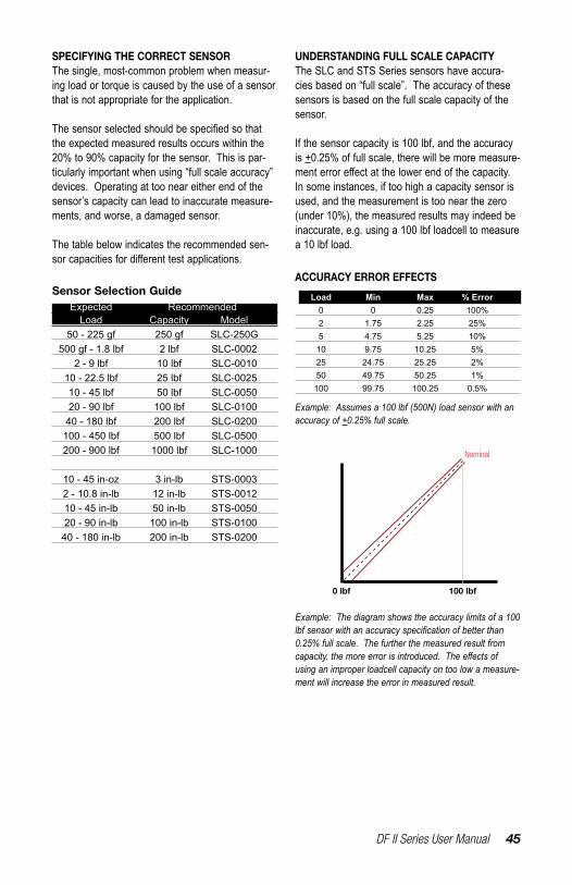
The table below indicates the recommended sen-sorcapacitiesfordifferenttestapplications.
UNDERSTANDING FULL SCALE CAPACITYThe SLC and STS Series sensors have accura-cies based on “full scale”. The accuracy of these sensors is based on the full scale capacity of the sensor.
If the sensor capacity is 100 lbf, and the accuracy is +0.25% of full scale, there will be more measure-menterroreffectatthelowerendofthecapacity.In some instances, if too high a capacity sensor is used, and the measurement is too near the zero (under 10%), the measured results may indeed be inaccurate, e.g. using a 100 lbf loadcell to measure a 10 lbf load.
Expected Recommended Load Capacity Model 50 - 225 gf 250 gf SLC-250G 500 gf - 1.8 lbf 2 lbf SLC-0002 2 - 9 lbf 10 lbf SLC-0010 10 - 22.5 lbf 25 lbf SLC-0025 10 - 45 lbf 50 lbf SLC-0050 20 - 90 lbf 100 lbf SLC-0100 40 - 180 lbf 200 lbf SLC-0200 100 - 450 lbf 500 lbf SLC-0500 200 - 900 lbf 1000 lbf SLC-1000
10 - 45 in-oz 3 in-lb STS-0003 2 - 10.8 in-lb 12 in-lb STS-0012 10 - 45 in-lb 50 in-lb STS-0050 20 - 90 in-lb 100 in-lb STS-0100 40 - 180 in-lb 200 in-lb STS-0200
Sensor Selection Guide Load Min Max % Error 0 0 0.25 100% 2 1.75 2.25 25% 5 4.75 5.25 10% 10 9.75 10.25 5% 25 24.75 25.25 2% 50 49.75 50.25 1% 100 99.75 100.25 0.5%
ACCURACY ERROR EFFECTS
Example: Assumes a 100 lbf (500N) load sensor with an accuracy of +0.25% full scale.
100 lbf0 lbf
Example: The diagram shows the accuracy limits of a 100 lbf sensor with an accuracy specification of better than 0.25% full scale. The further the measured result from capacity, the more error is introduced. The effects of using an improper loadcell capacity on too low a measure-ment will increase the error in measured result.
Nominal
46 DF II Series User Manual
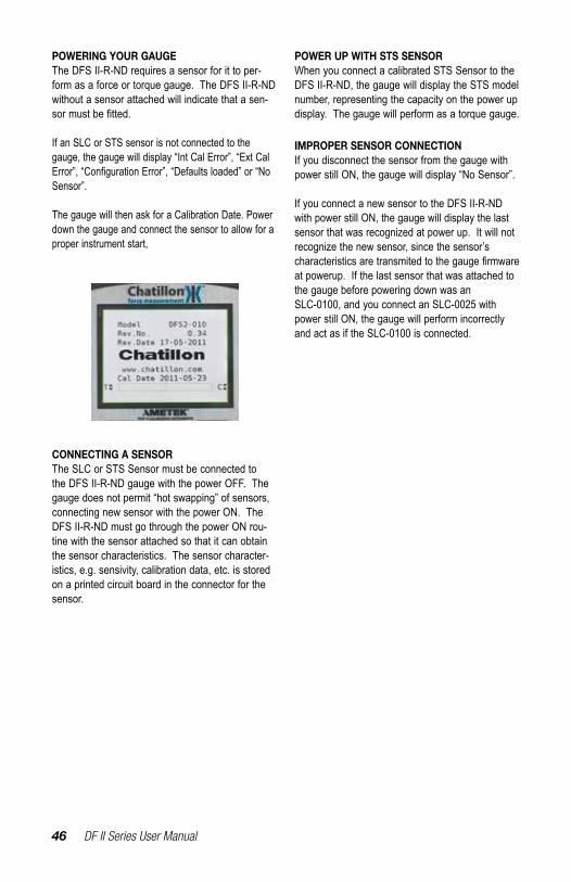
POWERING YOUR GAUGEThe DFS II-R-ND requires a sensor for it to per-form as a force or torque gauge. The DFS II-R-ND without a sensor attached will indicate that a sen-sormustbefitted.
If an SLC or STS sensor is not connected to the gauge, the gauge will display “Int Cal Error”, “Ext Cal Error”,“ConfigurationError”,“Defaultsloaded”or“NoSensor”.
The gauge will then ask for a Calibration Date. Power down the gauge and connect the sensor to allow for a proper instrument start,
POWER UP WITH STS SENSORWhen you connect a calibrated STS Sensor to the DFS II-R-ND, the gauge will display the STS model number, representing the capacity on the power up display. The gauge will perform as a torque gauge.
IMPROPER SENSOR CONNECTIONIf you disconnect the sensor from the gauge with power still ON, the gauge will display “No Sensor”.
If you connect a new sensor to the DFS II-R-ND with power still ON, the gauge will display the last sensor that was recognized at power up. It will not recognize the new sensor, since the sensor’s characteristicsaretransmitedtothegaugefirmwareat powerup. If the last sensor that was attached to the gauge before powering down was an SLC-0100, and you connect an SLC-0025 with power still ON, the gauge will perform incorrectly and act as if the SLC-0100 is connected.
CONNECTING A SENSORThe SLC or STS Sensor must be connected to the DFS II-R-ND gauge with the power OFF. The gauge does not permit “hot swapping” of sensors, connecting new sensor with the power ON. The DFS II-R-ND must go through the power ON rou-tine with the sensor attached so that it can obtain the sensor characteristics. The sensor character-istics, e.g. sensivity, calibration data, etc. is stored on a printed circuit board in the connector for the sensor.
DF II Series User Manual 47
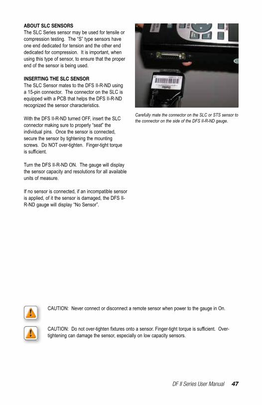
ABOUT SLC SENSORSThe SLC Series sensor may be used for tensile or compression testing. The “S” type sensors have one end dedicated for tension and the other end dedicated for compression. It is important, when using this type of sensor, to ensure that the proper end of the sensor is being used.
INSERTING THE SLC SENSORThe SLC Sensor mates to the DFS II-R-ND using a 15-pin connector. The connector on the SLC is equipped with a PCB that helps the DFS II-R-ND recognized the sensor characteristics.
With the DFS II-R-ND turned OFF, insert the SLC connector making sure to properly “seat” the individual pins. Once the sensor is connected, secure the sensor by tightening the mounting screws. Do NOT over-tighten. Finger-tight torque issufficient.
Turn the DFS II-R-ND ON. The gauge will display the sensor capacity and resolutions for all available units of measure.
If no sensor is connected, if an incompatible sensor is applied, of it the sensor is damaged, the DFS II-R-ND gauge will display “No Sensor”.
Carefully mate the connector on the SLC or STS sensor to the connector on the side of the DFS II-R-ND gauge.
CAUTION: Never connect or disconnect a remote sensor when power to the gauge in On.
CAUTION:Donotover-tightenfixturesontoasensor.Finger-tighttorqueissufficient.Over-tightening can damage the sensor, especially on low capacity sensors.

48 DF II Series User Manual
HANDLING THE SLC SENSORThe SLC Sensor is a precision instrument. HANDLE WITH CARE and follow these precautions:
PRECAUTIONS
n Do not connect the sensor when the pow-er to the DFS II-R-ND is ON. Make sure that power to the DFS II-R-ND is OFF before connecting your sensor.
n Do not disconnect the sensor by pulling on the cable. Grasp the connector and pull the sensor from the DFS II-R-ND gauge.
n Do not carry the sensor using the cable. This may damage the internal wiring of the sensor.
n Make sure to use the proper end of the “S” type sensors. One end is dedicated to “tension”. One end is dedicated to “compres-sion”.
n Use the proper capacity for your testing. Ideally, make sure that the expected mea-sured load falls within the 20% to 80% range of the sensor capacity.
n Never connect an incompatible sensor. Use only SLC Series or STS Series sensors.
n Store your sensor properly. When not in use, store your SLC sensor in its original carrying case.
NEVER disconnect the sensor by pulling on the cable. This may damage connections. Disconnect by grasping the connector and pulling from the connector housing.
For a tensile test, fix the tensile adapter at the end opposite the “Dead Side”. Connect the “Dead Side” to the tester.
For a compression test, fix the compression adapter at the end opposite the “Dead Side”. Connect the “Dead Side” to the tester.
“Dead” Side
“Dead” Side
DF II Series User Manual 49
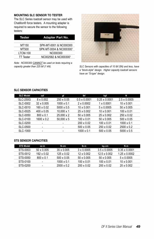
MOUNTING SLC SENSOR TO TESTERThe SLC Series loadcell sensor may be used with Chatillon® force testers. A mounting adapter is required to secure the sensor to the following testers:
Tester Adapter Part No. MT150 SPK-MT-0001 & NC000300 MT500 SPK-MT-0004 & NC0003001
LTCM-100 NC000300 TT Tester NC002582 & NC0003001
Note: NC000300 CANNOT be used on tests requiring a capacity greater than 225 lbf (1 kN).
SLC SENSOR CAPACITIES
SLC-250G 8 x 0.002 250 x 0.05 0.5 x 0.0001 0.25 x 0.0001 2.5 x 0.0005 SLC-0002 32 x 0.005 1000 x 0.1 2 x 0.0002 1 x 0.0001 10 x 0.001 SLC-0010 160 x 0.02 5000 x 0.5 10 x 0.001 5 x 0.0005 50 x 0.005 SLC-0025 400 x 0.05 10,000 x 1 25 x 0.002 10 x 0.001 100 x 0.01 SLC-0050 800 x 0.1 25,000 x 2 50 x 0.005 25 x 0.002 250 x 0.02 SLC-0100 1600 x 0.2 50,000 x 5 100 x 0.01 50 x 0.005 500 x 0.05 SLC-0200 - - 200 x 0.02 100 x 0.01 1000 x 0.1 SLC-0500 - - 500 x 0.05 250 x 0.02 2500 x 0.2 SLC-1000 - - 1000 x 0.1 500 x 0.05 5000 x 0.5
SLC Model ozf gf lbf kgf N
SLC Sensors with capacities of 10 lbf (5N) and less, have a “block-style” design. Higher capacity loadcell sensors have an “S-type” design.
STS SENSOR CAPACITIES
STS-0003 50 x 0.005 35 x 0.005 3 x 0.0005 3.5 x 0.0005 0.35 x 0.0001 STS-0012 192 x 0.02 125 x 0.02 12 x 0.002 12.5 x 0.002 1.25 x 0.0002 STS-0050 800 x 0.1 500 x 0.05 50 x 0.005 50 x 0.005 5 x 0.0005 STS-0100 - 1000 x 0.1 100 x 0.01 100 x 0.01 10 x 0.001 STS-0200 - 2000 x 0.2 200 x 0.02 200 x 0.02 20 x 0.002
STS Model oz-in N-cm lb-in kg-cm N-m

50 DF II Series User Manual
USING SOFTWAREYour DF II Series gauge can be operated using our applications software:- NEXYGEN DF2- ForceTest
Specificsoftwareinformationisavailableonde-mand.
DF II Series User Manual 51
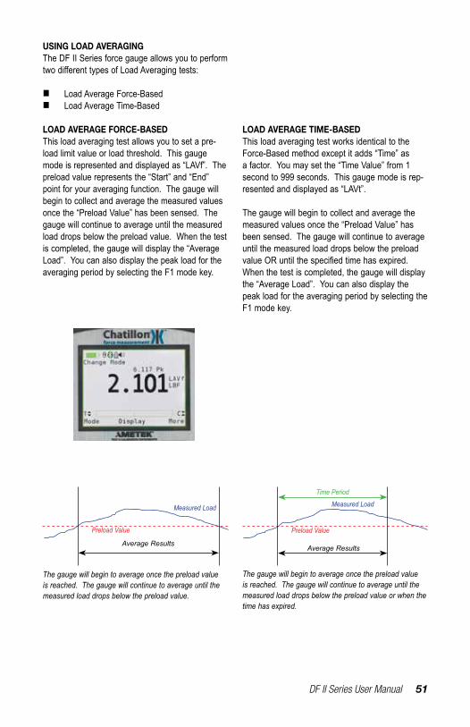
USING LOAD AVERAGINGThe DF II Series force gauge allows you to perform twodifferenttypesofLoadAveragingtests:
n Load Average Force-Basedn Load Average Time-Based
LOAD AVERAGE FORCE-BASEDThis load averaging test allows you to set a pre-load limit value or load threshold. This gauge mode is represented and displayed as “LAVf”. The preload value represents the “Start” and “End” point for your averaging function. The gauge will begin to collect and average the measured values once the “Preload Value” has been sensed. The gauge will continue to average until the measured load drops below the preload value. When the test is completed, the gauge will display the “Average Load”. You can also display the peak load for the averaging period by selecting the F1 mode key.
LOAD AVERAGE TIME-BASEDThis load averaging test works identical to the Force-Based method except it adds “Time” as a factor. You may set the “Time Value” from 1 second to 999 seconds. This gauge mode is rep-resented and displayed as “LAVt”.
The gauge will begin to collect and average the measured values once the “Preload Value” has been sensed. The gauge will continue to average until the measured load drops below the preload valueORuntilthespecifiedtimehasexpired.When the test is completed, the gauge will display the “Average Load”. You can also display the peak load for the averaging period by selecting the F1 mode key.
The gauge will begin to average once the preload value is reached. The gauge will continue to average until the measured load drops below the preload value.
The gauge will begin to average once the preload value is reached. The gauge will continue to average until the measured load drops below the preload value or when the time has expired.
Average Results
Measured Load
Preload Value
Average Results
Measured Load
Preload Value
Time Period

52 DF II Series User Manual
LOAD AVERAGE SETUPTo setup the Load Average function, from the Home display depress F3 (More) three times. Use the navigation key to position the arrow at the “Load Average” function. Press ENTER.
LOAD AVERAGE - SELECT TYPEThe DFS II load average default type is Load Aver-age Force-Based. The setup menu will display the current Preload Value (PreL).
To change the Load Average type to Time-based, select the F1 (T-ON) key. The gauge will now display “Time”. A cursor will appear next to the “Preload” value. Use the F1 key to toggle between the two available Load Average Types.
SELECTING INCREMENTSIncrements are associated with the numeric values displayed by the gauge during setup. You select the increment you want to use to adjust your setup values. Increments are provided in values corresponding to the gauge capacity and units of measure. Increment values available are:
n 0.001n 0.01n 0.1n 1.0n 10.0n 100.0
Selecting an increment of 10.0 will adjust the setup numeric value by “tens”. Selecting the increment 0.1 will adjust the setup numeric value by “tenths”.
You select increments using the RIGHT and LEFT arrow keys on the navigation pod. Selecting the RIGHT arrow increases the increment value. Selecting the LEFT arrow decreases the increment value.
DF II Series User Manual 53
SELECTING PRELOAD LIMITThe “Preload Value” is the threshold value or “trigger point”thatdefinesthe“Start”and“End”ofthe average function.
If the Preload Value is 5.00 lbf, the gauge will start to average once the load sensor has detected a 5.00 lbf load. The gauge will continue to average the load that is applied to the load sensor until the applied load drops below 5.00 lbf. Once the load drops below the preload value, the test is ended. The average is calculated and displayed.
SelectthePreloadLimitvaluebyfirstadjustingyour increments. Use the UP or DOWN navigation key to set the Preload Limit value. Depressing the DOWN key will decrease the displayed value. Depressing the UP key will increase the displayed value. Depress ENTER to select.
SELECTING TIME LIMITThe “Time Value” functions with the “Preload Value”. It represents the operand “OR” when selected. The gauge will “start” to average once the preload value is acheived. The gauge will continue to average until the load applied to the sensor drops below the preloadvalue,OR,untilthetimeperiodspecifiedexpires.
ToselectTime,youmustfirstactivethetimefunctionby pressing the F1 (T-ON) key. This enables the time function. When in the time function, you may disable by depressing the F1 (T-OFF) key.
Select the F2 (Time) key. This will reposition the cursor arrow next to the Time label.
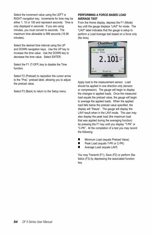
54 DF II Series User Manual
Select the increment value using the LEFT or RIGHT navigation key. Increments for time may be either 1, 10 or 100 and represent seconds. Time is only displayed in seconds. If you are using minutes, you must convert to seconds. The maximum time allowable is 999 seconds (16.56 minutes).
Select the desired time interval using the UP and DOWN navigation keys. Use the UP key to increase the time value. Use the DOWN key to decrease the time value. Select ENTER.
Select the F1 (T-OFF) key to disable the Time function.
Select F2 (Preload) to reposition the cursor arrow to the “PreL” preload label, allowing you to adjust the preload value.
Select F3 (Back) to return to the Setup menu.
PERFORMING A FORCE-BASED LOAD AVERAGE TESTFrom the Home display, depress the F1 (Mode) key until the gauge displays “LAVf” for mode. The “LAVf” label indicates that the gauge is setup to perform a Load Average test based on a force only (No time).
Apply load to the measurement sensor. Load should be applied in one direction only (tension or compression). The gauge will begin to display the changes in applied loads. Once the measured load equals the preload value, the gauge will begin to average the applied loads. When the applied loadfallsbelowthepreloadvaluespecified,thedisplay will “freeze”. The gauge will display the LAVf result when in the LAVf mode. The user may also display the peak load (the maximum load that was applied during the averaging function) be pressing the F1 key until you display “T-PK” or “C-PK”. At the completion of a test you may record the following:
n Minimum Load (equals Preload Value)n Peak Load (equals T-PK or C-PK)n Average Load (equals LAVf)
You may Transmit (F1), Save (F2) or perform Sta-tistics (F3) by depressing the associated function key.
DF II Series User Manual 55
PERFORMING A TIME-BASED LOAD AVERAGE TESTFrom the Home display, depress the F1 (Mode) key until the gauge displays “LAVt” for mode. The “LAVt” label indicates that the gauge is setup to perform a Load Average test based on a preload limit and a time period.
Apply load to the measurement sensor. Load should be applied in one direction only (tension or compression). The gauge will begin to display the changes in applied loads. Once the measured load equals the preload value, the gauge will begin to average the applied loads. When the applied loadfallsbelowthepreloadvaluespecified,orwhen the time set has expired, the display will “freeze”. The gauge will display the LAVt result when in the LAVt mode. The user may also dis-play the peak load (the maximum load that was ap-plied during the averaging function) be pressing the F1 key until you display “T-PK” or “C-PK”. At the completion of a test you may record the following:
n Minimum Load (equals Preload Value)n Peak Load (equals T-PK or C-PK)n Average Load (equals LAVf)
You may Transmit (F1), Save (F2) or perform Sta-tistics (F3) by depressing the associated function key.
TEST ANNUCIATORSThe Load Averaging feature employs three types of annunciators to:
1. Signal the START of your Test,2. Signal the END of your Test,3. Signal the FAILURE of a Test
Signal the START of a TestA single beep will sound to signal the START of a test.
The START of a test is determine by the measured load achieving the Preload Value that you setup for the test.
Signal the END of a TestA double beep will sound to signal the END of a test that is based on both a Preload Value and a Time Period.
When a Time-based test is being conducted, a double beep will annunciate when the time period for the test has been achieved.
Signal a FAILED TestA rapid, triple beep will sound to alert you that the measured load dropped below the Preload Value before the Time Period was completed.
56 DF II Series User Manual
USING BREAK DETECTION (DFS II ONLY)Break Detection is used when you want to capture the break load of a sample. This function is use-ful especially with samples that characteristically yield before they actually break. The Break Detect function provides you with the Peak Load and the Break Load.
The DFS II Series gauge will report the following as part of a Break Detect test:
n Break Loadn Break Point (Break Threshold)n % Drop (used to calculate the Break Load from Maximum Load)
The Break Load is calculated as:
Break Load = (Peak Load)(% Drop)
The%Dropisauser-definedpointthatthegaugewill use to determine the break load. The % Drop value is the percentage of the maximum load that theDFSmeasuresthatyoudefineastheBreakLoad.
In some cases, the Peak Load is the Break Load. However, with samples that yield before breaking, the Break Load is often not the same as the Peak Load.
Example: If the maximum load was measured to be 100 lbf and the % Drop was setup as 80%, the gaugewilldefinetheBreakLoadas80lbf.
If the maximum load was measured to be 50 N and the % Drop was setup as 50%, the gauge will de-finetheBreakLoadas25N(50Nx0.5=25N).
The DFS II Series force gauge allows you to per-formtwodifferenttypesofBreaktests:
n Sharp Break Test (95% Drop Fixed)n Percentage Drop (% Break) Test
ASharpBreakisdefinedasa95%dropinmea-sured load from the recorded maximum load. The 95% Drop is a preset and cannot be changed by the user. When the load drops to a value equal to 95% of the maximum load, the gauge will identify this point as the Break Load.
APercentageDrop(%Break)isauser-defineddrop in measured load after the maximum load. You may select the desired % Drop to be used to calculate the Break Load.
Noisy samples, such as adhesives or peel tests shouldbespecifiedwithahigh%Dropandwiththe Peak Filter set at 10Hz. Setting the % Drop too low may cause the gauge to sense a break be-fore a break actually occurs. Conversely, samples that are rigid may use a high % Drop value. How-ever, rigid samples typically break at a value equal to the Peak Load.

DF II Series User Manual 57
Time
Mea
sure
d Lo
ad
50 lbf Break Detect
95 lbf (95% Drop)
100 lbf - Max LoadX
X
PERCENTAGE BREAKThe Percentage Break test allows you to specify the % Drop from the Peak Load. If you set the % Drop at 80%, the DFS II gauge will determine the Break Load when the measured load is 80% of the Peak Load value.
When the DFS II Series gauge is in the “% Break Mode”, the mode indicator will display as “%CBk” for “% Compressive Break”. The DFS II mode indicator will display “%TBk” for “% Tension Break”.
SHARP BREAKThe Sharp Break test looks for a 95% Drop from the maximum load. In this test, you can determine the “Break Detect Point” which is the load that mustfirstbeachievedbeforetheDFSIISeriesgauges begins to look for a 95% Drop in load. The “Break Detect Point” is sometimes referred to as the “load threshold” or “trigger load”.
During a Sharp Break Test, the DFS II gauge will look for the Peak Load value and determine a “Sharp Break” when the measured load equals 95% of the Peak Load value.
When the DFS II Series gauge is in the “Sharp Break Mode” the mode indicator will display as “SCBk” for “Sharp Compressive Break”. The DFS II mode indicator will display “STBk” for “Sharp Tension Break”.
Time
Mea
sure
d Lo
ad
50 lbf Break Detect
75 lbf (75% Drop)
100 lbf - Max LoadX
X
58 DF II Series User Manual
BREAK DETECTION SETUPTo setup the Break Detection function, from the Home display depress F3 (More) three times. Use the navigation key to position the arrow at the “Break Detect” function. Press ENTER.
BREAK DETECT - SELECT TYPEThe DFS II break detect default type is Percentage Break. To change the break detect type to Sharp Break, select the F1 (Sharp) key.
To change from Sharp Break to Percentage Break, select F1 (% Drop).
Results are expressed with the following mode lables:n STBk (Sharp Break Tension)n SCBK (Sharp Break Compression)n %TBK (% Break Tension)n %CBK (% Break Compression)
SELECTING INCREMENTSIncrements are associated with the numeric values displayed by the gauge during setup. You select the increment you want to use to adjust your setup values. Increments are provided in values corresponding to the gauge capacity and units of measure. Increment values available are:
n 0.001n 0.01n 0.1n 1.0n 10.0n 100.0
Selecting an increment of 10.0 will adjust the setup numeric value by “tens”. Selecting the increment 0.1 will adjust the setup numeric value by “tenths”.
You select increments using the RIGHT and LEFT arrow keys on the navigation pod. Selecting the RIGHT arrow increases the increment value. Selecting the LEFT arrow decreases the increment value.
DF II Series User Manual 59
SELECTING BREAK POINTThe “Break Point” is the break detector value or the “break trigger”. It is the force value that must be acheived before the gauge will look for the maximum load and the peak load.
It is important to set a correct “Break Point” based on the type of sample and the sample’s break characteristics.
In a peel application, if the break point is set too low, the gauge may sense a break due to the characteristically noisy signal produced by a peel application. In a peel test, it is quite easy to have a 95% drop from a maximum load that is not representative of the true maximum load or true break load.
If the break point is set too high, the gauge may never see a break.
The best way to establish the break point is through sample testing trials.
Break Point - Sharp Break MethodTo set the Break Point in a Sharp Break setup, establish the correct increment value. Use the UP navigation arrow to increase the Break Point value, and the DOWN navigation arrow to decrease the value. Select Enter once you have the desired Break Point value displayed.
Break Point - Percentage Break MethodTo set the Break Point in a Percentage Break setup, establish the correct increment value. Position the arrow cursor next to the label “BkPt”.
If the cursor arrow is next to the “%Bk” label, select the F2 (BKpt) key. This will reposition the cursor arrow next to the “BkPt” label.
Use the UP navigation arrow to increase the Break Point value, and the DOWN navigation arrow to decrease the value. Select Enter once you have the desired Break Point value displayed.
60 DF II Series User Manual
SELECTING % DROP VALUEThe “% Drop” is the percentage drop value. This represents how much the measured load must drop from a previous maximum load for the DFS II Series gauge to identify the break load.
ASharpBreakhasafixedpercentagedropof95%. It presents the 95% value from full scale. If the maximum load is 100 lbf and the % Drop is 95% (for a Sharp Break), the break load will be at 95 lbf. At 95 lbf, the DFS II gauge will “end the test”. If the gauge is used with a TCD tester, the gauge will signal the tester at 95 lbf to stop the test.
APercentageBreakisauser-definedpercentagedrop. You may specify the % Drop to be from 1% to 99%.
To change the “% Drop” value, select the F2 (Percent) key. The cursor arrow will now point to the “%Drop” label.
Select the proper increments using the LEFT and RIGHT navigation arrows. The LEFT arrow decreases the increment value. The RIGHT arrow increases the increment value.
Use the UP arrow to increase the “%Drop” value. Use the DOWN arrow to decrease the “%Drop” value. Select Enter when the required % drop value is displayed.

DF II Series User Manual 61
PERFORMING A SHARP BREAK TESTOnce you have setup your Break Detect, from the Home display, depress the F1 (Mode) key until the DFS II displays “Norm”.
Pull to BreakA pull to break test will use the mode “STBk”. Af-fixyoursampletothegriporfixtureandzerothegauge.PresstheZerokeytozerotheloadeffectscausedbythesampleweightandfixture(tareout).
Pull the sample (manually or using a Chatillon® tester). The load applied to the load sensor is dis-played during the test.
When the sample breaks (physically breaks) or when the load caused by the sample being pulled drops by 95% from a maximum value, the test will end.
You may view the Peak Load by pressing the F1 (Mode) key until the mode indicator displays “T-PK”. The value displayed is the Peak Tensile value for the test. This value is taken from the DFS II Series gauge’s Peak Register.
You may view the Break Load by depressing the F1 (Mode) key until the mode indicator displays “STBk”. The DFS II Series gauge will display the following results and test parameters:
n 95% Drop (Sharp Break Default value)n Break (Break Load) expressed as “STBk”n Max (Maximum Load)
Compress to Rupture (Break)A compress to rupture test will use the mode “SCBk”.Affixyoursampletothegriporfixtureand zero the gauge. Press the Zero key to zero theloadeffectscausedbythesampleweightandfixture(tareout).
Compress (Push) the sample (manually or using a Chatillon® tester). The load applied to the load sensor is displayed during the test.
When the sample breaks (physically breaks) or when the load caused by the sample being pulled drops by 95% from a maximum value, the test will end.
You may view the Peak Load by pressing the F1 (Mode) key until the mode indicator displays “C-PK”. The value displayed is the Peak Compres-sion value for the test. This value is taken from the DFS II Series gauge’s Peak Register.
You may view the Break Load by depressing the F1 (Mode) key until the mode indicator displays “SCBk”. The DFS II Series gauge will display the following results and test parameters:
n 95% Drop (Sharp Break Default value)n Break (Break Load) expressed as “SCBk”n Max (Maximum Load)

62 DF II Series User Manual
PERFORMING A PERCENTAGE BREAK TESTOnce the Percentage Break Setup is complete, from the Home display, depress the F1 (Mode) key until the DFS II displays “Norm”.
Pull to BreakApulltobreaktestwillusethemode“%TBk”.Affixyoursampletothegriporfixtureandzerothegauge.PresstheZerokeytozerotheloadeffectscausedbythesampleweightandfixture(tareout).
Pull the sample (manually or using a Chatillon® tester). The load applied to the load sensor is displayed during the test.
When the sample breaks (physically breaks) or when the load caused by the sample being pulled dropsbyyourspecified%Dropfromamaximumvalue, the test will end.
You may view the Peak Load by pressing the F1 (Mode) key until the mode indicator displays “T-PK”. The value displayed is the Peak Tensile value for the test. This value is taken from the DFS II Series gauge’s Peak Register.
You may view the %Break Load by depressing the F1 (Mode) key until the mode indicator displays “%TBk”. The DFS II Series gauge will display the following results and test parameters:
n %Drop(user-defined)n Break (Break Load)) expressed as “%TBk”n Max (Maximum Load
Compress to Rupture (Break)A compress to rupture test will use the mode “%CBk”.Affixyoursampletothegriporfixtureand zero the gauge. Press the Zero key to zero theloadeffectscausedbythesampleweightandfixture(tareout).
Compress (Push) the sample (manually or using a Chatillon® tester). The load applied to the load sensor is displayed during the test.
When the sample breaks (physically breaks) or when the load caused by the sample being pulled drops by 95% from a maximum value, the test will end.
You may view the Peak Load by pressing the F1 (Mode) key until the mode indicator displays “C-PK”. The value displayed is the Peak Compression value for the test. This value is taken from the DFS II Se-ries gauge’s Peak Register.
You may view the Break Load by depressing the F1 (Mode) key until the mode indicator displays “%CBk”. The DFS II Series gauge will display the following results and test parameters:
n %Drop(user-defined)n Break (Break Load) expressed as “%CBk”n Max (Maximum Load)

DF II Series User Manual 63
VIEWING YOUR BREAK TEST RESULTThe DFS II Series gauge will display the following information at the completion of a test:From this display, you may record your reading manually; zero your test and start another, or navigate to the SAVE Mode. The SAVE Mode allows you to “Save” the result to the gauge memory or “Transmit” the value to an external de-vice through the gauge’s RS232, USB or Mitutoyo output.
To Zero the result, depress the Zero key. The result is erased from the gauge.
To go to the SAVE Mode, select the F3 (More) key.
TRANSMITTING YOUR BREAK TEST RESULTFrom the SAVE Mode, select the F1 (Xmit) key to transmit information through the DFS II Series RS232 or USB communication port. When you select the F1 (Xmit) key you will be provided with two options:
n Xmit-W (F1)n XmitAll (F2)
The F1 “Xmit-W” key will transmit the currently displayed value for %CBk mode through the DFS II gauge’s digital output port. The following informa-tion is transmitted:
n Break Load with Units (%TBk,%CBk, STBk, SCBk)n Maximum Load with Unitsn % Drop Valuen Break Point Valuen Peak Register Value (T-PK, C-PK)n Pass/Fail(ifconfigured)n Pass/FailLimits(ifconfigured)
The “Xmit-W” represents that the values will be transmited “With” units. You may elect to transmit values without units by changing the Transmit op-tion in the COMMUNICATIONS setup. Change the“XmitUnits”from“ON”to“OFF”.When“Off”,the gauge will transmit information without units. The F1 key will display “Xmit-O”, the values will be transmitted without units.

64 DF II Series User Manual
When the F2 “XmitAll” key is selected, the gauge will transmit all information “Saved” in the gauge memory for the %Bk mode. The following informa-tion is transmitted:
n Result Number (1- 10)n Break Load with or without Unitsn Maximum Load with or without Units n Peak Load with or without Unitsn % Drop Valuen Break Point Valuen Pass or Fail Resultn Pass/Fail High Limitn Pass/Fail Low Limit
Information will be transmitted in a Row format. Each Row will represent the Result Number. Column headers will be transmitted for each result value listed above.
Result Break Load Max Load Peak Load %Drop BkPt P/F P/F High P/F Low
1 25.00 lbf 50.00 lbf 53.48 lbf 50% 15 lbf Pass 30.00 lbf 20.00 lbf
Sample Row Report
DF II Series User Manual 65
SAVING YOUR BREAK TEST RESULTYou may save up to 100 results in the DFS II Series gauge memory. If you are saving informa-tion, remember that the gauge can only save 100 results. It is also important for good operating practice to save like mode information. Don’t mix differentresultsfromdifferentmodes.
From the SAVE Mode, select the F2 (Save) key to “save” information to the DFS II Series gauge’s in-ternal memory. Up to 100 results may be stored in memory. If larger numbers of results are required, you should use the Nexygen DF II Series Software.
The gauge will display the Result Number compared to the available results saved, e.g. “1 of 100 Saved”.
If the memory is full (100 results are saved), the gauge will display “Memory Full”. You must “Clear” a result to save another result.
When you “Clear” a result, select the F2 (Clear) key. The result that is currently displayed will be cleared after you select the Enter key. You may also clear all results by selecting the Zero key and all will be cleared after selecting the Enter key. The DFS II gauge will indicate how many results remain in memory, e.g. “1 of 9 Saved”, “1 of 8 Saved”, etc.
66 DF II Series User Manual
APPLYING STATISTICS TO YOUR BREAK TEST RESULTThe DFS II Series gauge will calculate statistics for your Break Test results saved in the gauge memory. The gauge will calculate and display the following:
n Meann CoefficientofVariation(COV)n %Differencen Standard Deviation
The “Statistics” function is part of the “Save” function within the DFS II Series gauge. To calculate and display statistics from the Home display, select the F3 (More) key. Then select the “i” key. Next select the F3 (More) key for gauge statistics.
View MeanThefirstcalculatedstatisticisMean.TheDFSIISeries gauge will display the average of the number of results saved in memory. In addition to the Mean value, the gauge will also display the Maximum and Minimum values on which the Mean was calculated.
Select the F1 (Xmit) key to transmit the displayed information through the digital output port.
Select F2 (COV) to calculate and display the next statistic-CoefficientofVariation.
Select F3 (More) to go to the next statistical operand-%Difference.
View COV (Coefficient of Variation)COV is displayed after Mean. The DFS II Series gauge will display the COV value and the Standard Deviation and Mean used to calculate this result.
Select the F1 (Xmit) key to transmit the displayed information through the selected communications port.
SelectF2(%Diff)tocalculateanddisplaythenextstatistic-%Difference.
Select F3 (More) to go to the next statistical operand- Standard Deviation.
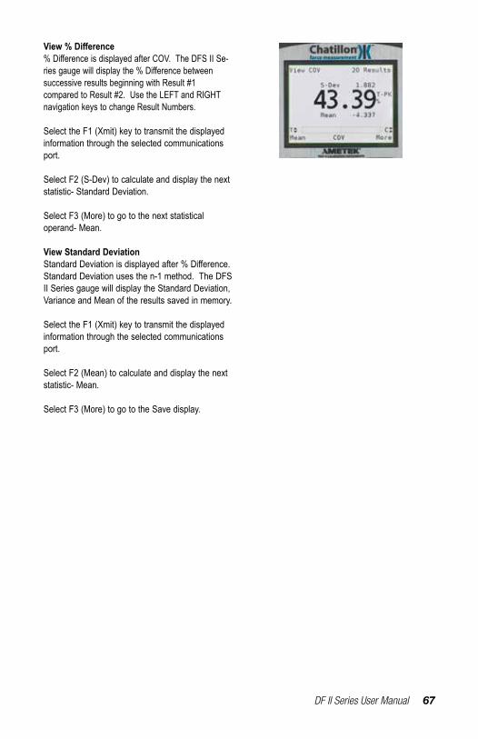
DF II Series User Manual 67
View % Difference%DifferenceisdisplayedafterCOV.TheDFSIISe-riesgaugewilldisplaythe%Differencebetween successive results beginning with Result #1 compared to Result #2. Use the LEFT and RIGHT navigation keys to change Result Numbers. Select the F1 (Xmit) key to transmit the displayed information through the selected communications port.
Select F2 (S-Dev) to calculate and display the next statistic- Standard Deviation.
Select F3 (More) to go to the next statistical operand- Mean.
View Standard DeviationStandardDeviationisdisplayedafter%Difference.Standard Deviation uses the n-1 method. The DFS II Series gauge will display the Standard Deviation, Variance and Mean of the results saved in memory. Select the F1 (Xmit) key to transmit the displayed information through the selected communications port.
Select F2 (Mean) to calculate and display the next statistic- Mean.
Select F3 (More) to go to the Save display.

68 DF II Series User Manual
USING FILTERSThe DF II Series digital force gauge supplies two typesoffiltering.Filteringmaybeusefulwith applications that are “noisy” or susceptible to vibrationeffects,e,g.,gaugesmeasuringextremelylow forces below 250gf. Filtering may be used to “dampen”theeffectsoftheseexternalconditionsin order to provide you with a more stable display of information.
DISPLAY FILTERThe Display Filter is also called the Normal Filter. The default display update rate for the DF II Series is 10Hz. The display data rate may be reduced to 4Hz (maximum data averaging before values are displayed).AdjustingtheDisplayFilteraffectstheinstantaneous force measurement results displayed in Normal mode.
PEAK FILTERThePeakFilteraffectsthepeaktensionandcom-pression values. The default Peak Filter is set at 1 KHz. At this rate, the gauge updates quickly with minimal averaging for peak load indication. The Peak Filter may be adjusted to 10Hz, 100Hz, 1 KHz, and 7 KHz for the DFE II or 10 KHz for the DFS II.
FILTER SETUPTheDFIISeriesfiltersaresetupfromtheMainSetup Menu. From the Home display, press the F3 (More) key three times.
DF II Series User Manual 69
Use the UP or DOWN navigation key to position the cursor arrow next to the “Filters” option. Select ENTER.
DISPLAY FILTER SETUPFrom the Main Filter Setup display, you may set theDisplayandPeakfilterrate.ThecursorarrowwillappearnexttotheDisplayfilteroption,“Disp10 Hz”. This is the default display update rate. To change the Display Filter rate to 4Hz, depress the UP or DOWN navigation key. The display rate will change between 10Hz and 4Hz. Select ENTER when the desired rate is displayed.
PEAK FILTER SETUPFrom the Display Filter setup, depress F1 (Peak) to change the Peak Filter setup. Selecting F1 (Peak) will position the cursor arrow next to the “Peak” label. Use the UP and DOWN arrow to adjust the peak sample rate to the desired setting. The peak sample rate default is 10KHz (10kHz) and may be changed to 1KHz, 100 Hz and 10Hz respectively. SelectENTERtoapplyfilterrate.
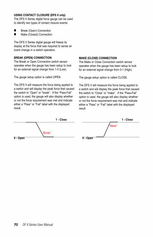
70 DF II Series User Manual
USING CONTACT CLOSURE (DFS II only)The DFS II Series digital force gauge can be used to identify two types of contact closure events:
n Break (Open) Connectionn Make (Closed) Connection
The DFS II Series digital gauge will freeze its display at the force that was required to sense an event change in a switch operation.
BREAK (OPEN) CONNECTIONThe Break or Open Connection switch sensor operates when the gauge has been setup to look for an external signal change from 1-0 (Low).
The gauge setup option is called OPEN.
The DFS II will measure the force being applied to a switch and will display the peak force that caused the switch to “Open” or “break”. If the “Pass-Fail” option is used, the gauge will also display whether or not the force requirement was met and indicate either a “Pass” or “Fail” label with the displayed result.
MAKE (CLOSE) CONNECTIONThe Make or Close Connection switch sensor operates when the gauge has been setup to look for an external signal change from 0-1 (High).
The gauge setup option is called CLOSE.
The DFS II will measure the force being applied to a switch and will display the peak force that caused the switch to “Close” or “make”. If the “Pass-Fail” option is used, the gauge will also display whether or not the force requirement was met and indicate either a “Pass” or “Fail” label with the displayed result.
0 - Open
1 - Close
“Make”
0 - Open
1 - Close
“Break”

DF II Series User Manual 71
CONTACT CLOSURE OPERATIONThecontactclosurefeaturemustbespecifiedinthe gauge setup and the gauge must be placed in Contact Closure Mode. When in Contact Closure mode, the DFS II Series gauge will “freeze” the display at the load that caused a switch “make” or “break”.
The DFS II Series gauge must have a cable that jumpers Pins 8 and 10 and that connects the switch to the force gauge.
CONTACT CLOSURE MODEThe DFS II Series will indicate that the gauge is in the Contact Closure mode. The mode indicator will display as “OFRZ” for a “break” setup or as “CFRZ” for a “make” setup. The load measurement will represent the actual load that was sensed by the gauge when the switch was “opened” of “closed”. Units may be changed and results may be saved in the gauge memory for statistical calculations.
CONTACT CLOSURE PASS-FAILThe DFS II Series gauge’s Pass-Fail feature can be used with the Contact Closure Mode. Pass orFaillimitsmaybeconfiguredbytheuserinthegauge setup. When this feature is enabled, the DFS II Series gauge will display a green “PASS” or ared“FAIL”basedonthelimitsthatwereconfig-ured and the load that is displayed by the gauge. The Pass or Fail limits may be based on a RANGE or on a NOMINAL VALUE with BANDWIDTH. See “Using Pass-Fail Limits” for more information.
1 TXD O RS-232 Transmitted Data 2 RXD I RS-232 Received Data 3 GND O Ground Digital Ground 4 O Clock Mitutoyo Clock 5 O Ready Mitutoyo Ready 6 I Request Mitutoyo Request 7 O Data Mitutoyo Data 8 I Detect Sense Contact Closure 9 O Setpoint Setpoint Output Signal 10 - Ground Digital Ground 11 - Analog GND Analog Ground 12 O Analog SIG Analog Output
PIN SYMBOL I/O PURPOSE DESCRIPTION
98
7
65
4
3
21
1012 11
72 DF II Series User Manual
CONTACT CLOSURE SETUPContactclosureisspecifiedusingtheDFSIIGauge Setup menu.
From the HOME display, press F3 (More) four times to get to the CONTACT CLOSURE option.
Use the UP or DOWN navigation key to cursor to the CONTACT CLOSURE option and select ENTER.

DF II Series User Manual 73
CONTACT CLOSURE - ON/OFFIf this option is selected, the DFS II Series gauge will not freeze its display when a switch event has oc-curred. There is no Contact Closure Mode available. Select F1 (ON/OFF) to enable or disable contact closure.
CONTACT CLOSURE - OPEN TYPEIf this option is selected, the DFS II Series gauge will freeze its display when a switch has been opened (break). Select F1 (OPEN) to specify the DFS II to look for a switch “break”. Select F2 (Back)toturncontactclosureOff.
CONTACT CLOSURE - CLOSE TYPEIf this option is selected, the DFS II Series gauge will freeze its display when a switch has been closed (make). Select F1 (CLOSE) to specify the DFS II to look for a switch “make”. Select F2 (Back)toturncontactclosureOff.
74 DF II Series User Manual
DFE II DFS II DFS II-R DFS II-R-SLC DFS II-R-STSAccuracy: % of full scale +0.25% +0.1% +0.1% +0.25%1 0.3%Data Sampling Rate (KHz): 7 10 10 10 10Peak Capture Rate (Hz): 7000 10,000 10,000 10,000 10,000Display Update Rate (Hz): 10 10 10 10Display Resolution: 1000:1 10,000:1 10,000:1 10,000:1 10,000:1Tare Capacity (% Full Scale): 110% 110% 110% 110% 110%Overload Protection (% Full Scale): 150% 150% 150% 150% 150%Display Type: Color Color Color Color ColorMemory (No. of Saved Results): 20 100 100 100 100Note 1: SLC-02000, SLC-05000 and SLC-10000 capacities used with the DFS II-R-ND have a calibration accuracy of +0.5% of full scale.
Common Specifications to all DF ModelsTemperature Rating Operating Temperature: 40O to 100OF (4O to 38OC) Storage Temperature: 0O to 130OF (-17O to 54OC) Temperature Stability: +0.015% per OF Relative Humidity: 20% to 85% non-condensingConformity: BS EN 61010-1: 2010 Safety Requirements for Electrical Equipment, BS EN 61326--1: 2006 Electrical Equipment for Measurement, Control and Laboratory use: General Requirements BS EN 61326--2-3: 2006 Electrical Equipment for Measurement, Control and Laboratory use: Transducers with integrated or remote signal conditioning, RoHS and WEEEPower: Battery (Nickel Metal Hydride) or direct AC 120/230VacBattery Life: With Dimming ON: 20 Hours With dimming OFF: 16 HoursSoftware: Use with NEXYGEN DF2 or Forcetest softwareInstrument Weight: 1.5 lbs (0.7 kg)Shipping Weight: 4 lbs (2 kg)Warranty Period: 1 yearFEATURES & FUNCTIONSOperating Modes DFE II DFS II DFS II-R DFS II-R-ND Normal Std Std Std Std Peak (Tension & Compression) Std Std Std Std Load Limits Std Std Std Std Load Average Std Std Std Std Break Detection - Std Std Std Contact Closure - Std Std Std Peak (Torque) - - - StdTolerances (Pass/Fail) Std Std Std StdOutputs Analog Std Std Std Std Digital RS232 Std Std Std Std USB Std Std Std Std Mitutoyo Std Std Std StdOutput Filters Peak Std Std Std Std Display Std Std Std StdStatistics Mean Std Std Std Std Max/Min Std Std Std Std COV Std Std Std Std Standard Deviation Std Std Std Std%Difference Std Std Std Std Password Std Std Std Std Auto Dimming Std Std Std Std Multiple Languages Std Std Std Std Graphing Std Std Std
SPECIFICATIONS
DF II Series User Manual 75
DIMENSIONS
2.86” (72.6 mm)
1.80” (45.7 mm)
3.00
” (76
.3 m
m)
3.48
” (88
.3 m
m)
2.25
” (57
.2 m
m)
5.53
” (14
0.3
mm
)
0.69” (17.4 mm)
1.62” (41.1 mm)
6.80
” (17
2.7
mm
)
7.28
” (18
4.8
mm
)
#10-32 UNC - 2BFemale Thread
E96-354
6.8
3
[17
3.5
m
m]
2 . 8 6 [ 7 2 . 6 m m ]1 . 6 2 [ 4 1 . 1 m m ]
1 0 - 3 2 U N FMtg H o le s( 2 P la c e s )
3 . 0 3 [ 7 7 . 0 m m ]
2 . 2 5[ 5 7 . 1 m m ]
E 9 6 - 3 5 3
Gauge with Integral Load Cell Sensor Gauge with Remote Load Cell Sensor
#10-32
1.5”
#10-32F
0.75”
0.75”
2.0”
8 ft +/-6 inCoiled Cable
Extended Length
8 ft +/-6 inCoiled Cable
Extended LengthF
A
BC
D E
8 ft +/-6 inCoiled Cable
Extended LengthE
A
BC
D
1.75”
1.69 ”
8 ft +/-6 inCoiled Cable
Extended Length
A
3.68” (93.5mm)
C
B
Interchangeable Sensors for DFS-R-ND
76 DF II Series User Manual
DF II Series User Manual 77
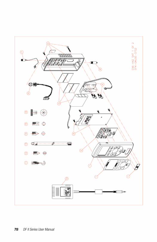
78 DF II Series User Manual
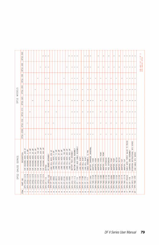
DF II Series User Manual 79
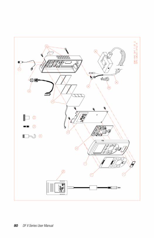
80 DF II Series User Manual
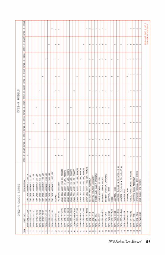
DF II Series User Manual 81

82 DF II Series User Manual

DF II Series User Manual 83

84 DF II Series User Manual
International Symbols
WEEE DirectiveThis equipment contains electrical and electronic circuits and should not be directly disposed of in a landfill site.
RoHSThis product is RoHS and China RoHS compliant. This symbol indicates the equipment contains some restricted hazardous substances above the recommended level, and may offer potential harm to the environment after 15 years from date of manufacture.
www.ametektest.com
Information in this document is subject to change without notice. ©2017 by AMETEK, Inc., www.ametek.com. All rights reserved.
UKLloyd Instruments LtdTel +44 (0)1243 833 [email protected]
FranceAMETEK S.A.S.Tel +33 (0)1 30 68 89 [email protected]
GermanyAMETEK GmbHTel +49 (0)2159 9136 [email protected]
DenmarkAMETEK DenmarkTel +45 4816 [email protected]
USAAMETEK Measurement & Calibration TechnologiesTel +1 (727) 538 [email protected]
IndiaAMETEK Instruments India Pvt Ltd.Tel +91 22 2836 [email protected]
Singapore AMETEK Singapore Pte LtdTel +65 6484 [email protected]
ChinaAMETEK Commercial Enterprise - ShanghaiTel +86 21 5868 5111
AMETEK Commercial Enterprise - BeijingTel +86 10 8526 [email protected]