User Guide - andymark-weblinc.netdna-ssl.com
16
User Guide AM14U4 Chassis Base Kit for the FIRST® Robotics Competition November 2019
Transcript of User Guide - andymark-weblinc.netdna-ssl.com

User Guide AM14U4 Chassis Base Kit for the
FIRST® Robotics Competition
November 2019

2
AndyMark – Your Robot Parts Experts
AndyMark, Inc. was founded in 2004 by Andy Baker and Mark Koors to design and sell unique mechanical parts for competition and educational robotics. Through their volunteer work at FIRST® Robotics Competition events they identified a niche market and began designing and selling robotics components for FIRST ® teams. At that time, many designs were being shared and re-created, but finding the correct fabrication resources for these parts was difficult for some FRC teams. AndyMark has been a proud supplier to the FIRST® Robotics Competition since 2005.
AndyMark's staff has over 200 years of FIRST team experience, and provides staffing services to many robot competition events throughout the year. Our Kokomo, Indiana home provides a central location for quick distribution across North America, as well as international shipping to over 70 countries.
Additional Instructions Available We encourage customers to seek product information at AndyMark.com, contact us via e-mail at [email protected], or call Toll-Free 877-868-4770 with questions about any of our products.
Detailed assembly tips and instructional videos can be found at AndyMark.com/FRCVideos. Additional resources, layout prints, and CAD are available on the AndyMark.com/KOP web page.
AM14U4 Recommended Hand Tool List (not included) Component Part Number QTY Part Photo Hammer Available at your
local hardware store. 1
Cordless Drill or Driver Available at your local hardware store.
1
3/8" Magnetic Nut Setter am-2755 1
5/16" Magnetic Nut Setter am-2754 1
9/16" Socket, 3/8" Drive am-2743 1
3/8" Socket, 3/8" Drive am-2740 1
5/32" Ball End Hex Bit Driver am-2748 1
3/8" Drive Quick Release Ratchet am-2753 1
1/2" - 9/16" Open-End Wrench am-2746 1

3
AM14U4 System Overview The AM14U4 system designed by AndyMark engineers is a fully customizable drive platform for the FIRST® Robotics Competition. The Kit of Parts Drive Chassis is a 6-Wheel Drive (6WD) AM14U4 configuration engineered to withstand the rigors of this year’s game challenge. The AM14U4 Drive Chassis Kit includes standard AndyMark products and is designed to be compatible with other AndyMark products. There are many ways to use the parts included in this kit.
• Utilize these step by step instructions to quickly build the standard drive chassis. • Take advantage of convenient built-in features to convert to another pre-engineered drive solution. • Take the existing parts and pieces included and re-design them in a new way
Gearbox Overview Each AM14U4 Chassis Base Kit includes two (2) AndyMark Toughbox Mini Gearboxes, unassembled (am-2598_K19). Each Toughbox Mini includes the parts needed to mount two 2.5” CIM motors (am-0255). The gearbox also includes holes for optional encoders such as the USDigital E4T Optical Encoder (am-3132).
]
Gear Ratio Specifications: To change the drive speed of the AM14U4, different gear ratios can be used in the Toughbox Mini. To change the ratio and drive speed, the standard 16 tooth Small Cluster Gear and 48 tooth Large Output Gear will need to be replaced with two gears totaling 64 teeth. The higher the ratio, the slower the output speed. More information about these optional gears can be found at "AndyMark.com/TBmini".
**AM14U4 speed estimation is based on calculations using 6” wheels, and one CIM motor per TB Mini running at 4100 rpm, or 75% of free speed.
Ratio 8mm Gear Lg. Cluster Sm. Cluster Lg. Output AM14U4 Speed** 5.95:1 14T (am-0034) 50T (am-0149) 24T (am-0177) 40T (am-0178) 18.0 ft/sec 7.31:1 14T (am-0034) 50T (am-0149) 21T (am-2564) 43T (am-2565) 14.7 ft/sec 8.45:1 14T (am-0034) 50T (am-0149) 19T (am-0176) 45T (am-0179) 12.7 ft/sec 10.71:1 (included) 14T (am-0034) 50T (am-0149) 16T (am-0747) 48T (am-0885) 10.0 ft/sec 12.75:1 14T (am-0034) 50T (am-0149) 14T (am-0151) 50T (am-0150) 8.4 ft/sec
Toughbox Mini Gearbox ∙ Gear Profile: 20 DP, 14.5° pressure angle ∙ Gear Material: Cold-formed 4140 Steel ∙ Output Shaft: 1/2” Hex, 4140 Steel ∙ Housing Material: Nylon 6/6 with long fiber reinforcements IN
CLU
DED
EVO Shifter 2-Speed
OPT
ION
AL
EVO Slim Single Speed Toughbox Micro For use with Mecanum

4
Power Train Specifications The AM14U4 Kit of Parts Chassis Base Kit includes Gates HTD belts and the parts needed to build a 6” 6-wheel drive chassis with a direct drive center wheel in three recommended frame sizes. Other belt sizes are available on AndyMark.com or through Gates to allow for many more configurations. Additionally, the AM14U4 parts can be used in other popular drive configurations as well. Sprocket & Chain, Direct Drive Mecanum Wheels, and 8WD can all be built by using the frame in this kit and swapping out some of the parts. For details on how to change your drive system visit AndyMark.com/AM14u4
Wheel Overview Included in the Drive Base Kit are 6” 80A HiGrip Wheels. These wheels are made of high-strength polycarbonate with an 80A urethane tread. These wheels provide long-lasting grip throughout the competition season. Many other wheels can be used as an alternative with minor adjustments to the plate spacing and layout.
6” HiGrip Wheels am-0940b
INCL
UD
ED
INCL
UD
ED 120, 131, and 160 Tooth Gates Belts for 3 recommended sizes
OPT
ION
AL
Mecanum Drive 8-Wheel Drive
OPT
ION
AL
DuraOmni Wheels am-3154
Performance Wheels am-0095b
SmoothGrip Wheels am-0144a
Plus many other 4”, 6”, and 8” options.
For full information
please visit AndyMark.com

5
Wheel and Belt Assembly Bill of Materials Component Part Number Quantity Part Photo
6" HiGrip Wheel am-0940b 6
500EX Hex Hub am-2568 2
Gates HTD 15mm wide, 160 Tooth Belt for Long Chassis
am-2266 4
Gates HTD 15mm wide, 120 Tooth Belt for Wide Chassis
am-2704 4
Gates HTD 15mm wide, 131 Tooth Belt for Square Chassis
am-2571 4
Pulley Half, 42 Tooth am-2234-half 16
Wheel Screw Kit – (am-14U4_CK7) 10-24 x 1.25” Thread Forming Screws
am-1266 48
Bearing Kit – (am-14U4_CK8) 1614ZZ Bearing am-0209 8
FR8ZZ - HexHD Bearing am-2986 2

6
Toughbox Mini Bill of Materials – Build two per Chassis
Component Part Number Quantity Part Photo TB Mini Housing am-0650 1
TB Mini Hex Output Shaft with Steel Dowel
am-2566a_K19 1
TB Mini Small Hex Shaft am-0152 1
TB Mini Kit 1– am-14U4_TM1 50 Tooth, 3/8” Hex Gear am-0149 1
14 Tooth, 8mm CIM Gear am-0034 2
16 Tooth, 3/8” Hex Gear am-0747 1
48 Tooth, 1/2” Hex Gear am-0885 1
TB Mini Kit 2 – am-14U4_TM2 R6ZZ Bearing am-0516 2
FR6ZZ Bearing am-0028 1
FR8ZZ HexHD Bearing am-2986 1
Red Tacky Grease Pack am-2768 1
TB Mini Kit 3 – am-14U4_TM3 2x2x10mm Machine Key am-1121 2
5/16" Washer am-1009 4
8mm Retaining Clip am-0033 2

7
10-32 x 0.625” SHCS with Nylon Thread Lock Patch
am-1120 4
10-32 x 0.75” SHCS am-1047 4
10-32 Nylock Nut am-1042 4
1/2" E-Clip Ring am-0206 1
AM14U4 Chassis Frame Bill of Materials Component Part Number QTY Part Photo AM14U4 End Plate am-3920 2
AM14U4 Outer Plate am-3921 2
AM14U4 Inner Plate am-3922 2
500 Churro, 24.25" am-2974 2
AM14U4 – Churro Screw Kit – AM14U4_CK1 1/4-20 x 0.75” Thread Rolling Screw
am-1310 28
AM14U4 – Axle Kit – AM14U4_CK2 3/8-16 x 4.25” HHS Bolt am-1297 4
3/8-16 Nylock Nut am-1054 4
AM14U4 – Spacer Kit – AM14U4_CK3 0.570" Hex Spacer am-1305 2
Plastic Spacer 0.280" am-1306 4
Plastic Spacer 0.850" am-1307 4
AM14U4 – Frame Hardware Kit – AM14U4_CK4 10-32 x 0.5” SHCS am-1002 24
10-32 Nylock Nut am-1042 24
AM14U4 Churro Kit – am-14U4_CK5 500 Churro, 3.375" am-2569 8

8
Frame Diagrams & Cut Lines: The AM14U4 is designed for multiple configurations. Chassis pieces should be measured and cut down to size; some possible configurations are shown below. Ensure that your final frame size complies with all current rules. Belts for recommended LONG, SQUARE and WIDE configurations are included in the full AM14U4 Kit.
9
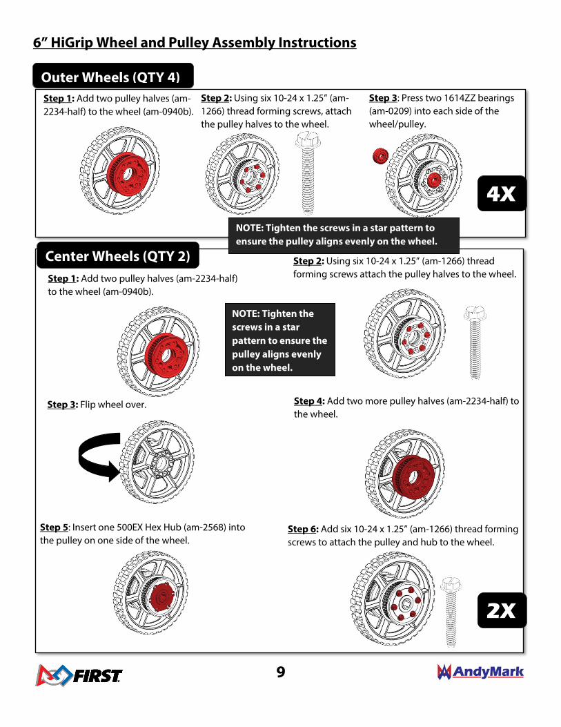
6” HiGrip Wheel and Pulley Assembly Instructions
Outer Wheels (QTY 4) Step 3: Press two 1614ZZ bearings (am-0209) into each side of the wheel/pulley.
4X
Center Wheels (QTY 2) Step 2: Using six 10-24 x 1.25” (am-1266) thread forming screws attach the pulley halves to the wheel.
Step 4: Add two more pulley halves (am-2234-half) to the wheel.
Step 3: Flip wheel over.
Step 5: Insert one 500EX Hex Hub (am-2568) into the pulley on one side of the wheel.
Step 6: Add six 10-24 x 1.25” (am-1266) thread forming screws to attach the pulley and hub to the wheel.
Step 1: Add two pulley halves (am-2234-half) to the wheel (am-0940b).
2X
NOTE: Tighten the screws in a star pattern to ensure the pulley aligns evenly on the wheel.
NOTE: Tighten the screws in a star pattern to ensure the pulley aligns evenly on the wheel.
Step 1: Add two pulley halves (am-2234-half) to the wheel (am-0940b).
Step 2: Using six 10-24 x 1.25” (am-1266) thread forming screws, attach the pulley halves to the wheel.

10
Toughbox Mini Assembly Instructions – Build 2 gearboxes
Step 1: Press two R6ZZ bearings (am-0516) into the two center holes of the TB Mini Housing (am-0650). Ensure they are fully seated and inserted all the way into the housing.
Step 2: Insert the TB Small Hex Shaft (am-0152) into R6ZZ bearing closest to the flat edge of the housing.
Step 6: Insert the small end of the TB Hex Output Shaft (am-2566a_K19) into the other R6ZZ bearing.
Step 5: Tap the 1/2” E-Clip (am-0206) onto the groove on the TB Hex Output Shaft (am-2566a_K19).
Step 7: Place the 48 Tooth Gear (am-0885) on TB Hex Output Shaft with the flat side touching the 1/2” E-Clip.
Step 8: Apply Red Tacky Grease (am-2768) to all of the gear teeth.
Step 3: Place the 50 tooth gear (am-0149) on the TB Small Hex Shaft with the small round boss touching the bearing and the flat side of the gear facing away from the housing.
Step 4: Place the 16 tooth gear (am-0747) on the TB Small Hex Shaft with flat side touching the 50 tooth gear.

11
Step 2: Attach the top flange of an Inside Plate to the top (large) flange of an End Plate (am-3920) at the 8th hole in from the end with two 10-32 x 0.500 socket head screws (am-1002) and two 10-32 Nylock nuts (am-1042).
Step 4: Repeat steps 2-3 on to attach the other Inside Plate to the End Plate.
Chassis Assembly Instructions Step 1: Press a FR6ZZ (am-0028) and a FR8ZZ-
HexHD (am-2986) bearing into the center holes on each Inside Plate (am-3922). Make sure the bearing flanges are on the same side as the bottom flange of the Inside Plate.
Step 3: Secure the bottom flange to the End Plate with an additional 10-32 x 0.500 socket head screw and 10-32 Nylock nut.
NOTE: The top flange of the Inside Plate should point toward the short side of the End Plate
NOTE: The top flange of the Inside Plate should point toward the short side of the End Plate

12
Step 6: Attach the two (cut to length) Long Churros between the Inside Plates using four ¼-20 x 0.750” thread forming screws (am-1310). A ½” wrench can be used to hold the churro while tightening.
NOTE: Be careful not to overtighten these screws. The gears should spin freely when the shaft is
rotated by hand.
Step 8: Attach one Toughbox Mini to each Inside Plate with four 10-32 x 0.75”SHCS (am-1047) and four 10-32 Nylock nuts (am-1042). The nuts will fit into the hex pockets on the Toughbox Mini housing and will hold the nut while tightening.
Step 7: Place one Toughbox Mini onto each Inner Plate ensuring the shafts are inserted into the flanged side of the bearings, and using the plastic studs to align the housing. The top flange of the Inside Plate will be facing away from the gearbox.
Step 5: Attach the other End Plate to the other end of the Inside Plates.

13
Step 13: Select the appropriate belts for your chassis configuration, and loop one belt over each Pulley on each Center Wheel Assembly.
Step 9: Slide two 5/16” washers (am-1009) onto each CIM motor shaft against the round boss of the motor. Place the Machine Key (am-1121) into the keyway of the motor shaft. Slide the 14 tooth (am-0034) gear onto the shaft up to the washers, while aligning the keyway of the gear to the key. Use a 7/16” socket to press the 8mm Retaining Clip (am-0033) onto the face of the gear, with the tabs of the clip pointing toward the motor shaft.
Step 10: Line up the CIM motors with the mounting holes in each Toughbox Mini. Secure each motor with gears installed to the Toughbox Mini housing using two 10-32 x 0.625” SHCS w/ Nylon Patch (am-1120).
The long chassis requires 160 tooth belts (am-2266).
The wide chassis requires 120 tooth belts (am-2704).
The square chassis requires 131 tooth belts (am-2571).
Step 12: Place the Hex Spacer (am-1305) onto each Toughbox Mini Hex Output Shaft and press into the round cavity in the pulley. The shaft will help align the spacer hex bore with the wheel hub hex bore.
Step 11: Place a Center Wheel Assembly onto each Toughbox Hex Output Shaft with the aluminum hub facing towards the Inside Plate.
NOTE: Each drive gearbox can accept up to 2 motors. Repeat this step for each motor.

14
NOTE: The Churro Standoffs are intended to help with the structure of the chassis. Be sure to install four on each Inner Plate.
Step 14: Press the FR8ZZ-HexHD Bearing (am-2986) into the center hole of each Outside Plate (am-3921). The bearing flange will be on the side opposite the plate flanges to ensure the bearings do not fall out during operation.
Step 15: Place each Outside Plate into the ends of both End Plates with the flanges of the Outside Plate pointing away from the Inside Plate. Ensure the Hex Bearing is aligned to and installed on the Toughbox Mini Hex Output Shaft.
Step 16: Secure the Outside Plates to each End Plate using six 10-32 x 0.500 socket head screws (am-1002) and two 10-32 Nylock nuts (am-1042).
Step 17: Attach four 3.375” Churro Standoffs (am-2569) (see below for recommended locations) with 1/4-20 x 0.75” Thread Forming Screws (am-1310) onto each Inside Plate. A 1/2” wrench can be used to hold the churro while tightening. Make sure to loop belts over the churro to ensure the belts have a straight path from axle to axle.
Recommended Support Churro Locations LONG CHASSIS
SQUARE CHASSIS
WIDE CHASSIS
15
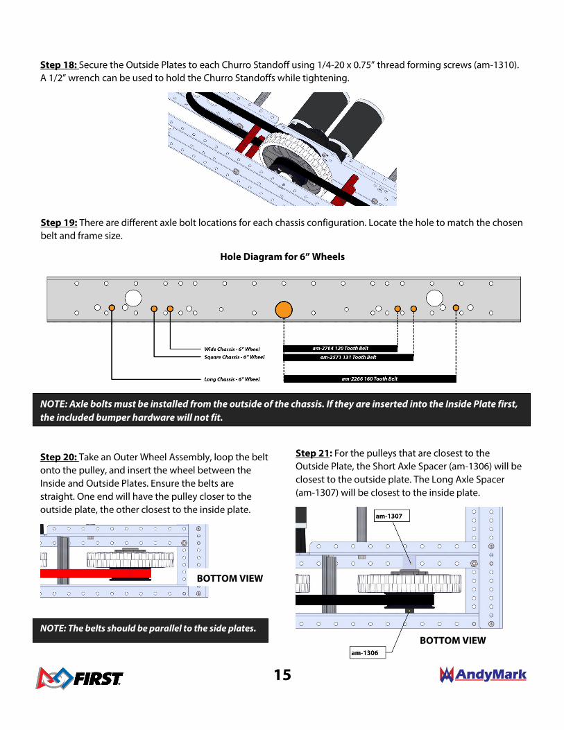
Step 19: There are different axle bolt locations for each chassis configuration. Locate the hole to match the chosen belt and frame size.
Hole Diagram for 6” Wheels
NOTE: The belts should be parallel to the side plates.
Step 18: Secure the Outside Plates to each Churro Standoff using 1/4-20 x 0.75” thread forming screws (am-1310). A 1/2” wrench can be used to hold the Churro Standoffs while tightening.
NOTE: Axle bolts must be installed from the outside of the chassis. If they are inserted into the Inside Plate first, the included bumper hardware will not fit.
Step 21: For the pulleys that are closest to the Outside Plate, the Short Axle Spacer (am-1306) will be closest to the outside plate. The Long Axle Spacer (am-1307) will be closest to the inside plate.
Step 20: Take an Outer Wheel Assembly, loop the belt onto the pulley, and insert the wheel between the Inside and Outside Plates. Ensure the belts are straight. One end will have the pulley closer to the outside plate, the other closest to the inside plate.
BOTTOM VIEW
BOTTOM VIEW

16
Step 23: Add another Outer Wheel Assembly to the other end of the chassis. Loop the belt onto the pulley and insert the assembly between the Inside and Outside Plates. This assembly should have its pulley facing opposite of the first assembly.
Step 24: For the belt runs that are closest to the Inside Plate, the Short Axle Spacer (am-1306) will be closest to the Inside Plate. The Long Axle Spacer (am-1307) will be closest to the Outside Plate.
Step 25: Slide a ⅜” axle bolt (am-1297) through the spacers and wheel assembly, with the head of the bolt pointing away from the chassis.
Step 22: There are different axle bolt locations for each chassis configuration. Slide a ⅜” axle bolt (am-1297) through the spacers and wheel assembly, with the head of the bolt pointing away from the chassis.
Step 26: Install one ⅜-16 Nylock Nut (am-1054) on each Axle Bolt. Tighten the bolt and nut until the spacers just begin to touch Inside and Outside Plates. The wheels should still easily turn, and the axle bolts should be able to spin with a light turn of a wrench.
Step 27: Repeat steps 19 through 26 to install wheels on other side of chassis.
BOTTOM VIEW
BOTTOM VIEW
BOTTOM VIEW
BOTTOM VIEW
You’ve completed the AM14U4 Kit of Parts Chassis. For more information, tips and instructions on how to mount your battery, bumpers, and more visit
AndyMark.com.