User Guide ADP186 / SDP & CDP-Pro / CDP-Scan / CDP eOBDcommon-rail.ru/autocom_eng_manual.pdf ·...
24
1 User Guide ADP186 / SDP & CDP-Pro / CDP-Scan / CDP eOBD Part no. 900 200 860 EN Ver. 1.2
Transcript of User Guide ADP186 / SDP & CDP-Pro / CDP-Scan / CDP eOBDcommon-rail.ru/autocom_eng_manual.pdf ·...
1
User Guide ADP186 / SDP & CDP-Pro / CDP-Scan / CDP eOBD
Part no. 900 200 860 EN Ver. 1.2
2
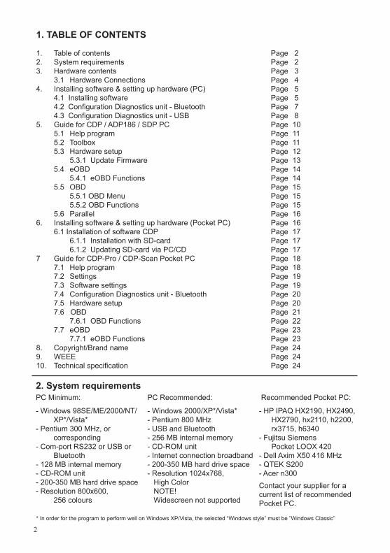
1. TABLE OF CONTENTS
1. Table of contents Page 22. System requirements Page 2 3. Hardware contents Page 3 3.1 Hardware Connections Page 44. Installing software & setting up hardware (PC) Page 5
4.1 Installing software Page 5 4.2 Configuration Diagnostics unit - Bluetooth Page 7 4.3 Configuration Diagnostics unit - USB Page 85. Guide for CDP / ADP186 / SDP PC Page 10 5.1 Help program Page 11 5.2 Toolbox Page 11 5.3 Hardware setup Page 12 5.3.1 Update Firmware Page 13 5.4 eOBD Page 14 5.4.1 eOBD Functions Page 14 5.5 OBD Page 15 5.5.1 OBD Menu Page 15 5.5.2 OBD Functions Page 15 5.6 Parallel Page 16 6. Installing software & setting up hardware (Pocket PC) Page 16 6.1 Installation of software CDP Page 17 6.1.1 Installation with SD-card Page 17 6.1.2 Updating SD-card via PC/CD Page 17 7 Guide for CDP-Pro / CDP-Scan Pocket PC Page 18 7.1 Help program Page 18 7.2 Settings Page 19 7.3 Software settings Page 19 7.4 Configuration Diagnostics unit - Bluetooth Page 20 7.5 Hardware setup Page 20 7.6 OBD Page 21 7.6.1 OBD Functions Page 22 7.7 eOBD Page 23 7.7.1 eOBD Functions Page 238. Copyright/Brand name Page 249. WEEE Page 2410. Technical specification Page 24
2. System requirementsPC Minimum:
- Windows 98SE/ME/2000/NT/XP*/Vista*
- Pentium 300 MHz, or corresponding - Com-port RS232 or USB or
Bluetooth- 128 MB internal memory- CD-ROM unit- 200-350 MB hard drive space - Resolution 800x600, 256 colours
PC Recommended:
- Windows 2000/XP*/Vista*- Pentium 800 MHz- USB and Bluetooth- 256 MB internal memory- CD-ROM unit- Internet connection broadband- 200-350 MB hard drive space - Resolution 1024x768, High Color NOTE! Widescreen not supported
* In order for the program to perform well on Windows XP/Vista, the selected “Windows style” must be ”Windows Classic”
Recommended Pocket PC:
- HP IPAQ HX2190, HX2490, HX2790, hx2110, h2200, rx3715, h6340- Fujitsu Siemens Pocket LOOX 420- Dell Axim X50 416 MHz- QTEK S200- Acer n300Contact your supplier for a current list of recommended Pocket PC.
3
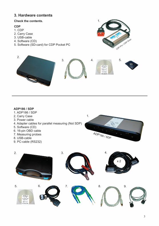
3. Hardware contents Check the contents.
CDP1. CDP2. Carry Case3. USB-cable4. Software (CD)5. Software (SD-card) for CDP Pocket PC
ADP186 / SDP1. ADP186 / SDP2. Carry Case3. Power cable4. Adapter cables for parallel measuring (Not SDP)5. Software (CD)6. 16-pin OBD cable7. Measuring probes8. USB-cable9. PC-cable (RS232)
ADP186 / SDP
1.
2. 3. 4.
5. 6. 7. 8. 9.
2.3. 4. 5.
1.
x 2
CDP-Pro / CDP-Scan
4
1.
3.4.
5.
6.
2.
17.18.
19.
1. 2. 3. 4. 5. 6. 7. 8. 9.
D1, D2
10.
11.
12.13.14.15.16.
ADP186 / SDP
ADP186
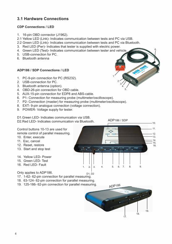
3.1 Hardware Connections CDP Connections / LED
1. 16-pin OBD connector (J1962).2:1 Yellow LED (Link)- Indicates communication between tests and PC via USB.2:2 Green LED (Link)- Indicates communication between tests and PC via Bluetooth.3. Red LED (Pwr)- Indicates that tester is supplied with electric power.4. Green LED (Test)- Indicates communication between tester and vehicle.5. USB-connection for PC.6. Bluetooth antenna
ADP186 / SDP Connections / LED 1. PC-9-pin connection for PC (RS232).2. USB-connection for PC.3. Bluetooth antenna (option).4. OBD-26-pin connection for OBD cable.5. AUX-15-pin connection for EDP8 and ABS-cable.6. P1- Connection for measuring probe (multimeter/oscilloscope).7. P2- Connection (master) for measuring probe (multimeter/oscilloscope).8. EXT- 9-pin analogue connection (voltage connection).9. POWER- Voltage supply for tester.
D1. Green LED- Indicates communication via USB.D2. Red LED- Indicates communication via Bluetooth. Control buttons 10-13 are used for remote control of parallel measuring. 10. Enter, execute11. Esc, cancel12. Reset, restore13. Start and stop test 14. Yellow LED- Power15. Green LED- Test16. Red LED- Fault
Only applies to ADP186.17. 1-62- 62-pin connection for parallel measuring.18. 63-124- 62-pin connection for parallel measuring.19. 125-186- 62-pin connection for parallel measuring.
5
4. Installing program & setting up hardware (PC)
New software must be installed before you can use your new product, and the hardware must be configured. 4.1 Installation of software. 4.2 / 4.3 Configuration of Bluetooth / USB. Installation of drivers.
NOTE! It is possible to select to configure one of these, or to use connection via Com-port (RS232) for ADP186 / SDP. Does not require any configuration. Only use one of the connection possibilities between PC and tester.
Following installation, the hardware must be configured. This is described in ch. 5.3
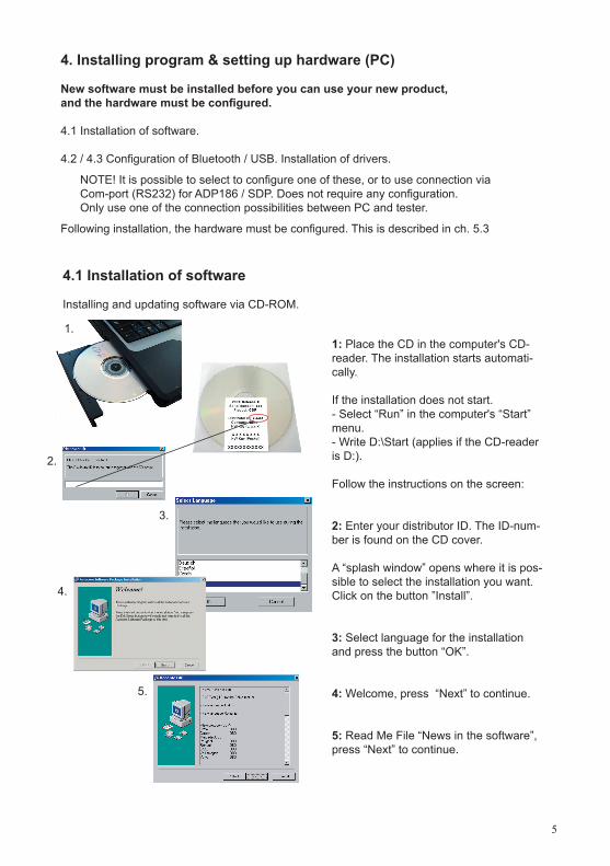
4.1 Installation of software Installing and updating software via CD-ROM.
1: Place the CD in the computer's CD-reader. The installation starts automati-cally.
If the installation does not start.- Select “Run” in the computer's “Start” menu.- Write D:\Start (applies if the CD-reader is D:).
Follow the instructions on the screen:
2: Enter your distributor ID. The ID-num-ber is found on the CD cover.
A “splash window” opens where it is pos-sible to select the installation you want. Click on the button ”Install”.
3: Select language for the installation and press the button “OK”.
4: Welcome, press “Next” to continue.
5: Read Me File “News in the software”, press “Next” to continue.
1.
3.
4.
5.
2.
6
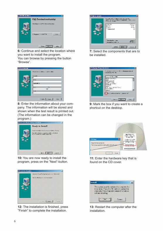
6: Continue and select the location where you want to install the program. You can browse by pressing the button “Browse”.
7: Select the components that are to be installed.
8: Enter the information about your com-pany. The information will be stored and shown when the test result is printed out. (The information can be changed in the program.)
9: Mark the box if you want to create a shortcut on the desktop.
10: You are now ready to install the program, press on the ”Next”-button.
13: Restart the computer after the installation.
11: Enter the hardware key that is found on the CD cover.
12: The installation is finished, press ”Finish” to complete the installation.
7
4.2 Configuration of Diagnostics unit - Bluetooth Note! - The computer's Bluetooth unit must be installed correctly and support Bluetooth Virtual Com-port (SPP – Serial Port Profile).
- Follow Microsoft's instructions when installing the Bluetooth unit on Microsoft Windows XP Service Pack 2 (SP2).
- If you install a Bluetooth unit on another operative system than Windows XP Service Pack 2 (SP2) or with another Bluetooth stack than Microsoft, follow the manufacturer's instructions on how to install the unit as well as connect to hardware via Bluetooth Virtual Comport (SPP – Se-rial Port Profile).
5. 6. 7.
1.
3.
2.
4.
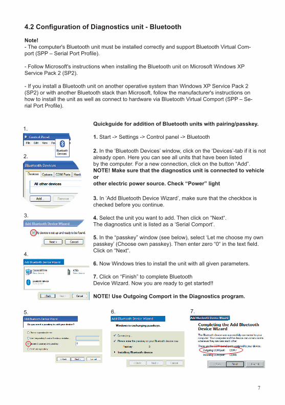
Quickguide for addition of Bluetooth units with pairing/passkey.
1. Start -> Settings -> Control panel -> Bluetooth 2. In the ‘Bluetooth Devices’ window, click on the ‘Devices’-tab if it is not already open. Here you can see all units that have been listed by the computer. For a new connection, click on the button “Add”.NOTE! Make sure that the diagnostics unit is connected to vehicle or other electric power source. Check “Power” light 3. In ‘Add Bluetooth Device Wizard’, make sure that the checkbox is checked before you continue.
4. Select the unit you want to add. Then click on “Next“.The diagnostics unit is listed as a ‘Serial Comport’.
5. In the “passkey” window (see below), select ‘Let me choose my own passkey’ (Choose own passkey). Then enter zero “0“ in the text field. Click on “Next“.
6. Now Windows tries to install the unit with all given parameters.
7. Click on “Finish” to complete Bluetooth Device Wizard. Now you are ready to get started!!
NOTE! Use Outgoing Comport in the Diagnostics program.
8
4.3 Configuration of Diagnostics unit – USB
Note! - It is important that the software installation is finished before the Diagnostics unit is connected.- During installation of the software, drivers for the same directory are also installed and placed in the sub-directory ”../Drivers/USB/”. It is important to remember the location since it shall be used when installing the drivers.
WinXP installationThis guide refers to a new installation of ADP186/SDP/CDP USB, it is also assumed that the software for ADP186//SDP/CDP is already installed. (If you have not performed the installation but still want to install the USB drivers, you will find the zip-files on the CD....Driver\USB\)
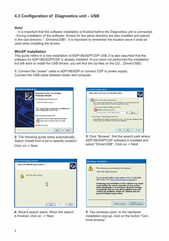
1: Connect the “power” cable to ADP186/SDP or connect CDP to power supply. Connect the USB-cable between tester and computer.
3: Click “Browse”, find the search path where ADP186/SDP/CDP software is installed and select “Driver/USB”. Click on -> Next.
4: Wizard search starts. When the search is finished, click on -> Next.
5: Two windows open. In the hardware installation pop-up, click on the button “Con-tinue anyway”.
2: The following guide starts automatically. Select “Install from a list or specific location”Click on -> Next
C:\Program\Autocom\ADP186\Driver\USB
ADP186 USB interface ADP186 USB interface
ADP186 USB interface
9
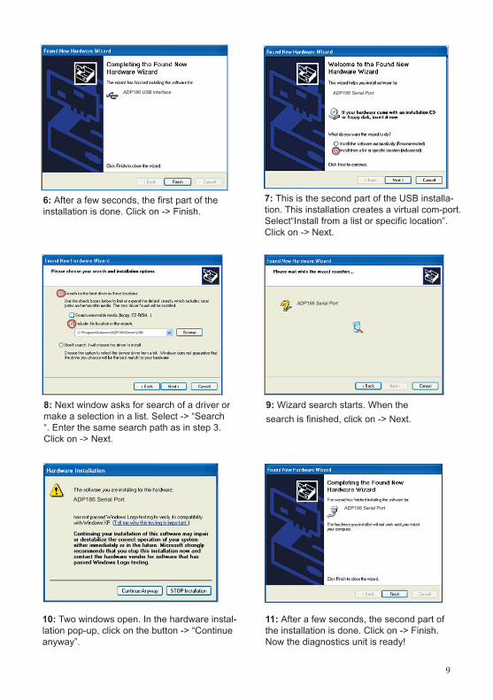
6: After a few seconds, the first part of the installation is done. Click on -> Finish.
7: This is the second part of the USB installa-tion. This installation creates a virtual com-port. Select“Install from a list or specific location”. Click on -> Next.
8: Next window asks for search of a driver or make a selection in a list. Select -> “Search “. Enter the same search path as in step 3. Click on -> Next.
9: Wizard search starts. When the search is finished, click on -> Next.
10: Two windows open. In the hardware instal-lation pop-up, click on the button -> “Continue anyway”.
11: After a few seconds, the second part of the installation is done. Click on -> Finish. Now the diagnostics unit is ready!
C:\Program\Autocom\ADP186\Driver\USB
ADP186 Serial Port
ADP186 USB interface ADP186 Serial Port
ADP186 Serial Port
ADP186 Serial Port
10
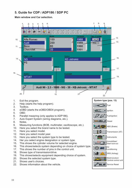
5. Guide for CDP / ADP186 / SDP PC Main window and Car selection.
1. Exit the program.2. Help (starts the help program).3. Toolbox.4. eOBD (starts the eOBD/OBDII program).5. OBD.6. Parallel measring (only applies to ADP186).7. Auto Expert System (wiring diagrams, etc.).8. Notes.9. Measuring functions (BOB, multimeter, oscilloscope, etc.).10. Here you select the brand name to be tested.11. Here you select model.12. Here you select model year.13. Here you select the system type to be tested.14. Her you select engine designation or system type.15. This shows the cylinder volume for selected engine.16. This shows/selects system depending on choice of system type. 17. This shows the number of pins in the control unit.18. Shows type of transmission/drive.19. This shows/selects equipment depending choice of system.20. Shows the selected system type.21. Shows user's choices.22. Shows information about the vehicle.
1. 2. 3. 4. 5. 6.
10.
11.
14.
18.
7. 8. 9.
12.
13.
16.
17.
19.
21.15.20.22.
System type (pos. 13)
Fuel
Ignition
Fuel/ignition
Diesel ABS (Brake) Transmission (AT) Instruments Immobiliser/ Start lock-out
Airconditioning
SRS (Airbag)
Multi-function/Central control unit
Service Reset
11
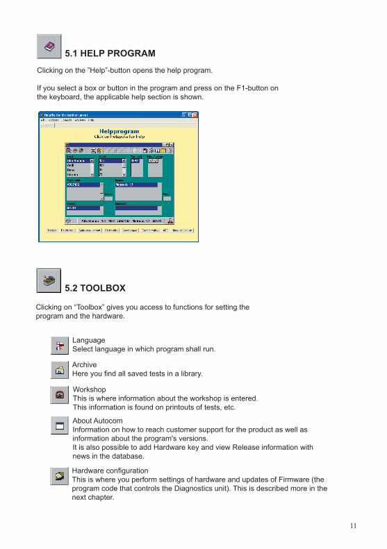
WorkshopThis is where information about the workshop is entered. This information is found on printouts of tests, etc.
Hardware configurationThis is where you perform settings of hardware and updates of Firmware (the program code that controls the Diagnostics unit). This is described more in the next chapter.
ArchiveHere you find all saved tests in a library.
5.1 HELP PROGRAM
5.2 TOOLBOX
Clicking on the ”Help”-button opens the help program.
If you select a box or button in the program and press on the F1-button on the keyboard, the applicable help section is shown.
Language Select language in which program shall run.
Clicking on “Toolbox” gives you access to functions for setting the program and the hardware.
About AutocomInformation on how to reach customer support for the product as well asinformation about the program's versions.It is also possible to add Hardware key and view Release information with news in the database.
12
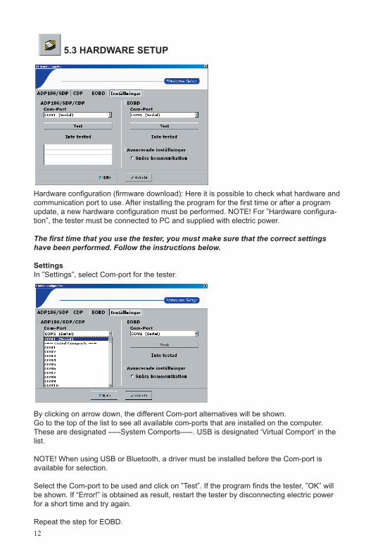
Hardware configuration (firmware download): Here it is possible to check what hardware and communication port to use. After installing the program for the first time or after a program update, a new hardware configuration must be performed. NOTE! For ”Hardware configura-tion”, the tester must be connected to PC and supplied with electric power.
The first time that you use the tester, you must make sure that the correct settings have been performed. Follow the instructions below.
SettingsIn ”Settings”, select Com-port for the tester.
By clicking on arrow down, the different Com-port alternatives will be shown. Go to the top of the list to see all available com-ports that are installed on the computer. These are designated -----System Comports-----. USB is designated ‘Virtual Comport’ in the list.
NOTE! When using USB or Bluetooth, a driver must be installed before the Com-port is available for selection.
Select the Com-port to be used and click on ”Test”. If the program finds the tester, ”OK” will be shown. If “Error!” is obtained as result, restart the tester by disconnecting electric power for a short time and try again.
Repeat the step for EOBD.
5.3 HARDWARE SETUP
13
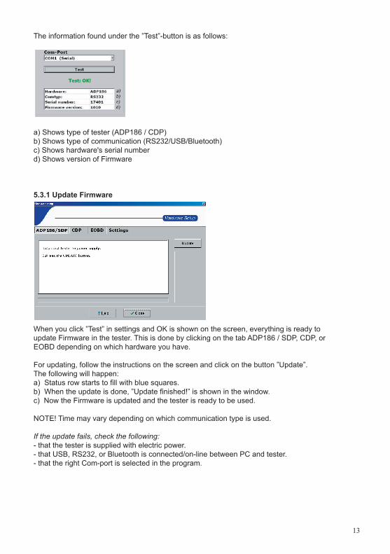
The information found under the ”Test”-button is as follows:
a) Shows type of tester (ADP186 / CDP)b) Shows type of communication (RS232/USB/Bluetooth)c) Shows hardware's serial numberd) Shows version of Firmware
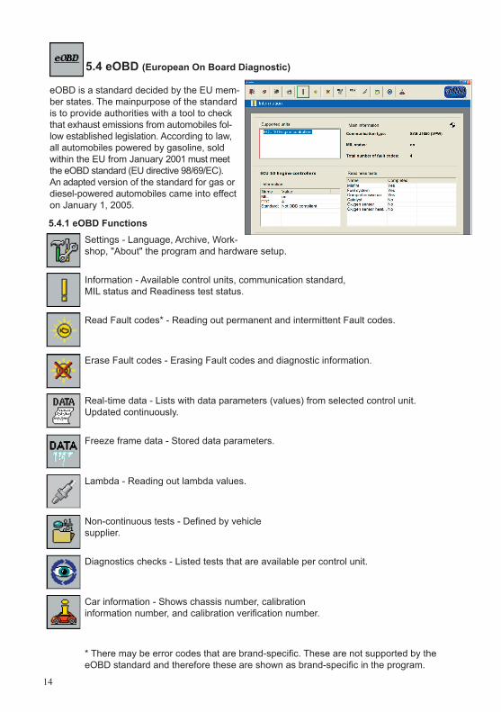
5.3.1 Update Firmware
When you click ”Test” in settings and OK is shown on the screen, everything is ready to update Firmware in the tester. This is done by clicking on the tab ADP186 / SDP, CDP, or EOBD depending on which hardware you have.
For updating, follow the instructions on the screen and click on the button ”Update”.The following will happen:a) Status row starts to fill with blue squares.b) When the update is done, ”Update finished!” is shown in the window.c) Now the Firmware is updated and the tester is ready to be used.
NOTE! Time may vary depending on which communication type is used.
If the update fails, check the following:- that the tester is supplied with electric power.- that USB, RS232, or Bluetooth is connected/on-line between PC and tester. - that the right Com-port is selected in the program.
14
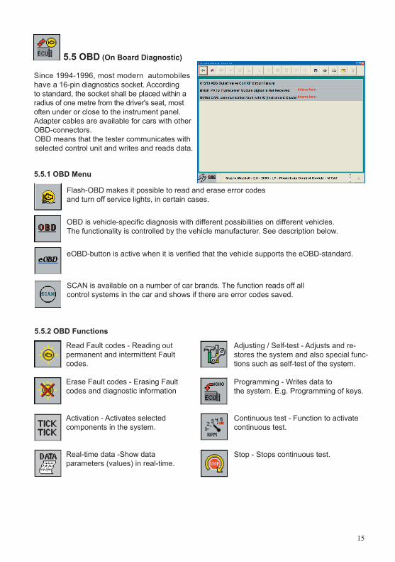
Settings - Language, Archive, Work-shop, "About" the program and hardware setup.
Information - Available control units, communication standard, MIL status and Readiness test status.
Read Fault codes* - Reading out permanent and intermittent Fault codes.
Erase Fault codes - Erasing Fault codes and diagnostic information.
Real-time data - Lists with data parameters (values) from selected control unit. Updated continuously.
Freeze frame data - Stored data parameters.
Lambda - Reading out lambda values.
Non-continuous tests - Defi ned by vehiclesupplier.
Diagnostics checks - Listed tests that are available per control unit.
Car information - Shows chassis number, calibrationinformation number, and calibration verifi cation number.
* There may be error codes that are brand-specifi c. These are not supported by the eOBD standard and therefore these are shown as brand-specifi c in the program.
5.4 eOBD (European On Board Diagnostic)
eOBD is a standard decided by the EU mem-ber states. The mainpurpose of the standard is to provide authorities with a tool to check that exhaust emissions from automobiles fol-low established legislation. According to law, all automobiles powered by gasoline, sold within the EU from January 2001 must meet the eOBD standard (EU directive 98/69/EC). An adapted version of the standard for gas or diesel-powered automobiles came into effect on January 1, 2005.
5.4.1 eOBD Functions
15
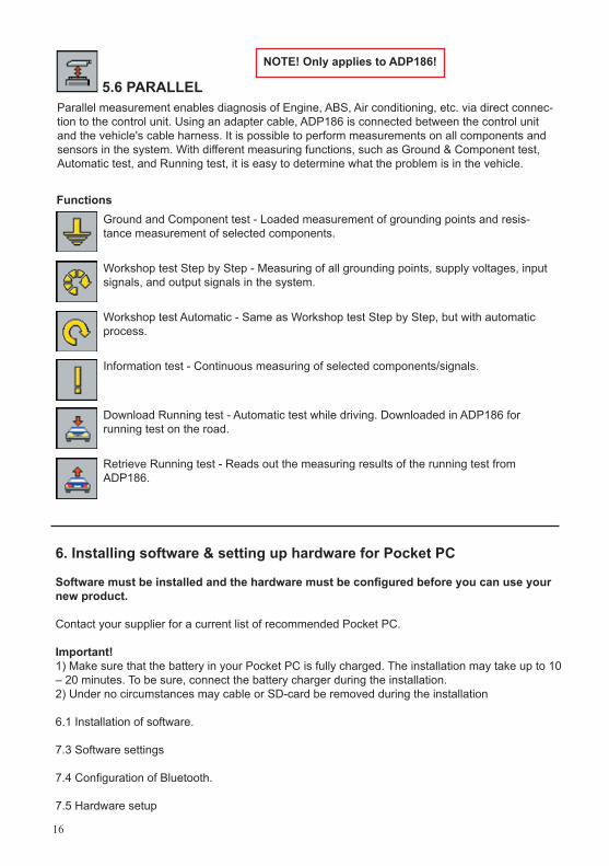
5.5 OBD (On Board Diagnostic)
Since 1994-1996, most modern automobiles have a 16-pin diagnostics socket. According to standard, the socket shall be placed within a radius of one metre from the driver's seat, most often under or close to the instrument panel. Adapter cables are available for cars with other OBD-connectors.OBD means that the tester communicates with selected control unit and writes and reads data.
Flash-OBD makes it possible to read and erase error codes and turn off service lights, in certain cases.
OBD is vehicle-specifi c diagnosis with different possibilities on different vehicles. The functionality is controlled by the vehicle manufacturer. See description below.
eOBD-button is active when it is verifi ed that the vehicle supports the eOBD-standard.
SCAN is available on a number of car brands. The function reads off all control systems in the car and shows if there are error codes saved.
5.5.1 OBD Menu
5.5.2 OBD Functions
Read Fault codes - Reading out permanent and intermittent Fault codes.
Erase Fault codes - Erasing Fault codes and diagnostic information
Activation - Activates selected components in the system.
Real-time data -Show data parameters (values) in real-time.
Adjusting / Self-test - Adjusts and re-stores the system and also special func-tions such as self-test of the system.
Programming - Writes data to the system. E.g. Programming of keys.
Continuous test - Function to activate continuous test.
Stop - Stops continuous test.
16
5.6 PARALLEL
Functions
6. Installing software & setting up hardware for Pocket PC
Software must be installed and the hardware must be confi gured before you can use your new product.
Contact your supplier for a current list of recommended Pocket PC.
Important! 1) Make sure that the battery in your Pocket PC is fully charged. The installation may take up to 10 – 20 minutes. To be sure, connect the battery charger during the installation. 2) Under no circumstances may cable or SD-card be removed during the installation
6.1 Installation of software.
7.3 Software settings
7.4 Confi guration of Bluetooth.
7.5 Hardware setup
Parallel measurement enables diagnosis of Engine, ABS, Air conditioning, etc. via direct connec-tion to the control unit. Using an adapter cable, ADP186 is connected between the control unit and the vehicle's cable harness. It is possible to perform measurements on all components and sensors in the system. With different measuring functions, such as Ground & Component test, Automatic test, and Running test, it is easy to determine what the problem is in the vehicle.
Ground and Component test - Loaded measurement of grounding points and resis-tance measurement of selected components.
Workshop test Step by Step - Measuring of all grounding points, supply voltages, input signals, and output signals in the system.
Workshop test Automatic - Same as Workshop test Step by Step, but with automatic process.
Information test - Continuous measuring of selected components/signals.
Download Running test - Automatic test while driving. Downloaded in ADP186 for running test on the road.
Retrieve Running test - Reads out the measuring results of the running test from ADP186.
NOTE! Only applies to ADP186!
17
6.1 Installation of Software on Pocket PC
6.1.1 Installation of SD-card
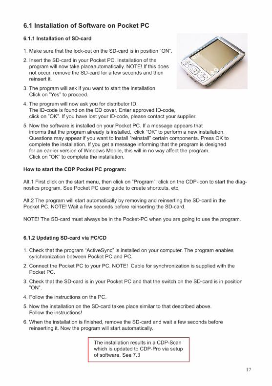
1. Make sure that the lock-out on the SD-card is in position “ON”.
2. Insert the SD-card in your Pocket PC. Installation of the program will now take place automatically. NOTE! If this does not occur, remove the SD-card for a few seconds and then reinsert it.
3. The program will ask if you want to start the installation. Click on ”Yes” to proceed.
4. The program will now ask you for distributor ID. The ID-code is found on the CD cover. Enter approved ID-code, click on ”OK”. If you have lost your ID-code, please contact your supplier.
5. Now the software is installed on your Pocket PC. If a message appears that informs that the program already is installed, click ”OK” to perform a new installation. Questions may appear if you want to install ”reinstall” certain components. Press OK to complete the installation. If you get a message informing that the program is designed for an earlier version of Windows Mobile, this will in no way affect the program. Click on ”OK” to complete the installation.
How to start the CDP Pocket PC program:
Alt.1 First click on the start menu, then click on ”Program”, click on the CDP-icon to start the diag-nostics program. See Pocket PC user guide to create shortcuts, etc.
Alt.2 The program will start automatically by removing and reinserting the SD-card in the Pocket PC. NOTE! Wait a few seconds before reinserting the SD-card. NOTE! The SD-card must always be in the Pocket-PC when you are going to use the program.
6.1.2 Updating SD-card via PC/CD
1. Check that the program “ActiveSync” is installed on your computer. The program enables synchronization between Pocket PC and PC.
2. Connect the Pocket PC to your PC. NOTE! Cable for synchronization is supplied with the Pocket PC.
3. Check that the SD-card is in your Pocket PC and that the switch on the SD-card is in position ”ON”.
4. Follow the instructions on the PC.
5. Now the installation on the SD-card takes place similar to that described above. Follow the instructions!
6. When the installation is finished, remove the SD-card and wait a few seconds before reinserting it. Now the program will start automatically.
The installation results in a CDP-Scan which is updated to CDP-Pro via setup of software. See 7.3
18
7. Guide for CDP-Pro / CDP-Scan Pocket PC
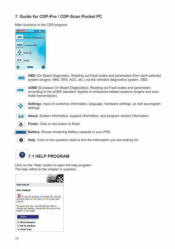
Main functions in the CDP-program.
OBD (On Board Diagnostic). Reading out Fault codes and parameters from each selected system (engine, ABS, SRS, ACC, etc.) via the vehicle's diagnostics system, OBD.
eOBD (European On Board Diagnostics). Reading out Fault codes and parameters according to the eOBD standard. Applies to emissions-related systems (engine and auto-matic transmission).
Settings. Input of workshop information, language, hardware settings, as well as program settings.
About. System information, support information, and program version information.
Finish. Click on the button to finish.
Battery. Shows remaining battery capacity in your PDA.
Help. Click on the question mark to find the information you are looking for.
7.1 HELP PROGRAM
Click on the “Help”-button to open the help program.The help refers to the chapter in question.
19
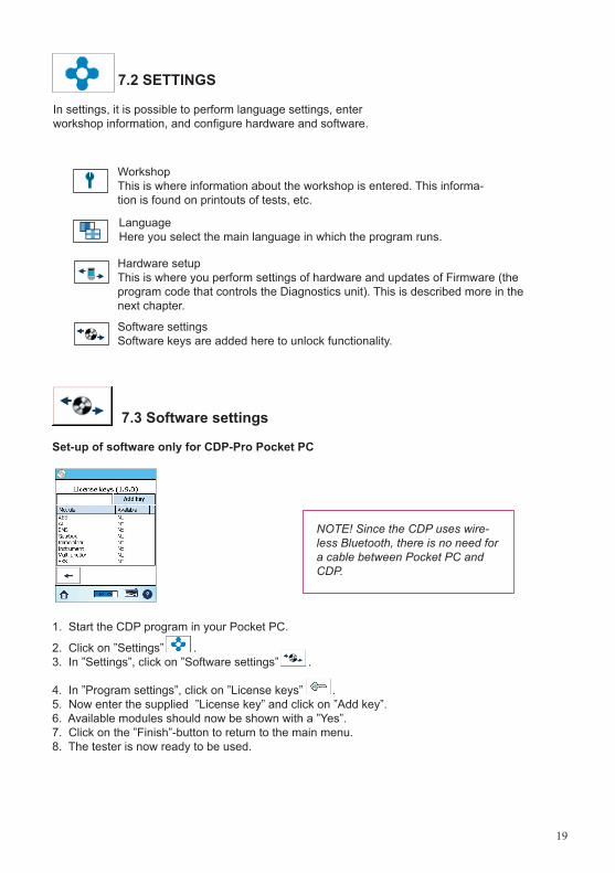
In settings, it is possible to perform language settings, enter workshop information, and configure hardware and software.
Workshop This is where information about the workshop is entered. This informa-tion is found on printouts of tests, etc.
Hardware setup This is where you perform settings of hardware and updates of Firmware (the program code that controls the Diagnostics unit). This is described more in the next chapter.
7.2 SETTINGS
Language Here you select the main language in which the program runs.
Software settings Software keys are added here to unlock functionality.
7.3 Software settings
Set-up of software only for CDP-Pro Pocket PC
1. Start the CDP program in your Pocket PC.
2. Click on ”Settings” .3. In ”Settings”, click on ”Software settings” .
4. In ”Program settings”, click on ”License keys” .5. Now enter the supplied ”License key” and click on ”Add key”.6. Available modules should now be shown with a ”Yes”.7. Click on the ”Finish”-button to return to the main menu.8. The tester is now ready to be used.
NOTE! Since the CDP uses wire-less Bluetooth, there is no need for a cable between Pocket PC and CDP.
20
7.4 Configuration of Diagnostics unit- Bluetooth Important! To enable a ”Bluetooth set-up” the CDP must be connected to a vehicle (the CDP must be supplied with voltage). See the service manual to find the diagnostics socket.
1. Start the CDP program in your Pocket PC.
2. Click on ”Settings” .3. In ”Settings”, click on ”Hardware configuration” .4. In ”Hardware configuration”, click on ”Bluetooth” . 5. In ”Bluetooth”, the program will automatically search for the hardware. If you do not find the hardware in the list, a new search is performed.6. When the hardware has been found and the serial number is shown in the list, select the row with your hardware (serial number). The serial number will now be shown in the field ”Serial no.”.7. Enter the hardware key, for your tester, in the field ”Hardware key”.8. Click on the ”Back”-button .
9. In the menu for ”Hardware configuration”, click on the ”Finish”-button to return to the main menu.
7.5 Hardware setup
Important! To enable a ”Hardware setup”, the CDP must be connected to a vehicle (the CDP must be supplied with voltage). See the service manual to find the diagnostics socket.
1. Start the CDP program in your Pocket PC.
2. Click on ”Settings” .3. In ”Settings”, click on ”Hardware configuration” .4. In ”Hardware configuration”, click on ”Update firmware” .5. To update firmware, click on ”Yes” (Note! Time approx. 15 min.).6. When firmware is updated, ”Firmware download successful. Firmware version: xxxx”.7. Click on the ”Finish”-button to return to the main menu.8. The tester is now ready to be used.
NOTE! When updating program or in case of new installation, always perform ”Hardware con-figuration”.
21
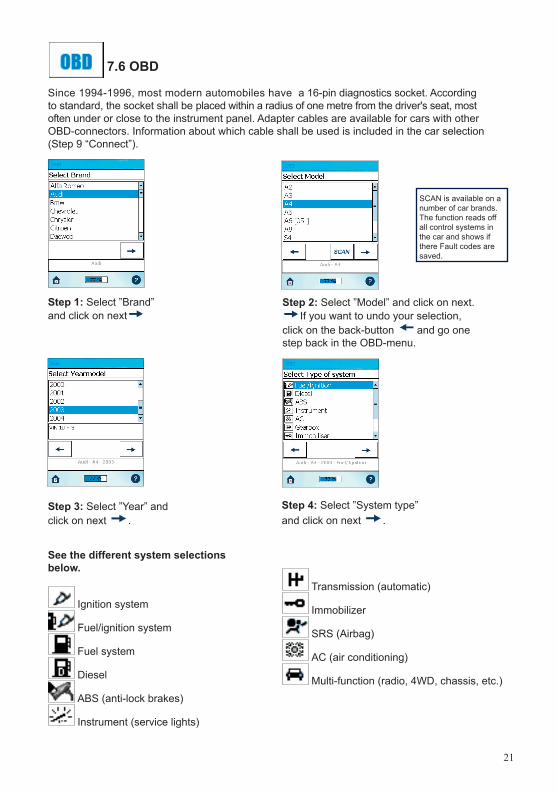
7.6 OBD
Since 1994-1996, most modern automobiles have a 16-pin diagnostics socket. According to standard, the socket shall be placed within a radius of one metre from the driver's seat, most often under or close to the instrument panel. Adapter cables are available for cars with other OBD-connectors. Information about which cable shall be used is included in the car selection (Step 9 “Connect”).
See the different system selections below.
Ignition system
Fuel/ignition system
Fuel system
Diesel
ABS (anti-lock brakes)
Instrument (service lights)
Transmission (automatic)
Immobilizer
SRS (Airbag)
AC (air conditioning)
Multi-function (radio, 4WD, chassis, etc.)
Step 2: Select ”Model” and click on next. If you want to undo your selection,
click on the back-button and go one step back in the OBD-menu.
Step 1: Select ”Brand” and click on next
Step 4: Select ”System type” and click on next .
Step 3: Select ”Year” and click on next .
SCAN is available on a number of car brands. The function reads off all control systems in the car and shows if there Fault codes are saved.
22
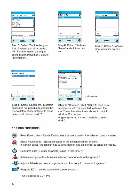
Step 6: Select ”System / Name” and click on next
.
Step 5: Select ”Engine designa-tion / System” and click on next
. For information on engine designation's placement, click on ”Information”.
Step 7: Select “Transmis-sion” and click on next
.
Step 9: “Connect”. Click “OBD“ to start com-munication with the selected system in the car. The entire selection is shown in the info window. For certain engine systems, it is also possible to select eOBD.
Step 8: Select equipment. In certain cases it is not possible to choose be-tween different alternatives. In these cases, just click on next .
7.6.1 OBD FUNCTIONS
Read Fault codes - Reads Fault codes that are stored in the selected control system. Erase Fault codes - Erases all codes in the selected control system. In certain cases, the ignition has to be turned off and on in order to erase the codes.
Real-time data - Reads parameter value in real-time. *
Activate components - Activates selected components in the system. *
Adjust - Adjusts and sets components and functions in the control system. *
Program ECU - Writes data to the control system. *
* Only applies to CDP-Pro
<- Info window
23
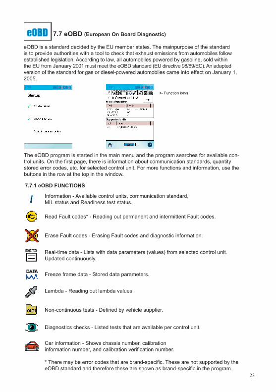
7.7 eOBD (European On Board Diagnostic)
eOBD is a standard decided by the EU member states. The mainpurpose of the standard is to provide authorities with a tool to check that exhaust emissions from automobiles follow established legislation. According to law, all automobiles powered by gasoline, sold within the EU from January 2001 must meet the eOBD standard (EU directive 98/69/EC). An adapted version of the standard for gas or diesel-powered automobiles came into effect on January 1, 2005.
Information - Available control units, communication standard, MIL status and Readiness test status. Read Fault codes* - Reading out permanent and intermittent Fault codes.
Erase Fault codes - Erasing Fault codes and diagnostic information.
Real-time data - Lists with data parameters (values) from selected control unit. Updated continuously.
Freeze frame data - Stored data parameters.
Lambda - Reading out lambda values.
Non-continuous tests - Defi ned by vehicle supplier.
Diagnostics checks - Listed tests that are available per control unit.
Car information - Shows chassis number, calibrationinformation number, and calibration verifi cation number.
* There may be error codes that are brand-specifi c. These are not supported by the eOBD standard and therefore these are shown as brand-specifi c in the program.
7.7.1 eOBD FUNCTIONS
The eOBD program is started in the main menu and the program searches for available con-trol units. On the fi rst page, there is information about communication standards, quantity stored error codes, etc. for selected control unit. For more functions and information, use the buttons in the row at the top in the window.
<- Function keys
24
Please feel free to contact us, if there is anything you wonder about or if there is anything you want to tell us.
Autocom Diagnostic Partner ABGrafitvägen 23 B461 38 Trollhättan
Telephone: +46 (0)520 - 470700Fax: +46 (0)520 - 470727E-mail: [email protected]: www.autocom.se
Thank you for choosing our products!
8. Copyright/Brand name Reproduction is strictly prohibited without written permission from Autocom Diag-nostic Partner AB. Protected by copyright since 1991, Autocom Diagnostic Partner AB. Autocom and Autocom's logotype are brand names belonging to Autocom Diagnostic Partner AB. 9. WEEE (Waste Electrical and Electronic Equipment)This label shows that the product is manufactured after August 13, 2005, and therefore it shall be recycled according to WEEE (EU directive 2002/96/EC for electrical and electronic equipment waste). Contact your local dealer for more information.
10. Technical specificationADP186 / SDP
Meets EU directive 89/336/EEC and 73/23/EECDimensions: 370 x 185 x 45 (mm)Weight: 1.9 kgVoltage supply: 9-32 VoltCurrent consumption: 270 mAOperating temperature: 0-70 ºCMeasuring range: Voltage: 0-200 Volt (+/- 0.5%) Frequency: 0-15 kHz (resolution 1 Hz) Resistance: 0-10 kOhm (+/- 2%)
CDP
Meets EU directive 89/336/EEC and 73/23/EECDimensions: 180 x 90 x 30 (mm)Weight: 0.5 kgVoltage supply: 9-32 VoltCurrent consumption: 150 mAOperating temperature: 0-70 ºC
Notes:
Autocom Diagnostic Partner AB, 2006