USE OF SACRIFICIAL OR GALVANIC ANODES ON IN … is a calculation of the surface area of the...
24
1 USE OF SACRIFICIAL OR GALVANIC ANODES ON IN-SERVICE BRIDGES NYSDOT OFFICE OF OPERATIONS TRANSPORTATION MAINTENANCE DIVISION BRIDGE MAINTENANCE
Transcript of USE OF SACRIFICIAL OR GALVANIC ANODES ON IN … is a calculation of the surface area of the...

1
USE OF SACRIFICIAL OR GALVANIC ANODES ONIN-SERVICE BRIDGES
NYSDOT OFFICE OF OPERATIONSTRANSPORTATION MAINTENANCE DIVISION
BRIDGE MAINTENANCE

2
Table of Contents
Page 3 Background and Decision Making Support Information
Page 5 Products List
Page 6 Steel Density Ratio
Page 7 Steel Density Tables
Page 8 Sacrificial Anodes on In-Service Bridges
Page 9 Open Patching
Page 11 Sample calculation for deck patch
Page 12 Sample calculation for column repair
Page 13 Sample deck repair using tabulated values
Page 14 Installation instructions
Page 15 Plug-Type Anodes
Page 23 Compatible Repair Materials
Page 25 Appendix

3
INTRODUCTION
CORROSION CONTROL USING GALVANIC CATHODIC PROTECTION
This section provides application information, designexamples, and reference tables for the use of galvaniccathodic protection systems for in-service reinforcedconcrete structures.
An overview of the various strategies that might be considered by the BridgeMaintenance Engineer in the rehabilitation of reinforced concrete structures isprovided in NCHRP Report 558 Chapter 5 “Extension of Service Life with Repair and Corrosion Mitigation Options.” The strategies can be divided into two categories; corrosion protection and corrosion control.
The overview includes discussions on the methods typically used with NYSDOT.These include, reinforcing bar coatings, overlays, waterproofing membranes, andpenetrating sealers. These strategies function to provide corrosion protection andare applicable for replacement projects or for repairs to elements with minimallevels of rebar corrosion.
In more aggressive environments, a strategy of adding corrosion controltechniques to standard repair procedures has been proven to provide the mosteffective repair. Typical corrosion control materials are corrosion inhibitors andgalvanic cathodic protection systems.
Corrosion inhibitors are chemical compounds either added to the repair material,applied directly to the rebar, or both. Calcium nitrite is the most commonly usedcorrosion inhibitor and has a long history of good performance. Nonetheless, intest patches in concrete with high levels of chloride ions“the nitrite inhibitor used in conjunction with patch repair material on field structures did not provide anybenefit” (NCHRP Report page 29).
The Federal Highway Administration has stated that “cathodic protection is theonly rehabilitation technique that has proven to stop corrosion in salt-contaminated bridge decks regardless of the chloride content inconcrete” (NCHRP Report, page 34).
Cathodic protection can be grouped into two basic types of systems: impressedcurrent and galvanic cathodic systems. An impressed current system is achievedby driving a low-voltage direct current (generally less than 50 volts) from arelatively inert anode material, through the concrete, to the reinforcing bars. Thecurrent is distributed to the reinforcing bars by an anodic material. Thisprocedure is very costly and requires specialized services to design and verify thesystem is working properly.

4
Galvanic cathodic protection (also called galvanic anode system) is based on theprinciples of dissimilar metal corrosion and the relative position of specific metalsin the galvanic series. No external power source is needed with this type ofsystem, and much less maintenance is required. Patch-repair and plug-typeanodes are examples of galvanic anodes.
As stated in NCHRP Report 558, when selecting a cathodic protection system fora given structure, several issues need to be considered:
o Long-term rehabilitation: the system is most effective for if a long-termrepair (5 to 10 years) is desired.
o Electrical continuity: a closed electrical circuit is required for properfunctioning of the system.
o Chloride concentrations: if the levels are in sufficient concentration toinitiate corrosion, cathodic protection may be the only viable method ofrehabilitation.
o Alkali-silica reaction: cathodic protection increases alkalinity at the steel-concrete interface, thereby theoretically accelerating the alkali-silicareaction, although this condition has never been reported.
Questions or comments regarding this material should be forwarded to the BridgeMaintenance Program Engineer in the Office of Operations.
References:
NCHRP Report 558 Manual on Service Life of Corrosion-Damaged ReinforcedConcrete Bridge Superstructure Elements.
Vector Corrosion Technologieswww.vector-corrosion.com
The Euclid Chemical Companywww.euclidchemical.com

5
PRODUCTS LIST
Supplier Product Name Description Contact
Galvashield XP+“Hockey puck”
with 100 grams ofzinc
Galvashield XP“Hockey puck”
with 65 grams ofzinc
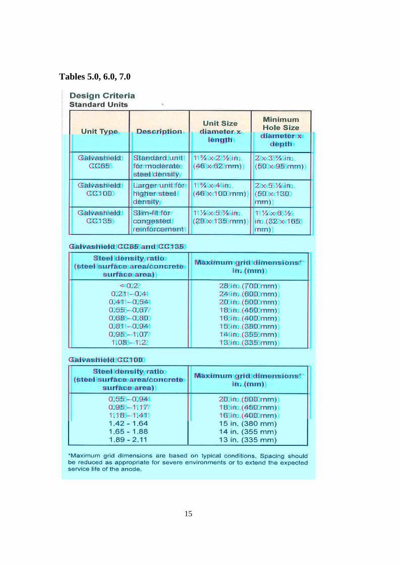
Galvashield CC 65 Moderate steeldensity
Galvashield CC 100 High steel density
Vector
Galvashield CC 135 Slim fit style
(813) 830-7566www.vector-corrosion.com
Galvashield XP+ Same as VectorSika Corp Galvashield CC 65,
100, 135 Same as Vector
1-800-933-7452www.sikaconstruction.com
BASF Corrstops Same as VectorGalvashield XP
1-800-526-1072www.basf.com
Euclid Sentinel-GL“V-notch” block with 40 grams of
zinc
1-800-321-7628www.euclidchemical.com

6
Steel Density Ratio
The number and spacing of anodes is determined by the steel density ratio. Theratio is a calculation of the surface area of the reinforcing steel to the area ofrepair.
Product manufacturers supply spacing tables based on the steel density ratio foreach anode type. Anodes are estimated to provide 5 to 15 years of corrosionprotection.
Steel density ratios based on rebar spacing have been calculated for rebar sizes 5,6, and 7 bars and are located in the appendix of this module. Spacing for Euclid’s Sentinel-GL is based on categories of heavy, medium, and light reinforcement.The tables are color coded and grouped to facilitate this designation.
The protective current supplied by sacrificial anodes will decrease slowly withtime as zinc corrosion products accumulate. The recommended anode spacingprovided by the manufacturers provides a balance between desired service lifeand reasonable cost. Altering the anode spacing will change the service life, butthe relationship between the spacing and the service life is not linear. Doublingthe anode spacing (therefore halving the anode cost) will reduce the expectedservice life by much more than half. Halving the anode spacing will extend theexpected service life by more than double, but at greatly increased cost.
Since the corrosion products of zinc occupy more volume than the original zinc,means must be provided to accommodate this expansion. Vector encapsulates thezinc in a high alkaline environment to chemically control expansion. Euclidallows for the expansion of the zinc corrosion by-products by using compressiblematerials within the encasement.

7
STEEL DENSITY TABLES
Corroded BarsGalvashield XP+ TABLE 1.0
Steel DensityRatio
Maximum Spacing(in)
< 0.2 280.21 - 0.40 240.41 - 0.54 200.55 - 0.67 180.68 - 0.80 160.81 - 0.94 150.95 - 1.07 141.08 - 1.20 13
Non-Corroded BarsGalvashield XP+ Galvashield XP
TABLE 2.0 TABLE 3.0
TABLE 4.0 Maximum Sentinel-GL Anode Spacing (in)
1. Characterized by a large amount of corrosion damage. Chloride content >about 5 lbs/yd3
2. Characterized by a small amount of corrosion damage. Chloride content <about 5 lbs/yd3
SteelDensityRatio
MaximumSpacing
(in)< 0.3 30
0.31 - 0.6 280.61 - 0.9 260.91 - 1.2 221.2 - 1.5 20
1.51 - 2.0 17
SteelDensityRatio
MaximumSpacing (in)
< 0.3 300.31 - 0.6 240.61 - 0.9 200.91 - 1.2 17
Steel Density Ratio Highly CorrosiveEnvironment1
Slightly CorrosiveEnvironment2
< 0.50 (light) 24 300.50 –1.0 (moderate) 18 24
> 1.0 (heavy) 12 18

8
STEPS FOR USE OF SACRIFICIAL ANODES ONIN-SERVICE BRIDGES
1. Determine if the use of sacrificial anodes are a cost effectivestrategy for the necessary repair.
2. Determine rebar types and repair material options. Galvanicanodes are not effective in materials with electrical resistivitygreater than 15,000 ohm-cm.
i. Many polymer, fly ash, and silica fume-basedrepair materials cannot be used in conjunction withsacrificial anodes.
ii. Additional steps are necessary if the rebars areepoxy coated.
iii. Low Volume Shotcrete: Repairs performed bylow volume shotcrete using Dry-Pak-Itmethodology and materials with galvanic anodesdo not exhibit improved performance over similarrepairs done without the use of galvanic anodes.
3. Determine the numbers of anodes required by calculating thedensity of the reinforcing steel. (See attachment for samplecalculation.)
4. Place the anodes accordingly as to the type of project beingconducted. For pre-stressed/post-tensioned concrete structures,provide an electrical connection between the wires strands andthe anodes. For top and bottom mat protection an electricalconnection must be provided to the bottom mat of bridge deckreinforcing steel.

9
OPEN PATCHING
Galvanic protection systems utilize sacrificial anodes that naturally generate anelectrical current to mitigate corrosion of the reinforcing steel. In concretestructures, zinc anodes are typically used. Galvanic protection for concrete can beclassified into two categories: targeted protection for concrete repair, anddistributed systems for blanket protection.
Discrete anodes are used to provide targeted protection around concrete patches,and can also be placed into drilled holes on a grid pattern in sound concrete toprovide distributed protection. Galvashield® XP and Sentinel-GL embeddedzinc anodes are examples of discrete zinc anodes that are used to provide targetedprotection for concrete patch repair.
Discrete zinc anodes are normally intended to provide corrosion protection foronly the top mat of reinforcing steel; since the top mat is usually where concreteis chloride contaminated and where corrosion takes place. In unusual cases it maybe necessary to provide sufficient current to provide protection to both mats ofreinforcing steel.
Galvashield® XP+ anode (above) Euclid Sentinel-GL (below)
10
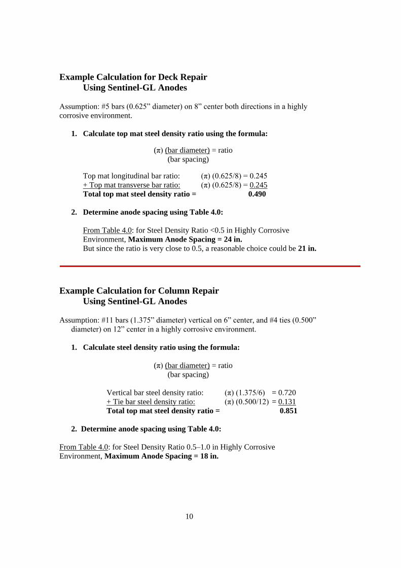
Example Calculation for Deck RepairUsing Sentinel-GL Anodes
Assumption: #5 bars (0.625” diameter) on 8” center both directions in a highly corrosive environment.
1. Calculate top mat steel density ratio using the formula:
(π) (bar diameter) = ratio(bar spacing)
Top mat longitudinal bar ratio: (π) (0.625/8) = 0.245+ Top mat transverse bar ratio: (π) (0.625/8) = 0.245Total top mat steel density ratio = 0.490
2. Determine anode spacing using Table 4.0:
From Table 4.0: for Steel Density Ratio <0.5 in Highly CorrosiveEnvironment, Maximum Anode Spacing = 24 in.But since the ratio is very close to 0.5, a reasonable choice could be 21 in.
Example Calculation for Column RepairUsing Sentinel-GL Anodes
Assumption: #11 bars (1.375” diameter) vertical on 6” center, and #4 ties (0.500” diameter) on 12” center in a highly corrosive environment.
1. Calculate steel density ratio using the formula:
(π) (bar diameter) = ratio(bar spacing)
Vertical bar steel density ratio: (π) (1.375/6) = 0.720+ Tie bar steel density ratio: (π) (0.500/12)= 0.131Total top mat steel density ratio = 0.851
2. Determine anode spacing using Table 4.0:
From Table 4.0: for Steel Density Ratio 0.5–1.0 in Highly CorrosiveEnvironment, Maximum Anode Spacing = 18 in.
11
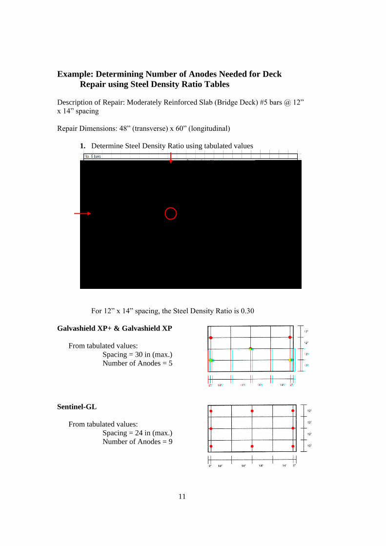
Example: Determining Number of Anodes Needed for DeckRepair using Steel Density Ratio Tables
Description of Repair: Moderately Reinforced Slab (Bridge Deck) #5 bars @ 12” x 14” spacing
Repair Dimensions: 48” (transverse) x 60” (longitudinal)
1. Determine Steel Density Ratio using tabulated values
For 12” x 14” spacing, the Steel Density Ratio is 0.30
Galvashield XP+ & Galvashield XP
From tabulated values:Spacing = 30 in (max.)Number of Anodes = 5
Sentinel-GL
From tabulated values:Spacing = 24 in (max.)Number of Anodes = 9

12
Installation Instructions
Prior to installation, the “Installation Instructions” bulletin shall be thoroughlyexamined for details on the placement and use ofmanufacturer’sunits. Concreteshall be removed from around and behind all corroding rebar, in accordance withgood concrete repair practice (ICRI Guideline No. 03730). Securely fasten theunit to clean reinforcing steel using a suitable wire twisting tool to eliminate freemovement, and to ensure a good electrical connection. Steel continuity within thepatch should be verified with an appropriate meter. If discontinuous steel ispresent, re-establish continuity with steel tie wires. Following the unit installation,electrical connection between the unit tie wires and the clean reinforcing bar
should be confirmed with an appropriatemeter. The location and spacing of theunits shall be as specified by the designer.
The anodes are typically tied on the side orbeneath the exposed rebar as close aspractical to the surrounding concretemaking sure than enough space is left tofully encapsulate the unit in the repair.
Minimum cover over the units must be 20 mm (3/4 in.). Units can be placed on agrid pattern throughout the repair to protect a second mat of steel if required.With the units in a position, complete the repairusing a suitable repair material with resistivityless than 15,000 ohm-cm. If higher resistancerepair materials are to be used, packmanufacturer’s mortar between the unit and thesubstrate to provide a conductive path to thesubstrate, the complete repair.
A standard tie wire will work, if there iscontinuity to start with. If there is none you willneed to weld either a heavy gage wire #1 or apiece of rebar between the mats.
Health and Safety
As with all cement-based materials, contact withmoisture can release alkalis which may beharmful to exposed skin. Anodes should behandled with suitable gloves and other personalprotective equipment in accordance with standard procedures for handlingcementitious materials. Additional safety information is included in the MaterialSafety Data Sheet.
Installation Instructions and Health and Safety information can be found for eachproduct on the manufacturer’s websites.

13
PLUG-TYPE ANODES
Installation Instructions
The location and spacing of the Galvashield® CC units shall be on a grid patternas specified by the engineer. Using a rebar locator, locate all existing steel withinthe area designated for protection and mark areas to drill unit installation holes.When possible, units should be installed a minimum of 4 in. (100 mm) fromreinforcing grid.
Series Connection –a single circuit shall contain no more than 10 Galvashield®CC units. Drill a minimum of two ½ in. (12 mm) rebar connection holes per stringof anodes. Saw cut a single continuous groove approximately ¼ in. (6mm) wideby ½ in. (12 mm) deep into the concrete to interconnect rebar connection holesand anode connection holes.
Individual Connection –drill one rebar connection hole per unit location. Saw cuta groove approximately ¼ in. (6 mm) wide by ½ in. (12 mm) deep into theconcrete to interconnect the rebar connection hole and anode connection hole.
Reinforcing steel connections should be made using the Vector Rebar ConnectionKit. Place the weighted end of the connector into the drilled hole until the steelcoil contacts the reinforcing steel. Feed the steel connector wire through theVector Setting Tool and set into place by striking with a hammer.
Connect the units directly to the rebar connection wire using the supplied wireconnector. If installing in series, connect the units to the interconnecting cable
with a wire connector (cable and wireconnectors are available as the VectorAnode Connection Kit). Verify continuitybetween unit locations and rebarconnections with a multi-meter. Aresistance of 1 ohm or less is acceptable.
Drill holes as per the dimensions listedabove to accommodate the anodes.Presoak the units for a minimum of 10 to a
maximum of 30 minutes in a shallow water bath. Galvashield Embedding MortarEmbedding mortar should be wet cured or cured with a curing compound andprotected from traffic for 24 hours. Place the mixed embedding mortar into thebottom⅔ of each hole and slowly press in the unit allowing the mortar to fill theannular space ensuring there are no air voids between the unit and the parentconcrete. The minimum unit cover depth shall be ¾ in. (20 mm). Place wires intogrooves and top off unit holes and saw cuts flush to the concrete surface withembedding mortar.

14
PLUG-TYPE ANODES
Placement ofGalvashield®
CC inconcrete
beam
A standard tie wire will work, if there iscontinuity to start with. If there is none you
will need to weld either a heavy gage wire #1or a piece of rebar between the mats.
15
Tables 5.0, 6.0, 7.0

16

17

18

19

20

21

22
Compatible Repair Materialsfor Use with Sentinel-GL Anodes
Product Supplier
Eucocrete Euclid Chemical Co.Eucopatch Euclid Chemical Co.Form & Pour CP Euclid Chemical Co.ThinTop Supreme Euclid Chemical Co.ConcreteTop Supreme Euclid Chemical Co.Euco Verticoat Euclid Chemical Co.EucoShot-LR Euclid Chemical Co.Corr-Bond Euclid Chemical Co.Express Repair TammsSpray Mortar TammsSpeedCrete PM TammsSpeedCrete Redline TammsSikaRepair 222 Sika Corp.SikaRepair 223 Sika Corp.MasterFlow 713 Master Builders (BASF)MasterFlow 928 Master Builders (BASF)MasterPatch 230VP Master Builders (BASF)MasterPatch 240CR Master Builders (BASF)Powermix Patch Power CretePowerGrout P Power CretePolyfast LPL Dayton SuperiorRe-Crete 20 Dayton Superior

23
Appendix
Tables for determining spacing for Sentinel-GL anodes for No. 5, No. 6 and No. 7 reinforcement bars.

24


![GAIL INDIA LIMITED CONSTRUCTION OF STEEL PIPELINE AND ... - CATHODIC PROTECTION_14.pdf · 3.1 Temporary Cathodic Protection [TCP]: Using sacrificial [Mg or Zn] anodes pre-packed in](https://static.fdocuments.in/doc/165x107/5dd12376d6be591ccb646812/gail-india-limited-construction-of-steel-pipeline-and-cathodic-protection14pdf.jpg)