Use of photoelastic modulators for high-accuracy spectropolarimetric ... · Use of photoelastic...
7
Use of photoelastic modulators for high-accuracy spectropolarimetric imaging of aerosols David J. Diner, Ab Davis, Tom Cunningham, Gary Gutt, Bruce Hancock, Nasrat Raouf, Yu Wang, Jason Zan Jet Propulsion Laboratory, California Institute of Technology, Pasadena, CA 91109 Russell Chipman, Neil Beaudry Optical Sciences Center, University of Arizona, Tucson, AZ 85721 Linda Hirschy Hinds Instruments, Inc., Hillsboro, OR 97142 Abstract-Passive multiangular, multispectral, and polarimetric sensing approaches each have unique strengths for the measurement of tropospheric aerosol column abundances and microphysical properties. Current spaceborne multispectral and multiangular aerosols sensors operate at ~1 km resolution. Under NASA’s Instrument Incubator Program, we are developing an electro-optic imaging approach that will enable adding high-accuracy polarimetry to such observations. To achieve a degree of linear polarization (DOLP) uncertainty of 0.5%, our approach temporally modulates the linear- polarization component of incoming light at a rapid rate, enabling each detector within a focal-plane array, combined with polarization analyzers, to measure the relative proportions of the linear Stokes components Q or U to the total intensity. Our system uses tandem photoelastic modulators (PEMs) within a high-reflectance, low diattenuation camera design. The two PEMs vibrate at slightly different resonant frequencies, leading to modulation of the polarized light at a heterodyne frequency of ~25 Hz. High-speed (1 kHz) readout of the detector arrays samples the output waveforms from which Q/I and U/I are derived. We report on experimental and theoretical analyses of PEM and optical system performance, along with plans for developing ruggedized PEMs capable of withstanding launch and on-orbit stresses. I. INTRODUCTION Satellite remote sensing, by virtue of its global perspective, has a substantial role in measuring aerosol amounts and microphysical properties of importance to climate and air quality studies. Recent remote sensing advances have used a variety of approaches, each sensitive to different aspects of aerosol microphysics [1]. Passive multiangular, multispectral, and polarimetric sensing approaches each have unique strengths, and fusion of such capabilities in an imaging system would represent a major technological advance in our ability to monitor and characterize particulate matter from space. Polarization in particular has unique sensitivity to particle real refractive indices and widths of the particle size distributions [2]. Polarimetry in both the visible and shortwave infrared (SWIR) enables size-resolved retrievals of particle real refractive index. We envision an integrated spaceborne instrument that can provide multispectral and multiangular global coverage of the Earth in a few days. Furthermore, a degree of linear polarization (DOLP) uncertainty of 0.5% is specified within a subset of the spectral bands to provide accuracies required for climate- quality aerosol optical and microphysical property retrievals. We call this instrument concept the Multiangle SpectroPolarimetric Imager (MSPI). The starting point for definition of the MSPI instrument architecture is the Multi-angle Imaging SpectroRadiometer (MISR) instrument [3], currently in orbit on the Terra satellite. MISR acquires multiangle imagery in four visible/near-infrared bands from a set of nine pushbroom cameras, with the forward and backward viewing cameras paired in a symmetrical arrangement at a fixed set of view angles. A similar approach would be used for MSPI, though certain aspects of the MISR design require modification to accommodate the MSPI requirements. The optics must be capable of high transmission over the spectral range 380 - 2130 nm, and nine spectral bands within this interval are baselined (380, 412, 446, 558, 650, 866, 1375, 1610, and 2130 nm). In addition to intensity measurements in these nine bands, polarization measurements within the bands centered at 650 nm and 1610 nm are also required. Furthermore, the MSPI cameras are envisioned to have roughly twice the cross-track field of view of the MISR cameras. The MISR pushbroom cameras acquire multispectral, non- polarimetric observations using focal planes in which adjacent line arrays are overlain by filters passing different wavelengths [3]. The analog of this measurement approach for polarimetry would be to overlay different line arrays with analyzers in different orientations. MISR experience shows that the data from different lines within a single camera can be digitally co-registered to better than 1/10 of a pixel; however, even after extensive analysis of the in-flight data residual uncertainties in the radiometric cross-calibration between channels are on the order of 1-2%. Such an arrangement would by itself risk violating the 0.5% DOLP requirement, and some additional means of reducing errors is needed. Under NASA’s Instrument Incubator Program, we are building a brassboard spectropolarimetric camera that incorporates an electro-optic imaging approach to temporally modulate the linear-polarization component of incoming light at a sub-pixel rate, enabling each detector within a focal-
Transcript of Use of photoelastic modulators for high-accuracy spectropolarimetric ... · Use of photoelastic...

Use of photoelastic modulators for high-accuracy spectropolarimetric imaging of aerosols
David J. Diner, Ab Davis, Tom Cunningham, Gary Gutt, Bruce Hancock, Nasrat Raouf, Yu Wang, Jason Zan
Jet Propulsion Laboratory, California Institute of Technology, Pasadena, CA 91109
Russell Chipman, Neil Beaudry Optical Sciences Center, University of Arizona, Tucson, AZ 85721
Linda Hirschy
Hinds Instruments, Inc., Hillsboro, OR 97142
Abstract-Passive multiangular, multispectral, and polarimetric sensing approaches each have unique strengths for the measurement of tropospheric aerosol column abundances and microphysical properties. Current spaceborne multispectral and multiangular aerosols sensors operate at ~1 km resolution. Under NASA’s Instrument Incubator Program, we are developing an electro-optic imaging approach that will enable adding high-accuracy polarimetry to such observations. To achieve a degree of linear polarization (DOLP) uncertainty of 0.5%, our approach temporally modulates the linear-polarization component of incoming light at a rapid rate, enabling each detector within a focal-plane array, combined with polarization analyzers, to measure the relative proportions of the linear Stokes components Q or U to the total intensity. Our system uses tandem photoelastic modulators (PEMs) within a high-reflectance, low diattenuation camera design. The two PEMs vibrate at slightly different resonant frequencies, leading to modulation of the polarized light at a heterodyne frequency of ~25 Hz. High-speed (1 kHz) readout of the detector arrays samples the output waveforms from which Q/I and U/I are derived. We report on experimental and theoretical analyses of PEM and optical system performance, along with plans for developing ruggedized PEMs capable of withstanding launch and on-orbit stresses.
I. INTRODUCTION
Satellite remote sensing, by virtue of its global perspective, has a substantial role in measuring aerosol amounts and microphysical properties of importance to climate and air quality studies. Recent remote sensing advances have used a variety of approaches, each sensitive to different aspects of aerosol microphysics [1]. Passive multiangular, multispectral, and polarimetric sensing approaches each have unique strengths, and fusion of such capabilities in an imaging system would represent a major technological advance in our ability to monitor and characterize particulate matter from space. Polarization in particular has unique sensitivity to particle real refractive indices and widths of the particle size distributions [2]. Polarimetry in both the visible and shortwave infrared (SWIR) enables size-resolved retrievals of particle real refractive index. We envision an integrated spaceborne instrument that can provide multispectral and multiangular global coverage of the Earth in a few days. Furthermore, a degree of linear polarization (DOLP) uncertainty of 0.5% is specified within a subset of the
spectral bands to provide accuracies required for climate-quality aerosol optical and microphysical property retrievals. We call this instrument concept the Multiangle SpectroPolarimetric Imager (MSPI).
The starting point for definition of the MSPI instrument architecture is the Multi-angle Imaging SpectroRadiometer (MISR) instrument [3], currently in orbit on the Terra satellite. MISR acquires multiangle imagery in four visible/near-infrared bands from a set of nine pushbroom cameras, with the forward and backward viewing cameras paired in a symmetrical arrangement at a fixed set of view angles. A similar approach would be used for MSPI, though certain aspects of the MISR design require modification to accommodate the MSPI requirements. The optics must be capable of high transmission over the spectral range 380 - 2130 nm, and nine spectral bands within this interval are baselined (380, 412, 446, 558, 650, 866, 1375, 1610, and 2130 nm). In addition to intensity measurements in these nine bands, polarization measurements within the bands centered at 650 nm and 1610 nm are also required. Furthermore, the MSPI cameras are envisioned to have roughly twice the cross-track field of view of the MISR cameras.
The MISR pushbroom cameras acquire multispectral, non-polarimetric observations using focal planes in which adjacent line arrays are overlain by filters passing different wavelengths [3]. The analog of this measurement approach for polarimetry would be to overlay different line arrays with analyzers in different orientations. MISR experience shows that the data from different lines within a single camera can be digitally co-registered to better than 1/10 of a pixel; however, even after extensive analysis of the in-flight data residual uncertainties in the radiometric cross-calibration between channels are on the order of 1-2%. Such an arrangement would by itself risk violating the 0.5% DOLP requirement, and some additional means of reducing errors is needed.
Under NASA’s Instrument Incubator Program, we are building a brassboard spectropolarimetric camera that incorporates an electro-optic imaging approach to temporally modulate the linear-polarization component of incoming light at a sub-pixel rate, enabling each detector within a focal-

plane array, combined with polarization analyzers, to measure the relative proportions of the linear Stokes components to the total intensity. This design circumvents inaccuracies introduced by detector gain changes or uncertainties in flight that could compromise meeting the required DOLP accuracy with a static detection approach. Our “self-calibrating” system uses tandem photoelastic modulators (PEMs) within a reflective camera lens having high-reflectance, low diattenuation mirrors. The approach is spectrally versatile, and can benefit other applications besides aerosol remote sensing.
II. MODULATION USING PEMS
A. Theory
PEMs have been in use for many years as a method of polarization modulation in a variety of research and industrial applications. Their operation is based on the principle that uniform optical materials such as glass become birefringent when compressed along one axis. This is commonly referred to as stress-induced birefringence, or the photoelastic effect. Thus, it is possible to construct a variable retarder by compressing optical glass. Considerable mechanical power is needed to slowly modulate the stress-induced birefringence. However, reducing the power requirement by a factor of 103 - 104, to less than 0.5 W, is possible by making use of mechanically resonant oscillation. By coupling a piezoelectric transducer to a glass or fused silica bar, a standing sound wave that oscillates at the bar’s fundamental frequency can be induced. This causes a modulation of the birefringence at a frequency proportional to the speed of sound in the glass and inversely proportional to the length of the bar. Typical frequencies measured in the tens of kHz for glass elements several cm in size. The oscillation amplitude can be regulated with an electronic feedback circuit.
The polarimetric state of light incident on an optical system can be represented by the Stokes vector, where the component I is the total intensity; Q represents the excess of light at 0º orientation to a specified plane relative to the intensity at 90º; U is the excess of intensity at 45º relative to 135º; and V is the excess of right-handed circular polarization to left-handed circular polarization. The DOLP is given by
!
DOLP = (Q/I)2
+ (U/I)2
= q2
+ u2 (1)
where
!
q = Q/I ,
!
u =U/I , and the linear polarization orientation is given by
!
" = arctan(U/Q) = arctan(u/q) (2)
from which we see that the required measurements depend only on the relative ratios q and u. For illumination by
sunlight, the amount of circular polarization in natural scenes is on the order of 0.1% of the total intensity. Our instrument concept measures only the linear polarization components. Nonetheless, the optical system is designed to minimize instrument-induced circular polarization, as well as cross-talk of V into Q and U.
The modulation frequency of a single PEM, f, is given by
!
f = cs / 2L (3)
where cs is the speed of sound in the glass and L is the length of the bar. For bars with L between 2 and 10 cm the frequency ranges from 20 to 100 kHz. The stress-induced retardance δ is given by
!
" = # " sin($x
L
) sin%t (4)
where δ’ is the amplitude of the oscillation in retardance, t is time,
!
" = 2#f , and the spatial variable x extends from 0 to L. The PEMs that we will use are constructed with an octagonal shape, and the spatial variation of retardance extends over two orthogonal dimensions. Because the amplitude of the modulation peaks at the center of the element and falls to 0 at the edges, only the central portion is used to attain maximum efficiency (e.g. the central 2.5 cm of a 6.3-cm octagonal element). If the PEM is placed in the pupil plane of an optical system, then the effective amplitude, averaged over the extent of the pupil, reduces to
!
" = "0sin#t (5)
where δ0 is the retardance integrated spatially over the area of the pupil.
To understand the functional form of the modulated signal produced by a single PEM, imagine a device with its fast axis oriented at 45º, sandwiched between two crossed quarter-wave plates, one with its fast axis at 0º and the other at 90º. This system is known as a circular retarder. This configuration is required so that the modulation is applied to Q and U. Circular polarization is expected to be small compared to linear polarization in the observed scenes, so it is not considered worthwhile to measure the V component in flight. Measuring V requires an additional row of pixels in the focal plane, additional on-board data storage, and a 33% increase in telemetry for the polarimetric bands, all at considerable expense and effort. Since V is not measured, we ensure the DOLP measurement is accurate by specifying that incident circular polarization does not couple into linear polarization or intensity via the instrument-induced polarization. A similar instrument-induced polarization requirement applies to circular diattenuation. Very little
circular diattenuation is expected in practice. Circular diattenuation can occur through the interaction of sequences of linear diattenuations and linear retardances oriented at 45º to each other, but only as a higher order effect.
The Mueller matrix of an ideal circular retarder is given by:
!
M =
1 0 0 0
0 cos" sin" 0
0 #sin" cos" 0
0 0 0 1
$
%
& & &
'
(
) ) )
(6)
If the focal plane contains a detector overlain by an analyzer at 0º and another detector with an analyzer at 45º, the measurements are given by:
!
I0
=1
2
I +Q cos" +U sin"[ ] (7a)
!
I45
=1
2
I "Q sin# + U cos#[ ] (7b)
Plugging (5) into (7a) and (7b) and using the Bessel function expansions of the cosine and sine of a sinusoid [3], we obtain:
!
I0 =1
2I + J0 (" 0)Q[ ] + J2k
k=1
#
$ (" 0) cos 2k%t&
' (
)
* + Q +
+ J2k+1k= 0
#
$ (" 0) sin(2k +1)%t&
' (
)
* + U
(8a)
!
I45 =1
2I + J0 (" 0)U[ ] + J2k
k=1
#
$ (" 0) cos 2k%t&
' (
)
* + U ,
, J2k+1k= 0
#
$ (" 0) sin(2k +1)%t&
' (
)
* + Q
(8b)
where Jn is the nth order Bessel function. Therefore
!
I0 is a
signal whose unmodulated component is proportional to
!
I + J0 (" 0)Q , plus a high-frequency component with Q modulated at a frequency of 2ω (and higher even harmonics) and U modulated at ω (and higher odd harmonics). An analogous signal is obtained from the measurement
!
I45 .
A clever approach to recovering the Stokes components from (8) has been demonstrated for solar astronomical polarimetry in which the high-frequency time-varying signals are electronically demodulated. The approach involves phase-locking the charge accumulation process that is inherent to a CCD to the modulation phase of the PEM [4-6]. Because our aerosol imaging application requires coverage of a broader
spectral range than can be covered by a CCD, we have baselined the use of a hybrid focal-plane device comprised of both silicon and InGaAs photodetectors and complementary metal oxide semiconductor (CMOS) read-out integrated circuits (ROICs). A CMOS-based approach to extracting the high-frequency modulation that is analogous to the CCD-based approach has been described [7]; however, concerns with electronic noise have led us to adopt a different methodology.
Reference to (8a) and (8b) shows that if the scientific application can afford to integrate the signal over intervals long compared to the tens of kHz frequency of the PEM, then the high-frequency terms nearly average to zero and the time-averaged portion of the signals are given by
!
I0 =1
2I + J0 (" 0)Q[ ] =
I
21+ J0 (" 0)q[ ] (9a)
!
I45 =1
2I + J0 (" 0)U[ ] =
I
21+ J0 (" 0)u[ ] (9b)
Aerosol imaging from space is just such an application. The line-to-line smear time for a MISR or MSPI system operating in low Earth orbit is about 40 msec (the time it takes to fly an along-track distance of 275 m) — long enough to average > 1600 cycles of the high frequency modulation.
In theory, by varying the voltage applied to the PEM it is possible to vary the peak amplitude,
!
"0, of the retardance and
therefore the value of the coefficient
!
J0 (" 0) that multiplies Q and U. Such an approach would permit solving (9a) and (9b) for I, q, and u. But a PEM is a high-Q resonant mechanical oscillator (Q =10,000; this parameter is written without italics to distinguish it from the Stokes vector component) with an inherent time constant, τ, of several hundred msec:
!
" =2Q
f#2 $10,000
42,000= 0.5 sec (10)
This limits the ability to modulate the peak retardance with low power consumption to about 1 Hz , which is too slow for our application.
Given that extracting the modulated signal at the resonant frequency is potentially noisy with CMOS technology, and that the ability to modulate the peak amplitude,
!
"0, of single
PEM is too slow, a suitable compromise is a dual-PEM configuration using two PEMs oscillating at slightly different frequencies. If we assume for now that the two PEMs have the same peak retardance
!
"0, the net retardance of the
tandem system is given by
!
" = " 0 sin#1t + " 0 sin#2t =
= 2" 0 cos1
2(#2 $ #1)t
%
& ' (
) * + sin
1
2(#1 +#2)t
%
& ' (
) * =
= 2" 0 cos#bt +sin# t
(11)
where ω1 and ω2 are the resonant frequencies of the two PEMs. The “carrier” frequency
!
" is the average of the two PEM frequencies, and the much slower beat, or heterodyne frequency
!
"b modulates this signal. The resonant frequency
of a PEM is inversely proportional to the size of the glass element, as shown in (3). Thus, by sizing the two PEMs differently, the beat frequency can be made to be a nearly arbitrary value from a few hertz to a few tens of hertz or higher. Comparison of (11) with (5) shows that the expression
!
2"0cos#
bt takes the place of
!
"0 and
!
" replaces
!
" in (8). Because
!
"b
<< " , integration over sample times long with respect to
!
" but short compared to
!
"b (i.e., ~1
msec) results in the signals recorded at the detectors being as follows:
!
I0"I
21+ J
02#
0cos$b t( )q[ ] (12a)
!
I45"I
21+ J
02#
0cos$
bt( )u[ ] (12b)
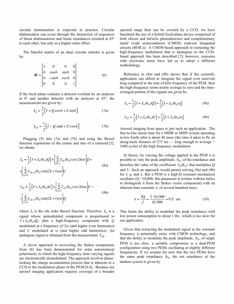
Therefore, signal processing depends only on the beat frequency, which differs from other dual-PEM approaches that retain dependence on the PEM resonance frequencies [9]. Note that the shape of the periodic waveform is given by the zeroth order Bessel function of a sinusoid. The number of oscillations above and below the mean that the signal transitions through during a single line-repeat interval depends on the magnitude of
!
"0, as shown in Fig. 1.
Figure 1. The J0 Bessel function vs. the total retardance of two PEMs (=
!
2"0). Locations where the maximum retardance of each PEM is a quarter
wave, half wave, and full wave (λ) are shown. Bottom: The signal modulating q or u as a function of time for each of these three conditions.
B. Laboratory Verification
To test how well the dual-PEM system performs relative to theoretical expectations, an experimental system was established on an optical bench. A white light source is followed by a tiltable glass plate that partially polarizes the beam in proportion to the angle of tilt. Quarter-wave plates bracket the dual-PEM system. A rotatable polarization analyzer is used for the detection of Q and U, and is also used as the control measurement of the polarization state. A red filter limits the spectral bandpass. The final element is a photodiode detector. The dual-PEM system was purchased from Hinds Instruments, Inc. and consists of II/IS42 fused silica PEMs with resonant frequencies near 42 kHz, and a beat frequency of 9 Hz.
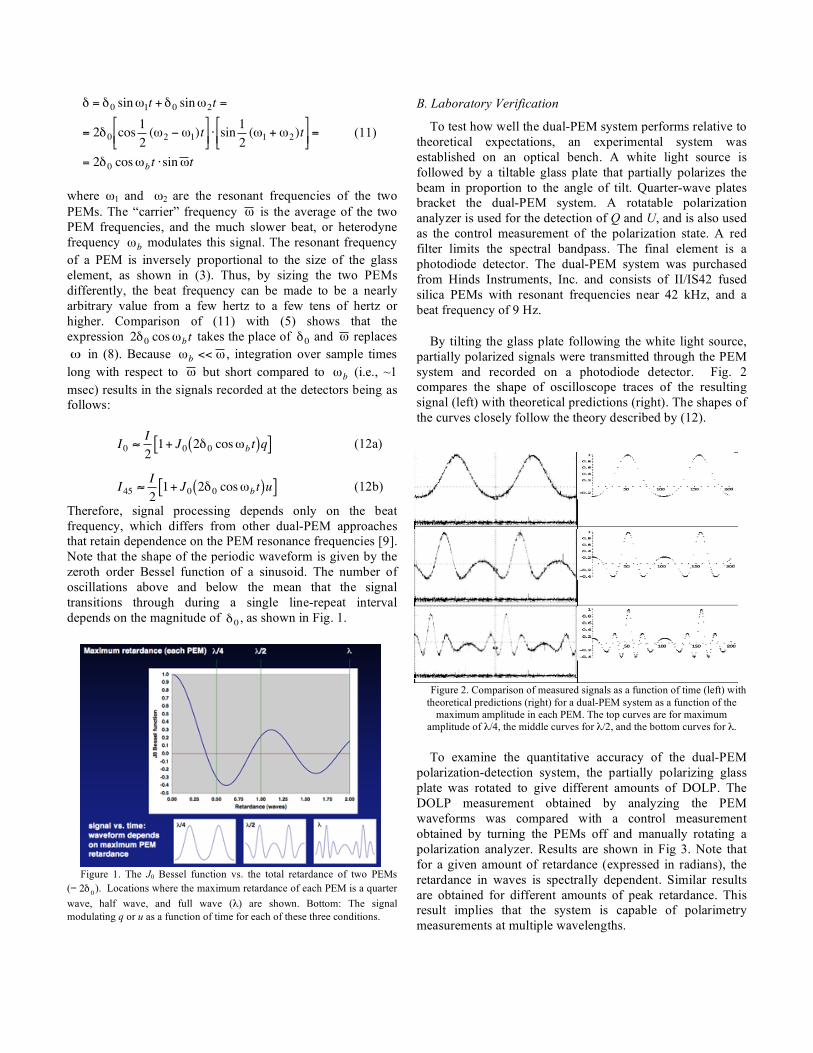
By tilting the glass plate following the white light source, partially polarized signals were transmitted through the PEM system and recorded on a photodiode detector. Fig. 2 compares the shape of oscilloscope traces of the resulting signal (left) with theoretical predictions (right). The shapes of the curves closely follow the theory described by (12).
Figure 2. Comparison of measured signals as a function of time (left) with theoretical predictions (right) for a dual-PEM system as a function of the
maximum amplitude in each PEM. The top curves are for maximum amplitude of λ/4, the middle curves for λ/2, and the bottom curves for λ.
To examine the quantitative accuracy of the dual-PEM polarization-detection system, the partially polarizing glass plate was rotated to give different amounts of DOLP. The DOLP measurement obtained by analyzing the PEM waveforms was compared with a control measurement obtained by turning the PEMs off and manually rotating a polarization analyzer. Results are shown in Fig 3. Note that for a given amount of retardance (expressed in radians), the retardance in waves is spectrally dependent. Similar results are obtained for different amounts of peak retardance. This result implies that the system is capable of polarimetry measurements at multiple wavelengths.

Figure 3. DOLP derived from the electro-optic dual-PEM system vs. measurements derived from a manually rotated analyzer. Curves
corresponding to different peak PEM retardance amplitudes are shown. Sensitivity to about 0.1% in DOLP is observed.
III. PEM INTEGRATION INTO A CAMERA
A. Optics
We assume a nominal low Earth orbit altitude of 470 km for MSPI, chosen in the interest of synergistic observation with an aerosol lidar. From this altitude, detectors 13.5 µm on a side in the focal plane arrays achieve a footprint of 250 m in the nadir with a lens effective focal length (EFL) of 29 mm. The required cross-track field-of-view (FOV) to obtain sufficient swath width for 4-day global coverage is ±31º for a camera with a view zenith angle intermediate between the 26º and 46º views of MISR. In the along-track direction, a FOV of ±1º is required in order to accommodate a thirteen-row line array containing detector lines filtered to various spectral bands and polarimetric states. An f/5.6 focal ratio is chosen by analogy with MISR. The optics must be capable of high transmission over the spectral range 380 - 2130 nm. To meet these requirements and to also control instrument-induced polarization (retardance, diattenuation, and depolarization) a reflective lens system is indicated.
Figure 4. Top view of the camera design, showing the three-mirrors, focal plane, and dual-PEM system. The design provides nearly diffraction limited imaging performance across the FOV.
A top view of the baseline lens design that we have developed to demonstrate the feasibility of manufacturing a spectropolarimetric camera is shown in Fig. 4. A convex, spherical primary mirror directs an expanding beam to a concave aspheric secondary. A nearly collimated beam passes through the quarter-wave plates/dual-PEM assembly and then reflects off an aspheric tertiary, which focuses the light onto the focal plane array. The dual-PEM system is located at the camera’s pupil plane. Together, the tandem PEMs are the largest optical element in the camera. Tracing salient rays (see Fig. 4) through this lens system highlights certain features of the design:
• The angles of incidence on the reflective surface all fall in the range ±23.5º from normal. Calculations show that for the baseline mirror coating, which consists of silver with an aluminum undercoat (for broadband performance) and a silicon nitride overcoat (for protection against oxidation), overall system diattenuation can be kept below about 1%. This is important because the camera must function as a polarization-insensitive intensity imager in the non-polarimetric bands.
• Quarter wave plates to convert linear to circular polarization must be designed to function at the two polarization bands (650 and 1610 nm). We find that a quartz-sapphire combination gives the best overall performance, keeping the retardance within ~5% of λ/4 over the required bandpasses.
• The length of the path of salient rays through the dual PEM assembly varies with field angle. Furthermore, the rays do not pass through the two PEMs at exactly the same distance from the optic axis, and as a result of (4) the pupil-averaged retardance is not identical for the two PEMs. The generalized equation for optical intensity vs. time for the dual PEM system, with the analyzer at 0º, and accounting for different retardances in each PEM is:
!
I0
= 0.5 I +Q J0"1( )J0 "2( ) + 2 #1( )
nJn"1( )Jn "2( ) cos n $1#$2( ) t( )
n=1
%
&'
( )
*
+ ,
- . /
0 1 2
(13)
Using this formulation, the relative retardances were calcul-ated for eight positions in the FOV by averaging the contributions from individual rays passing through the PEM apertures. The averaged retardance values for the eight positions differed by ±0.18%. Accounting for this geometri-cal effect can be accomplished through pixel-by-pixel calibration of the instrument-induced polarization effects.
• The lens system is nearly telecentric over the entire FOV. As with MISR, this feature ensures that the rays passing through the focal plane interference filters have essentially the same spectral content across the FOV.
2ndry
miirorPrimary
mirror
Focal Plane
Qtr wave plates
(typical 2 places)
Dual PEM assembly
Tertiary
mirror

B. PEM Packaging
The baseline design for the tandem PEM assembly represents a tradeoff between competing parameters of PEM physics. The parameters of the baseline design are: operating frequency f = 42 kHz; PEM lateral dimensions: ~ 63x63 mm; PEM thickness: 9.5 mm; working area (optical beam size): ~25-mm diameter. The parameters chosen reflect consideration of the MSPI system requirement for a set of cameras with different focal lengths (to preserve pixel size on the ground as a function of view angle, as with MISR), as well as heat dissipation in the PEM. The range of focal lengths required for MSPI vary from 29 mm in the nadir to 53 mm at the most oblique angle.
To maximize signal-to-noise ratio in both the 650 and 1610 nm bands, we estimate that the optimum retardance will be close to 527 nm (0.81 and 0.33 waves at 650 and 1610 nm, respectively). For a given value of retardance, δ0, the stress that must be induced in the PEM is inversely proportional to the thickness of the PEM along the optical axis (d):
!
"#$0
csd
(14)
For the baseline depth of the PEM, 9.5 mm, the working stress in the center of the optical element is < 8 MPa (1160 psi). This falls to near zero at the edges where stress induced failures usually start in glass.
Both the power to operate, and heat dissipated in, a PEM are a function of size and operating parameters:
!
Pwr"f
Q #d2
(15)
The baseline choice of large size (hence lower frequency) and maximum manageable thickness minimize the power and thermal issues. Thermal stresses in the PEM are a source of instrument-induced polarization, and are minimized by low heat dissipation. For the baseline PEM thickness, we estimate that the temperature rise above the surrounding environment will be less than 2ºC (Fig. 5) and the thermally induced stresses will be less 0.1% of the PEM working stress.
Figure 5. Estimated PEM temperature rise
C. PEM Ruggedization
PEMs work by means of stress-induced birefringence. A consequence of the stress is a strain that is a function of position within the PEM optical element. Integrating the strain over the dimensions of the PEM, we calculate that the dimension of the baseline PEM vary by ±7 µm. This range of motion must be accommodated in the mounting structure. Hinds Instruments has developed proprietary means for mounting PEMs that allows them to oscillate with high Q. As one would expect, this mounting structure puts a light touch on the PEM element. The resonant frequency of the optical element on its mount is in the range that is vulnerable to vibration loads that will be encountered during launch of a satellite to Earth orbit.
For space qualification of the PEMs, appropriate material choices and manufacturing processes will be adopted, as well as process controls suitable for a space-qualified product. A tailored program of load testing is being conducted to establish process parameters for specific bonds to be used in the space-PEM product. A structural finite model of the space-PEM design is being used by Hinds to check the margins of most elements of the design for quasi-static launch loads and for thermal stresses. Because the mount structure is non-linear, a high-fidelity mass model of the suspended elements will be used to determine loads on the mounts and the non-linear behavior of the mount.
IV. SUMMARY AND STATUS
The dual-PEM polarimetric imaging approach is maturing under the IIP. The key advantages of the PEM approach are self-calibration and spectral versatility. Readout of the arrays with analyzers at 0º and 45º provide signals from which Q/I and U/I can be retrieved, respectively. These ratios are insensitive to changes in detector gain or optical transmittance of the camera. We have baselined the use of fused silica to provide optical transmittance over the range 350 - 2130 nm. For other applications, PEMs exist for wavelengths ranging from 130 nm - 30 µm.
Full-up testing of a PEM designed for flight mechanical and thermal-vacuum environments is planned for summer 2006. The objective is to move this element of the camera from TRL-3 to TRL-5. This will be our first attempt to achieve this objective. A second design and qualification cycle is included in our Instrument Incubator Program effort.
Practical designs for key elements of the high-reflectance low-diattenuation optical system are in progress and detailed design of the brassboard camera is underway. The camera will demonstrate technology needed to incorporate the MSPI instrument into a next-generation Earth-orbiting aerosol mission, and is scheduled for testing in 2007.
7 8 9 10
4
3
2
1
Tem
pera
ture
Ris
e (d
eg C
)
PEM Thickness (mm)

ACKNOWLEDGMENT
This research was carried out, in part, at the Jet Propulsion Laboratory, California Institute of Technology, under contract with the National Aeronautics and Space Administration.
REFERENCES
[1] Yu, H., Y.J. Kaufman, M. Chin, G. Feingold, L.A. Remer, T.L. Anderson, Y. Balkanski, N. Bellouin, O. Boucher, S. Christopher, P. DeCola, R. Kahn, D. Koch, N. Loeb, M. S. Reddy, M. Schulz, T. Takemura, M. Zhou, “A review of measurement-based assessments of the aerosol direct radiative effect and forcing,” Atmos. Chem. Phys. 6, 613-666, 2006.
[2] Mishchenko, M.I. and L.D. Travis, “Satellite retrieval of aerosol properties over the ocean using polarization as well as intensity of reflected sunlight,” J. Geophys. Res. 102, 16989-17014, 1997.
[3] Diner, D.J., J.C. Beckert, T.H. Reilly, C.J. Bruegge, J.E. Conel, R.A. Kahn, J.V. Martonchik, T.P. Ackerman, R. Davies, S.A.W. Gerstl, H.R. Gordon, J-P. Muller, R.B. Myneni, P.J. Sellers, B. Pinty, and M. Verstraete, “Multi-angle Imaging SpectroRadiometer (MISR) instrument description and experiment overview,” IEEE Trans. Geosci. Rem. Sens. 36, 1072-1087, 1998.
[4] Abramowitz, M. and I.A. Stegun, Handbook of mathematical functions, Dover Publications, Inc., NY, 1965.
[5] Povel, H., H. Aebersold, and J.O. Stenflo, “Charge-coupled device image sensor as a demodulator in a 2-D polarimeter with a piezoelastic modulator,” Appl. Opt. 29, 1186-1190, 1990.
[6] Povel, H., C.U. Keller, and I.-A. Yadigaroglu, “Two-dimensional polarimeter with a charge-coupled-device image sensor and a piezoelastic modulator,” Appl. Opt. 33, 4254-4260, 1994.
[7] Gandorfer, A.M. and H.P. Povel, “First observations with a new imaging polarimeter,” Astron. Astrophys. 328, 381-389, 1997.
[8] Keller, C.U., “Charge-Caching CMOS Detector for Polarimetry (C3Po),” Proc. SPIE 5171, 2004.
[9] Stenflo, J.O., “Solar magnetic and velocity-field measurements: new instrument concepts,” Appl. Opt. 23, 1267-1278, 1984.