USE JP SP-300 R2 - Roland Care Service & Support |...
115
Thank you very much for purchasing this product. • To ensure correct and safe usage with a full understanding of this product's performance, please be sure to read through this manual completely and store it in a safe location. • Unauthorized copying or transferral of this manual, in whole or in part, is prohibited. • The contents of this operation manual and the specifications of this product are subject to change without notice. • The operation manual and the product have been prepared and tested as much as possible. If you find any misprint or error, please inform us. • Roland DG Corp. assumes no responsibility for any direct or indirect loss or damage which may occur through use of this product, regardless of any failure to perform on the part of this product. • Roland DG Corp. assumes no responsibility for any direct or indirect loss or damage which may occur with respect to any article made using this product. USER’S MANUAL
Transcript of USE JP SP-300 R2 - Roland Care Service & Support |...

Thank you very much for purchasing this product.
• To ensure correct and safe usage with a full understanding of this product's performance, please be sure to readthrough this manual completely and store it in a safe location.
• Unauthorized copying or transferral of this manual, in whole or in part, is prohibited.
• The contents of this operation manual and the specifications of this product are subject to change without notice.
• The operation manual and the product have been prepared and tested as much as possible. If you find anymisprint or error, please inform us.
• Roland DG Corp. assumes no responsibility for any direct or indirect loss or damage which may occur throughuse of this product, regardless of any failure to perform on the part of this product.
• Roland DG Corp. assumes no responsibility for any direct or indirect loss or damage which may occur withrespect to any article made using this product.
USER’S MANUAL

For the USA
FEDERAL COMMUNICATIONS COMMISSIONRADIO FREQUENCY INTERFERENCE
STATEMENT
This equipment has been tested and found to comply with thelimits for a Class A digital device, pursuant to Part 15 of theFCC Rules.These limits are designed to provide reasonable protectionagainst harmful interference when the equipment is operatedin a commercial environment.This equipment generates, uses, and can radiate radiofrequency energy and, if not installed and used in accordancewith the instruction manual, may cause harmful interferenceto radio communications.Operation of this equipment in a residential area is likely tocause harmful interference in which case the user will berequired to correct the interference at his own expense.
Unauthorized changes or modification to this system can voidthe users authority to operate this equipment.
The I/O cables between this equipment and the computingdevice must be shielded.
For Canada
CLASS A NOTICE
This Class A digital apparatus meets all requirements of theCanadian Interference-Causing Equipment Regulations.
CLASSE A AVIS
Cet appareil numérique de la classe A respecte toutes lesexigences du Règlement sur le matériel brouilleur duCanada.
NOTICEGrounding Instructions
Do not modify the plug provided - if it will not fit the outlet,have the proper outlet installed by a qualified electrician.
Check with qualified electrician or service personnel if thegrounding instructions are not completely understood, or if indoubt as to whether the tool is properly grounded.
Use only 3-wire extension cords that have 3-prong ground-ing plugs and 3-pole receptacles that accept the tool’s plug.
Repair or replace damaged or worn out cord immediately.
Operating Instructions
KEEP WORK AREA CLEAN. Cluttered areas and benchesinvites accidents.
DON’T USE IN DANGEROUS ENVIRONMENT. Don’tuse power tools in damp or wet locations, or expose them torain. Keep work area well lighted.
DISCONNECT TOOLS before servicing; when changingaccessories, such as blades, bits, cutters, and like.
REDUCE THE RISK OF UNINTENTIONAL STARTING.Make sure the switch is in off position before plugging in.
USE RECOMMENDED ACCESSORIES. Consult theowner’s manual for recommended accessories. The use ofimproper accessories may cause risk of injury to persons.
NEVER LEAVE TOOL RUNNING UNATTENDED.TURN POWER OFF. Don’t leave tool until it comes to acomplete stop.
As an ENERGY STAR® Partner, Roland DG Corp. has determined that this product meets the ENERGY
STAR® guidelines for energy efficiency.The International ENERGY STAR® Office Equipment Program is an international program thatpromotes energy saving through the penetration of energy efficient computers and other officeequipment. The program backs the development and dissemination of products with functions thateffectively reduce energy consumption. It is an open system in which business proprietors can
participate voluntarily. The targeted products are office equipment such as computers, monitors, printers, facsimiles,copiers, scanners, and multifunction devices. Their standards and logos are uniform among participating nations.
ROLAND DG CORPORATION1-6-4 Shinmiyakoda, Hamamatsu-shi, Shizuoka-ken, JAPAN 431-2103MODEL NAME : See the MODEL given on the rating plate.RELEVANT DIRECTIVE : EC LOW VOLTAGE DIRECTIVE (73/23/EEC)
EC ELECTROMAGNETIC COMPATIBILITY DIRECTIVE (89/336/EEC)
WARNINGThis is a Class A product. In a domestic environment this product may cause radio interference in whichcase the user may be required to take adequate measures.
1
Contents
Contents ........................................................................................................................... 1
Features of the SP-300 .................................................................................................... 4
To Ensure Safe Use ......................................................................................................... 5
About the Labels Affixed to the Unit ...................................................................................................... 9
Pour utiliser en toute sécurité ...................................................................................... 10
À propos des étiquettes collées sur l'appareil ..................................................................................... 14
1. Getting Started ........................................................................................................... 15
1-1 Checking Accessories ................................................................................................................... 161-2 Names and Functions ................................................................................................................... 171-3 Assembling and Installing .............................................................................................................. 19
Installation Environment ....................................................................................................................................................................... 19
Step 1: Assemble the Stand ................................................................................................................................................................... 20
Step 2: Install the Included Items .......................................................................................................................................................... 22
Step 3: Remove the Protective Media ................................................................................................................................................... 24
Step 4: Connect the Power Cord ........................................................................................................................................................... 25
Step 5: Set the Voltage Switches ........................................................................................................................................................... 26
Step 6: Change the Settings for the Language and Unit of Measurement, and Check the Voltage Settings ...................................... 27
Step 7: Fill Ink ....................................................................................................................................................................................... 28
Step 8: Match the Machine to the Environment Where Installed ........................................................................................................ 30
Step 9: Install the Blade ......................................................................................................................................................................... 31
Step 10: Connect to the Computer ........................................................................................................................................................ 32
2. Basic Operation ......................................................................................................... 33
2-1 Switching the Power On and Off ................................................................................................... 34Switching On the Power ........................................................................................................................................................................ 34
Switching Off the Power at the End of the Day ................................................................................................................................... 35
2-2 Menu Operations ........................................................................................................................... 36Displaying the Menus ............................................................................................................................................................................ 36
Basic Menu Operations ......................................................................................................................................................................... 37
2-3 Loading Media ............................................................................................................................... 38Loading Roll Media ............................................................................................................................................................................... 38
Loading Sheet Media ............................................................................................................................................................................. 41
Securing in Place Using the Media Clamps (Only When Printing) ..................................................................................................... 42
2-4 Heater Operation ........................................................................................................................... 45
3. Performing Output ..................................................................................................... 47
3-1 Points to Check Before Performing Output ................................................................................... 48Making the Temperature Setting for the Heaters .................................................................................................................................. 48
Checking the State of the Printing Heads ............................................................................................................................................. 49
Checking the Cutting Condition Settings ............................................................................................................................................. 50
3-2 Performing Output ......................................................................................................................... 52When You're Performing Printing Only ................................................................................................................................................ 52
When You're Performing Cutting Only ................................................................................................................................................. 53
When You're Performing Printing and Cutting ..................................................................................................................................... 53
3-3 Separating the Media .................................................................................................................... 543-4 Stopping or Pausing Output Operations ....................................................................................... 55

2
Contents
4. A wide variety of Operations ..................................................................................... 57
4-1 Setting the Location Where Output Starts .................................................................................... 58Setting the Start Location ...................................................................................................................................................................... 59
4-2 Making Corrections for Printing ..................................................................................................... 60Feed Correction ...................................................................................................................................................................................... 60
Bidirectional Correction ........................................................................................................................................................................ 62
4-3 Detailed Descriptions of Cutting Conditions ................................................................................. 654-4 Making Corrections for Printing and Cutting ................................................................................. 66
Adjusting Automatically ........................................................................................................................................................................ 66
Adjusting Manually ............................................................................................................................................................................... 67
4-5 Reloading the Media and Performing Cutting ............................................................................... 68Printing with Crop Marks ...................................................................................................................................................................... 68
Aligning Automatically ......................................................................................................................................................................... 69
Aligning Manually ................................................................................................................................................................................. 70
4-6 Checking the Remaining Ink Level ............................................................................................... 714-7 When Not in Use for a Prolonged Period ...................................................................................... 72
5. Maintenance ............................................................................................................... 73
5-1 Replacing the Ink Cartridges ......................................................................................................... 74Care and Handling of Ink Cartridges .................................................................................................................................................... 74
Replacing with New Ink Cartridges ...................................................................................................................................................... 74
If Ink Runs Out During Printing ........................................................................................................................................................... 75
5-2 Cleaning the Printing Heads ......................................................................................................... 76Cleaning the Printing Heads .................................................................................................................................................................. 76
If Drop-out Persists Even After Carrying Out Cleaning Several Times .............................................................................................. 77
Cleaning Using the Cleaning Kit .......................................................................................................................................................... 78
5-3 Other Cleaning Tasks .................................................................................................................... 835-4 Replacing the Consumable parts .................................................................................................. 84
Replacing the Wiper .............................................................................................................................................................................. 84
How to Replace the Blade ..................................................................................................................................................................... 86
How to Replace the Separating Knife ................................................................................................................................................... 87
5-5 Disposing of Discharged Ink ......................................................................................................... 885-6 When Moving the Unit ................................................................................................................... 89
6. About the Menus ........................................................................................................ 91
6-1 Menu Flowchart ............................................................................................................................. 926-2 Detailed Descriptions of the Menus .............................................................................................. 97
Main Menu ............................................................................................................................................................................................. 97
Cutting Configuration Menu ................................................................................................................................................................. 99
Heater Configuration Menu ................................................................................................................................................................. 100
Language/unit Menu ............................................................................................................................................................................ 100
Maintenance Menu .............................................................................................................................................................................. 100
3
ECO-SOL INK™ is trademark of Roland DG Corporation.ENERGY STAR® is a U.S. registered mark.Other company names and product names are trademarks or registered trademarks of their respective holders.
Copyright© 2003 Roland DG Corporation http://www.rolanddg.com/
Contents
7. What to Do If... .......................................................................................................... 101
7-1 What to Do If... ............................................................................................................................ 102The Machine Doesn't Run ................................................................................................................................................................... 102
Attractive Printing or Cutting Is Impossible ....................................................................................................................................... 102
The Media Becomes Jammed .............................................................................................................................................................. 104
What to Do If the Printing Carriage Does Not Operate ..................................................................................................................... 104
7-2 Responding to a Message .......................................................................................................... 105Action-prompting Messages ................................................................................................................................................................ 105
Error Message ...................................................................................................................................................................................... 105
8. Appendix ................................................................................................................... 107
8-1 Specifications .............................................................................................................................. 1088-2 Usable Media .............................................................................................................................. 1098-3 Printing or Cutting Area ............................................................................................................... 110
Maximum Area .................................................................................................................................................................................... 110
Area When Using Crop Marks ............................................................................................................................................................ 110
The Media-cutoff Location During Continuous Printing ................................................................................................................... 111
8-4 About Blade Life .......................................................................................................................... 112

4
Features of the SP-300
The SP-300 is capable of printing and cutting. This makes possible not only use as either a printer or a cutting machine,but also enables versatile uses such as performing printing followed by cutting.
Using the crop-mark feature enables you to perform cutting with accurate alignment when you remove the media forlamination or the like, then load the media on the machine again.
Also, two heaters are built in: a printing heater and a dryer. These help to fix and dry the ink, thereby enhancing workefficiency. The temperature setting for each can be preset to match the ambient environment and the media used.
Even better weatherability is achieved through use of ECO-SOL INK.
With these features, the SP-300 can accommodate a wide variety of uses, ranging from the creation of stickers and cut-out text and small-lot label printing to the production of panels, outdoor signs, and more.

5
Used for instructions intended to alert the user to the risk of death orsevere injury should the unit be used improperly.
About and Notices
Used for instructions intended to alert the user to the risk of injury ormaterial damage should the unit be used improperly.
* Material damage refers to damage or other adverse effects causedwith respect to the home and all its furnishings, as well to domesticanimals or pets.
About the Symbols
The symbol alerts the user to important instructions or warnings. The specific meaningof the symbol is determined by the design contained within the triangle. The symbol atleft means "danger of electrocution."
The symbol alerts the user to items that must never be carried out (are forbidden).The specific thing that must not be done is indicated by the design contained within thecircle. The symbol at left means the unit must never be disassembled.
The symbol alerts the user to things that must be carried out. The specific thing thatmust be done is indicated by the design contained within the circle. The symbol at leftmeans the power-cord plug must be unplugged from the outlet.
To Ensure Safe Use
Do not disassemble, repair, or modify.Doing so may lead to fire or abnormal op-eration resulting in injury.
Ground the unit with the ground wire.Failure to do so may result in risk of electro-cution in the event of a mechanical problem.
Do not use with any electrical powersupply that does not meet the ratingsdisplayed on the unit.Use with any other power supply may leadto fire or electrocution.
Do not connect the power cord withother electrical loads on a single elec-trical outlet.Doing so may generate heat and cause fire.
Use only with the power cord includedwith this product.Use with other than the included power cordmay lead to fire or electrocution.
Do not use while in an abnormal state(i.e., emitting smoke, burning odor,unusual noise, or the like).Doing so may result in fire or electrocution.Immediately switch off first the sub power,then the main power, unplug the power cordfrom the electrical outlet, and contact yourauthorized Roland DG Corp. dealer or ser-vice center.
Do not spill combustible liquid overthe platen.Doing so may cause fire.
Do not operate in a location exposedto open flame, sparking, or staticelectricity, or in a location exposedto high temperatures, such as in theimmediate vicinity of a heater. Also,do not place undried media in suchlocations.Doing so may result in fire due tocombustion of ink or cleaning liquid.
6
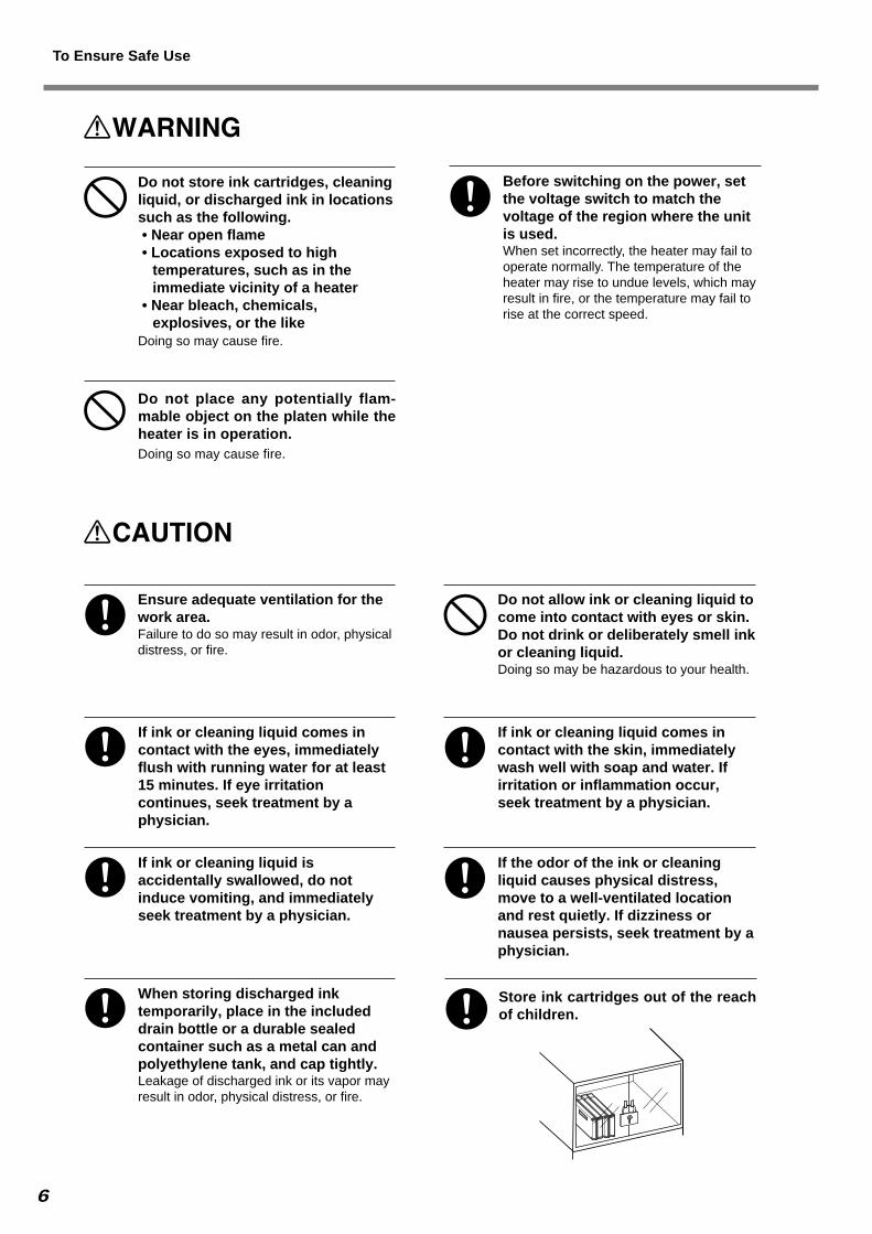
Ensure adequate ventilation for thework area.Failure to do so may result in odor, physicaldistress, or fire.
Do not allow ink or cleaning liquid tocome into contact with eyes or skin.Do not drink or deliberately smell inkor cleaning liquid.Doing so may be hazardous to your health.
If ink or cleaning liquid comes incontact with the eyes, immediatelyflush with running water for at least15 minutes. If eye irritationcontinues, seek treatment by aphysician.
If ink or cleaning liquid comes incontact with the skin, immediatelywash well with soap and water. Ifirritation or inflammation occur,seek treatment by a physician.
If ink or cleaning liquid isaccidentally swallowed, do notinduce vomiting, and immediatelyseek treatment by a physician.
If the odor of the ink or cleaningliquid causes physical distress,move to a well-ventilated locationand rest quietly. If dizziness ornausea persists, seek treatment by aphysician.
When storing discharged inktemporarily, place in the includeddrain bottle or a durable sealedcontainer such as a metal can andpolyethylene tank, and cap tightly.Leakage of discharged ink or its vapor mayresult in odor, physical distress, or fire.
Store ink cartridges out of the reachof children.
Do not store ink cartridges, cleaningliquid, or discharged ink in locationssuch as the following.• Near open flame• Locations exposed to high
temperatures, such as in theimmediate vicinity of a heater
• Near bleach, chemicals,explosives, or the like
Doing so may cause fire.
Do not place any potentially flam-mable object on the platen while theheater is in operation.Doing so may cause fire.
Before switching on the power, setthe voltage switch to match thevoltage of the region where the unitis used.When set incorrectly, the heater may fail tooperate normally. The temperature of theheater may rise to undue levels, which mayresult in fire, or the temperature may fail torise at the correct speed.
To Ensure Safe Use

7
Do not use with a damaged powercord or plug, or with a loose electri-cal outlet.Doing so may lead tofire, electrical shock,or electrocution.
Do not damage or modify the electri-cal power cord, subject it to exces-sive bending, twisting, pulling, bind-ing, or pinching, or place any objector weight on it.Doing so may dam-age the electricalpower cord, leadingto fire, electricalshock, or electrocu-tion.
When unplugging the electrical powercord from the power outlet, grasp theplug, not the cord.Unplugging by pullingthe cord may dam-age it, leading to fire,electrical shock, orelectrocution.
Do not attempt to unplug the power-cord plug with wet hands.Doing so may resultin electrical shockor electrocution.
Do not allow liquids, metal objects orflammables inside the machine.Such materialscan cause fire.
Install in a level and stable location.Failure to do so may result in the unit tippingover, leading to injury.
Use the joining screws to secure theunit to the stand.Failure to do somay result infalling of the unit,leading to injury.
Release the caster locks for the standbefore attempting to move.Otherwise theunit may tipover and causeinjury.
Unpacking, and installation must becarried out by four or more persons.Otherwise the machine or the stand may fall,resulting in injury.
Use care to avoid pinching the fingerswhen placing the unit on the stand.Doing so mayresult in injury.
To Ensure Safe Use

8
Be sure to install the media guidewhen loading roll media.Otherwise the roll mayfall and cause injury.
Load roll media at the proper position.Otherwise the roll mayfall, resulting in injury.
Do not touch the tip of the blade withyour fingers.Doing so may result in injury, and the cuttingperformance of the blade will be impaired.
Do not touch the control panel whilehead cleaning or other cleaning is inprogress.The printing carriage may move and causeinjury.
Before switching on the power, besure to install the drain bottle.Otherwise discharged fluid may leak from themachine.
Do not place hands within the spaceto the front of the unit while in opera-tion.Doing so mayresult in injury.
Do not touch the tip of the separatingknife with your fingers.Doing so may result in injury.
When cleaning the unit, be sure towait approximately 30 minutes ormore after switching off the power ofthe printer until the temperature of theplaten falls sufficiently.Doing so may cause burns because theplaten is hot.
Do not touch the platen when theheater is operating.Doing so may cause burns because theplaten is hot.
To Ensure Safe Use

9
About the Labels Affixed to the UnitThese labels are affixed to the body of this product.The following figure describes the location and content of these messages.
In addition to these symbols, the symbols shown below are also used.
: Indicates information to prevent machine breakdown or malfunction and ensure correct use.
: Indicates a handy tip or advice regarding use.
Ink and discharged ink are flammable.Keep away from open flame.
Ink and discharged ink are toxic. Avoid con-tact with the body. Use only in a well-venti-lated area.
Left
Front
Right
Inside the Front Cover
Inside the Cover
Do not touch the platen. It is hot when theheater is operating.
Do not place handswithin the space to thefront of the unit whilein operation.
Do not dismantle the cartridge.Keep out of reach of children.Do not store the cartridge in high or freezingtemperatures.
CAUTION : Read all Warnings and Procedures in the “User’s MANUAL” before performing any cleaning.
Rating label Use a rated power supply.
Ink Cartridge
To Ensure Safe Use

10
Utilisé pour avertir l'utilisateur d'un risque de décès ou de blessuregrave en cas de mauvaise utilisation de l'appareil.
Avis sur les avertissements
Utilisé pour avertir l'utilisateur d'un risque de blessure ou de dommagematériel en cas de mauvaise utilisation de l'appareil.
* Par dommage matériel, il est entendu dommage ou tout autre effetindésirable sur la maison, tous les meubles et même les animauxdomestiques.
À propos des symboles
Le symbole attire l'attention de l'utilisateur sur les instructions importantes ou lesavertissements. Le sens précis du symbole est déterminé par le dessin à l'intérieur dutriangle. Le symbole à gauche signifie "danger d'électrocution".
Le symbole avertit l'utilisateur de ce qu'il ne doit pas faire, ce qui est interdit. Lachose spécifique à ne pas faire est indiquée par le dessin à l'intérieur du cercle. Lesymbole à gauche signifie que l'appareil ne doit jamais être démonté.
Le symbole prévient l'utilisateur sur ce qu'il doit faire. La chose spécifique à faireest indiquée par le dessin à l'intérieur du cercle. Le symbole à gauche signifie que le filélectrique doit être débranché de la prise.
Pour utiliser en toute sécurité
Ne pas démonter, réparer ni modifier.Démonter, réparer ou modifier l'appareil ris-que de provoquer un incendie ou de causerun fonctionnement anormal entraînant desblessures.
Mettre l'appareil à la terre avec le filde mise à la terre.Ne pas respecter cette consigne peut créerun risque d'électrocution en cas de pannemécanique.
Ne pas utiliser avec une sourced'alimentation électrique nonconforme à la norme indiquée surl'appareil.Utiliser l'appareil avec une autre sourced'alimentation risque de provoquer unincendie ou de causer une électrocution.
Ne pas utiliser l'appareil s'il est dansun état anormal (p.ex., émission defumée, odeur de brûlé, bruit inhabituelou autre anomalie).Ne pas respecter cette consigne risque deprovoquer un incendie ou une électrocution.Couper immédiatement l 'alimentationsecondaire et ensuite l 'alimentationprincipale, débrancher le fil de la prise etcommuniquer avec le revendeur ou le cen-tre de service autorisés de la société RolandDG.
Ne pas brancher d'autres appareilsdans la même prise que l'appareil.Ne pas respecter cette consigne risque decauser une surchauffe et de provoquer unincendie.
Utiliser l'appareil uniquement avec lefil électrique fourni.Utiliser l'appareil avec un autre fil risque deprovoquer un incendie ou une électrocution.
Ne pas répandre de liquide combus-tible sur la plaque d’exposition.Cela crée un risque d'incendie.
Ne pas utiliser près d'une flamme nue,dans un endroit où se produisent desétincelles ou de l'électricité statique,ni dans un endroit où les températuressont élevées, par exemple à proximitéd'un appareil de chauffage.De plus, il ne faut pas placer le supporthumide dans de tels endroits car lacombustion de l'encre ou du liquide nettoyantpeut créer un risque d'incendie.

11
Ne pas entreposer les cartouchesd'encre, le liquide nettoyant ou l'encreusée dans les endroits suivants :• près d'une flamme nue,• dans des endroits où les
températures sont élevées, parexemple à proximité d'un appareilde chauffage,
• près de javellisants, de produitschimiques, d'explosifs ou autresproduits semblables.
Cela crée un risque d'incendie.
Pour entreposer temporairementl'encre usée, la placer dans un solidecontenant scellé, par exemple uncontenant en métal et un réservoir enpolyéthylène, et fermerhermétiquement.Les fuites d'encre usée ou la vapeur qui s'enéchappe peuvent causer des odeurs fortes,des malaises physique ou un incendie.
Ranger les cartouches d'encre horsde portée des enfants.
Si de l'encre ou du liquide nettoyantsont avalés accidentellement, ne pasprovoquer le vomissement, etconsulter un médecin immédiatement.
Si l'odeur de l'encre ou du liquidenettoyant cause un malaise physique,amener immédiatement la personnedans un endroit bien aéré et la laisserse reposer. Si l'étourdissement ou lesnausées persistent, consulter unmédecin.
Si de l'encre ou le liquide nettoyantviennent en contact avec les yeux,rincer immédiatement à l'eau courantependant au moins 15 minutes. Si lesyeux sont toujours irrités, consulterun médecin.
S'assurer que le lieu de travail est bienaéré.Sinon, des odeurs fortes peuvent se dégageret il y a risque de malaises physiques oud'incendie.
Ne pas mettre le liquide nettoyant encontact avec les yeux ou la peau. Nepas boire ou ni respirer délibérémentl'encre ou le liquide nettoyant.Cela est dangereux pour la santé.
Si de l'encre ou du liquide nettoyantentrent en contact avec la peau,immédiatement laver à fond avec del'eau et du savon. Si la peau devientirritée ou inflammée, consulter unmédecin.
Avant de mettre l'appareil soustension, régler le sélecteur detension sur la tension locale.Le chauffage risque de ne pas fonctionnernormalement si la tension n'est pascorrectement sélectionnée. La températuredu chauffage peut augmenteranormalement et provoquer un incendie, oubien la température peut ne pas augmenterà la vitesse correcte.
Ne jamais poser d’objetspotentiellement inflammables sur laplaque d’exposition lorsque lechauffage fonctionne.Cela crée un risque d'incendie.
Pour utiliser en toute sécurité

12
Pour débrancher l'appareil, saisir lafiche et non le fil électrique.Tirer sur le fil peut l'endommager, ce qui ris-que de provoquer un incendie ou de causerune déchargeélectrique ou uneélectrocution.
Ne pas utiliser si le fil ou la ficheélectriques sont endommagés; nepas brancher dans une prise malfixée.Négliger de suivrecette consigne risquede provoquer unincendie ou decauserune déchargeélectrique ou uneélectrocution.
Ne pas endommager ni modifier le filélectrique. Ne pas le plier, le tordre,l'étirer, l'attacher ou le serrer de façonexcessive. Ne pas placer d'objet oude poids sur le fil.Négliger de suivre cette consigne peutendommager le fil électrique, ce qui risquede provoquer unincendie ou de causerune déchargeélectrique ou uneélectrocution.
Ne pas débrancher le fil avec desmains mouillées.Ne pas respectercette consigne ris-que de provoquerdes déchargesélectriques ou uneélectrocution.
Ne pas laisser de liquides ni d'objetsmétalliques ou inflammabless'infiltrer dans l'appareil.De telles infiltra-tions peuventprovoquer unincendie.
Installer sur une surface stable et deniveau.Sinon, l'appareil risque de se renverser etde causer des blessures.
Utiliser les vis fournies pour bienfixer l'appareil sur le support.Le non-respect decetteconsignepourraitcauserdesdéfautsdansl'appareil entraînantdes blessures.
Le déballage, l’installation et ledéplacement de l’appareil doiventêtre effectués par quatre personnesou plus.Le non-respect de cette consigne pourraitcauser des défauts dans l’appareilentraînant des blessures.
Débloquer le mécanisme d'arrêt desroulettes du support avant de ledéplacer.Sinon l'appareil pourrait se renverser etprovoquer des blessures.
Manipuler avec précaution pouréviter de se coincer les doigts lorsde l'installation de l'appareil sur lesupport.Une négligence àce niveau pourraitprovoquer desblessures.
Pour utiliser en toute sécurité

13
Ne pas oublierd’installer le guidede média quandun rouleau estchargé.Le rouleur peuttomber et causer desblessures.
Le rouleau doit être placé quand labarre est en position adéquate.Une négligence à ceniveau pourraitprovoquer la chute durouleau et causer desblessures.
Ne pas toucher à l’extrémité de lalame avec vos doigts.Une négligence à ce niveau pourraitprovoquer des blessures.
Ne pas toucher le bout de la lameséparatrice avec les doigts.Une négligence à ce niveau pourraitprovoquer des blessures.
Ne pas toucher le panneau decommande pendant le nettoyage destêtes ou d’autres pièces.Le chariot d’impression peut bouger etcauser des blessures.
Avant de mettre la machine sous ten-sion, installer la bouteille de vidange,sinon du liquide peut fuir de la ma-chine.
Ne pas toucher la plaque d’expositionlorsque le chauffage fonctionne.La plaque étant très chaude, il est possiblede se brûler.
Avant de nettoyer le bloc dechauffage, attendre au moins 30 min-utes après l’extinction du chauffageet de l’alimentation secondaire del'imprimante pour que la températurede la plaque d’exposition soitsuffisamment basse.La plaque étant très chaude, il est possiblede se brûler.
Ne pas mettre les mains dans l'espacedu devant quand l'appareil est enmarche.Une négligence à ce niveau pourraitprovoquer des blessures.
Pour utiliser en toute sécurité
14
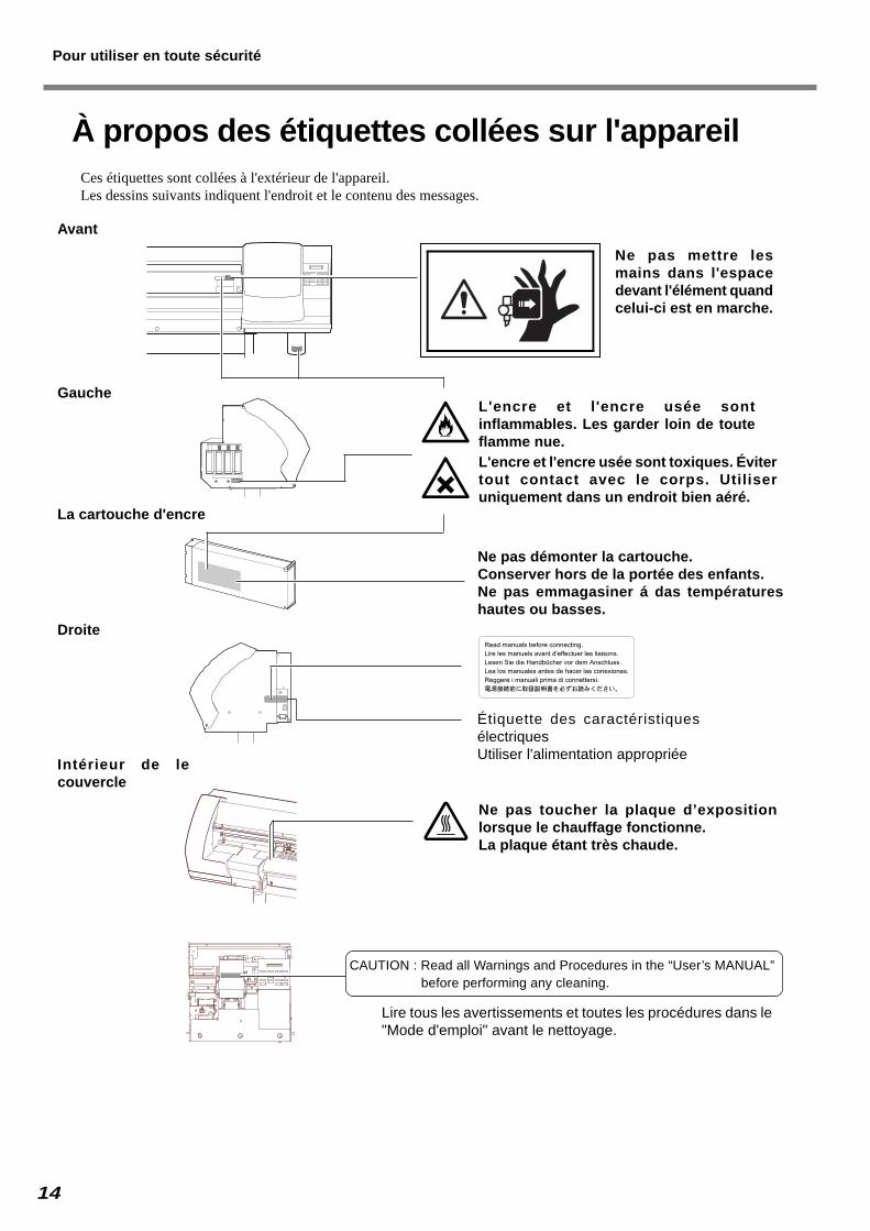
À propos des étiquettes collées sur l'appareilCes étiquettes sont collées à l'extérieur de l'appareil.Les dessins suivants indiquent l'endroit et le contenu des messages.
L'encre et l'encre usée sontinflammables. Les garder loin de touteflamme nue.L'encre et l'encre usée sont toxiques. Évitertout contact avec le corps. Utiliseruniquement dans un endroit bien aéré.
Gauche
Avant
Droite
Intérieur de lecouvercle
Ne pas toucher la plaque d’expositionlorsque le chauffage fonctionne.La plaque étant très chaude.
Ne pas mettre lesmains dans l'espacedevant l'élément quandcelui-ci est en marche.
Ne pas démonter la cartouche.Conserver hors de la portée des enfants.Ne pas emmagasiner á das températureshautes ou basses.
CAUTION : Read all Warnings and Procedures in the “User’s MANUAL” before performing any cleaning.
Étiquette des caractéristiquesélectriquesUtiliser l'alimentation appropriée
La cartouche d'encre
Lire tous les avertissements et toutes les procédures dans le"Mode d'emploi" avant le nettoyage.
Pour utiliser en toute sécurité

15
1. Getting Started
This section describes what to do when you first open the packing car-
ton, including how to install the machine and connect it to a computer.

16 1. Getting Started
1-1 Checking Accessories
The following items are packed together with the unit. Make sure they are all present and accounted for.
Power cord: 1 Arm (right): 1 Arm (left): 1 Stand legs: 2
Stays: 2 Shafts: 2 Large bolts : 20 Small Bolts: 2
Hexagonal wrench: 1 Pipe: 1 Media flanges: 2 Stoppers: 2
Short media clamp :1 each on left and right(*1)
Long media clamp:1 each on left and right
Blade holder: 1Pin:1
Drain bottles: 2 Stay mounting bracket: 1 CD-ROMs: 2Manuals: 3
SOL INK cleaningcartridges: 2
Blade: 1
Replacement blade forseparating knife: 1
Tweezers: 1Cleaning sticks: 10
Wipers: 2
Cleaning kit
*1 The short media clamps are installed on the machine.

17 1. Getting Started
1-2 Names and Functions
Front ViewFront cover
Maintenance cover
Sheet loading lever
Operation panel
Cover
Drain bottle
Side View
Main power switch
Power connector
USB connector
Ink cartridge ports
Items Inside the Front Cover
Pinch roller
Grit roller
Platen
Printing carriage
Cutting carriage
Knife guide
Blade protection
Media clamp adaptor
18 1. Getting Started
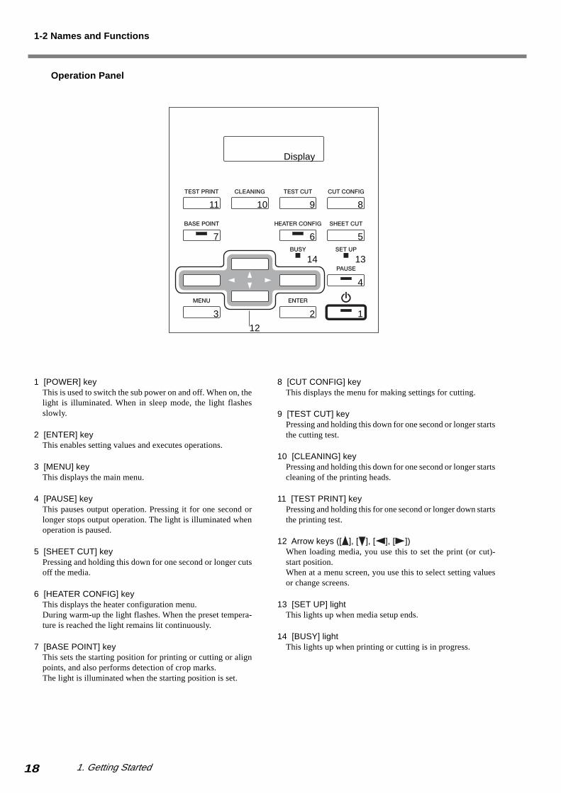
Operation Panel
1 [POWER] keyThis is used to switch the sub power on and off. When on, thelight is illuminated. When in sleep mode, the light flashesslowly.
2 [ENTER] keyThis enables setting values and executes operations.
3 [MENU] keyThis displays the main menu.
4 [PAUSE] keyThis pauses output operation. Pressing it for one second orlonger stops output operation. The light is illuminated whenoperation is paused.
5 [SHEET CUT] keyPressing and holding this down for one second or longer cutsoff the media.
6 [HEATER CONFIG] keyThis displays the heater configuration menu.During warm-up the light flashes. When the preset tempera-ture is reached the light remains lit continuously.
7 [BASE POINT] keyThis sets the starting position for printing or cutting or alignpoints, and also performs detection of crop marks.The light is illuminated when the starting position is set.
8 [CUT CONFIG] keyThis displays the menu for making settings for cutting.
9 [TEST CUT] keyPressing and holding this down for one second or longer startsthe cutting test.
10 [CLEANING] keyPressing and holding this down for one second or longer startscleaning of the printing heads.
11 [TEST PRINT] keyPressing and holding this for one second or longer down startsthe printing test.
12 Arrow keys ([ ], [ ], [ ], [ ])When loading media, you use this to set the print (or cut)-start position.When at a menu screen, you use this to select setting valuesor change screens.
13 [SET UP] lightThis lights up when media setup ends.
14 [BUSY] lightThis lights up when printing or cutting is in progress.
1-2 Names and Functions
123
4
567
891011
14 13
12
Display
19 1. Getting Started
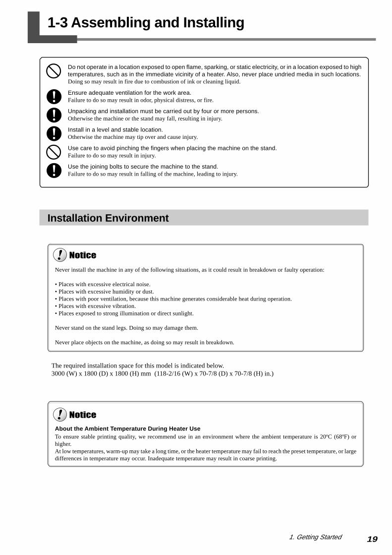
Installation Environment
The required installation space for this model is indicated below.3000 (W) x 1800 (D) x 1800 (H) mm (118-2/16 (W) x 70-7/8 (D) x 70-7/8 (H) in.)
1-3 Assembling and Installing
Do not operate in a location exposed to open flame, sparking, or static electricity, or in a location exposed to hightemperatures, such as in the immediate vicinity of a heater. Also, never place undried media in such locations.Doing so may result in fire due to combustion of ink or cleaning liquid.
Ensure adequate ventilation for the work area.Failure to do so may result in odor, physical distress, or fire.
Unpacking and installation must be carried out by four or more persons.Otherwise the machine or the stand may fall, resulting in injury.
Install in a level and stable location.Otherwise the machine may tip over and cause injury.
Use care to avoid pinching the fingers when placing the machine on the stand.Failure to do so may result in injury.
Use the joining bolts to secure the machine to the stand.Failure to do so may result in falling of the machine, leading to injury.
Never install the machine in any of the following situations, as it could result in breakdown or faulty operation:
• Places with excessive electrical noise.• Places with excessive humidity or dust.• Places with poor ventilation, because this machine generates considerable heat during operation.• Places with excessive vibration.• Places exposed to strong illumination or direct sunlight.
Never stand on the stand legs. Doing so may damage them.
Never place objects on the machine, as doing so may result in breakdown.
About the Ambient Temperature During Heater UseTo ensure stable printing quality, we recommend use in an environment where the ambient temperature is 20ºC (68ºF) orhigher.At low temperatures, warm-up may take a long time, or the heater temperature may fail to reach the preset temperature, or largedifferences in temperature may occur. Inadequate temperature may result in coarse printing.
20 1. Getting Started
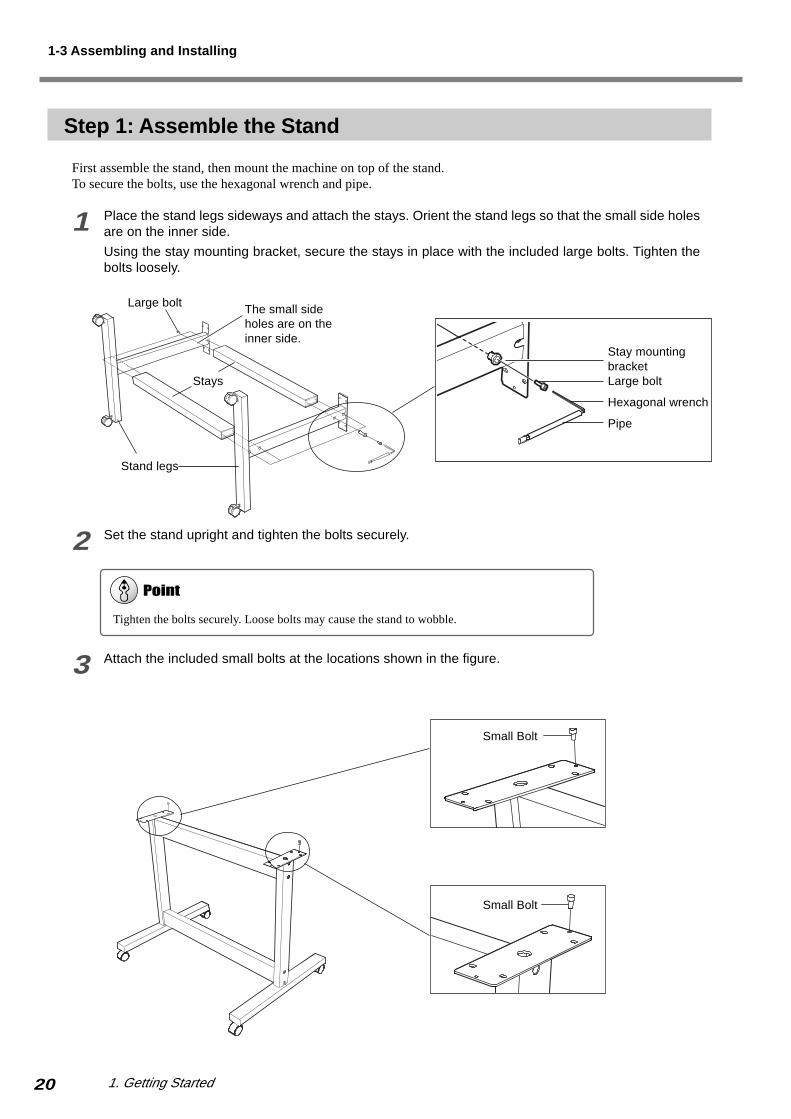
Step 1: Assemble the Stand
First assemble the stand, then mount the machine on top of the stand.To secure the bolts, use the hexagonal wrench and pipe.
1 Place the stand legs sideways and attach the stays. Orient the stand legs so that the small side holesare on the inner side.
Using the stay mounting bracket, secure the stays in place with the included large bolts. Tighten thebolts loosely.
2 Set the stand upright and tighten the bolts securely.
3 Attach the included small bolts at the locations shown in the figure.
Stays
Stand legs
Tighten the bolts securely. Loose bolts may cause the stand to wobble.
The small sideholes are on theinner side.
1-3 Assembling and Installing
Stay mountingbracketLarge bolt
Hexagonal wrench
Pipe
Small Bolt
Small Bolt
Large bolt
1. Getting Started 21
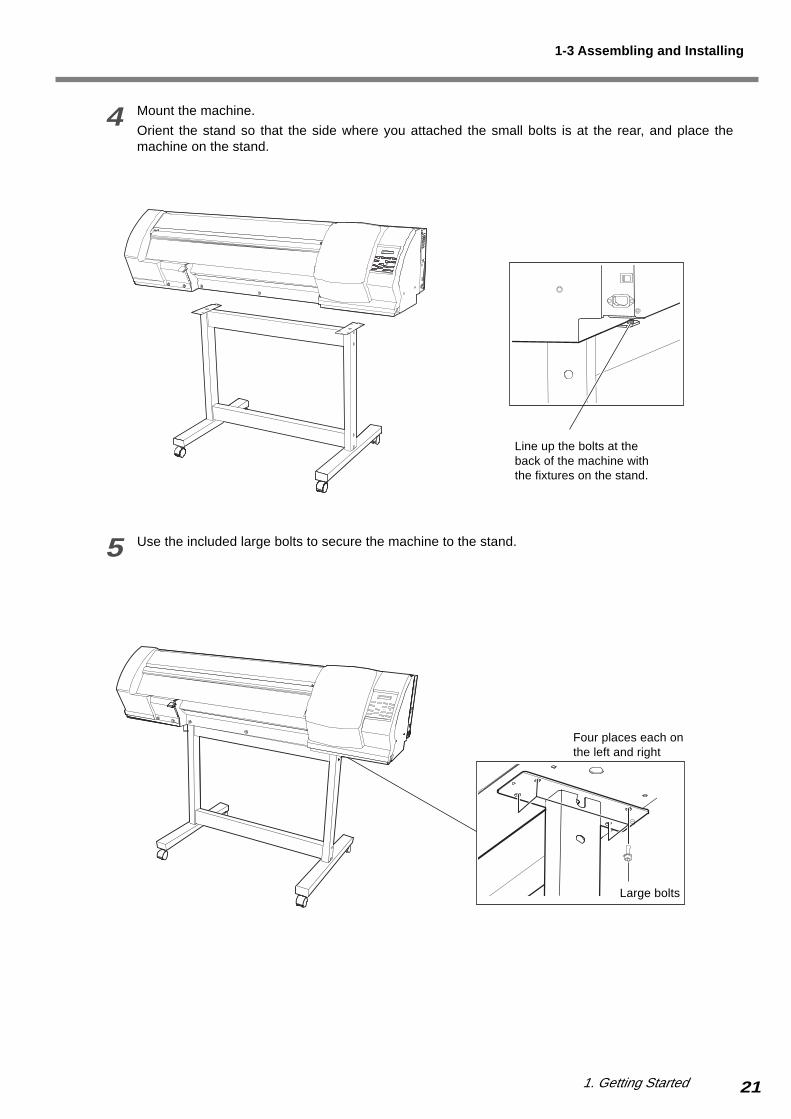
4 Mount the machine.
Orient the stand so that the side where you attached the small bolts is at the rear, and place themachine on the stand.
5 Use the included large bolts to secure the machine to the stand.
Line up the bolts at theback of the machine withthe fixtures on the stand.
Large bolts
Four places each onthe left and right
1-3 Assembling and Installing

22 1. Getting Started
Step 2: Install the Included Items
Install the arms, the shafts, and the drain bottle onto the machine. To secure the bolts, use the hexagonal wrench andpipe.
1 Attach the arms onto the back of the machine at the locations shown in the figure.
Attach the arms, and secure them using the included large bolts.
2 Pass the stoppers onto both ends of the shaft. When passing the shaft through the stopper, be sure toloosen the screws on the stopper first.
Large bolts
Arm (left)
Tighten the screw loosely.
Stopper
Shaft
1-3 Assembling and Installing
Arm (right)
Large bolts
1. Getting Started 23
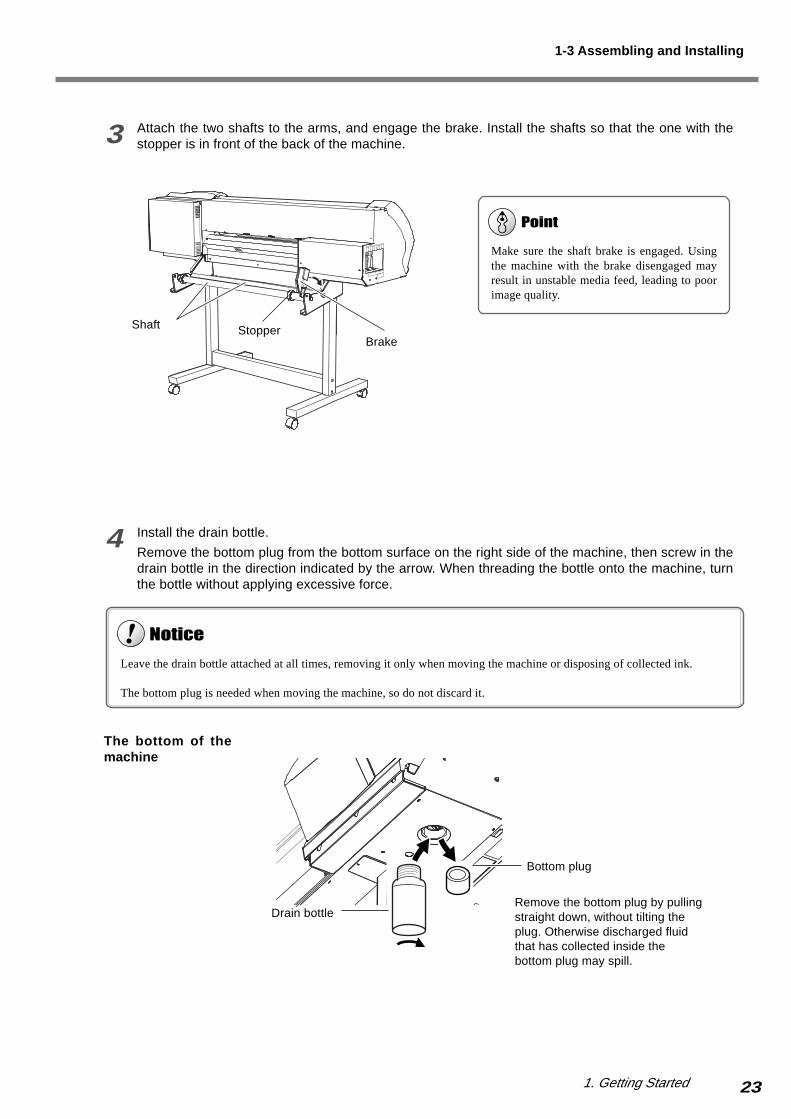
3 Attach the two shafts to the arms, and engage the brake. Install the shafts so that the one with thestopper is in front of the back of the machine.
4 Install the drain bottle.
Remove the bottom plug from the bottom surface on the right side of the machine, then screw in thedrain bottle in the direction indicated by the arrow. When threading the bottle onto the machine, turnthe bottle without applying excessive force.
Leave the drain bottle attached at all times, removing it only when moving the machine or disposing of collected ink.
The bottom plug is needed when moving the machine, so do not discard it.
Make sure the shaft brake is engaged. Usingthe machine with the brake disengaged mayresult in unstable media feed, leading to poorimage quality.
Shaft StopperBrake
Drain bottle
Bottom plug
Remove the bottom plug by pullingstraight down, without tilting theplug. Otherwise discharged fluidthat has collected inside thebottom plug may spill.
1-3 Assembling and Installing
The bottom of themachine
24 1. Getting Started
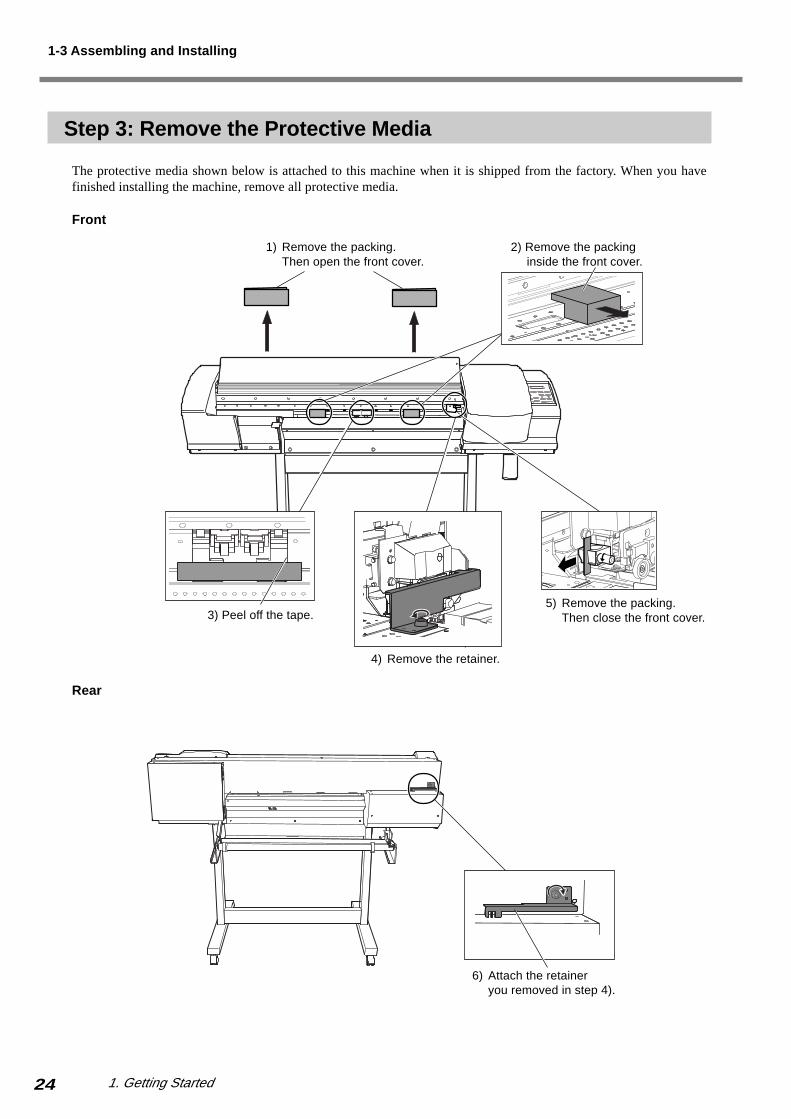
Step 3: Remove the Protective Media
The protective media shown below is attached to this machine when it is shipped from the factory. When you havefinished installing the machine, remove all protective media.
1) Remove the packing.Then open the front cover.
Front
Rear
6) Attach the retaineryou removed in step 4).
1-3 Assembling and Installing
2) Remove the packinginside the front cover.
3) Peel off the tape.
4) Remove the retainer.
5) Remove the packing.Then close the front cover.

1. Getting Started 25
Step 4: Connect the Power Cord
Connect the power cord to the machine.
Ground the unit with the ground wire.Failure to do so may result in risk of electrical shock in the even of a mechanical problem.
Use only with the power cord included with this product.Use with other than the included power cord may lead to fire or electrocution.
Use only with a power supply of the same rating as indicated on the unit.Use with any other power supply may lead to fire or electrocution.
Securely connect the power cord so that it will not become detached and during operation. Failure to do so may lead to faultyoperation or breakdown.
Arrange the power cord and interface connection cable to prevent tripping when moving around the unit.
Right side of the machine
Power Connector
1-3 Assembling and Installing
Power outlet
Power cord

26 1. Getting Started
Step 5: Set the Voltage Switches
Set the voltage switches to match the voltage of the region where the machine is used.
How to Make the Settings for the Voltage Switches
If your region is 100 to 120 V, move the switch to the location where [115 V] is visible. If your region is 220 to 240 V,move the switch to the location where [230 V] is visible.The default setting is [230V].
Voltage switch
The bottom of the machine
Before switching on the power, set the voltage switch to match the voltage of the region where the machine isused.When set incorrectly, the heater may fail to operate normally. The temperature of the heater may rise to undue levels, whichmay result in fire, or the temperature may fail to rise at the correct speed.
Voltage switch
Two voltage switches are located on the bottom of the machine. Make sure both voltage settings are correct, then switch on thepower.
The label indicatingthe position of thevoltage switch isattached.
115V
100 V to 120 V region
230V
220 V to 240 V region
Voltage switch
1-3 Assembling and Installing
The label indicating theposition of the voltageswitch is attached.
Stand

1. Getting Started 27
Step 6: Change the Settings for the Language and Unit of Measurement, and Check the Voltage Settings
Change the settings for the language and measurement unit used for the display, and check the settings of the voltageswitches.
1 Switch on the main power switch on the backof the machine.
2 Hold down the [MENU] key and press the[POWER] key.The sub power is switched on.The screen in the figure appears on the display.
3 Use the [ ] key to select [ENGLISH], then pressthe [ENTER] key.Make sure the text shown on the display is in English.
4 Make the setting for the measurement unit usedfor lengths.
Use the [ ] key to select [mm] or [INCH], then
press the [ENTER] key.
5 Make the setting for the measurement unit usedfor temperatures.
Use the [ ] key to select [ºC] or [ºF], then press
the [ENTER] key.
6 After a short interval the screen shown in thefigure appears.
Make sure the two voltage switches are setcorrectly, then press the [ENTER] key.
MENU LANGUAGEENGLISH
LENGTH UNITmm mm
TEMP. UNITºC ºC
Switch to the "I" side.
1-3 Assembling and Installing
CHECK HEATERVOLTAGE SETTING
If the voltage switches have not been set correctly, then stop operation.Follow the steps below to set the voltage switches, then start over from the beginning.
1. Press the [POWER] key to switch off the sub power.2. Switch off the main power switch.3. Refer to the previous section, "Set the Voltage Switches," and make the settings for the voltage switches.

28 1. Getting Started
Step 7: Fill Ink
Confirming the Ink-insertion Sites
The ink-cartridge ports are located on the side of the machine. Examine the labels affixed to the ink-cartridge ports andmake sure of the locations for inserting the cartridges.
Store ink cartridges out of the reach of children.
If ink or cleaning liquid comes in contact with the eyes, immediately flush with running water for at least 15minutes. If eye irritation continues, seek treatment by a physician.
Never drop or allow to fall an ink cartridge. The impact from a fall may cause damage, making it unusable.
When installing and removing an ink cartridge, never rush.
Use only ECO-SOL INK. Never insert any other type of ink cartridge.
1-3 Assembling and Installing
Black Cyan Magenta Yellow
Left side of the machine
1. Getting Started 29
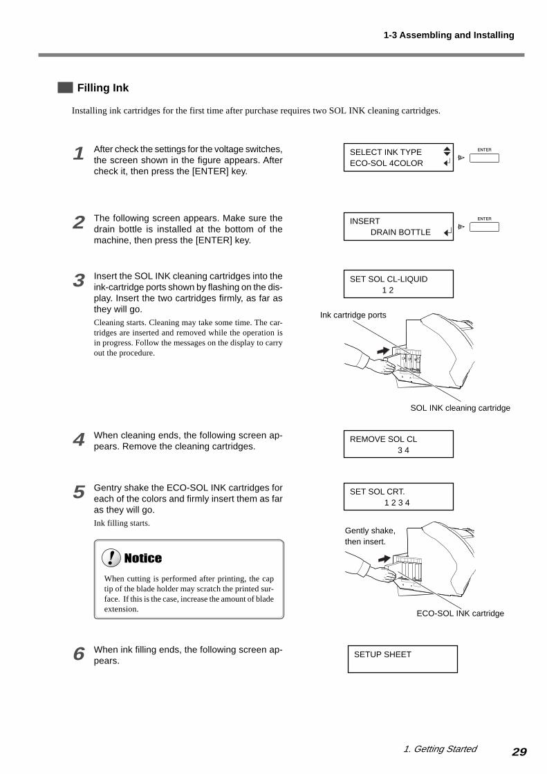
Filling Ink
Installing ink cartridges for the first time after purchase requires two SOL INK cleaning cartridges.
1 After check the settings for the voltage switches,the screen shown in the figure appears. Aftercheck it, then press the [ENTER] key.
2 The following screen appears. Make sure thedrain bottle is installed at the bottom of themachine, then press the [ENTER] key.
3 Insert the SOL INK cleaning cartridges into theink-cartridge ports shown by flashing on the dis-play. Insert the two cartridges firmly, as far asthey will go.Cleaning starts. Cleaning may take some time. The car-tridges are inserted and removed while the operation isin progress. Follow the messages on the display to carryout the procedure.
4 When cleaning ends, the following screen ap-pears. Remove the cleaning cartridges.
5 Gentry shake the ECO-SOL INK cartridges foreach of the colors and firmly insert them as faras they will go.Ink filling starts.
6 When ink filling ends, the following screen ap-pears.
1-3 Assembling and Installing
SELECT INK TYPEECO-SOL 4COLOR
INSERT DRAIN BOTTLE
SET SOL CL-LIQUID 1 2
REMOVE SOL CL 3 4
SET SOL CRT. 1 2 3 4
Ink cartridge ports
SOL INK cleaning cartridge
ECO-SOL INK cartridge
Gently shake,then insert.
When cutting is performed after printing, the captip of the blade holder may scratch the printed sur-face. If this is the case, increase the amount of bladeextension.
SETUP SHEET

30 1. Getting Started
Step 8: Match the Machine to the Environment Where Installed
The machine performs automatic adjustment to optimize its state to the environment where it is used (temperature andhumidity).Performing automatic adjustment reduces misalignment in the scanning direction (the direction of movement of thecarriage) during printing and cutting.
1 Press the [MENU] key, then press the [ ] keyto select [ENV. MATCH].
2 Press the [ENTER] key.The printing carriage moves and automatic adjustmentstarts.When automatic adjustment ends, the following screenappears.
3 Press the [ENTER] key.The display returns to the screen shown in step 1.
1-3 Assembling and Installing
MENUENV. MATCH
ENV. MATCHSETUP COMPLETED

1. Getting Started 31
Step 9: Install the Blade
Install the blade to the cutting carriage.
1 Insert the pin into the blade holder.
2 Insert a blade into the blade holder until it snapsinto place with an audible click.
3 Press the [MENU] key, then press the [ ] keyto select [REPLACE KNIFE].
4 Press the [ENTER] key.When the forrowing screen appears, the printing carriagesimultaneously moves to the left.
5 Open the front cover, then loosen the screwshown in the figure.
6 Support the tool-mounting screw from belowand install the blade holder.
7 Tighten the screw.Tug the blade holder upward to make sure it does notcome loose.
8 Close the front cover, then press the [ENTER]key.
Never touch the tip of the blade with your fingers.Doing so may result in injury, and the cutting performance of the blade will be impaired.
Never leave the tool-mounting screw tightened. Tightening the screw makes it more difficult to install the blade holder.
Pin
Blade holder
Blade
1-3 Assembling and Installing
MENUREPLACE KNIFE
FINISHED?
Insert the blade holderuntil the collar is flushwith the carriage.
If installed without supporting the screw in this way,cutting quality may become poor.
Screw
Screw
Pin
Blade holder
Cap

32 1. Getting Started
Step 10: Connect to the Computer
Be sure to make the connection between the machine to the computer during the course of installing the driver.If the cable connection is made before you start installation of the driver, driver installation may fail and the machinemay become unusable.
Use a USB cable to make the connection to the computer.Cables are available separately. One which you are sure matches the model of computer being used should be selected.
Make the cable connections as shown in the figure below.For more information about the connection procedure and driver installation, refer to the documentation for the driver.
1-3 Assembling and Installing
Right side of the machine
Use a shielded USB cable having a length of three meters or less. Never use a USB hub or the like.
Arrange the power cord and interface connection cable to prevent tripping when moving around the unit.
Never attempt to connect a USB cable before starting installing the driver.
Be sure to make the connection between the machine to the computer during the course of installingthe driver.
USB connector
USB port
USB cable
Computer

33
2. Basic Operation
This describes such basic operations as how to switch the power on
and off, menu operations, and how to load and set up media.
34 2. Basic Operation
2-1 Switching the Power On and Off
There are two power switches on the machine; the main power switch and the [POWER] key. Once you have switchedon the main power, you should normally leave it on.In day-to-day use, you switch the machine on and off using only the sub power.
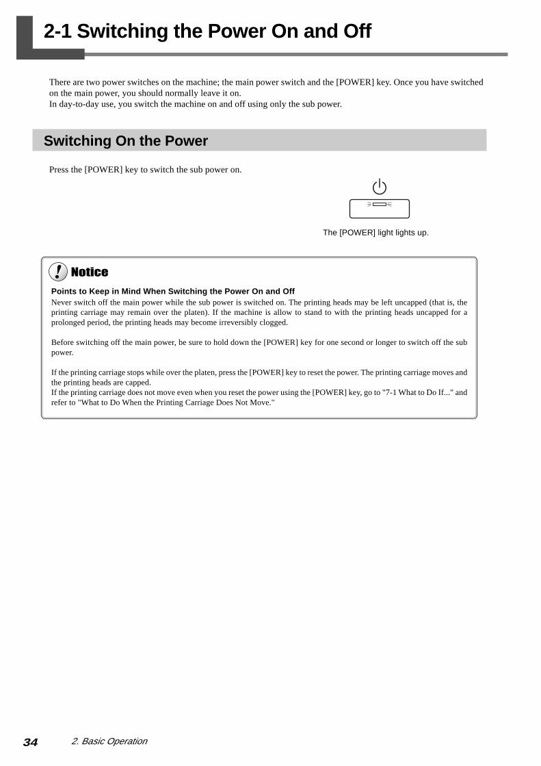
Switching On the Power
Press the [POWER] key to switch the sub power on.
Points to Keep in Mind When Switching the Power On and OffNever switch off the main power while the sub power is switched on. The printing heads may be left uncapped (that is, theprinting carriage may remain over the platen). If the machine is allow to stand to with the printing heads uncapped for aprolonged period, the printing heads may become irreversibly clogged.
Before switching off the main power, be sure to hold down the [POWER] key for one second or longer to switch off the subpower.
If the printing carriage stops while over the platen, press the [POWER] key to reset the power. The printing carriage moves andthe printing heads are capped.If the printing carriage does not move even when you reset the power using the [POWER] key, go to "7-1 What to Do If..." andrefer to "What to Do When the Printing Carriage Does Not Move."
The [POWER] light lights up.

352. Basic Operation
Raise the sheet loading lever to leave the pinch rollers raised when not in use.Deformation may occur if left lowered for a prolonged period.
Switching Off the Power at the End of the Day
Press and hold down the [POWER] key for one second or longer.The sub power is switched off.
The Power-saving FeatureThis machine is provided with a power-saving feature that switches to a low-power "sleep mode" when a fixed interval passeswith no operation. The factory default for the time after which the machine switches to the sleep mode is 30 minutes.You can change the setting for the time of the shift to the sleep mode. You can also switch off the power-saving feature. Formore information, go to "6-2 Detailed Descriptions of the Menus" and refer to [SLEEP].
When the machine enters the sleep mode, the [POWER] light flashes slowly. Also, heater operation stops.Normally the display goes blank, although it may not go blank in the event of an error message or the like.
To cancel the sleep mode, perform any of the following operations.
• Press any key on the operation panel.• Send data from the host computer (when media is loaded).• Open the front cover or the like.• Move the sheet loading lever.
To reduce power consumption, we recommend leaving the power-saving feature enabled and setting the interval until the sleepmode is activated to a time of 30 minutes or less.
The [POWER] light goes out.
Sheet loadinglever
2-1 Switching the Power On and Off
36 2. Basic Operation
2-2 Menu Operations
Displaying the Menus
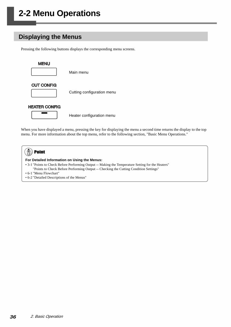
Pressing the following buttons displays the corresponding menu screens.
Main menu
Cutting configuration menu
Heater configuration menu
When you have displayed a menu, pressing the key for displaying the menu a second time returns the display to the topmenu. For more information about the top menu, refer to the following section, "Basic Menu Operations."
For Detailed Information on Using the Menus:• 3-1 "Points to Check Before Performing Output -- Making the Temperature Setting for the Heaters"
"Points to Check Before Performing Output -- Checking the Cutting Condition Settings"• 6-1 "Menu Flowchart"• 6-2 "Detailed Descriptions of the Menus"

372. Basic Operation
Basic Menu Operations
This section describes the items on the main menu. For more information about the heater configuration menu and thecutting configuration menu, see "3-1 Points to Check Before Performing Output."
How to View the Display
Top Menu
When media is loaded, the display shows the printable (or cuttable) width.This screen is called the "top menu."
Menu Screen
The figures show examples of main-menu screen displays.The operations that you can perform when a symbol is displayed are described below.
: This displays the previous menu screen.
: This displays the next menu screen.
: This selects the menu item or changes the value of the setting.
: This executes the menu item or enables the setting value.
Basic menu operations
When you are at the main menu, the keys function as follows.
This selects a menu item or changes the value of a setting.
This displays a menu that is one level lower.
This displays the menu that is one level higher.
At any menu screen, pressing the [MENU] key returns you to the top menu.
This executes a menu item or enables a setting value.The value for any setting is enabled only by pressing the [ENTER] key.
Top menu
Neither printing nor cutting is performed while menu settings are being made. When you have finished making menu settings,press the [MENU] key to go back to the top menu.
Pressing the [ ] keyreturns you to the previousmenu screen.
Pressing the [ ] and [ ] keys displaysother menu items under [ADJUST BI-DIR].
2-2 Menu Operations
W 500 mm
ADJUST BI-DIRTEST PRINT
Pressing the [ENTER] keyexecutes a printing test.

38 2. Basic Operation
2-3 Loading Media
Loading Roll Media
1 Open the front cover.
2 Line up the media flanges with the edges of the roll media, aligning them with the inner diameter of thecore of the roll media.
3 Place the roll media on the shaft.
Pass the end of the media between the pinchrollers and the grit rollers so that it extends fromthe front of the machine.
When loading roll media, be sure to install the shafts.Otherwise the roll may fall and cause injury.
Load roll media at the proper position.Otherwise the roll may fall, resulting in injury.
Never touch the rail or the inner sides of the covers.Touching the area may cause the fingers to be soiled by grease or ink, and may result in diminished image quality.
2 in. 3 in.
Roll media
Shaft
392. Basic Operation
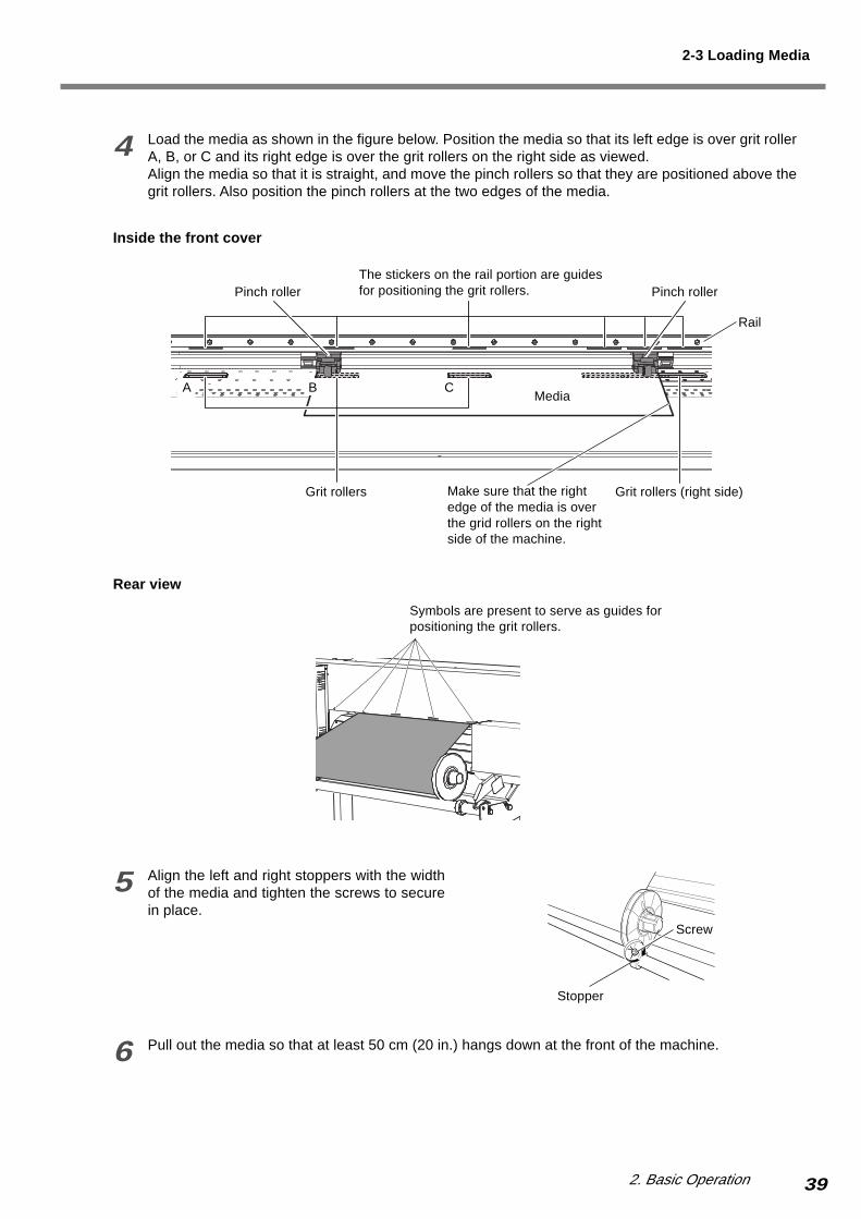
5 Align the left and right stoppers with the widthof the media and tighten the screws to securein place.
6 Pull out the media so that at least 50 cm (20 in.) hangs down at the front of the machine.
4 Load the media as shown in the figure below. Position the media so that its left edge is over grit rollerA, B, or C and its right edge is over the grit rollers on the right side as viewed.Align the media so that it is straight, and move the pinch rollers so that they are positioned above thegrit rollers. Also position the pinch rollers at the two edges of the media.
Rail
Grit rollers Grit rollers (right side)
Pinch roller Pinch rollerThe stickers on the rail portion are guidesfor positioning the grit rollers.
Stopper
Rear view
Symbols are present to serve as guides forpositioning the grit rollers.
Media
2-3 Loading Media
Make sure that the rightedge of the media is overthe grid rollers on the rightside of the machine.
Inside the front cover
Screw
BA C

40 2. Basic Operation
7 Turn the media flanges by hand to take up the media to a location where the portion hanging from thefront of the machine is positioned over the sensor. .
8 With the media that is pulled out from the roll stretched taut with no slack, lower the sheet loadinglever.The pinch rollers descend to hold the media in place.The [SET UP] light begins to flash and the screen in thefigure appears.
9 Close the front cover.This detects the width of the media and displays the print-able width. The heater temperature also begins to rise.The [SET UP] light lights up.
If a pinch roller is positioned over an area where there is no grit roller,the screen shown in the figure appears when you close the front cover.Check the positioning of the pinch rollers and make sure they are alignedat the correct locations.
PINCHROLL ERRORINVALID LEFT POS
If the machine is to remain unused for an extended period, remove the roll media from the machine and store it.If roll media is left mounted on the machine for an extended period, the entire roll may warp, resulting in poor printed imagequality or motor errors.
Pull out at least50 cm (20 in.)
Sensor
Pull out themedia until it ispositioned at thesensor.
Media flange
Shaft
Lower completely.
If there is slackness in the loadedmedia, the media may move at anangle and come loose from the pinchrollers.
or [RIGHT]
Sheet loadinglever
2-3 Loading Media
W 500 mm
For more information about the operation of the heaters, re-fer to "2-4 Heater Operation."
CLOSE THE COVER
412. Basic Operation
Loading Sheet Media
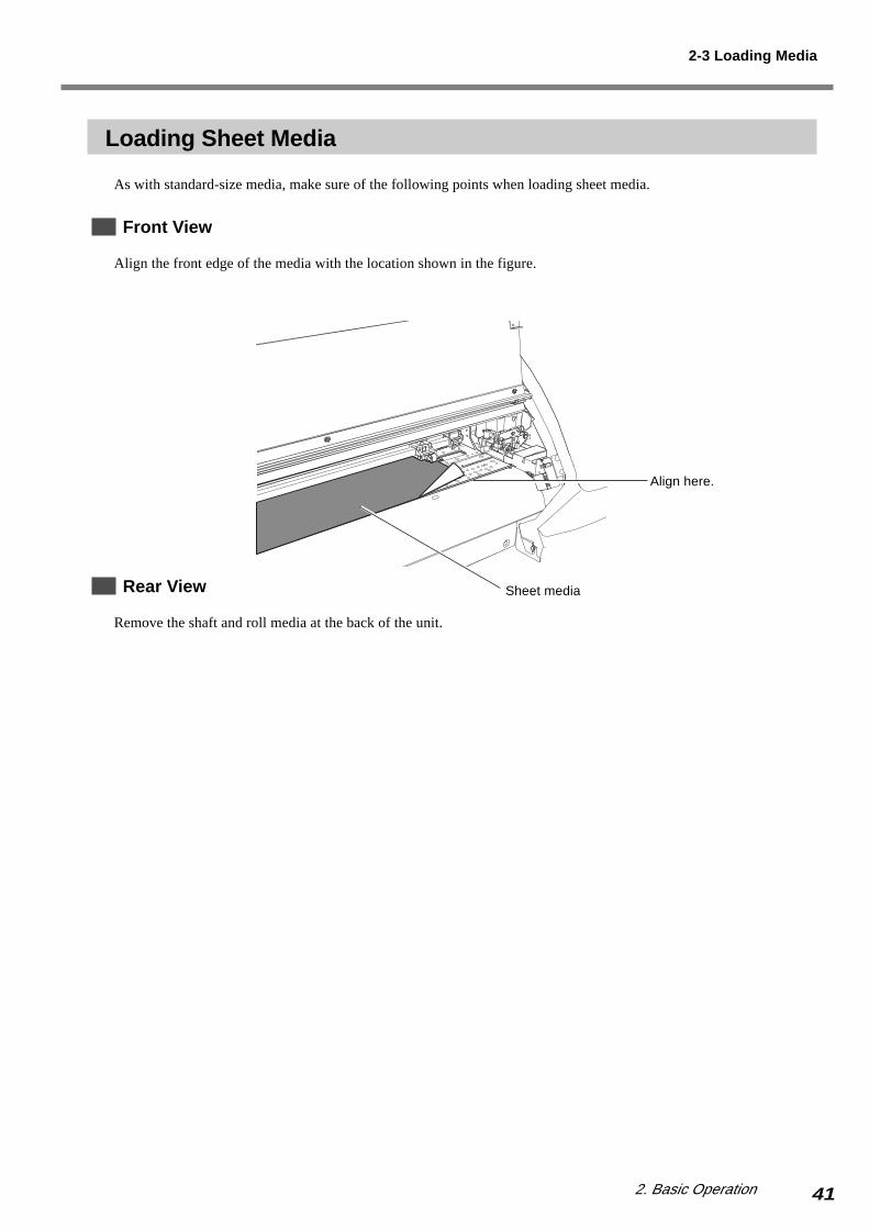
As with standard-size media, make sure of the following points when loading sheet media.
Front View
Align the front edge of the media with the location shown in the figure.
Rear View
Remove the shaft and roll media at the back of the unit.
Align here.
Sheet media
2-3 Loading Media
42 2. Basic Operation
Securing in Place Using the Media Clamps (Only When Printing)
When performing printing, be sure to use the media clamps to secure the media in place. Performing printing withoutusing the media clamps may in warping of the edges of the media due to thermal expansion or contraction. Warping ofthe media may result in catching on the printing carriage or other problems that prevent correct printing.
When performing cutting, remove the media clamps. Doing so may damage the equipment.
Types of Media Clamps
There are two types of media clamps. They each have different uses, as described below.
Short Media Clamps
You normally use the short media clamps. (These are installed on the machine when it is shipped from the factory.)
Long Media Clamps
You use these when you want to hold the media in place more securely, such as when you're printing media that warpseasily.The long media clamps interfere with the separating knife. When using them, refer to "Using the Long Media Clamps"on the following page to make the setting so that the media-cutoff operation is not performed.
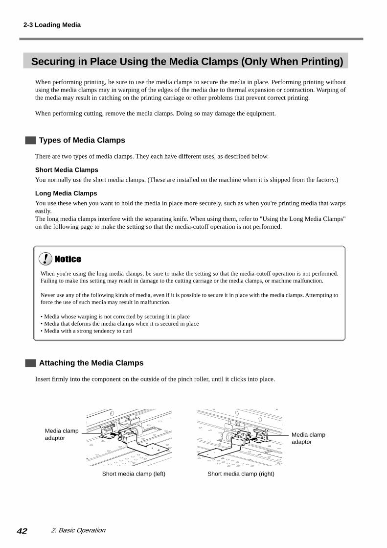
Attaching the Media Clamps
Insert firmly into the component on the outside of the pinch roller, until it clicks into place.
2-3 Loading Media
Short media clamp (left) Short media clamp (right)
Media clampadaptor Media clamp
adaptor
When you're using the long media clamps, be sure to make the setting so that the media-cutoff operation is not performed.Failing to make this setting may result in damage to the cutting carriage or the media clamps, or machine malfunction.
Never use any of the following kinds of media, even if it is possible to secure it in place with the media clamps. Attempting toforce the use of such media may result in malfunction.
• Media whose warping is not corrected by securing it in place• Media that deforms the media clamps when it is secured in place• Media with a strong tendency to curl
432. Basic Operation
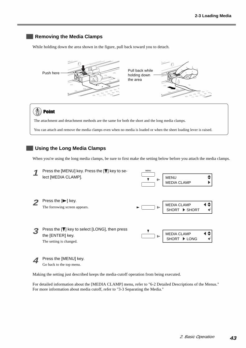
Removing the Media Clamps
While holding down the area shown in the figure, pull back toward you to detach.
Using the Long Media Clamps
When you're using the long media clamps, be sure to first make the setting below before you attach the media clamps.
1 Press the [MENU] key. Press the [ ] key to se-
lect [MEDIA CLAMP].
2 Press the [ ] key.
The forrowing screen appears.
3 Press the [ ] key to select [LONG], then press
the [ENTER] key.The setting is changed.
4 Press the [MENU] key.Go back to the top menu.
Making the setting just described keeps the media-cutoff operation from being executed.
For detailed information about the [MEDIA CLAMP] menu, refer to "6-2 Detailed Descriptions of the Menus."For more information about media cutoff, refer to "3-3 Separating the Media."
Push herePull back whileholding downthe area
2-3 Loading Media
The attachment and detachment methods are the same for both the short and the long media clamps.
You can attach and remove the media clamps even when no media is loaded or when the sheet loading lever is raised.
MENUMEDIA CLAMP
MEDIA CLAMP SHORT SHORT
MEDIA CLAMP SHORT LONG
44 2. Basic Operation
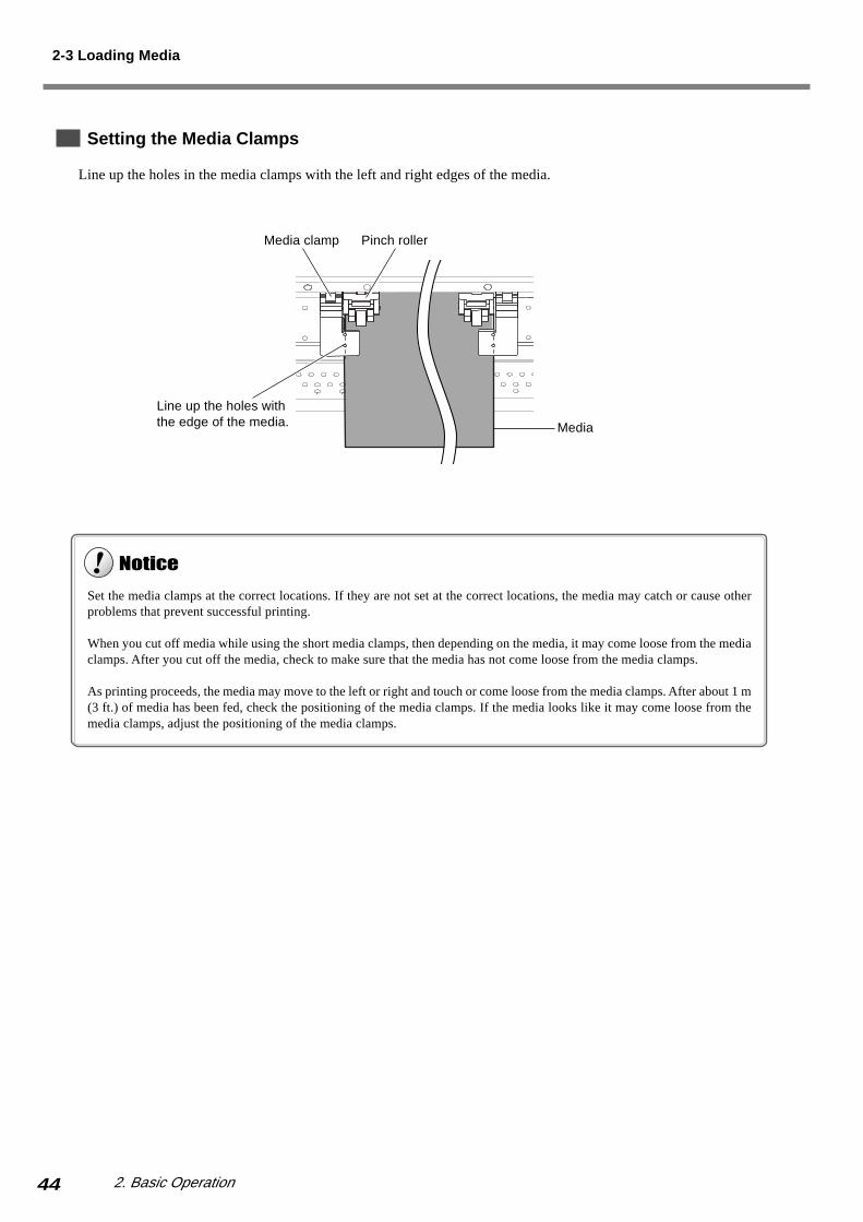
Setting the Media Clamps
Line up the holes in the media clamps with the left and right edges of the media.
Line up the holes withthe edge of the media. Media
Pinch rollerMedia clamp
Set the media clamps at the correct locations. If they are not set at the correct locations, the media may catch or cause otherproblems that prevent successful printing.
When you cut off media while using the short media clamps, then depending on the media, it may come loose from the mediaclamps. After you cut off the media, check to make sure that the media has not come loose from the media clamps.
As printing proceeds, the media may move to the left or right and touch or come loose from the media clamps. After about 1 m(3 ft.) of media has been fed, check the positioning of the media clamps. If the media looks like it may come loose from themedia clamps, adjust the positioning of the media clamps.
2-3 Loading Media

452. Basic Operation
2-4 Heater Operation
This machine has two types of heaters.The printing heater warms the media before printing, improving ink adhesion.The drier warms the media after printing, making the ink dry more rapidly.
When the machine is shipped from the factory, it is set up so that, by default, the heaters run when the sub power isswitched on.When you switch on the sub power, the [HEATER CONFIG] light begins to flash and the heaters start to run.The heaters run until a preset temperature is reached, then continue to maintain the temperature at the preset level. The[HEATER CONFIG] light is illuminated at this time.The temperature that is maintained varies as follows, depending on whether media is loaded.
When no media is loaded
The "warm-up temperature," which is lower than the operating temperature, is maintained.
When media is loaded
The temperature preset using the heater configuration menu is maintained.
The [HEATER CONFIG] light flashes while heater temperature is rising, and remains steadily lighted when the presettemperature is reached.
This machine uses automatic control that keeps printing from starting until the heaters reach the preset temperature. Youcan speed up the wait time until the preset temperature is reached after loading and setting up media by maintaining thewarm-up temperature before you load the media.
You can use the [PREHEATING] menu to make the settings for heater operation and warm-up temperature when nomedia is loaded. For more information, refer to "6-2 Detailed Descriptions of the Menus."For more information about the heater configuration menu, go to "3-1 Points to Check before Performing Output" andrefer to "Making the Temperature Setting for the Heaters."

46 2. Basic Operation
MEMO

47
3. Performing Output
This section describes points to check before you carry out printing or
cutting, as well as printing and cutting methods and other matters.

48 3. Performing Output
3-1 Points to Check Before Performing Output
Before starting printing or cutting, make sure the following points have been carried out.
• Media is loaded and a blade is installed.• The front cover is closed.• The [SETUP] light and the [HEATER CONFIG] light are illuminated.
When media setup finishes, the display shows the printable or cuttable width (top menu).
When the top menu appears, check the settings for the following items to ensure that correct printing or cutting ispossible.
Making the Temperature Setting for the Heaters
To set the heater temperature, press the [HEATER CONFIG] key then follow the steps below to make the setting.The printing heater warms the media before printing, improving ink adhesion.The drier warms the media after printing, making the ink dry more rapidly.
Do not touch the platen when the heater is operating.Doing so may cause burns because the platen is hot.
W 550 mm
You can set the temperature either to "OFF" or to a value from 35 to 50ºC [40 to 122ºF] (in steps of 1ºC [2ºF]). Adjust thetemperature to a suitable value matched to the type of media and the ambient environment. In particular, when you're using themachine in a low temperature environment, it may be a good idea to set the preset temperature to a slightly high value.
You can change the setting for the heater temperature even when printing is in progress or when no media is loaded.
If the software you're using is provided with a feature for setting the heater temperature, you can use your software to adjust thetemperature. For information on how to do this, refer to the documentation for your software.
Top menu

493. Performing Output
1 Press the [HEATER CONFIG] key.The heater configuration menu appears.
2 Press the [ ] and [ ] keys to enter the presettemperature for [PRINT], then press the [EN-TER] key.This enables the preset temperatures for the print heater.
3 Press the [ ] key to move the cursor to[DRYER].
4 In the same way as in step 2, enter the presettemperature and press the [ENTER] key.This enables the preset temperatures for the dryer.
5 Press the [HEATER CONFIG] key.The top menu appears.
Checking the State of the Printing Heads
Before you start to print, carry out a printing test to check the state of the heads.Problems such as missing dots may reduce the printing quality.If the test results show a problem, carry out head cleaning to restore the heads to their proper state.
1 Press and hold the [TEST PRINT] key for atleast one second.The test pattern is printed.
2 If dot drop-out is present, clean the heads.For more information about head cleaning, see "5-2Cleaning the Printing Heads."
PRINT 35 25DRYER 35 25
PRINT 38 25DRYER 35 25
Presettemperature
3-1 Points to Check Before Performing Output
Actualtemperature
PRINT 38 25DRYER 35 25
PRINT 38 25DRYER 38 25
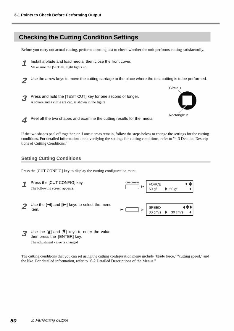
50 3. Performing Output
Checking the Cutting Condition Settings
Before you carry out actual cutting, perform a cutting test to check whether the unit performs cutting satisfactorily.
1 Install a blade and load media, then close the front cover.Make sure the [SETUP] light lights up.
2 Use the arrow keys to move the cutting carriage to the place where the test cutting is to be performed.
3 Press and hold the [TEST CUT] key for one second or longer.A square and a circle are cut, as shown in the figure.
4 Peel off the two shapes and examine the cutting results for the media.
If the two shapes peel off together, or if uncut areas remain, follow the steps below to change the settings for the cuttingconditions. For detailed information about verifying the settings for cutting conditions, refer to "4-3 Detailed Descrip-tions of Cutting Conditions."
Setting Cutting Conditions
Press the [CUT CONFIG] key to display the cutting configuration menu.
1 Press the [CUT CONFIG] key.The following screen appears.
2 Use the [ ] and [ ] keys to select the menuitem.
3 Use the [ ] and [ ] keys to enter the value,then press the [ENTER] key.The adjustment value is changed
The cutting conditions that you can set using the cutting configuration menu include "blade force," "cutting speed," andthe like. For detailed information, refer to "6-2 Detailed Descriptions of the Menus."
Rectangle 2
Circle 1
3-1 Points to Check Before Performing Output
SPEED30 cm/s 30 cm/s
FORCE50 gf 50 gf

513. Performing Output
Incorrect cutting conditions may cause symptoms such as those described below.
Blade force
Large • The media is easily torn during cutting.• The blade requires frequent replacement.• Cutting extends through the base paper, and normal advancing of the media becomes impossible.• The unit suffers damage.
Small • Some parts of media remain uncut
Cutting speed
Fast • Uncut areas remain in places.• The cut depth differs according to the location.• The cut shape is distorted.• The media is easily torn during cutting.
Slow • Cutting takes a long time.
For more information about detailed descriptions of cutting conditions, refer to "4-3 Detailed Descriptions of CuttingConditions."
Giving Priority to the Cutting Conditions Set on the MachineWhen [CUTTING PRIOR] on the machine's display menu has been set to [COMMAND], the program's settings for the cuttingconditions take priority. This is set to [COMMAND] by default.To give priority to the cutting conditions set on the machine, turn off the program settings, or set the [CUTTING PRIOR] menuitem to [MENU].For more information about the [CUTTING PRIOR] menu item, see the section "6-2 Detailed Descriptions of the Menus."
3-1 Points to Check Before Performing Output

52 3. Performing Output
3-2 Performing Output
Sending data starts printing or cutting.You can perform a wide variety of operations depending on the setting for how data is sent.Sending data only for printing or only for cutting from the computer executes the corresponding printing or cutting only.When data for both printing and cutting is sent, then after printing finishes, cutting starts automatically (Printing &Cutting).It's also possible to perform operations such as detaching the media after printing, carrying out lamination or the like,then reloading the media and cutting it.For information on how to make the settings, refer to the documentation for the software you're using.
The important points to note for printing only, for cutting only, and for printing and cutting are different.
When You're Performing Printing Only
In order to perform printing, the heaters must reach the preset temperature. If the heaters have not reached the presettemperature when printing is started, the [HEATER CONFIG] light flashes and the screen shown in the figure appears.
When the heaters reach the preset temperature, the [HEATER CONFIG] light stops flashing and remains continuouslylit, and printing starts automatically.
Never open the front cover. Opening the front cover while printing or cutting is in progress causes an emergency stop. Thismeans that printing or cutting may not be carried out correctly even if operation is resumed, due to drop-out or misalignmentof the image.
The printing heads may be left uncapped (that is, the printing carriage may remain over the platen). If the machine is allow tostand to with the printing heads uncapped for a prolonged period, the printing heads may become irreversibly clogged.If the printing carriage stops while over the platen, press the [POWER] key to reset the power. The printing carriage moves andthe printing heads are capped.If the printing carriage does not move even when you reset the power using the [POWER] key, go to "7-1 What to Do If..." andrefer to "What to Do When the Printing Carriage Does Not Move."
During printing, never touch the portion of the media that's already been discharged. Doing so may obstruct media feed orcause the media to rub against the heads, which may result in a paper jam or damage to the heads.
If the top menu isn't displayed, printing doesn't start even when data is sent from the computer. If another menu screen isdisplayed, press the corresponding menu key to go back to the top menu.
NOW HEATING...
533. Performing Output
When You're Performing Cutting Only
If you're using roll media, then before you start cutting, leave media hanging freely at the rear. Turn the media flangesby hand to pull out the necessary length from the roll. If cutting is started without doing this first, a motor error mayoccur or the roll may fall because the media is pulled with excessive force.Also, setting the heater temperature to [OFF] may obtain output results that are more stable. For more information aboutsetting the heater temperature, refer to "3-1 Points to Check Before Performing Output."
When You're Performing Printing and Cutting
Allow the Media to Dry Sufficiently Before Starting Cutting
Before you start cutting, allow the media to dry sufficiently. (The required drying time varies according to the type ofmedia.) If the media is not dry enough, the pinch rollers or the blade may smudge the printed surface during cutting.Setting the drying time on the software you're using lets you start cutting after waiting for a fixed interval. For informa-tion on how to make this setting, refer to the documentation for the software you're using.
Adjusting the Blade Extension
When you perform printing followed by cutting, the end of the cap for the blade holder may rub against and damage theprinted surface. (Damage is even more likely when the media has not been allowed to dry completely.)If this happens, increase the amount of extension of the blade tip slightly.
For more information about adjusting the blade extension, refer to "4-3 Detailed Descriptions of Cutting Conditions."
3-2 Performing Output
When cutting never use media clamps.
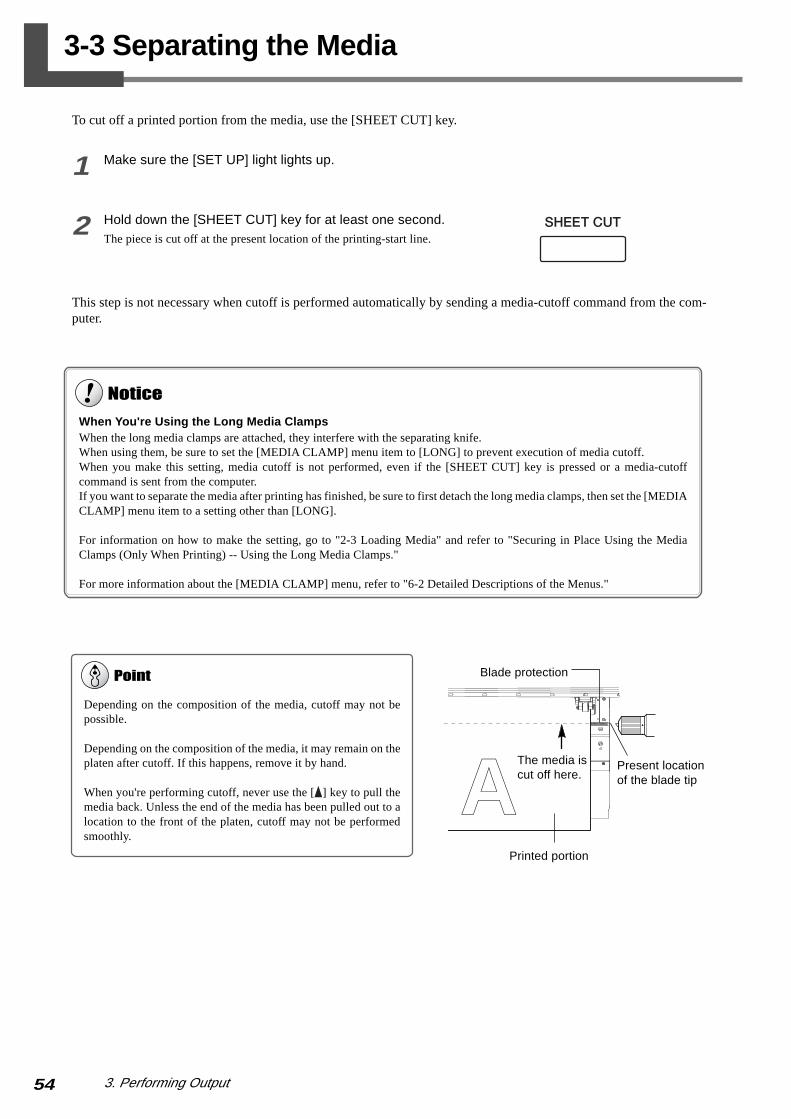
54 3. Performing Output
3-3 Separating the Media
To cut off a printed portion from the media, use the [SHEET CUT] key.
1 Make sure the [SET UP] light lights up.
2 Hold down the [SHEET CUT] key for at least one second.The piece is cut off at the present location of the printing-start line.
This step is not necessary when cutoff is performed automatically by sending a media-cutoff command from the com-puter.
Depending on the composition of the media, cutoff may not bepossible.
Depending on the composition of the media, it may remain on theplaten after cutoff. If this happens, remove it by hand.
When you're performing cutoff, never use the [ ] key to pull themedia back. Unless the end of the media has been pulled out to alocation to the front of the platen, cutoff may not be performedsmoothly.
AThe media iscut off here.
Blade protection
Printed portion
Present locationof the blade tip
When You're Using the Long Media ClampsWhen the long media clamps are attached, they interfere with the separating knife.When using them, be sure to set the [MEDIA CLAMP] menu item to [LONG] to prevent execution of media cutoff.When you make this setting, media cutoff is not performed, even if the [SHEET CUT] key is pressed or a media-cutoffcommand is sent from the computer.If you want to separate the media after printing has finished, be sure to first detach the long media clamps, then set the [MEDIACLAMP] menu item to a setting other than [LONG].
For information on how to make the setting, go to "2-3 Loading Media" and refer to "Securing in Place Using the MediaClamps (Only When Printing) -- Using the Long Media Clamps."
For more information about the [MEDIA CLAMP] menu, refer to "6-2 Detailed Descriptions of the Menus."
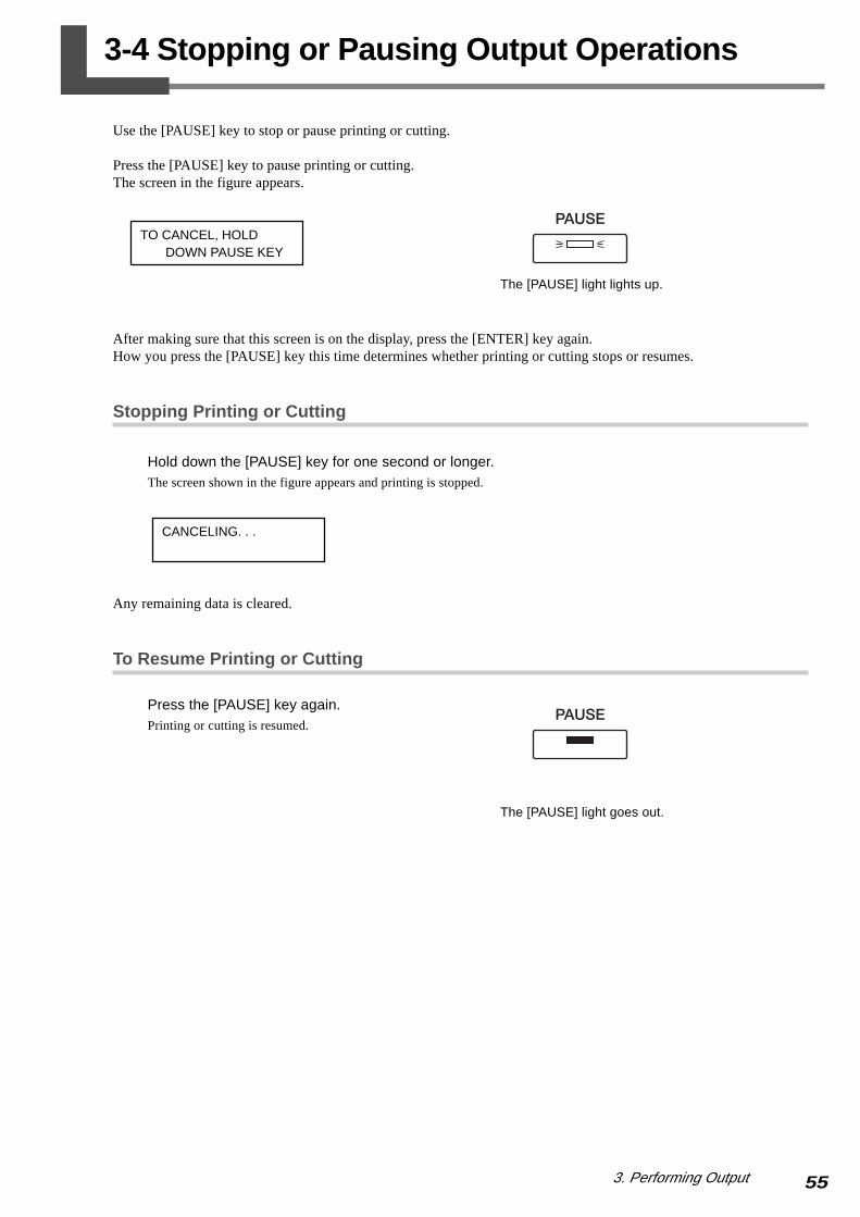
553. Performing Output
3-4 Stopping or Pausing Output Operations
Use the [PAUSE] key to stop or pause printing or cutting.
Press the [PAUSE] key to pause printing or cutting.The screen in the figure appears.
After making sure that this screen is on the display, press the [ENTER] key again.How you press the [PAUSE] key this time determines whether printing or cutting stops or resumes.
Stopping Printing or Cutting
Hold down the [PAUSE] key for one second or longer.The screen shown in the figure appears and printing is stopped.
Any remaining data is cleared.
To Resume Printing or Cutting
Press the [PAUSE] key again.Printing or cutting is resumed.
CANCELING. . .
TO CANCEL, HOLD DOWN PAUSE KEY
The [PAUSE] light lights up.
The [PAUSE] light goes out.

56 3. Performing Output
MEMO

57
4. A wide variety of Operations
This section describes a wide variety of operations and functions, grouped
by task.
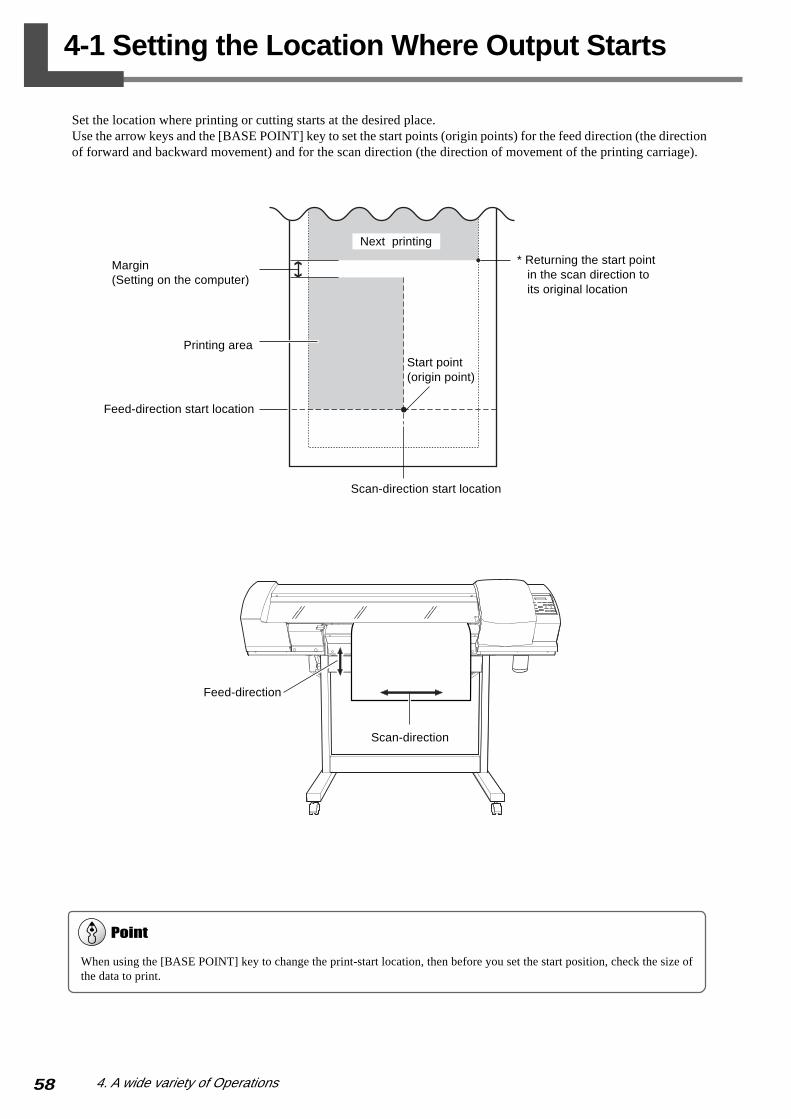
58 4. A wide variety of Operations
4-1 Setting the Location Where Output Starts
Set the location where printing or cutting starts at the desired place.Use the arrow keys and the [BASE POINT] key to set the start points (origin points) for the feed direction (the directionof forward and backward movement) and for the scan direction (the direction of movement of the printing carriage).
When using the [BASE POINT] key to change the print-start location, then before you set the start position, check the size ofthe data to print.
Margin(Setting on the computer)
Next printing
Printing area
Feed-direction start location
Start point(origin point)
* Returning the start point in the scan direction to its original location
Scan-direction start location
Scan-direction
Feed-direction

594. A wide variety of Operations
Setting the Start Location
1 Load media and install a blade.
2 Use the arrow keys to align the center of theblade with the new start location for printing orcutting.
3 Press the [BASE POINT] key.The display shown in the figure appears and the [BASEPOINT] lamp is illuminated.
To cancel the setting
The position set using the [BASE POINT] key is canceled in the following situations.
· When printing, cutting, or printing and cutting for one page finish
· When the setup for the media is canceled
When you're performing printing, using the arrow keys to pull back the media should be avoided as much as possible. Doingso may cause the reduce of printing accuracy or saging printing. Otherwise printing accuracy may reduce or printing may sag.
When the Start Location Is Specified Using the [ ] [ ] KeysWhen the operation is performed using only the [ ] [ ] keys, the cutting carriage comes to a stop inside the cover. Pressing the[BASE POINT] key while in this state sets just the start position for the feed direction (the direction of front-to-back move-ment). For the scanning direction (the direction of carriage movement), the setting is made at the edge of the printing area.
4-1 Setting the Location Where Output Starts
W 500 mmB
The center of the blade

60 4. A wide variety of Operations
4-2 Making Corrections for Printing
When you have replaced the media with media of a different type, or when you're using the machine in a locationsubject to severe changes in temperature, carry out correction as described below.
Feed Correction
This corrects for errors in the amount of feed of the grit rollers due the type of media. Be sure to make this setting whenyou have replaced the media with a different type. Correcting the amount of feed improves the dot-positioning accuracyin the feed direction, which can help enhance image quality.
Setting the Adjustment Value
1 Press the [MENU] key, then press the [ ] keyto select [CALIBRATION].
2 Press the [ ] key twice, then from the [PRINT-ING ADJ.] menu, select [TEST PRINT].The following screen appears on the display.
3 Press the [ENTER] key.A test pattern is printed.
When correcting the amount of feed, make the settings for the same conditions for the type of media used, the configuration ofthe media (roll media or sheet media), and the heater temperature as when actually performing printing.
When performing test printing for feed correction, load the media correctly (see "2-3 Loading Media"). If the media is notloaded correctly, the results of the printing test may not show accurate adjustment values.
When you can make a setting for error in the amount of feed for the grit rollers on the computer, the computer's setting takespriority. To make the machine's setting take priority, turn off the computer's setting.
Test Pattern
MENUCALIBRATION
CALIBRATIONPRINTING ADJ.
PRINTING ADJ.TEST PRINT
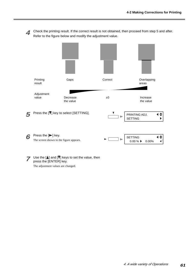
614. A wide variety of Operations
4 Check the printing result. If the correct result is not obtained, then proceed from step 5 and after.
Refer to the figure below and modify the adjustment value.
5 Press the [ ] key to select [SETTING].
6 Press the [ ] key.The screen shown in the figure appears.
7 Use the [ ] and [ ] keys to set the value, thenpress the [ENTER] key.The adjustment values are changed.
Gaps
Decreasethe value
Correct
±0
Overlappingareas
Increase the value
Printingresult
Adjustmentvalue
4-2 Making Corrections for Printing
PRINTING ADJ.SETTING
SETTING 0.00 % 0.00%

62 4. A wide variety of Operations
Bidirectional Correction
This adjusts for misalignment that occurs during bidirectional printing. Perform adjustment for bidirectional correctionwhen media is replaced with a different type or when you're using the machine in a location subject to large changes intemperature.
Setting the Adjustment Value
1 Press the [MENU] key, then press the [ ] keyto select [ADJUST BI-DIR].
2 Press the [ ] key.The screen shown in the figure appears.
3 Press the [ENTER] key.A test pattern is printed.After the printing test has finished, the media is fed to aposition that lets you view the test pattern.
4 Check the test pattern and select the adjust-ment value (a value that produces no displace-ment).
5 Check the adjustment value, then press the[ENTER] key.The media returns to its position where the printing testended.
Bidirectional correction is enabled only when you're performing bidirectional printing.
+10+9+8+7+6+5+4+3+2+10-1-2-3-29-30H1
H2
NO.2
+10+9+8+7+6+5+4+3+2+10-1-2-3-29-30H1
H2
NO.1
NO.3
NO.4
+10+9+8+7+6+5+4+3+2+10-1-2-3-29-30H1
H2
+10+9+8+7+6+5+4+3+2+10-1-2-3-29-30H1
H2
+10+9+8+7+6+5+4+3
+10+9+8+7+6+5+4+3
4-2 Making Corrections for Printing
MENUADJUST BI-DIR
ADJUST BI-DIRTEST PRINT
Adjustment value(The value with no displacement)In this figure, the No. 1 adjustmentvalues are H1 = 7 1/2 and H2 = 8.

634. A wide variety of Operations
6 Press the [ ] key to select [SETTING NO. 1].You can select from [SETTING NO. 1] through [SET-TING NO. 4].
7 Press the [ ] key.The screen shown in the figure appears.
8 Use the [ ] and [ ] keys to select H1 or H2.Use the [ ] and [ ] keys to set the value youchecked in step 4.
When you have entered all the adjustment val-ues, press the [ENTER] key.The adjustment values are changed.
9 Repeat steps 6 through 8 to enter adjustmentvalues for [SETTING No. 2] through [SETTINGNO. 4].
H1 H2 0 0
H1 H2H71/2 H8
4-2 Making Corrections for Printing
ADJUST BI-DIRSETTING No.1
In this case, for [SETTING NO. 1],enter H1 = 7 1/2 and H2 = 8.

64 4. A wide variety of Operations
Saving and Loading a Bidirectional-correction Value
You can save up to eight patterns of adjustment values for bidirectional correction that you've set in memory.Saving different adjustment values for different types of media lets you load the adjustment value simply and easilywhen you change the media type.
Saving an Adjustment Value
1 Follow the steps in the previous section, "Set-ting the Adjustment Value," to enter adjustmentvalues.
2 Press the [ ] key to select [SAVE PRESET-TING].
3 Press the [ ] key to display the screen shownin the figure. Select a memory to save to fromamong [PRESETTING 1] through [PRESET-TING 8], then press the [ENTER] key.The adjustment values are saved in the memory numberyou selected.
Loading an Adjustment Value
1 Press the [MENU] key, then press the [ ] keyto select [ADJUST BI-DIR].
2 Press the [ ] key.The screen shown in the figure appears.
3 Press the [ ] key to select [LOAD PRESET-TING].
4 Press the [ ] key to display the screen shownin the figure.
Select the memory number to load, then pressthe [ENTER] key.The selected adjustment value is loaded.
It may be a good idea to keep notes of the memory numbers and the kind of media whose adjustment value is saved ineach number.
This operation deletes adjustment values that are not saved in memory. If there are adjustment values that you want to keep,save them in memory first.
4-2 Making Corrections for Printing
ADJUST BI-DIRSAVE PRESETTING
SAVE PRESETTING 1
To select the number,Use [ ] and [ ] keys.
To select the number,Use [ ] and [ ] keys.
MENUADJUST BI-DIR
ADJUST BI-DIRTEST PRINT
ADJUST BI-DIRLOAD PRESETTING
LOAD PRESETTING 1

654. A wide variety of Operations
4-3 Detailed Descriptions of Cutting Conditions
Cutting quality is affected by the blade and media being used, and by the cutting conditions. There are four cuttingconditions: cutting speed, blade force, blade offset, and amount of blade extension. For high-quality cutting, it is neces-sary to set the appropriate cutting conditions for the blade and media in actual use. Repeat cutting tests and adjustmentsto the cutting conditions until the cutting quality for the media improves.
This section describes how to use the results of cutting tests to check the cutting conditions.
1 Peel off circle 1 (indicated by ).• When it can be peeled by itself, without disturbing rectangle 2 (indicated by ), the blade force is set appropriately.• If it peels, the setting for either the blade force or the amount of blade extension is insufficient.• If uncut areas remain in some places, the cutting speed is too fast.
2 Peel off rectangle 2 (indicated by ).• The optimum blade pressure (blade force) is correct if you can clearly make out the lines left by the blade.• If the blade trace is indistinct or too strong, you need to adjust the blade force or the amount of blade extension.
3 Check the shape of rectangle 2.• If the corners are cut fully and properly as shown in A, the conditions are correct.• If the corners are rounded as shown in B, the setting for blade offset is insufficient.• If the corners have "horns" as shown in C, the setting for blade offset is too large.• If the cut shape is distorted, the cutting speed is too fast.
Check the points described above, and if the cutting quality of the media is less than good, adjust the cutting conditions.For information on how to perform a cutting test and adjust the cutting conditions, go to "3-1 Points to Check BeforePerforming Output" and refer to "Checking the Cutting Condition Settings," and refer also to "6-2 Detailed Descriptionsof the Menus."
Adjusting the Blade Extension
When you want to perform accurate and fine adjustment of thecutting-in amount, such as when cutting media with thin carrierpaper, you can obtain good results by adjusting the tip of the blade.Turn the cap portion of the blade holder to adjust the amount ofblade extension.A change in extension of 0.5 mm can be made by rotating the capone full turn.Note that making the amount of blade extension too small maycause the end of the cap for the blade holder to touch and damagethe printed surface. It's important to be especially careful aboutthis when you're using media that has poor ink-adhesion proper-ties.
Rough Estimate for the Amount of Blade ExtensionUse the following dimension as a rough estimate for settingthe amount of blade extension.
Thickness ofAmount of blade Thickness of the carrier paperextension = the media portion +
2
A B C
�Min. 0mm Max. 2.5mm 0.1mm
Amount of bladeextension
Materialportion
Carrier-paperportion
BladeHalf of thecarrier paper
Amount of bladeis approximatelyequal to cutting-inamount
Holder
Circle 1
Rectangle 2
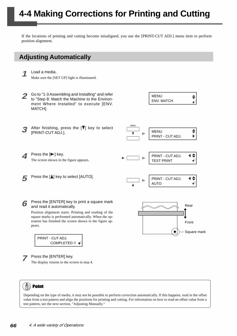
66 4. A wide variety of Operations
4-4 Making Corrections for Printing and Cutting
If the locations of printing and cutting become misaligned, you use the [PRINT-CUT ADJ.] menu item to performposition alignment.
Adjusting Automatically
1 Load a media.Make sure the [SET UP] light is illuminated.
2 Go to "1-3 Assembling and Installing" and referto "Step 8: Match the Machine to the Environ-ment Where Installed" to execute [ENV.MATCH].
3 After finishing, press the [ ] key to select[PRINT-CUT ADJ.].
4 Press the [ ] key.The screen shown in the figure appears.
5 Press the [ ] key to select [AUTO].
6 Press the [ENTER] key to print a square markand read it automatically.Position alignment starts. Printing and reading of thesquare marks is performed automatically. When the op-eration has finished the screen shown in the figure ap-pears.
7 Press the [ENTER] key.The display returns to the screen in step 4.
Depending on the type of media, it may not be possible to perform correction automatically. If this happens, read in the offsetvalue from a test pattern and align the positions for printing and cutting. For information on how to read an offset value from atest pattern, see the next section, "Adjusting Manually."
Rear
Front
Square mark
MENUPRINT - CUT ADJ.
PRINT - CUT ADJ.TEST PRINT
PRINT - CUT ADJ.AUTO
PRINT - CUT ADJ. COMPLETED !!
MENUENV. MATCH

674. A wide variety of Operations
Adjusting Manually
Read the adjustment value from the test pattern printed and cut on the media. Enter the read adjustment value with theoperation panel, then align the printing and cutting positions.
1 Load media and install a blade.Make sure the [SET UP] light is illuminated.
2 Go to "Adjusting Automatically" on the previ-ous page and carry out steps 2 through 4.The screen shown in the figure appears.
3 Press the [ENTER] key.Printing and cutting a test pattern are performed.
4 From the test pattern, read the value at the lo-cation shown in the figure.
5 Press the [ ] key to select [FEED SETTING].
6 Press the [ ] key.The screen shown in the figure appears.
7 Press the [ ] and [ ] keys to enter the feed-direction adjustment value read in step 5, thenpress the [ENTER] key.
8 Repeat steps 6 through 8 and enter the adjust-ment value for [SCAN SETTING].
+2.0 -2.0
+1.0 -1.0
+0.5 -0.5
+0.0 -0.0
+1.5 -1.5
Scan+2.0
-2.0
+1.0
-1.0
+0.5
-0.5
+0.0
-0.0
+1.5
-1.5
Feed
-0.5
Test pattern
4-4 Making Corrections for Printing and Cutting
Scan direction
Feed direction Cutting line
Adjustment-value scale
Cutting line
Read the scale on which thecutting line goes over as theadjustment value.In this figure, the value is "-0.3."Use the same method to readthe value for the feed direction.
PRINT - CUT ADJ.TEST PRINT
PRINT - CUT ADJ.FEED SETTING
FEED SETTING + 0.0 mm + 0.0 mm
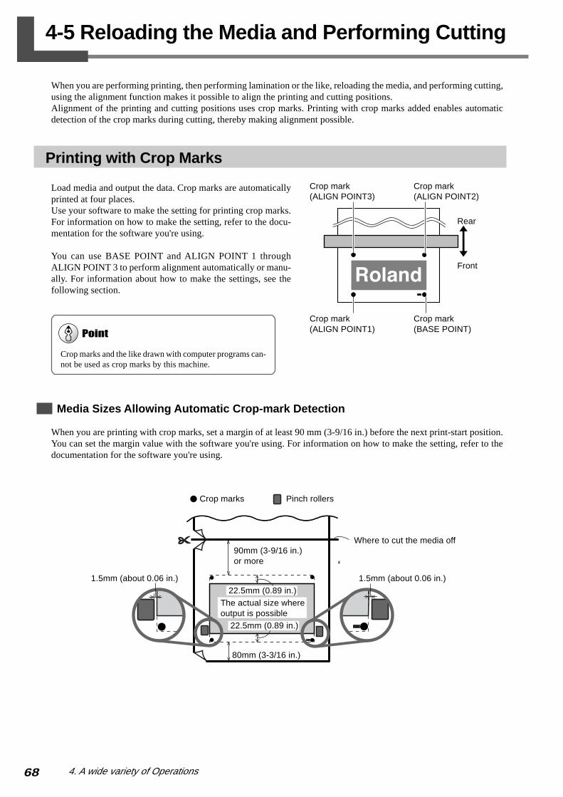
68 4. A wide variety of Operations
4-5 Reloading the Media and Performing Cutting
When you are performing printing, then performing lamination or the like, reloading the media, and performing cutting,using the alignment function makes it possible to align the printing and cutting positions.Alignment of the printing and cutting positions uses crop marks. Printing with crop marks added enables automaticdetection of the crop marks during cutting, thereby making alignment possible.
Printing with Crop Marks
Load media and output the data. Crop marks are automaticallyprinted at four places.Use your software to make the setting for printing crop marks.For information on how to make the setting, refer to the docu-mentation for the software you're using.
You can use BASE POINT and ALIGN POINT 1 throughALIGN POINT 3 to perform alignment automatically or manu-ally. For information about how to make the settings, see thefollowing section.
Media Sizes Allowing Automatic Crop-mark Detection
When you are printing with crop marks, set a margin of at least 90 mm (3-9/16 in.) before the next print-start position.You can set the margin value with the software you're using. For information on how to make the setting, refer to thedocumentation for the software you're using.
Crop marks and the like drawn with computer programs can-not be used as crop marks by this machine.
Rear
Front
Crop mark(BASE POINT)
Crop mark(ALIGN POINT1)
Crop mark(ALIGN POINT2)
Crop mark(ALIGN POINT3)
�
Crop marks Pinch rollers
Where to cut the media off
1.5mm (about 0.06 in.) 1.5mm (about 0.06 in.)
90mm (3-9/16 in.)or more
80mm (3-3/16 in.)
22.5mm (0.89 in.)
The actual size whereoutput is possible
22.5mm (0.89 in.)

694. A wide variety of Operations
Aligning Automatically
When you make the setting for reading crop marks when sending cutting data from the computer, alignment is per-formed with the presence or absence of crop marks determined automatically. For information on how to make thesetting, refer to the documentation for the software you're using.
1 Align the crop marks with the blade protector and load amedia.
2 When you send data, alignment is performed automatically,then cutting starts.
A
Alignment cannot be performed if the line connecting the leftand right crop marks is slanted by 5 degrees or more. Adjust thepositioning of the loaded media.
Blade protector
Crop marks
Within 5 degrees
Within 5 degrees
If Automatic Alignment Cannot Be Performed
If the machine fails to detect the crop marks, the screen shown at right appearsand operation stops.If this happens, press the [ENTER] key, then take action as follows.
(a) The media is slanted at too great an angle, or its loaded location is misaligned. Try redoing steps 1 and 2 described above.
(b) The media may not be suitable for automatic crop-mark detection. Perform alignment manually.
Lengthy media is prone to large error due to warping and the like, making it unsuited to cutting alignment. We recommenddividing the image data into segments that are as short as possible, then performing output separately for each segment.To perform alignment by hand, refer to the next section, "Aligning Manually."
To Stop Detection
To stop crop-mark detection while in progress, follow the steps below.
1. Press the [PAUSE] key. The screen shown in the figure appears.2. Press the [ENTER] key.
4-5 Reloading the Media and Performing Cutting
CANCEL CROPMARK DETECTION?
CROPMARK ERROR NOT FOUND

70 4. A wide variety of Operations
Aligning Manually
Depending on the type of media, it may not be possible to detect crop marks automatically. When crop marks cannot bedetected automatically, you perform alignment manually.
1 Set the location of the origin point. Use the ar-row keys to move the center of the blade to theposition above the lower-right crop mark.
2 Press the [BASE POINT] key.The [BASE POINT] light lights up.The location where the BASE POINT is set is displayed.
3 Use the arrow keys to align the center of theblade with any of the align points (ALIGN POINT1 through ALIGN POINT 3), then press and holdthe [BASE POINT] key for one second or longer.
4 When the screen shown in the figure appears,press the [ENTER] key.The align point is set.
You can make settings for up to three align points. Change the number of points set with [ALIGN POINT] as required.
The locations on the media of ALIGN POINT 1 through ALIGN POINT3 are fixed. The machine automatically determines from the locationof the BASE POINT setting which align point or points have been set.The screen display the number of each align point that has been set.For information about the location of align points, see the previoussection, "Printing with Crop Marks."
The ALIGN POINT settings cannot be made unless the BASE POINT has been set.Setting the BASE POINT after setting ALIGN POINTs clears all the previously set ALIGN POINTs.
Align the center of theblade with this location.
This screen shows BASE POINTand ALIGN POINT 1 are set.
Align the center of theblade with this location.
Center of the blade
SETTING ALIGN POINT 1
W 500 mmB 1
W 500 mmB
4-5 Reloading the Media and Performing Cutting
ALIGN POINT 3ALIGN POINT 2ALIGN POINT 1BASE POINT
W 500 mmB 1 2 3

714. A wide variety of Operations
4-6 Checking the Remaining Ink Level
You can use the [INK REMAINING] menu item to check how much ink is left after the ink cartridges have beeninstalled. Use this information as a guide for replacing the ink cartridges.
For more information about using and replacing ink cartridges, refer to "5-1 Replacing the Ink Cartridges."
1 Press the [MENU] key, then press the [ ] keyto select [INK REMAINING].
2 Press the [ ] key.The amount of remaining ink for all ink cartridges ap-pears on the display. The numerals on the display indi-cate the numbers on the labels for the ink-cartridge ports.The figure shows that little ink remains for No. 3 (ma-genta).
3 After checking, press the [MENU] key to returnto the top menu.
In situations such as the following, the actual amount of ink remaining is not displayed.
• When a partly used ink cartridge is removed and reinstalled• When a partly used ink cartridge is installed
The installed ink cartridge is taken to be an unused cartridge and the default amount of remaining ink is displayed.
The fewer the markers,the less is the amount ofink left.
MENUINK REMAINING
1 2 3 4
Ink-cartridge port label

72 4. A wide variety of Operations
4-7 When Not in Use for a Prolonged Period
When the machine will remain unused for an extended period, we recommend switching off only the sub power andleaving the main power on.About once a month a warning beep sounds to prompt cleaning as indicated below.
1 When the machine remains unused for about amonth, a warning beep sounds and the follow-ing message appears on the display.
2 Press the [POWER] key to switch on the subpower.Cleaning is performed automatically.
3 After cleaning has finished, hold down the[POWER] key for one second or longer to switchoff the sub power.
Switch on the power at least once a month, even when the main power is switched off. Switching on the sub powerautomatically performs cleaning.
Even when the machine is not in use, keep it in an environment where the temperature is 5 to 40ºC (41 to 104ºF) and thehumidity is 20 to 80% (with no condensation). Be especially careful not to expose the machine to high temperatures of 40ºC(104ºF) or more.
The [POWER] lightlights up.
The [POWER] lightgoes out.
PRESS THE POWERKEY TO CLEAN

73
5. Maintenance
This section describes replacement of the ink cartridge, cleaning for the
printing heads, daily care and maintenance, and the like.

74 5. Maintenance
5-1 Replacing the Ink Cartridges
If ink runs out, replace the ink cartridges.Be sure to use genuine ECO-SOL INK cartridges from Roland DG Corp.
Care and Handling of Ink Cartridges
Give attention to the following points when handling ink cartridges.
Replacing with New Ink Cartridges
Before you attempt to replace an ink cartridge, check the following points.
• The machine is switched on.
• Operation is stopped or paused.
Also, always be sure to gently shake the ink cartridge before you install it. Installing it without shaking it first may resultin unstable colors during printing.
Never attempt to disassemble.
Never drop or allow to fall. The impact from a fall may cause damage, making the cartridge unusable.
Store unopened in a well-ventilated location where the temperature is from -20ºC (-40ºF) to 40ºC (104ºF).
Once an ink cartridge has been installed, never remove it until the ink has been used up, except when moving the machine.Frequent insertion and removal may cause air to enter the ink tube, resulting in dot drop-out or other problems in printingquality.
Removing or inserting an ink cartridge while operation is in progress may cause air to get inside the cartridge, resulting in poorimage quality.
Never attempt to install any ink other than an ECO-SOL INK cartridge. Doing so may result in malfunction or faulty operation.
After removing an ink cartridge, never allow the machine to stand with the ink-cartridge port remaining empty -- install a newink cartridge immediately. Failure to do so may result in clogging of the heads.
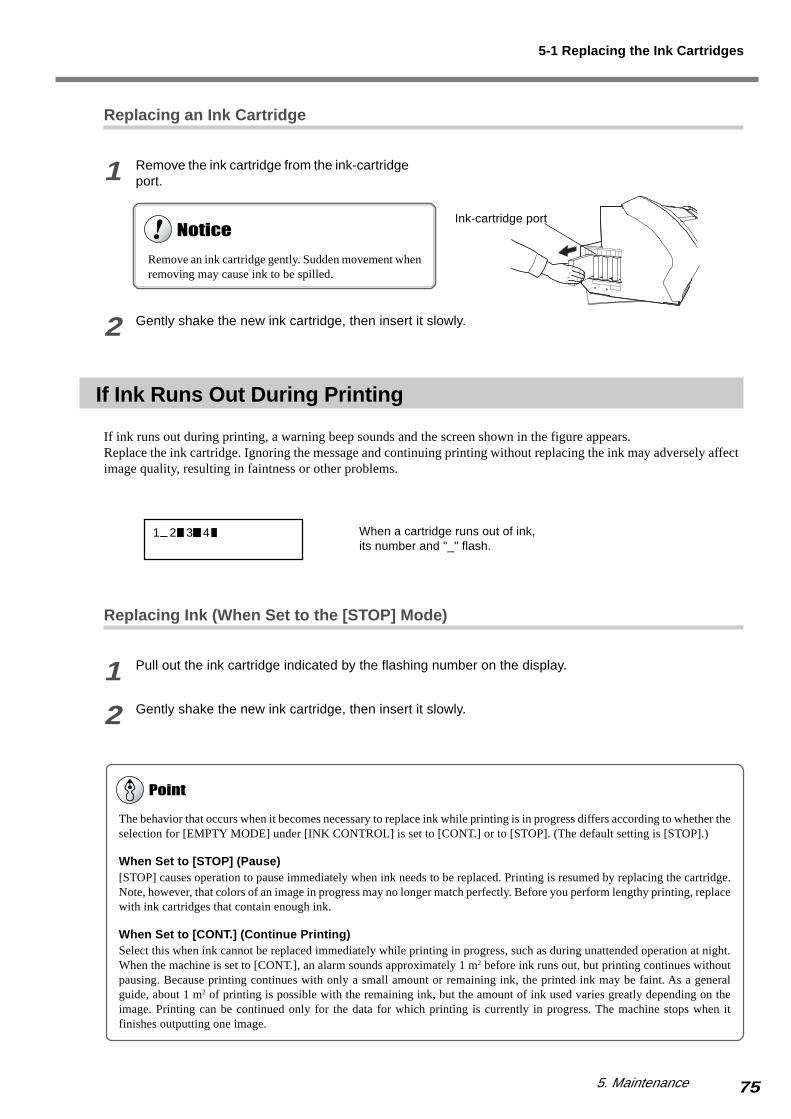
755. Maintenance
Replacing an Ink Cartridge
1 Remove the ink cartridge from the ink-cartridgeport.
2 Gently shake the new ink cartridge, then insert it slowly.
If Ink Runs Out During Printing
If ink runs out during printing, a warning beep sounds and the screen shown in the figure appears.Replace the ink cartridge. Ignoring the message and continuing printing without replacing the ink may adversely affectimage quality, resulting in faintness or other problems.
Replacing Ink (When Set to the [STOP] Mode)
1 Pull out the ink cartridge indicated by the flashing number on the display.
2 Gently shake the new ink cartridge, then insert it slowly.
Ink-cartridge port
5-1 Replacing the Ink Cartridges
1 2 3 4
The behavior that occurs when it becomes necessary to replace ink while printing is in progress differs according to whether theselection for [EMPTY MODE] under [INK CONTROL] is set to [CONT.] or to [STOP]. (The default setting is [STOP].)
When Set to [STOP] (Pause)[STOP] causes operation to pause immediately when ink needs to be replaced. Printing is resumed by replacing the cartridge.Note, however, that colors of an image in progress may no longer match perfectly. Before you perform lengthy printing, replacewith ink cartridges that contain enough ink.
When Set to [CONT.] (Continue Printing)Select this when ink cannot be replaced immediately while printing in progress, such as during unattended operation at night.When the machine is set to [CONT.], an alarm sounds approximately 1 m2 before ink runs out, but printing continues withoutpausing. Because printing continues with only a small amount or remaining ink, the printed ink may be faint. As a generalguide, about 1 m2 of printing is possible with the remaining ink, but the amount of ink used varies greatly depending on theimage. Printing can be continued only for the data for which printing is currently in progress. The machine stops when itfinishes outputting one image.
When a cartridge runs out of ink,its number and "_" flash.
Remove an ink cartridge gently. Sudden movement whenremoving may cause ink to be spilled.

76 5. Maintenance
5-2 Cleaning the Printing Heads
Switching on the sub power automatically performs maintenance operations, including cleaning of the printing heads.This means that there is normally no need to perform cleaning otherwise.If drop-out occurs with printed images, clean the printing heads.
Cleaning the Printing Heads
If drop-out occurs with printed images, you first use the [CLEANING] key to perform cleaning.
1 Load media for printing-test use.
2 Hold down the [CLEANING] key for at least onesecond.Cleaning of printing heads starts.
3 After head cleaning has ended, hold down the [TEST PRINT]key for one second or longer.The test pattern is printed.
4 Go to "3-1 Points to Check Before Performing Output" and refer to "Checking the State of the PrintingHeads" and check the printing-test results. If a problem is found, repeat the cleaning.
If performing cleaning several times does not correct the image drop-out problem, perform head cleaning by selectingthe [HEAD CLEANING] menu from the main menu. For more information, refer to "If Drop-out Persists Even AfterCarrying Out Cleaning Several Times" on the next page.
Perform head cleaning only when there is dot drop-out (gaps) or printing becomes faint.Performing head cleaning more than necessary subjects the heads to wear and consumes ink. In particular, cleaning performedusing the [POWERFUL] menu setting for [HEAD CLEANING] can cause premature head wear and consume large amounts ofink. (Performing cleaning at the [POWERFUL] setting consumes approximately 30 cc of ink for all ink cartridges.)

775. Maintenance
If Drop-out Persists Even After Carrying Out Cleaning Several Times
If drop-out persists even after carrying out cleaning several times, follow the steps below to perform head cleaning.
1 Load media for printing-test use.
2 Press the [MENU] key, then press the [ ] keyto select [HEAD CLEANING].
3 Press the [ ] key, then press the [ ] key toselect [POWERFUL] or [MEDIUM].
Press the [ENTER] key.Head cleaning starts.
4 When head cleaning finishes, perform a printing test to check the result.
If Performing Powerful Cleaning Several Times Does Not Correct the Drop-out ProblemIf performing cleaning several times at the [POWERFUL] menu setting does not correct the image drop-out problem, thenperform cleaning using the included cleaning kit. For information on how to use the cleaning kit, refer to the following section,"Cleaning Using the Cleaning Kit."
5-2 Cleaning the Printing Heads
MENUHEAD CLEANING
HEAD CLEANINGMEDIUM

78 5. Maintenance
Cleaning Using the Cleaning Kit
Cleaning using the cleaning kit should be carried out when automatic cleaning and forced cleaning performed using the[HEAD CLEANING] menu item fail to correct image drop-out. It removes any ink buildup and accumulated dust orgrime from around the printing heads, as these can cause image drop-out or ink drips. We also recommend performingperiodic cleaning using the cleaning kit to prevent problems like these during printing.If image drop-out persists even after performing cleaning with the cleaning kit, or if the cleaning kit has been used up,contact your authorized Roland DG Corp. dealer or Roland DG Corp. service center.The heads are consumable parts. The useful life is six billion shots per nozzle.
Before Starting Cleaning
1 Switch on the main power switch on the back of the machine.
Leave media unloaded at this time.
2 While holding down the [CLEANING] key, switch on the [POWER] key.The screen in the figure appears.
3 Select [CLEANING], then press the [ENTER] key.The screen in the figure appears.
Before you attempt cleaning, read through this section carefully to familiarize yourself with the procedures, then carry out thecleaning operations quickly and accurately.Cleaning is performed while the caps on the printing heads are detached, so cleaning must be completed before the heads dryout. It is suggested that cleaning be completed in thirty minutes or less.If it appears that cleaning operations may take more than thirty minutes, stop the cleaning operations and follow the stepsbelow.
1. Attach the cover for the right side of the machine.2. Press the [ENTER] key. (Cleaning of the printing heads starts.)3. Again carry out cleaning using the cleaning kit.
Switch to the"I" side.
5-2 Cleaning the Printing Heads
MAINTENANCECLEANING
OPEN MAINTENANCE COVER

795. Maintenance
4 Open the front cover and detach the mainte-nance cover.
5 Close the front cover, then press the [ENTER]key.The printing carriage moves, and the screen shown in thefigure appears.
6 Open the front cover, then remove the twoscrews and the cover.
Lift the cover up and remove it.
7 To discharge static electricity from your body,touch the location shown in the figure.
Screws
Maintenance cover
ScrewsCover
Take care not to drop the cover when removing it.If dropped, the impact may cause it to break.
Printingcarriage
5-2 Cleaning the Printing Heads
FINISHED CLEANING?

80 5. Maintenance
Cleaning Using the Cleaning Kit
1 Clean the heads and the area around the headson the left side of the machine. Use a cleaningstick to wipe off any grime from the stainless-steel frame for the heads and the plastic areason either side of the heads.
2 Clean the surface of the stainless-steel frameon the right side of the machine. Use a clean-ing stick to wipe away any buildup of dust andink from the surface of the stainless-steel frame.
3 Clean the rubber caps and the area aroundthem. Use a cleaning stick to wipe off anybuildup of dust or grime from the rubber caps.
If dust is present on the sponges, wipe it offwith the cleaning stick.
Plastic area
Stainless-steel framefor heads
Be sure to use one of the included cleaning sticks.Never touch the nozzle surface of the heads.
Give special attention to removing the fibrous dust thattends to build up on the heads.
Stainless-steel frame
Rubber cap Sponge
If no grime is present, never touch the sponges insidethe rubber caps.When removing grime adhering to the sponge inside arubber cap, touch the sponge gently with the tip of thecleaning stick to pick up the grime. Rubbing forcefullymay damage the surface of the sponge.
5-2 Cleaning the Printing Heads
Nozzle surfaceof the heads
Printing head

815. Maintenance
4 Clean the wiper.
Use the [ ] key to extract the wiper.
5 Use a cleaning stick to wipe away any buildupof dust and grime from the wiper.
Wiper
Replacing the WiperIf the message [REPLACE WIPER] appears on the dis-play, replace the wiper with a new one. As a rule of thumb,the message prompting you to replace the wiper appearswhen cleaning has been performed 1500 times (with [ALL]selected for head cleaning).For information on how to replace the wiper, refer to "5-4Replacing the Consumable Parts," the section "Replacingthe Wiper."
5-2 Cleaning the Printing Heads
Wiper

82 5. Maintenance
After Finishing Cleaning
1 Attach the cover of the machine, then close thefront cover.Engage the cover on the hooks to install.
2 Press the [ENTER] key.The screen in the figure appears.The printing heads return to the standby position, andhead cleaning starts automatically.
3 Make sure the screen in the figure appears on the display,then open the front cover and attach the maintenance cover.
4 Close the front cover and press the [ENTER] key.The sub power is switched off.
5 Again press the [POWER] key to switch on the sub power.
6 Load media and carry out a printing test.
Examine the results of the printing test and make sure that all dots are printed attractively. If necessary, perform headcleaning to make the dots clean and even.
Screws
Maintenance cover
ScrewsCover
Hook
5-2 Cleaning the Printing Heads
Cover
NOW PROCESSING..
CLOSE MAINTE -NANCE COVER
835. Maintenance
5-3 Other Cleaning Tasks
The machine and the inside of the front cover may become soiled with ink during printing. The cleaning methodsdescribed below let you continue printing without affecting the printed media or the machine.
Cleaning the Body
Use a cloth moistened with water then wrung well, and wipe gently to clean. Wipe the operation panel and displaygently with a clean, soft cloth.
Cleaning the Platen
Moisten a cloth with neutral detergent diluted with water, wring dry, and wipe gently.For buildup of cutting dust on the platen, use a commercially available brush to brush away the buildup toward the front.When doing this, never use a metal brush.
Cleaning the Grit Rollers
Use a commercially available brush to remove dust and other detritus.Any adhering grime may prevent the media from being held in place securely.
Cleaning the Pinch Rollers
Moisten a cloth with neutral detergent diluted with water, wring dry, and wipe gently.
Cleaning the Front Cover
Use a cloth moistened with water then wrung well, and wipe gently to clean.
Cleaning the Media Clamps
If there is buildup of ink or dust, moisten a cloth with neutral detergent diluted with water, wring dry, and gently wipethe surface.
When carrying out any cleaning other than cleaning using cleaning sticks, switch off the main power. * Before turning off the main power, press the [POWER] key to switch off the sub power.
Never lubricate the mechanisms.
Never clean with solvents (such as benzine or thinners).
Periodically clean the platen, grit rollers, and media clamps.
Never touch the printing heads or allow the printing heads to come in contact with anything except ink.
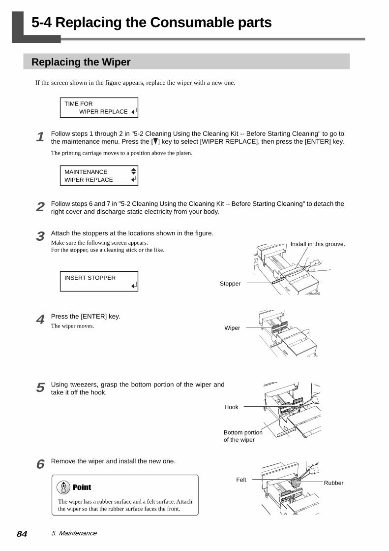
84 5. Maintenance
5-4 Replacing the Consumable parts
Replacing the Wiper
If the screen shown in the figure appears, replace the wiper with a new one.
1 Follow steps 1 through 2 in "5-2 Cleaning Using the Cleaning Kit -- Before Starting Cleaning" to go tothe maintenance menu. Press the [ ] key to select [WIPER REPLACE], then press the [ENTER] key.
The printing carriage moves to a position above the platen.
2 Follow steps 6 and 7 in "5-2 Cleaning Using the Cleaning Kit -- Before Starting Cleaning" to detach theright cover and discharge static electricity from your body.
3 Attach the stoppers at the locations shown in the figure.Make sure the following screen appears.For the stopper, use a cleaning stick or the like.
4 Press the [ENTER] key.The wiper moves.
5 Using tweezers, grasp the bottom portion of the wiper andtake it off the hook.
6 Remove the wiper and install the new one.
Bottom portionof the wiper
Hook
Felt
Wiper
Install in this groove.
The wiper has a rubber surface and a felt surface. Attachthe wiper so that the rubber surface faces the front.
Stopper
Rubber
TIME FOR WIPER REPLACE
MAINTENANCEWIPER REPLACE
INSERT STOPPER
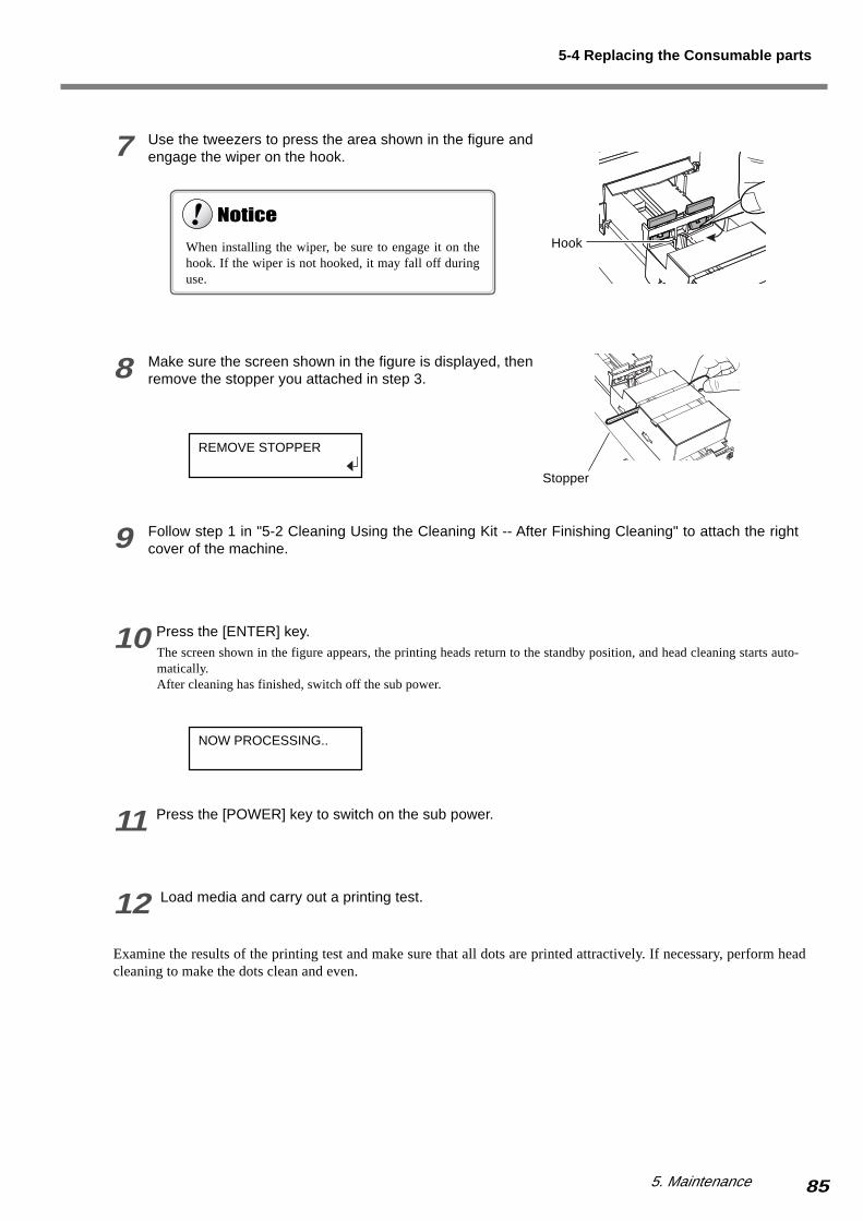
855. Maintenance
7 Use the tweezers to press the area shown in the figure andengage the wiper on the hook.
8 Make sure the screen shown in the figure is displayed, thenremove the stopper you attached in step 3.
9 Follow step 1 in "5-2 Cleaning Using the Cleaning Kit -- After Finishing Cleaning" to attach the rightcover of the machine.
10 Press the [ENTER] key.The screen shown in the figure appears, the printing heads return to the standby position, and head cleaning starts auto-matically.After cleaning has finished, switch off the sub power.
11 Press the [POWER] key to switch on the sub power.
12 Load media and carry out a printing test.
Examine the results of the printing test and make sure that all dots are printed attractively. If necessary, perform headcleaning to make the dots clean and even.
When installing the wiper, be sure to engage it on thehook. If the wiper is not hooked, it may fall off duringuse.
Hook
Stopper
5-4 Replacing the Consumable parts
REMOVE STOPPER
NOW PROCESSING..

86 5. Maintenance
How to Replace the Blade
If the blade becomes dull, replace it with the included replacement blade.The blade is a consumable item that will eventually wear out. For more information about the useful life of the blade,refer to "8-4 About Blade Life."
1 Press the [MENU] key, then press the [ ] keyto select [REPLACE KNIFE.]
2 Press the [ENTER] key.When the screen shown in the figure appears, the print-ing carriage simultaneously moves to the left.
3 Loosen the tool-mounting screw shown in thefigure, then remove the blade holder from thecutting carriage.
4 Remove the old blade.
5 Replace with a new blade.
6 Support the tool-mounting screw from belowand install the blade holder.
7 Tighten the tool-mounting screw.Tug the blade holder upward to make sure it does notcome loose.
8 Close the front cover, then press the [ENTER]key.
Do not touch the tip of the blade with your fingers.Doing so may result in injury, and the cutting performance of the blade will be impaired.
Screw
Press the push-pin.
Old blade
Blade holder
It snaps into placewith an audible click.
New blade
Blade holder
Push-pin
5-4 Replacing the Consumable parts
Screw
MENUREPLACE KNIFE
FINISHED?
If installed without supporting the screw in this way,cutting quality may become poor.
Insert the blade holderuntil the collar is flushwith the carriage.

875. Maintenance
How to Replace the Separating Knife
If the separating knife becomes dull, replace it with the included replacement blade.
1 Press the [MENU] key, then press the [ ] keyto select [REPLACE KNIFE].
2 Press the [ENTER] key.When the screen shown in the figure appears, the print-ing carriage moves to the left.
3 Open the front cover, then remove the separat-ing knife.
4 Replace with a new knife.The knife is secured in place by the magnet.
5 Install the separating knife.
6 Close the front cover and press the [ENTER]key.
Do not touch the tip of the separating knife with your fingers.Doing so may result in injury.
Do not touch the operation panel while replacing the separating knife is in progress.The cutting carriage may move and cause injury.
If the blade remains in the cutting carriage, use thetweezers in the cleaning kit to remove it.
1) Loosen the screw until it slips out.
2) Grasp the screw portion, and slowly pull it out in the direction of the arrow. When doing this, do not pull it back toward you.
Positioninggroove
1
2
1) Grasp the screw portion and slowly insert it into the groove.
2) Tighten the screw. Take care to ensure that the knife does not slip out of position at this time.
1
2
5-4 Replacing the Consumable parts
MENUREPLACE KNIFE
FINISHED?

88 5. Maintenance
5-5 Disposing of Discharged Ink
Dispose of ink in the drain bottle as described below.
Procedure for Disposing of Discharged Ink
1 Press and hold the [POWER] key for at least one second to switch off the sub power.
2 Remove the drain bottle and attach the bottom plug.
3 Dispose of discharged ink properly, in accordance with local laws and regulations.
4 Remove the bottom plug and attach the drain bottle.
Discharged ink is flammable and contains toxic ingredients. Never attempt to incinerate discharged ink or discard it withordinary trash. Also, never dispose of it in sewer systems, river, or streams. Doing so may have an adverse impact on theenvironment.
If any ink gets on your hands or clothing, wash it off as soon as possible. Ink stains may become difficult to remove if allowedto stand.
Drain bottle Bottom plug
The bottom of the body
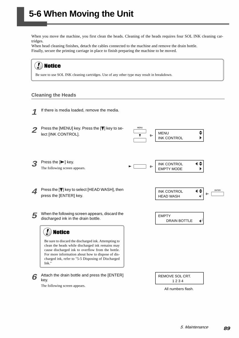
895. Maintenance
5-6 When Moving the Unit
When you move the machine, you first clean the heads. Cleaning of the heads requires four SOL INK cleaning car-tridges.When head cleaning finishes, detach the cables connected to the machine and remove the drain bottle.Finally, secure the printing carriage in place to finish preparing the machine to be moved.
Cleaning the Heads
1 If there is media loaded, remove the media.
2 Press the [MENU] key. Press the [ ] key to se-
lect [INK CONTROL].
3 Press the [ ] key.
The following screen appears.
4 Press the [ ] key to select [HEAD WASH], then
press the [ENTER] key.
5 When the following screen appears, discard thedischarged ink in the drain bottle.
6 Attach the drain bottle and press the [ENTER]key.The following screen appears.
Be sure to use SOL INK cleaning cartridges. Use of any other type may result in breakdown.
MENUINK CONTROL
INK CONTROLEMPTY MODE
INK CONTROLHEAD WASH
EMPTY DRAIN BOTTLE
REMOVE SOL CRT. 1 2 3 4
Be sure to discard the discharged ink. Attempting toclean the heads while discharged ink remains maycause discharged ink to overflow from the bottle.For more information about how to dispose of dis-charged ink, refer to "5-5 Disposing of DischargedInk."
All numbers flash.
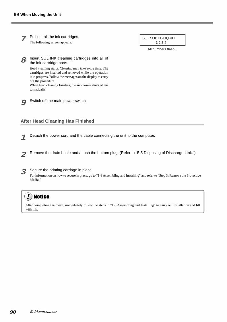
90 5. Maintenance
7 Pull out all the ink cartridges.The following screen appears.
8 Insert SOL INK cleaning cartridges into all ofthe ink-cartridge ports.Head cleaning starts. Cleaning may take some time. Thecartridges are inserted and removed while the operationis in progress. Follow the messages on the display to carryout the procedure.When head cleaning finishes, the sub power shuts of au-tomatically.
9 Switch off the main power switch.
After Head Cleaning Has Finished
1 Detach the power cord and the cable connecting the unit to the computer.
2 Remove the drain bottle and attach the bottom plug. (Refer to "5-5 Disposing of Discharged Ink.")
3 Secure the printing carriage in place.For information on how to secure in place, go to "1-3 Assembling and Installing" and refer to "Step 3: Remove the ProtectiveMedia."
After completing the move, immediately follow the steps in "1-3 Assembling and Installing" to carry out installation and fillwith ink.
All numbers flash.
5-6 When Moving the Unit
SET SOL CL-LIQUID 1 2 3 4

91
6. About the Menus
This chapter provides detailed item about the operation menus.

92 6. About the Menus
6-1 Menu Flowchart
For details about each of the menus, see the "6-2 Detailed Descriptions of the Menus."
When Switching on the Power Language/unit Menu
Hold down the [MENU] key andpress the [POWER] key
When the ink hasn'tfilled yet
Press the [POWER] key
Roland SP-300 Ver. 1.00
Roland SP-300INK NOT FILLED
Roland SP-300 ECO-SOL 4COLOR
MENU LANGUAGEENGLISH
[ENTER]
[ENTER]
[ENTER]
[ENTER]
SET SOL CL-LIQUID 1 2 3 4
SET SOL CRT. 1 2 3 4
FILLING INK
[ENTER][ENTER]
INSTALL DRAIN BOTTLE
SELECT INK TYPEECO-SOL 4COLOR
SETUP SHEET
CHECK HEATERVOLTAGE SETTING
NOW PROCESSING..
Set up media.
W 500mm
Top menu
Startup screen
To the "Startup screen"when switching on thepower
LENGTH UNIT mm mm
TEMP. UNIT 0 C 0 C

936. About the Menus
6-1 Menu Flowchart
Cutting Configuration Menu
Press the [CUTCONFIG] key.
Maintenance Menu
Heater Configuration Menu
Press and hold downthe [CLEANING] key forone second or more.
Hold down the [CLEANING] key,and press the [POWER] key.
Press the [HEATERCONFIG] key.
FORCE50 gf 50 gf
SPEED30 cm/s 30 cm/s
OFFSET0.250 mm 0.250 mm
UP - SPEED30 cm/s 30 cm/s
PRINT 35 25DRYER 35 25
CLEANING... MAINTENANCECLEANING
MAINTENANCEWIPER REPLACE
To the [CLEANING] menu
To the [WIPER REPLACE] menu
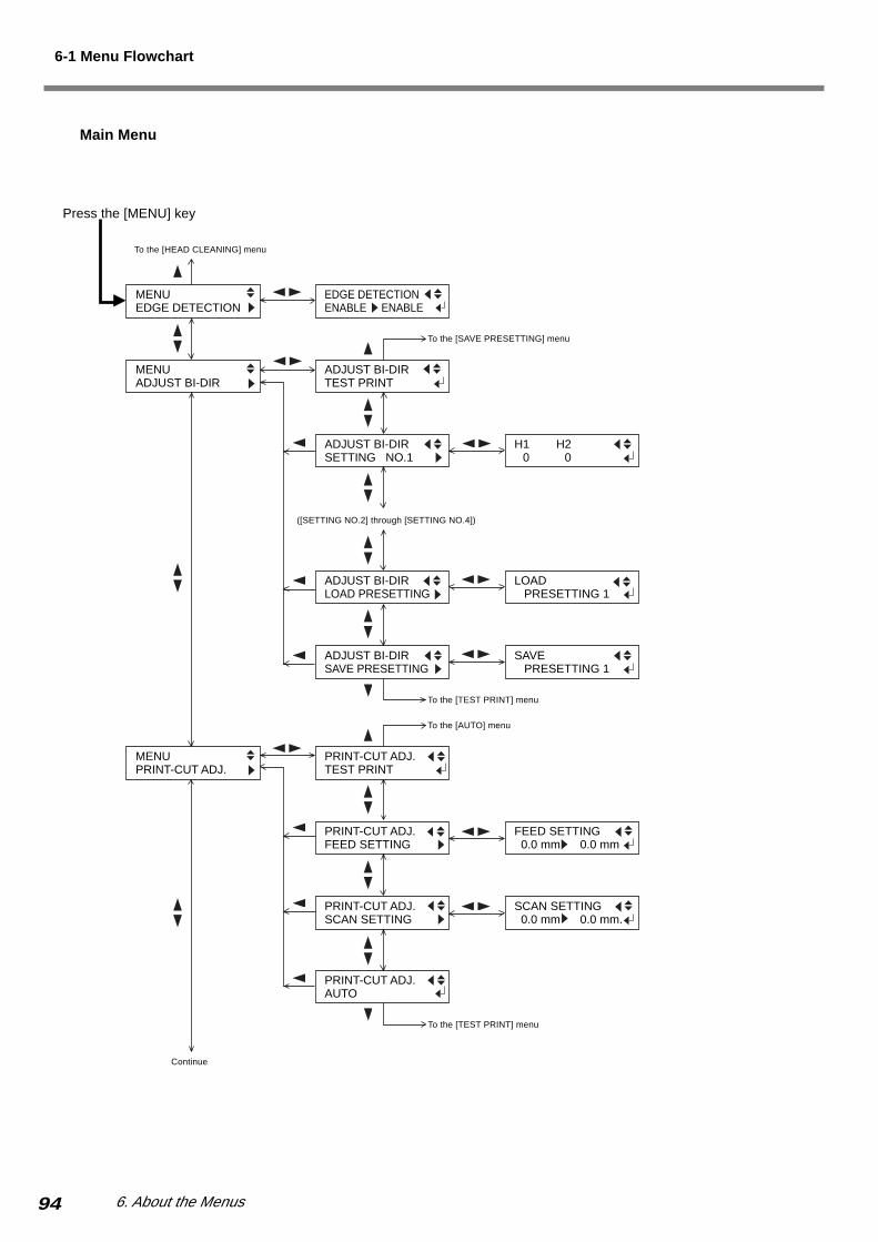
94 6. About the Menus
Press the [MENU] key
MENUADJUST BI-DIR
MENUPRINT-CUT ADJ.
MENUEDGE DETECTION
H1 H2H0 H0
SCAN SETTING 0.0 mm 0.0 mm.
EDGE DETECTIONENABLE ENABLE
ADJUST BI-DIRTEST PRINT
ADJUST BI-DIRSETTING NO.1
ADJUST BI-DIRLOAD PRESETTING
LOAD PRESETTING 1
ADJUST BI-DIRSAVE PRESETTING
SAVE PRESETTING 1
PRINT-CUT ADJ.TEST PRINT
PRINT-CUT ADJ.FEED SETTING
FEED SETTING 0.0 mm 0.0 mm
PRINT-CUT ADJ.SCAN SETTING
PRINT-CUT ADJ.AUTO
To the [SAVE PRESETTING] menu
To the [TEST PRINT] menu
To the [AUTO] menu
To the [TEST PRINT] menu
To the [HEAD CLEANING] menu
Continue
Main Menu
6-1 Menu Flowchart
([SETTING NO.2] through [SETTING NO.4])

956. About the Menus
Continue
MENUPREHEATING
PREHEATINGPREHEAT PREHEAT
MENUFULL WIDTH S
FULL WIDTH SENABLE ENABLE
MENUSCAN INTERVAL
SCAN INTERVALOFF OFF
MENUVACUUM POWER
VACUUM POWERAUTO AUTO
INK CONTROLPUMP UP
INK CONTROLHEAD WASH
MENUINK CONTROL
INK CONTROLEMPTY MODE
EMPTY MODESTOP STOP
To the [HEAD WASH] menu
To the [EMPTY MODE] menu
CUTTING ADJ.SCAN SETTING
SCAN SETTING 0.00% 0.00%
MENUCALIBRATION
CALIBRATIONPRINTING ADJ.
CALIBRATIONCUTTING ADJ.
PRINTING ADJ.SETTING
SETTING 0.00% 0.00%
CUTTING ADJ.FEED SETTING
FEED SETTING 0.00% 0.00%
PRINTING ADJ.TEST PRINT
To the [CUTTING ADJ.] menu To the [SETTING] menu
To the [TEST PRINT] menu
To the [SCAN SETTING] menu
To the [FEED SETTING] menu
To the [PRINTING ADJ.] menu
Continue
6-1 Menu Flowchart
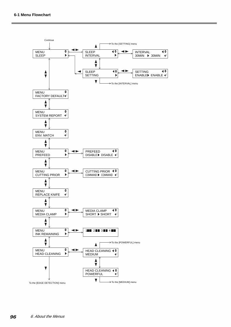
96 6. About the Menus
MENUPREFEED
PREFEEDDISABLE DISABLE
MENUCUTTING PRIOR
CUTTING PRIORCOMMAND COMMAND
MENUREPLACE KNIFE
MENUMEDIA CLAMP
HEAD CLEANINGPOWERFUL
1 2 3 4
MEDIA CLAMPSHORT SHORT
HEAD CLEANINGMEDIUM
MENUHEAD CLEANING
MENUINK REMAINING
To the [EDGE DETECTION] menu
INTERVAL30MIN 30MIN
MENUSLEEP
SETTINGENABLE ENABLE
MENUENV. MATCH
MENUSYSTEM REPORT
MENUFACTORY DEFAULT
SLEEPSETTING
SLEEPINTERVAL
To the [SETTING] menu
To the [INTERVAL] menu
To the [POWERFUL] menu
To the [MEDIUM] menu
6-1 Menu Flowchart
Continue

976. About the Menus
6-2 Detailed Descriptions of the Menus
Main Menu
[EDGE DETECTION]
Setting range: ENABLE, DISABLEDefault value: ENABLE
This specifies whether detection of the front and rear edges of themedia is enabled or disabled.This should normally be set to [ENABLE].When loading transparent media, set this to [DISABLE]. Whendoing this, ensure a margin of 80 mm (3-3/16 in.) or more fromthe leading edge of the media to the start position for printing orcutting.
[ADJUST BI-DIR] > [TEST PRINT]
This prints a test pattern for adjustment of bidirectional printing.
[ADJUST BI-DIR] > [SETTING No.1 to 4]
Setting range: -30 to +10 (in steps of 1/2)Default value: 0
This sets the adjustment values.
[ADJUST BI-DIR] > [LOAD PRESETTING]
This loads the adjustment values saved in memory 1 through 8.
[ADJUST BI-DIR] > [SAVE PRESETTING]
This saves the values of [SETTING NO.1 - 4] as [PRESETTING1] through [PRESETTING 8]. You can save up to eight adjust-ment-value patterns.
[PRINT-CUT ADJ.] > [TEST PRINT]
This prints a test pattern for adjustment use.
[PRINT-CUT ADJ.] > [FEED SETTING]
Setting range: -5.0 to +5.0 mm (in steps of 0.1 mm)Default value: 0 mm
This sets the adjustment value for the media-feed direction.
[PRINT-CUT ADJ.] > [SCAN SETTING]
Setting range: -5.0 to +5.0 mm (in steps of 0.1 mm)Default value: 0 mm
This sets the adjustment value for the scan direction (the car-riage-movement direction).
[PRINT-CUT ADJ.] > [AUTO]
Alignment of the printing and cutting positions is performed au-tomatically.
[CALIBRATION] > [PRINTING ADJ.] > [TEST PRINT]
This prints a test pattern for verifying the adjustment.
[CALIBRATION] > [PRINTING ADJ.] > [SETTING]
Setting range: -2.00% to +2.00% (in steps of 0.05%)Default value: 0%
This corrects for errors in the amount of feed of the grit rollersdue the type of media. Be sure to make this setting when you havereplaced the media with a different type. Make this setting againwhen horizontal stripes are plainly visible on printing results.
[CALIBRATION] > [CUTTING ADJ.] > [FEED SET-TING]
Setting range: -2.00% to +2.00% (in steps of 0.01%)Default value: 0%
This corrects for the cutting length (media-feed direction) whenusing the machine for cutting only. When using the machine forprinting and cutting, always set the offset value to [0].
[CALIBRATION] > [CUTTING ADJ.] > [SCAN SET-TING]
Setting range: -2.00% to +2.00% (in steps of 0.01%)Default value: 0%
This corrects for the cutting length (carriage-movement direction)when using the machine for cutting only. When using the machinefor printing and cutting, always set the offset value to [0].
[INK CONTROL] > [EMPTY MODE]
Setting range: CONT., STOPDefault value: STOP
When replacement of the ink cartridge becomes necessary whileprinting is in progress, this setting determines whether printingcontinues or pauses. This setting is used when the ink cartridgecannot be changed immediately during printing, such as duringunattended operation at night.[CONT.] causes printing to continue without pause even if inkrefilling becomes necessary. To replace an ink cartridge, press the[PAUSE] key to pause operation, then replace with a new car-tridge. Pressing the [PAUSE] key again resumes printing.Printing continues with the small amount of ink remaining, so theprinted image may become faint as the ink runs out. In general, itwould be possible to perform about 1 m2 (10 ft2) of printing oncethis message appears, although the actual amount varies widelyaccording to the amount of ink needed for the particular image.Printing is continued only for the data currently being printed.Operation stops after one image is output.[STOP] causes operation to pause immediately when the ink car-tridge needs to be changed. Printing is resumed by replacing thecartridge. Note, however, that the colors of an image in progressmay no longer match perfectly. Before you perform lengthy print-ing, replace with ink cartridges that contain enough ink.
[INK CONTROL] > [PUMP UP]
This drains ink from the printing heads.
[INK CONTROL] > [HEAD WASH]
This washes the printing heads using optionally available clean-ing cartridges.

98 6. About the Menus
[PREHEATING]
Setting range: PREHEAT, MENU, OFFDefault value: PREHEAT
This sets the temperature of the printing heater and the dryer whenno media is loaded and set up.[PREHEAT]: This maintains the warm-up temperature (which islower than the normal operating temperature) when no media isloaded and set up. When media is loaded and set up, the heatersare at the temperature values set at the heater configuration menu.[MENU]: This maintains the heaters at the temperature values setat the heater configuration menu even when no media is loadedand set up.[OFF]: The heaters do not operate when no media is set up andloaded. When media is loaded and set up, the heaters are at thetemperature values set at the heater configuration menu.
[FULL WIDTH S]
Setting range: ENABLE, DISABLEDefault value: ENABLE
This sets the movement width of the printing carriage during print-ing. Using this function may improve printing quality because thespeed of feeding media becomes uniform, but printing may takemore time. When you're using the heater unit, be sure to set thismenu item to [ENABLE].[ENABLE]: The movement width of the printing carriage is al-ways the full range.[DISABLE]: The movement width varies according to the print-ing data.
[SCAN INTERVAL]
Setting range: OFF, 0.1 to 10.0 sec. (in steps of 0.1 sec.)Default value: OFF
This sets the ink-drying time. If problems with ink stains occur,setting this to a longer value may improve printing quality.
[VACUUM POWER]
Setting range: AUTO, 0 to 100% (in steps of 10%)Default value: AUTO
This adjusts the suction force of the fan installed under the platento make the media contact the platen.Adjust this value when the media warps due to heat or sticks tothe platen. Increasing the value makes the suction force stronger,but because it lowers the temperature of the platen, the media maybecome difficult to warm.[AUTO]: The suction force is adjusted automatically according tothe width of media. Set this menu item to [AUTO] normally.[0 to 100%] (in steps of 10%): The suction force remains constantat the set value.
[SLEEP] > [INTERVAL]
Setting range: 15 to 120 min. (in steps of 15 min.)Default value: 30 min.
This sets the time until the machine enters the sleep mode.
6-2 Detailed Descriptions of the Menus
[SLEEP] > [SETTING]
Setting range: ENABLE, DISABLEDefault value: ENABLE
This sets whether the power-saving feature is enabled.When set to [ENABLE], the machine enters the sleep mode whenthe time set with the [INTERVAL] menu item is reached.
[FACTORY DEFAULT]
This returns all menu settings to their original values when shippedfrom the factory. For more about the factory defaults for the vari-ous settings, see the "Default value" entry for each menu settingin this section.
[SYSTEM REPORT]
This prints the current status of settings and other system infor-mation.
[ENV. MATCH]
This performs automatic adjustment on the machine to obtain astate optimized to the operating environment (temperature andhumidity).
[PREFEED]
Setting range: DISABLE, ENABLEDefault value: DISABLE
This specifies whether the media prefeed function is enabled.When set to [ENABLE], an amount of media equal to the size ofthe data sent from the computer is fed out first, and then printingor cutting is performed.When using the [PREFEED] function, set [EDGE DETECTION]to [ENABLE].
[CUTTING PRIOR]
Setting range: COMMAND, MENUDefault value: COMMAND
When set to [COMMAND], cutting conditions set with a programare to be given priority.When set to [MENU], cutting is performed using the values setwith the machine.
[REPLACE KNIFE]
This setting is used when replacing the separating knife, or wheninstalling or removing the media-cutting blade.

996. About the Menus
[MEDIA CLAMP]
Setting range: LONG, SHORT, NONEDefault value: SHORT
This makes the setting for the type of media clamps used.[LONG]: Select this value when you're using the long mediaclamps. Note that the long media clamps interfere with the sepa-rating knife, so when [LONG] is selected, media-separation op-erations are not performed.[SHORT]: Select this value when you're using the short mediaclamps.[NONE]: Select this value when you're not using any media clamps.
[INK REMAINING]
This shows the amount of ink left after each of the ink cartridgeshas been installed. The fewer the markers, the less ink is left.If a partially used ink cartridge is removed and reinstalled, or if apartially used ink cartridge is installed, the cartridge is taken to beunused, and the displayed amount of remaining ink is not true.
[HEAD CLEANING] > [MEDIUM]
This performs cleaning of the printing heads. This performs clean-ing that is more powerful than the cleaning carried out by press-ing the [CLEANING] key. If no improvement is obtained by per-forming cleaning several times using the [CLEANING] key, thenexecute this menu item.This cleaning causes more head wear and uses up more ink thancleaning using the [CLEANING] key, so you should execute itonly as seldom as necessary.
[HEAD CLEANING] > [POWERFUL]
This performs cleaning of the printing heads. This performs clean-ing that is more powerful than the cleaning carried out by using[MEDIUM]. If no improvement is obtained by performing clean-ing several times using [MEDIUM], then execute this menu item.This cleaning causes more head wear and uses up more ink thancleaning using [MEDIUM], so you should execute it only as sel-dom as necessary.
6-2 Detailed Descriptions of the Menus
Cutting Configuration Menu
[FORCE]
Setting range: 30 to 300gf (in steps of 5gf)Default value: 50gf
This sets the blade force used during cutting.When [CUTTING PRIOR] on the main menu has been set to[COMMAND], the program's settings for the cutting conditionstake priority. To give priority to the cutting conditions set on themachine, turn off the program settings, or set the [CUTTINGPRIOR] menu item to [MENU].
[SPEED]
Setting range: 1 to 30cm/s (in steps of 1cm/s)Default value: 30cm/s
This sets the cutting speed used during cutting.When [CUTTING PRIOR] on the main menu has been set to[COMMAND], the program's settings for the cutting conditionstake priority. To give priority to the cutting conditions set on themachine, turn off the program settings, or set the [CUTTINGPRIOR] menu item to [MENU].
[OFFSET]
Setting range: 0.000 to 1.500mm (in steps of 0.025mm)Default value: 0.250mm
This sets the blade offset used during cutting.When [CUTTING PRIOR] on the main menu has been set to[COMMAND], the program's settings for the cutting conditionstake priority. To give priority to the cutting conditions set on themachine, turn off the program settings, or set the [CUTTINGPRIOR] menu item to [MENU].
[UP-SPEED]
Setting range: 1 to 30cm/s (in steps of 1cm/s)Default value: 30cm/s
This sets the up speed for the blade (the speed when the blade israised).When [CUTTING PRIOR] on the main menu has been set to[COMMAND], the program's settings for the cutting conditionstake priority. To give priority to the cutting conditions set on themachine, turn off the program settings, or set the [CUTTINGPRIOR] menu item to [MENU].

100 6. About the Menus
Heater Configuration Menu
[PRINT/DRYER]
Setting range: OFF, 35 to 50ºC (in steps of 1º) or 94 to 122ºF (in steps of 2º)
These specify the preset temperature for the printing heater andfor the dryer. They also display the actual temperatures. The valueon the left side of the display is the preset temperature, and thevalue on the right side is the actual temperature.
Language/unit Menu
[MENU LANGUAGE]
Setting range: ENGLISH, JAPANESE
This specifies the language used for the display. After you havemade your selection, pressing the [ENTER] key displays the[LENGTH UNIT] menu.
[LENGTH UNIT]
Setting range: mm, inch
This specifies the measurement unit for the lengths shown on thedisplay. After you have made your selection, pressing the [EN-TER] key displays the [TEMP. UNIT] (temperature unit) menu.
[TEMP. UNIT]
Setting range: ºC, ºF
This specifies the measurement unit for temperatures shown onthe display. After you have made your selection, pressing the [EN-TER] key exits the menus, and initialization starts.
Maintenance Menu
[MAINTENANCE] > [CLEANING]
This performs operations for cleaning around the printing headsusing the cleaning kit. For more information, go to "5-2 Cleaningthe Printing Heads" and refer to "Cleaning Using the CleaningKit."
[MAINTENANCE] > [WIPER REPLACE]
This performs operations for replacing the wiper. For more infor-mation, go to "5-2 Cleaning the Printing Heads" and refer to "Re-placing the Wiper."
Preset temperature
6-2 Detailed Descriptions of the Menus
PRINT 35 25DRYER 35 25
Actualtemperature

101
7. What to Do If...
This section describes error messages that may appear on the display
and how to resolve problems that can occur during operation.

102 7. What to Do If...
7-1 What to Do If...
The Machine Doesn't Run
The Machine
Is the power switched on?After you switch on the main power, press the [POWER] key andmake sure the POWER light illuminates.
Is the [SETUP] light illuminated?Load media correctly, then lower the sheet loading lever and closethe front cover.
Is the front cover open?Close the front cover.
Is the top menu displayed?If the top menu isn't displayed, printing doesn't start even whendata is sent from the computer. Press the [MENU] key to displaythe top menu.
Is the PAUSE light illuminated?If the PAUSE light is lighted, the unit has been paused. To resumeprinting or cutting, press the [PAUSE] key. The PAUSE light goesdark and printing or cutting resumes.
Has ink run out?When printing or cutting data is sent while the screen shown inthe figure is displayed, a message appears and a warning beepsounds. At the same time, operation pauses. When the ink car-tridge is replaced with a new one, printing or cutting starts.
Is any message shown on the display?Refer to "7-2 Responding to a Message" elsewhere in this chapter.
The Connector Cable
Is the cable connected?Connect the cable securely.
Are you using a lengthy connector cable or a USB hub?Use a shielded USB cable having a length of three meters or less.Never use a USB hub or the like.
Attractive Printing or Cutting Is Impossible
The Results of Printing Are Coarse
Do the printing heads exhibit dot drop-out?Carry out a printing test and make sure no dot drop-out occurs. Ifdot drop-out is present, perform cleaning. For more information,refer to "3-1 Points to Check Before Performing Output", the sec-tion "Checking the State of the Printing Heads" and "5-2 Cleaningthe Printing Heads."
Have you carried out feed correction?Large misalignment in the amount of feed of the media may resultin printing that seems coarse or in horizontal stripes. Either makethe setting on the computer to match the type of media you're us-ing, or go to "4-2 Making Corrections for Printing" and refer to"Feed Correction -- Setting the Adjustment Value" to make thesetting for correction on the printer.
Have you carried out bidirectional correction?If you're performing bidirectional printing, use the [ADJUST BI-DIR] menu to perform correction. (Go to "4-2 Making Correc-tions for Printing" and refer to "Bidirectional Correction -- Set-ting the Adjustment Value.") The optimal adjustment value mayvary, depending mainly on the thickness of the media. Set or se-lect an adjustment value that is suited to the media.
Is the printing heater set at an appropriate temperature?The results of printing may be coarse when the media is not warmenough. In particular, the edges of the media tend not to becomeas warm as the center, which may result in ink drips or uneven-ness, depending on the printing data. If this happens, increase thepreset temperature and perform printing again. If the printing re-sults don't improve even when you increase the preset tempera-ture, the ambient temperature may be too low. Be sure to performprinting in the recommended operating environment.Setting the [SCAN INTERVAL] menu item for the printer mayimprove printing quality. Please refer to "6-2 Detailed Descrip-tions of the Menus."
Is the printer installed in a level and stable location?Never install the machine in a location where it is tilted or whereit may wobble or experience vibration. Also, ensure that the print-ing heads are not exposed to wind or blown air. These factors maylead to missing dots or reduced printing quality.
Is the media loaded and set up correctly?If the media is not loaded and set up correctly, media feed may notbe smooth, or printing or cutting may be adversely affected. Referto the following section, "The Media Comes Loose from the Bedor Feed Is Unstable," and take action accordingly.
Colors Are Not Stable
Did you shake the ink cartridges gently before install-ing them?Before you install a new ECO-SOL INK cartridge, gently shakethe cartridge.
Is the media loaded and set up correctly?If the media is not loaded and set up correctly, media feed may notbe smooth, or printing or cutting may be adversely affected. Referto the following section, "The Media Comes Loose from the Bedor Feed Is Unstable," and take action accordingly.
1 2 3 4
Top menu
This screen shows the ink 1 is ran out.
W 500 mm
1037. What to Do If...
7-1 What to Do If...
Was printing paused partway through?When printing is paused, the coloring at the seam may be alteredwhen printing resumes. Avoid pausing printing. With the factory-default settings, printing pauses when an ink cartridge runs empty.Before you perform lengthy printing, check the amount of ink re-maining in the ink cartridges.Printing may also pause when data is not sent from the computerquickly enough. We recommend not performing any other taskswith the computer while printing is in progress.
Is the printer installed in a level and stable location?Never install the machine in a location where it is tilted or whereit may wobble or experience vibration. Also, ensure that the print-ing heads are not exposed to wind or blown air. These factors maylead to missing dots or reduced printing quality.
Cutting Is Misaligned or Skewed
Is the media loaded and set up correctly?If the media is not loaded and set up correctly, media feed may notbe smooth, or printing or cutting may be adversely affected. Referto the following section, "The Media Comes Loose from the Bedor Feed Is Unstable," and take action accordingly.
Are the settings for the cutting conditions appropriate?Misalignment or skewing may occur if the cutting speed is toofast or the blade force is too high. Try changing the cutting condi-tions. With media having a strong adhesive layer, the adhesivelayer reattaches to itself immediately after cutting. However, if acutting test shows that the peeling of the media and the blade traceson the backing paper are optimal, then the media is being cut prop-erly. Be careful not to make the blade force too high.
Is the length of printing too long?For printing and cutting in particular, the long the page length(that is, the longer the distance the media is returned after print-ing), the greater is the chance of misalignment occurring. It is agood idea to keep the size of each single page to the minimumnecessary.
Are you using media that exhibits large expansion andcontraction?When you're performing printing and cutting, misalignment oc-curs if the media expands or contracts. If this happens, try per-forming printing with crop marks, then setting the base point andone or more align points and performing cutting. This corrects forexpansion and contraction of the media.
Has the [ENV. MATCH] menu item been executed?The printing length in the carriage direction may change depend-ing on the operating environment (temperature and humidity).Execute [ENV. MATCH] to adjust the machine to match the oper-ating environment. (Refer to "1-3 Assembling and Installing" andsee "Step 8: Match the Machine to the Environment Where In-stalled.")
Is the offset value for [CUTTING ADJ.] something otherthan zero "0"?When you're performing printing and cutting, go to [CALIBRA-TION] and set the [CUTTING ADJ.] menu item to "0."
The Media Becomes Soiled When Printed
Is the media loaded and set up correctly?If the media is not loaded and set up correctly, media feed may not
be smooth, or printing or cutting may be adversely affected. Referto the following section, "The Media Comes Loose from the Bedor Feed Is Unstable," and take action accordingly.
Are the printing heads dirty?The following may cause ink to drip on the media during printing.• Dust or fiber-containing grime around the heads may have ab-
sorbed ink.• The heads scraping the media may have caused ink to fail to be
discharged, resulting in ink buildup in the heads.If this happens, refer to "5-2 Cleaning the Printing Heads -- IfDrop-out Persists Even After Carrying Out Cleaning SeveralTimes" and clean the heads. We recommend carrying out periodichead cleaning. Also, before you start printing, perform a printingtest to make sure there is no dot drop-out.
Are the pinch rollers dirty?Refer to "5-3 Other Cleaning Tasks" and perform periodic clean-ing of the pinch rollers.
The Media Comes Loose from the Bed or Feed
Is Unstable
Unstable media feed may cause various problems. The quality ofprinting or cutting may be affected, the media may scrape the print-ing heads, or misalignment or jamming of the media may occur.Refer to the following and take appropriate action.
Is the media loaded and set up correctly?If the media is not loaded correctly, it may come loose, or mediafeed may not be straight. Refer to "2-3 Loading Media" and makesure the media is loaded correctly. For roll media in particular, itis important to make sure the media is loaded perfectly straightand is stretched taut.
Is the media striking against anything?If the media strikes some obstruction that subjects the media toexcessive force or impedes its movement, the quality of printingor cutting may be adversely affected or the media may jam orbecome misaligned. Remove the obstruction and ensure that themedia feed is smooth.
Has the media come loose from the bed, or is the mediawarped?1) Make sure the media is loaded correctly and does not strike
some obstruction.2) Use the media clamps when printing. Some media easily warps
the edge.3) Load media when the heaters are cool (at standby tempera-
ture), and ensure that the media is warmed gradually.4) Never allow the media to set up for any length of time. After
finishing printing, raise the sheet loading lever or remove themedia. Heating the media for a long time may cause wrinklesof the media.
Is the media too thick?Media that is too thick may not only cause unstable feed, but mayscrape the printing heads, resulting in malfunction. Never use suchmedia.
Are the grit rollers dirty?Check to make sure the grit rollers are free of buildup of foreignmaterial such as media scraps. If such buildup is present, refer to"5-3 Other Cleaning Tasks" and perform cleaning.

104 7. What to Do If...
7-1 What to Do If...
The Media Becomes Jammed
If [MOTOR ERROR: TURN OFF POWER] Appears andOperation Stops
Follow the steps below to clear the error.
1. Press the [POWER] key to switch off the sub power.2. Remove the jammed media. Cut off any creased or torn por-
tions.3. Press the [POWER] key to turn on the sub power.4. Correct whatever caused the media to jam.5. Press the [CLEANING] key to perform head cleaning and a
printing.
Jammed media may damage or soil the printing heads. Besure to perform head cleaning first before sending the print-ing data.
What to Do If the Printing Carriage Does Not Operate
During operation, if for some reason the printing carriage doesnot return to the standby position, then following the procedure,cap the printing heads, and contact the your authorized RolandDG Corp. dealer or service center.If the printing carriage is allowed to stand for a prolonged periodwith the printing heads uncapped (that is, with the printing car-riage over the platen), the heads may become clogged or evendamaged.
1. Make sure the main power is switched off, then detach the coveron the right side of the machine.
2. Open the front cover and move the printing carriage to thestandby position by hand.
3. Insert the oval end of the pipe included with the machine intothe hole in the bottom of the machine, then rotate the pipe. Thecap unit rises.
4. Align the guides at the two ends of the cap unit with the guides at the two ends of the printing carriage.
Turn the pipe more to bring the cap unit close to the printingcarriage.
5. When the printing carriage comes into contact with the caps,rotate the pipe one or two turns more.
Make sure the printing carriage and the caps are touching, thencontact your authorized Roland DG Corp. dealer or service cen-ter.
Standbyposition
Printing carriage
Guides
Cap unit
Guides

1057. What to Do If...
7-2 Responding to a Message
Action-prompting Messages
These are the main messages that appear on the machine's displayto prompt correct operation. They do not indicate any error. Fol-low the prompts and take action accordingly.
[CLOSE THE COVER]Close the front cover and the cover. For safety, the carriage doesnot operate while a cover is open.
[SHEET NOT LOADED SETUP SHEET]Load media. This message appears when an attempt to perform aprinting test was made while no media was loaded.
[1 2 3 4 ]Only a small amount of ink remains. Replace the cartridge indi-cated by the flashing number with a new cartridge.
[SET SOL CRT. 1 2 3 4]Insert the ink cartridge indicated by the flashing number. Thismessage appears at times such as during cartridge replacement.
[REMOVE SOL CRT. 1 2 3 4]Remove the ink cartridge indicated by the flashing number. Thismessage appears at times such as during head cleaning.
[SET SOL CL-LIQUID 1 2 3 4]Insert the cleaning cartridge indicated by the flashing number. Thismessage appears at times such as during head cleaning.
[REMOVE SOL CL 1 2 3 4]Remove the cleaning cartridge indicated by the flashing number.This message appears at times such as during head cleaning.
[EMPTY DRAIN BOTTLE]Remove the drain bottle from the machine, discard the collectedink, then reinstall the drain bottle. Press the [ENTER] key to con-tinue. This message appears before operations that will dischargelarge amounts of ink.
[INSTALL DRAIN BOTTLE]Make sure that the drain bottle is set in position. Set the drainbottle in place. Press the [ENTER] key to continue.
[TIME FOR MAINTENANCE]It is time to clean the printing heads. After checking, press the[ENTER] key. Go to "5-2 Cleaning the Printing Heads" and referto "If Drop-out Persists Even After Carrying Out Cleaning Sev-eral Times," and perform cleaning promptly.
[TIME FOR WIPER REPLACE]It is time to replace the wiper. After checking, press the [ENTER]key. Go to "5-4 Replacing Consumable Parts" and refer to "Re-placing the Wiper," and perform replacement promptly.
[PRESS THE POWER KEY TO CLEAN]When the main power switch is left on and the machine remainsunused for about a month, a warning beep sounds and this mes-sage appears. Refer to "4-7 When Not in Use for a Prolonged Pe-riod," and perform cleaning.
Error Message
This describes the error messages that may appear on the machine'sdisplay, and how to take action to remedy the problem. If the ac-tion described here does not correct the problem, or if an errormessage not described here appear, contact your vendor or thenearest Roland DG Corp. service center.
[SHEET SET ERROR SET AGAIN]
The sheet loading lever was lowered while no media wasloaded.Raise the sheet loading lever, place media at the correct locationon the bed, then lower the lever again. This message appears whenthe media is not at the correct location. Refer to "2-3 LoadingMedia."
An attempt was made to load media that is too small.Raise the sheet loading lever, then replace the media with mediaof a loadable size.
[EDGE DETECTION] is set to [ENABLE], but transparentmedia was loaded.Raise the sheet loading lever, set the [EDGE DETECTION] menuitem to [DISABLE], then reload the media. (Refer to "6-2 De-tailed Descriptions of the Menus.")
[PINCHROLL ERROR INVALID RIGHT POS]
The right pinch roller is positioned at a location where it doesnot pinch the media.Raise the sheet loading lever and move the right pinch roller tothe correct location. (Refer to "2-3 Loading Media.")
[PINCHROLL ERROR INVALID LEFT POS]
The left pinch roller is positioned at a location where it doesnot pinch the media.Raise the sheet loading lever and move the left pinch roller to thecorrect location. (Refer to "2-3 Loading Media.")
[DATA ERROR CANCELING...]
Output was stopped because a problem was found in thedata received.Operation cannot be continued. Check for problems with the con-nector cable or the computer, then redo the operation, starting withreloading the media.
[SHEET TOO SMALL CONTINUE?]
The size of the data is larger than the printing or cuttingarea of the loaded media.To continue performing output without correcting this, press the[ENTER] key. At this time, the portion extending beyond the print-ing or cutting area is not output. To stop output, stop sending datafrom the computer, then raise the sheet loading lever. Make theprinting or cutting area wider such as by replacing the media witha larger piece of media or by changing the positions of the pinchrollers, then send the data again.

106 7. What to Do If...
7-2 Responding to a Message
[CAN'T PRINT CROP CONTINUE?]
The size of the data including the crop marks is larger thanthe printing area of the loaded media.To continue performing output without correcting this, press the[ENTER] key. At this time, the portion extending beyond the print-ing or cutting area and crop marks is not output. To stop output,stop sending data from the computer, then raise the sheet loadinglever. Make the printing or cutting area wider such as by replacingthe media with a larger piece of media or by changing the posi-tions of the pinch rollers, then send the data again.
The size of the data being output is too small.Make the size of the data of the scan direction at least 65 mm (2-9/16 in.). To continue performing output without correcting this,press the [ENTER] key. At this time, the data is output withoutprinting the crop marks. To stop output, stop sending data fromthe computer, then raise the sheet loading lever. Change the sizeof the data, then send the data again.The size of the data of the feed direction is not limited.
[CROPMARK ERROR NOT FOUND]
Automatic detection of crop marks could not be accom-plished.Load the media at the correct position and perform detection ofcrop marks again. Depending on the media, it may not be possibleto detect crop marks automatically. If repeating automatic crop-mark detection results in an error again, then perform manual crop-mark detection.
[CANCELED FOR PROTECTING MOTOR]
Continuous operation caused the pump motor to becomehot, so operation was paused.Press any key to cancel the error. Allow the unit to stand for about40 minutes, then resume operation.
[CHECK HEATER VOLTAGE SETTING]
The heaters didn't reach their preset temperatures althoughapproximately 20 minutes had passed since printing started.Raise the temperature of the room if it is low.When this message appears in spite of using the machine in therecommended environment (refer to "8-1 Specifications"), checkif the voltage switches match the voltage of the region where themachine is used.To continue waiting for reaching the preset temperature, press the[ENTER] key.To start printing although the heaters have not reached their presettemperature, press the [PAUSE] key.
[MOTOR ERROR TURN OFF POWER]
A motor error occurred.Operation cannot be continued. [Use the [POWER] key to switchthe power off and back on again. After rectifying the cause of theerror (a media jam or the like), switch on the power. Never leavethe unit with the printing carriage not in standby position.
[TEMPERATURE IS TOO LOW]
The air temperature where installed is lower than the mini-mum ambient temperature at which the unit can operate(approx. 5ºC[41ºF]).Operation cannot be continued. Use the [POWER] key to switchthe power off. First raise the temperature of the area where in-stalled, then switch on the power.
[TEMPERATURE IS TOO HIGH]
The air temperature where installed is higher than the maxi-mum ambient temperature at which the unit can operate(approx. 40ºC [104ºF]).Operation cannot be continued. Use the [POWER] key to switchthe power off. First lower the temperature of the area (15 to 35ºC[59 to 95ºF] where installed, then switch on the power.
[HEATER VOLTAGE SETTING ERROR]
The heater temperature experienced a sudden rise becausethe settings for the voltage switches are incorrect.Operation cannot be continued. Press the [POWER] key to switchoff the power, then switch off the main power switch. Next, go to"1-3 Assembling and Installing" and refer to "Step 5: Set the Volt-age Switches," and make the correct settings for the voltageswitches. Finally, switch on the main power switch, then switchon the sub power.
[AVOIDING DRY-UP TURN OFF POWER]
Forced movement to the standby position was performed inorder to prevent the heads from drying out.Operation cannot be continued. Press the [POWER] key to switchthe power off and back on again. Opening the front cover whileprinting is in progress causes an emergency stop, and when themachine is left in this state for ten minutes or more, forced retrac-tion of the printing heads is performed.
[CARRIAGES ARE SEPARATED]
The cutting carriage and the printing carriage were improp-erly disconnected.A problem such as a media jam occurred, impeding correct opera-tion. Operation cannot be continued. Press the [POWER] key toswitch the power off and back on again.
[SERVICE CALL No: * * * *]
An unrecoverable error occurred, or part replacement thatmust be performed by a service technician is required.Check the number shown on the display, then press the [POWER]key to switch off the power. After you switch off the power, in-form your authorized Roland DG Corp. dealer or service center ofthe number that appeared on the display.

107
8. Appendix

108 8. Appendix
8-1 Specifications
Printing/Cutting method
Printing/Cutting width (*1)
Acceptable media widths
Type
Ink cartridges Capacity
Color
Printing resolution (Printing dot resolution)
Acceptable tool
Cutting Speed
Blade force
Blade offset compensation
Setting range of the preset Printing Heater
temperature (*2) Dryer
Software resolution (When cutting)
Distance accuracy (Printing while usingheater)
Distance accuracy (When cutting) (*3)
Repetition accuracy (When cutting) (*3)
Repetition between printing and cutting (*3)
Interface
Power-saving function
Power supply Voltage and frequency
Required power capacity
Power consumption Printing mode
Sleep mode
Acoustic noise level Printing mode
Standby mode
Dimensions (With stand)
Weight (With stand)
Packed dimensions
Packed weight
Environment Power on (*4)
Power off
Included items
SP-300
Piezo ink-jet method/media-moving method
147 to 736 mm (5-13/16 to 29 in.)
182 to 762 mm (7-3/16 to 30 in.)
Exclusive ECO-SOL INK cartridge
220 cc ±5 cc
The four colors cyan, magenta, yellow, black
Max. 1440 dpi
Special blade for CAMM-1 series
10 to 300 mm/s
30 to 300 gf
0.000 to 1.500 mm
35 to 50ºC (94 to 122ºF)
35 to 50ºC (94 to 122ºF)
0.025 mm/step
Error of less than ±0.4% of distance traveled, or 0.5 mm, whichever is greater(in Roland SV-G-610G, print travel: 1 m, temperature: 20ºC, humidity: 50%, heatertemperature setting: 40ºC)
Error of less than ±0.4% of distance traveled, or 0.3 mm, whichever is greaterWhen distance correction ([CUTTING ADJ.] menu item) has been performed: errorof less than ±0.2% of distance traveled, or 0.1 mm, whichever is greater
0.1 mm or less (excluding stretching/contraction of the media)
±0.5 mm max. at 25ºC (excluding possible shift caused by expansion/contraction ofthe media and/or by reloading the media)
USB interface (compliant with Universal Serial Bus Specification Revision 1.1)
Automatic sleep feature (compliant with the International ENERGY STAR® Office Equip-ment Program)
AC 100 to 120 V ±10% 50/60 Hz or AC 220 to 240 V ±10% 50/60 Hz
6.0A (100 to 120 V) or 3.0 A (220 to 240 V)
Approx. 650 W
Approx. 29 W
64 dB (A) or less (according to ISO 7779)
40 dB (A) or less (according to ISO 7779)
1720 [W] x 770 [D] x 1275 [H] mm (67-3/4 [W] x 30-3/8 [D] x 50-1/4 [H] in.)
130 kg (287 lb.)
1890 [W] x 830 [D] x 900 [H] mm (74-1/2 [W] x 32- 3/4 [D] x 35-1/2 [H] in.)
161 kg (355 lb.)
Temperature: 15 to 32ºC (59 to 90ºF) (20ºC [68ºF] or more recommended), Humid-ity: 35 to 80% (no condensation)
Temperature: 5 to 40ºC (41 to 104ºF), Humidity: 20 to 80% (no condensation)
Exclusive stand, cleaning liquid cartridges, media flanges, small media clamps, largemedia clamps, blade, blade holder, replacement blade for separating knife, cleaningkit, CD-ROMs, power cord, manuals
*1 The length of printing or cutting is subject to the limitations of the program or driver.*2 The heater temperature may not reach the preset temperature depending on ambient conditions or the width of the media.*3 Accuracy is assured within a range in which the media-feed length is 3,000 mm or less and expansion or contraction due to heater use is excluded.
And the setting for heater use requires a warm-up period of about 5 minutes after powerup. (Time may vary depending on the operating environment.)*4 Environment
80
55
35
15 27 32
Humidity
20
(%)
°C (°F)
(no condensation)
Temperature(59) (89.6)(80.6)(68)
0
We recommend use in an operatingenvironment within the rangeshown by solid lines.

1098. Appendix
8-2 Usable Media
Use genuine media for this machine.
A) Cuttable media thickness
0.08 to 0.22 mm (0.00315 to 0.00866 in.) (depending on media composition)
B) Maximum media thickness including backing paper
Printing only: 1.0 mm (0.0157 in.)When performing cutting: 0.4 mm (0.039 in.)
C) Maximum outer diameter of roll media
180 mm
D) Core inner diameter for roll media
50.8 mm (2 in.) or 76.2 mm (3 in.)
E) Maximum weight for roll media
12 kg (26 lb.)
F) Roll-method conditions
• Outward curl (printed surface on outer side)• Beginning of media curl not attached to paper tube (core)
C
D
A B
Side view of roll media

110 8. Appendix
8-3 Printing or Cutting Area
Maximum Area
The printing or cutting area along the horizontal plane (the direction in which the carriage moves) is determined by theposition of the pinch rollers. The workable area spans the length between the two rollers, minus a margin of approx. 1.5mm (approx. 0.06 in.) on both sides.
Area When Using Crop Marks
When crop marks are used, the printing or cutting area is reduced from the maximum area by an amount equal to thecrop marks.
90 mm (3-9/16 in.)
Max.: 736 mm (29 in.)
Printing or cutting area
Pinch roller
10 mm(0.4 in.)
80 mm (3-3/16 in.)
Printing or cutting coordinates origin (0,0)
Max.: 24998 mm (984-1/8 in.)
80 mm(3-3/16 in.)
Printing or cutting area
10 mm (0.4 in.)
12.5 mm (0.5 in.)
10 mm (0.4 in.)
12.5 mm (0.5 in.)
12.5 mm (0.5 in.)
10 mm (0.4 in.)
12.5 mm (0.5 in.)
10 mm (0.4 in.)
Crop mark
Maximum area
Approx. 1.5 mm(Approx. 0.06 in.)
10 mm(0.4 in.)
Approx. 1.5 mm(Approx. 0.06 in.)

1118. Appendix
8-3 Printing or Cutting Area
The Media-cutoff Location During Continuous Printing
The media-cutoff location that is used when a media-cutoff command is sent from the computer is determined asfollows.
Locationwhereseparated
80 mm (3-3/16 in.)
Margin (setting on the computer)
Second page
First page

112 8. Appendix
8-4 About Blade Life
Cutting conditions and blade life vary according to the hardness of the media and the usage environment. Making thesettings for the conditions described below does not automatically guarantee attractive cutting results in all situations.Before performing actual cutting, be sure to carry out a cutting test and make any necessary adjustments. (See "3-1Points to Check Before Performing Output.")If the media is not cut through completely even when the tool force is increased by 50 to 60 gf more than the tool forcevalues shown below, it means that the useful life of the blade has ended. Replace with a new blade.
Blade Media Tool-force Amount of cutter offset Life of a blade (General guide)
ZEC-U1005 General Signage Vinyl 50 to 150 gf 0.25 mm 8000 m
ZEC-U5025 General Signage Vinyl 30 to 100 gf 0.25 mm 4000 mFluorescent Vinyl 120 to 200 gf 0.25 mm 4000 mReflective Vinyl 100 to 200 gf 0.25 mm 4000 m
* The values for the life of a blade are intended to serve as a general guide when cutting media of identical type.

R3-031201