USCutter - MH Series Manual · - 3 - Welcome Thank you for choosing a MH series cutter from US...
42
-
Upload
vuongthuan -
Category
Documents
-
view
215 -
download
2
Transcript of USCutter - MH Series Manual · - 3 - Welcome Thank you for choosing a MH series cutter from US...


- 1 -
Contents
Welcome ........................................................................................................................................................................... 3
Cutter Parts ...................................................................................................................................................................... 4
Front View ...................................................................................................................................................................... 4
Detail of Carriage Arm ................................................................................................................................................. 5
Right Side View .............................................................................................................................................................. 5
Left Side View ................................................................................................................................................................ 6
Back View ........................................................................................................................................................................ 6
Detail of Pinch Roller (Back View) ............................................................................................................................ 7
Control Panel .................................................................................................................................................................. 8
Main Screen ..................................................................................................................................................................... 8
Offline/Pause Screen .................................................................................................................................................... 9
Setup Screen .................................................................................................................................................................. 10
Redraw Screen .............................................................................................................................................................. 11
Setting up ....................................................................................................................................................................... 12
Selecting a Location for Your Cutter ....................................................................................................................... 12
Connecting the Cutter to a Computer .................................................................................................................... 12
Install SignBlazer Software ......................................................................................................................................... 14
Installing the Pen Carriage ......................................................................................................................................... 15
Installing a New Blade ................................................................................................................................................. 17
Replacing a Worn Blade ............................................................................................................................................. 18
Preparing for Cutting .................................................................................................................................................. 19
Step By Step Instructions ....................................................................................................................................... 24
Starting SignBlazer ....................................................................................................................................................... 24
Making a Simple Cut in SignBlazer .......................................................................................................................... 26
Importing ....................................................................................................................................................................... 28
Cutting From an Imported File ................................................................................................................................. 30
Converting a Raster Image to Vector Image .......................................................................................................... 31

- 2 -
Specifications ............................................................................................................................................................... 34
Troubleshooting ......................................................................................................................................................... 35

- 3 -
Welcome
Thank you for choosing a MH series cutter from US Cutter. The MH cutters give users the
ability to afford a quality entry level cutter while still receiving the durability and dependability
needed to move you through all stages of your cutting experience, from beginner to expert alike.
This manual is here to help provide a starting point in the learning process of the MH cutters or to
vinyl cutting in general. Please read it thoroughly and follow the steps carefully to help insure a
trouble free experience with your new machine. If you have any questions along the way, we have
provided a few locations to go to get those questions answered. You can post on the US Cutter
forums at forum.uscutter.com, submit a request for support on the support website at
support.uscutter.com, or call customer service at 425-481-3555. We hope you enjoy your experience
with the MH series cutters and the US Cutter family.

- 4 -
Cutter Parts
Before you start cutting, you should familiarize yourself with the cutter and its basic parts and functions:
Front View
Control Panel Used to provide input directly to the cutter. Covered in detail in the “Control Panel” (page 8) section of this manual.
Carriage Arm Holds the Blade (or Pen) Carriage. Shown in detail on page 5.
Pinch Rollers Holds the media tightly to the feed roller below. Back view shown in detail on page 7.
Feed Rollers Positions the cutting material during operation.
Positioning Button Used by the cutter to determine the location of the Carriage Arm.
Left Side Cover Contains the Power Cable Port, Power Switch and Fuse Cartridge for the cutter. Shown in detail on page 6.
Right Side Cover Contains the USB and Serial cable ports for the cutter. Shown in detail on page 5.

- 5 -
Detail of Carriage Arm
Right Side View
Blade Carriage Slot (Back Slot)
Holds the Blade Carriage in place.
Pen Carriage Slot (Front Slot)
Holds the Pen Carriage in place.
Locking Knob Allows access to the Blade/Pen Carriage Slots for exchanging/replacing Carriages.
USB Cable Port Used to connect a USB cable from the cutter to a computer.
Serial (COM) Cable Port Used to connect a serial cable from the cutter to a computer.
Only one of the connection cables should be used to connect the cutter to a computer. Not both.

- 6 -
Left Side View
Back View
Pinch Rollers Holds the media tightly to the feed roller below. Back view shown in detail on next page.
Power Cable Port Used to connect a power cable from the cutter to a wall outlet or surge protector.
Power Switch Main power switch for turning the power of the cutter on(1) or off(0).
Fuse Cartridge Allows access to the fuse inside of the cutter.

- 7 -
Detail of Pinch Roller (Back View)
Pinch Roller Tension Knobs
Adjusts the tension of how tightly the pinch roller is held to the feed roller below.
Pinch Roller Release Lever
Allows you to release Pinch Rollers (either so they can be moved from side to side or to allow media to be easily fed below them) by pulling up on the Release Levers.

- 8 -
Control Panel
Main Screen
The main screen of the cutter allows you to set the main settings of the cutter including the cutting speed
and cutting force options. It also allows you to cut a test pattern or check the amount of force that is
currently set.
Reset Button Resets the cutter by setting the Baud rate back to 9600, clearing the memory of the machine, and setting the origin of the carriage arm to its rightmost position.
Offline/Pause Button
Accesses the Offline/Pause mode.
Setup Button Accesses the Setup mode.
Test Button
Will cut a small test shape so that the current force and speed settings of the cutter can be tested. You can use this to determine the proper cutting speed and force settings needed for different materials without wasting large amounts of material from cutting full designs.
Origin Button Shows the current cutting force amount by moving the Blade/Pen carriage down with the current amount of force. This can be useful in determining if the current Force setting is appropriate for the material being used. Press the Origin button with the blade in place and the material underneath the blade to see how much of the material and material backing will be penetrated during cutting.
V+/ V- Buttons
Adjusts the cutting speed. A cutting speed of 16inch/s is a reasonable default speed that can be used for most cuts. When working with smaller and more detailed images, a slower speed may be required. When working with larger and less detailed images, a higher speed can be used to shorten the operation time.
F+/F- Buttons Adjusts the cutting force. A cutting force of 100g is a good general starting place to work from when trying to determine the force needed for a specific material. All cuttable materials will differ in the amount of force needed so proper testing should always be made to determine the amount of force to use. The amount of force used should be enough to fully penetrate the material to be cut while not enough to cut through the backing material.

- 9 -
Offline/Pause Screen
Offline mode is used to reposition the cutting material and blade so that a new starting position can be set
for the next design. Offline mode can also be accessed while the cutter is in operation and will pause the
current cutting process. Although changes can be made to the material and blade positions if Offline/Pause mode is
accessed during cutting, making changes to either setting is not normally recommended.
Reset Button Resets the cutter by setting the Baud rate back to 9600, clearing the memory of the machine, and setting the origin of the carriage arm to its rightmost position.
Offline/Pause Button
Ignores any changes that have been made to the material or blade positions and exits Offline/Pause mode, returning the cutter to the main screen. Resumes any cutting that was taking place when Offline/Pause mode was entered.
Setup Button Accesses Redraw mode.
Test Button
Accepts any changes that have been made to the material or blade positions and exits Offline/Pause mode returning the cutter to the main screen. Resumes any cutting that was taking place when Offline/Pause mode was entered from the new blade/material positions. Same as Origin button.
Origin Button Accepts any changes that have been made to the material or blade positions and exits Offline/Pause mode returning the cutter to the main screen. Resumes any cutting that was taking place when Offline/Pause mode was entered from the new blade/material positions. Same as Test button.
V+/V- Buttons
Repositions the material by moving the feed rollers. After movements are made you can confirm the changes by pressing the or buttons or cancel by pressing the button.
F+/F- Buttons
Repositions the blade by moving the carriage arm. After movements are made you can confirm the changes by pressing the or buttons or cancel by pressing the button.

- 10 -
Setup Screen
The Setup screen allows you to adjust some of the more technical settings of the cutter. For most users, these
settings should not be changed.
Reset Button Resets the cutter by setting the Baud rate back to 9600, clearing the memory of the machine, and setting the origin of the carriage arm to its rightmost position.
Offline/Pause Button
Accesses Redraw mode.
Setup Button Exits Setup mode and returns to the main screen.
Test Button
Has no function in this mode.
Origin Button Has no function in this mode.
V+/ V- Buttons Adjusts the e Speed of the cutter.
F+/F- Buttons Adjusts the Baud rate of the cutter.

- 11 -
Redraw Screen
Redraw mode will allow you to repeat simple cuts that have recently been sent to the cutter.
Reset Button Resets the cutter by setting the Baud rate back to 9600, clearing the memory of the machine, and setting the origin of the carriage arm to its rightmost position.
Offline/Pause Button
Exits Redraw mode and returns to Setup mode.
Setup Button Exits Redraw mode and returns to Offline/Pause mode.
Test Button
Exits Redraw mode and returns to the main screen.
Origin Button Starts the Redraw process. If the cutters memory has been recently cleared or if the information of the last cut is too large to be completely stored in the cutters memory than the phrase “Nodata” will be shown on the screen and the cutter will return to the main screen.
V+/ V- Buttons Has no function in this mode.
F+/F- Buttons Has no function in this mode.

- 12 -
Setting up
If you are setting up for the first time please take a moment to refer to the Packaging Guide to take account off all the
included components and accessories.
For help with Stand Assembly, please refer to the included instructions.
Selecting a Location for Your Cutter
The first step to setting up your cutter is finding a good location for the machine. Consider these factors
when you are selecting a suitable place:
You will need to have access to both the front and rear of the machine for operations as well as for
loading and unloading new vinyl rolls. Try to find a space with adequate access to both the front
and back of the machine.
Since your cutter is a precision cutting device, you will want to find a location that will be stable to
insure cutting accuracy. Whether placing the unit on the stand, a floor or a table top, the accuracy
of the machine will be directly related to the stability of the platform it is placed on. Find a sturdy
floor space or table top for the machine and consider a location that will be out of the way of
people and other machines with moving parts while the cutter will be operating. Excessive moving
of the machine can not only disrupt accuracy of cutting but may also cause electrical components
inside the machine to dislodge and require otherwise unnecessary repairs and maintenance.
Fans located inside of the cutter can draw in outside dust from the area surrounding the cutter.
Excessive buildup of dust can cause either mechanical or electronic malfunctions. Keeping the
cutter as dust free as possible will help ensure trouble free operation. Try to find an area for the
cutter that will be free of any excessive dust and use the supplied cover when not in use.
All cutters will produce a small amount of noise while operating. Please take this into consideration
when selecting a location for your cutting purposes.
Do not remove the grounding plug from the power cord or attempt to use the cutter when it has
not been properly grounded.
Connecting the Cutter to a Computer
Attach the power cord to the cutter and then plug in the unit and turn on the power.
If Using the a Serial Cable to connect your cutter to a Computer:
If you are using a Serial Cable to connect your cutter to a computer then no further setup is necessary.
Simply connect one end of the cable to the cutter and the other end to a computer and setup is complete.
If you have more than one serial connection on your computer or you are experiencing communication issues between

- 13 -
your cutter and computer then you may wish to verify that the correct COM port is being used in your software setup (see
Finding Your COM Port on the next page), but for most users the COM port will be COM1.
If Using the USB Cable to connect your cutter to a Computer:
You will need to install drivers for the USB connection to work properly. These drivers can either be
obtained from the supplied drivers disc or downloaded from the support website (in the downloads section of
support.uscutter.com).Mac Users will need to download drivers from the support website as the drivers included on the
disc are Windows only.
Windows XP Users: 1. Insert the driver disc or download (and unzip if necessary) drivers to your system. 2. Connect the USB Cable to your computer and your cutter. The Found New Hardware wizard will
appear. 3. When asked, “Can Windows connect to Windows Update to search for software?” select “No, not
this time” and click next. 4. When asked, “What do you want the wizard to do?” select “Install from a list or specific location
(Advanced)” and click next. 5. Choose the “Search for the best driver in these locations” radio button and check the “Include this
location in the search” checkbox. Now type (or browse to find) the location of the downloaded drivers/inserted drivers disc and click next.
6. When the wizard is complete, click the Finish button. 7. The Found New Hardware wizard should appear again. When it does, follow steps 3-6 again for
the second driver.
Windows Vista Users: If you want to use downloaded drivers, download them before starting the install process.
1. Connect the USB Cable to your computer and your cutter. The Found New Hardware wizard will appear.
2. When told that “Windows needs to install driver software…” select “Locate and install driver software (recommended)”.
3. If Windows finds and downloads your needed drivers then the process is complete. Repeat the previous steps again for the second needed driver. If Windows does not find and download the needed drivers proceed to the next step.
4. If you are going to install the drivers from the disc insert it when advised by Windows. If you are going to use downloaded drivers, select “I don’t have the disc. Show me other options.”
5. Browse to the folder where the drivers are stored and click next. 6. When the wizard is complete, click the close button. 7. The Found New Hardware wizard should appear again. When it does, follow steps 2-6 again for
the second driver.
If you are using another version of Windows or a Mac OS and require specific instructions for installing the drivers, they
can be found at: ftdichip.com/Documents/InstallGuides.htm.
Once your drivers are installed you will need to make a note of the COM port that has been assigned to
your USB Cable connection.

- 14 -
-Finding Your COM Port
First navigate to the Device Manager by following the below instructions for your operating
system:
Windows 95/98/Me Users:
Click Start, then select Settings -> Control Panel.
Select Device Manager.
Windows 2000/XP Users:
Click Start, Then Right-click “My Computer” then select Properties.
Select the Hardware tab.
Click the Device Manager button.
Windows Vista/7 Users:
Click Start, Then in the "Start Search" box, Type "Dev" (without pressing enter); wait for a
list to show up.
Click Device Manager.
Expand the section labeled “Ports (COM & LPT)”.
Make a note of which number COM Port is associated with “USB Serial Port”.
You will need this information to properly install your software.
Installing SignBlazer Software
Insert the SignBlazer Elements CD into your computer.
Select “Run Setup” .
Follow the on screen instructions.
Ignore the warning of only being able to install SignBlazer on one computer. This does not apply since you
will be using trial mode and updates are no longer available for the SignBlazer software.
When asked what cutter you want to use, select the model that matches your cutter. If you are using the MH
871 and there is no listing for that model, select the MH 721.
When asked if you want to install the USB driver, select “No” since we have already done so.
When asked what port your cutter uses, select the Port that corresponds with your setup. If using a USB
connection you will need to select the COM port that corresponds with your setup (Noted above from the
“Finding Your COM Port” section of the manual).

- 15 -
Make sure that your Baud Rate option is set to 9600.
Do not change the, Data Bits, Stop Bits, or Parity options.
Make sure the Flow Control option is set to “Hardware”.
Installing the Pen Carriage
Most new users will benefit from practice “cutting” with the supplied pen carriage until they are comfortable with
normal operations of the cutter and cutting software.
Your Pen Carriage should come assembled and appear as it does in this image. If it does not, please refer to the pen
replacement section below for assembly instructions.
To install the pen carriage:
Loosen the locking knob on the carriage arm.
Drop the pen attachment into place in the front slot of the carriage arm.
Tighten the locking knob on the carriage arm.

- 16 -
To Replace the pen or spring inside of the Pen Carriage:
Unscrew the top cap from the Pen carriage.
Remove the top cap, the pen and the spring. Replace the pen and/or spring as necessary. Slide the spring
onto the pen from the top and insert it back into the pen carriage.
Replace the carriage cap and screw into place.

- 17 -
Once you are familiar with the cutter and its basic functions, install the blade carriage.
Installing a New Blade
Unscrew the cap from the Blade carriage.
Set Brass Ring on Blade Carriage to the fully down position
Remove the protective cover from a new blade.
Insert the blade into the top of the Blade carriage.
Screw the cap back onto the blade carriage.
Adjust the carriage cap until the blade is protruding approximately 1/64th of an inch.
Adjust the Brass Ring until it fits snug against the Cap. This will help keep the cap in place during operation.
Loosen the locking knob on the carriage arm.
Place Blade carriage into the carriage arm.
Tighten the locking knob on the carriage arm.

- 18 -
Replacing a Worn Blade
First remove the blade carriage from the carriage arm,
Unscrew the cap of the blade carriage
Press up on the release button (located on the bottom of the blade carriage) to raise the blade and remove it.
Follow the remaining steps from “Installing a New Blade” on the previous page.

- 19 -
Preparing for Cutting
If you are going to cut from a scrap or single sheet instead of a roll, then skip the next step on placing a vinyl roll. All
other steps will be the same.
Place the roll on top of the stand rollers.
Release the Pinch Rollers by pulling up on the Pinch Roller Release Levers.

- 20 -
Feed the vinyl underneath the pinch rollers (if working from a single sheet instead of a roll, the vinyl can also be
feed from the front).
Adjust the pinch rollers so there is one roller located on each side of the vinyl (and, on models with 3 or more
rollers, one roller near the center). Avoid lowering a pinch roller to the gap between the two feed rollers.

- 21 -
Leave a gap of between ½”-1 ½” from the edge of the roller and the edge of the vinyl on both sides.
Engage the Pinch Rollers by pushing down on the Pinch Roller Release Levers.
If the cutter is not already on, turn it on now

- 22 -
If you would like to change the position of where the cut will be made:
Press the button to enter offline mode.
Adjust the vinyl to where you want to make your cut to start by using the Up and Down Arrow Keys on
the Control Panel.
Now, adjust the Blade to where you want your cut to start by using the Left and Right Arrow Keys.

- 23 -
Now press the Origin button to tell the cutter that this is the location where you would like the cut to
begin.
When choosing a starting location for your design, remember that the process will start in the bottom right area of the
design. Please leave enough room to the left of and behind the starting location to finish your cut.
If you would like to make other adjustments to the pressure, speed, or other settings you can do so now. If you are setting
up for your first cut with the machine then the default values should be a good starting point.
If you make any adjustments to your cutter, make sure that you return to the main screen before you attempt to cut. If
you are unsure how to do this, refer to the Control Panel section of the manual on page 8.

- 24 -
Step By Step Instructions
Starting SignBlazer
Open the SignBlazer Software (The Default location will be in the Programs Folder under “SignBlazer Elements for
USCutter”).
Navigate to this folder and select “SignBlazer Elements for USCutter”.
SignBlazer will attempt to download update files.

- 25 -
When it fails, cancel the update process (By Pressing the Cancel button on the error window and then OK on the
confirmation window) and the program will start regularly. To override the update process in the future,
refer to the Troubleshooting listing titled “When starting the SignBlazer Software it fails to find updates”,
located in the Troubleshooting section of the manual (starting on 35).
We will be working in Trial Mode. Select “Trial Mode” from the following screen, then select “Yes” from
the confirmation window.

- 26 -
Now SignBlazer is open and you are looking at the main SignBlazer screen.
Making a Simple Cut in SignBlazer
You can create images from scratch using the various tools in SignBlazer. For this tutorial, we will be
drawing a simple square just to show the steps of making a cut from SignBlazer.
Select the Square tool at the top of the window.

- 27 -
Now draw a square by clicking first in the main window…
And then moving the mouse to determine the size of the square desired, and clicking a second time.
Now to cut this simple shape from the cutter:
Select Cutter from the top selection menu.
This will take you to the cutter screen of SignBlazer Elements where you can see a representation of how
your cut will be made when sent to the cutter as well as various cutter options.

- 28 -
Since this is a simple cut, no adjustments need to be made here. We can tell the software we are ready to
cut by pressing the cut button in the top selection menu…
and then pressing “Cut Tile” in the Cut Tile window:
When you are finished, you can go back to the main SignBlazer screen by pressing the Finish button in the
top selection menu.
Importing
Drawing images from scratch in SignBlazer may prove to be somewhat different than imaging software that
you are more familiar with. If you would rather create the images to be cut in another software or you
already have designs finished that need to be cut, then you can just import the finished artwork into
SignBlazer and cut from there.
Most major raster and vector image files are supported in SignBlazer Elements including dxf, eps, ai, bmp, tif, gif, pcx,
tga, jpg, pcd, pct, psd, cmx, ps, and wmf.

- 29 -
You can import to SignBlazer one of two ways:
Using the Clipboard
You can import from the clipboard by first copying or cutting an image opened from another software
program, and then placing it into SignBlazer by selecting Clipboard Paste from the Edit drop down menu.
Images imported via Clipboard Paste may not retain the same dimensions that they held in another software
program.
Using the Import Function
You can import an image that has been saved from another program by first selecting Import from
the File drop down menu:
Then navigate to the saved file by using the Folder and Drives menus:

- 30 -
Then Select the image to import,
And select the OK button.
If you are having trouble locating your file, make sure that the file type is selected from the “List Files of Type”
menu, or that “All Graphic Files” is selected.
Cutting From an Imported File
If the file imported is already a vector image then it is now ready to cut or be further edited within
SignBlazer. If you are ready to cut, you can follow the steps in the previous section “Making a Simple Cut
in SignBlazer”(starting on page 26).
- 31 -
If the image imported is a raster image then a few more steps will need to be taken to get the file ready for
cutting.
Converting a Raster Image to Vector Image
The difficulty of converting a raster image to a vector image will vary greatly depending on the amount of contrast in
the image. The portion of the image to be cut should be darker than the background or surrounding area and should
have a significant amount of contrast and separation from the rest of the image. If possible, the image should be
completely separated from the background and be black in color (though the image we chose for this demonstration has a
background and is not completely darkened to demonstrate that the process is possible with a variety of images).
First make sure that the image has been properly imported into SignBlazer and that the image is selected.
You can tell an image is selected when it shows a border and square bounding boxes around its parameter.
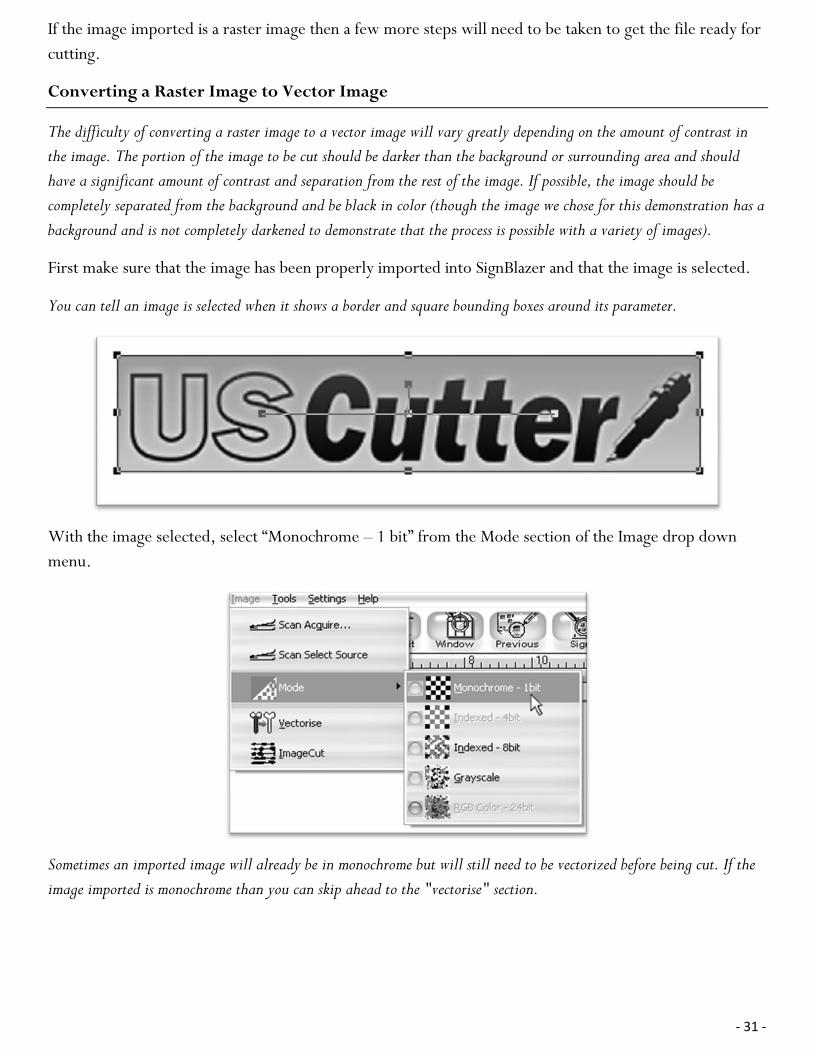
With the image selected, select “Monochrome – 1 bit” from the Mode section of the Image drop down
menu.
Sometimes an imported image will already be in monochrome but will still need to be vectorized before being cut. If the
image imported is monochrome than you can skip ahead to the "vectorise" section.

- 32 -
The “Convert Image to monochrome” window will appear.
Now you can adjust the Threshold Level slider. Where you place the slider will determine how much of
the image will be included in the monochrome conversion (which is to become the image that will be cut).
Anything darker than the level set on the Threshold slider will be included in the cut and anything lighter
will not.
Since we chose an image with good contrast and separation for our example this process will be easy. We
simply check that our image to be cut shows up in light grey or black and that there are no areas of the
background or other parts of the image that are unnecessarily included.
Now press the OK button on the “Convert Image to monochrome” window.
Now to convert a monochrome image to a vector, select “Vectorise” from the Image drop down menu.

- 33 -
And press the OK button on the Vectorise Image window.
You are now left with 1 monochrome image and 1 vectorized image. This may be difficult to see as they
are probably layered directly on top of one another. If you grab one image and drag it you will see the
other image left behind. You can now delete the monochrome image that has been left behind as it is no
longer needed.
The cutting process for a vectorized image is the same as it is for cutting a simple image. You can now
follow the steps from the “Making a Simple cut in SignBlazer” section of this manual (starting on page 26) to
make your cut.

- 34 -
Specifications
Maximum Paper Feed Width MH365(12 inch model) - 14.3 inches (365mm) MH721(25 inch model) - 28.3 inches (720mm) MH871(33 inch model) - 34.2 inches (870mm) MH1351(50 inch model) - 53.1 inches (1350mm)
Maximum Cutting Width MH365(12 inch model) - 10.8 inches (275mm) MH721(24 inch model) - 24.8 inches (630mm) MH871(33 inch model) - 30.7 inches (780mm) MH1351(50 inch model) - 49.6 inches (1260mm)
Cutting Speed 4-48 Inches per second (100-1200 mm per second) In 4 inch per second (100mm per second) increments
Pressure Range 10-400g In 10g increments
Maximum Cutting Thickness .039 inches (1mm)
Buffer Capacity 1-4m
CPU 8 bit CPU
Carriage Positions 1 blade slot and 1 pen (plotter) slot
Cutting Strip Double sheet (soft sheet and plastic sheet)
Motor Stepper Motor
Minimum Character Matrix Approximately .2 inches (5mm) high
Blade Type Roland Cemented Carbide blades
Plotting Pen All 11.4mm diameter plotting pens
Display Panel 8 digits x 2 line LCD
Communications Interface USB (Universal Serial Bus) and RS-232 Serial (9 pin)
Power Requirements 90 – 260 VAC
Repeatability 0.127 mm
Mechanical Resolution 0.0254mm/step
Commands Set DMPL/HPGL; automatic identification
Environmental Temperature 0-35˚ C
Environmental Humidity 5%-65% (without condensation)
Customer Service/Technical Support Line
425-481-3555; Available 7am - 5pm, Mon-Fri
Online Technical Support support.uscutter.com E-mail: [email protected]
Customer Forums forum.uscutter.com
Manufactured For and Sold Directly By
19510 114th Avenue NE, Suite C-1 Woodinville, WA 98072 425-481-3555 phone 888-640-0720 fax www.USCutter.com

- 35 -
Troubleshooting
Problem Solution
The cutter is unresponsive to communications from the computer and software.
Communication issues can arise if the cutter was powered on while the software is trying to send data to the cutter. Exiting the cutter screen of SignBlazer and returning to the main SignBlazer screen may resolve this issue. If not, save all work and try exiting SignBlazer and restarting with the cutter powered on. It is good practice to start SignBlazer with the cutter powered on to avoid communication problems.
Make sure that your output device in SignBlazer is set to the correct COM port (Found by selecting File>Cutter from the menu on the main SignBlazer screen, and then selecting Setup from the top menu buttons). Your COM port can be found by following the instructions in the “Finding Your COM Port” section of this manual on page 14. You can change your COM Port by right-clicking on the COM Port in the device manager and going to the advanced section of the Port Settings tab.
Adjust your Flow Control settings to Hardware by first locating your COM Port in the device manager (By following the instructions on page 14), then right-click the COM Port and select Properties. On the Port Settings tab, change to Flow Control option to Hardware.
The cutter performs erratically during cuts, stops cutting before the cut is finished, or cuts lines that do not appear in the design.
Some computers do not work well when connected via the USB port of the cutters. If you are having problems while cutting and are using the USB cable to connect from your cutter to computer, you may wish to try the serial cable connection to avoid further problems. If a serial cable connection is not available on your computer, you can try a third party USB to serial connecter or a PCI card serial adapter for your computer.
When starting the SignBlazer Software it fails to find updates.
This is a regular occurrence of the SignBlazer software and should not be considered a problem. All features of the software will continue to work in trial mode without updates. To deactivate the update process, redirect the SignBlazer shortcut (of either the desktop icon or start menu selection that you use to open the SignBlazer software). Right-click it and select Properties. From the Properties menu, change last section of the Target option from “sb.exe” to “sbnt.exe”. Press the Apply button, then the OK button. This will bypass the update process.

- 36 -
After the first cut is made, subsequent cuts are made over the top of the original, or vinyl is fed backwards until it loses contact with the rollers.
After a cut is made, you will need to reset the origin of the cutter. If the origin is not set again, the first origin will remain in the cutter and the cutter will return to this position before making any further cuts. To reset the origin; from the main screen of the cutter, press the Offline/Pause button on and then press the Origin button.
Cuts are jagged or inconsistent. The Blade may be dulled or damaged. Replace with a new blade and try again. Make sure that the blade can turn freely (by attempting to turn it with your fingers while the release button of the Blade Carriage is pressed).
Adjust the blade depth of the Blade Carriage (page 17) and Force setting on the cutter (page 8) until you are getting solid, uniform cuts. Start with a blade depth of around 1/64th of an inch and a pressure setting of 100g and try an increased pressure setting before attempting to increase the blade depth.
Slashes are made across the vinyl from the blade movement during cutting.
If the blade is protruding too far from the Blade Carriage then it can score and cut material during normal operations. If this is occurring, the blade needs to be adjusted so that it is protruding a minimal distance from the carriage. See the instructions on page 17.
Vinyl not feeding straight and the rightmost Pinch Roller will not move.
Sometimes, during shipping or movement of the machine, the right pinch roller will become stuck on a screw located on the back of the machine. If this occurs and is affecting your cutting, press forcefully against the pinch roller until it becomes dislodged from its position. If needed, remove the screw to reposition the pinch roller in the desired position.
Cuts are warped and inconsistent.
Sometimes, during shipping or movement of the machine, the Carriage Arm can be dislodged from its track. Make sure that the 2 white wheels behind the carriage arm are both resting securely on top of (not in front) of the track. If the wheels are not on the track, gently lift the carriage arm and press back until both wheels are resting on the track.
Other troubleshooting solutions may be found by visiting the Customer Forums or Technical Support Website, or by
calling the Technical Support Line (Web page addresses and Phone number on the specifications page, 34).

1

1 N
eed
ed F
or
This
Ste
p H (x1) - Right Roller Arm
J(x1) - Right Column C(x3) - Bolt B(x3) - Bolt Cap
Attaching the Right Roller Arm to the outer side of the Right Column (outer side will have a curved edge and will have larger hole openings)
2
Nee
ded
Fo
r Th
is S
tep
G(x1) -Left Roller Arm K(x1) - Left Column C(x3) - Bolt B(x3) - Bolt Cap
Attaching the Left Roller Arm to the outer side of the Left Column (outer side will have a curved edge and will have larger hole openings)
1

3 N
eed
ed F
or
This
St
ep
Assembled right side (roller arm, column) D(x4) - Long Screw M(x1) - Foot
Attaching a Foot on the right side
4
Nee
ded
Fo
r Th
is
Step
Assembled left side (roller arm, column) D(x4) - Long Screw M(x1) - Foot
Attaching a Foot on the left side

5 N
eed
ed F
or
This
St
ep
Assembled right side (roller arm, column, foot) I(x1) - Center Crossbeam A(x2) - Short Screw F(x2) - Screw Sleeve E(x2) - Screw Sleeve Cap
Adding the Center Crossbeam to the right side (Some larger models will have more than one Center Crossbeam. If your model has 2 Crossbeams, repeat this step, attaching both to the right side)
6
Nee
ded
Fo
r Th
is
Step
Assembled right side (roller arm, column, foot) with Center Crossbeam A(x2) - Short Screw F(x2) - Screw Sleeve E(x2) - Screw Sleeve Cap
Adding the Left Side to the completed right side (Some larger models will have more than one Center Crossbeam. If your model has 2 Crossbeams, repeat this step, attaching the left side to both)
1

7 N
eed
ed F
or
This
St
ep
Completed stand L(x2) - Rollers
Adding the Rollers
8
Nee
ded
Fo
r Th
is
Step
Completed stand with rollers MH series Cutter
Adding the Cutter to the completed Stand
1