
USB Function IP Core · 2019-01-31 · January 27, 2002 USB Function Core OpenCores 6 of 63 Rev....
65
USB Function IP Core Author: Rudolf Usselmann [email protected] www.asics.ws Rev. 1.5 January 27, 2002
Transcript of USB Function IP Core · 2019-01-31 · January 27, 2002 USB Function Core OpenCores 6 of 63 Rev....

OpenCores USB Function Core January 27, 2002
Revision History
Rev. Date Author Description
0.1 6/1/01 RudolfUsselmann
First Draft
0.4 10/1/01 RU Dropped the linked list for endpoints idea, removed the buffer. shared bit, added and modified registers.Added Appendix B: Configuring the Core.
0.5 11/1/01 RU Changed buffer memory to a dual ported SSRAM.Added quadruple buffering.Filled in CSR register.Added size field to end point buffers.
0.6 13/1/01 RU Added Change bars.Changed buffer memory back to single port SSRAM.Removed quadruple buffering (back to double buffering).Enhanced the way buffers work, added description.Added data organization section.Added various references to latency and bandwidth requirements.Added USB core behavior section.
0.7 15/1/01 RU Added frame number and time (FRM_NAT) register.Filled in USB core behavior section.Filled in most of the flowcharts.Fixed endpoint interrupt register.Added suspend output to wishbone IF.Added names to some of the bits in the endpoint registers.
0.8 20/1/01 RU Changed document format to double sided.Added Suspend and Resume Interrupts.Added RX control of packet that are not MAX_PL_SZ.Added vendor control IO port register and IOs.Added Setup description.
0.9 31/1/01 RU Added DMA operations and signals.Added separate core selects for registers and buffer memory.
0.9b 20/2/01 RU Some minor typing fixes.Added a brief discussion about PID sequencing.Modified the interrupts.Modified the WISHBONE interface.
1.0 28/2/01 RU Added Buffer Overflow & Underflow descriptions.Changed clock domain separation (Figure 1).Removed document status “Preliminary Draft”.
1.1 7/3/01 RU Added USB device control flow charts.Gave Names to Endpoint Registers.Added Interrupt Section.Added Suspend & Resume Section.Added Appendix C: USB Core Structure.Made various grammar and syntax corrections.
www.opencores.org Rev. 1.5 1 of 63

January 27, 2002 USB Function Core OpenCores
1.2 30/3/01 RU Rearranged Appendixes.Moved Buffer Memory (SSRAM) outside the core.Added Appendix describing SSRAM timing.Filled in Core Configuration Appendix.Modified DMA Operations section.Added OTS_STOP bit in endpoint CSR register.Added “OUT is smaller than MAX_PL_SZ” interrupt.Fixed addresses of registers.
1.3 30/5/01 RU Fixed many syntax and grammar errors.Removed Software model Section.Added Appendix E: Software model, provided by Chris Ziomkowski ([email protected]).
1.4 10/8/01 RU - Changed IO names to be more clear.- Uniquifyed define names to be core specific.
1.5 26/1/02 RU - Added more detailed descriptions and clarifications.
Rev. Date Author Description
2 of 63 Rev. 1.5 www.opencores.org
OpenCores USB Function Core January 27, 2002
1Introduction
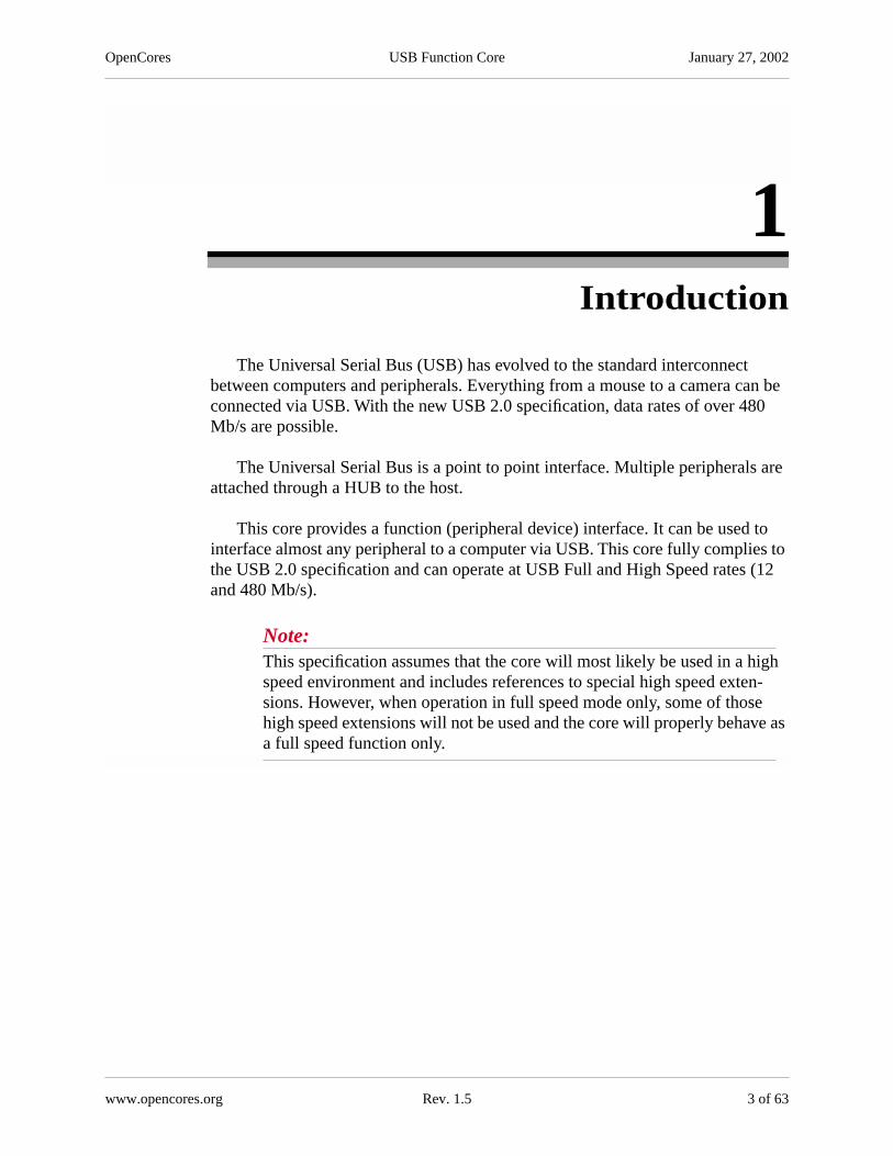
The Universal Serial Bus (USB) has evolved to the standard interconnect between computers and peripherals. Everything from a mouse to a camera can be connected via USB. With the new USB 2.0 specification, data rates of over 480 Mb/s are possible.
The Universal Serial Bus is a point to point interface. Multiple peripherals are attached through a HUB to the host.
This core provides a function (peripheral device) interface. It can be used to interface almost any peripheral to a computer via USB. This core fully complies to the USB 2.0 specification and can operate at USB Full and High Speed rates (12 and 480 Mb/s).
Note:This specification assumes that the core will most likely be used in a high speed environment and includes references to special high speed exten-sions. However, when operation in full speed mode only, some of those high speed extensions will not be used and the core will properly behave as a full speed function only.
www.opencores.org Rev. 1.5 3 of 63

January 27, 2002 USB Function Core OpenCores
(This page intentionally left blank)
4 of 63 Rev. 1.5 www.opencores.org

OpenCores USB Function Core January 27, 2002
2Architecture
The figure below illustrates the overall architecture of the core. The host inter-face provides a bridge between the internal data memory and control registers to the function controller. The data memory and control registers interface to the Pro-tocol Layer (PL). The protocol layer interfaces to UTMI interface block. The UTMI block interfaces to the PHY. Each of the blocks is described in detail below.
Figure 1: Core Architecture Overview
2.1. Clocks
The USB core has two clock domains. The UTMI interface block, runs off the clock provided by the PHY. The maximum clock output from the PHY is 60 MHz. The actual clock frequency depends on the operation mode (High Speed/Full
PHYPL
Function Interface(Wishbone)
Function Micro controller
External
UTMII/F
Control/StatusRegisters
SSRAM USBConnector
Clock Domain 1
Clock Domain 2
MemoryInterfaceandArbiter
External
www.opencores.org Rev. 1.5 5 of 63
January 27, 2002 USB Function Core OpenCores
Speed). The UTMI block includes synchronization logic to the rest of the USB core.
All other blocks run off the clock from the host interface. Because of USB latency requirements, the host interface must run at least at 60 MHz. The goal is that the minimum frequency of the USB core host interface is at least 100Mhz.
2.2. Host Interface
The host interface block provides a consistent core interface between the inter-nal functions of the core and the function-specific host or micro controller.The host interface is WISHBONE SoC bus specification Rev. B compliant.
2.2.1. Bandwidth Requirement
The USB maximum theoretical throughput is 480Mb/s, which translates to 60 Mbytes/s. On a 32 bit bus, four bytes (one word) are transferred per cycle. The minimum bandwidth requirement for the host is therefore 15 Mwords/s.
2.3. Memory Interface and Arbiter
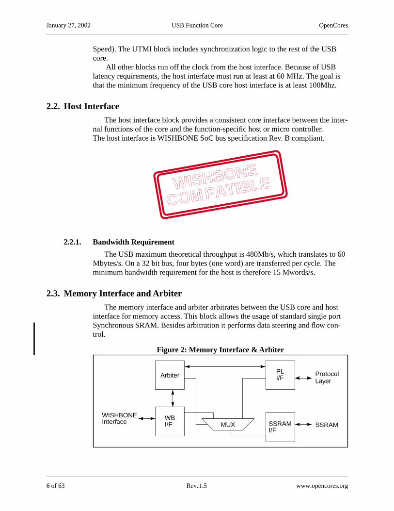
The memory interface and arbiter arbitrates between the USB core and host interface for memory access. This block allows the usage of standard single port Synchronous SRAM. Besides arbitration it performs data steering and flow con-trol.
Figure 2: Memory Interface & Arbiter
WISHBONE
COMPATIBLE
Arbiter
WISHBONEInterface
ProtocolLayer
SSRAMSSRAMI/F
PLI/F
WBI/F MUX
6 of 63 Rev. 1.5 www.opencores.org
OpenCores USB Function Core January 27, 2002
2.4. SSRAM
The SSRAM is a single ported Synchronous SRAM block that is used to buffer the input and output data.
2.5. Protocol Layer (PL)
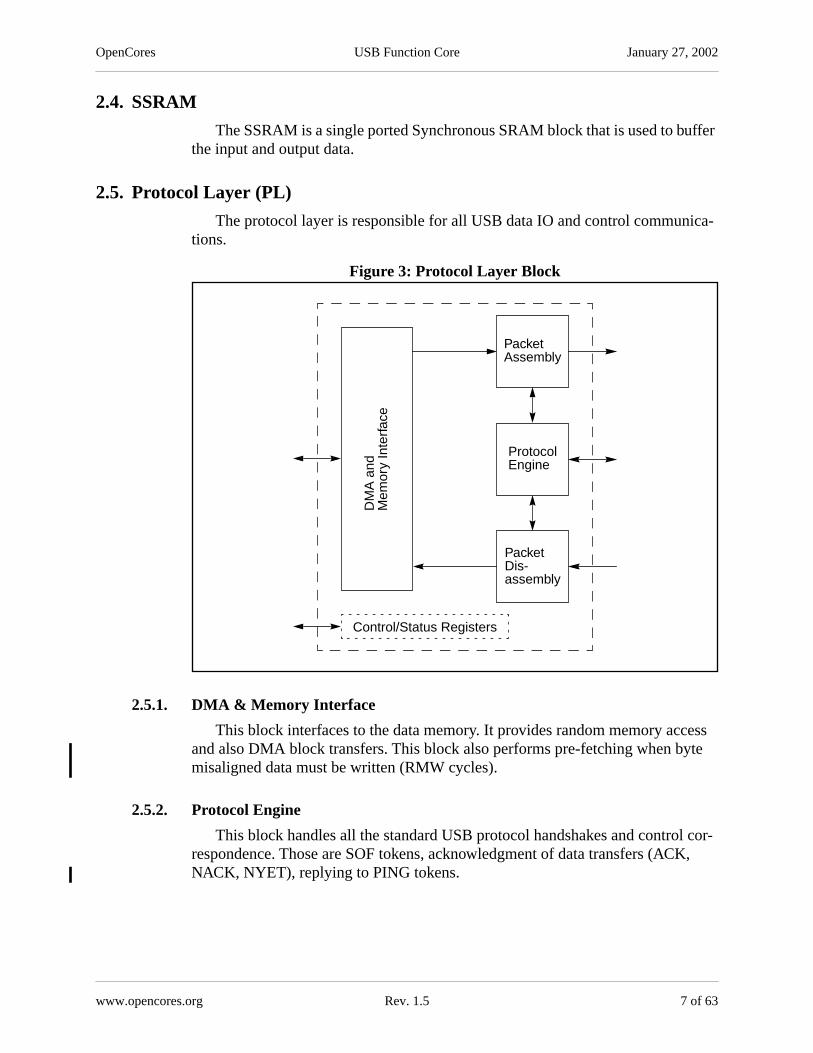
The protocol layer is responsible for all USB data IO and control communica-tions.
Figure 3: Protocol Layer Block
2.5.1. DMA & Memory Interface
This block interfaces to the data memory. It provides random memory access and also DMA block transfers. This block also performs pre-fetching when byte misaligned data must be written (RMW cycles).
2.5.2. Protocol Engine
This block handles all the standard USB protocol handshakes and control cor-respondence. Those are SOF tokens, acknowledgment of data transfers (ACK, NACK, NYET), replying to PING tokens.
Packet
Packet
ProtocolEngine
AssemblyD
MA
and
Mem
ory
Inte
rfac
e
Dis-assembly
Control/Status Registers
www.opencores.org Rev. 1.5 7 of 63
January 27, 2002 USB Function Core OpenCores
2.5.3. Packet Assembly
This block assembles packets and places them in to the output FIFO. It first assembles the header, inserting a proper PID and check sums, then adds a data field if requested.
2.5.4. Packet Disassembly
This block decodes all incoming packets and forwards the decoded data to the appropriate blocks. The decoding includes extracting of PID and sequence num-bers, as well as header check sum checking.
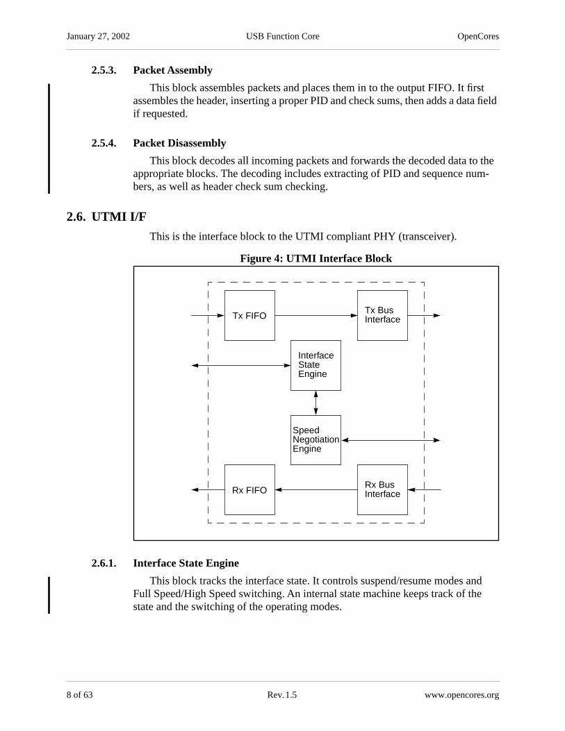
2.6. UTMI I/F
This is the interface block to the UTMI compliant PHY (transceiver).
Figure 4: UTMI Interface Block
2.6.1. Interface State Engine
This block tracks the interface state. It controls suspend/resume modes and Full Speed/High Speed switching. An internal state machine keeps track of the state and the switching of the operating modes.
Speed
Interface
Rx FIFORx Bus
Tx BusInterface
StateEngine
NegotiationEngine
Interface
Tx FIFO
8 of 63 Rev. 1.5 www.opencores.org
OpenCores USB Function Core January 27, 2002
2.6.2. Speed Negotiation Engine
This block negotiates the speed of the USB interface and handles suspend and reset detection.
2.6.3. Rx & Tx FIFOs
The FIFOs hold the temporary receive and transmit data. The receive FIFO temporarily hold received bytes before the DMS writes them to the SSRAM buffer. The transmit FIFO temporarily holds the bytes to be transmitted.
2.6.4. Rx & Tx Bus Interface
These blocks ensure proper handshaking with the receive and transmit inter-faces of the PHY.
www.opencores.org Rev. 1.5 9 of 63

January 27, 2002 USB Function Core OpenCores
(This page intentionally left blank)
10 of 63 Rev. 1.5 www.opencores.org

OpenCores USB Function Core January 27, 2002
3Operation
This section describes the operation of the USB function controller. It first dis-cusses the logical interface to the host micro controller (function) and then the log-ical USB interface.
The USB core uses a local buffer memory which is used as a temporary data storage. The memory size is user definable. Each endpoint has its own dedicated input/output buffer. No software intervention is needed between different endpoint accesses. Double buffers may be set up, reducing the latency requirement on the software, and increasing USB throughput.
Figure 5: Logical Representation of USB
PHY
E 0
E 1
E n
USB Core
Registers
Host orHUB
US
BF
unct
ion
CoreLogic
USBCable
www.opencores.org Rev. 1.5 11 of 63
January 27, 2002 USB Function Core OpenCores
3.1. Endpoints
This USB core supports up to 16 endpoints. The actual number of endpoints is set before synthesizing the core.
The function controller must set up the endpoints by writing to the endpoint registers: EPn_CSR, EPn_INT, EPn_BUFx.
The function controller must also assign actual endpoint numbers to each end-point (EP_NO). The endpoint numbering in this specification refers to the physical endpoints. The actual logical (the one that is matched against the endpoint field in tokens from the host) must be set in the EPn_CSR register EP_NO field. The soft-ware must make sure that all endpoints for a given transaction type are unique.
3.1.1. Buffer Pointers
The buffer pointers point to the input/output data structure in memory. A value of all ones (7FFFh) indicates that the buffer has not been allocated. If all buffers are not allocated, the core will respond with NAK acknowledgments to the USB host.
This USB core supports a double buffering feature which reduces the latency requirements on the functions micro controller and driver software. Double buffer-ing is enabled when all buffer pointers have been set. Data is being retrieved/filled from/to the buffers in a round robin fashion. When data is sent to/from an endpoint, first buffer 0 is used. When the first buffer is empty/full, the function controller may be notified via an interrupt. The function controller can refill/empty buffer 0 now. The USB core will now use buffer 1 for the next operation. When the second buffer is full/empty, the function controller is interrupted, and the USB core will use buffer 0 again, and so on. Any buffer that is not allocated will be skipped. A buffer that has the used bit set will cause the core to stall, replying with NAK/NYET acknowledgments to the host.
The Buffer Used bits indicate when a buffer has been used (this information is also provided in the Interrupt Source register). The function controller must clear these bits after it has emptied/refilled the buffer.
A buffer may be larger than the maximum payload size. In that case, multiple packets will be sourced/placed from/to a buffer. A buffer for an OUT endpoint must always be in multiples of maximum payload size. When the remaining space in a buffer is less than the maximum payload size (because a one or more packets with less than maximum payload were received), the buffer is considered full, and the USB core will switch to the next buffer. For example, if the maximum payload size is 512 bytes, the buffer may be 512, 1024, 1536, 2048, etc. bytes large. The software should always check the buffer size field. It should be zero when the entire buffer has been used. If the buffer size is not zero, then the size field indi-cates how many bytes of the buffer have not been used. There is no such limitation for IN buffers. The core will always transmit the maximum possible number of bytes. The maximum possible number of bytes is always the smaller one of maxi-mum payload size and remaining buffer size.
12 of 63 Rev. 1.5 www.opencores.org

OpenCores USB Function Core January 27, 2002
Figure 6: Buffer Operation
Control endpoints are somewhat special because they can receive and transmit data. Therefore, for control endpoints, Buffer 0 is always an OUT buffer, and Buffer 1 always an IN buffer. Data from SETUP and OUT tokens will therefore always be written to Buffer 0. Data sent in response to an IN token is always retrieved from Buffer 1.
Figure 7: Control Endpoint Buffer Usage
Initial Buffer
Initial BufferSize
Pointer
Buffer Pointerafter 1sttransaction
Buffer Sizeafter 1sttransaction
Max. PayloadSize
See Text
Max. PayloadSize
Local Buffer Memory
2nd Transaction
1st Transaction
Nth Transaction
. . .
Above
SE
TU
PTo
ken
DAT
AP
acke
t
AC
KP
acke
t
USB Host
USB IP Core
Buffer 0
DATA
INTo
ken
DAT
AP
acke
t
AC
KP
acke
t
USB Host
USB IP Core
Buffer 1
DATA
OU
TTo
ken
DAT
AP
acke
t
AC
KP
acke
t
USB Host
USB IP Core
Buffer 0
DATA
SETUP Stage DATA Stage STATUS Stage
www.opencores.org Rev. 1.5 13 of 63
January 27, 2002 USB Function Core OpenCores
3.1.2. Buffer Underflow
A buffer underflow condition occurs when either the function controller or external DMA engine did not fill the internal buffer with enough data for one MAX_PL_SZ packet. When an IN token is received in this condition, the USB core will reply with a NACK to the host. No special handling is required by the function controller. The UCB core will continue sending a NACK to each IN token, as long as this condition is true.
When both buffers are not allocated or empty (USED bit set), a buffer under-flow condition occurs as well.
3.1.3. Buffer Overflow
A buffer overflow occurs when a packet has been received that does not fit into the buffer. The packet will be discarded and a NACK will be sent to the host.
Typically the buffer would be set up to hold one or more MAX_PL_SZ pack-ets. There is no guarantee that the host will actually send MAX_PL_SZ packets, and therefore the buffer will not be completely filled with MAX_PL_SZ data on each transfer.
When a buffer overflow occurs, the USB core will discard the received data and reply with a NACK to the host. It will continue discarding received data and replying with NACK to each OUT token which payload size does not fit into the buffer.
When both buffers are not allocated or full, the USB core will immediately reply with a NACK when it receives an OUT token (it will not wait for the actual data packet from the host).
3.1.4. Data Organization
Since the buffer memory is 32 bits wide and USB defines all transactions on byte boundaries it is important to understand the relationship of data in the buffer to actual USB byte sequence. This USB core supports Little Endian byte ordering.
Figure 8: Byte Ordering
The buffer pointer always points to byte 0. The USB core always fetches four bytes from the buffer memory. The actual final byte that is transmitted in the Nth transaction depends on the Buffer Size. The MaxPacketSize must always be a mul-tiple of 4 bytes.
Byte 3 Byte 2 Byte 1 Byte 0
0781516232431
14 of 63 Rev. 1.5 www.opencores.org

OpenCores USB Function Core January 27, 2002
3.2. DMA Operation
DMA operation allows completely transparent data movement between the USB core and the function attached to the WISHBONE bus. Once set up, no func-tion micro controller intervention is needed for normal operations. Each endpoint has an associated pair of DMA_REQ and DMA_ACK signals.
When the DMAEN bit in the channel CSR register is set, the USB core will use the DMA_REQ and DMA_ACK signals for DMA flow control. The DMA_REQ signal is asserted when the buffer contains data or when the buffer is empty and needs to be filled. The DMA must reply with a DMA_ACK for each word (4 bytes) transferred. In DMA mode, the USED bits are not used and always cleared.
In DMA mode, only one buffer (buffer 0) is used. Buffer 1 is never used in DMA mode. Both buffer 0 and the external DMA must be set up to the same start-ing location in the USB memory buffer (the actual address for the external DMA will vary depending on the external address decoder for the USB core buffer select). They must also be set up to equal buffer size and wrap around when the amount of bytes specified has been transferred.
The buffer must hold at least one MAX_PL_SZ packet. Depending on DMA and external bus latency it may be set up to hold more than one packet.
MAX_PL_SZ must be set in 4 byte multiples, as the USB core does not sup-port byte transfers. For OUT endpoints it is impossible to guarantee that a received packet will be in multiples of 4 bytes. The USB core provides a mechanism to recover in those cases: Whenever the received packet is smaller than MAX_PL_SZ, an interrupt may be generated to notify the function controller of this condition. In addition buffer1 is set to the local buffer address of the packet that was smaller than MAX_PL_SZ. The size field in buffer1 indicates the number of actual bytes in that packet. The USB core will always pad the buffer to MAX_PL_SZ bytes, so that DMA transfers can continue uninterrupted.
If the OTS_STOP bit is set in the endpoint CSR register, the endpoint will be disabled to allow the function controller enough time to deal with the short packet. The function controller must re-enable the endpoint by setting the EP_DIS field in the endpoint CSR register to Normal Operation.
3.3. PID Sequencing
USB utilizes PID sequencing to keep data transfers synchronized. It also pro-vides a mechanism to recover data and synchronization when synchronization is lost. Synchronization can be lost due to corrupt packets, resulting in bad CRCs. This USB core fully implements and follows the PID synchronization and recov-ery as specified in the USB specification.
Isochronous endpoints provide no mechanism to automatically recover lost data due to a loss of synchronization. The USB core will automatically resynchro-nize with the host, however, since isochronous endpoints have no handshaking stage, have therefore no way to inform the host of such failures. The USB core pro-vides a “PID Sequencing Error” interrupt for this cases in order for the function controller to be notified of such events. This interrupt will only be asserted for iso-
www.opencores.org Rev. 1.5 15 of 63

January 27, 2002 USB Function Core OpenCores
chronous OUT endpoints. For any other endpoints it has no meaning and is auto-matically disabled.
3.4. USB Core Memory Size
This USB core includes a memory block which it uses for storing data and end-point control information. The memory is 32 bits wide. Depending on the applica-tion, the user should choose the appropriate memory size for the buffer memory.
Based on the actual number of endpoints and application, the memory can be as small as 256 bytes. The maximum supported memory size is 128 Kilobytes.
3.5. USB Core Behavior
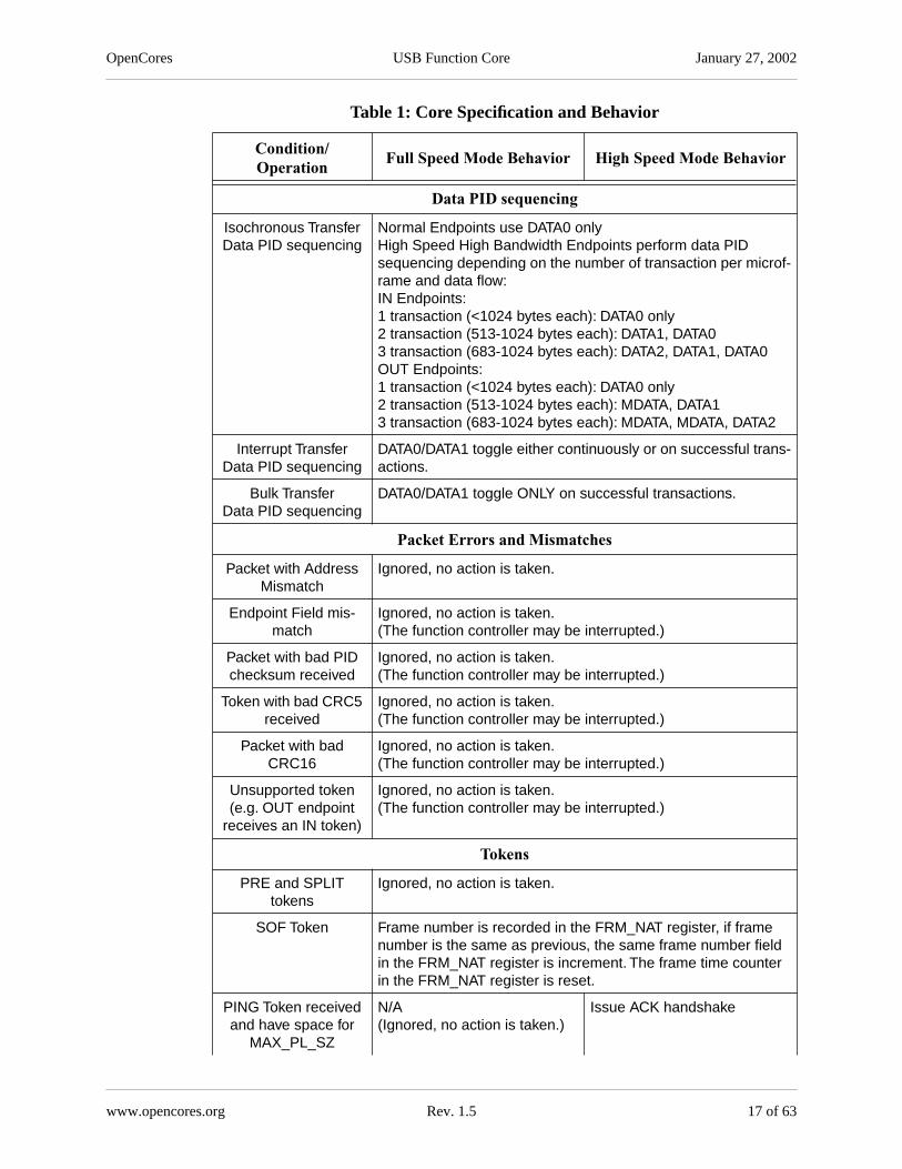
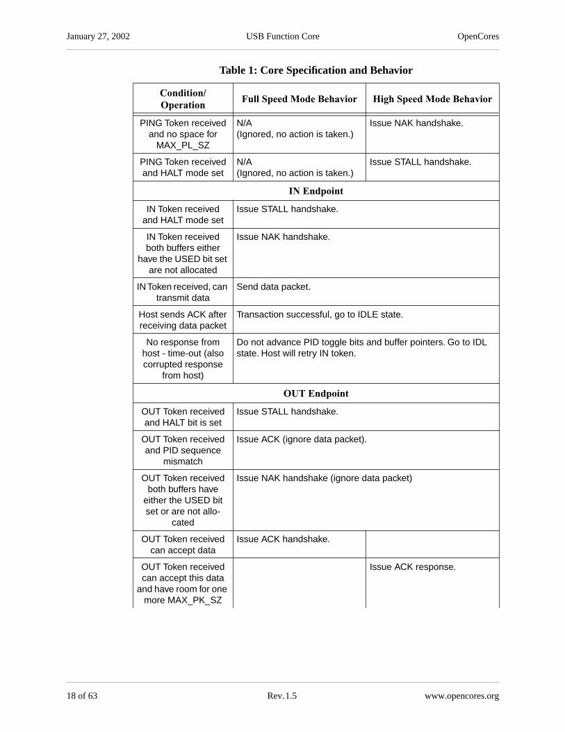
Below table illustrates the behavior of the USB core. It also summarizes all “What if?” conditions. (This information is mostly copied from the USB 2.0 spec-ification. Some items required interpretation of the information provided in the USB 2.0 specification).
Table 1: Core Specification and Behavior
Condition/Operation
Full Speed Mode Behavior High Speed Mode Behavior
Packet Sizes
Isochronous TransferMax. Payload size
1023 bytes 1024 bytes
Interrupt TransferMax. Payload size
64 bytes 1024 bytes
Bulk TransferMax. Payload size
8, 16, 32, 64 bytes 512 bytes
Timing
One Bit Time 83.33nS 2.0833 nS
UTMI Clock (UCLK) 16.67 nS 16.67 nS
Max. Inter Packet Delay (measured on
the USB bus)
7.5 Bit Times (~622 nS) 192 Bit Times (400 nS)
UTMI Rx worst case delay
17 UCLK (~283 nS) 63 Bit Times or 8 UCLK(~132 nS)
UTMI Tx worst case delay
5 UCLK (~83 nS) 16 Bit Times or 2 UCLK (~33 nS)
Worst Case USB core allowed decision time
(Rx to Tx)
~256 nS (15 UCLK) 96 Bit Times or 12 UCLK (200 nS)
Worst Case USB core allowed decision time
(Tx to Tx)
7.5 Bit Times or 37 UCLK (~622 nS)
192 Bit Times or 24 UCLK (400 nS)
16 of 63 Rev. 1.5 www.opencores.org
OpenCores USB Function Core January 27, 2002
Data PID sequencing
Isochronous TransferData PID sequencing
Normal Endpoints use DATA0 onlyHigh Speed High Bandwidth Endpoints perform data PID sequencing depending on the number of transaction per microf-rame and data flow:IN Endpoints:1 transaction (<1024 bytes each): DATA0 only2 transaction (513-1024 bytes each): DATA1, DATA03 transaction (683-1024 bytes each): DATA2, DATA1, DATA0 OUT Endpoints:1 transaction (<1024 bytes each): DATA0 only2 transaction (513-1024 bytes each): MDATA, DATA13 transaction (683-1024 bytes each): MDATA, MDATA, DATA2
Interrupt TransferData PID sequencing
DATA0/DATA1 toggle either continuously or on successful trans-actions.
Bulk TransferData PID sequencing
DATA0/DATA1 toggle ONLY on successful transactions.
Packet Errors and Mismatches
Packet with Address Mismatch
Ignored, no action is taken.
Endpoint Field mis-match
Ignored, no action is taken.(The function controller may be interrupted.)
Packet with bad PID checksum received
Ignored, no action is taken.(The function controller may be interrupted.)
Token with bad CRC5 received
Ignored, no action is taken.(The function controller may be interrupted.)
Packet with bad CRC16
Ignored, no action is taken.(The function controller may be interrupted.)
Unsupported token(e.g. OUT endpoint
receives an IN token)
Ignored, no action is taken.(The function controller may be interrupted.)
Tokens
PRE and SPLIT tokens
Ignored, no action is taken.
SOF Token Frame number is recorded in the FRM_NAT register, if frame number is the same as previous, the same frame number field in the FRM_NAT register is increment. The frame time counter in the FRM_NAT register is reset.
PING Token received and have space for
MAX_PL_SZ
N/A(Ignored, no action is taken.)
Issue ACK handshake
Table 1: Core Specification and Behavior
Condition/Operation
Full Speed Mode Behavior High Speed Mode Behavior
www.opencores.org Rev. 1.5 17 of 63
January 27, 2002 USB Function Core OpenCores
PING Token received and no space for
MAX_PL_SZ
N/A(Ignored, no action is taken.)
Issue NAK handshake.
PING Token received and HALT mode set
N/A(Ignored, no action is taken.)
Issue STALL handshake.
IN Endpoint
IN Token receivedand HALT mode set
Issue STALL handshake.
IN Token receivedboth buffers either
have the USED bit set are not allocated
Issue NAK handshake.
IN Token received, can transmit data
Send data packet.
Host sends ACK after receiving data packet
Transaction successful, go to IDLE state.
No response from host - time-out (also corrupted response
from host)
Do not advance PID toggle bits and buffer pointers. Go to IDL state. Host will retry IN token.
OUT Endpoint
OUT Token received and HALT bit is set
Issue STALL handshake.
OUT Token received and PID sequence
mismatch
Issue ACK (ignore data packet).
OUT Token received both buffers have
either the USED bit set or are not allo-
cated
Issue NAK handshake (ignore data packet)
OUT Token received can accept data
Issue ACK handshake.
OUT Token received can accept this data
and have room for one more MAX_PK_SZ
Issue ACK response.
Table 1: Core Specification and Behavior
Condition/Operation
Full Speed Mode Behavior High Speed Mode Behavior
18 of 63 Rev. 1.5 www.opencores.org

OpenCores USB Function Core January 27, 2002
OUT Token received, can accept this data and does not have room for one more
MAX_PK_SZ
Issue NYET response.
Data packet CRC16 error or received next
token
Ignore, no acknowledgment, handle new token.
Control Endpoint
SETUP Stage Same as OUT Token Above
DATA Stage Same as IN Token above
STATUS Stage Same as OUT Token Above
Table 1: Core Specification and Behavior
Condition/Operation
Full Speed Mode Behavior High Speed Mode Behavior
www.opencores.org Rev. 1.5 19 of 63
January 27, 2002 USB Function Core OpenCores
3.6. USB Core Flowcharts
Below flowcharts outline the basic operation of the USB core.
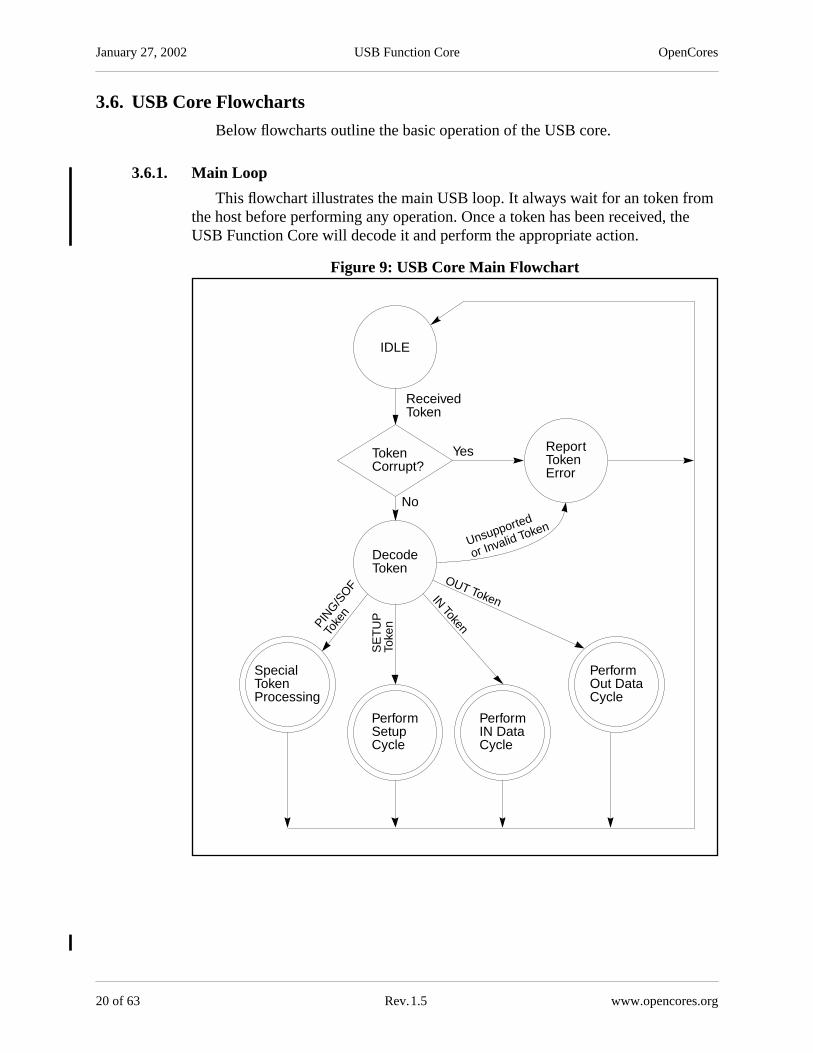
3.6.1. Main Loop
This flowchart illustrates the main USB loop. It always wait for an token from the host before performing any operation. Once a token has been received, the USB Function Core will decode it and perform the appropriate action.
Figure 9: USB Core Main Flowchart
IDLE
ReceivedToken
No
SpecialTokenProcessing
TokenCorrupt?
PerformSetup
PerformIN DataCycleCycle
PerformOut DataCycle
Yes
DecodeToken
Unsupported
or Invalid Token
ReportTokenError
PING
/SO
F
Toke
n
SE
TU
PTo
ken
IN Token
OUT Token
20 of 63 Rev. 1.5 www.opencores.org
OpenCores USB Function Core January 27, 2002
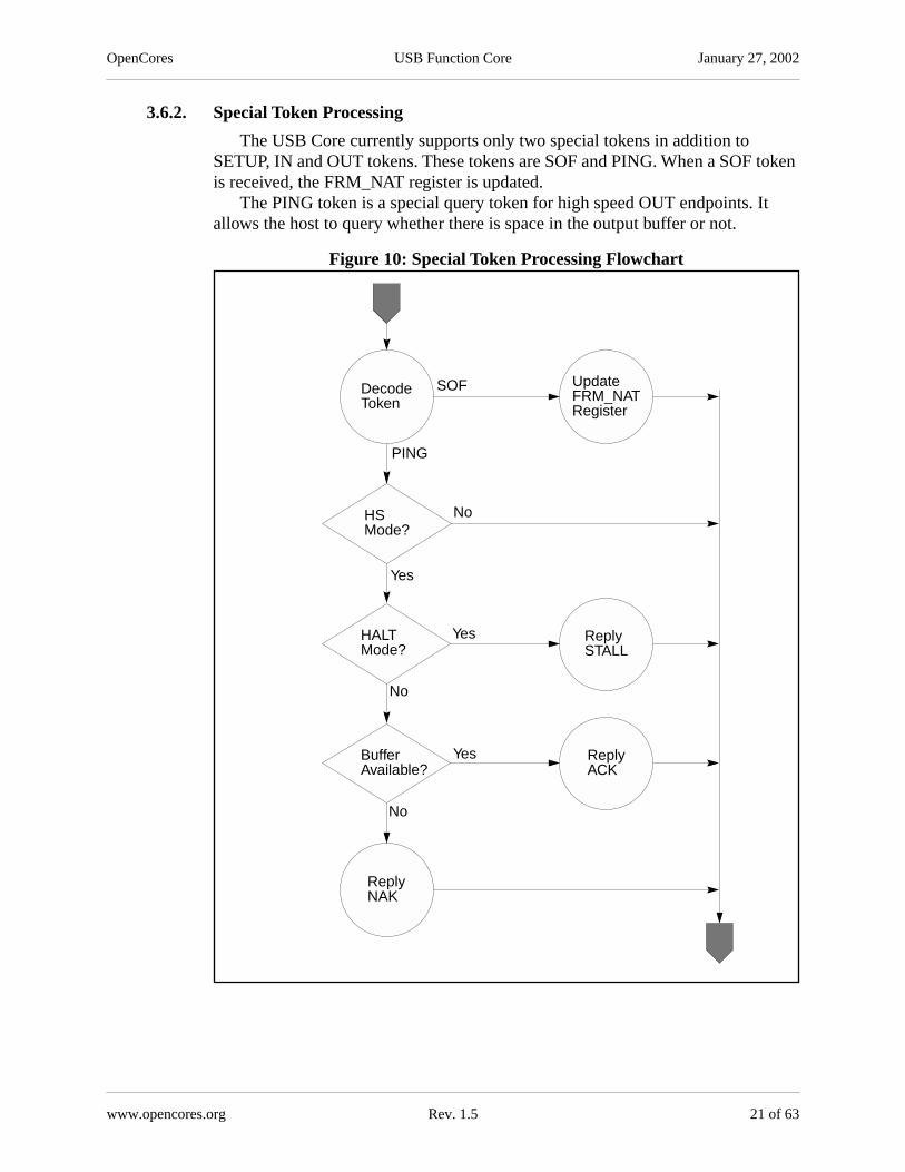
3.6.2. Special Token Processing
The USB Core currently supports only two special tokens in addition to SETUP, IN and OUT tokens. These tokens are SOF and PING. When a SOF token is received, the FRM_NAT register is updated.
The PING token is a special query token for high speed OUT endpoints. It allows the host to query whether there is space in the output buffer or not.
Figure 10: Special Token Processing Flowchart
UpdateFRM_NAT
ReplySTALL
Register
Yes
No
Yes
No
ReplyACK
ReplyNAK
DecodeToken
HALTMode?
BufferAvailable?
SOF
PING
Yes
NoHSMode?
www.opencores.org Rev. 1.5 21 of 63
January 27, 2002 USB Function Core OpenCores
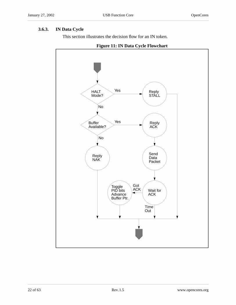
3.6.3. IN Data Cycle
This section illustrates the decision flow for an IN token.
Figure 11: IN Data Cycle Flowchart
ReplyNAK
ReplySTALL
SendDataPacket
Yes
No
No
Yes
Wait forACK
ReplyACK
GotACK
Time
TogglePID bits
Out
AdvanceBuffer Ptr.
BufferAvailable?
HALTMode?
22 of 63 Rev. 1.5 www.opencores.org
OpenCores USB Function Core January 27, 2002
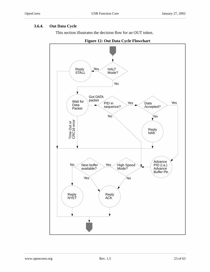
3.6.4. Out Data Cycle
This section illustrates the decision flow for an OUT token.
Figure 12: Out Data Cycle Flowchart
ReplySTALL
ReplyNAK
Yes
No
No
YesPID insequence?
HALTMode?
Yes
No
No
Yes
ReplyACK
ReplyNYET
Got DATA
Yes
No
Tim
e O
ut o
r
AdvancePID (i.a.)AdvanceBuffer Ptr.
Wait forDataPacket
DataAccepted?
High SpeedMode?
Next bufferavailable?
packet
CR
C16
err
or
www.opencores.org Rev. 1.5 23 of 63
January 27, 2002 USB Function Core OpenCores
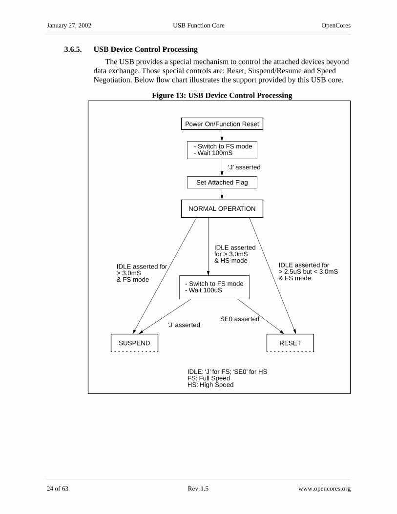
3.6.5. USB Device Control Processing
The USB provides a special mechanism to control the attached devices beyond data exchange. Those special controls are: Reset, Suspend/Resume and Speed Negotiation. Below flow chart illustrates the support provided by this USB core.
Figure 13: USB Device Control Processing
Power On/Function Reset
- Switch to FS mode- Wait 100mS
Set Attached Flag
NORMAL OPERATION
IDLE asserted for> 2.5uS but < 3.0mS
RESET
& FS mode
IDLE asserted for> 3.0mS& FS mode
SUSPEND
IDLE assertedfor > 3.0mS& HS mode
- Switch to FS mode- Wait 100uS
‘J’ assertedSE0 asserted
‘J’ asserted
IDLE: ‘J’ for FS; ‘SE0’ for HSFS: Full SpeedHS: High Speed
24 of 63 Rev. 1.5 www.opencores.org
OpenCores USB Function Core January 27, 2002
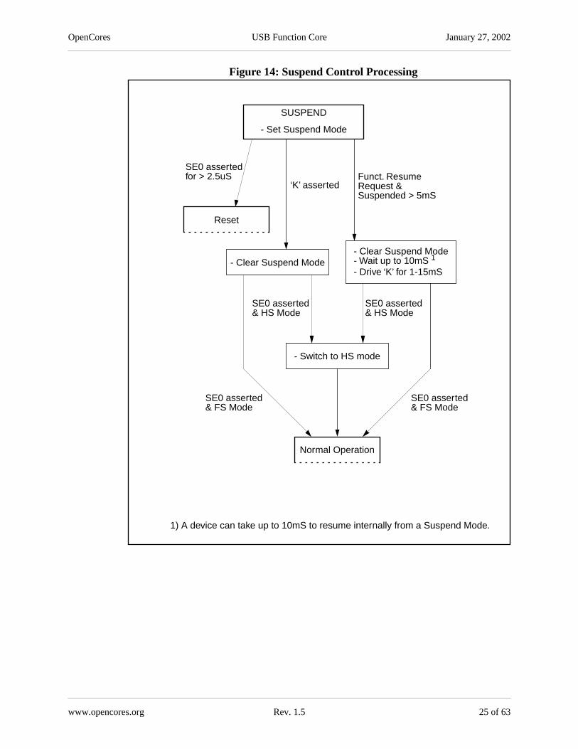
Figure 14: Suspend Control Processing
SE0 asserted& HS Mode
SE0 asserted& HS Mode
SUSPEND
‘K’ assertedFunct. ResumeRequest &Suspended > 5mS
- Clear Suspend Mode
Normal Operation
- Set Suspend Mode
- Wait up to 10mS 1 - Drive ‘K’ for 1-15mS
SE0 asserted& FS Mode
- Clear Suspend Mode
- Switch to HS mode
Reset
SE0 assertedfor > 2.5uS
1) A device can take up to 10mS to resume internally from a Suspend Mode.
SE0 asserted& FS Mode
www.opencores.org Rev. 1.5 25 of 63

January 27, 2002 USB Function Core OpenCores
Figure 15: Reset Control Processing
3.7. Interrupts
The USB core provides two interrupt outputs (INT_A and INT_B). Both out-puts are fully programmable. The programming for both outputs is identical to pro-vide full flexibility to software. The intention is to have one high priority interrupt and one low priority interrupt. The actual usage of the interrupts is up to the system into which the USB core is incorporated.
The interrupt mechanism in the USB core consists of a two level hierarchy:• The main interrupt source register (INT_SRC) indicates interrupts that
are endpoint independent. These interrupts indicate overall events that have either global meaning for all endpoints or can not be associated with an endpoint because of an error condition.
• The endpoint interrupt source registers indicate events that are specific to an endpoint.
RESET
Normal Operation
- Signal Reset Internally
- Switch to HS mode
- Send Chirp ‘K’ for 1 mS
- Wait for Chirp ‘K’
- Wait for Chirp ‘J’
Got Chirp ‘K’Got Chirp ‘J’
Got ‘SE0’
Got ‘SE0’
Chirp Count==6
Chirp Count==6
Got ‘SE0’
26 of 63 Rev. 1.5 www.opencores.org
OpenCores USB Function Core January 27, 2002
3.7.1. Timing
The interrupt outputs are asserted when the condition that is enabled in the interrupt mask occurs. They remain asserted until the main interrupt register is read.
3.7.2. Software Interaction
A interrupt handler should first read the main interrupt source register (INT_SRC) to determine the source of an interrupt. It must remember the value that was read until it is done, processing each interrupt source. If any of the bits 15 through 0 are set, the interrupt handler should also read the appropriate endpoint interrupt register to determine endpoint specific events. Multiple interrupt sources may be indicated at any given time. Software should be prepared to handle every interrupt source it cares about.
Note:When using both interrupt pins to service different events, or prioritizing event handling, care must be taken not to lose interrupt sources, as the main interrupt source register is cleared after a read.
3.8. Suspend & Resume
USB defines a protocol for suspending devices that are attached to the UCB bus. Devices that are powered by USB bus must enter a low power mode when a suspend signaling has been received. The USB core will assert and hold asserted the SUSP_O for as long as the device must remain in the suspended state.
A device that has entered suspend mode can be “woken up” in two different ways:
1. Resume Signaling from the USB.2. Asserting the resume_req_i line.
www.opencores.org Rev. 1.5 27 of 63

January 27, 2002 USB Function Core OpenCores
(This page intentionally left blank)
28 of 63 Rev. 1.5 www.opencores.org
OpenCores USB Function Core January 27, 2002
4Core Registers
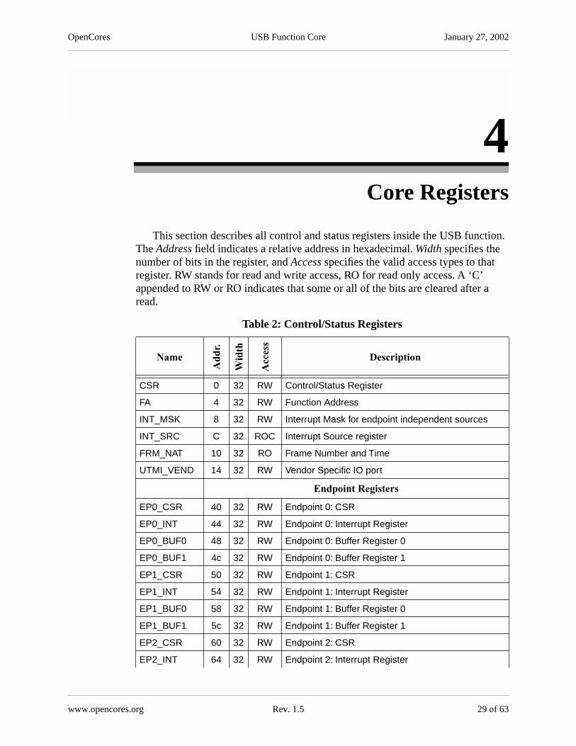
This section describes all control and status registers inside the USB function. The Address field indicates a relative address in hexadecimal. Width specifies the number of bits in the register, and Access specifies the valid access types to that register. RW stands for read and write access, RO for read only access. A ‘C’ appended to RW or RO indicates that some or all of the bits are cleared after a read.
Table 2: Control/Status Registers
Name
Add
r.
Wid
th
Acc
ess
Description
CSR 0 32 RW Control/Status Register
FA 4 32 RW Function Address
INT_MSK 8 32 RW Interrupt Mask for endpoint independent sources
INT_SRC C 32 ROC Interrupt Source register
FRM_NAT 10 32 RO Frame Number and Time
UTMI_VEND 14 32 RW Vendor Specific IO port
Endpoint Registers
EP0_CSR 40 32 RW Endpoint 0: CSR
EP0_INT 44 32 RW Endpoint 0: Interrupt Register
EP0_BUF0 48 32 RW Endpoint 0: Buffer Register 0
EP0_BUF1 4c 32 RW Endpoint 0: Buffer Register 1
EP1_CSR 50 32 RW Endpoint 1: CSR
EP1_INT 54 32 RW Endpoint 1: Interrupt Register
EP1_BUF0 58 32 RW Endpoint 1: Buffer Register 0
EP1_BUF1 5c 32 RW Endpoint 1: Buffer Register 1
EP2_CSR 60 32 RW Endpoint 2: CSR
EP2_INT 64 32 RW Endpoint 2: Interrupt Register
www.opencores.org Rev. 1.5 29 of 63

January 27, 2002 USB Function Core OpenCores
EP2_BUF0 68 32 RW Endpoint 2: Buffer Register 0
EP2_BUF1 6c 32 RW Endpoint 2: Buffer Register 1
EP3_CSR 70 32 RW Endpoint 3: CSR
EP3_INT 74 32 RW Endpoint 3: Interrupt Register
EP3_BUF0 78 32 RW Endpoint 3: Buffer Register 0
EP3_BUF1 7c 32 RW Endpoint 3: Buffer Register 1
EP4_CSR 80 32 RW Endpoint 4: CSR
EP4_INT 84 32 RW Endpoint 4: Interrupt Register
EP4_BUF0 88 32 RW Endpoint 4: Buffer Register 0
EP4_BUF1 8c 32 RW Endpoint 4: Buffer Register 1
EP5_CSR 90 32 RW Endpoint 5: CSR
EP5_INT 94 32 RW Endpoint 5: Interrupt Register
EP5_BUF0 98 32 RW Endpoint 5: Buffer Register 0
EP5_BUF1 9c 32 RW Endpoint 5: Buffer Register 1
EP6_CSR a0 32 RW Endpoint 6: CSR
EP6_INT a4 32 RW Endpoint 6: Interrupt Register
EP6_BUF0 a8 32 RW Endpoint 6: Buffer Register 0
EP6_BUF1 ac 32 RW Endpoint 6: Buffer Register 1
EP7_CSR b0 32 RW Endpoint 7: CSR
EP7_INT b4 32 RW Endpoint 7: Interrupt Register
EP7_BUF0 b8 32 RW Endpoint 7: Buffer Register 0
EP7_BUF1 bc 32 RW Endpoint 7: Buffer Register 1
EP8_CSR c0 32 RW Endpoint 8: CSR
EP8_INT c4 32 RW Endpoint 8: Interrupt Register
EP8_BUF0 c8 32 RW Endpoint 8: Buffer Register 0
EP8_BUF1 cc 32 RW Endpoint 8: Buffer Register 1
EP9_CSR d0 32 RW Endpoint 9: CSR
EP9_INT d4 32 RW Endpoint 9: Interrupt Register
EP9_BUF0 d8 32 RW Endpoint 9: Buffer Register 0
EP9_BUF1 dc 32 RW Endpoint 9: Buffer Register 1
EP10_CSR e0 32 RW Endpoint 10: CSR
EP10_INT e4 32 RW Endpoint 10: Interrupt Register
Table 2: Control/Status Registers
Name
Add
r.
Wid
th
Acc
ess
Description
30 of 63 Rev. 1.5 www.opencores.org
OpenCores USB Function Core January 27, 2002
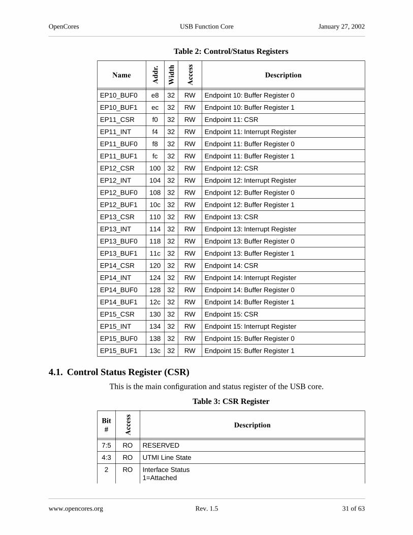
4.1. Control Status Register (CSR)
This is the main configuration and status register of the USB core.
EP10_BUF0 e8 32 RW Endpoint 10: Buffer Register 0
EP10_BUF1 ec 32 RW Endpoint 10: Buffer Register 1
EP11_CSR f0 32 RW Endpoint 11: CSR
EP11_INT f4 32 RW Endpoint 11: Interrupt Register
EP11_BUF0 f8 32 RW Endpoint 11: Buffer Register 0
EP11_BUF1 fc 32 RW Endpoint 11: Buffer Register 1
EP12_CSR 100 32 RW Endpoint 12: CSR
EP12_INT 104 32 RW Endpoint 12: Interrupt Register
EP12_BUF0 108 32 RW Endpoint 12: Buffer Register 0
EP12_BUF1 10c 32 RW Endpoint 12: Buffer Register 1
EP13_CSR 110 32 RW Endpoint 13: CSR
EP13_INT 114 32 RW Endpoint 13: Interrupt Register
EP13_BUF0 118 32 RW Endpoint 13: Buffer Register 0
EP13_BUF1 11c 32 RW Endpoint 13: Buffer Register 1
EP14_CSR 120 32 RW Endpoint 14: CSR
EP14_INT 124 32 RW Endpoint 14: Interrupt Register
EP14_BUF0 128 32 RW Endpoint 14: Buffer Register 0
EP14_BUF1 12c 32 RW Endpoint 14: Buffer Register 1
EP15_CSR 130 32 RW Endpoint 15: CSR
EP15_INT 134 32 RW Endpoint 15: Interrupt Register
EP15_BUF0 138 32 RW Endpoint 15: Buffer Register 0
EP15_BUF1 13c 32 RW Endpoint 15: Buffer Register 1
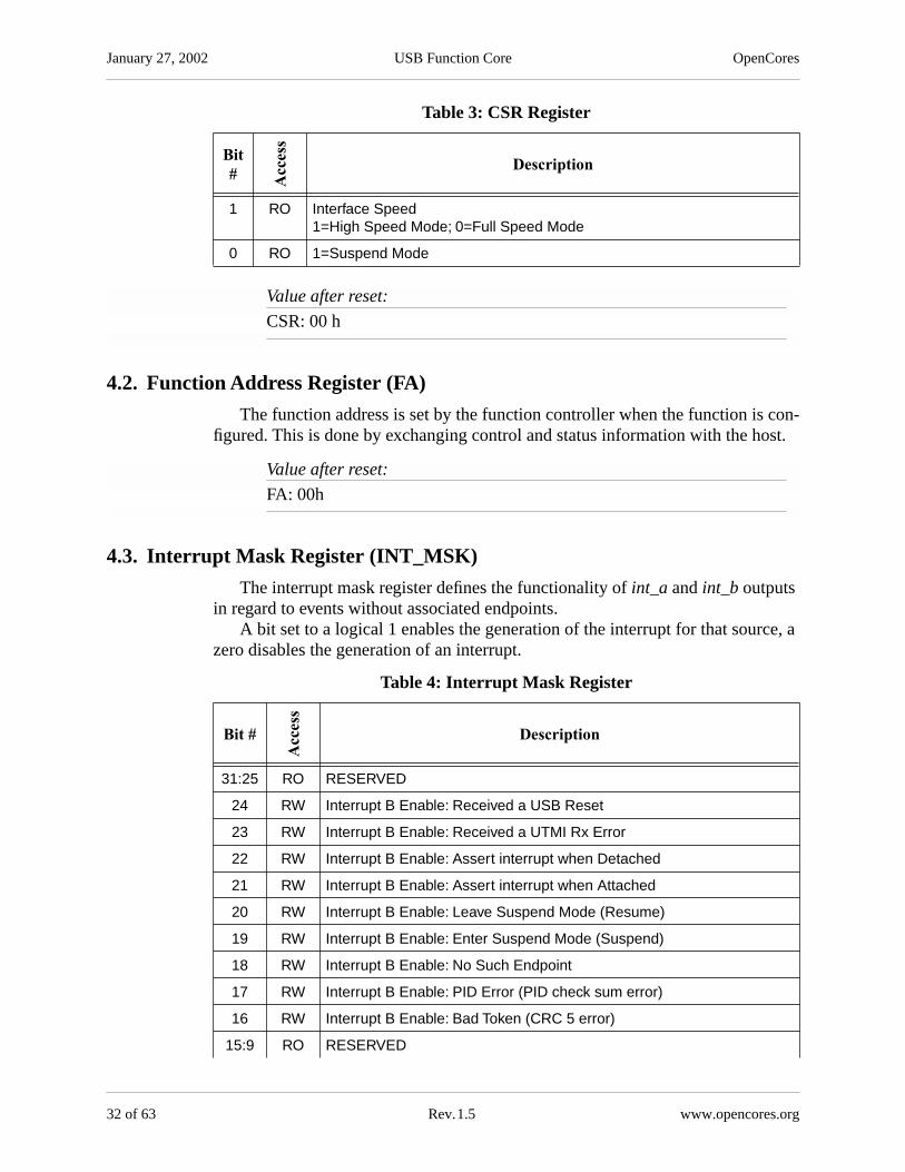
Table 3: CSR Register
Bit # Acc
ess
Description
7:5 RO RESERVED
4:3 RO UTMI Line State
2 RO Interface Status1=Attached
Table 2: Control/Status Registers
Name
Add
r.
Wid
th
Acc
ess
Description
www.opencores.org Rev. 1.5 31 of 63
January 27, 2002 USB Function Core OpenCores
Value after reset:
CSR: 00 h
4.2. Function Address Register (FA)
The function address is set by the function controller when the function is con-figured. This is done by exchanging control and status information with the host.
Value after reset:
FA: 00h
4.3. Interrupt Mask Register (INT_MSK)
The interrupt mask register defines the functionality of int_a and int_b outputs in regard to events without associated endpoints.
A bit set to a logical 1 enables the generation of the interrupt for that source, a zero disables the generation of an interrupt.
1 RO Interface Speed1=High Speed Mode; 0=Full Speed Mode
0 RO 1=Suspend Mode
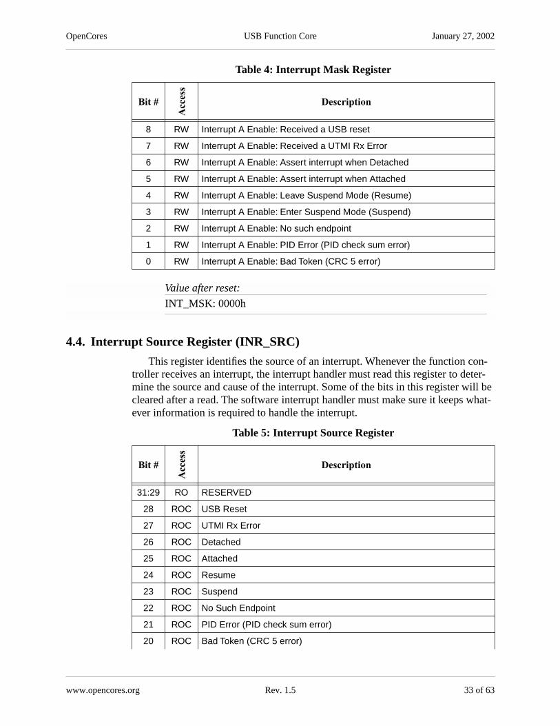
Table 4: Interrupt Mask Register
Bit #
Acc
ess
Description
31:25 RO RESERVED
24 RW Interrupt B Enable: Received a USB Reset
23 RW Interrupt B Enable: Received a UTMI Rx Error
22 RW Interrupt B Enable: Assert interrupt when Detached
21 RW Interrupt B Enable: Assert interrupt when Attached
20 RW Interrupt B Enable: Leave Suspend Mode (Resume)
19 RW Interrupt B Enable: Enter Suspend Mode (Suspend)
18 RW Interrupt B Enable: No Such Endpoint
17 RW Interrupt B Enable: PID Error (PID check sum error)
16 RW Interrupt B Enable: Bad Token (CRC 5 error)
15:9 RO RESERVED
Table 3: CSR Register
Bit # A
cces
s
Description
32 of 63 Rev. 1.5 www.opencores.org
OpenCores USB Function Core January 27, 2002
Value after reset:
INT_MSK: 0000h
4.4. Interrupt Source Register (INR_SRC)
This register identifies the source of an interrupt. Whenever the function con-troller receives an interrupt, the interrupt handler must read this register to deter-mine the source and cause of the interrupt. Some of the bits in this register will be cleared after a read. The software interrupt handler must make sure it keeps what-ever information is required to handle the interrupt.
8 RW Interrupt A Enable: Received a USB reset
7 RW Interrupt A Enable: Received a UTMI Rx Error
6 RW Interrupt A Enable: Assert interrupt when Detached
5 RW Interrupt A Enable: Assert interrupt when Attached
4 RW Interrupt A Enable: Leave Suspend Mode (Resume)
3 RW Interrupt A Enable: Enter Suspend Mode (Suspend)
2 RW Interrupt A Enable: No such endpoint
1 RW Interrupt A Enable: PID Error (PID check sum error)
0 RW Interrupt A Enable: Bad Token (CRC 5 error)
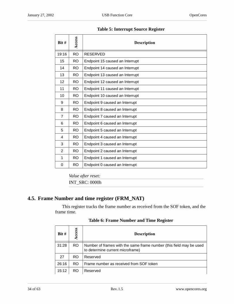
Table 5: Interrupt Source Register
Bit #
Acc
ess
Description
31:29 RO RESERVED
28 ROC USB Reset
27 ROC UTMI Rx Error
26 ROC Detached
25 ROC Attached
24 ROC Resume
23 ROC Suspend
22 ROC No Such Endpoint
21 ROC PID Error (PID check sum error)
20 ROC Bad Token (CRC 5 error)
Table 4: Interrupt Mask Register
Bit #
Acc
ess
Description
www.opencores.org Rev. 1.5 33 of 63
January 27, 2002 USB Function Core OpenCores
Value after reset:
INT_SRC: 0000h
4.5. Frame Number and time register (FRM_NAT)
This register tracks the frame number as received from the SOF token, and the frame time.
19:16 RO RESERVED
15 RO Endpoint 15 caused an Interrupt
14 RO Endpoint 14 caused an Interrupt
13 RO Endpoint 13 caused an Interrupt
12 RO Endpoint 12 caused an Interrupt
11 RO Endpoint 11 caused an Interrupt
10 RO Endpoint 10 caused an Interrupt
9 RO Endpoint 9 caused an Interrupt
8 RO Endpoint 8 caused an Interrupt
7 RO Endpoint 7 caused an Interrupt
6 RO Endpoint 6 caused an Interrupt
5 RO Endpoint 5 caused an Interrupt
4 RO Endpoint 4 caused an Interrupt
3 RO Endpoint 3 caused an Interrupt
2 RO Endpoint 2 caused an Interrupt
1 RO Endpoint 1 caused an Interrupt
0 RO Endpoint 0 caused an Interrupt
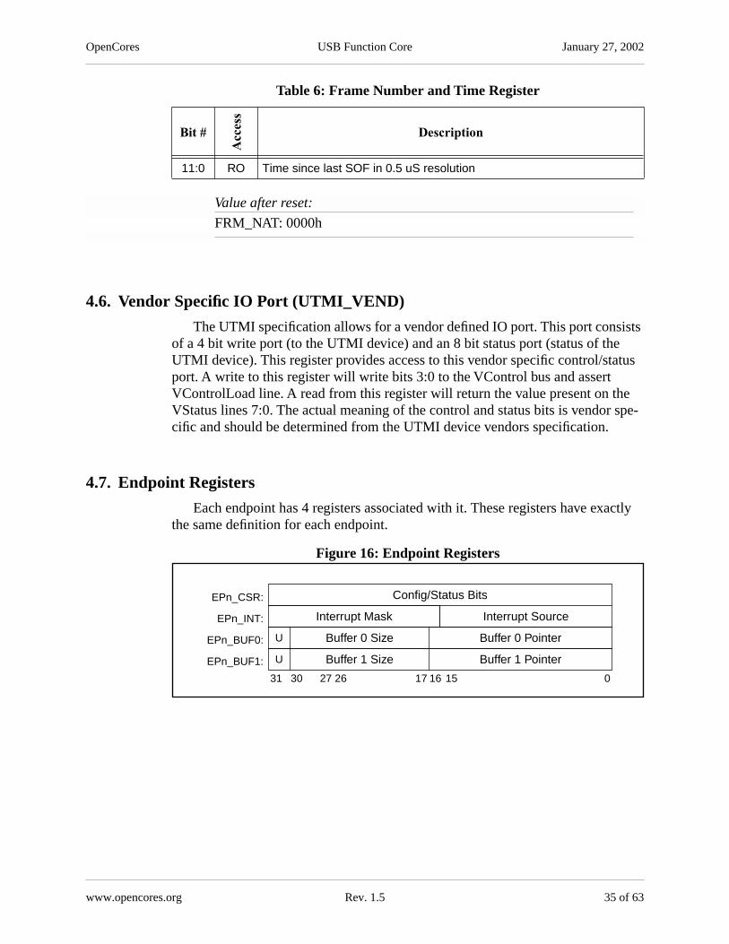
Table 6: Frame Number and Time Register
Bit #
Acc
ess
Description
31:28 RO Number of frames with the same frame number (this field may be used to determine current microframe)
27 RO Reserved
26:16 RO Frame number as received from SOF token
15:12 RO Reserved
Table 5: Interrupt Source Register
Bit #
Acc
ess
Description
34 of 63 Rev. 1.5 www.opencores.org
OpenCores USB Function Core January 27, 2002
Value after reset:
FRM_NAT: 0000h
4.6. Vendor Specific IO Port (UTMI_VEND)
The UTMI specification allows for a vendor defined IO port. This port consists of a 4 bit write port (to the UTMI device) and an 8 bit status port (status of the UTMI device). This register provides access to this vendor specific control/status port. A write to this register will write bits 3:0 to the VControl bus and assert VControlLoad line. A read from this register will return the value present on the VStatus lines 7:0. The actual meaning of the control and status bits is vendor spe-cific and should be determined from the UTMI device vendors specification.
4.7. Endpoint Registers
Each endpoint has 4 registers associated with it. These registers have exactly the same definition for each endpoint.
Figure 16: Endpoint Registers
11:0 RO Time since last SOF in 0.5 uS resolution
Table 6: Frame Number and Time Register
Bit #
Acc
ess
Description
Interrupt Source
Config/Status BitsEPn_CSR:
EPn_BUF0:
015162631
Interrupt MaskEPn_INT:
EPn_BUF1:
30 27
Buffer 1 PointerBuffer 1 SizeU
Buffer 0 PointerBuffer 0 SizeU
17
www.opencores.org Rev. 1.5 35 of 63
January 27, 2002 USB Function Core OpenCores
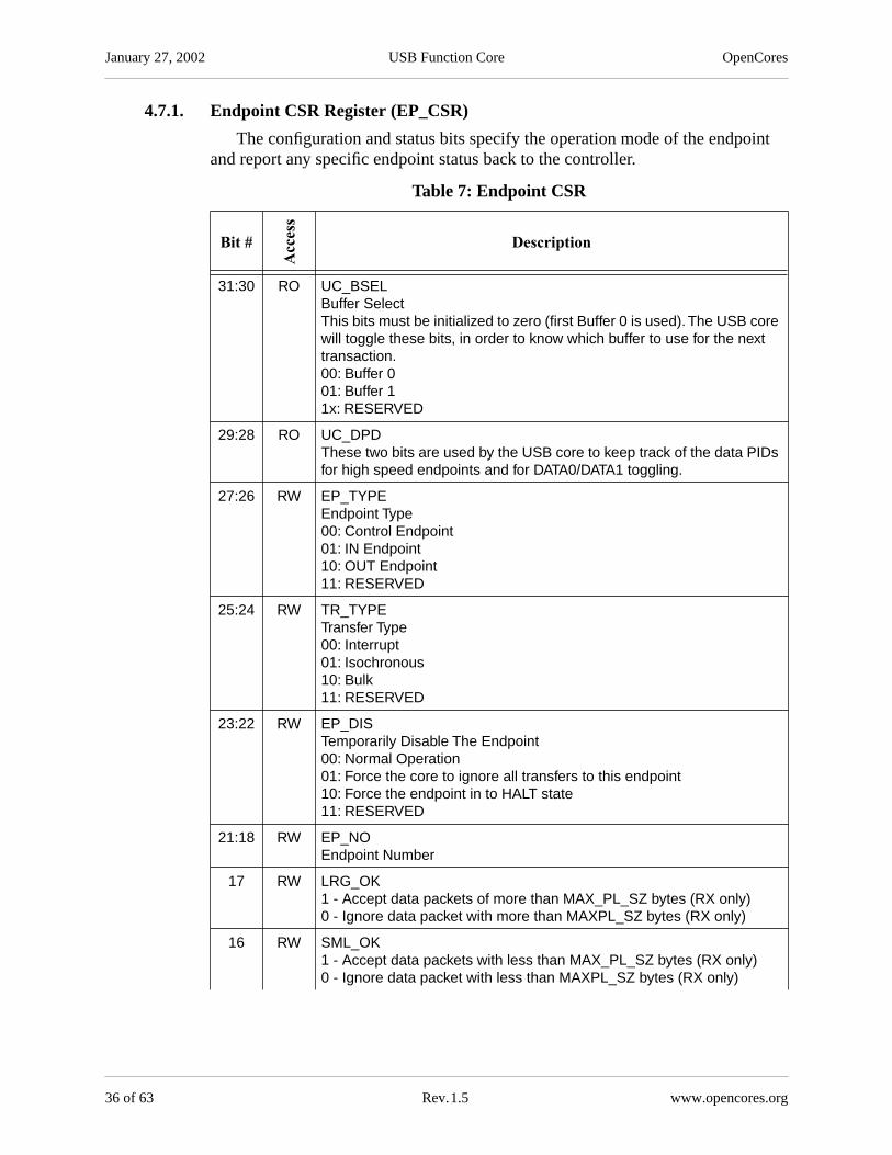
4.7.1. Endpoint CSR Register (EP_CSR)
The configuration and status bits specify the operation mode of the endpoint and report any specific endpoint status back to the controller.
Table 7: Endpoint CSR
Bit #
Acc
ess
Description
31:30 RO UC_BSELBuffer SelectThis bits must be initialized to zero (first Buffer 0 is used). The USB core will toggle these bits, in order to know which buffer to use for the next transaction.00: Buffer 001: Buffer 11x: RESERVED
29:28 RO UC_DPDThese two bits are used by the USB core to keep track of the data PIDs for high speed endpoints and for DATA0/DATA1 toggling.
27:26 RW EP_TYPEEndpoint Type00: Control Endpoint01: IN Endpoint10: OUT Endpoint11: RESERVED
25:24 RW TR_TYPETransfer Type00: Interrupt01: Isochronous10: Bulk11: RESERVED
23:22 RW EP_DISTemporarily Disable The Endpoint00: Normal Operation01: Force the core to ignore all transfers to this endpoint10: Force the endpoint in to HALT state11: RESERVED
21:18 RW EP_NOEndpoint Number
17 RW LRG_OK1 - Accept data packets of more than MAX_PL_SZ bytes (RX only)0 - Ignore data packet with more than MAXPL_SZ bytes (RX only)
16 RW SML_OK1 - Accept data packets with less than MAX_PL_SZ bytes (RX only)0 - Ignore data packet with less than MAXPL_SZ bytes (RX only)
36 of 63 Rev. 1.5 www.opencores.org
OpenCores USB Function Core January 27, 2002
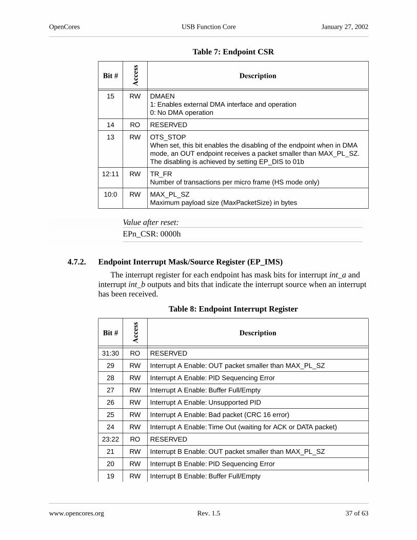
Value after reset:
EPn_CSR: 0000h
4.7.2. Endpoint Interrupt Mask/Source Register (EP_IMS)
The interrupt register for each endpoint has mask bits for interrupt int_a and interrupt int_b outputs and bits that indicate the interrupt source when an interrupt has been received.
15 RW DMAEN1: Enables external DMA interface and operation0: No DMA operation
14 RO RESERVED
13 RW OTS_STOPWhen set, this bit enables the disabling of the endpoint when in DMA mode, an OUT endpoint receives a packet smaller than MAX_PL_SZ.The disabling is achieved by setting EP_DIS to 01b
12:11 RW TR_FRNumber of transactions per micro frame (HS mode only)
10:0 RW MAX_PL_SZMaximum payload size (MaxPacketSize) in bytes
Table 8: Endpoint Interrupt Register
Bit #
Acc
ess
Description
31:30 RO RESERVED
29 RW Interrupt A Enable: OUT packet smaller than MAX_PL_SZ
28 RW Interrupt A Enable: PID Sequencing Error
27 RW Interrupt A Enable: Buffer Full/Empty
26 RW Interrupt A Enable: Unsupported PID
25 RW Interrupt A Enable: Bad packet (CRC 16 error)
24 RW Interrupt A Enable: Time Out (waiting for ACK or DATA packet)
23:22 RO RESERVED
21 RW Interrupt B Enable: OUT packet smaller than MAX_PL_SZ
20 RW Interrupt B Enable: PID Sequencing Error
19 RW Interrupt B Enable: Buffer Full/Empty
Table 7: Endpoint CSR
Bit #
Acc
ess
Description
www.opencores.org Rev. 1.5 37 of 63
January 27, 2002 USB Function Core OpenCores
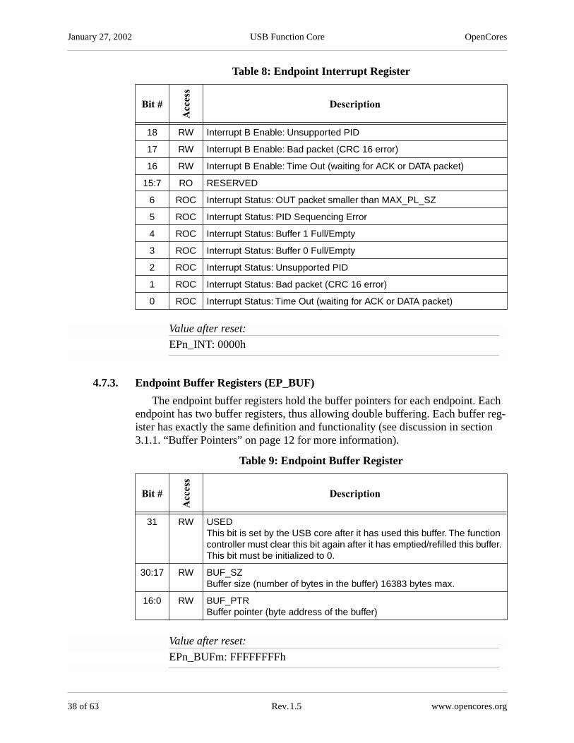
Value after reset:
EPn_INT: 0000h
4.7.3. Endpoint Buffer Registers (EP_BUF)
The endpoint buffer registers hold the buffer pointers for each endpoint. Each endpoint has two buffer registers, thus allowing double buffering. Each buffer reg-ister has exactly the same definition and functionality (see discussion in section 3.1.1. “Buffer Pointers” on page 12 for more information).
Value after reset:
EPn_BUFm: FFFFFFFFh
18 RW Interrupt B Enable: Unsupported PID
17 RW Interrupt B Enable: Bad packet (CRC 16 error)
16 RW Interrupt B Enable: Time Out (waiting for ACK or DATA packet)
15:7 RO RESERVED
6 ROC Interrupt Status: OUT packet smaller than MAX_PL_SZ
5 ROC Interrupt Status: PID Sequencing Error
4 ROC Interrupt Status: Buffer 1 Full/Empty
3 ROC Interrupt Status: Buffer 0 Full/Empty
2 ROC Interrupt Status: Unsupported PID
1 ROC Interrupt Status: Bad packet (CRC 16 error)
0 ROC Interrupt Status: Time Out (waiting for ACK or DATA packet)
Table 9: Endpoint Buffer Register
Bit #
Acc
ess
Description
31 RW USEDThis bit is set by the USB core after it has used this buffer. The function controller must clear this bit again after it has emptied/refilled this buffer. This bit must be initialized to 0.
30:17 RW BUF_SZBuffer size (number of bytes in the buffer) 16383 bytes max.
16:0 RW BUF_PTRBuffer pointer (byte address of the buffer)
Table 8: Endpoint Interrupt Register
Bit #
Acc
ess
Description
38 of 63 Rev. 1.5 www.opencores.org
OpenCores USB Function Core January 27, 2002
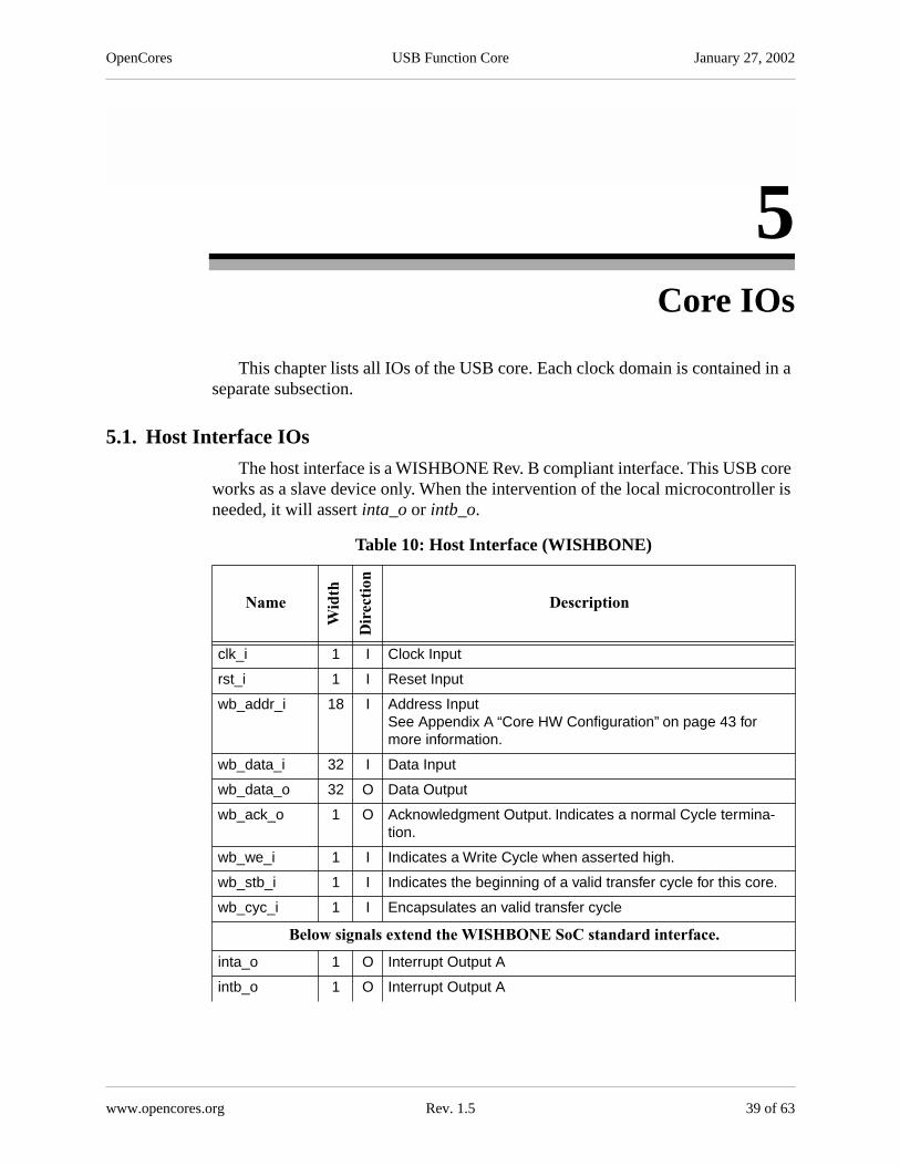
5Core IOs
This chapter lists all IOs of the USB core. Each clock domain is contained in a separate subsection.
5.1. Host Interface IOs
The host interface is a WISHBONE Rev. B compliant interface. This USB core works as a slave device only. When the intervention of the local microcontroller is needed, it will assert inta_o or intb_o.
Table 10: Host Interface (WISHBONE)
Name
Wid
th
Dir
ecti
on
Description
clk_i 1 I Clock Input
rst_i 1 I Reset Input
wb_addr_i 18 I Address InputSee Appendix A “Core HW Configuration” on page 43 for more information.
wb_data_i 32 I Data Input
wb_data_o 32 O Data Output
wb_ack_o 1 O Acknowledgment Output. Indicates a normal Cycle termina-tion.
wb_we_i 1 I Indicates a Write Cycle when asserted high.
wb_stb_i 1 I Indicates the beginning of a valid transfer cycle for this core.
wb_cyc_i 1 I Encapsulates an valid transfer cycle
Below signals extend the WISHBONE SoC standard interface.
inta_o 1 O Interrupt Output A
intb_o 1 O Interrupt Output A
www.opencores.org Rev. 1.5 39 of 63

January 27, 2002 USB Function Core OpenCores
Address line 17 selects between the core’s buffer memory and register file. When asserted high, the memory buffer is selected, when low, the register file.
5.2. UTMI IOs
The UTMI interface is a USB 2.0 UTMI specification Version 1.04 compliant interface.
dma_req_o 15 O DMA RequestFor each endpoint one line. Unused endpoints will tie their DMA_REQ output to zero.
dma_ack_i 15 I DMA AcknowledgementFor each endpoint one line. Unused endpoints will ignore their DMA_ACK line.
susp_o 1 O Suspend Output
resume_req_i 1 I Resume Request(Connect to 0 (zero) when not used.)
Table 11: UTMI Interface
Name
Wid
th
Dir
ecti
on
Description
phy_clk_pad_i 1 I Clock
phy_rst_pad_o 1 O Reset Output
DataIn_pad_i 8 I Input Data
DataOut_pad_o 8 O Output Data
TxValid_pad_o 1 O Transmit Valid
TxReady_pad_i 1 I Transmit Ready
RxActive_pad_i 1 I Receiver Active
RxValid_pad_i 1 I Receive Data Valid
RxError_pad_i 1 I Receive Error
XcvSelect_pad_o 1 O 1: Full speed transceiver selected0: High Speed transceiver selected
TermSel_pad_o 1 O 1: Full speed termination enabled0: High speed termination enabled
SuspendM_pad_o 1 O Places PHY into suspend mode
LineState_pad_i 2 I Line State
Table 10: Host Interface (WISHBONE)
Name
Wid
th
Dir
ecti
on
Description
40 of 63 Rev. 1.5 www.opencores.org
OpenCores USB Function Core January 27, 2002
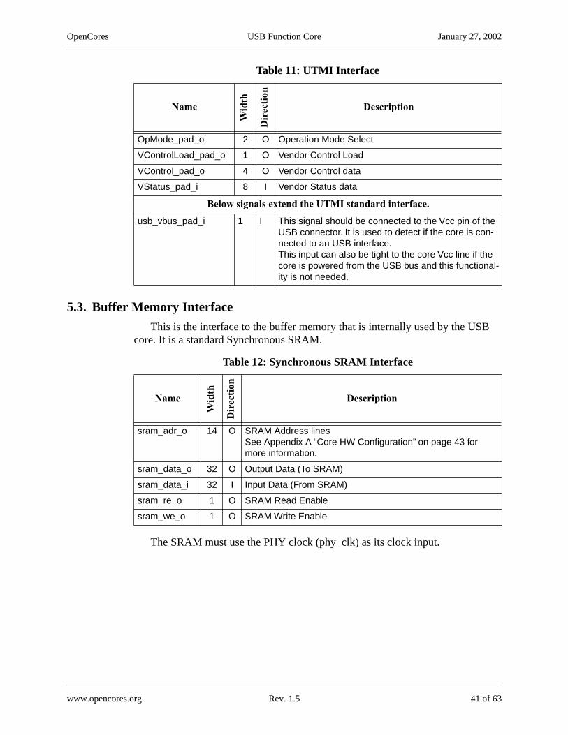
5.3. Buffer Memory Interface
This is the interface to the buffer memory that is internally used by the USB core. It is a standard Synchronous SRAM.
The SRAM must use the PHY clock (phy_clk) as its clock input.
OpMode_pad_o 2 O Operation Mode Select
VControlLoad_pad_o 1 O Vendor Control Load
VControl_pad_o 4 O Vendor Control data
VStatus_pad_i 8 I Vendor Status data
Below signals extend the UTMI standard interface.
usb_vbus_pad_i 1 I This signal should be connected to the Vcc pin of the USB connector. It is used to detect if the core is con-nected to an USB interface.This input can also be tight to the core Vcc line if the core is powered from the USB bus and this functional-ity is not needed.
Table 12: Synchronous SRAM Interface
Name
Wid
th
Dir
ecti
on
Description
sram_adr_o 14 O SRAM Address linesSee Appendix A “Core HW Configuration” on page 43 for more information.
sram_data_o 32 O Output Data (To SRAM)
sram_data_i 32 I Input Data (From SRAM)
sram_re_o 1 O SRAM Read Enable
sram_we_o 1 O SRAM Write Enable
Table 11: UTMI Interface
Name
Wid
th
Dir
ecti
on
Description
www.opencores.org Rev. 1.5 41 of 63

January 27, 2002 USB Function Core OpenCores
(This page intentionally left blank)
42 of 63 Rev. 1.5 www.opencores.org

OpenCores USB Function Core January 27, 2002
Appendix ACore HW Configuration
This Appendix describes the configuration of the core. This step is performed before final synthesis and tape-out of the USB core.
A.1. Endpoints
This core supports up to 16 individual endpoints. The actual functionality of each endpoint is under function software control. An implementation may choose how many endpoints it actually wants to support. The minimum number is 1 end-point (Endpoint 0 must be always present), the maximum number of endpoints for this USB core is 16 (inclusive endpoint 0).
To select the endpoints to be supported edit the “usbf_defines.v” file. Look for the following define statements:
d̀efine USBF_HAVE_EP1 1 // Endpoint 1 Presentd̀efine USBF_HAVE_EP2 1 // Endpoint 2 Presentd̀efine USBF_HAVE_EP3 1 // Endpoint 3 Presentd̀efine USBF_HAVE_EP4 1 // Endpoint 4 Presentd̀efine USBF_HAVE_EP5 1 // Endpoint 5 Presentd̀efine USBF_HAVE_EP6 1 // Endpoint 6 Presentd̀efine USBF_HAVE_EP7 1 // Endpoint 7 Presentd̀efine USBF_HAVE_EP8 1 // Endpoint 8 Present//̀ define USBF_HAVE_EP9 1 // Endpoint 9 NOT Present//̀ define USBF_HAVE_EP10 1 // Endpoint 10 NOT Present//̀ define USBF_HAVE_EP11 1 // Endpoint 11 NOT Present//̀ define USBF_HAVE_EP12 1 // Endpoint 12 NOT Present//̀ define USBF_HAVE_EP13 1 // Endpoint 13 NOT Present//̀ define USBF_HAVE_EP14 1 // Endpoint 14 NOT Present//̀ define USBF_HAVE_EP15 1 // Endpoint 15 NOT Present
For each endpoint that should be present in the USB core, un-comment the define statement. The “USBF_HAVE_EPn” tag indicates that an endpoint is present when it is defined. The number “n” in the tag indicates the physical end-point number (which should not be confused with the logical endpoint number, which can be set by software).
Endpoints must be defined sequential. In other words you must NOT define endpoints 1, 4 and 6, and comment out endpoints 2,3 and 5.
www.opencores.org Rev. 1.5 43 of 63

January 27, 2002 USB Function Core OpenCores
A.2. USB Core WISHBONE Address Lines
The Address encoding and WISHBONE interface address bus size may also be customized. Depending on the Buffer Memory size and the number of endpoints, the address bus size may be reduced, or enlarged. The minimum Address bus size must be able to address the buffer memory and select between the buffer memory the and register file.
To modify the address bus size and decode logic, edit the “usbf_defines.v” file, and look for the following lines:
d̀efine USBF_UFC_HADR 17d̀efine USBF_RF_SEL (!wb_addr_i[17])d̀efine USBF_MEM_SEL (wb_addr_i[17])
The first define statement specifies the MSB of the address bus coming into the USB core. With this setup, the core can support 128K bytes of buffer memory and has one address line available to distinguish between Register File and Buffer Memory Accesses.
The second define statement specifies how the USB core decodes register file accesses. The “wb_addr_i” bus is the WISHBONE address bus. Any simple com-binatorial statement is permitted here.
The third define statement specifies how the USB core decodes memory buffer accesses. Again, any simple combinatorial statement is permitted.
ExampleAn application may choose to extend the address bus width by setting
USBF_UFC_HADR to 20. This means wb_addr_i will be 21 bits wide [20:0].
d̀efine USBF_UFC_HADR 20
Then the USBF_RF_SEL may be set to (wb_addr_i[20:17] == 4’h3) and USBF_MEM_SEL to (wb_addr_i[20:17] == 4’h7).
d̀efine USBF_RF_SEL (wb_addr_i[20:17]==4’h3)d̀efine USBF_MEM_SEL (wb_addr_i[20:17]==4’h7)
This means the register file will be in the address space 0x60000 through 0x7FFFF and the buffer memory in 0xE0000 through 0xFFFFF.
A.3. Buffer Memory
This USB core supports up to 128 Kilobytes of buffer memory. The minimum memory size should be at least 256 bytes. The memory is organized in 4 byte boundaries (words). This means a 4Kbyte buffer would be organized as 1024 * 32bit entries. The memory must always start at address zero of the USB core and must be continued up to the last address.
44 of 63 Rev. 1.5 www.opencores.org

OpenCores USB Function Core January 27, 2002
To modify the buffer memory size, edit the “usbf_defines.v” file, and look for the following line:
‘define USBF_SSRAM_HADR14
This statement specifies the MSB of the SSRAM address lines. In this case the SSRAM will have 15 address lines [14:0], and be 2^15 (32K) words (4 byte quan-tities) large.
Alteratively this can be overwritten by parameterizing the USB core when instantiating it:
usbf_top #(USBF_SRAM_ADR_MSB) u0(<IO list>);
Now the value of USBF_SRAM_ADR_MSB will overwrite the setting of the define statement.
www.opencores.org Rev. 1.5 45 of 63

January 27, 2002 USB Function Core OpenCores
(This page intentionally left blank)
46 of 63 Rev. 1.5 www.opencores.org

OpenCores USB Function Core January 27, 2002
Appendix BUSB Core Structure
This section outlines the hierarchy structure of the USB core Verilog Source files.
Figure 17: USB Core Hierarchy Structure
usbf_top.v
usbf_utmi_if.v
Top Level
UTMI Interface
Protocol Layer Register File
Memory Arbiter Wishbone Interfaceusbf_wb.vusbf_mem_arb.v
usbf_rf.v
usbf_pd.v
usbf_pa.v usbf_idma.v
usbf_pe.v
Endpoint Register Files
pl.v
usbf_utmi_ls.vUTMI Line Status
Packet Disassembler
Packet Assembler
Protocol Engine
Internal DMA
usbf_ep_rf.v
“usbf_defines.v” is includedby all modules.
(usbf_ep_rf_dummy.v is a placeholder for unused endpoints)
www.opencores.org Rev. 1.5 47 of 63

January 27, 2002 USB Function Core OpenCores
(This page intentionally left blank)
48 of 63 Rev. 1.5 www.opencores.org
OpenCores USB Function Core January 27, 2002
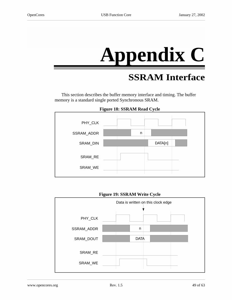
Appendix CSSRAM Interface
This section describes the buffer memory interface and timing. The buffer memory is a standard single ported Synchronous SRAM.
Figure 18: SSRAM Read Cycle
Figure 19: SSRAM Write Cycle
SSRAM_ADDR
PHY_CLK
SRAM_DIN
SRAM_RE
SRAM_WE
n
DATA[n]
SSRAM_ADDR
PHY_CLK
SRAM_DOUT
SRAM_RE
SRAM_WE
n
DATA
Data is written on this clock edge
www.opencores.org Rev. 1.5 49 of 63

January 27, 2002 USB Function Core OpenCores
(This page intentionally left blank)
50 of 63 Rev. 1.5 www.opencores.org
OpenCores USB Function Core January 27, 2002
Appendix DUTMI PHY
This core requires an external PHY (transceiver) that complies with the UTMI specification.
The UTMI specification can be downloaded from:http://developer.intel.com/technology/usb/download/2_0_xcvr_macrocell_1_03.pdf
The following companies have announced PHY chips:
Lucent: USS2X1http://www.lucent.com/micro/usb/usbdocs.html[30/3/2001 - I was informed that the Lucent (now Agere) PHY is shipping! I am in the process of acquiring some samples so I can build an FPGA prototype. RU]
NEC: uPD720120http://www.necel.com/home.nsf/Main?ReadForm&Multimedia+Products
Philips: ISP1501http://www.semiconductors.philips.com/pip/isp1501-01/
These are all I have found. If you know of others, please email me: [email protected]
www.opencores.org Rev. 1.5 51 of 63

January 27, 2002 USB Function Core OpenCores
(This page intentionally left blank)
52 of 63 Rev. 1.5 www.opencores.org
OpenCores USB Function Core January 27, 2002
Appendix ESoftware Model
By Chris Ziomkowski ([email protected])
The embedded programming model consists of a low level driver that is either integrated into an embedded operating system or exists in a standalone configura-tion if an operating system is not necessary. The low level driver provides an abstracted interface to the hardware so that higher level modules can access the USB interface in a fashion consistent with other network interfaces, and represents the combined levels 2 and 3 in the OSI model.
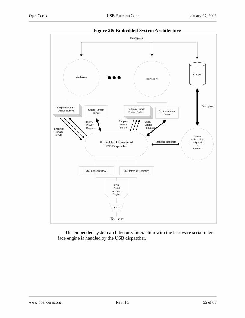
The embedded system architecture is shown in “Figure 20: Embedded System Architecture” on page 55. Each interface of the device is logically independent, and must receive distinct endpoints as required by the USB 2.0 specification. The descriptors for the required interfaces and endpoints should be stored in a memory structure that is abstractly represented as a database in the figure. Since these assignments are generally fixed, it is assumed that the descriptors will be loaded from a flash or other permanent storage device. The low level driver will use this information to direct USB requests to the appropriate interface.
Device requests flow from the hardware serial interface engine through the hardware endpoint interface buffers to the low level device drivers. Messages des-tined for endpoint 0 first will be inspected by the USB dispatcher to determine if they are standard device requests or class/vendor specific requests. Standard device requests will be returned directly by the configuration and control subsystem. This generally consists of returning static information stored in the descriptor database. Class or vendor specific requests will be forwarded to the interface associated with the specified endpoint or interface. The interface will then be responsible for decoding the request and replying with the correct information.
Every endpoint interface consists of 0 or more endpoints. Each endpoint is assigned a stream style memory buffer which can buffer reads and writes for increased efficiency. The model assumes the high level interfaces are implement-ing blocking reads and writes. In this configuration, a bulk or control endpoint interface will be alerted to the end of transmission by a read returning 0 bytes. End of transmission during a write be assumed if flush() is called on the buffer with any
www.opencores.org Rev. 1.5 53 of 63
January 27, 2002 USB Function Core OpenCores
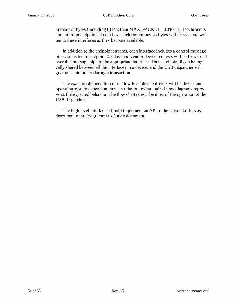
number of bytes (including 0) less than MAX_PACKET_LENGTH. Isochronous and interrupt endpoints do not have such limitations, as bytes will be read and writ-ten to these interfaces as they become available.
In addition to the endpoint streams, each interface includes a control message pipe connected to endpoint 0. Class and vendor device requests will be forwarded over this message pipe to the appropriate interface. Thus, endpoint 0 can be logi-cally shared between all the interfaces in a device, and the USB dispatcher will guarantee atomicity during a transaction.
The exact implementation of the low level device drivers will be device and operating system dependent, however the following logical flow diagrams repre-sents the expected behavior. The flow charts describe most of the operation of the USB dispatcher.
The high level interfaces should implement an API to the stream buffers as described in the Programmer’s Guide document.
54 of 63 Rev. 1.5 www.opencores.org
OpenCores USB Function Core January 27, 2002
Figure 20: Embedded System Architecture
The embedded system architecture. Interaction with the hardware serial inter-face engine is handled by the USB dispatcher.
FLASH
USBSerial
InterfaceEngine
PHY
To Host
Embedded MicrokernelUSB Dispatcher
Standard Requests
USB Endpoint RAM USB Interrupt Registers
Interface 0
Endpoint BundleStream Buffers Control Stream
Buffer
EndpointStreamBundle
Interface N
Endpoint BundleStream Buffers Control Stream
Buffer
EndpointStreamBundle
Class/VendorRequests
Class/VendorRequests
DeviceInitialization
Configuration&
Control
Descriptors
Descriptors
...
www.opencores.org Rev. 1.5 55 of 63
January 27, 2002 USB Function Core OpenCores
Figure 21: Control Endpoint Receive Channel
Wait for interrupton control channel
Read Endpoint RegisterClear Interrupts
SETUP bitset in register
NO
YES
state = DATAsetup descriptor
set bytes remaining
remaining== 0 ?
Set arrival time.state = STATUS
copy descriptor to active
YES
INFORMREAD
BUFFER
NO
START
1
3
Wait for read fromdest stream buffer
state ==PAUSE ?
NO
1
YES
START
3
state == EROR/IDLE ??
Delete packetstate = ERROR
YES
INFORMPROTOCOL
ERROR
INFORMPROTOCOL
STALL
SETPROTOCOL
STALLBIT
Delete packetstate = STALL
state == STALL
NO
room indest stream
buffer ?
NO
Subtract packet lengthfrom remaining
copy data from endpointto dest stream buffer
state = DATA
YES
remaining== 0 ?
state ==PAUSE ?
NO
YES
state = PAUSE
NO
INFORMREAD
BUFFER
Set arrival time.state = STATUS
copy descriptor to active
INFORMREAD
BUFFER
YES
1
packet len >remaining ?
NO
YES
Delete packetYES
NO
3
56 of 63 Rev. 1.5 www.opencores.org

OpenCores USB Function Core January 27, 2002
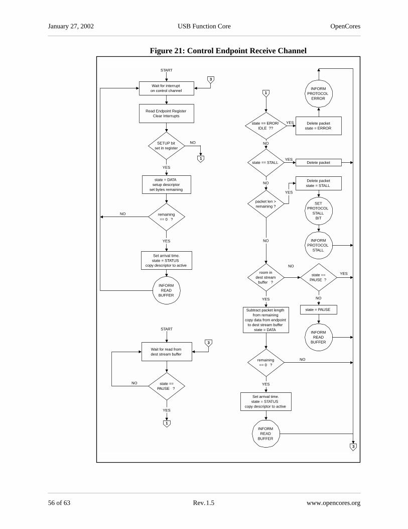
A control endpoint in receive mode. Bytes are received from the serial inter-face engine and transferred to the destination stream buffer. Communications external to the USB dispatcher are represented by circular states. Protocol stalls are supported as required by the USB 2.0 specification.
Figure 22: Control Endpoint Transmit Channel
A control endpoint in transmit mode. Bytes are read from the interface stream buffer and transferred to the serial interface engine. Communications external to the USB dispatcher are represented by circular states. The transmission is consid-ered complete upon receiving a flush from the stream buffer with a number of bytes less than MAX_PL_SIZE.
Wait for MAX_PL_SZ bytes from source stream or fflush().
Protocol Stallbit set ?
Discard data packetYES
End OfMessagebit set ?
availablebytes >= packet
len ?Wait for xmit interrupt
NO
NO
YES
NO
packet len ==MAX_PL_SZ?
YES
Copy packet from source streamto endpoint xmit buffer
NO
YES
SETEND OF
MESSAGEBIT
START
Wait for ProtocolStall ioctl().
Bytes inendpoint xmit
buffer?
Empty endpointxmit buffer
SETPROTOCOL
STALLBIT
NO
YES
START
INFORMPROTOCOL
STALL
www.opencores.org Rev. 1.5 57 of 63
January 27, 2002 USB Function Core OpenCores
Figure 23: Isochronous Endpoint Receive Channel w/ Explicit Feedback
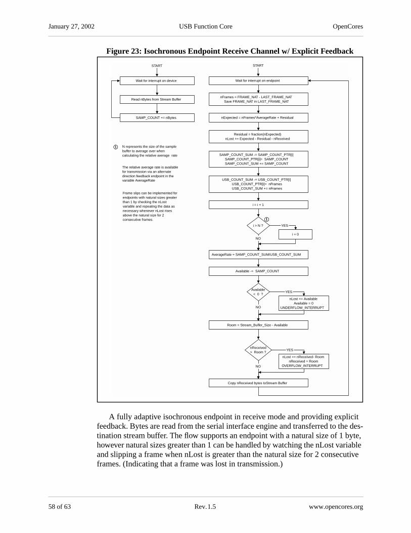
A fully adaptive isochronous endpoint in receive mode and providing explicit feedback. Bytes are read from the serial interface engine and transferred to the des-tination stream buffer. The flow supports an endpoint with a natural size of 1 byte, however natural sizes greater than 1 can be handled by watching the nLost variable and slipping a frame when nLost is greater than the natural size for 2 consecutive frames. (Indicating that a frame was lost in transmission.)
1
Wait for interrupt on endpoint
nFrames = FRAME_NAT - LAST_FRAME_NATSave FRAME_NAT in LAST_FRAME_NAT
nExpected = nFrames*AverageRate + Residual
Residual = fraction(nExpected)nLost += Expected - Residual - nReceived
SAMP_COUNT_SUM -= SAMP_COUNT_PTR[i]SAMP_COUNT_PTR[i]= SAMP_COUNTSAMP_COUNT_SUM += SAMP_COUNT
USB_COUNT_SUM -= USB_COUNT_PTR[i]USB_COUNT_PTR[i]= nFramesUSB_COUNT_SUM += nFrames
i = i + 1
i > N ? YES
AverageRate = SAMP_COUNT_SUM/USB_COUNT_SUM
NO
Available -= SAMP_COUNT
Available< 0 ?
i = 0
nLost += AvailableAvailable = 0
UNDERFLOW_INTERRUPT
YES
Room = Stream_Buffer_Size - Available
NO
nReceived> Room ?
nLost += nReceived- RoomnReceived = Room
OVERFLOW_INTERRUPT
YES
Copy nReceived bytes toStream Buffer
NO
Wait for interrupt on device
Read nBytes from Stream Buffer
SAMP_COUNT += nBytes
1 N represents the size of the samplebuffer to average over whencalculating the relative average rate
The relative average rate is availablefor transmission via an alternatedirection feedback endpoint in thevariable AverageRate
Frame slips can be implemented forendpoints with natural sizes greaterthan 1 by checking the nLostvariable and repeating the data asnecessary whenever nLost risesabove the natural size for 2consecutive frames.
STARTSTART
58 of 63 Rev. 1.5 www.opencores.org
OpenCores USB Function Core January 27, 2002
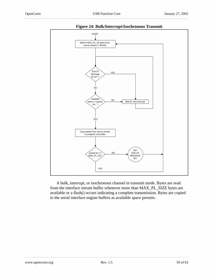
Figure 24: Bulk/Interrupt/Isochronous Transmit
A bulk, interrupt, or isochronous channel in transmit mode. Bytes are read from the interface stream buffer whenever more than MAX_PL_SIZE bytes are available or a flush() occurs indicating a complete transmission. Bytes are copied to the serial interface engine buffers as available space permits.
Wait for MAX_PL_SZ bytes from source stream or fflush().
End OfMessagebit set ?
availablebytes >= packet
len ?Wait for xmit interrupt
NO
YES
NO
packet len ==MAX_PL_SZ?
YES
Copy packet from source streamto endpoint xmit buffer
NOSET
END OFMESSAGE
BIT
START
YES
www.opencores.org Rev. 1.5 59 of 63
January 27, 2002 USB Function Core OpenCores
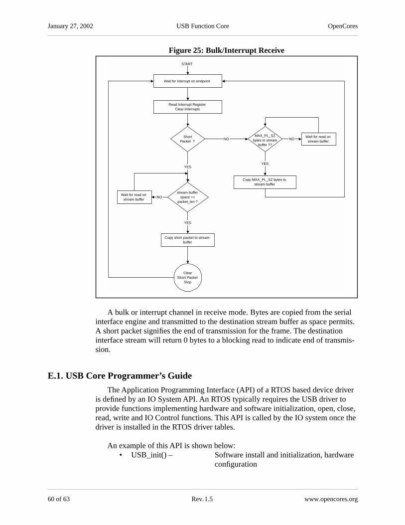
Figure 25: Bulk/Interrupt Receive
A bulk or interrupt channel in receive mode. Bytes are copied from the serial interface engine and transmitted to the destination stream buffer as space permits. A short packet signifies the end of transmission for the frame. The destination interface stream will return 0 bytes to a blocking read to indicate end of transmis-sion.
E.1. USB Core Programmer’s Guide
The Application Programming Interface (API) of a RTOS based device driver is defined by an IO System API. An RTOS typically requires the USB driver to provide functions implementing hardware and software initialization, open, close, read, write and IO Control functions. This API is called by the IO system once the driver is installed in the RTOS driver tables.
An example of this API is shown below:• USB_init() – Software install and initialization, hardware
configuration
Wait for interrupt on endpoint
ShortPacket ?
START
Read Interrupt RegisterClear Interrupts
stream bufferspace >=
packet_len ?
YES
Wait for read onstream buffer
NO
Copy short packet to streambuffer
YES
ClearShort Packet
Stop
MAX_PL_SZbytes in stream
buffer ??
NOWait for read on
stream bufferNO
Copy MAX_PL_SZ bytes tostream buffer
YES
60 of 63 Rev. 1.5 www.opencores.org
OpenCores USB Function Core January 27, 2002
• USB_open_interface() – Define a new interface and match it against the descriptors
• USB_open() – Opens an Endpoint• USB_close() – Closes an Endpoint• USB_read() – Performs a read operation on an Endpoint• USB_write() – Performs a write operation on an Endpoint• USB_ioctl() – Performs IO Control operations on an end-
point or the USB core
E.1.1. USB_init()
The USB_init() function provides the calling application with the means to install and initialize the driver while performing software and hardware configura-tion. The typical initialization steps required for an RTOS based USB Driver are:
• Install the USB Driver in the RTOS IO System• Acquire the interrupts used by the USB Core• Acquire system resources needed by the USB Core • Acquire system resources required for each endpoint• Initialize the USB driver data structures for the controller and each end-
point• Initialize the USB Registers to the default values• Start the task implementing the Standard Request Processing • Enable the Control Endpoint 0 and associated RAM buffers• Enable the minimum supported set of supported USB interrupts such as
Suspend, Resume, Endpoint 0 ACK, and Endpoint 0 Short Packet Receive.
E.1.2. USB_open_interface()
The USB_open_interface() function provides a mechanism to establish a map-ping between a task id and the standard class definition which it is implementing. The function call checks the defined descriptor database to determine the correct InterfaceID that will then be mapped to the task id. From this point on, configura-tion requests directed to a specific interface will be redirected to this task. A task may open more than one interface.
E.1.3. USB_open()
The USB_open() function provides the mechanism to establish an endpoint to interface mapping. The model should enforce the USB 2.0 restriction that an end-point can only be opened by a single interface within an alternate definition. The function call should also verify that the interfaces associated with the current selected alternate definition are associated with the calling task and are configured to open this endpoint.
The typical steps performed here will be:• Verify USB Controller State is CONFIGURED if the Endpoint is not
the default Control Endpoint 0.
www.opencores.org Rev. 1.5 61 of 63
January 27, 2002 USB Function Core OpenCores
• Verify endpoint is not already open.• Verify the Endpoint is valid for the current selected interface in this
alternate definition• Initialize the RAM buffers associated with this endpoint.• Initialize the USB registers which define this endpoint as Bulk, Inter-
rupt, Control, or Isochronous.• Set the endpoint state to open
E.1.4. USB_close()
The USB_close() function should perform the inverse of the open functionality above, and make sure all data structures and RAM buffers associated with an end-point are freed.
E.1.5. USB_write()
The USB_write() function allows a USB application to write data to an IN or Control endpoint.
The typical steps performed in a write call are:• Verify endpoint number, type and direction• Verify endpoint is in the open state• If a control channel, acquire the semaphore to guarantee availability• Transfer the data from the stream buffer to the USB RAM buffer for
this endpoint.• If a control channel, wait for a packet from the USB Host to complete
the Control Status stage• If a control channel, release the semaphore acquired earlier• Return number of bytes transmitted or ERROR
E.1.6. USB_read()
The USB_read() allows a USB application to read data from an OUT or Con-trol endpoint.
The typical steps performed in a read call are:• Verify endpoint number, type and direction• Verify endpoint is in the open state• If a control channel, acquire the semaphore to guarantee availability• Transfer the data from the USB RAM buffer for this endpoint to the
stream buffer.• If a control channel, send a packet to the USB Host to complete the
Control Status stage• If a control channel, release the semaphore acquired earlier• Return number of bytes received or ERROR
62 of 63 Rev. 1.5 www.opencores.org

OpenCores USB Function Core January 27, 2002
E.1.7. USB_ioctl()
The USB_ioctl() function allows the application to read status and execute IO Control functions. These IO Control functions provide the application with the ability to control the USB interface.
Typical control mechanisms provided by this function are:• Remote Wakeup• Enter Suspend mode• Exit Suspend mode (Resume)• Reset USB Core• Read current Start of Frame Time Stamp• Return current Configuration, Interface, and Alternate Definition• Get Endpoint status• Initiate a Protocol Stall on an endpoint (control channel only)• Enable/Disable an endpoint with the Halt bit• Read arrival time for last message (control channel only)
www.opencores.org Rev. 1.5 63 of 63