USARTL-TR-78-50 ., LEVEL. - DTIC
91
USARTL-TR-78-50 ., LEVEL. 4ELICOPTER DRIVE SYSTEM R&M DESIGN GUIDE K. k. Cormier SIKORSKY AIRCRAFT ' Division of United Technologies Corporation C• Stratford, Conn. 06602 DDC O April 1979 JN1 Final Report Approved for public releaxe; distribution unlimited. a'€. I Li-. Prepared for I j APPLIED TECHNOLOGY LABORATORY U. S. ARMY RESEARCH AND TECHNO)LOGY LA4•ORATORIES (AVRADCOM) Fort Eustis, Va. 23604 "•" "t:- ..
Transcript of USARTL-TR-78-50 ., LEVEL. - DTIC
USARTL-TR-78-50
., LEVEL.
4ELICOPTER DRIVE SYSTEM R&M DESIGN GUIDE
K. k. CormierSIKORSKY AIRCRAFT
' Division of United Technologies Corporation
C• Stratford, Conn. 06602
DDC
O April 1979 JN1
Final Report
Approved for public releaxe;
distribution unlimited.
a'€.
I Li-. Prepared forI j APPLIED TECHNOLOGY LABORATORY
U. S. ARMY RESEARCH AND TECHNO)LOGY LA4•ORATORIES (AVRADCOM)
Fort Eustis, Va. 23604
"•" "t:- ..
I
APPLIED TECHNOLOGY LABORATORY POSITION STATEMENT
Drive system components are among the largest contributors to Army helicopter reliability and maintainability probiems.
Past studies have focused on identifying the magnitude and nature of the problems. Other effort. have Investigeted the
potential R&M benefits of spocific design concepts. Extgnsive work has been performed in establishing the feasibility
of "arc-condition" maintenance. An extensive effoW t continues to address diagnostirs. Much of the documentation of
these endeavors has been written expressly for the R&M engineer-in a technical jargon incomprehensible to manydesigners.
-.1h onjective of this contract waS .! "translate" the aforementioned endeavors putting R&M into proper perspective,
thereby making design engineers more conscious of the R&M aspects of the drive systems they design. The reeults are
published in two reports: TH 78-50. Hciicopter Drive System R&M Design Guide, and TR 78-51, a final report
documenting the program.
The approach wes to analyze failure modes experienced, contrasting them to currant practices to determine design,development, and overhaul deficiencies. AnalVtical methods for estimating "off-the-board" reliability were reviewed.Testing methods, specifically acceleratld testing versus overload testing, end reliability growth were addressed. On-condition maintenance and diagnostics were also addressed. Positions In two of these area:- follow.
Reliability estimation needs more work to achieve parity with strength and weight analyses. Hazard functions couldnot be correisaed with such design parameters as load or induced stress, precluding the assignment of "hard" numbersto reliability estimation. Probabilistic design is the best way to predict service life. It has the potential for optimumutilization of weight, and is the only means for setting realistic bounds on reliability problems involving cost., warran-ties, and producer's risk. The R&D necessary to bring probabilistic design "on stream" is encouraged.
Regarding diagnostics, fuzz burn-off chip detectors coupled with ruparfine filters are seen as the simplest, most cost-effective diagnostic system for modern helicopter drive systems. Fine filtration has the potential for rendering spectra-
metric oil analysis (SOAP) and particle count techniques obsolete. The Automatic, Inspection, Diagnostics, andPrognosis System (AIDAPS) requires very sophisticated instrumcn•tat¶on. Without a breakthrough in understanding the
sympton-failure relationship, development of a practicel, cost-nf•trtive AIDAPS system appears remote.
This program was conducted under the tachnicil cognizance of Jopn H. McGarvey, Aeronautical Systems Division.
DISCLAIMERS
The findings in this report are not to be construed as en official Department of the Army position unless sodesignated by other authorized documents.
hen Government drawings, specifications, or other date are used for any purpose other than in connection4th a definitely reslated Government procurement operation, the United States Government thereby incurs no 4responsibility nor aniy obligation whatsoever; and the fact that the Government may have formulated, furnished,or in any vmy supplier the taid drawIng•, -specificeclon:, or other d•aa Ii ,iot to be regardo by Impication or
therwise as in any mannter licensing the holder or any other Person or corporation, or corveying any rights or tpermission, to manufacture, use, o.- sell any patented invention i,;at rmay in any way be rilated theorto.
Trade names citedi in this report do not constitute an official endorsement or approval of the uz of such
commercial hardware or software.
DISPOSITION INSTRUCTIONS '
Destroy this report when no longer needed. Do not return it to the iriginator.
LI
I7. , r~~f ~ s
UnclassifiedSECURITY CLASSIFICATION OF THIS AGE ft"DW. BnIrosO
DOCUMENTATION PAGE BIPAD UURCOTLII ORM
-TýC2. GOT ACCZASION NO, . RICIPIENTS1' CATALOG NUMBER
WLICOPTER DRIVE SYSTEMi~r ESIGN GU IDE p t
7. AUTHOR(.) ....
T. K~/o rni e r I J' DJ$2:-76,407J-
9 II. OTROLING OFFAICET~l NAME AND ACOSE IS NTS
U.Sikrk AniyRerchaf anAvlpeti. UERO A
Laorvoiesino UnitedCO) FehoortiestCorporation 2360 906 =il. CONTROLLING AGENCY NAME S AOORCISS( ~~n w.C.~i~ fi Is. EURITYR CAIS (.9 ~ en.t
Appled echnlog LaoritorUncrlassifie
Anproed fr pulic rleas; ditribtion nlimted.sif ied
I#. OISYRIEUTION STATEMENT (of this e p.IUG mleqdi F4 0 fdlen w )e
Gnroear foHubi eleaeicotersbto Bniitd
It. AUSTWORACO (Ca~iiwe . evvese side it neceeeer EW Idmit-Ip y ~c rle e r) .w.h.
ThsBeportnis aReliability adiananblt cinglefrhlcpepoint misiottoseaes ofdeignt whichcnaetruleolinthtelailt
and maintainability of helicopter drive systems. Besides containing informa-tion on the various drive system components, a manageentni section is includedthat outlines some practices which design managers may employ to insure thatreliability and maintainability are given proper emphasis during a design _7FZV4\
DO I RP 1473 EDITION OF I NOV,$*S19OWSOL.ETE UnclassifiedSgICURITY CLASSFICATIO01 OF THIS PAGE (11hon LW 13e8te aie

UnclassifiedLwIJI-ITY CLASSIFICATShN OF THIS PAGE(WhS. DVl. Zr•.i.r"J
20. Abstract (Cont'd)
Sprogram. The final section is devoted to a step-by-step procedure forhazard function analysis, which may be used to predict the reliabilityof a gearbnx during the design stage.
UnclassifiedsvcunIrIy CLASSIFICATION OF THIS PAGEMl..h. Fntmw.d)
F : ' lI II I I I I Il l li il lI !

PREFACE
The design guide presented herein was prepared u Contract DAAJ02.-76-C-0047 for the Applied Technology Laboratory, U. S. Aiqy Research and Tech-nology Laboratories (AVRADCOM), Fort Eustis, ViroinA. Technical directionfor the program was provided by Mr. J. McGarvey o• the Applied TechnologyLaboratory. Mr. C. Keller served as Task Manager at Sikorsky. Technicalcontributors were Mr. H. Frint of the Transmission Design and DevelopmentSection and Mr. B. Trustee of the R&M Section.
.Accession For
DDC TAB
By__
Distr!!,,. :-•
Jkvai! ýbi'l" IC:? ,,•.Aiv a L I avd/ or
DIst special
3
81A

TABLE OF CONTENTS
Section Page
PREFACE ............... ............................... 3
LIST OF ILL'STRATIONS .......... ........................ 8
LIST OF TABLES ......... ..... ........................... 10
INTROCUCTION ........... ............................ .. 11
PLANNING AND MANAGEMENT OF THE DESIGN PROGRAM ..... ............ 12
Planning ............................. 12Pre'iiminary Reliability Analysis . ............... 12Design Review ..... ........................ ... 13Detailed Reliability Analysis ........ ................ 13
Management .............. ........................... 13
General Design Considerations .......... ............... 15
Functional Group Activity ........ .................... 16
Accelerated Testing .......... ....................... 17
BEARINGS ......... ....... .............................. 19
Required Bearing Life ...... ...................... ... 19
Ball Bearings ..... ............................... .. 20
Cylindrical Roller Bearings ...... ................... .. 20
Internial Clearance ...... ..... ....................... 21
Tapered Roller Bearings ......... ..................... 21
Preventing Bearing Race Creep ....... .................. 21
Bearing Material ...... ....... ........................ 22
Inspection Requirements ..... .... ....... ........... 23
Installation/Removal ........ ...................... .. 23
Tail Rotor Driveshaft Bearings . . . . . . ..................... 23
-.6a
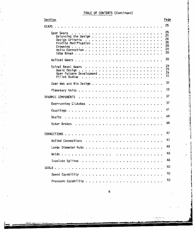
TABLE OF CONTENTS (Continued)
Section Page
GEARS .............. ................................ 25
Spur Gears ........... ........................... .. 25Balancing the Design ...... ..................... ... 25Design Criteria ....... ................ .. .. . 26 t.
Profile Modification ...... ..................... ... 26Crowning ........ ... ... ....................... 28Helix Correction ........ ................... . 28Edge Break .......... .......................... 28
Helical Gears ................................... ... 28
Spiral Bevel Gears ....... ....................... ... 29Basic Design ........ ......................... .. 29Gear Pattern Development ....... ................... 29Fillet Radius ......... ... ........................ 31
Gear Web and Rim Design ........................... 32
Planetary Units .......... ......................... 33
DYNAMIC COMPONENTS . . .. .. . . . . . . . . . . . . . . .. . . . 37 !
Overrunning Clutches ....... ...................... .. 37
Couplings ............. ............................ 41
Shafts .............. ............................. 44
Rotor Brakes .............. .......................... 44
CONNECTIONS ............. ............................. 47
Bolted Connections ......... 47.
Large Diameter Nuts ....... ....................... ... 48
Welds ........... ............................. 48
Involute Splines . . . . . . . . . . . . . . . . . . . . . . . . 48
SEALS .............................................. 50
Speed Capability . . . . . . . . . . . . . . . . . . . . . . . . 50
Pressure Capability . ....... ....................... 50
6
~ - - -
TABLE OF CONTENTS (Continued)
Section Page
Misalignment and Shaft Runout ...... .................. ... 50
Seal Materials .............. ......................... ... 53
Environmental Considerations ......... .................. ... 53
Sacrificial Runners ........... ....................... 53
O-Rings ........... ............................. .. 54
LUBRICATION SYSTEMS ........ ........................ ... 55
System Design .............. .......................... 55
Sizing and Positioning of Jets ..... ................. ... 55
Windage and Churning .. . .. .. .. ... .. .. .. . .. . 57
MAINTAINABILITY 58
Accessibility ............ .......................... 58
Modularization and Field Replaceable Items ....... ........... 59
Interchangeability ................ ....................... 62
Standardization ............ ......................... ... 62
Overhaul Enhancement Design Features ..................... ... 62
DIAGNOSTICS ...................... ............................ 64
Chip Detectors ............ ......................... ... 64
Filter Checks ............... ......................... ... 66
Spectrographic Oil Analysis Program (SOAP) ....... ........... 66Oil Debris Monitoring (Particle Count) ......... .......... 67Vibration Analysis ..... ......... . ................. .. 67
SILL I .LU l . . . . . . . . ... . . . . . . . . . . . . .. . . I
HAZARD FUNCTION ANALYSIS .......... ...................... .. 69
BIBLIOGRAPHY ............... ............................ .. 83
APPENDIX A. DESIGN CHECKLISTS ....... .................... .. 85
7

LIST OF ILLUSTRATIONS
Figure Page
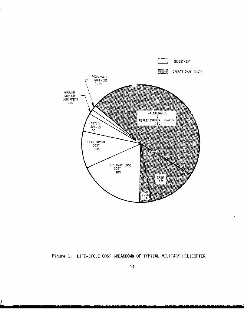
I Life-Cycle Cost Breakdown of Typical Military Helicopter 14
2 End Loading of Cylindrical Roller Bearing .............. 20
3 Roller Bearing With Extended Inner Race ............... 22
4 Conventional and Recess Action Spur Gear Meshes ......... 27
5 Spiral Bevel Gear Central Toe Bearing Pattern ........... 30
6 Preferred Spiral Bevel Gear Bearing Pattern Under FullLoad .......... ... ............................ 30
7 Spiral Bevel Gear Tooth Inspection Casts .... .......... 31
8 Assumed Load Distribution for Analysis of Thin SpurGear Web ........ .......................... .. 32
9 Roller/Thrustwasher Planetary Pinion Support .... ........ 34
10 Spherical Bearing Planetary Pinion Support .... ......... 35
11 Sprag-Type Overrunning Clutch .................... .. 38
12 Spring-Type Overrunning Clutch ...... ............... 39
13 Ramp Roller-Type Overrunning Clutch .... ............. 40
14 Disc Pack Thomas Coupling ....... .................. 42
15 KAflexR Coupling ...... ...................... ... 43
16 Gear Coupling ....... ........................ .. 45
17 Oil Dam for Lubrication of Loose Splines .... .......... 49
18 Conventional Lip Seal ..... .................... ... 51
19 Hydrodynamic Lip Seal ..... .................... ... 51
20 Circumferential Seal ...... .................... .. 52
21 Face Seal ........... .......................... 52
22 Typical Gea'box Lubrication System ................ .. 56
23 Through-Shaft Bearing Lubrication .................. .. 57
8

LIST OF ILLUSTRATIONS (Continued)
Figure Page
24 CH-54 Modularized Gearbox Isometric ..... ............. 60
25 CH-54 Modularized Gearbox Cross Section ............... 61
26 Typical Chip Detectors ...... ........ .......... 65
27 Gamma Function ....... ..... ...................... 73
28 Intermediate Gearbox With Known MTBUR and TBO ........... 77
29 Newly Designed Intermediate Gearbox ................ .. 79
9
A

LIST OF TABLES
Table Page
Size and Shape Parameters for fransmission Failure Modes . 70
2 Reliability Analysis for Existing Gearbox .............. 76
3 Reliability Analysis for New Gearbox ..... ............ 78
4 Reliability Analysis for 200-Hour Test .... ........... 82
4
101
mI

INTRODUCTION
In recent years there has been an ever-increasing emphasis on reliabilityand maintainability in the design of military hardwre. The reasons forthis increased emphasis followi
1. Material and manpower costs are expected to maintain their upwardspiral for the foreseeable future.
2. The branches of government overseeing military spending are becomingincreasingly conscious of the costs of military equipment.
3. Maintenance is generally the single most important item in the life-cycle cost of military hardware.
The design guide presented here is part of the Army's effort to make drivesystem design engineers more conscious of the reliability and maintain-ability aspects of the gearboxes they design.
This design guide is essentially divided into three p. -s. The first partdeals with planning and management of a drive system uesign effort.Although most engineers who head such design efforts ar- not trainedmanagers, they are usually given little guidance in how to plan the design/development program. In general they are given only drawing and testschedules, a budget requirement, aid weight requirements. The tendencyis to put too much emphasis on some of these program goals, usually at theexpense of the structural reliability of the design. The first part there-fore suggests various practices which may be implemented to avoid this pit-fall.
The second part is the "design" part of the design guide. Unlike moreconventionAl design guides, however, the information presented here is notbasic "how to design" information. Rather, it is more concerned with thesubtle aspects and details of design that often mean the differencebetween high and low reliability. Because the sections that make up thesecond part presuppose a basic knowledge of the design of helicopterdrive system components, analytical equations and illustrations showingbasic terminology will not be included. The emphasis of the second partis on "'attention to detail", and as such will include design checklistswhich may be used to insure that all aspects of a design are givenadequate attention.
The final part of this design guide presents the basic methodology fordetermining gearbox reliability with hazard function analysis. Althoughthe numerical results obtained from such an analysis may not be correctin an absolute sense, the results can be correlated with a previous designwhose reliability level is known. Knowledge of the relative reliabilitybetween the on-the-board design and the previous design can be extremelyuseful in insuring that the new design meets its reliability goal.
11

PLANNING AND MANAGEMENT OF THE DESIGN PROGRAM
The design of a reliable and maintainable drive system begins withplanning and management that gives proper emphasis to both of theseextremely important areas. If reliability and maintainability are notprimary considerations of the design manager it is unlikely that thedesign he produces will achieve the desired reliability and maintrinabilitygoals. There are two factors, both present in any drive system designprogram, that could adversely affect the reliability and maintainability ofthe design: schedule and weight requirements. Every drive system manageris extremely conscious of these two factors because, first, they areextremely visible to upper management, and second, the design manager'sperformance rating may depend on huw well he meets these requirements.Therefore, there is a great temptation for design managers to over-emphasize these areas, usually at the expense of other, perhaps moreimportant, considerations, such as reliability and maintainability. Thissection contains a number of suggestions whose implemerr. ion can minimizethe possibility of this happening.
PLANNING
Before serious design work begins, there is a substantial amount ofplanning with which the design manager is burdened. This planning usuallytakes the form of defining tasks, setting schedules and making man-hourestimates. However, this initial planning should also tddress whethertechnological developments such as rotor isolation will be an integralpart of the design. If so, planning for it from the very beginning wouldenhance prospects for an optimum system. Rarely does anyone except-theR&M engineer concern himself with reliability and maintainability at thisstage; yet this is precisely where reliability and maintainabilityassurance should start. The following three tasks should be planned asan integral part of the design program to insure that reliability andmaintainability do not become just incidental consider-tions:
1. Preliminary Reliability Analysis2. Design Review3. Detailed Reliability Analysis
Preliminary Reliability Analysis
After the basic drive system arrangement has been laid out and sized, butbefore detail design begins, a preliminary reliability analysis should beperformea on the gearbox design according to the procedures outlined inthe Hazard Function Analysis carf••, of this gude. T,,s analysis shoul,
then be compared tc a similar analysis performed on an existing design witha known MTBF. In this way the reliability of the new design can beassessed very early in the design stage. If it appears from the analysisthat the design will not achieve the desired goal, such design changes asswitching to bearings with higher lives can be made with as little troubleas possible. Since this is a preliminary analysis, some simplificationswill have to be made in the reliability analysis to keep the effort downto a reasonable level. The bearing portion of the analysis must be
12

simplified, since at this stage of the design such quantities as the lubri-cation, misalignment, and material factors have not as yeý been determined.Hence. a uniform life adjustment factor, which can be estimated from pastexperience, should be applied to all of the basic bearing lives.
One additional item should be noted here with regard to the preliminaryreliability analysis. The analysis should be performed based on theexpected aircraft mission power spectrum. If, however, the urive system isto be subjected to a "must-pass" overstress test, it would be wise to alsoconduct the analysis using the test spectrum to determine what the proba-bility is of passing the test. In recent years some of these tests havebecome so severe that designing the gearbox for a reasonable chance ofpassing the test is e more severe requirement than designing the gearboxfor the required field reliability level.
Design Review
It is suggested thai 'he design manager subject his basic design layout tothe scrutiny of other drive system engineers before the start of the detaildesign phase of the program. He should give to other design engineerscopies of the basic design layout with such information as shaft speedsand basic bearing lives, and should ask for their comments and criticismsof the design. The benefits of this type of design review cannnt be under-estimated. It is virtually certain that at least a few flaws in the basicdesign will be found by the reviewing engineerings. They will have hadexperience with one feature or another where past experience has shown thatit should be changed. No single design engineering will have had experiencewith all of the past problems; hence, the more design engineers reviewingthe basic layout, the smaller the chance that past mistakes will be repeated.
Detailed Rcltrbility Analysis
This is essentially a repeat of the reliability analysis suggested earlier.This analysis, however, is performed when the program is far enough intothe detail design stage to use actual bearing lives with the appropriateadjustment factors and with a refined power spectrum. Again, this analysisshould be compared to a similar analysis on a gearbox with a known MTBF.It is also suggested that if a "must-pass" overstress test is required,the detailed reliability analysis also be performed using the test spectrum.
MANAGEMENT
Apart from incorporating the above suggestions as integral parts of thedesign program, there are a number of other rules that the design managershould abide by to "nsure thdt reliability and maintainability goals arerealized.
First, the desigii manager must keep in mind that reliability is the singlemost important cost consideration in drive system designm. Maintenance andreplenishment spares generally account for more than 50 percent of the life-cycle cost of an aircraft as shown by the life-cycle cost breakdown ofFigure 1. Hence, even without considering the cost of aircraft downtime
13
S. ..
[-] INVESTMENT
E: OPERATIONAL COSTS
PERSONNELTRAINING1.~
GROUND
SUPPORT :il~ IEQUIPMENT .. ;lI: I~~ **
1. 5:~ *Wvi~P'MAINTENANCE -10
RPEISHE:NT SPARES1-LNT L__ ____..~ -
or mission aborts, it is clear that the importance or reliability must notbe underestimated.
With regard to executing the design program, the most important activitywith regard to reliability is the analysis of the various drive systemcomponents. The analysis of a helicopter drive system should be verythorough with attention to detail given top priority. The analyticaletfort should not be sacrificed to maintaining schedule. No one everremembers that the drawings went out on time or that the weight targetwas reached, when failures start occurring during development testing orfield operacion. One way to ensure that the analysis is thorough is touse design checklists such as those provided in this guide for the variousdrive train components. Although many of the items on these checklistsseem obvious, it is surprising how often the obvious is overlooked. Reviewsby other areas such as R&M, manufacturing, product support, and qualitycontrol can also head off many problems which may be more troublesome inlater stages of the program. Changing lines on a drawing during the designstage is always easier and cheaper than redesigning existing hardware. Itis also important that any high risk areas of a design be identified earlyin the design stage and that alternate designs be prepared in the eventthe initial design does not work out. This is especially true where newtechnology is being introduced for the first time into a production design.
Maintainability also requires much attention during the design stage. Themost common problem with respect to maintainability in past designs has beena lack of accessibility to drive train components that required servicing.To minimize this, the transmission design manager should maintain closecontact with the aircraft configuration manager and the design managersfrom other groups such as airframe, propulsion, and controls, etc., tomake certain that hardware integral to those areas does not interfere withdrivetrain maintenance and vice versa.
GENERAL DESIGN CONSIDERATIONS
Although the detail design of helicopter drive train components is perhapsmore important in insuring the reliability and maintainability of a givendrive system, some general design constraints and requirements should begiven special attention because of their potential impact on the long-termreliability of the drive system. The first ,-f these is the mission powerspectrum. rhe key point with regard to th' Jesign parameter is to anti-cipate increases in power and to leave room for growth in all primary power
train ...d b ,ring. r"his 1 s especially important fir tail -411 ,4Co drivesystem components, where the design power may be much less than maximumcontinuous. Despite predictions by aerodynamicists, the power requirementfor the tail rotor will noL be known with certainty until flight testingbegins. If no allowance is made for greater than predicted power levels,the redesign will be less than ideal, and the reliability of the componentsis likely to be compromisud. Another point to remember is that virtuallyevery military aircraft is uprated in power before the end of its opera-tional life. If this is not anticipated during initial design, thereliability of the later uprated transmission will suffer. In other words,one should anticipate charges for the worse.
15
New developments in technology or the addition of new features must alsobe anticipated during initial design. For example, it is possible that arotor isolation system may be added in the future. In this case the trans-mission designer must be certain that, if required, a new coupling with agreater misalignment capability can be added without drastically alteringthe present design. Allowance should also be made for increases inhousing stiffness without interfering with the control system or the inter-nal gearbox components. Room for growth in the filter envelope is anothervery desirable feature. The superfine filters currently under developmentwill in all likelihood require larger envelopes to accommodate the increasein particles trapped in the element.
Another factor to consider is the detectability of failure modes withinthe gearbox. Care must be taken to insure that debris resulting from anypossible failure can reach the chip detectors. A failure mode and effectsanalysis can be helpful "n determining this. It will also point out wheresimple design changes can prevent relatively minor failures from becomingmajor ones.
Noise and vibration can affect the reliability, not only of the drivesystem itself, but also of the other aircraft subsystems. Hence, everyeffort should be made to make the gearbox as quiet and vibration free asporsible. This may be accomplished by using helical or high contact ratiospur gears, instead of conventional spur gears, by making certain thatcritical speeds are avoided and by avoiding gear clash frequencies whichmay reinforce each other.
Another important consideration in the design of any drive system is theefficient use of weight. In general, overdesign means higher reliability,but in aircraft the importance of weight is such that overdesign of somecomponents will invariably lead to underdesign elsewhere. Given theexperience with past drive systems, bearing life should never be sacrificedin a weight reduction effort, since bearings are likely to be the maindrivers in the establishment of the MTBR. In the basic design of thedrive system, it should be realized that, in general, the greater the ratioin the final reduction stage, the lighter the transmission. The lightestfreewheel unit design will be possible when the freewheel unit is locatedon the first reduction stage input where the speed is highest and torque islowest. By taking advantage of such concepts, the weight allowance of thetransmission can be efficiently utilized in improving its reliability.
FUNCTIONAL GROUP ACTIVITY
The functional group charged with drive system design can contribute greatlyto the reliability and maintainability of future designs by setting up andcontinuously updating a problem file. This file, which could be arrangedby the various -eneric components, would essentially be a history of all ofthe developmental and field problems associated with past and present drivesystems. The information contained in this file would consist of descrip-tions, causes, and solutions of the various problems. The primary purposeof this file would be to prevent past mistakes from being repeated. Itwould also serve to centralize that information, which would otherwise be
16
-I

scattered in various memos or in the files of the engineers who worked onthe past problems. This procedure also documents "experience" and keepswithin the company information that othewise might be lost when experiencedengineers leave.
In conjunction with the "problem" file, it would be wise for the functionalsection to maintain a design manual that covers all aspects of drive systemdesign. This manual should be kept updated with the latest analyticaltechniques and should include, when appropriate, information that can begleaned from the problem file. The maintenance of such documents as thosesuggested here will ensure a uniform and orderly approach to drive systemdesign and will certainly lead to the development of drive systems withimproved reliability.
ACCELERATED TESTING
Accelerated testing, i.e., testing at loads greater than those experiencedin normal operatien, has long been used in the aerospace industry duringaircraft development programs. The purpose of such testing is twofold.First, the structural adequacy of the component or system can be substan-tiated from the standpoint of flight safety. Second, accelerated testingcan greatly reduce the test time and therefore the cost of a test program,especially where failure modes of a fatigue nature are anticipated.Accelerated testing has long been effectively utilized in this manner inthe structural testing of such helicopter components as rotor blades andmain rotor shafts.
Recently, a trend has developed where accelerated testing is being morewidely applied to entire gearboxes. The acceleration factor of some ofthese tests is quite high, with the prorated test power often double themission prorate or higher. This can lead to failures that may be uncharac-teristic of a gearbox operating at normal power levels. Since many ofthese tests can be classified as "must-pass", it is strongly advised thatduring design the probability of passing such a test be calculated. It maybe found that the design criteria may have to be more severe than themission in order to have an acceptably high probability of passing the test.
There are a number of components whose performance can be drasticallyaffected in an overstress environment. The most obvious is the drasticreduction in bearing life. Since bearing life varies inversely with the3.33 power of the load, doubling of the prorated load will cut the bearinglife by a factor of 10. Although the chances of spalling a single indivi-dual bearing remain small, the. probability of spalling a bearing whenconsidering all the bearings in the gearbox can be quite large. A rela-tively recent example showed that in a 200-hour overstress test, the proba-bility of spailing a bearing was over' 25 percent. If the same 200 hourswere run at the mission spectrum the probability of spalling a bearingwould be less than 2 percent. Considering the possible repercussions of aspalled bearing in a must-pass test, the 25 percent chance of failure isvery high.
There are other affects of overstress testing, which, while not as crucial
17
I
......... ...

as bearing spalling, nevertheless can adversely effect the condition ofgearbox components. Fretting is more likely, for example, on bolted gearflanges. Bearings are far more likely to creep or spin on shafts. Specialcare should be given to proper development of bevel gear patterns, sincehigh overloads can drastically shift the patterns, making tooth breakage amore likely occurrence. With spur gears the possibility of hard lines orscuffing increases with the increased load. The tip relief may beinsufficient to account for the increased deflection under load. Hence,the teeth go into mesh early and out of mesh late. Under certain circum-stances this could lead to contact below the TIF diameter of the gear,i.e., non-involute contact.
As can be seen from the aoove discussion, there are a number of factorsto be considered when a greatly accelerated test is included in a develop-ment program. It would be wise to assess the risk of failing such a testas early as possible in the design so that a decision could be made onwhether the risk is acceptable or design changes should be made. It isrecommended that overstress qualification tests be limited to a prorateof 110 percent of maximum power with only brief durations of running inexcess of 120 percent. It is also strongly recommended that thosediscrepancies which result in disqualification be clearly defii1ed beforethe test.
18
L
BEARINGS
From the standpoint of reliability, bearings are by far the most importantgearbox components, since they are among the few components that aredesigned for a finite life. Bearing life is usually calculated using theLundberg-Palmgren method. This method is a statistical technique based onthe subsurface initiation of fatigue cracks in a through-hardened air-meltbearing material. The life generally used In the BiO life, which is thenumber of hours at a given load that 90 percent of a set of apparentlyidentical bearings will complete or exceed. Over the years, bearingspecialists have devised a number of factors that can be applied to B10 lifeso that it more accurately correlates with the observed life. These includematerial, processing, lubrication film thickness (EHD), speed, and misalign-ment factors.
REQUIRED BEARING LIFE
The required bearing life depends on the desired rcliability of the gear-box (usually stated in terms of MTBF) and the number of bearings in thegearbox. This discussion relates to the KTBF or system life of the bearingsalone. The effect of other components on gearbox reliability is presentedin the Hazard Function Analysis section. The following expression gives theapproximate life for which each bearing should be designed to achieve agiven gearbox B10 life or MTBF for a system containing N bearings.
91 N10 _N MTBF Where L =0 design B10 life for each5.455.45 individual bearing
or
L10 = L N = number of bearings in systemLIO Lsys
L design B10 life of the systemSys
MTBF = design Mean Time BetweenFailure for bearings alone
The above expression assumes a Weihull failur, distribution with a shapeparameter equal to 10/9, the value generally used for rolling elementbearings. The life (L10 ) given in the above expression includes lubrication,misalignment, and material factors. Since the misalignment and lubricationfactors are usually approximately equal tn -0,; the desired tinmodifiedcalculated life, which is generally used in the early stages of a design,can be found by simply dividing the life found in the above expression bythe material factor. Typical material factors used for vacuum-melt air-craft quality bearings are 6.0 for ball bearings and 4.0 for roller andtapered roller bearings.
It would be advisable in initial bearing life calculations to use doublethe required unmodified calculated life for low-speed bearings under 1000rpm, since the lubrication factor for these bearings is likely to be quite
19

"low.
BALL BEARINGS
Ball bearings are generally used where there is likely to be excessivemisalignment or shaft deflection. They are also used, especially induplex arrangements, where accurate axial positioning is required in thepresence of thrust load, such as with bevel gear shafts. Ball bearings arenot as common in the main drive train of more recent designs because ofadvancements made with tapered roller bearings. Ball bearings are, however,often used on lightly loaded accessory shafts. Higher bearing life iseasily achieved in these applications due to the very small loads andinstallation is simplified, since a ball bearing is nonseparable andrequires no special setup procedures.
CYLINDRICAL ROLLER BEARINGS
Cylindrical roller bearings are used to support pure radial loads. Theyare often used at one end of highly loaded gear shafts with either taperedroller bearings or multiple-row matched ball bearings at the other end.Roller bearing life is drastically reduced by excessive misalignment ordeflection; hence, when using roller bearings, the stackup of tolerancescontributing to misalignment and the shaft or housing deflections shouldbe carefully considered. This is especially true with main rotor driveshafts where high shaft deflection is caused by the rotor head moment.To compensate for some degree of misalignment or deflection and to carryheavy radial loads, roller bearings are crowned to prevent the phenomenonknown as end loading (see Figure 2).
POLLk H E•I0 Ht )IRESS
END) LOADING
LENGTIH ALONG ROLLER
Figure 2. END LOADING OF CYLINDRICAL ROLLER BEARING
20 iI
... "I
End ioading invariably leads to a drastic reduction in bearing life. The
amount of crown to be used should be based on maximum continuous power. Atlower powers, the crown will not significantly change bearing life, whilehigher powers are usually transients that load the bearing for short dura-tions only.
INTERNAL CLEARANCE
Internal clearance is an important consideration in the design of ball androller bearings, since improperly mounted internal clearance can drasticallyshorten the life of a bearing. Too little internal clearance limits theamount of misalignrent that can be tolerated and can lead to heavilypreloaded bearings, particularly at low temperatures. Excessive internalclearance will cause the load to be carried by too few rolling elements.The best practice is to ensure that under all conditions there will be asmall positive internal clearance. Usually, the most significant factorsto consider when determining mounted internal clearance of the bearing arethe reduction of internal clearance due to shaft or housing fits and theeffect of temperautre on the magnesium housing/outer race interfacediameters. Given the high press fits generally used with helicoptertransmission bearings and the low temperature requirements, it will befound that standard catalog internal clearances are usually not correct.
TAPERED ROLLER BEARINGS
Tapered roller bearings are being used increasingly in helicopter drivesystems, since they can react both thrust and radial loads and can offerthe greatest load carrying capacity in the smallest possible envelope.Although early tapered roller bearings were speed limiter these restric-tions have been removed Ly utilizing bearings with special lubricationfeatures. However, on very high-speed shafts, the use of tapered rollerbearings may be precluded due to their inability to operate for requiredtime intervals under survivability (oil-off) conditions. Tapered rollerbearings, unlike single-row ball and cylindrical roller bearings, requirespacers or shims to give these bearings the proper amount of preload orend play for proper operation. Usually it is desirable to have a lightpreload although a smnall amount of end play is often acceptable. As withinternal clearance, extremes in end play or preload should be scrupulouslyavoided.
PREVENTING BEARING RACE CREEP
The creeping or spinning of bearing inner races on gearshafts is a fairlyconmmon, although not usually serious, problem. in helicopter drive systems.
Lundb•r'g and Palmgren developed fairly simple parametric calculations forthe minimum fit to prevent creep with solid shafts, but there has beenlittle if anything published on minimum press fits for hollow shafts, thetype exclusively used in helicopter drive systems. Since an accuratemathematica' solution to such a problem would be extremely difficult, thebest approach at this time seems to be a reliance on past experience.
21
• I i iI
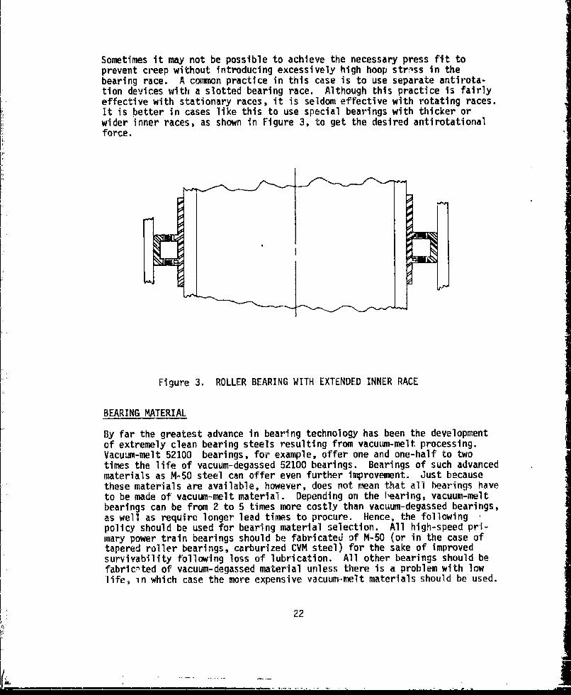
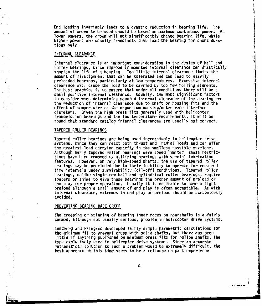
Sometimes it may not be possible to achieve the necessary press fit toprevent creep without introducing excessively high hoop strizss in thebearing race. A common practice in this case is to use separate antirota-tion devices with a slotted bearing race. Although this practice is fairlyeffective with stationary races, it is seldom effective with rotating races.It is better in cases like this to use special bearings with thicker orwider inner races, as shown in Figure 3, to get the desired antirotationalforce.
Figure 3. ROLLER BEARING WITH EXTENDED INNER RACE
BEARING MATERIAL
By far the greatest advance in bearing technology has been the developmentof extremely clean bearing steels resulting from vacuum-melt processing.Vacuum-melt 52100 bearings, for example, offer one and one-half to twotimes the life of vacuum-degassed 52100 bearings. Bearings of such advancedmaterials as M-50 steel can offer even further improvement. Just becausethese materials are available, however, does not mean that all hearings havpto be made of vacuum-melt material. Depending on the h'earing, vacuum-meltbearings can be from 2 to 5 times more costly than vacuum-degassed bearings,as well as require longer lead times to procure. Hence, the followingpolicy should be used for bearing material selection. All high-speed pri-mary power train bearings should be fabricated of M-50 (or in the case oftapered roller bearings, carburized CVM steel) for the sake of improvedsurvivability following loss of lubrication. All other bearings should befabric-ted of vacuum-degassed material unless there is a problem with lowlife, in which case the more expensive vacuum.-melt materials should be used.
22
JI

INSPECTION REQUIREMENTS
Proper inspectior, of bearings can significantly reduce their mortality rate.Besides the obvious dimensional inspection requirements, two additionalinspections should be specified for all helicopter drive system bearings;magnetic particle and nital etch. Magnetic particle inspection can detectthe presence of relatively large surface or near-surface anomalies, such asinclusions, which are often the cause of bearing spalls. Nital etch inspec-tion can detect the presence of grinding burns, which locally change thehardness of the material and also result in premature bearing failure.Recently research has been done on such techniques as magnetic perturbation,laser-scattc'red light, and Barkhausen noise to accurately detect surfaceand near-surface anomalies in bearings. These methods are presently usedon an experimental basis due to extremely high costs.
INSTALLATION/REMOVAL
The installation of bearings should be carefully considered during designnot only to prevent assembly errors, but also to permit easy removal of thebearing without damaging it. Lead chamfers should be provided at all bearingjournals to facilitate installation. When specifying the breakout on thebearing corners, the shaft drawing should be checked to ensure that themaximum radius at the shaft shoulder will be cleared by the bearing. Theheight of the shaft shoulder should, if possible, be consistent with thatreconmnended by bearing manufacturers. Where necessary, flats should bemachined on the shaft shoulder so that a bearing puller can remove thebearing by contacting the inner race. Many bearings have been damaged in thepast where the bearing puller could grab only the cage or rollers of thebearing. Where duplex bearings are used, the bearings should be marked sothat the installer can readily determine the proper way for the bearings tobe installed. Incorrectly installed duplex bearings will not properly reactthe design loads. All bearings that can be separated should have the serialnumber clearly shown on all of the separable components. This will preventthe inadvertent mixing of components. Every assembly drawing that containsbearings should clearly explain in the drawing notes how the bearing shouldbe installed. It is imperative that the mechanic building up an assemblyhave this information readily available.
TAIL ROTOR DRIVESHAFT BEARINGS
Tail rotor driveshaft bearings present a slightly different problem to thedrive system designer than bearings within the gearboxes. Load capacity israrely, if ever, a problem since the only loads on the bearing are those dueto a shaft weight, imbalance, and misalignment. Misalignment is usually nota problem with bearings mounted within viscous dampers, which in present-day drive systems is usually the case, If, however, a hard-mounted bearingis used, provision for the misalignment must be made either by using highinternal clearance or by some sort of spherical outside diameter that willallow the bearing to move as a complete unit to compensate for themisalignment.
23

Contamination of the lubricant either by water or by gritty particles isthe most common reason for failure of these bearings. To resist corrosionvacuum-melt stainless steel should be used as the bearing material, sincethe dynamic capacity of the bearing is not crucial. Another technique thathas been developed recently to prevent corrosion is the application of verythin chrome plating to the bearing elements. It has been reported thatthese coatings have performed very well in test.
There has been some debate as to whether it is desirable to have tail rotordrive shaft bearings with removable seals. The advantage in having remov-able seals is that the bearings may be inspected at overhaul, and if foundin satisfactory condition may be repacked and reused. Unfortunately in thepast when removable seals have been used, organizational maintenancepersonnel have removed the seals and have attempted to repack the bearingsthemselves. More often than not, they would overpack the bearings withgrease, which led to overheating and eventual failure. Generally thesebearings should be packed only about one-third full with grease. Hence, ifremovable seals are to be used, specific instructions should be provided inthe technical manuals on the correct way to pack these bearings.
24
' j

GEARS
Drive system design usually begins with the sele-tion of the gearing thatwill be used to transmit the power from the enginies to the main and tailrotors. The process begins with a layout showing location of engine in--puts, main rotor shaft centerline, and tail drive shaft centerline. Thisgeometry, along with the required reduction ratio, dictates to a largeextent what combination of spur gears, helical gears, spiral bevel gears,and planetary reduction units will be used to deliver the power to therotors. It is generally desirable from a weight and size standpoint tohave as large a ratio as possible in the final reduction stage.
The balance of this chapter will address itself to the detail design ofspur, helical, and spiral bevel gears, with a discussion of gear webdesign included. A separate section dealing exclusively with the designof planetary units is also provided.
SPUR GEARS
Spur gears are commonly used in helicopter drive systems both for parallel-axis speed reduction and in coaxial planetary units. In general thereliability level of helicopter drivetrain spur gears is extremely highusing present design standards, and maintainability is not an importantconsideration in the design of spur gears. There Ere, however, somedesign considerations that will be discussed her- because they are some-times overlooked.Balancing the Design
Generally the initial design of a spur gear mesh is onc of standard propor-tions and equal tooth thickness for both pinion and geav'. This is rarely,however, the opti.aum configuration for a spur gear mesh because this typeof design does not have two very desirable characteristics: recess action,and balanced bending stresses in pinion and gear. A recess-action gearmesh has a long addendum pinion and shcrt addendum gear. In this type ofdesign all or most of the sliding takes place as the gear teeth are movingaway from each other. A recess-action mesh is quieter and smootherrunning than a standard mesh and has a much lower tendency to score due tobetter lubrication characteristics within the mesh.
Although the advantage of having balanced bending stresses on pinion andgear is primarily lower weight, it does have an indirect bearing on relia-bility. As was stated earlier, whenever there is an inefficient use ofweight, reliability is compromised somewhat. For example, even a fractionof a pound wasted through not optimizing a spur-gear mesh could insteadbe applied to a bearing where the life could perhaps be doubled. Hence,while the emphasis on light weight can be detrimental to reliability, thecarrying of excess weight can also have an adverse effect. High relia-bility in a helicopter drive system depends largely on the efficient useof weight.
25
-K --------

Fortunately it is usually a fairly simple task to achieve recess actionand balanced bending stresses with most spur gear meshes. This is ac-complished by shifting the length of contact up the line of action towardsthe driven gear, as shown in Figure 4, while increasing the circular tooththickness of the pinion and decreasing that of the gear. It is essentiallya trial and error procedure but is usually easily done.
Design Criteria
There are four design criteria that are used to evaluate the adequacy of spuror helical gear design: bending stress, hertz stress, flash temperature index,and/or lubrication film thickness. The first three have long been used ingear design and the methods of calculation are well documented in manypublications. EHD film thickness is a more recently developed criterionthat some gear specialists have advanced as a check for scoring probability.It can be appreciated that if an oil film of a thickness greater than thecontacting surface asperities can be maintained, scoring will not occur.Although the exact method for calculating EHD film thickness is not yetstandardized, it is highly recommended that it be used as an added checkon spur gears, especially those with low pitch-line velocfties. Therehas been at least one instance of chronic pitting, which an EHD film thick-,ness calculation may have prevented. It is interesting to note that thecompressive stress in the particular mesh was well within the generallyrecognized allowable range recommended by American Gear ManufacturersAssociation.
The subject of allowable tooth stresses is a controversial one and noattempt will be made here to outline specific values. Each company design-ing gears seems to have its own set of criteria and limits that have evolvedover the years, a,.J this kind of experience is difficult to refute.
The same can be said of S-N curve shapes. Experience has shown that theuse of allowable stresses published by AGMA will result in satisfactorydesign and performance.
Profile Modification
In order to insure smooth conjugate action under l iad, it is generally thepractice to modify the involute profile, usually with tip relief, tocorrect for the deflection of the gear teeth under load. The deflectionof the gear teeth under load should be calculated as accurately as possible,since tGo little or too much relief can both be detrimental to the per-formance of spur gears. Ton little relief causes the gear teeth to go intomesh early and to go out of mesh late. This results in higher dynamic loadswith attendant increases in stress, vibration and noise, and possible non-involute contact that can lead to hard lines, scuffing, or scoring of thegear teeth. Too much tip relief lowers the LU,,cart ratio of the gear setand again can result in less than optimum performance with respect to stress,vibration, and noise.
26
I

Opp
I2
"LLqc op
1-1I-
Figure 4. CONVENTIONAL AND RECESS-ACTION SPUR GEAR MESHES
27

Crowning
Crowning is generally applied to spur gears to insure full contact acrossthe face of the gear without end loading. Again both excessive and insuf-ficient crown can be detrimental to spur gear performance. With insufficientcrown, end loading will occur that will result in higher than predictedbending and hertz stresses. With excessive crown the full face width willnot be used and again, higher than predicted hertz stress will occur in thecenter of the tooth. The method used to calculate the amount of crown fora spur gear tooth is very similar to that used to calculate the crown onbearing rollers
Helix Correction
If the bearing mountings at either end of a spur gear are not of equalstiffness the spur gear will tend to cock under load. This will cause theload to be concentrated at one end of the tooth, resulting in increasedstresses. This condition is more pronounced with gears with high LiDratios. By grinding a helix across the face of the gear, this conditioncan be corrected. Unfortunately analytical prediction of the requiredhelix correction, if any, is not very practical and visual pattern inspec-tion can be misleading. Strain gaging the gear rim is perhaps a bettermethod of determining correct helix corrections. This can be done byiteratively grinding a helix across the face of the gear until the straingages on either side of the face give equal readings.
When grinding for helix corrections, however, it must be certain that thelocation of the bearing bores of the housings used during the test are toblueprint tolerances. If the housing is Fad, grinding helix correctioninto gears which are used in good housings could cause the very problemthat helix corrections are designed to prevent.
Edge Break
It is advisable that all gear teeth, including spiral bevel and helicalgear teeth, have the edges broken. This will prevent chipping of the gearteeth at the corners, which carburization has made very brittle.
HELICAL GEARS
Helical gear-s are not nearly as common in helicopter drive trains as spu'gears, although they are quieter and have greater load-carrying capacityper inch of face width than spur gears. The one disadvantage of helicalnears is that ÷ .th ust l iiriuuceU along the gearshaft, thereby.. . ...J a ,,, l-a .is k. .... 1.. -necessitating somewhat larger bearings. This problem can sometiwnes beovercome if a spiral bevel gear is attached to the same shaft. In thiscase, the bevel and htlical gears can be designed sn that their thrust loadsoppose each other. Another way to avoid the thrust problem is to use doublehelical gears (sometimes called herringbone). Here the thrust loadsdeveloped by the opposing helical gear are canceled out. The problem withthis type of design is the difficulty of timing between the facing gears.
28
J1
Analysis of helical gears is very similar to that used for spur gears.The stress analysis is performed using an equivalent spur gear tooth. Thestrength analysis of helical gears, like that of spurs, is outlined inAGMA standards.
SPIRAL BEVEL GEARS
Spiral bevel gears are found, almost without exception in every present-day helicopter drive system. They are probably the most difficult gearsto design, since the geometry of spiral bevel gears is considerably morecomplicated that that of spur or helical gears. The Gleason Works ofRochester, New York has developed much of the current spiral bevel geartechnology, including the analytical techniques used throughout most ofthe helicopter industry. Although the literature published by Gleasoncontains much of the information needed to design reliable spiral bevelgears, some points will be covered here.
Basic Design
The hand of spiral of the gears should be chosen if possible, so that theaxial force tends to push both pinion and gear out of mesh. If that isnot possible, then the hand of spiral should be chosen so that the pinionis forced out o' mesh. The face contact ratio of the mesh should be ashigh as possible to ensure smooth quiet running. While a face contact of2.0 or greater is preferred, a face contact ratio as low as 1.25 is ac-ceptable. The face width of a spiral bevel gear should not in any caseexceed one-third of the outer cone distance or the gear becomes impracticalto manufacture because of the very small tooth depth at the toe of thegear and because load concentrations at the toe end could lead to toothbreakage.
Gear Pattern Development
The development of correct tooth contact patterns is extremely importantwith spiral bevel gears, since incorrect patterns can lead to high bendingstresses and eventual tooth fracture. Although gear pattern developmentis a rather complex subject and largely beyond the scope of this guide,some general points will be brought out. First, in general, a central toebearing equal to approximately one-half the tooth length, as shown inFigure 5, is specified under light load conditions. In practice the toothbearing pattern nearly always spreads out and shifts toward the heel underfull load, so that the operating patter-n will appear as shown in Figure 6.It is recommended that a V and H check be performed on all spiral bevelgears, since that is a more accurate method of determining the requiredlength of bearing than merely visually inspecting the patterns. The V andH check is a method for measuring the amount and direction of the verticaland axial displacements of the pinion from its standard position to obtaintooth bearing patterns at the extreme toe and the extreme heel of the tooth.The V and H readings are then compared to the readings of a master gear set.When the total vertical movement of the V and H check is too large, it in-dicates that the tooth bearing is too short, and therefore the load will beconcentrated on too small an area of the tooth surface, which could lead to
29
- - - - - - -- - - --.- _--.-..-
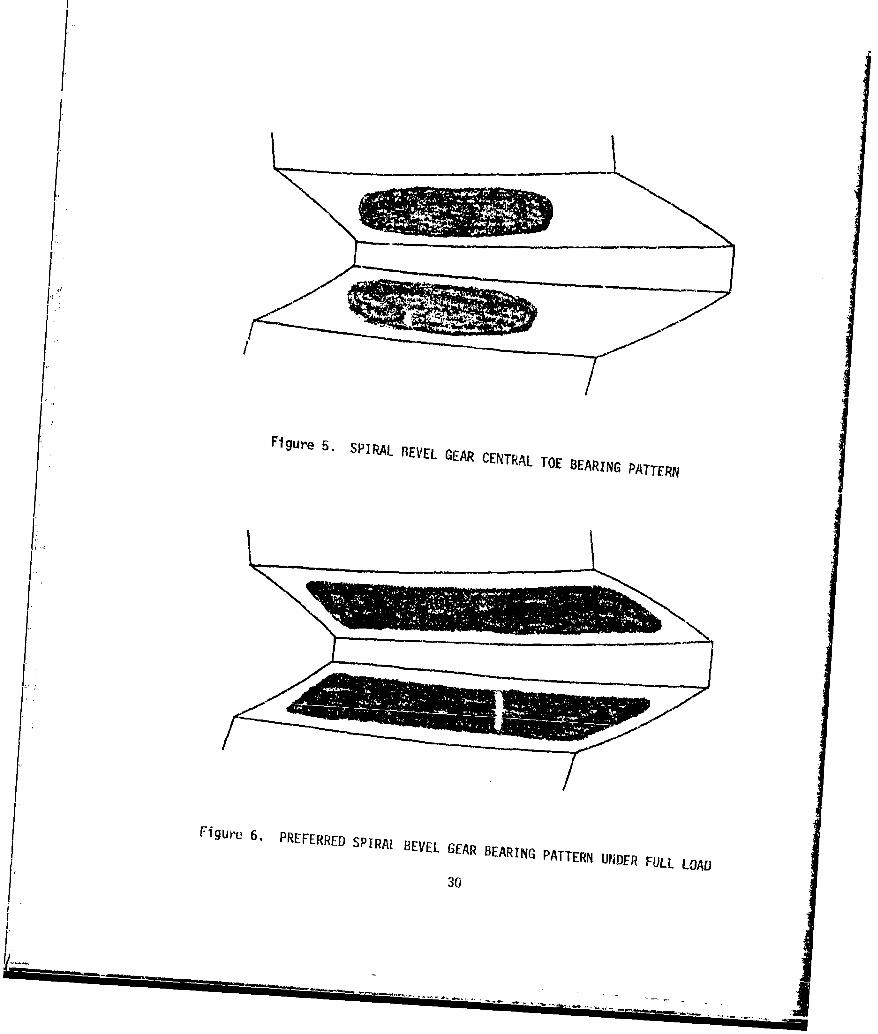
Figure 5. SPIRAL REVEL GEAR CENTR<AL TOE BEARING PATTERN
// FigUre 6. PREFERRED SPIRAL BEVEL GEAR BEARING PATTERN UNDER FULL LOArD
f 30
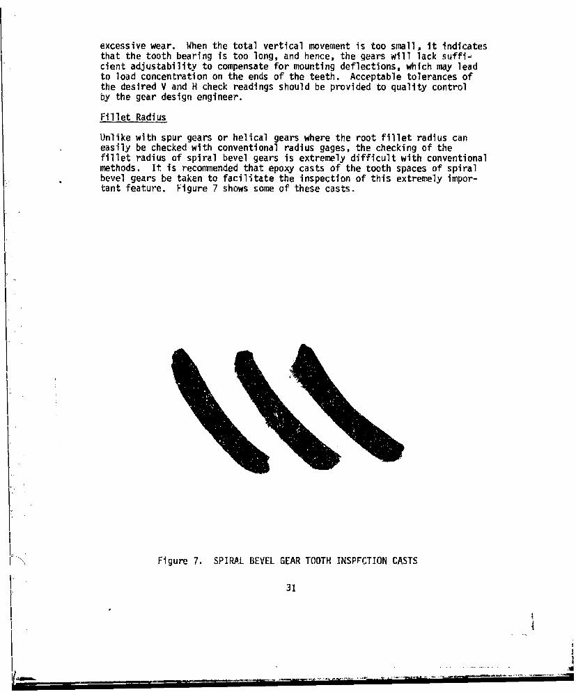
excessive wear. When the total vertical movement is too small, it indicatesthat the tooth bearing is too long, and hence, the gears will lack suffi.-cient adjustability to compensate for mounting deflections, which Hay leadto load concentration on the ends of the teeth. Acceptable tolerances ofthe desired V and H check readings should be provided to quality controlby the gear design engineer.
Fillet Radius
Unlike with spur gears or helical gears where the root fillet radius caneasily be checked with conventional radius gages, the checking of thefillet radius of spiral bevel gears is extremely difficult with conventionalmethods. It is reconmended that epoxy casts of the tooth spaces of spiralbevel gears be taken to facilitate the inspection of this extremely impor-tant feature. Figure 7 shows some of these casts.
K" Figure 7. SPIRAL BEVEL GEAR TOOTH INSPFCTION CASTS
31
I i
t '!
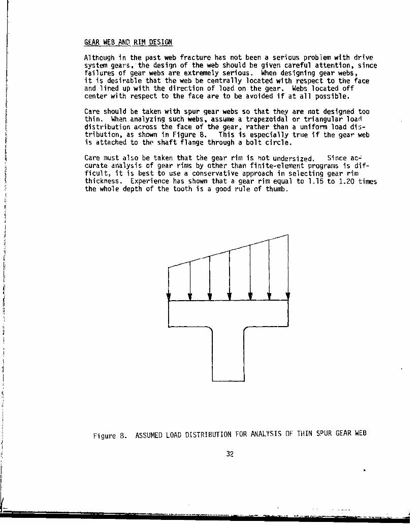
GEAR WEB AND RIM DESIGN
Although in the past web fracture has not been a serious problem with drivesystem gears,-the design of the web should be given careful attention, sincefailures of gear webs are extremely serious. When designing gear webs,it is desirable that the web be centrally located with respect to the faceand lined up with the direction of load on the gear. Webs located offcenter with respect to the face are to be avoided if at all possible.
Care should be taken with spur gear webs so that they are not designed toothin. When analyzing such webs, assume a trapezoidal or triangular loaddistribution across the face of the gear, rather than a uniform load dis-tribution, as shown in Figure 8. This is especially true if the gear webis attached to the shaft flange through a bolt circle.
Care must also be taken that the gear rim is not undersized. Since ac-curate analysis of gear rims by other than finite-element programs is dif-ficult, it is best to use a conservative approach in selecting gear rimthickness. Experience has shown that a gear rim equal to 1.15 to 1.20 timesthe whole depth of the tooth is a good rule of thumb.
iii
3I
Figure 8. ASSUMED LOAD DISTRIBUTION FOR ANALYSIS OF THIN SPUR GEAR WEB
32
F I...T -.
L. . '' ,• F
PLANETARY UNITS
Planetary units are used in many helicopter drive systems because theyoffer relatively large speed reductions in a compact package. Because theload is shared among the pinions, the face width of the planetary gears ismuch less than that which would be needed with a single mesh reduction.
There are several points to remember in the basic design of a planetaryUnit. First, it is desirable from a weight standpoint to use as manypinions as possible in the unit. Sometimes it is possible to add anotherpinion through the use of stub teeth on the pinions. When choosing aplanetary design, it -is desirable not to have the equally spaced planetsmeshing in unison with the sun or ring gear. This may be assured bydesigning the planetary unit so that the following relationship holds:
Nr or Ns = k + A
n n n
Where Nr = number of teeth in ring gear
Ns = number of teeth in sun gear
n = number of planet pinions
k = a whole numberalA an irreducible proper fraction
The analysis of planetary gears is exactly the same as for normal gearsexcept that with the reverse bending experienced by the pinion teeth, theallowable bending stress is lower. Often it will be necessary to grindhelix corrections across the face of the sun and ring gears, especially ifa roller/thrustwasher-type support is used for the pinions. The amount ofthis correction can be approximated during design by calculating the slopeof the planetary plates.
There are two basic types of pinion bearing supports that may be used inplanetary units: roller/thrustwasher and spherical bearing!,. These areshown in Figures 9 and 10, respectively. The rolle-/thrustiasher designis generally used for high-power planetary units where both an upper andlower plate are needed to support the planet posts. The most commonproblem with this type of design is thrustwasher wear. The excessive weargenerally results from an inadequate supply of iubricdnL to the thrust.washerarea. Hence, special attention should be given to this area with respectto lubrication. The spherical bearing-type support is generally the pre-ferred des gn from a reliability standpoint, since there are fewer partsand the tfrustwasher problem is eliminated. The spherical bearings alsoallow the pinions to maintain alignment with the sun and ring gears despitedeflection of the pinion posts. This obviates the need for any helix cor-rection on the sun and ring gears. Despite the advantages of this design,it may be impossible with very high torque planetary units to provide
33
L i i _ - _--"-_-- T--- -- - r . .•T .-- i. - i•. .__ .. --
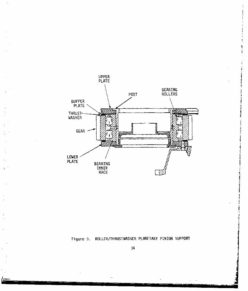
UPPERPLATE
BEARINGPOST ROLLERS
PL.ATE .T 1THRUST-•
WASHER
LOWERPLATE BERN
INNERRACE
Figure 9. ROLLER/THRUSTWASHER PLANETARY PINION SUPPORT
34
[ - , . . - . . .

CD0
coa
u0j
I-
LUU
C)n
aZOO
adequate support to the pinions with a cantilever design. In such casesit will be necessary to use the two-plate design.
36
36
ip _ " - " j
DYNAMIC COMPONENTS
OVERRUNNING CLUTCHES
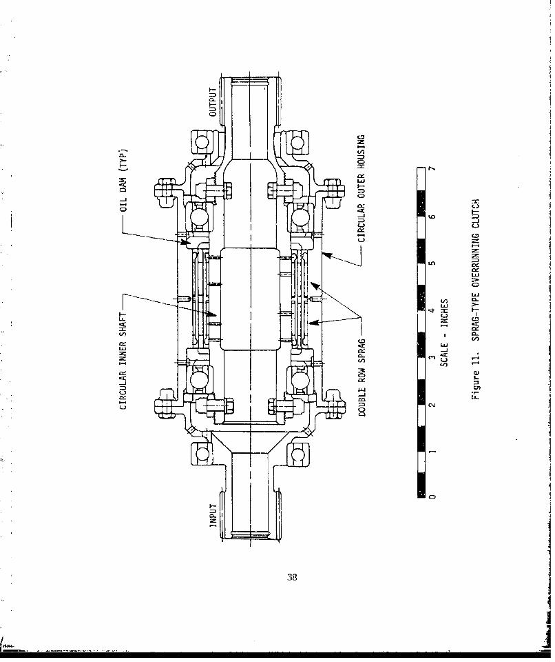
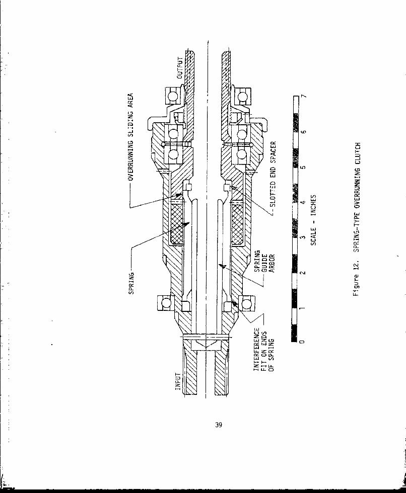
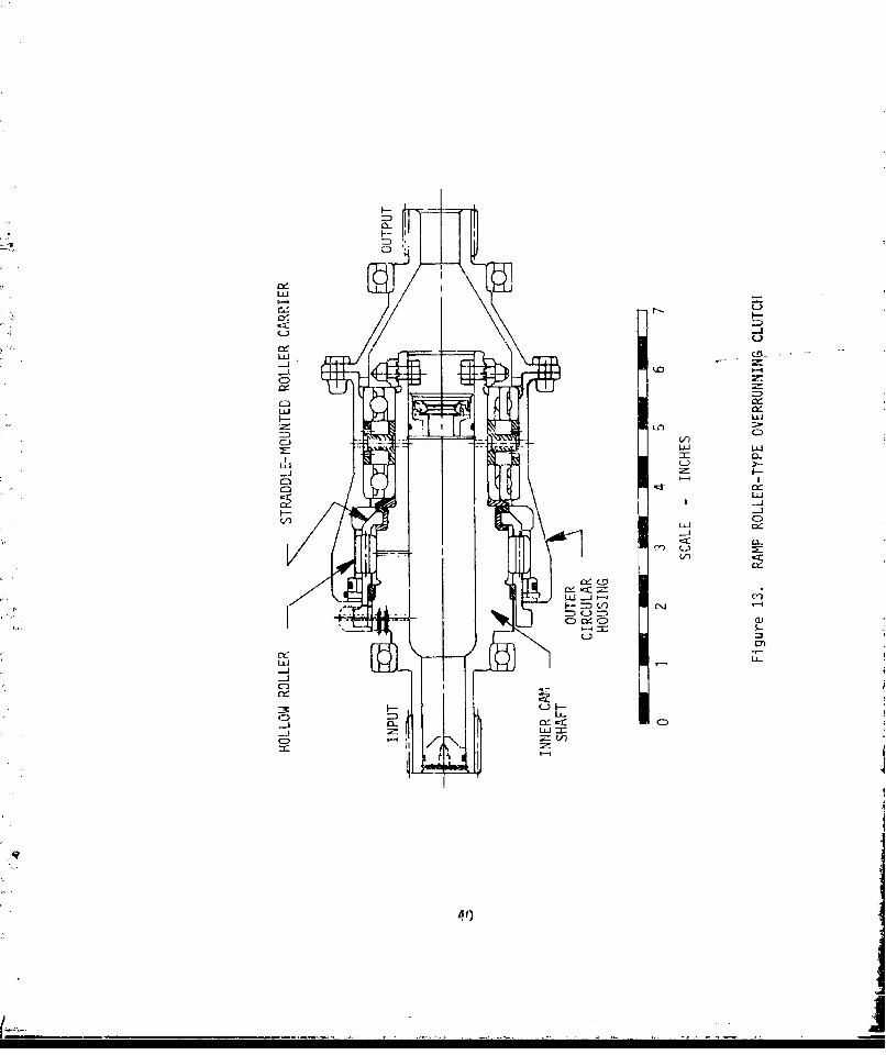
There are three basic types of overrunning clutches suitable for applica-tion to helicopter drive systems: sprag, spring, and ramp roller. Theseare shown in Figures 11 through 13.
The sprag type is by far the most common. The ramp roller has been usedexclusively by only one airframe manufacturer. The spring clutch, whichhas shown promise in some research and development programs, has yet to beused on a production aircraft. The detail design of all three types ofclutches is the subject of a design guide recently published by the AppliedTechnology Laboratory, U. S. Army Research and Technology Laboratories(AVRADCOM).
The most common reliability problem with all three types is excessive wearat the overrunning interfaces. This problem has been especially frequentwith auxiliary power unit clutches, which spend far more time than primarypower train clutches in the overrunning mode. The problem is extremelydifficult to deal with during design. Wear rates of the clutches are hardto predict and vary widely depending on the aircraft, operator, and clutchlocation. Even if wear rates could be predicted, the clutch designercannot add excess material to account for wear because of the extremelyclose tolerances required for proper operation of the clutch.
Lubrication of an overrunning clutch is obviously very critical, since itcan have a large impact in determining the life of the clutch. It is gen-erally desirable for the sake of lubrication to have the inner member ofthe clutch as the output member. This simplifies lubrication during over-running, since the centrifugal force may be used to force the lubricantto the sliding parts of the clutch through radial holes in the inner member.If the inner meriber is the driving member, the entire cavity of the innermember must be pressurized with lubricant to provide sufficient lubricantduring overrunning.
It is best from a size and weight standpoint for overrunning clutches tobe located at the earliest possible reduction stage, preferably at thetransmission input. While all three types -f clutches have operated suc-cessfully up to 20,000 rpm in test programs, there are differences inspeed capability among the three. The ramp roller clutch, because of itssensitivity to centrIfugal effects, should rh•aInc be lImitdA o 12,0nn0
rpm. The sprag clutch is probably at its limit at 20,000 rpm. However,the spring clutch, because of its simple design, could be applied at speedsgreater than 20,000 rpm. All clutches that are to be used at speedsgreater than 6,000 rpm should be dynamically balanced.
Special attention should be paid to certain design details of the variousclutches to ensure reliable operation. For the spring clutch, concentri-city between spring, arbor, input bore, and output bore is critical. Apath should be available for the lubricant to flow along the entire length
37
I.1
Lf)
o Ic-jý
CD
Lni
Ix -
LnLiiLUn
cic:
-%
0M
(NJ
C-D
V)
La
/ cij
-' CIAr
ca
Clj 2r CD
N'J tvý
LiCL
F---11Li- CZ)
39
Lii L
CDD
LUJ
Lai
-LJ
V1)
re)
-i.
, C'f
40

of the housing/spring interface. This may be accomplished by slots in thespring or housino. The overrunning coils at the ends of the spring shouldbe free of any type of plating.
For the sprag clutch, oil drainage should be such that when the clutch isat rest all oil is drained from the sprag area. At low temperatures, thethickened lubricant remaining in the sprag cavity could cause the sprags tohang up momentarily and lead to shock loading of the clutch and possiblesprag fracture. The clutch diameter should be as smail as possible tolimit centrifugal effects, and yet be consistent with permissible stresslevels. For high torque applications, it may be better to have a small-diameter double-row sprag unit rather than a larger diameter single-rowsprag unit. To insure proper loading of the sprag units, the clutch bear-ings should straddle the sprag unit.
For the ramp roller clutch, full accounting must be made of the effects ofcentrifugal force on the cage and pin/spring mechanism. Again, clutchdiameter should be designed to be as small as possible to limit the centri-fugal effects on clutch operation.
It appears from a reliability standpoint that the spring-type overrunningclutch is superior to both the sprag and ramp roller clutches. Its simpledesign with very few parts makes it an attractive alternative to the morecommon, older types, and it should be seriously considered for use infuture drive systems.
COUPLINGS
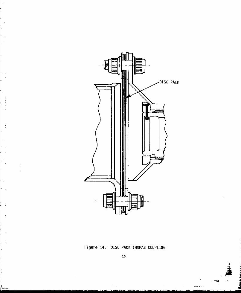
Although early couplings, which required periodic lubrication, have beenthe source of considerable reliability difficulties, these problems havebeen essentially eliminated with the widespread use of the disc pack orThomas coupling, shown in Figure 14. This coupling, which is used pri-marily in applications requiring very little relative axial displacementand low misalignment of about .5 degrees continuous, has an excellentservice record. The coupling is simple, lightweight, and maintenance free.It is also essentially immune to handling damage and corrosion. The mostcommon failure mode of Thomas couplings is fretting of the steel laminatesaround the bolt holes. Since analysis of this is very difficult, theproblem can be mitigated by use of a high bolt preload and a generouslylarge bolt-circle diameter.
The KAflexR coupling, shown in Figure 15, appears to be the preferred choicefrom a reliability standpoint, when the coupling must withstand continuousmisalignments of 3 degrees and transient misalignments up to 6 degrees.The KAflexR coupling, unlike the Thomas coupling, will also withstand axialdeflections. Requirements such as this may become much more common, iftransmission isolation is adopted to a greater extent to reduce cabinvibration, Like the Thomas coupling, the KAflexR coupling is simple andmaintenance free. Although not yet in production (some UH-l's and AH-l'swill be retrofitted with these couplings in the near future), KAflex"couplings have seen over 6,000 hours of flight time on UH-I and AH-I air-craft with no apparent problems.
41
j ... j
DISC PACK
Figure 14. DISC PACK THOMAS COUPLING
42
K __

0J
0
LQ-j
LfL
43
A
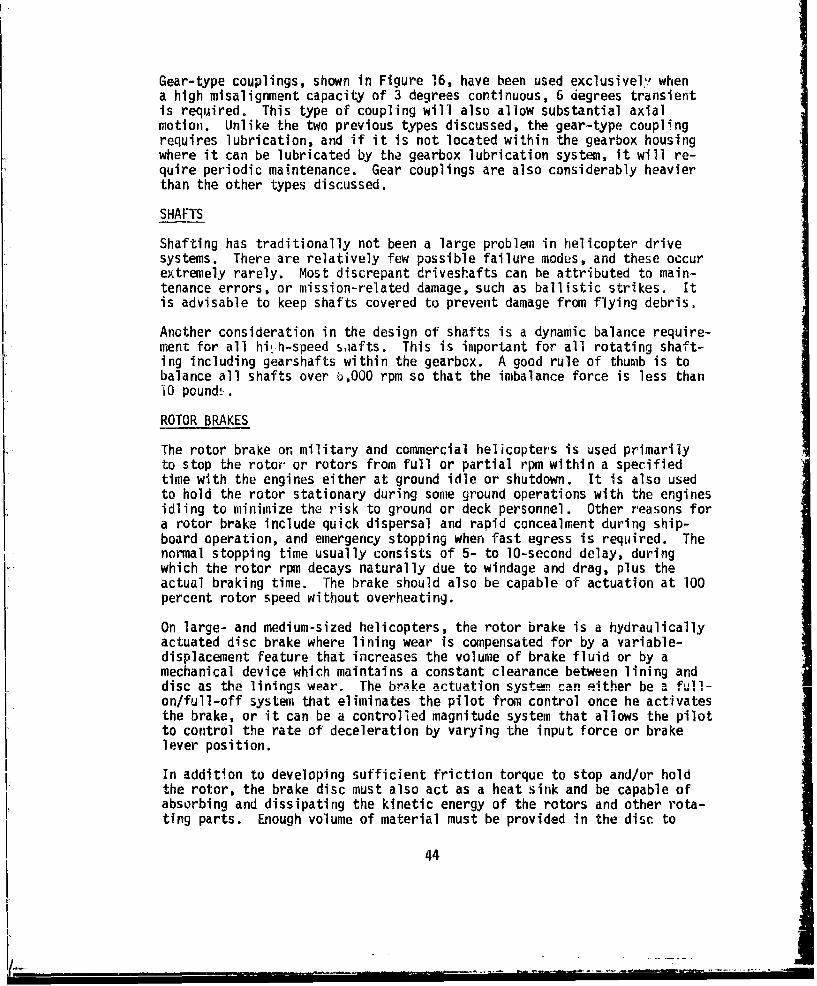
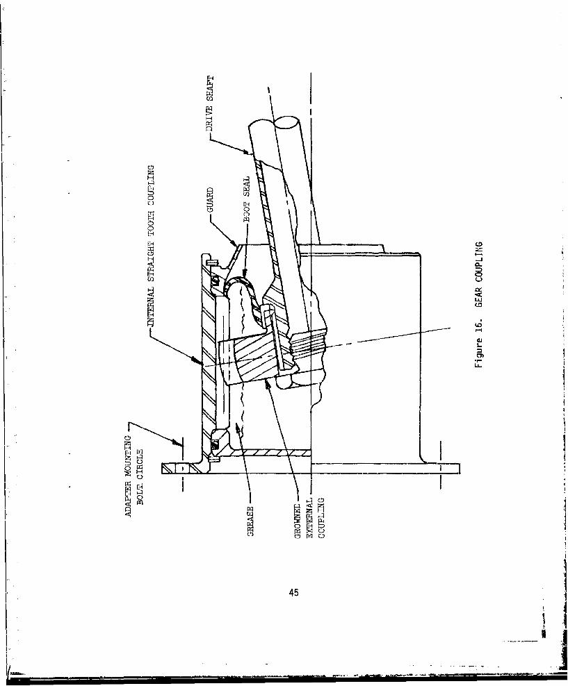
Gear-type couplings, shown in Figure 16, have been used exclusivel, whena high misalignment capacity of 3 degrees continuous, 6 degrees transientis required. This type of coupling will also allow substantial axialmotion. Unlike the two previous types discussed, the gear-type couplingrequires lubrication, and if it is not located within the gearbox housingwhere it can be lubricated by the gearbox lubrication system, it will re-quire periodic maintenance. Gear couplings are also considerably heavierthan the other types discussed.
SHAFTS
Shafting has traditionally not been a large problem in helicopter drivesystems. There are relatively few possible failure modes, and these occurextremely rarely. Most discrepant driveshafts can be attributed to main-tenance errors, or mission-related damage, such as ballistic strikes. Itis advisable to keep shafts covered to prevent damage from flying debris.
Another consideration in the design of shafts is a dynamic balance require-ment for all hilh-speed saafts. This is important for all rotating shaft-ing including gearshafts within the gearbox. A good rule of thumb is tobalance all shafts over b,OOO rpm so that the imbalance force is less than"i0 pounds.
ROTOR BRAKES
The rotor brake on military and commercial helicopters is used primarilyto stop the rotor or rotors from full or partial rpm within a specifiedtime with the engines either at ground idle or shutdown. It is also usedto hold the rotor stationary during some ground operations with the enginesidling to minimize the risk to ground or deck personnel. Other reasons fora rotor brake include quick dispersal and rapid concealment during ship-board operation, and emergency stopping when fast egress is required. Thenormal stopping time usually consists of 5- to 10-second delay, duringwhich the rotor rpm decays naturally due to windage and drag, plus theactual braking time. The brake should also be capable of actuation at 100percent rotor speed without overheating.
On large- and medium-sized helicopters, the rotor brake is a hydraulicallyactuated disc brake where lining wear is compensated for by a variable-displacement feature that increases the volume of brake fluid or by amechanical device which maintains a constant clearance between lining anddisc as the linings wear. The brake actuation system can either be a full-on/full-off system that eliminates the pilot from control once he activatesthe brake, or it can be a controlled magnitude system that allows the pilotto control the rate of deceleration by varying the input force or brakelever position.
In addition to developing sufficient friction torque to stop and/or holdthe rotor, the brake disc must also act as a heat sink and be capable ofabsorbing and dissipating the kinetic energy of the rotors and other rota-ting parts. Enough volume of material must be provided in the disc to
44
H
94
0
H
EH
CD
Hoor-
CD
I4
r 45
keep the temperatures within the thermal limits of the material and toprevent disc warpage.
Certain safety features are required to prevent inadvertent brake actuationin flight. These may take the form of mechanical or electrical interlocksthat must be deactivated before brake actuation. A relief valve and/ormechanical stop should be included to insure brake operation at a safe loadlevel. The location of the disc in the drive system should be carefullyconsidered not only to provide an adequate torque input to the rotor butalso to isolate the brake from flammable fluids or materials. Care shouldbe taken to assure adequate operating clearance between lining and disc topreclude the possibility of drag, thus producing a continuous source ofheat in flight that could ultimately result in a fire.
Standard mechanical engineering design principles for brakes and clutchesalso apply to rotor brakes. Numerous texts describe proper analysismethods. Static and dynamic friction coefficients can be obtained fromsuppliers of rotor brakes and will vary depending on specific liner/discmaterial combinations. Lining life and wear prediction calculations areconsidered proprietary by the lining manufacturers; therefore, they shouldbe consulted in any application where guaranteed lining life or a minimumnumber of stops is specified. Helicopter rotor brake analysis differs fromaircraft wheel brake analysis in two respects. First, advantage is takenof the aerodynamic drag on the rotating rotor blades, which varies with thesquare of the rotor rpm. This force alone would stop the rotor from fullrpm in about 3 to 4 minutes. The second point to consid-r is that theturbine engines at idle produce a positive torque that v.,ries inverselywith rpm and which must also be reacted by the rotor brake.
46
.............J ..
CONNECTIONS
There are several different kinds of connections used in helicopter trans-missions. These include bolts, studs, large diameter nuts, welds, andsplines. Although all are not strictly related, this chapter will providecomments on the reliability aspects of each.
BOLTED CONNECTIONS
Bolted connections are used primarily to attach gear members to shaft flangeswhere one-piece construction is riot possible or practical. The most commonreliability problem associated with such connections is fretting under thebolt heads. At present thnre is no technique that can accurately predictthe onset of fretting, nor are there any coatings available which will pre-vent fretting in all cases. It is known, however, that relative motion underunder load between the attached surfaces causes fretting, and that theamount of motion necessary to produce fretting is very small, perhaps onthe order of a few microns. There are some steps the designer can takethat will minimize the possibility of fretting. First, if at all possible,the gearbox designer should design the connection so that all loads arereacted by friction between the clamped surfaces rather than by shearthrough the bolt body. A conservative approach should be used whenanalyzing the bolt circle for reacting the load in friction, since it isdifficult to determine, particularly with radial loads, exactly how manybolts are reacting U! load. With helical ana spiral bevel gears, specialeffort should be madc to be conservative with respect to preload, sincethere will be loads normal to the plane of the flange that will tend toseparate the bolted surfaces. When titanium flanges are used, silver plateshould be used under the bolt head, since titanium is much more susceptibleto fretting than steel. Silver plate may also be used to minimize frettingon steel/steel connections. Webs and flanges that are offset, i.e., notcentered under the gear, should be avoided if at all possible.
Care should be taken with bolted flanges to provide at least one full boltdiameter between the outer edge of the bolt hole and the edge of the flange.A lug analysis may be used to analyze this part of the connection, and thisanalysis should be performed even if the load is theoretically reacted byfriction.
rhe bearing area under the bolt head should also be carefully checked foradequacy when analyzing bolted connections. This is especially true whensofter materials such as maqnesium are an element of the connection.
Studs and inserts are used to provide means of attachment to magnesiumhousings. Besides taking the same considerations as for bolted connections,the pull out strength of the studs and inserts mush be considered. Theliterature provided by such manufacturers as Rosan contains the informa-tion necessary to select the proper stud or insert for any given application.
47
L~.. _ _ _ _ ~_ =
LARGE DIAMETER NUTS
Large diameter nuts are used for clamping bearings onto gear shafts and mainrotor shafts and provide the means necessary to react thrust loads. Thehand of the thread for large diameter nuts should be chosen so that in theevont the bearing race turns on the shaft, the resulting motion will tendto tighten the nut on the shaft. A locking feature such as a small boltthrough the nut or a tanged locking ring must be used. It is also advisableto use buti;ress threads for large diameter nuts. This type of thread pro-duces very little radial load when torqued. This minimizes the reductionin shaft diameter which can adversely affect the press fit of adjacentbearings.
WELDS
Welding is used only to a very limited extent in helicopter transmissions.Although welded joints usually offer considerable weight savings overbolted connections and eliminate the possibility of fretting, the changein the metal 5tructure in the weld zone makes accurate prediction of thestrength of a walded joint difficult. This Is probably why so few weldsare found in current helicopter transmissions. Bolted connections areusually favored because there are coatings such as silver plating whichcan minimize fretting. When welds are used the design should be such thatthe exit side of the weid can be cleaned up. In other words, blind weldsshould be avoided.
INVOLUTE SPLINES
Involute splines are used to transfer torque between shafts and flanges,gears and shafts, and shaft and shafts. The design of splines is wellcovered by publicatinns of such organizations as the American Gear Manu-facturers Association and the Society of Automotive Engineerings. The mostcommon problem associated with splines is wear due to fretting, particularlywith loose splines such as those used on quill shafts. Attention to thefollowing details can significantly lessen the chance of encounteringspline problems. The miost important consideration in the design of splinesis strict observance '4 the limits on allowable bearing stress. With tightsplines care should be t7k',;i to provide an adequate length pilot to reactany type of be;nei•ii loads. Avoid the use of pilots which are too short.With loose splines 'ubrication is a vital factor in determining how wellthe spline will perforf'r. It is desirable, if possible, to keep the splinearea flooded with oil at. all times. Oil dams such as that shown in Figure17 can be used to accoiiiplýsh this. Crowning of loose splines is alsonecessary to prevent excessive wear. The amount of the crown should becarefully calculated on the basis of tolerances and full load deflections.
48 .I- -1. _.

O
Figure 17. OIL DAM FOR LUBRICATION OF LOOSE SPLINES
49
K- ... .. 4 --.......- "
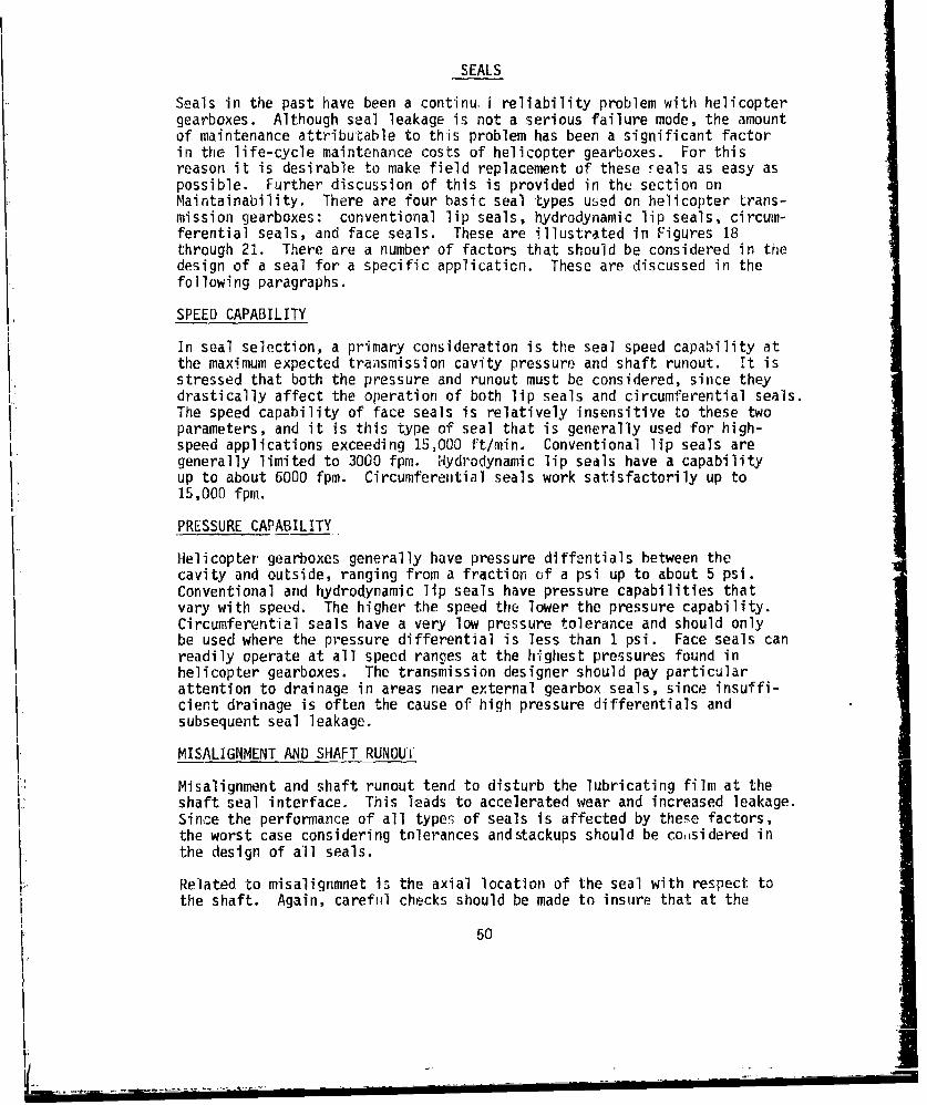
SEALS
Seals in the past have been a continu, reliability problem with helicoptergearboxes. Although seal leakage is not a serious failure mode, the amountof maintenance attributable to this problem has been a significant factorin the life-cycle maintenance costs of helicopter gearboxes. For thisreason it is desirable to make field replacement of these reals as easy aspossible. Further discussion of this is provided in the section onMaintainability. There are four basic seal types used on helicopter trans-mission gearboxes: conventional lip seals, hydrodynamic lip seals, circum-ferential seals, and face seals. These are illustrated in Figures 18through 21. There are a number of factors that should be considered in thedesign of a seal for a specific applicaticn. These are discussed in thefollowing paragraphs.
SPEED CAPABILITY
In seal selection, a primary consideration is the seal speed capability atthe maximum expected transmission cavity pressure and shaft runout. It isstressed that both the pressure and runout must be considered, since theydrastically affect the operation of both lip seals and circumferential seals.The speed capability of face seals is relatively insensitive to these twoparameters, and it is this type of seal that is generally used for high-speed applications exceeding 15,000 ft/min. Conventional lip seals aregenerally limited to 3000 fpm. Hydrodynamic lip seals have a capabilityup to about 6000 fpm. Circumfereintial seals work satisfactorily up to15,000 fpm.
PRESSURE CAPABILITY
Helicopter gearboxes generally have pressure diffentials between thecavity and outside, ranging from a fraction of a psi up to about 5 psi.Conventional and hydrodynamic lip seals have pressure capabilities thatvary with speed. The higher the speed the lower the pressure capability.Circumferential seals have a very low pressure tolerance and should onlybe used where the pressure differential is less than I psi. Face seals canreadily operate at all speed ranges at the highest pressures found inhelicopter gearboxes. The transmission designer should pay particularattention to drainage in areas near external gearbox seals, since insuffi-cient drainage is often the cause of high pressure differentials andsubsequent seal leakage.
MISALIGNMENT AND SHAFT RUNOUi
Misalignment and shaft runout tend to disturb the lubricating film at theshaft seal interface. This leads to accelerated wear and increased leakage.Since the performance of all types of seals is affected by these factors,the worst case considering tolerances andstackups should be coaisidered in
{'. the design of all seals.
Related to misalignmnet is the axial location of the seal with respect tothe shaft. Again, careful checks should be made to insure that at the
50

GARTERfSPRING
Z- LIP
Figure 18. CONVENTIONAL LIP SEAL
GARTERSPRING
LIP
Figure 19. HYDRODYNAMIC LIP SEAL
51
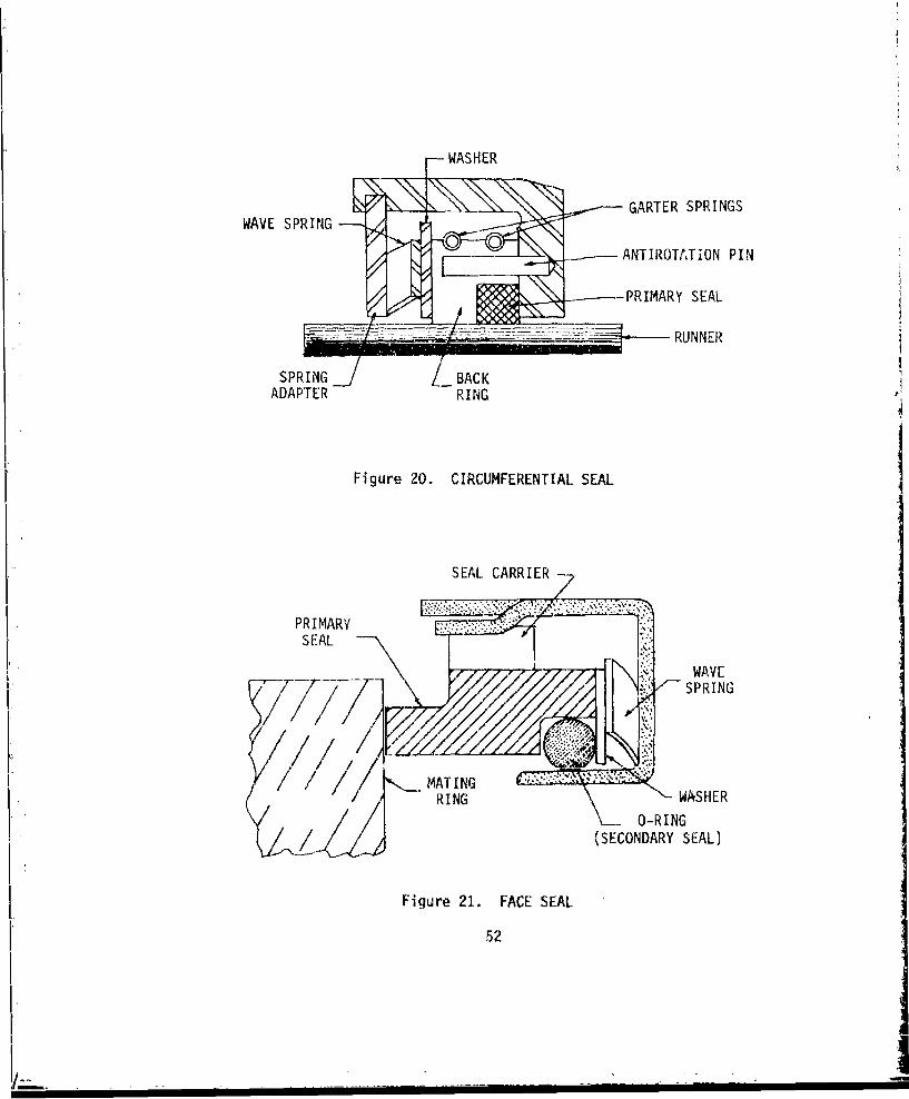
SWASHER
WAV SR-- GARTER SPRINGS
ANTIROTATION PIN
- PRIMARY SEAL.
S~RUNNER
SPRI NG _ZL BACK
ADAPTER RING
Figure 20. CIRCUMFERENTIAL SEAL
SEAL CARRIER -
PRIMARYSEAL
WAVE
IS SPRING
1RING WASHERf RING_ O-RING
(SECONDARY SEAL)
Figure 21. FACE SEAL
52
I.L
extreme positions of the seal relative to the shaft a suitable seal ridingsurface is present.
SEAL MATERIALS
There are three materials currently used for lip seals in helicopter trans-missions: fluorelastomers such as VitonR, silicone rubber, and nitrile.Fluorelastomers are currently used for most seals in helicopter trans-missions. They have good resistance to most oils, fuels, and chemical sol-vents as well as to ozone, salt water and weathering. They are, however,costly and tend to be brittle at low temperatures. Silicone rubber is usedto a very limited extent, since it has poor wear resistance and is onlyfair in its compatibility with most gearbox lubricants. Its only advantageis that it has excellent low temperature properties. This, however, isunimportant, since the lubricants become so viscous at low temperaturesthat leakage rarely occurs. Nitrile is rarely used in modern helicoptertransmissions, although it is still employed on some older models.Prolonged exposure to air and oil at temperatures above 180°F tend toharden this compound.
Some caution should be used when selecting seal materials. Various com-pani2s that manufacture oils to military specifications will use differentadditives even for oils of the same specification. In addition, the formu-lations for fluorelastomers vary from company to company. Hence, it ispossible for one particular formulation of a given military specificationlubricant to be compatible with a given seal material while another formu-lation of the very same lubricant could chemically attack the seal material.It is recommended that compatibility between seal materials and oil formu-lations, particularly with respect to additives, be carefully checked.
ENVIRONMENTAL CONSIDERATIONS
Exposure to various environmental conditions, such as water, sand andtemperature extremes, is one of the direct causes of seal failure in heli-copter gearboxes. It is imperative that secondary sealing devices beemployed to screen the primary seal from contaminants that can lead toabrasion. Lip seals usually have secondary "dust lips" incorporated withthe primary seal. Other exclusion devices that may be employed include
sheet shrouds, wiper seals, slingers, labryi½'-hs, and absorbent packings.The particular secondary seal chosen depends, of course, on the application.Such redundant seals are particularly important on main rotor shafts,where water seapage into the gearbox is a distinct possibility.
SACRIFICIAL RUNNERS
Seals are often designed to run directly on the shaft which they aresealing. This practice, however, can lead to the scrappage of the shaftif abrasive contaminants enter the seal and cause wear of the shaft itself.
i From a reliability viewpoint it is preferable to use thin sacrificialsleeves over shafts to provide a running surface for the seal. With thispractice, only a relatively inexpensive sleeve, not an expensive shaft,need be replaced in the event of wear.
53
II

O-RINGS
O-rings are static se~ils used at housing interfaces. O-ring failure andattendant leakage are rarely caused by gearbox operation but by cutting ofthe O-rings during installation. Among the steps transmission designerscan take to reduce the possibility of this happening are the fol'lowing:
1. Don't use O-rings with a cross sectional diameter less than.10 inch.
2. Make certain that all edges that could possibly catch O-ringsduring installation are properly broken.
O-rings that are cut during installation can lead to potentially seriousfailures. These failures occur when pieces of O-ring contaminate thelubricant and lodge in lube jets,thereby blocking the flow of lubricantto dynamic components.
54
I '.
LUBRICATION SYSTEMS
The lubrication system of a helicopter drive system, shewn schematically inFigjre 22, serve, two basic purposes. First, it provides the necessarylubricant film on the mating surfaces of dynamic components. Second, itprovides the medium through which the heat generated by friction isremoved from the gearbox to the outside air. It is importnat, from a relia-bility standpoint, fiat the lubrication system be properly designed, sincean inadequate or poorly designed system can adversely affect the reliabilityof the gearbox.
SYSTEM DESIGN
A truly redundant lubrication systcm with two completely independent lubri-cant paths is very desirable but often not practical with the helicopterdrive systems. More often, dual pumps are used, which feed into the samelubricant lines. I this is done, the pumps must be provided with one-waycheck valves which, in the event of failure of a single pump, prevent theworking pump from pumping lubricant back through the failed pump, insteadof into the lubrication system. A failure mode and effects analysis of thelubrication system can be a very useful tool in ensuring that the design ofthe pumps is such that this cannot happen. The pump should be protectedfrom debris damage by a screen in the pump inlet line. This screen can beincorporated with a full-flow-type chip detector to save added parts. Ashear area should be designed into the pump shaft so that in the event ofpump seizure, the pump shaft shears, not some other component in theaccessory drive train.
As fine a filteras possible should be incorporated into the lubricationsystem, because of the great impact filtration has on bearing life.Development is currently proceeding on filters as fine as 3 microns absolute.These should certainly be considered for all future gearbox designs.
SIZING AND POSITIONING OF JETS
The determinition of how much lubric., is required for each dynamic compo-nent is determined by an efficiency or heat generation analysis. The oilflow required to remove the heat is calculated. Then, based on the speci-fied pump pressure, the size of the jet can be easily found by using theequation for flow through an orifice. Care must bp taken that the jetselected for almy application is neither too large nor too small. A jet thatis too small can lead to excessive heat generation in a bearing or scoringof gear teeth, while an oversized jet will lead to excessive churninglosses. Jets with an orifice smaller than .040 inch should be avoided,since small pieces of debris can er-ily plug such small openings.
Primary power train gears should be lubricated both into and out of mesh,with perhaps 80 percent of the total for each mesh directed at the out-ofmesh side, where cooling of the gear teeth is best effected. Rollingelement bearings generally are first lubricated by jetting the requiredamount of oil into the gap between the cage and inner race. Some bearings,such as triplex and duplex bearings and overrunning clutch bearings, are
55

____ .LU
-j L
Li-i
=- U-Vco
CL.
Lii
ii CD
LU.
I--LU3
C-,I-)
[56
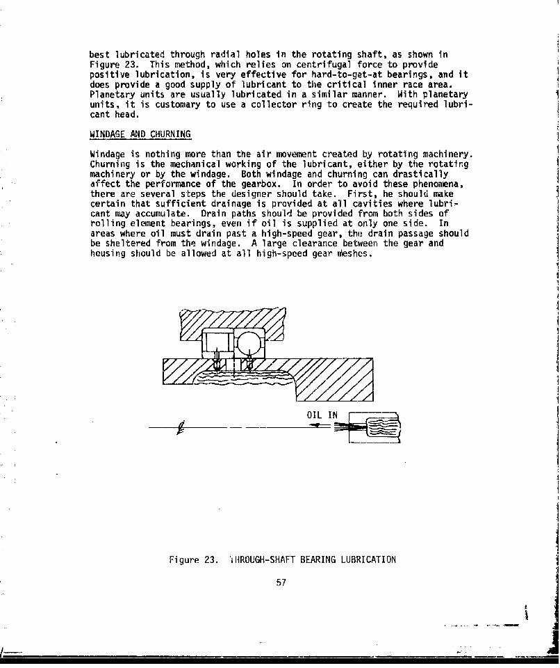
best lubricated through radial holes in the rotating shaft, as shown inFigure 23. This method, which relies on centrifugal force to providepositive lubrication, is very effective for hard-to-get-at bearings, and itdoes provide a good supply of lubricant to the critical inner race area.Planetary units are usually lubricated in a similar manner. With planetaryunits, it is customary to use a collector ring to create the required lubri-cant head.
WINDAGE AND CHURNING
Windage is nothing more than the air movement created by rotating machinery.Churning is the mechanical working of the lubricant, either by the rotatingmachinery or by the windage. Both windage and churning can drasticallyaffect the performance of the gearbox. In order to avoid these phenomena,there are several steps the designer should take. First, he should makecertain that sufficient drainage is provided at all cavities where lubri-cant may accumulate. Drain paths should be provided from both sides ofrolling element bearings, even if oil is supplied at only one side. Inareas where oil must drain past a high-speed gear, the drain passage shouldbe sheltered from the windage. A large clearance between the gear andhousing should be allowed at all high-speed gear n•eshes.
OIL IN
Figure 23. TiiROUGH-SHAFT BEARING LUBRICATION
57
MAINTAINABILITY
Designing maintainability into a helicopter drive system is a relativelyeasy task, if the program manager establishes a high priority for main-tainability, and the gearbox designer maintains an awareness of thischaracteristic during the design stage. A little thought during designcan save many hours of maintenance during the operational life of thegearbox.
ACCESSIBILITY
By far, the most common problem noted in earlier drive system designs isthe lack of accessibility provided for even routine maintenance tasks.Often such simple tasks as filter replacement, require maintenance per-sonnel to be part contortionist because of obstruction by airframe, controls,or even other drive system components. Another common problem is thereplacement of one defective component requiring the prior removal of otherperfectly good components in order to effect the repair. Such problems asthese can easily be avoided, if accessibility is a prime considerationduring design.
Accessibility to drive system components on the aircraft is largely amatter of communication between the transmission designer, the aircraftconfiguration manager, and the designers of other systems such as theairframe. By ensuring that other systems do not interfere with routinemaintenance and inspection of the transmission system and vice versa, manyfield problems can be avoided. The more awkward or difficult a maintenancetask is to perform, the more likely it will be performed incorrectly or notat all. A full size mock-up can be very useful in pinpointing potentialaccessibility problems.
Accessibility to the following components is especially important.
e Oil filter
a Oil filler cap and sight windows (Note: These should belocated so that a person adding oil to the gearbox can easilysee the sight window).
a Gearbox mounting hardware
e Chip detectors
e Tail drive shaft hanger bearings
• Oil cooler air inlet (so that it can be easily cleared of debris)
e Accessories such as oil pump, hydraulic pumps, and generators
58
MODULARIZATION AND FIELD REPLACEABLE ITEMS
Modularization is simply designing the main gearbox so that such sections asinputs, accessories and tail takeoff may be removed from the main part ofthe gearbox as self-contained modules. Figures 24 and 25 illustrate thisconcept. Note that quill shafts splined on either end provide the necessarytorque connections between the modules. Screens are provided at each moduleinterface so that a failure within a single module will not contaminate therest of the gearbox. In addition, each module is provided with its own chipdetector so that a failure can easily be isolated to a particular module.These modules should be designed so that they may be removed using onlystandard wrenches found in an aircraft repairman's tool box. Care must betaken that lubrication transfer passages between the modules are well sealed.
Modularization is an important concept that can lead to substantial savingsin maintenance costs by substantially reducing aircraft downtime. Itshould be seriously considered for all but the very low power helicopterdrive systems.
While on-aircraft repairs ai-e not practical for the majority of helicopterdrive train components, there are a number of items that should be easilyfield replaceable. Some of these, such as tail drive shafts,couplings and hanger bearings, and oil cholers, have'always been fieldreplaceable and should remain so. Careful attention should be paid to thedesign of such items to facilitate their replacement. There are two othercomponents, which, in the past, have not usually been field replaceable,but perhaps should be. These are freewheel units and external seals.
Freewheel units, because of their relatively low primary failure rate, werenot detrimental to the overall maintainability of the drive system. How-ever, new generation gearboxes will be exclusively on-condition maintenanceitems. This policy will lead to time accumulation on some gearboxes farbeyond that seen in the past; hence, wear-induced failure modes will becomemore prominent. The problem here is that all types of freewheel units,whether they be sprag, ramp roller, or spring, experience wear during theoverrunning mode. With the higher times accumulated on on-condition gear-boxes, it is more likely that wear will progress to the point where thefreewheel unit will not operate satisfactorily. In other words, it islikely that excessive freewheel unit wear will become more prominent as aprimury failure mode, thus making field replaceability of these items acost-effective design feature.
External seals of helicopter gearboxes have not in the past usually beendesigned as field replaceable items. Often however, to avoid costly over-hauls simply because of seal leakage, the replacement of these seals has
been assigned to the organization maintenance level. This has led tonumerous cases of incorrect installation, damage during installation, orgearbox contamination during seal replacement. A more desirable practice,from the maintainability point of view, would be to design seals premountedin a small housing, which pilots on the main housing and bolts in place.Replacement is accomplished by simply removing the bolts attaching the seal/housing assembly, sliding out this assembly, and replacing it with a new
59
II
_ JI,- -I-I- -I i-Ia

C-)
C3,
0~
oil
C-)
LA-
60
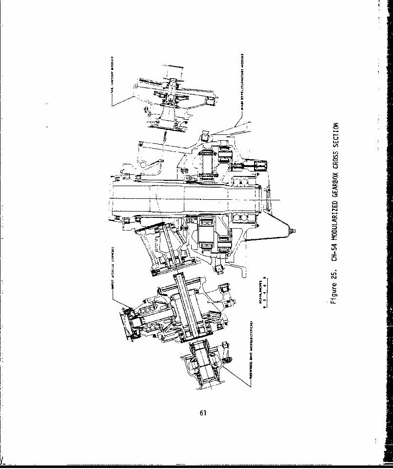
o-Co
SI4
-~ z
L k,L
in
61
L-,
-- - - - -- - - -- -- - - - - - - - - - - - - - - - -
seal/housing assembly. This assures proper alignment of the seal with theshaft centerline and minimizes handling of a seal surface by the aircraftmechanic.
INTERCHANGEABILITY
Interchangeability is another way to simply and conveniently reduce mainte-nance costs. The use of interchangeable parts can significantly reducespares requirements as well as considerably simplify maintenance. Amongthe items that lend themselves to interchangeability are tail drive shaftsections, drive shaft flanges, large diameter nuts, spacers, input and out-put intermediate gearbox housings, and all input components of multi-enginehelicopters. Using identical bearings in as many places as possible alsopromotes the interchangeability concept. Bearings have become extremelylong lead-time items and maintaining adequate supplies of riany differentbearings has become a serious problem at the depot level. Using the samebearing in as many applications as possible will not only reduce the numberof different bearings that must be stocked, but will also permit theordering of larger quantities of bearings with a substantial reduction inthe price per bearing. This same practice can also be effectively utilizedwith seals.
STANDARDIZATION
Standardization is yet another concept that can considerably improve themaintainability characteristics of a drive system design. It can simplifymany maintenance tasks as well as reduce the time to complete them. Likeinterchangeability, standardization can also have a beneficial effect inthe supply of replacement parts. Standardization should be employed to themaximum extent possible with such components as nuts, bolts, and studs.This will reduce the number of special tools required for drive systemmaintenance. Some earlier Army aircraft drive systems were particularlybad with respect to lack of standardization of hardware. They required theaircraft mechanic to be equipped with many special tools, which often addedmore than 100 pounds to the weight of his tool kit. Such situations couldhave been avoided, if the designers of these drive systems had maximizedstandardization during the design.
OVERHAUL ENHANCEMENT DESIGN FEATURES
Attention to the above practices can considerably simplify the task ofoverhauling helicopter gearboxes. There are, however, some special consi-derations that are especially pertinent to facilitating g,,arbox overhaul.The first of these is rather simple and should be adopted as a generaldesign practice.
Flats should be provided on shaft shoulders so that a bearing puller caneasily remove the bearing without damaging it. If this is not done, thebearing puller will often slip off the inner race and damage the cage,thereby ruining an otherwise perfectly good bearing. As was mentionedearlier, bearings have become very expensive, long lead-time items. Thedamaging of bearings due to inattention to removal procedures during design
62
is not excusable.
Another practice that is especially costly and time consuming at overhaulis the requirement that magnesium housings be completely stripped of theirprotective coatings prior to inspection. It is extremely unlikely that thehousing could be cracked without a corresponding crack in the protectivepaint. If certain areas of the housing had been touched up because ofcorrosion, these areas alone could be stripped. Magnetic particle inspec-tion of the housing could then be performed. If the housing is not cracked,which is virtually always the case, the housing could be returned to ser-vice with relatively little work. Thus magnetic particle inspection overthe paint could save two very expensive and time-consuming steps:stripping before inspection and reapplying coatings after inspection.
Container design, although not strictly the responsibility of the trans-mission designer, is another area where the improvement could result inconsiderable cost savings at depot. Housing corrosion is generally only aminor problem at the organizational level. There are occasional smallareas of corrosion but severe corrosion is relatively rare. Virtually allgearboxes arriving at depot for overhaul, however, are found to havecorrosion, and severe corrosion is not unconmon. The reason for theapparent discrepancy between corrosion at the two maintenance levels seemsto be the ineffectiveness of the gearbox containers in keeping out moisture.This is supported by the fact that accumulations of water are often foundin the bottoms of the containers when they are opened at depot.
Another practice that can substantially reduce depot maintenance costs isthe provision for extra material in those areas where fretting, corrosion,or wear may be expected. By providing extra material in such areas thepart can often be reworked and reused without sacrificing its structuralintegrity. This can lead to considerable savings in replacement parts atdepot.
Some-what related to the above is the practice of using the gearshaft as theinner race of the bearing. Although this practice is desirable from theweight standpoint since it eliminates the inner race, nut, and lockingdevice and usually results in a shorter shaft, it is not cost effectivefrom the overhaul standpoint. A spall on the bearing race surface of thegearshaft results in the scrapping of a very expensive gear and bearinginstead of just the bearing alone. The practice of using integral bearingraces on shafts could, however, be cost effective if a satisfactory proce-dure were developed where the shaft could be reworked and the bearingreplaced by one with o..r... rolling elements.
One final point should be made with respect to overhauling of helicoptergearboxes. In most cases product support personnel, not gearbox designers,set up overhaul procedures. While these people may be very competent andwell experienced in the preparation of such documents, the gearbox designeris certainly more qualified to say how his gearbox should be overhauled.Hence, it is recommended that overhaul procedures be prepared by the gear-box design engineers, or if that is not feasible, at least be carefullyreviewed and approved by them.
63
4.
DIAGNOSTICS
Diagnostic techniques for use in helicopter gearboxes can be divided intotwo basic groups: debris analysis and vibration analysis. The debrisanalysis methods include chip detectors, filter checks, and SOAP (Spectro-metric Oil Analysis Prog-am). Vibration analysis consists of the monitoringof certain frequency bands where changes in amplitude indicate failures orimpending failures. In addition to these techniques, the standard lubrica-tion system pressure and temperature sensors are employed.
CHIP DETECTORS
By far the most coumonly used failure detection device in helicopter gear-boxes is the magnetic chip detector. In its simplest form the chip detectoris a magnetic plug that collects ferrous debris on a powerful two-polemagnet. This type of chip detector must be removed and visually inspectedto determine component condition. Current transmissions use electric chipdetectors that are remotely monitored and checked periodically by a con-tinuity test. These chip detectors can be procured with a variety offeatures such as a self-closing feature for quick removal without lubricantdrainage, and the inclusion of a high-temperature warning switch.
The two types currently used in most present transmissions arethe full-flowand the sump-mounted plug shown in Figure 26. The full-flow chip detectoris usually installed in a lubrication line leading to the pump and monitorsall the lubricant that is continously circulating in the transmission. Astrainer incorporated with the chip detector retains large particles, thuseliminating the need for a separate pump inlet screen. The sump-mountedchip detector magnetically attracts particles that settle to the bottom ofthe sump. Its efficiency is less than the full-flow chip detector,sinceit depends mostly on magnetic attraction to capture debris particles, whilethe full-flow chip detector has the advantage of pump pressure carrying thedebris particles to it.
Chip detector sensitivity depends on the gap width, gap area, the type ofmagnetic circuit, and the shape of the electrodes. In general, smaller gapwidths and areas are more sensitive, as are closed (vs. open) magneticcircuits and sharp (vs. rounded) electrodes.
Recently, chip detection systems have been developed that are capable ofgenerating capacitor discharge pulses after the chip detector gap has beenbridged by conducting particles. If this conductive path consists of,,,ii7v, nv finn clivers i ,,,i111 kn 4 n*fi,-,jn÷nrK hu h r ,'an p•ln •.
Two types of systems can be employed with capacitive discharge chip detec-tors: manual and automatic. In the manual system, whenever the gap isbridged the chip detector light 's activated. The pilot then activates thedischarge mechanism. If the gap has been bridged by fuzz, it will beburned up and the light will go out. In the automatic system, the dischargemechanism is automatically activated, whenever the gap is bridged. Thechip light will not go on unless the discharge fails to interrupt the con-ductive path.
64

LuL
I-L
C3
LLLu
LAAuMC
L~i"T
iA-3
65-
iIEarly experience with capacitive discharge chip detectors has been veryencouraging. Several hundred hours of accumulated bench and flight testinghave not produce:d a single false indication, the problem which has longplagued conventional chip detectors.
FILTER CHECKS
Filter checks have been recently employed during the development of super-fine oil filters as a supplement to chip detectors. With this technique arelatively coarse screen (about 80 microns) is placed around the superfinefilter element. This screen, which traps only large particles, is inspectedperiodically and after chip light activation to aid in the determination ofwhether or not a failure has indeed occurred. The inspection of the debrisis done visually with a simple means of magnification to determine the typesof debris trapped by the mesh.
SPECTROMETIC OIL ANALYSIS PROGRAM (SOAP)
Another detection method, used to a much lesser extent than chip detectors,is the spectrometric oil analysis program commonly known as SOAP. The SOAPtechnique consists of performing a spectrometic analysis of a gearbox oilsample to determine metallic content. The SOAP sample is taken from asubject gearbox as soon as possible after a flight to prevent metallicparticles from settling out of the lubricant. A portion of the samplelubricant and an oil standard with known metallic content are placed on afilm plate to record the wave lengths of the different elements. Theexposed film is then placed in an optical comparator, which permitscomparison of the widths of the lines representing the various elements.This enables the technician to determine the contaminant levels in the SOAPsample. If the SOAP technique is to be used on a given gearbox, the trans--mission designer should provide means to facilitate the taking of the oilsample. With some past designs the taking of the sample is extremelyawkward, and this can affect the results of the SOAP analysis.
The SOAP technique has been used to a limited extent by conmmercialuperators, the Arimy (ASOAP) and the Navy (NOAP). The success has beensomewhat limited. There appears to be two basic problems with SOAP. First,the proper threshold level for gearbox removal has been difficult toestablish. It appears that although some gearboxes exhibit high ironcontent levels, the gearbox turns out to be perfectly acceptable when itis disassembled and inspected. Other gearboxes have exhibited frettingfailures, although the iron content has been relatively low. The Army,in particular, because of its large number of flight facilities, has ex-perienced logistics problems with its ASOAP program. This is due tocomnunication problems between the ASOAP laboratory and the various opera-tional activities, and has sometimes led to needless gearbox removal.
A more serious problem, perhaps a more pertinent one as far as the futureof SOAP is concerned, is the advent of superfine, oil filters with thecapability of removing all particles greater than 3 microns from the lub-ric,;tion system. Although such filters are currently only in the develop-ment stage in helicopter gearboxes, it seems certain that they will become
66j
standard equipment within a few years because of the great impact theyhave in improving bearing life. The problem this raises with SOAP is thatthe technique cannot be used to analyze such fine particles; hence, thelarge scale incorporation of superfine filters will be tantamount to endingthe practicality of SOAP.
Oil Debris Monitoring (Particle Count)
This technique, like SOAP, is not an in-flight monitoring technique. Itconsists essentially of determining the distribution of particle sizeswithin the gearbox lubricant. The primary problem with this method isthat the relationship between particle size distribution and failure modesis largely unknown. Hence, this method may result in a large number offalse removals and/or missed failures because the threshold for gearboxremoval is mostly guess work. This may be a moot point, however, sincesuperfine filters would also render this method impractical.
Vibration Analysis
The development of failure detection by vibration analysis has been themajor thrust of a number of programs to develop an AIDAPS (AutomaticInspection, Diagnosis,. and Prognosis System) for helicopter drive systems.Various techniques including low-frequency analysis, high-frequency analy-sis, narrow band spectrum analysis, and shock pulse monitoring have beenevaluated and some of the more promising techniques have been tested inan actual helicopter transmission. Testing to date has been largely con-ducted with discrepant components implanted in the gearbox in order todefine differences in vibration signatures between assemblies with defectiveparts and those without. There has been no extensive study on a fleet ofhelicopters that would provide an indication of the success rate of sucha system.
The instrumeni tion and electronics hardware required for an AIDAPS areof necessity very sophisticated, a fact which could jeopardize the relia-bility of the system should it ever be widely employed. Another problemfound with the application of AIDAPS to helicopter transmissions is thefact that vibration signatures of helicopter gearboxes are very maintenancesensitive and vary considerably from aircraft to aircraft, even among likemodels. Hence, in order to incorporate such a vibration detection system,a large amount of data would have to be assembled to establish vibrationlimits for gearbox removal. Thus, not only would the hardware itself beexpensive (probably greater than $10,000 per aircraft), but also theresearch and development costs required to develop an AIDAPS so it couldhe practically emtployed on production aircraft would probably be prohibi-tive.
Evaluation
From the above discussion, a number of conclusions can be drawn regardingthe best policy to adopt with respect to drive system diagnostic systems.First, it is not recommended that investigations of SOAP or particle counttechniques be pursued to a greater extent than they now are. In all likeli.-
67

hood, both of these techniques will soon be rendered obsolete by theincorporation of suoerfine filters. Second, before coummitting any largeamounts of resources to the development of AIDAPS, time should be ailuwedto evaluate how effective fuzz burn-off chip detectors are in reducingfalse indications or, the UH-60A BLACK HAWK. There is no sense in spendinglarge amount -i R&D funds developing a new expensive complicated systemwhen It is y that a mucih cheaper and simpler existing system will dothe job just well, if not better. Some may point out that chipdetectors only prov!de after the fact indication of f'ilures. However,given the fact that ,ittle is known about the symptom/failure relationshipbefore filures occur, it is unlikely that any system no matter howsophisticated could give reliable advance warning of failure in the fore-seeable future. Another justification often cited for supporting thedevelopment of AIDAPS is that chip detectors do not point out exactlywhich comiponent failed within the gearbox. For helicopter gearboxes,however, this information is nf academic itterest oifly. Any failure whichoccu•rs inside a helicopter gertrbox requires the removal of either theentire gearbox Gr the entire module in a modularized gearbox. Since thedefective gearbox or module will be completely disassembled and inspectedat depot anyway, there is no cost saving in knowing at the time of failureexactly whtt:I; component failed. This type of information is useful onlyfor failures which can be repaired on the aircraft, of which there are veryfew in helicopter gearboxes,
The mop;t promising approach to diagnostics at this time appears to bea system which incorporates both sump mounted and flow through fuzz burn-off chip detectors supplemented by filter inspection. This system hasmany advartaqes ever the other candidaL•n.. First, it is simple and in-expensive. Second, it is a proven system with respect to flight safety.Third, if early experience with fuzz burn-off chip detectors is any in-dication, it will be ver•y reliable and produce very few unnecessary gear-box removals.
68
I,I' -I f

HAZARD FUNCTION ANALYSIS
This chapter defines a step-by-step procedure for quantitatively evaluatingthe reliability of a gearbox during the design stage. This procedure willrelate the reliability of a new design to the reliability of an actualgearbox of similar design with a known MTBR (Mean Time Between Removal) bydetermining a correlation factor, K. The technique may also be used topredict the probability of a gearbox passing a test of a given length andpower spectrum.
The reliability is calculated for each failure mode anticipated, such asgear wear, bearing spalling, seal leakage, spline wear, housing corrosion,etc., using the Weibull reliability function given by Equation (1).
R(T) = e (1)
where R(T) = reliability at T hours
0 =size parameter
• 5 shape factor
Recommended size parameters and shape factors for each failure mode, to-gether with observed high and low limits, are given in Table 1. Except forbearing spalling, these values are based on historical experience Tromprevious helicopter drive systems using a hazard function analysis . Thesize parameter, e , for bearing spalling is based on the adjusted LI1bearing life including material factor, processing factor, EHD factor, etc.The value of the shape factor, $ , for bearing spalling is 10/9. Trhisvalue is commonly accepted within the bearing industry and is believed tobe somewhat conservative, since values .;,ging from 1.3 to 1.6 have beenmeasured in service.
The first step in the reliability prediction procedure is to determine thecorrelation factor. This is done by performing the analysis o'n an existinggearbox with a known MTBR as follows using Steps 1-5. If a jearbox ofsimilar design does not exist or the MTBR of the similar gearbox is unknown,the reliability of the new design can still e estimated by assuming thecorrelation factor is equal to 1.0 and proceeding with calculations usingSteps 6-9.
I Trustee, B., HELICOPTER DRIVE SYSTEM ON-CONDITION MAINTENANCE CAPABILITY,Sikorsky Aircraft Division, United Technologies Corporation; USAAMRDLTechnical Report 75-57, Eustis Directorate, U. S. Army Air MobilityResearch and Development Laboratory, Fort Eustis, Virginia, July 1976,AD A028414.
69
K.......L

0 ~ 0 D1 C.1 - r-,. -C= (=5 COr-C)C-1 - - _j _- - r. c' I
CD x x x x x x x x x x x x x xLO) (n 04 .- - co -.
V)
S:) n o 10 k.0 C) co CD 0% r- LO- C
ILO LO 0ý 0000 r-o r-O 00 00
0~~~~( CDx x x x x xx
LL. LO 0 LI) k- C)K 1 DC.0 ko -d' N.% r., N.r 0 rOl (%) C:J CD N CD. C:) C:3 C) CJ ci C lC
-L -) 00 - C OD . rI-o. -v m LO CI-)k O )ac Dmc
On COmI d c
m i 0 i 0 0 0 0) (D 0a) 0 00
I-:x
N4 -J 4J - . C . - 5-CJ r 30
=~. 4-C) Uu
)4-3 f3 1-' Q)
mJ di CirY
aa +j -
4) di 4
_nle 4) 43 PV
S--I- - V) I-SU)L.r
(a m wo -*) () S-- Lwa. (n "d CO c- 3-IL, ()'-
CD 3- S. ow ( . - ULA-,zS- V) S. (3)1 -Al 1Z0 5-
Wd (V r d di0) d)., CLJ -1 tu .0 U.O IUt i :3d) > 3c o0 m 0 r- -o E bdIts L
x C) : p- w M i. a l) w/ C-)ro U) 0n En 1 *ra Co Cr- fr)U Mi4L W ) W - (A f.- Q)' So - S. -0 - S- (A) c -2 4 CU. Wi ). 0) Cir- Wi Q) -d d).-W W W CU d-,- I4-~--
u. -9- tic .C _r d .0CU M ~ 5-- rd -C 0) M Q ic 4-3 cc, - rf-X -P 5 4. ) S- X 4--- L 4-) M dW 0. +1 ,- *-d A L4-- .LLa--:3 LLI 0 * Lii 0D - C/i 0 (n C) C0 V) C) z __j LL. C) co V)ULL.
1/ ) co I3 0-- I , U,
70
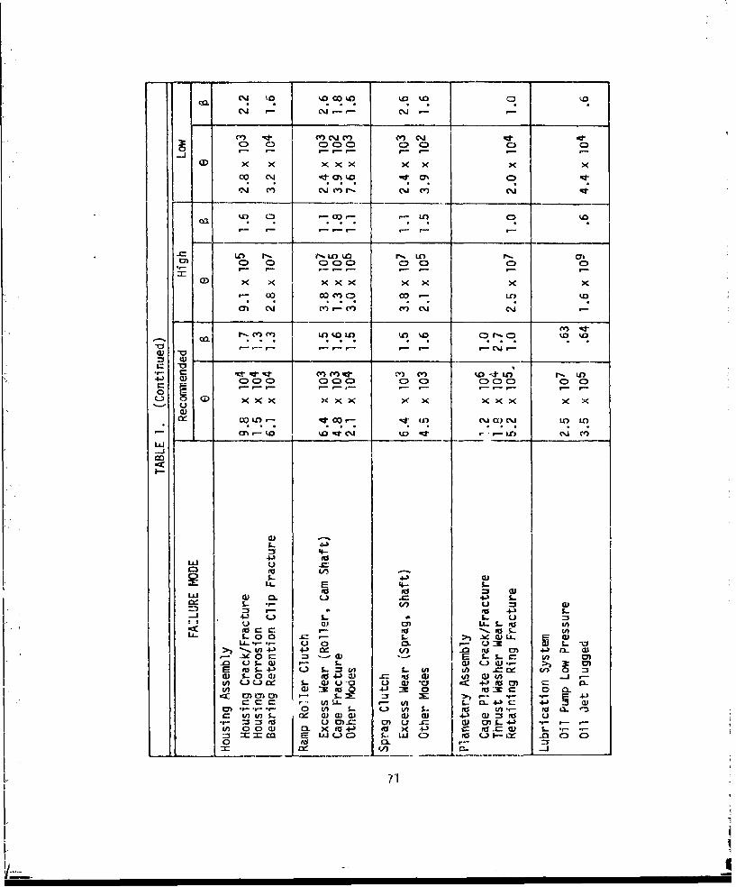
0 ~ ~ l CC00 0 0
cO~ C\J mC) CV) CD1 CD) CD )
LC) t- r0 U')o w U) 0 '.
-c) CD C)- Cý.~l. C) C)1- C D
a) 0 0 00 0 0 X 0
C4 cocwi M- LA '.0c
ca 0.1 (V"!(V (V) C) 01 CD
-Itcv Rl" .0m n wr m .mr- '0 '.O
4J C)C) C CV) CV)W CV CV) C)DC
000 0' t00 04 0n 000 0C 0~ -)
m ko .ý -d- r r- . -
- L u1'. OCJ L t0 V
LCL)
f" 44-3 L)L. u4-
u U UI) U L.juV4. a 0S b 344 -0
ta43 4 ) W ) tu C" 4- rLL. 0 - = -. C ) c
w S.U-4 4. ow fU 4-O 4) 4) ul w
U- W.o t- o- 4J %-.c 43
%-~~~~ CC aCd.. u 4- IJ (
to) u) CD) M -- ( LM 4-) t- I
r_.. 0ý. 0L
[ 71

STEP I
Compute the theoretical reliability of a gearbox with a known MTBRat 100 hours using the following equation:
sioo
R(100) = e (2)
where Gi - size parameter associated with ith failuremode (tabulated in Table 1)
= shape parameter associated with ith failuremode (tabulated in Table 1)
The summation in Equation (2) consists of all possible failure modes in thegearbox.
STEP 2
Siiiilarly, compute the theoretical reliability of the gearbox withthe known MTBR at 10,000 hours using the following equation:
ai
R(00,O00) = e .. ei j(3)
STEP 3
Compute the composite shape and size parameters, 0 and e , forthe gearbox with the known MTBR from the calculated values ofreliability at 100 and 10,000 hours using the following equations:
1 1
lnln -pol lnln I(4)
4.605
4.605 a - lnIn -- I
- e (5)
STEP 4
Compute the theoretical MIBR of the gearbox with the known MT8Rfrom the shape and size parameters calculated in Step 3 using thefollowing equation:
MTBR --- 0.r(l +11/) (6)
where r(l + 1/1) = the gamma function of the quantity (I + 1/B)which can be found using Figure 27.
72

NOTE: r'o,+ r
1.0
.96- - - - -- - - -
.94 --
.92 •
.90 - -r- - -
.881.0 1.1 1.2 !.3 1.4 1.5 1.6 1.7 1.8 1.9 2.0
Figure 27. GAMMA FUNCTION
73iA
i~ l I I I i I I I 1 1 I i I I I I " .... " "'i " -I'
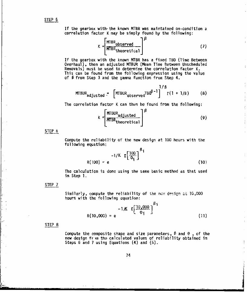
STEP 5
If the gearbox with- the known MTBR was maintained on-condition acorrelation factor K may be simply found by the following:
K = MTBRobserved (7)MTBRtheoretical
If the gearbox with the known MTBR has a fixed TBO (Time BetweenOverhaul), then an adjusted MTBUR (Mean Time Between UnscheduledRemovals) must be used to determine the correlation factor K.This can be found from the following expression using the valueof 0 from Step 3 and the gamma function from Step 4.
MTBUR = [MTBURobservedTBOP r] r(l + i/m) (8)
adjusted
The correlation factor K can then be found from the following:=MTBURadjusted
K~~a.A~e (9)theoretical]
STEP 6
Compute the reliability of the new design at 100 hours with thefollowing equation:
-1/KJi
R(l00) = e (10)
The calculation is done using the same basic method as that usedin Step 1.
STEP 7
Similarly, compute the reliability of the nc, des"ign at- 10,000hours with the following equation:
R(00,000) = e (11)
STEP 8
Compute the composite shape and size parameters, 0 and e , of thenew design fr-nm the calculated values of reliability obtained inSteps 6 and 7 using Equations (4) and (5).
74

STEP 9
Compute the MTBR of the new design from the calculated values ofa and e obtained in Step 8 using Equation (6).
Example - Reliability Prediction of New Intermediate Gearbox
To illustrate the reliability prediction procedure, the MTBR of the newlydesigned intermediate gearbox will be determined. The correlation factorfor a similar gearbox with a known MTBUR and TBO must be obtained beforethe MTBR of the newly designed gearbox can be determined. A parts listand corresponding values for size and shape parameters are given in Table2 for the gearbox of known MTBR shown in Figure 28. Similar data is givenin Table 3 for the new gearbox shown in Figure 29. Experience shows thatthe existing similar design has an observed MTBUR of 4000 hours and a TBOof 2000 hours. The calculations, starting with Step 1, are outlined below.
STEP 1
Compute the theoretical reliability of the existing gearbox at 100hours using Equation (2). Values of the exponent and the reli-ability for each failure mode are given in Table 2.
(I0O/Oi) = .02110 R(l00) = e -. 02110 .9791
STEP 2
Compute the theoretical reliability of the existing gearbox atI0,000 hours using Equation (3). Values of the exponent and thereliability for each failure mode are given in Table 2.
E00100,OO/6i10i = 2.1394 R(10,000) = e -2.1394 - .1177
STEP 3
Compute the composite shape and size parameters, 0 and 0 , for theexisting gearbox using th, value; calculated in Steps 1 and 2 bysubstitution in Equations (4) and (5).
Inln Ir nln .- 1.003
4.605
4.605(1.003) - lnln 9791
0 e = 4679
75
I ! I II I I iI
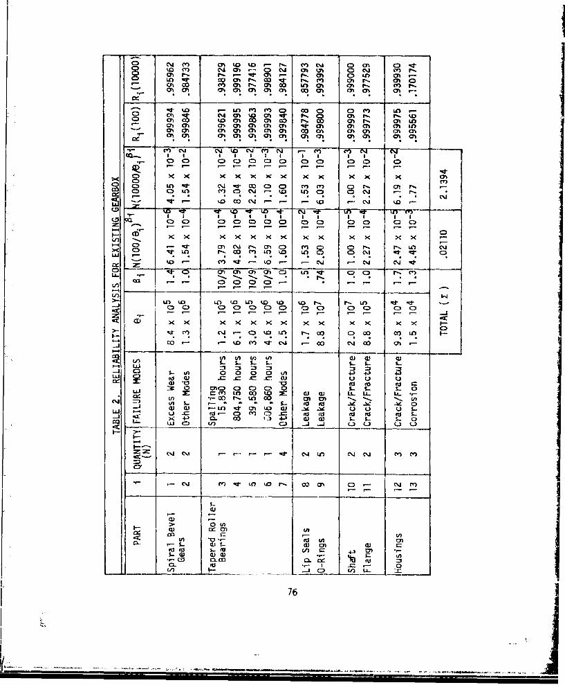
o 1 M~ ko LO rC - r-. ( CV) 0l C) 0T C>-dto CY cliO (n -C C4 Oh kA CD C%j kv r
0)rýr ,-W 0%~ rý 0h C) Gb c
CA~~ ~ 00 Ch0ýCh L mm P
U)o Ln m m C 0 D C (n~ )O iC) 0) 04 0 CA ~ ýg cr -r r,0) . fýCD 0)0 to a%)O o 0)0 00)0) r 01 U
rvý Ch m . c.J ON C', Jc -ti h m C% m I
Oi i a! !a!s 0 a! 0! a at a 1! 7
IP - r - - - r- 1 co x x x x x x x x x x x (M0
C~i~00 C"
CD -o- -o ,n W-
F- K 0
C> ( 0 r-. C ,LlL inO 0C:) r"q 0l OLii - . . . ..
~LO to at LO %C IC D l % r-s P- U) rt -d
-Ji
m C1 Q koin 00- a0 (D 4. o 4..) LO
.cC-n ~ CuU c ci
_ ~ ~ S In L.X 5. i U0 0)-. . I
= ~ S.-0 0 t1 0C w U 43 4-t 4s-Y (D 0. co to) P t S. .. -u±J0 M5) C, 0. .. 4 L2 %- 5- &
I.- LO0>sa i & A t
04 --3 LO
(Uz -% ý
ca u0) 40 (nC.) -j
cm 0v-C- LU n 0* ~j c) M
04 U m/ 1-c Ln Q0co c D m C
>-0 030 (icu~ I=
0. WU*- I ~ .
76
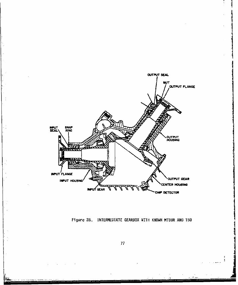
I
OUTPUT 3EAL
NUTOUTPUT FLANGE
•OUTPUT
OUTPUT GEAR
Figu r 8MICENTEBR AUSIND
I Figure 28. INTERMEDIATE GEARBOX WITH KNOWN MTBUR AND TBO
I~77'
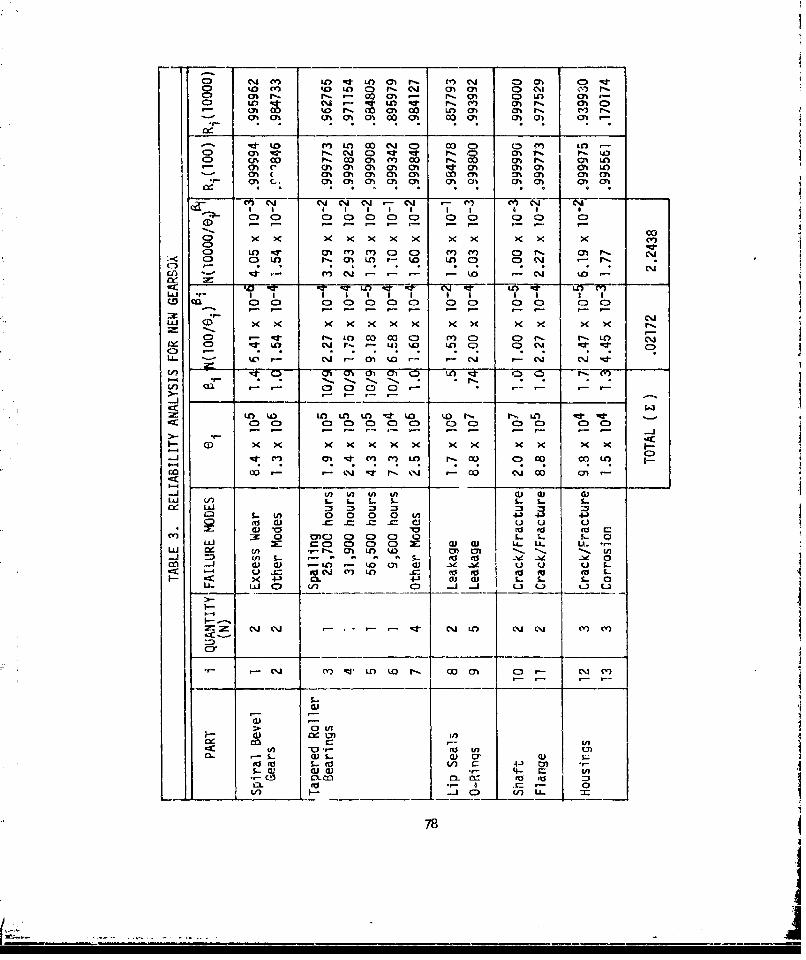
Cp 04 ) mnn f~ % O q101 - ~j C 0 ) C5I -tto mn ko -LO n R %%CN m 01 010ILI)rCD r r-. (M 01ý Cn CD 01 ) M- ~ '
cnM-r m10 0010 (oON 00o 01014 01-
- id U n O 0Co j coCiM n
CD CA OD r- w m m r-l CA 1 ONlinm 0n 01 , ON 0 M ON 01 0% 0h CA CA
a!- 0t Ci 01 10 a! CJ 01 01 00
cs- i Cl C*.J C -J -M CM~
0 0 0 0 0 0 0 0 0
CD x X X x ( x x xx X x x x
C0 mn ") m1 a) C3 CY) CY) 0 . 0 - C~1(7) - . . . . I
CE) - o grt :TZ in) C% . -O C
IL I .,I I I I I
iLl (D X x x x .c X~ x <
C) - týi ko 0 Coo m r ) 0l 0, N.LO ~w~ 0D R in CIJ r,: 7 Lu in i cq ~
LL- CJ Chli to C.,J C'J C%J d
-) C3 C1 01 01
- n U) in io mn inr ko to P, ri n I" -
en (1in c n r-. a) 0ý C) co in
wO w~ 0 . N 'C CDJ CD a)
S- . - 5 .
S-w 0 00 0 - 4ý 4
L xUCP. CO lD ClD LI. . &
LU 11 c n -- .-j =:) ^i . inU U -
*: -j UJn _: S aJClo in uI U QU &-- CC x~- +343 a L. &- t..0
U.. Id 0) Cii -A -j L3 ) -1 C.3
(~j C'J9 - -- C~J LO cmJ Cli M m
Crl
do -0 Ln
fl- a) c)
(a -- 0L/) -j .. 8 0 V L
78
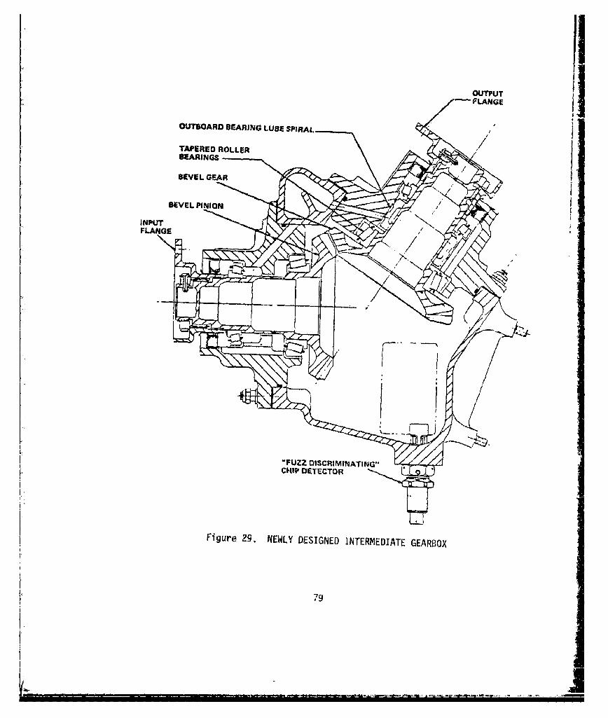
TAPERED ROL EWYDEINELEEREIAGERO
BEARING
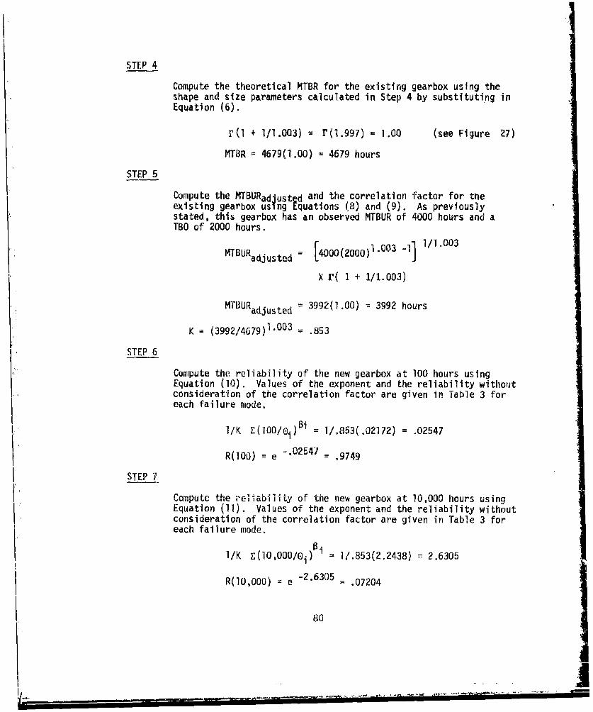
STEP 4
Compute the theoretical MTBR for the existing gearbox using theshape and size parameters calculated in Step 4 by substituting inEquation (6).
r(l + 1/1.003) = r(I.997) = 1.00 (see Figure 27)
MTBR = 4679(1.00) = 4679 hours
STEP 5
Compute the MTBURadjusted and the correlation factor for theexisting gearbox using Equations (8) and (9). As previouslystated, this gearbox has an observed MTBUR of 4000 hours and aTBO of 2000 hours.
MTBURadjusted [4000(2000)1.003 -11 1/1.003
X r( 1 + 1/1.003)
MTBURadjusted 3992(1.00) = 3992 hours
K (3992/4679)1.003 .853
STEP 6
Compute the reliability of the new gearbox at 100 hours usingEquation (10). Values of the exponent and the reliability withoutconsideration of the correlation factor are given in Table 3 foreach failure mode.
I/K E(100/oi)5i = ]/.853(.02172) = .02547
R(100) = e '.02547 = .9749
I. STEP 7
Compute the reliability of the new gearbox at 10,000 hours using
Equation (11). Values of the exponent and the reliability withoutconsideration of the correlation factor are given in Table 3 foreach failure mode.
1/K E(l0,000/oi) 1/.853(2.2438) = 2.6305
R(00,000) e -2.6305 = .07204
80
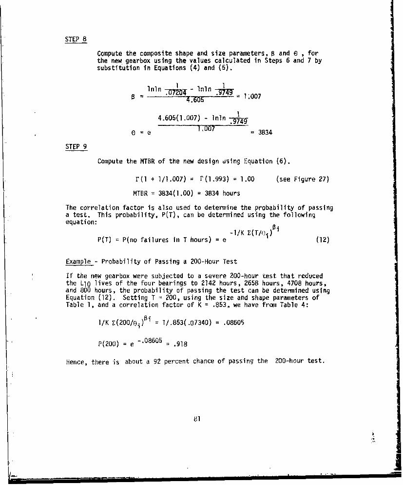
STEP 8
Compute the composite shape and size parameters, 0 and e , forthe new gearbox using the values calculated in Steps 6 and 7 bysubstitution in Equations (4) and (5).
Im 1Inln I-(T O- Inln I
B = T4.605 1.007
4.605(1.007) - nln.
_M49S= e 1007= 3834
STEP 9
Compute the MTBR of the new design using Equation (6).
r(l + 1/1.007) = (11.993) = 1.00 (see Figure 27)
MTBR = 3834(1.00) = 3834 hours
The correlation factor is also used to determine the probability of passinga test. This probability, P(T), can be determined using the followingequation:
-I/K (/ii
P(T) = P(no failures in T hours) = e (12)
Example - Probability of Passing a 200-Hour Test
If the new gearbox were subjected to a severe 200-hour test that reducedthe L1O lives of the four bearings to 2142 hours, 2658 hours, 4708 hours,and 800 hours, the probability of passing the test can be determined usingEquation (12). Setting T = 200, using the size and shape parameters ofTable 1, and a correlation factor of K = .853, we have from Table 4:
I/K E(200/ei)Bi = 1/.853(.07340) = .08605
P(200) = e -. 08605 .918
Hence, there is about a 92 percent chance of passing the 200-hour test.
81
I,-. I "1 1". ... . ii II I I i l I I ,i

*n 0%wW k 0'. "r I'm
C) to I I In w a% In II~ 00 0000 00 7$ 00 00
al 0wm r- m P. % m -% m r 0
cc. . .< .~ . . . X .
0 n L~o m C" O~ Icn Ln c l C-0aa. ID 0I00i - C1 (J u0 L1" 6- ( 8 1sf a~ CYý CDJ (V) CJ CD
010% 00c O 04 0W C r- pn C )C
C, I") Ch 0 C D Lo t%. CD
LaJC) )C C.D
C)~~~ ~ ~ C) Uýa Q C C lC
mt %0 0C o tO )00 00 EUw E
Lj. cl Li. Sý..:
- ~~~~ ~4 c)( ~ ~ 1 ) ~ ( O u L
'-4~~ I 4-1L . L
c(P -0..0 0La tc
K 1} CJ2 c - -4 -L LA-A ~ CJ C~
ca U -LL CDI C) C L I P - j CO ' -i
CL
-. UEU U' 0
co( 0.4WL _ _ _ _ _ _
toI
BIBLIOGRAPHY
GEARS
AGMA Publications
110.03 Gear Tooth Wear and Failure
210.02 Surface Durability (Pitting) of Spur Gear Teeth
211.02 Surface Durability (Pitting) of Helical and HerringboneGear Teeth
216.01 Surface Durability (Pitting) Formulas for Spiral BevelGear Teeth
217.01 Information Sheet - Gear Scoring Design Guide for Aero-space Spur and Helical Power Gears
220.02 Rating the Strený :h of Spur Gear Teeth
221.02 Rating the Strength of Helical and Herringbone Gear Teeth
223.01 Rating the Strength of Spiral Bevel Geir Teeth
The following pamphlets and standards are published by the Gleason Works ofRochester, Nev. York and pertain strictly to spiral bevel gears
"Spiral Bevel Gear System"
"Bending Stresses in Bevel Gear Teeth"
"Scoring Resistance of Bevel Gear Teeth"
"Surface Durability Pitting Formulas for Bevel Sear Teeth"
"Installation of Bevel Gears
"How to Test Bevel Gears"
Other Publications
Buckingham, Earie, ANALYTICAL MECHANICS OF GEARS, New York, DoverPuhlications, Tnc., !949-
Merritt, fl. E., GEAR ENGINEERING, New Vork, John Wiley & Sons, Inc.,1971.
BEARINGS
Harris, Tedric, A., ROLLING BEARING ANALYSIS, w'vw York, John Wiley &Sons, Inc., 1966.
83
/. • l• lI I I I IS-- .. .. ..... . . . . . . . . . . . . -.. " .. ... .. . .. " - - '
Banmberger, E.N., et al., LIFE ADJUSTMENT FACTORS FOR BALL AND ROLLERBEARINGS, New York, American Society of Mechanical Engineers, 1977
Palmgren, Arnold, BALL AND ROLLER BEARING ENGINEERING, Philadelphia,SKF Industries, Inc., 1959
Anderson, William and Zaretsky, Erwin, ROLLING ELEMENT BEARINGS - AREVIEW OF THE STATE OF THE ART, NASA TMX-71441, 1973.
In addition to the above publications, information on bearing design andselection is available from the various manufacturers of aerospace qualitybearings.
LUBRICATION
MII.-HDBK-275A, GUIDE FOR THE FrLECTION OF LUBRICANT FLUIDS ANDCOMPOUNDS FOR USE IN FLIGHT VEHICLES AND COMPONENTS, Pipartment ofDefense, Washington, D.C., 1976.
Campbell, Mahlon, and Thompson, Mason, LUBRICATION HANDBOOK FOR USE INTHE SPACE INDUSTRY, Midwest Research Institute, NASA, Marshall SpaceFlight Center, 1972.
SEALS
Hayden, T.S., and Keller, C.H., DESIGN GUIDE FOR HELICOPTER TRANS-MISSION SEALS, Sikorsky Aircraft; CP-120997, NASA-Lewis Research CenterCleveland, Ohio, 1974.
CLUTCHES
Kish, Jules, HELICOPTER FREEWHEEL UNIT DESIGN GUIDE, SikorskyAircraft; USAAMRDL Technical Report 77-18, Applied TechnologyLaboratory, U.S. AMrt Research 'nd Technology Laboratories (AVRADCOlI),Fort Eustis, Virginia, October 1977, AD A047559.
84
APPENDIX A
DESIGN CHECKLISTS
The checklists presented on the following pages are intended as a guide.The use of fairly detailed checklists during a design program can preventthe occurrence of costly oversights aid insure a uniform approach in thedesign of helicopter gearbox componenits. The checklists here may be usedas is, or new checklists may be made up according to the desires of thedesign manager. It is, however, s "ongly suggested th&t they be preparedbefore the start of a design prcgra!-i, and made an integral part of thedesign procedure.
851
II
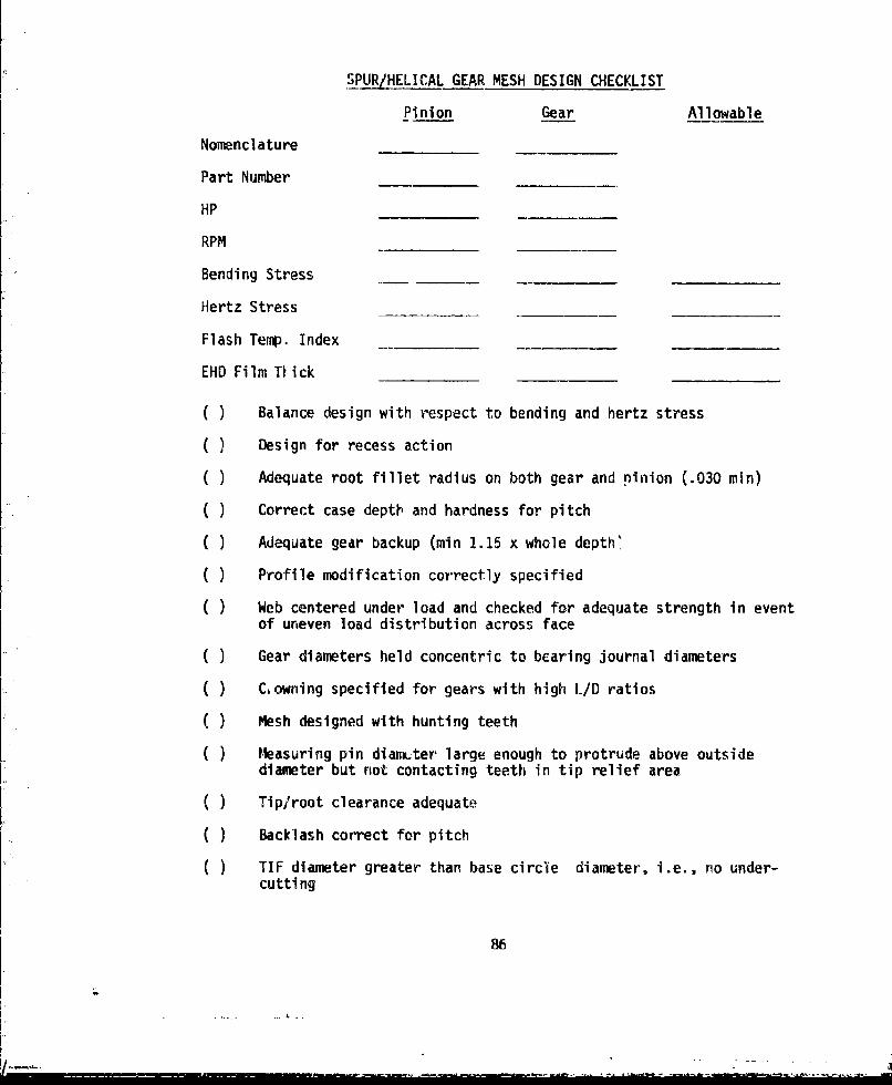
SPUR/HELICAL GEAR MESH DESIGN CHECKLIST
Pinion Gear Allowable
Nomenclature
Part Number
HP
RPM
Bending Stress
Hertz Stress
Flash Temp. Index
EHD Film TVick
( ) Balance design with respect to bending and hertz stress
( ) Design for recess action
( ) Adequate root fillet radius on both gear and pinion (.030 min)
( ) Correct case depth and hardness for pitch
( ) Adequate gear backup (min 1.15 x whole depth'
( ) Profile modification correctly specified
( ) Web centered under load and checked for adequate strength in eventof uneven load distribution across face
( ) Gear diameters held concentric to bearing journal diameters
( ) C, owning specified for gears with high L/D ratios
( ) Mesh designed with hunting teeth
( ) Measuring pin diam-ter large enough to protrude above outsidediameter but riot contacting teeth in tip relief area
( ) Tip/root clearance adequate
( ) Backlash correct for pitch
TIF diameter greater than base circle diameter-, i.e., ro under-cutting
86
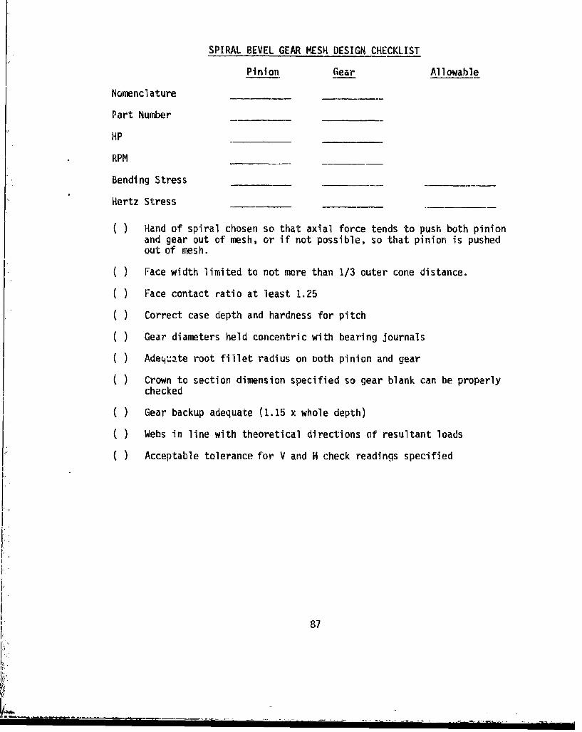
SPIRAL BEVEL GEAR MESH DESIGN CHECKLIST
Pinion Gear Allowable
Nomenclature
Part Number
HP
RPM
Bending Stress
Hertz Stress
( ) Hand of spiral chosen so that axial force tends to push both pinionand gear out of mesh, or if not possible, so that pinion is pushedout of mesh.
) Face width limited to not more than 1/3 outer cone distance.
( ) Face contact ratio at least 1.25
( ) Correct case depth and hardness for pitch
( ) Gear diameters held concentric with bearing journals
( ) Adequate root fillet radius on both pinion and gear
C ) Crown to section dimension specified so gear blank can be properlychecked
( ) Gear backup adequate (1.15 x whole depth)
( ) Webs in line with theoretical directions of resultant loads
C ) Acceptable tolerance for V and H check readings specified
87
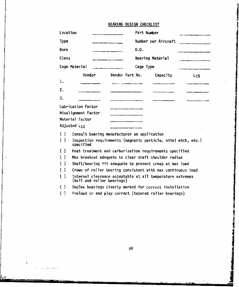
BEARING DESIGN CHECKLIST
Location Part Number
Type Number per Aircraft
Bore O.D.
Class Bearing Material
Cage Material Cage Type
Vendor Vendor Part No. Capacity LIO
1.________ _ _ _ _
3.
Lubrication Factor
Misalignment Factor
Material Factor
Adjusted LID
( ) Consult bearing manufacturer on application
) Inspection requirements (magnetic particle, nital etch, etc.)specified
( ) Heat treatment and carburization requiremlents specified
( ) Max breakout adequate to clear shaft shoulder radius
( ) Shaft/bearing fit adequate to prevent creep at max load
( ) Crown of roller bearing consistent with max continuous load
( ) Internal clearance acceptable at all temperature extremes(ball and roller bearings)
( ) Duplex bearings clearly marked for correct installationS( ) Preload or end play correct (tapered roller bearings)
I
88I
LI"I.- - '- --. ....• • ' _ . . "• " • ' ' • . . i

SEAL DESIGN CHECKLIST
Location Part Number
Type Speed
Shaft Eccentricity (Static)_ Shaft Runout (Dynamic)
Housing Bore Eccentricity Shaft Material --
Shaft Hardness Shaft Surface Finish
Temperature (Normal Operating) - Temperature Range
Pressure Leakage Rate
Type Fluid Being Sealed Seal Material
External Environment
) Seal speed capability consistent with operating speed consideringpressure and runout
) Seal pressure capability consistent with operating pressureconsidering speed
) Runout not excessive in application
( ) Extremes of seal axial position relative to shaft checked toinsure adequate running surface
S( ) Seal material compatible with fluid being sealed
( ) Primary seal protected from dust, grit, etc.,by secondary seal
( ) 2;acrificial runners considered for use on shaft
89

MANAGEMENT R&M CHECKLIST
Reliability and maintainability goals clearly established
Preliminary reliability analysis scheduled early in design stage
( ) Design review scheduled after completion of basic layout beforedetail design
Detailed reliability analysis scheduled during detail design
Consideration of "must pass" tests taken in design, i.e., must haveacceptably high chance of passing test
Attention to detail stressed in analytical effort
High risk areas identified and alternate designs prepared
Communication maintained with other design areas to minimizeaccessibility problems
( ) Allowance made for increased power (especially in tail rotor drivesystem components) so that excessive redesign will not be necessary
( ) Perform failiire mode and effects analysis
90 1511-19