Usain Boat Team: 2015 Roboboat Competition - Robonationrobonati/sites/default/files/pictures... ·...
9
Usain Boat Team: 2015 Roboboat Competition Dr J. Judge*, Augusto C. S. Peixoto*, Rafael L. Thomaz*, and Ronaldo C. Reis* *Catholic University of America, Washington, DC 20064 USA Abstract Usain Boat is a fully autonomous surface vehicle designed to fulfill the main task of navigating through an unknown path of water buoys. Due to the requirement of autonomous vehicle, the engineering students and faculty have developed a computer vision software integrated with a system of navigation and electronic sensors (IMU and GPS) which will work together with the goal of producing accurate commands that will control the boat’s impellers and consequently the direction that the boat moves. 1 Introduction The first idea to participate to 2015 Roboboat Competition came from the Senior Design Course of CUA Mechanical Engineer- ing Department. It is an 1-year long course where students learn topics essential for the design of mechanical systems. Also, students incorporate engineering standards, and use freehand sketching as well as PC based tools including CAD and Matlab. In our case, the final product is Usain Boat, as a pun with the name of the famous Jamaican runner Usain Bolt. It is a creative name and make empha- sis to our boat must be fast. As we are in just 3 people (3 students abroad at CUA from Brazil), we chose not run all mission tasks as Pinger location or Interoperability challenge. Also, using prin- ciples of System Engineering, we decided to split the project in 3 main parts: Electronics, Software and Mechanical Design, where each person is responsible for one part. On the beginning of the project, we did a literature review reading the previous jour- nal papers and previous competition rules. Also, we watched videos on Youtube of pre- vious competition to have a better notion of how the competition is. After that, we de- cided to make a simple project starting with the diagram of it, as showed in the figure 1. 2 Electronics 2.1 Camera The camera is one of the main points during the navigation. It is responsible for detecting the distance between the boat and the buoys, providing angles and distance data, in order to be always trying to reach the desired trajectory. Since this device acts as the vision of the boat, it needs to be reliable, displaying a high resolution image. For this purpose, the group chose a Logitech C930e Webcam, with 1080 pixels of resolution and 90-degree field of view with 30 frames per second. 2.2 GPS The GPS module is also an orientation device. The data of the boats position rela- tive to the buoys is fundamental for several reasons. Firstly, it provides information for making decisions during the execution of the main code, such as to increase the motors speed, rotate the boat or to brake. Further- more, when the buoys are not in the cameras field of view, it gives a notion of how the boat must move so that the buoys will lie inside the field of view. The group chose a PAM- 7Q GPS Module, due the amount of open 1
-
Upload
trinhkhanh -
Category
Documents
-
view
215 -
download
0
Transcript of Usain Boat Team: 2015 Roboboat Competition - Robonationrobonati/sites/default/files/pictures... ·...

Usain Boat Team: 2015 RoboboatCompetition
Dr J. Judge*, Augusto C. S. Peixoto*, Rafael L. Thomaz*, and Ronaldo C. Reis*
*Catholic University of America, Washington, DC 20064 USA
Abstract
Usain Boat is a fully autonomous surface vehicle designed to fulfill the main task ofnavigating through an unknown path of water buoys. Due to the requirement of autonomous
vehicle, the engineering students and faculty have developed a computer vision softwareintegrated with a system of navigation and electronic sensors (IMU and GPS) which will worktogether with the goal of producing accurate commands that will control the boat’s impellers
and consequently the direction that the boat moves.
1 Introduction
The first idea to participate to 2015Roboboat Competition came from the SeniorDesign Course of CUA Mechanical Engineer-ing Department. It is an 1-year long coursewhere students learn topics essential for thedesign of mechanical systems. Also, studentsincorporate engineering standards, and usefreehand sketching as well as PC based toolsincluding CAD and Matlab. In our case, thefinal product is Usain Boat, as a pun with thename of the famous Jamaican runner UsainBolt. It is a creative name and make empha-sis to our boat must be fast.
As we are in just 3 people (3 studentsabroad at CUA from Brazil), we chose notrun all mission tasks as Pinger location orInteroperability challenge. Also, using prin-ciples of System Engineering, we decided tosplit the project in 3 main parts: Electronics,Software and Mechanical Design, where eachperson is responsible for one part.
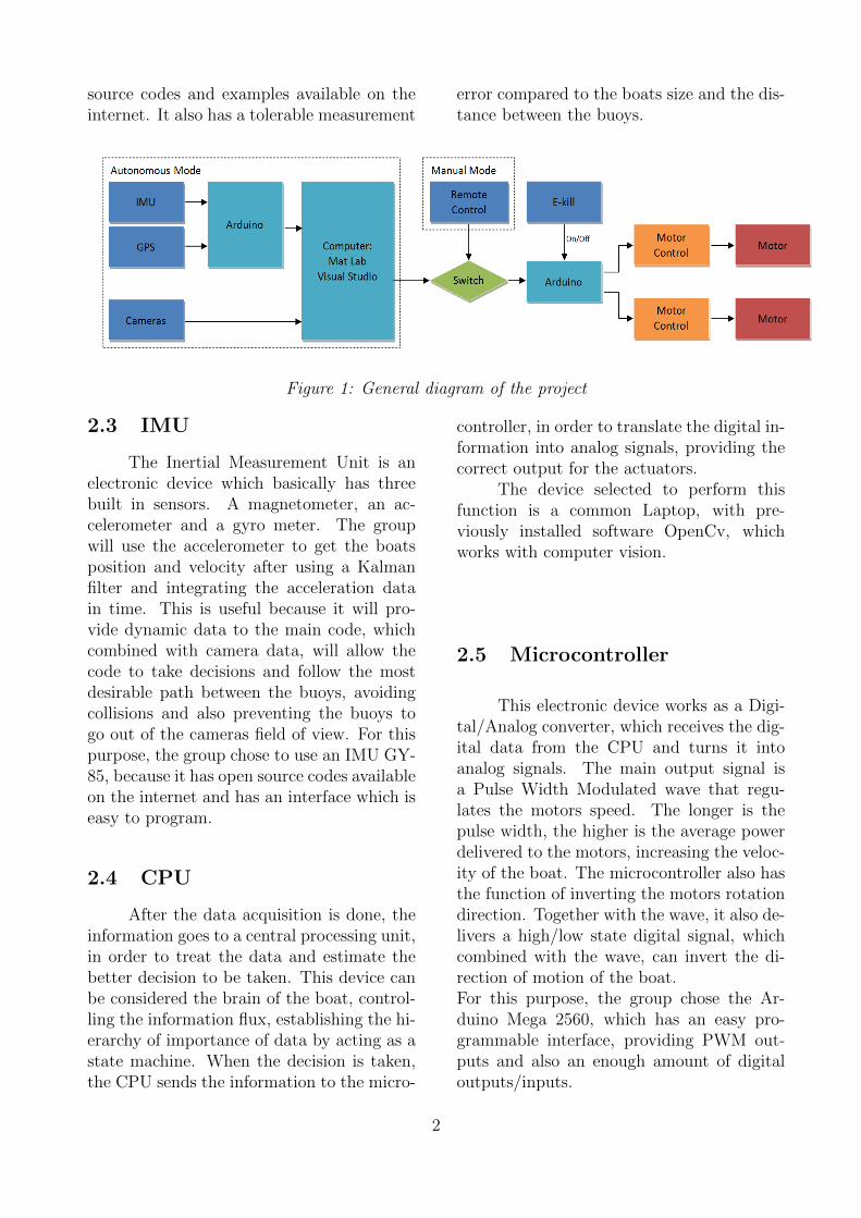
On the beginning of the project, we dida literature review reading the previous jour-nal papers and previous competition rules.Also, we watched videos on Youtube of pre-vious competition to have a better notion ofhow the competition is. After that, we de-cided to make a simple project starting withthe diagram of it, as showed in the figure 1.
2 Electronics
2.1 Camera
The camera is one of the main pointsduring the navigation. It is responsible fordetecting the distance between the boat andthe buoys, providing angles and distancedata, in order to be always trying to reach thedesired trajectory. Since this device acts asthe vision of the boat, it needs to be reliable,displaying a high resolution image. For thispurpose, the group chose a Logitech C930eWebcam, with 1080 pixels of resolution and90-degree field of view with 30 frames persecond.
2.2 GPS
The GPS module is also an orientationdevice. The data of the boats position rela-tive to the buoys is fundamental for severalreasons. Firstly, it provides information formaking decisions during the execution of themain code, such as to increase the motorsspeed, rotate the boat or to brake. Further-more, when the buoys are not in the camerasfield of view, it gives a notion of how the boatmust move so that the buoys will lie insidethe field of view. The group chose a PAM-7Q GPS Module, due the amount of open
1
source codes and examples available on theinternet. It also has a tolerable measurement
error compared to the boats size and the dis-tance between the buoys.
Figure 1: General diagram of the project
2.3 IMU
The Inertial Measurement Unit is anelectronic device which basically has threebuilt in sensors. A magnetometer, an ac-celerometer and a gyro meter. The groupwill use the accelerometer to get the boatsposition and velocity after using a Kalmanfilter and integrating the acceleration datain time. This is useful because it will pro-vide dynamic data to the main code, whichcombined with camera data, will allow thecode to take decisions and follow the mostdesirable path between the buoys, avoidingcollisions and also preventing the buoys togo out of the cameras field of view. For thispurpose, the group chose to use an IMU GY-85, because it has open source codes availableon the internet and has an interface which iseasy to program.
2.4 CPU
After the data acquisition is done, theinformation goes to a central processing unit,in order to treat the data and estimate thebetter decision to be taken. This device canbe considered the brain of the boat, control-ling the information flux, establishing the hi-erarchy of importance of data by acting as astate machine. When the decision is taken,the CPU sends the information to the micro-
controller, in order to translate the digital in-formation into analog signals, providing thecorrect output for the actuators.
The device selected to perform thisfunction is a common Laptop, with pre-viously installed software OpenCv, whichworks with computer vision.
2.5 Microcontroller
This electronic device works as a Digi-tal/Analog converter, which receives the dig-ital data from the CPU and turns it intoanalog signals. The main output signal isa Pulse Width Modulated wave that regu-lates the motors speed. The longer is thepulse width, the higher is the average powerdelivered to the motors, increasing the veloc-ity of the boat. The microcontroller also hasthe function of inverting the motors rotationdirection. Together with the wave, it also de-livers a high/low state digital signal, whichcombined with the wave, can invert the di-rection of motion of the boat.For this purpose, the group chose the Ar-duino Mega 2560, which has an easy pro-grammable interface, providing PWM out-puts and also an enough amount of digitaloutputs/inputs.
2

2.6 RF Control/Receiver
For the RoboBoat project there aresome security procedures that must be taken.During the navigation there is a possibilityof failure and subsequent inoperability of thecontrol system. In this case, a manual con-trol must be assumed, in order to avoid ma-terial damages and health injuries. For thispurpose, the group decided to install a relaysystem which remotely switches the controlwhen necessary. Since there were no specialspecifications related to the RF controller,the group decided to choose a 6 channel RFtransmitter/receiver, such as a Flysky FS-T6 V2 (2.4GHz) Transmitter. This item canbe replaced because there are several mod-els available with a large number of differentprices.
2.7 Motor Driver
The motor drive device has the func-tion of controlling the motor rotation direc-tion and speed. When it receives the PWMand High/Low state signal from microcon-troller, it combines these two information togenerate a truth table, which has five dif-ferent outputs: Forward, Backward, BrakeLow, Brake High and Coast. This deviceengages the motor with batteries. Since thegroup will use three motors, it will be neces-sary three motor drivers. The model PololuHigh-Power Motor Driver 18v25 CS was cho-sen because its small size, high power capac-ity and output functionality.
Figure 2: Motor Driver Board.
Figure 3: Motor Driver Truth Table.
2.8 Motors
The group chose a trolling motor as theimpeller. The model Minn Kota Endura C230 is a 12V Dc motor, with 30 lbs. of maxi-mum thrust. This motor is proper for navi-gation, containing a 30 inches shaft and ad-justable speed. Firstly, the group had consid-ered the usage of a bilge pump motor, with2000 gallons per hour of capacity. However,there was an inconvenient: the motors shaftwas too short, so that the water flux wouldbe partially obstructed by the pumps plasticbody.
The trolling motor is a nice way to solvethis problem because it is designed for nav-igation. Moreover, the price is lower than abilge pump motor.
Figure 4: Minn Kota Endura C2 30 TrollingMotor.
3

2.9 Batteries
The battery chosen is a 12V recharge-able lead-acid battery with 15 Ah.
Figure 5: 12V Lead-Acid Battery With 15ahCapacity.
2.10 Remote E-kill
The remote E-kill is a security devicewhich can be activated through a radio fre-quency trigger. It is a very important se-curity procedure, since it can instantly stopthe motors, by opening the circuit and dis-connecting the impellers from the batteries.For this purpose the group chose to use theXBee radio router/coordinator.
3 Software
3.1 Image Processing
The mission that the boat must ful-fill requires a way to acquire informationof pattern of buoys such as color, distance,and position. The work of determining thebuoys’ distance can be done using differentmethods that are divided in two groups: ac-tive method and passive method. The firstmethod need to send a signal to the tar-get and process the signal that the targetreturns, some examples using this approachare laser range finder, ultrasonic range finder,sonar, infrared, etc. On the other hand,the passive method only receives informationabout the object, and stereo vision is themost popular example using this technique.
The team has chosen to use stereo vi-sion as the resource for capturing distance in-formation because it has a great cost-benefitsince this method is cheaper, being necessaryonly two cameras, and it provides acceptabledata.
According to Jernej Mrovlje [1],the basic theoretical fundamentals of thismethod is shown in figure [6], where the ob-jective is express the distance D as func-tion of the following parameters: distancebetween the two cameras B, the number ofpixel on the horizontal line of the image x0,the viewing angle of the camera ϕ0.
Figure 6: Stereo vision fundamentals.Firstly we have,
B = B1 +B2 = D tanϕ1 +D tanϕ2
D =B
tanϕ1 + tanϕ2
Using triangulation we calculate,
x1(x02
) =tanϕ1
tanϕ2
2
−x2(x02
) =tanϕ2
tanϕ2
2
Finally,
4
D =Bx0
2 tan(ϕ0
2
)(x1 − x2)
However, before of calculating thisdistance the software need firstly to identifythe buoys on the image, using color recogni-tion. This task has been made using Opencv,a library designed for computer vision andwith a focus on real-time applications. Thecode is being writing in C/C++ language us-ing the compiler Microsoft Visual Studio.
Before using the cameras it is neces-sary to calibrate them in order to checktheir features and estimate their focal length(f). This last parameter can be calculate asan average of several experimental measure-ments following this equation,
f =d.Z
D
where D represents the known size of an ob-ject, Z the known distance from the camerato object and d the object size in pixel.
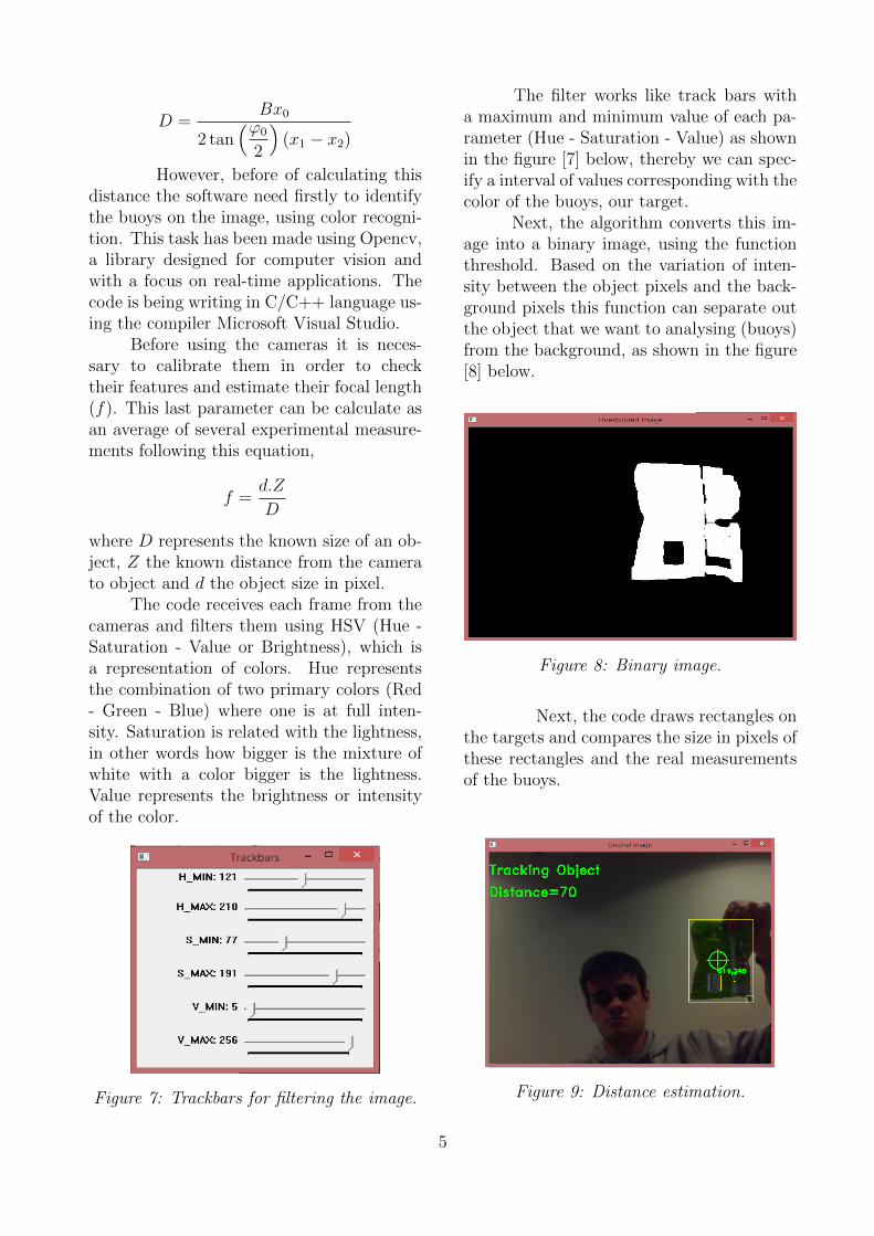
The code receives each frame from thecameras and filters them using HSV (Hue -Saturation - Value or Brightness), which isa representation of colors. Hue representsthe combination of two primary colors (Red- Green - Blue) where one is at full inten-sity. Saturation is related with the lightness,in other words how bigger is the mixture ofwhite with a color bigger is the lightness.Value represents the brightness or intensityof the color.
Figure 7: Trackbars for filtering the image.
The filter works like track bars witha maximum and minimum value of each pa-rameter (Hue - Saturation - Value) as shownin the figure [7] below, thereby we can spec-ify a interval of values corresponding with thecolor of the buoys, our target.
Next, the algorithm converts this im-age into a binary image, using the functionthreshold. Based on the variation of inten-sity between the object pixels and the back-ground pixels this function can separate outthe object that we want to analysing (buoys)from the background, as shown in the figure[8] below.
Figure 8: Binary image.
Next, the code draws rectangles onthe targets and compares the size in pixels ofthese rectangles and the real measurementsof the buoys.
Figure 9: Distance estimation.
5

4 Mechanical Design
The main final deliverable of Mechan-ical Subsystem is the structure of the boat.This structure contains basically a hull, im-pellers, a waterproof box and a frame to sup-port the Electronic Subsystem. It was cho-sen the pontoon style boat design in formatof catamaran for many reason that will beexplained after.
Moreover, we are based our struc-ture on Marine Robotic at the University ofHawaii [6], because they have designed forthe last competition a simple and easy to dohardware able to fit in different hulls. There-fore, it was thought in use foam and fiber-glass to do the hulls and in bars of wood ar-ranged as a grid to do the frame, as showedin the image bellow.
Figure 10: Isometric view of the Usain Boat.
This grid will be fixed in the top of thepontoons, impellers will be fastened in it andthe box will be fixed in it by the bottom.
The calculus and description of eachcomponent will be showed on the next sub-sections.
4.1 Basic Calculus of Buoy-ancy, Drag Force andPower
Let’s firstly consider the pontoons aretwo 5” PVC pipes of 1m length perfectly
cylindrical. If they are completely sub-merged, the total buoyancy (represented byB) generated by them is calculated by thefollowing formulas:
B = df .Vs.g
Where df is the fluid density, consid-ered 1000Kg/m3 to water, Vs is sub-merged volume of the pontoons equals to
2.1m.π.
((5”)(0.0254m)
2
)2
and g is the grav-
ity acceleration, considered 10m/s2. So, itresults a total buoyancy of 240N , approxi-mately.
After, setting a maximum speed V in2m/s (almost 4kts) and considering a dragcoefficient Cd equals to 1, it comes
D =1
2.df .V
2.A.Cd
Where A is cross section seen by thestream of water that is, in this case,
2.π.
((5”)(0.0254m)
2
)2
= 0.01227m2. Then,
it gets D = 50N , approximately.All in all, set Cd = 1 is an overestima-
tion. This coefficient will likely be smallerthan 1. This is a good news, because thedrag force is proportional to it. So, it alsowill likely be smaller than 50N .
Now, considering the total weight ofthe boat equal to W = 240N , it is possibledo a free body diagram as below
Figure 11: Free Body Diagram. Illustrativefigure.
Where T is the thrust generated by impellers.Then, to keep a constant speed, the boat re-quires almost 50N.2m/s = 100W of power.This amount of power has to by supplied by
6

2 impellers.This calculus are clearly not accurate,
but give us a notion of the drag force, thrustand power required to boat have a reasonablevelocity.
4.2 Hull
The main function of the hull is hav-ing enough buoyancy to keep the equilib-rium of vertical forces, that is, the generatedthrust must be equal or bigger than boatweight. This goal can be achieve by manymanners. We thought use two of 1.2m 5”PVC pipes as pontoons due to ease of work-ing with them (cut, join, make patches), andso, the structure would be early prepared forfuture tests. However, we have noticed theUniversity of Hawaii Team boat structure.The team has used in the last competitionpontoons made by fiberglass. The methodused consists firstly do the shape of the hullusing Styrofoam and after cover it with stripsof fiberglass and resin. The result is clearlybetter than PVC pipe with respect to weightand structural strength.
Besides the requirements of buoyancyand dimensions (Maximum dimensions arelength = 6ft, width = 3ft and height = 3ft),the hull was also designed to store the bat-teries. This configuration results on increas-ing of boat‘s stability since the batteries rep-resent a reasonable part of the total weightof the boat and it center of gravity will benearer of water level. Moreover, the catama-ran format gives more stability than mono-maran or trimaran.
The plan views of the hull final designis showed in Appendix.
The total volume of the hull calculatedby SolidWorks is equal to 51l, so both ofthe hulls can support the maximum weightof more than 100Kg. Of course, Usain Boatdoes not have this total weight.
Other important function of the boatis determine the hull velocity (design veloc-ity Vdesign- maximum velocity where the dragcoefficient does not increase suddenly) of the
boat. According to [7], we have
Vdesign = Fr√lg
Where Fr is Froude numbers, l is the lengthof the boat and g is the acceleration of thegravity. The ideal Fr number is 0.267, l is1.1m we can consider g = 10m/s2. So, weget
Vdesign = 0.88m/s
In this case, we can consider Cd =0.006. Then, taking the lateral area of thehull as a perfect parallelepiped, it results thedrag force showed below
D =1
2103(0.88)2[4(0.3)(1.1)](0.006)
D ≈ 3N
This is the total drag at the design ve-locity.
4.3 Frame
This component has the largest struc-tural efforts in the boat. The frame will sup-port the electronics, impellers and the wholeweight of the boat in the all competitionphases including weight and thrust measure-ment one. For this purpose, it was designed aframe made by wood as showed in the figurebelow.
Figure 12: Top view of the frame.
7

It was chose wood because it is lessdense than metals like steel or aluminum, itis easy to work with and it is available inDon’s Shop (CUA’s machinist). The framebasically consists in 3 bars of 28in by 2in by1in and the 4 hooks for fixation.
4.4 Impellers
After some professor suggestions, wewere thinking use bilge pump as boatthrusters. That is, modify the pump, adapt-ing the motor to turn a shaft with a propelleron one of its ends. This looks a good solutionto first view. However, considering the powerrequest to boat achieve a maximum speed of4 knots, the price of the bilge pumps withadequate specifications is almost the same ofother professional impellers used by last com-petition teams. Therefore, it was bought twoprofessional impellers, in this case, trollingmotor, as described in Electronic Subsystem.
4.5 Box
We first thought in doing a waterproofbox made by foam and coated by fiberglass,but for simplicity questions we bought a com-mercial one. In the bottom of this box willbe fixed some pieces of wood in order to fixit in the frame using screws. To discoverwhere is the best position to fix the box inthe frame, it was calculated the momentumgenerated by the heaviest components in theboat and considered static equilibrium of thesame. This calculus is showed below.
Figure 13: Free body diagram.
Where B1, B2 and B3 representthe three batteries placed into each pon-toon, BOX represents the weight of the box,BUOY ANCY represents the buoyancy forcegenerated by pontoons and MOTORS is thethrust generated by trolling motors. Theforces are in equilibrium because the buoy-ancy is equal the total weight of the boat.Considering the same weight for batteries of25.7N and the box has 200N of weight. So,the calculus for force and momentum is:∑
Fy = 0
BUOY ANCY = 6(25.7) + 200 = 352.2N∑MA = 0
2(25.7N)(13 + 39 + 65) + (200N)x
−(352.2N)(38) + (50N)45 = 0
x = 48cm
So, the best position of box is your masscenter placed 48cmm of the bar that sup-ports the impellers.
How it has to support a laptop and hasto fit in the frame, the box was designed withdimensions of 60cm by 50cm by 40cm.
5 References
[1] Georgia Tech 2014 Roboboat Com-petition. Sinead O’Sullivan et al.,p.2.
[2] 5th RoboBoat Competition - FinalRules. p.3. 2013.
[3] Building Wireless Sensor Networkswith ZigBee, XBee, Arduino, and Process-ing. Robert Faludi. 2010.
[4] Colour Object Tracking On Em-bedded Platform Using Open CV. KrutikaA Veerapuret et al., p.1.
[5] Multiple Objects Tracking usingCAMshift Algorithm in Open CV. Aditi Joget al., p.1.
[6] Design and Manufacture of an Au-tonomous Surface Vehicle (ASV) for the 2014RoboBoat Competition. Francis Cheng etal., p.2.
[7] Fluid Mechanics. White, F. M.,4th edition. p.466.
8

6 Appendix
All dimensions are in in millimeters.
9