
US14-O’Toole A MODULAR APPROACH TO VIDEO · PDF fileMANIPULATION TARGETS FOR MOBILE...
13
1 A MODULAR APPROACH TO VIDEO DESIGNATION OF MANIPULATION TARGETS FOR MOBILE MANIPULATORS Aaron O’Toole * and Jessica N. Jones † This paper describes a method for enhancing semi-autonomous tele-operation of highly dexterous manipulators. The presented process enables the operator of a mobile manipulator to select an object from a remotely viewed video feed transmitted from a UGV and watch the manipulator autonomously moves its end effector to a specified offset from the designated object. The presented method is robust to sensor noise and is constructed in a modular manner that does not re- ly on a specific 3D sensor, manipulator, camera, or number of cameras. By grossly estimating the workspace of the manipulator and scanning the general area of interest, an octree is created in which a ray is cast into to determine the point of interest. The system is designed specifically with future Explosive Ord- nance Disposal (EOD) robots in mind which will possess manipulators with high degrees of freedom. INTRODUCTION Currently fielded EOD robots are limited in terms of both mechanical ability and autonomous capabilities when compared to the current state-of-the-art in mobile robotics. To combat this problem (as well as several others) the Joint Service EOD Program is developing the Advanced EOD Robot System (AEODRS). AEODRS consists of three system variants that vary in size: small for dismounted operations, medium for tactical operations, and large for base/infrastructure operations. Differing from past EOD UGV development efforts, these robots will not be devel- oped by one sole company, but will be designed under a modular architecture consisting of sever- al capability modules that are to be developed by separate companies (or government agencies). Both the medium and large variants will incorporate heavy-duty, high degree of freedom ma- nipulators that can be cumbersome for operators to maneuver even with the help of high-tech controllers. As such, there are requirements for several semi-autonomous behaviors, one of which is the ability for the operator to designate an object through a 2D video feed and have the manipu- lator autonomous move to the object (but not grasp it). PREVIOUS WORK There are several solutions to the problem of designating an object for a robot to carry out ma- nipulation tasks in an unknown environment. One solution, which was previously examined at * Robotics Engineer, NSWC IHEODTD, Robotics Branch, 2008 Stump Neck Rd. Indian Head, MD. † Ph.D. Candidate, HCC Division School of Computing, 100 McAdams Hall Clemson University Clemson, SC. US14-O’Toole
Transcript of US14-O’Toole A MODULAR APPROACH TO VIDEO · PDF fileMANIPULATION TARGETS FOR MOBILE...
1
A MODULAR APPROACH TO VIDEO DESIGNATION OF MANIPULATION TARGETS FOR MOBILE MANIPULATORS
Aaron O’Toole* and Jessica N. Jones†
This paper describes a method for enhancing semi-autonomous tele-operation of
highly dexterous manipulators. The presented process enables the operator of a
mobile manipulator to select an object from a remotely viewed video feed
transmitted from a UGV and watch the manipulator autonomously moves its end
effector to a specified offset from the designated object. The presented method
is robust to sensor noise and is constructed in a modular manner that does not re-
ly on a specific 3D sensor, manipulator, camera, or number of cameras. By
grossly estimating the workspace of the manipulator and scanning the general
area of interest, an octree is created in which a ray is cast into to determine the
point of interest. The system is designed specifically with future Explosive Ord-
nance Disposal (EOD) robots in mind which will possess manipulators with
high degrees of freedom.
INTRODUCTION
Currently fielded EOD robots are limited in terms of both mechanical ability and autonomous
capabilities when compared to the current state-of-the-art in mobile robotics. To combat this
problem (as well as several others) the Joint Service EOD Program is developing the Advanced
EOD Robot System (AEODRS). AEODRS consists of three system variants that vary in size:
small for dismounted operations, medium for tactical operations, and large for base/infrastructure
operations. Differing from past EOD UGV development efforts, these robots will not be devel-
oped by one sole company, but will be designed under a modular architecture consisting of sever-
al capability modules that are to be developed by separate companies (or government agencies).
Both the medium and large variants will incorporate heavy-duty, high degree of freedom ma-
nipulators that can be cumbersome for operators to maneuver even with the help of high-tech
controllers. As such, there are requirements for several semi-autonomous behaviors, one of which
is the ability for the operator to designate an object through a 2D video feed and have the manipu-
lator autonomous move to the object (but not grasp it).
PREVIOUS WORK
There are several solutions to the problem of designating an object for a robot to carry out ma-
nipulation tasks in an unknown environment. One solution, which was previously examined at
* Robotics Engineer, NSWC IHEODTD, Robotics Branch, 2008 Stump Neck Rd. Indian Head, MD. † Ph.D. Candidate, HCC Division School of Computing, 100 McAdams Hall Clemson University Clemson, SC.
US14-O’Toole

Report Documentation Page Form ApprovedOMB No. 0704-0188
Public reporting burden for the collection of information is estimated to average 1 hour per response, including the time for reviewing instructions, searching existing data sources, gathering andmaintaining the data needed, and completing and reviewing the collection of information. Send comments regarding this burden estimate or any other aspect of this collection of information,including suggestions for reducing this burden, to Washington Headquarters Services, Directorate for Information Operations and Reports, 1215 Jefferson Davis Highway, Suite 1204, ArlingtonVA 22202-4302. Respondents should be aware that notwithstanding any other provision of law, no person shall be subject to a penalty for failing to comply with a collection of information if itdoes not display a currently valid OMB control number.
1. REPORT DATE 12 MAY 2014 2. REPORT TYPE
3. DATES COVERED 00-00-2014 to 00-00-2014
4. TITLE AND SUBTITLE A Modular Approach to Video Designation of Manipulation Targets for Manipulators
5a. CONTRACT NUMBER
5b. GRANT NUMBER
5c. PROGRAM ELEMENT NUMBER
6. AUTHOR(S) 5d. PROJECT NUMBER
5e. TASK NUMBER
5f. WORK UNIT NUMBER
7. PERFORMING ORGANIZATION NAME(S) AND ADDRESS(ES) NSWC IHEODTD, Robotics Branch,2008 Stump Neck Rd, Indian Head,MD,20640
8. PERFORMING ORGANIZATIONREPORT NUMBER
9. SPONSORING/MONITORING AGENCY NAME(S) AND ADDRESS(ES) 10. SPONSOR/MONITOR’S ACRONYM(S)
11. SPONSOR/MONITOR’S REPORT NUMBER(S)
12. DISTRIBUTION/AVAILABILITY STATEMENT Approved for public release; distribution unlimited
13. SUPPLEMENTARY NOTES Presented at AUVSI’s Unmanned Systems 2014, May 12-15, 2014 at the Orange County ConventionCenter, Orlando, FL, Supporting documentation attached as PowerPoint Presentation
14. ABSTRACT
15. SUBJECT TERMS
16. SECURITY CLASSIFICATION OF: 17. LIMITATION OF ABSTRACT Same as
Report (SAR)
18. NUMBEROF PAGES
24
19a. NAME OFRESPONSIBLE PERSON
a. REPORT unclassified
b. ABSTRACT unclassified
c. THIS PAGE unclassified
Standard Form 298 (Rev. 8-98) Prescribed by ANSI Std Z39-18

2
Naval Surface Warfare Center Indian Head EOD Technology Division (IHEODTD), is to pair a
rigidly attached one dimensional laser range finder with a camera. This method works well but
has several limitations. Every camera that objects are to be designated from must have a dedicat-
ed range finder.
Additionally, the range finder is only accurate for one pixel in the video feed. Therefore, the
user can only select items that are in the center of the video feed, or the camera and range finder
can be automatically re-aimed at the point of interest so an accurate measurement can be taken.
Another valid option that was considered is to have users designate objects from a point cloud
instead of a video feed. Using this method, a user can specify the desired manipulation target di-
rectly by selecting the exact point of interest (POI) in the form of a singular 3D point. This proce-
dure is preferred in some situations, such as tele-operation of a personal assistant robot, and is
especially intuitive when the 3D data is similar in appearance as 2D video data, such as structured
light sensors that overlays color data on the point cloud like the Microsoft Kinect.* However, se-
lecting points from a point cloud does not lend itself well to EOD operations for two reasons: 1) it
would be mentally taxing to manipulate (i.e. rotate and zoom) and visualize point cloud data dur-
ing an EOD operation, 2) 3D sensors that create data which is easy to visualize (such as struc-
tured light sensors) notoriously do not operate well in sunlight conditions.
The presented method overcomes all of these shortcomings. Specifically, it requires only one
3D sensor for any number of cameras onboard the robot, it can work in full sunlight conditions,
and it does not require the user to interact with complicated 3D data.
APPROACH
Our approach makes minimal assumptions about the robotic system on which it is implement-
ed. The few requirements needed to use this procedure are:
The robot is equipped with an encoded serial manipulator.
The robot has some type of 3D sensor (e.g. stereo camera, structured light, or scanning lidar)
that can be aimed to anywhere in the arm’s workspace
The robot has at least one video camera that transmits to an Operator Control Unit (OCU).
There is no maximum number of cameras.
There are known or encoded kinematic chains connecting the robot’s arm, cameras, and 3D
sensor.
Figure 1 below shows the hardware used during this development project. The arm is a 6 de-
gree of freedom Kinova Jaco, the lidar sensor is a Hokuyo UTM-30LX-EW, the pan tilt unit
(PTU) is the FLIR PTU-D46 and the camera is a Sony FCB-H11 block camera. Not depicted are
the two commodity laptops, one is used for the robot computer; the other is used as the OCU. All
the equipment is attached to cart to simulate a mobile robot.
* http://wiki.ros.org/assistive_teleop

3
Figure 1: System Hardware
A brief high level overview of the system is shown in Figure 2 which depicts a hand grenade
inside of a backpack being designated from a 2D video feed. In short, the user selects an object
from a video feed. The 2D pixel position is transformed into a 3D point using the forward kine-
matics of the robot. Inverse kinematics is used to solve the joint angles required to get the end
effector to that point. Finally the manipulator is commanded to those joint values.
Figure 2: High Level Overview

4
A more detailed overview follows:
1. Video feeds are sent from the robot to the OCU
2. The user selects an object from the OCU display
3. The pixel position corresponding to the selected object is sent to robot computer and trans-
formed into a ray
4. The 3D location of the point of interest is estimated using the ray, location of ground, and
arm’s workspace
5. The pan/tilt mechanism points at the estimated point of interest
6. A point cloud is constructed by tilting the lidar up and down
7. The point cloud is inserted into an octree format
8. The ray from step 3 is casted into the octree to find the 3D location of point of interest
9. Inverse kinematics are used to compute the pose of the arm required to get close to point of
interest
10. The arm motors are commanded to that pose
Steps 3, 4, 8, and 9 are the more complex steps and will be discussed in further detail below.
Open Source tools such as the Robot Operating System (ROS), Point Cloud Library (PCL),
and OpenRAVE were used to a great extent to help promote reusability of the code developed
during this project. 1, 2, 3
Specifically, the message passing scheme used by ROS enables the ab-
straction of the specific characteristics of the camera, 3D sensor, and robot used. Any camera or
3D sensor can be integrated into the system using this method as long as their position and orien-
tation is known to the system, the camera’s intrinsic parameters are provided in a ROS sen-
sor_msgs/CameraInfo message, and the 3D sensor (or a conversion program) is able to output the
ROS sensor_msgs/PointCloud2 message. The robot itself is also abstracted by use of the Unified
Robot Description Format (URDF) file. URDF is an XML based file format that describes the
geometry of a robot’s structure. There is an automated converter available within ROS that ena-
bles conversion of URDF files into the COLLADA file format which can be utilized by Open-
RAVE. OpenRAVE is an extensive toolset, but only its analytical inverse kinematics solver
(IKFast) was used during this project.* Additionally, the SPAWAR developed Muti-robot Opera-
tor Control Unit (MOCU) software was used for the operator control unit GUI development.4
Estimating Point of Interest Location
Some mobile robot systems are equipped with a 3D sensor that constantly scans the environ-
ment 360° around the robot to carry out obstacle detection and path planning tasks. For such sys-
tems, it is likely that any pixel a user selects from any camera will correspond to a 3D point that
has already been recorded. However, if a 3D sensor is only onboard for manipulation tasks, the
sensor only needs to scan when the user asks for semi-autonomous manipulation. Or, if the 3D
sensor has a limited field of view, it may not be currently pointing at the POI at the time the user
selects it. For either of these cases there needs to be a plan in place to enable the 3D sensor to
scan the area of interest quickly rather than waste time doing a full hemispheric scan. For this to
happen, the location of the POI needs to be approximated using the forward kinematic model of
the robot (e.g. a pan tilt mechanism) and the camera’s intrinsic parameters. Then the 3D sensor
can center its scan on this estimated location to get the true position of the point of interest.
* http://wiki.ros.org/collada_parser
5
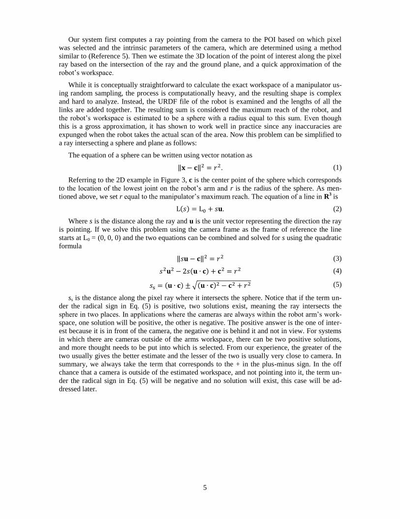
Our system first computes a ray pointing from the camera to the POI based on which pixel
was selected and the intrinsic parameters of the camera, which are determined using a method
similar to (Reference 5). Then we estimate the 3D location of the point of interest along the pixel
ray based on the intersection of the ray and the ground plane, and a quick approximation of the
robot’s workspace.
While it is conceptually straightforward to calculate the exact workspace of a manipulator us-
ing random sampling, the process is computationally heavy, and the resulting shape is complex
and hard to analyze. Instead, the URDF file of the robot is examined and the lengths of all the
links are added together. The resulting sum is considered the maximum reach of the robot, and
the robot’s workspace is estimated to be a sphere with a radius equal to this sum. Even though
this is a gross approximation, it has shown to work well in practice since any inaccuracies are
expunged when the robot takes the actual scan of the area. Now this problem can be simplified to
a ray intersecting a sphere and plane as follows:
The equation of a sphere can be written using vector notation as
‖ ‖ . (1)
Referring to the 2D example in Figure 3, c is the center point of the sphere which corresponds
to the location of the lowest joint on the robot’s arm and r is the radius of the sphere. As men-
tioned above, we set r equal to the manipulator’s maximum reach. The equation of a line in R3 is
( ) . (2)
Where s is the distance along the ray and u is the unit vector representing the direction the ray
is pointing. If we solve this problem using the camera frame as the frame of reference the line
starts at L0 = (0, 0, 0) and the two equations can be combined and solved for s using the quadratic
formula
‖ ‖ (3)
( ) (4)
( ) √( ) (5)
ss is the distance along the pixel ray where it intersects the sphere. Notice that if the term un-
der the radical sign in Eq. (5) is positive, two solutions exist, meaning the ray intersects the
sphere in two places. In applications where the cameras are always within the robot arm’s work-
space, one solution will be positive, the other is negative. The positive answer is the one of inter-
est because it is in front of the camera, the negative one is behind it and not in view. For systems
in which there are cameras outside of the arms workspace, there can be two positive solutions,
and more thought needs to be put into which is selected. From our experience, the greater of the
two usually gives the better estimate and the lesser of the two is usually very close to camera. In
summary, we always take the term that corresponds to the + in the plus-minus sign. In the off
chance that a camera is outside of the estimated workspace, and not pointing into it, the term un-
der the radical sign in Eq. (5) will be negative and no solution will exist, this case will be ad-
dressed later.

6
Figure 3: Estimating Point of Interest
Still referring to Figure 3, where V0 is a point on the ground plane and w = L0 – V0, we define
the vector pointing from V0 to any point on the pixel ray as
( ) . (6)
When this vector is perpendicular to the ground plane’s normal (n), the pixel ray is intersect-
ing the plane. Therefore, we need to find the value of s that satisfies
( ) . (7)
Solving Eq. (7) shows that the distance along the pixel ray to the ground plane is
(8)
If the denominator in Eq. (8) is zero there is no solution because the pixel ray is parallel to the
ground and does not intersect it. Likewise, if sp is negative, then the pixel ray is pointing upwards,
and the ground is behind the camera. We only use the result of Eq. (8) if sp > 0 which means the
pixel ray is pointing towards the ground. It should be noted that n is not always [0, 0, 1] since
some cameras can tilt and these calculations are done with respect to the camera frame.
If both Equations (5) and (8) produce useful solutions (i.e. positive values for ss and sp) the
lesser of the two values is used as the estimated point of interest. For example in Figure 3, the 3D
sensor would center its scan on L(ss). If neither of the equations produces useful values, it means
that the camera is positioned outside of the arm’s estimated workspace, and pointing away from
the ground and the workspace. While this case would suggest that the user has selected a point in
space that is out of reach for the robot’s arm, the area should be scanned anyways to make sure
this isn’t a mistake caused by the assumption that the workspace is a sphere with a radius the
length of the arm’s maximum reach. We center the scan on L(r) in these cases and leave it up to
the inverse kinematics solver to determine if the point of interest is out of reach or not. Also, if
the ray only intersects the ground at a distant point (e.g. the ray is almost parallel to the ground
and doesn’t pass through the sphere) we use L(r) instead of L(sp).
A screenshot of this process taking place on the actual system can be seen in Figure 4. The
light blue sphere represents the estimated workspace of the manipulator, the coordinate frame at
the top left is the camera’s frame, the pink line is the pixel ray, the small dot at the intersection of
the sphere and the pixel ray is the estimated point of interest and the green dot is refined point of
interest (the point cloud is omitted for clarity). The small dot above the point of interest is where
the manipulator is actually commanded to go. This offset is in place because the majority of tar-
gets are sitting on top of a surface, without it the manipulator is likely to collide with the surfaces.
u
L0
L(ss)
L(sp)
n
V0
w L(s) -V0 = w+su
c

7
Figure 4: Estimated Point of Interest Visualization
Refining the Point of Interest Location
Once the location of the point of interest is estimated and the 3D sensor takes a scan of the ar-
ea, the task of refining the estimation of the point of interest’s location remains. Given a point
cloud, and a ray (the origin of which corresponds to the focal point of the camera L0) the goal is
to select which point in the point cloud best represents the point the user wants to select. To solve
this problem, we rely heavy on the method described in (Reference 6) which is implemented in
PCL and lends itself well to large data sets (our method can work well with single scans, or large
scale collections of scans).
The point cloud is first inserted into an octree, which is a 3 dimensional spatial discretization
tree data structure that recursively subdivides space into smaller and smaller octants. Then, the
ray casting algorithm discussed in (Reference 6) is used to produce a list of occupied octree leaf
nodes that are intersected by the ray. A leaf node is a node of the smallest cell size in the tree; its
size is based on the resolution of the octree.
This process can be understood better by the 2D example in Figure 5, the top image of which
shows the side view of a ray going through a point cloud of a water bottle sitting on the ground.
The bottom left image shows the same point cloud after it has been subdivided into a quadtree
(the 2D equivalent of an octree). Notice that if a larger square does not contain any points, it is
not further subdivided, this is crucial in terms of saving computation time. Finally, any leaf nodes
that are intersected by the ray and contain at least one point are highlighted in green in the last
image. Obviously the optimal resolution of the octree depends on the sensor’s characteristics. For
our system we use a resolution of 3 inches, but higher density sensors with better accuracy could
use finer resolutions.
At this point, the system examines the intersected leaf nodes and disposes of cells that do not
contain at least a minimum number of points. This is to avoid selecting points that are the result
of sensor noise. In practice, with the Hokuyo UTM-30LX-EW, we found that a threshold value of
5 points suffices, but this depends on the quality and point density of the sensor. Next, the system
chooses from the remaining cells the one that is closest to the camera. It also goes one step farther
and picks which point within the chosen cell is closest to the camera.

8
Figure 5: Example of Octree Ray Casting
Inverse Kinematics
The system relies on the IKFast inverse kinematics solver from OpenRAVE. The process ex-
pects the long process of solving the inverse kinematics, and compilation of IKFast’s generated
C++ code to be done beforehand so it can be utilized at runtime without delay. OpenRAVE’s
XML robot format allows a transformation offset from a manipulator’s tip to allow for different
end effector lengths. This feature is used to provide a safe offset from the final pose of the end
effector to the designated object to avoid collisions (a 2 inch translation from the fingertips was
used in implementation).
The output of the procedure described in section B is a three degree of freedom translation that
the end effector must align to. However, six degrees of freedom are required to fully define the
end effector’s pose. The system must intelligently choose the final orientation of the end effector
in a manner that is convenient for the operator (i.e. minimize the amount of manual maneuvering
required to grasp the object). Using an end effector coordinate system in which the Z axis is col-
linear to the manipulator’s last joint axis vector, and the X axis is chosen depending on the geom-
etry of the end effector such that when it is parallel to the ground plane (with the Y axis tending
towards the upper hemisphere) the end effector is in a convenient orientation for grasping objects.
Achieving this orientation can be accomplished by setting the direction of the end effector’s X
axis direction equal to the cross product of the manipulator’s Z axis (which is collinear with the
first joint axis) and the vector from the manipulator’s base frame to the POI. Referring to Figure
6:
( ) (9)

9
Figure 6: Constraining End Effector Goal’s Roll and Yaw
In this 2D example, XEEF would be pointing into the page. This constraint defines the end ef-
fector’s roll and yaw but leaves the pitch undefined. Two valid ways of defining the pitch of the
end effector where examine, both methods are described below.
Method 1: The first method defaults to always setting the Z axis of the end effector to be par-
allel to the ground plane. However, a manipulator can publish a preferred pitch offset that equates
to a positive or negative rotation around the X axis. For example, for a hand-like end effector the
pitch offset could be 0, but a rake end effector could require a 45 pitch with respect to the
ground plane similar to the example in Figure 7.
Figure 7: Method 1 for Defining End Effector Pitch
Method 2: Shown in Figure 8, this method uses a manipulator specific aiming point (shown as
the red dot in the figure) that the end effector’s Z axis must pierce. The aiming point is defined as
an offset from the manipulator’s base coordinate system’s Z axis.
Figure 8: Method 2 for Defining End Effector Pitch
Both methods have pros and cons: Method 1 works well for systems that utilize many differ-
ent end effector types that require fixed orientations with respect to ground. This method defines

10
an absolute orientation that does not change depending on the position of the point of interest.
One downside to this method is it noticeably reduces the workspace of the manipulator by always
requiring the same orientation. Method 2 on the other hand defines a relative orientation that
changes the pitch depending on the elevation of the point of interest. This method works well
with gripper-type end effectors because it produces natural end effector orientations that are simi-
lar to what a human is familiar with (i.e. our hands’ Z axes tend to point towards the center of our
torso when reaching for objects).
During limited evaluations of the system, only method 2 was examined to do the lack of a va-
riety of end effectors. The resulting end effector orientations were found to be satisfactory. How-
ever, it was discovered that the workspace of the manipulator was slightly reduced using this
method (although, not as much as can be assumed for method 1).
In order for the system to be robust to many different end effector types, the system expects
end effectors (or manipulators with permanent end effectors) to publish two numbers upon con-
nection to the system. One number is an integer that describes whether to use method 1 or 2 for
defining the pitch of the end effector. The second number is a float whose meaning depends on
the method used. If method 1 is being used, the float represents the end effector’s preferred pitch
offset. If method 2 is being used, the float represents the height of the aiming point.
To combat situations in which the manipulator can reach a 3D point, but the orientation the
system imposes is impossible to reach, the system first tries to solve for the full 6 DoF pose, but if
no 6 DoF solution exists, it solves only 5 DoF (6 DoF minus pitch). This is made possible by us-
ing OpenRAVE’s TranslationDirection5D inverse kinematics solver and leaving the pitch pa-
rameter free in order to improve the possibility of solutions. The solutions returned by this pro-
cess are culled by comparing the corresponding pitch values with the desired pitch and discarding
solutions that would produce a difference in pitch above a certain threshold (±10 worked well
for the evaluated system, higher values produced unusable orientations and lower values con-
strained the system so much that solutions still couldn’t be found in many situations).
Whichever orientation definition method or inverse kinematics solver is used, once a valid
pose is available, OpenRAVE is able to produce all possible solutions for a given pose (situations
which have infinite solutions are discretized to some finite number of solutions). The task of pick-
ing which solution to choose is solved by minimizing the joint space distance from the manipula-
tor’s current pose to the final pose in the following manner.
The final joint configuration qfinal is the joint configuration that corresponds to the minimum
joint space distance
( ). (10)
Where m is the number of solutions and s is defined as
∑ ( ( ( ) ( ))) ( ) (11)
qcur is the manipulator’s current joint configuration and n is the number of joints. The function
f returns the shortest angular displacement required to go from one angle to the other:
√( ( ) ( ))
(12)
{
(13)

11
This assumes all joint angles are normalized between and -. Using the solution produced
by this process ensures the arm makes the minimum joint displacements required to move to the
specified pose.
CONCLUSION
The process outlined in this paper provides a modular method for designating, and manipulat-
ing to, objects in a video feed from a remotely controlled mobile manipulator. The process re-
quires only one 3D sensor for any number of cameras and makes no assumptions about the cam-
eras, 3D sensor, or kinematics of the manipulator. This method is highly adaptable for a variety of
end effectors types and manipulator architectures and greatly elevates cognitive loads for opera-
tors while tele-operating high degree of freedom manipulators.
FUTURE WORK
Currently the system does not perform any internal or external collision avoidance during au-
tonomous manipulation actions. This requires that a camera maintains field of view of the arm
during motion so the operator can pay close attention to prevent it from colliding with itself or
objects in the environment. In order for this method to be used in EOD operations, at least inter-
nal collision avoidance should be implemented. Moreover, external collision avoidance, similar
what is provided by MoveIt!, would be a great enhancement to the system.*
Additionally, one problem encountered during evaluation of the system is the designation of
points that require a ray to pass close to the manipulator as in Figure 9. 3D sensor points that cor-
respond to the manipulator are sometimes accidentally returned as the point of interest depending
on the resolution of the octree. One way to prevent this problem is to remove points from the
point cloud that belong to the robot, similar to what is done in the arm navigation package of
ROS.†
Figure 9: Points Corresponding to Robot
* http://moveit.ros.org/wiki/MoveIt! † http://wiki.ros.org/robot_self_filter

12
REFERENCES
1 M. Quigley et al., “ROS: an open-source Robot Operating System,” in International Conference on Robotics and Au-
tomation (ICRA), 2009.
2 R. Rusu and S. Cousins, “3D is here: Point Cloud Library (PCL),” in International Conference on Robotics and Au-
tomation (ICRA), Shanghai, China, 2011, pp. 1-4.
3 R. Diankov, “Automated Construction of Robotics Manipulation Programs,” M.S. thesis, Robotics Institute, Carnegie
Mellon University, Pittsburgh, PA. 2010.
4 D. Powell, G. Gilbreath, M. Bruch, “Multi-robot Operator Control Unit,” Proc. SPIE 6230, Unmanned Systems Tech-
nology VIII, 62301N, 12 May 2006
5 Z. Zhang, “A flexible new technique for camera calibration,” IEEE Transactions on Pattern Analysis and Machine
Intelligence, 22(11):1330-1334, 2000.
6 J. Revelles, C. Urena, M. Lastra, “An Efficient Parametric Algorithm for Octree Traversal,” in Journal of WSCG,
2000, pp. 212-219.