
US000009383520B220160705 - NASA · 556 545 I Power 554 eus to Discrete Thrusters I 0 544 542 I I...
52
11111111111111111111111111111111111111111111111111111111111111111111111111 (12) United States Patent Stone et al. (54) OPTICAL POWER TRANSFER SYSTEM FOR POWERING A REMOTE MOBILITY SYSTEM FOR MULTIPLE MISSIONS (71) Applicant: Piedra-Sombra Corporation, Inc., Del Valle, TX (US) (72) Inventors: William C. Stone, Del Valle, TX (US); Bartholomew P. Hogan, Rockville, MD (US) (73) Assignee: Piedra-Sombra Corporation, Inc., Del Valle, TX (US) (*) Notice: Subject to any disclaimer, the term of this patent is extended or adjusted under 35 U.S.C. 154(b) by 0 days. (21) Appl. No.: 14/723,206 (22) Filed: May 27, 2015 (65) Prior Publication Data US 2015/0256034 Al Sep. 10, 2015 Related U.S. Application Data (63) Continuation of application No. 13/303,449, filed on Nov. 23, 2011, now Pat. No. 9,090,315. (60) Provisional application No. 61/416,676, filed on Nov. 23, 2010. (51) Int. Cl. G02B 6/00 (2006.01) H02G 3/00 (2006.01) (Continued) (52) U.S. Cl. CPC .............. G02B 6/3604 (2013.01); B63B 35/12 (2013.01); B64D 33/00 (2013.01); E21B 41/0085 (2013.01); E21B 47/123 (2013.01); F25C 5/08 (2013.01); G02B 6/36 (2013.01); G02B 6/4268 (2013.01); G02B 6/4296 (2013.01); G02B 6/4415 (2013.01); G02B (io) Patent No.: US 9,383,520 B2 (45) Date of Patent: Jul. 5, 2016 6/4436 (2013.01); G02B 6/4458 (2013.01); G02B 71005 (2013.01); G02B 711827 (2013.01); G02B 19/0052 (2013.01); HOIL 35/00 (2013.01); (Continued) (58) Field of Classification Search CPC ...... G02B 6/3604; G02B 6/36; G02B 6/4268; G02B 6/4296; G02B 6/4415; G02B 6/4436; G02B 6/4458; G02B 7/005; G02B 7/1827; G02B 19/0052; B63B 35/12; B64D 33/00; E21B 1/00; F25C 5/08; HO1L 35/00; H02J 17/00 USPC ............................................ 385/137; 307/9.1 See application file for complete search history. (56) References Cited U.S. PATENT DOCUMENTS 2012/0068086 Al * 3/2012 DeWitt ................... E21B 10/60 250A92.1 Primary Examiner Jerry Blevins (74) Attorney, Agent, orFirm Miguel Villarreal, Jr.; Gunn, Lee & Cave, P.C. (57) ABSTRACT An optical power transfer system for powering a remote mobility system for multiple missions comprising a high power source and a chilling station connected to a laser source. The laser source transmits a high optical energy to a beam switch assembly via an optical fiber. The beam switch assembly is optically connected to actively cooled fiber spoolers. Docking stations are adapted for securing the fiber spoolers until alternatively ready for use by a remote mobility system. The remote mobility system is optically connected to the fiber spoolers and has a receiving port adapted for secur- ing the fiber spoolers thereon. The fiber spooler transmits the optical energy to a power conversion system which converts the optical energy received to another usable form of energy. More than one power source may be used where the remote mobility system transfers from one source to another while maintaining an operational radius to each source. 10 Claims, 34 Drawing Sheets 16- 18 500 II I II I I II I 26 36 II 26 32 0°°(°O 4U ( o °° (° ° ° o ° o ° 4U I I 2 22 36 I °000'00000° '00'00'0 I 32 24 54 56 52 I II I L --------------------------------- JL--------L https://ntrs.nasa.gov/search.jsp?R=20160010126 2018-07-24T05:21:43+00:00Z
Transcript of US000009383520B220160705 - NASA · 556 545 I Power 554 eus to Discrete Thrusters I 0 544 542 I I...

11111111111111111111111111111111111111111111111111111111111111111111111111
(12) United States PatentStone et al.
(54) OPTICAL POWER TRANSFER SYSTEM FORPOWERING A REMOTE MOBILITY SYSTEMFOR MULTIPLE MISSIONS
(71) Applicant: Piedra-Sombra Corporation, Inc., DelValle, TX (US)
(72) Inventors: William C. Stone, Del Valle, TX (US);Bartholomew P. Hogan, Rockville, MD(US)
(73) Assignee: Piedra-Sombra Corporation, Inc., DelValle, TX (US)
(*) Notice: Subject to any disclaimer, the term of thispatent is extended or adjusted under 35U.S.C. 154(b) by 0 days.
(21) Appl. No.: 14/723,206
(22) Filed: May 27, 2015
(65) Prior Publication Data
US 2015/0256034 Al Sep. 10, 2015
Related U.S. Application Data
(63) Continuation of application No. 13/303,449, filed onNov. 23, 2011, now Pat. No. 9,090,315.
(60) Provisional application No. 61/416,676, filed on Nov.23, 2010.
(51) Int. Cl.G02B 6/00 (2006.01)H02G 3/00 (2006.01)
(Continued)
(52) U.S. Cl.CPC .............. G02B 6/3604 (2013.01); B63B 35/12
(2013.01); B64D 33/00 (2013.01); E21B41/0085 (2013.01); E21B 47/123 (2013.01);F25C 5/08 (2013.01); G02B 6/36 (2013.01);
G02B 6/4268 (2013.01); G02B 6/4296(2013.01); G02B 6/4415 (2013.01); G02B
(io) Patent No.: US 9,383,520 B2(45) Date of Patent: Jul. 5, 2016
6/4436 (2013.01); G02B 6/4458 (2013.01);G02B 71005 (2013.01); G02B 711827
(2013.01); G02B 19/0052 (2013.01); HOIL35/00 (2013.01);
(Continued)
(58) Field of Classification SearchCPC ...... G02B 6/3604; G02B 6/36; G02B 6/4268;
G02B 6/4296; G02B 6/4415; G02B 6/4436;G02B 6/4458; G02B 7/005; G02B 7/1827;G02B 19/0052; B63B 35/12; B64D 33/00;E21B 1/00; F25C 5/08; HO1L 35/00; H02J
17/00USPC ............................................ 385/137; 307/9.1See application file for complete search history.
(56) References Cited
U.S. PATENT DOCUMENTS
2012/0068086 Al * 3/2012 DeWitt ................... E21B 10/60250A92.1
Primary Examiner Jerry Blevins(74) Attorney, Agent, orFirm Miguel Villarreal, Jr.; Gunn,Lee & Cave, P.C.
(57) ABSTRACT
An optical power transfer system for powering a remotemobility system for multiple missions comprising a highpower source and a chilling station connected to a lasersource. The laser source transmits a high optical energy to abeam switch assembly via an optical fiber. The beam switchassembly is optically connected to actively cooled fiberspoolers. Docking stations are adapted for securing the fiberspoolers until alternatively ready for use by a remote mobilitysystem. The remote mobility system is optically connected tothe fiber spoolers and has a receiving port adapted for secur-ing the fiber spoolers thereon. The fiber spooler transmits theoptical energy to a power conversion system which convertsthe optical energy received to another usable form of energy.More than one power source may be used where the remotemobility system transfers from one source to another whilemaintaining an operational radius to each source.
10 Claims, 34 Drawing Sheets
16- 18
500 III II II II I
26 36 II
26 32 0°°(°O 4U
(
o°°(°°°o°o°
4U I
I 2
22
36
I
°000'00000° '00'00'0 I 32
24
54 5652
I II IL--------------------------------- JL--------L
https://ntrs.nasa.gov/search.jsp?R=20160010126 2018-07-24T05:21:43+00:00Z

US 9,383,520 B2Page 2
(51) Int. Cl. B64D 33/00 (2006.01)G02B 6/36 (2006.01) HOIL 35/00 (2006.01)B63B 35/12 (2006.01) E21B 41/00 (2006.01)F25C 5/08 (2006.01) E21B 47/12 (2012.01)G02B 6/42G02B 6/44
(2006.01)(2006.01) HOIL 35/30 (2006.01)
G02B 7/00 (2006.01) EOI H 5110 (2006.01)
G02B 7/182 (2006.01) (52) U.S. Cl.G02B 19/00 (2006.01) CPC ................ HOIL 35/30 (2013.01); H02J17/00H02J17/00 (2006.01) (2013.01); EOIH5110 (2013.01)

U.S. Patent
0
a0.5
Jul. 5, 2016 Sheet 1 of 34 US 9,383,520 B2
Theoretical Attenuation Limits of Optical Poweras a function of Wavelength per Kilometer of Fiber
0 L—
800 1000 1200 1400 1600
Laser Wavelength (nanometers)
1800

U.S. Patent
1000
600ma~
m
400
30CL
200
raw
Jul. 5, 2016 Sheet 2 of 34 US 9,383,520 B2
Present Power Delivery (kilowatts) versusFiber Length (kilometers) for a
1 Megawatt input at 1550 nm Wavelength
Power (Out) =Power (In) * (0.9674)^ (Range in Kilometers)
---------------
0 20 40 60
Distance (km)
80 100

U.S. Patent
10
91
2
Jul. 5, 2016 Sheet 3 of 34 US 9,383,520 B2
High Power Fiber Transmission Tests
_ -------Input LaserPower (M) ~
TransmittedLaser
_ ............... ---------------- Power (kW)
00 20 40 60 80 100
% Input Power 10 kW Laser Source
1.2

U.S. Patent Jul. 5, 2016 Sheet 4 of 34 US 9,383,520 B2
Raw Power (Watts) for Single Mode Fiber Lasers from 1994 to 2010
10
E•1
6
2
C;1994 1996 1998 2000 2002 2004 2006 2008 2010
Year
U.S. Patent Jul. 5, 2016 Sheet 5 of 34 US 9,383,520 B2
Power Density (MW/cm^2) for Single Mode Fiber Lasers from 1994 to 2010
2500
2000
N
EV
1500
500
0 *0@10 '" I 1 I I I I 1 1
1994 1996 1998 2000 2002 2004 2006 2008 2010
Year
'j- ,. 3J3

U.S. Patent Jul. 5, 2016 Sheet 6 of 34 US 9,383,520 B2
LOG Power Density (MW/cm^2) for Single Mode Fiber Lasersfrom 1994 to 2010
3.5
3
1.5
11994 1996 1998 2000 2002 2004 2006 2008 2010
Year

U.S. Patent Jul. 5, 2016 Sheet 7 of 34 US 9,383,520 B2
Present Optical Power Transmission as a function of Fiber Core Diameter
14
12rcu3co
10
0 8IL
ca
CL 6O
asr4
NccoF- 2
0100 200 300 400 500 600 700
Fiber Care Diameter (Microns)
:11 •11
U.S. Patent Jul. 5, 2016 Sheet 8 of 34 US 9,383,520 B2
coN
-- — — —I----7
- - J

U.S. Patent Jul. 5, 2016 Sheet 9 of 34
------------------,I II I
I II I
co I IL-------- ---------~
---- --------
0 000000
0v
° 0 0 0 0 0 0 0 00 ° Io I
I ° 0 0 o Io 0 0 o0 O 0 0
o 0 0 o II o 0 o II °000000Ooo o° I/ o 0co 00000000
I Ii C.0 II ~ II II II II M II o II
M ~` I
I II II NI II
Ncc
N II II N II I
Ico
I I
US 9,383,520 B2

U.S. Patent Jul. 5, 2016 Sheet 10 of 34 US 9,383,520 B2
IfIIIIII
I
CN
NI NI I
I II I

U.S. Patent Jul. 5, 2016 Sheet 11 of 34 US 9,383,520 B2
O
mn
Ncc
NCO
U.S. Patent Jul. 5, 2016 Sheet 12 of 34 US 9,383,520 B2
00
C"

U.S. Patent Jul. 5, 2016 Sheet 13 of 34 US 9,383,520 B2
78
74
66 ̀ \ 50
17n
s4-- J' 58
to LaserPowerSource (22)
72

U.S. Patent Jul. 5, 2016 Sheet 14 of 34 US 9,383,520 B2
50
1
86
62

U.S. Patent Jul. 5, 2016 Sheet 15 of 34 US 9,383,520 B2
co0
0

U.S. Patent Jul. 5, 2016 Sheet 16 of 34 US 9,383,520 B2
coNr
M ~►

U.S. Patent Jul. 5, 2016 Sheet 17 of 34
~-- - - - - - - - - - - - -
0
0M'
coN
US 9,383,520 B2

U.S. Patent Jul. 5, 2016 Sheet 18 of 34 US 9,383,520 B2
133
U.S. Patent Jul. 5, 2016 Sheet 19 of 34 US 9,383,520 B2
0co -r-
CDm
vMr

U.S. Patent Jul. 5, 2016 Sheet 20 of 34 US 9,383,520 B2
wco
m
. ilz)(ft

irsl
!26
226
218
0 w
-206
U.S. Patent Jul. 5, 2016 Sheet 22 of 34 US 9,383,520 B2

334
son
344 J•
i~,.12
160
b CD
162

U.S. Patent Jul. 5, 2016 Sheet 24 of 34 US 9,383,520 B2
348 350352
354
356
366 ZZ
368
364 ----1370
372h
362376
386
378392
390 ; ; 394
388--------88 400
396 382
402 380°
398
406 \ 384
404
J1. 93
U.S. Patent Jul. 5, 2016 Sheet 25 of 34 US 9,383,520 B2

426
11 426
4
M430
430
Surf
ace Segment
Sub-S
urfa
ce Robotic Segment
434
444
450240
O
440
K04]
O
O
506
442
O AL O O
O
508
O
0 43
8 0
0
0
510
44
450
466
460
462
458
472
492
474
494
476
456
496
478
T498
480
500
482
468
484
470
12-22
~v
486
452
454
488
454
490
452
.15
--------------
I III II
I
II
152
2\53
653
4I
566
1 52
4
III
- -
iI
I I56
456
8 1
111
M 11111111111111i
l 0 0 000 000 0
0
0 0 0 0
I
I00000000 0 0°°°0 0 °0°°
518
ff(((((((
~ f fff(f
(l~l(
((((((((0((~~(
(((i
°°°°00°000
000000
I
1I
I000000
00000
00000
I
I516
I 1
0000000
00000000000
00
532
°°00 00
II1
~___
528
526
II
I1530
538----
iII
546
L540—
I1 L-----
---------
II ~ I
I II
I512
1547
11
Power Bus to
Wheel Mot
ors
1
514
544
542
520
1544
I
0 16
0
e54
454
8 1
154
654
4
1 54
6I
Whee
`~546
544—
----550
Meter=
546
I
154
41
L--------------------------------

----------------------------------~
Ii
I 1522`
536
534
I
524
°
D ° ° o ° o
°000 0000000000
io0 0 0 0 0 o°ooDo
00000
o000000
I000 0 0
oD 00
o°
I1
' °°0°0°0°0°0 0000
'
532
000000
01
j 528
526
530
538—
540
j
556
545
IPower
554
eus to
Disc
rete
Thrusters
I 0
544
542
I I
556
544
155
6544
1548
154
4
544
X550
1
1 556
11
544
1
L--------------------------------J

U.S. Patent Jul. 5, 2016
r-----------------------I
CrLn
co
0mLn n
LO
Sheet 29 of 34 US 9,383,520 B2
------------------i
CD
1III
NII ~ ~
I
~--~llll~~l~l~llllll
(9er) cnL" Ln
LM
r-- GL u
I OI ~I
rI to
I oI toI
I NI toII rI ~ LnIIII C1 ~Ii
I ~ n
I c~0
L--------------------------------------
I I o°000 0°
II o 0°I I c o ° I
I I o I
I I N 1I I N I
I I I
0
I I C II I N II I CDII I r p to 1I I eo ~n I
C I I u'+ I
I I II I ~I II I u) II I II I II I II I II II I
toNI I
I I I1 I 1I I I1 L-----------------JIII ~I
~
IIIII
II C
1I
I JI NII LnII
U.S. Patent Jul. 5, 2016 Sheet 30 of 34 US 9,383,520 B2
CA 'I
654
36
,62
66
668
X670

U.S. Patent Jul. 5, 2016 Sheet 31 of 34 US 9,383,520 B2

~i a000a0a
i 700
704
/ --712
i~ 0000000
698
r--jL -
----
-------~
/70
8
566
r-------------------- ----------,
I 1
I
564
568
518
j ;
706
—
I r-------------~
I 516
~sI
I
L---------------
(
' 536
~`
I ~
702
710
I---------------- ------------~
1
IILMUILI 111
111 II
H 111
0 0 0 0 0 0 0
I i
000
°I
0 0 a 0 0 0
pO0°o
0°0~
I° 0°°0
,1 ~— — — — — — — — — — — — — — —
—I I---
- ------ —~
532
L----------
— — ---------~
Jt • 21
528
530
526
538
1 ,
I I ,
1 --------------------------------------------------------
U.S. Patent Jul. 5, 2016 Sheet 33 of 34 US 9,383,520 B2
-----------------------------
I II v II
^ I
I ~ I
I ~ II II II camp I
cm
CV
I I
I ^ IC I ^ I
I I\ I I
~ I
v
o i II 0 00 I I I
° °0 I N
N I 00 o I t
^ I 00 °o I ^I 0 0 I
00 o
I i
I ~ II ~ II c II ^ I--------- ---------------------I

U.S. Patent Jul. 5, 2016 Sheet 34 of 34 US 9,383,520 B2
0Ln
i
rrr
rr
rr
s
ssf
,f
erm
n
US 9,383,520 B2
OPTICAL POWER TRANSFER SYSTEM FORPOWERING REMOTE MOBILITY SYSTEM
FOR MULTIPLE MISSIONS
CROSS REFERENCE TO RELATEDAPPLICATIONS
This is a continuation application claiming priority to andthe benefit of U.S. application Ser. No. 13/303,449, filed Nov.23, 2011, which claims priority to and the benefit of U.S.provisional application Ser. No. 61/416,676, filed Nov. 23,2010, both of which are hereby incorporated by referenceherein.
STATEMENT REGARDING FEDERALLYSPONSORED RESEARCH OR DEVELOPMENT
This invention was made with Government support underGrant No. NNXIOAE29G awarded by NASA. The Govern-ment has certain rights in the invention.
BACKGROUND OF THE INVENTION
1. Field of the InventionThe present invention relates to power systems. More spe-
cifically, the present invention is a system for the transfer ofoptical energy to a remote location and subsequent conver-sion of the transferred optical energy to another form ofenergy such as heat, electricity, or mechanical work.
2. Description of the Related ArtIt has been known in the telecommunications industry for
several decades that light, or optical energy, can be sent downa relatively small diameter (e.g., twenty-five micron) glassoptical fiber, modulated, and used to send large amounts oflow-noise data or voice channels in a manner superior totraditional metal conductors. The range (i.e., distance) overwhich an un-boosted signal can be sent down such a glassfiber is controlled by a number of physical phenomena alongwith the geometry of the fiber and the materials used in itsconstruction.As light travels down the fiber, a portion of the injected
energy is lost due to several mechanisms including Rayleighscattering, OH absorption, imperfection loss, and infraredabsorption. First, Rayleigh scattering is a function of thewavelength of the injected laser light and of the fiber material(frequently silica glass). Aside from selecting a low imped-ance fiber, the only way to reduce Rayleigh scattering is toselect the wavelength of light that produces the least powerloss per unit length of fiber. Second, OH absorption loss canbe controlled or reduced by constructing fibers with ultra lowOH content and avoiding wavelengths that coincide withwavelength-specific OH loss peaks. Third, imperfection losscan only be reduced by use of a fiber with minimal or nomanufacturing imperfections. Often this is an issue of qualitycontrol of raw materials and manufacturing processes thatdraw the fiber slowly so as to not introduce imperfections.Finally, infrared absorption loss is a function of wavelengthand material. Aside from material selection and improvementinfrared loss can only be minimized by choosing an opticalfrequency that minimizes the losses.
In addition to the optical transmission loss mechanismsjust described, there are other potential power loss mecha-nisms including: thermal damage to fiber at very high tem-peratures (whether externally or internally produced); non-linear effects such as SRS (stimulated Raman scattering), andalso "self-focusing." Self-focusing has been predicted topotentially limit actual power delivery in a fiber to four or five
2megawatts regardless of fiber diameter, based on current theo-retical assumptions and predictions. However, as with manyprevious theoretical predictions relating to estimates of powerand power density limitations for lasers, these estimates may
5 also prove overly conservative in time.FIG. lA shows a plot of the theoretical composite attenu-
ation limits for optical power transmission as a function ofwavelength per kilometer of pure silica fiber. Other materialsand fiber constructions (e.g., hollow, mirror-coated fiber) will
io have different attenuation characteristics. However, cur-rently, pure silica fiber is the most readily available material towork with and obtain in long lengths (on the order of tens ofkilometers). The composite attenuation is at a minimum atapproximately 1540 to 1550 nanometers (mu) wavelength.
15 This is due mainly because Rayleigh scattering decreaseswith increasing wavelength, but after a certain wavelengthinfrared losses begin to dominate, thus producing a distinctminimum attenuation, which is characteristic for pure silica.Other materials and in particular, other doped optical mate-
2o rials may exhibit different frequency response.As a consequence of FIG. 1A, and for a wavelength of
injected light between 1540 to 1550 nanometers with aninitial injection power level of one megawatt, FIG. 1B showsthe theoretical limiting optical power transmission as a func-
25 tion of the length of fiber, indicating that as far as one-hundredkilometers from the laser source, that an output power ofapproximately fifty kilowatts (kW) is achievable. This levelof output power is significant, and sufficient to enable a hostof novel applications.
30 FIG. 1B is a theoretical construct. Prior to the work of theinventors, fiber optics have been limited to low power datacommunications applications and limited "power over fiber"demonstrations at very low power levels (on the order ofmilliwatts) over standard telecommunications fiber. At the
35 other end of the spectrum, industrial cutting lasers, manypowered by fiber lasers, have used a very short (typically lessthan ten meters in length) "process" fiber for transfer of thelaser energy to a local cutting head adjacent the laser and inthe same building.
40 The concept of very high power transfer over very longdistances had not been investigated. The inventors, in the fallof 2007, began investigating the concept of using optical fiberto send tens of kilowatts of optical energy to an ice penetratingrobotic system as a means of enabling a test of a planetary
45 ice-cap penetrating science vehicle for the investigation of thepolar ice caps of Mars as well as the planetary ice cap of theJovian moon Europa. The concept was driven by a need toachieve thermal power levels at the robotic system that weresimilar to those that would be developed by a systems nuclear
5o auxiliary power (SNAP) thermal reactor (on the order ofseveral tens of kilowatts) without the use of nuclear power, asthe likely testing grounds for the system would be Antarctica,where present treaties prohibit the use of nuclear power.In early July 2010, the inventors conducted a high power,
55 long range laser power transfer test that utilized a twenty-kilowatt infrared (1070 nanometer) fiber laser wherein powerlevels from zero to ten kilowatts were incrementally injectedinto a 1050-meter long coil of multi-mode, step index, puresilica core, fluoride doped cladded with polyimide coating
60 (400 µm core, 440 µm cladding, 480 µm coating diameters).The fiber numerical aperture (NA) was 0.22.FIG. 2 shows the results of that test, which compare favor-
ably with the theoretical attenuation limits shown in FIG. IA.The fiber was coiled into a one-meter diameter spool which
65 was water cooled in a static flow bath, the temperature ofwhich was monitored. The power was ramped up from onehundred watts to ten kilowatts over an approximately one-
US 9,383,520 B23
hour period. After five minutes at ten kilowatts, the peaktemperature of the fiber was fifteen degrees Celsius aboveambient as monitored using a forward looking infrared(FLIR) camera. This test pushed new boundaries in terms ofthe injected power levels sent through an optical fiber but alsocontradicted traditional thinking in the high power processlaser industry that the power would have been completelydissipated by the large number (334) of bends to the fiber inthe process of fabricating the coil.
With this as a background, we now discuss some importantrecent factors that enable practical implementation of thesystems that will subsequently be described below. FIG. 3Ashows a plot of raw industrial laser continuous output inkilowatts versus year for a single mode fiber laser. These werelaboratory curiosities in the early 1990s. In 2009, however, anoutput level of ten kilowatts was achieved for a 1070 mnindustrial fiber laser. It is important to note that with fiberlasers it is possible to combine several single mode lasers byinjecting their individual beams into a multimode fiber. Todate, multimode fiber lasers have achieved power levels offifty to sixty kilowatts through one multimode fiber, operatingover a short distance of process fiber (less than ten meters)between the laser and its output optics.An equally important measure of progress is that of power
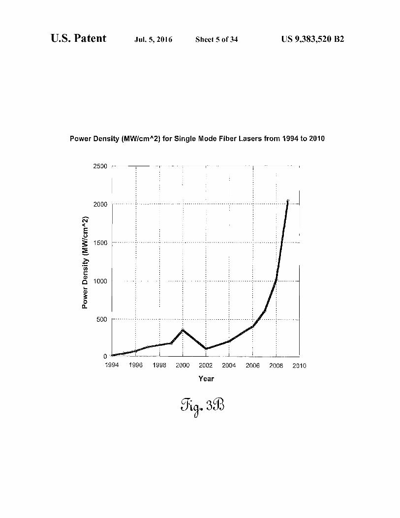
density, expressed in megawatts per square centimeter (MW/cm2). FIG. 3B plots power density in MW/cm2 since 1994. Amore practical means of understanding what this graph meansis presented in FIG. 3C, in which the LOG of power density isplotted. This plot indicates that, at the current pace of devel-opment, which has been sustained since 1994, the powerdensity will increase by an order of magnitude every sixyears.
Finally, FIG. 3D shows the theoretical power that can betransferred through a fiber optic carrier as a function of fibercore diameter (in microns) using optical power densitiesachieved in 2009. A three-hundred fifty micron core fiber iscapable, today, of carrying a megawatt of optical power. FIG.113, as previously discussed, shows the output power thatcould be expected as a function of distance from the laser fora contiguous fiber.The data presented in the figures referenced supra presage
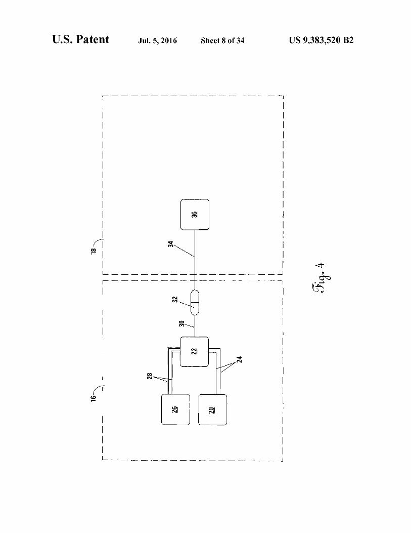
the possibility of sending enormous amounts of optical powerover very long distances using very small diameter, light-weight fibers and converting that optical power to a moreusable form of energy. Importantly, because the fiber is car-rying the power, it will neither be attenuated by the environ-ment surrounding the fiber nor by a situation wherein theconsumer of the power is not in visible line-of-sight of thesource laser. This has profound implications on the develop-ment of many systems heretofore not considered possible.FIG. 4 shows the very basic premise of the transfer of
coherent high power laser radiation between a laser source 22and a remote system 36 in which a base power source 20 (e.g.,a nuclear power plant, a fossil fueled power plant, a largediesel generator, a very large array of solar cells, etc.) is usedto provide electrical power to the high power fiber laser 22 viaelectrical conductors 24. Currently, the best fiber lasers are onthe order of thirty-five percent power conversion efficiency(i.e., for every ten watts of raw electrical power, three-and-a-half watts of coherent laser radiation can be produced).Because of this, the laser 22 dissipates a substantial thermalheat load. To counteract this, a cooling system 26 and heattransfer system 28 is used to maintain thermal control at thelaser. All of this infrastructure takes up volume, has signifi-cant mass, and consumes large amounts of power. It is there-fore best located in some fixed ground facility or a largemobile facility (e.g., a ship). From the laser 22, a high energy
4process fiber 30 leads to a high power optical coupler 32, towhich any number of devices can be connected. Traditionally,the only items to be connected to this category of multi-kilowatt laser are focusing optics for use in materials han-
k dling—e.g., cutting metal plates orfabric. Because ofthis, thelength of the process fiber 30, 34 are generally quite short on the order of five to ten meters.The present invention relates to a system and apparatus that
enables the transmission and effective end-use of very largel0 amounts of optical power (e.g., kilowatts to tens of mega-
watts) over relatively long distances (e.g., from a kilometer toas much as one hundred kilometers or more) to fixed, mov-able, or mobile platforms operating on the ground, undersea,
15 under ice, in the air, in space, and on other planets. Theinvention is usable in non-line-of-sight conditions, whichallows it to directly bypass severe problems that have plaguedefforts to utilize laser power beaming over large distancesthrough the atmosphere, underwater, and over terrain where
20 the receiver is not within view of the optical power source.The present invention permits first kilowatt and then ulti-mately multi-megawatt optical power injection and utiliza-tion over the length of a long deployed fiber.
25 BRIEF SUMMARY OF THE INVENTION
The invention is an optical power transfer system compris-ing a fiber spooler and an electrical power extraction sub-system connected to the spooler with an optical waveguide.
30 Optical energy is generated at and transferred from a basestation through fiber wrapped around the spooler, and ulti-mately to the power extraction system at a remote mobilityplatform for conversion to another form of energy. An alter-native embodiment of the invention further comprises a fiber
35 optic rotary joint mechanically connected to the fiber spooler,with the fiber optic rotary joint positioned optically betweenthe spooler and the power extraction system.
BRIEF DESCRIPTION OF THE SEVERAL40 VIEWS OF THE DRAWINGS
FIG. lA shows a plot of the theoretical composite attenu-ation limits for optical power transmission as a function ofwavelength per kilometer of pure silica fiber.
45 FIG. 1B shows a plot of the theoretical limiting opticalpower transmission as a function of the length of fiber.FIG. 2 is a plot of a high power, long range laser power
transfer test.FIG. 3A shows a plot of raw industrial laser continuous
50 output versus year for a single mode fiber laser.FIG. 3B plots power density in MW/cm2 since 1994.FIG. 3C plots the log of the power density of FIG. 3B for a
single mode fiber laser.FIG. 3D shows a plot of the present optical power trans-
55 mission as a function of fiber core diameter.FIG. 4 shows the basic premise of high power laser radia-
tion transfer between a plant fiber laser system and a remotesystem.FIG. 5A shows a first variation on the optical, long-range
60 power transfer invention of the present invention.FIG. 5B shows a second variation of the invention incor-
porating an axial precision-wound spooler.FIG. 5C is a detailed example of an embodiment involving
a single exterior mandrel, precision-wound high energy opti-65 cal fiber spooler.
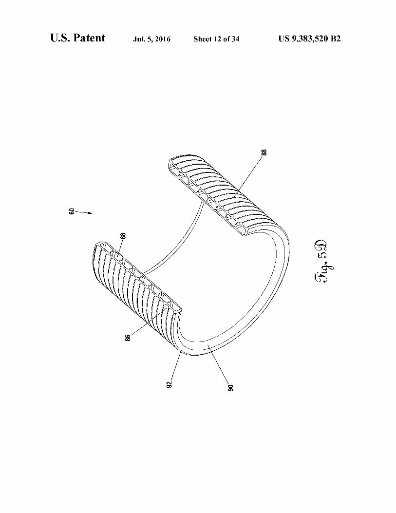
FIG. 5D shows a cut-away detail of the exterior wrappedmandrel of FIG. 5C.

US 9,383,520 B25
FIG. 5E is a top isometric view of the same external fiberspooler and protective shell system described with referenceto FIG. 5C.
FIG. 5F is a variation on the axial high power fiber spooler50 in which the mandrel 60 defines winding grooves 86 on theinterior surface.
FIG. 5G shows yet another variation on the high poweraxial fiber spooler 50.
FIG. 5H shows a cross sectional detail of an embodiment ofa drum-type high energy fiber spooler such as shown in FIG.5A.
FIG. 6 depicts an alternative embodiment of the system inwhich the fiber spooler is carried onboard a remote system ormobile system.FIG. 7 is a system diagram of the electrical power extrac-
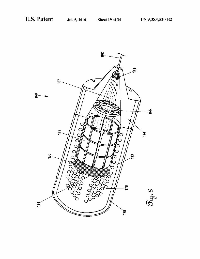
tion subsystem of the system.FIG. 8 is an isometric view of mobility system power head
160 implementing the invention.FIG. 9 is a sectional view of an embodiment of a fiber optic
rotary joint (FORD) that can be used with the present inven-tion.
FIG. 10 is a sectional view of another embodiment of aFORT that can be used with the present invention.
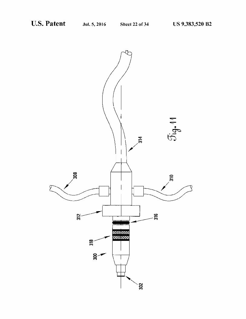
FIG. 11 shows an exemplary laser connector suitable foruse in the present invention.
FIG. 12 shows an embodiment of the system in use withBeta-type Stirling engine.
FIG. 13 shows an embodiment of the system in use with anautonomous underwater vehicle.
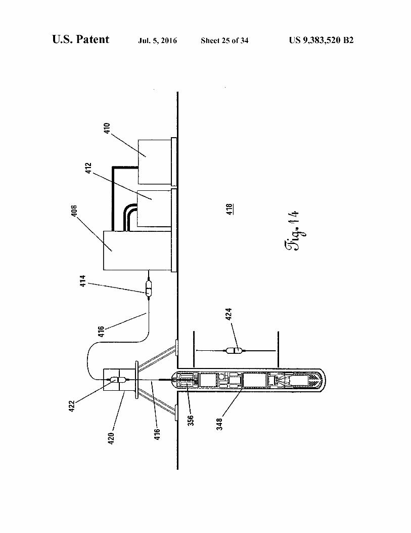
FIG. 14 depicts a mission configuration for the autono-mous vehicle shown in FIG. 13.FIG. 15 shows a system schematic for an autonomous
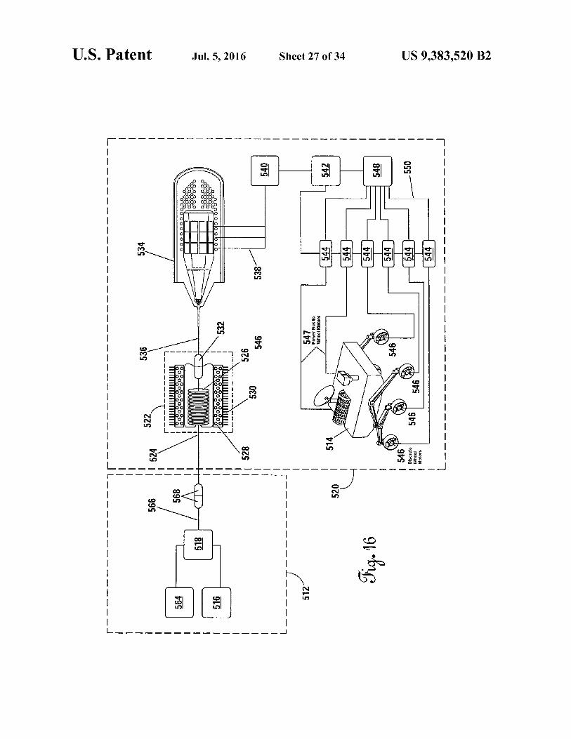
cryobot.FIG. 16 shows an embodiment in use with an exploration
and science rover.FIG. 17 shows another embodiment in use with an under-
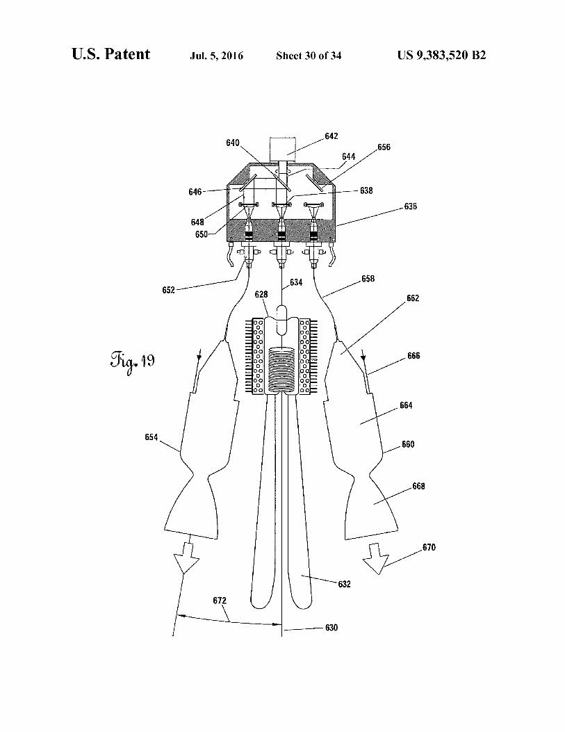
water vehicle.FIG. 18 shows an embodiment in use with a launch vehicle.FIG. 19 shows an embodiment having a central spooler in
use with multiple thrusters.FIG. 20 shows an alternative arrangement of the system of
FIG. 19.FIG. 21 shows an embodiment using a rotary beam switch
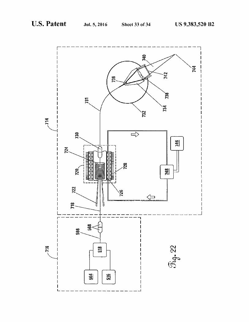
with multiple spoolers.FIGS. 22-23 show an embodiment in use with an
unmanned aerial system.
DETAILED DESCRIPTION OF THE INVENTION
Referring to FIG. 4, in the present invention, the length ofthe output fiber 34 is desirably a long distance from a fewkilometers to upwards of one hundred kilometers or moreand used for the purpose of providing, specifically, opticalenergy to a remote actuation system 36 that consumes thepower in a variety of ways for the purposes of mobility,propulsion, raw thermal power utilization, electrical powerconversion, mechanical power extraction or for the purposeof using the laser energy itself in a focused beam.
Referring now to FIG. 4 and FIG. 5A, one could conceiveof setting up such a system whereby a truck is used to lay fiber34 from the plant-based (fixed) fiber laser system 16 to a fixedactuation system or device 36 that uses the energy at somesignificant distance from the laser source 22. In general, thiswill have very limited utility because it would be, under mostconditions, equally possible to use a local power source at thelocation of the remote system 36 and not pay the price for thepower lost along the fiber 34. In other words, traditional
6electric power infrastructure will be more cost competitivethan deploying a fixed infrastructure that depends upon powersent to it via an optical waveguide or fiber. This is not the case,however, when we wish to consider mobile systems that
5 perform a variety of tasks and where it is entirely disadvan-tageous, if not impossible, for the mobile system to carry allof the extensive infrastructure needed to generate its ownpower.FIG. 5A shows a first embodiment on the present invention
to in which the base station 16 comprises a servo-controlledlarge-diameter drum spooler 38 fabricated from a high ther-mal conductivity material (e.g., beryllium oxide, copper, oraluminum) to facilitate cooling. A large length (kilometers) of
15 fiber 40 is rolled onto this spooler 38 prior to a mission inwhich the remote system 18 (e.g., a vehicle) is sent forth to dowork. As the vehicle leaves the base for example, a large seagoing ship, where the vehicle is an underwater vehicle such asan autonomous underwater vehicle (AUV) or remotely oper-
2o ated vehicle (ROV) the drum spooler 38 will rotate and feedfiber 40 out to the vehicle. This approach will work well in therestricted situation where there are no obstacles in the path ofthe vehicle that might serve to trap the fiber 40 and preventreturn of the vehicle. For example, it would work well for
25 sea-going operations and could potentially be made to work,using bare fiber, for aerial operations where the base station16 was carried by a large lighter-than-air airship and theremote vehicle 18 was an unmanned aerial vehicle (UAV)connected to the airship via a bare optical fiber for weight
so reduction.The drum spooler 38 has several important characteristics,
including an actively-cooled high power laser coupler 42 thatwill permit easy maintenance of the drum spooler 38.Because of the high power levels involved, the spooler 38
35 must have an active cooling system 44. The reason for this isthat not only will power be dissipated along the length of thefiber 40 by the normal Rayleigh scattering and infrared radia-tion, but it is also compounded by additional losses associatedwith the bend radius of the fiber 40. Bending losses are a
40 function of the fiber construction (e.g., core, cladding, coatingstyles, and refractive indexes), the fiber diameter, the bendingdiameter, and the laser power conditions entering the bendingsection. Bending losses will be controlled by selecting acombination of fiber type, size, and construction along with
45 an appropriate spooler diameter for the specific application.The cooling system 44 can consist of any traditional meansfor transferring excess heat away from the spooler 38, includ-ing, but not limited to, heat exchangers, convective, conduc-tive, and radiative cooling mechanisms (see FIGS. 5C-5H).
50 Importantly, the drum spooler 38 is mechanically con-nected to a high-energy fiber optic rotary joint 46, as will bedescribed in more detail with reference to FIGS. 9-10, inwhich a fixed fiber that transfers optical power at high levelsthrough coupler 42 is channeled to the core of the spooler 38
55 which rotates freely relative to the fixed coupler 42. This isrequired to avoid unacceptable twisting that would ultimatelylead to failure of the fiber 40. The design of a viable ultra-high-power fiber optic rotary joint is a complicated undertak-ing.
60 The drum spooler 38 is desirably of large diameter to limitpower loss associated with bending of the fiber to form thecylindrical (or other similar object of revolution) spool.Power loss associated with bending can be minimized byusing a large bend radius, using smaller diameter fiber, and
65 fiber with a high numerical aperture (NA). Preferably, thediameter of the spooler 38 needs to be large enough that thepower losses due to the bending of the fiber do not heat the

US 9,383,520 B27
fiber excessively for the given cooling conditions and they arean acceptable percentage of the total power (i.e., withinacceptable losses).The diameter and all other bending loss parameters are
designed to keep the bending losses at an acceptable level.The level of loss will depend on cooling requirements of theparticular application: some applications with good coolingand no need for high efficiency can have large losses and thuspossibly smaller diameters, while systems with poor coolingand needs of very high efficiency will require lower losses andthus typically larger diameters. This is extremely complexand based on many variables. Bending losses are a function ofthe fiber construction (e.g., core, cladding, coating styles, andrefractive indexes), the fiber diameter, the bending diameter,and the laser beam conditions entering the bending section(beam NA multimode/single mode/specific mode content formultimode, etc.)The selection of the fiber 40 is based on several criteria: it
should have low losses associated with Rayleigh scattering,Raman scattering, and infrared radiation; it should have anultra-low OH content; preferably have a high NA; have hightolerance to external heat load; be able to operate in fluidswithout degradation to the fiber's ability to transmit power; befree of imperfections in the manufacturing process; and havea durable cladding that permits reasonable handling tough-ness both during the winding and out-spooling events. Apreferable fiber has a pure fused silica core, with doped silicacladding to give a change in the index of refraction, whichallows the light to be guided with a NA between 0.22 and0.37.
Bare or armored fiber 40 exits the drum spooler 38 andthence communicates with the remote system 18, whichcould be any device, vehicle, or apparatus that is either self-propelled or is carried by a secondary mobility platformeither on land, under the sea, in the air, in space, or on Earthor another planet. Desirably, the remote system 18 isequipped with a high power fiber optic coupler 32' so that itcan be desirably disconnected from the power plant 16 formaintenance and transport between missions. The fiber inter-nal to the mobility system 18 then terminates in a fixed actua-tion system or device 36 that makes use of the optical powerby converting it to another form of energy.
FIG. 5B shows a variation of a power plant 16 incorporat-ing a precision-wound axial spooler assembly 50. Instead ofa drum spooler (as shown in FIG. 5A), the axial spooler 52 isone in which the fiber 40 is pre-wound in such a fashion thatit may be pulled out parallel to the axis of the winding withoutcausing the fiber 40 to twist or hockle. Typically, this requiresprecision winding equipment that inserts a pre-twist of acertain amount per wrap such that the fiber 40 can pull free inthe direction of the axis without twisting.The nature of the winding must be special for a high power
application in which large amounts of energy are transmittedthrough the fiber 40. These details are discussed with refer-ence to FIGS. 5C-5H. At a minimum, however, a high energyaxial fiber spooler assembly 50 will require an active coolingsystem 54 that chills the fiber 40. An auxiliary passive thermalpower dissipation system 56 may be desirable to further trans-fer unwanted heat to the environment (whether underwater,on the ground, in air, or in space).A plant-based fiber spooler can be quite large in diameter
and therefore limit bending losses. In general, axial spoolersare considered one-time-use devices because there is no reli-able or economical field method for re-spooling and makingre-use of the fiber in the fashion that would be possible for aship-based drum spooler working with jacketed (armored)fiber. Similar to the drum spooler 38 described withreference
8to FIG. 5A, the axial spooler 50 contemplates high poweroptical couplers 32 on opposing sides so that it may be field-connected to the laser 22 and to the remote system 18.FIG. 5C shows a detailed example of one embodiment of a
5 single exteriormandrel60referencedwith respect to FIG. SB.A hollow or solid winding mandrel 60, which is preferablymade of a high thermal conductivity material (e.g., beryllia,copper, aluminum), has bare optical fiber 62 wound upon itsradially exterior diameter in such a fashion that direct axial
io pull out parallel to the mandrel axis 64 is possible withoutintroducing twists to the fiber 62. This can be achieved bypre-twisting the fiber 62 during the precision winding pro-cess. The bare fiber 62 exits the rear of the spooler 50 andtrails in the direction of the laserpower source 22. The vehicle
15 moves in an opposite direction 66 along the same axis. Thefiber 62 is preferentially attached to mandrel 60 by a highthermal conductivity adhesive (e.g., materials consisting of abase synthetic polymer system containing thermally conduc-tive fillers) suchthat the adhesive transmits heat directly to the
20 mandrel 60 in an efficient manner and also lightly binds thefiber 62 to the mandrel 60 so that it does not unspool withouta constant tension being applied by the exiting fiber 62, saidallowable tension level being specific to a particular fiberdesign and diameter, but with the general characteristics of
25 both binding the fiber 62 to the mandrel 60 so that individualfibers do not slide freely relative to one another and yet not sohigh as to impede the free spool out of the fiber 62 to a degreewherein it may stress the fiber 62 to a point at which it eitherbreaks under tension or adversely affects the transmission of
30 power (e.g., by cross-sectional thinning under tension).Examples of appropriate adhesives are ResinLab EP 1121-4,Dow Corning SE4450, and the like.The mandrel 60 will require active cooling for high power
applications. To achieve this, internal flow channels 68 are35 disposed circumferentially through mandrel 60 and are fed by
an inlet 70 and exhausted by an outlet 72. The coolant, whichmay be either actively pumped or passively fed through thechannels 68, can be drawn: from the ambient environment inthe event that that fluid has a high heat conduction capacity;
40 from a reservoir of high heat conduction capacity coolant(e.g., water, liquid metals etc.) that is actively chilled (andthermal power dissipated non-local to the spooler 50); or froma reservoir of cold material (e.g., cryogenic liquids). In addi-tion, coolant can be caused to flow through the center of the
45 mandrel 60 to provide further heat removal from the spooler50.The spooler 50 has an exterior protective housing 74 that
also functions as a thermal radiator. The housing 74 maypreferentially have a thermally absorbing coating applied to
50 the radially interior surface 76 such that any heat radiatedfrom the spooled fiber 62 is preferentially absorbed by thehousing 74 and thermally-conductive coating. The housing74 further may desirably have internal coolant flow channels78 that may receive fluid flow from any of the aforementioned
55 coolant sources. The housing 74 may furthermore be advan-tageously equipped with exterior radiation panels 80 extend-ing along the length of the housing 74. The thermally absorb-ing coating has good absorbing ability in the infraredspectrum.
60 Yet another means for removing heat from spooler fiber 62is that of directed flow of a coolant via inlet ducts 82 thatdirect the cooling fluid to pass lengthwise down the axialassembly via a fiber feed channel 84 formed between themandrel 60 and the housing 74, and from which the fiber 62
65 ultimately exits the spooler 50.One purpose of all of these features is to maintain the fiber
62 within a working temperature range that will not affect the

US 9,383,520 B29
material or function of the fiber 62 for the transmission ofhigh power optical energy. Silica, and most materials suitablefor the purpose of optical power transmission down a smalldiameter fiber, has a very low thermal conductivity so it actsto impede cooling of adjacent fibers through contact. For thisreason, and as shown in FIG. 5C, the most efficient fiberspooler for high power optical energy transmission is one thatcontains only a single layer, or only a few layers, of bare fiber62. Depending on the power levels involved, additional layersmay be added and the flow of coolant through channels 68 andother coolant communication paths adjusted accordingly tomaintain fiber temperature within the specifications for theselected fiber.Not shown on this drawing, but of significance to the opera-
tion of this system, is a network of surface-mounted tempera-ture sensors that can be used to detect an impending hot spotthat may cause the fiber 62 to fail locally orregionally. In thiscase, these temperature sensors can be tied to the active ther-mal control system as well as to the laser for a pre-emptivebeam shut down in the event of an uncontrollable buildup ofheat in any particular section of the assembly.
For reference, a single wrapped axial spooler mandrel thatis two-tenths of a meter in diameter by one-half meter inlength can carry 1.3 kilometers of 250-micron fiber in a singlelayer; 2.6 kilometers in a double layer; 3.9 kilometers in athree-layer wrap, etc. There are means for building muchlonger, high power axial spoolers, as will be subsequentlydescribed below.
FIG. 5D shows a cut-away detail of the exterior wrappedmandrel 60 from FIG. 5C. Desirably, for improved heat con-duction, the exterior surface of the cylindrical mandrel 60 willcontain a smooth, form-fitting groove 86 designed to pre-cisely mate with the chosen bare power delivery fiber. Thegroove 86 would be preferentially manufactured using a pre-cision machining system or other method of creating a spiral,continuous groove 86 the local radius of which either pre-cisely matches or is slightly larger than that for the chosenpower fiber. The degree of machining depth will represent theminimum needed for secure fiber location. For very highpower applications, the spacing (pitch) between individualcoils of the groove 86 should be such that the adjacent fibersdo not touch each other. Further, the edges 88 between therespective grooves 86, as well as the groove surfaces, prefer-ably are polished and have a smooth transition radius suchthat there are no sharp edges anywhere on the face where thefiber is to be wound. Similarly, the interior trailing edge 90and the exterior trailing edge 92 have a smooth radius and arepolished to prevent fiber damage on spool-out. An alternativeto the spooler design shown in FIG. 5D would involve the useof a smooth polished cylindrical external winding surface(replacing the polished grooves 86 and 88 in FIG. 5D), or onethat is slightly tapered (with or without alignment grooves 86)toward the direction of fiber spool out so that the diameter ofthe tapered, truncated conical annulus is less at the point offiber departure (64 in FIG. 5C) than it is at the opposing end(in the direction of vehicle motion, 66 in FIG. 5C). In bothcases, the fiber is adhered to the smooth, polished surface bymeans of a thermally conducting adhesive means and, desir-ably, the fiber spacing is such that adjacent fibers do not touch.Multiple fiber layers, held together by a thermally conductingadhesive means, are possible on mandrels as shown in FIG.5D (and as described in this paragraph), however the ability toeffectively cool the multiple wraps will be diminished relativeto a single-wrap mandrel and careful thermal design will berequired to determine the maximum number of over-wraps
10for a given power transmission level, mandrel wrappingradius, and diameter of the transmission fiber, among otherthings.FIG. 5E shows a top isometric cutaway view of the same
5 external fiber spooler 50 and protective housing 74 describedwith reference to FIG. 5C. Importantly, the direct axial flowcooling fluid inlet ducts 82 are notional representations only.For travel through a fluid medium (e.g., water or air) there canbe present computer-controlled, servo panels that open to
io permit either water or air to be drawn into the vehicle as itmoves forward and to channel that fluid down into the fiberfeed channel 84 for the purposes of cooling the radially exte-rior surface face of the fiber 62. Because the fiber 62 mustfreely trail out from the channel 84, any cooling fluid that
15 passes into inlet ducts 82 will exit the fiber feed channel 84after one pass and not be able to be re-used. Contrarily, anyfluid or coolant pumped through circumferential channels 68,78 can be re-cycled and sent to an alternate location in thevehicle either for the purpose ofrefrigeration of the coolant or
20 potentially for pre-heating of a working fluid or propellant.FIG. 5F shows a variation on the axial high power fiber
spooler 50 in which the mandrel 60 defines winding grooves86 on the interior surface. All other aspects of this designremain the same as for those shown in FIGS. 5C-5E, includ-
25 ing the presence of circumferential cooling channels 68.Importantly, such a winding pattern depends on the use of thethermally-conducting adhesive to lightly attach each fiber tothe groove 86 as the fiber 92 is precision-placed. The groove86 forms a continuous spiral (helix) and the fiber 62 pays out
30 linearly in a direction parallel to the center axis of the cylin-drical mandrel 60. As discussed supra, for the highest powerapplications, it is desirable to have a single wrap of fiber 62.For lower power applications it will be possible to have sev-eral layers of wrapping.
35 An alternative to the spooler design shown in FIG. 5Fwould involve the use of a smooth polished cylindrical inter-nal winding surface (replacing the polished grooves 86 inFIG. 5F), or one that is slightly tapered (with or withoutalignment grooves 86) toward the direction of fiber spool out
40 so that the diameter of the tapered, truncated conical annulusis greater at the point of fiber departure (64 in FIG. 5C) thanit is at the opposing end (in the direction of vehicle motion, 66in FIG. 5C). In both cases, the fiber is adhered to the smooth,polished surface by means of a thermally conducting adhe-
45 sive means and, desirably, the fiber spacing is such that adja-cent fibers do not touch. Multiple fiber layers, held togetherby a thermally conducting adhesive means, are possible onmandrels as shown in FIG. 5F (and as described in this para-graph), however the ability to effectively cool the multiple
50 wraps will be diminished relative to a single-wrap mandreland careful thermal design will be required to determine themaximum number of over-wraps for a given power transmis-sion level, mandrel wrapping radius, and diameter of thetransmission fiber, among other things.
55 FIG. 5G shows yet another variation on the high poweraxial fiber spooler 50. An exterior mandrel 60 of this spooler50 is the same as shown in FIGS. 5C-5E. The inner mandrel100 is a variation of the mandrel shown in FIG. 5C and FIG.5F in which the fiber is wrapped on grooved surfaces on both
60 the radially interior and radially exterior surfaces of the innermandrel 100. All winding surfaces shown are smooth andtapered in the direction of fiber spool out, 112, with the fiberbeing held in place and positioned with the use of a thermally-conducting adhesive as described above. Each mandrel 60,
65 100 is independently cooled via coolant inlet ports 102, 104and outlet ports 106, 108, which serve to send a recyclablecoolant through cooling channels in the inner mandrel 100

US 9,383,520 B211
and outer mandrel 60. Chilled ambient environment fluid(e.g., water, air) can be routed into the exterior fiber channel110 or through the hollow central core 111 for additional fibercooling. The exhaust for such coolant, following one passthrough the spooler 50, is in the trailing direction 112. Theexterior mandrel 60 may additionally contain passive thermaldissipaters (e.g., radiation panels) as shown in FIG. 5C andFIG. 5E. The mandrels 60,100 are supported at one end only.The fiber is pulled off the free end.
In the design shown in FIG. 5G, up to three single-layer,individually-cooled fiber layers can be combined into a com-pact spooler to increase the range of the vehicle. The nestedmandrel, actively-cooled spooler concept can be extended toseveral annular ringed mandrels embedded within oneanother. All fibers are desirably retained in their grooves bythe use of a thermally-conducting adhesive or similar meansthat achieves the same intent. For lower power operations,multiple wraps can be applied to each winding face, bothinterior and exterior. Each wrap desirably contains an elementof pre-twist to prevent hockling upon pullout during a mis-sion. The fiber from one ring layer is desirably passed to thenext layer while maintaining the maximum possible bendradius on the fiber. Desirably, the trailing edges (not shown)of mandrels 60, 100 should have smooth, polished, radiusedsurfaces to as to present no sharp edges to the trailing fiber norto the cross-wrap fiber leading from one wrapping face to thenext.
FIG. 5H shows a cross sectional detail of an embodiment ofa drum-type high energy fiber spooler such as shown in FIG.5A. For some applications, particularly those involving lowspeed mobility platforms (e.g., underwater and groundvehicles), it will be possible to use a drum spooler on themobility platform (vehicle). The advantage of a drum spooleris that it simplifies the winding process and does not requireprecision winding and fiber pre-twist to assure a straight pullout as the mobility platform moves away from the laser powersource. It is therefore likely to be less costly than an axialprecision-wound spooler. For very high energy transmission,the drum spooler must be cooled in a manner analogous tothat previously described for an axial spooler. The mandrel 60will necessarily contain coolant flow channels 68, whetherinterior to the mandrel body or as a bonded set of thermallyconducting flow channels (e.g., a helical tube coil made ofcopper that is either soldered to the mandrel 60 or bonded toit with heat conducting material). The coolant that flowsthrough channels 68 can be from a closed-cycle system thatcontinuously chills the refrigerant while dumping the wasteheat elsewhere, desirably into a power conversion system foruse onboard the mobility platform. For applications where themobility platform will be working in water or air, eitherpassive or actively forced flow of the ambient fluid (e.g.,water, air) can be passed over and around the exterior of themandrel 60 to further remove heat from the fiber. As with theaxial spoolers previously described, for ultra-high energyoptical power transmission it is advantageous to have only asingle wrap of fiber 62 on the mandrel 60. A greater numberof wrap layers is possible for lower power levels or for envi-ronments where the ambient environment fluid has signifi-cant heat conduction capacity to allow further layers (e.g., icewater for deep ocean, or sub-glacial lake work). The drum caneither passively feed fiber 62 out (possibly with tension main-taining mechanisms) or actively with the use of sensors andservo drives 114 that match the rate of fiber pay out to thevehicle forward velocity.
Energy 116 from the base-located laser (not shown) is fedinto the drum spooler 38 and the drum spooler 38 unwinds asthe mobility platform moves away from the laser. The fiber 62
12from the drum spooler 38 terminates at a high energy opticalcoupler 32 where it enters the rotating element 118 of a highpower fiber optic rotary joint (FORD) 120.The FOR7120 is described in detail hereafter with refer-
5 ence to FIGS. 9-10. Briefly, this device allows the opticalenergy 116 to be transmitted between two adjacent fiberswhile allowing for one half of the FOR7120 to rotate relativeto the other. By this means, the drum spooler 38 may rotatefreely without twisting the fiber 62. The output side of the
io FOR7120 leads to a second coupler 32 and fiber section 122that transports the coherent optical energy 116 to the vehiclefor further use. The drum spooler 38 is supported by bearings124 on one or both sides. The bearings 124 are held in placeby a drum frame 126 that is fastened to the body of the
15 mobility platform. Both the drum frame 126 and drum side-walls 128 may have optional internal cooling channelsdepending on the power levels involved. The fiber 62 is pref-erably a bare fiber, since a much greater length can be storedin a given-size drum spooler 38, but there is nothing prevent-
20 ing a jacketed fiber to be used, provided the jacket and clad-ding and any other protective or strengthening elements havehigh thermal conductivity. Notably, bare fiber always hascladding and almost always has a coating of tens of micronsthat is not a jacket but nonetheless protects the fiber to a
25 degree.FIG. 6 depicts an alternative embodiment of the invention
wherein the power spooler 50 resides on the mobile remotesystem 18. All elements in FIG. 6 are identical to that of FIG.5B with the exception that the fiber spooler 50 is now
30 mounted on the vehicle. This architecture, wherein massiveamounts of optical power are transferred to the vehicle over afiber optic link over long distances with the vehicle carrying,and laying, its own power line, is the key to enabling a class ofmobile, autonomous systems that could never have previ-
35 ously existed owing to limitations of weight and power gen-eration or storage capability. As an explicit example, therange (both horizontal distance and depth rating) of a ship-tethered ROV (industrial class remotely operated vehicle) ofthe type commonly used in the petroleum industry is severely
40 limited by the excessive size and mass of that electrical-powertether, which grows larger with distance (because higher volt-ages must be used and this then begets further electricalinsulation requirements) and is significantly affected byocean current drag. There are thus practical limits today to
45 where ROV systems can operate. By contrast, a 1 mm diam-eter jacketed fiber optic laser power tether would scarcely beaffected by currents and the vehicle could receive usefuloptical power as far as 100 kilometers from a ship-carriedpower supply.
50 In FIG. 7, we explain the first of several high power energyextraction methods to be employed on the remote system 18of FIG. 6. The coherent energy 130 coming from the onboardfiber spooler (not shown) is injected into one or more sets ofpassive or actively controlled beam forming optics 132 com-
55 prising lenses, fiber assemblies, mirrors, prisms, etc, all typesof optical manipulating devices. The energy 130 is expandedand directed toward a refractory target 133 such that diffuselaserradiation illuminates abeam dump 134. The beam dump134 is a body preferably made of a refractory material (e.g.,
6o beryllium oxide (BeO)) that can tolerate sustained high tem-perature operation. Other high-temperature compatible,highly conductive materials (e.g., certain metals) could alsobe used as the beam dump. The core of the beam dump 134 isdesirably surroundedby an array of thermoelectric converters
65 136 whose interior side contacts with or is exposed to the hotbeam dump 134. The exterior side of the thermoelectric con-verters 136 is advantageously exposed to a cold environment

US 9,383,520 B213
or to a heat sink means that is either actively or passivelychilled to create the greatest temperature difference across thethermoelectric converter mechanism. Additional heatexchanger channels 138 may be run through and around thebeam dump 134 to extract heat for further directed use 5throughout the vehicle or for further power generation byadditional thermoelectric arrays or other means.One such direct heat use for coolant coming through the
heat exchanger system would be that of heating melt water tohigh temperatures and pressures and using that with a pump io140 to form of a hot water jet for hot water drilling through athick ice cap for example the three-kilometer thick ice capof Antarctica. Another use would be to supply hot workingfluid through a pump 142 for thermal management of a mobil-ity platform (e.g., to keep a planetary robotic rover's mecha- 15nisms and science payloads from freezing). The thermoelec-tric converters 136 send electrical power to the onboardcontrol system via a power bus 144, which is regulated by apower management sub-system 146. Electrical power is sub-sequently stored in one or more regenerative electrical power 20storage means 148 (e.g., a Lithium-ion battery stack, a fuelcell stack, etc.), which serves both as the primary continuouspower source for the main onboard computer control proces-sor 150 and controls for peripherals such as the pump actua-tors 152 that control the hot water jet pump 140, thermal 25management pump 142, mobility motors, and the like. Themobility system is desirably equipped with a sophisticatedsensor network 154 that continuously scans dozens of processsensors 156 thermal, pressure, and optical for overallmanagement of the vehicle. 30
FIG. 8 shows a physically realizable mobility systempower head 160 that can receive very large amounts of opticalpower (e.g., tens of kilowatts to low megawatts) and thenceconvert and simultaneously direct that energy in several use-ful ways to further the purpose of the mobility platform of 35which it forms the heart. Optical power is delivered to thepower head 160 via fiber 162 from an axial or drum typespooler as previously described and located on the mobilityplatform. The beam is first partially expanded via primarybeam forming optics 164 and then via forward beam forming 40optics 166 to form a diffuse beam 167 that impinges on beamdump 134, thus heating the entire body of the power head 160to high temperature. As previously described, a thermoelec-tric converter array 168 may be positioned around the beamdump 134 for direct generation of electrical power for use on 45the vehicle. This array 168 can be located anywhere aroundthe power head body where heat will be radiated onto one faceof the thermoelectric converter chips (TEC) while a lowertemperature surface can be created on the opposite side (e.g.,the TEC array could be located either inside the beam dump 50cavity and cooled on their outward side by heat exchangerchannels 176 or by mounting the TEC array on the outside ofthe beam dump as shown in FIG. 7 where it would be chilledby the ambient environment or other external heat extractionsystem). A second primary means of direct electrical power 55generation is possible by directly impinging the expandedoptical beam 167 onto an array of photovoltaic cells 170 thatare tuned to generate electricity efficiently at the wavelengthof the incident laser radiation. The body of the power head160, comprising forward housing 172 and rear housing 174, 60can be equipped with internal heat exchanger channels 176and heat pump channels 178 that can be used to transport heatto other locations about the vehicle for thermal control in coldenvironments or to power such direct thermal power consum-ers as hot water drills and the like. 65
FIG. 9 shows one embodiment of a high power (e.g., kilo-watts to low megawatts) FORT 180 as generally described
14with reference to FIG. 5A-511 The housing of the FOR7180,in this case an axial design, comprises two concentric ele-ments: a rotating element 182 that rotates freely and ismounted to the rotating fiber drum (not shown) by flange 184and a fixed element 186 that is fixed to the drum holding frame(not shown) and is prevented from rotating by torque arm 188.The rotating element 182 and fixed element 186 togetherdefine an optics chamber 195.
Optical power enters the axial FORT 180 through a firstconnector 190, which is cooled by coolant that enters at inletport 192, cools the connection and exits at outlet 194. How-ever, at this point coolant flow is subsequently routed tohousing inlet 196 where it cools the fixed element 186 andthen, by means of a rotary cooling water coupling 198, allowsthe flow to continue into the rotating element 182 withoutentering into the optics chamber 195. Water temporarily exitsthe rotating member 182 and connects to a cooling inlet 204of a second connector 202, cools the second outlet connector202, and exits the second connector 202 at an outlet port 200and then re-enters and re-cools the rotating element 182,passes back through the rotary water coupling 198, passesthrough the fixed element 186 and then exits to return to thecooling system via outlet port 206. Many variations on thisapproach are possible, but the concept is to efficiently coolboth the rotating element 182 and fixed element 186 of theFOR7180 as well as both fiber connectors 190, 202 using thesame coolant system for economy. O-ring radial and faceseals 208 are used to ensure that water does not enter theoptics chamber 195 or optical elements of the FOR7180 norto leak at any place while advantageously transporting heataway from both housings elements 182, 186.The rotating element 182 is supported and centered within
fixed element 186 by bearings 210, which are kept clean andsealed by a shaft seal 212. Electric slip ring contacts 214 areused for connector safety interlocks and are connected to asafety control system by external wires (not shown). Thepurpose of the safety interlocks is to prevent accidental sepa-ration of the FOR7180 while power is on. Additional safetysensors comprise a plurality of photodetectors 216 for sens-ing stray light that might predict the onset of failure of theoptics that would lead to a catastrophic melt down of thesystem if left unchecked. Similarly, a temperature sensingnetwork 218 is distributed throughout the rotating element182 and fixed element 186 for the same purpose of earlydetection of a failed optical control system that may be lead-ing to melt down of the FOR7180. Similarly, isolated elec-trical contacts 220 for connector integrity lock are provided toensure both the first and second connectors 190, 202 areproperly inserted and locked in place.The optics of the axial FOR7180 are complex. The incom-
ing beam from the first connector 190 will diverge at its end atthe fused silica block at a divergence angle defined by itsnumerical aperture (NA). The diverging beam is collimatedby first collimating optics 222. The beam then theoreticallytravels across the evacuated optics chamber 195 and impingeson second collimating optics 224 where the beam is focusedand impinges on the fused silica block of the second connec-tor 202 where the beam is injected into the output fiber 203.
Despite the best efforts at precision machining, there willexist alignment errors between connectors 190, 202 and theirrespective collimating optics 222, 224. Minor variances inthis alignment could result in substantial amounts of powerbeing dissipated in the optics chamber 195 and, if leftunchecked, could lead to meltdown and loss of the device.While fine-tuned optical bench solutions might be developed
US 9,383,520 B215
for laboratory versions of such a device, that will not besufficient for the high power industrial mobility inventionspreviously described herein.
To resolve the issues of alignment both due to axial andangular errors as the rotating element 182 rotates relative to 5
fixed element 186, actuators 226 are affixed to the first andsecond collimating optics 22, 224 for interactively, and withfine precision, moving these respective lenses in real-timeunder computer control. Alignment means 226 may compriseof a plurality of active control elements affixed to each lens iosuch that each lens can be both moved in three degrees-of-freedom (e.g., X, Y, and Z translations) as well as rotated inthree degrees of freedom (yaw, pitch, and roll) in order to bothactively change both the focus point as well as the pointing ofeach lens. 15
The connectors 190, 202 will have limited alignment pos-sibility, other than that determined by the precision of theconcentricity of rotating and fixed elements 182,186 and thedegree to which fabrication errors and tolerances permitmotion other than rotationally about the common centerline. 20For this reason, the actuators 226 must handle all of thecorrection. The actuators 226 may desirably be arrayed radi-ally about the perimeter of the lens and a minimum of threesuch elements per lens would be needed to provide a full sixdegrees of freedom. Alternatively, the lens could be held by an 25external servo controlled stage that allowed for X-, Y-, andZ-translation of the lens while other servo actuators providedfor the yaw, pitch and roll orientation. The lens actuatormeans could employ both slow and fast elements fast ele-ments being comprised of such technologies as piezoelectric 30stacks with or without displacement amplifiers; MEMS-based actuators for micro-fine tuning; acoustic SAW wavelinear actuators; electromagnetic and voice coil type actua-tors, to name a few. Importantly, these actuators are all drivenby an onboard embedded computer processor that is local to 35the FOR7180 or immediately adjacent the FOR7180 so thateach FOR7180 is independently responsible for its own real-time alignment. The alignment cycle begins at low power anda system identification mapping is performed at specifiedrotation angles of rotating element 182 relative to the fixed 40element 186. At each system identification angle, an optimi-zation is performed in whichthe delivered power to the outputconnector is maximized while minimizing the optical andthermal feedback from internal sensor networks 216, 218.The positions of the collimating elements 222, 224 are then 45noted and the next angular alignment proceeds automaticallyuntil a full revolution has been logged. A smoothed mappingis then mathematically defined between the discrete calibra-tion points and this mapping then forms the basis for an initialestimate of the real-time alignment system at any given 50angle the relative rotation angle between the rotating ele-ment 182 and fixed element 186 is determined by a highprecision angular encoder (not shown) that reports that angu-lar position to the embedded control system processor. Withthese initial seed alignments as a function of relative rotation 55angle the embedded processor then initiates a real-time opti-mization control of the collimating alignment motors andactuators for both lenses as power is ramped up to full indus-trial levels and the fiber is spooled out from the spooler drum.
FIG. 10 shows another embodiment of an FOR7180 that 60can be used with the present invention: a right-angled, highpower FORT 180 in which all elements are the same as forFIG. 9 and further comprises a high power actively cooledlaser mirror 230. The mirror 230 is mechanically connected tohighly responsive servo-controlled mirror alignment motors 65and actuator means 232 sufficient to control three orthogonaltranslations and three rotations (yaw, pitch, roll) of the mirror
16230 relative to collimating optics 224, 226. These actuatorsand motors 232 are, as before, connected to the onboardembedded processor which seeks to optimize the amount ofoptical power being transferred through the FORT 180 forany given rotation angle. This is in many ways superior to thepure axial design presented in FIG. 9 in that it allows forextremely fast adjustment of a lightweight, cooled mirror (asopposed to glass optics which have substantially more mass).Furthermore, the addition of the servo-aligned mirror has thecapability to compensate for translational misalignmentsbetween the axes of the assembled FORT connectors 190,202. This additional alignment was not possible in the axialFORT of FIG. 9 because the relative beam input angles arepre-determined by the machining precision of the connectorentries. In the FORT 180 of FIG. 10, this machining precisionerror can be completely compensated, leading to reducedlosses and at higher response speed. The same initializationalignment system identification and radial optimization willbe conducted, but with the addition of the degrees of freedomof the mirror added to the optimization algorithm.FIG. 11 shows an exemplary optical connector 300 suitable
for use in the present invention. The connector 300 has a fusedsilica beam expansion block 302 with a wavelength-specificanti-reflective (AR) coating contained inside an optical fibercable assembly 314 withmulti-layer armored jacket. Becausepower is lost in the connector 300, water cooling is fedthrough the connector by water cooling inlet line 308 andwater cooling outlet line 310. The connector is typicallyequipped with a mating flange 312 for a bolted connection. Adust-intrusion o-ring 316 prevents dust particles from enter-ing the optical pathway and potentially causing a localizedthermal buildup by blocking the beam. Two radial contactisolated electrical contacts 318 provide for a test of cableinterlock integrity.
FIG. 12 shows the heat engine 160 described with refer-ence to FIG. 8, the heat engine 160 comprising a high tem-perature housing 320 and an internal beam dump 176. Thelaser power enters the heat engine via fiber 162 coming fromthe power spooler (not shown). The beam is expandedthrough primary optics 164 and secondary optics 166 intodiffuse beam 326, which is directed into refractory beamdump 328. Heat can either be transferred directly through thewalls of the beam dump 328 or via an external heat exchanger330 that cycles an effective thermal transfer fluid (e.g., liquidsodium) through the beam dump 176 and back into a high-power heater 332.A beta Stirling engine 334 is driven by the heater 332. The
engine 334 comprises an expansion volume 336, a compres-sion volume 338, a displacer 340, a power piston 342, aregenerator 344, and a cooler 346. The expansion volume 336and compression volume 338 are preferably filled with aworking gas, which is typically air or helium. This workinggas is sealed within these volumes by the power piston 342and moved between the hot and cold spaces by a displacer340. The gas is recycled through the cooler 346 and throughregenerator 344 prior to re-entering the heater 332. The link-age driving a power piston 342 and displacement piston 340will move such that the gas will compress while it is mainly inthe cool compression space and expand while in the hotexpansion space. Because the gas is at a higher temperature inexpansion space 336 relative to the compression space 338,and therefore at higher pressure, more power is produced bythe movement of piston 342 during expansion than is reab-sorbed during compression. This net excess power is theuseful output of the engine. There are no valves or intermit-tent combustion, which is the major source of noise in aninternal combustion engine. The same working gas is used

US 9,383,520 B217
over and over again, making this a sealed, closed-cycle sys-tem. All that is added to the system is steady high-temperatureheat, and all that is removed from the system is low-tempera-ture (waste) heat and mechanical power. The piston 342 canbe used to drive a plurality of electrical generation means.This design, using ultra-high laser-delivered power, forms thebasis for a unique power generation mechanism that is non-collocated with the source of the energy.The power levels being dissipated in heater 332 can range
from the low kilowatt level to a dozen megawatts using asingle fiber. Electrical power conversion efficiencies for aproperly designed Stirling engine can reach thirty percent. Amegawatt of laser input power could be converted to five-hundred horsepower of electrical drive power. Ten mega-watts, feasible with an eight-hundred micron fiber, wouldyield five-thousand horsepower, which is sufficient to runheavy machinery, such as to conducting mining operationseleven kilometers below the surface of the ocean at the bottomof the Marianas Trench, powered by a ship-board dieselpower system driving the laser, or to power a fleet of remotelyoperated lunar regolith harvesters extracting ice on the Moon,powered by a lunar base nuclear power system using a similarStirling converter to power a laser. Both of these, as well asmany other extreme environment applications, ideally favorthis approach as the cooler 346 can easily extract cold fromthe environment. All of these systems can be operated at tensof kilometers from a static power base using the approachesdescribed herein.
FIG. 13 shows a robotic device 348 (a "cryobot") designedto autonomously penetrate extremely deep glacial ice caps(e.g., theAntarctic ice sheet over Lake Vostok, the South PoleLake, Lake Ellsworth, other such sub-glacial lakes, or eventhe ice caps of Mars or the surface ice cap of the 7ovian moonEuropa) by melting a path ahead of the vehicle as it descends.Prior to this disclosure, no attempt at the construction of apractical cryobot has succeeded, largely because of two fac-tors.
First, prior attempts at using electricity (in a device knownas a Philberth Probe) all failed at slightly over a kilometer ofdepth. For practical reasons namely, the ice cap freezesbehind the probe as it melts its way down the vehicle mustspool out its connection to the power source from the vehicle.This requires a large spool of wire on the vehicle. Because ofresistive losses, the voltage must be increased the further thevehicle descends until eventually arc-over limits the range.
Second, political restrictions on the use of nuclear powersources in Antarctica. While a small SNAP reactor couldpower such a device, it would never be tested in a deep ice capon Earth.A laser-powered cryobot, such as the cryobot 348 dis-
closed in FIG. 13, changes that. Enough fiber can be carriedon the vehicle to permit not only a descent through the deepestknown ice caps on Earth four thousand meters at Vostokbut also to permit a sample return mission by inverting thecryobot and melting its way back to the surface.The advantages of such a system are further enhanced by
environmental restrictions imposed by the international com-munity regarding entry into such subglacial lakes. PlanetaryProtection restrictions require extensive testing, certification,and lengthy approvals that can take years to decades toapprove access using hot water drilling from the surface,which is the only other known technology that can reach theselakes.
With a cryobot, the vehicle can be sterilized to acceptablelevels in the laboratory, sealed in a sterile container, andinserted into the ice cap in a sterile condition. Because the
18melt hole re-freezes only a few meters behind the vehicle,forward contamination is prevented.The design of a cryobot is governed almost entirely by the
diameter of the vehicle and the desired descent rate through5 the ice. This, along with the temperature of the ice, determines
the input power requirements. For example, a one-quartermeter diameter by two-meter long cylindrical cryobot withhemispherical end caps, similar to the cryobot 348 depicted inFIG. 13, working in ice with a temperature of minus five
to degrees (C.) will descend at a rate of fifteen to twenty metersper day when powered by a five-kilowatt fiber laser. Doublingthe diameter (e.g., to accommodate larger science payloads)will reduce the descent rate by a factor of four under the same
15 input power.FIG. 13 discloses one embodiment of a viable, deep ice
cryobot 348 having a cylindrical shell 350 with hemisphericalends. Power is delivered via a bare optical power fiber 352 tothe rear (top) of the vehicle. Data may be modulated and
20 extracted via the power fiber 352 so that a surface-basedmission control center could maintain a high-bandwidth datalink with the cryobot 348 throughout the mission. The cryo-hot 348 may be equipped with an auxiliary (second) co-linearaxial spooler 354 having an auxiliary fiber of smaller diam-
25 eter than the power fiber 352 for the purposes of maintaininga dedicated communications link. This is of considerablevalue for the purposes of supervised autonomy in which asurfaced-based scientific or industrial team could interpretreal-time data and override local autonomous behavior code
so for such purposes as collecting a sample from the adjacent icecolumn or for potentially causing the vehicle to deviate froma direct vertical descent. A primary power fiber spooler 356 issurrounded by actively-controlled chill water heat exchang-ers 358 that melt water from the front of the vehicle. When a
35 cryobot melts through an ice cap, the bubble of water thatsurrounds it sees the hydrostatic pressure of the ice massabove it, such that by the time it penetrates a sub-glacial lakeat, say, four kilometers depth, all of the sealed componentswithin the vehicle will see four hundred bar (forty MPa)
4o applied external pressure. The design must therefore includeprovision for either structurally resisting that pressure or forallowing compliant equalization of pressure (through the useof oil filling and a compliant accumulator). Pressure housing360 houses the primary onboard control computer, and guid-
45 ance, navigation, and thermal management electronics. Itstemperature is maintained within a functional band by heatexchanger 362.A science or sample bay resides at the center of the vehicle
and can include, among many possibilities, water sampling50 pumps 364; water sampling router valves 366; a lateral ice
wall sampling system 368; a lateral ice wall imaging system370; and potentially a lake floor sediment sampling system.Preferably, the cryobot 348 includes one or more regenerativepower storage systems 372. Apump 374 provides bothheated
55 and chilled water as needed to the various heat exchangersthroughout the vehicle. Science sample carosel 376 can beused for storage of a score or more of filtered water samples.A high-pressure jet pump 378 draws hot water from hot waterheat exchangers 380 and drives the heated water through hot
60 water first stagejet feed lines 382 to hot waterjets 384 locatedat the nose of the vehicle. Selective transfer of hot water todifferent jets (there may be as many as needed) for the pur-pose of auxiliary or primary steering of the vehicle for thepurpose of obstacle avoidance maneuvering. Melt head
65 actuators 386 provide primary or auxiliary steering of themelt head, also for the purpose of obstacle avoidance maneu-venng.
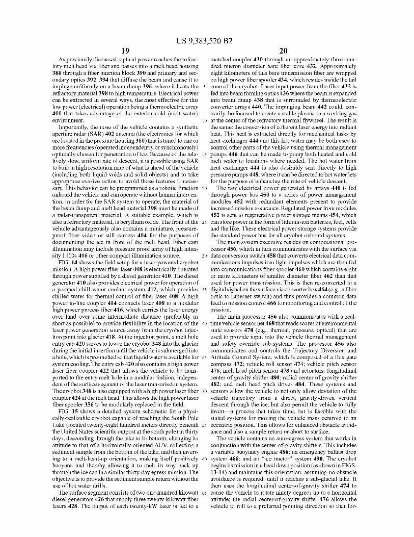
US 9,383,520 B219
As previously discussed, optical power reaches the refrac-tory melt head via fiber and passes into a melt head housing388 through a fiber junction block 390 and primary and sec-ondary optics 392, 394 that diffuse the beam and cause it toimpinge uniformly on a beam dump 396, where it heats therefractory material 398 to high temperature. Electrical powercan be extracted in several ways, the most effective for thislow power (electrical) operation being a thermoelectric array400 that takes advantage of the exterior cold (melt water)environment.
Importantly, the nose of the vehicle contains a syntheticaperture radar (SAR) 402 antenna (the electronics for whichare located in the pressure housing 360) that is tuned to one ormore frequencies (operated independently or synchronously)optimally chosen for penetration of ice. Because of the rela-tively slow, uniform rate of descent, it is possible using SARto build a high resolution map of what is ahead of the vehicle(including both liquid voids and solid objects) and to takeappropriate evasive action to avoid those features if neces-sary. This behavior can be programmed as a robotic functiononboard the vehicle and can operate without human interven-tion. In order for the SAR system to operate, the material ofthe beam dump and melt head material 398 must be made ofa radar-transparent material. A suitable example, which isalso a refractory material, is beryllium oxide. The front of thevehicle advantageously also contains a miniature, pressure-proof fiber video or still camera 404 for the purposes ofdocumenting the ice in front of the melt head. Fiber camillumination may include pressure proof array of high inten-sity LEDs 406 or other compact illumination source.FIG. 14 shows the field setup for a laser-powered cryobot
mission. A high power fiber laser 408 is electrically operatedthrough power supplied by a diesel generator 410. The dieselgenerator 410 also provides electrical power for operation ofa pumped chill water coolant system 412, which provideschilled water for thermal control of fiber laser 408. A highpower in-line coupler 414 connects laser 408 to a modularhigh power process fiber 416, which carries the laser energyover land over some intermediate distance (preferably asshort as possible) to provide flexibility in the location of thelaser power generation source away from the cryobot injec-tion point into glacier 418. At the injection point, a melt holeentry cab 420 serves to lower the cryobot 348 into the glacierduring the initial insertion until the vehicle is submerged intoa hole, which is pre-melted so that liquid water is available forsystem cooling. The entry cab 420 also contains a high powerlaser fiber coupler 422 that allows the vehicle to be trans-ported to the entry melt hole in a modular fashion, indepen-dent of the surface segment of the laser transmission system.The cryobot 348 is also equipped with a highpower laser fibercoupler 424 at the melt head. This allows the high power laserfiber spooler 356 to be modularly replaced in the field.
FIG. 15 shows a detailed system schematic for a physi-cally-realizable cryobot capable of reaching the South PoleLake (located twenty-eight hundred meters directly beneaththe United States scientific outpost at the south pole) in thirtydays, descending through the lake to its bottom, changing itsattitude to that of a horizontally-oriented AUV, collecting asediment sample from the bottom of the lake, and then invert-ing to a melt-head-up orientation, making itself positivelybuoyant, and thereby allowing it to melt its way back upthrough the ice cap in a similar thirty-day egress mission. Theobjective is to provide the sediment sample return without theuse of hot water drills.The surface segment consists of two one-hundred kilowatt
diesel generators 426 that supply three twenty-kilowatt fiberlasers 428. The output of each twenty-kW laser is fed to a
20matched coupler 430 through an approximately three-hun-dred micron diameter bare fiber core 432. Approximatelyeight kilometers of this bare transmission fiber are wrappedon high power fiber spooler 434, which resides inside the tail
5 cone of the cryobot. Laser input power from the fiber 432 isfed into beam forming optics 436 where thebeam is expandedinto beam dump 438 that is surrounded by thermoelectricconverter arrays 440. The impinging beam 442 could, con-trarily, be focused to create a stable plasma in a working gas
io at the center of the refractory thermal flywheel. The result isthe same: the conversion of coherent laser energy into radiantheat. This heat is extracted directly for mechanical tasks byheat exchanger 444 and this hot water may be both used tocontrol other parts of the vehicle using thermal management
15 pumps 446 that can be made to pump both heated and coldmelt water to locations where needed. The hot water fromheat exchanger 444 is also desirably sent directly to highpressure pumps 448, where it can be directed to hot water j etsfor the purpose of enhancing the rate of vehicle descent.
20 The raw electrical power generated by arrays 440 is fedthrough power bus 450 to a series of power managementmodules 452 with redundant elements present to provideincreased mission assurance. Regulated power from modules452 is sent to regenerative power storage means 454, which
25 can store power in the form of lithium-ion batteries, fuel, cellsand the like. These electrical power storage systems providethe standard power bus for all cryobot onboard systems.The main system executive resides on computational pro-
cessor 456, which in turn communicates with the surface viaso data conversion switch 458 that converts electrical data com-
munications impulses into light impulses which are then fedinto communications fiber spooler 460 which contains eightor more kilometers of smaller diameter fiber 462 than thatused for power transmission. This is then re-converted to a
35 digital signal on the surface via converter box 464 (e.g., a fiberoptic to Ethernet switch) and thus provides a common datafeed to mission control 466 for monitoring and control of themission.The main processor 456 also communicates with a real-
40 time vehicle sensornet 468 that reads scores of environmentalstate sensors 470 (e.g., thermal, pressure, optical) that areused to provide input into the vehicle thermal managementand safety override sub-systems. The processor 456 alsocommunicates and controls the Trajectory Diversion and
45 Attitude Control System, which is composed of a flux gatecompass 472; vehicle roll sensor 474; vehicle pitch sensor476; melt head pitch sensor 478 and actuators: longitudinalcenter of gravity shifter 480; radial center of gravity shifter482; and melt head pitch drives 484. These systems and
50 sensors allow the vehicle to not only allow deviation of thevehicle trajectory from a direct, gravity-driven verticaldescent through the ice, but also permit the vehicle to fullyinvert a process that takes time, but is feasible with thestated systems for moving the vehicle mass centroid to an
55 eccentric position. This allows for enhanced obstacle avoid-ance and also a sample return or abort to surface.The vehicle contains an auto-egress system that works in
conjunction with the center-of-gravity shifters. This includesa variable buoyancy engine 486; an emergency ballast drop
60 system 488; and an "ice tractor" system 490. The cryobotbegins its mission in a head down position (as shown in FIGS.13-14) and maintains this orientation, assuming no obstacleavoidance is required, until it reaches a sub-glacial lake. Itthen uses the longitudinal center-of-gravity shifter 474 to
65 cause the vehicle to rotate ninety degrees up to a horizontalattitude; the radial center-of-gravity shifter 476 allows thevehicle to roll to a preferred pointing direction so that for-

US 9,383,520 B221
merly lateral-looking science payload sensors can be made tolook directly at the lake bottom. The variable buoyancyengine 486 can be used to cause the vehicle to descend andhover at a specified altitude over the lake floor while a sedi-ment core sample is taken. The complete science payload cancontain, for example, imaging systems 492; environmentalsensors 494; lake bottom sediment core sampler 496; lakebottom sonar profiler 498; and water samplers, includingfilter samplers 500.At the conclusion of the data collection phase of a mission
(and the acquisition of the desired core and water samples) thevariable buoyancy engine 486 is caused to dump ballast (ster-ile water). The center-of-gravity shifters invert the vehicle toa head up position and the vehicle begins to melt its wayupward, using the positive buoyancy of the vehicle to drive itupward in a bubble of water. An optional, emergency ballastdrop-weight (made of a neutral, non-corroding, sterile mate-rial) system 488 may be activated if there is a failure in thevariable buoyancy system 486 fails on ascent. Lastly, anoptional "ice tractor" 490 can be employed to assist in ascentby providing a ratcheting mechanism that allows the vehicleto mechanically force itself forward (i.e., upward). This cancomprise direct lateral spur gears that can be extended fromthe body of the cryobot and driven either by pumped water orelectrical motors or it could be of a form consisting of atemporary lateral locking mechanism (e.g. a pressure cylin-der and blade pressed against the ice laterally) and a transla-tional ratchet that advances a specified distance up the body ofthe vehicle, locks to the wall (using a similar lateral forceapplication mechanism means) and then releases the lowerlatch and a draw motor (e.g. a linear actuator, or gear drivenlinear track means) pulls the vehicle forward. The intent of theice tractor 490 is to maintain contact between the melt headand the advancing ice column.
Importantly, the vehicle also contains an Obstacle Avoid-ance and Navigation System, which contains a forward-look-ing ice-penetrating low frequency radar (e.g., 100 MHz) 502;a forward looking mid-frequency ice penetrating radar (e.g.,400 MHz) 504; a depth sensor 506; a high precision gravime-ter 508; and an odometer 510. The ice-penetrating radar (IPR)system forms a part of the SAR system previously describedand can be used to dramatically enhance the ability of thevehicle to detect large objects as far as a kilometer ahead ofthe vehicle and small (centimeter-scale) objects as far as fiftymeters ahead of the vehicle. Further, for Arctic and Antarcticoperations on Earth, the top roughly fifty to one-hundredmeters of ice is not solid. This is a transition zone betweenfresh, loose snow and solid ice known as the "firm" layer.Because it is not made of solid ice, a cryobot returning to thesurface using positive buoyancy will eventually not be able tocause the vehicle to rise to the surface because air content inthe firm will cause a bubble of air to form at the head of thevehicle. The ice tractor 490 will overcome some of this and acryobot of the type described here will be able to rise to withinfifty meters of the surface before both buoyancy and lateralability to hold load will fail. At this point a surface-basedrecovery procedure is needed that employs a hot water drill topenetrate to the vehicle. An auto-docking and latching systemcan be created to retrieve the vehicle at that point. Knowingwhere to drill, however, is a critical part of this recoveryprocedure and for this the SAR radar now is used as a direc-tional beacon for the drilling system.
FIG. 16 shows another embodiment of the invention inwhich a laser power generation system 512, residing on aplanetary lander system, is used to remotely power an explo-ration and science rover 514. The advantages of this approachare significant in that the rover 514 can be made much more
22lightweight and agile and therefore survivable in a rug-ged, unknown environment. Furthermore, it allows for thecostly, heavy power generation equipment to remain with thelander (or planetary base) and therefore reduce the risk of
5 losing that precious resource were there to be an accident withthe rover 514. This approach can be used to either powermultiple rovers from the same power source or to allow manylong range missions by a single rover. The concept can befurther extended to one in which a fixed planetary base for
io example, a lunar polar base in a deep, sun-less cold cratermining water ice—can use a common central planetary(nuclear) power supply generating power in the five-hundredkilowatt to multi-megawatt range to operate a remote, distrib-uted fleet of large industrial regolith harvesters that scoop up
15 the surface dust and extract water through direct heating.The planetary lander laser power system 512 generally
comprises the elements previously described. Thepower sup-ply 516 for laser 518 is preferably provided by a compactradiothermal generator (RTG) for lightweight initial robotic
20 missions or a planetary high power (nuclear fission) thermalsource for industrial operations, either of which are subse-quently converted to electrical power using any of the meanspreviously described and then used to drive the laser. Photo-voltaics could also be used to provide power but this is not an
25 option for outer planet exploration and resource extraction(due to insufficient solar flux).
The mobility system 520 comprises the common powertrain previously described, which includes a rover-based fiberspooler system 522 that receives laser energy via inlet fiber
so 524, which is trailed out behind the vehicle as it moves fromonboard fiber spool 526. The fiber spool 526 is cooled byactively controlled heat exchanger and chiller 528 and passiveheat dissipation system 530. A high power fiber coupler 532allows connection of a beam dump 534 via process fiber 536.
35 Thermoelectric arrays (or other electrical power generationmeans previously described) send electrical power via powerbus 538 to a power management system 540 which charges orrecycles a regenerative energy storage system 542. Directcontrolled power from the regenerative power storage system
40 542 can be delivered at high current capacity to individualmotor or actuator controllers 544 that can be used to drivediscrete wheel drive electric motors 546 via power bus 547.Onboard computer system 548 makes behavioral decisionseither autonomously or scripted and sends digital control
45 signals via digital links 550 to operate the discrete motor oractuator controllers 544. All systems composing rover mobil-ity system 520 are carried onboard the actual rover 514.
FIG. 17 depicts another direct variation of the invention inwhich an unmanned underwater vehicle receives power in a
5o directly analogous fashion as that described in FIG. 16. Thereare two noteworthy differences in FIG. 17 vis-a-vis FIG. 16.First, the laser and laser power supply are based on a floatingplatform (e.g., an offshore oil rig or complex) or a ship as partof a ship-based power system 552. Either mission-specific,
55 dedicated diesel-electric power can be provided or theonboard power plant for the ship or platform itself (likelyeither diesel or nuclear) can be used to provide an essentiallyunlimited amount of input power to the laser. This is animportant factor as it permits (unlike an RTG-powered plan-
60 etary lander, for example) industrial power levels to be opti-cally transmitted to the underwater vehicle. For the samereasons as discussed earlier, there are severe limits to theamount of power an electrically operated underwater vehiclecan receive from the surface. The design of a high powered
65 ROV for work at three kilometers depth, for example, is acomplicated undertaking and the management of the cablealone is a major logistical cost and serious burden which

US 9,383,520 B223
limits the class of ship that can be used to conduct the work.While there are line losses associated with laser power trans-mission (see FIG. 113), and further losses associated withconversion of the delivered energy into electrical power, thoseare relatively small issues where there is plentiful electricalpower on the surface. The laser-powered AUV 554 or ROVcan competitively be operated against the mechanically inef-ficient current state of industrial ROVs being used for theoffshore oil industry. Further, with the laser-poweredapproach shown in FIG. 17, it becomes realistically feasibleto conduct high power industrial operations anywhere underthe ocean, to full ocean depth (eleven kilometers).The mechanism for power conversion for underwater
vehicle applications shown in FIG. 17 will likely be a heatengine (e.g., Stirling cycle) as this can be efficiently, andeconomically scaled to very large, continuous power levels(thousands of horsepower). Unlike the planetary roboticlanders, regenerative electrical power storage systems 542will largely be for clean (low electrical noise) operation ofonboard control, sensing, and communication and for limitedemergency maneuvering. The actuators (e.g., main thrusters556) will be driven via power bus 545 directly from theelectrical power output (generator) driven by the heat engine.The architecture shown in FIG. 17 creates an entirely newdesign space for underwater vehicles. Because the powerfiber can be very small in diameter (e.g., one megawattthrough an eight-hundred micron fiber) and because thevehicle has control of its own trajectory (because of theonboard fiber spooler), it becomes logical to run not onlytraditional surface-controlled ROVs, but also AUVs with thismethod, regardless of the degree of human intervention witha preprogrammed mission that may be carried out autono-mously in these last two cases. The ability to ditch the major-ity of the vehicle batteries means less requirement for expen-sive syntactic (ocean depth rated floatation foam) and theentire vehicle becomes able to be reduced to its key functionsof high power mobility and its designated mission task (e.g.repairing a deep pipeline; harvesting manganese nuggets offthe deep ocean floor, etc.).A dramatic variation of the invention is shown in FIGS.
18-20. For nearly three decades, intense research has beenconducted on the subject of laser or microwave poweredlaunch of spacecraft from the ground to Low Earth Orbit(LEO). These concepts involve direct beaming of a laser, orbanks of lasers, at a target launch vehicle in order to eitherdirectly ablate an expendable material on the back side of thespacecraft to create thrust or to heat a working fluid within thevehicle, generally using mirrors on the periphery of thevehicle to reflect the light towards a reaction chamber wherethe working fluid is to be heated, and then expand the workingfluid through a nozzle to create thrust. Regardless of themethod chosen, all of the approaches thus far attempted withlaser launch have failed for three primary reasons: atmo-spheric attenuation of the beam; atmospheric distortion of thebeam; and line-of-sight limitations. For an object to reach astable orbit in LEO, it must reach an altitude of approximatelythree-hundred kilometers or more, but more importantly, itmust accelerate to a tangential velocity of approximatelyeight kilometers per second. The launch trajectory is thuscurved and carries the vehicle a substantial distance horizon-tally away from the launch site before orbital insertionparam-eters are met. Tracking of the vehicle and attempting to keepthe beam locked onto it becomes a daunting task. Schemeshave been proposed to have multiple beaming stations aroundthe Earth to deal with the problem of not being able to keep asingle beam locked onto an ascending vehicle when it goesover the horizon, but these would represent wasteful duplica-
24tion of expensive laser power generation systems. Similardrawbacks apply to microwave power beaming. Bothapproaches are significantly degraded by weather.FIG. 18 presents the generic concept of fiber laser launch.
5 Similar to the previous discussions, a ground-based laserpower generation station 558 provides very large amounts ofpower into fiber 560, which is spooled out from a launchvehicle 562. The ground station consists of power source 516;laser chilling station 564; laser 518; high energy process fiber
io 566; and inline couplers 568. A spooler 570 on the launchvehicle 562 is chilled by any of the means previously identi-fied, but in the case of laser launch an additional coolant couldbe in the form of a cryogenic working fluid (e.g., liquidhydrogen, liquid nitrogen) that is stored in chamber 572 and
15 fed regeneratively via channels 574 through a heat exchangerthrough fiber spooler 570 to pre-heat the working fluid beforeentry into the working fluid injection ports 576 into a gasexpansion chamber 577. Importantly, the output of spooler570 goes through an optional coupler 578 and is then con-
2o nected to a laser injection interface structure 580 by fiber 582where the output proceeds through beam forming optics 584,586.
There are two general approaches available at this point tocreate thrust, both of them efficient. In the first idea, the beam
25 forming optics 586 focus the beam 588 of laser energythrough a laser window 590 on the back side of the gasexpansion chamber 577 and bring the beam to a point insidethe gas expansion chamber 577, creating a stable centralplasma core 592. Working fluid enters the gas expansion
so chamber 577 via fluid injection port 576 or other entry means.The working fluid can be any molecule that forms an expan-sive gas when heated thus it could be cryogenic liquids(e.g., liquid nitrogen, liquidhydrogen, liquid air, liquid argon,CO2, etc.), compressed gases of any type (e.g., nitrogen,
35 xenon, hydrogen, argon, air etc.), or liquids of any type (e.g.,water, methanol, or the like that, when heated, dramaticallyexpands in its gaseous phase).As the working fluid enters the gas expansion chamber
577, it is preheated in the focusing zone or optically heated40 expansion cavity 594 and begins to expand, passing around
the central plasma core 592 via path 596. A convective mixingzone 598 exists beyond the plasma centroid 592 and at thispoint the hot, expanded gas passes through nozzle throat 600,through high temperature expansion nozzle 602 and creates
45 thrust 624. Alternatively, plasma core 592 can be replaced bya series of heat exchangers where an expanded (as opposed tofocused) beam impinges, with all other facets remaining thesame. The purpose of the heat exchanger is to impart theenergy of the beam into the working fluid, rapidly creating
50 superheated gas in reaction chamber 577 whereupon, asbefore, the gas is expanded through nozzle throat 600 and intohigh temperature expansion nozzle 602 (i.e., exhaust) creat-ing thrust 624. It is the purpose of the method described toemulate the manner in which a normal mono- and bi-propel-
55 lant rocket engine creates thrust, but importantly allowing theuse of inert fuels (working fluids) which will lead to muchsafer launch and operation unlike traditional rocket launch,the termination of the laser beam would immediately ceasethrust and there would be no danger of an exploding booster
60 should a guidance system fail during launch. The reactionchamber or gas expansion chamber 577 is desirably designedto minimize radiative heat loss through the chamber walls606.
Importantly, the working fluid can be from several sources.65 During initial flight through the atmosphere, a ram air scoop
608 in the open position on the side of the vehicle allowsatmospheric air 610 to be compressed and taken into the

US 9,383,520 B225
vehicle. This atmospheric air 610 can then be sent through aram air intake structure 612 and through flow selector means614, and through bypass valves 616. Bypass valves 616 canoptionally send the working fluid to the heat exchangerlocated in the fiber spooler 570 for preheating to improve theefficiency of use of all heat being delivered to the vehicle viathe fiber laser power system. At approximately twenty tothirty kilometers altitude, the atmosphere will be too thin toprovide effective quantities of working fluid to be expandedto create thrust. A gradual transition will take place, whereworking fluid may be drawnboth from the atmosphere as wellas from the chamber 572. Eventually, at sufficient altitude,classed as "exo-atmospheric" flight, the vehicle 562 will needto rely solely on stored onboard working fluid (i.e., propel-lant). Chamber 572 carries that exo-atmospheric workingfluid, which is preferably one of liquid hydrogen, liquid nitro-gen or other liquefied gas, but alternatively could be a stablefluid such as water and other liquids and compressed gases(see above) as well as traditional monopropellants used forspacecraft maneuvering. The logic for using liquid water isthat the most logical micro payload (the class of launchvehicle most likely to be powered by this concept in the one toone-hundred kilogram payload range) is, in fact, waterbecause it is a dense, acceleration-insensitive material that isof great demand in low earth orbit (LEO). Other payloadsmight include dense consumables and acceleration resistantelectronics, sensors, and other high-technology re-supplyitems that may be needed in LEO. The working fluid con-tained in chamber 572 can be forced into the gas expansionchamber 577 by several means, including vehicle accelera-tion; an optional turbopump 617; or an optional gas blowdown system 618 that utilizes an inert pressurized gas to forcethe fluid through channel 620 to the reaction chamber (i.e.,gas expansion chamber 577).The length of optical fiber needed to achieve orbit is vari-
able as the launch vehicle can carry an independent smallpropulsion and guidance system for final orbital insertion.From a practical standpoint, however, a fiber length on theorder of one-hundred kilometers could be considered a lim-iting value as attenuation along the length of the fiber willeventually reduce the effective power received at the vehicle.During the highly energetic initial phase of the launch, aproperly designed vehicle should be able to make use of themajority of the heat delivered as the power loss over the fiberdeployed behind the vehicle will be small. Regenerative pre-heating of the working fluid, using channels 574, representsone of several means for extracting heat both from the coher-ent or focused element of the delivered laser energy (via thebeam focusing optics) and from the power dissipated in thefiber spooler 570. The spooler 570 could advantageously beplaced within the working fluid flow path or reservoir prior tothe fluid being injected into the focusing zone or opticallyheated expansion cavity 594. Both sources (coherent opticaland non-coherent radiative heat from the spooler) will viablycontribute to the overall thrust of the system.
Because the objective of fiber laser launch is to dramati-cally reduce the cost of placing small kilogram-level payloads(1 to 100 kg) into LEO, the vehicle design must be as efficientas possible. Thus, measures such as using the lightest weightmaterials for the vehicle structure and propulsion and guid-ance systems and striving for economy of scale are important.An important facet of economy will be that of fiber recovery.A one-hundred kilometer bare optical fiber will cost, in 2010dollars, between twenty and thirty thousand dollars depend-ing on its characteristics and core diameter. This price may bereduced significantly with large quantity purchases andimprovements in long-fiber extrusion manufacturing tech-
w1i
piques. Nonetheless, it will remain essential for commerciallaunch operations to reuse that fiber as many times as pos-sible. A bare one-hundred kilometer fiber extended in a typi-cal parabolic launch trajectory will take a substantial time to
5 fall through the atmosphere (on the order of more than an hourfrom the highest point) owing to its small diameter and lowdescent terminal velocity. A large, servo-controlled drumspooler 622 can be used to engage the fiber immediately afterlaunch and reel the fiber back in before it can hit the ground.
io The physics for this are well within the limits of currentmechanical systems design and available materials. The drumspooler 622 is not used during launch; it is strictly used forretrieval of the fiber after launch and does not engage norwrap any of the launch fiber until it has been fully spooled out
15 by the launch vehicle. In the notional example shown in FIG.18, the high power fiber 566 coming from the laser 518 can beadvantageously latched to drum 622 at high energy connector624, which mates to connector 626 which is rigidly affixed todrum 622. Following a launch, connector 626 can be discon-
2o nected from connector 624 and the drum 622 will be free tobegin the fiber retrieval process. With proper design, the fibercan be post-processed, cleaned, and re-wound for a subse-quent series of launches.FIG. 19 shows an embodiment in which one or more fiber
25 spooler assemblies 628 reside on the centerline of the launchvehicle. The fiber 630 connected to the laser source not shownis protected by fiber guide 632, which protects the fiber 630from direct thruster plume impingement that might otherwisedamage the fiber 630. The fiber 634 from the inboard side of
so the fiber spooler 628 connects to high power fast rotary beamswitch assembly 636 at its centerline. The beam is expandedthrough optical system 638 whereupon the beam impinges onthe high speed indexed rotary mirror 640 at the switch cen-terline. Servo motor 642 is connected to a high speed, high
35 stiffness rotary shaft 644, the rotational position of which issensed by embedded rotational encoders. The rotation ofshaft 644 causes high speed indexed rotary mirror 640 todirect the coherent laser energy to a plurality of fixed, staticmirrors 646 and 656 arrayed radially around the central high
40 speed indexed rotary mirror 640. When the beam is directedto the fixed, static mirror 646, the fixed, static mirror causesthe laser energy 648 to be deflected to beam focusing optics650, which in turn inject the beam into coupler 652 for sub-sequent transmission to thruster 654. If high speed indexed
45 rotary mirror 640 is subsequently rotated until it aligns withhigh energy fixed, static mirror 656, the beam is then divertedto exit fiber 658, which carries the optical energy to thrusterassembly 660. The light enters thruster assembly 660 via laseroptics cavity 662, where the beam is either focused or defo-
50 cused as previously discussed (with reference to FIG. 18) forthe purpose of optimal heating of heat exchanger or plasmacavity 664. Working fluid 666 enters heat exchanger 664 andis subsequently heated and expanded through nozzle 668 tocreate thrust 670. In this fashion any number of axially cen-
55 tered fiber spoolers can deliver power to a radial array ofthrusters. Advantageously, as will be described below, threeor more thrusters equally distributed radially (for example,three thrusters would have one-hundred twenty degrees ofangular spacing between them relative to the launch vehicle
60 centerline) allow for a significant simplification of the vehiclewhile still enabling full thrust vector control during launch.
Thrusters 654, 660 are advantageously canted at a desireddivergence angle 672 from centerline so as to further reducethe possibility of impingement of the exhaust plume from
65 these thrusters with the trailing fiber. Further, by canting thethrusters 654, 660 and using three or more thrusters, it ispossible to achieve active thrust vectoring of the launch

US 9,383,520 B2WA
vehicle with no moving parts associated with the thrusters654, 660. The high power fast rotary beam switch assembly636 is capable of rapidly transferring power to a specificthruster based on a desired vehicle direction. For direct,straight ascent, the laser is rapidly shifted between thrusters 5
so that all thrusters receive equal amounts of power and,therefore, each nominally produces symmetric thrust and thevehicle will maintain the instant tangent trajectory that it wason. However, even with dissimilar (or physically identical butvariably performing) thrusters, an onboard computer control 10system can rapidly generate a real-time vehicle state vectormatrix and from that determine which thruster to favor inorder to divert the vehicle to the desired trajectory.
FIG. 20 shows another preferred embodiment of the fiberlaser launch concept. In this variant, a plurality of fiber spool- 15ers 674 arrayed in a radial fashion about the centerline of thevehicle delivers power to a series of laser injection systems orassemblies 676. A high energy bare fiber 678 trails behind thevehicle during launch and connects to a ground-based laser(not shown). Fiber guides 680 protect the trailing fibers from 20direct exhaust plume impingement from the thruster. Thespoolers 674 are connected via fiber 682 to actively cooledhigh power couplers 684, which inject the beam into the laseroptics cavity 686 via laser injection assemblies 676. Beamforming optics 687 contained in each injection assembly 676 25are independently controlled in real-time to provide either afocused or diffuse output into the heat exchanger or plasmazone 688 at the core of the laser optics cavity 686 wherein aworking fluid, injected atport 690 is superheated and expandsthrough expansion nozzle 692 to create thrust 694. In this 30embodiment, one or more thrusters 696 are centrally locatedeither on centerline or arrayed symmetrically, radially, orotherwise about the vehicle centerline so as to create a centralthrust capability. One or more of these thrusters may beadditionally gimbaled so that its thrust vector can be modified 35under real-time computer control to maintain the vehicle on adesired ascent trajectory.
Notably, hybrid variants of the inventions described inFIGS. 18-20 are possible in which fast beam switches andbeam splitters are used to combine many laser inputs and 40channel them to many thruster outputs. These techniques canbe used to boost larger payloads. Telemetry from the vehicleto the ground, or conversely from radar tracking of the ascentvehicle, can be used to determine the instant state vector forthe launch vehicle. This can be used as the basis of corrective 45algorithms for steering the vehicle back to a correct course.The vehicle can optionally have onboard a navigation systemconsisting of either purely inertial sensors, a GPS (globalpositioning system) receiver, or other methods for estimatingthe position of the vehicle at any point in time and that 50information can be sent back in real-time to a mission controlcomputer either via radio (RF) telemetry or via modulateddata signal superimposed on the laser power transmissionfiber. This technique advantageously eliminates several sys-tems from the mass of the launch vehicle and it allows for 55direct non-line-of-sight communications to the vehicle, pos-sibly for over-ride of the onboard trajectory control or forrange-safety termination of the launch.
Another variation on fiber laser launch is that of an intel-ligent autonomous battlefield delivery system. This is far 60more effective than, e.g., a GPS-guided artillery shell forseveral reasons. First, the range for a laser-powered payload isin excess of one-hundred kilometers and more likely on theorder of two-hundred kilometers given that realistic fiberspoolers can be up to one-hundred kilometers long and, if the 65payload separates at apogee, then it will ballistically coastapproximately that same distance. However, up until the point
28of fiber separation it will be possible, again via modulateddata on the power fiber, or on a dedicated separately spooledfiber, to communicate with the payload and to cause it to bere-directed. A forward scouting team could provide such asystem with real-time GPS coordinates (even if moving),which could be uploaded to the payload for real-time re-targeting. Further, there is no requirement either for a maxi-mum thrust flight or for a ballistic trajectory. The fiber laserlaunch concept permits flight down to minimum stable flightspeed as well as "loitering" in a vicinity made possiblebecause the power source is continuous and substantial, andlocated at a rear base of operations. This means that the flightvehicle's dwell (or "loiter") time in an area of operationscould be made indefinite and the vehicle would not berequired to carry with it any fuel (because at low altitude,atmospheric air can be the "working fluid" for propulsion).Because the flight speed can be made variable, and arbitrarilylow if needed, sensitive supplies could also be sent to aforward operations team (human) with precision deliverycapability.FIG. 21 shows another variation of the invention in which
a rotary beam switch 698 is placed between the laser source518 and an array of two or more spoolers 700, 702. Thesespoolers 700, 702 are advantageously located on dockingports adjacent the central power supply and laser facility 704such that a mobile autonomous vehicle 706 could returnautomatically following a mission (after having expended itsone-use spooler) and dock with a port containing a fullspooler. At that point the vehicle 706 could re-load a freshspooler by removing it from the docking port and latching itonto a receiver port on the mobility system 708, thus re-enabling it for another mission.As an example, the mobility system 708 would begin a
mission using fiber spooler 702 which, as previouslyexplained, is connected to a power conversion system 710,which generates electrical power or alternative power tocause the mobility system 708 to move. At the conclusion ofa mission, mobility system 708 returns to the central powerlaser source 704 and discards spooler 702 and, while operat-ing on residual onboard electrical power storage systems,moves to the docking port that contains a second spooler 700.It then acquires that spooler 700, connects to it, and notifiesthe laser that power can now be transmitted through thatspooler. The main computer system at the laser source 704then causes beam switch 698 to re-route the laser energy tothe port that connects the power to spooler 700 with fiber 712.This is a viable multi-mission-enabling design that permitsre-load of a single vehicle (e.g., a planetary robotic explora-tion vehicle returning to a lander) for subsequent missionswhile maintaining the heavy elements of the system (powersource and laser) on the lander. However, this same approachcan also be used to sequentially send power to a plurality ofmobility systems (e.g., autonomous ground vehicles on abattlefield or forming a defensive perimeter around a forwardbase of operations).
Variations of this same theme are possible in which themobility platform 708 carries multiple fiber spools and canautonomously connect to an available laser power dockingstation which contains an appropriate high power laser cou-pler. In this fashion, the vehicle could utilize the presence ofmultiple laser power sources and transfer from one to anotherwhile still having an operational radius with respect to eachlaser power source. An example of a situation where this mayprove advantageous would be the exploration of the Ross IceShelf in Antarctica, where a surface-based traverse vehiclecould carry a single laser source to a new location at the limitof the fiber spooler carried by the vehicle. By drilling a new
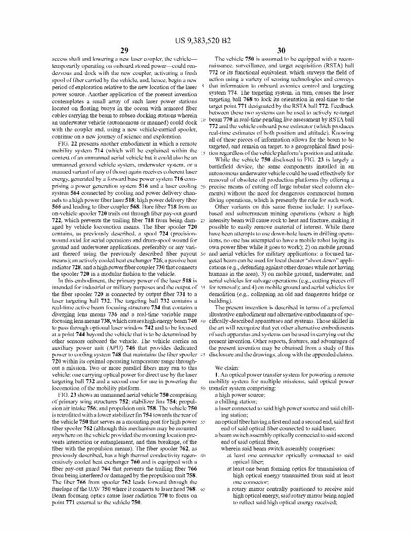
US 9,383,520 B229
access shaft and lowering a new laser coupler, the vehicletemporarily operating on onboard stored power—could ren-dezvous and dock with the new coupler, activating a freshspool of fiber carried by the vehicle, and, hence, begin a newperiod of exploration relative to the new location of the laserpower source. Another application of the present inventioncontemplates a small array of such laser power stationslocated on floating buoys in the ocean with armored fibercables carrying the beam to subsea docking stations whereinan underwater vehicle (autonomous or manned) could dockwith the coupler and, using a new vehicle-carried spooler,continue on a new journey of science and exploration.
FIG. 22 presents another embodiment in which a remotemobility system 714 (which will be explained within thecontext of an unmanned aerial vehicle but it could also be anunmanned ground vehicle system, underwater system, or amanned variant of any of those) again receives coherent laserenergy, generated by a forward base power system 716 com-prising a power generation system 516 and a laser coolingsystem 564 connected by cooling and power delivery chan-nels to a high power fiber laser 518; high power delivery fiber566 and leading to fiber coupler 568. Bare fiber 718 from anon-vehicle spooler 720 trails out through fiber pay-out guard722, which prevents the trailing fiber 718 from being dam-aged by vehicle locomotion means. The fiber spooler 720contains, as previously described, a spool 724 (precision-wound axial for aerial operations and drum-spool wound forground and underwater applications, preferably or any vari-ant thereof using the previously described fiber payoutmeans); an actively cooled heat exchanger 726; a passive heatradiator 728, and a high power fiber coupler 730 that connectsthe spooler 720 in a modular fashion to the vehicle.
In this embodiment, the primary power of the laser 518 isintended for industrial or military purposes and the output ofthe fiber spooler 720 is connected by output fiber 731 to alaser targeting ball 732. The targeting ball 732 contains areal-time active beam focusing structure 734 that contains adiverging lens means 736 and a real-time variable rangefocusing lens means 738, which causes high energy beam 740to pass through optional laser window 742 and to be focusedat a point 744 beyond the vehicle that is to be determined byother sensors onboard the vehicle. The vehicle carries anauxiliary power unit (APU) 746 that provides dedicatedpower to cooling system 748 that maintains the fiber spooler720 within its optimal operating temperature range through-out a mission. Two or more parallel fibers may run to thisvehicle: one carrying optical power for direct use by the lasertargeting ball 732 and a second one for use in powering thelocomotion of the mobility platform.
FIG. 23 shows an unmanned aerial vehicle 750 comprisingof primary wing structures 752; stabilizer fins 754; propul-sion air intake 756; and propulsion unit 758. The vehicle 750is retrofitted with a lower stabilizer fin 754 towards the rear ofthe vehicle 750 that serves as a mounting post for high powerfiber spooler 762 (although this mechanism may be mountedanywhere on the vehicle provided the mounting location pre-vents interaction or entanglement, and thus breakage, of thefiber with the propulsion means). The fiber spooler 762, aspreviously described, has a high thermal conductivity regen-eratively cooled heat exchanger 760 and is equipped with afiber pay-out guard 764 that prevents the trailing fiber 766from being interfered or damaged by the propulsion unit 758.The fiber 766 from spooler 762 leads forward through thefuselage of the UAV 750 where it connects to laser head 768.Beam focusing optics cause laser radiation 770 to focus onpoint 771 external to the vehicle 750.
30The vehicle 750 is assumed to be equipped with a recon-
naissance, surveillance, and target acquisition (RSTA) ball772 or its functional equivalent, which surveys the field ofaction using a variety of sensing technologies and conveys
5 that information to onboard avionics control and targetingsystem 774. The targeting system, in turn, causes the lasertargeting ball 768 to lock its orientation in real-time to thetarget point 771 designated by the RSTA ball 772. Feedbackbetween these two systems can be used to actively re-target
io beam 770 in real-time pending live assessment by RSTA ball772 and the vehicle onboard pose estimator (which producesreal-time estimates of both position and attitude). Knowingall of these pieces of information allows for the beam to betargeted, and remain on target, to a geographical fixed posi-
15 tion regardless of the vehicle platform's position and attitude.While the vehicle 750 disclosed in FIG. 23 is largely a
battlefield device, the same components installed in anautonomous underwater vehicle could be used effectively forremoval of obsolete oil production platforms (by offering a
20 precise means of cutting off large tubular steel column ele-ments) without the need for dangerous commercial humandiving operations, which is presently the rule for such work.
Other variants on this same theme include: 1) surface-based and subterranean mining operations (where a high
25 intensity beam will cause rock to heat and fracture, making itpossible to easily remove material of interest. While therehave been attempts to use down-hole lasers in drilling opera-tions, no one has attempted to have a mobile robot laying itsown power fiber while it goes to work); 2) on mobile ground
3o and aerial vehicles for military applications: a focused tar-geted beam can be used for local theater "shoot down" appli-cations (e.g., defending against other drones while not havinghumans in the area); 3) on mobile ground, underwater, andaerial vehicles for salvage operations (e.g., cutting pieces off
35 for removal); and 4) on mobile ground and aerial vehicles fordemolition (e.g., collapsing an old and dangerous bridge orbuilding).The present invention is described in terms of a preferred
illustrative embodiment and alternative embodiments of spe-40 cifically-described apparatuses and systems. Those skilled in
the art will recognize that yet other alternative embodimentsof such apparatus and systems can be used in carrying out thepresent invention. Other aspects, features, and advantages ofthe present invention may be obtained from a study of this
45 disclosure and the drawings, along with the appended claims.
We claim:1. An optical power transfer system for powering a remote
mobility system for multiple missions, said optical power50 transfer system comprising:
a high power source;a chilling station;a laser connected to said high power source and said chill-
ing station;55 an optical fiber having a first end and a second end, said first
end of said optical fiber connected to said laser;a beam switch assembly optically connected to said second
end of said optical fiber,wherein said beam switch assembly comprises:
60 at least one connector optically connected to saidoptical fiber;
at least one beam forming optics for transmission ofhigh optical energy transmitted from said at leastone connector;
65 a rotary mirror centrally positioned to receive saidhigh optical energy, saidrotary mirrorbeing angledto reflect said high optical energy received;

US 9,383,520 B231
a plurality of fixed mirrors arrayed radially about saidrotary mirror, said plurality of fixed mirrors angledtoward said rotary mirror;
a rotary shaft connected to said rotary mirror; anda servo motor for actuating said rotary shaft to rotate
said rotary mirror;an inline coupler positioned between said laser and saidbeam switch assembly;
a plurality of actively cooled fiber spoolers optically con-nected to said beam switch assembly;
a power conversion system optically connected to saidplurality of actively cooled fiber spoolers;
an inline coupler positioned between said power conver-sion system and said plurality of actively cooled fiberspoolers;
a plurality of docking ports positioned adjacent to said highpower source and adapted for securing said plurality ofactively cooled fiber spoolers;
at least one remote mobility system optically connected tosaid plurality of actively cooled fiber spoolers; and
wherein said power conversion system is located on said atleast one remote mobility system, said power conversionsystem for converting optical energy received to anotherform of energy usable by said at least one remote mobil-ity system.
2. The optical power transfer system, as recited in claim 1,wherein said at least one remote mobility system furthercomprises a receiving port on said at least one remote mobil-
32ity system, said receiving port adapted for securing said plu-rality of actively cooled fiber spoolers.
3. The optical power transfer system, as recited in claim 2,further comprising a computer for controlling said beam
5 switch assembly to re-route said optical energy to said plu-rality of docking ports currently in use by said at least oneremote mobility system.
4. The optical power transfer system, as recited in claim 3,wherein said plurality of actively cooled fiber spooler is
io mounted on said at least one remote mobile system.5. The optical power transfer system, as recited in claim 4,
wherein said high power source is adapted to produce opticalenergy in the range of kilowatts to tens of megawatts.
6. The optical power transfer system, as recited in claim 5,15 wherein said at least one remote mobile system is a rover.
7. The optical power transfer system, as recited in claim 5,wherein said at least one remote mobile system is an autono-mous underwater vehicle.
8. The optical power transfer system, as recited in claim 5,20 wherein said at least one remote mobile system is a remotely
operated vehicle.9. The optical power transfer system, as recited in claim 5,
wherein said at least one remote mobile system is anunmanned aerial vehicle.
25 10. The optical power transfer system, as recited in claim 5,wherein said at least one remote mobile system is an autono-mous ground vehicle.